SHEAR CAPACITY PREDICTION OF CONFINED MASONRY WALLS SUBJECTED TO CYCLIC LATERAL LOADING

Journal of Computational and Applied Mathematics 168 (2004) 135–144www.elsevier.com/locate/cam
A discrete model for cyclic mode I loading
K. De Profta ;∗, L.J. Sluysb, W.P. De Wildea
aDepartment of Mechanics of Materials and Constructions, Free University of Brussels, Pleinlaan 2,Brussel 1050, Belgium
bDelft University of Technology, Stevinweg 1, Delft 2628 CN, The Netherlands
Received 12 September 2002; received in revised form 19 May 2003
Abstract
The cyclic behaviour of a double-edge notched specimen loaded in tension is studied. Cracks in the materialare modelled by displacement discontinuities that can propagate during computation. Within these disconti-nuities, a cohesive zone model is used. The model assumes an additive split of the inelastic jump into arecoverable and an unrecoverable part. The in7uence of model parameters and discretisation is studied andthe results have been compared with experimental data.c© 2003 Elsevier B.V. All rights reserved.
Keywords: Damage-plasticity; Cohesive zone; Partition of unity
1. Introduction
The numerical simulation of fracture of quasi-brittle materials is a challenging subject for manyyears now. Di=erent kinds of models were developed over the years, all trying the simulate fractureindependent of the discretisation. In the continuum approach, nonlocal [5] and gradient [4] modelshave shown to be an e=ective tool to overcome mesh dependency. These models need a very@ne mesh within the fracture zone, in order to capture the steep deformation gradient. Anotherway of regularising the problem is to use discrete methods like the cohesive surface methodology orembedded discontinuities. The @rst introduces cohesive surfaces at inter element boundaries, allowingcracks to initiate and propagate [8]. The cohesive zones are present from the beginning of thecalculation. Since the crack path is not known a priori, the mesh must be re@ned in order to haveenough possible crack trajectories. The embedded discontinuities [6] allow cracks (discontinuities)to initiate during computation and to run through elements.
∗ Corresponding author.E-mail address: [email protected] (K. De Proft).
0377-0427/$ - see front matter c© 2003 Elsevier B.V. All rights reserved.doi:10.1016/j.cam.2003.05.007

136 K. De Proft et al. / Journal of Computational and Applied Mathematics 168 (2004) 135–144
In this paper, the cracks are modelled as a displacement discontinuity (strong discontinuity). Us-ing the partition of unity concept, nodes are locally enhanced by adding extra degrees of freedomwith the Heaviside function as enhanced basis [7]. In the @rst section, the kinematics of the dis-placement @eld and the governing equations are derived for two nonintersecting discontinuities. Acombined damage-plastic model is introduced as cohesive zone model in Section 3. Numerical simu-lation of a double edge-notched specimen subjected to monotonic and cyclic loading is discussed inSection 4.
2. Cohesive zone model based on partitions of unity
2.1. Kinematics of a displacement jump
Consider a body � crossed by a discontinuity �d as shown in Fig. 1. The discontinuity splitsthe body into two parts, �+ and �−. The normal to the discontinuity is pointed towards �+. Thedisplacement @eld within the body � can be split up into a continuous and a discontinuous part
u = u +H�d u; (1)
where u and u are continuous @elds and H�d is the Heaviside function centred at the discontinuity�d. The in@nitesimal strain @eld can be derived by taking the symmetric gradient of the displacement@eld
” =∇su +H�d∇su + ��d (u ⊗ n)s; (2)
where ��d is the Dirac delta distribution centred at the discontinuity. The presence of this Diracdelta distribution makes the strain @eld at the discontinuity unbounded.
Fig. 1. Body � crossed by a discontinuity �d.

K. De Proft et al. / Journal of Computational and Applied Mathematics 168 (2004) 135–144 137
The kinematic description of the displacement @eld crossed by a discontinuity can be easilygeneralised to the problem of a volume crossed by m non-intersecting discontinuities
u = u +m∑i=1
H�i ui: (3)
The strain @eld can be derived in the same way as for the one discontinuity case. For intersectingdiscontinuities, additional terms are needed to describe the intersection.
2.2. Partition of unity concept
Finite element shape functions, Ni, form partitions of unity sincen∑i=1
Ni = 1; (4)
where n is the number of discrete points. Duarte and Oden [2] showed that a @eld, such as thedisplacement @eld, can be interpolated making use of these partitions of unity
u=n∑i=1
Ni
ai +
k∑j=1
bij�j
; (5)
where ai and bij are discrete values and �j is an enhanced basis with k basis terms. When comparedwith ‘classical’ @nite elements, it can be seen that with partition of unity the regular interpolation ofthe displacement @eld can be enriched with enhanced terms. When the Heaviside function is chosenas enhanced basis, the displacement @eld can be interpolated as
u =Na +m∑i=1
H�iNbi ; (6)
where a are the regular degrees of freedom and bi are the enhanced degrees of freedom related tocrack i. Comparing with Eq. (3), it can be seen that
u =Na; (7)
ui =Nbi: (8)
2.3. Governing 5nite element equations
The weak form of the virtual work equation without body forces reads:∫�∇s� : � d� =
∫S� · Pt dS; (9)
where � is taken from the set of admissible displacement variations and S is the outer surface whereexternal tractions are applied. Using a Galerkin approach, the admissible displacement variations canbe decomposed in the same manner as the actual displacement @eld. Inserting the expression for
138 K. De Proft et al. / Journal of Computational and Applied Mathematics 168 (2004) 135–144
multiple (in this case m) nonintersecting discontinuities, the virtual work equation can be rewrittenin ∫
�∇s� : � d� +
m∑i=1
∫�H�i∇s�i : � d� +
m∑i=1
∫���i(�i ⊗ ni)s : � d�
=∫S� · Pt dS +
m∑i=1
∫S�i · Pt dS: (10)
Taking @rst variations of � (�i=0) and then variations of �i (� = 0), a set of m + 1 equations isobtained.∫
�∇s� : � =
∫S� · Pt dS; (11)
∫�H�i∇s�i : � d� +
∫�i
�i · ti d�i = 0 (i = 1; : : : ; m); (12)
where ti are the traction forces working at the discontinuity �i. To obtain Eq. (11), the enhanceddisplacement @eld, u, is assumed to be zero where essential boundary conditions are imposed.The discretised equations are obtained by inserting the discretised forms for the displacement andthe strain @eld.∫
�BT� d� =
∫SNT · Pt dS; (13)
∫�H�iB
T� d� +∫�i
NT · ti d�i = 0 (i = 1; : : : ; m); (14)
In these equations, the continuum and the discontinuity response are completely split up. Thecontinuum is assumed to remain elastic during the complete computation, so the stress rate is de@nedas
� = C e” = C e(Ba +H�iBbi); (15)
where C e is the elastic material tensor. The traction rate is de@ned as
Ti =DNbi; (16)
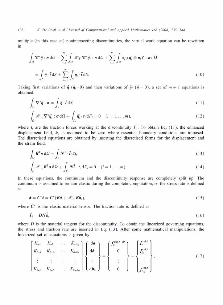
where D is the material tangent for the discontinuity. To obtain the linearized governing equations,the stress and traction rate are inserted in Eq. (13). After some mathematical manipulations, thelinearized set of equations is given by
Kaa Kab1 : : : Kabm
Kb1a Kb1b1 : : : Kb1bm
......
......
Kbma Kbmb1 : : : Kbmbm
da
db1...
dbm
=
f ext; t+dta
0
...
0
−
f int; ta
f int; tb1
...
f int; tbm
; (17)

K. De Proft et al. / Journal of Computational and Applied Mathematics 168 (2004) 135–144 139
where
Kaa =∫�BTC eB d�; (18)
Kabj =∫�HjBTC eB d�; (19)
Kbja =∫�HjBTC eB d�; (20)
Kbibj =∫�HiHjBTC eB d�; (21)
Kbjbj =∫�HjBTC eB d� +
∫�j
NTDN d�j; (22)
It can be seen from previous equations that when C e and D are symmetric, the global system ofequations remains symmetric. Eq. (17) is written on element level. It is assumed that only onediscontinuity j crosses the element but the element is in7uenced by discontinuity i.
2.4. Numerical implementation
The cohesive zone model based on partitions of unity allows discontinuities to propagate indepen-dent of a @nite element discretization. For the propagation of a discontinuity, a criterion is evaluatedin the elements in front of the crack tips. For mode I cracking, a discontinuity can be initiatedperpendicular to the maximal principal stress direction when the tensile strength in the element isexceeded. More general, a yield surface can be used to decide whether the discontinuity shouldpropagate or not. In this case, a bifurcation analysis may be necessary to compute the propagationdirection.Furthermore, discontinuities can only grow at the end of a time step, so that no discontinuities
are introduced in nonequilibrium states. As was stated in [7], this procedure ensures quadratic con-vergence of the Newton–Raphson process. Once a discontinuity has propagated, the nodes of thecrossed element are enhanced. The support of the discontinuity tip remains restrained, so that thedisplacement jump at the tip is zero. During computation, only one discontinuity is allowed to crossan element. When a new discontinuity enters an element, which is already crossed by a discontinuity,the discontinuity is arrested. When two discontinuities reach the same elastic element, the disconti-nuities can link up. In order to assure an adequate integration of crossed elements, the integrationscheme is changed in these elements. The integration scheme, proposed in [7], is used.
3. Cohesive zone model
The starting point for the cohesive zone model used in this paper is the Rankine yield surface.When n and t represent the normal and tangential direction to the discontinuity, respectively, the

140 K. De Proft et al. / Journal of Computational and Applied Mathematics 168 (2004) 135–144
Rankine yield surface can be written as
f = Tn − ft; (23)
where Tn is the normal component of the traction vector and ft is the tensile strength of the material.For modelling softening materials, the tensile strength is allowed to decrease during loading. Thedecrease is driven by the maximal plastic deformation reached.
ft = ft0 exp(−ft0
Gfupln
): (24)
For interface elements, the plastic deformation and the updated stress can be found using a classicalelasto-plastic computation. Because interface elements are present from the beginning of the compu-tation, they also develop an elastic part. This elastic part should be minimised which is achieved byusing a very high dummy elastic sti=ness. For the methodology used here, discontinuities are intro-duced only when the tensile strength of the material is exceeded. As a consequence the deformationin the discontinuity is completely inelastic. As was shown in [3], the elasto-plastic model shouldevolve to a rigid plastic computation, where no elastic part exists.For the Rankine yield surface, a rigid plastic analysis is relative simple. The new position of the
yield surface can be computed assuming that the jump is completely plastic. The new value for thenormal traction is immediately found.
Tn = ft0 exp(−ft0
Gfujumpn
)(25)
and the tangential sti=ness can be computed as
T n =−f2t0Gf
exp(−ft0
Gfujumpn
)ujumpn : (26)
For the Rankine yield surface, these relations can also be obtained starting from the elasto-plasticrate equations. For an associative plastic material, the elasto-plastic rate equations are given by
T =[C e − C ennTC e
nTC en + h
]u; (27)
where n= @f=@T , C e is the elastic sti=ness matrix and h is the softening modulus. For the Rankineyield surface, nT = (1; 0) so Eq. (27) simpli@es to
T n =[E − E2
E + h
]u n (28)
or
T n =[
h1 + h=E
]u n (29)
The elastic deformations becomes negligible when elastic sti=ness goes to in@nity,
T n = limE→∞
[h
1 + h=E
]u n = hu n (30)

K. De Proft et al. / Journal of Computational and Applied Mathematics 168 (2004) 135–144 141
and
h=−f2t0Gf
exp(−ft0
Gfun
): (31)
Eq. (30) is similar to the tangential sti=ness found with the rigid plastic model and integration ofEq. (30) results in Eq. (25).For the modelling of cyclic behaviour, also the unloading behaviour should be studied. Assume that
the inelastic deformation can be decomposed in a recoverable—damage—part and an unrecoverable—plastic—part. The index n is skipped for clarity:
ujump = upl + ud = (1− �)ujump + �ujump; (32)
where � is a model parameter. A fully damage model is found for � → 1, while a fully plasticmodel is obtained when � → 0.The unloading is then obtained by
Tn =ft0
�umaxnexp
(−ft0
Gfumaxn
)(un − (1− �)umaxn ) (33)
and the unloading sti=ness,
T n =ft0
�umaxnexp
(−ft0
Gfumaxn
)u n: (34)
For the tangential direction, elastic behaviour is assumed.
4. Numerical examples
The proposed model is used to simulate the tensile behaviour of a double edge-notched stonespecimen. The geometry of the specimen is given in Fig. 2. In the experiments, the lower and upperboundary are glued to loading platens, so that no rotation of the boundaries is possible. The loadis applied under displacement control. The opening displacement of both notches is averaged and isused as control signal for the displacement control.The numerical simulations are performed under load control with arc length control. For the arc
length, the averaged opening displacement of the notches is used as control signal. At the upperboundary all degrees of freedom are constrained while at the lower boundary, no displacements
Fig. 2. Geometry of the double edge notched specimen.

142 K. De Proft et al. / Journal of Computational and Applied Mathematics 168 (2004) 135–144
(a) (b) (c)
660 elements
372 elements
Fig. 3. Mesh with (a) 660 elements and (b) 372 elements and (c) obtained crack paths.
along the x-axis are allowed. The rotation of the specimen is prevented by expressing the symmetrycondition along the y-axis. The steel loading plate for the upper boundary is also modelled.For the simulations, a quadratic triangular element was used. The behaviour of the continuum is
assumed to remain elastic. The elastic material properties are: Young’s modulus E = 40 GPa and aPoisson’s ratio �=0:29. The behaviour of the discontinuity is described by the Rankine model wherea tensile strength ft0 =6:5 MPa and a fracture energy Gf=0:05 N=mm is chosen. Two meshes with372 elements and 660 elements are analysed. Fig. 3 shows used meshes and the obtained crack pathfor the two meshes. As can be seen the crack paths for di=erent meshes coincide remarkably well.The numerically simulated crack path also shows good agreement with the experimentally observedcrack path.Apart from local information, i.e. the monitoring of the crack path, also global information is
recorded. The averaged opening of the notches d, is plotted against the applied load in Fig. 4.Comparing the obtained load deformation curve for the mesh with 372 elements with the curve forthe mesh with 660 elements shows that there is only a small di=erence near the end of the postpeak branch. The predicted peak load is for both simulations identical. Although small di=erences,the cohesive zone model based on partition of unity seems to simulate fracture independent of thediscretization. Al further simulations are carried out with the coarser mesh.Fig. 5 shows the load–deformation curve of a specimen under cyclic loading. The parameter �
controlling the amount of recoverable deformation is varied from 0 to 1. Fig. 5a shows the load–deformation curve for �=0:7. A fully plastic model (Fig. 5b) is obtained for �=0:0 while the fullydamage model (Fig. 5c) is found for � = 1:0.Finally, model parameters are @tted to give a good correspondence with experiments [1]. The
following set is chosen: ft0=6:5 MPa, Gf=0:05 N=mm and �=0:7. The resulting load deformationcurve is given in Fig. 6. The value of � shows that the behaviour of the stone is more damage relatedthan plasticity related. Although for a good representation of unloading behaviour, the contributionof combined plasticity and damage is crucial.

K. De Proft et al. / Journal of Computational and Applied Mathematics 168 (2004) 135–144 143
d (mm)
P (
N)
0 0.005 0.01 0.0150
500
1000
1500
2000
372 elements660 elements
Fig. 4. Load–deformation curve for DEN tensile test.
d (mm)
P(N
)
0.005 0.01 0.0150
500
1000
1500
2000
(a) (b)
(c) d (mm)
P(N
)
0 0.005 0.01 0.0150
500
1000
1500
2000
P(N
)
0 0.005 0.01 0.0150
500
1000
1500
2000
d (mm)0
Fig. 5. Load–deformation curve for (a) � = 0:7, (b) � = 0:0 and (c) � = 1:0.
5. Conclusions
The numerical simulations of a double-edge notched specimen under tensile loading are presented.The discrete approach for modelling fracture is followed, introducing discontinuous terms in the

144 K. De Proft et al. / Journal of Computational and Applied Mathematics 168 (2004) 135–144
P(N
)
0 0.005 0.01 0.015 0.020
500
1000
1500
2000
NumericalExperimental
d (mm)
Fig. 6. Load–deformation curve for experimental results and numerical simulation.
displacement @eld. The partition of unity concept is used for the numerical implementation. It wasshown that this modelling technique yields results that are independent of the discretization.The behaviour of the discontinuities is modelled with a mode I model based on the Rankine yield
surface. Since discontinuities are only embedded when the tensile strength of the material is reached,the deformations in the discontinuity are completely inelastic. A rigid plastic or rigid damage modelis necessary to describe the behaviour.The model for cyclic loading used in this paper simply splits the inelastic behaviour into a
recoverable and an unrecoverable part. Simulations showed that this simple model is capable tosimulate the behaviour of limestone under cyclic loading. In the future, more complicated materialmodels will be used and implemented so that the modelling is extended to mixed mode cracking.
References
[1] K. De Proft, L.J. Sluys, W.P. De Wilde, Combined experimental–numerical study to monotonic and cyclic behaviourof limestone, in: C.A. Brebbia, S.I. Nishida (Eds.), Damage and Fracture Mechanics, Wessex Institute of Technology,UK, 2003.
[2] C.A. Duarte, J.T. Oden, H–p clouds and h–p meshless method, Numer. Methods Partial Di=erential Equations 12(1996) 673–705.
[3] J. Oliver, On the discrete constitutive models induced by strong discontinuity kinematics and continuum constitutiveequations, Internat. J. Solids Struct. 37 (2000) 7207–7229.
[4] R.H.J. Peerlings, R. De Borst, W.A.M. Brekelmans, M.G.D. Geers, Gradient-enhanced damage modelling of concretefracture, Mech. Cohesive-Frictional Materials 3 (1998) 323–342.
[5] G. Pijaudier-Cabot, Z. Bazant, Nonlocal damage theory, ASCE J. Eng. Mech. 113 (1987) 1512–1533.[6] J.C. Simo, J. Oliver, F. Armero, An analysis of strong discontinuities induced by strain-softening in rate-independent
inelastic solids, Comput. Mech. 12 (1993) 277–296.[7] G.N. Wells, L.J. Sluys, A new method for modelling cohesive cracks using @nite elements, Internat. J. Numer.
Methods Eng. 50 (2001) 2667–2682.[8] X.P. Xu, A. Needleman, Numerical simulations of fast crack growth in brittle solids, A new method for modelling
cohesive cracks using @nite elements, J. Mech. Phys. Solids 42 (1994) 1397–1434.
Copyright © 2022 FDOKUMEN