
a design study for a magnetohydrodynamic power system for ...
220
A DESIGN STUDY FOR A MAGNETOHYDRODYNAMIC POWER SYSTEM FOR A NUCLEAR ELECTRIC PROPELLED UNMANNED SPACECRAFT QUARTERLY PROGRESS REPORT NO. 1 COVERING THE PERIOD 26 MAY 1969 TO 25 SEPTEMBER 1969 PREPARED UNDER CONTRACT JPL 952415 FOR GESP-7017 SEPT 1 9 6 9 PROPULSION RESEARCH AND ADVANCED CONCEPTS SECTION JET PROPULSION LABORATORY 4800 OAK GROVE DRIVE PASADENA, CALIFORNIA, 91103
-
Upload
khangminh22 -
Category
Documents
-
view
5 -
download
0
Transcript of a design study for a magnetohydrodynamic power system for ...

A DESIGN STUDY FOR A MAGNETOHYDRODYNAMIC POWER SYSTEM
FOR A NUCLEAR ELECTRIC PROPELLED UNMANNED SPACECRAFT
QUARTERLY PROGRESS REPORT NO. 1
COVERING THE PERIOD 26 MAY 1969 TO 25 SEPTEMBER 1969
PREPARED UNDER CONTRACT JPL 952415
FOR
GESP-7017 SEPT 1 9 6 9
PROPULSION RESEARCH AND ADVANCED CONCEPTS SECTION JET PROPULSION LABORATORY
4800 OAK GROVE DRIVE PASADENA, CALIFORNIA, 91103

ISOTOPE POWER SYS
QUARTERLY PRO RESS REPORT NO. 1
COVERING THE PERIOD 26 MAY 1969 TO 25 SEPTEMBER 1969
PREPARED UNDER CONTRACT JPL 952415
FOR
PROPULSION RESEARCH AND ADVANCE^ CONCEPTS SECTION JET PROPULSION LABORATORY
4800 QAK GROVE DRIVE PASADENA, CAL~FORN~A, 91103
THIS WORK WAS PERFORMED FOR THE JET PROPULSION LABORATORY, CALIFORNIA INSTITUTE OF TECHNOLOGY A S SPONSORED BY THE NATIONAL AERONAUTICS AND SPACE ADMINISTRATION UNDER CONTRACT NAS7-100
SPACE DlVlSlON KIN(; OF PRCJSSIA PARK
F’.O.H@X > + 6 6 l * b ’ b l l l A L ) P L b ’ H I A . l ’ E N P J A , IYlOl
GESP -701 7 SEPT 1969

This report contains information prepared by the General Electric Company under JPL subcontract. Its content is not necessarily endorsed by the Jet Propulsion Laboratory, California Institute of Technology, or the National Aeronautics and Space Administration.
ii

ABSTRACT
This report discusses the progress made in the first quarter of a one-year design study of nuclear-electric propelled unmanned space- craft using a magnetohydrodynamic (MHD) power system. This report includes as appendices the analytical treatment of the MHD system as developed spacecraft analysis is based. The study guidelines and approach are defined here, and the characteristics of one launch vehicle, the thruster subsystem, and the payload and communications system are presented.
by Jet Propulsion Laboratory and upon which the
The MHD power conversion system is described and methods used to calculate MHD system parameters are discussed. includes the initial estimation of baseline (300 kwe) system design parameters and a discussion of the arrangement and structural arguments used to select system configuration. The system startup technique is identified, and the nuclear reactor and primary radiator characterization are presented.
This report
iiiliv
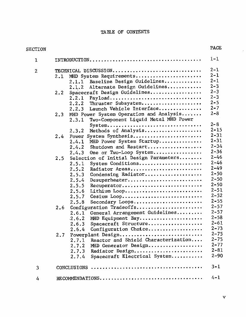
TABLE OF CONTENTS
SECTION PAGE
1 INTRODUCTION ....................................... 2
3
4
TECHNICAL DISCUSSION ............................... 2 .1 MKD System Requirements .......................
2.1 .1 Baseline Design Guidelines ............. 2.2 Spacecraft Design Guidelines .................. 2.1.2 Alterna te Design Guidelines ............
2.2 .1 Payload ................................ 2.2.2 Thruster Subsystem ..................... 2.2.3 Launch Vehicle I n t e r f a c e ............... MHD Power System Operation and Analysis ....... 2 . 3 . 1
System ................................. 2.3.2 Methods of Analysis ....................
2.4 Power System Synthesis ........................ 2.4.1 MHD Power System S ta r tup ............... 2.4.2 Shutdown and Restart ................... 2.4.3 One o r Two-Loop System ................. Selec t ion of I n i t i a l Design Parameters ........ 2 . 5 . 1 System Conditions ...................... 2.5.2 Radiator Areas ......................... 2.5.3 Condensing Radiator ....................
2.3 Two-Component Liquid Metal MHD Power
2.5
2 - 5 . 4 Desuperheater .......................... 2.5.5 Recuperator ............................ 2.5.6 Lithium Loop ........................... 2.5.7 Cesium Loop ............................ 2.5.8 Secondary LOOPS ........................
2.6 Configuration Tradeoffs ....................... 2.6 .1 General Arrangement Guidelines .........
2.6 .4 Configuration Choice ................... 2.7 Powerplant Design .............................
.2. 6.2 MHD Equipment Bay ...................... 2.6.3 Spacecraft S t ruc tu re ................... 2 . 7 . 1 Reactor and Shield Character izat ion .... 2.7.2 MHD Generator Design ................... 2.7.3 Radiator Design ........................ 2 . 7 . 4 Spacecraft Electrical System ...........
CONCLUSIONS ....................................... RECOMMENDATIONS ....................................
1-1
2 - 1 2 -1 2 -1 2-3 2-3 2-3 2-5 2-7 2-8
2-8 2-15 2-31 2-31 2-34 2-36 2-46 2-46 2-49 2-50 2-50 2-50 2 -51 2-52 2-55 2-57 2-57 2-58 2-61 2-73 2-75 2-75 2-77 2-81 2-90
3 - 1
4-1
V

TABLE O F CONTENTS (continued)
SECTION PAGE
5 NEW TEXHNOLOGY. ..................................... 5-1
6 REFERENCES.. ........................................ 6-1
+APPENDIX
I COMPUTATION OF VARIABLE - VELOCITY MHD INDUCTION GENERATOR PERFORMANCE (PROGRAM GENERATOR). .......... 1-1
I1 CYCLE ANALYSIS O F A CESIUM-LITHIUM MHD POWER SYSTEM WITH AN IMPINGING-JET SEPARATOR (PROGRAM CYCLE-B) ... 11-1
vi

LIST OF ILLUSTRATIONS
FIGURE TI TLE PAGE
2 - 1
2-2
2-3 2-4 2-5 2-6 2-7 2-8 2-9 2-10 2-11
2-12 2-13 2-14 2-15 2-16 2-17
2-18 2-19 2-20 2-21 2-22 2-23
2-24 2-25 2-26 2-27
2-28 2-29 2-30 2-31 2-32 2-33 2-34 2-35 2-36
Flight Fairing Weight and Payload Penalty (Titan
Effect of Shroud Retention on Payload Capability III C/7).0 ........................................... (Titan 111 C/7) ...................................... Lithium-Cesium MHD Cycle ............................. NaK/N2 MHD Test System ............................... Cutaway NaK/N2 MHD Test System ....................... Schematic of a Flat AC Induction Generator ........... Subroutine Calling Schematic of MHDGN ................ Sensitivity Factors for Net Power .................... Sensitivity Factors for Net Efficiency ............... Effects of Varying Twall from One to Ten fillimeters . Relation Between Coil Loss Factor. a . and External Conductor Resistance Factor. 7 ..................... MHD Stator Winding Geometry .......................... MHD Fluid System Schematic ........................... MHD Loop With Separate Reactor Loop .................. MHD Cesium Mass/Flow/Time Model ...................... Liquid Metal MHD Power System (Initial Baseline De- sign) ................................................ Auxiliary Loops for Liquid Metal MHD Power System .... MHD Equipment Arrangement with One Recuperator ....... MHD Equipment Arrangement with Two Recuperators ......
MHD Cycle Diagram ....................................
MHD Spacecraft Configuration No . 1. Conical Radiator . MHD Spacecraft Configuration No . 2. Conical Radiator . MHD Spacecraft Configuration No . 3. Conical and Cylindrical Radiator .................................. MHD Spacecraft Configuration No . 4. Triform Radiator . MHD Spacecraft Configuration No . 5. Triform Radiator . Cylindrical/Conical Radiator. Typical Cross-Section .. Triform Configuration. Typical Section with Stabiliz- ing Bracing .......................................... Triform Support structure.................^^.^.^^..^. MHD Reactor Diameter ................................. MHD Reactor Weight ................................... MHD Reactor and Shield ............................... MHD Reactor Control Actuator ......................... Cooling Pipes in MHD Stator Block .................... MHD Stator Cooling Passages at Lithium Duct Face ..... Actively-Cooled External Winding Loom ................ Concept I. Cylindrical or Elliptical Tube Fin ........
-
2-9
2-10 2-11 2-13 2-13 2-14 2-17 2-20 2-21 2-22
2-26 2-28 2-33 2-37 2-37 2-41
2-47 2-48 2-59 2-60 2-62 2-63
2-64 2-65 2-67 2- 70
2-72 2-72 2-76 2-76 2-77 2-78 2-79 2-79 2-80 2-83
vii

FIGURE
2-37 2-38 2-39 2-40 2-41 2-42 2-43 2-44 2-45 2-46
LIST OF ILLUSTRATIONS (continued)
TITLE
Concept 2. Rectangular Channel ........................ Concept 3 . Hexagonal Honeycomb ........................ Concept 4. Rectangular Channel Fin .................... Comparison of Condensing Configurations ............... Fluid Comparison Finned Cylinder Geometry ............. Duct-Chamber Concepts . Unpenetrated Duct ............. Duct-Chamber Concepts . Penetrated Duct ............... Evaluation Summary and Recomendations ................ MHD Spacecraft Electrical Power System ................ Individual Screen Circuit Interruption ................
PAGE
2-83 2-84 2-84 2-85 2-85 2-86 2-86 2-89 2-94 2-99
viii

LIST OF TABLES
TABLE TITLE PAGE
2 - 1 2-2 2-3 2-4 2-5
2-6
2-7
2-8 2-9 2-10 2-11 2-12
2- 13 2-14 2-15
2-16 2-17 2-18 2-19 2-20 2-21 2-22
Communications Subsystem Characteristics .............. Guidelines for Thruster Subsystem Design .............. Thruster Power Supply Requirements .................... Thruster Subsystem Weights ............................ Maximum Payload Capability with Shroud Ejection at 280 Seconds ............................................... Maximum Earth Orbital Altitude for a 30. 000 Pound Pay-
Maximum Payload Capability at 630 nm with Shroud load. with Shroud Jettison at 280 Seconds ............. Ejection After Achieving Earth Orbit .................. Cesium-133 (n. Y ) Cross Sections ..................... Initial Baseline Design Condensing Radiator ........... Recuperator Characteristics ........................... Lithium Loop Characteristics .......................... MHD Spacecraft - Weight Estimates for Configuration Tradeoff .............................................. Spacecraft Weight and Tip Deflection Summary . . . . . * Summary of Radiator Weights (No Structural Consider- MHD Reactor Design Characteristics .................... ations) ............................................... Summary of Radiator Weights ........................... Spacecraft Electrical Load Requirements ............... Thruster Power Requirements ........................... Electrical System Weight Summary ...................... High Voltage Converter Weight Breakdown ............... Electrical System Power Losses ........................ Auxiliary Power Conditioning Characteristics ..........
2-4 2-5 2-6 2-7
2-10
2-11
2-11 2-42 2-50 2-51 2-52
2-68 2-69 2-75
2-87 2-88 2-91 2-92 2-95 2-95 2-95 2-100
ix/x


1 e INTRODUCTION
On May 2 6 , 1969 , the General Electric Company began a design study for the magnetohydrodynamic (MKD) power system for a nuclear-electric pro- pelled unmanned spacecraft. Propulsion Laboratory under contract number JPL 952415, and is based on MHD system technology being developed by the Jet Propulsion Lab- oratory. The purpose of this study is to provide size, weight and mission performance estimates for nuclear-electric propelled unmanned spacecraft using MHD power systems rated at 100 kWe to 3 MWe. This study is also intended to guide future MHD development by discovering specific requirements associated with spacecraft power system design. The spacecraft design of principal interest is one whose unconditioned power output is a nominal 300 kW(e). The weight goal for this space- craft is 10,000 pounds including reactor, shielding, MHD conversion equipment, power distribution and conditioning equipment, thruster sub- systems, and structure.
This work is being performed for the Jet
The work of this study program is divided into four principal tasks:
a. Task 1 - System Evaluation - The purpose of this task is to establish guidelines and design requirements for the program and to measure the designs generated in the program against these guidelines and requirements.
b. Task 2 - Powerplant Design - The purpose of this task is to provide the engineering analysis and design information necessary for spacecraft design layout. This will include parametric analyses to identify the influence of major plant variables on powerplant and spacecraft characteristics. This task also includes evaluation of the effects of changes in technology levels associated with the powerplant components.
c. Task 3 - Spacecraft Design - The purpose of this task is to define the arrangement, mechanical design and weight esti- mation for the MHD spacecraft designs.
d. Task 4 - Mission Analysis and Engineering - The purpose of this task is to perform the analysis necessary to evaluate the mission capabilities of the various spacecraft, and to perform a preliminary assessment of prelaunch, launch and flight operations, specifically with respect to aerospace nuclear safety .
1-1

In the first half of this one-year study a baseline design spacecraft and powerplant are being developed. This baseline design is a 300 kWe system and is being based on relatively conservative estimates of com- ponent technology. the powerplant design will be varied parametically to evaluate the effects of changes in output power level and operating parameters, and to evaluate the effects of improvements in the technology of key com- ponents. At the end of the year-long Phase I, a reference MHD space- craft design will be selected. Phase I is then to be followed by a Phase I1 study, of about a year's length, in which this reference de- sign will receive detailed design analysis including startup and con- trol analysis.
In the second half of the year the spacecraft and
The MHD spacecraft study is being performed concurrently with a design study of a thermionic reactor power system for nuclear-electric pro- pelled unmanned spacecraft, (JPL Contract No. 952381). Wherever possible, design bases for the MHD spacecraft are being made the same as those for the thermionic spacecraft in order to provide a clear comparison of these two power systems. In particular, the MHD space- craft baseline design is using the same payload thruster subsystem and mission profile as the Phase I thermionic reactor spacecraft.
The MHD spacecraft study is proceeding on schedule. The computer programs for MHD generator and cycle analysis have been received from JPL and converted to basic FORTRAN IV for use on the IBM 1130 computer. Preliminary startup and reactor characterization have been completed. Configuration tradeoffs for the baseline design are complete and de- tailed design has begun. The remaining sections of this report dis- cuss the progress to date. Appendices I and 11, which reproduce Dr. D. G. Elliott's analytical treatment of the MHD generator and cycle, are included for the reader's convenience, since this summary treatment is unpublished.
1-2


2. TECHNICAL DISCUSSION
2 . 1 MHD SYSTEM REQUIREMENTS
2.1.1 EASELINE DESIGN GUIDELINES
The system requirements and design guide l ines f o r t he base l ine design have been i d e n t i f i e d ; they are:
a. Power Output - A nominal 300 kWe adjusted as necessary t o match t h r u s t e r system and o ther load requirements
b. Launch Vehicle - The Ti tan I I I C - 7
c. Mission - J u p i t e r planetary o r b i t e r . e a r t h o r b i t , the spacecraf t w i l l use low, ion t h r u s t t o s p i r a l away from ea r th , reach J u p i t e r and dece le ra t e i n t o Jovian o r b i t . The estimated t i m e periods and power l e v e l s are as follows:
S ta r t ing from a 750 nm
MISSION MODE POWER LEVEL TIME (kWe) (Days)
S p i r a l Escape from Earth 300 50
Accelerating Thrust 300 160
Coast 30 120
Decelerating Thrust 300 270
Jovian Orbi t Operation 30 (one o r b i t , 17 days minimum)
d. MHD Cycle - One s t age with two nozzles using impinging stream separa t ion
Cycle I n l e t Temperature - 1800°F (corresponds t o r eac to r out- l e t temperature i n a one-loop system)
e.
f . MHD Loop Containment Material - Cb-1Zr
g. Radiator Type - Triform, s t a i n l e s s steel heat pipe
2-1

h e Permanent Shield Materials - Lithium hydride and tungsten
i, Radiation Dose L i m i t s For Payload, Power Conditioning and Communications Equipment -
Neutron nvt > 1 mev
Gamma lo7 rad
j. Meteoroid Survival Criteria - The meteoroid model i s based on the following:
1. Penetrat ion Model 1/6 0.875
V 0.352
Pm t = 0.5 m
2 . Meteoroid Flux
# = a m -6
3 . Non-Puncture Probabi l i ty
4. Effective Thickness
teff = 0.432 t ( J u p i t e r )
where
t
pm
m
V
a
8
r a d i a t o r armor thickness , ern
meteoroid dens i ty , gm/cm 3
meteoroid mass, gm
meteoroid ve loc i ty , km/sec
empir ical c o e f f i c i e n t
empir ical exponent
non-puncture p robab i l i t y
cumulative meteoroid f lux , number par t ic les /m 2 sec
2-2

A = projected vulnerable area of the spacecraft (radiator), m 2
T = exposure time, sec
ASSWD VALUES
F m = O.!jg/cm
V = 20 km/sec B = 1 .34
T = 7.2 x 10 sec
-15 a = 6.62 x i o 3
P(0) = 0.95 7 (20,000 hr)
2.1.2 ALTERNATE DESIGN GUIDELINES
The requirements and design guidelines for the alternate designs differ from those of the baseline design as follows:
a. Power Output - 100 kWe, 300 to 500 kWe, and 3 MWe
b. Launch Vehicle - Titan IIIC-7 and Saturn V c. Missions
1. 100 kWe to escape on Titan IIIC-7
2. 300 to 500 kWe to low orbit on Titan IIIC-7
3 . 300 to 500 kWe to escape on Saturn V
4 . 3 W e to low orbit on Saturn V
d. MHD Cycle - 1-6 stage e. MHD Cycle Inlet Temperature - 1600 to 2200 F 0
f. MHD Containment Material - One advanced material
g. Radiator Type - Flatplate or triform, stainless steel or columbium heat pipe.
2 e 2 SPACECRAFT DESIGN GUIDELINES
2.2.1 PAYLOAD
The scientific payload and its communications system are assumed to
2-3

weigh one metric ton, 2205 pounds, and t o have a f u l l power requi re - ment of one kWe. Reference 1 has i d e n t i f i e d t e n t a t i v e payload d e t a i l s which have been adopted f o r t h e MHD spacecraf t as w e l l . The communi- ca t ions subsystem i s assumed t o r e q u i r e 800 of the 1000 W a l l o t e d ; sub- system component c h a r a c t e r i s t i c s are l i s t e d i n Table 2-1. A payload equipment bay of approximately n ine feet i n diameter and a t least 15 inches i n he ight can contain t h e payload equipment excluding t h e de- ployable antenna, and provide adequate sur face area f o r t h e payload thermal con t ro l r a d i a t o r .
TABLE 2-1. COMMUNICATIONS SUBSYSTEM CHARACTERISTICS
Low Gain Antenna (Receiving)
Diameter
Weight ( including cable)
Deployment S t ruc tu re Weight
High Gain Antenna (Transmitting)
Diameter
Weight ( including cable)
Deployment S t ruc tu re Weight
Power Input
Power Transmitted
B i t Rate (120 feet diameter re- ceiving antenna)
Transmitter
Weight
S ize
6 inches
2.5 pounds
Negl igible
9 feet
3 1 pounds
8 pounds
800 w a t t s
200 w a t t s
4 10 b i t s / s e c
20 pounds
6 x 6 x 20 inches
2-4

2.2 .2 THRUSTER SUBSYSTEM
The t h r u s t e r subsystem f o r the MHD spacecraf t has been defined by Reference 2 and has the following genera l characteristics:
a.
b.
C.
Spacecraft propulsion i s provided by 3 1 equal s ize e l ec t ron bombardment ion t h r u s t e r engines using mercury as the pro- pe l l an t .
S ix spare t h r u s t e r s w i l l be provided f o r a t o t a l of 37 u n i t s . Considering switching and power conditioning requirements, s ix spares provide one spa re f o r each group of f ive operat ing t h r u s t e r s .
Thrust vec tor con t ro l w i l l be provided by a t h r e e a x i s a t t i t u d e con t ro l system (two a x i s t r a n s l a t i o n , one axis gimbal) e
Guidelines f o r t h r u s t e r subsystem design are given i n Table 2-2. Thruster power supply requirements are l i s t e d i n Table 2 - 3 , and sub- system weights are given i n Table 2-4.
TABLE 2-2. GUIDELINES FOR THRUSTER SUBSYSTEM DESIGN
1. Tota l Conditioned Power t o Thrusters
2. True Spec i f i c Impulse
3 . Number of Thrusters
4. Thruster Redundancy
5. A t t i t ude Control
6 . Maximum Envelope Diameter
7. Thrust Duration
8 e Technology
240 kW
5000 seconds
37
20 percent
Electric Propulsion System
10 feet
10,000 hours
Estimated f o r 1980
2-5

0 In 43 m
l I I I I O I N a d 0
I I I I I I I 1 f I I I I I I I I
0 In u, n! N
hl r. 0 0 0
Q
r. .4
c. 4
4
a,
3, a k
-rl
U
3 m 0
k aJ > 0
k 0
u
d
. r i
-A 4
U
E
c a, I-r k 3 u
h
v N
N N m o N
In 0 I n 0 In LA
r-4 O N 0 0 O.
m h
co 4 0
(I] & rl 0 3
- 0 0
m L a
2 :
a 136, v u c a n
I-r ’.
k o z 0 a i l a m a cu > u 3
k $4 a, 0 n. a a, m a, D S 4
h k e a !
2-6

TABLE 2-4. THRUSTER SUBSYSTEM WEIGHTS
COMPONENT
Thrusters (37)
Thrust Vector Control System
Miscellaneous (wiring, adapters, etc.)
WEIGHT (POUNDS)
585
548
100
1,233
2.2.3 LAUNCH VEHICLE INTERFACE
The Titan IIIC-7 launch vehicle will be used to boost the spacecraft into a 750 nm (design objective) circular earth orbit. This vehicle is similar to the Titan IIIF except that it uses a standard transtage. It is a nonmanrated vehicle and employs the stretched Stage I tanks and seven segment, 120 inch diameter solids characteristic of the Titan IIIM. The overall length of the vehicle to the payload separa- tion plane is approximately 117 feet.
2.2.3.1 Physical Constraints on Shroud Size
The height of the 50-ton bridge crane above the launch vehicle is one identified constraint on the aerodynamic shroud (hence payload) over- all length. At the Eastern Test Range (ETR) Titan vehicles are launched from Launch Complex 40 or 41. With the Titan vehicle in place on the Mobile Service Tower, the clearance between the bridge crane and the Titan IIIC/7 payload interface is only 75 feet while for the Titan IIIC, this clearance is 88 feet. The decrease in available clear- ance is due to: (1) a 5-1/2 foot increase in the length of the first stage, and (2) a 7-1/2 foot increase in launch stand height. The launch vehicle contractor suggests the possibility of using ETR launch pad 37B, which has been used for S-IB launches. would be virtually no height limitations.
There
On the launch pad, a universal environmental shelter is used to pro- vide temperature and humidity control, and RF protection. It also acts as a clean room for the transtage and payload envelope. At the present time the limit of this facility is 55 feet, which means that this is the maximum payload plus transtage length which can be ac- commodated. Longer lengths will require major construction revisions to the shelter.
2-7

2.2.3.2 F l i g h t Fa i r ing Weight and Payload Penalty
I I During a nominal" launch of t h e Ti tan I I I F vehicle, t h e f l i g h t fa i r - ing i s normally j e t t i s o n e d a t 280 seconds, which i s j u s t after com- p l e t i o n of t h e Stage I burn. In order t o prevent f reez ing of t h e l i q u i d metal coolant during launch, i t may be d e s i r a b l e t o r e t a i n t h e f l i g h t f a i r i n g as a r a d i a t i o n b a r r i e r u n t i l after r e a c t o r s t a r t u p i n e a r t h o r b i t . However, t h i s procedure imposes a severe payload weight penal ty which depends on the shroud length (weight) and t h e terminal o r b i t a l t i t u d e .
Figure 2-1 shows t h e f l i g h t f a i r i n g weight and t h e payload penal ty as a funct ion of shroud length, assuming shroud j e t t i s o n a t 280 seconds i n t o t h e mission. If t h e shroud i s r e t a ined pas t e a r t h o r b i t a l i n se r - t i o n , then t h e payload weight penal ty w i l l be equal t o t h e shroud weight. It should be noted t h a t as t h e terminal o r b i t a l a l t i t u d e in - creases, t h e payload penal ty decreases f o r normal shroud e j e c t i o n s ince a l a r g e r por t ion of t h e AV i s added after shroud e j ec t ion . The curves are based on the da ta supplied by t h e Martin Marietta Corporation.
The e f f e c t of shroud r e t e n t i o n on payload c a p a b i l i t y i s shown i n Figure 2-2. f o r a 28.5 degree o r b i t a l i n c l i n a t i o n mission with shroud j e t t i s o n occurring a t 280 seconds i n t o t h e mission. The lower curves show t h e effect of r e t a i n i n g t h e shroud through achievement of f i n a l Ear th o r b i t .
The upper l i n e s de f ine t h e Ti tan IIIC/7 payload c a p a b i l i t y
Under nominal condi t ions, and with a 35-foot shroud, t h e veh ic l e can d e l i v e r 30,000 pounds i n t o a 630 nm c i r c u l a r o r b i t . Employing longer shrouds, with j e t t i s o n a t 280 seconds, reduces t h e payload c a p a b i l i t y ( i n i t i a l mass i n Ear th o r b i t ) as shown i n Table 2-5.
A l t e rna t ive ly , i n j e c t i n g 30,000 pounds of payload i n t o c i r c u l a r o r b i t w i l l decrease t h e maximum poss ib le o r b i t a l t i t u d e as shown i n Table 2-6.
If t h e shroud i s j e t t i s o n e d after achieving Ear th o r b i t (630 nm), t h e payload c a p a b i l i t y w i l l be reduced as shown i n Table 2-7.
2 . 3 MHD POWER SYSTEM OPERATION AND ANALYSIS
2 .3 .1 TWO-COMPONENT L I Q U I D METAL MHD POWER SYSTEM
2.3.1.1 Power System Fluid Flow
Figure 2-3 i l l u s t r a t e s t h e flow arrangement by which a two component l i q u i d metal MHD power system can generate u s e f u l amounts of electrical energy with no moving p a r t s except t h e f l u i d s themselves. A s t h e
2-8

0 0 5500
4#
0 0 5000
0 0
69 4500 0
/ / 4000
0 0
0 3500 0
0 3000
2500
2000
10 FT DIA. SHROUD
20 30 40 50 60 70 80 90 100 110 120 130 200 FLIGHT FAIRING LENGTH - FEET
400
FLIGHT FAIRING EJECTED AT 280 SECONDS
600
800
1000 ORBIT ALT. (NM)
1200
1400 '0° \ 100 \
Figure 2-1. F l i g h t Fa i r ing Weight and Payload Penalty (Titan I I I C / 7 )
2-9

I \ \ INCLINATION - Zw AZIMUTH - 93O EAST ETR CIRCULAR ORBIT
Figure 2-2.
TABLE 2-5.
1100
1000
900 !
E mo
2
J
3
I
700 3 t
t 5
600
a K
3 3 500
‘L
400
300
200
1 ~\ 35 FT SHROUD
60 FT SHROUD
EO FT SHROUD
100 FT SHROUD
SHROUD EJECTED AT zm SECONDS INTO THE
RETAINED UNTIL AFTER EARTH
1 8 25000 30000 35000
PAYLOADWElGHT - LBS
Effect of Shroud Retention on Payload Capabi l i ty (Titan 111C/7)
MAXIMUM PAYLOAD CAPABILITY WITH SHROUD EJECTION 280 SECONDS
AT
2-10

TABLE 2-6. MAXIMUM EARTH ORBITAL ALTITUDE FOR A 30,000 POUND PAYLOAD, WITH SHROUD JETTISON AT 280 SECONDS
Shroud Length ( f e e t )
60
80
100
Shroud Length (feet)
60
80
100
Shroud Penal ty Maximum Payload (pounds ) Weight (pounds)
3300 26,700
4200 25,800
5000 25;OOO
Maximum Orbi t
TABLE 2-7. MAXIMUM PAYLOAD CAPABILITY AT 630 NM WITH SHROUD EJECTION AFTER ACHIEVING EARTH ORBIT
PERATOR
\.
HEAT SOURCE
Figure 2-3. Lithium-Cesium MHD Cycle
2-11

i l l u s t r a t i o n shows, l i t h ium i s heated i n a heat source and i n j e c t e d i n t o expansion nozzles w i t h l i q u i d cesium. hea t t r a n s f e r from t h e l i th ium causes t h e cesium t o b o i l . The l i th ium l i q u i d does n o t b o i l but i s dispersed i n t h e stream by t h e bo i l ing of t h e cesium. A s t h e l i t h ium breaks up i n t o smaller and smaller drops i t s surface-to-volume r a t i o increases,enhancing hea t t r a n s f e r t o t h e cesium vapor. The high s p e c i f i c hea t of l i th ium along with a reta- t i v e l y high l i th ium mass flow t o cesium mass flow r a t i o enables t h e cesium bo i l ing and expansion i n the nozzles t o t a k e p lace a t almost isothermal conditions.
Upon mixing i n the nozzles ,
The expansion of t h e cesium vapor as i t travels down t h e nozzles accelerates the en t ra ined l i th ium l i q u i d d r o p l e t s t o high v e l o c i t i e s . A t t h e convergence of t h e two nozzles t h e impingement of t h e two streams requ i r e s each t o undergo a change i n d i r e c t i o n . The r e s u l t i n g lateral acce le ra t ion imposed on t h e flow stream causes i t s components t o sepa- ra te i n t o strata with the l i th ium c o l l e c t i n g i n the center of t h e com- bined stream and t h e cesium vapor moving out t o t h e s i d e s of t h e stream. The combined l i th ium streams e n t e r a d i f f u s e r where t h e stream pressure i s r a i s e d threefo ld t o d i s so lve any remaining cesium bubbles and t h e l i th ium stream then passes through t h e MHD generator duct where much of t h e stream's k i n e t i c energy i s converted t o electrical energy (see Paragraph 2.3.1.2 - Energy Conversion, following). A t t h e MHD gener- a t o r e x i t , the l i th ium stream passes i n t o a d i f f u s e r where most of i t s remaining k i n e t i c energy i s converted t o pressure head i n order t o pump t h e l i th ium through t h e heat source and back around t o t h e nozzle entrance with more hea t .
The cesium vapor, separated from t h e l i th ium streams a t t h e nozzle exits,is passed out through a recuperator t o a condenser. densed l i th ium i s pumped electromagnet ical ly back through the recup- e r a t o r t o t h e nozzle entrances where it can be vaporized again.
The con-
A simpler method of stream separa t ion i s used i n t h e s i n g l e nozzle MHD test system shown i n Figures 2-4 and 2-5. This system, which i s cu r ren t ly being used f o r development t e s t i n g by D r . D. G. E l l i o t t a t Jet Propulsion Laboratory, operates a t about room temperature with NaK a l l o y i n p lace of l i t h ium and compressed n i t rogen gas expanding t o accelerate the l i q u i d phase. In t h i s arrangement, t h e vapor and l i q u i d streams are separated by impingement on an inc l ined p l a t e , see Figure 2-5. The s i n g l e nozzle system, although simpler t o cons t ruc t , i s less d e s i r a b l e because of the sk in f r i c t i o n lo s ses the l i q u i d stream s u f f e r s i n passing across t h e separa tor p l a t e . In t h e dua l nozzle system t h e opposing streams, moving a t equal speeds, provide t h e flow d ivers ion thus el iminat ing t h i s f r i c t i o n lo s s and improving system o v e r a l l e f f i c i ency from about s i x and one-half percent t o almost e i g h t percent. Although the dua l nozzle system w i l l r e q u i r e flow balancing, i t s i m - proved e f f i c i ency makes i t t h e more attractive design.
2-12

Figure 2-4. NaK/N2 MHD T e s t System
Figure 2-5. Cutaway NaK/N2 MHD Test System
2-13

2 . 3 . 1 .2 Energy Conversion
The k i n e t i c energy of the high ve loc i ty l i thium stream i s converted t o a l t e r n a t i n g cur ren t power i n t h e MHD generator; a schematic depic t ion of t h i s f l a t induct ion generator i s shown i n Figure 2-6. The l i th ium stream, an electrical conductor, en t e r s t h e channel a t a ve loc i ty U, as indica ted i n the f igu re . A magnetic f i e l d , By set up across the channel acts on t h i s moving conductor t o generate a t ransverse cur ren t J. The magnetic f i e l d i s time-varying and t h e generator length, L, i s equal t o one wavelength.
L- WINDING SLOTS CONDUCTING SIDE P L A T E
L A M I N A T E D STATOR CORE
LITHIUM VELOCITY - 4 DUCT STRUCTURAL WALL
DUCT THERMAL INSULATION
COIL WINDINGS 800 000 ooo 888 Oo0 000 000 000 000 .ooo
NOTES: J = CURRENT DENSITY E = MAGNETIC F L U X DENSITY L DUCT LENGTH C = DUCT WIDTH U = L I T H I U M VELOCITY t = TOTAL WALL THICKNESS b = DUCT HEIGHT g = IRON GAP, g,<g2
-
Figure 2-6.
- STATOR BLOCK
Schematic of a F l a t AC Induction Generator
2-14

The induced cu r ren t , J, has a negat ive analog, -J, induced by t h i s time-varying, one-wavelength, t r a v e l l i n g f i e l d . J and -J are L/2 a p a r t and are e l e c t r i c a l l y connected by the conducting s i d e p l a t e s of t h e generator t o complete a cu r ren t loop. This l i th ium cu r ren t i n tu rn induces a power cu r ren t i n the same windings of the generator i n which t h e exc i t i ng cur ren t runs. The power cu r ren t i s n o t i n phase with the exc i t i ng cu r ren t and t h e exc i t i ng cu r ren t i s der ived from the power cu r ren t by t h e use of capac i tors . ceeds t h e n e t usable power by a f a c t o r of four . cu r ren t i n the l i th ium and, i n tu rn , i n t h e windings e x e r t s a r e t a rd - i ng fo rce on t h e l i t h ium stream. Thus, some of t h e k i n e t i c energy of t h a t stream i s converted i n t o electrical energy.
Typical ly , t h e reactive power ex- The induct ion of
2.3.2 METHODS OF ANALYSIS
Based on t h e ana lys i s presented i n Appendices I and 11, D r . E l l i o t t has w r i t t e n two programs used i n MHD generator and cyc le ca l cu la t ions .
These two programs "GENERATOR" and "CYCLE-B" are both w r i t t e n i n CAL, a language used by Tymshare, Inc. Both programs have been w r i t t e n i n b a s i c FORTRAN I V f o r use on t h e IBM 1130 computing system.
The I B M 1130 system configurat ion a t General Electr ic-Val ley Forge i n = cludes a processor with 8 K active memory and 512K on-l ine d i sk u n i t . W e have a 300 cpm card reader and a 110 lpm l i n e a t a t i m e p r i n t e r i n - cluded i n the system.
Unfortunately, n e i t h e r program f i t s i n 8K of s torage and a technique ca l l ed LOCALING must be used t o run these programs. Basical ly , t h i s means t h a t t h e mainline program and one subroutine are loaded i n t o t h e area of core occupied by t h e f i r s t subrout ine as they are needed.
This technique obviously slows down t h e execution of t h e programs. Execution t i m e including input and output f o r t h e generator program i s about t h r e e t o four minutes, and f o r t h e cyc le program about one minute.
2.3.2.1 Generator Program
The I B M 1130 vers ion of t h e generator program i s ca l l ed MHDGN. The re- quired input i s descr ibed below with t h e f i r s t column showing t h e v a r i a b l e i d e n t i f i c a t i o n used i n MHDGN, and t h e second t h e nomenclature used i n t h e ana lys i s of Appendix I,
* M 1 m f low rate (Kg/sec)
u1 U1 i n l e t v e l o c i t y (m/sec)
2-15

u2
C
D 1
v5
eo
I80
381
LO
L1
wo
w1
TWALL
CLOSS
CmMP
SATFD
NSLOT
INFLD
ENDU
Figure 2-7
u2 exit velocity (m/sec)
C Channel width (m)
P fluid density (Kg/m3)
P fluid viscosity (N-sec/m )
U f hid electrical conductivity (mho/m)
2
Iec1 eddy-current amp-turns in upstream compensating Pole (amps)\
eddy-current amp-turns in downstream compensating pole (amps)
length of upstream compensating pole (m)
Length of downstream compensating pole (m)
mean channel height in upstream compensating pole
Lcl
c2 L
C1 (d
pole (m) c2 mean channel height in downstream compensating
tW wall thickness (m)
a coil loss factor
TC coil temperature (OC)
BS saturated field (T)
N number of slots
inlet fielt (T)
number of upstream end slots (=1 or 2)
Bl
shows the subroutine calling schematic of MHDGN. Listed below are the subroutine names and a brief description of the purpose of each.
MKDGN Mainline program, directs logic of the whole code
INPUT writes the input values
2-16

NAMLT
SUB9
SUB11
SUB13
SUB20
SUB3 1
SUB34
OUT41
OUT42
OUT43
OUT46
simulated "namelist" i npu t
ca l cu la t ions common t o TW and end s l o t s
s l o t ca l cu la t ions i n t r ave l ing wave region
end s l o t ca l cu la t ions
ca l cu la t ions c e r t a i n parameters required throughout code
op t iona l d e t a i l e d ca l cu la t ions
end s l o t spacing
s l o t by s l o t output
s ec to r powers output
op t iona l ca l cu la t ions oufput
summary output 1
NAMLT 4- J c SUB31 .
SUB34
Figure 2-7. Subroutine Cal l ing Schematic of MHDGN
2-17

2.3.2.2 Cycle Program
The IBM 1130 vers ion of t h e cycle program i s c a l l e d MHDCY. quired input i s descr ibed below with the f irst column showing the v a r i a b l e i d e n t i f i c a t i o n used i n MHDCY and t h e second the nomenclature
The re-
used i n the
CASE
A2A
cH2
PEOUT
THETA
ZKV
RV3
Z L l C
ZL2 c
ZN1
ZN2
ETAP
DELPl
DELP2
DELP3
DELP4
ETAG
F W Q
THETC
ana lys i s i n Appendix 11.
nozzle a s e number
nozzle area r a t i o
nozzle e x i t width/height r a t i o
n e t electrical power output (w)
j e t impingement ha l f angle (rads)
ve loc i ty adjustment f a c t o r
capture s l o t gas / l i q . volume r a t i o
upstream d i f f u s e r length/width r a t i o
downstream vane length/width r a t i o
number of upstream vane channels
number of downstream vane channels
cesium pump e f f i c i ency
heat source pressure drop (N/m )
separator e x i t t o condenser i n l e t pressure drop (N/m2)
recuperator l i q u i d p r e s s u r e drop (N/m2)
condenser pressure drop (N/m2)
generator t r ave l ing wave region e f f i c i ency
generator frequency (Hz)
compensating pole f l u x (Wb)
2
2-18

The mainline program MHDCY does a l l t h e c a l l i n g i n t h i s code. Lis ted below are a l l t h e subroutines used i n MHDCY and a b r i e f desc r ip t ion of t h e i r purpose.
MHDCY mainline program, s t a t i o n by s t a t i o n ca l cu la t ions
NAMLT simulated "namelist" input
NOZLE performs t a b l e look-up f o r nozzle condi t ions
CYC3 nozzle flow conditions a t s t a t i o n s one and two
FF4 ve loc i ty l o s s i n vane channels
T3 cesium s a t u r a t i o n temperature loop
FINAL power and e f f i c i ency ca l cu la t ions
CYCOT output r o u t i n e
L i s t ings of both the MHDGN and MHDCY programs and sample cases are ava i l ab le , bu t have been omitted from t h i s r e p o r t f o r brev i ty .
2 . 3 . 2 . 3 Generator Variable S e n s i t i v i t y
The CAL generator program supplied by JPL w a s converted t o b a s i c FORTRAN IVY and included the modification f o r a symmetric generator with t h e impinging nozzles separa tor . A f t e r s a t i s f a c t o r y checkout aga ins t t h e supplied sample program, t h e input da t a f o r t h e sample case w a s rounded out and used t o generate a base re ference case. The rounded inpu t da t a f o r this case was :
The p r inc ipa l r e s u l t s f o r t h i s case w e r e :
'induc = 337 .9 kW,
'coi1 = 8.04 kW,
2-19

Pnet = 329.8 kW,
= 1248.5 kW, and 'rea, net efficiency 'Inet = 0.730.
The program was then run to determine the effect on the base case values of varying one input quantity at a time. X (=Ul, M1, etc. in turn) was varied over a small range about the base case value, Sef, to determine a sensitivity factor
This quantity
dQ %ef dX Qref - x -
and Pcoil. I
reac where Q was an output quantity such as Pnet, Tnet, P
The sensitivity factors for Pnec in Figure 2-8 show that U1, M1 and U2 are by far the most influential on net power, while, from Figure 2-9, M1, U2 and C have the most effect on net efficiency. sensitivity factors can be useful for interpolation when a particular operating point is required.
These
3 .O
1.0
0.
- 1 .o
U l
I 1 B1 L(1) L(2) 18(1) 18(2) H I H2
Figure 2-8. Sensitivity Factors for Net Power
2-20

- 0 . 1 -
-0.2 -
-0.3 -
-0.4
Figure 2-9.
u2
Sensitivity Factors for Net Efficiency
It should be noted that the variation of X about Xr values of 9net less than the optimum value presume8 associated with the reference base case by adjustment of B1.
probably produces
It was initially rather surprising that the wall thickness, twal , had almost no effect on Pnet and Since wall thickness has a hirect bearing on lithium duct heat transfer to the stator block, and incor- poration of methods to suppress wall currents, its effect was investi- gated further. As seen in Figure 2-10 the..principal effects of in- creasing twal power and pro uce a roughly proportionate increase in copper coil dis- sipation. These cause significant penalties in capacitor weight and low temperature radiator area.
vnet.
from one to ten millimeters are to double the reactive &
The decrease in Pnet and vnet are relatively modest, being, of course, directly coupled to Pcoi1
2.3.2.4 Additional Analyses
In addition to the parameters calculated in the generator and cycle programs as presently written (described in the preceding sections), there is a need to calculate other parameters which are of significant
2-21

P f l l KW
340
3 30
120
310
300
290
NET
PCOlL KW
35
30
25
20
15
111
5
0
1 1 1 5 s 7 8 P in 2 T W A L L . Mhn
Figure 2-10. Effects of Varying Twall From One to Ten Millimeters
concern to the spacecraft designer. portance are the MKD generator winding (copper) weight and the MHD generator stator (iron) weight. Modifications to the computer programs are being made to calculate these values on the bases described below.
Two which are of immediate im-
2.3.2.4.1 the stator slot height, Do, is calculated but the total iron height is not. sum of Do + D* where D* is the height of unslotted iron. D* can be calculated explicitly since the net magnetic flux in this region is equal to the compensating pole flux (Reference 5). The iron cross- sectional area can therefore be calculated by setting
MHD Stator Iron Weipht - In the present generator analysis This total height can be identified as D, and set equal to the
(1) fi 8c A BS
where: BS = saturation flux for iron, T
8, = compensating pole flux, 4
A = iron area, m 2
2-22

BS is an input to the program; 8 is calculated by the program; an$ A is the product of c (channel/stator width, a program input) and D , the dimension sought. Therefore, total stator iron height is
* DS = Do + D
D S = D + 6 8, BS
0
The length of the stator block is
LTo t = LTW L I N -I- LOUT = total length L~~~ where
(3)
Lm = length of travelling wave section
LIN = length of upstream compensating pole section
= length of downstream compensating pole section. LOUT From the arrangements developed in Appendix I, LIN and LOUT can be estimated quite closely as
2-23

By t h e same technique
The t o t a l s t a t o r volume then can be estimated by multiplying
The generator program a l ready ca l cu la t e s t h e s l o t area and t h e s l o t volume can be ca lcu la ted by
n-N-1
= c [w 1, Dn - w 2, (Dn - Do)] / 3 n=l V s l o t (7)
f o r
f o r the
t h e t r a v e l l i n g wave region and
= C 4 WA Do 'end s l o t
all four compensating pole s l o t s (assuming a p a i r a t each end of generat o r ) where
2-24

w2, = Ll, i f L1 < Do
i f LL ' Do w2, = Do,
and
L 1 = l ength of upstream compensating pole
L2 = length of downstream compensating pole
The i r o n weight can then be ca lcu la ted
- 'end s l o t 1 Weight Fe = PFe [ vst - Vslot
2.3.2.4.2 MHD Generator Winding Weight - In t h e ca l cu la t ion of MHD generator performance, winding l o s s e s are ca lcu la ted by t h e use of a winding loss f a c t o r , a , which i s defined:
a = a c t u a l winding lo s s (including i r o n loss ) s o l i d f i l l DC loss of s l o t por t ion of c o i l s
The numerical value of a Since the copper c o i l windings of t h e MHD generator are estimated t o weigh more than 1000 pounds (Reference 3) , an e x p l i c i t r e l a t i o n s h i p between copper weight and a c t u a l winding l o s s i s needed i n order that a t radeoff between copper weight and a u x i l i a r y cooling system weight can be made. I n Reference 4 t h e c o i l l o s s f a c t o r , a , was broken down as follows:
has been assumed t o be 3 as a t y p i c a l value.
a. s l o t f i l l h g f ac to r : 0.8
b. ac/dc resistance r a t i o : 1.4
c. ex te rna l conductor dc r e s i s t a n c e i s equal t o s l o t dc r e s i s t a n c e
\d. The i r o n core loss i s assumed t o be negl ig ib le .
R i Ri Thus, a = 1.4 - + 1.0 - = 3 Ri 0.8 0.8
2-25

where is the solid-fill slot dc resistance.
If the total current is I then the total winding loss is calculated as a 12q. With a broken down it is possible to determine the ex-
ternal conductor resistance penalty when reducing the conductor weight as follows. Let resistance of external copper by T times the above- assumed value so that y = 1 corresponds to a = 3 with the values assumed under items a and b above retained unchanged. Then:
Y 0.8 a = 1.75 +
which is plotted in Figure 2-11.
a
13
12
11
10
6
5
d
3
2
1
a = 1.75 + 7 / 0 . 8
Figure 2-11. Relation Between Coil Loss Factor, a , and External Conductor Resistance Factor, 7
We now wish to express copper weight as a function of 7 . Since resistance
R = P 4 A
2-26

where
P i s copper res i s t iv i ty
i s conductor length
A i s conductor a rea
It w i l l be necessary t o determine J! and A f o r t h e s l o t conductor and f o r t h e e x t e r n a l conductor. For t h e s l o t conductor t h e volume of t h e copper and hence t h e weight can be obtained e x p l i c i t y i n t h e program. The cross s e c t i o n a l area of a p a r t i c u l a r s l o t i s given by
A = [ W1.D - W2 e (D-Do)] / 3 (8 1
where
and
i s t h e sharp point depth of t h e las t inboard s l o t (see Dkml Figure 2-12)
and s ince t h e length i s c, t h e volume f o r t h e t r a v e l l i n g wave region s l o t s i s given by
n=N-1
n = l I= W1, Dn - W2, (Dn-Do) ( 9 )
- .8c V O l C U - -
3
The copper volume f o r t h e compensating pole s l o t s i s ca lcu la ted
= 0.8 c 4 WA Do 'end CU
where - w2, 3. W 2 N
W a - 2
and
w2, = L1, i f Ll
wZ0 = Do, i f L1
< Do
>Do
2-27

-=-
COPPER I
I I Li FLOW NORMAL TO PAPER
SECTION THROUGH STATOR AT A SLOT
t I w2
4tc
Figure 2-12. MHD Stator Winding Geometry
and
L1 = length of upstream compensating pole
L2 = length of downstream compensating pole
In both cases the sum is multiplied by 0.8 as this is the packing fraction of copper in a s l o t .
We can express the volume of the copper external to a particular slot as
2-28

We i s the ex te rna l width of the copper winding
1, i s the ex te rna l length of the copper winding
h i s the height of t he copper winding
By inspect ion of t h e generator program results, i t appears reasonable t o set
w e = 5/3 w1 (11)
(a b e t t e r approach might be t o set We equal t o the corresponding s e c t o r width, but t h i s requi res more inspect ion) . t h e outs ide face of t h e s t a t o r block with copper.
This w i l l reasonably f i l l
W e can estimate the length of t h e copper as
1, = c + 2 ( k Do + D* + h/2 + h/2)
= c + Ds + D* + 2h, (12)
The f i r s t t e r m (% Do) i n t he bracket i s considered a reasonable estimate i n the cross-sect ion shape-changing region on leaving the s l o t .
W e can now write t h e corss-sect ional area as
A, = 5/3 Wl. h
and s ince
W e can now write
C - c + Ds + D* + 2h Y - - AS 5/3 W1 h
solving f o r h y i e lds
A s [ c + D s + DJ1 h = -
5/3 w1 yc - 2AS (13)
2-29

Put t ing (ll), (12) and (13) i n t o (10) y i e l d s
A,, (c+DS+D*) = ( c+Ds+W+2h) (5 / 3 W l n )
C u n 5 /3 Wln ~ c - ~ A S , Vol
This equation y i e l d s t h e volume of t h e copper ex te rna l t o t h e n t h s l o t .
The t o t a l volume of copper i s then
n=N
V O l C U = Vol + Vol + 2 cuO CUN
Vol
n=o
The f i r s t two terms are necessary t o inc lude a l l compensating pole s l o t copper f o r t h e case of two compensating pole s l o t s a t each end.
These equations w i l l be used i n programming t h e weight ca l cu la t ions i n t o t h e generator code.
2-30

2.4 POWER SYSTEM SYNTHESIS
Before attempting the design and analysis of the baseline MHD powerplant, two basic questions had to be considered in order to synthesize a rational MHD power system. These two questions are the method of system startup and whether a one-loop or two-loop system is used.
2.4.1 MHD POWER SYSTEM STARTUP
A s indicated in Section 1 of this report, MT3D power system startup and control techniques are to be analyzed in Phase I1 of this study. It has been recognized, however, that some preliminary evaluation of startup techniques must be made early in Phase I in order that the arrangements and design layouts may include all the components such as'valves, lines, and reservoirs which will be needed for plant operation. Therefore, discussions of MHD system startup techniques were held with Dr. Elliott, the principal scientist developing this system, during the first quarter of this study and a startup technique was identified.
2.4.1.1 Startup Requirements
Operation of this MHD power system requires steady two-phase flow in the MHD nozzles with phase separation at the generator entranceo The cesium needs heat from the lithium to boil and expand the nozzle; the lithium needs the mechanical force of the expanding cesium to be accelerated down the nozzle. Thus, neither fluid stream can pass through the nozzles alone. the kinetic energy imparted to the lithium by the cesium in the
therefore, that the two streams must start into the nozzles together.
down
In addition, some of
nozzles is needed to pump the lithium. The first conclusion is ,
The NaK/N2 test system (see Subsection 2 . 3 ) has been started by simul- taneous injection of the two fluids into the empty nozzle with stable flow being achieved in seconds. The NaK/N2 system is a cold test sys- tem, with the compressed energy of the nitrogen providing the kinetic energy rather than heat taken from the NaK stream. system the simultaneous injection startup can be expected to work only if there is enough thermal energy in the lithium stream to cause boil- ing and expansion of the cesium at once, sufficiently to establish self- sustaining flow conditions. Some reduced temperature level may suffice to start system flow; however, lacking any detailed analysis or test data to support that conjecture, the second conclusion is drawn with regard to startup technique - namely, that the two fluids will be in- jected at or near normal operating temperatures.
In the hot Li/Cs
2-31

I f the two f l u i d s are t o be in j ec t ed i n t o the nozzles f o r s t a r t u p and steady s t a t e i s t o be achieved i n seconds, t h e nuclear r e a c t o r hea t source must a l ready have been taken c r i t i c a l and warmed up s ince l a r g e power swing i n a m a t t e r of seconds but r equ i r e s hours t o be taken c r i t i c a l and warmed up. aerospace nuclear s a f e t y considerat ions w i l l r equ i r e t h a t t he r eac to r does no t go critical u n t i l t he spacecraf t i s i n a high, l ong- l i f e o r b i t . Thus, a t h i r d conclusion about s t a r t u p techniques can be drawn, s t a r t u p i n j e c t i o n w i l l no t take place u n t i l the spacecraf t has been i n o r b i t f o r hours. A reasonable time l i m i t of f i v e hours can be estimated by allowing one hour f o r o r b i t ephemeris v e r i f i c a t i o n and four hours f o r achieving c r i t i c a l i t y and warmup.
the nuclear r e a c t o r can probably be designed t o take a
It i s reasonable t o assume t h a t
The two f l u i d s of t he MtID system, l i th ium and cesium, have melting poin ts of 357'F and 84OF, respec t ive ly . Since the spacecraf t w i l l be i n o r b i t a t l e a s t one hour before the l i th ium begins t o receive hea t from the r eac to r , the l i th ium must be preheated before launch t o prevent f l u i d freezing. The cesium, with a much %mer f reez ing poin t , poses f a r l e s s a problem. I n order t o f i l l the l i th ium system on the launch stand it w i l l have t o be preheated and then f i l l e d with hot molten l i thium t o assure complete f i l l . Thus, a fou r th conclusion about s t a r t u p i s drawn, the l i th ium systems w i l l be preheated and launched hot . previous s tud ie s such as SNAP-50/SPUR ind ica t e t h a t preheat t o 5OO0F should be adequate. enough hea t from the l i th ium system t o preclude freezing i n it, although some way t o warm up the r a d i a t o r i s needed.
The r e s u l t s of
The cesium system should receive
The general requirements f o r the s t a r t u p techniques can then be summarized :
a.
b.
C.
d o
S tar tup w i l l be by simultaneous i n j e c t i o n of l i th ium and cesium i n t o empty nozzles
The two f l u i d s w i l l be in j ec t ed a t t h e i r normal operat ing temperatures
S tar tup w i l l take place only a f t e r about f ive hours i n o r b i t
The l i th ium system w i l l be preheated t o 500'F a t launch.
2-32

2.4.1.2 System Arrangement for Startup
Figure 2-13 is a schematic diagram of the MHD fluid system with the necessary valves and other equipment added so that the system can be started. The entire system can be evacuated through the four evacuation and fill connections with the following valve lineup :
LV-1 open
LV-2 open
LV-4 open to reactor bypass line
CV-1 open
cv-2 open
After the system is evacuated, LV-1, LV-2, CV-1 and the cesium and lithium sections are filled through thefr re- spective fill connections. Preheating of the lithium piping and the reactor can be accomplished by circulating hot inert gas through their insulating jackets.
and CV-2 are closed
EVACUATION
CONNECTIONS & FILL
ACCW MU LA-
MHD GENERATOR
SEPARATOR
Figure 2-13. MHD Fluid System Schematic 2-33
After reaching a safe orbit, the reactor is taken critical and warmed up, circulating the lithium at a l ow flow rate with the battery-powered startup pump located in parallel with check valve LV-3. but is reverse through the reactor by-pass line. system is stagnant but shares the same insulated enclosure with all of the lithium system except the reactor and is, therefore, warmed up by radiated and conducted heat. System pressures are maintained by controlling the gas pressure acting on the two bellows type accumulators; the two accumulators absorb the fluid expansion volume during warmup.
The lithium flow path is normal through the reactor section The cesium
When operating temperatures are reached, accumulator gas pressures are increased and valves LV-1 and CV-1 open, injecting the two fluids into the nozzles. LV-2 and CV-2 are opened to complete the normal flow paths. The startup pump is secured and valve LV-4 switches the lithium reservoir connection over to the cesium pump suction to minimize the containment pressure requirements during long term operation. Cesium and lithium makeup to the system for leakage or volume expansion due to creep enter the system at the cesium pump suction controlled by accumulator gas pressure.
After appropriate intervals, valves
2.4.2 SHUTDOWN AND RESTART
The reference mission has a coast period halfway to Jupiter and the Jupiter orbit operation, both of which have a nominal ten percent power demand (See Paragraph 2.1.1). overall operating efficiency of the MHD power system when operating at ten percent output. If operation at ten percent rated output is achievable only at extremely low system efficiency, it might be worthwhile to shut down the MHD loop and operate the reactor at low power using an alternate conversion system, e.g., thermoelectrics, to generate power.
There is no estimate of the
For the reference mission the low power demand time is 120 + 17 = 137 days out of 50 + 160 + 120 + 270 + 17 = 637 days or -22 percent of the mission (more with longer time in Jovian orbit). If an al- ternate conversion system with equivalent efficiency ( - 7 to 8 percent) is available and the MHD loop can be shut down, the re= actor core life required can be reduced to
of the life required for continuous operation at rated power. Even without examining the possible difficulties of MHD loop shutdown
2-34
and incorporation of a second power conversion system, the -20 per- cent saving in core design life does not seem a strong incentive for design change,
To restart the MHD system after an in-space shutdown, it is as- sumed that the original startup conditions must be restored in shutting down the system, Two shutdown approaches were considered. In the first, an exhaust connection would be added to the diffuser downstream of the MHD generator, The system would be shutdown by closing valves, LV-1, LV-2, CV-1, and CV-2 and opening the exhaust port simultaneously. The hot fluids in the nozzles and vapor spaces would boil off into space and, with the exhaust port reclosed, the system would again be ready for startup if the accumulators contained sufficient fluid inventory, This method was rejected for many reasons, namely:
a. The spacecraft would receive a large impulse from fluid exhaust just after its attitude control system (the thrusters) was shut down.
b. The exhausted liquid metal may contaminate spacecraft surf aces
c'. The lithium and cesium reservoirs would require additional inventory for restart capability.
The second shutdown technique considered was to first close valves LV-1 and CV-1 and simultaneously lower the gas control pressures on the accumulators (the lithium accumulator is assumed to be valved back to the reactor by-pass line). The generator electrical circuits are then opened to minimize flow resistance and fluid momentum is relied upon to drive as much fluid as possible back into the accumulators. When sufficient fluid has been drawn out of the nozzle, generator and vapor spaces, valves LV-2 and CV-2 are closed to complete the shutdown. Successful execution of this type shut- down would require careful control and judgement of its feasibility would require extensive analysis. In the scope and context of this study and in view of the modest core life reduction to be attained, this analysis was not considered worthwhile.
If the MHD system cannot be shutdown but cannot operate stably at the low power levels required by the mission, it may be necessary to include a means of dissipating excess power. If this had to be taken out as electrical power, it would require a power flattening radiator of -100 ft2 (assuming radiator operation at 1000 to 12000F) . A radiator of this size would add less than four feet to the length of the spacecraft. As an alternate the power flattening resistor
2-35

could be located i n the l i th ium f l o w path so t h a t it would be l i q u i d cooled. This second approach would probably be the l i g h t e r and would not add t o spacecraf t length. Since n e i t h e r power f l a t - tening design would impose ser ious design p e n a l t i e s on the space- c r a f t , it i s considered sa fe t o assume s t a b l e p a r t power operat ion pending d e t a i l e d ana lys i s .
2.4.3 ONE OR TWO-LOOP SYSTEM
2.4.3,l
I n order t o provide the MHD loop with 1600 t o 2 2 0 0 9 l i th ium, a f a s t spectrum, lithium-cooled r eac to r such as SNAP-50 i s a l o g i c a l choice. With such a r eac to r , the r eac to r coolant may be used d i r e c t l y i n the MHD loop o r an intermediate hea t exchanger may be used t o separ- a t e the r eac to r and MHD loops. Figure 2-14 shows the bas i c MHD cycle diagram with the r eac to r piped d i r e c t l y i n t o the MHD loop. The movement of f l u i d s i n the MHD loop depends on the cesium stream receiving thermal energy from the l i thium when the two streams a r e mixed i n the nozzles. imparts k i n e t i c energy t o the l i th ium stream, p a r t of which i s con- ver ted t o e l e c t r i c a l energy i n the MHD generator and p a r t of which i s converted t o pumping pressure i n the d i f f u s e r t o c i r c u l a t e l i th ium back through the r eac to r and t o the nozzles. The opt iona l bypass shown i n Figure 2-14 can be used t o d i v e r t some of the l i th ium flow around the r eac to r i n order t o obtain a lower r eac to r pressure drop o r a more compact r eac to r .
The bo i l ing and expanding cesium then
I f the r eac to r loop i s separated from the MHD loop by a hea t source hea t exchanger as shown i n Figure 2-15, an add i t iona l pump i s needed t o c i r c u l a t e t he l i th ium through the r eac to r loop.
The incent ives f o r use of a separate r eac to r loop a re :
a. The r eac to r pressure ves se l may be designed f o r a con- tainment pressure lower than the 150 p s i a t y p i c a l of the MHD loop
b. Inges t ion of cesium by the r e a c t o r , w i th subsequent bubble formation, i s precluded
c. Activated coolant i s kept away from the payload
The incent ives fo r a one-loop system a re :
a. The system i s simpler and l i g h t e r
2-36

(CONDENSER)
DIFFUSER EX PANS ION
REACTOR
OPTIONAL BYPASS
Figure 2-14. MHD Cycle Diagram
,-( CESIUM IN
I . . - r . , I SOURCE HEAT
LITHIUM PUMP
REACTOR I
Figure 2-15. MHD Loop w i t h Separate Reactor Loop
2-37

b. Lithium can be circulated for prestart warmup (see startup discussion in Paragraph 2.4.1) using just one pump. A two-loop system could also use just one pump if all lithium in the MHD circuit is left stagnant and warmed by con- ducted heat
C. Only one lithium accumulator is needed
d. No reactor coolant pumping is needed once the system is started.
2.4.3.1.1 Containment Pressure - The weight penalty associated with designing the reactor for MHD pressure may be approximated as follows :
a. Assume a domed cylindrical pressure vessel of 12-inch diameter and 40-inch length made of Cb-1Zr. This size and material are typical of the MHD type reactor
b. Assume that the reactor pressure vessel would have a mini- mum design pressure of 50 psia
c . Assume that the reactor pressure vessel design stress for 20,000 hour operation is 1000 psi. is quite conservative for temperatures below -2000OF. More advanced alloys of Cb can provide much greater creep strength.
This low design stress
Calculating a minimum vessel wall thickness:
t = Pr = 50 psi x 6 in. = 0.3 in. - U 1000 psi
Design for 150 psia would revise this to:
t = 150 psi x 6 in. = 0.9 in. 1000 psi
An increase of 0.6 inch in wall thickness.
The surface area of the vessel is about 1500 square inches and the wall material density is 0.32 pounds per cubic inch, so the weight increase would be:
1500 in2 x 0.6 in x 0.32 lb/in3 ~ 3 0 0 lb.
2-38

Since the weight penal ty i s only about 300 pounds even wi th the con- serva t ive ma te r i a l and design s t r e s s s e l e c t i o n , the add i t iona l complexity and weight of a separa te r eac to r loop, pump and hea t source hea t exchanger would c o n s t i t u t e a g r e a t e r penalty. weight comparison, the hea t source hea t exchanger alone, with one s ide designed f o r 150 p s i , would weigh almost as much.
I n
2.4.3.1.2 Cesium Bubbles - The second-listed incent ive f o r a two- loop system i s t o keep cesium bubbles out of the r eac to r . f l u i d conditions a t the MHb generator i n l e t behind the upstream d i f f u s e r a r e such t h a t a l l remainlng cesium should be dissolved. I f any bubbles do s t i l l e x i s t a t the generator e x i t they may s t i l l d isso lve when s t a t i c pressure i s increased from -40 p s i a t o
any cesium bubbles would more l i k e l y follow the bypass l i n e ( - 80 t o 85 percent of the f l o w ) r a t h e r than e n t e r t he r eac to r l i n e ( - 1 5 t o 20 percent of the flow). Las t ly , i f the r eac to r core i s of one-pass design, as i s most l i k e l y , cesium bubbles would c o l l e c t i n the i n l e t or o u t l e t plenum r a t h e r than i n core f l u i d passages where they would be swept through, Col lec t ion of cesium vapor bubbles i n one of the r eac to r f l u i d plena i s not expected t o have a s i g n i f i c a n t e f f e c t on r eac to r performance.
The
- 150 p s i a i n the downstream d i f f u s e r . If s t i l l not dissolved,
2.4.3.1.3 may reach areas near the payload i n a one-loop system which may cause r a d i a t i o n damage. I n the lithium-cooled MHD r eac to r two bas ic sources of coolant r a d i o a c t i v i t y can be i d e n t i f i e d - leakage of f i s s i o n products from reac to r core f u e l elements i n t o the coolant and i r r a d i a t i o n of t he coolant i t s e l f during i t s passage through the r eac to r . An assessment of f u e l element leakage has not been made ye t but coolant i r r a d i a t i o n has been considered. reac t ions a r e of i n t e r e s t :
Coolant Act ivat ion - Radioact ivi ty i n the r eac to r coolant
Three nuclear
L i 6 + n __I__) H3 + a
~ i 7 + n Li8 + cs133 + n- cs134 +
The f i r s t of these reac t ions poses no high r a d i a t i o n t h r e a t t o equipment s ince tritium i s a weak emi t te r . However, the L i 6 r e - ac t ion does produce non-reactive, non-condensible helium, which can buildup i n the system, The tritium w i l l r e a c t with l i th ium t o form LiH. The L i 6 r eac t ion can be suppressed by using l i th ium coolant which i s a t l e a s t 99.9 percent the L i 7 isotope. enriched l i th ium i s ava i l ab le ; n a t u r a l l i th ium i s already -93 per- cent Li7. The Li7 r eac t ion i s of i n t e r e s t because of t he Li8 isotope
Such L i 7
2-39

formed emits a very high energy p ( -13 MeV). However, its half- life of 0.85 seconds is so short that most should decay before coming past the shield; this delay time can be extended by including an enlarged section in the reactor outlet line. In addition, the MHD loop itself keeps the lithium from approaching the payload.
2e4.3ele4 CS Activity - The Cs133 (n, ) Cs134 reaction pro- duces two isomers, the 2.9 hour half-life Cs134m and the 2.3 year Cs134. of the cesium dissolved in the lithium stream (natural cesium is 100 percent Cs133). have good knowledge of:
These nuclides can be formed by irradiation in the reactor
In order to evaluate this activity, one must
a.
be
C e
dm
Cesium flow distribution (residence time in reactor, residence time near thepayload, mass flow rates, and total inventory
Definition of the reactor neutron flux by neutron energy level for each reactor region of interest (annulus, inlet plenum, core, and outlet plenum)
Cs133 cross section data for each energy level of interest
Location of sensitive components with respect to the activated cesium.
Since the system, and especially the reactor, designs are both conceptual at this time the cesium activation was analyzed by using the best available information, making estimates, where necessary, and trying to keep the analysis conservative.
Figure 2-16 depicts the mass/flow/time model which was set up to represent the cesium distribution in the system. The flow dis- tributions and cesium inventory are based on initial baseline values. The radiation source is identified as the lowest of five radiator sections and it was assumed that 10 pounds of the cal- culated 31 pound cesium inventory of that radiator section would be one foot away from the payload. The cesium flow through the reactor will vary with system operating temperature and pressure (varying cesium solubility in lithium); the calculated baseline design value was used.
The Cs133 (n, y ) cross sections which were used are listed in Table 2-8. decay to 2.3 year Cs134 with the emission of a Om13 MeV y e
The 29-hour Cs134m was assumed to undergo 100 percent The
2-40

DESIGN LIFE = 14.000 H R S
REACTOR
t = 2.1 SEC.
e
m 0.12 L B / S E C
TOTAL CESIUM --I INVENTORY 155 LBS I
t ,
A = 12.8 L B / S E C
RADIATION *"c SOURCE (LAST
TUBE OF RADIATOR
* 60 % I N PLENA 30 % I N CORE 10 % IN ANNULUS
TOTAL LOOP TIME 2.9 SEC
TOTAL LOOP TIME 12.1 SEC
Jck M c S 10 LBS.
t = 4 SEC.
**;k RAD. EXPOSURE LIMIT
lo7 RAD GAMMA (NEUTRON N.A.)
Figure 2-16. MHD Cesium Mass/Flow/Time Model
2-41

1
TABLE 2-8. CESIUM - 133 (n, Y ) CROSS SECTIONS
Thermal Neutrons
134m Production of 2.9 hour C s
Production of 2.3 year C ~ 1 3 4 ~
0.215 ev I En I 10 kev
F ( n y ) z 5 barns
En = 20 kev
Estimates f o r High En Range
cs134m
cs134
cs134m
cs134
En 134m (barns) - 10 t o 100 kev 0.04
0.1 t o 0.4 MeV 0 . 007
0.4 t o 1.4 MeV 0 . 001
1.4 t o 10 MeV 0 . 0004
u = 2.6 barns
Q = 29 barns
Q = 0.5 barns
Q = 5 barns
Q = 0.09 barns
Q = 1 barn
134 (barns)
0.4
0.07
0.01
0.004
2-42

decay of Cs134 w a s assumed t o be:
a. 30 percent 0.3 MeV p - decay t o Ba134 followed by Ba decay wi th the emission of a s i n g l e 1.75 MeV 7 .
70 percent 0.68 Mevp' decay t o Ba134 followed by Ba decay with the emission of a p a i r of y o f energies 0.8 and 0.6 MeV.
b.
The a c t i v a t i o n r a t e i n the r e a c t o r
A = f j z (E) 8 (E, d) d V d E E V
requi res a knowledge of the r e a c t o r neutron f luxes i n varl'ous regions of the r eac to r . conceptual the following values were used:
Since the MHD r eac to r design i s s t i l l
FLUX (nv)
Core Annulus - Group
1 7 1 0 ~ 3 1 0 ~ 3
2 1.4 1014 2
3 1.4 101~ 3
4 1014 5
5 1.5 1013 4 1013
Thermal 1010 5 x 10¹¹
These f l u x values a r e expected t o be somewhat conservative f o r the MHD r eac to r s ince they a re more c lose ly r e l a t e d t o r eac to r designs with a s o f t e r neutron energy spectrum
The r eac to r average group f luxes were weighted fo r the time spent i n the var ious r eac to r regions (see model i n Figure 2-16), and
2-43

the average group fluxes 8 g were used to calculate activated nuclei per second
6
g = l
where
P C s N c g = Qg - A C S
ks = molecular weight of cesium
MCs = mass of cesium
For Cs134m this results in
~m = 3.5 x 10¹³ nuclei per sec.
For Cs this, and Cs134m decay, gives
= 3.8 x 10¹⁴ nuclei per sec.
Since Cs134 has a half-life of 2.3 years its decay is not negligible, so correcting for decay and the 10/155 fraction which is close to the payload, the number of activated nuclei contributing dose to the payload is calculated.
N = 2.6 x 10²⁰ (1 - e - x t)
where
N = nuclei contributing dose
= Cs134 effective decay constant
t = time
The following dose-to-flux conversion factors were used for the emissions of interest:
2-44

0.6 MeV C = 8.4 x lo5 photons/cm2sec per R/hr
0.8 MeV C = 6.5 x 10⁵ photons/cm2sec per R/hr
1.75 MeV C = 3.5 x lo5 photons/cm2sec per R/hr 7
Assuming a point source geometry with no attenuation by the pipe walls o r structure the dose as a function of time was calculated:
t
to get the following results:
T h e (Hrs)
5,000
10,000
15,000
Total Integrated Dose (R)
2.5 x 10⁵
9.2 105
1.9 x lo6
20,000 3.3 x lo6
The highest dose rate resulting from these calculations, 3.3 x 10⁶R, is about one-third of the allowable payload dose. The dose rate at nominal design life, 14,000 hours, is about 15 percent of allowable. In view of the conservatisms of the calculation, Cs134 activation and consequent irradiation of the payload is not considered a severe enough problem to warrant changing to a two-loop system. be reappraised in the future, when more specific information is available, to verify this conclusion.
It should be noted that Cs134 activation should
2-45

2.5 SELECTION OF INITIAL DESIGN PARAMETERS
I n order t o provide a b a s i s on which t o conduct configurat ion t rade- o f f s and design comparisons, a set of i n i t i a l design parameters f o r t h e base l ine design w a s drawn up. n e t output system with an 1800°F nominal i n l e t temperature and assumes:
This ana lys i s i s based on a 300 kWe
a. Only 15 percent of t h e l i th ium flow i s heated i n the r e a c t o r with the bulk of t he flow passing d i r e c t l y from the d i f f u s e r t o t h e nozzle i n l e t through t h e bypass l i n e
b. The vapor condi t ions a t t h e recuperator e x i t correspond t o 50 percent of t h e l i thium vapor condensing i n t h e recuperator with t h e remaining 50 percent assumed t o condense i n the de- superheater s ec t ion of the main r a d i a t o r .
2 .5 .1 SYSTEM CONDITIONS
Figure 2-17 presents t h e temperature, pressure, flow rate and energy t r a n s f e r conditions e x i s t i n g i n t h e powerplant primary system while Figure 2-18 shows t h e corresponding condi t ions i n the sh i e ld - r e f l ec to r cooling loop and the a u x i l i a r y cooling loop. Symbols are defined as follows:
T = Fluid temperature i n OF
P = Fluid pressure i n p s i
W = Fluid flow rate i n lbs / sec
Qt = Thermal energy t r a n s f e r i n kW
Qe = Electr ical energy t r a n s f e r i n kW
Qr = Nuclear r a d i a t i o n energy t r a n s f e r i n kW.
The enc i rc led numerals are the cycle s t a t i o n designat ions used i n t h e computer ana lys i s (see Appendix 11) . I
The previously mentioned assumption that only 15 percent of t h e l i th ium flow passes through t h e r eac to r r e s u l t s i n a 120°F r eac to r coolant temperature r ise compared t o the average 18OF temperature change i n the l i th ium c i r c u i t . The lower r eac to r flow rate reduces t h e r eac to r feed l i n e piping s i z e required and t h e pressure drop within t h e r eac to r . The t o t a l pressure drop of t en p s i assumed i n the cyc le ca l cu la t ions i s a r b i t r a r i l y evenly divided between the r eac to r and piping.
2-46

&---- ~ - I W I m W
I I I I
+a3
I I I I I I L
I I I I I I I I I 4 I I
I]: W m 3 LL
0 tt:
T
u d I
c\I
a, k 3 bo
*rl Fr
2-47

9 w_ L u)
f
x .
k 0 rcI
03 ri I
hl
cu
2-48

The JPL cyc le program c a l c u l a t e s a s t a t i o n n ine f l u i d temperature of 1672OF on t h e assumption t h a t a l l t h e l i th ium vapor en ter ing t h e re- cuperator condenses. Actual ly , only a por t ion of l i th ium w i l l condense, so the condi t ions shown on Figure 2-17 a r b i t r a r i l y assume 50 percent of l i th ium condenses i n t h e recupera tor wi th t h e remaining 50 percent condensing i n the desuperheater.
The f l u i d pressure a t the pump i n l e t was a r b i t r a r i l y decreased t o 3.27 p s i t o provide a one p s i AP i n the l i q u i d cesium r e t u r n l i n e s of t h e condensing r a d i a t o r . Later inves t iga t ions may show t h a t th is r e t u r n l i n e AP can be provided by a por t ion of t h e A P assigned t o t h e condensing r a d i a t o r by t h e cyc le ca l cu la t ion assumptions.
The apportioning of the pressure drops t o t h e recuperator and t h e at tached vapor and l i q u i d piping i s a r b i t r a r y and subjec t t o modifi- ca t ion i f so ind ica ted by t h e layout i nves t iga t ions .
The secondary cooling loops were a r b i t r a r i l y separated i n t o an 800°F s h i e l d - r e f l e c t o r cooling loop and a 400°F a u x i l i a r y cooling loop. For ty percent of the electrical power t o t h e s h i e l d and cesium pumps i s assum- ed t o be removed by the cooling c i r c u i t s while t h e MHD cooling requi re - ment i s estimated a t 50 kW.
The n e t electrical power i s t h e MHD output less t h e cesium, sh i e ld and a u x i l i a r y pump requirements. For the condi t ions shown on Figures 2-17 and 2-18, t h i s n e t power i s 297.6 kW. The corresponding thermal energy input t o t h e r eac to r i s 3764 kW which does no t include t h e estimated nuclear r a d i a t i o n deposited i n the sh i e ld (19 kW) and t h e r e f l e c t o r (54 kW). The 54 kW r e f l e c t o r hea t can be eliminated i f a r a d i a t i v e l y cooled r e a c t o r i s chosen. The ca lcu la ted cyc le e f f i c i ency i s - 7.95 percent.
2.5.2 RADIATOR AREAS
The r a d i a t o r s defined t o d a t e , their temperatures and areas are as follows:
COMPONENT TEMPERATURE (OF) AREA ( F 9 )
Condensing Radiator 1032 t o 1110 1285
Desuperheater 1110 t o 1380 13 2
Shield Radiator 800 60
Auxil iary Radiator 400 190
2-49

The condensing r a d i a t o r and t h e desuperheater are a c t u a l l y two sec t ions of one r a d i a t o r with a combined area of form configuration. PC r a d i a t o r , the payload and t h r u s t e r PC r a d i a t o r s and the generator e x c i t a t i o n r a d i a t o r s .
-1420 square feet i n a tri- The r a d i a t o r s s t i l l t o be evaluated are the main
2.5.3 CONDENSING RADIATOR
The bas i s f o r t h e condensing r a d i a t o r i s the design described i n Table 2-9 .
TABLE 2-9. INITIAL BASELINE DESIGN CONDENSING RADIATOR
Area Panel Length Primary Duct Width Primary Duct Height Vapor Chamber Output Diameter Total Number of Vapor Chambers Vapor Chamber Weight Primary Duct Weight Total Weight
1285 square feet 11 feet 3.86 inches 2 .51 inches 0.75 inch 3400 2440 pounds 594 pounds 3034 pounds
2.5.4 DESUPERHEATER
The desuperheater input condi t ions are as follows:
Heat r e j e c t i o n = 412 kW
Tin = 1380°F
= l l l O ° F T out
from which t h e effective r a d i a t i n g temperature of 1235'F and t h e rad- i a t i n g area of 132 square feet are calculated. weight of t h e vapor chambers i s determined t o be 250 pounds. duct design i s based on 12.8 pounds per second of vapor flow with s t r a i g h t configurat ion, the duct weight i s ca lcu la ted as 86 pounds. The t o t a l desuperheater weight i s 336 pounds.
By area r a t i o , t h e The vapor
2.5.5 RECUPERATOR
The recuperator i s assumed t o be a bundle of tubes with ex te rna l a x i a l
2-50

fins arranged in triangular array within a cylindrical shell. The high pressure liquid cesium flows inside the tubes with the high temperature- low pressure vapor flowing countercurrently down the finned exterior of the tubes. Table 2-10.
A summary of the recuperator characteristics is given in
TABLE 2-10. RECUPERATOR CHARACTERISTICS
Overall diameter (in. ) length (in.)
Weight (lbs. wet)
Finned Tubes Number Length (in.) I.D. (in.) Wall thickness (in.)
- Fins Number/tube Height (in.) Thickness (in.) Efficiency
Shell Thickness (in.)
Temperatures (OF) Vapor in let Vapor outlet Liquid inlet Liquid outlet Log-mean AT
Pressure Drops (psi) ~ Liquid I Vapor
I Flow Rates, Liquid and Vapor,lbs/sec.
17 32
395
160 24
.25
.03
24 e 45 .02 .695
.10
1788 1380 1055 1700 181
.15 2.0
12.8
2.5.6 LITHIUM LOOP
The lithium loop consists of the reactor feed lines and the reactor bypass line with conditions as shown in Table 2-11.
2-51

TABLE 2-11. LITHIUM LOOP CHARACTERISTICS
Flow rate, lbs/sec Length, feet Pressure drop, psi
Pipe ID, inches Pipe wall thickness Pipe weight Fluid weight Total weight
Reactor Feed Line
30.3 22 5
2.6 0.20
144.5 22.5 167
Bypass Line
171.7 7 10
3.3 0.25 73.5 11.5 85
The estimated inventory in the piping, accumulator and reactor is 130 pounds. Assuming a spherical accumulator configuration, the required accumulator diameter is 15 inches, and the accumulator wall thickness is 0.6 inches. The resulting weight of the wet accumulator is 145 pounds. The total weight of the lithium piping loop including the accumulator is 397 pounds.
2.5.7 CESIUM LOOP
The cesium loop consists of the following components:
a. Vapor feed lines to desuperheater
b. Liquid return lines from condensing radiator
c. Liquid piping from pump to recuperator and from recuperator to nozzle
d. Cesium pump
e. Cesium accumulator
f. Recuperator (previously defined).
The characteristics of each of these components is discussed separate- -, ly below.
2.5.7.1 Cesium Vapor Feed Lines
The cycle pressure drop of three psi between stations 8 and 9 is arb- itrarily divided as two psi across the recuperator and one psi in the
2-52

vapor duct ing i n t h e diagram of Figure 2-17. However, i n s i z ing t h e vapor duct ing, a two p s i drop i s needed t o achieve reasonable duct sizes. Modification of cycle condi t ions and/or recuperator s i z ing w i l l be required t o provide t h i s necessary pressure drop.
The desuperheater - condensing r a d i a t o r i s assumed t o have f i v e bays i n parallel from a f l u i d flow viewpoint, with the bays stacked a x i a l l y down the spacecraf t length. Each bay i s approximately 11 f e e t i n axial length. decreasing i n diameter a t t h e f r o n t end of each bay. The desuperheater duct i n each bay draws off vapor from the main duct a t t h e f r o n t end of each bay. The f r o n t end of t h e f i r s t bay i s assumed t o be a t t h e re- cuperator e x i t so only 80 percent of t he vapor en te r s t h e main vapor duct with t h e remainind 20 percent being d iver ted i n t o t h e f i r s t bay desuperheater. A run of 11 feet carries the vapor duct t o the f r o n t end of t h e second bay where another 20 percent of t he vapor i s d ive r t ed , etc. Therefore, t h e vapor duct i s 44 feet long with the f irst 11 feet carrying 80 percent of t he t o t a l vapor flow, the second 11 f e e t 60 per- cen t , e t c . The inner duct diameter of each 11 foot length i s as follows:
The vapor duct i s assumed t o vary i n diameter along i t s length,
F i r s t s ec t ion i s 8.7 inches
Second sec t ion i s 7.8 inches
Third sec t ion i s 6.7 inches
Fourth sec t ion i s 5.2 inches
The w a l l th ickness needed f o r the l a r g e s t diameter sec t ion i s 0.35 inches from an i n t e r n a l pressure considerat ion but meteoroid armor requirements exceed the pressure requirements. A duct w a l l of 0.083 inches surrounded by a bumper sh i e ld 0.055 inches th ick i s required t o achieve a 0.95 non- penetrat ion r e l i a b i l i t y . The r e s u l t a n t duct weight i s 304 pounds and the bumper weight i s 236 pounds f o r a t o t a l vapor duct weight of 540 pounds. The separat ion between the duct and bumper i s 0.625 inches.
2.5.7.2 Cesium Liquid Return Lines
The l i qu id r e t u r n l i n e s run the f u l l length of t he desuperheater - con- densing r a d i a t o r , about 55 f e e t . Although the cycle ca lcu la t ion does not provide pressure drop f o r t h i s pipe sec t ion , a AP of 1 p s i w a s assumed. The l iqu id r e t u r n l i n e can be tapered o r staggered i n diameter similar t o t h e vapor duct but t he constant diameter pipe w a s assumed. The cal- culated p i p e I.D. required i s 1.42 inches and the pipe w a l l th ickness i s determined by meteoroid protect ion requirements. A pipe w a l l of 0.072 inches with a bumper thickness of 0.048 inches a t a separat ion d i s t ance of 0 .6 inches i s needed f o r a 0.95 non-penetration probabi l i ty . The
2-53

resultant pipe weight is 143 pounds, the bumper weight is 177 pounds and the liquid cesium weight is 142 pounds for a total weight of 462 pounds for the return lines.
2.5,7.3 Cesium Pump-to-Nozzle
The pump to recuperator section of cesium piping is assumed to be five feet long with a pressure drop of 1 .5 psi. The resultant pipe diameter is 1.25 inches and its total weight is 13.5 pounds.
The recuperator-to-nozzle section of cesium piping is assumed to be two five-foot long sections, one to each nozzle, each having a pressure drop of 1 .5 psi. The resultant pipe diameters are 1.0 inch and the com- bined weight of both sections is 20 pounds.
2.5.7.4 Cesium Pump
The cesium pump flow rate is 12.8 pounds per second and the required pressure rise is 145 psi. A dc pump providing these conditions weighs 85 pounds while an ac pump weighs an estimated 218 pounds.
2.5 . 7.5 Cesium Accumulator
The cesium inventory in the piping, recuperator, radiator, etc., is estimated at 155 pounds. temperature is approximately 20 percent so a spherical accumulator is estimated to have a diameter of 11 inches. Assuming a wall of thick- ness of 0.125 inches, the total weight of the accumulator plus included cesium is 50 pounds.
The volume change from room to operating
2.5.7.6 Cesium Loop Summary
A weight summary of the cesium loop including the recuperator pre- viously described is as follows:
Vapor feed lines 540 pounds
Radiator return lines 462 pounds
Piping, pump-to-nozzle 34 pounds
Pump 85 pounds
.Accumulator 50 pounds
Recuperator 395 pounds
Total 2-54
1566 pounds

2.5 . 8 SECONDARY LOOPS
There are two secondary loops as shown in Figure 2-18; a shield-reflect- or cooling loop and an auxiliary cooling loop. The shield-reflector cooling loop is assumed to operate at 800°F, the upper temperature limit for the lithium hydride material in the shield. The auxiliary cooling loop is limited to 400°F which is dictated by the desired oper- ating temperature for the MHD generator magnetic and electrical mate- rials. The two loops are described separately below. If a radiatively cooled reactor is used, the reflector cooling portion of this loop can be omitted.
2.5.8.1 Shield-Reflector Loop
The heat dissipation load for this loop is 98 kW. The radiator required is estimated to be 60 square feet in area and weighs 224 pounds. These values are based on an assumed area limit of 0.7 and a corresponding weight multiplier of 1.3.
The shield loop piping is assumed to be five feet in length and the NaK coolant flow rate is 16.9 pounds per second. The optimum pipe diameter is calculated to be 1.92 inches, so the piping weight is 12 pounds for an assumed pipe wall thickness of 0.06 inches. The associated accumu- lator is estimated to weigh 35 pounds.
The total coolant pressure drop is estimated as 9.6 psi so the weight of a dc pump is 30 pounds while an ac pump weighs 75 pounds.
The total weight of the shield-reflector cooling loop is 302 pounds.
2.5.8.2 Auxiliary Cooling Loop
The auxiliary cooling loop cools the electrical components in the system, the MHD generator, the cesium pump and the shield loop pump. The MHD generator cooling load of 50 kW consists of 15 kW from the coil windings plus an estimated 35 kW thermal loss by the lithium stream. In both the cesium and shield loop pumps, the cooling load is assumed to be 40 percent of the electrical input power. The remaining 60 percent is deposited in the fluid being pumped. input power of the auxiliary loop pump is deposited in the NaK coolant of the auxiliary loop.
Of course, the total electrical
The area of the auxiliary radiator is estimated as 190 square feet and its weight as 705 pounds for an assumed area limit of 0.7 and a cor- responding weight multiplier of 1.3.
The length of the auxiliary loop piping is assumed to be 10 feet. Its
2-55

optimum pipe diameter is 1.7 inches and its total weight is 19 pounds. The weight of the corresponding accumulator is estimated as 45 pounds.
The total pressure drop in the auxiliary loop is approximately 15 psi. A dc pump providing the necessary flow rate and pressure rise weighs 33 pounds and a similar ac pump weighs 82 pounds.
The total weight of the auxiliary cooling loop is 802 pounds.
2-56

2.6 CONFIGURATION TRADEOFFS
Since the MHD spacecraft is expected to be rather long with many heavy pieces of equipment, configuration tradeoffs were conducted to determine the most attractive design arrangement.
2.6.1 GENERAL ARRANGEMENT GUIDELINES
To begin, some general conclusions were drawn about spacecraft arrangement:
a. The ion thruster subsystem includes a significant amount of electronic control and power conditioning equipment. Since this equipment will have radiation exposure limits equivalent to the payload, the payload and thruster sub- system should be located together at one end of the space- craft with the nuclear reactor at the opposite end.
b. The ion thruster subsystem has a characteristic diameter of about ten feet in order to provide adequate mounting area for the thrusters. needed here is of small diameter, no more than about three feet. Since a radiation shadow shield will be needed between the reactor and the payload/thruster area, the mini- mum shield diameter and weight will be obtained by locating the shield next to the reactor.
A nuclear reactor of the type
c. Working in a ten foot diameter envelope, the MHD power system requires a total radiator section of some 60 to 70 feet long. thruster area minimizes shielding thickness requirements, the radiators shall be located in a continuous section between the reactor and the payload/thruster area.
Since separation of the reactor and payload/
d. The MHD power generating equipment is linked to the nuclear reactor by at least two lithium coolant pipes and is con- nected to the payload/thruster area by the main power output cables. In addition, the MHD power generating equipment apparently does not include any items which are especially sensitive to radiation. put cables can be kept small (MHD raw output is - 300 Hz, - 600 Vac), the preferred location for the MHD equipment is just behind the radiation shield, near the reactor.
Since the power out-
With these guidelines as the starting point, the preliminary arrange- ment studies and configuration tradeoffs were conducted.
2-57

2.6.2 MHD EQUIPMENT BAY
The MHD nozzle assembly, the MHD generator, the excitation capa- citors, the recuperator, and other closely related equipment are to be located in one,section or bay. Some of these items, such as the MHD generator and nozzle assembly, must be located next to one another in order to function. Others should be close together for efficient design; for example, the excitation capacitors should be close to the MHD generator to minimize the length and, consequently, the I2R losses of the connecting cables which carry the large exciting currents which run from the capacitors to the generator and back. greater than its output power current).
(The MHD generator exciting current is about four times
Arrangement of the MHD bay was studied to determine the minimum diameter envelope which could contain this equipment so that if it is located just behind the radiation shield, the shield subtended angle (and weight and volume) would be minimized. The MHD nozzle assembly was first laid out using dimensions taken from the com- puter analysis of the baseline system. A 40-inch nozzle length was assumed since the JPL investigators indicated that extension beyond this length was not worthwhile. The downstream diffuser half-angle can vary from three degress to five degrees; a three degree half- angle was assumed in order to calculate the longest diffuser.
Using the nozzle assembly as the basis, the key piping and component items identified and sized in Subsections 2.4 and 2.5 were arranged to establish the MHD equipment envelope size. Figure 2-19 shows an arrangement which uses a single recuperator; Figure 2-20 shows an arrangement which uses two recuperators, one for each side of the nozzle. In both cases, the cylindrical segments flanking the dif- fuser are available for capacitor location providing more than the estimated three cubic feet required, an exposed surface which can reject - 1 5 O O W of heat, and a simple interface to insulate the capacitors from the hot MHD equipment. Aside from the capacitors, the MHD stators and pump windings are the only items in the MHD bay which do not operate at -1800OF. It was therefore assumed that the MHD bay would be insulated on the outside surface of the envelope with the insulation envelope also providing micrometeoroid protec- tion. The internal components (MHD stators, etc.) which do not run at high temperature would be internally insulated and provided with a piped cooling system. The insulated exterior surface of the MHD bay can then be used as the mounting surface for this auxiliary cooling system.
2-58

I I
---- - - 1 -
2-59

I \
[Y w cn 23 LL LL n
- - - -1 I I
\.\ I
2-60

The arrangements shown in Figures 2-19 and 2-20 show that the MHD equipment can be encased in a cone frustum about ten feet long with upper and lower diameters of 44 inches and 58 inches. These dia- meters can be reduced somewhat by canting the MHD nozzle assembly and using a single recuperator or relocating the dual recuperators.
2.6 .3 SPACECRAFT STRUCTURE
2 .6 .3 .1 Candidate Configurations
Based on the MHD equipment arrangement possibilities which were available, five general configurations for the MHD spacecraft were drawn up. Since the Thermionic Spacecraft Study found that a cyl- indrical or conical radiator was lighter than a triform radiator (Reference 6 ) , configurations with conical radiators were considered here even though the study guidelines specify a triform radiator.
Configuration No. 1 (Figure 2 - 2 1 ) uses a conical radiator with the radiation shield shadow projected to full diameter (ten foot nominal, nine and one-half foot actual) at the top of the payload bay. this configuration, as in the other four, a 190 square foot second- ary radiator is assigned and the MHD equipment is assumed to be located inside this radiator. In Configuration No. 1, the MHD bay is a bit slender with upper and lower diameters of 36 inches and 5 3 inches, but has extra length at 1 6 . 4 feet so it is reasonable to assume that all MHD equipment could be arranged in this bay.
In
Configuration No. 2 (Figure 2-22 ) d.iffers from No. 1 only in that the MHD equipment bay is relocated down near the payload instead of just behind the radiation shield. to reduce launch loads imposed on the main radiator or to move MHD equipment to a lower radiation region if the use of radiation sensi- tive components is found necessary.
This relocation might be made
Configuration No. 3 (Figure 2-23 ) , using a conical/cylindrical radiator, projects the radiation shield shadow to full diameter about halfway down the spacecraft. This shield angle covers an envelope behind it which accommodates the MHD by configurations discussed in the preceding sections.
Configuration No. 4 (Figure 2-24 ) projects the same shield angle but with a triform radiator and a triangular shield and MHD equipment bay. ment.
This size and shape MHD bay should accommodate all the equip-
2-61

I
I
5.0 FT-
PRYLORD BPY
> PRIMRRY RRD\QTOR
5800 I B S .
I
OVERRLL SHROUD HEIGHT AkTENHR BRY 93.9 FT*
SMIFLD w T.
1190.7 IBS. 14 -7 COB IC IT,
I Figure 2-21. MHD Spacecraft Configuration N o . 1, Conical R a d i a t o r
2-62

91.1 0VERRI.L.
72.8 PT RRD. PRER 14305qF'
RFiD R W R 190""
6.0" PRYLORD BFIY
I I- -( 8.8 Fr DIR .)
Figure 2-22. MHD Spacecraft Configuration No. 2 , Conical Radiator
2-63

51 RRD 1
14:
5.0=.
OVERFILL SHROUD HFI6HT 79, I-
Figure 2-23. MHD Spacecraft Configuration No. 3, Conical and Cy 1 ind r ic a 1 Rad i a t o r
2-64

VOL IJT 18.4 CUBIC ~ f , 1990.4 t.85
Figure 2-24. MHD Spacecraft Configuration No. 4 , Triform Radiator
2-65

Configuration No. 5 (Figure 2-25) uses the triform radiator and pro- jects the shield shadow to full diameter at the aft end of the MHD bay. MHD equipment bay, but at the expense of increased shield weight.
This arrangement provides the shortest spacecraft and a roomy
In order to provide weights to be used in structural evaluation, the weights listed in Table 2-12 were assumed; these weights are based on Subsection 2.5 calculations with the shield weights cal- culated on the bases of 80 pounds per cubic foot, assuming lithium hydride with three and one-half percent stainless steel density for structure and containment and approximately 10 pounds per cubic foot allowance for shield cooling equipment.
2.6.3.2 Structural Analysis
The purpose of this analysis is to define the structural require- ments for the five candidate spacecraft configurations to enable them to survive the static and dynamic load environments. The results of this study will be factored into the selection of a basic configuration.
The candidate configurations consist of two conical configurations, one cylindrical-conical configuration and two triform configurations. In each case, the spacecraft is cantilevered from the booster inter- face and no structure ties exist between the shroud and the space- craft.
Two load conditions were considered in the analysis, representing the combined static and dynamic loadings at Stage I burnout and at Stage I1 burnout. These are shown below:
Stage I Burnout - 3 g's lateral and. 6 g's axial. Stage I1 Burnout - 0.67 g's lateral and 4 g's axial.
These load conditions constitute the limiting design cases according to the booster manufacturer (Reference 7).
This analysis was limited to the primary radiator section of the spacecraft. figured for thermal requirements. The additional structure required to meet the combined static and dynamic load conditions was then identified and sized.
Maximum use was made of the structural material con-
A summary of the additional structural weight requirements along with the maximum lateral tip deflections for each configuration is presented in Table 2-13. It should be noted that Configurations
2-66

7 ~ . 6 ~ ' OVERPILL.
65.3 FT RQP RPER
\ 6 54 ~ r .
1 I t'0
c
. 3 9 0 0 F B S
$1
Figure 2-25. MHD Spacecraft Configuration N o . 5, Triform Radiator
2-67

TABLE 2-12. MHD SPACECRAFT - WEIGHT ESTIMATES FOR CONFIGURATION TRADEOFF
ITEM WEIGHT, POUNDS
Reactor
Radiation Shield
Primary Radiator
MHD Bay
Lithium Loop
cs loop
Auxiliary Cooling Loop
MHD Nozzle Assembly
MHD Generator
Capacitors
2400
1200 to 2500 * 3400 to 5800 ** 5500
400
1570
780
250
1500
500
Cables, Insulation, Etc. 500
Payload
Thruster System
Propellant
2200
1500
15,000
* Varies with included angle; assumes 30 inch LiH with no gama shield needed.
7 w 3400 pounds if triform geometry; 5800 pounds if cylindrical.
2-68

TABLE 2-13. SPACECRAFT WEIGHT AND TIP DEFLECTION SUMMARY
Configuration No I
1
2
3
4
5
3920
980
1030
2450
2370
AWL
3920
980
1030
250
224
0
0
0
2200
2 146
WL
37,500
34,580
35,140
33,950
34,870
WO
37,500
34,580
35 , 140
31,750
32,724
s~~~
22.8
22 .0
12 .5
1 2 . 0
12 .3
NOTES
All weights in pounds
AwT - Total additional structural weight required
AWL AWD
- Non-disposable additional structural weight required - Disposable additional structural weight required
WL - Total spacecraft weight at lift-off WO - Total spacecraft weight in orbit
Maximum lateral tip deflection - inches s~ IP-
2-69

1, 3, 4 and 5 each have the 5500 pound MHD generator and secondary radiator bay located near the tip of the spacecraft in contrast to Configuration No. 2 which has the MHD generator and secondary radia- tor bay located near the booster interface. Therefore, the loading in the secondary radiator is considerably lower for Configuration No. 2 resulting in lower structural weight. Configuration No. 3 has a comparably low structural weight because of its shorter over- all length, larger bending moment of inertia, and the same number of load paths in each bay (18 vapor ducts in each bay).
The primary radiators of Configurations 1 and 2 consist of six longi- tudinal elements and having the shape of truncated cones with each conical element made up of a number of flat radiator panels as shown in Figure 2-26. Configurations 1 and 2 have two elements of 2 4 panels, two of 12 panels and two of 6 panels. Configuration No. 3 has two cylindrical elements and two conical elements containing 18 panels each.
RADIATOR PANEL
Figure 2-26. Cylindrical/Conical Radiator, Typical Cross-Section
2-70

A stability analysis of the 0.02-inch thick radiator panel skins employed in Configurations 1, 2 and 3 has shown that buckling will occur at about 8,000 psi, far below the 46,500 psi working stress of the 301-1/2 hard stainless steel structural material. the panel skins were neglected as load carrying elements except in shear. The longitudinal loads are carried by the vapor ducts and the longerons located at the junctions of adjacent radiator panels. Four horizontal frames per conical or cylindrical element prevent buckling of the vapor duct and longerons. Because of the varying number of radiator panels in the conical elements of Configurations 1 and 2, load path discontinuities for the ducts and longerons exist at the junction of the conical elements. Therefore, shear panels have been provided at these junctions to redistribute the loads.
Therefore,
The conical-cylindrical configurations were assumed to have no disposable structure since the between-panel longerons and between- bay shear panels are expected to be impractical to jettison. There- fore,the structure sized for the maximum launch load must be carried throughout the complete mission.
The primary radiators of the triform configurations consist of flat panel elements maintained in a Y configuration by semibulkheads located at the junction of each longitudinal element. The length of a typical element is ten feet to twelve feet. Configuration No. 4 contains three 33.5-foot rectangular sections at the lower end and three 20-foot tapered sections at the upper end. Configuration No. 5 contains three 50.3-foot rectangular sections. figurations have been designed using disposable structure to support the maximum Stage I burnout loads, leaving only that structure re- quired to support the Stage 11 burnout loads to remain with the spacecraft throughout the mission.
The triform con-
To support the maximum Stage I burnout loads, 6.0 g's axial and 3.0 g's lateral, three disposable heavy channel sections are placed at the edge of the radiator and are joined to the launch vehicle at the base by a Marman clamp arrangement. ters transmit the loads from the radiator structure to the support channels. lateral and torsional stability. A typical section of this dis- posable structure is shown in Figures 2-27 and 2-28.
Shear pins on 12-inch cen-
Stabilizing bracing of 1-1/4 inch diameter tubes provide
The remaining structure, required to support the Stage I1 burnout loads, 4.0 g's axial and 0.67 g's lateral, consists of light channels permanently attached to the edges of the radiator.
2-71

Figure 2-27.
.DOWEL PINS
Triform Configuration, Typical Section with Stabilizing Bracing
DOWEL/ PIN
J RADIATOR PANEL
Figure 2-28, Triform Support Structure
2-72

In this appraisal, no methods of taking structural loads through a suitable reinforced flight fairing were considered. The flight fairing, at full diameter, offers the optimum bending moment of inertia per pound of material. However, reaching the load path would require that the payload and fairing diameters coincide or that load spreader members are included at suitably frequent inter- vals. It is not expected that a significantly lighter structural weight can be obtained by doubling up on the fairing; by using the separate structure, the analysis is simplified. An additional benefit of separate structure is that the payload is then acousti- cally isolated from the fairing; this is expected to be of signi- ficant advantage in the final design of small, poorly supported loads such as hoses and electrical leads.
Conclusions from this Structural Analysis include:
a.
b.
C.
The fundamental frequency of the selected configuration should be calculated and compared with the booster requirements. It is anticipated that the resulting fre- quency will be on the order of one Hz which is below the current booster requirement of -three Hz. The lower frequency can probably be accommodated by design changes in the booster autopilot
The effects of using aluminum in place of stainless steel for the disposable support structure of the triform designs should be analyzed. Stainless steel was chosen to elim- inate differential thermal expansion. radiator is launched at low temperature, it may be possi- ble to achieve attractive weight savings by using aluminum
Since the MHD
The effects of locating the MHD generator and secondary radiator bay near the booster interface should be inves- t igated.
2 .6 .4 CONFIGURATION CHOICE
The structural analysis preceding indicates that the triform radia- tor offers lower net weight than the conical radiator, so it will be used in the baseline design. The apparent success of the triform configuration here and its failure for the thermionic reactor space- craft can be ascribed to the fact that the MHD radiator derives significant strength from the cesium vapor ducts. The conduction fin radiator in the thermionic reactor spacecraft uses many small tubes.
2-73

The configuration with the MHD bay located at the bottom of the radiator (No. 2) seems to offer significant structural weight savings, suggesting synthesis of a new configuration using a tri- form radiator with the MHD bay at the aft end. The attraction of this idea dims when one considers some of the problems and weights that were omitted from Configuration No. 2 in order to simplify its analysis. inventory, piping, and pumping that would accompany relocation of the MHD bay. If the reactor line size calculated for the baseline design were retained the pipe and coolant alone would increase in weight by approximately 1,000 pounds and the reactor line pressure drop would increase by approximately 30 psi. In addition, the lithium accumulator, the startup pump, etc. would have to increase in size. One can conclude, then, that relocation of the MHD bay to the afc end is possible but not attractive.
An estimate was made of the increase in lithium
Configuration No. 4 will therefore be used as the basis for the baseline design arrangement.
2-74

2.7 POWERPLANT DESIGN
2 . 7.1 REACTOR AND SHIELD CHAMCTERIZATION
The MHD power system requires a nuclear reactor heat source which can operate with coolant outlet temperatures ranging from 1600 to 2200°F. If possible, the reactor should be lithium-cooled in order that there is at least an option to use the reactor coolant directly in the MHD cycle. Since no reactors of this type are under active development at present, it is important to base MHD reactor parameter estimates on reactor development work which has been done. The following reactor design characteristics were generated on the basis of the PWAR-20 SNAP- 50 design of 2.2 MW output (Reference 8). These characteristics are considered representative for an MHD reactor with minimum development time and risk. Extrapolations to other power levels and temperatures are based on data in Reference 9. Size extrapolation assumes that core size grows only in diameter and not in length, with core sectional area proportional to power. This assumption will give a conservative shield size estimate. The reactor design characteristics are listed in Table 2-14. Figures 2-29 and 2-30 show the size and weight variation with output power and Figure 2-31 shows an elevation view of the baseline design (3.75 Mw) reactor and shield.
TABLE 2-14 MHD REACTOR DESIGN CHARACTERISTICS
Reactor Type (spectrum)
Design Life (full power hours)
Fuel
Coolant
Coolant Outlet Temperature
Inlet to Outlet Coolant Temperature Difference
Reactor Coolant Pressure Drop
Reactor Coolant Inlet Pressure
Estimated Shield Thicknesses For 1OI2 nvt ( > 1 MeV) and lo7 rad y at 50-foot separation
Fast
20,000
95% dense UC/UN
Lithium
Nominal 2000°F Range 1700 to 2300°F
Nominal 100°F Range 75 to 125'F
Nominal 10 psi
Nominal 53 psia*
30 inches LiH
no 7 shield
2k Higher as necessary to suit MHD cycle conditions. 2-75

32
30 - 0 W v)
u 28 v)
9
P u 2 26 w - z 1
2 14
(L
I- 2 k! 22
20
Figure 2-29 MHD Reactor Diameter
I I
2
I I 1 I I 6 7
0 1 3 4 5
COOLANT EXIT TEMPERATURE
0 I 2 3 4 5 6 7
T H E R M A L POWER LEVEL- MW
Figure 2-30 MHD Reactor Weight
2-76

PREHEAT GA!S INLET AND JACCKET
REFLECTORS
Figure 2-31. MHD Reactur and Shield
The r eac to r shown i n Figure 2-31 uses s i x r e f l e c t o r s h u t t e r s f o r con- t r o l . The cont ro l d r i v e shown i n Figure 2-31 and i n d e t a i l i n Figure 2-32 i s based on a nuta t ing gear d r i v e which may be used with a l iqu id- cooled drum con t ro l system and der ives from a hydrogen flow con t ro l valve ac tua tor which w a s designed by Bendix Corporation Aerospace Division f o r NASA i n t h e NERVA program (Reference 10). This con t ro l d r i v e ac tua tor can be l i q u i d cooled through the connections provided. This ac tua to r can be used f o r a compact configurat ion. If des i red , a more conventional d r i v e could be i n s t a l l e d below t h e sh i e ld with ex- tension s h a f t s running through the sh ie ld t o the cont ro l r e f l e c t o r s . The ac tua tor design could then be simpler bu t weight would probably be g r e a t e r and t h e d r ives would occupy space below the sh i e ld which i s des i red f o r MHD equipment.
2.7.2 MHD GENERATOR DESIGN
I n se l ec t ing the base l ine design parameters (Subsection 2.5) t h e a u x i l i a r y r a d i a t o r w a s assumed t o operate a t 400°F removing t h e heat from the MHD generator . i n t he MHD generator i t w a s assumed t h a t t he temperature d i f f e rence between the winding c o i l s and ehe a u x i l i a r y coolant i s neg l ig ib l e ; a t the same t i m e , t he need t o test t h i s assumption by some ana lys i s
For ca lcu la t ion of electrical winding losses
2-77

!
NUTATING DISK
Figure 2-32. MHD Reactor Control Actuator
w a s reviewed f o r poss ib l e modifications by which t h e generator could be cooled without degrading i t s e lectr ical performance.
The hea t t o be removed from t h e generator s t a t o r s c o n s i s t s of 25 t o 50 kW conducted i n t o the i r o n from t h e hot l i thium channel and 5 t o 15 kW generated i n t h e copper c o i l s by L2R loss . be cont ro l led t o 400°F o r so t o minimize these 1 2 R l o s ses and t h e i r o n must be kept w e l l below i t s Curie temperature, about 1000°F (Curie temperature of i r o n ~ ~ 1 4 0 0 ~ F ) , t o keep i t s magnetic permeabili ty high.
The copper temperature must
Several techniques f o r cooling the s t a t o r are being inves t iga ted . Coolant passages may be i n s t a l l e d i n t h e s t a t o r above t h e s l o t t rans- verse t o t h e channel o r coolant passages may be i n s t a l l e d along and p a r a l l e l t o t h e channel w a l l . 2-33 and 2-34. Coil d i s s i p a t i o n may be t r ans fe r r ed t o t h e s t a t o r and removed by t h e s t a t o r coolant o r conducted through t h e c o i l s t ransverse t o t h e channel and removed from the c o i l sec t ions outs ide t h e s t a t o r block. A scheme f o r cooling t h e c o i l s as they c ross over t h e s t a t o r i s shown i n Figure 2-35. A t h i r d s t a t o r cooling p o s s i b i l i t y i s t o t r a n s f e r energy from s t a t o r t o c o i l s and then cool the c o i l s as i n Figure 2-35.
The geometries are indica ted i n Figures
2-78

COOLING IN
COOLING OUT
Figure 2-33. Cooling Pipes i n MHD S t a t o r Block
Figure 2-34. MHD S t a t o r Cooling Passages a t Lithium Duct Face
2-79

cc PI
A1
€
7 - - - . - 1
F igure
Considering now the
2-35. Actively-Cooled External Winding Loom
cooling technique shown i n Figure 2-33, t h e s t a t o r temperature grad ien t perpendicular t o t h e channel from the channel w a l l t o a coolant passage would be about 800°F including t r a n s f e r of c o i l d i s s i p a t i o n i n t o s t a t o r . the gradien t t o about 700°F. s t a t o r temperature near the channel only i f t h e coolant temperature i s rather low.
Cooling the c o i l independently reduces This technique r e s u l t s i n an acceptable
Cooling t h e s t a t o r using NaK i n 0.010-inch channels as shown i n Figure 2-34 i s f e a s i b l e considering pumping t h e NaK temperature increase 10 t o 20 F, pumping power i s 48 t o 8 w a t t s with pressure drop 0.7 t o 0.2 ps i . f e r r i n g c o i l d i s s i p a t i o n i n t o t h e s t a t o r would be about 100°F.
pressure drop, etc. With
The s t a t o r grad ien t due t o t rans- gower ,
Due t o the d i f f e rence i n des i red temperature levels of t he s t a t o r and t h e c o i l s and t h e grad ien t across t h e c o i l i n su la t ion , i t does no t seem p r a c t i c a l t o cool t h e c o i l through the s t a t o r . An independent cooling scheme such as shown i n Figure 2-35 has been considered f o r removing t h e c o i l d i s s i p a t i o n only. Gradients of about 5'F would exist i n t h e aluminum s t r u c t u r e while t he i n s u l a t i o n gradien t would be about 40°F (6 m i l s of s i l i c o n e rubber). Gradients along t h e len t h of the c o i l s , t ransverse t o t h e channel, would be approximately 100 % F.
2-80
The f i n a l p o s s i b i l i t y - cooling s t a t o r and c o i l s with t h e aluminum s t r u c t u r e of Figure 2-35 depends again on the gradien ts across in- su l a t ion . I n th i s case, t h e grad ien t from s t a t o r t o c o i l i s i n t h e r i g h t d i r e c t i o n - s t a t o r h o t t e r - but t h e magnitude i s a l s o about four t i m e s l a r g e r due t o t h e energy q u a n t i t i e s involved. Gradients i n t h e s t a t o r would be about 300°F perpendicular t o the channel and 230°F t ransverse t o t h e channel. about 300°F and t h e r e would be grad ien ts of as much as 150 t o 170°F across t h e c o i l i n s u l a t i o n (6 m i l s of s i l i c o n e rubber).
Coil g rad ien t s along the length would be
A magnitude has not been given f o r t h e grad ien t across t h e s t a t o r - c o i l insu la t ion . i n contact with t h e aluminum s t r u c t u r e thus grad ien ts across 6 m i l s of s i l i c o n rubber would be s i x times those given above. I f energy i s t o be t r ans fe r r ed between s t a t o r and c o i l , t h e c o i l i n s u l a t i o n w i l l have t o be a good thermal conductor t o lower t h e temperature d i f f e rences given above.
The hea t t r a n s f e r area t h e r e i s about 1 /6 th of t h e area
These cooling techniques are being evaluated i n order t o i d e n t i f y real is t ic temperatures f o r t h e a u x i l i a r y r a d i a t o r and t h e assoc ia ted winding temperatures. There w i l l be no attempt t o develop one or more of these techniques t o d e t a i l e d design i n t h i s phase of t h e study,
2.7.3 RADIATOR DESIGN
Study guidel ines f o r the MHD spacecraf t spec i fy the use of a t r i fo rm vapor chamber f i n r a d i a t o r with condensing cesium as t h e primary f l u i d . A s previously mentioned (Subsection 2.6, Configuration Trade-offs) t h e cone/cylinder configurat ion i s being re ta ined as a poss ib le a l t e r n a t i v e . Various hea t r e j e c t i o n system s tud ie s conducted a t General Electric have ind ica ted t h a t considerat ion of r a d i a t o r s t r u c t u r a l requirements o f t en decreases t h e a t t r a c t i v e n e s s of f l a t panel r ad ia to r s . Although these conclusions have been based on conduction f i n rbd ia to r analyses, they might be expected t o be v a l i d f o r vapor chamber f i n r a d i a t o r s as w e l l .
Work cu r ren t ly i n progress a t General Electric under t h e Vapor Chamber Radiator Study, NAS 3-10615, includes evaluat ion of four design con- cepts which are app l i cab le t o the MHD r a d i a t o r . These concepts include:
a. Cyl indr ica l or e l l i p t i c a l t ube / f in
b. Rectangular channel
c. Hexagonal honeycomb
d. Rectangular channel/fin
2-81

These gemoetries w e r e compared on the b a s i s of u t i l i z a t i o n i n a cone cy l inder , load bearing r a d i a t o r f o r the advanced Rankine cycle. Radia- t o r i n l e t and o u t l e t temperatures w e r e 1200 and 980°F, respec t ive ly . Vapor chamber construct ion w a s assumed t o be s t a i n l e s s steel; wicking material w a s assumed t o be 150 by 150 mesh screen. Sodium, potassium and cesium w e r e t he candidate f l u i d s .
Radiator weights f o r each combination of geometries and f l u i d s w e r e ca lcu la ted over a range of parameters as i l l u s t r a t e d i n Figures 2-36 , through 2-39. A comparison of t h e vapor chamber f i n s p e c i f i c weight versus vapor chamber condenser length i s shown i n Figure 2-40. The "A" thickness , respec t ive ly . During t h i s phase of t h e study potassium and cesium w e r e excluded from f u r t h e r study due t o sodium's superior per- formance (see Figure 2-41) -
and "C' designat ions refer t o a 0.020 inch and 0.010 inch f i n
In order t o obtain a more complete evaluat ion of t he o v e r a l l r a d i a t o r weight t he vapor chamber f i n r e s u l t s were combined with an ana lys i s of t h e primary duc ts . Two duct geometries were examined as shown i n Figures 2-42 and 2-43. Figure 2-42 shows an unpenetrated duct whereas t h e duct i n Figure 2-43 i s penetrated by t h e vapor chamber f i n . A summary of t he thermally optimum t o t a l r a d i a t o r weights including primary duc ts , vapor chambers, wicks, and f l u i d inventory i s presented i n Table 2-15.
The next s t e p i n the r a d i a t o r geometry evaluation w a s considerat ion of a d d i t i o n a l s t r u c t u r a l members required t o support a 15,000 pound power- p l an t during a Saturn V launch where the r a d i a t o r i s the aerodynamic f a i r i n g . Table 2-16 summarizes t h e complete r a d i a t o r system weight in- cluding s t r u c t u r a l weight. The l i g h t e s t weight i s obtained using Con- f igu ra t ion No. 2 with an unpenetrated duct .
Fab r i cab i l i t y of these concepts w a s a l s o inves t iga ted . geometries t o f a b r i c a t e are cases 1 and 4 , however, 2 w a s a l s o f e l t t o be possible . The f ab r i ca t ion of geometry 3 w a s judged t o be extremely d i f f i c u l t s ince each honeycomb sec t ion must be sealed from adjacent cells.
The easiest
A f i n a l comparison of t h e concepts on t h e bas i s of thermal, s t r u c t u r a l and f ab r i ca t ion considerat ions i s presented i n Figure 2-44. A r a t i n g has been assigned t o each geometry under each cri teria. these resul ts , t h e concepts, i n order of preference, are: rectangular channel, c y l i n d r i c a l and rectangular channel / f in , and hexagonal honey- comb.
In v i e w of
2-82

n W
3 J
W v) e W I- W 2 4 e 4 a
k 3
e
9
L?
9
cu e
e
c c
c
I e
0
0 II n
*. J I W
b
e e
0 0 9 c .. c c
0
? 0 c
c e
0 0 *. 0 II ?
0 e W I- W 2
0
9 W
s 6
e e
0 P
0 0.
c
I e
0 'u
0 9 ..
c e
E 9 0 II n
Z z I- M v) W Z Y u I- Z Ir.
W
I I
e e
0 0
0 v! c
c c
0 In
0 'u.
c - e Lo Eu, 0 .. e c
0 0
0 I) n
9
4 Ir. J X I- 13
v
!!i Z Ir. I
E? 9
M 0 W Z Y u I I- W 3 I-
0 II
I
m
A
Z G
I- d-
E *A Fr a, P E? rl a 0
*rl u a *rl rl rl w
rl a 0 4 k a E .rl rl h u rl
u a a, 0
u
n
\o m I hl
a,
bo .rl Fr
3
n W $ 3 a > W v) e w I- W 2 a 2 a
e
0 0
cu 0.
c e
0 0 *. e
c e
0 0 9 e
c c
0 0
0 II n
*. ,I
X I- 13
W
c c
0 * b 0 L
L e
8 u? 0 c
e - 0 m 0 I n W
".
0 U
4 n m
>' II
3 3
c c
0 Lo
0 b.
c e e
0 0
0 *. - e - e
Loo b o 0- ". *. c c
L C c c
o o 1 0 0
0- II n
'u. 9
z X I- n
J W Z
z u
W
5
2
L c
G 9 0
e c
sn, 9
a
0 II n
I- v) v) W z Y
2 I- W
W
2
5 a
L c
rl
0 c E Q)
t3 %
Z 9 Y U u I 0
9 E II a
3 I- v) v) W
- W
rl ? bo
X I- d n
hl
u a a, 0
J J a 3:
z I u
cc W z
3- I-
- m
I hl
a, a s I- bo
2-83

0
9 eJ
c
0 0
m 9
0 c c
0 0 0 c c .. - - 0 c 0 .. c c
0 0
0 II n
v!
W a
n i
v
9
3 I
3
0 w
0 9
L c
E! 9 0 c
c c
L - 0 c 0 8
9 (\I
L
c e
0 0
0 In.
v) 0
0 I n
9
3 P to W
c - c Lo 0
0 I1 n
9
a t- tn tn W Z Y u 2 t- u
W
I
3 a
.. c r
0 In
0 -.
c
0
a w k 8 *.
0 3 2 W tn E w t- u E: pc
2
v) pc W I- W
I4 a
bo E!
n d a E: a X E pc
cc)
c - 0
0 v! f
I- ll h
W II 2 6 3
B a X W I
u a a, 0
V 5
W Z Z I
2-84

1.:
1.4
1.3
1.2
1 . 1
E y 1.0
E
.. m
B 0.9
0 a u) 0.8
0.7
0.6
0.5 . 0
NI1 I 100°F STAINLESS STEEL
4A
3 4c
I A
2
IC
0.5 1 .o 1.5
CONDENSING LENGTH - FT
2.0
Figure 2-40. Comparison of Condensing Configuration
2.5
0.5
0 .a
Figure 2-41.
CONDENSING LENGTH 1.0 FT. PIPE O.D. .S IN. FIN LENGTH = .5 IN. FIN THICKNESS .01 IN.
I I I I 1
900 1000 1100 I200 1300
PIPE SURFACE TEMPERATURE -"F
Fluid Comparison Finned Cylinder Geometry
2-85

PRIMARY FLUID
" O n CHAMBER WALL
EVAPORATOR AND CONDFXSER WICK 0 1 \
Figure 2-42. Duct - Chamber Concepts - Unpenetrated Duct
PRIMARY FLUID
- AT 0'1 AT,,,
CHAHBER WALL
EVAPORATOR AND CONDENSER WICK 0 __
Figure 2-43. Duct - Chamber Concepts - Penetrated Duct
2-86

TABLE 2-15. SUMMARY OF RADIATOR WEIGHTS (NO STRUCTURAL CONSIDERATIONS)
CONFIGURATION (OPEN DUCTS)
1, 10 mil fins I
L - I 1 2
-i3-0-1, 20 mil fins
- 4 , 10 mil fins
- 4 , 20 mil fins
0 3
(CLOSED DUCTS)
i I 1 2
<--e I, 10 mil fins
-1, 20 mil fins
.m 4, 10 mil fins
-- 4 , 20 mil fins
0 3
WEIGHT (LBS. )
1510
1670
1700
1710
1850
2500
1520
1800
1950
1980
2075
2850
855
630
800
885
860
950
750
1000
950
990
950
1370
NUMBER OF CHAMBERS
11,500
9,200
8,500
8,900
6,550
281,000
11,100
12,800
9,050
8,950
7,700
405,000
2-87

a rl I hl
W Eli
0 0 0 0 0 0 0 0 0 0 ~ 0 m h l m c n m o
0 0 0 0 0 0 0 o o m m o o
a n e - m r i m r n c o a r l d h l Q \ r n h O ri co r l r l 4.
I - I c o O C n h n n n n n n n n
a
m o o m m o r n a c o
LLC
0 0 0 o m
2 2 *rl *rl w w
2-88

rl 8
a 9 h k
B ? cn
.rl U (d 7 d (6 3 w
2-89
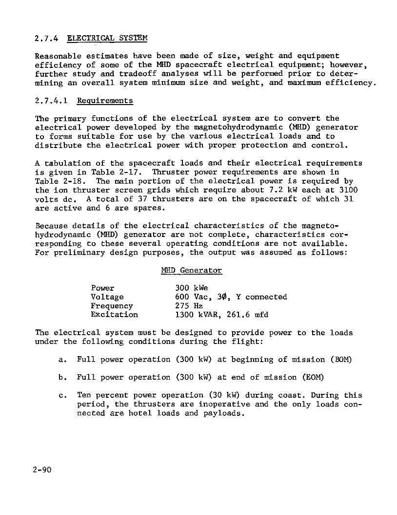
2 7.4 ELECTRICAL S Y S T E M
Reasonable estimates have been made of s ize , weight and equipment e f f ic iency of some of t h e MHD spacecraf t electrical equipment; however, f u r t h e r study and t radeoff analyses w i l l be performed p r i o r t o de t e r - mining an o v e r a l l system minimum s i z e and weight, and maximum e f f i c i ency .
2 .7 .4.1 Requirements
The primary funct ions of the electrical system are t o convert t h e electrical power developed by the magnetohydrodynamic (MHD) generator t o forms s u i t a b l e f o r use by the var ious electrical loads and t o d i s t r i b u t e t h e electrical power with proper pro tec t ion and control .
A tabula t ion of t h e spacecraf t loads and t h e i r electrical requirements i s given i n Table 2-17. Table 2-18. The main port ion of t h e electrical power i s required by t h e ion t h r u s t e r screen g r i d s which r e q u i r e about 7.2 kW each a t 3100 v o l t s dc. A t o t a l of 37 t h r u s t e r s are on t h e spacecraf t of which 31 are active and 6 are spares.
Thruster power requirements are shown i n
Because d e t a i l s of t h e electrical c h a r a c t e r i s t i c s of t he magneto- hydrodynamic (MHD) generator are not complete, c h a r a c t e r i s t i c s cor- responding t o these seve ra l operating condi t ions are not ava i lab le . For preliminary design purposes, the output w a s assumed as follows:
MHD Generator
Power 300 kWe Voltage Frequency 275 Hz Exci ta t ion 1300 kVAR, 261.6 mfd
600 Vac, 3@, Y connected
The electrical system must be designed t o provide power t o t h e loads under the following condi t ions during the f l i g h t :
a. F u l l power operation (300 kW) a t beginning of mission (BOM)
b. F u l l power operation (300 kW) a t end of mission (EOM)
c. Ten percent power operation (30 kW) during coast . During t h i s period, t h e t h r u s t e r s are inopera t ive and the only loads con- nected are h o t e l loads and payloads.
2-90

rn hl
cv rl
0
rl
0
0
cv o o m m 0 4 0 0 4- hl
n m a 6 3 a k 0 u (d k a, E a,
n
2 w a, 2 3 m
m m
Icr 0
rl r l . 0 0 0 0
u ua, U k PI 0 o u 8: $4
I
rl 0 k u
0
k 0 4 J m oa, @ E 3 u c m a , 3
g
8 -5
a a 6 6 3 ?
PI PI
a rl
E 3 .rl a, m a, V cn 2
m rl a 0 E k
3 u a fi (d
PI
h V
m rl 0 k U E 0 u 8 a, u m h cn
2-91

a .- Y C Q C a, *- 14u
In U 4 0 3
s 9 00
P- 0 0 0
C V N
hl m m 0 0
9 " 1 9 - O N ? ". 9 . " . 00 4 0
? O.
n m v
4 a,
I4 5 a 4 I4 U
W 0 0 k a, > 0 k 0
u -4
4 I4
U C a, & & ¶ U
d
E
h n d h l v w
2-92

2.7.4.2 System Description
The electrical system p re l imina r i ly proposed f o r use with t h e MHD generator i s shown i n Figure 2-45, I n th i s system approximately 80 percent of t h e 300 kW, 3 phase output i s transformed and converted t o 3100 v o l t s dc, whereas t h e remaining power i s d i s t r i b u t e d a t the 600 v o l t s ac, 3 phase, generated output level.
The high vo l t age bus provides power t o a l l of t h e screen e l ec t rodes of t h e ion engine t h r u s t e r s . es tab l i shed by t h e vol tage requirements of t h e screens.
The 3100 v o l t transmission level i s
The 600 v o l t s ac, 3 phase d i s t r i b u t i o n bus provides power t o t h e re- maining spacecraf t loads including t h e several power suppl ies required f o r each t h r u s t e r , as w e l l as h o t e l and payloads. The 600 v o l t s ac level w a s s e l ec t ed as t h e generator output so t h a t power d i s t r i b u t i o n could be done a t a s u f f i c i e n t l y high vol tage t o minimize cab le l o s e without requi r ing power conversion. Any higher vol tage i s considered inconvenient because of handling and component s e l e c t i o n problems and should not be used except where necessary. Since t y p i c a l 50-turn MHD generator c o i l s produce vol tages on t h e order of 700 v o l t s , t h e choice of 600 v o l t s as re ference i s considered reasonable.
Power t o t h e h o t e l loads and t o t h e t h r u s t e r a u x i l i a r y power suppl ies and t o t h e payloads i s d i s t r i b u t e d by means of two busses; one group of loads are near t h e generator and one group a t t h e t h r u s t e r payload area. Figure 2-45 shows t h e two busses and assoc ia ted loads.
The weight of t h e electrical system i s shown on Table 2-19, with t h e breakdown on t h e high vol tage converter on Table 2-20. system power lo s ses are i d e n t i f i e d on Table 2-21.
Electrical
r
2.7.4.3 High Voltage Power Di s t r ibu t ion
2.7 .4 .3 .1 Transformer Se lec t ion - I n order t o minimize transmission cab le l o s s , the 600 v o l t s ac i s transformed as c l o s e t o t h e MHD gen- e r a t o r as p r a c t i c a l . With ac vo l t age generated, vo l tage increase i s performed using a s i n g l e , l i q u i d cooled, t h r e e phase transformer. The output i s r e c t i f i e d and regulated by use of a S i l i con Controlled Recti- f i e r (SCR) set and then t h e three dc outputs are connected i n p a r a l l e l and f i l t e r e d t o create the high vo l t age d i s t r i b u t i o n bus.
The se lec ted transformer i s approximated t o be 12 by 12 by 2 4 inches high, of which the height has an allowance of t e n inches f o r coolant connections. The weight i s estimated t o be 100 pounds., Power lo s ses i n the transformer are about 4 kW, and hollow conductor w i r e i s used f o r hea t removal.
2-93

0 0 W
3SVHd /V L'LL %A 009 # / M Y 9-01
fl/A 009 @E MM 6'1 E
B a, U m h cn k a, ' 3 0 PI rl rd 0 *rl k U 0 a, rl rn
B
2-94

TABLE 2-19. ELECTRIC SYSTEM WEIGHT SUMMARY
Capacitors 450 High Voltage Converters 163.5 Auxiliary Power Conversion 277 Thruster Auxiliary PC 272 Power Distribution Cables * Screen Supply Interrupters 460 *
* Later
TABLE 2-20. HIGH VOLTAGE CONVERTER WEIGHT BliEAKDOWN
HV Converters
Transformer Rectifiers Control Circuits
100.0 3.0 0.5
Wire, Brackets, Heat Paths 60.0 163.5
TABLE 2-21 ELECTRIC SYSTEM POWER LOSSES
HV Converters
Transformer Rectifiers Control Circuits (voltage control) Total HV PC
4,000 660
8 4,668
Screen Supply Interrupters 1,250 EM Pump Power Conditioning 3,500 Payload Power Conditioning 50 Generator, Spacecraft Control Power Conditioning 155 Total Power Conditioning Losses 9,623 Total Capacitor Losses * Total Transmission Cable Losses * Total Power Losses * Overall Efficiency for 300 kWe MHD Generator System *
* Later
2-95

2.7.4.3.2 Rectifier Se lec t ion - R e c t i f i c a t i o n and vol tage r egu la t ion i s performed by phase cont ro l led S i l i c o n Controlled Rectifiers (SCR's) . I n an ac c i r c u i t t h e SCR must be t r iggered i n t o conduction a t t h e de- s i r e d i n s t a n t of t i m e during t h e ha l f -cyc le of t h e appl ied vo l t age wave during which the anode i s p o s i t i v e , I n t h e phase cont ro l led c i r c u i t , i n i t i a t i o n of conduction i s delayed by an angle so t h a t t h e SCR con- duc ts f o r only a predetermined por t ion of t h e p o s i t i v e half-cycle . In t h i s manner the average power de l ivered t o the load can be var ied , and when coupled wi th a f i l t e r , t h e output r e s u l t s i n a vo l t age regula ted d c bus.
When t h e l i n e vol tage reverses every half-cycle , t h e SCR w i l l be auto- mat ica l ly commutated o f f and consequently w i l l n o t r e q u i r e s p e c i a l c i r c u i t s . The u n i t s e l ec t ed f o r t h i s app l i ca t ion i s t h e GE-SCR type C145PB, with a r e p e t i t i v e Peak Reverse Voltage (PRV) of 1200 v o l t s and a 55 ampere r m s l i m i t . Due t o t h e type of c i r c u i t , t h e PRV f o r t h e SCR would be 1 .4 (load vo l t age ) , and consequently would r e q u i r e four SCR's i n series f o r each phase.
The SCR can be used i n series c i r c u i t s , however some form of forced vo l t age shar ing becomes mandatory. w i l l be assumed t h a t t h e r e i s proper vol tage sharing.
For t h e purposes of t h i s study it
Power loss i n each SCR, assuming c l o s e t o 180 degree conduction angle and 24 amperes (average) would be 55 w a t t s each (average).
Each group of four SCR's are mounted on an aluminum heat-s ink as shown below. Combined weight i s approximately one pound per phase.
1 1 D = 0.75
2.5 I ' 0.5 l t
2.5"
2-96

2.7.4.4 Low Voltage Power Di s t r ibu t ion
An ac three-phase d i s t r i b u t i o n w a s s e l ec t ed f o r t h e h o t e l and a u x i l i a r y power system i n order t o r e a l i z e s impl i f ied power conditioning and re- duced copper losses .
With ac being generated and d i s t r i b u t e d , t h e i n v e r t e r s t a g e of a l l the power condi t ioners can be el iminated thereby r a i s i n g t h e e f f i c i e n c y of conversion. The remaining lo s ses would be transformation and rectif- i c a t i o n .
Analysis shows t h a t the same amount of power may be t ransmi t ted a f ixed d i s t ance wi th a f ixed l i n e lo s s wi th only three-fourths of t h e amount of copper t h a t would be required f o r single-phase, o r one-third more copper i s requi red f o r single-phase than would be necessary f o r three- phase.
2.7.4.5 Capacitor Se lec t ion
The vol tage of t h e MHD generator depends upon t h e magnetizing component on the s t a t o r cu r ren t , and unless t h e load calls f o r a component equal t o t h i s component, t h e generator w i l l n o t operate . The funct ion of the capac i tors which are connected i n p a r a l l e l with t h e MHD generator i s t o a d j u s t t h e power f a c t o r of t h e load on t h e generator t o t h a t a t which i t can d e l i v e r t h e requi red power. The capac i tors must no t only supply whatever lagging cu r ren t i s required by t h e load but must also supply a lagging cur ren t equal t o the leading magnetizing cu r ren t of t h e gen- e r a t o r . For t h e purpose of t h e s tudy the load w i l l be assumed t o re- q u i r e no compensation.
Computer a n a l y s i s has shown t h a t about 1300 KVAR must be supplied and t h a t t h e capac i tor must be 261.6 mfd. Assuming t h i s t o be a machine t o t a l , 433 KVAR and 87.2 mfd are required f o r each phase.
A l imi ted indus t ry search has shown t h a t no u n i t s are a v a i l a b l e w i t h - ou t development; however, t h e technology e x i s t s f o r designing a capac- i t o r s t o m e e t the requirements.
General Electric Company, Large Capacitor Department has made an estimate of t h e s ize and weight of a bank of capac i tors and r e p o r t s that f o r t h e t h r e e phase machine, t h e capac i tor would be 12 by 12 by 36 inches and weigh 450 pounds.
2.7.4.6 Thruster Screen I n t e r r u p t e r s
The electric system configured f o r t h e use of a common t h r u s t e r screen supply i n t e r r u p t e r s f o r each t h r u s t e r .
MHD generator i s based on t h e with ind iv idua l s ta t ic-circui t
2-97

The interrupters operate immediately upon the development of a fault and series inductors provide the energy necessary to clear the fault, as well as providing momentary, transient circuit isolation during faults. In order to minimize system weight, it is assumed that electro- mechanical switches for permanent circuit interruption are not required.
Each individual thruster screen is fed from the common high voltage bus at the thrusters through a series network consisting of a high speed electronic switch (SCR) and a series reactor (L). The SCR interrupts the circuit between screens in the event of arcs within the thrusters, as detected by a sudden drop in voltage at the screems, the appearance of voltage across the series reactor, L, or some other signal. Follow- ing circuit interruption by the SCR, energy stored in L continues to supply power to the arc for a period of up to two milliseconds. The SCR remains off for a period of 0.2 seconds to allow time for the arc to clear and the thruster conditions to return to normal. After 0.2 seconds, the SCR is again switched on, re-establishing screen voltage and hope- fully restoring full thruster operation. If, for example, the arc re- strikes two more times within a short period of time, the screen supply to that thruster and the inputs to the auxiliary power supplies for that thruster are permanently disconnected. This thruster is considered completely disabled and one of the six spare thrusters is placed auto- matically into operation to replace it.
During the spacecraft coast period when-the thrusters are not required to operate, power to the thrusters is disconnected by the static switches in the screen supplies and by the contractors in the input circuits to the auxiliary thruster power supplies.
A simplified schematic diagram of the static switch used as the screen circuit interrupter is shown in Figure 2-46. connected in series to withstand the high voltage of the screen supply, and there are resistor networks across the SCR's and the resistor- capacitor networks to provide for proper steady state and transient voltage division.
A number of SCR's are
In order that a common screen supply be feasible several factors must be considered. If all screens are fed from a common supply all are interconnected electrically. Hence, it is necessary that such inter- connection be compatible with the complete electrical system, including the thruster auxiliary power conditioners. Also, it must be possible to isolate individual thrusters from the common supply in the event that the thrusters fail on momentary arc-over.
2-98

THRUSTER
- -
Figure 2-46. Indiv idua l Screen C i r c u i t In t e r rup t ion
2.7.4.7 Auxil iary Power Condit ioninq
2.7.4.7.1 electromagnetic pumps have been i n i t i a l l y se l ec t ed f o r u se with t h e MHD generator system. These pumps r e q u i r e very high cu r ren t a t very low vol tage , s p e c i f i c a l l y , f o r t h e primary pump, 5000 amperes a t 0.5 v o l t . Special , a d d i t i o n a l power condi t ioning equipment, therefore , i s necessary. Using conventional power conversion schemes f o r very low vol tage, e f f i c i e n c i e s of less than 50 percent are encountered. With ac-dc conversion, t h e vol tage drop i n t h e output rectifiers approxi- mates o r exceeds t h e output vo l t age required and hence t h e e f f i c i ency i s poor.
EM Pump Power Conditioning - Direct cur ren t conduction
I n order t o obta in t h e extremely low dc output vo l tage requi red a t the pumps, standard low-voltage conversion t o a higher output vo l tage i s performed and several pumps are connected i n series. Now, with t h e rectifiers dropping 0.7 v o l t s dc and t h e output t y p i c a l l y 10 v o l t s dc , an e f f i c i ency o r approximately 90 percent i s r e a l i z a b l e .
Two power condi t ioners are used i n t h e system. pump which r equ i r e s 25 kWe. The o ther feeds the s t a r t u p pump, aux- i l i a r y pump, t h e sh i e ld pump, and t h e propel lan t pump, requi r ing an
One feeds t h e cesium
2-99

estimated 1,3 kWe total. The cesium pump is assumed to be divided in- to 20 parallel fluid ducts, requiring 0.5 volts for each duct, all con- nected in series. The conditioner would have an efficiency of 90 per- cent as previously mentioned.
The remaining pumps are single duct machines, which when connected in series require a power conditioner to supply 1.3 kW at 2.0 volts dc. Efficiency for this supply would be approximately 65 percent, but for this relatively low power level the loss would be about 0.7 kW.
A standard 8 pound/kWe output has been applied for weight estimation for the main EM pumps. for the EM pumps are summarized on Table 2-22.
The characteristics of the power conditioning
TABLE 2-22. AUXILIARY POWER CONDITIONING CHARACTERISTICS
:OMPONENT APPLICATION
Main EM Pumps
Auxiliary EM Pumps
MKD Generator Control
System Control
Spacecraft Guidance Control
Special Ion Engine Units
Payload Units
Totals
?OWER CNPUT kWe
27.8
2.0
2.1
0.50
0.50
16.1
1.0
POWER CONDITIONER EFFICIENCY PERCENT
90
65
95
95
95
95
95
WEIGHT
POUNDS
220
12
15
10
10
272
1.0
549
POWER LOSSES WATTS (e)
2800
700
10 5
25
25
,-,*
50
3705
* Included in ion engine allocation
An important consideration in making the initial decision to use dc conduction pumps was the reactive power weight penalty occasioned by using ac induction pumps. For example, considering the five pumps in the system, using three-phase ac power, required an estimated 1150
2-100

pounds f o r power conditioning. This would be approximately equivalent t o 30 pounds/kVA, which with a 0.55 power f a c t o r would be about 50 pounds/kW. t o r s necessary f o r cor rec t ion of t h e power f a c t o r and t o t h e cabl ing c ross -sec t iona l area increase necessary t o handle the reactive vo l t - amperes. Further study w i l l be performed with t h e dc/ac pump trade- o f f .
Largely, t h e weight would be increased due t o t h e capaci-
2.7.4.7.2 Other Auxiliary Power Conditioning - Auxiliary power condi- t ion ing i s a l s o required f o r t h e following operations:
a. MHD generator con t ro l
b. System cont ro l
c. Special ion engine u n i t s
d. Spacecraft guidance and con t ro l
e. Payload
The weight of t h e power conditioning f o r a l l these u n i t s , except t h e s p e c i a l ion engine u n i t s , i s g r e a t e r than t h e 8 pounds/kWe output employed f o r t h e main EM pumps because of t h e smaller s i z e of these s p e c i a l purpose u n i t s , as shown on Table 2-22. The weights presented f o r t h e spec ia l ion t h r u s t e r u n i t s are those provided by JPL. The e f f i c i ency of these a u x i l i a r y u n i t s i s as shown on Table 2-22. No los ses are shown f o r t he s p e c i a l ion engine u n i t s , s ince t h i s power l o s s i s a l ready factored i n t o t h e ion t h r u s t e r e f f i c i ency , used t o c a l c u l a t e t h e beam power.
2 - 10 1 /2 - 102


3 . - CONCLUSIONS
The following conclusions are drawn.
1.
2.
3 .
4.
5.
6 .
7.
8.
The ca l cu la t ions of system parameters r equ i r e s i terative use of the two programs MHDGN and MHDCY. I n add i t ion , des i red parameters such as MHD generator weight and r a d i a t o r weight are n o t ca lcu la ted d i r e c t l y . t hese two programs could be combined and modified t o cal- c u l a t e s i g n i f i c a n t weight values d i r e c t l y .
It would be very u s e f u l i f
The one-loop MHD system appears t o be more attractive than a two-loop configurat ion, although t h e e f f e c t s of f i s s i o n pro- duct leakage from r e a c t o r f u e l elements has not been evalu- a ted . The effects of such leakage should be evaluated.
I n order t o shut down t h e MHD system during t h e f l i g h t coas t period and J u p i t e r operat ions, i t would be necessary t o pro- v ide an a u x i l i a r y power system of approximately 30 kWe out- put. The inc lus ion of shutdown and restart c a p a b i l i t y and a sepa ra t e power system requ i r e s a more complex p l a n t design. On the o ther hand, i t i s no t unreasonable t o assume t h a t t h e MHD system can be operated a t reduced power levels. cannot, a r e l a t i v e l y small power-flattening shunt can be in - corporated.
If it
The t r i fo rm geometry appears most a t t ract ive f o r t h e d i r e c t condensing vapor chamber r a d i a t o r , s ince a u x i l i a r y s t r u c t u r e i s most e a s i l y incorporated and most e a s i l y j e t t i s o n e d from it . The r a d i a t o r n e t weight can then be minimized f o r both launch and e lec t r ic -propel led f l i g h t .
The Configuration No. 4 of Section 2.6 with t h e MHD equipment up near t h e r eac to r i s t h e most at tractive bas i s f o r develop- ment of t h e base l ine design.
The temperature d i f f e rence between the MHD generator windings and t h e a u x i l i a r y cooling f l u i d and r a d i a t o r i s not y e t s u f f i c i e n t l y def ined f o r spacecraf t design d e t a i l t o proceed.
The rec tangular channel vapor chamber using sodium i s t h e most at tractive design f o r t h e primary r a d i a t o r .
The i n t e r f a c e between MHD generator output and t h e electrical power and d i s t r i b u t i o n system needs more d e f i n i t i o n .
3-113-2

4 . 'RECOMMENDATIONS
The following recommendations are made based on the first quarter's work and
1.
2.
3 .
4.
5.
6 .
7.
8.
the specific conclusions drawn in Section 3 .
Combine the MHDGN and MHDCY programs into a single program to calculate MHD parameters, with additional subroutines to cal- culate MHD generator weights and radiator area and weights.
Assume a one-loop system for the baseline MHD system, but evaluate the effects of reactor fuel element leakage.
Assume that the MHD system will operate at partial power level.
Use the triform geometry for the baseline design primary radiator.
Use Configuration No. 4 as the model for the baseline space- craft . Complete the MHD generator cooling analysis to determine a realistic temperature difference between windings and coolant.
Base the radiator design on rectangular channel vapor chambers with sodium fluid.
Investigate and clarify the electrical interface and inter- actions between the MHD generator and the power distribution system.
4-114-2

5. N E W TECHNOLOGY
No new technology items have been identified.
5-1/5-2

6. REFERENCES
1. GESP-7011, A Design Study For a Thermionic Reactor Power System For a Nuclear Electric Propelled Unmanned Spacecraf t , Quarter ly Progress Report Number 1, May 23, 1969.
2. Thrust Subsystem Design f o r Thermionic-Electric Spacecraf t Study, JPL Memo T. Masek t o N. Simon, February 20, 1969.
3. E l l i o t t , David G., "Variable-Velocity MHD Induction Generator With Rotating-Machine I n t e r n a l Electrical Efficiency", A I M Journa l , Volume 6,Number 9 , pp. 1695 - 1702, September 1968.
4. E l l i o t t , D. G. e t . a l . , "Theoret ical and Experimental Inves t i - ga t ion of Liquid-Metal MHD Power Generation," Electr ic i ty from - MHD, Volume 11, I n t e r n a t i o n a l Atomic Energy Agency, Vienna, 1966, pp. 995 - 1018.
5. Personal Communication D r . D. G. E l l i o t t t o R. M. Bernero, September 2 , 1969.
6. GESP-7013, A Design Study For a Thermionic Reactor Power System For a Nuclear Electric Propelled Unmanned Spacecraf t , Quarter ly Progress Report No. 2 , August, 1969.
7. GE-PIR Number U-1K25-072, J. Garr i ty , J . Cokonis t o W. 2. P r i c k e t t , Addendum To Structural/Dynamic Analysis of Thermionic Spacecraft Configurations, August 4, 1969.
8. PWAC-445, Preliminary Design of t h e 2 Mwt Reactor and Shield (PWAR-20) ~~ . For The SNAP-50/SPUR Powerplant, December 30, 1964.
9. PWAC-643, SNAP-50/SPUR Program Engineering Progress Report, Ju ly 1, 1964 t o September 30, 1964.
10. PWAC-457, 35 and 300 kWe SNAP-50/SPUR Powerplants For The Manned Orbi t ing Space S t a t i m Application.
6-1/6-2


Appendix I Comput,atipn of Variable -Ve.locity
MHD Induct ion Generator Performance
(Program GENERATOR)
D. G. E l l i o t t
Jet 'Propulsion Laboratory
This document desc r ibes the assumptions, ana lys i s , and procedures em-
ployed i n c a l c u l a t i n g generator e f f i c i e n c y and o t h e r performance parameters
f o r a va r i ab le -ve loc i ty MKD induct ion genera tor wi th the s l i p and f i e l d va r i ed
fo provide an i n t e r n a l e l e c t r i c a l e f f i c i e n c y equal t o t h a t of a r o t a t i n g gen-
e r a t o r .
i n s u l a t i n g vanes.
End los ses are suppressed by compensating poles and e l e c t r i c a l l y -
The ana lys i s i s the one presented i n Ref. 1, with a modified winding a r -
The computer program rangement and with equat ions f o r a d d i t i o n a l parameters.
f o r the a n a l y s i s i s GENERATOR,
I. GENERATOR DESCRTFTTCPT
The generator analyzed i s shown i n Fig. 1, a dravixtg of t h e 325-kW
_-I-- - " . ..-_
l i th ium generator discussed i n Ref. 1.
with a surface-impingement separa tor and i s unsymmetrical, wi th the cesium
vapor exhaust on one s i d e and the s l o t f o r t he upstream compensating pole on
the o ther . The genera tor used with an impinging-jet separa tor would be sym-
The design shown i s intended f o r use

metrical and have the upstream compensating winding i n two s l o t s l i k e t h e
downstream winding, and t h i s i s an opt ion i n the program.
Referr ing t o Fig. 1, the l i thium, with some cesium vapor, leaves t h e
separa tor and e n t e r s t h e capture s l o t of t h e generator .
d i f f u s e r t h e pressure of t h e mixture i s r a i s e d t o d i s so lve t h e cesium.
upstream d i f f u s e r i s a l s o t h e upstream compensating pole region, and it con-
t a i n s axial i n s u l a t i n g vanes f o r suppression of shunt end cu r ren t s and eddy
cu r ren t s from t h e compensating f i e l d .
In the upstream
The
The l i q u i d stream leaving the upstream compensating p o l e flows through
t h e traveling-wave region of t h e generator ( the 24.9-cm center s e c t i o n of t h e
generator i n Fig. 1).
s l o t s i n t h e upper and lower laminated-iron s t a t o r blocks and has copper
e l ec t rodes on each s i d e (canned i n a r e f r a c t o r y metal) f o r a x i a l l y completing
t h e f l u i d cu r ren t loops ~
The traveling-wave region has a polyphase winding i n
After leaving t h e traveling-wave region, a t reduced v e l o c i t y , t h e l i th ium
flows through t h e downstream compensating pole region which, l i k e t h e upstream
compensating pole region, has in su la t ing vanes f o r suppression of e l e c t r i c a l
losses . The downstream compensating pole region a l s o serves a s t h e i n l e t
s ec t ion of t h e downstream d i f f u s e r .
1.
2.
1-2
11. GENERATOR ANALYSIS ASSUMPTIONS
The assumptions employed i n analyzing the generator a r e a s follows:
The s l i p and t h e f i e l d a r e var ied t o maintain rotating-machine i n t e r n a l
-1 e l e c t r i c a l e f f i c i e n c y \ = (1 I- s) a t each po in t , where s i s t h e s l i p
(U .. U )/U v e l o c i t y U . The pressure i s constant from i n l e t t o e x i t of t he traveling-wave region.
between t h e f l u i d v e l o c i t y U and the magnetic f i e l d wave s s
S

. . . . . . 3 . The los ses i n t h e generator cons i s t only of -(I) ' f l u i d ohmic lo s ses from
t h e f l u i d cu r ren t necessary f o r the required r e t a rd ing fo rce , (2) shunt
end cu r ren t s and eddy cu r ren t s i n the compensating poles , (3) w a l l f r ic -
t i o n , (4) winding l o s s , and (5) t h e increase i n those lo s ses due t o t h e
l imi t a t ions on f i e l d amplitude and s l o t a r ea from i r o n sa tu ra t ion .
are no lo s ses from:
There
(1) v a r i a t i o n of magnetic f i e l d and cu r ren t dens i ty
across the he ight of t h e channel, (2) boundary layer cu r ren t s , (3) i n -
creased f r i c t i o n due t o MHD e f f e c t s , (4) ohmic
s ide-e lec t rodes , (5) departure of t h e magnetic f i e l d from s inusoida l wave-
lo s ses i n t h e copper
form, and (6) eddy c u r r e n t s i n the w a l l s .
Assumption 1 requi res t h e generator t o operate with the product of f i e l d
and wave v e l o c i t y , BUS, held constant from the i n l e t t o t he exit o f t h e t r a v e l -
ing-wave region. With t h i s cons t r a in t , t he cur ren t i n the f l u i d i s the same
a t every po in t as i t would be i n a constant-veloci ty generator and t h e e f f i c i e n c y
of power generat ion i n the f l u i d i s (1 + s) a t every poin t . The poss ib l e
disadvantage of a constant-BU design i s t h a t the f i e l d i n t h e upstream p a r t
of t he generator must be lower than would be optimium a t the same f l u i d vel-
-1
S
o c i t y i n a constant v e l o c i t y generator , because of t h e reduced upstream f i e l d
required t o maintain BU = constant w h i l e not s a tu ra t ing the i r o n a t the down-
stream end.
S
The p o s s i b i l i t y of higher o v e r a l l e f f i c i ency with a depar ture from
t h e constantlBU case assumed here has not been explored. S
Assumption 2 , constant pressure i n the traveling-wave region, i s adopted
f o r s impl ic i ty . There i s a p o s s i b i l i t y of higher cyc le e f f i c i e n c y with a
pressure rise i n t h e generator , because of lower v e l o c i t y and f r i c t i o n lo s s
and because of reduced pressure recovery requirement i n the downstream d i f f u s e r ,
but pressure- r i se operat ion has not been explored.
Assumption 3 i s the key one. Five loss mechanisms are adopted a s being
1-3

. . . . - .
t h e only s i g n i f i c a n t ones. A l l o ther losses , s i x of which are enumerated,
are assumed t o be neg l ig ib l e . The arguments f o r neglect ing the six los ses
enumerated w i l l be reviewed b r i e f l y .
1. F ie ld and cu r ren t dens i ty v a r i a t i o n across the channel height
The e f f i c i ency of a constant-veloci ty generator using t h e exac t f i e l d
equat ions (both x and y v a r i a t i o n s accounted for)was ca l cu la t ed by Pierson
(Ref. 2) and t h e r e s u l t s compared with the "s l i t -channel case" (B, = 0 and
B = const) assumed here. Pierson found neg l ig ib l e e f f i c i e n c y decrease using
t h e exact equat ions when nb/L << 1, where b
t h e wavelength. I n a typ ica l l i thium generator such a s the one i n Fig. 1,
t h e value of nb/L i s 0.2, and the re was no more than 0.1% e f f i c i ency l o s s a t
Y i s t h e channel he ight and L i s
t h i s value i n P ierson ' s ana lys i s .
2 . Boundary-layer cu r ren t s
Boundary-layer cu r ren t s of high dens i ty flow i n the near -s ta t ionary
p a r t of the f l u i d near the wal l . If the v e l o c i t y p r o f i l e i s a fully-developed
1/7-power p r o f i l e extending t o the center of t he channel, then the i n t e r n a l
electrical e f f i c i ency cannot exceed 0.78 (Ref.3). But t h e r e i s evidence (Ref.
4) t h a t t he v e l o c i t y p r o f i l e i s highly f l a t t e n e d i n t h e generator , i n which
case the boundary-layer shunt cu r ren t s may cause only neg l ig ib l e losses . There
i s a l s o t h e p o s s i b i l i t y of designing the generator with a wa l l t h a t i s r e t r a c t e d
from the boundary of the flow, giving a " f r ee - j e t " e f f e c t which could f u r t h e r
f l a t t e n the v e l o c i t y p r o f i l e .
3 . F r i c t i o n increase
F r i c t i o n increase due t o MHD e f f e c t s has been s tudied and found t o e x i s t ,
but only by about 10% a t r a t i o s of Reynolds number t o Hartmann number of
i n t e r e s t i n t h i s appl ica t ion . To account f o r t h i s and o ther poss ib le e f f e c t s ,
a f a c t o r of increase i n f r i c t i o n of 1.3 i s emplpyed i n the program.
1-4

4. Side-electrode l o s s e s
The ohmic lo s ses i n t h e canned copper s ide-e lec t rodes can be reduced
as much as des i r ed by g iv ing them a l a rge c r o s s sec t ion , bu t a t some po in t
they begin t o i n t e r f e r e wi th t h e c o i l s ,
z a t i o n problem between c o i l l o s s and axial-conductor l o s s ,
s tud ie s have ind ica ted t h a t t h e s i d e e l ec t rodes can have s u f f i c i e n t area f o r
n e g l i g i b l e l o s s i f sk in e f f e c t i s not too g r e a t , but f u r t h e r s t u d i e s are
required e
5 . Non-sinusoidal waveform
Thus, th i s l o s s reduces t o an optimi-
Prel iminary design
The l o s s due t o the f i n i t e number and width of t he winding s l o t s w a s ana-
lyzed i n Ref. 5. An e f f i c i e n c y lo s s of 3 percentage po in t s was ca l cu la t ed f o r
t he genera tor of Fig. 1 employing 24 s l o t s , i n s t ead of the 12 shown. The cal-
c u l a t i o n s were pess imis t i c i n t h a t they d id not consider the smoothing out of
t he waveform t h a t occurs i n p r a c t i c e due t o f r ing ing . Hence, a 15 deg spacing
between s l o t s can be expected t o give neg l ig ib l e l o s s compared wi th a cont in-
uous cu r ren t sheet .
6 . Wall c u r r e n t s
*
Operation without w a l l c u r r e n t s r equ i r e s achievement of a w a l l which is,
both thermally and e l e c t r i c a l l y in su la t ing . A s l o t t e d , cesium-purged r e f r a c -
tory-metal wa l l with ceramic between it and t h e s t a t o r , and a vacuum i n t e r f a c e
with t h e s t a t o r , i s the present concept.
The n e t e f f e c t of excluding the s ix losses enumerated i s t o make t h e
c a l c u l a t i o n s op t imis t i c by an amount which might only be a few percentage
po in t s but could be much l a rge r .
ana lys i s w i l l be considered t o p red ic t the genera tor performance u l t ima te ly
Pending f u r t h e r experiments, t h e present
achievable a f t e r c a r e f u l development.
* 11 a c t u a l TW s l o t s p lus a ha l f s ec to r a t each end with the c u r r e n t s i n - cluded i n the end s l o t c u r r e n t s
1-5
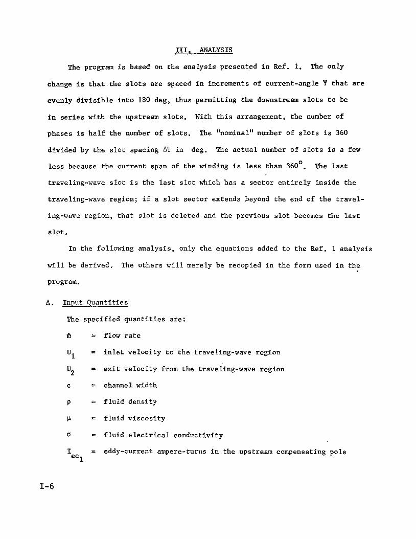
111. ANALYSIS
The program i s based on the ana lys i s presented i n R e f , 1. The only
change i s t h a t the s l o t s are spaced i n increments of current-angle f t h a t are
evenly d i v i s i b l e i n t o 180 deg, thus permit t ing t h e downstream s l o t s t o be
i n series wi th the upstream s l o t s .
phases i s h a l f t he number of s l o t s .
divided by the s l o t spacing AY i n
less because the cu r ren t span of t he winding i s l e s s than 360'.
traveling-wave s l o t i s the las t s l o t which has a sec to r e n t i r e l y in s ide t h e
traveling-wave region; i f a s l o t s ec to r extends beyond the end of t h e travel-
ing-wave region, t h a t s l o t i s de le ted and the previous s l o t becomes the las t
s l o t .
With t h i s arrangement, t h e number of
The "nominal" number of s l o t s i s 360
deg, The a c t u a l number of s l o t s i s a f e w
The las t
I n the following ana lys i s , only the equat ions added t o t h e Ref. 1 ana lys i s
w i l l be derived. The o the r s w i l l merely be recopied i n the form used i n t h e
program.
A . Input Quant i t ies
The spec i f i ed q u a n t i t i e s a re :
m = flow r a t e
=
=
i n l e t v e l o c i t y t o the traveling-wave region
e x i t v e l o c i t y from t h e traveling-wave region u2 C = channel width
P = f l u i d dens i ty
P = f l u i d v i s c o s i t y
Q = f l u i d e l e c t r i c a l conduct ivi ty
I = eddy-current ampere-turns i n t h e upstream compensating pole ec 1
'1-6

= eddy-current ampere-turns in the downstream compensating pole Iec 2 L = length of the upstream compensating pole
L = length of the downstream Compensating pole
b = mean channel height in the upstream compensating pole =2
=I b = mean channel height in the downstream compensating pole c2
= minimum (exit) channel wall thickness
= bw (;Y ratio of winding loss (including iron loss) to solid-fill DC
loss of slot portion of coils
= coil temperature
= saturation field of the iron C T
Bs N = nominal number of slots
=
B. General Calculations
rms field at the inlet of the traveling-wave region B1
1. Flow-dependent quantities and coil conductivity
The inlet height of the traveling-wave region is
m bl = - PUf
and:the exit height is
rh b2 = - Pup The inlet hydraulic diameter is
:Are a Dh = 4 Perimeter
2 bl c bl + c - -
The inlet Reynolds number is
'1 Dh Re = c1 (4)
1-7

Subs t i t u t ing U1 from Eq. (1) and Dh from Eq. (3) the Reynolds number i s
The sk in f r i c t i o n f a c t o r C i s one qua r t e r of t h e pipe f r i c t i o n f
f a c t o r f , which can be ca lcu la ted from t h e P rand t l r e l a t i o n , Eq. (6-56)
of R e f . 6.
t h e s k i n f r i c t i o n c o e f f i c i e n t i s
Multiplying by 1.3 t o cover any inc rease due t o MHD effects,
1,3 - cf - [4 l0glO(2 Re C f f j - 1.612
I n Ref. 1, t h e f a c t o r (1 + b/c) accounting f o r t h e small c o n t r i -
bu t ion of s ide-wal l f r i c t i o n i s dropped from t h e f r i c t i o n equat ion and
assumed included i n Cf . Therefore, C is correc ted by the average fac- f
t o r .
= Cf c1 + 2c c o r r cf
The f l u i d
energy change,
input power t o t h e traveling-wave region i s t h e k i n e t i c
m - - PITI - 2
The traveling-wave i ron
The required gap i s t h e e x i t
g =
2 2 (ul - u2 1
gap i s assumed i n
he ight p lus twice
b2 + 2bw
The compensating pole i ron gaps a r e
and.
= b + 2 b W gc 1 c1
= b + 2 b W gc2 c2
Ref. 1 t o be constant .
t h e e x i t wa l l thickness .
(9)
0 The e l e c t r i c a l conduct ivi ty of copper a t 20 C i s 1.7241 p ohm-cm,
0 -1 and the temperature c o e f f i c i e n t i s 0.00393 C , Hence t h e c o i l

conduct iv i ty i n mho/m i s
lo8 a - W - 1.7241 L 1 + 0.00393(T - 2 0 ) j
C
2. Inlet-f ie ld-dependent q u a n t i t i e s
The i n l e t Hartman number, a measure of t h e r a t i o of electrical
to f r i c t i o n forces , is given by Eq. (35) of Ref. 1,
H = al
The optimum i n l e t s l i p , t h e value t h a t balances f r i c t i o n loss
aga ins t ohmic loss f o r maximum i n t e r n a l e f f i c i e n c y a t t h e i n l e t , i s
given by -Eq. (34) of Ref. 1.
-5 s1
With the i n l e t s l i p known, the i n l e t va lues of t he sl ip-depen-
dent f a c t o r s i n Eqs. (38) , (39), and (40) of Ref. 1 can be calcu-
l a t ed . The slip-dependent f a c t o r i n t h e x-equation, Eq. (38) , i s
zl(s) = s 5 (1 + s)% .. ‘19 - Hw S + q] (15)
Ink The slip-dependent f a c t o r i n the Po-equation, Eq. (39) of Ref, 1,
5 is Z,(s ) = 4 s i n (2 + s)(1 - s)
L
The slip-dependent f a c t o r i n t h e 0-equation, Eq. (40) of Ref. 1,
is -1 Z 3 ( s ) = s i n s
(The last term w a s misprinted with a minus s i g n i n Ref. 1.)
5’ z219 and z3 1 ’ The va lues of these th ree f a c t o r s a t s a r e Z 1
respec t ive ly .
1-9

. - . . . .
The i n l e t wave v e l o c i t y from the d e f i n i t i o n of sl ' ip, Eq. (5)
of R e f . 1, i s
u1 1 + s1 u =
The ex i t s l i p making B U equal t o B U can be ca l cu la t ed s2
from Eq. (37) of R e f . 1. Se t t ing U = U2 and s = s i n t h a t equat ion 2
and rearranging, s can be expressed a s 2
This equat ion can be solved by i t e r a t i o n , success ive ly s u b s t i t u t i n g
on t h e r i g h t s ide , with s = s1 as t h e i n i t i a l guess. s2 2
The frequency i s found by s u b s t i t u t i n g 8 = ~ T T and s = s2 i n
Eq. (40) of Ref. 1 and solving f o r w,
The gross output power, t he power generated i n the f l u i d , is
given by Eq. (39) of Ref. 1.
The vo l t age induced by the gap f l u x i n each c o i l t u r n is given
by Eq. (28) of Ref.
The inverse of
1;
p) v* = c B u s1
the f i r s t f a c t o r i n Eq. (40) of Ref, 1 i s
1-10

. . . .
The first f a c t o r i n Eq, (38) of R e f . 1 i s
4 - ( bl 1 f s1
K2 2 Cf H
C. S l i p and Coordinate f o r Each S l o t Sec tor
The genera tor i s divided i n t o 2N equal increments of cu r ren t angle- I,
where Y i s t h e w t d i f f e rence between t h e i n s t a n t of peak winding cu r ren t a t
x = 0 and t h e i n s t a n t of peak winding cu r ren t a t t h e x-coordinate of i n t e r e s t .
Thus, a t p o s i t i o n K t h e cu r ren t angle i s K n y = - N
S l o t s 0, 1, 2; 3;** are located a t K = 0, 2, 4, 6 , * ' * . The boundaries of
t h e s e c t o r served by s l o t 0 (by t h e traveling-wave component of t h e cu r ren t i n
t h a t s l o t ) are a t K = 0 and 1. The boundaries of t h e sec to r served by s l o t 1
(K = 2) are a t K - = 1 and 3. The boundaries of t he s e c t o r served by s l o t 2 (K = 4)
are a t K =
t i c a l t i c k
i n Fig. 1,
cu r ren t i n
3 and 5 , and s o on. The s e c t o r boundaries a r e ind ica t ed by t h e ver-
marks along t h e x-ax is i n Fig. 1. I f t h e generator has 12 s l o t s , as
t h e l a s t s l o t i s a t K = 24 and the traveling-wave component of t he
t h a t s l o t se rves the s e c t o r bounded by K = 23 and K = 24.
From Eq. (26) o f Ref. 1, t h e f i e l d angle a t t he K'th p o s i t i o n i s
e = Y + ~ B (26)
where fl i s t h e upstream phase s h i f t of t h e winding cu r ren t peak from the f i e l d
zero due t o t h e f l u i d c u r r e n t , and I3
t i n g I from Eq. (25), t he f i e l d angle i s
is t h e va lue of fJ a t the i n l e t . Subs t i tu - 1
e = - + y p KTT N
The one except ion i s t h e l a s t s l o t , f o r which 8 = 2n. I n t h e genera tor
program, va lues of 8 a r e ca l cu la t ed from Eq. (26) f o r K = 0, 1, 2;** u n t i l a
value of K i s encountered f o r which 8 > IT, showing t h a t t he end of t he t r ave l ing -
1-11

wave region
(1) i f K is
s l o t number
has been passed.
even, t h e s l o t f o r t h a t K i s moved upstream t o 8 = Zn, and t h e las t
i s K/2; (2) i f K i s odd, t he las t previous s l o t is moved downstream
The winding is then terminated i n one of two ways:
t o 0 =-2n, and t h e last s l o t number is (K - 1)/2, The sketch below shows t h e
first type of terminat ion, f o r a case where 0 > 21r is encountered a t K = 46.
+ - I - - I - +-et- - 42 . 43 44 45 46 -+-
TW region I
Termination with even K
The e f f e c t i s t o shorten the ha l f - sec to r served by the traveling-wave com-
ponent of t h e cu r ren t i n t h e l a s t s l o t .
The sketch below shows the second type of terminat ion, f o r a case where ’
0 > 2l-r i s encountered a t K = 45. I I
- t -+ - + - -I-- ;t - K = 41 42 43
TW region I
a +-+--+--+-- 41 42 43 44
Termination with odd K
The e f f e c t i s t o lengthen the ha l f - sec to r served by the traveling-wave
component of the cur ren t i n the last s l o t , but a t most t o one f u l l s ec to r width,
The reason i s t o avoid having t o cu t a s l o t i n t h e s t a t o r block less than a
ha l f - sec to r width from the end, as would be t h e case i f a s l o t were c u t a t the
1-12

o r i g i n a l K = 44 pos i t i on ( left , above) and then another s l o t cu t a t 0 = 2n f o r
t h e compensating winding, The des i red termination i s done i n t h e program by
s e t t i n g K = K - K m o d 2
and e(K) =
when a K va lue i s encountered f o r which 0 > 2n. Thus, i n t h e f i rs t sketch above,
K = 46 46 mod 2 = 46 - 0 = 46. I n t h e second sketch, K = 45 - 45 mod 2 =
45 - 1 = 44. (In Step 4.10 of the program, where t h i s i s done, Eq. (28) is
w r i t t e n with K - 1 i n place of K on the r i g h t s ide , because K i s incremented
once beyond the 0 > 2n value on leaving S t e p 4.05.)
With 0 known, t h e s l i p a t t he K'th pos i t ion can be ca lcu la ted from Eq. (40)
of Ref. 1. The equation can be p a r t i a l l y solved f o r s a s follows.
(30) -1
s = exp (Z3 - Z + l n ( 1 + Z) - t a n (s/Z) - K1O) 1 2 s
where Z = (1 - s )
(23), r e spec t ive ly .
and Z3 and K a r e the constants given by E q s . (17) and 1 1
Eq. (30) can be solved i t e r a t i v e l y by successively s u b s t i t u t i n g s on the
r i g h t s i d e s t a r t i n g with t h e s value f o r t he previous K a s t h e i n i t i a l guess.
Next, t h e f l u i d v e l o c i t y a t K i s ca lcu la ted from Eq. (37) of Ref. 1.
2 - s>(1 + sl> 2 1 + = u1 [(1 (1 - S l ) ( l + s) s
The f l u i d channel he ight i s
The wave ve loc i ty , from Eq. (5) of Ref. 1, i s
U l + s us = - (33)
1-13

The f i e l d required f o r constant BU from Eq. (6) of Ref . 1, i s s’ B U
(34) *l B =
The r m s f l u i d cu r ren t p e r u n i t length is given by Eq. (10) of Ref . 1.
1
I f = o b B U s s (35)
The t o t a l (winding p lus f l u i d ) cur ren t per u n i t length can be considered
t o be made up of two conponents: (1) t h e cu r ren t required f o r a constant f i e l d
of rms value B and (2) t h e cu r ren t required f o r t h e f i e l d grad ien t dB/dx. The
f i rs t component i s given by Eq. (22) of R e f . 3.
The second component i s given by Eq. (23) of Ref. 1,
For cons tan t BU dB/dx i s equal t o -(B/Us) d/dx [ U / ( l -I- s)]. The S’
d e r i v a t i v e can be evaluated from Eqs . (37) and (38) of Ref. 1. After consider-
ab le a lgebra ic manipulation, t h e r e s u l t i s
2 I B1 us, Ha, cf 1
l + s - s . 2s(1 - 1 -
me phase s h i f t fl is given by Eq. (25) of K e f . 1.
If t h i s va lue does not agree with t h e va lue assumed i n c a l c u l a t i n g 0 from
1-14

. . . . . . .
t o Eq. (39) are repeated. An except ion i s t h e l a s t s l o t where i t is not neces-
s a r y t o i terate f o r 9 s ince 9 i s spec i f i ed as 27~.
F i n a l l y , t h e x-coordinate a t K is ca l cu la t ed from Eq. (38) of R e f . 1.
D. Winding Calculat ions
The cu r ren t i n each s l o t i s made equal t o t h e required winding cu r ren t per
u n i t length a t the s l o t pos i t i on times the length of t h e s e c t o r t o be served
by t h e s l o t . The s e c t o r length f o r t h e ( J /2 ) ' t h s l o t (K/2 is now t h e number of
t h e l a s t s l o t ) i s
AX = x(J + 1) - x(J - 1) (41)
For t h e f i r s t s l o t (J = 0) t h e s e c t o r length i s Lk = x( l ) , and f o r t h e
fas t s l o t (J = K) t h e s e c t o r length i s Ax = x(K) - x ( K - 1). Eq. (41) provides
t h e co r rec t va lues of Cur i f x(-1) and x(K 3- 1) a r e set equal t o 0 and x(K),
r e spec t ive ly . 1. Traveling-Wave S l o t
From Eq. (24) of R e f . 1 and the d e f i n i t i o n of 8, Eq. ( 2 5 ) of
R e f . 1, t h e winding cu r ren t per u n i t length i s r e l a t e d t o t h e two com-
ponents of t h e t o t a l cur ren t according t o t h e fol lowingphasor diagr.am,
I B I
I 1
A W
It can be seen t h a t the winding cu r ren t p e r u n i t
I
1 I B I W - cos B
- - (42 1
1-15

Hence, t h e winding cu r ren t i n 8 traveling-wave s l o t i s
I
I- Ax - B =w - cos B (43)
The base width of t h e s l o t i s given by Eq. (31) of R e f . 1.
w = 2 h ( l - B /Bs) (44) 1 m
where Bm i s t h e peak f i e l d , B/i, and t h e B i s t h e s a t u r a t i o n f i e l d
of t he i ron .
6
The s l o t shape i s parabol ic , and the depth of t h e s l o t i f t he
s i d e s extended u n t i l they met a t a sharp point would be t h e va lue
given by Eq. .(32) of R e f . 1. 2
Bs w1 D =
J 2 p0 I, s i n AY (45)
where AVI i s t h e cu r ren t angle increment per s ec to r 2"T/N.
The s l o t can be t runcated t o 75% of D wi th only an 8% l o s s of
a rea . Furthermore, most of t h e winding l o s s occurs i n the l a s t few
s l o t s ; t he re fo re , a l l of t h e s l o t s can be t runcated t o 75% of t h e depth
of t he l a s t inboard s l o t ( J = K - 2) with l i t t l e penal ty i n winding
loss . Accordingly, t h e depth of a l l t h e s l o t s i s set a t
Do = 0.75 D ( J = K-2) (46)
For t h e parabol ic shape t h e width a t any d i s t ance y from t h e sharp-
2 pointed bottom i s w = wl(y/D) . bottom i s
Hence t h e width' of t he t runcated
1-16

The area of the slot with the sharp bottom is wD/3, and the area 1
removed by truncation is w (D - D0)/3. cated slot is
Hence, the area of the trun- 2
A = [wlD - w2(D - Do) ]/3 (48)
Eq. (61) of Ref. 3 gives the average voltage per turn induced by
the slot flux in a sharp-pointed parabolic slot. The slot flux vol-
tage is little different for a truncated slot. The voltage is
Vs = 0 . 4 V (% - 1) 0 J2B (49 1
where Vo is the gap-flux voltage given by Eq. (22).
2. End Slot
The end slot currents required for the compensating field are
given by Eq. (27) of Ref. 1, In addition, the end slots carry the
traveling-wave currents for the first and last sectors,
of Ref. 1 the traveling-wave currents in the first and last slots,
From Eq. (24)
8 = 0 and 2n, respectively, are
I I I
To maintain the desired compensating field in the presence of
the eddy currents Iec
end slot current must be changed by -I
and Iec 1 2
in the compensating pole regions, the .~
upstream and -I downstream, 1 ec2 ec
in phase with the eddy currents. The peak positive upstream eddy.
current occurs when the upstream compensating field is zero and in-
creasing, This
winding current
takes place at ut = n/2; hence, the counterbalancing
required is e
AI = -1 sin Wt w1 eC1
1-17

The peak positive downstream eddy current occurs when the
downstream compensating field is zero and decreasing, This takes
place at cut = n/2, and the counterbalancing winding current required
is
AI = -I sin u k w2 ec2
Adding the compensating current from Eq.. (27) of Ref, 1, the
traveling-wave current from Eq, (50), and the eddy-current counterbal-
ancing currents from Eqs, (51) and (52); the total end-slot currents
are
I1 2
r 8.
+ I ~ A X + [. I sin Wt ec 2 1 1
2 Po L1 gcl B1 2
cos Wt
= I sin Wt + I cos Wt (53) a b
In Ref, 1, g and g are as.sumed equal to g, the traveling- c1 c2
wave gap, and the upstream and downstream compensating pole areas are
assumed equal, A = CL = A = CL Eq. (27) of Ref. 1 is still 2 ' c1 c2
1-18

. . . . . .
v a l i d , however, with unequal gaps and a r e a s and i s so used i n Eq. (53).
The angle between t h e t o t a l cur ren t and t h e cos ine component i s
adopted a s t h e angle re ference f o r the end s l o t cu r ren t s .
The rms magnitude is then
I = 'b cos Bc (55)
The end s l o t s can be made rec tangular and t i l t e d outward a s re-
quired t o avoid sa tu ra t ion . The width i s a r b i t r a r i l y made equal t o
t h e compensating pole length o r t o the s l o t depth, whichever i s least,
The two cases a r e sketched below,
L < D o 53 w = L L > D 0 * w = D O
The s l o t a rea , neglect ing the pole p iece , i s
o r A = w Do (one s l o t )
A = 2w Do (two s l o t s )
The vo l t age induced by the s l o t f l u x i s der ived using the sketch
below,
1-19

The cu r ren t i n s i d e t h e loop is Iy/DO. The f i e l d a t y is,
the re fo re , Po 1 Y
Do B =
(57)
The f l u x l i nk ing a winding t u r n a t y i s
($ = P c B d y Y
and the vol tage induced i n t h a t t u r n by t h e s l o t f i e l d i s
I f t h e r e are N t u r n s i n t h e s l o t t h e t o t a l c o i l vo l t age i s
Subs t i t u t ing E q s , (58) and (59) i n t o E q , (60) and i n t e g r a t i n g ,
t h e mean s l o t - f l u x vol tage pe r t u r n i s
3 , Windirlg Loss
The ohmic loss
s o l i d l y f i l l e d with
2 would be c Iw /ow
t h a t would occur i n one s l o t i f t he area A were
copper and t h e AC/DC r e s i s t a n c e r a t i o were u n i t y
A . To account f o r p a r t i a l f i l l , forohmic loss i n
1-20

. . - . .
t h e po r t ion of t h e c o i l ou ts ide the s l o t , f o r AC/DC r e s i s t a n c e r a t i o
greater than un i ty , and f o r t h e i r o n lo s s , t h e s o l i d - f i l l DC s l o t l o s s
is mul t ip l i ed by a f a c t o r of increase Cy, The t o t a l winding l o s s i s
then
E, Power Output and Ef f i c i ency
The net electric output from t h e traveling-wave reg ion i s
= P o - P W Tw e P
The n e t output from t h e generator as a whole i s reduced from P by t h e
amount of t h e eddy-current l o s ses i n t h e compensating pole regions, and t h i s
sub t r ac t ion i s made i n t h e cyc le program, The e f f i c i e n c y of t he t r ave l ing -
wave po r t ion of t h e generator i s defined a s
Po - P W
m h - p
This equat ion completes the ana lys i s needed f o r purposes of cyc le a n a l y s i s ,
F, Addit ional D e t a i l s f o r S l o t Sec tors
The g ross power output from the f l u i d i n s e c t o r J i s given by Eq. (39)
of Ref. 1.
From Eq, (36 ) of Ref, 1 the l o c a l i n t e r n a l e f f i c i e n c y i s (1 .- s)/(1 + s) .
Hence the f l u i d input power i n sec to r J i s
AP m = Ap0 (e)
1-21

. . _ . . . .
The l o c a l e l e c t r i c a l e f f i c i ency i s (1 + s)-', Hence, t h e f l u i d input power
due t o e l e c t r i c a l r e t a rd ing fo rce i s
AP ?* Ap0 (1 + s) (67) m e
From t h e equat ions f o r dPr and dPo presented following Eq. (11) of Ref. 1,
the f l u i d ohmic loss i n s ec to r J i s
= APo s ( 6 8 ) A pr
The f r i c t i o n loss is t h e d i f f e rence between AP and APm . e m
= APo (1 + s) (iyy 1 - 1) Apf
l + s
The power induced i n each s l o t i s equal t o the product of t h e
gap-flux vol tage Vo (which i s t h e same f o r every s l o t ) and t h e in-phase com-
ponent of the slot cur ren t , From Eqs. (1) and (28). of Ref. I t h e vo l tage Vo
is 180 deg out of phase with t h e f i e l d , a s sketched below,
T- The power induced i n t h e s l o t i s
APi = Vo Iw s i n i3 (70)
Comparing Eq. (28) of Ref. 1 with Eq, (53), t h e vol tage Vo i s i n phase
with the Ia component of t h e end s l o t cu r ren t , The voltage-current'relation-
sh ips are sketched below. ..
1-22
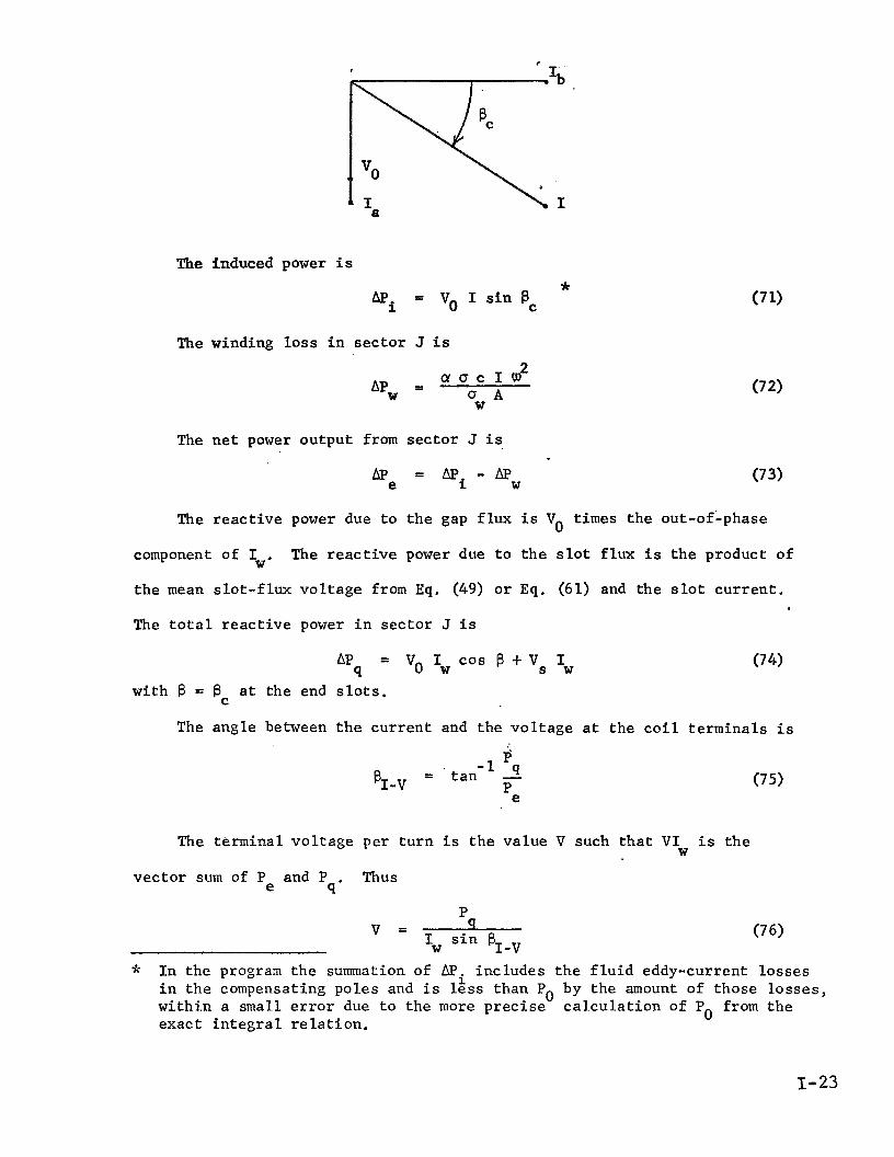
The induced power i s *
AP = Vo I s i n Bc i
The winding l o s s i n sec to r J is
The n e t power output from
e AP
The r e a c t i v e power due t o
component of I The r e a c t i v e W'
s ec to r J is
= AP -c\p (73) i W
t h e gap f l u x i s Vo times the out-of-phase
power due t o t h e s l o t f l u x i s t h e product of
t h e mean s l o t - f l u x vo l t age from Eq, (49) o r Eq. (61) and the s l o t cu r ren t .
The t o t a l r e a c t i v e power i n sec to r J i s
hp = vo Iw cos B + vs Iw (74) q with B = BC a t the end s l o t s .
The angle between t h e cur ren t and the vo l t age a t the c o i l t e rmina ls i s
p' -1 4 = t a n -
e PI-v P
The terminal vo l t age per t u r n i s the value V such t h a t V I i s the W
vec to r sum of P and P Thus e q'
P -9
Iw s i n $ v - I-v
(75)
* I n the progran the summation of AP includes t h e f l u i d eddy-current losses i i n t h e compensating poles and i s less than Po by the amount of those lo s ses , wi th in a small e r r o r due t o the more p rec i se exact i n t e g r a l r e l a t i o n .
c a l c u l a t i o n of Po from the
1-23

G, End-Slot Spacing
The requi red i r o n widths on t h e traveling-wave and outboard s i d e s of t h e
end s l o t s , ws and w6,
to be c a r r i e d ,
r e spec t ive ly , can be ca l cu la t ed from t h e peak flux
The geometry i s sketched below,
- - I t I------ - - - - - ++-+---I- - - - - - A
-h . I
Only t h e i r o n widths f o r the bottom s t a t o r block need be ca l cu la t ed s i n c e
the lower block has the smal le r end-toothwidths .
The gap f l u x passing through the tooth between t h e end s l o t and the ad jacent
traveling-wave s l o t i s
@ = J2 B1 (2Ax1) c
2 2 81 2
(7 7)
= (b/cBS. "he width of i r o n t h a t w i l l c a r r y t h i s f l u x a t s a t u r a t i o n i s w 3
Hence,
- 2 2 - S
"31 B 2
1-24

. _ . . . .
The peak f l u x through t h e end s l o t i s given by Eq. (58) with y = 0,
- - .' (two s l o t s )
wll
The required i r o n widths are
W = gl/(cBS) O1 2 2
The required i r o n width f o r t h e adjacent traveling-wave s l o t would be
h a l f t h e base width w i f t h e slot continued t o a sharp poin t s ince the sharp- 1
' po in t ed s l o t i s based on s a t u r a t i o n of t h e i r o n a l l t h e way t o t h e bottom.
Neglecting t h e small change of slot f l u x with t runca t ion , t h e i r o n widths re-
quired f o r t h e traveling-wave s l o t s adjacent t o the end s l o t s a r e
The sketch below shows t h e phasor diagram f o r t h e cu r ren t s i n t h e upstream
end s l o t and adjacent traveling-wave s l o t and f o r t h e upward (pos i t ive) f l u x
a t the root of t h e intervening tooth expressed i n terms of the sa tu ra t ed i ron
widths wo, w3 and w 4'
1-25

The upward flux giving rise to the w
field at BJ-l, - with I
of phase with Iw
iron requirements for the tooth to the right of the upstream s lo t is
requirement is.in phase with the gap . 3 The upward flux giving rise to the w requirement is in phase
requirement is 180 deg out
0
and the upward flux giving rise to the'w 1' 4
. From the diagram it can be seen that the vector sum of the J= 2
= x cos wt - y sin Wt (85)
The magnitude of the iron width requirement between the upstream slot and
the adjacent traveling-wave slot is, therefore,
.2 f W = (x + y2) 51
The rms compensating f lux , from Eq. (8) of Ref, 1, is
c B, U
w # = C
and, from Eq. (22), vO GC = - w
1-26

\
The iron requirement for this flux is
The phasor diagram for the flux on the left side of the upstream slot is
sketched be low,
B = C
W 0
The vector sum of the iron requirements for the slot and compensating
fluxes is
J2 vo - 0 - 'Os 'cl -I- UI c Bs w6 1
The sketch below shows the phasor diagram for the currents in the down-
stream end slot and adjacent traveling-wave slot and for the upward (positive)
flux at the root of the intervening tooth, expressed in terms of the saturated
iron widths w 4' and w 0' w3,
1-27

!L'hg.vector sum of the iron requirements for the tooth is
n = (w3 cos[ 5 - Q(K-1)I - wo cos 6 + w4 cos[Q(K-2) + e(K-2)]} cos w t w52 =2
Tc , z -(w3 sin[ - 2 - O(K-l)] + wo sin fi - "4 sin~ee-2 + fi(K-2.) 1) sin ut (91)
c2
The phasor diairam for the flux on the right side of the downstream slot
is sketched below,
W
12 The iron requirement is
J2 vo - W - wo cos B + c2 W c Bs 62
vO I-
wc
1-28

1-29/1030


!
Appendix I1
Cycle Analysis of a Cesium-
Lithium MHD Power System
Separator
(Program CYCLE-B)
D. G. E l l i o t t
Jet Propulsion b b o r a t o r y
This document descr ibes the assumptions, ana lys i s , and procedures employed
i n c a l c u l a t i n g cyc le e f f i c i e n c y and o the r performance parameters f o r a cesium-
l i t h i u m MHD power system with an impinging-jet s epa ra to r , The computer pro-
gram f o r t he ana lys i s i s CYCU-B,
I. C Y C U DESCRIPTION
A cesium-lithium MHD power system with an impinging-jet separa tor i s shown
schematical ly i n Fig. 1.
Liquid l i th ium and l iqu id cesium e n t e r a p a i r of two-phase nozzles and mix
a t low v e l o c i t y and high pressure. Heat t r a n s f e r from the l i th ium t o the cesium
vaporizes the cesium. The two-phase mixture expands to low pressure a t the noz-
z l e e x i t @ , accele’rat ing the l i qu id l i th ium t o high v e l o c i t y .
The two-phase je ts from the nozzles impinge on each o the r a t an angle , and
the inward momentum d r i v e s t h e l i th ium drops toge ther t o form a coalesced two-
phase j e t of s u b s t a n t i a l l y reduced vapor void f rac t ion . .
The j e t e n t e r s the upstream d i f f u s e r where the press’ure of t h e cesium-
l i th ium mixture i s increased u n t i l t h e cesium i s dissolved i n the l i thium.
The l i qu id stream then e n t e r s the generator .
11-1
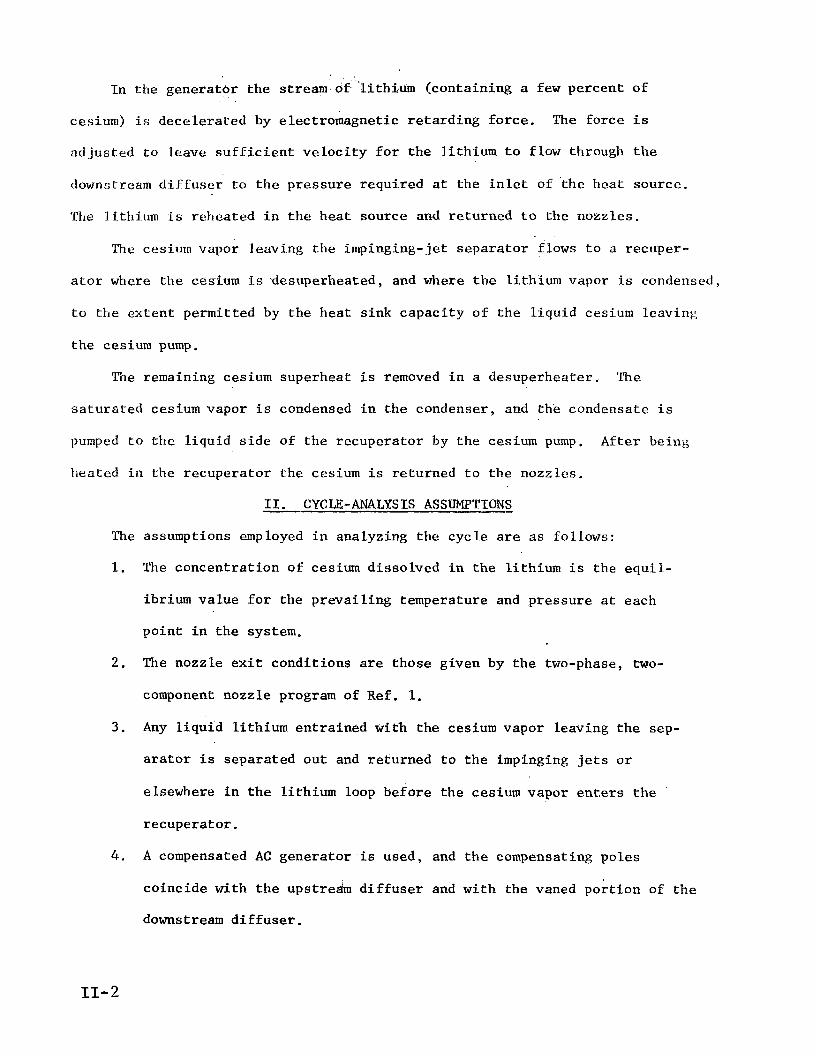
I n the generator t he S t r e a m of ‘l i thium (containing a f e w percent of
cesium) i s dece lera ted by electromagnetic r e t a rd ing force . The force i s
ad jus ted t o leave s u f f i c i e n t v e l o c i t y f o r t h e l i th ium t o flow through t h e
downstream d i f f u s e r t o t h e pressure required a t the i n l e t of t he heat source.
T’he l i thium i s reheated i n t h e hea t source and returned t o the nozzles.
‘fie cesium vapor leaving the impinging-jet s epa ra to r flows t o a recuper-
a t o r where the cesium i s desuperheated, and where t h e l i th ium vapor i s condensed,
t o tfle ex ten t permitted by the heat s ink capac i ty of t h e l i qu id cesium leavinp,
t he cesium pump,
The remaining cesium superheat i s removed i n a desuperheater. The
sa tu ra t ed cesium vapor i s condensed i n the condenser, and t h e condensate i s
pumped t o t h e l i qu id s i d e of t he recuperator by the cesium pump. After being
heated i n the recuperator the cesium i s returned t o the nozzles.
11. CYCTX-ANALYSIS ASSUMPTIONS
The assumptions employed i n analyzing the cyc le a r e a s follows:
1.
2.
3 .
4 .
The concent ra t ion of cesium dissolved i n the l i th ium i s the equ i l -
ibrium va lue f o r the preva i l ing temperature and p res su re a t each
poin t i n t he system.
The nozzle e x i t condi t ions are those given by t h e two-phase, tGo-
component nozzle program of Ref. 1.
Any l iqu id l i th ium ent ra ined with the cesium vapor leaving the sep-
a r a t o r i s separated out and returned t o the impinging j e t s o r
elsewhere i n t h e l i th ium loop before the cesium vapor e n t e r s t h e
recuperator .
A compensated AC generator is used, and t h e compensating poles
coincide with the upstream d i f f u s e r and with the vaned por t ion of t h e
downstream d i f f u s e r .
11-2

5. The losses i n t he upstream d i f f u s e r c o n s i s t o f : (1) f r i c t i o n on
the wa l l s and i n s u l a t i n g vanes (used f o r e l e c t r i c a l l o s s reduct ion)
corresponding t o 1.3 t i m e s f l a t - p l a t e sk in f r i c t i o n and (2) e l ec -
t r i c a l l o s ses due t o the AC compensating f i e l d of t h e genera tor .
6. The e f f i c i e n c y of the downstream d i f f u s e r without vane - f r i c t ion o r
e l e c t r i c a l losses i s 0.85.
7 . The add i t iona l l o s ses i n t h e downstream d i f f u s e r a re : (I) f r i c t i o n
on t h e in su la t ing vanes corresponding t o 1.3 times f l a t - p l a t e sk in
f r i c t i o n and (2) e l e c t r i c a l losses due t o t h e AC compensating f i e l d
of the generator .
8. There a r e no e l e c t r i c a l losses i n t he wal l s of t he upstream o r down-
stream d i f f u s e r s , o r i n t h e generator channel, due t o t h e AC generator .
9. The pressure i n the generator i s cons tan t from i n l e t t o ex i t .
10. The temperature d i f f e rence between t h e cesium vapor en te r ing t h e
recuperator and t h e l i qu id cesium leaving t h e recuperator i s 50°K.
The cesium pump i s dr iven by e l e c t r i c power from t h e MHD genera tor ,
and a l l power d i s s ipa t ed i s t r ans fe r r ed t o t h e cesium being pumped.
12. The hea t r e j e c t e d by the cyc le i s the hea t required t o cool and condense
t h e cesium vapor from t h e recuperator e x i t condi t ion t o the sa tu r -
a t ed l i qu id s t a t e a t the condenser e x i t p ressure , including t h e
hea t required t o cool the small amount o f l i th iummixed with the
cesium.
The r a d i a t i n g temperature a t each poin t i n t h e desuperheater and
condenser r a d i a t o r s is equal t o t h e l o c a l f l u i d temperature , and
t h e emis s iv i ty i s 0.9.
The pressure drop across t h e nozzle i n j e c t i o n , o r i f i c e s i s 5 p s i ,
and the i n j e c t i o n v e l o c i t y i s 30 f t /s .
11.
i
13.
14.
11-3

Assumption 1, equilibrium cesium dissolving, implies transfers of
several percent of cesium into and out of liquid solution in fractions of a
millisecond. No information is available on cesium-lithium solution rate,
and the validity of this assumption is not known.
tion did not occur, the nozzle performance would be improved but the efficiency
If equilibrium concentra-
of the diffusers would be decreased. Calculations assuming non-dissolving
cesium in a system with a surface-impingement separator showed that the two
effects would be about equal and the cycle efficiency with non-dissolving
cesium would be about the same as with equilibrium dissolving. With an
impinging-jet separator, however, the upstream diffuser losses with non-
dissolving cesium would probably be unacceptable without some added meclianical
removal of cesium vapor from the jet before entering the capture slot. Thus,
the rate of cesium dissolving affects the design of the system, but it prob-
ably does not greatly affect overall cycle efficiency.
Assumption 2, the validity of nozzle exit conditions from Ref. 1, is
well verified by experiments with water-nitrogen mixtures. Uncertainties in
cesium-lithium properties, including the dissolving rate, could change the
nozzle exit velocity a few percent from the values given by the nozzle program.
An additional requirement for Assumption 2 to be valid is that the separ-
ator duct must have about 40% more area than the nozzle exit to allow radial
expansion of the cesium jet as its velocity equalizes with that of the
slower liquid jet.
Assumption 3 requires removal from the cesium exhaust of a liquid flaw
equal to 0.5 to 1.0% of the nozzle liquid flow rate, in the case of the best
present surface-impingement separators. Several times as much lithium might
have to be removed with an impinging-jet separator where a curved target is
not available for collecting the smaller drops. A satisfactory method of
11-4

reLurning the co l l ec t ed l i q u i d t o t h e l i t h ium stream with an impinging- j e t
separator tias not ye t been demonstrated; r e i n j e c t i o n i n t o t h e impinging jets
causes increased d ispers ion . The penal ty of l i q u i d remaining with t h e ces ium
might be p re fe rab le , s ince the recuperator l iqu id-s ide s ink capac i ty would
increase almost as much as the added h e a t load, f a l l i n g shor t only by the
50L I< miniilium Of (Assumption 10). A v e l o c i t y reduct ion f a c t o r i s one of t he
inputs t o the cycle , ana lys i s program, and with t h i s f a c t o r thtb user can supply
any penal LY helieved a t t r i b u t a b l e t o r e tu rn ing t h e 'Lithium from the ccs i ir in
exhaust. Supplying a f a c t o r of 1.0 implies t h a t e i t h e r there is no l i q u i d
loss o r t h a t a l l l i t h ium is returned and remixed a t full v e l o c i t y with the i m -
pinging jets.
Assumption 4., t h e u t i l i z a t i o n of an AC induct ion genera tor , represents
t h e bes t choice both f o r generator e f f i c i e n c y and ease of power condi t ioning.
A DC generator might be thought: t o o f f e r b e t t e r e f f i c i e n c y , but the v o l t &
across the channel i n a DC generator causes shunt end' c u r r e n t s extending
"r
f a r t h e r upstream and downstream than can be suppressed by i n s u l a t i n g vanes
of reasonable length. An AC generator , on t h e o the r hand, operatles a t ground
p o t e n t i a l throughout the f l u i d , except l o c a l l y i n t h e Compensating poles
where r e l a t i v e l y sho r t i n su la t ing vanes can suppress t h e losses .
The second p a r t of Assumption 4, overlapping of t he compensating poles
a s i n g l e and d i f f u s e r s , represents a l o g i c a l combining of processes wi th in
region t o reduce f r i c t i o n losses,
Assumption 5 restricts t h e upstream d i f f u s e r l o s ses t o 1.3 x f l a t - p l a t e
f r i c t i o n , p lus e l e c t r i c a l losses from the compensating f lux . The f r i c t i o n
lo s ses observed i n t h e l imi ted tests conducted t o da te with vaned upstream
d i f f u s e r s could be co r re l a t ed by Applying a f a c t o r of between 2 and 3 t o
11-5

Ela t -p la te f r i c t i o n , o r they could be c o r r e l a t e d by an impact loss i n which
a l l o f t h e flow i n t e rcep ted by the 14 0.02-in. t h i c k vanes (5X of t h e t o t a l
flowj was sta:gnated." Another source of loss , and perhaps the most l i k e l y ,
is two-phase s l i p .or shock e f f e c t s a t t h e d i f f u s e r entrance. Whatever t h e
10s:; source, Assumption 5 pos tu l a t e s a reduct ion i n upstream d i f f u s e r loss
from an observed 2.5 x, t o an assumed 1.3 x, f l a t - p € a t e f r i c t i o n .
The e lectr ical lo s ses included i n Assumption 5 a r e ca l cu la t ed by a
procedure which agreed roughly wi th some l imi t ed da ta on a small-scale gener-
a t o r , but accura te experiments on t h e f l u i d e l e c t r i c a l l o s ses i n the compensa-
t i n g poles are lacking.
Assumption 6 , an e f f i c i e n c y of 0.85 f o r t he downstream d i f f u s e r before
adding vanes and e l e c t r i c a l l o s s e s , i s w e l l v e r i f i e d by l i qu id d i f f u s e r exper-
iments (Ref. 2 ) . i
Assumption 7 f o r t he losses added t o the downstream d i f f u s e r by the vanes
and e l e c t r i c a l e f f e c t s has the s a m e u n c e r t a i n t i e s as Assumption 5, bu t t o a
l e s s e r extent because only l i q u i d flow i s involved.
Assumption 8 , no e l e c t r i c a l losses i n t he w a l l s , i s cont ingent on devel-
opment of a thermally i n s u l a t i n g , e l e c t r i c a l l y i n s u l a t i n g w a l l which exposes
only metal t o the l i th ium stream. A poss ib le design i s an a x i a l l y - s l o t t e d
m e t a l l i c wa l l , purged by cesium vapor flowing i n t o the l i th ium stream w i t h
ceramic between t h e w a l l and the generator s t a t o r s and a vacuum i n t e r f a c e
wi th the s t a t o r s f o r low hea t t r a n s f e r . Assumption 8 implies such a w a l l ,
with s u f f i c i e n t l y f i n e spacing of s l o t s (say 1 cm) f o r n e g l i g i b l e eddy-current
loss, and with neg l ig fb le cesium purge flow o r some non-flow method of pre-
vent ing shor t ing between t h e wa l l segments.
Assumption 9 , cons tan t pressure i n the genera tor , i s adopted f o r s i m -
p l i c i t y .
11-6

0 Assurrrl.,tion 10, 50 K minimum recuperator AT, should alluw adequate heat
f lux at the hot end., The AT at the cold end is typically 200-300°K because
of the lithium condensation on the vapor side.
Assumption 11 specifies a cesium pump design utilizing power from the
AG generator either directly or after rectification, with the electrical com-
ponents at the cesium temperature. If lower electrical temperatures were
employed there would be a requirement for radiation of some power at the lower
temperature, but the cesium sink capacity would increase by an equal amount
and there would be no change in cycle heat rejection.
Assumption 12 limits the heat rejection considered to that from the
cesium vapor (and the lithium vapor mixed with it) only. Additional heat
losses from cooling of the generator and other components and from stray losses
are not considered in the heat balance or cycle efficiency.
Assumption 13, isothermal radiation at the local fluid temperature, is
adopted merely to provide a basic radiator area.
by additional factors to account for fluid and fin AT'S.
The area can be multiplied
Assumption 14, 5 psi injection pressure drop, is a value at which
stable nozzle operation has been demonstrated. The assumed inlet velocity
of 30ft/s, required only in calculating the nozzle inlet area {the effect on
exit velocity is negligible), corresponds to 2.0 psi dynamic pressure of the
lithium, and should be attainable with 5 psi injector pressure drop.
111. INPUTS
A. Inputs to Cycle Program From User
The twenty independent variables adopted for the cycle analysis are
the following, listed in the order of input to the CYCLE-B program:
nozzle inlet temperature
- r - C
(TI and rc nozzle
ratio of lithium flow rate to cesium flow rate in the nozzle
are supplied to the program as a single variable, the case number.)
11-7
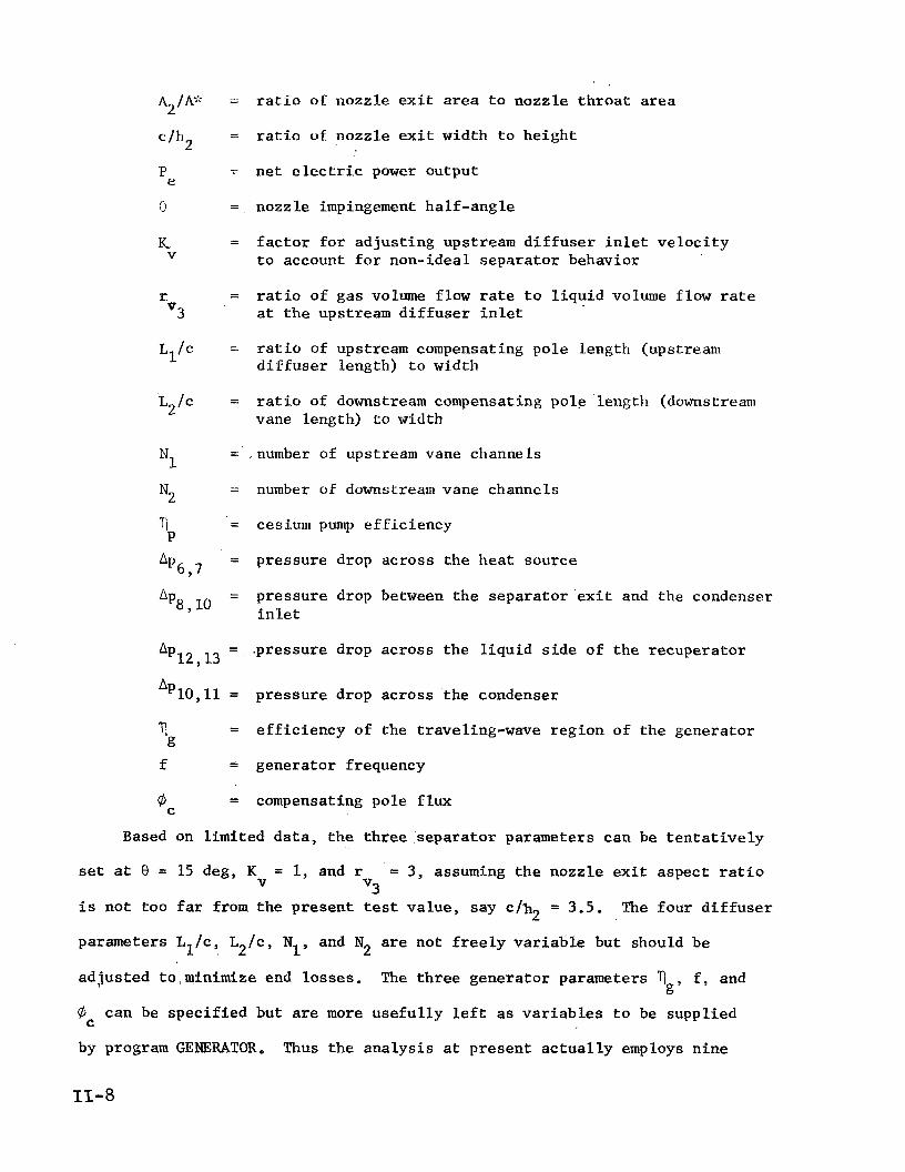
A /A;': 2
c/h*
e P
a
K V
r v3
L1/c
L2/c
N1
N2
P TI
"6 , 7
"8,lO
r a t i o o € nozzle e x i t area t o nozzle t h r o a t a r ea
r a t i o of nozzle ex i t width t o he ight
ne t electric power output
nozzle impingement ha l f -angle
f a c t o r f o r ad jus t ing upstream d i f f u s e r i n l e t v e l o c i t y t o account f o r non-ideal s epa ra to r behavior
r a t i o of gas volume flow rate t o l i q u i d volume flow r a t e a t t h e upstream d i f f u s e r i n l e t
r a t i o of upstream compensating pole length (upstream d i f f u s e r length} t o width
r a t i o of downstream compensating pole length (downstream vane length) t o width
number of upstream vane channels
number of downstream vane channels
cesium pump e f f i c i ency
pressure drop across the hea t source
pressure drop between the separa tor ex i n l e t
t and t h e condenser
pressure drop across the l i qu id s i d e of t he recuperator
pressure drop across ' the condenser
e f f i c i e n c y of the traveling-wave region of t he generator
generator frequency
compensating pole f l u x
Based on l imi ted da ta , t h e th ree sepa ra to r parameters can be t e n t a t i v e l y
set a t 8 = 15 deg, K = 1, and r = 3, assuming the nozzle ex i t aspect r a t i o
i s not too far from the present test va lue , say c/h2 = 3.5.
parameters L1/c, L2/c, N1, and N
v3 V
The four d i f f u s e r
are not f r e e l y v a r i a b l e but should be 2
ad jus ted to ,minimize end losses. The t h r e e genera tor parameters 71 f , and
4
by program GENERATOR.
IS-8
g'
can be spec i f i ed but are more use fu l ly l e f t as v a r i a b l e s t o be suppl ied C
Thus the ana lys i s a t p resent a c t u a l l y employs n ine

ind2pcndent va r i ab le s : t h e nozzle condi t ions T r and A2/A*; t h e ne t
power output P
1’ c’
the pump e f f i c i e n c y ‘ll ; and t h e four pressure drops A P ~ , ~ , e’ P
1 0 , l l ’ and Ap L p 8 , 10’ % 2 , 1 3 ’
f3. Inpiits t o Cycle Program from Nozzle Program
Nozzle th roa t a r e a and a t a b l e of nozzle flow condi t fons versus pressure
a r e suppl ied as inpu t s t o the cyc le ana lys i s a f t e r t h e i n l e t condi t ions T and
r ( ac tua l ly the corresponding nozzle case number) a r e spec i f i ed .
1
C
The q u a n t i t i e s furnished from the nozzle program a r e as follows:
Ag; = nozzle t h r o a t a r ea (at 61 = 100 lb / s )
D2 = exi t drop diameter
V = mass-weighted mean v e l o c i t y
A = flow a rea
A = flow a rea a f t e r e q u i l i z a t i o n of l i q u i d and gas v e l o c i t i e s
T = temperature a f t e r e q u i l i z a t i o n of l i q u i d and gas temperatures
t
-
- -
One va lue of A* and D i s supplied f o r each nozzle case. The o the r 2
q u a n t i t i e s are suppl ied f o r a range of pressures covering t h e poss ib le e x i t
pressures of i n t e r e s t .
For the nozzle ca l cu la t ions themselves, a d d i t i o n a l q u a n t i t i e s must be
suppl ied a s discussed next.
C . Inputs t o Nozzle Program
The nozzle program i s the two-phase, two-component program descr ibed i n
Ref. 1, with t h e opt ions of drop breakup and spec i f i ed p(x) s e l ec t ed .
Q u a n t i t i e s that .must be suppl ied t o the nozzle program a r e as follows:
- *1 -
P1 -
r = C
-
nozzle i n l e t temperature
l i thium/cesium component r a t i o
nozzle i n l e t p ressure
11-9

L{ = inverse Henry's Law constant
m = t o t a l flow rate
V1 = nozzle i n l e t v e l o c i t y
D1 = i n l e t l i th ium drop diameter
t
Tabulated f l u i d p rope r t i e s a r e furnished and a t a b l e of pressure versus
d i s t ancc through the nozzle i s b ' Tiven.
'file i n l e t p ressure p i s the vapor pressure of a s a tu ra t ed cesium- 1
l i th ium s o l u t i o n a t temperature T This pressure , according t o da t a r e -
ported i n Ref. 5, i s the same a s the sum of the vapor pressures of unmixed
cesium and l i th ium f o r temperatures up t o 1900 F, then f a l l s 10 p s i below
a t 2000°F.
nozzle ca l cu la t ions . The pressures a r e 4 - 10 p s i below the values t h a t would
be used based on Ref. 6 . Also l i s t e d a r e the va lues of t he inverse Henry's
Law constant H ca l cu la t ed from Fig. 2 of Ref. 8. That f i g u r e gives CY a s a
func t ion of T where CY i s the s a t u r a t i o n concent ra t ion of cesium i n the
l i qu id ; H i s ca l cu la t ed from Cy using Eq. ( A - 4 ) of Appendix A . The a values
a r e included i n Table I.
1'
0
Table I presents t he nozzle i n l e t p ressures used i n the a v a i l a b l e
1
The i n l e t v e l o c i t y V employed i n the ava i l ab le nozzle c a l c u l a t i o n s i s 1
1 VI = 50 f t / s i n s t ead of V =30 f t / s a s adopted here f o r consis tency with a
5 p s i i n j e c t i o n pressure drop; changing V t o 30 f t / s i n t he nozzle calcu-
l a t i o n s would have neg l ig ib l e e f f e c t on the exit condi t ions and has not been
1
done.
The t o t a l f low
t h i s is used i n the
f o r the a c t u a l flow
The i n l e t drop
r a t e i n t h e nozzle ca l cu la t ions i s fi = 100 l b / s , and
cyc le ana lys i s only t o determine t h e nozzle s i z e required
rate.
diameter i s chosen la rge enough t o g ive breakup i n t h e
t
nozzle , D1 = 0.05 i n .
11-10

The Lluid p rope r t i e s employed i n t h e nozzle program are a compilation
made i n 1964.
(Ref . 6 ) w c ~ i ~ l d nqt s i g n i f i c a n t l y change the nozzle r e s u l t s .
Employing the newer p rope r t i e s adopted f o r t he cyc le a n a l y s i s
'fhe curve of p r e s s u r e versus d i s t ance furnislied t o t h e nozzle program
is one wl l ich gives the same pressure r a t i o versus d i s t ance as the curve i n
Fig. 7 of K e f . 1. This p(x) curve corresponds t o a nozzle length of abotzt
LO in . from t h e 30 f t / s po in t t o an area 2.7 t i m e s t h e th roa t a r ea . A nozzle
length o f 100 in . would g ive 1-2 7, higher ve loc i ty .
The flow of information between t h e cyc le , nozz le , and generator progra.ns,
and between the programs and the use r , i s diagrammed i n Fig. 2 .
IV. ANALYSIS
A . Nozzle Exit (S ta t ion 2)
From t h e spec i f i ed nozzle a rea r a t i o A /A$<, t he nozzle e x i t condi t ions 2
can be determined by i n t e r p o l a t i n g i n t he t a b l e of 7, A, x, and ?: vcrsus p
furnished f o r the T1, r
a t the nozzle i n l e t and e x i t €or the cyc le ana lys i s can then be ca l cu la t ed
from p T and from p
i n Appendix A.
case spec i f i ed . Other f l o w condi t ions required C Y
T2 (=5;>, r e spec t ive ly , using the equat ions presented 1' 1 2 '
From the spec i f i ed output power P and spec i f i ed nozzle e x i t widthlheight e
r a t i o c /h
nozzle , c . The width c i s a l s o the width of t h e sepa ra to r , genera tor , and
an i n i t i a l es t imate can be made of t he required width of t h e 2 '
d i f f u s e r . With P i n wa t t s , the width i n meters i s es t imated , a s a f i r s t e
guess f o r i t e r a t i o n , from
The nozzle e x i t he ight i s
= ]L h2 c/h2
i (2 1
11-11

Tile t o t a l nozzle ex i t a r e a i s 2h c. The e x i t a r ea A from the nozzle 2 2
program i s the a rea corresponding t o a t o t a l flow r a t e of fi = 100 l b / s .
Therefore, the l i q u i d and gas flow rates ca l cu la t ed i n Appendix A must be
t
increased from t h e va lues ca l cu la t ed there by t h e f a c t o r
Expcrimnents have ind ica t ed t h a t a c t u a l flow rates a r e only 932 of the
values given by t h e computer program (see Ref. 1, Pigs. 26, 2 7 , amid 28) .
Therefore t h e f a c t o r i s decreased t o
0 .93 x 2h,c L K = ( 4 )
The i n l e t he ight of each nozzle, based on t h e t o t a l . i n l e t area AI from
Eq. (A-12) of Appendix A, i s - -
hl - 2c (5)
B. Impinging J e t s . (S ta t ion 2.1)
The l i qu id v e l o c i t y a t the nozzle e x i t i s less than the mean v e l o c i t y - V because of s l i p between the phases, but t he l i qu id i s f u r t h e r acce lera ted
downstream of the nozzles by t h e higher gas v e l o c i t y . I n Appendix B equat ions
are der ived f o r es t imat ing t h e l i qu id v e l o c i t y a t d i s t ance L downstream from
the* nozzle ex i t given the r a t i o of e x i t area A t o equal ized-veloci ty area A, drop diameter D r a t i o of l i q u i d flow rate t o gas flow r a t e r , gas dens i ty 2'
and l iqu id dens i ty pg. The two e f f e c t s accounted for are t h e f i n i t e , d i s t ance required t o a c c e l e r a t e a l i qu id drop and the r a d i a l displacement of
gas from the l i qu id j e t a s the gas dece le ra t e s .
The va lue employed f o r t he mean d i s t ance t o impingement i s the d i s t ance
along each nozzle axis t o the poin t of i n t e r s e c t i o n with the midplane, a s
11=12

s ke t ched be l o w :
.. . -.
The mean d is tance t o impingement i s
h2 2 t a n 0 L =
The v e l o c i t y a t impingement, V2,1, i s then given by Eq. (B-12).
C. Capture S lo t (S ta t ion 3)
The v e l o c i t y a f t e r impingement i s t h e a x i a l component of t h e ve loc i ty
before impingement, times a f a c t o r K
reduct ions from e f f e c t s such a s re turn ing flow separated out from the cesium
which can be used t o spec i fy v e l o c i t y V
exhaust . (7)
V3 = Kv V2,1 COS 8
The temperature of t h e l i thium i s increased over 'T by the k i n e t i c energy
d i s s ipa t ed relative t o 7. 2 2 - v3
- V
T 3 = T +
where
C = s p e c i f i c hea t of l i qu id l i th ium from Eq. (G-24) Li t
The capture s l o t a rea is equal t o the mixture volume flow r a t e divided
by the ve loc i ty .
11-13

where
6 = l i q u i d flow rate en te r ing t h e capture s l o t 5 3 r = spec i f i ed g a s l l i q u i d volume r a t i o a t the capture s l o t
p4 = l i qu id dens i ty
v3
The capture s l o t he ight , f o r zero vane th ickness , i s
The a c t u a l he ight would have t o be increased t o account f o r vane
thickness .
The flow r a t e of gas en te r ing t h e capture s l o t i s equal. t o the gas
dens i ty times the gas volume flow r a t e .
The gas flow r a t e leaving the separa tor and flowing t o the recuperator
i s reduced by this amount.
where
lil = flow rate i n t h e vapor loop ( s t a t i o n s 8 through 13) g8
fn = gas flow r a t e a t the nozzle ex i t
The gas en te r ing t h e capture s l o t d i s so lves , and the flow r a t e i n the g2
l i q u i d loop ( s t a t i o n s 4 through 7) i s
11-14

.- 1). Upstream 1) i f fuser Exit: (S t a t ion 4 )
The upstream d i f f u s e r flow i s t r e a t e d i n two s t e p s : (1) i s e n t r o p i c
pressure r ise t o a pressure s u f f i c i e n t t o d i s so lve a l l of t he i n l e t ces ium
vapor, and (2) reduct ion of the e x i t v e l o c i t y by f r i c t i o n and e l e c t r i c a l
losses . The i s e n t r o p i c flow equations are der ived i n Appendix C and the lo s s
equat ions are der ived i n Appendix E ( f r i c t i o n l o s s ) and Appendix F ( e l e c t r i c a l
losses).
The pressure f o r d i s so lv ing the cesium i s given by E q . ( C - 8 ) , and t l w
i s cn t rop ic exit: v e l o c i t y i s given by E q . (C-13) . 111e v e l o c i t y l o s s due t o
f r i c t i o n and e l e c t r i c a l losses is
nv e Avf -t Av
where
= f r i c t i o n v e l o c i t y lo s s from Eq. (E-11)
AV = e l e c t r i c a l v e l o c i t y loss from Eq. (F-21) e
The d i f f u s e r ex i t v e l o c i t y i s
= v - Qv (15) v4 4~
where
V4 = i s e n t r o p i c ( f r i c t i o n l e s s ) e x i t v e l o c i t y from Eq. (C-13) 0
The va lue of &l depends on the e x i t ve loc i ty . Hence E q . (15) must be
i t e r a t e d u n t i l V converges t o the des i red accuracy. 4
The d i f f u s e r exit he igh t , again ignoring the vane th ickness , i s
The ex i t temperature is increased by t he k i n e t i c energy d i s s ipa t ed ( the
k i n e t i c energy reduct ion beyond t h e amount going i n t o pumping work Ap/p4),
11-15
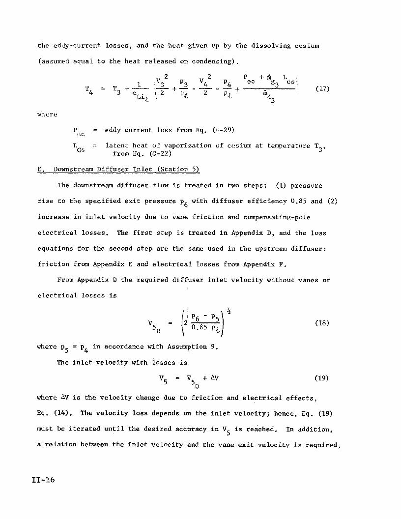
the eddy-current l o s ses , and the hea t given up by the d i s so lv ing cesium
(assumed equal. t o the h e a t re leased on condensing).
where
= eddy cu r ren t loss from Eq. (F-29) cc I'
L = l a t e n t hcat of vapor iza t ion of cesium a t temperature T 3' C S from E q . (C-22)
E. L)ownstream Dif fuser I n l e t (S ta t ion 5)
The downstream d i f f u s e r flow i s t r e a t e d i n two s t e p s : (1) pressure
r ise t o t h e s p e c i f i e d exit pressure p with d i f f u s e r e f f i c i e n c y 0.85 and (2) 6
increase i n i n l e t v e l o c i t y due t o vane f r i c t i o n and compensating-pole
e l e c t r i c a l losses . The f i r s t s t e p i s t r e a t e d i n Appendix D, and the l o s s
equat ions f o r the second s t e p a r e the same used i n the upstream d i f f u s e r :
f r i c t i o n from Appendix E and e l e c t r i c a l l o s ses from Appendix F.
From Appendix D t h e requi red d i f f u s e r i n l e t v e l o c i t y without vanes o r
e l e c t r i c a l l o s s e s i s
where p = p i n accordance with Assumption 9. 5 4 The i n l e t v e l o c i t y with lo s ses i s
where AV i s the v e l o c i t y change due t o f r i c t i o n and e lectr ical e f f e c t s ,
Eq. (14). The v e l o c i t y l o s s depends on the i n l e t v e l o c i t y ; hence, Eq. (19)
must be i t e r a t e d u n t i l t he des i red accuracy i n V
a r e l a t i o n between t h e i n l e t v e l o c i t y and the vane ex i t v e l o c i t y i s requi red ,
i s reached. In addi t ion , 5
11-16

A s shown i n t h e sketch above, t h e vane ex i t v e l o c i t y i s V-/K. Based 5
on the spec i f i ed L2/c , and a 4 deg divergence ha l f -angle ,
L K = l + h5
where h can be est imated from 5
= h4 v4 h5 -- - v c '0
After f ind ing V5, t he a c t u a l height i s ca l cu la t ed from
F. Power and Eff ic iency
The f l u i d power ava i l ab le t o t h e t r a v e l i n g wave region of t h e generator
i s
The e l e c t r i c power required by the cesium pump is the f l u i d pumping
power divided by t h e pump ef f ic iency .
11-17

where
P = l i qu id cesium dens i ty from Eq. (6-18) cs.e
l%e ne t e l e c t r i c output from the genera tor i s P t i m e s the e f f i c i e n c y of
t h e traveling-wave region, minus the pump power and d i f f u s e r eddy cu r ren t losses.
m
Pe = P m T l g - P - P - P ec 1 ec2 ( 2 5 )
whe r t'.
71 = e f f i c i e n c y of t h e traveling-wave region (spec i f ied , o r g supplied by generator program)
P = eddy cu r ren t l o s s i n the upstream compensating pole from Eq. (F-29)
P = eddy cu r ren t loss i n t h e downstream compensating pole from Eq. (F-29) ec2
The value of P from Eq. (25) is compared with the spec i f i ed output e
power, and i f t he two d i f f e r by more than the des i red accuracy, t he nozzle
, % . D exi t width i s ad jus ted t o
' especif i e d ' I ? i = c l C new
e t
and the ca l cu la t ions a r e repeated s t a r t i n g with Eq. (2 ) .
The temperature of the cesium leaving t h e pump, according to Assumption
11, i s increased by the d i s s ipa t ed e l e c t r i c power.
Pp ( 1 - Tp) T12 = T1l + I% c
ga cs.e
The hea t s ink capac i ty of t h e l i q u i d cesium and the small amount of l i th ium
mixed with i t , between t h e pump e x i t temperature T and the allowable recu-
p e r a t e r e x i t temperature T i s
12
13 '
11-18

[-; :: Eract:i.on 01 litliirini mixed with the cesium, Kq. (A-5) - .-- c = specific licat of liqwid cesium at the m a n temperature
+ T . ) / 2 , from Eq. (G-23) c: st @12 13
-- c = s p e c i f i c hea t of l i q u i d l i th ium a t the mean temperature
+ ‘JI ) /2 , from Eq. (C-24) T,i & (T 12 13
?&e h e a t t h a t must be r e j ec t ed to condense t h e l i th ium vapor en te r ing the
recuperator and t o c o o l t h e cesium vapor and t h e l i th ium condensate t o the
s a t u r a t i o n temperature q f cesium a t the condenser i n l e t i s
where i
- C = mean s p e c i f i c hea t of cesium vapor between superheat a t
P T and s a t u r a t i o n a t T from Eq. (6-26)
Li &
8 10 7
- . C = s p e c i f i c hea t of l i q u i d l i th ium a t the mean temperature
(T + T ) /2 , from Eq. (G-24) 8 10
I,,i = . l a t e n t h e a t of vapor iza t ion of l i t h ium a t temperature
from Eq. (6-27) T8 ’ The desuperheat r e j e c t i o n \ always exceeds the l i q u i d cesium s ink
capac i ty Q,. Therefore, t h e r e is an amount of h e a t remaining t o be r e j ec t ed
by t h e desuperheater r a d i a t o r equal t o
‘fie condenser hea t r e j e c t i o n is equal t o the hea t r e j ec t ed by condensing
the cesium a t temperature T
condensate and l i th ium condensate t o T t h e s a t u r a t i o n temperature a t the
p lus the h e a t r e j e c t e d by cool ing the cesium 10
11 ’ condenser exi t .
f
10’ where L c and c are evaluated a t T cs’ cs4 Lid
11-19

't'he k i ~ ~ i t input t o C ~ I C cycle i s equal t o the sum of che hea t r e j e c t e d
by the conckoser, t h e hcat r e j ec t ed by the drsuperhea ter , and the n e t e l e c t r i c
output .
The c y c l e e f f i c i e n c y i s t h e r a t io of net electric output t.o hea t input .
P - , q = - e
Qh (33)
The power d i s s ipa t ed i n t h e generator i s P (1 - power is d i s s ipa t ed i n l i thium f r i c t i o n and ohmic losses .
), and m o s t of t h i s m g
The l i th ium tern-
pe ra tu re leaving the generator is, t he re fo re , approximately
The d i f f u s e r exi t temperature i s increased by the k i n e t i c energy change,
above pumping work, and by the downstream eddy cu r ren t losses .
The hea t source e x i t temperature i s
'h T = T + . 7 6 " . P . ~ L i t
The desuperheater i n l e t temperature i s
Qd T9 = T1O +--
where
(37 1
- C = mean s p e c i f i c hea t of cesium vapor between superheat a t
T and s a t u r a t i o n a t T 10 P
9
11-20

desired accuracy.
“he areas of the desuperheater and condenser radiators are , re spec t ive ly ,
- Qd
a e T 4 ‘d -
d eff
QC
4 A = c
C Tef f
(39)
W l K ? I f 2
= Stefan-Boltzman constant
-2 0 -4 = 5.6697 x W m K ( R e f . 7 , p.5)
8 = emiss iv i ty
= 0 . 9 (Assumption 13)
= e f f e c t i v e radiating temperature between T and T from 9 10 Teffd Eq. (H-6)
= e f f e c t i v e radiating temperature between T and T from 10 11 Eq. (IT-6) ef fc T
IS-21

Table I
Inlet Conditions Employed
i n Nozzle Program
TI CY p1 p1
-1 K p s i N/cm p s i x 2 0 O p
1800 1255.6 137.0 94.5 1.294 3 . 2 9
18 50 1283.3 155 .O 106.9 1.410 4.05
1900 1311.1 177.0 122.0 1.512 4 . 9 0
1950 1338.9 201 .0 138.6 1.629 5 . 9 3
2000 1366.7 224.0 154.4 1 .831 7.34
11-22
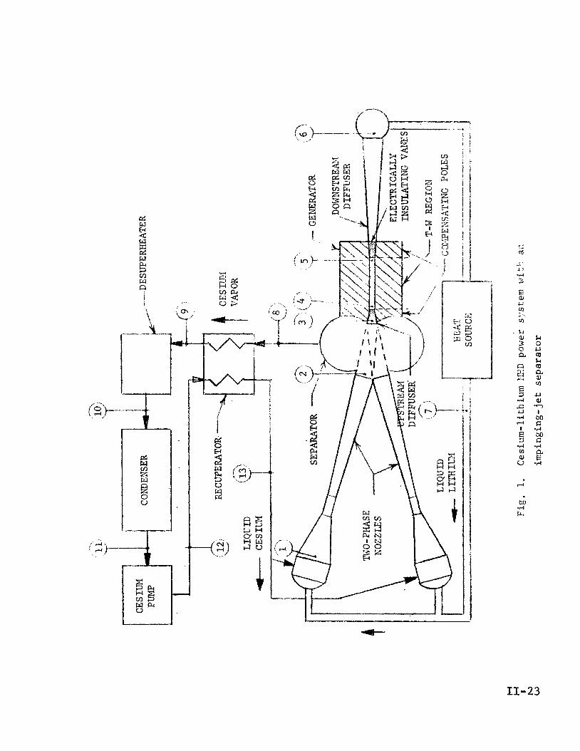
11-23

Ref ere nce s
1 . E l l j o t t , 11. G. , and Weinberg, E . , "Acceleration of Liquids in Two-Phase
Xozz lcs , '' Tecliuical Report 32-987 , Jet Propulsion Laboratory, Pasadena,
Calif., Ju1.y 1, i968.
Reneau, L. R., Johnston, J. P., and Kline, S. J., II Performance and Design 2.
of Straight, Two Dimensional Diffusers," Report PD-8, DepartGent of
Mechanical Engineering, Stanford University, Stanford, Calif., September
1964.
3 . Eckert, E. R. G . , and Drake, R. M., Heat and Mass Transfer, p. 147, McCraw-
H i l l , N. Y., 1959.
4 . Sutton, G. W., Hurwitz, H., Jr., and Poritsky, H., "Electr-ical and Pressure
Losses in a Magnetohydrodynamic Channel Due to End Current Loops," AIEE
Transactions, 58, pp. 687-695, January 1962.
5. Elliott, D. G., Cerini, D. J., and Weinberg, E., "Liquid-Metal MHD Power
Conversion," Space Power Systems Engineering, Academic Press, N. Y.,
1966, pp. 1275-1297.
6. Achener, P . Y., Mackewicz, W. V., Fisher, D. L., and Camp, D. C . , "Thermo-
physical and Heat Transfer Properties of Alkali Metals," Report No. AGN-
8195, Vol. I, Aerojet-General Corp., San Ramon, Calif., April 1968.
7 . Mechtly, E. A. , "The International System of U n i t s ; Physical Constants
and conversion Pactors, NASA SP-7012, 1964.
8. Tepper, F., Udavcak, R., and Zelenak, J., "Determination of the Solubility
of Potassium and Cesium in Lithium," Report MSAR 64-19, MSA Research Corp.,
Cullery, Pa., April 16, 1964.
11-24
Appendix I I A
Fiir t-1:c cycle arinlysi:; the fo l lowing q u a n t i t i e s must be known a t the
A = flow area - A = flow a rea a f t e r v e l o c i t y and teniperature equaZizaLion
ni -1 gas flow r a t e - .
int .= l i qu id flow r a t e
p = pres su re
r -- r a t i o of gas volume f l o w r a t e t o l i qu id volume f l o w r a t e V
L
T = temperature a f t e r equa l i za t ion
V = v e l o c i t y a f t e r equa l i za t ion
a = mass f r a c t i o n of cesium dissolved i n t h e l i qu id phase
B = mass f r a c t i o n of l i th ium vapor i n the gas phase
= dens i ty of the gas pg
= dens i ty of t h e l iqu id
A l l of these a r e p r in t ed out by the nozzle program, but to save copying -
only p , V, A, -A, and ?: are supplied t o t h e cyc le program while the rest a r e
reca lcu la ted wi th in the program. The temperature-dependent q u a n t i t i e s a, B,
and p4 are evaluated a t the equal ized temperature ?; and w i l l agree w i t h
t h e barred q u a n t i t i e s i n t h e nozzle output ; T i s the proper ' teniperature t o use - pE:
s ince the gas and l i qu id temperatures approach e q u a l i t y r ap id ly downstream of
the nozzles and cy, p, pg, and pk are only needed a f t e r t h a t .
IIA-1

Tlic !tart io1 pressure of the cesium vapor
- --
bd I c rc
- - cesium p a r r i a I " c s
- - vapor pressure PLi0
pressure
i s given by Eq. (42) of R e f . 1 .
of l i th ium a t T
H = inverse Henry's Law constant
= moles Cs dissolved pe r u n i t of C s p a r t i a l p ressure
The l i thium p a r t i a l p ressure i s given by Eq. (40) of Ref. 1.
PLi = (1 - H Pes) PLio (A-2)
The e f f e c t i v e molecular weight of t h e gas phase i s given by Eq. ( 4 6 ) of
Ref. 1.
P (A- 3 1
where
W = e f f e c t i v e molecular weight of t he gas phase g
Wcs = e f f e c t i v e molecular weight of t h e cesium vapor (Appendix G)
g
WLi = e f f e c t i v e molecular weight of t he l i th ium vapor (Appendix G) g
The f r a c t i o n of cesium dissolved i n the l i qu id phase i s given by Eq. (39)
of Ref. 1.
(A-4)
= molecular weight of l i q u i d cesium (atomic weight) = 132.9 %s4,
=- molecular weight of l i qu id l i th ium (atomic weight) = 6 .94 'Lj.,
f r a c t i o n of l i th ium vapor i n t h e gas phase is given by Eq. ( 4 9 ) of
The mixture r a t i o of l i qu id t o gas , Eq. (51) of R e f . 1, i s
r - (1 + rc ) B C r =
1 - ( 1 + rC) CY
where
r = r a t i o of l i qu id mass flow rate t o gas.mass f l o w rate
r = r a t i o of l i thium mass flow r a t e t o cesium mass flow r a t e C
The mass f l o w r a t e s of gas and l i qu id , from the d e f i n i t i o n of r, are,
re spec t i v e ly
t m m =-
g l + r
and
where
= t o t a l mass flaw r a t e m t
The dens i ty of t he l i q u i d , based on additive-volume mixing, i s given by
Eql (54) of Ref. 1.
(A-6)
(A- 7 1
(A-9)
ILA-3

1: density of l iquid cesium (Appendix G) 1, %S
= density of l iquid lithium (Appendix G) k: . "Lj
?'he densi ty of . the gas i s given by the perfect gas law, E q . (13) of
K e f . 1, us ing the e f f e c t i v e molecular weight which contains the real-gas
e f f cc t s .
where
R = universal gas constant
= 8314 J kg-mole-loK-l
Tlie volume f low r a t i o of gas to l iquid i s
'She flow area with no s l i p between the phases is given by Eg. (133) of
R e f . 1. .. m
no s l i p
A
(A- lo)
(A- 1 1 )
(A- 12)

Appendix SIB
Veloci ty Equal izat ion Downstream
of a Two-Phase Nozzle
A t the e x i t of a two-phase nozzle t h e v e l o c i t y of the gas is t y p i c a l l y
40% higher than t he v e l o c i t y of t h e l i q u i d (see Fig. 13 of Ref. 1). A s t h e jet
proceeds downstream a t cons tan t pressure the gas and l i qu id v e l o c i t i e s approach
<&qual i ty a t V , and the l i q u i d can ga in 4% i n v e l o c i t y a t the typ ica l L i / C s mis-
Lure r a t i o of 10. The a c t u a l ga in i s less because of two e f f e c t s : ( 1 ) onLy a
f i n i t e d i s t ance i s a v a i l a b l e before impingement i n t h e separa tor and (2) as the
gas dece le ra t e s i t spreads r a d i a l l y beyond the l i q u i d j e t and approaches an
a rea while only the c e n t r a l p a r t with a rea A ( t y p i c a l l y 70% of -A) remains
ava i l ab le t o acce le ra t e the l iqu id .
-
The following a n a l y s i s provides an es t imate of t he l i qu id v e l o c i t y d e f i - -
ciency below V a s a func t ion of d i s t ance beyond the nozzle exit..
A. Deficizncy Due t o F i n i t e Distance
The rate of i nc rease of v e l o c i t y of t h e l i q u i d drops with d i s t ance , dV&/dx,
can be found by equa t i jg the drag fo rce on t h e drops, due to the higher gas
v e l o c i t y , t o t h e mass t imes t h e acce le ra t ion of the drops. Thus,
I f r o n t a l a r ea of drop r e l a t i v e gas flow ] x (drag c o e f f i c i e n t
dynamic pressure of
= [:::; O f ) [drop acce le ra t ion of
o r
where
CD = drag c o e f f i c i e n t
D = drop diameter
V = gas v e l o c i t y 6
= l i qu id drop v e l o c i t y
IIB-1

t = time
x = ' d i s tance from nozzle e x i t
pg = gas dens i ty
= l i qu id dens i ty p- t
The equalized v e l o c i t y which the l i qu id would r e a c h - a t i n f i n i t e d i s t ance
i f a l l t h e gas remained mixed with the l i qu id i s the mass-weighted mean v e l o c i t y
V. This ve loc i ty is given by Eq. (6) of Ref. 1. -
- V + r VI, v = 1 + r
whctre - V = velocity a f t e r equal iza t ion
r = r a t i o of l i qu id mass flow r a t e t o gas mass, flowrate
Solving Eq. (B-2) f o r V and s u b s t i t u t i n g f o r V i n ( B - l ) , t he r e l a t i o n g 6
I
between d i s t ance and l i qu id v e l o c i t y i s
where V has been approximated by v i n t h e f a c t o r 4 pk D. &
The Reynolds number f o r t h e gas flow p a s t the drops i s t y p i c a l l y above
500 where CD i s nearly c o n s t a n t ' a t about 0.5 (see Fig. 2 , Ref. 1.). With only !
V varying, Eq. (B-3) can be in tegra ted from V4 = V4, a t x = 0 t o V4 = V a t &2 t
L
x = L t o give the v e l o c i t y def ic iency a t L, The r e s u l t i s
(B-2)
- V
Kd = -

V = ITquicl v e l o c i t y a t nozzle e x i t %
V = l i qu id v e l o c i t y a t d i s t ance L downstream 5 Kd = . "d i s t ance f ac to r " def ined by Eq. (B-4)
Solving Eq. (B-4) f o r the downstream l iqu id v e l o c i t y ' t h e r e s u l t i s
. .
The i n i t i a l l i qu id v e l o c i t y Vt can be est imated with s u f f i c i e n t accuracy 1
- - from V, A , and A. Since t h e f low area i s mostly gas, the con t inu i ty equat ion
- - f o r the gas before and a f t e r equal iza t ion i s V A :-: V A, or
g l
Subs t i t u t ing t h i s value of V i n t o Eq. (B-2), t he i n i t i a l l i qu id v e l o c i t y i s g
Usi.ng t h i s va lue of Vy, i n Eq. (B-4), the "dis tance f ac to r " K i s d 1
+ 0.375 r K = _ A/A - 1 PL d
03-71
B. Deficiency Due t o G a s Flow Loss
A t i n f i n i t e d i s t ance downstream the f i n a l l i q u i d v e l o c i t y i s v (without
the flow loss e f f e c t ) , and the gas flow occupies area while the l i q u i d flow
s t i l l occupies a rea A, neglec t ing divergence of t h e l i q u i d j e t . The f i n a l f low
rate of gas mixed with the l i qu id i s , the re fo re , only 4 A/A, and the mean flow
of gas ava i l ab le t o a c c e l e r a t e the l i qu id i s
g
IIB-3

1 + AfX € 5 2
m = m gm
(B- 9)
The v e l o c i t y increase of the l i qu id i s reduced i n proport ion t o t h e reduc-
t i o n i n gas f l o w . Thus,
(B- I O )
Subs t i t u t ing the mean gas flow from Eq. (12-9) and the in i l l i a l liquid
v e l o c i t y from Eq. (B-7), t he v e l o c i t y def ic iency a t i n f i n i t e d i s tance due to tlie
flow loss i s
- = V Kf (B- 11)
where
Kf = "f low l o s s f a c t o r " defined by Eq. (B-11)
From Eqs. (B-5) and ( B - l l ) , t h e l i qu id v e l o c i t y including both the d i s t ance
e f f e c t and the flow loss e f f e c t i s
- = V (1 - l /Kd) ( l Kf)
(B- 12)
Typical exi t condi t ions f o r a cesium-lithium nozzle a r e : mixture r a t i o
3 r = 14.5, area r a t i o A/K = 0.69, gas dens i ty p = 0.88 kg/m , l i q u i d d e n s i t y i3
= 437 kg/m3, drop diameter D = 0.057 cm, and mean ex i t . ve loc i ty = 138.8 m / s . P&
Equations (B-6) and (B-7) give V
i n s u f f i c i e n t agreement with the t r u e va lues 199 m / s and 134.7 m f s from the
nozzle. program. The value of Kf from Eq. (B-11) i s 0.0048 showing t h a t t he
1.imiting l i q u i d v e l o c i t y i s 0.48% less than v.
= 202 m / s and V& = 134.5 m/s, r e spec t ive ly , 81 1
I I B - 4

Figure B-1 presents the variation of liquid ve loc i ty with distance calcu-
The ve loc i ty increases rapidly for t h e f i r s t 20 c m then 1atc.d from E q . (B-12).
approaches the limiting value slowly. In a 300 kWe system the distance to the
intersection of the center l ines of the two impinging nozzles worild te about
15 c m . ‘fie liquid ve loc i ty a t that distance i s 136.4 m / s , which i s 1-72 l ess
th , i V and 402, of the way from V -
t o v, %
I I B - 5

m m 4
N I4
I F9
w w
0
II
;I
CJI N . \’
3
I
8
4
i !
-!
m m 4

Appendix IIC
I sen t rop ic Dtssolving Dif fuser Flow
A two-phase mixture of cesium and l i th ium e n t e r s a d i f f u s e r a t pressure
and ve1ocity.V I n the d i f f u s e r the pressure inc reases t o p causing the P l 1’ 2’
cesium t o d i s so lve i n t h e l i thium, and an a l l - l i q u i d s t ream’leaves the diffuser
at a reduced v e l o c i t y V The problem is, f i r s t , t o f ind the pressure p a t 2 ’ 2
which d isso lv ing i s complete and then t o f i n d t h e corresponding v e l o c i t y V., ,
f o r flow vi t t iout f r i c t i o n ( i s en t rop ic flow).
I
A . I.:x i t Pr c s s u r e
‘rhc mass of ccsiuin d isso lved i n the l i qu id a t the d i f f i i se r irilet i s
m = i n l e t l i qu id flow rate $1
cy = mass f r a c t i o n of cesium
i n l e t
A t a poi*.it i n the d i f f u s e r where the
d isso lved i n the l i qu id a t t he
pressure has increased t o p and t h e
gas flow-rate has decreased t o & the d isso lved cesium flow, i s 8
(C- 1 )
( C - 2 )
where
m = i n l e t gas f l o w rate gl
I I C - 1

Ignoring the lithium partial pressure for simplicity, the pressure ratio
for dissolving the, additional cesium is
d m P=-
Substituting Eqs. (C-1) and (C-2) into Eq. ( C - 3 1 , the pressure ratio is
By definition of the volume ratio r t h e inlet gas flow rate is V'
where
r = inlet gaslliquid volume ratio v1
= inlet gas density pg 1
p4, = liquid density
The gas flow rate at pressure p i s
(c- 3 )
(c-5)
ignoring the small temperature change.
I I C - 2

Subs t i t u t ing Eqs. (C-5) and (C-6) into Eq. (C-4) and ignor ing the small
change i n l i qu id flow rate , the pressure r a t i o is
m
E = 1 +- 81
P1 ct mdl - r;ppl)
A t Lhe exi t r. = 0. Therefore, the e x i t p ressure i s given by V
B. E x i t Veloc i ty
The r e t a r d i n g . f o r c e on a f l u i d element i n the d i f f u s e r with pressure p
upstream and pressure p 3. dp downstream is A dp.
t he momentum such t h a t
This r e t a rd ing fo rce reduces
m d V = - A d p &2
where
A = l oca l f l o w a rea
m = exi t l i q u i d flow r a t e &2
= t o t a l f l o w rate
V = l o c a l v e l o c i t y
The flow a rea i s r e l a t e d to t h e local volume r a t i o by
Subs t i t u t ing t h i s va lue of A i n t o Eq. ( C - 9 ) , noting t h a t V dV = dV 2 / 2 , and
Ileslcctini; the changc i n l i qu id flow, the momentum equat ion , Eq. (C-9), becomes
(c- 11)
IIC-3

sLtbstittlti.ng, Eq. (C-8) into Eq. (C-7), the volume ratio as a function of
pressure i s
(C- 12)
S u b s t i t u t i n g this expression for r into the momentum equation, Eq.. (C-11) , V
and i n t e g r a t i n g between p and p the exit velocity is 1 2’

Appendix I I D
Liquid D i f f u s e r Flow
The downstream d i f f u s e r i s a simple d iverg ing d i f f u s e r wi th l i q u i d flow.
Two added l o s s e s are t h e vane f r i c t i o n and e l ec t r i ca l f o r c e , bu t t hese are cal-
cu la t ed s e p a r a t e l y us ing t h e r e l a t i o n s of Appendix E and Appendix F. For t h e
d i f f u s e r channel without t h e vanes and electrical e f f e c t s , Ref. 2 , Fig. 2.01,
shows t h a t an e f f i c i e n c y of 0.85 is a t t a i n e d exper imenta l ly when (1) t h e i n l e t
1)oiiiiclary l a y c r i s t h i n , whicli should be the case w j t l i t h e veloci ty profile
f - l a t l en ing caused by the gene ra to r , (2) t h e divergence ha l f - ang le i s 3-5 deg,
and (3) t-he a r e a r a t i o i s 4.0 or l a r g e r , The e f f i c i e n c y i s def ined a s
where
= d i f f u s e r e f f i c i e n c y (= pres su re recovery C i n Ref. 2) P
p1 = i n l e t p re s su re
p2 = e x i t p re s su re
V1 = i n l e t v e l o c i t y
= l i q u i d d e n s i t y P - t
Thus, t h e r equ i r ed d i f f u s e r i n l e t v e l o c i t y f o r given p and p without 1 2’
vane f r i c t i o n lo s ses o r e lectr ical l o s s e s , i s

Appendix LIE
Vane-channel F r i c t i o n Loss
Figure E - 1 shows t he flow geometry. The i n l e t he ight i s
where
= t h e l iqu id f l o w rate, assumed constant a t the 1,
genera tor flow value & i n both d i f f u s e r s $4
r = inlet: volume r a t i o 1 V
V1 = i n l e t v e l o c i t y
pa = l i qu id density
c = d i f f u s e r width
The exi t he igh t , s ince r i s zero i n "0th I
2 V Efusers, i s
where
V2 = . ex i t : v e l o c i t y
For s impl i c i ty , t he f r i c t i o n loss w i l l be ca lcu la ted f o r cons tan t -ve loc i ty
f l o w a t the mean conditions. The mean he ight i s
hl + h2 2
h =
The mean v e l o c i t y is
03-31
V1 + v2 2 v = (E-4)
IIE-1

The i n l e t dcznsity i s
(E-5)
The e x i t dens i ty i s p and the mean dens i ty i s ( p I- p ) / 2 01: 1 2 4’
1 + rv 1
The a rea over which the f r i c t i o n fo rce is exerted i s the sum of the wall
area and the vane area.
(E-6)
where
L = . vane length
N = ‘number of vane channels I
For the downstream d i f f u s e r the w a l l area i s omitted, because the d i f f u s e r
e.fficiency (Appendix D) a l ready includes the wa l l f r i c t i o n .
The vanes i n both d i f f u s e r s , and t h e wal l s i n the upstream d i f f u s e r , have
no i n i t i a l boundary Layer, and the vane-channel lengths a r e t y p i c a l l y too shor t
f o r the boundary layers from opposite s i d e s t o meet. Therefore, t he drag i s
ca lcu la ted from f l a t p l a t e r e l a t i o n s . The Reynolds number based on vane length
i s
whcrc
p = l i qu id v i s c o s i t y
A s i m p l e r e l a t i o n f o r t h e mean f r i c t i o n f a c t o r is given i n Ref. 3.
(E-8)

2 The f r i c t i o n fo rce i s the product of dynamic pressure p V / 2 , f r i c t i o n
f a c t o r , and area . Adding 30% to be conservat ive, t h e f r i c t i o n fo rce i s
(E- 10) F = 0.65 p V 2 f A P"
I n the upstream d i f f u s e r t h i s force produces a decrease i n e x i t v e l o c i t y ,
and i n the downstream d i f f u s e r i t produces an increase i n required i n l e t
v e l o c i t y , equal t o
F A V f = -
% (E-11)
IIE-3

Fig. E-1. Friction loss in a vane channel

Appendix I I F
Vane Channel E l e c t r i c a l Losses
The two kinds 3f electrical lo s ses from the compensating f l u s are i l l u s -
t r a t c d i n Fig. F-1: (1) t h e motion of the f l u i d through the magnetic f i e l d
gvncrates a vo l t age across each vane channel causing shunt end c ~ i r r c n t s , and
( 2 ) Lhe r a t e o f change of the f i e l d genera tes eddy-current loops i n each
ch anne 1.
The power losses can be ca l cu la t ed sepa ra t e ly and added even though t h e
cu r ren t s may overlap, because the c u r r e n t s from the two e f f e c t s a r e 90 deg
apa r t i n phase. I f I i s the r m s cu r ren t through an a r b i t r a r y f l u i d element
due t o the f i r s t e f f e c t and I2 i s the r m s cu r ren t due t o t he second e f f e c t ,
then the r m s t o t a l cu r ren t through the element i s
1
I f the r e s i s t a n c e of the clement i s R the powcr d i s s ipa t ed in i t i s
2 P = 1 R , and from Eq. F-1
P = 112 R 4- 122 R
= P + P 2 1
where
P = t o t a l loss i n the f l u i d element
P1 = loss due t o motion-induced cu r ren t (effect 1)
P2 = loss due t o eddy cu r ren t ( e f f e c t 2)
I IF-1

Si.ncc E c ~ . (F-2) holds a t each po in t , t h e to ta l power .loss i n the f l u i d
can be foiind by c a l c u l a t i n g t h e loss due t o each e f f e c t s epa ra t e ly and adding.
A. Mean Flow Conditions
For s impl i c i ty , the electrical lo s ses w i l l be ca l cu la t ed f o r cons tan t -
The mean he igh t h and mean v e l o c i t y V v e l o c i t y flow a t the mean condi t ions .
a r e the same as .used i n Appendix E. A mean e l e c t r i c a l conduct iv i ty i s requi red ,
"he conduct iv i ty cf l i qu id l i th ium i s 2 x lo6 mho/m, and ' t h i s will be t h e con-
d u c t i v i t y a t the ex i t of the upstream vane channels and throughout the downstream
vane channels. A t the i n l e t of the upstream vane channels t h e conduct iv i ty can
be estimated from.the volume r a t i o r us ing the da t a p l o t t e d i n Fig. 9 of
Ref. 5. The conduct iv i ty i s equal t o o r l e s s than
6 2 x 10 c r =
where
o1 = i n l e t conduct iv i ty
r = i n l e t gas / l i qu id volume r a t i o 1 V
The mean conduct iv i ty i s
0 + o 1 2 2 ( T =
.(F-3)
(F-4)
where
(T = exi t conduct iv i ty
= 2 x 10 mho/m
1
2 6
Although (T may be several times less than ( T ~ , Eq. (F-4) properly averages
the two va lues for c a l c u l a t i n g t o t a l power loss, a t l e a s t f o r t h e shunt end
cu r ren t s . With the same vol tage E appl ied across the end r e s i s t a n c e s a t each end,
I IF-2

t h e loss ca l cu la t ed by t r e a t i n g each end sepa ra t e ly would be cons t x (E2 o
E2 G 2 ) , which i s the s a m e as const x(2 E 0).
+ 1 2
Subs t i t u t ing Eq. (F-3) i n t o Eq. (F-4), t h e mean conduct ivi ty is
1;. Shunt: End Loss
The shunt end l o s s can be ca l cu la t ed from the theory of Ref. 4. The theory
r equ i r e s a va lue of the e-folding length of the magnetic f i e l d . Keferr ing to
Fig. F-1, t h e rms f i e l d i s cons tan t a t a value B
channel of length L and drops o f f t o l / e of t h a t value a t the ends of t h e chan-
ne l , The d is tance over which the decrease occurs i s t h e e-folding length. The
c e n t r a l , cons t an t - f i e ld , length is
over a c e n t r a l po r t ion of the 0
0
Lo = L - 2 Ye
where
Lo = length of constant f i e l d
L = . length of vanes
‘e = d i s t ance over which the f i e l d decreases t o Bo/e
The e-folding length of a magnet is roughly equal t o the gap, h i n t h i s
ca se , ignor ing the thermal i n s u l a t i o n thickness . I f h/L is la rge enough t o
make Lo less than L./5, then Y i s assumed t o be s u f f i c i e n t l y smaller than h t o e
make Lo = L/5. Thus,
Ye = h i f L - 2h > L/5
= 2L/5 i f L - 2h < L/5
where
(F-6)
(F-7)
h = mean channel height from Eq. (E-3) (h = 1 i n Ref. 4 )
IIF-3

'Ilic nn:j rrlagnctic f l u x produced by the f i e l d is
cn
(3 =: c Lo Bo + 2c Bo e dx 0
= c Bo (Lo + 2 Ye)
usin;: Lo from E q . (F-6), the rms cen te r f i e l d required i s
C - Bo -cz,
where
dc = the required r m s compensating f l u x
Quant i t ies reguired i n the theory of Ref. 4 a r e
C - - '1 - N
2n Ye =-
1 Y e C
Ye
2 y = -
where
c = width of an ind iv idua l vane channel (= h i n Ref. 4 )
Ye
y = exponent ia l c o e f f i c i e n t of t h e f i e l d extension
1
= dimensionless e-folding length of t h e f i e l d extension
The q u a n t i t i e s y and y a r e used f o r c a l c u l a t i n g the two c o e f f i c i e n t s e
6, and p, employed i n the theory f o r determining the e f f e c t of the e - fo ld ing
length on the shunt end cu r ren t s .
The parameter @, i s given a s a funct ion of y by Eq. (20) of Ref. 4 . To
provide a simpler formula f o r f a s t e r computation, a polynomial was f i t t e d t o
the inverse of 6
formula i s
over t he range of y values of i n t e r e s t , 0 < y < 10. The 1
(F- 9)
(F- 10)
(F- 11)
(F- 12)
IIF-4

p = 1/(1:.45125 + 1.31968 y - 0.02505 y2 4- 0.00119 Y 3 ) 1
(F- 13)
The parameter i s the function of y i n s i d e the bracket of Eq. (91) of 3 e
R e f . 4 , w i t h a minus s ign (p, here equals - fl, i n Ref. 4).
f i t t e d t o (4
i s
A polynomial w a s
over t h e range of y 3 e va lues of i n t e r e s t , 0 < ye < 20. The formula
2 fj = 0.0044 + 0.12828 ye - 0.022195 y 3 e
4 + 0.0020146 ye3 - 0.8824 x ye
5 +,0.1473 x 10” ye (F- 14)
Each vane channel a c t s as an open-circuit generator, w i t h zero power
output. The loading, o r vo l tage c o e f f i c i e n t , f o r t h i s condition i s given by
Eq. (22) of Ref. 4. Using the present no ta t ion ,
(F- 15)
2c1 B l
- Lo - 2Cl loge 2
1 +
1 + 7T Lo
K i s the ratio between the a c t u a l vo l tage across the vane channel and the vo l t -
age c
0
B 1 0 V t h a t would exis t without end c u r r e n t s (KO i s denoted 7 i n Ref. 4.).
The pressure change from upstream of t h e channel t o downstream of the
channel due t o the shunt cu r ren t s i s given by Eq. (91) of Ref. 4 . Using present
not a t ion,
AP+ 2 - - - u V C B - VCl 1 o % + * p i (F- 16)
IIF-5

where
= d i f f e rence between t h e pressure downstream of t h e
channel and t h e pressure upstream of t h e channel
AP+ = power
Api = i d e a l
generated due t o f i e l d extension
pressure change (no end e f f e c t s )
The value 'of AP+ i s given by E q . (71) of Ref. 4. Correcting t h e misprinted
-4 TT t o n-', the r e l a t i o n is
(F- 17) 2 2 2 AP+ = 2 rs KO V Bo c Bl/n 1
The value of Ap i s given by Eq. (81) of Ref. 4 ( i n which cr i s missing on i
the r i g h t s ide) .
2 LO Api = CT (KO - 1) V Bo .(F- 18)
For the cons tan t v e l o c i t y case t r e a t e d i n Ref. 4 the f l u i d input power
i s equal t o the volume flow r a t e t i m e s the pressure drop. For a l l N vane
channels t he power input , which i s equa l t o t h e power d i s s ipa t ed i n t h e shunt
end cu r ren t s , i s
P S = - N c l h V A p a
- _ - c h V Apa (F- 19)
Equation (F-19) merely expresses t h e f a c t t h a t t he re i s a re ta rd ing force
on the f l u i d due t o t h e shunt cu r ren t s such t h a t
S (P-20) P
= - Fe v
I n t h e present case the fo rce changes the v e l o c i t y ins tead of t he pressure, and
t h e v e l o c i t y change i s
pS
rn4 V A V e = -
IIF-6
(F-2 1)

where
mG = t he flow r a t e through t h e d i f f u s e r
Subs t i t u t ing E q s . (F-16), (F-17), and (F-18) i n t o Eq. (F-19), t h e f l u i d
power input due t o the shunt end cu r ren t s i s
1T
C
P = rj c 1-1 1 - K O -E1(f3, - LO S
C. ECMY Current LOSS
Figure F-2 shows the f l u i d i n one of the vane channels as viewed i n the
field d i rec t ion . For ca lcu la t ing t h e eddy-current l o s s the f l u i d i n a vane
channel w i l l be t r e a t e d as a s l a b of length L, width c
ductivi.ty 0, with a uniform magnetic f i e l d of r m s value 8 penet ra t ing it and
o s c i l l a t i n g a t frequency f .
thickness h , and con-
0
1’
The eddy cur ren t paths can be approximated by rec tangular loops, one 01
which i s shown i n Fig. F-2. The r e s i s t a n c e of each of t h e longi tudina l legs is
2x R = L CT h dx (cl/L)
where
x = d i s t ance from the center of t h e channel t o the loop i n
t h e L d i r e c t i o n
dx = width of the loop i n the L d i r e c t i o n
The r e s i s t ance of each of the l a t e r a l l egs is
2 x Cl/L - Rc - CT h dx
The t o t a l r e s i s t ance around the loop i s
(F-22)
(F-23)
(F-24)
(F-25)
IIF-7

me area i n s i d e the loop is 4 x2 cl/L, and t h e t i m e 'rate of change o f
f lux through t h i s area is equal t o the r e s i s t a n c e times t h e cu r ren t i n t h e
loop.
2 R dl = 2 7~ f Bo 14 x c l / L /
where
f = frequency of t h e f i e l d
Subs t i t u t ing R from Eq. (F-25), the cu r ren t i n t h e loop is
2 TI f (5 c h Bo x dx 1 d1 = L (Cl/L + L/Cl)
The power d i s s ipa t ed i n the loop i s
2 = R (dI) 'ec
2 2 2
2
16 'IT f CT c1 h Bo2 x3 dx - -
L (Cl/L + L/Cl)
The power d i s s ipa t ed i n t h e vane channel is the i n t e g r a l of dPec from
x = 0 t o x = L/2. Mult iplying by N, t he eddy cu r ren t l o s s i n t h e d i f f u s e r i s
2 o N h (I-T f Bo c1 L) P = ec 4 (Cl/L + L/Cl)
This power loss does not produce a r e t a rd ing fo rce on the f l u i d , s ince
fo rces on one s i d e of the cu r ren t loops are canceled by fo rces on the o ther .
(F-26)
(F-27)
(F-28)
(F-29)
The source of t he power i s t h e generator , and P must be subt rac ted from the
genera tor power output.
ec
IIF-8

The eddy currents also affect the generator in requiring an increase in
compensating-pole winding current to overcome the reaction field produced by
the eddy currents. The field produced by the current loop dI is
"0 d= dB = - g
where
g = i r o n gap
po = fluid permeability
The flux is dB times the loop area 4 x 2 cl/L.
(F- 30)
(F- 3 1)
where
= reaction flux due to the eddy currents @r Substituting dI from E q . (F-27) and integrating over the vane channel, the
total reaction flux is
(F- 32)
The number of ampere-turns of winding current required to overcome the
reaction flux is given by
Substituting q5 from Eq. (F-32) and solving for N I, the number of ampere- r
turns that must be added to the generator compensating-pole excitation (180 deg
out of phase with the eddy currents) is
0 h n f Bo c1 L N I = 8 (cl/L 3. L/cl) (F- 34)
I IF-9
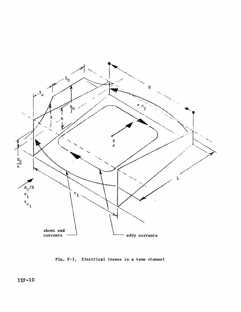
. F i g , F-1. Electrical losses in a vane channel

c. , dx/L
! I
eddy current ioop x -
Fig. F-2. Eddy currents in a vane channel
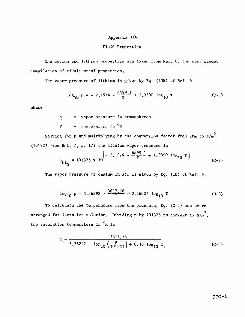
' Appendix IIG
Fluid Properties
Th esium and lithium properties are taken from R e f , 6, the mo
compilation of alkali metal properties.
The vapor pressure of lithium is given by Eq. (138) of Ref. 6.
6499*1 + 1.9390 loglo T T loglo p = - 2.1974 -
t recent
(G- 1)
where
P = vapor pressure in atmospheres
T = temperature in K 0
2 Solving for p and multiplying by the conversion factor from atm to N/m
(101325 from R e f . 7, p. 17) the lithium vapor pressure is
(G-2) 6499'1 + 1.9390 log [ - 2.1974 - T = 101325 x 10 %io
The vapor pressure of cesium in atm is given by Eq, (18) of Ref. 6 .
loglo p = 3.36292 - 3617.76 T + 0.16005 loglo T
To calculate the temperature from the pressure, E q . (G-3) can be re-
Dividing p by 101325 to convert to N/m', 3 arranged for iterative solution.
the saturation temperature in K is 0
3617.76 T =
S S 3.36292 - loglo I-) 101325 I - 0.16 loglo T
(6-3)

The effect ive c e s i u m molecular weight i s t h e v a l u e which, when s u b s t i -
t u t e d i n the p e r f e c t gas equat ion , gives t h e a c t u a l d e n s i t y of cesium vapor .
Thus, the effect ive molecular weight i s def ined by
*CS .-s - PCS R T
!3 (G- 5)
where
A cesium vapor d e n s i t y PCS
g
I’ = pres su re
R = u n i v e r s a l gas cons t an t
T = temp era t u re
The e f f e c t i v e molecular weight can be determined from t h e equa t ion of
s ta te g iven by Eq. (27) of R e f . 6 .
RT p = - ; - z
where
V = volume per mole o f monomer
and Z i s given by
7 82.173 T + 2.7318 x 10 exp (1500/T) 2 z = 1 - . v
V
19 1.0421 x exp (550/T) + 1.2610 x - 3.6091 x 10 5
V 4
V 3
V
(6-7) 3 -1 w i t h v i n c m g-mole monomer.
I I G - 2

'Jlhe monomer molecular weight i s the l iquid molecular weight (atomic
weight) W = 132.9 used i n Appendix A. The spec i f i c volume, by de f in i t i on
of v , i s v/Wcs & cs
and the density i s the inverse. G
From Eqs . (G-5) and (G-8) the value of v is
wcs, RT
'Cs 8
v =
Subst i tut ing Eq. (G-9 ) in to Eq . ( G - 6 ) , the e f f ec t ive molccular wcight i s
(G- 10)
The procedure f o r calculat ing W f o r given pressure and temperature is : cs g
(1) guess a value of Wcs , say W , (2) ca lcu la te v from Eq. ( G - 9 ) , (3) calcu- g -.e
l a t e Z from Eq. (G-7).and Wcs from Eq. ( G - l o ) , (4) continue recalculat ing v ,
Z , and W u n t i l W converges t o the desired accuracy. Using R = 8.314 i n cs CS
3 -1 0 -1 3 Eq. (G-9 ) w i l l give v i n m g-mole K ( R e f . 7 , p. 5); t o provide v i n c m
g-mole
g
g
0 6 K f o r Eq. ( 6 - 7 ) , R must be multiplied by 10
The e f fec t ive molecular weight of lithium vapor i s given by Eq. (148) of
Ref. 6. In present notat ion,
(G- 11)
IIG-3

where
= l iqu id , o r monomer, molecular weight (atomic weight)
= 6.94 t 'Li
= l i thium vapor pressure "Lie = p a r t i a l pressure of the monomer
p 1
The monomer p a r t i a l pressure i s given by Eq. (146) of Ref. 6.
(G- 12)
where
= equilibrium constant f o r formation of the dimer from the K2
monomer
~ubsti.tut-ng E q . (G-12) i n to Eq. ( G - l l ) , the e f f ec t ive molecular weight i s
where p i s i n atm f o r the K values given i n Ref. 6. L io 2
EquPtion (145.) of Ref. 6 gives the value of K2 as - Kf ,2
K2 - (Kf , 1)2
where
= equilibrium constant for formation of t he monomer from f , l
K
the l iquid
(G- 13)
(G- 14)
K = equilibrium constant for formation of the dimer from 592
the l iquid

are g iven i n Tables 74 and 75, rc- 10 K f , 2 Values of log ' K and log 10 f,l
(;pectively, of R e f . 6, I n ternis of t h e s e va lues Eq. (G-14) is
(G- 15) K2 = 10 Q
where
(G- 16)
from R e f . 6 and the corresponding va lues 10 Kf ,2 Values of loglo K f , l and log
of Q from Eq. (G-16) are t abu la t ed i n Table G - 1 f o r t h e temperature range of
i n t e r e s t , 1000 - 1500OK. "he v a l u e s of Q can be f i t t e d w,ithin 1% by
(G- 17 ) -5 'T2 Q = 10.1245 - 0.01183825 T -I- 0.31625 x 10
The d e n s i t y of l i q u i d cesium i n g/cm3 as a f u n c t i o n of tempera ture , t , i,n
0 C i s given by Eq. '(5) of Ref. 6. Replacing t by T-273 and mul t ip ly ing by 1000,
t h e d e n s i t y of l i q u i d cesium i n kg/m3 i s
= 434 + 24.95 (2043-T)1/2 + 0.2083 (2043-T) pcs * (G- 18)
3 The d e n s i t y of l i q u i d l i t h ium i n g/cm as a func t ion of temperature, t , i n
0 C i s given by Eq . (125) of Ref. 6. Replacing t by T-273 and mul t ip ly ing by
1000, t h e d e n s i t y of l i q u i d l i t h i u m i n kg/m3 i s
pLi = 124 + 5.306 (3173-T)ll2 + 0.04135 (3173-11) (G- 19) 4
The v i s c o s i t y of l i q u i d l i t h ium i n m i l l i p o i s e i s g iven by Eq. (136) of
Ref. 6
155.991 - 1.61506 loglo T T loglo IJI = 5.41921 - (6-20)
I I G - 5

-4 2 Solvj-ng f o r p and mul t ip ly ing by 10
(Ref. 7 , p. l a ) , the v i s c o s i t y of l i qu id l i th ium is
t o convert m i l l i p o i s e t o N . s / m
(1.419 - 156/T - 1.615 loglo T) p = 10 (G-2 1)
The l a t e n t h e a t , ’ o r en tha lpy , of vapor iza t ion of cesium i n c a l g-’. i s
given by Eq. (21) of Ref. 6. Mult iplying by 4184 t o convert t o J/kg (Ref. 7 ,
p. 13 o r Ref. 6 , p. 5 ) , the l a t e n t h e a t of vapor i za t ion of cesium i s
0.3547 Lcs = 6.1555 x LO5 ( 1 - L, 2 043 (C-22)
-1 0 - 1 The s p e c i f i c hea t of l i qu id cesium i n c a l g K i s given by Eq. (10)
of Kef. 6. Mult iplying by 4184 t o convert t o J kg K , the s p e c i f i c heat
of l i q u i d cesium i s
-1 0 -1
-4 t2 C = 286.2 - 0.3361 t + 3.345 x 10
cs& (6-23)
where
0 t = temperature i n C
= T-273
-1 0 -1 The s p e c i f i c hea t of l i q u i d l i th ium i n ca l g K is given by Eq. (130)
-1 0 -1 of Ref. 6. Multiplying by 4184 t o convert t o J kg K , the s p e c i f i c hea t
of l i q u i d l i t h ium i s
-4 t2 C = 4425 - 0,5084 t + 2.237 x 10 Li t
where
- (6-24)
0 t = temperature i n C
= T-273
IIG-6

For the recupera tor and desuperheater c a l c u l a t i o n s i t . i s necessary t o f i n d
the enthalpy change of cesium vapor between superheat condi t ions T, p and
s a t u r a t i o n condi t ions T p a t the same pressure . The enthalpy change dan be S'
ca lcu la t ed from a m e a n s p e c i f i c hea t defined by
(G-25)
The enthalpy of s a tu ra t ed and superheated cesium vapor i s given i n Table 9
of R e f . 6. The s a t u r a t i o n temperatures and en tha lp i e s from t h i s Table a r e
p l o t t e d i n P ig . C-1 a s a func t ion of pressure over t h e range of i n t e r e s t , 0.2 - 3 . 0 atm.
Table G - 2 presents t h e s a t u r a t i o n and superheat en tha lp i e s a s a funct ion
of pressure and temperature. The f i r s t l i n e f o r each pressure g ives t h e sa tura-
t i o n condi t ions: T from Fig. G - 1 i n Column 2 and H from Pig. G - 1 i n Column 3 .
The remaining l i n e s f o r each pressure g ive the temperature and corresponding
enthalpy for superheat condi t ions a t t h a t p ressure , taken d i r e c t l y from Table 9
of lief. 6.
S s .
TS The four th column i n Table G-2 gives the temperature increase AT = T -
above s a t u r a t i o n , and the f i f t h column g ives t h e enthalpy increase OH above
sa tu ra t ion . The l a s t column gives the mean s p e c i f i c hea t &/AT (Eq. G-25).
The mean s p e c i f i c hea t va lues are p l o t t e d as a func t ion of AT i n Fig. G-2,
and smooth curves are drawn thmugh the poin ts . Each curve i s f o r a f ixed pres-
sure and s a t u r a t i o n temperature. The curves are c ross -p lo t t ed i n Fig. G-3 t o
show mean s p e c i f i c hea t as a func t ion of s a t u r a t i o n temperature a t cons tan t AT.
The dependence of c-
f o 1 1 owing equat ion :
i s near ly l i n e a r and cap be represented by the p pn Ts

c
c = 6.66 - 1.6 x lom3 AT + (1.2 x - 1.1 x lom5 AT)(Ts - 800) P
(6-26)
-1 0 -1 where i s i n ca l g-mole K . D
Equation (6-26) i s p l o t t e d i n Fig. G-3 f o r comparison wi th t h e data; The
c.quution agrccs w i t h the d a t a w i t h i n 1% from AT = 200 t o AT = 400, t he range
o f . i n t e re s t .
-1 0 - 1 To convert c to J kg K Eq. (G-26) must be d iv ided by W = 132 .9 4, P C S
-1 0 - 1 t o give c a l g K and then m u l t i p l i e d by 4184 (Ref . 7 , .p. 13). The combined
f a c t o r i s 41841132.9 5. 31.48.
-1 The l a t e n t h e a t of vapor i za t ion of l i t h ium i n cal g i s given by
E q . ( 1 4 2 ) of Ref. 6 . Mult ip ly ing by 4184 t o conver t t o 3/kg, t h e l a t e n t
h e a t is 0.3725
3173 L~~ = 2.536 lo7 1 I
(G-27 )
IIG-8

Table G - 1
Lithium Equilibrium Constants
T logio Kf, 1 loglo Kf,2 Q
(Table 7 4 , (Table 75 ,
0 K Ref. 6 ) R e f . 6 ) Eq. (6 -16) ~
1000 - 3.0129
1 100 - 2.2519
1200 - 1.6937
1300 - 1.1909
1400 - 0.7621
1500 - 0 ,3921
- 4.569
- 3.667
- 2.920
- 2.296
- 1.764
- 1.309
1.457
0.917
0.467
0.086
- 0.240
- 0.525
I I G - 9

Table 6-2
Enthalpy Change and Mean Specif ic Heat of
Cesium Vapor Between Superheat and Saturat ion
ca 1 c a l - ca 1 - K mole K mole OK mole 0 0 a tm
0.2 799 .
825
900
1000
1100
1200
1300
1400
0.4 856
875
900
1000
1100
1200
1300
1400
0.6 8 92
9 50
1000
1100
1200
1300
1400
20510
20683
2 1169
2 17 93
22349
22923
23559
24149
20604
207 63
20 955
2 1660
22259
22858
23509
24110
20665
2 1154
2 1528
22 170
22794
23461
24072
0
26
LO 1
20 1
30 1
40 1
50 1
60 1
0
19
44
144
2 44
344
444
544
0
58
108
208
308
408
508
0
17 3
659
128 3
1839
2413
3049
3639
0
15 9
35 1
1056
1655
2254
2905
3506
0
489
863
1505
2129
2796
3407
6.654
6.525
6.383
6.110
6.017
6.086
6.055
8.368
7.977
7.333
6.782
6.552
6.543
6,445
8.431
7.991
7.236
6.912
6.853
6.707
(Continued)
IIG-10

Tab 1.e G-2 (Continued) . .
AH - c - - p - AT
ca 1 cal - - K mole K -mo le OK mole
0 cal
0 a tm
0.8 920
97 5 1000
1050 1100
1200
1300 1400
1 .o 942 1000 10 50
1100
12 00
1300 1400
2.0 102 1 1100
1200
1300
1400
3 .O 1074 1200
1300 1400
207 12 2 1200 2 1398
21759 22084
22733
23414 24036
20748 2 1269 216.56 22000 22673
23369 2400 1
20880
2 1606
22399
23 167 23844
2097 5
22156 22990
23709
0
55 80
130 18 0 280
380 48 0
0
58 108 158 258
358 458
0
79
17 9
279 37 9
0
12 6 226
326
0
48 8
' 686
1047 137 2 202 1
2702
3324
0
52'1 908 1252 1925
262 1
3253
0
'726
15 19 2287 2964
0
1181 2015 2734
8.873
8.575
8.054 7.622
7.218
7.111 6.925
8.983
8.407 7.924 7.461
7.321
7.103
9.190
8.486
8.197 7.821
9 373 8.916
8.387
IIG-11

0 3 + N
0 0,
0 0 0 0
0 cu N
m 0, 0 0 0 0 I-. \o 0 0 c*l cv
.. ..
0 Ln 0 .r(
0 m a\
0 m m
0 0 03

9.5
9 .o
8.5
8 .O
7 .5
7 .o
6.5
6.0 0 100 200 300 400 500 600
0 TEMPERATURE DIFFERENCE ABOVE SATURATION AT, K
Fig. 6-2. Mean specific heat of cesium vapor between superheat and saturation
IIG-13

9.5
9.0
8.5
8 .O
7.5
7 .o
6.5
6.0 800 850 900 950 1000 1050 1100
0 SATURATION TEMPERATURE Ts, K
Fig. G-3. Mean specific heat of cesium vapor between superheat and saturation as a function of saturation temperature, and comparison with Eq. G-26

Appendix IIH
Effective; Radiating Temperature
of a Variable-Temperature Radiator
A fluid enters a radiator at temperature T and leaves at temperature 1
T2 after giving up heat Q.
ature is ascurncd LO be constant. Thus,
The heat rejected over each increment of temper-
Q d T T2 - TI
It is desired to find an effect ive temperature such that
(H-2)
where
0 =I Stefan-Boltzman constant
c = emissivity
A = radiator area
The increment of area required to reject increment of heat dQ at local
temperature T i.s dQ
4 dA = T
Substituting. dQ from Eq. (H-l),
Q dT 0 8 (T2 - T1> T 4 dA =
Integrating from TI to T2, the total area is
Q 3 A =
30 T1 T2
I-
L
03-31
(H-5)
Substituting A into Eq. (H-2) the effective temperature i s given by
3 T13 T2 4 - -
Teff 2
IIH-1 /IIH-Z

G E N E R A L E L E C T R I C