Speed of a Magnetohydrodynamic Propulsion Boat as a Function of Salt Concentration
62
Speed of a Magnetohydrodynamic Propulsion Boat as a Function of Salt Concentration __________________________________________________________ An Investigatory Project Research Study Presented to the Faculty of the Science and Mathematics Education Department College of Education University of San Carlos _______________________________________________ _________________________________________________ In Partial Fulfillment of the Requirements for Research 2 _________________________________________ By: Moral, Fidelfo Jr. C. 1
Transcript of Speed of a Magnetohydrodynamic Propulsion Boat as a Function of Salt Concentration

Speed of a Magnetohydrodynamic Propulsion Boat as a
Function of Salt Concentration
__________________________________________________________
An Investigatory Project Research Study
Presented to the Faculty of the
Science and Mathematics Education Department
College of Education
University of San Carlos
_______________________________________________
_________________________________________________
In Partial Fulfillment of the Requirements for
Research 2
_________________________________________
By:
Moral, Fidelfo Jr. C.
1

Pableo, Niel Wilfred O.
October 2008
2

Chapter 1
PROBLEM AND ITS BACKGROUND
3

Rationale of the Study
Perhaps one of the most abstract areas in Physics is
that of electromagnetism. The reason for this is that many
students have difficulty of understanding the concepts of
electric and magnetic fields, and the behavior of charges
and currents in their presence. Most of the discussions in
this branch of Physics are abstract or intangible. Some are
quite simply beyond the lay person’s common sense. It is
quite hard for students and teachers alike to find familiar
examples or instances where concepts on electromagnetism are
applied. Even those that are available, such as the mere
moving of a bar magnet in and out of a coil of wire, are
rather disengaging and fail to give much motivation for
learning. The more exciting demonstrations, such as a
levitating metal ring, are currently unavailable to
virtually all high schools. All these tend to hamper the
students’ interests and capability to learn the subject.
4

The cinema industry can sometimes prove to be an ally
when searching for material with which to motivate students
to learn physics. Consider, for example, the electromagnetic
force on a current in the presence of a magnetic field. This
phenomenon is the heart of magnetohydrodynamic (MHD)
propulsion systems. A submarine employing this type of
propulsion was immortalized in the movie Hunt for Red
October. While mentioning this to students certainly gets
their attention, it often elicits comments that it is only
fiction and not physically possible. Imagine their surprise
when a working system is demonstrated! It is neither
difficult nor expensive to construct a working system that
can be demonstrated in the front of the classroom. An
article from the October 2004 issue of The Physics Teacher
Volume 42 Number 7 entitled Magnetohydrodynamic Propulsion
for the Classroom presents a detailed methodology in the
construction of such a set-up. It also details how to
optimize the dimensions of the boat.
5

This study however concerns not with the dimensions
of the boat, but rather with the salt concentration of the
water on which the boat can operate. The boat dimensions are
optimized based on the field strength of the available
magnets. The study aims to establish the relationship
between salinity and MHD speed and use the device to
determine the conductivity of a solution.
Theoretical Background
Magnetohydrodynamics
Magnetohydrodynamics (MHD) (magnetofluiddynamics or
hydromagnetics) is the physical-mathematical framework that
concerns the dynamics of magnetic fields in electrically
conducting fluids, e.g. in plasmas and liquid metals. The
word magnetohydrodynamics is comprised of the words magneto-
meaning magnetic, hydro- meaning water (or liquid) and -
dynamics referring to the movement of an object by forces.
One of the most famous scholars associated with MHD was the
6

Swedish physicist Hannes Alfvén (1908-1995), who received
the Nobel Prize in Physics (1970) for fundamental work and
discoveries in magnetohydrodynamics with fruitful
applications in different parts of plasma physics. The
central point of MHD theory is that conductive fluids can
support magnetic fields. The presence of magnetic fields
leads to forces that in turn act on the fluid (typically a
plasma), thereby potentially altering the geometry (or
topology) and strength of the magnetic fields themselves. A
key issue for a particular conducting fluid is the relative
strength of the advecting motions in the fluid, compared to
the diffusive effects caused by the electrical resistivity.
Other topics belonging to the fundamental framework of
magnetohydrodynamics include, e.g. MHD turbulence, MHD waves
(Alfvén waves), magneto-convection, MHD reconnection, and
hydromagnetic dynamo theory. (Biskamp, 1993)
Magnetohydrodynamic Propulsion
7

One of the viable alternatives to the screw propeller
that has gained a relative degree of notoriety is
magnetohydrodynamic (MHD) propulsion. Anyone who has read or
seen The Hunt for Red October has heard of it by its more
popularized name: caterpillar drive. It was the super-silent
propulsion system installed on the fictional Russian
submarine in the Tom Clancy story. MHD offers a propulsion
system that requires no moving parts. It works on a
principle similar to that of an electric motor or generator;
that is, passing an electrical current through a magnetic
field creates a force. In an MHD propulsion system, a
magnetic field is created within the hull, and sea water is
used to conduct the electric current. The underlying
principle is known as Fleming’s Right-Hand Rule as shown in
the Figure 1 below:
8
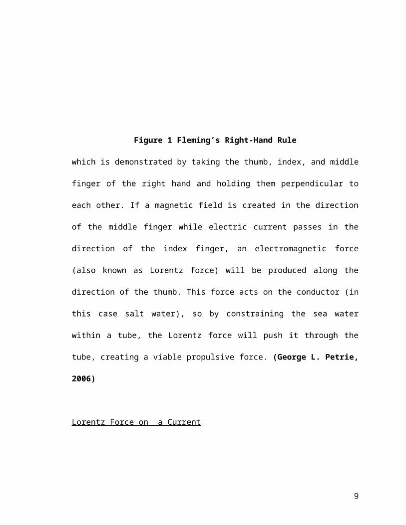
Figure 1 Fleming’s Right-Hand Rule
which is demonstrated by taking the thumb, index, and middle
finger of the right hand and holding them perpendicular to
each other. If a magnetic field is created in the direction
of the middle finger while electric current passes in the
direction of the index finger, an electromagnetic force
(also known as Lorentz force) will be produced along the
direction of the thumb. This force acts on the conductor (in
this case salt water), so by constraining the sea water
within a tube, the Lorentz force will push it through the
tube, creating a viable propulsive force. (George L. Petrie,
2006)
Lorentz Force on a Current
9

An electrically charged particle moving through a
magnetic field feels a force (see Figure 2 below).
Figure 2 Force on a Moving Charge in a Magnetic Field
The force is given by the equation:
where q and v are the particle charge and velocity,
respectively, and B is the applied magnetic field. (Vector
quantities in the text are represented by bold letters.) The
10

resulting force is perpendicular to both the velocity of the
particle and the magnetic field. Its direction may be
determined with the right-hand rule.
In order to harness this force for propulsion, one
simply passes a stream of charges through a magnetic field
and the charges are accelerated. By Newton's third law, the
propulsive force is exactly equal to the force imparted on
the charges. Since more than one charge will be accelerated,
the equation above may be recast by rewriting the term qv
using:
where n is the number of charges (Na+ and CL- ions) per
volume, A and L are the cross-sectional area (given by the
width w times the height H) and length, respectively, of
the water channel (as shown in Figure 3 below).
11

Figure 3 Boat Channel Dimension
The quantity qnAv is then defined as the current I.
This leads to the statement for the force imparted on a
current in the presence of a magnetic field,
The poles of the magnets used are located on the
sides of the magnet and not on the ends. This creates a
magnetic field across the channel and perpendicular to the
current direction. The magnets are oriented along the sides
of the channel as shown in Figure 4 below:
12

Figure 4 Orientation of Magnets
When NaCl salt dissolves in water, it disassociates
into Na+ and Cl- ions. When the salt solution passes through
the channel in the lack of a magnetic field, the motion of
the ions are random. However, in a magnetic field, the Na+
ions generally move towards the negative electrode of the
channel, while the Cl- ions move to the positive electrode.
Using conventional current, there is now an effective
current flowing from the positive to the negative electrode.
The magnetic field is oriented perpendicular to the current,
and so, by Fleming’s right hand rule, a Lorentz force is
exerted on the ions, and thus the water is pushed outwards
through the channel exit (stern). By Newton’s third law, a
13
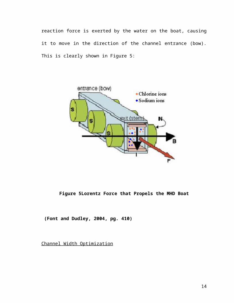
reaction force is exerted by the water on the boat, causing
it to move in the direction of the channel entrance (bow).
This is clearly shown in Figure 5:
Figure 5Lorentz Force that Propels the MHD Boat
(Font and Dudley, 2004, pg. 410)
Channel Width Optimization
14

In order to determine the dependence of the current
on the channel dimensions, it is necessary to examine the
transmission characteristics (i.e. resistances) of an
electrical conductor. The current flowing from the top
electrode to the bottom electrode of the channel can be
expressed in terms of the current density:
where J is the current density (A/m2) and A is the cross-
sectional area ( W) and θ is 0° (so cos θ is equal to 1).
The current density can be written in terms of the electric
field E and the conductivity σ, or resistivity ρ of the
water:
Pure water has a resistivity ρ value of 2. 6 × 10⁵
Ωm, while sea (salt) water has a resistivity of about 0.22
Ωm. It is immediately clear that very little current can be
transmitted through pure water. The electric field E can be
15

approximated by the potential difference across the
electrodes divided by the distance between the electrodes:
Therefore, the current in the channel is given by:
Inserting Eq. (7) to Eq. (3), and assuming that the
current and the magnetic field are perpendicular to each
other, gives the force produced,
where θ is 90° so sin θ is 1. Note that the quantity L in
Eq. (3) is the current path and is equivalent to the height
(H) in this geometry because the current path is vertical.
Therefore, to the first order, the force produced does not
depend on the channel height (H) but increases with longer
16

channels ( ) and wider channels (W). This conclusion is
only valid where the magnetic field is constant along entire
the channel. Any part of the channel that is outside of the
influence of the magnets will not add to the force. In order
to optimize the force, the exact behavior of the magnetic
field strength (B) as a function of magnet separation (W)
must be determined. The optimum width is specific to the
magnets chosen. (Font and Dudley, 2004, pp. 410)
Solubility of Sodium Chloride Salt
Solubility is a characteristic physical property
referring to the ability of a given substance, the solute,
to dissolve in a solvent. It is measured in terms of the
maximum amount of solute dissolved in a solvent at
equilibrium. The solubility of salt in water at 25 ºC is 35
grams NaCl in every 100 grams of water. This value will be
used for this study. The solubility of NaCl is somehow
affected by temperature, as shown in the graph below, but
the effect is insignificant to the study and will not be
17

accounted for because the temperature of the water used in
the experiment remains fairly constant. (Wikipedia, the Free
Encyclopedia)
Figure 6 Effect of Temperature on Solubility of NaCl
18

Chapter 2
PROBLEM AND ITS BACKGROUND
19

Statement of the Problem
This investigatory project aims to establish the
relationship between the speed of an MHD propulsion boat and
salt concentration and to construct a prototype conductivity
meter that can be used to determine the conductivity of a
solution.
Specifically, the study aims to:
1. determine the magnetic strength of the magnets used
in the experiment as a function of separation;
2. determine the optimum dimensions of the MHD boat,
given the set of magnets to be used, that would make
it the most efficient;
3. measure the speed of an MHD boat at the following
salt concentrations:
a. 10% of NaCl saturation concentration
b. 30% of NaCl saturation concentration
c. 50% of NaCl saturation concentration
d. 70% of NaCl saturation concentration
20
e. 90% of NaCl saturation concentration;
4. establish the operational equation for the speed of
the boat as a function of salt concentration; and
5. design a prototype conductivity meter design that
can be used to determine the concentration of an
unknown solution within a certain degree of error.
21

Significance of the Study
As was mentioned in the The Physics Teacher article,
the construction of a magnetohydrodynamic boat would be a
good way to motivate the students. Perhaps one of the
reasons why majority of the students have difficulty in
understanding the concepts in electromagnetism is that the
lessons are quite abstract. Showing an operating system that
embodies these concepts would surely make the students
appreciate the study of Physics more. An inexpensive MHD
propulsion boat could be easily constructed as detailed in
this paper. It would be a good demonstration for concepts on
electromagnetic forces on a current and even basic mechanics
such as Newton’s third law. And since this study concerns
itself with the relationship between the speed of the boat
and the salt concentration of the water on which it operates
on, it could also be used as a supplementary demonstration
for lessons in related topics on electrochemistry,
specifically on ionic disassociation kinematics and water
salinity and conductivity.
22

One of the important measuring equipments used in
Chemistry is the conductivity meter, used to measure the
conductivity (or the resistivity) of solutions. It is
commonly used in hydroponics, aquaculture and freshwater
systems to monitor the amount of nutrients, salts or
impurities in the water. This equipment is unavailable to
most schools, since it is commercialized and rather
expensive. It is possible to construct an inexpensive meter
using a simple circuit. This study aims to design a
prototype conductivity meter using the concepts of MHD laws
and processes. The data collected during the experimentation
for the speed function of the MHD boat will be used to
calibrate the MHD system to serve as a conductivity meter.
This study will hopefully serve as a rich resource
for future researchers like us who develop an interest in
pursuing further studies parallel or more intensive than
what we will accomplish. This study may hopefully trigger
23

more interest on contemporary research fields such as
magnetohydrodynamics.
Hypotheses
There is a direct relationship between the speed of
an MHD propulsion boat and the salt concentration of the
water on which it operates on. The boat would attain higher
speeds in higher concentrations than in lower
concentrations. The maximum speed could be attained at
concentrations just short of saturation. The speed of the
boat could be given as a function of salt concentration. The
data collected during the experimentation for the speed
function of the MHD boat could be used to calibrate the MHD
system to serve as a conductivity meter.
Assumptions
There are a few assumptions that were adopted in the
course of this investigatory project. The temperature of the
24

water used in the experiment is assumed to be constant. The
effect of impurities in the salt dissolved in the water is
assumed to be nonexistent. Room conditions would remain
constant and is uniform in the performance of the trials.
Scope and Limitations of the Study
The dimensions of the constructed MHD boat
(specifically the channel width) for this research are
optimum only for the magnetic field strength of the magnets
used. Any other replication of this experiment using a
different pair of magnets should conduct boat dimension
optimization. The magnetic field strength of the magnets
used in this study does not exceed 0.5 tesla because of the
unavailability of stronger magnets. The voltage used to
power the MHD boat does not exceed 90 Volts (from ten 9-volt
batteries) because placing more batteries may weigh the boat
down and significantly decrease the boat speed. The effect
of the formation of bubbles of hydrogen and oxygen being
liberated through electrolysis as the current passes through
25

the water is beyond the scope of this study and is
unaccounted for. The effect of the corrosion of the metal
electrodes due to the highly reactive chlorine ions in the
salt solution is beyond the scope of this study and is
unaccounted for. The research only deals with the effect of
salt concentration. Effects of other factors such as water
temperature, passage turbulence and others are beyond the
scope of this study and are not included in this study.
Definition of Terms
Boat. This refers to the constructed MHD boat used in the
experiments.
Salt. This refers to the sodium chloride (NaCl) used to
change the salt concentration of
the water on which the boat operates.
MHD. MagnetoHydroDynamic propulsion is a means of propelling
a ship without
moving parts like paddlewheels or propellers. Instead,
MHD relies on passing
26

electrical currents through the water, effectively
turning the water itself into part
of an electric motor, where the only thing that moves
is the water.
Laser System. This refers to the pair of a laser source and
a detector that would be used to
activate the time program used in this study.
Magnets. Permanent magnets, whose magnet poles are located
on the sides, are situated
along the channel to provide the external magnetic
field.
Electrodes. Brass scraps that are situated in the top and
bottom of the water channel,
connected to the battery, to provide voltage across the
water current.
Batteries. These are used as the voltage source for the MHD
boat.
27

Chapter 3
RESEARCH METHODOLOGY
28

Magnet Holder Construction
1. Two (2) pieces of Styrofoam® with a length of 17.00 cm
and a width of 2.8 cm were cut. These served as the
holders for the magnet as well as the sides of the
channel.
2. The shape of the magnets was carved on one side of the
Styrofoam®. It was carved in a way that the magnets
were snugly fit.
3. The depth of the carving was as deep as the thickness
of the magnets. This way, when the magnets were put in
place, it doesn’t protrude out of the hole.
4. Two (2) rulers were cut into pieces with a length of
17.00 cm and a width of 2.8 cm.
29

5. The magnets were then placed in their Styrofoam®
holder, with the north pole facing outward on one, and
the south pole facing outward on the other.
6. The ruler was placed over the magnets to secure them in
place. It was secured to the Styrofoam® holder by means
of masking tape wound around them.
Channel Width Optimization
1. A teslameter was used to take measurements of the
magnetic field strength between the magnets positioned
side by side.
30

Figure 7 Measuring the Magnetic Field Between Two Magnets
2. The magnets, already secured inside their holders, were
separated using rulers whose individual widths were 1
mm.
3. The first separation distance (W) was 7 mm, and taking
the width of the rulers on the holders, this was
achieved by inserting five rulers between them. The
measurements were done at distance of 2 mm, 4 mm and 6
mm from the north pole of one of the magnets. This was
done by removing the first, third and fifth separator
ruler, respectively, and placing the axial probe of the
teslameter in its place.
31

4. The second separation distance (W) was 11 mm, and
taking the width of the rulers on the holders, this was
achieved by inserting nine rulers between them. The
measurements were done at distance of 2 mm, 4 mm, 6 mm,
8 mm and 10 mm from the north pole of one of the
magnets. This was done by removing the first, third,
fifth, seventh and ninth separator ruler, respectively,
and placing the axial probe of the teslameter in its
place.
5. The third separation distance (W) was 15 mm, and
taking the width of the rulers on the holders, this was
achieved by inserting 13 rulers between them. The
measurements were done at distance of 2 mm, 4 mm, 6 mm,
8 mm, 10 mm, 12 mm and 14 mm from the north pole of one
of the magnets. This was done by removing the first,
third, fifth, seventh, ninth, 11th and 13th separator
ruler, respectively, and placing the axial probe of the
teslameter in its place.
32

6. The fourth separation distance (W) was 19 mm, and
taking the width of the rulers on the holders, this was
achieved by inserting 17 rulers between them. The
measurements were done at distance of 2 mm, 4 mm, 6 mm,
8 mm, 10 mm, 12 mm, 14 mm, 16 mm and 18 mm from the
north pole of one of the magnets. This was done by
removing the first, third, fifth, seventh, ninth, 11th,
13th, 15th and 17th separator ruler, respectively, and
placing the axial probe of the teslameter in its place.
7. The data gathered from the measurements were summarized
into Table 1.
8. Using Microsoft Excel 2003, the magnetic field strength
values were graphically displayed as the magnet
separation is increased.
9. The average magnetic field as a function of the
distance between the magnets was determined by curve-
fitting and integrating the results.
33

10. The magnetic fields were given in teslas and the
separation in meters in order to allow substitution for
the magnetic field strength (B) directly into equation
8 (see Theoretical Background for the derivation):
11. The curvefit for the results of no. 8 were
inserted to the above equation in order to yield an
empirical force function of F that is proportional to a
function of W.
12. The resultant function F versus magnet separation
W was graphed. The value of the Vbattery used is equal to
the resultant voltage output of the nine 9-volt
batteries in series used as the voltage source for the
boat (around 70 volts). Actual Vbattery was measured
using a voltmeter. The resistivity used was the same as
the resistivity of sea (salt) water of 0.22 m. The
value of was the water channel length (17.00 cm).
34

13. From the graph, the optimum separation width
between the magnets was determined.
Construction of the MHD Boat
1. The size of the boat is chosen such that it was large
enough to float the battery stack, composed of nine 9-
volt batteries connected in series. The hull of the
boat was made up of Styrofoam®.
2. The water channel length ( ) was as long as the boat,
approximately equal to the length of the magnets magnet
holders (17.00 cm).
3. The channel height (H) was chosen to match the height
of available magnets plus the thickness of the
electrodes (2.80 cm).
4. The channel width (w) was given by the process of
optimization, as derived in the previous section of
35

this methodology (found to be 1.97 cm, as shown in the
next chapter.
Figure 8 Water Channel Dimensions
5. The water channel was constructed using the dimensions
specified in nos. 2 to 4. Brass strips 17.00 cm long
and 1.76 cm wide were used as electrodes, and were
placed at the top and bottom of the channel. The
electrodes were secured using pieces of rulers.
36

6. Three (3) pieces of Styrofoam® (17.00 cm by 17.00 cm)
was cut and was held together on top of each other by
means of the double-sided tape. This would serve as the
hull of the boat.
7. A gap 17.00 cm long, 5.96 cm wide and 2.80 cm deep was
carved on the underside of the stacked Styrofoam®.
8. The channel was then inserted and secured inside the
gap.
9. The batteries were connected in series and laid on the
hull.
10. Heavy-gauge connecting cables were used to connect
the top electrode to the positive terminal of the
battery stack and the bottom electrode to the negative
terminal.
37

11. A “flag” was placed near the front of the boat. In
this case, a marker pen was used as the flag. Its width
was measured using a Vernier caliper and was then
recorded.
Research Set-up
1. A glass aquarium (with the dimensions 60 cm by 120 cm)
was used for this experiment.
2. The aquarium was filled with 14 liters of distilled
water, sufficient to float the boat. The waster was
measured using a volumetric flask.
3. Using a compass, the direction of the magnetic north
pole was determined. The aquarium was positioned
perpendicular to this direction. This was to align the
magnetic polarity of the boat with the magnetic field
of the earth.
38

4. A laser source was positioned on one side of the
aquarium. A laser sensor/detector was positioned on the
other side. The laser source and sensor were situated
well above the surface of the water, but not over the
height of the boat’s flag.
5. The light sensor was connected to the Phywe digital
counter. The counter was set to the timer function and
at the last trigger. This was so that the timer will
start when the laser is intercepted, and stops when the
laser signal is resumed.
39
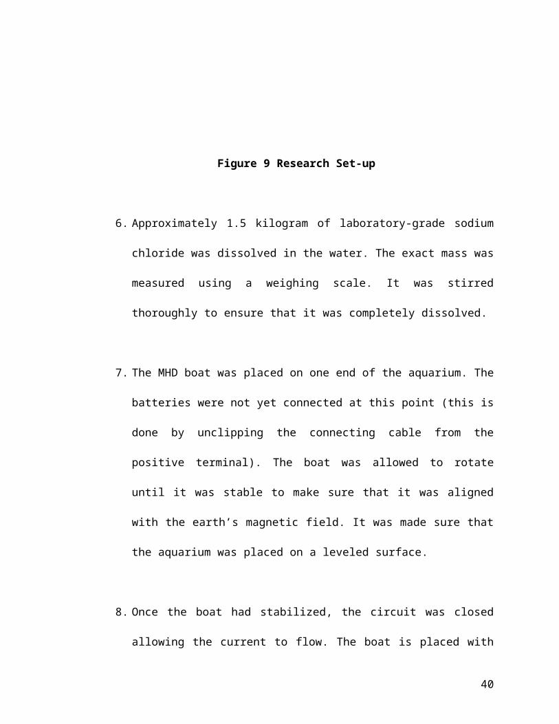
Figure 9 Research Set-up
6. Approximately 1.5 kilogram of laboratory-grade sodium
chloride was dissolved in the water. The exact mass was
measured using a weighing scale. It was stirred
thoroughly to ensure that it was completely dissolved.
7. The MHD boat was placed on one end of the aquarium. The
batteries were not yet connected at this point (this is
done by unclipping the connecting cable from the
positive terminal). The boat was allowed to rotate
until it was stable to make sure that it was aligned
with the earth’s magnetic field. It was made sure that
the aquarium was placed on a leveled surface.
8. Once the boat had stabilized, the circuit was closed
allowing the current to flow. The boat is placed with
40

its flag approximately 5cm from the laser beam to allow
it to reach its terminal velocity.
9. After the timer was triggered and stopped, the time
displayed on the digital counter was recorded.
10. Procedures 7 to 9 are repeated twice to get a
total of three trials.
11. The salt solution was then thrown away. The
aquarium was cleaned thoroughly, and 14 liters of
distilled water was added. Approximately two (2)
kilograms of laboratory-grade sodium chloride was
dissolved in the water. The exact mass was measured
using a weighing scale. It was stirred thoroughly to
ensure that it was completely dissolve.
12. The salt solution was then thrown away. The
aquarium was cleaned thoroughly, and 14 liters of
distilled water was added. Approximately 2.5 kilograms
41

of laboratory-grade sodium chloride was dissolved in
the water. The exact mass was measured using a weighing
scale. It was stirred thoroughly to ensure that it was
completely dissolve.
13. The salt solution was then thrown away. The
aquarium was cleaned thoroughly, and 14 liters of
distilled water was added. Approximately three (3)
kilograms of laboratory-grade sodium chloride was
dissolved in the water. The exact mass was measured
using a weighing scale. It was stirred thoroughly to
ensure that it was completely dissolve.
14. The salt solution was then thrown away. The
aquarium was cleaned thoroughly, and 14 liters of
distilled water was added. Approximately 3.5 kilograms
of laboratory-grade sodium chloride was dissolved in
the water. The exact mass was measured using a weighing
scale. It was stirred thoroughly to ensure that it was
completely dissolve.
42

15. The speed of the boat is calculated by dividing
the distance d by the time it took for the boat to
travel across. The average speed of the boat at every
concentration is calculated.
16. All data gathered was summarized in Table 2.
43

Chapter 4
PRESENTATION, ANALYSIS AND INTERPRETATION OF DATA
44

0
0.02
0.04
0.06
0.08
0.1
0.12
0 0.005 0.01 0.015 0.02y (m )
B (te
sla) W = 7 mm
W = 11 mmW = 15 mmW = 19 mm
Channel Width Optimization
Shown below is the data gathered from the
measurements of the magnetic field strength between the
magnets used in the boat channel. The averages of the field
strengths for every magnet separation (W) are also shown.
Table 1Magnetic Field Strength Between Magnets (T)
MagnetSeparation (W)(mm)
Distance from the North Pole of One Magnet (y) (mm)
2.00 4.00 6.00 8.00 10.00 12.00 14.00 16.00 18.00 Average
7.00 0.1016
0.0941
0.0907 0.095
511.00 0.094
40.0828
0.0713
0.0701
0.0737 0.078
515.00 0.086
90.0680
0.0594
0.0555
0.0536
0.0548
0.0590 0.062
519.00 0.083
30.0612
0.0535
0.0469
0.0452
0.0435
0.0435
0.0461
0.0533
0.0529
The magnetic field strengths (B) are graphed against
the distance from the north pole of one magnet (y) for every
separation (W).
45

0
0.02
0.04
0.06
0.08
0.1
0.12
0 0.005 0.01 0.015 0.02W (m )
Averag
e (T)
Figure 10 Magnetic Field Strength between Magnets
As shown in the graph, the magnetic field strength
decreases as the distance from the north pole increases, and
increases back again as it becomes closer to the south pole
of the other magnet. This is due to the square inverted
relationship between magnetic field strength and distance.
The average magnetic field is then graphed against
the magnet separation (W).
46

Figure 11 Average Magnetic Field Strength as a Function of
Magnet Separation
Using Microsoft Excel, the equation of the trend line
of the above graph is found to be:
47

00.0050.010.0150.020.0250.030.0350.040.045
0 0.005 0.01 0.015 0.02 0.025W idth separation (W )
Norm
alized Force
The average magnetic field decreases almost inversely
proportional to distance. Inserting this equation of the
trend line to Eq. 8 (derived in the Theoretical Background)
yields an empirical force function that is proportional to a
cubic function of W:
The function F versus magnet separation W is graphed
below. The value used for Vbattery is 70 volts, value of was
17.00 cm and the value of ρ is that of seawater which is
0.22 Ωm.
48

Figure 12 Normalized Force as a Function of Magnet
Separation
The results show that an optimum does indeed exist.
As the magnet separation increases from zero, the force also
increases. It must increase because the conducting area is
increasing (see Eq. 4). The result is that maximum is
reached between 19 and 20 mm, after which the force
decreases due to the diminishing magnetic field.
The exact value of this maximum point can be
determined by applying the first derivative to the above
graph’s trend line. The equation of the curve fit is:
49
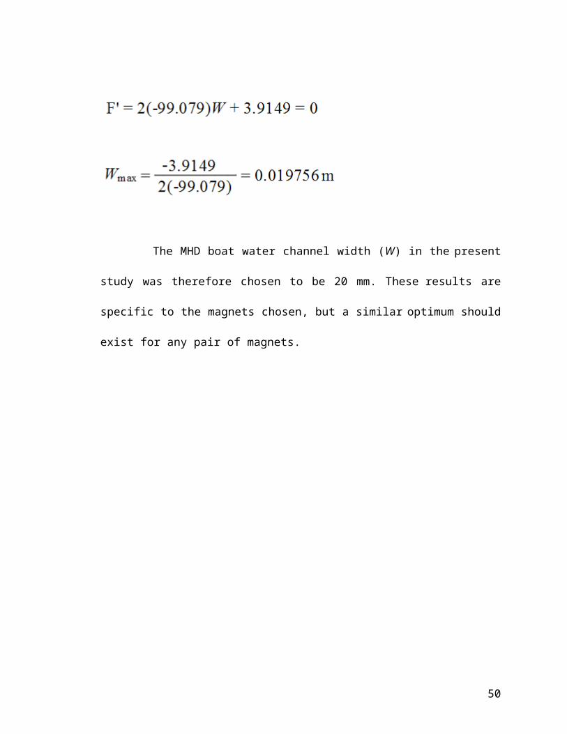
The MHD boat water channel width (W) in the present
study was therefore chosen to be 20 mm. These results are
specific to the magnets chosen, but a similar optimum should
exist for any pair of magnets.
50

Data Presentation and Analysis
Shown below is the data gathered from the research
set-up.
Table 2 Time of Travel of MHD Boat at Different Concentrations
Mass ofNaCl(kg)
Volumeof
Water(L)
CalculatedConcentration (kg/L)
Time of Travel (s) Distance
Travelled(cm)
Calculated Speed(cm/s)
1stTrial
2ndtrial
3rdtrial
Average
1.5001 14 0.1071526.35
25.74
25.96 26.02 1.53 0.0588
1.99949 14 0.1428217.56
17.11
18.12 17.60 1.53 0.0869
2.4987 14 0.1784813.38
14.52
13.54 13.81 1.53 0.1108
3.0059 14 0.2147111.24
11.84
11.69 11.59 1.53 0.1320
3.6165 14 0.2583212.83
13.25
13.66 13.25 1.53 0.1155
The mass of the NaCl dissolved for every solution was
measured by a weighing scale. The volume was measured
accurately using a volumetric flask. The concentration was
determined by dividing the mass of dissolved salt in
kilograms by the volume of water in liters. The data for the
three trials for the time of travel were taken from the
51

0
0.02
0.04
0.06
0.08
0.1
0.12
0.14
0 0.05 0.1 0.15 0.2 0.25 0.3Concentration (kg/L)
Speed (cm/s)
digital counter. The average of the three data for each set
is also determined. The distance traveled during the time
interval measured is equal to the diameter of the “flag” as
measured by a Vernier caliper. The speed is calculated by
dividing the distance traveled in centimeters by the time of
travel in seconds.
The relationship between the speed of the MHD boat
and the concentration of the salt solution on which it runs
on can be easily seen if we look at it graphically, as is
shown below:
52

Figure 13 Speed of MHD boat as a Function of Salt
Concentration
As is clearly shown by the trend line (red), there is
a parabolic relationship between the speed of the MHD boat
and salt concentration. As the concentration increases from
zero, the maximum speed the boat could attain rapidly
increases. However, when the concentration reaches a certain
point, the increase in speed stops. If the concentration is
increased further, the maximum speed attainable by the boat
decreases.
The concentration which is the maximum point of the
graph can be determined by applying the first derivative to
the above graph’s trend line. The equation of the trend line
(with a coefficient of variation r2 of 0.9655) is found to
be:
53

where S is the speed of the boat in cm/s while C in the salt
concentration in kg/L. Getting the first derivative and
equating it to zero, we have:
The boat is able to attain its maximum speed at a
salt concentration of 0.22395 kg/L. This concentration is
the same as dissolving 3.1353 kilograms of salt in 14 liters
of water. For a point of reference, it requires 4.90
kilograms to completely saturate 14 liters of distilled
water.
54

Chapter 5
FINDINGS, CONCLUSIONS AND RECCOMENDATIONS
55

FINDINGS
1. The optimum channel width for the magnets used for
this experiment was determined to be 0.19756 meters,
or 1.9756 centimeters.
2. This is wider than the channel width of the MHD boat
in the Physics Teacher article because the magnet
that they had has a stronger magnetic field than
what we used. Since the force produced is
proportional to the current flowing between the
electrodes, and that from Eq. 4 (shown in the
Theoretical Background) we can see that the current
is proportional to the cross-sectional area ( W), a
smaller magnetic field would need a wider separation
for optimum force. As was noted, As the magnet
separation increases from zero, the force also
increases. It must increase because the conducting
area is increasing. The average magnetic field is
56

decreasing, but not as fast as the conducting area
is increasing.
3. There is a parabolic relationship between the speed
of the MHD boat and salt concentration. As the
concentration increases from zero, the maximum speed
the boat could attain rapidly increases. However,
when the concentration reaches of 0.22395 kg/L, the
increase in speed stops. If the concentration is
increased further, the maximum speed attainable by
the boat decreases.
4. The relationship between the speed and concentration
could be expressed in the equation S = -5.0246C2 +
2.2505 – 0.1275, where S is the speed of the boat in
cm/s while C in the salt concentration in kg/L.
5. This parabolic relationship could possibly be
explained by the following (it could just be one or
an interplay of the three):
57

a. At higher concentrations (beyond the optimum of
0.22395 kg/L), the corrosion of the brass
electrodes with the reactive chloride ions
becomes very rigorous because of increased
electric current. This may cause material from
one brass strip to be electroplated into the
other, decreasing current in the process.
b. There is also a noticeable discoloration of the
solution when the boat operates on solutions of
higher temperature. The introduction of new
solutes (quite certainly from the brass
corrosion) may affect the amount of current,
and thus the speed of the boat.
c. At higher concentrations, a lot more bubbles
are formed by the electrolysis of water into
oxygen and hydrogen gas. The rapid evolution of
gas can cause water turbulence inside the
58

channel, hindering the propulsion of the water,
and thus effectively decreasing the speed of
the boat.
d. There is no direct correlation between
conductivity and salt concentration. It doesn’t
follow that if you increase the concentration,
the conductivity of the solution also
increases. We found no literature that shows
correlation between them at concentrations
higher than that of sea water.
CONCLUSION
Constructing an MHD propulsion boat for classroom
demonstration is not as easy and inexpensive as the article
from The Physics Teacher claims it to be. The hardest part
is finding a strong enough magnet, and that magnet should
have the correct orientation for it to work.
59

The channel width optimization is a tedious process.
From it, we had learned that although the magnetic field
decreases if the separation between the magnets increase, it
doesn’t follow that a weaker magnet would require you to
have narrower channel. Rather, it is quite the reverse, in
that you’d need a wider channel to increase the conducting
area.
There is also the nature of the MHD boat to align the
polarity of its magnets to the polarity of the Earth’s
magnetic field. For MHD to be a viable alternative means of
propulsion of sea-going vessels, something must be done to
circumvent this tendency to go off course. Also, new
material must be used as the electrodes, since the brass
ones would be corroded by chloride ions. Further, very
strong magnetic fields and electric source are required,
since the concentration of sea water is well blow the
optimum concentration for a MHD propulsion vessel to attain
its maximum velocity.
60

Lastly, the boat constructed could not be used to
design a device to determine the concentration of an unknown
solution. This is due to the parabolic relationship between
boat speed and concentration. The device would not be able
to distinguish an increase or decrease of concentration from
0.22395 kg/L.
RECOMMENDATIONS
For further study, the researchers recommend the
following:
Find stronger magnets of the correct orientation,
preferably in bar shape so that there’d be more uniform
magnetic field across the channel, giving you more
accurate results.
For those who want to try something more sophisticated,
you could increase the number of water channels and see
if the speed of the boat would be greater.
61
Use another material for the construction of the boat
hull. The Stryrofoam® that we used in this experiment
is advantageous in that it allows the boat to stay
afloat. However, it is highly unstable. You could use
polystyrene plastic or any other material.
You could increase the voltage source of the boat by
adding more batteries to the power source stack.
Instead of using brass as the electrodes, you could
also use other metals that are more resistant to
corrosion.
If you opt to use a power supply as your source, you
can have the MHD device in conjunction with a flow-
meter to have more accurate results.
If you could find a conductivity meter capable of
measuring conductivities of salt solutions with high
concentrations, you could attempt to establish the
relationship between the conductivity and boat speed.
62