a description and comparison of national specification systems
206
REPORT 1 A DESCRIPTION AND COMPARISON OF NATIONAL SPECIFICATION SYSTEMS A report for the International Construction Information Society Edited by Colin D McGregor BA BArch RIBA NBS Services Representative to ICIS June 2001 © International Construction Information Society 2001 All world rights reserved
-
Upload
khangminh22 -
Category
Documents
-
view
1 -
download
0
Transcript of a description and comparison of national specification systems

REPORT 1A DESCRIPTION AND COMPARISON
OF NATIONAL SPECIFICATION SYSTEMS
A report for theInternational Construction Information Society
Edited by Colin D McGregor BA BArch RIBANBS Services Representative to ICIS
June 2001
© International Construction Information Society 2001All world rights reserved

ICIS Report 1
ICIS Report 1: A description and comparison of national specification systems 6/01 1 of74Copyright ICIS 2001 All world rights reserved
A DESCRIPTION AND COMPARISON OF NATIONALSPECIFICATION AND COST ESTIMATING SYSTEMS
CONTENTS
THE REPORTIntroductionSome conclusions and propositionsTypes of specification systemGeneral scope of the specification systemsClassification and structuring of the specification systemsWho uses the specification systems and howHow the specification systems are maintainedThe use of proprietary referenceGuidance for users of the specification systemsThe use of computersLinks with other documentsScale of useLegal and contractual backgroundEnvironmental issues affecting the National Specification
APPENDICESA Contents and examples of the Australian NATSPEC systemB1 Contents and examples of the Canadian NMS systemB2 Contents and examples of the Canadian Digicon SpecSUITE systemsC Contents and examples of the Czech Republic systemD Contents and examples of the Finnish systemE Contents and examples of the German StLB systemF Contents and examples of Japanese specification systemsG Contents and examples of the Netherlands STABU and RAW systemH Contents and examples of the New Zealand Specification SystemI Contents and examples of the Norwegian Standard Specification SystemJ Contents and examples of the Swedish AMA83 and RA83K Contents and examples of the United Kingdom NBS and NES systemsL Contents and examples of the USA MASTERSPEC system

ICIS Report 1
ICIS Report 1: A description and comparison of national specification systems 6/01 2 of74Copyright ICIS 2001 All world rights reserved
INTRODUCTION
BACKGROUND
This report is a survey of the specification systems of fourteen members of the International ConstructionInformation Society (formerly known as the Building Specification Group – BSG) representing the followingcountries:
AustraliaCanadaCzech RepublicFinlandGermanyJapanNetherlandsNew ZealandNorwaySwedenUnited KingdomUnited States of America.
It is the outcome of proposals made at the concluding session of the BSG Conference held at Durham, UnitedKingdom, in September 1990. It was proposed that two groups be formed to report on the following subjects:• A description and comparative analysis of the group members’ specification systems• Specification techniques.
At the start of work it was realised that there was a considerable overlap between these two subjects, making itimpractical to clearly define the scope of each. As a result the two groups and subjects were combined.
The merged group held three meetings – November 1991, March 1992 and June 1992. To make the process ofanalysis manageable it was decided at the first meeting to start the study by issuing a questionnaire to members of theBSG. Its purpose was to discover:• The different contractual arrangements used in each country• For each type of contractual arrangement, what types of project document are used• When they are produced and who produces them• When they are used and who uses them.
The questionnaire was in the form of a matrix to enable easy comparisons between the different responses. Howeverit proved difficult to analyse in any meaningful way because of differences in interpretation of the document names.It had been hoped that the questionnaire would reveal similarities and differences in contracting practice that wouldenable groupings of countries with similar approaches, but this was not possible.
At the second meeting it was decided to continue the study by concentrating on a more limited range of projectdocuments. A second questionnaire was produced to obtain descriptions of the various documents in a structuredform and descriptions of the group members’ specification systems. This questionnaire was much more informativethan the first and has provided the main input to this report.
The report was first presented to the BSG Conference in Stockholm, Sweden, in September 1992. It has since beenexpanded and revised, and is now published under the group’s new name. This is the fifth revision with changesbeing made to the contributions from Australia, Canada, Finland, New Zealand and the United Kingdom. One newmember has been added – Digicon Information Inc of Canada – and one former member has been removed –Switzerland. There are two probationer members for whom reports are not yet included – Cobosystems, Belgium andUEOS-Komercia Bratislava of Slovakia.

ICIS Report 1
ICIS Report 1: A description and comparison of national specification systems 6/01 3 of74Copyright ICIS 2001 All world rights reserved
THE REPORT
Rather than describing each system in turn, the report considers each one under a series of headings to enable moredetailed comparisons to be made. The amount and type of information given under a heading for a system variesaccording to what and how much was provided.
The level of analysis is inevitably superficial. However, to acquire the necessary information to give greaterunderstanding of the systems would require a great deal of time and effort. It is questionable whether the end resultwould be worth it. Perhaps the report should be accepted for what it is – a general overview of specification systems– and used as a starting point for developing other more detailed areas of study, for example, classification; thenature of specification; definitions of industry sectors, user types, etc.
SOME CONCLUSIONS AND PROPOSITIONS
DIFFERENCES AND SIMILARITIES
To get an overview of the differences and similarities of the systems under review we have concentrated on thefollowing aspects:• Scope• Contents• Structure.
Some other aspects which are part of the environment in which the systems operate and which influence theirdevelopment have also been examined.
ScopeThis can be considered in two ways. The first concerns the overall scope of the system, that is, which types ofconstruction work does it cover? An overview of this is given in table 2. Most of the systems (in combination wherethere is more than one national organisation producing specifications) appear to be generally comprehensive in theircoverage. However it has been beyond the resources of the Working Group to determine whether this really is so andhow the depth coverage of each category of work differs between the specification systems.
The second consideration concerns the phases of the construction process in which the systems are used. Theconstruction process can roughly be divided into:• The inception phase• The design phase• The production phase.
During the lifetime of the building these phases may be repeated, as in maintenance projects, renovation, restorationand demolition. Also facility management may use some of the information produced during the constructionprocess.
The phases in the construction process covered by the specification systems are very much dependent on the relatedcontracting procedures and methods of tendering. Most tendering takes place at the end of the design phase and inmost systems the emphasis is on specifications for this type of contract. However, other types of contracts have beenintroduced, such as “design and build” which are initiated earlier in the construction process. Specifications have tofollow this trend and this development can be seen, for example, in the increasing use of performance specification.In the other direction there is more interest in using information produced during the construction phase in facilitymanagement. These two trends are widening the scope of specification systems. Differences between the systemsinvestigated in this report are at their greatest in this respect.
ContentsA related question is the scope and content of the specification systems and the level of detail which they contain.We know at this stage that most organisations produce and maintain libraries of descriptions, but have been unable tocompare their comprehensiveness and degree of detail. Nor have we been able to establish what the average detail of

ICIS Report 1
ICIS Report 1: A description and comparison of national specification systems 6/01 4 of74Copyright ICIS 2001 All world rights reserved
project specifications is in the various countries and how much the project specifications incorporate informationdirectly or by reference to standards.
As a consequence of specifications mainly being used with “conventional” contracts, all of the systems have beendeveloped to specify items of work. With other types of contractual arrangement and for facilities management thismode is often inappropriate. Specifications at the inception phase or at the beginning of the design phase cannot bebased on work sections. Instead the performance criteria of spaces and elements must be specified. Not all of thesystems have the ability to do this and those which have seem to differ substantially in the way they do it.
StructureAll of the systems include “items of work” specifications and therefore are structured by work sections. For somesystems this is the only structure. Others include other classifications like elements, trades and products.Specification systems with a single structure are hierarchical, those with combined structures are faceted or based ona relational model.
Most systems use a word processor environment, which means that a “delete unwanted text” or “cut and paste”technique is used to produce project specifications out of library specifications. In the word processor environment itis (nearly) impossible to use the contents of the specifications in an automated way; the information is onlyinterpretable by humans. One system uses a relational database technique. In relational systems bits of informationcan have a meaning understood by the computer by defining attributes and possible ranges of values so that theinformation to be interpreted by the system and processed without human intervention.
PROPOSALS FOR CONTINUED WORK
Much information has been gathered from the two questionnaires and this report contains only some of the possiblecomparisons. The exercise has revealed that there is a lot of work still to be done.
It seems clear that there is much overlapping of the work done by each organisation. The main field of overlap seemsto be the structure of information and the use of classifications in that structure. Cooperation in this field could beone of the outcomes. It must be admitted however that fundamental differences exist between systems based on asingle classification table and systems based on faceted tables or relational systems. There is also a big differencebetween a text-based (word processor) environment and a relational database environment. Nevertheless, this seemsthe most common field of interest.
Another common field of interest could be the contents of the specifications related to the different types ofspecifications (performance/prescription, description/by reference). This would involve further investigation on whatshould be specified and how it should be specified. This could imply setting up common sets of specificationattributes. A related area to this is quality assurance, which is already a common point of interest on the Europeanlevel.
The possibilities for continued work are of such a scale that one or more working groups would have to spend muchtime on them. Therefore a discussion is needed on the most important priorities, the status of the working groups, thestatus of the information, the possible use of the information and the financing of the work.

ICIS Report 1
ICIS Report 1: A description and comparison of national specification systems 6/01 5 of74Copyright ICIS 2001 All world rights reserved
TYPES OF SPECIFICATION SYSTEM
The specification systems considered in this report differ in purpose and method of use. Some are concerned mainlywith the principal purpose of defining the quality of the building whereas others are intended mainly to producepricing documents. The basic types of specification system are:
• Standard descriptions intended to be reproduced in the project documents. With this method the projectspecification is a complete statement of the qualitative requirements for the building.
• Standard specifications to which reference is made from the project documents. In this case, the contractors mustpossess and refer to the standard specifications in order to know the all the project requirements.
Table 1 broadly categorises each of the national systems.
Table 1
Aus Can CzR Fin Ger Jpn Neth NZ Nor Swed UK USA
Library of descriptions of quality
Standard reference descriptions of quality
Library of descriptions for pricing
THE AUSTRALIAN SPECIFICATION SYSTEM - NATSPEC
Construction Information Systems Australia Pty Ltd is a not-for-profit organisation founded in 1975, which hastwenty leading building industry organisations as its shareholders. The company’s primary function is to develop,produce and maintain the national building specification, NATSPEC.
NATSPEC is a simple, generic, subtractive system. That is, generally only one version of a clause or subclause isoffered (it is simple), there are no clauses specifying proprietary products (it is generic), specifiers start with fullprototype work sections and are therefore expected to delete text not required (it is subtractive).
There are a number of NATSPEC specification packages: NATSPEC BASIC is for simple building projects wherebrevity is a priority; NATSPEC BUILDING is for more complex projects, and is NATSPEC’s definitivespecification; NATSPEC SITE+STRUCTURE is for civil engineering and landscaping work; NATSPEC SERVICEScovers hydraulic, fire, electrical and mechanical installations; and NATSPEC DOMESTIC is for individual houses.
Each package consists of NATSPEC Templates, which combine text and prompts for the preparation of one-partspecifications, and a Commentary, which supplements the NATSPEC material and gives guidance on how to edit andcustomise text for specific projects. The Templates and Commentary are published in loose-leaf form andelectronically on CD (known as the NATSPEC//TOOLBOX). Core NATSPEC template text is published annually asa book called NATSPEC Reference – the national building and services reference specification.
Subscribers receive twice-yearly updates in print and on CD. NATSPEC word processing files are downloaded fromthe CD, and a searchable version in Adobe Acrobat .pdf format is also provided. Subscribers also receive anIntroduction including references to NATSPEC source material, a quarterly newsletter SPECnews, and the licence toreproduce NATSPEC material in their project specifications over the subscription period of a year.
As well as traditional technical work sections, CIS provides worksections on tendering, preliminaries mainly quasi-contractual material, package definitions for coordination of multiple-prime contracts, quality assurance and generalor common trade requirements e.g. format of maintenance manuals.
Technical work sections on vertical and horizontal transportation systems are proposed. Roads and earthworks arecovered in the current material. Civil hydraulic codes similar in style to NATSPEC have been written by the WaterServices Association of Australia (WSAA, formerly AWAQAN). The Department of Public Works and ServicesNSW (DPWS) has recently published WS-SPEC Water Services Specification again in NATSPEC style.

ICIS Report 1
ICIS Report 1: A description and comparison of national specification systems 6/01 6 of74Copyright ICIS 2001 All world rights reserved
THE CANADIAN SPECIFICATION SYSTEMS – NMS
The National Master Specification (NMS) is produced by the Government of Canada (the NMS Secretariat). TheNMS was developed and first introduced in Canada in the latter part of the 1970s and has been refined and updatedsince by participating federal agencies. The NMS is available in both English and French versions.
The NMS system is referred to generically, as a "master specification" and offers model technical text to be used bydesign consultants when preparing specification documents for their projects.
The NMS currently consists of 628 individual work sections, which together comprise a single master system. Theselection of work section titles are based on the highest level of detail which may be required for any project; lowerlevels of detail are achieved through text editing of the individual work sections.
The NMS is used extensively across Canada by design consultants who do work for the federal government as wellas work in the private sector. The NMS system generally follows the Manual Of Practice published by CSC withmodifications.
The NMS is published by three independent organizations; Construction Specifications Canada (CSC), DigiconInformation Inc., and Infoconstruction.com. Each publisher produces the text in their own manner.
Construction Specifications Canada (CSC) provides NMS text in multiple formats; as common word processingformats (WordPerfect, Word, Ami Pro, and ASCII), and as a proprietary format compatible with a dedicated editingsoftware called NMS Edit Plus.
Digicon Information Inc. currently offers NMS text in Word and WordPerfect file formats. Word processor macrosoftware is included with each package, to aid specifiers in the more laborious tasks such as producing tables ofcontents and changing document headers and footers. Shortly, Digicon will be including NMS text into the newdatabase interface being introduced in 2001.
THE CANADIAN SPECIFICATION SYSTEMS – SPECSUITEThe SpecSUITE family of master documents is produced by Digicon Information Inc., and used extensively acrossCanada by design consultants who do work for both government and private sector projects.
SpecSUITE can be generically described as "master specification systems" and offers model or template technicaltext to be used by design consultants when preparing specification documents for their projects. Some of thespecification subjects within the packages may also be used by facility managers and public agencies who areinvolved in renovation, retrofit, and facility maintenance programs.
SpecSUITE is the name used to describe the family of related specification documents developed and marketed byDigicon; each sub-document has specific uses or is required at different phases of a project.. SpecSUITE consists of:• Canadian Master Specification (CMS): the largest and most complete system of master specifications for any
size project• MiniSPEC: specification for small commercial or multi-residential construction• OutlineSPEC: specification for documenting early design stage decisions• RenoSPEC: a collection of restoration work sections, used with MiniSPEC or CMS• MasterPP: a “project prospectus” document, which documents early project requirements
The CMS portion of SpecSUITE has been available since the mid-1970s, and the others have been added to thefamily since then.
All documents are provided to industry as word processing documents, in WordPerfect or Word format. Digiconprovides its customers with a suite of macros to automate editing tasks.
The various SpecSUITE sub-documents are intended to be compatible with each other, to help solve some of the“document flow” problems expressed in the ICIS issues paper “Project Information and Document Flow” written byWayne Watson.

ICIS Report 1
ICIS Report 1: A description and comparison of national specification systems 6/01 7 of74Copyright ICIS 2001 All world rights reserved
New Digicon Products
Recently, Digicon is supplementing the traditional specification products in Canada with two more specification-oriented products. These are:• Publishing the National Master Specification (NMS) described elsewhere in this report• Specnique – a new database approach to preparing specifications, utilizing the existing text from the traditional
products
Specnique, a new Database Product
Digicon is developing a long-planned conversion from word-processing to database technology for editing ofspecifications. The interface will use Microsoft Access database storage format. The database software will bepopulated with master specification text currently published by Digicon to create a unique new product. The newproduct has been named "Specnique", and the release date for the first phase (implementing the current DigiconMiniSPEC text) is estimated for release in mid- 2001.
Eventually, Digicon plans to implement a system where all Digicon text bases are all offered as word processingfiles, or in a database format. Subscribers purchase a license to the specification text, and may choose either wordprocessing format or database format compatible with the Specnique interface. Whichever specification product theychoose is simply added to Specnique as a library module.
Digicon sees this new product as a logical step toward the future, leading existing users (who currently using wordprocessors to generate their specifications) toward the concept of using a database application for the task, AND witha direct move towards using the concept of Lexicon “objects” under development by ICIS. It is Digicon’s hope thatthe power and reliability of the database software over traditional word processing tools (which are inherentlyunreliable), will entice users to seriously consider switching.
THE CZECH REPUBLIC SPECIFICATION SYSTEM
Using a uniform specification system in the Czech Republic has a long tradition. The system was developed andupdated in URS Praha, in the period of applying a central model for managing the State economy. This system wasobligatorily used by all participants of the process of investment construction and it was utilized for constructionrepairs and maintenance, i.e. throughout the lifetime of the construction work.
The specification system, which had been recently used, became the basis for the system which is currently beingused in the Czech Republic. The parts of the system are:• Catalogues of Descriptions and Directive Prices for Construction Work• Catalogues of Descriptions and Directive Prices for Assembly Work• Transactions of Prices of Material for Construction published by URS Praha a.s.
These catalogues allow the exchange of information between the Technical designer, Investor and the Supplier.
The above stated catalogues, which make the frame for the specification system, are being amended by a number ofother elements and bases (sets), which constitute together “The System of Price Bases and Information URS Praha”.Among these other elements and bases belong, e.g.• Transactions for needs and costs of construction work• Offered aggregated prices• Catalogue of functioning parts for construction properties• Budget indicators of construction properties• Indicators of average orientation Price for measured unit and purpose-made unit
• Classifier of construction structures and work• Descriptor of construction work, etc.

ICIS Report 1
ICIS Report 1: A description and comparison of national specification systems 6/01 8 of74Copyright ICIS 2001 All world rights reserved
THE FINNISH SPECIFICATION SYSTEM
The Finnish specification system is produced by The Building Information Foundation. It consists of two maindocument groups• Reference specifications: RYL (Building works)
LVI-RYL (Mechanical)Sähkö-RYL (Electrical)
• Project specification writing guides
The RYL documents are generally considered to be a representation of good building practice and can thus beinvoked by reference in project specifications.
The project specification writing guides are systematic lists of priceable specification items. Every item has anumeric code, a full text heading, a short guidance and a list of applicable RYL clauses and product standards.
THE GERMAN SPECIFICATION SYSTEM – STLB
Although there are several specification systems available in Germany, the ‘Standardleistungsbuch für dasBauwesen’ (StLB – ‘The Standard Library of Descriptions of Building Works’) is the most comprehensive andtechnically reliable, and can be regarded as a national standard. The StLB is prepared by the ‘GemeinsamenAusschuß für Elektronik im Bauwesen’, GAEB, (Joint Electronic Committee for Civil Engineering and BuildingConstruction), in the ‘Bundesministerium für Raumordnung, Bauwesen und Städtebau’, BMBau (Federal Ministryfor Regional Planning, Building and Urban Development), and is published by the ‘DIN Deutschen Institut fürNormung e.V.’ (German Standards Institution).
The GAEB was founded in 1972 by individuals and companies involved in civil engineering and buildingconstruction. Its aim is to promote rationalisation in civil engineering and building construction by the use ofelectronic data processing. The GAEB membership comprises State and Länder departments, leading communalorganisations as well as leading business and technical organisations involved in construction. Each member bearsthe cost of his participation in the committee.
The texts of the StLB are based on the ‘German construction contract procedures’, VOB. This states that textsdescribing construction works have to be neutral, technically correct, complete and unambiguous. The completeStLB is divided into several work sections for the construction of buildings; a work section is largely identical with atrade. The sequence of texts within a work section corresponds to the order in which the works are executed.
In addition to the traditional works and services, new work sections were developed in 1993 for ‘Engineering andBuilding Works in Existing Structures’, ‘BIB’ (Bauen im Bestand). They cover works and services for therehabilitation of conventional construction works and of block and panel constructions in the new Länder of theFederal Republic of Germany.
For the construction of roads and civil engineering works there is a corresponding book, the‘Standardleistungskatalog’, (StLK) (Catalogue of Standard Works), published by the Federal Ministry of Transport.
The StLB was developed for manual and/or automated use and comprises:• Standard descriptions for preliminaries and• Standard descriptions for individual work sections.
THE JAPANESE SPECIFICATION SYSTEM
In Japan, there is no master-specification system as such and no such function as the specification writer. Projectspecifications consist of two types of specification “Standard specification” and “Particular specification”. Thestandard specification covers the common items for most of the building construction and determines the technicalstandard for construction practice. The Particular specification describes the specific requirements for eachindividual project, and the descriptions are usually presented in table form as statements quoted from the standardspecification except when there are special construction/structural methods.
ICIS Report 1
ICIS Report 1: A description and comparison of national specification systems 6/01 9 of74Copyright ICIS 2001 All world rights reserved
There is a standard specification produced by the Architectural Institute of Japan – the Japanese ArchitecturalStandard Specification (JASS). It was published in 1953, but is not maintained very well.
In Japan, each major design office has its own standard specification, and of these, a typical example used forcontracts for the construction of public facilities is the “Guide Specification for Public Building Works” under thesupervision of the Ministry of Construction.
Since there are various types of standard specification in each design office, JASS could be considered to have thefunction of a standard for standard specifications. Some offices use JASS for the specification of their projectwithout any modification, and many of the design offices, regardless of whether they are public or private sector, useJASS as the basis for the preparation of their own specifications.
THE NETHERLANDS SPECIFICATION SYSTEM – THE STABU SYSTEM
The STABU system consists of a relational database scheme, together with the necessary classifications and acomprehensive library of texts to be used in specifications. It was specially developed for use with computers and toform part of a wider system covering all aspects of information used in the construction industry – graphical, costinformation, planning, etc., and general information such as building regulations, standards, technical approvals andproduct information.
The STABU Standard Building Specifications, published by Stichting Standaardbestek Burger-en Utiliteitsbouw,cover building construction but not civil engineering. The latter is covered by the RAW Specification System forcivil engineering work published by the Centre for Research and Contract Standardisation in Civil and TrafficEngineering (CROW).
Changes in the STABU Specification SystemThe BouwBaak (formally known as Toolbox) is sent to the users of the Dutch STABU Specification System on CD-ROM in its first update of 2001. The BouwBaak will also be made available for the users of the system on theInternet. The BouwBaak contains the following: "contractual conditions”, “building regulations in the Netherlands”,“Specification projects to use as a model” and The last part of the STABU BouwBaak is the so called"Bestekteksten", conditions of the Dutch National Architects Society (BNA) and a manufacturer index with 60complete product ranges of the best–known manufacturers acknowledged by STABU.
THE NETHERLANDS SPECIFICATION SYSTEM – RAW SYSTEMATICS
The RAW specification system covers civil engineering work and is published by the Centre for Research andContract Standardisation in Civil and Traffic Engineering (CROW). The RAW system includes:• The RAW Standards• Catalogues containing descriptions of results used in the description of work• General specifications with standards to be included in a specification according to the type of project
undertaken.• A manual for using the systematics.
THE NEW ZEALAND SPECIFICATION SYSTEMS - MASTERSPEC
Construction Information Limited is the owner of MasterSpec - New Zealand’s leading specification systems.Shareholders in CIL include the New Zealand Institute of Architects, the Building Research Association of NewZealand, the Registered Master Builders Federation and architects JASMAX Limited.
The two main MasterSpec systems are presented as libraries of specification sections and clauses. Specifiers selectthe relevant specification sections from the master. The editing of the selected sections turns the text into a projectspecific specification.
The smallest specification system, designed for minor residential alteration projects is presented as a single templatefor customising, or as a hard copy document for completion by hand.

ICIS Report 1
ICIS Report 1: A description and comparison of national specification systems 6/01 10 of74Copyright ICIS 2001 All world rights reserved
Guidance notes and user’s guides are provided for all MasterSpec systems, to assist the specifier in customising theselected specification sections and clauses.
THE NORWEGIAN STANDARDS SPECIFICATION SYSTEM
This is defined in a series of Standards published by the Norwegian Council for Building Standardization. The mainstandards are the specification system itself:• The 3th edition of NS 3420 from 1999 which contain specification texts for building and civil engineering works,
furnishing and landscaping including project administration requirements and preliminaries. The new edition ofNS 3420 consist of 46 parts covering different work sections. Each part include technical requirements,specification texts, rules for calculation of quantities and guidance.
• The old NS 3421 from 1986 cover mechanical and electrical services and transport systems in buildings. This isorganized in the 'old' way where there are separate parts for technical requirements, specification texts, rules forcalculation of quantities and guidance. NS 3421 is under revision and is expected to be released in a new editionin 2002.
The Norwegian system is a system with 'specified bills', thus the specification texts are made suitable for beingpriced in a tendering situation. The system is a reference system, by using the coded specifications texts in a projectspecification, all the technical requirements and rules are invoked. The work sections are divided into variantsthrough an hierarchical classification, and the specification texts are located at the relevant level. Reference to text atone level invokes requirements from all higher levels.
3 standards cover other questions concerning specifications, tendering and contracts:• NS 3400 regulate competitions for tenders for buildings and civil engineering works• NS 3450 states requirements for project documents and gives guidance on how they are to be produced.• NS 3451 The building elements table, establishes a structure for the tendering documents.
6 standards cover contractual questions:• NS 3430 General conditions of contract concerning buildings and civil engineering works• NS 3431 General conditions for design and construct contracts• NS 3432 Standard form for the provision of security by the main contractor for design and construct sub-
contracts• NS 3433 General conditions for sub-contracts concerning the execution of building and civil engineering works• NS 3434 Handover of buildings and civil engineering works - Procedures• NS 3405 Rules for adjustment of contract sum for buildings and civil engineering works resulting from changes
in wages, prices and social charges, etc.
There is also a number of standardized forms:• NS 3410 Standard form of contract for building and civil engineering work• NS 3436 Standard form of contract concerning design and construction• NS 3435 Standard form for the provision of security by the contractor during the construction period and the
defects liability period• NS 3437 Standard form for the provision of security by the client in contracts concerning design and construction• NS 3438 Standard form for the provision of security by the design and construction contractor during the
construction period and the defects liability period• NS 3417 Standard form for the provision of security by the client• NS 3408 General conditions for contracts and form to be completed relating to the execution of simple buildings
and civil engineering works
THE SWEDISH SPECIFICATION SYSTEM – AMA83, AFAMA83 AND RA83
AMA is the abbreviation (in Swedish) for ‘General Material and Workmanship Specifications’ published by theSwedish Building Centre. It consists of standard specifications and is invoked by cross-reference in projectspecifications. Recommendations and guidance are given in a separate publication, RA. Contract administrationrequirements are covered by AFAMA.

ICIS Report 1
ICIS Report 1: A description and comparison of national specification systems 6/01 11 of74Copyright ICIS 2001 All world rights reserved
THE UNITED KINGDOM SPECIFICATION SYSTEMS – NBS AND NES
The United Kingdom has two systems:• The National Building Specification (NBS) covering building construction,• The National Engineering Specification (NES) covering mechanical, electrical and associated services.
Both systems consist of standard paragraphs arranged in work sections which are reproduced in projectspecifications to define performance of components, elements and services, and the quality of materials andworkmanship required. Text can be altered and new text added to suit the project.
The National Building SpecificationThe NBS is published by NBS Services, a division of RIBA Companies Ltd, which is wholly owned by the RoyalInstitute of British Architects.
NBS is available in:• Word processing formats with separate, extensive guidance notes on paper• Database systems which provide audit trailing, reports, onscreen guidance and links to manufacturers’ data.
There are versions for all sizes of building project and landscaping work. NBS provides performance andprescriptive specifications for most types of structural and building work but not for civil engineering or mechanicaland electrical services.
The National Engineering SpecificationThe NES is published by National Engineering Specification Ltd, which is three quarters owned by Havas UK andone quarter by the Chartered Institution of Building Services Engineers.
NES covers mechanical, electrical, communications, security and transport services. It is available only in aproprietary software system.
THE USA SPECIFICATION SYSTEM – MASTERSPEC
There are several specification systems in the US. Some are private enterprises and others are US Governmentagency guide specification systems for use by architects and engineers for project specifications written for thatagency’s projects.
There are two private organisations producing and publishing specification systems. They are The American Instituteof Architects (AIA) and the Construction Sciences Research Foundation (CSRF). The Professional Systems Divisionof the AIA produces MASTERSPEC Specification System and CSRF produces SpecText. SpecText is reviewed andapproved by the Construction Specifications Institute (CSI).
MASTERSPEC and SpecText are similar in scope and content. The main difference is in their methods forpresenting optional text from which to choose for a project specification. MASTERSPEC presents a library of fulltext specification paragraphs from which the architect/engineer (A/E) selects. Unwanted paragraphs are deleted bythe A/E. SpecText presents some optional text from which to choose and also provides blank space to insert variabletext. MASTERSPEC is the most widely used system in the US.
Each system organises and formats information according the CSI Manual of Practice. This is a style handbook fororganising, coordinating, formatting and writing specifications and other written construction documentation. Itincludes a classification system for specifications, a standard format for specification text within work sections, andwriting style rules for specifications. This Manual of Practice is followed by virtually all governmental agencies andprivate organisations for writing and organising written construction documentation. These same groups participatein the development and maintenance of the Manual of Practice, which is published by The ConstructionSpecifications Institute. Some chapters and appendices are published jointly with Construction SpecificationsCanada.

ICIS Report 1
ICIS Report 1: A description and comparison of national specification systems 6/01 12 of74Copyright ICIS 2001 All world rights reserved
GENERAL SCOPE OF THE SPECIFICATION SYSTEMS
The specification systems in this report are mainly concerned with building construction. However they also dealwith other, related types of work as shown in Table 2. The full contents of each system are given in the Appendices.The scope of each category in Table 2 is broadly as follows:
Project administration requirements: This includes:The parties to the contractHow the contract agreement will be completedAdministration of the contractSafety and security of the siteRestrictions on working, e.g. noise control, use of explosives, traffic movement
Building work: This includes all work related to the structure, enclosure and finishing of buildings, includingdemolition and excavation.
Civil engineering: This includes:Road building not directly related to a building projectBridges and damsTunnels and sewersPublic water storage and supply.
Mechanical and electrical services: This includes:Drainage of the buildingHeating, ventilating and air conditioningGases, water and oil storage and distributionElectric lighting and powerSafety and security systemsSound and communication systems.
Transport systems (in buildings): This includes:Lifts and escalatorsHoists and cranesTravelling cradlesDocument filing and conveying systems.
Furnishings: This includes:Built in and loose furnitureCarpets and rugsCurtains and blinds.Landscaping: This includes:Topsoil preparationGrass seeding and turfingTrees, shrubs and other plantsLand drainagePavingFencingStreet furniture.
Type of work is one aspect, another is suitability or otherwise for different sizes of project, and for conservationwork, renovation, maintenance, facilities management, etc. It has not been possible to consider these in this report.

ICIS Report 1
ICIS Report 1: A description and comparison of national specification systems 6/01 13 of74Copyright ICIS 2001 All world rights reserved
Table 2
Aus Can CzR Fin Ger Jpn Neth NZ Nor Swed UK USA
Project administration requirements ** **
Building work
Civil engineering ** ** *
Mechanical and electrical services ** ***
Transport systems (in buildings) ***
Furnishings **
Landscaping **
* RAW Specification System** Partly*** The National Engineering Specification (NES)
CLASSIFICATION AND STRUCTURING OF THE SPECIFICATIONSYSTEMS
The classification methods used by the specification systems reviewed in this report vary widely. All of the systemsare hierarchical but some also use faceted coding or relational structures. The work section and elementclassifications differ markedly country to country. Resolving such differences of approach would be a major factor inthe development of a common structure for project information.
Table 3
Aus Can CzR Fin Ger Jpn Neth NZ Nor Swed UK USA
STABU RAW
Faceted
Relational
Hierarchical
Spaces *
Elements
Trades
Work sections
Products
* In the near future

ICIS Report 1
ICIS Report 1: A description and comparison of national specification systems 6/01 14 of74Copyright ICIS 2001 All world rights reserved
CLASSIFICATION AND STRUCTURING OF THE AUSTRALIAN NATSPECSPECIFICATION SYSTEMNATSPEC material is divided into worksections. These work sections, which may correspond in scope to trades, arein turn broken down into subsections, then into clauses and subclauses, and then paragraphs and subparagraphs. Thework sections are grouped into convenient but optional workgroups.NATSPEC is organised around a draft (1998) work section classification system, Classification 2, devised in adialogue with the Association for Co-ordinated Building Information in New Zealand (ACBINZ), and based on theUK Common Arrangement of Work Sections (CAWS) system. NATSPEC material does not use codes, though theseare in the classification system. That is, project specifiers can number their work sections and so on as they see fit.For subsections and down, NATSPEC imposes a certain amount of standardisation, in titles (or keywords) andsequences. For example, the first two subsections are usually General, and Quality. Subsections and clauses arenumbered consecutively e.g. 2.1, 2.2, 2.3. Subclauses and below are not numbered.An example tracing through the NATSPEC hierarchy follows:
Workgroup Structure and carcass workWorksection IN SITU CONCRETESubsection 5 PLACING AND CURINGClause 5.6 CURINGSubclause GeneralParagraph Curing period:Subparagraph - Fully enclosed internal surfaces:
The contents of the NATSPEC system, by work group and work section, are listed in Appendix A; the classificationsystem extends beyond this material.
CLASSIFICATION AND STRUCTURING OF THE CANADIAN NMS AND DIGICONSPECIFICATION SYSTEMS
The classification tables are identical to the classification and structuring of the American MASTERSPEC systemand therefore are described under “Classification and structuring of the USA MASTERSPEC and Canadianspecification systems”.
CLASSIFICATION AND STRUCTURING OF THE CZECH REPUBLICSPECIFICATION SYSTEM
The system’s basic classification structure is “Classifier of construction structures and work”. This Classifierincludes a five-digit numerical code (see Appendix C). The first level of subdivision is the construction elements:
1 Groundworks2 Special foundation, reinforcement3 Vertical and complex structures4 Horizontal structures5 Roads and railroads6 Adaptation of surfaces, floor and placing of fillings to openings7 Structures and associated construction production works8 Pipe lines9 Other structures and work, demolitions
The second level of subdivision is construction parts, for example in Groundworks:
1011 preparatory and associated work m2
12 surface excavations and through digging m3
13 depth excavations m3
14 tunelling m3
15 sheeting, bracing m2

ICIS Report 1
ICIS Report 1: A description and comparison of national specification systems 6/01 15 of74Copyright ICIS 2001 All world rights reserved
16 moving soil m3
17 structures from soil m3
18 surfacing m2
19 sinking for underground walls, mining m3
The full list of construction parts is shown in Appendix C
“Classifier of Construction Structures and Works” is the basic document for structuring the Descriptor ofconstruction works, which includes uniform classification of construction works, definitions and uniform methods ofmeasuring, which follow the design bases and the relevant valid standards (see Appendix C).
The “Catalogue of the Description and Directive Prices of Construction Works” issues from the classifying system,which is being created by TSKP (Classifier of Construction Structures and Works) and it thus ensures not only theuniform description of construction works, but the uniform calculating contents of prices (see Appendix C) in theway, that the conditions are encoded in certain scope, under which these descriptions become effective.
CLASSIFICATION AND STRUCTURING OF THE FINNISH SPECIFICATIONSYSTEM
The Finnish specification system consists of two subsystems: reference specification and project specificationsystem.
The reference specification RYL (Code of good building practice) is arranged in five sequences. The sequences aresubdivided into chapters describing work section items (see also Appendix D).
Earthworks chapters 1–9Structurals chapters 10–23Supplementaries chapters 24–25Finishes chapters 26–50Equipment and fittings chapters 51–52
The arrangement within the chapters is uniform throughout (xx represents the number of the chapter):(Work section clauses:) (Example: 48. Linoleum flooring)xx.00 Definitions 48.01 Definitionsxx.01 Products 48.01 Linoleumxx.02 Ancillary products 48.02 Gluexx.03 Substratum 48.03 Floor basexx.04 Assembling or installation 48.04 Laying linoleumxx.05 Requirements of the finished work 48.05 Linoleum floorxx.06 Inspection, testing, handover 48.06 Inspectionsxx.07 Maintenance 48.07 Maintenance instructions
(Building element clauses:)xx.1 Work section as a part of an element 48.1 Linoleum on concrete floorxx.2 — " — 48.2 Linoleum on floor of boardsxx.3 — " — etc.
The RYL work section clauses xx.01 to xx.07 are invoked by reference in the element clauses. The building elementclauses xx.1, xx.2 etc. are in turn invoked by reference in the project specification.
The chapter numbers of the RYL do not have a classifying character, as they do not cover all possible work sections,but only those generally used. The chapter numbers may be changed in subsequent editions of the RYL. Appendix Dshows a typical page from the reference specification.
The project specifications are arranged according to a national classification of building elements, called Talo 80(Building 80). The specifiers are helped by the Specification writer’s guide, which has a complete list of buildingelement items arranged according to the Talo 80 (Building 80) codes. Every item heading has an short description of

ICIS Report 1
ICIS Report 1: A description and comparison of national specification systems 6/01 16 of74Copyright ICIS 2001 All world rights reserved
the contents of the specification clause and a complete list of applicable references to the RYL and nationalstandards. The guide has been published in the RT Information File annually since 1981. Appendix D shows atypical page from the specification writer’s guide.
CLASSIFICATION AND STRUCTURING OF THE GERMAN STLB SPECIFICATIONSYSTEM
The StLB is coded using three-digit numbers for the individual work sections (LB-No.) from 000 to 999. The LB-Nos. are allocated as follows:
‘The Standard Library of Descriptions of Building Works’, StLB, by the GAEB 000 - 099
- Carcassing and finishing work 000 - 039(excluding services and engineering)
- including External works 080 - 089
- Engineering services 040 - 049Heating, sanitary installations 050 - 069Ventilation, air conditioning 070 - 078
- Reserve 090 - 098
- General standard descriptions 099
Catalogue of Standard Works for Highway and Bridge Engineering (StLK) 100 - 199(The StLK, published by the Federal Ministry of Transport, is not part of the StLB)
Catalogue of Standard Works for Civil Engineering Hydraulics (StLK-W) 200 - 299(The StLK-W, published by the Federal Ministry of Transport, is not part of the StLB)
Engineering and Building Works in Existing Structures(Bauen im Bestand - BIB), conventional construction 300 - 399
Engineering and Building Works in Existing Structures (BIB),block and panel construction 500 - 599
To distinguish between different versions the year of publication may be added to the number of the work section. Acomplete list of work sections covered by the StLB is given in Appendix E.
The structure of the alphanumeric store of the StLB will now be described (see also example in Appendix E).
The standard item code (Standardleistungsnummer - StL-No.) which is unique and clearly defines the standard workitem comprises a maximum of 16 digits:Digits 1 - 5 indicating the work section (LB-No., year of publication)Digits 6 -16 indicating the work item code (LNR)
The work item code can reference a maximum of five text sections (T1 to T5). The number for text section T1 hasthree digits, T2 to T5 have two digits each. By splitting up the individual text sections, it is possible to achieve afurther subdivision. The standard item code is not used as an ordinal number and may recur in the specification asmany times as needed.
The individual text sections are arranged hierarchically which means that they must be put together in apredetermined order. The work item code of the standard item starts with the text section group T1, which generallycontains a basic statement on the following works. It ends with the text section group to which a unit of measurementor an end character is allocated.

ICIS Report 1
ICIS Report 1: A description and comparison of national specification systems 6/01 17 of74Copyright ICIS 2001 All world rights reserved
The other text sections contain information on, for instance, construction type, components, material, dimensions etc.If applicable, the text section group also contains guidance on special technical characteristics.
Work specifications requiring additions at item level may be supplemented by freely formulated texts. These areinserted at a defined position by using a code number related to the text section. These additions also allowadjustment to new technical developments and are necessary for information required of the tenderer (e.g. productnames). Here, a distinction is made betweenTA Text additions made by the clientTB Text additions made by the tenderer
The new work sections for ‘Engineering and Building Works in Existing Structures’ have a modified systemstructure as compared to the ‘Standard Library of Descriptions of Building Works’. The constituent text sectionshave been reduced to T1 to T3 as opposed to the conventional StLB (T1 to T5). The system structure also ensuresthat only technically compatible combinations may be selected at item level. Apart from that, the data structurecorresponds to that of the traditional ‘Standard Library of Descriptions of Building Works’.
CLASSIFICATION AND STRUCTURING OF JAPANESE SPECIFICATION SYSTEMS
At the moment in Japan, there is no standard classification system in common use within the construction industry.However, there are many pressures to develop systems such as this, for example, the wide spread development ofinformation processing technology and the application of computer systems to design, cost and quantity estimationand project management. To deal with the problem, both the Ministry of Construction and the Architectural Instituteof Japan are involved in developing systems.
One model for the classification system is the “Universal Building Construction Index” (UBCI) which is based onthe USA’s “Masterformat”.However, application and uptake have been very slow. An alternative is the ACT Code(Advanced Construction Technology) which has been developed as part of the Development Project for IntegratedTechnology conducted by Building Research Institute of the Ministry of Construction. This is currently at the stageof theoretical and corroborative verification and analysis, and the progress to put the ACT Code to practical use hasbeen carried out.
In the meantime, probably the best example of a classification system to use is “Guide Specification for PublicBuilding Works” (see also Appendix F):
1. General conditions2. Preliminaries - Temporary work3. Earth work4. Piling work5. Steel Reinforcement work6. Concrete work7. Structural Steel work8. Masonry, Pre-cast concrete curtain wall work9. Waterproofing work10. Granite work11. Tiling work12. Joinery work13. Roofing work14. Metal work15. Plaster work16. Doors and Windows work17. Paint work18. Interior finishing work19. Pavement work20. Drainage work21. Landscaping work22. Miscellaneous work

ICIS Report 1
ICIS Report 1: A description and comparison of national specification systems 6/01 18 of74Copyright ICIS 2001 All world rights reserved
CLASSIFICATION AND STRUCTURING OF THE NETHERLANDS STABUSPECIFICATION SYSTEM
The STABU system has a relational database structure, which permits the user to work with the system in variousways. It is based on the assumption that each part of a project has its own identity. In the STABU system such partsare called “building parts” and “spaces”. Building parts are the physical parts which can be recognised in a building,like walls, floors, stairs, lifts and heating installations. In the STABU system an extensive list of building parts hasbeen defined. Each building part represents a “group” which contains a number of variants, representing specialtypes and subtypes. For example, some of the variants for WALLS are: cavity walls, curtain walls, wall openings,lintels. For spaces a list has not yet been developed.
Building parts are the objects which will be specified in specifications. Moreover these objects are defined asgeometrical objects on the drawings and they are subject to regulations. The specification of a building part willeither be a performance specification, or a prescriptive specification. A performance specification does not describethe object, but specifies the required functionality of the object. A prescriptive specification specifies the structure ofthe object and the physical properties of it.
In the STABU system all types of specifications are organised in “specification groups” (see Appendix G).The main specification groups are:
B: products, materialsF: functional requirementsM: equipmentR: workmanship
Each main group contains a number of groups, which are defined by a name and a code. For example, there is aproduct group “B211312 SANDLIMESTONE BLOCKS”. Each group has a number of variants, representingdifferent types within the group. Each variant has its own specification. For example, some of the variantspecifications of B211312 SANDLIMESTONE BLOCKS are: a general specification, a specification referencingthe concerned Dutch Standard and a specification referencing the document for technical approval of sandlimestoneblocks. In addition, manufacturers may have proprietary specifications added to the system.
A complete description for a building part uses variant specifications out of one or more specification groups. In theSTABU system, complete description units have been defined, which can be used to specify building parts. In thesedescription units pointers are given to the relevant specification groups. For example, there is a description unit:“22.32.12 MASONRY WITH MORTAR, SANDLIMESTONE BLOCKS”, pointing to several specification groups,among which is B211312 SANDLIMESTONE BLOCKS. This description unit can be used to specify, for instance,one of the possible variants of the building part WALLS.
The following diagram gives an idea of the structure. On the left a building part is described as a PerformanceSpecification, and on the right as a Prescriptive Specification. The Building Parts are defined in the main group “D”.

ICIS Report 1
ICIS Report 1: A description and comparison of national specification systems 6/01 19 of74Copyright ICIS 2001 All world rights reserved
Building part
Performancespecification
Building part
Workmanshipspecification
Productspecification
STABUSPECIFICATIONS
F - SPECS D - SPECS R - SPECS B - SPECS
In the STABU system classifications are used for building parts and the several specification groups. A classificationfor spaces will be developed.
Each classification of a main group has two levels: the group level and the variant level. The group level identifies a“family” and the variant level identifies members of the family as well as subgroups within the family.
Building parts (main group “D”) on the group level represent those parts of the building that can be identified in thefirst design sketches, such as outer walls, inner walls, roofs, floors, heating installations. The variants in these groupsidentify special types and subtypes. Thus, on the high level these building parts could be used as Elements. When thedesign process progresses these Elements will be decomposed in parts, which will however remain part of theElement family.
The other main groups (“B”, “F”, “M” and “R”, see above) are categories of specifications, which follow the sameprinciple as used with building parts.
The specifications themselves are descriptions at this moment. STABU is now working on a further formalisation, insetting up a classification of attribute types, which are used to specify. For example, some attributes describeperformances, like isolation, waterproofness, strength, while other attributes mention physical properties, like sizes,form, material, structure.
CLASSIFICATION AND STRUCTURING OF THE NETHERLANDS SPECIFICATIONSYSTEM – RAW SYSTEMATICS
The RAW Catalogues do not use a formal classification system but are broadly based on work sections and productgroups (see Appendix G).
CLASSIFICATION AND STRUCTURING OF THE NEW ZEALAND MASTERSPEC
SPECIFICATION SYSTEMS
All MasterSpec systems are classified and coded in accordance with CBI (Coordinated Building Information) thenational classification system for construction information in New Zealand (see Appendix H). CBI is closely relatedto CAWS (Common Arrangement of Work Sections) as contained within the UK Uniclass system.

ICIS Report 1
ICIS Report 1: A description and comparison of national specification systems 6/01 20 of74Copyright ICIS 2001 All world rights reserved
CBI coding is presented on four levels:Level 1 Classes (1-8) e.g. 3 StructureLevel 2 Groups e.g. 31 ConcreteLevel 3 Sub Groups e.g. 311 Formwork and reinforcementLevel 4 Work Sections e.g. 3111 Formwork for insitu concrete
Levels 2 and 4 are used for classifying specification sections.
Individual specification sections are divided into:1. General2. Products3. Execution4. Schedules
Legal-decimal numbering to a single decimal point is used for individual clauses.
CLASSIFICATION AND STRUCTURING OF THE NORWEGIAN STANDARDSSPECIFICATION SYSTEM
The Norwegian system uses two hierarchically arranged tables for coding the trade sections of the projectspecification, see Appendix I for the tables.
The building element table (defined in Norwegian Standard NS 3451) has three levels as shown in the followingexample:2 Building 21 Foundations
22 Loadbearing system 221 Frames222 Columns223 Beams
The work section table is part of NS 3420 and NS 3421. The two standards contain standard specifications forbuilding work and installations respectively. The coding is alphanumeric, e.g.:
Q Timber constructionsQ1 Timber structuresQ13 Timber framed walls and partitionsQ13.1 Single stud walls(Those 4 are headings, the next level is a specification text)Q13.11-- Single stud wall of solid timber .... for horizontal cladding
In addition, information in the project specification can be arranged (and classified) by trade and/or project location,stage, etc. The codes used for these facets are not standardised and are ‘free’ for use by specifiers and contractors.Those additional structures may be used to keep track of quantities at a more detailed level and may be hidden inelectronic project specifications, or they may be included in the printed documents.
Thus the system allows alternative versions of the specification to be produced with various criteria for the levels.Items can be resorted and selected on every facet or partial code.
CLASSIFICATION AND STRUCTURING OF THE SWEDISH BSAB SPECIFICATIONSYSTEM
The technical part of the Swedish specification system, AMA83 (and RA83) is arranged in accordance with theBSAB classification system. This consists of two tables (see Appendix J). Table 1 is work section based and Table 2is elemental. AMA83 and RA83 use Table 1, and Table 2 subdivided by Table 1, to code the specification text.
Table 1 has a varying number of digits depending on the number of levels of subdivision required, e.g.F Brickwork and blockworkF4 Brickwork

ICIS Report 1
ICIS Report 1: A description and comparison of national specification systems 6/01 21 of74Copyright ICIS 2001 All world rights reserved
F4.2 Brick wallsF4.22 Wall of facing brick
Table 2 classifies the elements of the building, including services, into various levels within groups, e.g.5 Heating, cooling, water supply and sanitation systems57 Air handling systems57.1 Air inlet systems57.1/5 Air inlet systems/pipework
Codes ending in 9 are reserved for project specific text, e.g.F9F4.9F4.29F4.229
The BSAB classification system is also used in project specifications and bills of quantities (the latter usually beingcombined with the specification). However, it does not cover contract administration matters, therefore AFAMA83and the related parts of RA83 use their own coding – the letters AF followed by one or more digits, e.g. AF1.2.
AMA83 and RA83 are arranged in work sections. Each work section is divided into variants through an hierarchicalclassification. Specification texts are located at the relevant level in the classification system. Reference to text at onelevel automatically invokes specification at the higher levels, e.g. reference to clause F4.71 invokes all clauses atF4.7, F4 and F. This is called the ‘pyramid rule’.
CLASSIFICATION AND STRUCTURING OF THE UNITED KINGDOM NBS/NESSPECIFICATION SYSTEMS
The organisation of data in the NBS and NES is based on a classification system called the Common Arrangement ofWork Sections. This has a hierarchy of three levels grouping work sections together. A three digit, alphanumericcoding system is used (see Appendix K) denoting the three levels, e.g.
H CLADDING/COVERINGH6 Slate/Tile cladding/covering
H62 Natural slating
In the NBS work sections the clauses of text have a three digit numeric code which relates to the structure of theinformation in an ad hoc way (see Appendix K). NES uses a four digit code; the first digit relates to subsections andthe other three are used for the clauses.NBS does not have a standard arrangement or standard headings within work sections. The clauses are arranged tosuit the type of specification, e.g. Preliminaries, performance, materials and workmanship.
NES arranges the services specification requirements under the following main headings in each section:• System objectives (performance, design, etc.)• Selection schedules for reference specifications (cross referencing to other work sections which cover common
parts, e.g. pipelines, valves, insulation)• Products/materials• Workmanship.
CLASSIFICATION AND STRUCTURING OF THE USA MASTERSPEC ANDCANADIAN SPECIFICATION SYSTEMS
The American MASTERSPEC and Canadian specification systems are organised according to the MasterFormatclassification system and SectionFormat.
MasterFormat: This has become a US and Canadian standard classification system for written constructiondocumentation. It is also used for product data filing and construction cost classification. MasterFormat classifies

ICIS Report 1
ICIS Report 1: A description and comparison of national specification systems 6/01 22 of74Copyright ICIS 2001 All world rights reserved
work sections into 16 broadly related groups (called Divisions) of construction products, building systems, andconstruction methods (see Appendices B and L). Each Division is subdivided into an indefinite number of morenarrowly related groups (called Sections) of products, systems and methods.
SectionFormat: This has become a US and Canadian standard for organising a specification section. It presents astandard organisational concept for each specification section.This standard concept divides each section into threeparts:• Part 1 describes how the products in the section relate to the remainder of the specifications• Part 2 describes the qualitative requirements for the products included in the section• Part 3 specifies the quality of workmanship for installation of the products.
Each part is subdivided into articles and paragraphs which are presented in a uniform sequence from section tosection (see Appendices B and L). This standard format contributes to specification information being presented in aconsistent and uniform sequence. Every effort is made to avoid repeating information within each section and amongall sections of a project specification. The benefit of this is ease of retrieval of information by constructors and otherusers of the specification and reduction in errors and omissions by specification writers.
Sections in the American MASTERSPEC and Canadian specification systems vary in scope. Some sections include abroad variety of related products and installation requirements and some sections include a very narrow or limitedcoverage of products (perhaps even one product) and installation requirements, for example:
BROADSCOPE SECTION NARROWSCOPE SECTION
03300 – Cast-in-Place Concrete 03410 – Structural Precast Concrete – Plant Cast
This section includes formwork, reinforcing, This section includes only plant-cast,concrete mix design requirements, placement conventionally reinforced, and pretensioned,procedures, and finishes for all cast-in-place prestressed structural concrete units and theirconcrete on the project. installation requirements.
Coding is not used within work sections. Sequential paragraph numbering can be added by the specifier, if desired,after editing is completed.
WHO USES THE SPECIFICATION SYSTEMS AND HOW
The range of professions using the specification systems, as may be expected, is dependent on the subjects covered.In nearly all cases architects are the principal users, the exceptions being where a particular range of work is coveredby specifications produced solely for that work, for example the RAW system for civil engineering in theNetherlands and NES for mechanical and electrical services in the UK.
USE OF THE AUSTRALIAN NATSPEC SYSTEM
Almost 1300 organisations, including individual state offices of larger companies, subscribe to NATSPEC, and thereare around 1500 subscriptions, with some organisations subscribing to more than one package e.g. NATSPEC BASICand NATSPEC SERVICES. NATSPEC material is also licensed for use by a small number of specification writingbureaus around Australia.
According to the latest survey of NATSPEC subscribers (1999), 76% of subscribers are architects working in thepublic and private sectors, with the rest mostly made up of engineers and project managers, and a small percentageof builders, educationalists and urban designers. Of those responding to the survey(around 30% of NATSPECsubscriptions), just over a quarter have 1-4 staff, 15% have 5-9, 10% have 10-19 and 12% have 20 or more.
Over 60% of respondents subscribed to NATSPEC BASIC, 17% to NATSPEC BUILDING, 12% to NATSPECSERVICES, 6% to NATSPEC DOMESTIC, and 2% to NATSPEC SITE+STRUCTURE. Latest figures for the July

ICIS Report 1
ICIS Report 1: A description and comparison of national specification systems 6/01 23 of74Copyright ICIS 2001 All world rights reserved
2000 update indicate 872 BASIC subscriptions, 257 BUILDING, 186 SERVICES, 138 DOMESTIC and 94SITE+STRUCTURE.
Almost half the subscribing organisations are based in New South Wales (the company’s office is in Sydney), withQueensland next, followed by Victoria, the Australian Capital Territory, Tasmania and the Northern Territory.
Most government public works authorities mandate use of NATSPEC, though enforcement of this requirement isvariable.More information is given on the NATSPEC//TOOLBOX CD and on the CIS website (www.cis.asn.au) underFinding your way around and Downloading NATSPEC.
How NATSPEC is usedCIS recommends a procedure for specifiers working with NATSPEC material to produce their own projectspecifications. While increasingly specifiers are working directly on screen, a number still mark up photocopies ofthe selected NATSPEC Template.
STEP 1Customise the NATSPEC Template for your project by removing anything that doesn’t apply and adding any newmaterial needed.
STEP 2Edit systematically to ensure there aren’t conflicts with project requirements, with the drawing and with material thatyou have added.
STEP 3Fill in the information prompted by NATSPEC by adding defaults such as grade, colour, size, type and thickness. Dothe same for new material.
STEP 4Check cross-references (e.g. standards) to ensure nothing has been accidentally deleted and to minimise repetition.
STEP 5Print and proofread.
STEP 6Do a final check of details, then bind and distribute.
More information is given on the NATSPEC//TOOLBOX CD and on the CIS website (www.cis.asn.au) underAssembling specifications and Editing specifications.
NATSPEC also has a new program to help you assemble and format NATSPEC wordprocessing files using MicrosoftWord into a complete project specification. This program is called SPECbuilder and more information is availableunder Installing SPECbuilder on the Toolbox.
USE OF THE CANADIAN NMS SPECIFICATION SYSTEM
The NMS specification system is utilized by architects, engineers, interior designers, civil engineers, public andprivate firms, including government organizations at all levels. Project specifications are created by altering anelectronic copy of the specification sections, on computer screen and editorializing appropriate to the projectrequirements. Unwanted text is deleted and the remaining text modified, if necessary, to suit the specific projectrequirements.
The completed specification is a self contained project specific document (see Appendix B1). Contractors andbidders have no need to refer to the original master text. The NMS system uses a government standard form ofcontract.

ICIS Report 1
ICIS Report 1: A description and comparison of national specification systems 6/01 24 of74Copyright ICIS 2001 All world rights reserved
Project specifications based on the NMS specification systems are not priceable documents. Contractors preparetheir own estimates of quantities for tendering. Bills of quantities are not used. There are industry consultants whodevelop a "list of quantities" for larger projects and offer that listing to bidders for a commercial price.
MasterFormat (a construction product and assemblies based system) is used to classify detailed construction costestimate information for construction documents preparation and tendering - (see Appendix B1).
A differing classification system was introduced (in 1992) for estimating anticipated construction costs during earlydesign stages. This system is called UniFormat and is a broad "building elements" based system. UniFormatclassifies construction information according to basic building elements such as substructure, superstructure, exteriorclosure, interior construction, building services, and site work. Some architects/engineers and constructors useUniFormat for recording actual construction costs for historical data and comparison purposes for future projects.
USE OF THE CANADIAN DIGICON SPECSUITE SPECIFICATION SYSTEMS
Digicon’s SpecSUITE specification systems are utilized by architects, engineers, interior designers, civil engineers,public and private firms, sometimes including government organizations at all levels. Project specifications arecreated by altering an electronic copy of the specification sections, on computer screen and editorializing appropriateto the project requirements. Unwanted text is deleted and the remaining text modified, if necessary, to suit thespecific project requirements.
The completed specification is a self contained project specific document (see Appendix B2). Contractors andbidders have no need to refer to the original master text. Digicon’s systems reference the Canadian industrydeveloped standard forms of contract.
Project specifications based on the Canadian specification systems are not price-able documents. Contractors preparetheir own estimates of quantities for tendering. Bills of quantities are not used. There are industry consultants whodevelop a "list of quantities" for larger projects and offer that listing to bidders for a commercial price.
MasterFormat (a construction product and assemblies based system) is used to classify detailed construction costestimate information for construction documents preparation and tendering - (see Appendix B2).
A differing classification system was introduced (in 1992) for estimating anticipated construction costs during earlydesign stages. This system is called UniFormat and is a broad "building elements" based system. UniFormatclassifies construction information according to basic building elements such as substructure, superstructure, exteriorclosure, interior construction, building services, and site work. Some architects/engineers and constructors useUniFormat for recording actual construction costs for historical data and comparison purposes for future projects.
Digicon also offers assisted-text editing that is made more efficient with assistance macro routines that achieveautomated generation of Tables of Contents, improved and assisted grammar, and automatic selection of preferredunits of measure (metric or inch/pound).
USE OF THE CZECH REPUBLIC SPECIFICATION SYSTEM
The system is being utilized in all spheres of construction activity. Using system by designers/architects is the basisfor the construction work budget determination. It is being used in the phase of production preparation for theconstruction and making up the production calculations.
• Investor: Technical workers of the Investor, especially construction supervisors• Designer: Budget experts, designers - specialists• Contractor: Budget experts, preparation specialists, works foremen.

ICIS Report 1
ICIS Report 1: A description and comparison of national specification systems 6/01 25 of74Copyright ICIS 2001 All world rights reserved
USE OF THE FINNISH SPECIFICATION SYSTEM
The Finnish specification system is used in technical product definition by architects (RYL, general buildingspecification), mechanical engineers (LVI-RYL, general mechanical specification), and electrical engineers (Sähkö-RYL, general electrical specification) as a document. Their clauses are invoked by reference in projectspecifications.
The project specifications are compiled by elements. An element heading is subdivided into descriptions of everydifferent project specific element structure (corresponding to the Dutch building parts ). They are described bybreaking them down into lists of prescribed products, work methods to be applied and quality requirements. Therequirements refer to the RYL clauses for elements (RYL xx.1...RYL xx.n) . Appendix D shows a typical samplefrom a project specification.
The element structures (building parts) are priceable units. The prices can either be picked up directly from thecontractors files (typical, generally known element structures, eg. external wall: brick-insulation-brick, FIM/m2) , orindividually priced by breaking them down into measurable resources: products (m2, m3, pcs), labor (h/person,h/gang) and use of equipment (h/pcs).
RYL is also used as a source of good building practice in dispute cases, when the parties involved cannot reachunanimity on the quality agreed upon. There are numerous arbitration and court decisions based on the good buildingpractice specified in RYL or corresponding mechanical and electrical general specifications.
USE OF THE GERMAN STLB SPECIFICATION SYSTEM
The national construction authorities in Germany are bound by decrees and ordinances to use the StLB. It is alsoused by architects, engineers and private users. The StLB is preferred because it conforms with the VOB and offersneutral descriptions. For any works not contained in the StLB, texts are freely composed.
In some cases so-called master specifications are also used, i.e. an existing specification is taken and modified for thenew project.
Specifications are best compiled from the StLB using a computer program and the following example shows how awork item is made up.
The left column shows the item codes. The first item is coded 1.1.10 and specifies in the first line the quantity (to becalculated and entered by the specifier), the unit price (to be entered by the tenderer), and the total amount.
The second line presents the standard item code used (e.g. 81 = year of publication, 013 = work section ‘013 Plainand Reinforced Concrete Work’ (81013)) and the work item code of the selected text sections (037 00 21 30 06). Inthe next lines follows the full wording of the text. The designation TA, TB indicates that an addition to the text wasmade at the corresponding position. In the text itself the position is identified by a code number (e.g. 51) in brackets.Quality requirements are specified by invocation of the DIN standard. Moreover, a line is provided for each sectionand subsection for entering the total amounts. Appendix E shows the original pages of the work section 013 ‘Plainand Reinforced Concrete Work’ for the first item (1.1.10).
Item No. Description Unit Price Total Amount
1. Carcassing1.1. Concrete Work1.1.10. ...... m3 .................. ..................
Stl-No. 81 013/037 00 21 30 06 TAIn-situ concrete for wall,of reinforced concreteas normal density concrete to DIN 1045B 25,
(51) ‘......... cm’ thick.

ICIS Report 1
ICIS Report 1: A description and comparison of national specification systems 6/01 26 of74Copyright ICIS 2001 All world rights reserved
1.1.20. ...... m2 .................. .................Stl-No. 81 013/205 00 13 41 71 TAFormwork for wall,as rough formworkfrom formwork panels,vertical,as far as possible free from steps,
(51) ‘........ m’ high.
1.1.30. ...... kg .................. ..................Stl-No. 81 013/420 01 01 01 02Supply and fix fabric reinforcement DIN 488IV R,as standard fabric reinforcement,stocked on site, including cutting and bending.
1.1.40. ...... kg .................. ..................St-No. 81 013/415 41 01 01 02Supply and fix reinforcing bars DIN 488,III K,all diameters,not exceeding 14,00 m long,including cutting and bending.
Total 1.1.Concrete work ..............................Total 1.Carcassing ..............................
USE OF JAPANESE SPECIFICATION SYSTEMS
Specifications are produced by the design offices in both private and public sectors. Most offices have a standardspecification which is used in conjunction with a “particular” specification for each project.
USE OF THE NETHERLANDS STABU SPECIFICATION SYSTEM
The STABU system is used by architects, engineers, government agencies and contractors for all kind of projects,including services. It covers the written part of the project documents, which have to be completed with drawings.
The only way to prepare project documents is with a computer. A dedicated program is needed to work with theSTABU database. Such programs are developed by software houses, acknowledged by STABU and must have abasic set of possibilities defined by STABU. These programs form the user interface with the STABU database.
Depending on the program there are several possibilities for preparing project documents. One way is to selectdirectly from the STABU database. Another way is to compile a company database out of the STABU database. Thiscan then be tailored to the company’s needs and types of projects. A third way is to reuse specifications from earlierprojects. Whichever method is used, a control mechanism is provided to check the validity of the information withthe latest version of the STABU database.
Project specifications can be prepared using either building parts (elements) or work sections as a starting point (seeAppendix G). It is not necessary to follow a specific order, every description unit can be prepared independently andcan be detailed in several steps. The latest development is to use neither building parts nor work sections, butkeywords instead, which lead the specifier to the appropriate description unit. This frees the specifier from theburden of having to know where to find the information and how to build the specification.

ICIS Report 1
ICIS Report 1: A description and comparison of national specification systems 6/01 27 of74Copyright ICIS 2001 All world rights reserved
Once assembled, specifications can be output in several ways, sorted by building parts (elements), work sections, oruser defined order. The output can be detailed, an overview, or a bill of quantities, whatever is needed. The outputcan be exchanged on paper, or electronically, using the standard exchange format. Research is being done to use EDIprotocols and the ISO Step format.
USE OF THE NETHERLANDS SPECIFICATION SYSTEM – RAW SYSTEMATICS
The scope of the RAW Systematics is civil engineering, including road and railroad building, dams, tunnels andother engineering constructions such as noise screens, earthworks, etc.
Each RAW specification consists of three parts. The first primarily includes precontractual aspects, the second adescription of the work and part three the conditions under which work should be carried out. A tender as well as aquantified tender should also be part of the RAW specification. In the quantified tender the tendering contractorprovides a specification of the price offered.
Also part of the precontractual stipulations in Part 1 is information on the tenderer/principal, the management, theinvitation to tender, the selection and awarding criteria, the duration of the work and the term for last instalment ofpayment. In addition, the nature of the work to be carried out is broadly defined in Part 1.
Part 2.1 provides general information about the work, such as the numbers of drawings accompanying thespecification, specified bills, etc. as well as technical information on levels, main dimensions and water levels.
Under ‘further description’ in Part 2.2, the work is described in the form of a descriptive Bill of Quantities. Allcomponent parts to be completed have been described and quantified in specification posts. For the composition ofthis, use is made of the RAW-catalogue of Results Descriptions. For the planning of each separate specification, postordered result descriptions have been included in the catalogue according to work categories.
A results description consists of a main text for the indicating of a result, and a number of paragraphs withspecification texts (deficodes) from which a choice can be made per paragraph. In each results description it isclearly indicated where the specification writer can introduce project orientated information. Naturally, resultsdescriptions cannot be formulated for every conceivable situation and construction. If a design cannot be translatedinto specification posts with the aid of standard texts, the specification writers will have to make supplementary textsthemselves. For the editing of this there are directives and examples for this included in the manual. This type of textcan be recognised in the specification posts through a number ‘9’ in the coding of the catalogue number.
Each specification post which is taken from the RAW-catalogue of Results descriptions, is more or less anindependent description in itself. Besides a detailed description of the desired result and the building materialsnecessary for this result, each specification post has a number of codes: the catalogue number and the specificationpost number. One or more specification posts form the results obligation. Result obligations form the basis forpayment and calculation.
Part 3 of the specification contains the specification conditions applicable to the work. This part is called Standardconditions, because the majority of it is included in the RAW Standard conditions. This Standard is a declaredapplication in the specification. Through this the extent of the specification is limited to project linked conditions.
USE OF THE NEW ZEALAND MASTERSPEC SPECIFICATION SYSTEMS
Nearly 400 organisations, representing some 1500 individual designers use MasterSpec systems for preparingproject specifications. While the majority of users are architects, an increasing number of engineers, architecturaldesigners, government and quasi-government agencies subscribe to MasterSpec.
MasterSpec materials are provided, on subscription, in a range of common electronic formats, supported by hardcopy guides. The smallest system MasterSpec MINOR is also available as a hard copy document for use on a singleproject.

ICIS Report 1
ICIS Report 1: A description and comparison of national specification systems 6/01 28 of74Copyright ICIS 2001 All world rights reserved
MasterSpec is a master specification. Project specifications are created by selecting individual specificationsections and modifying them to create a customised, project-specific document. On-screen and hard copy guidancenotes are provided to assist the process.
For the two larger systems, a unique software programme, Create-a-Spec™, is provided for Word for Windows©
users only, to assist the assembly of selected work sections into a single project file. A “toolbar” is also providedwhich allows for “single-click” renumbering of clauses and for removing and displaying guidance notes text.
The newest and smallest of the three MasterSpec systems, designed for minor residential alteration projects, ispresented in its electronic form, as a single Word© template. The template has a series of macros and toolbarsattached to it to assist the specifier through the customising process.
Telephone support is offered with all systems, with in-house workshops provided on request to individualsubscribers and tertiary institutions. CIL also conducts an annual seminar series in all main centres throughout NewZealand.
Increasing use is being made of the MasterSpec internet site as a source of information and advice for members.CIL issues a bi-annual news bulletin entitled SpecNotes to all subscribers and construction industry stakeholders.There is also a twice a year SpecMail bulletin sent by e-mail or fax to all subscribers.
USE OF THE NORWEGIAN STANDARD SPECIFICATION SYSTEM
The Norwegian Standard Specification system is used by architects and civil, structural and services engineers. It'smore or less mandatory to use the system in specifications for public contracts. However it is also used in mostprivate contracts. It's also an increasing use of the system by main contractors when they specify works forsubcontractors. Due to experiences and price information connected to the specification texts, the contractors evenuse it in-house for managing design and build contracts.
In Norway the term ‘project specification’ is used for the complete package of written documents. They can bedivided into three categories:• General information: Invitation to tender, drawing lists, details of the parties, etc.• Legal/contractual information: Conditions of tender, contract conditions, the Agreement, guarantees, etc.• Technical requirements, i.e. the specification texts.
The specification texts are found in the two Norwegian Standards – NS 3420 ‘Specification texts for building andconstruction’ and NS 3421 ‘Specification texts for technical installations’. The specification is compiled byselecting specification texts from the relevant part of the standards. The specification items may be completed by thespecifier with details of type, size, performance, etc., and quantity. The details may be derived from productstandards, manufacturers catalogues and advisory guides which accompany NS 3420 and NS 3421. Due to thecomplexity, in most cases the project specification is prepared on a computer. The user selects the specification textsand enters the quantity.
USE OF THE SWEDISH AMA SPECIFICATION SYSTEM
Project specifications are compiled by architects using the BSAB classification system. AMA83 is included by crossreference to the relevant text, using RA83 and AMA News (a twice yearly publication) for guidance andrecommendations.
Quantities can be added to the other information in the specification provided that the description of the differentproduct elements is sufficiently detailed (see Appendix J).
USE OF THE UNITED KINGDOM NBS AND NES SPECIFICATION SYSTEMS
NBS is used mainly by architects, but also by landscape architects, quantity surveyors, building surveyors andstructural engineers.

ICIS Report 1
ICIS Report 1: A description and comparison of national specification systems 6/01 29 of74Copyright ICIS 2001 All world rights reserved
Project specifications are compiled by altering a copy of the NBS text on paper or computer by deleting clauses,inserting project specific information where the text is incomplete, changing the text if necessary and adding newclauses (see Appendix K). The objective is to produce a project specification which is a complete document, therebeing no need for the contractor to refer to the NBS.
NBS based project specifications are not priceable documents. Bills of quantities are produced by a quantitysurveyor who is employed by the client or the architect. On smaller projects the work is priced from the drawingsand specification or a schedule of work (an unquantified description of the work) and the specification.
NES is used by mechanical and electrical services engineers. The method of use is the same as for NBS except forthe insertion of project specific information. In many cases alternative project specific requirements are included inclauses and those not required must be deleted.
USE OF THE USA MASTERSPEC SPECIFICATION SYSTEM
MASTERSPEC is used by architects, structural engineers, service engineers and interior designers in private andpublic offices, including federal organisations. Project specifications are compiled by altering a copy of theMASTERSPEC text on paper or the computer screen, deleting editorial instructions and unwanted paragraphs,inserting project specific paragraphs and finally numbering the paragraphs or lines of text to aid referencing (seeAppendix L).
The completed specification is a self contained project specific document. Contractors do not have to refer to theoriginal MASTERSPEC text.
MASTERSPEC based project specifications are not priceable documents. Contractors prepare their own estimates ofquantities for tendering. Bills of quantities are not used.
MasterFormat is used to classify construction cost estimate information for construction documents preparation andtendering. A new classification system has been introduced for estimating anticipated construction costs during earlydesign stages. This system is called UniFormat and is a “building elements” based system. UniFormat classifiesconstruction information according to basic building elements such as substructure, superstructure, exterior closure,interior construction, building services, and site work. Some architects/engineers and constructors use UniFormat forrecording actual construction costs for historical data and comparison purposes for future projects.
HOW THE SPECIFICATION SYSTEMS ARE MAINTAINED
MAINTENANCE OF THE AUSTRALIAN NATSPEC SYSTEM
Advice on new and amended standards, and how they impact on NATSPEC, is published monthly on the company'sWeb site. The quarterly magazine SPECnews contains an edited version of this, plus a status report on the BuildingCode of Australia.
Formal updates, on paper and disk, are issued at six-month intervals to subscribers. Commentary and Introductionupdates are on paper only, and include detailed housekeeping advice. Template updates include affected pagesmarked with dated side bars and footers, and the full disk set (i.e. not just the affected worksections).
The Reference books are republished annually, as is DOMESTIC and the Standards HANDBOOK (a collection ofextracts from 150 relevant Australian standards, jointly published with Standards Australia).

ICIS Report 1
ICIS Report 1: A description and comparison of national specification systems 6/01 30 of74Copyright ICIS 2001 All world rights reserved
MAINTENANCE OF THE CANADIAN NMS SPECIFICATION SYSTEM
The federal government NMS system is maintained internally by civil service specification writers. An electronicversion is maintained in SGML format, and designated publishers convert the text to popular word processorsoftware.
Canada is officially a bilingual country; NMS sections are published jointly in both English and French languages.English paragraphs can be mapped directly to French paragraphs.
The NMS consists currently of 628 work sections. The sections are reviewed and updated on a rotating 5-year cycle(approximately 1/5 of the sections are reviewed annually).
MAINTENANCE OF THE CANADIAN SPECSUITE SPECIFICATION SYSTEMS
Digicon’s SpecSUITE specification systems are currently maintained regularly as word processing files, andpublished in a variety of word processing formats.
Work section updates are initiated by input and feedback from end users (including Digicon consulting personnel).In addition, updating is subject to outside reviews by construction product manufacturers, and in some instances,volunteer contributions by private practicing specifiers.
Updates are issued annually, with work sections updated on an as-needed basis rather than a scheduled basis.
MAINTENANCE OF THE CZECH REPUBLIC SPECIFICATION SYSTEM
Computer technology is used to maintain the system. Collection of information, its processing and statisticalevaluation is also carried out.
Catalogues of descriptions and directive prices for construction works are updated on floppy discs in the course ofthe six month cycle. In the paper form of “summary of items” updates are twice a year, as well. They are issued inthe printed version once in two years.
Catalogues of description and directive prices for assembly works are updated once a year. They are being issuedgradually in a printed version.
The Transactions of Material in construction are updated twice a year on floppy discs. They are issued in a printedversion once a year.
In addition, also being processed and issued are price indexes, catalogues of technical-economic indicators and otherprice aids and information.
MAINTENANCE OF THE FINNISH SPECIFICATION SYSTEM
The specification system is maintained and published by The Building Information Foundation and distributed byThe Finnish Building Centre.
The RYL general specification is published in intervals between 5 and 10 years. Because it reflects a consensus ofthe good building practice, it shall be thoroughly discussed in committees representing all parties. Thus, preparationof a redrafted edition requires two to four years and a resource of several man-years. RYL is published in book formas a part of RT Information File.
The Specification writer’s guide is published annually, as to up-date the changing references to new and re-editedstandards. It is published as a RT standard sheet and thus automatically distributed to subscribers (c. 5000) of the RTInformation File.

ICIS Report 1
ICIS Report 1: A description and comparison of national specification systems 6/01 31 of74Copyright ICIS 2001 All world rights reserved
The classification system is maintained by an independent joint organization called Talo 90 Group. There have beendifferent generations of the classification: Talo 60, Talo 70 and Talo 80. A new Talo 90 is coming soon. The validRYL edition and specification writer’s guide use the Talo 80 (Building 80) version of the classification.
MAINTENANCE OF THE GERMAN STLB SPECIFICATION SYSTEM
The individual work sections of the StLB are developed by working groups and revised where required. Rapidtechnical development makes revised editions necessary at ever shorter intervals. Participation in these workinggroups is honorary and open to qualified representatives of all construction parties (see also section 1.5).
The StLB is produced by GAEB in text form only and is published as books and computer files. The latter areincorporated into computer applications by several private software companies The computer versions range fromsimple word processing files to sophisticated data processing systems.
The prices for the StLB generally cover only the production costs.
MAINTENANCE OF JAPANESE SPECIFICATION SYSTEMS
Specifications produced by design offices are generally maintained every two or three years. “Guide Specificationfor Public Building Works” supervised by the Ministry of Construction is reviewed every year. In the case of JASS,the maintenance frequencies depend on the Chapters.
MAINTENANCE OF THE NETHERLANDS STABU SPECIFICATION SYSTEM
The STABU system is updated twice a year. All STABU users receive a complete version on CD-ROM. Users payan annual fee for using the system and receiving the updates.
For maintaining the system and further development, there are 12 project groups and one system development group.Each project group has delegates out of the participating organisations (architects, engineers, clients organisations,governmental agencies, contractors, manufacturers). Project groups can form working groups for work on specialisedsubjects. In these working groups specialists are invited to bring in their knowledge.
MAINTENANCE OF THE NETHERLANDS SPECIFICATION SYSTEM – RAWSYSTEMATICS
The RAW specification system is reviewed and revised on an ongoing basis by working parties and technicalcommittees. Major client organisations and contractors are represented thus ensuring an all-industry consensus onthe content and standards specified.
The system is distributed on paper as well as computer disc. Users can obtain the paper version directly from CROWand pay an annual subscription. Computerised versions are available from independent software bureaux.Subscriptions are based on a percentage of the value of contracts using the RAW Systematics.
MAINTENANCE OF THE NEW ZEALAND MASTERSPEC SPECIFICATIONSYSTEMS
All MasterSpec systems are reviewed and re-issued annually. There is also a parallel external reviewprocess, with all MasterSpec sections reviewed by a range of expert external reviewers over a 3-year cycle.

ICIS Report 1
ICIS Report 1: A description and comparison of national specification systems 6/01 32 of74Copyright ICIS 2001 All world rights reserved
MAINTENANCE OF THE NORWEGIAN STANDARDS SPECIFICATION SYSTEM
NS 3420 was released in a completely new 3rd edition in 1999. This edition will/may be updated twice a year. Theupdates may include new parts or revised parts. A new electronic database version will be supplied at each update.
In addition there has been established a newsletter, 'NS 3420 News', where new standards which has not yet beenimplemented in NS 3420, will be listed with guidance about how to take them into consideration.
The users may subscribe to paper or electronic versions. Subscribers to the paper version pay for the actual newparts. Subscribers to the electronic version pay an annual fee.
NS 3421 will be released in a new edition in 2002 and then be made parts of NS 3420 and included in the sameupdate procedure.
Revision and updates is carried out by committees for the Council for Building Standardization. Committee membersinclude architects, engineers, contractors, representatives from the particular trade and, occasionally, site operativesand craftsmen. Consultants are used but only rarely.
MAINTENANCE OF THE SWEDISH AMA SPECIFICATION SYSTEM
The Swedish Building Centre maintains the BSAB classification tables, AMA83 and RA83. Updating is bypublication of new codes, headings, specification and guidance in AMA News twice yearly. The AMA and RA arecompletely revised and republished at about 10 yearly intervals. The work is carried out by the Swedish BuildingCentre with the help of industry experts and advisory committees.
MAINTENANCE OF THE UNITED KINGDOM NBS AND NES SPECIFICATIONSYSTEMS
NBS is written and updated by a team of ten architects in consultation with industry experts, trade associations, NBSmembers, etc. The paper version of NBS is updated every six months. The database versions are updated every threemonths.
NES is updated three times per year. It is produced by a small team of editors with the revision being carried out byexternal consultants.
MAINTENANCE OF THE USA MASTERSPEC SPECIFICATION SYSTEM
MASTERSPEC Specification Systems is sold to architects and engineers on an annual ‘licence-to-use’ basis.
MASTERSPEC Specifications Systems is updated four times per year by issuing revised and new work sections onpaper and computer diskettes. Updating service is included as a part of the annual license for use of the system.Updating is accomplished through a process of review by a committee of system users and research by full-time AIAStaff specification writers.
THE USE OF PROPRIETARY REFERENCE
PROPRIETARY REFERENCE IN THE AUSTRALIAN NATSPEC SYSTEM
Because the contents of the system are generic, use of proprietary reference is an alternative to the informationprovided. That is, where brands and model numbers are identified, project specifiers may have to delete or alter

ICIS Report 1
ICIS Report 1: A description and comparison of national specification systems 6/01 33 of74Copyright ICIS 2001 All world rights reserved
NATSPEC text. Accordingly, prompts for proprietary items are no longer provided, as they carry the implication thatthey are compatible with the rest of the text. NATSPEC includes no proprietary text.
It is recognised that, for many items, specification by proprietary item is the norm e.g. fasteners, aggregate,vegetation, hardware, services equipment. For custom-made items it is not possible to do this, except for those itemsmade using a proprietary system or method. For some clients, particularly those in the public sector, it is generallynot permitted to nominate proprietary items, though exceptions are made in the case of items specifically requestedby the client or facility user, and for items subject to long-term supply contracts such as carpets. In these cases theinsertion of specific text nominating proprietary items is appropriate.
PROPRIETARY REFERENCE IN THE CANADIAN NMS SPECIFICATION SYSTEM
The NMS specification system does not permit the use of proprietary names or references within the documentstructure. Text is strongly focused on the use of consensus standards.
PROPRIETARY REFERENCE IN THE CANADIAN SPECSUITE SPECIFICATIONSYSTEMS
All of Digicon’s SpecSUITE specification systems provide for the choice of proprietary names or references withinthe document structure. Master specification text offers a location for proprietary names, complemented withreferences to consensus standards, as well as descriptive text.
In the use of SpecSUITE in project specifications, specifiers may choose proprietary names, consensus and industrystandards, performance or descriptive criteria, or any combination at their discretion.
PROPRIETARY REFERENCE IN THE CZECH REPUBLIC SPECIFICATIONSYSTEM
System URS Praha does not include information of a proprietary nature. It was established with genericrepresentation of relevant construction structures and works, in which this information did not occur. Amending thesystem for the new works will strike against the ownership rights only marginally.
The Act on allocating the public orders states that procurers must not limit the participants in competitive tenderingby specifying proprietary products - procurers must allow the use of alternatives.
PROPRIETARY REFERENCE IN THE FINNISH SPECIFICATION SYSTEM
It is self evident that neither the reference specification nor the specification writer’s guide include proprietaryreferences.
The specifier is, however, free to refer to trade marks and proprietary product models if he so wishes and if his clientallows. This was studied some years ago by a survey of architects. The most common reference to a proprietaryproduct was specifying a particular trade mark as an example of an acceptable quality level. The proprietaryreferences were often used when suitable standards were not available. In certain product groups (especiallyfinishing products and fittings) the proprietary references could not be avoided for architectural reasons. Generally,the contractors were not happy with proprietary references, because the method excludes competition.
PROPRIETARY REFERENCE IN THE GERMAN STLB SPECIFICATION SYSTEM
The StLB does not include reference to proprietary products but details of manufacturers and trade names can beadded to work items in project specifications.

ICIS Report 1
ICIS Report 1: A description and comparison of national specification systems 6/01 34 of74Copyright ICIS 2001 All world rights reserved
PROPRIETARY REFERENCE IN JAPANESE SPECIFICATION SYSTEMS
The names and details of proprietary products can be included in the “Particular” specification when appropriate.
PROPRIETARY REFERENCE IN THE NETHERLANDS STABU SPECIFICATIONSYSTEM
Manufacturers can, if desired, have proprietary specifications of their products in the STABU database. The user canselect such a proprietary specification as one of the variants within a specification group. There is always a generalspecification, therefore the user is never obliged to select a manufacturer’s specification.
Another way of using proprietary specifications is by use of the standard exchange protocol. Manufacturers,consultants, clients who have their own specific conditions, and others can prepare complete specifications and sendthese to the user in the standard exchange format.
PROPRIETARY REFERENCE IN THE NETHERLANDS SPECIFICATION SYSTEM –RAW SYSTEMATICS
The names of products are not normally included in RAW specifications.
PROPRIETARY REFERENCE IN THE NEW ZEALAND MASTERSPEC
SPECIFICATION SYSTEMS
Specification clauses are generic. While the text is mainly prescriptive in nature, there are elements of performance-based sections in work sections where this approach is favoured by designers; for example Curtain Walling.
Proprietary branded sections are provided for a number of major product suppliers. The use of these is optional, witha generic alternative always offered.
However all specification schedules are open and can be used to specify selected branded products.
PROPRIETARY REFERENCE IN THE NORWEGIAN STANDARDS SPECIFICATIONSYSTEM
The specification system does not include proprietary references. However, the system allows to include details ofproprietary products in the specification items.
In project specifications for public authorities, proprietary references should be avoided. It may only be used wherethat is the only way to specify what is wanted or where there are special requirements concerning design or othermatters which only may be solved with proprietary references. The practice of those rules has been sharpened by theimplementation of European directives in Norwegian law. The new edition of the standard supports the rules of thedirectives concerning using technical specification from national (European) standards.
In specification for private sector, there is no such formal limitations. Some manufacturers produce proprietaryspecifications of their products as a help for the specifiers.
PROPRIETARY REFERENCE IN THE SWEDISH AMA SPECIFICATION SYSTEM
AMA83 does not refer to proprietary products. These are included in the project specification.

ICIS Report 1
ICIS Report 1: A description and comparison of national specification systems 6/01 35 of74Copyright ICIS 2001 All world rights reserved
PROPRIETARY REFERENCE IN THE UNITED KINGDOM NBS AND NESSPECIFICATION SYSTEMS
The names of proprietary products are not included in the master text of NBS or NES. However many clauses havethe facility for the specifier to insert product details as part of the project specification. To aid this process, NBShave introduced proprietary information into the database versions. This appears as alternative guidance against eachspecification clause. It consists of product specific data that can be dragged and dropped into the clauses.Manufacturers pay to have their data included but it is edited by NBS personnel to ensure that it is in an appropriateform.
There is an increasing trend towards “generic” specification, even with private building owners. As a consequence,many NBS sections include clauses for performance/standards based specification as well as proprietary.
Where proprietary reference is acceptable, designers are requesting specifications from manufacturers based on theNBS text. NBS Services are now producing an increasing number of these and employ a technical writer full time onthis task.
PROPRIETARY REFERENCE IN THE USA MASTERSPEC SPECIFICATIONSYSTEM
MASTERSPEC includes manufacturers’ and proprietary product names as options for some products. The specifieralso has the choice of including the names as guidance to the contractor (others not listed not being prohibited) or asa means of limiting selection to an approved list. The specifier can extend or limit the lists to suit office policy andproject requirements.
GUIDANCE FOR USERS OF THE SPECIFICATION SYSTEMS
GUIDANCE FOR USERS OF THE AUSTRALIAN NATSPEC SYSTEM
NATSPEC subscriptions include• an Introduction with references to NATSPEC source material;• a clause-by-clause technical and advisory Commentary;• a quarterly newsletter SPECnews, which includes updates on standards revising NATSPEC and new to
NATSPEC, a Standards Watch column, and news and views on industry and regulatory issues relevant tospecifiers;
• the general information on how to use NATSPEC and how to write specifications on the NATSPEC//TOOLBOXCD and the CIS Building on the Internet website at www.cis.asn.au under Assembling specifications and Editingspecifications; and
• the building information links on the CIS website including those to specification organisations around the world,under Building-Documentation.
• CIS also publishes a number of NATSPEC books that either help to put a specification together quickly or provide acontext for specification practice.
The NATSPEC guide series of technical books covers building, design and specification themes. The three books todate are: Specifying buildings – a guide to best-practice (2nd edition due out in early 2000), Purchasing landscapetrees – a guide to assessing tree quality, and Timber in context – a guide to sustainable use. For more information,see Shop CIS at www.cis.asn.au.

ICIS Report 1
ICIS Report 1: A description and comparison of national specification systems 6/01 36 of74Copyright ICIS 2001 All world rights reserved
GUIDANCE FOR USERS OF THE CANADIAN NMS SPECIFICATION SYSTEM
The NMS specification system offers, within the text of specification sections, special non-project notes directed tothe specification author to assist them in the edit process. Those notes include technical comments and editingassistance in order to assist the editor in selecting the appropriate options that exist within the text structure.
GUIDANCE FOR USERS OF THE CANADIAN DIGICON SPECIFICATION SYSTEMS
Digicon’s specification documents offer, within the text of each specification section, special non-project notes (helpnotes) directed to the specification author to assist them in the edit process and to understand decisions to be made.Those notes include technical comments and editing assistance in order to assist the editor in selecting theappropriate options that exist within the text structure.
In these systems, there are also notes within the documents themselves which offer to the specification author,technical assistance and advice, hints for coordination that may be required with drawings, drawing details, or otherrelated documents. Also, “hot-links” achieved by URLs to manufacturer’s web sites, direct the specification authorto additional support information.
GUIDANCE FOR USERS OF THE CZECH REPUBLIC SPECIFICATION SYSTEM
URS Praha a.s. provides information for users of the system on an ongoing basis. In addition, it is possible to obtainguidance by phone or personal visits.
Once a month, price information is issued, including actual information from the area of maintenance of thespecification system and from the area of creation of directive prices for construction works.
Catalogues of description and directive prices for construction works and Transactions of material, which serve asthe basic building blocks of the system, are updated twice a year. Indexes and Technical-economic indicators ofconstruction properties are also issued. Training is carried out on a regular basis.
GUIDANCE FOR USERS OF THE FINNISH SPECIFICATION SYSTEM
As the guidance is an essential functional part of the system, the guidance has been explained in ‘Classification andstructuring of the specification systems’ and ‘Who uses the specification system and how’.
Some independent institutions arrange seminars for specification writers.
GUIDANCE FOR USERS OF THE GERMAN STLB SPECIFICATION SYSTEM
Each work section includes additional information and explanations:• List of contents• Alphabetic index of technical content• Information on optional texts• Orientation aides (attached sheet)• List of work sections to which reference is made within the text• List of DIN standards, regulations, stipulations and guide lines contained in the work section• Overview of all work sections of the StLB.
The use of the StLB is described using examples within a work section and in a user manual. Further information onthe use of the complete StLB is given in the ‘Rules for preparing a bill of quantities’ and ‘Rules for data exchange’.

ICIS Report 1
ICIS Report 1: A description and comparison of national specification systems 6/01 37 of74Copyright ICIS 2001 All world rights reserved
GUIDANCE FOR USERS OF JAPANESE SPECIFICATION SYSTEMS
The Japanese Architectural Standard Specification (JASS) is often used as a guide when producing officespecifications and as a source of technical guidance.
For public work, project specifications are produced, applied and operated in accordance with the followingpublications:• “Guidance for the preparation of design documents for building construction”• “Guide Specification for Public Building Works”• “Guidance for the superintendent of building construction” which covers the fundamental technicalinformation required for the superintendent of work such as construction method, testing method, materialproperties, etc.
GUIDANCE FOR USERS OF THE NETHERLANDS STABU SPECIFICATIONSYSTEM
Part of the STABU system is a manual, which has a full description of the system and its use. In addition, STABUorganises one-day courses and online service for use of the system. Users can send their project specifications toSTABU for comments.
To help select the right clauses, guidance notes are included in the STABU specifications. These notes are not partof the project specification.
The STABU system includes relevant parts of those reference documents (e.g. standards) referred to in thespecifications in the STABU database.
GUIDANCE FOR USERS OF THE NETHERLANDS SPECIFICATION SYSTEM –RAW SYSTEMATICS
CROW employs six consultants who are available full time to provide guidance to users by running training coursesand seminars, correcting concept-RAW-contracts and so on. In addition, each user has a complete RAW Systematicsmanual on paper.
Training courses in the use of software are given by the various software bureaux.
GUIDANCE FOR USERS OF THE NEW ZEALAND MASTERSPEC SPECIFICATIONSYSTEMS
Section-specific and clause-specific guidance notes are an integral part of all MasterSpec systems. These:
• Provide specific technical advice• and assistance on clause selection.
A range of “related documents” are listed in each section as a guide to further information, or for general guidanceon specifying.
In addition, each system has a “user’s guide” which provides commentary on writing specifications and “how to use”the electronic system.
The MasterSpec internet site is being increasingly used to provide information and advice to subscribers.

ICIS Report 1
ICIS Report 1: A description and comparison of national specification systems 6/01 38 of74Copyright ICIS 2001 All world rights reserved
GUIDANCE FOR USERS OF THE NORWEGIAN STANDARDS SPECIFICATIONSYSTEM
In the new edition of NS 3420, the guidance is included for each work section on the appropriate level. In theelectronic version there is established links between specification texts and guidance, making it possible for thesoftware companies to establish 'pop up' guidance. The guidance mainly give details and recommendations on how tocomplete the specification items.
Users may also contact the Norwegian Council for Building Standardization with questions and proposals for newtexts. A web site is established where similar information and help is supplied.
The software companies making software for writing specifications, include various levels of supplementaryguidance in their software.
GUIDANCE FOR USERS OF THE SWEDISH AMA SPECIFICATION SYSTEM
This is provided in RA83, ‘Recommendations and Advisory Notes to AM83’, supplemented by AMA News. RA83is for use by the specifier when compiling project specifications. It consists of a series of volumes to accompanyeach of those in AMA83.
GUIDANCE FOR USERS OF THE UNITED KINGDOM NBS AND NESSPECIFICATION SYSTEMS
NBS provides extensive guidance in the form of general notes at the beginning of each work section and moredetailed notes alongside the clauses (see Appendix K). The latter help the specifier to select and complete clauses,choose from alternatives and cross-refer to other sources of guidance.
More general supporting information is also supplied as part of the service:• Notes on the preparation of specifications• Status lists giving a detailed history of revisions to each work section• A listing of all standards, regulations and other technical references cited in NBS, showing the latest amendments
and where the documents appear in the work sections
Public and inhouse courses are held to show specifiers, through practical exercises, how to use NBS and the softwaresystems.
GUIDANCE FOR USERS OF THE USA MASTERSPEC SPECIFICATION SYSTEM
MASTERSPEC includes extensive guidance for each work section:• A cover sheet describes scope and summarises the current revisions.• Evaluation sheets describe product characteristics, performance criteria, special design considerations, etc. and
list standards and manufacturers.• Editing instructions are interspersed throughout the specification text to help the specifier select, delete or amend
the paragraphs.• Recommendations for coordination with drawings.

ICIS Report 1
ICIS Report 1: A description and comparison of national specification systems 6/01 39 of74Copyright ICIS 2001 All world rights reserved
THE USE OF COMPUTERS
There are two basic methods of use:• Word processing• Database applications.
Word processing is the most widely used method but some systems, principally the Netherlands STABU system andthe Swiss CSD system have been developed from the outset for database use. Of the others, those using a facetedclassification (e.g. Norwegian and Swedish) are suitable for database applications but are also used extensively withword processing.
The demands for greater coordination and interaction of different types of information (performance criteria, spaceparameters, quality levels, cost information, etc.) are bound to affect the future development of specification systems.Simple word processing to produce specifications will continue to be used for many years, particularly for smallerprojects, but it seems likely that the trend will be towards the increasing use of databases.
THE USE OF COMPUTERS WITH THE AUSTRALIAN NATSPEC SYSTEM
Microsoft Word for Windows is rapidly becoming the default wordprocessing software for NATSPEC subscribers.The Toolbox carries NATSPEC Template and Commentary files in Word for Windows and Word for Macintosh, butonly Template files in Wordperfect for Windows. All files are available for downloading to a computer. The CD alsohas searchable .pdf files of NATSPEC material.
The 1999 survey of NATSPEC subscribers showed that 94% of respondents have a CD-ROM drive and all therespondents that do not plan to buy one in the next 12 months; 84% have modems in their office, and of the ones thatdo not about two-thirds plan to buy one in the next 12 months; and 84% use the Internet, mainly for e-mail andresearch.
THE USE OF COMPUTERS WITH THE CANADIAN NMS SPECIFICATION SYSTEM
Although the NMS specification text is developed by the Canadian government, but the publication method (andtherefore the computerized features) varies with each publisher.
The development is performed on master SGML formatted files, in both languages simultaneously. These SGMLfiles are provided to industry publishers, and are converted to electronic formats which are friendlier to end users.
Construction Specifications Canada (CSC) has been a publisher of the NMS for many years. CSC offers commonword processor versions of the NMS, as well as a proprietary format suitable for use with dedicated specificationeditor software called “NMS Edit Plus”. The original NMS page layout differed from the current “CSC/CSIPageFormat” industry standard, and was difficult for users to manipulate using word processors of the time. NMSEdit software was developed to solve that problem, in addition to adding more word processor functions most usefulfor specifications work.
Digicon Information Inc. began publishing NMS text in 2001, and offer the files currently in common wordprocessor formats. The internal file formatting features in these NMS files parallel the features incorporated inDigicon’s SpecSUITE file formats (refer to SpecSUITE description).
THE USE OF COMPUTERS WITH THE CANADIAN DIGICON SPECIFICATIONSYSTEMS
Digicon’s SpecSUITE specification systems are currently provided in popular word processing software packages,namely Corel WordPerfect and Microsoft Word.
The text structure within work section files includes automatic numbering of article titles and paragraphs, to facilitateconsecutive numbering while editing the text. Helpful specifier notes (text to assist specifiers to make decisions

ICIS Report 1
ICIS Report 1: A description and comparison of national specification systems 6/01 40 of74Copyright ICIS 2001 All world rights reserved
while editing) are presented with “hidden” font attributes. This allows users to selectively view or not view thespecifier notes, and selectively omit those notes while printing the final text.
Since work section files are stored independently, macro tools are provided which automate many labour-intensiveediting tasks. These macros will operate on both SpecSUITE and NMS files (described elsewhere in this report)published by Digicon. The most useful of these tools is a macro which compiles a comprehensive table of contents,and another which will globally update project information in document headers.
Digicon plans to release new database interface software in 2001, which will include the existing specification text.The new software interface is intended to replace the traditional word processor products by providing previouslyimpossible or unreliable computerized features.
THE USE OF COMPUTERS WITH THE CZECH REPUBLIC SPECIFICATIONSYSTEM
The system URS Praha is very extensive; therefore it is necessary to utilize computer technology for its maintenance.Its utilization is being implemented by computer technology as well. Computers are being used for processingcalculations, budgets, statements on measurements, ordering budgets and for production calculations. Programs arebased upon the data databases. The specification system is also utilized in programs for processing the plans, timeschedules of construction, for invoicing, etc.
The system is being utilized by more producers of software for budgeting and calculations.
Currently, the software is being reprocessed for utilization in Windows 95 with utilization of the long itemsdescription for the design specification.
THE USE OF COMPUTERS WITH THE FINNISH SPECIFICATION SYSTEM
Computers are used to compile specifications, but usually only by using word processing programs. Some architectsuse their own applications of database programs as internal specification libraries, where items from previousspecifications can be retrieved and added to new ones.There is available commercially one more sophisticated system ’SELO’, which links the RYL clauses and thespecification writer’s guide to a specification library. For TELERATAS — the national data distribution system forbuilding information — there is an ongoing project which will link both the SELO system, product database, CADconstruction element database and regulation database.
THE USE OF COMPUTERS WITH THE GERMAN STLB SPECIFICATION SYSTEM
In the majority of cases the construction authorities of the State and the Länder as well as larger constructioncompanies use computer systems. In small firms the use of computers is not yet standard. Electronic data interchange(EDI) between the partners engaged in a project is becoming more usual.
In Germany there are more than 100 producers of AVA Systems (Automatisierte Vergabe und Abrechnung vonBauleistungen/Automated Contract Award and Accounting of Construction Works) who develop and offer therelevant software. An AVA program usually has the following functions: preparation of a specification and bill ofquantities, comparative analysis of unit prices, and accounting of the construction work. AVA programs may alsosupport cost planning and analysis.
AVA programs are independent of each other, may operate with different alphanumeric stores, and exchange datavia the interface produced by the GAEB. For the efficient development of AVA programs, recommendations arepublished by the GAEB. Data exchange to EDIFACT is still in development.

ICIS Report 1
ICIS Report 1: A description and comparison of national specification systems 6/01 41 of74Copyright ICIS 2001 All world rights reserved
THE USE OF COMPUTERS WITH JAPANESE SPECIFICATION SYSTEMS
No information is available on the usage of computers for Japanese specification systems.
THE USE OF COMPUTERS WITH THE NETHERLANDS STABU SPECIFICATIONSYSTEM
Computers are necessary to use the STABU system. Programs are available on several platforms, from softwarehouses acknowledged by STABU.
Users require a license from STABU and special, third-party computer programs, which can be obtained fromseveral software houses, which must be acknowledged by STABU. Project specifications are extracted from thegeneral STABU database and stored in a project-database, together with project-related information. Tailoredcompany-databases can be built as preselections out of the STABU-database. Project information can be presentedin several sortations, among which element-oriented or work section-oriented and as full-text presentations as well asshort versions and bills of quantities.
A standard file exchange protocol checks the validity of the exchanged information and guarantees that informationcan be exchanged between the different applications. Research is being done concerning the use of othercommunication protocols, like ISO Step (as far as developed at this moment) and EDI.
THE USE OF COMPUTERS WITH THE NETHERLANDS SPECIFICATION SYSTEM– RAW SYSTEMATICS
The specification system is available as part of software applications produced under licence by various softwarebureaux (currently five).
THE USE OF COMPUTERS WITH THE NEW ZEALAND MASTERSPEC
SPECIFICATION SYSTEMS
All specification text is provided in electronic format, suitable for use with a range of common word processingsoftware.
With the exception of the hard copy version of the smallest system MasterSpecMINOR, a computer is essential forfinal specification production. Subscribers are encouraged to carry out the whole customising process on screen.
A database version of all MasterSpec systems is likely to be offered in the future.
THE USE OF COMPUTERS WITH THE NORWEGIAN STANDARDSSPECIFICATION SYSTEM
The new edition of NS 3420 is available on 4 electronic formats.
There are two database versions, intended for use by the writers of specifications, one including the complete contentof the standard and one including the specification texts only. In order to keep the intelligence of the system, thedatabase structure is quite complicated. However, in order to facilitate for software developers, the structure isdeveloped together with the leading software developers, it is well documented and on a standardized format(Microsoft Access). The texts is not available on word processing formats.
In additon the standard is available on Acrobat .pdf format (like all Norwegian standards). This is mainly forinstallation on company servers for those who need to have the standard available for reading and browsing, withoutreally using it for writing specifications.

ICIS Report 1
ICIS Report 1: A description and comparison of national specification systems 6/01 42 of74Copyright ICIS 2001 All world rights reserved
It is also available as an 'electronic book' in SGL format which has extended searching and browsing facilities.
Computers are in common use for preparation of specifications. There are a number of programs available of varyingcomplexity, sophistication and cost. Some of the programs intend to cover all users and uses, but most concentrateupon either the needs of the writers of specifications or the needs of the contractors. The best software for bothparties allow them to follow and manage the whole building process. Some of the software vendors also includeother types of information in their packages, like cost information, building regulations and codes etc.
All the programs are compatible with Norwegian Standard NS 3459 which defines a common format for theexchange of building specification data.
THE USE OF COMPUTERS WITH THE SWEDISH AMA SPECIFICATION SYSTEM
A computer is not essential to produce project specifications based on AMA83 but does make the task a lot easier.90% of specifications produced on computer use standard word processing programs. The remainder are producedwith specialised database systems, usually combined with word processing for final text editing.
THE USE OF COMPUTERS WITH THE UNITED KINGDOM NBS AND NESSPECIFICATION SYSTEMS
Although NBS is still available on paper, this method of distribution is rapidly being superseded by the databasesystems. NES is no longer available on paper and is supplied with its own software system.
The most common method for producing project specifications from NBS is word processing and NBS Services sellthe specification clauses on disc for a wide range of programs on PCs and Macintosh computers. In addition, a fewsoftware companies are licensed to sell the clauses in database form as part of their quantities billing systems.
Many design offices are concerned about the quality of the information they produce and have developed systems tohelp control the process. However these seldom work as intended, especially for specification production. NBSServices, in collaboration with the School of Architecture at Newcastle University, developed ‘SpecificationManager’, a fully computer based application which combines the advantages of the database with word processing.It provides not only specification clauses on screen, but also the guidance notes in hypertext, together withsophisticated information management, automatic reporting of updating, audit trails of usage, reporting functions,free text searching, etc.
The latest version ‘Specification Manager 4’ was launched at the end of 1997. At the same time a ‘light’ versioncalled ‘Specification Writer’ was introduced for those offices not requiring the full management system. This hasbeen very successful and has been followed by a version for landscape architects called, not surprisingly, ‘NBSLandscape’. All three systems have links to a hypertext version of the Building Regulations and to scanned images ofstandards, regulations, etc. on CD ROM and on the Internet. .
THE USE OF COMPUTERS WITH THE USA MASTERSPEC SPECIFICATIONSYSTEM
MASTERSPEC is available in files for use with word processing programs – on MS-DOS computers andMacintoshes. Enhanced versions are available (in Wordperfect) which provide automatic renumbering of paragraphs,global changes in all sections simultaneously, contents lists, headers, footers and reports.

ICIS Report 1
ICIS Report 1: A description and comparison of national specification systems 6/01 43 of74Copyright ICIS 2001 All world rights reserved
LINKS WITH OTHER DOCUMENTS
Table 4
Aus Can CzR Fin Ger Jpn Neth NZ Nor Swed UK USA
Drawings C C X C C C/X X C
Bills of quantities C/X C C/X C/X C/X C/X
Cost classification system C C C/X C C (partly)
Cost estimating system C/X C C/X C C C/X
Product information C C X C/X X C C
Standards X X C X X X X X X X X X
X = cross-reference between the specification and the other documentsC = coordination through a common classification
LINKS BETWEEN THE AUSTRALIAN NATSPEC SPECIFICATION AND OTHERDOCUMENTS
NATSPEC makes extensive reference to Australian and some British and American standards. The Commentaryadvises legislative status of standards and suggests sources of further information.
There is no organised set of links between NATSPEC and other documents at this stage, though hypertext links willbe provided on the BuilDIR CD-ROM, mostly to background technical information, cited standards and the BuildingCode of Australia. In due course it is expected that there will be links to an independent product information serviceon the CD-ROM. The current edition of the Australian standard method of measurement is not aligned to thestructure of NATSPEC.
LINKS BETWEEN THE CANADIAN NMS SPECIFICATION SYSTEM AND OTHERDOCUMENTS
The NMS specification system is not specifically structured to be coordinated with drawings at the work sectionlevel. Cross reference can be achieved with drawings and drawing details by utilizing the North AmericanMasterFormat five-digit number codes.
The NMS associates with material and quality standards and building codes, and codes of practice where relevant.
LINKS BETWEEN THE CANADIAN DIGICON SPECIFICATION SYSTEMS ANDOTHER DOCUMENTS
Digicon’s private sector specifications may be coordinated with drawings, drawing details, and related documentswith special text notations accordingly. Cross reference can be achieved with drawings and drawing details byutilizing MasterFormat five-digit number codes.
Digicon’s systems reference material and quality standards, building codes, and codes of practice where relevant. AsDigicon development evolves from text to database storage mediums, these links will be easier and more reliable tomaintain.

ICIS Report 1
ICIS Report 1: A description and comparison of national specification systems 6/01 44 of74Copyright ICIS 2001 All world rights reserved
LINKS BETWEEN THE CZECH REPUBLIC SPECIFICATION SYSTEM AND OTHERDOCUMENTS
The relations between computer processing the drawing documentation (CAD) and specification system are beingworked, including directive prices. The joining contents are also being searched for.
Specifications of work and materials, costs in the form of production calculations and operative plans are beingmade. Databases of Transactions of materials include the data on products (materials and suppliers). References tostandards are also in catalogues.
LINKS BETWEEN THE FINNISH SPECIFICATION SYSTEM AND OTHERDOCUMENTS
The Finnish specification system is linked both upwards and downwards in the construction process. This is achievedby using the element method instead of work sections.The construction process starts from the clien’ts needs, which are defined in the brief and the room program. Fromthe program is calculated a so called target price. The program is also starting point for design which results todrawings and a preliminary specification. From these is calculated an element cost estimation which is comparedwith target price to control the efectivity of the design solution.
On subsequent design phases the design is completed into tendering drawings and final specification. The quantiesare measured and the tendering prices defined from these. The element method is in use. It is described above inchapter Use of the specification system.
RT Information File contains an extensive series of typical element structures which are used in specifications. Theelement classification is an self evident link between them and the specification clauses. The element structuredrawings are awailable for project drawing use in AutoCAD form as well.
New links are planned and in preparation within TELERATAS information network as described in chapter Use ofcomputers.
NB: In the table 4 above the term bill of quantities is used both for the element cost estimation and the list ofquantities (of elements) in the tendering phase.
LINKS BETWEEN THE GERMAN STLB SPECIFICATION SYSTEM AND OTHERDOCUMENTS
The StLB has no links with other documents other than DIN standards which are invoked by cross-reference.
LINKS BETWEEN JAPANESE SPECIFICATION SYSTEMS AND OTHERDOCUMENTS
Japanese specification systems have no links with other documents other than standards which are invoked by cross-reference.
LINKS BETWEEN THE NETHERLANDS STABU SPECIFICATION SYSTEM ANDOTHER DOCUMENTS
The STABU system has been developed to be part of a broad information system, like product models. The STABUsystem itself covers all kinds of specifications and bills of quantities in all phases of the construction process. Linkscan be made to drawings, design systems, cost information systems, planning systems, management systems, productinformation, building regulations and standards. For most of these territories research is going on to make the actuallinks. Results so far are:

ICIS Report 1
ICIS Report 1: A description and comparison of national specification systems 6/01 45 of74Copyright ICIS 2001 All world rights reserved
• Linkage with Dutch standards and technical approval documents;• Linkage with cost calculation systems, developed by several software houses;• A linkage between the STABU system and the NBD product information system;• Linkage with proprietary product specification by manufacturers;• A prototype of a design system, using a product model and AutoCAD (a thesis project at the Technical
University of Eindhoven);• A study to extend the STABU System with systematical briefing.• An agreement on a national level for producing a building model (same information and classification structure
for CAD, costs and specifications) called BAS (Bouw Afspraken Stelsel).
LINKS BETWEEN THE NETHERLANDS RAW SPECIFICATION SYSTEM ANDOTHER DOCUMENTS
The RAW system has links to Standards and Technical Approvals by cross-reference and to cost calculation systemsdeveloped by the software bureaux.
LINKS BETWEEN THE NEW ZEALAND MASTERSPEC SPECIFICATION SYSTEMAND OTHER DOCUMENTS
The unique CBI coding allows for the coordination of specification data with all other sources of constructioninformation – drawings, schedules of quantities, product information and research information.
Hotlinks are located in the text of proprietary branded sections to related internet web sites.
While no other live linkages are provided, extensive references are made within the MasterSpec text to NewZealand and International Standards and to other industry guides.
LINKS BETWEEN THE NORWEGIAN STANDARDS SPECIFICATION SYSTEM ANDOTHER DOCUMENTS
The Norwegian Standard Specification System combines specification with bills of quantities thus avoiding the needto coordinate the two types of information.
The building element table (NS 3451) is used for building cost information and drawings as well as specifications.This provides a direct link between the different kinds of information.
The specification system make extensive references to other standards, especially requirements in product and executionstandards. In this way the specification system fullfills the intentions of the European directives concerning neutralspecifications. Those references are so comprehensive that the specification system may be considered as a guide to theother standards.
The software producers supply various degree of 'informal' links with other documents like building regulation, costinformation etc.
LINKS BETWEEN THE SWEDISH AMA SPECIFICATION SYSTEM AND OTHERDOCUMENTS
AMA83 is related to drawings, bills of quantities, cost estimates and product information through the BSABclassification system.
Standard methods of measurement are coordinated directly with AMA83. Cost estimate reports are built upelementally using BSAB Table 2, subdivided by Table 1 when a more detailed breakdown is required.

ICIS Report 1
ICIS Report 1: A description and comparison of national specification systems 6/01 46 of74Copyright ICIS 2001 All world rights reserved
Drawings use the principal group numbers in BSAB Table 2 (e.g. 33) as part of the drawing number to provideelemental groupings of graphic information. Notes on drawings can be directly linked to the specification by crossreference.
In the event of a discrepancy between project documents, the specification takes precedence.
LINKS BETWEEN THE UNITED KINGDOM NBS AND NES SPECIFICATIONSYSTEMS AND OTHER DOCUMENTS
The Common Arrangement of Work Sections classification used by NBS, NES and the Standard Method ofMeasurement (rules for bills of quantities) is not generally suitable for arrangement of drawings. Consequently NBShas been designed to allow coordination by cross-reference. Many clauses are for “types of work” rather than justmaterial or workmanship, e.g. “brick walling”, “built up felt roof covering system”. These can be cross-referred fromthe drawings and bills of quantities by stating the work section and clause code, e.g. “Polished concrete blockwalling F10/250”.
The Common Arrangement is not used for cost estimates, which are normally elementally based.NBS cross refers to British Standards, industry standards, codes of practice and other specifications where suitable,to minimise the amount of information given in the project specification, particularly for materials and components.However, workmanship requirements are covered in detail except in a few sections where a suitable standard exists.
LINKS BETWEEN THE USA MASTERSPEC SPECIFICATION SYSTEM AND OTHERDOCUMENTS
MASTERSPEC can be coordinated with drawings at work section level by cross reference to the Masterformatcodes. A drawing annotation system has been developed for this purpose called CADNOTES/M. This is a databaseof coded keynotes which extends the Masterformat classification with a structured suffix to uniquely identify specificcomponents or elements, e.g. ‘10160.A32 Toilet partition, metal; ceiling hung; porcelain enamel finish’.
Keynotes can be used in manual drawing systems but are particularly useful for CAD.
Currently being developed is a system which will read the keynote codes on the CAD drawings and thenautomatically edit the text of the specification to suit.
MASTERSPEC links with standards and codes of practice by cross-reference where relevant.
SCALE OF USE
Table 5, together with the following notes, gives an approximate idea of the extent of use of most of the systems. Thefigures in the table (other than national population and total number of users for Sweden) are the number oforganisations using the system. The national populations have been given as a rough indicator of the relative size ofone country to another and hence the relative sizes of their building industries.

ICIS Report 1
ICIS Report 1: A description and comparison of national specification systems 6/01 47 of74Copyright ICIS 2001 All world rights reserved
Table 5
Aus Can CzR Fin Ger Jpn Neth NZ Nor Swed UK USAArchitects 690 1500 n/a 810 n/a n/a 814 258 200 n/a 2814 2600
Civil engineers 5 n/a n/a n/a 500* ) ) n/a 115 ))42 )360 )50
Structural engineers 100 3000 n/a 610 n/a n/a ) ) ) n/a 122 ))310 )
Services engineers 200 n/a n/a n/a ) ) 100 n/a 300** 600
Landscape architects 40 n/a n/a – n/a n/a – 20 n/a 134 10–20
Interior designers 10 n/a n/a n/a n/a – 2 20 n/a 11 220
Quantity surveyors 10 n/a n/a n/a n/a – – n/a 657 –
Others*** 195 n/a n/a 750 n/a n/a 711 98 300 n/a 837 250
Public offices 125¶ n/a n/a 860 n/a n/a 138 100 n/a 1530 n/a
Private offices 1125 n/a n/a 710 n/a n/a 1700 100 n/a 3160 n/a
Total number of users† 1250 4500 5400 3740 n/a n/a 1838 397 1200 >25000†† 4990 3740
National pop. (millions) 17.8 30 10 5 80.3 125 15.4 3.6 4 8.6 57 250
* RAW-systematics** Using NES*** Others includes contractors, project managers, facilities managers, building surveyors, manufacturers.† Organisations†† Total number of individuals¶ Multidisciplinary - includes government departments, statutory authorities, local councils, defence installations, hospitals
etc.
SCALE OF USE OF THE AUSTRALIAN NATSPEC SPECIFICATION SYSTEM
See “Use of the Australian NATPEC system”.
SCALE OF USE OF THE CANADIAN NMS AND DIGICON SPECSUITESPECIFICATION SYSTEMS
The NMS and Digicon SpecSUITE specification systems cannot be categorized by the numbers that are offered inthe table except to say that the majority of design firms in Canada (in excess of 95%) utilize either NMS orSpecSUITE. There are approximately 4,000 architectural practices and approximately 4,500 building engineer sub-consultant firms in Canada.
Digicon’s SpecSUITE systems may also be utilized by other users who do not engage a design firm to prepare theirspecifications, such as building owners, contractors, project managers and maintenance or facility managers.
SCALE OF USE OF THE CZECH REPUBLIC SPECIFICATION SYSTEM
The practice of utilization of the specification system was considerably different in Czech Republic than in the otherICIS member countries. Formerly, there existed a specialized profession “the budgeters”, which processedstatements on measurements and budgets. These specialists fully utilized the URS Praha specification system.
Statements on measurements and budgets had the character of design specifications. They were always important,especially at reconstructions and in such issues, where it was complicated to transfer all information in graphical

ICIS Report 1
ICIS Report 1: A description and comparison of national specification systems 6/01 48 of74Copyright ICIS 2001 All world rights reserved
form or in free text in technical reports; there it was essential. Currently, architects and civil engineers do not processthese design specifications and they undervalue their necessity; as a consequence, contractual relations are at a lowlevel in construction practice. Designers-specialists always processed these design specifications and they processthem today, as well.
The detail data on using specification system for individual kinds of investment activity and construction activity arenot available in our organization. We have only the information about total amount of users of specification system,i.e.
Total number of users - organizations: 5,400Number of inhabitants: 10 million
SCALE OF USE OF THE FINNISH SPECIFICATION SYSTEM
The system has almost a monopoly in Finland. In government projects it is practically compulsory. The system isdistributed as a part of RT Information File, and it can be assumed that all subscribers use the system. There are veryfew old-timers who still stick to SfB and an own company specification model.
SCALE OF USE OF THE GERMAN STLB SPECIFICATION SYSTEM
No information is available on extent of usage of the StLB.
SCALE OF USE OF JAPANESE SPECIFICATION SYSTEMS
No information is available on extent of usage of Japanese specification systems.
SCALE OF USE OF THE NETHERLANDS STABU SPECIFICATION SYSTEM
The current version of the STABU system was published for the first time at the beginning of 1991. The use of thesystem is therefore still in the growing curve. At the beginning of 2001 there are approximately 1800 licensed users,with an expected growth to 2500 licenses, on the assumption that the system will not be extended to new areas.
Percentages of use in some main areas:• Architects: 44.3%• Engineers and other consultants: 16.9%• Project development organisations: 15.6%• Big contractors: 10.7%• Medium/small contractors: 3.7%• Schools/universities: 4.6%• Others: 4.2%.
SCALE OF USE OF THE NETHERLANDS SPECIFICATION SYSTEM – RAWSYSTEMATICS
There are approximately 500 users of the RAW Systematics at the time of publication of this report and the numberis rising. This represents about 70% of Dutch civil engineers.

ICIS Report 1
ICIS Report 1: A description and comparison of national specification systems 6/01 49 of74Copyright ICIS 2001 All world rights reserved
SCALE OF USE OF THE NEW ZEALAND MASTERSPEC SPECIFICATIONSYSTEMS
MasterSpec STANDARD is promoted to and used by larger architectural and engineering practices on largerprojects.
MasterSpec BASIC was prepared as the national specification system for residential projects and is used mainly bysmall to medium sized architectural practices.
MasterSpec MINOR is promoted to a wide range of designers and the general public for specifying minorresidential alteration projects.
Many organisations subscribe to more than one system.
SCALE OF USE OF THE NORWEGIAN STANDARDS SPECIFICATION SYSTEM
There has been sold approximately 15 000 of the old edition. Almost all traditional tender documents are based uponthe specification system, and even in design and build contracts, the system is used within the contractorsorganizations or for sub contractors.
The main users are engineers (structural and services), architects (including landscape and interior) and contractors.
SCALE OF USE OF THE SWEDISH AMA SPECIFICATION SYSTEM
Because the AMA is a reference specification system contractors of all types in the building industry must have it.There are approximately 2300 building and civil engineering firms, 1500–2000 HVAC firms and 800–1000electrotechnical firms in Sweden of which 80–90% use the AMA.
The AMA is used by consultants of all kinds but numbers of offices are not available. The total number ofindividuals given in the table is based on an estimate that 80–90% of all people in the Swedish building industry areusing the system.
SCALE OF USE OF THE UNITED KINGDOM NBS AND NES SPECIFICATIONSYSTEMS
NBS has nearly 4700 subscribing offices consisting of architects (approximately 60%), quantity surveyors (11%),building surveyors (7%) and structural/civil engineers (5%) in public and private organisations.
There are approximately 5000 architects’ offices, 2400 surveyors’ offices and 500 structural engineers’ offices in theUK. There are also about 600 local authorities and other public organisations. Of all of these it is estimated that thenumber of NBS subscribers will grow to about 5000.
NBS also has 34 subscribers in other countries, mainly the Middle and Far East. It is used where British Standardsand construction practices are accepted.
NES is used by mechanical and electrical engineers and has about 300 subscribing offices.
SCALE OF USE OF THE USA MASTERSPEC SPECIFICATION SYSTEM
MASTERSPEC has nearly 4000 subscribers, two thirds of which are architects.

ICIS Report 1
ICIS Report 1: A description and comparison of national specification systems 6/01 50 of74Copyright ICIS 2001 All world rights reserved
LEGAL AND CONTRACTUAL BACKGROUND
LEGAL AND CONTRACTUAL BACKGROUND IN AUSTRALIA
The Building Code of Australia (BCA) is a performance-based code in two volumes: Volume One for non-residential buildings and Volume Two for residential. The BCA is produced and maintained by the AustralianBuilding Codes Board (ABCB) on behalf of the Commonwealth government and each state and territorygovernment.
The BCA is a uniform set of technical provisions for the design and construction of buildings and other structuresthroughout Australia. It covers matters such as structure, fire resistance, access and egress, fire-fighting equipment,mechanical ventilation, lift installations, and aspects of health and amenity. It allows for variations in climate andgeological or geographic conditions, and aims to enable the achievement and maintenance of acceptable standards instructural, safety and health and amenity.
The BCA is amended every six months (January and July). Although it is a national code, each state and territory hasto adopt it into their legislation (with amendments) subject to the variations or deletion of some of the provisions, orthe addition of extra provisions. These variations, deletions and additions are in appendices to each six-monthlyBCA amendment.
More information is available at the ABCB website, www.abcb.gov.au.
The most common form of procurement is the single-prime construct-only contract, for which there are severalstandards forms of contract. These forms can also be used for multiple-prime contracting, under a project orconstruction manager; this is common for large projects. Design-and-construct procurement is also common forcertain classes of large project, and again standard forms of contract are available.
More recent developments such as quality assurance and total quality management, partnering and alliancing, design-and-construct contracting, document-and-construct contracting, build-own-operate-and-transfer (BOOT)procurement, turn-key procurement, pre-qualification criteria and performance documentation, all require new formsof contract.
Public works authorities have downsized and privatised over recent years, with the result that some no longer designand document building work directly at all, while others do much less than before. Often they still set governmentprocurement policy. Most non-works departments e.g. health and education no longer have to use the public worksauthorities for building design. Government design and document work is often contracted to the private sectorinstead.
LEGAL AND CONTRACTUAL BACKGROUND IN CANADA
Canada is in a favourable position with respect to standardization of legal and contractual documents in use withinCanada. Government agencies at the federal and provincial level, have pre-printed contract forms which are requiredto be used by design consultants and contractors when engaged in specific project work.
In the private sector, a Canada-wide joint committee comprising architects, engineers, contractors, and owners havedeveloped and publish standard documents representing construction contracts for stipulated price, cost-plus, andunit prices. These documents have been in wide spread use across Canada since the 1960s and enjoy an excellentreputation. They are used for the majority of private sector contracts in Canada.
The stipulated price contract is by far the most popular contract use in Canada. An owner will contract with acontractor for a single, stipulated price to construct the work. This contract method does not utilize bills of quantitiesnor does it reference material or product quantity in any specific way. This contract method requires the designconsultant to produce a complete set of drawings and a full set of specification work sections in order to fullydescribe the work so that contractors and subcontractors may bid the work. The building owner (or project financier)contracts directly with the contractor; the owner does not have a contractual relationship with any subcontractor.

ICIS Report 1
ICIS Report 1: A description and comparison of national specification systems 6/01 51 of74Copyright ICIS 2001 All world rights reserved
A cost-plus contract is used to a very minor degree in Canada and is utilized only where renovation and retro-fitwork prevails. A design consultant, who is unable to clearly identify the scope of work or the extent of work becauseof concealed conditions or unknown factors, will use this contract type. This contract type may or may not include amaximum stipulated sum.
Unit price contracts are used primarily in engineering works and infrastructure projects where the government owneror municipality contracts with a contractor to quote and to execute work in accordance with a list of known quantitiesof materials or products. The arithmetic sum of the unit prices represents the total contract amount. Minor changes inquantities in excess of or less than the contract amount, will adjust the contract sum.
Project and construction management contracts as well as design-build contracts in Canada usually utilize a uniqueor special contract form often simulating the stipulated price contract described above. There is a new standardcontract form for this contract method in Canada. Canadian contracting methods do include a variety of managementcontracts, fast-track contracts, design-build contracts, and turn-key contracts.
LEGAL AND CONTRACTUAL BACKGROUND IN THE CZECH REPUBLIC
The basic direction in construction legislation is the Act on Construction, which distributes the responsibilitiesbetween the State and the local self-administration. It solves territorial planning and the construction order.
The Act on Construction and its execution decrees are effective for the pre-design preparation. Several other lawsensure and regulate relations towards society interests (e.g. environment, etc.). New buildings, changes of utilization,demolitions, etc., are first resolved in the territorial proceedings and the territorial decision is then issued. Afterwardsfollows the design preparation.
Legislation in the area of water management, energy management, inspection of emissions, protection of nature andlabour security is important for construction design. There exist a number of other decrees, which relate to specialareas.
The processing of the project is followed by obligatory construction proceedings, and on this basis is issued theconstruction permit. The construction permit is issued by local authorities and they determine the conditions underwhich the construction may be implemented.
Contractual relations are governed by the following laws:
• Civil Code• Commercial Code• Act on Allocation of public orders• Act on Prices• Decree of the Institution of the Security of Work on the labour security• Act on the Czech Technical Standards
and general and supplementary conditions from the parties of Investor and Contractor.
The contents of the most important part of the construction contract, which is the specification with specification ofwork and material, is negotiated and agreed by the parties to the contract.
Catalogues of the description and the directive prices and Transactions of material, being processed in theconstruction, i.e. the specification system, URS Praha can play here the main role.
LEGAL AND CONTRACTUAL BACKGROUND IN FINLAND
Finnish contracting is regulated by a national General conditions of contracts, which inter alia sets up the order ofpriority of the various contract documents. The order also clearly divides the documents into legal ones, where thetrade between parties is regulated and the technical ones, where the object of the trade is specified. The former havea higher priority than the latter, from the latter the specifications have a higher priority than the drawings.

ICIS Report 1
ICIS Report 1: A description and comparison of national specification systems 6/01 52 of74Copyright ICIS 2001 All world rights reserved
The usual contracting forms are:• General contracting: one contractor is responsible for the whole of the work, for different trades he may have
subcontractors• Split contracting: several contractors of different trades, the construction contractor is responsible for the
coordination• Total contracting: the contractor is responsible for design, management and the whole of the work, of which parts
may be subcontracted.
There are many variations of these according to the pricing method (lump sum, unit price, lump sum with someworks unit priced, building on account, etc.)
In general and split contracting the architect, structural engineer, mechanical engineer and electrical engineer areeach directly hired by the client. In demanding projects the client may hire a consulting manager, who is responsiblefor programming, cost control and tendering procedures. During the construction process the client has a permanentsite supervisor to ensure compliance with the contract documents.
A commonly used form of contract is based on a lump sum, which is calculated from the general drawings and theproject specification. Detail drawings are not always included with the tendering and contract documents. The designprocess normally continues after the contract has been signed, often to the day of handover.
This situation is a challenge to architects and other consulting designers as specification writers. The quality has tobe defined in general terms, but accurately enough to allow exact pricing. How the designers succeed, can bemeasured by the scattering of received bids.
LEGAL AND CONTRACTUAL BACKGROUND IN GERMANY
The legal situation in Germany is determined by several legal codes. Competencies in planning and buildinglegislation are equally distributed between the state, Länder and communes.
The Federal Comprehensive Regional Planning Act (Bundesraumordnungsgesetz, BROG) sets out the generalprinciples for area development in Germany. It provides Federal framework regulations for comprehensivedevelopment planning at the Länder level. As a legal framework, it is restricted to the principles of regionalplanning. The individual Länder also have their own land development plans (Landesplanungsgesetze). Thecommunes are responsible for the implementation of the planning.
Building permits are obligatory for the construction, alteration, change in use, demolition or removal of any building.They cover planning and land use as well as public safety, welfare and environmental protection. Building permitsare issued by the local authority.
The essential constituents of the construction contract are:• The provisions under public law, e.g. the German Civil Code, the Federal Building Act, and the Building
Regulations of the Länder• The ‘German construction contract procedures’, ‘VOB’ (Verdingungsordnung für Bauleistungen)• The conditions concerning contracts for supplies and services, ‘VOL’ (Verdingungsordnung für Leistungen)• The relevant technical codes, e.g. the DIN Standards• The general and supplementary contract conditions of the client
Embedded in this framework is the most important part of the construction contract, the specification with bill ofquantities. Beyond that, the VOB plays a central role in the execution of the construction work.
Of great importance for construction projects is the secondary building legislation in the areas of energyconservation, water rights, emission control and nature conservation, and of labour protection. In addition, there area great number of regulations covering specific areas (e.g. construction suitable for the disabled).

ICIS Report 1
ICIS Report 1: A description and comparison of national specification systems 6/01 53 of74Copyright ICIS 2001 All world rights reserved
Standardisation in Germany takes the form of self-control by trade and industry and is performed by the DeutschesInstitut für Normung e.V., DIN (German Standards Institution). In the construction industry DIN standards arealways used as binding standards although, from a legal point of view, they are only recommendations.
LEGAL AND CONTRACTUAL BACKGROUND IN JAPAN
The general conception of Japanese contract conditions is as follows:• Most of the provisions of contract conditions are confined to two parties (purchaser and contractor) and the role
of the superintendent officer (project engineer) is to ensure the cooperation between these two parties.• There are many provisions in the contract conditions for the determination of disputes by negotiation between the
two parties.• For the valuation of variations due to design changes and other reasons, there are no clear rules for adjustment of
the contract sum.• No clear procedure is described for the settlement of disputes. The settlement is mainly made by way of mutual
consent rather than legal action.• Rights and duties for the parties concerned with the project are not defined in the contract documents.
Quality management for the building construction is conducted as part of the project management, to ensure therequired performance prescribed in the contract documents. As the means of realising this quality management, thefollowing regulatory systems have been introduced:
• The Building Standard Law (1950)– The minimum requirements for the building on the site aspect, structure, facilities and usage should be
fulfilled.– The obligatory provision of superintendent officer is requested, so as to verify the quality management of the
contractor.– Report on construction planning and work status should be submitted to the authority.
• The Kenchikushi (Architects/Building Engineers) LawIn designing buildings and superintending construction work by a qualified person, improvement of building’squality will be promoted.
• The Building Contractor Law (1949)The obligatory provision of qualified full-time engineer, is to secure the construction technology of construction.
This means, by indirect control through the superintendent and project management, the authority can confirm thelegal conformity construction of the building.
LEGAL AND CONTRACTUAL BACKGROUND IN THE NETHERLANDS
In 1992 new building regulations came into effect in the Netherlands. These regulations are on a national level.Building must comply with these national regulations and additional local regulations. The national regulations limitthe possible areas of local regulations. The main areas covered by the national regulations are: safety, health,usability and use of energy. The regulations apply to the following main categories of buildings: new and existingdwellings, mobile homes, new and existing buildings not for dwelling, new and existing constructions not beingbuildings. The regulations also implement the EC directive on building products.
Methods of contracting in the Netherlands are:• General contracting where one contractor is responsible for the whole of the work. The architect and
engineers/consultants are responsible for the design. The contractor is responsible for the construction methods.The contractor may have subcontractors. The client can be either the future user or a project developmentcompany.
• Split contracting where the work has been divided between several contractors. In this case the architect or amanagement office (or sometimes one of the contractors) is in charge for coordinating the work.
• Turn key projects where the contractor is responsible for design and construction.
ICIS Report 1
ICIS Report 1: A description and comparison of national specification systems 6/01 54 of74Copyright ICIS 2001 All world rights reserved
• Project team development where the design is developed in a team with client, architect, engineers/consultantsand contractors.
LEGAL AND CONTRACTUAL BACKGROUND IN NEW ZEALAND
In 1992 the Building Act and the associated performance-based Building Code came into effect. Specifications(along with drawings and related documents) are now required to provide the prescriptive answers to the BuildingCode’s performance requirements.
Territorial authorities (generally associated with city and local councils) are the approving bodies for codecompliance. There are also private “certifiers” for some aspects of compliance, while territorial authorities may alsoaccept “producer statements” in lieu of checking some technical matters.
While there is no single national conditions of contract for building projects, Standards New Zealand publish twoforms of contract and tender. The New Zealand Institute of Architects also publishes a suite of Conditions ofContract and Tender for use by their members and others. Design-build companies and project managementorganisations tend to use their own forms of contract. Building contractor organisations also publish their own formsof contract, particularly for smaller projects.
LEGAL AND CONTRACTUAL BACKGROUND IN NORWAY
The building regulations of Norway were revised in 1997. The building act (Plan- og Bygningsloven) is highlyperformance based, however, there are more detailed building codes and guidance. The new builidng act implementsthe EC directive on building products. Everything done according to Norwegian standards are considered to complywith the regulations. Thus using Norwegian Standards are the easiest way to ensure accordance with the buildingregulations.
Local authorithies approve building projects based upon drawings and simple (non standardized) descriptions. Thenew building regulations has established a system of quality assurance where the control and documentation aremoved away from the authorithies to the actors own control or third party control.
There are four basic methods of contracting in Norway:• Split contracting where the work is divided among several contractors on a trade basis with separate contracts
between each and the owner.• Main contracting where there is one contractor for all of the building work and separate contractors for the
mechanical and electrical services. The contractor for the building work will usually be appointed to coordinatethe work (the main contractor).
• General contracting where one contractor is responsible for the whole of the work. A variation of this isconstruction management with all of the work subcontracted.
• Design and build (total contractor in Norwegian) where the contractor is responsible for design, projectmanagement and construction.
For the time beeing almost half of the value of buildings works are done with design and build contracts. However,this varies according to the market situation.
LEGAL AND CONTRACTUAL BACKGROUND IN SWEDEN
Construction in Sweden is controlled by PBL Plan-och Bygglagen 1987 (The Planning and Construction Law) andothers such as the Law for Working Environment 1977. These laws empower government agencies to publishRegulations for new construction projects. As the Regulations are progressively updated, they are being shortenedand the previous detail replaced by basic performance requirements. Technical solutions are published in AMA,Swedish standards and handbooks.
About 50% by value of contracts let in Sweden are design and build. The remainder are construction contracts witheither a main contractor and subcontractors or with directly employed contractors (a divided contract), the client

ICIS Report 1
ICIS Report 1: A description and comparison of national specification systems 6/01 55 of74Copyright ICIS 2001 All world rights reserved
acting as coordinator (often with a specialised project manager). In the latter case clients may instead appoint one ofthe contractors as project manager.
There are two main forms of contract, ABT74 for design and build and AB92 for normal construction contracts(including ‘divided’ contracts). These are published by the BKK Committee (Construction Industry ContractCommittee) which represents clients (private and public) and contractors.
LEGAL AND CONTRACTUAL BACKGROUND IN THE UNITED KINGDOM
The design and construction of most buildings, (including provision of services) in the UK must comply withnational Building Regulations. These are concerned with:• Health, safety, welfare and convenience of persons in or about buildings• Conservation of fuel and power• Preventing waste, undue consumption, misuse or contamination of water.
The government publishes design solutions and specifications that have been approved as complying with theregulations. These may also require compliance with British Standards and Codes of Practice or may do so as analternative. Many of the approved solutions are adequate for smaller buildings but for larger contracts it is moreusual to follow Codes of practice.
Compliance with the Regulations is checked by local authority inspectors. They have the power to approve drawingsand specifications and can demand additional evidence, calculations, etc. The inspectors visit the building site duringconstruction to ensure that the work complies with the Regulations.
Design and specification are normally the responsibility of the architect and engineer(s), employed directly by theclient. The most common method of contracting is to employ a main contractor who takes full responsibility forexecuting all of the work. Main contractors let most of the work to specialist subcontractors. Direct employment ofspecialist contractors by the client is rare and almost always for renovation work.
Design and build contracting is used on 10–15% of projects, mainly the larger, more complex type.
LEGAL AND CONTRACTUAL BACKGROUND IN THE USA
The most common construction contract is the single contract. The architects/engineer (A/E) has a contract with theowner (client) for design services which normally includes construction contract administration. There is nocontractual relationship between the A/E and the contractor. Responsibility for design and specifications restsprimarily with the A/E. Construction methods and means are the responsibility of the contractor.
The multiple prime contracts form of contracting is similar to the single contract, except the work is divided amongseveral contractors having a construction contract directly with the owner rather than to a single contractor withsubcontractors. Each prime contractor may have numerous subcontractors. Division of design responsibility anddetail of design and specification are similar to single contracts.
Construction management, where sharing of design responsibility sometimes takes place, is employed frequently for‘fast-track’ projects. In these cases the construction manager is normally introduced to the project during earlydesign phases to provide design and cost input and to offer suggestions for alternative construction details.
In the project management contracting method the contractor’s responsibility is extended to oversight of the designprocess. Levels of design completeness and specification detail are carried to the extent necessary for estimatingpurposes and to obtain approval from local building code officials (for health and life safety). Some design functionsmay be carried out during construction. There is a direct contractual relationship between the A/E and the contractor(project manager).
With design-build contracting, the owner is provided with a ‘turnkey’ operation. The A/E is either employed by thecontractor the contractor is employed by the A/E. Design responsibilities are similar to project management.

ICIS Report 1
ICIS Report 1: A description and comparison of national specification systems 6/01 56 of74Copyright ICIS 2001 All world rights reserved
ENVIRONMENTAL ISSUES AFFECTING THE NATIONALSPECIFICATIONS
AUSTRALIAN CISA NATSPEC SYSTEMBecause special funding is not available, CIS can only "green" NATSPEC as part of the normal maintenance anddevelopment program. It is doing this slowly, at its own initiative, and in response to specifier interest in this area.
However, following an initiative by an ex-Greenpeace environmentalist and an architect who have been involved inSydney 2000 Olympics projects, CIS has prepared proposals seeking funding from the Australian Greenhouse Officefor the greening of NATSPEC. The proposal was titled Sustainable Specifying - a plan for the greening of thenational building specification.
CIS does not have an environment policy, though several of its 20 shareholders do (notably the RAIA, IEAust andNSW DPWS). The Australian Council of Building Design Professions (BDP) has adopted the RAIA's EnvironmentDesign Guide (EDG), an indication of the importance of this issue in the Australian building design sector. The EDGis therefore a central document for green building design.
Sustainable Specifying is aligned to the National Greenhouse Strategy, and draws on the policies of the Olympic Co-ordination Authority.
NATSPEC is progressively addressing statutory (e.g. organochlorine deregistration) and voluntary (e.g. waterefficient fixtures) green issues, and OHS (e.g. maximum stone sizes for safe manual handling).
Sustainable Specifying covers statutory & voluntary green issues, & OHS.
Issues in the RAIA Environment Policy are being picked up where relevant, and are reflected in the content of theEDG. Eco-labelling is being picked up where available. There is no building-wide model for evaluating green issues,such as BREEAM, in Australia.
Priority is the same as for other routine development and maintenance work. Sustainable Specifying envisages a 3-year funded project, and is underway now. Updates are issued every quarter. These may include new work sections.
Sustainable Specifying sets several projects for 1999/2000, and others for 2000 onwards. Maintenance anddevelopment continues after that.
Sustainable Specifying will use 2 consultants, CIS staff, and external reviewers. Funding will come partly from AGO($135,000 a year), and partly from CIS and shareholders and in kind contributions.
Eventually, environmental and OHS issues will feature throughout the Commentary alongside other issues, andTemplate text and prompts will reflect this.
Sustainable Specifying envisages, in the short term, a green version of NATSPEC Domestic, a new (and green)Fitout specification, and national workshops on green specifying. Beyond these, existing text will have flagged greenoptions, new generic green sections will be developed, new proprietary green worksections will be developed, andall will have appropriate commentary. CIS also envisages being involved in developing assessment and evaluationmethods.
Text will be modified e.g. defaults neutralised, prompts for environmental issues added. Global bans will not be used- they are being replaced by more pragmatic text.
CIS is not about to force green specifying on anybody. The intention is that all legal and readily available choiceswill be offered. For example, the Termite control section covers chemical (e.g. organophosphate) and non-chemical(e.g. graded stone, stainless steel mesh, ant caps) termite control methods.
Green advice will be rolled into the existing Commentary, and includes cross-references to EDG and other materialwhere relevant. Systematic greening of Services material is not happening at the moment. Sustainable Specifying willtackle Fabric and Services sections at the same time.
A Monolithic stabilised earth walling section was published in 1997, and Earth block walling in 1999. Gas flooding(non-halon systems) is due for publication in 2000. Sustainable Specifying envisages preparation of perhaps 12 newsections over the 3 year period, possibly including deconstruction, environmental protection, brick repair, straw baleconstruction, natural fibre floorcoverings, rainwater tanks, septic tanks, composting toilets, solar water heating, andphotovoltaics.
Green commentary will be flagged.

ICIS Report 1
ICIS Report 1: A description and comparison of national specification systems 6/01 57 of74Copyright ICIS 2001 All world rights reserved
CANADIAN NMS SYSTEMGenerally, Canadians have not been very "environment" oriented in the recent past. I am not sure of the reasonexcept to suggest that we have so much land area, so much in natural resources (exporting most of it), that we areprobably far too casual with respect to our own bad habits. Our federal government has recently become moreinterested in this area and hence have charged Ian Bartlett to get involved.
Initiator: Canadian Government via the "Auditor General Act" amendments of December 15, 1995.
Background policy: PWGSC's Real Property Services (RPS) "Sustainable Development Strategy".
Covers statutory & voluntary green issues, & OHS.
The 6 priority issues are:
• toxic or hazardous substances and waste management;
• ozone depleting substances;
• non-hazardous solid waste management;
• energy and water efficiency in facilities;
• contaminated sites management; and
• land and marine/fresh water activities management.
Mostly based on these Canadian Standards:
• CSA Z760 -94 - Life Cycle Assessment.
• CSA Z762 -95 - Design for the Environment.
NMS staff developed an action plan with goals and objectives, directly supporting integration of RPS sustainabledevelopment principles into NMS policies and operations.
The RPS SDS was examined in detail to see where the NMS already had sections which could be updated to meetthe sustainable development requirements, and to identify where there were gaps in the coverage of the NMS forsustainable development purposes. This allowed the NMS to identify pertinent goals.
The NMS database of sections was then scrutinized to decide on the most effective way to improve these areas.NMS was then modified (see below). Then NMS staff undertook communication and training about this initiative.
Staffed internally, by NMS.
Outcomes will be environmentally responsible specification text (amended and new) and guidance. Environmentallyresponsible choices have been added to many sections (see full 1998 list below). The environmentally responsiblechoices are highlighted by prefacing each paragraph containing an environmentally responsible choice with a SPECNOTE: ENVIRONMENTAL.
The environmental group at PWGSC has published a document titled An Architect’s Guide to Sustainable Design inOffices and Buildings. NMS staff took excerpts from this document and related them directly to many of the existingNMS sections.
Some work groups are being prioritised. Nine new green sections were published over 1998:
• 01355 Waste Management and Disposal
• 01356 Procedures for Deconstruction of Structures
• 01357 Hazardous Waste Materials
• 01358 Toxic Waste
• 02115 Underground Storage Tank Removal
• 02227 Deconstruction of Structures
• 02952 Contaminated Sites
• 13285 PCB (Polychlorinated Biphenyl) Abatement

ICIS Report 1
ICIS Report 1: A description and comparison of national specification systems 6/01 58 of74Copyright ICIS 2001 All world rights reserved
• 13286 Hazardous Waste Materials
Several other new green sections were published in 1997.
"SUSTAINABLE DEVELOPMENT STRATEGIES
Public Works and Government Services Canada (PWGSC)
Public Works and Government Services Canada have advanced a Sustainable Development Strategy (SDS) inresponse to the Auditor General Act.
Directorates within PWGSC have responded with supporting SDSs. One such Directorate is Real Property Services(RPS) who have a Sustainable Development Strategy in place to efficiently and effectively manage environmentalissues in federal buildings under its custody, and in the service s provided to its clients.
RPS is the federal government's centre of expertise for environmentally sound real property management. They are ateam of experts from coast to coast with experience in handling environmental issues through the entire life cycle ofbuildings.
They keep abreast of the rapid changes in the environmental scene and in new environmental technology. Throughresearch and development, they continuously enhance their skills and knowledge base and find improved ways ofdoing things. One of their current focuses is on developing new, cost-effective green construction, demolition andrenovation practices.
NATIONAL MASTER SPECIFICATION (NMS)
Methodology
As a result of amendments to the Auditor General Act on December 15, 1995 each federal government departmentwas required to table a Sustainable Development Strategy (SDS) prior to December 31, 1997. Ministers are requiredto update their SDS every three years and report annually on their progress towards sustainable development inPart 3 of their Main Estimates. As a response to this legislative requirement, the Real Property Services (RPS)branch of Public Works and Government Services Canada (PWGSC) developed an SDS which sets out the goals,objectives and actions required for integrating the sustainable development strategies into its policies and operations.The RPS strategy forms an integral part of the overall SDS for PWGSC.
The staff at the National Master Specification (NMS) in turn developed an action plan with goals and objectiveswhich directly support the integration of the RPS sustainable development principles into its policies and operations.
The RPS SDS was first examined in detail to see where the NMS already had sections which could be updated tomeet the sustainable development requirements as well as to identify where there were gaps in the coverage of theNMS for sustainable development purposes. This allowed the NMS to identify pertinent goals. Through these goals,the NMS has been able to provide a tool which supports RPS and assists in the integration of a comprehensiveenvironmental management system into the overall RPS management framework. This will assist RPS indemonstrating due diligence, and will ensure that environmental performance is achieved and sustained according toestablished objectives.
The criteria used by the NMS to determine the environmentally responsible choices (ERC) which have been added tothe NMS are based, for the most part, on the requirements of two Canadian Standards Association documents: CSAZ760 -94 - Life Cycle Assessment, and, CSA Z762 -95 - Design for the Environment.
The NMS staff identified several areas of concern within the RPS SDS where the NMS could be used as an effectivetool to implement the SDS objectives. Although the goal is to “green” all of the NMS sections, there were six areasidentified within the RPS SDS that could immediately be targeted for action. These six were chosen as having thegreatest environmental impact. They were:
• toxic or hazardous substances and waste management;
• ozone depleting substances;
• non-hazardous solid waste management;
• energy and water efficiency in facilities;
• contaminated sites management; and
• land and marine/fresh water activities management.
Each of these items was identified as a high priority item in the “greening” process of the NMS.
ICIS Report 1
ICIS Report 1: A description and comparison of national specification systems 6/01 59 of74Copyright ICIS 2001 All world rights reserved
The NMS database of sections was then scrutinized to decide on the most effective way to improve these areas. Thefollowing is a description of the actions taken.
Toxic or hazardous substances and waste management
There were several places in the NMS where this was addressed. First of all, three existing sections dealingexclusively with asbestos abatement were updated to include the most current practices, codes and regulations for theasbestos abatement industry:
• A new Division 1 section was developed for the removal and disposal of hazardous materials.
• A new Division 1 section was developed for the removal and disposal of toxic materials.
• A new technical section was developed for the removal and disposal of hazardous materials.
A new technical section was developed for the storage, safety and management of PCB materials. This new NMSsection written to address
• decontamination requirements for reuse and recycling of polychlorinated biphenyl (PCB) transformers; storagesite management; and
• leak and spill safety and labeling.
Twenty existing NMS sections were updated to include information advising against the selection of PCB containingproducts.
The two existing NMS sections for the installation of aboveground and underground storage tanks were updated toreflect more environmentally responsible practices. Additions have been made throughout each of these sectionsencouraging maximum leak and spill protection.
A new NMS section was also developed for the removal of underground storage tanks. The new section outlines thebasic procedures that must be followed when removing underground storage tanks, including governmentregulations, safety and environmental requirements and licensing.
Ozone depleting substances
Seventeen sections of the NMS were identified as having an impact on ozone depletion. These were reviewed byspecialists in that field and updated with more environmentally responsible choices and practices.
Non-hazardous solid waste management
The existing NMS sections dealing with construction related demolition were updated to reflect moreenvironmentally responsible procedures. There were also two new NMS sections developed dealing withdeconstruction and dismantling. The first new NMS section was a Division 1 section addressing the administrativeand procedural aspects of deconstruction and dismantling, and the second new NMS section was a Division 2 sectionaddressing the more technical aspects of deconstruction and dismantling.
One other important initiative that was undertaken by NMS staff in this area was the negotiations that took placewith the committee that was updating SectionFormat. A new article heading in Part 1 of SectionFormat which reads“Waste Management and Disposal” was included in the updated version of the format document. This may not seemlike much at first glance, but does in actual fact have far reaching consequences. What this simple article headingmeans is that the NMS (and every other master construction specification for that matter) now has a consistent placeto address this problem in every specification section. The NMS is treating the waste management and disposal ofmaterials on the construction site in a manner similar to its use of the article for shop drawings (i.e. the Division 1section deals with the administrative and procedural aspects related to shop drawings and the technical sections dealwith the technical and specific requirements for materials and products included in the individual sections. e.g. theDivision 1 section explains how shop drawings should be submitted, their size and how many copies are required,whereas, the technical section for, say, doors would outline the requirements that should be included on the shopdrawing such as hardware locations).
As a result of this new article in SectionFormat, the NMS has produced a new Division 1 section and is in theprocess of including a Waste Management and Disposal article in each and every technical section in Divisions 2through 16.
Energy and water efficiency in facilities
Twenty-eight existing NMS sections were identified as having a direct effect on energy conservation through the useof energy efficient products and equipment, practices and were updated with information outlining more

ICIS Report 1
ICIS Report 1: A description and comparison of national specification systems 6/01 60 of74Copyright ICIS 2001 All world rights reserved
environmentally responsible choices. This mainly targeted products and equipment that use energy such aselectricity, gas or oil directly. Items such as thermal insulation or insulated glass units are being dealt with separately.
Contaminated sites management
The existing NMS database of sections did not address the problems associated with contaminated sites. A newDivision 1 section was developed to address the administrative and procedural aspects associated with contaminatedsites. Two other new technical sections were developed to deal with specific areas of concern. The first dealsspecifically with hydrocarbons and the other section addresses other forms of site contamination.
Land and marine/fresh water activities management
Four existing NMS sections were identified as having an impact on wastewater management. These sections werereviewed and updated to include the most current environmentally responsible choices and practices.
A further six existing sections relating directly to marine activities were reviewed and updated to include the mostcurrent environmentally responsible choices and practices. These activities included dredging, channel excavation,pontoons and other mooring devices, and the preservation of water courses.
Other initiatives
The NMS includes information aimed directly at specification writers to assist them in making informed and correctdecisions about the various choices and options available to them in the master specification when they are preparingtheir project specific contract documents. The vehicle that the NMS uses to highlight this information forspecification writers is called a SPEC NOTE. The environmentally responsible choices are further highlighted byprefacing each paragraph containing an environmentally responsible choice with a SPEC NOTEENVIRONMENTAL.
The environmental group at PWGSC has published a document titled An Architect’s Guide to Sustainable Design inOffices and Buildings. The NMS was able to take excerpts from this document and relate them directly to many ofthe existing NMS sections.
The most difficult thing in an initiative such as has been undertaken by the NMS staff is how to communicate to therest of the construction industry exactly what is being done. The NMS staff have approached this in several differentways. There have been workshops for federal government people from all across the country who are involved withwriting construction specifications and contract documents. There has been a cross-country tour to all regions ofPWGSC with a presentation outlining the RPS SDS of which the “greening” of the NMS is an integral part. TheNMS has held an Environmental Update Forum and several meetings with interested private sector groups,particularly trade and manufacturers’ associations. The NMS staff have also written articles for construction andenvironmental related magazines and newsletters.
However, the most important tool that has been used to communicate this information is the NMS itself. This is notonly through the sale and distribution of the NMS, but through the NMS staff encouraging as many public andprivate sector groups and individuals to become involved in the NMS review and update process. The NMS staff hasasked for, and received, the “buy-in” to the whole review and update process by, for the most part, the Canadianconstruction industry.
Conclusion
The “buy-in” of the process for “greening” of the NMS has shown that the Canadian construction industry as awhole, for the first time, is making a concerted effort to develop a construction contract documents tool whichembodies the principles of sustainable development and which can be integrated not only into the operations offederal government buildings, but for buildings owned and operated by other governments and private sector entities.Participation in this initiative by the private sector has enhanced the outcome and highlights the opportunities forachieving more sustainable building practices in the future.

ICIS Report 1
ICIS Report 1: A description and comparison of national specification systems 6/01 61 of74Copyright ICIS 2001 All world rights reserved
LIST OF NMS SECTIONS WITH ENVIRONMENTALLY RESPONSIBLE CHOICES(Sections with + will be updates for 1998. Sections with ** are new NMS sections.)
Division 1
+01355 Waste Management and Disposal **
+01356 Procedures for Deconstruction of Structures**
+01357 Hazardous Waste Materials **
+01358 Toxic Waste **
+01561 Environmental Protection
+01562 Environmental Requirements (presentlyunder review)
Division 2
+02115 Underground Storage Tank Removal **
02221 Demolition of Structures Short Form
+02222 Demolition of Structures
+02225 Sitework Demolition and Removal
+02227 Deconstruction of Structures **
+02231 Clearing and Grubbing
+02233 Preservation of Topsoil
02311 Site Grading
+02315 Excavating, Trenching and Backfilling
02361 Chemical Control of Vegetation
02379 Preservation of Watercourses
+02476 Fixed End Caisson Piles (Rock Socketed)
+02530 Sewerage
02531 Sewage Force Mains
+02541 Precast Concrete Septic Tank
02542 Disposal Fields for Septic Tanks
02553 Telethermics - Thermal Insulation
02622 Foundation and Underslab Drainage
02630 Storm Drainage
02742 Asphalt Concrete Pavement for SectionBuilding Sites
02747 Reshaping Asphalt Pavement
02870 Site Furnishings
+02901 Tree and Shrub Preservations
02911 Topsoil and Finish Grading+02952 Contaminated Sites **
Division 3
+03100 Concrete Forms and Accessories
03200 Concrete Reinforcement
03300 Cast-in-Place Concrete Long Form
03301 Concrete for Bridge Decks
03302 Cast-in-Place Concrete Short Form
+03306 Underwater Concreting
03361 Concrete Floor Hardeners
03362 Concrete Floor Treatment
+03371 Shotcrete
03410 Plant-Precast Structural Concrete
03450 Plant-Precast Architectural Concrete
03481 Precast Concrete Parking Curbs
Division 4
+04411 Marble
04412 Granite
04420 Collected Stone
Division 5
05210 Steel Joists
Division 6
+06071 Historic Structures: Long-Term Treatment ofWood
+06072 Historic Structures Eradication of Insects inWood
+06073 Historic Structures - Antiseptic Treatment
+06100 Rough Carpentry Long Form
06101 Rough Carpentry Short Form
+06131 Historic Structures Period Horizontal LogWork
06180 Glued-Laminated Structural Units
+06200 Finish Carpentry
+06400 Architectural Woodwork
06911 Historic Structures: Splicing of WoodenComponents06912 Historic Structures Storage and Protection ofWood
Division 7
07212 Board Insulation

ICIS Report 1
ICIS Report 1: A description and comparison of national specification systems 6/01 62 of74Copyright ICIS 2001 All world rights reserved
07213 Batt and Blanket Insulation
07215 Spray-Applied Cellulose Insulation
07217 Spray Applied Mineral Fibre Insulation
07610 Sheet Metal Roofing
+07900 Joint Sealers
Division 8
+08110 Steel Doors and Frames
Division 9
09250 Gypsum Board
09310 Ceramic Tile
09510 Acoustical Ceilings
+09651 Resilient Tiles Flooring
+09652 Resilient Sheet Flooring
+09710 Acoustical Wall Treatment
09721 Vinyl-Coated Fabric Wall Fabric
09911 Interior Painting
+09912 Exterior Painting
Division 10
10200 Toilet, Bath and Laundry Accessories
+10618 Stud Type Demountable Partitions
Division 11
+11405 Prefab Walk-In Freezers and Coolers
Division 12
12500 Furniture
Division 13
+13201 Oil Storage Tanks - Underground (IncludingMounded)
+13202 Oil Storage Tanks - Aboveground
+13281 Asbestos Abatement Minimum Precautions
13282 Asbestos Abatement Intermediate Precautions
13283 Asbestos Abatement Maximum Precautions
+13285 PCB (Polychlorinated Biphenyl) Abatement**
+13286 Hazardous Waste Materials **+13930 Wet Pipe Fire Suppression Sprinklers
13935 Dry Pipe Fire Suppression Sprinklers
13961 Carbon Dioxide Extinguishing Systems - TotalFlooding
13962 Carbon Dioxide Extinguishing Systems - LocalApplication
13966 Pre-Engineered Wet Chemical Fire ProtectionSystem
13971 Pre-Engineered Dry Chemical Fire ProtectionSystem
Division 15
+15401 Plumbing Specialties and Accessories
+15411 Plumbing Fixtures and Trim
+15440 Plumbing Pumps
+15531 Forced Air Furnaces
15601 Process Refrigeration
15621 Packaged Reciprocating Water Chillers
15622 Packaged Centrifugal Water Chillers
15623 Packaged Absorption Water Chillers
15624 Packaged Rotary-Screw Water Chillers
15641 Cooling Towers - Induced Draft Crossflow
15702 Forced Air Heaters
15703 Incremental Heating and Cooling Units
15721 Built-Up Air Handling Units
15722 Packaged Air Handling Units
15731 Computer Room Air Conditioning System
15740 Heat Pumps
15763 Baseboard Convectors - Residential (presentlyunder review)
+15764 Baseboard Convectors - Commercial(presently under review)
+15765 Unit Heaters (presently under review)
+15766 Unit Heaters (presently under review)
+15767 Unit Ventilators (presently under review)
+15768 Electric Infrared Radiant Heaters (presentlyunder review)
+15769 Cabinet Convector Heaters (presently underreview)
+15771 Heating Cables - Snow Melting (presentlyunder review)
+15772 Heating Cables - Floor Warming (presentlyunder review)15821 Dampers – Balancing
15822 Dampers - Operating
+15831 Commercial Fans (presently under review)
+15832 Domestic Fans (presently under review)
15861 Filters and Filter Gauges
15916 Electric Heating and Cooling Controls

ICIS Report 1
ICIS Report 1: A description and comparison of national specification systems 6/01 63 of74Copyright ICIS 2001 All world rights reserved
Division 16
16061 Grounding - Primary
16121 Power Cable and Overhead Conductors (1001V)
16139 Multi-Outlet Assemblies
+16221 Motors-Fractional Horsepower
+16222 Motors: [1 to 200 hp] [0.746 kW to 149W]
+16223 Motors Starters to 600 V
+6224 Motors Controllers - 2000 to V (Non-Hazardous)
+16225 Motor Control Centre (presently underreview)
16273 Transformer Vault Equipment to 15 kV
16274 Distribution Transformers-Liquid Cooled
16276 Pad Mounted Distribution Transformers
16278 Outdoor Substation to 15kV
16281 Capacitors for Power Factor Correction+16302 Hospital Operating Rooms, Isolated PowerSupply
+16341 Primary Switchgear Assembly to 15 kV
+16361 Unit Substation to 15 kV
+16422 Fire Pump Control
+16423 Control Devices
+16431Secondary Switchgear
16442 Panelboards Switch and Fuse Type
+16443 Generator Switchboard To 600V
+16444 Generator Switchboard Over 600 V
+16461 Instrument Transformers
+16505 Lighting Equipment
+16512 Inset Lighting (presently under review)
+16521 Airport Lighting General
+16525 Floodlighting - Exterior (presently underreview)
+16527 Visual Approach Slope Indicator System
+16528 High (and Low) Intensity Approach LightingSystem
+16529 Low Intensity Approach Lighting System
+16531 Exit Lights (presently under review)
+16563 Red Hazard Beacon
+16571 Lighting Control Equipment Dimming -Incandescent (presently under review)+16572 Lighting Control Equipment Dimming -Fluorescent (presently under review)
FINNISH RYLRYL 2000 has been published in three volumes over 1997 and 1998. The volumes are:
• MaaRYL 2000 (Earthworks).
• RunkoRYL 2000 (Building frame and external envelope).
• SisaRYL 2000 (Internal subdivision and finishing).
All these volumes are internally divided into three parts according to the national classification Construction-90:
• Elements of construction.
• Work sections.
• Specification writer's checklist.
The first two parts contain "green" text sections. The part of elements is aimed at designers and gives advice onfunctional design, service life and operation economy. The part of work sections is aimed at contractors and isinvoked by reference in project specifications. Every work section has a systematic subdivision. The last two itemsare as follows:
• Repair work (e.g. openings in load bearing and non load bearing elements).
• Environmental impacts.
At least these are "green". In some work sections, however, the contents of "green" items are pretty thin. This iscaused, naturally, by the fact that the building industry is not yet very green itself. The next edition will have moremuscles around the bones.

ICIS Report 1
ICIS Report 1: A description and comparison of national specification systems 6/01 64 of74Copyright ICIS 2001 All world rights reserved
JAPANESE SPECIFICATION SYSTEMSWhile I2BH does not produce a specification, specification documents used nationally exist in the form of the multi-disciplinary AIJ's (Architectural Institute of Japan) JASS (Japanese Architectural Standard Specifications), and theMOC's (Ministry of Construction) "Guide Specification for Public Building Works". Some of the JASS series of 26architectural, structural and electrical work sections are quite old (a third pre-1990) and the series is not beinggreened. One would expect the MOC to be greening its material in line with its other environmental initiatives, but itis not. MOC has an environment policy, however. Though the AIJ and MOC are not ICIS members, they do belongto I2BH.
"There is no National Master Specification in Japan. [but see note above] And our organisation (I2BH) isnot doing any work in making NMS or such kind of contents.
But we are interested in environmental issues from the viewpoint of international standardisation offramework for construction information such as specification, BQ [bill of quantities], performanceindication or CAD system. And each member of the Specification System Study Group in I2BH, whichconsists of researchers, estimators, architects and so on, may be concerned with environmental issues moreor less in each daily work."
Indeed, the Recycling Law of 1991, and the MOC's (Ministry of Construction) 1994 Recycle Plan 21, both requireowners to specify recycling issues such as location and standards for reused materials, taking waste to recyclingplants, and disposal methods for site waste. Yasuo Omi therefore notes (his emphasis):
"We must promote recycling movement in the construction field more and more, and in process of contract,we must specify the project considering environmental issues more strictly. This is a capital chance to makea national specification system for Japan."
THE NETHERLANDS STABU SYSTEMFollows the request of the Ministry of Housing, Planning and the Environment to add the directives of thegovernment covenant, the National Package for Sustainable Building (Duurzaam Bouwen Nationaal pakketWoningbouw, Nieuwbouw - DUBO) (housing and new building?), to the STABU System.
Background policy: The covenant (DUBO).
The covenant (DUBO) is currently voluntary, but will become mandatory in due course (via the Housing Act).
Materials, energy, water, and inner environment/milieu [IAQ?]. STABU System contains most of the directives thatcan be easily be turned into sustainable building specifications.
Example of the way information is presented in the STABU System:
Product group mentioning SBR rule S039:
• B531110 WATER HEATERS
• B533130 HEATING APPARATUS
• B536110 GAS GEYSER
• B536120 GAS BOILER
Work is high priority - underway now. The work is staged so that it runs parallel with the update cycles of theSTABU-system, which is every six months.
The project had three phases:
1. Checking the rules to see if they can be defined in the STABU system.
Not all of the rules are suitable for the STABU system. Some of the rules are for design requirements only,other rules apply to parts of the specification which will have to be added to the existing specificationvariant, and for some of the rules a new type of specification will have to be developed.
Result phase 1: An overview of the rules in relation to the specification in the STABU system.
2. Using existing tools in the STABU system, new specifications are to be added to the where blanks in phase1 have been detected, and specification variants with specific information about the rule are to be made.
ICIS Report 1
ICIS Report 1: A description and comparison of national specification systems 6/01 65 of74Copyright ICIS 2001 All world rights reserved
Result phase 2: Specific "m"-specification variants including the specification choices and informationneeded to conform to the specific rule, which is identified by its number.
Implementation date: January 1997.
3. Using new tools in the STABU system, a technique will be developed along existing lines so that theSTABU users can consult a special help text window which will display the relevant part of the rule. Thiswill be an extra aid in choosing specifications.
Result phase 3: Help screens with the text of the relevant part of the rule at the level of choice in the "m"-specifications.
Implementation date: January 1998.
The STABU Foundation has been asked to amend/update the STABU-system every six months with the newrules/measures in the covenant. There is no separate budget/subsidy for the work undertaken by STABU.
The STABU building specifications for sustainable building are modified basic [i.e. non-sustainable] specificationsthat supply the most useful information of the rules/measures for sustainable building. In the STABU-system analternative basic specification ("m"-variant), with the information about the rules/measures for sustainable buildingwhich are supported, can be viewed and selected.
The STABU Foundation however only has the authorisation of the STABU Board to support broad initiatives withinthe Building Industry. The STABU Foundation assists/supports the Building Industry by standardisingspecifications. It is not the intention of the STABU Foundation to promote products/materials used by theconstruction market.
STABU is developing two new tools for the user to help them with the selection from the package of rules/measuresfor sustainable building ("m"-specifications):
• Help screens which will display the most relevant part of the rule/measure at the level of choice in the "m"-specifications.
• A toolbox will help the user select the "m"-specifications from the total package of specifications in theSTABU-system.
In this way a project specific selection of specifications is created by the delimiting choice of the rules.
The price consequences for choosing "green" specifications are not visible in the STABU System.
The priority is determined by the package of rules/measures:
1. Rules for the building of houses.
2. Rules for renovation and refurbishment of houses.
3. Rules are being developed for the building of utilities.
Another project will start in 1998 to implement the rules for sustainable renovation. This project for renovation is torun parallel with the project for housing. There are several new products promoted in the package of rules/measurese.g. sun boilers.
Other examples: Applying the directives to the specifications for cement types led to new green specifications for insitu flooring, sheet flooring, cement mortars, masonry mortars, and prefabricated concrete elements such as floorslabs. Directives on re-use of PVC, energy performance requirements, environmentally aware paint products, burglarresistance, accessibility etc. have led to new green specifications.
For services installations, directives on the NOx issue, high-efficiency boilers, re-use of PVC, and economical use ofwater have led to new green mechanical services specifications. For electrical services, lighting fixtures and kilowattenergy meters have new green specifications.
In the future a new option in the STABU system will be developed. The option of pre-selecting a part of the systemspecially for environmentally friendly demolition will be added to the selection of U-specifications (U = utility) orW-specifications (W = housing).
The STABU Foundation is willing to share the results of the work they have done with the other ICIS members.

ICIS Report 1
ICIS Report 1: A description and comparison of national specification systems 6/01 66 of74Copyright ICIS 2001 All world rights reserved
NEW ZEALAND CIL MASTERSPEC SYSTEMThe New Zealand Institute of Architects is one of our shareholders. The NZIA has promoted its EnvironmentalPolicy to its membership since 1992. This promotion consisted of 21 position papers and 20 wall charts. While thisprovided designers with a valuable resource, there is little mainstream support for environmental issues as asignificant design factor.
For example, one of New Zealand's largest timber producers is currently promoting the use of "chemical-free"timber, and is finding little if any support from designers or builders. Most locally-grown softwoods are treated witheither boron salts (for borer protection) or CCA (for durability in damp and/or subgrade locations).
Much of the initiative for environmental issues, particularly those affecting safety and the workplace, come from theDepartment of Labour's network of OSH (Occupational Safety and Health) offices. Publications such as"Management of lead-based paints", "Safety and Health guidelines in working with precast concrete", "What everyhomeowner should know about asbestos", are referred to widely including in our own MasterSpec specificationsystems.
At this stage we don't have a work programme to change our master specification to become a "fully green"specification. Our approach is softer trying to stay with the market.
Changes to MasterSpec are primarily made in response to
• changes in the market - this may include physical changes i.e. new products becoming available, different workpractices. We may also instigate changes as a result of a shift in attitude, particularly on green issues; and
• legal changes - this includes issues such as asbestos, lead in paints etc.
Background policy: NZIA environment policy.
In New Zealand there is comprehensive legislation dealing with Health and Safety issues. A separate body with wideranging powers has been set up to uphold these standards. Naturally our specification has to comply with thesestandards.
In addition we have (and are) addressing further voluntary environmental issues. Typical examples include solventresidues, smoking on site. It is however critical that we stay in tune with the market on these issues.
In regard to the greening of MasterSpec: this is a gradual but slow process. With every update we include "anothershade of green" into our specification text.
Our policy is to stay with the market and give specifiers options in specifying.
A commentary or a "green guide" on specifying "environmentally friendly" could be helpful for New Zealandspecifiers.
NORWEGIAN NBR SYSTEMOur specification system is very much a specification system. It is not a system for planning or design. That meansthat the designer should have done most of his environmental thinking before he sits down with our specificationsystem.
Health, environment and safety are all covered.
We are discussing just how we shall handle the use of recycled materials - the question is whether the use of suchmaterials should be allowed always or only when specified.
There has been a Norwegian study by the Norwegian centre for sustainable production and consumption concerningthe environmental profile for buildings. This work has some similarities with the UK's BREEAM. This work will beimportant for us when we are going to expand our specification system to also include specifications based uponfunctional requirements and also for bigger parts than the ordinary work sections.
Our new publishing policy where we will publish the specification system in many parts, small groups of worksections, with a frequency of two mailings of new or revised parts to the subscribers each year, is partly made inorder to make it possible to adjust the requirements to the work sections as new environmental questions rise.
Our concern is to make it possible to make a specification for a construction and a construction process which is thebest possible for the environment.

ICIS Report 1
ICIS Report 1: A description and comparison of national specification systems 6/01 67 of74Copyright ICIS 2001 All world rights reserved
The general clauses will be enlarged with new requirements concerning health, environment and safety. There willalso be new clauses concerning what is called "clean building".
This also means ensuring responsible waste handling and making it possible to specify demolition.
For example are we trying to include green products and solutions where applicable in order to make it as easy tospecify alternative green solutions as others. This results in new specification texts.
We open up for requirements to work sections and designed elements concerning design life. This will be moreimportant when we expand our specification system to include performance specifications on a less detailed level.For example, when you specify a complete wall it has to include requirements for heat loss etc.
When you specify a complete house or construction you probably want to specify how much energy it will use forheating and operating and you may want to specify its design life and how much waste it is allowed to accumulatethrough its service life. You may want to classify this building into a certain environmental class or give it a certaineco-profile if such tools exist.
However, we will not try to tell people not to use materials which we don't like from an environmental point of view.We will handle all materials and solutions which are allowed according to Norwegian law in the same way. Thespecifier can choose solutions which are good or bad for the environment.
SWEDISH AMA SYSTEMOur next AMA generation due to be published autumn 97 - autumn 98 has developed a specific environmental policywhich we follow.
In AMA for Civil Engineering we have both vegetation and environmental issues. In the other parts of AMA(Housing, Installation) we have naturally only environmental issues [i.e. not vegetation] and of course naturalmaterials in a few constructions for housing.
The time schedule for AMA is:
• Housing - books exist and database under construction.
• Installation - books and database in November [1998].
• Civil engineering - books and database late next year [1999].
We see changes for many years ahead as the consequences on the content of specifications are developing all thetime. There is not so much text for the moment but in the regular updates of AMA (2 times a year) we believe therewill be quite a lot of text in some years time.
We are understaffed as most companies nowadays [i.e. being done with existing staff].
In this work we are revising existing text and commentary and adding text about environmental issues. We aredeveloping an environmental product base to supplement other product information services from our centre. Weproduce books on environmental issues. We arrange study visits to interesting sites.
Text will be modified e.g. contractor should be asked to submit declarations of product contents, to showconformance to Ecocycle Council requirements.
We are not producing separate green guides for specifiers.
UNITED KINGDOM NBS SYSTEMWe were originally approached by ECD Energy & Environment Ltd with a proposal to jointly producerecommendations for improving coverage of green issues in NBS. The work is funded by a grant from theDepartment of the Environment (DOE). ECD have undertaken to carry out the research and NBS Services havecommitted to implementing the results into the specification system.
A draft report has just been submitted for our comments. There is no policy against which the work is beingundertaken.
The study is dealing with statutory and voluntary green issues, and also health and safety matters.

ICIS Report 1
ICIS Report 1: A description and comparison of national specification systems 6/01 68 of74Copyright ICIS 2001 All world rights reserved
The study is taking account of embodied energy, resource depletion, durability, recyclability, etc. where appropriateto the materials and products under consideration. It also relates to the BREEAM environmental assessment method.What do you mean by biodiversity and how does it relate to construction? Are you thinking of things like batroosting sites in old buildings?
The implementation of the work is high priority in that we are fully committed to implementing the results. However,it is likely to take about three years to update all the affected sections of NBS. This will be as part of the normalupdating cycle and consequently the effect on resourcing is hard to quantify.
The stages for the work are:
• Production of the first draft of the report (completed mid-July 1996).
• Correlation to NBS July to October 1996.
• Final report by 30 November 1996.
• Implementation report by 30 November 1996.
• Implementation in NBS during 1997 to 1999.
Review programme not yet formalised. Will be linked to the normal technical review and updating of NBS (i.e. twicea year).
The research is being carried out by a team of three at ECD. The whole of the NBS technical team (9) will beinvolved in commenting with coordination by one team member and one director. Funding initially is by the grantfrom DOE; thereafter from revenue.
The work will result in a report (to be published), new specification text and new guidance in NBS.
Most of it is guidance but we introduce clauses where we can - the specification text will be modified whereappropriate. NBS is not mandatory in any sense and therefore cannot impose standards on specifiers. However, wecan inform and recommend together with the appropriate specification text for selection and editing by green mindeddesigners.
Global injunctions such as "Do not use PVC" are not considered to be helpful. They give a false sense of beingenvironmentally concerned but encourage laziness by the specifier. It may look good to the client initially but maywell lead to problems on site if it is found that alternatives are too costly and/or the designer has also specified PVCproducts without realising they are prohibited by the general specification. Consequently we intend to deal with eachissue on a section by section basis.
We will be very pragmatic. We will not be producing green specifications but providing our users with the means todo so. However, we will try to encourage them not to specify what is impractical or unverifiable.
We envisage that most of the information provided in NBS about green issues will be guidance rather thanspecification text. It will be mainly general notes at the beginning of each work section supplemented by notesadjacent to clauses - although this will be mainly cross-reference.
We will not be prioritising any particular work groups. Greening NBS is being carried out as part of the normalpublishing programme, i.e. section by section. Refer to The Greening Report (available separately from NBS) fordetails of NBS's activities. The standard letter dated March 1998 accompanying the Report advises subscribers that"guidance on environmental issues has been introduced in sections C52 (timber preservatives), G20 (timber), H32(plastics), Q30 and Q31 (peat)."
New work sections, whether green or not, tend to be determined by demand from users.
We are prepared to share the results of the work with other ICIS members, subject to agreement with ECD.
Notes prepared by Norman Carless, the author of NBS section G20 Carpentry, etc.
Norman took a view that tended to favour the Forests Forever Campaign (FFC). Unfortunately the ECD report [TheGreening Report] leans towards the approach of the Forest Stewardship Council. The guidance note as publishedtook a neutral position to avoid any conflict! The following is what Norman originally wanted to publish:
"ENVIRONMENTAL ISSUES
The issues involved in specifying timber and timber based products in an environmentally sound manner arecomplex and often controversial. In recent years various organisations have raised public awareness of the scale andrate of depletion of the world’s rain forests. Unfortunately, in some cases the propaganda has been emotive rather

ICIS Report 1
ICIS Report 1: A description and comparison of national specification systems 6/01 69 of74Copyright ICIS 2001 All world rights reserved
than factual – so much so that the specification of any timber has been seen by some to be an environmentallyunfriendly option. In particular, specification of tropical hardwoods has been deprecated, and there have been callsfor trading in such timbers to be banned and producing countries to be boycotted. More recently timber fromtemperate and boreal forests has been targeted.
However, studies by organisations such as the World Bank and the London Environmental Economics Centre(LEEC) show that restrictive trade measures do nothing to stop deforestation and can actually be counterproductive.A report produced by the World Bank in 1991 stated, "Tropical forests are being lost primarily to agriculturalsettlement (about 60% of the area cleared each year) with the balance split roughly between logging and other uses(roads, urbanisation, fuelwood, and so on)" – see also TRADA Research Report 6/85. Of the timber that is extracted,only an estimated 6% is traded internationally. Therefore a boycott of this trade would not be addressing the keyissues and problems. The view taken by the Overseas Development Administration (ODA) is that "refusing to usetropical timber is not an environmentally or developmentally sound option. It would reduce the long-term economicvalue of forests and increase the likelihood of their conversion to other land uses".
Organisations such as the World Wide Fund for Nature (WWF) are committed to the concept of sourcing timberonly from "well managed" forests (see WWF 1995+ Group "Philosophy and modus operandi"). The UK timbertrade also has not ignored calls for action to be taken to ensure that only timber supplied from "sustainable" sourcesis imported. However, as yet, there is no internationally agreed definition of, or accepted criteria for "sustainability".A supplier may be able to provide evidence that timber comes from a "sustained yield" source i.e. managed toprovide a continuous supply of timber, but sustainability encompasses many other issues, including bio-diversity,environmental impact and socio-economic problems. Until international agreement is reached, any claims regardingthe supply of timber or timber-based products from a "sustainable" source should be treated with caution.
Timber certification
There is widespread acceptance worldwide of the concept of timber certification, and it is anticipated thatinternationally recognised schemes will be operational by the year 2000, the target date set by the InternationalTropical Timber Organisation (ITTO) for achieving sustainable management of all tropical forests, and will covertimber sourced from temperate, boreal and tropical forests.
The certification process will be in two stages:
• Forest management certification: Independent assessment of forest management practices according topredetermined standards.
• Wood product certification ("labeling"): Tracing of wood harvested in certified forests through all stages oftransport, processing and marketing to the finished product (the "chain of custody").
Further information on the progress in timber certification schemes worldwide may be obtained from Forests Forever(FFC), an independent advisory body initiated by the Timber Trade Federation (TTF).
Banned woods
The Convention on International Trade in Endangered Species (CITES) lists wood species that are threatened.
Currently seven softwood species and two hardwood species are officially listed as endangered (Appendix I), and arebanned from international trade. A further group (Appendix II) is subject to strict regulation in order to avoidutilisation incompatible with the survival of the species. For further information see FFC Explanatory Note onCITES or contact the DOE, UK CITES Management Authority.
Specifying wood responsibly
FFC advise against using the terms "sustainable" and "independently certified" in specification clauses untilinternational agreement on their meaning is reached, and bona fide certification schemes are in place. Instead, theyrecommend that specifications place conditions on the timber supplier, rather than on the "sustainability" of aparticular species – see [proposed] Clause 140. A substantial number of timber related companies in the UK haveadopted FFC’s Environmental Purchasing Policy and should be able to confirm that all timber supplied has beenderived from legal sources and, where possible, that it has been harvested in accordance with the laws andregulations governing forest management in the producer country. Details of the national forest management policiesof the major countries supplying timber to the UK are given in a guide published by FFC.
The specification of familiar woods is common practice. However, where time for research is available, the use ofless well known species should be considered. This takes pressure off overexploited species and encourages moreproductive use of forests containing a wide range of species. The Timber Trade Federation can provide information

ICIS Report 1
ICIS Report 1: A description and comparison of national specification systems 6/01 70 of74Copyright ICIS 2001 All world rights reserved
on the availability of particular wood species, and information on their technical properties may be obtained eitherfrom TRADA (Timber Research and Development Association) or BRE (Building Research Establishment).
[Proposed] Clause 140:
140 ENVIRONMENTAL POLICY FOR WOOD AND WOOD BASED PRODUCTS:
• Timber and wood based product suppliers must have adopted an environmental policy for wood and woodproducts and must show evidence of commitment to that policy. A copy of the policy must be provided uponrequest by the CA [contract administrator].
• For each parcel of timber or wood based products provide CA with details of source of wood and wherepossible the nature of forest management at source.
UNITED STATES MASTERSPEC SYSTEMEnvironmental issues are largely a design problem. However, where does design end and specifying begin. My beliefis that there is no line separating these two activities. The common area to both activities is product selection. Once aproduct or system is selected, specifications can not make them ... more energy efficient, longer lasting, easier torecycle, or better serve the building's life cycle. The KEY is proper product selection and systems design. ThePROBLEM is knowing where to get the information that facilitates that proper selection. The NEED is a resourceguide like American Institute of Architect's Environmental Resource Guide, Washington, DC. John Wiley & Sons,Inc, 1998 ISBN 0-471-14043-0.
One concern is the extent of questions one must ask of manufacturers to get a comprehensive picture of theirproducts in relation to environmental issues. Most manufacturer's representatives are not focussed on these issuesand the information at their disposal is insufficient on these issues. When you do find someone with this interest, theycan overwhelm you with data and it is difficult to sift through it all.
There is some resistance to including research on environmental issues, primarily because there are so many otherpriorities. This is the same situation where many architects and engineers in the U.S.A. find themselves. It seems thatthe interest in environmental issues here is spotty, at best. Where there is interest, it is very intense; where there is nointerest, well, it is more than indifference - attitudes are unfortunately negative. The motivation for sustainable andenergy efficient design must come from the building owners the architects and engineers serve. Architects andengineers can only encourage their clients toward being environmentally responsible, and when they do so, they musthave the resources to support the effort."
In an Environmental Building News article ("The Gradual Greening of MASTERSPEC", EBN, September 1999, p3 -4) the ICIS effort represented by this Report is given some of the credit for starting MASTERSPEC off on agreening program! Client demand, including from GSA, is the other factor of course.
ARCOM has taken the initiative to include articles in the reference materials for each master specification sectionthat addresses environmental and energy considerations. These articles are included in a document attached to eachmaster specification section we call “Evaluations.” The content of these articles will vary depending on the subject,but typically attempt to present the environmental and energy efficiency issues that architects and engineers shouldconsider when making product selections and editing the specification.
There is no policy statement developed by ARCOM. The AIA has a “Professional Interest Area” (a group ofvolunteer members) who meet to discuss environmental issues, but the PIA is not regulatory, only informative.Federal Government agencies have been given some mandates for energy efficiency. However, the regulations andtheir promulgation are extremely difficult to find and understand.
With the exception of the regulatory issues mentioned above for Federal Goverment agencies, most, if not all, “greenwork” is voluntary.
Most of the “green issues” focus on energy efficieny. This is due primarily because there is a direct and reasonablyquick payback to building owners. This payback makes convincing owners to be environmentally responsible easier.
There is no general model for energy efficiency and environmental or sustainability issues. Each subject(construction product or activity) is considered on its own merits. The AIA Environmental Resource Guide offerssome appearance as a model by identifying issues for several products. One can glean from it ideas for questions topose to product manufacturers relative to energy and environmental issues.

ICIS Report 1
ICIS Report 1: A description and comparison of national specification systems 6/01 71 of74Copyright ICIS 2001 All world rights reserved
Unfortunately, the priority for ARCOM is lower than most other production issues. Within the architectural andengineering community, the priorities are also very low, taking a “backseat” to production and performance issues.Architectural and engineering design fees do not normally support the kind of research necessary for green designand product selection. Designers are squeezed for fees and production time which creates an attitude by architectsand engineers towards expedient design solutions that are not necessarily environmentally responsible.
ARCOM is adding environmental and energy efficiency considerations articles to the “Evaluations” documentssupporting each specification section through the updating process. This process takes ARCOM between three andfive years to update the over 500 MASTERSPEC specifications sections. Most specifications sections have thesearticles, but they are currently not very comprehensive.
There is a special project underway for Water Chillers. Plans are to update the current five master specificationsections for the December 1999 update of the Mechanical/Electrical Library. See details below.
MASTERSPEC specification sections are reviewed by a committee of volunteer, practicing architects and engineers.Part of that review includes a review of the Evaluations supporting the sections.
In the Water Chiller update, the specifications sections are being reviewed and assistance is being rendered by GreenSeal. See details below.
We have assigned one of our architectural writers [Martha Radcliffe] to be the focal point for environmental issues.We met with Sandra Mendler of HOK to see if it was feasible to co-operate on some efforts. We are stillconsidering this question.
For the Water Chiller update project, funds have been applied for through a proposal to the U.S. Department ofEnergy. However, most of the work will be done even if the Department of Energy does not grant the funds. Mostfunding will be absorbed by ARCOM in its normal update production costs, even if the DoE grants funds. Seedetails below.
Outcome will be revised Section Text and Evaluations. Each section will have a comprehensive presentation ofissues about environmentally responsible project selections and energy efficiency from which architects andengineers can use along with the many other project criteria for product selection.
For the Water Chiller update project, the results will be a set of master specifications for water chillers that engineerscan edit for energy efficiency and environmentally responsible selections. Green Seal has a certification program forelectric water chillers and this will be an option for engineers to choose when editing MASTERSPEC for projects.
Examples include:
• 02361 Termite Control.
• Inclusion of bait products.
• 02881 Playground Equipment.
• Inclusion of optional text for recycled plastic and sustainably sourced wood.
• Sliding Aluminum-Framed Glass Doors and 08263 Sliding Wood-Framed Glass Doors: Thermal considerations.
• Division 2: Options for stockpiling of topsoil, reuse of site soils, composting, tree protection, and recyclingasphalt paving.
• Division 3: Reuse of aggregates as allowed per ASTM C33 and option for fly ash and silica fume.
• Waterproofing: Volatile Organic Compound (VOC) regulation.
• Flat Roofing: Thermal considerations. HCFC blowing agent and options for roof color.
No global bans will be posted in MASTERSPEC since MASTERSPEC is used on a voluntary basis by architectsand engineers and ARCOM and the AIA do not have regulatory authority for product selections.
Pragmatic application of green issues is the primary way greening will take place in the U.S. Within MASTERSPEC,the answer is the same. Most research is done to find products that are nationally distributed, that meet regulatoryrequirements, industry and trade association standards, and can be specified in the framework of our system. Verylittle regulatory requirements and industry standards focus on environmental issues and only a few on energyefficiency issues.
ARCOM has begun to address environmental issues in our "Evaluations" (aka commentary). For example:

ICIS Report 1
ICIS Report 1: A description and comparison of national specification systems 6/01 72 of74Copyright ICIS 2001 All world rights reserved
• 02361 Termite Control.
• Discussion of bait products using less pesticide or reduced risk pesticide, preventative design, and alternatemethods including sand and basaltic rock particle barriers, stainless steel mesh, and biological agents.
• 02821 Chain-Link Fences and Gates.
• Discussion of lead free Zn-5-Al-MM alloy coating.
• 02881 Playground Equipment.
• Discussion of materials re environment in general.
• Sliding Aluminum-Framed Glass Doors and 08263 Sliding Wood-Framed Glass Doors: Thermalconsiderations.
• Division 2: Options for stockpiling of topsoil, reuse of site soils, composting, tree protection, and recyclingasphalt paving.
• Division 3: Reuse of aggregates as allowed per ASTM C33 and option for fly ash and silica fume.
• Waterproofing: VOC regulation.
• Flat Roofing: Thermal considerations.
Water chillers and boilers are being prioritized for 1999. In depth research is being conducted primarily on energyefficiency issues and secondarily on environmental issues. For example, refrigerant types and refrigerant leakingissues are being researched for the major water chiller manufacturers in both the manufacturing and testing processesand the owner operating and maintaining arena.
Some green sections exist e.g. 04901 Clay Masonry Restoration and Cleaning Section. We also have 04902 StoneRestoration and Cleaning and 02070 Selective Demolition which includes saving parts of existing buildings,salvaging, salvaging for reinstallation, etc.
Thermal storage is propose for late in 1999 or early in 2000. Other energy recovery sections are on the list ofproposed mechanical sections.
In the electrical sections, new work is being done on electric motors and variable frequency controllers for motors.
WATER CHILLER UPDATE PROJECT
For this project ARCOM has entered into an agreement with Green Seal to serve as a consultant to ARCOM. To ourknowledge, Green Seal is the only organization in the US recommending energy- efficient products that meet theEPA's standards for third party certification. Specifically, Green Seal has developed:
• An open, public process used to develop the Green Seal standards
• Transparent, published standards
• A system of data verification
• A peer-review process
In addition, Green Seal complies with ISO 14020 and ISO 14024 criteria and the standards of the GlobalEcolabeling Network. Green Seal is the US member of this international harmonizing organization.
Green Seal is the sole source for recommendations of energy-efficient products that take a life-cycle approach.Green Seal's standard for electric chillers, for instance, includes requirements for energy efficiency, refrigerant,leakage, testing methods, noise levels, and labeling. By contrast, U.S. Federal Energy Management Program, withwhich Green Seal closely coordinated its standard, is concerned only with energy efficiency. Green Seal's life-cycleapproach results in less impact on the environment.
Green Seal's staff and consultants are among the nation's leading experts on energy efficiency and green products.Green Seal's concentration exclusively on environmental procurement, its nine years of experience in the field, andits knowledgeable staff enable Green Seal to complete projects quickly and with authority.
Green Seal has extensive knowledge of HVAC because they have prepared standards for electric chillers, residentialcentral air conditioners, heat pumps, and room air conditioners. Green Seal has certified products that comply withthese standards for manufacturers like Carrier, Panasonic, and Trane.

ICIS Report 1
ICIS Report 1: A description and comparison of national specification systems 6/01 73 of74Copyright ICIS 2001 All world rights reserved
The use of an independent, established, nonprofit organization to define environmental responsibility for the chillerspecifications and reliance on Green Seal's publicly reviewed, transparent standards in MASTERSPEC Evaluationswill increase the acceptance of MASTERSPEC chiller specifications.
Green Seal's project tasks include:
• Act as consultant, providing advice and counsel to ARCOM and the MASTERSPEC Engineering ReviewCommittee on the definition, identification, and testing of environmentally responsible chillers.
• Provide comparisons of the energy and environmental impact of various types of chillers.
• Prepare and execute the announcement and promotion program.
• Review and update the existing Green Seal standards for electric water chillers.
• Direct the preparation of standards for direct- and indirect-absorption water chillers using a stakeholder processand public review.
• Prepare the audit plan and mail the questionnaire.
• Analyze the results of the questionnaire response and prepare a report.
• Interview manufacturers, compile, analyze results, and prepare a report.
• Solicit participation of national water chiller manufacturers in the Green Seal certification program.
The following is an excerpt from a letter sent to the five major water chiller manufacturers in a effort to solicit theirparticipation in updating MASTERSPEC chiller specification sections. This excerpt discusses the update processand the goals of the update project. This is being viewed by ARCOM as a pilot project with hopes that other subjectscan be done in a similar and comprehensive manner.
"MASTERSPEC and Green Seal are beginning a project to develop environmentally responsible andenergy efficient water chiller specifications for MASTERSPEC Specifications. This project will involveupdating five existing MASTERSPEC sections. There are more than 2,200 licensed users of theMechanical/Electrical Library of MASTERSPEC and many Federal government agencies require theircontract A/Es use MASTERSPEC. The most notable is the General Services Administration.
We are asking for your help on this project through your review of existing sections and contributions oftechnical information. The five existing sections include the following:
15621 — Indirect-Fired Absorption Water Chillers
15622 — Direct-Fired Absorption Water Chillers
15625 — Centrifugal Water Chillers
15628 — Reciprocating Water Chillers
15684 — Rotary-Screw Chillers
The process for updating MASTERSPEC sections involves many people and spans several months. First,we have a technical review committee made up of six volunteers and seven consultants, and each is aprofessional engineer. These engineers come from variety of firm sizes and different parts of the U.S. andCanada. This committee met on 26-27 February 1999 and reviewed the five existing chiller sections.
The next step is for the engineer responsible for updating the sections to conduct specific research. Thatresearch includes reviewing all applicable standards and trade association publications and consulting withnational manufacturers. The results of this research will be draft sections and their supportingdocumentation for a technical review. Once that is done there will be an editorial review and otherprocessing for production and distribution to licensed MASTERSPEC users.
Our plans are to conclude the process by issuing the updated sections with our December 1999 update.Each of the current sections has a supporting document we call "Evaluations." This document includesinformation for MASTERSPEC users to help them make informed decisions during product selection andspecifications development. Among the articles typically presented in our Evaluations are "ProductCharacteristics," "Product Selection and Application Considerations," Environmental Considerations,""Energy Considerations," "Referenced Standards," "References," and "Manufacturers." During this project,Green Seal will be working for us to research and write the articles for "Environmental Considerations" and"Energy Considerations."

ICIS Report 1
ICIS Report 1: A description and comparison of national specification systems 6/01 74 of74Copyright ICIS 2001 All world rights reserved
This letter serves to introduce you to the two engineers who will be working on this project with me andwho will be contacting you directly for specific information. The primary writer of these sections will beJawahar Chaudhary, P.E. Chaudhary is a mechanical engineering consultant to ARCOM and has writtenseveral sections of MASTERSPEC for us. Chaudhary will be asking you various technical questionsrelating to the chillers you manufacture. His questions will cover a broad range of issues about chillers.Green Seal will be serving as a consulting firm for ARCOM and has assigned Mark Petruzzi as their projectengineer. Mark will be focusing on the environmental and energy issues. Mark will be updating the GreenSeal Standard GS-31 "Environmental Standard for Electric Chillers." He will also be gathering informationfor development of a potential, new environmental standard for absorption chillers. Mark will be gatheringinformation for product comparisons among the various chiller types and among chiller attributes. Thisresearch will result in tables to be included in the MASTERSPEC Evaluations for these sections.
Our objective is to provide information that will allow engineers to decide first among chiller types(absorption and compression) and then among the various types within these to major categories based ontheir project requirements. MASTERSPEC will not be taking a position on which type is best, because onlythe project engineer can determine that and their determination is based on criteria and requirementsunknown to the MASTERSPEC writers. We intend to identify and compare critical characteristics andattributes about chillers in general and about the environmental and energy issues in particular.
Our preliminary plans are to develop two questionnaires for you to answer. We see this as a multiple-stepprocess. The first step is to solicit your help in developing the questionnaire. We will create a workingdraft for distribution, then invite your comments on the comprehensiveness and appropriateness of thequestionnaire. Then we will meet with you to brainstorm the final questionnaire which will be mailed toeach chiller manufacturer for response. The next step is to draft the updated sections and ask your critiqueof that material. If necessary, we will hold another meeting of the manufacturers to discuss questions andconcerns. The draft will also be reviewed by our technical committee at several steps in the process.
Our schedule begins immediately. We are planning the first meeting on Monday or Tuesday 22 or 23March in the ARCOM offices in Alexandria, VA. I propose convening the meeting at 10 am to allow forlocal travel and adjourn around 4 pm. We will brainstorm the questionnaire and related issues. A detailedagenda and directions to the ARCOM office will follow this letter in a few days.
Please contact me with your interest and let me know if you are the correct person to help us with thisproject. When I receive your response, I will arrange to have the current chiller sections mailed to you foryour use on this project.
I am looking forward to working with you."
UNITED STATES CSI GUIDE SPECIFICATIONSInitiative: US Green Building Council.
As for joint activities between USGBC and CSI, the challenge this year (FY 1999) is to create a strategic allianceagreement between the two organizations which sets forth common goals and programs we can achieve together.
CSI's Board approved the alliance in February 1999, USGBC's Board is expected to approve the alliance spring of1999, with formalisation of the alliance due in June 1999.
The model is USGBC's LEED. The alliance specification will be based upon measures of environmental concernidentified under the LEED program criteria.
Hopefully this project will come to pass sooner rather later. USGBC has strongly indicated that they would like CSIto develop standard guide specifications for "green" building materials which would tie into their LEED GreenBuilding Rating Criteria program. This can be one of the "products" our alliance can produce.
The alliance will develop a performance-based specification format supporting the LEED rating system. CSI willdevelop the specification language for the building materials, for systems and for installations.
A master specification system for design-build, PerSpective, was published in 1999, as a joint venture between CSIand the Design-Build Institute of America. It is not known if the alliance specification will be incorporated inPerSpective.

ICIS Report 1: A description and comparison of national specification systems 6/01 1 of 22Copyright ICIS 2001 All rights reserved
APPENDIX A: CONTENTS AND EXAMPLES OF THE AUSTRALIANNATSPEC SYSTEM
CONTENTS OF THE AUSTRALIAN NATSPEC SYSTEM
WORK DIVISION WORKGROUP WORKSECTIONPreliminaries & Preliminaries Tenderinggeneral work Preliminaries SBW2
Preliminaries JCCPreliminaries AS 2124QualityPackage definitions
General technical requirements General requirementsAdhesives, sealants & fastenersMetals & prefinishesTermite controlTimber finishes & treatment
Site & groundwork Site preparation DemolitionSite preparation
Earthwork EarthworkService trenching
Substructure PilingStructure & carcass work Concrete construction Concrete formwork
Concrete reinforcementConcrete post-tensioningIn situ concreteConcrete finishesPrecast concrete
Timber construction Structural timberLight timber framingTimber flooring and decking
Steel construction Structural steelLight steel framing
Brick & block construction Brick & block constructionStone construction Stone masonry
Stone repairEnclosure work Insulation & barriers Insulation & barriers
Waterproofing WaterproofingRoofing RoofingCladding Cladding
Stone claddingWalling systems Curtain walls
Structural glazingOpenings Doors and hatches
Overhead doorsWindowsGlazingDoor & window hardware
Lining LiningSpace systems Suspended ceilings
Access floorsPartitionsOperable wallsGlass blockwork
Finishes work Trowelled & poured coatings TerrazzoPlasteringCementitious toppings
Block & tile finishes Mosaic parquetryTiling
Floor coverings & coatings Floor sandingResilient finishes

Appendix A: Contents and examples of the Australian NATSPEC system ICIS Report 1
ICIS Report 1: A description and comparison of national specification systems 6/01 2 of 22Copyright ICIS 2001 All rights reserved
CarpetsPaint & film coatings Painting
Paper hangingCommissioning work Custom-made fixtures Metal fixtures
Timber fixturesLoose furniture Miscellaneous furnitureSigns & display Signs & displaySpecialised equipment Extinguishers & blankets
Hydraulic installations Stormwater installations StormwaterWastewater installations WastewaterFresh water installations Fresh water
IrrigationGas & liquid installations Fuel gasFire suppression installations Hydrants
Hose reelsSprinklers
Electrical installations Electrical installations Generating setsUninterruptible power supplySwitchboardsWiring & accessoriesLuminairesEmergency evacuation lighting
Communications & security installations Telecommunications cablingMaster antenna televisionLightning protectionFire detection & alarmsEmergency warning & intercommunicationElectronic security
Mechanical installations Local heating, ventilation & ac installations Packaged equipmentCentral heating, ventilation & ac installations Chillers
Water heating boilersCooling towersRefrigerationWater treatment
Distribution of heating, ventilation & acinstallations
FansPumpsAir coilsTanks & vesselsDuctworkMechanical pipingMechanical insulationLiquid fuelsMechanical commissioning
External work Fences & external walls Fences & external wallsLandscaping Landscaping
Trees supplyPaving & roads Paving
Road base & subbaseAsphalt road surfacingSprayed bituminous road surfacingConcrete road surfacingRoadwork ancillaries

Appendix A: Contents and examples of the Australian NATSPEC system ICIS Report 1
ICIS Report 1: A description and comparison of national specification systems 6/01 3 of 22Copyright ICIS 2001 All rights reserved
EXAMPLES OF TEXT FROM THE AUSTRALIAN NATSPEC SYSTEM
GUIDANCE NOTES FOR A TYPICAL SECTION FOLLOWED BY THESPECIFICATION TEXT
BRICK AND BLOCK CONSTRUCTION
Various publications of the Clay Brick and Paver Institute (CBPI) are of general application,particularly Manual 2. See also NSB 62.Earthwall construction is not included in this worksection, refer to the Monolithic stabilisedearth walling and Earth block walling worksections.For stone masonry to AS 3700, refer to the Stone masonry worksection.Refer to the relevant NATSPEC Preliminaries for clauses on occupied premises, existingservices, adjoining property, provisional sums, requirements of authorities, and the like. Forselected (or approved) subcontractors, see NATSPEC Tendering.For information on thermal mass and embodied energy, refer to BDP EDG Notes DES4 andPRO2.For background information to AS 3700, see SAA SEM 157.See also NATSPEC Papers # 1 ‘Masonry in the 1990’s’ for a brief overview of the revisionsto AS 3700 and other masonry standards, and the seismic behaviour of unreinforced masonryand AS 3700 Supp 1 for a commentary on the standard.
1 GENERAL
1.1 CROSS REFERENCESGeneralThe General requirements worksection contains ‘umbrella’ requirements for referenceddocuments, inspections, tests, samples, contractor’s submissions, proprietary items,manufacturers’ recommendations, warranties, record drawings, operation and maintenancemanuals, and the like.Related worksectionsThe specification for a self-contained brick and block construction contract may need toinclude text from other worksections. Such text can be relocated to this worksection, in whichcase delete this prompt, or customised versions of these worksections can be includedalongside this worksection in the contract package, in which case you may retain the promptand list those worksections. In either case, make sure that the interlocking contracts leave noloopholes, such as work by non-existent ‘others’, and have no overlaps.Specify tie-down bolts, mild steel straps and other built-in roof restraints in this worksection(after Lintels) or in the appropriate structural worksection (e.g. Light timber framing, Lightsteel framing).
1.2 STANDARDGeneralMaterials, construction and detailing: Design to AS 3700 is assumed not to be thecontractor’s responsibility. AS 3700 is cited in the BCA at clause B1.3(a) for structuralsufficiency, Specification A2.3.2(d)(iv) for fire-resistance level, and Table F5.5 for wall tiesin cavity walls between wet areas in adjoining residential units, for sound transmission.AS 3700, Section 11, covers general requirements for construction, including protection ofmaterials, moisture content of masonry units, bedding, preparation of movement controljoints, cutting and chasing of masonry units, rate of construction, construction during adverseweather conditions, construction of grouted masonry, protection of new and incomplete work,tolerances, cavity construction, jointing, installing damp-proof courses and flashings,cleaning, and other matters not repeated in this specification. Only particular requirements forthe project should be added to this specification.Masonry units: This standard covers AAC, calcium silicate, concrete, dimension stone andfired clay units. SAA HB 124 covers acoustics, robustness, fire, loading, movement,durability and thermal performance of concrete masonry units.
1.3 INTERPRETATIONDefinitionsFacework: This definition encompasses bagged or painted work in which only the unit form isvisible, and masonry is left exposed for reasons of economy, not aesthetics (see Concealed

Appendix A: Contents and examples of the Australian NATSPEC system ICIS Report 1
ICIS Report 1: A description and comparison of national specification systems 6/01 4 of 22Copyright ICIS 2001 All rights reserved
work, under Construction generally). Identify any exclusions as not facework, here or on thedrawings.
2 QUALITY
2.2 TESTSThe tests listed here will usually be required only for “special masonry” as defined in clause1.5.2.21(f) of AS 3700, that is, structural masonry with design strengths higher than thosespecified in the standard could be taken from the body of the code, and requiring justificationby testing. See also NSB 119.No provision is made for specifying grout tests (AS 3700 clause 3.5). Add if required.Masonry units test criteriaCriteria for most of the tests are given in the applicable standards in the clauses listed. Ifvalues other than those in the standards are required, or if the standard gives no value, insertthe required criteria.Masonry unit tests scheduleThese test methods are optional in AS/NZS 4455.Dry density: No limiting criterion given in AS/NZS 4455.Resistance to salt attack: Appropriate durability depends on the conditions of exposure. SeeAS 3700 Section 5 for general principles. Consult manufacturers of the units proposed.Coefficients of expansion: No limiting criterion given in AS/NZS 4455. Values range fromless than 0.6 mm/m to over 2 mm/m. Consult manufacturers of the units proposed.Coefficients of contraction: No limiting criterion given in AS/NZS 4455. Consultmanufacturers of the units proposed. See also clause 5.7 “control joints” in the Template.Water absorption properties: No limiting criterion given in AS/NZS 4455.Lateral modulus of rupture: No limiting criterion given in AS/NZS 4455.Initial rate of absorption: No limiting criterion given in AS/NZS 4455.Mortar chemical testsAS 3700 clause 11.11.4 references AS 2701.10.Special masonry testsDesignation of special masonry: See the definition in clause 1.5.2.21(f) of AS 3700. Eithershow on the drawings, or specify here, the precise extent of the work which is to bedesignated as special masonry and subject to test.Special masonry tests scheduleProperty to be tested: AS 3700 clause 11.7.1(b) provides for the testing of either compressivestrength or flexural strength, or both if necessary. Select one or both, and insert the requiredstrength criteria.
2.3 SAMPLESParticular samples required may include accessories such as ties, ant caps, damp proof course,flashing, sill bricks, squints and vents. Samples of sand may be required where a particularsource or colour is required, and for major works, where testing for grading is necessary.AS 3700 clause 11.7.2 covers rate of sampling.Masonry unit samplesUse this subclause only where the units are not specified as a proprietary item. Otherwisesubstitute e.g. “Samples of four units of each type specified, representing the total range ofacceptable variation, are provided.” It is suggested that these samples be provided by thecontract administrator, as a means of specifying acceptable colour, texture and regularity ofthe units. That is, these units would be part of the contract documentation. See AS/NZS 4455Appendix C.Sand samplesAS 2701.10 clause 8 is applicable also to testing for soluble salt content of sand, if required.Facework sample panelsIf final design decisions have not been made about mortar colour and joint finish, it may benecessary to specify several trial sample panels illustrating different combinations. However,to reduce cost, consider locating sample panels so that they may be retained if approved, andincorporated into the works. Rely on these panels for definition of quality e.g. accuracy,neatness.
3 MATERIALS AND COMPONENTS
3.1 MATERIALS AND COMPONENTSAS 3700 Section 3 covers design properties for masonry units, masonry, ties and accessories,grout, reinforcement and tendons.

Appendix A: Contents and examples of the Australian NATSPEC system ICIS Report 1
ICIS Report 1: A description and comparison of national specification systems 6/01 5 of 22Copyright ICIS 2001 All rights reserved
AS 3700 Section 10 covers general requirements of masonry, masonry units, mortar, wall ties,connectors, accessories, damp-proof courses, flashings, weatherings, grout, reinforcement andtendons.Only particular requirements for the project should be added in the project specification. SeeAS 3700 clause 1.4. The standard contains defaults which should be adequate for most small-works masonry.If the face units cannot be satisfactorily described by characteristics only, it will be necessaryto identify face units either as a proprietary item (brand name, manufacturer) or by referenceto preselected samples. These remarks also apply to “selected commons” specified to be usedas face bricks. Preferably use clay commons with clay face units. If using different types inclose proximity, e.g. in the two leaves of a cavity wall, make sufficient provision fordifferential movement between them. See AS 3700, Section 6 for fire rated units. A specificfire resistance level or fire rating can apply only to an element of construction (i.e. masonry -brickwork, blockwork, etc. - as defined in AS 3700), but building regulations may contain“deemed to comply” provisions specifying particular masonry units, dimensions, etc.Masonry units scheduleGive sufficient information to identify the required unit; or show this information on thedrawings. Alternatively refer to approved samples.Type of unit: Evidence of compliance with the standards should be sought.Perforated clay blocks and refractory bricks may also be required. Separate schedules may bepreferred. For stone units, see the Stone masonry worksection.Source: Verify that the nominated manufacturer can supply the selected bricks or blocks inthe necessary quantities, including purpose-made specials if required, in time to meet theconstruction program. Alternative sources may be given where practicable.Location: e.g. “All masonry”, or “Facework”, “External leaves of cavity walls”, “Internalleaves of cavity walls”, “Internal partition walls”, “Underpinning”, “Work below groundlevel”. If different types of units are required for different locations, it may be preferable toshow the various locations on the drawings.Manufacturing dimensions: Commonly 230 x 110 x 76 mm for bricks and 390 x 190 x190 mm for blocks, but many other sizes are available (e.g. for blocks: 90, 140 and 290 mmthick). For AAC blocks and perforated clay blocks, check with manufacturers. For AAC unitsthe wall blocks are all 200 mm high and 600 mm long - thickness ranges from 75 to 300 mm.Category: For bricks, either “Solid” or “Cored”, with or without frogs. For blocks, “Solid” or“Hollow”, “Split face”. See AS 3700, clause 1.5.2.22.Dimensional category: DWO is generally not recommended, and not widely available thanksto modern manufacturing processes.Unconfined compressive strength: For engineered masonry, where standard defaults (e.g.AS/NZS 4455 clause 2.3) are inadequate; a certificate may be required.Coefficient of expansion and contraction: e.g. Maximum 1 mm per metre. There is no defaultin AS/NZS 4455. See also AS 3700 clause 1.4.1(h). A certificate should be obtained to verifythis figure.Refractory bricksUnits complying with AS 1617.5 are intended for industrial application and are very costly.They are inappropriate for building applications. The 30% alumina bricks suggested are low-grade refractories but may still be excessive for building applications - check with themanufacturer.Location: e.g. “Fireplace and hearth”.Steel componentsDurability classification to AS 3700: State R0, R1, R2, R3 or R4 depending on the exposureenvironment. See AS 3700 clause 5.5, Table 5.1.Mortar materialsCement type to AS 3972: Normally “Type GP”. Where sulphate attack is possible, specify“Type SR” (see Note to AS 3700 clause 5.4). If fly ash is permitted, the cement will be toType GB or Type LH.White cement: Pure white cement is imported, not being made in Australia. If requiredspecify as a proprietary item.Sand for facework:• Source: If a particular source or colour is specified, a sample is required. If possible,
mortar colour should be achieved by the natural colour of the sand (including blendedsands), if necessary in combination with white or off-white cement, rather than by theaddition of colouring pigments.
Admixtures: Or one or more of the materials listed in AS 3700 clause 10.4.2.4, may bepermitted. Plasticisers are not recommended as a substitute for lime. A recent CBPI surveyfound that bricklayers routinely add between 4 and 20 times the recommended amount,resulting in low bond strength and durability.Coloured mortar:

Appendix A: Contents and examples of the Australian NATSPEC system ICIS Report 1
ICIS Report 1: A description and comparison of national specification systems 6/01 6 of 22Copyright ICIS 2001 All rights reserved
• Colour: State a colour, e.g. “White” if other than normal grey.• Location: State, e.g. “All facework”.Premixed mortar: State “May” (or may not) “be used”. If premixed mortar is permitted,include “Provide set retarding chemical agents”. Proprietary thin bed mortar is used for AACblockwork. See AS 3700, clause 1.5.2.33.Refractory mortarBurnt fireclay, made by crushing ordinary firebricks, does not expand or contract markedly,and therefore constitutes a suitable aggregate for firebrick mortar mixed with high alumina orother bauxitic cement. Also AS 3582.2 covers finely ground granulated iron burnt-furnaceslag for use as a cementitious material in mortar.Mortar mix tableState the proportions of the mortar mixes for the project, and the location in which each is tobe used, if different from the template. AS 3700 offers some other classes and proportions.See Table 10.1 and clause 10.4 and 11.3.3.See NSB 70 and NSB 141.GroutSee AS 3700 clauses 3.5 and 10.7.Composition: State proportions of cement, aggregate, and admixtures.Characteristic compressive strength: If more than 12 MPa (minimum in AS 3700 clause 3.5).Some block manufacturers recommend 15 MPa.
4 EXECUTION
4.1 CONSTRUCTION GENERALLYFor jointing, see AS 3700 clauses 4.9 and 11.4.2. Vertical joints are unfilled in perforatedclay block masonry, common in WA.For proprietary systems such as AAC blockwork, manufacturer’s recommendations andCSIRO Appraisal limitations, if any, should be applied. Repair of AAC blockwork, which iseasily damaged in handling, requires careful documentation.CleaningAS 3700 clause 11.10 applies. Choice of correct cleaning method is the contractor’sresponsibility.See also NSB 59 and CBPI Technique Sheet 03. Appropriate detailing, protection of bricksand brickwork, careful finishing, and prompt cleaning should reduce the need for subsequentcleaning with acid or high-pressure water. Acids can damage metal and plastic items, such aswindow frames and damp-proof courses.“Grassing” of bricksBrick growth is a particular problem with polychromatic brickwork - detail accordingly. Seealso RAIA Advisory Note AN14.01.602. Grassing of bricks is not always practicable, mayadd to costs, and may be difficult to police.Sills and thresholdsAdd here clauses specifying other trim items, if required; e.g. copings, string courses, corbelcourses, parapets, if not shown on the drawings.Sill units: State type of unit here (e.g. squint bricks, brick on edge, purpose-made blocks,tiles) if not shown on the drawings. Sills should project (around 20 mm) and slope (around25o) to be effective.Threshold units: State here type of unit (e.g. brick on edge, purpose-made blocks, tiles) if notshown on the drawings.RodsAerated autoclaved concrete blocks and perforated clay blocks will be to rods other than thoselisted in the template.BondsOther options include English, Flemish, stack, or running 100 mm stagger for AAC units.Existing work: e.g. “Rod and bond to match existing”. Will toothing in to existing work berequired (see AS 3700 clause 11.4.10)?Tolerances: If the tolerances in AS 3700 Table 11.1 are to be varied, as is suggested forfacework of extremely regular, or irregular, masonry units. For AAC blockwork refer tomanufacturer’s specification.Built in steel door framesHeads of some steel door frames may be used as lintels. Consult manufacturer.Fire resistance scheduleMasonry elements required (e.g. by regulations) to have a specific fire resistance should bedesigned to AS 3700 Section 6. Show the elements and required rating on the drawings, orschedule here. Note sealing of penetrations to AS 4072.1 (deemed-to-satisfy clause C3.15(a)in the BCA, regarding openings for services installations).

Appendix A: Contents and examples of the Australian NATSPEC system ICIS Report 1
ICIS Report 1: A description and comparison of national specification systems 6/01 7 of 22Copyright ICIS 2001 All rights reserved
See CBPI Manual 5.
5 COMPONENTS
5.1 FACEWORKSingle face wallsLocation: e.g. “External leaves of cavity walls” or show on the drawings.Double face wallsDelete if shown on the drawings.CommencementAmend if facework commences at a higher level.PerpendsAmend for exceptions to the template.JointsJoint profile: “Ironed with a 12 mm diameter rod”, “Cut and struck”, “Weatherstruck”, “Flushjointed”, “Raked out 5 mm deep and ironed square (or half round)”, “Broomed”, “To matchexisting”, or “As shown on the drawings”, etc. Raked joints are generally not recommended.The exposed mortar face should be compressed. Tuck pointing, if required, should beseparately specified.Depth of raking: See AS 3700 clauses 4.9.2 and 11.4.15.
5.2 SUBFLOORDelete if the building does not have a timber floor. Otherwise, show support layout on thedrawings and coordinate with the Timber flooring and decking worksection.Air vents typeFor subfloor ventilation, see BCA clause F1.12. See also National Association of ForestIndustries (NAFI) Timber Datafile SS3 Table 10 and AS 1860 clause 5. The information inthese documents is not necessarily current. Air vents may also be used for cavity ventilationat, say, 2000 mm2 free area per metre run of storey-height brickwork.Concrete framed units of the type described are made by Aleta Industries Pty Ltd, Smithfield,NSW.State type and size, or show on the drawings.
5.4 DAMP-PROOF COURSESSee AS 3700 clauses 4.7.3 and 10.6. BCA at clause F1.9(b) permits two options for damp-proof courses - to AS/NZS 2904 or impervious termite shields. This is varied in SA to addressthe effects of salt damp.See AS 3700 clause 10.6.2 for mortar weatherings. The use of damp-resisting additives is notrecommended; they are not listed in AS 3700 clause 10.4.2.4.MaterialStandard: AS/NZS 2904 references AS/NZS 4347, parts 0 to 10. The terms “concealed” and“exposed” are defined in the standard with a requirement for “exposed” flashing to be UVstabilised. Certification roll “labelling” is a requirement. AS/NZS 2904 is cited in BCA atclause F1.9 for damp-proofing, not for flashing.Type: e.g. (building regulations may govern)• Bitumen coated 0.45 mm aluminium.• 0.1 mm aluminium faced both sides with bitumen adhesive, enclosed with embossed
black polyethylene at least 0.1 mm thick on each face, with a nominal total thickness ofat least 0.5 mm before embossing (suitable for salt damp conditions).
• Bitumen-impregnated 3-ply materials of at least 2.5 mm thickness (but note wall heightlimits in BCA etc.).
• Embossed black polyethylene with a nominal thickness of 0.5 mm before embossing(suitable for salt damp conditions).
• Lead to AS 1804, mass 15 kg/m2, sheets not exceeding 1.5 m long.LocationThe template defaults are not comprehensive. See CBPI Technical Note 10A for diagramsshowing typical damp-proof course and flashing applications. They should be shown on thedrawings. Coordinate damp-proof courses with slip joints for AAC blockwork, and withtermite shields.InstallationLap sealing: Special treatment for severe conditions, e.g. mastic sealing, or pop riveting lapsin metal materials.

Appendix A: Contents and examples of the Australian NATSPEC system ICIS Report 1
ICIS Report 1: A description and comparison of national specification systems 6/01 8 of 22Copyright ICIS 2001 All rights reserved
5.5 CAVITY WALLSMinimum cavity widthSee AS 3700 clauses 4.7.1 and 11.4.13.OpeningsDelete if drawings indicate closed cavities.Flashings materialSee Commentary to Damp-proof courses. Different material thicknesses will apply - seeAS/NZS 2904 Table 2. BCA is silent on flashings.See AS 3700 clauses 4.7.3, 10.6 and 11.4.16.Flashings locationThe locations, profiles and fixings of flashings are best shown on the drawings.General: The template defaults are not comprehensive. See the Roofing worksection for roofflashings.• Floors: Position depends upon masonry support detail - shelf angle, slab or rebated slab.Flashings installationAny significant interruption of the cavity, including conduits, should be flashed. Head and sillflashings should not be taut across the cavity and threshold flashings should be bedded inmortar to run vertically and horizontally, not diagonally.WeepholesSee AS 3700 clauses 4.7.2 and 11.4.14. Weepholes immediately above and below openingsshould be located every second or third perpend (approx. 600 mm centres), and shouldcorrespond and be placed symmetrically for aesthetic reasons, especially in light-colouredwork. Weepholes do not need to be the full height of the perpend at the outside face, but mustbe clear and free-draining. Indicate location and detail on the drawings.Wall tiesDurability classification to AS/NZS 2699.1: Durability classifications R0 to R5 are defined inAS/NZS 2669.1, at clause 2.4. Durability requirements for masonry structures are defined inTable 5.1 of AS 3700. For wall ties deemed to meet durability criteria, see Tables 3 and 4 ofAS/NZS 2699.1. This standard is based on a wall tie life of not less than 50 years, see clause2.2 (a). For wall tie types, including those for seismic conditions, see clause 1.4.15.1 ofAS/NZS 2699.1.Stainless steel is suggested for all cavity metalwork, particularly for earthquake-prone areas. Itis used for AAC blockwork. Vibration-isolating wall ties are available for noise reduction.AS 3700 clause 4.10 gives spacings for wall ties in general work, adjacent to lateral supportsand control joints and around openings in masonry. For cavities exceeding 80 mm width,closer horizontal spacing may be necessary. If spacings other than those given in the standardare required, specify them here.Wall ties installationFixing of masonry veneer ties to steel frames: e.g. “Welded”, or “Drilled and bolted”, or “Asshown on the drawings”. Refer to AS 3700 clause 4.10 for general design principles.Embedment of wall tiesOr, > 80 mm wide - also in the Wall ties category table.
5.6 AUTOCLAVED AERATED CONCRETE WALLSCSR Hebel has a current Australian Building Products and Systems Certification SchemeCertificate for its AAC Masonry System. Associated products such as AAC lintels are coveredby other CSIRO Appraisals e.g. number 159.See CSIRO Appraisals No 136 and 142 for autoclaved concrete (AAC) blocks. See also“Australian House Building the easy Hebel way - The Step-by-Step Guide to Building withAAC Blocks and Panels” by Allan Staines (Pinedale Press) and “Hebel Technical Handbook”from CSR Hebel.
5.7 CONTROL JOINTSNSB 57 details different joints and why they are required. NSB 134 and NSB 135, and CBPIDN 1A and BN 1B give guidance on the sizing and location of joints in clay bricks. Forvertical joints in articulated walling on reactive sites, see CCA TN61.Control joints in concrete masonry are required to prevent cracking caused by shrinkage andother potential movements. Consult manufacturers’ recommendations.See AS 3700 clause 4.8 for principles of design and detailing of control joints in masonry.Note that panels isolated by control joints are structurally unstable. See Flexible wall ties, incavity walls.Control joints are frequently rendered useless during construction by mortar droppings andthe like. Inspection before filling is provided for in Inspection.Location and details are preferably shown on the drawings.Filler materialState here if not shown on the drawings.
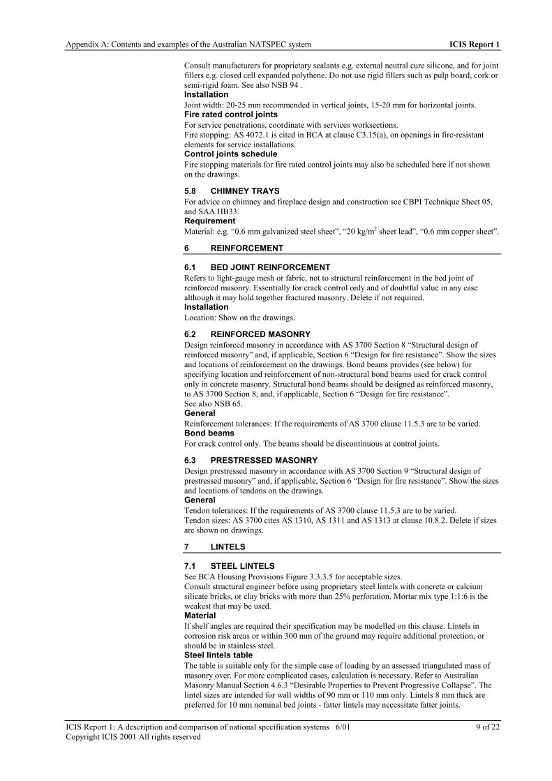
Appendix A: Contents and examples of the Australian NATSPEC system ICIS Report 1
ICIS Report 1: A description and comparison of national specification systems 6/01 9 of 22Copyright ICIS 2001 All rights reserved
Consult manufacturers for proprietary sealants e.g. external neutral cure silicone, and for jointfillers e.g. closed cell expanded polythene. Do not use rigid fillers such as pulp board, cork orsemi-rigid foam. See also NSB 94 .InstallationJoint width: 20-25 mm recommended in vertical joints, 15-20 mm for horizontal joints.Fire rated control jointsFor service penetrations, coordinate with services worksections.Fire stopping: AS 4072.1 is cited in BCA at clause C3.15(a), on openings in fire-resistantelements for service installations.Control joints scheduleFire stopping materials for fire rated control joints may also be scheduled here if not shownon the drawings.
5.8 CHIMNEY TRAYSFor advice on chimney and fireplace design and construction see CBPI Technique Sheet 05,and SAA HB33.RequirementMaterial: e.g. “0.6 mm galvanized steel sheet”, “20 kg/m2 sheet lead”, “0.6 mm copper sheet”.
6 REINFORCEMENT
6.1 BED JOINT REINFORCEMENTRefers to light-gauge mesh or fabric, not to structural reinforcement in the bed joint ofreinforced masonry. Essentially for crack control only and of doubtful value in any casealthough it may hold together fractured masonry. Delete if not required.InstallationLocation: Show on the drawings.
6.2 REINFORCED MASONRYDesign reinforced masonry in accordance with AS 3700 Section 8 “Structural design ofreinforced masonry” and, if applicable, Section 6 “Design for fire resistance”. Show the sizesand locations of reinforcement on the drawings. Bond beams provides (see below) forspecifying location and reinforcement of non-structural bond beams used for crack controlonly in concrete masonry. Structural bond beams should be designed as reinforced masonry,to AS 3700 Section 8, and, if applicable, Section 6 “Design for fire resistance”.See also NSB 65.GeneralReinforcement tolerances: If the requirements of AS 3700 clause 11.5.3 are to be varied.Bond beamsFor crack control only. The beams should be discontinuous at control joints.
6.3 PRESTRESSED MASONRYDesign prestressed masonry in accordance with AS 3700 Section 9 “Structural design ofprestressed masonry” and, if applicable, Section 6 “Design for fire resistance”. Show the sizesand locations of tendons on the drawings.GeneralTendon tolerances: If the requirements of AS 3700 clause 11.5.3 are to be varied.Tendon sizes: AS 3700 cites AS 1310, AS 1311 and AS 1313 at clause 10.8.2. Delete if sizesare shown on drawings.
7 LINTELS
7.1 STEEL LINTELSSee BCA Housing Provisions Figure 3.3.3.5 for acceptable sizes.Consult structural engineer before using proprietary steel lintels with concrete or calciumsilicate bricks, or clay bricks with more than 25% perforation. Mortar mix type 1:1:6 is theweakest that may be used.MaterialIf shelf angles are required their specification may be modelled on this clause. Lintels incorrosion risk areas or within 300 mm of the ground may require additional protection, orshould be in stainless steel.Steel lintels tableThe table is suitable only for the simple case of loading by an assessed triangulated mass ofmasonry over. For more complicated cases, calculation is necessary. Refer to AustralianMasonry Manual Section 4.6.3 “Desirable Properties to Prevent Progressive Collapse”. Thelintel sizes are intended for wall widths of 90 mm or 110 mm only. Lintels 8 mm thick arepreferred for 10 mm nominal bed joints - fatter lintels may necessitate fatter joints.
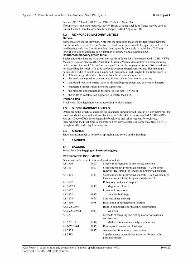
Appendix A: Contents and examples of the Australian NATSPEC system ICIS Report 1
ICIS Report 1: A description and comparison of national specification systems 6/01 10 of 22Copyright ICIS 2001 All rights reserved
See also NSB 27 and NSB 72, and CBPI Technical Note 17A.If proprietary lintels are required, specify. Heads of some steel door frames may be used aslintels. Consult manufacturer. See for example CSIRO Appraisal 148.
7.2 REINFORCED MASONRY LINTELSGeneralShow locations on the drawings. Note that the suggested locations for reinforced masonrylintels exclude external leaves. Prestressed brick lintels are suitable for spans up to 1.8 m forload bearing walls and 3 m for non load bearing walls (available in multiples of 300 mmlength). For design guidance see Australian Masonry Manual Section 4.5.5.Reinforced masonry lintels tableTables under this heading have been derived from Table 4.8 of the superseded ACSE (NSW)Masonry Code of Practice (the Australian Masonry Manual does not have a correspondingtable, but see Section 4.5.6), and are designed for lintels carrying uniformly distributed loadsnot exceeding the weight of a tiled roof plus gypsum plasterboard ceiling. The maximumpermissible width of construction supported (measured at right angles to the lintel span) is4 m. A lintel design should be obtained from the structural engineer if• the loads are applied as concentrated forces such as from beams or struts;• additional loads are carried, such as air handling equipment and solar water heaters;• engineered timber trusses are to be supported;• the masonry unit strength in the lintel is less than 17 MPa; or• the width of construction supported is greater than 4 m.Perpend tiesBlockwork: Note leg length varies according to block height.
7.3 BLOCK MASONRY LINTELSObtain from the structural engineer the calculated superimposed load, in kN per metre run, foreach case (lintel span and wall width); then use Table 4.9 of the superseded ACSE (NSW)Masonry Code of Practice to determine block type and reinforcement for each case.State whether the block type is concrete or fired clay (available in some localities, e.g. N.T.,though locally made clay bricks are not).
7.4 ARCHESShow radius, number of voussoirs, springing, and so on, on the drawings.
8 FINISHES
8.1 BAGGINGSelect from Dry bagging or Textured bagging.
REFERENCED DOCUMENTSDocuments referred to in this worksection include:AS 1310 (1987) Steel wire for tendons in prestressed concreteAS 1311 (1987) Steel tendons for prestressed concrete - 7-wire stress-
relieved steel strand for tendons in prestressed concreteAS 1313 (1989) Steel tendons for prestressed concrete - Cold-worked high-
tensile alloy steel bars for prestressed concreteAS 1617 Refractory bricks and shapesAS 1617.5 (1993) Magnesite, chromeAS 1672 Limes and lime stonesAS 1672.1 (1997) Lime for buildingsAS 1804 (1976) Soft lead sheet and stripAS 1860 (1998) Installation of particleboard flooringAS/NZS 2699 Built-in components for masonry constructionAS/NZS 2699.1 (2000) Wall tiesAS 2701 Methods of sampling and testing mortar for masonry
constructionsAS 2701.10 (1984) Methods for chemical analysis of mortarsAS/NZS 2904 (1995) Damp-proof courses and flashingsAS 2975 (1987) Accessories for masonry constructionAS 3582 Supplementary cementitious materials for use with
portland cement

Appendix A: Contents and examples of the Australian NATSPEC system ICIS Report 1
ICIS Report 1: A description and comparison of national specification systems 6/01 11 of 22Copyright ICIS 2001 All rights reserved
AS 3582.2 (1991) Slag - Ground granulated iron blast-furnaceAS 3700 (1998) Masonry structuresAS 3700 Supp 1 (1999) Masonry structures - CommentaryAS 3972 (1997) Portland and blended cementsAS 4072 Components for the protection of openings in fire-resistant
separating elementsAS 4072.1 (1992) Service penetrations and control jointsAS/NZS 4347 (Various) Damp-proof courses and flashings - Methods of testAS/NZS 4455 (1997) Masonry units and segmental paversAS/NZS 4456 Masonry units and segmental pavers - Methods of testAS/NZS 4456.6 (1997) Determining potential to effloresceAS/NZS 4456.7 (1997) Determining core percentage and material thicknessAS/NZS 4456.8 (1997) Determining moisture content and dry densityAS/NZS 4456.10 (1997) Determining resistance to salt attackAS/NZS 4456.11 (1997) Determining coefficients of expansionAS/NZS 4456.12 (1997) Determining coefficients of contractionAS/NZS 4456.13 (1997) Determining pitting due to lime particlesAS/NZS 4456.14 (1997) Determining water absorption propertiesAS/NZS 4456.15 (1997) Determining lateral modulus of ruptureAS/NZS 4456.16 (1997) Determining permeability to waterAS/NZS 4456.17 (1997) Determining initial rate of absorption (suction)AS/NZS 4456.18 (1997) Determining tensile strength of masonry units and
segmental paversAS/NZS 4600 (1996) Cold-formed steel structuresSAA HB33 (1992) Domestic open fireplacesSAA HB124 (1999) Design of concrete masonry buildingsSAA SEM157 (1999) Masonry structuresAN14.01.602 (1983) Do you make adequate allowance for brick growth?CBPI M 2 (1982) The Basics of BrickworkCBPI M 5 (1999) Fire Resistance Levels for Clay Brick WallsCBPI TN 1A (1995) The design of clay brickwork expansion gapsCBPI TN 1B (1995) Clay brick expansion gapsCBPI TN 10A (1995) Dampness in BrickworkCBPI TN 17A (1994) Lintels for BrickworkCBPI TS 03 (1996) Brick cleaning and internal finishes for full brick housesCBPI TS 05 (1992) Open fireplace design and constructionCCA TN61 (1998) Articulated wallingCSIRO App 136 (1991) CSR Hebel Autoclaved Aerated Concrete Block Wall
SystemsCSIRO App 142 (1991) Thermalite Autoclaved Aerated Concrete BlocksCSIRO App 148 (1993) GalintelCSIRO App 159 (1992) Thermalite autoclaved aerated concrete lintelsEDG DES4 (1995) Thermal mass in building designEDG PRO2 (1995) Embodied energy of building materialsNAFI SS3 (1989) Timber floors - Commercial and industrialNSB 27 (1975) Arch bars and angle lintels for brick wallsNSB 57 (1971) Movement control joints in masonry wallsNSB 59 (1968) Cleaning brickworkNSB 62 (1980) Masonry - Veneer constructionNSB 65 (1969) Structural applications of masonry unitsNSB 70 (1971) Plaster mixesNSB 72 (1975) Steel lintels for garage door openingsNSB 94 (1973) Weatherproofing of movement joints in wallsNSB 119 (1972) Testing bricks

Appendix A: Contents and examples of the Australian NATSPEC system ICIS Report 1
ICIS Report 1: A description and comparison of national specification systems 6/01 12 of 22Copyright ICIS 2001 All rights reserved
NSB 134 (1974) Differential movement in buildings clad with clay bricks 1- The magnitude of differential movements
NSB 135 (1975) Differential movement in buildings clad with clay bricks 2- The design of expansion gaps
NSB 141 (1976) Bond strength in masonryPWD-NSW/ACSE (1991) Australian Masonry Manual
BCA citations of the above referenced standards include:AS 1860 B1.3 Structure - Structural provisions - Materials and forms of
constructionAS/NZS 2904 F1.9 Health and amenity - Damp and weatherproofing - Damp-
proofingAS 3700 Spec-A2.3 General provisions - Fire-resistance of building elements -
RatingB1.3 Structure - Structural provisions - Materials and forms of
constructionF5.5 Health and amenity - Sound transmission and insulation -
Walls between a bathroom, sanitary compartment, laundryor kitchen and a habitable room in adjoining unit
AS 4072.1 C3.15 Fire resistance - Protection of openings - Openings forservice installations
AS/NZS 4600 B1.3 Structure - Structural provisions - Materials and forms ofconstruction
Some of these documents may be referred to only in the Commentary. For sources of thesedocuments refer to Sources of referenced material.An updated schedule of referenced documents, mainly standards, is provided on disk only. Itlists only those standards cited in the Template. Ideally the list should be edited for eachproject. Its function is only to give the title of the referenced documents, for the contractor’sinformation.

Appendix A: Contents and examples of the Australian NATSPEC system ICIS Report 1
ICIS Report 1: A description and comparison of national specification systems 6/01 13 of 22Copyright ICIS 2001 All rights reserved
EXAMPLE OF TYPICAL SPECIFICATION TEXT
BRICK AND BLOCK CONSTRUCTION
1 GENERAL
1.1 CROSS REFERENCESGeneralRefer to the General requirements worksection.Related worksectionsRefer to the following worksections: >
1.2 STANDARDGeneralMaterials, construction and detailing: To AS 3700.Masonry units: To AS/NZS 4455
1.3 INTERPRETATIONDefinitionsFace units: Masonry units used in facework, including purpose-made units such as squints,sills and thresholds.Facework: Masonry in which the form, or form and colour, of the face units and joints isvisible in the completed works.
2 QUALITY
2.1 INSPECTIONWitness pointsStages: Give sufficient notice so that inspection may be made at the following stages:• Damp-proof courses, in position.• Flashings, in position.• Bottoms of cavities, after cleaning out.• Bottoms of core holes, before grouting.• Control joints, ready for insertion of joint filler.• Lintels, in position.• Structural steelwork, including bolts and shelf angles, in position.Hold points >
2.2 TESTSMasonry units test criteriaGeneral: The criterion for the relevant test stated or recommended in AS/NZS 4455, or thespecified criterion (in which case the latter prevails).Masonry units tests scheduleAttribute Test method Number of testsPotential to effloresce AS/NZS 4456.6Care % and material thickness AS/NZS 4456.7Moisture content and drydensity
AS/NZS 4456.8
Resistance to salt attack AS/NZS 4456.10Coefficients of expansion AS/NZS 4456.11Coefficient of contraction AS/NZS 4456.12Pitting due to lime particles AS/NZS 4456.13Water absorption properties /NZS 4456.14Lateral modulus of rupture AS/NZS 4456.15Permeability to water AS/NZS 4456.16Initial rate of absorption AS/NZS 4456.17Tensile strength AS/NZS 4456.18

Appendix A: Contents and examples of the Australian NATSPEC system ICIS Report 1
ICIS Report 1: A description and comparison of national specification systems 6/01 14 of 22Copyright ICIS 2001 All rights reserved
Mortar chemical testsNumber of tests: >Special masonry testsDesignation of special masonry: >Special masonry tests scheduleProperty to be tested Test criterion Number of testsCompressive strengthFlexural strength
2.3 SAMPLESMasonry unit samplesGeneral: Submit face units of each type illustrating the range of variation available, includingcolour, texture, surface irregularities, defective arrises, and shape.Number of each type: 6.Sand samplesGeneral: Submit a 2 kg sample of each type of sand required to be of a particular colour,grade or source.Facework sample panelsGeneral: Provide in a suitable position a sample panel of each type of facework including faceor pointing mortar.Facework type: >Location: >Minimum size (face of panel) (mm): >Footings: >Facework set-outGeneral: Provide a trial set-out of 2 courses for each panel of facework.
2.4 SUBMISSIONSMaterialsMortar for refractory brickwork: Submit proposal.
3 MATERIALS AND COMPONENTS
3.1 MATERIALS AND COMPONENTSMasonry units schedule
Types of unitAttributeClay masonryunits
Concretemasonry units
Calcium silicatemasonry units
AAC masonryunits
SourceLocationManufacturingdimensions (mm)CategoryDimensionalcategoryUnconfinedcompressivestrength (MPa)Coefficient ofexpansion(mm/m)Salt attackresistancecategory
Refractory bricksChemical constitution: 30% alumina (Al2O3).Location: >Steel componentsDurability classification to AS 3700:• Steel products (including reinforcement), at least:

Appendix A: Contents and examples of the Australian NATSPEC system ICIS Report 1
ICIS Report 1: A description and comparison of national specification systems 6/01 15 of 22Copyright ICIS 2001 All rights reserved
Mortar materialsCement type to AS 3972: GP.White cement: Iron salts content ≤ 1%.Lime: To AS 1672.1.Sand: Fine aggregate with a low clay content and free from efflorescing salts, selected forcolour and grading.Sand for facework:• Colour: >• Grading: >• Source: >Admixtures: Do not provide admixtures.Cement type to AS 3972: GP.White cement: Iron salts content ≤ 1%.Coloured mortar:• Colour: >• Location: >Premixed mortar: >Refractory mortar >Type: >Mortar mix tableMortar type toAS 3700
Mortar proportions(cement:lime:sand)
Location
M3 1:0:5 + water thickener Concrete or calcium silicate masonryM4 1:0:4 + water thickener Grouted and reinforced masonryM4 1:0 - 0.25:3 Underpinning, high strength masonryM3 1:1:6 Other masonry
GroutComposition: >Characteristic compressive strength (MPa): >
4 EXECUTION
4.1 CONSTRUCTION GENERALLYCleaningGeneral: Clean masonry progressively as the work proceeds. Clean facework to removemortar smears, stains and discolouration. Do not use acid.Concealed workJoints: Cut flush, and leave unstruck.“Grassing” of bricksGeneral: Do not lay clay bricks until they have been out of the kiln for at least 14 days.Sills and thresholdsBedding: Solidly bed masonry sills and thresholds and lay them so that the top surfaces drainaway from the building. Set out so that no unit is cut smaller than 3/4 full width.Sill units: >Threshold units: >Joints and cuttingSet out: Set out masonry with joints of uniform width and minimise cutting of masonry units.Holes, sleeves and chases: Build in during erection.Depth of raking (other than facework): >Rods76 mm high units: 7 courses to 600 mm.90 mm high units: 6 courses to 600 mm.190 mm high units: 3 courses to 600 mm.BondsSingle leaf: Stretcher bond.Facework: Stretcher bond.Existing work: >Tolerances (mm): >Built in steel door framesFill the backs of jambs and heads solid with mortar as the work proceeds.Monolithic structural actionGeneral: Provide masonry header units, except in stretcher bond facework.

Appendix A: Contents and examples of the Australian NATSPEC system ICIS Report 1
ICIS Report 1: A description and comparison of national specification systems 6/01 16 of 22Copyright ICIS 2001 All rights reserved
Location:• Between leaves in solid masonry construction.• At engagement of engaged piers.• At intersections with supporting walls and buttresses.• At engagement of diaphragms with the leaves in diaphragm walls.• At intersections of flanges with shear walls.Clearance for timber frame shrinkageIn seasoned timber frame brick veneer construction, leave the following clearances betweenwindow frames and brick sill and between roof frames and the brick veneer:• Single storey frames and ground floor windows (not for slab on ground): 10 mm.• Two storey frames and upper floor windows: 20 mm.• Additional clearance: Accommodate additional shrinkage of unseasoned floor timbers.Fire resistance scheduleMasonry element Required fire resistance
5 COMPONENTS
5.1 FACEWORKSingle face wallsLocation: >Double face wallsGeneral: Select face units for uniform width and double-face qualities in single leaf masonrywith facework both sides. Before starting, obtain a ruling as to which is the preferred wallface, and favour that face should a compromise be unavoidable.Location: >CommencementPosition: Commence at least 1 full course for blockwork, or 2 full courses for brickwork,below adjacent finished ground level.PerpendsAlignment: Vertically align perpends in alternate courses.PerforationsExposed: Provide solid face units where perforations would otherwise be visible.JointsSurface: Work with a jointing tool to a dense smooth surface, except where the surface is tobe bagged.Joint profile: >Depth of raking: >Colour mixingGeneral: Where the colour of the face units is visible, evenly distribute the colour range ofunits. Prevent colour concentrations and “banding”.
5.2 SUBFLOORUnderpinningInstallation: Construct underpinning in alternate panels, each panel not exceeding 1200 mmin length. Maintain bond and coursing in adjoining panels. Set out rod to leave 13 mmmaximum between top or underpinning and bottom of existing footing.Grouting: Pressure grout between underpinning and footing with 1:0.25:3 mortar within 48hours of completion of each panel.Bearer supportPiers: Support bearers on engaged and free standing masonry piers at 1800 mm maximumcentres.Engaged piers:• Brickwork: 230 x 110 mm, bonded to walls.• Blockwork: 390 x 90 mm, bonded to walls.Free standing piers tableHeight (mm) Brickwork (mm) Blockwork (mm)

Appendix A: Contents and examples of the Australian NATSPEC system ICIS Report 1
ICIS Report 1: A description and comparison of national specification systems 6/01 17 of 22Copyright ICIS 2001 All rights reserved
Height (mm) Brickwork (mm) Blockwork (mm)
< 1500 230 x 230 390 x 190
1500 - 2700 350 x 350 390 x 390
Access openingsGeneral: In internal walls, leave door width openings beneath doorways to give access tounderfloor areas.Air vents typeBrickwork:• Terra cotta: Perforated, 230 x 160 mm.• Concrete framed: Bronze wire mesh in concrete frames, 470 x 160 mm.• Cut brick: 2 cut bricks laid vertically and evenly spaced in a 230 mm wide x 2 course
high opening, backed with bronze wire mesh built in.Blockwork:• Vent blocks: Purpose-made vent blocks.• Concrete framed: Bronze wire mesh in concrete frame 390 x 190 mm.Air vents locationVentilation rate: At least 7300 mm2 free ventilation area per linear metre of wall.Location: Below damp-proof course, within 600 mm of corners, elsewhere as required byventilation rate, to internal and external walls.Cavity walls: Provide matching vents in the internal leaves located as near as practicable tothe vents in the external leaves.
5.3 PRECAST DOOR THRESHOLDSLocation >
Profile >
Finish to exposed facesOff steel forms.Concrete mix1:2:4 cement:coarse aggregate 10 mm size:fine aggregate.
5.4 DAMP-PROOF COURSESMaterialStandard: To AS/NZS 2904.Type: >LocationGeneral: Provide damp-proof courses in the following locations, if applicable:• Walls adjoining infill floor slabs on membranes: In the course above the underside of the
slab in internal walls and inner leaves of cavity walls. Project 40 mm and dress downover the membrane turned up against the wall.
• Cavity walls built off slabs on ground: In the bottom course of the outer leaf, continuoushorizontally across the cavity and up the inner face bedded in mortar, turned 30 mm intothe inner leaf 1 course above. Project 10 mm beyond the external slab edge and turndown at 45o.
• Masonry veneer construction: In the bottom course of the outer leaf, continuoushorizontally across the cavity. Fasten to the inner frame 75 mm above floor level. Project10 mm beyond the external slab edge and turn down at 45o.
• Internal walls built off slabs on ground: In the first course above floor level.• At timber floors: In the first course below the level of the underside of ground floor
timbers in internal walls and inner leaves of cavity walls.InstallationGeneral: Lay in long lengths. Lap full width at angles and intersections and at least 150 mm atjoints. Step as necessary, but not exceeding 2 courses per step. Sandwich damp-proof coursesbetween mortar.Junctions: Preserve continuity of damp-proofing at junctions of damp-proof courses andwaterproof membranes.Location: At least 150 mm above adjacent finished ground level.Lap sealing: >

Appendix A: Contents and examples of the Australian NATSPEC system ICIS Report 1
ICIS Report 1: A description and comparison of national specification systems 6/01 18 of 22Copyright ICIS 2001 All rights reserved
5.5 CAVITY WALLSMinimum cavity widthMasonry walls: 50 ± 10 mm.Masonry veneer walls: 25 mm, between the masonry leaf and the loadbearing frame and40 mm between the masonry leaf and sheet bracing.OpeningsClosure: Do not close the cavity at the jambs of external openings.Cavity fillHeight: Fill the cavity to 1 course above adjacent finished ground level with mortar weatheredtowards the outer leaf.Flashings materialStandard: To AS/NZS 2904.Type: >Flashings locationGeneral: Provide flashings and weatherings in the following locations, if applicable:• Floors: Full width of outer leaf immediately above slab or shelf angle, continuous across
cavity and up the inner face bedded in mortar, turned 30 mm into the inner leaf 2 coursesabove. Where the slab supports the outer skin and is not rebated, bed the flashing in asuitable sealant.
• Under sills: 30 mm into the outer leaf bed joint 1 course below the sill, extending upacross the cavity and under the sill.
• Over lintels to openings in cavity walls: Full width of outer leaf immediately above thelintel, continuous across cavity, turned 30 mm into the inner leaf 2 courses above.Extend at least 50 mm beyond the lintels.
• Over lintels to openings in masonry veneer construction: Full width of outer leafimmediately above the lintel, continuous across cavity. Turn up against the inner frameand fasten to it. Extend at least 50 mm beyond the lintels.
• At abutments with structural frames or supports: Vertical flashing in the cavity using150 mm wide material, wedged and grouted into a groove in the frame opposite thecavity.
• At stiles where cavities are closed: Full height flashing extending 75 mm beyond theclosure into the cavity, interleaved with the sill and head flashing at each end. Fix toframe stiles.
Flashings installationGeneral: Sandwich flashings between mortar except where on lintels or shelf angles.Lap sealing: >Pointing: Point up joints around flashings, filling voids.WeepholesForm: Open perpends.Maximum spacing: 720 mm.Location: Provide weepholes to external leaves of cavity walls in the course immediatelyabove flashings, and cavity fill, and at the bottoms of unfilled cavities.Wall tiesDurability classification to AS/NZS 2699.1: >Wall ties category tableClassification to AS/NZS 2699.1 Service conditions
Light duty Masonry veneer
Medium duty Normal cavity construction and at abutments
Heavy duty Cavities > 60 mm wide
Wall ties installationFixing of masonry veneer ties at abutments:• To timber frames: Clouts or integral spikes.• To concrete: Masonry anchors.• To steel frames: >• To structural supports: >• Special requirements for cyclone areas: >Spacing: >Embedment of wall tiesCavities > 60 mm wide: 75 mm minimum.

Appendix A: Contents and examples of the Australian NATSPEC system ICIS Report 1
ICIS Report 1: A description and comparison of national specification systems 6/01 19 of 22Copyright ICIS 2001 All rights reserved
Wall ties in reinforced masonryLocation: In unreinforced courses.Flexible wall tiesType: Where ties or anchors extend across control joints, provide ties or anchors which do notimpair the effectiveness of the joint.
5.6 AUTOCLAVED AERATED CONCRETE WALLSGeneralType: A proprietary system which• has a current Australian Building Product and Systems Certification Scheme certificate;
or• has a current appraisal report issued by the CSIRO Building Products and Systems
Appraisals stating that the system is suitable for use in walls in buildings.
5.7 CONTROL JOINTSFiller materialType: Provide compatible sealant and bond breaking backing materials which are non-staining to masonry. Do not provide bituminous materials with absorbent masonry units.Foamed materials: Closed-cell or impregnated, not water-absorbing.Bond breaking materials: Non-adhesive to sealant, or faced with a non-adhering material.Primer: Required.Slip joints: >InstallationCleaning: Clean joints thoroughly before sealing.Joint width:• Vertical joints: >• Horizontal joints: >Sealant depth: 0.67 - 1.0 times joint width.Toothed jointsGeneral: Not permitted.Fire rated control jointsGeneral: Where a control joint occurs in an element of construction required to have a fireresistance rating, construct the control joint using fire stopping materials so that the fireresistance rating of the element is not reduced.Fire stopping: To AS 4072.1.Control joints schedule
Joint fillerJoint code Joint width
Primer Backing rod Sealant
5.8 CHIMNEY TRAYSRequirementGeneral: Build a one-piece corrosion resistant metal tray to the chimney at roof level.Material: >InstallationGeneral: Cut an opening for the flue. Turn tray edges up 25 mm around the flue opening13 mm clear of the flue walls. Externally turn the tray up 100 mm under the stepped flashingand down 100 mm over the apron flashing. Lap and solder joints.Weep holesGeneral: Provide 2 weepholes through the flue walls on opposite sides immediately above thetray.
6 REINFORCEMENT
6.1 BED JOINT REINFORCEMENTReinforcementMaterial: Galvanized welded wire mesh.Width: Equal to the width of the masonry leaf, less 15 mm cover from each exposed surfaceof the mortar joint.

Appendix A: Contents and examples of the Australian NATSPEC system ICIS Report 1
ICIS Report 1: A description and comparison of national specification systems 6/01 20 of 22Copyright ICIS 2001 All rights reserved
InstallationGeneral: Lap 450 mm at splices. Fold and bend at corners so that the longitudinal wires arecontinuous. Stop 200 mm short of control joints.In brickwork: Extend 450 mm beyond each side of openings.Location:• In third bed joint above bottom of wall.• In second bed joint below top of wall.• In first 2 bed joints above and below openings.• In first 2 bed joints above and below head and sill flashings to openings.Maximum vertical intervals: 500 mm.
6.2 REINFORCED MASONRYGeneralDesignation: Masonry strengthened with embedded steel reinforcement, other than bed jointreinforcement.Reinforcement tolerances: >Cleaning core holesBlockwork: Provide purpose-made cleanout blocks or machine cut a cleaning hole at the baseof each reinforced core. Locate on the side of the wall which is to be rendered or otherwiseconcealed. Cover the hole with formwork and grout the core.Bond beamsType: Provide bond beams made from purpose-made hollow concrete blocks withreinforcement grouted in place.Reinforcement: Two 12 mm diameter galvanized rods.
6.3 PRESTRESSED MASONRYGeneralDesignation: Masonry strengthened with embedded prestressed tendons.Tendon tolerances: >Tendon size: >
7 LINTELS
7.1 STEEL LINTELSMaterialType: Mild steel galvanized to AS/NZS 4680, minimum coating mass 600 g/m2. Do not cutafter galvanizing.Steel lintels scheduleLintel dimensions (mm) Maximum span (mm)
75 x 8
75 x 10
90 x 90 x 6
90 x 90 x 8
100 x 100 x 6
100 x 100 x 8
150 x 90 x 8
150 x 100 x 10
Cold-formed lintelsType: Proprietary flat-base type designed to AS/NZS 4600.Type tests: Required.Tension barsType tests: Required.InstallationGeneral: Provide 1 lintel to each wall leaf. Do not cut on site. Keep lintels 6 mm clear ofheads of frames. Pack mortar between the angle upstand and supported masonry units.Minimum bearing each end:• Span ≤ 1800 mm: 150 mm.• Span > 1800 mm, ≤ 3000 mm: 230 mm.

Appendix A: Contents and examples of the Australian NATSPEC system ICIS Report 1
ICIS Report 1: A description and comparison of national specification systems 6/01 21 of 22Copyright ICIS 2001 All rights reserved
Propping: To prevent deflection or excessive rotation, temporarily prop proprietary cold-formed lintels until the masonry reaches its required strength.• Minimum propping period: 3 days.
7.2 REINFORCED MASONRY LINTELSGeneralPlace horizontal reinforcement in one or two bed joints in the masonry immediately above theopening.LocationOver openings in internal walls and internal leaves of cavity walls.ReinforcementGeneral: 6.3 mm diameter rods complying with the Reinforced masonry lintels table.Protection: Galvanized, minimum coating mass 470 g/m2.Reinforced masonry lintels table
Maximum span (m)Masonry unitsize (mm) andtype
Depth of lintel(courses)
2 rods 3 rods 4 rods
110 wide x 76high
56789
0.971.21.51.92.2
1.21.72.22.42.6
90 wide x 90high;Brick
5678
1.01.2
1.21.62.02.2
1.41.82.22.4
90 wide x 90high;Block
678910
1.01.21.4 1.6
1.82.0
140 wide x 90high
6789
1.01.21.41.6
190 wide x 90high
6789
1.01.21.41.6
90 wide x 190high
4567
1.21.62.0
2.4
140 wide x 190high
4 1.2
190 wide x 190high
4 1.2
Perpend tiesBrickwork: Form from 2.5 mm diameter galvanized steel wire bent to U-shape, 75 x 35 mm,with the ends of the 75 mm legs hooked inward.Blockwork: Form from 2.5 mm diameter galvanized steel wire bent to U-shape with legs35 mm apart, with the ends of the legs hooked inward.
Blockwork perpend ties tableBlock height Leg length unbent Leg length embedded

Appendix A: Contents and examples of the Australian NATSPEC system ICIS Report 1
ICIS Report 1: A description and comparison of national specification systems 6/01 22 of 22Copyright ICIS 2001 All rights reserved
90 mm 65 mm 50 mm
190 mm 125 mm 100 mm
InstallationGeneral: Place 2 reinforcing rods in the lowest horizontal joint with the remainder of therequired rods (if any) in the 2nd lowest horizontal joint. Set rods at least 15 mm from theexposed surface of the mortar joint. Keep lintels 6 mm clear of heads of frames. Supportlintels for at least 7 days after installation.Beyond opening: Extend rods 600 mm beyond each side of the opening. Where masonrybetween adjacent openings is less than 600 mm wide, extend rods continuously across bothopenings.T-intersections: Crank the rods 300 mm along the intersecting walls and place the crankedends with at least 50 mm cover from the face of the wall into which the lintel is spanning.Perpend ties: Hang the hooked ends of the perpend ties over the lowest pair of rods and builda tie solidly into each perpend of the lowest course.Blockwork perpend ties: In 190 mm wide blocks, provide 2 ties side by side per perpend.
7.3 BLOCK MASONRY LINTELSDescriptionGeneral: Reinforced lintels using purpose-made U-section hollow blocks as permanentformwork.StandardGeneral: Comply with the recommendations of Australian Masonry Manual (PWD-NSW/ACSE) clause 4.5.6.Block masonry lintel schedule
ReinforcementLintel span(mm)
Wall width (mm) Lintel block type
Bar type No. of bars
7.4 ARCHESShapes and dimensionsGeneral: Form masonry arches using solid or cored (not hollow) masonry units.Arch voussoirsGeneral: Cut masonry units using a masonry saw.
8 FINISHES
8.1 BAGGINGDry baggingPreparation: Cut joints flush before bagging.Application: Apply laying mortar to the surface using a hessian bag or similar. Flush upirregularities, but leave the minimum amount of mortar on the surface.Textured baggingPreparation: Cut joints flush before bagging.Application: Apply laying mortar to the surface using a sponge float. Flush up irregularities,but leave approximately 2 mm of mortar on the surface. When initial set is reached, textureusing a hand bristle brush.Texture: >

ICIS Report 1: A description and comparison of national specification systems 6/01 1 of 15Copyright 2001 ICIS All rights reserved
APPENDIX B1: CONTENTS AND EXAMPLES OF THE NMSSPECIFICATION SYSTEM
CONTENTS OF THE NATIONAL MASTER SPECIFICATION (NMS)
SECTION LISTING USED BY NMS
Bid and Contract Requirements
00001 Project Title Page00005 Certifications Page00007 Seals Page00010 Table of Contents00015 List of Drawings00020 List of Schedules
00100 Bid Solicitation00200 Instructions To Bidders00300 Information Available To
Bidders00400 Bid Forms and
Supplements00490 Bidding Addenda
00500 Agreement00600 Bonds and Certificates00700 General Conditions00800 Supplementary
Conditions00900 Addenda and
Modifications
Division 1 — General Requirements01100 Summary01200 Price and Payment
Procedures01300 Administrative
Requirements01400 Quality Requirements01500 Temporary Facilities and
Controls01600 Product Requirements01700 Execution Requirements
01800 Facility Operation01900 Facility
Decommissioning
Division 2 - Site Construction02050 Basic Site Materials and
Methods02100 Site Remediation02200 Site Preparation02300 Earthwork02400 Tunneling, Boring, and
Jacking02450 Foundation and Load
Bearing Elements02500 Utility Services02600 Drainage and
Containment02700 Bases, Ballasts,
Pavements, andAppurtenances
02800 Site Improvements andAmenities
02900 Planting02950 Site Restoration and
Rehabilitation
Division 3 - Concrete03050 Basic Concrete Materials
and Methods03100 Concrete Forms and
Accessories03200 Concrete Reinforcement03300 Cast-in-place Concrete03400 Precast Concrete
03500 Cementitious Decks andUnderlayment
03600 Grouts03700 Mass Concrete03900 Concrete Restoration and
Cleaning
Division 4 - Masonry04050 Basic Masonry Materials
and Methods04200 Masonry Units04400 Stone04500 Refractories04600 Corrosion Resistant
Masonry04700 Simulated Masonry04800 Masonry Assemblies04900 Masonry Restoration and
Cleaning
Division 5 - Metals05050 Basic Metal Materials
and Methods05100 Structural Metal Framing05200 Metal Joists05300 Metal Deck05400 Cold Formed Metal
Framing05500 Metal Fabrications05600 Hydraulic Fabrications05650 Railroad Track and
Accessories05700 Ornamental Metal05800 Expansion Control05900 Metal Restoration and
Cleaning
Division 6 - Wood and Plastics
06050 Basic Wood and PlasticMaterials and Methods
06100 Rough Carpentry06200 Finish Carpentry06400 Architectural Woodwork06500 Structural Plastics06600 Plastic Fabrications06900 Wood and Plastic
Restoration and CleaningDivision 7 - Thermal and MoistureProtection07050 Basic Thermal and
Moisture ProtectionMaterials and Methods
07100 Dampproofing andWaterproofing
07200 Thermal Protection07300 Shingles, Roof Tiles, and
Roof Coverings07400 Roofing and Siding
Panels07500 Membrane Roofing07600 Flashing and Sheet Metal07700 Roof Specialties and
Accessories07800 Fire and Smoke
Protection07900 Joint Sealers
Division 8 - Doors and Windows08050 Basic Door and Window
Materials and Methods08100 Metal Doors and Frames08200 Wood and Plastic Doors08300 Specialty Doors08400 Entrances and Storefronts08500 Windows08600 Skylights08700 Hardware08800 Glazing08900 Glazed Curtain Wall
Division 9 - Finishes09050 Basic Finish Materials
and Methods09100 Metal Support
Assemblies09200 Plaster and Gypsum
Board09300 Tile09400 Terrazzo09500 Ceilings09600 Flooring09700 Wall Finishes09800 Acoustical Treatment

Appendix B1: Contents and examples of the Canadian specification systems ICIS Report 1
ICIS Report 1: A description and comparison of national specification systems 6/01 2 of 15Copyright 2001 ICIS All rights reserved
09900 Paints and Coatings
Division 10 - Specialties10100 Visual Display Boards10150 Compartments and
Cubicles10200 Louvers and Vents10240 Grilles and Screens10250 Service Walls10260 Wall and Corner Guards10270 Access Flooring10290 Pest Control10300 Fireplaces and Stoves10340 Manufactured Exterior
Specialties10350 Flagpoles10400 Identification Devices10450 Pedestrian Control
Devices10500 Lockers10520 Fire Protection
Specialties10530 Protective Covers10550 Postal Specialties10600 Partitions10670 Storage Shelving10700 Exterior Protection10750 Telephone Specialties10800 Toilet, Bath, and
Laundry Accessories10880 Scales10900 Wardrobe and Closet
Specialties
Division 11 - Equipment11010 Maintenance Equipment11020 Security and Vault
Equipment11030 Teller and Service
Equipment11040 Ecclesiastical Equipment11050 Library Equipment11060 Theater and Stage
Equipment11070 Instrumental Equipment11080 Registration Equipment11090 Checkroom Equipment11100 Mercantile Equipment11110 Commercial Laundry and
Dry Cleaning Equipment11120 Vending Equipment11130 Audio-visual Equipment11140 Vehicle Service
Equipment11150 Parking Control
Equipment11160 Loading Dock
Equipment11170 Solid Waste Handling
Equipment11190 Detention Equipment11200 Water Supply and
Treatment Equipment
11280 Hydraulic Gates andValves
11300 Fluid Waste Treatmentand Disposal Equipment
11400 Food Service Equipment11450 Residential Equipment11460 Unit Kitchens11470 Darkroom Equipment11480 Athletic, Recreational,
and TherapeuticEquipment
11500 Industrial and ProcessEquipment
11600 Laboratory Equipment11650 Planetarium Equipment11660 Observatory Equipment11680 Office Equipment11700 Medical Equipment11780 Mortuary Equipment11850 Navigation Equipment11870 Agricultural Equipment11900 Exhibit Equipment
Division 12 - Furnishings12050 Fabrics12100 Art12300 Manufactured Casework12400 Furnishings and
Accessories12500 Furniture12600 Multiple Seating12700 Systems Furniture12800 Interior Plants and
Planters12900 Furnishings Repair and
Restoration
Division 13 - Special Construction13010 Air Supported Structures13020 Building Modules13030 Special Purpose Rooms13080 Sound, Vibration, and
Seismic Control13090 Radiation Protection13100 Lightning Protection13110 Cathodic Protection13120 Pre-engineered
Structures13150 Swimming Pools13160 Aquariums13165 Aquatic Park Facilities13170 Tubs and Pools13175 Ice Rinks13185 Kennels and Animal
Shelters13190 Site Constructed
Incinerators13200 Storage Tanks13220 Filter Underdrains and
Media13230 Digester Covers and
Appurtenances13240 Oxygenation Systems
13260 Sludge ConditioningSystems
13280 Hazardous MaterialAbatement
13400 Measurement andControl Instrumentation
13500 RecordingInstrumentation
13550 Transportation ControlInstrumentation
13600 Solar and Wind EnergySystems
13700 Security Access andSurveillance
13800 Building Automation andControl
13850 Detection and Alarm13900 Fire Suppression and
Protection
Division 14 - Conveying Systems14100 Dumbwaiters14200 Elevators14300 Escalators and Moving
Walks14400 Lifts14500 Material Handling14600 Hoists and Cranes14700 Turntables14800 Scaffolding14900 Transportation
Division 15 - Mechanical15050 Basic Mechanical
Materials and Methods15100 Building Services Piping15200 Process Piping15300 Fire Protection Piping15400 Plumbing Fixtures and
Equipment15500 Heat Generation
Equipment15600 Refrigeration Equipment15700 Heating, Ventilating, and
Air ConditioningEquipment
15800 Air Distribution15900 Hvac Systems
Instrumentation andControls
15950 Testing Adjusting andBalancing
Division 16 - Electrical16050 Basic Electrical Materials
and Methods16100 Wiring Methods16200 Electrical Power16300 Transmission and
Distribution16400 Low-voltage Distribution16500 Lighting16700 Communications

Appendix B1: Contents and examples of the Canadian specification systems ICIS Report 1
ICIS Report 1: A description and comparison of national specification systems 6/01 3 of 15Copyright 2001 ICIS All rights reserved
16800 Sound and Video

Appendix B1: Contents and examples of the Canadian specification systems ICIS Report 1
ICIS Report 1: A description and comparison of national specification systems 6/01 4 of 15Copyright 2001 ICIS All rights reserved
EXAMPLE OF THE CANADIAN NATIONAL MASTER CONSTRUCTIONSPECIFICATION (NMS) – (As Published By Digicon Information Inc.)
SPEC NOTE: This section specifies steel doors and frames, lead lined steel doors and frames (forradiation shielding), fire retardant, labelled and unlabelled doors.
SPEC NOTE: Verify components with manufacturer and edit section to suit specific door type.
PART 1 GENERAL
SPEC NOTE ENVIRONMENT: This section specifies environmentally responsible material choices,including recycling and reuse options, and generally available disposal options.
�The inclusion of recycled content provides efficient use of natural resources and diverts materials fromthe waste stream.
1.1 Related Sections
.1 Section[07900] - [Joint Sealers]: Caulking of joints between frames and other buildingcomponents.
.2 Section [08710] - [Door Hardware]: Supply of finish hardware, includingweatherstripping and mounting heights.
.3 Section [08800] - [Glazing]: Glazing.
.4 Section [09911] - [Interior Painting].
.5 Section [10200] - [Louvres and Vents]: Door louvres.
.6 Section 16 [___] [___]: Wiring for electronic hardware.
1.2 References
SPEC NOTE: Edit the following paragraphs to suit standards specified in project specifications.
.1 American Society for Testing and Materials (ASTM).
.1 ASTM A 653M-95, Specification for Steel Sheet, Zinc-Coated (Galvanized) orZinc-Iron Alloy-Coated (Galvannealed) by the Hot-Dip Process.
.2 ASTM B 29-[92], Specification for Pig Lead.
.3 ASTM B 749-[85(1991)], Specification for Lead and Lead Alloy Strip, Sheetand Plate Products.
.2 Canadian General Standards Board (CGSB).
.1 CAN/CGSB-1.181-[92], Ready-Mixed Organic Zinc-Rich Coating.
.2 CGSB 41-GP-19Ma-[84], Rigid Vinyl Extrusions for Windows and Doors.
.3 CAN/CGSB-51.20-[M87], Thermal Insulation, Polystyrene, Boards and PipeCovering.
.4 CGSB 51-GP-21M-[78], Thermal Insulation, Urethane and Isocyanurate,Unfaced.

Appendix B1: Contents and examples of the Canadian specification systems ICIS Report 1
ICIS Report 1: A description and comparison of national specification systems 6/01 5 of 15Copyright 2001 ICIS All rights reserved
.3 Canadian Standards Association (CSA).
.1 CSA A101-[M1983], Thermal Insulation, Mineral Fibre, for Buildings.
.2 CAN/CSA-G40.21-[M92], Structural Quality Steels.
.3 CSA W59-[M1989], Welded Steel Construction (Metal Arc Welding).
.4 Canadian Steel Door and Frame Manufacturers' Association, (CSDFMA).
.1 CSDFMA, Specifications for Commercial Steel Doors and Frames, [1990].
.2 CSDFMA, Recommended Selection and Usage Guide for Commercial SteelDoors, [1990].
.5 National Fire Protection Association (NFPA).
.1 NFPA 80-[1992], Fire Doors and Windows.
.2 NFPA 252-[1990], Door Assemblies, Fire Tests of.
.6 Underwriters' Laboratories of Canada (ULC).
.1 CAN4-S104M- [M80(R1985)], Fire Tests of Door Assemblies.
.2 CAN4-S105M-[M85], Fire Door Frames.
1.3 Design Requirements
SPEC NOTE: Use the following paragraph for exterior steel doors and when area of entrance screens isabove 10 m2.
.1 Design exterior frame assembly to accommodate to expansion and contraction whensubjected to minimum and maximum surface temperature of -35�C to 35�C.
SPEC NOTE: Use the following paragraph only when exterior steel entrance screens are detailed.
.2 Maximum deflection for exterior steel entrance screens under wind load of 1.2 kPa not toexceed 1/175th of span.
1.4 Shop Drawings
.1 Submit shop drawings in accordance with Section [01330 - Submittal Procedures].
.2 Indicate each type of door, material, steel core thicknesses, mortises, reinforcements,location of exposed fasteners, openings, [glazed] [louvred], arrangement of hardware[and] [fire rating] and finishes.
.3 Indicate each type frame material, core thickness, reinforcements, glazing stops, locationof anchors and exposed fastenings [and] [reinforcing] [firerating] finishes.
.4 Include schedule identifying each unit, with door marks and numbers relating tonumbering on drawings and door schedule.
SPEC NOTE: Use the following paragraph for radiation sheilding steel doors and frames.
.5 Submit test and engineering data, and installation instructions.

Appendix B1: Contents and examples of the Canadian specification systems ICIS Report 1
ICIS Report 1: A description and comparison of national specification systems 6/01 6 of 15Copyright 2001 ICIS All rights reserved
1.5 Samples
.1 Submit samples in accordance with Section [01330 - Submittal Procedures].
.2 Submit one [300 x 300] mm [[top] butt] corner sample of each type door.
.3 Submit one [300 x 300] mm corner sample of each type of frame.
.1 Show [butt cutout] [glazing stops] [[300] mm long removable mullionconnection] [snap-on trim with clips].
1.6 Requirements of Regulatory Agencies
.1 Steel fire rated doors and frames: labelled and listed by an organization accredited byStandards Council of Canada in conformance with CAN4-S104M [NFPA 252] forratings specified or indicated.
SPEC NOTE: Use the following paragraph to specify fire labelled frames to suit project requirements.
.2 Provide fire labelled frame products for those openings requiring fire protection ratings,as scheduled. Test products in strict conformance with CAN4-S104, ASTM E 152 orNFPA 252 and list by nationally recognized agency having factory inspection serviceand construct as detailed in Follow-Up Service Procedures/Factory Inspection Manualsissued by listing agency to individual manufacturers.
1.7 Waste Management and Disposal
.1 Separate and recycle waste materials in accordance with [Section 01355 - WasteManagement and Disposal]and the Waste Reduction Workplan.
SPEC NOTE ENVIRONMENT: Since emptied containers retain product residues (vapours, liquid,and/or solid) extreme caution should still be exercised in their handling. Keep out of reach of children.
SPEC NOTE ENVIRONMENT: With steel there is little site-generated scrap, and any that is generatedcan be recycled and used for a new application.
.2 Place materials defined as hazardous or toxic waste in designated containers.
.3 Ensure emptied containers are sealed and stored safely for disposal away from children.
.4 Set aside and protect the following surplus and uncontaminated waste finish materials:[___]. Deliver to, or arrange collection by employees, individuals, or organizations [___]for verifiable re-use or re-manufacturing.
.5 Place materials defined as hazardous or toxic waste in designated containers, and placeused sealant and adhesive tubes and containers in areas designated for hazardous waste.
.6 Return solvent and oil soaked rags, used during installation, for contaminant recovery,proper disposal, or appropriate cleaning with no contaminant release to water systems.
.7 Close and seal tightly all partly used sealant and adhesive containers and store protect inwell ventilated fire-safe area at moderate temperature.
.8 Separate corrugated cardboard in accordance with the Waste Management Plan andplace in designated areas for recycling.

Appendix B1: Contents and examples of the Canadian specification systems ICIS Report 1
ICIS Report 1: A description and comparison of national specification systems 6/01 7 of 15Copyright 2001 ICIS All rights reserved
.9 Fold up metal banding, flatten, and place in designated area for recycling.
.10 Collect wood packing shims and pallets and place in designated area for recycling andreuse.
.11 Do not dispose of paints or solvents by pouring on the ground. Place in designatedcontainers and ensure proper disposal in accordance with federal, provincial andmunicipal regulations.
.12 Solvent based paints, which cannot be reused must be treated as hazardous waste anddisposed of in an appropriate manner in accordance with hazardous waste regulations.Empty paint cans are to be dry prior to disposal or recycling (where available).
.13 Where paint recycling is available, collect all waste paint by type and provide fordelivery to recycling or collection facility.
.14 Paints and finishes are regarded as hazardous products and are subject to regulations fortheir disposal. Information on these controls can be obtained from the ProvincialMinistries of Environment and Regional levels of Government.
PART 2 PRODUCTS
SPEC NOTE ENVIRONMENT: The reuse of scrap steel has positive environmental effects, including a47 percent reduction in oil use, an 86 percent reduction in air emissions, a 76 percent reduction in watercontaminants, a 40 percent reduction in water use and a 97 percent reduction in mine wastes. Electric-arc furnaces (EAFs) will typically use 100 percent scrap as input material, whereas the basic oxygenfurnace uses 20 to 30 percent scrap. Specify [___] % recycled content in doors and frames fabricatedfrom steel.
SPEC NOTE ENVIRONMENT: The galvanizing process, which requires zinc, results in air emissionssuch as CO, VOCs, carbon dioxide, sulfur dioxide, nitrogen/oxygen combinations and particulates. Thegalvanizing process can make zinc coatings stable, and galvanized materials generally have a long life.
SPEC NOTE ENVIRONMENT: Untreated chromium wastes are toxic and occupational exposure tohexavalent chromium compounds has been associated with an increased incidence of bronchial cancer.
2.1 Materials
SPEC NOTE: Heavier galvanized coatings are available for specialized applications, refer to ASTM A653M and specify.
.1 Hot dipped galvanized steel sheet: to ASTM A 653M, [ZF75], minimum base steelthickness in accordance with CSDFMA Table 1 - Thickness for Component Parts.
.2 Reinforcement [channel]: to CAN/CSA-G40.21, Type 44W, coating designation toASTM A 653M, [ZF75].
SPEC NOTE: Sheet leads are specified by weight per square foot (meter) and/or nominal thickness.
.3 Cast or rolled pure sheet lead: to [ASTM B 29] [ASTM B 749] , weight: [9.8][14.6][19.5] kg/m2, thickness [0.8] [1.2] [1.6] mm.
.4 Composites: balance of core materials used in conjuction with lead: in accordance withmanufacturers' proprietary design.

Appendix B1: Contents and examples of the Canadian specification systems ICIS Report 1
ICIS Report 1: A description and comparison of national specification systems 6/01 8 of 15Copyright 2001 ICIS All rights reserved
.5 [The manufacturing process must adhere to Lifecycle Assessment Standards as perCAN/CSA-ISO 14040.]
2.2 Door Core Materials
SPEC NOTE: Delete the following paragraph for lead lined doors.
SPEC NOTE: The following paragraph specifies standard door core material.
.1 Honeycomb construction:
.1 Structural small cell, 24.5 mm maximum kraft paper 'honeycomb', weight: 36.3kg per ream minimum, density: 16.5 kg/m3 minimum sanded to requiredthickness.
.2 Stiffened: face sheets [laminated] [welded], [honeycomb] [uninsulated] [insulated] core.
SPEC NOTE: To specify optional door core materials check manufacturer's literature to determineavailability.
SPEC NOTE ENVIRONMENT: The fully halogenated chloroflourocarbons (CFCs) used as blowing orexpansion agents in polymeric plastic foam insulation materials have been found to damagestratospheric ozone. Ensure that expanded polystyrene and polyurethane door core materials were notproduced with CFCs as the flowing agent. Options include HCFCs and in certain cases, pentane.
SPEC NOTE ENVIRONMENT: None of the many studies to date have found a cause-and-effectrelationship between exposure to fiberglass, rock wool, and slag wool fibers and cancer or lung diseasein humans. These studies use scientific evidence to illustrate that these insulation products are safe tomanufacture, install, and use when recommended work practices are followed.
.1 Fibreglass: to CSA A101, semi-rigid Type [___] density 24 kg/m3.
.2 Expanded polystyrene: CAN/CGSB-51.20, Type [___], density 16 to 32 kg/m3.
.3 Polyurethane: to CGSB 51-GP-21M rigid, modified poly/isocyanurate, closedcell board. Density 32 kg/m3.
.3 Temperature rise rated (TRR): core composition to limit temperature rise on unexposedside of door to 250�C at [30] [60]minutes. Core to be tested as part of a complete doorassembly, in accordance with CAN4-S104, ASTM E 152 or NFPA 252, coveringStandard Method of Tests of Door Assemblies and listed by nationally recognized testingagency having factory inspection service.
.4 Thermal insulation material must:
.1 not require being labelled as poisonous, corrosive, flammable or explosive underthe Consumer Chemical and Container Regulations of the Hazardous ProductsAct;
.2 be manufactured using a process that uses chemical compounds with theminimum ozone depletion potential (ODP) available.
.5 Board-type thermal insulation materials must:
.1 contain, when calculated on a 12-month rolling basis:
.1 over [35] % recycled material by weight of the finished product if madefrom glass fibre,

Appendix B1: Contents and examples of the Canadian specification systems ICIS Report 1
ICIS Report 1: A description and comparison of national specification systems 6/01 9 of 15Copyright 2001 ICIS All rights reserved
.2 over [45] % recycled material by weight of the finished product if madefrom mineral composition,
.3 over [10] % recycled material by weight of the finished product, if madefrom plastic.
.6 Loose-fill and spray-on thermal insulation materials must:
.1 contain, when calculated on a 12-month rolling basis:
.1 over [75] % recycled material by weight of the finished product, if madefrom cellulose fibre,
.2 over [35] % recycled material by weight for the finished product if madefrom glass fibre,
.3 over [50] % recycled material by weight of the finished product, if madefrom mineral wool,
.4 over [10] % recycled material by weight of the finished product, if madefrom plastic;
.7 Batt-type thermal insulation materials must:
.1 contain when calculated on 12-month rolling basis:
.1 over [35] % recycled material by weight of the finished product if madefrom glass fibre,
.2 over [45] % recycled material by weight of the finished product if madefrom mineral composition.
2.3 Adhesives
SPEC NOTE: Select the appropriate paragraph to suit core material specified.
SPEC NOTE ENVIRONMENT: Wherever possible, specify adhesives with low VOCs and withoutcomponents harmful to users and the environment.
SPEC NOTE ENVIRONMENT: Select Adhesives which are not formulated or manufactured with[aromatic solvents], [borax], [formaldehyde], [any halogenated solvent], [mercury, lead, cadmium,hexavalent chromium or their compounds].
.1 Select Adhesives which:
.1 do not contain volatile organic compounds in excess of [5] % by weight asmeasured by [EPA Method 24-24A, 40 C.F.R., Part 60, Appendix A (1991)],[Method 18,48 Federal Register 48, no. 202, October 18, 1983] [Method 1400NIOSH Manual of Analytical Methods, Volume 1, February 1984],[Environmental Protection Agency Method 8240 GC/MS Method for VolatileOrganics, September 1986], [as demonstrated through calculation from recordsof the amounts of constituents used to make the product];
SPEC NOTE: In the case of multi-component adhesives, the VOC content should be calculated after thecomponents have been mixed together to produce the final product.
.2 are accompanied by detailed instructions for proper application so as tominimize health concerns and maximize performance;

Appendix B1: Contents and examples of the Canadian specification systems ICIS Report 1
ICIS Report 1: A description and comparison of national specification systems 6/01 10 of 15Copyright 2001 ICIS All rights reserved
.3 are accompanied by information describing proper disposal methods forcontainers.
.2 Honeycomb cores and steel components: heat resistant, spray grade, resin reinforcedneoprene/rubber (polychloroprene) based, low viscosity, contact cement.
SPEC NOTE: Delete the following paragraph for lead lined doors.
.3 Polystyrene and polyurethane cores: heat resistant, epoxy resin based, low viscosity,contact cement.
.4 Lock-seam doors: fire resistant, resin reinforced polychloroprene, high viscosity,sealant/adhesive.
2.4 Primers
.1 Touch-up prime CAN/CGSB-1.181.
SPEC NOTE ENVIRONMENT: The use of coating systems based on zinc-rich primers will reduce thefrequency of painting thereby reducing the emission of VOCs.
SPEC NOTE ENVIRONMENT: Paint may be applied to steel either with solvent systems orelectrolytically to assure chemical bonding to the metal. Maintenance usually involves recoating of steelsurfaces, the preparation of which usually involves treatment with abrasives, solvent or dilute acids.Environmental impacts include release of VOCs from solvents, release of dust, release of toxic pigmentsfrom old paint to the environment, and contamination of groundwater or surface water from any of thesepreparations. Specify least toxic paints suitable, with lowest environmental impact.
SPEC NOTE ENVIRONMENT: When selecting paints, solvent free paints are preferable to water based(latex) paints. Low-toxicity water-based latex paints are considered safer than conventional latex paint.When these options are not practical, solvent based paints with low VOC content should be specified.Higher grade paints should be chosen only when necessary.
2.5 Paint
.1 Steel doors and frames shall be field painted in accordance with Sections 09911, 09912.Weatherstrips shall be protected from paint. Finish shall be free of scratches or otherblemishes.
.2 Paint: [water based], [water soluble], [water clean-up], [non-flammable],[biodegradable], [low Volatile Organic Compound (VOC) content], [manufacturedwithout compounds which contribute to ozone depletion in the upper atmosphere],[manufactured without compounds which contribute to smog in the lower atmosphere],[does not contain methylene chloride], [does not contain chlorinated hydrocarbons],[does not contain toxic metal pigments], [recycled content: [___]% post-consumer orpost-industrial waste], [recycled content: [___] % [___] waste].
2.6 Accessories
SPEC NOTE: Select accessories from those listed to suit project requirements.
.1 Door siliencers: single stud rubber/neoprene type.
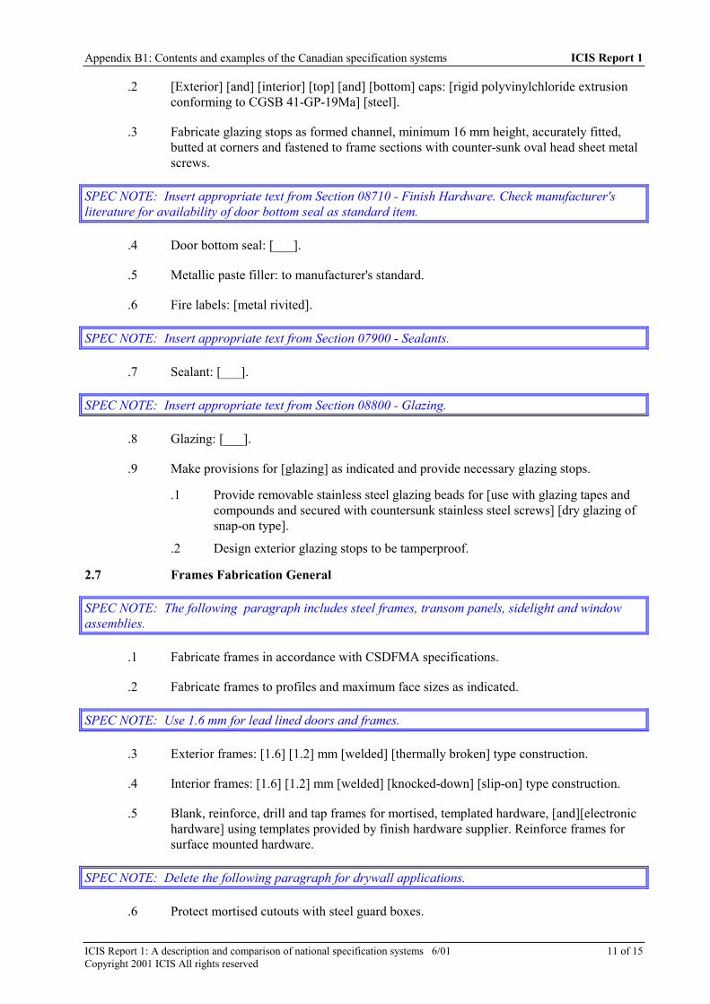
Appendix B1: Contents and examples of the Canadian specification systems ICIS Report 1
ICIS Report 1: A description and comparison of national specification systems 6/01 11 of 15Copyright 2001 ICIS All rights reserved
.2 [Exterior] [and] [interior] [top] [and] [bottom] caps: [rigid polyvinylchloride extrusionconforming to CGSB 41-GP-19Ma] [steel].
.3 Fabricate glazing stops as formed channel, minimum 16 mm height, accurately fitted,butted at corners and fastened to frame sections with counter-sunk oval head sheet metalscrews.
SPEC NOTE: Insert appropriate text from Section 08710 - Finish Hardware. Check manufacturer'sliterature for availability of door bottom seal as standard item.
.4 Door bottom seal: [___].
.5 Metallic paste filler: to manufacturer's standard.
.6 Fire labels: [metal rivited].
SPEC NOTE: Insert appropriate text from Section 07900 - Sealants.
.7 Sealant: [___].
SPEC NOTE: Insert appropriate text from Section 08800 - Glazing.
.8 Glazing: [___].
.9 Make provisions for [glazing] as indicated and provide necessary glazing stops.
.1 Provide removable stainless steel glazing beads for [use with glazing tapes andcompounds and secured with countersunk stainless steel screws] [dry glazing ofsnap-on type].
.2 Design exterior glazing stops to be tamperproof.
2.7 Frames Fabrication General
SPEC NOTE: The following paragraph includes steel frames, transom panels, sidelight and windowassemblies.
.1 Fabricate frames in accordance with CSDFMA specifications.
.2 Fabricate frames to profiles and maximum face sizes as indicated.
SPEC NOTE: Use 1.6 mm for lead lined doors and frames.
.3 Exterior frames: [1.6] [1.2] mm [welded] [thermally broken] type construction.
.4 Interior frames: [1.6] [1.2] mm [welded] [knocked-down] [slip-on] type construction.
.5 Blank, reinforce, drill and tap frames for mortised, templated hardware, [and][electronichardware] using templates provided by finish hardware supplier. Reinforce frames forsurface mounted hardware.
SPEC NOTE: Delete the following paragraph for drywall applications.
.6 Protect mortised cutouts with steel guard boxes.

Appendix B1: Contents and examples of the Canadian specification systems ICIS Report 1
ICIS Report 1: A description and comparison of national specification systems 6/01 12 of 15Copyright 2001 ICIS All rights reserved
.7 Prepare frame for door silencers, 3 for single door, 2 at head for double door.
SPEC NOTE: Use the following paragraph after considering maintenance requirements. Nameplatesmay be required to determine manufacturer when maintenance is required. Location of nameplates canbe specified on hinge side of frame concealed from view.
.8 Manufacturer's nameplates on frames and screens are not permitted.
.9 Conceal fastenings except where exposed fastenings are indicated.
.10 Provide factory-applied touch up primer at areas where zinc coating has been removedduring fabrication.
SPEC NOTE: Thermally broken frame product, louvres or dampers in transoms or angled or radiusedcorners, heads or transoms are not available as fire labelled product.
.11 Insulate exterior frame components with polyurethane insulation.
2.8 Frame Anchorage
.1 Provide appropriate anchorage to floor and wall construction.
.2 Locate each wall anchor immediately above or below each hinge reinforecement onhinge jamb and directly opposite on strike jamb.
.3 Provide 2 anchors for rebate opening heights up to 1520 mm and 1 additional anchor foreach additional 760 mm of height or fraction thereof.
SPEC NOTE: Use the following paragraph to specify frame anchors in previously placed concrete,masonry or steel.
.4 Locate anchors for frames in existing openings not more than 150 mm from top andbottom of each jambs and intermediate at 660 mm o.c. maximum.
2.9 Frames: Welded Type
SPEC NOTE: Transom frames, sidelight and window assemblies are generally available as welded typeproduct only.
.1 Welding in accordance with CSA W59.
.2 Accurately mitre or mechanically joint frame product and securely weld on inside ofprofile.
.3 Cope accurately and securely weld butt joints of mullions, transom bars, centre rails andsills.
.4 Grind welded joints and corners to a flat plane, fill with metalic paste and sane touniform smooth finish.
.5 Securely attach floor anchors to inside of each jamb profile.
.6 Weld in 2 temporary jamb spreaders per frame to maintain proper alignment duringshipment.

Appendix B1: Contents and examples of the Canadian specification systems ICIS Report 1
ICIS Report 1: A description and comparison of national specification systems 6/01 13 of 15Copyright 2001 ICIS All rights reserved
SPEC NOTE: Use the following paragraph to specify fabrication and splicing of units that due to siteaccess or shipping limitations have to be fabricated in sections and site assembled. Specify openings andsizes.
.7 Fabricate frame products for openings [___] in sections, [___] x [___] mm, splice jointsfor field assembly.
SPEC NOTE: Use the following paragraph only when lead-lining is an integral part of frame assembly.
.8 Securely attach lead to inside of frame profile from return to jamb soffit (inclusive) ondoor side of frame only.
SPEC NOTE: Delete all of the following paragraphs for lead lined steel frames.
2.10 Frames: Knocked-Down Type
SPEC NOTE: Components for knocked-down type frames are intended to be assembled as completeunits prior to installation.
.1 Ship knocked-down type frames unassembled.
.2 Provide frames with mechanical joints which inter-lock securely and providefunctionally satisfactory performance when assembled and installed in accordance withCSDFMA Recommended Installation Guide for Steel Doors and Frames.
.3 Securely attach floor anchors to inside of each jamb profile.
SPEC NOTE: Delete all of the following paragraphs for lead lined steel frames.
2.11 Frames: Slip-on Type
SPEC NOTE: Components for slip-on type frames are intended for installation in rough stud openingafter drywall has been applied.
.1 Ship slip-on type frames unassembled.
.2 Provide frames with mechanical joints which inter-lock securely and providefunctionally satisfactory performance when installed in accordance with CSDFMARecommended Installation Guide for Steel Doors and Frames and manufacturers'instructions.
.3 Provide slip-on frames with manufacturers' proprietary design of wall anchoragecomprising single, adjustable tension type per jamb and provision for secure attachmentof each jamb base to stud runners.
2.12 Door Fabrication General
.1 Doors: swing type, flush, with provision for glass and/or louvre openings as indicated.
SPEC NOTE: Use honeycomb core construction for lead lined doors.
.2 Exterior doors: [honeycomb] [hollow steel] construction. Interior doors: [honeycomb][hollow steel] construction.

Appendix B1: Contents and examples of the Canadian specification systems ICIS Report 1
ICIS Report 1: A description and comparison of national specification systems 6/01 14 of 15Copyright 2001 ICIS All rights reserved
SPEC NOTE: For lead lined doors specify edges as either mechanically interlocked or mechanicallyinterlocked, adhesive assisted. Specify seams as visible.
.3 Fabricate doors with longitudinal edges [locked seam] [locked seamed, adhesiveassisted] [welded]. Seams: [visible] [grind welded joints to a flat plane, fill with metallicpaste filler and sand to a uniform smooth finish].
.4 Doors: manufacturers' proprietary construction, tested and/or engineered as part of afully operable assembly, including door, frame, gasketing and hardware in accordancewith ASTM E 330 to provide blast resistance of [___].
.5 Blank, reinforce, drill doors and tap for mortised, templated hardware [and][electronichardware].
SPEC NOTE: Holes less than 12.7 mm diameter can be factory prepared when required for function ofdevice (for knob, lever, cylinder, thumb or turn pieces) or when these holes over-lap function holes.Determine project requirements and specify here.
.6 Factory prepare holes 12.7 mm diameter and larger except mounting and through-boltholes, on site, at time of hardware installation.
.7 Reinforce doors where required, for surface mounted hardware. Provide flush [PVC][steel] top caps to exterior doors. Provide inverted, recessed, spot welded channels to topand bottom of interior doors.
.8 Provide factory-applied touch-up primer at areas where zinc coating has been removedduring fabrication.
.9 Provide fire labelled doors for those openings requiring fire protection ratings, asscheduled. Test such products in strict conformance with CAN4-S104, ASTM E 152 orNFPA 252 and list by nationally recognized agency having factory inspection serviceand construct as detailed in Follow-Up Service Procedures/Factory Inspection Manualsissued by listing agency to individual manufacturers.
SPEC NOTE: Use the following paragraph after considering maintenance requirements. Nameplatesmay be required to determine manufacturer when maintenance is required. Location of nameplates canbe specified on hinge side of door concealed from view.
.10 Manufacturer's nameplates on doors are not permitted.
2.13 Doors: Honeycomb Core Construction
SPEC NOTE: 'Honeycomb' is standard door core material. For insulated doors specify polystyrene orpolyurethane core. For temperature rise rated doors specify TRR core, with 1.6 or 1.2 mm face sheets.
.1 Form each face sheet for exterior doors from [1.6] [1.2] [1.0] mm sheet steel with[honeycomb] [polystyrene] [polyurethane] core laminated under pressure to face sheets.
.2 Form each face sheet for interior doors from [1.6] [1.2] [1.0] mm sheet steel with[honeycomb] - [temperature rise rated] core laminated under pressure to face sheets.

Appendix B1: Contents and examples of the Canadian specification systems ICIS Report 1
ICIS Report 1: A description and comparison of national specification systems 6/01 15 of 15Copyright 2001 ICIS All rights reserved
2.14 Hollow Steel Construction
SPEC NOTE: Fibreglass is standard core material. Polystyrene or polyurethane core can also bespecified for insulated doors. For temperature rise rated doors specify TRR core. Welded seams areavailable only with fibreglass and temperature rise rated cores.
.1 Form each face sheet for exterior doors from [1.6] [1.2] mm sheet steel.
.2 Form each face sheet for interior doors from [1.6] [1.2] sheet steel.
.3 Reinforce doors with vertical stiffeners, securely [welded][laminated] to each face sheetat 150 mm on centre maximum.
.4 Fill voids between stiffeners of exterior doors with [fibreglass][honeycomb][polystyrene] [polyurethane] core.
.5 Fill voids between stiffeners of interior doors with [fibreglass] [honeycomb][temperaturerise rated] core.
2.15 Thermally Broken Doors and Frames
SPEC NOTE: When thermally broken doors and frames are selected, specify factory sealed double-glazed units for glazing.
.1 Fabricate thermally broken doors by using insulated core and separating exterior partsfrom interior parts with continuous interlocking thermal break.
.2 Thermal break: rigid polyvinylchloride extrusion conforming to CGSB 41-GP-19Ma.
.3 Fabricate thermally broken frames separating exterior parts form interior parts withcontinuous interlocking thermal break.
.4 Apply insulation.
PART 3 EXECUTION
3.1 Installation General
SPEC NOTE: Use the following paragraph when fire doors are specified.
.1 Install labelled steel fire rated doors and frames to NFPA 80 except where specifiedotherwise.
.2 Install doors and frames to CSDFMA Installation Guide.
3.2 Frame Installation
SPEC NOTE: When voids between exterior frames and exterior wall components are to be filled withinsulation, coordinate requirement with Division 07 insulation sections and specify.
.1 Set frames plumb, square, level and at correct elevation.
.2 Secure anchorages and connections to adjacent construction.

Appendix B1: Contents and examples of the Canadian specification systems ICIS Report 1
ICIS Report 1: A description and comparison of national specification systems 6/01 16 of 15Copyright 2001 ICIS All rights reserved
.3 Brace frames rigidly in position while building-in. Install temporary horizontal woodspreader at third points of door opening to maintain frame width. Provide verticalsupport at centre of head for openings over 1200 mm wide. Remove temporary spreadersafter frames are built-in.
.4 Make allowances for deflection of structure to ensure structural loads are not transmittedto frames.
.5 Caulk perimeter of frames [between frame and adjacent material].
.6 Maintain continunity of [air barrier] [and] [vapour retarder].
3.3 Door Installation
.1 Install doors and hardware in accordance with hardware templates and manufacturer'sinstructions and Section [08710 - Door Hardware].
SPEC NOTE: Use the following paragraph when fire doors are specified.
.2 Provide even margins between doors and jambs and doors and finished floor[andthresholds] as follows.
.1 Hinge side: 1.0 mm.
.2 Latchside and head: 1.5 mm.
.3 Finished floor, [top of carpet] [noncombustible sill] [and thresholds]: 13 mm.
.3 Adjust operable parts for correct function.
.4 Install louvres.
3.4 Finish Repairs
.1 Touch up with primer finishes damaged during installation.
.2 Fill exposed frame anchors [and] [surfaces with imperfections] with metallic paste fillerand sand to a uniform smooth finish.
3.5 Glazing
.1 Install glazing for doors [and] [frames]in accordance with Section [08800 - Glazing].
END OF SECTION

ICIS Report 1: A description and comparison of national specification systems 6/01 1 of 10Copyright 2001 ICIS All rights reserved
APPENDIX B2: CONTENTS AND EXAMPLES OF THE DIGICONSPECIFICATION SYSTEMS
CONTENTS OF THESE SYSTEMS
DIGICON’S MasterPP LISTING
PP-1 PROJECT CRITERIAProject AbstractDesign AssumptionsProject CalculationsProject QualityProject Bid RequirementsProject Form of ContractProject GeneralRequirementsExisting Facilities
PP-2 SITEDesign CalculationsPreparationEarthworkSite ServicesPavementsSurface ImprovementsOther Site Construction
PP-3 SUBSTRUCTUREDesign CalculationsFoundationsBasement/SubgradeFloor and WallsService TunnelSubgrade ProtectionFoundation Drainage
PP-4 SUPERSTRUCTUREDesign CalculationsFramingBearing WallsFloor and Flat RoofConstructionMezzanine ConstructionSloped RoofConstructionStair ConstructionFraming AccessoriesSpecial StructuresSpecial Construction
PP-5 EXTERIOR CLOSUREDesign CalculationsExterior WallsExterior Wall OpeningsFlat Roof CoveringsSloped Roof CoveringsRoof AccessoriesRoof OpeningsExterior Specialties
PP-6 INTERIORSEPARATIONDesign RequirementsVertical SeparationsCeiling ConstructionInterior OpeningsInterior Finishes(including stairwells)Stair SpecialtiesInterior Specialties
PP-7 INTERIORSPECIALTIESInterior EquipmentInstitutional EquipmentVehicular EquipmentFood Service EquipmentSanitation EquipmentOther EquipmentFixed FurnishingsMoveable FurnishingsSpecial ConstructionTransportationMaterial HandlingScaffoldingSpecial Transportation
PP-8 ENVIRONMENTSERVICESDesign CalculationsPlumbingFire ProtectionHVACControls andInstrumentationCommissioning
PP-9 ELECTRIC SERVICESDesign CalculationsPowerLightingSafety SystemsCommunication SystemsCommissioning

Appendix B2: Contents and examples of the Canadian specification systems ICIS Report 1
ICIS Report 1: A description and comparison of national specification systems 6/01 2 of 10Copyright 2001 ICIS All rights reserved
DIGICON’S OutlineSPEC LISTING
Bid and Contract Requirements00-10 Project Suppositions00-20 Project Design and
Requirements00-70 Bid Information00-80 Contract Information
Division 1 - General Requirements01-10 Contract Summary01-20 Project Requirements01-30 Facility Activation01-40 Facility Operation01-90 Facility Shut-down
Division 2 - Site Construction02-10 Preparation02-20 Earthwork02-30 Foundations02-40 Utility Services02-50 Pavements02-60 Surface Improvements02-70 Hazardous Products02-90 Site Article Restoration
Division 3 - Concrete03-10 Concrete Frame03-20 Fabricated Concrete03-30 Associated Concrete03-90 Concrete Restoration
Division 4 - Masonry04-10 Masonry Assemblies04-20 Decorative Masonry04-30 Stone Assemblies04-90 Masonry Restoration
Division 5 - Metals05-10 Structural Metal Framing05-20 Metal Accessories05-90 Metal Restoration
Division 6 - Wood and Plastics06-10 Structural wood Framing06-20 Wood Finishing06-30 Plastic Fabrications06-90 Wood Restoration
Division 7 - Thermal andMoisture Protection07-10 Subgrade Protection07-20 Enclosure Protection07-30 Siding07-40 Sloped Roofs07-50 Flat Roofs07-60 Roof Specialties07-90 Wall/Roof Restoration
Division 8 - Doors and Windows08-10 Doors and Frames08-20 Windows
08-30 Glazed Assemblies
Division 9 - Finishes09-10 Floor Finishes09-20 Wall Finishes09-30 Ceiling Finishes09-40 Coating Finishes09-90 Finishes Restoration
Division 10 - Specialties10-10 Space Dividers10-20 Room Accessories10-30 Specialties10-90 Specialties Restoration
Division 11 - Equipment11-10 Vehicle Equipment11-20 Food Services Equipment11-30 Institutional Equipment11-90 Equipment Restoration
Division 12 - Furnishings12-10 Room Treatment12-90 Furnishings Restoration
Division 13 - Special Construction13-10 Environment Controlled
Spaces13-20 Special Purpose Spaces13-30 Aquatic Facilities13-40 Engineered Assemblies13-50 Automated Controls13-60 Detection and Alarm13-70 Fire Suppression
Division 14 - Conveying Systems14-10 Vertical Transportation14-20 Inclined Transportation
Division 15 - Mechanical15-10 Basic Materials15-20 Plumbing15-30 Heating, Ventilating, and
Air Conditioning15-40 Equipment Controls15-50 Test, Adjust, and Balance
Division 16 - Electrical16-10 Basic Materials16-20 Power, Transmission,
and Distribution16-30 Lighting16-40 Communication and
Alarms16-50 Heating Cables and Mats16-60 Equipment Controls

Appendix B2: Contents and examples of the Canadian specification systems ICIS Report 1
ICIS Report 1: A description and comparison of national specification systems 6/01 3 of 10Copyright 2001 ICIS All rights reserved
CMS, MiniSPEC and RenoSPEC SECTION LISTINGS USED BY DIGICON(These specification products rely on work section naming standards established by MasterFormat; a defacto industrystandard classification system shared with USA).
Bid and Contract Requirements
00001 Project Title Page00005 Certifications Page00007 Seals Page00010 Table of Contents00015 List of Drawings00020 List of Schedules
00100 Bid Solicitation00200 Instructions To Bidders00300 Information Available To
Bidders00400 Bid Forms and
Supplements00490 Bidding Addenda
00500 Agreement00600 Bonds and Certificates00700 General Conditions00800 Supplementary
Conditions00900 Addenda and
Modifications
Division 1 — General Requirements01100 Summary01200 Price and Payment
Procedures01300 Administrative
Requirements01400 Quality Requirements01500 Temporary Facilities and
Controls01600 Product Requirements01700 Execution Requirements
01800 Facility Operation01900 Facility
Decommissioning
Division 2 - Site Construction02050 Basic Site Materials and
Methods02100 Site Remediation02200 Site Preparation02300 Earthwork02400 Tunneling, Boring, and
Jacking02450 Foundation and Load
Bearing Elements02500 Utility Services02600 Drainage and
Containment02700 Bases, Ballasts,
Pavements, andAppurtenances
02800 Site Improvements and
Amenities02900 Planting02950 Site Restoration and
Rehabilitation
Division 3 - Concrete03050 Basic Concrete Materials
and Methods03100 Concrete Forms and
Accessories03200 Concrete Reinforcement03300 Cast-in-place Concrete03400 Precast Concrete
03500 Cementitious Decks andUnderlayment
03600 Grouts03700 Mass Concrete03900 Concrete Restoration and
Cleaning
Division 4 - Masonry04050 Basic Masonry Materials
and Methods04200 Masonry Units04400 Stone04500 Refractories04600 Corrosion Resistant
Masonry04700 Simulated Masonry04800 Masonry Assemblies04900 Masonry Restoration and
Cleaning
Division 5 - Metals05050 Basic Metal Materials
and Methods05100 Structural Metal Framing05200 Metal Joists05300 Metal Deck05400 Cold Formed Metal
Framing05500 Metal Fabrications05600 Hydraulic Fabrications05650 Railroad Track and
Accessories05700 Ornamental Metal05800 Expansion Control05900 Metal Restoration and
Cleaning
Division 6 - Wood and Plastics06050 Basic Wood and Plastic
Materials and Methods06100 Rough Carpentry06200 Finish Carpentry06400 Architectural Woodwork06500 Structural Plastics
06600 Plastic Fabrications06900 Wood and Plastic
Restoration and CleaningDivision 7 - Thermal and MoistureProtection07050 Basic Thermal and
Moisture ProtectionMaterials and Methods
07100 Dampproofing andWaterproofing
07200 Thermal Protection07300 Shingles, Roof Tiles, and
Roof Coverings07400 Roofing and Siding
Panels07500 Membrane Roofing07600 Flashing and Sheet Metal07700 Roof Specialties and
Accessories07800 Fire and Smoke
Protection07900 Joint Sealers
Division 8 - Doors and Windows08050 Basic Door and Window
Materials and Methods08100 Metal Doors and Frames08200 Wood and Plastic Doors08300 Specialty Doors08400 Entrances and Storefronts08500 Windows08600 Skylights08700 Hardware08800 Glazing08900 Glazed Curtain Wall
Division 9 - Finishes09050 Basic Finish Materials
and Methods09100 Metal Support
Assemblies09200 Plaster and Gypsum
Board09300 Tile09400 Terrazzo09500 Ceilings09600 Flooring09700 Wall Finishes09800 Acoustical Treatment09900 Paints and Coatings
Division 10 - Specialties10100 Visual Display Boards10150 Compartments and
Cubicles10200 Louvers and Vents10240 Grilles and Screens10250 Service Walls
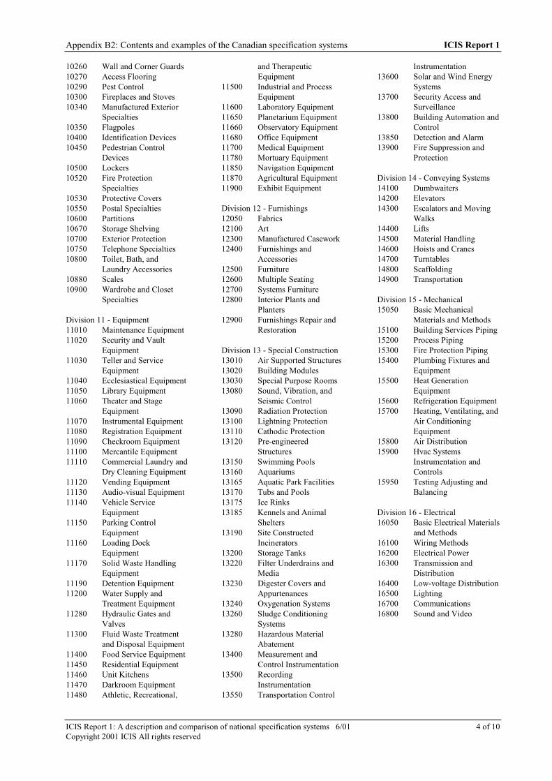
Appendix B2: Contents and examples of the Canadian specification systems ICIS Report 1
ICIS Report 1: A description and comparison of national specification systems 6/01 4 of 10Copyright 2001 ICIS All rights reserved
10260 Wall and Corner Guards10270 Access Flooring10290 Pest Control10300 Fireplaces and Stoves10340 Manufactured Exterior
Specialties10350 Flagpoles10400 Identification Devices10450 Pedestrian Control
Devices10500 Lockers10520 Fire Protection
Specialties10530 Protective Covers10550 Postal Specialties10600 Partitions10670 Storage Shelving10700 Exterior Protection10750 Telephone Specialties10800 Toilet, Bath, and
Laundry Accessories10880 Scales10900 Wardrobe and Closet
Specialties
Division 11 - Equipment11010 Maintenance Equipment11020 Security and Vault
Equipment11030 Teller and Service
Equipment11040 Ecclesiastical Equipment11050 Library Equipment11060 Theater and Stage
Equipment11070 Instrumental Equipment11080 Registration Equipment11090 Checkroom Equipment11100 Mercantile Equipment11110 Commercial Laundry and
Dry Cleaning Equipment11120 Vending Equipment11130 Audio-visual Equipment11140 Vehicle Service
Equipment11150 Parking Control
Equipment11160 Loading Dock
Equipment11170 Solid Waste Handling
Equipment11190 Detention Equipment11200 Water Supply and
Treatment Equipment11280 Hydraulic Gates and
Valves11300 Fluid Waste Treatment
and Disposal Equipment11400 Food Service Equipment11450 Residential Equipment11460 Unit Kitchens11470 Darkroom Equipment11480 Athletic, Recreational,
and TherapeuticEquipment
11500 Industrial and ProcessEquipment
11600 Laboratory Equipment11650 Planetarium Equipment11660 Observatory Equipment11680 Office Equipment11700 Medical Equipment11780 Mortuary Equipment11850 Navigation Equipment11870 Agricultural Equipment11900 Exhibit Equipment
Division 12 - Furnishings12050 Fabrics12100 Art12300 Manufactured Casework12400 Furnishings and
Accessories12500 Furniture12600 Multiple Seating12700 Systems Furniture12800 Interior Plants and
Planters12900 Furnishings Repair and
Restoration
Division 13 - Special Construction13010 Air Supported Structures13020 Building Modules13030 Special Purpose Rooms13080 Sound, Vibration, and
Seismic Control13090 Radiation Protection13100 Lightning Protection13110 Cathodic Protection13120 Pre-engineered
Structures13150 Swimming Pools13160 Aquariums13165 Aquatic Park Facilities13170 Tubs and Pools13175 Ice Rinks13185 Kennels and Animal
Shelters13190 Site Constructed
Incinerators13200 Storage Tanks13220 Filter Underdrains and
Media13230 Digester Covers and
Appurtenances13240 Oxygenation Systems13260 Sludge Conditioning
Systems13280 Hazardous Material
Abatement13400 Measurement and
Control Instrumentation13500 Recording
Instrumentation13550 Transportation Control
Instrumentation13600 Solar and Wind Energy
Systems13700 Security Access and
Surveillance13800 Building Automation and
Control13850 Detection and Alarm13900 Fire Suppression and
Protection
Division 14 - Conveying Systems14100 Dumbwaiters14200 Elevators14300 Escalators and Moving
Walks14400 Lifts14500 Material Handling14600 Hoists and Cranes14700 Turntables14800 Scaffolding14900 Transportation
Division 15 - Mechanical15050 Basic Mechanical
Materials and Methods15100 Building Services Piping15200 Process Piping15300 Fire Protection Piping15400 Plumbing Fixtures and
Equipment15500 Heat Generation
Equipment15600 Refrigeration Equipment15700 Heating, Ventilating, and
Air ConditioningEquipment
15800 Air Distribution15900 Hvac Systems
Instrumentation andControls
15950 Testing Adjusting andBalancing
Division 16 - Electrical16050 Basic Electrical Materials
and Methods16100 Wiring Methods16200 Electrical Power16300 Transmission and
Distribution16400 Low-voltage Distribution16500 Lighting16700 Communications16800 Sound and Video
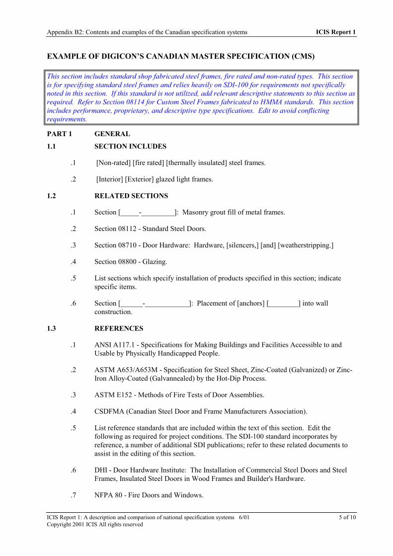
Appendix B2: Contents and examples of the Canadian specification systems ICIS Report 1
ICIS Report 1: A description and comparison of national specification systems 6/01 5 of 10Copyright 2001 ICIS All rights reserved
EXAMPLE OF DIGICON’S CANADIAN MASTER SPECIFICATION (CMS)
This section includes standard shop fabricated steel frames, fire rated and non-rated types. This sectionis for specifying standard steel frames and relies heavily on SDI-100 for requirements not specificallynoted in this section. If this standard is not utilized, add relevant descriptive statements to this section asrequired. Refer to Section 08114 for Custom Steel Frames fabricated to HMMA standards. This sectionincludes performance, proprietary, and descriptive type specifications. Edit to avoid conflictingrequirements.
PART 1 GENERAL
1.1 SECTION INCLUDES
.1 [Non-rated] [fire rated] [thermally insulated] steel frames.
.2 [Interior] [Exterior] glazed light frames.
1.2 RELATED SECTIONS
.1 Section [_____-_________]: Masonry grout fill of metal frames.
.2 Section 08112 - Standard Steel Doors.
.3 Section 08710 - Door Hardware: Hardware, [silencers,] [and] [weatherstripping.]
.4 Section 08800 - Glazing.
.5 List sections which specify installation of products specified in this section; indicatespecific items.
.6 Section [______-____________]: Placement of [anchors] [________] into wallconstruction.
1.3 REFERENCES
.1 ANSI A117.1 - Specifications for Making Buildings and Facilities Accessible to andUsable by Physically Handicapped People.
.2 ASTM A653/A653M - Specification for Steel Sheet, Zinc-Coated (Galvanized) or Zinc-Iron Alloy-Coated (Galvannealed) by the Hot-Dip Process.
.3 ASTM E152 - Methods of Fire Tests of Door Assemblies.
.4 CSDFMA (Canadian Steel Door and Frame Manufacturers Association).
.5 List reference standards that are included within the text of this section. Edit thefollowing as required for project conditions. The SDI-100 standard incorporates byreference, a number of additional SDI publications; refer to these related documents toassist in the editing of this section.
.6 DHI - Door Hardware Institute: The Installation of Commercial Steel Doors and SteelFrames, Insulated Steel Doors in Wood Frames and Builder's Hardware.
.7 NFPA 80 - Fire Doors and Windows.

Appendix B2: Contents and examples of the Canadian specification systems ICIS Report 1
ICIS Report 1: A description and comparison of national specification systems 6/01 6 of 10Copyright 2001 ICIS All rights reserved
.8 NFPA 252 - Fire Tests for Door Assemblies.
.9 SDI-100 - Standard Steel Doors and Frames.
.10 UL 10B - Fire Tests of Door Assemblies.
1.4 SUBMITTALS FOR REVIEW
Do not request submittals if drawings sufficiently describe the products of this section or if proprietaryspecifying techniques are used. The review of submittals increases the possibility of unintendedvariations to drawings, thereby increasing the Specifier's liability. The following submittals are intendedfor review and approval or other action by the Consultant. Include a requirement for shop drawingsonly for special frame configurations or conditions. Include product data only if required to supplementshop drawing information.
.1 Section 01300: Submission procedures.
.2 Product Data: Indicate frame configuration and finishes.
.3 Shop Drawings: Indicate frame elevations, reinforcement, anchor types and spacings,location of cut-outs for hardware, and finish.
.4 Include the following paragraph for submission of physical samples for selection offinish, colour, texture, etc.
.5 Samples: Submit [two] [_______] samples of frame, <[____x____] mm><<[____x____] inch>> in size illustrating factory finished frame colours and surfacetexture.
1.5 SUBMITTALS FOR INFORMATION
The following submittals are informational; responsive action by the Consultant is not required.
.1 Section 01300: Submission procedures.
.2 Manufacturer's Installation Instructions: Indicate special installation instructions.
.3 Manufacturer's Certificate: Certify that [Products] [________] meet or exceed [specifiedrequirements.] [________.]
1.6 QUALITY ASSURANCE
Include the last sentence of the following paragraph only when the costs of acquiring the specifiedstandards are justified.
.1 Conform to requirements of [CSDFMA] [SDI-100] [and ANSI A117.1]. [Maintain [onecopy] [[____] copies] of [each] document on site.]
.2 Manufacturer: Company specializing in manufacturing the Products specified in thissection with minimum [three] [_______] years [documented] experience.
1.7 REGULATORY REQUIREMENTS
One or more of the following standards must be selected as applicable to fire rated doors, as appropriateto authority having jurisdiction.
.1 Fire Rated Frame Construction: Conform to [ASTM E152] [NFPA 252] [UL 10B].

Appendix B2: Contents and examples of the Canadian specification systems ICIS Report 1
ICIS Report 1: A description and comparison of national specification systems 6/01 7 of 10Copyright 2001 ICIS All rights reserved
.2 Installed Frame Assembly: Conform to [NFPA 80] [_________] for fire rated classsame as fire door.
1.8 DELIVERY, STORAGE, AND PROTECTION
.1 Section 01600: Transport, handle, store, and protect products.
.2 Accept frames on site in manufacturer's packaging. Inspect for damage.
1.9 PROJECT CONDITIONS
.1 Section 01300: Coordination and meetings.
.2 Coordinate the work with frame opening construction, door, and hardware installation.
.3 Include the following paragraph if electric hardware components are contained withinthe frame construction.
.4 Sequence installation to ensure wire connections are achieved in an orderly andexpeditious manner.
PART 2 PRODUCTS
2.1 FRAME MANUFACTURERS
In this article, list the manufacturers acceptable for this project. Edit the subsequent descriptivespecifications to identify project requirements and to eliminate any conflict with specified manufacturer'sproducts.
.1 [_________________________________] Model [________].
.2 [_________________________________] Model [________].
.3 [_________________________________] Model [________].
.4 Substitutions: [Refer to Section 01600.] [Not permitted.]
2.2 FRAMES
SDI-100 identifies differing frame thicknesses for differing grades and models of doors specified.
.1 Frames: To suit [CSDFMA] [SDI-100 Grade and Model of] door specified in Section[08111.] [________.]
[OR]
.2 Exterior Frames:
.1 Grade I for Door Type [1] [2], <[1.2] [1.5] [____] mm> <<[0.047] [0.058][____] inch>> thick material, base metal thickness.
.2 Grade II for Door Type [1] [2], <[1.5] [____] mm> <<[0.058] [____] inch>>thick material, base metal thickness.
.3 Grade III for Door Type [1] [2] [3], <[1.5] [1.8] [____] mm> <<[0.058] [0.070][____] inch>> thick material, base metal thickness.
.4 Grade III for Door Type [1a] [2a], <[1.8] [2.5] [____] mm> <<[0.070] [0.099][____] inch>> thick material, base metal thickness.

Appendix B2: Contents and examples of the Canadian specification systems ICIS Report 1
ICIS Report 1: A description and comparison of national specification systems 6/01 8 of 10Copyright 2001 ICIS All rights reserved
.3 Interior Frames:
.1 Grade I for Door Type [1] [2], <[1.2] [1.5] [____] mm> <<[0.047] [0.058][____] inch>> thick material, base metal thickness.
.2 Grade II for Door Type [1] [2], <[1.5] [____] mm> <<[0.058] [____] inch>>thick material, base metal thickness.
.3 Grade III for Door Type [1] [2] [3], <[0.058] [1.5] [1.8] [____] mm> <<[0.070][____] inch>> thick material, base metal thickness.
.4 Grade III for Door Type [1a] [2a], <[1.8] [2.5] [____] mm> <<[0.070] [0.099][____] inch>> thick material, base metal thickness.
2.3 ACCESSORIES
.1 Removable Stops: Rolled [steel] [aluminum] [channel] [________] shape, [butted][mitered] corners; prepared for countersink style [tamper proof] screws.
.2 Bituminous Coating: [Fibered asphalt emulsion.] [________.]
.3 Primer: [Zinc chromate] [_________] type.
.4 Silencers: [Specified in Section [08710] [________].] [Resilient [rubber] [vinyl] set in[steel] [aluminum] channel] [fitted into drilled hole] [stick-on type].]
.5 Weatherstripping: [Specified in Section [08710] [________].] [Resilient [rubber] [vinyl]set in [steel] [aluminum] frame.]
2.4 FABRICATION
Welded or knock-down frame types may be used for fire rated openings up to and including 3 hours. Gypsum board slip on types may only be used for openings rated less than 3 hours.
.1 Fabricate frames [as welded unit.] [for knock down field assembly.] [for gypsum boardslip on type.]
.2 Mullions for Double Doors: [Fixed] [Removable] type, of same profiles as jambs.
.3 Transom Bars for Glazed Lights: Fixed type, of same profiles as jamb and head.
.4 Fabricate frames with hardware reinforcement plates welded in place. [Provide mortarguard boxes.]
.5 Reinforce frames wider than <[1 200] [____] mm> <<[48] [____] inches>> with rollformed steel channels fitted tightly into frame head, flush with top.
.6 Utilize the following paragraph for "hospital" stops or where stop must terminate abovethe finished floor.
.7 Terminate door stops <[150] [_________] mm> <<[6] [_________] inches>> abovefinished floor. Cut stop at [45] [90] degree angle and close.
.8 Prepare frames for silencers. Provide [three] [____] single silencers for single doors[and mullions of double doors] on strike side. Provide [two] [____] single silencers onframe head at double doors without mullions.

Appendix B2: Contents and examples of the Canadian specification systems ICIS Report 1
ICIS Report 1: A description and comparison of national specification systems 6/01 9 of 10Copyright 2001 ICIS All rights reserved
.9 Configure [exterior] frames with special profile to receive recessed weatherstripping.
.10 Attach fire rated label to each fire rated door unit.
.11 Use the following paragraph when drawings do not illustrate special head member size.
.12 Fabricate frames to suit masonry wall coursing with <[100] [50] [____] mm> <<[4] [2][____] inch>> head member.
2.5 FINISH
.1 Steel Sheet: Galvanized to ASTM A653/A653M <[Z180] [ZF180]> << [G60] [A60]>>.
.2 Primer: [Air dried.] [Baked.]
.3 [Factory Finish: [Baked enamel] [Thermosetting epoxy] [_________] of [_________]colour [as selected].]
.4 Include the following paragraph for sound deadening purposes or for protection of steelframe from corrosion when in contact with masonry where corrosive mortar additivesmay be used.
.5 Coat inside of frame profile with bituminous coating to a thickness of <[1.5] [____]mm> <<[1/16] [____] inch >>.
PART 3 EXECUTION
3.1 EXAMINATION
.1 Section 01700: Verification of existing conditions before starting work.
.2 Verify that opening sizes and tolerances are acceptable.
3.2 INSTALLATION
.1 Install frames in accordance with [CSDFMA] [SDI-100] [and] [DHI].
.2 Coordinate with [masonry] [gypsum board] [concrete] [_________] wall construction foranchor placement.
.3 Coordinate installation of glass and glazing.
.4 Coordinate installation of frames with installation of hardware specified in Section[08710] [________] and doors in Section [08111.] [________.]
.5 Install roll formed steel reinforcement channels between two abutting frames. Anchor tostructure and floor.
3.3 ERECTION TOLERANCES
.1 Maximum Diagonal Distortion: <[1.5] [3] [_________] mm> <<[1/16] [1/8][_________] inch>> measured with straight edges, crossed corner to corner.
3.4 SCHEDULE
Provide schedule when door and frame schedules are not described on drawings. The schedule should

Appendix B2: Contents and examples of the Canadian specification systems ICIS Report 1
ICIS Report 1: A description and comparison of national specification systems 6/01 10 of 10Copyright 2001 ICIS All rights reserved
identify various types or categories of doors and associated frames, fire ratings if any, hardware sets,etc.
END OF SECTION

ICIS Report 1: A description and comparison of national specification systems 6/01 1 of 5Copyright 1997 ICIS All rights reserved
APPENDIX C: CONTENTS AND EXAMPLES OF THE CZECHREPUBLIC URS PRAHA SPECIFICATION SYSTEM
CONTENTS OF THE CZECH REPUBLIC URS PRAHA SYSTEM
Summary of construction elements and their groups
Group of construction elements Construction parts Specific(1.digit of the numerical code) (1. and 2.digit of the code unit
0 general structures and work 001 groundworks 10
11 preparatory and associated work m2
12 surface excavations and through digging m3
13 depth excavations m3
14 tunelling m3
15 sheeting, bracing m2
16 moving soil m3
17 structures from soil m3
18 surfacing m2
19 sinking for underground walls, mining m3
2 special foundation, reinforcement 2021 adjustment of bed and ground for
basement jointm2
22 piles m23 pitching walls m2
24 wells m3
25 caissons m3
26 holes m27 basements m3
28 reinforcement of grounds and structures m3
3 vertical and comlex structures 3031 supporting and free walls m3
32 retaining and partition walls m3
33 columns and piers, masts and framestanchions
m3
34 walls and partition walls m2
35 sewers m3
36 tunnels37 tunnel and underground space lining m3, (m2)38 various complex indivisible structures for
constr. partsm3
39 reconstructions of tunnels m3, (m2)4 horizontal structures 40
41 ceilings and ceiling structures - structuralconstructions
m2
42 horizontal load-bearing structure -engineering constructions
m2
43 staircases m2
44 roofing m2
45 basement and adjacent structures withexception of road surfaces andsuperstructures
m2
46 reinforced surfaces with exception ofroad surfaces and superstructure
m2
5 roads and railroads 5051 rail bed m2
52 rail m

Appendix C: Contents and examples of the Czech Republic URS Praha specification system ICIS Report 1
ICIS Report 1: A description and comparison of national specification systems 6/01 2 of 5Copyright 1997 ICIS All rights reserved
53 rail points pcs54 other adjustments of superstructure Kc55 tractive line m56 basic layers of roads and reinforced
surfacesm2
57 covers of gravel and bitumen roads andreinforced surfaces
m2
58 cement-concrete covers of roads andreinforced surfaces
m2
59 paving and repaving of roads andreinforced surfaces
m2
6 adaptation of surfaces, floor and placingof fillings to openings
60
61 adaptation of inner surfaces m2
62 adaptation of outer surfaces m2
63 floors and floor structures m2
64 fillings of openings m2
7 structures and associated constructionproduction works
70
71 insulation m2
72 sanitary - technical installations Kc73 central heating Kc74 heavy-current Kc75 light-current Kc76 other structures Kc77 floors m2
78 completing work Kc79 other structures and associated
construction production worksKc
8 pipe lines 8081 pipeline from concrete pipes m82 pipeline from reinforced concrete and
prestressed concrete pipesm
83 pipeline from stoneware pipes m84 pipeline from asbestos-concrete pipes m85 pipeline from cast-iron pipes m86 pipeline from steel pipes m87 pipeline from plastic, glass and basalt
pipesm
88 pipeline from drain tiles m89 other structures and work on pipelines m
9 other structures and work, demolitions 9091 additional structures and work on roads
and reinforced surfacesKc
92 additional structures and railroad work Kc93 different completing structures and work
on engineering constructionsKc
94 scaffolding and construction hoists m2, (m3)95 different completing structures and work
on structural constructionsKc
96 demolition of structures m3
97 hole punching and other demolition work m3
98 demolition Kc99 moving materials Kc

Appendix C: Contents and examples of the Czech Republic URS Praha specification system ICIS Report 1
ICIS Report 1: A description and comparison of national specification systems 6/01 3 of 5Copyright 1997 ICIS All rights reserved
EXAMPLE OF TEXT FROM THE CZECH REPUBLIC URS PRAHA SYSTEM
Construction part 27 - Foundations
Item Description Nominalunit
Bar CodeMatrix 2/5
271 31 Protection layer of foundation joint from concrete m3
271 41 Joining layer on foundation joint from cement grout m2
271 45 Joining layer on foundation joint from cement or activatedmortar
m2
271 52 Bedding compacted under foundation from ground roughaggregates - macadam
m2
271 53 Bedding compacted under foundation from ground roughaggregates - gravel
m2
271 57 Bedding compacted under foundation from gravel - sand m3
272 21 Foundation masonry of vaults from quarry stone m3
272 31 Foundation masonry of vaults from concrete, mixed withstone, without forming
m3
272 32 Foundation masonry of vaults from reinforced concrete,without forming
m3
272 35 Forming of foundation vaults, onesided and bothsided m2
272 36 Reinforcement of foundation vaults from concrete steel orfrom welded nets
t
273 12 Foundation plates from reinforced concrete parts m3
273 31 Foundation plates from concrete mixed with stone, withoutforming
m3
273 32 Foundation plates from reinforced concrete, withoutreinforcement and forming
m3
273 34 Foundation plates from light compacted concretes, withoutreinforcement and forming
m3
273 35 Forming of foundation plates m2
273 36 Reinforcement of foundation plates from concrete steel orfrom welded nets
t
274 11 Foundation belts, thresholds, collar sets, spurs from concreteparts
m3
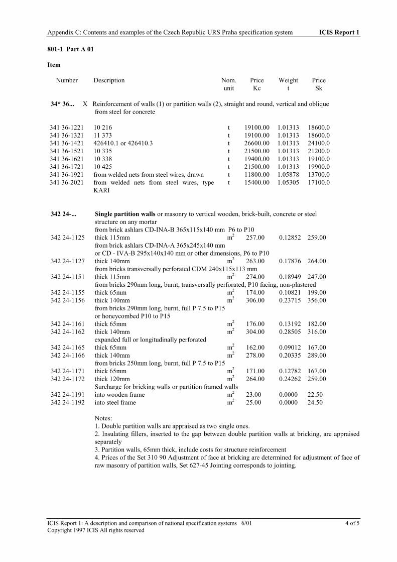
Appendix C: Contents and examples of the Czech Republic URS Praha specification system ICIS Report 1
ICIS Report 1: A description and comparison of national specification systems 6/01 4 of 5Copyright 1997 ICIS All rights reserved
801-1 Part A 01
Item
Number Description Nom.unit
PriceKc
Weightt
PriceSk
34* 36... X Reinforcement of walls (1) or partition walls (2), straight and round, vertical and obliquefrom steel for concrete
341 36-1221 10 216 t 19100.00 1.01313 18600.0341 36-1321 11 373 t 19100.00 1.01313 18600.0341 36-1421 426410.1 or 426410.3 t 26600.00 1.01313 24100.0341 36-1521 10 335 t 21500.00 1.01313 21200.0341 36-1621 10 338 t 19400.00 1.01313 19100.0341 36-1721 10 425 t 21500.00 1.01313 19900.0341 36-1921 from welded nets from steel wires, drawn t 11800.00 1.05878 13700.0341 36-2021 from welded nets from steel wires, type
KARIt 15400.00 1.05305 17100.0
342 24-... Single partition walls or masonry to vertical wooden, brick-built, concrete or steelstructure on any mortarfrom brick ashlars CD-INA-B 365x115x140 mm P6 to P10
342 24-1125 thick 115mm m2 257.00 0.12852 259.00from brick ashlars CD-INA-A 365x245x140 mmor CD - IVA-B 295x140x140 mm or other dimensions, P6 to P10
342 24-1127 thick 140mm m2 263.00 0.17876 264.00from bricks transversally perforated CDM 240x115x113 mm
342 24-1151 thick 115mm m2 274.00 0.18949 247.00from bricks 290mm long, burnt, transversally perforated, P10 facing, non-plastered
342 24-1155 thick 65mm m2 174.00 0.10821 199.00 342 24-1156 thick 140mm m2 306.00 0.23715 356.00
from bricks 290mm long, burnt, full P 7.5 to P15or honeycombed P10 to P15
342 24-1161 thick 65mm m2 176.00 0.13192 182.00 342 24-1162 thick 140mm m2 304.00 0.28505 316.00
expanded full or longitudinally perforated 342 24-1165 thick 65mm m2 162.00 0.09012 167.00 342 24-1166 thick 140mm m2 278.00 0.20335 289.00
from bricks 250mm long, burnt, full P 7.5 to P15 342 24-1171 thick 65mm m2 171.00 0.12782 167.00 342 24-1172 thick 120mm m2 264.00 0.24262 259.00
Surcharge for bricking walls or partition framed walls 342 24-1191 into wooden frame m2 23.00 0.0000 22.50 342 24-1192 into steel frame m2 25.00 0.0000 24.50
Notes:1. Double partition walls are appraised as two single ones.2. Insulating fillers, inserted to the gap between double partition walls at bricking, are appraisedseparately3. Partition walls, 65mm thick, include costs for structure reinforcement4. Prices of the Set 310 90 Adjustment of face at bricking are determined for adjustment of face ofraw masonry of partition walls, Set 627-45 Jointing corresponds to jointing.

Appendix C: Contents and examples of the Czech Republic URS Praha specification system ICIS Report 1
ICIS Report 1: A description and comparison of national specification systems 6/01 5 of 5Copyright 1997 ICIS All rights reserved
Number Description Nom.unit
PriceKc
Weightt
PriceSk
342 24- Single partition walls from diagonal bricks on any mortar, burnt, in dimensions: 342 24-2122 390x190x40mm m2 132.00 0.05249 141.00 342 24-2128 290x140x40mm m2 145.00 0.06591 140.00 342 24-2129 290x140x65mm m2 162.00 0.09011 167.00
Notes:1. Double partition walls are appraised as two single ones.
324 25- Partition walls from fibrebond plates or blocks with bandaging gaps,without trellis work coatingto any mortar, thickness:
342 25-2121 35mm (Lignos) m2 145.00 0.02619 138.00 342 25-3111 50mm m2 161.00 0.03059 158.00
from porous concrete, gas concrete (e.g. Siporex),or gas silicate plates or blocks, thickness:
342 25-4511 70 - 80mm m2 162.00 0.09040 164.00 342 25-4611 90 - 100mm m2 196.00 0.11930 199.00 324 25-4711 120 - 130mm m2 259.00 0.17504 255.00 324 25-4811 140 - 150mm m2 233.00 0.15418 257.00

ICIS Report 1: A description and comparison of national specification systems 6/01 1 of 1Copyright 1997 ICIS All rights reserved
APPENDIX D: CONTENTS OF THE FINNISH SPECIFICATION SYSTEM
PRELIMINARIES
0 General quality requirements related to theproject
SITEWORK
1 Ground investigation2 Demolition and site preparation3 Excavation4 Blasting5 Piling and soil stabilization6 Draining and pipework in the ground7 Substructures and frost protection8 Paving and surfacing9 Vegetation work
STRUCTURAL WORK
Structural work in situ10 Concrete11 Masonry12 Structural timber13 Structural steel14 Structural aluminium
Structural component work15 Component work of concrete and lightweight
aggregate concrete16 Component work of autoclaved lightweight
concrete17 Component work of timber18 Component work of glue laminated timber19 Component work of metal
Protective work20 Heat insulation21 Sound absorption and noise insulation22 Water and moisture protection23 Sealing and damp-proofing
SUPPLEMENTARYCOMPONENTWORK
24 Doors25 Windows
FINISHES
Coating26 Plastering27 Screeding28 Painting
Timber and board finishes
29 Timber lining and flooring30 Parquet flooring31 Chipboard lining32 Fibreboard lining33 Plywood and laminwood lining
Mineral finishes34 Plasterboard lining35 Mineral board lining36 Mineral board external cladding37 Mineral sheet overlap roofing38 Concrete roof tiling39 Ceramic wall and floor tiling40 Natural stone tiling41 Glazing
Metal finishes42 Steel sheet finishes43 Aluminium sheet finishes44 Copper sheet finishes
Flexible sheet finishes45 Textile carpet flooring46 Plastic sheet flooring47 Plastic sheet lining48 Linoleum flooring49 Cork sheet and tile flooring50 Wallpapering
FIXTURES
51 Fittings52 Equipment
SERVICES
53 Construction work in connection withmechanical and electrical installations
NB. The technical requirements of heating,ventilation, plumbing and sewering as well aselectrical services are covered by separateCodes of Practices.

ICIS Report 1: A description and comparison of national specification systems 6/01 1 of 4Copyright ICIS 1997 All rights reserved
APPENDIX E: CONTENTS AND EXAMPLES OF THE GERMAN StLBSPECIFICATION SYSTEM
CONTENTS OF THE GERMAN StLB SYSTEM
LB-Nr
Bezeichnung Bearbeitungs-stand
000 Baustelleneinrichtung (2. Auflage) Buch 07.77*)001 Gerüstarbeiten (3. Auflage) Buch 11.90002 Erdarbeiten (3. Auflage) Buch 03.81*)003 Landschaftsbauarbeiten (2. Auflage) Buch 09.83*)004 Landschaftsbauarbeiten;
Pflanzen (2. Auflage) Buch 11.90
005 Brunnenbauarbeiten undAufschlussbohrungen
Buch 03.77*)
006 Verbau-, Ramm- undEinpressarbeiten (3. Auflage)
Buch 10.88
007 Untertagebauarbeiten (2. Auflage) Buch 02.88008 Wasserhaltungsarbeiten Buch 05.74*)009 Entwässerungskanalaarbeiten
(3. Auflage) Buch 03.85010 Dränarbeiten (3. Auflage) Buch 07.85011 Abschiederanlagen, Kleinkläranlagen Buch 04.89012 Mauerarbeiten (4. Auflage) Buch 10.92013 Beton-und Stahlbetonarbeiten
(4.Auflage) Buch 10.92014 Naturwerksteinarbeiten,
Betonwerksteinarbeiten (2. Auflage) Buch 09.87016 Zimmer-und Holzbauarbeiten (2.
Auflage)Buch 10.78*)
017 Stahlbauarbeiten Buch 11.74*)018 Abdichtungsarbeiten gegen Wasser
(3. Auflage)Buch 02.87
020 Dachdeckungsarbeiten (3. Auflage) Buch 10.89*)021 Dachabdichtungsarbeiten
(3. Auflage) Buch 02.87*)022 Klempnerarbeiten (3. Auflage) Buch 03.90023 Putz-und Stuckarbeiten (3. Auflage) Buch 03.91024 Fliesen-und Plattenarbeiten
(3. Auflage) Buch 03.90025 Estricharbeiten (3. Auflage) Buch 02.84027 Tischlerarbeiten (2. Auflage) Buch 11.90028 Parkettarbeiten, Holzpflasterarbeiten
(3. Auflage)Buch 10.91
029 Beschlagarbeiten (2. Auflage) Buch 09.83030 Rolladenarbeiten (2. Auflage) Buch 05.82*)031 Metallbauarbeiten, Schlosserarbeiten Buch 02.77*)032 Verglasungsarbeiten (2. Auflage) Buch 5.93033 Gebäudereinigungsarbeiten Weissentwurf
034 Maler-und Lackiererarbeiten (2.Auflage)
Buch 10.88
035 Korrosionsschutzarbeiten an Stahl-und Aluminiumbaukonstructionen
Buch 03.78*)
036 Bodenbelagarbeiten (3. Auflage) Buch 10.88037 Tapezierarbeiten (2. Auflage) Buch 03.92039 Trockenbauarbeiten (2. Auflage) Buch 08.85*)040 Heizungs-und zentrale Brauchwasser-
erwärmungsanlagen (2. Auflage)Buch 02.79*)
042 Gas-und Wasserinstallationsarbeiten;Leitungen und Armaturen
Buch 08.80*)
043 Druckrohrleitungen fur Gas, Wasserund Abwasser (2. Auflage)
Buch 09.83
044 Abwasserinstallationsarbeiten;Leitungen, Ablaufe und Abscheider
Buch 12.80*)
045 Gas-, Wasser- und Abwasserinstal-lationsarbeiten;Einrichtungsgegenenstände
Buch 12.78*)
046 Gas-, Wasser-und Abwasserinstal-ationsarbeiten; Betriebseinrichtungen
Buch 01.79*)
047 Wärme-und Kaltedämmarbeiten anbetriebstechnischen Anlagen (2.Auflage)
Buch 08.85
049 Feuerlöschanlagen, Feuerlöschgeräte(2. Auflage)
Buch 11.81
050 Blitzschutz-und Erdungsanlagen (3.Auflage)
Buch 03.85
051 Bauleistungen für Kabelanlagen Buch 05.82052 Mittelspannungsanlagen (2. Auflage) Buch 05.87053 Niederspannungsanlagen (3. Auflage) Buch 04.85055 Ersatzstromversorgungsanlagen Buch 03.77*)056 Batterien Buch 03.77*)058 Leuchten und Lampen (2. Auflage) Buch 03.91059 Notbeleuchtung in
Vorbereitung060 Elektroakustische Anlagen, Sprech-
anlagen, Personenrufanlagen (2.Auflage)
Buch 10.92
061 Fernmeldeleitungsanlagen (2.Auflage)
Buch 07.82*)
063 Meldeanlagen (2. Auflage) Buch 10.89065 Empfangsantennenanlagen Buch 05.74069 Aufzüge (2. Auflage) Buch 10.89070 Regelung und Steuerung für heiz-
raumluft-und sanitärtechnischeAnlagen
Buch 12.80
071 Gebäudeautomation; Messen,Steuern, Regeln und Leiten
inVorbereitung
074 Raumlufttechnische Anlagen;Zentralgeräte und deren Bauelemente
Buch 09.81*)
075 Raumlufttechnische Anlagen;Luftverteulsysteme und derenBauelemente
Buch 09.81*)
076 Raumlufttechnische Anlagen;Einzelgeräte
Buch 11.90
077 Raumlufttechnische Anlagen;Schutzräume
Buch 02.81*)
078 Raumlufttechnische Anlagen;Kälteanlagen
Buch 04.89
080 Straßen, Wege, Plätze (2. Auflage) Buch 04.89081 Schutz und Erhaltung von
Betonbauteilenin Vorbeitung
099 Allgemeine Standardbeschreibungen(3. Auflage)
Buch 07.92
482 Bauarbeiten an Bahnübergangen Buch 1983486 Bauarbeiten an Gleisen und Weichen Buch 1983
*) Neuauflage in Vorbereitung

Appendix E: Contents and examples of the German StLB specification system ICIS Report 1
ICIS Report 1: A description and comparison of national specification systems 6/01 1 of 4Copyright ICIS 1997 All rights reserved
EXAMPLE OF TEXT FROM THE GERMAN StLB SYSTEM
T1 T2 T3 T4 T5 Einh Langtext K-Nr. Kurztext
3.2 Aufgehende Bauteile
Hinweis:Der Leistungsbeschreibung sind dieAbrechnungsvorschriften des Abschnittes 0.1, seite 7,voranzustellen. Konstruktiv zusammenhängend Bauteile,die in einem Arbeitsgang hergestellt werden, sind inT1/048 oder 053 zu beschreiben.
037 Ortbeton der Wand, Wand038 ––––––––– Schachtwand, Schachtwand
039 ––––––––– Kanalwand, Kanalwand
040 ––––––––– Wand Zwischen, stahlkonstrucktion, Wand-
041 ––––––––– Brüstung, Brustung
042 ––––––––– Treppenbrüstung, Treppenbrüsung
043 ––––––––– Attika, Attika
044 ––––––––– Stützwand, Stützwand
045 ––––––––– Flügelwand, Flügelwand
046 –––––– des Widerlagers, Widerlager
047 –––––– des Auflagers, Auflager
048 –––––– ……………………………………………………… , 11 Ortbeton
1 eine Seitenfläche geneigt,
2 –––––––––––––––––––– , Neigung ………………….……,
21
3 beide Seitenflächen geneigt,
4 –––––––––––––––––––– , Neigung ………………….……,
21
5
0
………………………………………………………………..,
21
1 obere Betonflache geneigt,
2 –––––––––––––––––––– , Neigung ………………….……,
22
3 –––––––––––––––––––– , mit Deckschalung,Deckschalung wird gesondert vergütet,
4 obere Betonfläche geneigt, mit Deckschalung,Deckschalung wird gesondert vergütet, Neigung …………,
22
5 ……………………………………………………………… ..,
22

Appendix E: Contents and examples of the German StLB system ICIS Report 1
ICIS Report 1: A description and comparison of national specification systems 6/01 2 of 4Copyright 1997 ICIS All rights reserved
T1 T2 T3 T4 T5 Einh Langtext K-Nr. Kurztext
1 aus unbewehrtem Beton Beton
2 aus Stahlbeton Stahlbeton
3 aus Spannbeton DIN 4227 Spannbeton
0
1 als Normelbeton DIN 1045
2 als Schwerbeton DIN 1045
3 ––––––––––––––––––––––, Rohdichte ……………………,
31
4 ––––––––––––––––––––––––––––––– ……………………,
31
Zuschlag ………………………………………………………,
32
1 B10, B10
2 B15, B15
3 B25, B25
4 B35, B35
5 B45, B45
6 B55, B55
7 …………………………………………………………………,
41 . . . . . . . . . . . . . . . .(17)
01 wasserundurchlässig.
2 mit hohem Frostwiderstand.
3 ––––––––– Widerstand gegen chemische Angriffe,Angriffsgrad DIN 4030 ………………………………………,
42
4 mit hohem Abnutzwiderstand.
5 mit ausreichendem Widerstand gegen Hitze.
6 für Unterwasserschüttung.
7 …………………………………………………………………,
42
4 aus Leichtbeton DIN 4219, Leichtbeton
5 aus Stahlleichtbeton DIN 4219, Stahlleichbeton
0
1 wasserundurchlässig,
2 …………………………………………………………………,
31
1 LB 8, LB8
2 LB10, LB10
3 LB15, LB15
4 LB25, LB25

Appendix E: Contents and examples of the German StLB system ICIS Report 1
ICIS Report 1: A description and comparison of national specification systems 6/01 3 of 4Copyright 1997 ICIS All rights reserved
5 LB35, LB35
6 LB45, LB45
7 LB55, LB55
8 …………………………………………………………………,
41 . . . . . . . . . . . . . . . .(17)

ICIS Report 1: A description and comparison of national specification systems 6/01 1 of 3Copyright 1997 ICIS All rights reserved
APPENDIX F: CONTENTS OF THE JAPANESE SPECIFICATIONSYSTEMS
The following list of work sections is typical of office standard specifications in Japan and is taken from the“Common Specification for Building Construction” published by the Ministry of Construction for use on publicprojects:
1. General conditions2. Preliminaries - Temporary work3. Earth work4. Piling work5. Steel Reinforcement work6. Concrete work7. Structural Steel work8. Masonry, Pre-cast concrete curtain wall work9. Waterproofing work10. Granite work11. Tiling work12. Joinery work13. Roofing work14. Metal work15. Plaster work16. Doors and Windows work17. Paint work18. Interior finishing work19. Pavement work20. Drainage work21. Landscaping work22. Miscellaneous work
The following shows the subdivision within a section of the “Common Specification” using concrete work as anexample:
1. GeneralScope of the work, Design standard strength, Type of ready mixed concrete
2. Materials for ordinary concreteCement, Aggregate, Water, Admixture
3. Design mix of ordinary concreteApproval of design mix, Specification of design mix
4. Quality control for ordinary concreteGeneral, Slump, Air content, Chloride content, Total alkali content, Compressive strength
5. Production, Conveyance and Placing of ordinary concreteGeneral, Production, Handling to conveyance machinery, Conveyance and site transportation, Placing,Construction joint, Protection and Curing, Rectification
6. Hot-weather concreteGeneral, Handling, Production and Placing, Curing
7. Light weight concreteGeneral, Types, Aggregate, Watering to aggregate, Design mix, Quality management, Conveyance and sitetransportation, Placing
8. Cold-weather concreteGeneral, Handling and Storage of Materials, Design mix, Production and Placing, Curing, Testing forcompressive strength, Removal of form work
9. Non-reinforced concreteGeneral, Materials, Design mix
10. Ordinary concrete using Blast furnace cement type BScope of application, Cement, Specification of Design mix, Curing
11. TestingGeneral, Material test, Test for fresh concrete, General principle for compressive strength test, Test formaintenance of design strength, Test for estimated strength of hardened structural part of concrete

Appendix F: Contents of the Japanese specification systems ICIS Report 1
ICIS Report 1: A description and comparison of national specification systems 6/01 2 of 3Copyright 1997 ICIS All rights reserved
12. Trowel to floor concreteGeneral, Types, Construction method, Curing
13. Form workMaterials and Structure, Assembling, Fair faced concrete, Removal of forms and struts.
To accompany the standard specification, a typical project specification would contain the following information,usually in tabular/schedule form:
1. Design standard strengthOrdinary concrete, Light weight concrete - Design standard strength and applicable components
2. Types of ready mixed concrete3. Types of cement4. Aggregate
Types of crashed sand and crashed stone, Chloride content of fine aggregate5. Admixture6. Mixing or ordinary concrete
Required air content7. Mixing of light weight concrete
Types, Required weight of unit volume, Applicable components8. Cold weather concrete
Design standard strength, Age to determine the mix strength, Period for initial curing9. Non-reinforced concrete.
Maximum size of coarse aggregate, Applicable components10. Floor finishing
Types, Applicable part of construction11. Water-tight concrete
Applicable component, Types of cement, Admixture, Water - cement ratio, Slump, Air content12. Water tight test13. Types of fair faced concrete
Types, Applicable components
THE RELATIONSHIP OF SPECIFICATIONS TO STANDARDS, REGULATIONS ANDCERTIFICATION SYSTEMS
The diagram on the following page shows the various inputs to the specification process in Japan.

Appendix F: Contents of the Japanese specification systems ICIS Report 1
ICIS Report 1: A description and comparison of national specification systems 6/01 3 of 3Copyright 1997 ICIS All rights reserved
The Standards and Certification System in Japan regarding Building Materials andProducts
MOC: Ministry ofConstruction
FDA: Fire Defence AgencyMHW: Ministry of Health &
WelfareMITI: Ministry of
International Trade &Industry
MOL: Ministry of LaborMAFF: Ministry of Agriculture,
Forestry & FisheriesGHLC: Government Housing
Loan Corporation
Reference(if appropriate)
Ministerial Regulations
MOC
FireService
Law
WaterworksLaw
Electricity/GasControl Law
IndustrialSafety andHealth Law
FDA
MHW
MITI
MOL
Kenchikushi Law
BuildingStandard
Law
JapaneseIndustrialStandardsCommittee
ForestrystandardsCommittee
JISMarking
JASSMarking
MITI MAFF
JIS
AIJ* “Design Standards"
AIJ “Standard Specification"(JASS Series)
Other (Standard Specificationof private company)
- GHLC Specification- Public Housing
Specification
Government BuildingsSpecification Guide
Standard/GuideSpecifications for
Public Works
VoluntaryCertification System
ex.
TypeApproval
TechnicalStandards forMaterials and
Products
TechnicalStandards
SpecialApproval
InnovativeMaterials and
DesignMethods, etc
TechnicalStandards
TechnicalStandards
InstallationStandards
National Standards
JASS
Building
Specifi-
cation
Confirmation
MandatoryUse
Recognitionof Use
MandatoryUseInspectionTechnical
Standards
Reference(generally)
MandatoryUse inCase
referred inRegulations
MandatoryUse
Inspection
MandatoryUse
Inspection
Inspection
Applicatio
Reference (generally)
Recommendation(generally)
Codes of Practice
* ArchitecturalInstitute of JapanApplicatio
n inRecommendation(generally)
TechnologyEvaluation
BLMarking
TechnicalStandards
TechnicalStandards
BLTechnologyEvaluation
System

ICIS Report 1: A description and comparison of national specification systems 6/01 1 of 26Copyright 1997 ICIS All rights reserved
APPENDIX G: CONTENTS AND EXAMPLES OF THE NETHERLANDSSTABU AND RAW SPECIFICATION SYSTEMS
CONTENTS OF THE STABU SYSTEM
Following is an extract of the tables used in the STABUsystem:- table of headings for work sections- table of headings for elements - based on NL-SfB- table of headings for elements - based on SROW
(dwelling renovation)- table of specification groups - A (general)- table of specification groups - B (products)- table of specification groups - D (building parts)- table of specification groups - F (functions)- table of specification groups - M (site equipment)- table of specification groups - R (workmanship/assembly)- table of specification groups - V (spaces)
TABLE OF HEADINGS FOR WORK SECTIONS
This table is used to label and organise completespecifications and conditions. Project specifications may besorted using this table. The sections use two digits, leavingnumbers 9 free to the users. Complete specification labelshave another 4 digits to the number of the heading.
00 GENERALOrientation, general information, related work
01 CONTRACTUAL CONDITIONSConditions related to Standard Contract Conditions, assurances, priceadjustments, drawings, calculations
02 PERFORMANCE SPECIFICATIONS (reservation)0304
05 BUILDING SITETemp. buildings, temp. employees, cleaning and maintenance, lay outof the building site, temp. works and services.
06 CONSERVATIONOnly general conditions
10 SHORING AND DEMOLISHMENTGeneral, total/partial demolishment, shoring, gaps and grooves
12 GROUND WORKSGeneral, surface cleaning, groundremoval/supplementing/compressing, ground treatment, foils andfabrics
14 EXTERNAL SEWERAGE AND DRAINAGEGeneral, functional descriptions, testing, existing works, pipeworks,gutters, pits, separators, tanks, insulation
15 TRAFFIC SURFACESGeneral, edgings, pavings, conducting constructions
16 GARDENINGGeneral, maintenance, applying/removing
17 EXTERIOR FURNITUREGeneral, minor buildings, furniture, sporting/playing equipment,traffic equipment, decorations/advertising, art objects, fences
20 FOUNDATION PILES AND GROUND RETAINING WALLSGeneral, foundation piles prefabricated/in situ, ground retaining wallssections/in situ
21 IN SITU CONCRETEGeneral, repairing, protection, formwork, steel/concrete floors,reinforcement, concrete, pre-/post tensioning, treatment, insulation,accessories
22 MASONRYGeneral, existing work, masonry works, treatment, reinforcement,accessories, insulation, moisture proofings
23 STONE ELEMENTSGeneral, floor-, roof-, wall-elements, stairs, balustrades, coverings,panellings, accessories, joints
24 STRUCTURAL TIMBERWORKGeneral, beams, levellings/linings, coverings, panelling, rafters, woodelements, moisture proofings, accessories
25 METAL CONSTRUCTION WORKGeneral, framework, sections and sheets, moisture proofings,accessories
26 CHIMNEYSGeneral, existing work, chimneys, openings
27 WINDOWS AND DOORSGeneral, frames/windows/doors, accessories, rooflights, glazingsystems, industrial/commercial doors, movable walls, accessories
31 CLADDINGSGeneral, existing work, cladding constructions, moisture proofings
32 STAIRS AND BALUSTRADESGeneral, fixed/movable stairs, ladders, balustrades, accessories
33 ROOF COVERINGSGeneral, flexible sheet coverings, tile coverings, metal sheetcoverings, accessories
34 GLAZINGGeneral, glazing, additional glazing
35 NATURAL STONE, TERRAZZO ELEMENTSGeneral, floor-elements, stairs, balustrades, mason work, insulation,moisture proofings, accessories
36 JOINTSGeneral, joints
37 POST INSULATIONGeneral, insulation coverings
38 OUTSIDE BLINDS AND SHUTTERSGeneral, movable blinds/screens/canopies, fixed screens, shutters
40 PLASTERWORKGeneral, existing work, preparation, plasterboards and grids,plasterwork, plaster/insulation systems, accessories
41 TILINGGeneral, wall tiling, floor tiling, stair tiling, special tiling, joints,insulation, moisture proofings, accessories
42 FLOORING

Appendix G: Contents and examples of the Netherlands STABU and RAW specification systems ICIS Report 1
ICIS Report 1: A description and comparison of national specification systems 6/01 2 of 26Copyright 1997 ICIS All rights reserved
General, existing work, mortar floors, insulated floors, monolithicfloors, floor panels, raised floors, accessories
43 METAL AND PLASTIC PRODUCTSGeneral, openings, frames, sections, products
44 PARTITIONING AND CEILING SYSTEMSGeneral, ceilings, partitions
45 DECORATIONAL TIMBERWORKGeneral, levellings and linings, panelling, finishing, insulation, dampproofing
46 PAINTINGGeneral, existing work, new work
47 FIXED FURNISHINGSGeneral, cupboards, wardrobes, kitchens, entrances, signs andsymbols, decoration, advertising
48 UPHOLSTERING, FLOOR COVERINGS, DECORATIONGeneral, existing work, wall papering, upholstering, floor coverings,internal blinds and fabrics
50 GUTTERS, RAINWATER REMOVALGeneral, functional descriptions, drawings/calculations, testing,gutters, pipes, accessories
51 INTERNAL WASTE WATER REMOVALGeneral, functional descriptions, drawings/calculations, testing, pipes,gutters, pits, sepArators, pumps, accessories, insulation
52 WATER SUPPLY INSTALLATIONSGeneral, functional descriptions, drawings/calculations, testing, pipes,pumps, waterheaters, watertanks, accessories, insulation
53 SANITARY EQUIPMENTGeneral, functional descriptions, closets, urinals, showers, baths,bidets, washbasins, sinks, taps, valves, accessories
54 FIRE FIGHTING INSTALLATIONSGeneral, functional descriptions, drawings/calculations, testing, pipes,accessories, mobile equipment
55 GAS SUPPLY INSTALLATIONSGeneral, functional descriptions, drawings/calculations, testing, pipes,gas tanks and bottles, accessories
56 PRESSURED AIR AND VACUUM INSTALLATIONSGeneral, functional descriptions, drawings/calculations, testing, pipes,pressured air devices, accessories
57 TECHNICAL EQUIPMENT(reservation)
60 HEATING INSTALLATIONSGeneral, functional descriptions, drawings/calculations, testing, pipes,channels, terminal devices, heating devices, oil tanks, accessories,insulation, control devices
61 VENTILATION AND AIR TREATMENT INSTALLATIONSGeneral, functional descriptions, drawings/calculations, testing,channels, ventilation and air treatment devices, shutters/grills,accessories, insulation
62 COOLING/REFRIGERATION INSTALLATIONSGeneral, functional descriptions, drawings/calculations, testing, pipes,cooling devices, refrigerators, terminal devices, storage devices,accessories, insulation
68 CONTROL INSTALLATIONS
General, functional descriptions, drawings/calculations, testing,measuring/detection/registration devices, control devices,transformers
70 ELECTRICAL INSTALLATIONSGeneral, functional descriptions, drawings/calculations, testing,transformation devices, batteries, no-break systems, conduits,conductors, switches, contactors, terminal devices, earthing andlightning installations
78 BUILDING MANAGEMENT SYSTEMSGeneral, functional descriptions, drawings/calculations, testing,applications, hardware
80 LIFTSGeneral, functional descriptions, drawings/calculations, testing,cabins, drives, constructions, control, doors, accessories
81 ESCALATORS AND MOVING PAVEMENTS(reservation)
82 LIFTING AND HOISTING INSTALLATIONS(reservation)
83 GOOD TRANSPORTS AND DISTRIBUTIONINSTALLATIONS(reservation)
84 CLEANING INSTALLATIONSGeneral, functional descriptions, drawings/calculations, testing, rails,carriers, platforms/cabins, ladders
TABLE OF HEADINGS FOR ELEMENTS - BASED ONNL-SFB
This table is used to organise complete specifications andconditions. Project specifications may be sorted using thistable. The sections use two digits, and two additional digits forsubsections (the following list is detailed with only oneadditional digit)
(11) SOIL PROVISIONS(11.0) soil provisions; general(11.1) soil provisions; ground(11.2) soil provisions; water
(13) FLOORS ON GROUND(13.0) floors on ground; general(13.1) floors on ground; non structural(13.2) floors on ground; structural
(16) FOUNDATIONS(16.0) foundations; general(16.1) foundations; footings and beams(16.2) foundations; retaining walls
(17) PILED FOUNDATIONS(17.0) piled foundations; general(17.1) piled foundations; not-driven piles(17.2) piled foundations; driven piles
(21) EXTERNAL WALLS(21.0) external walls; general(21.1) external walls; non structural(21.2) external walls; structural
(22) INTERNAL WALLS(22.0) internal walls; general(22.1) internal walls; non structural(22.2) internal walls; structural

Appendix G: Contents and examples of the Netherlands STABU and RAW specification systems ICIS Report 1
ICIS Report 1: A description and comparison of national specification systems 6/01 3 of 26Copyright 1997 ICIS All rights reserved
(23) FLOORS(23.0) floors; general(23.1) floors; non structural(23.2) floors; structural
(24) STAIRS AND RAMPS(24.0) stairs and ramps; general(24.1) stairs and ramps; stairs(24.2) stairs and ramps; ramps(24.3) stairs and ramps; ladders and step irons
(27) ROOFS(27.0) roofs; general(27.1) roofs; non structural(27.2) roofs; structural
(28) MAIN LOAD BEARING CONSTRUCTION(28.0) main load bearing construction; general(28.1) main load bearing construction; columns and beams(28.2) main load bearing construction; walls and floors(28.3) main load bearing construction; space structures
(31) OPENINGS IN EXTERNAL WALLS(31.0) openings in external walls; general(31.1) openings in external walls; not filled(31.2) openings in external walls; filled with windows(31.3) openings in external walls; filled with doors(31.4) openings in external walls; filled with window walls
(32) OPENINGS IN INTERNAL WALLS(32.0) openings in internal walls; general(32.1) openings in internal walls; not filled(32.2) openings in internal walls; filled with windows(32.3) openings in internal walls; filled with doors(32.4) openings in internal walls; filled with window walls
(33) OPENINGS IN FLOORS(33.0) openings in floors; general(33.1) openings in floors; not filled(33.2) openings in floors; filled
(34) BALUSTRADES AND BANNISTERS(34.0) balustrades and bannisters; general(34.1) balustrades and bannisters; balustrades(34.2) balustrades and bannisters; bannisters
(37) OPENINGS IN ROOFS(37.0) openings in roofs; general(37.1) openings in roofs; not filled(37.2) openings in roofs; filled
(38) BUILT-IN PACKAGES(38.0) built-in packages; general(38.1) built-in packages
(41) EXTERNAL WALL FINISHES(41.0) external wall finishes; general(41.1) external wall finishes
(42) INTERNAL WALL FINISHES(42.0) internal wall finishes; general(42.1) internal wall finishes
(43) FLOOR FINISHES(43.0) floor finishes; general(43.1) floor finishes; raised floors(43.2) floor finishes; non-raised floors
(44) STAIR AND RAMP FINISHES(44.0) stair and ramp finishes; general(44.1) stair and ramp finishes; stair finishes(44.2) stair and ramp finishes; ramp finishes
(45) CEILING FINISHES(45.0) ceiling finishes; general(45.1) ceiling finishes; suspended ceilings(45.2) ceiling finishes; non-suspended ceilings
(47) ROOF FINISHES(47.0) roof finishes; general(47.1) roof finishes; finishes(47.2) roof finishes; coverings
(48) FINISH PACKAGES(48.0) finish packages; general(48.1) finish packages
(51) HEAT SOURCE(51.0) heat source; general(51.1) heat source; local(51.2) heat source; central(51.3) heat source; supplied heat(51.4) heat source; total energy systems(51.5) heat source; special
(52) REMOVAL(52.0) removal; general(52.1) removal; rain water removal(52.2) removal; toilet water removal(52.3) removal; waste water removal(52.4) removal; combined water removal(52.5) removal; special(52.6) removal; refuse disposal
(53) WATER(53.0) water; general(53.1) water; drinking water supply(53.2) water; hot water supply(53.3) water; industrial water supply(53.4) water; steam and condensors(53.5) water; water treatment
(54) GASSES(54.0) gasses; general(54.1) gasses; fuel(54.2) gasses; compressed air and vacuum(54.3) gasses; medical(54.4) gasses; technical(54.5) gasses; special
(55) COOLING SOURCE AND DISTRIBUTION(55.0) cooling source and distribution; general(55.1) cooling source and distribution; local(55.2) cooling source and distribution; central(55.3) cooling source and distribution; distribution
(56) HEAT DISTRIBUTION(56.0) heat distribution; general(56.1) heat distribution; water(56.2) heat distribution; steam(56.3) heat distribution; air(56.4) heat distribution; special
(57) AIR CONDITIONING(57.0) air conditioning; general(57.1) air conditioning; natural ventilation(57.2) air conditioning; local induced draught(57.3) air conditioning; central induced draught(57.4) air conditioning; local mechanical ventilation(57.5) air conditioning; central mechanical ventilation(57.6) air conditioning; local(57.7) air conditioning; central
(58) CLIMATE AND SANITARY CONTROL(58.0) climate and sanitary control; general(58.1) climate and sanitary control; specific control

Appendix G: Contents and examples of the Netherlands STABU and RAW specification systems ICIS Report 1
ICIS Report 1: A description and comparison of national specification systems 6/01 4 of 26Copyright 1997 ICIS All rights reserved
(58.2) climate and sanitary control; central signalling, measuringand steering
(61) CENTRAL ELECTRICAL SERVICES(61.0) central electrical services; general(61.1) central electrical services; energy, emergency supply(61.2) central electrical services; earthing(61.3) central electrical services; conducting(61.4) central electrical services; energy, high voltage(61.5) central electrical services; energy, low voltage(61.6) central electrical services; energy, very low voltage(61.7) central electrical services; lightning conducting
(62) ELECTRICAL POWER(62.0) electrical power; general(62.1) electrical power; high voltage(62.2) electrical power; low voltage, not guarded(62.3) electrical power; low voltage, guarded(62.4) electrical power; low voltage, stabilised(62.5) electrical power; low voltage, compensated
(63) LIGHTING(63.0) lighting; general(63.1) lighting; standard, not guarded(63.2) lighting; emergency, decentral(63.3) lighting; special, not guarded(63.4) lighting; standard, guarded(63.5) lighting; emergency, central(63.6) lighting; special, guarded(63.7) lighting; advertising
(64) COMMUNICATION(64.0) communication; general(64.1) communication; signals(64.2) communication; sound(64.3) communication; visual(64.4) communication; data(64.5) communication; integrated systems(64.6) communication; antenna systems
(65) PROTECTION(65.0) protection; general(65.1) protection; fire(65.2) protection; burglar(65.3) protection; nuisance(65.4) protection; social alarm(65.5) protection; environmental nuisance, detection and alarm
(66) TRANSPORT(66.0) transport; general(66.1) transport; elevators(66.2) transport; escalators, conveyers(66.3) transport; goods(66.4) transport; documents
(67) BUILDING MANAGEMENT SYSTEMS(67.0) building management systems; general(67.1) building management systems; tending, signaling(67.2) building management systems; computerising(67.3) building management systems; climate/sanitary equipment,
remote control
(71) FIXED TRAFFIC EQUIPMENT(71.0) fixed traffic equipment; general(71.1) fixed traffic equipment; standard(71.2) fixed traffic equipment; special
(72) FIXED USER EQUIPMENT(72.0) fixed user equipment; general(72.1) fixed user equipment; standard(72.2) fixed user equipment; special
(73) FIXED KITCHEN EQUIPMENT
(73.0) fixed kitchen equipment; general(73.1) fixed kitchen equipment; standard(73.2) fixed kitchen equipment; special
(74) FIXED SANITARY EQUIPMENT(74.0) fixed sanitary equipment; general(74.1) fixed sanitary equipment; standard(74.2) fixed sanitary equipment; special(75) FIXED MAINTENANCE EQUIPMENT(75.0) fixed maintenance equipment; general(75.1) fixed maintenance equipment; standard(75.2) fixed maintenance equipment; special
(76) FIXED STORAGE EQUIPMENT(76.0) fixed storage equipment; general(76.1) fixed storage equipment; standard(76.2) fixed storage equipment; special
(81) NON-FIXED TRAFFIC EQUIPMENT(81.0) non-fixed traffic equipment; general(81.1) non-fixed traffic equipment; standard(81.2) non-fixed traffic equipment; special
(82) NON-FIXED USER EQUIPMENT(82.0) non-fixed user equipment; general(82.1) non-fixed user equipment; standard(82.2) non-fixed user equipment; special
(83) NON-FIXED KITCHEN EQUIPMENT(83.0) non-fixed kitchen equipment; general(83.1) non-fixed kitchen equipment; standard(83.2) non-fixed kitchen equipment; special
(84) NON-FIXED SANITARY EQUIPMENT(84.0) non-fixed sanitary equipment; general(84.1) non-fixed sanitary equipment; standard(84.2) non-fixed sanitary equipment; special
(85) NON-FIXED CLEANING EQUIPMENT(85.0) non-fixed cleaning equipment; general(85.1) non-fixed cleaning equipment; standard(85.2) non-fixed cleaning equipment; special
(86) NON-FIXED STORAGE EQUIPMENT(86.0) non-fixed storage equipment; general(86.1) non-fixed storage equipment; standard(86.2) non-fixed storage equipment; special
(90) SITE(90.0) site(90.1) soil provisions(90.2) buildings(90.3) enclosures(90.4) site finishes(90.5) site services, mechanical(90.6) site services, electrical(90.7) site equipment, standard(90.8) site equipment, special
(0-) INDIRECT PROJECT PROVISIONS(0-.0) indirect project provisions(0-.1) site preparation(0-.2) equipment handling provisions(0-.3) risk assurance(0-.4) project organisation(0-.5) trade organisation
TABLE OF HEADINGS FOR ELEMENTS - BASED ONSROW (DWELLING RENOVATION)
This table is used to organise complete specifications andconditions. Project specifications may be sorted using this

Appendix G: Contents and examples of the Netherlands STABU and RAW specification systems ICIS Report 1
ICIS Report 1: A description and comparison of national specification systems 6/01 5 of 26Copyright 1997 ICIS All rights reserved
table. The sections use two digits, and two additional digits forsubsections.
1. TEMPORARY PROVISIONS, WORK AND SITE
11 SITE
111 enclosures1111 enclosures1112 entrances1113 guard
112 advertising1121 boards113 temporary roads1131 approach1132 site roads
114 earth shapes1141 revetment1142 drainage
115 cabin1151 cabin, supervision1152 cabin, project management1153 cabin, employees1154 cabin, material1155 supply, assembling, disassembling, removal1156 connections1157 equipment
116 ......
117 personal provisions1171 managers1172 supervisors1173 employees for general purposes1174 additional provisions
118 other costs1181 not available site sections1182 execution costs1183 taxes
12 WORK
121 delivery1211 drying1212 cleaning1213 delivery works
122 climate protection1221 roof constructions1222 coverings1223 heating
123 dimensioning1231 boundary survey1232 batter boards1233 grade stakes
126 assurance1261 assurance for the employer1262 work assurance1263 security
13 MACHINERY, EQUIPMENT
131 big machinery1311 transport machines1312 machines for ground works1313 tools1315 supply, assembling, disassembling, removal
132 small machines1321 transport machines1322 machines for ground works1323 tools1325 supply, assembling, disassembling, removal
133 additional means1331 scaffoldings1332 traffic plates1335 supply, assembling, disassembling, removal
134 other machinery, equipment1341 for the employer1342 work equipment1345 supply, assembling, disassembling, removal
136 assurance1361 machinery/equipment assurance
2. MAIN STRUCTURE
21 FOUNDATIONS
211 load bearing construction2111 piles2112 soil improvement2113 foundation rings
212 foundation constructions2121 foundations2122 upgoing foundation works2123 soil insulation2124 finishes2125 provisions2126 side aspects
22 FLOORS
221 floors on soil2111 floors on soil2114 finishes2115 provisions2116 side aspects
222 structural slabs2221 construction2223 surfaces2224 finishes2225 provisions2226 side aspects
223 structural slabs between apartments2231 construction2233 surfaces2234 finishes2235 provisions2236 side aspects
225 openings in floors2252 hatches2255 provisions2256 side aspects
23 INNER WALLS
231 inner wall constructions2311 walls2313 surfaces2314 finishes2315 provisions2316 side aspects

Appendix G: Contents and examples of the Netherlands STABU and RAW specification systems ICIS Report 1
ICIS Report 1: A description and comparison of national specification systems 6/01 6 of 26Copyright 1997 ICIS All rights reserved
233 columns and beams2331 columns2332 beams2333 frames2334 finishes2335 provisions2336 side aspects
234 inner channels2342 breasts2343 channels2444 finishes2445 provisions2446 side aspects
235 openings in inner walls2351 frames, complete2352 doors2353 windows2354 finishes2355 provisions2356 side aspects
236 doors (if necessary)2361 rotating doors2362 rotating/dropping doors2363 double doors2364 sliding doors2365 overhead doors2366 folding doors
237 windows (if necessary)2371 rotating windows2372 rotating/dropping windows2373 double windows2374 sliding windows2375 dropping windows2376 awning windows2377 pivoting windows2378 extra (?) windows
24 stairs241 outer stair constructions2411 outer stairs2412 steps2414 finishes2415 provisions2416 side aspects
242 inner stair constructions2421 inner stairs2422 steps2424 finishes2425 provisions2426 side aspects
245 outer ramp constructions2451 outer ramps2454 finishes2455 provisions2456 side aspects
246 inner ramp constructions2461 inner ramps2464 finishes2465 provisions2466 side aspects
248 balustrades2481 balustrades for stairs2482 balustrades for steps2483 bannisters2484 finishes
2485 provisions2486 side aspects
25 OUTER WALLS
251 cavity walls2511 outer wallsides2512 inner wallsides2513 surfaces2514 finishes2515 provisions2516 side aspects
252 massive walls2521 outer walls2523 surfaces2524 finishes2525 provisions2526 side aspects
253 columns and beams2531 columns2532 beams2533 frames2534 finishes2535 provisions2536 side aspects
254 awning constructions2541 awnings2544 finishes2545 provisions2546 side aspects2547 roof finishes
255 openings in outer walls2551 frames, complete2552 doors2553 windows2554 finishes2555 provisions2556 side aspects
256 doors (if necessary)2561 rotating doors2562 rotating/dropping doors2563 double doors2564 sliding doors2565 overhead doors2566 folding doors
257 windows (if necessary)2571 rotating windows2572 rotating/dropping windows2573 double windows2574 sliding windows2575 dropping windows2576 awning windows2577 pivoting windows2578 additional windows
258 bay windows2581 bay windows, complete2583 windows2584 finishes2585 provisions2586 side aspects2587 roofs
26 BALCONIES AND GALLERIES
261 balcony construction2611 balconies

Appendix G: Contents and examples of the Netherlands STABU and RAW specification systems ICIS Report 1
ICIS Report 1: A description and comparison of national specification systems 6/01 7 of 26Copyright 1997 ICIS All rights reserved
2613 surfaces2614 finishes2615 provisions2616 side aspects
262 outer gallery constructions2621 outer galleries2623 surfaces2624 finishes2625 provisions2626 side aspects
263 inner gallery constructions2631 inner galleries2633 surfaces2634 finishes2635 provisions2636 side aspects
264 loggia constructions2641 loggias2644 finishes2645 provisions2646 side aspects
265 walk bridge constructions2651 walk bridges2653 surfaces2654 finishes2655 provisions2656 side aspects
268 balustrades2681 balustrades for balconies2682 balustrades for galleries2683 screens2684 finishes2685 provisions2686 side aspects
27 ROOFS
271 roof constructions2711 roofs2713 surfaces2714 finishes2715 provisions2716 side aspects
272 gutter constructions2721 gutters2724 finishes2725 provisions2726 side aspects
273 eaves constructions2731 eaves2734 finishes2735 provisions2736 side aspects
274 outer channels2741 chimneys2742 holes2744 finishes2745 provisions2746 side aspects
275 roof openings2751 roof lights2752 roof hatches2753 roof windows2754 finishes
2755 provisions2756 side aspects
276 attic constructions2761 frames, complete2763 windows2764 finishes2765 provisions2766 side aspects2767 roofs2768 side wings
277 windows (if necessary)2771 rotating windows2772 rotating/dropping windows2773 double windows2774 sliding windows2775 dropping windows2776 awning windows2777 pivoting windows2778 additional windows
278 balustrades2781 balustrades2784 finishes2785 provisions2786 side aspects
4 COMPLETION
42 NON STRUCTURAL FLOORS AND FLOOR FINISHES
421 inner floors and floor finishes4211 secondary floors4214 finishes4215 provisions4216 side aspects
422 outer floors and floor finishes4221 secondary floors4224 finishes4225 provisions4226 side aspects
43 INNER WALLS AND WALL FINISHES
431 inner walls and wall finishes4311 separation walls4312 additional walls4314 finishes4315 provisions4316 side aspects
435 openings in inner walls4351 frames, complete4352 doors4353 windows4354 finishes4355 provisions4356 side aspects
436 doors (if necessary)4361 rotating doors4363 double doors4364 sliding doors4366 folding doors
437 windows (if necessary)4371 rotating windows4374 sliding windows4375 dropping windows4376 awning windows4377 pivoting windows

Appendix G: Contents and examples of the Netherlands STABU and RAW specification systems ICIS Report 1
ICIS Report 1: A description and comparison of national specification systems 6/01 8 of 26Copyright 1997 ICIS All rights reserved
44 CEILINGS
441 ceiling constructions4411 frames4413 surfaces4414 finishes4415 provisions4416 side aspects
45 EQUIPMENT/FURNITURE
451 individual kitchen equipment4511 under cupboards4512 upper cupboards4513 blades4514 finishes4515 provisions4516 side aspects
452 common kitchen equipment4521 under cupboards4522 upper cupboards4523 blades4524 finishes4525 provisions4526 side aspects
453 cupboards4531 hanging-cupboards4532 laying-cupboards4533 combined cupboards4535 cupboards completions4536 side aspects4537 work cupboards4538 letter boxes
454 distribution cabinets4541 individual4542 common4543 mounting boards4546 completions4547 side aspects
5 MECHANICAL INSTALLATIONS
51 WASTE REMOVAL
511 waste removal installation5112 channels5114 finishes5115 provisions5116 side aspects
52 INNER WASTE WATER REMOVAL
521 inner waste water removal5212 conduits5214 finishes5215 provisions5216 side aspects
53 WATER AND SANITARY INSTALLATIONS
531 individual water supply installations5311 boilers5312 water conduits5313 water treatment5314 finishes5315 provisions5316 side aspects
532 common water supply installations
5321 boilers5322 water conduits5323 water treatment5324 finishes5325 provisions5326 side aspects
533 sanitary installations5331 sanitary equipment5333 plumbing fixtures5334 finishes5335 provisions5336 side aspects
54 GAS SUPPLY INSTALLATIONS
541 individual gas supply installations5411 gas devices5412 gas conduits5413 gas fittings5414 finishes5415 gasmeters5416 side aspects
542 common gas supply installations5421 gas devices5422 gas conduits5423 gas fittings5424 finishes5425 gasmeters5426 side aspects
55 RAIN WATER REMOVAL
551 rain water removal5512 conduits5514 finishes5515 provisions5516 side aspects
56 HEATING INSTALLATIONS
561 individual warm water heating installations5611 heaters5612 conduits5613 discharge canals5614 finishes5615 provisions5616 side aspects
562 common warm water heating installations5621 heaters5622 conduits5623 discharge canals5624 finishes5625 provisions5626 side aspects
563 heating terminals5631 heating terminals5633 fittings5634 finishes5635 provisions5636 side aspects
564 air heating installations5641 heaters5642 conduits5643 discharge canals5644 finishes5645 provisions5646 side aspects

Appendix G: Contents and examples of the Netherlands STABU and RAW specification systems ICIS Report 1
ICIS Report 1: A description and comparison of national specification systems 6/01 9 of 26Copyright 1997 ICIS All rights reserved
57 AIR TREATMENT INSTALLATIONS
571 natural ventilation5712 channels5714 finishes5715 provisions5716 side aspects
572 mechanical ventilation5721 ventilators5722 channels5724 finishes5725 provisions5726 side aspects
6 NON MECHANICAL AND OTHER INSTALLATIONS
63 ELECTRICAL INSTALLATIONS
631 individual electrical installations6311 electrical devices6312 conduits6313 grounding6314 switches6315 control6316 side aspects6317 low voltage installations6318 fixtures
632 common electrical installations6321 electrical devices6322 conduits6323 grounding6324 switches6325 control6326 side aspects6327 low voltage installations6328 fixtures
64 COMMUNICATION INSTALLATIONS
641 telephone installations6411 apparatus6412 conduits6413 grounding6414 switches6415 control6416 side aspects
642 cable television installation6421 apparatus6422 conduits6423 grounding6424 switches6425 control6426 side aspects
643 antenna installations6431 apparatus6432 conduits6433 grounding6434 switches6435 control6436 side aspects
644 broadcasting installations6441 apparatus6442 conduits6443 grounding6444 switches6445 control6446 side aspects
67 TRANSPORT INSTALLATIONS
671 lift installations6711 lift devices6714 equipment6715 provisions/control6716 side aspects672 conveyors6721 apparatus6724 equipment6725 provisions/control6726 side aspects
673 cleaning installations6731 devices6734 equipment6735 provisions/control6736 side aspects
68 PROTECTIVE INSTALLATIONS
681 lightning protection6812 conduits6813 grounding6815 provisions6816 side aspects
682 fire protection conduits6823 conduits6824 finishes6825 provisions6826 side aspects
683 fire fighting equipment6831 fire lines6832 apparatus
8 SITE
81 SITE SOIL
811 site soil8114 ground works8116 revetments
814 site stairs8141 stairs8142 heights8144 finishes8145 provisions8146 side aspects
82 PREFABRICATED BUILDINGS
821 storage building constructions8211 storage buildings8214 finishes8215 provisions8216 side aspects
822 garages8221 garages8224 finishes8225 provisions8226 side aspects
83 SITE FURNISHINGS
831 enclosure constructions8311 enclosures8314 finishes8315 provisions8316 side aspects

Appendix G: Contents and examples of the Netherlands STABU and RAW specification systems ICIS Report 1
ICIS Report 1: A description and comparison of national specification systems 6/01 10 of 26Copyright 1997 ICIS All rights reserved
832 terrace separation constructions8321 terrace separations8324 finishes8325 provisions8326 side aspects
833 pergola constructions8331 pergolas8334 finishes8335 provisions8336 side aspects
835 entrances in enclosures8351 gates (small)8352 gates8354 finishes8355 provisions8356 side aspects
836 letter boxes8361 letter boxes8364 finishes8365 provisions8366 side aspects
837 washing line constructions8371 washing line constructions8374 finishes8375 provisions8376 side aspects
84 SITE FINISHINGS (on the ground)
841 pavements8414 pavements8415 provisions8416 side aspects
842 planting8424 planting8425 provisions8426 side aspects
85 SITE INSTALLATIONS (mechanical)
852 water drainage8522 conduits8524 finishes8545 provisions8546 side aspects
853 water and sanitary installations8531 individual water installations8532 common water installations8533 sanitary installations8537 site provisions
854 gas installations8541 individual gas installations8542 common gas installations8547 site provisions
855 site drainage8551 gutters8552 drainage8554 finishes8555 provisions8556 side aspects
856 heating installations8561 individual warm water installations8562 common warm water installations
8563 heating installations8564 air heating installations8567 site provisions
86 SITE INSTALLATIONS (non mechanical)
861 individual electrotechnical installations8611 grounding8612 site devices8613 site cabling8614 switches8615 control8616 side aspects8617 site provisions8618 fixtures
862 common electrotechnical installations8621 grounding8622 site devices8623 site cabling8624 switches8625 control8626 side aspects8627 site provisions8628 fixtures
863 communication installations8631 telephone installations, site provisions8632 cable television installations, site provisions8633 antenna installations, site provisions8634 broadcasting installations, site provisions8635 communication installations, site provisions8636 side aspects
SPECIFICATION GROUPS
Specification groups are used for all kind of specifications.They are identified by a letter, indicating the main group,followed by six digits. Each group may have a number ofmembers, where each member is indicated by digit-lettercombination of the form: 999.x99. The letter is used toindicate the type of specification:a conditional specificationb performance specificationc descriptive specificationf proprietary specificationThe members of a group are regarded as belonging to the samefamily, which makes them, to a certain extent,interchangeable.
The following lists of tables contain only the first two levels (2digits) of the specification groups. The total number of groupsis about 3000.
TABLE OF SPECIFICATION GROUPS - A (GENERAL)
Main group A contains references to standards and otherpublications used in specifications, and contractual conditions.
A000000 GENERAL
A100000 STANDARDSA110000 DUTCH STANDARDSA120000 CEN STANDARDSA130000 EUROPEAN STANDARDSA140000 IEC STANDARDSA150000 ISO STANDARDSA170000 TECHNICAL APPROVAL DOCUMENTS

Appendix G: Contents and examples of the Netherlands STABU and RAW specification systems ICIS Report 1
ICIS Report 1: A description and comparison of national specification systems 6/01 11 of 26Copyright 1997 ICIS All rights reserved
A180000 OTHER PUBLICATIONSA200000 REGULATIONS/CONDITIONSA210000 CONTRACTUAL CONDITIONS IN ADDITION TO
UAV (standard conditions)A220000 DRAWINGS, CALCULATIONS, DOCUMENTATIONA300000 PROJECT INFORMATIONA310000 LOCATIONAL INFORMATIONA320000 TENDERING INFORMATION
TABLE OF SPECIFICATION GROUPS - B(PRODUCTS)
Main group B contains product specifications.
B000000 MATERIALS AND PRODUCTS, GENERAL
B100000 BASIC MATERIALB110000 HARDENING/STIFFENING MATERIALSB120000 LOOSE MATERIALB130000 CONSERVING/PROTECTING FLUIDSB180000 PLANTS, SEEDS, ETC.
B200000 BASIC PRODUCTSB210000 RIGID BLOCKS, TILES, SHEETSB220000 FLEXIBLE BLOCKS, TILES, SHEETSB230000 QUILTS, MATS, CONTINUOUS FLAT SHEETSB240000 PIPES, SECTIONSB250000 BARS, WIRESB260000 CHAINS, BANDS, STRIPSB270000 CHANNELS, CONDUITS
B300000 CONSTRUCTION PRODUCTS -1B310000 MINOR BUILDINGSB320000 INDIVIDUAL CONSTRUCTION ELEMENTSB330000 FLOOR ELEMENTSB340000 WALL ELEMENTSB350000 ROOF ELEMENTSB360000 STAIRS, LADDERSB370000 CEILING SYSTEM ELEMENTS
B400000 CONSTRUCTION PRODUCTS -2B410000 WINDOWS/DOORSB420000 ACCESS/BARRIER/CONDUCTING ELEMENTSB430000 CLADDING/PANELLING/COVERING ELEMENTSB440000 UPHOLSTERING/DECORATION PRODUCTSB480000 FURNITURE
B500000 MECHANICAL INSTALLATION PRODUCTSB510000 VALVESB520000 MEASURING/DETECTION/CONTROL DEVICESB530000 ENERGY TRANSFORMATION DEVICESB540000 LIQUID/GAS DISTRIBUTION/TREATMENT
DEVICESB550000 TERMINAL DEVICESB560000 STORING DEVICES
B600000 ELECTRICAL INSTALLATION PRODUCTSB610000 TRANSFORMATION/STORING DEVICESB620000 TERMINAL DEVICESB630000 ELECTRONIC/COMMUNICATION
DEVICES/SOFTWARE
B700000 TRANSPORT INSTALLATION PRODUCTSB710000 LIFTSB720000 LIFTING AND HOISTING DEVICES
B800000 ACCESSORIESB810000 FIXING ACCESSORIESB820000 CONNECTING ACCESSORIESB830000 IRONMONGERY
TABLE OF SPECIFICATION GROUPS - D (BUILDINGPARTS)
Main group D contains names of parts of the building/facilitywhich may be distinguished as a identifiable part which couldhave it’s own specification. The members of each group arefurther decompositions and specialisations of the group.
D000000 BUILDING/INSTALLATION PARTS, GENERAL
D100000 OUTER SPACED110000 TRAFFIC SURFACED120000 UNPAVED SURFACED130000 WATER SURFACED140000 OUTSIDE CONSTRUCTIONSD150000 OUTSIDE INSTALLATIONSD170000 OUTSIDE FURNITURE
D200000 BUILDING/FACILITYD210000 INDIVIDUAL CONSTRUCTION PARTSD220000 FLOORSD230000 WALLSD240000 ROOFSD250000 STAIRS/RAMPSD260000 CEILINGS/ACOUSTICAL ELEMENTSD270000 CHANNELS/SHAFTS
D300000 BUILDING INSTALLATIONSD310000 REMOVAL/SUPPLY INSTALLATIONSD320000 CLIMATE INSTALLATIONSD330000 TOTAL-ENERGY INSTALLATIONSD340000 ELECTRICAL ENERGY SUPPLY/EARTHING
INSTALLATIONSD350000 LIGHTING INSTALLATIONSD360000 COMMUNICATION INSTALLATIONSD370000 MANAGEMENT/CONTROL INSTALLATIONSD380000 TRANSPORT INSTALLATIONS
D400000 PROPRIETARY INSTALLATIONS
D500000 BUILDING DECORATION/FURNITURED510000 BUILDING DECORATIOND520000 FIXED BUILDING FURNITURED530000 FIXED TECHNICAL EQUIPMENTD540000 INVENTORY
TABLE OF SPECIFICATION GROUPS - F(FUNCTIONS)
Main group F contains functional requirements andperformance specifications bound to building parts.
F000000 FUNCTIONS, GENERAL
F100000 OUTER SPACEF110000 TRAFFIC SURFACESF120000 UNPAVED SURFACESF130000 WATER SURFACESF140000 OUTSIDE CONSTRUCTIONSF150000 OUTSIDE NETWORKSF160000 OUTSIDE SERVICES
F200000 BUILDING/FACILITYF220000 FLOORSF230000 WALLSF240000 ROOFSF250000 STAIRS/RAMPSF260000 CEILINGS/ACOUSTICAL PROVISIONS

Appendix G: Contents and examples of the Netherlands STABU and RAW specification systems ICIS Report 1
ICIS Report 1: A description and comparison of national specification systems 6/01 12 of 26Copyright 1997 ICIS All rights reserved
F300000 BUILDING SUPPLY/REMOVAL SERVICESF310000 WATER SUPPLYF320000 FUEL SUPPLYF330000 ENERGY SUPPLYF340000 TELECOMMUNICATIONS SUPPLYF350000 WATER REMOVALF360000 GAS REMOVAL
F400000 BUILDING CONTROL SERVICESF410000 HEATING SERVICESF420000 COOLING/REFRIGERATION SERVICESF430000 AIR TREATMENT/VENTILATION SERVICESF440000 LIGHTING SERVICESF450000 TELECOMMUNICATION SERVICESF460000 BUILDING MANAGEMENT SERVICESF470000 CLEANING/MAINTENANCE SERVICESF480000 TRANSPORT SERVICES
TABLE OF SPECIFICATION GROUPS - M (SITEEQUIPMENT)
Main group M contains specifications about site equipment, asfar as this could be of importance for specifications. For thisreason the group is not very detailed at this moment, but this isof course possible when there is a need for.
M000000 EQUIPMENT, GENERAL
M100000 SITE OFFICES, SHEDS, FACILITIESM110000 SITE OFFICES, SHEDSM120000 FENCES, TEMP. PARTITIONSM130000 SCAFFOLDINGSM140000 TEMP. TRAFFIC PROVISIONSM150000 SILO’S, TANKSM160000 FORMWORK PRODUCTS
M200000 ENERGY SUPPLYM210000 GENERATORSM220000 ENERGY DISTRIBUTION EQUIPMENTM230000 LIGHTING EQUIPMENTM240000 COMMUNICATION EQUIPMENTM250000 HEATING- AND DEHYDRATION EQUIPMENTM260000 WATER SUPPLY
M300000 MACHINERYM310000 CRANES, LIFT- AND HOIST EQUIPMENTM320000 TRANSPORT EQUIPMENTM330000 PILING EQUIPMENTM340000 COMPRESSORS, CLEANING EQUIPMENT
M400000 TOOLSM410000 HAND TOOLS
M500000 INSTRUMENTSM510000 MEASURING INSTRUMENTSM520000 TESTING EQUIPMENT
M700000 TRANSPORT CARRYING EQUIPMENT
TABLE OF SPECIFICATION GROUPS - R(WORKMANSHIP/ASSEMBLY)
Main group R contains specifications about the quality of thework (RESULTS), such as workmanship quality, mountingtolerances, etc.
R000000 RESULTS, GENERALR010000 CLEANING, MAINTENANCE WORKR020000 MEASURING
R030000 ADDITIONAL REQUIREMENTS
R100000 CUTTING, DRILLING, SHORING ANDDEMOLISHING
R110000 CUTTING, DRILLINGR120000 SHORINGR130000 DEMOLISHING
R200000 SITE WORKR210000 GROUND WORKR220000 PAVINGSR230000 GARDENING
R400000 CONSTRUCTION WORKR410000 PILING, UNDERGROUND CONSTRUCTIONSR420000 MAIN CONSTRUCTION WORKSR430000 FINISHINGS, COMPLETIONSR440000 DECORATION, UPHOLSTERING
R500000 MECHANICAL INSTALLATIONSR510000 PIPINGR520000 CHANNELLINGR550000 INSTALLING DEVICESR560000 INSTALLING TERMINALSR570000 INSTALLING COMBINED DEVICES
R600000 ELECTRICAL INSTALLATIONSR630000 CONDUITSR650000 COMMUNICATION AND
CONTROL/MANAGEMENT INSTALLATIONS
TABLE OF SPECIFICATION GROUPS - V (SPACES)
main group V will contain names of spaces which could beidentified inside and outside the building, which could haveits own specification. This table is not available yet.

Appendix G: Contents and examples of the Netherlands STABU and RAW specification systems ICIS Report 1
ICIS Report 1: A description and comparison of national specification systems 6/01 13 of 26Copyright 1997 ICIS All rights reserved

Appendix G: Contents and examples of the Netherlands STABU and RAW specification systems ICIS Report 1
ICIS Report 1: A description and comparison of national specification systems 6/01 14 of 26Copyright 1997 ICIS All rights reserved
EXAMPLE OF TEXT FROM THE NETHERLANDS STABU SYSTEM
This example is given in two of the possible arrangements. The first arrangement uses NL-SfB for headings, whereasthe second arrangement uses the work section headings. Because it concerns only one specified item (pilingfoundation) the automatic adjustment (splitting up or combining) of specifications is not shown.
ARRANGEMENT USING NL-SfB - ELEMENTS
(17) PILED FOUNDATIONS(17.2) Piled foundations; driven piles(17.21) Driven piles, constructive
PILED FOUNDATION quantity: 86according to drawing nr. 123SPECIFICATION 20.31.12-a.01
0. PILE DRIVINGDirection: vertical.Lowest point (m): 10,50 - N.A.P.Height wooden pile head (m): 1,50 - N.A.P.
1. WOODEN PILE SOFTWOOD (BRL 2302/02)Wood type (NEN 5491): pine.Quality (NEN 5491): B.Pile length (m): 9,50.Pile must be peeled.Quality certificate KOMO required.
2. CONCRETE EXTENSION PILEDiameter(s) (mm): 250.Length(s) (m): 2,50.
6. DRIVE PLANDrive plan provided by contractor.Number of plans to provide:- for appoval: 3.- final: 2.
ARRANGEMENT USING WORK SECTIONS20. FOUNDATION PILES AND GROUND RETAINING WALLS20.31 PILE FOUNDATION USING PREFABRICATED PILES20.31.12-a DRIVEN PILES, WOODEN PILE, CONCRETE EXTENSION PILE
0. PILE DRIVINGDirection: vertical.Lowest point (m): 10,50 - N.A.P.Height wooden pile head (m): 1,50 - N.A.P.
1. WOODEN PILE SOFTWOOD (BRL 2302/02)Wood type (NEN 5491): pine.Quality (NEN 5491): B.Pile length (m): 9,50.Pile must be peeled.Quality certificate KOMO required.
2. CONCRETE EXTENSION PILEDiameter(s) (mm): 250.Length(s) (m): 2,50.
6. DRIVE PLANDrive plan provided by contractor.Number of plans to provide:- for appoval: 3.- final: 2.
.01 PILED FOUNDATION quantity: 86according to drawing nr. 123
CONTENTS OF THE RAW SYSTEM
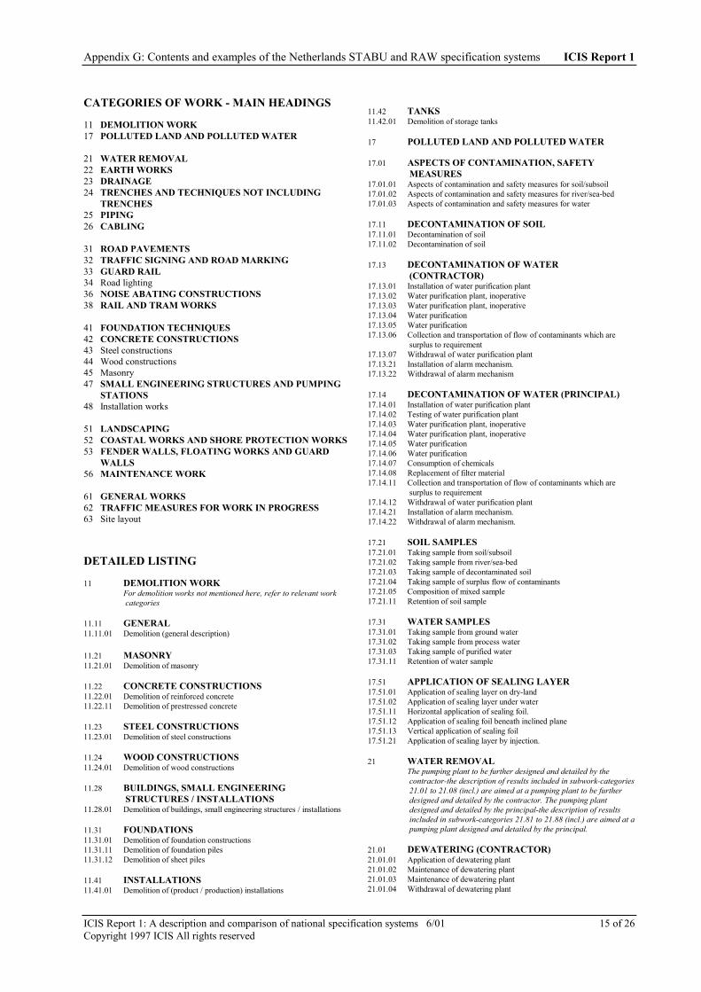
Appendix G: Contents and examples of the Netherlands STABU and RAW specification systems ICIS Report 1
ICIS Report 1: A description and comparison of national specification systems 6/01 15 of 26Copyright 1997 ICIS All rights reserved
CATEGORIES OF WORK - MAIN HEADINGS
11 DEMOLITION WORK17 POLLUTED LAND AND POLLUTED WATER
21 WATER REMOVAL22 EARTH WORKS23 DRAINAGE24 TRENCHES AND TECHNIQUES NOT INCLUDING
TRENCHES25 PIPING26 CABLING
31 ROAD PAVEMENTS32 TRAFFIC SIGNING AND ROAD MARKING33 GUARD RAIL34 Road lighting36 NOISE ABATING CONSTRUCTIONS38 RAIL AND TRAM WORKS
41 FOUNDATION TECHNIQUES42 CONCRETE CONSTRUCTIONS43 Steel constructions44 Wood constructions45 Masonry47 SMALL ENGINEERING STRUCTURES AND PUMPING
STATIONS48 Installation works
51 LANDSCAPING52 COASTAL WORKS AND SHORE PROTECTION WORKS53 FENDER WALLS, FLOATING WORKS AND GUARD
WALLS56 MAINTENANCE WORK
61 GENERAL WORKS62 TRAFFIC MEASURES FOR WORK IN PROGRESS63 Site layout
DETAILED LISTING
11 DEMOLITION WORKFor demolition works not mentioned here, refer to relevant workcategories
11.11 GENERAL11.11.01 Demolition (general description)
11.21 MASONRY11.21.01 Demolition of masonry
11.22 CONCRETE CONSTRUCTIONS11.22.01 Demolition of reinforced concrete11.22.11 Demolition of prestressed concrete
11.23 STEEL CONSTRUCTIONS11.23.01 Demolition of steel constructions
11.24 WOOD CONSTRUCTIONS11.24.01 Demolition of wood constructions
11.28 BUILDINGS, SMALL ENGINEERINGSTRUCTURES / INSTALLATIONS
11.28.01 Demolition of buildings, small engineering structures / installations
11.31 FOUNDATIONS11.31.01 Demolition of foundation constructions11.31.11 Demolition of foundation piles11.31.12 Demolition of sheet piles
11.41 INSTALLATIONS11.41.01 Demolition of (product / production) installations
11.42 TANKS11.42.01 Demolition of storage tanks
17 POLLUTED LAND AND POLLUTED WATER
17.01 ASPECTS OF CONTAMINATION, SAFETYMEASURES
17.01.01 Aspects of contamination and safety measures for soil/subsoil17.01.02 Aspects of contamination and safety measures for river/sea-bed17.01.03 Aspects of contamination and safety measures for water
17.11 DECONTAMINATION OF SOIL17.11.01 Decontamination of soil17.11.02 Decontamination of soil
17.13 DECONTAMINATION OF WATER(CONTRACTOR)
17.13.01 Installation of water purification plant17.13.02 Water purification plant, inoperative17.13.03 Water purification plant, inoperative17.13.04 Water purification17.13.05 Water purification17.13.06 Collection and transportation of flow of contaminants which are
surplus to requirement17.13.07 Withdrawal of water purification plant17.13.21 Installation of alarm mechanism.17.13.22 Withdrawal of alarm mechanism
17.14 DECONTAMINATION OF WATER (PRINCIPAL)17.14.01 Installation of water purification plant17.14.02 Testing of water purification plant17.14.03 Water purification plant, inoperative17.14.04 Water purification plant, inoperative17.14.05 Water purification17.14.06 Water purification17.14.07 Consumption of chemicals17.14.08 Replacement of filter material17.14.11 Collection and transportation of flow of contaminants which are
surplus to requirement17.14.12 Withdrawal of water purification plant17.14.21 Installation of alarm mechanism.17.14.22 Withdrawal of alarm mechanism.
17.21 SOIL SAMPLES17.21.01 Taking sample from soil/subsoil17.21.02 Taking sample from river/sea-bed17.21.03 Taking sample of decontaminated soil17.21.04 Taking sample of surplus flow of contaminants17.21.05 Composition of mixed sample17.21.11 Retention of soil sample
17.31 WATER SAMPLES17.31.01 Taking sample from ground water17.31.02 Taking sample from process water17.31.03 Taking sample of purified water17.31.11 Retention of water sample
17.51 APPLICATION OF SEALING LAYER17.51.01 Application of sealing layer on dry-land17.51.02 Application of sealing layer under water17.51.11 Horizontal application of sealing foil.17.51.12 Application of sealing foil beneath inclined plane17.51.13 Vertical application of sealing foil17.51.21 Application of sealing layer by injection.
21 WATER REMOVALThe pumping plant to be further designed and detailed by thecontractor-the description of results included in subwork-categories21.01 to 21.08 (incl.) are aimed at a pumping plant to be furtherdesigned and detailed by the contractor. The pumping plantdesigned and detailed by the principal-the description of resultsincluded in subwork-categories 21.81 to 21.88 (incl.) are aimed at apumping plant designed and detailed by the principal.
21.01 DEWATERING (CONTRACTOR)21.01.01 Application of dewatering plant21.01.02 Maintenance of dewatering plant21.01.03 Maintenance of dewatering plant21.01.04 Withdrawal of dewatering plant

Appendix G: Contents and examples of the Netherlands STABU and RAW specification systems ICIS Report 1
ICIS Report 1: A description and comparison of national specification systems 6/01 16 of 26Copyright 1997 ICIS All rights reserved
21.02 WELL-POINTING (CONTRACTOR)21.02.01 Application of well-pointing21.02.02 Maintenance of well-pointing21.02.03 Maintenance of well-pointing21.02.04 Withdrawal of well-pointing
21.03 STRESS WATER REMOVAL (CONTRACTOR)21.03.01 Application of stress water removal21.03.02 Maintenance of stress water removal21.03.03 Maintenance of stress water removal21.03.04 Withdrawal of stress water removal
21.07 OBSERVATION MANHOLE (CONTRACTOR)21.07.01 Construction of manhole21.07.02 Removal of manhole
21.08 ADDITIONAL WORK (CONTRACTOR)21.08.01 Application of run-off measuring point21.08.02 Application of facilities at discharge point21.08.11 Installation of alarm mechanism.
21.81 DEWATERING (PRINCIPAL)21.81.01 Excavation of earth from trench -dewatering-21.81.02 Excavation of earth from collection well -dewatering-21.81.11 Installation of pump for use in dewatering21.81.21 Installation of drainage pipes for dewatering21.81.31 Maintenance of dewatering plant21.81.32 Maintenance of dewatering plant21.81.33 Withdrawal of dewatering plant
21.82 WELL-POINTING AND STRESS WATERREMOVAL (PRINCIPAL)
21.82.01 Making borehole for pumping plant21.82.11 Construction of soakaway with riser pipe21.82.12 Application of filler material to drainage pit21.82.13 Application of underwater pump in drainage pit21.82.14 Installation of pump in dewatering plant21.82.15 Replacement of pump in dewatering plant21.82.21 Application of drainage pipe for well-pointing and stress water
removal21.82.22 Application of drainage pipe with underwater pump21.82.23 Application of power plant to facilitate dewatering21.82.31 Maintenance of well-pointing / stress water removal plant21.82.32 Maintenance of well-pointing / stress water removal plant21.82.34 Withdrawal of well-pointing21.82.35 Withdrawal of stress water removal
21.87 OBSERVATION MANHOLE (PRINCIPAL)21.87.01 Construction of manhole21.87.02 Removal of manhole
21.88 ADDITIONAL WORK (PRINCIPAL)21.88.01 Application of run-off measuring point21.88.02 Application of facilities at discharge point21.88.11 Installation of alarm mechanism.
22 EARTH WORKS
22.01 EXCAVATION22.01.01 Excavation from trench/water-course/gully22.01.02 Excavation from cutting22.01.03 Excavation from sump/harbour22.01.04 Excavation from embankment.22.01.05 Excavation from lining
22.02 EARTH MOVING22.02.01 Earth moving
22.03 PROCESSING OF SOILS22.03.01 Processing of soil in earth body22.03.02 Processing of soil in spoil22.03.03 Processing of soil in embankment22.03.04 Processing of soil in lining22.03.05 Processing of soil in filler22.03.21 Supplying soil
22.04 SEPARATION OF FRACTIONS, COMPACTIONAND PROFILING
22.04.01 Separating earth into fractions22.04.02 Separating saturated soil into sectioned streams22.04.03 Separating saturated soil into sectioned streams
22.04.04 Dewatering of saturated soil22.04.11 Compaction of sand or non-cohesive earth22.04.12 Compaction of sand or non-cohesive earth22.04.13 Compaction of soil22.04.21 Profiling of surfaces
22.08 BAG CORDONS22.08.01 Positioning of bag cordons22.08.02 Extending bag cordons22.08.03 Removing bag cordons
22.11 LAND DEVELOPMENT EARTH WORKS22.11.01 Cleaning up drainage ditch22.11.02 Cleaning up drainage ditch22.11.03 Excavation of soil from drainage ditch to be enlarged22.11.04 Excavation of soil from drainage ditch to be enlarged22.11.05 Soil from drainage ditch to be enlarged, excavated separately22.11.06 Excavation of soil to sustain drainage ditch22.11.07 Separate excavation of soil for sustaining drainage ditch22.11.08 Restoration of slope from drainage ditch22.11.11 Excavation of soil from ditch to be enlarged22.11.12 Excavation of soil to sustain ditch22.11.15 Excavation of soil from deeper sections22.11.21 Preparation of soil in drainage ditch22.11.22 Construction of dam in drainage ditch22.11.25 Removing dam22.11.31 Levelling22.11.32 Levelling with consolidation of top soil22.11.33 Levelling of steep edge, suspension of lot boundary22.11.41 Site landscaping/development22.11.42 Removal of refuse/rubble22.11.43 Removal of well
22.21 WORKING THE GROUND22.21.01 Soil turning22.21.02 Mixed turning22.21.03 Deep ploughing22.21.04 Deep scoring22.21.05 Scoring or ploughing22.21.06 Deep tilling22.21.07 Tilling22.21.11 Harrowing22.21.12 Cultivating
22.41 LIGHT FILLERS22.41.01 Applying Flugsand22.41.02 Applying Flugsand
22.45 SYNTHETIC FILLERS22.45.01 Applying expanded polystyrene22.45.11 Supplying expanded polystyrene
23 DRAINAGE
23.01 HORIZONTAL DRAINAGE23.01.01 Excavation from trenches23.01.11 Placement of drains23.01.12 Placement of fittings23.01.21 Tamping of trenches
24 TRENCHES AND TECHNIQUES NOT INCLUDINGTRENCHES
24.01 EARTH WORKS FACILITATING PIPING ANDCULVERTS
24.01.01 Excavation of soil for trench24.01.02 Excavation of soil for trench24.01.11 Soil improvement24.01.21 Tamping of trench24.01.22 Tamping of trench24.01.31 Soil transport24.01.51 Digging and tamping of excavation24.01.52 Digging and tamping of excavation
24.02 EARTH WORKS FACILITATING CABLES ANDPIPING
24.02.01 Digging and tamping of trench (to a depth of 1 m)24.02.02 Digging and tamping of trench (1 m and deeper)24.02.03 Digging and tamping of trench, non-mech.(to depth of 1 m)24.02.04 Digging and tamping of trench, non-mech.(1 m and deeper)24.02.06 Digging and tamping of excavation hole24.02.11 Soil transport

Appendix G: Contents and examples of the Netherlands STABU and RAW specification systems ICIS Report 1
ICIS Report 1: A description and comparison of national specification systems 6/01 17 of 26Copyright 1997 ICIS All rights reserved
24.02.12 Supply of soil deficiency24.02.31 Earth works including cable/pipe-laying through drainage ditch
24.06 FACILITIES FOR EXCAVATIONS WITHPIPEWORK
24.06.01 Taking measures for caving of trench (sewer)24.06.11 Taking measures for caving of trench (gas/water)
24.11 TRENCH COVERING24.11.01 Taking up of trench covering, tiles24.11.02 Taking up of trench covering, cobble-stones24.11.03 Taking up of trench covering, ornamental paving24.11.04 Taking up of trench covering, stone aggregate pavement24.11.05 Taking up of trench covering, concrete paving24.11.06 Taking up of trench covering, asphalt paving24.11.07 Taking up of trench covering, concrete slabs24.11.08 Taking up of trench covering, turf24.11.11 Restoration of trench covering, tiles24.11.12 Restoration of trench covering, cobble-stones24.11.13 Restoration of trench covering, ornamental paving24.11.14 Restoration of trench covering, stone aggregate pavement24.11.17 Restoration of trench covering, concrete slabs24.11.18 Restoration of trench covering, turf24.11.21 Temporary restoration of trench covering, tiles24.11.22 Temporary restoration of trench covering, cobble-stones24.11.23 Temporary restoration of trench covering, other pavements
25 PIPINGIn the sub-categories for piping further distinction is made betweensewer piping, gas piping, water pipes, culverts and sag pipes. Inparticular the descriptions of results for sewer, gas and water pipeshave been formulated from these disciplines. For the descriptions ofother piping systems the onus is on the specification writer todetermine which descriptions of results are most suitable. Thedescriptions of results from the work category Piping can inprinciple be used with other piping systems
25.01 RENDERING SEWER PIPING INOPERATIVE25.01.01 Temporary measures used for closing off sewer pipe25.01.11 Blocking of pipe which has been rendered inoperative
25.02 RENDERING GAS PIPING INOPERATIVE25.02.01 Application of bubble25.02.02 Temporary sealing off of piping25.02.06 Degassing of piping25.02.11 Blocking of pipe which has been rendered inoperative25.02.21 Installation of diversionary piping
25.11 REMOVAL OF SEWER PIPING25.11.01 Removal of concrete pipe25.11.02 Removal of asbestos cement pipe25.11.03 Removal of plastic pipe25.11.04 Removal of cast-iron pipe25.11.05 Removal of steel pipe25.11.06 Removal of stoneware pipe25.11.21 Removal of inspection chamber25.11.22 Removal of lock-chamber25.11.23 Removal of manhole frame and cover
25.12 REMOVAL OF GAS PIPINGFor the removal of service pipes, see subwork-category 25.3325.12.01 Removal of asbestos cement pipe25.12.02 Removal of plastic pipe25.12.03 Removal of steel pipe25.12.04 Removal of cast-iron pipe25.12.21 Removal/extension of cut-off25.12.22 Removal/extension of insulation25.12.23 Removal of shut-off valve25.12.24 Removal of syphon25.12.25 Extension of fitting
25.13 REMOVAL OF WATER PIPESFor the removal of connecting pipes, see subwork category 25.37
25.13.01 Removal of concrete pipe25.13.02 Removal of asbestos cement pipe25.13.03 Removal of plastic pipe25.13.04 Removal of cast-iron pipe25.13.05 Removal of steel pipe25.13.06 Removal of copper pipe25.13.21 Removal/extension of cut-off25.13.22 Removal/extension of insulation25.13.26 Extension of fitting
25.13.27 Removal/extension of fire-hydrant
25.16 REMOVAL OF CULVENTS25.16.01 Removal of concrete culverts - elements -25.16.02 Removal of culverts - PVC pipe25.16.03 Removal of culverts - asbestos cement pipe25.16.04 Removal of steel plate culverts
25.18 REMOVAL OF FOUNDATIONS25.18.01 Removal of foundations
25.21 CONCRETE PIPES AND FITTINGS, SEWERPIPING
25.21.01 Application of concrete pipe -socket-spigot-25.21.02 Application of prestressed concrete pipe -socket-spigot-25.21.03 Construction of adapter from concrete pipe25.21.04 Application of reinforced concrete pipe -steel plate core25.21.05 Application of fitting reinforced concrete pipe -steel plate core25.21.06 Application of joint reinforced pipe -steel plate core25.21.11 Application of concrete -male and female coupling
25.22 PLASTIC PIPES AND FITTINGS, SEWER PIPING25.22.01 Application of PVC pipe25.22.02 Application of PVC fitting25.22.11 Application of HDPE pipe25.22.12 Application of HDPE fitting25.22.13 Application of welded joint HDPE pipe25.22.21 Application of GVK pipe25.22.22 Application of GVK fitting
25.23 METAL PIPES AND FITTING, SEWER PIPING25.23.01 Application of cast-iron pipe25.23.02 Application of cast-iron fitting25.23.11 Application of steel pipe25.23.12 Application of steel fitting25.23.13 Application of welded joint steel pipe
25.24 STONEWARE PIPES AND FITTINGS, SEWERPIPING
25.24.01 Application of stoneware pipe25.24.02 Application of stoneware fitting
25.26 INSPECTION CHAMBERS AND LOCK-CHAMBERS, SEWER PIPING
25.26.01 Connecting to sewage drain25.26.02 Constructing inspection chamber from precast concrete elements25.26.03 Constructing inspection chamber from a combination of stonework
and concrete25.26.04 Construction of inspection chamber from glass-fibre reinforced
polyester25.26.11 Construction of sand-trap in gutter25.26.12 Construction of drain in gutter25.26.13 Construction of lock-chamber from a combination of concrete and
cast-iron25.26.14 Construction of lock-chamber from a combination of synthetic
material and cast-iron.
25.27 SEWER COVERS25.27.01 Construction of manhole frame and cover25.27.02 Raising level of existing manhole covers
25.28 SPECIAL FITTINGS AND FACILITIES, SEWER25.28.01 Application of valve25.28.02 Application of slider25.28.03 Application of cut-off valve25.28.04 Application of de-aerator25.28.21 Construction of masonry shield25.28.32 Construction of intake
25.31 PIPES AND FITTINGS, GAS PIPING25.31.11 Application of impact-resistant PVC pipe25.31.12 Application of impact-resistant PVC fitting25.31.13 Application of polyethylene pipe25.31.14 Application of polyethylene fitting25.31.15 Application of welded joint in polyethylene pipe25.31.21 Application of cast-iron pipe25.31.22 Application of cast-iron fitting25.31.23 Application of steel pipe25.31.24 Application of steel fitting25.31.25 Application of welded joint in steel pipe

Appendix G: Contents and examples of the Netherlands STABU and RAW specification systems ICIS Report 1
ICIS Report 1: A description and comparison of national specification systems 6/01 18 of 26Copyright 1997 ICIS All rights reserved
25.32 SPECIAL FITTINGS AND FACILITIES, GASPIPING
25.32.01 Application/installation of cut-off valve25.32.02 Application/installation of insulation25.32.03 Application/installation of shut-off valve25.32.11 Installation of fitting25.32.15 Application of pressure gauge25.32.21 Construction of (cable or piping) intersection25.32.31 Treatment of steel pipe terminal
25.33 SERVICE PIPING C.A., GAS PIPING25.33.01 Application of branch fitting to impact-resistant PVC piping25.33.02 Application of branch fitting to polyethylene piping25.33.03 Application of branch fitting to cast-iron piping25.33.04 Application of branch fitting to steel piping25.33.11 Transfer to service piping25.33.21 Application of cut-off valve to service piping25.33.26 Application of fittings/facilities for point of connection25.33.31 Application of polyethylene piping25.33.32 Application of polyethylene fitting25.33.33 Application of welded joint in polyethylene pipe25.33.34 Application of transitional coupling polyethylene-copper/steel25.33.35 Application of steel piping25.33.36 Application of welded joint in steel pipe25.33.37 Application of copper pipe25.33.38 Application and fixing of PEKO pipe25.33.51 Installation of gas meter25.33.61 Installation of regulating device25.33.62 Removal of service piping25.33.66 Shutting off service piping
25.35 PIPING AND FITTINGS, WATER PIPING
25.35.01 Application of prestressed concrete pipe -socket-spigot-25.35.02 Application of concrete pipe -steel plate core-25.35.03 Application of fitting to concrete pipe-steel plate core-25.35.04 Application of joint section of concrete pipe-steel plate core-25.35.11 Application of PVC pipe25.35.12 Application of PVC fitting25.35.13 Application of polyethylene piping25.35.14 Application of polyethylene fitting25.33.15 Application of welded joint in polyethylene pipe25.35.16 Application of GVK pipe25.35.17 Application of GVK fitting25.35.21 Application of cast-iron pipe25.35.22 Application of cast-iron fitting25.35.23 Application of steel pipe25.35.24 Application of steel fitting25.35.25 Application of welded joint in steel pipe25.35.26 Application of copper pipe
25.36 SPECIAL FITTINGS AND FACILITIES, WATERPIPING
25.36.01 Application/installation of cut-off valve25.36.02 Application/installation of insulation piece25.36.03 Application/installation of shut-off valve25.36.11 Installation of fitting25.36.21 Installation of fire-hydrant25.36.31 Application/installation of (cable- or piping)intersection25.36.41 Application of connection to existing network25.36.51 Application of splash control construction25.36.61 Treatment of steel pipe terminal25.36.71 Internal cementing of water piping
25.37 CONNECTING PIPES, WATER PIPING
25.37.11 Transfer to copper connecting pipes25.37.12 Transfer to polyethylene connecting pipes25.37.13 Transfer to PVC connecting pipes25.37.21 Application of service stop-cock25.37.22 Application of intermediate service stop-cock25.37.26 Application of facilities for connecting points25.37.27 Replacement of facilities for connecting points25.37.31 Application of copper connecting pipes25.37.32 Application of polyethylene connecting pipes25.37.33 Application of PVC connecting pipes25.37.36 Application of copper pipe for connecting pipes25.37.37 Application of polyethylene pipe for connecting pipes25.37.38 Application of PVC pipe for connecting pipes25.37.61 Removal of connecting piping25.37.62 Removal of connecting piping25.37.66 Shutting off connecting piping at the service stop-cock
25.38 OTHER FACILITIES, GAS AND WATER PIPING
25.38.01 Application of pipe sleeve25.38.06 Application of pipe sleeve without trench25.38.07 Application of piping without the use of a trench25.38.08 Application of piping without the use of a trench25.38.11 Application of piping within a pipe sleeve25.38.31 Application of cover at joint/fitting25.38.36 Application of sleeves25.38.41 Making hole for exterior wall duct25.38.42 Making hole for floor duct25.38.43 Making exterior wall duct air tight and water tight25.38.46 Application of pipe sleeve (service and connecting piping)25.38.61 Construction of surface mounted fitting25.38.62 Application of surface trim25.38.66 Adjusting surface trim25.38.66 Removing surface trim
25.51 CULVERTS
25.51.01 Application of reinforced concrete culvert - m-s pipe -25.51.02 Application of plain concrete culvert - m-s pipe -25.51.03 Application of reinforced concrete culvert -steel plate core-25.51.04 Application of concrete culvert -rectangular profile-25.51.05 Application of concrete culvert -male and female coupling-25.51.06 Application of PVC culvert25.51.11 Application of steel plated culvert -spiral corrugation-25.51.12 Application of steel plated culvert -parallel corrugation-
25.56 SAG PIPES
25.56.01 Application of sag piping25.56.02 Application of sag pipe board
25.61 CHECKS ON SEWAGE PIPING
25.61.01 Check sewage piping for water tightness
25.62 TESTING AND MAKING OPERATIVE, GAS PIPING
25.62.01 Testing strength and sealing of piping25.62.06 Testing service piping25.62.11 Allowing gas conveyance through main pipe
25.63 TESTING AND MAKING OPERATIVE, WATERPIPING
25.63.01 Pressure testing of water piping25.63.11 Facilities for disinfecting water piping25.63.12 Disinfecting water piping
25.64 GAUGING PIPING
25.64.01 Gauging and processing revised data (gas/water)
25.71 INSPECTION OF SEWAGE PIPING
25.71.01 Taking photo('s) from inspection chamber25.71.02 Making a video recording from inspection chamber25.71.03 Making a video recording from sewer25.71.04 Inspecting accessible sewer25.71.11 Taking measurements from inspection chamber
25.75 CLEANING OF SEWERS25.75.01 Cleaning sewer piping at high pressure25.75.02 Cleaning of sewer inspection chamber25.75.11 Cleaning of cellar/basin
25.76 CLEANING OF GAS AND WATER PIPING25.76.01 Internal cleaning of gas piping25.76.11 Internal cleaning of water piping
25.78 CLEANING OF CULVERTS AND SAG PIPES25.78.01 Cleaning of culvert25.78.11 Cleaning of sag pipe
25.81 RENOVATION OF SEWER PIPING25.81.01 Installing pipes within an existing sewer25.81.02 In-situ insertion of PVC spiral winding pipe25.81.03 Applying a synthetic lining to sewer, sleeve method

Appendix G: Contents and examples of the Netherlands STABU and RAW specification systems ICIS Report 1
ICIS Report 1: A description and comparison of national specification systems 6/01 19 of 26Copyright 1997 ICIS All rights reserved
25.81.06 Applying cladding within an accessible sewer25.81.11 Internal application of joint sealing with sealing rings25.81.12 Grouting joints in accessible sewer25.81.13 Grouting joints in inaccessible sewer25.81.16 Supplying material for grouting joints25.81.21 Filling of voids between existing and new pipes25.81.31 Repairing inlet25.81.51 Inserting a man-hole within an existing inspection chamber25.81.56 Applying cladding in inspection chamber25.81.57 Applying a protective coating to inspection chamber25.81.61 Filling voids between existing and new inspection chamber
25.82 REPAIR AND RENOVATION, GAS AND WATERPIPING
25.82.01 Installing polyethylene pipe within existing piping25.82.11 Adjusting level of piping25.82.21 Repairing gas piping
26 CABLING
26.11 REMOVING CABLES, CABLE BOXES26.11.01 Removing under-ground cable26.11.05 Removing low voltage distribution box
26.21 CABLE PIPES AND CONDUITS26.21.01 Application of cable pipe in trench26.21.02 Application of cable pipe by boring26.21.03 Application of sectioned concrete cable conduit26.21.05 Application of pull chamber
26.31 CABLE WORKS (UNDER-GROUND ELECTRICCABLES)
26.31.01 Application of under-ground electric cables26.31.02 Application of connecting cables26.31.05 Application of current shut-off mechanism, under-ground electric
cables26.31.11 Pulling up under-ground electric cable26.31.12 Laying down under-ground electric cable26.31.13 Adjusting under-ground electric cable26.31.14 Diverting under-ground electric cable26.31.16 Pulling up low voltage distribution box26.31.21 Application of sleeve joint in under-ground electric cable, high
tension26.31.22 Application of sleeve joint in under-ground electric cable, low tension26.31.23 Application of single dividing sleeve in under-ground electric cable26.31.24 Application of double diving sleeve in under-ground electric cable26.31.26 Application of socket in under-ground electric cable, low tension26.31.31 Application of low voltage distribution box
26.41 AUXILIARY WORKS ON CONNECTIONS26.41.01 Making hole for exterior wall duct26.41.02 Making hole for floor duct26.41.03 Installation and attaching of protective sleeve pipe26.41.04 Securing cable
31 ROAD PAVEMENTS
31.01 PREPARATORY WORKS31.01.01 Completion of capping layer31.01.05 Packing of stone aggregate pavement31.01.06 Application a profiling layer of stone aggregate31.01.11 Cleaning road surface31.01.21 Milling asphalt to facilitate connection31.01.22 Removing asphalt by milling31.01.23 Roughening surface of concrete31.01.24 Roughening surface of asphalt31.01.31 Applying edge fitting of asphalt31.01.41 Sawing pavement31.01.51 Applying synthetic inserts31.01.52 Applying metal inserts
31.05 LAYING STONE AGGREGATE PAVEMENT31.05.01 Applying an unstabilized stone aggregate course31.05.02 Applying a lightly stabilized stone aggregate course31.05.11 Applying a test section of stone aggregate31.05.21 Delivering stone aggregate for road pavements
31.06 LAYING STABILIZED COURSES31.06.01 Laying a course of sand cement31.06.02 Laying a course of macadam type 131.06.03 Laying a course of macadam type 231.06.04 Delivery of cement for sand cement mixture
31.06.05 Delivery of cement for macadam.
31.07 TREATING SURFACES OF PAVEMENT COURSES31.07.01 Applying singular surface treatment31.07.02 Applying double surface treatment31.07.03 Applying subsequent surface spreading of chippings31.07.04 Applying sandwich treatment31.07.07 Delivery of binders31.07.08 Delivery of covering material31.07.11 Applying slurry seal31.07.21 Roughening the surface of asphalt pavements31.07.22 Roughening the surface of concrete pavements31.07.31 Repairing cracks in asphalt31.07.32 Repairing cracks in concrete31.07.41 Repairing damage to concrete31.07.51 Treatment of oily patches31.07.52 Treatment of rough or worn patches31.07.61 Repairing joint sealants in concrete pavements
31.21 LAYING OF ASPHALT PAVEMENTS31.21.01 Laying tack coat31.21.11 Laying a course of dense asphalt concrete31.21.12 Laying a course of pervious coated macadam31.21.13 Laying a course of stone mastic tar macadam31.21.14 Laying a course of open textured asphalt concrete31.21.21 Laying a course of graded asphalt concrete31.21.22 Laying a two-layered course of graded asphalt concrete31.21.23 Laying a three-layered course of graded asphalt concrete31.21.24 Laying a four-layered course of graded asphalt concrete31.21.31 Laying a course of well graded asphalt concrete31.21.32 Laying a two-layered course of well graded asphalt concrete31.21.33 Laying a three-layered course of well graded asphalt concrete31.21.34 Laying a four-layered course of well graded asphalt concrete31.21.81 Laying chippings on wearing course
31.22 LAYING PROFILED COURSES AND PACKING31.22.01 Laying profiled courses of asphalt31.22.02 Laying profiled wearing courses of asphalt31.22.05 Laying asphalt packing.
31.23 APPLYING COLD ASPHALT AND EMULSIONASPHALT CONCRETE
31.23.01 Application of a course of cold asphalt31.23.05 Applying cold asphalt packing31.23.11 Application of a course of emulsion asphalt concrete31.23.12 Applying emulsion asphalt concrete to ruts
31.24 APPLYING GROUTING31.24.01 Applying grouting
31.31 LAYING CONCRETE PAVEMENT31.31.01 Laying base material31.31.11 Laying a single course of concrete pavement31.31.12 Laying a double course of concrete pavement31.31.16 Laying a single course of concrete pavement -test section31.31.17 Laying a double course of concrete pavement -test section
31.32 TREATMENT OF CONCRETE SURFACE31.32.01 Applying texture to concrete surface
31.33 CONSTRUCTION OF JOINTING31.33.01 Constructing transverse joints31.33.02 Constructing longitudinal joints
31.34 APPLYING REINFORCEMENT31.34.01 Applying steel reinforcement rods in concrete pavement31.34.02 Applying steel reinforcement nets in concrete pavement
31.35 APPLYING LEAN-MIX CONCRETE31.35.01 Applying a pavement course of lean-mix concrete
31.37 APPLYING PREFABRICATED CONCRETE SLABS31.37.01 Applying pavement of prefabricated concrete slabs
31.41 SETT PAVING31.41.01 Laying a course of sett paving31.41.11 Laying a course of cobble stones31.41.12 Laying a course of concrete blocks31.41.13 Laying a course of flag paving31.41.31 Applying longitudinal road marking to sett paving31.41.32 Applying transverse road marking to sett paving31.41.33 Applying transverse road marking to sett paving

Appendix G: Contents and examples of the Netherlands STABU and RAW specification systems ICIS Report 1
ICIS Report 1: A description and comparison of national specification systems 6/01 20 of 26Copyright 1997 ICIS All rights reserved
31.41.34 Applying transverse road marking to asphalt pavement
31.42 ORNAMENTAL PAVING31.42.01 Applying ornamental paving
31.43 KERBING AND DRAINAGE CHANNELS31.43.01 Applying a cobble stone kerbing31.43.02 Applying a kerbing of concrete blocks31.43.05 Application of curved drainage channel31.43.11 Applying a concrete footpath kerb31.43.12 Applying a concrete kerbing31.43.15 Applying a concrete approach transition kerbing31.43.21 Applying a drainage channel of concrete sections
31.45 REPAVING31.45.01 Repaving of cobble stones31.45.02 Repaving of concrete block paving31.45.03 Repaving of concrete flag-paving31.45.05 Repaving of curved drainage channels31.45.11 Repositioning of concrete footpath kerbing31.45.12 Repositioning of concrete kerbing31.45.13 Repositioning of approach transition kerbing31.45.21 Repaving of ornamental paving31.45.22 Repositioning of drainage channel of concrete sections31.45.31 Repaving transverse road marking in asphalt paving
31.47 AUXILIARY WORKS ON PAVING31.47.01 Fitting of paving material31.47.02 Fitting of concrete kerbing31.47.71 Clearing soil from paving material31.47.81 Transportation of paving material
31.48 DELIVERY OF PAVING MATERIALS31.48.01 Delivery of sand31.48.11 Delivery of cobble stones31.48.12 Delivery of concrete paving blocks31.48.13 Delivery of flag stones31.48.21 Delivery of straight sections of concrete kerbing for footpath31.48.22 Delivery of curved sections of concrete kerbing for footpath31.48.23 Delivery of fitting -concrete kerbing for footpath-31.48.24 Delivery of straight concrete kerbing31.48.25 Delivery of curved concrete kerbing31.48.26 Delivery of fitting for concrete kerbing
31.51 TAKING UP ASPHALT PAVEMENTS31.51.01 Taking up asphalt pavement31.51.11 Taking up grouting31.51.71 Taking up bituminously bound paving material31.51.72 Taking up bituminously bound paving material
31.52 TAKING UP CONCRETE PAVEMENTS31.52.01 Digging up non-reinforced concrete pavement31.52.11 Digging up reinforced concrete pavement31.52.21 Taking up prefabricated concrete slab pavement31.52.51 Pounding non-reinforced concrete pavement31.52.61 Removal of sand cement course31.52.62 Removing course of asphalt aggregate cement31.52.71 Demolishing cement bound pavement material31.52.72 Demolishing cement bound pavement material
31.53 TAKING UP SETT PAVING31.53.11 Taking up cobble stones31.53.12 Taking up concrete block pavers31.53.13 Taking up flag pavers31.53.21 Taking up cobble-stone kerbing31.53.22 Taking up concrete-block kerbing31.53.23 Taking up curved drainage channel31.53.31 Removal of road-marking from sett paving31.53.32 Removal of transverse road-marking from sett paving31.53.33 Removal of transverse road-marking from asphalt paving31.53.51 Taking up concrete kerbing31.53.52 Taking up drainage channel in concrete sections
31.54 TAKING UP STONE AGGREGATE PAVEMENTCOURSES
31.54.11 Removing stone aggregate pavement course
32 TRAFFIC SIGNING AND ROAD MARKING
32.01 ROAD MARKING32.01.01 Applying longitudinal marking -road paint-32.01.02 Applying longitudinal marking -thermoplastic material
32.01.03 Applying longitudinal marking -predetermined lanes-32.01.11 Applying other marking -road paint-32.01.12 Applying other marking -thermoplastic material-32.01.13 Applying other marking -predetermined lanes-32.01.16 Applying road surface cats' eyes reflectors (permanent)32.01.17 Applying road surface cats' eyes reflectors (temporary)32.01.21 Restoration of longitudinal road-marking -road paint-32.01.22 Restoration of longitudinal road-marking -thermoplastic material-32.01.23 Restoration of longitudinal road-marking-predetermined lanes-32.01.25 Restoration of other marking -road paint-32.01.26 Restoration of other marking -thermoplastic material-.m232.01.27 Restoration of other marking -predetermined lanes-32.01.31 Delivery of road-marking materials32.01.41 Removing road marking32.01.42 Preparing existing road marking32.01.43 Removal of road surface cats' eyes reflectors
32.13 SIGNPOSTING32.13.01 Putting up traffic sign posts32.13.02 Putting up traffic signs32.13.03 Putting up traffic signs and sign posts32.13.11 Removing traffic signs32.13.12 Removing traffic sign posts32.13.13 Removing traffic signs, including posts
32.21 DIRECTION SIGNING32.21.01 Laying foundation blocks32.21.02 Putting up overhead traffic signs32.21.03 Putting up one-post overhead traffic signs32.21.11 Removing overhead traffic signs32.21.12 Removing foundation blocks
32.22 DELINEATORS, MARKER POSTS AND CONVEXMIRRORS
32.22.01 Placing delineators32.22.02 Placing 100 m interval posts32.22.03 Placing convex mirrors32.22.05 Placing 100 km interval posts32.22.11 Removing delineators and marker posts32.22.12 Removing 100 m interval posts32.22.13 Removing convex mirrors32.22.15 Removing 100 km interval posts
33 GUARD RAIL
33.01 INSTALLING GUARD RAIL33.01.01 Installing guard rail, on verge33.01.02 Installing guard rail, on engineering structures33.01.04 Application of sliding construction33.01.05 Application of joint transition33.01.06 Application of transverse transition33.01.07 Application of junction33.01.08 Application of end fitting33.01.11 Application of protrusion33.01.12 Application of slots33.01.13 Application of anchoring33.01.14 Application of transfer construction
33.02 REMOVING GUARD RAIL33.02.01 Removing guard rail, on verge33.02.02 Removing guard rail, on engineering structures33.02.04 Removing sliding construction33.02.05 Removing joint transition33.02.06 Removing transverse transition33.02.07 Removing junction33.02.08 Removing end fitting33.02.11 Removing protrusion33.02.13 Removing anchoring33.02.14 Removing transfer construction33.02.15 Removing end of anchor from engineering structures33.02.16 Removing concrete stile from engineering structures
33.03 ALIGNMENT AND HEIGHT ADJUSTMENT OFGUARD RAIL
33.03.01 Alignment and height adjustment
33.11 FITTING OF GUARD RAIL MATERIALS33.11.01 Fixing anchors for stiles33.11.02 Fitting stiles33.11.03 Fitting beam (to previously constructed stiles)33.11.04 Construction of joint transition in beam33.11.05 Fitting hand railing to guard rail

Appendix G: Contents and examples of the Netherlands STABU and RAW specification systems ICIS Report 1
ICIS Report 1: A description and comparison of national specification systems 6/01 21 of 26Copyright 1997 ICIS All rights reserved
33.11.06 Fitting steel hand rail
33.12 AUXILIARY WORKS GUARD RAIL33.12.01 Grouting base plate, including finishing of anchors33.12.02 Making recesses in asphalt33.12.03 Drilling holes in asphalt33.12.04 Drilling holes in concrete33.12.05 Fixing anchors through holes drilled
36 NOISE ABATING CONSTRUCTIONS.
36.11 FITTING STILES36.11.01 Fitting steel stiles36.11.02 Fitting aluminium stiles36.11.03 Fitting prefabricated concrete stiles36.11.04 Fitting wooden stiles
36.12 FITTING REFLECTIVE SECTIONS36.12.01 Fitting steel reflective sections36.12.02 Fitting aluminium reflective sections36.12.03 Fitting prefabricated concrete reflective sections36.12.04 Fitting wooden reflective sections36.12.05 Fitting reflective sections made of synthetic material36.12.06 Fitting reflective sections made of laminated glass
36.13 FITTING ABSORBENT SECTIONS36.13.01 Fitting absorbent steel sections36.13.02 Fitting absorbent aluminium sections36.13.03 Fitting prefabricated concrete absorbent sections36.13.04 Fitting absorbent wooden sections36.13.05 Fitting absorbent sections made of synthetic material
36.14 FITTING STACKS36.14.01 Fitting prefabricated concrete stacks36.14.02 Fitting wooden stacks
36.16 FITTING OTHER COMPONENTS36.16.01 Fitting horizontal member36.16.11 Fitting frame36.16.12 Fitting door36.16.21 Fitting stile cover36.16.22 Fitting cover profile to section36.16.61 Fitting expansion construction36.16.81 Fitting pictogram
36.17 AUXILIARY WORKS36.17.01 Drilling holes in asphalt36.17.02 Fixing anchors through holes drilled36.17.03 Grouting base plate, including finishing of anchors36.17.11 Packing of soil at stacked sections
36.18 APPLICATION OF PAD FOUNDATIONS ANDFOUNDATION CAPS
36.18.01 Application of prefabricated concrete pads36.18.02 Application of prefabricated concrete foundation cap
36.61 DELIVERY OF STILES36.61.01 Delivery of steel stiles36.61.02 Delivery of aluminium stiles36.61.03 Delivery of prefabricated concrete stiles36.61.04 Delivery of wooden stiles
36.62 DELIVERY OF REFLECTIVE SECTIONS36.62.01 Delivery of steel reflective sections36.62.02 Delivery of aluminium reflective sections36.62.03 Delivery of prefabricated concrete reflective sections36.62.04 Delivery of wooden reflective sections36.62.05 Delivery of reflective sections made of synthetic material36.62.06 Delivery of reflective sections made of laminated glass
36.63 DELIVERY OF ABSORBENT SECTIONS36.63.01 Delivery of absorbent steel sections36.63.02 Delivery of absorbent aluminium sections36.63.03 Delivery of prefabricated concrete absorbent sections36.63.04 Delivery of absorbent wooden sections36.63.05 Delivery of absorbent sections made of synthetic material
36.64 DELIVERY OF STACKS36.64.01 Delivery of prefabricated concrete stacks36.64.02 Delivery of wooden stacks
36.66 DELIVERY OF OTHER COMPONENTS
36.66.01 Delivery of other screen components
38 RAIL AND TRAM WORKS
38.01 BALLAST BED38.01.01 Application of ballast material
38.03 RAIL COMPONENTS38.03.01 Laying sleepers38.03.02 Laying sleeper plate rails38.03.03 Laying foundation pads38.03.11 Laying rails38.03.21 Application of cross bars38.03.31 Application of rail fixing brackets38.03.32 Application of temporary rail fixing brackets
38.05 COMPOSITE RAIL PARTS38.05.11 Construction of Vignole rail points38.05.12 Construction of Vignole rail junction38.05.13 Construction of Vignole rail junction points38.05.21 Construction of grooved rail points38.05.22 Construction of grooved rail junction38.05.31 Construction of rail head terminal.38.05.41 Construction of compensation weld / compensation device38.05.51 Application of preconstructed rail sections38.05.71 Application of preconstructed grooved rail points38.05.72 Application of preconstructed grooved rail junction
38.07 WELDED JOINTS38.07.01 Construction of metal welds38.07.11 Construction of electrical partition welds38.07.21 Construction of welded joints using butt straps38.07.22 Application of temporary welded joints using butt straps
38.11 EXTENDING RAILS38.11.01 Extending rails
38.13 RAISING, TAMPING, RE-ALIGNING ANDADJUSTING
38.13.01 Raising, tamping and re-aligning rail38.13.06 Adjusting rail38.13.11 Raising, tamping and re-aligning Vignole rail points38.13.12 Raising, tamping and re-aligning Vignole rail junction38.13.13 Raising, tamping and re-aligning Vignole rail junction points38.13.21 Raising, tamping and re-aligning grooved rail points38.13.22 Raising, tamping and re-aligning grooved rail junction
38.15 UNDER GROUND PROFILE FINISHING OFBALLAST BED.
38.15.01 Under ground profile finishing of ballast bed for rail38.15.11 Under ground profile finishing of ballast for Vignole rail points38.15.12 Under ground profile finishing of ballast for Vignole rail junction38.15.13 Under ground profile finishing of ballast for Vignole rail junction
points38.15.21 Under ground profile finishing of ballast for grooved rail points38.15.22 Under ground profile finishing of ballast for grooved rail junction
38.21 OTHER WORKS38.21.01 Application of points control mechanism at manually controlled
points38.21.11 Application of concrete edge strips and posts
41 FOUNDATION TECHNIQUES
41.01 PILES41.01.01 Driving concrete piles41.01.11 External driving of steel piles41.01.12 Internal driving of steel piles41.01.13 Vibrating steel piles driving41.01.14 Jack-piling steel piles41.01.15 Screwing steel piles41.01.16 Ramming steel piles41.01.17 Construction of steel piles41.01.21 Driving hardwood piles41.01.22 Construction of hardwood piles41.01.23 Driving softwood piles41.01.24 Construction of softwood piles41.01.25 Construction of concrete pile caps
41.02 PILES SHAPED TO SUBSTRATA41.02.01 Shaping concrete piles to substrata; driving41.02.02 Shaping concrete piles to substrata; vibrating

Appendix G: Contents and examples of the Netherlands STABU and RAW specification systems ICIS Report 1
ICIS Report 1: A description and comparison of national specification systems 6/01 22 of 26Copyright 1997 ICIS All rights reserved
41.02.03 Shaping concrete piles to substrata; screwing41.02.04 Shaping concrete piles to substrata; steel base41.02.05 Applying concrete piles with round base; internal driving41.02.06 Shaping concrete piles with round base to substrata41.02.11 Applying twist drill type screw piles41.02.12 Applying twist drill type pipe screw piles41.02.21 Applying twist drill type tubular screw piles41.02.22 Applying tubular pipe screw piles41.02.31 Applying vibro-combi piles with concrete component41.02.32 Applying vibro-combi piles with steel component
41.04 SHEET PILING41.04.01 Driving concrete sheet piling41.04.11 Driving steel sheet piling41.04.12 Equalized driving of steel sheet piling41.04.13 Vibrating steel sheet piling41.04.14 Equalized vibrating steel sheet piling41.04.15 Jack-piling steel sheet piling41.04.16 Application of steel sheet piling41.04.17 Application of steel sheet pile41.04.21 Application of steel wedge beam41.04.22 Application of steel adjusting beam41.04.23 Application of steel corner piece41.04.24 Application of steel branch beam41.04.31 Driving hardwood sheet piling41.04.32 Driving hardwood corner pile41.04.41 Driving softwood sheet piling41.04.42 Driving softwood corner pile
41.11 MACHINING OF PILES41.11.01 Removing concrete pile heads41.11.02 Machining concrete pile heads41.11.11 Removing wooden pile heads41.11.21 Removing steel pile heads
41.12 MACHINING OF SHEET PILING41.12.01 Removing the top of concrete sheet piling41.12.11 Removing the top of steel sheet piling41.12.21 Removing the top of wooden sheet piling
41.13 FINISHING PILES AND SHEET PILING41.13.01 Applying purlin41.13.02 Applying cap41.13.11 Applying head beams
41.21 REMOVING PILES
41.21.01 Removing concrete piles41.21.11 Removing steel piles41.21.21 Removing wooden piles
41.22 REMOVING SHEET PILING41.22.11 Extracting steel sheet piling41.22.12 Extracting steel sheet piles
41.51 SEALING WALLS41.51.01 Application of cement bentonite wall41.51.02 Application of sectioned cement bentonite wall41.51.11 Application of grout wall through displacement41.51.21 Excavation and maintenance of trench for wall
41.71 DELIVERY OF PILES41.71.01 Delivery of concrete piles41.71.11 Delivery of steel piles41.71.21 Delivery of hardwood piles41.71.22 Delivery of softwood piles
41.74 DELIVERY OF SHEET PILES41.74.01 Delivery of concrete sheet piles41.74.02 Delivery of concrete sheet piles41.74.11 Delivery of steel sheet piles41.74.21 Delivery of hardwood sheet piles41.74.31 Delivery of softwood sheet piles
42 CONCRETE CONSTRUCTIONS
42.01 SHUTTERING42.01.01 Application of shuttering for bedding42.01.02 Application of bedding42.01.11 Application of shuttering column -rectangular-42.01.12 Application of shuttering column -non rectangular-42.01.13 Application of shuttering beam
42.01.14 Application of shuttering wall42.01.15 Application of shuttering wall -bent-42.01.16 Application of shuttering floor42.01.17 Application of shuttering foundation pads42.01.21 Application of shuttering foundation caps42.01.31 Application of peripheral shuttering42.01.32 Application of shuttering bridging edge42.01.33 Application of shuttering span surface42.01.34 Application of shuttering recesses42.01.35 Application of internal shuttering shaft
42.02 SUPPORT CONSTRUCTIONS FOR SHUTTERING42.02.01 Fitting support constructions for shuttering42.02.02 Removing support constructions for shuttering
42.08 DRAWINGS AND CALCULATIONS FORSHUTTERING
42.08.01 Calculation and drawing work shuttering £....,.
42.11 REINFORCING STEEL42.11.01 Application of reinforcing steel diameter 6 mm42.11.02 Application of reinforcing steel diameter 8 mm42.11.03 Application of reinforcing steel diameter 10 mm42.11.04 Application of reinforcing steel diameter 12 mm42.11.05 Application of reinforcing steel diameter 16 mm42.11.06 Application of reinforcing steel diameter 20 mm42.11.07 Application of reinforcing steel diameter 25 mm42.11.08 Application of reinforcing steel diameter 32 mm42.11.11 Application of reinforcing steel diameter 40 mm
42.12 SPOTWELDED REINFORCEMENT MATS42.12.01 Application of spotwelded mats; main reinf. 4 mm42.12.02 Application of spotwelded mats; main reinf. 4,5 mm42.12.03 Application of spotwelded mats; main reinf. 5 mm42.12.04 Application of spotwelded mats; main reinf. 5,5 mm42.12.05 Application of spotwelded mats; main reinf. 6 mm42.12.06 Application of spotwelded mats; main reinf. 6,5 mm42.12.07 Application of spotwelded mats; main reinf. 7 mm42.12.08 Application of spotwelded mats; main reinf. 7,5 mm42.12.11 Application of spotwelded mats; main reinf. 8 mm42.12.12 Application of spotwelded mats; main reinf. 8,5 mm42.12.13 Application of spotwelded mats; main reinf. 9 mm42.12.14 Application of spotwelded mats; main reinf. 9,5 mm42.12.15 Application of spotwelded mats; main reinf. 10 mm42.12.16 Application of spotwelded mats; main reinf. 10,5 mm42.12.17 Application of spotwelded mats; main reinf. 11 mm42.12.18 Application of spotwelded mats; main reinf. 11,5 mm42.12.21 Application of spotwelded mats; main reinf. 12 mm42.12.22 Application of spotwelded mats; main reinf. 13 mm42.12.23 Application of spotwelded mats; main reinf. 14 mm
42.18 SUPPORT CONSTRUCTIONS (SUPPORTS,SPACERS)
42.18.01 Application of support steel for reinforcement
42.21 CONCRETE42.21.01 Application of concrete bedding42.21.11 Application of concrete column42.21.13 Application of concrete beam42.21.14 Application of concrete wall42.21.16 Application of concrete floor42.21.17 Application of concrete foundation pad42.21.21 Application of concrete foundation cap42.21.32 Application of concrete bridging edge42.21.41 Application of concrete42.21.51 Application of concrete foundation section42.21.81 Finishing concrete cement surface
42.22 LIGHTWEIGHT CONCRETE42.22.11 Application of lightweight concrete column42.22.13 Application of lightweight concrete beam42.22.14 Application of lightweight concrete wall42.22.16 Application of lightweight concrete floor42.22.17 Application of lightweight concrete foundation pad42.22.32 Application of lightweight concrete bridging edge42.22.41 Application of lightweight concrete filler42.22.81 Finishing concrete cement surface
42.31 PIPING TO BE CONCRETED OVER42.31.01 Application of PVC pipe to be concreted over42.31.02 Application of HDPE pipe to be concreted over
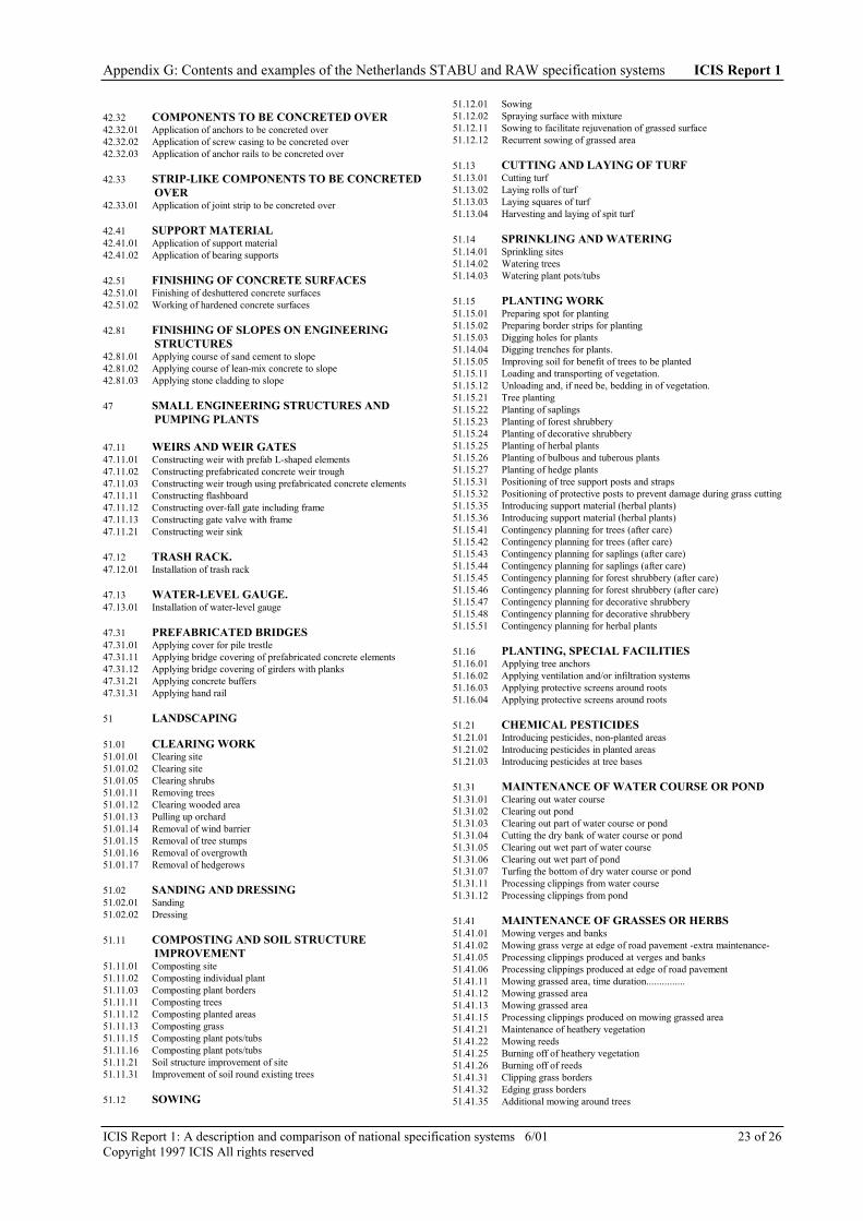
Appendix G: Contents and examples of the Netherlands STABU and RAW specification systems ICIS Report 1
ICIS Report 1: A description and comparison of national specification systems 6/01 23 of 26Copyright 1997 ICIS All rights reserved
42.32 COMPONENTS TO BE CONCRETED OVER42.32.01 Application of anchors to be concreted over42.32.02 Application of screw casing to be concreted over42.32.03 Application of anchor rails to be concreted over
42.33 STRIP-LIKE COMPONENTS TO BE CONCRETEDOVER
42.33.01 Application of joint strip to be concreted over
42.41 SUPPORT MATERIAL42.41.01 Application of support material42.41.02 Application of bearing supports
42.51 FINISHING OF CONCRETE SURFACES42.51.01 Finishing of deshuttered concrete surfaces42.51.02 Working of hardened concrete surfaces
42.81 FINISHING OF SLOPES ON ENGINEERINGSTRUCTURES
42.81.01 Applying course of sand cement to slope42.81.02 Applying course of lean-mix concrete to slope42.81.03 Applying stone cladding to slope
47 SMALL ENGINEERING STRUCTURES ANDPUMPING PLANTS
47.11 WEIRS AND WEIR GATES47.11.01 Constructing weir with prefab L-shaped elements47.11.02 Constructing prefabricated concrete weir trough47.11.03 Constructing weir trough using prefabricated concrete elements47.11.11 Constructing flashboard47.11.12 Constructing over-fall gate including frame47.11.13 Constructing gate valve with frame47.11.21 Constructing weir sink
47.12 TRASH RACK.47.12.01 Installation of trash rack
47.13 WATER-LEVEL GAUGE.47.13.01 Installation of water-level gauge
47.31 PREFABRICATED BRIDGES47.31.01 Applying cover for pile trestle47.31.11 Applying bridge covering of prefabricated concrete elements47.31.12 Applying bridge covering of girders with planks47.31.21 Applying concrete buffers47.31.31 Applying hand rail
51 LANDSCAPING
51.01 CLEARING WORK51.01.01 Clearing site51.01.02 Clearing site51.01.05 Clearing shrubs51.01.11 Removing trees51.01.12 Clearing wooded area51.01.13 Pulling up orchard51.01.14 Removal of wind barrier51.01.15 Removal of tree stumps51.01.16 Removal of overgrowth51.01.17 Removal of hedgerows
51.02 SANDING AND DRESSING51.02.01 Sanding51.02.02 Dressing
51.11 COMPOSTING AND SOIL STRUCTUREIMPROVEMENT
51.11.01 Composting site51.11.02 Composting individual plant51.11.03 Composting plant borders51.11.11 Composting trees51.11.12 Composting planted areas51.11.13 Composting grass51.11.15 Composting plant pots/tubs51.11.16 Composting plant pots/tubs51.11.21 Soil structure improvement of site51.11.31 Improvement of soil round existing trees
51.12 SOWING
51.12.01 Sowing51.12.02 Spraying surface with mixture51.12.11 Sowing to facilitate rejuvenation of grassed surface51.12.12 Recurrent sowing of grassed area
51.13 CUTTING AND LAYING OF TURF51.13.01 Cutting turf51.13.02 Laying rolls of turf51.13.03 Laying squares of turf51.13.04 Harvesting and laying of spit turf
51.14 SPRINKLING AND WATERING51.14.01 Sprinkling sites51.14.02 Watering trees51.14.03 Watering plant pots/tubs
51.15 PLANTING WORK51.15.01 Preparing spot for planting51.15.02 Preparing border strips for planting51.15.03 Digging holes for plants51.14.04 Digging trenches for plants.51.15.05 Improving soil for benefit of trees to be planted51.15.11 Loading and transporting of vegetation.51.15.12 Unloading and, if need be, bedding in of vegetation.51.15.21 Tree planting51.15.22 Planting of saplings51.15.23 Planting of forest shrubbery51.15.24 Planting of decorative shrubbery51.15.25 Planting of herbal plants51.15.26 Planting of bulbous and tuberous plants51.15.27 Planting of hedge plants51.15.31 Positioning of tree support posts and straps51.15.32 Positioning of protective posts to prevent damage during grass cutting51.15.35 Introducing support material (herbal plants)51.15.36 Introducing support material (herbal plants)51.15.41 Contingency planning for trees (after care)51.15.42 Contingency planning for trees (after care)51.15.43 Contingency planning for saplings (after care)51.15.44 Contingency planning for saplings (after care)51.15.45 Contingency planning for forest shrubbery (after care)51.15.46 Contingency planning for forest shrubbery (after care)51.15.47 Contingency planning for decorative shrubbery51.15.48 Contingency planning for decorative shrubbery51.15.51 Contingency planning for herbal plants
51.16 PLANTING, SPECIAL FACILITIES51.16.01 Applying tree anchors51.16.02 Applying ventilation and/or infiltration systems51.16.03 Applying protective screens around roots51.16.04 Applying protective screens around roots
51.21 CHEMICAL PESTICIDES51.21.01 Introducing pesticides, non-planted areas51.21.02 Introducing pesticides in planted areas51.21.03 Introducing pesticides at tree bases
51.31 MAINTENANCE OF WATER COURSE OR POND51.31.01 Clearing out water course51.31.02 Clearing out pond51.31.03 Clearing out part of water course or pond51.31.04 Cutting the dry bank of water course or pond51.31.05 Clearing out wet part of water course51.31.06 Clearing out wet part of pond51.31.07 Turfing the bottom of dry water course or pond51.31.11 Processing clippings from water course51.31.12 Processing clippings from pond
51.41 MAINTENANCE OF GRASSES OR HERBS51.41.01 Mowing verges and banks51.41.02 Mowing grass verge at edge of road pavement -extra maintenance-51.41.05 Processing clippings produced at verges and banks51.41.06 Processing clippings produced at edge of road pavement51.41.11 Mowing grassed area, time duration...............51.41.12 Mowing grassed area51.41.13 Mowing grassed area51.41.15 Processing clippings produced on mowing grassed area51.41.21 Maintenance of heathery vegetation51.41.22 Mowing reeds51.41.25 Burning off of heathery vegetation51.41.26 Burning off of reeds51.41.31 Clipping grass borders51.41.32 Edging grass borders51.41.35 Additional mowing around trees

Appendix G: Contents and examples of the Netherlands STABU and RAW specification systems ICIS Report 1
ICIS Report 1: A description and comparison of national specification systems 6/01 24 of 26Copyright 1997 ICIS All rights reserved
51.41.36 Mowing foliage of bulbous plants51.41.41 Clearing leaves from grassed area51.41.42 Clearing excess dirt from grassed area51.41.43 Clearing leaves from pavement51.41.51 Rolling grassed area51.41.52 Dragging grassed area51.41.53 Fork pricking grassed area51.41.54 Deep ventilating grassed area51.41.55 Raking grassed area
51.42 MAINTENANCE OF PLANTING51.42.01 Weeding planted section, forest shrubbery51.42.02 Weeding planted section, decorative shrubbery51.42.03 Weeding base of hedgerow51.42.04 Weeding base of hedge (block hedge)51.42.05 Weeding around edge of planted section51.42.06 Weeding of plant pots and tubs51.42.11 Controlling weeds within planted area51.42.12 Controlling weeds at base of hedgerow51.42.13 Controlling weeds around edge of planted section51.42.14 Controlling weeds in plant pots and tubs51.42.15 Processing weeded material (planted area)51.42.16 Processing weeded material (edge of planted section)51.42.17 Processing weeded material (base of hedge)51.42.21 Contingency planning for forest shrubbery51.42.22 Contingency planning for decorative shrubbery51.42.23 Contingency planning for herbal plants51.42.25 Pulling up, clipping and replanting of perennials51.42.26 Removing herbal plants51.42.27 Removing bulbous or tuberous plants51.42.31 Removing leaves from planted section51.42.51 Clearing out planted section51.42.52 Clearing around the edge of planted section51.42.53 Removing dirt from planted section51.42.54 Removing dirt from the edge of planted section51.42.61 Pruning decorative shrubbery51.42.62 Pruning edge of planted section51.42.63 Pruning rose bushes51.42.65 Clipping hedges51.42.66 Clipping creeper shrubs51.42.71 Thinning out vegetation51.42.72 Freeing up planted area51.42.73 Replacing vegetation51.42.74 Fencing off planted area51.42.81 Checking climbers and trellis plants
51.43 MAINTENANCE OF TREES51.43.01 Weeding around base of tree51.43.02 Controlling weeds at base of tree51.43.05 Replacing damaged or lost tree support posts51.43.06 Replacing damaged or lost tree support straps51.43.07 Removing tree support posts and straps51.43.08 Checking trees51.43.11 Contingency planning for trees51.43.12 Contingency planning for saplings51.43.21 Pruning trees51.43.25 Topping trees
51.44 EARTH WORKS FACILITATING MAINTENANCEOF VERGES
51.44.01 Replenishing verges51.44.02 Trimming excess growth at edges51.44.03 Lowering level of verges
52 COASTAL WORKS AND SHORE PROTECTIONWORKS52.0 Ballast works
52.1 Rubble layers52.2 Foot and bank protection, sheet piling, pile rows and lock constructionsfor lock retainers refer to main code 52352152.3 Shore protection works52.4 Sand reclamation and anti-nebulization facilities52.5 Signposting and lighting52.7 Removing constructions
52.01 FASCINE MATTRESSES AND CRIBS52.01.01 Constructing osier fascine mattress52.01.02 Constructing fascine mattress with plastic sole52.01.03 Constructing fascine mattress fixed ballast - concrete blocks52.01.04 Constructing fascine mattress fixed ballast - tar macadam52.01.05 Constructing fascine mattress fixed ballast - rockfilled cage52.01.11 Constructing osier crib52.01.12 Constructing crib with plastic sole
52.01.14 Constructing crib fixed ballast - tar macadam52.01.21 Application of bed protection at engineering structure52.01.31 Application of filling and fascine for mattress52.01.32 Application of filling and fascine for crib52.01.41 Dragging composition pieces52.01.51 Sinking fascine mattress52.01.52 Applying crib
52.11 RUBBLE AS DEFENCE OR FILTER52.11.01 Applying rubble52.11.02 Applying granular filer layer above water52.11.11 Finishing rubble
52.12 RUBBLE USED WITH BALLAST WORKS52.12.01 Applying rubble during ballasting52.12.11 Applying extra rubble to fascine mattress52.12.12 Applying extra rubble to crib
52.13 THRESHOLD RUBBLE52.13.01 Applying rubble as a threshold under water52.13.11 Sloping away of rubble under water
52.14 PROCESSING STONY MATERIAL INEMBANKMENT/COVERING
52.14.01 Processing stone or stony material in embankment52.14.02 Processing stone or stony material in covering52.14.11 Compacting stone or stony material
52.15 STORING ROCK-FILL AT DEPOT52.15.01 Storing stone or stony material at depot
52.21 SHEET PILE WALL AND REVETMENT52.21.01 Applying piles52.21.02 Applying sheet piling52.21.03 Applying planks52.21.04 Applying girders
52.22 SCREENING AND OSIER PARTITION52.22.01 Application of osier woven screen52.22.02 Application of prefabricated red ironwood woven screen52.22.03 Application of pile row
52.23 DRAINAGE CAISSON52.23.01 Application of drainage caisson
52.32 BANK DEFENCES OF OSIER MATERIALS ANDREED
52.32.01 Application of mounting to facilitate shore defence
52.33 BANK DEFENCES OF PREFABRICATEDMATTRESSES
52.33.01 Application of fascine work52.33.11 Application of synthetic filter material with reed mattress52.33.12 Application of synthetic filter material52.33.21 Application of concrete block mattress - cable mattress52.33.22 Application of concrete block mattress - pin mattress52.33.23 Application of concrete block mattress - glued mattress52.33.27 Fixing concrete block mattress52.33.28 Finishing concrete block mattress
52.35 BANK DEFENCES OF NATURAL OR MAN-MADESTONE
52.35.01 Positioning natural stone52.35.02 Delivery of natural stone52.35.11 Application of man-made stone52.35.12 Application of concrete elements52.35.21 Application of concrete fascias52.35.31 Finishing slope of concrete elements
52.36 BITUMINOUS BOUND BANK DEFENCES52.36.01 Application of hydraulic engineering asphaltic concrete52.36.02 Penetration of quarry stone with bituminous material52.36.03 Application of asphalt mastic52.36.04 Application of pervious tar macadam52.36.05 Application of dense tar macadam52.36.06 Application of sand asphalt52.36.07 Processing sand asphalt in embankment52.36.11 Applying surface treatment to asphalt covering52.36.12 Applying tack coat52.36.17 Supplying binders52.36.18 Supplying topping material
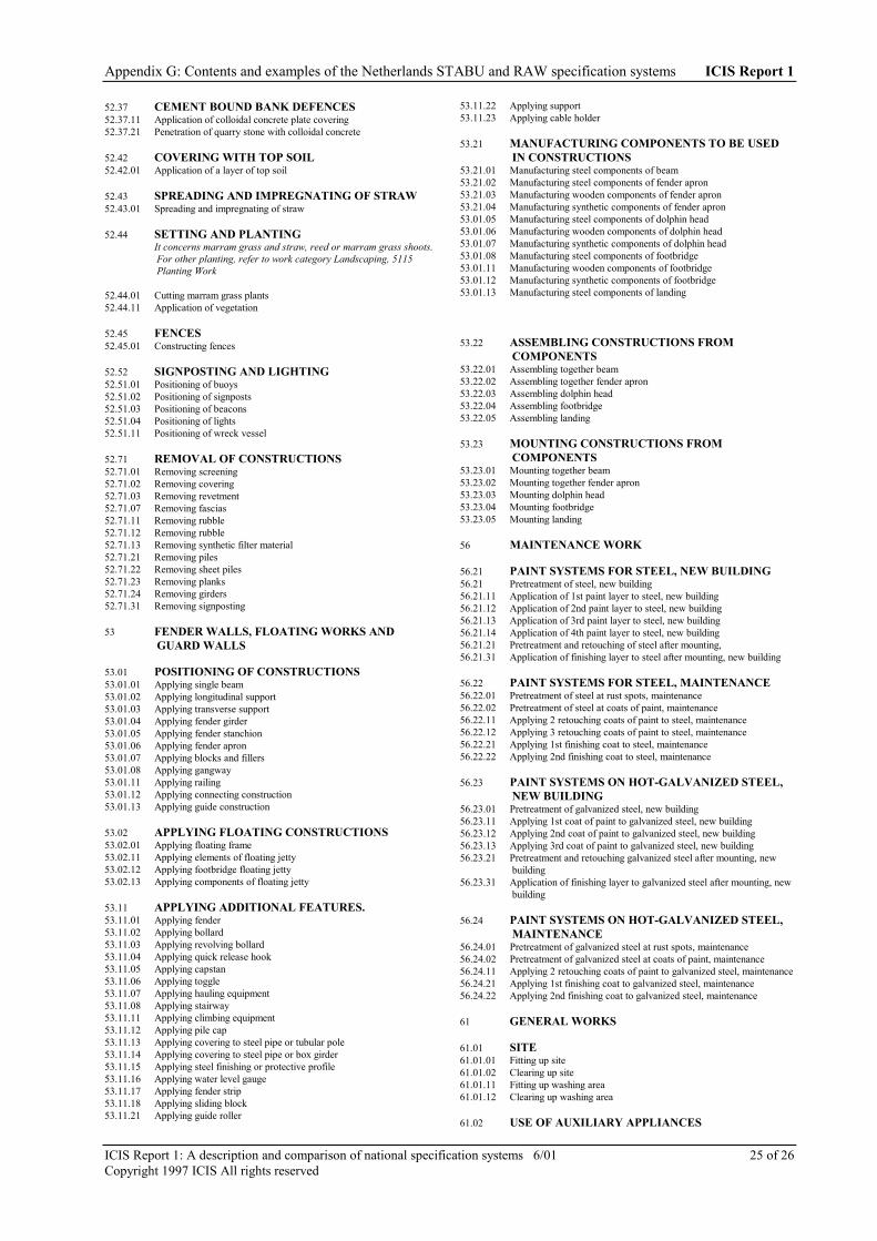
Appendix G: Contents and examples of the Netherlands STABU and RAW specification systems ICIS Report 1
ICIS Report 1: A description and comparison of national specification systems 6/01 25 of 26Copyright 1997 ICIS All rights reserved
52.37 CEMENT BOUND BANK DEFENCES52.37.11 Application of colloidal concrete plate covering52.37.21 Penetration of quarry stone with colloidal concrete
52.42 COVERING WITH TOP SOIL52.42.01 Application of a layer of top soil
52.43 SPREADING AND IMPREGNATING OF STRAW52.43.01 Spreading and impregnating of straw
52.44 SETTING AND PLANTINGIt concerns marram grass and straw, reed or marram grass shoots.For other planting, refer to work category Landscaping, 5115Planting Work
52.44.01 Cutting marram grass plants52.44.11 Application of vegetation
52.45 FENCES52.45.01 Constructing fences
52.52 SIGNPOSTING AND LIGHTING52.51.01 Positioning of buoys52.51.02 Positioning of signposts52.51.03 Positioning of beacons52.51.04 Positioning of lights52.51.11 Positioning of wreck vessel
52.71 REMOVAL OF CONSTRUCTIONS52.71.01 Removing screening52.71.02 Removing covering52.71.03 Removing revetment52.71.07 Removing fascias52.71.11 Removing rubble52.71.12 Removing rubble52.71.13 Removing synthetic filter material52.71.21 Removing piles52.71.22 Removing sheet piles52.71.23 Removing planks52.71.24 Removing girders52.71.31 Removing signposting
53 FENDER WALLS, FLOATING WORKS ANDGUARD WALLS
53.01 POSITIONING OF CONSTRUCTIONS53.01.01 Applying single beam53.01.02 Applying longitudinal support53.01.03 Applying transverse support53.01.04 Applying fender girder53.01.05 Applying fender stanchion53.01.06 Applying fender apron53.01.07 Applying blocks and fillers53.01.08 Applying gangway53.01.11 Applying railing53.01.12 Applying connecting construction53.01.13 Applying guide construction
53.02 APPLYING FLOATING CONSTRUCTIONS53.02.01 Applying floating frame53.02.11 Applying elements of floating jetty53.02.12 Applying footbridge floating jetty53.02.13 Applying components of floating jetty
53.11 APPLYING ADDITIONAL FEATURES.53.11.01 Applying fender53.11.02 Applying bollard53.11.03 Applying revolving bollard53.11.04 Applying quick release hook53.11.05 Applying capstan53.11.06 Applying toggle53.11.07 Applying hauling equipment53.11.08 Applying stairway53.11.11 Applying climbing equipment53.11.12 Applying pile cap53.11.13 Applying covering to steel pipe or tubular pole53.11.14 Applying covering to steel pipe or box girder53.11.15 Applying steel finishing or protective profile53.11.16 Applying water level gauge53.11.17 Applying fender strip53.11.18 Applying sliding block53.11.21 Applying guide roller
53.11.22 Applying support53.11.23 Applying cable holder
53.21 MANUFACTURING COMPONENTS TO BE USEDIN CONSTRUCTIONS
53.21.01 Manufacturing steel components of beam53.21.02 Manufacturing steel components of fender apron53.21.03 Manufacturing wooden components of fender apron53.21.04 Manufacturing synthetic components of fender apron53.01.05 Manufacturing steel components of dolphin head53.01.06 Manufacturing wooden components of dolphin head53.01.07 Manufacturing synthetic components of dolphin head53.01.08 Manufacturing steel components of footbridge53.01.11 Manufacturing wooden components of footbridge53.01.12 Manufacturing synthetic components of footbridge53.01.13 Manufacturing steel components of landing
53.22 ASSEMBLING CONSTRUCTIONS FROMCOMPONENTS
53.22.01 Assembling together beam53.22.02 Assembling together fender apron53.22.03 Assembling dolphin head53.22.04 Assembling footbridge53.22.05 Assembling landing
53.23 MOUNTING CONSTRUCTIONS FROMCOMPONENTS
53.23.01 Mounting together beam53.23.02 Mounting together fender apron53.23.03 Mounting dolphin head53.23.04 Mounting footbridge53.23.05 Mounting landing
56 MAINTENANCE WORK
56.21 PAINT SYSTEMS FOR STEEL, NEW BUILDING56.21 Pretreatment of steel, new building56.21.11 Application of 1st paint layer to steel, new building56.21.12 Application of 2nd paint layer to steel, new building56.21.13 Application of 3rd paint layer to steel, new building56.21.14 Application of 4th paint layer to steel, new building56.21.21 Pretreatment and retouching of steel after mounting,56.21.31 Application of finishing layer to steel after mounting, new building
56.22 PAINT SYSTEMS FOR STEEL, MAINTENANCE56.22.01 Pretreatment of steel at rust spots, maintenance56.22.02 Pretreatment of steel at coats of paint, maintenance56.22.11 Applying 2 retouching coats of paint to steel, maintenance56.22.12 Applying 3 retouching coats of paint to steel, maintenance56.22.21 Applying 1st finishing coat to steel, maintenance56.22.22 Applying 2nd finishing coat to steel, maintenance
56.23 PAINT SYSTEMS ON HOT-GALVANIZED STEEL,NEW BUILDING
56.23.01 Pretreatment of galvanized steel, new building56.23.11 Applying 1st coat of paint to galvanized steel, new building56.23.12 Applying 2nd coat of paint to galvanized steel, new building56.23.13 Applying 3rd coat of paint to galvanized steel, new building56.23.21 Pretreatment and retouching galvanized steel after mounting, new
building56.23.31 Application of finishing layer to galvanized steel after mounting, new
building
56.24 PAINT SYSTEMS ON HOT-GALVANIZED STEEL,MAINTENANCE
56.24.01 Pretreatment of galvanized steel at rust spots, maintenance56.24.02 Pretreatment of galvanized steel at coats of paint, maintenance56.24.11 Applying 2 retouching coats of paint to galvanized steel, maintenance56.24.21 Applying 1st finishing coat to galvanized steel, maintenance56.24.22 Applying 2nd finishing coat to galvanized steel, maintenance
61 GENERAL WORKS
61.01 SITE61.01.01 Fitting up site61.01.02 Clearing up site61.01.11 Fitting up washing area61.01.12 Clearing up washing area
61.02 USE OF AUXILIARY APPLIANCES

Appendix G: Contents and examples of the Netherlands STABU and RAW specification systems ICIS Report 1
ICIS Report 1: A description and comparison of national specification systems 6/01 26 of 26Copyright 1997 ICIS All rights reserved
61.02.01 Use of office61.02.02 Use of mobile office61.02.03 Use of portacabin61.02.04 Use of truck51.03.05 Use of storage shed61.03.11 Use of washing area
61.03 FENCING61.03.01 Applying fence posts61.03.02 Applying struts for fencing61.03.03 Applying horizontal tube, span wire or barbed wire61.03.04 Applying chicken wire netting for fencing61.03.05 Applying gate61.03.11 Applying temporary fencing, cattle repellent61.03.21 Removing fencing61.03.22 Removing gate
61.04 EQUIPMENT FOR PROTECTING PLANTING61.04.01 Applying temporary fencing61.04.02 Applying temporary fencing61.04.03 Applying tree trunk protection61.04.04 Applying load spreading layer
61.05 APPROXIMATE ESTIMATE61.05.01 Approximate estimate
61.11 DEPLOYMENT OF EMPLOYEES61.11.01 Deployment of employee61.11.02 Deployment of gate-keeper61.11.03 Deployment of erector of guard-rail61.11.04 Deployment of team of erectors of guard-rail
61.12 DEPLOYMENT OF PLANT61.12.01 Deployment of bulldozer61.12.02 Deployment of dragline61.12.03 Deployment of hydraulic excavator61.12.04 Deployment of truck61.12.05 Deployment of wheel loader61.12.06 Deployment of tractor61.12.07 Deployment of mobile clipper61.12.21 Deployment of floating crane61.12.22 Deployment of roof hod61.12.41 Deployment of motorized chain saw
61.12.42 Deployment of compressor61.12.43 Deployment of mower
61.13 DEPLOYMENT OF MEANS OF TRANSPORT61.13.01 Deployment of moped61.13.05 Deployment of site vehicle61.13.11 Deployment of boat
61.21 USE OF BOATS.61.21.01 Use of patrol or escort vessel61.21.02 Use of gauging and measuring vessel61.21.03 Use of gauging and measuring vessel61.21.04 Use of management vessel61.21.05 Use of auxiliary vessel
62 TRAFFIC MEASURES FOR WORKS IN PROGRESS
62.01 APPLICATION OF CORDONING OFF AND OTHERFACILITIES
62.01.01 Application of temporary cordoning off on motorway62.01.02 Application of temporary cordoning off on dual carriage way62.01.03 Application of temporary cordoning off on single lane road with
limited access62.01.04 Application of temporary cordoning off on single lane carriage way62.01.11 Application of temporary cordoning off on motorway62.01.12 Application of temporary cordoning off on dual carriage way62.01.13 Application of temporary cordoning off on single lane road with
limited access62.01.14 Application of temporary cordoning off on single lane carriage way62.01.21 Application of permanent cordoning off on motorway62.01.22 Application of permanent cordoning off on dual carriage way62.01.23 Application of permanent cordoning off on single lane road with
limited access62.01.24 Application of permanent cordoning off on single lane carriage way62.01.31 Application of temporary gantry sign62.01.32 Application of temporary signposts62.01.33 Application of signposting for traffic diversions62.01.41 Application of wooden pedestrian board-walks62.01.42 Application of steel planking62.01.43 Application of emergency bridge62.01.44 Application of emergency bridge
translated by M.J. Tait August 1996

ICIS Report 1: A description and comparison of national specification systems 6/01 1 of 8Copyright ICIS 2001 All rights reserved
APPENDIX H: CONTENTS AND EXAMPLE OF THE NEW ZEALANDMasterSpec® SPECIFICATION SYSTEMS
CONTENTS OF THE SYSTEMS
MasterSpec® STANDARD 2000CODE WORK SECTION TITLE
011 COVER SHEET012 SPECIFICATION STRUCTURE013 LIST OF CONTENTS014 TABLE OF CONTENTS FORM015 SECTION FORMAT016 WORK SECTION TEMPLATE017 TENDER FORM018 TENDER SUMMARY
GENERAL
CONTRACT1121 SPECIAL CONDITIONS OF CONTRACT (MW2)1122 SPECIAL CONDITIONS OF CONTRACT (SCC1)1123 SPECIAL CONDITIONS OF CONTRACT (NBC-G1)1124 SPECIAL CONDITIONS OF CONTRACT (NZS)1125 SPECIAL CONDITIONS OF CONTRACT (NBC-SW2)1141 SPECIAL CONDITIONS OF TENDER (MW2)1142 SPECIAL CONDITIONS OF TENDER (SCC1)1143 SPECIAL CONDITIONS OF TENDER (NBC-G1)1144 SPECIAL CONDITIONS OF TENDER (NZS)1145 SPECIAL CONDITIONS OF TENDER (NBC-SW2)1149 CONDITIONS OF TENDER (GENERIC)
PRELIMINARIES AND GENERAL1211 PRELIMINARIES AND GENERAL (MW2)1212 PRELIMINARIES AND GENERAL (SCC1)1213 PRELIMINARIES AND GENERAL (NBC-G1)1214 PRELIMINARIES AND GENERAL (NZS)1215 PRELIMINARIES AND GENERAL (NBC-SW2)1218 GUARANTEE FORM1219 PROJECT PERSONNEL1311 WASTE MANAGEMENT
SITE
DEMOLITION2111 DEMOLITION
PREPARATION AND GROUNDWORK2211 REMOVING VEGETATION2221 EXCAVATION2222 BACKFILLING2223 REMOVING SUBSURFACE CONSTRUCTIONS
FOUNDATIONS2311 CAST IN PLACE CONCRETE PILING2321 TIMBER POLE FOUNDATIONS2322 PRECAST CONCRETE BLOCK FOOTINGS2323 TIMBER POSTS AND BLOCKS
STRUCTURE
CONCRETE3111 FORMWORK FOR INSITU CONCRETE3112 REINFORCEMENT FOR INSITU CONCRETE3121 CONCRETE PLACEMENT3124 FINISHES TO WET CONCRETE3129 CONCRETE PRODUCTION3131 PRECAST STRUCTURAL ITEMS, SUPPLY3132 PRECAST NON STRUCTURAL ITEMS, SUPPLY3141 PRECAST STRUCTURAL ITEMS, INSTALL3142 PRECAST NON STRUCTURAL ITEMS, INSTALL
3151 CONCRETE ON STEEL FLOOR SYSTEM3151D DIMOND HI-BOND FLOOR SYSTEM3152 CONCRETE ON PRECAST FLOOR SYSTEM
MASONRY3311 BRICKWORK3321 HOLLOW CONCRETE BLOCKWORK3322 HOLLOW PLASTIC BLOCKWORK3361 NATURAL STONEWORK
STEEL3411 STRUCTURAL STEELWORK3411D DHS PURLINS AND GIRTS3421 LIGHT STEEL FRAMING3431 STEEL STAIRS, LADDERS AND BALUSTRADES3441 MISCELLANEOUS STEEL METALWORK3442 STEEL SCREENS AND SHUTTERS3451 SHEET STEEL ITEMS
STAINLESS STEEL3541 MISCELLANEOUS STAINLESS STEEL METALWORK3551 SHEET STAINLESS STEEL ITEMS
ALUMINIUM3641 MISCELLANEOUS ALUMINIUM METALWORK3651 SHEET ALUMINIUM ITEMS
OTHER METALS3711 COPPER AND COPPER ALLOY ITEMS
TIMBER3811 TRUSSES AND LAMINATED MEMBERS, SUPPLY3813 TIMBER STRUCTURAL FRAMING3821 TIMBER FRAMING3821L LASERFRAME TIMBER FRAMING3831 PARTICLE BOARD FLOORS3832 TIMBER STRIP FLOORS3833 PLYWOOD FLOORS AND DECKING3841 TIMBER STAIRS, HANDRAILS, BALUSTRADES3851 TIMBER SCREENS AND SHUTTERS
ENCLOSURE
TANKING AND DAMP-PROOFING4111 MASTIC ASPHALT TANKING4121 LIQUID APPLIED BITUMINOUS TANKING4131 SHEET TANKING
CLADDING4211 PROPRIETARY CURTAIN WALLING4221 TIMBER BOARD CLADDING4223 PLYWOOD CLADDING4224 TIMBER EXTERIOR TRIM4231 FIBRE CEMENT FLAT SHEET CLADDING4241 PROFILED METAL CLADDING4241B STEEL AND TUBE PROFILED METAL CLADDING4241D DIMOND PROFILED METAL CLADDING4242 PROFILED PLASTIC CLADDING4251 ALUMINIUM COMPOSITE CLADDING4255 INSULATING WALL CLADDING4257 STEEL CLAD INSULATING CLADDING4258 STEEL CLAD POLYSTYRENE CLADDING
ROOFING4311 PROFILED METAL ROOFING4311B STEEL AND TUBE PROFILED METAL ROOFING4311D DIMOND PROFILED METAL ROOFING4312 PROFILED PLASTIC ROOFING4312D DIMOND PROFILED GRP ROOFING4321 CONCRETE TILE ROOFING4322 CLAY TILE ROOFING4323 PRESSED STEEL ROOFING TILES4351 TIMBER SHINGLE AND SHAKE ROOFING

Appendix H: Contents and examples of the New Zealand MasterSpec™ specification system ICIS Report 1
ICIS Report 1: A description and comparison of national specification systems 6/01 2 of 8Copyright ICIS 2001 All rights reserved
MEMBRANE ROOFING4411 MASTIC ASPHALT ROOFING4421 MINERAL FIBRE ASPHALT ROOFING4422 SYNTHETIC RUBBER SHEET ROOFING
DOORS, WINDOWS AND ROOF LIGHTS4511 TIMBER WINDOWS, DOORS AND FRAMES4521 ALUMINIUM WINDOWS, DOORS AND FRAMES4531 STEEL WINDOWS, DOORS AND FRAMES4551 COMPOSITE WINDOWS, DOORS AND FRAMES
GLAZING4611 GENERAL GLAZING4621 GLASS BLOCK WALLING
INSULATION4712 FIRE RATED COATINGS4719 THERMAL INSULATING MATERIALS4729 ACOUSTIC INSULATING MATERIALS
SEALANTS4811 SEALANTS
INTERIOR
LININGS5111 FIBRE CEMENT SHEET LININGS5112 FIBROUS PLASTER LININGS5113 PLASTERBOARD LININGS5113G GIB PLASTERBOARD LININGS5113GS GIB LIVING SOLUTIONS FOR SCHOOLS5121 WOODWOOL PANELS5122 PLYWOOD LININGS5123 MANUFACTURED TIMBER BOARD LININGS5124 TIMBER BOARD LININGS5131 PREFINISHED PANEL LININGS5151 INTERNAL TRIM
PARTITIONS5211 PROPRIETARY PARTITIONS5214 TOILET AND CUBICLE PARTITIONS
CEILINGS5311 SUSPENDED CEILINGS5311A ACOUSTICAL USG/DONN SUSPENDED CEILINGS5311F FORMAN BUILDING SYSTEMS SUSPENDED
CEILINGSACCESS FLOORS
5411 PROPRIETARY RAISED ACCESS FLOORSFIXTURES
5511 PURPOSE MADE FIXTURES5513 BATHROOM AND TOILET FIXTURES5521 HARDWARE SUPPLY
FURNITURE AND APPLIANCES5711 UNSERVICED LOOSE APPLIANCES
FINISH
TROWELLED AND SPRAYED COATINGS6112 SOLID PLASTER COATINGS6122 CONCRETE FLOOR SCREEDS6123 TERRAZZO FINISHES
TILING6211 WALL TILES6211C TILE WAREHOUSE WALL TILES6211J JACOBSEN WALL TILES6221 FLOOR TILES6221C TILE WAREHOUSE FLOOR TILES6221J JACOBSEN FLOOR TILES6231 TIMBER STRIP, BLOCK AND PLANK FLOORING6231J JACOBSEN TIMBER FLOORING
RESILIENT SURFACING6411 VINYL SURFACING6411J JACOBSEN VINYL SURFACING6412 LINOLEUM SURFACING6413 RUBBER SURFACING6414 CORK SURFACING
CARPETING6511 CARPETING
6511F FELTEX COMMERCIAL CARPETS6512 CARPET TILES
FLOORING ANCILLARIES6611 FLOOR PREPARATION, SHEET UNDERLAYS
PAINTING AND PAPERHANGING6711 PAINTING AND CLEAR FINISHING6711D DULUX PREPARATION AND PAINTING6711R RESENE PREPARATION AND PAINTING6721 DECORATIVE COATINGS6721N NUPLEX TEXTURED AND DECORATIVE COATINGS6731 PROTECTIVE COATINGS, STEELWORK6751 WALLPAPER FINISHES
SERVICES
LIQUID7123 HOT AND COLD WATER SYSTEM7151 TAPWARE SUPPLY
GAS7211 GAS SYSTEM7221 GAS APPLIANCES
FIRE SUPPRESSION7311 FIRE HOSE REEL SYSTEM7312 AUTOMATIC FIRE SPRINKLER SYSTEM
PLUMBING AND DRAINAGE7413 SPOUTING AND DOWNPIPES7421 SANITARY PLUMBING7422 SANITARY FIXTURES7431 GROUNDWATER DRAINAGE7432 STORMWATER DRAINAGE7441 SEWER DRAINAGE
ELECTRICAL POWER AND LIGHTING7711 PRIMARY POWER SUPPLY7722 GENERAL POWER DISTRIBUTION7741 LUMINAIRES AND LAMPS7742 EXTERIOR LIGHTING7743 EMERGENCY EVACUATION LIGHTING7761 ELECTRIC APPLIANCES
COMMUNICATIONS AND CONTROLS7831 MANUAL FIRE ALARM SYSTEMS7832 AUTOMATIC FIRE AND SMOKE DETECTION
SYSTEMS
EXTERNAL
RETAINING WALLS8113 PRECAST CONCRETE RETAINING WALLS8114 TIMBER RETAINING WALLS
ROADS AND PAVINGS8211 EDGING, KERBS AND GUTTERS8221 SUB BASES TO SEALING AND PAVING8222 ASPHALTIC PAVING8223 SPRAYED BITUMEN SEALING8231 INTERLOCKING PAVING
LANDSCAPING8311 SOIL AND SOIL PREPARATION8312 PLANTING8313 SEEDING AND TURFING

Appendix H: Contents and examples of the New Zealand MasterSpec™ specification system ICIS Report 1
ICIS Report 1: A description and comparison of national specification systems 6/01 3 of 8Copyright ICIS 2001 All rights reserved
MasterSpec® BASIC 200001 COVER SHEET02 CO-ORDINATED BUILDING INFORMATION (CBI)03 LIST OF CONTENTS04 TABLE OF CONTENTS FORM05 SECTION FORMAT06 WORK SECTION TEMPLATE07 TENDER FORM08 TENDER SUMMARY
1101 SPECIAL CONDITIONS (MW2)1102 SPECIAL CONDITIONS (SCC1)1103 SPECIAL CONDITIONS (NBC-G1)1104 SPECIAL CONDITIONS (NZS)1105 SPECIAL CONDITIONS (NBC-SW2)1109 TENDER CONDITIONS
1201 PRELIMINARIES AND GENERAL1202 GUARANTEE FORM
2101 DEMOLITION2201 PREPARATION AND GROUNDWORK2301 FOUNDATIONS3101 CONCRETE3301 BRICKWORK3302 BLOCKWORK3303 HOLLOW PLASTIC BLOCKWORK3401 STEELWORK3701 METALWORK3801 CARPENTRY3801L LASERFRAME CARPENTRY4201 WALL CLADDING4301 ROOFING4301B STEEL AND TUBE ROOFING4401 MEMBRANE ROOFING4501 TIMBER WINDOWS AND DOORS4502 ALUMINIUM WINDOWS AND DOORS4503 COMPOSITE WINDOWS, DOORS AND SKYLIGHTS4601 GLAZING5101 LINING5101G GIB® PLASTERBOARD LINING5101GR GIB® LIVING SOLUTIONS5301 SUSPENDED CEILINGS5301A ACOUSTICAL USG/DONN SUSPENDED CEILINGS5501 JOINERY FITTINGS6101 SOLID PLASTER6201 TILING6201J JACOBSEN TILING6202 TIMBER OVERLAY FLOORING6202J JACOBSEN TIMBER FLOORING6401 RESILIENT SURFACING6401J JACOBSEN VINYL SURFACING6501 CARPETING6701 PAINTING AND PAPERHANGING6701R RESENE PAINTING7101 WATER7201 GAS7401 RAINWATER PLUMBING7402 SANITARY PLUMBING7403 DRAINAGE7701 ELECTRICAL8101 RETAINING WALLS8201 PAVING8301 LANDSCAPING
MasterSpec® MINOR 2000PROJECT INFORMATIONCOMPLIANCE INFORMATIONPRODUCT INFORMATIONPROJECT SELECTIONS
11 GENERAL REQUIREMENTS
21 DEMOLITION22 PREPARATION23 FOUNDATIONS31 CONCRETE32 BRICKWORK33 CONCRETE BLOCKWORK34 CARPENTRY41 WALL CLADDING42 ROOFING43 MEMBRANE ROOFING44 TIMBER WINDOWS AND DOORS45 ALUMINIUM WINDOWS AND DOORS46 GLAZING51 INTERNAL LININGS52 FITTINGS61 SOLID PLASTER62 TILING63 PAINTING AND PAPERHANGING71 WATER72 RAINWATER PLUMBING73 SANITARY PLUMBING74 DRAINAGE75 ELECTRICAL
91 ADDITIONAL ITEMS
ITEMS BY OTHERSREFERENCESADDENDA
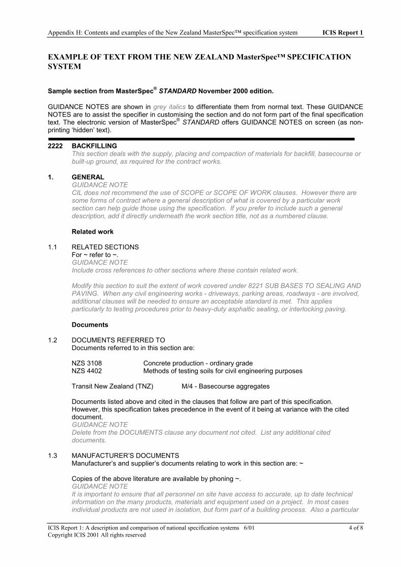
Appendix H: Contents and examples of the New Zealand MasterSpec™ specification system ICIS Report 1
ICIS Report 1: A description and comparison of national specification systems 6/01 4 of 8Copyright ICIS 2001 All rights reserved
EXAMPLE OF TEXT FROM THE NEW ZEALAND MasterSpec™ SPECIFICATIONSYSTEM
Sample section from MasterSpec® STANDARD November 2000 edition.
GUIDANCE NOTES are shown in grey italics to differentiate them from normal text. These GUIDANCENOTES are to assist the specifier in customising the section and do not form part of the final specificationtext. The electronic version of MasterSpec® STANDARD offers GUIDANCE NOTES on screen (as non-printing ‘hidden’ text).
2222 BACKFILLINGThis section deals with the supply, placing and compaction of materials for backfill, basecourse orbuilt-up ground, as required for the contract works.
1. GENERALGUIDANCE NOTECIL does not recommend the use of SCOPE or SCOPE OF WORK clauses. However there aresome forms of contract where a general description of what is covered by a particular worksection can help guide those using the specification. If you prefer to include such a generaldescription, add it directly underneath the work section title, not as a numbered clause.
Related work
1.1 RELATED SECTIONSFor ~ refer to ~.GUIDANCE NOTEInclude cross references to other sections where these contain related work.
Modify this section to suit the extent of work covered under 8221 SUB BASES TO SEALING ANDPAVING. When any civil engineering works - driveways, parking areas, roadways - are involved,additional clauses will be needed to ensure an acceptable standard is met. This appliesparticularly to testing procedures prior to heavy-duty asphaltic sealing, or interlocking paving.
Documents
1.2 DOCUMENTS REFERRED TODocuments referred to in this section are:
NZS 3108 Concrete production - ordinary gradeNZS 4402 Methods of testing soils for civil engineering purposes
Transit New Zealand (TNZ) M/4 - Basecourse aggregates
Documents listed above and cited in the clauses that follow are part of this specification.However, this specification takes precedence in the event of it being at variance with the citeddocument.GUIDANCE NOTEDelete from the DOCUMENTS clause any document not cited. List any additional citeddocuments.
1.3 MANUFACTURER’S DOCUMENTSManufacturer’s and supplier’s documents relating to work in this section are: ~
Copies of the above literature are available by phoning ~.GUIDANCE NOTEIt is important to ensure that all personnel on site have access to accurate, up to date technicalinformation on the many products, materials and equipment used on a project. In most casesindividual products are not used in isolation, but form part of a building process. Also a particular

Appendix H: Contents and examples of the New Zealand MasterSpec™ specification system ICIS Report 1
ICIS Report 1: A description and comparison of national specification systems 6/01 5 of 8Copyright ICIS 2001 All rights reserved
manufacturer’s and/or supplier’s requirements for handling, storage, preparation, installation,finishing and protection of their product can vary from what might be considered the norm.Access to technical information can help overcome this potential problem.
2. PRODUCTS
Materials
2.1 EXCAVATED FILLMaterial from other formations in the excavation which may be selected and approved as suitablefor filling and complying with NZS 4402 by having grading and moisture content properties that willallow recompaction to 95% of maximum density.GUIDANCE NOTEFor contract control consider specifying imported fill only, with a proviso that if excavated materialis approved it can be used with consequent cost adjustments.
2.2 COMPACTED ROP ROCK STRIPPINGSRotten rock or quarry strippings, free of organic material, maximum density to NZS 4402, test4.1.1 or equivalent.
2.3 VOLCANIC TUFF FILLScoriaceous tuff of variable grading excluding excessive silt or clay material, capable of beingplaced and compacted as specified.
2.4 ROCK FILLHard material comprising rock, broken stone, hard brick, concrete, run of pit scoria, or othercomparable inert material, with a maximum particle size of 100 mm, capable of being placed andcompacted as specified.
2.5 SAND FILLClean sand of such grading in particle size as to allow for mechanical compaction to 90%maximum density to NZS 4402.
2.6 HARDFILLScoria or crushed rock to GAP (General All Passing) 65 grading.
2.7 GRANULAR BASEApproved screened crushed gravel or scoria graded in size from 20 mm to 7 mm, clean. Whentested with a standard sieve of 4.75 opening no material is to pass.
2.8 TNZ BASECOURSEMetal aggregate to TNZ M/4 specification.
2.9 BASECOURSEMetal aggregate for road construction to GAP 40 grading.
2.10 TNZ SUB-BASECOURSEMetal aggregate to TNZ M/4 specification notes.
2.11 SUB-BASECOURSEMetal aggregate for road construction to GAP 80 grading.GUIDANCE NOTESelect from the above alternate BASECOURSE and SUB-BASECOURSE clauses.
2.12 DRESSING COURSEScoria to GAP 20 grading, or "dirty footpath scoria", or equivalent "all in" graded crushed metalaggregate.
2.13 FREE-DRAINING AGGREGATEScoria or crushed gravel graded 50 to 14 clean.

Appendix H: Contents and examples of the New Zealand MasterSpec™ specification system ICIS Report 1
ICIS Report 1: A description and comparison of national specification systems 6/01 6 of 8Copyright ICIS 2001 All rights reserved
2.14 SITE CONCRETEOrdinary grade 10.0 MPa to NZS 3108.
3. EXECUTION
Conditions
3.1 UNSUITABLE MATERIALSRemove from site all unsuitable filling material.
3.2 REMOVE SURPLUSRemove surplus imported filling materials from the site.
3.3 SPREAD SURPLUSSpread and level surplus imported filling materials where directed.GUIDANCE NOTERefer to the disposal of surplus excavated material in 2221 EXCAVATION.
3.4 PLACE FILLINGPlace filling using approved methods, to required dimensions, levels, lines and profiles and so thatsurface water drains freely.
3.5 PROTECTION OF FORMATIONDo not allow construction traffic on filling until the level has been raised not less than 150 mmabove formation level by properly compacted temporary protective filling. Remove temporaryprotective filling from the site before beginning permanent construction. Do not stockpilematerials on newly filled areas without permission.
3.6 DIFFERING MATERIALSWhere materials of widely divergent characteristics are used for filling, spread and compact inclearly defined separate layers.
3.7 EARTHMOVING EQUIPMENTDo not use earthmoving equipment for compaction.
3.8 COMPACTION NEAR EDGE SUPPORTSEnsure that edge supports are strong enough to support compaction forces without movement,cracking or other damage. Make good damage caused by compaction.
3.9 MOISTURE CONTENT, GENERAL FILLMoisture content at time of compaction to be within the range of optimum less 6% up to optimum.Do not use filling with moisture content above optimum value. If necessary:- adjust moisture content of filling by turning and drying- provide water sprinkling equipment if fill is too dry.
Application
3.10 SPREAD AND COMPACT GRANULAR FILLSpread and level in layers not more than 150 mm loose depth from the approved level. Compactfilling in layers as specified by at least four passes of a vibratory roller having a static linearloading of 1.8 - 2.3 kg/mm, or twelve passes of a vibratory roller having a static linear loading of0.8 - 1.2 kg/mm. Achieve a density of not less than 95% of maximum at optimum moisturecontent to NZS 4402.
Alternative compaction plant may be used provided it can be shown that the density requirementcan be achieved.GUIDANCE NOTESmooth wheeled, non vibrating rollers of suitable size, or vibrating plate compactors may besuitable alternatives.
Modify this clause to suit other types of granular fill.

Appendix H: Contents and examples of the New Zealand MasterSpec™ specification system ICIS Report 1
ICIS Report 1: A description and comparison of national specification systems 6/01 7 of 8Copyright ICIS 2001 All rights reserved
3.11 SPREAD AND COMPACT ROCK FILLSpread and compact in layers of not more than 200 mm loose depth where designated on thedrawings. Compact with suitable heavy plant to provide a dense, unyielding base.GUIDANCE NOTEBecause of variability and general lack of good grading of sizes, compaction can be difficult. Innon-critical areas the use of a heavy crawler tractor to spread and compact may be sufficient.
3.12 SPREAD AND COMPACT HARDFILLSpread and level in layers of not more than 150 mm loose depth where required to make up fromapproved subgrade to the underside of basecourse, sitework construction or to where shown onthe drawings. Compact as described under GRANULAR FILL.
3.13 SPREAD AND COMPACT VOLCANIC TUFFSpread and level in layers of not more than 150 mm loose depth where required to make up fromapproved subgrade to the underside of construction. Remove lumps larger than 100 mm.Compact as described under GRANULAR FILL.
3.14 SPREAD AND COMPACT SAND FILLINGSpread and level in layers of not more than 125 mm loose depth for areas designated on the planor agreed on site. Carry out vibrating compaction on a trial area to show that 90% maximumdensity to NZS 4402 can be achieved.
3.15 BLIND SURFACEBlind surface of area being covered with a concrete slab with clean sand to a thickness not morethan 12 mm and roll or compact with a vibrating plate tamper ready to take dampproofing.
3.16 BLINDINGFill maximum 25 mm depressions in granular base with clean sand and roll or compact with avibrating plate tamper to form a surface ready for dampproofing. Finish the surface with a non-vibrating smooth wheeled roller.GUIDANCE NOTESelect one or both of the above two clauses as appropriate.
3.17 BACKFILL TO FOUNDATIONSBackfill with approved material, compacted in 150 mm layers using mechanical vibrating tampersweighing at least 65kg, to achieve a density of not less than 90% maximum at optimum moisturecontent to NZS 4402.GUIDANCE NOTEFilling greater in extent than normal for construction formwork requirements should be subject tocareful quality control, special clauses and in situ testing.
3.18 BACKFILL TO RETAINING WALLSProtect tanking membranes with polystyrene sheets glue-fixed in place and with joints taped.Backfill the drainage space behind walls with free-draining aggregate in 200 mm layers. Do notdisturb subsoil drains. Follow the sequence of filling shown on the drawings so that dependentaction from suspended floors is available before filling behind the wall is complete. Do not over-compact with heavy plant.
3.19 SUBGRADE TO CONCRETE SLABSFrom approved sub-subgrade spread and level granular base in 100 mm maximum loose layers.Compact with a roller or a vibrating plate tamper of at least 70kg to provide a dense unyieldingbase. Dress this surface with a 25 mm layer of dressing course and roll to form a tight densesurface. Blind with a maximum 12 mm layer of sand and compact with a roller or a vibrating platetamper to leave ready for dampproofing.
3.20 SUBGRADE FOR CONCRETE SLABSFrom approved subgrade spread and level volcanic tuff in 125 mm maximum loose layers,removing lumps over 100 mm in size. Compact each layer with a minimum of 4 passes of avibratory roller having a static linear loading of 1.8 - 2.3 kg/mm, or 12 passes of a vibratory rollerhaving a static linear loading of 0.8 - 1.2 kg/mm. Achieve a density not less than 95% of

Appendix H: Contents and examples of the New Zealand MasterSpec™ specification system ICIS Report 1
ICIS Report 1: A description and comparison of national specification systems 6/01 8 of 8Copyright ICIS 2001 All rights reserved
maximum at optimum moisture content to NZS 4402. Blind with a maximum 12 mm layer of sandand compact with a roller or a vibrating plate tamper to leave ready for dampproofingGUIDANCE NOTESelect from one of the above two alternate clauses
Completion
3.21 TAKE AWAYTake away from the site all selected excavated material or brought-in material not used forbackfilling, leaving the site clear and tidy.
3.22 LEAVELeave work to the standard required by following procedures.
3.23 REMOVERemove all debris and unused materials from the site.

ICIS Report 1: A description and comparison of national specification systems 6/01 1 of 7Copyright ICIS 1997 All rights reserved
APPENDIX I: CONTENTS AND EXAMPLE OF THE NORWEGIANSTANDARD SPECIFICATION SYSTEM
NS 3420 Specifications for building, construction, installations - Table of work sectionsThe 46 parts of NS 3420 are in bold (Translation of the 46 parts are official. Translation of the other clauses areunauthorized)
0 General conditions
B Capital allocations and preliminary worksB1 Capital allocationsB2 Preliminary works
C1 Demolition, removing, making openings etcC2 Inspection and repairCK Operation and maintenance of outdoorareas
F Site clearing, ground reinforcement,excavating and filling
F1 Site clearingF2 Ground reinforcementF3 ExcavationF4 Moving massesF5 Filling
G RockG1 Blasting of construction pits and cuttingsG2 Final scaling and safety measures above groundG3 Probing and hole drillingG4 GroutingG5 Blasting in tunnels, rock chambers and shaftsG6 Boring in tunnelsG7 Final scaling and safety measures under groundG8 Special rock works
H Ditches, pipelines, manholes and wellsH1 TrenchesH2 Substructures for pipelines and cables in the
groundH3 Pipelines in the groundH4 ManholesH5 Pump stations, basins, tanksH6 Cables in the groundH7 Testing, control and finishing of pipelines in
the groundH8 Wells
I1 Driven pilesI2 Piles cast in-situI3 Sheet pile walls and bracingsI4 Geotextiles and geotextile-related productsI5 Substructures for roads, railroads, runways,
parking fields etc.I6 Surfacing for roads and aerodromes
K1 VegetationK2 Paving, edges and channelsK4 Structures and walls in the terrainK5 Fences, screens, gates and barriersK8 Equipment for gardens, parks and streets
L ConcreteL1 Formwork for in situ concreteL2 Reinforcement for in situ concreteL3 Cast in situ concreteL4 Curing, worked finishes and accessories cast
into in situ concreteL5 Strengthening, heating and coolingL7 Precast concreteL8 Renovation and repair of concrete
N1 MasonryN4 Rigid tilesN5 Rendering and plastering
P1 Steel structuresP3 Structures of cold formed thin gauge
membersP5 Corrosion protection
Q1 Timber structuresQ3 Wood panelling and claddingQ4 Timber flooringQ6 Dry liningQ7 Trims and skirtings
R1 Wall, ceiling and floor systemsR3 Stairs, ramps, balconies, railings etc.R4 Eaves, gutters and down-pipe systems, roof
safety equipmentR5 Windows, skylights, French windows and
sunscreensR6 Doors, gates, folding doors, hatches etc.R7 GlazingR8 Complex elements, sections
S1 InsulationS2 Sealing layers, water pressure membranes
and roof coveringsS3 Sealant jointsS4 Malleable covering, cladding and flashing of
metal sheetsS5 Discontinuous roofing and claddingS6 Penetration seals

Contents and examples of the Norwegian Standard specification system ICIS Report 1
ICIS Report 1: A description and comparison of national specification systems 6/01 of 7Copyright 1997 ICIS All rights reserved
2
T Surface finishesT1 Preparation for finishesT2 Cast floor coatingsT5 Decorative paper and fabricsT6 Carpets, plastic, cork, linoleumT7 Painting and clear finishes
V Furnishings and equipmentV1 Interior furnishingV3 General fixtures, equipment
NS 3421 Installations - Table of work sections (under revision)
J Electrical supply, power, lighting systems and communicationM Transport systemsW Equipment for transportation and treatment of fluids and gases, heating and coolingU Piped supply systemsY Air treatment systemsZ Control systems

Contents and examples of the Norwegian Standard specification system ICIS Report 1
ICIS Report 1: A description and comparison of national specification systems 6/01 3 of 7Copyright 1997 ICIS All rights reserved
NS 3451 TABLE OF BUILDING ELEMENTS
Main parts0 Vacant1 Vacant2 Building3 Heating, ventilation and sanitary inst4 Electrical power5 Telecommunications and automation6 Other installations7 External works8 Vacant9 Vacant
Two-digit level0 Vacant1 Vacant
2 Building21 Foundations22 Structure23 Exterior walls24 Interior walls25 Floor slabs26 Roofs27 Fixed furniture28 Staircases, balconies, etc.29 Miscellaneous
3 Heating, ventilation and sanitary inst.31 Sanitary installations32 Heating installations33 Fire extination34 Gas and compressed air35 Refrigeration36 Air treatment37 Air-conditioning, cooling
4 Electrical power41 General installations42 High voltage43 Distribution44 Lighting45 Electrical heating46 Technical operation
5 Telecommunications and automation51 General installations52 Computer Communications53 Telephone54 Alarms and signalling55 Sound and picture56 Automation
6 Other installations61 Power reserve62 Lifts, elevators63 Excalators, internal mail systems64 Combination units65 Garbage disposal and vacuum cleaning66 Chimneys
7 External works71 Terrain treatment72 Structures73 Exterior sanitary works74 Exterior electrical power75 Exterior telecommunications and autom76 Roads. Open areas77 Parks. Gardens
8 Vacant
9 Vacant

Contents and examples of the Norwegian Standard specification system ICIS Report 1
ICIS Report 1: A description and comparison of national specification systems 6/01 4 of 7Copyright 1997 ICIS All rights reserved
EXAMPLE FROM THE NORWEGIAN STANDARD SPECIFICATION SYSTEMThe example shows parts of the technical requirements and specification texts for a work section.
Q13 Timber framed walls and partitions etc.
a1) Includes timber framed walls and partitions, and openings and strengthening and reinforcement of timberframes.
a2) For framed partitions with steel studs, see P3.
a3) The sub-product includes lateral bracing, noggings and plates.
c1) Timber frames shall have tolerances in accordance with table Q13:1, and shall fit closely to underlyingand adjacent structures.
c2) Studs shall not be jointed unless it can be documented that this is justifiable from a structural point ofview. The studs shall be nailed to the plates
c3) The structure shall be given necessary and securely anchored lateral bracing.
NOTE: This can be achieved by trusses, boards, steel straps etc.
c4) If the distance between nailing strips or noggings is not specified, the noggings shall be placed in such away that the cladding or lining will have adequate support and rigidity.
c5) Plates in framed wall made from timber based I-profiles may be of either solid wood or of timber based I-profiles.
d1) Permissible deviations for timber framed walls and partitions
Table Q13:1 – Permissible deviations for timber framed walls and partitions
Type of deviation Distance to bemeasured in
metres
For toleranceclass 1
For toleranceclass 2
For toleranceclass 3
For toleranceclass 4
Positional deviation for the placing ofthe sole plate
± 5 mm ± 5 mm ± 5 mm ± 5 mm
Deviation from flatness of surface ofstructure measured over a minimum ofthree studs
2,0 ± 2 mm ± 3 mm ± 5 mm ± 8 mm
1,0 ± 1,2 mm ± 2 mm ± 3 mm ± 5 mm
Deviation from plumb line, studs > 5 m ± 4 mm ± 6 mm ± 10 mm ± 15 mm
2,5 - 5,0 m ± 0,8 ‰ ± 1,2 ‰ ± 2 ‰ ± 3 ‰
< 2,5 m ± 2 mm ± 3 mm ± 5 mm ± 7,5 mm
Height deviation between top edge ofloadbearing walls
± 0,8 ‰ ± 1,2 ‰ ± 2 ‰ ± 3 ‰
Deviation c/c studs ± 3 mm ± 3 mm ± 3 mm ± 3 mm
x1) The area of timber-framed walls and partitions is calculated continuously from bottom of sole plate to topof wall plate.
y1) Specify under Strength Class:Strength class for load bearing structures of timber or glued laminated timber
y2) As required, specify under [Special requirements]:C/C studs if other than 600mm

Contents and examples of the Norwegian Standard specification system ICIS Report 1
ICIS Report 1: A description and comparison of national specification systems 6/01 5 of 7Copyright 1997 ICIS All rights reserved
type of cladding;which side of the wall or partition is going to have which type of cladding;bracing;surface treatment;sound proofing or fire resistance;other quality than C14 according to NS INSTA 142:1997;other than single plates.whether the wall or partition needs to be adjusted to accommodate installations, fittings or structures, and
whether this necessitates stricter tolerance.
y3) Timber framed walls and partitions which has faces with different kinds of cladding, i.e. gypsum boardon one side and wood panelling on the other side, must be specified as the kind of timber frame whichgives the necessary support. If this leads to a need for additional noggings or nailing strips, this needs tobe specified.
y4) The specifying texts for timber framed walls and partitions be completed using texts and digits fortolerance class, dimension, and C/C from table Q13.2.
Table Q13:2 – Specification of stud walls
Digit inthe code
For tolerance class a Dimension solid wood Dimension timber based I-profiles
0 Unspecified OPTIONAL OPTIONAL
1 FOR TOLERANCE CLASS 1 36 mm x 73 mm 45 mm x 170 mm
2 FOR TOLERANCE CLASS 2 36 mm x 98 mm 45 mm x 200 mm
3 FOR TOLERANCE CLASS 3 36 mm x 148 mm 45 mm x 250 mm
4 FOR TOLERANCE CLASS 4 36 mm x 198 mm
5 48 mm x 73 mm
6 48 mm x 98 mm
7 48 mm x 148 mm
8 48 mm x 198 mm
9 For other tolerance classes.Must be specified
Other dimensions.Must be specified
Other dimensions.Must be specified
a For tolerance class according to table Q13:1.
Q13.1 Single stud wall
a1) Includes single stud walls for cladding, and single stud walls that are not to be clad.
a3) The sub-product includes noggings and nailing strips for the specified cladding.
Q13.11-- SINGLE STUD WALL SOLID WOOD.DIMENSION.{Dimension solid wood- table Q13:2}.{For tolerance class - table Q13:2}.FOR HORIZONTAL CLADDINGStrength class:Type of cladding:[Special requirements]Area.........................................................................................m2

Contents and examples of the Norwegian Standard specification system ICIS Report 1
ICIS Report 1: A description and comparison of national specification systems 6/01 6 of 7Copyright 1997 ICIS All rights reserved
Q13.12-- SINGLE STUD WALL OF SOLID WOOD.DIMENSION.{Dimension solid wood- table Q13:2}.{For tolerance class - table Q13:2}.FOR VERTICAL CLADDINGStrength class:Type of cladding:[Special requirements]Area.........................................................................................m2
Q13.13-- SINGLE STUD WALL OF SOLID WOODNO CLADDING.DIMENSION {Dimension solid wood - table Q13:2}.{For tolerance class - table Q13:2}Strength class:[Special requirements]Area.........................................................................................m2
Q13.14-- SINGLE STUD WALL OF TIMBER BASED I-PROFILES.DIMENSION {Dimension timber based I-profiles- tableQ13:2}.{For tolerance class - table Q13:2}.FOR HORIZONTAL CLADDINGType of cladding:Strength class:[Special requirements]Area.........................................................................................m2
Q13.15-- SINGLE STUD WALL OF TIMBER BASED I-PROFILES.DIMENSION {Dimension timber based I-profiles - tableQ13:2}.{For tolerance class - table Q13:2}.FOR VERTICAL CLADDINGType of cladding:Strength class:[Special requirements]Area.........................................................................................m2

Contents and examples of the Norwegian Standard specification system ICIS Report 1
ICIS Report 1: A description and comparison of national specification systems 6/01 7 of 7Copyright 1997 ICIS All rights reserved
EXAMPLE OF USE OF TEXT FROM THE NORWEGIAN STANDARDSPECIFICATION SYSTEM
This illustration shows how the project specification is based on the specification texts of the relevant standard(NS 3420 or NS 3421) and automatically invokes the technical requirements.
PART 1 TECHNICAL REQUIREMENTS
W Electrotechn. equip.W5 . . . . . . . . . . . . . . . . . . .
W53 . . . . . . . . . . . . . . . . . . .W53.1 Radiators
PART 2 SPECIFICATION. TEXTS (items)
W . . . . . . . . . . . . . . . . . . .W5 . . . . . . . . . . . . . . . . . . .
W53 . . . . . . . . . . . . . . . . . . .W53.100 Radiators . . . . . . . . . . . .
PRODUCT STANDARDS CATALOGUES
W53.100 RADIATORS pc
NS 3421 PROJECT SPECIFICATION
52 x nok
Type . . . . . . . . .Dimensions . . . .
PRICING CONDITIONSRULES OF MEASUREMENT
FREE - NONSTANDARD TEXT
NS 3421
EXAMPLE TEXT FROM A NORWEGIAN PROJECT SPECIFICATION
PROJECT: PAGE
Chapter: 08 TIMBER AND CARPENTRY 08.01
Item Code Specification Quantity Price Sum
08 TIMBER AND CARPENTRY
The chapter contains . . . . . .
Ref. drawings . . . . . . . . . . . .
08.23. EXTERIOR WALLS
08.23.01 Q13.1163 SINGLE STUD WALL SOLID WOOD.
DIMENSION. 48 mm x 98 mm.
FOR TOLERANCE CLASS 3
FOR HORIZONTAL CLADDING
Strength class:Type of cladding:
Area m2519

ICIS Report 1: A description and comparison of national specification systems 6/01 1 of 8Copyright ICIS 1997 All rights reserved
APPENDIX J: CONTENTS AND EXAMPLE OF THE SWEDISH AMA83AND RA83 SPECIFICATION SYSTEMS
CONTENTS OF THE SWEDISH AMA83 AND RA83 SPECIFICATION SYSTEMS
AMA83 and RA83 are based on the BSAB classification system which contains two product classification tables. These containcodes and headings for the products which make up a project or structure. The term product in the BSAB tables refers to theplanned or actual result of production on the construction site. Products which are built into a structure or a building servicesinstallation are referred to in this context as resources, in spite of the fact that from the point of view of the product manufacturerthey are products.
Product Table 1 is mainly subdivided according to the material content of the product elements. It is used for the classification ofstructures, mounted appliances, etc. Most of the classification terms in this table have an obvious relationship with productresources.
PRODUCT TABLE 1A Marking, testing, technical documentation etcB Preparatory work, auxiliary work, excavation etcC Filling, reinforcement, piling etcD Earthworks, surfacing etcE In situ concrete structuresF Brickwork and blockworkG Carcassing of precast unitsH Structural elements of profiled sectionsI Pipes, tubes, ducts etcJ Electrical conduits and wiring etcK Thermal insulation etcL WaterproofingM Flat sheet products for roof and facade claddingN Tiles, profiled materials etc for roof and facade claddingO Lining etc of board and sheet materialsP Plasterwork, painting, protective treatment etcQ Covering and cladding products - buildingsR Apparatus in heating and cooling systems etcS Sanitary fittings etc in piped systemsT Apparatus, ducts, terminals etc in air handling systemsU Control and monitoring equipment in technical systemsV Apparatus, machinery etc in electrical systemsW Apparatus, machinery etc in materials and passenger handling
systemsX Individual objects as secondary elementsY Fittings and furnishings etcZ Building sundries of miscellaneous bulk and continuous materials
and individual objects
SUB-DIVISION OF PRODUCT TABLE 1
A Marking, testing, documentation etcA7 Marking, testing etcA8 Technical documentation
B Preparatory work, auxiliary work, excavation etcB1 Investigation, trial works, surveyingB2 Auxiliary worksB3 Relocation, demolition, dismantling etcB4 Tree felling, clearing etcB5 Excavation in soilB6 Excavation in rock
C Filling, reinforcement, piling etcC1 Filling for buildings, paved surfaces etcC2 Filling etc for pipes, culverts, ducts etcC3 Filter course, reshaping or regulating course, separating courseC4 Soil reinforcementC5 Rock reinforcementC6 PilingC7 Pervious slabs for drainage purposes
D Earthworks, fixtures above ground etcD1 Separating course, sub-base, base course etcD2 Surfacing etcD3 Planted areasD4 Edge strips, gutters, surface markings etcD5 Precast units for site steps, walls etcD6 Fixtures above groundD7 Reinstatement
E In situ concrete structuresE1 FormworkE2 Reinforcement, waterbars etcE3 Concrete cast in fixed formworkE4 Concrete cast in sliding formwork
F Brickwork and blockworkF1 Brickwork of sandlime bricksF2 Concrete brickwork, concrete blockwork etcF3 Blockwork of autoclaved aerated concrete blocks, lightweight
aggregate concrete blocks, etcF4 BrickworkF6 Brickwork and blockwork of refractory materialsF7 Brickwork and blockwork of miscellaneous materials
G Carcassing of precast unitsG1 Carcassing of natural stone unitsG2 Carcassing of concrete units, artificial stone units etcG3 Carcassing of autoclaved aerated concrete units, lightweight
aggregate concrete units, etcG4 Carcassing of burnt clay unitsG5 Carcassing of metal unitsG6 Carcassing of timber, wood fibre and wood chipboard unitsG7 Carcassing of units of miscellaneous materialsG8 Carcassing of units of mixed materials
H Structural elements of profiled sectionsH1 Structural elements of metal sectionsH5 Structural elements of timber sectionsH6 Structural elements of plastics sectionsH7 Structural elements of sections of miscellaneous materialsH8 Structural elements of sections of heterogeneous materials
I Pipes and tubes, ducts etcI1 Pipes and tubes, singleI2 Pipes and tubes, compositeI3 Pipes for special mediaI4 Flues of pipes, precast units etcI5 Arrangements for the anchorage, expansion, protection etc of
pipesI6 Arrangements for the isolation, emptying, venting etc of
underground pipes

Appendix J: Contents and examples of the Swedish AMA83 & RA83 specification systems ICIS Report 1
ICIS Report 1: A description and comparison of national specification systems 6/01 2 of 8Copyright ICIS 1997 All rights reserved
I7 Underground manholes etc
J Electrical conduits and wiringJ2 Installation materialsJ3 Conduits, cable entries etc for electrical wiringJ4 Wiring, cables etcJ5 Junction boxes, connectors etcJ8 Earthing, potential equalisation and lightning protection
K Thermal insulation etcK1 Thermal insulation of underground constructionsK2 Thermal insulation of building structuresK3 Thermal insulation of in situ cold stores and deep freeze storesK4 Thermal insulation of building servicesK5 Precast insulation units for cold stores and deep freeze storesK6 Special thermal insulationK7 Sound insulationK8 Finishes on thermal insulation of building services
L Building felt, fabric, foil etc for waterproofingL1 Protective layers and drainage layers of building felt, fabric, foil
etcL2 Watertight layers of building felt, fabric, felt etcL3 Damp proofing of building felt, fabric, foil etcL4 Windtight layers of building felt, fabric, foil etcL5 Vapour barriers of building felt, fabric, foil etc
M Flat sheet products for roof and facade claddingM1 Metallised steel sheeting for roof and facade claddingM2 Stainless steel sheeting for roof and facade claddingM3 Aluminium sheeting for roof and facade claddingM4 Copper sheeting for roof and facade claddingM5 Lead sheeting for roof and facade claddingM6 Zinc sheeting for roof and facade claddingM8 Plastics sheet products (for accessories)
N Tiles, profiled materials etc for roof and facade claddingN1 Slate for roof and facade claddingN2 Cement bound materials for roof and facade claddingN3 Burnt clay for roof and facade claddingN5 Profiled metal for roof and facade claddingN6 Profiled timber for roof and facade claddingN7 Profiled plastics for roof and facade cladding
O Lining etc of board and sheet materialsO1 Lining etc of cement and plaster based boardsO2 Lining etc of metal panelsO3 Lining etc of boards of wood laminatesO4 Lining etc of boards of organic fibres, wood chips etcO5 Lining etc of boards of inorganic fibres, expanded stone etcO6 Lining etc of sheets of plastics, plastics laminates etcO7 GlazingO8 Lining etc of boards and sheets of miscellaneous materials
P Plaster, rendering, protective treatment etcP1 Plaster, renderingP2 PaintingP3 Protective treatment by coatingP4 Protective treatment by impregnationP5 Electrochemical protectionP7 Miscellaneous protective treatment
Q Covering and cladding products - buildingsQ1 Coverings and cladding of jointed tilesQ2 Coverings of wood, wood fibre board and wood chipboardQ3 Coverings of textile materials, cork, linoleum, rubber, plastics etcQ5 Cladding of miscellaneous materialsQ6 Coverings of jointless materialsQ7 Cladding of jointless materialsQ8 Covering and cladding products of composite materials
R Apparatus in heating and cooling systems etc
R0 Devices of composite function in heating systems, tapwatersystems etc
R1 Vessels and tanksR2 Apparatus for cleaning and treating liquids, compressed air etcR3 Pumps, air compressors etcR4 BoilersR5 Burners, heating appliancesR6 Heat exchangers, radiators etcR7 Refrigeration plants and heat pumpsR8 Components etc in refrigeration and heat pump systems
S Sanitary fittings etc in piped and ducted systemsS1 Gullies etc in buildingsS2 Baths, bidets, washbasins, WC pans etcS3 Kitchen sink units, laundry sinks, bucket sinksS4 Pipe fittings etc for water, gas and compressed airS5 Gas cookers
T Apparatus, ducts, equipment etc in air handling systemsT0 Equipment of composite function in air handling systemsT1 Ventilation duct systems, silencers, dampers etcT2 Inlet and extract terminals, gratings, hoods etcT3 Air cleanersT4 Air humidifiers, air dehumidifiersT5 Heat exchangersT6 FansT7 Terminal appliances
U Control and monitoring equipment in technical systemsU0 Equipment of composite function for the control and monitoring
of technical systemsU1 TransducersU2 ControllersU3 ActuatorsU4 ValvesU5 Monitoring equipmentU6 Measuring instrumentsU7 Control and monitoring equipment in refrigeration and heat pump
systemsU8 Computer centres, peripheral equipment etc in control and
monitoring systems
V Apparatus, machinery etc in electrical systemsV1 Switching equipment and switching apparatusV2 Electric relays and circuit breakers etcV3 Lighting fittings, lamp holders etcV4 Switches, control switches, socket outlets etcV5 Electrical machinery, batteries etcV6 Electric heating appliancesV7 Apparatus in telecommunications installations
W Apparatus, machinery etc in materials and passengerhandling systems
W1 Load carrying equipment - arrangements for fixing, suspensionetc
W2 Hoisting and traction equipment, guides etcW3 Safety equipmentW4 Power plant, machinery, gearing etcW5 Load carrying equipment etcW6 Control centresW7 Control and indicating equipment etc
X Individual objects as secondary elementsX1 Objects mounted in floor openings etcX2 Objects mounted in wall openings etcX3 Objects mounted in roof openings etcX4 Screens, apparatus enclosures etcX5 Canopies etcX6 Stairs, ladders, handrails, roof walkways etcX7 Miscellaneous individual objects as secondary elements
Y Fittings and furnishings etcY0 Fittings and furnishings of composite function

Appendix J: Contents and examples of the Swedish AMA83 & RA83 specification systems ICIS Report 1
ICIS Report 1: A description and comparison of national specification systems 6/01 3 of 8Copyright ICIS 1997 All rights reserved
Y1 Technical fittingsY2 Signs, signboards etcY3 Storage unitsY4 Table unitsY5 Seating unitsY6 Beds etcY7 Textile units etcY8 Miscellaneous fittings and furnishings
Z Building sundries of miscellaneous bulk and continuousmaterials and individual objects
Z1 Building sundries of miscellaneous bulk materialsZ2 Building sundries of miscellaneous continuous materialsZ3 Building sundries of miscellaneous individual objects
PRODUCT TABLE 2
Principal groups0 Complex1 Earthworks etc2 (Reserved)3 Buildings4 (Reserved)5 Heating, cooling, ventilation and sanitation systems6 Electrical installations7 Transport installations8 Control and monitoring systems9 (Vacant for e.g. project specific application)
1 EARTHWORKS, ETC.10 Complex11 Earthworks121314 Structural elements above and below ground16 Surfacing etc1718 Fixtures above ground19 Other earthworks etc
Subdivision of Principal Group 1 along vertical axis of grid10 Complex11 Earthworks14 Structural elements above and below ground16 Surfacing etc18 Fixtures above ground19 Other earthworks etc
Subdivision of Principal Group 1 along the horizontal axis of the grid
3 BUILDINGS
30 COMPLEX32 SUBSTRUCTURE32.0 Complex32.2 Excavation, filling32.3 Soil reinforcement, piling etc32.4 Foundations32.5 Underground ducts, tunnels32.8 Secondary elements, foundations32.9 Foundations. Others.
33 LOADBEARING STRUCTURE33.0 Complex33.1 Loadbearing walls33.2 Columns33.4 Structural floors, beams33.6 Stairways, lift shafts33.7 Loadbearing roof structure33.8 Secondary elements in the loadbearing structure33.9 Loadbearing structure. Others34 ROOFS; climatic envelope and secondary elements34.0 Complex
34.1 Secondary loadbearing elements, roof sheathing34.2 Internal climatic envelope in roofs34.3 External climatic envelope in roofs34.4 Roof terminations34.5 Secondary elements in roof openings34.7 Roof terraces34.8 Secondary elements on or in roofs34.9 Roofs; climatic envelope and secondary elements. Others
35 EXTERNAL WALLS; climatic envelope and secondaryelements
35.0 Complex35.1 Internal climatic envelope in external walls35.3 External climatic envelope in external walls35.5 Secondary elements in openings in external walls35.8 Secondary elements on or in external walls35.9 External walls; climatic envelope and secondary elements.
Others
36 INTERNAL SPACE ENCLOSURE ETC; secondaryelements
36.0 Complex36.2 Subfloors etc36.3 Internal walls etc36.4 Ceilings36.5 Secondary elements in openings in internal walls etc36.6 Internal stairs, fittings to stairs36.8 Internal fittings to building36.9 Internal space enclosure etc; secondary elements. Others
37 INTERNAL COVERINGS, CLADDING AND LINING,FITTINGS
37.0 Complex37.2 Coverings, cladding on floors and stairs37.3 Coverings, cladding and lining on walls37.4 Coverings, cladding and lining on ceilings37.8 Internal fittings in rooms37.9 Internal coverings, cladding and lining, fittings. Others
39 OTHER BUILDING ELEMENTS
5 HEATING, COOLING, WATER SUPPLY ANDSANITATION SYSTEMS
50 Complex5152 Tapwater and drainage systems53 Sprinkler systems54 Gas and compressed air systems55 Refrigeration and heat pump systems56 Heating systems57 Air handling systems5859 Other heating, cooling, water supply and sanitation systems
Vertical linear subdivision of Group 5252.1 Tapwater systems52.5 Drainage systems
Subdivision of Group 52 along horizontal axis of grid52/0/ Tapwater and drainage systems/Complex/52/2/ Tapwater and drainage systems/Central equipment/52/4/ Tapwater and drainage systems/Ductwork/52/5/ Tapwater and drainage systems/Pipework/52/8/ Tapwater and drainage systems/Local equipment/52/9/ Tapwater and drainage systems/Others/
Vertical and horizontal subdivision can be combined, e.g.52.1/5/ Tapwater systems/Pipework/
Subdivision of Group 53 along horizontal axis of grid53/0/ Sprinkler systems/Complex/53/2/ Sprinkler systems/Central equipment/53/4/ Sprinkler systems/Ductwork/

Appendix J: Contents and examples of the Swedish AMA83 & RA83 specification systems ICIS Report 1
ICIS Report 1: A description and comparison of national specification systems 6/01 4 of 8Copyright ICIS 1997 All rights reserved
53/5/ Sprinkler systems/Pipework/53/8/ Sprinkler systems/Local equipment/53/9/ Sprinkler systems/Others/
Subdivision of Group 54 along horizontal axis of grid54/0/ Gas and compressed air systems/Complex/54/2/ Gas and compressed air systems/Central equipment/54/4/ Gas and compressed air systems/Ductwork/54/5/ Gas and compressed air systems/Pipework/54/8/ Gas and compressed air systems/Local equipment/54/9/ Gas and compressed air systems/Others
Subdivision of Group 55 along horizontal axis of grid55/0/ Refrigeration and heat pump systems/Complex/55/2/ Refrigeration and heat pump systems/Central equipment/55/4/ Refrigeration and heat pump systems/Ductwork/55/5/ Refrigeration and heat pump systems/Pipework/55/8/ Refrigeration and heat pump systems/Local equipment/55/9/ Refrigeration and heat pump systems/Others/
Subdivision of Group 56 along horizontal axis of grid56/0/ Heating systems/Complex/56/2/ Heating systems/Central equipment/56/4/ Heating systems/Ductwork/56/5/ Heating systems/Pipework/56/8/ Heating systems/Local equipment/56/9/ Heating systems/Others/
Vertical linear subdivision of Group 5757.1 Air inlet systems57.5 Air extract systems
Subdivision of Group 57 along horizontal axis of grid57/0/ Air handling systems/Complex/57/2/ Air handling systems/Central equipment/57/4/ Air handling systems/Ductwork/57/5/ Air handling systems/Pipework/57/8/ Air handling systems/Local equipment/57/9/ Air handling systems/Others/
Vertical and horizontal subdivision can be combined, e.g.57.5/8/ Air extract systems/Local equipment/
6 ELECTRICAL INSTALLATIONS60 Complex6162 Power supply installations63 Lighting, electric heating and motor control installation64 Telecommunications installations6566 Potential equalisation installations676869 Other electrical installationsVertical linear subdivision of Group 6262.1 Electrical distribution networks62.2 Distribution and transformer stations62.3 Capacitor installations62.4 Rectifier installations62.5 Standby power installations62.51 Installations with engine driven generator sets62.52 Installations with turbine driven generator sets62.53 Installations with a secure power source
Subdivision of Group 62 along horizontal axis of grid62/0/ Power supply installations/Complex/62/2/ Power supply installations/Central equipment/62/4/ Power supply installations/Conduit systems/62/5/ Power supply installations/Wiring systems/62/8/ Power supply installations/Local equipment/62/9/ Power supply installations/Others/
Vertical and horizontal subdvision can be combined, e.g.
62.5/2/ Standby power installations/Central equipment/
Vertical linear subdivision of Group 6363.1 Lighting installations63.2 Electric heating installations63.3 Motor control installations
Subdivision of Group 63 along horizontal axis of grid63/0/ Lighting, electric heating and motor control
installations/Complex/63/2/ Lighting, electric heating and motor control
installations/Central equipment/63/4/ Lighting, electric heating and motor control
installations/Conduit systems/63/5/ Lighting, electric heating and motor control
installations/Wiring systems/63/8/ Lighting, electric heating and motor control
installations/Local equipment/63/9/ Lighting, electric heating and motor control
installations/Others/
Vertical and horizontal subdivision can be combined, e.g.63.1/5/ Lighting installations/Wiring systems/
Vertical linear subdivision of Group 6464.1 Signalling installations64.11 Entry signal installations64.12 Call signal installations64.14 Absence indicator installations64.15 Scoreboard installations64.16 Queue position indicator installations64.17 Radiopaging installations64.18 Inductive loop paging installations64.2 Control installations64.28 Entry and access control installations
64.3 Telephone installations64.31 External telephone installations64.33 Telephone recording etc installations64.34 Internal telephone installations64.35 Telephone entry installations64.38 Intercom installations
64.4 Sound and vision transmission installations64.41 Loudspeaker installations64.42 Central radio installations64.43 Central aerial installations64.44 Close circuit television installations64.45 Cable television installations64.46 Sound transmission installations via magnetic fields
(communica-tion circuits)64.47 Mobile radio installations64.48 Miscellaneous sound and vision transmission installations64.5 Time signalling installations, time recording installations
etc64.51 Time signalling installations64.52 Time recording installations64.53 Rest period signalling installations64.54 Wake-up alarm installations64.55 Timer installations
64.6 Alarm installations64.61 Fire alarm installations64.62 Intruder alarm and assault alarm installations64.64 Emergency signal installations64.65 Security guard control installations64.66 Fire door control installations64.67 Security alarm installations64.68 Miscellaneous alarm installations
Subdivision of Group 64 along horizontal axis of grid64/0/ Telecommunications installations/Complex/64/2/ Telecommunications installations/Central equipment/

Appendix J: Contents and examples of the Swedish AMA83 & RA83 specification systems ICIS Report 1
ICIS Report 1: A description and comparison of national specification systems 6/01 5 of 8Copyright ICIS 1997 All rights reserved
64/4/ Telecommunications installations/Conduit systems/64/5/ Telecommunications installations/Wiring systems/64/8/ Telecommunications installations/Local equipment/64/9/ Telecommunications installations/Others/
Vertical and horizontal subdivision can be combined, e.g.64.31/4/ External telephone installations/Conduit systems/
Vertical linear subdivision of Group 6666.1 Lightning protection installations66.2 Installations for protection against static electricity66.3 Installations for EMP protection66.4 Installations for equipotential environment
Subdivision of Group 66 along horizontal axis of grid66/0/ Potential equalisation installations/Complex/66/2/ Potential equalisation installations/Central equipment/66/4/ Potential equalisation installations/Conduit systems/66/5/ Potential equalisation installations/Wiring systems/66/8/ Potential equalisation installations/Local equipment/66/9/ Potential equalisation installations/Others
Vertical and horizontal subdivision can be combined, e.g.66.1/5/ Lightning protection installations/Wiring systems/
7 TRANSPORT INSTALLATIONS70 Complex71 Lift installations7273 Passenger conveyor installations74 Lift table installations75 Goods conveyor installations7677 Installations with mechanical doors, gates etc7879 Other transport installations
Vertical linear subdivision of Group 7171.1 Rope lift installations71.2 Hydraulic lift installations71.3 Chain lift installations71.4 Rack and pinion drive lift installations71.5 Screw gear lift installations71.6 Lifting platform installations71.61 Wheelchair lift installations71.62 Lifting platform installations for goods
Subdivision of Group 71 along horizontal axis of grid71/0/ Lift installations/Complex/71/2/ Lift installations/Central equipment/71/4/ Lift installations/Conduit systems/71/5/ Lift installations/Wiring systems/71/8/ Lift installations/Local equipment/71/9/ Lift installations/Others/
Vertical and horizontal subdivision can be combined, e.g.71.2/5/ Hydraulic lift installations/Wiring systems/
Vertical linear subdivision of Group 7373.1 Escalator installations73.2 Inclined travelator and moving pavement installations
Subdivision of Group 73 along horizontal axis of grid73/0/ Passenger conveyor installations/Complex/73/2/ Passenger conveyor installations/Central equipment/73/4/ Passenger conveyor installations/Conduit systems/73/5/ Passenger conveyor installations/Wiring systems/73/8/ Passenger conveyor installations/Local equipment/73/9/ Passenger conveyor installations/Others/
Vertical and horizontal subdivision can be combined, e.g.73.1/5/ Escalator installations/Wiring systems/
Vertical linear subdivision of Group 7474.1 Lift table installations, scissor74.2 Lift table installations, other
Subdivision of Group 74 along horizontal axis of grid74/0/ Lift table installations/Complex/74/2/ Lift table installations/Central equipment/74/4/ Lift table installations/Conduit systems/74/5/ Lift table installations/Wiring systems/74/8/ Lift table installations/Local equipment/74/9/ Lift table installations/Others
Vertical and horizontal subdivision can be combined, e.g.74.1/5/ Lift table installations, scissor/Wiring systems/Vertical linear subdivision of Group 7575.1 Installations with driverless trucks75.2 Box and parcel conveyor installations75.3 Pneumatic conveyor installations75.32 Pneumatic tube installations75.4 Winding machine, tracked car haulage etc installations75.5 Crane installations75.51 Overhead travelling crane installations75.55 Hoisting crane installations
Subdivision of Group 75 along horizontal axis of grid75/0/ Goods conveyor installations/Complex/75/2/ Goods conveyor installations/Central equipment/75/4/ Goods conveyor installations/Conduit systems/75/5/ Goods conveyor installations/Wiring systems/75/8/ Goods conveyor installations/Local equipment/75/9/ Goods conveyor installations/Others/
Vertical and horizontal subdivision can be combined, e.g.75.32/8/ Pneumatic tube installations/Local equipment/
Subdivision of Group 77 along horizontal axis of grid77/0/ Installations with mechanical doors, gates etc/Complex/77/2/ Installations with mechanical doors, gates etc/Central
equipment/77/4/ Installations with mechanical doors, gates etc/Conduit
systems/77/5/ Installations with mechanical doors, gates etc/Wiring
systems/77/8/ Installations with mechanical doors, gates etc/Local
equipment/77/9/ Installations with mechanical doors, gates etc/Others/
8 CONTROL AND MONITORING SYSTEMS80 Complex818283 Control systems84 Monitoring systems8586878889 Other control and monitoring systems
Vertical linear subdivision of Group 83
83.1 Operating systems83.2 Program control systems83.3 Regulatory systems
Subdivision of Group 83 along horizontal axis of grid83/0/ Control systems/Complex/83/2/ Control systems/Central equipment/83/4/ Control systems/Conduit systems/83/5/ Control systems/Wiring systems/83/8/ Control systems/Local equipment/83/9/ Control systems/Others

Appendix J: Contents and examples of the Swedish AMA83 & RA83 specification systems ICIS Report 1
ICIS Report 1: A description and comparison of national specification systems 6/01 6 of 8Copyright ICIS 1997 All rights reserved
Vertical and horizontal subdivision can be combined, e.g.83.1/2/ Operating systems/Central equipment/
Vertical linear subdivision of Group 84
84.1 Operational display systems84.2 Measuring systems84.3 Operational alarm systems84.32 Fault signal systems

Appendix J: Contents and examples of the Swedish AMA83 & RA83 specification systems ICIS Report 1
ICIS Report 1: A description and comparison of national specification systems 6/01 7 of 8Copyright ICIS 1997 All rights reserved
EXTRACT FROM AMA83 FOLLOWED BY AN EXAMPLE FROM A PROJECTSPECIFICATION
S SANITARY INSTALLATIONS ETC IN PIPED SYSTEMS
SPECIFICATIONS FOR MATERIALS AND PRODUCTS
Appliances shall be provided with the fasteners needed for fitting.
Finish
Corrosion protection of fasteners etc.
Specified zinc coating shall conform to P3.11.
SPECIFICATIONS FOR WORKMANSHIP
Appliances shall be installed in accordance with the manufacturer’s instructions.
When appliances and fittings are mounted on stud partitions, special fasteners shall be used.
Seals shall be applied
– around fasteners which pass through waterproof coverings on floors and walls in bathroomsetc.
– along joints between mounted appliances, fittings and waterproof coverings.
S4 FITTINGS, TAPS ETC FOR WATER, GAS AND COMPRESSED AIR
S4.2 Mixer taps
Exposed metal parts of mixer taps shall be chrome plated.
Mixer taps shall have thermally insulated handles.
Information to be provided
The following information shall be supplied on demand.
– acoustic data for mixer taps– pressure drop across mixer tap at standard flow rate– service instructions for thermostatic mixer taps.
24.21 Shower mixer taps, showers
Exposed metal parts of showers and mixer taps shall be chrome plated.
Installation
Shower mixer taps shall be fitted in accordance with Typical Drawing No. S4.21:1.
Bath mixer taps shall be fitted in accordance with Typical Drawing No. S4.21:1.

Appendix J: Contents and examples of the Swedish AMA83 & RA83 specification systems ICIS Report 1
ICIS Report 1: A description and comparison of national specification systems 6/01 8 of 8Copyright ICIS 1997 All rights reserved
EXAMPLE FROM A SWEDISH PROJECT SPECIFICATION
52 TAPWATER AND HIGH STREETDRAINAGE SYSTEMS ANYTOWN
52/1
Code Item Text Q’ty Unit
52 TAPWATER AND DRAINAGE SYSTEMS
Performance specifications
The service connections for water and drainage are setout on Drawing No. 52:5.- - - - - - - -
S SANITARY INSTALLATIONS ETC IN PIPED SYSTEMS
S4 FITTINGS, TAPS ETC FOR WATER, GAS AND COMPRESSED AIR
S4.2 Mixer taps
BL1
Sink mixer tap RSK xxx xx xx 7 NoDimension 15
The mixer shall be providedwith 2 No. stopcocks RSK xxx xx xxDimension 15 x 12
BL2
Flushing mixer RSK xxx xx xx 2 NoDimension 15
S4.21 Shower mixer taps, showers
BL3
Bath and shower mixer tap RSK xxx xx xx & No
The mixer shall be providedwith 2 No stopcocksDimension 12 x 12
Shower RSK xxx xx xx & No

Appendix K: Contents and example of the British NBS & NES specification systems ICIS Report 1
ICIS Report 1: A description and comparison of national specification systems 6/01 1 of 13Copyright ICIS 2001 All rights reserved
APPENDIX K: CONTENTS AND EXAMPLE OF THE BRITISH NBS &NES SPECIFICATION SYSTEMS
CONTENTS OF THE BRITISH NBS & NES SPECIFICATION SYSTEMS
A PRELIMINARIES/GENERAL CONDITIONSA Main Contract Preliminaries/General conditionsA10 Project particularsA11 Tender and contract documentsA12 The site/Existing buildingsA13 Description of the worksA20 The ContractA30 Tendering/Subletting/SupplyA31 Provision, content and use of documentsA32 Management of the WorksA33 Quality standards/controlA34 Security/Safety/ProtectionA35 Specific limitations on method/sequence/timingA36 Facilities/Temporary work/ServicesA37 Operation/Maintenance of the finished buildingA40 Management and staffA41 Site accommodationA42 Services and facilitiesA43 Mechanical plantA44 Temporary worksA50 Work/ Products by/ on behalf of the EmployerA51 Nominated subcontractorsA52 Nominated SuppliersA53 Work by statutory authorities/ undertakersA54 Provisional workA55 DayworksA56 Advance ProcurementA60 Preliminaries/General conditions for demolition
contractA70 General specification requirements for work package
C DEMOLITION/ALTERATION/RENOVATIONC20 DemolitionC30 Shoring/ Facade retentionC40 Cleaning masonry/concreteC41 Repairing/Renovating/Conserving masonryC45 Damp proof course renewal/ insertionC46 Cavity wall tie renewal/insertionC52 Fungus/Beetle eradicationC90 Alterations – spot items
D GROUNDWORKD20 Excavating and fillingD30 PilingD40 Embedded retaining wallsD41 Crib walls/Gabions/Reinforced earth
E IN SITU CONCRETE/LARGE PRECASTCONCRETE
E05 In situ concrete construction generallyE10 In situ concrete mixes, casting and curingE20 Formwork for in situ concreteE30 Reinforcement for in situ concreteE40 Designed joints in in situ concreteE41 Worked finishes to in situ concreteE60 Precast/Composite concrete floors/roof decks
F MASONRYF10 Brick/Block wallingF11 Glass block wallingF20 Natural stone rubble wallingF21 Natural stone ashlar walling/dressingsF22 Cast stone walling/ dressingsF30 Accessories/Sundry items for brick/block/stone wallingF31 Precast concrete sills/lintels/copings/features
G STRUCTURAL/CARCASSING METAL/TIMBERG10 Structural steel framingG12 Isolated structural metal membersG20 Carpentry/Timber framing/First fixingG30 Metal profiled sheet deckingG32 Edge supported/reinforced woodwool slab decking
H CLADDING/COVERINGH10 Patent glazingH11 Curtain wallingH13 Structural glass assembliesH20 Rigid sheet claddingH21 Timber weatherboardingH30 Fibre cement profiled sheet cladding/coveringH31 Metal profiled/flat sheet cladding/coveringH32 Plastics profiled sheet cladding/coveringH41 Glass reinforced plastics panel cladding/
featuresH42 Precast concrete panel cladding/featuresH51 Natural stone slab cladding/featuresH60 Plain roof tilingH61 Fibre cement slatingH62 Natural slatingH65 Single lap roof tilingH71 Lead sheet coverings/flashingsH72 Aluminium strip/sheet coverings/ flashingsH73 Copper strip/sheet coverings/ flashingsH74 Zinc strip/sheet coverings/ flashingsH75 Stainless/steel strip sheet coverings/ flashingsH92 Rainscreen cladding
J WATERPROOFINGJ20 Mastic asphalt tanking/damp proof membranesJ21 Mastic asphalt roofing/finishesJ30 Liquid applied tanking/damp proof membranesJ31 Liquid applied waterproof roof coatingsJ40 Flexible sheet tanking/damp proof membranesJ41 Built-up felt roof coveringsJ42 Single layer polymeric roof coveringsJ43 Proprietary roof decking with felt finishJ44 Sheet linings for pools/ lakes/ waterways
K LININGS/SHEATHING/DRY PARTITIONINGK10 Plasterboard dry lining/ partitions/ ceilingsK11 Rigid sheet flooring/sheathing/sarking/linings/casingsK12 Under purlin/Inside rail panel linings

Appendix K: Contents and example of the British NBS & NES specification systems ICIS Report 1
ICIS Report 1: A description and comparison of national specification systems 6/01 2 of 13Copyright ICIS 2001 All rights reserved
K13 Rigid sheet fine linings/panellingK20 Timber board flooring/sheathing/linings/casingsK21 Timber strip/board fine flooring/liningsK30 Panel partitionsK32 Panel cubiclesK40 Demountable suspended ceilingsK41 Raised access floors
L WINDOWS/DOORS/STAIRSL10 Windows/Rooflights/Screens/LouvresL20 Doors/Shutters/HatchesL30 Stairs/Walkways/BalustradesL40 General glazing
M SURFACE FINISHESM10 Cement:sand/Concrete screeds/toppingsM11 Mastic asphalt flooring/ floor underlaysM12 Resin flooringM13 Calcium sulfate based screedsM20 Plastered/Rendered/Roughcast coatingsM21 Insulation with rendered finishM22 Sprayed monolithic coatingsM30 Metal mesh lathing/Anchored reinforcement for
plastered coatingsM40 Stone/Concrete/Quarry/Ceramic tiling/MosaicM41 Terrazzo tiling/In situ terrazzoM42 Wood block/ Composition block/ Parquet flooringM50 Rubber/Plastics/Cork/Lino/Carpet tiling/sheetingM51 Edge fixed carpetingM52 Decorative papers/fabricsM60 Painting/Clear finishingM61 Intumescent coatings for fire protection of steelwork
N FURNITURE/EQUIPMENTN10 General fixtures/furnishings/equipmentN13 Sanitary appliances/fittingsN25 Permanent access and safety equipment
P BUILDING FABRIC SUNDRIESP10 Sundry insulation/proofing work/fire stopsP11 Foamed/Fibre/Bead cavity wall insulationP20 Unframed isolated trims/skirtings/sundry itemsP21 Door/ Window ironmongeryP30 Trenches/Pipeways/Pits for buried engineering servicesP31 Holes/Chases/Covers/Supports for services
Q PAVING/PLANTING/FENCING/SITEFURNITURE
Q10 Stone/Concrete/Brick kerbs/edgings/channelsQ20 Granular sub-bases to roads/pavingsQ21 In situ concrete roads/ pavings/ basesQ22 Coated macadam/Asphalt roads/pavingsQ23 Gravel/ Hoggin / Woodchip roads/ pavingsQ24 Interlocking brick/block roads/pavingsQ25 Slab/Brick/Sett/Cobble pavingsQ26 Special surfacings/ pavings for sport/ general amenityQ30 Seeding/TurfingQ31 PlantingQ32 Internal plantingQ35 Landscape maintenanceQ40 FencingQ41 Barriers/ GuardrailsQ50 Site/Street furniture/equipmentR DISPOSAL SYSTEMSR10 Rainwater pipework/guttersR11 Foul drainage above ground
R12 Drainage below groundR13 Land drainageR14 Laboratory/Industrial waste drainageR20 Sewage pumpingR21 Sewage treatment/sterilisationR30 Centralised vacuum cleaningR31 Refuse chutesR32 Compactors/MaceratorsR33 Incineration plant
S PIPED SUPPLY SYSTEMSS10 Cold waterS11 Hot waterS12 Hot and cold water (small scale)S13 Pressurized waterS14 IrrigationS15 Fountains/Water featuresS20 Treated/Deionised/Distilled waterS21 Swimming pool water treatmentS30 Compressed gasS31 Instrument airS32 Natural gasS33 Liquid petroleum gasS34 Medical/Laboratory gasS40 Petrol/Oil – lubricationS41 Fuel oil storage/distributionS50 VacuumS51 SteamS60 Fire hose reelsS61 Dry risersS62 Wet risersS63 SprinklersS64 DelugeS65 Fire hydrantsS70 Gas fire fightingS70 Foam fire fighting
T MECHANICAL HEATING/COOLING/REFRIGERATION SYSTEMS
T10 Gas/Oil fired boilersT11 Coal fired boilersT12 Electrode/Direct electric boilersT13 Packaged steam generatorsT14 Heat pumpsT15 Solar collectorsT16 Alternative fuel boilersT20 Primary heat distributionT30 Medium temperature hot water heatingT31 Low temperature hot water heatingT32 Low temperature hot water heating (small scale)T33 Steam heatingT40 Warm air heatingT41 Warm air heating (small scale)T42 Local heating unitsT50 Heat recoveryT60 Central refrigeration plantT61 Primary/Secondary cooling distributionT70 Local cooling unitsT71 Cold roomsT72 Ice pads
U VENTILATION/AIR CONDITIONING SYSTEMSU10 General supply/extractU11 Toilet extractU12 Kitchen extractU13 Car parking extract

Appendix K: Contents and example of the British NBS & NES specification systems ICIS Report 1
ICIS Report 1: A description and comparison of national specification systems 6/01 3 of 13Copyright ICIS 2001 All rights reserved
U14 Smoke extract/Smoke controlU15 Safety cabinet/Fume cupboard extractU16 Fume extractU17 Anaesthetic gas extractU20 Dust collectionU30 Low velocity air conditioningU31 VAV air conditioningU32 Dual duct air conditioningU33 Multizone air conditioningU40 Induction air conditioningU41 Fan coil air conditioningU42 Terminal re-heat air conditioningU43 Terminal heat pump air conditioningU50 Hybrid system air conditioningU60 Free standing air conditioning unitsU61 Window/Wall air conditioning unitsU70 Air curtains
V ELECTRICAL SUPPLY/POWER/LIGHTINGSYSTEMS
V10 Electricity generation plantV11 HV supply/distribution/public utility supplyV12 LV supply/public utility supplyV20 LV distributionV21 General lightingV22 General LV powerV30 Extra low voltage supplyV31 DC supplyV32 Uninterrupted power supplyV40 Emergency lightingV41 Street/Area/Flood lightingV42 Studio/Auditorium/Arena lightingV50 Electric underfloor heatingV51 Local electric heating unitsV90 General lighting and power (small scale)
W COMMUNICATIONS/SECURITY/CONTROLSYSTEMS
W10 TelecommunicationsW11 Staff paging/locationW12 Public address/Sound amplificationW13 Centralised dictationW20 Radio/TV/CCTVW21 ProjectionW22 Advertising displayW23 ClocksW30 Data transmissionW40 Access controlW41 Security detection and alarmW50 Fire detection and alarmW51 Earthing and bondingW52 Lightning protectionW53 Electromagnetic screeningW60 MonitoringW61 Central controlW62 Building automation
X TRANSPORT SYSTEMSX10 LiftsX11 EscalatorsX12 Moving pavementsX20 HoistsX21 CranesX22 Travelling cradlesX23 Goods distribution/Mechanised warehousingX30 Mechanical document conveying
X31 Pneumatic document conveyingX32 Automatic document filing and retrieval
Y SERVICES REFERENCE SPECIFICATIONY10 PipelinesY11 Pipeline ancillariesY20 PumpsY21 Water tanks/cisternsY22 Heat exchangersY23 Storage cylinders/calorifiersY24 Trace HeatingY25 Cleaning and chemical treatmentY30 Air ductlinesY31 Air ductline ancillariesY40 Air handling unitsY41 FansY42 Air filtrationY43 Heating/Cooling coilsY44 HumidifiersY45 Silencers/Acoustic treatmentY46 Grilles/Diffusers/LouvresY50 Thermal insulationY51 Testing and commissioning of mechanical servicesY52 Vibration isolation mountingsY53 Control components - mechanicalY54 Identification - mechanicalY60 Conduit and cable trunkingY61 HV/LV cables and wiringY62 Busbar trunkingY63 Support components - cablesY71 LV switchgear and distribution boardsY72 Contactors and startersY73 Luminaires and lampsY74 Accessories for electrical servicesY80 Earthing and bonding componentsY81 Testing and commissioning of electrical servicesY82 Identification - electricalY90 Fixing to building fabric
Z BUILDING FABRIC REFERENCESPECIFICATION
Z10 Purpose made joineryZ11 Purpose made metalworkZ12 Preservative/flame retardant treatmentZ20 Fixings/AdhesivesZ21 MortarsZ22 SealantsZ31 Powder coatings

Appendix K: Contents and example of the British NBS & NES specification systems ICIS Report 1
ICIS Report 1: A description and comparison of national specification systems 6/01 4 of 13Copyright ICIS 2001 All rights reserved
EXAMPLE OF TEXT FROM THE BRITISH NBS SPECIFICATION SYSTEM
RESIN FLOORING M12GENERAL GUIDANCE1 INTRODUCTIONEpoxy resins were introduced as floor finishes in the 1960s.Their formulation has developed subsequently to include othersynthetic resins and compatible chemicals. Their commonproperty remains the conversion of a liquid applied product to asolid finish by polymerisation or curing.
Resin flooring is applied to rigid bases, usually concrete slabsor polymer modified screeds, to provide a durable, seamlessfinish.
The Federation of Resin Formulators and Applicators(FeRFA), formed in the early days of resin flooring production,has been superseded by the Resin Flooring Association, but theFeRFA acronym has been retained. FeRFA represents manyresin flooring manufacturers and installers. Their publication‘Resin Flooring Industry Handbook and Directory of Members’contains an excellent ‘Guide to the Application of SyntheticResin Flooring’ from which much of the specification andguidance content of this NBS section is derived. The guide isalso accessible on the FeRFA web site: www.ferfa.org.uk.
There are no British Standards for resin flooring but someproducts are Agrément certified and many manufacturersoperate BS EN ISO 9001 quality management systems. Someresin flooring manufacturers operate internationally and quoteconformance with other national standards in technicalinformation.
2 TYPES OF RESIN FLOORING
2.1 Classification of resin flooring typesFeRFA have classified resin flooring according to thickness andsurface finish as follows:Type 1: Floor seal: Two coats with total dry film thickness up to150 micrometres. Generally solvent or water borne.Type 2: Floor coating: Two or more coats with dry film thicknessup to 100 micrometres per coat. Generally solvent-free or waterborne.Type 3: High build floor coating: Two or more coats with totaldry film thickness from 300 to 1000 micrometres. Generallysolvent free.Type 4: Multilayer flooring: Layers of floor coating or flowapplied flooring with aggregate dressing; overall thicknessgreater than2 mm.Type 5: Flow applied flooring: Applied in a layer from 2 to 3 mmthick. Often referred to as ‘self-smoothing’ or ‘self-levelling’flooring. May have a smooth surface or surface dressing.Type 6: Screed flooring: Filled, trowel finished layer greaterthan 4 mm thick. Generally finished with a sealer to minimiseporosity.Type 7: Heavy duty flow applied flooring: Aggregate filled layer4 to 6 mm thick. May have a smooth surface or surfacedressing.Type 8: Heavy duty screed flooring: Aggregate filled, trowelfinished layer greater than 6 mm. Generally impervious.
The types are generally in ascending order of durability butproduct formulation will also dictate life expectancy.
2.2 Appearance of resin flooringResin flooring has gained a reputation for durability in industrialapplications where the colour range is restricted by theavailability of pigments with chemical resistant properties. Itsincreasing use in commercial applications is promoting thedevelopment of lighter and brighter colours and special effects.Care should be taken with colour selection where resin flooring
is exposed to strong sunlight or UV radiation, prolongedexposure will discolour the organic binders unless UV resistantresin formulations are used.
Smooth or textured surfaces can be specified on resinflooring. Smooth surfaces are easier to keep clean and willusually have good slip resistance in dry conditions. In wet orgreasy conditions an applied texture may be required to provideadequate slip resistance, at the expense of ease of cleaning.The degree of slip resistance of an applied texture may reducewith repeated cleaning
Decorative (terrazzo) effect resin floorings are an optionwhere durability and appearance are important. Colouredquartz, marbleor granite is incorporated as aggregate in the mix or lamina(flakes) are scattered over the surface which is then sealed.
An innovative decorative treatment is the addition of logosand motifs into resin flooring by incorporating a design below asurface sealer.
3 PERFORMANCE OF RESIN FLOORING
3.1 DurabilityService life of resin flooring is generally related to its formulationand applied thickness – see 2.1. Resin types should beselected to suit service conditions, e.g. trafficking, wear andtear, chemical contact, cleaning methods. Types 1 to 3 aresuitable for pedestrian and light vehicular use (with specialattention to maintenance in any high wear areas). Types 4 and5 are suitable for light to medium vehicular use. Types 6 to 8are suitable for regular or heavy (fork lift truck) vehicular useand are particularly suitable where there is the additional risk ofheavy impact damage.
3.2 Chemical resistanceMany resin flooring formulations are resistant to mild andinfrequent chemical contact. Some special formulations willwithstand prolonged chemical contact, though none areresistant to high concentrations of all chemicals. By provisionfor containment and drainage of all chemical spillage, integrityof resin flooring can be Type 6: Screed flooring: Filled, trowelfinished layermaintained. However, some chemicals may causediscolouration of the resin surface if not diluted, drained away orcleaned up immediately. Where spillages are anticipated, seekthe advice of resin flooring manufacturers.
3.3 Temperature resistanceStandard formulations of many resin floorings have a low HeatDistortion Temperature (HDT). Exposure to temperatures,typically between 60 and 100°C, over an extended period canresult in softening of the resin and a reduction in physicalproperties, (in extreme cases blistering and debonding canoccur). Improved formulations of resin will raise the HDT butonly to the point where intermittent exposure to temperaturesover 100°C will be tolerated. Flooring, drainage for hot liquidsand movement joints should be appropriate for serviceconditions.
3.4 Water/vapour resistanceResin floorings offer various degrees of water and vapourpermeability. Most types are impermeable to water, althoughscreeds (FeRFA types 6 and 8) will usually require theapplication of a surface sealer to ensure this property. Somewater impermeable resins are vapour permeable to a degreeand can tolerate higher levels of moisture in the base than isnormallyrecommended. Performance properties should be checked with
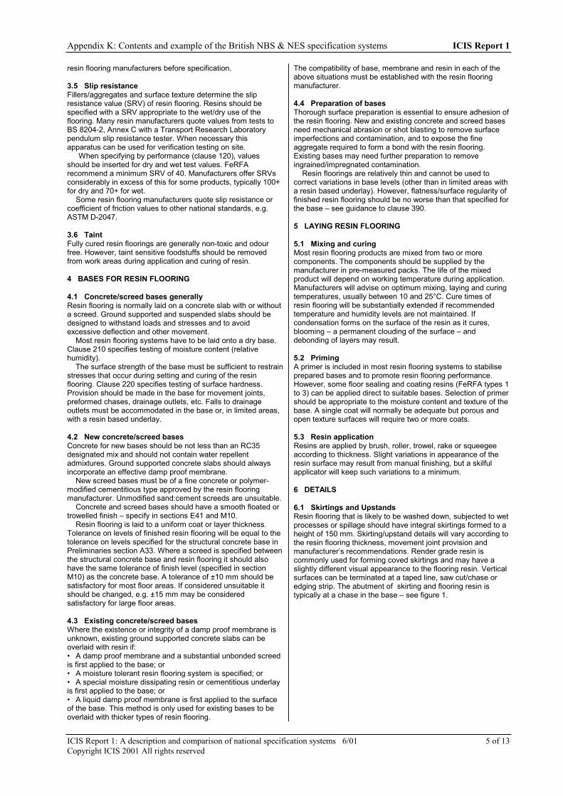
Appendix K: Contents and example of the British NBS & NES specification systems ICIS Report 1
ICIS Report 1: A description and comparison of national specification systems 6/01 5 of 13Copyright ICIS 2001 All rights reserved
resin flooring manufacturers before specification.
3.5 Slip resistanceFillers/aggregates and surface texture determine the slipresistance value (SRV) of resin flooring. Resins should bespecified with a SRV appropriate to the wet/dry use of theflooring. Many resin manufacturers quote values from tests toBS 8204-2, Annex C with a Transport Research Laboratorypendulum slip resistance tester. When necessary thisapparatus can be used for verification testing on site.
When specifying by performance (clause 120), valuesshould be inserted for dry and wet test values. FeRFArecommend a minimum SRV of 40. Manufacturers offer SRVsconsiderably in excess of this for some products, typically 100+for dry and 70+ for wet.
Some resin flooring manufacturers quote slip resistance orcoefficient of friction values to other national standards, e.g.ASTM D-2047.
3.6 TaintFully cured resin floorings are generally non-toxic and odourfree. However, taint sensitive foodstuffs should be removedfrom work areas during application and curing of resin.
4 BASES FOR RESIN FLOORING
4.1 Concrete/screed bases generallyResin flooring is normally laid on a concrete slab with or withouta screed. Ground supported and suspended slabs should bedesigned to withstand loads and stresses and to avoidexcessive deflection and other movement.
Most resin flooring systems have to be laid onto a dry base.Clause 210 specifies testing of moisture content (relativehumidity).
The surface strength of the base must be sufficient to restrainstresses that occur during setting and curing of the resinflooring. Clause 220 specifies testing of surface hardness.Provision should be made in the base for movement joints,preformed chases, drainage outlets, etc. Falls to drainageoutlets must be accommodated in the base or, in limited areas,with a resin based underlay.
4.2 New concrete/screed basesConcrete for new bases should be not less than an RC35designated mix and should not contain water repellentadmixtures. Ground supported concrete slabs should alwaysincorporate an effective damp proof membrane.
New screed bases must be of a fine concrete or polymer-modified cementitious type approved by the resin flooringmanufacturer. Unmodified sand:cement screeds are unsuitable.
Concrete and screed bases should have a smooth floated ortrowelled finish – specify in sections E41 and M10.
Resin flooring is laid to a uniform coat or layer thickness.Tolerance on levels of finished resin flooring will be equal to thetolerance on levels specified for the structural concrete base inPreliminaries section A33. Where a screed is specified betweenthe structural concrete base and resin flooring it should alsohave the same tolerance of finish level (specified in sectionM10) as the concrete base. A tolerance of ±10 mm should besatisfactory for most floor areas. If considered unsuitable itshould be changed, e.g. ±15 mm may be consideredsatisfactory for large floor areas.
4.3 Existing concrete/screed basesWhere the existence or integrity of a damp proof membrane isunknown, existing ground supported concrete slabs can beoverlaid with resin if:• A damp proof membrane and a substantial unbonded screedis first applied to the base; or• A moisture tolerant resin flooring system is specified; or• A special moisture dissipating resin or cementitious underlayis first applied to the base; or• A liquid damp proof membrane is first applied to the surfaceof the base. This method is only used for existing bases to beoverlaid with thicker types of resin flooring.
The compatibility of base, membrane and resin in each of theabove situations must be established with the resin flooringmanufacturer.
4.4 Preparation of basesThorough surface preparation is essential to ensure adhesion ofthe resin flooring. New and existing concrete and screed basesneed mechanical abrasion or shot blasting to remove surfaceimperfections and contamination, and to expose the fineaggregate required to form a bond with the resin flooring.Existing bases may need further preparation to removeingrained/impregnated contamination.
Resin floorings are relatively thin and cannot be used tocorrect variations in base levels (other than in limited areas witha resin based underlay). However, flatness/surface regularity offinished resin flooring should be no worse than that specified forthe base – see guidance to clause 390.
5 LAYING RESIN FLOORING
5.1 Mixing and curingMost resin flooring products are mixed from two or morecomponents. The components should be supplied by themanufacturer in pre-measured packs. The life of the mixedproduct will depend on working temperature during application.Manufacturers will advise on optimum mixing, laying and curingtemperatures, usually between 10 and 25°C. Cure times ofresin flooring will be substantially extended if recommendedtemperature and humidity levels are not maintained. Ifcondensation forms on the surface of the resin as it cures,blooming – a permanent clouding of the surface – anddebonding of layers may result.
5.2 PrimingA primer is included in most resin flooring systems to stabiliseprepared bases and to promote resin flooring performance.However, some floor sealing and coating resins (FeRFA types 1to 3) can be applied direct to suitable bases. Selection of primershould be appropriate to the moisture content and texture of thebase. A single coat will normally be adequate but porous andopen texture surfaces will require two or more coats.
5.3 Resin applicationResins are applied by brush, roller, trowel, rake or squeegeeaccording to thickness. Slight variations in appearance of theresin surface may result from manual finishing, but a skilfulapplicator will keep such variations to a minimum.
6 DETAILS
6.1 Skirtings and UpstandsResin flooring that is likely to be washed down, subjected to wetprocesses or spillage should have integral skirtings formed to aheight of 150 mm. Skirting/upstand details will vary according tothe resin flooring thickness, movement joint provision andmanufacturer’s recommendations. Render grade resin iscommonly used for forming coved skirtings and may have aslightly different visual appearance to the flooring resin. Verticalsurfaces can be terminated at a taped line, saw cut/chase oredging strip. The abutment of skirting and flooring resin istypically at a chase in the base – see figure 1.

Appendix K: Contents and example of the British NBS & NES specification systems ICIS Report 1
ICIS Report 1: A description and comparison of national specification systems 6/01 6 of 13Copyright ICIS 2001 All rights reserved
Figure 1. Skirting detail
resin flooring
render graderesin
abutment atchase in base
chase in wall
6.2 EdgesTreatment of free edges of resin flooring depends on coat/layerthickness:• Thin coatings (FeRFA types 1, 2, and 3) will not usuallyrequire any special edge provision• Thin layers (FeRFA types 4 and 5) should be run into a singlesaw cut• Thick layers (FeRFA types 6, 7 and 8) should be run into achamfer-edged chase, cast or cut into the base, to finish levelwith an abutting floor finish – see figure 2.Treatment of other edges of resin flooring (containedperimeters, day joints, etc.) will depend on resin type. Somepolyurethane resins will need retention at all edges and possiblyat intervals across the floor.
chamfer edgedretaining chasein base
resin flooring
Figure 2. Free edge detail
6.3 Movement jointsMovement joints in the base must be carried through the resinflooring. To optimise the benefits of a seamless floor finish, thenumber of joints should be kept to a minimum. Joints withmovement of small magnitude, e.g. isolation joints, inducedcrack joints, can normally be formed in the resin and filled withsealant – see figure 3. Where movement is more significant,e.g. over expansion joints, a preformed strip movement jointmay be required.In designing movement joints ensure that:• Anticipated traffic conditions and degree of movement canbe withstood common with other smooth, hard flooringmaterials, resin can become slippery when water, dust, dirt, oil,• Materials used are compatible with resin• A secure and watertight joint is obtained between the jointand the resin flooring.Location and construction details may need to be shown ondrawings.
resinflooring
joint sealantand backingstrip
movement joint filler
retainingchase in base
Figure 3. Movement joint
6.4 Falls and drainageFor smooth finished resin flooring, a minimum fall of 1 in 80 isrequired to drain standing water; textured finishes will require agreater fall. For flow applied resins, falls greater than 1 in 60 arelikely to result in slumping during application.
Open channels, channel gratings and drain outlets should beprovided in the base where wet conditions prevail. Follow theresin flooring manufacturer’s recommendations for detailingaround drainage fittings.
6.5 Service penetrations/fixturesWhere service pipes or cables have to pass through the resinflooring, they are usually sleeved or ducted. Fixtures on existingfloors that cannot be removed during resin flooring application,e.g. structural base plates, plinths, will need to be prepared,primed and finished.
7 HEALTH AND SAFETYHealth and safety risks should be listed in the pre-tender healthand safety plan (NBS Main Contract Preliminaries, section A34clause 110 et seq.) and method statements obtained from thecontractor in the outline construction phase health and safetyplan (NBS Main Contract Preliminaries, section A30 clause 570or 571).
7.1 MaterialsSome of the components of resin flooring may be hazardousduring mixing and application. Operatives must be familiar withthe resin manufacturer’s health and safety data sheets that willusually recommend the following minimum precautions:• Protective clothing and goggles to be worn• Barrier cream to be applied to exposed skin• No smoking, eating or drinking in the working area• Provision of exhaust ventilation in confined working areasand where volatile resin formulations are used.
7.2 DesignIn use, primary health and safety concerns relate to the slipresistance of the finished surface – see 3.5. In
8 CONTRACTUAL ARRANGEMENTS
8.1 SubcontractingThe specifier may chose a subcontractor or influence the choiceof subcontractor in several different ways. See generalguidance to NBS Main Contract Preliminaries, section A30.Clause 310 in this section requires the use of operatives trainedin the application of resin flooring. Many manufacturers havetheir own installation teams or an approved network ofcontractors. The Resin Flooring Association (FeRFA) has acategory of membership for installation contractors. Membersmust comply with a Code of Practice for members. FeRFA andthe CITB have developed a NVQ Level 2 qualification for resinflooring operatives.

Appendix K: Contents and example of the British NBS & NES specification systems ICIS Report 1
ICIS Report 1: A description and comparison of national specification systems 6/01 7 of 13Copyright ICIS 2001 All rights reserved
8.2 Requirements for submission of informationThe specifier may require the Contractor or Subcontractor tosubmit drawings or other technical information either at tenderstage or during the course of the contract. For general guidancesee NBS Main Contract Preliminaries, section A31.
Typical requirements to be listed in MainContract/Subcontract preliminaries:• A full description of builder’s work, special provisions andspecial attendance to be provided by others.• Drawn details of proposals for forming skirtings, movementjoints, drainage outlets, etc.

Appendix K: Contents and example of the British NBS & NES specification systems ICIS Report 1
ICIS Report 1: A description and comparison of national specification systems 6/01 8 of 13Copyright ICIS 2001 All rights reserved
GUIDANCE NOTES^ against the clause denotes included in the Intermediate Version.
SPECIFICATION CLAUSESM12 RESIN FLOORING
To be read with Preliminaries/General conditions.
TYPES OF FLOORING
110Use this clause for resin flooring specified by proprietaryreference. Use clause 120 for specification by performance.Clause heading: Insert, e.g. TO CLEAN ROOMBase: See general guidance 4. Insert, e.g.Existing in situ concrete slab.New polymer-modified cementitious screed.Preparation: See general guidance 4.4. All bases will requiresome preparation – see clauses 210 to 260. Insert, e.g. Asclauses 230 and 240.Resin flooring system manufacturer: Insert proprietaryreference, e.g. XYZ Resiflor Ltd.Primer reference: See general guidance 5.2. Insert, e.g.Resiprime.
Resin coatings (FeRFA types 1,2 and 3) may not need aprimer - insert Not required.Resin flooring reference: See general guidance 2. Insert, e.g.Resiflor S floor coating.Resiflor XL heavy duty flooring.Nominal thickness: Refer to manufacturer’srecommendations. Coatings are measured in micrometres,layers and screeds in millimetres.Surface finish/treatment: Many resin flooring products areself-finishing, others will require one or more of the following:• Addition of filler or aggregate to the resin to provide a slipresistant finish• Textured finish – applied by roller• Grinding/grouting/fine abrading – to expose colouredaggregate (clauses 360 and 370)• Coating with sealer – gloss, satin, matt, anti-microbial, etc.(clause 380)Insert, e.g.One coat Resiseal Gloss as clause 380.None.Flatness/Surface regularity: This item is not applicable toresin flooring applied in thin coatings. For resin flooring appliedin layers, see guidance to clause 390 and insert permissibledeviation required to suit use of floor, e.g.5 mm (normal standard).3 mm to studios and 5 mm elsewhere.Resin skirtings/upstands: See general guidance 6.1 andguidance to clause 410. Insert, e.g.As clause 410.Not required.Other requirements: See general guidance 6.3, 6.4 and 6.5.Insert, e.g. Sealant movement joints as clause 430.
110^ RESIN FLOORING . . . . . .• Drawing references: . . . . . .• Base: . . . . . .
– Preparation: . . . . . .• Resin flooring system:
– Manufacturer: . . . . . .– Primer reference: . . . . .– Resin flooring reference: . . . . . .– Nominal thickness: . . . . . .– Colour: . . . . . .– Surface finish/treatment: . . . . . .
• Flatness/Surface regularity: Sudden irregularities are notpermitted. Maximum permissible deviation whenmeasured as clause 390: . . . . . .
• Resin skirtings/upstands: . . . . . .• Other requirements: . . . . . .

Appendix K: Contents and example of the British NBS & NES specification systems ICIS Report 1
ICIS Report 1: A description and comparison of national specification systems 6/01 9 of 13Copyright ICIS 2001 All rights reserved
120Use this clause for resin flooring specified by performance. Useclause 110 for specification by proprietary reference.Clause heading: Insert, e.g. TO LABORATORYBase: See general guidance 4. Insert, e.g.Existing in situ concrete slab.New polymer-modified cementitious screed.Preparation: See general guidance 4.4. All bases will requiresome preparation – see clauses 210 to 260. Insert, e.g. Asclauses 230 and 240.Resin flooring system type: See general guidance 2. InsertFeRFA type and/or description, e.g.FeRFA type 2 floor coating.Heavy duty resin/terrazzo flooring, 8 mm thick.Surface finish/treatment: Many resin flooring products areself-finishing, others will require one or more of the following:·• Addition of filler or aggregate to the resin to provide a slipresistant finish• Textured finish – applied by roller• Grinding/grouting/fine abrading – to expose colouredaggregate (clauses 360 and 370)• Coating with sealer – gloss, satin, matt, anti-microbial, etc.(clause 380).Insert, e.g.One coat gloss sealer as clause 380.None.Flatness/Surface regularity: This item is not applicable toresin flooring applied in thin coatings. For resin flooring appliedin layers, see guidance to clause 390 and insert permissibledeviation required to suit use of floor, e.g.5 mm (normal standard).3 mm to studios and 5 mm elsewhere.Slip resistance value: See general guidance 3.5 and insertvalues, e.g.Not less than 80 for wet test, 50 for dry test.Not less than 40 for wet and dry tests.Activities/Trafficking: Insert details, e.g. Heavy foot traffic incorridors.Wheeled conveyors: Insert details of, e.g. fork lift trucks,trolleys, etc, including loading, speed of movement andtype/width of wheels/tyres.Standing loads: Identify where significant standing loads arelikely to occur and, if possible, give details of their mass,bearing area and any point loading.Processes: Describe the nature of any industrial or commercialprocesses that may have a bearing on the type of resin to beused.Materials in contact with flooring: See general guidance 3.2and 3.3. Insert details of chemicals, concentration andtemperature.Water/vapour resistance: See general guidance 3.4. Insert,e.g. Zero water permeability/not less than 15 g/m².24 h watervapour permeability.Environmental conditions in service: Give details of relevantmaximum and minimum temperatures, humidity, etc.Resin skirtings/upstands: See general guidance 6.1 andguidance to clause 410. Insert, e.g.As clause 410.Not required.Other requirements: See general guidance 6.3, 6.4 and 6.5.Insert, e.g. Sealant movement joints as clause 430.
120 RESIN FLOORING . . . . . .• Drawing references: . . . . . .• Base: . . . . . .
– Preparation: . . . . . .• Resin flooring system: Requirement for primer and
detailing of features to be determined by the resinflooring manufacturer/contractor to adequately resist thespecified trafficking, loads and conditions.– Type: . . . . . .– Colour: . . . . . .– Surface finish/treatment: . . . . . .
• Flatness/Surface regularity: Sudden irregularities are notpermitted. Maximum permissible deviation whenmeasured as clause 390: . . . . . .
• Slip resistance value to BS 8204-2, Annex C: . . . . . .• Durability:
– Activities/Trafficking: . . . . .– Wheeled conveyors: . . . . . .– Standing loads: . . . . . .– Processes: . . . . . .– Materials in contact with flooring: . . . . . .
• Water/vapour resistance: . . . . . .• Environmental conditions in service: . . . . . .• Resin skirtings/upstands: . . . . . .• Other requirements: . . . . . .

Appendix K: Contents and example of the British NBS & NES specification systems ICIS Report 1
ICIS Report 1: A description and comparison of national specification systems 6/01 10 of 13Copyright ICIS 2001 All rights reserved
210A dry base is essential for most resin flooring systems. Somesystems are tolerant of moisture in the base or can be laid overa surface applied damp proof primer but, in the absence ofspecific recommendations from the manufacturer, the specified75% relative humidity level should not be exceeded.
Drying times will depend upon their composition, thickness ofthe base, and the environmental conditions. Even in gooddrying conditions, a 150 mm thick concrete base can take 12months to dry to a relative humidity of 75%.
220Testing surface hardness to BS 1881-202 allows rapidevaluation of a large area of flooring. For all types of resinflooring the hammer ‘rebound value’ should be not less than 25.A lower reading may be acceptable (check with resin flooringmanufacturer) if the surface tensile strength of the base, whenfurther tested to BS 8204-3, Appendix B2, is not less than 1.5N/mm².
230See general guidance 4.Chases: See general guidance 6. Chases should be cast intonew concrete/screed wherever possible.Cleanliness: FeRFA and resin manufacturers recommend:• The use of shot blasting, planing or grinding equipment withself contained dust recovery• Final cleaning with industrial vacuum equipment.Texture of surface: Thinner resin floorings (coatings) willreflect the surface preparation in the finish. Lighter preparationis required.
240See general guidance 4.1 and 4.3.First item: Resin manufacturers recommend removal ofingrained contaminants by steam cleaning, high pressure waterblasting or high temperature burning.Second item: If it is necessary to cut out areas of the base,reinstatement could be by repair product, polymer modifiedscreed or concrete – check suitability with resin flooringmanufacturer.
260This clause is intended for use where metal is rigid and presentonly in isolated areas as base plates, cover strips, etc. GradeSa2 is ‘thorough blast-cleaning’. Treated surfaces must be freefrom visible oil, grease and dirt, and from most mill scale, rust,paint coatings and foreign matter.
PREPARATION OF BASES
210^ MOISTURE CONTENT OF BASES• Drying aids: Before testing, turn off and wait at least four
days.• Test for moisture content: To BS 8203, Appendix A using
an accurately calibrated hygrometer. Take readings incorners, along edges, and at various points over the areabeing tested.
• Acceptability: Do not lay resin flooring until readingsshow 75% relative humidity or less.
220^ SURFACE HARDNESS OF BASES• General: Bases must restrain stresses that occur during
setting and hardening of resin.• Test for surface hardness: To BS 1881-202 using a
rebound hammer.• Report: Submit:
– Details of areas where base hardness values do notcomply with the resin flooring manufacturer’srequirements.– Proposals for repair or cut out and replacement.
230^ PREPARATION OF BASES GENERALLY• Chases/saw cuts: Cut/break out at skirtings, free edges,
movement joints, etc. for termination of resin flooring.• Blow holes, cavities, cracks, etc: Fill with repair product
recommended by resin flooring manufacturer.• Cleanliness: Remove surface contaminants, debris, dirt
and dust.• Texture of surface: Suitable to accept resin flooring and
achieve a full bond over the complete area.
240^ EXISTING BASES• Remove: Surface imperfections, ingrained contaminants,
coatings and residues.• Areas impregnated with contaminants: Submit proposals
for removal and repair.
250^ EXISTING TILE/SHEET FLOOR COVERINGS• Remove: Coverings, residual adhesive, bedding, grouting
and pointing.
260^ METAL BASES• Cleaning: Shot blast to BS 7079-A1, grade Sa2.
310Operatives: Resin flooring should be carried out by specialistcontractors, trained and approved by the resin manufacturer –see general guidance 8.1.Scattered aggregates: May be applied to primers to assistspread of subsequent resin coats/layers, and to resin surfacecoats/layers for decoration or slip resistance.Curing: Periods will depend on the type of flooring andenvironmental conditions. Those generally required oncompletion are: 1-3 days before light trafficking, 3-7 days beforeheavy trafficking, wetting or contact with chemicals.
LAYING FLOORING
310^ WORKMANSHIP• Operatives: Trained/experienced in the application of
resin floorings. Submit evidence of training/experience tothe CA on request.
• Fillers and incorporated aggregates: Thoroughly mix in toensure wetting. Avoid over-vigorous mixing resulting inexcessive air entrainment.
• Scattered aggregates: Broadcast onto wet surface ofresin to give consistent appearance.
• Curing: Allow appropriate periods between coats, beforesurface treatments, and before trafficking/use.
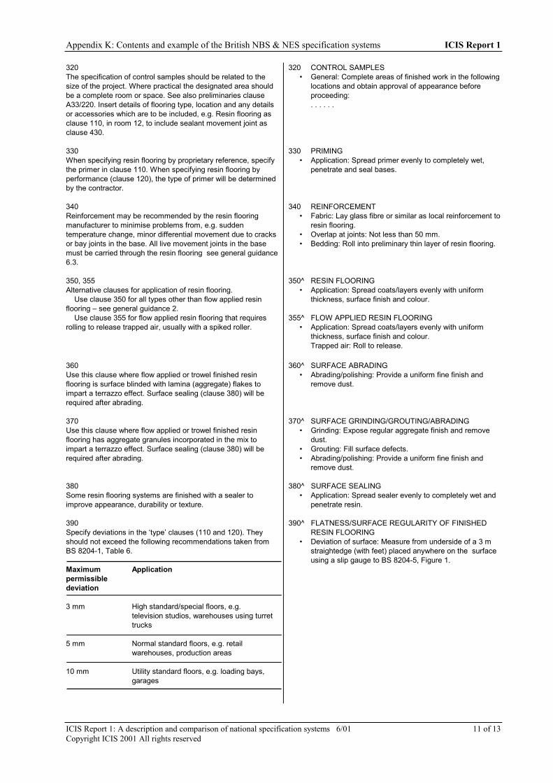
Appendix K: Contents and example of the British NBS & NES specification systems ICIS Report 1
ICIS Report 1: A description and comparison of national specification systems 6/01 11 of 13Copyright ICIS 2001 All rights reserved
320The specification of control samples should be related to thesize of the project. Where practical the designated area shouldbe a complete room or space. See also preliminaries clauseA33/220. Insert details of flooring type, location and any detailsor accessories which are to be included, e.g. Resin flooring asclause 110, in room 12, to include sealant movement joint asclause 430.
330When specifying resin flooring by proprietary reference, specifythe primer in clause 110. When specifying resin flooring byperformance (clause 120), the type of primer will be determinedby the contractor.
340Reinforcement may be recommended by the resin flooringmanufacturer to minimise problems from, e.g. suddentemperature change, minor differential movement due to cracksor bay joints in the base. All live movement joints in the basemust be carried through the resin flooring see general guidance6.3.
350, 355Alternative clauses for application of resin flooring.
Use clause 350 for all types other than flow applied resinflooring – see general guidance 2.
Use clause 355 for flow applied resin flooring that requiresrolling to release trapped air, usually with a spiked roller.
320 CONTROL SAMPLES• General: Complete areas of finished work in the following
locations and obtain approval of appearance beforeproceeding:. . . . . .
330 PRIMING• Application: Spread primer evenly to completely wet,
penetrate and seal bases.
340 REINFORCEMENT• Fabric: Lay glass fibre or similar as local reinforcement to
resin flooring.• Overlap at joints: Not less than 50 mm.• Bedding: Roll into preliminary thin layer of resin flooring.
350^ RESIN FLOORING• Application: Spread coats/layers evenly with uniform
thickness, surface finish and colour.
355^ FLOW APPLIED RESIN FLOORING• Application: Spread coats/layers evenly with uniform
thickness, surface finish and colour.Trapped air: Roll to release.
360Use this clause where flow applied or trowel finished resinflooring is surface blinded with lamina (aggregate) flakes toimpart a terrazzo effect. Surface sealing (clause 380) will berequired after abrading.
370Use this clause where flow applied or trowel finished resinflooring has aggregate granules incorporated in the mix toimpart a terrazzo effect. Surface sealing (clause 380) will berequired after abrading.
380Some resin flooring systems are finished with a sealer toimprove appearance, durability or texture.
390Specify deviations in the ‘type’ clauses (110 and 120). Theyshould not exceed the following recommendations taken fromBS 8204-1, Table 6.
Maximum Applicationpermissibledeviation
3 mm High standard/special floors, e.g.television studios, warehouses using turrettrucks
5 mm Normal standard floors, e.g. retail warehouses, production areas
10 mm Utility standard floors, e.g. loading bays,garages
360^ SURFACE ABRADING• Abrading/polishing: Provide a uniform fine finish and
remove dust.
370^ SURFACE GRINDING/GROUTING/ABRADING• Grinding: Expose regular aggregate finish and remove
dust.• Grouting: Fill surface defects.• Abrading/polishing: Provide a uniform fine finish and
remove dust.
380^ SURFACE SEALING• Application: Spread sealer evenly to completely wet and
penetrate resin.
390^ FLATNESS/SURFACE REGULARITY OF FINISHEDRESIN FLOORING
• Deviation of surface: Measure from underside of a 3 mstraightedge (with feet) placed anywhere on the surfaceusing a slip gauge to BS 8204-5, Figure 1.

Appendix K: Contents and example of the British NBS & NES specification systems ICIS Report 1
ICIS Report 1: A description and comparison of national specification systems 6/01 12 of 13Copyright ICIS 2001 All rights reserved
BS 8204-1 specifies the gap under a straightedge placeddirectly on the floor. Clause 390 specifies maximum variation ingap under a straightedge with feet so that high spots and ridgescan be measured more accurately.
To achieve the regularity of finished surface, the sameregularity must be specified for the structural concrete base insection E05 or the screed in section M10.
Tolerance on levels of finished resin flooring will be equal tothe tolerance on levels specified for the structural concrete –see general guidance 4.2.
400Resin flooring adheres very strongly to preparedconcrete/screed bases. Adhesion failure will arise only wheresome form of base contamination remains. Local areas ofadhesion failure can be treated by resin injection or saw cutting,removal and replacement. BS 8204-3, Annex B2 requires pulloff testing of a core cut into the resin and base. Resin flooringmanufacturers bond strength expectations are usually 1.0 or 1.5N/mm².
410This clause specifies the most common skirting detail – arender grade resin cove which can be feathered out to abut alltypes of resin flooring. See general guidance 6.1 and figure 1.Last item: Insert, e.g.Abutment at chase in the base.Sealant movement joint as clause 430.
420Retention of resin edges: Free edges of thicker types of resinflooring require restraint – see general guidance 6.2 and figure2.
For resin coatings (FeRFA types 1, 2 and 3) insert Notrequired.
For thin resin layers (FeRFA types 4 and 5) insert Saw cut inbase.
For thick resin layers (FeRFA types 6,7and 8) insertChamfered edge chase in base.
430Sealant movement joints are recommended by resinmanufacturers as suitable for most movement/isolation joints.Clause heading: Insert, e.g. FOR CLEAN ROOMSRetention of resin edges: Free edges of thicker types of resinflooring require restraint – see general guidance 6.3 and figure3.
For resin coatings (FeRFA types 1, 2 and 3) insert Notrequired.
For thin resin layers (FeRFA types 4 and 5) insert Saw cut inbase.
For thick resin layers (FeRFA types 6,7and 8) insert Chase inbase.Sealant: Insert proprietary reference or type and BS reference.Selection is determined by the type of movement to beaccommodated, resistance to chemicals, etc.
440Strip movement joints provide reinforcement to resin edges inheavy traffic areas and can accommodate a greater magnitudeof movement. They consist of rigid plastics or metal edgingstrips with pre-formed strip inserts. Check suitability forproposed use with the manufacturer (e.g. watertightness,chemical resistance, loadings).Clause heading: Insert, e.g. FOR PRODUCTION WORKSHOPRetention of resin edges: Free edges of thicker types of resinflooring require restraint – see general guidance 6.3 and figure3.
For resin coatings (FeRFA types 1, 2 and 3) insert Notrequired.
400 ADHESION OF RESIN FLOORING• Bond strength between base and fully cured resin
flooring: In accordance with manufacturer’s performancedata.
• Test for bond strength: To BS 8204-3, Annex B2.
410^ RESIN SKIRTINGS/UPSTANDS• Drawing references: . . . . . .• General: Use a vertical grade of resin for
skirting/upstand. Form radius cove. Tuck top edge ofresin into a chase in the skirting/upstand or retain with astop bead.
• Transition with resin flooring: . . . . . .
420^ FREE EDGES OF RESIN FLOORING• General: Form a straight, smooth transition to abutting
floor finishes.• Retention of resin edges: . . . . . .
430^ SEALANT MOVEMENT JOINTS . . . . . .• General: Position over movement joints in base.• Preparation and application: As section Z22.• Retention of resin edges: . . . . . .• Joint width: . . . . . . mm.• Sealant: . . . . . .
– Colour: . . . . . .
440^ STRIP MOVEMENT JOINTS . . . . . .• General: Position over movement joints in base.• Retention of resin edges: . . . . . .• Joint width: . . . . . . mm.• Strip:
– Manufacturer: . . . . . .– Product reference: . . . . . .– Insert type: . . . . . .– Colour: . . . . . .– Fixing: To exact finished level of resin flooring: . . . . . .

Appendix K: Contents and example of the British NBS & NES specification systems ICIS Report 1
ICIS Report 1: A description and comparison of national specification systems 6/01 13 of 13Copyright ICIS 2001 All rights reserved
For thin resin layers (FeRFA types 4 and 5) insert Saw cut inbase.
For thick resin layers (FeRFA types 6,7and 8) insert Chase inbase.Insert type: Synthetic rubbers are most common but check withmanufacturer for suitability.Strip fixing: Strips are either cast into or fixed to the base.Insert, e.g. Cast into base using NSS 60 anchors at 300 mmcentres.

Appendix K: Contents and example of the British NBS & NES specification systems ICIS Report 1
ICIS Report 1: A description and comparison of national specification systems 6/01 14 of 13Copyright ICIS 2001 All rights reserved

ICIS Report 1: A description and comparison of national specification systems 6/01 1 of 7Copyright ICIS 1997 All rights reserved
APPENDIX L: CONTENTS AND EXAMPLE OF THE USA MASTERSPECSPECIFICATION SYSTEM
CONTENTS OF THE USA MASTERSPEC SPECIFICATION SYSTEM
DIVISION 1 GENERAL REQUIREMENTS01010 SUMMARY OF WORK01020 ALLOWANCES01026 UNIT PRICES01027 APPLICATIONS FOR PAYMENT01030 ALTERNATES01035 MODIFICATION PROCEDURES01040 PROJECT COORDINATION01045 CUTTING AND PATCHING01050 FIELD ENGINEERING01095 REFERENCE STANDARDS AND DEFINITIONS01200 PROJECT MEETINGS01300 SUBMITTALS01400 QUALITY CONTROL SERVICES01500 TEMPORARY FACILITIES01600 MATERIALS AND EQUIPMENT01631 PRODUCT SUBSTITUTIONS01700 PROJECT CLOSEOUT01740 WARRANTIES AND BONDS
DIVISION 2 SITEWORK02060 BUILDING DEMOLITION02070 SELECTIVE DEMOLITION02110 SITE CLEARING02160 EXCAVATION SUPPORT SYSTEMS02200 EARTHWORK02282 TERMITE CONTROL02360 DRIVEN PILES02380 CAISSONS02511 HOT-MIXED ASPHALT PAVING02515 UNIT PAVERS02520 PORTLAND CEMENT CONCRETE PAVING02668 WATER SERVICE PIPING02669 PRIVATE FIRE SERVICE MAINS02711 FOUNDATION DRAINAGE SYSTEMS02720 STORM SEWERAGE02730 SANITARY SEWERAGE02776 POND AND RESERVOIR LINERS02810 UNDERGROUND IRRIGATION SYSTEM02831 CHAIN LINK FENCES AND GATES02900 LANDSCAPE WORK
DIVISION 3 CONCRETE03300 CAST-IN-PLACE CONCRETE03350 CONCRETE TOPPINGS03355 SPECIAL CONCRETE FINISHES03410 STRUCTURAL PRECAST CONCRETE - PLANT
CAST03450 ARCHITECTURAL PRECAST CONCRETE -
PLANT CAST03455 GLASS FIBER REINFORCED PRECAST
CONCRETE - PLANT CAST03470 TILT-UP PRECAST CONCRETE03520 INSULATING CONCRETE DECKS
DIVISION 4 MASONRY04200 UNIT MASONRY
04270 GLASS UNIT MASONRY04405 DIMENSION STONE04450 STONE TILE04500 MASONRY RESTORATION AND CLEANING
DIVISION 5 METALS05120 STRUCTURAL STEEL05220 STEEL JOISTS AND JOIST GIRDERS05310 STEEL DECK05400 COLD-FORMED METAL FRAMING05500 METAL FABRICATIONS05521 PIPE AND TUBE RAILINGS05580 SHEET METAL FABRICATIONS05700 ORNAMENTAL METALWORK05715 PREFABRICATED SPIRAL STAIRS05720 ORNAMENTAL HANDRAILS AND RAILINGS05810 EXPANSION JOINT COVER ASSEMBLIES
DIVISION 6 WOOD AND PLASTICS06100 ROUGH CARPENTRY06105 MISCELLANEOUS CARPENTRY06130 HEAVY TIMBER CONSTRUCTION06170 STRUCTURAL GLUED LAMINATED UNITS06192 PREFABRICATED METAL-PLATE-CONNECTED
WOOD TRUSSES06200 FINISH CARPENTRY06265 MOLDED ARCHITECTURAL
ORNAMENTATION06401 EXTERIOR ARCHITECTURAL WOODWORK06402 INTERIOR ARCHITECTURAL WOODWORK06410 CUSTOM CASEWORK06420 PANELWORK
DIVISION 7 THERMAL AND MOISTUREPROTECTION
07110 SHEET MEMBRANE WATERPROOFING07120 FLUID-APPLIED WATERPROOFING07160 BITUMINOUS DAMPPROOFING07180 WATER REPELLENTS07210 BUILDING INSULATION07241 EXTERIOR INSULATION AND FINISH
SYSTEMS - CLASS PB07242 EXTERIOR INSULATION AND FINISH
SYSTEMS - CLASS PM07251 SPRAYED-ON FIREPROOFING07311 ASPHALT SHINGLES07317 WOOD SHINGLES AND SHAKES07410 MANUFACTURED ROOF AND WALL PANELS07460 SIDING07511 BUILT-UP ASPHALT ROOFING07512 BUILT-UP COAL TAR ROOFING07526 APP-MODIFIED BITUMINOUS SHEET
ROOFING07527 SBS-MODIFIED BITUMINOUS SHEET ROOFING07530 SINGLE-PLY MEMBRANE ROOFING07570 TRAFFIC TOPPING07600 FLASHING AND SHEET METAL07700 ROOF SPECIALTIES AND ACCESSORIES

Appendix L: Contents and examples of the USA MASTERSPEC specification system ICIS Report 1
ICIS Report 1: A description and comparison of national specification systems 6/01 2 of 7Copyright 1997 ICIS All rights reserved
07710 MANUFACTURED ROOF SPECIALTIES07720 ROOF ACCESSORIES07901 JOINT SEALANTS07905 PAVING JOINT SEALANTS
DIVISION 8 DOORS AND WINDOWS08111 STANDARD STEEL DOORS AND FRAMES08114 CUSTOM STEEL DOORS AND FRAMES08211 FLUSH WOOD DOORS08212 PANEL WOOD DOORS08305 ACCESS DOORS08311 ALUMINUM SLIDING GLASS DOORS08312 WOOD SLIDING GLASS DOORS08314 SLIDING METAL FIRE DOORS08331 OVERHEAD COILING DOORS08340 OVERHEAD COILING GRILLES08351 FOLDING DOORS08360 SECTIONAL OVERHEAD DOORS08410 ALUMINUM ENTRANCES AND STOREFRONTS08450 ALL-GLASS ENTRANCES08460 AUTOMATIC ENTRANCE DOORS08470 REVOLVING ENTRANCE DOORS08510 STEEL WINDOWS08520 ALUMINUM WINDOWS08525 ALUMINUM ARCHITECTURAL WINDOWS08610 WOOD WINDOWS08710 DOOR HARDWARE08800 GLAZING08825 DECORATIVE GLASS08830 MIRRORED GLASS08920 GLAZED ALUMINUM CURTAIN WALLS
DIVISION 9 FINISHES09200 LATH AND PLASTER09215 VENEER PLASTER09250 GYPSUM DRYWALL09270 GYPSUM BOARD SHAFT WALL SYSTEMS09300 TILE09400 TERRAZZO09511 ACOUSTICAL PANEL CEILINGS09512 ACOUSTICAL TILE CEILINGS09513 ACOUSTICAL SNAP-IN METAL PAN CEILINGS09521 ACOUSTICAL WALL PANELS09546 LINEAR METAL CEILINGS09549 SUSPENDED DECORATIVE GRIDS09550 WOOD FLOORING09590 RESILIENT WOOD FLOORING SYSTEMS09600 INTERIOR STONEWORK09635 BRICK FLOORING09660 RESILIENT TILE FLOORING09666 SHEET VINYL FLOOR COVERINGS09675 CONDUCTIVE RESILIENT FLOORING09678 RESILIENT WALL BASE AND ACCESSORIES09680 CARPET09690 CARPET TILE09800 SPECIAL COATINGS09900 PAINTING09920 INTERIOR PAINTING09921 MULTICOLORED INTERIOR COATINGS09950 WALL COVERINGS09980 WOOD VENEER WALL COVERINGS09990 IMPACT-RESISTANT WALL COVERINGS
DIVISION 10 SPECIALTIES10100 VISUAL DISPLAY BOARDS10155 TOILET COMPARTMENTS
10180 STONE TOILET PARTITIONS10190 CUBICLES10200 LOUVERS AND VENTS10250 SERVICE WALL SYSTEMS10265 WALL SURFACE PROTECTION SYSTEMS10270 ACCESS FLOORING10350 FLAGPOLES10416 DIRECTORIES AND BULLETIN BOARDS10425 SIGNS10436 EXTERIOR POST AND PANEL SIGNS10500 METAL LOCKERS10522 FIRE EXTINGUISHERS, CABINETS, AND
ACCESSORIES10550 POSTAL SPECIALTIES10605 WIRE MESH PARTITIONS10615 DEMOUNTABLE PARTITIONS10652 FOLDING PANEL PARTITIONS10653 FIRE-RATED FOLDING PANEL PARTITIONS10655 ACCORDION FOLDING PARTITIONS10675 METAL STORAGE SHELVING10681 HIGH DENSITY STORAGE AND SHELVING
SYSTEMS10750 TELEPHONE SPECIALTIES10753 WALL-MOUNTED TELEPHONE ENCLOSURES10800 TOILET AND BATH ACCESSORIES
DIVISION 11 EQUIPMENT11030 TELLER AND SERVICE EQUIPMENT11050 LIBRARY EQUIPMENT11054 LIBRARY STACK SYSTEMS11060 PORTABLE THEATER AND STAGE
EQUIPMENT11062 STAGE CURTAINS11100 MERCANTILE EQUIPMENT11132 PROJECTION SCREENS11150 PARKING CONTROL EQUIPMENT11160 LOADING DOCK EQUIPMENT11400 FOOD SERVICE EQUIPMENT11452 RESIDENTIAL APPLIANCES11460 UNIT KITCHENS11610 LABORATORY FUME HOODS11910 MAILROOM EQUIPMENT AND FURNITURE
DIVISION 12 FURNISHINGS12052 UPHOLSTERY FABRICS12320 RESTAURANT AND CAFETERIA CASEWORK12345 LABORATORY CASEWORK12372 KITCHEN CASEWORK12511 HORIZONTAL LOUVER BLINDS12512 VERTICAL LOUVER BLINDS12520 SHADES12530 WINDOW TREATMENT HARDWARE12540 DRAPERIES AND CURTAINS12611 SYSTEMS FURNITURE12620 FURNITURE12625 HOSPITAL FURNITURE12626 HOTEL AND MOTEL FURNITURE12627 LIBRARY FURNITURE12630 RESTAURANT FURNITURE12631 METAL CASEGOODS12632 WOOD AND LAMINATE CASEGOODS12676 CUSTOM RUGS12680 FOOT GRILLES12690 FLOOR MATS AND FRAMES12700 MULTIPLE SEATING12710 AUDITORIUM AND THEATER SEATING

Appendix L: Contents and examples of the USA MASTERSPEC specification system ICIS Report 1
ICIS Report 1: A description and comparison of national specification systems 6/01 3 of 7Copyright 1997 ICIS All rights reserved
12760 TELESCOPING BLEACHERS12800 INTERIOR PLANTS AND PLANTINGS12900 BUILDING ACCESSORIES
DIVISION 13 SPECIAL CONSTRUCTION13052 SAUNAS13122 METAL BUILDING SYSTEMS
DIVISION 14 CONVEYING SYSTEMS14100 DUMBWAITERS14210 ELECTRIC TRACTION ELEVATORS14240 HYDRAULIC ELEVATORS14310 ESCALATORS14560 CHUTES
DIVISION 15 MECHANICAL15010 BASIC MECHANICAL REQUIREMENTS15050 BASIC MECHANICAL MATERIALS AND
METHODS15100 VALVES15125 PIPE EXPANSION JOINTS15135 METERS AND GAGES15140 SUPPORTS AND ANCHORS15170 MOTORS15250 MECHANICAL INSULATION15300 FIRE PROTECTION15410 PLUMBING PIPING15430 PLUMBING SPECIALTIES15440 PLUMBING FIXTURES15453 PLUMBING PUMPS15455 WATER STORAGE TANKS15457 WATER SOFTENERS15460 WATER HEATERS15481 COMPRESSED-AIR SYSTEMS15483 FUEL OIL SYSTEMS15488 NATURAL GAS PIPING SYSTEMS15510 HYDRONIC PIPING15520 STEAM AND CONDENSATE PIPING15530 REFRIGERANT PIPING15540 HVAC PUMPS15556 CAST-IRON BOILERS15557 SCOTCH MARINE BOILERS15558 ELECTRIC BOILERS15570 BOILER ACCESSORIES15575 BREECHINGS, CHIMNEYS, AND STACKS15580 FEEDWATER EQUIPMENT15610 FURNACES15620 FUEL-FIRED HEATERS15670 CONDENSING UNITS15683 RECIPROCATING CHILLERS15685 CENTRIFUGAL CHILLERS - WATER COOLED15711 FACTORY-FABRICATED COOLING TOWERS15743 AIR COOLED CONDENSERS15755 HEAT EXCHANGERS15781 PACKAGED HEATING AND COOLING UNITS15782 ROOFTOP HEATING AND COOLING UNITS15786 WATER-SOURCE HEAT PUMPS15830 TERMINAL UNITS15850 AIR HANDLING15854 CENTRAL-STATION AIR-HANDLING UNITS15860 CENTRIFUGAL FANS15865 AXIAL FANS15870 POWER VENTILATORS15885 AIR CLEANING15891 METAL DUCTWORK15893 FIBROUS GLASS DUCT SYSTEMS
15910 DUCT ACCESSORIES15932 AIR OUTLETS AND INLETS15933 AIR TERMINALS15971 ELECTRIC CONTROL SYSTEMS15973 PNEUMATIC CONTROL SYSTEMS15985 SEQUENCE OF OPERATION15990 TESTING, ADJUSTING, AND BALANCING
DIVISION 16 ELECTRICAL16010 BASIC ELECTRICAL REQUIREMENTS16050 BASIC ELECTRICAL MATERIALS AND
METHODS16110 RACEWAYS16111 CABLE TRAYS16120 WIRES AND CABLES16121 CONTROL/SIGNAL TRANSMISSION MEDIA16122 UNDERCARPET FLAT CABLING SYSTEMS16123 OPTICAL FIBER CABLING SYSTEMS16135 CABINETS, BOXES, AND FITTINGS16143 WIRING DEVICES16170 CIRCUIT AND MOTOR DISCONNECTS16190 SUPPORTING DEVICES16195 ELECTRICAL IDENTIFICATION16420 SERVICE ENTRANCE16425 SWITCHBOARDS16426 LOW-VOLTAGE POWER SWITCHGEAR16438 RECTIFIERS AND INVERTERS16452 GROUNDING16460 TRANSFORMERS16470 PANELBOARDS16475 OVERCURRENT PROTECTIVE DEVICES16477 FUSES16481 MOTOR CONTROLLERS16482 MOTOR-CONTROL CENTERS16495 TRANSFER SWITCHES16515 INTERIOR LIGHTING16525 EXTERIOR LIGHTING16610 UNINTERRUPTIBLE POWER SUPPLY
SYSTEMS16621 DIESEL GENERATOR SYSTEMS16631 CENTRAL BATTERY INVERTER SYSTEMS16670 LIGHTNING PROTECTION SYSTEMS16721 FIRE ALARM SYSTEMS16730 CLOCK AND PROGRAM SYSTEMS16740 TELEPHONE SYSTEMS16760 INTERCOMMUNICATION SYSTEMS16770 PUBLIC ADDRESS SYSTEMS16775 SOUND MASKING SYSTEMS16780 TELEVISION SYSTEMS16851 ELECTRIC HEATING TERMINALS

Appendix L: Contents and examples of the USA MASTERSPEC specification system ICIS Report 1
ICIS Report 1: A description and comparison of national specification systems 6/01 4 of 7Copyright ICIS 1997 All rights reserved
EXAMPLE OF TEXT FROM THE USA MASTERSPEC SPECIFICATION SYSTEM
Copyright 1991 AIA MASTERSPEC 4/91
SECTION 09950 - WALL COVERINGS
THIS SECTION USES THE TERM 'ARCHITECT'. CHANGE THIS TERM AS NECESSARY TO MATCH THE ACTUAL TERMUSED TO IDENTIFY DESIGN PROFESSIONAL AS DEFINED IN THE GENERAL AND SUPPLEMENTARY CONDITIONS.
PART 1 - GENERAL
RELATED DOCUMENTS
Drawings and general provisions of Contract, including General and Supplementary Conditions and Division 1Specification Sections, apply to this Section.
SUMMARY
This section includes the following:
ADJUST LIST BELOW TO SUIT PROJECT
Vinyl wall covering.
Textile wall covering.
Wallpaper.
Prime coats for substrates are specified in division 9 Section "Painting".
Wood veneer wall coverings are specified in Division 9 Section "Wood Veneer Wall Coverings."
DELETE THE FOLLOWING IF NO ALLOWANCE. IF ALLOWANCES ARE USED, DELETE DATA SHEETS AT END OF THISSECTION.
Allowances: Wall covering materials, adhesives, and edge mouldings are specified by a cash allowance. Refer toDivision 1 Section "Allowances" for cash amounts and general requirements.
DELETE THE FOLLOWING IF NO ALTERNATES.
Alternates: Wall covering materials and installation are included in an Alternate. Refer to Division 1, Section"Alternates" for a description of the alternate and general requirements for acceptance of alternates.
SUBMITTALS
General: Submit the following in accordance with conditions of Contract and Division 1 Specification Sections.
Product data for each type of product specified. Indicate data on physical characteristics, durability, fade resistance,and flame resistance characteristics.
Shop drawings show location and extent of each wall covering type. Indicate termination points.

Appendix L: Contents and examples of the USA MASTERSPEC specification system ICIS Report 1
ICIS Report 1: A description and comparison of national specification systems 6/01 5 of 7Copyright 1997 ICIS All rights reserved
SELECT FROM FOLLOWING 2 PARAGRAPHS. USE FIRST OPTION FOR DESCRIPTIVE SPEC WHERE MFR AND CATALOGNUMBER ARE NOT SPECIFIED OR WHEN WALL COVERING IS SPECIFIED BY ALLOWANCE. USE 2ND OPTION FORPROPRIETARY SPEC - WITH DATA.
Samples for initial selection purposes of each type of wall covering required, in manufacturer's standard sizesshowing full range of colours, textures, and patterns available.
Samples for verification purposes of each type, colour, texture, and pattern of wall covering and moulding accessoryrequired, prepared on samples of size indicated below:
Full width sample, not less than 36 inches .long, of each wall covering specified. Show complete patternrepeat.
12 inch long sample of each moulding accessory.
Product certificates signed by wall covering manufacturer certifying materials furnished comply with specifiedrequirements.
Certified test reports showing compliance with requirements for fire performance characteristics and physicalproperties.
Maintenance data for inclusion in "operating and Maintenance Manual" specified in Division 1. Include thefollowing:
Methods for maintaining wall covering.
Precautions for use of cleaning materials and methods that could be detrimental to finishes and performance.
QUALITY ASSURANCE
ALL VINYL WALL COVERINGS COMPLYING WITH FS CCC-W-408A ARE CLASS A (FLAME SPREAD NOT MORE THAN 25)
Fire Performance Characteristics: Provide wall coverings with the following surface burning characteristics asdetermined by testing identical products per ASTM E 84 by UL or other testing and inspecting organisationsacceptable to authorities having jurisdiction. Identify wall coverings with appropriate markings of applicable testingand inspecting organisation.
Flame Spread: 25 or less.
Smoke Developed: 450 or less.
IF THE FOLLOWING IS RETAINED, INDICATE LOCATION, SIZE, AND OTHERDETAILS OF MOCK-UPS ON DRAWINGS OR BY DESCRIPTION BELOW.
Field-Constructed Mock-ups: Before installation, prepare mock-ups for each finish on substrates required to verifyselections made under sample submittals. Approved mock-ups set quality standards for installation and aestheticeffect. Comply with the following requirements:
Use specified materials.
Locate mock-ups as directed by Architect.
Retain and maintain mock-ups in undisturbed condition as a standard for judging completed Work.
When directed, demolish and remove mock-ups from Project site.
DELETE ABOVE OR BELOW
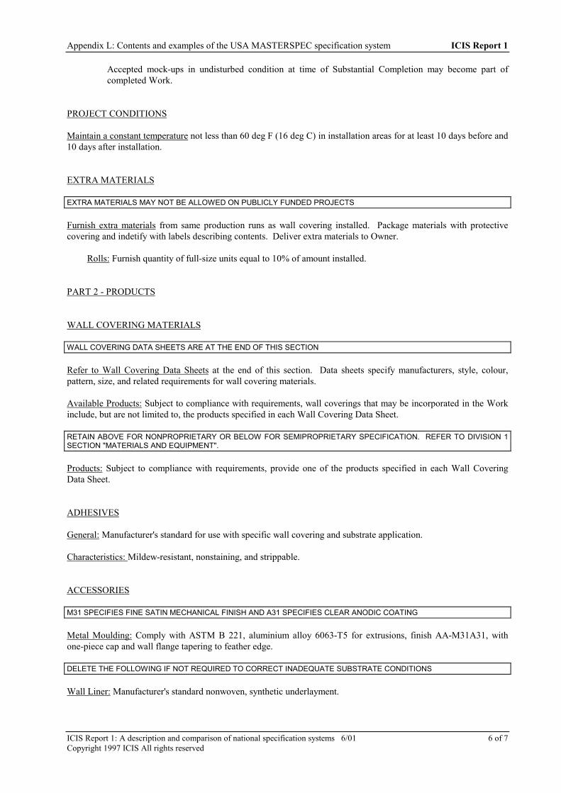
Appendix L: Contents and examples of the USA MASTERSPEC specification system ICIS Report 1
ICIS Report 1: A description and comparison of national specification systems 6/01 6 of 7Copyright 1997 ICIS All rights reserved
Accepted mock-ups in undisturbed condition at time of Substantial Completion may become part ofcompleted Work.
PROJECT CONDITIONS
Maintain a constant temperature not less than 60 deg F (16 deg C) in installation areas for at least 10 days before and10 days after installation.
EXTRA MATERIALS
EXTRA MATERIALS MAY NOT BE ALLOWED ON PUBLICLY FUNDED PROJECTS
Furnish extra materials from same production runs as wall covering installed. Package materials with protectivecovering and indetify with labels describing contents. Deliver extra materials to Owner.
Rolls: Furnish quantity of full-size units equal to 10% of amount installed.
PART 2 - PRODUCTS
WALL COVERING MATERIALS
WALL COVERING DATA SHEETS ARE AT THE END OF THIS SECTION
Refer to Wall Covering Data Sheets at the end of this section. Data sheets specify manufacturers, style, colour,pattern, size, and related requirements for wall covering materials.
Available Products: Subject to compliance with requirements, wall coverings that may be incorporated in the Workinclude, but are not limited to, the products specified in each Wall Covering Data Sheet.
RETAIN ABOVE FOR NONPROPRIETARY OR BELOW FOR SEMIPROPRIETARY SPECIFICATION. REFER TO DIVISION 1SECTION "MATERIALS AND EQUIPMENT".
Products: Subject to compliance with requirements, provide one of the products specified in each Wall CoveringData Sheet.
ADHESIVES
General: Manufacturer's standard for use with specific wall covering and substrate application.
Characteristics: Mildew-resistant, nonstaining, and strippable.
ACCESSORIES
M31 SPECIFIES FINE SATIN MECHANICAL FINISH AND A31 SPECIFIES CLEAR ANODIC COATING
Metal Moulding: Comply with ASTM B 221, aluminium alloy 6063-T5 for extrusions, finish AA-M31A31, withone-piece cap and wall flange tapering to feather edge.
DELETE THE FOLLOWING IF NOT REQUIRED TO CORRECT INADEQUATE SUBSTRATE CONDITIONS
Wall Liner: Manufacturer's standard nonwoven, synthetic underlayment.

Appendix L: Contents and examples of the USA MASTERSPEC specification system ICIS Report 1
ICIS Report 1: A description and comparison of national specification systems 6/01 7 of 7Copyright 1997 ICIS All rights reserved
PART 3 - EXECUTION
PREPARATION
Acclimatise wall covering materials by removing them from packaging in the installation areas not less than 24 hoursbefore installation.
Follow manufacturer's printed instructions for surface preparation.
Prepare substrates to achieve a smooth, dry, clean surface free of flaking, unsound coatings, cracks, anddefects.
Painted Surfaces: Treat areas susceptible to pigment bleeding.
Metals: If not factory-primed, clean and apply rust inhibitive zinc primer.
Moisture Content: Maximum of 5% on new plaster, concrete, and concrete masonry units when tested with anelectronic moisture meter.
Prime new gypsum board with a recommended primer.
Allow new plaster to cure. Treat areas of highly alkalinity.
Check painted surfaces for pigment bleeding. Sand gloss, semi-gloss, and eggshell finishes with fine sandpaper.
DELETE THE FOLLOWING IF NOT REQUIRED TO CORRECT INADEQUATE SUBSTRATE CONDITIONS
Install wall liner, with no gaps or overlaps, where required by wall covering manufacturer. From smooth wrinkle-free surface for finished installation. Do not begin wall covering installation until wall liner has dried.
INSTALLATION
Follow manufacturer's printed instructions for installation.
Install wall covering with no gaps or overlaps.