A-dec 200Service Reference
104
A-dec 200 Service Reference Tubing, Flow Diagrams, and Illustrated Parts Breakdown
-
Upload
khangminh22 -
Category
Documents
-
view
0 -
download
0
Transcript of A-dec 200Service Reference
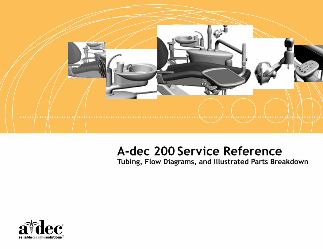
A-dec 200 Service ReferenceTubing, Flow Diagrams, and Illustrated Parts Breakdown
Copyright© 2011 A-dec Inc. All rights reserved.
A-dec Inc. makes no warranty of any kind with regard to this material, including, but not limited to, the implied warranties of merchantability and fitness for a particular purpose. A-dec Inc. shall not be held liable for any errors contained herein or any consequential or other damages concerning the furnishing, performance or use of this material. The information in this document is subject to change without notice. If you find any problems in the documentation, please report them to us in writing. A-dec Inc. does not warrant that this document is error-free.
No part of this document may be copied, reproduced, altered, or transmitted in any form or by any means, electronic or mechanical, including photocopying, recording, or by any information storage and retrieval system, without prior written permission from A-dec Inc.
Trademarks and Additional Intellectual Property RightsA-dec, the A-dec logo, A-dec 500, A-dec 300, Cascade, Cascade Master Series, Century Plus, Continental, Decade, ICX, ICV, Performer, Preference, Preference Collection, Preference ICC, and Radius are trademarks of A-dec Inc. and are registered in the United States and other countries. A-dec 200, Preference Slimline, and reliablecreativesolutions are also trademarks of A-dec Inc. None of the trademarks or trade names in this document may be reproduced, copied, or manipulated in any manner without the express, written approval of the trademark owner.
Certain touchpad symbols are proprietary to A-dec Inc. Any use of these symbols, in whole or in part, without the express written consent of A-dec Inc., is strictly prohibited
Intended Application and UseThis equipment/system is intended for diagnostic and therapeutic treatment of dental patients by licensed health care professionals.
A dental operative unit (with or without accessories) is an AC-powered device intended to supply power to and serve as a base for other dental devices, such as a dental handpiece, a dental operating light, an air or water syringe unit, an oral cavity evacuator, a suction operative unit, and other dental devices and accessories.
Regulatory InformationThe Regulatory Information and Specifications document is delivered with A-dec dental device equipment as mandated by agency requirements. If you need this information, please go to the Document Library at www.a-dec.com.
Product ServiceFor service information, contact your local authorized A-dec dealer. To find your local dealer, go to www.a-dec.com.
Document Conventions
Click this arrow to return to a level above the current section.
Icon used to visually describe water.
Icon used to visually describe air.
page 1 Click this bubble to move to the indicated page.
86.0324.00 Rev B 1Tubing, Flow Diagrams, Illustrated parts Breakdown, Diagnostics
page 7
page 15
page 2
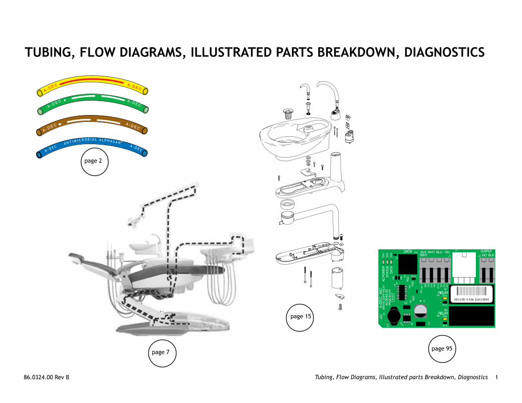
TUBIng, Flow DIAgRAmS, IllUSTRATeD PARTS BReAkDown, DIAgnoSTICS
page 95

A-dec 200 Service Reference A-dec Tubing 2
A-DeC TUBIng
Tubing Function Description Tubing Color/Tracer Part number (10' length)
Chip blower/accessory button Chip blower air - 1/8" OD, brown/white long dash 036.014.02
Air coolant signal Air coolant signal air from foot control; signal air for cuspidor cupfill and vacuum actuator - 1/8" OD, green/white long dash
036.006.03
Unregulated air Unregulated air to flexarm brake - 1/8” OD, black 036.020.03
Water coolant signal air 1/8" OD, clear 024.015.04
Water supply, cold water (regulated)
Oral cavity water - 1/8" OD, blue 036.004.03
Antimicrobial AlphaSan and Color Tracer markingsIn 2005 A-dec began incorporating Antimicrobial AlphaSan® in A-dec waterline tubing, as indicated with the Antimicrobial AlphaSan tracer marking. Only tubing with the Antimicrobial AlphaSan tracer contains Antimicrobial AlphaSan. This table lists functions, descriptions, and part numbers for A-dec Tubing.
note: The last two numbers of the tubing part number determine the length of tubing. By default the numbers shown are for the 10' lengths.
Antimicrobial AlphaSan Tracer Marking Tracer Marking
page 1
86.0324.00 Rev B 3A-dec Tubing
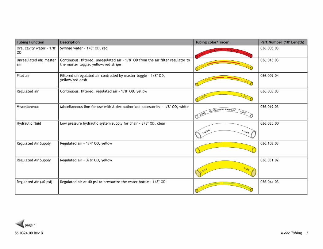
Tubing Function Description Tubing color/Tracer Part number (10' length)
Oral cavity water - 1/8" OD
Syringe water - 1/8" OD, red 036.005.03
Unregulated air, master air
Continuous, filtered, unregulated air - 1/8" OD from the air filter regulator to the master toggle, yellow/red stripe
036.013.03
Pilot air Filtered unregulated air controlled by master toggle - 1/8" OD, yellow/red dash
036.009.04
Regulated air Continuous, filtered, regulated air - 1/8" OD, yellow 036.003.03
Miscellaneous Miscellaneous line for use with A-dec authorized accessories - 1/8" OD, white 036.019.03
Hydraulic fluid Low pressure hydraulic system supply for chair - 3/8" OD, clear 036.035.00
Regulated Air Supply Regulated air - 1/4" OD, yellow 036.103.03
Regulated Air Supply Regulated air - 3/8" OD, yellow 036.031.02
Regulated Air (40 psi) Regulated air at 40 psi to pressurize the water bottle - 1/8" OD 036.044.03
page 1

A-dec 200 Service Reference A-dec Tubing 4
Tubing Function Description Tubing color/Tracer Part number (10' length)
Drive Air Drive air for foot control - 1/4" OD 036.052.03
Drive Air Handpiece drive air - 1/4" OD, clear 036.066.03
Signal Air, Water Coolant
Signal air/water coolant from foot control, signal air for cuspidor bowl rinse - 1/8" OD signal, green/white dash
036.018.03
Water Supply Regulated water, water to bowl rinse - 1/4" OD, blue 036.053.03
Water Supply Unregulated water - 3/8" OD, blue/white dash 036.033.02
Handpiece 4-Hole tubing, vinyl No image available 98.1114.01
Handpiece 6-Pin tubing, vinyl No image available 98.1115.01
Cuspidor Drain 20 mm cuspidor drain tubing No image available 024.210.01
Vacuum Tubing 25 mm vacuum tubing No image available 024.209.01
Foot Control Tubing Foot control replacement tubing, Gray 3 (10 ft) No image available 024.242.01
Foot Control Tubing Foot control replacement tubing. Grau 3 (50 ft) No image available 024.424.02 (50' length)
page 1

86.0324.00 Rev B 5A-dec Connectors and Cables
A-DeC ConneCToRS AnD CABleSFunction Description Part number
Vacuum Connectors 20mm Female vacuum connector 022.092.01
Vacuum Connectors 20mm Male vacuum connector 022.093.01
Vacuum Connectors 25mm Female vacuum connector 022.094.01
Vacuum Connectors 25mm Male vacuum connector 022.095.01
Vacuum Connectors Male to female elbow 022.099.01
page 1
A-dec 200 Service Reference A-dec Connectors and Cables 6
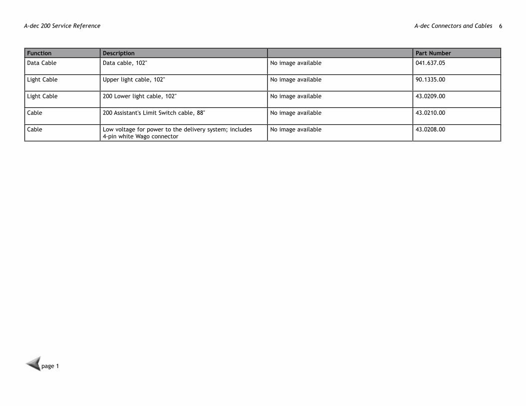
Function Description Part number
Data Cable Data cable, 102" No image available 041.637.05
Light Cable Upper light cable, 102" No image available 90.1335.00
Light Cable 200 Lower light cable, 102" No image available 43.0209.00
Cable 200 Assistant's Limit Switch cable, 88" No image available 43.0210.00
Cable Low voltage for power to the delivery system; includes 4-pin white Wago connector
No image available 43.0208.00
page 1

86.0324.00 Rev B 7Flow Diagrams
page 8
page 10 page 9
Flow DIAgRAmS
page 1
page 11 page 12
page 13 page 14

A-dec 200 Service Reference Flow Diagrams 8
A-dec 200 Chair Flow Diagram
10AMP
10AMP
10AMP
10AMP
10AMP
1
2 34
5
6
9
87
10
11
1
2
3
4 5
6
987
1011
Item Description Item Description
1 Tilt cylinder 7 Chair circuit board
2 Lift cylinder 8 Chair manifold
3 Back potentiometer 9 Hydraulic fluid reservoir
4 Base potentiometer 10 Power supply
5 Capacitor 11 Light circuit board
6 Motor pump
page 7

86.0324.00 Rev B 9Flow Diagrams
Delivery System Flow Diagram
page 7

A-dec 200 Service Reference Flow Diagrams 10
Support Center, Cuspidor and water Bottle Flow Diagram
page 14page 7

86.0324.00 Rev B 11Flow Diagrams
Dental light Flow Diagram - light with Touchpad
page 14
page 7
A-dec 200 Service Reference Flow Diagrams 12
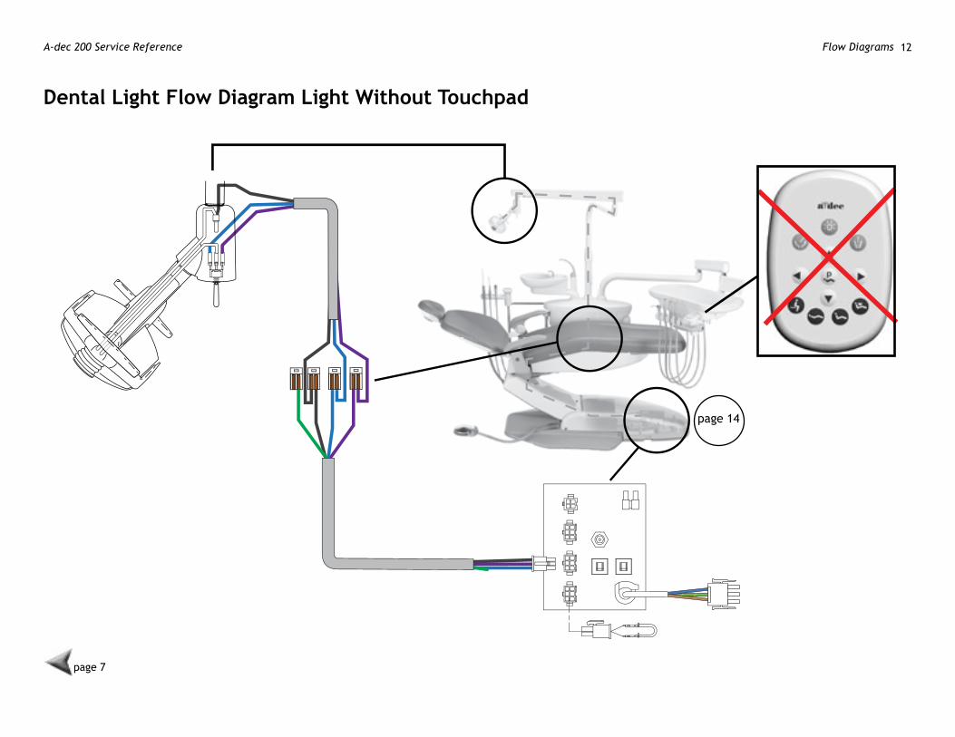
Dental light Flow Diagram light without Touchpad
page 14
page 7
86.0324.00 Rev B 13Flow Diagrams
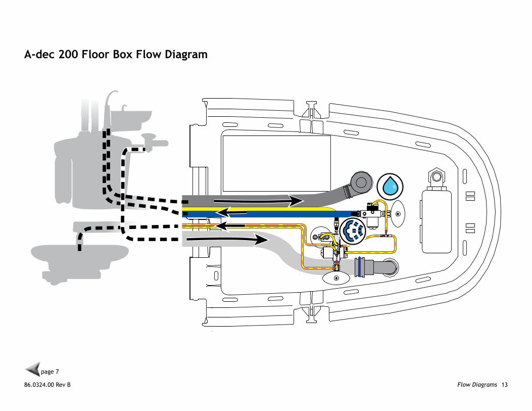
A-dec 200 Floor Box Flow Diagram
page 7

A-dec 200 Service Reference Flow Diagrams 14
A-dec 200 Floor Box options Flow Diagram
page 7
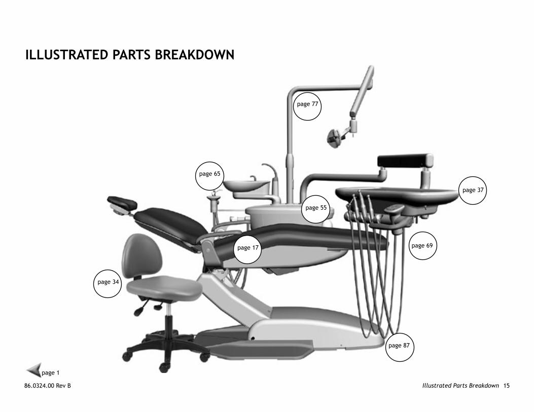
86.0324.00 Rev B 15Illustrated Parts Breakdown
IllUSTRATeD PARTS BReAkDown
page 65
page 77
page 37
page 69
page 55
page 17
page 1
page 87
page 34
A-dec 200 Service Reference Illustrated Parts Breakdown 16
86.0324.00 Rev B 17Dental Chair
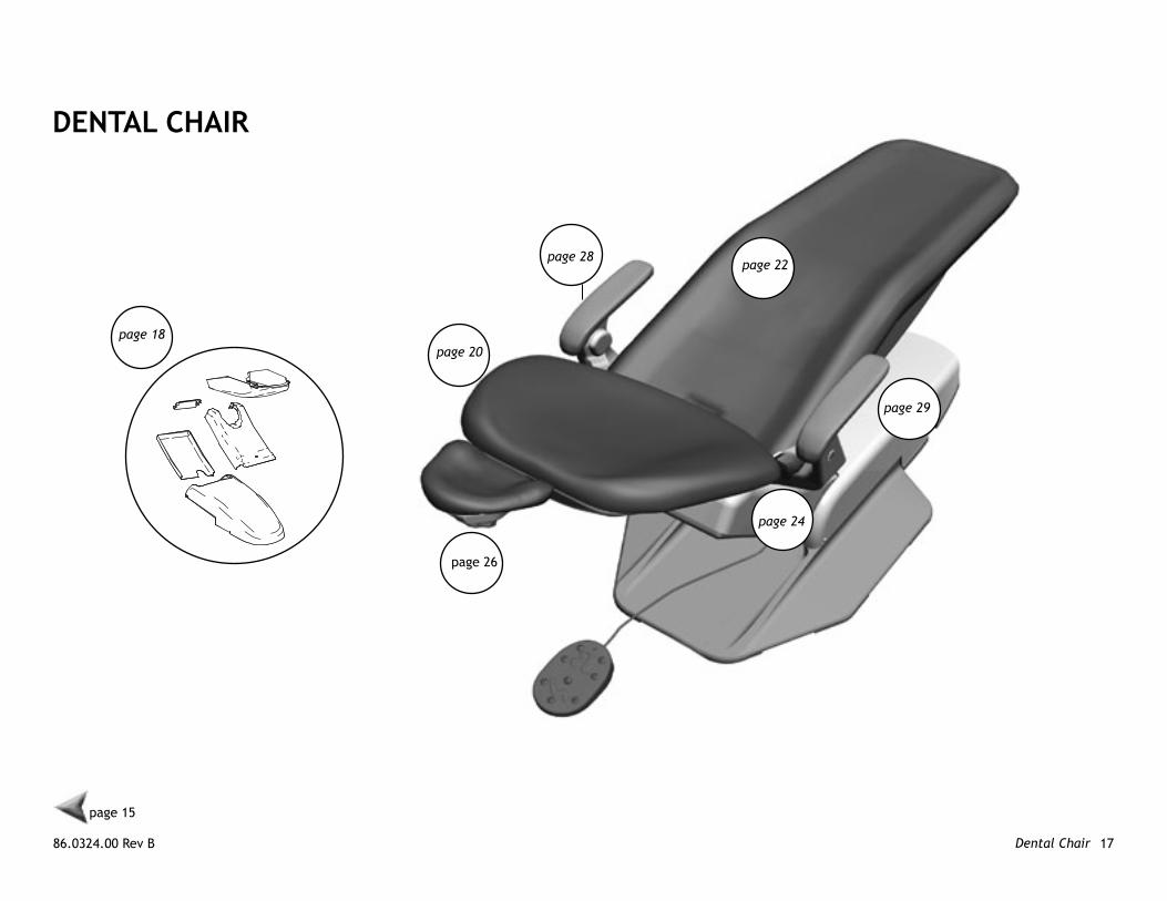
DenTAl ChAIR
page 18page 20
page 22page 28
page 26
page 24
page 29
page 15

A-dec 200 Service Reference Dental Chair 18
Chair CoversItem Part number Description
1 61.3821.00 Rear chair cover
2 61.3847.00 Bottom cover
3 001.268.00 Fasteners (total of 10)
4 61.2243.02 Lift arm front cover
5 61.3846.00 Pump utility cover
6 61.2089.01 Stop plate/cover
7 61.2239.01 Lift arm rear cover
7
2
5
4
1
6
3
page 17

86.0324.00 Rev B 19Dental Chair
A-dec 200 Service Reference Dental Chair 20
page 17
1
3
page 26
page 28
page 28
2
45
6
7
8 9
10
111213
14
15
16
17
18
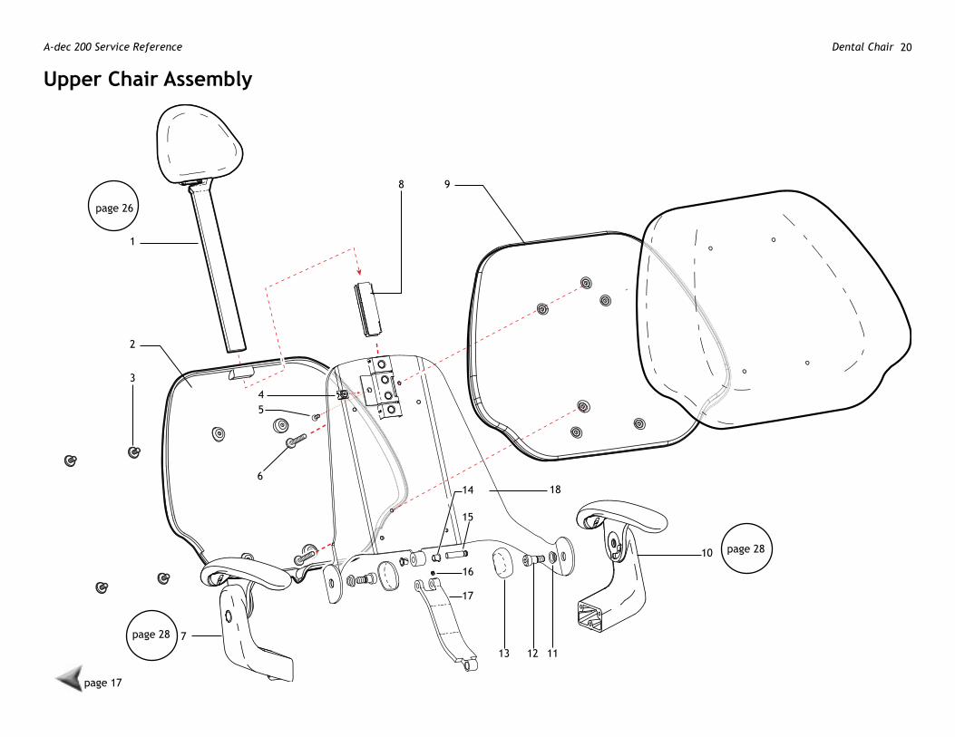
Upper Chair Assembly

86.0324.00 Rev B 21Dental Chair
page 17
Upper Chair Assembly
Item Part number Description
1 — Headrest assembly
2 61.3824.00 Back cover
3 001.268.00 Back cover mounting screws
4 006.122.01 Retaining nut
5 005.147.00 Flat head socket screw, 1/4-20 X 1-1/4
6 002.136.00 Back armature mounting screws
7 — Right hand armrest assembly
8 61.2743.00 Brake shoe
9 61.3785.00 † Back armature
10 — Left hand armrest assembly
11 61.3108.00 Flanged bearing
12 001.164.00 Socket shoulder screw, 1/2-13 X 5/8 X 5/8
13 61.3788.01 Pivot bolt cover
14 016.131.00 Flanged bearing
15 61.2740.00 Backrest link pin
16 007.069.00 Set screw, socket 1/4-20 X 1/4
17 61.3792.01 Back link
18 61.3823.00 † Backrest
† Indicates that the individual part is not available for sale

A-dec 200 Service Reference Dental Chair 22
page 17
1 35
12 11
42 12
5
2
2
2
5
6
6
778
9
8
13
15
16
1918
17
212021
14
10
10
20
2
15
page 32 page 32
mid-Chair Assembly
86.0324.00 Rev B 23Dental Chair
page 17
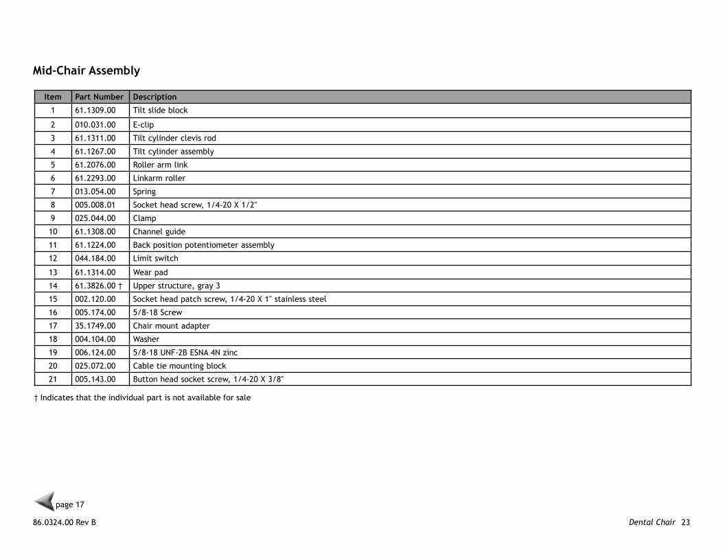
mid-Chair Assembly
Item Part number Description
1 61.1309.00 Tilt slide block
2 010.031.00 E-clip
3 61.1311.00 Tilt cylinder clevis rod
4 61.1267.00 Tilt cylinder assembly
5 61.2076.00 Roller arm link
6 61.2293.00 Linkarm roller
7 013.054.00 Spring
8 005.008.01 Socket head screw, 1/4-20 X 1/2"
9 025.044.00 Clamp
10 61.1308.00 Channel guide
11 61.1224.00 Back position potentiometer assembly
12 044.184.00 Limit switch
13 61.1314.00 Wear pad
14 61.3826.00 † Upper structure, gray 3
15 002.120.00 Socket head patch screw, 1/4-20 X 1" stainless steel
16 005.174.00 5/8-18 Screw
17 35.1749.00 Chair mount adapter
18 004.104.00 Washer
19 006.124.00 5/8-18 UNF-2B ESNA 4N zinc
20 025.072.00 Cable tie mounting block
21 005.143.00 Button head socket screw, 1/4-20 X 3/8"
† Indicates that the individual part is not available for sale
A-dec 200 Service Reference Dental Chair 24
page 17
1
9
16
2
17
19 22
20
212024
2
2 3 2 4
4 2
2
356
7
2
8
7
2
1011
12
131414
1516
18
17
1725
20
2123
26
page 29
page 33
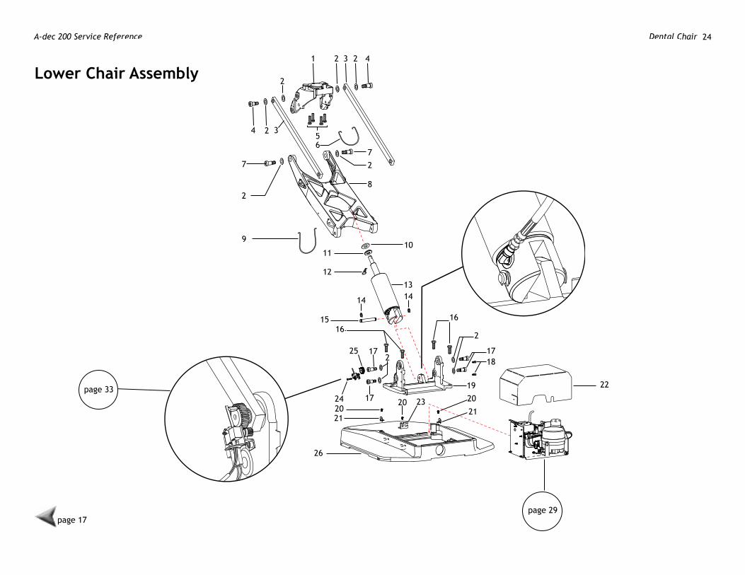
lower Chair Assembly

86.0324.00 Rev B 25Dental Chair
page 17
Item Part number Description
1 61.3825.00 † Swivel bracket
2 004.148.00 Flat nylatron washer
3 61.1294.00 † Lower structure link
4 001.164.00 Socket head shoulder bolt
5 001.177.00 Socket head screw, 1/2-13 x 1/4, zinc
6 41.1145.00 Umbilical support
7 001.165.00 Socket head shoulder screw
8 61.2095.00 † Lift arm
9 41.1144.00 Umbilical retainer
10 004.149.00 Flat neoprene washer, .680 ID
11 004.104.00 Flat steel plated washer, .640 ID
12 011.046.00 Clip pin
13 90.1312.00 Lift cylinder
14 010.031.01 E-clip
15 61.1285.00 Lift pin
16 001.163.00 Hex head cap screw, 1/2-13 X 1-1/4
17 001.165.00 Socket head shoulder screw
18 005.008.01 Socket head screw, 1/4-20 X 1/2
19 61.1277.01 † Sub base
20 005.143.00 Button head socket screw, 1/4-20 X 3/8
21 61.1286.00 Bracket
22 61.3848.00 Floorbox/pump cover
23 61.1650.00 Foot switch/foot control bracket
24 61.1221.00 Base potentiometer assembly (includes items 24, 25 and 26)
25 61.1295.00 Gear
26 61.2037.01 Baseplate
lower Chair Assembly
† Indicates that the individual part is not available for sale

A-dec 200 Service Reference Dental Chair 26
page 17
1 2 3 4 5 6
7
8
9
10
11
12
13
14 15
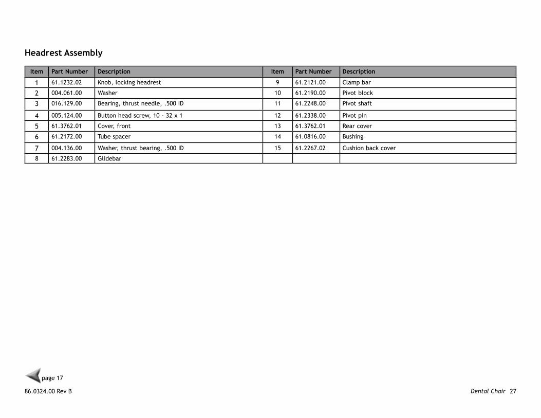
Double Articulating headrest AssemblyP/n 61.2265.01
86.0324.00 Rev B 27Dental Chair
page 17
headrest Assembly
Item Part number Description Item Part number Description
1 61.1232.02 Knob, locking headrest 9 61.2121.00 Clamp bar
2 004.061.00 Washer 10 61.2190.00 Pivot block
3 016.129.00 Bearing, thrust needle, .500 ID 11 61.2248.00 Pivot shaft
4 005.124.00 Button head screw, 10 - 32 x 1 12 61.2338.00 Pivot pin
5 61.3762.01 Cover, front 13 61.3762.01 Rear cover
6 61.2172.00 Tube spacer 14 61.0816.00 Bushing
7 004.136.00 Washer, thrust bearing, .500 ID 15 61.2267.02 Cushion back cover
8 61.2283.00 Glidebar
A-dec 200 Service Reference Dental Chair 28
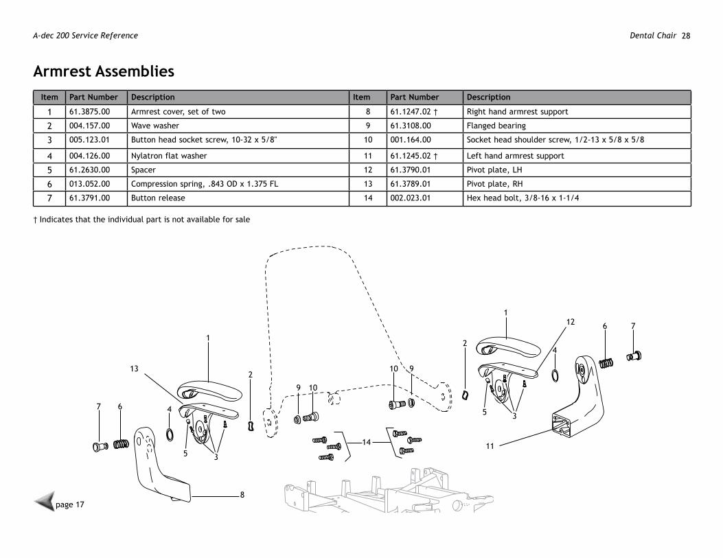
Armrest Assemblies
page 17
1
1
2
3
4
42
67
6 7
8
9 10
115
35
12
13 910
14
Item Part number Description Item Part number Description
1 61.3875.00 Armrest cover, set of two 8 61.1247.02 † Right hand armrest support
2 004.157.00 Wave washer 9 61.3108.00 Flanged bearing
3 005.123.01 Button head socket screw, 10-32 x 5/8" 10 001.164.00 Socket head shoulder screw, 1/2-13 x 5/8 x 5/8
4 004.126.00 Nylatron flat washer 11 61.1245.02 † Left hand armrest support
5 61.2630.00 Spacer 12 61.3790.01 Pivot plate, LH
6 013.052.00 Compression spring, .843 OD x 1.375 FL 13 61.3789.01 Pivot plate, RH
7 61.3791.00 Button release 14 002.023.01 Hex head bolt, 3/8-16 x 1-1/4
† Indicates that the individual part is not available for sale
86.0324.00 Rev B 29Dental Chair
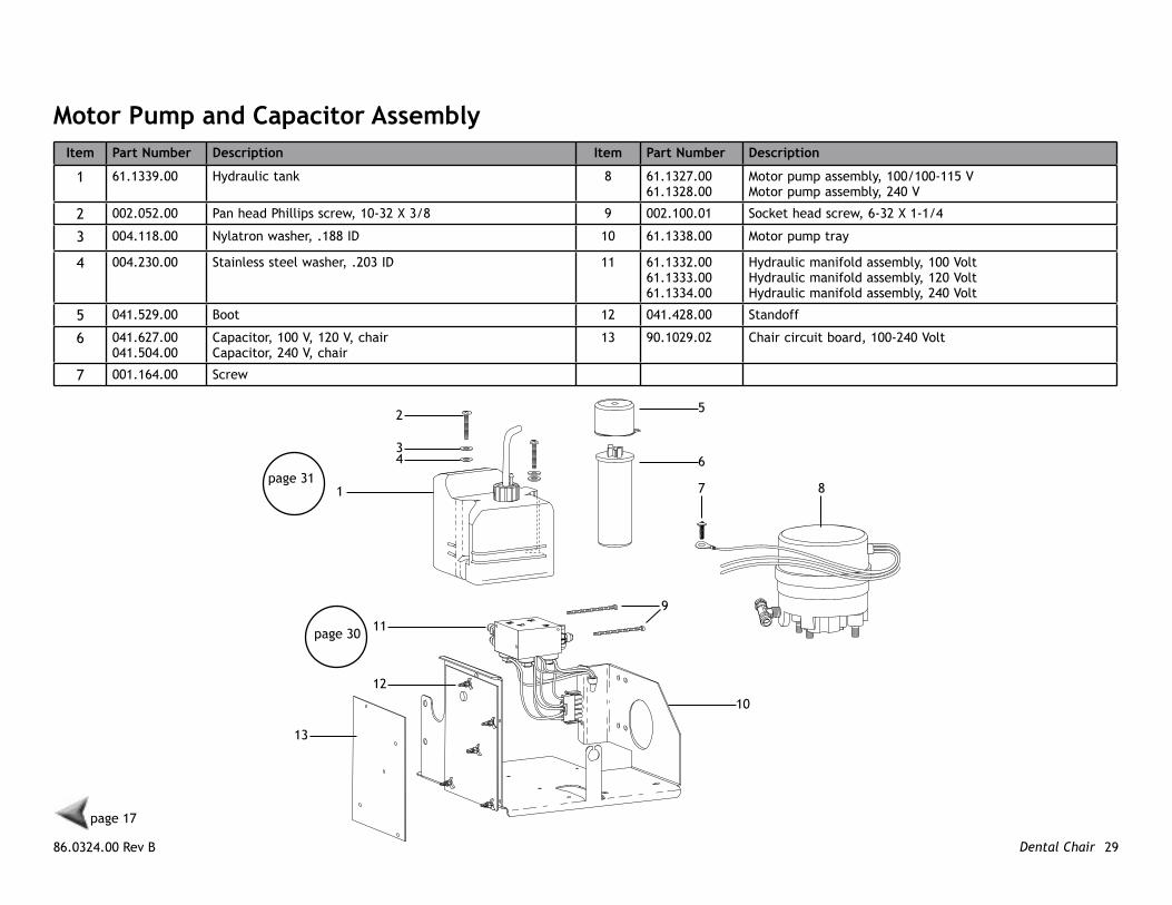
motor Pump and Capacitor AssemblyItem Part number Description Item Part number Description
1 61.1339.00 Hydraulic tank 8 61.1327.0061.1328.00
Motor pump assembly, 100/100-115 VMotor pump assembly, 240 V
2 002.052.00 Pan head Phillips screw, 10-32 X 3/8 9 002.100.01 Socket head screw, 6-32 X 1-1/4
3 004.118.00 Nylatron washer, .188 ID 10 61.1338.00 Motor pump tray
4 004.230.00 Stainless steel washer, .203 ID 11 61.1332.0061.1333.0061.1334.00
Hydraulic manifold assembly, 100 VoltHydraulic manifold assembly, 120 VoltHydraulic manifold assembly, 240 Volt
5 041.529.00 Boot 12 041.428.00 Standoff
6 041.627.00041.504.00
Capacitor, 100 V, 120 V, chairCapacitor, 240 V, chair
13 90.1029.02 Chair circuit board, 100-240 Volt
7 001.164.00 Screw
1
2
34
5
6
7 8
9
10
11
12
13
page 17
page 30
page 31

A-dec 200 Service Reference Dental Chair 30
hydraulic manifold AssemblyItem Part number Description
1 002.118.02 Screw, button head socket
2 61.0460.00 Flow adjust screw with O-ring
3 030.004.02 O-ring, AS568-004 package of 10
4 61.1335.0061.1336.0061.1337.00
Solenoid, 8-watt, 100 V, yellow wiresSolenoid, 8-watt, 120 V, black wiresSolenoid, 8-watt, 240 V, red wires
5 030.015.02 O-ring, package of 10
6 61.0500.00 Lift/Tilt manifold block
7 055.277.00 Decal
8 017.007.00 Bumper pad
9 018.057.00 Expanding plug
10 61.0461.01 Check valve with O-ring
11 013.044.00 Compression spring
12 022.049.00 Straight fitting with O-ring
13 61.0465.00 Outlet screen
14 022.067.00 3/8" Elbow fitting
15 022.014.01 Nut with sleeve
page 17
1
23
3
4
5
6
9
7
10
12118
13
12 14
15
86.0324.00 Rev B 31Dental Chair
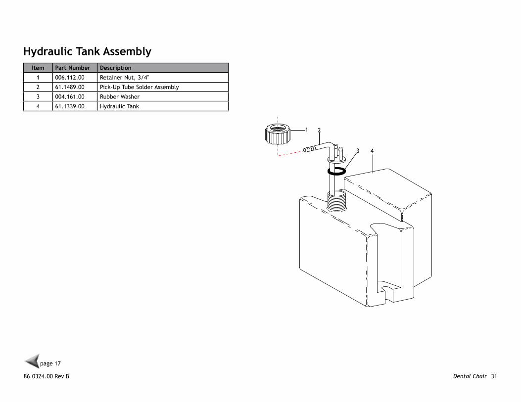
Item Part number Description
1 006.112.00 Retainer Nut, 3/4"
2 61.1489.00 Pick-Up Tube Solder Assembly
3 004.161.00 Rubber Washer
4 61.1339.00 Hydraulic Tank
hydraulic Tank Assembly
1 2
3 4
page 17
A-dec 200 Service Reference Dental Chair 32
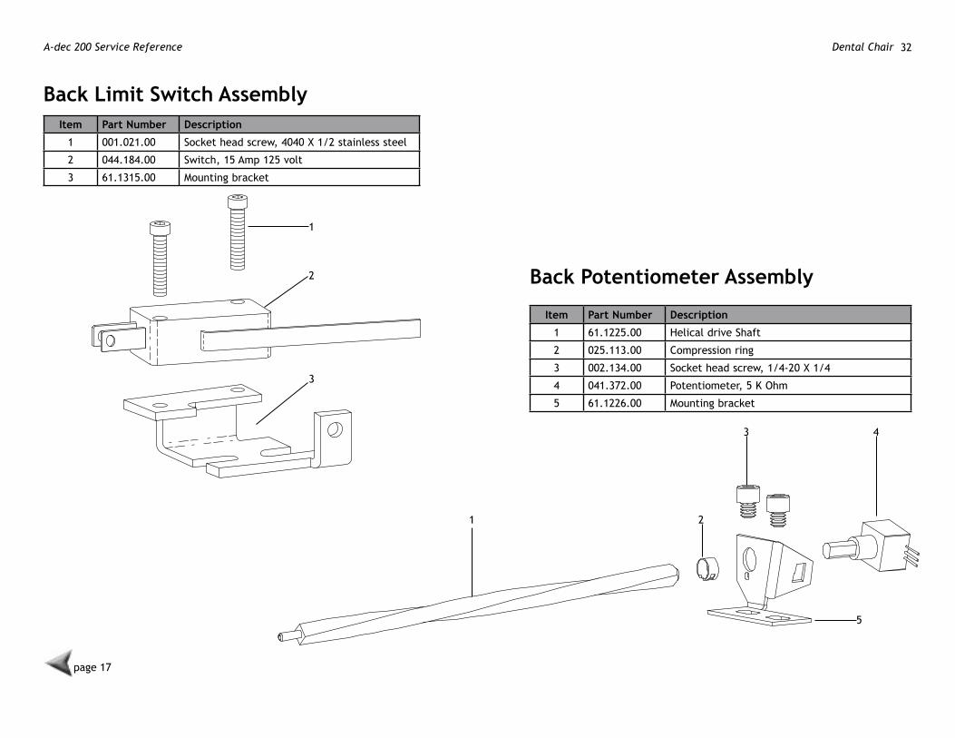
Back limit Switch AssemblyItem Part number Description
1 001.021.00 Socket head screw, 4040 X 1/2 stainless steel
2 044.184.00 Switch, 15 Amp 125 volt
3 61.1315.00 Mounting bracket
1
2
3
Back Potentiometer Assembly
Item Part number Description
1 61.1225.00 Helical drive Shaft
2 025.113.00 Compression ring
3 002.134.00 Socket head screw, 1/4-20 X 1/4
4 041.372.00 Potentiometer, 5 K Ohm
5 61.1226.00 Mounting bracket
1 2
3 4
5
page 17
86.0324.00 Rev B 33Dental Chair
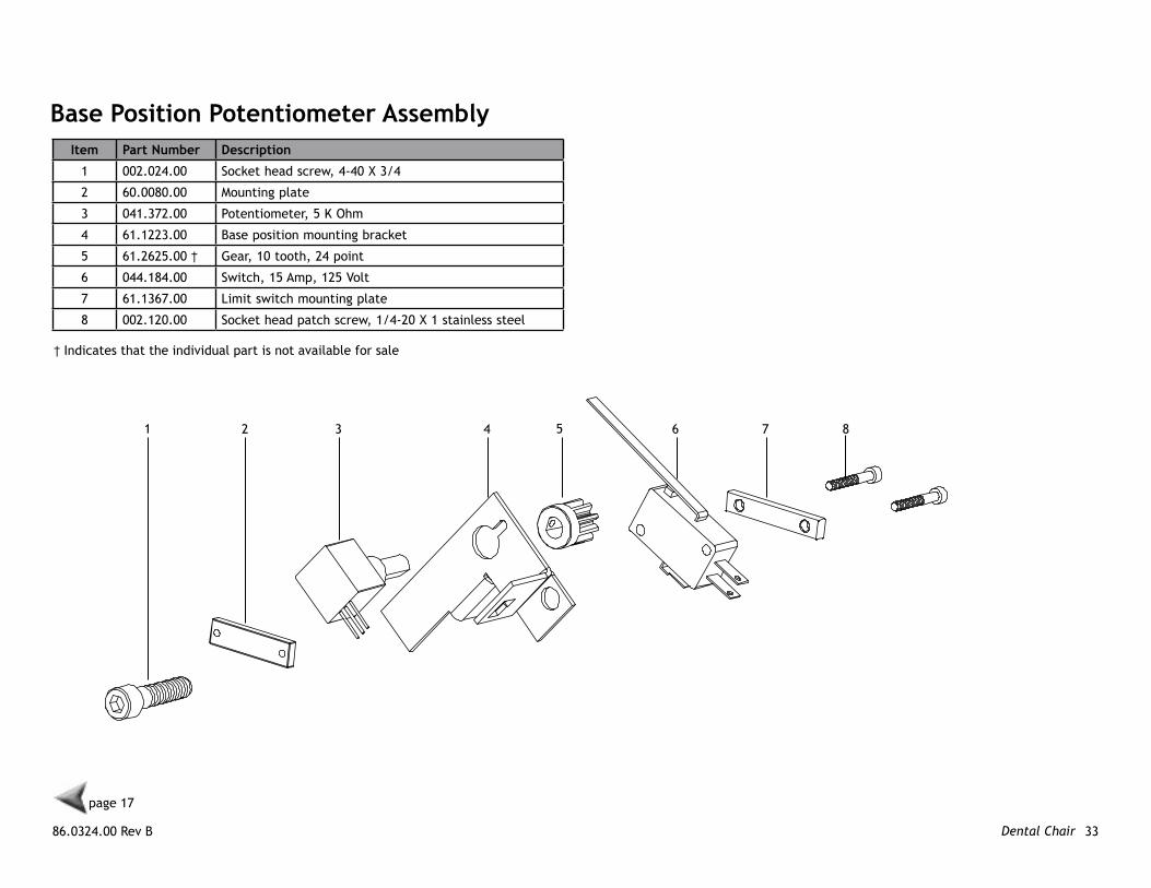
Base Position Potentiometer AssemblyItem Part number Description
1 002.024.00 Socket head screw, 4-40 X 3/4
2 60.0080.00 Mounting plate
3 041.372.00 Potentiometer, 5 K Ohm
4 61.1223.00 Base position mounting bracket
5 61.2625.00 † Gear, 10 tooth, 24 point
6 044.184.00 Switch, 15 Amp, 125 Volt
7 61.1367.00 Limit switch mounting plate
8 002.120.00 Socket head patch screw, 1/4-20 X 1 stainless steel
1 2 3 4 6 7 85
page 17
† Indicates that the individual part is not available for sale

A-dec 200 Service Reference Dental Chair 34
12
3
4
5
6
8
910
7
200 Stool Assembly
page 17
86.0324.00 Rev B 35Dental Chair
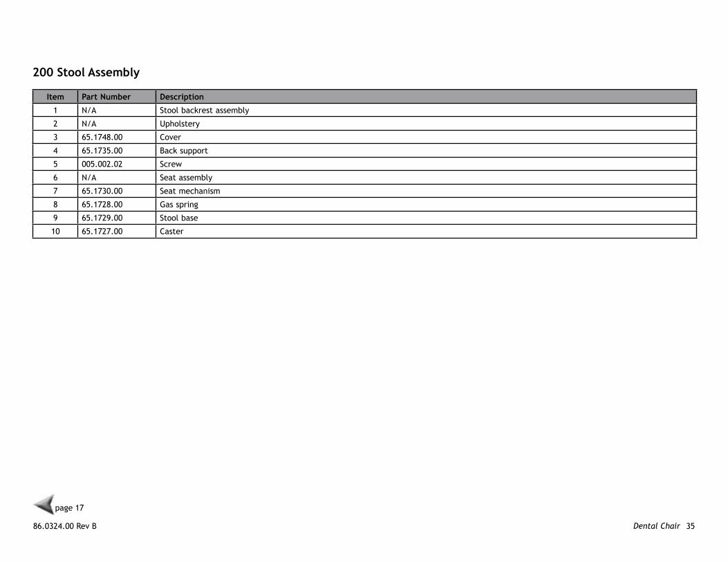
200 Stool Assembly
Item Part number Description
1 N/A Stool backrest assembly
2 N/A Upholstery
3 65.1748.00 Cover
4 65.1735.00 Back support
5 005.002.02 Screw
6 N/A Seat assembly
7 65.1730.00 Seat mechanism
8 65.1728.00 Gas spring
9 65.1729.00 Stool base
10 65.1727.00 Caster
page 17

A-dec 200 Service Reference Dental Chair 36

86.0324.00 Rev B 37Delivery System
DelIveRy SySTem
page 44 page 49
page 48
page 38
page 15
page 40
page 42
A-dec 200 Service Reference Delivery System 38
page 37
1
2
3
5
4page 44
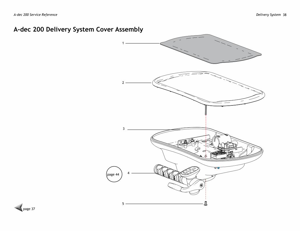
A-dec 200 Delivery System Cover Assembly
86.0324.00 Rev B 39Delivery System
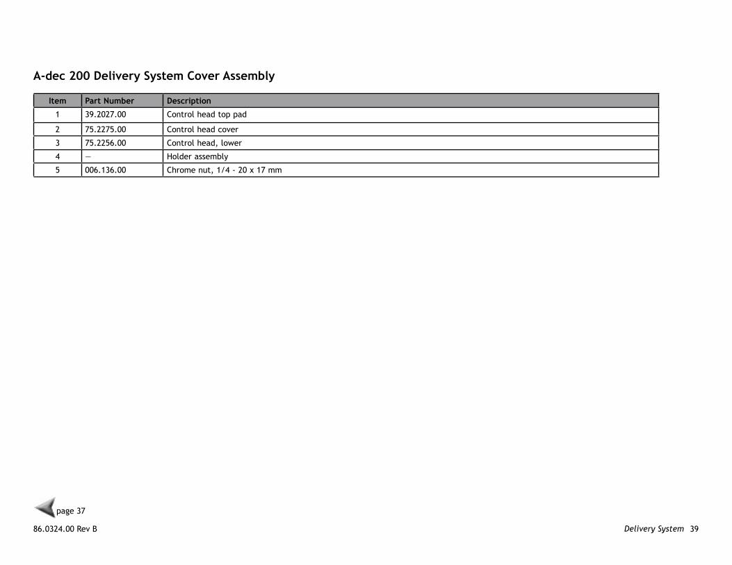
A-dec 200 Delivery System Cover Assembly
Item Part number Description
1 39.2027.00 Control head top pad
2 75.2275.00 Control head cover
3 75.2256.00 Control head, lower
4 — Holder assembly
5 006.136.00 Chrome nut, 1/4 - 20 x 17 mm
page 37

A-dec 200 Service Reference Delivery System 40
page 37
2
34
5
7
8
9
6
10
2
3
8
117
8
14
15
1213
page 421
A-dec 200 Delivery System and Arm Assemblies
10
86.0324.00 Rev B 41Delivery System
page 37
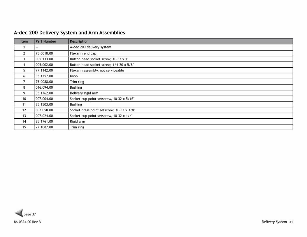
A-dec 200 Delivery System and Arm Assemblies
Item Part number Description
1 — A-dec 200 delivery system
2 75.0010.00 Flexarm end cap
3 005.133.00 Button head socket screw, 10-32 x 1"
4 005.002.00 Button head socket screw, 1/4-20 x 5/8"
5 77.1142.00 Flexarm assembly, not serviceable
6 35.1757.00 Knob
7 75.0088.00 Trim ring
8 016.094.00 Bushing
9 35.1762.00 Delivery rigid arm
10 007.004.00 Socket cup point setscrew, 10-32 x 5/16"
11 35.1503.00 Bushing
12 007.058.00 Socket brass point setscrew, 10-32 x 3/8"
13 007.024.00 Socket cup point setscrew, 10-32 x 1/4"
14 35.1761.00 Rigid arm
15 77.1087.00 Trim ring

A-dec 200 Service Reference Delivery System 421 2 3
4
5
6
9
8
7
21
10
11
12
13
14
15
16
17
18
19
20
22
23
24
page 46
page 49
page 37
A-dec 200 Delivery System Assembly
86.0324.00 Rev B 43Delivery System
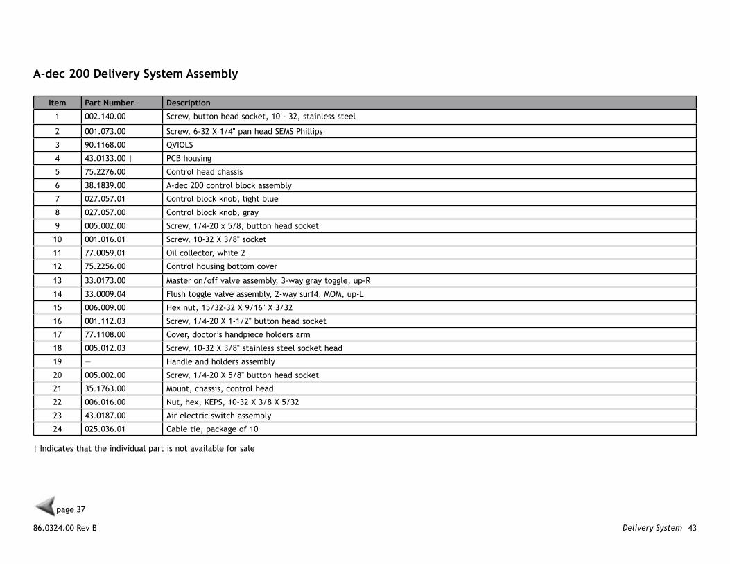
A-dec 200 Delivery System Assembly
Item Part number Description
1 002.140.00 Screw, button head socket, 10 - 32, stainless steel
2 001.073.00 Screw, 6-32 X 1/4" pan head SEMS Phillips
3 90.1168.00 QVIOLS
4 43.0133.00 † PCB housing
5 75.2276.00 Control head chassis
6 38.1839.00 A-dec 200 control block assembly
7 027.057.01 Control block knob, light blue
8 027.057.00 Control block knob, gray
9 005.002.00 Screw, 1/4-20 x 5/8, button head socket
10 001.016.01 Screw, 10-32 X 3/8" socket
11 77.0059.01 Oil collector, white 2
12 75.2256.00 Control housing bottom cover
13 33.0173.00 Master on/off valve assembly, 3-way gray toggle, up-R
14 33.0009.04 Flush toggle valve assembly, 2-way surf4, MOM, up-L
15 006.009.00 Hex nut, 15/32-32 X 9/16" X 3/32
16 001.112.03 Screw, 1/4-20 X 1-1/2" button head socket
17 77.1108.00 Cover, doctor’s handpiece holders arm
18 005.012.03 Screw, 10-32 X 3/8" stainless steel socket head
19 — Handle and holders assembly
20 005.002.00 Screw, 1/4-20 X 5/8" button head socket
21 35.1763.00 Mount, chassis, control head
22 006.016.00 Nut, hex, KEPS, 10-32 X 3/8 X 5/32
23 43.0187.00 Air electric switch assembly
24 025.036.01 Cable tie, package of 10
† Indicates that the individual part is not available for sale
page 37
A-dec 200 Service Reference Delivery System 44
page 37
1
2
3
4
5
6
7 6
8 9 10 11
12
13
12
14
15
16
17
8
18
19
19202122
23
24
holder Assembly
86.0324.00 Rev B 45Delivery System
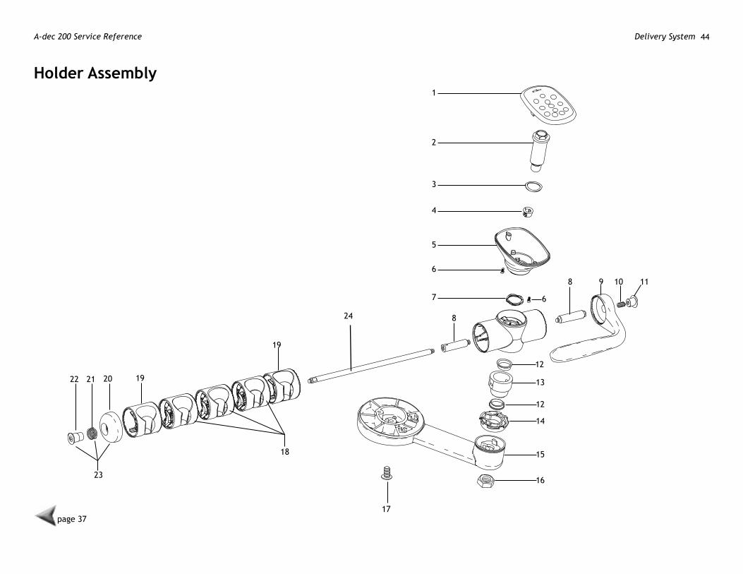
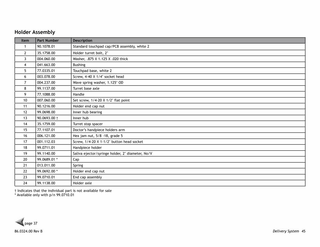
holder AssemblyItem Part number Description
1 90.1078.01 Standard touchpad cap/PCB assembly, white 2
2 35.1758.00 Holder turret bolt, 2"
3 004.060.00 Washer, .875 X 1.125 X .020 thick
4 041.663.00 Bushing
5 77.0335.01 Touchpad base, white 2
6 003.078.00 Screw, 4-40 X 1/4" socket head
7 004.237.00 Wave spring washer, 1.125" OD
8 99.1137.00 Turret base axle
9 77.1088.00 Handle
10 007.060.00 Set screw, 1/4-20 X 1/2" flat point
11 90.1216.00 Holder end cap nut
12 99.0698.00 Inner hub bearing
13 90.0693.00 † Inner hub
14 35.1759.00 Turret stop spacer
15 77.1107.01 Doctor’s handpiece holders arm
16 006.121.00 Hex jam nut, 5/8 -18, grade 5
17 001.112.03 Screw, 1/4-20 X 1-1/2" button head socket
18 99.0711.01 Handpiece holder
19 99.1140.00 Saliva ejector/syringe holder, 2" diameter, No/V
20 99.0689.01 * Cap
21 013.011.00 Spring
22 99.0692.00 * Holder end cap nut
23 99.0710.01 End cap assembly
24 99.1138.00 Holder axle
† Indicates that the individual part is not available for sale* Available only with p/n 99.0710.01
page 37
A-dec 200 Service Reference Delivery System 46
page 37
1 2 3 4
5
6
8
7
9
10
11
12
13
14
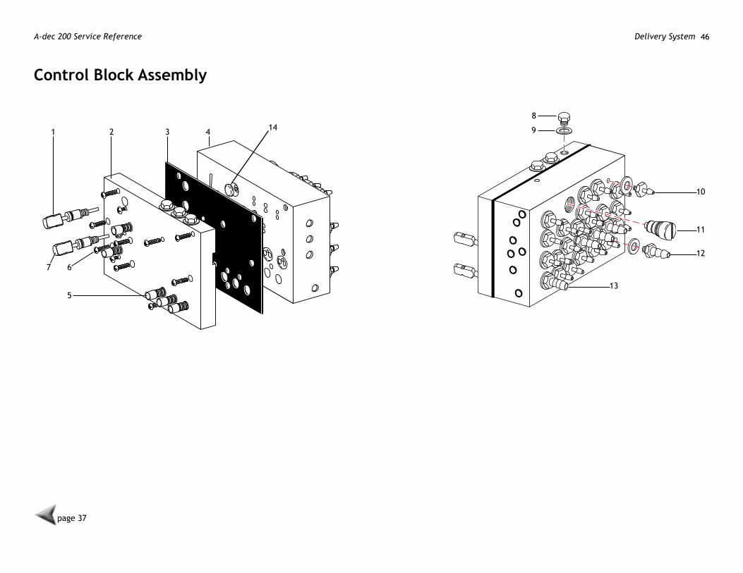
Control Block Assembly

86.0324.00 Rev B 47Delivery System
page 37
Control Block AssemblyItem Part number Description
1 38.0712.00 Water coolant stem (with O-ring)
2 38.0710.00 † Block cap
3 38.0711.01 Diaphragm, package of 5
4 38.1839.00 Control block assembly (with barbs)
5 38.0766.02 Flow control screw, package of 5
6 001.021.00 Screw
7 38.0713.00 Air coolant stem (with O-ring)
8 021.016.04 Plug, package of 10
9 004.005.02 Washer, package of 10
10 023.004.03 Barb, 1/8", package of 10
11 38.0717.00* Water cartridge
12 023.001.03 Barb, 1/4", package of 10
13 023.805.01 Barb, 5/16", package of 10
14 38.0718.00 Actuator
† Indicates that the individual part is not available for sale* p/n 38.1775.00 is the service kit for the water cartridge
A-dec 200 Service Reference Delivery System 48
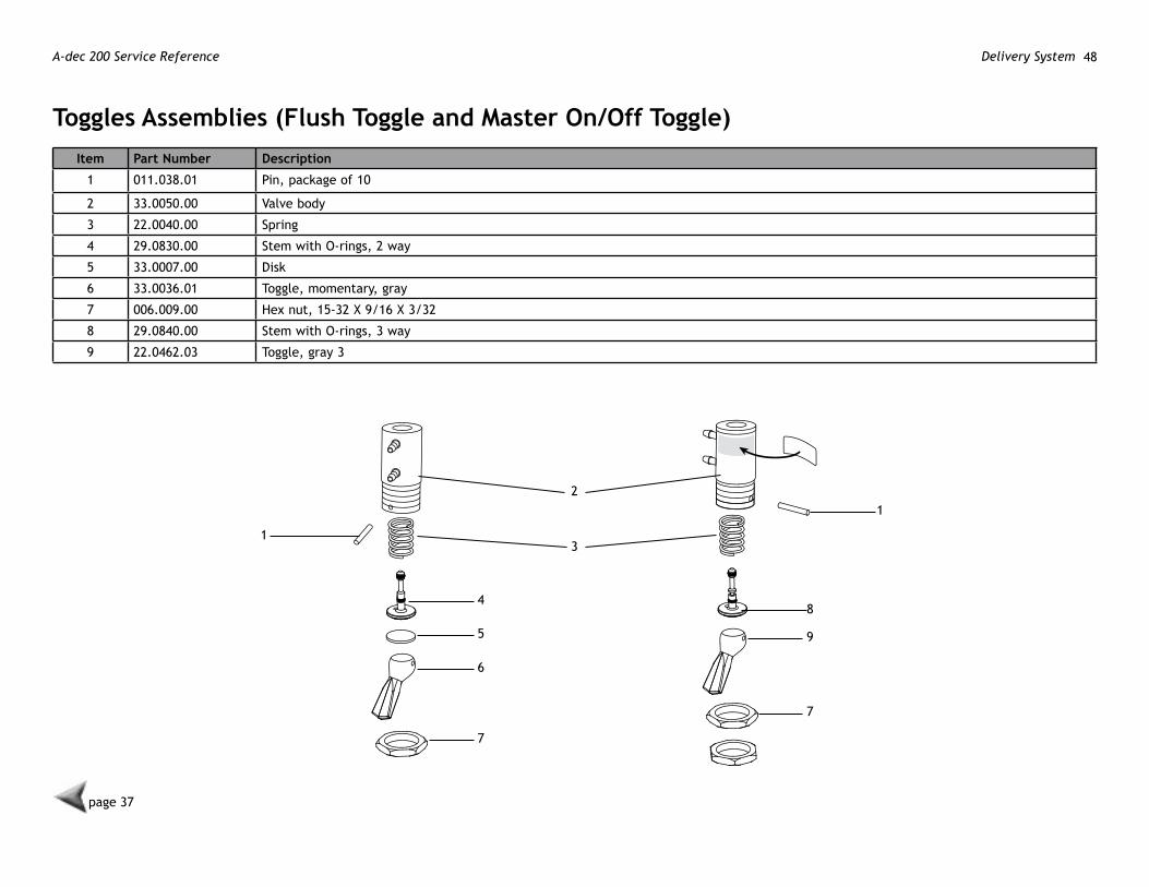
Toggles Assemblies (Flush Toggle and master on/off Toggle)Item Part number Description
1 011.038.01 Pin, package of 10
2 33.0050.00 Valve body
3 22.0040.00 Spring
4 29.0830.00 Stem with O-rings, 2 way
5 33.0007.00 Disk
6 33.0036.01 Toggle, momentary, gray
7 006.009.00 Hex nut, 15-32 X 9/16 X 3/32
8 29.0840.00 Stem with O-rings, 3 way
9 22.0462.03 Toggle, gray 3
1
21
3
4
5
6
7
7
9
8
page 37
86.0324.00 Rev B 49Delivery System
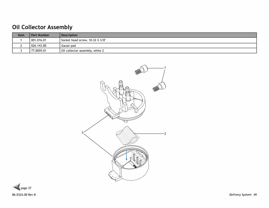
oil Collector AssemblyItem Part number Description
1 001.016.01 Socket head screw, 10-32 X 3/8"
2 026.143.00 Gauze pad
3 77.0059.01 Oil collector assembly, white 2
1
23
page 37

A-dec 200 Service Reference Delivery System 50
SyringeItem Part number Description
1 23.1320.00 Syringe
2 23.0872.01 A-dec syringe tip, package of 5
3 23.1208.01 3-Hole tubing assembly, 7' Gray 3
1 2
3
page 37
86.0324.00 Rev B 51Delivery System
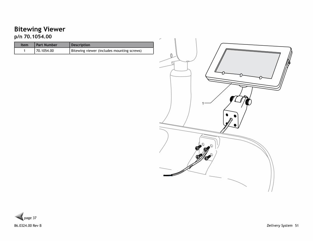
Bitewing viewerp/n 70.1054.00
Item Part number Description
1 70.1054.00 Bitewing viewer (includes mounting screws)
1
page 37

A-dec 200 Service Reference Delivery System 52
Foot Control Assemblyp/n 38.1842.00
page 37
p/n 90.1352.00, foot control repair kit
86.0324.00 Rev B 53Delivery System
page 37
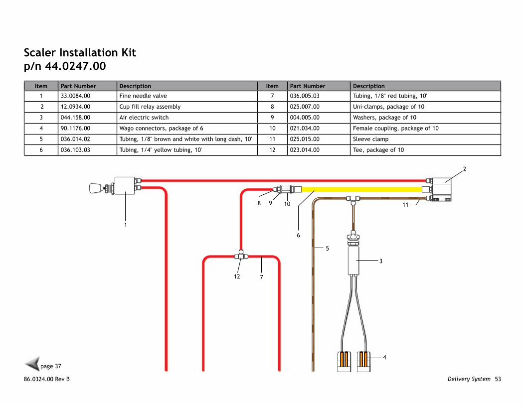
Scaler Installation kitp/n 44.0247.00
Item Part number Description Item Part number Description
1 33.0084.00 Fine needle valve 7 036.005.03 Tubing, 1/8" red tubing, 10'
2 12.0934.00 Cup fill relay assembly 8 025.007.00 Uni-clamps, package of 10
3 044.158.00 Air electric switch 9 004.005.00 Washers, package of 10
4 90.1176.00 Wago connectors, package of 6 10 021.034.00 Female coupling, package of 10
5 036.014.02 Tubing, 1/8" brown and white with long dash, 10' 11 025.015.00 Sleeve clamp
6 036.103.03 Tubing, 1/4" yellow tubing, 10' 12 023.014.00 Tee, package of 10
1
2
3
4
5
6
7
8 9 10 11
12

A-dec 200 Service Reference Delivery System 54
86.0324.00 Rev B 55Support Center
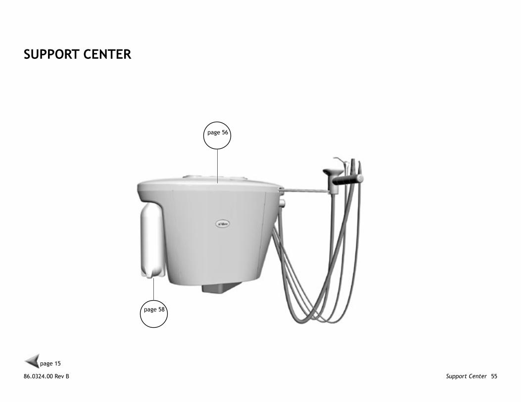
SUPPoRT CenTeR
page 56
page 58
page 15
A-dec 200 Service Reference Support Center 56
page 55
1
23
4 5
6
7
89
10
11
12
13
14
15
7
16
17
18 19 20 21
9
23
24
25
26
22
page 65
page 70
page 58
page 68
A-dec 200 Support Center Assembly
86.0324.00 Rev B 57Support Center
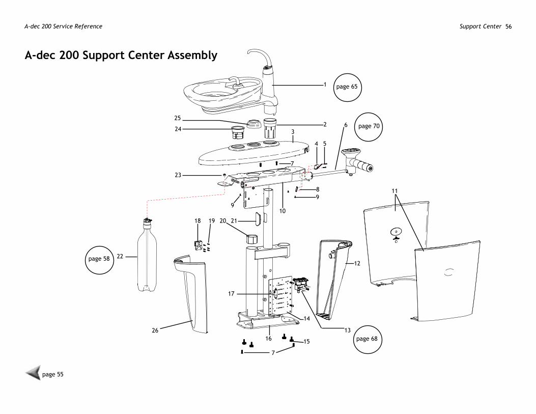
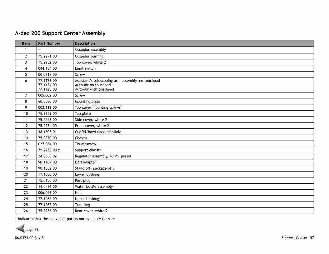
A-dec 200 Support Center Assembly
Item Part number Description
1 — Cuspidor assembly
2 75.2271.00 Cuspidor bushing
3 75.2252.00 Top cover, white 2
4 044.184.00 Limit switch
5 001.218.00 Screw
6 77.1123.0077.1124.0077.1125.00
Assistant’s telescoping arm assembly, no touchpadAuto-air no touchpadAuto-air with touchpad
7 005.002.00 Screw
8 60.0080.00 Mounting plate
9 003.112.00 Top cover mounting screws
10 75.2259.00 Top plate
11 75.2253.00 Side cover, white 2
12 75.2254.00 Front cover, white 2
13 38.1803.01 Cupfill/bowl rinse manifold
14 75.2270.00 Chassis
15 027.064.00 Thumbscrew
16 75.2258.00 † Support chassis
17 24.0388.02 Regulator assembly, 40 PSI preset
18 90.1167.00 CAN adapter
19 90.1082.00 Stand off, package of 5
20 77.1086.00 Lower bushing
21 75.0150.00 Post plug
22 14.0486.00 Water bottle assembly
23 006.052.00 Nut
24 77.1085.00 Upper bushing
25 77.1087.00 Trim ring
26 75.2255.00 Rear cover, white 2
† Indicates that the individual part is not available for sale
page 55
A-dec 200 Service Reference Support Center 58
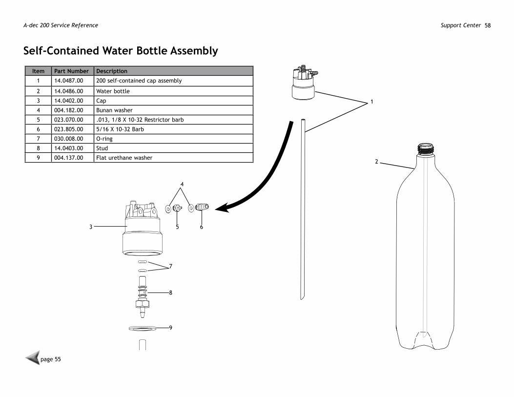
Self-Contained water Bottle Assembly
Item Part number Description
1 14.0487.00 200 self-contained cap assembly
2 14.0486.00 Water bottle
3 14.0402.00 Cap
4 004.182.00 Bunan washer
5 023.070.00 .013, 1/8 X 10-32 Restrictor barb
6 023.805.00 5/16 X 10-32 Barb
7 030.008.00 O-ring
8 14.0403.00 Stud
9 004.137.00 Flat urethane washer
1
2
page 55
3
4
5 6
7
8
9

86.0324.00 Rev B 59Support Center

A-dec 200 Service Reference Support Center 60
1
2
Air vacuum System Assembly
To vacuum Canister
To Cuspidor3
14
3
2
10
6
5
7
8
9
12
page 37
13
11
11 13
13
14
4
86.0324.00 Rev B 61Support Center
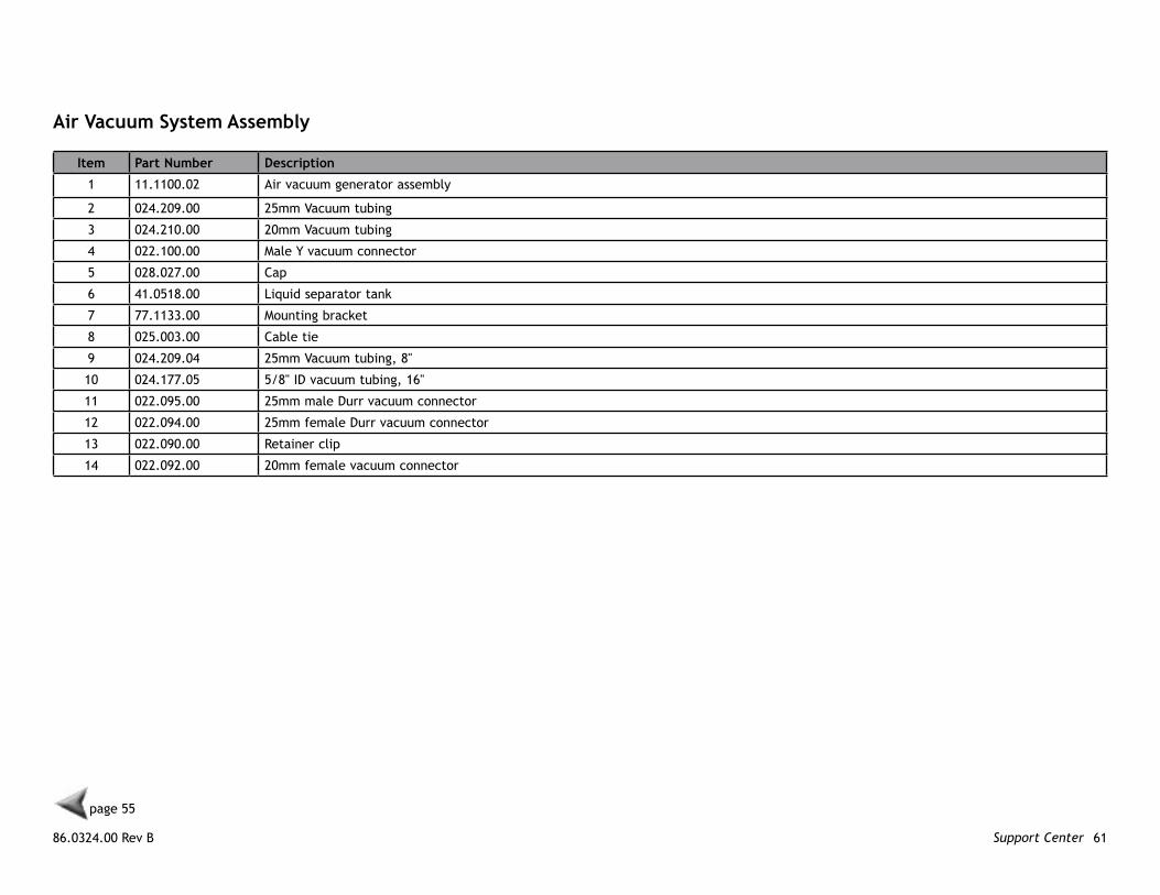
Air vacuum System Assembly
Item Part number Description
1 11.1100.02 Air vacuum generator assembly
2 024.209.00 25mm Vacuum tubing
3 024.210.00 20mm Vacuum tubing
4 022.100.00 Male Y vacuum connector
5 028.027.00 Cap
6 41.0518.00 Liquid separator tank
7 77.1133.00 Mounting bracket
8 025.003.00 Cable tie
9 024.209.04 25mm Vacuum tubing, 8"
10 024.177.05 5/8" ID vacuum tubing, 16"
11 022.095.00 25mm male Durr vacuum connector
12 022.094.00 25mm female Durr vacuum connector
13 022.090.00 Retainer clip
14 022.092.00 20mm female vacuum connector
page 55
A-dec 200 Service Reference Support Center 62
1
2
20
1514
Air vacuum generator Assembly
3
4
5
19
18
18
6
7
8
9
10
11
12
2
17
16
13
13
page 55
86.0324.00 Rev B 63Support Center
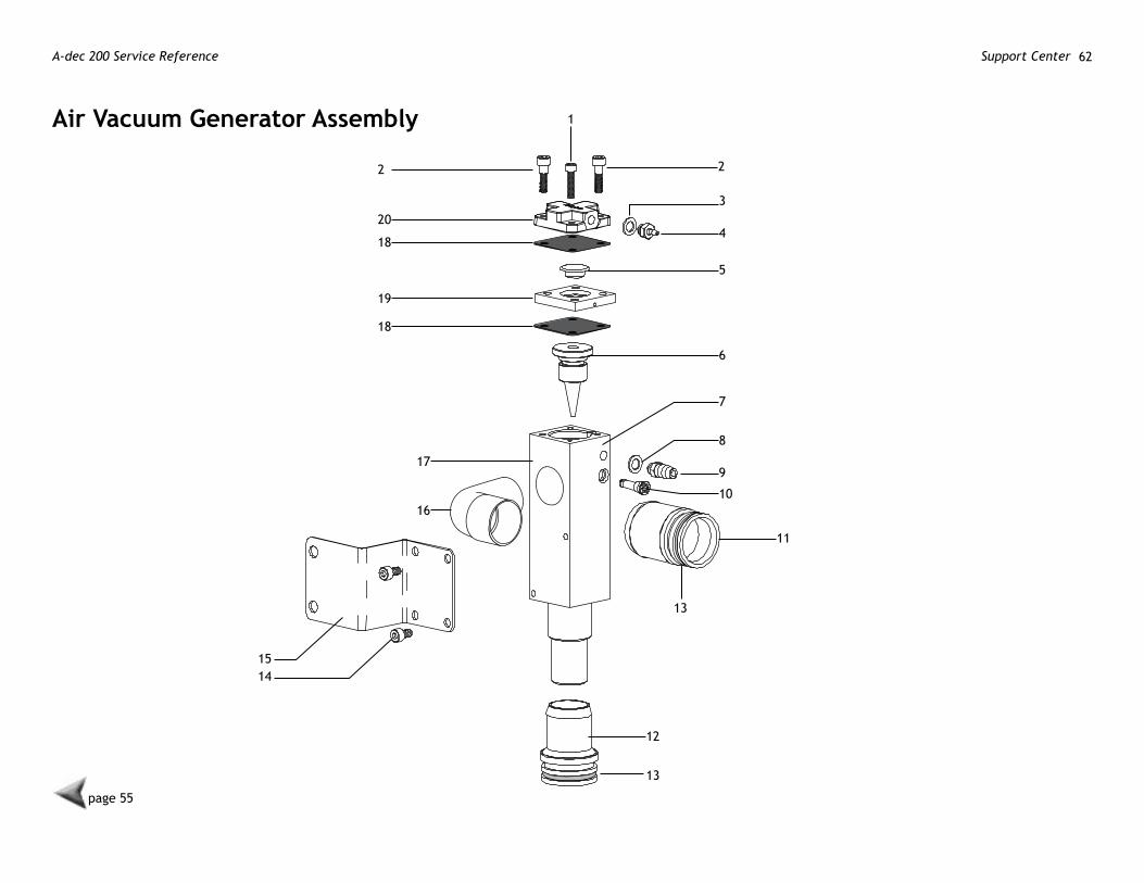
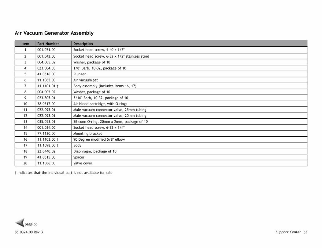
Air vacuum generator Assembly
Item Part number Description
1 001.021.00 Socket head screw, 4-40 x 1/2"
2 001.042.00 Socket head screw, 6-32 x 1/2" stainless steel
3 004.005.02 Washer, package of 10
4 023.004.03 1/8" Barb, 10-32, package of 10
5 41.0516.00 Plunger
6 11.1085.00 Air vacuum jet
7 11.1101.01 † Body assembly (includes items 16, 17)
8 004.005.02 Washer, package of 10
9 023.805.01 5/16" Barb, 10-32, package of 10
10 38.0517.00 Air bleed cartridge, with O-rings
11 022.095.01 Male vacuum connector valve, 25mm tubing
12 022.093.01 Male vacuum connector valve, 20mm tubing
13 035.053.01 Silicone O-ring, 20mm x 2mm, package of 10
14 001.034.00 Socket head screw, 6-32 x 1/4"
15 77.1130.00 Mounting bracket
16 11.1103.00 † 90 Degree modified 5/8" elbow
17 11.1098.00 † Body
18 22.0440.02 Diaphragm, package of 10
19 41.0515.00 Spacer
20 11.1086.00 Valve cover
page 55
† Indicates that the individual part is not available for sale

A-dec 200 Service Reference Support Center 64
86.0324.00 Rev B 65Cuspidor
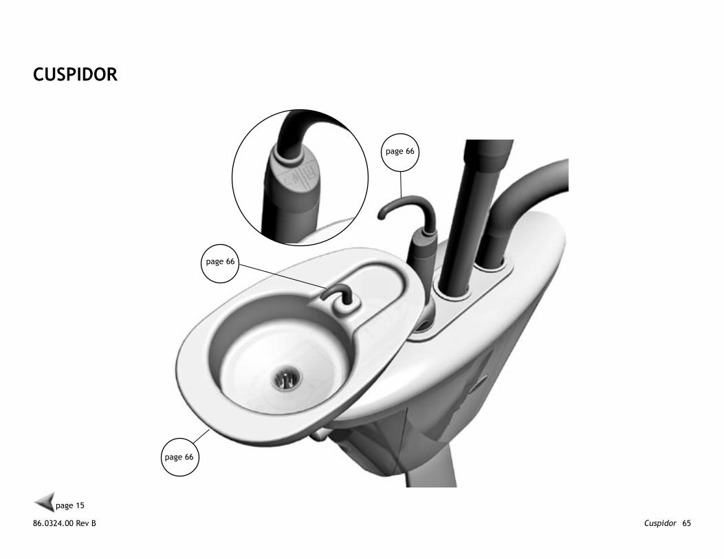
CUSPIDoR
page 66
page 15
page 66
page 66
A-dec 200 Service Reference Cuspidor 66
page 65
1 2
34
5
6
7 8
9
10
11
12
13
14
15
1617
18
19
20
15
21
22
23
24
2827
2625
29
30
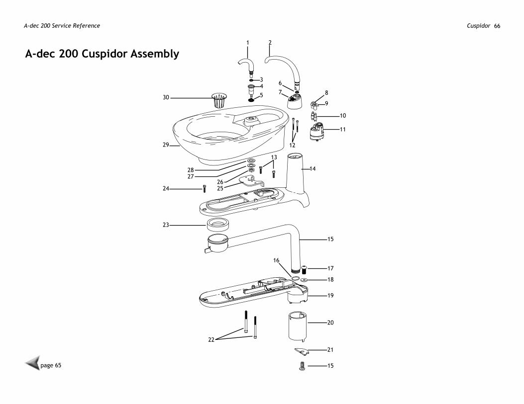
A-dec 200 Cuspidor Assembly
86.0324.00 Rev B 67Cuspidor
page 65
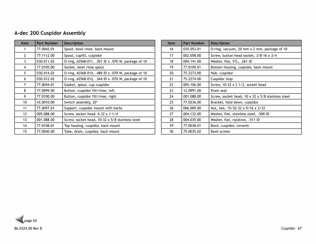
A-dec 200 Cuspidor Assembly
Item Part number Description
1 77.0042.01 Spout, bowl rinse, back mount
2 77.1112.00 Spout, cupfill, cuspidor
3 030.011.02 O-ring, AS568-011, .301 ID x .070 W, package of 10
4 77.0105.00 Socket, bowl rinse spout
5 030.014.02 O-ring, AS568-014, .489 ID x .070 W, package of 10
6 030.012.02 O-ring, AS568-012, .364 ID x .070 W, package of 10
7 77.0044.01 Gasket, spout, cup cuspidor
8 77.0099.00 Button, cuspidor fill/rinse, left
9 77.0100.00 Button, cuspidor fill/rinse, right
10 43.0010.00 Switch assembly, 20"
11 77.0097.01 Support, cuspidor mount with barbs
12 005.088.00 Screw, socket head, 6-32 x 1-1/4
13 001.088.00 Screw, socket head, 10-32 x 5/8 stainless steel
14 77.0108.01 Top housing, cuspidor, back mount
15 77.0040.00 Tube, drain, cuspidor, back mount
Item Part number Description
16 035.053.01 O-ring, vacuum, 20 mm x 2 mm, package of 10
17 002.058.00 Screw, button head socket, 3/8-16 x 3/4
18 004.141.00 Washer, flat, STL, .261 ID
19 77.0109.01 Bottom housing, cuspidor, back mount
20 75.2273.00 Hub, cuspidor
21 75.2274.00 Cuspidor stop
22 005.106.00 Screw, 10-32 x 2 1/2, socket head
23 12.0991.00 Drain seal
24 001.088.00 Screw, socket head, 10 x 32 x 5/8 stainless steel
25 77.0236.00 Bracket, hold down, cuspidor
26 006.009.00 Nut, hex, 15/32-32 x 9/16 x 3/32
27 004.132.00 Washer, flat, stainless steel, .500 ID
28 004.035.00 Washer, flat, nylatron, .511 ID
29 77.0038.01 Bowl, cuspidor, ceramic
30 75.0035.02 Bowl screen
A-dec 200 Service Reference Cuspidor 68
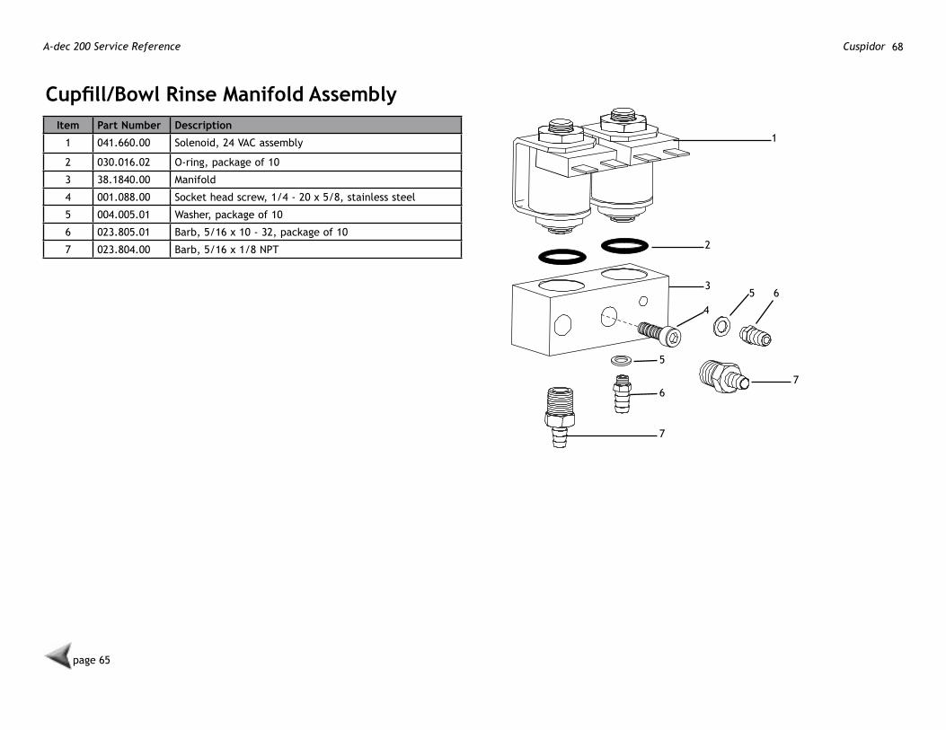
Cupfill/Bowl Rinse Manifold AssemblyItem Part number Description
1 041.660.00 Solenoid, 24 VAC assembly
2 030.016.02 O-ring, package of 10
3 38.1840.00 Manifold
4 001.088.00 Socket head screw, 1/4 - 20 x 5/8, stainless steel
5 004.005.01 Washer, package of 10
6 023.805.01 Barb, 5/16 x 10 - 32, package of 10
7 023.804.00 Barb, 5/16 x 1/8 NPT
1
2
35 6
7
4
5
6
7
page 65
86.0324.00 Rev B 69Assistant's Instrumentation
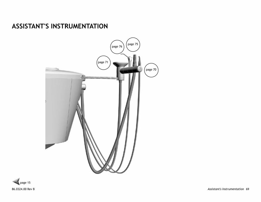
ASSISTAnT'S InSTRUmenTATIon
page 70
page 71
page 15
page 75page 76

A-dec 200 Service Reference Assistant's Instrumentation 70
Assistant's Telescoping Arm Assemblyp/n 77.1122.00*
Item Part number Description Item Part number Description
1 75.0018.00 Assistant’s arm slide 7 77.1082.00 Assistant’s arm rod
2 018.005.00 Grommet, 1/4 ID x .38 groove 8 002.080.01 Socket head screw, 1/4-20 x 3/4
3 77.1081.00 Telescoping arm 9 001.134.00 Socket shoulder screw, 5/16-18 x 3/8 x 2
4 001.167.00 Button head socket screw, 6-32 x 3/8, stainless steel 10 011.099.00 Pin dowel, .187 dia x 1.00 lg
5 006.040.00 Retainer nut, 6-32 11 006.132.00 Nut, lock, 5/16-18 x 1/2 x .275
6 75.0019.01 End cap 12 024.152.01 Convolute tubing, 5/8 ID - 4" long
1
2 3 4 5 6
4
910
11
12
7 8
page 72page 74
page 69
* 77.1122.00
86.0324.00 Rev B 71Assistant's Instrumentation
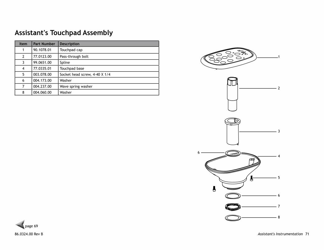
Assistant's Touchpad AssemblyItem Part number Description
1 90.1078.01 Touchpad cap
2 77.0123.00 Pass-through bolt
3 99.0651.00 Spline
4 77.0335.01 Touchpad base
5 003.078.00 Socket head screw, 4-40 X 1/4
6 004.173.00 Washer
7 004.237.00 Wave spring washer
8 004.060.00 Washer
1
2
3
4
5
6
7
8
6
page 69
A-dec 200 Service Reference Assistant's Instrumentation 72
page 69
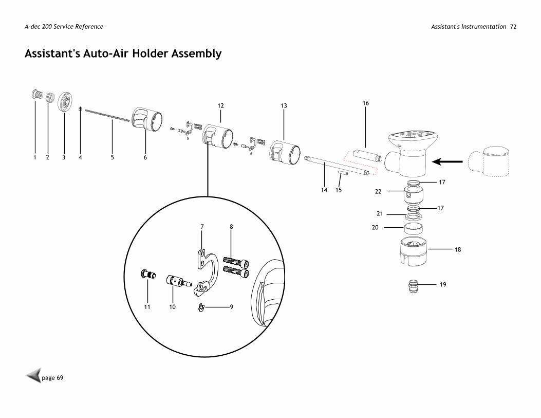
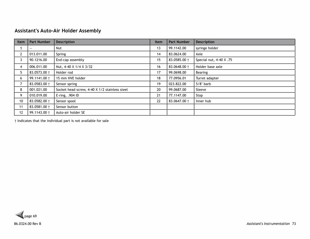
Assistant's Auto-Air holder Assembly
1 2 3 4 5 6
12 13
14 15
16
17
22
17
18
19
21
7 8
91011
20
86.0324.00 Rev B 73Assistant's Instrumentation
Assistant's Auto-Air holder Assembly
† Indicates that the individual part is not available for sale
page 69
Item Part number Description Item Part number Description
1 — Nut 13 99.1142.00 syringe holder
2 013.011.00 Spring 14 83.0624.00 Axle
3 90.1216.00 End-cap assembly 15 83.0585.00 † Special nut, 4-40 X .75
4 006.011.00 Nut, 4-40 X 1/4 X 3/32 16 83.0648.00 † Holder base axle
5 83.0573.00 † Holder rod 17 99.0698.00 Bearing
6 99.1141.00 † 15 mm HVE holder 18 77.0956.01 Turret adapter
7 83.0583.00 † Sensor spring 19 023.822.00 5/8" barb
8 001.021.00 Socket head screw, 4-40 X 1/2 stainless steel 20 99.0687.00 Sleeve
9 010.019.00 E-ring, .904 ID 21 77.1147.00 Stop
10 83.0582.00 † Sensor spool 22 83.0647.00 † Inner hub
11 83.0581.00 † Sensor button
12 99.1143.00 † Auto-air holder SE
A-dec 200 Service Reference Assistant's Instrumentation 74
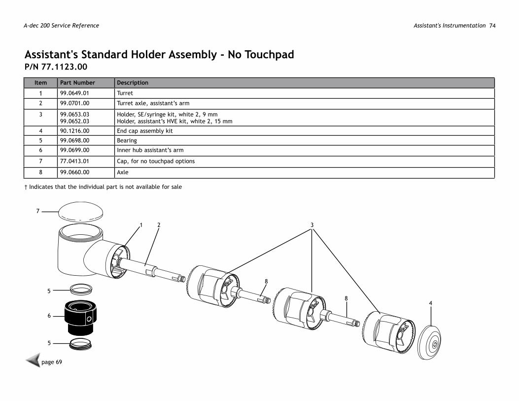
Assistant's Standard holder Assembly - no TouchpadP/n 77.1123.00
Item Part number Description
1 99.0649.01 Turret
2 99.0701.00 Turret axle, assistant’s arm
3 99.0653.0399.0652.03
Holder, SE/syringe kit, white 2, 9 mmHolder, assistant’s HVE kit, white 2, 15 mm
4 90.1216.00 End cap assembly kit
5 99.0698.00 Bearing
6 99.0699.00 Inner hub assistant’s arm
7 77.0413.01 Cap, for no touchpad options
8 99.0660.00 Axle
† Indicates that the individual part is not available for sale
21 3
48
8
5
6
5
page 69
7
86.0324.00 Rev B 75Assistant's Instrumentation
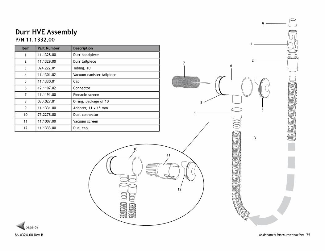
Durr hve AssemblyP/n 11.1332.00
Item Part number Description
1 11.1328.00 Durr handpiece
2 11.1329.00 Durr tailpiece
3 024.222.01 Tubing, 10'
4 11.1301.02 Vacuum canister tailpiece
5 11.1330.01 Cap
6 12.1107.02 Connector
7 11.1191.00 Pinnacle screen
8 030.027.01 0-ring, package of 10
9 11.1331.00 Adapter, 11 x 15 mm
10 75.2278.00 Dual connector
11 11.1007.00 Vacuum screen
12 11.1333.00 Dual cap
1
2
3
4
page 69
5
67
8
9
10
11
12
A-dec 200 Service Reference Assistant's Instrumentation 76
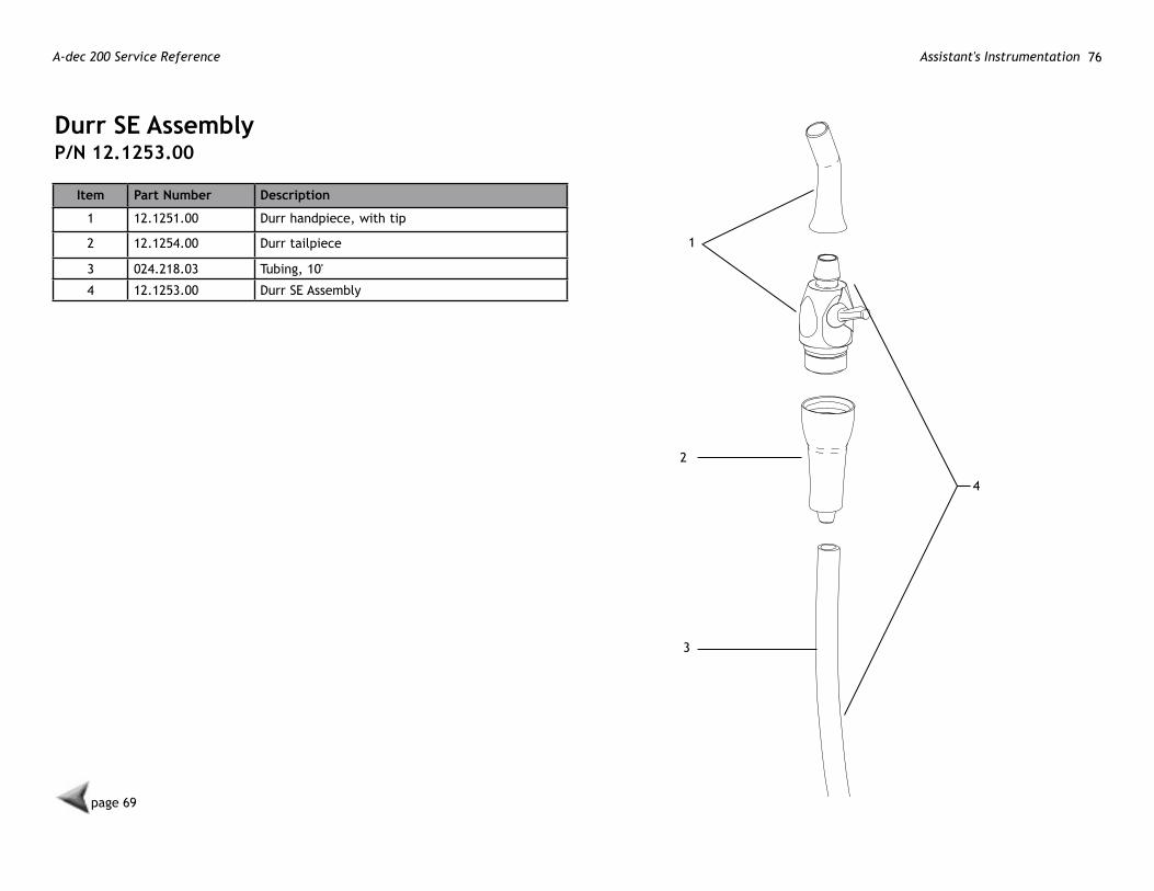
Durr Se AssemblyP/n 12.1253.00
Item Part number Description
1 12.1251.00 Durr handpiece, with tip
2 12.1254.00 Durr tailpiece
3 024.218.03 Tubing, 10'
4 12.1253.00 Durr SE Assembly
1
2
3
page 69
4
86.0324.00 Rev B 77Dental Lights
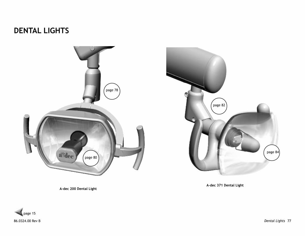
DenTAl lIghTS
A-dec 200 Dental light
page 78
page 80
A-dec 371 Dental light
page 82
page 84
page 15

A-dec 200 Service Reference Dental Lights 78
page 77
1
23
4
5
67
9
8
10
page 80
A-dec 200 Dental light Assembly

86.0324.00 Rev B 79Dental Lights
page 77
A-dec 200 Dental light Assembly
Item Part number Description
1 003.099.00 Phillips head screw, 6-19 X 1/2"
2 75.0009.01 Rear end cap
3 28.1027.05 Top cover
4 28.1953.00 Flexarm assembly - DO NOT DISASSEMBLE
5 75.0008.01 Front end cap
6 — A-dec 200 dental light head assembly
7 28.1821.00 Rigid arm
8 77.0824.00 Trim ring
9 12.0974.00 Bushing
10 28.1114.01 Upper trim ring

A-dec 200 Service Reference Dental Lights 80
A-dec 200 Dental light head AssemblyItem Part number Description
1 041.709.00 Bulb
2 97.0411.00 Shield
3 90.1304.00 Light switch kit
4 90.1309.00 Light socket kit
5 28.1956.00 Light hole plug
6 28.1950.00 Handle
2
1
3
4
page 77
5
6
6

86.0324.00 Rev B 81Dental Lights
A-dec 200 Service Reference Dental Lights 82
page 77
1
3
2
4
2
5
7
8
9
page 84 6
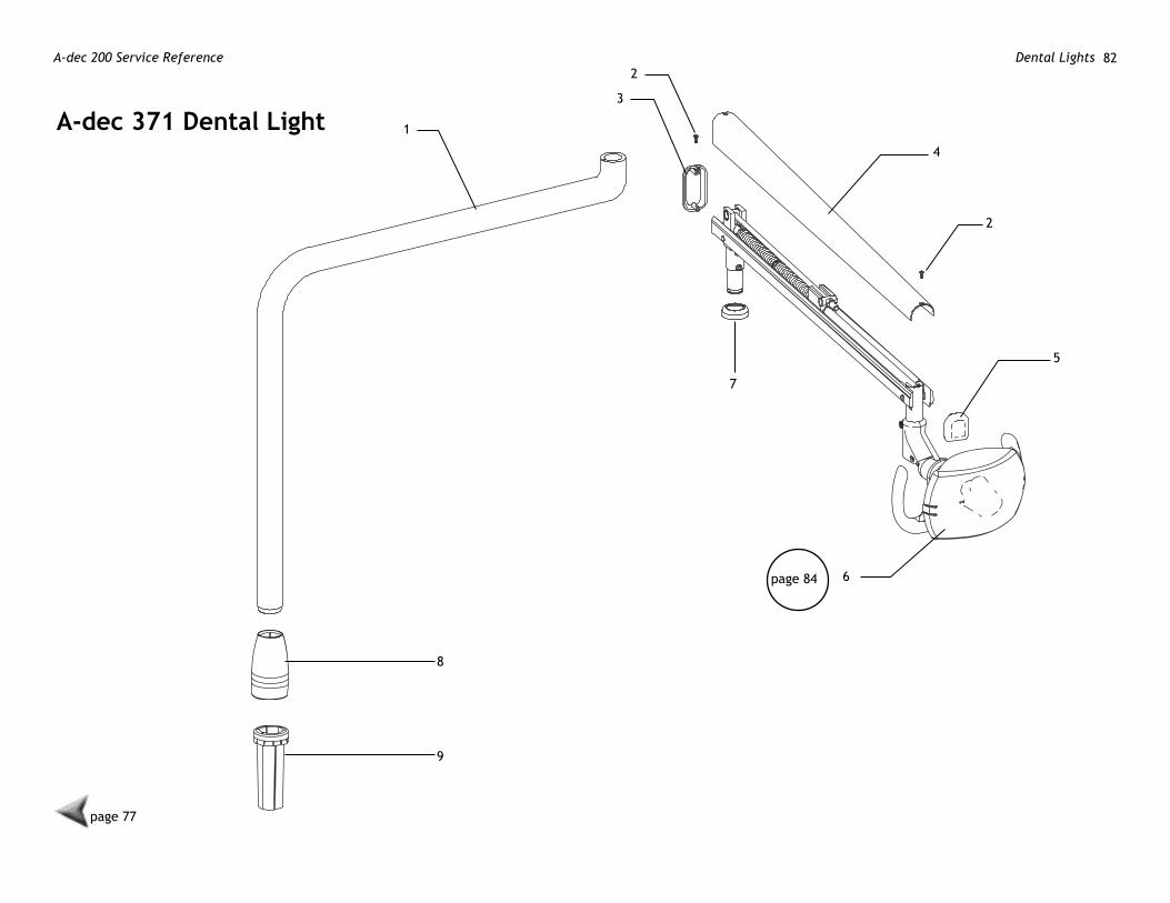
A-dec 371 Dental light
86.0324.00 Rev B 83Dental Lights
page 77
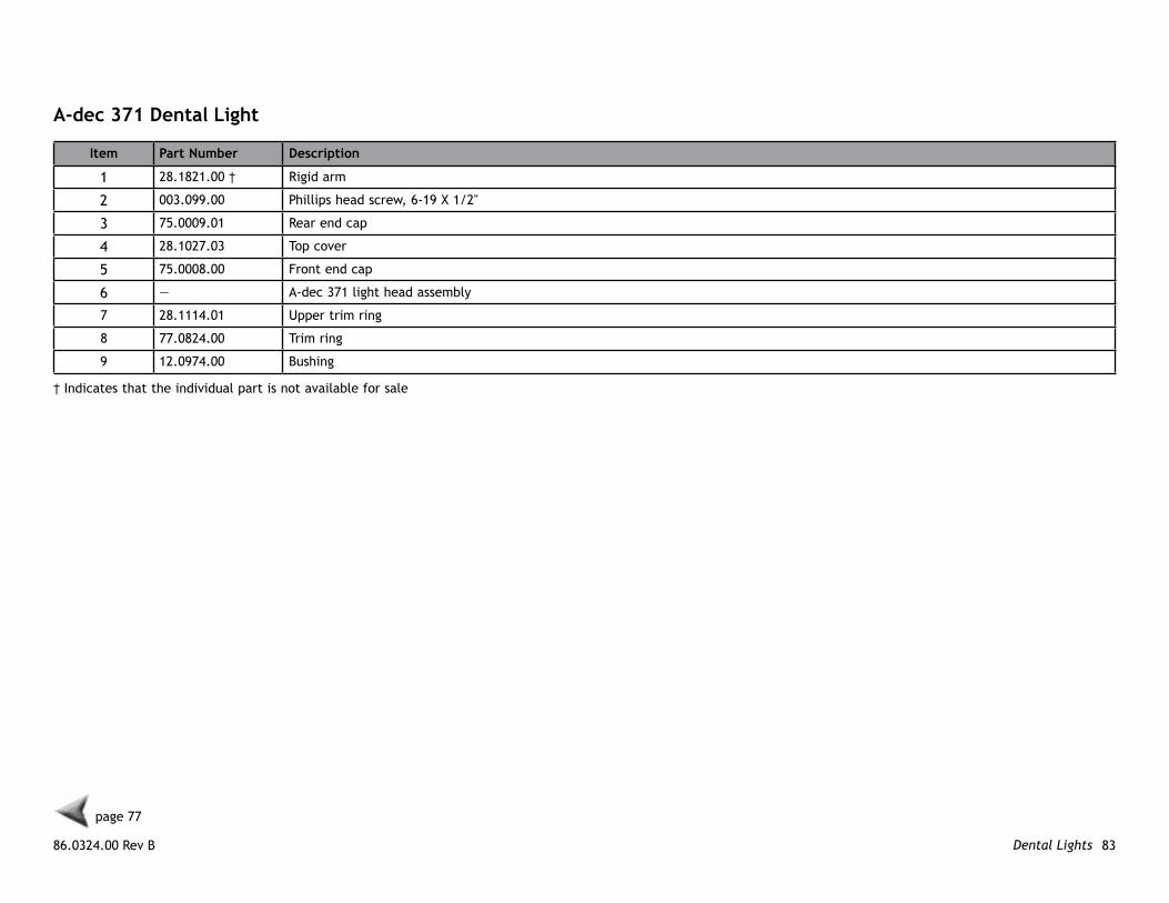
Item Part number Description
1 28.1821.00 † Rigid arm
2 003.099.00 Phillips head screw, 6-19 X 1/2"
3 75.0009.01 Rear end cap
4 28.1027.03 Top cover
5 75.0008.00 Front end cap
6 — A-dec 371 light head assembly
7 28.1114.01 Upper trim ring
8 77.0824.00 Trim ring
9 12.0974.00 Bushing
† Indicates that the individual part is not available for sale
A-dec 371 Dental light

A-dec 200 Service Reference Dental Lights 84
page 77
1
2
3
34
3
5
67
8
910
911
13
14
12
15
16
1718
17
1920 21
2223
24
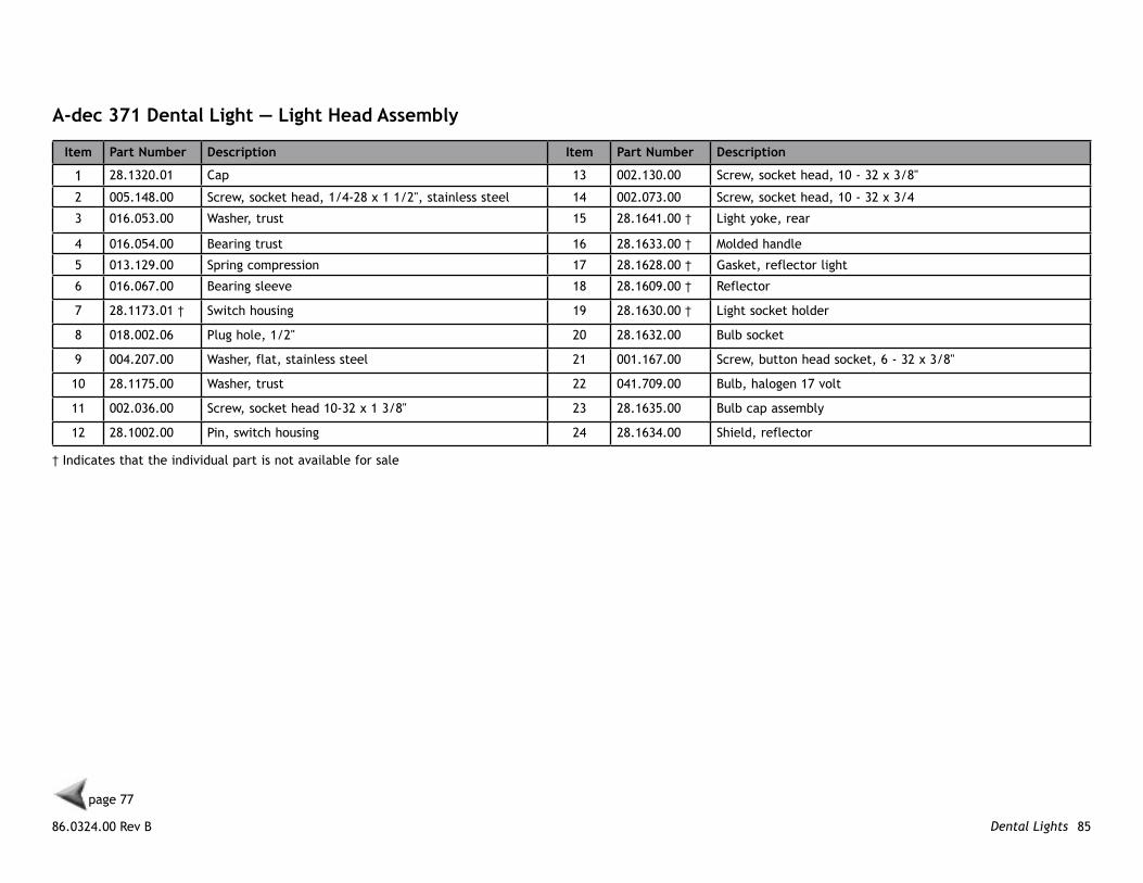
A-dec 371 Dental light — light head Assembly
86.0324.00 Rev B 85Dental Lights
page 77
Item Part number Description Item Part number Description
1 28.1320.01 Cap 13 002.130.00 Screw, socket head, 10 - 32 x 3/8"
2 005.148.00 Screw, socket head, 1/4-28 x 1 1/2", stainless steel 14 002.073.00 Screw, socket head, 10 - 32 x 3/4
3 016.053.00 Washer, trust 15 28.1641.00 † Light yoke, rear
4 016.054.00 Bearing trust 16 28.1633.00 † Molded handle
5 013.129.00 Spring compression 17 28.1628.00 † Gasket, reflector light
6 016.067.00 Bearing sleeve 18 28.1609.00 † Reflector
7 28.1173.01 † Switch housing 19 28.1630.00 † Light socket holder
8 018.002.06 Plug hole, 1/2" 20 28.1632.00 Bulb socket
9 004.207.00 Washer, flat, stainless steel 21 001.167.00 Screw, button head socket, 6 - 32 x 3/8"
10 28.1175.00 Washer, trust 22 041.709.00 Bulb, halogen 17 volt
11 002.036.00 Screw, socket head 10-32 x 1 3/8" 23 28.1635.00 Bulb cap assembly
12 28.1002.00 Pin, switch housing 24 28.1634.00 Shield, reflector
† Indicates that the individual part is not available for sale
A-dec 371 Dental light — light head Assembly

A-dec 200 Service Reference Dental Lights 86
86.0324.00 Rev A 87Utilities
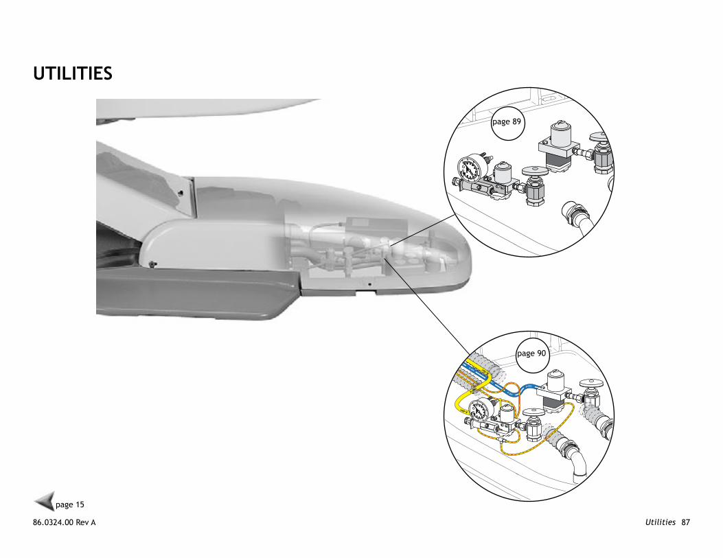
UTIlITIeS
page 15
page 90
page 89
A-dec 200 Service Reference Utilities 88
10AMP
10AMP
10AMP
10AMP
10AMP
1
2
3
page 91 4
5
6
page 92
page 87
page 95
78
9
86.0324.00 Rev B 89Utilities
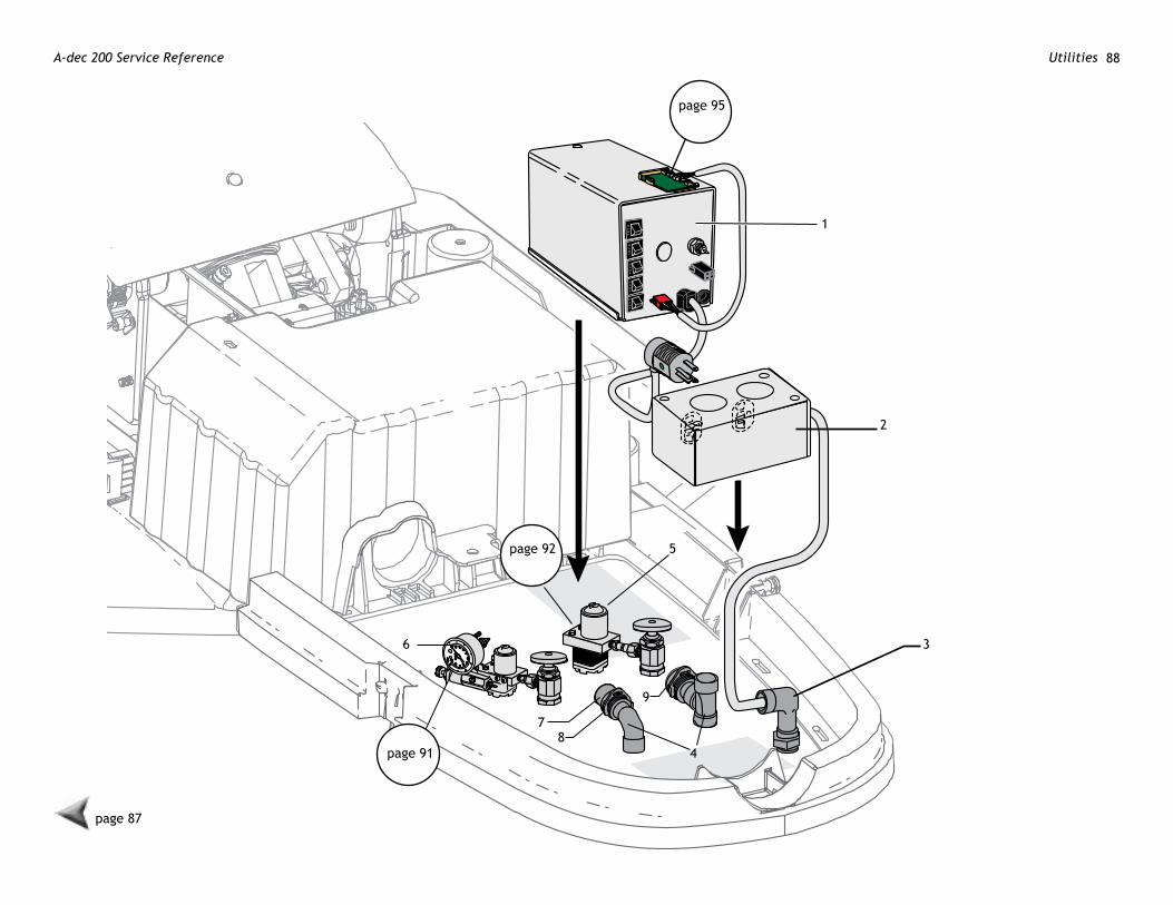
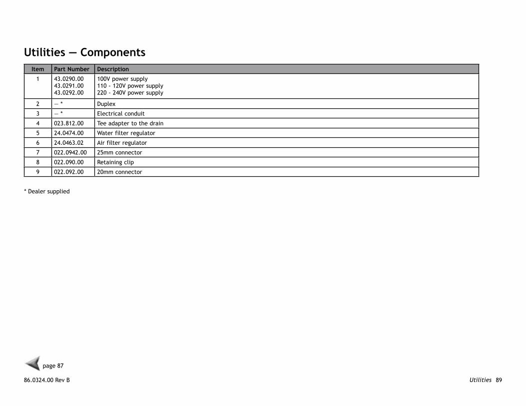
Utilities — ComponentsItem Part number Description
1 43.0290.0043.0291.0043.0292.00
100V power supply110 - 120V power supply220 - 240V power supply
2 — * Duplex
3 — * Electrical conduit
4 023.812.00 Tee adapter to the drain
5 24.0474.00 Water filter regulator
6 24.0463.02 Air filter regulator
7 022.0942.00 25mm connector
8 022.090.00 Retaining clip
9 022.092.00 20mm connector
page 87
* Dealer supplied
A-dec 200 Service Reference Utilities 90
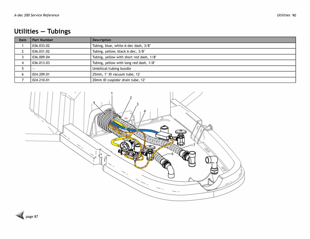
Utilities — TubingsItem Part number Description
1 036.033.02 Tubing, blue, white A-dec dash, 3/8"
2 036.031.02 Tubing, yellow, black A-dec, 3/8"
3 036.009.04 Tubing, yellow with short red dash, 1/8"
4 036.013.03 Tubing, yellow with long red dash, 1/8"
5 — Umbilical/tubing bundle
6 024.209.01 25mm, 1" ID vacuum tube, 12'
7 024.210.01 20mm ID cuspidor drain tube, 12'
3
4
21
5
page 87
7
6

86.0324.00 Rev B 91Utilities
Air filter/Regulator Assembly
p/n 24.0463.02Item Part number Description Item Part number Description
1 026.154.00 Gauge 12 22.0460.00 Spring
2 002.140.00 Button head socket patch screw, 6-32 X 1/4" 13 24.0132.00 Piston with O-ring
3 24.0365.00 Bracket 14 22.0440.02 Diaphragm, package of 10
4 24.0232.00 Stud, filter/regulator manifold 15 24.0368.00 Valve cover
5 24.0234.01 Filter, package of 6 16 004.005.02 Washer, flat nylon, 187 ID
6 030.019.03 O-ring, package of 10 17 023.004.01 Barb, 1/8 x 10-32
7 24.0229.00 Filter housing 18 001.026.00 Screw, socket head, 6-32 x 7/8"
8 021.042.00 Adapter 19 006.015.00 Nut, hex, 6-32 x 5/16 x 9/64"
9 24.0162.00 Manifold, filter/regulator 20 24.0182.81 Regulator, air assembly
10 24.0137.01 Gasket, 9-hole 21 006.009.00 Nut, hex, 15/32 - 32 x 9/16 x 3/32"
11 24.0135.00 Regulator, body, white 22 001.024.00 Socket head screw, 4-40 X 3/8"
1
2
3
4
5
6
7
8
9
1011
12
1314
15
1617
18
19
20
21
page 87 22

A-dec 200 Service Reference Utilities 92
water Filter/Regulator Body Assemblyp/n 24.0474.00
Item Part number Description
1 24.0229.00 Housing, filter
2 030.019.03 O-ring, package of 3
3 24.0234.02 Filter kit, package of 2
4 24.0232.00 Stud, filter/regulator manifold
5 021.016.04 Plug, hex head, 10 - 32
6 004.005.02 Washer
7 021.042.00 Adapter, 1/8" MPT to 3/8"
8 24.0137.01 9-hole gasket
9 24.0355.00 Body, black
10 013.032.00 Spring
11 24.0132.00 Piston with O-ring
12 24.0140.00 Spacer, water regulator
13 22.0440.02 Diaphragm, package of 10
14 023.004.01 Barb, 1/8" x 10-32
15 004.005.01 Washer, flat nylon 187 ID
16 24.0368.00 Valve cover
17 001.021.00 Screw, socket head, 4-40 x 1/2", stainless steel
18 001.024.00 Screw, socket head, 4-40 x 3/8", stainless steel
19 24.0142.00 Plunger
1
2
3
4
5
6
7
8
9
10
11
12
19
13
14
15
1617
18page 87
86.0324.00 Rev B 93Utilities
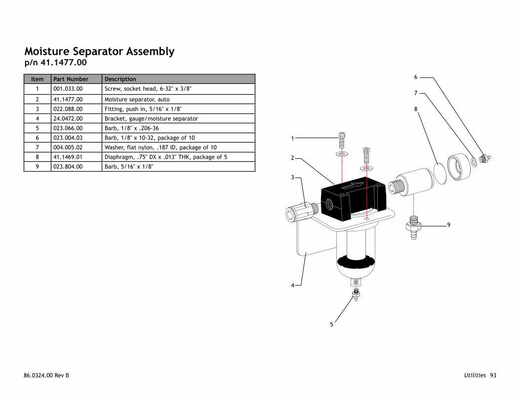
moisture Separator Assemblyp/n 41.1477.00
Item Part number Description
1 001.033.00 Screw, socket head, 6-32" x 3/8"
2 41.1477.00 Moisture separator, auto
3 022.088.00 Fitting, push in, 5/16" x 1/8"
4 24.0472.00 Bracket, gauge/moisture separator
5 023.066.00 Barb, 1/8" x .206-36
6 023.004.03 Barb, 1/8" x 10-32, package of 10
7 004.005.02 Washer, flat nylon, .187 ID, package of 10
8 41.1469.01 Diaphragm, .75" DX x .013" THK, package of 5
9 023.804.00 Barb, 5/16" x 1/8"
1
2
3
4
5
6
7
8
9

A-dec 200 Service Reference Utilities 94
86.0324.00 Rev B 95Diagnostics
DIAgnoSTICS
page 1
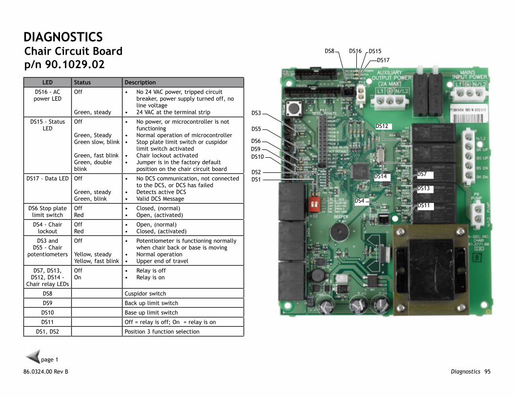
leD Status Description
DS16 - AC power LED
Off
Green, steady
• No 24 VAC power, tripped circuit breaker, power supply turned off, no line voltage
• 24 VAC at the terminal strip
DS15 - Status LED
Off
Green, SteadyGreen slow, blink
Green, fast blinkGreen, double blink
• No power, or microcontroller is not functioning
• Normal operation of microcontroller• Stop plate limit switch or cuspidor
limit switch activated• Chair lockout activated• Jumper is in the factory default
position on the chair circuit board
DS17 - Data LED Off
Green, steadyGreen, blink
• No DCS communication, not connected to the DCS, or DCS has failed
• Detects active DCS• Valid DCS Message
DS6 Stop plate limit switch
OffRed
• Closed, (normal)• Open, (activated)
DS4 - Chair lockout
OffRed
• Open, (normal)• Closed, (activated)
DS3 and DS5 - Chair
potentiometers
Off
Yellow, steadyYellow, fast blink
• Potentiometer is functioning normally when chair back or base is moving
• Normal operation• Upper end of travel
DS7, DS13, DS12, DS14 -
Chair relay LEDs
OffOn
• Relay is off• Relay is on
DS8 Cuspidor switch
DS9 Back up limit switch
DS10 Base up limit switch
DS11 Off = relay is off; On = relay is on
DS1, DS2 Position 3 function selection
Chair Circuit Boardp/n 90.1029.02
DS8 DS16 DS15
DS17
DS12
DS14 DS7
DS13
DS11DS4
DS3
DS5
DS6DS9DS10
DS1DS2

A-dec 200 Service Reference Diagnostics 96
QvIolS Circuit Boardp/n 90.1168.00
Item Description
1 DS1 AC Power LED
2 DS2 Status LED
3 DS3 Data LED
4 J1 - 24 VAC Input
5 J1 - 0VAC Input
6 DS4 - LED (displays as yellow when circuit board closed)
7 P1 Data Port
8 J3 Switch Input Common
9 J3 Switch Input #1
10 J2 Switch Input #2
11 J2 Switch Input #3
12 J2 Switch Input #4
13 J4 Light Source Output #1
14 J4 Light Source Output #2
15 J5 Light Source Output #3
16 J5 Light Source Output #4
17 S1 Decrease Lamp Output
18 S2 Increase Lamp Output
19 P2 Normally closed jumper
8
9
10
11
12
719
6 13 14 1516 5
4
17
18
3
2
1
page 1
86.0324.00 Rev B 97Diagnostics
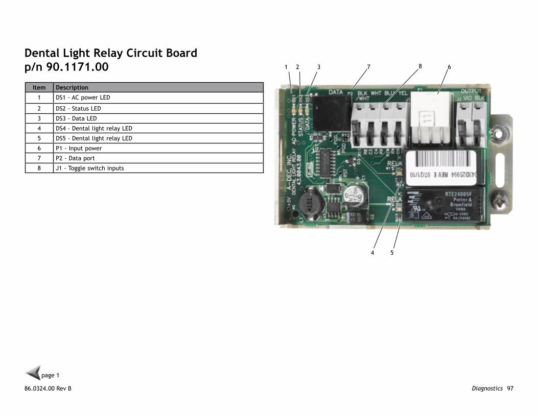
Dental light Relay Circuit Boardp/n 90.1171.00
Item Description
1 DS1 - AC power LED
2 DS2 - Status LED
3 DS3 - Data LED
4 DS4 - Dental light relay LED
5 DS5 - Dental light relay LED
6 P1 - Input power
7 P2 - Data port
8 J1 - Toggle switch inputs
page 1
1 2 3 7 8 6
4 5
A-dec 200 Service Reference Diagnostics 98
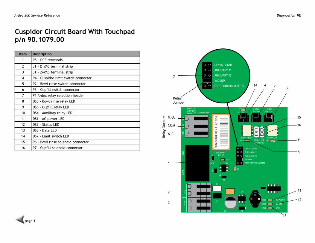
Cuspidor Circuit Board with Touchpadp/n 90.1079.00
Item Description
1 P5 - DCS terminals
2 J1 - Ø VAC terminal strip
3 J1 - 24VAC terminal strip
4 P4 - Cuspidor limit switch connector
5 P2 - Bowl rinse switch connector
6 P3 - Cupfill switch connector
7 P1 A-dec relay selection header
8 DS5 - Bowl rinse relay LED
9 DS6 - Cupfill relay LED
10 DS4 - Auxiliary relay LED
11 DS1 - AC power LED
12 DS2 - Status LED
13 DS3 - Data LED
14 DS7 - Limit switch LED
15 P6 - Bowl rinse solenoid connector
16 P7 - Cupfill solenoid connector
N.O.
Rela
y O
utpu
ts
COM
N.C.
7
Relay Jumper
1
2
3
14 4 56
15
16
9
8
11
12
13page 1
86.0324.00 Rev B 99Diagnostics
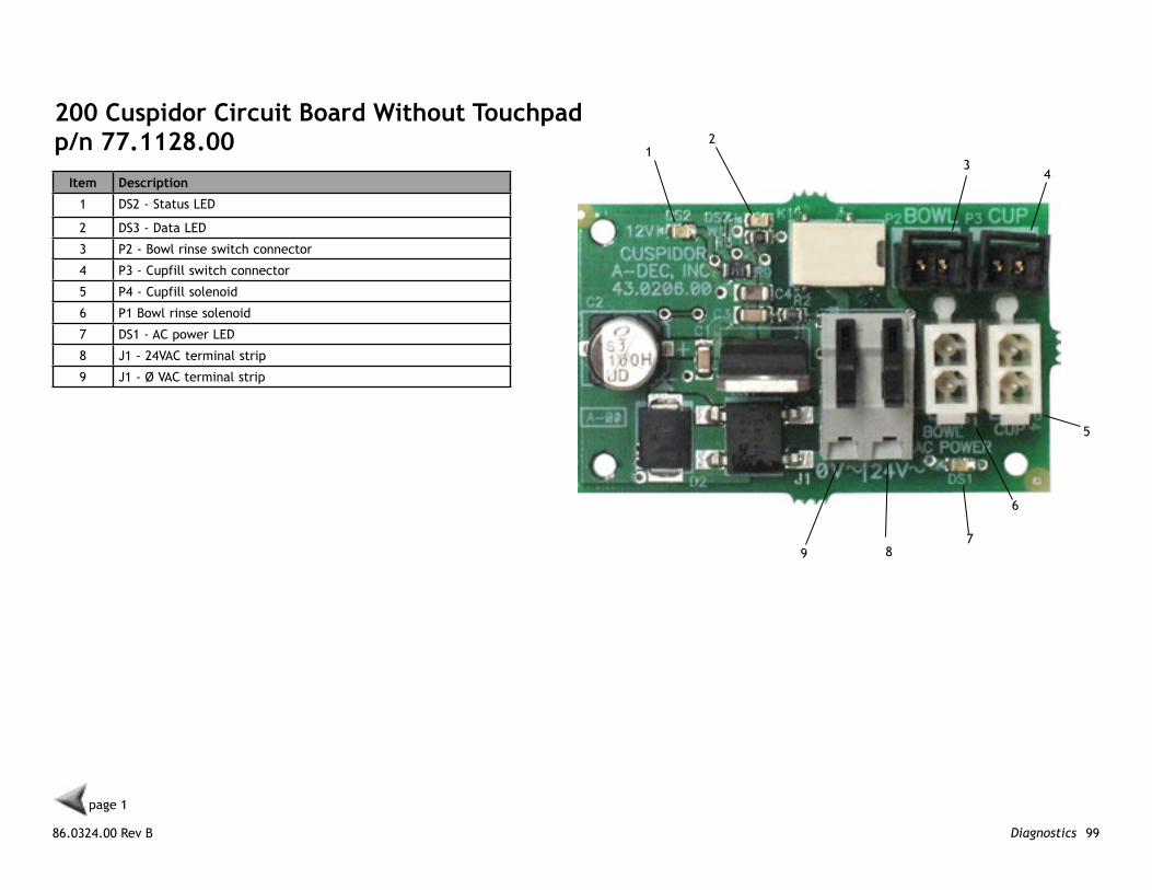
200 Cuspidor Circuit Board without Touchpadp/n 77.1128.00 1
2
79
34
6
5
8
Item Description
1 DS2 - Status LED
2 DS3 - Data LED
3 P2 - Bowl rinse switch connector
4 P3 - Cupfill switch connector
5 P4 - Cupfill solenoid
6 P1 Bowl rinse solenoid
7 DS1 - AC power LED
8 J1 - 24VAC terminal strip
9 J1 - Ø VAC terminal strip
page 1

A-dec 200 Service Reference Diagnostics100

86.0324.00 Rev BCopyright 2012 A-dec Inc.
All rights reserved.
A-dec headquarters2601 Crestview DriveNewberg, OR 97132 USATel: 1.800.547.1883 Within USA/CanadaTel: 1.503.538.7478 Outside USA/CanadaFax:1.503.538.0276www.a-dec.com
International Distribution Centers
A-dec United kingdomEU Authorized RepresentativeAustin House, 11 Liberty WayNuneaton, Warwickshire CV11 6RZEngland Tel: 0800 ADECUK (233285) Within UKTel: +44 (0) 24 7635 0901 Outside UKwww.a-dec.co.uk
A-dec AustraliaUnit 85-9 Ricketty StreetMascot, NSW 2020AustraliaTel: 1.800.225.010 Within AustraliaTel: +61 (0)2 8332 4000 Outside Australiawww.a-dec.com.au
ÍvÈ.Ç#8È.00LÎ