A Course Material on EC 2401- WIRLESS COMMUNICATION ...
148
A Course Material on EC 2401- WIRLESS COMMUNICATION By Mr. C. Sundar Rasu ASSISTANT PROFESSOR DEPARTMENT OF ELECTRONICS AND COMMUNICATION ENGINEERING SASURIE COLLEGE OF ENGINEERING VIJAYAMANGALAM – 638 056
-
Upload
khangminh22 -
Category
Documents
-
view
5 -
download
0
Transcript of A Course Material on EC 2401- WIRLESS COMMUNICATION ...

A Course Material on
EC 2401- WIRLESS COMMUNICATION
By
Mr. C. Sundar Rasu
ASSISTANT PROFESSOR
DEPARTMENT OF ELECTRONICS AND COMMUNICATION ENGINEERING
SASURIE COLLEGE OF ENGINEERING
VIJAYAMANGALAM – 638 056

QUALITY CERTIFICATE
This is to certify that the course material
Subject Code : EC 2401
Subject : Wireless communication
Class : IV Year ECE
Being prepared by me and it meets the knowledge requirement of the university curriculum.
Signature of the Author
Name : C.Sundar Rasu
Designation : Asst. Professor
This is to certify that the course material being prepared by Mr.C.Sundar Rasu is of adequatequality. He has referred more than five books among them minimum one is from abroad author.
Signature of HD
Name : Dr. K Pandiarajan
SEAL

UNIT I SERVICES AND TECHNICAL CHALLENGES 1-20
1.1 History 011.1.1 How It All Started
1.1.2 The First Systems
1.1.3 Analog Cellular Systems
1.1.4 GSM and the Worldwide Cellular Revolution
1.2 Types of service used in wireless communication 031.2.1 Broadcast
1.2.2 Paging
1.2.3 Cellular Telephony
1.2.4 Trunking Radio
1.2.5 Cordless Telephony
1.2.7 Personal Area Networks
1.2.8 Fixed Wireless Access
1.3 Requirement for the service 07
1.3.1 Data Rate
1.3.2 Range and Number of Users
1.3.3 Mobility
1.3.4 Energy Consumption
1.3.5 Use of Spectrum
1.3.6 Direction of Transmission
1.3.7 Service Quality
1.4 Principle of cellular networks 08
1.4.1 Reuse Distance
1.4.2 Cell shape
1.4.3 Cell Planning with Hexagonal Cells
1.4.4 Methods for Increasing Capacity

1.5 Effects of multipath propagation in cellular network 10
1.5.1 Multipath Propagation
1.5.2 Fading
1.5.3 Inter symbol Interference:
1.6 Multiple Access Schemes. 12
1.6.1 Introduction:
1.6.2 Frequency Division Multiple Access(FDMA)
1.6.3 Time division multiple-access (TDMA)
1.6.4. Code division multiple-access (CDMA)
UNIT II WIRELESS PROPAGATION CHANNELS 20-36
2.1. Propagation Mechanism 20
2.1.1 Reflection
2.1.1.1 Snell’s Law
2.1.2 Diffraction
2.1.2.2 Diffraction by a Single Screen or Wedge
2.1.3 Scattering
2.2 Propagation effects with mobile radio 27
2.2.1 Path Loss
2.2.2 Fading: Slow Fading / Fast Fading
2.2.3 Delay Spread
2.2.4 Doppler Shift
2.3. Link calculations 30
2.3.1 Log-distance Path Loss Model
2.3.2 Log Normal Shadowing

2.4. Narrow band models 30
2.4.1 Outdoor Propagation Models
2.4.2 Okumura Model
2.4.3 Hata Model
2.5 Wide band model 33
2.5.1 Indoor Propagation Models
2.5.2 Log-distance Path Loss Model
2.6 Channel Classification 36
UNIT III WIRELESS TRANSCEIVERS 37-52
3. Structure of a wireless communication link 37
3.1 Generation & detection of QPSK technique
3.1.2 Transmitter block diagram &explanation
3.1.4 Receiver block diagram &explanation
3.2. Generation & detection of π/4QPSK technique 40
3.2.2 Block diagram &explanation
3.3. Generation & detection of BFSK technique 45
3.3.2 Transmitter block diagram &explanation
3.3.4 Receivers block diagram &explanation
3.4 Generation & detection of GMSK technique 48
3.4.1 Principle

3.4.2 Transmitter block diagram &explanation
3.4.3 Receiver block diagram &explanation
3.5 Generation & detection of MSK technique 50
3.5.2 Transmitter block diagram &explanation
3.5.3 Receiver block diagram &explanation
UNIT IV SIGNAL PROCESSING IN WIRELESS SYSTEMS 53-71
4.1 Diversity techniques used in wireless communication 53
4.1.1 Principle of Diversity
4.1.1.1 Micro Diversity
4.1.1.2 Macro Diversity
4.2 Linear Equalizers and Decision Feedback Equalizers 61
4.2.1 Equalization
4.2.2 Zero Forcing Equalization
4.3 Channel coding techniques 65
4.3.1 Types
4.3.2 Block Codes
4.3.3Convolution Codes
4.4. RAKE Receiver 68
4.4.1Principle
4.5 Linear predictive coder 69
4.5.1 Working principle
4.5.2 Advantages

UNIT V ADVANCED TRANSCEIVER SCHEMES 71-88
5.1 1G, 2G, 3G generation systems & their standards 71
5.1.1 1G First Generation Networks
5.1.2 2G Second Generation Networks
5.1.3 2.5G Mobile Networks
5.1.4 3G Third Generation Networks
5.2 Detail notes about GSM – system overview,
physical and logical channels. 73
5.2.1 Introduction
5.2.2 GSM Services
5.2.3 System Architecture
5.3 OFDM & List out the benefits of cyclic prefix in OFDM 77
5.3.1 Introduction
5.3.2 Principle
5.3.3 OFDM multiplexing
5.4 CDMA 80
5.4.1 Principle
5.4.2 Pilot Signal
5.4.3 Power Control Subchannel
5.5. WCDMA/UMTS. 84
5.5.1 Historical Overview:
5.5.2 Physical-Layer Overview
5.5.3 Network Structure
5.5.4 Data Rates and Service Classes
5.5.5 Physical and Logical Channels
Glossary 89
Two Marks Question & Answers 98

Important Question Bank 120
University Question Bank 127
EC2401 WIRELESS COMMUNICATION
UNIT I SERVICES AND TECHNICAL CHALLENGES 9
Types of Services, Requirements for the services, Multipath propagation, SpectrumLimitations, Noise and Interference limited systems, Principles of Cellular networks,Multiple Access Schemes.
UNIT II WIRELESS PROPAGATION CHANNELS 9
Propagation Mechanisms (Qualitative treatment), Propagation effects with mobile radio,Channel Classification, Link calculations, Narrowband and Wideband models.
UNIT III WIRELESS TRANSCEIVERS 9
Structure of a wireless communication link, Modulation and demodulation – Quadrature PhaseShift Keying, /4-Differential Quadrature Phase Shift Keying, Offset-Quadrature Phase ShiftKeying, Binary Frequency Shift Keying, Minimum Shift Keying, Gaussian Minimum Shift Keying,Power spectrum and Error performance in fading channels.
UNIT IV SIGNAL PROCESSING IN WIRELESS SYSTEMS 9
Principle of Diversity, Macrodiversity, Microdiversity, Signal Combining Techniques, Transmitdiversity, Equalisers- Linear and Decision Feedback equalisers, Review of Channel codingand Speech coding techniques.
UNIT V ADVANCED TRANSCEIVER SCHEMES 9
Spread Spectrum Systems- Cellular Code Division Multiple Access Systems- Principle, Powercontrol, Effects of multipath propagation on Code Division Multiple Access, OrthogonalFrequency Division Multiplexing – Principle, Cyclic Prefix, Transceiver implementation, SecondGeneration(GSM, IS–95) and Third Generation Wireless Networks and Standards
TEXT BOOKS TOTAL : 45 PERIODS
1. Andreas.F. Molisch, “Wireless Communications”, John Wiley – India, 2006.2. Simon Haykin & Michael Moher, “Modern Wireless Communications”, Pearson Education,2007.

EC 2401 WIRELESS COMMUNICATION
SCE 1 ECE
UNIT-I
SERVICES AND TECHNICAL CHALLENGES
1.1 History:
1.1.1 How It All Started:
When looking at the history of communications, we find that wireless communications is
actually the oldest form – shouts and jungle drums did not require any wires or cables to function.
Even the oldest “electromagnetic” (optical) communications are wireless: smoke signals are based
on propagation of optical signals along a line-of-sight connection.
However, wireless communication as we know it started only with the work of Maxwell and
Hertz, who laid the basis for our understanding of the transmission of electromagnetic waves. It
was not long after their groundbreaking work that Tesla demonstrated the transmission of
information via these waves – in essence, the first wireless communications system. In 1898,
Marconi made his well-publicized demonstration of wireless communications from a boat to the
Isle of Wight in the English Channel.
It is noteworthy that while Tesla was the first to succeed in this important endeavor,
Marconi had the better public relations, and is widely cited as the inventor of wireless
communications, receiving a Nobel prize in 1909.2 In the subsequent years, the use of radio (and
later television) became widespread throughout the world. While in the “normal” language, we
usually do not think of radio or TV as “wireless communications,” they certainly are, in a
scientific sense, information transmission from one place to another by means of electromagnetic
waves.
They can even constitute “mobile communications,” as evidenced by car radios. A lot of
basic research – especially concerning wireless propagation channels – was done for
entertainment broadcasting. By the late 1930s, a wide network of wireless information
transmission – though unidirectional – was in place.
EC 2401 WIRELESS COMMUNICATION
SCE 2 ECE
1.1.2 The First Systems:
At the same time, the need for bidirectional mobile communications emerged. Police
departments and the military had obvious applications for such two-way communications, and
were the first to use wireless systems with closed user groups. Military applications drove a lot of
the research during, and shortly after, the SecondWorldWar.
This was also the time when much of the theoretical foundations for communications in
general were laid. Claude Shannon’s [1948] groundbreaking work A Mathematical Theory of
Communications appeared during that time, and established the possibility of error-free
transmission under restrictions for the data rate and the Signal-to-Noise Ratio (SNR).
Some of the suggestions in that work, like the use of optimum power allocation in
frequency-selective channels, are only now being introduced into wireless systems.
1.1.3 Analog Cellular Systems:
The 1970s saw a revived interest in cellular communications. In scientific research, these
years saw the formulation of models for path loss, Doppler spectra, fading statistics, and other
quantities that determine the performance of analog telephone systems.
A highlight of that work was Jakes’ book Microwave Mobile Radio that summed up the
state of the art in this area [Jakes 1974]. The 1960 and 1970s also saw a lot of basic research that
was originally intended for landline communications, but later also proved to be instrumental for
wireless communications. For example, the basics of adaptive equalizers, as well as multicarrier
communications, were developed during that time.
1.1.4 GSM and the Worldwide Cellular Revolution:
Even though the public did not see a need for changing from analog to digital, the network
operators knew better. Analog phones have a bad spectral efficiency (we will see why in Chapter
3), and due to the rapid growth of the cellular market, operators had a high interest in making

EC 2401 WIRELESS COMMUNICATION
SCE 3 ECE
room for more customers. Also, research in communications had started its inexorable turn to
digital communications, and that included digital wireless communications as well.
In the late 1970s and the 1980s, research into spectrally efficient modulation formats, the
impact of channel distortions, and temporal variations on digital signals, as well as multiple
access schemes and much more, were explored in research labs throughout the world. It thus
became clear to the cognoscenti that the real-world systems would soon follow the research.
Again, it was Europe that led the way. The European
1.2 Types of service used in wireless communication:
1.2.1 Broadcast :
1. The information is only sent in one direction. It is only the broadcast station that sends
information to the radio or TV receivers;
2. The transmitted information is the same for all users.
3. The information is transmitted continuously.
4. In many cases, multiple transmitters send the same information.
1.2.2 Paging:
1. The user can only receive information, but cannot transmit. Consequently, a “call”
(message)can only be initiated by the call center, not by the user.
2. The information is intended for, and received by, only a single user.
3. The amount of transmitted information is very small

EC 2401 WIRELESS COMMUNICATION
SCE 4 ECE
1.2.3 Cellular Telephony:
The information flow
is bidirectional. A user can transmit and receive information at the same time.
1.2.4 Trunking Radio:
Trunking radio systems are an important variant of cellular phones, where
there is no connection between the wireless system and the PSTN;
1. Group calls: a communication can be sent to several users simultaneously, or several
users can set up a conference call between multiple users of the system.
2. Call priorities: a normal cellular system operates on a “first-come, first-serve” basis.
Once a call is established, it cannot be interrupted
3. Relay networks: the range of the network can be extended by using each Mobile Station
(MS) as a relay station for other MSs
1.2.5 Cordless Telephony:
1. The BS does not need to have any network functionality
2. There is no central system
3. The fact that the cordless phone is under the control of the user also implies a different
pricingstructure

EC 2401 WIRELESS COMMUNICATION
SCE 5 ECE
1.2.6 Wireless Local Area Networks:
The functionality of Wireless Local Area Networks (WLANs) is very
similar to that of cordless phones – connecting a single mobile user device to a public landline
system. The “mobile user device” in this case is usually a laptop computer and the public landline
system is the Internet
1.2.7 Personal Area Networks:
When the coverage area becomes even smaller than that of WLANs, we
speak of Personal Area Networks (PANs). Such networks are mostly intended for simple “cable
replacement” duties. For example, devices following the Bluetooth standard allow to connect a
hands-free headset to a phone without requiring a cable
1.2.8 Fixed Wireless Access:
Fixed wireless access systems can also be considered as a derivative of
cordless phones or WLANs, essentially replacing a dedicated cable connection between the user
and the public landline system.

EC 2401 WIRELESS COMMUNICATION
SCE 6 ECE
1.3 Requirement for the service.
A key to understanding wireless design is to realize that different
applications have different requirements in terms of data rate, range, mobility, energy
consumption, and so on
1.3.1 Data Rate:
Data rates for wireless services span the gamut from a few bits per second to several gigabit per
second, depending on the application
1.3.2 Range and Number of Users:
Another distinction among the different networks is the range and the number of users that they
serve. By “range,” we mean here the distance between one transmitter and receiver.

EC 2401 WIRELESS COMMUNICATION
SCE 7 ECE
1.3.3 Mobility:
Wireless systems also differ in the amount of mobility that they have to allow for the
users. The ability to move around while communicating is one of the main charms of wireless
communication for the user.
1.3.4 Energy Consumption:
Energy consumption is a critical aspect for wireless devices. Most wireless devices use
(one-way orrechargeable) batteries, as they should be free of any wires – both the ones used for
communicationand the ones providing the power supply.
1.3.5 Use of Spectrum:
Spectrum can be assigned on an exclusive basis, or on a shared basis. That determines to a
largedegree the multiple access scheme and the interference resistance that the system has to
provide:
Spectrum dedicated to service and operator
Spectrum allowing multiple operators
Ultra Wide Bandwidth systems

EC 2401 WIRELESS COMMUNICATION
SCE 8 ECE
Adaptive spectral usage
1.3.6 Direction of Transmission:
Simplex systems
Full-duplex systems
Semi-duplex systems
Asymmetric duplex systems.
1.3.7 Service Quality:
The requirements for service quality also differ vastly for different wireless services. The
first mainindicator for service quality is speech quality for speech services and file transfer speed
for dataservices. Speech quality is usually measured by the Mean Opinion Score (MOS).
1.4 Principle of cellular networks:
1.4.1 Reuse Distance:
Let us now turn to the question of how a wireless system can cover a large area, and
provide service to as many users as possible within this area. The first mobile radio systems were
actually noise-limited systems with few users. Therefore, it was advantageous to put each BS on
top of mountains or high towers, so that it could provide coverage for a large area. The next BS
was so far away that interference was not an issue.
1.4.2 Cell shape :
What shapes do cells normally take on? Let us first consider the idealized situation where
path loss depends only on the distance from the BS, but not the direction. The most natural choice
would be a disk (circle), as it provides constant power at the cell boundary. However, disks cannot
fill plane without either gaps or overlaps.
Hexagons, on the other hand, have a shape similar to a circle, and they can fill up a plane,
like in a beehive pattern. Thus, hexagons are usually considered the “basic” cell shape, especially
for theoretical considerations. We stress, however, that hexagonal structures are only possible
under the following circumstances:

EC 2401 WIRELESS COMMUNICATION
SCE 9 ECE
• The required traffic density is independent of the location. This condition is obviously
violated whenever the population density changes.
• The terrain is completely flat, and there are no high edifices, so that path loss is
influenced only by the distance from the BS.
1.4.3 Cell Planning with Hexagonal Cells :
For the case of hexagonal cells, some interesting conclusions can be drawn about the
relationship between link margin and reuse distance.
Consider the hexagon whose center is at the origin of the coordinate system. Proceed now
i hexagons in the y direction, turn 60◦ counterclockwise, and proceed k hexagons in that new
direction. This gets us to the cell whose center has the following distance from the origin:

EC 2401 WIRELESS COMMUNICATION
SCE 10 ECE
1.4.4 Methods for Increasing Capacity:
Increasing the amount of spectrum used
More efficient modulation formats and coding
Better source coding
Discontinuous Voice Transmission
Multiuser detection
Adaptive modulation and coding
Reduction of cell radius
Use of sector cells
Use of an overlay structure
Multiple antennas
Fractional loading
Partial frequency reuse
1.5 Effects of multipath propagation in cellular network:
1.5.1 Multipath Propagation:
For wireless communications, the transmission medium is the radio channel between
transmitter TX and receiver RX. The signal can get from the TX to the RX via a number of
different propagation paths.
In some cases, a Line Of Sight (LOS) connection might exist between TX and RX.
Furthermore, the signal can get from the TX to the RX by being reflected at or diffracted by
different Interacting Objects (IOs) in the environment: houses, mountains (for outdoor
environments), windows, walls, etc. The number of these possible propagation paths is very large.
1.5.2 Fading:
A simple RX cannot distinguish between the different Multi Path Components (MPCs); it
just adds them up, so that they interfere with each other. The interference between them can be
constructive or destructive, depending on the phases of the MPCs, (see Figure).
EC 2401 WIRELESS COMMUNICATION
SCE 11 ECE
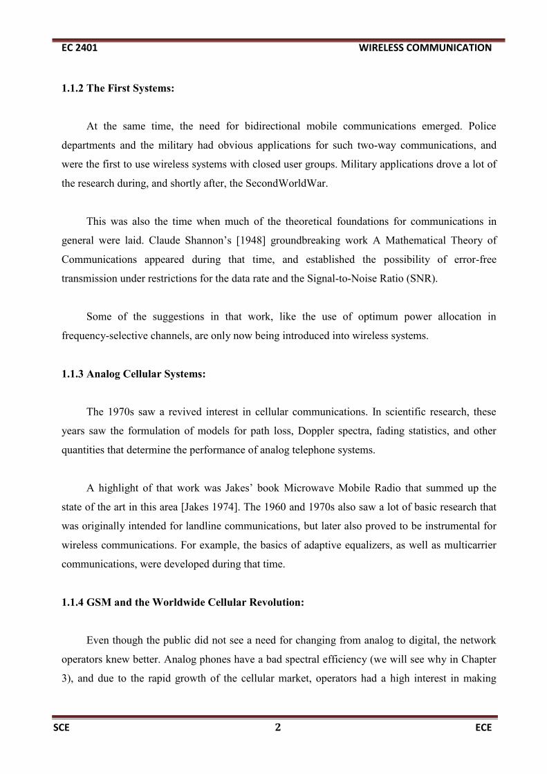
The phases, in turn, depend mostly on the run length of the MPC, and thus on the position of the
Mobile Station (MS) and the IOs. For this reason, the interference, and thus the amplitude of the
total signal, changes with time if either TX, RX, or IOs is moving. This effect – namely, the
changing of the total signal amplitude due to interference of the different MPCs – is called small-
scale fading.
1.5.3 Inter symbol Interference:
The runtimes for different MPCs are different. We have already mentioned above that this
can lead to different phases of MPCs, which lead to interference in narrowband systems.
In a system with large bandwidth, and thus good resolution in the time domain,3 the major
consequence is signal dispersion: in other words, the impulse response of the channel is not a
single delta pulse but rather a sequence of pulses (corresponding to different MPCs), each of
which has a distinct arrival time in addition to having a different amplitude and phase

EC 2401 WIRELESS COMMUNICATION
SCE 12 ECE
ISI is essentially determined by the ratio between symbol duration and the duration of the
impulse response of the channel. This implies that ISI is not only more important for higher data
rates but also for multiple access methods that lead to an increase in transmitted peak data rate.
1.6 Multiple Access Schemes.
1.6.1 Introduction:
In wireless communication systems it is often desirable to allow the subscriber to send
simultaneously information to the base station while receiving information from the base station.
A cellular system divides any given area into cells where a mobile unit in each cell
communicates with a base station. The main aim in the cellular system design is to be able to
increase the capacity of the channel i.e. to handle as many calls as possible in a given bandwidth
with a sufficient level of quality of service.
Thereare several different ways to allow access to the channel. These includes mainly the
following:
1) Frequency division multiple-access (FDMA)
2) Time division multiple-access (TDMA)
3) Code division multiple-access (CDMA)
4) Space Division Multiple access (SDMA)

EC 2401 WIRELESS COMMUNICATION
SCE 13 ECE
FDMA,TDMA and CDMA are the three major multiple access techniques that are used to
share the available bandwidth in a wireless communication system.
Depending on how the available bandwidth is allocated to the users these techniques can
be classified as narrowband and wideband systems.
1.6.2 Frequency Division Multiple Access(FDMA):
This was the initial multiple-access technique for cellular systems in which each
individual user is assigned a pair of frequencies while making or receiving a call as shown in
Figure.
One frequency is used for downlink and one pair for uplink. This is called frequency
division duplexing (FDD). That allocated frequency pair is not used in the same cell or adjacent
cells during the call so as to reduce the co channel interference.
FDMA is usually implemented in a narrow band system The symbol time is large
compared to the average delay spread. The complexity of the FDMA mobile systems is lower
than that of TDMA mobile systems. FDMA requires tight filtering to minimize the adjacent
channel interference.
FDMA/FDD in AMPS

EC 2401 WIRELESS COMMUNICATION
SCE 14 ECE
FDMA/TDD in CT2
Key Features:
• The transmitter (TX) and receiver (RX) require little digital signal processing. However,
this is not so important in practice anymore, as the costs for digital processing are
continuously decreasing.
• (Temporal) synchronization is simple. Once synchronization has been established during
the call setup, it is easy to maintain it by means of a simple tracking algorithm, as
transmission occurs continuously.
• If an FDMA channel is not in use, then it sits idle and cannot be used by other users
• The bandwidths of FDMA channels are narrow (30kHz)
• Intersymbol interference is low
• It needs only a few synchronization bits
De Merits:
• FDMA systems are costlier because of the single channel per carrier design,
• It need to use costly bandpass filters to eliminate spurious radiation at the base station.
• The FDMA mobile unit uses duplexers since both the transmitter and receiver operate at
the same time. This results in an increase in the cost of FDMA subscriber units and base
stations.

EC 2401 WIRELESS COMMUNICATION
SCE 15 ECE
• FDMA requires tight RF filtering to minimize adjacent channel interference.
1.6.3 Time division multiple-access (TDMA):
In digital systems, continuous transmission is not required because users do not use the
allotted bandwidth all the time.
In such cases, TDMA is a complimentary access technique to FDMA. Global Systems for
Mobile communications (GSM) uses the TDMA technique. In TDMA, the entire bandwidth is
available to the user but only for a finite period of time.
TDMA requires careful time synchronization since users share the bandwidth in the frequency
domain. The number of channels are less, inter channel interference is almost negligible. TDMA
uses different time slots for transmission and reception. This type of duplexing is referred to as
Time division duplexing(TDD).

EC 2401 WIRELESS COMMUNICATION
SCE 16 ECE
TDMA/FDD in GSM
TDMA/TDD in DECT
TDMA shares a single carrier frequency with several users, where each user makes use of
nonoverlapping time slots.
• TDMA uses different time slots for transmission and reception
• Adaptive equalization is usually necessary in TDMA systems, since the transmission
rates are generally very high as compared to FDMA channels
Frame Structure:
The preamble contains the address and synchronization information that both the base
station and the subscribers use to identify each other.
• Trial bits specify the start of a data.
• Synchronization bits will intimate the receiver about the data transfer.
• Guard Bits are used for data isolation.

EC 2401 WIRELESS COMMUNICATION
SCE 17 ECE
Efficiency of TDMA:
• The efficiency of a TDMA system is a measure of the percentage of transmitted data that
contains information as opposed to providing overhead for the access scheme.
Then the frame efficiency is
1.6.4. Code division multiple-access (CDMA).
In CDMA, the same bandwidth is occupied by all the users, however they are all assigned
separate codes, which differentiates them from each other (shown in Figure).
CDMA utilize a spread spectrum technique in which a spreading signal (which is
uncorrelated to the signal and has a large bandwidth) is used to spread the narrow band message
signal.

EC 2401 WIRELESS COMMUNICATION
SCE 18 ECE
• The narrowband message signal is multiplied by a very large bandwidth signal called the
spreading signal (pseudo-noise code)
• The chip rate of the pseudo-noise code is much more than message signal.
• Each user has its own pseudorandom codeword.
Direct Sequence Spread Spectrum (DS-SS)
This is the most commonly used technology for CDMA. In DS-SS, the message signal is
multiplied by a Pseudo Random Noise Code.
Each user is given his own codeword which is orthogonal to the codes of other users and
in order to detect the user, the receiver must know the codeword used by the transmitter. There
are, however, two problems in such systems which are discussed in the sequel.
Hybrid Spread Spectrum Techniques
The hybrid combinations of FHMA, CDMA and SSMA result in hybrid spread spectrum
techniques that provide certain advantages. These hybrid techniques are explained below,

EC 2401 WIRELESS COMMUNICATION
SCE 19 ECE
Hybrid FDMA/CDMA (FCDMA): An alternative to the CDMA technique in which the
available wideband spectrum is divided into a smaller number of sub spectra with smaller
bandwidths.
• CDMA uses CO-Channel Cells
• All the users use the same carrier frequency and may transmit simultaneously without
any knowledge of others.
• The receiver performs a time correlation operation to detect only the specific desired
codeword.
• All other code words appear as noise
CDMA Advantages:
frequency band
other users can not decode the messages that are in transit

EC 2401 WIRELESS COMMUNICATION
SCE 20 ECE
UNIT 2
WIRELESS PROPAGATION CHANNELS
2.1. Propagation Mechanism:
2.1.1 Reflection:
2.1.1.1 Snell’s Law
Electromagnetic waves are often reflected at one or more IOs before arriving at the RX.
The reflection coefficient of the IO, as well as the direction into which this reflection occurs,
determines the power that arrives at the RX position.
In this section, we deal with specular reflections. This type of reflection occurs when
waves are incident onto smooth, large (compared with the wavelength) objects. A related
mechanism is the transmission of waves – i.e., the penetration of waves into and through an IO.
Transmission is especially important for wave propagation inside buildings.
If the Base Station (BS) is either outside the building, or in a different room, then the
waves have to penetrate a wall (dielectric layer) in order to get to the RX.

EC 2401 WIRELESS COMMUNICATION
SCE 21 ECE
Reflection is fairly easy to model, diffraction and scattering are harder Electromagnetic
waves travel at different speeds in different media. Velocity of light waves is more in media of
lower refractive index.
This causes the waves to bend from normal to surface, when it travels from medium of
higher refractive index to lower.
Reflection occurs when an electromagnetic wave falls on an object, which has very large
dimensions as compared to the wavelength of the propagating wave. For example, such objects
can be the earth, buildings and walls.
When a radio wave falls on another medium having different electrical properties, a part
of it is transmitted into it, while some energy is reflected back. Let us see some special cases.
EC 2401 WIRELESS COMMUNICATION
SCE 22 ECE
If the medium on which the e.m. wave is incident is a dielectric, some energy is reflected
back and some energy is transmitted. If the medium is a perfect conductor, all energy is reflected
back to the first medium.
The amount of energy that is reflected back depends on the polarization of the e.m. wave.
Another particular case of interest arises in parallel polarization, when no reflection occurs in the
medium of origin.
This would occur, when the incident angle would be such that the reflection coefficient is
equal to zero.
2.1.1.2 Reflection and Transmission for Layered Dielectric Structures
The previous section discussed the reflection and transmission in a dielectric halfspace.
This is of interest, e.g., for ground reflections and reflections by terrain features, like mountains.
A related problem is the problem of transmission through a dielectric layer.
It occurs when a user inside a building is communicating with an outdoor BS, or in a
picocell where the Mobile Station (MS) and the BS are in different rooms. In that case, we are
interested in the attenuation and phase shift of a wave transmitted through a wall.
Fortunately, the basic problem of dielectric layers is well known from other areas of
electrical engineering – e.g., optical thin film technology [Heavens 1965], and the results can be
easily applied to wireless communications.
2.1.2 Diffraction:
Diffraction is the phenomenon due to which an EM wave can propagate beyond the
horizon, around the curved earth’s surface and obstructions like tall buildings. As the user moves
deeper into the shadowed region, the received field strength decreases.
2.1.2.2 Diffraction by a Single Screen or Wedge
The Diffraction Coefficient The simplest diffraction problem is the diffraction of a
homogeneous plane wave by a semi-infinite screen, as sketched in Figure
Diffraction can be understood from Huygen’s principle that each point of a wavefront can
be considered the source of a spherical wave. For a homogeneous plane wave, the superposition
of these spherical waves results in another homogeneous plane wave, see transition from plane A

EC 2401 WIRELESS COMMUNICATION
SCE 23 ECE
This phenomenon can be explained by the Huygen’s principle, according to which, every
point on a wavefront acts as point sources for the production of secondary wavelets, and they
combine to produce a new wavefront in the direction of propagation.
The propagation of secondary wavelets in the shadowed region results in diffraction. The
field in the shadowed region is the vector sum of the electric field components of all the
secondary wavelets that are received by the receiver.

EC 2401 WIRELESS COMMUNICATION
SCE 24 ECE
Fresnel Zones:
The impact of an obstacle can also be assessed qualitatively, and intuitively, by the
concept of Fresnel zones. shows the basic principle. Draw an ellipsoid whose foci are the BS
and the MS locations.
According to the definition of an ellipsoid, all rays that are reflected at points on this
ellipsoid have the same run length (equivalent to runtime). The eccentricity of the ellipsoid
determines the extra run length compared with the LOS – i.e., the direct connection between
the two foci.
Ellipsoids where this extra distance is an integer multiple of λ/2 are called “Fresnel
ellipsoids.” Now extra run length also leads to an additional phase shift, so that the ellipsoids
can be described by the phase shift that they cause. More specifically, the ith Fresnel ellipsoid
is the one that results in a phase shift of i · π.
Diffraction by a Wedge:
The semi-infinite absorbing screen is a useful tool for the explanation of diffraction, since
it is the simplest possible configuration. However, many obstacles especially in urban
environments are much better represented by a wedge structure, as sketched in Figure 4.8. The
problem of diffraction by a wedge has been treated for some 100 years, and is still an area of
active research.

EC 2401 WIRELESS COMMUNICATION
SCE 25 ECE
Depending on the boundary conditions, solutions can be derived that are either valid at arbitrary
observation points or approximate solutions that are only valid in the far field (i.e., far away
from the wedge). These latter solutions are usually much simpler, and will thus be the only ones
considered here.
Bullington’s Method:
Bullington’s method replaces the multiple screens by a single, “equivalent” screen. This
equivalent screen is derived in the following way: put a tangential straight line from the TX to
the real obstacles, and select the steepest one (i.e., the one with the largest elevation angle), so
that all obstacles either touch this tangent, or lie below it. Similarly, take the tangents from the
RX to the obstacles, and select the steepest one. The equivalent screen is then determined by the
intersection of the steepest TX tangent and the steepest RX tangent

EC 2401 WIRELESS COMMUNICATION
SCE 26 ECE
2.1.3 Scattering:
The actual received power at the receiver is somewhat stronger than claimed by the
models of reflection and diffraction. The cause is that the trees, buildings and lampposts scatter
energy in all directions. This provides extra energy at the receiver.
Roughness is tested by a Rayleigh criterion, which defines a critical height hc of
surface protuberances for a given angle of incidence θi, given by,
A surface is smooth if its minimum to maximum protuberance h is less than hc,
and rough if protuberance is greater than hc.

EC 2401 WIRELESS COMMUNICATION
SCE 27 ECE
2.2 Propagation effects with mobile radio:
2.2.1 Path Loss:
Path loss in decreasing order:
Urban area (large city)
Urban area (medium and small city)
Suburban area
Open area
Definition of path loss LP is

EC 2401 WIRELESS COMMUNICATION
SCE 28 ECE
2.2.2 Fading: Slow Fading / Fast Fading :
Slow Fading:
The long-term variation in the mean level is known as slow fading (shadowing or log-
normal fading). This fading caused by shadowing.
Fast Fading:
The signal from the transmitter may be reflected from objects such as hills, buildings, or
vehicles. When MS is near BS (and there is a line of sight component), the envelope distribution
of received signal is Rician distribution.

EC 2401 WIRELESS COMMUNICATION
SCE 29 ECE
2.2.3 Delay Spread :
When a signal propagates from a transmitter to a receiver, signal suffers one or more
reflections.
This forces signal to follow different paths.
Each path has different path length, so the time of arrival for each path is different.
This effect which spreads out the signal is called “Delay Spread”.
2.2.4 Doppler Shift :
Doppler Effect: When a wave source and a receiver are moving towards each other, the
frequency of the received signal will not be the same as the source.
When they are moving toward each other, the frequency of the received signal is
Higher than the source.
When they are opposing each other, the frequency decreases.
Thus, the frequency of the received signal is fr= fc-fd
where fC is the frequency of source carrier, fD is the Doppler frequency.

EC 2401 WIRELESS COMMUNICATION
SCE 30 ECE
2.3. Link calculations :
2.3.1 Log-distance Path Loss Model:
According to this model the received power at distance d is given by,
The value of n varies with propagation environments. The value of n is 2 for free
space. The value of n varies from 4 to 6 for obstruction of building, and 3 to 5 for urban
scenarios. The important factor is to select the correct reference distance d0.
Limitations:
Surrounding environmental clutter may be different for two locations having the
same transmitter to receiver separation. Moreover it does not account for the shadowing
effects.
2.3.2 Log Normal Shadowing:
The equation for the log normal shadowing is given by,
where Xσ is a zero mean Gaussian distributed random variable in dB with standard
deviation σ also in dB. In practice n and σ values are computed from measured data.
2.4. Narrow band models:
In radio, narrowband describes a channel in which the bandwidth of the message does not
significantly exceed the channel's coherence bandwidth.
In the study of wired channels, narrow band implies that the channel over consideration is
sufficiently narrow that its frequency response can be considered flat. The message bandwidth

EC 2401 WIRELESS COMMUNICATION
SCE 31 ECE
will therefore be less than the coherence bandwidth of the channel. That is, no channel has
perfectly , but the analysis of many aspects of wireless systems is greatly simplified if flat fading
can be assumed.
Narrow band can also be used with the audio spectrum to describe sounds which occupy a narrow
range of frequencies.
In telephony, narrow band is usually considered to cover frequencies 300–3400 Hz.
2.4.1 Outdoor Propagation Models:
There are many empirical outdoor propagation models such as Longley-Rice model,
Durkin’s model, Okumura model, Hata model etc. Longley-Rice model is the most
commonly used model within a frequency band of 40 MHz to 100 GHz over different
terrains.
Certain modifications over the rudimentary model like an extra urban factor
(UF) due to urban clutter near the reciever is also included in this model. Below, we
discuss some of the outdoor models, followed by a few indoor models too.
2.4.2 Okumura Model:
The Okumura model is used for Urban Areas is a Radio propagation model that is
used for signal prediction. The frequency coverage of this model is in the range of 200
MHz to 1900 MHz and distances of 1 Km to 100 Km. It can be applicable for base station
effective antenna heights (ht ) ranging from 30 m to 1000 m.
Okumura used extensive measurements of base station-to-mobile signal attenua- tion
throughout Tokyo to develop a set of curves giving median attenuation relative to free
space (Amu) of signal propagation in irregular terrain. The empirical path-
loss formula of Okumura at distance d parameterized by the carrier frequency fc is
given by
PL (d)dB = L(fc, d) + Amu(fc, d) − G(ht ) − G(hr ) − GAREA

EC 2401 WIRELESS COMMUNICATION
SCE 32 ECE
where L(fc, d) is free space path loss at distance d and carrier frequency fc, Amu(fc, d)
is the median attenuation in addition to free-space path loss across all environments,G(ht ) is
the base station antenna height gain factor,G(hr ) is the mobile antenna height gain
factor,GAREA is the gain due to type of environment. The values of Amu (fc, d) and
GAREA are obtained from Okumura’s empirical plots.
Okumura derived empirical formulas for G(ht ) and G(hr ) as follows:
G(ht ) = 20 log10(ht /200), 30m < ht < 1000m
G(hr ) = 10 log10(hr /3), hr ≤ 3m
G(hr ) = 20 log10(hr /3), 3m < hr < 10m Correlation
factors related to terrain are also developed in order to improve the models accuracy.
Okumura’s model has a 10-14 dB empirical standard deviation between the path loss
predicted by the model and the path loss associated with one of the measurements used to
develop the model.
2.4.3 Hata Model
The Hata model is an empirical formulation of the graphical path-loss data provided
by the Okumura and is valid over roughly the same range of frequencies, 150-1500 MHz.
This empirical formula simplifies the calculation of path loss because it is closed form
formula and it is not based on empirical curves for the different param- eters. The
standard formula for empirical path loss in urban areas under the Hata model is
PL,urban(d)dB = 69.55+26.16 log10(fc)−13.82 log10(ht )−a(hr )+
(44.9−6.55 log10(ht )) log10(d)
The parameters in this model are same as in the Okumura model,and a(hr ) is
a correction factor for the mobile antenna height based on the size of coverage area. For small
to medium sized cities this factor is given by
a(hr ) = (1.11 log10(fc) − 0.7)hr − (1.56 log10(fc) − 0.8)dB

EC 2401 WIRELESS COMMUNICATION
SCE 33 ECE
and for larger cities at a frequencies fc > 300 MHz by
a(hr ) = 3.2(log10(11.75hr ))2 − 4.97dB
else it is
a(hr ) = 8.29(log10(1.54hr ))2 − 1.1dB
Corrections to the urban model are made for the suburban, and is given by
PL,suburban(d)dB = PL,urban(d)dB − 2(log10(fc/28))2 − 5.4
Unlike the Okumura model,the Hata model does not provide for any specific path-
correlation factors.
The Hata model well approximates the Okumura model for distances d > 1 Km.
2.5 Wide band model:
In communications, a system is wideband when the message bandwidth significantly
exceeds the coherence bandwidth of the channel. Some communication links have such a high
data rate that they are forced to use a wide bandwidth;
other links may have relatively low data rates, but deliberately use a wider bandwidth than
"necessary" for that data rate in order to gain other advantages; see spread spectrum.
A wideband antenna is one with approximately or exactly the same operating
characteristics over a very wide passband. It is distinguished from broadband antennas, where the
passband is large, but the antenna gain and/or radiation pattern need not stay the same over the
passband.
The term Wideband Audio or (also termed HD Voice or Wideband Voice) denotes a
telephony using a wideband codec, which uses a greater frequency range of the audio spectrum
than conventional voiceband telephone calls, resulting in a clearer sound.

EC 2401 WIRELESS COMMUNICATION
SCE 34 ECE
Wideband in this context is usually considered to cover frequencies in the range of 50–
7,000 Hz, therefore allowing audio with richer tones and better quality.
2.5.1 Indoor Propagation Models:
The indoor radio channel differs from the traditional mobile radio channel in ways
- the distances covered are much smaller ,and the variability of the environment is
much greater for smaller range of Tx-Rx separation distances.
A radio propagation model, also known as the Radio Wave Propagation Model or
the Radio Frequency Propagation Model, is an empirical mathematical formulation for the
characterization of radio wave propagation as a function of frequency, distance and other
conditions. A single model is usually developed to predict the behavior of propagation for
all similar links under similar constraints. Created with the goal of formalizing the way
radio waves are propagated from one place to another, such models typically predict the
path loss along a link or the effective coverage area of a transmitter.
As the path loss encountered along any radio link serves as the dominant factor for
characterization of propagation for the link, radio propagation models typically focus on
realization of the path loss with the auxiliary task of predicting the area of coverage for a
transmitter or modeling the distribution of signals over different regions.
Because each individual telecommunication link has to encounter different terrain,
path, obstructions, atmospheric conditions and other phenomena, it is intractable to
formulate the exact loss for all telecommunication systems in a single mathematical
equation. As a result, different models exist for different types of radio links under
different conditions. The models rely on computing the median path loss for a link under a
certain probability that the considered conditions will occur.
Features such as lay-out of the building, the construction materials, and the building
type strongly in- fluence the propagation within the building. Indoor radio propagation is
dominated by the same mechanisms as outdoor:

EC 2401 WIRELESS COMMUNICATION
SCE 35 ECE
reflection, diffraction and scattering with vari- able conditions. In general, indoor
channels may be classified as either line-of-sight or obstructed.
Partition Losses Inside a Floor (Intra-floor)
The internal and external structure of a building formed by partitions and obstacles
vary widely.Partitions that are formed as a part of building structure are called hard
partitions , and partitions that may be moved and which do not span to the ceiling
are called soft partitions. Partitions vary widely in their physical and electrical
characteristics,making it difficult to apply general models to specific indoor installations.
Partition Losses Between Floors (Inter-floor)
The losses between floors of a building are determined by the external dimensions
and materials of the building,as well as the type of construction used to create the floors
and the external surroundings. Even the number of windows in a building and the
presence of tinting can impact the loss between floors.
2.5.2 Log-distance Path Loss Model:
It has been observed that indoor path loss obeys the distance power law given by
P L(dB) = P L(d0) + 10n log10 (d/d0) + Xσ
where n depends on the building and surrounding type, and Xσ represents a normal
random variable in dB having standard deviation of σ dB.
Radio propagation models are empirical in nature, which means, they are developed based
on large collections of data collected for the specific scenario. For any model, the collection of
data has to be sufficiently large to provide enough likeliness (or enough scope) to all kind of
situations that can happen in that specific scenario.
Like all empirical models, radio propagation models do not point out the exact behavior
of a link, rather, they predict the most likely behavior the link may exhibit under the specified
conditions.

EC 2401 WIRELESS COMMUNICATION
SCE 36 ECE
Different models have been developed to meet the needs of realizing the propagation
behavior in different conditions. Types of models for radio propagation include:
Models for indoor applications
Models for outdoor applications
Ground wave propagation models
Sky wave propagation models
Environmental Attenuation models
Point-to-Point propagation models
Terrain models
City Models
2.6 Channel Classification:
• Large-scale effects
• due to terrain, density and height of the building.
• characterized statistically by median path loss and lognormal shadowing
• Small-scale effects
• due to local environment and the movement of radio terminal.
• They are characterized statistically as fast Rayleigh fading.
• Channels are classified on the basis of the properties of timevarying impulse
response
Tim-Selective Channels
Frequency-Selective Channels
General Channel
WSSUS Channels
Coherence Time
Power-Delay Profile
Coherence Bandwidth

EC 2401 WIRELESS COMMUNICATION
SCE 37 ECE
UNIT 3
WIRELESS TRANSCEIVERS
3. Structure of a wireless communication link :
The structure of wireless communication link in Wireless operations permit services like
long-range communications which are impossible or impractical to implement with the wires
usage in communication.
This term is commonly used in the telecommunication industry in reference to
telecommunications systems like (e.g. are radio transmitters and receivers and remote controls
etc.) which use some form of the energy like (e.g. are radio waves and the acoustic energy, etc.)
which is used to transfer information without the usage of wires.The information is then
transferred in this manner over both short and long distances.
Transceiver block diagram structure :

EC 2401 WIRELESS COMMUNICATION
SCE 38 ECE
Each of the gigabit transceiver block has a clock multiplier unit CMU which provides clocking
flexibility and supports a range of incoming data streams. In each CMU two transmitter phase-
locked loops that is PLLs which generates the required clock frequencies that is based upon the
synthesis of an input reference clock.In each transmitter PLL supports all multiplication factors to
allow the use of various input clock frequencies during transmission.
Both of the transmitter’s PLLs are identical for which they support data ranges from 600
Mbps to 6.375 Gbps data transfer. But however each PLL is configured to support different data
rates where each transmitter PLL drives four channels.
During PIPE x8 mode the transmitter PLL of the master transceiver block drives upto
eight channels where CMU block is active both in single- and double-width modes and is
powered off when not in use.
This is often preferable to have simplified models for wireless communication links.
Moreover the analog radio channels with the downconverters ,upconverters, RF elements and
noise interfere the signals and it is then added to time discreet low pass channel during
transmission.The other simplified models use a digital representation of the channel suitable for
the analysis of the coding scheme.
The most simple modulation is binary modulation where +1 bit value is mapped to one
specific wave form while a -1 bit value is mapped to a different wave form. During choosing of a
modulation wave format in wireless system the ultimate goal is to transmit with certain energy as
much as information can transmit over a channel.
• The information source provides an analog source signal and feeds it into the source
ADC (Analog to Digital Converter). This ADC first band limits the signal from the analog
information source (if necessary), and then converts the signal into a stream of digital data at a
certain sampling rate and resolution (number of bits per sample).
For example, speech would typically be sampled at 8 ksamples/s, with 8-bit resolution,
resulting in a datastream at 64 kbit/s. For the transmission of digital data, these steps can be
omitted, and the digital source directly provides the input to interface “G” in Figure.

EC 2401 WIRELESS COMMUNICATION
SCE 39 ECE
• The source coder uses a priori information on the properties of the source data in order to
reduce redundancy in the source signal. This reduces the amount of source data to be transmitted
,and thus the required transmission time and/or bandwidth.
For example, the Global System for Mobile communications (GSM) speech coder reduces
the source data rate from 64 kbit/s mentioned above to 13 kbit/s. Similar reductions are possible
for music and video (MPEG standards).
Also, fax information can be compressed significantly. One thousand subsequent symbols
“00”(representing “white” color), which have to be represented by 2,000 bits, can be replaced by
the statement: “what follows now are 1,000 symbols 00,” which requires only 12 bits. For a
typical fax, compression by a factor of 10 can be achieved. The source coder increases the entropy
(information per bit) of the data at interface F; as a consequence, bit errors have greater impact.
• The channel coder adds redundancy in order to protect data against transmission errors.
This increases the data rate that has to be transmitted at interface E – e.g., GSM channel coding
increases the data rate from 13 to 22.8 kbit/s.
Channel coders often use information about the statistics of error sources in the channel
(noise power, interference statistics) to design codes that are especially well suited for certain
types of channels (e.g., Reed–Solomon codes protect especially well against burst errors).
• The multiplexer combines user data and signaling information, and combines the data
from multiple users.2 If this is done by time multiplexing, the multiplexing requires some time
compression.

EC 2401 WIRELESS COMMUNICATION
SCE 40 ECE
3.1 Generation & detection of QPSK technique:
3.1.1 Principle:
2 bits are combined in a single symbol.
• It is represented by carriers with 4 different phases.
• QPSK has twice the bandwidth efficiency of BPSK.
Es – Amplitude of digital symbol
Ts - duration of symbol
Tb- duration of a single bit
• For QPSK Ts = 2 Tb
3.1.2 Transmitter block diagram &explanation:
• The input to the system is a binary message stream has bit rate Rb
• The NRZ Encoder will convert the unipolar message to bipolar bit sequence.
• The serial to parallel convertor will split the stream of bits into two separate data
streams.
QPSK signal constellation.

EC 2401 WIRELESS COMMUNICATION
SCE 41 ECE
• They are provided to the I-channel and QChannel.
• The bit stream ml (t) is called the "even" stream and mQ (t) is called the "odd" stream
• The oscillator produces a high frequency carrier.
• The 90o phase shifter will produce an exactly out of phase signal to that of the carrier.
• The two binary sequences are separately modulated by two carriers.
Transmitter
• The two modulated signals are summed to produce a QPSK signal.

EC 2401 WIRELESS COMMUNICATION
SCE 42 ECE
• The filter at the output of the modulator confines the power spectrum of the QPSK signal
within the allocated band.
• This prevents spill-over of signal energy into adjacent channels and also removes out-of-
band spurious signals generated during the modulation process
3.1.4 Receiver block diagram &explanation:
• A carrier recovery is used to estimate the frequency and phase of a received
signal's carrier.
• The incoming signal is split into two parts, and each part is coherently demodulated
using the inphase and quadrature carriers.
• The decision making device is used to regenerate digital signals. It uses a threshold level
to distinguish between “0” & “1”
Receiver

EC 2401 WIRELESS COMMUNICATION
SCE 43 ECE
3.2.Generation & detection of / QPSK technique:
3.2.1 Principle:
• In π/4 QPSK the maximum phase change is limited to ±135°.
• So it has less amplitude fluctuations than QPSK.
• It can be detected non coherently .
• The phase shift between successive symbols is an integer multiple of π /4 radians
3.2.2 Block diagram &explanation:
The data for π/4 DQPSK like QPSK can be thought to be carried in the phase of a
single modulated carrier or on the amplitudes of a pair of quadrature carriers. The
modulated signal during the time slot of kT < t < (k + 1)T given by:
s(t) = cos(2πfct + ψk+1)
Here, ψk+1 = ψk + ∆ψk and ∆ψk can take values π/4 for 00, 3π/4 for 01, −3π/4 for 11
and −π/4 for 10.
Inphase & Quadrature

EC 2401 WIRELESS COMMUNICATION
SCE 44 ECE
Transmitter
The signal can be represented as
Where,

EC 2401 WIRELESS COMMUNICATION
SCE 45 ECE
This corresponds to eight points in the signal constellation but at any instant
of time only one of the four points are possible: the four points on axis or the four points
off axis. The constellation diagram along with possible transitions are shown in Figure .
3.3.Generation & detection of BFSK technique:
3.3.1Principle:
• BFSK uses a pair of discrete frequencies to transmit binary data.
• The frequency of a constant amplitude carrier signal is switched between two values
corresponding to a binary 1 or 0
3.3.2 Transmitter block diagram &explanation:
In binary phase shift keying (BPSK), the phase of a constant amplitude carrier
signal is switched between two values according to the two possible signals m1 and m2
corresponding to binary 1 and 0, respectively. Normally, the two phases are separated
by 180o .

EC 2401 WIRELESS COMMUNICATION
SCE 46 ECE
3.3.4 Receivers block diagram &explanation:
Coherent Receiver:
• The carrier used in the transmitter was regenerated by the Carrier Recovery circuit.
• Then they are multiplied with the incoming FSK signal.

EC 2401 WIRELESS COMMUNICATION
SCE 47 ECE
Coherent Receiver
• Then the high frequency components are filtered out and only the low frequency
message is passed though.
• Threshold comparator will decide whether the received signal is logic 1 or a 0.
Non-Coherent Receiver:
• Extracting the same Carrier from the FSK signal will not be accurate , and it take lot of
effort to do that.
• To avoid this we use Non Coherent detection, where we don’t need any information
about the original carrier.
• The receiver consists of a pair of matched filters, upper filter is matched to the FSK
signal of frequency fH and the lower filter is matched to the frequency Fl

EC 2401 WIRELESS COMMUNICATION
SCE 48 ECE
Non-Coherent Receiver
3.4 Generation & detection of GMSK technique:
3.4.1 Principle:
• In GMSK the side lobe levels of the spectrum are further reduced.
• GMSK will minimize bandwidth, improve spectral performance, and easy for detection.
• GMSK has excellent power efficiency , so it is used for GSM applications.
• But GMSK is affected by ISI.

EC 2401 WIRELESS COMMUNICATION
SCE 49 ECE
3.4.2 Transmitter block diagram &explanation:
• An unfiltered binary data stream will produce an RF spectrum of considerable
bandwidth.
• A Gaussian pulse-shaping filter smoothes the phase trajectory of input NRZ code.
Transmitter
• Input: Binary NRZ Signal
• Each binary pulse goes through a Gaussian LPF
• The filter smoothes the phase trajectory of the binary pulses and stabilizes the
instantaneous frequency variations.
• The power spectrum of MSK & GMSK are equivalent.
3.4.3 Receiver block diagram &explanation:
Bit Error Rate:
• The bit error probability is a function of BT.
• Where γ is a constant related to BT and Y is
0.68 for GMSK with BT = 0.25
0.85 for simple MSK BT= ∞
GaussianFilter
FMTransmitter A

EC 2401 WIRELESS COMMUNICATION
SCE 50 ECE
• Eb/No is the energy per bit to noise power spectral density ratio.
• It is a normalized signal-to-noise ratio (SNR) measure, also known as the "SNR per bit“
• No = Noise Spectral Density
GMSK Receiver
3.5 Generation & detection of MSK technique:
3.5.1 Principle:
• QPSK results in larger side lobes due to the phase change of 900 or 1800. .
• So to reduce this we use MSK, where the peak deviation is ¼ of bit rate.
• MSK is closely related to OQPSK, where we replace rectangular pulses by sinusoidal
pulses.
• Modulation index of MSK is 0.5

EC 2401 WIRELESS COMMUNICATION
SCE 51 ECE
3.5.2 Transmitter block diagram &explanation:
• MSK uses two frequencies which are separated by 1/4T.
• The carrier frequency is choose to be the multiple of 1/4T fc - 1/4T & fc + 1/4T.
• The filtered signal is then multiplied with the odd and even data sequences to form MSK
signal.
• SMSK(t) = aI(t)cos(π/2T)t. cos2πfct + aQ(t)sin( π/2T)t . sin2πfct
aI(t) = In-phase bit sequence (Even)
aQ(t) = Qudrature sequence (odd)

EC 2401 WIRELESS COMMUNICATION
SCE 52 ECE
3.5.3 Receiver block diagram &explanation:
`aI(t) & aQ(t) = +1 for Binary “1” & Φk = 0, aI(t) & aQ(t) = -1 for Binary “0” & Φk = π
Also bk(t) = 0 if aI(t) & aQ(t) are opposite bk(t) = 1 if aI(t) & aQ(t) are same
Demodulation of Minimum Shift Keying:
The different interpretations of MSK are not just useful for gaining insights into the
modulation scheme but also for building demodulators. Different demodulator structures
correspond to different interpretations:
• Frequency discriminator detection: since MSK is a type of FSK, it is straightforward to
check whether the instantaneous frequency is larger or smaller than the carrier frequency (larger
or smaller than 0 when considering equivalent baseband).
• Differential detection: the phase of the signal changes by +π/2 or −π/2 over a 1-bit
duration,depending on the bit that was transmitted.

EC 2401 WIRELESS COMMUNICATION
SCE 53 ECE
UNIT 4
SIGNAL PROCESSING IN WIRELESS SYSTEMS
4.1 Diversity techniques used in wireless communication:
• Diversity is a method for improving the reliability of a message signal by using two or
more communication channels with different characteristics.
4.1.1 Principle of Diversity:
In the previous chapter, we treated conventional transceivers that transmit an uncoded
bitstream over fading channels. For Additive White Gaussian Noise (AWGN) channels, such an
approach can be quite reasonable: the Bit Error Rate (BER) decreases exponentially as the Signal-
to-Noise Ratio (SNR) increases, and a 10-dB SNR leads to BERs on the order of 10−4.
However, in Rayleigh fading the BER decreases only linearly with the SNR. We thus
would need an SNR on the order of 40 dB in order to achieve a 10−4 BER, which is clearly
unpractical.
The reason for this different performance is the fading of the channel: the BER is mostly
determined by the probability of channel attenuation being large, and thus of the instantaneous
SNR being low.
A way to improve the BER is thus to change the effective channel statistics – i.e., to make
sure that the SNR has a smaller probability of being low. Diversity is a way to achieve this.
The principle of diversity is to ensure that the same information reaches the receiver (RX)
on statistically independent channels. Consider the simple case of an RX with two antennas.
The antennas are assumed to be far enough from each other that small-scale fading is
independent at the two antennas.
EC 2401 WIRELESS COMMUNICATION
SCE 54 ECE
The RX always chooses the antenna that has instantaneously larger receive power.
As the signals are statistically independent, the probability that both antennas are in a
fading dip simultaneously is low – certainly lower than the probability that one antenna is in a
fading dip.
In the following, we first describe the characterization of correlation coefficients between
different transmission channels.
We then give an overview about how transmission over independent channels can be
realized – spatial antenna diversity described above is one, but certainly not the only approach.
Next, we describe how signals from different channels can best be combined, and what
performance can be achieved with the different combining schemes.
The diversity thus changes the SNR statistics at the detector input.
• It is based on the fact that individual channels experience different levels of fading and
interference.
• The main concept of diversity is that if one radio path undergoes a deep fade, another
independent path may have a strong signal.
• Diversity is usually implemented by using two or more receiving antennas.
• Multiple versions of the same signal may be received and combined in the receiver.
• Diversity plays an important role in combating fading, co-channel interference and
avoiding error bursts.
Types:
4.1.1.1 Micro Diversity:

EC 2401 WIRELESS COMMUNICATION
SCE 55 ECE
Types:
A. Space or Antenna diversity
B. Polarization diversity
C. Frequency diversity
D. Time diversity
A. Space or Antenna diversity:
• It uses two or more antennas to improve the quality .
• Antenna diversity is effective at negating the multipath loss.
• Each antenna will experience a different level of interference. Thus, if one antenna is
experiencing a deep fade, another antenna will have sufficient signal.
• Collectively such a system can provide a efficient signal
Space diversity reception methods:
a. Selection diversity
b. Feedback or Scanning Diversity
c. Maximal ratio combining
d. Equal gain diversity

EC 2401 WIRELESS COMMUNICATION
SCE 56 ECE
B.Polarization diversity:
• Space diversity is less practical since large antenna spacing was required to have enough
angle of incident.
• Polarization diversity allows us to have the antenna elements to be co-located.
• This provides diversity by orthogonal (horizontal and vertical) Polarization
• Circular and linear polarized antennas are used to characterize multipath inside buildings

EC 2401 WIRELESS COMMUNICATION
SCE 57 ECE
• Polarization diversity was found to reduce the multi path delay spread without
decreasing the received power.
• Vertical and horizontal Polarization paths has little correlation. This De-correlation is
mainly because of multiple reflections.
• It is assumed that the signal is transmitted from a mobile with vertical (or horizontal)
polarization.
• The base station polarization diversity antenna has 2 branches A1 and A2 α =
polarization angle β = offset angle of mobile

EC 2401 WIRELESS COMMUNICATION
SCE 58 ECE
C. Frequency diversity:
• Frequency diversity transmits information on more than one carrier frequency.
• Frequency diversity is implemented using frequency division multiplex mode (FDM).
• Normally 1 frequency will be held as a backup for performing diversity.
• When diversity is needed, the appropriate traffic is simply switched to the backup
frequency
Disadvantage
• It requires additional bandwidth
• Many receivers are necessary to record Frequency diversity
D. Time Diversity:
• Time diversity repeatedly transmits information at time spacing Multiple repetition of
the signal will be received with independent fading conditions, thereby providing for
diversity.
• A modern implementation of time diversity involves the use of RAKE receiver for
spread spectrum CDMA, where the multipath channel provides redun- dancy in the
transmitted message.

EC 2401 WIRELESS COMMUNICATION
SCE 59 ECE
• Disadvantage is that it requires spare bandwidth also as many receivers as there
are channels used for the frequency diversity. Two important types of time diversity
application is discussed below.
• E.g RAKE RECEIVER
Maximum Radio Combining:
MRC compensates for the phases, and weights the signals from the different
antenna branches according to their SNR.
This is the optimum way of combining different diversity branches – if several
assumptions are fulfilled. Let us assume a propagation channel that is slow fading and flat
fading.
EC 2401 WIRELESS COMMUNICATION
SCE 60 ECE
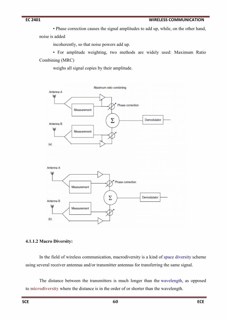
• Phase correction causes the signal amplitudes to add up, while, on the other hand,
noise is added
incoherently, so that noise powers add up.
• For amplitude weighting, two methods are widely used: Maximum Ratio
Combining (MRC)
weighs all signal copies by their amplitude.
4.1.1.2 Macro Diversity:
In the field of wireless communication, macrodiversity is a kind of space diversity scheme
using several receiver antennas and/or transmitter antennas for transferring the same signal.
The distance between the transmitters is much longer than the wavelength, as opposed
to microdiversity where the distance is in the order of or shorter than the wavelength.

EC 2401 WIRELESS COMMUNICATION
SCE 61 ECE
4.2 Linear Equalizers and Decision Feedback Equalizers:
4.2.1 Equalization:
ISI has been identified as one of the major obstacles to high speed data
transmission over mobile radio channels. If the modulation bandwidth exceeds the
coherence bandwidth of the radio channel (i.e., frequency selective fading), modulation
pulses are spread in time, causing ISI.
W i r e l es s ch an n e l s c an ex h i b i t d e l a y d i s pe r s io n M ul t i P a th
C om po ne n t s (MP Cs) c a n ha v e d i f f e r e n t ru n t im e s f ro m t h e t r a ns mi t t e r (T X)
t o t h e r e c e i v e r ( RX ) . D e l a y d i sp e rs io n l e a ds t o In t e rSym b o l In t e r f e r en c e
( IS I) , w h i ch c an g re a t l y d i s tu r b t h e t r a n smi ss io n o f d i g i t a l s i gn a l s
An equalizer at the front end of a receiver compen- sates for the average range of
expected channel amplitude and delay characteristics. As the mobile fading channels are
random and time varying, equalizers must track the time-varying characteristics of the
mobile channel and therefore should be time- varying or adaptive.

EC 2401 WIRELESS COMMUNICATION
SCE 62 ECE
An adaptive equalizer has two phases of operation: training and tracking.
These are as follows.
Training Mode:
• Initially a known, fixed length training sequence is sent by the transmitter so that
the receiver equalizer may average to a proper setting.
• Training sequence is typically a pseudo-random binary signal or a fixed, of
prescribed bit pattern.
• The training sequence is designed to permit an equalizer at the receiver to
acquire the proper filter coefficient in the worst possible channel condition.
Tracking Mode:
• When the training sequence is finished the filter coefficients are near optimal.
• Immediately following the training sequence, user data is sent.
• When the data of the users are received, the adaptive algorithms of the equal- izer
tracks the changing channel.

EC 2401 WIRELESS COMMUNICATION
SCE 63 ECE
• As a result, the adaptive equalizer continuously changes the filter characteris- tics
over time.
In a zero forcing equalizer, the equalizer coefficients cn are chosen to force the
samples of the combined channel and equalizer impulse response to zero.
When each of the delay elements provide a time delay equal to the symbol
duration T, the frequency response Heq (f ) of the equalizer is periodic with a period equal
to the symbol rate 1/T. The combined response of the channel with the equalizer must
satisfy Nyquist’s criterion
Hch (f) Heq (f) = 1, |f| < 1/2T
where Hch (f ) is the folded frequency response of the channel. Thus, an
infinite length zero-forcing ISI equalizer is simply an inverse filter which inverts the folded
frequency response of the channel.
Disadvantage: Since Heq (f ) is inverse of Hch (f ) so inverse filter may excessively
amplify the noise at frequencies where the folded channel spectrum has high atten- uation,
so it is rarely used for wireless link except for static channels with high SNR such as local
wired telephone. The usual equalizer model follows a time varying or adaptive structure
which is given next.
A Generic Adaptive Equalizer
The basic structure of an adaptive filter is shown in Figure . This filter
is called the transversal filter, and in this case has N delay elements, N+1 taps and N+1
EC 2401 WIRELESS COMMUNICATION
SCE 64 ECE
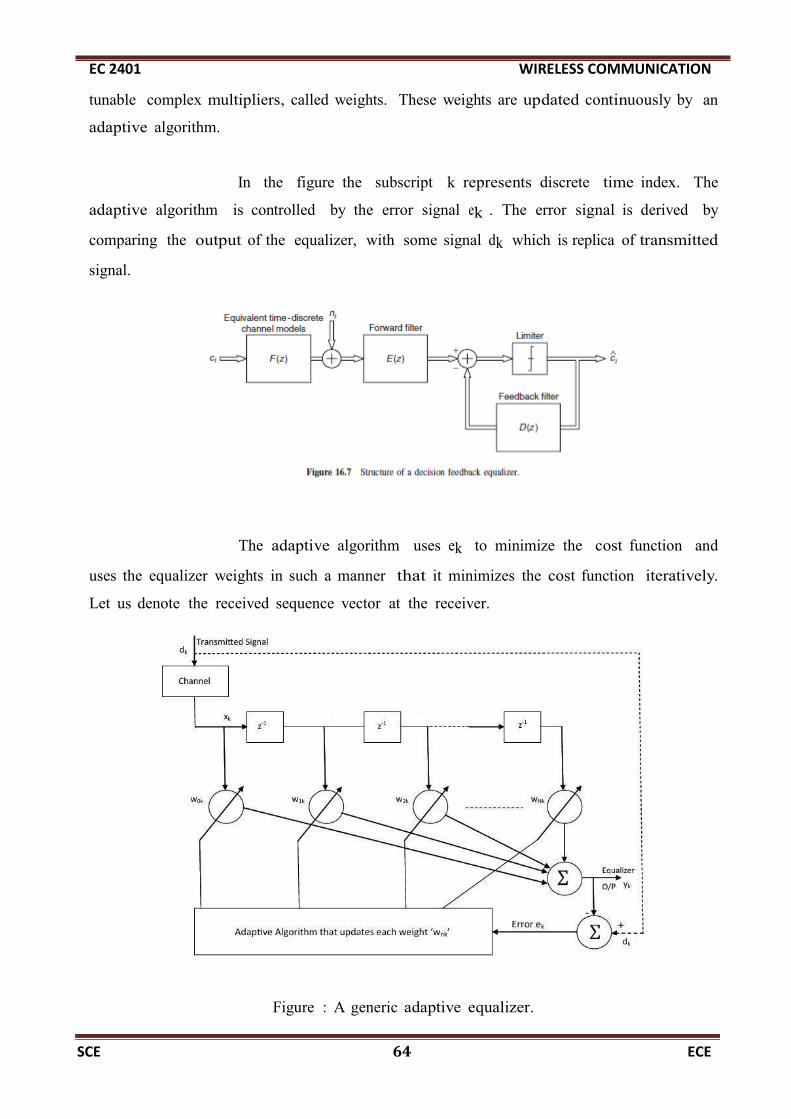
tunable complex multipliers, called weights. These weights are updated continuously by an
adaptive algorithm.
In the figure the subscript k represents discrete time index. The
adaptive algorithm is controlled by the error signal ek . The error signal is derived by
comparing the output of the equalizer, with some signal dk which is replica of transmitted
signal.
The adaptive algorithm uses ek to minimize the cost function and
uses the equalizer weights in such a manner that it minimizes the cost function iteratively.
Let us denote the received sequence vector at the receiver.
Figure : A generic adaptive equalizer.

EC 2401 WIRELESS COMMUNICATION
SCE 65 ECE
4.3 Channel coding techniques:
• Channel coding protects digital data from errors by selectively introducing redundancies
in the transmitted data.
• A channel coder operates on digital message by encoding the source information into a
code sequence for transmission through the channel.
4.3.1 Types:
1. Error detection codes. - Channel codes that are used to detect errors
2. Error Correction Codes - Codes that can detect and correct errors
Types of error correction and detection codes
1. Block codes
2. Convolutional codes.
4.3.2 Block Codes:
• Block codes are also called as forward error correction (FEC) codes
• In block codes the redundant bits are added to data blocks.
• The key idea of FEC is to transmit enough redundant data to allow receiver to recover
from errors all by itself, without retransmission.

EC 2401 WIRELESS COMMUNICATION
SCE 66 ECE
• Linear codes - the sum of any two code words gives another valid codeword.
• Systematic codes - is one in which the parity bits are appended to the end of the
information bits.
• Cyclic codes - any cyclic shift of a codeword results in another valid codeword
4.3.3Convolution Codes:
Convolutional codes offer an approach to error control coding substantially
different from that of block codes.
A convolutional encoder:
• encodes the entire data stream, into a single codeword.
• maps information to code bits sequentially by convolving a
sequence of information bits with “generator” sequences.
• does not need to segment the data stream into blocks of fixed size.
• is a machine with memory.
This fundamental difference imparts a different nature to the design and evaluation of the
code.

EC 2401 WIRELESS COMMUNICATION
SCE 67 ECE
• Block codes are based on algebraic/combinatorial techniques.
• Convolutional codes are based on construction techniques.
Encoding:
• Information is divided into blocks of length k
• “r” parity bits or check bits are added to each block (total length n = k + r),.
• Code rate R = k/n
• So normally a code is represented as (n,k)
Decoding:
• The coded data is checked for errors.
• If the error checking is successful only the message block is processed further and the
parity bits will be discarded.
• Else suitable error correction methods will be applied.
4.4. RAKE Receiver :
4.4.1Principle:
• Rake receiver is designed to counter the effects of multipath fading.
• If multipath components are delayed in time by more than one chip duration (1/Rc), they
appear like uncorrelated noise.
• It is mainly used in reception of CDMA signals where conventional equalization wont
work.

EC 2401 WIRELESS COMMUNICATION
SCE 68 ECE
• Multipath results in multiple versions of the transmitted signal at the receiver.
• Each component has some information in it.
4.4.2 Block diagram of RAKE receiver:
The RAKE receiver uses a multipath time diversity principle.
• It uses several "sub-receivers" called fingers, that is, several correlators each assigned to
a different multipath component.
• Each multipath component is extracted by using a single correlator. In all we use several
correlators which independently decodes a single multipath component.
• The outputs of each correlator are weighted to provide better estimate of the transmitted
signal than is provided by a single component.

EC 2401 WIRELESS COMMUNICATION
SCE 69 ECE
• The Integrator is used to provide the average for a specific time period.
• The decision maker is used to regenerate digital signals from the incoming weak signals.
Advantage:
RAKE receiver has to know
– Multipath delays -> time delay synchronization
– Phases of the multipath components -> carrier phase synchronization
– Amplitudes of the multipath components -> amplitude tracking
– Number of multipath components
4.5 Linear predictive coder:
4.5.1 ·Working principle:
• Instead of transmitting the analog voice signals we analyze, extract and transmit only the
significant features(formants) of speech signal
• It is a digital method for encoding an analog signal in which the present value is redicted
by a linear function of the past values of the signal.
• These formats are used to re-create the original speech signal in the receiver.
• Key formats
Gain factor
i. Pitch information
ii. Voiced/ Unvoiced decision information
Block diagram of Linear predictive coder:

EC 2401 WIRELESS COMMUNICATION
SCE 70 ECE
• Pitch is the auditory attribute of sound according to which sounds.
• It is determined by how quickly the sound wave is making the air vibrate.
• “High" pitch means very rapid oscillation, and "low" pitch corresponds to slower
oscillation
• Pitch is closely related to frequency, but the two are not equivalent.
• Women have higher pitched voices than men as a result of a faster rate of vibration
during the production of voiced sounds
• The categorization of sounds as voiced or unvoiced is an important consideration in the
analysis and synthesis process
• Unvoiced sounds are usually consonants and generally have less energy and higher
frequencies than voiced sounds.
4.5.2 Advantages:
• The input signal is sampled at a rate of 8000 samples per second.
• This input signal is then broken up into segments or blocks which are each
analyzed and transmitted to the receiver.
• Each segment represents app 20ms

EC 2401 WIRELESS COMMUNICATION
SCE 71 ECE
UNIT 5
ADVANCED TRANSCEIVER SCHEMES
5.1 1G, 2G, 3G generation systems & their standards:
5.1.1 1G: First Generation Networks:
The first mobile phone system in the market was AMPS. It was the first U.S.
cellular telephone system, deployed in Chicago in 1983. The main technology of
this first generation mobile system was FDMA/FDD and analog FM.
5.1.2 2G: Second Generation Networks:
Digital modulation formats were introduced in this generation with the main
tech- nology as TDMA/FDD and CDMA/FDD. The 2G systems introduced three
popular TDMA standards and one popular CDMA standard in the market.
TDMA/FDD Standards
(a) Global System for Mobile (GSM): The GSM standard, introduced by Groupe
Special Mobile, was aimed at designing a uniform pan-European mobile system.
It was the first fully digital system utilizing the 900 MHz frequency band. The
initial GSM had 200 KHz radio channels, 8 full-rate or 16 half-rate TDMA
channels per carrier, encryption of speech, low speed data services and support for
SMS for which it gained quick popularity.
(b) Interim Standard 136 (IS-136): It was popularly known as North American
Digital Cellular (NADC) system. In this system, there were 3 full-rate TDMA
users over each 30 KHz channel. The need of this system was mainly to
increase the capacity over the earlier analog (AMPS) system.
(c) Pacific Digital Cellular (PDC): This standard was developed as the counter- part

EC 2401 WIRELESS COMMUNICATION
SCE 72 ECE
of NADC in Japan. The main advantage of this standard was its low transmis- sion bit
rate which led to its better spectrum utilization.
CDMA/FDD Standard
Interim Standard 95 (IS-95): The IS-95 standard, also popularly known as
CDMA- One, uses 64 orthogonally coded users and codewords are transmitted
simultaneously on each of 1.25 MHz channels. Certain services that have been
standardized as a part of IS-95 standard are: short messaging service, slotted
paging, over-the-air activation (meaning the mobile can be activated by the service
provider without any third party intervention), enhanced mobile station identities
etc.
5.1.3 2.5G Mobile Networks:
In an effort to retrofit the 2G standards for compatibility with increased
throughput rates to support modern Internet application, the new data centric
standards were developed to be overlaid on 2G standards and this is known as 2.5G
standard.
5.1.4 3G: Third Generation Networks:
3G is the third generation of mobile phone standards and technology,
supersed- ing 2.5G. It is based on the International Telecommunication Union (ITU)
family of standards under the International Mobile Telecommunications-2000 (IMT-
2000).
. IMT-2000 defines a set of technical requirements for the realization of such
targets, which can be summarized as follows:
• high data rates: 144 kbps in all environments and 2 Mbps in low-mobility and
indoor environments
• symmetrical and asymmetrical data transmission

EC 2401 WIRELESS COMMUNICATION
SCE 73 ECE
• circuit-switched and packet-switched-based services
• speech quality comparable to wire-line quality
• improved spectral efficiency
• several simultaneous services to end users for multimedia services
• seamless incorporation of second-generation cellular systems
• global roaming
• open architecture for the rapid introduction of new services and technology.
3G Standards and Access Technologies
• W-CDMA
• CDMA2000
• TD-SCDMA
5.2 Detail notes about GSM – system overview, physical and logical channels.
5.2.1 Introduction:
Global System for Mobile (GSM) is a 2G cellular standard.
It is the most popular standard.
GSM was first introduced into the European market in 1991

EC 2401 WIRELESS COMMUNICATION
SCE 74 ECE
5.2.2 GSM Services:
The has 3 main services
1. Telephone services – this refers to the normal telephone services, in addition to
that we have video calls and teleconferencing calls.
2. Bearer services or data services- GPRS & EDGE
3. Supplementary ISDN services- SMS, call diversion, closed user groups and caller
identification
Features:
1. Subscriber Identity Module (SIM) - a memory device that stores all the user information
2. On air privacy- The privacy is made possible by encrypting the digital bit stream sent by a
GSM transmitter. Each user is provided with a unique secret cryptographic key, that is known
only to the cellular carrier. This key changes with time for each user
5.2.3 System Architecture:
It has 3 subsystems
1. Base Station Subsystem (BSS),
2. Network and Switching Subsystem (NSS),
3. Operation Support Subsystem (OSS)

EC 2401 WIRELESS COMMUNICATION
SCE 75 ECE
o Each BSS consists of many Base Station Controllers (BSCs) which connect the MS to the
Network and Switching Subsystem (NSS) via the MSCs
o Each BSC typically controls up to several hundred Base Transceiver Stations (BTSs).
o BTSs are connected to the BSC by microwave link or dedicated leased line.
o Handoffs between two BTSs (under same BSC)can be handled by the BSC instead of the
MSC. This greatly reduces the switching burden of the MSC.
NSS maintains are three databases for switching operations.
1. Home Location Register (HLR)
2. Visitor Location Register (VLR)
3. Authentication Center (AUC)
o The HLR contains subscriber information and location information for each user under
a single MSC.

EC 2401 WIRELESS COMMUNICATION
SCE 76 ECE
o Each subscriber is assigned a unique International Mobile Subscriber Identity (IMSI),
and this number is used to track each user.
Visitor Location Register (VLR)
o This will oversee the operations of a ROAMING mobile. It temporarily stores the
IMSI and customer information of the roamer.
Authentication Center
o Authentication Center is a strongly protected database which handles the
authentication and encryption keys for every user in the HLR and VLR.
Channels:
The GSM Channels
1. Traffic channels (TCH) - carry digitally encoded user speech or user data

EC 2401 WIRELESS COMMUNICATION
SCE 77 ECE
o GSM traffic channels may be either
o Full-rate – input raw data is processed at a rate of 13 kbps
o Half-rate - input raw data is processed at a rate of 6.5 kbps
2. Control channels (CCH) - carry signaling and synchronizing commands between the
base station and the mobile station.
Types
1. The Broadcast Channel (BCH)
2. The Common Control Channel (CCCH)
3. The Dedicated Control Channel (DCCH)
5.3 OFDM & List out the benefits of cyclic prefix in OFDM:
5.3.1 Introduction:
• Orthogonal Frequency Division Multiplexing (OFDM) is a modulation scheme suited for
high-data-rate transmission in delay-dispersive environments.
• It converts a high-rate data stream into a number of low-rate streams that are transmitted
over parallel, narrowband channels.
• OFDM is a combination of modulation and multiplexing.

EC 2401 WIRELESS COMMUNICATION
SCE 78 ECE
5.3.2 Principle:
• Multiplexing generally refers to independent signals.
• In OFDM the multiplexing is applied to independent signals but these independent
signals are a sub-set of the one main signal.
• In OFDM the signal itself is first split into independent channels, modulated by data and
then re-multiplexed to create the OFDM carrier.
5.3.3 OFDM multiplexing:
• The main concept in OFDM is orthogonality of the sub-carriers.
• Since the carriers are all sine/cosine wave, we know that area under one period of a sine
or a cosine wave is zero.
• Hence we conclude that when we multiply a sinusoid of frequency n by a sinusoid of
frequency m/n, the area under the product is zero.
• In general for all integers n and m, sinmx, cosmx, cos nx, sin nx are all orthogonal to
each other. These frequencies are called harmonics.

EC 2401 WIRELESS COMMUNICATION
SCE 79 ECE
• A harmonic of a wave is a component frequency of the signal that is an integer multiple
of the fundamental frequency.
• The orthogonality allows simultaneous transmission on a lot of sub-carriers in a tight
frequency space without interference from each other.
All three of these frequencies are harmonic to c1
• These carriers are orthogonal to each other, when added together, they do not interfere
with each other.
• Carrier 1 - We need to transmit 1, 1, 1 -1,-1,-1 , with a BPSK carrier of frequency 1 Hz.
First three bits are 1 and last three -1

EC 2401 WIRELESS COMMUNICATION
SCE 80 ECE
•Carrier 2 - The next carrier is of frequency 2 Hz. It is the next orthogonal/harmonic to
frequency of the first carrier of 1 Hz. Now take the bits in the second column, marked c2,
1, 1, -1, 1, 1, -1
5.4 CDMA:
5.4.1 Principle:
CDMA is officially termed as Interim Standard 95 (IS-95), it is the first CDMA-based
digital cellular standard by Qualcomm.
• The brand name for IS-95 is cdmaOne.
• CDMA-3G is CDMA2000
5.4.2 Frequency and Channel Specifications:
• Reverse Link - 849 MHz & 1850–1910MHz
• Forward Link - 894 MHz & 1930–1990MHz
• A forward and reverse channel pair is separated by 45MHz

EC 2401 WIRELESS COMMUNICATION
SCE 81 ECE
• IS-95 specifies two possible speech rates 13.3 or 8.6kbit/s.
• Channel Chip Rate of 1.2288 Mchip/s
• IS-95 allows each user within a cell to use the same radio channel, and users in
adjacent cells also use the same radio channel, since this is a direct sequence spread
spectrum CDMA system.
• CDMA completely eliminates the need for frequency reuse.
• Each IS-95 channel occupies 1.25 MHz of spectrum on each one-way link.
• IS-95 uses a different modulation and spreading technique for the forward and
reverse links.
• On the forward link, the base station simultaneously transmits the user data for all
mobiles in the cell by using a different spreading sequence for each mobile.
• A pilot code is transmitted simultaneously and at a higher power level, to all mobiles
to synchronize with the carrier frequency.
• On the reverse link, all mobiles respond in an asynchronous fashion and have ideally
a constant signal level due to power control applied by the base station.
• Received power is controlled at the base station to avoid Near-Far Problem.
5.4.3 Pilot Signal
• Each BS sends out a pilot signal that the MS can use for timing acquisition, channel
estimation, and to help with the handover process.
• It is not power controlled
• It uses Walsh code 0 for transmission: this code is the all-zero code.
• It has higher transmit power than traffic channels

EC 2401 WIRELESS COMMUNICATION
SCE 82 ECE
5.4.4 Power Control Subchannel
• IS-95 strives to force each user to provide the same power level at the base station
receiver to avoid near-far problem
• Mobiles use peak power of 200mW
• Since both the signal and interference are continually varying, power control updates
are sent by the base station every 1.25 ms.
• Power control commands are sent to each subscriber unit on the forward control
subchannel which instruct the mobile to raise or lower its transmitted power in 1 dB
steps.
• If the received signal is low, a ‘0' is transmitted over the power control subchannel,
thereby instructing the mobile station to increase its mean output power level.

EC 2401 WIRELESS COMMUNICATION
SCE 83 ECE
• If the mobile's power is high, a ‘1’ is transmitted to indicate that the mobile station
should decrease its power level
Synchronization Channel
• The synchronization channel transmits information about system details that are
required for the MS to synchronize itself to the network.
• The synchronization channel transmits data at 1.2 kbit/s.
• Synch message includes system ID (SID), network ID (NID), the offset of the PN
short code, the state of the PN-long code, and the paging channel data rate (4.8/9.6
Kbps)
Paging Channel
• The paging channel transmits system and call information from the BS to the MS
like…
– Message to indicate incoming call
– System information and instructions
– Handoff thresholds
– Maximum number of unsuccessful access attempts
– Channel assignment messages.
– Acknowledgments to access requests.
Access Channel
• The access channel is a channel in the uplink that is used for signaling by MSs
• Access channel messages include security messages (authentication challenge
response page response,origination, and registration)
• A call initiated by the MS starts with a message on the access channel
Traffic Channels
• Traffic channels are the channels on which the voice data for each user are
transmitted

EC 2401 WIRELESS COMMUNICATION
SCE 84 ECE
• A number of control messages are also transmitted on traffic channels
5.5.WCDMA/UMTS.
5.5.1 Historical Overview:
This chapter is a short summary of the Wideband Code Division Multiple Access
(WCDMA) standard for third generation (3G) cellular telephony.
This standard is also part of a group of standards that are known as the Universal
Mobile Telecommunication System (UMTS),
Third Generation Partnership Project (3GPP), and International Mobile
Telecommunications (IMT-2000).
In this section, we will review the history of this standard and show its relationship
to other third-generation standards.
• Better spectral efficiency;
• Higher peak data rates – namely, up to 2 Mbit/s indoor and 384 kbit/s outdoor.
This should result in a choice of channels with a bandwidth of 5MHz instead of
200 kHz;
•Supporting multimedia applications, meaning the transmission of voice, arbitrary
data, text, pictures, audio and video, which requires increased flexibility in the
choice of data rates;
• Backward compatibility to second-generation systems.

EC 2401 WIRELESS COMMUNICATION
SCE 85 ECE
5.5.2 Physical-Layer Overview:
The UMTS standard uses a number of unusual abbreviations. For example, the MS
is called User Equipment (UE).
The WCDMA air interface uses CDMA for distinguishing between different users,
and also between users and some control channels.
5.5.3 Network Structure:
1. UE domain, which consists of:
◦ User Service Identity Module (USIM).
◦ Mobile Equipment (ME) consisting of:
– Terminal Equipment (TE);
– Terminal Adapter (TA);
– Mobile Termination (MT).
2. Infrastructure domain, which consists of:
◦ The access network domain consisting of:
– UTRAN.
◦ The CN domain consisting of:
– Inter Working Unit (IWU);
– serving network;
– transit network;

EC 2401 WIRELESS COMMUNICATION
SCE 86 ECE
.
5.5.4 Data Rates and Service Classes:
Conversational: this class is mainly intended for speech services, similar to GSM.
The delays for this type of service should be on the order of 100 ms or less.
Streaming: audio- and videostreaming are viewed as one important application of
WCDMA. Larger delays (in excess of 100 ms) can be tolerated, as the receiver typically
buffers several seconds of streaming material.
Interactive: this category encompasses applications where the user requests data
from a remote appliance.
Background class: this category encompasses services where transmission delays
are not critical. These services encompass email, Short Message Service (SMS), etc.

EC 2401 WIRELESS COMMUNICATION
SCE 87 ECE
Data rates versus mobility for Universal Mobile Telecommunications System,
Global System for Mobile communications, Digital Enhanced Cordless Telephone,
wireless local area network mobile broadband systems and landline networks.
UMTS is intended to achieve global availability and thereby enable roaming
worldwide. Therefore,the coverage area in UMTS is divided hierarchically into layers.
The highest layer achieves worldwide coverage by using satellites.1 The lower
layers are the macrolayer, microlayer, and picolayer. They constitute the UTRAN . Each
layer consists of several cells. The lower the layer the smaller the cells.
Thus, the macrolayer is responsible for nationwide coverage with macrocells.
Microcells are used for additional coverage in the urban environment and picocells are
employed in buildings or “hotspots” such as airports or train stations.
By 2009, this rollout deployment mode is still used in the U.S.A., while Japan and
most of Europe have achieved coverage of all areas with WCDMA.

EC 2401 WIRELESS COMMUNICATION
SCE 88 ECE
5.5.5 Physical and Logical Channels
Logical Channels Similar to GSM, we distinguish between different logical
channels in UMTS, which are mapped to physical channels. The logical channels in
UMTS are sometimes referred to as transport channels.
There are two kinds of transport channels: common transport channels and
Dedicated (transport) CHannels (DCHs).

EC 2401 WIRELESS COMMUNICATION
SCE 89 ECE
GLOSSARY:
ALOHA
Algorithm that allows multiple terminals to share the same
communication channel. Newly arriving packets are transmitted
immediately. Packets are retransmitted if no acknowledgement is
received. First used in Hawaii.
American Mobile Phone
SystemAMPS.U.S. Analog cellular phone system.
analog modulation
(traditional) method of transmitting voice signals where the radio
carrier wave is directly based on electrical voltages or currents caused
by a user speaking into the microphone, or similar transmission of a
signal which takes values from a continuous range of values as
opposed to from a finite alphabet of values
base stationA land station at a fixed location supporting radio access by mobile
users to a fixed communication infrastructure.
Bit Error Rate BER.
burst The physical (electric or electromagnetic) contents of a time slot
capture
Successful transmission of a data packet despite interference from
other terminals transmitting a conflicting signal. Occurs due to
differences in received signal power, or signal separation properties of
the receiver or the modulation method.
Code Division Multiple
Access
CDMA.Multiple access method based on spread spectrum in which different users transmit
on (approximately) the same carrier frequency, but use different spreading codes.
cellthe area covered by radio signals from a base station, and in which a
mobile station can successfully transmit to a base station
cellular networkNetwork in which frequencies are reused in a regular pattern, usually
with basic area elements of hexagonal shape
cell sectorization
Splitting (theorectically hexagonal) cells into multiple independent
sectors (typically 3) that each have their own transmit and receive
facilities.

EC 2401 WIRELESS COMMUNICATION
SCE 90 ECE
cell splitting A method of increasing capacity by reducing the size of the cell.
circuit-switchingThe allocation of network resources (link capacity, switches) for the
entire duration of a communication session.
cluster sizeNumber of different channels needed in a particular frequency reuse
plan. Related to reuse distance.
coding
Intentional replacement of a set of symbols by another set of symbols.
Applications are detection or correction of errors, spectral shaping of
the transmit signal, or confidentiality.
collisionConflicting simultaneous transmission by multiple terminals in a
random access network.
coverage area part of the area to which a transmitter gives satisfactory service
Carrier Sense Multiple
AccessCSMA.listen before talk
Cordless Telephone ..CT-0, CT-1, CT-2.Various generations of a cordless phone standard.
Digital Audio
BroadcastingDAB.
Dynamic Channel
AssignmentDCA.
Digital Communication
SystemDCS.1800 MHz version of GSM
decibel
A ratio, expressed as ten times the base-10 logarithm of the ratio of
two power levels. This is equivalent to 20 times the base-10 logarithm
of the ratio of two voltage, field or current levels.
Digital Enhanced
Cordless Telephone
DECT.
Previously: Digital European Cordless Telephone. Operates in 1800 MHz band.
delay spread
Parameter describing the frequency dispersion of a multipath channel.
1) total delay spread: time interval during which delayed reflected
waves arrive. 2) rms delay spread: weighted value of interarrival times

EC 2401 WIRELESS COMMUNICATION
SCE 91 ECE
of reflected waves
digital modulationA method of transmitting a signal over a radio carrier using symbols of
an alphabet of finite size, such as the computer's binary 0s and 1s.
dispersion
variations in the channel transfer amplitude. Frequency dispersion:
differences in channels response at different frequencies. Time
dispersion: time variations of the channel response
diversitytechnique of receiving a radio signal through multiple channels, to
improve reliability
doppler spread(one half times the) width of the spectrum of a received signal when a
sinusoidal wave is transmitted over a time dispersive channel
downlink
Originally: A radio link from a satellite to a receiving site on earth or
in an aircraft. Now also used for the (forward) link from base station to
portable terminal.
Direct SequenceDS.Form of spread-spectrum in which the user signal is multiplied by a fast (spectrally
broad) code sequence to increase the transmission bandwidth.
Digital Short Range
Radio
DSRR.System for short range communication. For in stance between a car and a roadside
base station or gantry.
DuplexMethod of operating a network in which transmission is possible
simultaneously in both directions of a telecommunications channel.
ERMES Paging system, originally developed in Europe
equalization
Signal processing (filtering) intended to undue channel dispersion.
Mostly a compromise is made between combating channel dispersion
and avoiding undesirable noise enhancements
Erlang Unit of telephone traffic intensity.
European
Telecommunications
Standards Institute
ETSI.European organization responsible for establishing common industry-wide
telecommunication standards.
fading Time variations of the signal strength received over a radio link.

EC 2401 WIRELESS COMMUNICATION
SCE 92 ECE
Fading occurs when the several reflected waves (destructively or
constructively) interfere with each other.
Federal Communications
CommissionFCC.U.S.
Frequency Division
Multiple Access
FDMA.Multiple access method in which different users transmit at different carrier
frequencies.
flat fadingfrequency-nonselective fading. Form of fading that does not cause
intersymbol interference.
frequency modulationFM.analog modulation method, exploiting variations in the instantaneuos carrier
frequency
Frequency Shift KeyingFSK.digital frequency modulation method
free space lossFSL.power loss due to the spreading of energy over the surface of a sphere as the signal
travels away from the transmit source.
Geosynchronous Earth
OrbitGEO.satellite communication system.
GMSKDigital phase (or frequency) modulation method, for instance used in
GSM
GSMpreviously Groupe de travail Speciale pour les services Mobiles.
Widely used digital cellular phone standard, initiated in Europe.
handover
Action of changing the handling the operation and control of a radio
link from one base station to another as the user moves from one cell
to another.
half duplex
communications system that supports conversation in two directions
but not simultaneously by sharing a communication path between the
two directions
Hertz Unit of measuring the frequency of a signal.
hidden terminal Terminal in a CSMA network actively transmitting data, but which is

EC 2401 WIRELESS COMMUNICATION
SCE 93 ECE
not noticed by another terminal with data ready for transmission.
Intelligent NetworkIN.A secondary network used to create and deliver advanced services to subscribers to
public telephone networks (fixed or mobile)
in-phase componentComponent of a signal that has the same phase as a reference
sinusoidal signal.
interference
Signals from other emitters than from transmitter sending the wanted
signal. Interference differs from noise in that interference often
contains similar waveforms as the wanted signal
interleaving
intentional resequencing (shuffling) of the bits in a signal according to
a predefined method known by both transmitter and receiver, to avoid
burst errors.
IS-95 U.S. Cellular CDMA standard.
Industrial, Scientific and
MedicalISM.bands of the radio spectrum.
Inhibit Sense Multiple
Access
ISMA.random access scheme in which the central node broadcasts a busy signal to avoid
that terminals start a conflicting transmission when it is receiving data
International
Telecommunication
Union
ITU.
jamming
Deliberate radiation of electromagnetic energy with the intent to
impair the use of electronic systems by the opponent or enemy.
Jamming signals can be sinusoidal (CW), noise-like or broadband
transmitters, specific deceptive signals that imitate messages.
Japanese Digital CellularJDC.now renamed PDC. Operates in the 900 MHz and 1.5 GHz band.
Low Earth OrbitingLEO.Satellite communication system
matched filterfilter with impulse response which is the time inverse of the expected
received waveform. Optimum form of detection in Linear Time-

EC 2401 WIRELESS COMMUNICATION
SCE 94 ECE
Invariant Additive White Gaussian Noise channel. Can also be
implemented as a correlator.
maximum ratio
combining
method of prefiltering and adding signals arriving through different
branches of a diversity receiver. Follows the principle of the matched
filter by weighing a signal proportionally to its amplitude.
microcellcell with relatively small radius, typically a few hundreds of meters,
typically used in a dense cellular network with many subscribers.
mobile stationa user terminal in a radio network intended to be used while in motion
or during halts at unspecified points
Mobile Switching CenterMSC.Telecommunications node connecting and controlling several cellular base stations.
multiple accessmethod that allows multiple spatially separated users to share the same
communication channel to a common receiver.
multiplexingmethod of combining multiple user signals in a telecommunications
switch or base station
noiserandom variations in output signal, due to natural of man-induced
mechanisms.
noise temperature
ratio of the thermal noise power present in a system over the noise
power that would be present a perfect system with only thermal noise,
operating at 1 degree Kelvin.
narrowband
1. A radio signal whose bandwidth is smaller than the coherence
bandwidth of the dispersive channel, or 2 . A radio signal whose
bandwidth is on the order of its information bandwidth, as opposed to
spread spectrum.
Nordic Mobile TelephoneNMT.Scandinavian analog cellular telephone system, at 450 or 900 MHz.
Orthogonal Frequency
Division Multiplex
OFDM.Multi-carrier modulation method with partially overlapping but nonetheless
orthogonal subcarriers.
outageevent during which the signal-to-noise or signal-to-interference ratio is
insufficient to allow acceptable performance of the receiver

EC 2401 WIRELESS COMMUNICATION
SCE 95 ECE
path loss
(average) propagation attenuation between transmitter and receiver.
Depends on distance, antenna heights and atmospheric and terrain
properties.
packetmessage or a piece of a message, treated as an independent segment of
data by the network.
packet switching
the assignment of network resources by splitting the information flow
into packets. These are sent from node to node in the network without
prior reservations
paging
Communication service that offers one-way transmission of short
messages. Typically a paging device (pager) produces an audible
'bleep' when a message arrives.
Personal
Communications
Network
PCN.usually for short range radio communication but nonetheless with a cellular reuse
lay-out. Acronym now often used for DCS 1800.
Personal
Communications ServicePCS.In the U.S., a band of a width of 120 MHz has been allocated in the near 1.9 GHz
Personal
Communications ServicePCS-1900.U.S. version of GSM, operating in the 1.9 GHz band.
Personal Digital CellularPDC.Japanese cellular system.
Phase modulationPM.Method of modulating a base signal to create an RF signal by varying the phase on a
(sinusoidal) carrier wave.
propagation natural mechanism of dissemination of radio energy
Phase Shift KeyingPSK.Digital phase modulation.
Quadrature componentComponent of a signal that is orthogonal to (90 degrees out of phase
with) a reference sinusoidal signal.
random accessMethod or algorithm that allows multiple terminals to share the same
communication channel.

EC 2401 WIRELESS COMMUNICATION
SCE 96 ECE
rake receiver
Special form of a matched filter to detect direct-sequence spread-
spectrum signals over a dispersive (multipath) channel. Optimally
collects energy received over variously delay propagation paths.
rayleigh fading
Fading characterized by a rayleigh probability density of the
amplitude, thus an exponentially distributed power. Rayleigh fading
typically occurs when an infinitely large number reflected waves with
i.i.d. amplitude and amplitude cumulate
Radio Data (Broadcast)
System
RDS, RDBS.Method to add a data signal to an FM broadcast signal by subcarrier modulation (57
kHz).
reuse
assignment of the same frequency channel in multiple areas, and
simultaneous use of these channels allowed by propagation losses
between spatially separated areas
reuse distanceDistance between the centers of two cells using same frequency
channel.
rician fading
Fading characterized by a rician probability density of the amplitude.
Rician fading typically occurs when a dominant component (say a
line-of-sight) plus an infinitely large number reflected waves with i.i.d.
amplitude and amplitude cumulate
Radio Frequency
RF.In radio communication baseband signals (voice or data) are modulated onto a
carrier and before transmission. Hence, the signal spectrum is shifted to a band
where propagation and interference conditions are appropriate.
scattering dispersion of radio energy caused by reflections
service area
Area in which a mobile station can be reached or from where a mobile
station can initiate a communication session. Typically includes the
coverage areas of multiple cells
simplexMethod of operating a network in which transmission is possible only
in one direction. No return channel available.
smart antennaArray of antenna elements and associated signal processing, used to
improve the performance and to minimize the effect of interference.

EC 2401 WIRELESS COMMUNICATION
SCE 97 ECE
spread spectrumtransmission and modulation method that intentionally spreads a signal
bandwidth over a wide bandwidth
Total Access
Communication System
TACS.analog cellular telephone system in the United Kingdom and Japan, using 25 kHz
NBFM channels
Time Division Multiple
AccessTDMA.Multiple access method in which different users transmit in different time intervals.
Trans European Trunked
Radio AccessTETRA.European digital cellular landmobile radio system for closed user groups
Telecommunications
Industry AssociationTIA.
thermal noiserandom variations in output signal, due to the natural mechanism of
motion of electrons.
trunkin a telephone network, the connection between the switches carrying
multiple voice circuits
trunking
use of the radio spectrum in which multiple user groups share the same
channels using an automatic multiple access mechanism, thus gaining
efficiency
uplink
Originally: A radio link from a site on the earth or from an aircraft to a
satellite. Now also used for the (reverse) link from mobile user
terminal to base station.
vocoder
Voice coder in which speech is heavily compressed to reduce the
channel bit rate required to transmit speech typically to a few hundreds
of bits per second
Very Small Aperture
Terminal
VSAT.a small mobile or portable satellite communication terminal using small diameter
dish antenna.
Vector Sum Excited
Linear PredictiveVSELP.Commonly used method for speech coding
Wireless Local Area
NetworkWLAN.Typically using spread-spectrum transmission in the 2.4 GHz or 5.8 GHz ISM band.

EC 2401 WIRELESS COMMUNICATION
SCE 98 ECE
2 MARKS
UNIT-I SERVICES AND TECHNICAL CHALLENGES
PART-A
1.1. What is meant by frequency reuse?
If an area is served by a single Base Station, then the available spectrum can be divided into N
frequency channels that can serve N users simultaneously. If more than N users are to be served,
multiple BSs are required, and frequency channels have to be reused in different locations. Since
spectrum is limited, the same spectrum has to be used for different wireless connections in
different locations. This method of reusing the frequency is called as frequency reuse.
1.2. What are the trends in cellular radio systems?
The trends in personal cellular radio systems are:
i. PCS – Personal Communication Services
ii. PCN – Personal Communication Networks
1.3. What do you mean by forward and reverse channel?
Forward channel is a radio channel used for transmission of information from base station to
mobile. Reverse channel is a radio channel used for transmission from mobile to
base station.
1.4. What is the function of control channel? What are the types?
The function of control channel is to transmit call setup, call request, call initiation
and Control. There are two types of control channels,
i. Forward control channel
ii. Reverse control channel
1.5. What is channel assignment? What are the types?
EC 2401 WIRELESS COMMUNICATION
SCE 99 ECE
For efficient utilization of radio spectrum a frequency reuse scheme with increasing capacity
and minimizing interference is required. For this channel assignment is used. The types of channel
assignment are:
i. Fixed channel assignment
ii. Dynamic channel assignment.
1.6. What is fixed channel assignment?
If the channels in each cell are allocated to the users within the cell, it will be called as fixed
channel assignment. If all channels are occupied, the call will be blocked.
1.7. What is dynamic channel assignment?
If the voice channels are not allocated permanently in a cell, it will be called as
dynamic channel assignment. In this assignment, channels are dynamically allocated to users by
the MSC.
1.8. Define MS, BS and MSC.
MS – Mobile station. A station in the cellular radio service intended for use. BS – Base Station.
A fixed station in a mobile radio system used for radio communication with MS.
MSC – Mobile Switching Centre. Mobile switching centre coordinates the routing of calls in large
service area. It connects the base station and mobiles to PSTN. It is also called as MTSO(Mobile
telephone switching office.
1.9. Define hand off and mode of hand off.
A handoff refers to the process of transferring an active call or data session from one cell in a
cellular network to another or from one channel in a cell to another. A well- implemented
handoff is important for delivering uninterrupted service to a caller or data session user. Modes of
hand off are:

EC 2401 WIRELESS COMMUNICATION
SCE 100 ECE
i. MCHO – Mobile Controlled Hand off
ii. NCHO – Network Controlled Hand off iii.
iii. MAHO – Mobile Assisted Hand off
1.10. Write the types of hand off.
Types of handoff are:
i. Hard hand off – Mobile monitors BS and new cell is allocated to a call with strong signal.
ii. Soft hand off – MS with 2 or more calls at the same time and find which is the strongest
signal BS, the MSC automatically transfers the call to that BS.
1.11. Define Cell, Cluster.
For a large geographic coverage area, a high powered transmitter therefore has to be used. But a
high power radio transmitter causes harm to environment. Mobile communication thus calls for
replacing the high power transmitters by low power transmitters by dividing the coverage area
into small segments, called cells.
Each cell uses a certain number of the available channels and a group of adjacent cells together
use all the available channels. Such a group is called a cluster.
1.12. What do you mean by foot print and dwell time?
The region over which the signal strength lies above this threshold value x dB is known as the
coverage area of a BS and it must be a circular region, considering the BS to be isotropic radiator.
Such a circle, which gives this actual radio coverage, is called the foot print of a cell. The time
over which a call may be maintained within a cell without hand off is called the dwell time.
1.13. What are the major types of cellular interference?
The major types of cellular interferences are as follows

EC 2401 WIRELESS COMMUNICATION
SCE 101 ECE
i. CCI – Co-channel interference is the interference between signals from co-channel cells.
ii. ACI – Adjacent channel interference resulting from signals which are adjacent in
frequency to the desired signal.
1.14. What are the techniques used to expand the capacity of cellular system?
Cell splitting, Sectoring, Coverage Zone approaches are the techniques used to expand the
capacity of cellular system.
Cell splitting – Cell-splitting is a technique which has the capability to add new smaller cells in
specific areas of the system. i.e. divide large cell size into small size.
Sectoring – use of directional antennas to reduce Co-channel interference.Coverage Zone
approaches – large central BS is replaced by several low power transmitters on the edge of the
cell.
1.15. What is frequency reuse ratio?
If the cell size and the power transmitted at the base stations are same then co-
channel
interference will become independent of the transmitted power and will depend on radius of the
cell (R) and the distance between the interfering co-channel cells (D). If D/R ratio is increased,
then the effective distance between the co-channel cells will increase and interference will
decrease.
1.16. Define FDMA, TDMA and CDMA.
FDMA - the total bandwidth is divided into non-overlapping frequency subbands. TDMA –
divides the radio spectrum into time slots and in each slot only one user is allowed to either
transmit or receive.
CDMA – many users share the same frequency same tome with different coding.
1.17. Define Grade of service.

EC 2401 WIRELESS COMMUNICATION
SCE 102 ECE
Grade of service is defined as the measure of the ability of a user to access a trunked
system during the busiest hour.
1.18. What is blocked call clear system (BCC)?
In a system, a user is blocked without access by a system when no channels are
available in the system. The call blocked by the system is cleared and the user should try again
.This is called BCC system.
1.19. What is blocked call delay system?
If a channel is not available immediately, the call request may be delayed until a channel
becomes available. This is called as blocked call delay system.
1.20. Define cell splitting.
Cell splitting is the process of subdividing congested cells into smaller cells each with its own
base stations and a corresponding reduction in antenna height and transmitter power.
It increases the capacity of cellular system.
1.21. What is sectoring?
Sectoring is a technique for decreasing co-channel interference and thus increasing
the system performance by using directional antennas.
1.22. What are the features of TDMA?
Features of TDMA are:
i. TDMA shares a single carrier frequency with several users, where each user makes use of
non overlapping time slots.
ii. Data transmission occurs in bursts.
iii. Handoff process is much simpler
iv. Duplexers are not required, since transmission and reception occurs at different time slots.

EC 2401 WIRELESS COMMUNICATION
SCE 103 ECE
1.23. What are the features of FDMA?
Features of FDMA are:
i. FDMA channel carries only one phone circuit at a time
ii. The bandwidth of FDMA channels are relatively narrow as each channel supports only
one circuit per carrier.
2.1. What are the propagation mechanisms of EM waves?
The four propagation mechanisms of EM waves are
i. Free space propagation
ii. Reflection
iii. Diffraction iv. Scattering
2.2. What is the significance of propagation model?
The major significance of propagation model are:
i. Propagation model predicts the parameter of receiver.
ii. It predicts the average received signal strength at a given distance from the transmitter.
2.3. What do you mean by small scale fading?
Rapid fluctuations of the amplitude, phase as multipath delays of a radio signal over a short period
of time is called small scale fading.
2.4. What are the factors influencing small scale fading?
The factors which influence small scale fading are:
Multipath propagation, Speed of the mobile, Speed of surrounding objects and the
transmission bandwidth of the signal.
2.5. When does large scale propagation occur?
Large scale propagation occurs due to general terrain and the density and height of
buildings and vegetation, large scale propagation occurs.
2.6. Differentiate the propagation effects with mobile radio.

EC 2401 WIRELESS COMMUNICATION
SCE 104 ECE
Slow Fading Fast Fading
Slow variations in the signal strength. Rapid variations in the signal strength.
Mobile station (MS) moves slowly. Local objects reflect the signal causes
Fast Fading
2.7. Define Doppler shift.
If the receiver is moving towards the source, then the zero crossings of the signal appear faster
and the received frequency is higher.The opposite effect occurs if the receiver is moving away
from the source. The resulting chance in frequency is known as the Doppler shift (fD).
2.8. Differentiate time selective and frequency selective channel.
The gain and the signal strength of the received signal are time varying means
then the channel is described as time selective channel. The frequency response of the time
selective channel is constant so that frequency flat channel. The channel is time invariant but the
impulse response of the channel show a frequency-dependent response so called frequency
selective channel.
2.9. Define coherence time and coherence bandwidth.
Coherence time is the maximum duration for which the channel can be assumed to be
approximately constant. It is the time separation of the two time domain samples. Coherence
bandwidth is the frequency separation of the two frequency domain samples.
2.10. What do you mean by WSSUS channels?
In multipath channels, the gain and phase shift at one delay are uncorrelated with another delay is
known as uncorrelated scattering of WSSUS.
2.11. What is free space propagation model?

EC 2401 WIRELESS COMMUNICATION
SCE 105 ECE
The free space propagation model is used to predict received signal strength, when unobstructed
line-of-sight path between transmitter & receiver. Friis free space equation is given by, The factor
(λ/4πd)2 is also known as the free space loss factor.
2.12.Define EIRP.
EIRP (Equivalent Isotropically Radiated Power) of a transmitting system in a given direction is
defined as the transmitter power that would be needed, with an isotropic radiator, to produce the
same power density in the given direction.
EIRP=PtGt
Where Pt-transmitted power in W
Gt-transmitting antenna gain
2.13. Explain path loss.
The path loss is defined as the difference (in dB) between the effective transmitted
power and the received power. Path loss may or may not include the effect of the antenna gains.
2.14. What is intrinsic impedance and Brewster angle?
Intrinsic impedance is defined by the ratio of electric to magnetic field for a uniform plane
wave in the particular medium. Brewster angle is the angle at which no reflection occurs in the
origin. Brewster angle is denoted by θB as shown below,
2.15. What is scattering?
When a radio wave impinges on a rough surface, the reflected energy is spread out in all
directions due to scattering.
2.16. Define radar cross section.
Radar Cross Section of a scattering object is defined as the ratio of the power density of
the signal scattered in the direction of the receiver to the power density of the radio wave incident
upon the scattering object & has units of squares meters
2.17. Name some of the outdoor propagation models?
EC 2401 WIRELESS COMMUNICATION
SCE 106 ECE
Some of the commonly used outdoor propagation models are
i. Longely-Rice model
ii. Durkin’s model
i. Okumura model.
2.18. Define indoor propagation models.
The indoor propagation models are used to characterizing radio propagation inside the
buildings. The distances covered are much smaller, and the variability of
the environment is much greater for smaller range of Transmitter and receiver separation
distances. Features such as lay-out of the building, the constructionmaterials, and the
building type strongly influence the propagation within the building.
2.19. Mention some indoor propagation models?
Some of the indoor propagation models are:
i. Long –distance path loss model
ii. Ericession multiple break point model
iii. Attenuation factor model.
2.20.What are merits and demerits of Okumara’s model?
Merits:
Accuracy in parameter prediction.
Suitable for modern land mobile radio system.
Urban, suburban areas are analyzed. Demerits:
Rural areas are not analyzed.
Analytical explanation is not enough.
2.21.List the advantages and disadvantages of Hata model?

EC 2401 WIRELESS COMMUNICATION
SCE 107 ECE
Advantages: Suitable for large cell mobile system. Cell radius on the order of
1km is taken for analysis.
Disadvantages: Not suitable for PCS model. This model does not have any path
specific correction.
2.22.What is the necessity of link budget?
The necessities of link budget are:
i. A link budget is the clearest and most intuitive way of computing the required Transmitter
power. It tabulates all equations that connect the Transmitter power to the received SNR
ii. It is reliable for communications.
iii. It is used to ensure the sufficient receiver power is available. iv. To meet the SNR
requirement link budget is calculated.
3.1.List the advantages of digital modulation techniques.
The advantages of digital modulation techniques are:
i. Immunity to channel noise and external interference.
ii. Flexibility operation of the system. iii. Security of information.
iv. Reliable since digital circuits are used.
v. Multiplexing of various sources of information into a common format is possible.
vi. Error detection and correction is easy.
3.2.What are the factors that influence the choice of digital modulation?
The factors that influence the choice of digital modulation are:
i. Low BER at low received SNR.
ii. Better performance in multipath and fading conditions.
iii. Minimum bandwidth requirement.
iv. Better power efficiency.
v. Ease of implementation and low cost.
3.3.Define power efficiency and bandwidth efficiency.

EC 2401 WIRELESS COMMUNICATION
SCE 108 ECE
Power efficiency describes the ability of a modulation technique to preserve
the fidelity of the digital message at low power levels.
ɳp = Eb/N0 = Bit energy / Noise power spectral density
Ability of a modulation scheme to accommodate data within a limited bandwidth is
called bandwidth efficiency.
ɳB = R/B = Datarate / Bandwidth in bps/Hz
3.4. What is QPSK?
The Quadrature Phase Shift Keying (QPSK) is a 4-ary PSK signal. The phase of the
carrier in the QPSK takes 1 of 4 equally spaced shifts. Two successive bits in the data sequence
are grouped together.
1 symbol = 2 bits
This reduces bit rate and bandwidth of the channel.
Coherent QPSK = 2 x coherent BPSK system
The phase of the carrier takes on one of four equally spaced values such as π/4, 3π/4,5π/4 and
7π/4.
3.5. Define offset QPSK and π/4 differential QPSK.
In offset QPSK the amplitude of data pulses are kept constant. The time alignment of the
even and odd bit streams are offset by one bit period in offset QPSK. In π/4 QPSK, signaling
points of the modulated signal are selected from two QPSK constellations which are shifted by
π/4 with respect to each other. It is differentially encoded and detected so called π/4 differential
QPSK.
3.6. What is meant by MSK?
A continuous phase FSK signal with a deviation ratio of one half is referred to as MSK. It
is a spectrally efficient modulation scheme.
3.7. List the salient features of MSK scheme.

EC 2401 WIRELESS COMMUNICATION
SCE 109 ECE
Salient features of MSK are:
i. It has constant envelope, smoother waveforms than QPSK.
ii. Relatively narrow bandwidth.
iii. Coherent detection suitable for satellite communications.
iv. Side lobes are zero outside the frequency band, so it has resistance to co-channel
interference.
3.8. Why GMSK is preferred for multiuser, cellular communication?
It is a simple binary modulation scheme. Premodulation is done by Gaussian pulse shaping
filter, so side lobe levels are much reduced. GMSK has excellent power efficiency and spectral
efficiency than FSK.For the above reasons GMSK is preferred for multiuser, cellular
communication.
3.9.How can we improve the performance of digital modulation under fading channels?
By the using of diversity technique, error control coding and equalization techniques
performance of the digital modulation under fading channels are improved.
3.10.Write the advantages of MSK over QPSK.
Advantages of MSK over QPSK:
i. In QPSK the phase changes by 90degree or 180 degree .This creates abrupt amplitude
variations in the waveform, Therefore bandwidth requirement of QPSK is more filters of other
methods overcome these problems , but they have other side effects.
ii. MSK overcomes those problems. In MSK the output waveform is continuous in phase
hence there are no abrupt changes in amplitude.
3.11.Define M-ary transmission system?
In digital modulations instead of transmitting one bit at a time, two or more bits are
transmitted simultaneously. This is called M-ary transmission.
3.12.What is quadrature modulation?

EC 2401 WIRELESS COMMUNICATION
SCE 110 ECE
Sometimes two or more quadrature carriers are used for modulation. It is called
quadrature modulation.
3.13.What is QAM?
At high bit rates a combination of ASK and PSK is employed in order to inimize the
errors in the received data. This method is known as “Quadrature Amplitude Modulation”.
3.14.Define QPSK
QPSK is defined as the multilevel modulation scheme in which four phase shifts are used
for representing four different symbols.
3.15. What is linear modulation?
In linear modulation technique the amplitude of the transmitted signal varies linearly with
the modulating digital signal. In general, linear modulation does not have a constant envelope.
3.16. Define non linear modulation.
In the non linear modulation the amplitude of the carrier is constant, regardless of the
variation in the modulating signals.
Non-linear modulations may have either linear or constant envelopes depending on
whether or not the baseband waveform is pulse shaped.
3.17. What is the need of Gaussian filter?
Need for Gaussian Filter:
i. Gaussian filter is used before the modulator to reduce the transmitted bandwidth of
the signal.
ii. It uses less bandwidth than conventional FSK.
3.18. Mention some merits of MSK.

EC 2401 WIRELESS COMMUNICATION
SCE 111 ECE
Merits of MSK:
i. Constant envelope
ii. Spectral efficiency
iii. Good BER performance
iv. Self-synchronizing capability
v. MSK is a spectrally efficient modulation scheme and is particularly attractive for use in
mobile radio communication systems.
3.19. Give some examples of linear modulation.
Examples of linear modulation:
i. Pulse shaped QPSK
ii. OQPSK
4.1. How the link performance can be improved?
Link performance can be improved by various techniques such as
i. Equalization
ii. Diversity
iii. Channel coding
4.2. Why diversity and equalization techniques are used?
To reduce ISI, Equalization technique is used. Diversity is used to reduce fading effects.
4.3.What is diversity?
Signal is transmitted by more than one antenna via channel. It ensures that the same information
reaches the receiver on statistically independent channels.
4.4.Differentiate selection diversity and combining diversity.
EC 2401 WIRELESS COMMUNICATION
SCE 112 ECE
Selection Diversity Combining Diversity
The best signal is selected and processed while all other signals are discarded.
All signals are combined before processing and the combined signal
is
decoded. Simple circuits are used.
At individual receiver, phasing circuits
are needed. None of the signal is not in
acceptable
SNR. It works well.
4.5. Define Switched Diversity
If the signal level falls below the threshold, then the receiver switches to a new antenna which is
called as switched diversity.
4.6. Define feedback or scanning diversity.
All the signals are scanned in a fixed sequence until one signal is found to be above a
predetermined threshold.
4.7. Define temporal diversity.
Wireless propagation channel is time variant, so for sufficient decorrelation, the temporal
distance between antennas must be atleast the half of maximum Doppler frequency.
4.8.What is meant by frequency diversity?
Correlation is increased by transmitting information on more than one carrier frequency.
Frequencies are separated by more than one coherence bandwidth of the channel. So the signals
will not experience same fades.
4.9.Differentiate micro and macro diversity.

EC 2401 WIRELESS COMMUNICATION
SCE 113 ECE
Micro diversity Macro diversity
Used to reduce small scale fading effects. Used to reduce large scale fading effects.
Multiple reflection causes deep fading. This effect is reduced. Deep shadow causes fading.
This effect is reduced.
BS-MS are separated by small distance. BS-MS are separated by large distance.
4.10.What is transmit diversity?
Diversity effect is achieved by transmitting signals from several transmit antenna.
4.11.What is an equalizer?
Equalizer is a linear pulse shaping circuit which is used to reduce ISI.
4.12.What is linear and non-linear equalizer?
Linear equalizer: the current and past values of the received signal are linearly weighted
by the filter coefficients and summed to produce the output. No feedback path is used. Simple
and easy to implement. Not suitable for severely distorted channel. Noise power signal is
enhanced. Nonlinear equalizer: If the past decisions are correct, then the ISI contributed by
present symbol can be cancelled exactly, feedback path is used. Suitable for severely distorted
channel. Noise power signal is not enhanced. Complex in structure. channels with low SNR.
Suffers from error propagation.
4.13. What are the techniques used to improve the received signal quality?
Techniques such as,
i. Equalization
ii. Diversity
iii. Channel coding
are used to improve the received signal quality.
4.14. What is the need of equalization?

EC 2401 WIRELESS COMMUNICATION
SCE 114 ECE
Equalization can be used to compensate the Inter Symbol Interference created by
multipath within time dispersion channel.
4.15. What is diversity?
Diversity is used to compensate the fading channel impairments and is usually
implemented by using two or more receiving antennas. Diversity improves transmission
performance by making use of more than one independently faded version of the transmitted
signal.
4.16. Define spatial diversity.
The most common diversity technique is spatial diversity, whereby multiple antennas are
strategically spaced and connected to a common receiving system. While one antenna sees a
signal null, one of the other antenna may sees a signal peak, and the receiver is able to select the
antenna with the best signals at any time.
4.17. Define STCM.
Channel coding can also be combined with diversity a technique called Space-Time Coded
Modulation. The space-time coding is a bandwidth and power efficient method for wireless
communication.
4.18. Define adaptive equalization?
To combine Inter Symbol Interference, the equalizer coefficients should change
according to the channel status so as to break channel variations. Such an equalizer is called an
adaptive equalizer since it adapts to the channel variations.
4.19. Define training mode in an adaptive equalizer?

EC 2401 WIRELESS COMMUNICATION
SCE 115 ECE
First, a known fixed length training sequence is sent by the transmitter then the receivers
equalizers may adapt to a proper setting of minimum bit error detection where the training
sequence is a pseudo random binary signal or a fixed and prescribed bit pattern.
4.20. What is tracking mode in an adaptive equalizer?
Immediately following this training sequence the user data is sent and the adaptive
equalizer at the receiver utilizes a recursive algorithm to evaluate the channel and estimate filter
coefficients to compensate for the distortion created by multipath in the channel.
4.21. Why non linear equalizers are preferred?
The linear equalizers are very effective in equalizing channels where ISI is not severe.The
severity of the ISI is directly related to the spectral characteristics. In this case that there are
spectral noise in the transfer function of the effective channel, the additive noise at the receiver
input will be dramatically enhanced by the linear equalizer. To overcome this problem non
linear equalizers are used.
4.22. What are the nonlinear equalization methods used?
Commonly used non linear equalization methods are:
i.Decision feedback equalization
ii.Maximum likelihood symbol detection
Maximum likelihood sequence estimation
5.1. Write the two types of spread spectrum?
Types of spread spectrum are:
Direct Sequence Spread Spectrum (DS-SS) Frequency hop spread spectrum (FH-SS)
5.2. What do you mean by spread spectrum?

EC 2401 WIRELESS COMMUNICATION
SCE 116 ECE
Spread spectrum multiple access uses signals which have a transmission bandwidth
whose magnitude is greater than the minimum required RF bandwidth. A pseudo noise (PN)
sequence converts a narrowband signal to a wideband noise like signal before transmission
5.3. What is PN sequence?
Pseudo noise sequence is a coded sequence of 1’s and 0’s with autocorrelation properties.
5.4. When is the PN sequence called as maximal length sequence?
When the pseudo-noise sequence generated by linear feedback shift register has the length (N) of
2m-1 where m is number of stages in shift register is called maximal length sequence.
5.5. Write the properties which a PN sequence should have.
Properties of PN sequence are:
i. Balance property
ii. Run property
iii. Correlation property
5.6. Define chip duration and chip rate.
The duration of every bit in PN sequence is known as chip duration. The number of bits (chips)
per second is called chip rate.
5.8.List the advantages and disadvantages of DS-SS.
Advantages of DS-SS:
i. The performance of DS-SS in presence of noise is superior to FH-SS.
ii. Good antijamming capability.
iii. Low multipath interference.
Disadvantages of DS-SS:
i. Poor synchronization.
ii. Requires large bandwidth.

EC 2401 WIRELESS COMMUNICATION
SCE 117 ECE
iii. Long acquisition time so that the system is slow.
5.9. Define jamming and jamming margin.
Jamming is a multitone or powerful broad band noise. It is the ratio of the average interference
power and the signal power. Jamming margin in dB as the difference between the processing gain
in dB and minimum SNR in dB.
5.10. What is meant by anti-jamming?
With the help of spread spectrum method, the transmitted signals are spread over the mid
frequency band. Hence these signals appear as noise. Then it becomes difficult for the jammers to
attack our signal. This method is called antijamming.
5.11.List the advantages and disadvantages of FH-SS.
Advantages of FH-SS:
i. High processing gain than DS-SS.
ii. Shorter acquisition time makes the system fast.
Disadvantages of FH-SS:
i. FH-SS requires large bandwidth.
ii. Circuit used for FH-SS is complex. Expensive frequency synthesizers are required.
5.12.List the types of FH-SS.
Types of FH-SS are:
i. Slow frequency hopping
ii. Fast frequency hopping
5.13.Compare slow and fast FH-SS.

EC 2401 WIRELESS COMMUNICATION
SCE 118 ECE
Slow FH-SS Fast FH-SS
More than one symbol is transmitted per
hop. One symbol is transmitted with more than
one hops.
Chip rate is equal to the symbol rate. Chip rate is equal to the hop rate.
Same carrier frequency is used to
transmit one or more symbols. One symbol is transmitted over multiple
carriers in different hops.
5.14.Compare DS-SS and FH-SS.
DS-SS
PN sequence is multiplied with narrow
band signal.
Data bits are transmitted in different
frequency slots which are changed by PN
sequence.
Modulation used is BPSK-coherent.
FH-SS
noncoherent. Faster than DS-SS.
Fixed chip rate. Variable chip rate.
Long acquisition time is required.
Short acquisition time. Effect of distance is
high. Effect of distance is less.
Modulation used is M-ary FSK
5.15. State the principles of CDMA.
Principles of CDMA:
i. Many users share the same frequency.
ii. Each user is assigned a different spreading code.
5.16. How the capacity can be increased in CDMA?

EC 2401 WIRELESS COMMUNICATION
SCE 119 ECE
Capacity in CDMA can be increased by
i. Quiet periods during speech transmission is shared by many users.
ii. Flexible data rate.
iii. Soft capacity.
iv. Error Correction coding used.
5.17.Write short notes on OFDM.
OFDM splits the information into N parallel streams which are modulated by N distinct
carriers and then transmitted. In order to separate the subcarriers by the receiver, they have to be
orthogonal.
5.18. Why cyclic prefix?
In delay dispersive channel, inter carrier interference occur. To overcome the
effect of inter carrier interference and ISI, cyclic prefix is introduced. It is a cyclically extended
guard interval whereby each symbol sequence is preceded by a periodic extension of the sequence
itself.
5.19. Write the goals of GSM standard.
Better and more efficient technical solution for wireless communication. Single standard
was to be realized all over Europe enabling roaming across borders.
5.20. What is W-CDMA?
It is a 3G wireless standard for cellular telephony. It provides better efficiency, higher peak
rates upto 2 Mbps. Bandwidth of 5 MHz. Supports multimedia
applications.
5.21.What are the services offered by GSM?

EC 2401 WIRELESS COMMUNICATION
SCE 120 ECE
Services offered by GSM are:
i. Telephone services
ii. Bearer or Data services
iii. Supplementary services
UNIT – I
SERVICES AND TECHNICAL CHALLENGE
PART - A
1. What are the types of Services?
2. What are the Requirements for the services?
3. What are the benefits of Paging?
4. Write in short about the World’s first Cellular System.
5. What are the princ iples of Cellular Architecture?
6. What are the advantages of Digita l techniques in cellular Systems?
7. Why 800 MHz frequency is selected for mobiles?
8. What is a page?
9. What are the channels used in mobile communication systems?
10. What are the basic units of a Cellular system?
11. What are the classifications of Wire less technologies and systems?
12. What is base station?
13. What is MSC?
14. What do you mean by forward and reverse channel?
15. Define cell
16. What is foot pr int?
17. What is channel assignment? What are the types?
18. What are the techniques used to expand the capacity of cellular system?
19. Define frequency reuse ratio.
20. What are the factors to be considered for link budget design.
21. What is meant by frequency reuse?
22. Define FDMA, TDMA and CDMA.
23. What is co channel interference?

EC 2401 WIRELESS COMMUNICATION
SCE 121 ECE
24. Define co-channel reuse ratio.
25. Define adjacent channel interference.
26. Define Grade of service.
27. What is blocked call clear system (BCC)?
28. What is blocked call de lay system?
29. Define cell splitting.
30. What is sectoring?
PART – B
1. Discuss on various types of wireless services. (16)
2. List out the requirement of services (16)
3. Enumerate on spectrum limitation (16)
4. Explain about noise and interference limited system (16)
5. Briefly expla in the princ iple of cellular networks. (16)
6. Discuss on:
FDMA (6)
TDMA (6)
CDMA (4)
7. Discuss and explain the multipath propagation (16)
8. Describe in detail about the history of development of Paging and the future
Trends of paging systems. (16)
9. Explain in detail about the Standards adopted for Paging Systems. (16)
10. Describe in detail about the Wireless Services and it types (16)
UNIT-II
WIRELESS PROPAGATION CHANNELS
PART-A
1. What are the propagation mechanisms of EM waves?
2. What do you mean by WSSUS channels?
3. What are the merits and demerits of Okumara’s model?
4. List the advantages and disadvantage of Hata model?

EC 2401 WIRELESS COMMUNICATION
SCE 122 ECE
5. What is the necessity of Link budget?
6. What is propagation mode l?
7. Define large scale propagation mode l?
8. What is small scale mode l?
9. What is free space propagation mode l?
10. Define EIRP
11. Explain path loss?
12. What is intr insic impedance& Brewster angle?
13. What is scattering?
14. Define radar cross section?
15. Name some of the outdoor propagation mode ls?
16. What is the function of outdoor propagation mode ls?
17. Define indoor propagation mode ls?
18. Mention some indoor pr opagation models?
19. Explain small scale fading?
20. What are the factors inf luencing small scale fading?
21. Define Doppler shift?
22. What flat fading?
23. What is frequency selective fading?
24. Define fast fading channel?
25. Define slow fading channe l?
26. Define coherence time, coherence bandwidth?
PART-B
1. Enumerate of propagation mechanism. (16)
2. Discuss about propagation effects with mobile radio (16)
3. Explain about channel classif ication (16)
4. Brief notes about link calculations for various applications (16)
5. What are Narrow band models , explain the signif icance of each model (16)
6. Discuss on wide band mode ls (16)
UNIT – III
WIRELESS TRANCEIVERS

EC 2401 WIRELESS COMMUNICATION
SCE 123 ECE
PART - A
1. Write the advantages of MSK over QPSK.
2. Define M-ary transmission system?
3. What is quadrature modulation?
4. What is QAM?
5. Define QPSK?
6. What is linear modulation?
7. Define non linear modulation?
8. What is the need of Gaussian filter?
9. Mention some merits of MSK
10. Give some examples of linear modulation?
11. Define fast fading channel?
12. Define slow fading channe l?
13. List the advantages of digital modulation technique?
14. Define digital modulation?
15. What are the types of digita l modulation technique?
16. What are the factors that influence the choice of digital modulation?
17. Define Power efficiency?
18. Define constellation diagram? What do you infer from it?
19. Define offset QPSK, differentia l QPSK.
20. How can we improve the performance of digital modulation under fading channels?
21. List the salient features of MSK scheme.
22. Why GMSK is preferred for multiuser, cellular communications?
23. Compare linear, non linear modulation.
24. Define the term Bandwidth effic iency
25. What is up converter?
PART – B
1. Draw and explain the structure of wireless communication link (16)
2. Explain the generation, detection and bit error probability of QPSK technique. (16)
3. What are the salient features of offset QPSK? (16)
4. Explain the principle and operation of differentia l QPSK transmission and

EC 2401 WIRELESS COMMUNICATION
SCE 124 ECE
reception. (16)
5. What is BFSK? Derive the bit error probability of BFSK and also
expla in the constellation diagram of it. (16)
6. Explain the generation, detection and constellation diagram of MSK scheme. (16)
7. Enumerate on Gaussian MSK. Why we prefer it for wireless communication? (16)
8. Discuss about the error performance of various modulation techniques
in fading channe ls. (16)
9. Describe in detail about the Digita l modulation schemes DPSK and QPSK (16)
10. Describe in detail about the Digita l modulation schemes BPSK. (16)
UNIT – IV
SIGNAL PROCESSING IN WIRELESS SYSTEM
PART-A
1. What are vocoders?
2. What are the techniques used to improve the received signa l qua lity?
3. What is the need of equalization?
4. What is divers ity?
4. Define spatial diversity?
5. Define STCM
6. Define adaptive equalization?
7. Define training mode in an adaptive equalizer?
8. Write a short note on linear equalizers and non linear equalizers?
9. Why non linear equalizers are preferred?
10. What are the nonlinear equalization methods used?
11. What are the factors used in adaptive algorithms?
12. Define MSE in equalizers
13. Write the advantages of LMS algorithm.
14. What are the advantages of RLS algor ithm?
15. Define divers ity concept?
16. What is tracking mode in an adaptive equalizer?
17. What is fast and slow frequency hopping?
18. Define capacity of cellular systems
19. Define forward channel interference

EC 2401 WIRELESS COMMUNICATION
SCE 125 ECE
20. Define adaptive channel allocation
21. What is narrow band system?
22. Define SDMA
23. State some of the features of CDMA
24. Define efficiency of TDMA
25. What are the features of TDMA?
26. What is time divis ion multiplexing?
27. What are the features of FDMA?
PART – B
1. What is the necessity of diversity techniques? Explain temporal and frequency diversity
and how it can reduce fading in a multipath propagation (16)
2. Explain various diversity techniques used in wireless communication. (16)
3. Compare the performance of signa l combining techniques. (16)
4. Explain about linear, non linear equalization technique. (16)
5. Enumerate on spatial diversity, angular diversity, and polar izat ion diversity. (16)
6. Explain about micro diversity (8)
7. Explain about macro diversity (8)
8. Discuss on transmit diversity (8)
9. Explain the following divers ity technique (16)
a. Special
b. Temporal
c. Frequency
d. Angular
e. Polarization
UNIT – V
ADVANCED TRANCEIVER SCHEMES
PART-A
1. Why the second generation was developed?
2. What are second generation are available?
3. Write advantages 2G over 1G.
4. What are services offered by GSM?
5. What is the function of NSS in GSM?
6. Define Abis Interface.

EC 2401 WIRELESS COMMUNICATION
SCE 126 ECE
7. Define an Interface.
8. What is the function of VLR?
9. What are the basic channels available in GSM?
10. Define the bursts.
11. Write types of TCH channels of GSM?
12. What is the need guard period (space)?
13. Why Dummy burst is used?
14. Define burst formatting in GSM.
15. What is the need of pilot channel?
16. What are the supervisory s igna ls are used AMPS?
17. What are the advantages of N-AMPS over AMPS?
18. Define Pico net.
19. What is Bluetooth?
20. What is Scatter net?
21. Identify multiple access techniques used.
22. What is IS – 95?
23. Why we go for 3G?
24. What is W-CDMA?
25. What is IEEE 802.11 standard?
PART – B
1. Compare slow FH and fast FH scheme. (16)
2. Explain about CDMA princ iple, power control (16)
3. Discuss about effects of multipath propagation (16)
4. Enumerate on FDMA principle, transceiver implementation (16)
5. List out the benefits of cyclic prefix in OFDM (16)
6. Detail notes about GSM – system overview, phys ical and logica l channels (16)
7. Explain about IS-95 used for wireless communication (16)
8. Discuss about 3G standards – WCDMA/UMTS for wireless network. (16)

EC 2401 WIRELESS COMMUNICATION
SCE 127 ECE

EC 2401 WIRELESS COMMUNICATION
SCE 128 ECE

EC 2401 WIRELESS COMMUNICATION
SCE 129 ECE

EC 2401 WIRELESS COMMUNICATION
SCE 130 ECE

EC 2401 WIRELESS COMMUNICATION
SCE 131 ECE

EC 2401 WIRELESS COMMUNICATION
SCE 132 ECE

EC 2401 WIRELESS COMMUNICATION
SCE 133 ECE
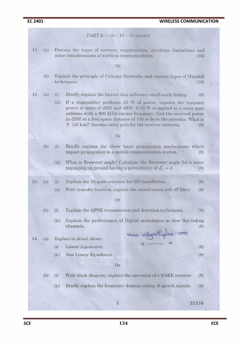
EC 2401 WIRELESS COMMUNICATION
SCE 134 ECE

EC 2401 WIRELESS COMMUNICATION
SCE 135 ECE

EC 2401 WIRELESS COMMUNICATION
SCE 136 ECE

EC 2401 WIRELESS COMMUNICATION
SCE 137 ECE

EC 2401 WIRELESS COMMUNICATION
SCE 138 ECE

EC 2401 WIRELESS COMMUNICATION
SCE 139 ECE

EC 2401 WIRELESS COMMUNICATION
SCE 140 ECE