A comparison between customized clear and removable orthodontic appliances manufactured using RP and...
10
d e n t a l m a t e r i a l s 2 9 ( 2 0 1 3 ) e1–e10 Available online at www.sciencedirect.com jo u rn al hom epa ge : www.intl.elsevierhealth.com/journals/dema A comparison between customized clear and removable orthodontic appliances manufactured using RP and CNC techniques Massimo Martorelli a,∗ , Salvatore Gerbino b , Michele Giudice c , Pietro Ausiello d a University of Naples Federico II, School of Engineering, Department of Mechanics and Energetics – DiME, P.le Tecchio, 80, 80125 Naples, Italy b University of Molise, School of Engineering, S.A.V.A. Department, Via Duca degli Abruzzi, 86039 Termoli (CB), Italy c Giudice Dental Office, Salerno, Italy d University of Naples Federico II, School of Dentistry, Department of Restorative Dentistry, Via S. Pansini 5, 80131 Naples, Italy a r t i c l e i n f o Article history: Received 15 September 2012 Accepted 19 October 2012 Keywords: Orthodontic appliances Non-contact reverse engineering systems 3D printers CNC milling machine Modeling and simulation FEM analysis a b s t r a c t Objectives. Aim of the research is to compare the orthodontic appliances fabricated by using rapid prototyping (RP) systems, in particular 3D printers, with those manufactured by using computer numerical control (CNC) milling machines. 3D printing is today a well-accepted technology to fabricate orthodontic aligners by using the thermoforming process, instead the potential of CNC systems in dentistry have not yet been sufficiently explored. Materials and methods. One patient, with mal-positioned maxillary central and lateral incisors, was initially selected. In the computer aided virtual planning was defined that, for the treatment, the patient needed to wear a series of 7 removable orthodontic appliances (ROA) over a duration of 21 weeks, with one appliance for every 3 weeks. A non-contact reverse engineering (RE) structured-light 3D scanner was used to create the 3D STL model of the impression of the patient’s mouth. Numerical FEM simulations were performed varying the position of applied forces (dis- crete and continuous forces) on the same model, simulating, in this way, 3 models with slice thickness of 0.2 mm, 0.1 mm (RP staircase effect) and without slicing (ideal case). To define the areas of application of forces, two configuration “i” and “i−1” of the treatment were overlapped. 6 patients to which for three steps (3rd, 4th and 5th step) were made to wear aligners fabricated starting from physical models by 3D printing (3DP-ROA) and afterwards, for the next steps (6th, 7th and 8th step), aligners fabricated starting from physical models by CNC milling machine (CNC-ROA), were selected. Results. For the 6 patients wearing the CNC-ROA, it was observed a best fitting of the aligner to the teeth and a more rapid teeth movement than the 3DP-ROA (2 weeks compared to 3 weeks for every appliance). ∗ Corresponding author. Tel.: +39 81 7682470. E-mail addresses: [email protected] (M. Martorelli), [email protected] (S. Gerbino), [email protected] (M. Giudice), [email protected] (P. Ausiello). 0109-5641/$ – see front matter © 2012 Academy of Dental Materials. Published by Elsevier Ltd. All rights reserved. http://dx.doi.org/10.1016/j.dental.2012.10.011
Transcript of A comparison between customized clear and removable orthodontic appliances manufactured using RP and...

Aot
Ma
Ib
c
d
a
A
R
A
K
O
N
s
3
C
M
F
(0h
d e n t a l m a t e r i a l s 2 9 ( 2 0 1 3 ) e1–e10
Available online at www.sciencedirect.com
jo u rn al hom epa ge : www.int l .e lsev ierhea l th .com/ journa ls /dema
comparison between customized clear and removablerthodontic appliances manufactured using RP and CNCechniques
assimo Martorelli a,∗, Salvatore Gerbinob, Michele Giudice c, Pietro Ausiellod
University of Naples Federico II, School of Engineering, Department of Mechanics and Energetics – DiME, P.le Tecchio, 80, 80125 Naples,talyUniversity of Molise, School of Engineering, S.A.V.A. Department, Via Duca degli Abruzzi, 86039 Termoli (CB), ItalyGiudice Dental Office, Salerno, ItalyUniversity of Naples Federico II, School of Dentistry, Department of Restorative Dentistry, Via S. Pansini 5, 80131 Naples, Italy
r t i c l e i n f o
rticle history:
eceived 15 September 2012
ccepted 19 October 2012
eywords:
rthodontic appliances
on-contact reverse engineering
ystems
D printers
NC milling machine
odeling and simulation
EM analysis
a b s t r a c t
Objectives. Aim of the research is to compare the orthodontic appliances fabricated by using
rapid prototyping (RP) systems, in particular 3D printers, with those manufactured by using
computer numerical control (CNC) milling machines.
3D printing is today a well-accepted technology to fabricate orthodontic aligners by using
the thermoforming process, instead the potential of CNC systems in dentistry have not yet
been sufficiently explored.
Materials and methods. One patient, with mal-positioned maxillary central and lateral
incisors, was initially selected. In the computer aided virtual planning was defined that, for
the treatment, the patient needed to wear a series of 7 removable orthodontic appliances
(ROA) over a duration of 21 weeks, with one appliance for every 3 weeks. A non-contact
reverse engineering (RE) structured-light 3D scanner was used to create the 3D STL model
of the impression of the patient’s mouth.
Numerical FEM simulations were performed varying the position of applied forces (dis-
crete and continuous forces) on the same model, simulating, in this way, 3 models with
slice thickness of 0.2 mm, 0.1 mm (RP staircase effect) and without slicing (ideal case). To
define the areas of application of forces, two configuration “i” and “i−1” of the treatment
were overlapped.
6 patients to which for three steps (3rd, 4th and 5th step) were made to wear aligners
fabricated starting from physical models by 3D printing (3DP-ROA) and afterwards, for the
next steps (6th, 7th and 8th step), aligners fabricated starting from physical models by CNC
milling machine (CNC-ROA), were selected.
Results. For the 6 patients wearing the CNC-ROA, it was observed a best fitting of the aligner
to the teeth and a more rapid teeth movement than the 3DP-ROA (2 weeks compared to 3
weeks for every appliance).
∗ Corresponding author. Tel.: +39 81 7682470.E-mail addresses: [email protected] (M. Martorelli), [email protected] (S. Gerbino), [email protected]
M. Giudice), [email protected] (P. Ausiello).109-5641/$ – see front matter © 2012 Academy of Dental Materials. Published by Elsevier Ltd. All rights reserved.ttp://dx.doi.org/10.1016/j.dental.2012.10.011

e2 d e n t a l m a t e r i a l s 2 9 ( 2 0 1 3 ) e1–e10
FEM simulations showed a more uniform stress distribution for CNC-ROA than 3DP-ROA.
Conclusions. In this research, 6 different case studies and CAD-FEM simulations showed that,
to fabricate an efficient clear and removable orthodontic aligner, it is necessary to consider
a compromise of several factors. A lower staircase effect (lower layer thickness) and a higher
physical prototype accuracy allow a better control of tooth movement.
emy
for different part build orientations. Inclined and curved sur-faces show staircase effects more predominantly than othersurfaces. The orientation, at which the part is built, has a
© 2012 Acad
1. Introduction
Dental aligners allow to generate and transmit a system offorces and moments to the teeth and their surrounding peri-odontal ligaments. They can be divided into two main groups:fixed and removable devices.
Traditional treatment with fixed orthodontic appliancescreates some plaque retention sites and thus increases apatient’s risk to develop white spot lesions, caries and peri-odontitis. For these reasons patients with fixed appliancesmust follow a rigid oral hygiene protocol to avoid theseside effects. How to approach these issues were studied in[1–5].
In 1999, Align Technology, Inc. (San Jose, CA, USA)introduced a new generation of appliances in orthodontics:a removable alternative to fixed appliance therapy in correct-ing malocclusion, marketed under the trade name Invisalign[6].
However, although Align Technology, Inc. has been manu-facturing removable orthodontic appliances for over 10 years,the concept of removable appliances is far from new, it wasdeveloped in 1944 by Harold D. Kesling [7]. One of the lim-itations that prevented these positioning appliances frombecoming a new standard in orthodontic care, was the lackof appropriate instruments and methodologies.
In the last years there has been a growing interest inorthodontic treatments with removable appliances, thanks tothe latest technological advancements in scanning, CAD/FEMsoftware and rapid prototyping (RP) techniques [8–13].
Nowadays several companies offer this type of technologyto dentists and orthodontists worldwide.
The straightening teeth process is based on sequentialappliances (aligners) made of a clear thermoplastic material.The aligners are worn on a biweekly regimen, and a progres-sive alignment of 0.2 mm translation or 1◦ rotation per toothis designed in each aligner [14,15].
The primary benefit of the clear and removable customizedaligners in moving the dentition is the ability to remove themwhen eating, brushing and flossing, and the superior com-fort and ease of use. Furthermore they are “invisible” and formany patients, aesthetic considerations during treatment areas important as other factors, such as comfort, pain, length oftreatment or cost [16].
The fabrication process (Fig. 1) of the teeth clear remov-able aligners begins with digital scans (reverse engineering(RE) acquisition – step 1) of the patient teeth, so that a 3D modelcan be created. This step can be carried out, starting from a
plaster model of the teeth created, from an impression of thepatient’s mouth, using a non-contact RE system or directly onthe patient’s mouth using an intraoral scanner.of Dental Materials. Published by Elsevier Ltd. All rights reserved.
Specialist orthodontic technicians then plan out each indi-vidual movement of the teeth according to the treatmentplan as prescribed by the orthodontist (computer aided virtualstraightening – step 2).
A 3D physical model is then manufactured by a RP system[17] (physical model fabrication – step 3), for each single stepof the sequence defined in the virtual planning.
Finally from this physical model, the clear orthodonticaligner (0.4 mm thick) is manufactured by a vacuum ther-moforming process in which a polyurethane resin sheet isstretched over each of the physical model (aligner fabrication– step 4).
Step 3 of the process is carried out by using RP systems.Align Technology, Inc. uses SLA (Stereolithographic Appara-tus) machines from 3D Systems: 35 SLA systems manufactureabout 40,000 parts a day for a yearly total of 8–10 million pieces[18].
ClearCorrect LLC, another US company producing clear,removable orthodontic aligners based on digital technology,uses 3D printing systems by Objet Ltd. as an integral partof its mass-scale manufacturing of custom-made orthodonticaligners [19].
So RP models play a crucial role in automating the alignerproduction process, but in any rapid prototyping process, thelayer by layer building process introduces an error on theamount of material used compared to the volume specified bythe computer aided design model. This error causes the stair-case effect [20] on the surface profile (Fig. 2) and adverselyaffects the dimensional accuracy as well as surface finish
Fig. 1 – Flow chart of the process for planning andmanufacturing of customized orthodontic appliances.

d e n t a l m a t e r i a l s 2 9
s[
ttp
dubnt
mnm
mat
considering the ideal case (without slicing) and a RP slicing of
Fig. 2 – Staircase effect.
ignificant effect on the quality of various surfaces of the part21].
Part’s orientation also affects other factors such as the buildime, the complexity of support structure, shrinkage, curling,rapped volume, and material flow in many rapid prototypingrocesses.
Stair-stepping inaccuracies can be reduced either byecreasing the layer thickness and by orienting the part [22] orsing the adaptive slicing which adapts the thickness of eachuild layer to better match the part surface geometry [23,24];evertheless, today there is no way the staircase effect can beotally eliminated.
RP systems are also called with the term “additiveanufacturing” (AM) for distinguish them from computer
umerical control (CNC) systems, which instead subtractaterial to obtain the final shape.In the paper the authors take into account a CNC
illing 5-axis machine to manufacture orthodontic appli-nces. Although the RP process is more efficient than CNCraditional technique as the former does not require much
Fig. 3 – From plaster model to CAD geom
Fig. 4 – Analysis performed on the four h
( 2 0 1 3 ) e1–e10 e3
human input (CNC machining instead involves CAM program-ming, and so, much time is spent in programming toolpaths),and models are generated quickly and independently of theshape complexity, CNC systems allow to get higher accuracythan RP systems [25] and it does not present the staircaseeffect. CAD-FEM simulations and six different case studies areused to compare the appliances fabricated in the two ways.
2. Materials and methods
2.1. 3D virtual DATA of the patient teeth
One patient with mal-positioned maxillary central and lateralincisors was selected.
3D data of the patient teeth were generated from the plastermodel obtained from an impression of the patient’s mouth.
A non-contact RE structured-light 3D scanner (Sint Scan130, by Sintesi Sud, Italy) was used to create the 3D STL model(Fig. 3).
Within a computer assisted environment, CAD-like opera-tions are then made to separate teeth, so the whole 3D modelthe patient’s teeth is ready for the analysis and the virtualplanning of orthodontic treatment (performed with the soft-ware package OrthoAnalyzerTM by 3Shape). In our case study,the sequence of different steps to move the teeth were defined:a series of 7 removable orthodontic appliances (ROA) wereplanned, each for 3 weeks, for a 21-week treatment (Fig. 4).
Figs. 5 and 6 show the 3D STL models obtained, respectively,
0.2 mm.CNC systems allow to get very smooth surfaces and higher
accurate contours than RP systems; moreover no staircase
etry through 3D scanning process.
ighlighted teeth through four steps.

e4 d e n t a l m a t e r i a l s 2 9 ( 2 0 1 3 ) e1–e10
Table 1 – Comparison of various systems suitable to fabricate orthodontic aligners.
System/manufacturer Technology Build envelope Layerthickness
Accuracy
Objet 24/Objet Ltd. (mergedwith Stratasys by 2012)
Jetted photopolymer 9.22 mm × 192 mm × 149 mm 0.028 mm ±0.1 mm
ProJetTM 6000/3D Systems Film transfer of photopolymer 250 mm × 250 mm × 250 mm 0.10 mm 0.025–0.05 mmMojoTM/Stratasys Fused deposition modeling (FDM) 127 mm × 127 mm × 127 mm 0.17 mm Not specifiedZPrinter® 150/Z Corporation
[Acquired by 3D Systems]Three dimensional printing (3DP) 236 mm × 185 mm × 127 mm 0.10 mm Not specified
Roland DWX-50/Roland DGCorporation
Computer numerical control(CNC)
Disc external diameter:98–100 mm height:12–26 mm
0 ±0.01 mm
Table 2 – Time and cost comparison of the two systems used in the present study.
System Number of models Total time Mean time Mean cost
h 30 m80 m
Objet 24 8 7
Roland DWX-50 1
effect is generated as, instead, observed in the RP models(Fig. 6).
In Table 1 the main characteristics of various RP and CNCsystems, suitable to fabricate orthodontic aligners, are shownand compared.
Data are derived from the datasheets from Manufacturers.In the paper, among these systems, the 3D printing Objet
24 by Objet Ltd and the 5-axis CNC milling machine, RolandDWX-50 by Roland DG Corporation were used.
In Table 2 for the two systems chosen in the paper, times
and costs in the models manufacturing are compared (datafrom the Sintesi Sud Company, Italy).Fig. 5 – STL model without slicing (ideal case).
Fig. 6 – Sliced STL file of patient te
in 55 min 5–10 Din 80 min 2–5 D
2.2. FEM simulations
To numerically simulate the difference of applied forcesaction, with and without staircase effect, FE analysis was car-ried out.
To deeply understand what happen on the teeth dur-ing the application of the aligners made by two differentmanufacturing processes, numerical FEM simulations wereperformed within NASTRAN (by MSC Corporation). For the FEpre-processing and post-processing phases HyperMesh V10.0and HyperView (by Altair Engineering, Inc.) software wererespectively used.
To perform FE analysis, it was necessary to individuate theareas of application of forces. For two consecutive steps theycan be highlighted by overlapping the ith configuration withthe i−1th configuration: Fig. 7 shows the overlapped areas onwhich forces have to be applied.
All models were modeled with TETRA (3D tetrahedral with4 nodes) elements. 213,378 nodes and 882,700 elements wereused.
Due to the high number of elements of the models, it waschosen to achieve a gradual mesh ranging from a minimumfeature size of 0.02 mm in the areas of greatest interest (areasof application of the forces) to a maximum size of 1.40 mm in
the other areas.FEM simulations were performed considering 3 differentcases by using the same model, varying only the position of
eth. Slice thickness = 0.2 mm.

d e n t a l m a t e r i a l s 2 9 ( 2 0 1 3 ) e1–e10 e5
Fig. 7 – Overlapping of ith and i−1th steps to i
Fig. 8 – Constrains modeling.
twoc
oc
epata
In order to express the evaluation on the fitting and esthet-ics aspects of the two types of aligners, the group of 6 patients
Fc
he applied loads (forces pairs acting on each tooth). In thisay it was possible to simulate models with slice thicknessf 0.2 mm and 0.1 mm (RP models) and without slicing (idealase). The base of the model was fixed (Fig. 8).
Fig. 9 shows the local areas where loads were defined,btained, as explained above, by overlapping two consecutiveonfigurations of the treatment.
A linear static structural analysis was performed consid-ring an unique material with the following mechanicalroperties: E = 70e3 MPa, � = 0.30, and a load equal to 25 N,pplied for each side of each tooth, varying the position of
he applied forces (0.2 mm, 0.1 mm and case continuum) andssuring the same total pressure effect (Fig. 10).Fig. 9 – Active force sy
ig. 10 – Force pressure imparted by ROA onto teeth in the three
ontinuum (on the right).
dentify the areas of application of forces.
2.3. Case studies
6 patients were selected. The steps 1–4, described in Section 1of the paper, were carried out.
For the step 3, a 3D Printing, Objet 24 by Objet Ltd and a5-axis CNC milling machine, Roland DWX-50 by Roland DGCorporation, were used.
Fig. 11 shows virtual models before and after treatment forone of the six patients. For the same patient, in Table 3 aresummarized the teeth to be moved and the type of movement.
Each patient wore aligners fabricated starting from physi-cal models generated by 3D printing (3DP-ROA) for three steps(3rd, 4th and 5th step), each for three weeks, and then thosegenerated by 5-axis CNC milling machine (CNC-ROA) for thenext three steps (6th, 7th and 8th step), each for two weeks(Fig. 12).
All patients completed active orthodontic treatment andthey were asked to give back information regarding to pain,adaptation and esthetics of the oral aligners made by the twotechniques, compiling two questionnaires.
The pain was evaluated by means of a visual analogue scale(VAS) questionnaire from 0 to 10 that codifies the responsecategories from no pain to very severe pain. The results areshown in Fig. 13.
were asked to compile another questionnaire through a Likertgraduated scale from 1 to 5.
stem Modeling.
cases: 0.2 mm (on the left), 0.1 mm (on the center),

e6 d e n t a l m a t e r i a l s 2 9 ( 2 0 1 3 ) e1–e10
ter (o
Fig. 11 – Virtual models before (on the left) and afFive ordered response levels were used: the answers to the2 closed-ended questions on fitting and esthetic aspects were
transformed to numbers so that values from 1 to 5 representsthe response categories from poorest to best, respectively.Although many psychometricians advocate using seven ornine levels, a recent empirical study [26] found that data fromTable 3 – Tooth movement overview for one of the six patients.
Teeth Rotation Angulation Inclination Le
15 3◦
14
13 13◦ −17.4◦ −3.9◦ −312 0◦ −011 3◦ −021 3◦ 022 −2◦ 4◦ 023 −24◦ 8.7◦ −3.5◦ 224 025 034 12◦
33 1◦ 4◦ 032 6◦ 031 −2◦
41 −1◦
42 2◦ 0.1◦ 3◦
43 4◦
44 6◦
n the right) treatment for one of the six patients.
5-level, 7-level and 10-level items showed very similar char-acteristics in terms of mean, variance, skewness and kurtosis
after a simple transformation was applied.In the questionnaire the aligners were identified with theacronyms “3DP-ROA” and “CNC-ROA”. For each question thesubject had to give two answers, one for 3DP-ROA and one for
ft/right Extrusion/intrusion Forward/backward
2.7 mm2.4 mm
.8 mm 2.2 mm
.9 mm 3.4 mm
.3 mm
.4 mm
.9 mm 1.6 mm
.7 mm −1.5 mm
.6 mm 1.7 mm
.5 mm 1.5 mm
.4 mm
.2 mm
d e n t a l m a t e r i a l s 2 9 ( 2 0 1 3 ) e1–e10 e7
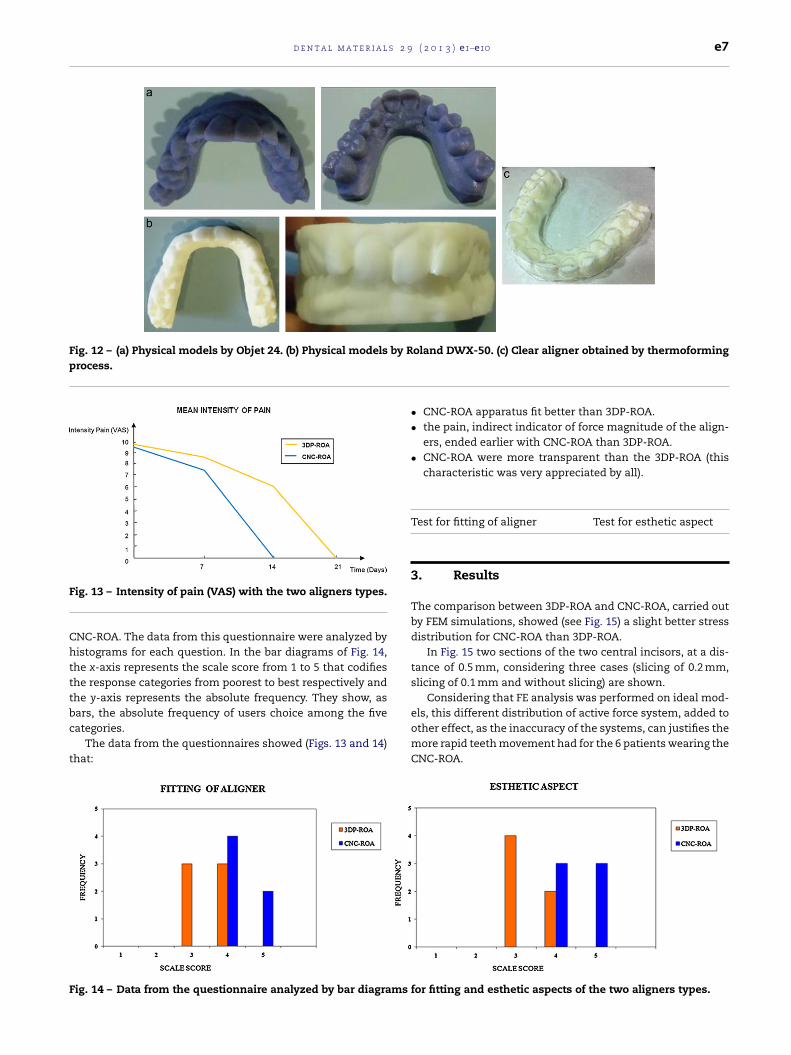
Fig. 12 – (a) Physical models by Objet 24. (b) Physical models by Roland DWX-50. (c) Clear aligner obtained by thermoformingprocess.
F
Chtttbc
t
F
ig. 13 – Intensity of pain (VAS) with the two aligners types.
NC-ROA. The data from this questionnaire were analyzed byistograms for each question. In the bar diagrams of Fig. 14,
he x-axis represents the scale score from 1 to 5 that codifieshe response categories from poorest to best respectively andhe y-axis represents the absolute frequency. They show, as
ars, the absolute frequency of users choice among the fiveategories.The data from the questionnaires showed (Figs. 13 and 14)hat:
ig. 14 – Data from the questionnaire analyzed by bar diagrams
• CNC-ROA apparatus fit better than 3DP-ROA.• the pain, indirect indicator of force magnitude of the align-
ers, ended earlier with CNC-ROA than 3DP-ROA.• CNC-ROA were more transparent than the 3DP-ROA (this
characteristic was very appreciated by all).
Test for fitting of aligner Test for esthetic aspect
3. Results
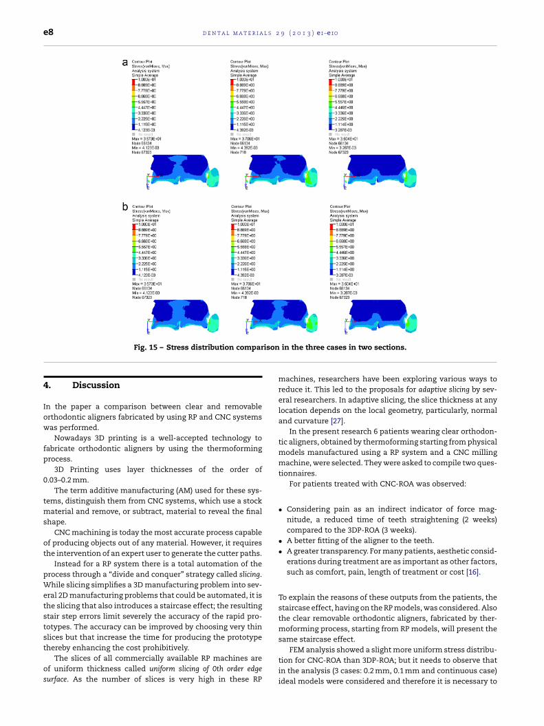
The comparison between 3DP-ROA and CNC-ROA, carried outby FEM simulations, showed (see Fig. 15) a slight better stressdistribution for CNC-ROA than 3DP-ROA.
In Fig. 15 two sections of the two central incisors, at a dis-tance of 0.5 mm, considering three cases (slicing of 0.2 mm,slicing of 0.1 mm and without slicing) are shown.
Considering that FE analysis was performed on ideal mod-
els, this different distribution of active force system, added toother effect, as the inaccuracy of the systems, can justifies themore rapid teeth movement had for the 6 patients wearing theCNC-ROA.for fitting and esthetic aspects of the two aligners types.
e8 d e n t a l m a t e r i a l s 2 9 ( 2 0 1 3 ) e1–e10
ison
Fig. 15 – Stress distribution compar4. Discussion
In the paper a comparison between clear and removableorthodontic aligners fabricated by using RP and CNC systemswas performed.
Nowadays 3D printing is a well-accepted technology tofabricate orthodontic aligners by using the thermoformingprocess.
3D Printing uses layer thicknesses of the order of0.03–0.2 mm.
The term additive manufacturing (AM) used for these sys-tems, distinguish them from CNC systems, which use a stockmaterial and remove, or subtract, material to reveal the finalshape.
CNC machining is today the most accurate process capableof producing objects out of any material. However, it requiresthe intervention of an expert user to generate the cutter paths.
Instead for a RP system there is a total automation of theprocess through a “divide and conquer” strategy called slicing.While slicing simplifies a 3D manufacturing problem into sev-eral 2D manufacturing problems that could be automated, it isthe slicing that also introduces a staircase effect; the resultingstair step errors limit severely the accuracy of the rapid pro-totypes. The accuracy can be improved by choosing very thinslices but that increase the time for producing the prototype
thereby enhancing the cost prohibitively.The slices of all commercially available RP machines areof uniform thickness called uniform slicing of 0th order edgesurface. As the number of slices is very high in these RP
in the three cases in two sections.
machines, researchers have been exploring various ways toreduce it. This led to the proposals for adaptive slicing by sev-eral researchers. In adaptive slicing, the slice thickness at anylocation depends on the local geometry, particularly, normaland curvature [27].
In the present research 6 patients wearing clear orthodon-tic aligners, obtained by thermoforming starting from physicalmodels manufactured using a RP system and a CNC millingmachine, were selected. They were asked to compile two ques-tionnaires.
For patients treated with CNC-ROA was observed:
• Considering pain as an indirect indicator of force mag-nitude, a reduced time of teeth straightening (2 weeks)compared to the 3DP-ROA (3 weeks).
• A better fitting of the aligner to the teeth.• A greater transparency. For many patients, aesthetic consid-
erations during treatment are as important as other factors,such as comfort, pain, length of treatment or cost [16].
To explain the reasons of these outputs from the patients, thestaircase effect, having on the RP models, was considered. Alsothe clear removable orthodontic aligners, fabricated by ther-moforming process, starting from RP models, will present thesame staircase effect.
FEM analysis showed a slight more uniform stress distribu-tion for CNC-ROA than 3DP-ROA; but it needs to observe thatin the analysis (3 cases: 0.2 mm, 0.1 mm and continuous case)ideal models were considered and therefore it is necessary to

d e n t a l m a t e r i a l s 2 9
Fig. 16 – Compromise of several factors to get a bettercontrol of tooth movement with the clear and removableorthodontic aligner.
aiC
sst
hpt
af
ttaoaasa
-
-
-
-
Taa(a
r
orthodontic molar bands. European Journal of Orthodontics1990;12:316–9.
dd the negative effect on the stress distribution, due to thenaccuracy of the systems (3D Printing are less accurate thanNC systems [25]).
The effect of the inaccuracy of the system, added to thetaircase effect, can also explain the reduced time of teethtraightening (2 weeks versus 3 weeks) and the better fittingo the teeth of the CNC-ROA compared to the 3DP-ROA.
In addition to these factors, the thickness of the alignersas an important influence on the phenomenon [28]. In theaper the aligner thickness was assumed the same for thewo considered technologies.
So, the choice of the system, that allows to get the best clearnd removable orthodontic aligner, is a compromise of severalactors.
Fig. 16 shows the layer thickness versus the accuracy ofhe system. Considering three factors: effectiveness, produc-iveness and transparency of the orthodontic aligner, threereas are identified. Green area represents the effectivenessf the aligner that is better fitting to the teeth; the yellowrea represents the productiveness and the three verticalreas, identified by stars (four stars, best transparency – twotars, worst transparency) represent the transparency of theligner:
The effectiveness of the aligner decreases when the layerthickness, and then the staircase effect, increases.
The accuracy of the system decreases when the layer thick-ness increases.
The productiveness of the aligner decreases when the layerthickness increases.
The transparency of the aligner increases when the layerthickness decreases.
he best compromise of the several factors, that allows to get better control of tooth movement with the clear and remov-ble orthodontic aligner, is achieved by using those systems
RP or CNC) whose characteristics allow to be in the circledrea indicated with A, in Fig. 16.( 2 0 1 3 ) e1–e10 e9
5. Conclusions
The main disadvantage of CNC machining compared to RPprocesses is in the lead-time. Since CNC machining involvesCAM programming, much time is spent programming toolpaths. Longer periods of machining time are required.
Unlike CNC machining, the entire RP process is efficientwithout much human input, and models are created quickly.
The most evident advantage exhibited by CNC machines isthe tolerance and accuracy. The paths taken by the tool bits donot have to follow a 2D profile like other RP processes, so forCNC systems there is not the problem of the staircase effect.
So, with the limits of the present investigation, it can beconcluded that, for the choice of the system, RP or CNC, thatallows to get the best clear and removable orthodontic aligner,it is necessary to consider the right compromise of severalfactors, in particular the staircase effect, depending on thelayer thickness, the accuracy of the system, the duration ofthe treatment (time and costs) and the transparency of thealigner.
A lower staircase effect (lower layer thickness) and a higherphysical prototype accuracy allow a better control of toothmovement.
Funding
None.
Acknowledgements
The authors gratefully acknowledge the eng. Angelo Salamini(Sintesi Sud – Ariano Irpino, Italy) and eng. Leonardo Severinofor their useful technical support.
e f e r e n c e s
[1] Jenatschke F, Elsenberger E, Welte HD, Schlagenhauf U.Influence of repeated chlorhexidine varnish applications onmutans streptococci counts and caries increment inpatients treated with fixed orthodontic appliances. Journalof Orofacial Orthopedics 2001;62:36–45.
[2] Heintze SD, Jost-Brinkmann PG, Finke C, Miethke RR. Oralhealth for the orthodontic patient. Chicago: Quintessence;1999.
[3] Gehlen I, Netuschil L, Berg R, Reich E, Katsaros C. Theinfluence of a 0.2% chlorhexidine mouthrinse on plaqueregrowth in orthodontic patients. Journal of OrofacialOrthopedics 2000;61:54–62.
[4] Basdra EK, Huber H, Komposch G. Fluoride released fromorthodontic bonding agents alters the enamel surface andinhibits enamel demineralization in vitro. American Journalof Orthodontics and Dentofacial Orthopedics1996;109:466–72.
[5] Adrianens ML, Dermout LR, Verbeeck RM. The use of fluor, afluoride varnish, as a caries prevention method under
[6] Wong BH. Invisalign A to Z. American Journal ofOrthodontics and Dentofacial Orthopedics 2002;121(5):540–1.

l s 2
e10 d e n t a l m a t e r i a[7] Kesling HD. The philosophy of the tooth positioningappliance. American Journal of Orthodontics1945;31:297–304.
[8] Ausiello P, Franciosa P, Martorelli M, Watts DC. Numericalfatigue 3D-FE modelling of indirect composite-restoredposterior teeth. Dental Materials 2011;27(5):423–30,http://dx.doi.org/10.1016/j.dental.2010.12.001 [ISSN0109-5641].
[9] Ausiello P, Franciosa P, Martorelli M, Watts DC. Mechanicalbehavior of post-restored upper canine teeth: a 3D FEanalysis. Dental Materials 2011;27(12):1285–94,http://dx.doi.org/10.1016/j.dental.2011.09.009 [ISSN0109-5641].
[10] Martorelli M, Ausiello P. A novel approach for a complete 3Dtooth reconstruction using only 3D crown data. InternationalJournal on Interactive Design and Manufacturing 2012,http://dx.doi.org/10.1007/s12008-012-0166-8[ISSN:1955-2513].
[11] Giordano M, Ausiello P, Martorelli M. Accuracy evaluation ofsurgical guides in implant dentistry by non-contact reverseengineering techniques. Dental Materials 2012;28(9):178–85,http://dx.doi.org/10.1016/j.dental.2012.06.006 [ISSN0109-5641].
[12] Citarella R, Armentani E, Caputo F, Naddeo A. FEM and BEManalysis of a human mandible with addedtemporomandibular joints. The Open MechanicalEngineering Journal 2012;6:100–14.
[13] Citarella R, Armentani E, Caputo F, Lepore M. Stress analysisof an endosseus dental implant by BEM and FEM. The OpenMechanical Engineering Journal 2012;6:115–24.
[14] Kuo E, Miller R. Automated custom-manufacturingtechnology in orthodontics. American Journal ofOrthodontics and Dentofacial Orthopedics 2003;123:578–81.
[15] Boyd R, Vlaskalic V. Three-dimensional diagnosis andorthodontic treatment of complex malocclusions with theInvisalign. Seminars in Orthodontics 2001;7:274–93.
[16] Shalish M, Cooper-Kazaz R, Ivgi I, Canetti L, Tsur B, Bachar E,et al. Adult patients’ adjustability to orthodontic appliances.Part I: a comparison between Labial, Lingual, and
InvisalignTM. European Journal of Orthodontics 2011,http://dx.doi.org/10.1093/ejo/cjr086.[17] Mazzoli A, Germani M, Raffaeli R, Gracco A. In: GregorioRomero Rey, Luisa Martinez Muneta, editors.
9 ( 2 0 1 3 ) e1–e10
Three-dimensional diagnosis and visualization supports inorthodontics based on reverse engineering and solidfree-form fabrication techniques, modelling simulation andoptimization. 2010., ISBN 978-953-307-048-3 p. 1–24[chapter 1].
[18] Waterman P. 3D printing: how a star trek fantasy hasbecome reality for the dental and orthodontic professions.Orthotown 2012;(April):56–9.
[19] ClearCorrect reveals integration of advanced digitalorthodontic production using objet’s 3D printing systems.Houston, TX/Israel: PRNewswire/REHOVOT; 2012 [June 12].
[20] Pandey PM, Venkata N, Dhande R, Dhande SG. Slicingprocedures in layered manufacturing: a review. RapidPrototyping Journal 2003;9(5):274–88.
[21] Campbell RI, Martorelli M, Lee HS. Surface roughnessvisualisation for rapid prototyping models. Computer AidedDesign 2002;34(September (10)):717–25 [ISSN 0010-4485,Publisher Elsevier].
[22] Masood SH, Rattanawong W, Iovenitti P. A generic algorithmfor a best part orientation system for complex parts in rapidprototyping. Journal of Materials Processing Technology2003;139(1–3):110–6, 20.
[23] Zhao Z, Laperriere L. Adaptive direct slicing of the solidmodel for rapid prototyping. International Journal ofProduction Research 2000;38(3):89–98.
[24] Singhal SK, Jain PK, Pandey PM. Adaptive slicing for SLSprototyping. Computer-Aided Design and Applications2008;5(1–4):412–23.
[25] Wohlers T, Grimm T. Is CNC machining really better thanRP? Mold Making Technology 2006;(November).
[26] Dawes J. Do data characteristics change according to thenumber of scale points used? An experiment using 5-point,7-point and 10-point scales. International Journal of MarketResearch 2008;50(1):61–77.
[27] Karunakaran KP, Solanki PD, Sahasrabudhe OS, Pushpa V,Dwivedi R, Kovacevic R. Simplified production of largeprototypes using visible slicing. In: Proceedings of the solidfreeform fabrication symposium. 2005.
[28] Hahn W, Dathe H, Fialka-Fricke J, Fricke-Zech S, Zapf A,
Kubein-Meesenburg D, et al. Influence of thermoplasticappliance thickness on the magnitude of force delivered to amaxillary central incisor during tipping. American Journal ofOrthodontics & Dentofacial Orthopedics 2009;136(1):12.e1–7.