A Coarse-to-Fine Registration Approach for Point Cloud Data ...
30
Citation: Yuan, M.; Li, X.; Cheng, L.; Li, X.; Tan, H. A Coarse-to-Fine Registration Approach for Point Cloud Data with Bipartite Graph Structure. Electronics 2022, 11, 263. https://doi.org/10.3390/ electronics11020263 Academic Editor: Flavio Canavero Received: 9 December 2021 Accepted: 12 January 2022 Published: 14 January 2022 Publisher’s Note: MDPI stays neutral with regard to jurisdictional claims in published maps and institutional affil- iations. Copyright: © 2022 by the authors. Licensee MDPI, Basel, Switzerland. This article is an open access article distributed under the terms and conditions of the Creative Commons Attribution (CC BY) license (https:// creativecommons.org/licenses/by/ 4.0/). electronics Article A Coarse-to-Fine Registration Approach for Point Cloud Data with Bipartite Graph Structure Munan Yuan 1,2, *, Xiru Li 1 , Longle Cheng 1,2 , Xiaofeng Li 1, * and Haibo Tan 1 1 Hefei Institute of Physical Science, Chinese Academy of Sciences, Hefei 230031, China; [email protected] (X.L.); [email protected] (L.C.); [email protected] (H.T.) 2 Science Island Branch, Graduate School of USTC, Hefei 230026, China * Correspondence: [email protected] (M.Y.); xfl[email protected] (X.L.); Tel.: +86-551-6559-5684 (M.Y.); +86-551-6559-1219 (X.L.) Abstract: Alignment is a critical aspect of point cloud data (PCD) processing, and we propose a coarse-to-fine registration method based on bipartite graph matching in this paper. After data pre- processing, the registration progress can be detailed as follows: Firstly, a top-tail (TT) strategy is designed to normalize and estimate the scale factor of two given PCD sets, which can combine with the coarse alignment process flexibly. Secondly, we utilize the 3D scale-invariant feature transform (3D SIFT) method to extract point features and adopt fast point feature histograms (FPFH) to describe corresponding feature points simultaneously. Thirdly, we construct a similarity weight matrix of the source and target point data sets with bipartite graph structure. Moreover, the similarity weight threshold is used to reject some bipartite graph matching error-point pairs, which determines the dependencies of two data sets and completes the coarse alignment process. Finally, we introduce the trimmed iterative closest point (TrICP) algorithm to perform fine registration. A series of extensive experiments have been conducted to validate that, compared with other algorithms based on ICP and several representative coarse-to-fine alignment methods, the registration accuracy and efficiency of our method are more stable and robust in various scenes and are especially more applicable with scale factors. Keywords: point cloud; coarse-to-fine registration; top-tail (TT) strategy; bipartite graph matching; 3D scale-invariant feature transform (3D SIFT); fast point feature histograms (FPFH); trimmed iterative closest point (TrICP) 1. Introduction With the rapid development of optical measurement technology, three-dimensional (3D) models of real-world objects with different views have been employed to collect data for many application scenarios [1–5]. As the fundamental technique in 3D data processes, the registration method is mainly responsible for determining the correspondence and transformation of multiple-view 3D data, which facilitates the implementation of many reverse engineering applications, such as multi-platform data alignment for airborne and terrestrial laser scanning [6], foot alignment for reconstruction in the footwear consumer field [7], remote sensing image registration in military and civilian fields [8], skull reg- istration for craniofacial reconstruction in the medical field [9], cross-source point cloud registration in large-scale scanned data for street views outdoors [10], 3D face registration for face recognition [11], etc. During the past few decades, the high-performance registra- tion method has become an increasingly important research topic. However, the existing registration algorithms still have many defects in terms of efficiency and accuracy in prac- tice. According to the transformation relationship of different-view 3D data, registration methods can be divided into rigid registration algorithms and non-rigid registration algo- rithms. In this paper, we mainly focus on rigid alignment methods with some extensibility, and all processed 3D data is PCD. Electronics 2022, 11, 263. https://doi.org/10.3390/electronics11020263 https://www.mdpi.com/journal/electronics
-
Upload
khangminh22 -
Category
Documents
-
view
2 -
download
0
Transcript of A Coarse-to-Fine Registration Approach for Point Cloud Data ...
�����������������
Citation: Yuan, M.; Li, X.; Cheng, L.;
Li, X.; Tan, H. A Coarse-to-Fine
Registration Approach for Point
Cloud Data with Bipartite Graph
Structure. Electronics 2022, 11, 263.
https://doi.org/10.3390/
electronics11020263
Academic Editor: Flavio Canavero
Received: 9 December 2021
Accepted: 12 January 2022
Published: 14 January 2022
Publisher’s Note: MDPI stays neutral
with regard to jurisdictional claims in
published maps and institutional affil-
iations.
Copyright: © 2022 by the authors.
Licensee MDPI, Basel, Switzerland.
This article is an open access article
distributed under the terms and
conditions of the Creative Commons
Attribution (CC BY) license (https://
creativecommons.org/licenses/by/
4.0/).
electronics
Article
A Coarse-to-Fine Registration Approach for Point Cloud Datawith Bipartite Graph StructureMunan Yuan 1,2,*, Xiru Li 1, Longle Cheng 1,2, Xiaofeng Li 1,* and Haibo Tan 1
1 Hefei Institute of Physical Science, Chinese Academy of Sciences, Hefei 230031, China; [email protected] (X.L.);[email protected] (L.C.); [email protected] (H.T.)
2 Science Island Branch, Graduate School of USTC, Hefei 230026, China* Correspondence: [email protected] (M.Y.); [email protected] (X.L.);
Tel.: +86-551-6559-5684 (M.Y.); +86-551-6559-1219 (X.L.)
Abstract: Alignment is a critical aspect of point cloud data (PCD) processing, and we propose acoarse-to-fine registration method based on bipartite graph matching in this paper. After data pre-processing, the registration progress can be detailed as follows: Firstly, a top-tail (TT) strategy isdesigned to normalize and estimate the scale factor of two given PCD sets, which can combine withthe coarse alignment process flexibly. Secondly, we utilize the 3D scale-invariant feature transform(3D SIFT) method to extract point features and adopt fast point feature histograms (FPFH) to describecorresponding feature points simultaneously. Thirdly, we construct a similarity weight matrix ofthe source and target point data sets with bipartite graph structure. Moreover, the similarity weightthreshold is used to reject some bipartite graph matching error-point pairs, which determines thedependencies of two data sets and completes the coarse alignment process. Finally, we introduce thetrimmed iterative closest point (TrICP) algorithm to perform fine registration. A series of extensiveexperiments have been conducted to validate that, compared with other algorithms based on ICPand several representative coarse-to-fine alignment methods, the registration accuracy and efficiencyof our method are more stable and robust in various scenes and are especially more applicable withscale factors.
Keywords: point cloud; coarse-to-fine registration; top-tail (TT) strategy; bipartite graph matching;3D scale-invariant feature transform (3D SIFT); fast point feature histograms (FPFH); trimmediterative closest point (TrICP)
1. Introduction
With the rapid development of optical measurement technology, three-dimensional(3D) models of real-world objects with different views have been employed to collect datafor many application scenarios [1–5]. As the fundamental technique in 3D data processes,the registration method is mainly responsible for determining the correspondence andtransformation of multiple-view 3D data, which facilitates the implementation of manyreverse engineering applications, such as multi-platform data alignment for airborne andterrestrial laser scanning [6], foot alignment for reconstruction in the footwear consumerfield [7], remote sensing image registration in military and civilian fields [8], skull reg-istration for craniofacial reconstruction in the medical field [9], cross-source point cloudregistration in large-scale scanned data for street views outdoors [10], 3D face registrationfor face recognition [11], etc. During the past few decades, the high-performance registra-tion method has become an increasingly important research topic. However, the existingregistration algorithms still have many defects in terms of efficiency and accuracy in prac-tice. According to the transformation relationship of different-view 3D data, registrationmethods can be divided into rigid registration algorithms and non-rigid registration algo-rithms. In this paper, we mainly focus on rigid alignment methods with some extensibility,and all processed 3D data is PCD.
Electronics 2022, 11, 263. https://doi.org/10.3390/electronics11020263 https://www.mdpi.com/journal/electronics
Electronics 2022, 11, 263 2 of 30
As the best-known registration algorithm, ICP conducts an iterative process to alignthe relatively similar 3D point clouds well with constraint conditions of uniform density,high overlap rate and good initial position, and it is prone to trap into local optimal prob-lems [12,13]. Multiple ICP variants have also been proposed to improve performance.Trimmed ICP (TrICP) utilizes the Least-Trimmed Squares approach to improve robustnessin low data overlaps [14]. Generalized ICP(GICP) designs a structure by minimizing theplane-to-plane distance to enhance the resistance to noise [15]. Globally Optimal ICP(Go-ICP) provides a globally optimal Euclidean solution under L2 error with a branch-and-bound scheme to avoid local optimization [16]. Multi-resolution ICP (MRICP) incorporatesa hierarchical octree for data multi-resolution spatial partitioning to speed up computationand enhance robustness [17]. Markov chain Monte Carlo simulated annealing (MCMC-SA)ICP combined an MCMC method and an improved SA method to accelerate convergencewith the global minimum [18]. Although ICP-based algorithms achieve high registration ac-curacy, the iterative computational approach and good initial position condition restrictionlimit their applications in practical 3D data processing.
Probability distribution alignment (PDA) methods regard the registration problem asa probability density estimation problem and have good robustness in noise and differentdata overlap rates. The Normal Distributions Transform (NDT) utilizes a Gaussian prob-ability distribution to represent each point and completes the alignment by maximizingthe sum of the Gaussian probability distributions of transformed unregistered PCD [19].Coherent Point Drift (CPD) fits the Gaussian mixture model (GMM) centroids of target PCDto source PCD through estimating the maximum likelihood [20]. Student’s t latent mixturemodel (TLMM) constructs a hierarchical Bayesian network to algin different PCD based onstudent-t mixture model (SMM), which effectively improves the robustness [21]. Amongthese PDA algorithms, some have lower accuracy with fast registration speed, such as NDT,and conversely, high-performance methods (CPD and TLMM are also applicable for non-rigid alignment) utilize EM iterative algorithms to solve the optimization of the objectivefunction, which cannot avoid large computational and local optimization problems.
In recent years, the PCD registration research based on deep learning framework hasgradually attracted the attention of scholars. The Deep Closest Point (DCP) predicts a rigidtransformation for two PCD from a deep learning perspective [22]. A Deep Gaussian Mix-ture Registration (DeepGMR) model designs a neural network to search GMM parametersand computation blocks to obtain optimal transformation [23]. As a data-driven model,3DMatch learns local volumetric patch descriptors for establishing 3D data correspondencesduring the rough registration phase [24]. The Robust Point Matching (RPM)-Net confirmspoint correspondences with differentiable Sinkhorn layers and estimates optimal annealingparameters with the second network [25]. These algorithms have good performance inalignment robustness, accuracy and large data. However, the majority of deep learningmethods suffer from heavy memory resources, which limits the generality of application.
The coarse-to-fine alignment algorithms are the most widely used non-rigid registra-tion methods. At first, common coarse alignment algorithms, such as Random SampleConsensus (RANSAC) [26], 4-Points Congruent Sets (4PCS) [27], Principal ComponentAnalysis (PCA) [28], etc., perform fast rough position transformation estimation by ran-domly selecting some points with distance constraints or downscaled processing. Thefine alignment algorithms, such as ICP and its variants, conduct further transformationcomputation of two PCD on the basis of previous initial transformation correspondence,which greatly reduces the iterative computation. However, the results of these coarseregistration methods may be unstable and have a large error, which sometimes imposesa greater burden for the fine alignment process. Then, the coarse registration methodsutilize similarity measures of local feature points and descriptors to determine the initialtransformation correspondence. SAmple Consensus Initial Alignment (SAC-IA) utilizesFast Point Feature Histograms (FPFH) local geometry descriptors to match points in differ-ent point clouds [29]. Keypoint-based 4PCS (K4PCS) adopts 3D Difference-of-Gaussiansor 3D Harris corner detector to extract key points and then performs coarse alignment
Electronics 2022, 11, 263 3 of 30
instead of raw PCD to improve computation efficiency and accuracy [30]. The enhancedperformance of coarse alignment algorithms contributes to the application of coarse-to-fineregistration methods. Liu et al. [31] utilized FPFH features to find corresponding pointpairs, RANSAC to eliminate initial incorrect correspondence and NDT to refine the transfor-mation. Li et al. [32] proposed a graph-enhanced sample consensus (GESAC) to estimaterough transformation with robust shape-annealing, which improved RANSAC-based fineregistration accuracy. Although these methods show good alignment performance, the na-ture of local feature point extraction is prone to interference from noise and inhomogeneousdensity. Shi et al. [33] adopted a PDA model of NDT to compute the initial transformationmatrix, where ICP performs the fine alignment, which improves the robustness of thealignment algorithm to noise. Currently, the top state-of-art coarse-to-fine registrationmethods summarize the results of continuous optimization of rough alignment and ICP.Wu et al. [34] designed a coarse-to-fine registration algorithm based on FPFH eigenvalueand volume constraints. This algorithm can reduce mismatch rate and improves the pointcloud registration precision with ICP. Lu et al. [35] proposed a point cloud registrationalgorithm combined with improved K4PCS and ICP to improve the speed and accuracy.Wu et al. [36] presented a triangular model registration algorithm based on differentialtopological singularity points (DTSP)-ICP. This algorithm is able to obtain the mesh modelnature of differential topological structure and avoid local errors based on Euclideandistance. Shi et al. [33] utilized SAC-IA to conduct rough alignment and perform fineregistration with NDT and ICP, respectively. According to their research, SAC + ICP hasbetter performance. Yao et al. [37] proposed an improved iterative closest point (ICP)algorithm based on the curvature feature similarity. PCA was used to confirm a betterinitial value, and the similarity of curvature features was used to determine the nearestpoints for fine registration. Kamencay et al. [38] presented an improved feature-basedregistration algorithm to reduce time consumption and improve ICP convergence speed,with the combination of 3D scale-invariant feature transform (SIFT) key-point extractionand K-nearest neighbor (KNN) clusters. Xu et al. [39] designed a fast point cloud registra-tion algorithm combined with intrinsic shape signatures (ISS) detector, 3D shape context(3DSC) descriptor, RANSAC and an improved ICP method. The ISS key points describedby 3DSC were used for rough alignment with RANSAC, and ICP conducted accurateregistration. Wen et al. [9] proposed a hierarchical coarse-to-fine alignment method forskull registration. The improved spin image and k-means algorithm rough stage wereused in the rough stage. The advanced ICP algorithm improved performance in pointsampling and mismatched point elimination. Wang et al. [40] introduced a coarse-to-finetrimmed strategy with Generalized Iterative Closest Point (GICP) algorithm. This algo-rithm implemented an inner iteration process and outer strategy to refine the match results.Through various improvements and optimizations, the robustness, accuracy and speed ofthe coarse-to-fine algorithms have been improved. The coarse-to-fine alignment methodsbased on local feature points and descriptors are still very competitive. However, thesemethods do not take global characteristics into consideration, which still easily increasesthe mismatching rate. This paper is dedicated to proposing a rough alignment methodthat combines local features with global characteristics assignment and adopts TrICP tocomplete the subsequent fine alignment process.
Moreover, the general rigid registration methods will fail in point sets with scalefactors, while the scale factor is easily produced by scanning data with different reso-lutions or multi-perspective distance. Several pioneering works have been proposed toextend rigid registration algorithms to the isotropic scale case. Zha et al. [41] computedthe scale with extended signature images (ESIs) correspondence and applied it to ICP.Du et al. [42] integrated a bounded scale into ICP. Ying et al. [43] incorporated a scale factorinto ICP and iteratively searched for the optimal solution to register data sets with isotropicstretches. Du et al. [44] provided a new isotropic scaling ICP algorithm with the cornerpoint constraint adding to the objective function. Huang et al. [10] presented a coarse-to-fine algorithm to register two cross-source PCD and the estimated scale value with the same
Electronics 2022, 11, 263 4 of 30
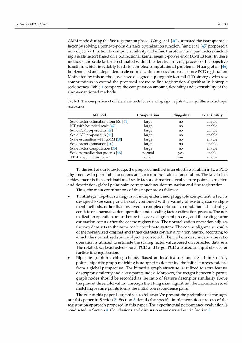
GMM mode during the fine registration phase. Wang et al. [40] estimated the isotropic scalefactor by solving a point-to-point distance optimization function. Yang et al. [45] proposed anew objective function to compute similarity and affine transformation parameters (includ-ing a scale factor) based on a bidirectional kernel mean p-power error (KMPE) loss. In thesemethods, the scale factor is estimated within the iterative solving process of the objectivefunction, which inevitably leads to complex computational problems. Huang et al. [46]implemented an independent scale normalization process for cross-source PCD registration.Motivated by this method, we have designed a pluggable top-tail (TT) strategy with fewcomputations to extend the proposed coarse-to-fine registration algorithm in isotropicscale scenes. Table 1 compares the computation amount, flexibility and extensibility of theabove-mentioned methods.
Table 1. The comparison of different methods for extending rigid registration algorithms to isotropicscale cases.
Method Computation Pluggable Extensibility
Scale factor estimation from ESI [41] large no enableICP with bounded scale [42] large no enableScale-ICP proposed in [43] large no enableScale-ICP proposed in [44] large no enableScale estimation with GMM [10] large no enableScale factor estimation [40] large no enableScale factor computation [35] large no enableScale normalization process [46] normal yes enableTT strategy in this paper small yes enable
To the best of our knowledge, the proposed method is an effective solution in two-PCDalignment with poor initial positions and an isotropic scale factor solution. The key to thisachievement is the combination of scale factor estimation, local feature points extractionand description, global point pairs correspondence determination and fine registration.
Thus, the main contributions of this paper are as follows:
• TT strategy. Top-tail strategy is an independent and pluggable component, which isdesigned to be easily and flexibly combined with a variety of existing coarse align-ment methods, rather than involved in complex optimum computation. This strategyconsists of a normalization operation and a scaling factor estimation process. The nor-malization operation occurs before the coarse alignment process, and the scaling factorestimation occurs after the coarse registration. The normalization operation adjuststhe two data sets to the same scale coordinate system. The coarse alignment resultsof the normalized original and target datasets contain a rotation matrix, according towhich the normalized source object is corrected. Then, a boundary most-value ratiooperation is utilized to estimate the scaling factor value based on corrected data sets.The rotated, scale-adjusted source PCD and target PCD are used as input objects forfurther fine registration.
• Bipartite graph matching scheme. Based on local features and descriptors of keypoints, bipartite graph matching is adopted to determine the initial correspondencefrom a global perspective. The bipartite graph structure is utilized to store featuredescriptor similarity and a key-points index. Moreover, the weight between bipartitegraph nodes should be recorded as the ratio of feature descriptor similarity abovethe pre-set threshold value. Through the Hungarian algorithm, the maximum set ofmatching feature points forms the initial correspondence pairs.
The rest of this paper is organized as follows: We present the preliminaries through-out this paper in Section 2. Section 3 details the specific implementation process of theregistration approach proposed in this paper. The experimental performance evaluation isconducted in Section 4. Conclusions and discussions are carried out in Section 5.
Electronics 2022, 11, 263 5 of 30
2. Preliminaries
In this section, we review some of the relevant background knowledge and relatedknowledge that will be used in this paper.
2.1. 3D SIFT
The 3D SIFT describes local features with the ability to resist the influence of viewingangle changes, noise interference, brightness changes, affine transformations and rotationtransformations, which are explored in the difference of Gaussian (DOG) pyramid [47]. Atfirst, a Gaussian pyramid is built through a voxelized point cloud with scale ε, and the scalespace L(X, ε) can be obtained from the convolution of Gaussian blur kernel G(X, ε) with3D image, as described in (1).
L(X, ε) = G(X, ε) ∗Q(X)
G(X, ε) = e−||X||22ε2(√
2πε)−3
DOG(Xi, ε j+1
)= L
(Xi, ε j+1
)− L
(Xi, ε j
) (1)
where X denotes 3D coordinates (x, y, z).Then, a series of octaves with different scales should be generated. For every scale ε,
two adjacent scales can be described as (2).
εi+1 = kεi, ε0 = k−1εmin, (i = 0, 1, . . . , ξ + 2) (2)
To detect local extreme values in the DOG pyramid, nearest k-neighborhood pointsare compared with the query point. The points with minima or maxima DOG values areregarded as 3D SIFT key points.
2.2. FPFH Descriptor Estimation
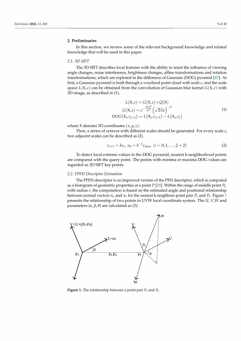
The FPFH descriptor is an improved version of the PFH descriptor, which is computedas a histogram of geometric properties at a point P [29]. Within the range of middle point PCwith radius r, the computation is based on the estimated angle and positional relationshipbetween normal vectors ns and nt for the nearest k neighbors point pair Ps and Pt. Figure 1presents the relationship of two points in UVW local coordinate system. The U, V,W andparameters (α, β, θ) are calculated as (3):
Electronics 2022, 11, x FOR PEER REVIEW 6 of 31
Ps Pt
W
U
V
nt
β
α
θPt-Ps
U=ns
V=U×(Pt-Ps)
Figure 1. The relationship between a point pair 𝑃𝑠 and 𝑃𝑡.
{
𝑈 = 𝑛𝑠
𝑉 = 𝑈 × (𝑃𝑡− 𝑃𝑠)
‖𝑃𝑡− 𝑃𝑠‖2
𝑊 = 𝑈 × 𝑉 𝛼 = 𝑉 𝑛𝑠
𝛽 = 𝑈(𝑃𝑡− 𝑃𝑠)
‖𝑃𝑡− 𝑃𝑠‖2
𝜃 = 𝑎𝑟𝑐𝑡𝑎𝑛(𝑊𝑛𝑠, 𝑈𝑛𝑡)
, (3)
where 𝛼, 𝛽 and 𝜃 of k-neighborhood point pairs constitute triplets.
Each triplet feature value need be separated into some subdivisions, of which the
number of occurrences should be recorded as the histogram description. Compared with
PFH, the FPFH descriptor reduces the computation complexity from O(nk2) to O(nk): (1)
FPFH increases neighborhood selection range from r to 2r, which also includes the neigh-
borhood of all points in the neighborhood; (2) FPFH only computes the relationships of
point and its k-neighborhood to form the simplified point feature histograms (SPFH). The
neighboring values of SPFH are utilized to weight the final histogram, as computed in (4):
𝐹𝑃𝐹𝐻(𝑃) = 𝑆𝑃𝐹𝐻(𝑃) + 1
𝑘∑
1
𝑊𝑖𝑔ℎ𝑡𝑖
𝑘
𝑖=1𝑆𝑃𝐹𝐻(𝑃𝑖) (4)
2.3. Bipartite Graph Matching
A weighted bipartite graph structure 𝐺 = {𝑁 ∪ 𝑉, 𝐸,𝑊} contains two types of verti-
ces (𝑁—the set of nodes ({𝑛1, 𝑛2, … , 𝑛𝑚}), 𝑉—the set of nodes ({𝑣1, 𝑣2, … , 𝑣𝑚})), edges 𝐸 ∈
{𝑁 × 𝑉} and 𝑊—the weight matrix ({𝑤11, 𝑤12, … , 𝑤𝑚𝑚}). For 𝑒𝑖𝑗 ∈ 𝐸, each edge carries a
weight 𝑤𝑖𝑗 that represents the connection strength between 𝑛𝑖 and 𝑣𝑖, where i and j de-
note the i-th and j-th vertices in 𝑁 and 𝑉. If edge subset 𝑀 ⊆ 𝐸 and no two edges in 𝑀
share a common vertex incident to them, the 𝑀 should be regarded as a match. Moreover,
if |𝑀| = |𝑁| = |𝑉|, the 𝑀 is a perfect match. The Kuhn−Munkres (KM) theorem is used
to find a perfect matching of weighted complete bipartite graph [48]. The KM algorithm
transforms the weights and sets an initial benchmark at each vertex of the X-set and Y-set.
Then, the greedy algorithm preferentially selects the edge with the largest weight for
matching. When there is another one where the largest edges of the two X vertices have
the same Y vertex, the selected complete benchmark needs to be adjusted to form a new
matching subgraph with largest weight. Finally, when an equal subgraph is found, the
corresponding maximum weight matching is found.
Figure 1. The relationship between a point pair Ps and Pt.

Electronics 2022, 11, 263 6 of 30
.
U = ns
V = U × (Pt−Ps)‖Pt−Ps‖2
W = U ×Vα = V ns
β = U (Pt−Ps)‖Pt−Ps‖2
θ = arctan(Wns, Unt)
, (3)
where α, β and θ of k-neighborhood point pairs constitute triplets.Each triplet feature value need be separated into some subdivisions, of which the
number of occurrences should be recorded as the histogram description. Compared withPFH, the FPFH descriptor reduces the computation complexity from O(nk2) to O(nk):(1) FPFH increases neighborhood selection range from r to 2r, which also includes theneighborhood of all points in the neighborhood; (2) FPFH only computes the relationshipsof point and its k-neighborhood to form the simplified point feature histograms (SPFH).The neighboring values of SPFH are utilized to weight the final histogram, as computedin (4):
FPFH(P) = SPFH(P) +1k ∑k
i=11
WightiSPFH(Pi) (4)
2.3. Bipartite Graph Matching
A weighted bipartite graph structure G = {N ∪ V, E, W} contains two types ofvertices (N—the set of nodes ({n1, n2, . . . , nm}), V—the set of nodes ({v1, v2, . . . , vm})),edges E ∈ {N ×V} and W—the weight matrix ({w11, w12, . . . , wmm}). For eij ∈ E, eachedge carries a weight wij that represents the connection strength between ni and vi, wherei and j denote the i-th and j-th vertices in N and V. If edge subset M ⊆ E and no twoedges in M share a common vertex incident to them, the M should be regarded as amatch. Moreover, if |M| = |N| = |V|, the M is a perfect match. The Kuhn−Munkres(KM) theorem is used to find a perfect matching of weighted complete bipartite graph [48].The KM algorithm transforms the weights and sets an initial benchmark at each vertex ofthe X-set and Y-set. Then, the greedy algorithm preferentially selects the edge with thelargest weight for matching. When there is another one where the largest edges of the twoX vertices have the same Y vertex, the selected complete benchmark needs to be adjustedto form a new matching subgraph with largest weight. Finally, when an equal subgraph isfound, the corresponding maximum weight matching is found.
2.4. TrICP Algorithm
Based on the least-squares (LS) optimal matching idea, the ICP algorithm puts the sourcecloud points P =
{pj∣∣j = 1, . . . , n
}into the frame of the target point set Q = {qi|i = 1, . . . , m}
to obtain consistent point cloud. As followed in (5), to repeat the calculation of optimalrigid body transformation until the convergence criterion is satisfied or the preset numberof iterations is reached, the ICP algorithm can obtain a good estimate of the rotation R andthe translation T.
F(R, T) = 1m
m∑
i=1
∣∣∣∣∣∣qi − Rk pk−1j − Tk
∣∣∣∣∣∣2, (1 ≤ j ≤ n)
MEk =1m
m∑
i=1
∣∣∣∣∣∣qki − pk−1
i
∣∣∣∣∣∣ (5)
where k is the iteration number, ME denotes the mean error after the k-th iteration compu-tation, and the value of || MEk −MEk−1|| represents the preset convergence value.
As an optimization variant of ICP, TrICP utilizes the overlap ratio for points matchingand Least-Trimmed Squares (LTS) to enhance the robustness for noise [14]. The pre-setoverlap rate between the source point cloud P and the target point cloud Q is γ. Thecorresponding points number nc can be described as nc = γn. TrICP reserves nc pairs

Electronics 2022, 11, 263 7 of 30
of points that satisfy the overlap ratio after distance ordering by LTS and searches thetransformation matrix by Singular Value Decomposition (SVD) method, as shown in (6).
d2i (R, T) = ‖argmin‖q− pi(R, T)‖ − pi(R, T)‖2,
d21 ≤ d2
2 ≤ d23 ≤ . . . ≤ d2
nc
Sumdi=
nc∑
i=1d2
i:nc
MSE = Sumdi/nc
(6)
where d2i represents squared distance value of the i-th point pair, Sumdi
is the sum of nc d2i
value, and MSE is the termination condition of the iterative computation.
3. The Proposed Coarse-to-Fine Registration Method Overview
In this section, we detail the coarse-to-fine registration algorithm based on bipartitegraph perfect matching for scaled 3D data. The design scheme of proposed registration al-gorithm described in Figure 2 contains four phases: data pre-processing, TT strategy, coarsealignment and fine registration. The specific steps of these phases include filter process,point cloud normalization process, key points extraction, FPFH descriptor presentation,bipartite graph construction, correspondence point pair confirmation, initial rotation matrixestimation, scale factor estimation and fine registration.
Electronics 2022, 11, x FOR PEER REVIEW 8 of 31
Source Point Cloud Target Point Cloud
Input 3D Datasets
Hierarchical Hybrid Filter
Normalization Computation
Pre-processing
Keypoint Extration
FPFH Descriptor
Point-pair Match Computation with Bipartite Graph
Rotation Matrix Estimation
Scale Factor Estimation
TrICP Registration
Alignment 3D object
Coarse Registration Fine Registration
Top-tail Strategy
Figure 2. Architecture of the coarse-to-fine registration.
3.1. Data Pre-Processing
Data pre-processing of PCD registration workflows mainly eliminates noise, which
is essential for subsequent alignment processing. In this paper, the raw sampled 3D face
data is scanned from depth camera RealSense with different views, which cannot be pro-
cessed directly due to inevitable noise and outliers caused by a device’s inherent noise,
object surface characteristics and object reflection [49]. Based on our previous study [7]
and research [50], a hierarchical filter specifically designed for depth image point cloud is
presented. Since the 3D model in the public library, such as the bunny rabbit, dragon and
scanned room from an open-source library used in Section 4, does not involve the noise
problem of sampling equipment, the ability of this filter should degenerate to a Gaussian
filter. The solution of noise filtering in the acquisition process of non-depth camera equip-
ment is not within the scope of this paper.
⚫ Range filter. In the multi-view scene, the noise is mainly generated by the back-
ground because each scanning device will capture the opposite one or bracket. In this
level, the filter performs a wide range and coarse-grained filtering by removing in-
valid points with a depth value of 0.
⚫ Gray image segmentation filter. For large-scale outlier noise, to compute the thresh-
old of target and background in an IR image obtained directly from the camera, the
outliers are eliminated with a mathematical morphological opening operation in bi-
nary image converted from IR image. Regard the new binary image as an index map
to filter the 3D point cloud.
⚫ Gaussian filter. The Gaussian filter is utilized to remove small-scale noise points
(when the density is less than the threshold value) located inside or at the boundary
Figure 2. Architecture of the coarse-to-fine registration.
3.1. Data Pre-Processing
Data pre-processing of PCD registration workflows mainly eliminates noise, which isessential for subsequent alignment processing. In this paper, the raw sampled 3D face datais scanned from depth camera RealSense with different views, which cannot be processed

Electronics 2022, 11, 263 8 of 30
directly due to inevitable noise and outliers caused by a device’s inherent noise, objectsurface characteristics and object reflection [49]. Based on our previous study [7] andresearch [50], a hierarchical filter specifically designed for depth image point cloud ispresented. Since the 3D model in the public library, such as the bunny rabbit, dragonand scanned room from an open-source library used in Section 4, does not involve thenoise problem of sampling equipment, the ability of this filter should degenerate to aGaussian filter. The solution of noise filtering in the acquisition process of non-depthcamera equipment is not within the scope of this paper.
• Range filter. In the multi-view scene, the noise is mainly generated by the backgroundbecause each scanning device will capture the opposite one or bracket. In this level,the filter performs a wide range and coarse-grained filtering by removing invalidpoints with a depth value of 0.
• Gray image segmentation filter. For large-scale outlier noise, to compute the thresholdof target and background in an IR image obtained directly from the camera, the outliersare eliminated with a mathematical morphological opening operation in binary imageconverted from IR image. Regard the new binary image as an index map to filter the3D point cloud.
• Gaussian filter. The Gaussian filter is utilized to remove small-scale noise points(when the density is less than the threshold value) located inside or at the boundary ofpoint cloud sets. The k neighborhood points around each point cloud are searched inturn, and the average Euclidean distance of the sampled point to its k neighborhoodpoints can be calculated. The distances of all points in the point cloud should form aGaussian distribution, and the noise reduction can be achieved by providing the meanand variance value.
3.2. Top-Tail Strategy
To solve the problem of PCD alignment for the scale variation, the TT strategy, includ-ing normalization computation and scale estimation, has been designed to flexibly nestwith multiple coarse alignment algorithms to adjust the initial position and scale factors ofunregistered point cloud objects.
• Normalization Computation. As scale factors should improve the difficulty for thepoint cloud registration process, we firstly normalize the PCD for the subsequentcoarse alignment to be proceed smoothly. The scale-adjusted problem can be describedas (5) by extending (7):
F(S, R, T) =1m
m
∑i=1
∣∣∣∣qi − SRpj − T∣∣∣∣2, (1 ≤ j ≤ n) (7)
where S is the scale factor.Inspired by [46], the normalization process computes the maximum component ofdifferent dimensions and then calculates the proportion in different dimensions foreach point, as described in (8).
CPnor(x, y, z) =CP(xi, yi, zi)− CP(x, y, z)min
CP(x, y, z)max − CP(x, y, z)min(8)
where CP(x, y, z) denotes the coordinate values of points in the point cloud, i is thei-th index of points, label nor denotes the normalized value of points, label max is themaximum value of points, and label min is the minimum value of points. Throughthe normalization process, the effect of translation and scale can be eliminated, and (7)can be simplified to (9).
F(R) =1m
m
∑i=1
∣∣∣∣qi − Rpj∣∣∣∣2, (1 ≤ j ≤ n) (9)

Electronics 2022, 11, 263 9 of 30
• Scale estimation. To remove scale variation, the source point cloud P needs to berotated with R (computed from coarse alignment) to obtain the PR set. Then, themaximum distance of PR points and Q points should be calculated, respectively. Thescale can be computed by comparing these two maximum distances as (10).
scale =||Qmax −Qmin||||PRmax − PRmin||
(10)
Through this method, we cannot deal with the scale problem completely. However,the adjusted PCD is sufficient for the fine registration since most of the scale differenceis eliminated.
3.3. The Coarse Registration
In the coarse alignment phase, the most important solution is to find the correspondentkey point set. Instead of regarding points with smallest distance between the FPFH localfeature descriptors as a matching set, the KM method is utilized to confirm the point setcorrespondence globally, which is used for initial rotation matrix estimation.
• Feature points extraction and description. In order to improve processing efficiencycaused by a large amount of 3D data, the key points extracted by the 3D SIFT methodand described with FPFH are used to simply represent the two pre-processed normal-ized PCD sets as KNP′ and KNQ′, respectively. From a local perspective, these featurepoints have the ability of being scale-invariant and rotation-invariant.
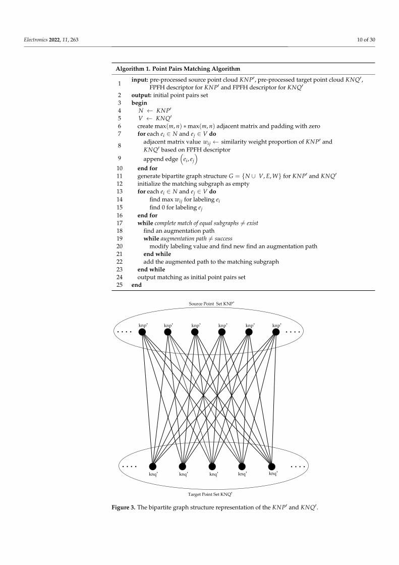
• Point pairs matching. The feature points extraction and description only take thelocal relationships of points into consideration. This step desires to incorporate globalfactors to determine the initial point pair matching. The graph is an ideal data structurefor representing the global relationships of types of vertices. Among many graphstructures [51,52], the bipartite graph structure is the most similar to the PCD structure,the simplest representation of the relationships between points and has the leastcomputation amount. Moreover, inspired by the solution of the M-M assignmentproblem [53], we convert the point cloud feature matching process to handle theperfect matching based on the bipartite graph structure. The points in the source pointcloud set KNP′ and the target point set KNQ′ denote the nodes of a bipartite graphstructure G, as shown in Figure 3.
In this phase, the KM algorithm is implemented with the point cloud bipartite graphstructure G. The number of the point cloud set KNP′ and KNQ′ is recorded as n and m,respectively. In this bipartite graph structure G, a max(m, n) ∗max(m, n) adjacent matrixshould be considered to represent edges of G, where the value of the i-th row and j-th
column represent the similarity weight componentsimilarity(FPFH)ij
∑nj=1 similarity(FPFH)ij
of local feature
descriptors. Here, the main objective is to find an assignment of point cloud set KNP′ andKNQ′, with maximum total similarity weight. During the perfect matching process, theKM algorithm is used to find the maximum matching weight in the bipartite graph withthe following steps: (1) select wij as the maximum weight of edges, which is connected toknp′i and knq′j; (2) choose a weighted match to find a subgraph with weight coverage; (3)set a coverage until a good match is obtained for the subgraph equation. The pseudo-codeof the point pairs matching computation is shown in Algorithm 1.
Electronics 2022, 11, 263 10 of 30
Algorithm 1. Point Pairs Matching Algorithm
1input: pre-processed source point cloud KNP′, pre-processed target point cloud KNQ′,
FPFH descriptor for KNP′ and FPFH descriptor for KNQ′
2 output: initial point pairs set3 begin4 N ← KNP′
5 V ← KNQ′
6 create max(m, n) ∗max(m, n) adjacent matrix and padding with zero7 for each ei ∈ N and ej ∈ V do
8adjacent matrix value wij ← similarity weight proportion of KNP′ andKNQ′ based on FPFH descriptor
9 append edge(
ei, ej
)10 end for11 generate bipartite graph structure G = {N ∪ V, E, W} for KNP′ and KNQ′
12 initialize the matching subgraph as empty13 for each ei ∈ N and ej ∈ V do14 find max wij for labeling ei15 find 0 for labeling ej16 end for17 while complete match of equal subgraphs 6= exist18 find an augmentation path19 while augmentation path 6= success20 modify labeling value and find new find an augmentation path21 end while22 add the augmented path to the matching subgraph23 end while24 output matching as initial point pairs set25 end
Electronics 2022, 11, x FOR PEER REVIEW 10 of 31
and described with FPFH are used to simply represent the two pre-processed nor-
malized PCD sets as 𝐾𝑁𝑃′ and 𝐾𝑁𝑄′, respectively. From a local perspective, these
feature points have the ability of being scale-invariant and rotation-invariant.
⚫ Point pairs matching. The feature points extraction and description only take the lo-
cal relationships of points into consideration. This step desires to incorporate global
factors to determine the initial point pair matching. The graph is an ideal data struc-
ture for representing the global relationships of types of vertices. Among many graph
structures [51,52], the bipartite graph structure is the most similar to the PCD struc-
ture, the simplest representation of the relationships between points and has the least
computation amount. Moreover, inspired by the solution of the M-M assignment
problem [53], we convert the point cloud feature matching process to handle the per-
fect matching based on the bipartite graph structure. The points in the source point
cloud set 𝐾𝑁𝑃′ and the target point set 𝐾𝑁𝑄′ denote the nodes of a bipartite graph
structure 𝐺, as shown in Figure 3.
knp knp knp knp knp knp
Source Point Set KNP
knq knq knq knq knq
Target Point Set KNQ
Figure 3. The bipartite graph structure representation of the 𝐾𝑁𝑃′ and 𝐾𝑁𝑄′.
In this phase, the KM algorithm is implemented with the point cloud bipartite graph
structure 𝐺. The number of the point cloud set 𝐾𝑁𝑃′ and 𝐾𝑁𝑄′ is recorded as 𝑛 and
𝑚, respectively. In this bipartite graph structure 𝐺, a max(𝑚, 𝑛) ∗ max(𝑚, 𝑛) adjacent ma-
trix should be considered to represent edges of 𝐺, where the value of the i-th row and j-
th column represent the similarity weight component 𝑠𝑖𝑚𝑖𝑙𝑎𝑟𝑖𝑡𝑦(𝐹𝑃𝐹𝐻)𝑖𝑗
∑ 𝑠𝑖𝑚𝑖𝑙𝑎𝑟𝑖𝑡𝑦(𝐹𝑃𝐹𝐻)𝑖𝑗𝑛𝑗=1
of local feature
descriptors. Here, the main objective is to find an assignment of point cloud set 𝐾𝑁𝑃′ and
𝐾𝑁𝑄′, with maximum total similarity weight. During the perfect matching process, the
KM algorithm is used to find the maximum matching weight in the bipartite graph with
the following steps: (1) select 𝑤𝑖𝑗 as the maximum weight of edges, which is connected
to 𝑘𝑛𝑝𝑖′ and 𝑘𝑛𝑞𝑗
′ ; (2) choose a weighted match to find a subgraph with weight coverage;
(3) set a coverage until a good match is obtained for the subgraph equation. The pseudo-
code of the point pairs matching computation is shown in Algorithm 1.
Figure 3. The bipartite graph structure representation of the KNP′ and KNQ′.
Electronics 2022, 11, 263 11 of 30
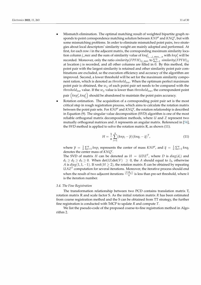
• Mismatch elimination. The optimal matching result of weighted bipartite graph re-sponds to point correspondence matching solution between KNP′ and KNQ′, but withsome mismatching problems. In order to eliminate mismatched point pairs, two strate-gies about local descriptors’ similarity weight are mainly adopted and performed. Atfirst, for each row i in the adjacent matrix, the corresponding maximum similarity loca-tion column j_max and the sum of similarity value of knq′1,...,j_max,...n with knp′i will berecorded. Moreover, only the ratio similarity(FPFH)ij_max to ∑n
j=1 similarity(FPFH)ijat location j is recorded, and all other columns are filled in 0. By this method, thepoint pair with the largest similarity is retained and other similarity point pair com-binations are excluded, so the execution efficiency and accuracy of the algorithm areimproved. Second, a lower threshold will be set for the maximum similarity compo-nent ration, which is denoted as thresholdlow. When the optimum perfect maximumpoint pair is obtained, the wij of each point pair set needs to be compared with thethresholdlow value. If the wij value is lower than thresholdlow, the correspondent point
pair(
knp′i, knq′j)
should be abandoned to maintain the point pairs accuracy.
• Rotation estimation. The acquisition of a corresponding point pair set is the mostcritical step in rough registration process, which aims to calculate the rotation matrixbetween the point pair sets. For KNP′ and KNQ′, the rotation relationship is describedin Equation (9). The singular value decomposition (SVD) algorithm is one of the mostreliable orthogonal matrix decomposition methods, where U and Z represent twomutually orthogonal matrices and A represents an angular matrix. Referenced in [54],the SVD method is applied to solve the rotation matrix R, as shown (11).
H =1n
n
∑i=1
(knpi − p)(knqi − q)T , (11)
where p = 1n ∑n
i=1 knpi represents the center of mass KNP′, and q = 1n ∑n
i=1 knqidenotes the center mass of KNQ′.The SVD of matrix H can be denoted as H = UDZT , where D is diag(di) andd1 ≥ d2 ≥ d3 ≥ 0. When det(U)det(V) ≥ 0, the A should equal to I3, otherwiseA is diag(1, 1,−1). If rank(H ≥ 2), the rotation matrix R can be obtained by repeatingUAZT computation for several iterations. Moreover, the iterative process should endwhen the result of two adjacent iterations | f (Rk)|
n is less than pre-set threshold, where kis the iteration number.
3.4. The Fine Registration
The transformation relationship between two PCD contains translation matrix T,rotation matrix R and scale factor S. As the initial rotation matrix R has been estimatedfrom coarse registration method and the S can be obtained from TT strategy, the furtherfine registration is conducted with TrICP to update R and compute T.
We list the pseudo-code of the proposed coarse-to-fine registration method in Algo-rithm 2.

Electronics 2022, 11, 263 12 of 30
Algorithm 2. The Coarse-to-Fine Registration Algorithm
1input: source point cloud P, target point cloud Q, SVD iteration number
iter_numSVD, and TrICP overlap ratio ratioTrICP2 output: final transformation matrix3 begin4 pre-process P and Q to obtain P′ and Q′
5 normalize P′ and Q′ to obtain NP′ and NQ′
6extract feature points from NP′ as KNP′ and obtain FPFH descriptorextract feature points from NQ′ as KNQ′ and obtain FPFH descriptor
7 create bipartite graph structure for KNP′ and KNQ′
8explore perfect maximum match between KNP′ and KNQ′ as initialcorrespondence points set
9 eliminate the mismatching point pairs10 calculate KNP′ center mass as p and KNQ′ center mass as q11 compute matrix H as 1
n
n∑
i=1(knpi − p)(knqi − q)T
12 for iteration i = 1 : iter_numSVD do13 if rank(H) ≥ 2 then14 while | f (Rk)|
n > thresholdpre_set15 update R = UAZT
16 else17 abort18 end if19 end for
20rotate KNP′ with initial rotation matrix R to obtain KNP′R point setrotate P′ with initial rotation matrix R to obtain P′R point set
21estimate scale factor S with ||KNQ′max−KNQ′min ||
||KNP′Rmax−KNP′Rmin ||adjust P′R as SP′R with S
22 search the nearest point from Q′ in SP′R and calculate the distance squared D2
23 sort D2 from smallest to largest and calculate the sum of the first ratioTrICP ∗Q′
24 compute and output final rotation matrix R and translation matrix T25 end
4. Implementation and Performance Evaluation
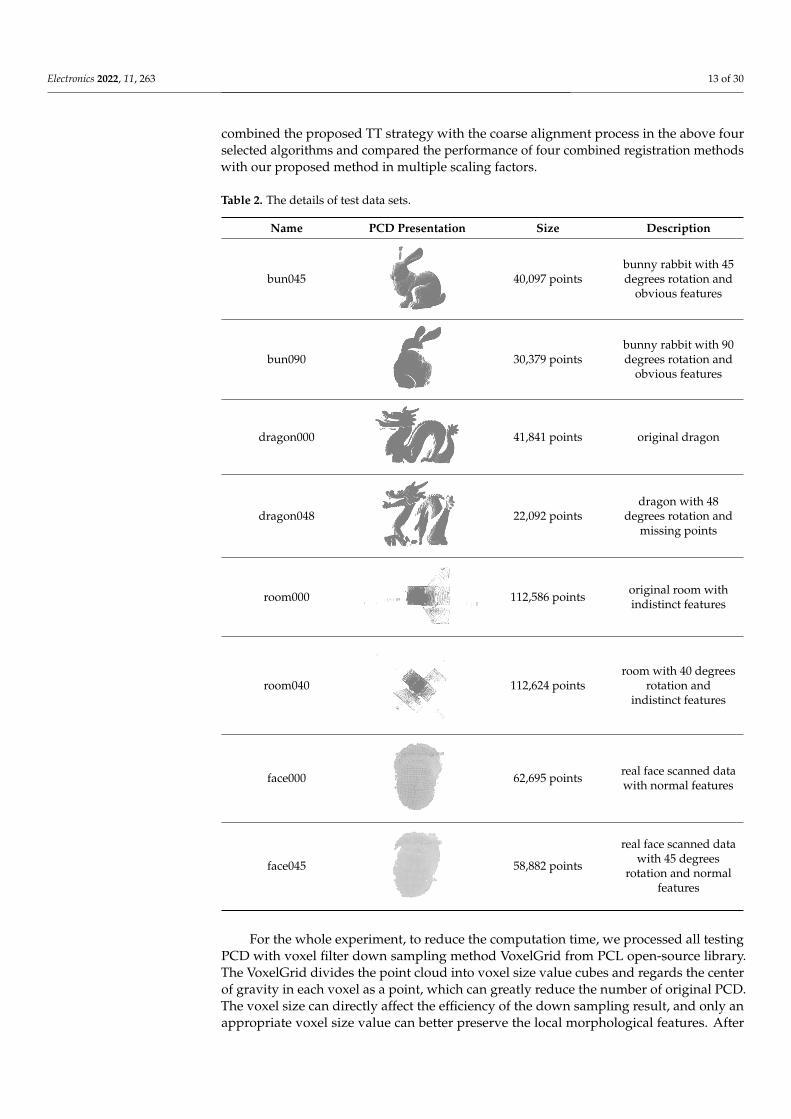
In this section, we implement the proposed coarse-to-fine registration algorithmsuccessfully with C++ language and point cloud library (PCL), which runs in ThinkPad X1with Intel i7-10710 CPU and 16G memory. To comprehensively validate the performanceof proposed algorithm, three groups of representative point cloud models have beenselected, such as bunny rabbit, dragon from Stanford 3D model public library and roomfrom PCL library. As shown in Figure 4, self-sampling raw 3D data, collected from twoidentical depth cameras in the same environment with a 45-degree difference, has also beenconsidered to evaluate this algorithm. All testing PCD need pre-processing to eliminatenoise interference with the hierarchical filter method proposed in this paper. Table 2comprehensively summarizes the details of the test data sets.
The first group consists of bun045 and bun090 as testing objects with low overlap(poor initial position). Even in some experimental parts, bun090 is scaled to form a testingdata set with a higher difficulty coefficient. Dragon000 and scaled dragon048 form thesecond data set to simulate testing objects with missing data and scaling factors. The thirddata set, containing room000 and room040, is used to validate registration performancewithout obvious features. The real scanning data of face000 and face045 constitute thefourth data set, used to measure the practicality of the alignment methods.
The performance validation experiment was conducted in three rounds. In the firstphase, we mainly compared the registration accuracy of ICP and TrICP with or withoutthe coarse alignment method and TT strategy proposed in this paper. In second stage, fourrepresentative coarse-to-fine registration algorithms were selected and compared with ourproposed method in alignment accuracy and time consumption. For the last round, we
Electronics 2022, 11, 263 13 of 30
combined the proposed TT strategy with the coarse alignment process in the above fourselected algorithms and compared the performance of four combined registration methodswith our proposed method in multiple scaling factors.
Table 2. The details of test data sets.
Name PCD Presentation Size Description
bun045
Electronics 2022, 11, x FOR PEER REVIEW 14 of 32
Name PCD Presentation Size Description
bun045
40,097 points bunny rabbit with 45 de-grees rotation and obvi-
ous features
bun090
30,379 points bunny rabbit with 90 de-grees rotation and obvi-
ous features
dragon000
41,841 points original dragon
dragon048
22,092 points dragon with 48 degrees
rotation and missing points
room000
112,586 points original room with indis-
tinct features
room040
112,624 points room with 40 degrees ro-tation and indistinct fea-
tures
40,097 pointsbunny rabbit with 45degrees rotation and
obvious features
bun090
Electronics 2022, 11, x FOR PEER REVIEW 14 of 32
Name PCD Presentation Size Description
bun045
40,097 points bunny rabbit with 45 de-grees rotation and obvi-
ous features
bun090
30,379 points bunny rabbit with 90 de-grees rotation and obvi-
ous features
dragon000
41,841 points original dragon
dragon048
22,092 points dragon with 48 degrees
rotation and missing points
room000
112,586 points original room with indis-
tinct features
room040
112,624 points room with 40 degrees ro-tation and indistinct fea-
tures
30,379 pointsbunny rabbit with 90degrees rotation and
obvious features
dragon000
Electronics 2022, 11, x FOR PEER REVIEW 14 of 32
Name PCD Presentation Size Description
bun045
40,097 points bunny rabbit with 45 de-grees rotation and obvi-
ous features
bun090
30,379 points bunny rabbit with 90 de-grees rotation and obvi-
ous features
dragon000
41,841 points original dragon
dragon048
22,092 points dragon with 48 degrees
rotation and missing points
room000
112,586 points original room with indis-
tinct features
room040
112,624 points room with 40 degrees ro-tation and indistinct fea-
tures
41,841 points original dragon
dragon048
Electronics 2022, 11, x FOR PEER REVIEW 14 of 32
Name PCD Presentation Size Description
bun045
40,097 points bunny rabbit with 45 de-grees rotation and obvi-
ous features
bun090
30,379 points bunny rabbit with 90 de-grees rotation and obvi-
ous features
dragon000
41,841 points original dragon
dragon048
22,092 points dragon with 48 degrees
rotation and missing points
room000
112,586 points original room with indis-
tinct features
room040
112,624 points room with 40 degrees ro-tation and indistinct fea-
tures
22,092 pointsdragon with 48
degrees rotation andmissing points
room000
Electronics 2022, 11, x FOR PEER REVIEW 14 of 32
Name PCD Presentation Size Description
bun045
40,097 points bunny rabbit with 45 de-grees rotation and obvi-
ous features
bun090
30,379 points bunny rabbit with 90 de-grees rotation and obvi-
ous features
dragon000
41,841 points original dragon
dragon048
22,092 points dragon with 48 degrees
rotation and missing points
room000
112,586 points original room with indis-
tinct features
room040
112,624 points room with 40 degrees ro-tation and indistinct fea-
tures
112,586 points original room withindistinct features
room040
Electronics 2022, 11, x FOR PEER REVIEW 14 of 32
Name PCD Presentation Size Description
bun045
40,097 points bunny rabbit with 45 de-grees rotation and obvi-
ous features
bun090
30,379 points bunny rabbit with 90 de-grees rotation and obvi-
ous features
dragon000
41,841 points original dragon
dragon048
22,092 points dragon with 48 degrees
rotation and missing points
room000
112,586 points original room with indis-
tinct features
room040
112,624 points room with 40 degrees ro-tation and indistinct fea-
tures 112,624 points
room with 40 degreesrotation and
indistinct features
face000
Electronics 2022, 11, x FOR PEER REVIEW 15 of 32
face000
62,695 points real face scanned data with normal features
face045
58,882 points real face scanned data
with 45 degrees rotation and normal features
The first group consists of bun045 and bun090 as testing objects with low overlap (poor initial position). Even in some experimental parts, bun090 is scaled to form a testing data set with a higher difficulty coefficient. Dragon000 and scaled dragon048 form the second data set to simulate testing objects with missing data and scaling factors. The third data set, containing room000 and room040, is used to validate registration performance without obvious features. The real scanning data of face000 and face045 constitute the fourth data set, used to measure the practicality of the alignment methods.
The performance validation experiment was conducted in three rounds. In the first phase, we mainly compared the registration accuracy of ICP and TrICP with or without the coarse alignment method and TT strategy proposed in this paper. In second stage, four representative coarse-to-fine registration algorithms were selected and compared with our proposed method in alignment accuracy and time consumption. For the last round, we combined the proposed TT strategy with the coarse alignment process in the above four selected algorithms and compared the performance of four combined registration methods with our proposed method in multiple scaling factors.
For the whole experiment, to reduce the computation time, we processed all testing PCD with voxel filter down sampling method VoxelGrid from PCL open-source library. The VoxelGrid divides the point cloud into voxel size value cubes and regards the center of gravity in each voxel as a point, which can greatly reduce the number of original PCD. The voxel size can directly affect the efficiency of the down sampling result, and only an appropriate voxel size value can better preserve the local morphological features. After testing, we find that the down sampling effect is optimal when the voxel size is set to 0.002: the number of bun045 is reduced to 6813, the number of bun090 is reduced to 6041, the number of dragon000 is reduced to 7155, the number of dragon048 is reduced to 4529, the number of room000 is reduced to 5387, the number of room040 is reduced to 7590, the number of face000 is reduced to 8508, the number of face045 is reduced to 8667, and all the down sampling data sets do not affect the subsequent processing. When the voxel size is set as less than 0.002, the retained number of points is larger. On the contrary, when A is set as larger than 0.002, the local morphological structure of some testing data sets (such as room and scanned face) could be damaged, and the feature point extraction results are much affected. Considering the above factors, the voxel size value is uniformly set to 0.002.
Time consumption and root mean square error (RMSE) are two important criterions for the registration algorithm performance evaluation. The time consumption is the indi-cator to measure the algorithm efficiency, and the RMSE, as described in (12), is used to quantify the registration accuracy.
62,695 points real face scanned datawith normal features
face045
Electronics 2022, 11, x FOR PEER REVIEW 15 of 32
face000
62,695 points real face scanned data with normal features
face045
58,882 points real face scanned data
with 45 degrees rotation and normal features
The first group consists of bun045 and bun090 as testing objects with low overlap (poor initial position). Even in some experimental parts, bun090 is scaled to form a testing data set with a higher difficulty coefficient. Dragon000 and scaled dragon048 form the second data set to simulate testing objects with missing data and scaling factors. The third data set, containing room000 and room040, is used to validate registration performance without obvious features. The real scanning data of face000 and face045 constitute the fourth data set, used to measure the practicality of the alignment methods.
The performance validation experiment was conducted in three rounds. In the first phase, we mainly compared the registration accuracy of ICP and TrICP with or without the coarse alignment method and TT strategy proposed in this paper. In second stage, four representative coarse-to-fine registration algorithms were selected and compared with our proposed method in alignment accuracy and time consumption. For the last round, we combined the proposed TT strategy with the coarse alignment process in the above four selected algorithms and compared the performance of four combined registration methods with our proposed method in multiple scaling factors.
For the whole experiment, to reduce the computation time, we processed all testing PCD with voxel filter down sampling method VoxelGrid from PCL open-source library. The VoxelGrid divides the point cloud into voxel size value cubes and regards the center of gravity in each voxel as a point, which can greatly reduce the number of original PCD. The voxel size can directly affect the efficiency of the down sampling result, and only an appropriate voxel size value can better preserve the local morphological features. After testing, we find that the down sampling effect is optimal when the voxel size is set to 0.002: the number of bun045 is reduced to 6813, the number of bun090 is reduced to 6041, the number of dragon000 is reduced to 7155, the number of dragon048 is reduced to 4529, the number of room000 is reduced to 5387, the number of room040 is reduced to 7590, the number of face000 is reduced to 8508, the number of face045 is reduced to 8667, and all the down sampling data sets do not affect the subsequent processing. When the voxel size is set as less than 0.002, the retained number of points is larger. On the contrary, when A is set as larger than 0.002, the local morphological structure of some testing data sets (such as room and scanned face) could be damaged, and the feature point extraction results are much affected. Considering the above factors, the voxel size value is uniformly set to 0.002.
Time consumption and root mean square error (RMSE) are two important criterions for the registration algorithm performance evaluation. The time consumption is the indi-cator to measure the algorithm efficiency, and the RMSE, as described in (12), is used to quantify the registration accuracy.
58,882 points
real face scanned datawith 45 degrees
rotation and normalfeatures
For the whole experiment, to reduce the computation time, we processed all testingPCD with voxel filter down sampling method VoxelGrid from PCL open-source library.The VoxelGrid divides the point cloud into voxel size value cubes and regards the centerof gravity in each voxel as a point, which can greatly reduce the number of original PCD.The voxel size can directly affect the efficiency of the down sampling result, and only anappropriate voxel size value can better preserve the local morphological features. After

Electronics 2022, 11, 263 14 of 30
testing, we find that the down sampling effect is optimal when the voxel size is set to 0.002:the number of bun045 is reduced to 6813, the number of bun090 is reduced to 6041, thenumber of dragon000 is reduced to 7155, the number of dragon048 is reduced to 4529, thenumber of room000 is reduced to 5387, the number of room040 is reduced to 7590, thenumber of face000 is reduced to 8508, the number of face045 is reduced to 8667, and all thedown sampling data sets do not affect the subsequent processing. When the voxel size isset as less than 0.002, the retained number of points is larger. On the contrary, when A isset as larger than 0.002, the local morphological structure of some testing data sets (suchas room and scanned face) could be damaged, and the feature point extraction results aremuch affected. Considering the above factors, the voxel size value is uniformly set to 0.002.
Electronics 2022, 11, x FOR PEER REVIEW 13 of 31
22 search the nearest point from 𝑄′ in 𝑆𝑃′𝑅 and calculate the distance squared
𝐷2
23 sort 𝐷2 from smallest to largest and calculate the sum of the first 𝑟𝑎𝑡𝑖𝑜𝑇𝑟𝐼𝐶𝑃 ∗𝑄′
24 compute and output final rotation matrix 𝑅 and translation matrix 𝑇
25 end
4. Implementation and Performance Evaluation
In this section, we implement the proposed coarse-to-fine registration algorithm suc-
cessfully with C++ language and point cloud library (PCL), which runs in ThinkPad X1
with Intel i7-10710 CPU and 16G memory. To comprehensively validate the performance
of proposed algorithm, three groups of representative point cloud models have been se-
lected, such as bunny rabbit, dragon from Stanford 3D model public library and room
from PCL library. As shown in Figure 4, self-sampling raw 3D data, collected from two
identical depth cameras in the same environment with a 45-degree difference, has also
been considered to evaluate this algorithm. All testing PCD need pre-processing to elimi-
nate noise interference with the hierarchical filter method proposed in this paper. Table 2
comprehensively summarizes the details of the test data sets.
Figure 4. Real face point cloud data acquisition environment.
Table 2. The details of test data sets.
Name PCD Presentation Size Description
bun045
40,097 points
bunny rabbit with 45 de-
grees rotation and obvi-
ous features
bun090
30,379 points
bunny rabbit with 90 de-
grees rotation and obvi-
ous features
dragon000
41,841 points original dragon
dragon048
22,092 points
dragon with 48 degrees
rotation and missing
points
Figure 4. Real face point cloud data acquisition environment.
Time consumption and root mean square error (RMSE) are two important criterions forthe registration algorithm performance evaluation. The time consumption is the indicatorto measure the algorithm efficiency, and the RMSE, as described in (12), is used to quantifythe registration accuracy.
RMSE =
√√√√ 1mt
mt
∑i=1
∣∣∣∣Rpi + T − qj∣∣∣∣ (12)
where mt denotes the matching points number and (pi, qj) is the matching point pair.The range of alignment accuracy obtained by the same registration algorithm in differentPCD sets is not uniform, while different registration algorithms have the same range ofalignment accuracy on the same PCD set. Since it is impossible to label a specific accuracyvalue for a particular alignment algorithm, we identify a registration algorithm with ahigher accuracy by comparing the alignment RMSE of different algorithms on the samePCD set in the subsequent experiment.
4.1. The Availability Evaluation of Proposed Coarse Registration Method with TT Strategy
In the experiment, bun045-bun090, dragon000-dragon048 magnified 2 times andface000-face045 are selected to be the testing data set, as shown in Figure 5. We conduct testson two ICP algorithms (ICP and TrICP) with different parameter-setting conditions, andthe registration results are shown in Figure 6. The iteration number parameter can reflectICP performance, and fewer iterations indicate a lower time consumption for processingthe same data. Therefore, we set the iteration number parameter as 5, 10, 15, 30 andcompare the corresponding alignment results. For the TrICP, a higher overlap ratio meansto search for more points with a larger computation effort. We set the TrICP ratio to0.65, 0.75, 0.85, 0.95 and compare the corresponding registration results. In Figure 7, weexhibit the registration results of the ICP and TrICP with the proposed coarse registrationprocess and TT strategy (regarded as coarse-to-ICP and coarse-to-TrICP) under the same

Electronics 2022, 11, 263 15 of 30
parameter-setting conditions of Figure 6. The registration errors are analyzed in Table 3and Figures 8 and 9. In visual presentation, the source point cloud data is marked as redand the target point cloud set as blue. Bun045, dragon000 and face000 are labeled in red,while bun090, dragon048 magnified 2 times and face045 are colored in blue.
Electronics 2022, 11, x FOR PEER REVIEW 15 of 31
𝑅𝑀𝑆𝐸 = √1
𝑚𝑡∑||𝑅𝑝𝑖 + 𝑇 − 𝑞𝑗||
𝑚𝑡
𝑖=1
(12)
where 𝑚𝑡 denotes the matching points number and (𝑝𝑖, 𝑞𝑗) is the matching point pair.
The range of alignment accuracy obtained by the same registration algorithm in different
PCD sets is not uniform, while different registration algorithms have the same range of
alignment accuracy on the same PCD set. Since it is impossible to label a specific accuracy
value for a particular alignment algorithm, we identify a registration algorithm with a
higher accuracy by comparing the alignment RMSE of different algorithms on the same
PCD set in the subsequent experiment.
4.1. The Availability Evaluation of Proposed Coarse Registration Method with TT Strategy
In the experiment, bun045-bun090, dragon000-dragon048 magnified 2 times and
face000-face045 are selected to be the testing data set, as shown in Figure 5. We conduct
tests on two ICP algorithms (ICP and TrICP) with different parameter-setting conditions,
and the registration results are shown in Figure 6. The iteration number parameter can
reflect ICP performance, and fewer iterations indicate a lower time consumption for pro-
cessing the same data. Therefore, we set the iteration number parameter as 5, 10, 15, 30
and compare the corresponding alignment results. For the TrICP, a higher overlap ratio
means to search for more points with a larger computation effort. We set the TrICP ratio
to 0.65, 0.75, 0.85, 0.95 and compare the corresponding registration results. In Figure 7, we
exhibit the registration results of the ICP and TrICP with the proposed coarse registration
process and TT strategy (regarded as coarse-to-ICP and coarse-to-TrICP) under the same
parameter-setting conditions of Figure 6. The registration errors are analyzed in Table 3
and Figures 8 and 9. In visual presentation, the source point cloud data is marked as red
and the target point cloud set as blue. Bun045, dragon000 and face000 are labeled in red,
while bun090, dragon048 magnified 2 times and face045 are colored in blue.
(a) (b) (c)
Figure 5. Three groups of PCD consisting of bunny rabbit, dragon and scanned face. (a) Bunny rab-
bit bun045 and bun090. (b) Dragon000 and dragon048 with scale factor 2. (c) Scanned face face000
and face045.
Figure 5. Three groups of PCD consisting of bunny rabbit, dragon and scanned face. (a) Bunnyrabbit bun045 and bun090. (b) Dragon000 and dragon048 with scale factor 2. (c) Scanned face face000and face045.
Table 3. The RMSE of ICP, coarse-to-ICP, TrICP and coarse-to-TrICP registration results.
Algorithm Rabbit Dragon Face
ICP
5 iterations 0.0152612 0.0218693 0.020082510 iterations 0.015228 0.0202673 0.015124115 iterations 0.0152134 0.0199412 0.013754130 iterations 0.015211 0.0187953 0.0132282
coarse-to-ICP
5 iterations 0.0135064 0.014808 0.016280310 iterations 0.0134225 0.013352 0.013365415 iterations 0.0134095 0.0132034 0. 013222230 iterations 0.0134096 0.013181 0.0132146
TrICP
0.65 ratio 0.0261943 0.0322299 0.03495350.75 ratio 0.0215244 0.0319884 0.03375090.85 ratio 0.0160249 0.020968 0.03050690.95 ratio 0.0155848 0.020663 0.0188006
coarse-to-TrICP
0.65 ratio 0.0126224 0.01676 0.02793360.75 ratio 0.0124424 0.0162853 0.02023010.85 ratio 0.0121801 0.0137099 0.01404380.95 ratio 0.0118857 0.0132985 0.0133452
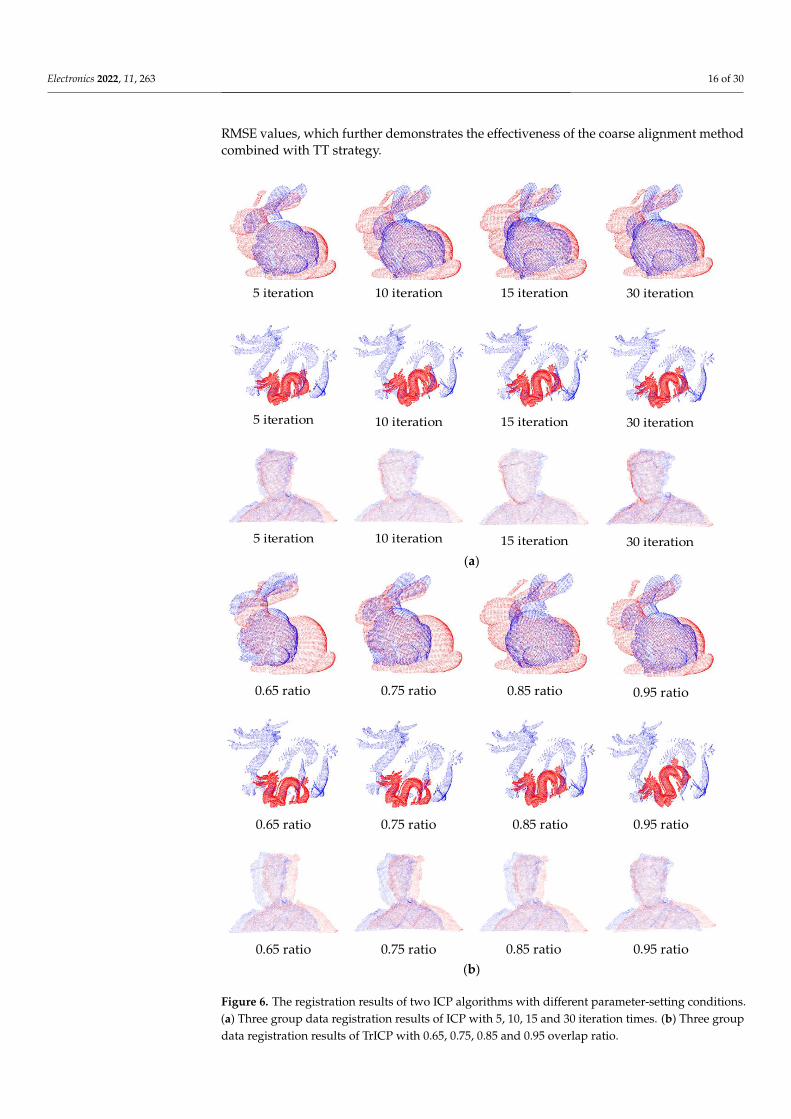
The registration visual results of ICP and TrICP are presented in Figure 6a,b, respec-tively. We can obviously find that both of the algorithms have a bad registration effect inthe bunny rabbit and scaled dragon, which indicates that ICP and TrICP have a bad abilityto process PCD sets with a poor initial position and scale variations. Figure 7 illustrates theregistration results of coarse-to-ICP and coarse-to-TrICP for bunny rabbit, scaled dragonand scanned face, which shows that the two algorithms can perform well in all three datasets. By comparing these visual results, our coarse registration method with TT strategyconducts very well, which significantly enhances comprehensive availability of originalICP and TrICP.
RMSE values with different iterations of ICP and ratio setting conditions of TrICPare recorded in Table 3. For the bunny rabbit and face testing sets without scaling factors,the coarse alignment process combined with TT strategy should degenerate to the coarsealignment method. As shown in the table, ICP and TrICP have higher RMSE values thancoarse-to-ICP and coarse-to-TrICP, with the same bunny rabbit, face and parameter settingconditions, which validates the availability of the proposed coarse alignment method. Forthe scaled dragon data set, coarse-to-ICP and coarse-to-TrICP obviously have much lower
Electronics 2022, 11, 263 16 of 30
RMSE values, which further demonstrates the effectiveness of the coarse alignment methodcombined with TT strategy.
Electronics 2022, 11, x FOR PEER REVIEW 16 of 31
5 iteration 10 iteration 15 iteration 30 iteration
5 iteration 10 iteration 15 iteration 30 iteration
5 iteration 10 iteration 15 iteration 30 iteration (a)
0.65 ratio 0.75 ratio 0.85 ratio 0.95 ratio
0.65 ratio 0.75 ratio 0.85 ratio 0.95 ratio
0.65 ratio 0.75 ratio 0.85 ratio 0.95 ratio (b)
Figure 6. The registration results of two ICP algorithms with different parameter-setting conditions.
(a) Three group data registration results of ICP with 5, 10, 15 and 30 iteration times. (b) Three group
data registration results of TrICP with 0.65, 0.75, 0.85 and 0.95 overlap ratio.
Figure 6. The registration results of two ICP algorithms with different parameter-setting conditions.(a) Three group data registration results of ICP with 5, 10, 15 and 30 iteration times. (b) Three groupdata registration results of TrICP with 0.65, 0.75, 0.85 and 0.95 overlap ratio.

Electronics 2022, 11, 263 17 of 30Electronics 2022, 11, x FOR PEER REVIEW 17 of 31
5 iteration 10 iteration 15 iteration 30 iteration
5 iteration 10 iteration 15 iteration 30 iteration
5 iteration 10 iteration 15 iteration 30 iteration (a)
0.65 ratio 0.75 ratio 0.85 ratio 0.95 ratio
0.65 ratio 0.75 ratio 0.85 ratio 0.95 ratio
0.65 ratio 0.75 ratio 0.85 ratio 0.95 ratio (b)
Figure 7. The registration results of bunny rabbit, dragon and scanned face with coarse-to-ICP and
coarse-to-TrICP. (a) Three group data registration results of coarse-to-ICP with 5, 10, 15 and 30 iter-
ation times of ICP. (b) Three group data registration results of coarse-to-TrICP with 0.65, 0.75, 0.85
and 0.95 overlap ratio of TrICP.
The registration visual results of ICP and TrICP are presented in Figure 6a,b, respec-
tively. We can obviously find that both of the algorithms have a bad registration effect in
Figure 7. The registration results of bunny rabbit, dragon and scanned face with coarse-to-ICPand coarse-to-TrICP. (a) Three group data registration results of coarse-to-ICP with 5, 10, 15 and30 iteration times of ICP. (b) Three group data registration results of coarse-to-TrICP with 0.65, 0.75,0.85 and 0.95 overlap ratio of TrICP.
In Figure 8, we compare the registration RMSE of ICP and coarse-to-ICP under dif-ferent iterations and plot the results in a line chart. The line chart can be interpretedas: the x-axis shows different iterations; the y-axis represents registration error; the blue

Electronics 2022, 11, 263 18 of 30
diamond connected by the dotted line indicates the RMSE trend of ICP; and the orangecircle connected by the solid line shows the RMSE trend of coarse-to-ICP. In contrast to ICP,the coarse-to-ICP achieves convergence more efficiently (decrease from about 30 iterationsto about 10 iterations) for a scanned face with good quality. Moreover, coarse-to-ICP caneffectively avoid registration failure for poor initial position and scale variations data setsand can achieve convergence at about 15 iterations. We can conclude that the proposedcoarse alignment method combined with TT strategy improves the performance of ICP.
Electronics 2022, 11, x FOR PEER REVIEW 18 of 31
the bunny rabbit and scaled dragon, which indicates that ICP and TrICP have a bad ability
to process PCD sets with a poor initial position and scale variations. Figure 7 illustrates
the registration results of coarse-to-ICP and coarse-to-TrICP for bunny rabbit, scaled
dragon and scanned face, which shows that the two algorithms can perform well in all
three data sets. By comparing these visual results, our coarse registration method with TT
strategy conducts very well, which significantly enhances comprehensive availability of
original ICP and TrICP.
Table 3. The RMSE of ICP, coarse-to-ICP, TrICP and coarse-to-TrICP registration results.
Algorithm Rabbit Dragon Face
ICP
5 iterations 0.0152612 0.0218693 0.0200825
10 iterations 0.015228 0.0202673 0.0151241
15 iterations 0.0152134 0.0199412 0.0137541
30 iterations 0.015211 0.0187953 0.0132282
coarse-to-
ICP
5 iterations 0.0135064 0.014808 0.0162803
10 iterations 0.0134225 0.013352 0.0133654
15 iterations 0.0134095 0.0132034 0. 0132222
30 iterations 0.0134096 0.013181 0.0132146
TrICP
0.65 ratio 0.0261943 0.0322299 0.0349535
0.75 ratio 0.0215244 0.0319884 0.0337509
0.85 ratio 0.0160249 0.020968 0.0305069
0.95 ratio 0.0155848 0.020663 0.0188006
coarse-to-
TrICP
0.65 ratio 0.0126224 0.01676 0.0279336
0.75 ratio 0.0124424 0.0162853 0.0202301
0.85 ratio 0.0121801 0.0137099 0.0140438
0.95 ratio 0.0118857 0.0132985 0.0133452
(a) (b) (c)
Figure 8. The RMSE records of ICP and coarse-to-ICP with different iterations. (a) RMSE values of
ICP and coarse-to-ICP for bun045 and bun090 with 5, 10, 15, 30 iteration number. (b) RMSE values
of ICP and coarse-to-ICP for dragon000 and magnified twice dragon048 with 5, 10, 15, 30 iteration
number. (c) RMSE values of ICP and coarse-to-ICP for face000 and face045 with 5, 10, 15, 30 iteration
number.
(a) (b) (c)
Figure 8. The RMSE records of ICP and coarse-to-ICP with different iterations. (a) RMSE values of ICPand coarse-to-ICP for bun045 and bun090 with 5, 10, 15, 30 iteration number. (b) RMSE values of ICPand coarse-to-ICP for dragon000 and magnified twice dragon048 with 5, 10, 15, 30 iteration number.(c) RMSE values of ICP and coarse-to-ICP for face000 and face045 with 5, 10, 15, 30 iteration number.
Electronics 2022, 11, x FOR PEER REVIEW 18 of 31
the bunny rabbit and scaled dragon, which indicates that ICP and TrICP have a bad ability
to process PCD sets with a poor initial position and scale variations. Figure 7 illustrates
the registration results of coarse-to-ICP and coarse-to-TrICP for bunny rabbit, scaled
dragon and scanned face, which shows that the two algorithms can perform well in all
three data sets. By comparing these visual results, our coarse registration method with TT
strategy conducts very well, which significantly enhances comprehensive availability of
original ICP and TrICP.
Table 3. The RMSE of ICP, coarse-to-ICP, TrICP and coarse-to-TrICP registration results.
Algorithm Rabbit Dragon Face
ICP
5 iterations 0.0152612 0.0218693 0.0200825
10 iterations 0.015228 0.0202673 0.0151241
15 iterations 0.0152134 0.0199412 0.0137541
30 iterations 0.015211 0.0187953 0.0132282
coarse-to-
ICP
5 iterations 0.0135064 0.014808 0.0162803
10 iterations 0.0134225 0.013352 0.0133654
15 iterations 0.0134095 0.0132034 0. 0132222
30 iterations 0.0134096 0.013181 0.0132146
TrICP
0.65 ratio 0.0261943 0.0322299 0.0349535
0.75 ratio 0.0215244 0.0319884 0.0337509
0.85 ratio 0.0160249 0.020968 0.0305069
0.95 ratio 0.0155848 0.020663 0.0188006
coarse-to-
TrICP
0.65 ratio 0.0126224 0.01676 0.0279336
0.75 ratio 0.0124424 0.0162853 0.0202301
0.85 ratio 0.0121801 0.0137099 0.0140438
0.95 ratio 0.0118857 0.0132985 0.0133452
(a) (b) (c)
Figure 8. The RMSE records of ICP and coarse-to-ICP with different iterations. (a) RMSE values of
ICP and coarse-to-ICP for bun045 and bun090 with 5, 10, 15, 30 iteration number. (b) RMSE values
of ICP and coarse-to-ICP for dragon000 and magnified twice dragon048 with 5, 10, 15, 30 iteration
number. (c) RMSE values of ICP and coarse-to-ICP for face000 and face045 with 5, 10, 15, 30 iteration
number.
(a) (b) (c)
Figure 9. The RMSE records of TrICP and coarse-to-TrICP with different ratios. (a) RMSE values ofTrICP and coarse-to-TrICP for bun045 and bun090 with 0.65, 0.75, 0.85, 0.95 ratio settings. (b) RMSEvalues of TrICP and coarse-to-TrICP for dragon000 and magnified twice dragon048 with 0.65, 0.75,0.85, 0.95 ratio settings. (c) RMSE values of TrICP and coarse-to-TrICP for face000 and face045 with0.65, 0.75, 0.85, 0.95 ratio settings.
Figure 9 displays the RMSE comparison of TrICP and coarse-to-TrICP with differentratio setting conditions. In this line chart, the x-axis represents multiple ratios, the y-axis shows RMSE value, the blue diamond connected by the dotted line presents RMSEvariations of TrICP, and the orange circle connected by the solid line indicates RMSE ofcoarse-to-TrICP. By comparing the two RMSE curves, it can be analyzed that the proposedcoarse registration method with TT strategy not only effectively compensates for thedefects of TrICP in dealing with poor initial position and scale variations problems, but alsospeeds up algorithm convergence at a lower ratio setting. According to the observation ofexperimental results, when the ratio is set to 0.85, coarse-to-TrICP shows good performance.Moreover, comparing the RMSE of coarse-to-ICP and coarse-to-TrICP, the latter can achievea lower RMSE, which indicates a more comprehensive and stable registration ability.Therefore, the TrICP algorithm used in subsequent experiments is set with a 0.85 ratio.
4.2. The Performance Evaluation of Multiple Coarse-to-Fine Registration Methods
In this part of the experiment, we mainly compare the performance of the completecoarse-to-fine registration algorithm proposed in this paper (combined with TT strategy)

Electronics 2022, 11, 263 19 of 30
with four coarse-to-fine registration algorithms, such as NDT + ICP [33] (as the representa-tive of probability model + ICP), ISS-3DSC-RANSAC + ICP [39] (as the representative offeature points with descriptors + coarse process + ICP), SAC-IA + ICP [33] (as the repre-sentative of coarse process + ICP) and K4PCS + ICP [35] (as the representative of featurepoints + coarse process + ICP).
The face000-face045, room000-room040, bun045-bun090, dragon000-dragon048 magni-fied two times and bun045-bun090 magnified 0.5 times are selected as the validation objectsfor this round of experiments. The visual registration results of different algorithms areexhibited in Figure 10. In these figures, the original source datasets are shown in green, theoriginal target dataset is shown in blue and the registered datasets are in red. The totalregistration time, coarse phase time, fine process time and RMSE of each algorithm arerecorded and analyzed in Figure 11.
Electronics 2022, 11, x FOR PEER REVIEW 20 of 31
For Figure 10a,b, the visual alignment results of face and room data sets apparently
show that all five coarse-to-fine registration algorithms can effectively process PCD with
obscure or general features. However, in Figure 10c, the visual results indicate that the
alignment effect of a bunny rabbit with four compared coarse-to-fine registration algo-
rithms, especially the NDT + ICP algorithm, is worse than the method proposed in this
paper. This proves that our proposed algorithm is more robust in processing low overlap
PCD sets. Moreover, Figure 10d,e reveals that four common coarse-to-fine algorithms fail
in scaling alignment, except for the proposed method.
Original data set NDT+ICP ISS-3DSC-RANSAC+ICP
SAC-IA+ICP K4PCS+ICP Our method (a)
Original data set NDT+ICP ISS-3DSC-RANSAC+ICP
SAC-IA+ICP K4PCS+ICP Our method (b)
Figure 10. Cont.
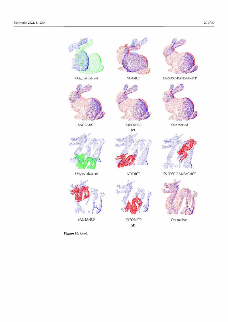
Electronics 2022, 11, 263 20 of 30Electronics 2022, 11, x FOR PEER REVIEW 21 of 31
Original data set NDT+ICP
SAC-IA+ICP K4PCS+ICP Our method
ISS-3DSC-RANSAC+ICP
(c)
Original data set NDT+ICP ISS-3DSC-RANSAC+ICP
SAC-IA+ICP K4PCS+ICP Our method (d)
Figure 10. Cont.

Electronics 2022, 11, 263 21 of 30Electronics 2022, 11, x FOR PEER REVIEW 22 of 31
Original data set NDT+ICP ISS-3DSC-RANSAC+ICP
SAC-IA+ICP K4PCS+ICP Our method
(e)
Figure 10. The visual registration results for testing data sets with five coarse-to-fine registration
methods. (a) The original scanned face data and registration results of face000-face 045 with five
coarse-to-fine registration methods. (b) The original room data and registration results of room000-
room040 with five coarse-to-fine registration methods. (c) The original bunny rabbit data and regis-
tration results of bun045-bun090 with five coarse-to-fine registration methods. (d) The original
scaled dragon data and registration result of dragon000-dragon048 magnified 2 times with five
coarse-to-fine registration methods. (e) The original scaled bunny rabbit data and registration re-
sults of bun045-bun090 magnified 0.5 times with five coarse-to-fine registration methods.
The numerical records and analysis of five coarse-to-fine algorithms about alignment
time and accuracy for different datasets are presented in Figure 11: the horizontal coordi-
nates are grouped by dataset name, where each group covers five registration algorithms
(four compared algorithms and our proposed algorithm); the main vertical coordinate in-
dicates the time in milliseconds, where the total registration time in blue bars, the coarse
registration time in orange bars and the fine registration time in gray bars follow this axis;
the secondary vertical coordinate shows the RMSE, where the registration errors of the
five algorithms in all data models, represented by yellow boxes connected by yellow solid
lines, follow this axis. As shown in Figure 11, the average registration time of NDT + ICP,
ISS-3DSC-RANSAC + ICP, SAC-IA + ICP, K4PCS + ICP and our method for all data sets
is 96.1208 ms, 17.2456 ms, 168.6878 ms, 10.377 ms and 76.081 ms, respectively. Analyzing
from the perspective of algorithm execution efficiency, we can conclude that K4PCS + ICP
is the highest and SAC-IA + ICP is the lowest, and our algorithm performs generally. For
the non-scale point cloud object face and room, all five algorithms have similar small reg-
istration error, which indicates that these methods have close accuracy for aligning PCD
with small position deviations or few features. However, our algorithm has the smallest
0.0117964 RMSE of bunny rabbit with poor initial position, which shows the proposed
method has superior performance in processing low overlap rate PCD sets. Moreover, for
data sets with scale variations, the RMSE of the four coarse-to-fine alignment algorithms
is much higher compared to our proposed algorithm, which implies that these four algo-
rithms fail to register scaling data sets and our proposed methods have more generality.
Figure 10. The visual registration results for testing data sets with five coarse-to-fine registrationmethods. (a) The original scanned face data and registration results of face000-face 045 with fivecoarse-to-fine registration methods. (b) The original room data and registration results of room000-room040 with five coarse-to-fine registration methods. (c) The original bunny rabbit data andregistration results of bun045-bun090 with five coarse-to-fine registration methods. (d) The originalscaled dragon data and registration result of dragon000-dragon048 magnified 2 times with fivecoarse-to-fine registration methods. (e) The original scaled bunny rabbit data and registration resultsof bun045-bun090 magnified 0.5 times with five coarse-to-fine registration methods.
For Figure 10a,b, the visual alignment results of face and room data sets apparentlyshow that all five coarse-to-fine registration algorithms can effectively process PCD withobscure or general features. However, in Figure 10c, the visual results indicate that thealignment effect of a bunny rabbit with four compared coarse-to-fine registration algorithms,especially the NDT + ICP algorithm, is worse than the method proposed in this paper. Thisproves that our proposed algorithm is more robust in processing low overlap PCD sets.Moreover, Figure 10d,e reveals that four common coarse-to-fine algorithms fail in scalingalignment, except for the proposed method.
The numerical records and analysis of five coarse-to-fine algorithms about alignmenttime and accuracy for different datasets are presented in Figure 11: the horizontal coordi-nates are grouped by dataset name, where each group covers five registration algorithms(four compared algorithms and our proposed algorithm); the main vertical coordinateindicates the time in milliseconds, where the total registration time in blue bars, the coarseregistration time in orange bars and the fine registration time in gray bars follow this axis;the secondary vertical coordinate shows the RMSE, where the registration errors of thefive algorithms in all data models, represented by yellow boxes connected by yellow solidlines, follow this axis. As shown in Figure 11, the average registration time of NDT + ICP,ISS-3DSC-RANSAC + ICP, SAC-IA + ICP, K4PCS + ICP and our method for all data sets is96.1208 ms, 17.2456 ms, 168.6878 ms, 10.377 ms and 76.081 ms, respectively. Analyzing fromthe perspective of algorithm execution efficiency, we can conclude that K4PCS + ICP is thehighest and SAC-IA + ICP is the lowest, and our algorithm performs generally. For the non-scale point cloud object face and room, all five algorithms have similar small registrationerror, which indicates that these methods have close accuracy for aligning PCD with small

Electronics 2022, 11, 263 22 of 30
position deviations or few features. However, our algorithm has the smallest 0.0117964RMSE of bunny rabbit with poor initial position, which shows the proposed method hassuperior performance in processing low overlap rate PCD sets. Moreover, for data setswith scale variations, the RMSE of the four coarse-to-fine alignment algorithms is muchhigher compared to our proposed algorithm, which implies that these four algorithms failto register scaling data sets and our proposed methods have more generality.
Electronics 2022, 11, x FOR PEER REVIEW 23 of 31
Figure 11. The registration performance records of testing data sets with five coarse-to-fine registra-
tion methods.
4.3. The Extensibility Evaluation of Multiple Registration Methods with TT Strategy
In order to test the performance of the coarse process in different coarse-to-fine algo-
rithms combined with the TT strategy proposed in this paper, we scale the bunny rabbit
and dragon data sets with multi factors (0.5, 1.5, 2) to simulate isotropic scale cases and
form testing data sets: dragon000-dragon048 magnified 0.5 times, dragon000-dragon048
magnified 1.5 times, dragon000-dragon048 magnified 2 times, bun045-bun090 magnified
0.5 times, bun045-bun090 magnified 1.5 times and bun000-bun090 magnified 2 times. The
experiment is conducted with the same coarse-to-fine registration algorithms mentioned
in Section 4.2. The four course methods of NDT, ISS-3DSC-RANSAC, SAC-IA and K4PCS
combine with the TT strategy, respectively, to modify NDT + ICP as NDT + ICP-TT, ISS-
3DSC-RANSAC + ICP as ISS-3DSC-RANSAC + ICP-TT, SAC-IA + ICP as SAC-IA + ICP-
TT, and K4PCS + ICP as K4PCS + ICP-TT. Figures 12 and 13 respectively record the visual
registration results of dragon and bunny rabbit with different scaling variations. In Figure
14, we compare scale estimation value with the real scale factor. Moreover, the registration
errors are recorded and analyzed in Table 4 and Figure 15.
0.001
0.016
0.031
0.046
0.061
0.076
0.091
0
50
100
150
200
250N
DT+
ICP
ISS-
3D
SC-R
AN
SAC
+IC
PSA
C-I
A+
ICP
K4P
CS+
ICP
ours
ND
T+IC
PIS
S-3D
SC-R
AN
SAC
+IC
PSA
C-I
A+
ICP
K4P
CS+
ICP
ours
ND
T+IC
PIS
S-3D
SC-R
AN
SAC
+IC
PSA
C-I
A+
ICP
K4P
CS+
ICP
ours
ND
T+IC
PIS
S-3D
SC-R
AN
SAC
+IC
PSA
C-I
A+
ICP
K4P
CS+
ICP
ours
ND
T+IC
PIS
S-3D
SC-R
AN
SAC
+IC
PSA
C-I
A+
ICP
K4P
CS+
ICP
ours
face room rabbit scaled dragon scaled rabbitR
MSE
reg
istr
atio
n t
ime/
ms
total time/ms coarse time/ms fine time/ms RMSE
Figure 11. The registration performance records of testing data sets with five coarse-to-fine registra-tion methods.
4.3. The Extensibility Evaluation of Multiple Registration Methods with TT Strategy
In order to test the performance of the coarse process in different coarse-to-fine algo-rithms combined with the TT strategy proposed in this paper, we scale the bunny rabbit anddragon data sets with multi factors (0.5, 1.5, 2) to simulate isotropic scale cases and formtesting data sets: dragon000-dragon048 magnified 0.5 times, dragon000-dragon048 magni-fied 1.5 times, dragon000-dragon048 magnified 2 times, bun045-bun090 magnified 0.5 times,bun045-bun090 magnified 1.5 times and bun000-bun090 magnified 2 times. The experimentis conducted with the same coarse-to-fine registration algorithms mentioned in Section 4.2.The four course methods of NDT, ISS-3DSC-RANSAC, SAC-IA and K4PCS combine withthe TT strategy, respectively, to modify NDT + ICP as NDT + ICP-TT, ISS-3DSC-RANSAC +ICP as ISS-3DSC-RANSAC + ICP-TT, SAC-IA + ICP as SAC-IA + ICP-TT, and K4PCS + ICPas K4PCS + ICP-TT. Figures 12 and 13 respectively record the visual registration results ofdragon and bunny rabbit with different scaling variations. In Figure 14, we compare scaleestimation value with the real scale factor. Moreover, the registration errors are recordedand analyzed in Table 4 and Figure 15.
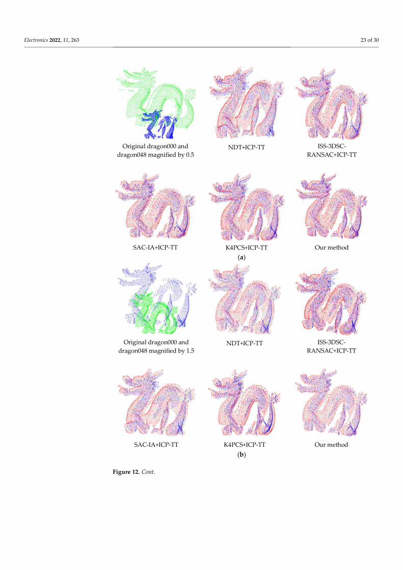
Electronics 2022, 11, 263 23 of 30Electronics 2022, 11, x FOR PEER REVIEW 24 of 31
Original dragon000 and
dragon048 magnified by 0.5 NDT+ICP-TT ISS-3DSC-
RANSAC+ICP-TT
SAC-IA+ICP-TT K4PCS+ICP-TT Our method (a)
Original dragon000 and
dragon048 magnified by 1.5NDT+ICP-TT ISS-3DSC-
RANSAC+ICP-TT
SAC-IA+ICP-TT K4PCS+ICP-TT Our method (b)
Figure 12. Cont.

Electronics 2022, 11, 263 24 of 30Electronics 2022, 11, x FOR PEER REVIEW 25 of 31
Original dragon000 and
dragon048 magnified by 2NDT+ICP-TT ISS-3DSC-RANSAC+ICP-
TT
SAC-IA+ICP-TT K4PCS+ICP-TT Our method (c)
Figure 12. The registration results for scaled dragon data set of multiple registration methods with
TT strategy. (a) The dragon000 and dragon048 magnified by 0.5 and registration results of five
coarse-to-fine registration methods combined with TT strategy. (b) The dragon000 and dragon048
magnified by 1.5 and registration results of five coarse-to-fine registration methods combined with
TT strategy. (c) The dragon000 and dragon048 magnified by 2 and registration results of five coarse-
to-fine registration methods with TT strategy.
Original bun045 and
bun090 magnified by 0.5 NDT+ICP-TT ISS-3DSC-
RANSAC+ICP-TT
SAC-IA+ICP-TT K4PCS+ICP-TT Our method (a)
Figure 12. The registration results for scaled dragon data set of multiple registration methods withTT strategy. (a) The dragon000 and dragon048 magnified by 0.5 and registration results of five coarse-to-fine registration methods combined with TT strategy. (b) The dragon000 and dragon048 magnifiedby 1.5 and registration results of five coarse-to-fine registration methods combined with TT strategy.(c) The dragon000 and dragon048 magnified by 2 and registration results of five coarse-to-fineregistration methods with TT strategy.
Electronics 2022, 11, x FOR PEER REVIEW 25 of 31
Original dragon000 and
dragon048 magnified by 2NDT+ICP-TT ISS-3DSC-RANSAC+ICP-
TT
SAC-IA+ICP-TT K4PCS+ICP-TT Our method (c)
Figure 12. The registration results for scaled dragon data set of multiple registration methods with
TT strategy. (a) The dragon000 and dragon048 magnified by 0.5 and registration results of five
coarse-to-fine registration methods combined with TT strategy. (b) The dragon000 and dragon048
magnified by 1.5 and registration results of five coarse-to-fine registration methods combined with
TT strategy. (c) The dragon000 and dragon048 magnified by 2 and registration results of five coarse-
to-fine registration methods with TT strategy.
Original bun045 and
bun090 magnified by 0.5 NDT+ICP-TT ISS-3DSC-
RANSAC+ICP-TT
SAC-IA+ICP-TT K4PCS+ICP-TT Our method (a)
Figure 13. Cont.

Electronics 2022, 11, 263 25 of 30Electronics 2022, 11, x FOR PEER REVIEW 26 of 31
Original bun045 and
bun090 magnified by 1.5 NDT+ICP-TT ISS-3DSC-
RANSAC+ICP-TT
SAC-IA+ICP-TT K4PCS+ICP-TT Our method (b)
Original bun000 and
bun090 magnified by 2 NDT+ICP-TT ISS-3DSC-
RANSAC+ICP-TT
SAC-IA+ICP-TT K4PCS+ICP-TT Our method (c)
Figure 13. The registration results for scaled bunny rabbit data set of multiple registration methods
with TT strategy. (a) The bun045 and bun090 magnified by 0.5 and registration results of five coarse-
to-fine registration methods with TT strategy. (b) The original bun045 and bun090 magnified by 1.5
and registration results of five coarse-to-fine registration method with TT strategy. (c) The original
bun045 and bun090 magnified by 2 and registration results of five coarse-to-fine registration method
with TT strategy.
Figure 13. The registration results for scaled bunny rabbit data set of multiple registration methodswith TT strategy. (a) The bun045 and bun090 magnified by 0.5 and registration results of five coarse-to-fine registration methods with TT strategy. (b) The original bun045 and bun090 magnified by 1.5and registration results of five coarse-to-fine registration method with TT strategy. (c) The originalbun045 and bun090 magnified by 2 and registration results of five coarse-to-fine registration methodwith TT strategy.
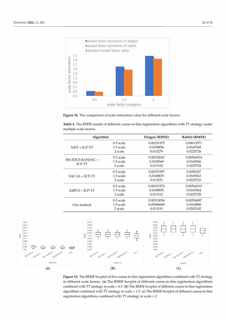
Electronics 2022, 11, 263 26 of 30
Electronics 2022, 11, x FOR PEER REVIEW 27 of 31
In Figures 12 and 13, the original source data are colored in green, the scaled target
object is labeled in blue and registered scaled-adjusted target object is shown in red. From
the visual registration results in these figures, we find that the NDT + ICP-TT is less stable
(large deviations in bun045 and bun090 magnified by 0.5), the performance of ISS-3DCS-
RANSAC + ICP-TT, SAC-IA + ICP-TT and K4PCS + ICP-TT are close to each other, and
our method is better. Our proposed TT strategy can extend the four coarse-to-fine regis-
tration algorithms to scale scenes effectively.
Figure 14. The comparison of scale estimation value for different scale factors.
Figure 14 records scale factor estimation value of dragon and bunny rabbit data sets
with different scale factors. The x-axis represents the scale factor category, the y-axis rep-
resents the scale estimation value, the blue bar indicates the scale factor estimation value
of the dragon data set, the orange bar indicates the scale factor estimation value of the
bunny rabbit object, and the red triangle shows the real scale factor value. For scale factor
0.5, the estimation value for dragon and bunny rabbit is 0.520670 (+4.13% error) and
0.488558 (−2.23% error). For scale factor 1.5, the estimation value for dragon and bunny
rabbit is 1.61036 (+7.36% error) and 1.46719 (−2.19% error). For scale factor 2, the estima-
tion value of dragon and bunny rabbit is 2.08243 (+4.12% error) and 1.95423 (−2.29% error).
The average error of our scale-estimation value for dragon and bunny rabbit is −2.24%
and +5.2%.
Table 4. The RMSE results of different coarse-to-fine registration algorithms with TT strategy under
multiple scale factors.
Algorithm Dragon (RMSE) Rabbit (RMSE)
NDT + ICP-TT
0.5 scale 0.00331975 0.00613571
1.5 scale 0.0108856 0.0169368
2 scale 0.013279 0.0225726
ISS-3DCS-RANSAC +
ICP-TT
0.5 scale 0.00332043 0.00564314
1.5 scale 0.0109569 0.0169366
2 scale 0.013332 0.0225729
SAC-IA + ICP-TT
0.5 scale 0.00331957 0.0056327
1.5 scale 0.0108835 0.0169363
2 scale 0.013251 0.0225733
K4PCS + ICP-TT
0.5 scale 0.00331974 0.00564319
1.5 scale 0.0108855 0.0169364
2 scale 0.013312 0.0225728
Our method 0.5 scale 0.00313056 0.00554097
0.3
0.5
0.7
0.9
1.1
1.3
1.5
1.7
1.9
2.1
0.5 1.5 2
scal
e fa
cto
r es
tim
atio
n
scale factor category
scaled factor estimation of dragon
scaled factor estimation of rabbit
standard scaled factor value
Figure 14. The comparison of scale estimation value for different scale factors.
Table 4. The RMSE results of different coarse-to-fine registration algorithms with TT strategy undermultiple scale factors.
Algorithm Dragon (RMSE) Rabbit (RMSE)
NDT + ICP-TT0.5 scale 0.00331975 0.006135711.5 scale 0.0108856 0.01693682 scale 0.013279 0.0225726
ISS-3DCS-RANSAC +ICP-TT
0.5 scale 0.00332043 0.005643141.5 scale 0.0109569 0.01693662 scale 0.013332 0.0225729
SAC-IA + ICP-TT0.5 scale 0.00331957 0.00563271.5 scale 0.0108835 0.01693632 scale 0.013251 0.0225733
K4PCS + ICP-TT0.5 scale 0.00331974 0.005643191.5 scale 0.0108855 0.01693642 scale 0.013312 0.0225728
Our method0.5 scale 0.00313056 0.005540971.5 scale 0.00946669 0.01628882 scale 0.013191 0.0202102
Electronics 2022, 11, x FOR PEER REVIEW 28 of 31
1.5 scale 0.00946669 0.0162888
2 scale 0.013191 0.0202102
(a) (b) (c)
Figure 15. The RMSE boxplot of five coarse-to-fine registration algorithms combined with TT strat-
egy in different scale factors. (a) The RMSE boxplot of different coarse-to-fine registration algo-
rithms combined with TT strategy in scale = 0.5. (b) The RMSE boxplot of different coarse-to-fine
registration algorithms combined with TT strategy in scale = 1.5. (c) The RMSE boxplot of different
coarse-to-fine registration algorithms combined with TT strategy in scale = 2.
The registration results for RMSE of different coarse-to-fine algorithms with TT strat-
egy are recorded in Table 4. As shown in the table, our method obtains the smallest errors
of six scaled data sets, which indicates that our method’s performance is more stable and
consistent than the other four coarse-to-fine registration algorithms with TT strategy. In
Figure 15, we exploit boxplots to illustrate the RMSE for all data in Table 3: the x-axis
represents five scale-adjusted coarse-to-fine registration algorithms; the y-axis represents
the RMSE of each registration method; the central solid mark shows the median; and the
bottom and top edges of the box are the 25th and 75th percentiles, respectively. Analyzing
Table 3 and Figure 15, we explore that, except for NDT + ICP-TT which has a large RMSE
in registering bun045 and bun090 magnified by 0.5, NDT + ICP-TT, ISS-3DSC-RANSAC +
ICP-TT, SAC-IA + ICP-TT and K4PCS + ICP-TT have relatively similar errors, but they
higher than our method for other data sets. Moreover, the comparison in Figure 10c and
11, Table 4 and Figure 15 reveals that (1) NDT + ICP obviously fails to match bun045 and
bun090, while NDT + ICP-TT has good registration results in bun045-bun090 magnified
by 1.5 times and bun045-bun090 magnified by 2; (2) the registration RMSE of ISS-3DSC-
RANSAC + ICP, SAC-IA + ICP and K4PCS + ICP is smaller than that of ISS-3DSC-RAN-
SAC + ICP-TT, SAC-IA + ICP-TT and K4PCS + ICP-TT for the same PCD set, which is
unavoidably caused by the scaling estimation error.
From the analysis above, we can conclude that our proposed TT strategy can be easily
combined with current coarse-to-fine registration algorithms to adjust the source and tar-
get data sets to the same scale coordinate system, which effectively extend the applicabil-
ity of alignment methods to scaling scenes. With a comprehensive consideration of the
experimental results of Sections 4.2 and 4.3, the efficiency of the coarse-to-fine registration
algorithm (including the TT strategy) proposed in this paper is not optimal, but the excel-
lent stable accuracy indicates this method has good extensibility and applicability whether
including scaling factors or not.
5. Conclusions and Future Work
In this paper, we have proposed a coarse-to-fine registration algorithm with local
feature extraction, feature description and bipartite graph global matching to confirm the
initial correspondence, as well as TrICP to refine the transformation relationship. A
weight threshold rejection method has been adopted to eliminate the initial correspond-
ence error for further TrICP processing. Moreover, the TT strategy is designed to extend
Figure 15. The RMSE boxplot of five coarse-to-fine registration algorithms combined with TT strategyin different scale factors. (a) The RMSE boxplot of different coarse-to-fine registration algorithmscombined with TT strategy in scale = 0.5. (b) The RMSE boxplot of different coarse-to-fine registrationalgorithms combined with TT strategy in scale = 1.5. (c) The RMSE boxplot of different coarse-to-fineregistration algorithms combined with TT strategy in scale = 2.
Electronics 2022, 11, 263 27 of 30
In Figures 12 and 13, the original source data are colored in green, the scaled targetobject is labeled in blue and registered scaled-adjusted target object is shown in red. Fromthe visual registration results in these figures, we find that the NDT + ICP-TT is less stable(large deviations in bun045 and bun090 magnified by 0.5), the performance of ISS-3DCS-RANSAC + ICP-TT, SAC-IA + ICP-TT and K4PCS + ICP-TT are close to each other, and ourmethod is better. Our proposed TT strategy can extend the four coarse-to-fine registrationalgorithms to scale scenes effectively.
Figure 14 records scale factor estimation value of dragon and bunny rabbit data setswith different scale factors. The x-axis represents the scale factor category, the y-axisrepresents the scale estimation value, the blue bar indicates the scale factor estimationvalue of the dragon data set, the orange bar indicates the scale factor estimation value ofthe bunny rabbit object, and the red triangle shows the real scale factor value. For scalefactor 0.5, the estimation value for dragon and bunny rabbit is 0.520670 (+4.13% error)and 0.488558 (−2.23% error). For scale factor 1.5, the estimation value for dragon andbunny rabbit is 1.61036 (+7.36% error) and 1.46719 (−2.19% error). For scale factor 2, theestimation value of dragon and bunny rabbit is 2.08243 (+4.12% error) and 1.95423 (−2.29%error). The average error of our scale-estimation value for dragon and bunny rabbit is−2.24% and +5.2%.
The registration results for RMSE of different coarse-to-fine algorithms with TT strat-egy are recorded in Table 4. As shown in the table, our method obtains the smallest errorsof six scaled data sets, which indicates that our method’s performance is more stable andconsistent than the other four coarse-to-fine registration algorithms with TT strategy. InFigure 15, we exploit boxplots to illustrate the RMSE for all data in Table 3: the x-axis rep-resents five scale-adjusted coarse-to-fine registration algorithms; the y-axis represents theRMSE of each registration method; the central solid mark shows the median; and the bottomand top edges of the box are the 25th and 75th percentiles, respectively. Analyzing Table 3and Figure 15, we explore that, except for NDT + ICP-TT which has a large RMSE in regis-tering bun045 and bun090 magnified by 0.5, NDT + ICP-TT, ISS-3DSC-RANSAC + ICP-TT,SAC-IA + ICP-TT and K4PCS + ICP-TT have relatively similar errors, but they higher thanour method for other data sets. Moreover, the comparison in Figures 10c and 11, Table 4and Figure 15 reveals that (1) NDT + ICP obviously fails to match bun045 and bun090,while NDT + ICP-TT has good registration results in bun045-bun090 magnified by 1.5 timesand bun045-bun090 magnified by 2; (2) the registration RMSE of ISS-3DSC-RANSAC +ICP, SAC-IA + ICP and K4PCS + ICP is smaller than that of ISS-3DSC-RANSAC + ICP-TT,SAC-IA + ICP-TT and K4PCS + ICP-TT for the same PCD set, which is unavoidably causedby the scaling estimation error.
From the analysis above, we can conclude that our proposed TT strategy can beeasily combined with current coarse-to-fine registration algorithms to adjust the sourceand target data sets to the same scale coordinate system, which effectively extend theapplicability of alignment methods to scaling scenes. With a comprehensive considerationof the experimental results of Sections 4.2 and 4.3, the efficiency of the coarse-to-fineregistration algorithm (including the TT strategy) proposed in this paper is not optimal, butthe excellent stable accuracy indicates this method has good extensibility and applicabilitywhether including scaling factors or not.
5. Conclusions and Future Work
In this paper, we have proposed a coarse-to-fine registration algorithm with localfeature extraction, feature description and bipartite graph global matching to confirmthe initial correspondence, as well as TrICP to refine the transformation relationship. Aweight threshold rejection method has been adopted to eliminate the initial correspondenceerror for further TrICP processing. Moreover, the TT strategy is designed to extend thisalignment method to scaling cases, such as 3D object acquisition with different devices,by combing rough registration flexibly. The experiment is conducted in three phases andthe results show that: 1. Compared with ICP on different iterations and TrICP on different

Electronics 2022, 11, 263 28 of 30
overlap ratio settings for multiple PCD testing sets, the proposed coarse registration methodcombined with the TT strategy can accelerate the registration convergence speed, improvethe registration accuracy and compensate the availability in scaling scenes effectively;2. Compared with NDT + ICP, ISS-3DCS-RANSAC + ICP, SAC-IA + ICP and K4PCS + ICPalgorithms, the RMSE and time consumption indicate that the proposed coarse-to-fineregistration method has good efficiency, obviously higher accuracy and is more extensive;3. Through comparing the RMSE of multiple coarse alignment methods combined withthe proposed TT strategy, the corresponding original coarse-to-fine registration algorithmscan be effectively improved in stability, accuracy and availability range. Although it isdifficult to be widely applied due to the usage conditions, the ICP algorithm has beenable to be used in some 3D data processing scenes, such as facial recognition, generalconsumer use, etc., with initial position, overlap rate and missing data conditions meetingthe requirements. The comparison registration algorithms and the proposed algorithm inthis paper are all based on the improvement of ICP. Specifically, the proposed registrationmethod has good performance in aligning PCD sets with lower overlap, missing points,obscure features and scaling factors, which provides a better guarantee for extending the3D data processing scenarios that have been applied. Future work should also addressworking with non-uniform density, improving the accuracy of TT strategy both in uniformand non-uniform density and optimizing the whole registration efficiency.
Author Contributions: Conceptualization and methodology, M.Y.; investigation, M.Y. and X.L. (Xiru Li);writing—original draft preparation, M.Y.; writing—review and editing, M.Y.; visualization, L.C. andH.T.; supervision and project administration, X.L. (Xiaofeng Li); resources, L.C. All authors have readand agreed to the published version of the manuscript.
Funding: This work was supported by the National Natural Science Foundation of Anhui underGrant 1708085QF153.
Data Availability Statement: Data sharing is not applicable.
Conflicts of Interest: The authors declare no conflict of interest.
References1. Cao, K.; Jain, A.K. Automated Latent Fingerprint Recognition. IEEE Trans. Pattern Anal. Mach. Intell. 2019, 41, 788–800. [CrossRef]2. Carfagni, M.; Furferi, R.; Governi, L.; Servi, M.; Uccheddu, F.; Volpe, Y. On the Performance of the Intel Sr300 Depth Camera:
Metrological and Critical Characterization. IEEE Sens. J. 2017, 17, 4508–4519. [CrossRef]3. Abate, A.F.; De Maio, L.; Distasi, R.; Narducci, F. Remote 3d Face Reconstruction by Means of Autonomous Unmanned Aerial
Vehicles. Pattern Recognit. Lett. 2021, 147, 48–54. [CrossRef]4. Kang, G.; Zhang, Q.; Wu, J.; Zhang, H. Pose Estimation of a Non-Cooperative Spacecraft without the Detection and Recognition
of Point Cloud Features. Acta Astronaut. 2021, 179, 569–580. [CrossRef]5. Tsai, C.; Tsai, S. Simultaneous 3d Object Recognition and Pose Estimation Based on Rgb-D Images. IEEE Access 2018, 6,
28859–28869. [CrossRef]6. Cheng, L.; Tong, L.; Li, M.; Liu, Y. Semi-Automatic Registration of Airborne and Terrestrial Laser Scanning Data Using Building
Corner Matching with Boundaries as Reliability Check. Remote Sens. 2013, 5, 6260–6283. [CrossRef]7. Yuan, M.; Li, X.; Xu, J.; Jia, C.; Li, X. 3d Foot Scanning Using Multiple Realsense Cameras. Multimed. Tools Appl. 2021, 80,
22773–22793. [CrossRef]8. Dongzhen, W.; Ying, C.; Jipeng, L. Remote Sensing Image Registration Based on Dual-Channel Neural Network and Robust Point
Set Registration Algorithm. In Proceedings of the 2020 5th International Conference on Intelligent Informatics and BiomedicalSciences (ICIIBMS), Naha, Japan, 18–20 November 2020; pp. 208–215.
9. Wen, Y.; Mingquan, Z.; Guohua, G.; Xiaoning, L. A Hierarchical Skull Point Cloud Registration Method. IEEE Access 2019, 7,132609–132618. [CrossRef]
10. Huang, X.; Zhang, J.; Wu, Q.; Fan, L.; Yuan, C. A Coarse-to-Fine Algorithm for Matching and Registration in 3d Cross-SourcePoint Clouds. IEEE Trans. Circuits Syst. Video Technol. 2018, 28, 2965–2977. [CrossRef]
11. Yu, Y.; Da, F.; Guo, Y. Sparse Icp with Resampling and Denoising for 3d Face Verification. IEEE Trans. Inf. Forensics Secur. 2019, 14,1917–1927. [CrossRef]
12. Besl, P.J.; McKay, N.D. A Method for Registration of 3-D Shapes. IEEE Trans. Pattern Anal. Mach. Intell. 1992, 14, 239–256.[CrossRef]
13. Chen, Y.; Medioni, G. Object Modelling by Registration of Multiple Range Images. Image Vis. Comput. 1992, 10, 145–155.[CrossRef]

Electronics 2022, 11, 263 29 of 30
14. Chetverikov, D.; Stepanov, D.; Krsek, P. Robust Euclidean Alignment of 3d Point Sets: The Trimmed Iterative Closest PointAlgorithm. Image Vis. Comput. 2005, 23, 299–309. [CrossRef]
15. Segal, A.; Haehnel, D.; Thrun, S. Generalized-Icp. In Proceedings of the Robotics: Science and Systems, Washington, DC, USA, 28June–1 July 2009; p. 435.
16. Yang, J.; Li, H.; Jia, Y. Go-Icp: Solving 3d Registration Efficiently and Globally Optimally. In Proceedings of the 2013 IEEEInternational Conference on Computer Vision, Sydney, Australia, 1–8 December 2013; pp. 1457–1464.
17. Vlaminck, M.; Luong, H.; Philips, W. Multi-Resolution Icp for the Efficient Registration of Point Clouds Based on Octrees. InProceedings of the 2017 Fifteenth IAPR International Conference on Machine Vision Applications (MVA), Nagoya, Japan, 8–12May 2017; pp. 334–337.
18. Liu, H.; Liu, T.; Li, Y.; Xi, M.; Li, T.; Wang, Y. Point Cloud Registration Based on Mcmc-Sa Icp Algorithm. IEEE Access 2019, 7,73637–73648. [CrossRef]
19. Biber, P.; Strasser, W. The Normal Distributions Transform: A New Approach to Laser Scan Matching. In Proceedings of the 2003IEEE/RSJ International Conference on Intelligent Robots and Systems (IROS 2003) (Cat. No.03CH37453), Las Vegas, NV, USA,27–31 October 2003; pp. 2743–2748.
20. Myronenko, A.; Song, X. Point Set Registration: Coherent Point Drift. IEEE Trans. Pattern Anal. Mach. Intell. 2010, 32, 2262–2275.[CrossRef] [PubMed]
21. Zhou, J.; Ma, X.; Liang, L.; Yuhe, L.; Xu, S.; Ong, S.; Yang, Y. Robust Variational Bayesian Point Set Registration. In Proceedingsof the 2019 IEEE/CVF International Conference on Computer Vision (ICCV), Seoul, Korea, 27 October–2 November 2019;pp. 9904–9913.
22. Wang, Y.; Solomon, J. Deep Closest Point: Learning Representations for Point Cloud Registration. In Proceedings of the 2019IEEE/CVF International Conference on Computer Vision (ICCV), Seoul, Korea, 27 October–2 November 2019; pp. 3522–3531.
23. Yuan, W.; Eckart, B.; Kim, K.; Jampani, V.; Fox, D.; Kautz, J. Deepgmr: Learning Latent Gaussian Mixture Models for Registration.In European Conference on Computer Vision; Springer: Cham, Switzerland, 2020; pp. 733–750.
24. Zeng, A.; Song, S.; Nießner, M.; Fisher, M.; Xiao, J.; Funkhouser, T. 3dmatch: Learning Local Geometric Descriptors from Rgb-DReconstructions. In Proceedings of the 2017 IEEE Conference on Computer Vision and Pattern Recognition (CVPR), Honolulu,HI, USA, 21–26 July 2017; pp. 199–208.
25. Yew, Z.J.; Lee, G.H. Rpm-Net: Robust Point Matching Using Learned Features. In Proceedings of the 2020 IEEE/CVF Conferenceon Computer Vision and Pattern Recognition (CVPR), Seattle, WA, USA, 13–19 June 2020; pp. 11821–11830.
26. Chen, C.-S.; Hung, Y.-P.; Cheng, J.-B. Ransac-Based Darces: A New Approach to Fast Automatic Registration of PartiallyOverlapping Range Images. IEEE Trans. Pattern Anal. Mach. Intell. 1999, 21, 1229–1234. [CrossRef]
27. Aiger, D.; Mitra, N.J.; Cohen-Or, D. 4-Points Congruent Sets for Robust Pairwise Surface Registration. In Proceedings of the ACMSiggraph 2008 papers, Los Angeles, CA, USA, 11–15 August 2008; p. 85.
28. Bellekens, B.; Spruyt, V.; Berkvens, R.; Weyn, M. A Survey of Rigid 3d Pointcloud Registration Algorithms. In Proceedings of theAmbient: The Fourth International Conference on Ambient Computing, Rome, Italy, 24–28 August 2014.
29. Rusu, R.B.; Blodow, N.; Beetz, M. Fast Point Feature Histograms (Fpfh) for 3d Registration. In Proceedings of the 2009 IEEEInternational Conference on Robotics and Automation, Kobe, Japan, 12–17 May 2009; pp. 3212–3217.
30. Theiler, P.W.; Wegner, J.D.; Schindler, K. Keypoint-Based 4-Points Congruent Sets–Automated Marker-Less Registration of LaserScans. ISPRS J. Photogramm. Remote Sens. 2014, 96, 149–163. [CrossRef]
31. Liu, Y.; Kong, D.; Zhao, D.; Gong, X.; Han, G. A Point Cloud Registration Algorithm Based on Feature Extraction and Matching.Math. Probl. Eng. 2018, 2018, 7352691. [CrossRef]
32. Li, J.; Hu, Q.; Ai, M. Gesac: Robust Graph Enhanced Sample Consensus for Point Cloud Registration. ISPRS J. Photogramm.Remote. Sens. 2020, 167, 363–374. [CrossRef]
33. Shi, X.; Peng, J.; Li, J.; Yan, P.; Gong, H. The Iterative Closest Point Registration Algorithm Based on the Normal DistributionTransformation. Procedia Comput. Sci. 2019, 147, 181–190. [CrossRef]
34. Wu, P.; Li, W.; Yan, M. Point Cloud Registration Algorithm Based on the Volume Constraint. J. Intell. Fuzzy Syst. 2020, 38, 197–206.[CrossRef]
35. Lu, J.; Wang, W.; Shao, H.; Su, L. Point Cloud Registration Algorithm Fusing of Super 4pcs and Icp Based on the Key Points. InProceedings of the 2019 Chinese Control Conference (CCC), Guangzhou, China, 27–30 July 2019; pp. 4439–4444.
36. Wu, D.; Gao, J.; Xiao, Z.; Zhang, L.; Chen, X.; Tang, H.; Chen, Y.; He, Y. Triangular Model Registration Algorithm throughDifferential Topological Singularity Points by Helmholtz-Hodge Decomposition. IEEE Access 2019, 7, 34776–34790. [CrossRef]
37. Yao, Z.; Zhao, Q.; Li, X.; Bi, Q. Point Cloud Registration Algorithm Based on Curvature Feature Similarity. Measurement 2021,177, 109274. [CrossRef]
38. Kamencay, P.; Sinko, M.; Hudec, R.; Benco, M.; Radil, R. Improved Feature Point Algorithm for 3d Point Cloud Registration. InProceedings of the 2019 42nd International Conference on Telecommunications and Signal Processing (TSP), Budapest, Hungary,1–3 July 2019; pp. 517–520.
39. Xu, G.; Pang, Y.; Bai, Z.; Wang, Y.; Lu, Z. A Fast Point Clouds Registration Algorithm for Laser Scanners. Appl. Sci. 2021, 11, 3426.[CrossRef]
40. Wang, X.; Li, Y.; Peng, Y.; Ying, S. A Coarse-to-Fine Generalized-Icp Algorithm with Trimmed Strategy. IEEE Access 2020, 8,40692–40703. [CrossRef]

Electronics 2022, 11, 263 30 of 30
41. Zha, H.; Ikuta, M.; Hasegawa, T. Registration of Range Images with Different Scanning Resolutions. In Proceedings of the2000 IEEE International Conference on Systems, Man and Cybernetics, Nashville, TN, USA, 8–11 October 2000; Volume 1492,pp. 1495–1500.
42. Du, S.; Zheng, N.; Ying, S.; Wei, J. Icp with Bounded Scale for Registration of M-D Point Sets. In Proceedings of the 2007 IEEEInternational Conference on Multimedia and Expo, Beijing, China, 2–5 July 2007; pp. 1291–1294.
43. Ying, S.; Peng, J.; Du, S.; Qiao, H. A Scale Stretch Method Based on Icp for 3d Data Registration. IEEE Trans. Autom. Sci. Eng. 2009,6, 559–565. [CrossRef]
44. Du, S.; Cui, W.; Wu, L.; Zhang, S.; Zhang, X.; Xu, G.; Xu, M. Precise Iterative Closest Point Algorithm with Corner Point Constraintfor Isotropic Scaling Registration. Multimed. Syst. 2019, 25, 119–126. [CrossRef]
45. Yang, Y.; Fan, D.; Du, S.; Wang, M.; Chen, B.; Gao, Y. Point Set Registration with Similarity and Affine Transformations Based onBidirectional Kmpe Loss. IEEE Trans. Cybern. 2021, 51, 1678–1689. [CrossRef]
46. Huang, X.; Zhang, J.; Fan, L.; Wu, Q.; Yuan, C. A Systematic Approach for Cross-Source Point Cloud Registration by PreservingMacro and Micro Structures. IEEE Trans. Image Process. 2017, 26, 3261–3276. [CrossRef] [PubMed]
47. Lowe, D.G. Distinctive Image Features from Scale-Invariant Keypoints. Int. J. Comput. Vis. 2004, 60, 91–110. [CrossRef]48. Shen, B.; Xu, X.; Qi, L.; Zhang, X.; Srivastava, G. Dynamic Server Placement in Edge Computing toward Internet of Vehicles.
Comput. Commun. 2021, 178, 114–123. [CrossRef]49. Han, X.-F.; Jin, J.S.; Wang, M.-J.; Jiang, W.; Gao, L.; Xiao, L. A Review of Algorithms for Filtering the 3d Point Cloud. Signal Process.
Image Commun. 2017, 57, 103–112. [CrossRef]50. Wang, S.; He, J.; Peng, S.; Gao, X. Research on Denoising Algorithm of 3d Point Cloud Data Based on Curvature Change. IOP
Conf. Ser. Mater. Sci. Eng. 2020, 768, 072041. [CrossRef]51. Pathak, H.K.; Shahzad, N. Some Results on Best Proximity Points for Cyclic Mappings. Bull. Belg. Math. Soc. Simon Stevin 2013,
20, 559–572. [CrossRef]52. Alfuraidan, M.R.; Khamsi, M.A. Fixed Points of Monotone Nonexpansive Mappings on a Hyperbolic Metric Space with a Graph.
Fixed Point Theory Appl. 2015, 2015, 44. [CrossRef]53. Zhu, H.; Liu, D.; Zhang, S.; Zhu, Y.; Teng, L.; Teng, S. Solving the Many to Many Assignment Problem by Improving the
Kuhn–Munkres Algorithm with Backtracking. Theor. Comput. Sci. 2016, 618, 30–41. [CrossRef]54. Arun, K.S.; Huang, T.S.; Blostein, S.D. Least-Squares Fitting of Two 3-D Point Sets. IEEE Trans. Pattern Anal. Mach. Intell. 1987,
PAMI-9, 698–700. [CrossRef] [PubMed]