A Bouc-Wen model compatible with plasticity postulates
15
JOURNAL OF SOUND AND VIBRATION Journal of Sound and Vibration 322 (2009) 954–968 A Bouc–Wen model compatible with plasticity postulates A.E. Charalampakis, V.K. Koumousis National Technical University of Athens, Athens, Greece Received 20 April 2008; received in revised form 7 November 2008; accepted 12 November 2008 Handling Editor: C.L. Morfey Available online 8 January 2009 Abstract The versatile Bouc–Wen model has been used extensively to describe hysteretic phenomena in various fields of engineering. Nevertheless, it is known that it exhibits displacement drift, force relaxation and nonclosure of hysteretic loops when subjected to short unloading–reloading paths. Consequently, it locally violates Drucker’s or Ilyushin’s postulate of plasticity. In this study, an effective modification of the model is proposed which eliminates these problems. A stiffening factor is introduced into the hysteretic differential equation which enables the distinction between virgin loading and reloading. Appropriate reversal points are utilized effectively to guide the entire process. It is shown that the proposed modification corrects the nonphysical behavior of the model under short unloading–reloading paths without affecting its response in all other cases. It is further demonstrated that the original and modified model exhibit significantly different response under seismic excitation. r 2008 Elsevier Ltd. All rights reserved. 1. Introduction The Bouc–Wen model is a smooth phenomenological model that is often used to describe hysteretic phenomena. It was introduced by Bouc [1] and further extended by Wen [2], who investigated the random vibration of hysteretic systems. Although developed independently, it belongs to the class of endochronic models, first introduced by Valanis [3], which use the notion of intrinsic time to describe the inelastic behavior of materials. The Bouc–Wen model has been employed successfully in many areas of engineering. Nevertheless, it is known that it suffers from displacement drift, force relaxation and nonclosure of hysteretic loops when subjected to short unloading–reloading paths. As a result, it locally violates Drucker’s [4] or Ilyushin’s [5] postulate of plasticity. Drucker’s postulate states that the work done by an external added stress over a closed stress loop is nonnegative, while Ilyushin’s postulate states that the total work done over a closed strain loop is nonnegative. These postulates are of paramount importance in classical elastoplasticity as they imply the normality rule for the plastic strain rate and the convexity of the yield surface in stress space. Ilyushin’s postulate is less restrictive and characterizes the behavior of a very large class of materials, while resulting in the same consequences as Drucker’s [6]. ARTICLE IN PRESS www.elsevier.com/locate/jsvi 0022-460X/$ - see front matter r 2008 Elsevier Ltd. All rights reserved. doi:10.1016/j.jsv.2008.11.017 Corresponding author. Tel.: +30 210 772 1657; fax: +30 210 772 1651. E-mail address: [email protected] (V.K. Koumousis).
Transcript of A Bouc-Wen model compatible with plasticity postulates
ARTICLE IN PRESS
JOURNAL OFSOUND ANDVIBRATION
0022-460X/$ - s
doi:10.1016/j.js
�CorrespondE-mail addr
Journal of Sound and Vibration 322 (2009) 954–968
www.elsevier.com/locate/jsvi
A Bouc–Wen model compatible with plasticity postulates
A.E. Charalampakis, V.K. Koumousis�
National Technical University of Athens, Athens, Greece
Received 20 April 2008; received in revised form 7 November 2008; accepted 12 November 2008
Handling Editor: C.L. Morfey
Available online 8 January 2009
Abstract
The versatile Bouc–Wen model has been used extensively to describe hysteretic phenomena in various fields of
engineering. Nevertheless, it is known that it exhibits displacement drift, force relaxation and nonclosure of hysteretic
loops when subjected to short unloading–reloading paths. Consequently, it locally violates Drucker’s or Ilyushin’s
postulate of plasticity. In this study, an effective modification of the model is proposed which eliminates these problems.
A stiffening factor is introduced into the hysteretic differential equation which enables the distinction between virgin
loading and reloading. Appropriate reversal points are utilized effectively to guide the entire process. It is shown that the
proposed modification corrects the nonphysical behavior of the model under short unloading–reloading paths without
affecting its response in all other cases. It is further demonstrated that the original and modified model exhibit significantly
different response under seismic excitation.
r 2008 Elsevier Ltd. All rights reserved.
1. Introduction
The Bouc–Wen model is a smooth phenomenological model that is often used to describe hystereticphenomena. It was introduced by Bouc [1] and further extended by Wen [2], who investigated the randomvibration of hysteretic systems. Although developed independently, it belongs to the class of endochronicmodels, first introduced by Valanis [3], which use the notion of intrinsic time to describe the inelastic behaviorof materials.
The Bouc–Wen model has been employed successfully in many areas of engineering. Nevertheless, it isknown that it suffers from displacement drift, force relaxation and nonclosure of hysteretic loops whensubjected to short unloading–reloading paths. As a result, it locally violates Drucker’s [4] or Ilyushin’s [5]postulate of plasticity. Drucker’s postulate states that the work done by an external added stress over a closedstress loop is nonnegative, while Ilyushin’s postulate states that the total work done over a closed strain loop isnonnegative. These postulates are of paramount importance in classical elastoplasticity as they imply thenormality rule for the plastic strain rate and the convexity of the yield surface in stress space. Ilyushin’spostulate is less restrictive and characterizes the behavior of a very large class of materials, while resulting inthe same consequences as Drucker’s [6].
ee front matter r 2008 Elsevier Ltd. All rights reserved.
v.2008.11.017
ing author. Tel.: +30 210 772 1657; fax: +30 210 772 1651.
ess: [email protected] (V.K. Koumousis).
ARTICLE IN PRESSA.E. Charalampakis, V.K. Koumousis / Journal of Sound and Vibration 322 (2009) 954–968 955
The aforementioned deficiencies of the Bouc–Wen model have been reported repeatedly in the literature,e.g., [7–11]. To cope with this issue, a modification of the Bouc–Wen model was proposed by Casciati [8]. Itinvolves the introduction of an additional ‘‘counterclockwise’’ hysteretic term which becomes effective whenloading and gives rise to ‘‘negative’’ inelastic displacements. This modification achieves the reduction, yet notthe elimination of the problem [10–12]. Notably, these violations can also be reduced by using a large value ofthe exponential parameter of the model. However, this approach results in an almost bilinear behavior andoffers no advantage in comparison to the simple bilinear model. In addition, it reduces the accuracy achievedby using stochastic equivalent linearization techniques [13].
In this study, a simple modification is proposed which eliminates the aforementioned nonphysicalbehavior of the Bouc–Wen model. Thus, the long-established conclusion that ‘‘when endochronic modelsare adopted, local violations of the Drucker’s stability postulate cannot be avoided’’ (Casciati and Iwan [12])is reconsidered. The modification focuses at the root of the problem, i.e., the reduced reloading stiffness,by inserting a stiffening factor into the hysteretic differential equation. The modified model incorporatesthe observation that reloading after partial unloading should follow the unloading path up to the reversalpoint. Similar remedy was proposed by Riddell and Newmark [14] to correct the nonphysical behaviorof the model by Clough and Johnston [15]. It is shown that the proposed modification eliminatesthe unrealistic behavior of the Bouc–Wen model with respect to short unloading–reloading paths whileleaving its behavior in full hysteretic loops practically unaffected. It is further shown that, when com-pared to the original, the modified model may exhibit significantly different response under seismicexcitation.
2. Original model formulation
The restoring force F(t) of a single-degree-of-freedom system can be expressed as:
F ðtÞ ¼ aF y
uy
uðtÞ þ ð1� aÞF yzðtÞ, (1)
where u(t) is the displacement, Fy the yield force, uy the yield displacement, a the ratio of post-yield to pre-yield(elastic) stiffness and z(t) a dimensionless hysteretic parameter that obeys a single non-linear differentialequation with zero initial condition:
_zðtÞ ¼1
uy
½A� jzðtÞjnðbþ sgnð _uðtÞzðtÞÞgÞ� _uðtÞ, (2)
where A, b, g, n are dimensionless quantities controlling the behavior of the model, sgnð�Þ is the signumfunction and the overdot denotes the derivative with respect to time.
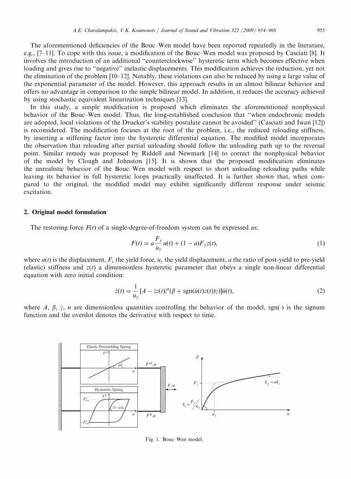
Fig. 1. Bouc–Wen model.
ARTICLE IN PRESSA.E. Charalampakis, V.K. Koumousis / Journal of Sound and Vibration 322 (2009) 954–968956
It follows from Eq. (1) that the restoring force F(t) can be analyzed into an elastic and a hysteretic part asfollows:
F elðtÞ ¼ aFy
uy
uðtÞ (3)
F hðtÞ ¼ ð1� aÞFyzðtÞ (4)
Thus, the model can be visualized as two springs connected in parallel (Fig. 1) where ki ¼ F y=uy andkf ¼ aki are the initial and post-yielding stiffness of the system.
3. Parameter constraints
The parameters of Bouc–Wen model are functionally redundant; there exists a multiplicity of parametervectors that produce an identical response for a given excitation [16]. Removing this redundancy is bestachieved by fixing parameter A to unity [16]. Henceforth, this constraint is assumed to hold.
4. Response
Recently, analytical expressions for the hysteretic response and dissipated energy of Bouc–Wen model werederived by the authors [17]. These expressions can be employed for the quantification of the displacement drift,the force relaxation and the violation of Ilyushin’s postulate, as demonstrated in the next section. Further,they form the basis of the proposed modification as they provide the full unloading path in analytical form.For sake of completeness, these expressions are reproduced here in brief.
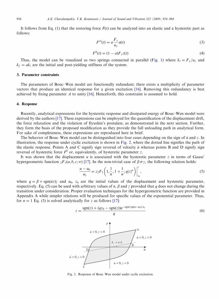
The behavior of Bouc–Wen model can be distinguished into four cases depending on the sign of _u and z. Inillustration, the response under cyclic excitation is shown in Fig. 2, where the dotted line signifies the path ofthe elastic response. Points A and C signify sign reversal of velocity _u whereas points B and D signify signreversal of hysteretic force Fh or, equivalently, of hysteretic parameter z.
It was shown that the displacement u is associated with the hysteretic parameter z in terms of Gauss’hypergeometric function 2F 1ða; b; c;wÞ [17]. In the non-trivial case of bag, the following relation holds:
u� u0
uy
¼ z2F 1 1;1
n; 1þ
1
n; qjzjn
� �����z
z0
, (5)
where q ¼ bþ sgnð _uzÞg and u0, z0 are the initial values of the displacement and hysteretic parameter,respectively. Eq. (5) can be used with arbitrary values of n, b and g provided that q does not change during thetransition under consideration. Proper evaluation techniques for the hypergeometric function are provided inAppendix A while simpler relations will be produced for specific values of the exponential parameter. Thus,for n ¼ 1 Eq. (5) is solved analytically for z as follows [17]:
z ¼sgnðzÞ þ ðqz0 � sgnðzÞÞe�sgnðzÞqðu�u0Þ=uy
q(6)
u
Fig. 2. Response of Bouc–Wen model under cyclic excitation.
ARTICLE IN PRESS
Table 1
Values of q and sgn(z) per segment.
Segment q sgn(z)
AB b�g +1
BC b+g �1
CD b�g �1
DA b+g +1
A.E. Charalampakis, V.K. Koumousis / Journal of Sound and Vibration 322 (2009) 954–968 957
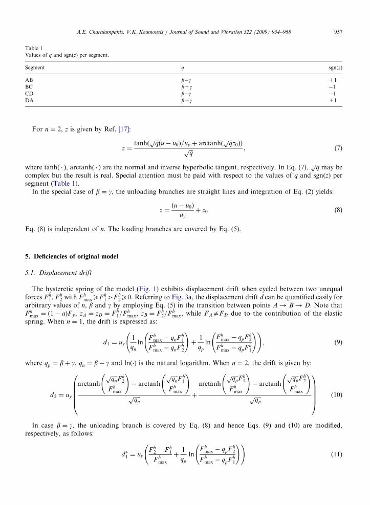
For n ¼ 2, z is given by Ref. [17]:
z ¼tanhð
ffiffiffiqpðu� u0Þ=uy þ arctanhð
ffiffiffiqp
z0ÞÞffiffiffiqp , (7)
where tanh( � ), arctanh( � ) are the normal and inverse hyperbolic tangent, respectively. In Eq. (7),ffiffiffiqp
may becomplex but the result is real. Special attention must be paid with respect to the values of q and sgn(z) persegment (Table 1).
In the special case of b ¼ g, the unloading branches are straight lines and integration of Eq. (2) yields:
z ¼ðu� u0Þ
uy
þ z0 (8)
Eq. (8) is independent of n. The loading branches are covered by Eq. (5).
5. Deficiencies of original model
5.1. Displacement drift
The hysteretic spring of the model (Fig. 1) exhibits displacement drift when cycled between two unequalforces Fh
1, Fh2 with Fh
maxXF h14F h
2X0. Referring to Fig. 3a, the displacement drift d can be quantified easily forarbitrary values of n, b and g by employing Eq. (5) in the transition between points A! B! D. Note thatFh
max ¼ ð1� aÞF y, zA ¼ zD ¼ F h1=Fh
max, zB ¼ Fh2=F h
max, while FAaFD due to the contribution of the elasticspring. When n ¼ 1, the drift is expressed as:
d1 ¼ uy
1
qn
lnF h
max � qnF h1
F hmax � qnF h
2
!þ
1
qp
lnFh
max � qpFh2
Fhmax � qpFh
1
! !, (9)
where qp ¼ bþ g, qn ¼ b� g and lnð�Þ is the natural logarithm. When n ¼ 2, the drift is given by:
d2 ¼ uy
arctanh
ffiffiffiffiffiqn
pFh
2
F hmax
!� arctanh
ffiffiffiffiffiqn
pF h
1
F hmax
!ffiffiffiffiffiqn
p þ
arctanh
ffiffiffiffiffiqpp
Fh1
Fhmax
!� arctanh
ffiffiffiffiffiqpp
Fh2
Fhmax
!ffiffiffiffiffiqpp
0BBBB@
1CCCCA (10)
In case b ¼ g, the unloading branch is covered by Eq. (8) and hence Eqs. (9) and (10) are modified,respectively, as follows:
d�1 ¼ uy
Fh2 � F h
1
Fhmax
þ1
qp
lnF h
max � qpF h2
F hmax � qpF h
1
! !(11)
ARTICLE IN PRESS
hF
A
B
u
D
d
1hF
f
1u2u
W
2hF
hF
A
B
u
C1hF
Fig. 3. (a) Displacement drift and (b) force relaxation of hysteretic spring.
A.E. Charalampakis, V.K. Koumousis / Journal of Sound and Vibration 322 (2009) 954–968958
d�2 ¼ uy
F h2 � Fh
1
Fhmax
þ
arctanh
ffiffiffiffiffiqpp
Fh1
Fhmax
!� arctanh
ffiffiffiffiffiqpp
F h2
F hmax
!ffiffiffiffiffiqpp
0BBBB@
1CCCCA (12)
5.2. Force relaxation
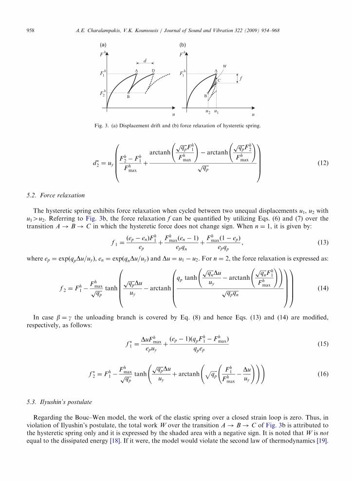
The hysteretic spring exhibits force relaxation when cycled between two unequal displacements u1, u2 withu14u2. Referring to Fig. 3b, the force relaxation f can be quantified by utilizing Eqs. (6) and (7) over thetransition A! B! C in which the hysteretic force does not change sign. When n ¼ 1, it is given by:
f 1 ¼ðep � enÞF
h1
ep
þFh
maxðen � 1Þ
epqn
þF h
maxð1� epÞ
epqp
, (13)
where ep ¼ expðqpDu=uyÞ, en ¼ expðqnDu=uyÞ and Du ¼ u1 � u2. For n ¼ 2, the force relaxation is expressed as:
f 2 ¼ F h1 �
Fhmaxffiffiffiffiffiqpp tanh
ffiffiffiffiffiqpp Du
uy
� arctanh
qp tanh
ffiffiffiffiffiqn
pDu
uy
� arctanh
ffiffiffiffiffiqn
pFh
1
Fhmax
! !ffiffiffiffiffiffiffiffiffiqpqnp
0BBBB@
1CCCCA
0BBBB@
1CCCCA (14)
In case b ¼ g the unloading branch is covered by Eq. (8) and hence Eqs. (13) and (14) are modified,respectively, as follows:
f �1 ¼DuF h
max
epuy
þðep � 1ÞðqpFh
1 � F hmaxÞ
qpep
(15)
f �2 ¼ Fh1 �
F hmaxffiffiffiffiffiqpp tanh
ffiffiffiffiffiqpp Du
uy
þ arctanhffiffiffiffiffiqp
p Fh1
F hmax
�Du
uy
! ! !(16)
5.3. Ilyushin’s postulate
Regarding the Bouc–Wen model, the work of the elastic spring over a closed strain loop is zero. Thus, inviolation of Ilyushin’s postulate, the total work W over the transition A! B! C of Fig. 3b is attributed tothe hysteretic spring only and it is expressed by the shaded area with a negative sign. It is noted that W is not
equal to the dissipated energy [18]. If it were, the model would violate the second law of thermodynamics [19].
ARTICLE IN PRESSA.E. Charalampakis, V.K. Koumousis / Journal of Sound and Vibration 322 (2009) 954–968 959
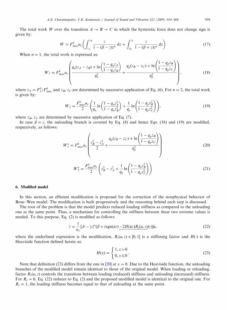
The total work W over the transition A! B! C in which the hysteretic force does not change sign isgiven by:
W ¼ F hmaxuy
Z zB
zA
z
1� ðb� gÞzndzþ
Z zC
zB
z
1� ðbþ gÞzndz
� �(17)
When n ¼ 1, the total work is expressed as:
W 1 ¼ Fhmaxuy
qnðzA � zBÞ þ ln1� qnzA
1� qnzB
� �q2
n
þ
qpðzB � zCÞ þ ln1� qpzB
1� qpzC
!
q2p
0BBBB@
1CCCCA, (18)
where zA ¼ Fh1=Fh
max and zB, zC are determined by successive application of Eq. (6). For n ¼ 2, the total workis given by:
W 2 ¼Fh
maxuy
2
1
qn
ln1� qnz2A1� qnz2B
� �þ
1
qp
ln1� qpz2B
1� qpz2C
! !, (19)
where zB, zC are determined by successive application of Eq. (7).In case b ¼ g, the unloading branch is covered by Eq. (8) and hence Eqs. (18) and (19) are modified,
respectively, as follows:
W �1 ¼ Fh
maxuy
z2B � z2A2þ
qpðzB � zCÞ þ ln1� qpzB
1� qpzC
!
q2p
0BBBB@
1CCCCA (20)
W �2 ¼
Fhmaxuy
2z2B � z2A þ
1
qp
ln1� qpz2B
1� qpz2C
! !(21)
6. Modified model
In this section, an efficient modification is proposed for the correction of the nonphysical behavior ofBouc–Wen model. The modification is built progressively and the reasoning behind each step is discussed.
The root of the problem is that the model predicts reduced loading stiffness as compared to the unloadingone at the same point. Thus, a mechanism for controlling the stiffness between these two extreme values isneeded. To this purpose, Eq. (2) is modified as follows:
_z ¼1
uy
½A� jzjnðbþ ðsgnð _uzÞ �2Hð _uzÞRsðu; zÞÞgÞ� _u, (22)
where the underlined expression is the modification, Rsðu; zÞ 2 ½0; 1� is a stiffening factor and Hð�Þ is theHeaviside function defined herein as:
HðxÞ ¼1;x40
0;xp0
(. (23)
Note that definition (23) differs from the one in [20] at x ¼ 0. Due to the Heaviside function, the unloadingbranches of the modified model remain identical to those of the original model. When loading or reloading,factor Rsðu; zÞ controls the transition between loading (reduced) stiffness and unloading (increased) stiffness.For Rs ¼ 0, Eq. (22) reduces to Eq. (2) and the proposed modified model is identical to the original one. ForRs ¼ 1, the loading stiffness becomes equal to that of unloading at the same point.
ARTICLE IN PRESS
+P
C
pu+
pz+
1
displacement
z
cu
FA
u
as cs
hyst
eret
ic p
aram
eter
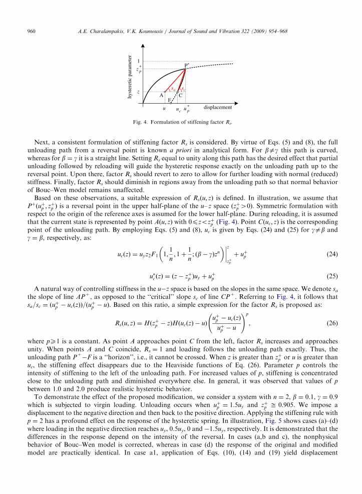
Fig. 4. Formulation of stiffening factor Rs.
A.E. Charalampakis, V.K. Koumousis / Journal of Sound and Vibration 322 (2009) 954–968960
Next, a consistent formulation of stiffening factor Rs is considered. By virtue of Eqs. (5) and (8), the fullunloading path from a reversal point is known a priori in analytical form. For bag this path is curved,whereas for b ¼ g it is a straight line. Setting Rs equal to unity along this path has the desired effect that partialunloading followed by reloading will guide the hysteretic response exactly on the unloading path up to thereversal point. Upon there, factor Rs should revert to zero to allow for further loading with normal (reduced)stiffness. Finally, factor Rs should diminish in regions away from the unloading path so that normal behaviorof Bouc–Wen model remains unaffected.
Based on these observations, a suitable expression of Rsðu; zÞ is defined. In illustration, we assume thatPþðuþp ; z
þp Þ is a reversal point in the upper half-plane of the u– z space ðzþp 40Þ. Symmetric formulation with
respect to the origin of the reference axes is assumed for the lower half-plane. During reloading, it is assumedthat the current state is represented by point Aðu; zÞ with 0pzozþp (Fig. 4). Point Cðuc; zÞ is the correspondingpoint of the unloading path. By employing Eqs. (5) and (8), uc is given by Eqs. (24) and (25) for gab andg ¼ b, respectively, as:
ucðzÞ ¼ uyz2F1 1;1
n; 1þ
1
n; ðb� gÞzn
� �����z
zþp
þ uþp (24)
u�c ðzÞ ¼ ðz� zþp Þuy þ uþp (25)
A natural way of controlling stiffness in the u�z space is based on the slopes in the same space. We denote sa
the slope of line AP+, as opposed to the ‘‘critical’’ slope sc of line CP+. Referring to Fig. 4, it follows thatsa=sc ¼ ðu
þp � ucðzÞÞ=ðuþp � uÞ. Based on this ratio, a simple expression for the factor Rs is proposed as:
Rsðu; zÞ ¼ Hðzþp � zÞHðucðzÞ � uÞuþp � ucðzÞ
uþp � u
!p
, (26)
where pX1 is a constant. As point A approaches point C from the left, factor Rs increases and approachesunity. When points A and C coincide, Rs ¼ 1 and loading follows the unloading path exactly. Thus, theunloading path P+
�F is a ‘‘horizon’’, i.e., it cannot be crossed. When z is greater than zþp or u is greater thanuc, the stiffening effect disappears due to the Heaviside functions of Eq. (26). Parameter p controls theintensity of stiffening to the left of the unloading path. For increased values of p, stiffening is concentratedclose to the unloading path and diminished everywhere else. In general, it was observed that values of p
between 1.0 and 2.0 produce realistic hysteretic behavior.To demonstrate the effect of the proposed modification, we consider a system with n ¼ 2, b ¼ 0.1, g ¼ 0.9
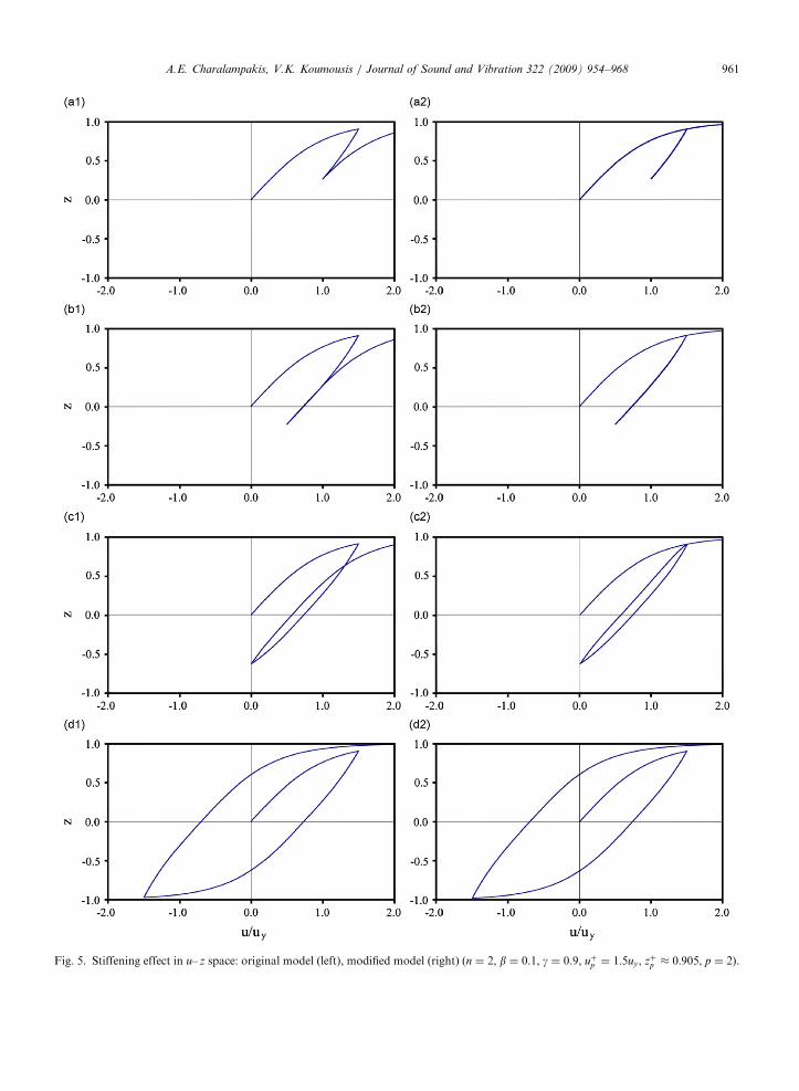
which is subjected to virgin loading. Unloading occurs when uþp ¼ 1:5uy and zþp ffi 0:905. We impose adisplacement to the negative direction and then back to the positive direction. Applying the stiffening rule withp ¼ 2 has a profound effect on the response of the hysteretic spring. In illustration, Fig. 5 shows cases (a)–(d)where loading in the negative direction reaches uy, 0.5uy, 0 and �1.5uy, respectively. It is demonstrated that thedifferences in the response depend on the intensity of the reversal. In cases (a,b and c), the nonphysicalbehavior of Bouc–Wen model is corrected, whereas in case (d) the response of the original and modifiedmodel are practically identical. In case a1, application of Eqs. (10), (14) and (19) yield displacement
ARTICLE IN PRESS
Fig. 5. Stiffening effect in u– z space: original model (left), modified model (right) (n ¼ 2, b ¼ 0.1, g ¼ 0.9, uþp ¼ 1:5uy, zþp � 0:905, p ¼ 2).
A.E. Charalampakis, V.K. Koumousis / Journal of Sound and Vibration 322 (2009) 954–968 961
ARTICLE IN PRESS
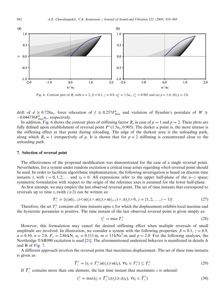
Fig. 6. Contour plot of Rs with n ¼ 2, b ¼ 0.1, g ¼ 0.9, uþp ¼ 1:5uy, zþp � 0:905 and (a) p ¼ 1.0, (b) p ¼ 2.0.
A.E. Charalampakis, V.K. Koumousis / Journal of Sound and Vibration 322 (2009) 954–968962
drift of d ffi 0:728uy, force relaxation of f ffi 0:257F hmax and violation of Ilyushin’s postulate of W ffi
�0:044756Fhmaxuy, respectively.
In addition, Fig. 6 shows the contour plots of stiffening factor Rs in case of p ¼ 1 and p ¼ 2. These plots arefully defined upon establishment of reversal point Pþð1:5uy; 0:905Þ. The darker a point is, the more intense isthe stiffening effect at that point during reloading. The edge of the darkest area is the unloading path,along which Rs ¼ 1 irrespectively of p. It is shown that for p ¼ 2 stiffening is concentrated close to theunloading path.
7. Selection of reversal point
The effectiveness of the proposed modification was demonstrated for the case of a single reversal point.Nevertheless, for a system under random excitation a critical issue arises regarding which reversal point shouldbe used. In order to facilitate algorithmic implementation, the following investigation is based on discrete timeinstants ti with i ¼ 0; 1; 2; . . . and t0 ¼ 0. All expressions refer to the upper half-plane of the u�z space;symmetric formulation with respect to the origin of the reference axes is assumed for the lower half-plane.
As first attempt, we may employ the last observed reversal point. The set of time instants that correspond toreversals up to time ti (with iX2) can be written as:
Tþi ¼ ftjjuðtj�1ÞouðtjÞ ^ uðtjÞ4uðtjþ1Þ ^ zðtjÞ40; j ¼ f1; 2; . . . ; i � 1gg (27)
Therefore, the set Tþi contains all time instants upto ti for which the displacement exhibits local maxima andthe hysteretic parameter is positive. The time instant of the last observed reversal point is given simply as:
tþi ¼ maxTþi (28)
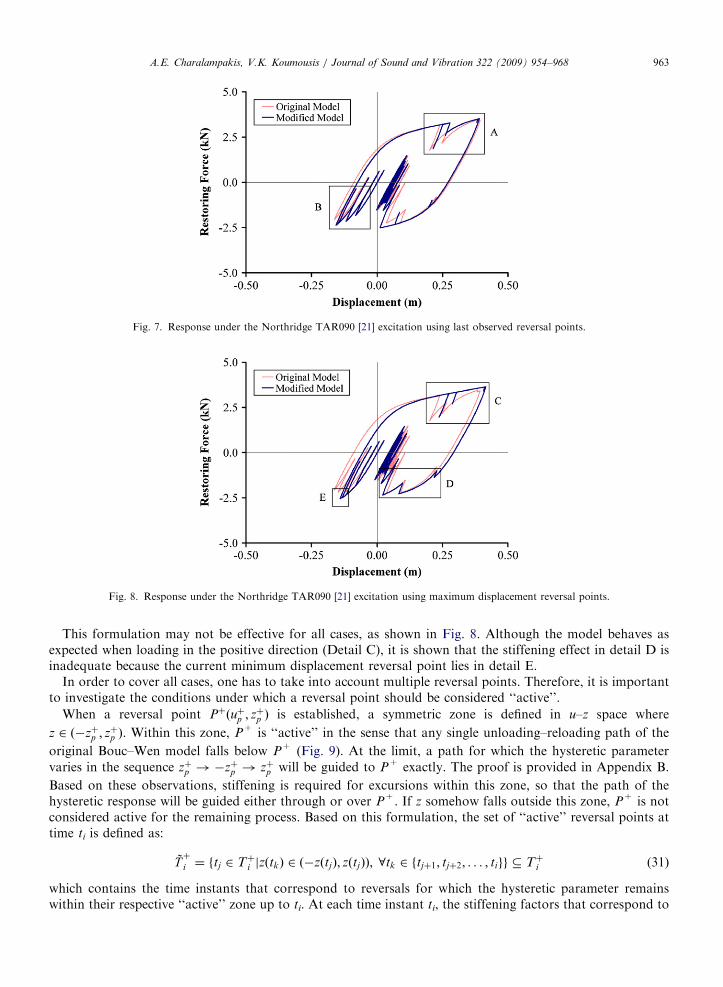
However, this formulation may cancel the desired stiffening effect when multiple reversals of smallamplitude are involved. In illustration, we consider a system with the following properties: b ¼ 0:1, g ¼ 0:9,a ¼ 0:10, n ¼ 2:0, F y ¼ 2:86 kN, uy ¼ 0:111m, m ¼ 13 kNs2/m and p ¼ 2.0. For the following analyses, theNorthridge TAR090 excitation is used [21]. The aforementioned undesired behavior is manifested in details Aand B of Fig. 7.
A different approach involves the reversal point that maximizes displacement. The set of these time instantsis given as:
Tþ
i ¼ ftj 2 Tþi juðtjÞXuðtkÞ; 8tk 2 Tþi g � Tþi (29)
If Tþ
i contains more than one element, the last time instant that maximizes z is selected:
tþi ¼ maxftj 2 Tþ
i jzðtjÞXzðtkÞ; 8tk 2 Tþ
i g (30)
ARTICLE IN PRESS
Fig. 7. Response under the Northridge TAR090 [21] excitation using last observed reversal points.
Fig. 8. Response under the Northridge TAR090 [21] excitation using maximum displacement reversal points.
A.E. Charalampakis, V.K. Koumousis / Journal of Sound and Vibration 322 (2009) 954–968 963
This formulation may not be effective for all cases, as shown in Fig. 8. Although the model behaves asexpected when loading in the positive direction (Detail C), it is shown that the stiffening effect in detail D isinadequate because the current minimum displacement reversal point lies in detail E.
In order to cover all cases, one has to take into account multiple reversal points. Therefore, it is importantto investigate the conditions under which a reversal point should be considered ‘‘active’’.
When a reversal point Pþðuþp ; zþp Þ is established, a symmetric zone is defined in u–z space where
z 2 ð�zþp ; zþp Þ. Within this zone, P+ is ‘‘active’’ in the sense that any single unloading–reloading path of the
original Bouc–Wen model falls below P+ (Fig. 9). At the limit, a path for which the hysteretic parameter
varies in the sequence zþp !�zþp ! zþp will be guided to P+ exactly. The proof is provided in Appendix B.
Based on these observations, stiffening is required for excursions within this zone, so that the path of thehysteretic response will be guided either through or over P+. If z somehow falls outside this zone, P+ is notconsidered active for the remaining process. Based on this formulation, the set of ‘‘active’’ reversal points attime ti is defined as:
Tþ
i ¼ ftj 2 Tþi jzðtkÞ 2 ð�zðtjÞ; zðtjÞÞ; 8tk 2 ftjþ1; tjþ2; . . . ; tigg � Tþi (31)
which contains the time instants that correspond to reversals for which the hysteretic parameter remainswithin their respective ‘‘active’’ zone up to ti. At each time instant ti, the stiffening factors that correspond to
ARTICLE IN PRESS
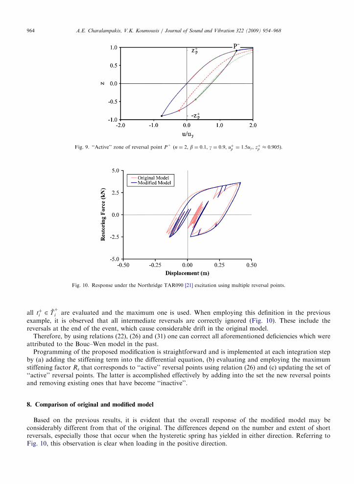
Fig. 9. ‘‘Active’’ zone of reversal point P+ (n ¼ 2, b ¼ 0.1, g ¼ 0.9, uþp ¼ 1:5uy, zþp � 0:905).
Fig. 10. Response under the Northridge TAR090 [21] excitation using multiple reversal points.
A.E. Charalampakis, V.K. Koumousis / Journal of Sound and Vibration 322 (2009) 954–968964
all tþi 2 Tþ
i are evaluated and the maximum one is used. When employing this definition in the previous
example, it is observed that all intermediate reversals are correctly ignored (Fig. 10). These include thereversals at the end of the event, which cause considerable drift in the original model.
Therefore, by using relations (22), (26) and (31) one can correct all aforementioned deficiencies which wereattributed to the Bouc–Wen model in the past.
Programming of the proposed modification is straightforward and is implemented at each integration stepby (a) adding the stiffening term into the differential equation, (b) evaluating and employing the maximumstiffening factor Rs that corresponds to ‘‘active’’ reversal points using relation (26) and (c) updating the set of‘‘active’’ reversal points. The latter is accomplished effectively by adding into the set the new reversal pointsand removing existing ones that have become ‘‘inactive’’.
8. Comparison of original and modified model
Based on the previous results, it is evident that the overall response of the modified model may beconsiderably different from that of the original. The differences depend on the number and extent of shortreversals, especially those that occur when the hysteretic spring has yielded in either direction. Referring toFig. 10, this observation is clear when loading in the positive direction.
ARTICLE IN PRESSA.E. Charalampakis, V.K. Koumousis / Journal of Sound and Vibration 322 (2009) 954–968 965
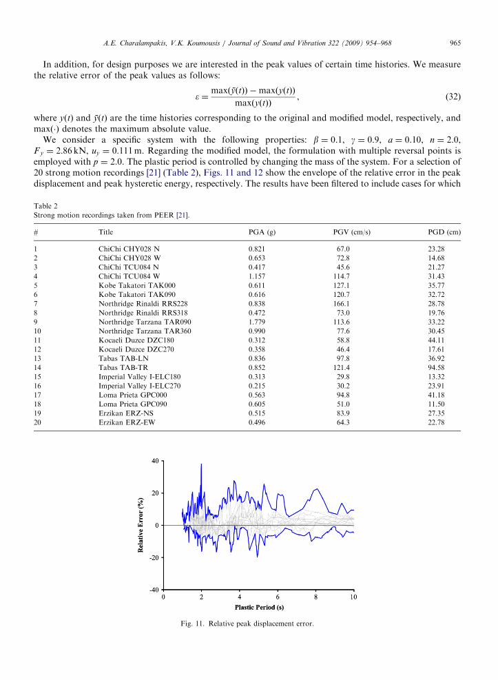
In addition, for design purposes we are interested in the peak values of certain time histories. We measurethe relative error of the peak values as follows:
� ¼maxðyðtÞÞ �maxðyðtÞÞ
maxðyðtÞÞ, (32)
where y(t) and yðtÞ are the time histories corresponding to the original and modified model, respectively, andmaxð�Þ denotes the maximum absolute value.
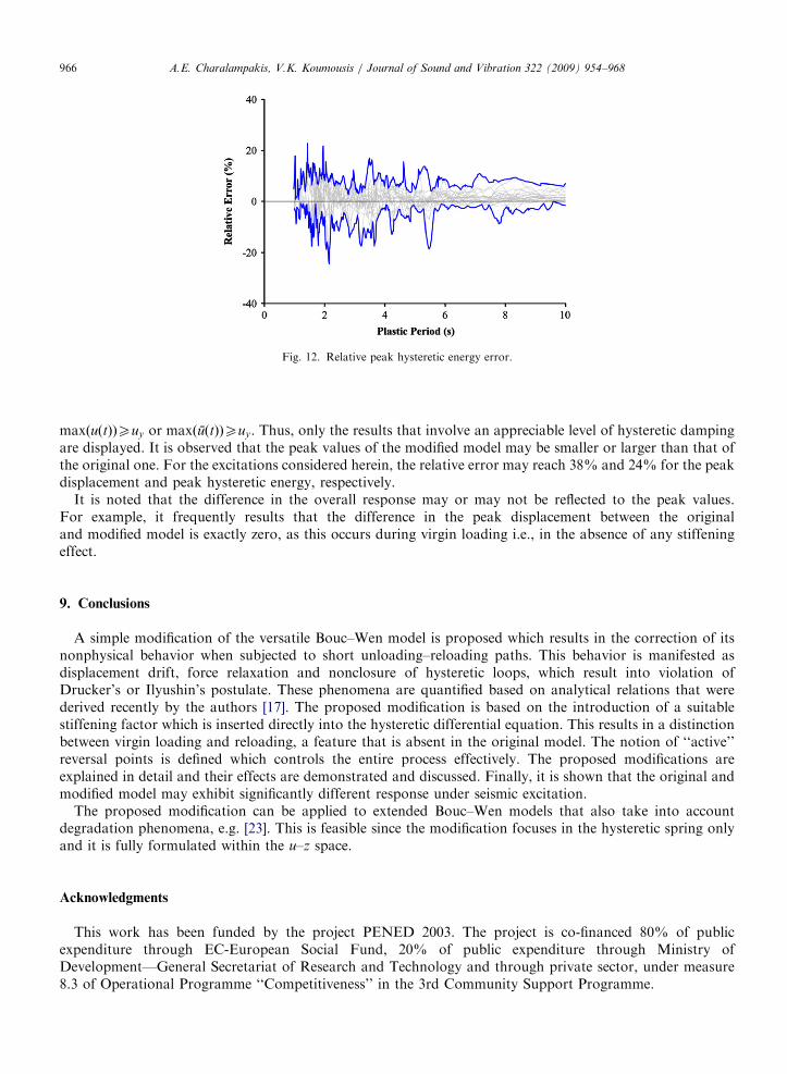
We consider a specific system with the following properties: b ¼ 0.1, g ¼ 0.9, a ¼ 0.10, n ¼ 2.0,Fy ¼ 2:86 kN, uy ¼ 0:111m. Regarding the modified model, the formulation with multiple reversal points isemployed with p ¼ 2.0. The plastic period is controlled by changing the mass of the system. For a selection of20 strong motion recordings [21] (Table 2), Figs. 11 and 12 show the envelope of the relative error in the peakdisplacement and peak hysteretic energy, respectively. The results have been filtered to include cases for which
Table 2
Strong motion recordings taken from PEER [21].
# Title PGA (g) PGV (cm/s) PGD (cm)
1 ChiChi CHY028 N 0.821 67.0 23.28
2 ChiChi CHY028 W 0.653 72.8 14.68
3 ChiChi TCU084 N 0.417 45.6 21.27
4 ChiChi TCU084 W 1.157 114.7 31.43
5 Kobe Takatori TAK000 0.611 127.1 35.77
6 Kobe Takatori TAK090 0.616 120.7 32.72
7 Northridge Rinaldi RRS228 0.838 166.1 28.78
8 Northridge Rinaldi RRS318 0.472 73.0 19.76
9 Northridge Tarzana TAR090 1.779 113.6 33.22
10 Northridge Tarzana TAR360 0.990 77.6 30.45
11 Kocaeli Duzce DZC180 0.312 58.8 44.11
12 Kocaeli Duzce DZC270 0.358 46.4 17.61
13 Tabas TAB-LN 0.836 97.8 36.92
14 Tabas TAB-TR 0.852 121.4 94.58
15 Imperial Valley I-ELC180 0.313 29.8 13.32
16 Imperial Valley I-ELC270 0.215 30.2 23.91
17 Loma Prieta GPC000 0.563 94.8 41.18
18 Loma Prieta GPC090 0.605 51.0 11.50
19 Erzikan ERZ-NS 0.515 83.9 27.35
20 Erzikan ERZ-EW 0.496 64.3 22.78
Fig. 11. Relative peak displacement error.
ARTICLE IN PRESS
Fig. 12. Relative peak hysteretic energy error.
A.E. Charalampakis, V.K. Koumousis / Journal of Sound and Vibration 322 (2009) 954–968966
maxðuðtÞÞXuy or maxðuðtÞÞXuy. Thus, only the results that involve an appreciable level of hysteretic dampingare displayed. It is observed that the peak values of the modified model may be smaller or larger than that ofthe original one. For the excitations considered herein, the relative error may reach 38% and 24% for the peakdisplacement and peak hysteretic energy, respectively.
It is noted that the difference in the overall response may or may not be reflected to the peak values.For example, it frequently results that the difference in the peak displacement between the originaland modified model is exactly zero, as this occurs during virgin loading i.e., in the absence of any stiffeningeffect.
9. Conclusions
A simple modification of the versatile Bouc–Wen model is proposed which results in the correction of itsnonphysical behavior when subjected to short unloading–reloading paths. This behavior is manifested asdisplacement drift, force relaxation and nonclosure of hysteretic loops, which result into violation ofDrucker’s or Ilyushin’s postulate. These phenomena are quantified based on analytical relations that werederived recently by the authors [17]. The proposed modification is based on the introduction of a suitablestiffening factor which is inserted directly into the hysteretic differential equation. This results in a distinctionbetween virgin loading and reloading, a feature that is absent in the original model. The notion of ‘‘active’’reversal points is defined which controls the entire process effectively. The proposed modifications areexplained in detail and their effects are demonstrated and discussed. Finally, it is shown that the original andmodified model may exhibit significantly different response under seismic excitation.
The proposed modification can be applied to extended Bouc–Wen models that also take into accountdegradation phenomena, e.g. [23]. This is feasible since the modification focuses in the hysteretic spring onlyand it is fully formulated within the u–z space.
Acknowledgments
This work has been funded by the project PENED 2003. The project is co-financed 80% of publicexpenditure through EC-European Social Fund, 20% of public expenditure through Ministry ofDevelopment—General Secretariat of Research and Technology and through private sector, under measure8.3 of Operational Programme ‘‘Competitiveness’’ in the 3rd Community Support Programme.
ARTICLE IN PRESSA.E. Charalampakis, V.K. Koumousis / Journal of Sound and Vibration 322 (2009) 954–968 967
Appendix A. Evaluation of Gauss’ hypergeometric function
The hypergeometric function is the analytical continuation of the so-called hypergeometric series [20]:
2F1ða; b; c;wÞ ¼X1n¼0
ðaÞnðbÞnðcÞn
wn
n!, (33)
where ðwÞn ¼ wðwþ 1Þ . . . ðwþ n� 1Þ; ðwÞ0 ¼ 1 is Pochhammer’s symbol and n! the factorial of n.In this study, one is interested in the evaluation of 2F1ða; b; c;wÞ for real values of w 2 ð�1; 1Þ. Although the
circle of convergence of series (33) is the unit circle |w| ¼ 1, its rate of convergence is satisfactory only for|w|p1/2 [22]. For wA(1/2,1), the values are produced by linear transformation. In the cases presented herein,c ¼ a+b and hence the following formula is used [20]:
2F1ða; b; aþ b;wÞ ¼Gðaþ bÞ
GðaÞGðbÞ
X1n¼0
ðaÞnðbÞn
ðn!Þ2½2cðnþ 1Þ � cðaþ nÞ � cðbþ nÞ � lnð1� wÞ�ð1� wÞn, (34)
where Gð�Þ is the Gamma function, cð�Þ the Psi (Digamma) function and lnð�Þ the natural logarithm. In general,Eq. (34) exhibits satisfactory rate of convergence even when evaluating the limit of the hypergeometricfunction as w-1�. Finally, for wA(�N,�1/2), the following linear transformation is used [20]:
2F1ða; b; c;wÞ ¼ ð1� wÞ�a2F1 a; c� b; c;
w
w� 1
� �(35)
The new function evaluation falls into one of the cases covered by Eqs. (33) and (34).
Appendix B. Proof
Regarding Fig. 9, we will prove that, beginning at Pþðuþp ; zþp Þ, a hysteretic loop for which z varies in the
sequence zþp !�zþp ! zþp will be guided to P+ exactly.
We assume that the final point is Pþðuþp ; z
þp ÞaPþ. The hysteretic loop can be analyzed into the sequence
Pþ ! P1ðu1; 0Þ ! P2ðu2;�zþp Þ ! P3ðu3; 0Þ ! Pþ. By successive application of Eq. (5), one obtains:
u1 � uþp
uy
¼ 0� zþp 2F 1 1;1
n; 1þ
1
n; ðb� gÞjzþp j
n
� �(36)
u2 � u1
uy
¼ �zþp 2F 1 1;1
n; 1þ
1
n; ðbþ gÞj � zþp j
n
� �� 0 (37)
u3 � u2
uy
¼ 0� �zþp 2F1 1;1
n; 1þ
1
n; ðb� gÞj � zþp j
n
� �� (38)
uþp � u3
uy
¼ zþp 2F 1 1;1
n; 1þ
1
n; ðbþ gÞjzþp j
n
� �� 0 (39)
By adding Eqs. (36)–(39) by parts, one obtains uþp ¼ uþp . Thus, Pþ¼ Pþ.
References
[1] R. Bouc, Forced vibration of mechanical systems with hysteresis, Proceedings of the Fourth Conference on Non-linear Oscillation,
Prague, Czechoslovakia, 1967.
[2] Y.K. Wen, Method for Random Vibration of Hysteretic Systems, Journal of the Engineering Mechanics Division 102 (EM2) (1976)
249–263.
[3] K.C. Valanis, A theory of viscoplasticity without a yield surface, Part I: general theory, Archives of Mechanics 23 (4) (1971) 517–533.
[4] D.C. Drucker, Some implications of work hardening and ideal plasticity, Quarterly of Applied Mathematics 7 (1950) 411–418.
[5] A.A. Ilyushin, On the postulate of plasticity, Prikladnaya Matematika i Mekhanika 25 (1961) 503–507.
ARTICLE IN PRESSA.E. Charalampakis, V.K. Koumousis / Journal of Sound and Vibration 322 (2009) 954–968968
[6] Y.F. Dafalias, Il’iushin’s postulate and resulting thermodynamic conditions on elasto-plastic coupling, International Journal of Solids
and Structures 13 (1977) 239–251.
[7] I.S. Sandler, On the uniqueness and stability of endochronic theories of material behavior, Journal of Applied Mechanics 45 (1978)
263–266.
[8] F. Casciati, Non-linear stochastic dynamics of large structural system by equivalent linearization, Proceedings ICASP5, Vancouver,
1987, pp. 1165–1172.
[9] R.S. Thyagarajan, Modeling and analysis of hysteretic structural behavior, Report No. EERL-89-03, Earthquake Engineering
Research Laboratory, California Institute of Technology, Pasadena, CA, 1989.
[10] E. Spacone, V. Ciampi, F.C. Philippou, A beam element for seismic damage analysis, Report No. UCB/EERC-92/07, Earthquake,
Engineering Research Center, University of California, Berkeley, 1992.
[11] C.W. Wong, Y.Q. Ni, J.M. Ko, Steady-state oscillation of hysteretic differential model II: performance analysis, Journal of
Engineering Mechanics 120 (11) (1994) 2299–2325.
[12] F. Casciati, Stochastic dynamics of hysteretic media, Structural Safety 6 (1989) 259–269.
[13] F. Casciati, L. Faravelli, M.P. Singh, Non-linear structural response and modeling uncertainty on system parameters and seismic
excitation, Proceedings Eighth ECEE, Lisbon, 1986, 6.3, pp. 41–48.
[14] R. Riddell, N.M. Newmark, Force-deformation models for non-linear analysis, Journal of Structural Division 105 (ST12) (1979)
2773–2778.
[15] R.W. Clough, S.B. Johnston, Effect of stiffness degradation on earthquake ductility requirements, Proceedings of the Japan
Earthquake Engineering Symposium, Tokyo, Japan, 1966.
[16] F. Ma, H. Zhang, A. Bockstedte, G.C. Foliente, P. Paevere, Parameter analysis of the differential model of hysteresis, Journal of
Applied Mechanics ASME 71 (2004) 342–349.
[17] A.E. Charalampakis, V.K. Koumousis, On the response and dissipated energy of Bouc–Wen hysteretic model, Journal of Sound and
Vibration 309 (2008) 887–895.
[18] K.C. Valanis, On the substance of Rivlin’s remarks on the endochronic theory, International Journal of Solids and Structures 17 (1981)
249–265.
[19] M. Sasani, E.P. Popov, Seismic energy dissipators for RC panels: analytical studies, ASCE Journal of Engineering Mechanics 127 (8)
(2001) 835–843.
[20] M. Abramowitz, I.A. Stegun, Handbook of Mathematical Functions, National Bureau of Standards, Washington, Dover Publications,
New York (reprinted on 1972).
[21] Pacific Earthquake Engineering Research Centre (PEER), Strong ground motion database 2006 /http://peer.berkeley.edu/S.
[22] W.H. Press, S.A. Teukolsky, W.T. Vetterling, B.P. Flannery, Numerical Recipes in C++: The Art of Scientific Computing, Cambridge
University Press, Cambridge, 2002.
[23] M.V. Sivaselvan, A.M. Reinhorn, Hysteretic models for deteriorating inelastic structures, ASCE Journal of Engineering Mechanics
126 (6) (2000) 633–640.