9500 Shared Virtual Array - Oracle Help Center
104
StorageTek June, 2000 9500 Shared Virtual Array Operation and Recovery Part Number: MP4002C
-
Upload
khangminh22 -
Category
Documents
-
view
3 -
download
0
Transcript of 9500 Shared Virtual Array - Oracle Help Center

StorageTekJune, 2000
9500Shared Virtual ArrayOperation and Recovery
Part Number: MP4002C

Copyright © Storage Technology Corporation 1999, 2000. All rights reserved.
Information contained in this publication is subject to change. In the event of changes, the publication will be revised. Comments concerning its contents should be directed to the address shown below.
StorageTekOne StorageTek DriveLouisville, Colorado80028-2201

MP4002
© Storage Technology Corp. 1999, 2000 Contents Page 3
ContentsPreface . . . . . . . . . . . . . . . . . . . . . . . . . . . . . . . . . . . . . . . . . . . . . . . . . . . . 7
Notices . . . . . . . . . . . . . . . . . . . . . . . . . . . . . . . . . . . . . . . . . . . . . . . . . . . . . . . . . . . . 7United States FCC Compliance Statement . . . . . . . . . . . . . . . . . . . . . . . . . . . . . 7Industry Canada Compliance Statement . . . . . . . . . . . . . . . . . . . . . . . . . . . . . . . 7Japanese Compliance Statement . . . . . . . . . . . . . . . . . . . . . . . . . . . . . . . . . . . . 7Taiwan Warning Label Statement . . . . . . . . . . . . . . . . . . . . . . . . . . . . . . . . . . . . 8
About This Book. . . . . . . . . . . . . . . . . . . . . . . . . . . . . . . . . . . . . . . . . . . . . . . . . . . . . 8Who Should Read This Book . . . . . . . . . . . . . . . . . . . . . . . . . . . . . . . . . . . . . . . . . . . 8Do You Have The Complete Manual? . . . . . . . . . . . . . . . . . . . . . . . . . . . . . . . . . . . . 8Trademarks . . . . . . . . . . . . . . . . . . . . . . . . . . . . . . . . . . . . . . . . . . . . . . . . . . . . . . . . 8Related Documents . . . . . . . . . . . . . . . . . . . . . . . . . . . . . . . . . . . . . . . . . . . . . . . . . . 8Viewing and Ordering Documents . . . . . . . . . . . . . . . . . . . . . . . . . . . . . . . . . . . . . . . 9
Viewing the Documents Online . . . . . . . . . . . . . . . . . . . . . . . . . . . . . . . . . . . . . . 9Ordering Documents . . . . . . . . . . . . . . . . . . . . . . . . . . . . . . . . . . . . . . . . . . . . . 10
CD-ROM. . . . . . . . . . . . . . . . . . . . . . . . . . . . . . . . . . . . . . . . . . . . . . . . . . . . 10Bound Books . . . . . . . . . . . . . . . . . . . . . . . . . . . . . . . . . . . . . . . . . . . . . . . . 10
Other Documents . . . . . . . . . . . . . . . . . . . . . . . . . . . . . . . . . . . . . . . . . . . . . . . . . . . 10History of Changes. . . . . . . . . . . . . . . . . . . . . . . . . . . . . . . . . . . . . . . . . . . . . . . . . . 11
Chapter 1 Power Control Operations . . . . . . . . . . . . . . . . . . . . . . . . . . 13Power System Description . . . . . . . . . . . . . . . . . . . . . . . . . . . . . . . . . . . . . . . . . . . . 13Power Control Panel Controls and Indicators . . . . . . . . . . . . . . . . . . . . . . . . . . . . . 13
Turning On a Shared Virtual Array . . . . . . . . . . . . . . . . . . . . . . . . . . . . . . . . 15Turning Off a Shared Virtual Array . . . . . . . . . . . . . . . . . . . . . . . . . . . . . . . . 15Emergency Power Off (EPO) Operations. . . . . . . . . . . . . . . . . . . . . . . . . . . 15Resetting a Unit After an Emergency Power Off . . . . . . . . . . . . . . . . . . . . . 16Software-Controlled Power Off/Thermal EPO . . . . . . . . . . . . . . . . . . . . . . . 16
Chapter 2 Operator Panel Introduction. . . . . . . . . . . . . . . . . . . . . . . . . 19Operator Panel Overview. . . . . . . . . . . . . . . . . . . . . . . . . . . . . . . . . . . . . . . . . . . . . 19
Keyboard Mastership . . . . . . . . . . . . . . . . . . . . . . . . . . . . . . . . . . . . . . . . . . . . . 19Operator Panel Control . . . . . . . . . . . . . . . . . . . . . . . . . . . . . . . . . . . . . . . . . . . 20Shared Virtual Array Security . . . . . . . . . . . . . . . . . . . . . . . . . . . . . . . . . . . . . . . 20
Operator Panel Security . . . . . . . . . . . . . . . . . . . . . . . . . . . . . . . . . . . . . . . . 20CSE/CMC Security . . . . . . . . . . . . . . . . . . . . . . . . . . . . . . . . . . . . . . . . . . . . 20
Operator Panel Description . . . . . . . . . . . . . . . . . . . . . . . . . . . . . . . . . . . . . . . . . . . 21Moving Around the Operator Panel Screens . . . . . . . . . . . . . . . . . . . . . . . . . . . 23
Subsystem Main Menu Tree. . . . . . . . . . . . . . . . . . . . . . . . . . . . . . . . . . . . . 24Customer Main Menu Tree. . . . . . . . . . . . . . . . . . . . . . . . . . . . . . . . . . . . . . 24Function Keys. . . . . . . . . . . . . . . . . . . . . . . . . . . . . . . . . . . . . . . . . . . . . . . . 25Data Entry . . . . . . . . . . . . . . . . . . . . . . . . . . . . . . . . . . . . . . . . . . . . . . . . . . 26
Operational Status . . . . . . . . . . . . . . . . . . . . . . . . . . . . . . . . . . . . . . . . . . . . . . . 26Starting an Operator Panel Session. . . . . . . . . . . . . . . . . . . . . . . . . . . . . . . . . . 27Selecting and Performing Functions . . . . . . . . . . . . . . . . . . . . . . . . . . . . . . . . . 28Using the Quick Menu . . . . . . . . . . . . . . . . . . . . . . . . . . . . . . . . . . . . . . . . . . . . 28Initial Configuration of an Shared Virtual Array Subsystem . . . . . . . . . . . . . . . . 29Ending an Operator Panel Session . . . . . . . . . . . . . . . . . . . . . . . . . . . . . . . . . . 30
Chapter 3 Viewing Operations. . . . . . . . . . . . . . . . . . . . . . . . . . . . . . . . 33Nonrestricted and Restricted Operations . . . . . . . . . . . . . . . . . . . . . . . . . . . . . . . . . 33Viewing the Subsystem Availability . . . . . . . . . . . . . . . . . . . . . . . . . . . . . . . . . . . . . 33

MP4002
Page 4 Shared Virtual Array Operation and Recovery
Terms Used to Describe the Subsystem Availability . . . . . . . . . . . . . . . . . . . . 35Viewing the Status of the Subsystem Configuration . . . . . . . . . . . . . . . . . . . . . . . . 36
Terms Used to Describe the Subsystem (Global) Configuration . . . . . . . . . . . 37Viewing the Status of the Channel Configuration. . . . . . . . . . . . . . . . . . . . . . . . . . . 38
Terms Used to Describe the Channel Configuration . . . . . . . . . . . . . . . . . . . . . 38Viewing the Status of the Functional Device Configuration . . . . . . . . . . . . . . . . . . . 39
Terms Used to Describe the Functional Device Configuration . . . . . . . . . . . . 40Viewing the Status of the Partition/Array Configuration . . . . . . . . . . . . . . . . . . . . . . 41
Terms Used to Describe the Partition and Array Configuration . . . . . . . . . . . . . 42Viewing the Status of the Drive Module Configuration . . . . . . . . . . . . . . . . . . . . . . . 42
Terms Used to Describe the Drive Module Configuration . . . . . . . . . . . . . . . . . 43Viewing the Status of the FRU Configuration. . . . . . . . . . . . . . . . . . . . . . . . . . . . . . 45
Terms Used to Describe the FRU Configuration . . . . . . . . . . . . . . . . . . . . . . . 46Chapter 4 Subsystem (Global) Configuration . . . . . . . . . . . . . . . . . . . 47
Subsystem (Global) Configuration Terms . . . . . . . . . . . . . . . . . . . . . . . . . . . . . . . . 48Terms Used to Describe Subsystem Passwords . . . . . . . . . . . . . . . . . . . . . . . . 49Modifying the Subsystem Configuration. . . . . . . . . . . . . . . . . . . . . . . . . . . . . . . 49Assigning Passwords and Security Levels. . . . . . . . . . . . . . . . . . . . . . . . . . . . . 51Changing Passwords and Security Levels . . . . . . . . . . . . . . . . . . . . . . . . . . . . . 52Performing an IML . . . . . . . . . . . . . . . . . . . . . . . . . . . . . . . . . . . . . . . . . . . . . . . 52Powering Off the Subsystem via the Operator Panel. . . . . . . . . . . . . . . . . . . . . 53Resetting the Data Assurance Check Mode . . . . . . . . . . . . . . . . . . . . . . . . . . . 54
Chapter 5 Functional Device Configuration . . . . . . . . . . . . . . . . . . . . . 57Functional Device Configuration Terms . . . . . . . . . . . . . . . . . . . . . . . . . . . . . . . . . . 57
Defining a Functional Device Configuration . . . . . . . . . . . . . . . . . . . . . . . . . . . . 58Duplicating a Functional Device Configuration. . . . . . . . . . . . . . . . . . . . . . . . . . 58Modifying a Functional Device Configuration . . . . . . . . . . . . . . . . . . . . . . . . . . . 59Deleting a Functional Device Configuration . . . . . . . . . . . . . . . . . . . . . . . . . . . . 62Sending a Functional Device Attention Interrupt to a Host. . . . . . . . . . . . . . . . . 64
Chapter 6 Channel Configuration . . . . . . . . . . . . . . . . . . . . . . . . . . . . . 65Channel Configuration Terms. . . . . . . . . . . . . . . . . . . . . . . . . . . . . . . . . . . . . . . . . . 65
Modifying the Channel Interface Configuration . . . . . . . . . . . . . . . . . . . . . . . . . 67Duplicating a Channel Configuration . . . . . . . . . . . . . . . . . . . . . . . . . . . . . . . . . 69
Chapter 7 Drive Module Configuration . . . . . . . . . . . . . . . . . . . . . . . . . 71Drive Module Configuration Terms . . . . . . . . . . . . . . . . . . . . . . . . . . . . . . . . . . . 71Allocating Spares to the Spares Partition. . . . . . . . . . . . . . . . . . . . . . . . . . . . . . 72Forming a Production Array . . . . . . . . . . . . . . . . . . . . . . . . . . . . . . . . . . . . . . . . 73Moving Test Arrays to Production. . . . . . . . . . . . . . . . . . . . . . . . . . . . . . . . . . . . 75Re-configuring an Array . . . . . . . . . . . . . . . . . . . . . . . . . . . . . . . . . . . . . . . . . . . 75Draining a Disk Array . . . . . . . . . . . . . . . . . . . . . . . . . . . . . . . . . . . . . . . . . . . . . 76Draining Part of an Array . . . . . . . . . . . . . . . . . . . . . . . . . . . . . . . . . . . . . . . . . . 77Viewing the Status of a Drain Operation . . . . . . . . . . . . . . . . . . . . . . . . . . . . . . 80
Chapter 8 Service Management System Overview . . . . . . . . . . . . . . . 81Error Detection . . . . . . . . . . . . . . . . . . . . . . . . . . . . . . . . . . . . . . . . . . . . . . . . . . . . . 81
Predictive Service Analysis . . . . . . . . . . . . . . . . . . . . . . . . . . . . . . . . . . . . . . . . 81Media Maintenance . . . . . . . . . . . . . . . . . . . . . . . . . . . . . . . . . . . . . . . . . . . . . . 81
Error Recovery and Reporting . . . . . . . . . . . . . . . . . . . . . . . . . . . . . . . . . . . . . . . . . 82Fencing. . . . . . . . . . . . . . . . . . . . . . . . . . . . . . . . . . . . . . . . . . . . . . . . . . . . . . . . 82State Saves . . . . . . . . . . . . . . . . . . . . . . . . . . . . . . . . . . . . . . . . . . . . . . . . . . . . 82Service Information Messages . . . . . . . . . . . . . . . . . . . . . . . . . . . . . . . . . . . . . . 83Event Logging and Reporting. . . . . . . . . . . . . . . . . . . . . . . . . . . . . . . . . . . . . . . 83

MP4002
Contents Page 5
ServiceTek . . . . . . . . . . . . . . . . . . . . . . . . . . . . . . . . . . . . . . . . . . . . . . . . . . . . . 83Guided FRU Replacement (GFR) . . . . . . . . . . . . . . . . . . . . . . . . . . . . . . . . 83
Host Error Recovery. . . . . . . . . . . . . . . . . . . . . . . . . . . . . . . . . . . . . . . . . . . . . . . . . 84Customer Service Remote Center (CSRC) . . . . . . . . . . . . . . . . . . . . . . . . . . . . . . . 84
Level 1 Support . . . . . . . . . . . . . . . . . . . . . . . . . . . . . . . . . . . . . . . . . . . . . . . . . 85Level 2 Support . . . . . . . . . . . . . . . . . . . . . . . . . . . . . . . . . . . . . . . . . . . . . . . . . 85
Chapter 9 Operator Panel Messages . . . . . . . . . . . . . . . . . . . . . . . . . . 87Subsystem Status Messages. . . . . . . . . . . . . . . . . . . . . . . . . . . . . . . . . . . . . . . . . . 87Action Messages . . . . . . . . . . . . . . . . . . . . . . . . . . . . . . . . . . . . . . . . . . . . . . . . . . . 88Operational Status Messages . . . . . . . . . . . . . . . . . . . . . . . . . . . . . . . . . . . . . . . . . 88Fault Symptom Codes . . . . . . . . . . . . . . . . . . . . . . . . . . . . . . . . . . . . . . . . . . . . . . . 89
Chapter 10 Service Information Messages. . . . . . . . . . . . . . . . . . . . . . 91SIM Overview. . . . . . . . . . . . . . . . . . . . . . . . . . . . . . . . . . . . . . . . . . . . . . . . . . . . . . 91
SIM Alert Message Formats. . . . . . . . . . . . . . . . . . . . . . . . . . . . . . . . . . . . . . . . 92SIM Reference Codes (SIM REFCODE) . . . . . . . . . . . . . . . . . . . . . . . . . . . . . . 93SIM ALERT Severity Levels . . . . . . . . . . . . . . . . . . . . . . . . . . . . . . . . . . . . . . . . 94
SIM Logging and Reporting . . . . . . . . . . . . . . . . . . . . . . . . . . . . . . . . . . . . . . . . . . . 95SIM Severity Reporting Option. . . . . . . . . . . . . . . . . . . . . . . . . . . . . . . . . . . . . . 96PM2 Report . . . . . . . . . . . . . . . . . . . . . . . . . . . . . . . . . . . . . . . . . . . . . . . . . . . . 96Machine-Initiated Maintenance (MIM) . . . . . . . . . . . . . . . . . . . . . . . . . . . . . . . . 97Shared Virtual Array-Generated SIMs and MIMs. . . . . . . . . . . . . . . . . . . . . . . . 97
Chapter 11 Error Recovery Actions . . . . . . . . . . . . . . . . . . . . . . . . . . . 99General Operator Error Recovery Actions . . . . . . . . . . . . . . . . . . . . . . . . . . . . . . . . 99FSC Lookup . . . . . . . . . . . . . . . . . . . . . . . . . . . . . . . . . . . . . . . . . . . . . . . . . . . . . . . 99PPRC Emergency Bridge Disconnect . . . . . . . . . . . . . . . . . . . . . . . . . . . . . . . . . . 100
Appendix A Drive Module Status . . . . . . . . . . . . . . . . . . . . . . . . . . . . 101

MP4002
Page 6 Shared Virtual Array Operation and Recovery
This page intentionally left blank
MP4002
© Storage Technology Corp. 1999, 2000 Preface Page 7
Preface
NoticesUnited States FCC Compliance Statement
The following is the compliance statement from the Federal Communications Commission:Note: This equipment has been tested and found to comply to the limits for Class A digital devices pursuant to Part 15 of the FCC Rules. These limits are designed to provide reasonable protection against harmful interference when the equipment is operated in a commercial environment. This equipment generates, uses, and can radiate radio frequency energy and, if not installed in accordance with the instruction manual, may cause harmful interference to radio communications. Operation of this equipment in a residential area is likely to cause harmful interference, in which case the user will be required to correct the interference at his or her own expense. Some of the cables used to connect peripherals must be shielded and grounded as described in the installation manual. Operation of this equipment with the required cables that are not shielded and correctly grounded may result in interference to radio and TV reception. Changes or modifications not expressly approved by StorageTek could void the user's authority to operate the equipment.
Industry Canada Compliance StatementThis digital apparatus does not exceed the Class B limits for radio noise emissions from digital apparatus set out in the radio interference regulations of the Canadian Department of Communications.Le présent appareil numerique német pas de bruits radioélectriques dépassant les limites applicables aux appareils numériques de la classe B prescrites dans le Reglément sur le brouillage radioélectrique édicté par le ministére des Communications du Canada.
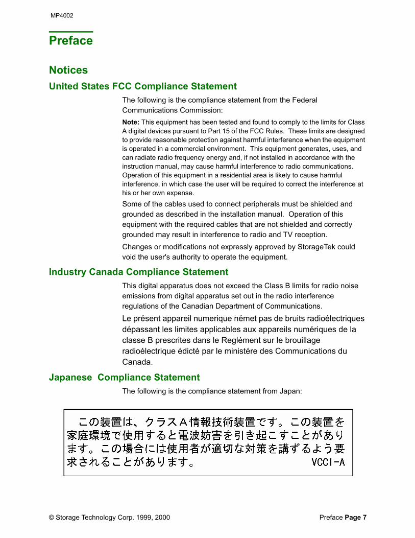
Japanese Compliance StatementThe following is the compliance statement from Japan:

About This Book MP4002
Page 8 Shared Virtual Array Operation and Recovery
Note: This equipment is in the Class A category information technology equipment based on the rules of Voluntary Control Council For Interference by Information Technology Equipment (VCCI). When used in a residential area, radio interference may be caused. In this case, user may be required to take appropriate corrective actions.Consequently, when used in residential area or in an adjacent area thereto, radio interference may be caused to radios and TV receivers, etc. Read the instructions for correct handling.
Taiwan Warning Label Statement The following is the warning label statement from Taiwan, R.O.C.:
About This BookThis book provides the operators of the 9500 Shared Virtual Array with information about the Shared Virtual Array (SVA) family of products and how to operate the Shared Virtual Array Subsystem in the mainframe environment.
Who Should Read This BookThe audience for this book includes system console operators, system programmers, and storage administrators.
Do You Have The Complete Manual?This manual consists of pages 1 through 104. Note: The last two pages are the reader comment form and its mailer. These
pages may not be there if someone sent the comment form to StorageTek.
TrademarksStorageTek is a registered trademark of Storage Technology Corporation. All other trademarks and features mentioned in this document are either trademarks of Storage Technology Corporation or of other corporations.
Related DocumentsThe documents listed below comprise the complete SVA 9500 set. See “Viewing and Ordering Documents” (below) to obtain documents through available distribution channels.Shared Virtual Array (SVA) SubsystemDocuments below are available online, on CD-ROM, and as bound books.• 9500 Shared Virtual Array Introduction (MP4001B).

MP4002 Viewing and Ordering Documents
Preface Page 9
• 9500 Shared Virtual Array Operation and Recovery (MP4002B)• 9500 Shared Virtual Array Planning, Implementation and Usage
(MP4003B)• 9500 Shared Virtual Array Physical Planning (MP4004B)• 9500 Shared Virtual Array Reference (MP4005B)• 9500 Shared Virtual Array System Assurance (MP4006B)• Peer to Peer Remote Copy Configuration Guide (MP4007A)Shared Virtual Array Administrator (SVAA) for OS/390Documents below are available online and on CD-ROM.• SVAA for OS/390 Configuration and Administration (PN 3112905xx)• SVAA for OS/390 Reporting (PN 3112906xx)• SVAA for OS/390 Messages and Codes (PN 3112907xx)• SVAA for OS/390 Installation, Customization, and Maintenance (PN
3112908xx)SnapShot for OS/390Documents below are available online and on CD-ROM.• SnapShot for OS/390 User’s Guide (PN 3112912xx)• SnapShot for OS/390 Installation, Customization, and Maintenance
(PN 3112913xx)Shared Virtual Array Administrator (SVAA) for SolarisDocuments below are available online and on CD-ROM.• SVAA for Solaris User’s Guide (PN 3112909xx)• SVAA for Solaris Messages (PN 3112910xx)• SVAA for Solaris Installation (PN 3112911xx)• SVAA for Solaris Quick Start Guide (PN 3112971xx)SnapShot for SolarisDocuments below are available online and on CD-ROM.• SnapShot for Solaris User’s Guide (PN 3112914xx)• SnapShot for Solaris Quick Start Guide (PN 3112915xx)Shared Virtual Array Console (SVAC) for Windows NTThe document below is available online and on CD-ROM.• SVAC for Windows NT Quick Start Guide (PN 3112993xx)
Viewing and Ordering DocumentsViewing the Documents Online
SVA 9500 documents can be viewed (and printed on your printer - these are PDF files) at the Customer Resource Center website at:
http://www.support.storagetek.com/wwcss/SilverStream/Pages/pgCRCHome.html
Click on ‘Disk Subsystems’, then ‘Docs’ under the 9500 section.Note: A password is required. You may obtain the password from a StorageTek marketing representative.

Other Documents MP4002
Page 10 Shared Virtual Array Operation and Recovery
Ordering DocumentsSVA 9500 documents are available on CD-ROM, and bound book. Consult a StorageTek marketing representative to order the various manuals relating to the 9500.
CD-ROM• Customer hardware documents: a CD-ROM of SVA 9500 customer
documents is available by requesting the 9500 Customer Documentation, PN MP-9500x.
• Software documents: a CD-ROM of SVA 9500 software documents is available by requesting SVA Software Publications, PN 311295301-xx.
Bound BooksIndividual bound books of SVA 9500 documents are available through Software Manufacturing Distribution (SMD); request by document title and/or part number.
Other DocumentsThe following IBM documents may also assist you in using SVA 9500:• Planning For IBM Remote Copy SG24-2595-xx• Remote Copy Administrator’s Guide and Reference SC35-0169-xx

MP4002 History of Changes
Preface Page 11
History of ChangesRev A - Initial release November 1999. Rev B - First revision, December 1999.• Minor revisions, and pagination change to reflect the way the PDF files
number pages.Rev C - Second revision, June 2000.• Added information about the PPRC bridge disconnect.• Other minor changes and updates.

History of Changes MP4002
Page 12 Shared Virtual Array Operation and Recovery
This page intentionally left blank

MP4002
© Storage Technology Corp. 1999, 2000 Chapter 1 Power Control Operations Page 13
Chapter 1 Power Control Operations
This chapter describes the power controls and indicators found in the 9500 Shared Virtual Array subsystem. It provides procedures for turning the unit on or off for normal operation, and for turning the SVA off in an emergency.
Power System DescriptionThe 9500 Shared Virtual Array has two power cords. For true ac redundancy, these cords should connect to two independent power sources that will not fail at the same time. If both unit power cords are connected to different circuits from the same AC source, reliability is enhanced, but true AC redundancy is not realized.The redundant dc power supplies protect all Shared Virtual Array components, including cache and the physical devices (disk drives). Redundant battery backup units provide nonvolatile storage with at least 72 hours of protection.
Power Control Panel Controls and IndicatorsThe Shared Virtual Array has a power control panel recessed into the right front door of the cabinet. The power control panel contains buttons and switches to select power control states, and indicators to show the unit’s power status. Figure 1-1 illustrates the Shared Virtual Array’s power control panel. Table 1-1 provides a brief functional description of the controls and indicators found on the power control panel.

Power Control Panel Controls and Indicators MP4002
Page 14 Shared Virtual Array Operation and Recovery
Figure 1-1 Power Control Panel
Table 1-1 Power Control Panel
Figure 1-1Reference
Switch orIndicator
Function
1 UNIT EMERGENCY Switch (EPO)
Setting switch to ON (1) instantly disables subsystem power beyond PDUs. Setting switch to OFF (0) allows subsystem power to be enabled when POWER ENABLE switch is pressed. A battery backup system protects nonvolatile cache data (NVS) during EPO.
2 POWER ON Indicator Lights green if 5V DC is present and within spec at C3 motherboard.
3 POWER SEQUENCE COMPLETE Indicator
Microcode-controlled; lights green after subsystem verifies that all power checks completed error-free during ‘power on’ sequence.
4 POWER ENABLE Switch
Setting switch to OFF (0) initiates a controlled power down (CPD) of subsystem. Setting switch to ON (1) enables subsystem power.
5 POWER CHECK Indicator
Microcode-controlled; lights amber if subsystem power checks do not complete error-free during ‘power on’ sequence.
6 ISP Drive LEDs Light green when ISP drives are active (visible from the right side).
7 RUN/RESET Switch Resets subsystem after thermal EPO. Switch is accessible only if front doors of unit are unlocked.
8 CSE/CUSTOMER Switch
Determines how subsystem power is reset after EPO. Switch is set by CSE at installation and is accessible only if front doors of unit are unlocked.
1 2
3
5
6
8
C95003
4
7
RESET/RUN CUSTOMER/CSE
POWER CHECK
POWER
SEQUENCE
COMPLETE
POWER ON

MP4002 Power Control Panel Controls and Indicators
Chapter 1 Power Control Operations Page 15
Turning On a Shared Virtual ArrayTo turn on a Shared Virtual Array:
1. Verify that the red UNIT EMERGENCY button on the Controller power control panel is set to ON. Refer to Figure 1-1.
- A UNIT EMERGENCY button is off when the red button stands out from the frame.
- A UNIT EMERGENCY button is on when the red button is flush with the frame.
If necessary, refer to “Resetting a Unit After an Emergency Power Off” to reset the subsystem.
2. Set the POWER ENABLE button on the Controller power control panel to ON (1).
- The POWER ON indicator on the Controller power control panel illuminates.
- The Power Sequence Complete indicator on the Controller power control panel illuminates and the subsystem automatically begins an IML procedure.
- The operator panel displays a series of messages describing the steps in the IML procedure. When the IML procedure is complete, the status field on the operator panel indicates “Full Box IML Complete”.
Turning Off a Shared Virtual ArrayTo turn off a Shared Virtual Array:
1. At the host console, vary all of the addresses to the Disk Array Controller offline.
2. At the host console, vary all of the channels to the Disk Array Controller offline.
3. Set the POWER ENABLE button on the Controller power control panel to OFF (0).
- The Power ON indicator on the Controller power control panel goes out.
Emergency Power Off (EPO) OperationsTo turn off a Shared Virtual Array Controller in an emergency:
1. Locate the red UNIT EMERGENCY button on the unit’s power control panel.
2. Lift the clear plastic guard, and press the UNIT EMERGENCY button.
Note: The unit powers down is the fastest possible sequence without compromising data integrity, and the Power On indicator goes out.

Power Control Panel Controls and Indicators MP4002
Page 16 Shared Virtual Array Operation and Recovery
Resetting a Unit After an Emergency Power OffDepending on how the CSE/CUSTOMER switch on the unit was set at installation, you may have to call a CSE to reset the subsystem after an Emergency Power Off (EPO). Table 1-2 describes the situations and what to do.
To reset a Shared Virtual Array Controller after an EPO, return the red UNIT EMERGENCY button on its power control panel to OFF (0).A UNIT EMERGENCY button is off when the red button stands out from the frame.A UNIT EMERGENCY button is on when the red button is flush with the frame.
Software-Controlled Power Off/Thermal EPOIn certain situations, such as an over temperature condition, the Controller operational software may initiate a software-controlled power off. In this case, a CSE must be called to reset the subsystem.There are two types of system "power down" procedures, as follows:• Controlled power down (CPD)--an ISP software function primarily used
to reduce power consumption when a system is not in use (e.g. holidays).
• Relocation power shutdown--a total power shutdown done during system relocation, including CPD of all units and turning off all AC inlet and PDU breakers.
Using the 9500 system POWER ENABLE switch:
1. Have the operator vary offline all channels and functional devices between the host(s) and the system.
2. Set the 9500 system POWER ENABLE switch to OFF (O).
The unit initiates a CPD sequence, which automatically:
Table 1-2 Resetting Shared Virtual Array After an EPO
Cause of EPO
CSE/Customer Switch Option
How to Reset (power unit on)
Manual EPO
“Customer” reset option
Return the red UNIT EMERGENCY button on the unit’s power control panel to OFF (0).
Manual EPO
“CSE” reset option Return the red UNIT EMERGENCY button on the unit’s power control panel to OFF (0) and call a service representative to turn on the subsystem.
Thermal EPO
Any position Return the red UNIT EMERGENCY button on the unit’s power control panel to OFF (0) and call a service representative to turn on the subsystem.

MP4002 Power Control Panel Controls and Indicators
Chapter 1 Power Control Operations Page 17
- Disables each front-end channel and saves its last state for the next IML.
- Transfers customer data and mapping tables from nonvolatile cache to the arrays.
- Compresses all raw state saves (takes 10 minutes to one hour). - Logically disconnects CNV cards from the battery backup system

Power Control Panel Controls and Indicators MP4002
Page 18 Shared Virtual Array Operation and Recovery
This page intentionally left blank

MP4002
© Storage Technology Corp. 1999, 2000 Chapter 2 Operator Panel Introduction Page 19
Chapter 2 Operator Panel Introduction
This chapter describes the Shared Virtual Array operator panel, which provides the human interface to the subsystem. This chapter also describes how to start using the operator panel and how to move around its menus and screens.
Operator Panel OverviewThe operator panel allows the operator to configure and control a Shared Virtual Array subsystem. On the Disk Array Control Unit, the operator panel is recessed into the left front door of the Control Unit cabinet.
Keyboard MastershipThe top field on the operator panel display lists the operator panels that are attached to the Shared Virtual Array subsystem and which operator panel is keyboard master. The abbreviations (or acronyms) are as follows:DACDisk Array Controller DisplayDAUDDisk Array Unit DisplayIXOFShared Virtual Array AdministratorCSRCCustomer Service Remote CenterThe operator panel may be in one of three states: idle, keyboard master, or maintenance.• In the “idle” state, there is no activity at any of the connected operator
panels.• In the “keyboard master” state, an operator is performing actions at
one of the connected operator panels. If the operator allows more than three minutes to pass without performing a function, mastership is lost and the operator panel reverts to the “idle” state.
• In the “maintenance” state, a CSE is performing maintenance actions at one of the connected operator panels. If the CSE allows more than 60 minutes to pass without performing a function, he or she is logged off and the operator panel reverts to the “keyboard master” state.
Mastership is established by pressing any soft-key while the "Subsystem Main Menu (SS01)" screen is displayed; when this occurs, the support facility designates that panel as ’master,’ and all other connected panels as ’slaves.’ To prevent one user from interfering with the activity of another, slave panels display the content of the master panel but cannot perform any functions while the master panel is in use.After keyboard mastership is forfeited using the [F3] (EXIT KEYM) key on the "Subsystem Main Menu (SS01)" screen, any other panel can assume keyboard mastership.

Operator Panel Overview MP4002
Page 20 Shared Virtual Array Operation and Recovery
Operator Panel ControlShared Virtual Array subsystems have two Shared Virtual Array support processors, which form the basis of the subsystem’s support facility. The support facility is responsible for managing and administrating the subsystem, including operator panel control.Shared Virtual Array’s two ISPs conform to the subsystem’s fault-tolerant design. At any one time, one ISP is the master processor, performing all of the support facility responsibilities. At the same time, the other ISP is in standby mode, accepting checkpoint messages and ready to take over as master as required. When a processor switch occurs, the standby ISP becomes the master and takes over all of the support facilities’ responsibilities.
Shared Virtual Array SecurityMultiple levels of access passwords provide a Shared Virtual Array subsystem with security, preventing unauthorized access to Shared Virtual Array maintenance and control functions.Initial passwords are factory-set and remain in effect until the customer or CSE, as appropriate, modifies them. To modify passwords, refer to “Assigning Passwords and Security Levels.”An operator has five opportunities to type in the correct customer logon password. After five incorrect attempts, the operator panel returns to the Subsystem Main Menu.The following sections describe the levels of access and the different passwords required for Shared Virtual Array.
Operator Panel SecurityOperator panel functions are divided into two levels of functionality. Non-restricted functions, which include viewing operations and enabling and disabling channels, do not require a password. Restricted functions, which include all configuration and drain functions, require a customer logon password. Refer to “Assigning Passwords and Security Levels” for more information on the customer logon password.
CSE/CMC SecurityStorageTek CSEs and Customer Service Remote Center (CSRC) engineers may need to access operator panel functions. Shared Virtual Array’s normal security system ensures that when performing maintenance and diagnostic functions, StorageTek personnel do not have access to customer data. However, a customer can ensure that an operator is always notified when StorageTek personnel need to access a subsystem. The customer does this by accessing the Customer Configurable Items screen and setting the CSRC connection security level to “high.”

MP4002 Operator Panel Description
Chapter 2 Operator Panel Introduction Page 21
When the security level is set to “high,” StorageTek personnel must request the password from the system operator at the host console. The system operator runs IDCAMS, a host-based facility that generates a temporary password, which expires after one hour. The system operator supplies this password to the CSE.
Operator Panel DescriptionThe Shared Virtual Array local operator panel consists of a liquid crystal display (LCD), ten variable function “Soft Keys,” a 16-Key hexadecimal keypad (0 - F), an [ENTER] key, and a [CLEAR] key. Figure 2-1 illustrates the Shared Virtual Array subsystem operator panel, and Table 2-1 provides a description of the display and function keys found on an operator panel.
Figure 2-1 Operator Panel Controls and Indicators
C95036
F1
F2
F3
F4
F5
F6
F7
F8
F9
F10
CLEARENTER 0 1 2 3 4 5 6 7 8 9 A B C D E F
HELP QUIKMENU
EXITKEYM
SSYSAVAL
SSYSSTAT
CHANSTAT
FDEVSTAT
ARAYSTAT
DRIVSTAT
LOGON
Connected: OPNL CSRC Master: OPNLStatus: Full Box IML Complete
ISP0S/N 00000001
Subsystem Main Menu
F3 Exit Keyboard MasterF4 Subsystem AvailabilityF5 Subsystem Configuration StatusF6 Channel Enable/DisableF7 Functional Device StatusF8 Partition Status/Array StatusF9 Drive Module StatusF10
(SS10)(SS11)(SS12)(SS13)(SS14)(SS15)(SS16)
1
2
3
5
4
6
7
8
9
11
10
1214 1315
=> Action: Status:
SS01
FSC:
Logon

Operator Panel Description MP4002
Page 22 Shared Virtual Array Operation and Recovery
Table 2-1 Operator Panel Controls and Indicators
Figure 2-1 Reference
Control or Indicator Function
1 “Connected” Field Lists all of the operator panels that are connected to the subsystem.DACD Local panel for 9500 systemCSRC Remote panel for Field Support Center
2 System “Status” Field Indicates system status (normal, over temperature, power failure, power check, etc.); displays messages during IML.
3 Application/Input Field
Displays status information; allows users to access screens and functions, change configuration data, etc.
4 “Action/Status/FSC” Fields
Action - Describes current function being performed by the support facilityStatus - Describes the status of the current function being performed.FSC - Fault symptom code; indicates successful (FSC=None) or less than successful (FSC=XXXX) completion of an operation. (Where XXXX is a hexadecimal fault symptom code that indicates a failed operation.)
5 Function Key Guide Field
Provides abbreviated descriptions of soft-key functions available for current screen.
6 [F1]-[F10] Function Keys
Activate selected functions as listed on the current screen. Refer to “ on page 25”
7 [ENTER] Key Moves the cursor to the next field, or in some cases, sends operator-keyed information to the Shared Virtual Array support processor.
8 0-9 and A-F Data Entry Keys
Allow users to enter hexadecimal information at the current screen (if prompted).
9 [CLEAR] Key Deletes user-keyed information from current screen.10 Screen Title/ID Field Functional title of a screen, plus its unique
alphanumeric identifier for the screen (for example, the ID for the Subsystem Main Menu is SS01).
11 “Heartbeat Field” Expands and contracts continuously to indicate that the ISP is functional; the pulse=30 beats/minute.
12 “Hourglass Field” Indicates that the ISP is performing a requested (user-keyed) command.
13 “Serial” # Field Indicates the unit serial number (000xxxxx).14 “ISP” Field Indicates which ISP (ISP-0 or ISP-1) is the master. The
master ISP controls the operator panel displays.

MP4002 Operator Panel Description
Chapter 2 Operator Panel Introduction Page 23
Moving Around the Operator Panel ScreensThe operator panel screens are arranged into two levels: nonrestricted and restricted, which are separated by a logon menu (“Subsystem Main Menu Tree” on page 24). Nonrestricted screens are accessible directly from the Subsystem Main Menu without a password. Restricted screens require that the operator type in a logon password in order to gain access to the Customer Main Menu. Nonrestricted functions include enabling and disabling channels and viewing the status of the subsystem configuration and operations. All other functions are restricted functions. Note: In Shared Virtual Array terminology, a menu is an operator panel display
that lists selections; a screen is an operator panel display into which you can type information and perform functions.
Because the path to a screen may involve several menus, the path is displayed graphically. For example:
15 “Master” Field Indicates which connected operator panel is keyboard master.
Table 2-1 Operator Panel Controls and Indicators
Figure 2-1 Reference
Control or Indicator Function
SubsystemMain Menu
F9
C92428
Indicates that you must press[ ] to get from the SubsystemMain Menu to the Drive ModuleStatus screen.
F9
Nonrestricted(No password required)
DriveModuleStatus

Operator Panel Description MP4002
Page 24 Shared Virtual Array Operation and Recovery
Subsystem Main Menu TreeFigure 2-2 shows the arrangement of screens available through the SUBSYSTEM MAIN MENU.
Figure 2-2 Subsystem Main Menu Tree
Customer Main Menu TreeFigure 2-3 shows the arrangement of the screens available through the CUSTOMER MAIN MENU.
SubsystemMain Menu
(SS01)
F10
F9
F8
F7
F6
F5
F4
F3
F2
F1
C92429
Logon(SS16)
CustomerMain Menu
(PS01)
DriveModule Status
(SS15)
Partition/Array Status
(SS14)
FunctionalDevice Status
(SS13)
ChanelEnable/Disable
(SS12)
SubsystemConfigurationStatus (SS11)
SubsystemAvailability
(SS01)
ExitKeyboard
Master
QuikMenu
(SP01)
Help
NONRESTRICTED FUNCTIONS
RESTRICTED FUNCTIONS

MP4002 Operator Panel Description
Chapter 2 Operator Panel Introduction Page 25
Figure 2-3 Customer Main Menu Tree
Function KeysFunction keys allow you to move around the operator panel menus. There are three function keys that are found on all of the Shared Virtual Array menus and screens, and always have the same function key number. There are four function keys that are common to many of the Shared Virtual Array menus and screens. When they are selections on a menu or screen, they also always have the same function key number. The function keys found on all Shared Virtual Array menus and screens are:
F6
F5
F10
F7
F10
F4
F6
F5
F7
F8
F6
F9
F6
F5
F7
F4
F5
C95037
DrainDisk Array
(CD28)
Configure/Drain Menu
(DC01)
DriveModule Status
(CD38)
CustomerMain Menu
(PS01)
Drain Unit/Tray/Slot(CD29)
FRUConfiguration
(CD26)
Information/Status Menu
(IS01)
DrainMenu
(CD12)
DrainStatus
(CD27)
Form Pro-duction Array
(CD33)
Partition/Array Status
(CD20)
AllocateSpares(CD36)
Drive ModuleConfigurationMenu (CD25)
ChannelConfiguration
(CD22)
ConfigureSubsystem
Menu (CD11)
FunctionalDevice Config-ursation (CD23)
ModifyFunctional
Device (CD32)
CustomerConfigurableItems (CD24)
Modify ChannelInterface(CD31)
SubsystemConfiguration
(CD21)

Operator Panel Description MP4002
Page 26 Shared Virtual Array Operation and Recovery
The function keys common to many Shared Virtual Array menus and screens are:
To perform a menu function, press the appropriate function key. For example, pressing [F8] while viewing the Subsystem Main Menu (Figure 2-4 on page 27) displays the status of the partitions and disk arrays.Any keystrokes made while the hourglass figure is on-screen are ignored.
Data EntryUse the hexadecimal keys (0 through F) for data entry functions at the operator panel. However, note that while zero is a valid entry in some fields, leading zeros are, in most cases, ignored.
Operational StatusAs mentioned before, the second line of the operator panel display contains the subsystem status line, which indicates the status of events that are detected by the subsystem. The subsystem status field usually indicates “Full Box IML Complete.” However, in certain conditions, other subsystem status information may appear here. Finally, if the subsystem detects a problem, it may display information about the problem on the subsystem status field.When an operator entry is out of the stated range for a field, “Invalid data entered - Press any key to continue” appears on the line above the function keys.
Table 2-2 Shared Virtual Array Function Keys
HELP [F1] To access context-based HELP about the menu or screen currently displayed.
QUIK MENU [F2] To access an abbreviated list of operator panel menus. The Quick Menu allows you to quickly move from a menu or screen at the bottom of the menu tree to a menu at the top of the menu tree without having to go through the previous menus. Refer to “Using the Quick Menu” for information on how the Quick Menu option works.
PREV MENU [F3] To return to the previous menu. (On the SUBSYSTEM MAIN MENU, this key allows you to quit as keyboard master.)
Table 2-3 Common Function Keys
PAGE UP [F4] To move to the previous page of data.PAGE DOWN [F5] To move to the next page of data.CURS UP [F6] To move the cursor to the previous selection item.
(Cursor position is highlighted in reverse video.)CURS DOWN [F7] To move the cursor to the next selection item.

MP4002 Operator Panel Description
Chapter 2 Operator Panel Introduction Page 27
Starting an Operator Panel SessionTo start an operator panel session:
1. Determine if another operator is keyboard master.
The keyboard master is identified in the Master: field on the top line of the screen (refer to Figure 2-4), and the actions of the current keyboard master are displayed on the operator panel screen.
Figure 2-4 Subsystem Main Menu
2. If another operator is keyboard master, wait until the Master: field is blank before requesting to become keyboard master.
Note:If you request to become keyboard master while another operator is keyboard master, your request will be refused.
3. When the Master: field is empty, request to become keyboard master by pressing any key on the keyboard.
- “Request Key Master” appears in the action field and “Started” appears in the operation status field. When your request to become keyboard master is approved, “Granted” appears in the operation status field, and you can begin your session.
4. If the SUBSYSTEM MAIN MENU is not displayed, press PREV MENU [F3] until it is.
Always start an operator panel session at the SUBSYSTEM MAIN MENU.
5. Select the operator panel function you wish to perform. Refer to chapters 4 through 9 for the operator panel functions that are available to you.
Note: As mentioned in “Moving Around the Operator Panel Screens,” to perform restricted operator panel functions, you must be authorized and know the customer logon password.
Connected: DACD CSRC Master: DACD ISP0 Status: S/N: 00000001 ♥----------------------------------------------------------------------- Subsystem Main Menu SS01
F3 - Exit Keyboard Master F4 - Subsystem Availability (SS10) F5 - Subsystem Configuration Status (SS11) F6 - Channel Enable/Disable (SS12) F7 - Functional Device Status (SS13) F8 - Partition Status Array Status (SS14) F9 - Drive Module Status (SS15) F10- Logon (SS16)
=>-----------------------------------------------------------------------
HELP QUIKMENU
EXITKEYM
SSYS SSYS CHAN FDEV ARAY DRIV LOGAVAL STAT STAT STAT STAT STAT ON

Operator Panel Description MP4002
Page 28 Shared Virtual Array Operation and Recovery
Selecting and Performing FunctionsThere are three methods of making selections and executing functions on the operator panel:
Using the Quick MenuEvery operator panel screen and menu has a Quick Menu option. This Quick Menu allows you to move around through menus and screens more rapidly and easily. It also eliminates the ‘backing out’ steps otherwise required to exit screens and menus.Note: The “Quick Menu (SPO1)” screen does not have a HELP screen. Press
[F1] (HELP) to display help screens for the menu highlighted by the cursor.
To access the QUIK MENU, press [F2]
Table 2-4 Selecting and Performing Functions
Method How you can tell What you do
Cursor-selectable When a list of items is displayed and one of the items is highlighted in reverse-video. Also, the cursor up [F6] and cursor down [F7] function keys are displayed.
Move the cursor until the item that you want to select or the function that you want to perform is highlighted. Press the appropriate function key (usually [F8], [F9], [F10], or [ENTER]) to make the selection or execute the function.
Data field entry If one or more data fields into which you can type information are displayed.
Type in the information, using the hex and decimal keys. Press the appropriate function key (usually [F8], [F9], [F10], or [ENTER]) to make the selection or perform the function.
Soft-key only If you can simply press a function key to make a selection or perform a function. You do not move the cursor or type in information.
Press the appropriate function key to make the selection or perform a function. Only valid function keys (those with functions assigned on-screen) can be used to make a selection or perform a function.Press function keys that are not labeled (i.e., those that do not have functions indicated on-screen), or pressing the [CLEAR], [ENTER], and hex keys [0]-[F] will not cause anything to happen on these screens.

MP4002 Operator Panel Description
Chapter 2 Operator Panel Introduction Page 29
• If you are working in the non-restricted screens, the following QUIK MENU screen appears:
• If you are working in the restricted screens, the following QWIK MENU screen appears:
1. Move the cursor until the menu that you want to access is highlighted.
2. Press [ENTER]. The menu you selected appears.
Initial Configuration of an Shared Virtual Array SubsystemOnce the Shared Virtual Array subsystem is installed, it must be configured to accept data. Configuring the subsystem is achieved in four steps. The first three configuration steps are performed by StorageTek personnel. You can complete the fourth configuration step, or a CSE can do so.
1. The configuration features that are standard for all subsystem configurations are factory-installed on the hard drives in the Shared Virtual Array Controller.
2. As part of the subsystem installation, a CSE installs the optional features selected by your company when placing the order. Features that can be installed with the subsystem include:
- The addition of ServiceTek.
Connected: DACD CSRC Master: DACD ISP0 Status: S/N: 00000001 ♥----------------------------------------------------------------------- Quick Menu SP01 ---------------------------------------- Subsystem Main Menu (SS01) Logon (SS16) Customer Main Menu (PS01) Information/Status Menu (IS01) Configure/Drain Menu (CD01) CSE Main Menu (PS02) General Service Information Menu (GI01) Guided FRU Replacement Menu (GR01) File Utilities Menu (FU01) Subsystem Maintenance Menu (SM01) Engineer Main Menu (PS03) Subsystem Debug Menu (DE11) Select Desired Menu and press ENTER =>-----------------------------------------------------------------------
Connected: DACD CSRC Master: DACD ISP0 Status: S/N: 00000001 ♥----------------------------------------------------------------------- Quick Menu SP01 ---------------------------------------- Subsystem Main Menu (SS01) Logon (SS16) Customer Main Menu (PS01) Information/Status Menu (IS01) Configure/Drain Menu (CD01) CSE Main Menu (PS02) General Service Information Menu (GI01) Guided FRU Replacement Menu (GR01) File Utilities Menu (FU01) Subsystem Maintenance Menu (SM01) Engineer Main Menu (PS03) Subsystem Debug Menu (DE11) Select Desired Menu and press ENTER =>-----------------------------------------------------------------------
HELP PREVMENU
PAGE PAGE CURS CURS UP DOWN UP DOWN
HELP PREVMENU
PAGE PAGE CURS CURS UP DOWN UP DOWN
Operator Panel Description MP4002
Page 30 Shared Virtual Array Operation and Recovery
- The customer cache size in the Controller.
3. As part of the subsystem installation, a StorageTek CSE sets up the minimum subsystem configuration. This set-up procedure consists of several sub-tasks, including:
- Defining the minimum subsystem (global) configuration- Defining the minimum channel configuration- Allocating the spares required to form a production array- Forming at least one production array- Defining the minimum functional configuration and designating a
privileged Extended Control and Monitoring (ECAM) device.
4. To complete the subsystem configuration, a trained customer representative or a StorageTek CSE modifies the minimum subsystem configuration.
In order to perform these configuration sub-tasks, you must have access to restricted functions. In addition, you must thoroughly understand the configuration process and its implications, which are discussed in the 9500 Shared Virtual Array Planning, Implementation, and Usage Guide.
You can perform all of the configuration sub-tasks at the local operator panel. Once you have assigned passwords and security levels at the local operator panel, you can perform the remainder of these sub-tasks from a host-attached terminal via the IBM Extended Facilities Product (SVAA).Because SVAA is more flexible and easier to use, it is recommended that after you assign passwords and security levels at the local operator panel, you then perform the remainder of the sub-tasks at a host terminal via SVAA.
Ending an Operator Panel SessionTo maintain subsystem security, completely end each operator panel session.There are two ways to end an operator panel session: by backing out of each screen or by using the Quick Menu.To back out of each screen:
1. Press PREV MENU [F3] until the SUBSYSTEM MAIN MENU is displayed.
2. Press EXIT KEYM [F3] to resign as keyboard master.
To use the Quick Menu to end an operator panel session:
1. Press Quick Menu [F2].
2. Move the cursor until the SUBSYSTEM MAIN MENU is highlighted.
3. Press [ENTER].

MP4002 Operator Panel Description
Chapter 2 Operator Panel Introduction Page 31
The SUBSYSTEM MAIN MENU appears.Press EXIT KEYM [F3] to resign as keyboard master.

Operator Panel Description MP4002
Page 32 Shared Virtual Array Operation and Recovery
This page intentionally left blank

MP4002
© Storage Technology Corp. 1999, 2000 Chapter 3 Viewing Operations Page 33
Chapter 3 Viewing Operations
This chapter describes how to view the availability, configuration, and status of Shared Virtual Array resources.The following table describes the procedures that are found in this chapter and provides a reference page for those procedures.
Nonrestricted and Restricted OperationsExcept for the FRU configuration and status, you can view the information listed above on screens that are nonrestricted (no password required) or on screens that are restricted (logon password required). Both paths (nonrestricted and restricted) to a viewing operation are identified in the procedure. Access to the FRU configuration and status is always restricted.You can also view the status of a drain operation. To view the status of a drain operation, refer to “Viewing the Status of a Drain Operation” on page 88.
Viewing the Subsystem AvailabilityThe SUBSYSTEM AVAILABILITY screen describes how much of a specified subsystem resource is currently operational.To view the SUBSYSTEM AVAILABILITY screen:
1. Follow the nonrestricted or restricted path to access the SUBSYSTEM AVAILABILITY screen.
Table 3-1 Procedures in Chapter 4
To view: Refer to page:
The availability of Shared Virtual Array resources 33
The subsystem configuration 36
The channel configuration 38
The functional device configuration 39
The partition and disk array status 41
The drive module configuration 42
The FRU (field-replaceable unit) configuration and status 45
SS01F4
SS10

Viewing the Subsystem Availability MP4002
Page 34 Shared Virtual Array Operation and Recovery
The SUBSYSTEM AVAILABILITY screen appears.
For a definition of the terms used in describing the subsystem availability, refer to the next section.Press PREV MENU [F3] to exit.
Connected: DACD CSRC Master: DACD ISP0 Status: S/N: 00000001 ♥----------------------------------------------------------------------- Subsystem Availability SS10 Availability Paths Data Transfer Path 0,1: 100 % Data Transfer: 8 out of 8 Data Transfer Path 2,3: 100 % Array Links : 16 out of 16 Data Transfer Path 4,5: 100 % Host Path Grp: 128 out of 128 Data Transfer Path 6,7: 100 % DAU Drives : 64 out of 64 ISP Drives : 2 out of 2 Control Regions : 100 % DC Power Supplies Support Facility: 2 out of 2 Disk Array Units : 100 % DAC Card Cages : 4 out of 4 Array Card Cage : 0 out of 0 Battery Backup : 100 % Array Drive Tray: 4 out of 4
Circulating Fans Support Facility : 100 % Disk Controller : 4 out of 4 Disk Arrays : 4 out of 4 =>-----------------------------------------------------------------------
HELP QUIKMENU
PREVMENU

MP4002 Viewing the Subsystem Availability
Chapter 3 Viewing Operations Page 35
Terms Used to Describe the Subsystem Availability Table 3-2 Subsystem Availability Terms
AVAILABILITYData Transfer Paths 0, 1, 2, and 3, or 0-8 for 8 Data Path feature
The percentage of data path resources that are operational.
Total Cache The percentage of total cache that is operational. Total cache is the sum of user cache and Shared Virtual Array-reserved cache.
User Cache The percentage of cache that is available for user data.Disk Array Units The percentage of disk drives that are available for user data, which
equals the number of operational drives divided by the number of installed drives converted to a percentage.
Battery Backup The relative percentage of dc electrical charge available in the nonvolatile storage (NVS) battery backup system. If the battery can provide at least 72 hours of protection, the display reads 100%. If the battery can provide less than 72 hours of protection, the display reads 0%.
STATUSOutlet Temp DAC Indicates the temperature status (either normal or over temp) at the Disk
Array Controller outlet.Outlet Temp DAU Indicates the temperature status (either normal or over temp) at the Disk
Array Unit outlets. If any Disk Array Unit is over temperature, this field indicates over temp.
PATHSData Transfer The number of data transfer paths that are operational (maximum of four
for 4 Data Path or eight for 8 Data Path).Channels The number of channel interfaces that are operational (maximum of 32).Disk Drives The number of physical disk drives that are operational (maximum of 128).Support Facility The number of operational dc power supplies available to support the
system support processors (maximum of 2).Disk Array Controller The number of operational dc power supplies available to support the Disk
Array Controller (maximum of 4).Disk Array Unit The number of operational dc power supplies available to support the Disk
Array Units, not including the drive trays (maximum of 4).Disk Drive Tray The number of operational dc power supplies available to support the disk
drive trays (maximum of 32).CIRCULATING FANSDisk Controller The number of operational blower assemblies in the Disk Array Controller
(maximum of 4).Disk Array Unit The number of operational card cage and tray fan assemblies in the Disk
Array Units (maximum of 36).

Viewing the Status of the Subsystem Configuration MP4002
Page 36 Shared Virtual Array Operation and Recovery
Viewing the Status of the Subsystem ConfigurationThe SUBSYSTEM CONFIGURATION STATUS screen describes how the subsystem is configured, including the number of channels and the amount of cache installed.To view the subsystem configuration status:
1. Follow the nonrestricted or restricted path to access the SUBSYSTEM CONFIGURATION STATUS screen.
The SUBSYSTEM CONFIGURATION STATUS screen appears.
For a definition of the terms used to describe the subsystem configuration, refer to the next section.
2. Press PREV MENU [F3] to exit.
Connected: DACD CSRC Master: DACD ISP0 Status: S/N: 00000001 ♥----------------------------------------------------------------------- Subsystem Configuration Status SS11
Site Name: DBF00009 Site loc#: 222222 Subsystem Name: DAC00001 S/N: 000000000001 Rel Lev: K06.00.xx ISP Ver: P990217 SSIDs: 1A96 1A97 1A98 1A99 Host Path Groups- Cl0:4 Cl1:4 Cache Size Installed: 3072 MB Num Arrays: 4 DA Capacity: 1142.21GB Configured: 2944 MB Global Spares: 2 % Net Load: 50% System: 128 MB Def Array Size: 13+2 % Coll Free Sp: 47% Fenced: 256 MB % Uncoll Free: 3% Avail User: 2944 MB Date: 99/12/01 Nonvolatile: 8 MB Time: 12:01:01 ISP/IUP Code Mismatch: N
Snapshot Maintenance IXOF ESCON
=>-----------------------------------------------------------------------
SS01F5
SS11
HELP QUIKMENU
PREVMENU

MP4002 Viewing the Status of the Subsystem Configuration
Chapter 3 Viewing Operations Page 37
Terms Used to Describe the Subsystem (Global) Configuration Table 3-3 Subsystem (Global) Configuration Terms
Site Name The unique name for your site. This name must be the same for all Shared Virtual Array subsystems at a site.
Subsystem Name The name of a specific subsystem at a site. Each subsystem should have a unique name.
Site Location Number The number assigned by StorageTek that identifies your site.Model A number that identifies the general characteristics (such as
hardware level) of the subsystem.S/N (Serial Number) The unique hardware number that identifies a specific subsystem.Cluster/Channels The number of channels installed for each cluster.SSIDs The subsystem identifiers (SSIDs) that identify the functional
storage control units (the functional 3990 storage controls). A single Shared Virtual Array subsystem can have up to four SSIDs. If your site has more than one Shared Virtual Array subsystem, each functional 3990 must have a unique SSID.
Release Level The level of software operating in the Shared Virtual Array Controller.
ISP Version The level of software operating the Shared Virtual Array support processor.
Cache Size The size (in megabytes) of customer cache installed in the subsystem.
DA Capacity The total formatted physical capacity (in gigabytes) of the Disk Array Units.
Number of Arrays The number of arrays currently defined in the subsystem.Nonvolatile The size (in megabytes) of nonvolatile storage (NVS) installed in
the subsystem. 16 megabytes of effective NVS is standard in an Shared Virtual Array subsystem.
Net Load The physical space (in gigabytes) on the disk arrays that is currently occupied by compressed user data.
Global Spares The number of spare drive modules to be reserved when you form a new array. A subsystem may have one or two array spares assigned. This value is set from Def Array size.
% Net Load The percentage of the physical disk array capacity that is currently occupied by compressed user data.
Date and Time Displays the current date and time, based on a 24 hour clock and displayed in coordinated universal time (cut).
List of Options Indicates what options are installed or activated in the subsystem.

Viewing the Status of the Channel Configuration MP4002
Page 38 Shared Virtual Array Operation and Recovery
Viewing the Status of the Channel ConfigurationThe CHANNEL ENABLE/DISABLE screen describes the configuration and status of the Shared Virtual Array channel interfaces.To view the channel configuration:
1. Follow the nonrestricted or restricted path to access the CHANNEL ENABLE/DISABLE screen.
The CHANNEL ENABLE/DISABLE screen appears.
For a definition of the terms used in the channel configuration, refer to the next section.The channel information may require more than one screen.You can also enable and disable channels from this screen. To do so, refer to “Disabling a Channel.”
2. Press PREV MENU [F3] to exit.
Terms Used to Describe the Channel ConfigurationThe following terms are used to describe the configuration of subsystem channels:
Connected: DACD CSRC Master: DACD ISP0 Status: S/N: 00000001 ♥----------------------------------------------------------------------- Channel Enable/Disable SS12 Name Cl Card Link Group Enab Speed Type Base Range BFDID ------------------------------------------------------------------- ABC00001 0 ICE00 0 A Y 20.0 ESCON 00 256 00 ABC00002 0 ICE00 0 B Y 20.0 ESCON 00 256 00 ABC00003 0 ICE00 1 C Y 20.0 ESCON 00 256 00 ABC00004 0 ICE00 1 D Y 20.0 ESCON 00 256 00 ABC00005 0 ICE01 0 E Y 20.0 ESCON 00 256 00 ABC00006 0 ICE01 0 F Y 20.0 ESCON 00 256 00 ABC00007 0 ICEO1 1 G Y 20.0 ESCON 00 256 00 ABC00008 0 ICEO1 1 H Y 20.0 ESCON 00 256 00 ABC00009 0 ICE02 0 I Y 20.0 ESCON 00 256 00 ABC00010 0 ICE02 0 J Y 20.0 ESCON 00 256 00 ABC00011 0 ICEO2 1 K Y 20.0 ESCON 00 256 00 ABC00012 0 ICEO2 1 L Y 20.0 ESCON 00 256 00 F10 - Modify Channel Enable/Disable =>-----------------------------------------------------------------------
Table 3-4 Channel Configuration Terms
Name The unique name for a channel.Clust(er) The cluster (0 or 1) to which the channel interfaces.Chan(nel) The channel interface to which the channel is connected within the
specified cluster. Shared Virtual Array supports up to 32 parallel channels (16 per cluster), so channel interfaces are designated ‘A’ through ‘P.’
Enab(le) Identifies whether the channel interface is enabled (Y or Yes) or disabled (N or No).
SS01F6
SS12
HELP QUIKMENU
PREVMENU
PAGE PAGE CURS CURS ENAB UP DOWN UP DOWN DSAB

MP4002 Viewing the Status of the Functional Device Configuration
Chapter 3 Viewing Operations Page 39
Viewing the Status of the Functional Device ConfigurationThe FUNCTIONAL DEVICE STATUS screen describes the configuration and status of the functional devices in the subsystem. (The term “functional” refers to the host view of the Shared Virtual Array device configuration.)To view the functional device status:
1. Follow the nonrestricted or restricted path to access the FUNCTIONAL DEVICE STATUS screen.
The FUNCTIONAL DEVICE STATUS screen appears.
For a definition of terms used in the functional device configuration, refer to the next section.The functional device information may require more than one screen.Press PREV MENU [F3] to exit.
Speed The data transfer rate (in megabytes per second) of the channel. Shared Virtual Array supports 3.0 or 4.5 megabyte-per-second parallel channels or 20.0 megabyte-per-second ESCON channels.
Type The type of channel interface installed. Shared Virtual Array supports parallel and ESCON channels.
Base The base channel address (hexadecimal), which is the lowest interface address on the channel.
Range The number of addresses (decimal) with which the channel can interface.
BFDID The base functional device identifier (hexadecimal) for the channel. The BFDID identifies the path between the base address and the functional device.
Connected: DACD CSRC Master: DACD ISP0 Status: S/N: 00000001 ♥----------------------------------------------------------------------- Functional Device Status SS13 Name PT SSID FDID Type Cyls GB CEn CWP CA FW Priv SEn SWP --------------------------------------------------------------------- A0000001 P 1AA 19A 33909 10017 8.51 Y N Y Y N Y N A0000002 P 1AA 19B 33909 10017 8.51 Y N Y Y N Y N A0000003 P 1AA 19C 33909 10017 8.51 Y N Y Y N Y N A0000004 P 1AA 19D 33909 10017 8.51 Y N Y Y N Y N A0000005 P 1AA 19E 33909 10017 8.51 Y N Y Y N Y N UNDEFINE UNDEFINE UNDEFINE UNDEFINE UNDEFINE UNDEFINE UNDEFINE UNDEFINE =>-----------------------------------------------------------------------
Table 3-4 Channel Configuration Terms (Continued)
SS01F7
SS13
HELP QUIKMENU
PREVMENU
PAGE PAGE CURS CURS PREV NEXT UP DOWN UP DOWN 64 64

Viewing the Status of the Functional Device Configuration MP4002
Page 40 Shared Virtual Array Operation and Recovery
Terms Used to Describe the Functional Device Configuration
Refer to the SVAA Configuration and Administration, XXXXXX for more information about ECAM and privileged ECAM devices.
Table 3-5 Functional Device Configuration Terms
Name The name assigned to a functional device.PT The partition with which the functional device is associated.
Functional devices must be in either the Test partition or the Production partition.
SSID The subsystem identifier (SSID) for the functional storage control with which the functional device is associated.
FDID The hexadecimal identifier of the functional device. The FDID is a value between 00 and 3FF.
Type The type of device that the functional device emulates. Functional devices may emulate 3380J, 3380K, 3380KE, 33901, 33902, 33903, or 33909 devices.
CYLS The number of cylinders for the functional device.GB The functional capacity (in gigabytes) of the functional device,
which is determined by the capacity of the device model being emulated.
ENA(ble) Identifies whether host access to the functional device is enabled (Y or Yes) or disabled (N or No).
WP Identifies whether the functional device is write protected (Y or Yes) or not write protected (N or No). If the functional device is write protected, the data on it is read-only and cannot be overwritten.
CA Indicates whether cache for the functional device is enabled (Y or Yes) or disabled (No or No).When cache is disabled, data is still cached, but the caching algorithm is changed. Therefore, in a write operation, tracks are queued for immediate de-staging to the arrays, rather than being held in cache. In a read operation, a track is staged to cache and then queued for de-allocation from cache as soon as the read operation is completed.
FW Indicates whether DASD fast write for the functional device is enabled (Y or Yes) or disabled (N or No). All writes to Shared Virtual Array are DASD fast writes; DASD fast write is never truly disabled.
PRIV Indicates whether the functional device is a privileged ECAM device (Y or Yes) or not (No or No).To implement the SVAA software, you must designate at least one functional device as a privileged ECAM device--that is, as an eligible designation for Category 1-restricted messages. However, you should limit the number of such devices.

MP4002 Viewing the Status of the Partition/Array Configuration
Chapter 3 Viewing Operations Page 41
Viewing the Status of the Partition/Array ConfigurationThe PARTITION/ARRAY STATUS screen describes the configuration and status of the partitions and arrays in the subsystem.To view the partition and array status:
1. Follow the nonrestricted or restricted path to access the PARTITION/ARRAY STATUS screen.
The PARTITION/ARRAY STATUS screen appears.
For a definition of terms used to describe the partition and array status, refer to the next section.
2. Press PREV MENU [F3] to exit.
Connected: DACD CSRC Master: DACD ISP0 Status: S/N: 00000001 ♥----------------------------------------------------------------------- Partition Status Array Status SS14
Partition Size Array ID Partition Size ------------------ ---------------------------------- Production 30 Ary0 Production 13+2 Test 14 Ary1 Production 13+2 MAT 0 Ary2 Test 5+2 Spares 4 Ary3 Test 5+2 Unavailable 48 Ary4 Undefined Ary5 Undefined Ary6 Undefined Ary7 Undefined
=>-----------------------------------------------------------------------
SS01F8
SS14
HELP QUIKMENU
PREVMENU

Viewing the Status of the Drive Module Configuration MP4002
Page 42 Shared Virtual Array Operation and Recovery
Terms Used to Describe the Partition and Array Configuration
Drives are not dedicated to carrying user data or redundancy data. Instead, the system dynamically assigns user data and control data to the drives.
Viewing the Status of the Drive Module ConfigurationThe DRIVE MODULE STATUS screen describes the configuration and status of all of the physical drive modules in the subsystem by partition.To view the drive module configuration:
Table 3-6 Partition and Array Configuration Terms
PARTITION STATUSPartition Identifies the partitions to which the drives are assigned. Drives
may be in one of four partitions: production (P), test (T), spare (S), and unavailable (U).
Size The number of functional devices in each partition.ARRAY STATUSArray ID The unique identifier for an array. The array ID is assigned when
the array is formed.Partition Identifies to which partition an array is assigned. Arrays must be in
either the production or the test partition.Size Identifies the size and configuration of the array.
In an Shared Virtual Array, 15, 14, or 8 physical devices are organized into a logical group. Within the group, user data is recorded on identically addressed tracks on all but two of the devices. The identically addressed tracks on the other two devices are reserved for the two levels of redundancy data generated by the subsystem.You have three configuration options for a Shared Virtual Array: a 15-device array, a 14-device array, or a 7-device array. In a 15-device array, which is referred to as a 13+2 or 13+2+1 array, one physical device in the array is reserved as a spare device, and is globally available to the subsystem. In a 14-device array, which is referred to as 12+2 or 12+2+2 array, two physical devices in the array are reserved as spare devices and are globally available to the subsystem. In a 7- (or 8-) device array, one physical device is reserved as a spare device.The 15-device array option (13+2) provides more user data capacity. The 14-device array option (12+2) provides more spare devices.The default disk array configuration is the 15-device array. This configuration provides the maximum data capacity with an adequate number of spare drives for data recovery.

MP4002 Viewing the Status of the Drive Module Configuration
Chapter 3 Viewing Operations Page 43
1. Follow the nonrestricted or restricted path to access the DRIVE MODULE STATUS screen.
The DRIVE MODULE STATUS screen appears.
For a definition of terms used in the drive configuration, refer to the next section.The drive module information may require more than one screen.
2. To view another partition, press NEXT PART [F7] or PREV PART [F6]. Pressing NEXT PART takes you through the partitions in the following order:
A. Production (P)
B. Test (T)
C. Spares (S)
D. Unavailable (U)
3. Press PREV MENU [F3] to exit.
Terms Used to Describe the Drive Module ConfigurationThe drive module configuration can be described in physical terms or in logical terms. In physical terms, a drive module is identified by its physical unit, tray, and slot (U.T.S.) location. In logical terms, a drive module is identified by its array ID, which identifies the array to which it belongs.The terms that related to the drive module configuration are described in the following section.
Connected: DACD CSRC Master: DACD ISP0 Status: S/N: 00000001 ♥----------------------------------------------------------------------- Drive Module Status Production SS15 U.T.S Status Array ID Type --------------------------------------------------- 0.0.0 P.A Ary0 9.0 GB SSA 0.0.1 P.A Ary4 9.0 GB SSA 0.0.2 P.A Ary1 9.0 GB SSA 0.0.3 P.A Ary5 9.0 GB SSA 0.0.4 P.A Ary8 9.0 GB SSA 0.0.5 P.A Ary0 9.0 GB SSA 0.0.6 P.A Ary0 9.0 GB SSA 0.0.7 P.A Ary3 9.0 GB SSA 0.1.0 P.A Ary7 9.0 GB SSA 0.1.1 P.A Ary6 9.0 GB SSA 0.1.2 P.A Ary4 9.0 GB SSA 0.1.3 P.A Ary1 9.0 GB SSA 0.1.4 P.A Ary6 9.0 GB SSA =>-----------------------------------------------------------------------
SS01F9
SS15
HELP QUIKMENU
PREVMENU
PAGE PAGE PREV NEXT UP DOWN PART PART
Viewing the Status of the Drive Module Configuration MP4002
Page 44 Shared Virtual Array Operation and Recovery
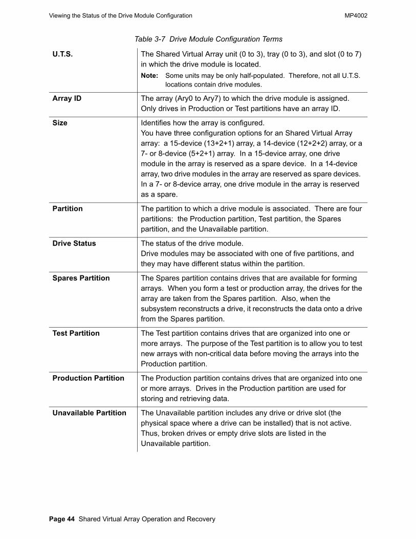
Table 3-7 Drive Module Configuration Terms
U.T.S. The Shared Virtual Array unit (0 to 3), tray (0 to 3), and slot (0 to 7) in which the drive module is located.Note: Some units may be only half-populated. Therefore, not all U.T.S.
locations contain drive modules.
Array ID The array (Ary0 to Ary7) to which the drive module is assigned. Only drives in Production or Test partitions have an array ID.
Size Identifies how the array is configured.You have three configuration options for an Shared Virtual Array array: a 15-device (13+2+1) array, a 14-device (12+2+2) array, or a 7- or 8-device (5+2+1) array. In a 15-device array, one drive module in the array is reserved as a spare device. In a 14-device array, two drive modules in the array are reserved as spare devices. In a 7- or 8-device array, one drive module in the array is reserved as a spare.
Partition The partition to which a drive module is associated. There are four partitions: the Production partition, Test partition, the Spares partition, and the Unavailable partition.
Drive Status The status of the drive module.Drive modules may be associated with one of five partitions, and they may have different status within the partition.
Spares Partition The Spares partition contains drives that are available for forming arrays. When you form a test or production array, the drives for the array are taken from the Spares partition. Also, when the subsystem reconstructs a drive, it reconstructs the data onto a drive from the Spares partition.
Test Partition The Test partition contains drives that are organized into one or more arrays. The purpose of the Test partition is to allow you to test new arrays with non-critical data before moving the arrays into the Production partition.
Production Partition The Production partition contains drives that are organized into one or more arrays. Drives in the Production partition are used for storing and retrieving data.
Unavailable Partition The Unavailable partition includes any drive or drive slot (the physical space where a drive can be installed) that is not active. Thus, broken drives or empty drive slots are listed in the Unavailable partition.

MP4002 Viewing the Status of the FRU Configuration
Chapter 3 Viewing Operations Page 45
Viewing the Status of the FRU ConfigurationThe FRU CONFIGURATION screen describes the configuration and status of the field-replaceable units (FRUs) in the subsystem, including their hardware and software serial numbers, engineering change (EC) levels, and compatibility levels.To view the FRU configuration:
1. Access the restricted FRU CONFIGURATION screen.
The FRU CONFIGURATION screen appears.
For a definition of terms used in the FRU configuration, refer to the next section.
2. The FRUs are listed according to the partition to which they belong beginning with the DAC Hardware partition. To view another partition, press NEXT PART [F7] or PREV PART [F6]. Pressing NEXT PART takes you through the partitions in the following order:
DAC HardwareController hardwareDAC-ISP SoftwareSystem support processor softwareDAC-IUP SoftwareShared Virtual Array microprocessor softwareDAU-FDE SoftwareDisk array software
3. Press PREV MENU [F3] to exit.
Connected: DACD CSRC Master: DACD ISP0 Status: S/N: 00000001 ♥----------------------------------------------------------------------- FRU Configuration DAC Hardware CD26 Loc ID P/N S/N EC/N HW Cpt FEN-Type ------------------------------------------------------------ CU.1.ICE00 000000000001 100001 000001 01 Y 10 CU.1.ICE01 000000000002 100002 000001 01 P 20 CU.1.ICE02 000000000003 100003 000001 01 N 0 CU.1.ICE03 000000000004 100004 000001 01 N 0 CU.1.ICE04 000000000005 100005 000001 01 N 0 CU.1.ICE05 000000000006 100006 000001 01 N 40 CU.1.IEA01 000000000008 100008 000001 01 N 0 CU.1.IEA02 000000000009 100009 000001 01 N 0 CU.1.IEA03 000000000010 100010 000001 01 N 0 CU.1.ISF00 000000000011 100011 000001 01 N 0 CU.1.ISF01 000000000012 100012 000001 01 N 0
=>-----------------------------------------------------------------------
SS01F10
SS16ENTER
PS01F6
CD01 CD11F10
CD26F5
HELP QUIKMENU
PREVMENU
PAGE PAGE PREV NEXT SUB UP DOWN PART PART PART

Viewing the Status of the FRU Configuration MP4002
Page 46 Shared Virtual Array Operation and Recovery
Terms Used to Describe the FRU Configuration Table 3-8 Terms Used to Describe the FRU Configuration
Loc ID The code that describes the location (in Unit.Tray.Slot nomenclature) of the FRU. These codes are assigned by the manufacturer and are not required in routine operations.
P/N The part number for the FRU as assigned by the manufacturer.
S/N The unique hardware identifier (serial number).
EC/N The engineering change level of the FRU.
HW Cpt Describes the hardware compatibility level of the FRU.
FEN-Type Indicates whether a FRU is fenced (Y or Yes), not fenced (N or No), or partially fenced (P or Partially), and the type of fence imposed. When the subsystem fences a FRU, it is taken out of use until it can be replaced or repaired. Fencing does not disrupt the subsystem’s operation.A partially fenced FRU indicates that some subset of the FRU (such as a port) is fenced, but all other portions of the FRU is unfenced.

MP4002
© Storage Technology Corp. 1999, 2000 Chapter 4 Subsystem (Global) Configuration Page 47
Chapter 4 Subsystem (Global) Configuration
This chapter provides the information necessary to perform subsystem configuration operations via the operator panel. “Terms Used to Describe the Subsystem (Global) Configuration” defines the terms that apply to the global configuration of the subsystem. The remaining sections provide the procedures that the operator may perform. The following table provides a reference page for those procedures.
Table 4-1 Procedures in Chapter 5
For information on: Refer to page:
Modifying the Subsystem Configuration 49
Assigning Passwords and Security Levels 51
Changing Passwords and Security Levels 52
IMLing the Subsystem 52
Powering off the Subsystem 53
Resetting the Data Assurance Check Mode 54

Subsystem (Global) Configuration Terms MP4002
Page 48 Shared Virtual Array Operation and Recovery
Subsystem (Global) Configuration Terms Table 4-2 Subsystem (Global) Configuration Terms
Site Name The unique name for your site. This name must be the same for all Shared Virtual Array subsystems at a site.
Subsystem Name The name of a specific subsystem at a site. Each subsystem should have a unique name.
Site Location Number The number assigned by StorageTek that identifies your site.
Model A number that identifies the general characteristics (such as hardware level) of the subsystem.
S/N (Serial Number) The unique hardware number that identifies a specific subsystem.
Cluster/Channels The number of channels installed for each cluster.
SSIDs The subsystem identifiers (SSID) that identify the functional storage control units (the functional 3990 storage controls). A single Shared Virtual Array subsystem can have up to four SSIDs. If your site has more than one Shared Virtual Array subsystems, each functional 3990 must have a unique SSID.
Release Lev The level of software operating in the Shared Virtual Array Controller.
ISP Ver The level of software operating the Shared Virtual Array support processor.
Cache Size The size (in megabytes) of customer cache installed in the subsystem.
DA Capacity The total formatted physical capacity (in gigabytes) of the Disk Array Units.
Number of Arrays The number of arrays currently defined in the subsystem.
Nonvolatile The size (in megabytes) of nonvolatile storage (NVS) installed in the subsystem. 16 megabytes of effective NVS is standard in an Shared Virtual Array subsystem.
Net Load The physical space (in gigabytes) on the disk arrays that is currently occupied by compressed user data.
Global Spares The number of spare drive modules to be reserved when you form a new array. A subsystem may have one or two array spares assigned. This value is set from Def Array size.

MP4002 Subsystem (Global) Configuration Terms
Chapter 4 Subsystem (Global) Configuration Page 49
Terms Used to Describe Subsystem PasswordsThe following terms are used to describe the configuration of the customer configurable items:Customer Logon PasswordIdentifies the logon password that the user must type in to access the Customer Service Menu. The user can change the logon password here.CSE Low Security Logon PasswordIdentifies the password that the service representative must type in to access the operator panel maintenance menus when the connection security is set to “low.”
Modifying the Subsystem ConfigurationTo modify elements of the subsystem configuration, including the subsystem identifiers (SSIDs), the number of spares per array, and the date and time:
1. Access the SUBSYSTEM CONFIGURATION screen.
The SUBSYSTEM CONFIGURATION screen appears
For a definition of the terms used in the subsystem configuration, refer to “Subsystem (Global) Configuration Terms” on page 48.
% Net Load The percentage of the physical disk array capacity that is currently occupied by compressed user data.
Date and Time Displays the current date and time, based on a 24 hour clock and displayed in coordinated universal time (cut).
List of Options Indicates what options are installed or activated in the subsystem.
Connected: DACD CSRC Master: DACD ISP0 Status: S/N: 00000001 ♥----------------------------------------------------------------------- Subsystem Configuration CD21
Site Name: DBF00009 Site loc#: 222222 Subsystem Name: DAC00001 S/N: 000000000001 Rel Lev: K06.00.xx ISP Ver: P990217 SSIDs: 1A96 1A97 1A98 1A99 Host Path Groups- Cl0:4 Cl1:4 Cache Size Installed: 3072 MB Num Arrays: 4 DA Capacity: 1142.21GB Configured: 2944 MB Global Spares: 2 % Net Load: 50% System: 128 MB Def Array Size: 13+2 % Coll Free Sp: 47% Fenced: 256 MB % Uncoll Free: 3% Avail User: 2944 MB Date: 99/12/01 Nonvolatile: 8 MB Time: 12:01:01 ISP/IUP Code Mismatch: N
Snapshot Maintenance IXOF ESCON
=>-----------------------------------------------------------------------
Table 4-2 Subsystem (Global) Configuration Terms (Continued)
SS01F10
SS16ENTER
PS01F6
CD01 CD11F10
CD21F5
HELP QUIKMENU
PREVMENU
CURS CURS MOD UP DOWN SSYS

Subsystem (Global) Configuration Terms MP4002
Page 50 Shared Virtual Array Operation and Recovery
2. Move the cursor to the subsystem configuration attribute(s) that you want to change and make the required modification.
Note: Modifying a subsystem configuration requires special training and specific knowledge about the configuration. To perform the following procedures, it is essential that you have this training and knowledge.
• To change the site name:Using the hex keys (0-F), type in the site name and press [ENTER]. The site name can be up to eight characters long.
• To change the subsystem name:Using the hex keys (0-F), type in the subsystem name and press [ENTER]. The subsystem name can be up to eight characters long.
• To change the site location number:Using the decimal keys (0-9), type in the site location number and press [ENTER]. The site location number can be up to six characters long and is assigned by StorageTek Customer Services.
• To change the subsystem ID:Using the hex keys (0-F), type in the subsystem IDs (SSIDs) and press [ENTER]. The SSID identifies the functional storage controls defined for the subsystem and can be up to four characters long.
• To change the Def Array size:Type in 13, 12, or 7 and press [ENTER].You have three configuration options for a RAMAC array: a 15-device (13+2+1) array, a 14-device (12+2+2) array, or a 7-device (5+2+1) array. In a 15-device or 7-device array, one drive module is reserved as a spare device. In a 14-device array, two drive modules are reserved as spare devices.
• To change the subsystem date:Using the decimal keys (0-9), type in the current date and press [ENTER].The format for the date is YY/MM/DD (coordinated universal time).
Valid entries for the year (YY) are: 1 - 99
Valid entries for the month (MM) are: 1 - 12
Valid entries for the day (DD) are: 1 - 31.
For example, to enter December 15, 1998, type in: 98, 12, and 15. (The cursor advances automatically or by pressing CURS DOWN [F6]. The slash is automatically inserted.)
Note: Changing the subsystem date changes the date logged in the event log and on SIM messages.
To change the subsystem time:Using the decimal keys (0-9), type in the current time and press [ENTER].
MP4002 Subsystem (Global) Configuration Terms
Chapter 4 Subsystem (Global) Configuration Page 51
The format for the time is HH:MM:SS (coordinated universal time).
Valid entries for the hour (HH) are: 00 - 24
Valid entries for the minute (MM) are: 00 - 59
Valid entries for the second (SS) are: 00 - 59.
For example, to enter 4:35:23 pm, type in: 16, 35, and 23. (The cursor advances automatically. The colon is automatically provided.)
Note: Changing the subsystem time will change the time logged in the event log and on SIM messages.
3. Move the cursor to change another attribute, or press MOD SSYS [F10] to complete the configuration change.
“Subsystem Config” appears in the action field and “Started” appears in the operation status field. When the operation is complete, “Completed” appears in the operation status field.
4. Press PREV MENU [F3] to exit.
Assigning Passwords and Security LevelsYou can assign passwords and security levels to restrict access to the subsystem. The passwords that you can assign are:• Customer Logon Password
This password restricts access to the customer information, configuration, and drain menus. It must be eight hex (0-F) characters long and start with ‘A.’
• CSE Low Security Logon Password- This password restricts service representative access to the
subsystem when the CSE security level is set to “low.”- The service representative cannot perform local diagnostics or
maintenance on the subsystem without typing in this password.- The CSE Low Security Logon Password can be up to eight hex (0-
F) characters long, and it must start with ‘B.’• CSE High Security Connection Password
This password restricts service representative access to the subsystem when the CSE security level is set to “high.” The CSE cannot perform local diagnostic or maintenance on the subsystem without obtaining an IDCAMS remote password from the host console operator and typing in the password. The IDCAMS remote password is valid for only one hour from its generation.
Although CSEs and CSRC personnel can use the operator panel menus to access diagnostic and maintenance information, they do not have access to user data.To assign a password or security level:

Subsystem (Global) Configuration Terms MP4002
Page 52 Shared Virtual Array Operation and Recovery
1. Access the CUSTOMER CONFIGURABLE ITEMS screen.
The CUSTOMER CONFIGURABLE ITEMS screen appears.
2. Move the cursor to and assign the password(s).
• To assign a Customer Logon Password:Using the hex keys (0-F), type in the customer logon password and press [ENTER]. The customer logon password must be eight hex (0-F) characters long and start with ‘A.’
• To assign a CSE Low Security Logon Password:Using the hex keys (0-F), type in the CSE logon password and press [ENTER]. The CSE Low Security Logon Password can be up to eight hex (0-F) characters long, and must start with ‘B.’
3. Move the cursor to change another customer-configurable item, or press MOD CCFG [F10] to complete the configuration change.
- “Customer Config Update” appears in the action field and “Started” appears in the operation status field. When the operation is complete, “Completed” appears in the operation status field.
4. Move the cursor to perform another operation from the CUSTOMER CONFIGURABLE ITEMS screen, or press PREV MENU [F3] to exit.
Changing Passwords and Security LevelsRefer to “Assigning Passwords and Security Levels” on page 51 to change or assign passwords and security levels.
Performing an IMLTo re-start a subsystem after a system malfunction, perform an IML. The IML procedure re-loads and validates the subsystem configuration. To perform an IML from the operator panel:
Connected: DACD CSRC Master: DACD ISP0 Status: S/N: 00000001 ♥----------------------------------------------------------------------- Customer Configurable Items CD24 Customer Logon Password: (8 digits, start with A) IXOF Connection Password: CSRC Low Security Conn Password: CSE Low Security Logon Password: (8 digits, start with B)
CSRC Connection Security: 0 (1 = High 0 = Low) Allow CSRC Connection: 1 (1 = Yes 0 = No) Allow IXOF Connection: 1 (1 = Yes; 0 = No) IXOF Baud Rate: 9600 (1200, 2400, 4800, 9600, 19200)
PROD DAC: / / 00:00:00 F5 - Reset Data Assurance Check Mode TEST DAC: / / 00:00:00 F8 - IML the Subsystem F9 - Power Off the Subsystem F10- Make Requested Modifications =>-----------------------------------------------------------------------
SS01F10
SS16ENTER
PS01F6
CD01 CD11F10
CD24F5
HELP QUIKMENU
PREVMENU
RSET CURS CURS IML PWR MODDCHK UP DOWN SSYS OFF CCFG

MP4002 Subsystem (Global) Configuration Terms
Chapter 4 Subsystem (Global) Configuration Page 53
1. Access the CUSTOMER CONFIGURABLE ITEMS screen.
The CUSTOMER CONFIGURABLE ITEMS screen appears.
2. Press IML SSYS [F8] to IML the subsystem.
- The system responds with “Subsystem Will Be IMLed, Do You Want To Continue?”
To continue the IML operation, press YES [F10].- The subsystem stops accepting new host commands and finishes
the operations currently underway.- “IML Subsystem” appears in the action field and “Started” appears
in the operation status field. - The subsystem initiates the internal steps required for IML. There
are many steps in the IML process. As steps are completed, they are listed on the subsystem status field. When the IML is finished, “Full Box IML Complete” appears in the subsystem status field, and the SUBSYSTEM MAIN MENU appears.
Powering Off the Subsystem via the Operator PanelYou can shut down the subsystem by powering off via the operator panel.To power off the subsystem from the operator panel:
1. Access the CUSTOMER CONFIGURABLE ITEMS screen.
Connected: DACD CSRC Master: DACD ISP0 Status: S/N: 00000001 ♥----------------------------------------------------------------------- Customer Configurable Items CD24 Customer Logon Password: (8 digits, start with A) IXOF Connection Password: CSRC Low Security Conn Password: CSE Low Security Logon Password: (8 digits, start with B)
CSRC Connection Security: 0 (1 = High 0 = Low) Allow CSRC Connection: 1 (1 = Yes 0 = No) Allow IXOF Connection: 1 (1 = Yes; 0 = No) IXOF Baud Rate: 9600 (1200, 2400, 4800, 9600, 19200)
PROD DAC: / / 00:00:00 F5 - Reset Data Assurance Check Mode TEST DAC: / / 00:00:00 F8 - IML the Subsystem F9 - Power Off the Subsystem F10- Make Requested Modifications =>-----------------------------------------------------------------------
SS01F10
SS16ENTER
PS01F6
CD01 CD11F10
CD24F5
HELP QUIKMENU
PREVMENU
RSET CURS CURS IML PWR MODDCHK UP DOWN SSYS OFF CCFG
SS01F10
SS16ENTER
PS01F6
CD01 CD11F10
CD24F5

Subsystem (Global) Configuration Terms MP4002
Page 54 Shared Virtual Array Operation and Recovery
The CUSTOMER CONFIGURABLE ITEMS screen appears.
2. Press PWR OFF [F9] to safely shut down the subsystem.
The system responds with “Subsystem Power Off, Do You Want To Continue?”
3. To continue the power off operation, press YES [F8].
- The subsystem stops accepting new host commands and finishes the operations currently underway.
- “Power Down Subsystem” appears in the action field and “Started” appears in the operation status field.
- The subsystem initiates the internal steps required for powering off.- The operator panel screen goes blank when the power off
operation is complete.
Resetting the Data Assurance Check ModeIn certain conditions, an Shared Virtual Array subsystem may enter a data assurance check mode. In this state, data cannot be assured to be correct, and commands that access data or affect the subsystem or device configuration are not accepted.The conditions that cause the subsystem to enter data assurance check mode are:• The battery backup units that support nonvolatile storage (NVS) have
discharged after a power failure with modified records in nonvolatile storage
• The mapping tables cannot be completely recovered during a Controller initialization.
Once the condition that caused the data assurance check is corrected, or if the condition is not expected to compromise data integrity, you can reset the subsystem. To do so:
Connected: DACD CSRC Master: DACD ISP0 Status: S/N: 00000001 ♥----------------------------------------------------------------------- Customer Configurable Items CD24 Customer Logon Password: (8 digits, start with A) IXOF Connection Password: CSRC Low Security Conn Password: CSE Low Security Logon Password: (8 digits, start with B)
CSRC Connection Security: 0 (1 = High 0 = Low) Allow CSRC Connection: 1 (1 = Yes 0 = No) Allow IXOF Connection: 1 (1 = Yes; 0 = No) IXOF Baud Rate: 9600 (1200, 2400, 4800, 9600, 19200)
PROD DAC: / / 00:00:00 F5 - Reset Data Assurance Check Mode TEST DAC: / / 00:00:00 F8 - IML the Subsystem F9 - Power Off the Subsystem F10- Make Requested Modifications =>-----------------------------------------------------------------------
HELP QUIKMENU
PREVMENU
RSET CURS CURS IML PWR MODDCHK UP DOWN SSYS OFF CCFG

MP4002 Subsystem (Global) Configuration Terms
Chapter 4 Subsystem (Global) Configuration Page 55
1. Access the CUSTOMER CONFIGURABLE ITEMS screen.
The CUSTOMER CONFIGURABLE ITEMS screen appears.
Press RST DCHK [F5] to reset the subsystem.- The subsystem resets and begins to accept write data commands
from the host.
Connected: DACD CSRC Master: DACD ISP0 Status: S/N: 00000001 ♥----------------------------------------------------------------------- Customer Configurable Items CD24 Customer Logon Password: (8 digits, start with A) IXOF Connection Password: CSRC Low Security Conn Password: CSE Low Security Logon Password: (8 digits, start with B)
CSRC Connection Security: 0 (1 = High 0 = Low) Allow CSRC Connection: 1 (1 = Yes 0 = No) Allow IXOF Connection: 1 (1 = Yes; 0 = No) IXOF Baud Rate: 9600 (1200, 2400, 4800, 9600, 19200)
PROD DAC: / / 00:00:00 F5 - Reset Data Assurance Check Mode TEST DAC: / / 00:00:00 F8 - IML the Subsystem F9 - Power Off the Subsystem F10- Make Requested Modifications =>-----------------------------------------------------------------------
SS01F10
SS16ENTER
PS01F6
CD01 CD11F10
CD24F5
HELP QUIKMENU
PREVMENU
RSET CURS CURS IML PWR MODDCHK UP DOWN SSYS OFF CCFG

Subsystem (Global) Configuration Terms MP4002
Page 56 Shared Virtual Array Operation and Recovery
This page intentionally left blank

MP4002
© Storage Technology Corp. 1999, 2000 Chapter 5 Functional Device Configuration Page 57
Chapter 5 Functional Device Configuration
This chapter provides the information necessary to perform functional device configuration operations via the operator panel. The following table provides a reference page for those operations.
Note: The CSE defines the functional device configuration at installation. Any subsequent changes to the configuration are modifications. Refer to “Modifying a Functional Device Configuration” on page 59 to modify the functional device configuration.
Functional Device Configuration TermsThe functional device configuration is the “host view” of the system device configuration. The following terms are used to describe the configuration of the functional devices in the subsystem:
Table 5-1 Procedures in Chapter 6
For information on: Refer to page:Defining a Functional Device Configuration 58Modifying a Functional Device Configuration 59Duplicating a Functional Device Configuration 58Deleting a Functional Device Configuration 62Sending a Functional Device Attention to a Host 64
Table 5-2 Functional Device Configuration Terms
Name The name assigned to a functional device.PT The partition with which the functional device is associated.
Functional devices must be in either the Test partition or the Production partition.
SSID The subsystem identifier (SSID) for the functional storage control with which the functional device is associated.
FDID The hexadecimal identifier of the functional device. The FDID is a valuer between 00 and 3FF.
Type The type of device that the functional device emulates. Functional devices may emulate 3380J, 3380K, 3380KE, 33901, 33902, 33903, or 33909 devices.
CYLS The number of cylinders for the functional device.GB The functional capacity (in gigabytes) of the functional device,
which is determined by the capacity of the device model being emulated.
ENA(ble) Identifies whether host access to the functional device is enabled (Y or Yes) or disabled (N or No).
WP Identifies whether the functional device is write protected (Y or Yes) or not write protected (N or No). If the functional device is write protected, the data on it is read-only and cannot be overwritten.

Functional Device Configuration Terms MP4002
Page 58 Shared Virtual Array Operation and Recovery
Defining a Functional Device ConfigurationAfter the first functional device is configured, the fastest way to define a new functional device configuration is to duplicate an existing functional device configuration (refer to“Duplicating a Functional Device Configuration” on page 58) and then modify it (refer to “Modifying a Functional Device Configuration” on page 59).
Duplicating a Functional Device ConfigurationYou can define a functional device by duplicating the configuration of an existing functional device, provided the functional device selected is defined and the next functional device in the list is undefined.To duplicate a functional device configuration:
1. Access the FUNCTIONAL DEVICE CONFIGURATION screen.
CA Indicates whether cache for the functional device is enabled (Y or Yes) or disabled (N or No).When cache is disabled, data is still cached, but the caching algorithm is changed. Therefore, in a write operation, tracks are queued for immediate de-staging to the arrays, rather than being held in cache. In a read operation, a track is staged to cache and then queued for de-allocation from cache as soon as the read operation is completed.
FW Indicates whether DASD fast write for the functional device is enabled (Y or Yes) or disabled (N or No). All writes to RAMAC Virtual Array are DASD fast writes; DASD fast write is never truly disabled.
PRIV Indicates whether the functional device is a privileged ECAM device (Y or Yes) or not (N or No).To implement the SVAA software, you must designate at least one functional device as a privileged ECAM device--that is, as an eligible designation for Category 1-restricted messages. However, you should limit the number of such devices.Refer to the SVAA Configuration and Administration, XXXXXX for more information about ECAM and privileged ECAM devices.
Table 5-2 Functional Device Configuration Terms (Continued)
SS01F10
SS16ENTER
PS02F6
CD01F5
CD11F7
CD23

MP4002 Functional Device Configuration Terms
Chapter 5 Functional Device Configuration Page 59
The FUNCTIONAL DEVICE CONFIGURATION screen appears.
For a definition of terms used in the Functional Device Configuration, refer to Table 5-2 on page 57.
2. Move the cursor until the functional device you want to copy is highlighted.
Note: Remember that the next functional device on the list must be undefined.
3. Press FDEV DUP [F9].
- “Functional Device Dup” appears in the action field and “Started” appears in the operation status field. When the operation is complete, “Completed” appears in the operation status field.
- The previously undefined functional device that was next in the list retains its FDID but has the functional device configuration of the device that preceded it.
4. To name the newly defined functional device or to modify the functional device configuration, refer to “Modifying a Functional Device Configuration.”
5. You can perform other functions within the FUNCTIONAL DEVICE CONFIGURATION screen, or press PREV MENU [F3] to exit.
Modifying a Functional Device ConfigurationIn some situations, you can modify elements of the functional device configuration including the:• Functional device name• Functional device partition• Functional device type• Functional device status (enabled or disabled)• Functional device modifiers such as:
- Its Write Protect status (enabled or disabled)- Its Cache status (active or inactive)
Connected: DACD CSRC Master: DACD ISP0 Status: S/N: 00000001 ♥----------------------------------------------------------------------- Functional Device Configuration CD23 Name PT SSID FDID Type Cyls GB CEn CWP CA FW Priv SEn SWP --------------------------------------------------------------------- A0000001 P 1AA 19A 33909 10017 8.51 Y N Y Y N Y N A0000002 P 1AA 19B 33909 10017 8.51 Y N Y Y N Y N A0000003 P 1AA 19C 33909 10017 8.51 Y N Y Y N Y N A0000004 P 1AA 19D 33909 10017 8.51 Y N Y Y N Y N A0000005 P 1AA 19E 33909 10017 8.51 Y N Y Y N Y N UNDEFINE UNDEFINE UNDEFINE UNDEFINE UNDEFINE UNDEFINE UNDEFINE UNDEFINE =>-----------------------------------------------------------------------
HELP QUIKMENU
PREVMENU
PAGE PAGE CURS CURS PREV NEXT FDEV UP DOWN UP DOWN 64 64 DUP

Functional Device Configuration Terms MP4002
Page 60 Shared Virtual Array Operation and Recovery
- Its DASD fast write status (enabled or disabled)- Whether it is an ECAM device (yes or no)
To modify the functional device configuration:
1. Access the FUNCTIONAL DEVICE CONFIGURATION screen.
The FUNCTIONAL DEVICE CONFIGURATION screen appears.
2. Move the cursor until the functional device you want to modify is highlighted.
3. Press [ENTER].
- “Functional Device Select” appears in the action field and “Started” appears in the operation status field. When the operation is complete, “Completed” appears in the operation status field.
- The MODIFY FUNCTIONAL DEVICE screen for the selected functional device appears.
Connected: DACD CSRC Master: DACD ISP0 Status: S/N: 00000001 ♥----------------------------------------------------------------------- Functional Device Configuration CD23 Name PT SSID FDID Type Cyls GB CEn CWP CA FW Priv SEn SWP --------------------------------------------------------------------- A0000001 P 1AA 19A 33909 10017 8.51 Y N Y Y N Y N A0000002 P 1AA 19B 33909 10017 8.51 Y N Y Y N Y N A0000003 P 1AA 19C 33909 10017 8.51 Y N Y Y N Y N A0000004 P 1AA 19D 33909 10017 8.51 Y N Y Y N Y N A0000005 P 1AA 19E 33909 10017 8.51 Y N Y Y N Y N UNDEFINE UNDEFINE UNDEFINE UNDEFINE UNDEFINE UNDEFINE UNDEFINE UNDEFINE =>-----------------------------------------------------------------------
SS01F10
SS16ENTER
PS02F6
CD01F5
CD11F7
CD23
HELP QUIKMENU
PREVMENU
PAGE PAGE CURS CURS PREV NEXT FDEV UP DOWN UP DOWN 64 64 DUP

MP4002 Functional Device Configuration Terms
Chapter 5 Functional Device Configuration Page 61
For a definition of terms used in the Functional Device Configuration, refer to Table 5-2 on page 57.
4. Move the cursor to the functional device configuration attribute(s) that you want to change and make the required modifications.
Caution: Modifying a functional device configuration requires special training and specific knowledge about your subsystem configuration. To perform the following procedures, it is essential that you have this training and knowledge.• To change the name of a functional device:
Using the hex keys (0-F), type in the functional device name and press [ENTER]. The functional device name can be up to eight characters long.
• To change the partition of a functional device:To change the partition of a functional device that has data associated with it, delete the existing functional device and redefine it.Type in ‘1’ to select the production partition or ‘2’ to select the test partition and press [ENTER].
• To change the type of device that the functional device is emulating:To change the type of device that the functional device is emulating, delete the existing functional device and redefine it.
• To enable or disable the functional device:Type in ‘0’ to disable the functional device or ‘1’ to enable the functional device. Press [ENTER].
• To change the write protect status of the functional device:Type in ‘0’ to disable write protection for the functional device or type in ‘1’ to enable write protection for the functional device. Press [ENTER].
• To change the cache status of the functional device:Type in ‘0’ to deactivate full cache status for the functional device or ‘1’ to activate full cache status for the functional device. Press [ENTER].
Connected: DACD CSRC Master: DACD ISP0 Status: S/N: 00000001 ♥----------------------------------------------------------------------- Modify Functional Device CD32
Name: 0sssssss Partition: 1 (1 = Production, 2 = Test) SSID: xxxx FDID: xxxx Type: 1 (1 = 3380J 2 = 3380K 3 = 3380KE 4 = 33901 5 = 33902 6 = 33903 7 = 33909) Format Type: 0 (0 = CKD, 1 = SCSI) SCSI Block Size: 512 (512 1024 2048 4096 8192 16384 27648) SCSI ID - Domain: 0 Target: 0 LUN: 0 Index: xxx Valid: 0
CKD Enable: 1 SCSI Enable: 1 <- CKD Write Protect: 0 SCSI Write Protect: 0 <- (1 = Yes) Cache Active: 1 DASD Fast Write: 1 <- (0 = No) Privileged: 0 <- =>-----------------------------------------------------------------------
HELP QUIKMENU
PREVMENU
CURS CURS DELE FDEV MOD UP DOWN FDEV ATTN FDEV

Functional Device Configuration Terms MP4002
Page 62 Shared Virtual Array Operation and Recovery
• To change the DASD fast write designation of the functional device:Type in ‘0’ to disable DASD fast write for the functional device or ‘1’ to enable DASD fast write for the functional device. Press [ENTER].
• To change the functional device’s ECAM privileges:Type in ‘0’ to indicate that the functional device is not a privileged ECAM device or ‘1’ to indicate that the functional device is a privileged ECAM device. Press [ENTER].
5. Move the cursor to change another functional device attribute, or press MOD FDEV [F10] to make the modifications.
- “Functional Device Config” appears in the action field and “Started” appears in the operation status field. When the operation is complete, “Completed” appears in the operation status field.
6. Press PREV MENU [F3] to exit.
Deleting a Functional Device ConfigurationYou can delete a functional device from the functional device configuration. However, before deleting a functional device, back up the data to another functional device. Once the data is backed up:
1. Take the functional device that is to be deleted offline.
2. Access the FUNCTIONAL DEVICE CONFIGURATION screen.
The FUNCTIONAL DEVICE CONFIGURATION screen appears.
For a definition of terms used in the Functional Device Configuration, refer to Table 5-2 on page 57.
3. Move the cursor until the functional device you want to delete is highlighted.
4. Press [ENTER].
Connected: DACD CSRC Master: DACD ISP0 Status: S/N: 00000001 ♥----------------------------------------------------------------------- Functional Device Configuration CD23 Name PT SSID FDID Type Cyls GB CEn CWP CA FW Priv SEn SWP --------------------------------------------------------------------- A0000001 P 1AA 19A 33909 10017 8.51 Y N Y Y N Y N A0000002 P 1AA 19B 33909 10017 8.51 Y N Y Y N Y N A0000003 P 1AA 19C 33909 10017 8.51 Y N Y Y N Y N A0000004 P 1AA 19D 33909 10017 8.51 Y N Y Y N Y N A0000005 P 1AA 19E 33909 10017 8.51 Y N Y Y N Y N UNDEFINE UNDEFINE UNDEFINE UNDEFINE UNDEFINE UNDEFINE UNDEFINE UNDEFINE =>-----------------------------------------------------------------------
SS01F10
SS16ENTER
PS02F6
CD01F5
CD11F7
CD23
HELP QUIKMENU
PREVMENU
PAGE PAGE CURS CURS PREV NEXT FDEV UP DOWN UP DOWN 64 64 DUP

MP4002 Functional Device Configuration Terms
Chapter 5 Functional Device Configuration Page 63
- “Functional Device Select” appears in the action field and “Started” appears in the operation status field. When the operation is complete, “Completed” appears in the operation status field.
- The MODIFY FUNCTIONAL DEVICE screen for the selected functional device appears.
For a definition of terms used in the Functional Device Configuration, refer to Table 5-2 on page 57.
5. Delete the functional device by pressing DELE FDEV [F8].
- “Functional Device Delete” appears in the action field and “Started” appears in the operation status field.
If the subsystem determines that no back-end data is associated with the functional device and that the functional device is not part of a path group, the subsystem deletes the functional device configuration.
If the subsystem determines that back-end data is associated with the functional device and that the functional device is not part of a path group, the subsystem responds with: “Back End Storage Detected - Do You Want To Continue?”
6. To delete the functional device configuration, press Yes [F9].
- “Functional Device Delete” appears in the action field and “Started” appears in the operation status field.
- When the operation is complete, “Completed” appears in the operation status field.
- The functional device configuration for that FDID is deleted and the functional device name returns to “undefined”
- An updated FUNCTIONAL DEVICE CONFIGURATION screen appears.
You can perform other functions within the FUNCTIONAL DEVICE CONFIGURATION screen, or press PREV MENU [F3] to exit.
Connected: DACD CSRC Master: DACD ISP0 Status: S/N: 00000001 ♥----------------------------------------------------------------------- Modify Functional Device CD32
Name: 0sssssss Partition: 1 (1 = Production, 2 = Test) SSID: xxxx FDID: xxxx Type: 1 (1 = 3380J 2 = 3380K 3 = 3380KE 4 = 33901 5 = 33902 6 = 33903 7 = 33909) Format Type: 0 (0 = CKD, 1 = SCSI) SCSI Block Size: 512 (512 1024 2048 4096 8192 16384 27648) SCSI ID - Domain: 0 Target: 0 LUN: 0 Index: xxx Valid: 0
CKD Enable: 1 SCSI Enable: 1 <- CKD Write Protect: 0 SCSI Write Protect: 0 <- (1 = Yes) Cache Active: 1 DASD Fast Write: 1 <- (0 = No) Privileged: 0 <- =>-----------------------------------------------------------------------
HELP QUIKMENU
PREVMENU
CURS CURS DELE FDEV MOD UP DOWN FDEV ATTN FDEV

Functional Device Configuration Terms MP4002
Page 64 Shared Virtual Array Operation and Recovery
Sending a Functional Device Attention Interrupt to a HostIf the host operating system misses a device end from a Shared Virtual Array subsystem and experiences a “hang” condition, sending a functional device attention interrupt to the host may free the condition.To send a functional device attention interrupt to a host:
1. Access the FUNCTIONAL DEVICE CONFIGURATION screen.
The FUNCTIONAL DEVICE CONFIGURATION screen appears.
For a definition of terms used in the Functional Device Configuration, refer to Table 5-2 on page 57.
2. Move the cursor until the functional device for which you want to generate an attention interrupt is highlighted.
3. Press FDEV ATTN [F10].
“Functional Device Atn” appears in the action field and “Started” appears in the operation status field. When the operation is complete, “Completed” appears in the operation status field.
Note: There may be a slight delay between the time the “Completed” message appears at the operator panel and the functional device status is retrieved by the host.
4. You can perform other functions within the FUNCTIONAL DEVICE CONFIGURATION screen, or press PREV MENU [F3] to exit.
Connected: DACD CSRC Master: DACD ISP0 Status: S/N: 00000001 ♥----------------------------------------------------------------------- Functional Device Configuration CD23 Name PT SSID FDID Type Cyls GB CEn CWP CA FW Priv SEn SWP --------------------------------------------------------------------- A0000001 P 1AA 19A 33909 10017 8.51 Y N Y Y N Y N A0000002 P 1AA 19B 33909 10017 8.51 Y N Y Y N Y N A0000003 P 1AA 19C 33909 10017 8.51 Y N Y Y N Y N A0000004 P 1AA 19D 33909 10017 8.51 Y N Y Y N Y N A0000005 P 1AA 19E 33909 10017 8.51 Y N Y Y N Y N UNDEFINE UNDEFINE UNDEFINE UNDEFINE UNDEFINE UNDEFINE UNDEFINE UNDEFINE =>-----------------------------------------------------------------------
SS01F10
SS16ENTER
PS02F6
CD01F5
CD11F7
CD23
HELP QUIKMENU
PREVMENU
PAGE PAGE CURS CURS PREV NEXT FDEV UP DOWN UP DOWN 64 64 DUP

MP4002
© Storage Technology Corp. 1999, 2000 Chapter 6 Channel Configuration Page 65
Chapter 6 Channel Configuration
This chapter provides the information necessary to perform channel configuration operations via the operator panel. “Terms Used to Describe the Channel Configuration” defines the terms that apply to the channel configuration. The remaining sections provide the procedures that the operator may perform. The following table provides a reference page for those procedures.
Notice that you cannot add or delete a channel. When the channel hardware is installed, the channel automatically appears in the list of channels, with the default configuration. A channel can only be deleted by deinstalling the channel hardware.
Channel Configuration TermsThe following terms are used to describe the configuration of subsystem channels:
Table 6-1 Procedures in Chapter 7
For information on: Refer to page:
Modifying a Channel Configuration 67
Duplicating a Channel Configuration 69
Table 6-2 Channel Configuration Terms
Name The unique name for a channel.
Clust(er) The cluster (0 or 1) to which the channel interfaces.
Chan(nel) The channel interface to which the channel is connected within the specified cluster. Shared Virtual Array supports up to 32 parallel channels (16 per cluster), so channel interfaces are designated ‘A’ through ‘P’.
Enab(le) Identifies whether the channel interface is enabled (Y or Yes) or disabled (N or No).
Speed The data transfer rate (in megabytes per second) of the channel. Shared Virtual Array supports 20.0 megabytes-per-second ESCON channels.
Type The type of channel interface installed. Shared Virtual Array supports Fibre and ESCON channels.
Base The base channel address (hexadecimal), which is the lowest interface address on the channel.

Channel Configuration Terms MP4002
Page 66 Shared Virtual Array Operation and Recovery
Table Table 6-3 displays the valid base address and BFDID for the defined address ranges.
Range The number of addresses (decimal) with which the channel can interface.
BFDID The base functional device identifier (hexadecimal) for the channel. The BFDID identifies the path between the base address and the functional device.
Table 6-3 Channel Addressing (Maximum 256 Configurable)
Number ofContinuous Addresses
dec hex
Number ofValid BaseIDID/FDIDs
Valid Base IDID/FDIDs(hexadecimal)
8 8 32 00 08 10 18 20 28 30 38 40 48 50 58 60 68 70 78 80 88 90 98 A0 A8 B0 B8 C0 C8 D0 D8 E0 E8 F0 F8
16 10 16 00 10 20 30 40 50 60 70 80 90 A0 B0 C0 D0 E0 F0
32 20 8 00 20 40 60 80 A0 C0 E0
64 40 4 00 40 80 C0
128 80 2 00 80
256 100 1 00
¹ Maximum 256 channel addressing applies ONLY to SRLs <K05.00.xx¹ Only decimal address ranges are displayed on subsystem operator panels.
Table 6-2 Channel Configuration Terms (Continued)

MP4002 Channel Configuration Terms
Chapter 6 Channel Configuration Page 67
Modifying the Channel Interface ConfigurationYou can modify elements of the channel interface configuration including the: • Channel name• Channel status (enabled or disabled)• Channel base address• Channel range• Base functional device identifier (BFDID) for the channel range.Note: Before modifying the channel speed, the system disables the channel
interface. When you finish modifying the channel interface configuration, the system re-enables the channel interface, unless you disable the channel during the modification procedure.
To modify a channel configuration:
1. Vary the channel offline from the host operating system.
Table 6-4 Channel Addressing (Maximum 1024 Configurable)
Number ofContinuous Addresses
dec hex
Number ofValid BaseIDID/FDIDs
Valid Base IDID/FDIDs(hexadecimal)
8 8 128 000 008 010 018 020 028 ... 390 398 0A0 0A8 0B0 0B8 0C0 0C8 0D0 0D8 0E0 0E8 0F0 0F8 1A0 1A8 1B0 1B8 1C0 1C8 1D0 1D8 1E0 1E8 1F0 1F8 2A0 2A8 2B0 2B8 2C0 2C8 2D0 2D8 2E0 2E8 2F0 2F8 3A0 3A8 3B0 3B8 3C0 3C8 3D0 3D8 3E0 3E8 3F0 3F8
16 10 64 000 010 020 030 ... 3900A0 0B0 0C0 0D0 0E0 0F0 1A0 1B0 1C0 1D0 1E0 1F0 2A0 2B0 2C0 2D0 2E0 2F0 3A0 3B0 3C0 3D0 3E0 3F0
32 20 32 000 020 040 060 ... 3800A0 0C0 0E0 1A0 1C0 1E0 2A0 2C0 2E0 3A0 3C0 3E0
64 40 16 000 040 080 100 140... 3800A0 1A0 2A0 3A0
128 80 8 000 080 100 180 200 280 300 280
256 100 4 000 100 200 300
512 200 2 000 200
1024 400 1 000
Note: Maximum 1024 channel addressing applies ONLY to SRLs. Only decimal address ranges are displayed on subsystem operator panels.

Channel Configuration Terms MP4002
Page 68 Shared Virtual Array Operation and Recovery
2. Press CHAN DSAB [F10] to disable the channel.
3. Access the CHANNEL CONFIGURATION screen.
The CHANNEL CONFIGURATION screen appears. Note: Modifying a channel configuration requires special training and specific
knowledge about your subsystem configuration. To perform the following procedures, it is essential that you have this training and knowledge.
4. Move the cursor until the channel you want to modify is highlighted.
5. Press [ENTER].
- “Channel Select” appears in the action field and “Started” appears in the operation status field. When the operation is complete, “Completed” appears in the operation status.
- The MODIFY CHANNEL INTERFACE screen for the selected channel appears.
For a definition of terms used in the Channel Configuration, refer to Table 6-2 on page 65. Note: Changing the channel configuration of an enabled channel takes that
channel offline for a short time.
6. Move the cursor to the channel configuration attribute(s) that you want to change and make the required modifications.
• To change a channel name:Using the hex keys (0-F), type in the channel name and press [ENTER]. The channel name can be up to eight characters long.
• To enable or disable the channel:Type in ‘0’ to disable the channel or ‘1’ to enable the channel. Press [ENTER].
• To change the channel base address:Using the hex keys (0-F), type in a channel base address and press [ENTER]. The valid parameters for a channel base address are listed in Table 7-3, “Valid Channel Configuration Entries,” on page 68.
• To change the channel range:Type in the address range for the channel and press [ENTER]. The valid parameters for channel range are listed in Table 7-3 on page 68.
• To change the channel BFDID:Using the hex keys (0-F), type in the base functional ID and press [ENTER]. The valid parameters for a channel BFDID are 0-255 (as listed in Table 7-3 on page 68).
SS01F10
SS16ENTER
PS01F6
CD01 CD11F6
CD22F5

MP4002 Channel Configuration Terms
Chapter 6 Channel Configuration Page 69
7. Move the cursor to change another channel configuration attribute, or press MOD CHAN [F10] to complete the channel configuration modifications.
- “Channel Config” appears in the action field and “Started” appears in the operation status field. When the operation is complete, “Completed” appears in the operation status.
8. Press PREV MENU [F3] to exit.
9. If desired and if the channel is enabled, vary the channel online to the host operating system.
Duplicating a Channel ConfigurationYou can define a channel configuration for an channel by duplicating the configuration of an existing channel configuration. To do so:
1. Access the CHANNEL CONFIGURATION screen. .
The CHANNEL CONFIGURATION screen appears.2. Move the cursor until last configured channel in the list is highlighted
and the next channel in the list is unconfigured.
3. Press CHAN DUP [F9].
- “Channel Duplication” appears in the action field and “Started” appears in the operation status field. When the operation is complete, “Completed” appears in the operation status.
- The previously unconfigured channel that was next in the list has the channel configuration of the channel that preceded it.
To name the channel or to modify the channel configuration, refer to “Modifying the Channel Interface Configuration.”You can perform other functions within the CHANNEL CONFIGURATION screen, such as modifying the channel configuration, or press PREV MENU [F3] to exit.
SS01F10
SS16ENTER
PS01F6
CD01 CD11F6
CD22F5

Channel Configuration Terms MP4002
Page 70 Shared Virtual Array Operation and Recovery
This page intentionally left blank

MP4002
© Storage Technology Corp. 1999, 2000 Chapter 7 Drive Module Configuration Page 71
Chapter 7 Drive Module Configuration
This chapter provides the information necessary to perform drive module test, configuration, and drain operations via the operator panel. “Terms Used to Describe the Drive Module Configuration” defines the terms that apply to the drive module configuration. The remaining sections provide the procedures that the operator may perform. The following list provides a reference page for those procedures.
Drive Module Configuration TermsThe drive module configuration can be described in physical terms or in logical terms. In physical terms, a drive module is identified by its physical unit, tray, and slot (U.T.S.) location. In logical terms, a drive module is identified by its array ID, which identifies the array to which it belongs.The terms that relate to the drive module configuration are described in the following section.
Table 7-1 Procedures in Chapter 8
For information on: Refer to page:Allocating spares to the spares partition 72Forming a production array 73Moving test arrays to production 75Re-configuring an array 75Draining a disk array 76Draining part of an array 77Viewing the status of a drain operation 80
Table 7-2 Drive Module Configuration Terms
U.T.S. The Shared Virtual Array unit (0 to 3), tray (0 to 3), and slot (0 to 7) in which the drive module is located.Note:Some units may be only half-populated. Therefore, not all U.T.S. locations contain drive modules.
Array ID The array (Ary0 to Ary7) to which the drive module is assigned. Only drives in Production or Test partitions have an array ID.

MP4002
Page 72 Shared Virtual Array Operation and Recovery
Allocating Spares to the Spares PartitionAllocating spares is the process of reassigning drive modules from the MAT partition to the Spares partition. To be eligible for allocation, a drive module must be in the MAT partition and have a status of M.A. (MAT partition, active).When you allocate spares, all eligible spares in the MAT partition are reassigned; you cannot select only specific drive modules to be reassigned to the Spares partition.To move all of the eligible drives in the MAT partition to the spares partition:
Size Identifies how the array is configured.You have three configuration options for a Shared Virtual Array array: a 15-device (13+2+1) array, a 14-device (12+2+2) array, or a 7- or an 8-device (5+2+1) array. In a 15-device array, one drive module in the array is reserved as a spare device. In a 14-device array, two drive modules in the array are reserved as spare devices. In a 7- or 8-device array, one drive module in the array is reserved as a spare.
Partition The partition to which a drive module is associated. There are four partitions: the Production partition, Test partition, the Spares partition, and the Unavailable partition.
Drive Status The status of the drive module.Drive modules may be associated with one of five partitions, and they may have different status within the partition.
Spares Partition The Spares partition contains drives that are available for forming arrays. When you form a test or production array, the drives for the array are taken from the Spares partition. Also, when the subsystem reconstructs a drive, it reconstructs the data onto a drive from the Spares partition.
Test Partition The Test partition contains drives that are organized into one or more arrays. The purpose of the Test partition is to allow you to test new arrays with non-critical data before moving the arrays into the Production partition.
Production Partition The Production partition contains drives that are organized into one or more arrays. Drives in the Production partition are used for storing and retrieving data.
Unavailable Partition The Unavailable partition includes any drive or drive slot (the physical space where a drive can be installed) that is not active. Thus, broken drives or empty drive slots are listed in the Unavailable partition.
Table 7-2 Drive Module Configuration Terms (Continued)

MP4002
Chapter 7 Drive Module Configuration Page 73
1. Access the ALLOCATE SPARES screen.
The ALLOCATE SPARES screen appears.
For a definition of terms used in Allocating spares, refer to Table 7-2 on page 71.
2. Press MAKE SPAR [F10] to allocate all media active (M.A.) drives to the spares partition (S.A).
- “All MAT drives to Spares” appears in the action field and “Started” appears in the operation status field. When the operation is complete, “Completed” appears in the operation status field.
3. Press PREV MENU [F3] to exit.
Forming a Production ArrayTo form a production array, the spares partition must have 15, 14, or 8 available drives, depending on your specifications in the subsystem configuration. To form a production array:
1. Verify that there are enough drive modules in the Spares partition to form an array.
Connected: DACD CSRC Master: DACD ISP0 Status: S/N: 00000001 ♥----------------------------------------------------------------------- Allocate Spares CD36 U.T.S Status Type ------------------------------------------ 0.0.0 M.A 8.51 GB SSA 0.0.1 M.A 8.51 GB SSA 1.0.2 M.A 8.51 GB SSA 1.0.3 M.A 8.51 GB SSA 1.0.4 M.A 8.51 GB SSA 1.0.5 M.A 8.51 GB SSA 1.0.6 M.A 8.51 GB SSA 1.0.7 M.A 8.51 GB SSA 1.1.0 M.A 8.51 GB SSA 2.1.1 M.A 8.51 GB SSA 2.1.2 M.A 8.51 GB SSA 3.1.3 M.A 8.51 GB SSA 3.1.4 M.A 8.51 GB SSA =>-----------------------------------------------------------------------
SS01F10
SS16ENTER
PS01F6 CD01
CD11 F9 CD25
F5
F6CD36
HELP QUIKMENU
PREVMENU
PAGE PAGE MAKE UP DOWN SPAR

MP4002
Page 74 Shared Virtual Array Operation and Recovery
2. Access the FORM PRODUCTION ARRAY screen.
The FORM PRODUCTION ARRAY screen appears.
For a definition of terms used in Allocating spares, refer to Table 7-2 on page 71.
3. Select the drive type from which you will form the array. Press NEXT TYPE and PREV TYPE to move between types.
4. Press MAKE 5+2, MAKE 12+2, or MAKE 13+2 ([F8]-[F10]) to form a new production array.
- “Form Production Array” appears in the action field and “Accepted” appears in the operation status field.
- An updated FORM PRODUCTION ARRAY screen appears.
Because forming and initializing an array is a background task that the subsystem can perform asynchronously, you do not have to receive a “Completed” message in the operation status field before starting another task.
When the array has been formed and initialized, “Initialize AryX Complete” appears in the subsystem status field, where X is the array number assigned by the subsystem.
5. Form another production array, or press PREV MENU [F3] to exit.
The subsystem allows you to form multiple arrays at one time.Note: The subsystem automatically reserves the designated number of spare
drives to support the subsystem’s standby redundancy.
Connected: DACD CSRC Master: DACD ISP0 Status: S/N: 00000001 ♥----------------------------------------------------------------------- Form Production Array 8.5 GB SSA CD33 U.T.S Status Type --------------------------------------- 0.0.0 S.A 8.5 GB SSA 0.0.1 S.A 8.5 GB SSA 0.0.2 S.A 8.5 GB SSA 1.0.3 S.A 8.5 GB SSA 1.0.4 S.A 8.5 GB SSA 1.0.5 S.A 8.5 GB SSA 2.0.6 S.A 8.5 GB SSA 2.0.7 S.A 8.5 GB SSA 2.1.0 S.A 8.5 GB SSA 3.1.1 S.A 8.5 GB SSA 3.1.2 S.A 8.5 GB SSA 3.1.3 S.A 8.5 GB SSA 3.1.4 S.A 8.5 GB SSA =>-----------------------------------------------------------------------
SS01F10
SS16ENTER
PS01F6
CD01
CD11 F9 CD25
F5
F7CD33
HELP QUIKMENU
PREVMENU
PAGE PAGE PREV NEXT MAKE MAKE UP DOWN TYPE TYPE 5+2 13+2
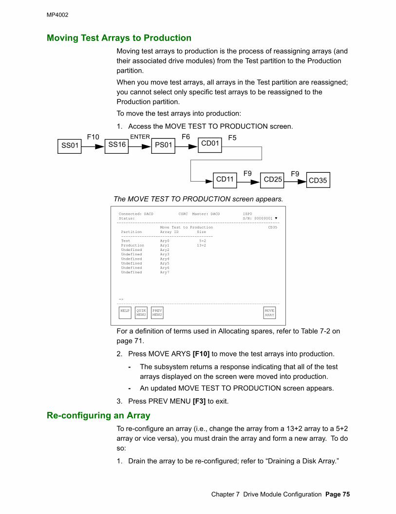
MP4002
Chapter 7 Drive Module Configuration Page 75
Moving Test Arrays to ProductionMoving test arrays to production is the process of reassigning arrays (and their associated drive modules) from the Test partition to the Production partition.When you move test arrays, all arrays in the Test partition are reassigned; you cannot select only specific test arrays to be reassigned to the Production partition.To move the test arrays into production:
1. Access the MOVE TEST TO PRODUCTION screen.
The MOVE TEST TO PRODUCTION screen appears.
For a definition of terms used in Allocating spares, refer to Table 7-2 on page 71.
2. Press MOVE ARYS [F10] to move the test arrays into production.
- The subsystem returns a response indicating that all of the test arrays displayed on the screen were moved into production.
- An updated MOVE TEST TO PRODUCTION screen appears.
3. Press PREV MENU [F3] to exit.
Re-configuring an ArrayTo re-configure an array (i.e., change the array from a 13+2 array to a 5+2 array or vice versa), you must drain the array and form a new array. To do so:
1. Drain the array to be re-configured; refer to “Draining a Disk Array.”
Connected: DACD CSRC Master: DACD ISP0 Status: S/N: 00000001 ♥----------------------------------------------------------------------- Move Test to Production CD35 Partition Array ID Size ---------------------------------------- Test Ary0 5+2 Production Ary1 13+2 Undefined Ary2 Undefined Ary3 Undefined Ary4 Undefined Ary5 Undefined Ary6 Undefined Ary7
=>-----------------------------------------------------------------------
SS01F10
SS16ENTER
PS01F6
CD01
CD11F9
CD25
F5
F9CD35
HELP QUIKMENU
PREVMENU
MOVEARAY

MP4002
Page 76 Shared Virtual Array Operation and Recovery
2. Form a new array (production or test) with the different configuration; refer to “Forming a Production Array” on page 73.
Draining a Disk ArrayTo drain a disk array (test or production), the subsystem off-loads the data stored in the array to other arrays in the same partition. If there is not sufficient subsystem capacity to accommodate the off-loaded data, the subsystem rejects the drain request.Also, drain operations are asynchronous operations. While they occur in the background, you can perform other operator panel functions.To drain a disk array:
1. Access the DRAIN DISK ARRAY screen.
The DRAIN DISK ARRAY screen appears.
For a definition of terms used in Allocating spares, refer to Table 7-2 on page 71. Caution: The drain screen includes a warning that a drain operation must not proceed without authorization. Do not drain any part of the subsystem without a proper understanding of what a drain operation involves.
2. If you are authorized to continue, use the hex and decimal keys to type in the Array ID of the array to be drained.
3. Press DRAN IT [F10].
The system responds with “Array Will Be Drained, Do You Want To Continue?”
Caution: This is your last opportunity to abort the drain operation.
4. To continue the drain operation, press YES [F9].
- If you continued the drain operation, “Drain Array” appears in the
Connected: DACD CSRC Master: DACD ISP0 Status: S/N: 00000001 ♥----------------------------------------------------------------------- Drain Disk Array CD28
Partition Array ID Size----------------------------------------- Production Ary1 13+2 Production Ary2 13+2 Test Ary3 5+2 Test Ary4 5+2
Disk Array ID:
WARNING: DO NOT EXECUTE THIS FUNCTION WITHOUT CUSTOMER AUTHORIZATION
=>-----------------------------------------------------------------------
SS01F10
SS16ENTER
PS01F6
CD01 CD12F6
CD28F6
HELP QUIKMENU
PREVMENU
DRAN IT

MP4002
Chapter 7 Drive Module Configuration Page 77
action field and “Accepted” appears in the operation status field.- When the drain operation is accepted, an updated DRAIN DISK
ARRAY screen appears.- When the drain operation is complete, “Drain Array Complete”
appears in the subsystem status field.A request to drain an array will fail if:• Another multiple-drive drain operation is currently being processed• The array is already draining or a drain operation is pending for it• There is not enough free subsystem capacity to hold the data
contained in the array.
5. Press PREV MENU [F3] to exit.
Draining Part of an ArrayTo drain a Disk Array Unit, a tray of drive modules, or a single drive module, the subsystem off-loads the data stored in the unit, tray, or drive (respectively) to another array in the same partition. If there is not sufficient subsystem capacity to accommodate the off-loaded data, the subsystem rejects the drain request.Also, drain operations are asynchronous operations. While they occur in the background, you can perform other operator panel functions.To drain part of an array:
1. Access the DRAIN UNIT/TRAY/DRIVE screen.
The DRAIN UNIT/TRAY/DRIVE screen appears.
For a definition of terms used in Allocating spares, refer to Table 7-2 on page 71.
Connected: DACD CSRC Master: DACD ISP0 Status: S/N: 00000001 ♥----------------------------------------------------------------------- Drain Unit/Tray/Slot CD29
Disk Array Unit ID: (0-3) Drive Tray ID: (0-3) Drive Slot ID: (0-7)
WARNING: DO NOT EXECUTE THIS FUNCTION WITHOUT CUSTOMER AUTHORIZATION
Enter Unit ID only for Disk Unit Drain Enter Unit ID and Tray ID for Disk Tray Drain Enter Unit ID, Tray ID, and Slot ID for Disk Module drain
=>-----------------------------------------------------------------------
SS01F10
SS16ENTER
PS01F6
CD01 CD12F7
CD29F6
HELP QUIKMENU
PREVMENU
CURS CURS DRAN UP DOWN IT

MP4002
Page 78 Shared Virtual Array Operation and Recovery
Caution: The drain screen includes a warning that a drain operation must not proceed without authorization. Do not drain any part of the subsystem without a proper understanding of what a drain operation involves.
2. If you are authorized to continue, select the Disk Array Unit or subset of the unit to be drained.
• To drain a single drive module:
A. Using the hex keys (0-F), type in the Disk Array Unit ID, the Tray ID, and the Drive ID of the drive module to be drained.
B. Press DRAN IT [F10].
- The system responds with “UTS Will Be Drained, Do You Want To Continue?”
Caution: This is your last opportunity to abort the drain operation.
C. To continue the drain operation, press YES [F9].
- If you continued the drain operations, “Drain unit/tray/drive” appears in the action field and “Accepted” appears in the operation status field.
- When the drain operation is accepted, an updated DRAIN UNIT/TRAY/DRIVE screen appears.
- When the drain operation is complete, “DRAIN DRIVE U.T.S. COMPLETE” appears in the subsystem status field.
A request to drain a single drive will fail if:- The drive is being reconstructed- The drive is already undergoing a drain operation.- A drain operation for the drive is pending.
• To drain a tray of drives:
A. Using the hex keys (0-F), type in the Disk Array Unit ID and the Tray ID of the drive modules to be drained; leave the Slot ID space empty.
B. Press DRAN IT [F10].
You are asked “Drain Unit:Tray:Drive: Are you sure?”Caution: This is your last opportunity to abort the drain operation.
C. To continue the drain operation, press YES [F9].
- If you continued the drain operation, “Drain unit/tray/drive” appears in the action field and “Accepted” appears in the operation status field.
- When the drain operation is accepted, an updated DRAIN UNIT/TRAY/DRIVE screen appears.
- When the drain operation is complete, “Drain Tray x Complete”

MP4002
Chapter 7 Drive Module Configuration Page 79
appears in the subsystem status field.A request to drain a tray of drives will fail if:- The tray is already draining or a drain operation is pending for it- There is not enough free subsystem capacity to hold the data
contained in the tray.• To drain a full Disk Array Unit:
A. Using the hex keys (0-F), type in the Disk Array Unit ID only; leave the Tray ID and Slot ID spaces empty.
B. Press DRAN IT [F10].
- You are asked “Drain Unit:Tray”Drive: Are you sure?”Caution: This is your last opportunity to abort the drain operation.
C. To continue the drain operation, press YES [F9].
- If you continued the drain operation, “Drain unit/tray/drive” appears in the action field and “Accepted” appears in the operation status field.
- When the drain operation is accepted, an updated Drain Unit/Tray/Drive screen appears.
- When the drain operation is complete, “Drain Unit x Complete” appears in the subsystem status field.
A request to drain a Disk Array Unit will fail if:- The unit is already draining or a drain operation is pending for it- There is not enough free subsystem capacity to hold the data
contained in the tray.
3. Perform another drain operation or press PREV MENU [F3] to exit.
While you cannot perform more than one multi-drive drain operations (array drains, unit drains, or tray drains) at a time, you can perform any number of single drive drain operations at a time.

MP4002
Page 80 Shared Virtual Array Operation and Recovery
Viewing the Status of a Drain OperationTo view the status of all of the physical drive modules in the subsystem that are currently being drained:
1. Access the DRAIN STATUS screen.
The DRAIN STATUS screen appears.
For a definition of terms used in Allocating spares, refer to Table 7-2 on page 71. All of the fields in the DRAIN STATUS screen are display only. No changes can be made to a drain status through the viewing selection.Note:For information about the status of drive modules that are draining, refer to Table A-1, “Drive Module Status Descriptions,” on page 101.
2. Press PREV MENU [F3] to exit.
Connected: DACD CSRC Master: DACD ISP0 Status: S/N: 00000001 ♥----------------------------------------------------------------------- Drain Status CD27 U.T.S Status S/N ----------------------- 0.0.0 P.D 00000001 0.0.1 P.D 00000002 0.0.2 P.D 00000003 0.0.3 P.D 00000004 0.0.4 P.D 00000005 0.0.5 P.D 00000006 0.0.6 T.D 00000007 0.0.7 T.D 00000008 0.1.0 T.D 00000009 0.1.1 T.P 00000010 0.1.2 T.P 00000011 0.1.3 T.P 00000012 0.1.4 T.P 00000013 =>-----------------------------------------------------------------------
SS01F10
SS16ENTER
PS01F6
CD01 CD12F5
CD27F6
HELP QUIKMENU
PREVMENU
PAGE PAGE UP DOWN

MP4002
© Storage Technology Corp. 1999, 2000 Chapter 8 Service Management System Overview Page 81
Chapter 8 Service Management System Overview
The Shared Virtual Array has a comprehensive service management system that includes error detection facilities and error recovery and reporting programs. An overview of the Shared Virtual Array’s service management system is included here.
Error DetectionThe Shared Virtual Array support processor in the Control Unit handles error detection for most of the subsystem through its predictive service analysis (PSA) facility. However, media maintenance is performed by the Disk Array Units and the drive electronics. PSA and media maintenance are discussed in the following sections.
Predictive Service AnalysisPSA is a knowledge-based system that resides in the ISP, while its detection capability is integrated into the Shared Virtual Array’s operational code. PSA monitors the subsystem’s operational performance and, using a data base of possible situations and sets of rules, detects “change-in-status” situations, including:• If a subsystem component requires service • If a subsystem component is running with degraded performance or
has error or statistical counters that need to be downloaded• If information about the status of a subsystem operation should be
reported.Related failure reports are grouped and tracked through a structure called a ‘Composite Failure Event (CFE).’ Each CFE has a unique ID (CFE ID), allowing the information to be retrieved and reviewed as needed. The PSA database resides on the ISP drives; its detection capabilities are embedded in the functional code.If PSA detects a problem, it starts isolation and takes appropriate action, as dictated by database rules. If a FRU requires service, PSA may also relay a SIM to the host describing the FRU and suspected problem. If the system has a remote support connection, the same information is relayed to the Field Support Center as a MIM message.PSA-generated information is regularly downloaded to the remote support center as part of normal Event Log MIM processing to allow problem analysis and correction.
Media Maintenance If a drive module experiences a read error, the drive electronics detects the error and begins retry and recovery procedures. If the number of media errors logged against a drive module exceeds a threshold limit, the

Error Recovery and Reporting MP4002
Page 82 Shared Virtual Array Operation and Recovery
drive is marked as defective. In this case, the Control Unit initiates a drive reconstruction process that is transparent to the host.For more information about defective track management, media maintenance, defective device management and drive reconstruction, refer to the Shared Virtual Array Planning, Implementation, and Usage Guide, MO6007B.
Error Recovery and ReportingIf PSA detects a change-in-status condition that indicates a problem with a component, it begins the error recovery process by isolating the component and initiating a series of steps that analyze the problem and identify the failing component. These steps are discussed in the following sections.
FencingIf necessary, PSA can dynamically reroute data flows and fence off a FRU or a subset of a FRU. In doing so, PSA fences off the smallest discrete functional unit of a FRU--the minimally fenceable resource. The minimally fenceable resource is taken out of service, but the balance of the FRU or path remains operational. To impose a fence, the subsystem restricts the paths to the minimally fenceable resource.All fence requests are passed to the ISP. The ISP checks the request to ensure that the fence will not noticeably disrupt operations and will not remove the last path to a resource. It also records all fence activity--when a fence is set and when it is released--in its database. Changes in the status of a fence operation are logged as events to the database.Most fences are also automatically cleared by the Shared Virtual Array subsystem. After replacing the FRU, the CSE will indicate through the operator panel that a failing component has been replaced, and the subsystem will test the FRU and release the fence.
State SavesA state save is a snapshot of the state of a subsystem at the moment a microcode, software, or hardware problem occurs. State saves are initiated by subsystem software whenever a problem is detected.Note: State saves do not record or compromise customer data and do not store
data on customer arrays. State saves record only maintenance and failure event data, and store it on the Controller ISP hard drives; customer data remains secure and undisturbed on array drives.
Using state save data, service representatives can isolate a problem, determine its likely cause, and issue a corrective ‘fix’ as needed.When the subsystem records a state save, a SIM is issued to the host and recorded in the Shared Virtual Array’s error recording log. State saves are assigned to a category based on their severity.

MP4002 Error Recovery and Reporting
Chapter 8 Service Management System Overview Page 83
Each state save file has a header identifying its cause, time of occurrence, and options, plus an error value indicating whether the state save was completed.
Service Information MessagesIf PSA identifies a change-in-status condition that should be reported, the ISP sends a message to the host as a service information message (SIM). The SIM includes a description of the condition and its cause and, in the case of a component failure, the impact of the failure and the impact of the repair. Depending on the severity of the SIM, a SIM alert message may be sent to the host console. SIMs and SIM alerts are discussed in more detail in Chapter 11, “Service Information Messages” on page 101.
Event Logging and ReportingThe Shared Virtual Array also sends the SIM to the host error recovery program (ERP) where it is logged to the error recording data set (ERDS). The Performance Monitoring and Predictive Maintenance (PM2) program allows you to print reports that include SIM information. PM2 provides performance and error reports for maintenance history, daily reporting, and monthly statistics. PM2 reports also aid the service representative in troubleshooting subsystem problems by correlating SIM and Call Home information with the error and event logs.
ServiceTekIf the subsystem is supported by ServiceTek, StorageTek’s machine-initiated maintenance (MIM) facility, the subsystem automatically places a service order to the Customer Service Remote Center (CSRC). If the subsystem is not supported by ServiceTek, the operator records the information contained in the SIM alert and places a service order, as needed. ServiceTek calls are driven either by the detection of a fault, or by the expiration of the download timer (a time interval set by the CSRC). The download timer ensures the regular collection of the subsystem event log. If a problem is detected, ServiceTek sends an alert to the CSRC.A partial list of Shared Virtual Array-generated SIMs and MIMs is provided in Chapter 11, “Service Information Messages.”ServiceTek periodically downloads the event log to CSRC. The CSRC system integrates the event logs from all Shared Virtual Array ServiceTek users into an engineering database. From this database, the system updates and creates the PSA rules. This cycle allows us to constantly improve service for Shared Virtual Array users.
Guided FRU Replacement (GFR)PSA compiles a suspect FRU list that identifies the most likely failed FRU. A SIM relayed to the host contains a coded identifier of that FRU in the REFCODE. If the subsystem is supported by ServiceTek, this information

Host Error Recovery MP4002
Page 84 Shared Virtual Array Operation and Recovery
is also automatically relayed to the CSRC. If not, the operator contacts the CSRC with this information. Once on-site, the CSE begins a guided FRU replacement procedure without interrupting the subsystem’s normal activities. After the CSE has replaced the FRU and the subsystem completes a diagnostic check of the FRU, it will release the FRU fence.If PSA detects a problem, but cannot pinpoint the FRU that requires service, the CSE can access a menu-driven, guided service information (GSI) facility. In special cases, an Engineering alert notifies the CSRC and engineering of the need for special diagnostic engineers who can perform diagnostics on the subsystem via a remote link.Note:Although CSEs and CSRC personnel can use the operator panel menus for diagnostic and maintenance information, they do not have access to any customer data.
Host Error RecoveryIn most cases, the Shared Virtual Array Control Unit executes error recovery actions. However, in the following conditions, full host ERP involvement is required.• If both data paths in a storage cluster have failed and there are no path
groups to a channel in the other storage cluster from which internal subsystem recovery can be invoked.
• If the card processing a command chain has failed, and no path group to another channel has been established. If another path exists, it must be tried through host ERPs.
• If a host processing error or a file protect fault occurs. Shared Virtual Array has no control over host system errors.
No matter how involved the host ERPs are in error recovery, no changes to the host ERPs are required to support an Shared Virtual Array subsystem.
Customer Service Remote Center (CSRC)StorageTek products receive product support and service from the Customer Services Division. Support and service are available through CSRC, a 24 hours-a-day, 7 days-a-week, multilevel organization.At the CSRC, diagnostic engineers investigate user’s subsystem problems and determine corrective actions. There are two levels of CSRC support. Level 1 is responsible for end-user customer support. Level 2 is responsible for CSE telephone support.

MP4002 Customer Service Remote Center (CSRC)
Chapter 8 Service Management System Overview Page 85
Level 1 SupportLevel 1 support receives customer calls and diagnoses problems. Using diagnostics, the event log, ServiceTek information, and the incident tracking database, the primary goal of Level 1 support is to work with the user to resolve subsystem malfunctions without the necessity of sending a CSE to the site. If required, Level 1 support dispatches a CSE to the site with the appropriate FRU and continues to minimize the impact of the subsystem malfunction until the CSE arrives.
Level 2 SupportLevel 2 support provides telephone assistance to StorageTek technical specialists and CSEs. Level 2 uses all the tools available to assist the CSE in resolving a subsystem problem in a timely manner.

Customer Service Remote Center (CSRC) MP4002
Page 86 Shared Virtual Array Operation and Recovery
This page intentionally left blank

MP4002
© Storage Technology Corp. 1999, 2000 Chapter 9 Operator Panel Messages Page 87
Chapter 9 Operator Panel Messages
On an operator panel screen, there are four message fields that provide information on the status of a subsystem and the operations it is currently performing. These four fields are:• The System “Status” field• The “Action” field• The operational “Status” field• The “FSC” field.Refer to Figure 2-1 on page 21 for an illustration showing the location of these fields. The messages displayed in these four fields also provide information about faults or errors detected by the subsystem during some subsystem operations. The following sections describe the purpose of these message fields and some of the messages, including error messages, that may appear in these message fields.
Subsystem Status MessagesThe messages that appear in the subsystem “Status” field describe the status of internal subsystem processes. Many of the messages provide information about the initial microcode load (IML) process diagnostics and FRU validation. Others provide information about state save operations.All of the messages that may be displayed in this field are not listed here. Instead, the following table lists some of the subsystem status messages that indicate a fault or error condition and a brief description of their meaning.
Table 9-1 Subsystem Status Messages
Message MeaningFRU Failed Validation XXXXX (FFFF) Indicates that a FRU with a FRUID=XXXXX failed
validation during an IML. FFFF is the fault symptom code that describes the error.
Software Check0 State Save in Progress Occurs if a microprocessor cannot complete an operation because of a nonrecoverable software failure.
Hardware Check0 State Save in Progress
Occurs if a microprocessor cannot complete an operation because of a hardware failure.
Double Check0 State Save in Progress Indicates that a second software or hardware Check0 occurred before recovery of the first Check0 was finished.

Action Messages MP4002
Page 88 Shared Virtual Array Operation and Recovery
Action MessagesAction messages describe the operation that the subsystem is currently performing. The only fault or error condition described in the “Action” field is “Default Action Function,” which indicates that the operation that was requested is not available. Refer to the appropriate section of this manual to find out how to perform the operation.
Operational Status MessagesThe messages that appear in the operational “Status” field describe the status of the operation currently in process. The following table includes the operational status messages that indicate a fault or error condition and a brief description of their meaning and, where applicable, the actions the operator should take in response to the message.Note:Only those operational status messages that indicate a fault or error condition are listed. Many other informational messages may appear in the operational “Status” field.
ISP State Save in Progress Occurs if a support processor cannot complete an operation because of a hardware or software failure.
Freezer State Save in Progress Occurs if a disk array unit cannot complete an operation because of a hardware or software failure.
State Save Data Completed Indicates that all of the state save data has been recorded on the ISP hard drive.
State Save Compression Started Indicates that the subsystem is compressing the state save data.
State Save Compression Completed Indicates that the subsystem has finished compressing the state save data.
Table 9-2 Operational Status Messages
Message MeaningFailed Indicates that the requested operation has failed.Timed Out Indicates that a step within the requested
operation required more time than was allotted for it by the subsystem.
In Progress Indicates that the subsystem is processing the requested operation.
Refused Indicates that an operator request for keyboard mastership has been refused.
Cancelled Indicates that the requested operation has been cancelled.
Table 9-1 Subsystem Status Messages

MP4002 Fault Symptom Codes
Chapter 9 Operator Panel Messages Page 89
Fault Symptom CodesAs with other subsystems, when Shared Virtual Array issues a fault symptom code (FSC), it indicates an error in the subsystem. However, there are different types of fault symptom codes. A fault symptom code sent to the host as part of a service information message indicates an error in processing a request made at the host. A fault symptom code displayed on the operator panel indicates an error in processing a request made at the operator panel.
No Changes Indicates that no changes or modifications were made.
Table 9-2 Operational Status Messages (Continued)

Fault Symptom Codes MP4002
Page 90 Shared Virtual Array Operation and Recovery
This page intentionally left blank

MP4002
© Storage Technology Corp. 1999, 2000 Chapter 10 Service Information Messages Page 91
Chapter 10 Service Information Messages
This chapter discusses service information messages (SIMs) and how a Shared Virtual Array subsystem generates and reports them.
SIM OverviewThe Shared Virtual Array support processor constantly monitors Shared Virtual Array operations for “change-in-status” conditions. When it detects such a condition and determines that the condition should be reported to the host, the ISP generates a SIM. It then sends the SIM to a host console on the next I/O operation asynchronous of the change-in-status condition. If the subsystem is ServiceTek-equipped, a MIM event may also be sent to the Customer Service Remote Center (CSRC). Shared Virtual Array generates service SIMs based on the change-in-status condition detected. Because of its RAID architecture, unlike the 3390 and 3990, Shared Virtual Array does not generate media SIMs. Media maintenance is internal to the Disk Array Units; it does not require Controller or host ERPs, or operator intervention.A service SIM is a text message that notifies users and service personnel that the subsystem hardware has experienced a condition requiring a service action, that subsystem operation may be affected by a threshold being reached or other event, or that general service-related information is being conveyed to the user. A service SlM acts as the service-action trigger for a Shared Virtual Array subsystem. The subsystem sends a service SIM when the ISP has detected an error condition, threshold, or event, AND has:• Fenced and/or isolated the field-replaceable unit (FRU) that requires
serviceOR
• Determined that the error cannot be isolated or corrected by Shared Virtual Array’s extensive internal error recovery programs or user intervention may be required.
In most cases, the Shared Virtual Array Control Unit executes error recovery actions. Host ERP involvement is delayed until after the failing FRU has been isolated. This frees up host resources for other processes. However, in certain conditions, full host ERP involvement is required.A service SIM identifies the error condition and its severity classification, the general hardware area that experienced the fault, the impact of the failure, the FRU requiring service, and the impact of the repair.The service SIM reduces the amount of work an operator or CSE must do to identify and isolate a problem, and to request service.In general, if a service SIM is reported and the required repair is not made, the SIM is reported two more times, at approximately eight hour intervals.

SIM Overview MP4002
Page 92 Shared Virtual Array Operation and Recovery
If the subsystem is powered down before the SlM count of three is reached, the SIM reporting process continues after the next power-on IML is completed.SIMs are not issued during IML and until 16K start I/O operations have occurred. All SIMs, both initial reporting or repeat events, are stored on the subsystem until these conditions have been met.SIMs that have a severity of SERVICE are information SIMs and generally do not require a service call. They provide information about the status of specific situations such as a remote session or drain operation. Usually, SIMs at a severity level of service are reported only once.If a SIM cannot be issued to the host due to channel unavailability, no further SIMs will be issued until that initial failing SIM can be sent to and acknowledged by the host. The ISP will periodically check for acknowledgement and re-send the SIM until this occurs. In the meantime, all subsequent SIMs will accumulate in the SIM database on the ISP, and will eventually be sent. No SIMs will be discarded until all initial and repeat occurrences have been sent to and acknowledged by the host.
SIM Alert Message FormatsAs stated previously, Shared Virtual Array notifies the operator that a SIM event has occurred via a SlM alert message at the host operator console. While Shared Virtual Array may create unique SIMs (SIMs different than those produced by the 3990-3), the SIM alert messages sent to the operator console are, in general, consistent with those sent by the 3990-3. In only a few instances are the SIM alert messages unique to Shared Virtual Array.Figure 10-1 shows the general format of a SIM alert message. Figure 10-2, and Figure 10-3, show examples of a SlM alert message for the specific MVS and VM operating environments. Table 10-1 on page 93 describes the message fields within the SIM alert message.
Figure 10-1 SIM Alert Message Format
Figure 10-2 An Example MVS SIM Alert Message
MESSAGE, ADDRESS, AREA, SEVERITY, MACHINE TYPE, SERIAL NUMBER
REFERENCE CODE, SUBSYSTEM ID, VOLUME AND SERIAL NUMBER, CYLINDER AND HEAD, REPEATED
IEA480E Ocuu,CACHE, SERVICE ALERT, MT=9200XD3, SER=200-00000001
REFCODE=0000-0000-0000, ID=01, VOLSER=volser, cchh=x’cccc hhhh’, REPEATED

MP4002 SIM Overview
Chapter 10 Service Information Messages Page 93
Figure 10-3 An Example VM/SP and VM/SP HPO SIM Alert Message
SIM Reference Codes (SIM REFCODE)As indicated in the preceding table, a SIM contains a 12-character (six-byte) REFCODE that identifies, where appropriate, the fault symptom code for the error and a list of FRUs the CSE may need to repair the unit.The first four characters (first two bytes) of the REFCODE is the fault symptom code (FSC). This FSC can be typed in at the operator panel (refer to “FSC Lookup”) to obtain general information about the error. These bytes are the same as bytes 20 through 21 of the SIM sense data.
Table 10-1 SIM Alert Messages
SIM Alert Message Field DescriptionMessage Identifies a category of SIM alert for the environment and condition.
Messages beginning with ‘IEA’ are MVS SIM alert messages. Messages beginning with ‘DMK’ are VM/SP HPO SIM alert messages.
Address Identifies the channel or unit address (the I/O address) of the failing functional storage control. This address is ‘Ocuu’ in MVS SIM alert messages, and ‘ccuu’ in VM/HPO and VM/SP SIM alert messages.
Area Identifies the general area of Shared Virtual Array that requires service. For example, SCU (storage control unit) in this field shows that a fault requiring service has occurred in the non-cached part of the hardware. CACHE in this field shows that a fault requiring service has occurred in the cache or NVS. DASD in this field shows that a fault occurred in the device hardware.
Severity Identifies the severity of the failure. The severity may be: ACUTE, SERIOUS, MODERATE, or SERVICE.
Machine type Identifies the machine type and model number of the reporting unit.Serial number Identifies the serial number of the reporting unit.REFCODE Identifies a reference code that provides additional information
about the fault or error. Refer to “SIM Reference Codes (SIM REFCODE).”
REPEATED Identifies a SIM alert as a repeat SIM--a presentation of a previously reported SIM. This field is blank for the initial SIM presentation.
DMKDAD403I ccuu, SCU, MODERATE ALERT, MT=9200XD3, SER=200-00000001
REFCODE=0000-0000-0000, ID=01, VOLSER=volser, CChh=x’ cccc hhhh’ , REPEATED

SIM Overview MP4002
Page 94 Shared Virtual Array Operation and Recovery
The remaining eight characters (or four bytes) provide information about your subsystem and the location of the error that caused a SIM. These bytes are the same as bytes 11 through 14 of the SIM sense data.Refer to the Shared Virtual Array Reference, MO6005B for more information about SIM sense bytes.Note: REFCODE=0000-0000-0000 identifies an information-only SIM. It does
not reflect a machine fault condition and does not require a service call.
SIM ALERT Severity LevelsTable 10-2 lists the different severity levels established for SIM alert messages. It also describes the general effect on the system and applications of the condition that caused the SIM alert.
Table 10-2 SIM Severity Levels
Severity Field
Meaning Recommended Action
SERVICE No system or application performance degradation is expected in any environment. No system or application outage has occurred. The SIM is presented purely for informational purposes.
Although presented for informational purposes, the SIM may be part of a larger impact on system operations. Therefore, if accompanied by other higher-severity SIMs, an evaluation of the potential effects on system operations in terms of the higher severity SIMs is warranted.Otherwise, no specific action need be taken unless directed by local site data collection procedures.
MODERATE Performance degradation is possible in a heavily loaded environment. No system or application outage has occurred.
Promptly evaluate the effects on system operations. As required, plan for service action by the customer service engineer.If you defer action, application outages and/or unacceptable performance degradation may occur if previously recoverable exceptions become unrecoverable.
SERIOUS A primary I/O resource in the subsystem is disabled. Significant performance degradation is possible. System or application outage may have occurred.
Immediately evaluate the effect on system operations. Plan appropriate system recovery actions.Call for service action, which is required to restore the unit to full operation.

MP4002 SIM Logging and Reporting
Chapter 10 Service Information Messages Page 95
SIM Logging and ReportingAt the host, a host error recovery procedure (ERP) logs the SIM in the error recording data set (ERDS). If the SIM severity level is less than or equal to a pre-established severity level threshold (refer to “SIM Severity Reporting Option”), a SIM alert message is sent to the operator console. The SIM alert message contains a subset of the information included in a SIM. Refer to “SIM Alert Message Formats” for more information about the SIM alert message.Because the ERDS often contains more detailed information about the condition than the SIM alert message, StorageTek’s Performance Monitoring and Predictive Maintenance (PM2) program, the host Environmental Record Editing and Printing (EREP) program, or a similar program can be used to produce a report describing the error. Refer to the PM2 Installation and Operation manual, 16720 for more information about printing Shared Virtual Array SIM records only.Error reports such as these speed problem determination and can help you to decide when to request immediate or deferred service.
ACUTE A major I/O resource in the subsystem is disabled, or damage to the unit is possible. Performance may be severely degraded. System and/or application outages may have occurred.
Treat as an emergency. Evaluate the current or potential effect on system and application operations. Determine appropriate system recovery actions or actions to prevent possible product damage.Call for service action, which is required to restore the unit to full operation.
Table 10-2 SIM Severity Levels (Continued)

SIM Logging and Reporting MP4002
Page 96 Shared Virtual Array Operation and Recovery
SIM Severity Reporting OptionShared Virtual Array allows you to select which SIM alert messages are sent to the host console, although the selection must be implemented by a StorageTek CSE.The following SIM severity reporting options are available:
Note: ACUTE alerts cannot be suppressed.As shipped from StorageTek, the severity reporting option is pre-set to zero; therefore, all SIMs are reported as SIM alert messages. Upon installation, you may request that the CSE change the severity reporting option. However, if you modify the setting, we recommend that:• You do not suppress alerts with a severity higher than MODERATE.• You regularly run EREP to extract the System Exception Report, which
contains detailed SIM activity for ALL logged SIM activity, including those that have had SIM alert console messages suppressed.
To have SIMs automatically initiate EREP, keep the SIM severity reporting option at three. In this case, when a SIM alert message is received and the full SIM is logged in the error recording log, it will be automatically included in an Asynchronous Notification Record Detail report.
PM2 ReportPM2 (Performance Measurement and Predictive Maintenance) reports are generated from SIMs and printed by operators. PM2 compiles subsystem performance and error information from daily reports, monthly statistics, and maintenance histories to assist service representatives in troubleshooting subsystem problems. PM2 information can also be used to correlate SIM and ServiceTek (MIM) information. Figure 10-4 on page 97 shows the format of a PM2 report.
Setting Reporting OptionZero All SIMs are reported as SIM alert messages.One All SIMs, except those with the lowest severity,
SERVICE, are reported as SIM alert messages. Two Only SIMs with the two highest severity levels,
SERIOUS and ACUTE, are reported as SIM alert messages.
Three Only SIMs with the highest severity level, ACUTE, are reported as SIM alert messages.

MP4002 SIM Logging and Reporting
Chapter 10 Service Information Messages Page 97
Figure 10-4 Example of a PM2 Report
Machine-Initiated Maintenance (MIM)Machine-initiated maintenance reduces onsite CSE requirements by automatically reporting whether a system is inoperable, degraded, subject to potential failure, or ready to offload event log data. When a fault condition occurs or a download timer expires, a MIM alert message is sent to a remote service center PC.Messages concerning actual or potential unit problems are sent as they occur; critical messages are repeated at 24-hour intervals until servicing is complete. The remote support center (Customer Service Remote Center, or CSRC) evaluates the messages to determine maintenance requirements, then performs remote servicing or dispatches a service representative for service.
Shared Virtual Array-Generated SIMs and MIMsTable 10-3 provides a partial list of the SIM and MIM events generated by Shared Virtual Array, listed by functional area and fault symptom code, problem description, severity, and whether a MIM event is also issued.PSA-generated SIMs are not listed because a specific problem may be manifested by several fault symptom codes occurring at different times or frequencies. All PSA-originated SIM/MIM events range in severity from MODERATE to ACUTE. They may contain SIMs, MIMs, or both, depending on the precise nature of the problem isolated and being reported by PSA. In all cases, the action to be taken by the user is to examine the subsystem op panel menu giving further information on the CFE_ID being reported. A PSA-originated SIM/MIM event is identified by byte 29 and byte 30 bits 0-3 containing a value between 0x64 and 0x1000 (100-4096) which is the CFE_ID.

SIM Logging and Reporting MP4002
Page 98 Shared Virtual Array Operation and Recovery
Table 10-3 System-Generated SIM and MIM Events
Functional Area/FSC Problem Description Severity
MIMIssued
Extended Control and Monitoring (ECAM) events730C HOST INITIATED MAT COMPLETE SERVICE No730D HOST INITIATED DRAIN COMPLETE SERVICE No7328 OP PANEL INITIATED DRAIN COMPLETE SERVICE No7329 OP PANEL INITIATED MAT COMPLETE SERVICE NoLow Spares events3E5F NEED SPARES!!! ACUTE Yes3E61 ONE SPARE REMAINING SERIOUS Yes3E62-5 2-5 SPARES REMAINING MODERATE Yes3E66-F 6-15 (OR MORE) SPARES REMAINING SERVICE YesDrive Reconstruction events3E01 DRIVE RECONSTRUCTION BEGIN SERVICE No3E02 DRIVE RECONSTRUCTION END SERVICE NoConditional Capacity (none remaining or threshold reached) events1
3E40 PRODUCTION PARTITION-NONE REMAINING ACUTE No3E41 PRODUCTION PARTITION-THRESHOLD
REACHEDSERIOUS No
3E50 ATTACHED TEST SET PARTITION-THRESHOLD REACHED
ACUTE No
3E51 ATTACHED TEST SET PARTITION-THRESHOLD REACHED
SERIOUS No
Subsystem Security (Secure Options) events71C2 through 71C9 SECURITY VIOLATION MODERATE Yes7201 SECURITY VIOLATION UNCORRECTED MODERATE Yes7200 SECURITY VIOLATION ONGOING MODERATE YesData Loss events3E20 TRIPLE DRIVE FAILURE ACUTE NoSupport Facility Problems Detected events3FFF SUPPORT FACILITY DOWN SERIOUS NoHost-based Application Problems eventsFFF5 ASYNCHRONOUS PROCESSING ERROR SERVICE NoMIM Failure Event7351 MIM SEND FAILED WITH RETRY SERVICE NoNote:
1. Customer action is required.

MP4002
© Storage Technology Corp. 1999, 2000 Chapter 11 Error Recovery Actions Page 99
Chapter 11 Error Recovery Actions
This chapter describes the procedures an operator should perform in fault or error conditions. It describes the actions an operator should take for general fault or error conditions (errors other than an array failure).In any error situations, the operator should also follow the established error handling procedures for the site.
General Operator Error Recovery ActionsFor a fault or error that is not an array failure, the operator should perform the following procedure:
1. Generate an error report for the subsystem (a PM2 report or its equivalent).
2. Record all of the information that is available about the fault or error, including any information displayed on the operator panel. This includes:
- The site location number, subsystem model number, and serial number of the machine, which are displayed on the operator panel SUBSYSTEM CONFIGURATION screen.
- The fault symptom code, which may be displayed on the operator panel, included in the SIM REFCODE, or included in the error report.
- The REFCODE, which is included in the SIM alert.- The FRUID, which may be displayed on the operator panel or
included in the error report.
3. Perform a Fault Symptom Code (FSC) lookup. (Refer to “FSC Lookup”.)
4. Record the phone number of the phone nearest to the subsystem.
5. Call for StorageTek service. (If the subsystem is supported by ServiceTek, this step is automatically performed by the subsystem.)
FSC LookupWhen you receive a FSC at any operator panel screen, you can use the FSC lookup facility to determine the meaning of the FSC. To do so:
1. Record the alpha-numeric FSC.
2. Press HELP [F1].
The HELP screen appears.3. Press FIND FSC [F10].

PPRC Emergency Bridge Disconnect MP4002
Page 100 Shared Virtual Array Operation and Recovery
The FSC AND DCC INFORMATION screen appears.
4. Type in the four-character FSC.
5. Press FSC INFO [F5].
- “Getting FSC Text” appears in the action field and “Started” appears in the operation status field.
- A brief description of the fault appears on the screen.
PPRC Emergency Bridge DisconnectIn the even that one of the 9500s has become disabled, use the following procedure to break the bridge connection so the operating 9500 can be IMLed. This procedure works for Standard PPRC, Direct PPRC, and WAN PPRC.
1. Use the following menu sequence to get to the CD24 Customer Configurable Items screen.
2. At the CD24 screen, press the [F4] key to terminate the PPRC secondaries.
3. The CD24 screen will show a warning. Press the [F9] key for Yes.
Note: All devices that were PPRC secondary devices will be put in the simplex state.
The 9500 will do a warm start at this time.
Connected: DACD CSRC Master: DACD ISP0 Status: S/N: 00000001 ♥----------------------------------------------------------------------- FSC or DCC Information GI12
Enter FSC/DCC ID:
Press F6 for FSC or F7 for DCC Description
=>-----------------------------------------------------------------------
HELP QUIKMENU
PREVMENU
PAGE PAGE FSC DCC UP DOWN INFO INFO
SS01F10
SS16ENTER
PS02F6
CD01F5
CD11F4
CD24

MP4002
© Storage Technology Corp. 1999, 2000 Appendix A Drive Module Status Page 101
Appendix A Drive Module Status
Table A-1 lists and describes the status designations for a drive module. The drive module status is represented by a two-character code: the first character identifies the partition with which the drive is associated; the second character shows the current state of the drive.Status codes are displayed either as two characters or as two characters separated by a period. For example, the status of a drive module associated with the Production Partition in the active state is “PA” or “P.A.”.
Table A-1 Drive Module Status Descriptions
Production PartitionProduction: Active P.A. (PA) Drive module is a member of an array that is
associated with the Production partition.Production: Broken P.B. (PB) Drive module has been marked as broken. It will
remain in this state until reconstruction is complete. It will also appear as U.B. in the unavailable partition.
Production: Copy (receiving drain data)
P.C. (PC) Drive module is receiving data from the drain of a single drive module in the Production partition.
Production: Draining P.D. (PD) Drive module is being drained.Production: Initialize array P.I. (PI) Drive module is part of an array initialization
process.Production: Pending drain P.P. (PP) Drive module is waiting to be drained. The drain
cannot begin for one of the following reasons:A drive module reconstruction is in progress.Another drive in the array is being drained.The number of available spares is inadequate (this can occur if the number of spares was reduced after the drain request was accepted)
Production: Reconstruction P.R. (PR) Drive module is being used to reconstruct data for a Production partition drive module that failed.
Test PartitionTest: Active T.A. (TA) Drive module is a member of an array that is
associated with the Test partition.Test: Broken T.B. (TB) Drive module has been marked as broken. It will
remain in this state until reconstruction is complete. It will also appear as U.B. in the unavailable partition.
Test: Copy (receiving drain data)
T.C. (TC) Drive module is receiving dat5a from the drain of a single drive module in the Test partition.
Test: Draining T.D. (TD) Drive module is being drained.

MP4002
Page 102 Shared Virtual Array Operation and Recovery
Test: Initialize array T.I. (TI) Drive module is part of an array initialization process.
Test: Pending drain T.P. (TP) Drive module is waiting to be drained. The drain cannot begin for one of the following reasons:A drive module reconstruction is in progressAnother drive in the array is being drainedThe number of available spares is inadequate (this can occur if the number of spares was reduced after the drain request was accepted)
Test: Reconstruction T.R. (TR) Drive module is being used to reconstruct data for a Test partition drive module that failed
Spares PartitionSpare: Active S.A. (SA) Drive module is available for forming arrays, for
data reconstruction, or for receiving data from a drain of a single drive module
Spare: Fenced S.F. (SF) Drive module is fenced for a periodic drive testSpare: Pending drain S.P. (SP) Drive module is waiting to be drained pending
completion of a periodic drive testUnavailable PartitionUnavailable: Broken U.B. (UB) Drive module in slot is brokenUnavailable: No active drive module
U.N. (UN) No active drive module is sensed in slot or slot has not been installed
Table A-1 Drive Module Status Descriptions (Continued)

Manual Name:
Please check or fill in the items; adding explanations/comments in the space provided.
Which of the following terms best describes your job?
Field Engineer
Introductory text Reference manual Student/Trainee
Yes
Yes
No (explain below)
No (explain below)
Instructor text
Other (explain)
Manager Programmer Systems Analyst
Engineer Mathematician Sales Representative Systems Engineer
Instructor Operator Student/Trainee Other (explain below)
How did you use this publication?
Did you find the material easy to read and understand?
Did you find the material organized for convenient use?
Specific criticisms (explain below):
Clarifications on pages
Additions on pages
Deletions of pages
Errors on pages
Explanations and other comments:
Thank you for your cooperation. No postage stamp necessary if mailed in the U.S.A.
Manual PN:
Note: Staples can cause problems with automated mail sorting equipment. Please use pressure sensitive or othergummed tape to seal this form. If you would like a reply, please supply your name and address on the reverse sideof this form.
READER'S
COMMENT
FORM

Last page.
Cut or FoldAlong Line
TO COMPLY WITH POSTAL REGULATIONS, FOLD EXACTLY ON DOTTED LINES AND TAPE (DO NOT STAPLE)
DO NOT STAPLE FOLD HERE AND TAPEFOLD HERE AND TAPE
NO POSTAGENECESSARY
IF MAILEDIN THE
UNITED STATES
BUSINESS REPLY MAILFIRST CLASS PERMIT NO. 2
POSTAGE WILL BE PAID BY ADDRESSEE
LOUISVILLE, CO U.S.A.
STORAGE TECHNOLOGY CORPORATIONENTERPRISE DISK INFORMATION DEVELOPMENTONE STORAGETEK DRIVELOUISVILLE CO 80028-2201
If you would like a reply, please print:
Your Name:
Company Name: Department:
Street Address: