.8i 2 05 009 - CiteSeerX
64
TECHNICAL REPORT, ,RB RL-TR-02277 CHARGE DESIGN CONSIDERATIONS AND THEIR R EFFECT ON PRESSURE WAVES IN GUNSL I ngo W./May Albert W. 'Horsti • Ab•w'"°'"DTIC SELECTE FEB 2 3 1981 .1/. DecemI'r. 1980 S D D US ARMY ARMAMENT RESEARCH AND DEVELOPMENT COMMAND BALLISTIC RESEARCH LABORATORY ABERDEEN PROVING GROUND, MARYLAND Approved fcor public release; distribution unlimited. -- .8i 2 05 009
-
Upload
khangminh22 -
Category
Documents
-
view
1 -
download
0
Transcript of .8i 2 05 009 - CiteSeerX
TECHNICAL REPORT, ,RB RL-TR-02277
CHARGE DESIGN CONSIDERATIONS AND THEIR R
EFFECT ON PRESSURE WAVES IN GUNSL
I ngo W./MayAlbert W. 'Horsti• Ab•w'"°'"DTIC
SELECTEFEB 2 3 1981
.1/. DecemI'r. 1980 S DD
US ARMY ARMAMENT RESEARCH AND DEVELOPMENT COMMANDBALLISTIC RESEARCH LABORATORY
ABERDEEN PROVING GROUND, MARYLAND
Approved fcor public release; distribution unlimited.
-- .8i 2 05 009
Destroy this report when it is no longer needed.Do not return it to the originator.
Secondary distribution of this report by originatingor sponsoring activity is prohibited.
Additional copies of this report may be obtainedfrom the National Technical Information Service,U.S. Department of Commerce, Springfield, Virginia 1'2 2 1 5 1 . • ,
t, The findings in this report are not to be construed as
'•. ~an official Department of the Army position, unless •, I ~so designated by other authorized documents'. •
S•~~he use of tmde namsa or menaufact;urers' n~es in thisa report"
--7
UNCLASSIFIEDSECURITY CLASSIFICATION OF THIS PAGE ("o9n note Frntered)
CAL REPORT DOCUETATION PAGEREAD INSTRUCTIONS_"REPORT DOCUMENTATION PAGE BEIORE COMPLETING FORMREPORT NUMBER 1/ j2. GOVT ACCESSION NO., 3 RECIPIENT'S CATALOG NUMBER
TIINICAL IRE1PORT ARBIGL-TR-02277 .,,
4 TITLE (and Subtitle) 5 TYPE OF REPORT 4 PERIOD COVERED
CHARGE DESIGN CONSIDERATIONS AND THEIR EFFECT• ONPRESUREWAVE IN UNSBRL TECHNICAL REPORTON IiRFSSURE WAVES IN GUNS 6 PFRFORMING ORG. REPORT NUMBER
7. AUTHOR(&) S. CONTRACT OR GRANT NUMBER(-)' (Ingo W. May and Albert W. Ilorst
9 PERFORMING ORGANIZATION NAME AND ADDRESS 10 PROGRAM ELEMENT. PROJECT. TASKIf S. Army Ballistic Research Laboratory AREA & WORK UNIT NUMSEPS
. ~ ~ATrTN : DRDAR-BLP 1I ,2 818
Aberdeen Proving Ground, MD 21005
SIt •-ONTROLLIJG OFFICE N ME AND ADDRESS 12. REPORT DATEArmy Armament Research & Development Command December 1980UI.S. Army Ballistic Research Laboratory 11 NUMBEROFPAGESflTN DRYAR-1BL
ere roving Ground, NID 21005 0414 MONITORING AGENCY NAME & ADDRESS(If different from Controlling Ofi#( e) IS SECURITY CLASSý (of this report)
UNCLASSIFIED
1Sa. OECLASSIFICATION'OOWNGRADINGSCHEDULE
16 DIST RIBIJTION STATEMENT (of this Report)
Approved for public release; distribution unlimited.
17 DISTRIBUTION STATEMENT (of the obstract entered In Block 20, If different from Report)
18 SUPPLEMENTARY NOTES
19 EEY WORDS (Continue on reverse side It necessary and identify by block number)Interior Ballistics...!Charge lDesign...
GunsPressure Waves
20 ABSTRACT (Continue ... revre side It necý*eary and Identify by block number) jmkCombustion instability, usually manifested as longitudinal pressure waves,
has long been a serious problem in the design of high-performance, conventionalguns. The source of this phenomenon was identified correctly to lie in theignition phase of the interior ballistic cycle. Only recently, however, has it -,lbeen understood that the ignition phase not only involves functioning of theigniter train components themselves but also depends on such factors asdistribution of ullage, flow restrictions, and propellant bed mobility. The
R)DOR I A 7 43 EDITION OF I NOV 6S IS OBSOLETE UCASFE
SECURI: Y CLASSIFICATION OF THIS PAGE (Wllfen Date Fntrerd)
WIT "7"
UNCLASSIFIED
SECURITY CLASSIFICATION OF THIS PAGE(Wheni Dat. Enter.d)
concepts of local as well as macroscopic gas permeability have been shown to I)eimportant factors governing the formation, growth, and dissipation of pressurewaves. High gas generation rates during the ignition and flamespreading phase,as defined by both burning surface and linear burning rates, also lead to in-creased levels of traveling pressure waves. The integration of these conceptsinto two-phase-flow interior ballistic codes now is beginning to allow a moreprecise unraveling of the interaction among these complex processes.
Accession For
I TIS GRA&IDTIC TABUnannounced 0Justification S-. flAC
I.... _-
J-LET.Distribution/Availability Codes 1981
Dit Avail and/orDist Special
I I
I INC IASS IF I EF)-i,(.AIRITY C1 A-,ýI"F ATION I F 1 P-.I 1 I it. . P-. 1*' . -I a
II
TABLE OF CONTENTS
Page
LIST OF ILLUSTRATIONS ...... .................. . . .. S
LIST OF TABLES ................ ...................... 7
I. INTRODUCTION .................. ........................ 9
11I. PRESSURE-WAVE PHENOMENOLOGY . .. .. .. .. .. .. . .. 11
111II. EXPERIMENTAL CONSIDERATIONS . I 7
IV. CHARGE-DESIGN FACTORS INFLUENCING PRESSURE WAVES .......... 20
A. Ignition Stimulus ......... ................... ... 20
B. Mass Burning Rate ......... ................... ... 29
C. Permeability .......... ...................... ... 34
D. Chamber and Charge Geometry ...... .............. ... 40
V. RELIABLE GUN IGNITION ................ •........... 47
VI. CONCLUSIONS ................. ........................ Sl
REFERENCES ............ ........................... 5S
DISTRIBUTION LIST ............... ..................... 61
I3
41'
LIST OF ILLUSTRATIONS
Figure Page
1. Pressure vs time Data from an Ignition Study in a 155-mmmiiiGun 2 2 . . . . . . .. .. .. . . . . . . . . . . . . . . .. . . . . . . . . . . . . . .. 14
2. Pressure-Time Records for a Navy 5-In./38-Caliber BlowoutGun 2 5 . . . . .. .. . .. .. . . . . . . . . . . . . . .. . . . . . . . . . . . . I. .. . 1
3. Pressure-Space-Time Profiles2 5 . . . . . . . . . . . . . 16
4. Typical Location of Pressure Transducers in Chamber. 18
5. Typical Centercore-Ignited Artillery P, pellin, Charge . 18
6. Pressure-Time and Pressure Difference Profiles for a
Properly Ignited, High-performance Charge .. .. .. ......... 19
7. Pressure-Time and Pressure Difference Profiles for a iProperly Ignited, Localized Base Ignition ..... ......... 19
8. Catastrophic Pressure-Wave Behavior Observed in a175-mm Gun Firing ....... ...................... 21
9. Comparison of Pressure-Time Curves for NACO PropellantFirings with Primers MK 48 Mod 2 and MK 48 Mod 435 .. 23
10. Ignition Study Test Results 4 0 . . . . . . . . . . . . . . . 25
4011. Velocity vs Maximum Pressure for Test Configuration0. . 26
12. Predicted Effect of Ignition in the 8-In., MlIOE2 HowitzerS(M188E1, Zone 9 Propelling Charge) 8 . . .. . . . . . . . . . . . . . .. 27
13. Pressure Difference Simulation for 5-In./54-Caliber 28
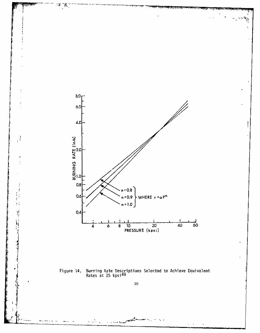
14. Burning Rate Descriptions Selected to Achieve EquivalentRates at 25 kpsi 4 4 . . . . . .. . . . . . . . . . . . .. . . . . . . . . .. 30
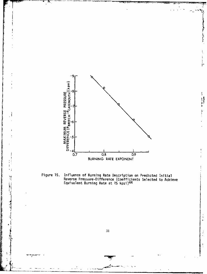
15. Influence of Burning Rate Description on Predicted InitialReverse Pressure Difference (Coefficients Selected toAchieve Equivalent Burning Rate at 25 kpsi) 4 4 . . .. . . . .. . . 31
4916. Effect of Charge Configuration on Chamber Pressure 34
17. Pressure-Time and Differential Pressure-Time Traces for
7- and 19-Perforated Grains 4 6 . . . . . . .. . . . . . . . .. . . . . . . 35
18a. Pressure-Time Trace for 5-In./38-Caliber Gun with Pyro
3S
SPropellant and Primer MK 48 Mod 235..... 36
~41IEjG PAGE BIAWKgOT ?LiAED
I A
- I
LIST OF ILLUSTRATIONS (continued)
Figure Page
18b. Pressure-Time Trace for 5-In./38-Caliber Gun with NACOPropellant and Primer MK 48 Mod 235 ................ .. 36
19a. Pressure-Time Curves for Oto Melara 76-mm Gun with PotassiumSulfate Confined in a Polyethylene BagSl.. .............. 37
19b. Pressure-Time Curves for Oto Melara 76-mm Gun with GranularPotassium Sulfate Dispersed in Propellant Bed 51 . . . . . . . . . . 38
20. Propelling Carge Assembly for 76-mm Oto Melara Gun ..... .40
21. Comparison of TheoreLical Predictions of Pressure Differencewith Experimental Results 5 7 . . . . .. . . . . . . . . . . . . . . . . . .. 41
22. Special Experimental Propelling Charges for 5-In./54-CaliberGun 5 7 . . . . . . .. .. .. . . . . . . . . . . . . . . . . . .. . . . . . . . . . .. 42
23. Pressure-Time Profiles for the 8-In., Mll0E2 HowitzerBreechblow (M188EI, Zone 9 Propelling Charge) 8 .. . . . . . . . . . 44
24. Air Gun Impact Test Results for M6 Propellant.51 ....... .. 45
6325. Igniter Simulator Apparatus ...... ................ ..48
26. Effect of Standoff on the Amplitude of -APi 6 5 . . . . . . . . . . . 49
27. Pressure Wave Sensitivity for the 175-mm, M107 Gun(M86A2, Zone 3 Propelling Charge) 8 S2
28. Distribution of Pressure Wave Amplitudes for the 175-mm,M107 Gun (M86A2, Zone 3 Propelling Charge) 8 . . . .. . . . .. . . . 52
29. Probability of High-Amplitude Pressure Waves for the175-rm, M107 Gun (M86A2, Zone 3 Propelling Charge) 8 . . . . . . . 53
I6
'I
fh '
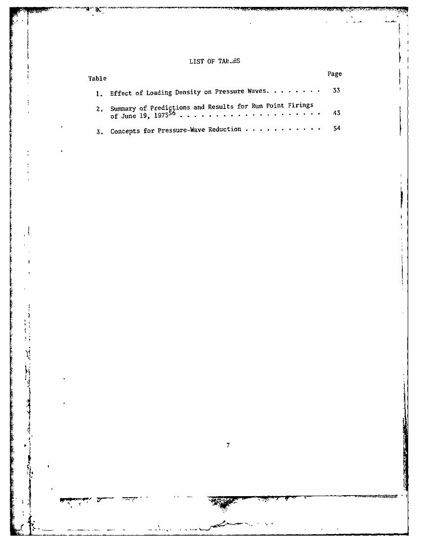
LIST OF TAP-ES
Table Page
1. Effect of Loading Density on Pressure Waves..... . . 5.33
2. Summary of Predictions and Results for Rum Point Firings
of June 19, 197556 .............................. 43
3. Concepts for Pressure-Wave Reduction ...... ........... 54
I7I
I *:I
K'1.
I. INTRODUCfION
Combustion instability in conventional guns as manifested by long-itudinal pressure waves has been a phenomenon largely ignored by propell-ing charge designers unless accompanied by catastrophic failures. Asimilar situation existed for many years within the rocket motor designcommunity. Today, however, the principle that combustion instabilitydesign considerations must be integrated into the overall propulsiondesign approach is well accepted1 . The problem in both communities, how-ever, has been the intrinsic difficulty of specifying acceptable levelsof instability and integrating into the overall propulsion packagedevelopment process the techniques and approaches known to minimizecombustion instability.
From a pragmatic viewpoint, combustion instability in guns as exhib-ited by pressure waves is of concern only because of its causal connectionwith high chamber pressures, which, in turn, may lead to breechblows, bal-listic variability, projectile prematures, and fuze malfunctions. Therelationship, however, is not necessarily a simple one. Low-performancepropelling charge and gun combinations seem to be able to tolerate a fairlysubstantial level of pressure waves without any apparent effect on maximumchamber pressures. Maximizing some performance parameter, such as muzzlevelocity, usually leads to increased pressure wave problems. This problemhas been discussed recently in the context of current development efforts 2 .Typically, the charge designer is asked to launch a specified projectileat a muzzle velocity necessary to achieve a given range, target penetration,or time of flight. This projectile launch velocity must be achieved outof a gun with an interior ballistic envelope usually designed to meet dif-ferent performance requirements. It is indeed rare for a gun charge de-signer to dictate those gun envelope parameters important to him (e.g.,loading density, maximum operating pressures, projectile travel, propel-
lant type, etc.). Normally one rather quickly determines if a specifiedlaunch velocity is attainable using the simpler interior ballistic models 3 .When additional, stringent design requirements for velocity precision,ballistic temperature coefficient, useful wear life, muzzle flash andblast, propellant availability, chamber residue, packaging geometry, andcompatibility with other, similar weapon systems and projectiles areadded, the design easily can become a challenge. These more or less
"1 "Combustion Instability in Solid Rocket Motors", Chemical PropulsionInformation Agency, Laurel, MD. Pubi. 290, Nov. 1977.
T. W. May, "The Role of Ignition and Combustion in Gun Propulsion: ASurvey of Developmental Efforts", Thirteenth JANNAF Combustion Meeting,Chemical Propulsion Information Agency, Laurel, MD, Publ. 281, Sept. 1976.
3 P. G. Baer, "Practical Interior Ballistic Analysis of Guns", "InteriorBallistics of Guns Ed, M. Summerfield and H. Krier, Progress in Astro-nautics and Aeronautics, Vol. 66, 1979.
9
-- A
firm and clear requirements need to be validated during the developmentcycle of the charge. Hence potentially serious but less well-definedpressure-wave problems often are ignored. Only when pressure waves have,or are suspected to have, impacted directly on a well-defined performancerequirement has the available, though meager, technology been appliedin the past. Indeed it only recently has become accepted practice todetermine if nominal pressure wave characteristics of a propelling charge,as measured during limited test programs, are likely to reach highamplitudes. If this is possible, then interior ballistic systemsensitivity to pressure waves is determined.
This recent emphasis on pressure waves is the result of many diverseproblems encountered in both Army and Navy gun development programs. Inthe past five years these have resulted in experimental 4 - 8 and theoreti-
4 J. H. Wiegand, J. H. Smith and A. W. Horst, "Ignition Studies at IndianHead", Proceeding o` the Tri-Service Gun Propellant Symposium, PicatinnyArsenal, Dover, NJ, Oct. 1972.
5 A. W. Horst, T. C. Smith, and S. E. Mitchell, "Experimental Evaluationof Three Concepts for ?educing Pressure Wave Phenomena in Navy 5-inch,54-Caliber Guns: Summajy of Firing Data", NaVal Ordnance Station, IndianHead, MD. MR 76-258, Aug 1976.
6 W. G. Soper, "Ignition Waves in PYRO Propellant", Combustion and Flame,Vol. 22(2), 4pril 1974, pp. 273-276.
7 J. J. Rocchio, K. J. White, C. R. Ruth, and I. W. May, "Propellant GrainTailoring to Reduce Pressure Wave Generation in Guns", 12th JANNAF Com-bustion Meeting, Chemical Propulsion Information Agency, Laurel, MD,Publ. 273, December 1975.
8A. W. Horst, I. W. May, and E. V. Clarke, Jr., "The Missing Link Between
Pressure Waves and Breechblows", Ballistic Research Lab., Aberdeen
"Proving Ground, MD., ARBRL-MR-02849, July 1978. (AD #A058354)
ci41
"i1
i'I- ,-
I T 'j I
cal 9-14efforts to understand and model the phenomenology of pressurewaves in guns.
It is the aim of this paper to illustrate some of the historicalaspects of gun pressure-wave phenomena, to present some current diagnosticinformation on pressure-wave measurements, and to discuss, in the contextof current experimental and theoretical understanding, the basic chargedesign factors influencing the creation and growth of pressure waves.Finally, a new procedure for assessing safety aspects due to pressurewaves will be outlined.
I!. PRESURE-WAVE PHENOMENOLOGY
A brief historical background oit gun pressure-wave phenomenologyhas been presented previously1 S. More recently, a survey on pressure-wave generation in gun systems has been reported by Budka and Knapton 1 6 .
9 K. K. Kuo, R. Vicktevetsky, and M. Summerfield, "Generation of anAccelerated Flame Front in a Porous Propellant", AIAA Paper 71-210, NewYork, Jan. 1971.
l1 P. S. Gough, "Numerical Analysis of a Two-Phase Flow with ExplicitInternal Boundaries", Naval Ordnance Station, Indian Head, MD.,CR 77-5, April 1977.
"1 1 E. B. Fisher and K. W. Graves, "Propellant Ignition and Combustion inthe 155-im Howitzer", Calspan Corp., Buffalo, N.Y., VQ-5524-D-2, Jan. 1975.
12K. K. Kuo, J, H. Koo, T. R. Davis, and G. R. Coates, "Transient
Combustion Ln Mobile Gas Permeable Propellants", Acta Astronautica,Vol. 3, 1976, pp. 573-591.
-: • ~~~~13H.Kir Pe""H. Krier, "Predictions of Flamespreading and Pressure Wave Propagationin Propellant Beds", Ballistic Research Lab., Aberdeen Proving Ground,MD., CR 275, Nov. 1975. (AD #B009170L)
14A. W. Horst, C. W. Nelson and I. W. May, "Flame Spreading in GranularPropellant Beds: A Diagnostic Comparison of Theory to Experiment",AIAA Paper 77-586, Orlando, Flz., July 1977.
151. W. May and E. V. Clarke, Jr., "A Case History: Gun Ignition Related
1 Problems and Solutions for the XM-198 Howitzer", Ballistic Research
Lab., Aberdeen Proving Ground, MD., IMR 150, Oct. 1973.
.1 6 A. J. Budka and J. D. Knapton, "Pressure Wave Generation in Gun Systems:
"A Survey", Ballisvic Research Lab., Aberdeen Proving Ground, MD., MR I2567, Dec. 1975. (AD #BOO8893L)
11
SIi.
_______,•1_________•____-__•__ .... 7__.__,_,
~v"Žý
17Goode and Weald attempted to classify different categories of pressure-wave irregularities. The classic interior ballistics textbooks byCorner 1 8 and Hunt and Hinds 1 9 also briefly mention the existence and theperverse nature of pressure waves.
The first observation of pressure waves in a gun chamber was madeby Vielle 20 (circa 1880) with his invention, the recording crusher gage.The significance of pressure waves, their origin and connection withhigh pressure and catastrophic failure was, however, not appreciatedfully until the 1930's, with the advent of reliable piezoelectric gagescapable of withstanding the rifors of a gun environment. Kent, in earlywork with piezoelectric gages2 22, correctly identified the cause ofpressure waves in the 155-mm Gun, Hodel 1918, Ml, as being due tovigorous base ignition of the chare. He also reasoned 23 , 2 4 that some
J. B. Goode and D. E. Weald, "Survey-Fluid Dynamic Aspects of the
Internal Baltistics of Guns", Advisory Group for Aerospace Researchand Development (NATO), AGARD Conference Proceedings No. 40, Sept.1966, pp. 1-12.
18 J. Corner, Theory of the Interior Ballistics of Guns, Wiley, New York,1950.
19F. R. W. Hunt and G. H. Hinds, Internal Ballistics, Philosophical
Library, New York, 1951, p. 80.
S2 0p. Vielle, quoted by C. Cranz in Lehrbuch der Ballistik, Vol. II,Springer-Verlag, Berlin, 1926, p. 151.
2 1 R. H. Kent, "Study of Ignition of 155-mm Gun in Connection with Project
KW 250-Study of the Factors In)olved in the Design of Propelling Charges",Ballistic Research Lab., Aberdeen Proving Ground, MD., MR 4, Feb. 1935.(AD #493405)
2 2R. H. Kent, "Study of Ignition of 155-rm Gun", Ballistic Research Lab.,
Aberdeen Proving Ground, MD., R22, Oct. 1935. (AD #494703)
3 R H. Kent, "Velocity Dispersion Obtained with Charles of Slender Base
3ection in the 155-mm Gun G.P.F.," Ballistic Research Lab., AberdeenProving Ground, MD., R45, March 1936.
2 4 R. H. Kent, "Study of the Ignition and Velocity Dispersion of FNH
Powder in the 155-,m Gun G.P.F.," Ballistic Research Lab., AberdeenProving Ground, MD., R91, Dec. 1937. (AD #491768)
, -12
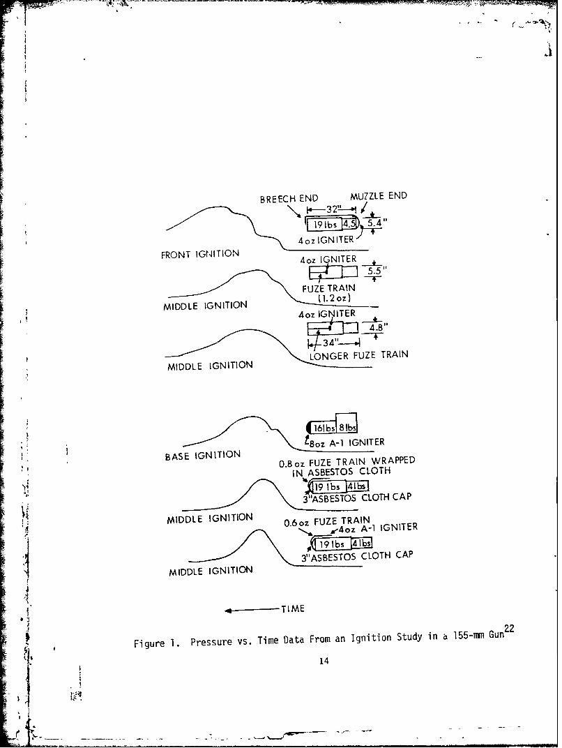
of the velocity dispersion accompanying this particular charge/guncombination resulted from pressure cscillations traversing the chamber,leading to slightly higher pressures and velocities. In his attempt toreduce the velocity dispersion, he employed various ignition train con-figurations to achieve smooth pressure-time curves. Some of his resultsare shown in Figure 1. His basic concepts of annular space around thecharge to allow flamespreading and pressure equilibration throughout thechamber are still useful, as are the results of his experiments withcentral and centercore ignition. He recognized the benefits of thenatural convective channels found in strip and stacked charges. He alsocommented on the additional safety factor required in the gun designwhen large-amplitude pressure-waves are present.
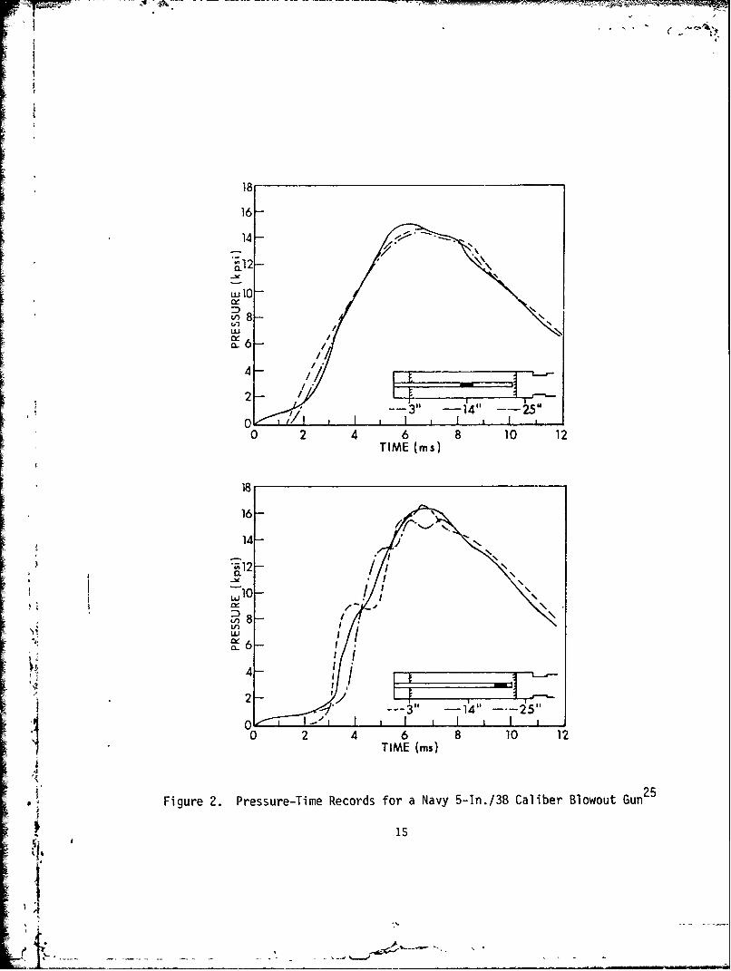
¶ The work by Hedden and Nance25 represents one of the most comprehensiveexperimental studies of pressure-waves resulting from variations in thelocation of the ignition source in a propellant bed and the effects offree space or ullage on wave generation and propagation. Hedden andNance used a blowout gun made by cutting off a Navy S-In./38-CaliberGun approximately 9.5 in. (24.1 cm) forward of the origin-of-riflingand modified by installing an orifice at a point representing the location
- of the projectile base. Three pressure gages were installed: at mid-chamber, 3 in. (7.6 cm) forward of the breech, and 3 in. (7.6 cm) rearward from the orifice. In properly controlled experiments, the pressure-time histories could be made to duplicate actual gun performance. Byadjusting the free space behind and in front of the charge and by adjustingthe location of a point-type, localized ignition source, these experimentswere able to determine how pressure-waves could be induced and avoided.
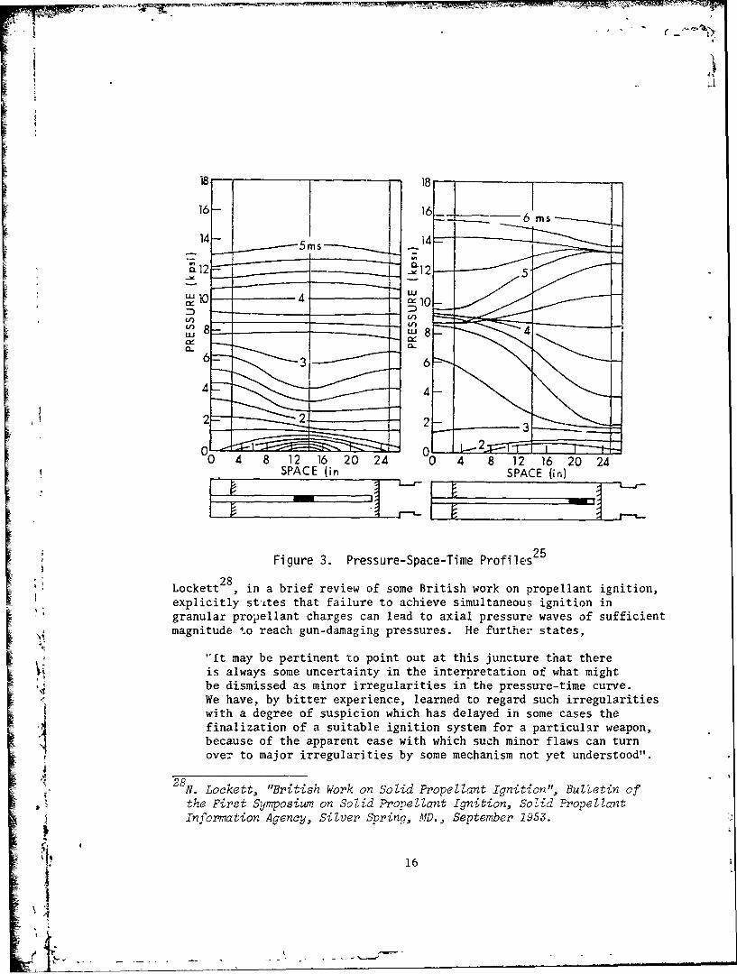
They concluded that placing the ullage completely toward either endof the chamber dnd igniting the charge adjacent to the ullage producedthe largest-amplitude waves. Moving the point of ignition away from theullage reduced wave amplitude. Distributing the free space at both endsof the charge and igniting the charge in the center gave smooth pressure-time records. Some representative results showing the space/ignitionrelationship and resulting pressure-time histories from the differentgage locations are illustrated in Figures 2 and 3.
26 27Other studies, by Bauman and Bird and Gowen and Elzufonconfirmed the importance of geometric effects such as location of the
V ignition source and the distribution of free space in the chamber.'S. E. Heddon and G. A. Nance, "An Experimental Study of Pressure-Waves
in Gun Chambers," Naval Proving Ground, Dahlaren, VA., R 1534, April 1957.
N. Bauman and E. Bird, "Ignition Problems in Separate-Loading Ammunition,"Joint Army-Navy-Air Force Seoond Symposium on Propellant Ignition, Vol.II, Solid Propellant Information Agency, Silver Spring, MD., October 1956.
L Gowen and E. Eizufon, "A Review of Igniter Studies and Their
Application to Igniter Design," Joint Army-Nav,-Air Force Second7yrSyposiurn o0 Sold ProneLZ H,:to, Vol. TI, Solid Prorellant Information
Agency, Silver Spring, 1M1., Oct. 1956.
13
e
BREECH END MUZZLE END
4 oz IGNITER"
FRONT IGNITION 4o IGNITER
5.5"
FUZE TRAINr- ir I[N(1. 2oz)
MIDDLE IGNITION4oz IGNITER
4.811
LONGER FUZE TRAINMIDDLE IGNITION
•8oz A-1 IGNITER
BASE IGNITION0.8oz FUZE TRAIN WRAPPED
IN ASBESTOS CLOTH19 1 b - b
3"ASBESTOS CLOTH CAP
0MIDDLE IGNITION .6oz FUZE TRAINAiIGNITER
4 3"ASBESTOS CLOTH CAP
MIDDLE IGNITION
= - -TIME
Figure I. Pressure vs. Time Data From an Ignition Study in a 155-mm Gun 2 2
14
I
16-
S14
---3"l -24 --
TIM 1ins 10 1
18
16-
4-
"•12
0l1
'I0 2 4 6 8 10 12
18
112 - i"
W 0 2 0 1
I
18
rj. _ _..__//_• ,
m_ 6-
0 2 4 6 8 10 12
i TIME (ms)
Si" Figure 2. Pressure-Time Records for a Navy 5-In./38 Caliber Blowout Gun2
16 - 16 _ 6
14- 514
SSPACE (in SPACE (in)
"-- -----1 12 5
S~Figure 3. Pressure-Space-Time Profiles2 5
, • L ck et 2 8 ,Locet ,in a brief review of some British work on propellant ignition,
I ~explicitly st'ites that failure to achieve simultaneous ignition in;' granular prop~ellant charges can lead to axial pressure waves of sufficient• ~magnitude to reach gun-damaging pressures. He further states,
0 ~"It may be pertinent tco point out at this juncture that there%i is always some uncertainty in the internretation of what might• ,,,•be dismissed as minor irregularities in the pressure-time curve.
• • We have, by bitter experience, learned to regard such irregularitiesi with a degree of suspicion which has delayed in some cases the•! finalization of a suitable ignition system for a particular weapon,because of the apparent ease with which such minor flaws can turn
, over to major irregularities by some mechanism not yet understood".
S"•. 2 8 N. Locke tt, "British Work on Solid Propellant Iqnition", Bulletin of• i the First Symposium on Solid Propellant Ignition, Solid PropellantS~Information Aqency, Silver Spring, MD., September 2953.
r_ 016
13
r7
An intereresting difficulty is referred to by Gowen and Elzufon27
In an attempt to reduce hangfires, they increased the amount of igniter
material. When that problem was solved for a particular coo:-burning,
single-base propellant at the low temperatures, pressure waves developedat the high temperatures. Apparently they could not solve both the hang-fire and pressure-wave problem simultaneously. Another conclusion fromthis work, since confirmed by mary other investigators, is that pressurewaves are less likely to develop or are of lower amplitude at lowertemperatures. For the case of brittle propellant grains, however,mechanical failure of the grain at the lower temperatures can lead toa different phenomenon, as evidenced by our catastrophic experience withM17 triple-base propellant in the 76-mm tank guns in Korea 2 . This 30propellant exhibited breakup even in closed-bomb burning rate experimentsIn an earlier report, Lane 3 1 had speculated that low-temperature propellantbrittleness contributed to excess velocity dispersion. He also conjecturedthat peak pressure increases were the result of higher-amplitude pressure-waves. A more recent, further development of the impact of propellantmechanical properties on pressure waves will be discussed in a followingsection.
III. EXPERIMENTAL CONSIDERATIONS
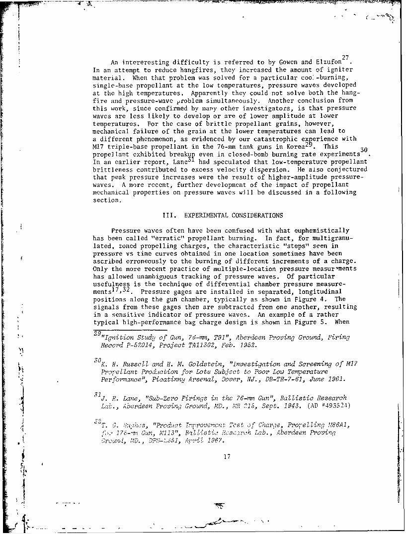
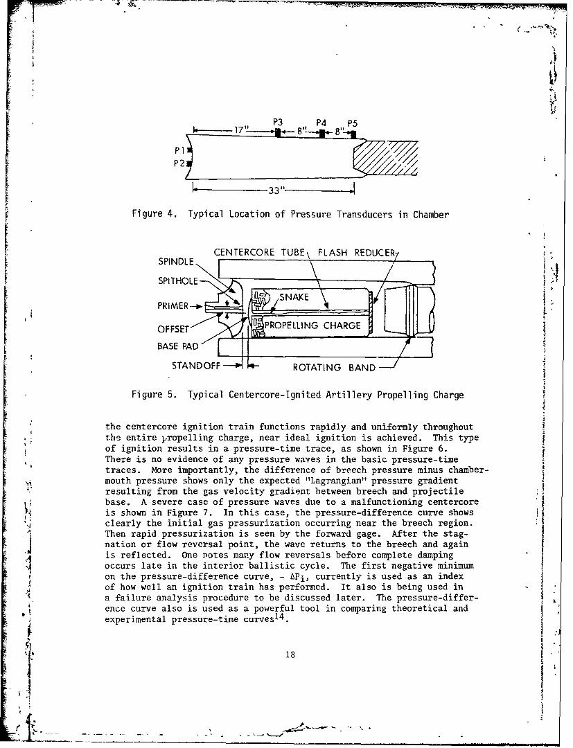
Pressure waves often have been confused with what euphemisticallyhas been called "erratic" propellant burning. In fact, for multigranu-lated, zoned propelling charges, the characteristic "steps" seen inpressure vs time curves obtained in one location sometimes have beenascribed erroneously to the burning of different increments of a charge.Only the more recent practice of multiple-location pressure measurementshas allowed unambiguous tracking of pressure waves. Of particularusefulness is the technique of differential chamber pressure measure-mentsl7,32. Pressure gages are installed in separated, longitudinalpositions along the gun chamber, typically as shown in Figure 4. Thesignals from these gages then are subtracted from one another, resultingin a sensitive indicator of pressure waves. An example of a rathertypical high-performance bag charge design is shown in Figure 5. When
29"lanition Study of Gun, 76-,na, T91", Aberdeen Proving Ground, FiringRecord P-52014, Project TA11302, Feb. 1952.
3OK. H. Russell and H. Al. Goldstein, "Investigation and Screening of M17
Propellant ProdUction for Lots Subject to Poor Low TemperaturePerformance", Picatinny Arsenal, Dover, NJ., DB-TR-7-61, June 1961.
31J. F. Lane, "Sub-Zero Firings in the 76-m•, Gun", Ballistic Research
Lab., Aberdeen Proving Ground, MD., MR 215, Sept. 1943. (AD -493524)
G2. 7. #JuOI~s, "Product Tr'provemcnt T st of Char, e, Pro-elling M86A1,f".' 175--rn Gun, M113", BzlListic Resc,-rh Lab., Aberdeen Proving(rn, rD.o.i , DPS-:_551, A.4rii 1967.
9 •17
II
I ,-
P3 P4 P5I1711 8
P I
k 33"3 3
Figure 4. Typical Location of Pressure Transducers in Chamber
CENTERCORE TUBE\ FLASH REDUCER7
SPl THOLE-- /;_,
,SNAKE :
OFFSET- "PROPELLING CHARGE•
BASE PAD
STANDOFF ROTATING BAND
Figure 5. Typical Centercore-Ignited Artillery Propelling Charge
the centercore ignition train functions rapidly and uniformly throughoutthe entire propelling charge, near ideal ignition is achieved. This typeof ignition results in a pressure-time trace, as shown in Figure 6.There is no evidence of any pressure waves in the basic pressure-timetraces. More importantly, the difference of breech pressure minus chamber-mouth pressure shows only the expected "Lagrangian" pressure gradient '
resulting from the gas velocity gradient between breech and projectilebase. A severe case of pressure waves due to a malfunctioning centercore
,Z is shown in Figure 7. In this case, the pressure-difference curve showsclearly the initial gas pressurization occurring near the breech region."Then rapid pressurization is seen by the forward gage. After the stag-4 ination or flow reversal point, the wave returns to the breech and again
4 is reflected. One notes many flow reversals before complete dampingoccurs late in the interior ballistic cycle. The first negative minimumon the pressure-difference curve, - APi, currently is used as an index
4 of how well an ignition train has performed. It also is being used ina failure analysis procedure to be discussed later. The pressure-differ- Ience curve also is used as a powerful tool in comparing theoretical andexperimental pressure-time curves 1 4 .
18

U. RD20-2
"_ _ _ _ _ _ _ _ _ _ _ _ _ 0 f""4- -30
6-Cu J375wn40 I \
. -- 25o600
"20
"O 125-
U C,'0 4 8 12 16 20 24
TIME (ms)Figure 6. Pressure-Time and Pressure-Difference Profiles for a Properly
Ignited, High-Performance Charge
I I 16020-
wu RD. NO.127 120UZLU 12- - 80uj
L- 40
w w
0 -Ai - - 40
12 - - 80
400S•Lux- 45 -..- ;V ME = 200:E
UC , 0
0 4 8 12 16 20 24T IME (m s)
Figure 7. Pressure-Time and Pressure-Difference Profiles, Localized'• Base Ignition
' • 19
I;
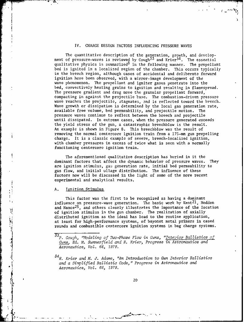
IV. CHARGE DESIGN FACTORS INFLUENCING PRESSURE WAVES
The quantitative description of the generation, growth, and dovelop-ment of pressure-waves is reviewed by Cough 3 3 and Krier 3 4 . The essentialqualitative physics is summarized 8 in the following manner. The propellantbed is ignited in a localized region of the chamber. This occurs typicallyin the breech region, although cases of accidental and deliberate forwardignition have been observed, with a mirror-image development of thewave phenomenon. The propellant and igniter gases penetrate into thebed, convectively heating grains to ignition and resulting in flamespread.The pressure gradient and drag move the granular propellant forward,compacting in against the projectile base. The combustion-driven pressurewave reaches the projectile, stagnates, and is reflected toward the breech.Wave growth or dissipation is determined by the local gas generation rate,available free volume, bed permeability, and projectile motion. Thepressure waves continue to reflect between the breech and projectileuntil dissipated. In extreme cases, when the pressure generated exceedsthe yield stress of the gun, a catastrophic breechblow is the result.An example is shown in Figure 8. This breechblow was the result ofremoving the normal centercore ignition train from a 175-mm gun propellingcharge. It is a classic example of severe, breech-localized ignition,with chamber pressures in excess of twice what is seen with a normallyfunctioning centercore ignition train.
The aforementioned qualitative description has buried in it thedominant factors that affect the dynamic behavior of pressure waves. Theyare ignition stimulus, gas generation rate, initial bed permeability togas flow, and initial ullage distribution. The influence of thesefactors now will be discussed in the light of some of the more recentexperimental and analytical results.
A. Ignition Stimulus
This factor was the first to be recognized as having a dominantinfluence on pressure-wave generation. The basic work by Kent 2 l, Heddonand Nance 2 5 , and others clearly illustrates the importance of the locationof ignition stimulus in the gun chamber. The realization of axiallydistributed ignition as the ideal has lead to the routine application,at least for high-performance systems, of bayonet metal primers in casedrounds and combustible centercore ignition systems in bag charge systems.
33 p, Gough, "Modeling of Two-Phase Flow in Guns, "Intevior Ballistics ofGuns, Ed. M. Summerfield and H. Krier, Progress in Astronautics andAeronautics, Vol. 66, 1979.
H. Krier and M. J. Adams, "An Introduction to Gun Interior Ballisticsand a Simplified Ballistic Code," Progress in Astronautics andAeronautics, Vol. 66, 1979.
20
-- -
30040
-200
, 20
Ow
100
0. < - 200
U aoZ a_
u~m -600
4. ac 0
; -400-LU0
0 10 20,, -2600
175-m F;; " 50i- -4 400-
:214,,
,0 10 20I~ TI ME (s
'• Figure 8. Catastrophic Pressure-Wave Dynamic Behavior Observed in aS~175-mm Gun Firing
i2
Other parameters, however, play an equally important role, especiallyfor "nonideal" ignition systems. These are the rate at which both energyand gas pressure are delivered by the ignition train, as well as thetot energy delivered to the propellant bed and the total "ignition"pressure. In practice, even centercore igniters for both cased andbag charge systems rarely function in the ideal manner. A typical exampleof the nonideal behavior of a bayonet primer has been described 3 5.Figure 9 shows the firing results obtained using two versions of theMK 48 Primer tested in the Navy 5-In./38-Caliber Gun. The MK 48 Mod 2Primer, venting largely in the first half of the chamber, results instrong pre' ,ure-wave symptoms. The longer MK 48 Mod 4 Primer, withventing more central'y located, leads to much improved pressure-timecurves. It should be noted that the mere act of placing vent holesdistributed over a full chamber length bayonet primer does not insureuniform venting. The studies by Vest 3 6 , and more recently by Smith 3 7
and East and McClure38, quite clearly indicate that pressure-wavephenomena inside bayonet primers can readily produce spatially and tem-
porally uneven ignition gas venting. With our current knowledge anddiagnostic capabilities, the design of new bayonet primers with near-ideal functioning is relatively straightforwptcd. The recent work bySmith 39 supports this view. The unique problems of low-pressure combust-ible ignition systems for bag charges will be discussed separately.
Another recent, extensive study on the effects of igniter location40
shows clearly the benefits of rapid, distributed ignition in reducingpressure waves. For this study, charges with nine different ignitionsystem configurations with the same amount of black powder were firedout of a 5-In./54-Caliber Gun. The results are shown schematically in35192Ana
A. W. Horst and A. C. Haukiand, "Gun Interior Ballistics: 1972 Annual* Report," Naval Ordnance Station, Indian Head, MD., TR 386, April 1973.
36D. C. Vest, "On the Performance of Primers for Artillery Weapons",Ballistic Research Lab., Aberdeen Proving Ground, MD., R852, March 1953.(AD #13294)
T. C. Smith, "Development of Electric Primer Mark 48 Mods 3 and 4 forthe 5-inch, 38-Caliber Gun", Naval Ordnance Station, Indian Head, MD.,TR 396, Feb. 1974.
.38. L. East and D. R. McClure, "Experimental Studies of Ignition and
Combustion in Naval Guns", Twelfth JANNAF Combustion Meeting, ChemicalPropulsion Information Agency, Laurel, MD., Publ. 273, Aug. 1975.
x39S 3 9 T. C. Smith, "Rapid Ignition of Granular Propellant Beds with a 'Hotline'Igniter", 1978 JANNAF Propulsion Meeting, Chemical Propulsion Informat-ion Agency, Laurel, MD., Publ. 293, Feb. 1978.
40A. W. Horst, "Navy Gun Interior Ballistics Modeling Efforts: AnOverview", 1973 JANNAF Propulsion Meeting, Chemical Propulsion Informa-tion Agency, Laurel, MD., Publ. 242, Sept. 1973.
22
P1.
P2-i
4 5 6 7 8 9 10
TIME (ins)
>1 MOD 4 CONFIGURATION
Figure 9. Comparison of Pressure-Time Curves for NACO Propellant Firingswitn Primers MK 48 Mod 2 and MK 48 Mod 435
23
I'~%__ f d- - -
Figure 10. The black powder in configuration I was ignited with a low-velocity detonation cord. Figures 10 and 11 clearly show the stronginfluence that pressure waves have on chamber pressure and muzzlevelocity. One conclusion that can be drawn from these data is that,unless an ignition system functions with good reproducibility, ballisticvariability can be increased. Another example of the effect of ignitionvariability on ballistic uniformity has been reported by Clarke and May 4 1
for a 155-mm howitzer bag charge. For base-ignited propelling charges,as the average pressure-wave level increased for a particular ignitionsystem, the variability in the pressure-wave content increased, withaccompanying increased muzzle velocity dispersion. During the develop-ment of this base-ignited charge, it uIso was noted that the faster base-pad igniter tested resulted in a higher level of pressure-waves, as mightbe expected.
Although several parametric, two-phase-flow, interior ballisticI calculations concentrating on the ignition stimulus have been performedl 1 4 2
of particular note are the results by Horst et al. 8 using the NOVA code 10
to simulate an 8-in. howitzer breechblow induced by a deliberate blockageof the centercore ignition train. The effect of distributed ignition vssevere, localized ignition on pressure-wave generation is seen clearlyin the computed pressure-time traces of Figure 12. It appears thatcurrent onc-dimensional two-phase-flow interior ballistic codes thatincorporate ignition and flamespread predict the appropriate trends asigniter location and delivery rate are varied. More impressive, perhaps,is the good agreement obtained between theory and experiment14 in thesimulation of the 76-mm Oto Melara and the S-In.i54-Caliber Gun. Thelatter is shown in Figure 13. For this cased gun simulation, experimen-tally measured primer output data were used as input to the NOVA calcula-tion. Simulations for bag charge pressure-wave dynamics are, at pres-nt,not quite so successful.
j
4 1 E.V. Clarke and I. W. May, "Subtle Effects of Low Amplitude Pressurea Wave Dynamwics on the Ballistic Performance of Guns", Eleventh JANNAFCombustion Meeting, Chemical Propulsion Information Agency, Laurel,MD., Publ. 261, Sepvember 1974.
S•42 E. F~sher, K. Graves and A. Trippe, "Application of a Flamespread Modelto Design Problems on the 155-mm Propelling Charge", Twelfth JANNAF
"Combustion Meeting, Chemical Propulsion Information Agency, Laurel, MD.,2 1975.
24
BREECH
IAIW
U-)
ig
A B C
lOresMOUTH
D E F
LEE -ýIz
G H
.I.1
Figure 10. Ignition Study Test Results
251'.
14i-! ~ ~m ~
2520-
C
'248o E
0 AL 2440
1- "F G H
S, 2400 -I I , I36 38 40
4' MAXIMUM PRESSURE (kpsi)
44
i• ~Figure 11. Velocity vs. Maximum Pressure for Test Configuration0
-2-
-'4
280' '-BREECH
240
CL200
'"160
w 120120 CHAMBER
MOUTH80
40
0 4 8 12 16 20,I I ME (ins)
"SOFT" BASE
240 -
200-
616O-
ou 120 ,CHAMBER
Si I v MOUTH
0e 80
I 4 0
00 4 8 12 16 20
TIME (ms)"HARSH" BASE
SFigure IZ. Predicted Effect of Ignition in the 8-In., MlIOE2
Howitzer (M1I8E1, Zone 9 Propelling Charge) 8
27
t I
I I I I I I I I
120 EXPERIMENTALPREDICTED
80-
aa-
U40
u 40-
a -- 4 0
(z
-80
0 2 4 6 8 10 12
,.. TIME (ins)
I
-414
Figure 13. Pressure Difference Simulation for 5-In./54-Caliber Gun
28
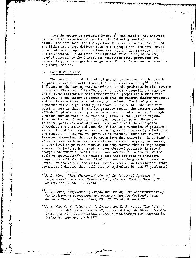
From the arguments presented by Hicks4 3 and based on the analysisof some of the experimental results, the following conclusion can bedrawn. The more localized the ignition stimulus is in the chamber andthe higher its energy delivery rate to the propellant, the more severea case of local propellant ignition, burning, and gas pressure buildupcan be expected. In addition, the ignition stimulus is, of course,coupled strongly to the initial gas generation rate, propellant bedpermeability, and charge/chamber geometry factors important in determin-ing charge motion.
B. Mass Burning Rate
The contribution of the initial gas generation rate to the growthof pressure waves is well illustrated in a parametric study4 4 on theinfluence of the burning rate description on the predicted initial reverse
pressure difference. This NOVA study considers a propelling charge forthe 5-In./54-Caliber Gun with =ombinations of propellant burning ratecoefficients and exponents chosen such that the maximum chamber pressures
L and muzzle velocities remained roughly constant. The burning rateexponents varied significantly, as shown in Figure 14. The importantpoint to note is that, in the low-pressure region, the extreme burningr: rate descriptions varied by a factor of two. In other words, the highexponent burning rate is substantially lower in the ignition regime.This results in a lower propellant gas production rate. Hence anylocalized pressures generated will have more time to be dissipated
* throughout the chamber and thus should lead to a reduction of pressure-waves. Indeed the computed results in Figure 15 show nearly a factor oftwo reduction in the reverse pressure difference. There are severalimportant deductions that can be drawn from this analysis. Since burningrates increase with initial temperatures, one would expect, in general,a lower level of pressure waves at low temperatures than at high temper-atures. In fact, such a trend has been observed routinely in recentcharge development efforts for a 155-mm howitzer1 S. Although, in therealm of speculation45 , we should expect that deterred or inhibitedpropellants will also be less likely to support the growth of pressurewaves. An analysis of the initial surface area of multiperforated graingeometries indicates that ballistically equivalent 19- and 37-perforated
i•43 B. L. Hicks, "Some Characteristics of the Practical Ignition of
Propellants", Ballistic Research Lab., Aberdeen Proving Ground, MD.,"MR 640, Dec. 1952. (AD #3342)
4 4 A. W. Horst, "Influence of Propellant Burning Rate Representation ofGun Environment Flamespread and Pressure-Wave Predictions", NavalOrdnance Station, Indian Head, A., MR 76-255, Narch 1976.
iv. May, C. W. Nelson, J. J. Rocchio and K. J. White, "The Role of
Initzon in Artillery Propulsion", Proceedings of the Third Internat-* • a Symposiw2 on Ballistics, Deutsche Gesellschaft fur Wehrtechnik,
Kar'Lsru•ee, Germany, M.larch 1977.
29
'S
- I
8.0-
6.0
4.0o
0z
:51.0
0 .8
a6 n=0.9 WHERE r=uPn
S/ n =1.0J
0.4F
4 6 8 10 20 40 60PRESSURE (kpsi)
Figure 14. Burning Rate Descriptions Selected to Achieve Equivalent:1Rates at 25 kpsi 44
30
4--
' I'
• 8-9
-8ID
LUI • . -7
~LU
<uJLUj> U- _
DU-
EBURNING RATE EXPONENT
• ~Figure 15. Influence of Burning Rate Description on Predicted Initial ••,•, Reverse Pressure-Difference (Coefficients Selected to Achieve
i Equivalent Burning Rate at Z5 kpsi) 44
LL
Ix. UI'
) -4
f,07Q .
grains have reduced initial surface areas over 7-perforated grains andhence should offer a reduction in pressure-wave tendencies 4 6, A moresubtle effect also might be of importance. It has long been postulated 1 9
that ignition of the inner perforations is delayed until some criticalpressure or flow condition is reached, This factor, admittedly not welldocumented, also would enhance the pressure-wave reduction of multi-perforated propellants. Since the more unusual 19- and 37- perforatedgrain geometries also improve gas flow permeability, discussion ofexperimental results will be deferred to the next section.
Because the low-pressure mass burning rate now is known to be an im-portant factor in pressure-wave phenomenology, it is somewhat disappointingto discover that good, low-pressure burning rate data for gun propellantsare almost nonexistent. Another study by Horst et al. 1 4 points out thisdilemma. In attempting to achieve a reasonable simulation of experimentalresults for base-ignited charges, the low-pressure burning rate had tobe increased artificially by the addition of a small constant value tothe closed-bomb aPl' fit. On a relative basis, this has a substantialeffect on the low-pressure burning rate and improves substantially theagreement between simulation apd experiment. It is tempting to conjecturethat a transient burning rate contribution is the likely explanation. Theobservation that this effect appears to be associated more with baseignition is puzzling. Kooker and Nelson4 7 have examined the responsesof three different transient burning models under typical gun pressuriz-ation envelopes, Their main conclusions are that the effect is usuallyimportant only in the low-pressure region, and burning rate enhancementfactors on the order of 10 are plausible. Experimental verification islacking, however. Of a more practizal nature is the inference that a
* charge operating at a higher pressure is more likely to have pressure-wave problems than a lower pressure charge. This is the result of theenhamiced, low-pressure mass burning rate required to obtain the higherpressures. Because of the effect of available volume on the generated[ 4 pressure and its feedback on the burning rate, one also should expectincreased pressure-wave generation as the loading density and the maxi-mum chamber pressure increase, An example of this effect is shown inTable 148. It should be noted, however, that this effect also iscomplicated by both charge geometry and bed-permeability effects.
4 6 j. J. Rocchio, C. R. Ruth and I. W. May, "Grain Geometry Effects onWave Dynamics in Large Caliber Guns", Thirteenth JANNAF Combustion"Meeting, Chemical Propulsion Informavion Agency. Laurel, MD., Publ.
'281, Dec. 1976.
4 7D. E. Kooker and C. W. Nelson, "Numerical Solution of Three SolidPropellant 'Combustion Models During a Gun Pressure Transient", BallisticResearch Lab., Aberdeen Proving Ground, MD., R 1953, January 1977.(AD #A035250)
to- 48 "Aberdeen Proving Ground, Firing Record P-82415, March 1974.
I32
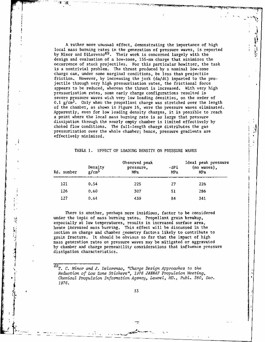
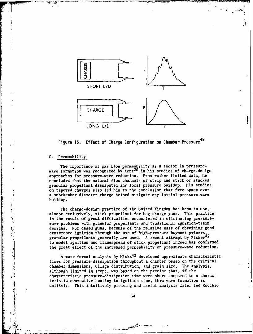
A rather more unusual effect, demonstrating the importance of highlocal mass burning rates in the generation of pressure waves, is reportedby Minor and DiLorenzo 4 9 . Their work is concerned largely with thedesign and evaluation of a low-zone, 155-mm charge that minimizes theoccurrence of stuck projectiles. For this particular howitzer, the taskis a nontrivial problem. The thrust produced by a nominal low-zonecharge can, under some marginal conditions, be less than projectilefriction. However, by increasing the jerk (da/dt) imparted to the pro-jectile through very high pressurization rates, the frictional forceappears to be reduced, whereas the thrust is increased. With very high
r pressurization rates, some early charge configurations resulted in[ severe pressure waves wich very low loading densities, on the order of0.1 g/cm3 . Only when the propellant charge was stretched over the lengthof the chamber, as shown in Figure 16, were the pressure waves eliminated.Apparently, even for low loading density charges, it is possible to reacha point where the local mass burning rate is so large that pressuredissipation through the nearly empty chamber is limited effectively bychoked flow conditions. The full-length charge distributes the gaspressurization over the whole chamber; hence, pressure gradients areeffectively minimized.
t ;-TABLE 1. EFFECT OF LOADING DENSITY ON PRESSURE WAVES
Observed peak Ideal peak pressureDensity pressure, -APi (no waves),
Rd. number g/cm3 MPa MPa MPa
121 0.54 225 27 226
126 0.60 307 51 286
127 0.64 439 84 341
There is another, perhaps more insidious, factor to be consideredunder the topic of mass burning rates. Propellant grain breakup,especially at low temperatures, results in increased surface area,hence increased mass burning. This effect will be discussed in thesection on charge and chamber geometry factois likely to contribute tograin fracture. It should be obvious so far that the impact of highmass generation rates on pressure waves may be mitigated or aggravated"by chamber and charge permeability considerations that influence pressuredissipation characteristics.
49 T. C. Minor and J. Delorenzo, "Charge Design Approaches to theReduction of Low Zone Stickers", 1976 JANNAF Propulsion Meeting,
SChemical Propulsion Information Agency, Laurel, MD., Publ. 280, Dec.1976.
S33
*I
PAA
PLIL~ __
SHORT L/Dr
LONG L/D T
49Figure 16. Effect of Charge Configuration on Chamber Pressure
C. Permeability
The importance of gas flow permeability as a factor in pressure-wave formation was recognized by Kent 2 0 in his studies of charge-designapproaches for pressure-wave reduction. From rather limited data, heconcluded that the natural flow channels of strip and stick or stackedgranular propellant dissipated any local pressure buildup. His studieson tapered charges also led him to the conclusion that free space overa subchamber diameter charge helped mitigate any initial pressure-wave
, buildup.
•,. The charge-design practice of the United Kingdom has been to use,
almost exclusively, stick propellant for bag charge guns. This practiceis the result of great difficulties encountered in eliminating pressure-" wave problems with granular propellants and traditional ignition-trainSdesigns. For cased guns, because of the relative ease of obtaining goodcentercore ignition through the use of high-pressure bayonet primersgranular propellants generally are used. A recent attempt by Fisher 4 2"to model ignition and flamespread of stick propellant indeed has confirmedthe great effect of the increased permeability on pressure-wave reduction.
A more formal analysis by Hicks 4 3 developed approximate characteristictimes for pressure-dissipation throughout a chamber based on the criticalchamber dimensions, ullage distribution, and grain size. The analysis,although limited in scope, was based on the premise that, if the
*- characteristic pressure-dissipation time were short compared to a charac-teristic convective heating-to-ignitiun time, then wave formation isunlikely. This intuitively pleasing and useful analysis later led Rocchio
34
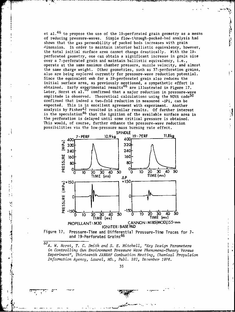
et al. 46 to propose the use of the 19-perforated grain geometry as a meansof reducing pressure-waves. Simple flow-through-packed-bed analysis hadshown that the gas permeability of packed beds increases with graindimension. In order to maintain interior ballistic equivalency, however,the total initial surface area cannot change drastically. With the 19-perforated geometry, one can obtain a significant increase in grain sizeover a 7-perforated grain and maintain ballistic equivalency, i.e.,operate at the same maximum chamber pressure, muzzle velocity, and almostthe same charge weight. Other geometries, such as 37-perforation grains,also are being explored currently for pressure-wave reduction potential.Since the equivalent web for a 19-perforated grain also reduces theinitial surface area, as previously mentioned, a sympathetic effort isobtained. Early exgerimental results4 6 are illustrated in Figure 17.Later, Horst et al. confirmed that a major reduction in pressure-waveamplitude is observed. Theoretical calculations using the NOVA code 50
confirmed that indeed a two-fold reduction in measured -APi, can beexpected. This is in excellent agreement with experiment. Anotheranalysis by Fisher 42 resulted in similar results. Of further interestis the speculation 46 that the ignition of the available surface area inthe perforation is delayed until some critical pressure is obtained.This would, of course, further enhance the pressure-wave reductionpossibilities via the low-pressure mass burning rate effect.
a SPINDLE
7-PERF 10.9kg 19- PERF 11.8kg400400
O-320-30
240 240
, 160 160
S80 80LUc 0"C 0 10 20 30 40 50 0 10 20 30 40 50
TIME (ms) AP TIME (is)S0 _ _+150 +150
•'' 0 0
I..U
0 10 20 30 40 50 0 10 20 30 40 50TIME (ms) TIME (ms)
PROPELLANT: M30 CANNON: M185(MOD),155-mmIGNITER: BASE PAD
Figure 17. Pressure-Time and Differential Pressure-Time Traces for 7-and 19-Perforated Grains 4 6
50 A. W. Horst, T. C. Smith and S. E. Mitchell, "Key Design Parameters"in Controlling Gun Environment Pressure Wave Phenomena-Theory VersusExperiment", Thirteenth JANNAF Combustion Meeting, Chemical PropulsionInformation Agency, Laurel, MD., Pub1. 281, December 1976.
35
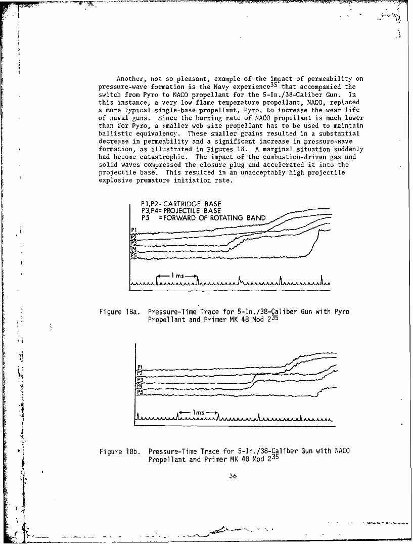
Another, not so pleasant, example of the impact of permeability onpressure-wave formation is the Navy experience35 that accompanied theswitch from Pyro to NACO propellant for the 5-In.,/38-Caliber Gun. Inthis instance, a very low flame temperature propellant, NACO, replaceda more typical single-base propellant, Pyro, to increase the wear lifeof naval guns. Since the burning rate of NACO propellant is much lowerthan for Pyro, a smaller web size propellant has to be used to maintainballistic equivalency. These smaller grains resulted in a substantialdecrease in permeability and a significant increase in pressure-waveformation, as illustrated in Figures 18. A marginal situation suddenly
[I
had become catastrophic. The impact of the combustion-driven gas andsolid waves compressed the closure plug and accelerated it into the
I
projectile base. This resulted in an unacceptably high projectileexplosive premature initiation rate.
[ P 1,P2= CARTRIDGE BASE
II P
Figure 18a. Pressure-Time Trace for 5-In./38-Caliber Gun with NACoPropellant and Primer MK 48 Mod 23
P36
15
M
Figurer 18b. Pesure-Tieant Tracpe for the 38Caibc Gun wemaiith Aon
swich romPyr oNC ropellant anfPim r the 48 n/8-a e Gun. 235
ths nsane avey owfam tmpraue roelanNAOrela6
fW
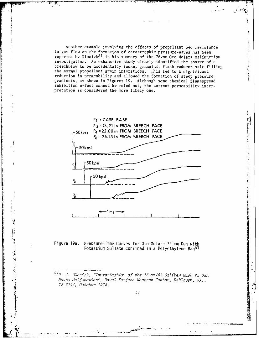
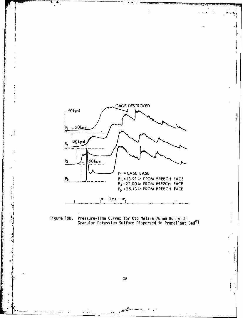
to Another example involving the effects of propellant bed resistanceto gas flow on the formation of catastrophic pressure-waves has beenreported by olenick5 l in his summary of the 76-mm Oto Melara malfunctioninvestigation. An exhaustive study clearly identified the source of abreechblow to be accidentally loose, granular, flash reducer salt fillingthe normal propellant grain interstices. This led to a significantreduction in permeability and allowed the formation of steep pressuregradients, as shown in Figures 19. Although some chemical flamespreadinhibition effect cannot be ruled out, the current permeability inter-
pretation is considered the more likely one.
PI =CASE BASE
P3 =13.91 in FROM BREECH FACE
50kpsi P4 =22.00in FROM BREECH FACEIP6 =25.13 in FROM BREECHF
50 kpsi
P37
P4 ~ ~ ~ ~ ~ ~ . .......... ...
S~P6
, -0-1 MS so
;, Figure 19a. Pressure-Time Curves for Oto Melara 76-mm Gun withPotassium Sulfate Confined in a Polyethylene Bag~l
"•,• 51P. J. Olenick., "Investigatio't of the 76-=1/62 Caliber Mark 75 Gun
• i Mount Malfunction",. Naval Surface Weapons Center, DahZgren, VA.,i TR 3144, October 1975.
F• 37
GAGE DESTROYED
P4P 4 22.00in FROM BREECH FACE
P6 =25.13 in FROM BREECH FACE
rn S
"Figure 19b. Pressure-Time Curves for Oto Melara 76-mm Gun withGranular Potassium Sulfate Dispersed in Propellant Bed 5 1
i.• 38
Il
i --
- S
The concept of flow channels around a charge, as opposed to throughthe propellant bed, has been exploited recently in the development of abase-ignited, intermediate-zone propelling charge for a 155-mm Armyhowitzer3 2 . For a variety of reasons, general practice has been todesign virtually full chamber diameter charges. For less than fullperformance charges, this may allow a substantial amount of free, forwardullage. In the loading density region of approximately 0.45 g/cm3 ,stretching the charge to full chamber length has been found to allow theuse of a simple, low-cost, iase ignition system. The full-bore diametercharge, however, virtually demands a reasonably well-functioning center-core ignition train. The reduced-diameter, chamber-length charge withsome breech standoff reduces the normally expected, localized, ignition-induced, pressure-wave potential by allowing rapid pressure equilibrationthroughout the chamber. As long as rigidity is maintained during theearly ignition phase, charge fluidization and grain pileup will notresult in loss of this powerful design approach for increasing permeability.A preliminary, pseudo-two-dimensional analysis by Gough 5 3 has confirmedthat a flow channel over a charge offers a significant pressure-wavereduction potential.
A special topic to be considered is the importance of permeabilityin the design of conventional bayonet primers. The observed deficienciesof standard primers led Vest et al. 54 , 5 to consider the use of specialprimer formulations extruded as strands. The natural flow channel typicalwith stick propellants also resulted in improved uniform gas venting overthe entire primer length. Extension of this work resulted in the useof Benite (Black Powder Extruded Nitrocellulose) strands 56 instead ofgranular black powder in Army bayonet primers.
52I. W. May and E. V. Clarke Jr., "The Reverse Chamber Pressure Gradient:
A Tool for Assessing the Effects of Wave Dynamics on the BallisticPerformance of Guns", Proceedings of the 2nd International Symposiumon Ballistics, American Defense Preparedness Assoc., Daytona Beach,
Fla., March 1976.
5 3 P. S. Gough, "The Influence of Annular Ullage and Bag Rupture on theBallistic Predictions of the NOVA Code", Paul Gough Associates, Inc.,Portsmouth, N.J., TR 77-4, September 1977.
5 4 D. C. Vest, E. V. Clarke, Jr., W. W. Shoemaker and W. F. Baker, "On
the Performance of Primers for Artillery Weapons", Ballistic ResearchLab., Aberdeen Proving Ground, MD., R852, March 1953. (AD #13294)
55D C. Vest, "A General Discussion of Extruded Igniter Compositions",Ballistic Research Lab., Aberdeen Proving Ground, MD, MR 894, June 1955.
4,• (AD #74459)
H. H. Hassmann, "Evaluation of Benite, An Extruded Form of Black Powder
"in Separate Loaded Ammunition", Picatinny Arsenal, Dover, N.J., R 1,SSeparate Loaded Ammunition", Picatinny Arsenal, Dover, N.J., R 1,SAugust 1958.
39
~:FW
D. Chamber and Charge Geometry
The importance of charge configuration on pressure-wave formationhas been discussed previously in terms of its effect on permeability andignition stimulus. As pointed out by Horst and Gough 5 7 , an additionalfactor mus: be kept in mind. That factor is the tendency of a chargeto allow motion of the propellant bed and subsequent pileup and compact-ion at an internal boundary such as the projectile base, the breech,or a closure plug is encountered. Compaction of a granular bed reducesporosity, decreases gas permeability, and increases the steepness of acombustion-driven pressure front. The reduced free volume caused by bedcompaction leads to enhanced reverse pressure gradients. Moreover, the
impact of the moving propellant and other solids such as closure plugsmay add significant additional stress to the projectile, besides thenormal gas pressure. A further undesirable consequence of propellant
motion and compaction is the possibility of grain fracture, leading toenhanced mass burning rate via the increased exposed surface area.
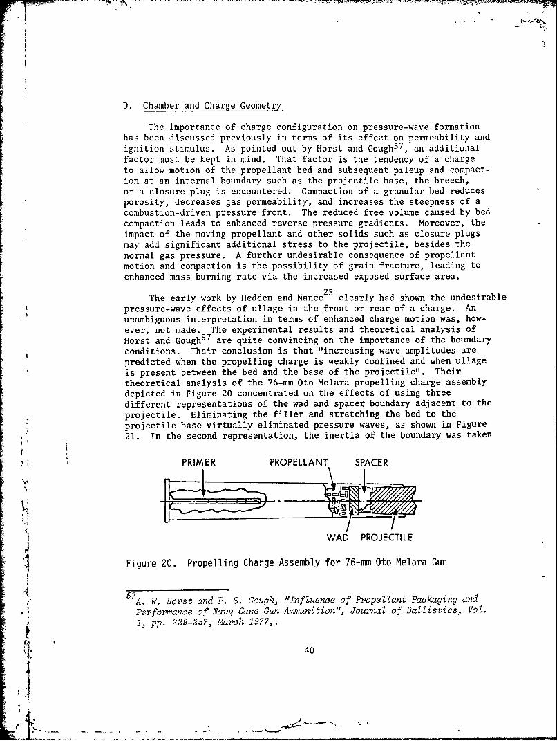
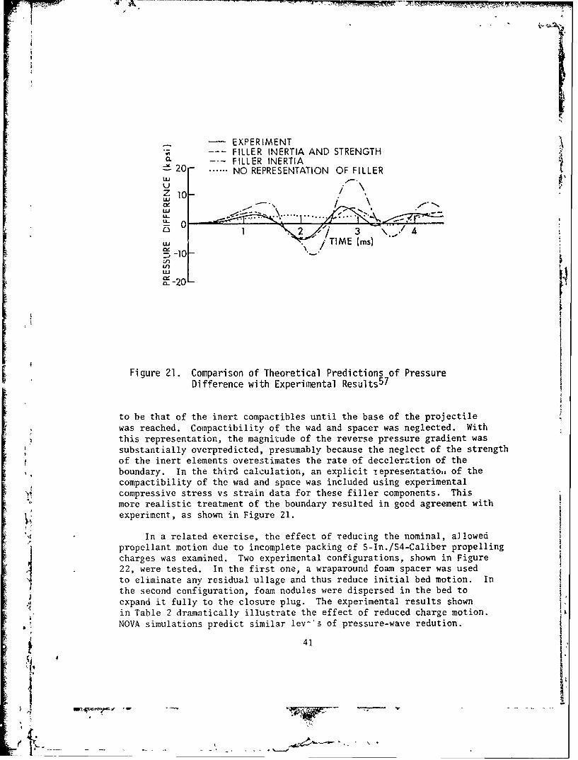
The early work by Hedden and Nance25 clearly had shown the undesirablepressure-wave effects of ullage in the front or rear of a charge. AnF unambiguous interpretation in terms of enhanced charge motion was, how-ever, not made. The experimental results and theoretical analysis ofHorst and Gough 5 7 are quite convincing on the importance of the boundaryconditions. Their conclusion is that "increasing wave amplitudes arepredicted when the propelling charge is weakly confined and when ullageis present between the bed and the base of the projectile". Theirtheoretical analysis of the 76-nm Oto Melara propelling charge assemblydepicted in Figure 20 concentrated on the effects of using threedifferent representations of the wad and spacer boundary adjacent to theprojectile. Eliminating the filler and stretching the bed to theprojectile base virtually eliminated pressure waves, as shown in Figure21. In the second representation, the inertia of the boundary was taken
PRIMER PROPELLANT SPACER
WAD PROJECTILE
4 Figure 20. Propelling Charge Assembly for 76-mm Oto Melara Gun
5 7 A. W. Horst and P. S. Gcugh, "Influence of Propellant Packaging andPerformance of Navy Case Gun Ammunition", Journal of Ballistics, Vol.1, pp. 229-257, March 1977,.
40
.. . . . . . .... - _ _.
!I-•EXPERIMENT
"FILLER INERTIA AND STRENGTHFILLER INERTIA
0 ... ..... NO REPRESENTATION OF FILLERu- Ii \ ,V IUz 10-
LU
3 \1 - 4LU TIME (ms)•-10 "•
i - Vu
IIFigure 21. Comparison of Theoretical Predictions of Pressure
Difference with Experimental Results 57
to be that of the inert compactibles until the base of the projectilewas reached. Compactibility of the wad and spacer was neglected. Withthis representation, the magnitude of the reverse pressure gradient wassubstantially overpredicted, presumably because the neglect of the strengthof the inert elements overestimates the rate of deceleration of theboundary. In the third calculation, an explicit tepresentatioa of thecompactibility of the wad and space was included using experimentalcompressive stress vs strain data for these filler components. Thismore realistic treatment of the boundary resulted in good agreement withexperiment, as shown in Figure 21.
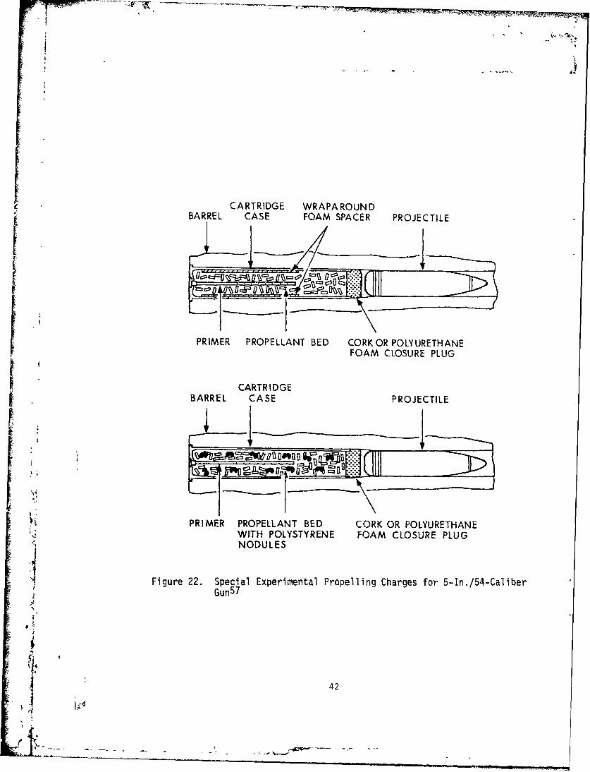
In a related exercise, the effect of reducing the nominal, allowedpropellant motion due to incomplete packing of S-In./S4-Caliber propellingcharges was examined. Two experimental configurations, shown in Figure
22, were tested. In the first one, a wraparound foam spacer was usedto eliminate any residual ullage and thus reduce initial bed motion. Inthe second configuration, foam nodules were dispersed in the bed to
2 •expand it fully to the closure plug. The experimental results shownin Table 2 dramatically illustrate the effect of reduced charge motion.NOVA simulations predict similar lev-'s of pressure-wave redution.
41 1
CARTRIDGE WRAPAROUNDBARREL CASE FOAM SPACER PROJECTILE
PRIMER PROPELLANT BED CORK OR POLYURETHANE
"FOAM CLOSURE PLUG
I, C.ARTRIDGE
BARREL CASE PROJECTILE
PRIMER PROPELLANT BED CORK OR POLYURETHANEWITH POLYSTYRENE FOAM CLOSURE PLUGNODULES
Figure 22. Special Experimental Propelling Charges for 5-In./54-CaliberGun 5 7
f
42
.wo
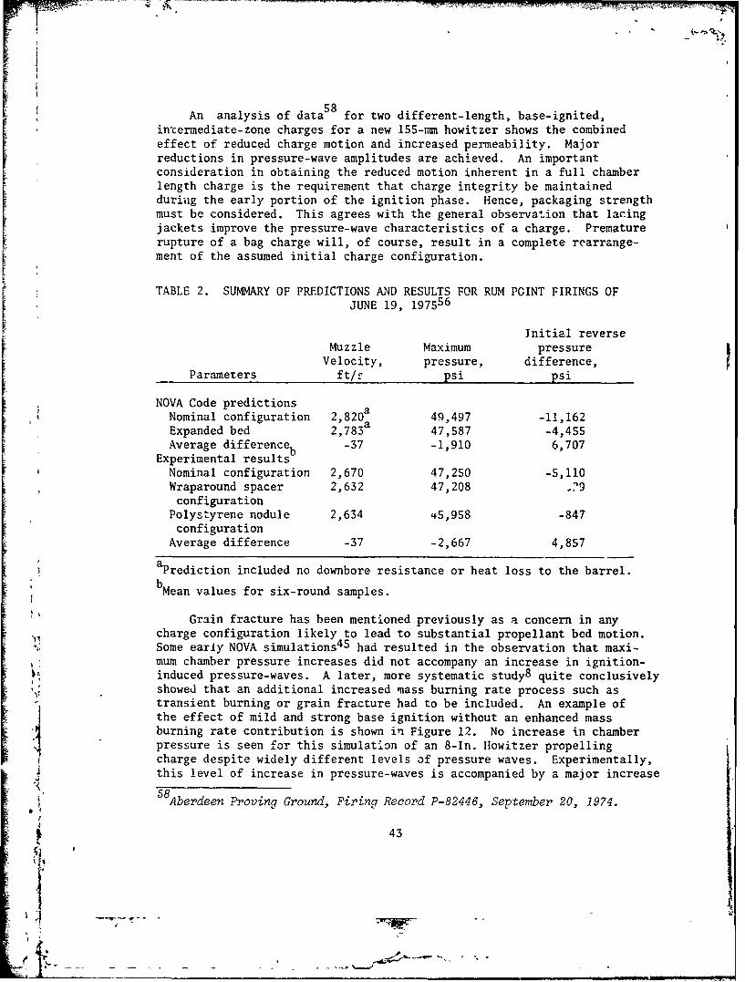
587 i An analysis of data for two different-length, base-ignited,intermediate-zone charges for a new 155-mm howitzer shows the combinedeffect of reduced charge motion and increased permeability. Majorreductions in pressure-wave amplitudes are achieved. An importantconsideration in obtaining the reduced motion inherent in a full chamberlength charge is the requirement that charge integrity be maintained
during the early portion of the ignition phase. Hence, packaging strengthmust be considered. This agrees with the general observation that lacingjackets improve the pressure-wave characteristics of a charge. Prematurerupture of a bag charge will, of course, result in a complete rearrange-ment of the assumed initial charge configuration.
TABLE 2. SUMMARY OF PREDICTIONS AND RESULTS FOR RUM POINT FIRINGS OF
JUNE 19, 197556
Initial reverseMuzzle Maximum pressure
Velocity, pressure, difference,Parameters ft/f psi psi
NOVA Code predictions aNominal configuration 2 , 8 20a 49,497 -11,162Expanded bed 2,783 47,587 -4,455Average difference -37 -1,910 6,707
Experimental resultsbSNominal configuration 2,670 47,250 -5,110
Wraparound spacer 2,632 47,208 2?9configuration
Polystyrene nodule 2,634 45,958 -847configuration
Average difference -37 -2,667 4,857
aPrediction included no downbore resistance or heat loss to the barrel.
bMean values for six-round samples.
Grain fracture has been mentioned previously as a concern in anycharge configuration likely to lead to substantial propellant bed motion.Some early NOVA simulations 4 5 had resulted in the observation that maxi-mum chamber pressure increases did not accompany an increase in ignition-induced pressure-waves. A later, more systematic study8 quite conclusivelyshowed that an additional increased mass burning rate process such astransient burning or grain fracture had to be included. An example ofthe effect of mild and strong base ignition without an enhanced massburning rate contribution is shown in Figure 12. No increase in chamberpressure is seen for this simulation of an 8-In. Howitzer propellingcharge despite widely different levels of pressure waves. Experimentally,this level of increase in pressure-waves is accompanied by a major increase
5 8 Aberdeen Proving Ground, Firing Record P-82446, September 20, 1974.
Z 43
4
in maximum chamber pressure for a low-temperature-conditioned charge;
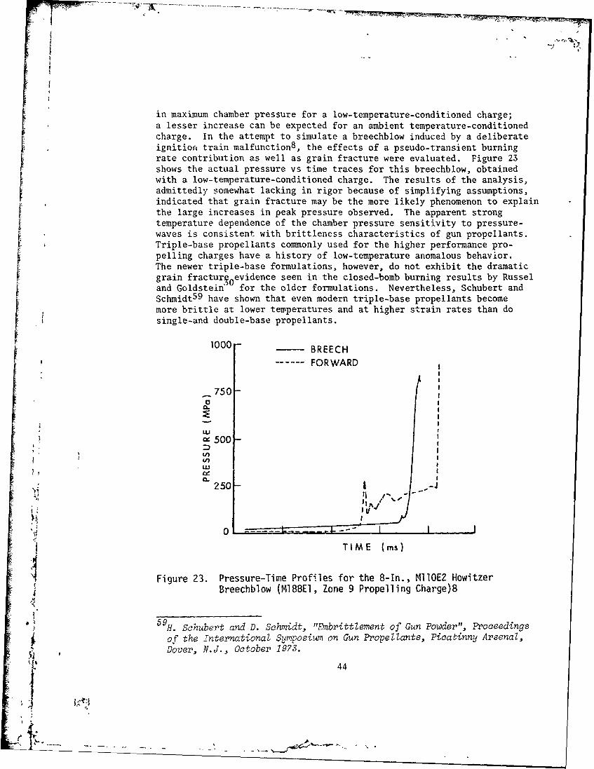
a lesser increase can be expected for an ambient temperature-conditionedcharge. In the attempt to simulate a breechblow induced by a deliberateignition train malfunction8 , the effects of a pseudo-transient burningrate contribution as well as grain fracture were evaluated. Figure 23shows the actual pressure vs time traces for this breechblow, obtainedwith a low-temperature-conditioned charge. The results of the analysis,admittedly somewhat lacking in rigor because of simplifying assumptions,indicated that grain fracture may be the more likely phenomenon to explainthe large increases in peak pressure observed. The apparent strongtemperature dependence of the chamber pressure sensitivity to pressure-waves is consistent with brittleness characteristics of gun propellants.Triple-base propellants commonly used for the higher performance pro-pelling charges have a history of low-temperature anomalous behavior.The newer triple-base formulations, however, do not exhibit the dramaticgrain fracturioevidence seen in the closed-bomb burning results by Russeland Goldstein* for the older formulations. Nevertheless, Schubert andSchmidt 5 9 have shown that even modern triple-base propellants becomemore brittle at lower temperatures and at higher strain rates than dosingle-and double-base propellants.
1000 BREECH
---- FORWARD
_75O-
w 500
Lo
250-1.
0 - j
TIME (ms)
Figure 23. Pressure-Time Profiles for the 8-1n., MIIOE2 HowitzerBreechblow (MIB8EI, Zone 9 Propelling Charge)8
-59
H. Schubert and D. Schmidt, "Embrittlement of Gun Powder", Proceedings
of the international Symposium on Gun Propellants, Picatinny Arsenaz,Dover, N.J., October 1973.
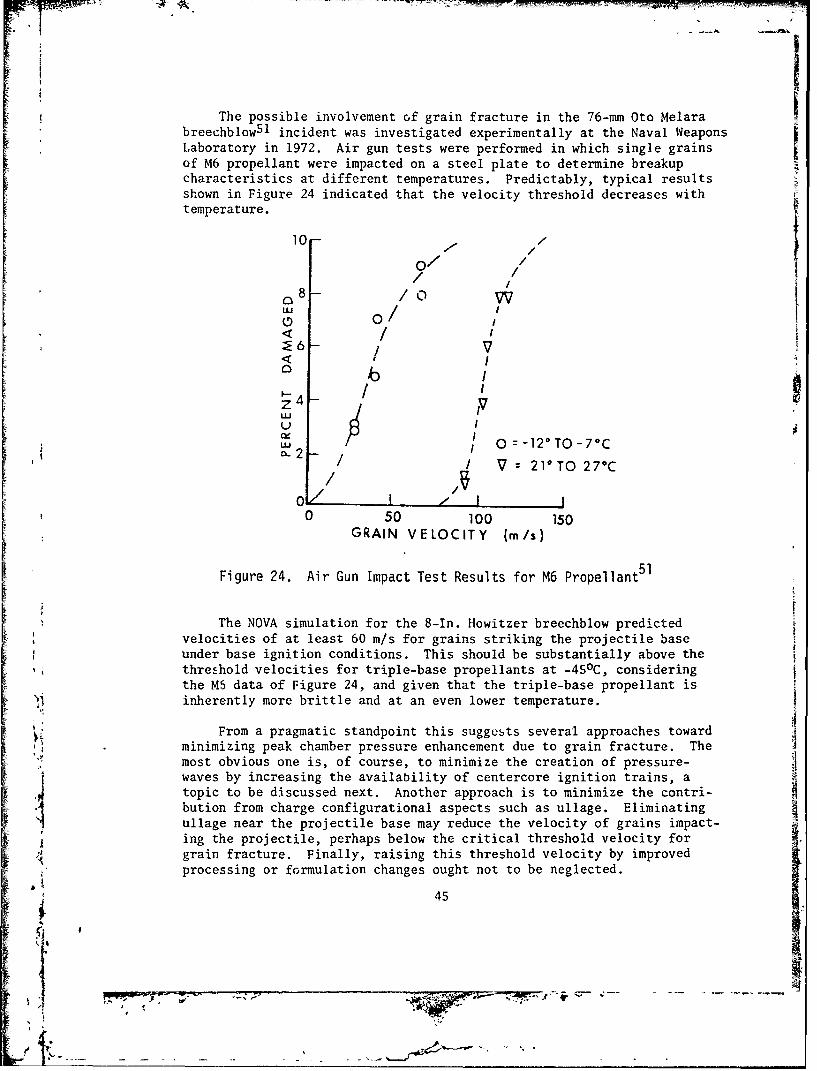
The possible involvement of grain fracture in the 76-mm Oto Melarabreechblow51 incident was investigated experimentally at the Naval WeaponsLaboratory in 1972. Air gun tests were performed in which single grainsof M6 propellant were impacted on a steel plate to determine breakupcharacteristics at different temperatures. Predictably, typical resultsshown in Figure 24 indicated that the velocity threshold decreases withtemperature.
10 -
/ /
/0 /:E /6 -!
0 I
U IU
i 0 0-12 0 TO-70CS / / V 21°T0 27°C
0! 1 - I I0 50 100 150
GRAIN VELOCITY (m/s)
Figure 24. Air Gun Impact Test Results for M6 Propellant 5 1
The NOVA simulation for the 8-In. Howitzer breechblow predictedvelocities of at least 60 m/s for grains striking the projectile baseunder base ignition conditions. This should be substantially above thethreshold velocities for triple-base propellants at -45 0C, consideringthe MS data of Figure 24, and given that the triple-base propellant isinherently more brittle and at an even lower temperature.
From a pragmatic standpoint this suggests several approaches towardminimizing peak chamber pressure enhancement due to grain fracture. Themost obvious one is, of course, to minimize the creation of pressure-waves by increasing the availability of centercore ignition trains, atopic to be discussed next. Another approach is to minimize the contri-bution from charge configurational aspects such as ullage. Eliminatingullage near the projectile base may reduce the velocity of grains impact-ing the projectile, perhaps below the critical threshold velocity forgrain fracture. Finally, raising this threshold velocity by improved
C" processing or formulation changes ought not to be neglected.
45
-! - .
In addition to contributing to propellant grain fracture, chargemotion and compaction introduce a related safety concern for the survivalof the projectile. The response of a projectile and its components tothe impact of a closure plug or the propellant bed itself is a complexsubject of great concern during the past few years. A classic exampleof the importance of the charge/projectile interface is found in the5-In./38-Caliber Gun premature study by Culbertson et al. 6 0 and the8-In./SS-Caliber Gun close-aboard malfunction investigation by Sbamblenand O'Brasky6 1 . In both instances, the causes of projectile malfunctionswere shown to be related directly to shock excitation of the projectileresulting fiom charge component impact induced by high-amplitude pressurewaves.
The origin of the pressure-wave problem causing the 5-In./38-CaliberGun malfunctions has been discussed in the previous section on permea-bility. Data reported by Soper 6 2 from flash radiograph-instrumentedexperiments performed with fiberglass chambers indicated that the forwardboundary of the NACO propellant bed accelerated to a velocity of about250 m/s at closure plug impact onto the projectile base. The shock ex-citation produced by this impact was sufficient to initiate the high-explosive fill. The analysis by Soper also indicates that the peak stresslevel on the projectile base due to impact was about 35 kpsi, whereas themeasured gas pressure in a sidewall gage was only about 1/5 of thisvalue. Although quantitative measurements in such an environment may beopen to question, the point to be made is that normal gas pressuremeasurements in a high-amplitude pressure-wave environment do not allowan adequate assessment of the interior ballistic forcing function actingon a projectile. Instrumented projectile measurements are necessary.
Shamblen and O'Brasky61 attributed fuze malfunctions observed withthe 8-In./55-Caliber reduced charge to shock excitation of the projectileby propelling charge component impact. Interestingly, the reduced chargewith much increased forward ullage provided a more severe shock acceler-ation environment than did the higher-performance full service charge.The change to a larger granulation propellant with increased permeabilityand reduced initial mass burning rate eventually provided a more accept-able shock loading environment similar to tl~at of the full service charge.
60 D. W. Culbertson, M. C. Shamblen and J. S. O'Brasky, "Investigation
of 5"/38 Gun In-Bore Ammunition Malfunctions", Naval Weapons Lab.,Dahlgren, VA., TR-2624, December 1971.
61M. C. Shamblen and J. S. O'Brasky, "Investigation of 8"/55 Close AboardMalfunctions", Naval Weapons Lab., Dahlgren VA., TR-2753, April 1973.
W. G. Soper, "Ignition Waves in Gun Chambers", Combustion and Flame,
Vol. 20(2), April 1973, pp. 157-162.
46'46
IMP
A recent concern has been the influence of certain chamber-geometryfactors on the development of pressure waves. These include the effectsof area reduction due to chambrage, forcing cones, normal projectileboattails, breech details, and, perhaps most importantly, area reductionassociated with long, fin-stabilized projectiles with tapered bodiespenetrating deeply into the propellant bed. Given some initial pressure-wave formation from an ignition stimulus, pressure-wave focusing andgrowth are to be expected with, perhaps, enhanced bed compaction andgrain fracture. An unusually high sensitivity of peak chamber pressureto rather modest levels of pressure waves recently has been observed forsuch a fin-stabilized projectile. This observation has been rationalizedon the basis of pressure-wave focusing. A theoretical analysis is inprogress.
V. RELIABLE GUN IGNITION
The primary concern over pressure wa'es during the past half dozenF years has been with safety hazards such as breechblows and prematures.F- Failure rates for such catastrophic events normally are required to be i,
lower than one per million. This safety reliability requirement places
a difficult burden on the propulsion system designer, as well as on thettest and evaluation agency that has to safety-certify a munitions itemon the basis of minimal testing.
This problem is particularly acute for high-performance bag chargedesigns using granular propellant. Typically such charges require complex,low-pressure, centercore ignition trains as shown in Figure 5. The high-pressure, bayonet primers commonly used in cased ammunition generallyare designed more easily to function with great reliability as far astiming and spatial distribution of output are concerned. The experimentaltechniques and approaches used by Smith3 9 and earlier by Vest et al. 5 4
have shown the proper methodology to be used in the design and testingof reliable, high-pressure bayonet primers. The fact that far from ideal,K high-pressure primers are found in many fielded gun systems is not dueto a lack of basic understanding.1 i For low-pressure, combustible, centercore ignition trains, thecurrent understanding and practice do not appear to be nearly as well inhand. The reasons for this situation include the following: theintrinsic geometry variability of bag charge systems; the sensitivityof the several ignition transfer events occurring at low pressures tovariability of cloth barriers; the intrinsic flamespread variability ofblack powder, the most commonly used material; and, finally, the lack of: a well-developed, simple diagnostic technique that allows an unambiguousfunctional evaluation of centercore ignition tra .as. The recent work by
47
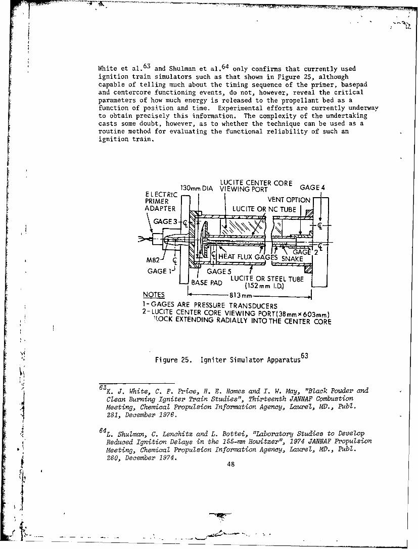
White et al. 6 3 and Shulman et al. 6 4 only confirms that currently usedignition train simulators such as that shown in Figure 25, althoughcapable of telling much about the timing sequence of the primer, basepadand centercore functioning events, do not, however, reveal the criticalparameters of how much energy is released to the propellant bed as afunction of position and time. Experimental efforts are currently underwayto obtain precisely this information. The complexity of the undertakingcasts some doubt, however, as to whether the technique can be used as aroutine method for evaluating the functional reliability of such anI ignition train.
LUCITE CENTER CORE130rm DIA VIEWING PORT GAGE4
PRIMRC VENT OPTIONADAPTER I- LUCITE OR NCUB
•,: ~~~~GAGE 31-- '/GAE
'~~ L (152m 2..
BASE PAD LUCITE OR STEEL TUBE
NOTES 813mm1-GAGES ARE PRESSURE TRANSDUCERS2-LUCITE CENTER CORE VIEWING PORT(38mmx603mm)
,LOCK EXTENDING RADIALLY INTOTHE CENTER CORE
Figure 25. Igniter Simulator Apparatus 6 3
6 3K. J. White, C. F. Price, H. E. Homes and I. W. May, "Black Powder and
Clean Burning Igniter Train Studies", Thirteenth JANNAF CombustionMeeting, Chemical Propulsion Information Agency, Laurel, MD., Publ.281, December 1976.
"6 4 L. Shulman, C. Lenchitz and L. Bottei, "Laboratory Studies to Develop
Reduced Ignition Delays in the 155-mm Howitzer", 1974 JANNAF PropulsionMeeting, Chemical Propulsion Information Agency, Laurel, MD., Publ.260, December 1974.. 48
~' I
Basically, a typical centercore ignition train should function inthe following manner. A primer jet of hot gases and particles impingeson the base pad and ignites it. With perfect alignment between theprimer vent and the centercore, the jet may puncture through the basepad into the centercore and ignite the cloth-covered, black-powder-filledsnake. With some offset in the alignment, the basepad's function isto burn through the cloth layers and ignite the snake, which then ignitesthe propellant bed.
63White et al. have discussed the effects of primer total energy
output and rate of delivery, the effect of primer vent exit configuration,charge standoff, the effect of cloth barriers, alignment, and blackpowder distribution in the snake. Shulman et al.6& have discussed theeffects of black powder quickness on centercore functioning. Recentdata suggest that manufacturing tolerances for the same class of blackpowder are so wide that a factor of two difference in quickness is possible.Such differences could have disastrous results in shifting the delicatebalance of centercore flamespread times toward earlier propellant bedignition. It also has been shown that the cloth characteristics of thebasepad and snake can have a significant effect on the ignition transferfrom the base pad to the snake. In fact, a cloth change made to improvesturdiness at one point in the development of a charge for a new 155-mmhowitzer resulted in a low-temperature hangfire in which the propellantfinally was ignited before the centercore. A breechblow resulted!
An example of the effect of charge standoff on centercore function-ing is shown in Figure 26 for an intermediate-performance, 155-mmpropelling charge 6 5. The highest level of pressure waves was obtained
1600 /155F
S1200 7
< 800 ,' .+-65°F
400 -
0 2 4 6 8 10STANDOFF (in)
Figure 26. Effect of Standoff on the Amplitude of -APi65
65E. V. Clarke, I. W. May and J. R. Kelso, "Effects of Pressure-Wave
Dynamics on The 3allistic Performance of Guns", Ballistic Research Lab.,Aberdeen Proving Ground, MD., I14R 311, November 1974.
49
SI
with the charge contacting the breech face (zero standoff) and whencontacting the projectile base (20-cm standoff). At 2- to 5-cm standoff,a minimum appears to exist. In addition, the pressure-wave level tendsto decrease with temperature. The most pllusible explanation for theseobservations is that, at zero standoff, the effects of primer-jet center-core misalignment should be most pronounced, the local breech pressuriz-ation is greatest, and the impact of charge motion should be more severe.At the intermediate standoffs, the primc jet plume has a chance toexpand, thus reducing the effects of primer-centercore offset. Theadditional free volume in the breech region also will reduce thepressurization effects, as well as initial charge motion. At maximumstandoff, the primer jet is thought to be too weak to penetrate throughthe centercore efficiently. Because of the large free volume, thepressurization rate is low, ignition delays are long, and heating ofignition materials (such as Benite or black powder) and propellantgenerally favors propellant ignition. During a 153-mm howitzer malfunct-ion investigation, the effect of primer-centercore misalignment wasexamined. Results reported by Hassmann and Yerma1 6 6 , at least in thisinztance, clearly showed that reduced and more reproducible ignition
Sdelays aczompanied those charges fired with the improved alignment.
The difficulties encountered in the design of an extremely low-
pressure reliable centercore ignition system lead to the followingconclusion: a breakthrough in design is clearly desirable. The clothbarriers m~ust be eliminated. The geometry variabilities of bag charge
diameter, length, and relative chamber location must be reduced. A morereproducible, predictable igniter material with superior ignition andflamespread characteristics is clearly desirable. At the same time, allof the design approaches previously discussed should be implemented tominimize the effects of a malfunctioning centercore ignition train. Amore detailed discussion of implementing these conclusions has beenpresented recently by Rocchio et al. 6 7 in the context of combustiblecase artillery charges.
If As indicated before, a real problem exists in evaluating the safetyreliability of a propelling charge. Largely on the basis of an observedsensitivity of peak chamber pressure to initial reverse pressure differ-ence sensitivity curve developed by Clarke et al. 6 5 for a 155-mm howitzer,a new failure rate estimation technique currently is being tested inthe U.S. Army. Essentially, it can be summarized as follows 8 :
66H. Hassma,.n and A. Yermal, "Controlled Ballistic Firing at Aberdeen
Proving Ground Relating to Malfunction Investigation of 155-mm PropellingCharge, XM123E1, in 155-mm Towed Howitzer, XM198", Picatinny Arsenal,S• Dover, N.J., July 1973.
J. Rocchio, C. R. Ruth, I. W. May and K. J. White, "A Consumable Casefor Artillery Systems", 1978 JANNAF Propulsion Meeting, ChemicalPropulsion Information Agency, Laurel, MD., Publ. 293, February 1978.
Is
1) Charge design sensitivity firings are conducted to determine1the relationship between -APi and maximum chamber pressure for thatcharge/temperature/weapon combination. Intentionally defeated centercorecharges may be included in this series to assure that data from a local-ized-ignition/high-pressure-wave firing can be obtained with a reasonablenumber of tests.
2) A failure criterion is identified, usually in terms of some
maximum permissible chamber pressure, dictated most often by breech orpayload failure levels.
3) This failure level is reinterpreted in terms of a -APi level,determined from the sensitivity curve developed in step 1.
4) A firing data base then is obtained which is believed to berepresentative of "real world" propelling charges, typical of those tobe fielded for use.
5) The probability of failure (as defined in step 3) then can bedetermined statistically with res,,ect to the distribution of -APi valuesfrom step 4.
Thus, a -APi failure level tailored to the sensitivity of theparticular system of interest is employed. Application of this procedurecan be described briefly with respect to the 175-mm, M107 Gun. Therelationship between -APi and maximum chamber pressure for M86A2 (Zone3) Charges fired in the M107 Gun, based on charge design sensitivityfirings, is presented in Figure 27. A -APi failure criterion also canbe identified on this curve, corresponding to known breech failurepressure levels. Figure 28 then presents the cumulative distribution of-APi levels for a data base considered to represent a typical sample ofreal-world changes. The probability of achieving the -APi failure level,as determined using Kolmogorov-Smirnov statistics for two differentpopulation distribution functions, is presented in Figure 29. Althoughconfidence levels associated with this statistical procedure are quitelow, the prediction of one failure in about half a million firingscompares quite favorably with historical data of half a dozen breechblowsin some two and one-half million firings to date. This agreement,
- - although satisfying, must be considered somewhat fortuitous.
V VI. CONCLUSION
The preceding sections have attempted to summarize the salientfeatures of pressure-wave phenomenology in guns. The progress in ourexperimental and theoretical understanding of the physics of pressurewaves has indeed been satisfying. The two old, opposing attitudes of"all pressure-waves are unacceptable" and "we haven't blown a gun yetwith this charge, so why should we worry" are being replaced slowlywith a more thorough understanding of the complex interactions of the
' .critical parameters, allowing a more reasoned analysis for each system
I51
-7t.
800-
-BREECH FAILURE---
, 600
,n
a_F 400
x
200.0 100 200
-APi (MPa)
Figure 27. Pressure-Wave Sensitivity for the 175-mm, M107 Gun(M86A2, Zone 3 Propelling Charge) 8
-API (MPa)0 10 20 30 40
z0 1.0-
ca~i.: ' • - -O.8 -
Fx " • 0.48
S0.2U
G 00 2 4 64_ . -APi (kpsi)
Figure 28. Distribution of Pressure-Wave Amplitudes f r the 175-mm,
M107 Gun (M86A2, Zone 3 Propelling Charge)•
52
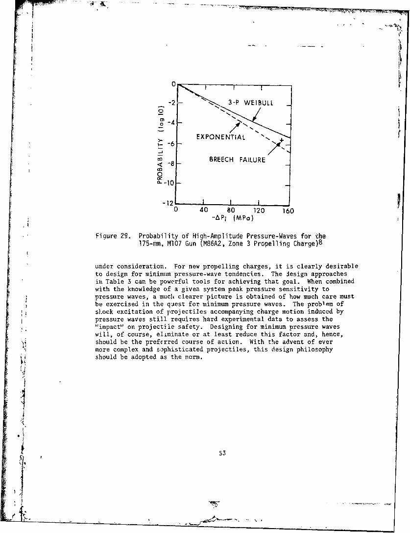
|N
i0
-2. 3-P EBLo -0-4
1 /T
>_ EXPONENTIAL +-
"ca BREECH FAILURE<-8
0
-12L I0 40 80 120 160
-APi (MPo)
Figure 29. Probability of High-Amplitude Pressure-Waves for the175-mm, M107 Gun (M86A2, Zone 3 Propelling Charge)8
under consideration. For new propelling charges, it is clearly desirableto design for minimum pressure-wave tendencies. The design approachesin Table 3 can be powerful tools for achieving that goal. When combinedwith the knowledge of a given system peak pressure sensitivity topressure waves, a much clearer picture is obtained of how much care must
.= be exercised in the quest for minimum pressure waves. The problem ofst.ock excitation of projectiles accompanying charge motion induccd bypressure waves still requires hard experimental data to assess the"impact" on projectile safety. Designing for minimum pressure waveswill, of course, eliminate or at least reduce this factor and, hence,should be the preferred course of action. With the advent of evermore complex and sophisticated projectiles, this design philosophy"should be adopted as the norm.
53
-I,
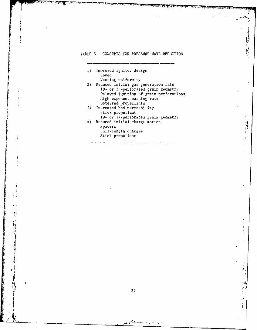
TABLE 3. CONCEPTS FOR PRESSURE-WAVE REDUCTION4
1) Improved igniter designSpeedVenting uniformity
2) Reduced initial gas generation rate19- or 37-perforated grain geometryDelayed ignition of grain perforationsIHigh exponent burning rateDeterred propellants
5) Increased bed permeability
Stick propellant19- or 37-perforated -rain geometry
4) Reduced initial charg( motion :
SpacersFull-length chargesStick propellant
j
54
JI
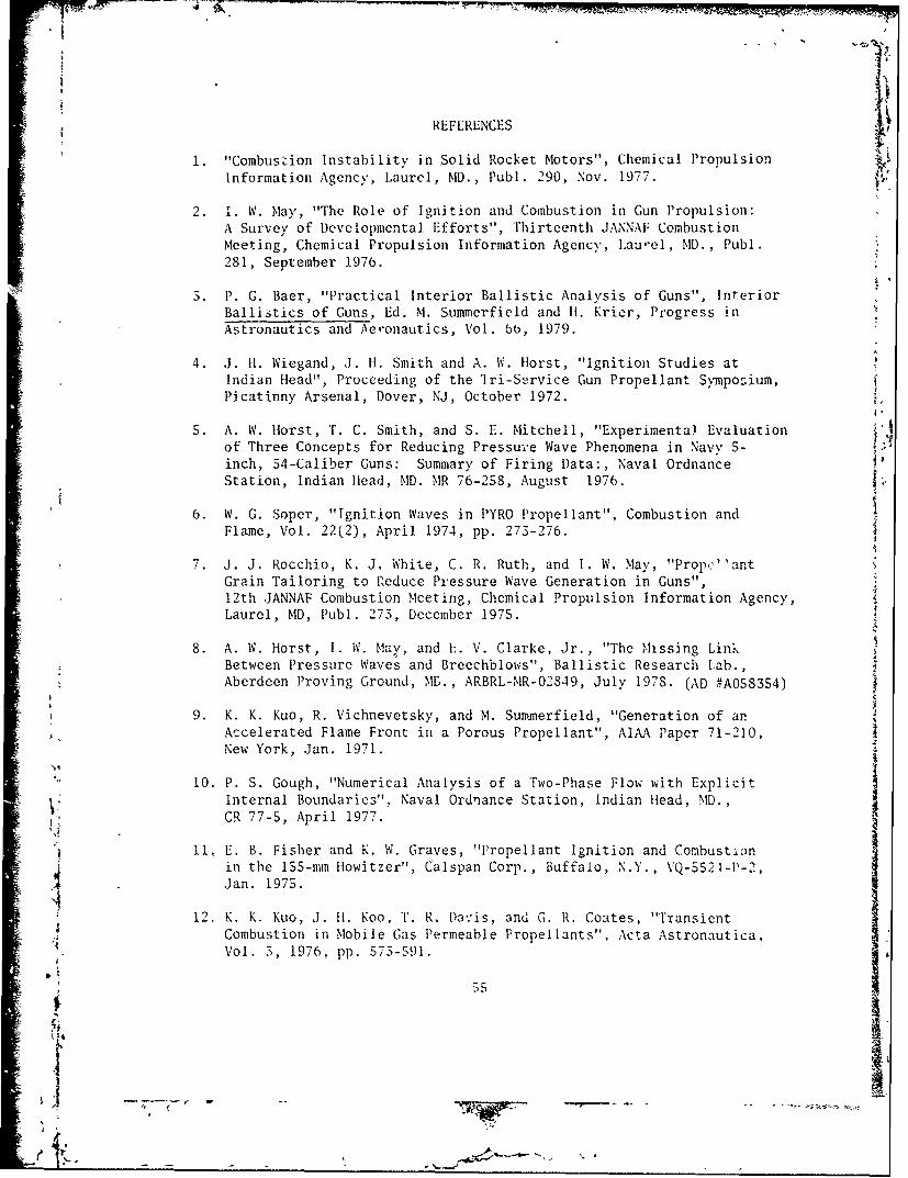
. , !,
REFERENCES
1. "Combuszion Instability in Solid Rocket Motors", Chemical PropulsionInformation Agency, Laurel, MD., Publ. 290, Nov. 1977.
2. 1. W. May, "The Role of Ignition and Combustion in Gun Propulsion:A Survey of Developmental Efforts", Thirteenth JANNAF CombustionMeeting, Chemical Propulsion Information Agency, Lau-el, MD., Publ.281, September 1976.
3. P. G. Baer, "Practical Interior Ballistic Analysis of Guns", InteriorBallistics of Guns, Ed. M. Summerfield and li. Krier, Progress inAstronautics and Aeronautics, Vol. bb, 1979.
4. J. H. Wiegand, J. H1. Smith and A. IV. llorst, "Ignition Studies atIndian Head", Proceeding of the 'lri-Service Gun Propellant Symposium,Picatinny Arsenal, Dover, NJ, October 1972.
5. A. W. Horst, T. C. Smith, and S. E. Mitchell, "Experimental Evaluationof Three Concepts for Reducing Pressur:e Wave Phenomena in Navy 5-inch, 54-Caliber Guns: Summary of Firing Data:, Naval OrdnanceStation, Indian Head, MD. MR 76-258, August 1976.
6. W. G. Soper, "Ignition Waves in PYRO Propellant", Combustion andFlame, Vol. 22(2), April 1974, pp. 273-276.
7. J. J. Rocchio, K. J. White, C. R. Ruth, and I. W. May, "Propc''antGrain Tailoring to Reduce Pressure Wave Generation in Guns",12th JANNAF Combustion Meeting, Chemical Propulsion Information Agency,Laurel, MD, Publ. 273, D)ecember 1975.
8. A. W. Horst, I. W. May, and h. V. Clarke, Jr., "The Missing LinkBetween Pressure Waves and Breechblows", Ballistic Research Lab.,Aberdeen Proving Ground, M., ARBRL-MR-02849, July 1978. (AD #A058354)
9. K. K. Kuo, R. Vichnevetsky, and M. Suminerfield, "Generation of anAccelerated Flame Front in a Porous Propellant", AIAA Paper 71-210,New York, Jan. 1971.
10. P. S. Gough, "Numerical Analysis of a Two-Phase Flow with ExplicitInternal Boundarie3", Naval Ordnance Station, Indian Head, MD.,CR 77-5, April 1977.
"11, E. B. Fisher and K. W. Graves, "Propellant Ignition and Combustionin the 155-mm Howitzer", Calspan Corp., Buffalo, N.Y., VQ-5521-P-2,Jan. 1975.
S12. K. K. Kuo, J. H!. Koo, T. R. Dav;is, and G. R. Coates, "TransientCombustion in Mobile Gas Permeable Propellants", Acta Astronautica,
Vol. 3, 1976, pp. 573-591.
-- 5Ir
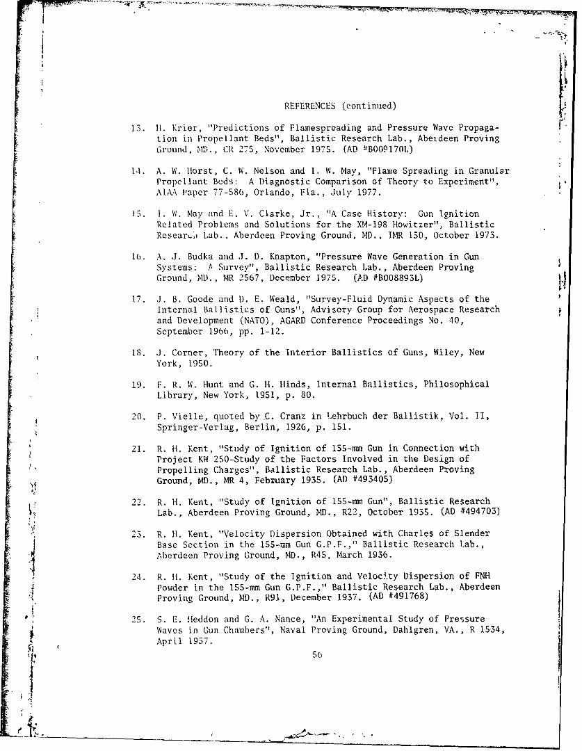
i% S -
REFERENCES (continued)
13. II. Krier, "Predictions of Flamespreading and Pressure Wave Propaga-tion in Propellant Beds", Ballistic Research Lab., Abeideen ProvingGround, MD'., CR 275, November 1975. (AD ftBO0917OL)
14. A. W. IHorst, C. W. Nelson and I. W. May, "Flame Spreading in GranularPropellant Beds: A Diagnostic Comparison of Theory to Experiment",AIA:\ Paper 77-586, Orlando, Fla., July 1977.
iS. i. W. May and E. V. Clarke, Jr., "A Case History: Gun IgnitionRelated Problems and Solutions for the XM-198 Howitzer", BallisticResearch Lab., Aberdeen Proving Ground, MD.. IMR 150, October 1973.
lb. A. J. Budka and J. D. Knapton, "Pressure Wave Generation in GunSystems: A Survey", Ballistic Research Lab., Aberdeen ProvingGround, MD., MR 2567, December 1975. (AD #B008893L)
17. J. B. Goode and D. E. Weald, "Survey-Fluid Dynamic Aspects of theInternal Ballistics of Guns", Advisory Group for Aerospace Researchand Development (NATO), AGARD Conference Proceedings No. 40,September 1966, pp. 1-12.
18. J. Corner, Theory of the Interior Ballistics of Guns, Wiley, NewYork, 1950.
19. F. R. W. Hunt and G. H. Hinds, Internal Ballistics, PhilosophicalLibrary, New York, 1951, p. 80.
20. P. Vielle, quoted by.C. Cranz in Lehrbuch der Ballistik, Vol. II,Springer-Verlag, Berlin, 1926, p. 151.
21. R. H. Kent, "Study of Ignition of 155-mm Gun in Connection withProject KW 250-Study of the Factors Involved in the Design ofPropelling Charges", Ballistic Research Lab., Aberdeen Proving
Ground, MD., MR 4, Febvuary 1935. (AD #493405)
22. R. H. Kent, "Study of Ignition of 155-mm Gun", Ballistic ResearchLab., Aberdeen Proving Ground, MD., R22, October 1935. (AD #494703)
23. R. H1. Kent, "Velocity Dispersion Obtained with Charles of SlenderBase Section in the 155-mm Gun G.P.F.," Ballistic Research Lab.,Aberdeen Proving Ground, MD., R45, March 1936.
24. R. It. Kent, "Study of the Ignition and Veloci.ty Dispersion of FNH' I Powder in the 155-mm Gun G.P.F.," Ballistic Research Lab., Aberdeen
Proving Ground, MD., R91, December 1937. (AD #491768)
)i2S. S. E. Hleddon and G. A. Nance, "An Experimental Study of PressureWaves in Gun Chambers", Naval Proving Ground, Dahlgren, VA., R 1534,
April 1957.
56
REFERENCES (continued)
26. N. Bauman and E'. Bird, "Ignition Problems in Separate-LoadingAmmunition", Joint Army-Navy-Air Force Second Symposium on PropellantIgnition, Vol. II, Solid Propellant Information Agency, SilverSpring, MD., October 1956.
27. L. Gowen and E. Elzufon, "A Reveiw of Igniter Studies and TheirApplication to Igniter Design", Joint Army-Navy-Air Force SecondSymposium on Solid Propellants, Vol. II, Solid Propellant InformationAgency, Silver Spring, MD., October 1956.
28. N. Lockett, "British Work on Solid Propellant Ignition", Bulletinof the First Symposium on Solid Propellant Ignition, Solid PropellantInformation Agency, Silver Spring, MD., September 1953.f 29. "Ignition Study of Gun, 76-mm, T91", Aberdeen Proving Ground, Firing
LRecord P-52014, Project TA1l302. February 1952.
30. K. H. Russel and H. N, Goldstein, "Investigation and Screening ofI M17 Propellant Production for Lots Subject to Poor Low Temperature
Performance", Picatinny Arsenal, Dover, NJ., DB-TR-7-61, June 1961.
31. J. R. Lane, "Sub-Zero Firings in the 76-mm Gun", Ballistic ResearchLab., Aberdeen Proving Ground, MD., MR 215, September 1943.
i (AD #493524)
32. T. G. Hughes, "Product Improvement Test of Charge, Propelling M86AI,for 175-mm Gun, MIt3", Ballistic Research Lab., Aberdeen ProvingGround, MD., DPS-2351, April 1967.
33. P. Gough, "Modeling of Two-Phase Flow in Guns", "Interior Ballisticsof Guns", Ed. M. Summerfield and H. Krier, Progress in Astronauticsand Aeronautics, Vol. 66, 1979.
34. H. Krier and M. J. Adams, "An Introduction to Gun Interior Ballisticsand a Simplified Ballistic Code", Progress in Astronautics andAeronautics, Vol. 66, 1979.
35. A. W. Horst and A. C. Haukland, "Gun Interior Ballistics: 1972Annual Report", Naval Ordnance Station, Indian Head, MD., TR 386,"April 1973.
J 36. P. C. V>st, "un the Performance of Primerb for Artillery Weapons",Bal'istic Research Lab.. Aberdeen Proving Ground, MD., R 852,March 1953. (AD #13294)
.,7. T. C. Smith, "Development of Electric Primer Mark 48 Mods 3 and4 for the S-inch, 38-Caliber Gun", Naval Ordnance Station, IndianHead, MD., TR 396, February 1974.
57
'I
i4
REFERENCES (continued)
38. J. L. Fast and D. R. McClure, "Experimental Studies of Ignition andCombustion in Naval Guns", Twelfth JANNAF Combustion Meeting, ChemicalPropulsion Information Agency, Laurel, MD., Publ. 273, August 1975.
39. T. C. Smith, "Rapid Ignition of Granular Propellant Beds with a'Hotline" Igniter", 1978 JANNAF Propulsion Meeting, Chemical Propul-sion Information Agency, Laurel, MiD., Publ. 293, February 1978.
40. A. W. Htorst, "Navy Gun Interior Ballistics Modeling Efforts: AnOverview", 1973 JANNAF Propulsion Meeting, Chemical PropulsionInformation Agency, Laurel, MD.,, Publ. 242, September 1973.
41. E. V. Clarke and I. W. May, "Subtle Effects of Low Amplitude PressureWave Dynamics on the Ballistic Performance of Guns", EleventhJANNAF Combustion Meeting, Chemical Propulsion Information Agency,Laurel, MD., Pub]. 261, September 1974.
42. E. Fisher, K. Graves and A. Trippe, "Application of a FlamespreadModel to Design Problems on the 155-mm Propelling Charge", TwelfthJANNAF Combustion Meeting, Chemical Propulsion Information Agency,Laurel, MD., Publ. 273, December 1975.
43. B. L. Hicks, "Some Characteristics of the Practical Ignition ofPropellants", Ballistic Research Lab., Aberdeen Proving Ground, MD.,MR 640, December 1952. (AD #3342)
44. A. W. Horst, "Influence of Propellant Burning Rate Representationof Gun Environment Flamespread and Pressure Wave Predictions",Naval Ordnance Station, Indian Head, MD., MR 76-255, March 1976.
45. I. W. May, C. W. Nelson, J. J. Rocchio and K. J. White, "The Roleof Ignition in Artillery Propulsion", Proceedings of the Third
International Symposium on Ballistics, Deutsche Gesellschaft fur• Wehrtechnik, Karlsruhe, Germany, March 1977.
46. J. J. Rocchio, C. R. Ruth and I. W. May, "Grain Geometry Effectson Wave Dynamics in Large Caliber Guns", Thirteenth JANNAFCombustion Meeting, Chemical Propulsion Information Agency, Laurel,
] MD., Publ. 281, December 1976.47. D. E. Kooker and C. W. Nelson, "Numerical Solution of Three Solid
Propellant Combustion Models During a Gun Pressure Transient",Ballistic Research Lab., Aberdeen Proving Ground, MD., R 1953,January 1977. (AD #A035250)
48. Aberdeen Proving Ground, Firing Record P-82415, March 1974.
58
-I'

REFERENCES (continued)
49. T. C. Minor and J. DeLorenzo, "Charge Design Approaches to the
Reduction of Low Zone Stickers", 1976 JANNAF Propulsion Meeting,Chemical Propulsion Information Agency, Laurel, MD., Publ. 280,December 1976.
50. A. W. llorst, T. C. Smith and S. E. Mitchell, "Key Design Parametersin Controlling Gun Environment Pressure Wave Phenomena-Theory VersusExperiment", Thirteenth JANNAF Combustion Meeting, Chemical PropulsionInformation Agency, Laurel, MD., Publ. 281, December 1976.
51. P. J. Olenick, "Investigation of the 76-mm/62 Caliber Mark 75 GunMount Malfunction", Naval Surface Weapons Center, Dahlgren, VA.,TR 3144, October i975.
52. 1., W. May and E. V. Clarke Jr., "The Reve-se Chamber PressureGradient: A Tool for Assessing the Effects of Wave Dynamics on theBallistic Performance of Guns", Proceedings of the 2nd InternationalSymposium on Ballistics, American Defense preparedness Assoc.,
Daytona Beach, Fla., March 1976.
53. P. S. Gough, "The Influence of Annular Ullage and Bag Rupture on theBallistic Predictions of the NOVA Code", Paul Gough Associates, Inc.,Portsmouth, N.J., TR 774-4, September 1977.
54. D. C. Vest, H. V. Clarke. .Jr., W. W. Shoemaker and W. F. Baker,"On the Performance of Primers for Artillery Weapons", BallisticResearch Lab,., Aberdeen Proving Ground, MD., R852, March 1953.(AD #13294)
55. D. C. Vest, "A General Discussion of Extruded Igniter Compositions",Ballistic Research Lab., Aberdeen Proving Ground, MD, MR 894, June1955. (AD #74459)
56. H. H. Hassmann, "Evaluation of Benite, An Extruded Form of BlackPowder in Separate Loaded Ammunition", Picatinny Arsenal, Dover,
', N.J. R 1, August 1958.
57. A. W. Horst and P. S. Gough, "Influence of Propellant Packaging andPerformance of Navy Case Gun Ammunition", Journal of Ballistics,Vol. 1, March 1977, pp. 229-257.
58. Aberdeen Proving Ground, Firing Record P-82446, September 20, 1974.
59. IL, Schubert and D. Schmidt, "Embrittlement of Gun Powder", Proceedings•. . of the International Symposium on Gun Propellants, Picatinny Arsenal,"1 Dover, N.J., October 1973.
IL
REFERENCES (continued)
60. 1). W. Culbertson, M. C. Shamblen and J. S. O'Brasky, "Investigationof 5"/38 Gun In-Bore Ammunition Malfunctions", Naval Weapons Lab.,l)ahlgren, VA., TR-2624, December 1971.
61. M. C. Shamblen and J. S. O'Brasky, "Investigation of 8"/55 CloseAboard Malfunctions", Naval Weapons Lab., Dahlgren, VA., TR-2753,April 1973.
62. W. G. Soper, "Ignition Waves in Gun Chambers", Combustion and Flame,Vol. 20(2), April 1973, pp. 157-162.
63. K. J. White, C. F. Price, H. E. Homes and 1. W. May, "Black Powderand Clean Burning Igniter Train Studies", Thirteenth JANNAF Combu3tionMeeting, Chemical Propulsion Information Agency, Laurel, MD., Publ.281, December 1976.
64. L. Shulman, C. Lenchitz and L. Bot.ei, "Laboratory Studies toDevelop Reduced ignition Delays - the 15S-mm Howitzer", 1974 JANNAFPropulsion Meeting, Chemical Prorulsion Information Agency, Laurol,MD., Publ. 260, December 1974.
65. E. V. Clarke, I. W. May and J. R. Kelso, "Effects of Pressure WaveDynamics on the Ballistic Performance of Guns", Ballistic ResearchLab., Aberdeen Proving Ground, MD., IMR 311, November 1974.
66. H. Hassmann and A. Yermal, "Controlled Ballistic Firing at AberdeenProving Ground Relating to Malfunction Investigation of 155-mmPropelling Charge, XMl23EI. in i55-mm Towed Howitzer, XM198",Picatinny Arsenal, Dover, N.J., July 1973.
67. J. Rocchio, C. R. Ruth, I. W. May and K. J. White, "A ConsumableCase for Artillery Systez,,s", 1978 JANNAF Propulsion Meeting, ChemicalPropulsion Information Agency, Laurel, MD., Publ. 293, February 1978.
.]0
4
DISTRIBUTION LIST
No. of No. ofCopies Organization Copes Organization
12 Commander 1 CommanderDefense Technical Info Center US Army Armament ResearchATTN: DDC-DDA and '"evelopment CommandCameron Station ATTN: DRDAR-SCA-T, L. StiefelAlexandria, VA 22314 Dover, NJ 07801
1 Director 1 CommanderDefense Advanced Research US Army Armament Materiel
Projects Agency Readiness CommandATTN: E. F. Blase ATTN: DRSAR-LEP-L, Tech Lib1400 Wilson Boulevard Rock Island, 11 61299Arlington, VA 22209
1 Director1 Director US Army ARRADCOM
Institute for Defense Analyses Benet Weapons LaboratoryATTN: R. C. Oliver ATTN: DRDAR-LCB-TL400 Army-Navy Drive Watervliet, NY 12189Arlington, VA 22202
1 Commander1 Commander US Army Watervliet Arsenal
US Army Materiel Develtment ATTN: SARWV-RD, R. Thierryand Readiness Command Watervliet, NY 12189
ATTN: DRCDMD-ST5001 Eisenhower Avenue 1 CommanderAlexandria, VA 22333 US Army Aviation Research
and Development Command1 Commander ATTN: DRSAV-E
US Army Materiel Development P. 0. Box 209and Readiness Command St. Louis, MO 63166
*, ATTN: DRCDE-DW, S.R. Matos500i Eisenhower Avenue 1 DirectorAlexandria, VA 22333 US Army Air Mobility Research
"and Development Laboratory2 Commander Amczb Reszzroh Centcr
US Army Armament Research Moffett Field, CA 94035and Development Command
ATTN: DRDAR-TSS 1 CommanderDover, NJ 07801 US Army Communications Rsch
and Development Command1 Commander ATTN: DRDCO-PPA-SA
US Army Armament Research Fort Monmouth, NJ 07703and Development Command
ATTN: DRDAR- LCEDover, NJ 07801
I-
• ° 61
1'
4 A7
DISTRIBUTION LIST
No. of No. ofCopies Organization Copies Organization
I Commander 1 CommanderUS Army F-lctronics Research Naval Surface Weapons Center
and Development Command ATTN: Code 633, J.L. EastTechnical Support Activity Dahigren, VA 22448ATTN: DELSD-LFort Monmouth, NJ 07703 1 Commander
Naval Surface Weapons Center
2 Commander ATTN: G. B. WilmotUS Army Missile Command Silver Sprirng, MD 20910\T•\ DRSMI - R
DRSMI-TK, R.G. Rhoades 1 CommanderRedstone Arsenal, AL 35809 Naval Underwater Systems Ctr
Energy Conversion Dept.1 Commander ATTN: Code 5B331, R.S. Lazar
US Army Missile Command Newport, RI 02840ATTN : DRSMI-YD'L
Redstone Arsenal, AL 35809 1 CommanderNaval Weapons Center
1 Commander ATTN: Code 388, R.L. DerrUS Army Tank Automotive China Lake, CA 93555
Research & Development CmdATTN- DRDTA-UL 1 SuperintendentWarren, MI 48090 Naval Postgraduate School
Dept of Mechanical Engineering
1 Director ATTN: A.E. FuhsUS Army TRADOC Systems Monterey, CA 93940
Analysis Activit,ATTN: ATAA-SL, Tech Lib 1 CommanderWhite Sands Missile Range Naval Ordnance StationNM 88002 ATTN: P. L. Stang
Indian Head, MD 20640I Chief of Naval Research
ATTN: Code 473, R.S. Miller 1 Program Manager, AFOSR800 N. Quincy Street Directorate of AerospaceArlington, VA 22217 Sciences
ATTN: Dr. L. It. Caveny
1 Comwander Bolling AFB, DC 20332Naval Sea Systems CommandATTN: 62R2, J.W. Murrin 1 AFATL/DLDL (O.K. Heiney)National Ctr, Bldg. 2, Rm 6E08 Eglin AFB, FL 32542Washington, DC 20362
'I• 62 6
DISTRIBUTION LIST
No. of No. ofCopies Organization Copies Organization
I Atlantic Research Corporation i Hercules, Inc.ATTN: M. K. King Eglin Operations5390 Cherokee Avenue AFATL/DLDLAlexandria. VA 22314 ATTN: R.L. Simmons
1o aEglin AFB, FL 325421 AVCO Corporation
AVCO Everett Rsch Lab Di, IITRIATTN: D Stickler ATTN: M.J. Klein2385 Revere Beach Parkway 10 W. 35th StreetEverett, MA 02149 Chicago, IL 60615
1 Calspan Corporation 1 Olin CorporationATTN: L. B. Fisher Badger Army Ammunition PlantP. 0. Box 400 ATTN: R.J. ThiedeBuffalo, NY 14221 Bababoo, WI 53913
1 Foster Miller Associates, Inc. 1 Olin CorporationATTN: A.J. Erickson Smokeless Powder Operations135 Second Avenue ATTN: R.L. CookWaltham, MA 02154 P.O. Box 222
St. Marks, FL 323551 General Applied Sciences Labs
ATTN: J. Erdos 1 Pulsepower Systems, Inc.Merrick & Stewart Avenues ATTN, L.C. ElmoreWestbury Long Island, NY 11590 815 American Street
San Carlos, CA 940701 General Electric Company
Armament Systems Dept. 1 Rockwell International Corp.ATTN: M.J. Bulman, Rm. 1311 Rocketdyne DivisionLakeside Avenue ATTN: BA08, J.E. FlanaganBurlington, VT 05402 6633 Canoga Avenue
Canoga Park, CA 913041 Hercules, Inc.
Allegany Ballistics Laboratory 1 Science Applications, Inc.ATTN: R.B. Miller ATTN: R.B. Edelman, Suite 423"P.O. Box 210 23146 Cumorah CrestCumberland, MD 21502 Woodland Hills, CA 91364
1 Hercules, Inc. 1 Thiokol Corporation""Bacchus Works Wasatch DivisionATTN: K.P. McCarty ATTN: J.A. PetersonP.O. Box 98 P.O. Box 524Magna, UT 84044 Brigham City, UT 84302
63
DISTRIBUTION LIST
No. of No. of
Copies Organization Copies Organization
1 Universal Propulsion Company 1 University of Southern
ATTN: H.J. McSpadden California
1800 1%. Deer Valley Rd. Mechanical Engineering Dept.
I'hocnix, A: 85027 ATTN: OHE200, M. GersteinLos Angeles, CA 90007
1 Brigham Young UniversityATTN: M.W. Beckstead 1 University of California,Provo, UT 84601 San Diego
AMES Dept.1 California Institute of ATTN. F.A. Williams
Technology P.O. Box 109Jet Propulsion Laboratory LaJolla, CA 92037ATTN: L.D. Strand4800 Oak Grove Drive University of Illinois
Pasadena, CA 91103 AAE Dept.ATTN: H. Krier
1 Johns Hopkins University/APL Transportation Bldg. Rm. 105
Chemical Propulsion Infor- Urbana, IL 61801mation Agency
.ATTN: T.W. Christian 1 University of Massachusetts
Johns Hopkins Road Dept. of Mechanical Engineering
Laurel, MD 20810 ATTN:. K. JakusAmherst, MA 01002
1 Pennsylvania State UniversityATTN: G.M. Faeth 1 University of Waterloo.214 M.E. Building Dept. of Mechanical Engineering
University Park, PA 16802 ATTN: C.E. HermanceWaterloo, Ontario, Canada
1 Purdue UniversitySchool'of Mechanical Aberdeen Proving Ground
EngineeringATTN: J.R. Osborn Dir, USAMSAATSPC Chaffee Hall ATTN: DRXS\ -1)
West Lafayette, IN 47906 D!XSY-.lP, II Cohen
Cdr, USATECOMl1 Southwest Research Institute ATTN: DRSTIE-TO-F
Institute Scientists Dir, (ISACSL, Bldg. E3516
ATTN: W.11. McLain ATTN: DRDAR-CLB- PAP.O. Drawer 28510San Antonio, TX 78228
1 Universitv of CaliforniaLos Alamos Scientific Lab.
ATTN: T3, D. ButlerLos Alamos, NM 87554
64AI