85p MAJOR SOLID STATE BANI BABANI PRESS NO.29
100
85p MAJOR SOLID STATE B AN I i Historie v/d Ra< BABANI PRESS NO.29
-
Upload
khangminh22 -
Category
Documents
-
view
0 -
download
0
Transcript of 85p MAJOR SOLID STATE BANI BABANI PRESS NO.29
85p
MAJOR SOLID STATE
B AN I
i Historie v/d Ra<
BABANI PRESS NO.29

MAJOR SOLID STATEUOTHEEK
xifcj.v,H.a. /
HI-FI1
BY
BABANI PBESSThe Publishing Division of
Babani Trading and Finance Co Limited The Grampians
Shepherds Bush Road London W6 7NF
Although ^very care is taken with the preparation of this book the publishers will not be responsible for any errors that might occur. .
The compiler of this book wishes to express his most sincere thanks to "Electronics Australia" the leading radio, TV and electronics magazine published in that continent, and to their agent 'Sungrhvure' for permission to use much of the material in this book which appeared originally as articles in that magazine.
|
© 1975 by Bernard B. Babani! I.S.B.N. 0 85934 032 5
First Published - Jan 1976\
Printed and Manufactured in Great Britain by C. Nicholls & Co Limited
i
i
.SlBLiOTHEEKs.v.H.a,.PLAYMASTER 143
Stereo Amplifier 2 x 12. 5 watts :Specification Basic Plan of Amplifier Pre-Amp Tone Control Circuit Power Module Circuit Heatsink Details Quadraphonic Simulator Circuit Detailed Layout Diagram Component List Transistor Equivalents
57
10111112162628
PLAYMASTER 145 •8 Input Stereo / Mono Mixer :
Specification Mixer Board Circuit Power Supply Circuit Basic Plan of Mixer Detailed Layout Diagram Frequency Response Curves Mute Board Circuit Universal Pre-Amplifier Circuit Ceramic Cartridge Pre-Amplifier
Circuit Component List
2934354245494951
5153
1PLAYMASTER 140 Quadraphonic Amplifier 4 x 14 watts :
Specification Basic Plan of Amplifier Frequency Response Curves Detailed Layout Diagram Hi-Lo Filter Circuit & Details Power Module Mount Details Wiring Loom Layout Power Module Circuit SQ Decoder Circuit P re-Amp Tone Control Circuit • Stereo 24 Decoder Circuit Phase Change Module Circuit Case Construction Details Component ListNotes on Alternative Transistors
565761 .667171737575798383909194
)
N. B.Because these projects are fairly complex, we would not recommend them to the inexperienced constructor.The dimensions and mounting details given in this book are those that applied to the prototype and should only be used as a guide, as the builder may well construct module boards, or use components of a different dimension to those used in the prototype.Many of the modules may be constructed simply on Vero- board or an equivalent type of assembly board, alternatively it is quite possible for an experienced amateur to design and etch his own printed circuit boards.
II
| *
!
‘\
I
*\
I '1 , I
i v
/ i
PLAYMASTER 143... a new high performance stereo amplifier
/
Specifications
Power Output (8 ohms): 16.5W RMS with one channel driven:12.5W per two channels driven:Frequency Response: within +2 and -2dB from 20Hz to 20kHz with tone controls at approx, centre. Power amplifiers flat to 60kHz, then deliberately rolled off.Compensation: RIAA for phono input. Other inputs flat.Sensitivity: Magnetic phono, 2mV into 50K nominal for 15W RMS output. Other inputs, ISOmV into 500K nominal.Signal/Noise Ratio: Better than 60dB for all inputs, tested with input circuits open.Cross-Talk: Better than 44dB at lkllz for all channels with typical sources connected to the inputs.Distortion: THD at I kHz and max rated power 0.6pc. At typical listening levels (inc noise component) 0.4pc.Bass, Treble Controls: Nominally +14dB and -18dB at SOHzand 10k Hz.Stability: Tested and stable into capacitance values across load up to 2/a F.
The Paymaster 136 solid state stereo amplifier design was, without a doubt, our most popular project ever. The last time we heard, the estimate of the number that had been built ran well into five figures!
At the same time it has also been a very successful project, with few constructors encountering any trouble. To the best of our knowledge, most amplifiers worked first time and are continuing to give their builders satisfaction.
FJcctronics is an ever-changing activity, however, and it is inevitable that things have changed in the eighteen months since the Playmaster 136 design was presented. For example some of the transistor types used arc no longer available, while other types suitable for the design have recently made their appearance.
Since the original design was published, we ourselves have gained more experience with the power amplifier modules used, and have come up with an improved modiile which we used recently in the Playmaster 140 quadraphonic amplifier. We have also found ways of reducing residual hum and distortion level, to make a further improvement in overall amplifier performance.
In view of these changes we thought it desirable to present here an updated version of the original design, ineprorating all of the improve-
5

ments and modifications evolved to date. At the same time, we have kept the overall styling and construction of the new design as similar as possible to the original 136, to minimise additional cost.
In terms of facilities, the new design is rather similar to the original except for two features. One is that it offers a stereo headphone socket, which the earlier design lacked. The other feature is an improved quadraphonic simulation circuit, which while still very simple, offers two different simulation modes in addition to normal stereo.
The input DIN socks have also been arranged in the same way as in the Playmaster 140, following the accepted DIN conventions. We have used the same power amplifier boards as in the 140, and the same pre-amplifier and tone control board as'in the original Playmaster 136.
\In the Playmaster 136, each power amplifier board contained its own power supply components. This arrangement did lead to some problems with regard to circulating ripple currents penetrating the input wring. To overcome these problems, we have used a single power supply, similar to that of the Playmaster 140, consisting of a 30-volt centre-tapped transformer, four rectifying diodes and three chassismounting electrolytic capacitors.
As the power requirements of the new amplifier are smaller than that of the Playmaster 140, we were able to use the original Playmaster 136 transformer.
We have not followed the recent trend towards using slider potentiometers, as these present difficulties with respect to mounting. It is much easier to drill or punch a round hole in a chassis than to make a thin rectangular slot, especially for the home constructor making his own chassis. For this reason we have retained the original type of rotary controls in what is essentially a budget-conscious design.
The basic arrangement of the new amplifier is shown in the block diagram. Input signals are accepted by the five input sockets. The phono signal is processed by the pre-amplifier, which also serves to apply the required R1AA equalisation, before being fed to the source switch, along with the four other inputs.
After selection of the required signal, it passes the balance control and then proceeds into a buffer stage. The required signals for the tape socket are taken from the output of this stage, being therefore unaffected by the volume and tone control settings of the amplifier proper. Program material can therefore be recorded quite independently of the
< .listening level.
From the buffer stage, the signals are then processed by the tone control stages, pass through the volume control and thence into the power amplifiers.
6

The output from the power amplifier is passed through a fuse to a stability network. This consists of a 15 ohm resistor in series with a 0.47pF capacitor placed across the load to inhibit any possible instability due to loudspeaker reactance.
The next component in the signal chain is the headphone socket. This is the type incorporating a fully isolated double-pole double-throw switch which is operated whenever a jack is plugged into the socket. We have wired this so that when the headphones are not plugged in, the signal passes to the loudspeakers; when they are plugged in, the signal passes only to the headphones.
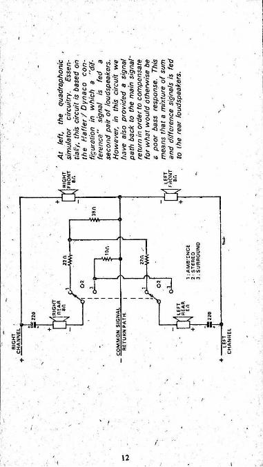
The qudraphonic simulator is situated after the headphone socket, so that all four loudspeakers arc silenced when the headphones are in use. The operation of this unit is best understood by referring to the accompanying circuit diagram.
Reduced to essentials, the idea involves connecting a second pair of loudspeakers in series between the active lines leading to the main speakers. This means that the additional loudspeakers receive what is basically a “difference" signal. The two additional loudspeakers are connected in anti-phase with the idea of blurring the apparent source of the sounds they produce.
While capable of creating a useful “ambience” effect, this arrangement does give a sound lacking in bass response^as on most stereo records the bass content is predominantly an in-phase component. A second disadvantage is that on mono signals, no sound at all is obtained from the rear loudspeakers - there being no difference component.
To partially compensate for this, we have provided a signal path for the rear loudspeakers back to the main signal return. This means that a mixture of sum and difference signals is fed to them.
> The levels at which these components are radiated are determined by the values of the resistors in series with the loudspeakers, and by the value of the resistor forming the common path to the main signal
' return. Ideally, these resistors would all be variable, but this poses problems with respect to cost and availability of components.
We have compromised by using a special type of miniature toggle switch: a double-pole double-throw type with a centre “off” position. In the centre position, the rear speakers are disconnected, giving normal 2-channel stereo reproduction.
The_other two positions are used to switch two sets of resistors into the circuit. In the “Ambience" position, two 22-ohm resistors are connected in series with the loudspeakers, and a 39-ohm resistor is connected in the signal return path. This gives a reduced signal level, and a small amount of bass content.
8
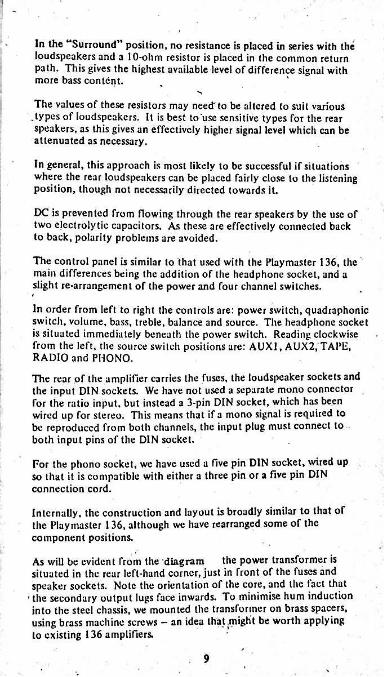
In the “Surround” position, no resistance is placed in series with the loudspeakers and a 10-ohm resistor is placed in the common return path. This gives the highest available level of difference signal with more bass content.
The values of these resistors may need" to be altered to suit various .types of loudspeakers. It is best to use sensitive types for the rear speakers, as this gives an effectively higher signal level which can be attenuated as necessary.
In general, this approach is most likely to be successful if situations where the rear loudspeakers can be placed fairly close to the listening position, though not necessarily directed towards it.
DC is prevented from flowing through the rear speakers by the use of two electrolytic capacitors. As these are effectively connected back to back, polarity problems are avoided.
The control panel is similar to that used with the Playmaster 136, the main differences being the addition of the headphone socket, and a slight re-arrangement of the power and four channel switches.
In order from left to right the controls are: power switch, quadraphonic switch, volume, bass, treble, balance and source. The headphone socket is situated immediately beneath the power switch. Reading clockwise from the left, the source switch positions are: AUXI, AUX2, TAPE, RADIO and PHONO.The rear of the amplifier carries the fuses, the loudspeaker sockets and the input DIN sockets. We have not used a separate mono connector for the ratio input, but instead a 3-pin DIN socket, which has been wired up for stereo. This means that if a mono signal is required to be reproduced from both channels, the input plug must connect to both input pins of the DIN socket.
For the phono socket, we have used a five pin DIN socket, wired up so that it is compatible with either a three pin or a five pin DIN connection cord.
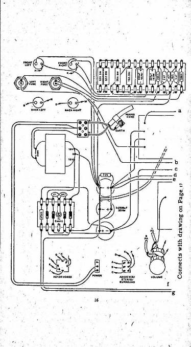
Internally, the construction and layout is broadly similar to that of the Playmaster 136, although we have rearranged some of the component positions.
As will be evident from the diagram the power transformer is situated in the rear left-hand corner, just in front of the fuses and speaker sockets. Note the orientation of the core, and the tact that the secondary output lugs face inwards. To minimise hum induction into the steel chassis, we mounted the transformer on brass spacers, using brass machine screws - an idea that .might be worth applying to existing 136 amplifiers.
9

V
r I♦ 21V
U - Hi"*'
LINK—1JtO M4ATR»€ 0
TH1 120p»i !SIGNALIN Con
IMA'
S’**1MIMA;2 in•«* .SMAKIR
ACTIVITM«.»v;S(T
QUIESCCN1
c W: s IMA27A
.supplyBARTH
A 27A;.Q, 3$0A. TfU
-IVl»L kc OTIP31B.TIP32B TUIiOh: IMA;
A| ' ' -20V
Ik' 4 60 A;11
C -JIV .ODJJV0O2J6. LOOKING 00201.UD2Q? AT PI_HS
A6ovo /< f/K2 circuit oiagrom or tne power moou/v
____ PL A YM ASTER JO. POWER MOgUll_____
May be constructed on Vero board
HOLES IN H TO M POWi
IEATSINH TO CR TRANSlS
HOLES f0 SISTORS^
CLEARANCE TO-S2 TRAN l/i WHIT. SCREW WITH
/ TWO NUTS AS SPACERSSCREW
V
COLLECTOR LEa\> SNIPPED OFF
WASHER
TO-124POWERTRANSISTOR
HEATSINK
The method of mounting the plastic BD235 end 8D236 power transistors is apparent from the line drawing directly above
v
11
In front of the transformer is the tag strip containing the rectifier diodes and the dropping resistor for the pilot light. Next to this, to the right, are the three chassis-mounting electrolytic filter capacitors.
The main pre-amplifier and the tone control board is mounted in the front right-hand sector, while the power amplifier boards are behind them. Tlie quadraphonic components, stability components and headphone dropping resistors are mounted on a piece of tag strip fastened
I to the centre of the rear of the chassis, between the input and output sockets.
Construction of the new amplifier is quite straightforward, as most of the circuitry is contained on the three printed wiring boards. Two tag strips are used to hold the components of the power supply and the stability and quadraphonic networks. The remaining components are fixed direct to the chassis.
Commence construction by fitting the following components to the chassis: power transformer, filter capacitors, input and output sockets, fuse holders, potentiometers, and the source switch. For those components requiring mounting bolts, we used j inch machine screws and nuts. Alternatively, “pop rivets” could be used, although these are of a more permanent nature, and do not permit easy disassembly if this is required.
The power transformer must be mounted on brass spacers using brass nuts and bolts. The spacers should be about 10mm long, in order to provide approximately the same clearance at the top and bottom of the transformer.
The 240V AC wiring can now be completed. The mains cord enters the chassis through a grommeted hole at the rear, and is securely anchored used a suitable clamp. The active and neutral wires are termined at a small insulated terminal block. The earth wire is threaded through, and soldered to a solder lug attached to the cord clamp.
Regular lamp cord or suitably insulated twisted hookup wire runs from the terminal block to the miniature toggle switch, and from the terminal block to the primary of the transformer. The exact connections at the terminal block are shown in the wiring diagram.
\Once the connections have been made and checked, a wise safety precaution is to tape the primary connections to the transformer and the power switch, as these points are possible shock hazards. Two or three layers of insulating tape should be sufficient to prevent accidental contact with the mains. '
Assemble the power supply components on the tag strip, taking particular care to mount the diodes correctly. The tag strip is helb in place by a metal spacer, which, in conjunction with a solder lug, forms the chassis earth for the two RF bypass capacitors. Do not forget to
13
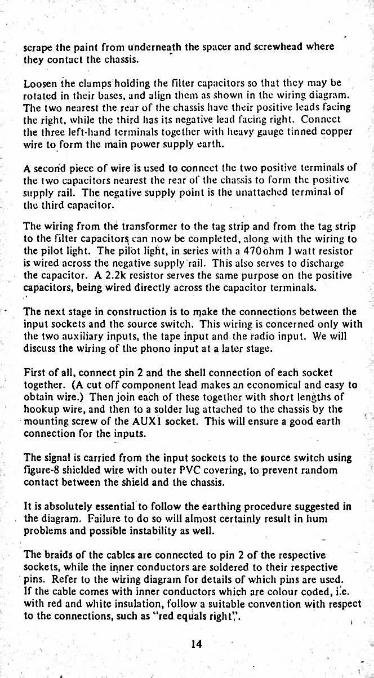
scrape the paint from underneath the spacer and screwhead where they contact the chassis.
Loosen the clamps holding the filter capacitors so that they may be rotated in their bases, and align them as shown in the wiring diagram. The two nearest the rear of the chassis have their positive leads facing the right, while the third has its negative lead facing right. Connect the three left-hand terminals together with heavy gauge tinned copper wire to form the main power supply earth.
A second piece of wire is used to connect the two positive terminals of the two capacitors nearest the rear of the chassis to form the positive supply rail. The negative supply point is the unattached terminal of the third capacitor.
The wiring from the transformer to the tag strip and from the tag strip to the filter capacitor^ can now be completed, along with the wiring to the pilot light. The pilot light, in series with a 470ohm 1 watt resistor is wired across the negative supply rail. This also serves to discharge the capacitor. A 2.2k resistor serves the same purpose on the positive capacitors, being wired directly across the capacitor terminals.
The next stage in construction is to make the connections between the input sockets and the source switch. This wiring is concerned only with the two auxiliary inputs, the tape input and the radio input. We will discuss the wiring of the phono input at a later stage.
First of all, connect pin 2 and the shell connection of each socket together. (A cut off component lead makes an economical and easy to obtain wire.) Then join each of these together with short lengths of hookup wire, and then to a solder lug attached to the chassis by the mounting screw of the AUX1 socket. This will ensure a good earth connection for the inputs.
The signal is carried from the input sockets to the source switch using figure-8 shielded wire with outer PVC covering, to prevent random contact between the shield and the chassis.
It is absolutely essential to follow the earthing procedure suggested in the diagram. Failure to do so will almost certainly result in hum problems and possible instability as well.
The braids of the cables are connected to pin 2 of the respective sockets, while the inner conductors are soldered to their respective pins. Refer to the wiring diagram for details of which pins are used.If the cable comes with inner conductors which are colour coded, i.c. with red and white insulation, follow a suitable convention with respect to the connections, such as “red equals right’,'.
14
If your cable is not colour coded, use coloured insulating tape or a scrap of PVC sleeving to mark the inner conductors. Tiiis is best done by using say red tape for the right channel, and marking both ends of the conductor before soldering the cable into position.
At the source switch end of the cables, no connection is made to the shield. Only the inner conductors are soldered to the switch, the braids being cut off short and insulated with the coloured tape or sleeve already mentioned. Refer to the wiring diagram for details of the connections to the switch. Once all connections have been made, the four stereo cables may be taped or bound into a single cable, using either nylcx tubing or insulating tape, and tucket down into the angle of the chassis.
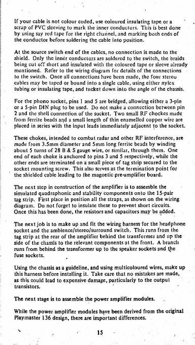
For the phono socket, pins 1 and 5 are bridged, allowing either a 3-pin or a 5-pin DIN plug to be used. Do not make a connection between pin 2 and the shell connection of the socket. Two small RF chockcs made from ferrite beads and a small length of thin enamelled copper wire are placed in series with the input leads immediately adjacent to the socket.
These chokes, intended to combat radar and other RF interference, are made from 3.5mm diameter and 5mm long ferrite beads by winding about 5 turns of 28 B & S gauge wire, or similar, through them. One end of each choke is anchored to pins 3 and 5 respectively, while the other ends are terminated on a small piece of tag strip secured to the socket mounting screw. This also serves as the termination point for the shielded cable leading to the magnetic pre-amplifier board.
The next step in construction of the amplifier is to assemble the simulated quadraphonic and stability components onto the 15-pair tag strip. First place in position all the straps, as shown on the wiring diagram. Do not forget to insulate these to prevent short circuits. Once this has been done, the resistors and capacitors may be added.
The next job is to make up and fit the wiring harness for the headphone socket and the ambience/stereo/surround switch. This runs from the tag strip at the rear of the amplifier behind the transformer and up the side of the chassis to the relevant components at the front. A branch runs from behind the transformer up to the speaker sockets and the fuse sockets.
Using the chassis as a guideline, and using multicoloured wires, make up this harness before installing it. Take care that no mistakes are made, as this could lead to expensive damage, particularly to the output transistors.
The next stage is to assemble the power amplifier modules.
While the power amplifier modules have been derived from the original Playmaster 136 design, there are important differences.
15

1
i
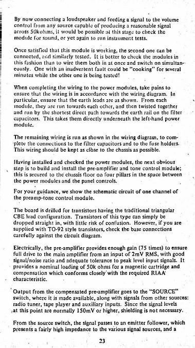
f/Pay particular attention to the
earth wiring sequence when constructing your amplifier.
ti//1 ////n//n// lin rowH M>n«io
bcn do
§ e;
STCC'UIICT
The most obvidus has already been mentioned, in that the new board does not carry any power supply components. Power input is by three wires; power supply earth or common, plus 21V and minus 21V. A fourth lead from the same end of the board feeds the active side of the loudspeaker circuit. The remaining connection is the shielded signal input lead which also provides the earth link back to the preamp board.
Adjacent to the plus 21V lead is a link into which a milliammcter can be inserted to measure the quiescent current of the output stage. For simplicity, we used a loop of hookup wire with a soldered joint in the ' middle.
/The passive components, resistors and capacitors on the wiring diagram require no special comment.
Note, however, that we have added one resistor to the amplifier, a 6.8k bridging one side of the quiescent current adjustment potentiometer. This is to protect the output transistors in the event that potentiometer wiper or element becomes open-circuit. What happens in this circumstance is that the quiescent current control transistor, TR5, is turned
■ off and the output transistors arc turned hard on, drawing heavy current which can cause them to burn out.
While the possibility of an open circuit potentiometer is fairly remote, the 6.8k resistor provides cheap insurance. Now, in the event of an open circuit pot, the control transistor is turned on and the output transistors draw zero quiescent current. In this condition, cross-over distortion occurs but no damage eventuates and the situation can be rectified.
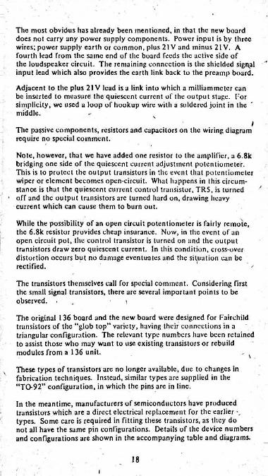
The transistors themselves call for special comment. Considering first the small signal transistors, there are several important points to be observed. . t
The original 136 board and the new board were designed for Fairchild transistors of the “glob top” variety, having their connections in a triangular configuration. The relevant type numbers have been retained to assist those who may want to use existing transistors or rebuild modules from a 136 unit. \These types of transistors are no longer available, due to changes in fabrication techniques. Instead, similar types are supplied in the “TO-92” configuration, in which the pins are in line.
In the meantime, manufacturers of semiconductors have produced transistors which are a direct electrical replacement for the earlier types. Some care is required in fitting these transistors, as they do not all have the same pin configurations. Details of the device numbers and configurations are shown in the accompanying table and diagrams.
18i
With TR1 and TR2, the transistors are fitted simply by bending the leads sufficiently to fit the triangular pattern of holes, so that they sit about one centimetre or so above the board.
The real difficulty has to do with the other three which need to make physical contact with the output transistor heat sink to provide thermal feedback.
With the glob top transistors, the requirement was met by providing three suitably positioned dimples in the underside of the heatsink, each partially filled with silicone paste. The small-signal transistors were dropped into position on the board but not soldered. The heatsink carrying the power transistors was then locked in position with the power transistor leads just emerging through the copper pattern. This done, the glob tops were pushed up into the silicone-filled dimples and the leads soldered.
The TO-9 style transistors don’t lend themselves to this approach. They don't sit down snugly on the present board and the small, Hat top does not mate naturally with a dimple. We are therefore suggesting that holes be drilled in the heatsink, which will be a clearance fit for the TO-92 bodies, Allowing the transistor to sit part way through the heatsink. A blob of silicone compound can blend the two thermally.
The mounting method has a possible bonus in that the transistors are no longer trapped under the heatsink. They could, if necessary, be extracted and replaced through the holes.
The original circuit board and heatsink was designed for use with the TO-66 style transistors, specifically the Fairchild types AY8171 and AY9171. These are no longer available, but Fairchild have suggested the use of the 2N4232 and 2N3740. These pose no problems with regard to fitting, as they are also TO-66 types.
Electrically but not mechanically similar transistors are also ayailable from other manufacturers, and these require a different mounting arrangement. This will be described immediately following the description of the mounting arrangements for the TO-66 style transistors.
The first step is to inspect the heatsinks, which should be of aluminium, not less than 16 gauge. Make sure that the two power transistors sit flat against the surface, with mounting holes aligned and withadequate clearance around the base and emitter pins. If there is any inaccuracy, lead the holes as necessary with a small round file.
In fact, we rubbed the inside surfaceof our own heatsinks witli a large flat fine-gauge file to remove any high spots and then buffed the surface all over with steel wool.
19

Now check the heatsinks against the wiring board. Make sure that the bolts securing the power transistors can pass straight through, and the pins likewise. If there is any fit problem, the mounting holes in the board can be elongated as necessary.
If the small-signal transistors happen to be the older glob tops, the heatsink will need dimples or countersunk holes in the underside.If, as likely, the transistors are of the TO-92 configuration, the heatsink will need snug clearance holes instead. In fact, dimple type heatsinks can be adapted by drilling appropriate holes. They may not be concentric with the dimples, however, since the TO-92 transistors sit most naturally between the collector and emitter pins, with the base lead kinked outwards to fit the triangular pattern in the board.
With all this sorted out for each of the boards, the heatsink assemblies can be completed. Smear the underside of the power transistors with silicone compound and secure the transistors firmly to the heatsinks with j-inch long bolts and nuts, cither p Whitworth or 5BA. The transistors do not need to be insulated from the heatsink. In fact, the heatsink and mounting bolts form part of the collector circuitry.
You will need four spacers per board, either 4mm or ■&, such that when the heatsinks arc mounted, the base and emitter pins of the power transistors just come through the copper pattern. We found some brass nuts of a larger size which we turned into spacers by running a p-inch clearance drill through them. This done, the power transistors assemblies can be put aside for later installation.
On the wiring board itself, it is wise to smear the copper around the heatsink mounting holes with a thin layer of solder. If this is done, the nuts will bite into the solder when they are finally tightened and make good contact between the transistor collectors, heatsink and mounting bolts and the copper pattern on the board.
At this stage, the remaining components can be installed as per the diagram. Use an iron with a clean, slender tip and flow the solder around each component lead as quickly as possible, to avoid overheating cither the pattern or the component. Make sure that you install the electrolytics with the correct polarity.
The alternative types of transistors come in an SOT-32 style case. This is a plastic package, having three pins in line, the centre one being the collector. The collector is also connected to a metal plate which forms the coupling to the heatsink. Unfortunately, different manufacturers have different configurations for the base and emitter leads.
The Philips types BD235 and BD236 must be mounted underneath the heatsink as explained below.
20i
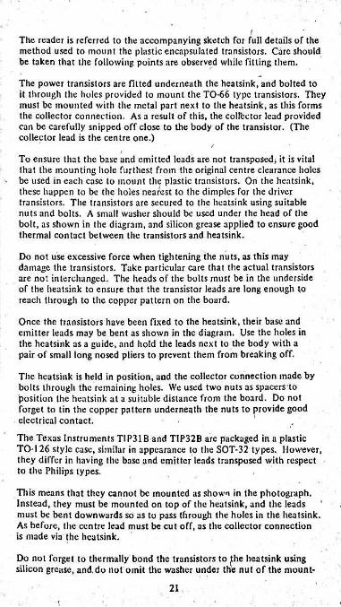
The reader is referred to the accompanying sketch for full details of the method used to mount the plastic encapsulated transistors. Care should be taken that the following points are observed while fitting them.
The power transistors are fitted underneath the heatsink, and bolted to it through the holes provided to mount the TO-66 type transistors. They must be mounted with the metal part next to the heatsink, as this forms the collector connection. As a result of this, the collector lead provided can be carefully snipped off close to the body of the transistor. (The collector lead is the centre one.)
To ensure that the base and emitted leads are not transposed* it is vital that the mounting hole furthest from the original centre clearance holes
• be used in each case to mount the plastic transistors. On the heatsink, these happen to be the holes nearest to the dimples for the driver transistors. The transistors are secured to the heatsink using suitable nuts and bolts. A small washer should be used under the head of the bolt, as shown in the diagram, and silicon grease applied to ensure good thermal contact between the transistors and heatsink.
Do not use excessive force when tightening the nuts, as this may damage the transistors. Take particular care that the actual transistors arc not interchanged. The heads of the bolts must be in the underside of the heatsink to ensure that the transistor leads are long enough to reach through to the copper pattern on the board.
Once the transistors have been fixed to the heatsink, their base and emitter leads may be bent as shown in the diagram. Use the holes in the heatsink as a guide, and hold the leads next to the body with a pair of small long nosed pliers to prevent them from breaking off.
The heatsink is held in position, and the collector connection made by bolts through the remaining holes. We used two nuts as spacers to position the heatsink at a suitable distance from the board. Do not forget to tin the copper pattern underneath the nuts to provide good electrical contact. - 1
The Texas Instruments TIP31B and TIP32B arc packaged in a plastic TO-126 style case, similar in appearance to the SOT-32 types. However, they differ in having the base and emitter leads transposed with respect to the Philips types.
This means that they cannot be mounted as shown in the photograph. Instead, they must be mounted on top of the heatsink, and the leads must be bent downwards so as to pass through the holes in the heatsink. As before, the centre lead must be cut off, as the collector connection is made via the heatsink.
Do not forget to thermally bond the transistors to (the heatsink using silicon grease, and. do not omit the washer under the nut of the mount-
21

i-
ing bolt. This is to prevent damage to the case of the transistor. Excessive force must not be used when tightening the mounting bolts.
The heatsink is mounted in the same way as before, using $-inch machine screws, in conjunction with spacers made from nuts.
The fitting of the completed power modules can now be checked against the holes in the chassis. The modules are mounted on spacers, which do not have to be insulated, as appropriate clearances have been provided on the boards.
After checking the fit of the modules, remove them from the chassis. The next step it to check the power supply and only then install the modules. This procedure has less chance of damaging anything should any fault exist.
Gieck that the chassis and associated power supply wiring, as described last month, is correct, and that no trailing wires are resting against the chassis. If all is in order, plug the mains connector in to a suitable receptacle and switch on. If all is in order, the indicator light should come on and voltages, plus and minus 21.5V approximately, should appear across the respective supply rails at the filter capacitors.
The fust module may now be wired up to the appropriate points, as shown in the wiring diagram, and installed in position. At this stage, do not switch on.
Insert a milliammeter in the link, with plus to the supply, and set to the 250mA range. Rotate the current set potentiometer, as viewed in the chassis fully anti-clockwise, and set the volume control pot at full off. Since the earthy side of the pot may not at this stage have an earth return, run a temporary link to a chassis earth.
Now watch the current meter and switch on. If the meter slams over, there is something radically wrong. Switch off instantly and check. You may have the power transistors interchanged, or one of the other transistors the wrong way round. Whatever you do, don’t tempt fate by switching on again and repeating the overload condition.
In fact, the current flow with the preset pot retarded, should be zero.If it is, reset the milliammeter to 50mA and carefully rotate the potentiometer clockwise. Bring the current up to 12mA and leave the module running for a few minutes. If all is well, switch off, remove the milliammeter and close the link.
Note that the current should be set without a loudspeaker or other load connected. When the loudspeaker is plugged in, current distribution in the output stage will change due to the small offset voltage (0.2V approx.) across the loudspeaker terminals.
22
By now connecting a loudspeaker and feeding a signal to the volume control from any source capable of producing a reasonable signal across SOkohms, ii would be possible at this stage to ciieck the module for sound, or yet again to run instrument tests.
Once satisfied that this module is working, the second one can be connected, and similarly tested. It is better to check the modules in this fashion than to wire them both in at once and switch on simultaneously. One with an inadvertent fault could be “cooking” for several minutes while the other one is being tested!
:i
When completing the wiring to the power modules, take pains to ensure that the wiring is in accordance with the wiring diagram. In particular, ensure that the earth leads are as shown. From each module, they are run towards each other, and then twisted together and run by the shortest direct path towards the earth rail on the filter capacitors. This takes them directly underneath the left-hand power module.
The remaining wiring is run as shown in the wiring diagram, to complete the connections to the filter capacitors and to the fuse holders. This wiring should be kept as clbse to the chassis as possible.
Having installed and checked the power modules, the next obvious step is to build and install the pre-amplifier and tone control module; this is secured to the chassis floor on four pillars in the space between the power modules and the panel controls.
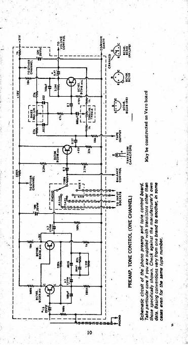
For your guidance, we show the schematic circuit of one channel of the preamp-tone control module.
The board is drilled for transistors having the traditional triangular CBE lead configuration. Transistors of this type can simply be dropped straight in, with little risk of confusion. However, if you are supplied with TO-92 style transistors, check the base connections carefully against the circuit diagram.
Electrically, the pre-amplifier provides enough gain (75 times) to ensure full drive to the main amplifier from an input of 2mV RMS, with good signal/noise ratio and adequate tolerance to peak level input signals. It provides a nominal loading of 50k ohms for a magnetic cartridge and compensation which conforms closely'with the required R1AA' characteristic.
Output from the compensated pre-amplifier goes to the “SOURCE” switch, where it is made available, along with signals from other sources: radio tuner, tape player and auxiliary inputs. Since the signal levels
,at this point are normally 150mV or higher, shielding is not necessary.
From the source switch, the signal passes to an emitter follower, which presents a fairly high impedance to the various signal sources, and a
23

/
low source impedance for the tone control circuitry. At the same time, it provides a convenient point from which to derive signal for an external tape deck; this signal is independent of the amplifier's own volume and tone controls.
The tone control circuit is of the feedback type, favoured because of its inherently low distortion and its tolerance to higher level input signals.
The point should be made, however, that signals derived from the source switch are applied directly to a transistor base and can overload the cirduitry between this and the volume control, if the level is excessive. Signals from radio tuners, tape players, etc., must be limited in some way if there is any suggestion of overload, or if you find that the amplifier is being fully driven with the volume control only fractionallyon.
In constructing the preamp-tone control module, a useful first step is to check the fit of the board and chassis mounting and make any adjust
ments necessary by filing holes, etc. We used £-inch threaded pillars,. with 5—inch long, y-inch diameter countersunk screws securing them to
the chassis and y-inch long, y-incli diameter roundhead screws securing the printed wiring board.
Next solder a solder lug onto the copper pattern so that it will earth the pattern next to the mounting hole nearest to the magnetic preamp inputs.
, This forms the main earth of the amplifier. We used a double-ended solder lug, so that it formed 2 bridge across the gap in the pattern which , had previously been provided for when the earth was not at this point.No earth connections should be made at any of the other mounting _ positions.
Dp not overlook the cut which is desirable in the board pattern to eliminate a possible troublesome earth loop. The exact position is shown on the component layout diagram.
For the rest, the components drop into place, as per the accompanying drawing. Polarity is important only in respect to the electrolytic capacitors, and this calls for some care. Note that we have shown an alternative position for the main decoupling capacitor, in case it happens to be larger than the one originally planned. An extra hole may be required and, for this, you will need a fine twist bit and, preferably, a small “egg-beater" hand-drill.
The most tedious job with the module has to do with the leads which must ultimately connect to the potentiometers and switches. The leads range from about 3 to 7 inches long and are unshielded, except where otherwise indicated. It is a good idea to use as many different colours as possible to facilitate lead tracing, and to use thin rather than thick hookup to retain maximum flexibility.
■ 24
The leads should be anchored to the wiring board during initial assembly and left trailing. Please yourself whether you make them all generously long, or save wire by cutting each qne discretely to suit the requirement. But, whatever you do, plan for each wire to follow a gently curved path so that the board can be unbolted and lifted up for testing or service.For the same reason, leave some slack in the phono input and tape output leads, which run back to the DIN sockets.
Numbers 1-19 on the board wiring diagram relate to numbers on the main diagram and indicate where each lead goes.
These leads are best soldered at their ends after the board has been fitted in position. Do not forget to scrape off any paint underneath the spacer forming the earth connection. A good idea is to “tin” the steel beforehand, thus ensuring a good connection.
The general layout of the leads is as shown in the main diagram. Try and keep all leads as close to the chassis as possible, as this will minimise hum pickup. We found.that a neat appearance could be obtained by tucking as many leads as possible underneath adjacent boards: this can be seen in the photographs.
The final step in construction is to fit the front panel, which is held in place by the switches and potentiometers. Care must be taken during this process, as a scratch on the panel can be quite unsightly, and very difficult to remove.
The amplifier is best tested by actually using it. Connect up a suitable pair of eight-ohm speakers and turn the amplifier on. Switch to stereo, and set the tone and balance controls at the mid-range position. Switch to PHONO, and turn the volume control full off. The amplifier should sound dead quiet from the listening position, and only if your head is placed rigiit up next to the speakers should any hiss or hum be audible. When the volume control is advanced about halfway, the noise level should not increase audibly at a normal listening position.
v.Connect up a suitable input, and check the operation of all controls.
, If a suitable pair of speakers are available, the simulated quadraphonic feature may be tested. Note that true operation is npt obtained unless the main speakers are connected. Using a suitable pair of headphones, check the operation of the headphone switch. All speakers must be silenced when the phones are plugged in.
\ 25
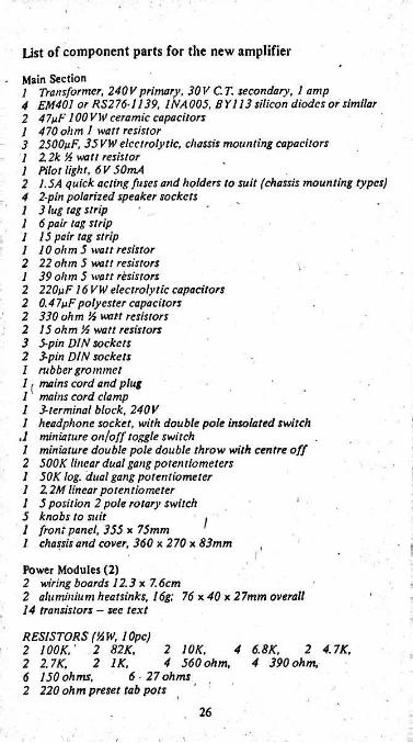
Ust of component parts for the new amplifier
- Main Section1 Transformer, 240 V primary, 30 V C.T. secondary, 1 amp4 EM401 or RS276-1139, 1NA005, BY 113 silicon diodes or similar2 47yF 100 VW ceramic capacitors 1 470 ohm 1 watt resistor3 2500tiF, 35 VW electrolytic, chassis mounting capacitors 1 22k 'A watt resistor1 Pilot light, 6 V 50mA2 1.5A quick acting fuses and holders to suit (chassis mounting types)4 2-pin polarized speaker sockets 1 3 lug tag Strip1 6 pair tag strip 1 15 pair tag strip1 10 ohm 5 watt resistor2 22 ohm 5 watt resistors1 39 ohm 5 watt resistors2 220tiF 16 VW electrolytic capacitors 2 0.47tiFpolyester capacitors2 330 ohm A watt resistors2 15 ohm ’A watt resistors3 5-pin DIN sockets 2 3-pin DIN socketsI rubber grommetII mains cord and plug 1 mains cord clamp1 3-terminal block, 240 V1 headphone socket, with double pole insolated switch
,1 miniature on/off toggle switch1 miniature double pole double throw with centre off2 500K linear dual gang potentiometers 1 50K log. dual gang potentiometer1 2 2M linear potentiometer 1 5 position 2 pole rotary switch5 knobs to suit 1 front panel, 355 x 75mm 1 chassis and cover, 360 x 270 x 83mm
I
' !Power Modules (2)2 wiring boards 12.3 x 7.6cm 2 aluminium heatsinks, 16g; 76 *40 x 27mm overall 14 transistors - see text
RESISTORS ('AW, lOpc)2 lOOK: 2 82K.2 27K.6 150 ohms,2 220 ohm preset tab pots
2 1 OK, 4 6.8K, 2 4.7K.4 560 ohm, 4 390 ohm,2 IK,
6 ■ 27 ohms
26
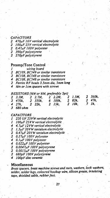
CAPACITORS2 470pF 16V vertical electrolytic 2 1 OOpF 25 V vertical electrolytic 2 0.47pF 160 V polyester 2 390pF polystyrene 2 270pFpolystyrene
Preamp/Tone Controlwiring board
2 BC109, BC549 or similar transistors 2 BC108, BC548 or similar transistors 4 BC108. BC548 or similar transistors 2 Ferrite RF beads 3.5mm dia, 5mm tong 4 ‘Ain or 1cm spacers with screws
1
RESISTORS (AW or'A W, preferably Spc) 2 3.3M,2 470k,
. 4 27k.3 680 ohm
2 560k. 2 47k.7 Ik,
2 1.5M, 2 82k.2 10k.
2 2.2 M, 6 100k. 2 15k.
2 2.7M, 2 330k. 2 22k.
CAPACITORS .1 220 UF 25 VW vertical electrolytic1 100nF 25 VW vertical electrolytic 4 4.7pF 12 VW vertical electrolytic2 I.5pF20VW tantalum electrolytic 2 0.47pF 20 VW tantalum electrolytic 2 0.27pF 100 V polyester4 0.1 pF 100 V polyester 4 0.022pF 100 V polyester 2 0.004 7pF 100 V polystyrene 2 0.0015 pF 100Vpolystyrene 2 680pF 100 V polystyrene 4 100pF disc ceramic
- MiscellaneousBrass spacers, brass machine screws and nuts, washers, lock washers, solder, solder lugs, coloured hookup wire, silicon grease, insulating tape, shielded cable, rubber feet.
27
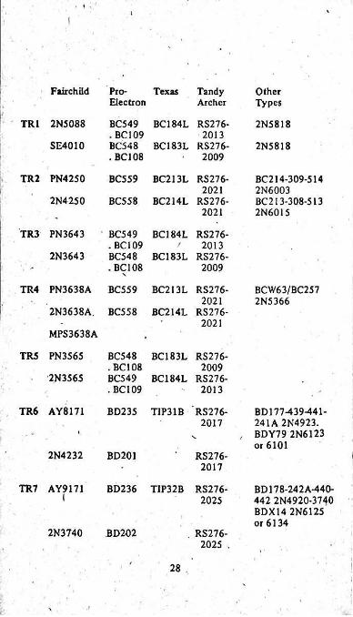
Fairchild Pro- Texas Electron
TandyArcher
OtherTypes
TR1 2N5088 BC549 BC184L RS276- . BC109 BC548 BC183L RS276- . BC108
2N58182013
SE4010 2N58182009
TR2 PN42S0 BC559 BC213L RS276- BC214-309-514 2N6003 BC213-308-513 2N6015
20212N4250 BC558 BC214L RS276-
2021
TR3 PN3643 BC549 BC184L RS276- . BC109 BC548 . BC108
2013/2N3643 BC183L RS276-
2009
TR4 PN3638A BC559 BC213L RS276- BCW63/BC2572N53662021
2N3638A. BC558 BC214L RS276-2021
MPS3638A
TR5 PN3565 BC548 BC183L RS276- . BC108 BC549 .BC109
20092N3565 BC184L RS276-
2013
TR6 AY8171 BD235 TIP31B RS276- BD177-439-441- 241A 2N4923. BDY79 2N6123 or 6101
2017
2N4232 BD201 RS276-2017
TR7 AY9171 BD236 T1P32B RS276- BD178-242A-440-2025 442 2N4920-3740
BDX14 2N6125 or 6134
2N3740 BD202 . RS276- 2025 .
28
I
PLAYMASTER 145
........... our new eight input stereo/mono mixer.Many of our readers require a multi-input stereo mixer with comprehensive facilities such as automatic muting, tone controls, headphone monitoring, signal metering and ability to handle a whole range ol signal sources.Here Is our answer to your requirements.
Mixer Specifications
Eight Input stereo mono mixer with automatic noise muti'ftg, level metering, bass and treble controls and stereo headphone socket. All input and output connections are made via 6.5mm jacks.
Mixer SectionFrequency response at nominal output: 30Hz to 70kHz between - ldB points;♦ lldB, - lOdB at lOkllz; constant turnover Baxandall circuit.
3dB points at 10Hz and 150kHz. Tone controls: " , * lOdB at 100Hz. Variable slope,
Sensitivity (without preamplifiers): 40mV at 5k input impedance for rated output of 0.775V RMS. Input impedance may be Increased with a series resistor in the input circuit, with consequent reduction of sensitivity.Maximum Output Signal: 5V RMS; with headphones connected the output signal clips at Just above the rated output of 0.775V RMS.Output impedance: 4.7k for stereo mode; 2.35k for mono mode. Output signal levels are halved when both channel outputs are connected together for driving a mono amplifier.Headphone socket: To suit, any lW impedance dynamic phones of 8 ohms or more.Maximum control interaction: Less than 0.5dB Signal-to- nolse ratio: better than 60dB with respect to 0.775V RMS output.Distortion: typically less than 0.04% at 1kHz at rated output.Separation between channels: typically better than - 50dB Microphone Preamplifier-^for 600 ohdi microphones) Sensitivity: O.SmV at 100k input impedance Frequency response: 20Hz to 70kHz at - ldB points Input overload: lOmV at 1kHz.Signal-to-noise ratio: - 42dB with respect to rated output
\
29
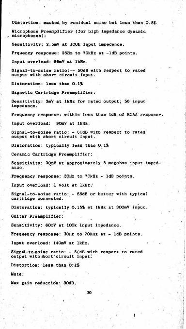
Distortion: masked, by residual noise but less than 0.5%Microphone Preamplifier (for high Impedance dynamic
.. microphones):Sensitivity: 2.5mV at 100k input impedance.Frquency response: 25Hz to 70kHz at -ldB points. Input overload: 95mV at lkBz.Slgnal-to-nolse ratio:— 50dB with respect to rated output with short circuit input.Eistoratlon: less than 0.1%Magnetic Cartridge Preamplifier:Sensitivity: 3mV at 1kHz for rated output; 56 input' impedance.Frequency response: within less than ldB of RIAA response.Input overload: 90mV at 1kHz.Signal-to-noise ratio: - 60d(5 with respect to rated output with short circuit input.DistoratioD: typically less than 0.1%Ceramic Cartridge Preamplifier:Sensitivity: 30mV at approximately 3 megohms input impedance.Frequency response: 30Hz to 70kHz - ldB points.Input overload: 1 volt at 1kHz.'Signal-to-noise ratio: - 56dB or better with typical cartridge connected.Dlstoration: typically 0.15% at 1kHz at 30OmV input.Guitar Preamplifier:Sensitivity: 60mV at 100k input impedance.Frequency response: 30Hz to 70kHz at - ldB points.Input overload: 140mV at 1kHz.Signal-to-noise ratio: - 5(dB with respect to rated output with diort' circuit input!Distortion: less than Or-1%
Mute:Max gain reduction: 30dB.
30
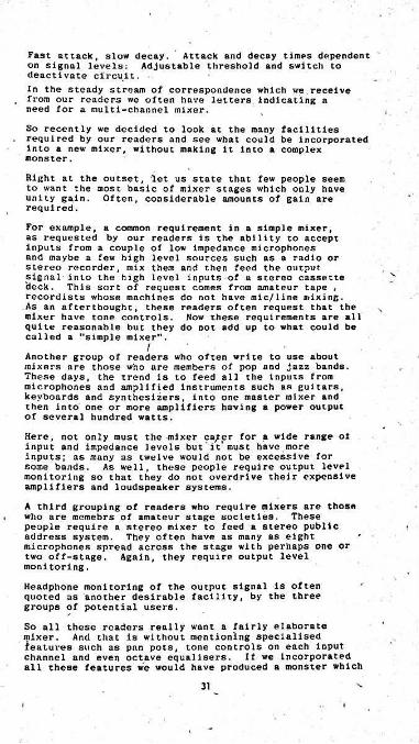
Fast attack, slow decay, on signal levels: deactivate circuit.In the steady stream of correspondence which we receive from our readers we often have letters indicating a need for a multi-channel mixer.So recently we decided to look at the many facilities required by our readers and see what could be incorporated into a new mixer, without making it Into a complex monster.
Attack and decay times dependent Adjustable threshold and switch to
Right at the outset, let us state that few people seem to want the most basic of mixer stages which only have unity gain. Often, considerable amounts of gain are required.For example, a common requirement in a simple mixer, as requested by our readers is the ability to accept inputs from a couple of low impedance microphones and maybe a few high level sources such as a radio or stereo recorder, mix them and then feed the output signal into the high level Inputs of a stereo cassette deck. This sort of request comes from amateur tape , recordists whose machines do not have mlc/line mixinc.As an afterthought, these readers often request that the mixer have tone controls. Now these requirements are all quite reasonable but they do not add up to what could be called a "simple mixer".
V
/Another group of readers who often write to use about mixers are those who are members of pop and jazz bands. These days, the trend is to feed all the Inputs from microphones and amplified instruments such as guitars, keyboards and synthesizers, into one master mixer and then into one or more amplifiers having a power output of several hundred watts.Here, not only must the mixer ca/pr for a wide range oi input and impedance levels but it must have more inputs; as many as twelve would not be excessive for some bands. As well, these people require output level monitoring so that they do not overdrive their expensive amplifiers and loudspeaker systems.A third grouping of readers who require mixers are those who are memebrs of amateur stage societies. These people require a stereo mixer to feed a stereo public address system. They often have as many as eight microphones spread across the stage with perhaps one or two off-stage. Again, they require output level monitoring.Headphone monitoring of the output signal is often quoted as another desirable facility, by the three groups of potential users.So all these readers really want a fairly elaborate mixer. And that is without mentioning specialised features such as pan pots, tone controls on each input channel and even octave equalisers. If we Incorporated all these features we would have produced a monster which
31
•only relatively few readers would be game to build.
What we have produced Is a new Playmaster mixer which will cater for a total of eight inputs, (four per channel on a stereo basis), has tone controls, output signal monitoring and stereo- headphone socket for monitoring.With the two output channels bridged together it can be used as a mono mixer with eight inputs.
One of the problems with complex mixers, is that they tend to be noisy when all inputs are running with high gain.The situation can be particularly bad where several low impedance microphones are used. Because they have such a low signal output voltage to begin with, typically several hbndred microvolts, they inevitably give a poor signal-to-noise ratio when plugged directly into a preamplifier.
v
Professional equipment used in broadcasting and recording studios gets around this problem by using low impedance microphones with balanced lines and step-up transformers. The balanced lines eliminate hum and other mains-induced noise while the step-up transformers improve the Inherent signal-to-noise ratio of the system by increasing the signal level to the preamplifier.
Unfortunately, microphone transformers are expensive, so we really could not incorporate them into the Play- master mixer, however, there is another way of improving the signal/noise ratio.
In a typical situation where a mixer is used, microphone channels with a poor signal/noise ratio will be most noticeable during quiet sections of the programme and less noticeable during loud sections. During the quiet sections chances .are that some or all of the noise microphone channels in question are not actually being used.
However', in typical use by amateurs, it may not be possible to turn down the unused channels, and thereby improve the signal/noise ratio. Of course, in recording studios the mixer operator constantly juggles the signal levels and settings to obtain the best programme quality.
In the amateur situation, the mixer is more likely to be initially set up and then left untouched for the entire programme.
Our Playmaster mixer Incorporates automatic muting circuits which drastically cut the gain of unused input channels to improve the signal/noise ratio.As soon as the signal level to a given microphone rises above a given threshold, which is adjustable, the input channel is made fully operational.' I
When Initially setting up relative signal levels for each input channel, the automatic muting can be switched out of operation using the same control used to adjust the threshold level. More about this later.Now let us describe some of the physical features of the Playmaster mixer. The chassis is 400 x 150 x 180mra (W x H x D) and is' a simple U-shape with timber
32
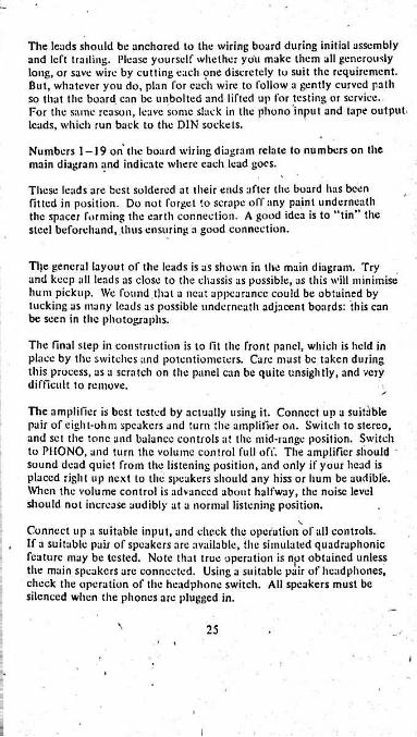
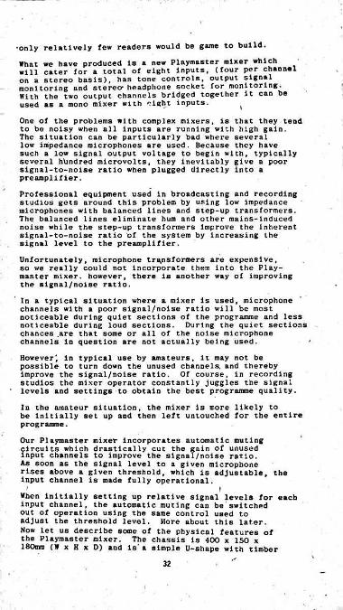
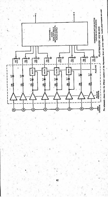
end-covers and a vinyl-covered top panel. Altogether it has fifteen Knobs, a toggle switch, headphone socket and dual meters on the front panel.To avoid making the front panel appear too large, we have split it into two sections, one finished in black while the other has a natural aluminium finish.The prototype front panel was made from photosensitive aluminium.On the black section of the panel is the master level control and immediately above it, the dual level meters. This seems to be a fairly logical arrangement.On the other section of the front panel are the two tone control knobs, level knobs for the 8 input channel, and four knobs which control the muting threshold and also switch it out of operation if required. ■ The muting facility is only provided on four inputs in the prototype but this can be extended to all inputs if'need be.The four input level and two mute threshold controls for each output channel are grouped together on the front panel. Thus, a group including knobs 1, 2, 5 and 6 on the LH side serves the left output channel.Other panel layouts and chassis configurations could have been used. Sloping panels are common. However, we felt that for a universal mixer the configuration we chose was most appropriate. It can be placed on a shelf or on top of other equipment and all settings are visible from some distance away. This is not the : ( case with sloping panels. It wolild also appear to be more compatible with the vertical control panels of many tape and cassette decks now being retailed.Slider controls have not been used, for several reasons: for a start, unless the better quality 60mm types are used, they give a poor control "feel": they are considerably more expensive than conventional rotary potentiometers; the need to provide brackets and slots in chassis and escutcheon panels makes the metalwork very expensive and dirt can quickly gain ingress to the track, to make it noisy.To top it off, the author is not particularly keen on slider potentiometers.On the back panel, we have standardised the input and output sockets. 6.5mm Jack sockets are used.Inside the chassis are two relatively large PC boards, one we call the "mother" board and the other the main mixer board. Reference to the schematic diagram will show how it all comes together.Twelve edge connectors are 'mounted on the mother ooard.The connecters mate up to eight small preamp boards and four mute boards. The preamp boards have the same universal pattern but can be wired up to suit quite a range of input sources. In this way, the mixer can cater for high level Inputs such as tape recorders, electronic keyboard instruments and synthesizers, and
33
ss s'5m
i &5 5 f i-IjL
•mf «■Es "o
ItI w. >552 °o3 o<fl
<k~” " 5
£i sioI ’ ££ if'14
g «
s*
2Ifr?* T 31si s; gIo S!
“2<hEw
tU5 § fI H !r • If:I« }1 /
aisi ■0. S Is
8525
5t 3 IIS§:■Q* I5:
PConnects with drawing on Page 35
'
34
'
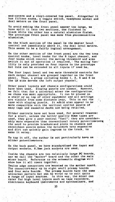
Connects with drawing on Page 34i
S 5• i-T . ♦
iU l| %s 5 sc
ft
3 PSs
S s5 2"tMM MM
?! fM«*s
si-2I
54 5:1 i»; Si >P ' J
it 4-ft• S'5 1ST
meg A £ * r *000 > kjiafiiyH. -*
I. sMM J4 4! » wiryoistiswirh
8?
■! v\ TM—%n i< i
MAY BE CONSTRUCTED ON VERO-BOARD
35
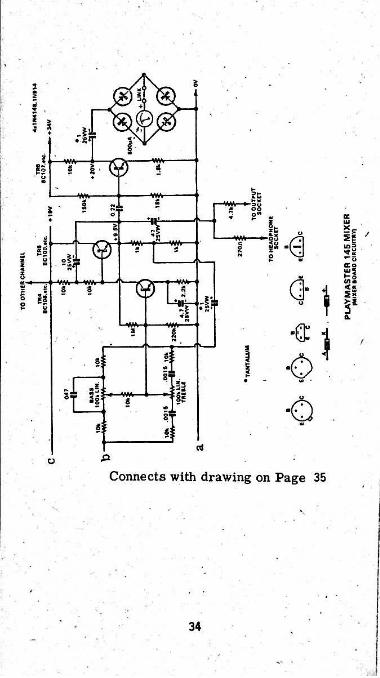
!- 'low level Inputs such as low or high Impedance microphones, magnetic cartridge, ceramic cartridge, electric guitar and so on.'The mother board not only provides a convenient method of plugging In preamp and mute boards but also eliminates the tedious job of wiring up and mounting all those eight-way edge connectors.Dimensions of the mother board are 127 x 178mm while those for the mixer board are 100 x 20Onm.,Each channel on the mixer board has four Inputs, each with a maximum sensitivity of 4CtaV at 10k input impedance for the nominal output level of 0.775V R11S. nominal output level of the mixer can be varied easily up or down by chanlng a few resistors on this board. This enables the mixer to drive any amplifier to full power.Refer now the circuit diagram of the main mixer board. This contains the mixer stages, tone controls, metering circuits and the regulated power supply. The circuit shows one channel on the mixer board plus the common power supply.Trl is the mixer stage which accepts the signals from the wipers of four level controls. Shunt negative feedback is applied from the collector of the transistor to its base - it could be referred to as a virtual earth mixer. The gain is unity, fixed by the ratio of the feedback resistor (10k) to the Input resistor (also 10k).
The
I.
A 22k resistor provides the DC collector load for the mixer stage but because the considerable feedback applied around it the output Impedance is low, so that it can feed the 10k master level control without being unduly loaded.A mixer stage such as this, with unity gain, canhandle four inputs with negligible interaction, distortionand noise.Following the master volume control is a direct-coupled transistor pair, Tr2 and Tr3, which provide a stage gain of 10. This circuit is interesting because it has two feedback loops, one predominantly AC and the other DC.fiC feedback is applied rrom the collector of Tr3 to the emitter of Tr2. The gain of 10 is set by the ratio of the 15k resistor to the 1.5k resistor. Note that the 15k resistor provides a DC path so that to some extent, the 15k resistor provides a second DC feedback path which tends to interact with the DC feedback path mentioned above. This means that an alteration to AC feedback requires an adjustment to the biasing conditions.Output from the collector of Tr3 is fed via a luF capacitor to the tone control section comprising Tr4
- 36

and Tr5. This circuit is quite different from those we have used in the past which have employed a single transistor - the common Baxandall negative feedback tout control.Our tone control circuit is based on a design by P. U.' Quilcer. Basically, it consists of common-emitter amplifier stage with an emitter follower. The emitter follower provides an output buffer for the relatively
• high collector load of Tr4 and also supplies a bootstrap voltage to effectively raise the value of this collector load.Bootstrap voltage, ie., positive feedback with almost unity gain from the collector of Tr3 (via the emitter- follower) is coupled from the emitter of Tr5 by a lOuF capacitor to the Junction of two 10k resistors which form the collector load of Tr4. voltage at the junction of the two 10k resistors is almost the same as at the collector of Tr4, a very little AC current flows in the "lower" 10k resistor and so Tr4 "sees” a very high value of collector load,' much higher than 20k.This means that the open loop gain of the stage becomes very high and with the application of negative feedback, the distortion is very low. Thus the performance of this circuit is significantly improved over the common single transistor tone control stage. Distortion of this section is typically-less than 0.01% over the whole audio range.Another difference between our circuit and those published in previous years is that it has a "constant turnover, variable slope characteristic" whereas those published previously have a "variable turnover, constant slope". Slope refers to the rate of boost or cut in the circuit; this is a maximum of 6dB/octave for any typical tone control circuit.
Since the AC
Turnover refers to the frequency above which, in the case of treble control, boost or cut occurs, case of a variable turnover, constant slope tone control, the frequency above which treble boost or cut occurs varies with the setting of the tone control, while the slope above this frequency remains constant at 6d8/octave.
, in a variable slope, constant turnover tone fentured here, the slope is altered by the
In the
By contrast control astone control while the turnover frequency remains the sune. For the same time constants, both tone controls systems will give the same amount of maximum boost or cut but the variable slope control will seem to be more progressive, in its operation.A look at the tone control performance curves shows why. The solid lines show the amount of boost or cut available at maximum and half settings of the controls.The dotted line shows,the amount of bass boost available at half boost setting for an equivalent "variable turnover" control.
3?
As can be seen, what boost'does occur Js below 100Hz and will not be apparent on much of music programs, contrast the variable slope control gives quite a reasonable maount of boost to frequencies above 100Hz at the half boost setting, and thus will sound quite effective.
In
This means that while the variable slope tone control sounds quite progressive in its action, the effect of the variable turnover control "seems" to be compressed into the ends of the control rotation - nothing appears to happen over much of the control rotation, reason, "apparent effectiveness", we have used the variable slope control in the Playmaster mixer.
For this
One small drawback with the circuit as we have used is a certain amount of interaction between the bass and treble controls; if the treble control is fully boosted and then the bass control is fully boost or cut, the amount of treble boost is reduced by about 2dB at the extreme highs. However, use of the treble control does not similarly reduce the amount of bass boost or cut available.
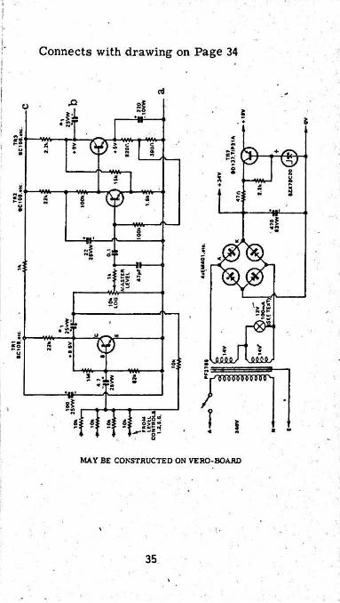
I We feel that the drawback is a small disadvantage and it is seldom that full bass boost and full treble boost are applied simultaneously.As the tone control curves show, generous bass and treble boost and cut is available at the extremes of control rotation, while there is a very little interation with the mid-frequencies. 10k limiting resistors are placed in series with both sides of the one control potentiometers. This prevents the boost and cut from being excessive at very low frequencies, and at very high frequencies. This improves stability and helps prevent acoustic feedback.Since the tone control stage has a very low output Impedance due to the large amount of negative feedback (stage gain is two) it can drive a pair of stereo headphones via a resistor of only a few hundred ohms,270 ohms in this case. This resistor is selected so that when the mixer is delivering slightly more than the maximum nominal output signal, ie., 0.775V RMS in the case of this circuit, the signal becomes distorted due to current limiting in the tone control stage.This warns the person monitoring the mixer output signal with headphones that the power amplifier is being overdriven . If the nominal output of the mixer is changed to suit another amplifier, the 270 ohm resistor is changed accordingly to give an audible warning when the power amplifier is being overdriven.With the headphones disconnected, the mixer output does not does not clip until the signal rises to about 5V RMS.Output from the tone control stage is coupled to the output socket of the mixer via a 4.7k resistor so that it can drive amplifiers with a low input impedance’.The 4.7 resistor can be reduced to lk, if necessary.
38
I
■The output signal of the mixer Is amplified by Tr6 and then fed to a bridge rectifier and meter to provide signal monitoring.The power supply is derived from the mains via a small transformer, which has two 14V windings connected in series to give 28V. This is fed to a bridge rectifier to give a nominal 34V DC which is fed to the metering stages, ie., Tr6.All the other circuitry in the mixer is powered from a 19V supply. This is derived from the 34V rail via a zener diode network and emltter-follower regulator,Tr7. The 47 ohm resistor renders Tr7 short-circuit proof. This is a very worthwhile feature, as the author can testify from repeated experience.As stated previously the main mixer board has four inputs in each channel, each with an input sensitivity of 40mV for the nominal output level of 0.775 volts RKS, and an input impedance of 10k. When combined with the -10k level control of each input, the input impedance is shunted down to a minimum of 5k.Where a higher input impedance is required for a high level source such as a tuner, the input impedance may be simply increased by connecting a resistor in series with the input. This is done by making up a Jumper board which
, is Inserted into the mother board in place of the preamplifier board. For example, the input impedance can be increased to 20k by using a Jumper board with a 15k resistor. This reduces the sensitivity to 16mV for rated output .We will describe how to make a Jumper board later, in the section on construction.Apart from high level sources such as broadcast tuners or tape recorders, greatly Increased sensitivity is required for all the low level sources the mixer is likely to be used with.Accordingly, each intput is provided with its own PC preamp board which is plugged into the mother board. The preamplifier boards use a standard copper pattern and circuit configuration. Circuit constants are modified to .give the required gain, input impedance and frequency characteristic.Refer now to the circuit of the preamplifier which we have designated as a "universal preamplifier". Two high-gain low-noise NPN transistors are used, in a direct-coupled feedback pair configuration.Astute readers will notice that this circuit is very, similar to one following the mixer stage on the main mixer board. The voltage divider resistors in the anl tterclrcuit of the second transistor, Tr9, have been changed (from the circuit of the mixer board) to take into account different operating conditions.The AC feedback components are R3, C3, R4, C2, R2, Cl and the 1.5k resistor in the emitter circuit of the
39
I
first translator, changing bias feed resistor Rl.
The input Impedance Is varied by
The values for the components nominated above are tabulated below the circuit. To make each type of preamplifier. Just refer to the appropriate values In the table.
For a qultar preamplifier, for example, Rl Is 100k,R3 is 33k, R4 Is replaced by a wire link and the others (R2, Cl, C2 and C3) are omitted. The resulting preamplifier has a gain of Just over 20 and an input impedance of 100k.
Note that the input impedance of all the low level preamplifiers, except that of the magnetic cartridge preamp, is lOOk. We have not attempted to "match" the input loads to the nominal impedance of the sources, we have the apparent anomaly of a 600-ohm microphone (say) feeding a 100k input load.
So
There is no point in providing a low Impedance load for a low impedance source. If the load impedance matches the sources impedance half the signal is lost and residual noise produced by the amplifying stage reduced little, if at all. For optimum signal/noise ratio, an amplifier should be arranged to provide a nominal high Impedance load and be driven by a low impedance source.At the same time, the operating conditions of the amplifier should be optimised to give the lowest possible residual noise considering the source it is to be used with. In general this means selecting the optimum quiescent current for the first transistor in the amplifier. This has been done in the universal pream- • plifler circuit, after considering the variety of sources it will be used with.
. To make a corollary of the previous paragraphs: unless an audio source is required to operate into a stated load (such as 50k for a magnetic cartridge) in order to obtain its rated frequency response, the load impedance should be considerably higher than the source impedance, other-wise there will be a loss of signal and a reduction in thesignal/noise ratio.
There are two preamplifier outputs, output 1 and output 2, the latter being fed via a 10k resistor, outputs are necessary to drive the mute board which is described later.is no output coupling capacitor on the universal preamplifier board, or on the mother board.
These two
Readers will also notice that there
This is located on the mute board
Readers may wonder why the frequency response of the ■ low impedance microphone preamplifier is better at the
low end than for all the other preamplifiers. This is merely a function of the reedback network which causes a slight "hump“ in the low frequency response.
Slgnal-to-noise ratios are quoted with respect to the rated output of 0.775V RMS and are unweighted (ie.,
40
measured with a raillivoltmeter having a wideband response). Unless otherwise stated, the measurements were taken with a short-circuit input, ie.( with the appropriate input jack removed with automatically shorts the input.In each case, connecting a typical input source causes a slight degradation in signal to noise ratio.While the universal preamplifier will cater for low level sources which are likely to be required, it will not provide for a ceramic cartridge. Here, we have used a quite different circuit. Two high gain NPH transistors are employed. TrlO is connected as a common-emitter stage with a high-value collector load of 100k and a bootstrapped bias network to give a high input impedance.A .047uF capacitor connected from the emitter of TrlO to the junction of the three resistors in the biasing network provides the bootstrapping. Bootstrapping increases the input impedance in the following way: Without the above- mentioned -047uF capacitor, the input impedance is determined by the product of the 22k resistor multiplied by the AC current gain of TrlO, shunted by the sum of the 330k resistor and the parallel combination of the lM and 150k resistors. This long-winded expression adds up to about 450k, which is not adequate for good bass response from a ceramic cartridge. 'Bootstrapping here makes use of the fact that the voltage gain from the base of a high-gain transistor to its emitter is very close to unity. In fact, It is typically 0.98 or more in the stage under discussion. So with the aid of the .047uF capacitor, 98% of the input signal is coupled to the Junction of the three bias resistors.This drastically reduces the signal current flow in the 330k resistor. By way of illustration, if IV RMS was fed to the input of the preamplifier, the signal current flowing in the 330k resistor would just 2.2 raicroaraps, without bootstrapping. With the bootstrapping capacitor in circuit, the signal current flow in the 330k resistor is typically reduced by more than 30 times. In other words, the input signal "see" the 330k resistor multiplied by more than 30 times, or about 10 megohms. When combined with the product of the transistor's AC gain multiplied by the 22k emitter resistor, we find that the bootstrapping has raised the input impedance to an adequate value of about 3 megohms or more.An emitter-follower stage, Trll, acts as a buffer for the high collector load (100k) of TrlO and thus provides a low otuput impedance for the preamplfier. Voltage gain of the preamp is about 4 times. >As mentioned in the first article, automatic muting is provided to Improve the apparent signal-to-noise ratio of low-level sources such as high or low-impedance microphones. This is particularly desirable with low impedance microphones because they have such a low output signal, but it can Improve ths signal-noise ratio with any microphone used in a noise environment. So besides accommodating the eight preamplifier PC boards,
41
i
|
\:
ES Igo ■'
is a 5Us?i| •'O'' •
i *»° in S §2 ^ 1!! i ‘ilI s
ZL rvL-f-8- ipyMrl' rvly-t* 11> r‘^H>-VsW-jl'-vaH1- IIII IIII'll II II iII
~\ ir~' Imm ----- D O
13?Sr St
iinI:si! -i; S3s; liI;. I|
A^AAHj!(>—(;)—ii j
A-2 *II____
<s>©-----©---- © s
42

ithe mother board has provision for up to eight mute boards. In the prototype mixer, only four mute boards are provided: we imagine that this needs of most constructors. will satisfy the i
If all eight mute boards are required, the extra controls will mean a larger control panel. Either this or they
! will have to be installed on the rear panel.Refer now to the circuit of the mute board. It uses • three transistors and two diodes. As can be seen, the circuit requires two inputs, from 1 and output 2 of the associated preamplifier board.Rasical1v. the circuit works as follows: Slenal is fed from the preamplifier outnut 2 via a 10k resistor and 4.7uF capacitor to the collector of Trl4. The 68k resistor connected to the 19 volt supply line forward- biases the base-emitter Junction of this transistor and causes its collector emitter path to become a low resistance to AC signals.In this way, the transistor can be used similarly to a FET, as an audio switch. Note that the transistor does not 'give as progressive a control characteristic as can be obtained with a FET, but this is of little importance in this application, since the muting action need not be progressive.
• To recap then, when the base-emitter Junction of Trl4 is forward-biased, -the collector-emitter path becomes a low resistance, typically 100 ohms or so, depending on beta. This low resistance forms a voltage divider with the series 10k resistor (which for calculation purposes is effectively in parallel with the 10k mixing level control) to reduce the signal level by about 30dB, dependent upon the setting of the level control. In this condition, the preamplifier is muted. •In order to get the mute circuit unmuted, Trl4 must be changed from the low resistance state to a high resistance state, i.e., it must be turned off. by overcoming the forward bias provided by the 680k resistor with a negative voltage, developed by the mute amplifier comprising Trl2, Trl3, D1 and D2.Trl2 and Trl3 form a complementary voltage amplifier stage with negative AC and DC feedback from the collector
. of Trl3 to the emitter of Trl2 via a 10k resistor. Signal from output 1 of the preamplifier is coupled to the base of Trl2 via a' 100k resistor.Besides signal coupling, the 100k resistor also provides the required bias voltage for the base of Trl2 (from the collector of Tr9 on the preamplifier board). This is one of the reasons for not having an output coupling capacitor on the preamplifier boards. The 100k resistor also prevents Trl2 and 13 from being driven hard into clipping-when presented with a very loud signal.Thus it prevents a "click" being heard when TrU is unmuted.
This is achieved
43
-
Trl2 and Trl3 amplify the signal and feed it to a halfwave "voltage doubler" rectifier formed by D1 and D2 which develop a negative voltage across the 470uf capacitor. If the input signal to the mute amplifier is sufficiently high, the resulting negative voltage is sufficient to turn off Trl4, which stops it from shunting AC signal to the negative supply line.The signal threshold above which the mute circuit amplifier and its associated diodes develop enough negative voltage to Unmute Trl4 is dependent on the gain of Trl2 and Trl3. This is adjusted by the lk switch/pot in series with the 400 ohm resistor and lOuF capacitor.When the pot, which is wired as a variable resistance, is set to its minimum resistance condition (fully anticlockwise) the gain of the mute amplifier is at maximum and therefore provides the lowest threshold for unmuting. In this condition small signals will unmute Trl4. When' the pot is fully clockwise, gain of the mute amplifier is at a minimum and so relatively large signals are required for unmuting to occur.Since very low frequencies are of little Importance to the mute amplifier, a relatively small capacitor, lOuF, can be used to roll off the low frequency response. Similarly, high frequency response. Similarly, high frequency response is rolled off by the .OOluF capacitor in parallel with the 10k feedback resistor.When the mixer is used in a typical set-up it is necessary to be able to disable the muting circuits while gain levels
Otherwise it would be possible to step up to a microphone with the appropriate gain control fully advanced but the system sounding relatively quiet, soon as you spoke into the mic, the system would unmute and then break into the ear-shattering howl of maximum acoustic feedback!
are set.As
Consequently, the switch section of the lk pot is connected in series with the collector of Trl4. the switch-pot fully anticlockwise to operate the switch disables the muting function and enables gain levels for all channels to be set in the normal way.
Rotating
Having described the major circuitry features, we can now talk about construction of the mixer, can begin with assembly of the PC boards, with the mixer board.
ConstructionStart
Assembly of the mixer board is straightforward. }W or If resistors of low noise cracked carbon or metal film construction may be used throughout. The board has been designed to suit PC electrolytic capacitors so these should be used if at all possible. Three luF capacitors in each channel should be tantalum types as marked on the circuit diagram, In several places on the board where a 4.7uF capacitor is specified we have also used tantalum types but this is not mandatory.Quite a diverse range of transistors may be used on all the boards in the mixer, encapsulated types are to be preferred.
From a cost point of view plastic
44
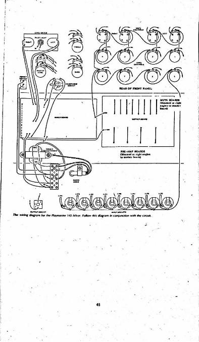
A plastic encapsulated BC137 (or TIP31A) is specified for the supply regulator transistor. This is operated without any heat sink. Note that the centre lead of the transistor must be bent to insert it.PC stakes are used for all connections to the board. Any type may be used, provided they are a tight fit in the PC board holes before soldering.There are several wire links on the board. Note the two associated with the output to the dual meter. These are required with the meter we used in the prototype but must be replaced with suitable resistors if a more sensitive meter movement is used and/or'if. the rated output of the mixer is increased.Assembly of the mother board, is equally straightforward. Twelve eight-way edge connectors with mounting brackets are required. These have one closed and one open mounting bracket. The closed mounting bracket (i.e., not slotted like the Individual connectors) functions as a polarising key for the P.C board inserted into it.Screws, nuts and washers or pop-rivets and washers may be used to secure the edge connector brackets to the mother board before soldering. If pop-rivets are used, take care not to crack the board when they are applied, especially when close to the edge.Assuming that only four muting PC boards are required, as in the prototype, the space for the additional four edge connectors may be left vacant. In their place, 4.7uF tantalum or aluminium PC electrolytic' capacitors are installed as shown on the mother board diagram.As with the mixer board, all connections to the mother board are made via suitable PC stakes.After assembly of the mixer and mother boards is-complete, attention can be turned to the preamplifier and mute boards.A keyway must be cut in each of the plug-in PC boards to polarise them and so prevent them from being plugged in to the edge connector incorrectly. This isarranged by cutting along the length of the connector contact nearest the input capacitor using a hacksaw.Ensure that all boards plug in easily without fouling of the keyway, before mounting any components or soldering.No problems should be encountered with assembly of the plug-in boards. If constructors are not able to obtain PC mounting 220uF capacitors, Cl can most easily be mounted by interchanging its position with R2 (where Cl is required). On the mute board, the 4.7uF capacitor in series with Trl4 should be a tantalum type. The other 4.7uF capacitor associated with the output from Trl3 may be either a tantalum or PC mounting aluminium electrolytic.Since the circuit of the ceramic cartridge is quite different from the universal preamplifier circuit, the
46

Tstandard board pattern has to be modified to accommodate
The wiring diagram of the ceramic preamplifier board shows where the copper pattern is cut and the position of the wire links-three on the topside and two on the
. copper side of the board.Having assembled and carefully soldered all the PC boards, attention may be turned to the chassis. Mount the four rubber feet first. Then carefully follow the details given in the following paragraphs for mounting the transformer and associated hardware.One of the problems we had to contend with early in the development of the Playmnster mixer was the possibility of earth loops, when the mixer was connected to a tupe recorder or power amplifier that was itself earthed back via the mains wiring. The problem is compounded because even the very low level input sockets are earthed directly to the chassis. ‘
(l)Use a two-section bobbin-wound transformer conforming to the insulation and winding construction requirements of BS1.
it.
i
(2)Do not earth the chassis of the mixer back via the mains cord. Instead, mount the transformer on two insulating pillars. In the unlikely event that the transformer insulation does break down to the cote, no hazard would result.(3) Sheath the active leads from the on/off switch with suitable plastic sleeving.(4) Use an on/off switch of all plastic construction, and sleeve the spade lugs of the switch to prevent accidental contact of the user with the mains.(5)We found it necessary to earth the core of the transformer back to the mains cord earth, in order to reduce the induced hum in the low level preamplfiers, particularly those for the magnetic cartridge.Twist the two wires from the terminal block to the on/off switch and sleeve them - the outer sleeve of the mains cord will be quite suitable. Before soldering the wires to the switch, push a length of suitable sleeving over the wires and after soldering, push the sleeving over the spade terminals of the switch. All three terminals of the switch should be sleeved.Ideally, the transformer should have a wraparound cover for the mains primary connections. The cover should be made of Presspahn or Elephantide (trade names for a vulcanised insulation material used in transformer and electrical motor construction). Unfortunately, we were unable to obtain a supply of this material during construction so we had to be content with wrapping two layers of Insulation tape around the transformer to cover the terminations, after soldering short leads to them.Note that ordinary cardboard is not suitable for the job, as it is hygroscopic.
47
Before actually mounting the transformer on the insulating pillars, riiount the six-way terminal block and terminate the transformer primary and secondary leads to it. the red and blue secondary leads together to form the' centre-tap of the series connected windings.
The mains cord should be passed through a grommetted hole in the rear of the chassis and anchored with a cord clamp. Terminate the mains active and neutral leads to the terminal block and solder the earth wire to a solder lug to be secured under one of the transformer mounting feet screws.
Connect
Uake sure that two screws in each insulating spacer do not touch in the centre and thus negate the intended isolation of the transformer core, a suitable length and check with a multimeter to ensure that the transformer core is actually isolated from the chassis yet'is in good electrical contact with the earth wire of the.mains cord.
In other words, use screws of
The headphone socket must also be isolated from the chassis and be provided with an earth return lead back to the mixer board. Otherwise, the headphone earth return current flows in the chassis and hack via the earth paths for the input signals. This causes instability when the low impedance microphone preamplifiers are used.
Wrap the threaded bush of the headphone socket with insulating tape or a suitable piece of plastic sleeve, a fibre washer on both sides of the front panel and check with a. multimeter to see that tile socket is correctly isolated from chassis.
Use
The dual meter is a rather attractive unit. It has blue- tinted scales (but not calibrations) with red pointers.It is intended to be illuminated by a.light shining through the translucent rear section. At the same time, mounting of the meter presents problems as there are no screws or lugs of any sort provided.
Our approach was to make up a bracket which holds the meter in place and also positions a small lamp in the correct position for lighting. The bracket itself Is held in position by fhe master level control dual potentiometer.
Illumination is provided by a Sato miniature bez61 with the red lens removed. A 12V lamp is fitted, which draws about 100mA from one of the 14V windings of the transformer, and the regulation is such that only 12V is applied to the lamp. When combined with the 60mA DC drawn by the mixer circuitry, the total load is excess of the nominal transformer rating, which is 2 x 14V at 60mA.
In short, while the transformer is running in excess of lt3 ratings, it does not represent a situation of undue stress.After an extended period of running, the transformer was found to be warm to the touch, but not unduly so.
48 4t

+20TO«« COW
ANO HTROLSATMAI lAlf SITTINGS
-T StTTlNOS ON CQUIVAUWT VAftlASlf
* TURNOVIR' TONI CONTROL
IMUM
“ ~ - MAl» BOOST
+10 \7
s ■;so
> V
-»o9:
-201to 100 M|RT2 ■000 10000 20000
These curves show ,he per/ormence of the tone controls at half and maximum settings
r i100k-VAV O/M
*7 iithis
OCIM.ie.
=sr«22l io»:
IQ/n<10*
AM#ARO
♦ •IVOOI2i IN4143
o«
©10% 4.2
i0On
oi<5 ■) TOMIXKRjo.: evw io%:
L____------------1
i%: 3 \i\ L. -J \L
FLAVMA$T(R 141 MIXfR MUTI STACK
IFour plug-in mute boards ere used in the prototype Playmester 145 miter.
MAY BE CONSTRUCTED ON VERO-BOARD
49•*
I
Before the master level control potentiometer is mounted to secure the meter bracket in place, cut the shaft to 13 mm length and solder the figure-8 shielded cable to it. Two lengths of 20Cmm of figure-8 shielded cable will be adequate.All the potentiometers should have their shafts cut to 13mm length before being installed.All the input sockets and the output sockets may now be installed. The input sockets have a shorting contact to earth the Input when not in use. All the chassis connections together with a length of tinned copper wire. All interconnections to the mixer and mother boards should be made using pieces of flat multiconductor cable (otherwise known as "rainbow" cable) apart from the shielded input cables. Using the rainbow cable obviates the need for cable lacing and makes circuit tracing easy. We found two meters of 10-conductor cable to be more than adequate. As a bonus it gives a wide range of wire colours and is cheaper than an equivalent quantity of hookup wire.Take care to wire the boards, pots and sockets exactly as indicated in the chassis wiring diagram. Otherwise, hum and instability will almost certainly result.Having checked all connections, fit a three-pin plug ;to the mains cord and apply power to the mixer. Check all the voltages shown on the mixer circuit diagram All voltages should be within IV or 10% of those on the circuit. If not, check the components.If all the voltages check out, now is an appropriate time to make a "Jumper" board which enables the mixer to be operated without a preamplifier, i.e., direct. You will need a piece of Veroboard with 0.15in conductor spacing, at least eight conductors wide and at least 30mm long.Now refer to one of the assembled preamplifier boards and identify which of the contacts is the input connection (this is actually the contact next to the keyway) and which is the output 2 connection. The idea is to make a dummy board which bridges the above two contacts together, with a wire link.With the jumper (or dummy) board in place, the input sensitivity is 40mV with an input impedance of 5k.
\
Alternatively, if you wish to provide higher input impedance and/or reduced sensitivity than the mixer board provides, the input and output 2 connectionsshould be connected by a suitable resistor. For example, by using a 22k resistor, the input impedance is increased to 27k and the sensitivity is reduced to 216mV which would be adequate for most high level sources.Now, with the Jumper board in one of the edge connectors for inputs 5,6, 7 or 8 (refer to the photograph of the front panel to identify these), check out the mixer operation with a set of headphones and a suitable signal
50
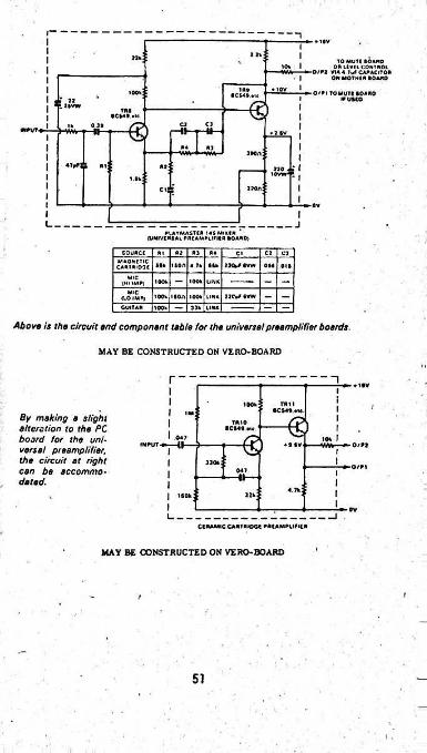
♦ 1*v
22*\ > h|TO MUTC BOARD
OR LEVEL CONTROL »„f CAPACITOR OTHER BOARD
UOT* BOARD If U5C0
»/R* VIA 4 ON M
• 10VI5?.u•OOV O'H TO•C
1 illitt €iV...BC
€ C2 C3IN RUT. a; «? BV
J»on:«WB *1;
•8S.«l.tv;
c.:[ jjoa:
ov
L. JPLAYMASTIA 145 MlKlR * l«*AL PREAMPLIFIER BOARD}OJNIVE
GOURCI JM A? RJ 04 CJ C3ClMAONITIC
utiooE BBk ' 500 4 7k iifc IKfcFBVW 051 01kCARMIC
100k 100 k LINKiHHMPjMIC
(10 IMF| a?c*f «vw100V ikon lOOv UNX
GUITAR 33k100V LINK
Above is the circuit and component table for the universe!preamplifier boards.
MAY BE CONSTRUCTED ON VERO-BOARD
r ♦ 1BV
100k TTU 18CS45 «ic l
IMBy making a slight alteration to the PC board for the universal preamplifier, the circuit at right can be accommodated.
TAlOacs40.*ic
047IIINPUT • ♦ • BV. O/Pl
3304O/Pl047
II«.n:-160
L.CCRAMIC CARTRIDGE PREAMPLIFIER
MAY BE CONSTRUCTED ON VERO-BOARD
f/
51
source connected. With no signal applied, the mixer should be almost completely silent, even with all level and tone controls at maximum settings.
Note that the jumper board will not allow the mixer to function correctly when used in place of preamplfiers for inputs 1 to 4, unless the associated mute board is in position and the mute control is switched to off.
Now plug each of the preamplfier boards, one at a time, into an appropriate edge connector on the mother board and check the voltages on the circuit. Now plug preamplifier boards into edge connectors for inputs 1 to 4 and plug in the associated mute boards and check voltages on these (i.e., at the emitter of Trll on each mute board).
Note that the mute board will not work unless an associated preamplifier board is plugged in. This is because the mute board obtains its bias from the output of the preceding preamplifiers, as explained previously.
With a microphone connected to an appropriate input, you can now check that the mute function is operational. Check this with all the mute boards.
When all checking and de-bugglng has been completed, you can install the front panel, this step until now, otherwise there is a strong chance of scratching the panel while fiddling about.
It is better to leave
Scotchal was used to make the front panel of the prototype mixer. The panel was made in two parts, with Che Join being concealed by a piece of pressure-sensitive tape.We assume that metalwork suppliers will have front panels available shortly after this article is published.
Fifteen knobs are used in all. photographs, we have used several different types of knob, each selected to suit the control function. It is desirable to have the individual mixer level controls small while the main level control knob can be fairly large. „
As can be seen from the
Qn the prototype, the timber end panels were attached by screws from inside the chassis, but this is a very awkward method. A better procedure would be to have recessed holes in each panel and attach them bv self-taoping screws to the chassis, from the outside. Before mounting the panels, staple a sheet of aluminium foil (as used for cooking) and position it oh the panel so that it will make contact with the chassis and so provide a degree of shielding.
The top panel can be given a practical finish by covering it with vinyl, using contact adhesive.
For best results, do not stack the mixer on top of power amplifiers with large transformers, otherwise hum will be a problem. Power amplifiers need plenty of ventilation anyway. At the same time, keep low level input leads away from power transformer fields.
52

List of Component Parts Chassis and hardware1 chassis with cover2 timber end panels, 205 x 165mra 1 front panel1 power transformer with two 14V secondaries.1 dual level meter, 500uA sensitivity.1 meter bracket (see text)1 miniature bezel with 12V lamp 15 knobs; select types to suit.1 10k (log) dual ganged potentiometer2 100k (lin) dual ganged potentiometers 8 10k (log) potentiometers4 lk (lin or log) potentiometers with switch 2 6.5mra stereo Jack sockets 8 6.5mm jack sockets with shorting contacts1 all-insulated toggle switch2 12mm insulating spacers, tapped l/8in Whitworth1 solder lug <1 mains cord clamp 1 six-way insulated terminal block1 three-pin mains plug and three-core mains cord. 8 PC board supports2 meters of 10-conductor rainbow cable 2 meters of figure-8 shield cable2 fibre washers for headphone socket
i
Mixer Board
1 Vero board 37 PC stakes
Semiconductors4 EM401, BY126/100, IN40O2, RS 276-1136 silicon rectifier diodes.8 1N4148, RS276-1136, 1N914A, BA 127-209, BAY 39-611 x B2X79/C20 zener diode4 BC109, BC549, BC184L, RS 276-2013/2031, 2N930 low noise NPN silicon transistors6 BC108, BC548, BC183L silicon NPN transistors, RS276-2009, 2N929-9302 BC107, P.C547, BC182L silicon NPN transistors, RS276-2009/2031. 5K3020. 2H929-9301 BD137, TIP31A RS 276-2018, 2N2102-4922. SK3054.Resistors (JW or i'll, 5% tolerance)
4 x 1M, 2 X 220k, 2 x 150k, 4 X 100k2 x 82k, 4 x 22k, 4 x 15k, 26 x 10k, 2 x 4.7k, 5 x 2.2k,2 x 1.8k, 2 X 1.5k, 8 x lk, 2 x 820 ohms, 2 x 390 ohms,2 x 270 ohms, 1 x 47ohms.Capacitors1 470uF 63VW PC electrolytic2 220uF 10VW PC electrolytic2 lOOuF 25VW PC electrolytic2 47uF 25VW PC electrolytic2 22uF 25VW PC electrolytic2 lOuF 25VW PC electrolytic4 4.7uF 25VW PC or tantalum electrolytic
53I
l
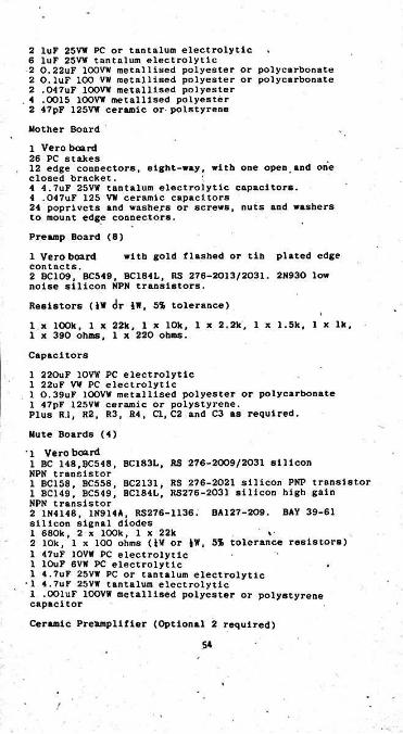
2 luF 25VW PC or tantalum electrolytic 6 luF 25VW tantalum electrolytic2 0.22uF 100VW metallised polyester or polycarbonate 2 O.luF 100 VW metallised polyester or polycarbonate 2 ,047uF 100VW metallised polyester
. 4 .0015 10OVW metallised polyester 2 47pF 125VW ceramic or-polstyreneMother Board1 Vero board 26 PC stakes12 edge con.nectors, eight-way, with one open, and one closed bracket.4 4.7uF 25VW tantalum electrolytic capacitors.4 .047uF 125 VW ceramic capacitors24 poprlvets and washers or screws, nuts and washers to mount edge connectors.Preamp Board (8)
with gold flashed or tib plated edge1 Vero board contacts.2 BC109, BC549, BC184L, RS 276-2013/2031. 2N930 low noise silicon NPN transistors.Resistors <JW <Jr iW, 5% tolerance)1 x 100k, 1 x 22k, 1 x 10k, 1 x 2.2k, 1 x 1.5k, 1 x lk,1 x 390 ohms, 1 x 220 ohms.Capacitors
1 220uF 10VW PC electrolytic 1 22uF VW PC electrolytic1 0.39uF 100VW metallised polyester or polycarbonate 1 47pF 125VW ceramic or polystyrene.Plus R.l, R2, R3, R4, Cl, C2 and C3 as required.
Mute Boards (4)'1 Vero board1 BC 148.BC548, BC183L, RS 276-2009/2031 silicon NPN transistor1 BC158, BC558, BC2131, RS 276-2021 silicon PNP transistor1 BC149, BC549, BC184L, RS276-2031 silicon high gain NPN transistor2 1N4148, 1N914A, RS276-1136. BA127-209. BAY 39-61Silicon signal diodes1 680k, 2 x 100k, 1 x 22k2 10k, 1 x 100 ohms (iW or iW, 5% tolerance resistors)1 47uF 10VW PC electrolytic 1 lOuF 6VW PC electrolytic 1 4.7uF 25VW PC or tantalum electrolytic
•1 4.7uF 25VW tantalum electrolytic 1 .OOluF 100VW metallised polyester or polystyrene capacitorCeramic Preamplifier (Optional 2 required)
5»
1 Vero board2 BC109, BC5'19, BC184L, RS 276-2013/2031. 2N930 low noise silicon NPN transistors2.047uF 100VW ceramic or metallised polyester capacitors 1 x Ira, 1 x 150k. 1 x 22k, 1 x 10k. 1 x 4.7k, 1 x 100k, 1W or iW, 5% tolerance resistors).Miscellaneous
spaghettiTinned copper wire, electrical insualtlon tape, sleeving, vinyl covering material, contact adhesive, selftapping screws, solder.
55
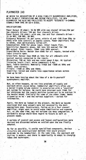
PAYMASTER MOHE BEGIN THE DESCRIPTION OF A HIGH FIDELITY QUADRAPHONIC AMPLIFIER, WITH IN-BUIlT SYNTHESISING AND DECODE FACILITIES, THE NEU PLAYMASTEP 140 ALSO HAS FACILITIES TO ACCEPT "OISCRETE” 4-CHANNEL SIGNALS FROM TAPE OR CD-4 DISCS.SPECIFICATIONSPower Output (8 ohms): 16.5H RMS with one channel driven;15W per two channels driven; 14W per four channels driven.Power Output (16 ohms): with one, two and four channels driven - 10.SH RMS, 10H RMS, 9H RMS.Frequency Response: As per curve, within *2 and -2dB from 20Hz to 20kHz with tone controls at appro* centre. Power amplifiers flat to 60kHz, then deliberately rolled off.Compensation: RIAA for phone input. Other Inputs flat. Sensitivity: Magnetic phono, 2mV into SOK nominal for 15W RMS output. Other inputs, 150mY into SOOK nominal.Signal/Noise Ratio: Better than 60dB for all inputs, tested with input circuits open.Cross-Talk: Better than 44dB at 1kHz for all cKSnnels with typical sources connected to the inputs.Distortion: THD at 1kHz and ma* rated power 0.6pc. At typical listening levels (incl. noise component) 0.4pc.Bass, Treble Controls: Nominally +14dB and -18dB at 50Hz and lOkHZ. (see curves).Filters: -14dB at 20Hz and 10kHz.Stability: Tested and stable into capacitance values across load up to 2uF.
We have been tossing about the idea of a do-it-yourself quadrophonic amplifer.
But, as often happens, we ran into problems of supply and approach which caused delay. Comerc'ial amplifiers often use a master 4-gang volume control in association with a "joystick" pot system for balance. We could have obtained such items for our prototype but the supply position turned Out to be dubious in the months ahead. Similarly for some of the other items. Weeks slipped by as we - and the various suppliers - waited for information.
Again, the more we looked at the project, the more we became convinced that easy answers were not necessarily the most appropriate ones. Constructors, facing up to a four channel amplifier, might want to avoid undue complication and expense but, at the same time, may not welcome too many compromises. A worthwhile design would have regard to future as well as present needs.
A variety of control and access and layout configurations were devised and discarded before we settled upon the one finally adopted.
As far as possible, it avoids specialised components, devious circuitry and constructional methods that would present problems to the homebuilder. At the same time, the approach and styling is modern, and there is opportunity to adapt to changing ideas and techniques.
56
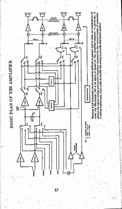
PSafa i -
I<C
e iHfa ■O55< ;5
faU►—<cn<«
»
f:sA51‘I
< \1i
LsiJ sl i% n| 3SI !i.
57
■ >:\ :
At this point 1n the article, we would normally refer to the main circuit diagram and use it to explain our general approach. We can't do that on this occasion, because the circuit diagram of a complete quadraphonic amplifier is hard to draw and hard to read, particularly 1f compressed into the available page area.
Instead, we plan to rely on block and functional diagrams which, hopefully, will contain a lot of information of constructional value. The basic circuit lumps around which the amplifier is built are regarded as modules, each one to be the subject of separate presentation.
Not only should this simplify construction of the amplifier as a whole, but it will meet the needs of those who may want to tackle the project in stages. For example, by providing just the preamp, board, two power modules and the power supply, the amplifier could be operated as a normal 2-channel stereo system. The additional channels and facilities could be added, as they are needed, or as finances permit.
But, before proceeding further, the simple diagram indicates the positions assumed for the four loudspeakers and the coding
, adopted to identify them. When ultimately building the amplifier you will need to be constantly alert to avoid getting the channels mixed up. Different coloured wiring will help, but we have also tried to build into the layout and diagrams a logical clockwise
/ progression which is: front left; front right; back right; back left.
Perhaps we should add that the listening room need not be as regular or as bare as the diagram seems to suggest. One of the attractions of quadraphonic sound is that it can fill a listening room with pleasantly dimensioned sound, without being overmuch inhibited by the-shape of the room or the disposition of other furniture. It is, in fact, a good deal less demanding in this respect than ordinary 2-channel stereo.
The general approach adopted 1s best appreciated by examining the accompanying block diagram.
A series of DIN sockets on the rear of the chassis accepts inputs from five possible sources: magnetic phono pickup, feeding directly into a preamplifier compensated for RIAA characteristic; radio, either mono or stereo; external stereo tape player, providing it has its own preamp / compensation; auxiliary, either mono or stereo; external 4-channel source, providing it has its own low-level circuitry. i
We shall have more to say later about the external 4-channel input.
The precise sensitivity at the various inputs will vary somewhat with component tolerances and with operating mode. However, in general terms, the specification for the phono input is 2.0aV minimum into 50k Ohms for full output. This will more than meet the needs of current magnetic cartridges.
Other Input channels present an impedance of approximately 0.5 megoiwi and require an input of nominally 150mV for full output. These again are convenient and conventional'figures.
i
58
On this occasion, we have not sought to make specific provision for ceramic phono cartridges, since magnetic types are now virtually universal in the high fidelity field.
The desired input is selected by a 5-positton "Select" switch marked as Sla and Sib. The switch has two other poles which we shall also refer to later but, otherwise, this much of the circuitry is conventional.
Conventional also is the left/right balance potentiometer which follows the Select switch, and the "Tape Out" provision from this same part of the circuit. Hade available via the Tape DIN socket already referred to, the tape output allows material to be copied from the.amplifier, without being subject to the amplifier's volume and tone controls.
The tone controls employ conventional bass and treble cut and boost circuitry which can modify signals arriving via any one of the 2-channel stereo inputs. They are therefore effective
■ for anything derived from these sources, including normal 2-channel stereo, simulated quadraphonic, or matrixed quadraphonic.Output from the tone control stages passes to two poles of a "Mode” switch, designated as S2a and S2b. Some of our earlier effort was aimed directly at avoiding the need for such a switch and we had a scheme worked out involving interchangeable plugs at the rear of the chassis, which would have been readily adaptable to future needs. 8ut who wants to fiddle with plugs behind a chassis, when changing from one mode of operation to another? Whether by a socket system or a mode switch, the operating mode will almost certainly need to be changed, perhaps more than once in a typical listening session.
Output from the various signal sources may need to be directed to the power amplifiers for straight-through 2-channel stereo, or it may need to be diverted to one or other of the synthesising or decoding systems, either in-built or external.
The Modes switch therefore needs to direct the available signal the the circuit which is to receive it while, at the same time,
.the power amplifiers have to be switched to pick up their signal from that source. Poles S2a and S2b perform the first function, while poles $2c, d.e S f operate at the respective inputs of the power amplifier modules.
Before proceeding, it would be appropriate here to refer to the additional poles on the Select switch Sic and Sid, which relate to the provision for external 4-channel input. Such a provision is necessary if the amplifier is to cope with the discrete 4- channel signals which might typically be derived from a tape deck or from a future CD-4 record playing deck and demodulator.
The front channels present no problem, since they can be handled by Sla and Sib and fed through to the appropriate left and right front power amplifiers.
The back channels, on the other hand, have to be fed to the respective ppwer amplifiers which, in all other modes, derive signals extracted from'the "front" 2-channel sources. Thus the Select switch has to carry two extra poles so wired that, in the "Ext 4" position, the power amplifiers driving the back loudspeakers are connected through to the "Ext 4“ signal source.
59
But the problem doesn’t quite end here. The “front" signals pass through the tone control board and we would not want it any other way; it retains the bass/treble control facility, but it does introduce a 180-degree phase change in the signal.
A seemingly obvious course would be to duplicate the tone control facility, but this is one area where we accepted compromise. Duplication would apply only for the back channels and only with discrete input signals. And, coming from the latest technology sources, these would hopefully be the signals least likely to need “doctoring”.
The price would be duplication of the entire tone control circuitry, including the provision of additional and expensive ganged potentiometer elements.Rather than coranit constructors to this course, we suggest that the back channels be operated level in the "Ext 4" mode. The problem of the phase change can be handled simply by incorporating in the signal lines a relatively simple stage operating at ^ slightly less than unity gain and virtually duplicating the tone control stage in this respect.
The difficulty might alternatively have been tackled by reversing the connections to the back loudspeakers in this mode only, but this might have led to other problems.
As it is, the phase inverting amplifier can be added much later, and only when the “Ext 4“ facility is needed. Since it uses only a couple of small signal NPN transistors and a few standard wiring components on a piece of Veroboard, there will be no risk of the parts becoming unavailable.
At this point, we faced the decision of what modes to provide for in the prototype amplifier, having in mind present and future needs and the fact that firms selling kits and components would not want to stock variously marked front panels. What we have suggested should meet most requirements, while retaining a large element of flexibility.
In the fully clockwise position of the Mode switch (the position as drawn) the signal frcm the tone control stage is directed straight through to the front left and right power amplifiers via a 2-gang slide volume control. Using this much of the system, the amplifier works as a conventional 2-channel stereo unit, with no redundant circuitry in the line, and no "blend” to deteriorate left/right stereo separation.
The same pair of signals is made available to the back channel amplifiers via a second 2-^ang slide volume control. •
You will note that phone jacks are provided so that the front and back amplifiers may optionally feed pairs of loudspeakers or stereo headphones.
Taken together, the foregoing paragraphs add up to a range of useful options in this first position of the Mode switch:
1. Double sereo in the one room, with balance determined by the volume control settings.
60
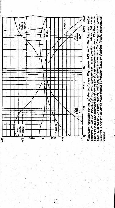
i
Z. Two-channel stereo at either end of a long listening room. If this is an important option, the links to S2e and S2f could be interchanged so that the right and left channels are in their proper positions when you face the "back" end of the room.
3. Two channel stereo in separate rooms with the level of each controlled by its own "front" or “back" potentiometer.
4. Mixed loudspeaker and headphone, or double headphone listening, with each channel independently adjustable.
In the second position of the Mode switch, the front signals again go straight through to the front power amplifiers, without passing through redundant circuitry. On this setting, however, the signals are also fed to the input of the EA 2/4 decoder, which can provide a measure of decoding for matrixed signals, and which does an excellent job of synthesising four channels from 2-channel program material.Output from the decoder goes to the back channels via the appropriate volixae control.
The provision of separate slide type volume controls, mounted side by side, obviates the need for a separate front/back balance control, and also renders unimportant slight variations in the gain of the signal paths to the power amplifiers, in the various modes. It is very simple to operate the sliders together or to nudge either one up or down slightly to get Just the right effect.
The back channels can therefore be set very easily for "ambience", or a matching level, or even a dominant signal.
On the third position of the Mode switch, the signal is routed via a basic SQ decoder, about which we will say more later. This is the position you will normally choose for SQ encoded discs; you may or may not prefer it for other discs or for synthesised effects.
Quite deliberately, we have avoided marking the panel in a specific way. Instead, position 1 is marked "ST 2/4", the others "HAT1" and "MAT2".
The "ST2/4" position is the appropriate one to select for straight 2-channel stereo and also for discrete quadraphonic, when the Mode switch is set to "Ext 4". For this reason, we have wired the switches so that the "ST2/4" and “Ext 4" positions are adjacent and easily,bridged by a line drawn on the panel.
In fact, if you are not interested in the double stereo facility, the 2/4 decoder can be wired to this first position. The labelling is still valid and the straight-through frontal stereo is not prejudiced, since the 2/4 decoder does not blend'the front channels.
By doing this, or else eliminating the 2/4 decoder altogether, a switch position can be cleared to select some other type of in-built decoder that!might turn up.
Alternatively, we have provided for an octal or other socket of the chassis.on the rear While we have not actually wired up
such a socket, it should be Dossible to connect to it output
62/
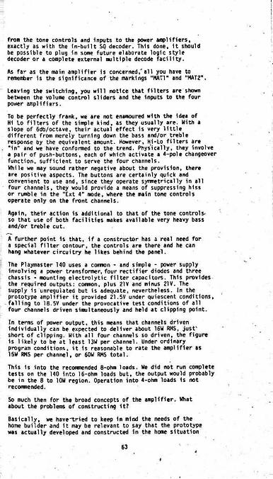
from the tone controls and Inputs to the power amplifiers, exactly as with the in-bu1lt SQ decoder. This done, it should be possible to plug in some future elaborate logic style decoder or a complete external multiple decode facility.
As far as the main amplifier is concerned,'al1 you have to remember is the significance of the markings “HAT!" and "MAT2".
Leaving the switching, you will notice that filters are shown between the volume control sliders and the inputs to the four power amplifiers.
To be perfectly frank, we are not enamoured with the idea of Hi Lo filters of the simple kind, as they usually are. Kith a slope of 6db/octave, their actual effect is very little different from merely turning down the bass and/or treble response by the equivalent amount. However, Hi-lO filters are
. “in" and we have conformed to the trend. Phys'icatly, they involve a pair of push-buttons, each of which activate a 4-pole changeover function, sufficient to serve the four channels.While we may sound rather negative about the provision, there are positive aspects. The buttons are certainly quick and convenient to use and, since they operate symmetrically in all four channels, they would provide a means of suppressing hiss or rumble in the "Ext 4" mode, where the main tone controls operate only on the front channels.
Again, their action is additional to that of the tone controls, so that use of both facilities makes available very heavy bass and/or treble cut.
A further point is that, if a constructor has a real need for a special filter contour, the controls are there and he can hang whatever circuitry he likes behind the panel.
The Playmaster 140 uses a common - and simple - power supply involving a power transformer, four rectifier diodes and three chassis - mounting electrolytic filter capacitors. This provides the required outputs: common, plus 21V and minus 21V. The supply is unregulated but is adequate, nevertheless, in the prototype amplifier it provided 21.5V under quiescent conditions,
-falling to 18.5V under the provocative test conditions of all four channels driven simultaneously and held at clipping point.
In terms of power output, this means that channels driven individually can be expected to deliver about 16W RMS, just' short of clipping. With all four channels so driven, the figure is likely to be at least 13W per channel. Under ordinary program conditions, it is reasonable to rate the amplifier as 15W RMS per channel, or 60V RMS total.
This is into the recommended 8-ohn loads. We did not run complete tests on the 140 into 16-ohm loads but, the output would probably be in the 8 to 10W region. Operation into 4-ohm loads is not recommended.
So much then for the broad concepts of the amplifier. What about the problems of constructing it?
Basically, we have-tried to keep in mind the needs of the home builder and it may be relevant to say that the prototype was actually developed and constructed in the home situation
63f

during evenings and weekends. Host copies will typically be produced in the same situation, with the difference that individual constructors will be able to follow pictures and diagrams, rather than have to work out the tedious detail for themselves. ' •
He have done our best to assist, in this regard, in the space available, but we must warn that construction of the complete amplifier is a fairly formidable task, and one that will absorb a lot of hours. If you have successfully constructed a normal stereo amplifier, you should be able to cope with the 140. But don't tackle it as your first substantial electronics project; it's too big a job for that!
If you do decide to "have a go", you'll need to pay plenty of attention to the main wiring diagram, into which we have tried to cram a lot of essential information.
First point of interest is the wiring to the OIN input connectors. To the best of our knowledge they conform to current “standards”. The connectors are drawn looking on the socket tags but, if you are in anyway confused, work to the numbers which are usually moulded igto plugs and sockets alike.
In the case of phono socket, pins 1 and 5 are bridged, allowing either a 3-pin or a 5-pin plug to be used. The chokes, intended -- to combat radar or other RF interference, involve a couple of ferrite RF beads, typically 3.5mm diameter and 5mm long. Loop about 5 turns of thin enamelled wire through the beads; anchor the chokes between pins 3 and 5 of the socket and a tagstrip secured to the socket mounting screw.
All signal wiring from the input sockets to the rest of the circuitry should be carried out in fugureB shielded wire with outer PVC covering, to prevent random contact between the shield and chassis.
IIt is absolutely essential to follow the earthing procedure suggested in the diagram. Failure to do so will almost certainly result in huj problems and possibly Instability as well.
Looking again at the phono input, the socket shell and pin 2 are shown earthed to the chassis at this point. The intention is that the incoming phono leads be earthed whefe they enter the amplifier chassis and that the internal circuitry be earthed back to - and only to - this same point.
As a first step to this objective, the braids of the figure-8 leads running back to the preamplifier input should be earthed to pin 2 of the phono socket and also to the earthy pattern of the preamplifier board. When you ultimately mount this board on its pillars, you will have to make sure that the pillars and/or screws are clear of the copper pattern.
For the sake of simplicity, all other input sockets can be wired with the braid joining to pin 2 and thence to the earthed shell.
- However, there is one vital difference; whereas the braids from the phono socket join to the preamp earth pattern, the braids from the other sockets go nowhere at the far end.
64' 'I
i
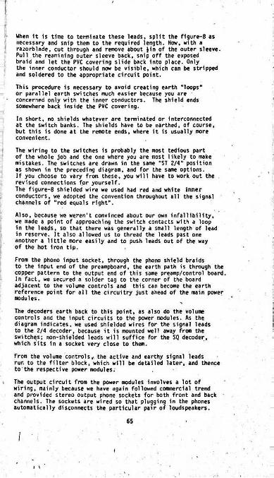
When 1t is time to terminate these leads, split the figure-8 as necessary and snip them to the required length. Now, with a razorblade, cut through and remove about Jin of the outer sleeve. Pull the reamining outer sleeve back, snip off the exposed braid and let the PVC covering slide back into place. Only the inner conductor should raw be visible, which can be stripped and soldered to the appropriate circuit point.This procedure is necessary to avoid creating earth “loops" or parallel earth switches much easier because you are concerned only with the inner conductors. The shield ends somewhere back inside the PVC covering.In short, no shields whatever are terminated or interconnected at the switch banks. The shields have to be earthed, of course, but this is done at the remote ends, where it is usually more convenient.The wiring to the switches is probably the most tedious part of the whole job and the one where you are most likely to make mistakes. The switches are drawn in the same "ST 2/4" position as shown in the preceding diagram, and for the same options.If you choose to vary from these, you will have to work out the revised connections for yourself.The figure-8 shielded wire we used had red and white inner conductors, we adopted the convention throughout all the signal channels of “red equals right".Also, because we weren't convinced about our own infallibility, we made a point of approaching the switch contacts with a loop in the leads, so that there was generally a small length of lead in reserve. It also allowed us to thread the leads past one another a little more easily and to push leads out of the way of the hot iron tip.From the phono input socket, through the phono shield braids to the input end of the preampboard. the earth path is through the copper pattern to the output end of this same preamp/control board. In fact, we secured a solder tag to the corner of the board adjacent to the volume controls and this can become the earth reference point for all the circuitry just ahead of the main power modules.The decoders earth back to this point, as also do the volume controls and the input circuits to the power modules. As the diagram indicates, we used shielded wires for the signal leads to the 2/4 decoder, because it is mounted well away from the switches; non-shielded leads will suffice for the SQ decoder, which sits in a socket very close to them.From the volume controls, the active and earthy signal leads run to the filter block, which will be detailed later, and thence tothe respective power modules.
i The output circuit from the power modules involves a lot of wiring, mainly because we have again followed commercial trend and provided stereo output phone sockets for both front and back channels. The sockets are wired so that plugging in the phones automatically disconnects the particular pair of loudspeakers.
I
65
i \
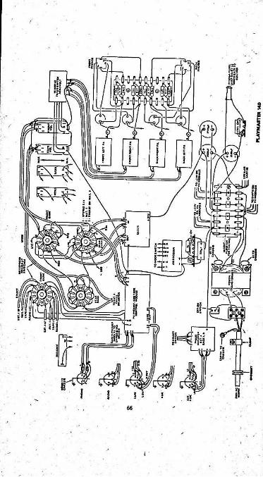
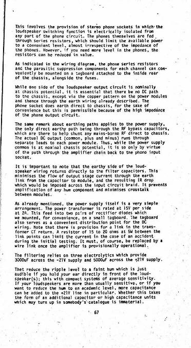
This Involves the provision of stereo phone sockets In which'the loudspeaker switching function 1s electrically Isolated from any part of the phone circuit. The phones themselves are fed . through series resistors, which should limit the available power to a convenient level, almost irrespective of the impedance of the phones. However, if you need more level in the phones, the resistors can be reduced in value.
As indicated in the wiring diagram, the phone series resistors and the parasitic suppression components for each channel can conveniently be mounted on a tagboard attached to the inside rear of the chassis, alongside the fuses.
While one side of the loudspeaker output circuit is nominally at chassis potential, it is essential that there be no DC path to the chassis, except via the copper pattern on the power modules and thence through the earth wiring already described. The phone socket does earth direct to chassis, for the sake of convenience but this is permissible because of the high impedance of the phone output circuit.
The same remark about earthing paths applies to the power supply, the only direct earthy path being through the RF bypass capacitors, which are there to help shunt any mains-borne RF direct to chassis. The actual DC output (cornnon, plus and minus) runs through separate leads to each power module. Thus, while the power supply coimon is at nominal chassis potential, it is so only by virtue of the path through the amplifier chain back to the phono input socket.
It is Important to note that the earthy side of the loudspeaker wiring returns directly to the filter capacitors. This minimises the flow of output stage current through the earth link from the capacitor to module, and the resulting IR drop which would be imposed across the input circuit braid. It prevents amplification of any hum component and minimises crosstalk between modules.
As already mentioned, the power supply itself is a very simple arrangement. The power transformer is rated at 15V per side at 2A. This feed into two pairs of rectifier diodes which we mounted, for convenience, on a small tagboard. The tagboard also serves as a convenient distribution point for the OC wiring. Note that there is provision for a link in the transformer CT return. A resistor of 15 to 20 ohms at 5W between the link points can limit the current in the case of an accident during the initial testing. It must, of course, be replaced by * wire link once the amplifier is provisionally operational.
The filtering relies on three electrolytics which provide 3000uF across the -21V supply and 5000uF across the t21V supply.
Thet reduce the ripple level to a faint hum which is just audible if you hold your ear directly in front of the loudspeakers); this with compact systems of average sensitivity.If your loudspeakers are more than usually sensitive, or if you want to reduce the hum to an academic level, more capacitahce can be added to the +21V line in particular. Whether this takes the form of an additional capacitor or high capacitance units which may turn up in somebody's'catalogue is immaterial.
‘ 67

Once final point: Note that the indicator lamp 1s wired back to the coirnon line. Even though it is nominally a DC circuit, you will find yourself with an hum loop problem if one side of the lamp returns to chassis.
In the interest of economy and accessibility, we used a simple dish chassis, as pictured. Dimensions of the prototype are 38.3cm wide, 28.1cm deep and 9cm high. Such a chassis can be slid into a wooden case, if your preference or your skill lies in that direction. Alternatively, a simple metal fold can be slipped over the top and secured to the side flanges by self-tapping screws. Such a cover would normally be dressed with a wood-grain adhesive cloth.
/
Cooling is not a critical problem with the particular output stages, but it certainly should not be ignored, particularly if you are likely to push the amplifier towards its power limits. There is a pattern of holes under the chassis and, for these to be effective, the chassis must be stood up on rubber feet.If a wooden case is used, make sure it has a cut-out to expose the holes, with feet on the cabinet instead.
A wooden case or metal top cover should also have some kind of venting at the top to allow free air circulation. The styling is a matter for individual suppliers.
In approaching the construction of the amplifier, we strongly advise that you instal the components along the rear and front • edges of the chassis, interconnecting them by wires laced together into cables. An alternative, which you might prefer is to push the wires through a series of rings cut from nylex tubing.
By doing this when the amplifier is little more than a shell, you will have room to work. If you do things the other way, installing the modules and then simply running the wires individually, you will almost certainly end up with a disorderly tangle.
Instal the DIN input sockets first, all with pin 2 towards the bottom of the chassis dish. The phono socket is at the end with a 3-lug tag secured under the mounting rivet adjacent to pins 3 and 5. The other sockets follow in the same order as in the main diagram. We used a hand rivetter to attach the sockets but screws and nuts can be used instead.
To fill the central socket hole, as yet unused, we mounted an ordinary octal socket.
Next come the four polarised loudspeaker sockets. If you plan to use rivets, make sure to get the sockets with metal, not moulded, flanges. The larger "earthy" pins go towards the centre of the chassis.
Alongside the loudspeaker sockets are the fuseholders, which need to be fitted with 1.5A fuses.
Then comes the power cord, which will involve an access groamet, a 3-hole junction block and a cord clamp.
Also attached to the inside of the rear chassis face by lin stand-off spacers is a 20-lug section of tagboard which accomodates the output shunt and headphone feed components. This
68 f
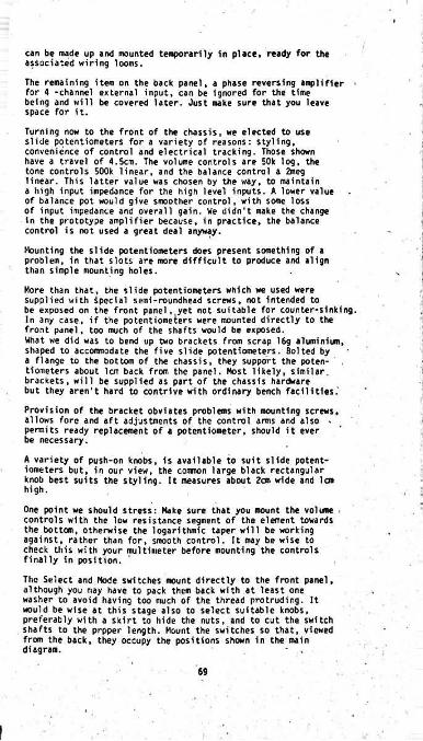
can be made up and mounted temporarily in place, ready for the associated wiring looms.
The remaining item on the back panel, a phase reversing amplifier for 4 -channel external input, can be ignored for the time being and will be covered later. Just make sure that you leave space for it.Turning now to the front of the chassis, we elected to use slide potentiometers for a variety of reasons: styling, convenience of control and electrical tracking. Those shown have a travel of 4.5cm. The volume controls are 50k log, the tone controls 500k linear, and the balance control a 2meg linear. This latter value was chosen by the way, to maintain a high input impedance for the high level inputs. A lower value of balance pot would give smoother control, with some loss of input impedance and overall gain. We didn't make the change in the prototype amplifier because, in practice, the balance control is not used a great deal anyway.
Mounting the slide potentiometers does present something of a problem, in that slots are more difficult to produce and align than simple mounting holes.
More than that, the slide potentiometers which we used were supplied with Special semi-roundhead screws, not intended to be exposed on the front panel,,yet not suitable for counter-sinking. In any case, if the potentiometers were mounted directly to the front panel, too much of the shafts would be exposed.What we did was to bend up two brackets from scrap 16g aluminiun, shaped to accommodate the five slide potentiometers. Bolted by a flange to the bottom of the chassis, they support the potentiometers about 1cm back from the panel. Most likely, similar, brackets, will be supplied as part of the chassis hardware but they aren't hard to contrive with ordinary bench facilities.’
Provision of the bracket obviates problems with mounting screws, allows fore and aft adjustments of the control arms and also - permits ready replacement of a potentiometer, should it ever be necessary.
A variety of push-on knobs, is available to suit slide potentiometers but, in our view, the conmon large black rectangular knob best suits the styling. It measures about Zc® wide and lcn high.
One point we should stress: Make sure that you mount the volume controls with the low resistance segment of the element towards the bottom, otherwise the logarithmic taper will be working against, rather than for, smooth control. It may be wise to check this with your multimeter before mounting the controls finally in position.
The Select and Mode switches mount directly to the front panel, although you may have to pack them back with at least one washer to avoid having too much of the thread protruding. It would be wise at this stage also to select suitable knobs, preferably with a skirt to hide the nuts, and to cut the switch shafts to the prpper length. Mount the switches so that, viewed from the back, they occupy the positions shown in the main diagram. - ,
>
69
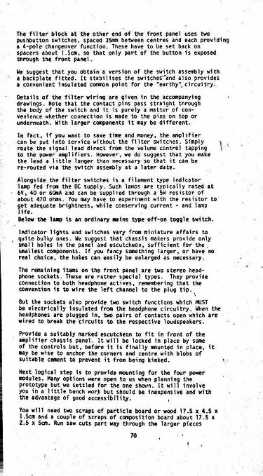
The filter block at the other end of the front panel uses two pushbutton switches, spaced 35nn between centres and each providing a 4-pole changeover function. These have to be set back on spacers about 1.5cm, so that only part of the button is exposed through the front panel.
We suggest that you obtain a version of the switch assembly with a backplate fitted. It stabilises the switcheS"and also provides a convenient insulated common point for the “earthy" circuitry.
Details of the filter wiring are given in the accompanying drawings. Note that the contact pins pass straight through the body of the switch and it is purely a matter of convenience whether connection is made to the pins on top or underneath. With larger components it may be different.
In fact, if you want to save time and money, the amplifier can be put into service without the filter switches. Simply route the signal lead direct from the volume control tapping to the power amplifiers. However, we do suggest that you make the lead a little longer than necessary so that it can be re-routed via the switch assembly at a later date.
Alongside the filter switches is a filament type indicator lamp fed from the DC Supply. Such lamps are typically rated at 6V, 40 or 60mA and can be supplied through a 5W resistor of about 470 ohms. You may have to experiment with the resistor to get adequate brightness, while conserving current - and lamp life.Below the lamp is an ordinary mains type off-on toggle switch.
Indicator lights and switches vary from miniature affairs to , quite bulky ones. We suggest that chassis makers provide only
small holes in the panel and escutcheon, sufficient for the. smallest components. If you fancy something larger, or have no real choice, the holes can easily be enlarged as necessary.
The remaining items on the front panel are two stereo headphone sockets. These are rather special types. They provide connection to both headphone actives, remembering that the convention is to wire the left channel to the plug tip.
But the sockets also provide two switch functions which MUST be electrically insulated from the headphone circuitry. When the headphones are plugged in, two pairs of contacts open which are wired to break the circuits to the respective loudspeakers.
Provide a suitably marked escutcheon to fit in front of the amplifier chassis panel. It will be locked in place by some of the controls but, before it is finally mounted in place, it ■ay be wise to anchor the corners and centre with blobs of suitable cement to prevent it from being kinked.
Next logical step is to provide mounting for the four power modules. Many options were open to us when planning the prototype but we settled for the one shown. It will involve you in a little bench wor)c but should be inexpensive and with the advantage of good accessibility. ,
You will need two scraps of particle board or wood 17.5 x 4.5 x 1.5cm and a couple of scraps of composition board about 17.5 x 2.5 x 5an. Run saw cuts part way through the larger pieces
\
\ •
70i

1mm WIDE01(1
A : EAmm OlA. HOIASIECES Omm ■ lOmma 170mm
OLUE TO OTHER PIECES ATTER SAWINQ QHOOVE«
TWO PIEl : Emm OIA HEXES
All 01MEHSI0NS IN MIUJMETAU
33kFROM TAP TO POWERON VOLUME CONTROL
MODULEI
toHI
OUTOUT OINC^IN
.0015TO EARTH
FROM FRONT LEFT VOL.
FROM FRONT RIGHT VOL.
vFROM BACK LEFT VOL.
FROM BACK RIGHT VOL.
V TO EARTH ON PREAMP BOARD
TO BACK RIGHT PA
TO BACK LEFT PATO FRONT LEFT PATO FRONT RIGHT PA .
PLAVMASTER 1*0: HI. LO FILTERS At top Is the information you need to make the supports for the prnwr module boards while below are the circuit end wiring diagram for the filter switch assembly.
71

wide enough to receive the edges of the modules, drill holes ■ for the incoming wiring and fix the thinner pieces to the bottom as footings to keep the modules clear of the chassis. Details are given in the accompanying drawing.
For the sake of appearance, we sprayed the prototype supports flat black.
They are held in place by two countersunk screws in each, driven up through the bottom of the chassis. The rear one in our case was mounted 3cm from the rear of the chassis and about 2cm from the end. Exact positioning will, of course, depend on the boards and your sawcuts but it is well to attend to the matter at this early stage.
The next item to assemble is the 9+9 tagboard, which carries the four silicon rectifiers, and provides convenient distribution for some of the power wiring. Rectifiers could be used witl) a PIV rating of 100 or more and a current rating of 3A or more.The tagboard should be stood off the chassis on 1cm or Jin pillars.
At this stage, it is probably appropriate to plan, make up and install, the looms which account for most of the wiring in the amplifier. The rest of the wiring can be added as the modules are inserted.
I
/To assist in the task, we have prepared a wiring diagram which shews the nature and position of the looms.First off, seven pairs of figure-8 shielded and insulated leads are necessary from the input sockets to the Select switch, with a couple branching out halfway to the preamp board, leave a fair amount of slack at each end when you make up the loom so that the leads can loop naturally to the points where they are supposed to terminate. Be careful to observe the requirements
in regard to termination or otherwise ofset outthe shield braid.Depending on how economically you work, it is likely that you will need approximately 7m or 8 yds of twin shielded cable for the amplifier as a whole.
Another simple loom runs from the switches to the volume controls and to the 2/4 decoder. This can tuck conveniently into the space between the pot bracket and the front panel, just above the travel of the pot arms. \Incidentally, you will need a multimeter when wiring in these various looms, since it is difficult to trace leads once they are laced securely and laid into position. The colour coding will enable you to identify left and right channels but the meter will be necessary to sort out the cables.
Turning now to the nonrshielded circuits, a 16-lead harness needs to be made up to cope with the mains switch, indicator lamp, and the headphone sockets. We suggest you make an effort to get a few feet of as many colours as possible for this one, otherwise you will have real fun sorting them out. Either that, or the wires will have to be soldered in place as neatly as possible and then laced.
72

Tl
§ 2°S?>S
r
2«CD
O BACK LEFT AMP.r
X*>c/i01
>>. BACK RIGHT AMP. ==
s•rm
cZiFRONT RIGHT AMP. &
2ofTl mi
V FRONT LEFT AMP. WVtm 1'£n SQ SUPPLY
7 SH1EL0ED PAIRS
-------- 5 SHIELDED PAIRS TO SWITCHES
73
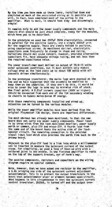
By the time you have made up these loons, installed them and completed as much of the associated wiring as is possible you will, in fact, have completed most of the wiring in the amplifier. What is more, it should look tidy and disarmingly simple!
It remains Only to add the power Supply components and the main chassis dish should be just about complete, ready for the modules, which have yet to be described.
In the prototype we used two 2SO0uF 35VW electrolytics, connected in parallel for the positive supply, and a single 3000uF unit for the negative supply. These are simply bolted in position, using countersunk screws. As mentioned earlier, electrolytic capacitors seem frequently to change in shape and rating. Variations should not cause concern, however, provided alternative capacitors fit, have adequate voltage rating, and not less than the required capacitance value.
The power transformer must deliver an output of 15-0-15 volts under quiescent conditions, but it must exhibit only modest voltage drop as the load peaks up to about-100 watts with all channels driven simultaneously.
In the prototype transformer, the mains lugs were exposed at the top and we have suggested that the assembly be modified to • keep them on the underside. If they don't do this, it would be wise to cover the lugs in some way to minimise risk of shock.One final point: A O.OluF ceramic capacitor (100V or higher) should be connected from each end of the 15V secondary winding to chassis to bypass mains-borne RF energy.
With these remaining components installed and wired up, attention can be turned to the various modules.
While the power amplifier modules have been derived from the original Playmaster 136 design, there are important differences.
The most obvious has already been mentioned, in that the new board does not carry any power supply components. Power input is by three wires from the loom mentioned dearlier; power supply earth or common, plus--21V and minus-21V. A fourth lead from the same end of the board feeds the active side of the loudspeaker circuit. The remaining connection is the shielded signal input lead which also provides the earth link back to the preamp board.
Adjacent to the plus-21V lead is a link into which a milliaimeter can be inserted to measure the quiescent current of the output stage. For simplicity, we used a loop of hook-up wire with a soldered joint in the middle. In the finished amplifier it rests on the top of the support bracket, our of harm's way.
The passive components, resistors and capacitors on the wiring . diagram require no special comnent.
Note, however, that we have added one resistor to the amplifier, a 6.8k bridging one side of th? quiescent current adjustment potentiometer. This is to protect the output transistors in the event that potentiometer wiper or element becomes open-circuit. What happens in this circumstance is that the quiescent current control transistor, 2N3565, is turned off and the output tran-
74
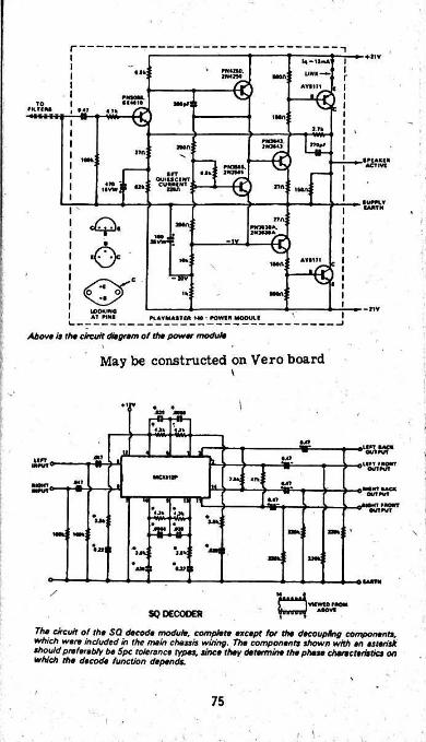
r'♦11VU - UmA
• n PN4H0.JMftO LI*»K—^Mon;
€ av»i?i
WMM.01*010 M0*l !TO
»MI«-9b
ill.F»OMlJrtMl tn*r1*00;
m €1~ACTIVtnut.
WM»■ All *srrCKJICACICU^ £<5livtr j * m rin: i
■um.Tcaath
r»nnmiu.2NNMA€-IV
AVtlTlIMA; *€H57
l 1h •0*0
-11VLOORIHO AT WHO PVAYMAfTCft 1*0 • fOWI" MOOUlf
Above is the circuit dmgrsm of the power module
May be constructed on Vero board\
♦i
to•AT
1} 441?un,
iunn' * ■flll” # AOMT OVTfUT
VCUUf 21* *HMl •A?a MMTAACA0»/TfVl
40HT fAOWT OtfTfVT
■Ml'0.4?w
3E»a*; u*.
•A»l "H*Ulm
•JJI I
IAJITH
/SQ DECOOER
77i» circuit of the SQ decode module, complete except lot the decoupling components, which were included in the meb cheats wiring. The components shown with en esterisk shouldpreterebty be Spc tolerance types, since they determine the phase characteristics on 'which the decode function depends.
75
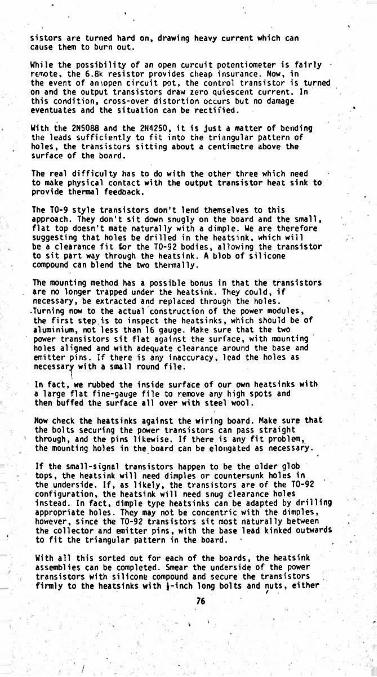
sistors are turned hard on, drawing heavy current which can cause them to burn out.
While the possibility of an open curcuit potentiometer is fairly remote, the 6.8k resistor provides cheap insurance. Now, in the event of amopen circuit pot, the control transistor is turned on and the output transistors draw zero quiescent current. In this condition, cross-over distortion occurs but no damage eventuates and the situation can be rectified.
With the 2N5088 and the 2N4250, it is just a matter of bending the leads sufficiently to fit into the triangular pattern of holes, the transistors sitting about a centimetre above the surface of the board.
The real difficulty has to do with the other three which need to make physical contact with the output transistor heat sink to provide thermal feedback.
The TO-9 style transistors don't lend themselves to this approach. They don't sit down snugly on the board and the small, flat top doesn't mate naturally with a dimple. We are therefore suggesting that holes be drilled in the heatsink, which will be a clearance fit tor the TO-92 bodies, allowing the transistor to sit part way through the heatsink. A blob of silicone compound can blend the two thermally.
The mounting method has a possible bonus in that the transistors are no longer trapped under the heatsink. They could, if necessary, be extracted and replaced through the holes.
-Turning now to the actual construction of the power modules, the first step is to inspect the heatsinks, which should be of aluminium, not less than 16 gauge. Make sure that the two power transistors Sit flat against the surface, with mounting holes aligned and with adequate clearance around the base and emitter pins. If there is any inaccuracy, lead the holes as necessary with a small round file.\In fact, we rubbed the inside surface of our own heatsinks with a large flat fine-gauge file to remove any high spots and then buffed the surface all over with steel wool.
Now check the heatsinks against the wiring board. Make sure that the bolts securing the power transistors can pass straight through, and the pins likewise. If there is any fit problem, the mounting holes in the board can be elongated as necessary.
If the small-signal transistors happen to be the older glob tops, the heatsink will need dimples or countersunk holes in the underside. If, as likely, the transistors are of the TO-92 configuration, the heatsink will need snug clearance holes instead. In fact, dimple type heatsinks can be adapted by drilling appropriate holes. They may not be concentric with the dimples, however, since the TO-92 transistors sit most naturally between the collector and emitter pins, with the base lead kinked outwards to fit the triangular pattern in the board.
With all this sorted out for each of the boards, the heatsink assemblies can be completed. Smear the underside of the power transistors with silicone compound and secure the transistors firmly to the heatsinks with l-inch long bolts and nuts, either
76
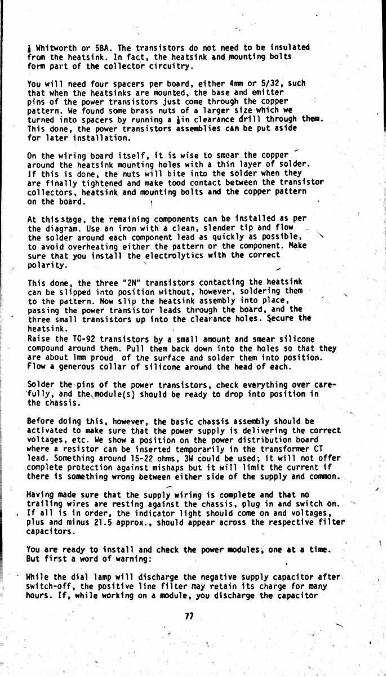
J Whitworth or 5BA. The transistors do not need to be Insulated from the heatsink. In fact, the heatsink and mounting bolts form part of the collector circuitry.
You will need four spacers per board, either Aim or S/32, such that when the heatsinks are mounted, the base and emitter pins of the power transistors just come through the copper pattern. We found some brass nuts of a larger size which we turned into spacers by running a Jin clearance drill through them.This done, the power transistors assemblies can be put aside for later installation.
On the wiring board itself, it is wise to smear the copper around the heatsink mounting holes with a thin layer of solder.If this is done, the nuts will bite into the solder when they are finally tightened and make tood contact between the transistor collectors, heatsink and mounting bolts and the copper pattern on the board. i
At this stage, the remaining components can be installed as per the diagram. Use an iron with a clean, slender tip and flow the solder around each component lead as quickly as possible, '•> to avoid overheating either the pattern or the component. Hake sure that you install the electrolytics with the correct polarity. '
This done, the three "2N" transistors contacting the heatsink can be slipped into position without, however, soldering them to the pattern. Now slip the heatsink assembly into place, passing the power transistor leads through the board, and the three small transistors up into the clearance holes. Secure the heatsink.Raise the TO-92 transistors by a small amount and smear silicone compound around them. Pull them back down into the holes so that they are about 1mm proud of the surface and solder them into position.Flow a generous collar of silicone around the head of each.
Solder the pins of the power transistors, check everything over carefully, and the..module(s) should be ready to drop into position in the chassis.
Before doing this, however, the basic chassis assembly should be activated to make sure that the power supply is delivering the correct voltages, etc. We show a position on the power distribution board where a resistor can be inserted temporarily in the transformer CT lead. Something around 15-22 ohms, 3W could be used; it will not offer complete protection against mishaps but it will limit the current if there is something wrong between either side of the supply and common.
Having made sure that the supply wiring is complete and that no trailing wires are resting against the chassis, plug in and switch on. If all is in order, the indicator light should come on and voltages, plus and minus 21.5 approx., should appear across the respective filter capacitors.
You are ready to install and check the power modules, one at a time.But first a word of warning:
While the dial lamp will discharge the negative supply capacitor after switch-off, the positive line filter may retain its charge for many hours. If, while working on a module, you discharge the capacitor
I
I
77
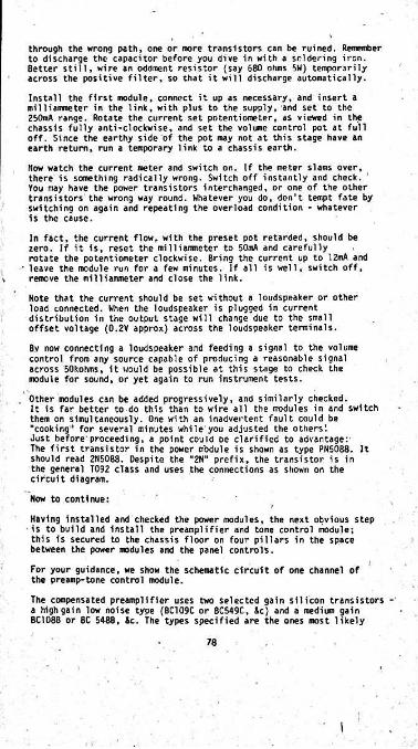
through the wrong path, one or more transistors can be ruined. Remember to discharge the capacitor before you dive in with a soldering iron. Better still, wire an oddment resistor (say 580 ohms 5W) temporarily across the positive filter, so that it will discharge automatically.
Install the first module, connect it up as necessary, and insert a milliammeter in the link, with plus to the supply, and set to the 250mA range. Rotate the current set potentiometer, as viewed in the chassis fully anti-clockwise, and set the volume control pot at full off. Since the earthy side of the pot may not at this stage have an earth return, run a temporary link to a chassis earth.
Now watch the current meter and switch on. If the meter slams over, there is something radically wrong. Switch off instantly and check.You may have the power transistors interchanged, or one of the other transistors’the wrong way round. Whatever you do, don't tempt fate by switching on again and repeating the overload condition - whatever is the cause.
In fact, the current flow, with the preset pot retarded, should be . If it is, reset the mi 11 iairmeter to 50mA and carefullyzero
rotate the potentiometer clockwise. Bring the current up to 12mA and • leave the module run for a few minutes. If all is well, switch off,
remove the milliammeter and close the link.Note that the current should be set without a loudspeaker or other load connected. When the loudspeaker is plugged in current distribution in the output stage will change due to the small offset voltage (0.2V approx) across the loudspeaker terminals.By now connecting a loudspeaker and feeding a signal to the volume control from any source capable of producing a reasonable signal across 50kohms, it would be possible at this stage to check the module for sound, or yet again to run instrument tests.
, Other modules can be added progressively, and similarly checked.It is far better to do this than to wire all the modules in and switch them on simultaneously. One with an inadvertent fault could be "cooking" for several minutes while you adjusted the others!Just before'proceeding, a point could be clarified to advantage:'The first transistor in the power m'odule is shown as type PN5088. It should read 2N5088. Despite the “2N" prefix, the transistor is in the general T092 class and uses the connections as shown on the circuit diagram.Now to continue:
Having installed and checked the power modules, the next obvious step is to build and install the preamplifier and tone control module; this is secured to the chassis floor on four pillars in the space between the power modules and the panel controls.For your guidance, we show the schematic circuit of one channel of the preamp-tone control module.
The compensated preamplifier uses two selected gain silicon transistors - a high gain low noise type (BC109C or BC549C, &c} and a medium gain BC108B or BC 548B, Sc. The types specified are the ones most likely
78
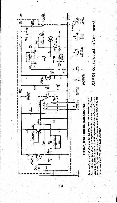
to be supplied but the “Sc" indicates the existence of possible substitutes.
However, in addition to the electrical characteristics of possible alternative types it is important to take note of the connections.The board is drilled for transistors having the traditional triangular CBE lead configuration. Transistors of this type can simply be dropped straight in, with little risk of confusion.
If you are supplied with T092 style transistors of another brand, check the base connections carefully. For example, in the NS range, the BC548 does not have a cranked base pin and the lead sequence is reversed in relation to the flat on the body.
Electrically, the preamplifier proves enough gain (75 times) to ensure full drive to the main amplifier from an input of 2mv RMS, with good signal/noise ratio ind adequate tolerance to peak level input signals. It provides a nominal loading of 50k ohms for a magnetic cartridge and compensation which conforms closely with the required RIAA characteristic.
Output from the compensated preamplifier goes to "Select" switch, where it is made available, along with signals from other sources: radio tuner,- tape player, auxiliary input or external 4-channel input. Since the signal levels at this point are normally 150mV or higher, shielding is not a critical requirement. It has been specified for long lead runs, but the switch banks, shorter leads and other associated circuitry are open, relying only on sensible layout to avoid instability problems.From the Select switch, the signal passes to an emitter follower, which presents a fairly high impedance to the various signal sources, and a low source impedance for the tone control circuitry. At the same time, it provides a convenient point from which to derive signal for an external tape deck; this signal is independent of the amplifier's own volume and tone controls. v
The tone control circuit is of the feedback type, favoured because of its inherently low distortion and its tolerance to higher level input signals.The point should be made, however, that signals derived from the Select switch are applied directly to a transistor base and can overload the circuitry between this and the volume control, if the level is excessive. Signals from radio tuners, tape players *c, must be limited in some way if there is any suggestion of overload, or if you find that the amplifier is being fully driven with the volume controls only fractionally on.' t}
In constructing the preamp-tone control module, a useful first ,\ step is to check the fit of the board and chassis mounting and make any adjustments necessary by filing holes, &c. We used threaded pillars, with J” long J“ diameter countersunk screws securing them to the chassis and J" long 1“ diameter roundhead screws securing the printed wiring board.
However you arrange it, remember that there must be no direct circuit between the copper pattern and chassis. The only earth must be via the phone input braids back to the phone input socket.
To provide a conrnon earth point for other circuitry, we suggest you add a solder lug to the corner of the board adjacent to the filter switches, bolting and soldering it to the earthy copper pattern.
80
I
For the rest, the components drop Into place, as per the accompanying drawing. Polarity is important only in respect to the electrolytic capacitors, and this calls for some care. Note that we have shown an alternative postion for the main decoupling capacitor, in case it happens to be larger than the one originally planned. An extra hole may be required and, for this, you will need a fine twist bit and preferably, a small "egg-beater" hand-drill.
As indicated, an extra hole will also be required for the shield braid of the leads running back to the "Mode" switch. He have suggested that constructors cope Individually with these minor matters to save us originating a new board pattern for the sake of two or three extra holes.
The most tedious job with the module has to do with the leads which must ultimately connect to the potentiometers and switches. The leads range from about 3 to 7 inches long and are unshielded, except where otherwise indicated. It is a good idea to use as many different colours as possible to facilitate lead tracing and to use thin rather than thick hbok-up to retain maximum flexibility.
The leads should be anchored to the wiring board during initial assembly and left trailing. Please yourself whether you make them all generously long, or save wire by cutting each one discretely to suit the requirement. But, whatever you do, plan for each wire to follow a gently curved path so that the board can be unbolted and lifted up for testing or service. For the same reason, leave some slack in the phono input and tape outputs leads, which run back to the DIN sockets.
I
;
With the module in position, wired and checked, and connected to the plus-21V supply line, the amplifier could operate in normal stereo mode from phono or other inputs. The signal and earth paths should have been established from the phono input socket, through the copper pattern on the preamp-tone control module, thence to the Hi-Lo filters and volume controls, and to the input connections to the four power modules.
Just make sure that any other temporary or accidental earth path has been obviated.
One other point we should mention: If you do operate the amplifier 1n this semi-finished state, remember that you have two volume controls and four power modules. While operating one volume control, two modules and two loudspeakers, it is all too easy to have the other volume control advanced, and be overdriving the other power modules without knowing it. It wouldn't necessarily cause trouble, but care 1s usually preferable to lament!
If this much of the amplifier Is working normally, 1t will be driven to full listening volume by an average magnetic cartridge, with the volume control(s) about halfway up, in terms of physical movement. Frequency response will be level with the bass and treble controls at about half setting though, in our prototype, they needed to be about 1' above centre for a nominally flat response.
In these circumstances, lifting the pickup off the record and leaving the controls untouched, the amplifier should sound dead quiet from the listening position. Only if you put your head right up to one of
81
i
i
the loudspeakers should any hum or hiss be audible, and then only faintly, with loudspeakers of the usual modern compact design.
The Stereo-24 Adaptor is Intended to process signals already being fed to the front channels and from them to synthesise signals for the rear channels.
With this in view, the left and right signals are made available respectively to two NPN transisitors, operating with equal loads in the collector and emitter circuits. It is, in fact, the old time phase-splitter configuration which provides a pair of out-of-phase signals, each about 0.9 the amplitude or the original input.
A network of resistors merges the four outputs in such a way that a “mono" or “centre" signal that is coranon to both channels is partially cancelled; as a result “difference" or ambience signals become relatively more prominent. These “processed" signals pass through the upper transistors in the schematic circuit to their respective rear channels.
For example, a signal in the left frontchannel will be applied to the base of the lower left transistor and will appear at slightly reduced amplitude at the emitter. If it is unique to the left channel, it will be fed through the 47k resistor, with a further loss of amplitude to the base of the upper transistor feeding the left rear channel.
However, if a similar signal'is present in the right channel, an out-of-phase replica will appear at the collector of the lower right transistor and this, via the 82k resistor, will tend to cancel and diminish the "left" signal which actually reaches the upper'left transistor.
The same will, of course, apply for what reaches the upper right transistor.
This partial cancellation forms the basis of most of the currently popular systems which synthesise 4-channel sound by loudspeaker matrixing. The Sterio 24 Adaptor incorporates a further subtlety, however.
The rear channel feed transistors which are also connected as phase splitters and the signal is taken from an R/C network strung between collector and emitter.
At low signal frequencies, where the reactance of the capacitor is high, the output comes effectively from the emitter and is in phase with the original front input signal. This means that low frequency energy from all loudspeakers will tend to be in phase,
' avoiding the'thin" sound that might result if it were otherwise.
At high frequencies, the signals'come from the respective collectors while, in betweeen, they are derived from both collector and emitter in a phase whicH varies with frequency between 0 and 180 degrees.The networks feeding the respective rear channels are deliberately different, such that there is an approximate 90-degree phase difference between the rear channels over the middle audio range. •
The partial cancellation and the progressive phase rotation in the rear channels, relative to the front and relative to one another, minimises any tendency for the system to produce a firm image of
82
i
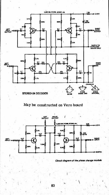
(■•ClM.PCTt*. BCVU Mp♦ I1V
i&u•»i ! T*1c
»'-- -*h HIOMT..BACKouirvT
0.1itrrBACK
OUT (ion;
uet no*:
(ANTH TO »**l*¥f•OARO ontr
«;i:U‘»wWk; • 10.1 Ilk in KKJKT
ITWTii rr Mtur
c
i-sss.0.1•••: —I
*>•1J«*
STEREO-24 DECODER
May be constructed on Vero board
IU FT RIGHTOVTRUT OUTFVT
U ta»Ci«a.KMMCM>.«c-. tor ►-♦11V
. M* oj^noeioinok 0.41047
•47-HE SSUrii rr II1JM
sm:MOk.I4k
CAfTTM
I
Circuit diagram of tha phase change module
:
’ \\v
83

"nono" material at the sides or rear. Thus centre front signals tend to "stay put", while the side and ambience signals are dispersed, subject of course, to the level in the rear loudspeakers.
Experience has shown that the system works out very well indeed in synthesising quadraphonic sound from existing 2-channel recordings, it can also produce some very compelling effects from matrixed discs, even though the energy distribution may not be in line with the producer's original idea.
It was our original intention to derive the left and right signals for the Stereo-24 Adaptor from the output circuits of the front channel power modules - as was assumed when the unit was first devised. It was for this reason that preset input pots were provided on the board.
However, on this basis, the front volume control would have affected all four channels, making operation in this mode different from any other. To avoid this, the Stereo-24 Adaptor now picks up its signal from the tone control output. The preset pots are simply turned full on; in fact, they could be replaced by resistors and the signals fed directly to the coupling capacitors.The effective gain through the Adaptor is less than unity but the imbalance between front and back channels is of no consequence in practice. If you want full "surround" sound, it is simply a matter of nudging the rear volume control a fraction of an inch above the front control; there will always be gain to spare.
Assert>ly of the unit should be a simple matter, using Vero board.Two figure-8 shielded pairs need to be attached, which run back to the Mode switch in the space between the pot mounting bracket and the front panel. One pair conveys signal to the unit, the other from the unit back ultimately to the rear channel amplifiers. The remaining leads are the positive 21V lead to the main filter bank and the earth lead back to the lug on the preamp-tone control module.
Placement of the Stereo-24 adaptor is fortunately not critical and , we were able to locate it in the space behind the Hi-lo filter switches.
To mount the unit, we made up a small angle bracket which was secured to the adaptor, on the copper pattern side, but stood off by Jin spacers. This was secured to the floor of the chassis with countersunk screws, with the edge of the board just clear of’the metal. The potentiometers face outwards although, as we have already mentioned, they are not strictly necessary in this application.\One point about the pots: they are mounted in a mirror-image configuration and rotate in opposite directions for the same function. For full on, both wipers should be turned towards the centre of the wiring board.
And there 1t is: with the Stereo-24 Adaptpr built and installed, you should be able to synthesise four channel sound to your heart's content fro* existing recordings, whether disc or stereo tape. And you will also be able to cope reasonably well with matrixed quadraphonic discs.
Two other modules reoain to tbe discussed, one to change the phase of rear channel signals being fed into the amplifier via the Ext-4 input, the other a decoder expressly for SQ matrix quadraphonic discs. While
7
84

I
Its immediate role relates to the Playmaster 140, it could in fact be used to advantage with any quadraphonic system that you might be putting together.
As explained, rear channel signals fe(i into the Playmaster 140 through the "Ext-4" input do not pass through the tone control stage, being reproduced “flat" unless deliberately modified by the Hi and to filters. As a result, the signals are not subject to the 180 degree phase change that the tone control introduces and this could lead to difficulties. We have therefore provided a phase change module for the rear channels: strictly speaking, it will be necessary only when you get around to using the Ext-4 input.
Fortunately, the phase change module can be a relatively simple device, devoid of adjustments. As long as the gain approximates unity, any slight difference between the front and back channels will be taken up by the volume control settings, without the user even being aware of it!
As indicated by the schematic circuit, the respective rear signals are fed to two small-signal NPN transistors with equal collector and emitter loads. Since a phase change is required, output is taken from the collectors and made available to the Selector switch.
With the split load configuration, the gain through each stage will be slightly less than unity but balance between stages will depend almost entirely on the 5.6k resistors.If you want to be fussy, the gain of either stage can be nudged upwards by using a slightly higher value of collector load and/or shunting downwards the emitter load. Increasing the emitter load and/or decreasing the collector load will reduce the gain.Whether all this effort would be worth-while is quite another matter!
We built up the phase change module on a scrap of Veroboard 9 tracks wide, measuring 37rnr, wide by 67nm long. The circuitry was concentrated on 7 tracks, leaving the Outer two tracks for mounting. We bent up an angle bracket from a scrap of light aluminium and mounted the unit in the space alongside the loudspeaker sockets.
While shielded lead was used to convey signals to and from the module, the level and impedance of the signal circuitry is such that no other shielding proved to be necessary. A positive lead is necessary for the plus 21V supply but the negative return can be via the shield braid to chassis.
The decode module is very compact being assembled on a Vero circuit board measuring 76 x 60mm. It operates normally from a supply rail of about 20V and can be cut into a typical system either just before or just after the volume controls.
Fed with left channel and right channel signal^, it will deliver outputs for all four channels of a quadraphonic system. While its prime purpose is to decode SQ matrix recodings, it will produce a multidimensional output from other matrix recordings, and doubles as a 4 channel simulator for two-channel stereo recordings.
Distortion is low, noise level is low and the gain from.either input to any output is nominally one. It dropped into the Playmaster 140 system without the slightest hint of trouble.
85
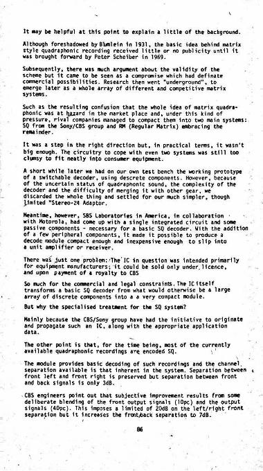
It may be helpful at this point to explain a little of the background.
Although foreshadowed byBYmlein In 1931, the basic idea behind matrix style quadraphonic recording received little or no publicity until it was brought forward by Peter Scheiber in 1969.
Subsequently, there was much argument about the validity of the scheme but it came to be seen as a compromise which had definate commercial possibilities. Research then went "underground", to emerge later as a whole array of different and competitive matrix systems.
Such as the resulting confusion that the whole idea of matrix quadraphonic was at lyuard in the market place and, under this kind of pressure, rival companies managed to compact them into two main systems:SQ from the Sony/CBS group and RM (Regular Matrix) embracing the remainder.
It was a step in the right direction but, in practical terms, it wasn't big enough. The circuitry to cope with even two systems was still too clumsy to fit neatly into consumer equipment.
A short while later we had on our own test bench the working prototype of a switchable decoder, using descrete components. However, because of the uncertain status of quadraphonic sound, the complexity of the decoder and the difficulty of merging it with other gear, we discarded the whole thing and settled for our much simpler, though limited "Stereo-24 Adaptor.
Meantime, however, SBS Laboratories in America, in collaboration with Motorola, had come up with a single integrated circuit and some passive components - necessary for a basic SQ decoder. With the addition of a few peripheral components, it made it possible to produce a decode module compact enough and inexpensive enough to slip into a unit amplifier or receiver.
There was just one problem:'The'IC in question was Intended primarily for equipment manufacturers; it could be sold only under.licence, and upon payment of a royalty to CBS
So much for the commercial and legal constraints. The ICitself transforms a basic SQ decoder from what would otherwise be a large array of discrete components into a a very compact module.
But why the specialised treatment for the SQ system?
Mainly because the CBS/Sony group have had the initiative to originate and propagate such an IC, along with the appropriate application data.
The other point is that, for the time being, most of the currently available quadraphonic recordings are encoded SQ.
The module provides basic decoding of such recordings and the channel, separation available is that inherent in the system. Separation between i front left and front right is preserved but separation between front and back signals is only 3dB.
CBS engineers point out that subjective improvement results from some deliberate blending of the front output signals (lOpc) and the output signals (40pc). This imposes a limited of 20dB on the left/right front separation but it Increases the front^jack separation to 7dB.
86
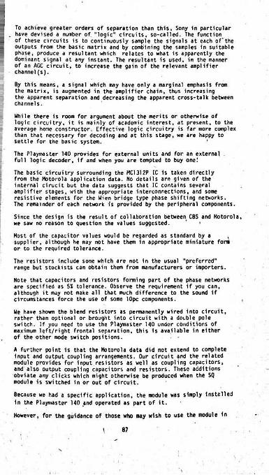
To achieve greater orders of separation than this, Sony in particular . have devised a number of “logic" circuits, so-called. The function
of these circuits is to continuously sample the signals at each of the outputs from the basic matrix and by combining the samples in suitable phase, produce a resultant which relates to what is apparently the dominant signal at any instant. The resultant is used, in the manner of an AGC circuit, to increase the gain of the relevant amplifier channel(s).
By this means, a signal which may have only a marginal emphasis from the matrix, is augmented in the amplifier chain, thus increasing the apparent separation and decreasing the apparent cross-talk between channels.
While there is room for argument about the merits or otherwise of logic circuitry, it is mainly of academic interest, at present, to the average home constructor. Effective logic circuitry is far more complex than that necessary for decoding and at this stage, we are happy to settle for the basic system. 1
The Playmaster 140 provides for external units and for an external full logic decoder, if and when you are tempted to buy one!
The basic circuitry surrounding the MC1312P IC is taken directly from the Motorola application data. No details are given of the internal cirucit but the data suggests that 1C contains several amplifier stages, with the appropriate interconnections, and some resistive elements for the Wien bridge type phase shifting networks.The remainder of each network is provided by the peripheral components.
Since the design is the result of collaboration between CBS and Motorola, we saw no reason to question the values suggested. ' 1
Most of the capacitor values would be regarded as standard by a , supplier, although he may not have them in appropriate miniature fora or to the required tolerance.
The resistors include some which are not in the usual "preferred" range but stockists can obtain them from manufacturers or importers.
Note that capacitors and resistors forming part of the phase networks are specified as 51 tolerance. Observe the requirement if you can, although it may not make all that much difference to the sound if circumstances force the use of some lOpc components.
We have shown the blend resistors as permanently wired into circuit, rather than optional or brought into circuit with a double pole switch. If you need to use the Playmaster 140 under conditions of maximum left/right frontal separation, this is available in either of the other mode switch positions.
A further point is that the Motorola data did not extend to complete input and output coupling arrangements. Our circuit and the related module provides for input resistors as well as coupling capacitors, and also output coupling capacitors and resistors. These additions obviate any clicks which might otherwise be produced when the SQ module is switched in or out of circuit.
Because we had a specific application, the module was simply installed in the Playmaster 140 and operated as part of it.However, for the guidance of those who may wish to use the module in
1 87

another context, the following information is relevant, taken from the Motorola data:
Supply volts: 20 typ; 25 max ,Supply current: 16mA typ; 21 max.Input imp: 1.8 meg min; 3 meg typ.Output imp: 5k ohms.Input volts: 0.5 typ; 2 max.Distortion: O.lpc typ.Sig/noise ratio: 74dB typ; 70dB min.Gain: within -1 and +ld8 L/R balance: within -1 and +ldB Op. temp: 0 to *75c.
It will be evident from this table that the module is being operated in the Playmaster 140 at well below the maximum rated voltage, being effectively at about 12V for the two prototypes which we made up. If you have reason to do so, the supply could be increased in the Playmaster 140 by simply reducing the value of the decoupling resistor. However, be prepared to increase also the value of the decoupling capacitor, otherwise power supply ripple could penetrate the signal chain.
In point of fact, we increased the value of the decoupling capacitor to 400uf to ensure the lowest possible ripple at this point.
The circuitry can most logically be put together on a Vero board.
For our purposes, however, we completely redesigned the pattern, providing for the additional input and output components, as mentioned earlier. There is room on the board for everything - provided you use modern miniature components. If you have to use some older more bulky components, it will be necessary to resort to such measures as standing resistors on end or mounting capacitors well above the surface of the board. Electrically this will be of no consequence and, fortunately, there is room in the chassis to accommodate a more bulky assembly.
. As with any compact wiring board, and especially one involving an IC, it is essential to use a small iron with a clean, sharp tip and apply the solder sparingly but quickly to each point. If the solder doesn’t flow immediately, don't fiddle with the Iron tip on the board in the hope that brute force - or brute heat - will do the trick. Try to scrape the offending surface with something small and sharp and try again.
Be particularly careful with the connection to the IC itself, first to get it round the right way, as indicated by the indentation on one end, and secondly to avoid overheating or bridgng the connections while soldering. '
If you feel at all apprehensive, it is possible to buy a suitable socket (McMurdo, 4cJ which can be soldered to the board. The IC then plugs straight in with little risk of incident or accident. We installed such a socket in our prototype, not just for this reason, but to have a test-bed into which we could plug other speciments of the 1CIncidently, the writer is not too proud to adnit having an old-fashioned reading glass handy on the bench. It makes it d lot eetier, upon completion of such a unit, to inspect it for solder runs, or "whiskers'1, dry joints and so on. ,
For the rest, it is simply a matter of identifying the components and
88

placing them correctly on the board. If you do this, the nodule can hardly do anything else but work!
be apparent, the module Is designed to plug into a PC edge connector of pitch 0.15in and of sufficient length to accoomodateN the 6nm or 2-3/8in width of the board. The connector lugs must be sufficiently stubby to clear the bottom of the chassis when the module has clearance height at the top.
As will
We used Vero board connectors which are available In packs and can be bought quite easily. Care must be taken to allow enough clearance at the top of the module.
With the module on hand, the connections can be identified readily.Oust make sure that the board mates correctly with the contacts and if the connector is longer than necessary, take some step to ensure that it will always be plugged in correctly. The connections to be made to the module'via the edge connector are shown clearly.
Note what we said earlier about the 220uF decoupling capacitor.
That just about completes the electrical description of the Playmaster 140. He may have occasion later to suggest addtions or extensions, but, for the time being, we propose to sit back for a while and enjoy the music.'
8ut perhaps we should say a few words about the cabinet work: The upturned dish chassis lends itself to the fitting of a simple metal hood finished in any way the supplier believes to be appropriate. How simple or ornate, or how cheap or costly such metalwork will be governed largely by supply and demand.
iAlthough we have not had occasion to investigate the matter, a metal cover with not-too-open ventilation would have a possible advantage in areas close to powerful radio and television transmitters. Curiously the problem of RF penetration is less likely to occur in the input stages, than directly into the power modules, with their relatively high gain and extremely wide inherent frequency response. When it does occur, such interference is independant of the volume control setting.
But, leaving aside RF penetration, many constructors may prefer to house the amplifier in a wooden case, finished to match other equipment or other furnishings. The case can likewise be a simple item, although not everyone finds it easy to achieve a really pleasing finish.
If you do plan to build your own cabinet, we suggest that you regard our diagram as provisional only and wait until your own chassis is to hand. At this point, the metal work can be measured and the cabinet made to fit snugly - not 2nm too small or with a 2™ gap all around!
Unless you have more facilities than average, and a great deal more skill, you won't attempt 45 degree mitre corners; butt joints are manageable.
If using natural timber or veneered particle board, it will be necessary to make some provision to hide the end grain at the corners of the cabinet.
One method is to leave the top very slightly short and to glue strips of veneer against the end grain, flush with the side surfaces. Another method is to make the end cheeks deliberately oversize, butting the
89 .

top and possibly the bottom against them. The exposed edges of the cheeks can then be dressed with veneer, while the front edges can also be veneered as necessary.
If the cabinet is built of natural particle board, the surface can be covered with adhesive wood-grain fabric or, again, with grained laminate or veneer.
You may have your own preferred method of wood finishing but one we have used ourselves is ready-made for the not-too-skilled handyman:
Thoroughly sand the surface, being careful not to introduce linseed putty or a high lacquer content filler, which tends to soak into the adjacent fibres, making them react differently to the rest of the surface.
Now go over the whole surface with one even coat'of thinned clear lacquer, allowing it to dry thoroughly. This tends to soak in and partially seal-without producing a surface gloss.
If you want a natural timber finish, it may be necessary only now to apply a coat of "teak" oil, rubbing it in with ordinary steel wool • (not the soap pads, or course). The result will be an oiled,matte finish,, probably about honey colour.
If you want a darker finish, apply an appropriate oil stain before the finishing oil, rubbing it in with steel wool. In fact (let's just whisper this) some professionals use selected shades of shoe polish as a handy and easily controlled form of stain!
Finish with clear oil, wipe over with a soft rag and you will end up with a pleasing matte finish, not easily marked but easily touched - up if it is.
/
PARTS YOU NEED FOR:MAIN SECTION
v1 chassis, nominally 38 x 28 x 9cm or IS x 11 x 3) ins.1 Escutcheon plate.1 Metal cover or wooden case to suit.1 Mounting bracket for slide potentiometers.4 rubber feet.2 3-pin DIN sockets, with plugs as required.3 5-pin DIN sockets (180 degree) with plugs as required.2 tagstrips, 3-lug and 4-lug.1 Octal socket (optional).4 Polarised loudspeaker sockets and plugs. '4 Fuse holders.4 1.5A fuses.1 Power cord, with grommet, clamp, 3-way terminal block.1 2-bank, 4 pole, 5 position rotary switch.1 2-bank, 6 pole, 3-position rotary switch.2 2-gang 50k log potentiometers (volume controls) with mounting screws,
4.5ou travel..2 2-gang 500k linear potentiometers (tone controls) with mounting screws.1 2-meg single linear potentiometer with mounting screws.5 PuSh-on knobs for slide potentiometers.2 skirted knobs for Select, Mode switches.1 Mains off-on switch (if required).1 6V 5ftnA indicator light assembly.
i
f
91
! \

2 Stereo headphone sockets with Isolated stereo speaker switching (see text).
2 pieces of particle board and compjsfcion board to support power modules. (See text and diagram.)
1 Tagboard, 9 lugs per side.2 Mounting pillars, 1cm or Jin.4 Silicon diodes (100P1V, 3A min).7 metres (8 yds) twin shielded and braided figure-8 wire, plus
hook-up wire-as necessary in a variety of colours.1 Resistor 470 ohm 5W.2 Electrolytic capacitors, 2500uf 35VW upright can type.
Electrolytic capacitor, 3000 or 3300uF, 35VW upright can type.1 Power transformer 15-0-15V 2A nominal.2 O.OluF ceramic, 100V or higher.
POWER MODULES (4)
4 Vero boards.TRANSISTORS FOR POWER MODULE
AY9171=RS276-2025. RS276-2026. 2N3740. BD202. BD236. TIP32B.AY817I-RS276-2017. RS276-2018. 2N4232. B0201. B0235. TIP3IB. 2N5088=RS276-2013. BC548/9. BC183L/184L.2N4250=RS2?6-2024. BC558/9. BC213L/214L.2N3565=RS2?6-2009. BC548/9. BC183L/184L. ,2N3643=RS2?6-2009. BC548/9. BC183L/184L.2N3638A.RS276-2021. BC558/9. BC213L/2141.
Aluminium heat skinks 16 gauge 7.6 x 4 x 2.7cm.Resistors (JW 10X)4 100k; 4 82k; 4 10k; 8 6.8k; 4 4.7k; 4 2.7k; 4 lk; 8 560 ohm; 8 390 ohm; 12 150 ohm; 12 27 ohm.4 220 ohm preset tab pots.Capacitors4 470uF 16V vertical electrolytic.4 lOOuF 25V vertical electrolytic.4 0.47uF 160V polyester.4 390pF polystyrene.4 270pF polystyrene.
SHUNT, PHONE BOARD
1 tagboard, 10 lugs per side.2 Jin mounting spacers.4 0.47uF polyester (small, typically 50V).4 15-ohm JW resistors.4 330-ohm JW resistors.FILTER ASSEMBLY
1 lsostat 2-push-button switch assextoly or 3-push-button assembly including mains switch.
4 0.015uF polyester capacitors, 50V or higher.4 O.OOlSuF polyester capacitors 50V or higher.4 33k resistors J or JW2 Mounting spacers, 1.5cm or |1n.
1
/
'192
I

IMODULESPreamp and tone control board.Stereo-24 adaptor.SO Decoder.a small Vero wiring board, with plug-in provision and a McMurdo or other chassis mounting socket. One Motorola HC1312P IC. Plus 11 jv resistors, mostly unusual values; 10 small polystyrene capacitors.1 220uF 25VW electro. 4 4.?uF 5YW electros.Ext. 4 phase change: Built on a piece of Yeroboard 6.7 x 3.7cm, this module contains 2 small signal transistors, 13 JW resistors, 4 0.47uF polyester capacitors and 1 220uF 25VW electrolytic.
PREAMP TONE CONTROL•'v
1 Vero board.2 RS 276-2009, BC109C, BC549C or similar transistors.2 RS 276-2009, BC108B, BC548B or similar transistors. - 4 RS 276-2009, BC108, BC548 or similar transistors.2 Ferrite RF beads 3.5nm dia., 5nn long.4 Jin or 1cm spacers with screws.
Resistors (JW or JW, preferably 5pc)2 3.3N; 2 2.7M; 2 2.2M 2 1,5M;2560k; 2 470k; 2 330k; 6 100k;2 82k; 2 56k; 2 47k; 4 27k; 2 22k; 2 15k; 2 10k 7 lk; 3 680 ohm
Capacitors1 220uf 25VW vert electrolytic.1 lOOuF 25Yw vert electrolytic.4 4.7uF 12Yw vert electrolytic.2 1.5uF 20VW tantalum electrolytic.2 0.47uF 20VW tantalum electrolytic.2 0.27uF 100V polyester.4 O.luF 100Y polyester 4 .022uF 100V polyester 2 ,0047uF 100V polystyrene.2 .0015uF 100V polystyrene.
' 2 680pF 100V polystyrene.4 lOOpF disc ceramic.
STEREO-24 ADAPTOR
1 Vero board.4 transistors BC108, BC548.1 Angle bracket approx 1 x 1 x 7.5a«.2 Jin or Jem long spacers with Jin dia or similar screws to suit Resistors: (JW or JW, preferably 5pc)4 820k; 4 330k; 282k; 247k; 210k; 4 4.7k; 4 3.3k; 1 1.2k ohm JW 2 1M preset pots (optional, see text).
Capacitors:1 220uF 25Yw electrolytic.9 O.luF 100Y min polyester.1 .OluF 100V min polyester.
PHASE CHANGE MODULE
1 piece of Veroboard, 9 tracks, 37nra x 67um.1 Mounting bracket, scrap aluninium, 2-Jin long.
. 2 Transistors, BC108, BC548, RS276-2009, SK3020. BC148-168-208-318. AM252, ZXT108, MPS6520.
/%
93\
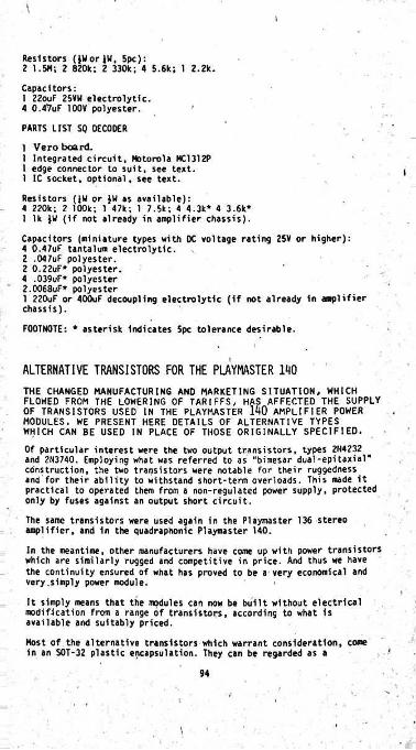
\l
Resistors (JHorJH, 5pc):2 1.5H; 2 820k; 2 330k; 4 5.6k; 1 2.2k.
Capacitors:1 22ouF 25VW electrolytic.4 0.4^uF 100V polyester. '
PARTS LIST SQ DECODER
1 Vero board.1 Integrated circuit, Motorola HC1312P 1 edge connector to suit, see text.1 IC socket, optional, see text.
Resistors (JW or }W as available):4 220k; 2 100k; 1 47k; 1 7.5k; 4 4.3k* 4 3.6k*1 lk )W (if not already in amplifier chassis).Capacitors (miniature types with DC voltage rating 25V or higher):4 0.47uF tantalum electrolytic.2 ,047uF polyester.2 0.22uF* polyester.4 .039uF* polyester 2.0068uF* polyester1 220uF or 400uF decoupling electrolytic (if not already in amplifier chassis).
FOOTNOTE: * asterisk indicates 5pc tolerance desirable.
I
ALTERNATIVE TRANSISTORS FOR THE PAYMASTER 1R0THE CHANGED MANUFACTURING AND MARKETING SITUATION, WHICH FLOWED FROM THE LOWERING OF TARIFFS, HAS AFFECTED THE SUPPLY OF TRANSISTORS USED IN THE PLAYMASTER 1A0 MODULES. WE PRESENT HERE DETAILS OF ALTERNATIVE TYPES WHICH CAN BE USED IN PLACE OF THOSE ORIGINALLY SPECIFIED.
Of particular interest were the two output transistors, types 2H4232 and 2H3740. Employing what was referred to as "bimesar dual-epitaxial’ construction, the two transistors were notable for their ruggedness and for their ability to withstand short-term overloads. This made it practical to operated them from a non-regulated power supply, protected only by fuses against an output short circuit.
The same transistors were used again in the Playmaster 136 stereo amplifier, and in the quadraphonic Playmaster 140.
In the meantime, other manufacturers have come up with power transistors which are similarly rugged and competitive in price. And thus we have the continuity ensured of what has proved to be a very economical and very.simply power module.
It simply means that the modules can now be built without electrical modification from a range of transistors, according to what is available and suitably priced.
Host of the alternative transistors which warrant consideration, come in an SOT-32 plastic encapsulation. They can be regarded as a
AMPLIFIER POWER
94
\

=?_
ddirect electrical replacement for the earlier TO-66 style transistors, but are mechanically quite different. Fortunately, it has proved possible to retain the same circuit board and heatsink, varying only the method of assembly. '
It is still possible to obtain the small-signal transistors, but we have specified possible replacements for these types as well. The complete set of possible replacements is listed in the accompanying table. Where there are two or more types of the same brand listed, the first listing is the preferred choice, although the remaining types will work satisfactorily.It is possible to mix brands without any loss in performance.The reader is referred to the accompanying sketch for full details of the method used to mount the plastic encapsulated transistors. Care should be taken that the following points are observed while fitting them.The power transistors are fitted underneath the heatsink, and bolted to it through the holes provided to mount the TO-66 type transistors. They must be mounted with the metal part next to the heatsink, as this forms the collector connection. As a result of this, the collector lead provided can be carefully snipped off close to the body of the transistor. (The collector lead is the centre one).To ensure that the base and emitter leads are not transposed, it is vital that the mounting hole furthest from the original centre clearance holes be used in each case to mount the plastic transistors. On the heatsink, these happen to be the holes nearest to the dimples for the driver transistors. The transistors are secured to the heatsink using suitable nuts and bolts. A small washer should be used under the head of the bolt, as shown in the diagram, and silicon grease applied to ensure good thermal contact between the transistors and heatsink.
5
/
/
Do not use exessive force when tightening the nuts, as this may damage the transistors. Take particular care that the actual transistors are not interchanged. The heads of the bolts must be on the underside of the heatsink to ensure that the transistor leads are long enough to reach through to the copper pattern on the board.
Once the transistors have been fixed to the heatsink, their base and emitter leads may be bent as shown in the diagram. Use the holes in the heatsink as a guide, and hold the leads next to the body with a pair of small long nosed pliers to prevent them from breaking off.The heatsink is held in position, and the collector connection made
through the remaining holes. We used two nuts as spacersby boltsto position the heatsink a suitable distance from the board. Do not forget to tin the copper pattern underneath the nuts to provide good electrical contact.
No difficulties should be experienced with the mounting of the small- signal transistors, as all the recommended types have TO-92 cases. These TO-92 versions mount partly through the heatsink; drill directly above where the transistors will mount with a suitable sized drill so that they are a snug fit. Do not solder them to the board until the heatsink has been fixed in position, as otherwise their height may be wrong. The final step is to thermally bond their cases to the heatsink with a generous blob of silicon grease.
95 ' I

NOTES
\i
) \
:
I
/!
t >
l

BSBLIOTHEEKM.V.H.Rf
:
/
••;
1 !'.
S
!•
1.■
BERNARDS a BABANI PRESS RADIO AND ELECTRONICS BOOKS BPI Fine Book of Transistor Equivalents and Substitutes .BP2 Handbook of Radio, TV and Ind. & Transmitting Tub* & Valve Equiv. 60p BP3 Handbook of Tested Transistor Circuits BP4 World's Short, Medium A Lon* Wave FM A TV Broadcasting
Stations Listing (International Edition)BPS Handbook of Simple Transistor Circuits BPS Engineers and Machinists Reference Tables BP7 Radio and Electronic Colour Codes and Data Chart BPS Sound and Loudspeaker ManualBP9 38 Practical Tested Diode Circuits for the Home Constructor BPIO Modern Crystal and Transistor Set Circuits for Beginners BPI I Practical Transistor Novelty CircuitsBPI2 Hi-Fi, PJL, Guitar A Discotheque Amplifier Design Handbook BPI3 Electronic Novelties for the Motorist BPI4 Second Book of Transistor Equivalents BPIS Constructors Manual of Electronic Circuits for the Home BPIt Handbook of Electronic Circuits for the Amiteur Photographer 60pBPI7 Radio Receiver Construction Handbook using IC's and Transistors 60p BPIB Boys A Beginners Book of Practical Radio and Electronics BP22 79 Electronic Novelty Circuits BP23 first Book of Practical Electronic Projects BP24 52 Projects using IC74I (or Equivalents)BP25 How to Build Your Own Electronic and Quartz Controlled Watches A
ClocksRadio Antenna Handbook for Long Distance Reception A Transmission 85p
BP27 Giant Chart of Radio, Electronic, Semiconductor A Logic Symbols 60p BP28 Resistor Selection Handbook (International Edition)BP29 Major Solid State Audio Hi-Fi Construction Projects
A Comprehensive Radio Valve Guide - Book I 121 A Comprehensive Radio Valve Guide - Book 2 126 Boys Book of Crystal Sets 129 Universal Gram-Motor .138 How to Make Aerials for TV (Band 1-2-3)143 A Comprehensive Radio Valve Guide - Book 3 150 Practical Radio Inside Out 157 A Comprehensive Radio Valve Guide - Book 4160 Coil Design and Construction Manual161 Radio, TV and Electronics Data Book 170 Transistor Circuits for Radio Controlled Models177 Modern Transistor Circuits for Beginners178 A Comprehensive Radio Valve Guide - Book 5 183 Howto Receive Foreign TV Programmes on your Set by Simple
Modifications195 High Fidelity 14 Watt Amplifier Design Chart196 AF - RF Reactance-Frequency Chart for Constructors197 Inexpensive Push-Pull Amplifier Construction Chart200 Handbook of PracticaLEIeoronic Musical Novelties201 Practical Transistorised Novelties for Hi-Fi Enthusiasts202 Handbook of Integrated Circuits (IC's) Equivalents and Substitutes203 IC's and Transistor Gadgets Construction Handbook204 Second Book of Hi-fi Loudi. "205 first Book of Hi-Fi Loudspeaker Enclosures206 Practical Transistor Circuits for Modern Test Equiprr207 Practical Electronic Science Projects208 Practical Stereo and Quedrophony Handbook209 Modern Tape Recording H210 The Complete Car Radio Manual211 first Book ofDiodaCharacceratia Equivalents and S214 Audio Enthusiast Handbook215 Shortwave Circuits and Gear for Experimenters and216 Electronic Gadgets and Games ~3 Build your own ElectronicExperimenters Laboratory RCC Resistor Colour Code Disc Calculator
40p
40p
60p?5p30pISp50p?5p35p40p?5pSOp95p50p
60pZSp75p75p
85pBP26
60p85 p40p100 .140p2Sp
Speed Indicator (Combined 50 A 60 ©o model) lOp25p40p40p40pSOp60p40p40 p40p
35p!5PI5pI5p50p35p75p
ker Enclosures
N\Ibook
E-218
Bibliotheek Ned. Ver.The Grampians, Shepherds Bush Road, London W6
Telephone Number: 01-603 2581/7294