8237DMA CONTROLLER - Rajiv Ramesh Bhandari
22
8237DMA CONTROLLER
-
Upload
khangminh22 -
Category
Documents
-
view
0 -
download
0
Transcript of 8237DMA CONTROLLER - Rajiv Ramesh Bhandari

8237DMA CONTROLLER

Introduction: Direct Memory Access (DMA) is a method of
allowing data to be moved from one location toanother in a computer without intervention fromthe central processor (CPU).
It is also a fast way of transferring data within(and sometimes between) computer.
The DMA I/O technique provides direct access tothe memory while the microprocessor istemporarily disabled.
The DMA controller temporarily borrows theaddress bus, data bus and control bus from themicroprocessor and transfers the data directlyfrom the external devices to a series of memorylocations (and vice versa).

Basic DMA Operation:
Two control signals are used to request and
acknowledge a direct memory access (DMA)
transfer in the microprocessor-based system.
The HOLD signal as an input(to the processor) is
used to request a DMA action.
The HLDA signal as an output that acknowledges
the DMA action.
When the processor recognizes the hold, it stops its
execution and enters hold cycles.
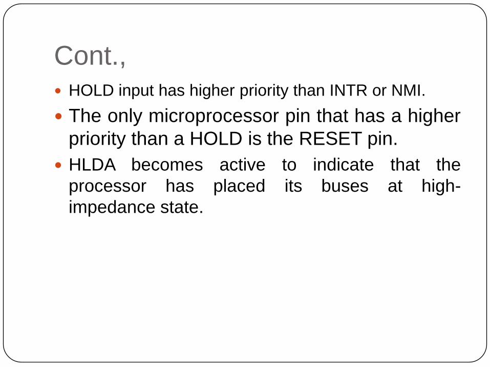
Cont., HOLD input has higher priority than INTR or NMI.
The only microprocessor pin that has a higher
priority than a HOLD is the RESET pin.
HLDA becomes active to indicate that the
processor has placed its buses at high-
impedance state.

Basic DMA Definitions:
Direct memory accesses normally occur between
an I/O device and memory without the use of the
microprocessor.
A DMA read transfers data from the memory
to the I/O device.
A DMA write transfers data from an I/O device
to memory.
The system contains separate memory and I/O
control signals.
Hence the Memory & the I/O are controlled
simultaneously

6
The DMA controller provides memory with its address,
and the controller signal selects the I/O device during
the transfer.
Data transfer speed is determined by speed of the
memory device or a DMA controller.
In many cases, the DMA controller slows the speed of
the system when transfers occur.
The serial PCI (Peripheral Component Interface)
Express bus transfers data at rates exceeding DMA
transfers.
This in modern systems has made DMA is less
important.

The 8237 DMA Controller
The 8237 supplies memory & I/O with control
signals and memory address information during
the DMA transfer.
It is actually a special-purpose microprocessor
whose job is high-speed data transfer between
memory and I/O
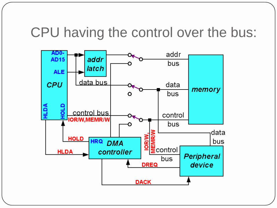
CPU having the control over the bus:

When DMA operates:

10
8237 is not a discrete component in modern
microprocessor-based systems.
It appears within many system controller chip
sets
8237 is a four-channel device compatible with
8086/8088, adequate for small systems.
Expandable to any number of DMA channel
inputs
8237 is capable of DMA transfers at rates up
to 1.6MB per second.
Each channel is capable of addressing a
full
64K-byte section of memory.
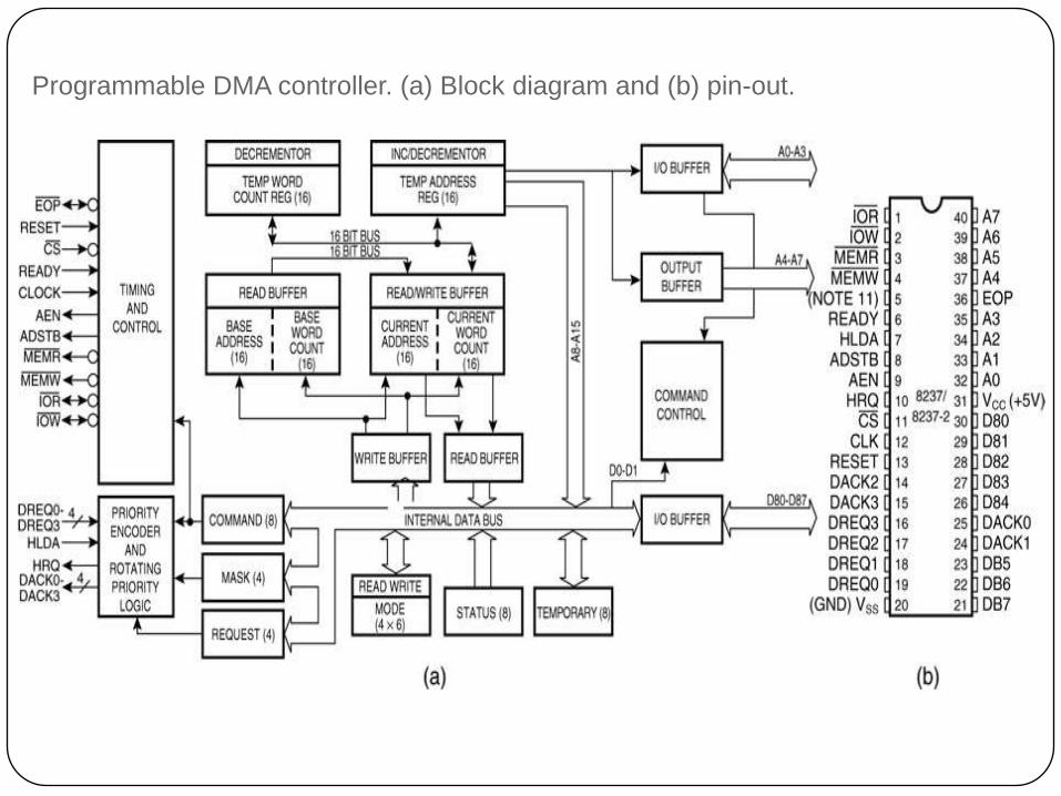
Programmable DMA controller. (a) Block diagram and (b) pin-out.
11

8237 Internal Registers
CAR
The current address register holds a 16-bit
memory address used for the DMA transfer.
Each channel has its own current address
register for this purpose.
When a byte of data is transferred during a DMA
operation, CAR is either incremented or
decremented depending on how it is
programmed.

CWCR
The current word count register programs a
channel for the number of bytes to transferred
during a DMA action.
CR
The command register programs the operation
of the 8237 DMA controller.
The register uses bit position 0 to select the
memory-to-memory DMA transfer mode.
Memory-to-memory DMA transfers use DMA
channel 0 to hold the source address
DMA channel 1 holds the destination address

command register.
14

BA and BWC
The base address (BA) and base word count
(BWC) registers are used when auto-initialization
is selected for a channel.
In auto-initialization mode, these registers are
used to reload the CAR and CWCR after the
DMA action is completed.

16
The mode registerprograms the mode of operation for a channel.
Each channel has its own mode register as selected by bit positions 1 and 0. Remaining bits of the
mode register select operation, auto-initialization, increment/decrement, and mode for the channel
MR
17
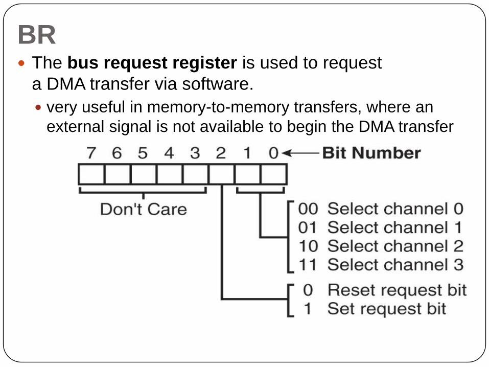
The bus request register is used to request
a DMA transfer via software.
very useful in memory-to-memory transfers, where an
external signal is not available to begin the DMA transfer
BR

18
The mask register set/reset sets or clears the channel
mask.
if the mask is set, the channel is disabled
the RESET signal sets all channel masks
to disable them
MRSR

19
The mask register clears or sets all of
the masks with one command instead of individual
channels, as with the MRSR.
MSR

20
The status register shows
status of each DMA
channel. The TC bits
indicate if the channel has
reached its terminal count
(transferred all its bytes).
When the terminal count is
reached, the DMA transfer
is terminated for most
modes
of operation.
The request bits indicate
whether
the DREQ input for a given
channel is active.
SR

Master clear
Acts exactly the same as the RESET signal to the 8237.
As with the RESET signal, this command disables all
channels
Clear mask register
Enables all four DMA channels.
Clear the first/last flip-flop
Clears the first/last (F/L) flip-flop within 8237.
The F/L flip-flop selects which byte (low or high order) is
read/written in the current address and current count
registers.
if F/L = 0, the low-order byte is selected
if F/L = 1, the high-order byte is selected
Any read or write to the address or count register
automatically toggles the F/L flip-flop.
22
Memory-to-memory transfer is much more
powerful than the automatically repeated
MOVSB instruction.
most modern chip sets do not support the
memory-to-memory feature
8237 requires only 2.0 µs per byte, which is
over twice as fast the existing data transfer.