
Rajiv Gandhi University of Knowledge Technologies
87
Rajiv Gandhi University of Knowledge Technologies Department of Chemical Engineering Process Heat Transfer Lab (CH2801)
-
Upload
khangminh22 -
Category
Documents
-
view
0 -
download
0
Transcript of Rajiv Gandhi University of Knowledge Technologies
Rajiv Gandhi University of Knowledge Technologies
Department of Chemical Engineering
Process Heat Transfer Lab
(CH2801)
Course Objectives:
• This lab will provide practical knowledge on various heat transfer process
and equipment like heat exchangers and evaporators.
• Learn basic Heat transfer principles.
• Impart the knowledge in heat transfer measurements and different heat
transfer equipment.
• Learn how the convection takes place in natural and forced convection and
gain knowledge of the heat transfer taking place in different heat
exchangers.
List of Experiments:
S.No Name of the experiment
1. Emissivity measurement apparatus
2. Heat transfer in forced convection
3. Heat transfer in natural convection
4. Heat tansfer through composite wall
5. Pool boiling apparatus
6. Shell and tube heat exchanger
7. Thermal conductivity of liquids
8. Hermal conductivity of metal rod
Course Outcomes:
By the end of this course, the student should be able to:
• Understanding fundamentals of some major Heat transfer operation.
• Development of design processes
• Application of design principles for heat transfer devices.
• Learning operations of various heat transfer systems

EMISSIVITY MEASUREMENT
APPARATUS (HT-111)

Foreword
Welcome to the fast growing family of K.C. product owners. We appreciate your interest in us and thank you for buying our product. You have chosen the finest quality product in the market which is produced using latest techniques and has underwent strict quality control tests. It is a product that we are proud to build and you are proud to own it. Our products are easy to understand and operate. They are excellent for students who are trying to gain practical knowledge through experiments. However your comfort and safety are important to us, so we want you have an understanding of proper procedure to use the equipment. For the purpose, we urge you to read and follow the step-by-step operating instructions and safety precautions in this manual. It will ensure that your favourite product delivers reliable, superior performance year after year. This manual includes information for all options available on this model. Therefore, you may find some information that does not apply to your equipment. All information, specifications and illustrations in this manual are those in effect at the time of printing. We reserve the right to change specifications or design at any time without notice. Customer satisfaction is our primary concern. Feel Free to contact us for any assistance. So what are you waiting for, roll up your sleeves and let us get down to work!
K.C. Engineers Pvt. Ltd.

Important Information About This Manual
Reminder for Safety
Modification on Equipment:
This equipment should not be modified. Modification could affect its performance, safety or
disturbance. In addition damage or performance problems resulting from modification may not be
covered under warranties.
Precautions and Maintenance:
This is used to indicate the presence of a hazard that could cause minor or moderate personal injury
or damage to your equipment. To avoid or reduce the risk, the procedures must be followed
carefully.
K.C. Engineers Pvt. Limited, Ambala EMISSIVITY MEASUREMENT APPARATUS (Rev. 1)
Contents 1. Objective …………………………………… 1 2. Aim …………………………………… 1 3. Introduction …………………………………… 1 4. Theory …………………………………… 1 5. Description …………………………………… 2 6. Utilities Required …………………………………… 2 7. Experimental Procedure …………………………………… 2 8. Observation & Calculation …………………………………… 3 9. Nomenclature …………………………………… 4 10. Precautions & Maintenance Instructions …………………………………… 4 11. Troubleshooting …………………………………… 5 12. References …………………………………… 5 13. Block Diagram …………………………………… 6

K.C. Engineers Pvt. Limited, Ambala EMISSIVITY MEASUREMENT APPARATUS Page No. 1 of 6 (Rev. 1)
EMISSIVITY MEASUREMENT APPARATUS
1. OBJECTIVE:
Study of radiation heat transfer by black plate and test plate.
2. AIM:
To calculate the emissivity of test plate.
3. INTRODUCTION:
All substances at all temperature emit thermal radiation. Thermal radiation is an
electromagnetic wave and does not require any material medium for propagation. All
bodies can emit radiation and have also the capacity to absorb all of a part of the
radiation coming from the surrounding towards it.
4. THEORY:
An idealized black surface is one, which absorbs all the incident radiation with reflectivity
and transmissivity equal to zero. The radiant energy per unit time per unit area from the
surface of the body is called as the emissive power and is usually denoted by E. The
emissivity of the surface is the ratio of the emissive power of the surface to the emissive
power of a black surface at the same temperature. It is denoted by ε.
BE
E
Emissivity is a property of the surface depends on the nature of the surface and
temperature.
)(44
DS
SBBS
TTA
QQEE
From the above eqn we can find the emissivity of test plate, Where EB is emissivity of
black body. QB, QS are heat input of the black plate and test plate. A is area of heat
transfer is stefan boltzmaan constant, TS, TD are surface temperature and
surrounding temperature.

K.C. Engineers Pvt. Limited, Ambala EMISSIVITY MEASUREMENT APPARATUS Page No. 2 of 6 (Rev. 1)
5. DESCRIPTION:
The experimental set up consists of two plates, the test plate comprises of a mica
heater. Black plate is identical with test plate, but its surface is blackened. As all the
physical properties, dimension and temperature are equal. Both plates are supported on
individual brackets in a wooden enclosure with one side glass to ensure steady
atmospheric conditions. Temperature sensors are provided to measure the
temperature of each plate and surrounding. Supply is given to heaters through
separate variacs so that temperatures of both can be kept equal and is measured
with digital voltmeter and digital ammeter.
6. UTILITIES REQUIRED:
6.1 Electricity Supply: Single Phase, 220 V AC, 50 Hz, 5-15 Amp combined socket
with earth connection.
6.2 Bench Area Required: 1m x 1m
7. EXPERIMENTAL PROCEDURE:
7.1 STARTING PROCEDURE:
7.1.1 Ensure that mains ON/OFF switch given on the panel is at OFF position &
dimmer stat is at zero position.
7.1.2 Connect electric supply to the set up.
7.1.3 Switch ON the mains ON / OFF switch.
7.1.4 Set the test plate heater input by the dimmer stat, voltmeter in the range
40-100 V.
7.1.5 Set black plate heater input by dimmer stat, voltmeter, 2 volt above than
test plate heater.
7.1.6 After 0.5 hrs. observe the difference in surface temperature of black plate
and test plate, adjust the heater input of black plate to make both the
sensor reading same.
7.1.7 Wait for 5 minutes every time after changing the black plate heater input
and then again change the input if required.
K.C. Engineers Pvt. Limited, Ambala EMISSIVITY MEASUREMENT APPARATUS Page No. 3 of 6 (Rev. 1)
7.1.8 At same surface temperature note down the reading of voltmeter, ampere
meter and temperature sensors.
7.2 CLOSING PROCEDURE:
7.2.1 When experiment is over set the dimmer stat to zero position.
7.2.2 Switch OFF the mains ON/OFF switch.
7.2.3 Switch OFF electric supply to the set up.
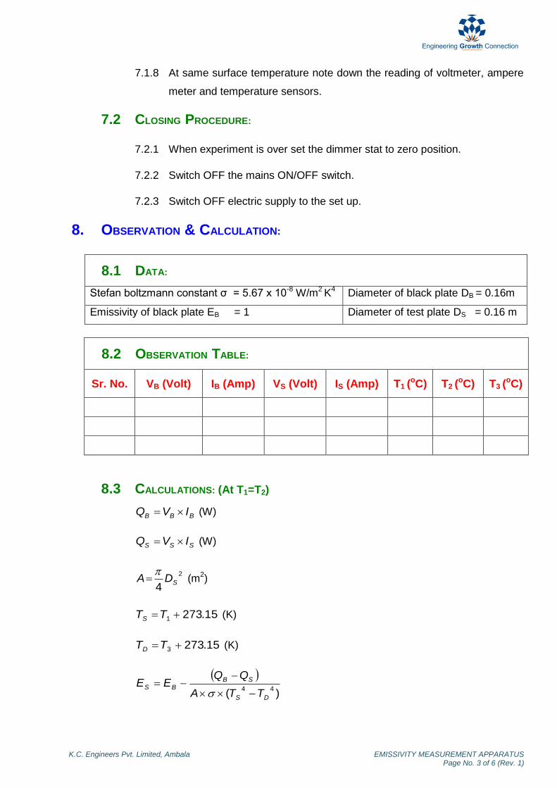
8. OBSERVATION & CALCULATION:
8.1 DATA:
Stefan boltzmann constant σ = 5.67 x 10⁻⁸
W/m2 K
4 Diameter of black plate DB = 0.16m
Emissivity of black plate EB = 1 Diameter of test plate DS = 0.16 m
8.2 OBSERVATION TABLE:
Sr. No. VB (Volt) IB (Amp) VS (Volt) IS (Amp) T1 (oC) T2
(oC) T3 (oC)
8.3 CALCULATIONS: (At T1=T2)
BBB IVQ (W)
SSS IVQ (W)
2
4SDA
(m
2)
15.2731 TTS (K)
15.2733 TTD (K)
)(44
DS
SBBS
TTA
QQEE
K.C. Engineers Pvt. Limited, Ambala EMISSIVITY MEASUREMENT APPARATUS Page No. 4 of 6 (Rev. 1)
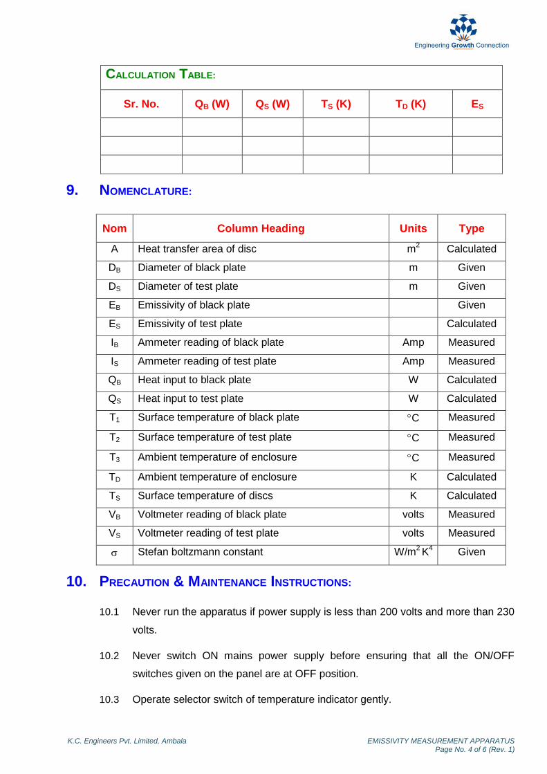
CALCULATION TABLE:
Sr. No. QB (W) QS (W) TS (K) TD (K) ES
9. NOMENCLATURE:
Nom Column Heading Units Type
A Heat transfer area of disc m2 Calculated
DB Diameter of black plate m Given
DS Diameter of test plate m Given
EB Emissivity of black plate Given
ES Emissivity of test plate Calculated
IB Ammeter reading of black plate Amp Measured
IS Ammeter reading of test plate Amp Measured
QB Heat input to black plate W Calculated
QS Heat input to test plate W Calculated
T1 Surface temperature of black plate C Measured
T2 Surface temperature of test plate C Measured
T3 Ambient temperature of enclosure C Measured
TD Ambient temperature of enclosure K Calculated
TS Surface temperature of discs K Calculated
VB Voltmeter reading of black plate volts Measured
VS Voltmeter reading of test plate volts Measured
Stefan boltzmann constant W/m2 K
4 Given
10. PRECAUTION & MAINTENANCE INSTRUCTIONS:
10.1 Never run the apparatus if power supply is less than 200 volts and more than 230
volts.
10.2 Never switch ON mains power supply before ensuring that all the ON/OFF
switches given on the panel are at OFF position.
10.3 Operate selector switch of temperature indicator gently.
K.C. Engineers Pvt. Limited, Ambala EMISSIVITY MEASUREMENT APPARATUS Page No. 5 of 6 (Rev. 1)
10.4 Always keep the apparatus free from dust.
11. TROUBLESHOOTING:
11.1 If electric panel is not showing the input on the mains light, check the main
supply.
11.2 If voltmeter showing the voltage given to heater but ampere meter does not,
check the connection of heater in control panel.
12. REFERENCES:
12.1 Holman, J.P (2008). Heat Transfer. 9th Ed. ND: McGraw Hill. pp 371-378.
12.2 Cengel, Y.A (2007). Heat and Mass Transfer. 3rd
Ed. ND: Tata McGraw Hill. pp
27-29.

K.C. Engineers Pvt. Limited, Ambala EMISSIVITY MEASUREMENT APPARATUS Page No. 6 of 6 (Rev. 1)
13. BLOCK DIAGRAM:
HEAT TRANSFER IN FORCED
CONVECTION (HT-109)

ForewordForewordForewordForeword
Welcome to the fast growing family of K.C. product owners. We appreciate your interest in us and thank you for buying our product. You have chosen the finest quality product in the market which is produced using latest techniques and has underwent strict quality control tests. It is a product that we are proud to build and you are proud to own it. Our products are easy to understand and operate. They are excellent for students who are trying to gain practical knowledge through experiments. However your comfort and safety are important to us, so we want you have an understanding of proper procedure to use the equipment. For the purpose, we urge you to read and follow the step-by-step operating instructions and safety precautions in this manual. It will ensure that your favourite product delivers reliable, superior performance year after year. This manual includes information for all options available on this model. Therefore, you may find some information that does not apply to your equipment. All information, specifications and illustrations in this manual are those in effect at the time of printing. We reserve the right to change specifications or design at any time without notice. Customer satisfaction is our primary concern. Feel Free to contact us for any assistance. So what are you waiting for, roll up your sleeves and let us get down to work!
K.C. Engineers Pvt. Ltd.K.C. Engineers Pvt. Ltd.K.C. Engineers Pvt. Ltd.K.C. Engineers Pvt. Ltd.

ImportanImportanImportanImportant Information About This Manualt Information About This Manualt Information About This Manualt Information About This Manual
Reminder for SafetyReminder for SafetyReminder for SafetyReminder for Safety
Modification on Equipment:Modification on Equipment:Modification on Equipment:Modification on Equipment:
This equipment should not be modified. Modification could affect its performance, safety or
disturbance. In addition damage or performance problems resulting from modification may not be
covered under warranties.
Precautions and Maintenance:Precautions and Maintenance:Precautions and Maintenance:Precautions and Maintenance:
This is used to indicate the presence of a hazard that could cause minor or moderate personal injury
or damage to your equipment. To avoid or reduce the risk, the procedures must be followed
carefully.

K.C. Engineers Pvt. Limited, Ambala HEAT TRANSFER IN FORCED CONVECTION (Rev. 1)
ContentsContentsContentsContents 1. Objective …………………………………… 1 2. Aim …………………………………… 1 3. Introduction …………………………………… 1 4. Theory …………………………………… 1 5. Description …………………………………… 2 6. Utilities Required …………………………………… 2 7. Experimental Procedure …………………………………… 2 8. Observation & Calculation …………………………………… 3 9. Nomenclature …………………………………… 4 10. Precautions & Maintenance Instructions …………………………………… 5 11. Troubleshooting …………………………………… 5 12. References …………………………………… 6 13. Block Diagram …………………………………… 7

K.C. Engineers Pvt. Limited, Ambala HEAT TRANSFER IN FORCED CONVECTION Page No. 1 of 7 (Rev. 1)
HEAT TRANSFER IN FORCED CONVECTION
1. OBJECTIVE:
To study the heat transfer in forced convection.
2. AIM:
2.1 To calculate surface heat transfer coefficient for a pipe by forced convection.
2.2 To do comparison of heat transfer coefficient for different air flow rates and heat
flow rates.
3. INTRODUCTION:
Convection is defined as process of heat transfer by combined action of heat conduction
and mixing motion. Convection heat transfer is further classified as natural convection
and forced convection. If the mixing motion takes place due to density difference caused
by temperature gradient, then the process of heat transfer is known as natural or free
convection. If the mixing motion is induced by some external means such as a pump or
blower then the process of heat transfer is known as forced convention.
4. THEORY:
Air flowing into the heated pipe with very high flow rate the heat transfer rate increases.
The temperature taken by the cold air from the bulk temperature and rises its
temperature. Thus, heat flow rate by air is expressed in terms of temperature difference
by inlet to outlet temperature of air.
)( 12
.
TTCmq P −=
Heat transfer coefficient can be calculated by following:
( )as TTA
qU
−=
Where Ta, Ts are surrounding temperature and surface temperature respectively. A is
heat transfer area, q is heat flow rate and U is overall heat transfer coefficient.
22 AVF x ρ=
K.C. Engineers Pvt. Limited, Ambala HEAT TRANSFER IN FORCED CONVECTION Page No. 2 of 7 (Rev. 1)
5. DESCRIPTION:
The apparatus consists of blower unit fitted with the test pipe. The test section is
surrounding by nichrome heater. Four temperature sensors are embedded on the test
section and two temperature sensors are placed in the air stream at the entrance and
exit of the test section. Test pipe is connected to the delivery side of the blower along
with the orifice. Input to the heater is given through a dimmerstat and measured by volt
meter & ampere meter. Digital temperature indicator is provided to measure
temperature. Airflow is measured with the help of orifice meter and the water manometer
fitted on the board. Control valve is provided to control the flow rate.
6. UTILITIES REQUIRED:
6.1 Electricity Supply: Single Phase, 220 V AC, 50 Hz, 5-15 Amp combined socket
with earth connection.
6.2 Floor Area Required: 1.5 m x 0.5 m
7. EXPERIMENTAL PROCEDURE:
7.1 STARTING PROCEDURE:
7.1.1 Ensure that mains ON/OFF switch given on the panel is at OFF position &
dimmer stat is at zero position.
7.1.2 Connect electric supply to the set up.
7.1.3 Fill water in manometer up to half of the scale, by opening PU pipe
connection from the air flow pipe and connect the pipe back to its position
after doing so.
7.1.4 Switch ON the mains ON / OFF switch.
7.1.5 Set the heater input by the dimmer stat, voltmeter in the range 40 to 100
volt.
7.1.6 Switch ON the blower.
7.1.7 Set the flow of air by operating the valve V1.
7.1.8 After 0.5 hrs. note down the reading of voltmeter, ampere meter,
manometer and temperature sensors at every 10 minutes interval (till
observing change in consecutive readings of temperatures ±0.2 oC).
K.C. Engineers Pvt. Limited, Ambala HEAT TRANSFER IN FORCED CONVECTION Page No. 3 of 7 (Rev. 1)
7.1.9 Repeat the experiment for different flow rate of air.
7.2 CLOSING PROCEDURE:
7.2.1 When experiment is over set the dimmer stat to zero position.
7.2.2 Switch OFF the blower.
7.2.3 Switch OFF the mains ON/OFF switch.
7.2.4 Switch OFF the power supply to the set up.
8. OBSERVATION & CALCULATION:
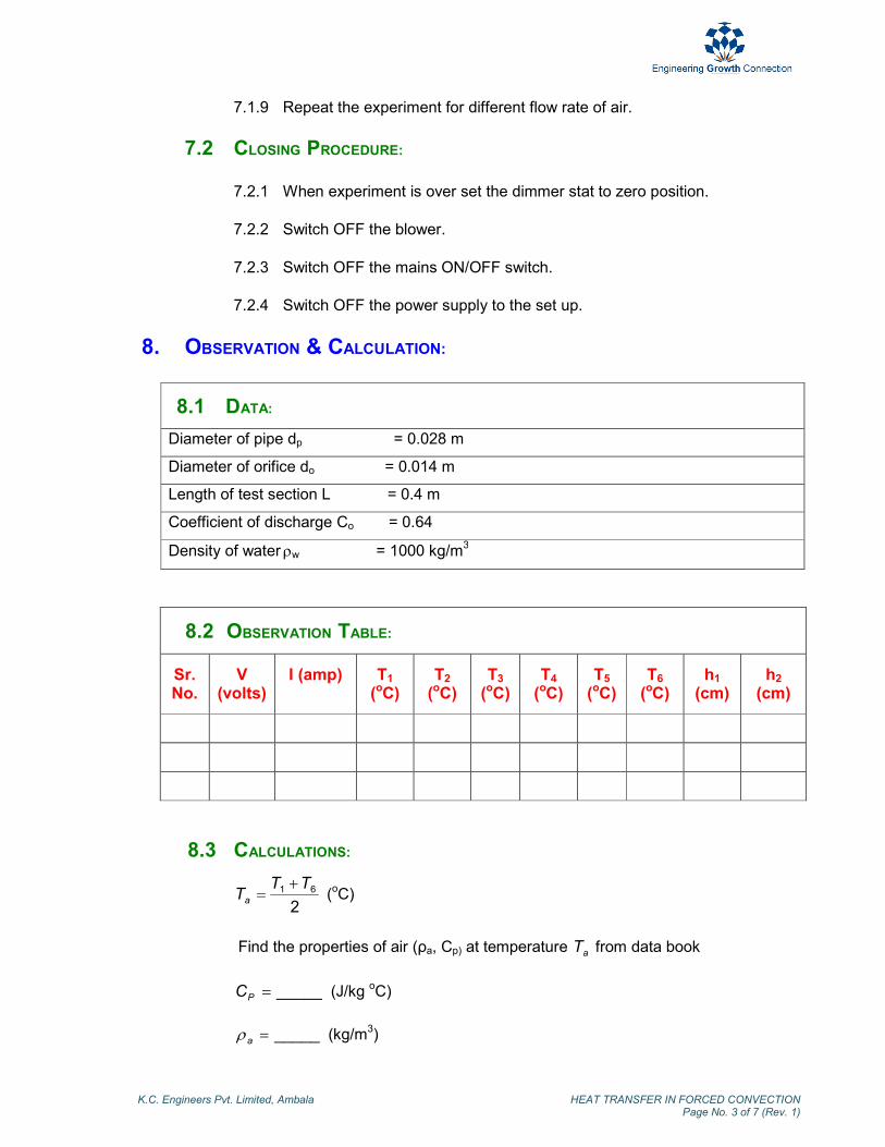
8.1 DATA:
Diameter of pipe dp = 0.028 m
Diameter of orifice do = 0.014 m
Length of test section L = 0.4 m
Coefficient of discharge Co = 0.64
Density of water ρw = 1000 kg/m
3
8.2 OBSERVATION TABLE:
Sr. No.
V (volts)
I (amp) T1 (oC)
T2 (oC)
T3 (oC)
T4 (oC)
T5 (oC)
T6 (oC)
h1 (cm)
h2 (cm)
8.3 CALCULATIONS:
2
61 TTTa
+= (
oC)
Find the properties of air (ρa, Cp) at temperature aT from data book
_____=PC (J/kg oC)
_____=aρ (kg/m3)

K.C. Engineers Pvt. Limited, Ambala HEAT TRANSFER IN FORCED CONVECTION Page No. 4 of 7 (Rev. 1)
4
5432 TTTTTs
+++= (
oC)
LdA pπ= (m2)
−
−=∆ 1
100
21
a
whhH
ρρ
(m)
2
4oo da
π= (m
2)
2
4pp da
π= (m
2)
22
2
op
opo
aa
HgaaCQ
−
∆= (m
3/sec)
aQM ρ×= (kg/sec)
)( 16 TTCMQ Pa −= (W)
)( as
a
TTA
QU
−= (W/m
2 °C)
CALCULATION TABLE:
S.No. Q (m3/sec) Qa (W) U (W/m2 °°°°C)
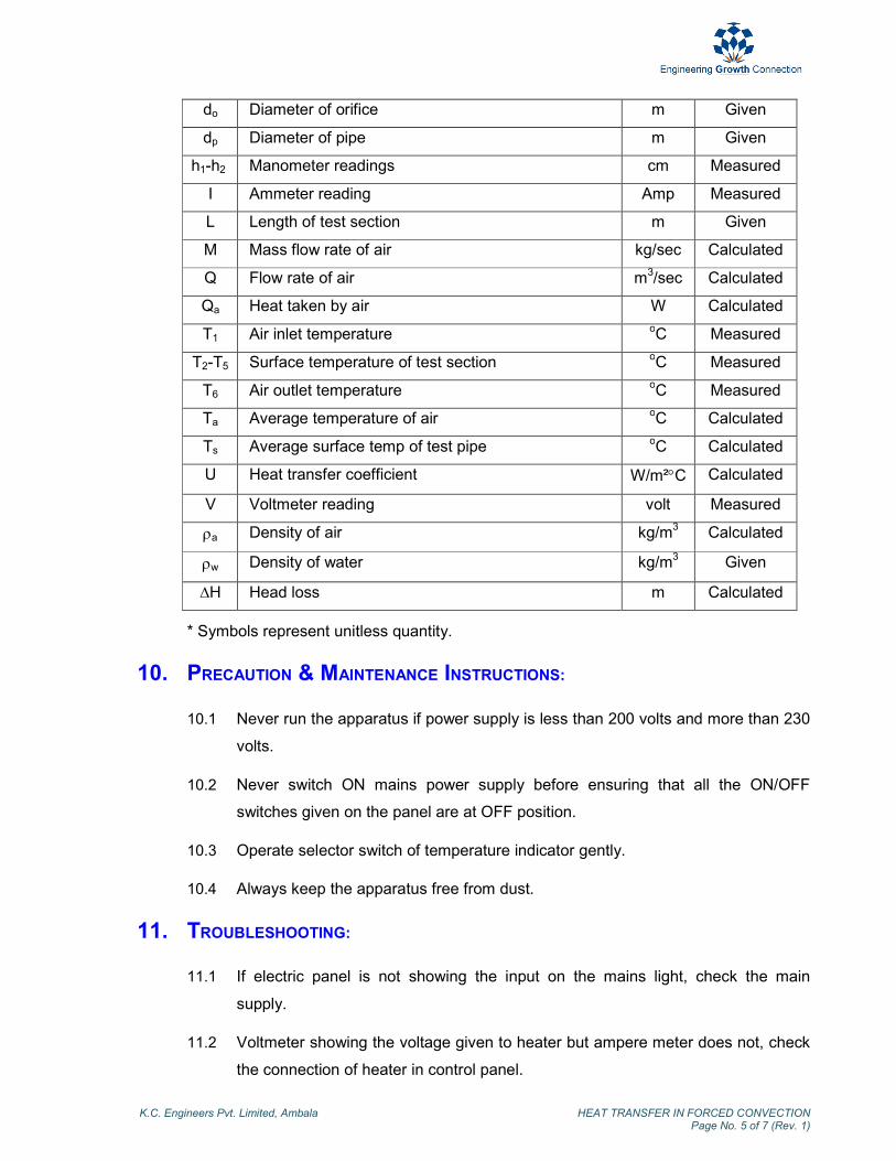
9. NOMENCLATURE:
Nom Column Heading Units Type
A Heat transfer area m2 Calculated
ao Cross- sectional area of orifice m2 Calculated
ap Cross – sectional area of pipe m2 Calculated
Co Coefficient of discharge * Given
Cp Specific heat of air kJ/kgoC Calculated
K.C. Engineers Pvt. Limited, Ambala HEAT TRANSFER IN FORCED CONVECTION Page No. 5 of 7 (Rev. 1)
do Diameter of orifice m Given
dp Diameter of pipe m Given
h1-h2 Manometer readings cm Measured
I Ammeter reading Amp Measured
L Length of test section m Given
M Mass flow rate of air kg/sec Calculated
Q Flow rate of air m3/sec Calculated
Qa Heat taken by air W Calculated
T1 Air inlet temperature oC Measured
T2-T5 Surface temperature of test section oC Measured
T6 Air outlet temperature oC Measured
Ta Average temperature of air oC Calculated
Ts Average surface temp of test pipe oC Calculated
U Heat transfer coefficient W/m²°C Calculated
V Voltmeter reading volt Measured
ρa Density of air kg/m3 Calculated
ρw Density of water kg/m3 Given
∆H Head loss m Calculated
* Symbols represent unitless quantity.
10. PRECAUTION & MAINTENANCE INSTRUCTIONS:
10.1 Never run the apparatus if power supply is less than 200 volts and more than 230
volts.
10.2 Never switch ON mains power supply before ensuring that all the ON/OFF
switches given on the panel are at OFF position.
10.3 Operate selector switch of temperature indicator gently.
10.4 Always keep the apparatus free from dust.
11. TROUBLESHOOTING:
11.1 If electric panel is not showing the input on the mains light, check the main
supply.
11.2 Voltmeter showing the voltage given to heater but ampere meter does not, check
the connection of heater in control panel.
K.C. Engineers Pvt. Limited, Ambala HEAT TRANSFER IN FORCED CONVECTION Page No. 6 of 7 (Rev. 1)
12. REFERENCES:
12.1 McCabe, Smith, Harriott (2005). Unit Operations of Chemical Engineering. 7th
Ed. NY: McGraw Hill. pp 296, 357-363.
12.2 Cengel, Y.A (2007). Heat and Mass Transfer. 3rd
Ed. ND: Tata McGraw Hill. pp
Page 25-26.
12.3 Domkundwar A (2003). A Course in Heat & Mass Transfer. 6th Ed. NY: S.C
Dhanpat Rai & Co. (P) Ltd. pp A.6, A.10
K.C. Engineers Pvt. Limited, Ambala
HEAT TRANSFER IN FORCED CONVECTION
Page No. 7 of 7 (Rev. 1)
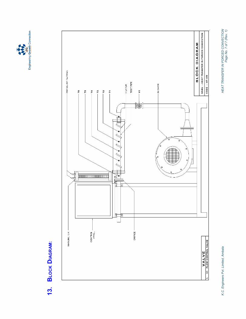
13. BLOCK D
IAGRAM:

HEAT TRANSFER IN NATURAL
CONVECTION (HT-110)

Foreword
Welcome to the fast growing family of K.C. product owners. We appreciate your interest in us and thank you for buying our product. You have chosen the finest quality product in the market which is produced using latest techniques and has underwent strict quality control tests. It is a product that we are proud to build and you are proud to own it. Our products are easy to understand and operate. They are excellent for students who are trying to gain practical knowledge through experiments. However your comfort and safety are important to us, so we want you have an understanding of proper procedure to use the equipment. For the purpose, we urge you to read and follow the step-by-step operating instructions and safety precautions in this manual. It will ensure that your favourite product delivers reliable, superior performance year after year. This manual includes information for all options available on this model. Therefore, you may find some information that does not apply to your equipment. All information, specifications and illustrations in this manual are those in effect at the time of printing. We reserve the right to change specifications or design at any time without notice. Customer satisfaction is our primary concern. Feel Free to contact us for any assistance. So what are you waiting for, roll up your sleeves and let us get down to work!
K.C. Engineers Pvt. Ltd.

Important Information About This Manual
Reminder for Safety
Modification on Equipment:
This equipment should not be modified. Modification could affect its performance, safety or
disturbance. In addition damage or performance problems resulting from modification may not be
covered under warranties.
Precautions and Maintenance:
This is used to indicate the presence of a hazard that could cause minor or moderate personal injury
or damage to your equipment. To avoid or reduce the risk, the procedures must be followed
carefully.

K.C. Engineers Pvt. Limited, Ambala HEAT TRANSFER IN NATURAL CONVECTION (Rev. 1)
Contents 1. Objective …………………………………… 1 2. Aim …………………………………… 1 3. Introduction …………………………………… 1 4. Theory …………………………………… 1 5. Description …………………………………… 1 6. Utilities Required …………………………………… 2 7. Experimental Procedure …………………………………… 2 8. Observation & Calculation …………………………………… 2 9. Nomenclature …………………………………… 3 10. Precautions & Maintenance Instructions …………………………………… 4 11. Troubleshooting …………………………………… 4 12. References …………………………………… 4 13. Block Diagram …………………………………… 5

K.C. Engineers Pvt. Limited, Ambala HEAT TRANSFER IN NATURAL CONVECTION Page No. 1 of 5 (Rev. 1)
HEAT TRANSFER IN NATURAL CONVECTION
1. OBJECTIVE:
To study the heat transfer in natural convection.
2. AIM:
To calculate the average heat transfer co-efficient of vertical cylinder under natural
convection.
3. INTRODUCTION:
Convection is defined as process of heat transfer by appreciable motion of molecules.
Convection heat transfer is further classified as natural convection and forced
convection. If the mixing motion takes place due to density difference caused by
temperature gradient, then the process of heat transfer is known as heat transfer by
natural or free convection. If the mixing motion is induced by some external means such
as a pump or blower then the process is known as heat transfer by forced convection.
4. THEORY:
Natural convection phenomenon is due to the temperature difference between the
surface and the fluid and is not created by any external agency. The setup is designed
and fabricated to study the natural convection phenomenon from a vertical cylinder in
terms of average heat transfer coefficient.
The average heat transfer coefficient is given by.
)( as
a
TTA
Qh
Where Qa, Ts, Ta and A are amount of heat transfer, surface temperature, ambient
temperature and area of heat transfer respectively.
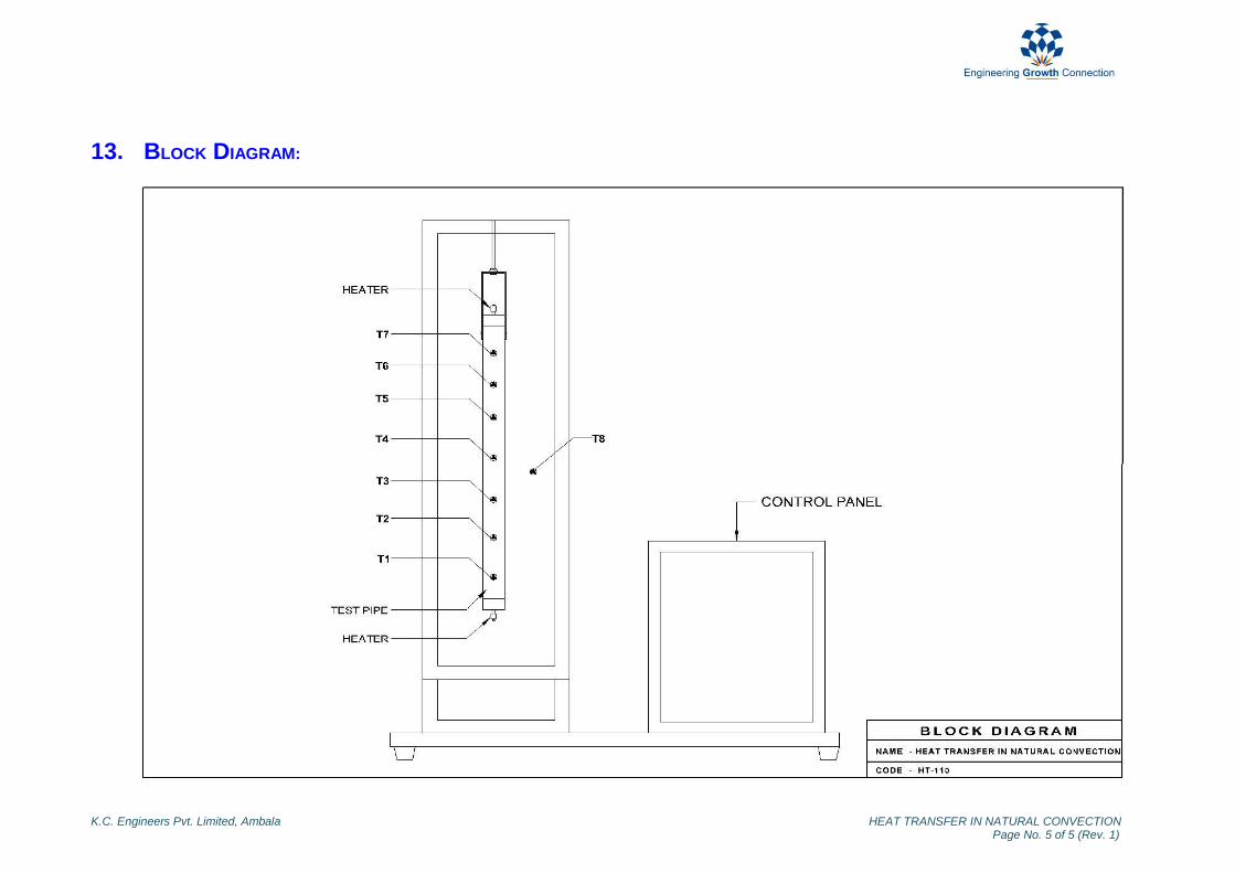
5. DESCRIPTION:
The apparatus consists of a test pipe fitted in a rectangular duct in a vertical fashion.
Heater is provided in the middle of test pipe. The duct is open at the top and bottom and
forms an enclosure and serves the purpose of undisturbed surrounding. Seven
temperature sensors are provided to measure the temperature of test pipe surface and
K.C. Engineers Pvt. Limited, Ambala HEAT TRANSFER IN NATURAL CONVECTION Page No. 2 of 5 (Rev. 1)
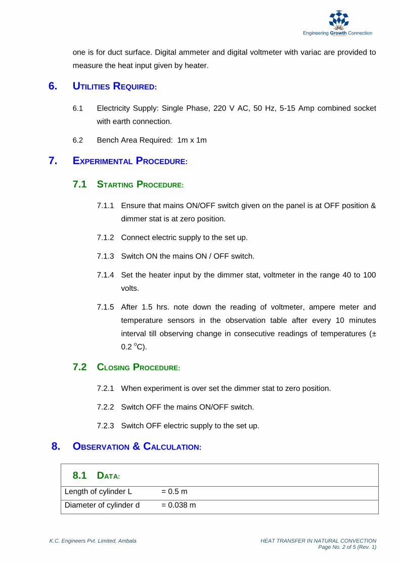
one is for duct surface. Digital ammeter and digital voltmeter with variac are provided to
measure the heat input given by heater.
6. UTILITIES REQUIRED:
6.1 Electricity Supply: Single Phase, 220 V AC, 50 Hz, 5-15 Amp combined socket
with earth connection.
6.2 Bench Area Required: 1m x 1m
7. EXPERIMENTAL PROCEDURE:
7.1 STARTING PROCEDURE:
7.1.1 Ensure that mains ON/OFF switch given on the panel is at OFF position &
dimmer stat is at zero position.
7.1.2 Connect electric supply to the set up.
7.1.3 Switch ON the mains ON / OFF switch.
7.1.4 Set the heater input by the dimmer stat, voltmeter in the range 40 to 100
volts.
7.1.5 After 1.5 hrs. note down the reading of voltmeter, ampere meter and
temperature sensors in the observation table after every 10 minutes
interval till observing change in consecutive readings of temperatures (±
0.2 oC).
7.2 CLOSING PROCEDURE:
7.2.1 When experiment is over set the dimmer stat to zero position.
7.2.2 Switch OFF the mains ON/OFF switch.
7.2.3 Switch OFF electric supply to the set up.
8. OBSERVATION & CALCULATION:
8.1 DATA:
Length of cylinder L = 0.5 m
Diameter of cylinder d = 0.038 m
K.C. Engineers Pvt. Limited, Ambala HEAT TRANSFER IN NATURAL CONVECTION Page No. 3 of 5 (Rev. 1)
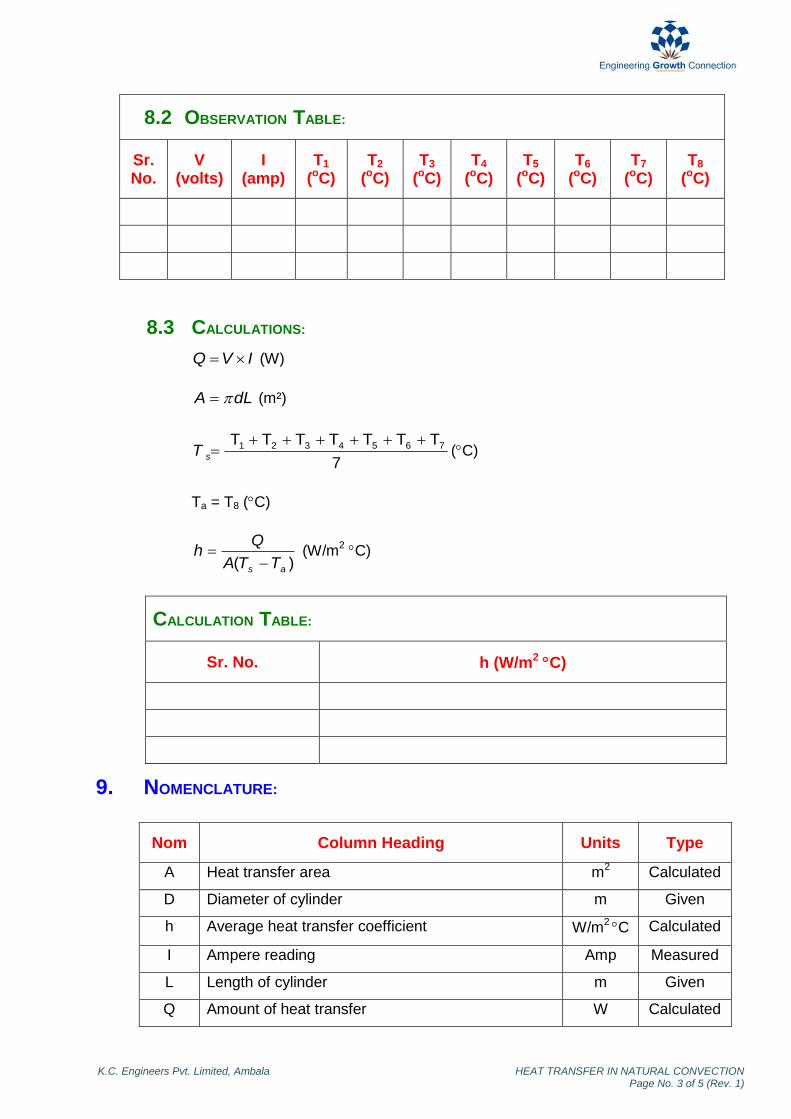
8.2 OBSERVATION TABLE:
Sr. No.
V (volts)
I (amp)
T1
(oC) T2
(oC) T3
(oC) T4
(oC) T5
(oC) T6
(oC) T7
(oC) T8
(oC)
8.3 CALCULATIONS:
IVQ (W)
dLA (m²)
7
TTTTTTT 7654321 sT (C)
Ta = T8 (C)
)( as TTA
Qh
(W/m
2 C)
CALCULATION TABLE:
Sr. No. h (W/m2 C)
9. NOMENCLATURE:
Nom Column Heading Units Type
A Heat transfer area m2 Calculated
D Diameter of cylinder m Given
h Average heat transfer coefficient W/m2 C Calculated
I Ampere reading Amp Measured
L Length of cylinder m Given
Q Amount of heat transfer W Calculated

K.C. Engineers Pvt. Limited, Ambala HEAT TRANSFER IN NATURAL CONVECTION Page No. 4 of 5 (Rev. 1)
T1 - T7 Surface temperatures of test pipe C Measured
T8/Ta Temperature of air in duct C Measured
Ts Average surface temperature of test pipe C Calculated
V Voltmeter reading Volts Measured
10. PRECAUTION & MAINTENANCE INSTRUCTIONS:
10.1 Never run the apparatus if power supply is less than 200 volts and more than 230
volts.
10.2 Never switch ON mains power supply before ensuring that all the ON/OFF
switches given on the panel are at OFF position.
10.3 Operate selector switch of temperature indicator gently.
10.4 Always keep the apparatus free from dust.
11. TROUBLESHOOTING:
11.1 If electric panel is not showing the input on the mains light, check the main
supply.
11.2 Voltmeter showing the voltage given to heater but ampere meter does not, check
the connection of heater in control panel.
12. REFERENCES:
12.1 McCabe, Smith, Harriott (2005). Unit Operations of Chemical Engineering. 7th
Ed. NY: McGraw Hill. pp 296, 376-379.
12.2 Cengel, Y.A, (2007). Heat and Mass Transfer. 3rd
Ed. ND: Tata McGraw Hill. pp
25-26.
K.C. Engineers Pvt. Limited, Ambala HEAT TRANSFER IN NATURAL CONVECTION Page No. 5 of 5 (Rev. 1)
13. BLOCK DIAGRAM:

HEAT TRANSFER THROUGH
COMPOSITE WALL (HT-101)

Foreword
Welcome to the fast growing family of K.C. product owners. We appreciate your interest in us and thank you for buying our product. You have chosen the finest quality product in the market which is produced using latest techniques and has underwent strict quality control tests. It is a product that we are proud to build and you are proud to own it. Our products are easy to understand and operate. They are excellent for students who are trying to gain practical knowledge through experiments. However your comfort and safety are important to us, so we want you have an understanding of proper procedure to use the equipment. For the purpose, we urge you to read and follow the step-by-step operating instructions and safety precautions in this manual. It will ensure that your favourite product delivers reliable, superior performance year after year. This manual includes information for all options available on this model. Therefore, you may find some information that does not apply to your equipment. All information, specifications and illustrations in this manual are those in effect at the time of printing. We reserve the right to change specifications or design at any time without notice. Customer satisfaction is our primary concern. Feel Free to contact us for any assistance. So what are you waiting for, roll up your sleeves and let us get down to work!
K.C. Engineers Pvt. Ltd.

Important Information About This Manual
Reminder for Safety
Modification on Equipment:
This equipment should not be modified. Modification could affect its performance, safety or
disturbance. In addition damage or performance problems resulting from modification may not be
covered under warranties.
Precautions and Maintenance:
This is used to indicate the presence of a hazard that could cause minor or moderate personal injury
or damage to your equipment. To avoid or reduce the risk, the procedures must be followed
carefully.
K.C. Engineers Pvt. Limited, Ambala HEAT TRANSFER THROUGH COMPOSITE WALL (Rev. 1)
Contents 1. Objective …………………………………… 1 2. Aim …………………………………… 1 3. Introduction …………………………………… 1 4. Theory …………………………………… 1 5. Description …………………………………… 2 6. Utilities Required …………………………………… 2 7. Experimental Procedure …………………………………… 2 8. Observation & Calculation …………………………………… 3 9. Nomenclature …………………………………… 5 10. Precautions & Maintenance Instructions …………………………………… 6 11. Troubleshooting …………………………………… 6 12. References …………………………………… 6 13. Block Diagram …………………………………… 7
K.C. Engineers Pvt. Limited, Ambala HEAT TRANSFER THROUGH COMPOSITE WALL Page No. 1 of 7 (Rev. 1)
HEAT TRANSFER THROUGH COMPOSITE WALL
1. OBJECTIVE:
To study the heat transfer through conduction in composite wall.
2. AIM:
2.1 To calculate total thermal resistance of composite wall.
2.2 To calculate total thermal conductivity of composite wall.
2.3 To calculate thermal conductivity of one material in composite wall.
2.4 To plot the temperature profile along the composite wall.
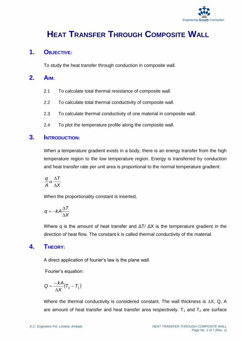
3. INTRODUCTION:
When a temperature gradient exists in a body, there is an energy transfer from the high
temperature region to the low temperature region. Energy is transferred by conduction
and heat transfer rate per unit area is proportional to the normal temperature gradient:
X
T
A
q
When the proportionality constant is inserted,
X
TkAq
Where q is the amount of heat transfer and ΔT/ ΔX is the temperature gradient in the
direction of heat flow. The constant k is called thermal conductivity of the material.
4. THEORY:
A direct application of fourier’s law is the plane wall.
Fourier’s equation:
12 TTX
kAQ
Where the thermal conductivity is considered constant. The wall thickness is X, Q, A
are amount of heat transfer and heat transfer area respectively. T1 and T2 are surface

K.C. Engineers Pvt. Limited, Ambala HEAT TRANSFER THROUGH COMPOSITE WALL Page No. 2 of 7 (Rev. 1)
temperatures. If more than one material is present, as in the multilayer wall, the analysis
would proceed as follows:
The temperature gradients in the three materials (A, B, C), the heat flow may be written
C
CC
B
BB
A
AA
X
TAk
X
TAk
X
TAkQ
A
For material A thermal conductivity can be calculated as following:
A
AA
T
Xqk
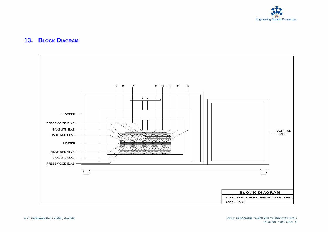
5. DESCRIPTION:
The apparatus consists of a heater sandwiched between two asbestos sheets. Three
slabs of different material are provided on both sides of heater, which forms a composite
structure. A small press- frame is provided to ensure the perfect contact between the
slabs. A variac is provided for varying the input to the heater and measurement of input
power is carried out by a digital voltmeter & digital ammeter. Eight temperature sensor
are embedded between inter faces of the slab, to read the temperature at the surface.
6. UTILITIES REQUIRED:
6.1 Electricity Supply: Single Phase, 220 V AC, 50 Hz, 5-15 Amp combined socket
with earth connection.
6.2 Bench Area Required: 1m x 1m.
7. EXPERIMENTAL PROCEDURE:
7.1 STARTING PROCEDURE:
7.1.1 Ensure that mains ON/OFF switch given on the panel is at OFF position &
dimmer stat is at zero position.
7.1.2 Connect electric supply to the set up.
7.1.3 Switch ON the mains ON / OFF switch.

K.C. Engineers Pvt. Limited, Ambala HEAT TRANSFER THROUGH COMPOSITE WALL Page No. 3 of 7 (Rev. 1)
7.1.4 Set the heater input by the dimmer stat, voltmeter in the range 40 to 100
volt.
7.1.5 After 1.5 hrs. note down the reading of voltmeter, ampere meter and
temperature sensors in the observation table after every 10 minutes
interval till observing change in consecutive readings of temperatures (±
0.2 oC).
7.2 CLOSING PROCEDURE:
7.2.1 When experiment is over set the dimmer stat to zero position.
7.2.2 Switch OFF the mains ON/OFF switch.
7.2.3 Switch OFF the power supply to the set up.
8. OBSERVATION & CALCULATION:
8.1 DATA:
Thermal conductivity of cast iron k1 =
52 W/moC
Cast iron thickness X1 = 0.02 m
Thermal conductivity of bakelite k2 =
1.4 W/moC
Bakelite thickness X2 = 0.015 m
Diameter of slab d = 0.25 m Press wood thickness X3 = 0.012 m
8.2 OBSERVATION TABLE:
Sr. No. V
(Volt)
I
(Amp)
T1
(oC) T2
(oC) T3
(oC) T4
(oC) T5
(oC) T6
(oC) T7
(oC) T8
(oC)
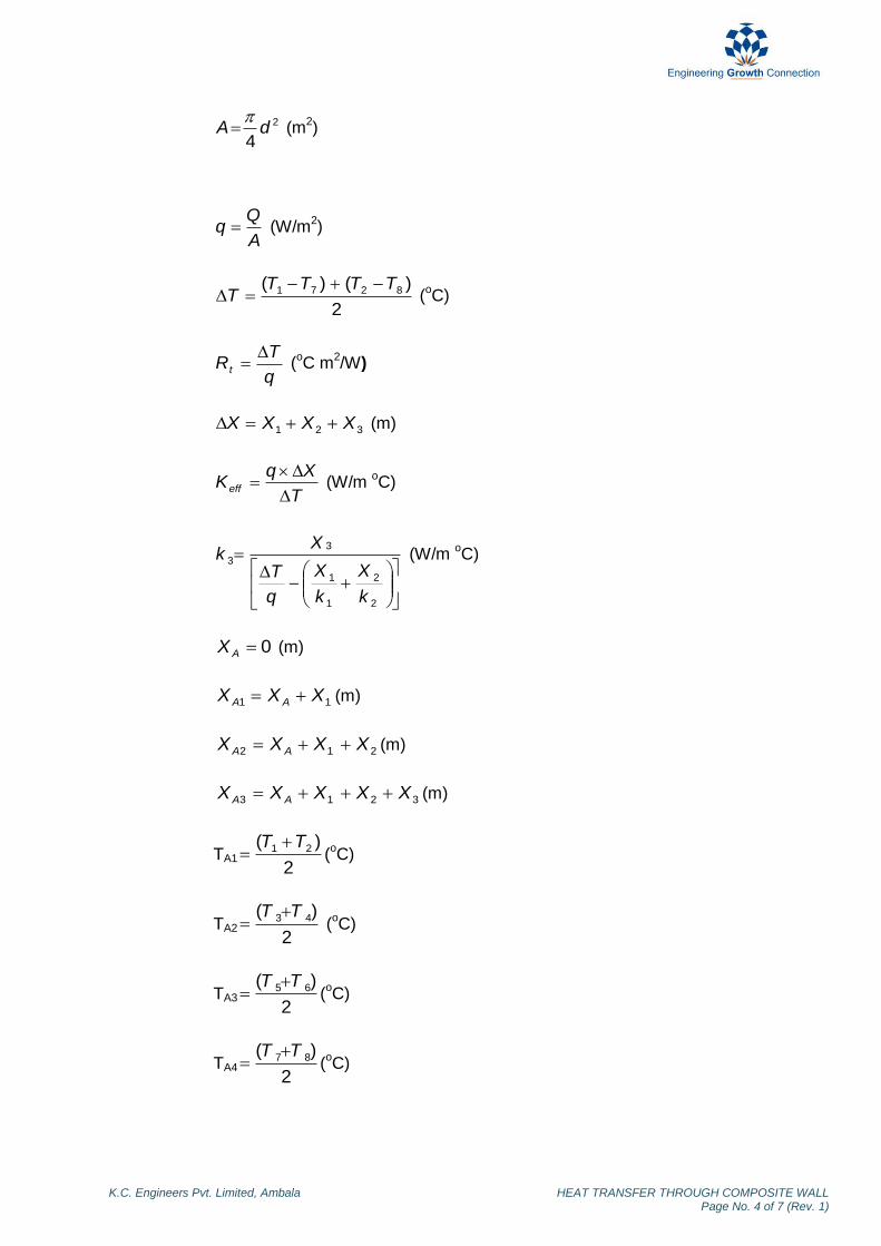
8.3 CALCULATIONS:
IVW (W)
2
WQ (W)
K.C. Engineers Pvt. Limited, Ambala HEAT TRANSFER THROUGH COMPOSITE WALL Page No. 4 of 7 (Rev. 1)
2
4dA
(m
2)
A
Qq (W/m
2)
2
)()( 8271 TTTTT
(
oC)
q
TRt
(
oC m
2/W)
321 XXXX (m)
T
XqKeff
(W/m
oC)
2
2
1
1
3
3
k
X
k
X
q
T
Xk (W/m
oC)
0AX (m)
11 XXX AA (m)
212 XXXX AA (m)
3213 XXXXX AA (m)
TA12
)( 21 TT (
oC)
TA22
)( 43 TT (
oC)
TA32
)( 65 TT (
oC)
TA42
)( 87 TT (
oC)

K.C. Engineers Pvt. Limited, Ambala HEAT TRANSFER THROUGH COMPOSITE WALL Page No. 5 of 7 (Rev. 1)
CALCULATION TABLE:
Sr. No
Q (W/m2)
T (oC)
Rt
(oCm2/W) keff
(W/moC) k3
(W/moC) TA1
(oC) TA2
(oC) TA3
(oC) TA4
(oC)
To plot the graph of length (XA, XA1, XA2, XA3) vs temperature (TA1, TA2, TA3, TA4).
9. NOMENCLATURE:
Nom Column Heading Units Type
A Area of heat transfer m2 Calculated
D Diameter of slab m Given
I Ammeter reading Amp Measured
Keff Total thermal conductivity of composite wall W/m oC Calculated
k1 Thermal conductivity of cast iron W/m oC Given
k2 Thermal conductivity of bakelite W/m oC Given
k3 Thermal conductivity of press wood W/m oC Calculated
Q Amount of heat transfer W Calculated
q Heat flux W/m2 Calculated
Rt Total thermal resistance of composite wall oC m
2/W Calculated
T1-T2 Interface temperature of cast iron and heater oC Measured
T3-T4 Interface temperature of cast iron and bakelite oC Measured
T5-T6 Interface temperature of bakelite and press wood oC Measured
T7-T8 Top surface temperature of press wood oC Measured
TA1 Average temperature at the interface of cast iron
slab and heater
oC Calculated
TA2 Average temperature at the interface of cast iron
slab and bakelite slab
oC Calculated
TA3 Average temperature at the interface of bakelite
slab and press wood slab
oC Calculated
TA4 Average temperature at the surface of press wood
slab
oC Calculated
V Voltmeter reading Volt Measured

K.C. Engineers Pvt. Limited, Ambala HEAT TRANSFER THROUGH COMPOSITE WALL Page No. 6 of 7 (Rev. 1)
W Heat supplied by the heater W Calculated
X1 Cast iron thickness m Given
X2 Bakelite thickness m Given
X3 Press wood thickness m Given
XA Reference point to measure distances m Calculated
XA1 Distance of reference point to cast iron slab m Calculated
XA2 Distance of reference point to bakelite slab m Calculated
XA3 Distance of reference point to press wood slab m Calculated
∆T Overall temperature difference oC Calculated
∆X Total thickness of wall m Calculated
10. PRECAUTION & MAINTENANCE INSTRUCTIONS:
10.1 Never run the apparatus if power supply is less than 200 volts and more than 230
volts.
10.2 Never switch ON mains power supply before ensuring that all the ON/OFF
switches given on the panel are at OFF position.
10.3 Operate selector switch of temperature indicator gently.
10.4 Always keep the apparatus free from dust.
11. TROUBLESHOOTING:
11.1 If electric panel is not showing the input on the mains light, check the main
supply.
11.2 If voltmeter showing the voltage given to heater but ampere meter does not,
check the connection of heater in control panel.
12. REFERENCES:
12.1 Holman, J.P (2008). Heat Transfer. 9th Ed. ND: McGraw Hill. pp 23-24.
12.2 Kern, D.Q (2007). Process Heat Transfer. 16th Ed. ND: McGraw Hill. pp 14-15.
12.3 Domkundwar A (2003). A Course in Heat & Mass Transfer. 6th Ed. NY: S.C
Dhanpat Rai & Co. (P) Ltd. pp A.4 – A.5.
K.C. Engineers Pvt. Limited, Ambala HEAT TRANSFER THROUGH COMPOSITE WALL Page No. 7 of 7 (Rev. 1)
13. BLOCK DIAGRAM:

POOL BOILING APPARATUS
(HT-251)

ForewordForewordForewordForeword
Welcome to the fast growing family of K.C. product owners. We appreciate your interest in us and thank you for buying our product. You have chosen the finest quality product in the market which is produced using latest techniques and has underwent strict quality control tests. It is a product that we are proud to build and you are proud to own it. Our products are easy to understand and operate. They are excellent for students who are trying to gain practical knowledge through experiments. However your comfort and safety are important to us, so we want you have an understanding of proper procedure to use the equipment. For the purpose, we urge you to read and follow the step-by-step operating instructions and safety precautions in this manual. It will ensure that your favourite product delivers reliable, superior performance year after year. This manual includes information for all options available on this model. Therefore, you may find some information that does not apply to your equipment. All information, specifications and illustrations in this manual are those in effect at the time of printing. We reserve the right to change specifications or design at any time without notice. Customer satisfaction is our primary concern. Feel Free to contact us for any assistance. So what are you waiting for, roll up your sleeves and let us get down to work!
K.C. Engineers Pvt. Ltd.K.C. Engineers Pvt. Ltd.K.C. Engineers Pvt. Ltd.K.C. Engineers Pvt. Ltd.
ImportanImportanImportanImportant Information About This Manualt Information About This Manualt Information About This Manualt Information About This Manual
Reminder for SafetyReminder for SafetyReminder for SafetyReminder for Safety
Modification on Equipment:Modification on Equipment:Modification on Equipment:Modification on Equipment:
This equipment should not be modified. Modification could affect its performance, safety or
disturbance. In addition damage or performance problems resulting from modification may not be
covered under warranties.
Precautions and Maintenance:Precautions and Maintenance:Precautions and Maintenance:Precautions and Maintenance:
This is used to indicate the presence of a hazard that could cause minor or moderate personal injury
or damage to your equipment. To avoid or reduce the risk, the procedures must be followed
carefully.
K.C. Engineers Pvt. Limited, Ambala POOL BOILING APPARATUS (Rev. 1)
ContentsContentsContentsContents 1. Objective …………………………………… 1 2. Aim …………………………………… 1 3. Introduction …………………………………… 1 4. Theory …………………………………… 1 5. Description …………………………………… 2 6. Utilities Required …………………………………… 2 7. Experimental Procedure …………………………………… 3 8. Observation & Calculation …………………………………… 4 9. Nomenclature …………………………………… 4 10. Precautions & Maintenance Instructions …………………………………… 5 11. Troubleshooting …………………………………… 5 12. References …………………………………… 5 13. Block Diagram …………………………………… 6
K.C. Engineers Pvt. Limited, Ambala POOL BOILING APPARATUS Page No. 1 of 6(Rev. 1)
POOL BOILING APPARATUS
1. OBJECTIVE:
To study about the critical flux in a pool boiling apparatus.
2. AIM:
To determine the critical heat flux of a given wire.
3. INTRODUCTION:
When heat is added to a liquid from a submerged solid surface which is at a temperature
higher than the saturation temperature of the liquid, it is used for the part of the liquid to
change phase. This change of phase is called ‘Boiling’. Boiling of various types, the
depending upon the temperature difference between the surface and the liquid.
4. THEORY:
This experimental set-up is designed to study the pool boiling phenomenon up to critical
heat flux. The pool boiling over the heater wire can be visualized in the different regions
up to the critical heat flux point at which the wire melts. The heat flux from the wire is
slowly increased by gradually increasing the applied convection to nucleate boiling can
be seen. The formation of bubbles and their growth in size and number can be
visualized followed by vigorous bubble formation and their immediate carrying over to
surface and ending this in the breaking of wire indicating the occurrence of critical heat
flux point. This is repeated for various temperatures of the water in the container.
The different types experimental boiling curve obtained in a saturated pool of liquid.
The heat flux supplied to the surface is plotted against (Tw-T1) (The difference between
the temperature of the surface and the boiling temperature of the liquid.)
It is seen that the boiling curve can be divide into three regions;
4.1 Natural Convection Region
4.2 Nucleate Boiling Region
4.3 Film Boiling Region.
K.C. Engineers Pvt. Limited, Ambala POOL BOILING APPARATUS Page No. 2 of 6(Rev. 1)
4.1 NATURAL CONVECTION REGION:
The region of natural convection occurs at low temperature differences (of the order of
10 oC or less). Heat transfer from the heated surface to liquid in its vicinity causes the
liquid to be superheated. This superheated liquid rises to the free liquid surface by
natural convection, where vapour is produced by evaporation.
4.2 NUCLEATE BOILING REGION:
As the temperature difference (Tw – T1) is increased, nucleate boiling starts. In this
region, it is observed that bubble start to form at certain locations on the heated surface.
Region II consists of two parts. In the first part, II-a, the bubbles formed are very few in
number. In the second part, II-b, the rate of bubble formation as well as the number of
locations where they are formed, increase. Some of the bubbles now rise all the way to
the free surface. With increasing temperature difference a stage is finally reached when
the rate of formation of bubble is so high, that they start to collapse and blanked the
surface with a vapour film. This the beginning of region III.
4.3 FILM BOILING REGION:
In the first part of region III, the vapour film is unstable, so that film boiling may be
occurring on a portion of the heated surface area, while nucleate boiling may be
occurring on the remaining area. In the second part of region III, a stable film covers the
entire surface. The temperature difference in this region is the order of 100o deg C and
consequently radiative heat transfer across the vapour film is also significant.
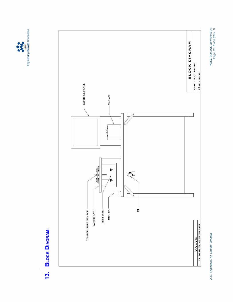
5. DESCRIPTION:
The apparatus consists of water bath with heater and test wire. Heater is also connected
to mains via a dimmer stat and a voltmeter. Temperature sensor is provided to measure
the temperature. A micro controller based peak detector has been provided to measure
the maximum current during the process. The heater wire can be viewed through a
transparent window.
6. UTILITIES REQUIRED:
6.1 Electricity Supply: Single Phase, 220 V AC, 50 Hz, 5-15 Amp. combined socket
with earth connection
6.2 Water Supply (Initial Fill).

K.C. Engineers Pvt. Limited, Ambala POOL BOILING APPARATUS Page No. 3 of 6(Rev. 1)
6.3 Floor Drain Required
6.4 Floor Area Required : 1.5m x 1m
7. EXPERIMENTAL PROCEDURE:
7.1 STARTING PROCEDURE:
7.1.1 Close the valve V1.
7.1.2 Fill the water bath with water up to 3/4th of its capacity.
7.1.3 Ensure that ON/OFF switches given on the panel are at OFF position.
7.1.4 Connect the test heater wire.
7.1.5 Connect electric supply to the set up.
7.1.6 Set the desired bath temperature with the help of DTC (50o - 80
oC).
7.1.7 Switch ON the heater and wait till desired temperature achieved.
7.1.8 Initialize the process monitor indicator by pressing the button provided.
7.1.9 Switch-ON the test heater.
7.1.10 Very gradually increase the voltage across it by slowly changing the variac
from one position to the other and stop a while at each position to observe
the boiling phenomena on wire.
7.1.11 Go on increasing the voltage till wire breaks and carefully note down the
voltage and current at this point.
7.1.12 Bring the variac to zero voltage.
7.1.13 Repeat the experiment for different water bath temperature.
7.2 CLOSING PROCEDURE:
7.2.1 When experiment is over, switch OFF the heater.
7.2.2 Switch OFF the main power supply.
7.2.3 Drain the water bath by opening the valve V1.

K.C. Engineers Pvt. Limited, Ambala POOL BOILING APPARATUS Page No. 4 of 6(Rev. 1)
8. OBSERVATION & CALCULATION:
8.1 DATA:
Diameter of test heater wire d = 1.219*10-4 m
Length of the test heater wire L = 0.08 m
OBSERVATION:
T1 = _______ (oC)
8.3 CALCULATIONS:
IVW ×= (W)
LdA ××= π (m2)
A
Wqc = (W/m
2)
CALCULATION TABLE:
Sr. No. qc (W/m2 )
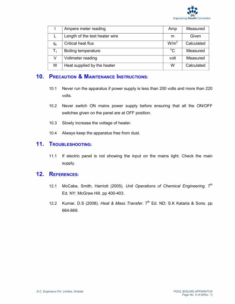
9. NOMENCLATURE:
Nom Column Heading Units Type
A Area of test heater wire m2 Calculated
d Diameter of test heater wire m Given
8.2 OBSERVTION TABLE:
S. No. V (Volt) I (Amp)
K.C. Engineers Pvt. Limited, Ambala POOL BOILING APPARATUS Page No. 5 of 6(Rev. 1)
I Ampere meter reading Amp Measured
L Length of the test heater wire m Given
qc Critical heat flux W/m2 Calculated
T1 Boiling temperature oC Measured
V Voltmeter reading
volt Measured
W Heat supplied by the heater W Calculated
10. PRECAUTION & MAINTENANCE INSTRUCTIONS:
10.1 Never run the apparatus if power supply is less than 200 volts and more than 220
volts.
10.2 Never switch ON mains power supply before ensuring that all the ON/OFF
switches given on the panel are at OFF position.
10.3 Slowly increase the voltage of heater.
10.4 Always keep the apparatus free from dust.
11. TROUBLESHOOTING:
11.1 If electric panel is not showing the input on the mains light. Check the main
supply.
12. REFERENCES:
12.1 McCabe, Smith, Harriott (2005). Unit Operations of Chemical Engineering. 7th
Ed. NY: McGraw Hill. pp 400-403.
12.2 Kumar, D.S (2008). Heat & Mass Transfer. 7th Ed. ND: S.K Kataria & Sons. pp
664-669.
K.C
. Engin
eers
Pvt. L
imited, Am
bala
P
OO
L B
OIL
ING
APPAR
ATU
S
Page N
o. 6 o
f 6 (R
ev. 1)
13.
BLOCK D
IAGRAM:

SHELL & TUBE HEAT
EXCHANGER (HT-115)

Foreword
Welcome to the fast growing family of K.C. product owners. We appreciate your interest in us and thank you for buying our product. You have chosen the finest quality product in the market which is produced using latest techniques and has underwent strict quality control tests. It is a product that we are proud to build and you are proud to own it. Our products are easy to understand and operate. They are excellent for students who are trying to gain practical knowledge through experiments. However your comfort and safety are important to us, so we want you have an understanding of proper procedure to use the equipment. For the purpose, we urge you to read and follow the step-by-step operating instructions and safety precautions in this manual. It will ensure that your favourite product delivers reliable, superior performance year after year. This manual includes information for all options available on this model. Therefore, you may find some information that does not apply to your equipment. All information, specifications and illustrations in this manual are those in effect at the time of printing. We reserve the right to change specifications or design at any time without notice. Customer satisfaction is our primary concern. Feel Free to contact us for any assistance. So what are you waiting for, roll up your sleeves and let us get down to work!
K.C. Engineers Pvt. Ltd.

Important Information About This Manual
Reminder for Safety
Modification on Equipment:
This equipment should not be modified. Modification could affect its performance, safety or
disturbance. In addition damage or performance problems resulting from modification may not be
covered under warranties.
Precautions and Maintenance:
This is used to indicate the presence of a hazard that could cause minor or moderate personal injury
or damage to your equipment. To avoid or reduce the risk, the procedures must be followed
carefully.

K.C. Engineers Pvt. Limited, Ambala SHELL & TUBE HEAT EXCHANGER (Rev. 1)
1. Objective …………………………………… 1 2. Aim …………………………………… 1 3. Introduction …………………………………… 1 4. Theory …………………………………… 1 5. Description …………………………………… 2 6. Utilities Required …………………………………… 2 7. Experimental Procedure …………………………………… 3 8. Observation & Calculation …………………………………… 4 9. Nomenclature …………………………………… 5 10. Precautions & Maintenance Instructions …………………………………… 6 11. Troubleshooting …………………………………… 7 12. References …………………………………… 7 13. Block Diagram …………………………………… 8

K.C. Engineers Pvt. Limited, Ambala SHELL & TUBE HEAT EXCHANGER Page No. 1 of 9 (Rev. 1)
SHELL & TUBE HEAT EXCHANGER
1. OBJECTIVE:
To study of heat transfer in shell and tube heat exchanger.
2. AIM:
2.1 To calculate the LMTD.
2.2 To calculate the heat transfer rate.
2.3 To calculate the overall heat transfer coefficient.
3. INTRODUCTION:
Heat exchanger is device in which heat is transferred from one fluid to another. The
necessity for doing this arises in a multitude of industrial applications. Common
examples of heat exchangers are the radiator of a car, the condenser at the back of a
domestic refrigerator and the steam boiler of a thermal power plant.
Heat exchangers are classified in three categories:
3.1 Transfer Type.
3.2 Storage Type.
3.3 Direct Contact Type.
4. THEORY:
A transfer type of heat exchanger is one on which both fluids pass simultaneously
through the device and heat is transferred through separating walls. In practice, most of
the heat exchangers used are transfer type ones.
The transfer type exchangers are further classified according to flow arrangement as -
4.1 Single Pass.
4.2 Multiple Pass
A simple example of transfer type of heat exchanger can be in the form of a tube type
arrangement in which one of the fluids is flowing through the inner tube and the other
K.C. Engineers Pvt. Limited, Ambala SHELL & TUBE HEAT EXCHANGER Page No. 2 of 9 (Rev. 1)
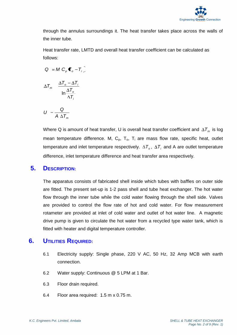
through the annulus surroundings it. The heat transfer takes place across the walls of
the inner tube.
Heat transfer rate, LMTD and overall heat transfer coefficient can be calculated as
follows:
iop TTCMQ
i
o
iom
T
T
TTT
ln
mTA
QU
Where Q is amount of heat transfer, U is overall heat transfer coefficient and mT is log
mean temperature difference. M, Cp, To, Ti are mass flow rate, specific heat, outlet
temperature and inlet temperature respectively. oT , iT and A are outlet temperature
difference, inlet temperature difference and heat transfer area respectively.
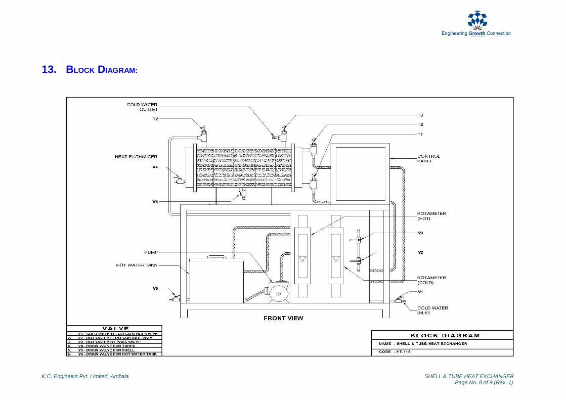
5. DESCRIPTION:
The apparatus consists of fabricated shell inside which tubes with baffles on outer side
are fitted. The present set-up is 1-2 pass shell and tube heat exchanger. The hot water
flow through the inner tube while the cold water flowing through the shell side. Valves
are provided to control the flow rate of hot and cold water. For flow measurement
rotameter are provided at inlet of cold water and outlet of hot water line. A magnetic
drive pump is given to circulate the hot water from a recycled type water tank, which is
fitted with heater and digital temperature controller.
6. UTILITIES REQUIRED:
6.1 Electricity supply: Single phase, 220 V AC, 50 Hz, 32 Amp MCB with earth
connection.
6.2 Water supply: Continuous @ 5 LPM at 1 Bar.
6.3 Floor drain required.
6.4 Floor area required: 1.5 m x 0.75 m.

K.C. Engineers Pvt. Limited, Ambala SHELL & TUBE HEAT EXCHANGER Page No. 3 of 9 (Rev. 1)
7. EXPERIMENTAL PROCEDURE:
7.1 STARTING PROCEDURE:
7.1.1 Close all the valves V1-V6.
7.1.2 Open the lid of hot water tank, fill the tank with water and put the lid back
to its position.
7.1.3 Ensure that switches given on the panel are at OFF position.
7.1.4 Connect electric supply to the set up.
7.1.5 Set the desired water temperature in the DTC by operating the increment
or decrement and set button of DTC.
7.1.6 Open by pass valve V3 and switch ON the pump.
7.1.7 Switch ON the heater and wait till desired temperature achieves.
7.1.8 Connect cooling water supply to the set up.
7.1.9 Connect the outlet of cooling water from heat exchanger to drain.
7.1.10 Open the valve V1 for circulation of cold water and adjust the flow rate.
7.1.11 Allow hot water to flow through heat exchanger and adjust the flow rate by
valve V2-V3.
7.1.12 At steady state (constant temperature) record the temperatures & flow rate
of hot and cold water.
7.1.13 Repeat the experiment for different flow rate of hot & cold water.
7.1.14 Repeat the experiment for different temperature of DTC.
7.2 CLOSING PROCEDURE :
7.2.1 When experiment is over switch OFF the heater.
7.2.2 Switch OFF the pump.
7.2.3 Stop cooling water supply by close the valve V1.
7.2.4 Drain the water from hot water tank by open the valve V6.
7.2.5 Drain the water from shell side by open the valve V5.
7.2.6 Drain the water from tube side by open the valve V4.
K.C. Engineers Pvt. Limited, Ambala SHELL & TUBE HEAT EXCHANGER Page No. 4 of 9 (Rev. 1)
8. OBSERVATION & CALCULATION:
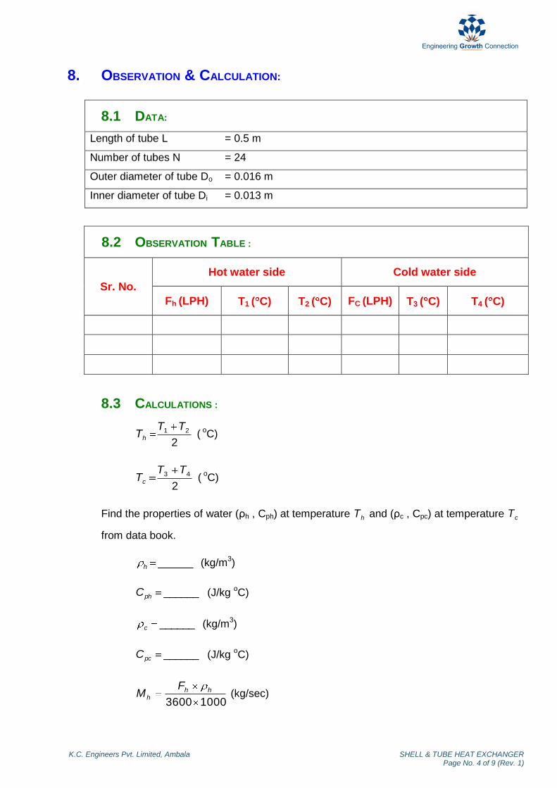
8.1 DATA:
Length of tube L = 0.5 m
Number of tubes N = 24
Outer diameter of tube Do = 0.016 m
Inner diameter of tube Di = 0.013 m
8.2 OBSERVATION TABLE :
Sr. No.
Hot water side Cold water side
Fh (LPH) T1 ( C) T2 ( C) FC (LPH) T3 ( C) T4 ( C)
8.3 CALCULATIONS :
2
21 TTTh (
oC)
2
43 TTTc (
oC)
Find the properties of water (ρh , Cph) at temperature hT and (ρc , Cpc) at temperature cT
from data book.
______h (kg/m3)
______phC (J/kg oC)
______c (kg/m3)
______pcC (J/kg oC)
10003600
hhh
FM (kg/sec)
K.C. Engineers Pvt. Limited, Ambala SHELL & TUBE HEAT EXCHANGER Page No. 5 of 9 (Rev. 1)
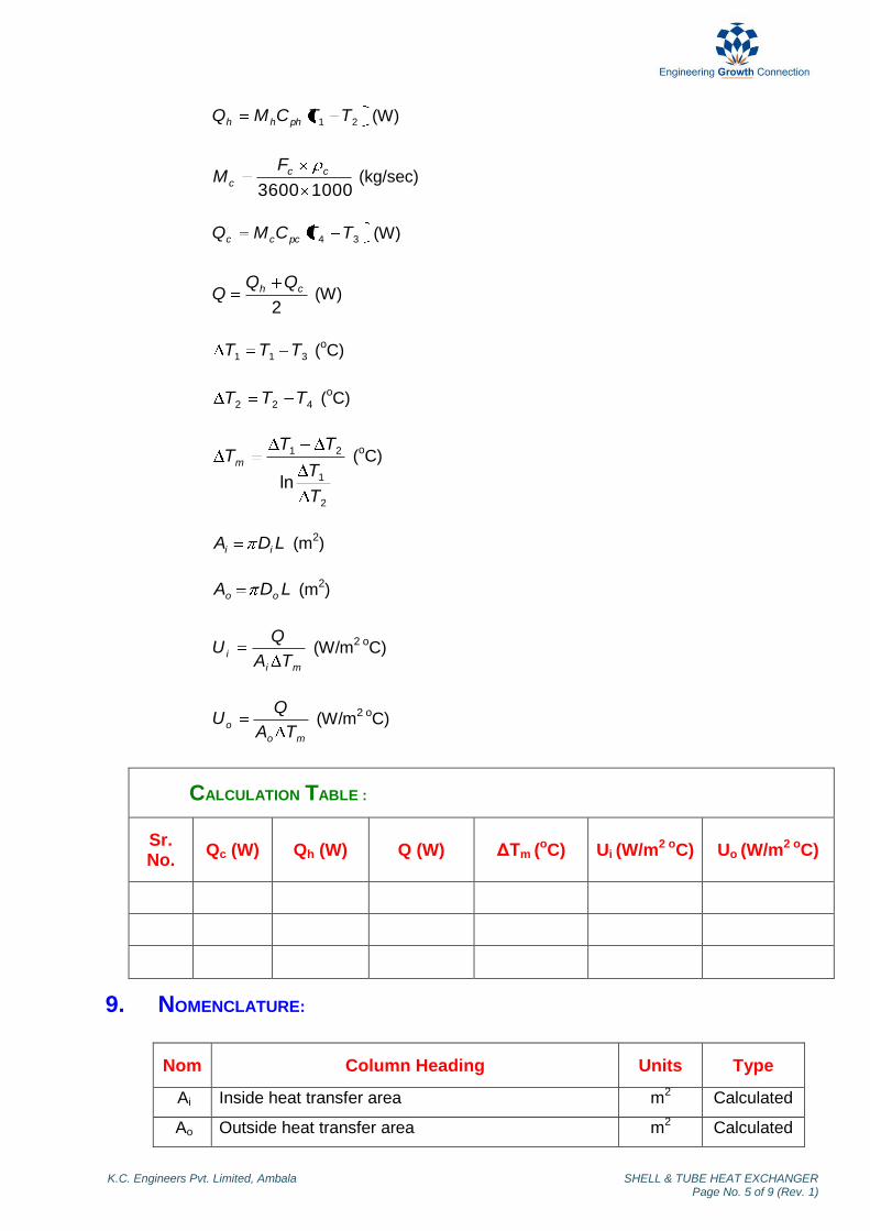
21 TTCMQ phhh (W)
10003600
ccc
FM (kg/sec)
34 TTCMQ pccc (W)
2
ch QQQ (W)
311 TTT (oC)
422 TTT (oC)
2
1
21
lnT
T
TTTm (
oC)
LDA ii (m2)
LDA oo (m2)
mi
iTA
QU (W/m
2 oC)
mo
oTA
QU (W/m
2 oC)
CALCULATION TABLE :
Sr. No.
Qc (W) Qh (W) Q (W) ΔTm (oC) Ui (W/m2 oC) Uo (W/m2 oC)
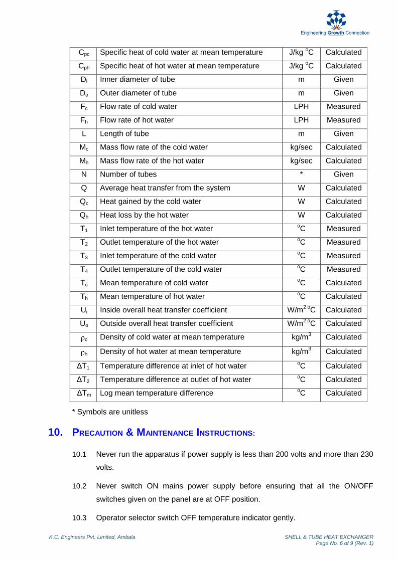
9. NOMENCLATURE:
Nom Column Heading Units Type
Ai Inside heat transfer area m2 Calculated
Ao Outside heat transfer area m2 Calculated
K.C. Engineers Pvt. Limited, Ambala SHELL & TUBE HEAT EXCHANGER Page No. 6 of 9 (Rev. 1)
Cpc Specific heat of cold water at mean temperature J/kg oC Calculated
Cph Specific heat of hot water at mean temperature J/kg oC Calculated
Di Inner diameter of tube m Given
Do Outer diameter of tube m Given
Fc Flow rate of cold water LPH Measured
Fh Flow rate of hot water LPH Measured
L Length of tube m Given
Mc Mass flow rate of the cold water kg/sec Calculated
Mh Mass flow rate of the hot water kg/sec Calculated
N Number of tubes * Given
Q Average heat transfer from the system W Calculated
Qc Heat gained by the cold water W Calculated
Qh Heat loss by the hot water W Calculated
T1 Inlet temperature of the hot water oC Measured
T2 Outlet temperature of the hot water oC Measured
T3 Inlet temperature of the cold water oC Measured
T4 Outlet temperature of the cold water oC Measured
Tc Mean temperature of cold water oC Calculated
Th Mean temperature of hot water oC Calculated
Ui Inside overall heat transfer coefficient W/m2 o
C Calculated
Uo Outside overall heat transfer coefficient W/m2 o
C Calculated
c Density of cold water at mean temperature kg/m3 Calculated
h Density of hot water at mean temperature kg/m3 Calculated
ΔT1 Temperature difference at inlet of hot water oC Calculated
ΔT2 Temperature difference at outlet of hot water oC Calculated
ΔTm Log mean temperature difference oC Calculated
* Symbols are unitless
10. PRECAUTION & MAINTENANCE INSTRUCTIONS:
10.1 Never run the apparatus if power supply is less than 200 volts and more than 230
volts.
10.2 Never switch ON mains power supply before ensuring that all the ON/OFF
switches given on the panel are at OFF position.
10.3 Operator selector switch OFF temperature indicator gently.
K.C. Engineers Pvt. Limited, Ambala SHELL & TUBE HEAT EXCHANGER Page No. 7 of 9 (Rev. 1)
10.4 Always keep the apparatus free from dust.
11. TROUBLESHOOTING:
11.1 If electric panel is not showing the input on the mains light, check the main
supply.
12. REFERENCES:
12.1 Holman, J.P (2008). Heat Transfer. 9th Ed. ND: McGraw Hill. pp 525-527, 528-
531.
12.2 McCabe, Smith, Harriott (2005). Unit Operations of Chemical Engineering. 7th
Ed. NY: McGraw Hill. pp 441-447.
12.3 Domkundwar A (2003). A Course in Heat & Mass Transfer. 6th Ed. NY: S.C
Dhanpat Rai & Co. (P) Ltd. p A.6
K.C. Engineers Pvt. Limited, Ambala SHELL & TUBE HEAT EXCHANGER Page No. 8 of 9 (Rev. 1)
13. BLOCK DIAGRAM:

K.C. Engineers Pvt. Limited, Ambala SHELL & TUBE HEAT EXCHANGER Page No. 9 of 9 (Rev. 1)
THERMAL CONDUCTIVITY OF
LIQUIDS (HT-107)

Foreword
Welcome to the fast growing family of K.C. product owners. We appreciate your interest in us and thank you for buying our product. You have chosen the finest quality product in the market which is produced using latest techniques and has underwent strict quality control tests. It is a product that we are proud to build and you are proud to own it. Our products are easy to understand and operate. They are excellent for students who are trying to gain practical knowledge through experiments. However your comfort and safety are important to us, so we want you have an understanding of proper procedure to use the equipment. For the purpose, we urge you to read and follow the step-by-step operating instructions and safety precautions in this manual. It will ensure that your favourite product delivers reliable, superior performance year after year. This manual includes information for all options available on this model. Therefore, you may find some information that does not apply to your equipment. All information, specifications and illustrations in this manual are those in effect at the time of printing. We reserve the right to change specifications or design at any time without notice. Customer satisfaction is our primary concern. Feel Free to contact us for any assistance. So what are you waiting for, roll up your sleeves and let us get down to work!
K.C. Engineers Pvt. Ltd.

Important Information About This Manual
Reminder for Safety
Modification on Equipment:
This equipment should not be modified. Modification could affect its performance, safety or
disturbance. In addition damage or performance problems resulting from modification may not be
covered under warranties.
Precautions and Maintenance:
This is used to indicate the presence of a hazard that could cause minor or moderate personal injury
or damage to your equipment. To avoid or reduce the risk, the procedures must be followed
carefully.

K.C. Engineers Pvt. Limited, Ambala THERMAL CONDUCTIVITY OF LIQUIDS (Rev. 1)
Contents 1. Objective …………………………………… 1 2. Aim …………………………………… 1 3. Introduction …………………………………… 1 4. Theory …………………………………… 1 5. Description …………………………………… 2 6. Utilities Required …………………………………… 2 7. Experimental Procedure …………………………………… 2 8. Observation & Calculation …………………………………… 3 9. Nomenclature …………………………………… 4 10. Precautions & Maintenance Instructions …………………………………… 5 11. Troubleshooting …………………………………… 5 12. References …………………………………… 5 13. Block Diagram …………………………………… 6

K.C. Engineers Pvt. Limited, Ambala THERMAL CONDUCTIVITY OF LIQUIDS Page No. 1 of 6 (Rev. 1)
THERMAL CONDUCTIVITY OF LIQUIDS
1. OBJECTIVE:
To study the heat transfer through liquids.
2. AIM:
To calculate the thermal conductivity of a liquid.
3. INTRODUCTION:
When a temperature gradient exists in a body, there is an energy transfer from the high
temperature region to the low temperature region. Energy is transferred by conduction
and heat transfer rate per unit area is proportional to the normal temperature gradient.
X
T
A
q
When the proportionality constant is inserted,
X
TkAq
Where q is the amount of heat transfer and ΔT/ΔX is the temperature gradient in the
direction of heat flow. The constant k is called thermal conductivity of the material.
4. THEORY:
For thermal conductivity of liquids using fourier’s law, the heat flow through the liquid
from hot fluid to cold fluid is the heat transfer through conductive fluid medium.
Fourier’s equation:
12 TTX
kAq
Fourier’s law for the case of liquid
At steady state, the average face temperatures are recorded (Th and Tc) along with the
amount of heat transfer (Q) knowing, the heat transfer area (Ah) and the thickness of the
sample (X) across which the heat transfer takes place, the thermal conductivity of the
sample can be calculated using fourier’s law of heat conduction.
K.C. Engineers Pvt. Limited, Ambala THERMAL CONDUCTIVITY OF LIQUIDS Page No. 2 of 6 (Rev. 1)
X
TTkAQ Ch
Ch TTA
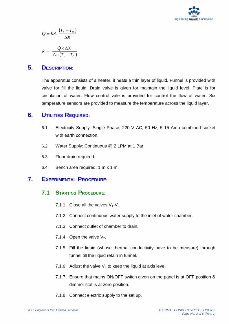
XQk
5. DESCRIPTION:
The apparatus consists of a heater, it heats a thin layer of liquid. Funnel is provided with
valve for fill the liquid. Drain valve is given for maintain the liquid level. Plate is for
circulation of water. Flow control vale is provided for control the flow of water. Six
temperature sensors are provided to measure the temperature across the liquid layer.
6. UTILITIES REQUIRED:
6.1 Electricity Supply: Single Phase, 220 V AC, 50 Hz, 5-15 Amp combined socket
with earth connection.
6.2 Water Supply: Continuous @ 2 LPM at 1 Bar.
6.3 Floor drain required.
6.4 Bench area required: 1 m x 1 m.
7. EXPERIMENTAL PROCEDURE:
7.1 STARTING PROCEDURE:
7.1.1 Close all the valves V1-V3.
7.1.2 Connect continuous water supply to the inlet of water chamber.
7.1.3 Connect outlet of chamber to drain.
7.1.4 Open the valve V2.
7.1.5 Fill the liquid (whose thermal conductivity have to be measure) through
funnel till the liquid retain in funnel.
7.1.6 Adjust the valve V3 to keep the liquid at axis level.
7.1.7 Ensure that mains ON/OFF switch given on the panel is at OFF position &
dimmer stat is at zero position.
7.1.8 Connect electric supply to the set up.
K.C. Engineers Pvt. Limited, Ambala THERMAL CONDUCTIVITY OF LIQUIDS Page No. 3 of 6 (Rev. 1)
7.1.9 Switch ON the mains ON / OFF switch.
7.1.10 Start the water supply and adjust the flow of water by valve V1.
7.1.11 Set the heater input by the dimmer stat, voltmeter in the range 40 to 100
V.
7.1.12 After 1.5 hrs. note down the reading of voltmeter, ampere meter and
temperature sensors in the observation table after every 10 minutes
interval till observing change in consecutive readings of temperatures (±
0.2 oC).
7.1.13 Repeat the experiment for different liquids.
7.2 CLOSING PROCEDURE:
7.2.1 When experiment is over set the dimmer stat to zero position.
7.2.2 Switch OFF the mains ON/OFF switch.
7.2.3 Switch OFF electric supply to the set up.
7.2.4 Stop flow of water by closing the valve V1.
7.2.5 Drain the water by open the valve V3.
8. OBSERVATION & CALCULATION:
8.1 DATA:
Thickness of liquid ΔX = 0.018 m
Diameter of plate D = 0.165 m
8.2 OBSERVATION TABLE:
Sr. No V
(volts) I
(amp) T1
(oC) T2
(oC) T3
(oC) T4
(oC) T5
(oC) T6
(oC)

K.C. Engineers Pvt. Limited, Ambala THERMAL CONDUCTIVITY OF LIQUIDS Page No. 4 of 6 (Rev. 1)
8.3 CALCULATIONS:
IVQ (W)
2
4DA
(m
2)
3
321 TTTTh
(
oC)
3
654 TTTTc
(
oC)
)( ch TTA
XQk
(W/m
oC)
CALCULATION TABLE:
Sr. No k (W/m oC)
9. NOMENCLATURE:
Nom Column Heading Units Type
A Heat transfer area m2 Calculated
D Diameter of plate m Given
I Ammeter reading Amp Measured
k Thermal conductivity of liquid W/m oC Calculated
Q Heat supplied by heater W Calculated
T1-T3 Temperature of the temperature sensors on the hot
side
oC Measured
T4-T6 Temperature of the temperature sensors on the
cold side
oC Measured
Tc Cold face average temperature oC Calculated
Th Hot face average temperature oC Calculated
V Volt meter reading volts Measured
ΔX Thickness of liquid m Given

K.C. Engineers Pvt. Limited, Ambala THERMAL CONDUCTIVITY OF LIQUIDS Page No. 5 of 6 (Rev. 1)
10. PRECAUTION & MAINTENANCE INSTRUCTIONS:
10.1 Never run the apparatus if power supply is less than 200 volts and more than 230
volts.
10.2 Never switch ON mains power supply before ensuring that all the ON/OFF
switches given on the panel are at OFF position.
10.3 Operate selector switch of temperature indicator gently.
10.4 Always keep the apparatus free from dust.
11. TROUBLESHOOTING:
11.1 If electric panel is not showing input on the mains light, check the main supply.
11.2 If voltmeter showing the voltage given to heater but ampere meter does not,
check the connection of heater in control panel.
12. REFERENCES:
12.1 Cengel, Y.A (2007). Heat and Mass Transfer. 3rd
Ed. ND: Tata McGraw Hill. pp
17-19.
12.2 Kern, D.Q (2007). Process Heat Transfer. 16th
Ed. ND: McGraw Hill. pp 6-9

K.C. Engineers Pvt Limited, Ambala THERMAL CONDUCTIVITY OF LIQUIDS Page No. 6 of 6 (Rev. 1)
13. BLOCK DIAGRAM:

THERMAL CONDUCTIVITY OF
METAL ROD (HT-105)

Foreword Welcome to the fast growing family of K.C. product owners. We appreciate your interest in us and thank you for buying our product. You have chosen the finest quality product in the market which is produced using latest techniques and has underwent strict quality control tests. It is a product that we are proud to build and you are proud to own it. Our products are easy to understand and operate. They are excellent for students who are trying to gain practical knowledge through experiments. However your comfort and safety are important to us, so we want you have an understanding of proper procedure to use the equipment. For the purpose, we urge you to read and follow the step-by-step operating instructions and safety precautions in this manual. It will ensure that your favourite product delivers reliable, superior performance year after year. This manual includes information for all options available on this model. Therefore, you may find some information that does not apply to your equipment. All information, specifications and illustrations in this manual are those in effect at the time of printing. We reserve the right to change specifications or design at any time without notice. Customer satisfaction is our primary concern. Feel Free to contact us for any assistance. So what are you waiting for, roll up your sleeves and let us get down to work!
K.C. Engineers Pvt. Ltd.

Important Information About This Manual
Reminder for Safety
Modification on Equipment:
This equipment should not be modified. Modification could affect its performance, safety or
disturbance. In addition damage or performance problems resulting from modification may not be
covered under warranties.
Precautions and Maintenance:
This is used to indicate the presence of a hazard that could cause minor or moderate personal injury
or damage to your equipment. To avoid or reduce the risk, the procedures must be followed
carefully.

K.C. Engineers Pvt. Limited, Ambala THERMAL CONDUCTIVITY OF METAL ROD (Rev. 1)
Contents 1. Objective …………………………………… 1 2. Aim …………………………………… 1 3. Introduction …………………………………… 1 4. Theory …………………………………… 1 5. Description …………………………………… 2 6. Utilities Required …………………………………… 2 7. Experimental Procedure …………………………………… 2 8. Observation & Calculation …………………………………… 3 9. Nomenclature …………………………………… 5 10. Precautions & Maintenance Instructions …………………………………… 6 11. Troubleshooting …………………………………… 6 12. References …………………………………… 6 13. Block Diagram …………………………………… 7
K.C. Engineers Pvt. Limited, Ambala THERMAL CONDUCTIVITY OF METAL ROD Page No. 1 of 7 (Rev. 1)
THERMAL CONDUCTIVITY OF METAL ROD
1. OBJECTIVE:
To study the heat transfer through conduction in metal rod.
2. AIM:
2.1 To calculate the thermal conductivity of metal rod.
2.2 To plot the temperature distribution along the length of rod.
3. INTRODUCTION:
Thermal conductivity of substance is a physical property, defined as the ability of a
substance to conduct heat. Thermal conductivity of material depends on chemical
composition; state of matter, crystalline structure of a solid, the temperature, pressure
and weather.
4. THEORY:
The heater will heat the rod on its one end and heat will be conducted through the rod to
the other end. Since the rod is insulated from outside, it can be safely assumed that the
heat transfer along the copper rod is mainly due to axial conduction and at steady state
the heat conducted shall be equal to the heat absorbed by water at the cooling end. The
heat conducted at steady state shall create a temperature profile within the rod. (T = f
(x))The steady state heat balance at the rear end of the rod is:
Heat absorbed by cooling water,
TMCQ p
Heat conducted through the rod in axial direction:
dX
dTkAQ
At steady state:
TMCdX
dTkAQ p
K.C. Engineers Pvt. Limited, Ambala THERMAL CONDUCTIVITY OF METAL ROD Page No. 2 of 7 (Rev. 1)
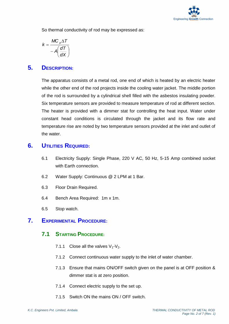
So thermal conductivity of rod may be expressed as:
dX
dTA
TMCk
p
5. DESCRIPTION:
The apparatus consists of a metal rod, one end of which is heated by an electric heater
while the other end of the rod projects inside the cooling water jacket. The middle portion
of the rod is surrounded by a cylindrical shell filled with the asbestos insulating powder.
Six temperature sensors are provided to measure temperature of rod at different section.
The heater is provided with a dimmer stat for controlling the heat input. Water under
constant head conditions is circulated through the jacket and its flow rate and
temperature rise are noted by two temperature sensors provided at the inlet and outlet of
the water.
6. UTILITIES REQUIRED:
6.1 Electricity Supply: Single Phase, 220 V AC, 50 Hz, 5-15 Amp combined socket
with Earth connection.
6.2 Water Supply: Continuous @ 2 LPM at 1 Bar.
6.3 Floor Drain Required.
6.4 Bench Area Required: 1m x 1m.
6.5 Stop watch.
7. EXPERIMENTAL PROCEDURE:
7.1 STARTING PROCEDURE:
7.1.1 Close all the valves V1-V2.
7.1.2 Connect continuous water supply to the inlet of water chamber.
7.1.3 Ensure that mains ON/OFF switch given on the panel is at OFF position &
dimmer stat is at zero position.
7.1.4 Connect electric supply to the set up.
7.1.5 Switch ON the mains ON / OFF switch.

K.C. Engineers Pvt. Limited, Ambala THERMAL CONDUCTIVITY OF METAL ROD Page No. 3 of 7 (Rev. 1)
7.1.6 Set the heater input by the dimmer stat, voltmeter in the range 40 to 100
V.
7.1.7 Open the valve V1 and start the flow of water.
7.1.8 Start the stop watch and collect the water in measuring cylinder.
7.1.9 Note down the time and volume of water.
7.1.10 After 1.5 hrs. note down the reading of voltmeter, ampere meter and
temperature sensors at every 10 minutes interval (till observing change in
consecutive readings of temperatures ± 0.2 oC) .
7.2 CLOSING PROCEDURE:
7.2.1 When experiment is over set the dimmer stat to zero position.
7.2.2 Stop the water supply by closing the valve V1.
7.2.3 Switch OFF the mains ON/OFF switch.
7.2.4 Switch OFF electric supply to the set up.
7.2.5 Drain the water by open the valve V2.
8. OBSERVATION & CALCULATION:
8.1 DATA:
Specific heat of water Cp = 4186 J/kg oC
Density of water w = 1000 kg/m3
Diameter of rod d = 0.025 m
Distance of first temperature sensor (T1) from the one end point of pipe X1 = 0.035 m
Distance of second temperature sensor (T2) from the one end point of pipe X2= 0.075 m
Distance of third temperature sensor (T3) from the one end point of pipe X3 = 0.115 m
Distance of fourth temperature sensor (T4) from the one end point of pipe X4 = 0.155 m
Distance of fifth temperature sensor (T5) from the one end point of pipe X5 = 0.195 m
Distance of sixth temperature sensor (T6) from the one end point of pipe X6 = 0.235 m

K.C. Engineers Pvt. Limited, Ambala THERMAL CONDUCTIVITY OF METAL ROD Page No. 4 of 7 (Rev. 1)
8.2 OBSERVATION TABLE:
V = ________ Volts I = _________ Amp.
Sr. No
F (ml) t1
(sec) t
(sec) T1
(oC) T2
(oC) T3
(oC) T4
(oC) T5
(oC) T6
(oC) T7
(oC) T8
(oC)
8.3 CALCULATIONS:
1
610
t
FM
(kg/sec)
78 TTMCQ p (W)
2
4dA
(m
2)
Plot a graph of temperature (T1, T2, T3, T4, T5, T6) vs. length (X1, X2, X3, X4, X5,
X6)
and find slope
dX
dT.
dX
dTA
Qk (W/m
oC)
CALCULATION TABLE:
Sr. No. Q (W) k (W/m oC)
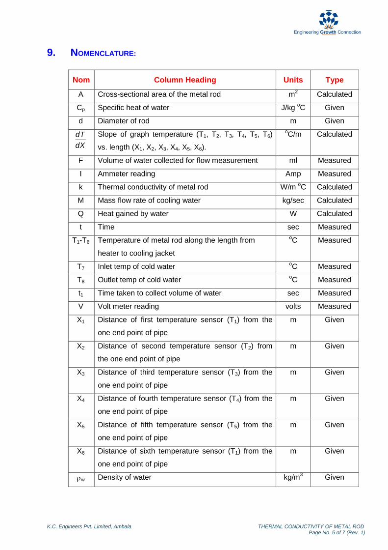
K.C. Engineers Pvt. Limited, Ambala THERMAL CONDUCTIVITY OF METAL ROD Page No. 5 of 7 (Rev. 1)
9. NOMENCLATURE:
Nom Column Heading Units Type
A Cross-sectional area of the metal rod m2 Calculated
Cp Specific heat of water J/kg oC Given
d Diameter of rod m Given
dX
dT
Slope of graph temperature (T1, T2, T3, T4, T5, T6)
vs. length (X1, X2, X3, X4, X5, X6).
oC/m
Calculated
F Volume of water collected for flow measurement ml Measured
I Ammeter reading Amp Measured
k Thermal conductivity of metal rod W/m oC Calculated
M Mass flow rate of cooling water kg/sec Calculated
Q Heat gained by water W Calculated
t Time sec Measured
T1-T6 Temperature of metal rod along the length from
heater to cooling jacket
oC Measured
T7 Inlet temp of cold water oC Measured
T8 Outlet temp of cold water oC Measured
t1 Time taken to collect volume of water sec Measured
V Volt meter reading volts Measured
X1 Distance of first temperature sensor (T1) from the
one end point of pipe
m Given
X2 Distance of second temperature sensor (T2) from
the one end point of pipe
m Given
X3 Distance of third temperature sensor (T3) from the
one end point of pipe
m Given
X4 Distance of fourth temperature sensor (T4) from the
one end point of pipe
m Given
X5 Distance of fifth temperature sensor (T5) from the
one end point of pipe
m Given
X6 Distance of sixth temperature sensor (T1) from the
one end point of pipe
m Given
w Density of water kg/m3 Given
K.C. Engineers Pvt. Limited, Ambala THERMAL CONDUCTIVITY OF METAL ROD Page No. 6 of 7 (Rev. 1)
10. PRECAUTION & MAINTENANCE INSTRUCTIONS:
10.1 Never run the apparatus if power supply is less than 200 volts and more than 230
volts.
10.2 Never switch ON mains power supply before ensuring that all the ON/OFF
switches given on the panel are at OFF position.
10.3 Operate selector switch of temperature indicator gently.
10.4 Always keep the apparatus free from dust.
11. TROUBLESHOOTING:
11.1 If electric panel is not showing the input on the mains light. Check the main
supply.
11.2 If voltmeter showing the voltage given to heater but ampere meter does not,
check the connection of heater in control panel.
12. REFERENCES:
12.1 D.S Kumar, “Heat & Mass Transfer”, 7th ed, S.K Kataria & Sons, ND, 2008,
Page 5.

K.C. Engineers Pvt. Limited, Ambala THERMAL CONDUCTIVITY OF METAL ROD Page No. 7 of 7 (Rev. 1)
13. BLOCK DIAGRAM: