80301954.pdf - Peavey
22
-
Upload
khangminh22 -
Category
Documents
-
view
0 -
download
0
Transcript of 80301954.pdf - Peavey


A lntended to alert the user to the presence of uninsulated “dangerous voltage” within the product’s enclosurethat may be of sufficient magnitude to constitute a risk of electric shock to persons.
A Intended to alert the user of the presence of important operating and maintenance (servicing) instructions in theliterature accompanying the product.
CAUTION: Risk of electrical shock - DO NOT OPEN!CAUTION: To reduce the risk of electric shock, do not remove cover. No user serviceable parts inside. Refer servicing toqualified service personnel.
WARNING: To prevent electrical shock or fire hazard, do not expose this appliance to rain or moisture. Before using thisappliance, read the operating guide for further warnings.
propcisito de alertar al usuario de la presencia de “(voltaje) peligroso” que no tieneaislamiento dentro de la caja de1 product0 que puede tener una magnitud suficiente coma para constituir riesgo de
A Este simbolo tiene el prop&it0 de alertar al usario de la presencia de instruccones importantes sobre la operaciciny mantenimiento en la literatura que viene con el producto.
PRECAUCION: Riesgo de corrientazo - No abra.P R E C A U C I O N : Para disminuir el riesgo de corrientazo, no abra la cubierta. No hay piezas adentro yue el usario puedareparar. Deje todo mantenimiento a 10s t6cnicos calificados.
A D V E R T E N C I A : Para evitar corrientazos o peligro de incendio, no deje expuesto a la lluvia o humedad este aparatoAntes de usar este aparato, lea m6s advertencias en la guia de operaci6n.
A Ce symbole est utilisk pur indiquer & l’utilisateur la prksence B l’int&ieur dc ce produit de tension non-isolkedangereuse pouvant &re d’intensitk suffisante pour constituer un risque de choc 6lectrique.
A Ce symbole est utilis6 pour indiquer B l’utilisateur qu’il ou qu’elle trouvera d’importantes instructions xurl’utilisation et l’entretien (service) de l’appareil dans la littkrature accompagnant le produit.
ATTENTION: Risques de choc klectrique - NE PAS OUVRIR!A T T E N T I O N : Afin de rkduire le risque de choc electrique, ne pas enlever le couvercle. I1 ne se trouve h I’int6rieutaucune pi&e pouvant etre r&Parke par l’utilisateur. Confier l’entretien B un personnel qualifi6.
AVERTISSEMENT: Afin de prkvenir les risques de d&l-r;1I l;~e klectrique ou de feu, n’exposel! pas cet appareil h la pluieou h l’humiditk. Avant d’utiliser cet appareil, lisez les avertisscments suppl6mentaircs situ& dans le guide.
A Dieses Symbol sol1 den Anwender vor unisolierten gefihrlichen Spannungen innerhalb des Gehtiuses warnen, dievon Ausreichender Starke sind, urn einen elektrischen Schlag vcrursachen zu kiinnen.
A Dieses Symbol sol1 den Benutzer auf wichtige Instruktionen in der Bedienungsanleitung aufmerkcam machen, dieHandhabung und Wartung des Produkts betreffen.
VORSICHT: Risiko - Elektrischer Schlag! Nicht iiffnen!V O R S I C H T : Urn das Risiko eines elektrischen Schlages zu vermeiden, nicht die Abdeckung enfernen. Es befinden sichkeine Teile darin, die vom Anwender repariert werden kiinnten. Reparaturen nur von qualifiziertem Fachpersonaldurchfi.ihren lassen.
A C H T U N G : Urn einen elektrischen Schlag oder Feuergefahr zu vermeiden, solltc dieses Get-tit nicht dem IXegen oderFeuchtigkeit ausgesetzt werden. Vor Inbetriebnahme unbcdingt die Bedienungsanleitung lesen.
2

AWARNING!
For optimum performance and reliability DO NOT PRESENT THE AMPLIFIER WITH A SPEAKER LOAD OF LESS THAN 2 OHMS, OR ACOMBINATION OF SPEAKERS THAT TOGETHER ARE LESS THAN 2 OHMS!
Using one speaker, it must be rated at 2 ohms minimum.
Using two speakers, they must be rated each at 4 ohms minimum.
Using three speakers, they must be rated each at 8 ohms minimum.
The world-famous CS@ 1200 power amplifier has been changed to the new, extended-perfor-mance CS@ 1200X. This upgraded model provides impressive 2-ohm output power capabilitywhile still maintaining the current 4- and g-ohm ratings, and meets rigid industry standards forpower bandwidth, slew rate, and distortion specifications.
The new extended specs are:630 W RMS into 4 ohms / 900 W RMS into 2 ohms (per channel)1260 W RMS into 8 ohms / 1800 W RMS into 4 ohms (bridged)DDTTM compression with LED indicators and defeat switchSlew Rate: 40 V/microsecond, stereo mode, each channelPower Bandwidth: 10 Hz to 50 kHz @ 4 ohms, rated powerTotal Harmonic Distortion: less than 0.03%, rated powerHum and Noise: 100 dB below rated power, unweighted
All the current features of the previous units have been retained, including Peavey’s patentedDDTTM compression system and the very flexible back-panel patching capabilities. The two-speed fan cooling system has been improved to automatically provide additional cooling for thetwo-ohm load conditions.
FEATURES
Separate power transformers and circuit breakers for each channelAutomatic two-speed fan cooling system/tunnelIndependent channel thermal/fault protectionTransient-free turn-on/off operation (relay)Two “back-porch” crossover “island” sockets for plug-in modulesTwo “back-porch” balanced-input transformer sockets for PL-2’sSingle XLR and dual phone plug inputs each channelXLR input can be transformer-balancedDual phone plug and 5-way binding post outputs each channelHigh temperature shutdown LED each channelDDTTM activation LED each channelTen-segment, tri-colored power level LED array each channelCalibrated/detented input attenuator control each channelRear panel DDT TM defeat and bridge mode select slide switches
3

CHANNEL A
lN!wT --SEN!3TlVITY
MADE IN U.S.A.
CHANNEL 0
INPUTSENSITIVITY
CS” 12oozPROFESSIONAL STEREO POWER AMPLIFIER
DDTTM ACTIVE LEDs (1)The DDTTM active LEDs indicate when compression is taking place. As long as gain reduction isoccurring, the LED will continue to light, thereby giving a valuable indication of this uniquecompression function. The DDT function can be defeated on both channels simultaneously byselecting the defeat position on the DDT compression switch (7) located on the back panel of theCS 1200X. When the compressor is defeated, the DDT active LED will indicate clipping, thisbeing the condition where the amp is failing to faithfully reproduce the input signal. A morethorough discussion of the DDT function is included later in this manual.
HIGH TEMPERATURE LEDs (2)These LEDs illuminate whenever the thermal logic system has determined that a particularchannel is operating above safe temperature limits and has shut down the unsafe channel. Whenthis LED is illuminated, the “0” LED will also go out on that channel. Excessive temperatureconditions can occur in the CS 1200X if either or both channels are continuously operated intoless than 2-ohm loads (or a short circuit), or if the ambient temperature of the air supply becomestoo hot to provide adequate cooling even under normal 2-ohm or greater loading situations. Sincethe CS 1200X is a “redundant” amplifier, the shutdown of one channel will not affect the opera-tion of the other channel. When the unsafe channel has cooled down to safe limits, operation willbe restored in that channel. Normal operation is indicated when the high temperature LED is offand the “0” LED is on. Continued operation under fault conditions will not harm the amplifier,but because of the nuisance factor, steps should be taken to determine the problem and solve it.
LED ARRAYS (3)The CS 1200X has a tri-colored LED array on each channel to indicate the output power level.The LED array is calibrated in two different ways to offer maximum flexibility and ease of use.To the left of each LED ladder, the calibration is percent of full power output. The top LED,labeled lOO%, will flash when the CS 1200X has reached full RMS power output capability on
4

that particular channel. Operation at power output levels below 100% will naturally be indicatedby lower LED readings. The lowest value indicated is 0.4% of full power, which corresponds to2.0 watts RMS output into 4 ohms. Operation below that power level will not be indicated, sincethe lowest LED is calibrated at 0% or standby. As mentioned, this LED should be illuminatedwhenever the amplifier is operating with AC mains power applied under zero signal conditions.To the right of each ladder the calibration is “dB below full power.” This is a conventhat indicates the amount of power amp headroom left for any signal condition.
INPUT SENSITIVITY CONTROLS (4)The CS 1200X features a 31 detented, calibrated sensitivity control for each channel,
leent sea
Eachcontrol is labeled to show the actual input sensitivity ratings of the amplifier for various settingsin decibel volts necessary to attain the full-output power rating. Thus, maximum input gain(minimum sensitivity rating) is achieved at the full clockwise setting, and this setting yieldsmaximum mixer/system headroom. A setting of less than full clockwise will yield lower systemnoise at the expense of mixer/system headroom. A more thorough discussion of input sensitivityfollows later in this manual.
MAINS POWER SWITCH (5)The front panel of the CS 1200X contains a conventional on/off rocker switch. When the ampli-fier is plugged into a suitable power source, activating this switch should light both channel “0”array LEDs after the power-up delay sequence is completed (approximately two seconds). Youshould also be able to hear the output relays close (click). If the amplifier is cool, the fan shouldstart on low-speed operation. If only one channel “0” indicator lights, then the possibility existsof an internal “fault.” If neither channel “0” indicator lights, check the rear panel circuit breakersand the mains power source. It’s always a good idea to check to see that the cooling fan is opera-tional, especially on a new unit. The possibility exists that due to shipping and handling, the fanbearings may be too tight to allow low-speed fan operation. If this is the case, immediately seekprofessional help. The CS 1200X must have normal fan operation to provide adequate coolingfor the unit. Without air flow, the amplifier will “thermal” very quickly under any signal condi-tions.
5

A
GRILLE (6)The back panel includes the fan opening with protective grille (6), where cooling air is drawninto the amplifier. This opening should never be blocked or restricted.
DDT SWITCH (7)This switch is used to either ENABLE or DEFEAT the DDT compressor. Defeating the DDTcompressor should not be performed lightly or simply as a matter of course. Most loudspeakersystems simply cannot handle the square wave power of the CS 1200X, and defeating thisvaluable limit can eventually cause the speakers to be damaged.
MAINS POWER SOURCE (120V products only) (8)The CS 1200X is fitted with a single heavy-duty #14 AWG 3 conductor line cord and a conven-tional AC plug with a ground pin. It should be connected to an independent mains circuit capableof delivering at least 15 AMPS continuously. This is particularly critical for sustained high-power applications. If the socket does not have a ground pin, a suitable ground lift adaptorshould be used, and the third wire grounded properly. Never break off the ground pin on theCS 1200X or any amplifier. The use of extension cords should be avoided, but if essential,always use a three-wire type with at least a #14 AWG wire size. The use of lighter wire willseverely limit the power capability of this amplifier. Always use a qualified electrician to installany necessary electrical equipment. To prevent the risk of shock or fire hazard, always be surethat the amplifier is properly grounded.
CIRCUIT BREAKERS (9)The new CS 1200X now features circuit breakers in place of the mains fuses. These breakers areprovided to limit the mains current to the associated power transformers, thereby protecting themfrom overheating and possible destruction due to any fault conditions in the amplifier. The tripcurrent value has been carefully chosen to allow continuous power output performance, whilestill providing adequate protection for the power transformer itself. Normally the breakersshould not trip; however, abnormal conditions such as a short circuit on either or both channels,or continuous operation at overload or clipping, especially into a 2-ohm load, will cause thebreakers to trip. If this occurs, simply reset the breaker and correct the cause of the overload.When tripped, the button on the breaker will be extended outward nearly l/2” and can be reset bypushing inward. A normal reset button length is about l/4”. If this “thermal”-type breaker doestrip, simply pushing the button back in will reset it, after waiting a brief period of time to allow itto cool down. If a breaker trips instantly each time you attempt to reset it, then the unit should betaken to a qualified service center for repair.
The back panel of the CS 1200X features a unique “back-porch” design containing the variousinput and output connectors for each channel. A patch panel is also included, providing a veryflexible system for use with balanced-input transformers and dual crossover networks. Thesefeatures are unduplicated in any other stereo power amplifier on the market today.

MODE SWITCH (10)The mode switch is located on the “back-porch” next to the channel input jacks. This switchconverts the CS 1200X from normal stereo mode to bridge mode. Bridge-mode operation is verypopular for commercial sound distribution systems (70/l 00 volt lines).
A WARNING: In bridge mode, the CS 1200X is capable of delivering 1200 W RMS into 8 ohmsand 1800 W RMS into 4 ohms. Always be very certain that the associated loudspeaker systemcan handle this power level reliably. Also, be advised that in most crossover applications,accidental switching to the bridge mode could destroy the speaker system. Specific applicationsof the bridge mode will be covered later in this manual.
LOW-Z INPUTS (11)Conventional three-pin, female XLR input jacks are provided, which can be used as either thechannel inputs or the crossover inputs, depending upon what has been plugged into the crossoversocket (14). Further, this XLR input is balanced or unbalanced, depending upon what is pluggedinto the transformer socket (12). When the (PL-2) line-balancing transformer is used in socket(12) this XLR input becomes fully TRANSFORMER-BALANCED, with pin #3 as the positiveinput and pin #2 as the negative input. When a blank plug (PL- 1) is inserted in socket (12), thisXLR input becomes unbalanced, with pin #3 as positive input and pin #2 as ground. If aPL-MODULE ELECTRONIC CROSSOVER is plugged into socket (14), the XLR input systemdrives the crossover, but if a blank plug (PL-1) is inserted in socket (15), the XLR input systemis connected directly to the channel power amp input.
TRANSFORMER RECEPTACLES (12)These receptacles only receive the optional (PL-2) line-balancing transformer. When conditionsexist that demand the usage of a TRANSFORMER-BALANCED XLR at the input of a power
7

amp channel or at the input of the PL-MODULE ELECTRONIC CROSSOVER whenBIAMPING, the (PL-2) transformer must be inserted here. Otherwise a blank plug (PL- 1) isinserted in this socket.
CROSSOVER INPUTS (13)These are the HIGH-Z INPUTS when an ELECTRONIC CROSSOVER module is installed.Two parallel input jacks are provided at this point, allowing flexible Y-cord capability. Theoutput of the LOW-Z XLR input circuitry is always connected to these inputs, which allow theLOW-Z INPUT to be used as the ELECTRONIC CROSSOVER input if desired. These inputscan then be used as FULL-RANGE outputs for additional patching capability.
CROSSOVER MODULE RECEPTACLE (14)This receptacle may only receive a plug-in PL-MODULE ELECTRONIC CROSSOVER.PL-MODULES are optional accessories and are available in many different crossover frequen-cies. Some modules contain special equalization and padding for a particular Peavey speakerenclosure. Always be sure to select the correct module for your speaker system. Other special-purpose modules are also available for use with this receptacle. This receptacle supplies both theinput and output patch facilities as well as the power supply “feeds” for these active electronicdevices.
CROSSOVER LOW OUTPUT (15)This jack supplies the crossed-over low-frequency output from the installed PL-MODULEELECTRONIC CROSSOVER. This output must be patched to the appropriate power amp inputjack to “create” an operational biamp system. On some special-purpose modules, this output jackis not used.
CROSSOVER HIGH OUTPUT (16)This jack supplies the crossed-over high-frequency output from the installed PL-MODULEELECTRONIC CROSSOVER. This output must also be patched to the appropriate power ampinput jack to create an operational biamp system.
POWER AMPLIFIER INPUT (17)Two parallel input jacks are provided for each channel, delivering flexible Y-cord capability.These jacks can be considered the normal power amplifier high-Z input. If a blank plug (PL-1)is inserted in the crossover accessory socket (15), the associated XLR input system is connectedto these input jacks internally, perrnitting the XLR input (11) to be a direct power amplifier inputwithout the use of a patch cord.
SPEAKER OUTPUTS (18) (19)Two l/4” jacks and 5-way binding post speaker output terminals are provided for each channel,with all the outputs from each channel in parallel. Thus, the loudspeaker connection cables canbe terminated with l/4” phone plugs, banana plugs, or stripped wires for use in the binding postterminals. For sustained high-power applications, the use of the binding post terminals is highlyrecommended; however, care must be exercised to assure correct speaker phasing. Regardless ofwhat connections are used, the typical parallel speaker load should always be limited to 2 ohms
8

per channel or 4 ohms BRIDGE mode for any application. Operation at loads of 4 ohms perchannel or 8 ohms BRIDGE mode is more desirable for sustained operation applications, be-cause the amplifier will run much cooler at this load. Operation above 4 ohms per channel andeven open-circuit conditions can always be considered safe; however, sustained operation atloads below 2 ohms could result in temporary amp shutdown due to operation of the thermallimiting and/or the fault detection circuitry.
INSTALLATION AND CONNECTIONThe Peavey CS 1200X Commercial Series Power Amplifier is designed for durability in com-mercial installations and quality of performance required in studio and home applications, Theunit is a standard 19” rack-mount configuration that requires 7” rack height; it is cooled by anautomatic two-speed internal fan. The front panel contains various LED indicators for the moni-toring of power output, DDT activation, and thermal shutdown. Detented and calibrated inputsensitivity controls and a heavy-duty mains power switch are also provided. All inputs, outputs,and patch points are on the back panel,
MAINS POWER SOURCEIf possible, each amplifier should be connected to separate mains circuits capable of delivering atleast 15 amps continuously. This is most critical for sustained high-power applications into2 ohms per channel. Never break off the ground pin on the CS 1200X. Always use a qualifiedelectrician to install any necessary electrical equipment. To prevent the risk of shock or firehazard, always check to see that the amplifiers are properly grounded.
INDUSTRIAL AND COMMERCIAL INSTALLATIONSFor commercial and other installations where sustained high-power operation is required, theamplifiers should be mounted in a standard 19” rack. It is not necessary to leave a rack spacebetween each amplifier in the stack, since the fan pulls air in from the rear and exhausts the hotair out of the front. An adequate cool air supply must be provided for the amplifiers when rack-mounted. The internal fan must have a source of air that is not preheated by other equipment.The amplifier will start up in low-speed fan operation and will normally stay at low-speed opera-tion unless sustained high-power operating levels occur. As the amplifier heat sinks heat up, theautomatic thermal-sensing circuitry will cause high-speed operation to occur. Depending uponsignal conditions and amplifier loading, high-speed fan operation may continue, or the fan maycycle continuously between high and low. This situation is quite normal. If cooling is inadequatedue to preheated air, or a reduction of air flow occurs due to blockage of the inlet or outlet ports,or if the amplifier is severely overloaded or short-circuited, the internal thermal-sensing systemmay cause temporary shutdown of that particular channel. Depending upon the availability ofcool air, operation should be restored in that channel relatively quickly. In any case, correctiveaction should be taken to determine the cause of the thermal shutdown. If the amplifier is notseverely overloaded or short-circuited, and air flow is normal in the amplifier, steps should betaken to provide a cooler environment for all the amplifiers. As a general rule, the cooler elec-tronic equipment is operated, the longer its useful service life will be.
9

OPERATIONThe CS 1200X is designed for maximum ease and flexibility of operation. When the unit isinstalled and connected as described in the previous sections, operation is as simple as turning onthe mains switch (S), turning up the sensitivity controls (4) to the full clockwise setting, and thenadjusting the associated mixer or pre-amplification equipment to supply the necessary signallevels to provide the desired output level or until the front panel DDT active LED indicatorshows that the amplifier is compressing. Further increases in signal levels beyond this point willnot produce any significant increase in output and may cause distortion problems.
MODES OF OPERATION
1. STEREO MODE (UNBALANCED INPUTS)The CS 1200X is shipped from the factory with jumper plugs inserted in the transformer ( 12) andcrossover (14) accessory sockets. These jumper plugs are necessary if the low-impedance con-nectors (11) are to be used as inputs for each channel. As indicated in Diagram 1, the XLRconnectors are wired in an unbalanced configuration (pins 1 and 2 are ground: pin 3 is input).The unbalanced-input configuration is acceptable whenever relatively short cable runs are em-ployed, or when the associated mixer used has a full transformer-balanced output. Under thesecircumstances, this configuration will usually provide adequate hum and interference rc.jectionfor most environments. Notice that the jumper plugs in the crossover accessory sockets arcrequired to complete the signal patch to the respective power amp inputs ( 17). If‘ the normalunbalanced l/4” power amp input jacks are used instead, the jumper plugs are not necessary. It issuggested, however, that they be left in their respective sockets for possible later usage. As withall Peavey amplifiers, the CS 1200X has two power amp input jacks per channel ( 17), whichoffer considerable flexibility in hook-up possibilities. For monaural operation, the same signal isapplied to both channels; the mixer output is plugged in one of the parallel input jacks in one ofthe channels, and a short shielded jumper cable is connected between the remaining input jack on
that channel to one of the parallel input jacks on the other channel. This technique is calleddaisy-chaining, and can be repeated many times to patch to additional amplifier channels requir-ing the same signal feed.
0 PATCH PANEL (STEREO MODE) WITH JUMPERS
TRANSFORMERLOW Z INPUT
CHANNEL
1 2 GROUND3 POSITIVE
SENSITIVITY
SENSITIVITY-
TRANSFORMER
CHANNEL
I 2 GROUND3 POSiTl”E X-OVER
BRIDGE
STEREO
11

2. STEREO MODE (BALANCED INPUTS)When conditions require the use of a balanced input at the power amplifier, the XLR connectors(11) on either or both channels can be converted to a balanced configuration by removing thejumper plug from the transformer accessory socket (12) and plugging in an input transformermodule (PL-2). The Peavey model PL-2 transformer module is a nominal 1: 1 turn-ratio type,resulting in unity gain. In Diagram 2, the XLR connector is now wired as a conventional bal-anced-type input (pin 1 is ground; pin 2 is negative; pin 3 is positive). The jumper plugs in thecrossover accessory sockets are required to complete the signal patch to the respective poweramp inputs (14). For balanced stereo operation, two PL-2 modules are required. For monauraloperation, only one PL-2 is needed, and the inputs can be connected by placing a short shieldedjumper cable between one of the power amp input jacks (17) on each channel. Thus, the XLRconnector associated with the PL-2 module is the balanced-system input, and the other XLRconnector is not used.
TRANSFORMER(PL-2 MODULE)
SENSITIVITY
TRANSFORMER(PL-2 MODULE)
SENSITIVITY
2 NEGATIVE X-OVER
BRIDGE
STEREO
3 PclSlTl”E
0 PATCH PANEL (STEREO MODE) WITH BAL. INPUT TRANSFORMER MODULES
3. BIAMP STEREO MODEThe Peavey CS-1200X patch panel can also be used to biamp and/or provide special equalizationcapabilities for loudspeaker systems. Various electronic crossovers and special purpose modulesare available in a broad range of frequencies for both Peavey and non-Peavey loudspeakersystems. More complicated systems, such as stereo biamped, triamped, or even 4-way crossoversystems are possible. We suggest you contact your Authorized Peavey Dealer for details. Atypical stereo biamp system will be discussed in this manual. Referring to Diagram 3, the jumperplugs in both crossover accessory sockets (14) have been replaced by two-way crossover mod-ules. Also, notice that the PL-2 transformer modules are still in the transformer accessory sockets(12). This configuration now has the makings of a complete stereo-balanced biamp system. Theonly thing required is an additional stereo power amplifier, which, together with the existing dualpower amp sections of the CS 1200X, makes up the four independent power amplifiers requiredfor a stereo biamplification system. You will notice that because of the pin-out arrangements ofthe jumper plugs versus the crossover networks, whenever the jumper plugs are removed fromthe crossover accessory sockets (14), the power amplifier inputs for the respective channels are
12

isolated (no longer connected to anything). In other words, the crossover modules and all associ-ated connectors (as well as the PL-2 transformers and respective XLR connectors) are islandsunto themselves: in this case, two islands with each crossover having a balanced input (1 l), dual(parallel) unbalanced inputs (13), an unbalanced low output (15), and an unbalanced high output(16). In order to complete the system, external patching must be accomplished between the lowand high crossover outputs and the various power amp inputs using shielded patch cords. A patchdiagram showing this arrangement is included at the end of this manual.
@ PATCH PANEL (STEREO MODE) WITH CROSSOVER AND INPUT TRANSFORMER MODULES
TRANSFORMER(PL-2 MODULE)
2 NEGATIVE3 PcslTl”E SENSITIVITY
SENSITIVITY
TRANSFORMERIPL-2 MODULEI
2 NEGATIVE X-OVER3 POSITIVE
BRIDGE
STEREO
3A. BIAMP MONO MODEObviously, for a monaural biamp system (only one mixer feed), only one crossover module isrequired and only one crossover island will be used. In this case, one channel of the CS 1200Xcan be patched for the lows and the other channel patched for the highs, resulting in a simple,compact system with outstanding performance.
A CAUTION:Since the CS 1200X is capable of producing more than 600 watts RMS per channel into a 4-ohmload, the high-frequency components of the particular loudspeaker system must be able to handlethese power levels reliably. Alternatively, use a smaller power amplifier!
4. BRIDGE MODEDiagram 4 shows the actual arrangement for the CS 1200X patch panel in the bridge mode.Notice that the jumper plugs are inserted in the transformer (12) and crossover (14) accessorysockets of Island A. These jumper plugs cause the XLR connector of this island to be wired inthe unbalanced configuration (as in Diagram 1) and complete the connection to the Channel Apower amp input jacks (which are now the only active inputs). The Channel A sensitivity controlnow determines the sensitivity of the bridge-mode amplifier. The Channel B input jacks andsensitivity control serve no purpose in this mode, and are actually electronically removed fromthe circuit. Both sets of parallel l/4” output phone jacks are also not normally used in the bridge
13

mode. Remember, the 4-ohm minimum load must be connected between the red binding posts. Ifindividual loads were connected to each output (as in normal stereo applications) when thebridge mode is selected. Channel A would supply a normal in-phase signal to its respective load,but Channel B would supply an abnormal out-of-phase signal to its respective load, and both ofthese signals would contain Channel A source material (Channel B source material, if present,would be defeated). This is a potentially dangerous situation, especially if the individual chan--nels are being used to supply high and low signals in a typical biamp configuration. Obviously,the speaker components on Channel B would no longer be supplied their intended signal but anout-of-phase version of the Channel A signal, which could easily destroy the associated IOLK-
speaker components. To help prevent this, whenever the bridge mode is selected, the standby(“0”) LED and the LED array itself on Channel B is defeated (off), just as if there was some kindof a fault condition present on Channel B. This provides a positive indication that the CS 1000Xis no longer in the stereo mode.
TRANSFORMER
CHANNEL B INPUTSAND SENSITIVITY
CONTROL ARE DEFEATED CONNECT LOADBETWEEN REDBINDING POSTS7OVIlOOV LINE
RANSFORMER
X-OVER
INPUT SENSITIVITY CONTROLS
0 PATCH PANEL (BRIDGE MODE) WITH JUMPERS
The input sensitivity rating of a power amplifier is ,he RMS voltage level required at the input toproduce full-rated power into the rated load at the output. This voltage then becomes the level atwhich the associated mixer must operate in order to drive the amplifier to full output. TheCS 1200X sensitivity controls are calibrated in decibel volts values rather than RMS voltage(usually listed in typical mixer specs), and as such are more useful, since most contemporarymixers employ LED arrays to indicate mixer output levels and are calibrated in decibel volts.Knowing the power amplifier sensitivity rating in decibel volts will allow the mixer operator toknow the status of the power amplifier by noting which LED on the mixer is peaking. Obviously,the LED labeled the same or closest to the sensitivity rating of the power amplifier will indicatefull power output of the system. Operation at levels above this rating will cause the power ampli-fier to clip (produce distortion) unless the associated amplifier has a compressor/limiter to mini-mize this distortion. Such a system, called DDT (U.S. Patent #4,3 l&053), is included in the CS1200X, and the advantages should be obvious. Without DDT, the sound engineer must “ridegain” on the mixer or employ an outboard limiter in order to prevent amp clipping. With DDTthe sound man can relax more and enjoy the “ride.” For maximum mixer headroom (which in
14

turn really is maximum compression range), the input sensitivity control should be set at Ihemaximum clockwise setting. This is always the best setting to start with. If, however, the ampti-fier is used in a small club, church, or studio application where the full-output capability of the
power amplifier is seldom needed, or there is no need for large amounts of headroom capability,the full-clockwise setting may not be the wisest choice. Then too, such applications often requirelow system noise. In this case, it is possible to reduce the overall system noise at the expense ofheadroom capability by increasing the power amplifier sensitivity as in the following example:if, instead of a sensitivity rating of +3 dB V, we adjust the CS 1200X to a rating of + t2dB V,overall system noise wilt be improved by 9 dB, and the system headroom will decrease 9 dB.
DDT’lM COMPRESSIONThe CS 1200X is a compact and powerful amplifier that features a new type of dynamic com-pression. This compression system enables the user to maximize the performance of the ampti-fier/speaker combination. We have determined through much research that the compressioncircuitry should prevent the power amplifier from running out of headroom (clipping) and shouldbe as simple to operate as possible to avoid undue complication for the user. This compressionsystem is activated by our exclusive DDT compression circuitry, which senses conditions thatmight overload the amplifier and activates compression when clipping is imminent. In otherwords, compression takes place whenever signal conditions exist that prevent the amptil‘iers fromfaithfully reproducing the input signal. In this case, threshold is clipping itself, and no specificthreshold control is provided. This technique effectively utilizes every precious watt available
from the power amplifier. Techniques using external compressors/limiters are usually lesseffective, severely limit output power levels and require additional controls, and add complexityto an already complicated system. The DDT system is an automatic, hands-ofl‘approach to Iheproblem of amp clipping. Because of the dynamics of music and vocals, it is quite common loactivate the DDT compression circuitry almost constantly during a high-level performance, sincethis is what it was designed to do: i.e., to maximize the dynamics available from the amplifierwithin its power-output capabilities regardless of power supply/AC line voltage variations andload impedance selection. Defeating the DDT compression should be very carefully consideredbefore one just “flips the switch.” Most loudspeaker systems simply cannot handle the squarewave power of the CS 1200X, and defeating the D9T system opens up the door for sevcrcclipping! Often studio engineers feel the need to defeat the DDT compressor, for fear it mightcolor the sound in studio listening. The DDT compressor is only activated when clipping isimminent. LJntit this occurs, it’s simply a passive friend. The only reason the dcfcat switch isthere in the first place is to allow check-out technicians to evaluate the power amplifier at clip-ping. Valuable performance illformation, such as power- supply ripple and regulation, can onlybe assessed when an amplifier is allowed to clip.
THERMAL SYSTEMThe CS 1200X has a unique thermal system that employs a tunnel-type heat sink design toprovide maximum cooling for the 32 power transistors (16 for each channel). A single 100 CF;Mfan mounted on the back panel of the unit provides an almost unrestricted airflow through Ihetunnel to provide the lowest possible operating temperature for the power devices. This approachis so efficient that even continuous operation into 2 ohms will not cause a thermal shutdownunless the ambient air temperature is considerably higher than normal (above 40” C). Under
15

normal intermittent applications, low-speed fan operation will provide adequate cooling. Sincethe CS 1200X is a redundant two-channel amplifier, but only one fan is employed, the fancircuitry is an independent system, separately fused internally. You will notice that the heat sinkcomponents are divided horizontally. The lower half contains Channel A output transistors,while the upper half belongs to Channel B. The fan provides equal cooling for both channels.Each channel has separate built-in thermal sensors and fault logic circuitry. If one channel’s heatsink reaches an operating temperature of 60°C, its logic will cause high-speed fan operationirrespective of the other channel’s operating temperature. In other words, either channel’s heatingwill control the fan speed. Under normal continuous usage at full-rated power output into therated load, the thermal logic system will continuously monitor heat sink temperatures and willautomatically select the fan speed required to maintain safe operating limits for the power tran-sistors.
HIGH TEMPERATURE LIMITSBecause of the very efficient design of the CS 1200X heat tunnel dissipation system, thermalshutdown conditions will almost never occur unless there is truly an external fault. For con-tinuous operation, the CS 1200X requires a source of cool air. As an added help in locatingmismatched or shorted speakers, the DDT active LED is a powerful tool. If this LED flashescontinuously at relatively low-output power levels (indicated by low-power readings on the LEDarray), it is almost a sure sign that the amplifier loading impedance is too low in value, or thatthere might be a short circuit. Remember, usually the power LED array should reach 100%before the DDT system is activated on any particular channel. The CS 1200X also has a fail-safethermal mechanism built into the unit. If either channel’s thermal logic system should fail tocause thermal shutdown in that channel or if the fan itself should fail, this fail-safe system willshut down the entire amplifier, just as if you had turned off the power switch. This is just onemore protection that Peavey has incorporated into this unique amplifier as a backup system. Ifthis should ever occur, immediately seek professional help at an authorized Peavey servicecenter.
PASSIVE CROSSOVERThe purpose of a traditional high-level passive crossover found inside most speaker systems is toseparate the low-frequency material from the program and feed it to the woofer (low-frequencydriver), and to separate the high-frequency material from the program and feed it to the tweeter(high-frequency driver). This crossover is connected between a power amplifier and the speak-ers, and, as its name implies, is made up entirely of passive components (no transistors or tubes).Such a system is usually referred to as “full-range,” which simply means that the power amplifiermust handle the full range of frequencies. There are many good reasons for using a biamplifiedprofessional system as opposed to a full-range system. One reason is that the biamp system willprovide more headroom with the same power amplifier complement than that of the full-rangesystem. The term headroom deserves some consideration. Program material (music or speech) ismade up of many different frequencies and their harmonics. Most music, especially contempo-rary rock music, is bass-heavy. That is, the low-frequency material contains much more energythan the high-frequency material. If both high- and low-frequency material, such as voice andbass guitar, are present in a full-range system, the high-energy bass frequencies can use up mostof the power available from the power amplifier, leaving little (or none) for the high frequencies.
16
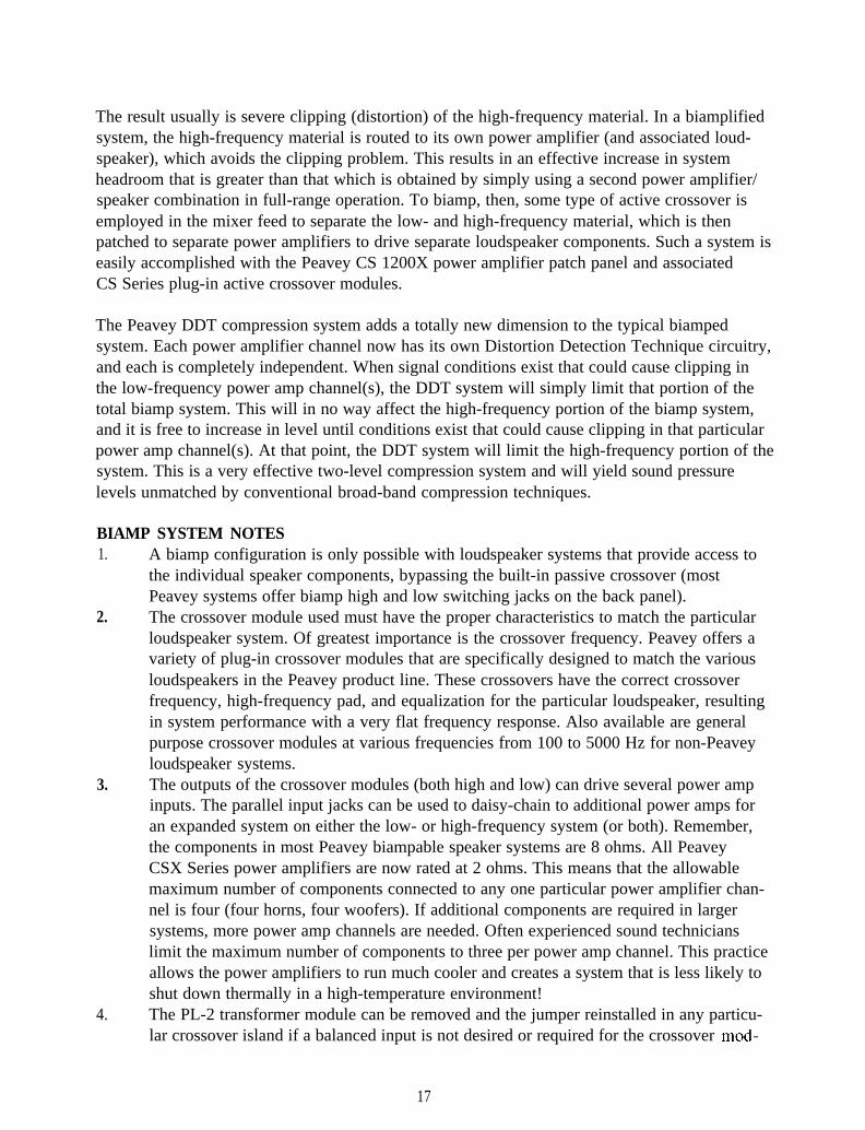
The result usually is severe clipping (distortion) of the high-frequency material. In a biamplifiedsystem, the high-frequency material is routed to its own power amplifier (and associated loud-speaker), which avoids the clipping problem. This results in an effective increase in systemheadroom that is greater than that which is obtained by simply using a second power amplifier/speaker combination in full-range operation. To biamp, then, some type of active crossover isemployed in the mixer feed to separate the low- and high-frequency material, which is thenpatched to separate power amplifiers to drive separate loudspeaker components. Such a system iseasily accomplished with the Peavey CS 1200X power amplifier patch panel and associatedCS Series plug-in active crossover modules.
The Peavey DDT compression system adds a totally new dimension to the typical biampedsystem. Each power amplifier channel now has its own Distortion Detection Technique circuitry,and each is completely independent. When signal conditions exist that could cause clipping inthe low-frequency power amp channel(s), the DDT system will simply limit that portion of thetotal biamp system. This will in no way affect the high-frequency portion of the biamp system,and it is free to increase in level until conditions exist that could cause clipping in that particularpower amp channel(s). At that point, the DDT system will limit the high-frequency portion of thesystem. This is a very effective two-level compression system and will yield sound pressurelevels unmatched by conventional broad-band compression techniques.
BIAMP SYSTEM NOTES1. A biamp configuration is only possible with loudspeaker systems that provide access to
the individual speaker components, bypassing the built-in passive crossover (mostPeavey systems offer biamp high and low switching jacks on the back panel).
2. The crossover module used must have the proper characteristics to match the particularloudspeaker system. Of greatest importance is the crossover frequency. Peavey offers avariety of plug-in crossover modules that are specifically designed to match the variousloudspeakers in the Peavey product line. These crossovers have the correct crossoverfrequency, high-frequency pad, and equalization for the particular loudspeaker, resultingin system performance with a very flat frequency response. Also available are generalpurpose crossover modules at various frequencies from 100 to 5000 Hz for non-Peaveyloudspeaker systems.
3. The outputs of the crossover modules (both high and low) can drive several power ampinputs. The parallel input jacks can be used to daisy-chain to additional power amps foran expanded system on either the low- or high-frequency system (or both). Remember,the components in most Peavey biampable speaker systems are 8 ohms. All PeaveyCSX Series power amplifiers are now rated at 2 ohms. This means that the allowablemaximum number of components connected to any one particular power amplifier chan-nel is four (four horns, four woofers). If additional components are required in largersystems, more power amp channels are needed. Often experienced sound technicianslimit the maximum number of components to three per power amp channel. This practiceallows the power amplifiers to run much cooler and creates a system that is less likely toshut down thermally in a high-temperature environment!
4. The PL-2 transformer module can be removed and the jumper reinstalled in any particu-lar crossover island if a balanced input is not desired or required for the crossover mod-
17

, 5.
6.
ule. In this case, the associated XLR connector (11) is now unbalanced as per previousdiscussion. If desired, the parallel unbalanced phone jack inputs (13) may be used tosupply signal to the crossover module. In addition, whenever the XLR connector on aparticular crossover island is used (either balanced or unbalanced), the crossover inputjacks (13) can be used to patch out full-range signals to other amplifier/speaker systemsthat are operating in full range or other biamped systems that require different crossovers.Care must be taken never to remove or replace a crossover module with the CS 1200Xpower switch on. The complex circuitry used in the crossover modules receives bipolarpower through the socket, and removal or replacement could cause severe transients thatcan destroy the loudspeaker system. Always turn off the CS 1200X first. As an addedfeature, the bipolar power for the crossover islands can be supplied from either channel ofthe CS 1200X. Thus, if one channel should shut down for any reason, the redundancy ofthe system will maintain operation of the crossovers.The individual sensitivity controls on each channel play a very important role in the useof the crossover modules. As such, they represent a signal loss when they are operated atanother setting other than full clockwise (maximum sensitivity). Biamped speaker sys-tems usually require less signal level for the high-frequency components because they aregenerally more efficient. Consequently, a system balance can be achieved by reducing thehigh-pass level. This is particularly important on non-Peavey loudspeakers where thePL-500, PL-800 or PL-1200 crossover modules must be used. These modules are referredto as “no pad and equalization” types. As such, there is no reduction in high-pass level.Consequently, the pad must be accomplished using the high-pass channel sensitivitycontrol. The amount of pad required is always the difference between the efficiencyratings of the high and low speaker components. Whenever Peavey loudspeakers areoperated using the special crossovers, the sensitivity controls should be set at full-clock-wise settings (maximum sensitivity) to provide maximum system headroom, since thecorrect pad and equalization is already provided in the crossover module itself.
BRIDGE MODE NOTES1. The bridge mode on stereo amplifiers is often misunderstood as to actual operation and
usage. In basic terms, when a two-channel amplifier is operated in the bridge mode, it isconverted to a single-channel unit with a power rating equal to the sum of both channels’continuous power ratings, at a load rating of twice that of the single-channel ratings. Forthe CS 1200X, the bridge ratings are now 1200 W RMS into 8 ohms and 1800 W RMSinto 4 ohms (minimum load). Bridge-mode operation is accomplished by placing themode switch (10) in the bridge position, connecting the load between the red bindingposts of each channel, and using Channel A as the input channel. All the input functionsof Channel B are defeated. What actually happens from a technical standpoint is thatChannel B is supplied an input signal that is equal in level but is 180 degrees out of phasefrom that of the Channel A input signal (i.e., when Channel A’s signal is positive, Chan-nel B’s signal is negative, and vice versa). Thus, the load (which is connected between thechannel outputs) sees the sum of the output voltages of both channels (which is thentwice that of the single channel), and this load must be 4 ohms or greater.
2. For proper bridge-mode operation, both wires of the output must “float” above ground. Ifeither wire becomes grounded, this will present a short circuit to the associated channel
18

SPECIFICATIONS
Characteristics: (@ 120 V AC, 60 Hz)Output Power: (Typical Value)
Stereo mode, both channels driven2 ohms, 1 kHz, 1% THD4 ohms, 1 kHz, 1% THD8 ohms, 1 kHz, 1% THD
Bridge mode, mono4 ohms, 1 kHz, 1% THD8 ohms, 1 kHz, 1% THD
Rated Output Power:Stereo mode, both channels driven
4 ohms, 20 Hz to 20 kHz, 0.03% THD8 ohms, 20 Hz to 20 kHz, 0.02% THD
Power Bandwidth: (Typical Value)Stereo mode, both channels driven@ rated power, 4 ohms, 0.1% THD
Slew Rate: (Typical Value)Stereo mode, each channelBridge mode, mono
Total Harmonic Distortion: (Typical)Stereo mode, both channels driven
20 Hz to 20 kHz, 4 ohm rated output
Input Sensitivity & Impedance:Input attenuator set @ FCW
@ rated output power, 4 ohms
Dimensions & Weight:HeightWidthDepthWeight
900 W RMS per channel630 W RMS per channel390 W RMS per channel
1800 W RMS1260 W RMS
600 W RMS per channel350 W RMS per channel
10 Hz to 50 kHz
40 Volts per uSec80 Volts per uSec
Less than 0.03%
1.4 V RMS (+3 dBV)20 K ohms (+32 dB)
7” (17.8 cm)19” (48.3 cm)17” (43.2 cm)65 lbs. (29.5 kg)
20

k’requency Response: (Typical Value)Stereo mode, both channels driven
+O, -1 dB, 1 W RMS, 4 ohms+O, -0.2 dB @ rated output, 4 ohms
Damping Factor: (Typical Value)Stereo mode, both channels driven
4 ohms, 1 kHz
Hum & Noise:Stereo Mode, both channels driven
Below rated output power, 4 ohms
Power Consumption:Stereo mode, both channels driven
@ rated output power, 4 ohms
Cooling System:
DDT Compression System:
5 Hz to 50 kHz20 Hz to 20 kHz
Greater than 200
100 dB, unweighted
15A@ 120VAC
2 speed fan
Switchable with LED
21

CS42OOX PATCH DIAGRAMS
Channel ASpeakers
Channel A (Shielded)
Channel ASpeakers
Stereo Mode Channel B (ShIelded)
PATCH DIAGRAM 1Stereo Operation
Unbalanced High Z Inputs(Typical Home Stereo)
Channel A
Channel ApL-2 (Balanced)
Channei A Stereo Mode Jumper Plugs ilChannel B(Balanced)
PATCH DIAGRAM 2Stereo Operation
Balanced Low Z Inputs
(Balanced)Mono Signal from Mixer
Stereo Mode Jumper Plugs PL-2Transformer
PATCH DIAGRAM 3Monaural Operation
Balanced Low Z Inputs(Jumped Inputs)
Bridge Mode(Unbalanced)
Mono S~onal from M,xer
1 Ohm Mmlmmum Speaker Load3xmected Between Red Binding Posts
Jumper Plugs
PATCH DIAGRAM 4Bridae Mode Ooeration
Unbalanced Lod Z Inputs(Pin #3 Input)
To Low-requency Speakers
ShIelded Patch Cord for Low Pass (Balanced
Crossover ModuleMono Stgnal from MIX
Jumper PlugsTo H,gh
-requency SpeakersShlelded Patch Cord for High Pass
PATCH DIAGRAM 5Biamp Operation
Balanced Low Z Input(Monaural Signal)
To Channel AHigh Frequency Speakers
To Channel BLow Frequency Speakers
Shwlded Cord (ShIelded)Crossover JumperModules Plugs
Channel B
PATCH DIAGRAM 6Biamp Operation
Unbalanced High Z Inputs(Stereo Signal)
22

THIS LIMITED WARRANTY VALID ONLY WHEN PURCHASED AND REGISTERED IN THE UNITED STATES OR CANADA. ALL EXPORTED PRODUCTS ARE SUBJECTTO WARRANTY AND SERVICES TO BE SPECIFIED AND PROVIDED BY THE AUTHORIZED DISTRIBUTOR FOR EACH COUNTRY.Ces clauses de garantie ne sont vaiables qu’aux Etats-Unis et au Canada. Dans tour les autres pays, les clauses de garantie et de maintenance sont fixees parle distributeur national et assuree par Iul seion la legislation envigueur.Diese Garantie ist nur in den USA and Kanada gultig. Alle Export-Produkte sind der Garantie und dem Service des lmporteurs des jewelligen Landes unterworfen.Esta garantia es valida solamente cuando el product0 es comprado en E.U. continentales o en Canada. Todos 10s productos que Sean comprados en el extranjero,estan sujetos a las garantias y servicio que cada distribuidor autorizado determine y ofrezca en 10s diferentes paises.
PEAVEY ONE-YEAR LIMITEDWARRANTY/REMEDY
PEAVEY ELECTRONICS CORPORATION (“PEAVEY”) warrants this product, EXCEPT for covers, footswitches, patchcords, tubes and meters, to be free from defectsin material and workmanship for a period of one (1) year from date of purchase, PROVIDED, however, that this limrted warranty is extended only to the orrginal retail purchaserand is subject to the conditions, exclusions, and lrmrtations hereinafter set forth:
PEAVEY OO-DAY LIMITED WARRANTY ON TUBES AND METERS
If this product contains tubes or meters, Peavey warrants the tubes or meters contained in the product to be free from defects in material and workmanship for a periodof nmety (90) days from date of purchase; PROVIDED, however, that this limited warranty is extended only to the original retail purchaser and is also subject to the conditions,exclusions, and limitations hereinafter set forth.
CONDITIONS, EXCLUSIONS, AND LIMITATIONS OF LIMITED WARRANTIES
These limited warranties shall be void and of no effect, if:a. The first purchase of the product is for the purpose of resale; orb. The original retail purchase is not made from an AUTHORIZED PEAVEY DEALER; orc. The product has been damaged by accident or unreasonable use, neglect, improper service or maintenance, or other causes not arising out of defects in
material or workmanship; ord. The serial number affixed to the product is altered, defaced, or removed.In the event of a defect in material and/or workmanship covered by this limited warranty, Peavey will:a. In the case of tubes or meters, replace the defective component without charge.b. In other covered cases (i.e., cases involving anything other than covers, footswitches, patchcords, tubes or meters), repair the defect in material or workmanship
or reolace the oroduct. at Peavev’s ootion:and provided, however, that, in any case, all costs of shipping, if necessary, are paid by you, the purchaser.
THE WARRANTY REGISTRATION CARD SHOULD BE ACCURATELY COMPLETED AND MAILED TO AND RECEIVED BY PEAVEY WITHIN FOURTEEN (14) DAYSFROM THE DATE OF YOUR PURCHASE.
In order to obtain service under these warranties, you must:a. Bring the defective item to any PEAVEY AUTHORIZED DEALER or AUTHORIZED PEAVEY SERVICE CENTER and present therewith the ORIGINAL PROOF
OF PURCHASE supplied to you by the AUTHORIZED PEAVEY DEALER in connection with your purchase from him of this product.If the DEALER or SERVICE CENTER is unable to provide the necessary warranty servrce you will be directed to the nearest other PEAVEY AUTHORIZEDDEALER or AUTHORIZED PEAVEY SERVICE CENTER which can provide such service.
O R
b. Ship the defecttve item, prepaid, to:PEAVEY ELECTRONICS CORPORATION
International Service CenterHighway 80 East
MERIDIAN, MS 39301including therewith a complete, detailed description of the problem, together with a legible copy of the original PROOF OF PURCHASE and a complete returnaddress. Upon Peavey’s receipt of these items:If the defect is remedial under these limited warranties and the other terms and conditions expressed herein have been complied wrth, Peavey will provide thenecessary warranty service to repair or replace the product and will return it, FREIGHT COLLECT, to you, the purchaser.
Peavey’s liability to the purchaser for damages from any cause whatsoever and regardless of the form of action, including negligence, is limited to the actualdamages up to the greater of $500.00 or an amount equal to the purchase price of the product that caused the damage or that is the subject of or is directlyrelated to the cause of action. Such purchase price will be that in effect for the specific product when the cause of action arose. This limitation of liability willnot apply to claims for personal injury or damage to real property or tangible personal property allegedly caused by Peavey’s negligence. Peavey does not assumeliability for personal injury or property damage arising out of or caused by a non-Peavey alteration or attachment, nor does Peavey assume any responsbilityfor damage to interconnected non-Peavey equipment that may result from the normal functioning and maintenance of the Peavey equipment.
UNDER NO CIRCUMSTANCES WILL PEAVEY BE LIABLE FOR ANY LOST PROFITS, LOST SAVINGS, ANY INCIDENTAL DAMAGES, OR ANY CONSE-QUENTIAL DAMAGES ARISING OUT OF THE USE OR INABILITY TO USE THE PRODUCT, EVEN IF PEAVEY HAS BEEN ADVISED OF THE POSSIBILITYOF SUCH DAMAGES.
THESE LIMITED WARRANTIES ARE IN LIEU OF ANY AND ALL WARRANTIES, EXPRESSED OR IMPLIED, INCLUDING, BUT NOT LIMITED TO, THE IM-PLIED WARRANTIES OF MERCHANTABILITY AND FITNESS FOR A PARTICULAR USE; PROVIDED, HOWEVER, THAT IF THE OTHER TERMS AND CONDI-TIONS NECESSARY TO THE EXISTENCE OF THE EXPRESSED, LIMITED WhRRANTIES, AS HEREINABOVE STATED, HAVE BEEN COMPLIED WITH, IM-PLIED WARRANTIES ARE NOT DISCLAIMED DURING THE APPLICABLE ONE-YEAR OR NINETY-DAY PERIOD FROM DATE OF PURCHASE OFTHIS PRODUCT,
SOME STATES DO NOT ALLOW LIMITATION ON HOW LONG AN IMPLIED WARRANTY LASTS, OR THE EXCLUSION OR LIMITATION OF INCIDENTALOR CONSEQUENTIAL DAMAGES, SO THE ABOVE LIMITATIONS OR EXCLUSIONS MAY NOT APPLY TO YOU. THESE LIMITED WARRANTIES GIVE YOUSPECIFIC LEGAL RIGHTS, AND YOU MAY ALSO HAVE OTHER RIGHTS WHICH MAY VARY FROM STATE TO STATE.
THESE LIMITED WARRANTIES ARE THE ONLY EXPRESSED WARRANTIES ON THIS PRODUCT, AND NO OTHER STATEMENT, REPRESENTATION, WAR-RANTY, OR AGREEMENT BY ANY PERSON SHALL BE VALID OR BINDING UPON PEAVEY.
In the event of any modification or disclaimer of expressed or implied warranties, or any limitation of remedies, contained herein conflicts with applicablelaw, then such modification, disclaimer or limitation, as the case may be, shall be deemed to be modified to the extent necessary to comply with such law.
Your remedies for breach of these warranties are limited to those remedies provided herein and Peavey Electronics Corporation gives this limited warrantyonly with respect to equipment purchased in the United States of America.
INSTRUCTIONS - WARRANTY REGISTRATION CARD1. Mail the completed WARRANTY REGISTRATION CARD to:
PEAVEY ELECTRONICS CORPORATIONPOST OFFICE BOX 2898
MERIDIAN, MISSISSIPPI 39302-2898a. Keep the PROOF OF PURCHASE. In the event warranty service is required during the warranty period, you will need this document. There will
be no identification card issued by Peavey Electronics Corporation.2. IMPORTANCE OF WARRANTY REGISTRATION CARDS AND NOTIFICATION OF CHANGES OF ADDRESSES.
a Completion and marling of WARRANTY REGISTRATION CARDS ~ Should notlfrcatlon become necessary for any condition that mayrequrre correctron, the REGISTRATION CARD wrll help ensure that you are contacted and properly notrfred.
b. Notrce of address changes - If you move from the address shown on the WARRANTY REGISTRATION CARD, you should notrfy Peavey ofthe change of address so as to facilitate your receipt of any bulletins or other forms of notification which may become necessary inconnectIon with any condrtlon that may requrre dissemrnatron of rnformatron or correction
3 You may contact Peavey directly by telephoning (601) 483-5365
23

IMPORTANT SAFETY INSTRUCTIONSWARNING: When using electric products, basic cautions should always be followed, including the following.
1.
2.
3.
4.
5.
6.
7.
8.
9.
10.
11.
12.
13.
14.
15.
16.
17
18
Read all safety and operating instructions before using this product.
All safety and operating instructions should be retained for future reference.
Obey all cautions in the operating instructions and on the back of the unit.
All operating instructions should be followed.
This product should not be used near water, i.e., a bathtub, sink, swimming pool, wet basement, etc.
This product should be located so that its position does not interfere with its proper ventilation. It should not be placed flat against a wall orplaced in a built-in enclosure that will impede the flow of cooling air.
This product should not be placed near a source of heat such as a stove, radiator, or another heat producing amplifier.
Connect only to a power supply of the type marked on the unit adjacent to the power supply cord.
Never break off the ground pin on the power supply cord. For more information on grounding, write for our free booklet “Shock Hazard andGrounding.”
Power supply cords should always be handled carefully. Never walk or place equipment on power supply cords. Periodically check cords forcuts or signs of stress, especially at the plug and the point where the cord exits the unit.
The power supply cord should be unplugged when the unit is to be unused for long periods of time.
If this product is to be mounted in an equipment rack, rear support should be provided.
Metal parts can be cleaned with a damp rag. The vinyl covering used on some units can be cleaned with a damp rag or an ammonia-basedhousehold cleaner if necessary. Disconnect unit from power supply before cleaning.
Care should be taken so that objects do not fall and liquids are not spilled into the unit through the ventilation holes or any other openings.
This unit should be checked by a qualified service technician if:a. The power supply cord or plug has been damaged.b. Anything has fallen or been spilled into the unit.c. The unit does not operate correctly.d. The unit has been dropped or the enclosure damaged.
The user should not attempt to service this equipment, All service work should be done by a qualified service technician.
This product should be used only with a cart or stand that is recommended by Peavey Electronics.
Exposure to extremely high noise levels may cause a permanent hearing loss. Individuals vary considerably in susceptibility to noise inducedhearing loss, but nearly everyone will lose some hearing if exposed to sufficiently intense noise for a sufficient time.The U.S. Government’s Occupational Safety and Health Administration (OSHA) has specified the following permissible noise level exposures.
Duration Per Day In Hours Sound Level dBA, Slow Response8 906 924 953 972 100
1 l/2 1021 105
l/2 110l/4 or less 115
According to OSHA, any exposure in excess of the above permissible limits could result in some hearing loss.Ear plugs or protectors in the ear canals or over the ears must be worn when operating this amplification system in order to prevent a permanenthearing loss if exposure is in excess of the limits as set forth above. To ensure against potentially dangerous exposure to high sound pressure levels, itis recommended that all persons exposed to equipment capable of producing high sound pressure levels such as this amplification system beprotected by hearing protectors while this unit is in operation.
SAVE THESE INSTRUCTIONS!. .-
Features and specifications subject to change without notice.
0 1 9 9 5Peavey Electronics Corporation 711 A Street / Meridian, MS 39301 / U.S.A. / (601) 483-5365 / Fax 486-1278
#80301954 Printed in U.S.A. 5195