Design and Test of a Certifiable ASIC for a Safety-Critical Gas Burner Control System
Upload
khangminh22Category
view
0download
0
CC1N7560en 3/4/2020
Smart Infrastructure
7560
Burner management
system LMV6…
The LMV6 is a microprocessor-based unit with matching system components for controlling and supervision of forced draft burners of medium to large capacity. The LMV6 and this data sheet are intended for original equipment manufacturers (OEMs) using the LMV6 in or on their products.
Notes
Attention! All the safety, warning, and technical notes given in the basic documentation for the LMV6 (P7560) also apply to this document in full. Failure to observe this poses a risk of damaging the safety functions and the risk of electric shock.
Use
The LMV6 burner management system carries out all supervision tasks associated with medium to large-capacity forced draft burners, and features integrated communication interfaces that enable modular system extensions. Flame supervision takes place with the following sensors: Operating mode Flame detector
Continuous operation Ionization probe
Intermittent operation QRA2 / QRA2M / QRA4 / QRA10 Ionization probe
Type-tested and approved in accordance with DIN EN 298

2/20
Smart Infrastructure CC1N7560en 3/4/2020
Features
Burner control Electronic ratio control Gas pressure switch valve proving Flue gas recirculation (FGR) Fault status messages counter Error history Separate restart counter for each fuel Program stop function Forced intermittent operation (can be deactivated) Low-fire load shutdown Alarm in case of start prevention Parameterizable program times and functions The following items are integrated into the LMV6: Burner control complete with valve proving system Plug-in space for additional AGQ6.x flame signal amplifier Electronic fuel-air ratio control system for a maximum of 3 actuators Flue gas recirculation (FGR), started via time or power input (thermostat) CAN bus interface for connecting components (e.g., AZL66, SQM4 …) Control for actuators

3/20
Smart Infrastructure CC1N7560en 3/4/2020
Supplementary documentation
Product type Designation Documentation type Documentation number
LMV60.110A2 Burner management system User Documentation A7560.1
LMV6 Burner management system Environmental Product Declaration E7560 *)
LMV60.110A2 Burner management system Parameter list and error code list I7560
LMV6 Burner management system Product range overview Q7560
LMV6 Burner management system Basic documentation P7560
*) On request only
Note! This document only refers to the product type – not the product designation. See the table below for details.
Product type Product designation
AGG6.200A5 100 to 240 V DC power supply unit
AGG6.500 Shielding plate
AGG6.635 Ready-fitted CAN bus connecting cable
AGG6.641 CAN bus connecting cable
AGG9 Connector set
ASK33.4 Mounting kit
AZL66 Display and operating unit
LMV6 Burner management system
QRA2 UV flame detector
QRA2M UV flame detector
QRA4 UV flame detector
QRA10 UV flame detector
SQM4 Actuators
VKF41.xxxC Butterfly valves
VKF41.xxxH Butterfly valves
VKP Proportional controlling element

4/20
Smart Infrastructure CC1N7560en 3/4/2020
Standards and certificates
Applied directives:
Low Voltage Directive 2014/35/EU
Electromagnetic compatibility EMC (immunity) *) 2014/30/EU
*) The compliance with EMC emission requirements must be checked after the burner management
system is installed in equipment
Compliance with the regulations of the applied directives is verified by the adherence to the following standards/regulations:
Automatic burner control systems for burners and appliances burning gaseous or liquid fuels
DIN EN 298
Safety and control devices for gas burners and gas-burning appliances – Valve proving systems for automatic shutoff valves
DIN EN 1643
Safety and control devices for gas burners and gas-burning appliances – General requirements
DIN EN 13611
Automatic electrical controls for household and similar use Parts 2–5: Special requirements on automatic electric burner control and monitoring systems
EN 60730-2-5
The edition of the standards that applies in each case can be found in the declaration of conformity.
Note on DIN EN 60335-2-102! Household and similar electrical appliances – Safety Part 2-102: Particular requirements for gas, oil, and solid-fuel burning appliances having electrical connections. The electrical connections of the LMV6 comply with the requirements of EN 60335-2-102.
ISO 9001:2015 ISO 14001:2015 OHSAS 18001:2007
China RoHS Hazardous substances table: http://www.siemens.com/download?A6V10883536

5/20
Smart Infrastructure CC1N7560en 3/4/2020
Open Source Software (OSS) declaration
Due to the license terms of the software we use, Siemens AG wishes to note that the OEM is obligated to provide the following license text for the end user in the documentation: Open Source Software (OSS) declaration Embedded in – or bundled with – the LMV6 are open source software (OSS) components and other third-party components identified below. You will find the specific product type and the valid version in the OSS document. Title: Readme_OSS System LMV6 V01. You may obtain, distribute, and/or modify a copy of the open source code for the component under the terms of their respective licenses. These may be a GNU General Public License, the GNU Lesser General Public License, a modified BSD license, or an MIT license. In the event of conflicts between Siemens license conditions and the open source software license conditions, the open source software conditions shall prevail with respect to the open source software portions of the software. You are permitted to modify proprietary components originating from Siemens and make changes as part of a reverse engineering process for debugging purposes, to the extent that these are linked to libraries licensed under the GNU Lesser General Public License. You are not permitted to distribute information resulting from this reverse engineering process of from the modified proprietary components. Your rights to modify proprietary components originating from parties other than Siemens are governed by the respective third-party license conditions. On written request within three years from the date of product purchase and against payment of our expenses, Siemens will supply the source code for any OSS component identified below in line with the terms of the applicable license. Please contact us in this regard at: Siemens AG Otto-Hahn-Ring 6 81739 Munich Germany Reference: Open Source Request The identified OSS components are generally distributed in the hope that they will be useful, but WITHOUT ANY WARRANTY, without even implied warranty of merchantability or FITNESS FOR A PARTICULAR PURPOSE, and without liability for any Siemens entity other than as explicitly documented in your purchase contract. All open source software components used within the product (including their copyright holders and the license conditions) can be found on the website at http://www.siemens.com/download?A6V11985963

6/20
Smart Infrastructure CC1N7560en 3/4/2020
Lifetime
The LMV6 has a designed lifetime* of 250,000 burner startup cycles which, under normal operating conditions in heating mode, corresponds to approx. 10 years of service (starting from the date of manufacture on the nameplate). This is based on the endurance tests specified in the EN 298 standard. A summary of the conditions has been published by the European Control Manufacturers Association (Afecor) (www.afecor.org). The designed lifetime is based on use of the LMV6 according to the manufacturer’s data sheet and the basic documentation. After reaching the designed lifetime in terms of the number of burner startup cycles, or after the corresponding usage time, the LMV6 must be replaced by authorized personnel. * The designed lifetime is not the warranty time specified in the Terms of Delivery.
System overview
The system components for the LMV6 (e.g., AZL66) are connected directly to the LMV6 via the CAN bus. All safety-related digital inputs and outputs of the LMV6 are monitored via a contact-feedback network. The LMV6 is operated and parameterized via the AZL66. The AZL66 features menu-driven operation, offering straightforward operation and targeted diagnostics. When performing diagnostics, the display shows the operating statuses and type of error are communicated via the display as well as via the signal lamp (LED). The various parameterization levels of the burner/boiler manufacturer and heating engineer are password-protected against unauthorized access. Simple settings that the plant operator can make on site do not require a password.

7/20
Smart Infrastructure CC1N7560en 3/4/2020
Type summary
Burner management system The LMV6 is a microprocessor-based burner control with coordinated system components for controlling and monitoring forced draft burners of medium to large capacity. All LMV6 systems are approved for intermittent operation and continuous operation in accordance with DIN EN 298.
Article no. Type (ASN) F
or fo
rced
dra
ft g
as b
urne
rs
With
dua
l-fu
el o
pera
tion
Max
. num
ber
of
actu
ator
s
With
var
iab
le s
pee
d dr
ive
With
flue
gas
re
circ
ulat
ion
(FG
R)
With
load
co
ntro
ller
With
O2
cont
rol
Par
amet
er s
et (
coun
try
spec
ific)
Mai
ns v
olta
ge
Temperature compensation
Without With
S55402-C403-A100 LMV60.110A2 ● --- 3 --- ● --- --- --- EU 230 V~
Note! Details on the accessories and required system components can found in the LMV6 product range overview Q7560.

8/20
Smart Infrastructure CC1N7560en 3/4/2020
Technical data
Mains voltage 230 V AC -15% / +10%
Mains frequency 50 Hz 6%
External primary fuse (Si) Max. 6.3 A, slow
Caution! Risk of damage to the switching contacts! If the external primary fuse (Si) or internal fuse (F1) is blown due to overload or short-circuit at the terminals, the LMV6 must be replaced.
Internal consumption < 35 W, typically
Safety class I, with parts according to II in accordance with DIN EN 60730-1
Degree of protection IP00
Note! The burner or boiler manufacturer must ensure degree of protection IP40 for the LMV6 in accordance with DIN EN 60529 through adequate installation.
Rated surge voltage Category III (DIN EN 60664)
4 kV
Creepage distances and air gaps 2.5 kV due to voltage limitation measures
Pollution degree 2 in accordance with DIN EN 60730-1
Software class Class C in accordance with DIN EN 60730-1:2017 / DIN EN 60730-2-5:2015
Permissible mounting position Any
Weight Approx. 870 g
Top hat rail TH 35-7.5 in accordance with DIN EN 60715
Basic unit LMV6

9/20
Smart Infrastructure CC1N7560en 3/4/2020
Technical data (continued)
Mains supply: The input current for the power supply is dependent on the operating status of the LMV6
Rated voltage UMains 230 V
Safety shutdown from the operating position at mains voltage
≤ 185 V AC
Restart is initiated when mains voltage exceeds
≥ 195 V AC
Status inputs (with the exception of the safety loop) of the contact feedback network are used for system supervision and require mains-related input voltage
Safety loop Refer to Terminal loading: Outputs
Contact material recommended for external signal sources (air pressure switch, gas pressure switch-min, gas pressure switch-max, etc.)
Gold-plated silver contacts
Transition / settling behavior / bounce - Permissible bounce time of contacts when switching on/off
Max. 20 ms (after the bounce time, the contact must stay closed or open)
Inputs for voltage detection
- ON > 160 V AC
- OFF < 80 V AC
Input currents 0.7 to 1.5 mA peak
Terminal loading: Inputs

10/20
Smart Infrastructure CC1N7560en 3/4/2020
Technical data (continued)
Total contact loading:
Rated voltage 230 V AC, 50 Hz
LMV6 input current and safety loop Max. 5 A
Note! The input current at terminal X93 pin 5 also flows through safety loop terminal X93 pin 1 / pin 2. Fusing is provided via the unit fuse (F1) of the LMV6. The components of the safety loop disconnect the energy supply to the following loads when tripped: Ignition transformer Fuel valves
Individual contact loading:
Fan motor (M) terminal X72 pin 4
Rated voltage 230 V AC, 50 Hz
Rated current 2 A
Power factor Cos 0.4
Alarm (AL) terminal X92 pin 2
Rated voltage 230 V AC, 50 Hz
Rated current 1 A
Power factor Cos 0.6
Ignition transformer (Z) terminal X82 pin 3
Rated voltage 230 V AC, 50 Hz
Rated current 2 A
Power factor Cos 0.2
Fuel valve (V1) terminal X84 pin 3 Fuel valve (V2) terminal X91 pin 4
Rated voltage 230 V AC, 50 Hz
Rated current 2 A
Power factor Cos 0.4
Note! With activated valve proving via fuel valve circuit Rated current 1 A Power factor Cos 0.4
Pilot valve (PV) terminal X83 pin 3
Rated voltage 230 V AC, 50 Hz
Rated current 1 A
Power factor Cos 0.4
Terminal loading: Outputs

11/20
Smart Infrastructure CC1N7560en 3/4/2020
Technical data (continued)
Mains supply line Max. 100 m (100 pF/m)
Fan motor Max. 50 m (100 pF/m), unshielded
Pressure switch valve proving Max. 50 m (100 pF/m), unshielded
Remote lockout reset (laid separately) Max. 50 m (100 pF/m), unshielded
Alarm Max. 50 m (100 pF/m), unshielded
Air pressure switch Max. 50 m (100 pF/m), unshielded
Safety loop Max. 50 m (100 pF/m), unshielded
Ignition transformer Max. 50 m (100 pF/m), unshielded
Gas pressure switch-max Max. 50 m (100 pF/m), unshielded
Gas pressure switch-min Max. 50 m (100 pF/m), unshielded
Load controller Max. 50 m (100 pF/m), unshielded
Fuel valve Max. 50 m (100 pF/m), unshielded
Pilot valve Max. 50 m (100 pF/m), unshielded
Flame detector Refer to Flame supervision chapter
SQM4 Refer to Data Sheet N7820
AZL66 Refer to Data Sheet N7562
Specifications as per EN 60730-1
Type of shutdown or interruption for each circuit
Shutdown with micro switch 1-pole
Mode of operation Type 2 B
The cross-sectional areas of the mains power lines (L, N, and PE) and, if required, the safety loop (safety temperature limiter, water shortage, etc.) must be sized for rated currents according to the selected external primary fuse. The cross-sectional areas of the other cables must be sized in accordance with the primary fuse for the LMV6 (max. 6.3 AT).
Minimum cross-sectional area 0.75 mm² (single-core or multi-core in accordance with VDE 0100)
Cable insulation must be suitable for the respective temperatures and environmental conditions.
Cable lengths
Cross-sectional areas

12/20
Smart Infrastructure CC1N7560en 3/4/2020
Technical data (continued)
Connection cross sections, conductor screw connection
Stranded conductor, fine-wired (flexible)
Cross section Min. 0.14 mm² Max. 1.5 mm²
Stranded conductor, fine-wired (flexible) with ferrule
Cross section Min. 0.25 mm² Max. 1 mm²
Stripping length Approx. 7 mm
Screw tightening torque 0.25 Nm
Note! AGG9 connector sets! The AGG9 connectors on the connecting cables for the LMV6 may only be removed or replaced when the plant is shut down (all-pole disconnection)!
Insertion force / contact 4 N
Withdrawal force / contact 1 N
Tightening torque / screw 0.5 Nm in accordance with DIN EN 60335-1
Contacting with flat pin connector 6.3 x 0.8 mm in accordance with DIN EN 46244 Male multipoint connector in accordance with RAST5 standard
Connection cross sections, conductor screw connection
Stranded conductor Cross section max. 2.5 mm²
Stranded conductor with ferrule Cross section max. 2.5 mm²
Stripping length Approx. 8 mm
Note! AGG9 connector sets! The AGG9 connectors on the connecting cables for the LMV6 may only be removed or replaced when the plant is shut down (all-pole disconnection)!
RAST3.5 connector Mechanical data
RAST5 connector Mechanical data
13/20
Smart Infrastructure CC1N7560en 3/4/2020
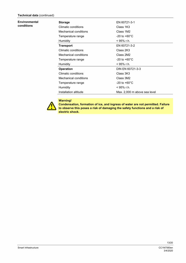
Technical data (continued)
Storage EN 60721-3-1
Climatic conditions Class 1K3
Mechanical conditions Class 1M2
Temperature range -20 to +60°C
Humidity < 95% r.h.
Transport EN 60721-3-2
Climatic conditions Class 2K3
Mechanical conditions Class 2M2
Temperature range -20 to +60°C
Humidity < 95% r.h.
Operation DIN EN 60721-3-3
Climatic conditions Class 3K3
Mechanical conditions Class 3M2
Temperature range -20 to +60°C
Humidity < 95% r.h.
Installation altitude Max. 2,000 m above sea level
Warning! Condensation, formation of ice, and ingress of water are not permitted. Failure to observe this poses a risk of damaging the safety functions and a risk of electric shock.
Environmental conditions

14/20
Smart Infrastructure CC1N7560en 3/4/2020
Technical data (continued)
With LMV6 at terminal X52.
Warning! Provide protection to prevent people from coming into contact with the ionization probe (risk of electric shock)!
Short-circuit current Max. AC 850 µA
Permissible length of flame detector cable (laid separately)
10 m (100 pF/m), unshielded
Note! Display on the AZL66 in the event of a short-circuit! In the event of a short-circuit, a flame signal of 12% is displayed on the AZL66.
At mains voltage
230 V AC Flame intensity
Detector voltage between ionization probe and ground (AC voltmeter Ri 10 M)
Approx. 230 V AC ---
Switching threshold (limit values):
Switching on (flame ON) (DC ammeter Ri 5 k) 3 µA 25%
Switching off (flame OFF) (DC ammeter Ri 5 k) --- 18%
Recommended flame intensity for reliable operation --- > 40%
Switching threshold in the event of poor flame during operation --- Approx. 30%
Possible detector current with flame (typical) > 15 µA 100%
Maximum detector current 60 µA DC ---
Note! As the detector line capacitance (detector line length) increases, the voltage at the ionization probe – and thus the detector current – will drop. Long line lengths and very high-ohmic flames may necessitate the use of a low-capacitance cable. In spite of special electronic circuits designed to compensate possible adverse effects of the ignition spark on the ionization current, it is important to ensure that the minimum detector current required is already available during the ignition phase. If this is not the case, the primary ignition transformer connections must be interchanged and/or the electrodes relocated.
Flame supervision with ionization probe

15/20
Smart Infrastructure CC1N7560en 3/4/2020
Technical data (continued)
Ionization probe
Legend
C Electrolytic capacitor 100 to 470 µF; 10 to 25 V DC
ION Ionization probe
M Micro-ammeter Ri max. 5000
Connection diagram
Measuring circuit for detector current measurement

16/20
Smart Infrastructure CC1N7560en 3/4/2020
Technical data (continued)
Caution! If QRA2 / QRA2M / QRA4 / QRA10-UV tubes are used for flame supervision on the LMV6, it must be ensured that the LMV6 is permanently connected to power (EN 298), thus enabling the LMV6 to detect flame detector failures during startup and shutdown. The LMV6 generally operates with QRA flame detectors in intermittent operation. For Technical data, refer to Data Sheet N7712, UV flame detector QRA2 / QRA2M / QRA10! For Technical Data, refer to Data Sheet N7711, UV flame detector QRA4!
Operating voltage in operation Max. 350 V peak Possible detector current in operation Max. 80 µA Permissible length of the standard detector cable (laid separately)
Max. 10 m
Threshold values when flame is supervised by QRA Start prevention (extraneous light) Flame intensity ≥ 18% Operation Flame intensity > 25% For more detailed information on QRA2 / QRA2M / QRA10, refer to Data Sheet N7712. For more detailed information about QRA4, refer to data sheet N7711.
Legend C Electrolytic capacitor 100 to 470 µF; 10 to 25 V DC M Micro-ammeter Ri max. 5000
Warning! Simultaneous operation of the ionization probe and QRA2 / QRA2M / QRA4 / QRA10 is not permitted. Failure to observe this information poses a risk of damaging the safety functions.
Flame supervision with QRA2 / QRA2M / QRA4 / QRA10
Connection diagram QRA2 / QRA2M / QRA4 / QRA10
Measuring circuit for detector current measurement

17/20
Smart Infrastructure CC1N7560en 3/4/2020
Assignment of terminals

18/20
Smart Infrastructure CC1N7560en 3/4/2020
Legend
AL Alarm device
FGR Flue gas recirculation
/reset (EK1) Lockout reset button (info button)
ION Ionization probe
LP Air pressure switch
LR Load controller
LR-OPEN Load controller OPEN position
LR-CLOSED Load controller CLOSED position
M Fan motor
P LT Pressure switch valve proving
Pmax Pressure switch-max
Pmin Pressure switch-min
PV Pilot valve
QRA UV flame detector
SK Safety loop
V1 Fuel valve
V2 Fuel valve
Z Ignition transformer

19/20
Smart Infrastructure CC1N7560en 3/4/2020
Dimensions
Dimensions in mm
LMV60.110A2

20/20
Smart Infrastructure CC1N7560en 3/4/2020
Dimensions (continued)
Dimensions in mm
77
55,39
135
137
,75
153
,75
756
0m0
8/0
519
AGG6.200A5
2020 Siemens AG Smart Infrastructure, Berliner Ring 23, 76437 Rastatt, Germany Subject to change!
Copyright © 2022 FDOKUMEN