7-R124 733 DESIGN OF A MULTIPROCESSING OPERATING ...
152
7-R124 733 DESIGN OF A MULTIPROCESSING OPERATING SYSTEM FOR 1/2 SIXTEEN-BIT MICROPROCESSORS(U) AIR FORCE INST OF TECH URIGHT-PATTERSON RFB OH SCHOOL OF ENGI. . D S HUNEYCUTT UNLSII DEC 82 AFIT/GCS/EE/82D-28 .F/G 9/2 N
-
Upload
khangminh22 -
Category
Documents
-
view
0 -
download
0
Transcript of 7-R124 733 DESIGN OF A MULTIPROCESSING OPERATING ...
7-R124 733 DESIGN OF A MULTIPROCESSING OPERATING SYSTEM FOR 1/2SIXTEEN-BIT MICROPROCESSORS(U) AIR FORCE INST OF TECHURIGHT-PATTERSON RFB OH SCHOOL OF ENGI. . D S HUNEYCUTT
UNLSII DEC 82 AFIT/GCS/EE/82D-28 .F/G 9/2 N
11.
(%.%
-% -. -. - .- - -
\'~.$~C
~ I '*DT
LET
OW"FEKDEATET FTEAI OC
AI NM ST (T.
IR INTTTO E" LG
A Olt4 --a- e
Wright-Pattmon A r FreBsOi
7%b d~mad b
p~-.7 .t" awao
a~~~ S * ... - - ... .
AFIT/GCS/EE/82D-20
Design of a Multiprocessing
Operating Systemfor
Sixteen-Bit Microprocessors
THESIS
-a AFIT/GCS/EE/82D Douglas S. Huneycutt Sr.Captain USAF
Approved for public release; distribution unlimited.
* ~* DTIC* b-- , ~ELECTE
FEB 2 3 1983
WPI.I
Aj
* . AFIT/GCS/EE/82D-20
Design of a Multiprocessing
Operating System
for
Sixteen-Bit Microprocessors
THESIS
Presented to the Faculty of the School of Engineering
of the Air Force Institute of Technology
Air University
in Partial Fulfillment of the
Requirements for the Degree of
Master of Science
Accession ForNTIS GRA&I
DTTC TAB
Uyannounced -Justificatio
by By_Douglas S. Huneycutt, Sr., B.A. .istribution/
Availibility CodesCaptain USAF iAvail and/or
~ist ISpecial
Graduate Computer Systems
December 1982
Approved for public release; distribution unlimited.
iW-7
Preface
This thesis presents a design of a multiprocessing
operating system intended for implementation of 16-bit
microprocessor systems. The design is based on the works of
Mitchell S. Ross and Robert J. Yusko, to whom I would like
to express my thanks for a job well done.
Additionally, I would like to thank my faculty advisor#
Dr. Gary B. Lamont, for his help and understanding during
this effort.
Most of all, I would like to express my indebtedness and
greatest appreciation to my wife, Miriam. Her tolerance
and encouragement made my stay at APIT tolerable. Thanks
also to my son, Scott, who was forced to spend his first
year of life as a 'computer orphan'.
Douglas S. Huneycuttl Sr.
4,-p1
S .. . . -",,-* *. P !, , - , + + " , l
Table of Contents
.." .- -I, Preface . .............................. , ...... iiTable of Contents ...............................,ooooo*
2' Abs t r a c t i * .................*.. 0000000 viI. Scope of Project oo o 1
Introduction 0000.. ***..000*00 * **0**** * ** *so0oe 1itryduction..... ,..........,.,................. 2History oooo,,o ,,o o ooooooo o ooo~ o.oo,.,,,,,,,o
Objectives . .00 60*90000000600009.00000 5Approach . .......a. * .a......... 6Overview 0 .0 ......a.*.a . 7
Ii. Requirements ooooooooooooo*oeooo*oooooooooeoeo 9
Introduction ........ .. 000000.000** .. 00.0 9Local Requirements 000000000*............... 9Minimum Capabilities .......................... 10Design Approach .................. .0........ 10Language Considerations 0000000000000.00000000 13CPU Considerations 0000000000* 16
Restriction of CPU Access ............ 00000000 17A - Restriction of Memory Access ...... ..... 17Memory Mapping o.0900000006606000000*000000.. 18Program Relocation 0000..0000000........0000.0 19Sharing of Memory .00409090000000096006060000 20Context Switching **.*ee**ooo***.oooooo 20Interrupt Support *..0..0.00......0.. 0000. 20CPU Access Restriction 00.0.000.00000000000060 21Memory Access/Mapping/Sharing ................ 21Context Switching *ooooooo.....****. .ooooo 21Interrupt Handling ......................*... 21Choice of Target Device ................... 22
Summary oooooo..o.............. 000.. 22
III. Top-Level System Design and Implementation....e. 23
Introduction ................ ................... 23-' Structured Design Limitations ......... •........ 24
Top-Level Modules 26Bootstrap (Level 1) .................. e....... 27System Initialization (Level 2) o.o606........ 28Interrupt Service (Level 3) ................... 28System Calls . .. . .. 29
CPU Scheduling (Level 4) ........ ......... 30Summary 30
oeA'o o o ooo..,o e o o o o oo o e
IV. Interrupt Service .............................. 32
* "': Introduction 32Linkage ....* ............... .................. 32Timer Interrupts ... ...................... 33Other Hardware Interrupts ........ *00*.**.... 33System Call Management ............. *. ...... 34
I.,.-. File System Calls ... ......................... 36User Structure Calls .. 36Process Structure Calls ...................... 37System Modification Calls .................... 37Communications Calls ......................... 37
Summary ............... . .................. 38
V. AMOS Data Structures Design and Implementation.. 39
• :Introduction 39
The Process Structure .......................... 39The DDB Structure .... ... .......... ...... . 41The User Structure .... ........................ 41The Master Block Structure ..................... 43The Directory Entry Structure ........ ........ 43Summary ... ..................................... 43
VI. The AMOS File System Design and Implementation.. 44
Introduction ....... ........ 44Specifications . . [email protected].... .e.45
File Types .................. 45AMOS File System Structure ...... .46
File Addressing .. .............. 47Secondary Devices , .... ........ 49Disk Descriptor Blocks and Files ............... 49AMOS Disk Format .............................. 51I/O Buffering ............ ............... 53AMOS File System Calls (structure chart) ..... 4
Creating a File ......... 0.................... 55Opening a File ...................... 59Other System Calls ........................... 6
* Summary ............... ....... ....... 61
VII. Results ................... 62
Implementation Problems .......... • ... 62
Solution ........ .. ...... ... • .... 63Summary .. . ........ .. ............... ..... 65
VIII. Conclusions and Recommendations ................ 66
Recommendations .6. .... . ........ ...... 67Major Recommendation ........................ • 69
0, h 1 ; i . ,"
; "
' "" " '" ' "" " '" " " "" ' ". ..." " " *
"" " . .""" '
Bibliography . . . .... . aaaaaa******** a aaaaaaa70
Appendix A: Microprocessor Benchmarks ............... Al
Appendix B: UNIX Short Course Notes B........ 1
Appendix C: AMOS Bootstrap and ISRs *........ Cl
Appendix D: AMOS Structure Charts ........... Dl
Appendix E: AMOS Source Code *... . .00000*...... El
Vita ............................................. V
9:
i .
Vit
"S l e e e e e ee e e e e e ee e e e e e e e
*P~
"4:
*t

Abstract
A multiprocessing operating system for the Air Force
Institute of Technology Digital Engineering Laboratory was
designed and partially implemented. The requirements for
such a design were developed by a thorough literature search
and through an abstraction of the works of Ross and Yusko.
The resultant design is functionally compatible with UNIX,
version 2.7.
Because of the broad scope of such a project, this
effort was geared toward the total design of the file
system, with a high-level design to cover all other areas.
Further research is needed to complete the design, as the
high-level areas are not sufficiently detailed for full
implementation.
.4.
vi
I. Scope of Project
Introduction
:;T he purpose of this investigation is to develop a
multiprocessing operating system for sixteen-bit micro-
computers. The AFIT Multiprocessing Operating System (AMOS)
is based on state-of-the-art software and hardware
technology. AMOS has been designed to be implementable on
any of the current powerful microprocessors. The Zilog
-21*1W single chip microprocessor was chosen for the initial
implementation due to its advanced architecture and
architectural similarity to popular minicomputer processors.
Chapter 2 deals with this selection in much greater detail.
:.The Z8000 was designed with operating system support in
mind, and this investigation takes every advantage of that
design.
The purpose of this chapter is to give a brief histor-
ical introduction to operating systems, to outline the
objectives of this investigation, and to detail the approach
taken to attain the stated objectives.
A formal definition of an operating system is: "those
program modules that govern the control of computer system
resources such as processors, main storage, secondary sto-
rage, I/0 devices, and files. "(Ref 1, P. ). The important
implication in this definition is that the operating system
is usually a software program. Because the operating system
and user programs both execute in computer hardware, the
operating system must have the capability of gaining

'special' status, thus allowing it to allocate and
deallocate resources at a higher priority level than that of
the normal user program.
Historically, there has been a logical line of demar-
cation between microcomputers and minicomputers. Even the
low-level minicomputers, such as the Digital Equipment
Corporation's PDP-11 series, have hardware capable of en-
forcing the difference between the system and the user. On
the other hand, microcomputer systems have typically been
restricted to a single user, confined within a narrow
address space, usually 64K bytes.
Within the past few years, however, there has been a
tremendous surge in technology, resulting in a new class of
microprocessors with the capability of addressing up to 16
megabytes of main memory directly.(Ref " 2) This extendedmemory access capability immediately opened the micro-
computer segment of technology to advanced applications,
such as intricate graphics, large database manipulation,
multiuser environments, and others. Because of the new
emphasis on microcomputer software, operating systems
development for microcomputers can now achieve the same
level of sophistication already available for minicomputers.
History
The earliest computers were designed for processing a
single jot at a ti, t, and were programmed by hand, setting
memory locWa'nb with switches and reading in punched cards.
The 'operating systems' of these machines were basically
2
program loaders. As the technology improved, processor
speed increased, and it became obvious that a large amount
of time was spent waiting for 1/0 operations to be
completed. Multiprogramming was developed to take advantage
of the wasted time by having multiple jobs in memory and
allowing their 1/0 wait states and processing states to
*overlap. This technique depends rather heavily on having a
good mix of I/O-bound and CPU-bound jobs in memory to
achieve the most efficient usage of system
resources. (Ref. 1# p- 238) To alleviate this requirement,
time-slice preemption was developed where each job was given
a set time (100 milliseconds, for example) in which to
perform CPU processing. If the job had not requested I/O by
the end of its time-slice, it was preempted and placed in a
holding queue until its turn came to be processed again.
From the development of time-slice preemption, it was a
natural turn of events to start using timesharing, in which
most user input and output centers at the user's terminal.
The use of terminal timesharing required that the computer
* have some way of conversing with the average user, not just
the specially trained operators. 'User-friendly' has become
a popular phrase in referring to operating systems, often
for the lack of the characteristic. For an operating system
to be user-friendly, it must communicate with the user at
whatever level the user desires. The early mainframes had
no degree of user-friendliness, while today's large systems
(e.g. the DEC-20 seripi) have operating systems which make
it very difficult for the uninitiated user to achieve
3
'computer suicide'. This is achieved in part by providing
defaults for command options, allowing easy recovery of
deleted files, and repeated confirmation requests during
dangerous procedures.(Ref. 3) Whether or not this techinque
is actually 'friendly' or not depends heavily on the user's
point of view and experience level.
In 1969, Ken Thompson of the Bell Laboratories began
developing the UNIX timesharing operating system for Digital
Equipment Corporation's minicomputers. Originally designed
as a research tool for Thompson's own work, UNIX spread
through the Bell facilities due to its utilitarian nature.
From the Bell groups, UNIX went on to find popular support
at universities and (to a lesser extent) the business world.
Today, UNIX is one of the most popular operating system for
DEC minicomputers.(Ref. 4)
In 1974, Microcomputer Applications Associates deve-
loped the Control Program for Microcomputers (CP/M). CP/M
was designed as a single-user operating system, taking
advantage of the new technologies of 8-bit microprocessors
and low-cost floppy disk storage to provide an attainable
computer for a single user. CP/M gained in popularity
rapidly, mostly due to its wide acceptance by the growing
person~l computer market, and is now "the operating system
of choice of more than 500,000 users, almost 100 vendors,
and more than 500 independent software vendors."(Ref 5)
In the last few years, many efforts have been made to
usurp CP/M's position in the 8-bit computer world. 'Unix-
4
LS- 7777. 6 7 -7 79
like' operating systems have been marketed for 8-bit
machines, most notably Cromix(Ref " 5) for Cromemco Z-80
computers and the Apple-Ill operating system(Ref" 5), which
implement many of the Unix features. These efforts, while
partially successful, have shown that minicomputer
*performance cannot generally be achieved from an 8-bit
computer.
Until the last few years, UNIX and CP/M formed a
natural boundary between minicomputer and microcomputer
software. Microcomputer eight-bit architecture was
*incapable of the performance levels required to efficiently
use the powerful structures of the UNIX system. Recently,
however, the development of the new 16-bit microcomputers
has narrowed the architectural gap between minicomputers andW "-microcomputers. With the introduction of processors such as
the Intel 8086, the Zilog Z8000, and the Motorolla 68000,
the microcomputer user is no longer bound to overly
restrictive architecture and processor speeds. The new
microprocessors are complemented with new, powerful control
software.
Objectives
The objective of this investigation is to develop a
multiprocessing operating system for a 16-bit micro-
processor. Requirements definitions, design and implemen-
tation will be accomplished using modern top-down
I methodology. The phrase 'divide and conquer' is particu-
* * larly appropriate in the realm of operating system design.
Each module will contain only procedures relevant to the
5
stated purpose of the module, and will be restricted in
length to a reasonably understandable amount of information.
The major considerations involved are reliability, fairness
in resource allocation, 'user-friendliness', and cost-
effectiveness. As in the development of Unix, the operating
system will consist of the 'kernel' only, leaving
development of utility and user programs for future
projects.
The implementation of the operating system will be
accomplished in a structured high-level language. Again as
with Unix, the operating system development will avoid as
much as possible hardware configuration dependency.
Approach
This investigation began with a thorough literature
review to extract useful methods already proven successful
- in the development of operating systems. Most of the
requirements definitions were derived from the works of
RosslRef. 6) and Yusko(Ref " 71. There is no accepted
standard method for operating systems design, but literature
abounds with methods for software engineering. Recalling
the previously stated definition of an operating system, the
design offered by this investigation will treat the
operating system as, a large, very complex combination of
,algorithms and will proceed with techniques suggested by the
software engineering community.
Because of the complex nature of an operating system, a
top-down structured approach to design and implementation
6

. , .,,
is essential. More appropriately, from the user's view, an
'outward-in' approach is taken, looking inward from where
the user sits at the terminal. This method helps insure
that user requirements are met and that the system behaves
in a 'user friendly' manner.(Ref. 5)
The initial implementation computer for the operating
system is a Multibus Z8000 system from Advanced Micro
Devices (AMD). The system consists of a non-segmented Z800
CPU card, a multi-port serial I/O card, 128-Kbytes of main
memory, a floppy disk controller, a clock/timer card, and a
mainframe with motherboard, power supply, and cooling fans.
Overview
This investigation is rooted in the investigative works
of Ross(Ref " 6) and Yusko(Ref " 7). Yusko's scheduler, as
presented in his thesis, is modified to fit directly into
the AMOS structure.
Ross' high-level design is used in a modified form and
greatly expanded. Appendices will include structure charts,
structured English modules, and the data dictionary. The
actual source code for the operating system is placed in
appendix E.
. Testing of the operating system was done at all points
.% 1 during its development. Both validation (assuring that the
development stage produces correct results)(Ref - 18, p. 84)
and verification (making sure that the results are what is
required)(Ref. 18, p. 85) were continuous processes.
The sequence of steps taken in this development and
their relative importance were derived from the author's
7
7. ( . . " "
experiences. To be a valid learning experience, this
project was designed to be as highly structured as possible,
otherwise all other students to follow will become
hopelessly bogged down in the project's complexity. AFIT
needs this operating system as a tool, both for further
student research and eventually as a basis for cost-
effective student development systems.
-. 8
U-
U.... ..
l-
'

'11
II. Requirements
Introduction
Operating systems today are sophisticated interface
devices between the computer user and individual computer
resources. On some of the more friendly systems, the user
has the capability to ask the computer to prompt for
'commands. For example, on the TOPS-20 operating system for
Digital Equipment Corporation's DEC-20 computers, a user may
type in 'DIR' followed by an escape, and TOPS-20 will auto-
matically complete the command line with 'ECTORY (of what
account?)'. To achieve this level of sophistication,
operating systems are by nature very complex.
(S To design an operating system to complement the state-
of-the-art, highly structured techniques must be used
religiously or months of effort may be wasted through
confusion and incompatibility as the project grows. The
purpose of this chapter is to present the
objectives/approaches considered for this design and
implementation effort and to explain the logic used in
selecting the techniques and tools.
Local Requirements
AFIT personnel rely heavily on various computer systems
for study and research work. Both faculty members and
students currently have to rely on the availability of
computer resources external to AFIT. From benchmarks
conducted by the MITRE Corporation, an efficient
* ". microprocessor multiuser system should be capable of
9

handling (conservatively) 8 to 10 concurrent users with
little degradation. (Ref. 8, P. 20) This would provide AFIT
with a very cost-effective software development system.
Additionally, AFIT courses include subjects such as
software engineering and operating systems development.
Carefully designed and highly structured operating system
documentation would prove invaluable to the teaching of
these subjects.
Perhaps the most important requirement locally is for
* an operating system that is highly reliable and user-
friendly. Students in particular become very disenchanted
when having to learn cryptic commands in an attempt to
recover lost files that should not have been lost in the
first place.
The Air Force is gradually recognizing the value of the
microcomputer in support of the Air Force mission. To this
end, the Microcomputer Technology Branch of the Air Force
Data Systems Design Center at Gunter AFS, Alabama has been
recently created to supervise the production and acquisition
of standard Air Force microcomputer software. (Re f. 9) This
project is designed not only to provide a multitasking
operating system, but also to provide the insight necessary
for Air Force acquisition personnel to correctly specizfy
required software.
Minimum Capabilities
*1~ The following Is a list of the minimum capabilities
that should be produced by this design effort. These
requirements were developed by the author over several years
10
*.*~~~~~* .- - . . .~.. . ... . . . . . . . .. .
' ,. of use of various operating systems. Additionally, the
works of Ross (Ref " 8) and Yusko (Ref " 9) were consulted to
c'nsolidate the requirements research of prior works.
1) Multiuser support (at least 4 concurrent
users, more if hardware is available)
2) Friendly user interface
3) Interprocess/interuser communication
4) Fair allocation of system resources
5) Meaningful error/recovery diagnostics
6) Minimal device/user utility support
These requirements are specified as a goal, to give the
research effort a point of focus. As research continues,
the requirements will be modified and consolidated to
conform to ever-changing needs.
Due to the nature of this project, user utilities and
support software will not be considered unless time permits.
The main thrust of this design will be toward the total
specification and implementation of the multiple-user file
system, with process control and interfacing being given
secondary attention.
Design Approach
The operating system in this design will be approached
from the 'hierarchical view,(Refo 10) to best allow for
continued development in future projects. This view
considers the system as a layered series of subsystems, each
with a specific routine to perform. To achieve its
function, one layer may call upon lower layers, which may in
*1
;o11
turn call upon still lower layers. The key to this view is
knowing exactly where each layer belongs, what information
it needs as input to perform its task, and what information
it will return to the calling layer when its task is
complete.
Dijkstra first formalized this view of operating
systems design.(Ref " 10) His T.H.E. operating system is the
classic example of the hierarchical operating system design
approach. In this system, level 0 controls the CPU resource
and level 1 controls the memory resource, virtualizing
memory by providing paging and segment management. Level 2
virtualizes the operator console. Level 3 manages
peripheral devices, while levels 4 and 5 are user and
operator processes, respectively. By using this technique
of isolating all functions on a hierarchical level basis
". with strictly defined operations, inputs, and outputs, the
correctness of any operating system module can be tested by
stubbing its subordinate modules. Further still, Dijkstra
claims the entire system can be tested and proven logically
correct before it is implemented(Ref. ), although such an
project.
The hierarchical, top-down approach will be used by
this study. Other methods, such as Hansen's bottom-up
F approach,(Ref. 11) are acknowleged but will not be
considered further, as they do not lend themselves as well
V 1 to the continued research required by such a large project.
12

Language Considerations
In discussing structured design and implementation of
* a project such as this, careful consideration must be given
to the choice of language in which to carry out the
Implementation. Obviously, a structured design lends itself
well to being coded in a structured language, but there are
other factors to consider.
Historically, operating systems have been written in
assembly language.(Refo 20) The main reasons for this are
that: 1) well written and optimized assembly code is the
fastest-executing code available, and 2) the code produced
is the most compact, taking up the least possible amount of
expensive (in price and availability) memory.
The trend in software development today is turning
toward structured languages for a single major reason --
cost (including time of implementation). The cost of
hardware continues to drop in the competitive marketplace,
while the shortage of competent software designers continues
and grows more severe. Managers have recognized for a
number of years that the cost of developing and maintaining
a large software system, over time, far exceeds the cost of
the hardware required to run the system.(Ref 12 In an
A effort to minimize this expense, large-scale design projects
now commonly use software engineering structured design
techniques. The use of structured languages allows programs
to be written in a style that follows the physical form of
If 10 the design used. This allows maintenance programmers to
reference system documentation that directly matches the
13
J.. 4 7

. -Z structure charts, HIPOs, or whatever techniques are used.
The benifits of using structured language for
implementation of large projects has extended into the
design of operating systems, where speed and size are
crucial factors. The result is a hybrid construction where
the structured language is used for the control structures
and, in speed sensitive areas, assembly language is used to
optimize performance. Both UNIX, written in C, and UCSD
Pascal, written in Pascal, are implemented in this fashion.
Another consideration in the AFIT environment is porta-
bility. AFIT has a tendency to pick up new microcomputers
as they become available. Often software is not available
for these devices until much later than the time the
hardware is released. If an operating system is designed
with portability in mind, then transfering It to the new
hardware should involve modifications to low level routines
only. An operating system implemented mostly in a high-
level language eases the process, as there are usually one
or more cross-compilers for that language. With low-level
driver modification, any software project that is well
designed should be able to be transfered from one machine to
another. If the implementation is in assembly language,
this process would be very costly, if not impossible. An
excellent example of this process is the UNIX system, which
has been implemented on several machines ranging from the
Interdata 7/32 and IBM/370(Ref. 13) machines down to the
LSI-11 microprocessor.(Re f 14) As a counter-example,
14
kz, .PLO -
consider the CP/M and MP/M operating systems which, being
K "written in 8080 assembly language, can only run on 8080,
Z80, and 8085 microcomputers.
Given that this implementation effort will take place
mainly in a high-level structured language, the only choice
is which one to use. Two of the choices are Pascal and C,
with others (PL/I, Algol, etc) in the background. Require-
ments are that the language provide clean, easy to
understand flow control structures (the basic for/next,
repeat, and decision structures) and that the language not
be overly restrictive. In other words, the language chosen
must allow the type of 'bit-tweaking' required in typical
operating systems functions, such as bit masking and boolean
logic operations. This stems from the desire to optimize
code for certain functions without having to resort to
assembly language.
The C language was chosen for this effort because, of
the two language compilers readily available for this
research (Pascal and C), C is by far the less restrictive.
Because of this lack of restriction, extreme care must be
taken to strictly adhere to structured design and
implementation rules. Otherwise, porrly designed and
written code may result, having a very negative effect on
future efforts. A strong influence in choosing C are that
AFIT has several C compilers available, including a Z8000
cross-compiler that runs under UNIX donated by the Mitre
Corporation.(Ref. 8, p. 28) Additionally, the C source for
the UNIX operating system is available for study.
15
. N W _ .. V . V 7 7 7. . . .
CPU Considerations
This design and implementation effort is geared toward
device independence. However, to have an implementation, a
target device must be selected. There are currently several
16-bit microprocessor devices on the market. Of these,
three were considered as initial implementation targets for
this study. The devices were the Intel 8086, the Zilog
Z8000, and the Motorolla 68000. The 8086 device was the
choice for the two thesis projects which preceeded this
effort, due to its availability in the Digital Engineering
Laboratory. In conversations with the authors of those
projects, the main drawback to the 8086 discussed was the
lack of differentiation between system tasks and user tasks.
This flaw would require operating system implementation to
rely on specialized external hardware and relatively complex
low-level system software to prevent malicious- or error-
induced mahem by users on one another. Of the three devices
inspected, only the Z8800 has the capability to discern
between system and user tasks and control the operations
performed by users.(Ref. 15)
Thorough benchmarks have been made testing the relative
merits ot the 8086, Z8000, and 68000. Appendix A details
these benchmarks. The Z8000 generally came out to be a bit
slower than the 68000, but much faster than the 8086.
Measurements made by the Mitre Corporation indicate that, in
local network processing, the Z8000 at 4 MHz is S 5 to 20
percent faster than a PDP 11/ 4 5.'(Ref. 8, p. 20)
16
'V . . - - - - . 4
17 7Z7- - 77 7
The amount of hardware operating system support offered
4 by the CPU was of great importance in selecting the proper
device on which to implement the design. The support
desired includes restriction of access to the CPU,
restriction of memory access, memory mapping and program
relocation capability, sharing of memory (programs and
p data), context switching support, and 1/0 interrupt support.
The degree to which the devices in question support these
* items was the deciding factor in the choice of the Z8000 as
the implementation target. Each will be examined in detail
in the rest of this chapter.
Restriction of CPU access
The operating system is faced with a serious problem in
allocating its resources. It must relinquish control of
the CPU in order for user tasks to be processed, yet be
assured of regaining control correctly when a specific event
occurs. Obviously, when the CPU is turned over to a user
task, the operating system is no longer In control of the
*system. Therefore, there must be some mechanism to prevent
user tasks from doing mischief while running. The separa-
tion of the CPU into two modes, system and normal, solves
this problem. In system mode, the full power of the device
is available to the operating system. In normal mode, the
user tasks are restricted in their use of I/O instructions,
-~ control register manipulation, and other special instruc-
tions (i.e. the HALT instruction). The transfer between
~, ~.modes is normally accomplished through automatic circuitry
17
* 5 4 5 7 -. . . *
involving the interrupt structures and the use of special-
ized system interrupts called traps.
Restriction of Memory Access
Hardware support for restriction of access to memory
usually takes the form of interpretion of an address
presented by the CPU and matching the address against a
table of attributes set by the operating system. There are
two basic types of address that processors use.(Ref, 16)
Segmented addresses consist of a segment address and an
offset within that segment. This is sometimes called two-* i,.
dimensional addressing. Linear addresses (or one-
dimensional addresses) consist only of an offset within
memory relative to address zero. In a system that uses
; segmented addresses, attributes are associated with a
segment. In systems that use linear addressing, attributes
are usually associated with fixed-length blocks of memory
called pages.
Memory Mapping
Memory mapping is the function of assigning each
logical address used in a program to a physical address in
the system. Usually, this is done by dividing the logical
address space into blocks of contiguous addresses, then
mapping the logical blocks into physical contiguous blocks
of memory. Such a scheme requires only that the base
physical address for each block be stored and that the
origins and sizes of the logical blocks be provided.
18
Program Relocation
There are three types of program relocation: static
relocation, dynamic logical address relocation, and dynamic
physical address relocation. (Ref.- 16) Static relocation is
what occurs in the operation of a linking loader, where
program location is determined at the time the program is
brought into memory from disk. Once running, the program is
fixed in memory. Dynamic logical address relocation is "the
process of changing the logical address at which a given
Program is to run.u(Ref. 16) This process is usually
possible only when the code being relocated has been written
in a position-independent manner, as is common with the PDP-
11 systems. Dynamic physical address relocation is achieved
by physically movirg the code in memory, charoqing the
* physical location at which it runs, but leaving the logical
* -addressing alone. To achieve dynamic physical relocation,,
memory mapping must be used.
Static physical relocation is possible on any system,
as it is a function of the program loader and is totally
software-dependent. On the other hand, to achieve dynamic
relocation, device support is required. Logical address
relocation is very helpful in implementing program/data
sharing between tasks, and physical address relocation
allows recompaction of fragmented memory. The availability
* * of both techniques is a great advantage in a sophisticated
operating system design.
19
Sharing of Memory
Sharing of memory segments is a desireable feature to
design into an operating system, particularly for a system
designed to run as efficiently as possible on a small
system. This technique allows utility programs to be
reentrant and allows multiple users to access the same code.
This technique discourages multiple copies of the same
-program from being resident in main memory.
Context Switching
In a multiuser system, each time a task is interrupted
to allow another task to run, the machine state of the
current task must be saved and the state of the new task
. must be reloaded from memory. This is known as Ocontextswitching".(Ref. 16, p. 3-78) Hardware support of this
function includes automatic saving of at least part of the
machine state on the stack or in system memory when an
interrupt occurs.
Interrupt Support
As stated above, context switching support is heavily
dependent on interrupt handling. The device in question
should support as much as possible the following
features: (Ref. 16)
1) A vectored interrupt scheme to avoid the
*necessity of polling devices to determine
the type of interrupt that occured.
2) Fast interrupt response.
3) A priority scheme, for allowing interrupts
of interrupts.
20
4 . . .• ' - . ." S - . " " " " " r ' ° '. . , .' ," . ,j . ., " ' ' - -. : _- + ,, -, . - . , .? - - ,- .
4) Block I/0 and DMA capability.
5) Restricted access to I/0 intructions.
The rest of this section defines how the three devices in,0
question match up to these specifications.
CPU Access Restriction
Of the three devices, only the 8086 has no
differentiation between normal and system modes. However,
the 68000 uses memory-mapped I/O, therefore the normal user
has access to I/O instructions. The Z8000 normal mode
restricts the use of I/O instructions, control register
manipulation, and the HALT instruction.
Memory Access/Mapping/Sharing
All the devices inspected require external circuitry to
S .control access to memory. However, the Z8000 provides
instructions for use with memory segmentation.
Context Switching
All the devices store at least par-t-otthe machine
state on receiving an interrupt. The Z8000 has block move
instructions for facilitating the storage of the entire
Instruction set.
Interrupt Handling
, All the devices react in a similar manner to
interrupts. However, the Z8000 allows the interrupt vector
table to be located anywhere in memory, whereas the 68000
requires the table to be located in specific memory
locations.
S.:.
.°,21
S A * A A A * S. . . . .*.* *.* *.*..A*.. S 2%
'77~~ 7777777 7. 7
Choice of the Target Device
Given the considerations above plus the results of the
benchmarks given appendix A, the Z8000 was chosen as the
%I target device for this study.
Summary
The operating system is generally accepted as the
single most complex piece of software that a computer system
is expected to run. A sophisticated operating system must
be designed and implemented using the strictest of
techniques. The advantages of structured design and imple-
mentation far outweigh the penalties imposed.
The C language was chosen for this implementation for
its clarity, power, and availability. Many examples exist
for operating systems algorithms in C, and the UNIX C source
is available for study.
-~ Also, the Z8000 microprocessor was chosen for this
implementation due to its design which supports operating
system constructs.
Thi-s dasign and implementation effort will provide AFIT
with a useful teaching tool for future classes, plus a cost-
efficient software development system. It is expected that#
as with UNIX, very few years will pass before extensive
modifications to this system have been made. But, again as
* with UNIX, the overall concept of the design will still be
apparent*
22
ZC '.N **~'" *
III. Top-LevelSystemDesignand Implementation
Introduction
The first two chapters of this thesis have emphasized
two main techniques required for the successful completion
of the design effort.(Ref. 17) These are the use of top-
down structured design and implementation techniques and the
incorporation of user-friendliness into the design at all
levels. The efforts of the previous chapters, taken in
concert with the total efforts of Ross(Ref. 6), form the
basis for the design of the AMOS system. This chapter deals
with the actual design of the AMOS operating system kernel.
While the design of Ross provided the major motivation for
this effort, a major flaw exists in the his results. Ross'
design has no readily apparent method specified for
processes to request operations from the operating system.
The AMOS design, on the other hand, is centered on the
ability to efficiently service any request made by
processes. The design is approached from the outside
inward, dealing first with the high-level requests that
software and hardware external to the kernel are likely to
want AMOS to satisfy. These requests are often refered to
as 'hooks' into the operating system, and will hereafter be
called system calls. The design proceeds inward to the low-
level (and possibly system-dependent) routines AMOS itself
uses to satisfy these system calls.
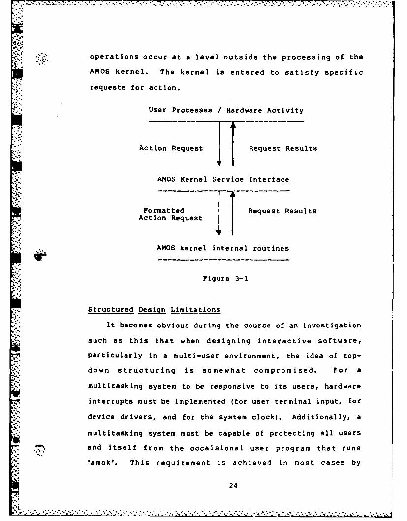
To help to visualize the basis of the AMOS design# the
following chart shows the logical flow of requests and
service in the AMOS system. User processes and hardware
23
Ell 4~
'~%- - - -7-
operations occur at a level outside the processing of the
AMOS kernel. The kernel is entered to satisfy specific
requests for action.
User Processes /Hardware Activity
19Action Request Request Results
AMOS Kernel Service Interface
xAFormatted RqetResults
Action Request
AMOS kernel internal routines
Figure 3-1
Structured Design Limitations
It becomes obvious during the course of an investigation
such as this that when designing interactive software#
particularly in a multi-user environment, the idea of top-
down structuring is somewhat compromised. For a
multitasking system to be responsive to its users, hardware
interrupts must be implemented (for user terminal input, for
17 % device drivers, and for the system clock). Additionally, a
multitasking system must be capable of protecting all users
and itself from the occaisional user program that runs
'amok'. This requirement is achieved in most cases by
24

;.<: reserving privileged instructions for exclusive use by the
operating system. The user programs must therefore request
the operating system to perform certain tasks through the
% use of system calls, which on the Z8000 are another type of
interrupt.
All interrupts, whether hardware or software, will cause
an unconditional transfer of control to the operating
system, where a routine designed to handle the interrupt
will be executed. These Interrupt Service Routines (ISR's)
will handle the specific task requested (queueing I/O,
performing scheduling, running a child task, etc), then
return control to a routine within the operating system
proper.
The Z8000 microprocessor has a very sophisticated
interrupt handling scheme which allows for up to 262
different entry points to interrupt service
routines.(Ref. 15) This capability makes the Z8000 very
responsive in a multi-user environment. However, to follow
the spirit of top-down structured design and to make the.4
4
resultant design easier to comprehend, the choice was made
to restrict AMOS to a minimum of entry points, thereby
enforcing smooth data/control flow as much as possible.
Exceptions to this rule are unavoidable if reasonable
response times are to be achieved, stemming from interrupts
due to the terminal, printer, and disk interfaces.
b' ,,
25
.~ ~ 2",4 -
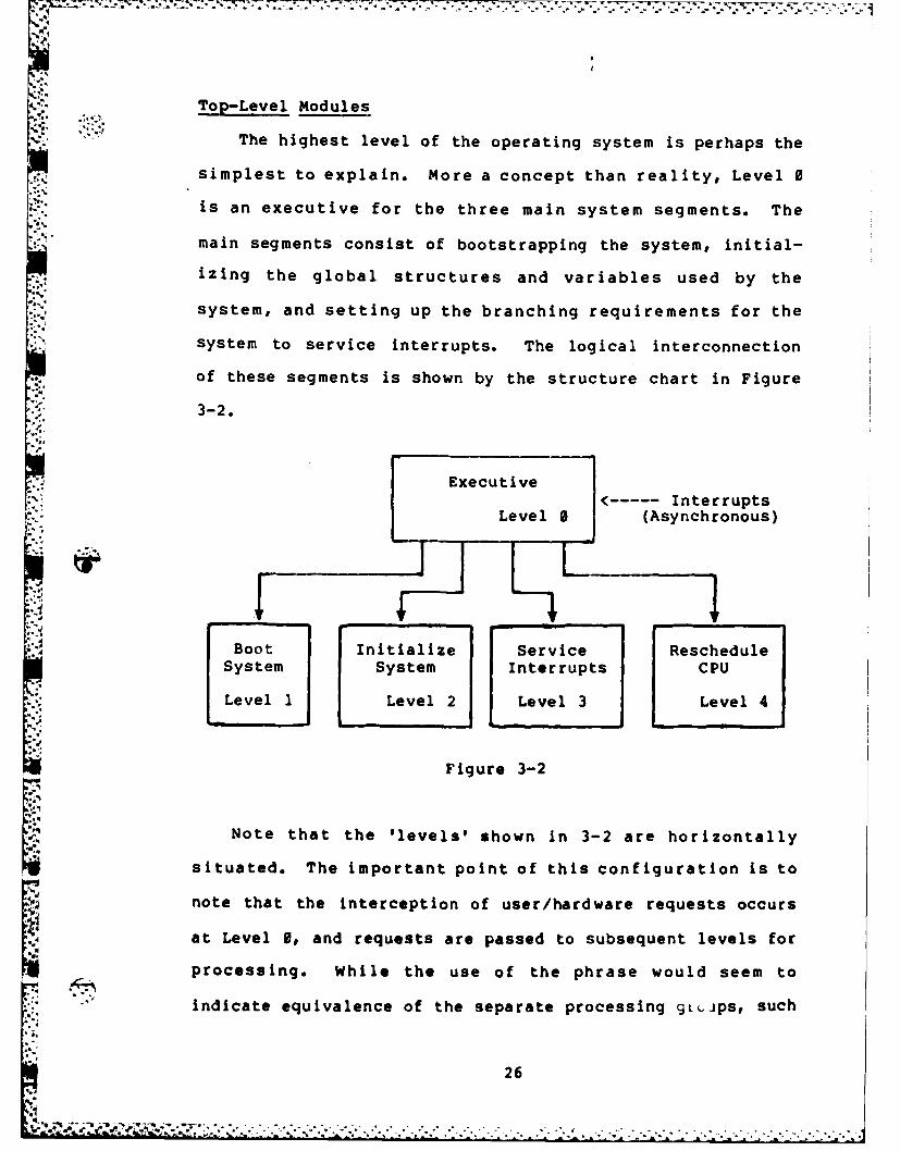
Top-Level Modules
S"The highest level of the operating system is perhaps the
simplest to explain. More a concept than reality, Level 0
is an executive for the three main system segments. The
main segments consist of bootstrapping the system, initial-
izing the global structures and variables used by the.
system, and setting up the branching requirements for the
system to service interrupts. The logical interconnection
of these segments is shown by the structure chart in Figure
S•..3-2.
Executive.----- Interrupts
Level 0 (Asynchronous)
Boot Initialize Service RescheduleSystem System Interrupts CPU
Level 1 Level 2 Level 3 Level 4
Figure 3-2
Note that the 'levels' shown in 3-2 are horizontally
situated. The important point of this configuration is to
note that the interception of user/hardware requests occurs
at Level 0, and requests are passed to subsequent levels for
processing. While the use of the phrase would seem to
A" indicate equivalence of the separate processing 9L.jps, such
26
* ': .d4" -- '-!, - * *,, *. .> .. ... ., ... ... . -. - .- . ... •t ." -ft - . . . , • . •.. - -, -
is not the case. Procedures below the individule modules
shown above follow a numbering scheme with the 'real' part
of the number being the original entry point from Level 0.
The interconnections shown in Figure 3-2 are logical
only. Actually, Level 1 is entered immediately when power
is applied to the system. In the absence of a failure, Level
2 is entered to initialize the global structures, buffer
pools, and variables used by the system. This initial-
ization includes setting up the branching requirements for
interrupts. After initialization, Level 2 branches to Level
0. Level 0 initiates the system task, which sets itself up
as process 0 and goes to sleep awaiting an event
(interrupt). When an interrupt occurs, Level 0 saves the
-. system state and takes actions appropriate to the type of
'Uinterrupt. Level 3 is called from Level 0 to process the
interrupt request, acceptinq as input the parameters passed
from Level 0. A special case interrupt (that of a terminal
interrupt from a device not currently attached to a process)
X:.results in the spawning of a login process. Level 4 is
entered upon a successful return from Level 3 to reschedule
r allocation of the CPU resource after an interrupt.
Bootstrap2 (Level 1)
What actually occurs when the computer is initially
powered-on depends on the hardware. There are two general
P... possibilities:
1. The CPU begins executing from an on-board
monitor which may allow different low-level
functions to be performed without disk
27
VN~jinteraction. This is not a disk operating
system functihn.
2. The CPU may be held in a RESET state while
the disk controller independently loads a
small segment of code from the disk. The CPU
is then allowed to run, executing the code
loaded by the controller. This code is known
as the bootstrap loader, because it 'boot-
straps' the rest of the operating system
proper.
The bootstrap operation is obviously highly hardware-
dependent. For the purposes of this chapter, it is assumed
that the bootstrap correctly loads the required operating
system code into memory. An introduction to the bootstrap
loader is presented in Appendix B.
System Initialization (Level 2)
When the operating system is first loaded and run, the
CPU is running in system mode with interrupts disabled. All
devices (disk controller, I/0 ports, and the system clock)II.are initialized. Memory management hardware is initialized.
Finally the system initializes the I/0 buffers and various
structure arrays, interrupts are enabled, and then control
returns to the executive.
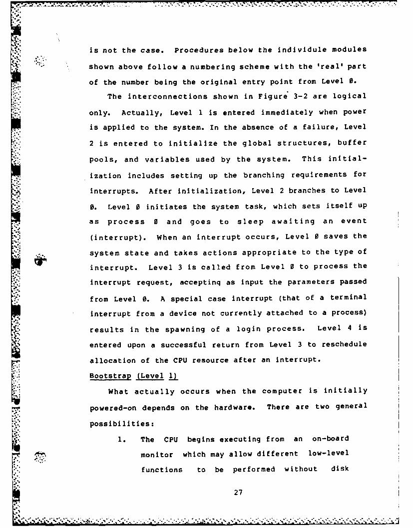
Intrrut Service (Level 3)
Interrupt service is divided into three groupings, as
shown in Figure 3-3. These groupings are indicated by the
nature of processing required by each type of interrupt.
28
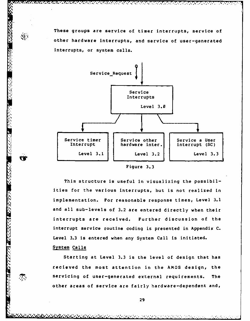
These groups are service of timer interrupts, service of
other hardware interrupts, and service of user-generated
interrupts, or system calls.
ServiceRequest
ServiceInterrupts
Level 3.0
Service timer Service other Service a UserInterrupt hardware inter. interrupt (SC)
Level 3.1 Level 3.2 Level 3.3
* Figure 3.3
This structure is useful in visualizing the possibil-
ities for the various interrupts, but is not realized in
implementation. For reasonable response times, Level 3.1
and all sub-levels of 3.2 are entered directly when their
interrupts are received. Further discussion of the
interrupt service routine coding is presented in Appendix C.
Level 3.3 is entered when any System Call is initiated.
System Calls
Starting at Level 3.3 is the level of design that has
recieved the most attention in the AMOS design, the
4servicing of user-generated external requirements. The
other areas of service are fairly hardware-dependent and,
29
'rk i7-.
once the hardware configuration is defined, are relatively
inflexible as to their design requirements. As previously
mentioned, AMOS will satisfy many of the system calls
presented by programs written to run under the Unix environ-
ment. Because the design of the system call handling
section is so extensive and so important, full discussion of
this section is deferred to the next chapter.
CPU Scheduling (Level 4)
The final level of processing in the top-level modules
is the CPU scheduling module. With modification to accept
the structures of AMOS, the work presented by Yusko will be
used to implement scheduling. This set of algorithms has
already been proved to be correct by implementation in
Pascal for a basic operating systems class.
Summary
This chapter has presented the overview of the top-level
modules of AMOS. Paradoxically, it is those top-level
modules that fail to conform In reality to the concepts of
top-down structured design. Where there ideally should be
strong cohesion between modules, the requirement of
reasonable response time and the restrictions of boot-
strapping make it impossible to enforce ?uch a cohesive
structure. This chapter is presented in the hope that
readers can recognize the conceptual cohesion of the AMOS
design, despite the slightly disjointed flow between top-
level modules in implementation.lef
30
~~-T.
Due to a lack of time, a thorough test design was not
developed for the AMOS project. However, each module of C
code for the partial implementation of AMOS was thoroughly
tested through the use of driver routines and stubbs.
Interface requirements were defined and validated at all
levels.
I-.3
,%'
*'
. -'-. * . *--. . . . .
%

77. 7
IV. Interrupt Service
Introduction
This chapter is devoted to the development of logical
ideas of interrupt service as implemented in the design of
AMOS. This development is geared toward the implementation
of the requirements propp.sed in chapter 2. The previous
chapter gave a brief introduction to the three basic logical
groupings of interrupts that may occur, those being timer
interrupts, general hardware interrupts, and user-generated
or software interrupts (system calls). These basic groups
will be explained in more detail in this chapter, with
emphasis on operating system call handling. To begin the
chapter, the linkage between the interrupt intercept code
and the interrupt service routines will be defined.
Linkage
The interrupt linkage portion of any operating system is
highly hardware-dependent. Interrupts generally force the
host microprocessor to branch to a specific area of code
pointed to either by registers within the processor or by
pre-set interrupt service tables in main memory. For the
purposes of this chapter, is is assumed that hardware inter-
rupts (not system calls) branch directly to their spe-cif ic
interrupt service routines for reasons of efficiency, then
enter Level 0 for non-time-sensitive processing. A timer
interrupt results in blockage of the current process and a
call to Level 4 to reschedule the processor.
System calls all branch to a common rout e that accepts
arguments from the calling process and branches to Level 0
32

for further processing. Level 0 essentially creates a block
of argument pointers then calls Level 3 to process the call.
After the call is completed, Level 0 blocks the current
process and calls Level 4 to reschedule the processor.
Timer Interrupts
Any multitasking system must depend on a 'heartbeat'
pulse to allow for timely service of the tasks being
processed. If tasks were interrupted only when I/O was
requested or when they voluntarily put themselves to sleep,* tasks which require a high percentage of processor time as
opposed to I/O would monopolize the CPU resource. This
situation would prove unfair to the other tasks being
processed.
To provide a more even distribution of processing time
among the resident tasks, AMOS provides each task with a
'Slice' of time in which to run. If the task has not
requested some action of AMOS during that period, it is
preempted and placed at the rear of the appropriate queue to
wait for further processing. Any request made to AMOS by
the current task results in the task being preempted, as if
a time-out had occured.
* Other Hardware Interrupts
There may be many sources of other hardware interrupts,
depending upon the configuration of the machine upon which
AMOS is running. The most common is the terminal input
fa interrupt, which occurs whenever a user strikes a key at the
terminal. This action results in a hardware branch to a
33
service routine to intercept the character and place it in
the proper process buffer.
Other sources of interrupts include intelligent device
controllers. These controllers contain microprocessors
dedicated to the performance of specific tasks within the
host system. They exist on the system bus in concert with
but independent of the central processor. Device
controllers of this variety may use interrupts to
communicate with the host. The current state of the art in
small computer circuitry is tending more toward the
independent device controller (for example, the Morrow
Designs DJ/DMA floppy disk DMA controller, which is
patterned after the IBM 370 disk channel device).(e 21
System Call Management
The final category of interrupts recognized by AMOS is
the software-generated interrupt, or system call. These are
requests made by proceses for services which they cannot
* perform for themselves due to the nature of the service
requested as presented in Chapter II.
T1he AMOS design breaks system calls into five logical
groupings according to the action requested. These groups
are sufficient in that their categories should be able to
comply with future modifications to the system requirements.
1) File System Calls -- requests for access to
and/or modification of files
2) User Structure Calls -- requests for access to
and/or modification of information pertaining to
* '.,the requesting task
34
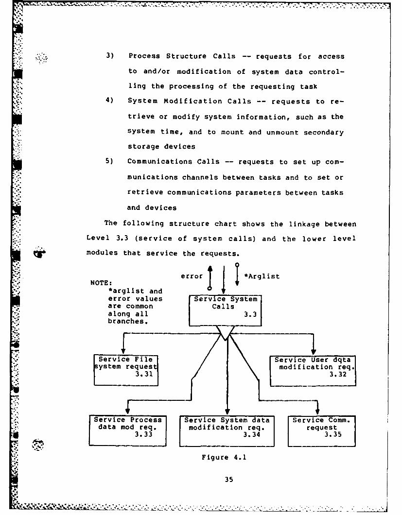
3) Process Structure Calls -- requests for access
to and/or modification of system data control-
ling the processing of the requesting task
. 4) System Modification Calls -- requests to re-
trieve or modify system information, such as the
system time, and to mount and unmount secondary
storage devices
5) Communications Calls -- requests to set up com-
munications channels between tasks and to set or
retrieve communications parameters between tasks
and devices
The following structure chart shows the linkage between
Level 3.3 (service of system calls) and the lower level
modules that service the requests.
NOTE: error *Arglist
*arglist anderror values -Service System
are common Callsalong all3.branches.
Service File Service user dqta
system reques modification req.3.31 3.32
Service Process Service System data Service Comm.data mod req. modification req. request
3.33 3.3 3.35
Figure 4.1
35
; ' " ' ' ' '' . c -...... .... . ... *' " ' ' - "" " "* L " " : -" -. ." * . •. " . '
* *.:..File System. Calls
The AMOS file system is patterned to closely resemble
the UNIX file system from the external point of view. This
design decision was based on the availability of large
amounts of utility and support code geared specifically
* toward the UNIX file system. In designing an externally
compatible file system for AMOS, much of this code will be
directly applicable to the AMOS environment. Pathnames
familiar to UNIX users (see Appendix B) are recognized by
AMOS. For the microcomputer environment, however, the
fragility of the UNIX file system internal structure is
unacceptable. Microcomputers are generally expected to
function in harsher surroundings than the minicomputers that
run UNIX. Any event that causes even a temporary power
fluctuation can easily destroy the UNIX f ile system on
disk. (Ref. 22) Additionally, the role the user plays in the
microcomputer environment is that of the system operator.
This allows the user to make mistakes (such as switchiing
disks without notifying the operating system) that result in
disaster under the UNIX file system. AMOS seeks to nullify
the problems caused by such user intervention.
User Structure Calls
The AMOS user structure contains 'personal' information
about the user that owns a specific set of processes.
System calls exist under AMOS to allow modifications to the
current working directory and the cur rent u se r
Identification.
36
Process Structure Calls
The AMOS process structure contains information about
* an individual process, and must remain in main memory at all
times when the process is active (i.e. nct terminated).
AMOS system calls exist to allow the retrieval or
modification of the process identification number, the
process priority, and the process running time.
Additionally, calls are available to allow a process to
create new child processes (processes that return control to
the parent when finished), to kill a specific process, to
wait for completion of a process, to spawn a new process in
* .the calling process' memory space, to kill itself, and to
* request more memory from AMOS.
System Modification Calls
AMOS system calls are available to get or set the system
time, to mount or dismount alternate f ile system devices,
and to force the writing of main memory-resident information
to disk. Other requirements will become necessary as the
development of the AMOS environment is expanded.
Communications Calls
There are three communications requests that AMOS
honors. The f irst if the PIPE request, which creates a
System f ile to act as a pipeline for output f rom one process
to feed the input to another process. This pipeline is
temporary, being deleted as soon as the receiving process
terminates. The PIPE call can be used to allow for parallel
processing of dependent processes, with the PIPE enforcing
the synchronization of the processes.
37

The other two requests are for the retrieval or setting
of the characteristics of the controlling terminal device
attached to the process. This information is used to allow
processes to tailor their input and output for specific
devices without making it necessary to have multiple copies
of a process for each 1/O device.
Summary
This chapter has dealt with the handling of interrupts
by AMOS. It may seem incongruous to deal with a seemingly
low level function like an interrupt at such a high level in
the AMOS design. It must be remembered that for any opera-
ting system to respond efficiently to several concurrent
users, it must be designed from the top-down to handle
interrupts efficiently. One must only remember work done on
.. 0 one of the older operating systems (the ones that have to
run a 'time-sharing subsystem' to support interactive
terminals) to understand the crippling response times that
are realized by operating systems that have added interrupt
. % support as an after-thought. As an example, the Department
of Defense supports a world-wide network of Honeywell 6000
computers in a defense network. The H1-6000 series is not an
interrupt driven system. As a result, in the latest series
of tests of the network, the failure rate due to abnormal
termination of communications was consistantly over 75% in
the network.
38
'-S. V. AMOS Data Structures Designl and Implementation
Introduction
This chapter defines the information structures used in
the design and development of AMOS. These structures have
evolved to efficiently fulfil the requirements definitions
specified in chapter 2. It is essential to bring this
discussion into the investigation at this point, because the
next chapter and the appendices delve quite deeply into the
implementation section of AMOS. A thorough understanding of
the way structure design and their use is necessary for the
continued understanding of AMOS development.
The term 'structure' comes from the c programming
language, the implementation language for AMOS. It defines
* a logical grouping of perhaps dissimilar data items into an
entity. Each item within the structure may be referenced by
5.'-.naming the structure (or a pointer to the structure) and the
item. The nature of C, combined with the natural grouping of
data items In the design of AMOS, leads to the definition of
many different structures. The structures which have been
defined in the present stage of design are presented ~n this
chapter.
K The Process Structure
The AMOS process structure contains all the information
necessary to properly schedule the active process (which is
in competition with other active processes for processing
time). An active process is defined as a process that has
begun processing and not yet terminated. All active
proesss hve rocssstructure entries in the proctal
39
S . *** * S..- .- *.-~.*:* il . 7 ... ~
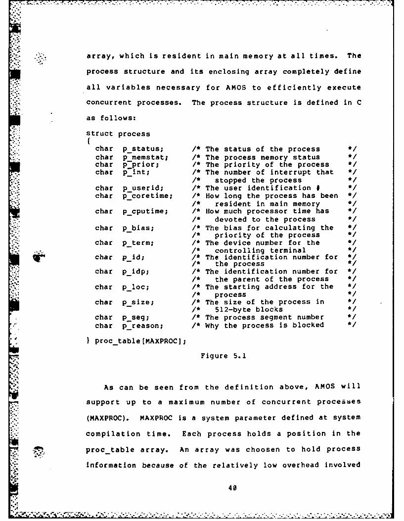
Sarray, which is resident in main memory at all times. The
process structure and its enclosing array completely define
all variables necessary for AMOS to efficiently execute
concurrent processes. The process structure is defined in C
as follows:
struct process
char pstatus; /* The status of the process */char p_memstat; /* The process memory statuschar p prior; /* The priority of the process */char pint; /* The number of interrupt that */
/* stopped the process */char puserid; /* The user identification #char pcoretime; /* How long the process has been */
1 * resident in main memory */char pcputime; /* How much processor time has
/* devoted to the process */char p bias; /* The bias for calculating the */
-/* priority of the process */char pterm; /* The device number for the
* '." /* controlling terminal */char pid; /* The identification number for */chr d/* the process */char pidp; /* The identification number for */
-/* the parent of the process */char p_loc; /* The starting address for the */
, * process */char psize; /* The size of the process in
/* 512-byte blocks */char p_seg; /* The process segment number */
- char preason; /* Why the process is blocked */
} proc table[MAXPROC];
Figure 5.1
As can be seen from the definition above, AMOS will
support up to a maximum number of concurrent processes
(MAXPROC). MAXPROC is a system parameter defined at system
compilation time. Each process holds a position in the
proc table array. An array was choosen to hold process
information because of the relatively low overhead involved
40

~* in table manipulation as opposed to the more flexible
alternatives, such as a dynamically growing linked-
list.(Ref. 23, p. 401) Additionally, a linked-list, which
requires at least one level of indirection, is more
difficult to implement, verify, and debug.
The DDB Structure
The Disk Descriptor Block (DDB) structure of AMOS issimilar to the inode structure of UNIX (see Appendix B).
Each DDB structure describes completely a disk file. This
structure is described more completely in chapter VI,
including its C language definition, but is presented
briefly here because it is referenced several times in the
next structure to be examined, the user structure.
~ The User Structure
The AMOS user structure contains information similar to
a that found in the process structure, but the information is
of a noncritical nature in scheduling the processes.
Because of this fact, the data is maintained in a separate
array. This design feature allows for future modifications,
such as the capability to swap out noncritical data item,
thus making more memory space available for active
processes. Currently, swapping of the user scructure is not
anticipated due to the overhead incurred in disk I/0. In
-~ -the future when more systems are available with hard disk
subsystems, this overhead will be reduced and may be deemed
acceptable.
,44
41

-A
The elements of the user structure are defined as
fo l lows:
struct user{int u state[STATSIZ]; /* Storage space for thestate */
-/* of the processor after an */1 /* interrupt. */
char uerror; /* The last error that occured */char u eid; /* The effective user id # */char rid; /* The real id #ddbptr *i wddb; /* Pointer to the working dir- */
:1 * ectory DDB entry */char u wname(NAMSIZ]; /* Working directory name */ddbptr *u tddb; /* Pointer to the temporary */
-/* directory DDB entry */char u tname[NAMSIZ]; /* Temporary directory name */int u-files[MAXFILES]; /* Pointers to open filesint uarglst[101; /* Room for 10 arguments to */
/* a system callchar uargstr[80]; /* Storage for up to 80 chars */
/* (pathnames, etc) */struct process *u_proc; /* Pointer to owning process */
} user table[MAXPROCI;
Figure 5.2
There are several global data areas of the user structure
that are accessed from nearly all levels in the service of
system calls. In particular, the u error field is filled
with the most recent error condition which occured. The
pointers to disk descrpitor block structures are set during
file system calls, to make recovery of the current state
after a blockage easier (for instance, if the process is
blocked during a pathname search due to a component already
being used, the ddb pointers allow the process to be placed
into a queue waiting for the ddb to be freed, then resumed
when the ddb is available).
42
V- ' " . . , . . . " , - . " . - . . . - - - - " , "
The Master Block Structure
The AMOS Master Block structure (mblock) is used by the
file system to completely define a mounted file system
device. A copy of the master block resides in a known
location on each mountable device, and provides an entry
point into that device for all file system accesses. The C
definition of the mblock structure is given in the next
chapter.
The Directory Entry Structure
The AMOS Directory Entry structure (dir entry) is used
to define an entry for a single file within a directory
- block. It also is more completely defined in the chapter
VI.
Summary
,Y This chapter has given the reader an introduction to the
C structures used by AMOS to group similar data item into
logical areas of memory for easier access. These data
structures are the product of the total requirements
* definition and the capability of the C language. Given
these structures, the manipulation of processes in AMOS has
been made as efficient yet easy to understand as possible.
The works of Yusko(Ref" 7) have to be modified to handle
these structures as part of the ongoing implementation of
AMOS. It is strongly suggested that the material presented
in this chapter Is made fully familiar before proceeding to
the rest of the report.
43

W. VI. The AMOS File System Design and implementation
Introduction
The AMOS file system is designed to provide the user
with a flexible and powerfully structured method for storing
and retrieving text and data. While any file system is a
data structure in itself, it is important not to confuse the
generic term 'structure' as used in reference to a file
system with the specific reserved term 'structure' as seen
by the C language. The AMOS file system definition contains
many C structure definitions which, when taken as a whole,
define the overall 'structure' of the file system.
The AMOS file system was designed to agree with the
total requirements definitions presented in chapter 2. Not
coincidentally, the AMOS file system is very similar to the
UNIX f ile system. There are two reasons for this
similarity. The f irst and over-riding reason is that the
UNIX file system is well structured. All major requirements
for a multiuser system are met (e.g. f ile protection,
sharing, etc). Minor problems, such as a lack of extremely
strenuous security checks, are assumed acceptable for the
AFIT environment, where cooperation among users is to be
expected and no security-sensitive material will be stored.
The second reason for adoption of a UNIX-like f ile
structure is that, in the AFIT environment, UNIX has a
strong following. Any new development that makes use of
existing tools can be more valuable than one that requires
ground-up effort. The UNIX toolset is extensive, and AMOS
Is designed to enable a reasonable porting capability of the
44

UNIX tools to the AMOS environment. Alternatives to a
UNIX-like system, such as a linear directory structure
(CP/N), do not lend themselves well to conversion of
existing software structures for a tree-structured system.
Specifications
As in UNIX, AMOS regards a file as a named character
string which may be stored on or retrieved from a variety of
peripheral devices (including main memory).(Ref" 19) AMOS
seeks to negate the differences between storage devices to
allow the greatest flexibility in storage/retrieval. Also
as with UNIX, there is no record structure imposed upon
files, but the 'newline' character (an ASCII line feed) may
be used by user programs to simulate this feature. Although
current hardware is anticipated to be closely tied to floppy
disk storage, the AMOS file system allocation scheme allows
a single file to be up to 34,606,592 bytes long. This
scheme anticipates the expansion of the AMOS hardware to
include hard disk capability.
File Types
All accesses to an AMOS file system device are made to
files, with the 3xceptions of the system information fetches
available only the the AMOS kernel. The AMOS file system
recognizes three logical types of files. These are standard
files, directory fileq- and special files.
Standard files make up the bulk of the files on any
system. These files contain normal text, executable'- .-
programs, binary tables, etc. In other words, standard
* 45
"o4., ,
files contain standard data. Most user interaction will be
concerned with standard files.
Directory files contain the information necessary for
the operating system to correlate file names with the
physical locations of the named files. They also contain
system information about access rights to the files
referenced and various other information. The capability to
create and delete directory files is restricted to either
the owner of the directory or the AMOS Wizard (system
manager), for obvious system security reasons.
Special files exist to provide the interface between the
operating system and the I/O devices. All devices
recognized by AMOS can be read from and written to simply by
- accessing the correct special file. As with UNIX, there are
three advantages to treating device I/O in this
manner'(Ref. 19) The first is that device and file I/O are
very similar. Tho second is that file and device name have
the same meaning in the same context, so that I/O
redirection can be implemented. The final advantage is that
I/O devices are afforded the same protection as normal files
through the operating system.
AMOS File System Structure
The AMOS file system is structured as a rooted tree,
where the interior nodes of the tree are directory files and
the leaves of the tree are either standard files or special
files. Reasoning behind this design choice, which directlymatches the UNIX file structure, was given in the
introduction of this chapter. The following simple graph
46
" . r . ....'-" v-"" .',".'"" . . . .."- ."•"-". ". . . . . . . . .,d '% ,,a. ,,a~,..;o,3e . ,,., ,,,,,".,r/' ,- - -"• . " - '."• • - . .' • . -. -.. - " ". " . * . --- - - . . .-- . -
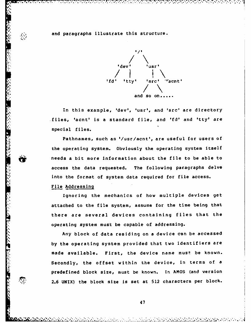
and paragraphs illustrate this structure.
., / \
'dev' 'usr'
Ifd' 'tty' 'src' ."acnt '
and so on.....
In this example, 'dev', 'usr', and 'src' are directory
files, 'acnt' is a standard file, and 1fd' and 'tty' are
special files.
Pathnames, such as '/usr/acnt', are useful for users of
the operating system. Obviously the operating system itself
needs a bit more information about the file to be able to
access the data requested. The following paragraphs delve
into the format of system data required for file access.
File Addressing
Ignoring the mechanics of how multiple devices get
attached to the file system, assume for the time being that
there are several devices containing files that the
operating system must be capable of addressing.
Any block of data residing on a device can be accessed
by the operating system provided that two identifiers are
made available. First, the device name must be known.
Secondly, the offset within the device, in terms of a
predefined block size, must be known. In AMOS (and version
- 2.6 UNIX) the block size is set at 512 characters per block.
47
This is the atomic unit of any file access, and is set as a
system parameter at compilation time. Any changes made to
*the block size should give serious consideration to the
*effects of the change, which will vary from one hardware
configuration to another. Given that the device identifier
and offset are known, it is a relatively simple matter to
retrieve data from device. Users cannot be expected to keep
track of such matters as the device and offset of their
files, however, so a naming scheme that allows pathname
specifications for files is essential.
When the system is initialized, the root of the file
system is at a known location on the system device. The
root contains directory entries for its immediate lower
levels, some of which may themselves be directories. By
walking the tree indicated by a given pathname, any file on
the system may be uniquely specified. For example, take the
pathr-ame '/usr/src/games/chess.c'. To locate the file
'chess.c', start at the root of the file system and search
for an entry in the root directory named 'usr'. Search the
directory 'usr' for an entry named 'src'. Search 'src' for
'games', then search 'games' for 'chess.c'. Since each
portion of the pathname is a file itself, including the
'leaf' named 'chess.c', identical operating system proce-
dures may be followed for walking the pathname. Following
UNIX convention, if the pathname starts with the characterb1/o
'I', the root directory is the starting point for the walk.
Otherwise, the current directory of the task is the starting
po i n t.
48
j,,- .$ * ," . .. ,o.-.. ,, .J ..- o-....• .- .. ,.- ... ... . .... .. ....... ,•... .. .
Secondary Devices
If only a single device were allowed to contain the
entire file system, AMOS would soon run out of file space.
Therefore it is essential that secondary devices be
accessible to the file system. Again, the solution is found
In the methods of the UNIX system.
A secondary device is added to the file system by
mounting the device so that its root overlays an existing
standard file (leaf) in the system device structure. After
the mounting, any references to the original leaf file will
actually be routed through the root of the secondary device.
At this point is becomes clear why the device identifier is
essential is addressing. Users can easily reference files
without knowing on which device the files reside. For theoperating system to access the files, however, the device
identifier must be available within the system mount table,
to be combined with the directory entry for the file. This
brings us to the point of the directory entries themselves.
.*. Disk Descriptor Blocks and Files
Any file (directory or standard) under AMOS is composed
of two parts, a header and a data area. The header infor-
mation for a disk file is located entirely in a structure
termed a 'disk descriptor block', or ddb. This structure,
similar to the UNIX inode(Ref" 19), is a record of file
attributes and physical disk locations. There are two
varieties of ddb defined for AMOS. The first is the
., , description of the ddb as it occurs on the disk. The second
49
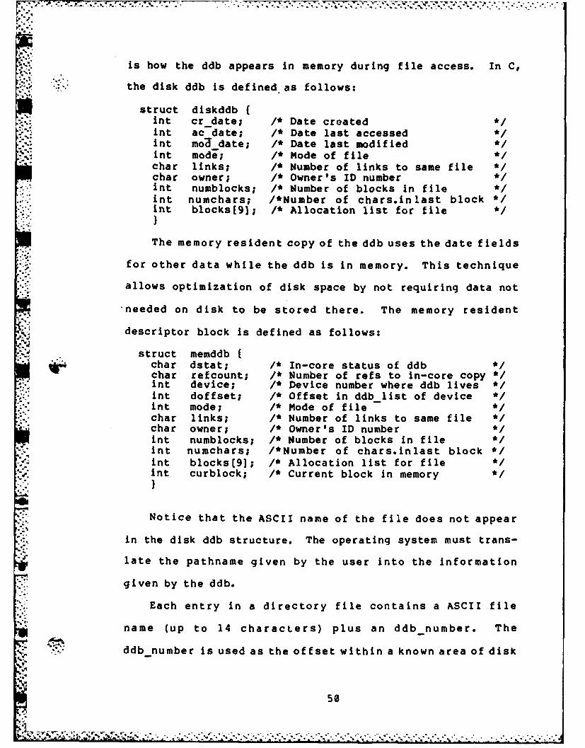
* . .T Q-.,
is how the ddb appears in memory during file access. In C,
the disk ddb is defined as follows:
struct diskddb {.nt cr date; /* Date created;nt ac-date; /* Date last accessedmnt moddate; /* Date last modified-nt mode; /* Mode of filechar links; /* Number of links to same file "/char owner; /* Owner's ID number */int numblocks; /* Number of blocks in fileint numchars; /*Number of chars.inlast block */
Sint blocks[91; /* Allocation list for file
The memory resident copy of the ddb uses the date fields
for other data while the ddb is in memory. This technique
allows optimization of disk space by not requiring data not
'needed on disk to be stored there. The memory resident
N, descriptor block is defined as follows:
struct memddb.,char dstat; 1* In-core status of ddbchar refcount; /* Number of refs to in-core copy */,nt device; /* Device number where ddb lives */int doffset; /* Offset in ddb list of device */int mode; /* Mode of filechar links; /* Number of links to same file */char owner; /* Owner's ID numberint numblocks; /* Number of blocks in fileint numchars; /*Number of chars.inlast block */nt blocks[9]; /* Allocation list for file
.- int curblock; /* Current block in memory */
Notice that the ASCII name of the file does not appear
in the disk ddb structure. The operating system must trans-
late the pathname given by the user into the information
77. given by the ddb.
Each entry in a directory file contains a ASCII file
name (up to 14 characters) plus an ddb number. The
ddb number is used as the offset within a known area of disk4-50
• _ % *- . ; /- :. ' ". N'. .. . . N " .J , ' .... **.. . ,, . * * ..' " '. .. . . ., . ., " ,. ,

IN. . . -. - - - -
that contains only ddb's, called the ddb list. When walking
the pathname given by the user, each time a match for a
segment of the pathname is made, the ddb number found by the
match is used to as the offset into the ddb list to retrieve
the ddb for the wanted file.
The allocation array for each file (contained in the ddb
structure) consists of 9 pointers to 512-character blocks on
the disk. This array is structured as a double-indirect
addressing table. The first 7 pointers point to data blocks
which contain file data. This gives a basic allocation of
3584 characters. While this will probably be enough for
most directory files, it certainly is not sufficient for
most other files. In this case, the 8th pointer points to a
*block containing 256 more pointers to data blocks. This is
the single-indirect pointer. With this scheme, up to
134,656 characters may be contained within a file, a much
more palatable size. If this is still not enough storage,
the last pointer points at up to 256 blocks, each pointing
at up to 256 data blocks. This is the double-indirect
scheme, which allows for files containing up to 34,606,592
bytes. This should be enough storage for a microcomputer-
based system, even with a hard disk.
AMOS Disk Format
Currently the AMOS system device is assumed to be a
rfloppy disk. Tracks 0 and 1 of each disk are reserved forthe system bootstrap and for future expansion requirements.
Starting at track 2, sector 1 is the available disk storage*space for the AMOS file system. The disk is broken into
51
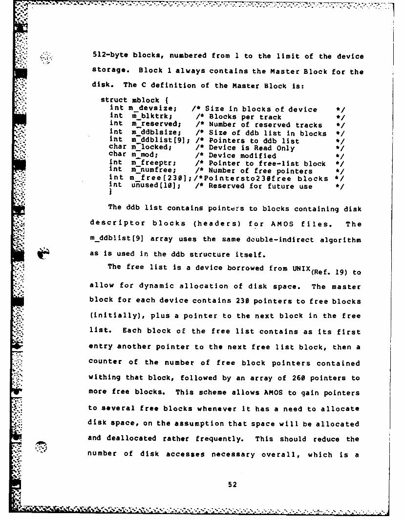
,' -* * * - - -,-
512-byte blocks, numbered from 1 to the limit of the device
storage. Block 1 always contains the Master Block for the
disk. The C definition of the Master Block is:
struct mblock,t m -devsize; /* Size in blocks of device */nt m-blktrk; /* Blocks per track */
int m reserved; /* Number of reserved tracks /int m -ddblsize; /* Size of ddb list in blocks */int mddblist[9]; /* Pointers to ddb list */char mlocked; /* Device is Read Onlychar m-mod; /* Device modified */int m freeptr; /* Pointer to free-list block */int m~numfree; /* Number of free pointers */int m-free[230];/*Pointersto230free blocks */int unused(1e]; /* Reserved for future use */
The ddb list contains pointers to blocks containing disk
descriptor blocks (headers) for AMOS files. The
":. mddblist[9] array uses the same double-indirect algorithmas is used in the ddb structure itself.
The free list is a device borrowed from UNIX(Ref. 19) to
allow for dynamic allocation of disk space. The master
block for each device contains 230 pointers to free blocks
(initially), plus a pointer to the next block in the free
list. Each block of the free list contains as its first
entry another pointer to the next free list block, then a
"- counter of the number of free block pointers contained
Si' withing that block, followed by an array of 260 pointers to
more free blocks. This scheme allows AMOS to gain pointers
to several free blocks whenever it has a need to allocate
disk space, on the assumption that space will be allocated
and deallocated rather frequently. This should reduce the
number of disk accesses necessary overall, which is a
V.5
valuable attribute for any system bound to slow speed
devices such as floppy disks.
The reserved tracks field was added to the master block
in order to simplify having several 'logical' disk drives
contained within a single physical device. Given a hard
disk with 300 tracks per surface, the drive may be broken
into logical devices by using the reserved tracks field to
offset within the physical device.
I/O Buffering
Any operating system that is limited in storage to a
single atomic unit of disk access will be slow and overly
disk bound in normal, disk-intensive processing. AMOS is
currently in this category. Future modifications to AMOS
should include a buffered I/O capability as one of the
highest priorities.
53

* AMOS File System Calls
The AMOS file system allows user processes to manipulate
file data through a series of system calls. The process
doing the manipulating must be either be controlled by the
owner of the area within which the manipulation is to take
place, have permissions (indicated by f ields with the ddb
for the directory/file), or be controlled by user #0-5, who
in AMOS are granted the status of Wizard. Wizards of AMOS
have the power to manipulate any parameter of the system
without restriction. The file system calls available under
AMOS make it possible for the user to create, open, close,
read, write, and delete files. Additionally, there are
calls to return the disk status of files and to position the
current read/write pointer for an open file.
Level 3.31 (Service File System Request) accepts as
input a pointer (*arglist) that points to an array of 10
integers. The first entry in the array contains the system
call number. From this number 3.31 will decide which file
system routine to call. The following entries in the array
either point to strings or actually contain integer
arguments to be used by the lower level routines. No error
checking is done on the contents of the subsequent arglist
entries at Level 3.31. The decision is made as to which
routine to call and the arglist pointer Is merely passed
down to the correct routine.
54
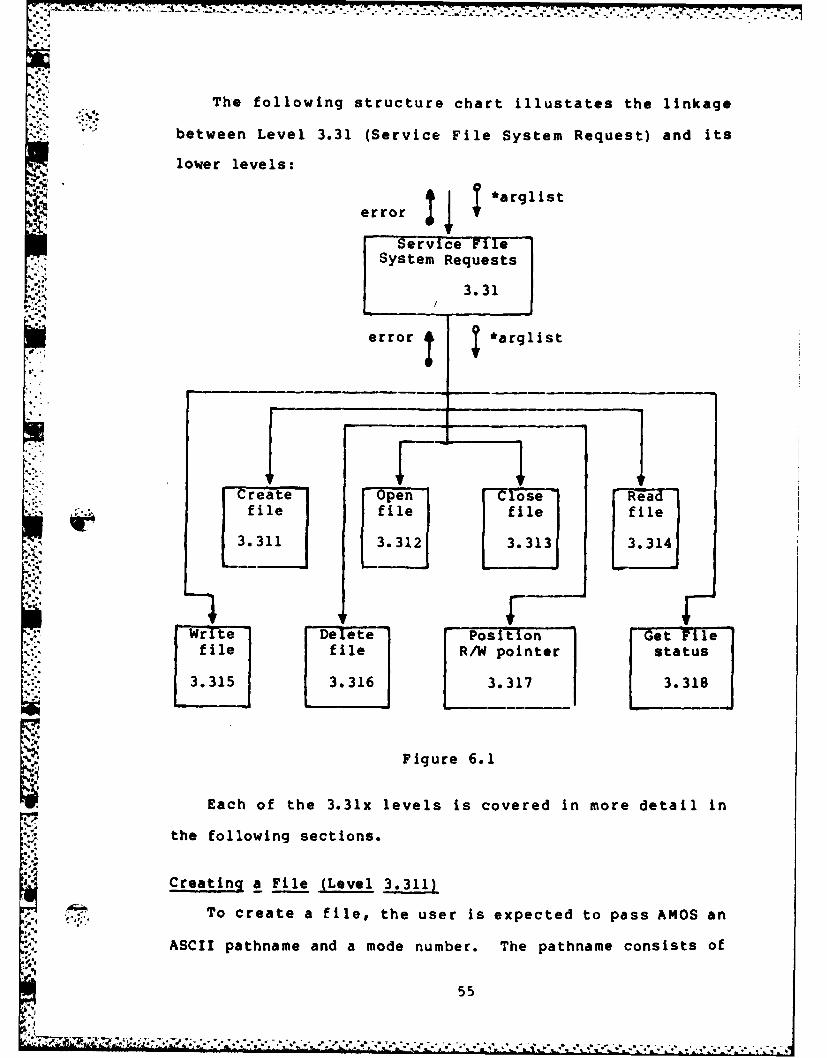
The following structure chart illustates the linkage
between Level 3.31 (Service File System Request) and its
lower levels:
error ~ *arglist
Service File",- System Requests
""-' 3.31
error *arglist
create [pen -Cose Read* .~file file file file
*~*3.311 3.312 3133.314
Wrr te De -t e Posit-ion Get Tile-file file R/W pointer status
33.316 3.317 3.318
Figure 6.1
Each of the 3.31x levels is covered in more detail in
the following sections.
Creating a File (Level 3.311)
To create a file, the user is expected to pass AMOS an
ASCII pathname and a mode number. The pathname consists of
55
6-. -,

a null-terminated string composed of names, not to exceed 12
characters in length, separated by one or more '/'
characters. Redundant ''s are treated as a single
character. The characters of the name components may be any
of the printable ASCII characters except the '/' itself.
The mode number is an integer, defined in AMOS as either
READ (0) or WRITE (1). The CREATE system call, if
successful, creates and opens the file WRITE operations.
The mode argument is necessary for permission checking at
the intermediate levels of the pathname conversion.
The following structure chart shows the breakdown of the
steps necessary to accomplish the CREATE system call:
fnumb, *name,error ? mode
Create-: [File
3.311* name,mode _______
" h*tddb, *name, error WRITE, ferror mode, error *tddb fnumb,
~ i*tddb error
Translate Create a' Accessname to new ddb File
ddb
3.3111 3.3112 3.3113
Figure 6.2
56
*,-: r -; . -'r o , -: ,- "* --.* -. ' " . -. • . .. . . .. .*~
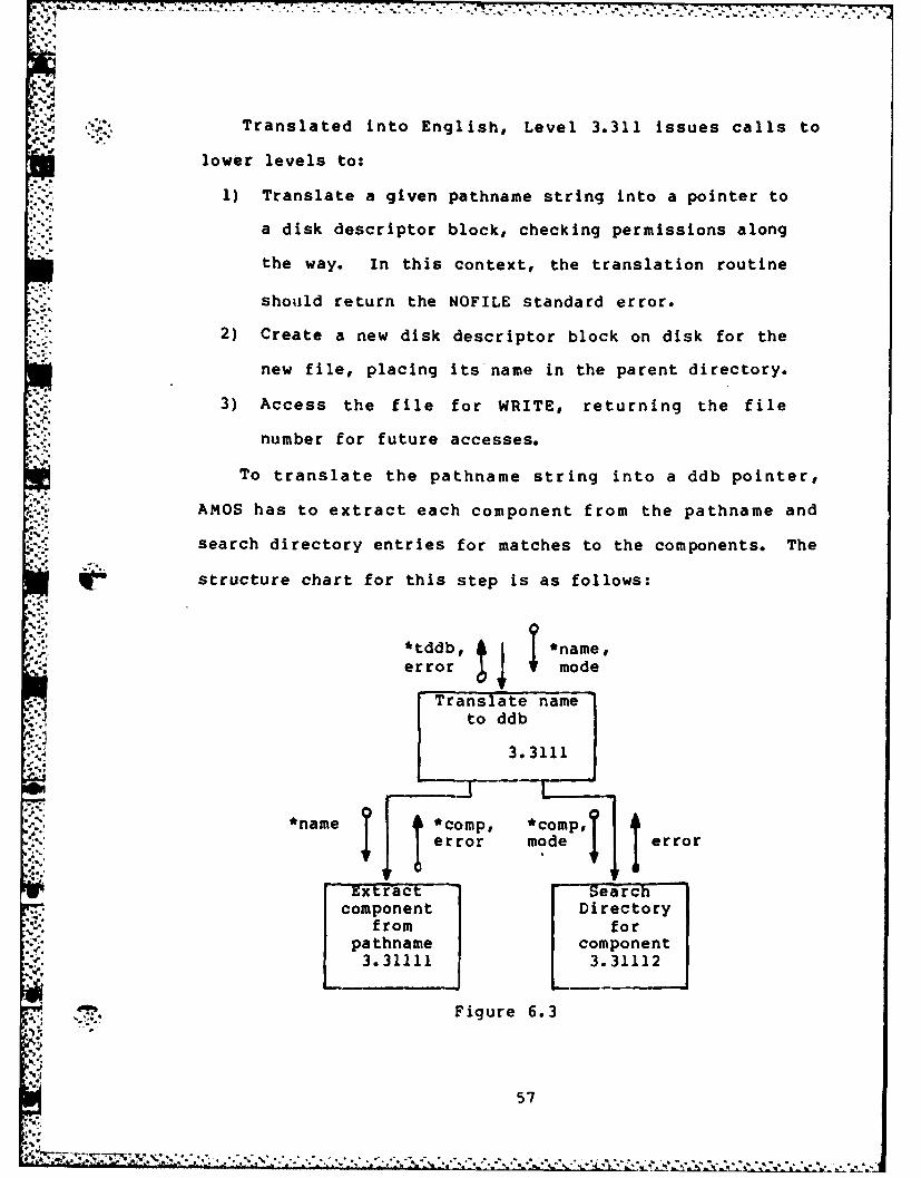
Translated into English, Level 3.311 issues calls to
lower levels to:
1) Translate a given pathname string into a pointer to
. a disk descriptor block, checking permissions along
the way. In this context, the translation routine
.* should return the NOFILE standard error.
2) Create a new disk descriptor block on disk for the
new file, placing its name in the parent directory.
3) Access the file for WRITE, returning the file
* number for future accesses.
To translate the pathname string into a ddb pointer,
AMOS has to extract each component from the pathname and
search directory entries for matches to the components. The
V structure chart for this step is as follows:
*tddb, 1 *name,
error mode
Translate nameto ddb
3.3111
*name *comp, *comp,*;t'error mode error
Extract- - Searc-component Directory
from for* +. pathname component
3.31111 3.31112
Figure 6.3
57L.4,
t "r-j r 4 ''.. 4 . ,-'-+ ,a""""" ' : . 4 -* * *.--' -"
*" " " ' " " " " ,."-'." + ,-:." ," ". '!" _,., " "." "-,"+ ,, . , +"+..- """ ' ., .

What Figure 6.3 does not show is that, to avoid
- repetitive stack manipulation in an area that is likely to
recieve a large amount of traffic, the directory to be
searched for a matching component entry is pointed to be the
*tddb entry in the current user structure. This entry is
set in Level 3.3111 to either the root entry (if the first
character of the pathname is a '/') or to the current
working directory entry, which is also stored in the current
user structure.
Level 3.31112 is broken down still further into
sublevels, as illustrated in the following chart:
*comp, tmode error
' searchDirectory
VV l:forcomponent3.31112
*dirbl*dirlk J*dirblk• di rbl k, *comp
match
Read next Search block for Release blockblock of component match from bufferddb entry poolddbenry3.3111223.311121 3.311123
'Figure 6.4
h..58
'~ . - ~~7~ **66~-..
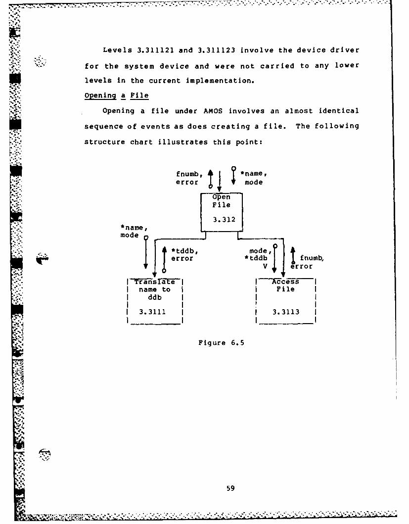
Levels 3.311121 and 3.311123 involve the device driver
-,:2. *'- for the system device and were not carried to any lower
Plevels in the current implementation.
Opening a File
Opening a file under AMOS involves an almost identical
sequence of events as does creating a file. The following
structure chart illustrates this point:
fnumb, *namfe#error mode
Opn
~3.312
*name,mode
• . *tddb, mode,
* .error *tddb fnumb,
I Transeater:7 r-'an s I----Acess
•-name to I File"I ddb I
3.3111 I 3.3113
Figure 6.5
;.5,9
.7,,-1
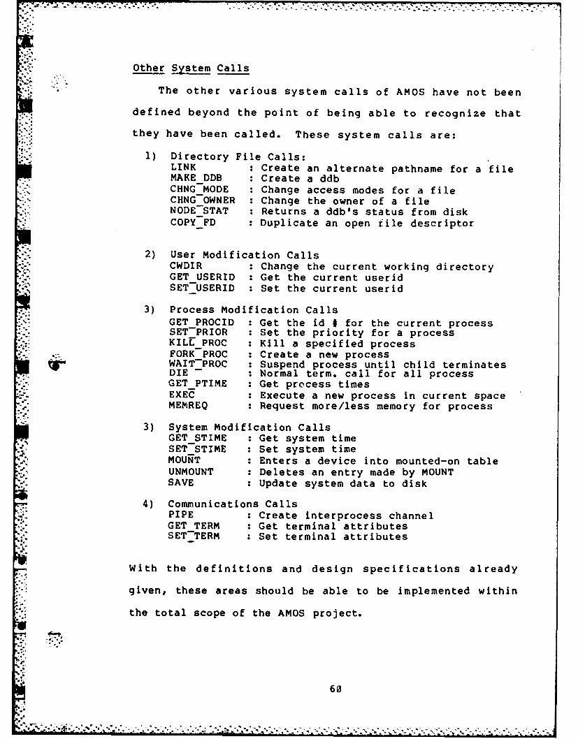
Other System Calls
The other various system calls of AMOS have not been
defined beyond the point of being able to recognize that
they have been called. These system calls are:
1) Directory File Calls:LINK : Create an alternate pathname for a fileMAKE DDB : Create a ddbCHNG MODE : Change access modes for a fileCHNGOWNER : Change the owner of a fileNODE STAT : Returns a ddb's status from diskCOPY FD : Duplicate an open file descriptor
2) User Modification CallsCWDIR : Change the current working directoryGET USERID : Get the current useridSET USERID : Set the current userid
3) Process Modification CallsGET PROCID : Get the id # for the current processSET-PRIOR : Set the priority for a processKILL PROC : Kill a specified processFORK PROC : Create a new processWAIT-PROC : Suspend process until child terminatesDIE - : Normal term. call for all processGET PTIME : Get process timesEXEU : Execute a new process in current spaceMEMREQ : Request more/less memory for process
3) System Modification CallsGET STIME : Get system timeSET STIME : Set system timeMOUNT : Enters a device into mounted-on tableUNMOUNT : Deletes an entry made by MOUNTSAVE : Update system data to disk
4) Communications CallsPIPE : Create interprocess channelGET TERM : Get terminal attributes
f. SET-TERM : Set terminal attributes
With the definitions and design specifications already
given, these areas should be able to be implemented within
the total scope of the AMOS project.
60
Summa ry
'-' The AMOS file system is specified at the upper levels
completely. The lower, hardware-dependend routines which
will be common to all file system routines are incomplete
due to the lack of an implementation system. The mid-level
creation and opening routines have been specified in a
hardwa re- independent manner to allow development and testing
to continue.
Obviously, the system device routines will need to be
built into AMOS (hard-wired). Modularization has hopefully
kept the hardware-dependent modules to a minimum, so future
complete implementations will need recompilation at only the
lowest driver level.
The structures defined in this chapter would seem to
contain several elements that conflict with good software
engineering practice. In particular, the error flags and
character string space (items which would seem to be
* transient in nature) are included as set fields of the user
structure. As will be seen in the next chapter, this design
'flaw' is actually a necessity for an interrupt-driven
* system where asynchronous events may cause the interruption
of Process flow while dealing with 'transient' data. Having
a storage slot allocated helps to prevent loss of continuity
due to asynchronous events.
61
_-,7 ,7 . 7--_ 7
VII. Results
This chapter covers the partial implementation of the
AMOS multiprocessing system. Also discussed are some of the
problems encountered with the implementation and the
solutions to the problems. As will be seen in the
implementation section, the precepts of good structured
programming and testing were used at all levels of the
partial implementation.
* "-" Implementation Problems
Implementation of the partial design of AMOS was
hampered by the inability of the author to achieve a working
Z8000 development environment at AFIT. After much effort in
bringing up UNIX 4 .1 (Ref. 24) on the DEL VAX 11/780 to
support the Z8000 C cross-compiler and assem-
bler(Ref. 8, p. 28), it was discovered that these packages
were incompatible with the Berkeley UNIX distribution's
format for the C language(Ref. 24, Sect. 8). The
modifications needed to correct this problem would have
required more time than was available for the project.
7Additionally, the AMD Z8000 target microcomputer system
was not fully configured until very late in the
- d implementation effort. While all of the system boards were
available, the control monitor read-only memory (ROM) chips
to control the CPU board were not delivered until
approximately 10 of the 12 months devoted to this effort
., 9-. were past. When they were delivered, it was discovered that
the control program does little more on its own than allow
for low-level (hexadecimal) memory/register display and
62
7 7. 7 .*
*.'. ~block memory moves. While there are commands to allow for a
host system to up/down load from the Z8000 system, these
commands are dependent on the host being an Am/Sys AMD
development system.
The ef forts devoted to securing both a software
development system (UNIX/VAX) and a hardware implementation
system were spent in the belief that is would be possible to
have these items available for AMOS implementation. Since
this was not the case, other resources had to be used for
the partial implementation.
Solution
The development system used for the partial
implementation of AMOS consists of an S-100 based Z80
'00 microprocessor, a Morrow DJ/2D floppy disk controller, 56K
bytes of RAM, several 1/O ports, a terminal, and a printer.
This system belongs to the author. The implementation
language is the BD Software C compiler, version 1.50 (pre-
release), by Leor Zolman(fi2) BDS C is a subset imple-
mentation of UNIX C, with some slightly annoying restric-
__ tions, such as the lack of initializing declarations and
register variables. Despite such restrictions, BDS C is
close enough to UNIX C to allow for the generation of
portable source code.
All file system modules given in the previous chapters
have been implemented in C. A driver module was written to
simulate the system calls, interrogate the tester for input
data, and call Level 0. Output is directed to the terminal
63
screen.
Interrupt service routines that will eventually handle
the actual AMOS interrupts were not written. Due to the
inefficiencies generated in even the best optimizing C
A compilers, for the sake of response time these routines will
most likely have to be written in the assembly language of
the host microprocessor. Since the author's system is a Z80
based system (and is not capable of handling interrupts,
anyway) the development of these modules appeared to
be inappropriate at this time.
The AMOS file system disk structure has been implemented
on the host system's floppy disks. This was achieved
* through the use of the CP/M operating system's BIOS calls to
do direct I/O to the floppy disks. The listings of two
utilities are included in the source code appendix. These
are AFORM.C, a floppy disk formatter for AMOS, and LS.C,
which prints out the master block information and a
directory listing for the root dircetory. AFORM depends on
the floppy disk to be formatted having already been through
a CP/M-style formatting program. To create the basic
information in the master block, AFORM does BIOS calls to
retrieve the floppy disk information from CP/M's disk
Parameter header and disk parameter block. This
information is used to determine the total number of blocks
which may be used on the disk and the number of blocks that
will fit per track of the disk. Currently, AMOS will not
allow a data block to be split over track boundaries.
64

Test Approach and Results
Due to the severe lack of time, a comprehensive test
plan was not developed for the AMOS partial implementation.
Thorough testing was done on each module implemented as an
entity in itself (through drivers and stubbs) and as a part
* of the integrated whole. The development of a driver
S.' routine allowed testing of the ent're package, using as data
items known to be good test items through the entity
testing.
Summary
The implementation effort given to this investigation
has proven the file system capability of the AMOS design. A
good bit of the time spent was given over to figuring out
the CP/M - AMOS interface, which will not be used in the
final implementation. Nevertheless, test results on the
,CP/M implementation show that the basic file system
structure is valid and implementable.
65
* * S!% .*.-

VIII. Conclusions and Recommendations
This investigation has been concerned with the
development of a multiprocessing operating system. The
chief objective of the design was to present a complex
* system as a conglomerate of relatively simple modules
operating on small objects (structures). An unstructured
*design ofthis mgiuecould ntbe talyunderstood b
a single person, but each small segment of processing
required may be grasped without very strenuous effort.
The concepts of structured design made the approach
taken possible. These concepts were followed to the
greatest extent possible. However, two of the measures of
high cohesiveness were basically ignored. Global data areas
ar-4 used extensively to avoid having to pass structure
values on the stack (which is impossible in C). While this
technique is dangerous, the amount of code and stack space
*necessary to pass all arguments dynamically is prohibitive.
Also, address pointers are used to pass system call
arguments to the lower levels of AMOS. Again, the purpose
'.1* for this travesty of software engineering is to preserve
system memory. Arguments to system calls may be up to 100bytes in length, so without passing pointers to the
arguments each level of the call would reproduce the
arguments on the stack.
In summary, AMOS is designed to be an interactive
multiprocessing operating system similar in use to the UNIX
operating system. Most of the UNIX version 2.6 system calls
are recognized by AMOS, although the majority have not been
66
taken to their conclusion in this effort. The use of
structured design techniques and the use of a highly
structured language in the partial implementation of AMOS
made the effort feasible.
What has been achieved in implementation in this effort
is a 'proof by example' that the AMOS file system is a valid
design. The CP/M environment (specifically the BIOS) is too
restrictive to allow much of the other areas of AMOS to be
easily implemented under its structure.
Recommendations
The previous chapter listed the areas of AMOS needing
immediate attention to provide AFIT with a functional
operating system. Specifically, further attention is needed
in the system call areas, hardware device interfaces, and in
modification to Yusko's works.(Ref. 7) Additionally, as
mentioned earlier, a buffered input/output facility should
be provided before any serious work can be accomplished
using AMOS.
The user interface (in UNIX, the Shell) must also be
provided before multiterminal use can be provided
effectively. This effort will be difficult enough to
constitute a separate research effort.
Before complete implementation can occur, cross-compiler
software must be available. The MITRE sources provided as a
Z8000 assembler and C cross-compiler proved to the author
that C and UNIX are no longer a set of standard
" -4 'transportable' software tools. The MITRE code is foreign
67,-r . a-
.- to the UNIX systems available to AFIT currently, rroducing
several hundred errors on compilation. This code will have
to be rewritten if it is to be used. It is recommended that
the problems involved with the MITRE code be investigated
further and one of two courses be taken. First, the code
may be rewritten to comply with the expectations of the UNIX
C compiler. Second, if the rewrite is extensive enough to
warrany this action, the code may be taken apart and
implemented under the BDS C compiler to be run on one of the
CP/M systems available in the DEL. This second course of
action is the more work-intensive, but offers the advantage
of allowing much more flexible work to be done in the future
without having to depend on the schedules of the UNIX
systems. Additionally, the experience gained through the
rewrite of the code would be invaluable for the student in
the compilers course sequence at AFIT.
The host microcomputer system must be made fully
operational before implementation can occur. What
implementation of AMOS occured was accomplished on the
author's home CP/M-oriented S-100 computer. The fact that
the system is locked to 56K bytes of memory, is non-
interrupt driven, and had available only the BD Software C
compiler severly hampered any efforts to extend
4implementation beyond the basic file system. The AMD Z8000
system original planned for the host system is complete in
all its hardware, but major firmware (bootstrap, disk
interface, etc) programs need to be developed.
Alternatively, the Z8000 board in the AMD system could
1 66
C. . be replaced with another processor and the system be given
over to another project. A fully configured Z8001 system
from Zilog (the Zeus system, for example) would more
completely conform to the hardware requirements for
implementation of AMOS, as the Zeus system contains a
segmented Z8001 processor and three memory management units.
The AND system contains a Z8002 non-segmented processor, no
memory management units, and is restricted to a bank-
switched memory scheme.
* * Major Recomendation
As far as the author is aware, there have been to date
three operating systems theses, including AMOS. Each has
been relatively independent of the others. Ross provided a
very high-level design with no apparent 'hooks' for user
programs. Yusko provided a scheduler that, after some
modification, worked as specified. AMOS provides a high-
level system definition in somewhat less detail that Ross',
but goes much deeper into the file system area.
It is recommended that results of the AMOS study, plus
Ross' and Yusko's work, be used to define an operating
* system down to the different managable levels (i.e. file
system, scheduler, etc). This definition should include avery strict interface specifiction. Each separate level of
the design should then be assigned as a separate effort.
a: Only with a continuing management scheme for the design, to
be implemented over several cycles of thesis students, will
a project of this magnitude be fully accomplished.
69
d . .- : 2 jx -i§:?-- **&> ~ . *
7. 7- a 77 7 4. 7 ,-- - 7
,.. '", Bibliography
,. 1. Madnick, Stuart E. and John J. Donovan, Operating Systems,New York: McGraw-Hill, 1974.
2. Grappel, Robert D. and Jack E Hemenway, NA tale of fourmicroprocessors: Benchmarks quantify performance",Electronic Design News, 85-103 (April 1981).
3. TOPS-20 Commands Reference Manual, Digital EquipmentCorporation manual #AA-5115B-TM (Intro).
4. Greenburg, Robert B. *The UNIX Operating System and theXENIX Standard Operating Environmentu, Byte, 6:248-264(June 1981).
5. Freedman, David "Portable Operating Systems Fight for 16-Bit Machines", Mini-Micro Systems, 9:237-249 (September1982).
6. Ross, Mitchell S. Design and Development of a Multi-programming Operating System for Sixteen BtMicroprocessors, MS Thesis Wright-Pattersn AFB, Ohio:School of Engineering, Air Force Institute of Technology,December 1981.
7. Yusko, Robert J. Development of a Multiprogramming Systemfor the Intel 8086 Microprocessor, MS Thesis, Wraht-Patterson AFB, -- o: School of Engineering, Air ForceInstitute of Technology, December 1981.
8. Skelton, Anita P., Jose Nabielsky, and Steven F. Holmgren,FY80 Final Revort: C able Bus Applications in Commandeners-, p.20 The MITRE Corporation, McLean, Virginia.
P.20 (28 for Compiler)
9. Department of the Air Force letter dated 17 May 1982,subject: Air Force Small Computer/Office AutomationService Organization (AFSCOASO) (DPD:HAF-P82-02).
10. Dijkstra, E.W. "The Structure of T.H.E. MultiprogrammingSystem," Communications of the ACM, 11: 341-346 (May1968).
.5,.
11. Hansen, Brinch. "The Nucleus of a MultiprogrammingSystem," Communications of the ACM, 13: 238-241 (April1970).
12. Bergland, G.D. "A Guided Tour of Program DesignMethodologies", COMPUTER, 13-37 (October 1981).
?. "..... ---*.~.-.......... .. .. .
. -
13. Johnson, S.C. and D.M. Ritchie. "Portability of C Programsand the UNIX System, Bell System Technical Journal, 57:
-! 2021-2048 (July - Auguis-E-T97 -.
14. Lycklama, H. OUNIX on a Microprocessor", Bell SystemTechnical Journal, 57: 2087-2101 (July - August 1978).
15. Mateosian, Richard. Programming the Z8000, Berkeley:*i Sybex, 1980.
16. Microprocesscr Applications Reference Book, Vol. I, page3.75-3.83. Zilog, Inc. Cupertino, California.-1981.
17. Huneycutt, Douglas S. Desigin a Multipprcessin Operating System for SixteenSit Mi-roprocessors,SThesis, Wright-Patterson AFB, Ohio: School ofEngineering, Air Force Institute of Technology, December1982.
18. ASD-TR-78-43, wComputer Program Maintenance", Dec. 77,Aeronautical Systems Division# Air Force SystemsCommand, Wright-Patterson AFB, OH.
19. Thompson, K. "UNIX Implementation', Bell System TechnicalJournal, 57: 1931-1946 (July - August 1978).
20. Ritchie, D.M. "A Retrospective', Bell S TechnicalJournal, 57: 1947-1970 (July - August 1978).
21. Advertisement for Morrow Designs, BYTE 7:168 ( 1982).
22. UNIX Programmers Manual, Seventh Edition, Virtual VAX-ilVersion. Coputer Sclence Division, Department of:E c'_--rcal Engneern and Computer Sciences, Un-ersityof California at Berkeley. June, 1981.
23. Koffman, Elliot B. Problem Solving and StructuredProgramming in Pascal. Reading: Addison-Wesley 1981.
24. Ibid, Ref. 22.
25. Zolman, Leor. The BD Software C Compiler Manual, vl.4
26. Lions# J. A Commentary on the UNIX Operating System.Department of Computer Science, University of New SouthWales, June1977.
,"..

Appendix A
Microprocessor Benchmarks
This appendix presents the results of a series of
benchmark tests run against four 16-bit microprocessors:
the Digital Equipment Corporation LSI-11/23, the Intel 8086,
the Motorola 68000, and the Zilog Z8000. The results were
originally published in Electronic Desig News, April 1
1981, by Robert D. Grappel and Jack E. Hemenway.
The choice of microprocessors was based on the major
16-bit microprocessors in use in systems at the time of the
survey. Currently there are several newer devices either on
the market or in the process of being introduced, in
addition to manufacturer's upgrades to the devices studied.
The benchmark results are presented in this appendix as a
reference point from which to make further investigation as
to an appropriate device on which to base future AMOS
implementations.
- The benchmarks in this study consist of various
exercises in microprocessor agility. All of the test cases
are applicable to some portion of operating system
processing. In particular, the interrupt handling tests
strongly indicate what kind of response time can be expected
in the new processors when compared to a known factor such
as the responses realized from the LSI-Il. In all cases,
the code submitted for the benchmarks was developed by the
manufacturer of the device and submitted to the other manu-
facturers for comment. The following sections present the
Al
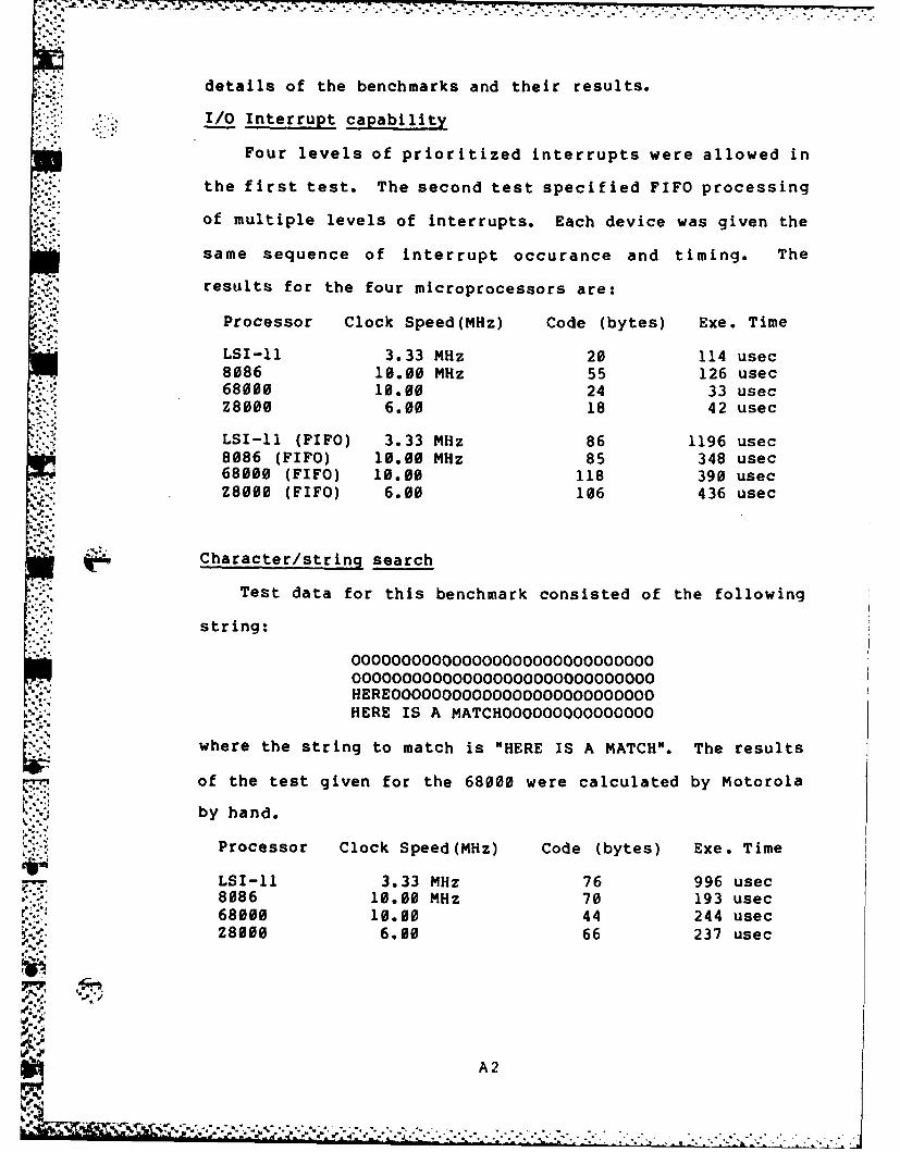
details of the benchmarks and their results.
-: I/O Interrupt capability
Four levels of prioritized interrupts were allowed in
the first test. The second test specified FIFO processing
of multiple levels of interrupts. Each device was given the
same sequence of interrupt occurance and timing. The
results for the four microprocessors are:.4,.4
Processor Clock Speed(MHz) Code (bytes) Exe. Time
LSI-11 3.33 MHz 20 114 usec8086 10.00 MHz 55 126 usec68000 10.00 24 33 usecZ8000 6.00 18 42 usec
LSI-11 (FIFO) 3.33 MHz 86 1196 usec8086 (FIFO) 10.00 MHz 85 348 usec68000 (FIFO) 10.00 118 390 usecZ8000 (FIFO) 6.00 106 436 usec
Character/string search
Test data for this benchmark consisted of the following
string:
OOOOOOOOOOOOOOOOOOOOOOOOO
OOOOOOOOOOOOOOOOOOOOOOOOOOOOOOHEREOOOOOOOOOOOOOOOOOOOOOOOO OHERE IS A MATCHOOOOOOOOOOOOOOO
where the string to match is "HERE IS A MATCH". The results
of the test given for the 68000 were calculated by Motorola
by hand.
Processor Clock Speed(MHz) Code (bytes) Exe. Time
LSI-11 3.33 MHz 76 996 usec8086 10.00 MHz 70 193 usec68000 10.00 44 244 usecZ8000 6.00 66 237 usec
A2
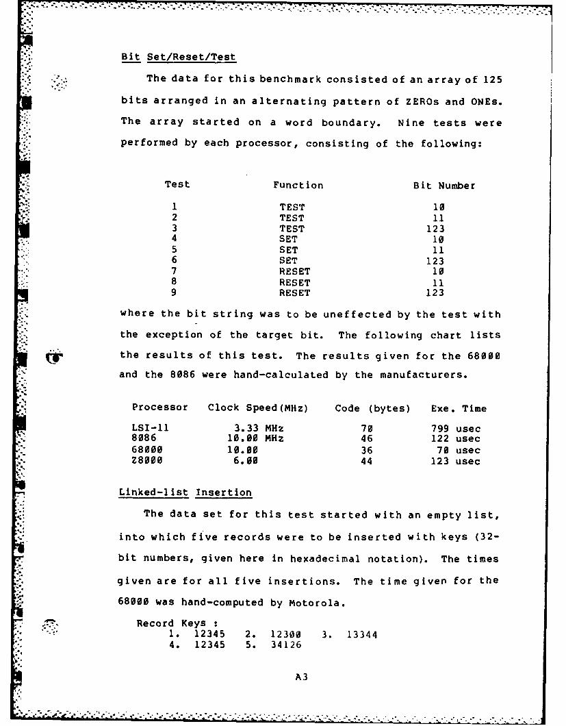
Bit Set/Reset/Test
The data for this benchmark consisted of an array of 125
bits arranged in an alternating pattern of ZEROs and ONEs.
The array started on a word boundary. Nine tests were
performed by each processor, consisting of the following:
Test Function Bit Number
I TEST 102 TEST 113 TEST 1234 SET 105 SET 116 SET 1237 RESET 108 RESET 119 RESET 123
where the bit string was to be uneffected by the test with
the exception of the target bit. The following chart lists
the results of this test. The results given for the 68000
and the 8086 were hand-calculated by the manufacturers.
Processor Clock Speed(MHz) Code (bytes) Exe. Time
LSI-11 3.33 MHz 70 799 usec8086 10.00 MHz 46 122 usec68000 10.00 36 70 usecZ8000 6.00 44 123 usec
Linked-list Insertion
The data set for this test started with an empty list,
into which five records were to be inserted with keys (32-
bit numbers, given here in hexadecimal notation). The times
given are for all five insertions. The time given for the
68000 was hand-computed by Motorola.
Record Keys :1. 12345 2. 12300 3. 133444. 12345 5. 34126
A3
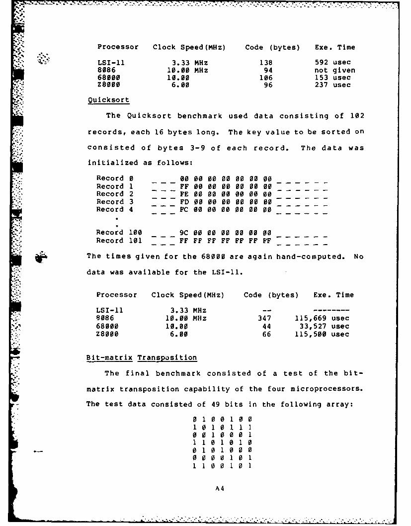
4'.'.-.,
Processor Clock Speed(MHz) Code (bytes) Exe. Time
LSI-11 3.33 MHz 138 592 usec8086 10.00 MHz 94 not given68000 10.00 106 153 usecZ8000 6.00 96 237 usec
Quicksort
The Quicksort benchmark used data consisting of 102
records, each 16 bytes long. The key value to be sorted on
consisted of bytes 3-9 of each record. The data was
initialized as follows:
Record 0 00 00 00 00 00 00 00Record 1 FF 00 00 00 00 00 00Record 2 FE 00 00 00 00 00 00Record 3 FD 00 00 00 00 00 00Record 4 FC 00 00 00 00 00 00
Record 100 9C 00 00 00 00 00 00
Record 101 FF FF FF FF FF FF FF
The times given for the 68000 are again hand-computed. No
data was available for the LSI-II.
Processor Clock Speed(MHz) Code (bytes) Exe. Time
LSI-11 3.33 MHz --
8086 10.00 MHz 347 115,669 usec68000 10.00 44 33,527 usec
.- Z8000 6.00 66 115,500 usec
Bit-matrix Transposition
The final benchmark consisted of a test of the bit-
matrix transposition capability of the four microprocessors.
The test data consisted of 49 bits in the following array:
01001001010111001000111010100101000
0 1 0 0 1 0 0
1100101
A4
, • -,' • "' ,,;' "-,",;',;< ':;-,.-','...;.,. i.'.'....'.".".....,.-,.... . . .... .-.--....-....-. ".."..-..-. .
1.. . . .0. .1.. . . . .. . . . . . . . . . . . .

where the array began on a word boundary. Once again, the
., timing for the 68000 was hand-computed.
Processor Clock Speed(MHz) Code (bytes) Exe. Time
LSI-11 3.33 MHz 152 1517 usec8086 10.00 MHz 88 820 usec68000 10.00 74 368 usec
*Z8000 6.00 110 646 usec
Summary
In most of the above benchmarks the timing for the 68000
had to be computed by the Motorola programming staff, based
on their knowlege of the time required for their processor
to complete the required sequences of instructions. This
does not detract from the validity of the times given (due
to the fact that all other manufacturers were given the
opportunity to rebuf the results), but it is difficult to
place as much weight on the 68000 results as on the other
validated results.
The processor speeds given were current as of April,
1981. Since that time, Zilog has made available a version
of the Z8000 (both the Z8002 and the Z8001) that run at 10
MHz. Obviously, the use of higher-speed devices would
modify the results of the benchmarks somewhat, particularly
in test/processor combinations that allow much of the
processing required to be register-resident. This
combination allows memory access times have their least
impact. The Zilog device tested was the Z8002 unsegmented
processor, but the results would have been identical with
the Z8001 running in non-segmented mode.
-- Again, it must be stressed that newer devices are
'A
: a .. " - .. -' -. --- ". , * . .- ... -...-. . . a . . .- , .. - .,. - .- ,. -., , , , , , _. . . .*' , .,C ,,.+ zdag ,+, , ,, .a._ ... . +, . .. ,... .+. ._ .,&_, ,+ + .. ...... ... ... . ... . . * . . *
,'4_.-L -, .- -o -, . ,l . ,, . ,..? . ,.. ,j,, , °.. . . . . .. . . . . . . . . . . . . ., .. ,.. . . . . . . . . . . . . . .' ' -'
becoming available on the market almost monthly. Some of
the devices demonstrate combinations of the features that
make the tested devices excell in certain areas. For
example, the recently announced Zilog Z800 !.ombines the
separated Bus Interface Unit/Arithmetic Logic Unit of the
8086 with the memory management capabilities of the Z8000
family of processors. The ALU of the Z800 is timed
separately from the BIU, allowing ALU speeds of up to 25MHz.
These capabilites are combined on a single processors that
retains object code compatibility with the popular Z80
microprocessor.
3. .
.*9
-.-
-- A6
- 3 - - .% ~
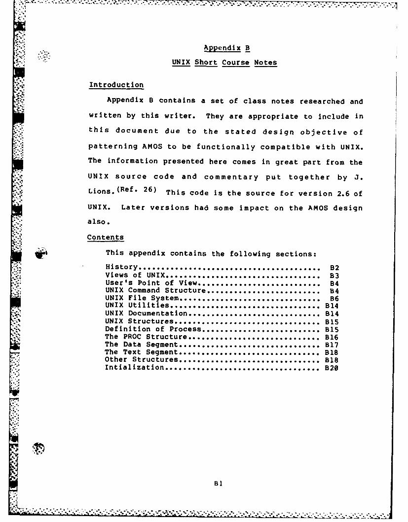
. ,'.:. ~- . .. .. . . . . .- .. . .. . .. .. . .. .-.
Appendix B
UNIX Short Course Notes
.. Introduction
Appendix B contains a set of class notes researched and
.written by this writer. They are appropriate to include in
this document due to the stated design objective ofS.,
patterning AMOS to be functionally compatible with UNIX.
The information presented here comes in great part from the
UNIX source code and commentary put together by J.
Lions. (Ref. 26) This code is the source for version 2.6 of41
UNIX. Later versions had some impact on the AMOS design
also.
Contents
This appendix contains the following sections:
.: History ............. 0 0.... .. .. .. .. 00..... .. . B2I, ;V iew s o f UN IX ..o. ...o. .. .o... .... ... .. ... ... .... ..o B 3
User's Point of View.... B4UNIX Command Structur B4* UNIX File s . . ......................... B6UNIX Utilities ............... o................. B14UNIX ocumntato... • o o . o. .o .o o o o . . . . . . . . . . . . B1UNIX Documentation ... ... .. .. ... ....... B14
UNIX Structures................................ B15Definition of Process............ ....... ... . B15The PROC Structure............................. B16The Data Segment........ ....................... B17The Text Segment.... . .......................... B18Other Structures............................... B18"" InlalizttonB20
B1
7 -1 S . k IelAt 0Wt .. *tWt1~~ .** * . . . . .
UNIX Short Course Notes
Capt Doug HuneycuttGCS-82D
October, 1982
History
UNIX was written by Ken Thompson of the Bell Laboratories
in 1969. Originally written in assembly language for a PDP-
7 mini-computer, UNIX was created specifically to provide a
useful environment for programming research and development.
The operating system grew in popularity within Bell Labs and
spread to educational and business sites. In the summer of
1973, UNIX was rewritten in the C programming language (also
greatly influenced by Ken Thompson). Since the translation
to C, UNIX has been ported to several other minicomputers
and mainframes, recently making its appearance in the
microcomputer sphere running on the Z8000 and 68000 16-bit
microprocessors. The original version of UNIX (2.6) was
modified and re-released as version 2.7 to eliminate for the
most part the hardware dependencies of 2.6 and make
*implementation easier for different sites. Bell
Laboratories is currently 'pre-releasing' an vastly modified
version called 3.0, which is incompatible in many areas with
the earlier versions of UNIX. The University of California
at Berkeley developed and maintains the 32V version of UNIX,
developed specifically for varieties of VAXen. Version 4.1
.~ .. ~-.:..bsd (a version of 32V) is currently being used on the SSC at
AFIT, and is command upward compatible with version 7, but
B2
C-source incompatible in many respects. Soon to be
released, version 4.2 bsd will be incompatible with 4.1#
3.0, 2.7, and 2.6 versions, but is deemed by UCB to be so
vastly improved that this lack of upward compatibility is
acceptable. (Compatibility observations obtained by
eavesdropping on the UNIX-WIZARDS list from SRI-CSL.)
Views of UNIX
There are three types of people who work with the UNIX
operating system. The most common is the normal user. The
user is the person who literally 'uses' the system to
achieve an end outside the realm of the machine. An example
of a user is an AFIT student who merely uses the programming
facilities of UNIX to achieve an external result (a grade).
The second class is the system programmer. This is the
person who writes programs that aid the system in achieving
the results demanded by the users. An example is the person
who writes a device driver for a new graphics terminal and
installs it under the UNIX file system. Users generally
r don't knew or care HOW the interface was written, only that
it works as needed.
The third type of UNIXophile is the system modifier,
alternately called the Super User, Guru, Wizard, or on
occasions when a file system is garbaged, a MUCH wider
variety of names. This is the person who maintains the
system and modifies it to meet the changing needs of the
installation. Examples as far as AFIT is concerned are Joe
Hamlin and Role Black.
B3
I. The user's Point of View
There are four major areas with which each user must have
a high degree of familiarity. These are the UNIX command
structure, the UNIX file system, the utilities (which make
up the largest part of the UNIX operating system), and the
documentation facilities UNIX has to offer. Each of these
areas will be covered in this section.
The UNIX command structure
The UNIX command structure can perhaps best be regarded as
a form of programming language. The standard command
interpreter is called the shell (sb), and supports a
language syntax similar to the ALGOL-68 language. The
Berkeley UNIX interpreter is called the C shell (csh), jnd
supports a language syntax similar to the C programming
W language. The shell programs are the most commonly used
interface to the UNIX system.
When a user logs in under UNIX, the configuration file is
read to determine the defaults for the user. This file may
specify either sb or csh as the default shell. It is also
possible to substitute a 'personal' shell program, which may
be desirable in cases where the user needs special
consideration.
-~ The shell prints a prompt and awaits Input. Following the
* syntax for input to the shell it is possible to produce very
extensive control structures (see the appendices of 'The
UNIX Shell', BSTJ pp. 1987-1990). A 'null progra-m' is a
:~ valid response, given by simply hitting the carriage return,
which causes the cycle to start over again. The most common
B4
..............
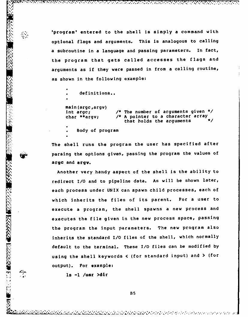
:.*. . ... .-.. . . . . . , , . -. . -. . ' .. , .. ..-
'program' entered to the shell is simply a command with
optional flags and arguments. This is analogous to calling
a subroutine in a language and passing parameters. In fact,
the program that gets called accesses the flags and
-arguments as if they were passed in from a calling routine,
as shown in the following example:
. definitions..
main (argc ,argv)int argc; /* The number of arguments given '1
- char **argv; /* A pointer to a character arraythat holds the arguments */
Body of program
The shell runs the program the user has specified after
, parsing the options given, passing the program the values of
argc and argv.
Another very handy aspect of the shell is the ability to
redirect I/0 and to pipeline data. As will be shown later,
each process under UNIX can spawn child processes, each of
which inherits the files of its parent. For a user to
execute a program, the shell spawns a new process and
executes the file given in the new process space, passing
the program the input parameters. The new program also
inherits the standard I/O files of the shell, which normally
default to the terminal. These I/0 files can be modified by
using the shell keywords < (for standard input) and > (for
5 output). For example:
ls -1 /usr >dir
ILO....B5

. lists the directory contents of the /usr node, placing the
listing in the file dir under the current working directory.
The command
wc <dir
then performs a word count on the file dir. Actually, a
simpler method of achieving the same results exists. By
using the pipe feature of UNIX, two or more processes may be
executed concurrently, one feeding data to the other. For
example:
ls -1 /usr I wc
achieves the same result as the previous examples without
leaving a file in the working directory to be cleaned up
later. Contrary to the statement in the BSTJ article on the
shell, the pipe facility does create a file on disk, but it
is deleted after use automatically, so the effect is the
same.
This explanation of the facilities of the shell barely
scratches the surface of the capabilities of the standard
shell, let alone the C shell. For more complete tutorial
information, see the UNIX programmers manual set.
The UNIX file system
UNIX regards a file as a named character string which may
be stored on or retrieved from a variety of peripheral
devices. The file system tends to minimize the differences
between storage devices to allow the greatest flexibility in
storage and retrieval. There is no record structure imposed
upon files, but the newline character (an ASCII line feed)
may be used to simulate this feature.
B6
7 77 -
There are three types of files associated with the UNIX
file system. These are standard data f iles, directory
files, and special files (device drivers). As the name
implies, standard files contain standard data such as that
entered by programmers during an editing session.
Directory files contain the information necessary for the
operating system to correlate file names with the physical
locations of the named files. They also contain specialized
information about the files such as access rights, etc. The
capability to create and delete directory files is
restricted, for obvious security reasons.
Special files exist to provide the interface between UNIX
and system I/0 devices. All devices recognized by UNIX can
be read from and written to simply be accessing the correct
* special file. There are three advantages to treating device
I/0 in this manner (taken from BSTJ, p. 1909):
1. Device and file I/0 are made similar2. File and device names have the same meaning in
the same context, so I/0 redirection is easilyimplemented.
3. I/0 devices are afforded the same systemprotection as normal files.
The UNIX file system takes the form of a rooted tree where
the leaves of the tree are data files (text, numerical data,
etc) or device drivers and the interior nodes of the tree
are directory f iles. A leaf f ile may be referenced by any
B7
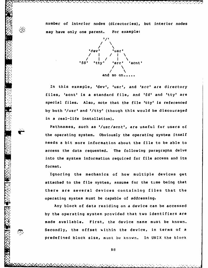
number of interior nodes (directories), but interior nodes
'.-" may have only one parent. For example:
-,, . I/
'dev' 'usr'/.: I! II \
'fd' 'tty' 'src' tacnt'/ \/ \
and so on.....
In this example, 'dev', usr', and 'src' are directory
files, 'acnt is a standard file, and 'fd' and 'tty' are
special files. Also, note that the file Itty' is referenced
by both "/usr' and '/tty' (though this would be discouraged
in a real-life installation).
Pathnames, such as '/usr/acnt', are useful for users of
the operating system. Obviously the operating system itself
needs a bit more information about the file to be able to
access the data requested. The following paragraphs delve
into the system information required for file access and its
format.
Ignoring the mechanics of how multiple devices get
attached to the file system, assume for the time being that
there are several devices containing files that the
operating system must be capable of addressing.
Any block of data residing on a device can be accessed
by the operating system provided that two identifiers are
made available. First, the device name must be known.
Secondly, the offset within the device, in terms of a
predefined block size, must be known. In UNIX the block
B8
size is set at either 512 (versions 2.6 and 2.7) or 1024
(version 4.1) characters per block. This is the atomic unit
of any file access. Given that the device identifier and
offset are known, it is a relatively simple matter to
retrieve data from device. Users cannot be expected to keep
track of such matters as the device and offset of their
files, however, so a naming scheme that allows pathname
specifications for files is essential.
When the system is initialized, the root of the file
system is at a known location on the system device. The
root contains directory entrie for its immediate lower
levels, some of which may themselves be directories. By
walking the tree indicated by a given pathname, any file on
the system may be uniquely specified. For example, take the
pathname '/usr/src/games/chess.c'. To locate the file
'chess.c', the following procedure is followed. Starting at
the root of the file system, search for an entry in the root
' directory named 'usr'. Search the directory 'usr' for an
entry named 'src'. Search 'src' for 'games', then search
'games' for 'chess.c'. Since each portion of the pathname
is a file itself, including the 'leaf' named 'chess.c',
identical operating system procedures may be followed for
walking the pathname. If the pathname starts with the
character '/', the root directory is the starting point for
the walk. Otherwise, the current directory of the task is
the starting point.
If only a single device were allowed to contain the entire
B9
u I '+ +- +" 'r + *
+r • • ".. . . .. . . . . . . ... . .""" """""""""". . . . . . .o °
. . . . . . . . . . .
file system, UNIX would soon run out of file space.
Therefore it is essential that secondary devices be
accessible to the file system.
A secondary device is added to the file system by mounting
the device so that its root overlays an existing standard
file (leaf) in the system device structure. After the
mounting, any references to the original leaf file will
actually be directed through the root of the secondary
device. At this point it becomes clear why the device
identifier is essential in addressing. Users can easily
reference files without knowing on which device the files
reside. For the operating system to access the files the
device identifier must be available within the system data
structures and the offset must be contained within the
directory entry for the file. This brings us to the point
a.' of the directory entries themselves.
The UNIX specification of a disk file is located entirely
in a structure termed an i-node. This structure, es defined
in the BSTJ, p.1942, is a record of file attributes and
.a physical disk locations. In C, the i-node is defined as
follows:
struct inode {
int i mode; /* Protection codes and type *1char i nlink; /* Number of links to the file */
char uid; /* The user ID of the ownerchar i-gid; /* The group ID of the owner */char i size0; /* Least significant size value */
char *T sizel; /* Most significant size *1int i iddr[81; /* Physical device addresses */
int i-atime[2]; /* Creation time */int i-mtime(2]; /* Modification time */
Notice that the ASCII name of the file does not appear in
B10

the i-node structure. So how does the operating system
translate the pathname given by the user into the
information given by the i-node?
Each entry in a directory file contains a ASCII file name
(up to 14 characters) plus an i-number. The i-number is the
offset within a predefined area of the disk that contains
the i-nodes, called the i-list. When walking the pathname
given by the user, each time a match for a segment of the
pathname is made, the i-number found by the match is used to
offset into the i-list and retrieve the i-node for the
desired file.
Depending on the size of the i-list on the disk, all or
part of the list may be core-resident to speed access times
for the operating system. Obviously, the number of file
accesses during a given period make this optimization
worthwhile. A major drawback, however, occurs when the
system is mishandled or crashes unexpectedly. Any changes
made to the i-list while in core that were not forced to
disk before an accident occurs are not remembered by the
system when it is brought back up. In what amounts to a
massive multiply-linked list, this can be disasterous,
resulting is a totally useless file system. Only through
painful hand-walking of the i-list can such a meltdown be
recovered.
The final section of the file system discussion presents
the algorithm used to allocate file space under UNIX.
Though this algorithm is presented in the BSTJ, it will be
B1
AD-Rt24 733 DESIGN OF A MULTIPROCESSING OPERATING SYSTEM FOR 2/2SIXTEEN-BIT MICROPROCESSORS(U) AIR FORCE INST OF TECHMRIGHT-PRTTERSON RFB OH SCHOOL OF ENGI.. D S HUNEYCUTT
UNCLASSIFIED DEC 82 RFIT/GCS/EE/82D-28 F/G 9/2 NLEIIIIIIIIIIEIElllIIhllllllEIIIIIIIIIIIIIIflfflfI IEEEEEEEEEI ,

I, . W
1 .
IBii&0.
* ... ,.aEL=
L AS1"25 j- 16
RMUTM TST CHAR
su~mOf SAPDADS-163-
7.1,
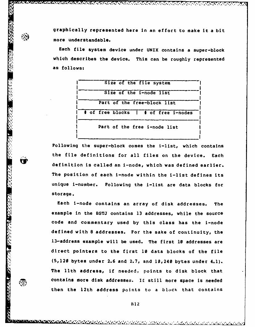
g .graphically represented here in an effort to make it a bit
Smore understandable.
Each file system device under UNIX contains a super-block
which describes the device. This can be roughly represented
as follows:
Size of the file system
I "Size of the i-node list
I Part of the free-block list
I of free blocks I # of free i-nodes
Part of the free i-node list
Following the super-block comes the i-list, which contains
the file definitions for all files on the device. Each
*definition is called an i-node, which was defined earlier.
The position of each i-node within the i-list defines its
unique i-number. Following the i-list are data blocks for
storage.
Each i-node contains an array of disk addresses. The
example in the BSTJ contains 13 addresses, while the source
code and commentary used by this class has the i-node
defined with 8 addresses. For the sake of continuity, the
13-address example will be used. The first 10 addresses are
direct pointers to the first 10 data blocks of the file
(5,120 bytes under 2.6 and 2.7, and 10,240 bytes under 4.1).
The l1th address, if needed, points to disk block that
contains more disk addresses. If still more space is needed
then the 12th address points to a block that contains
B12
"P-' ," ' .g- *-.,"..., ,e ,**,""' " "d" " * " . " '""." ",., -4•, "",.-.. " .. ".' " .,".. -,. '-.
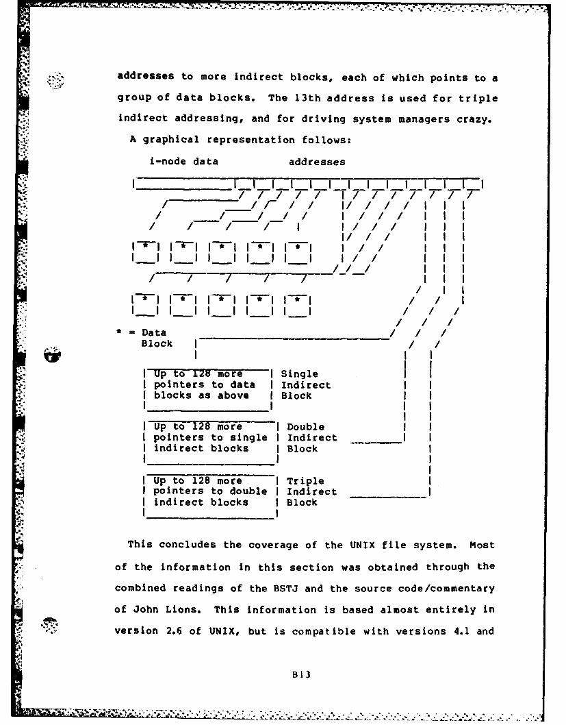
.7. -37--
addresses to more indirect blocks, each of which points to a
* group of data blocks. The 13th address is used for triple
Indirect addressing, and for driving system managers crazy.
A graphical representation follows:
i-node data addresses
pintr to dat Iirect II
pontr to sigl Indirec
poiter to double InirectI
Block ec blck Bloc
Tis cpolue more cov Sige f th NXflsse.Ms
of poeintrs ata in tindiecto Ia obandthog h
coblocks rans aovethe Block an th orecdecmetr
ver ontr to6 sigl UNX bt indirecatil with_ vrion 4. n
* I idiret bloks IBlok3

2.7. The use of these structures will be covered in more
.... • k detail in the later sections concerning modification of the
UNIX system.
UNIX Utilities
By far the greatest bulk of the UNIX system is comprised
of the utilities package, while the kernel of the operating
system is relatively small. All the utilities are available
in source form on tape for modification by the AFIT
programming staff.
Version 4.1 of UNIX has between 180 and 200 utilities
available, an alphabetical list of which has been made
available as an attachment to this document. The massive
amount of material available makes inclusion in this paper
with any degree of justice impossible, so the reader is
directed to the uNIX Programmers Manual for assistance in
wading through the system.
UNIX Documentation
As just mentioned, the most valuable source of
documentation for UNIX is the UNIX Programmers Manual. This
massive set of volumes enshrines all the information about
the utilities (commands), system calls, subroutines, special
files, file formats, GAMES!, macro packages, and maintenance
procedures for the UNIX system.
Additionally, the learn command is available to run the
user through a tutorial on a variety of subjects, including
C, the editor, files, morefiles, and others. The strength
_of learn is that it actually allows the 'student' to give
commands and run exercises under UNIX, while regaining
B14
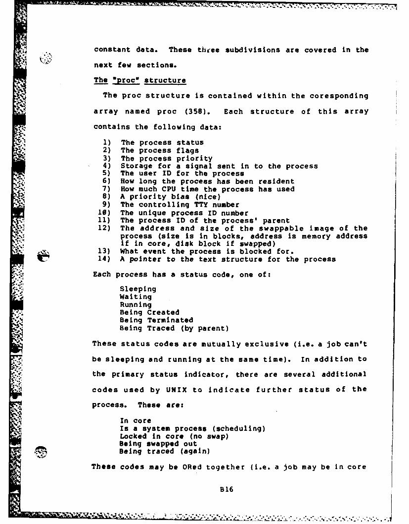
constant data. These three subdivisions are covered in the
next few sections.
The Oproc* structure
The proc structure is contained within the coresponding
array named proc (358). Each structure of this array
contains the following data:
1) The process status2) The process flags3) The process priority4) Storage for a signal sent in to the process5) The user ID for the process
-K 6) How long the process has been resident7) How much CPU time the process has used8) A priority bias (nice)9) The controlling TTY number
10) The unique process ID number11) The process ID of the process' parent12) The address and size of the swappable image of the
process (size is in blocks, address is memory addressif in core, disk block if swapped)
13) What event the process is blocked for.14) A pointer to the text structure for the process
Each process has a status code, one of:
SleepingWaitingRunningBeing CreatedBeing TerminatedBeing Traced (by parent)
These status codes are mutually exclusive (i.e. a job can't
be sleeping and running at the same time). In addition to
the primary status indicator, there are several additional
codes used by UNIX to indicate further status of the
process. These are:
In coreIs a system process (scheduling)Locked in core (no swap)Being swapped outBeing traced (again)
These codes may be ORed together (i.e. a job may be in core
B16
~ u~*.-.,- ~ ~---A
and locked at the same time).
Each process running under UNIX must have a proc structure
in the proc array, which remains core-resident at all times.
As shown in the source (376), this limits the number of
concurrent processes to NPROC. Theoretically, a linked list
could be used instead of an array to contain the proc
structures and remove the limitation on the number of
concurrent processes. In real life, however, this would
probably be more trouble and cost more in overhead than it
would be worth.
The Data Segment
The process data segment is the portion of the process
which is 'swappable'...that is, which must be written to
disk in its entirety if the process is to be removed from
main memory. For the purposes of this paper, the data
segment contains program code and data, the contents of the
stack, and a copy of the user structure for the process.
One point to notice is that on a PDP-11 running UNIX, there
are as many kernel stacks as there are processes, making it
impossible for the stack information of the kernel to
migrate from one process to another, even In the event of a
machine failure. The user structure (413) contains the
following process data:
1) Storage for various registers2) I/0 flag3) An error code4) The effective and real user and group IDs5) A pointer to the proc structure6) I/0 data (file offset, etc)7) A pointer to the inode for the current directory8) Storage for the current pathname component
B17
.AR
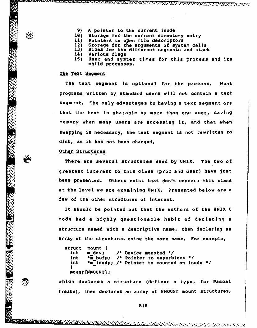
9) A pointer to the current inode_- 10) Storage for the current directory entry
11) Pointers to open file descriptors12) Storage for the arguments of system calls13) Sizes for the different segments and stack14) Various flags15) User and system times for this process and its
child processes.
The Text Segment
The text segment is optional for the process. Most
programs written by standard users will not contain a text
segment. The only advantages to having a text segment are
that the text is sharable by more than one user, saving
memory when many users are accessing it, and that when
swapping is necessary, the text segment is not rewritten to
disk, as it has not been changed.
Other Structures
There are several structures used by UNIX. The two of
greatest interest to this class (proc and user) have just
been presented. Others exist that don't concern this class
at the level we are examining UNIX. Presented below are a
few of the other structures of interest.
It should be pointed out that the authors of the UNIX C
code had a highly questionable habit of declaring a
structure named with a descriptive name, then declaring an
array of the structures using the same name. For example,
struct mount {nt m dev; /* Device moupted */nt *m bufp; /* Pointer to superblock */int "° inodp; * Pointer to mounted on mnode
mount (NMOUNT) ;
..4..,which declares a structure (defines a type, for Pascal
freaks), then declares an array of NMOUNT mount structures,
B18
• " ' ,. . .. . % " ',e" °
",a" .- f, a. . - - . . - ..... f a .. . . . . .
. naming the array mount also. Bad news for many C compilers
today.
This is a good place to start, though. The Omount" array
.4 contains structures in core to allow UNIX to find the super
block of any mounted device. This is essential to allowing
multiple devices to be accessed throught the rooted tree
type of file system.
The next structure of interest is the text structure
(4306). This structure contains information concerning the
disk address of each pure text segment currently in use by
processest how many processes are using the text, its main
memory address if loaded, and an inode pointer. The main
point of this structure is to see that for any text segment,
no matter how many processes are accessing it, there is only
one entry in the text array, thus saving memory space.
The file structrue (5507) contains a flag (read, write, or
pipe), a pointer to an inode structure, a reference count,
and a pointer to a read/write offset value. This structure
(again contained in an array by the same name) defines any
file open under UNIX, and is always resident In main memory.
The filesys structure (5561) contains the definition of
the super block for each mounted file system device, plus
status flags. This structure appears to be used as a
template to overlay and give structure to the block of data
S# read in from disk as the super block. The contents of this
block were defined earlier.
B19
Initialization
~ Hardware (memory management, etc) is not referenced in
this discussion, as each configuration is different. The
low levels of UNIX are too hard ware -dependent for a general
OS class. Discussion begins here with the "main' procedure
(1550) which performs the following functions:
1) Initializes memory - a pair of memo ry-managementregisters is used to step sequentially upward throughmemory in blocks, initializing the blocks to containzeros. When any block cannot be read, it is assumedthat the maximum of physical memory has been reached.
2) The maximum memory size per process is set by takingthe minimum of the physical memory size, the MAXMEMsite-dependent definition, and the physical limitImposed by the hardware.
3) Disk swapping space is defined and initialized.
4) The system clock is initialized.
5) The character buffer pool is initialized.
6) The large buffer pool is initialized.
7) The table entries for the root device are initialized.
8) Process 0 is kicked off.
This discussion will not get into the details of how the
buffer pools are used by I/O devices. Suffice it to say
that there are two types of devices recognized by UNIX.
These are character-oriented devices and block-oriented
devices. Examples are terminals and disk drives,
respectively.
* As noted~ above, the last step of initialization is to
start process 0, which executes sched (1940). Sched handles
the I/O procedures necessary to swap processes In and out of
maina memory. NOTE: sched is itself a process, being
820

executed in the space of process 0. The logical states of
sched consist of the following:
1) Waiting for swapping I/0 to complete2) Waiting because none of the swapped processes are
ready to run.3) Waiting because none of the processes swapped out
have been out for more than 3 seconds and/or noneof the main memory resident processes are inactiveor have been In memory for more than 2 seconds.
4) Running (scheduling a processes to run)
When sched is able to run (ioe. a process may be
scheduled), the following algorithm is used to select which
process to enable:
1) Disable clock interrupts to prevent timinginformation from being changed.
2) Scan the proc array to find the process that isready to run AND has been inactive for the longestt ime.
3) If not found, case 2 above holds.*4) Search for a block of memory to hold the swapped
process. Note that if a text segment is needed,and is swapped out, the memory needed is the datasegment size PLUS the text segment size, requiredas a contiguous block of memory.
5) If no memory block large enough is found, searchthrough the in-memory processes to find a processthat is waiting or stopped (not sleeping, lockedor process 0, the scheduler itself). If found,swap the process out to disk and load the'news process back into main memory.
6; If a process is not found in step 5), and theprocess to be swapped in hasn't been out for morethan 3 seconds, then case 3 above holds.
7) If the process has been swapped for more than 3seconds, search for a resident process which issleeping of ready to run and swap out the selectedprocess that has been in memory the longest time
SI IF the process has been in memory longer than 2seconds. ELSE, case 3 holds again.
8) Swap in the 'new' process.
Following a successfuil swap, the area of disk used to
contain the swapped out process isfreed frthe system to
use in future swaps.
This explains how processes are swapped into and out of
821
main memory, but how does processor allocation occur between
processes that are memory resident? The answer is that a
switch may occur in one of two general ways:
1) The process may initiate an action which resultsin it being inactivated.
2) An interrupt (clock, device controller, etc) mayforce the start of a system process, which willcause rescheduling of the CPU after it finishes.
In either case, ultimately a call is made to the swtch
routine (2178). This routine searches the proc array for
the process that is ready to run and has the highest
priority (the lowest priority number). The priority value
of a process is changed frcm time to time through the setpri
routine (2156). This routine basically sets the priority of
the process proportionally to the CPU time used, also
factoring in the value found In p_nice of the user
structure. P nice may be altered by the system of the
user/super user, making the priority externally setable.
B22
Appendix CAMOS Bootstrap and Interrupt Service Routines
This appendix deals with the logical requirements for
the implementation of the AMOS bootstrap and the AMOS
interrupt service routines. The actual implementation will
depend heavily on the host processor choosen for the
implementation and the server devices (i.e. disk controller,
serial I/0 controller, etc) available to that host device.
Bootstrap
The AMOS bootstrap should be implemented to allow for
the greatest of ease in system modifications. When the host
system is powered up, control may be directed either toward
a monitor ROM or toward a power-on bootstrap loader. In the
first case, the capabilities of the monitor may vary from
system to system, but the option of bootstrapping from disk
must be available.
The AMOS bootstrap program should consist of the
. following steps:
1) Load the first sector of code (128 bytes) from
track 0, sector 1 of the system device, placing
it into a known location in memory. Begin
executing this code (the bootstrap loader).
2) The bootstrap loader will call the AMOS low-
level device drivers to load the rest of the
bootstrap program from within the system data
area of the system device.
3) The bootstrap program will again use the low-
Cl
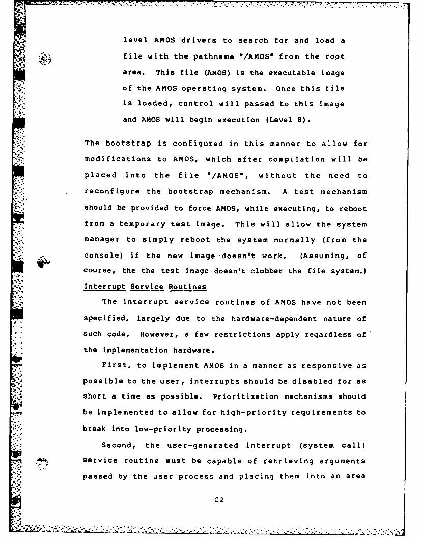
level AMOS drivers to search for and load a
file with the pathname */AMOSw from the root
area. This file (AMOS) is the executable image
of the AMOS operating system. Once this fileI%.
is loaded, control will passed to this image
and AMOS will begin execution (Level 0).
The bootstrap is configured in this manner to allow for
modifications to AMOS, which after compilation will be
placed into the file "/AMOS", without the need to
reconfigure the bootstrap mechanism. A test mechanism
should be provided to force AMOS, while executing, to reboot
from a temporary test image. This will allow the system
manager to simply reboot the system normally (from the
console) if the new image -doesn't work. (Assuming, of
course, the the test image doesn't clobber the file system.)
Interrupt Service Routines
The interrupt service routines of AMOS have not been
specified, largely due to the hardware-dependent nature of
such code. However, a few restrictions apply regardless of
• 'the implementation hardware.
First, to implement AMOS in a manner as responsive as
possible to the user, interrupts should be disabled for as
short a time as possible. Prioritization mechanisms should
be implemented to allow for high-priority requirements to
break into low-priority processing.
Second, the user-generated interrupt (system call)
.. service routine must be capable of retrieving arguments
passed by the user process and placing them into an area
C2
. .".
* - - -~-;*7-
accessible to the AMOS kernel. This process is device
dependent also, as many *i, the newer processors allow for
separation of memory Into system, normal, data, code, and
stack spaces (all permutations). Careful attention must be
given to not disturb data areas that may be needed by the
user process In later processing (i.e. for a file name
search, the service routine must not overwrite the name
string when retrieving it. The user task may recieve an
error flag from AMOS that will require further processing on
the name).
Summary
The AMOS bootstrap and interrupt service routines are
essential parts of the implementation details. This
investigation has not specified implementation details for
these routines, due to the expectation of varied hardware
availability in the future. The minimal requirements listed
above should be followed, however, in future implementation
to allow the greatest flexibility in system modifications.
"C3
Apeni D
AMOS Structure Charts
This appendix contains the module structure charts for
AMOS developed in the main body of the report. The charts
have been spatially expanded for increased readability.
Full discussion of the logic of development for these charts
* is found in the main report body
Di
4.~~~~~~~~~~~~~ 7W~ V,~5
,S. %~.S.-.~* * ~
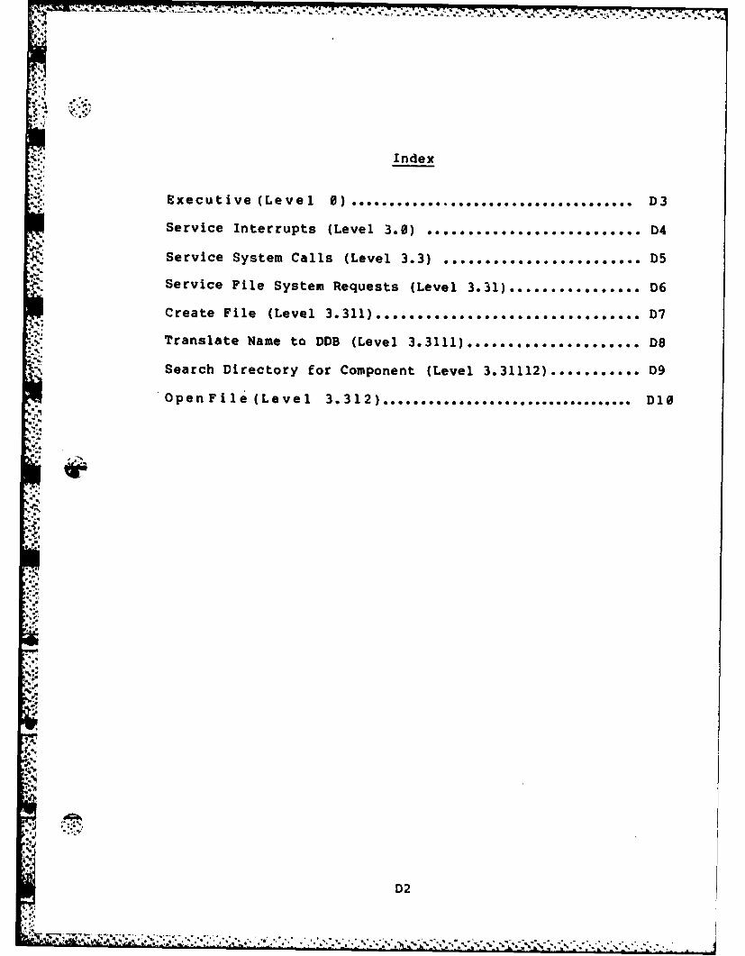
17- fA ... . . -b. - -
Index
Executive (Level 0) ............ D3
Service Interrupts (Level 3.0) .......................... D4
Service System Calls (Level 3.3) ................ D5
Service File System Requests (Level 3.31) ................ D6
Create File (Level 3.311) ................. ............... D7
Translate Name to DDB (Level 3.11...........D8
Search Directory for Component (Level 3.31112) ........... D9
OpenFile (Level 3.312) .................................. DlO
,.'
4-D2
-.4 , , ' . ' . , , . . , . ', . , , . , , " . . . . ' .. , , . . . . . - . . . . . , . . . - . . . - . . . - .
A:[
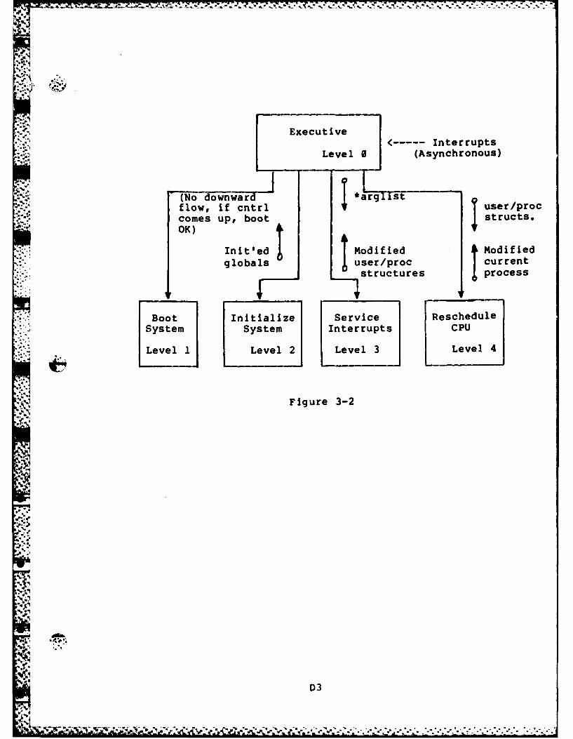
Executive<----- Interrupts
Level 0 (Asynchronous)
(No downward *rlsflow, if cntrl i user/proccomes up, boot structs.
- OK)A
Init'ed d Modified
globals J user/proc currentstructures process
Boot Initialize Service RescheduleSystem System Interrupts CPU
Level 1 Level 2 Level 3 Level 4
IE7
Figure 3-2
'D3
.9
t.
,A°. •
D3
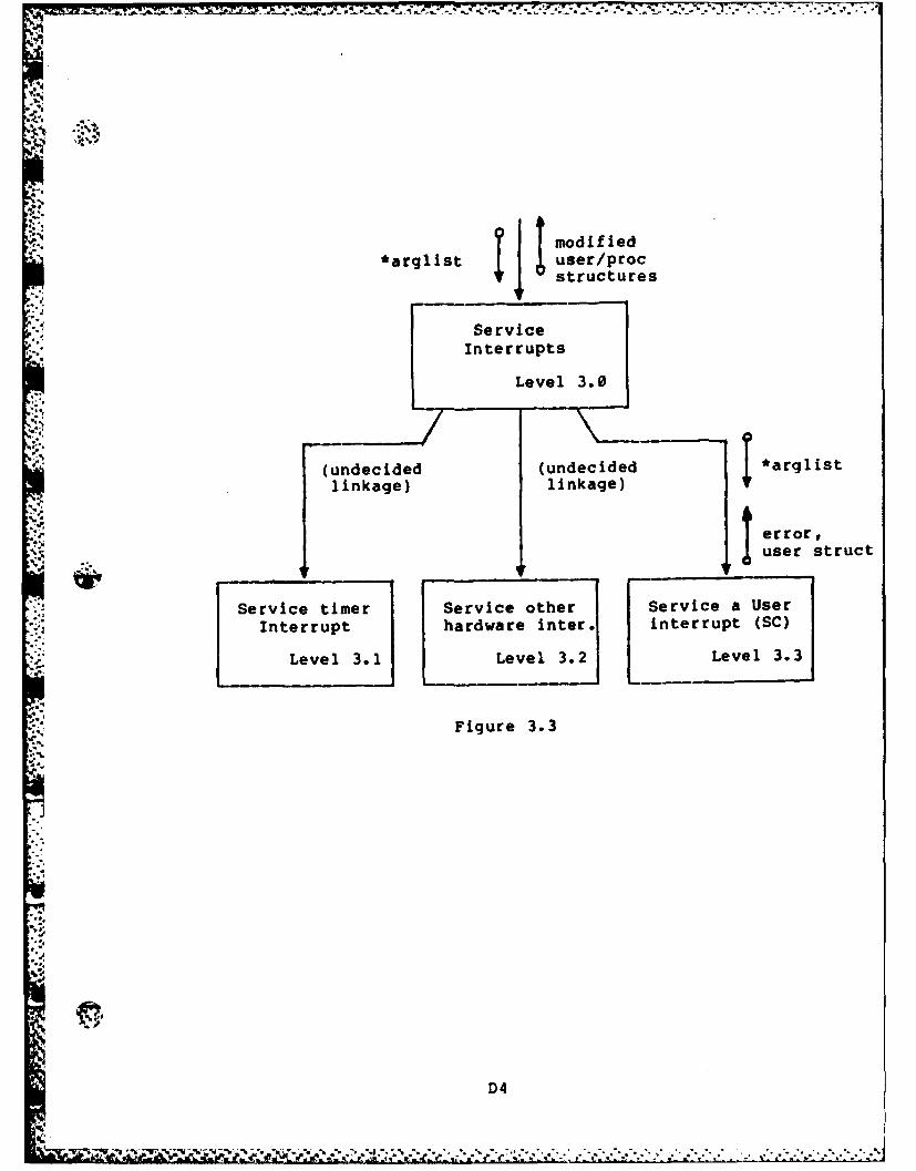
t.1*
9.. modied
*arglist user/proc
structures
Service
Interrupts
Level 3.0
(undecided (undecided *arglistlinkage) linkage)
Serror#e
user struct
Service timer Service other Service a UserInterrupt hardware inter. interrupt (SC)
Level 3.1 Level 3.2 Level 3.3
Figure 3.3
4.D4
1 . " * . ° - ° ~
S""d,,: " ," " " " ," .
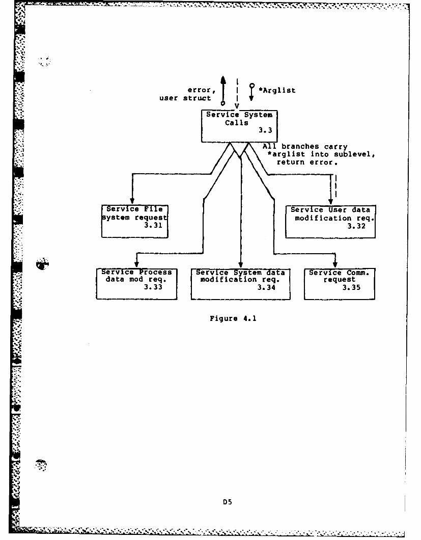
I,-A
. error, *Arglist: user struct /
":"Service System'3.3
AlCbanhelsrr
!.-. /*a rglist into sublevel#
ue err return errorServiceSevic Systeriemse dt
Isystem request moiiato3.3331. 3 .
ServTice Proces ervce System data Service Comm.
data mod re . modification req. request3.33 3.34 3.35
Figure 4.1
'D5
.1-
D5
%" . %-% %t....."..........................."......."................."".............,.. "-"......

.° ~ -.. . , ... , . A . A . -, . . . -. . % , . V;. . I. . .. .. : . . .L.....-
?*arglisterror J
System Requests
" 3.31
error *arglist
Crae pen Close Readfile file file file
3.311 3.31 3.314
.,i
Write Delete Position Get File
file file R/W pointer status
3.315 3.316 3.317 3.318
Figure 6.1
ID
D6

!.4 V . K:'..,
f numb, *name,error mode
~CreateFile
-3.311
* name,mode
r *tddb, *name, WRITEnerror mode, error *tddb fnumb
*tddb error
Translate Create a Accessname to new ddb File
ddb
3.3111 3.3112 3.3113
Figure 6.2
D7
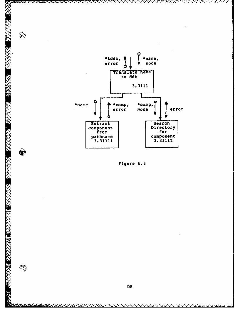
7: - ,--..
~..
*tddb, *name,
error t mode
Translate nameto ddb
3.3111
*name *comp, *ooIp,error mode error
Extract Searchcomponent Directory
from forpathname component3.31111 3.31112
Figure 6.3
08
-.1 7.%
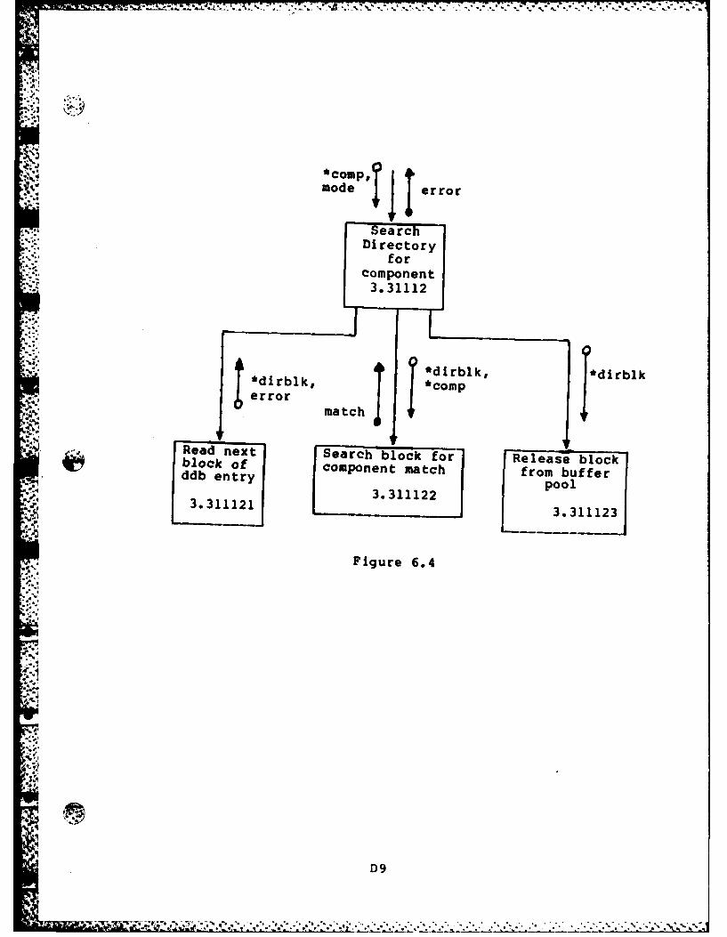
V. 7d I.-IM 7
"oo,,,cop,? 1mode error
SearchDirectory
forcomponent3.31112
*dirblk *dirrb k
error match fdb
Read next ESearch block for Release blockdboenty component match from buffer: , 3. 11122pool
; F 33 .31 1 1 2 13.311121 3.311123
Figure 6.4
,...
'9'.D,
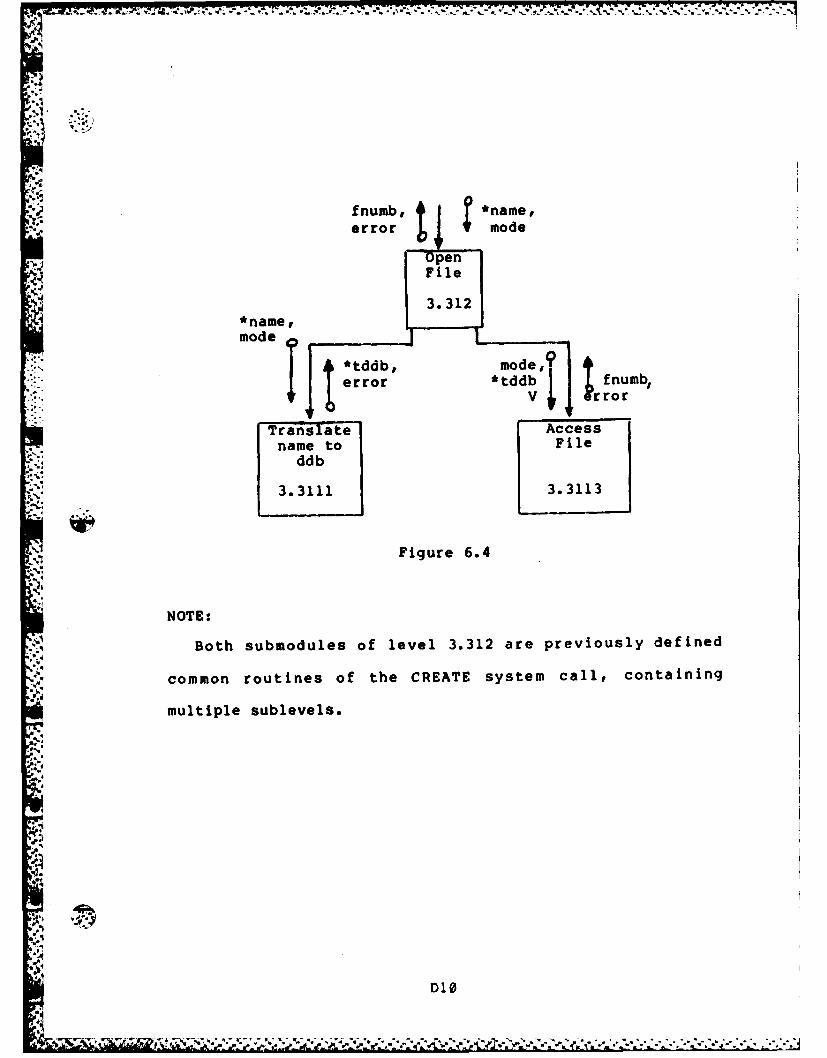
- ..
,.4
f fnumb, 4 *name,U °° I:
error mode
OpenFile
*name,mode T *tddb, mode,9
error *tddb fnumb: Irror
• Translate Accessname to File
: ddb
3.31113.3113
Figure 6.4
NOTE:
' Both submodules of level 3.312 are previously defined
common routines of the CREATE system call, containing
multiple sublevels.
-
D10
... --------- 4 *~ .. 4* 4 4
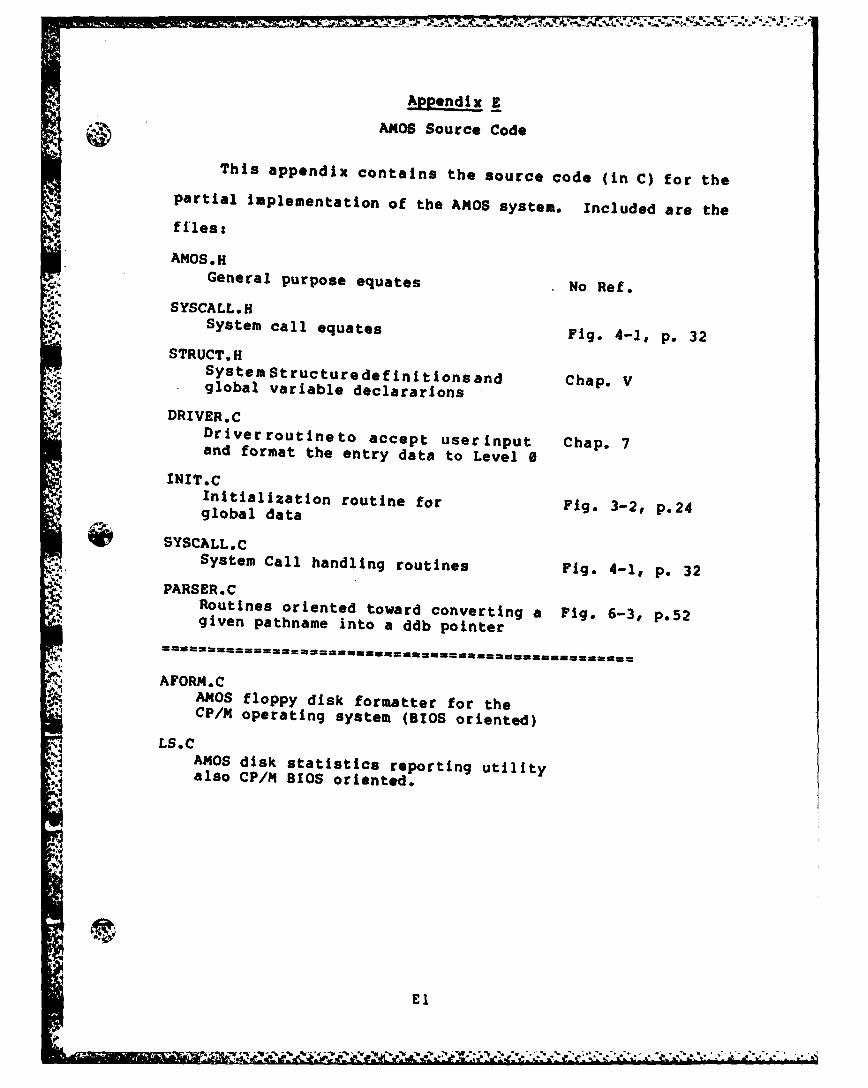
ApPendix E
AMOS Source Code
This appendix contains the source code (in C) for thepartial implementation of the AMOS system. Included are the
files:
AMOS. HGeneral purpose equates No Ref.
SYSCALL.HSystem call equates Fig. 4-1, p. 32
STRUCT.HSystemStructuredefinitionsand
Chap. Vglobal variable declararions
DRIVER.CDriverroutineto accept userinput Chap. 7and format the entry data to Level 0
INIT.CInitialization routine for Fig. 3-2, p.24global data
~ SYSCALLC
System Call handling routines Fig. 4-1, p. 32PARSER.C
Routines oriented toward converting a Fig. 6-3, p.52* given pathname into a ddb pointer
AFORMCAMOS floppy disk formatter for theCP/M operating system (BIOS oriented)
LS.CAMOS disk statistics reporting utilityalso CP/m BIOS oriented.
AV
E

.** General System Parameter Equates for AMOS **
•* Date last modified: 30 Nov 82 **U: ******************************* ***struct ddbdef *rootddb;int error; /* Gotta have a global error value */
#define SEPARATOR 1/' /* Pathname separator */#define NAMESIZ 12 /* 12 characters/name#define NULL 0 /* Null value#define MAXDEV 4 /* 4 devices can be mounted#define MAXFILES 16 /* Up to 16 files open */#define NUMDDB 40 /* 40 spaces for in-core ddb */4define DDBSIZ 32 /* DDB is 32 bytes long */#define STATSIZ 20 /* Size of status block of integers...
used to store off user status in acontext switch.
#define NAMESIZ 12 /* Number of characters per name*/#define TRUE 1 /* Boolean value */#define MAXPROC 30 /* Try 30 concurrent processes */
/* Error codes */#define E NOFILE 1 /* No file */#define E-EXISTS 2 /* File already exists */#define E-NOPERM 3 /* No/invalid permissions */
/* File access modes */#define MREAD 1#define A-WRITE 2
I.
E2
l. , . - ",,. 7 --..... .
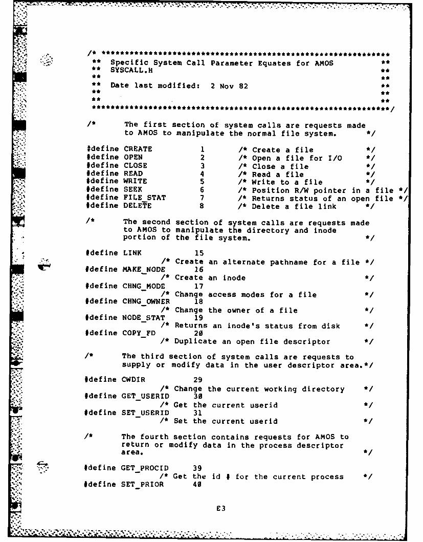
"2-. /* ***** ********** *********** ***** ****** *********** *'**********,*
** Specific System Call Parameter Equates for AMOS ****SYSCALL.H *
** Date last modified: 2 Nov 82 **,** **',., ** **
/* The first section of system calls are requests madeto AMOS to manipulate the normal file system. */
tdefine CREATE 1 /* Create a file#define OPEN 2 I* Open a file for I/O#define CLOSE 3 /* Close a file#define READ 4 /* Read a file#define WRITE 5 /* Write to a fileidefine SEEK 6 /* Position R/W pointer in a file */#define FILE STAT 7 /* Returns status of an open file */#define DELETE 8 /* Delete a file link
,* The second section of system calls are requests madeto AMOS to manipulate the directory and inodeportion of the file system. *
#define LINK 15/* Create an alternate pathname for a file */#define MAKENODE 16/* Create an inode
#define CHNGMODE 17/* Change access modes for a file
#define CHNGOWNER 18/* Change the owner of a file
#define NODESTAT 19/* Returns an inode's status from disk
#define COPYFD 20/* Duplicate an open file descriptor
The third section of system calls are requests tosupply or modify data in the user descriptor area.*/
#define CWDIR 29/* Change the current working directory
#define GET USERID 30/* Get the current userld */
#define SETUSERID 31/* Set the current userid */
S* The fourth section contains requests for AMOS toreturn or modify data in the process descriptorarea. *
#define GET PROCID 39/* Get the Id # for the current process */
#define SET PRIOR 40
E3
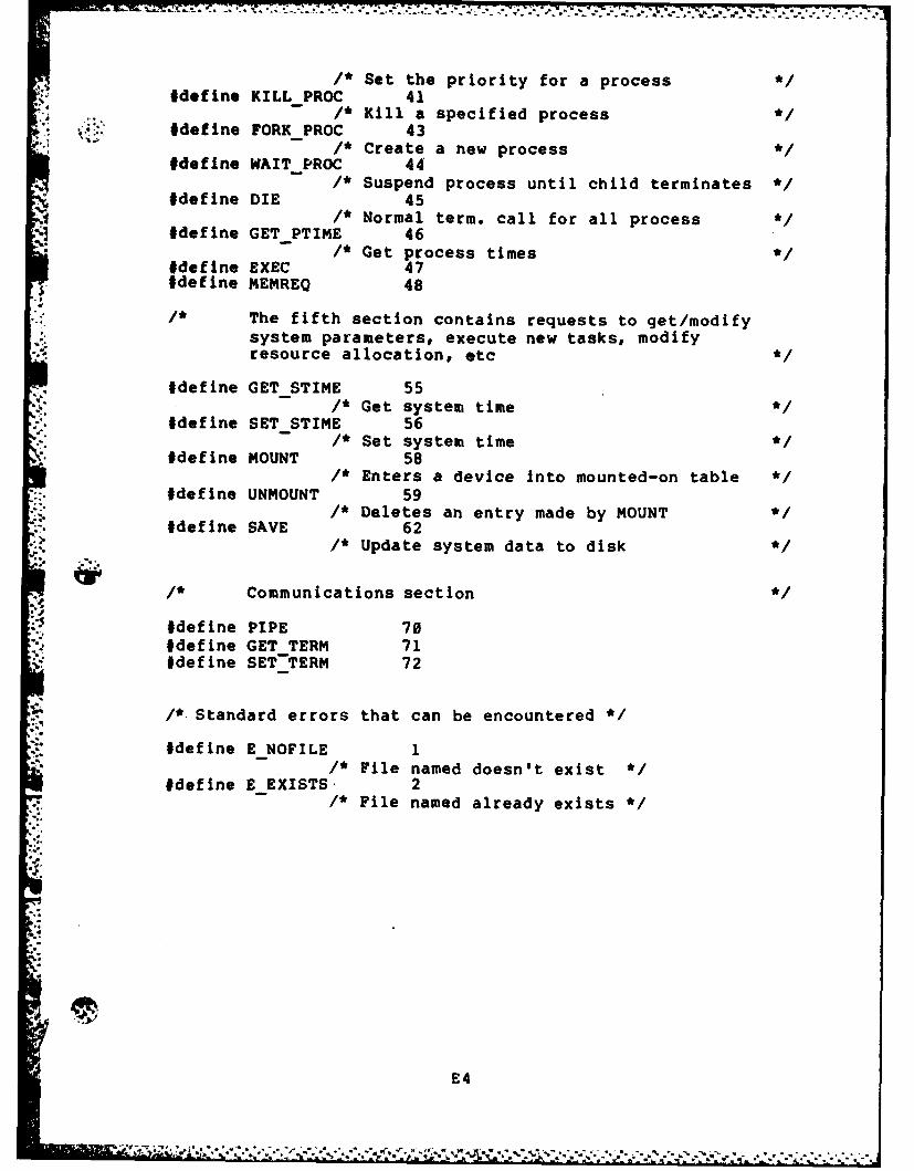
/* Set the priority for a process */#define KILL PROC 41
/* Kill a specified process */#define FORK PROC 43
/* Create a new process .1#define WAITPROC 44
/* Suspend process until child terminates */#define DIE 45
/* Normal term. call for all process */#define GETPTIME 46
/* Get process times */#define EXEC 47#define MEMREQ 48
The fifth section contains requests to get/modifysystem parameters, execute new tasks, modifyresource allocation, etc */
#define GETSTIME 55/ Get system time */
#define SETSTIME 56/* Set system time */
#def in. MOUNT 58* Enters a device into mounted-on table */
#define UNMOUNT 59/* Deletes an entry made by MOUNT
#define SAVE 62/* Update system data to disk
/* Communications section */
#define PIPE 70#define GET TERM 71#define SET-TERM 72
/*.Standard errors that can be encountered */
#define ENOFILE 1/, File named doesn't exist */
#define EEXISTS. 2/* Pile named already exists */
E4

q
** Structure definitions for AMOS data areas** STRUCT.H **
S* Date last modified: 18 Nov 82 ******************************* ****
#include "amos.h"
** Definitions for the proc table array, which **' ** contains the in-core information needed by **
** AMOS for keeping track of current processes.
struct process fchar p flag; /* Process flagschar p prior; /* Process priority *1char pint; /* Storage for an interrupt */char p userid; /* User ID of this process */char p.coretime; /* How long in core */char p cputime; /* How much CPU time given */char p_bias; /* Bias for priority calcs */char p term; /* Terminal connected to proc */int pid; /* Process ID #Int p_idp; /* Parent's ID #int ploc; /* Address of start of process */int p-slze; /* Size of process in blocks *-nt p reason; /* Reason process is blocked */proc_table[MAXPROC]; /* Allocate the space needed */
/****** Now define the status and flag values *
/* Status codes */
#define CURRENT 0; /* Currently running proc */#define SLEEPING 1; /* Waiting for external event */#define NATAL 2; /* Process is being created#define DYING 3; /* Process is terminating */
/* Flag codes */
#define RESIDENT 1; /* In main memory */#define SWAPPED 2; I' Out on disk#define LOCKED 4; /* Can't be swapped (le sys) *1
E5
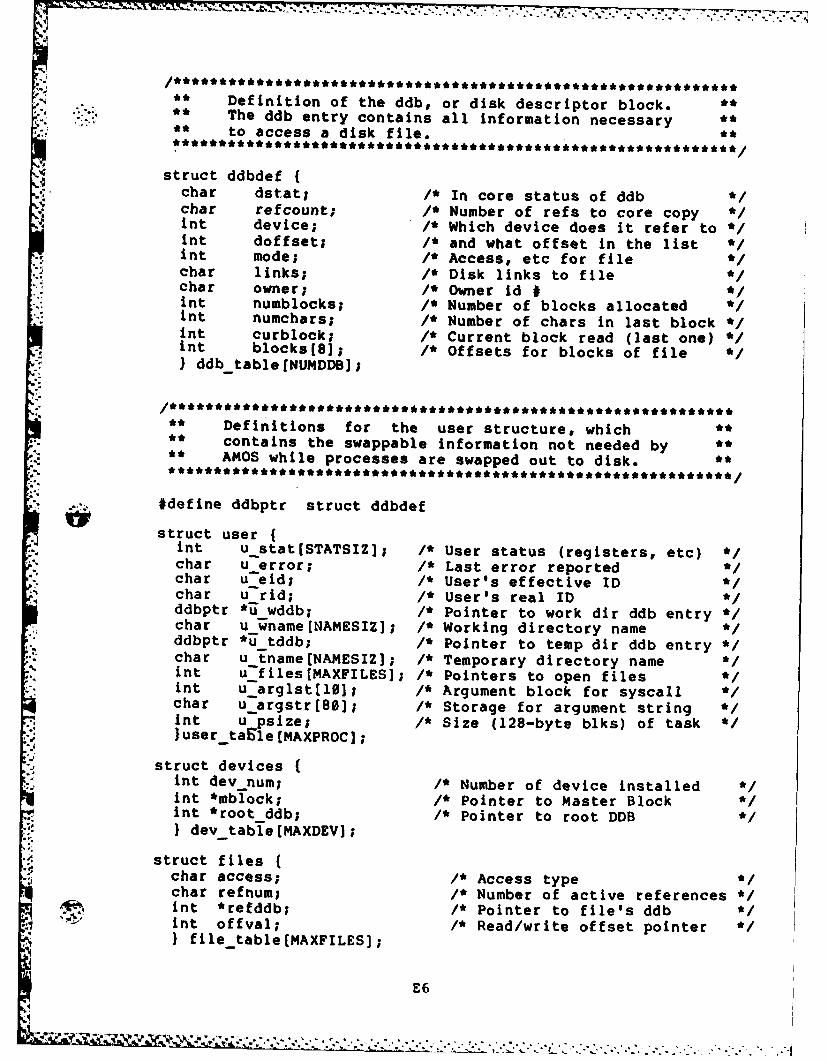
Definition oftedb rdisk descriptor bok** The ddb entry contains all information necessary *** to access a disk file. *
struct ddbdef{char dstat; 1* In core status of ddb *Ichar refcount; /* Number of ref s to core copy *Int device; /* Which device does it refer to *int doffset; /* and what offset in the list *int mode; /* Access, etc for filechar links; /* Disk links to filechar owner; /* Owner id # *mnt numblocks; /* Number of blocks allocatedint numchars; /* Number of chars in last block *mnt curblock; /* Current block read (last one) *int blocks(Bl; I' Offsets for blocks of file)ddb-table fNUI4DDB];
** Definitions for the user structure, which** contains the swappable information not needed by *** AMOS while processes are swapped out to disk. *
*.. #define ddbptr struct ddbdef
struct usernt ustat(STATSIZJ; 1* User status (registers, etc) *chr uerror; /* Last error reported '
char u eid; I' User's effective IDchar u -rid;- /* User's real ID 'ddbptr *jj wddb; /* Pointer to work dir ddb entry *char u wname[NAMESIZ]; /* Working directory name Cddbptr *ii tddb; I' Pointer to temp dir ddb entry *char u-tname[NAMESIZ]; /* Temporary directory name 'int u files[M'AXFILES]; /* Pointers to open files Cint u arglst[101; IC Argument block for syscall Cchar u-argstr[80]; l* Storage for argument string C* mt u psize; /* Size (128-byte biks) of task 'luser taEle MAXPROC];
struct devices{* mt dev num; l* Number of device installed Cint *mblock; /* Pointer to Master Blockint *root ddb; /* Pointer to root DDB CIdev table[MAXDEVJ;
struct fileschar access; /* Access type Cchar refnum; IC Number of active references C
A mt *refddb; 1* Pointer to file's ddb C* mt offval; /* Read/write offset pointer C
Ifile table (MAXFILES];
E6
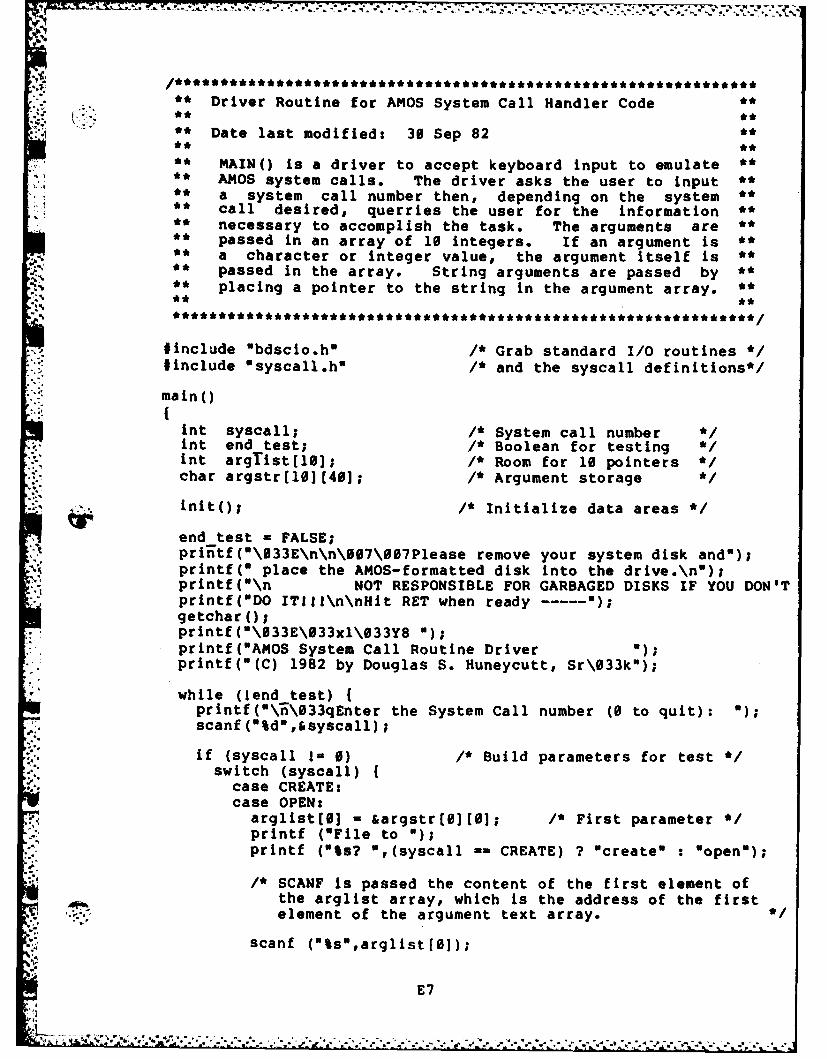
** Driver Routine for AMOS System Call Handler Codeii . t .~ ** **
** Date last modified: 30 Sep 82 **
** MAIN() is a driver to accept keyboard input to emulate **,** AMOS system calls. The driver asks the user to input **
** a system call number then, depending on the system **** call desired, querries the user for the information *** necessary to accomplish the task. The arguments are **** passed in an array of 10 integers. If an argument is **** a character or integer value, the argument itself is **** passed in the array. String arguments are passed by **** placing a pointer to the string in the argument array. **** **
#include "bdscio.h" /* Grab standard I/O routines */#include "syscall.h" /* and the syscall definitions*/
main()
int syscall; /* System call numberint end test; /* Boolean for testing */int argTist[lo]; /* Room for 10 pointers */char argstr[10)[40]; /* Argument storage */
inito; /* Initialize data areas */
end test - FALSE;priitf(0\033E\n\n\007\007Please remove your system disk and");printf(w place the AMOS-formatted disk into the drive.\no);printf("\n NOT RESPONSIBLE FOR GARBAGED DISKS IF YOU DON'Tprintf(ODO ITIlI\n\nHit RET when ready ----- );getcharo;printf(0\033E\033x1\033Y8 ");printf("AMOS System Call Routine Driverprintf(O(C) 1982 by Douglas S. Huneycutt, Sr\033k");
while (lend test)printf(\i\033qEnter the System Call number (0 to quit): ");scanf(%d',&syscall);
if (syscall 1= 0) /* Build parameters for test */switch (syscall) {
case CREATE:case OPEN:
arglist[0] - &argstr[0][0]; /* First parameter */printf ("File to ");printf ("ts? ",(syscall -= CREATE) ? "create" : "open");
/* SCANF is passed the content of the first element ofthe arglist array, which is the address of the firstelement of the argument text array. *
scanf ("Ss",arglistf0]);
E 7
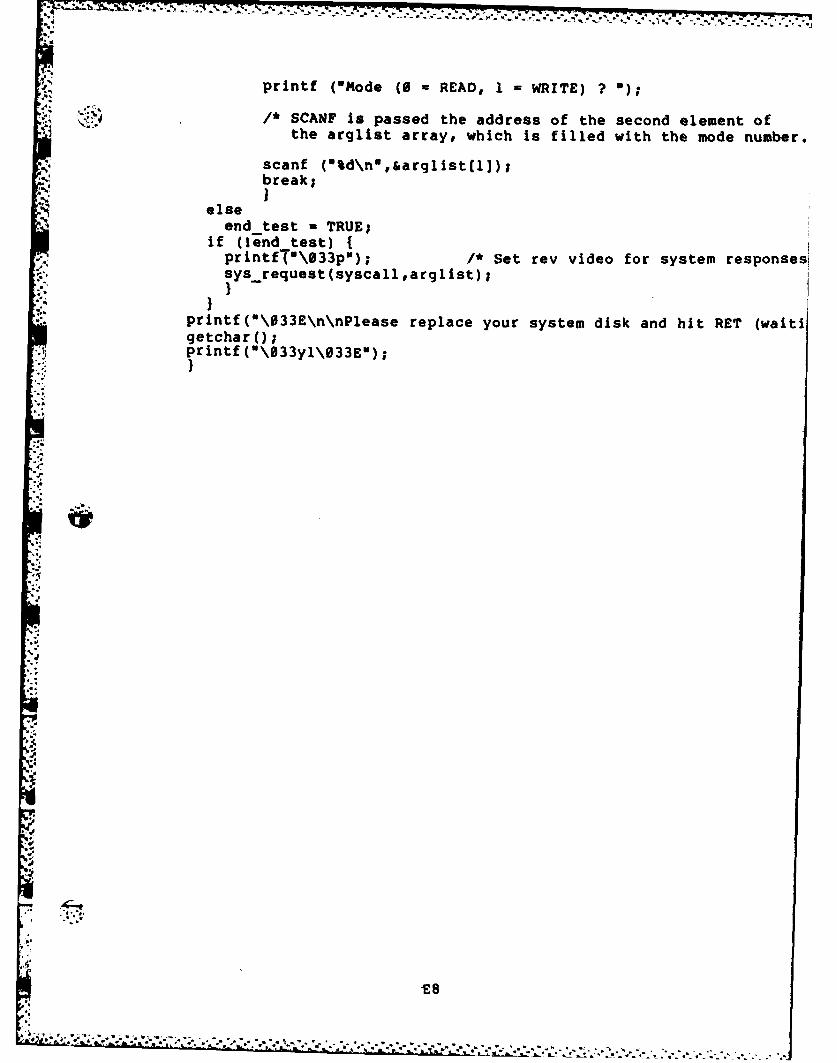
!.: . . . . . . ........-....... .
printf ('Mode ( - READ, 1 = WRITE) ? U);
/* SCANF is passed the address of the second element ofthe arqlist array, which is filled with the mode number.
scanf ("%d\n*,&arglist[1]);break;
elseend test - TRUE;
if (lend test) {printfTO\033p"); I* Set rev video for system responses| sys request(syscallrarglist);
'printf(0\033E\n\nPlease replace your system disk and hit RET (waitigetchar (;printf (0\33yl\033E");}
.4
7-
E8
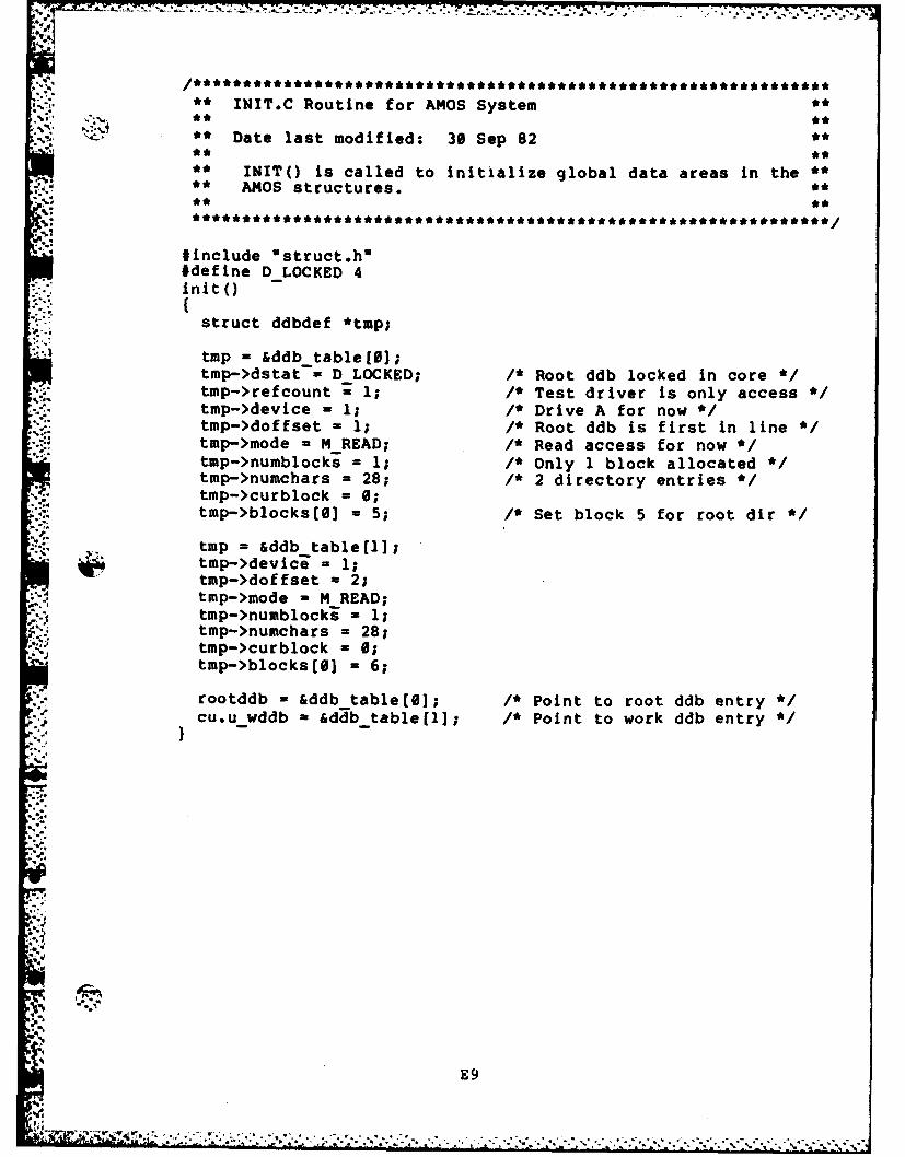
INIT.C Routine for AMOS System *****' _. **
** Date last modified: 30 Sep 82 **
• * INIT() is called to initialize global data areas in the *** AMOS structures.
#include "struct.h"#define DLOCKED 4Init()
struct ddbdef *tmp;
tmp = &ddb table[);tmp->dstat - DLOCKED; /* Root ddb locked in core */tmp->refcount 1 1; /* Test driver is only access */tmp->device = 1; /* Drive A for now */tmp->doffset = 1; /* Root ddb is first in line */tmp->mode -M READ; /* Read access for now */tmp->numblocki = 1; /* Only 1 block allocated */tmp->numchars = 28; /* 2 directory entries */tmp->curblock = 0;tmp->blocks(3 = 5; /* Set block 5 for root dir
C. tmp = &ddb table [11;tmp->devici = 1;tmp->doffset = 2;tmp->mode - M READ;tmp->numblocks - 1;tmp->numchars = 28;tmp->curblock = 0;tmp->blocks[) = 6;
rootddb - &ddb table[]; /* Point to root ddb entry */cu.u wddb a &ddb table[l); /* Point to work ddb entry */
E9
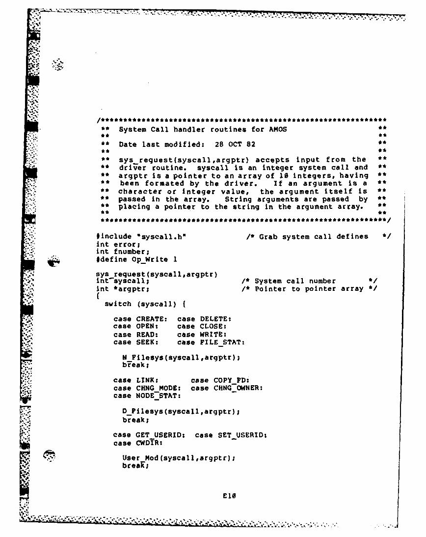
'-
• ** System Call handler routines for AMOS *
,5':* ** **
Daelast modified:28OT2
,.. *. *
** sys request (syscall argptr) accepts input from the **
** driver routine. syscall is an integer system call and **** argptr is a pointer to an array of 10 integers, having **
** been formated by the driver. If an argument is a **** character or integer value, the argument itself is *** passed in the array. String arguments are passed by **
** placing a pointer to the string in the argument array. ********************************* ****
tinclude "syscall.h" /* Grab system call defines */int error;int fnumber;#define OpWrite 1
sys request(syscalleargptr)intsyscall; !* System call number '/int *argptr; /* Pointer to pointer array */
switch (syscall) {
case CREATE: case DELETE:., case OPEN: case CLOSE:
case READ: case WRITE:case SEEK: case FILE STAT:
N Filesys(syscallargptr);break;
case LINK: case COPY FD:case CHNG MODE: case CHNG OWNER:case NODE-STAT:
D Pilesys(syscallargptr);
break;
case GET USERID: case SET USERID:case CWDIR:
User Mod(syscallargptr);brear;
£10
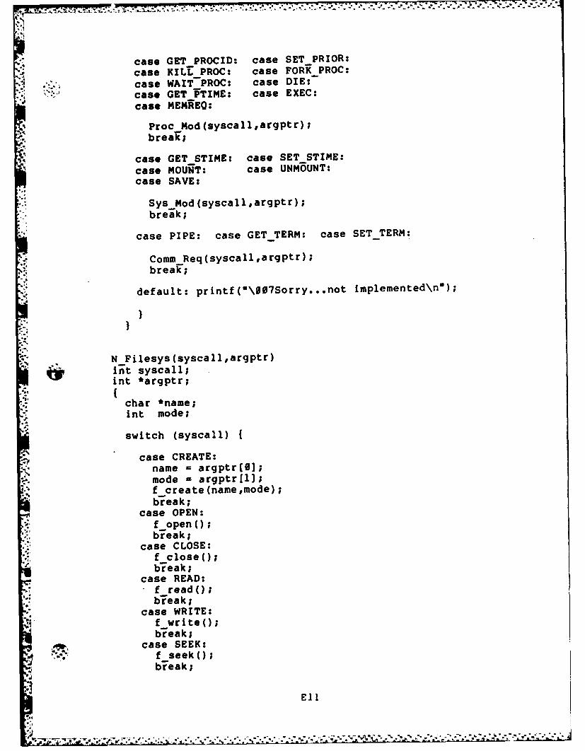
s7.. ,-~t -7 7- - --
case GET PROCID: case SET PRIOR:
case KILL PROC: case FORK PROC:case WAIT PROC: case DIE:case GET PTIME: case EXEC:case MEMREQ:
Proc Mod(syscall,argptr);brear;
case GET STIME: case SET STIME:
case MOUNT: case UNMOUNT:case SAVE:
Sys Mod(syscallargptr);
break;
case PIPE: case GET TERM: case SET-TERM:
CommReq(syscall,argptr) ;break;
,' default: printf("\007Sorry...not implemented\n");
N Filesys(syscall,argptr)i't syscall;int *argptr;
char *name;int mode;
switch (syscall) {
case CREATE:name = argptr(01;
'-'.. mode = argptr[l];f create (namemode);break;
case OPEN:f openo;break;
case CLOSE:f closeo;bieak;
case READ:f reado;bieak;
case WRITE:f writeo;break;
case SEEK:f seeko;
'p break;
Ell
.,I
4.. . . ..
,-.: ~ ~.. ,..* ..9*, , " -"--,-*9 . ' :',=-r '--: '"-:"-""""
"; " *"; " -"" "
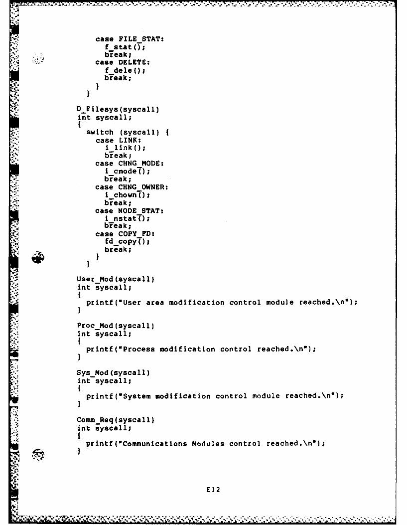
case FILESTAT:f stat(O;
.4 b7eak;case DELETE:
f deleo;b~reak;
D Filesys(syscall)int syscall;
switch (syscall)case LINK:i linko;bireak;
case CHNGMODE:i cmodeo;b-reak;
case CHNGOWNER:i chowno;break;
case NODE STAT:i nstatt);
N blreak;case COPY FD:
fd -copyT);break;
User Mod (syscall)int syscall;
printf("User area modification control module reached.\n");
ProcMod(syscall)int syscall;
printf(*Process modification control reached.\n");
SysMod(syscall)int syscall;
printf(wSystem modification control module reached.\n");
* Comm Req (sysca 11)nt syscall;
printf("Communications Modules control reached.\n");
E1 2
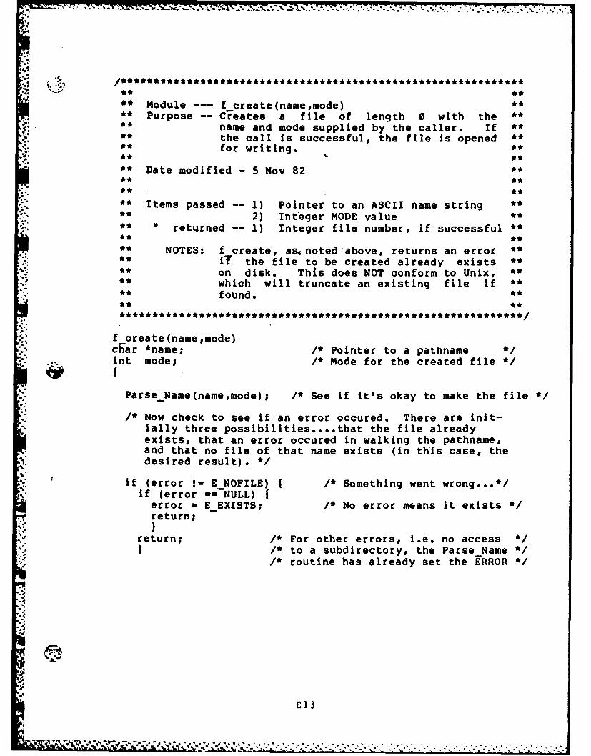
t.* 4 '-':' -*' * ** ' ' ' '
. .. . . . . .
** Module --- f create(namemode) **** Purpose -- Creates a file of length 0 with the **** name and mode supplied by the caller. If **
the call is successful, the file is opened *for writing. **
** Date modified -5 Nov 82 **.. ** **
** Items passed -- 1) Pointer to an ASCII name string **
** 2) Integer MODE value ****,returned -- 1) Integer file number, if successful **
** NOTES: f create, as noted'above, returns an error **** iT the file to be created already exists **** on disk. This does NOT conform to Unix, *** which will truncate an existing file if *** found. ******************************* ***
f create(name,mode)char *name; /* Pointer to a pathname */"nt mode; /* Mode for the created file */
ParseName(name,mode); /* See if it's okay to make the file */
/* Now check to see if an error occured. There are init-ially three possibilities .... that the file alreadyexists, that an error occured in walking the pathname,and that no file of that name exists (in this case, thedesired result). */
if (error I- E NOFILE) { /* Something went wrong..,*/
if (error ----NULL) jerror - E EXISTS; /* No error means it exists */return;)I
- return; /* For other errors, i.e. no access */1,'i /* to a subdirectory, the Parse Name */
/* routine has already set the 'ERROR */
E13
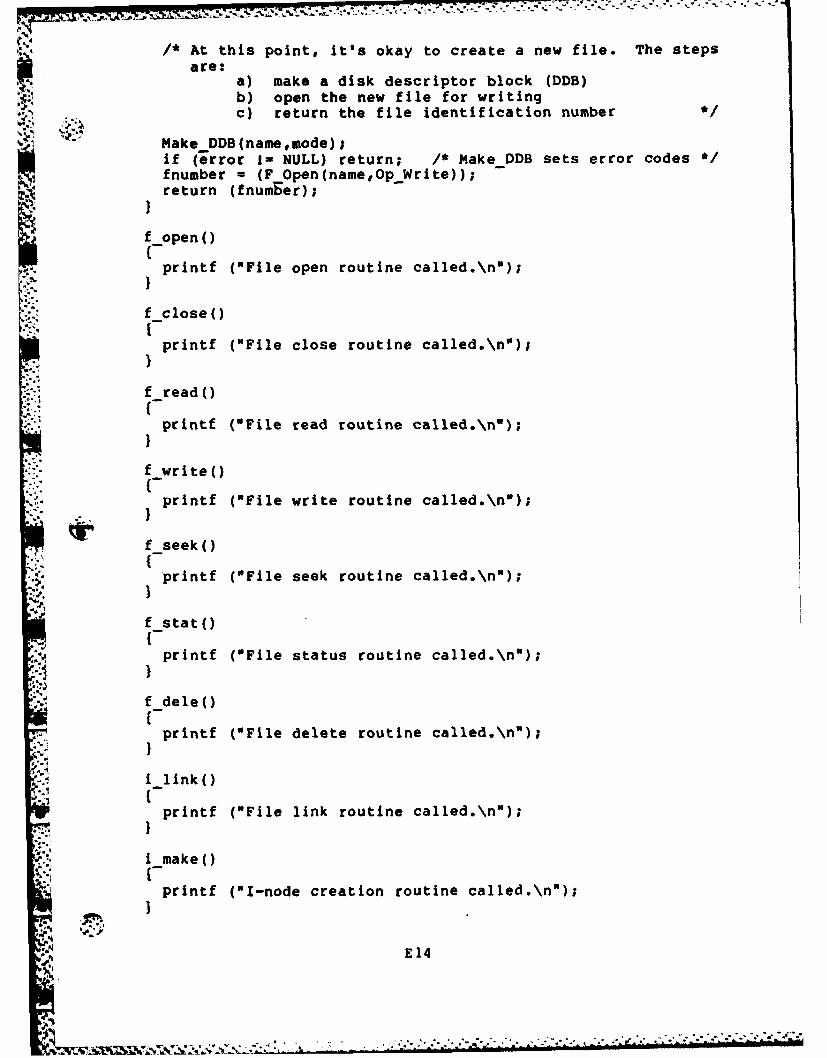
/* At this point, it's okay to create a new file. The stepsare:
a) make a disk descriptor block (DDB)b) open the new file for writing
0.. c) return the file identification number */
Make DDB(namemode);if (error I= NULL) return; /* Make DDB sets error codes */fnumber = (FOpen(name,Op Write));return (fnumber);
f open()
printf (NFile open routine called.\nl);
f close()
printf ("File close routine called.\n");}
f _read()
printf ("File read routine called.\nO);}
f write()
printf ("File write routine called.\n*);
f_seek()
printf ("File seek routine called.\nn);
f stat(Iprintf ("File status routine called.\n*);
f dele()Iprintf ("File delete routine called.\n");
. ilink()
printf ("File link routine called.\n");
I make()
-{printf ("I-node creation routine called.\n");
E14
.', o, ' " _' -', .. -'" X .*- .-- '/: ;- ."*"*" " *" -.. .. *. -. .- .*..=, * . . 2 . *
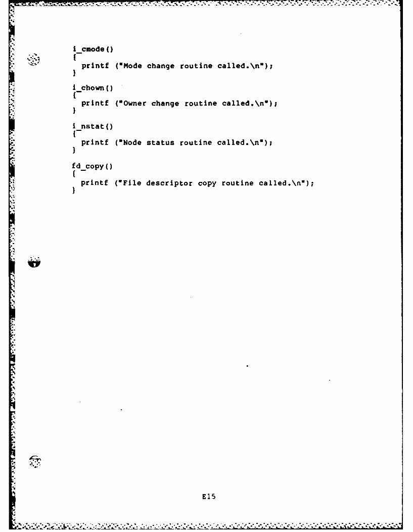
i cmode C
printf ("Mode change routine called.\n");
-chown()
printf (0Owner change routine called.\n");
Instat()
FIprintf (ONode status routine called.\n");
fd copy()
printf ("File descriptor copy routine called.\n*);
EI
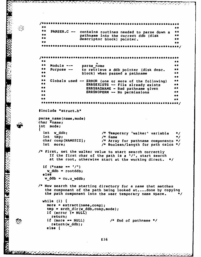
. ,..,** **
** PARSER.C -- contains routines needed to parse down a **** pathname into the correct ddb (disk **** descriptor block) pointer. **S** **
** **t
; ** Module --- parse_name **** Purpose -- to retrieve a ddb pointer (disk desc. **'."** block) when passed a pathname **
** Globals used -- ERROR (one or more of the following) **** ERR$EXISTS -- File already exists **,,.' ERR$BADNAME -Bad pathname given **...', ** ERR$NOPERM -- No permissions **** **
* " ** t ti**i * *** I*r**** t 1, **** *** . **/
#include Istruct.h*
parse name (namemode)* char *name;int mode;
int w ddb; /* Temporary 'walker' variable */int tmp; /* Same */char comp[NAMESIZ]; /* Array for pathname components */int more; /* Boolean/length for path calcs */
/* First, set the walker value to start search correctly- If the first char of the path is a '/', start search
at the root, otherwise start at the working direct. *
if (*name -= '/')w ddb = rootddb;
elseSw_ddb = cu.uw ddb;
/* Now search the starting directory for a name that matchesthe component of the path being looked at .... done by copyingthe path component into the user temporary name space. *
while (1) (more = extract(namecomp);tmp = srch dir(wddb,comp,mode);if (error T- NULL)
return;if (more -= NULL) /* End of pathname */
return(w.ddb);else {
E16
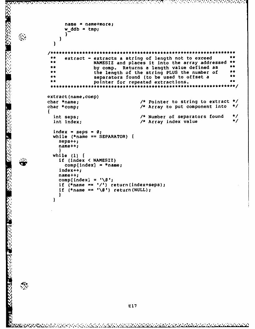
name - name+more;w ddb = tmp;
K }
** extract - extracts a string of length not to exceed **": ** NAMESIZ and places it into the array addressed **'
° :** by comp. Returns a length value defined as **** the length of the string PLUS the number of **** separators found (to be used to offset a **-** pointer for repeated extractions.
extract (name,comp)char *name; /* Pointer to string to extract */char *comp; /* Array to put component into */
". {
int seps; /* Number of separators foundint index; /* Array index value */
index = seps = 0;while (*name == SEPARATOR) f
seps++;name++;
while (1)if (index < NAMESIZ)complindex] = *name;
index++;name++;comp(index] =1\0;if (*name == 'I') return(index+seps);if (*name == \0) return(NULL);}
II
E.17
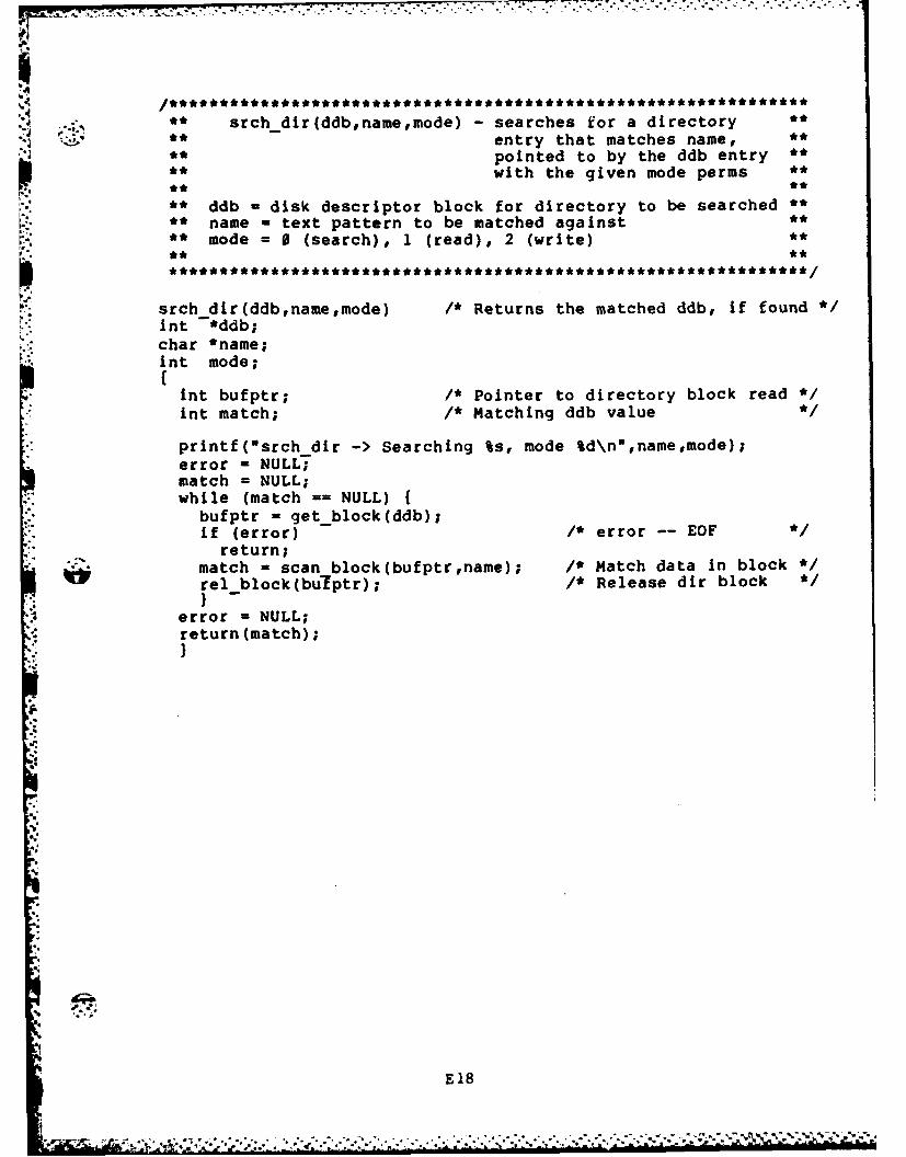
.** srch dir(ddb,namemode) - searches for a directory
"** -entry that matches name, **
• * pointed to by the ddb entry *• * with the given mode perms **
** ddb = disk descriptor block for directory to be searched **.** name = text pattern to be matched against
** mode = 0 (search), 1 (read), 2 (write) **".** * *
srch dir(ddb,name,mode) /* Returns the matched ddb, if found */.nt *ddb;char *name;nt mode;(int bufptr; /* Pointer to directory block read */int match; /* Matching ddb value *1
printf(Osrch dir-> Searching %s, mode %d\n",name,mode);error = NULL;match = NULL;while (match == NULL) {
bufptr = get_block(ddb);if (error) I* error -- EOF
return;match = scan block(bufptrname); /* Match data in block */rel block(bulfptr); /* Release dir block */
error = NULL;• "return(match);
E18
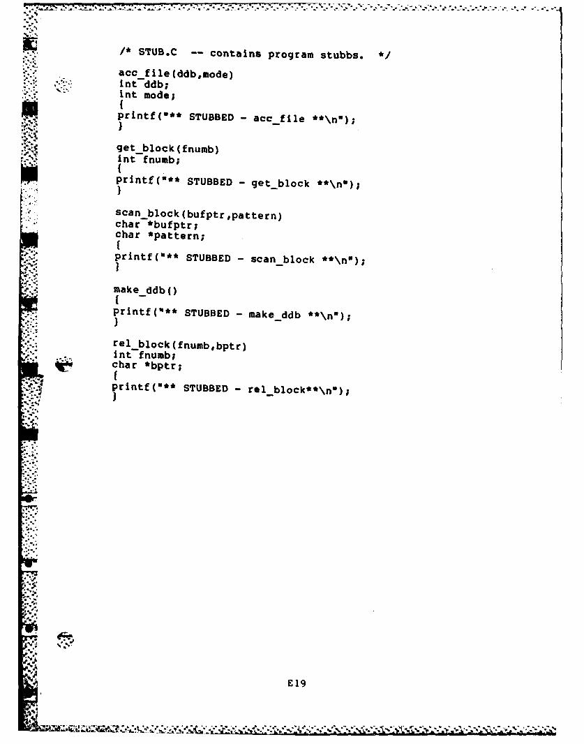
1* STUB.C -- contains program stubbs. *acc file(ddb,mode)
* mnt ddb;mnt mode;'UK'.printf("** STUBBED - CC-file **\n');
get block(fnumb)int fnumb;
printf(*** STUBBED- get-block **\flU);
scan block (bufptrlpattern)char *bufptr;char *pattern;I
.p ~ printf("** STUBBED - scan-block **\flU);
make ddb()Iprintf(*** STUBBED - make ddb **\flU);
rel block (fnumb,bptr)int fnumb;char *bptr;,fprintf("** STUBBED - el-block**\n");
E 19
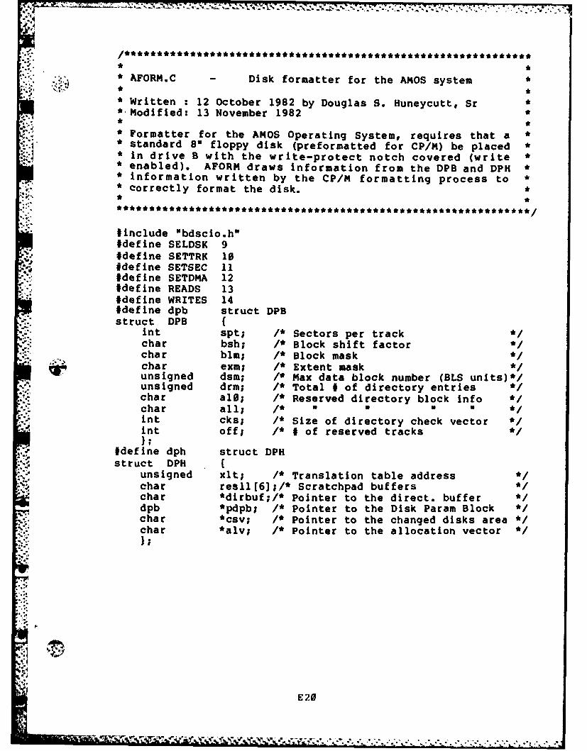
*VJ ./''''''''''''''''''''''''''''''''''''''''
* AFORM.C - Disk formatter for the AMOS system *
* Written : 12 October 1982 by Douglas S. Huneycutt, Sr*-Modified: 13 November 1982 *i* ** Formatter for the AMOS Operating System, requires that a ** standard 8" floppy disk (preformatted for CP/M) be placed ** in drive B with the write-protect notch covered (write* enabled). AFORM draws information from the DPB and DPH *• information written by the CP/M formatting process to ** correctly format the disk. *
#include "bdscio.h"#define SELDSK 9#define SETTRK 10#define SETSEC 11#define SETDMA 12#define READS 13#define WRITES 14#define dpb struct DPBstruct DPB {
int spt; /* Sectors per trackchar bsh; /* Block shift factor *1char blm; /* Block maskchar exm; /* Extent maskunsigned dsm; /* Max data block number (BLS units)*/unsigned drm; /* Total # of directory entries */char al0; /* Reserved directory block infochar all; /* U U U *int cks; /* Size of directory check vector */int off; /* # of reserved tracks */
#define dph struct DPHstruct DPH
unsigned xlt; /* Translation table addresschar resll[61;/* Scratchpad buffers */char *dirbuf;/* Pointer to the direct, buffer */dpb *pdpb; /* Pointer to the Disk Param Block */char *csv; /* Pointer to the changed disks area */char *alv; /* Pointer to the allocation vector */
.E2
E 20

#define mblock struct MBLOCKstruct MBLOCK { /* AMOS Master block definition '/
int m devsize; /* Size in blocks of dev. (33.28 Mb) */int m~blktrk; /* Blocks per track for device */int a-reserved; /* Reserved tracks on device (from 0)*/in, m-ddblsize; /* Size of ddb list in blocks 'IInt mdblist[93; /* Double-indir. pointers to listchar m-locked; /* Flag for locked-mountedchar m-mod; /* Flag for mblock modifiedint -freeptr; /* Pntr to next block of freelist */int m numfree; /* # of free block pntrs in this blk '/int m-freef230]; /* Pntr to 230 free blocks on disk */tin unassigned[le];/* Reserved for future expansion */
)master;
#define d ddb struct DiskDDBstruct DikDDB {
int cr_date; /* Date created */int ac date; /* Date last accessedint mou date; /* Date last modifiedint mode; /* Mode of filechar links; /* Disk links to filechar owner; /* Owner number for filent numblocks; /* Number of blocks allocated to file*/int numchars; /* Number of chars in the last block*/int blocks[91; /* Allocation array for file1;
d ddb *ddbptr;cliar dskbuf[512]; /* Disk buffer */
:# *define dir ent struct DirEntrystruct DirEtry /
char fname[14]; /* ASCII name of file */int ddb number; /* Position in ddb list */
struct dir block {dir ent entry[321;
main (I'I
dph *header; /* Disk parameter header */dpb *pblock; /* Parameter block '/int blk trk; /* # of blocks per track '/int wasTe track; /* # of sectors wasted per track */int blk dTsk; /* Blocks per disk '/int dati;int ind;
E21
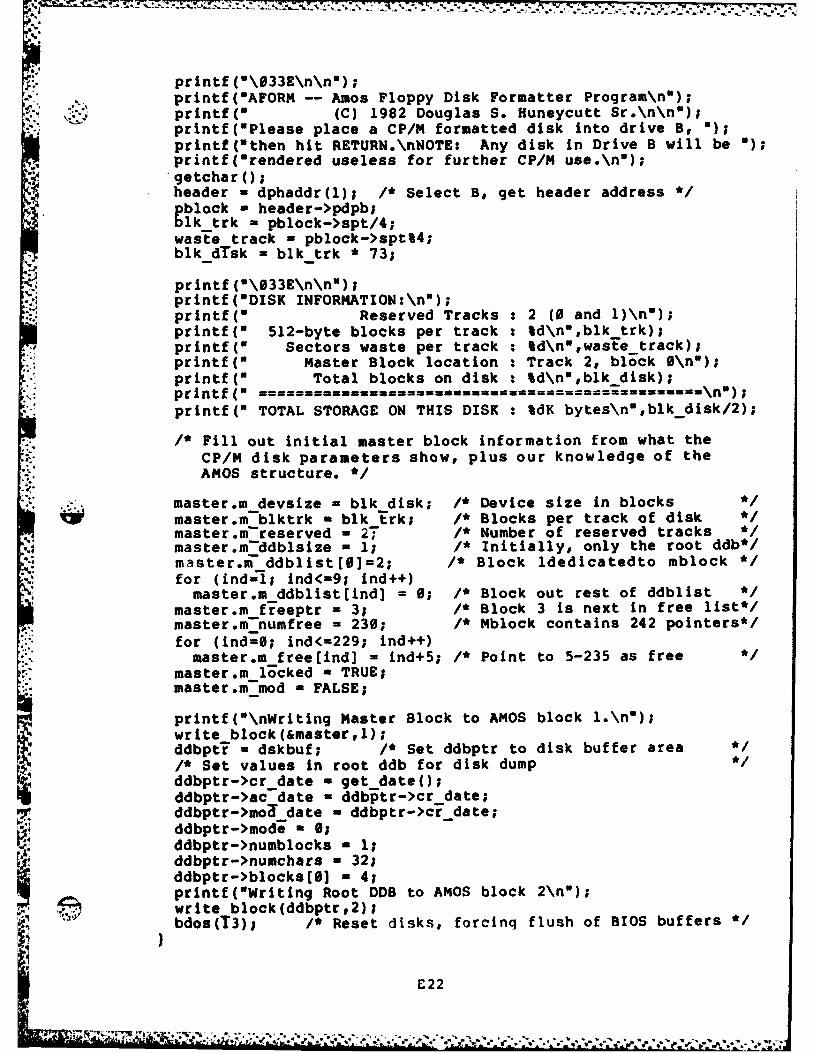
p printf(-\033E\n\nN);printf("AFORM -- Amos Floppy Disk Formatter Program\n*);printf(" (C) 1982 Douglas S. Huneycutt Sr.\n\n");printf(OPlease place a CP/M formatted disk into drive B, );
printf(Ithen hit RETURN.\nNOTE: Any disk in Drive B will be );printf(Orendered useless for further CP/M use.\nO);getcharo;header - dphaddr(1); /* Select B, get header address */gblock - header->pdpb;lk_trk - pblock->spt/4;
waste track - pblock->spt%4;blk dTsk - blk trk * 73;
printf (\033E\n\nl);printf (DISK INFORMATION:\n");printf(" Reserved Tracks : 2 (0 and l)\no);printf(m 512-byte blocks per track : %d\nl,blk trk);printf(U Sectors waste per track : %d\nwwaste track);printf(w Master Block location : Track 2, block 0\n");printf(" Total blocks on disk : %d\n",blk disk);printf(w ======================== ======= n======\='==printf(" TOTAL STORAGE ON THIS DISK : %dK bytes\n",blkdisk/2);
/* Fill out initial master block information from what the* CP/M disk parameters show, plus our knowledge of the
AMOS structure. */-master.m devsize - blk disk; /* Device size in blocks *1
master.mblktrk = blk trk; /* Blocks per track of diskmaster.m-reserved - 27 /* Number of reserved tracks */master.m-ddblsize - 1; /* Initially, only the root ddb*/master.m-ddblist[0=2; /* Block ldedicatedto mblock */for (ind=l; ind<-9; Ind++)master.m ddblist[ind] = 0; /* Block out rest of ddblist */
master.m freeptr a 3; /* Block 3 is next in free list*/master.m-numfree = 230; /* Mblock contains 242 pointers*/for (indf0; ind<-229; ind++)master.m free[Ind] = ind+5; /* Point to 5-235 as free */
master.m locked - TRUE;master.m-od - FALSE;
printf("\nWriting Master Block to AMOS block l.\n);write block(&master,1);ddbptf - dskbuf; /* Set ddbptr to disk buffer area/* Set values in root ddb for disk dump */ddbptr->cr date - getdate();ddbptr->ac date a ddbptr->cr date;ddbptr->moa date - ddbptr->crdate;ddbptr->mode a 0;ddbptr->numblocks = 1;ddbptr->numchars = 32;ddbptr->blocks[S] - 4;printf(*Writing Root DDB to AMOS block 2\n");write block(ddbptr,2);bdos(T3); /* Reset disks, forcinq flush of BIOS buffers el
E22

-s7,71
*Dphaddr - return the address of a disk parameter header*This Is performed by bios call 9, but the Blos() function*can not be usedl because it returns a <A> not <HL>
dphaddr (drive)int drive;
unsigned *warmstartt,seldsk,result;
warmstart - 1;seldsk - *warmstart +- 24; /* address of SELDSK routine *result = call(seldsk,0,0,l,0); /* bios seldsk routine *
2:. return(result);
write block (buffer ,block)char *buffer;imt block;
int sector,lndexinewsec;char *dmaadr;
sector ((block-l)*4)+l;dmaadr =buffer;for (index-0;lndex<4;index++)
nevsec - transec(sector-l);bios (SELDSK.l);
bris (ETTRK 2); log. sector #%d, phys sec #%d\n",print (\t~r tingsectorlnewsec);
bios (SETSEConewsoc);bios (SETDMA,dmaadr);
* *, bios (WRITES);sector - sector+l;dmaadr - dmaadr+128;
transec(sector) /* Translate log. to phy sector *int sector;
unsigned *warmstart,trans,,seldsk,result#*tdpb,
* * table;
warmstart - 1;seldsk -*warmstart + 24; /* Select disk routine *trans -*warmstart + 45; /* Translate sec routine ~
~.tdpb -call(seldsk,0#,,,); /* Select drive B */table -*tdpb; /* Get trans table address *
E23
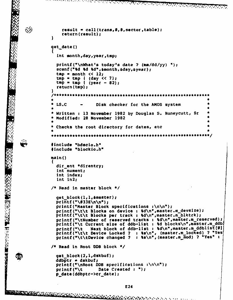
reslt caltan5hIsgtocrtabl);
qet dateoC
int month,daypyear~top;
printf("\nWhat's today's date ? (mm/dd/yy) )scanf("%d %d %d&month&day,&year);tmp - month << 12;tap - tap I (day << 7);tmp - tap I (year - 82);return Ctsp);
*LS.C - Disk checker for the AMOS system*
*Written :13 November 1982 by Douglas S. Huneycutt, SrModified: 28 November 1982*
*Checks the root directory for dates# etc*
#include Obdacio.h"#include Oblockio.h"
main()
dir ent *direntry;int nument;int index;int In2;
1* Read in master block *
get block(1l.l&master);prinEtf (\@33E\n\nw);printf (smaster Block specifications :\n\n");prmntf("\t\t blocks on device : Id\n~rmaster.m devsize);printf('\t\t Blocks per track : %d\nl,master.m blktrk);printf(*\tNumber of reserved tracks : %d\nwmaster.m reserved);printf(*\t Current size of ddb-list : %d blocks\ntmaster.m 'ddbprintf(*\t Next block of ddb-list : td\n"rmaster.m.ddblisECO)printf("\t\t Device Locked ? : Is\n", (master.m locked) ? "Yesprintf(*\t\tDovice changed ? : %s\nI,(master.m iod) ? "Yes"
/* Read in Root D block *
get block(2,lldskbuf);ddbptr - dskbuf;PrIntf(I\nRoot DDS specifications :\n\n*);PrIntt('\t Date Created: )pdoat*(ddbptr->cr date);
E 24
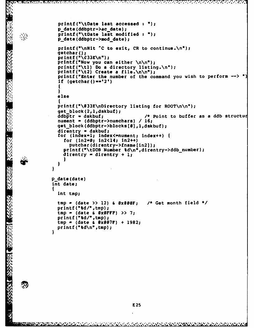
printf(u\tDate last accessed :U)p date (ddbptr->ac date);printf(*\tDate last modified : )p_date(ddbptr->mod date);
printf(O\nHit C to exit, CR to continue\n");getcharo;printf (\033E\nN);Printf("Now you can either \n\n");printf("\tl) Do a directory listing\n");printf("\t2) Create a file.\n\n");printf("Enter the number of the command you wish to perform ~Uif (getcharo--121)
else
printf(0\033E\nDirectory listing for ROOT\n\n");get block(2,l,dskbuf);ddb~ptr - dskbuf; /* Point to buffer as a ddb structunument - (ddbptr->numchars) / 16;get -block(ddbptr->blocks[8J ,l,dskbuf);direntry - dskbuf;for (index-l; index<-nument; index++)
for (in2-0f; in2(14; in2++)* putchar (direntry->fname [in2l);
printf("\tDDB Number %d\n",direntry->ddb-number);direntry -direntry + 1;
p date (date)mnt date;
int tmp;
tmp - (date >> 12) &OxI0UF; /* Get month field *printf("%d/"#tmp);tmp = (date & Ox0FFF) >> 7;prIntf (%d/Otmp);tmp - (date & BxflS7F) + 1982;printf (%d\n",tmp);
E25

Vita
Captain Douglas S. Huneycutt, Sr. was born on October
13, 1956 in Salina, Kansas. In 1974, he graduated from
Summerville Senior High School In Summerville, South
Carolina. He attended Clemson University and the College of
Charleston, South Carolina from which he recieved a Bachelor
of Arts degree with a major in Physics and concentration in
Pre-medicine in 1978. Following graduation, he attended the
Air Force Officer Training School at Medina Base, Texas,
followed by the Computer System Design Officer school at
Keesler AFB, Mississippi. Between February 1979 and Jane
1981 he served in the Directorate of Data Automation,
Headquarters, Air Force Systems Command at Andrews AFB, DC.
He entered the Air Force Institute of Technology in June
1981.
Permanent Address:
120 President Circle
Summerville, SC 29483
V
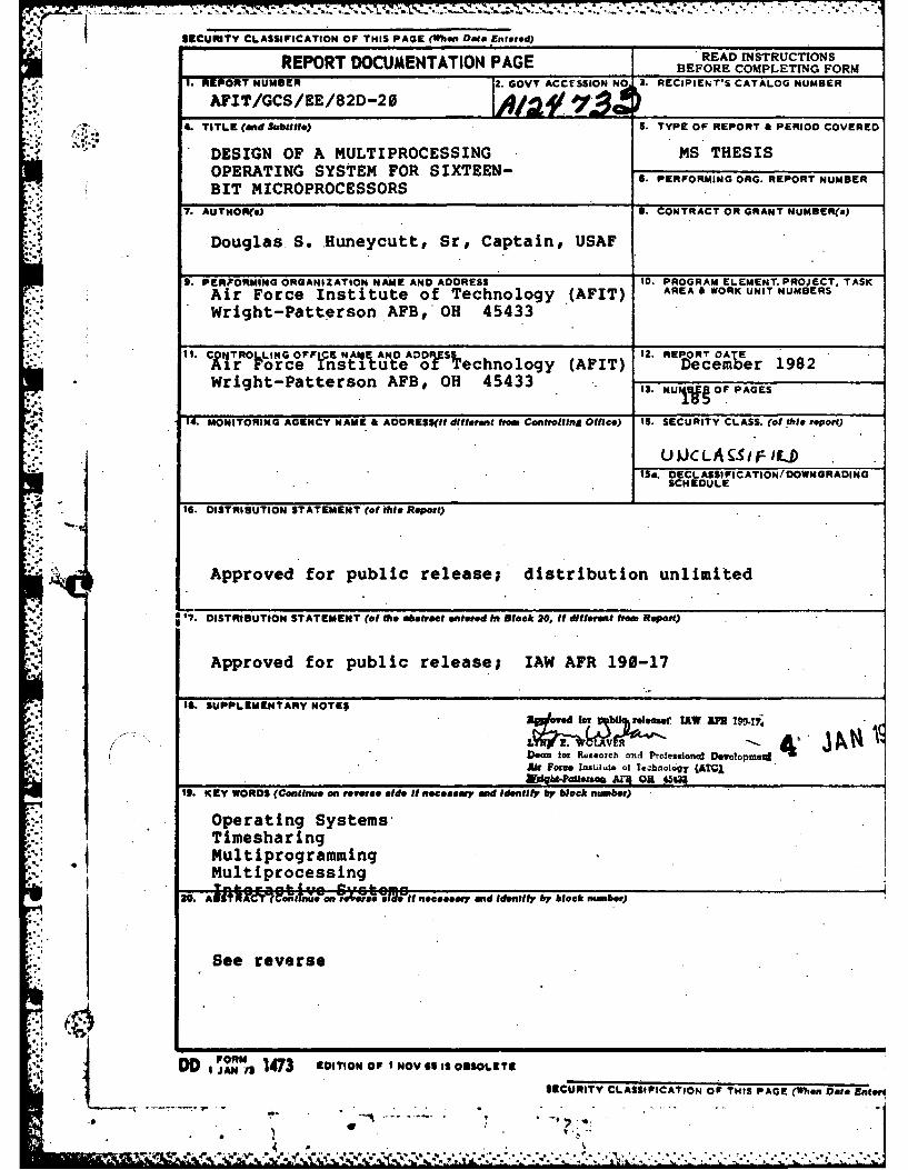
SECURITY CLASSIFICATION OF THIS PAGE (U1,at Date Entered) _________________
READ INSTRUCTIONSREPORT DOCUMENTATION PAGE BEFORE COMPLETING FORM1. REPORT NUMBER 2. GOVT ACCETSSION NO 3. RECIPIENT'S CATALOG NUMBER
AFIT/GCS/EE/82D-20*<-.4. TITLE (ad Subtitle) is. TYPE OF REPORT & PERIOD COVERED
DESIGN OF A MULTIPROCESSING MS THESISOPERATING SYSTEM FOR SIXTEEN- 6. PERFORMING ORG. REPORT NUMBERBIT MICROPROCESSORS
7. AUTHOR(s) 6. CONTRACT OR GRANT NUMBER(s)
Douglas.S. .Huneycutt, Sr, Captain,, USAF
9. PERFORMING ORGANIZATION NAME AND ADDRESS 10. PROGRAM ELEMENT. PROJECT. TASKAir Force Institute of Technology (AFIT) AREA & WORK UNIT NUMBERS
* Wright-Patterson AFB,*OH 45433
11. CWJR IG OFFLCE NAIE AND ADRll 12. REPORT OATE
i~r rObce !nstitUte o rsechnology (AFIT) Dec ember 1982
Wright-Patterson AFB, OH 45433 IS. NUIj~gOF PAGES
14. MONITORING AGENCY NAME & ADDRESS(iI different from Conitrolling Office) 1S. SECURITY CLASS. (of this report)
UJkCLA9SFiL..D
SCHEDULE
f tO. DISTRIBUTION STATEMENT (of this Report)
Approved for public release; distribution unlimited
a .117. DISTRIBUTION STATEMENT (of the abstract entered In Block 20, if different krm Report)
Approved for public release; IAW AFR 190-17
* -~ IS. SUPPLEMENTARY NOTE$
L%72 'V -IAVP --l -- k
Dean for Research and Professional Detclopmo~dAir tome. lnzlAe of Technology (ATj,
It. KEY WORDS (Continue an reverse side if necesary and Identifyby block num~ber)
Operating SystemsTimesharingMultiprogramming
Multiprocessing
20. AIM M Okne "ot r~9 e~e Wit necesary and Identify by block nimber)
See reverse
d ~ Z#~U 173 EDIIONOF NO69 I OBOLEE SCURITY CLASSIFICATION OF THIS PAGE (*Won Data Enteri
SECURITY CLASSIFICATION OF THIS PAGE(ikaen Date Enitore)
.-- , ,
....- 20. Abstract
A multiprocessing operating system for the Air ForcInstitute of Technology Digital Engineering Laboratory wadesigned and partially implemented. The requirements for suchdesign were developed by a thorough literature search and througan abctraction of the works of Ross and Yusko. The resultantdesign is functionally compatible with UNIX, version 2.7.
Because of the broad scope of. such. a project, this effort wasgeared toward the total design of the file system,-with a highlevel design to cover all other areas. Further research ineeded to complete the design, as the high-level areas are nosufficiently detailed for full implementation.
O.-S _
SECURITY CL.ASSIIlCATION OP THIS PAOE'W~ien Data Entegi.
.0
g
I
I