Volume XIX Issue No. 01 01 June 2020 Pages: 148 - Agrobios ...
Upload
khangminh22Category
view
0download
0
6th Iss
ue
June 2015


Tech Tips
LuKClutch Clinic Clio 2.0 Sport 4
NTKTypes of lambda sensors 5
A.D.SBMW Air bag fault from an unlikely source 6
eXponentiaOscillloscope basics explained 7
LuKClutch Clinic Mercedes A Class 8
A.D.SRelative compression testing 9
febi bilsteinAntifreeze facts and basics 10
GatesCooling problems - symptom or cause 12
LuKClutch Clinic Caddy 1.9D 13
Blue PrintSpin Doctors - an overboosted L200 14
Auto-SolveYour new workshop Diagnostic Assistant 16
TEXACan a service cause poor running? 18
Blue PrintToyota D-4D suction control valve 19
AutoinformTime to inject some sense 20
DaycoRenault 1.9dCi timing belt guide 21
LuKClutch Clinic Mercedes C220 CDi 22
INATiming Belt 2008 Audi A4 2.0TDi 23
DENSOTroubleshooting guide Lambda Sensors 24
Blue PrintNavara halfshaft replacement 26
AutoinformHaving a good process 27
LuKClutch Clinic Golf GT TDi DSG 28
febi bilsteinDSG filter & oil servicing 29
LuKClutch Clinic Aygo 1.0 HC07 JUG 30
AUTOBIZ TECH TIPS June 2015 >> 3
Tech Tips is published by:
Unit 2, Pier Road, Barna, GalwayPhone 091- 523292Web www.autobiz.ieEmail [email protected]
Tech Tips is published by Autobiz Ltd and is sent free of charge to all readers ofAutobiz. While every care is taken to provide accurate information, the publishercannot accept responsibility for any errors or omissions, no matter how caused.
autobiz.ie/training
Technically speaking … More than five years
ago, I started to realise that most mechanics I was talking to,
all had a common problem, new technology and access to
good technical data. Four years ago we published our first set
of Tech Tips, after contacting many sources that had bits of
information of interest to these mechanics. Over the years,
Tech Tips has gained momentum and has built up a large
amount of technical information, and now that we have
started the flow of information, it is gaining strength and
providing much needed help to the independent garage.
The Tech Tips that appear in Autobiz, and repeated in these
compendiums, are just the tip of the iceberg. All of these Tech
Tips can be found on Autobiz.ie/techtips, or on our new
dedicated Tech Tips website, Techtips.ie. But we also have a
vast amount of Tech Tips that have been pulled together from
a number of sources, all respected authorities in automotive
technical information. Currently, there are close to 2,000 Tech
Tips that can be searched by text, company, or type. The Tech
Tips included are PDFs, videos and technical articles that have
appeared in Autobiz, as well as other sources. With the
amount of information that is freely and easily accessible, the
chances are very good that you will find an answer to a
problem you are facing after a short search.
Our online Tech Tips are being continually updated and
expanded as new information becomes available. Our
technical partners are constantly sending me new technical
articles and information. Additionally, I am also monitoring
many sources that provide excellent information that
mechanics need to have access to, so you don’t have to scour
the internet to find accurate and reliable information. The
major advantage to you is that I am looking out for what you
need to know, then it is put in one place for you.
Training courses continue to be important. More course are
coming, and all details will be available in Autobiz and on
Autobiz.ie/training.
If there are any technical issues that you are facing and don’t
have a good source of information, let me know and I will dig
into it to see what can be found.
John O’Callaghan, Technical Editor

4 >> June 2015 AUTOBIZ TECH TIPS
Tech Tips
The model in this article is the 2004 Clio
2.0 Sport. No special tools are required to
complete the repair, the only additional tools
needed are a transmission jack, an engine
support cradle and a long axle stand. A two
post ramp was used in this example, however,
it is recommended that a four post ramp is
not used as it may not provide enough
clearance. For the sake of safety, it’s
considered best practice to disconnect the
battery earth lead before commencing work.
If the vehicle has alloy wheels, it may be fitted
with anti theft wheel bolts, so make sure you
have the key before you start.
Open the bonnet and disconnect both
battery terminals. Undo the battery clamp and
remove the battery. Undo the jubilee clips
securing the air inlet pipe and remove the
connected breather. Lift the inlet pipe out and
undo the two air filter housing securing bolts.
Lift out the air filter housing slightly and
disconnect the inlet pipe underneath. Unclip
the plastic inlet pipe attached to the slam
panel housing and remove. Remove the air
filter securing brackets and remove the
complete air filter housing.
Retract and unclip the clutch cable and
disconnect the fuel injection control unit
connector. Undo the bracket attached to the
gearbox supporting the ECU harness and
remove the earth lead attached to the rear.
Remove the large single gearbox mounting
nut and the smaller bolts on either side (fig 1).
These smaller bolts are not captive and will
need to be held from underneath. Undo the
bolts securing the gearbox mounting bracket
and lift the mount from under the battery
tray. Undo all visible upper bell-housing bolts,
support the engine with the support cradle
and raise the vehicle to waist height.
Remove the nearside front road wheel
and the associated hub nut. Remove the front
nearside wheel arch liner and raise the vehicle
to full working height. Drain the gearbox oil
and unbolt the nearside bottom ball joint
fixing (fig 2). With care, knock the short shaft
out of the hub and stow it to one side.
Remove the three bolts (fig 3) securing the
driveshaft to the gearbox, and then remove
the driveshaft. Unbolt the rear gearbox
support mounting (fig 4) and undo the three
starter motor bolts and stow the starter to
one side. Remove the nearside suspension link
and the two earth leads attached to the
gearbox. Unbolt the lower gearbox mounting
(fig 5) and undo the subframe bolts, allowing
it to lower on the nearside. Disconnect the
reverse light switch and remove the two rear
suspension brackets. Remove the remaining
bell housing bolts and with support, lower the
gearbox onto the subframe. You should now
have enough clearance to remove the clutch
and release bearing.
With the clutch removed, check the
flywheel for signs of heat stress. Clean the
first motion shaft splines and any debris from
the bell housing (especially important when a
release bearing has failed).
Put a small dab of high melting point
grease (not a copper based product) on the
first motion shaft splines and make sure the
new driven plate slides freely back and forth.
This not only spreads the grease evenly, but
also makes sure you have the correct kit. Wipe
any excess grease off the shaft and driven
plate hub. Using a universal alignment tool
and checking the driven plate is the correct
way round (note “Getriebe Seite” is German
for “Gearbox Side”) the clutch can be bolted
to the flywheel evenly and sequentially.
Before fitting the gearbox, make sure the
locating dowels are in place and not
damaged. Refit any that have become
dislodged and refit the gearbox. Make sure
the gearbox bell housing bolts are secured
before lowering the jack. Refitting is the
reverse of the removal.
For technical support and repairinstallation tips, go towww.RepXpert.com oryou can call the LuKtechnical hotline on 0044-143-226-4264.
Clutch ClinicClio 2.0 Sport
The Renault Clio 2.0 Sport in its Mk2 guise, was introduced by Renault Sport in 1998 and face lifted in 2004.With a lengthy removal process of more than 7 hours, this article will undoubtedly help you along the way.
1
2
3
4 5
Malcolm Short, Schaeffler

AUTOBIZ TECH TIPS June 2015 >> 5
Tech Tips
Zirconia Binary TypeUnder the metal protective end of the
sensor, there is a hollow thimble shaped ceramic
body made from zirconium dioxide. The
protective metal shell has specially designed
holes to allow the exhaust gases to come into
contact with the outside of the ceramic
element. Both sides of this ceramic element are
coated with a thin micro porous layer of
platinum. These layers are the electrodes that
carry the sensors signal to the wire cables. Over
the outside electrode, a thin additional layer of
porous ceramic is added to protect the platinum
from erosion by the exhaust gases. The inside of
the thimble is hollow and is used to hold
ambient air as a reference gas.
At temperatures in excess of 300°C, the
zirconia element possesses a property that
causes a transfer of oxygen ions. This
movement creates a voltage. The greater the
difference of oxygen concentration between the
exhaust gas and the ambient reference air in
the centre of sensor thimble, the higher the
voltage produced. The voltage produced in the
fuel lean position should be approximately 0.1
volt and in the fuel rich position approximately
0.9 volt. The very useful part of this function is
that at around the stoichiometric point, there is
a relatively large change in voltage. This allows
the sensor to keep the engine emissions within
strict limits by constantly switching between a
fuel lean or fuel rich position to retain the
stoichiometric mixture. The time taken to switch
from fuel lean to fuel rich is approximately 300
milliseconds.
Because this switching process will not
occur until the sensor is up to working
temperature, there is a period of time after
starting the engine during which the fuelling
system is not being controlled as strictly as we
would like and may increase unwanted
emissions. To combat this delay, heated exhaust
gas oxygen (HEGO) sensors are used. These
sensors have a heating element installed in the
centre of the thimble, which rapidly brings the
sensor up to operating temperature, and
therefore strict fuelling control can start very
quickly. During periods of idling, exhaust gas
temperature can drop significantly; heated
sensors ensure that this drop in temperature
does not affect the stable operation of the
sensor.
Titania TypeExternally, these sensors look similar to the
zirconia type however the sensor body may be
generally smaller. These sensors do not generate
a voltage as in the zirconia type, but the
electrical resistance of the titania changes in
relation to the oxygen content of the exhaust
gas. If there is a surplus of oxygen in the
exhaust gas (fuel lean) the element resistance
rises. As the concentration of oxygen decreases
(becoming fuel rich) the resistance falls. In a
similar way to the zirconia sensors there is a
large change in voltage when the stoichiometric
point is reached the titania sensor element has a
large change in resistance at the stoichiometric
point. As there is no need for a pocket of air as
a reference gas, and due to certain other design
differences, the sensor can be smaller, stronger
and have a faster reaction time. The control
system for this type of sensor is very different to
that used for the zirconia type. All titania type
sensors have internal heating elements.
ZFAS-U Type (Air/Fuel Sensor)Also known as a UEGO, wide band or linear
sensor, the easiest way to identify this type of
lambda sensor is by the number of lead wires -
they usually require at least five and are always
heated types. The sensor is of layered
construction with two ceramic substrate
components, a Zirconia detection element and
an Alumina heating element. No external
reference air is required as the sensor generates
its own. The detecting cavity is exposed to
exhaust gas through a gas diffusion layer. Put
very simply, the sensor tries to maintain a
stoichiometric air/fuel ratio in the detection
chamber by pumping oxygen in or out of the
chamber. The value of the pumping current
required to achieve this corresponds to the air
fuel ratio of the exhaust gas. Not only does this
type of sensor have an extended window of
measurement, and can be used successfully
where lean burn strategy is employed, it also
provides exceptional accuracy around the
stoichiometric point which is
useful in the quest for
emission reduction. This type
of sensor will also be used in
conjunction with diesel
engines as they operate with
an excess air factor.
Lambda sensor voltage, or resistance, changes rapidly on either side of the correctair/fuel ratio, making it ideal to very accurately control fuel delivery
Lambda sensors, also known as oxygen or O2 sensors, have evolved in design as better control isrequired and newer technology is developed. NGK/NTK describes the types used to date.
Types of lambda sensors

6 >> June 2015 AUTOBIZ TECH TIPS
Tech Tips
The BMW 520D was brought into our work
shop with the air bag light on, so we
connected up the Vedis II and read the
following fault: 9382 ACSM/MRS Safety
battery terminal. The BMW abbreviations for
the air bag system are as follows:
ACSM = Crash safety module
MRS = Multiple restraint system
Most modern BMWs are equipped with a
safety battery terminal. The purpose of the
safety battery terminal is to disconnect battery
power to the entire car in the event of a crash
of sufficient severity. The positive connection
on the battery terminal is disconnected by a
command from the air bag control module,
that triggers a pyrotechnic device inside the
battery terminal. The charge physically and
permanently disconnects the positive cable
inside the battery terminal. After a crash, the
safety battery terminal must be replaced.
But in this case, this car had not been
involved in an accident and the lead had not
been disconnected. The next step was to see if
it was a terminal fault, a wiring fault or a
module fault.
The battery connection was closely
checked. Contact cleaner was sprayed on the
connection. Even after inspection and cleaning,
the fault could still not be cleared.
From previous research on this safety
battery terminal, we
knew the resistance of
the safety battery
terminal should be
between 2.2 and 2.8
ohms. With this
information and the
aid of connections
from the ATA95 test
lead set, the circuit
was simulated to help
narrow down the
fault. Many circuits
and components can be successfully simulated
with the wide variety of test leads that come
with the ATA95 Test Lead Kit. The set contains
95 pieces of test aids that can be used for
tracing, checking, capturing, or fixing complex
vehicle circuitry. An appropriately sized resistor
to mimic the safety battery terminal was
inserted into the test lead, that was designed
to hold a resistor. The clips at the ends of the
test lead were then attached to the connector
for the safety battery terminal.
With the simulated safety battery terminal
attached to the loom side of the safety battery
connector, it was possible to clear the fault.
This proved that the wiring back to the control
unit was fine, and that the control module was
also fine. The fault had to be the safety battery
terminal. With this information, we were
confident that replacing the safety battery
terminal would cure the fault. The safety
battery terminal was replaced and the fault was
cleared, and didn’t return.
The reason why the safety battery
terminal unit failed is unknown. The safety
battery terminal is normally very reliable, and
should only have to be replaced after it has
been triggered in a crash. It is possible the
safety battery terminal was somehow damaged
during a battery replacement.
Most modern BMWs have a safety battery terminal. The air bagcontrol module fires a pyrotechnical device within the terminal thatdisconnects the battery when a collision occurs.
A test lead from the ATA95 Test Lead Kit (inset) holds a resistor tomimic the safety battery terminal. This allowed the rest of the circuitto be tested, narrowing the fault to the battey terminal itself.
A 2009 BMW 520D was brought to A.D.S Ryan recently with an air bag light on. Seamus Ryanrecounts the steps, including a simulated circuit, that made the repair possible.
BMW Air bag fault froman unlikely source

AUTOBIZ TECH TIPS June 2015 >> 7
Tech Tips
The difference in using an oscilloscope
and a multi-meter to measure voltage, is like
trying to determine the elevation of a mountain
range with high peaks and deep valleys. You
could pick a few points and say that is the
height, but you wouldn’t see that there are
peaks and valleys. With some signals, it’s the
peaks and valleys that you need to see. To put
it simply, a multimeter takes measurements at
set time intervals and reports the measured
value at that point in time. An oscilloscope
takes measurements at intervals that can be
changed as needed, and the measurements are
displayed as a graph. The end result is that if
you select the correct settings the scope will
show all of the peaks and valleys, allowing you
to see the signal to diagnose a problem.
An example would be using a multi-meter
to measure voltage from a wheel speed sensor
as you rotated the wheel. You could spin the
wheel forever and never be able to learn
anything worthwhile. You would only read a
voltage that would fluctuate without any
meaning. The scope would show you the
square wave pattern shown in figure 1, a scope
trace.. If one of the teeth in the wheel speed
sensor was damaged/missing/deformed it could
be easily seen using the scope and comparing
the waves to each other. The ability to see the
sensor signal allows you to see if there are any
peculiarities or patterns that indicate the
problem being diagnosed.
Many mechanics are puzzled by the
terminology when looking at which
oscilloscope to buy, or when trying to use it for
the first time. The main concepts/terminology
to understand are:
Selecting the correct leads
Selecting the correct range
Selecting the correct time scale
Selecting a trigger
As intimidating as it sounds, a bit of
explanation and experience will soon make it
clear.
Correct LeadsThis is just like using a multi-meter, you
choose the correct probe/leads based on what
you want to measure. One difference is that
many scopes will adjust to accommodate the
measurement being made by recognising the
lead selected. The scope may anticipate that
you are measuring voltage, or may switch to
measuring current if a current clamp is
attached.
Correct RangeThis is just like using a multi-meter. If you
are measuring a voltage that should be around
5 volts, selecting a range of 12 volts should
show the signal clearly. Selecting a range that is
too high will make the signal very flat and close
to zero on the scale. You will not be able to see
much, if any, detail and the actual voltage may
be difficult to read from the scale. If the signal
is too flat, changing the range will zoom in on
the signal and allow more detail to be seen.
Changing the range is like zooming in or out to
either fit the signal into the window or have it
fill the screen.
Correct Time ScaleThis is where the oscilloscope leaves the
multi-meter behind, and makes the scope
indispensable. The scope can be set to take
measurements at a very high frequency. This is
similar to changing the range until the signal
fills the screen vertically. Changing the time
scale will zoom in on the horizontal scale of the
signal, allowing you to see the complete signal,
in complete detail like being able to see all of
the peaks and valleys in our example of the
mountain range.
The ability to change the time scale means
that you can see individual signals sent to an
injector, or a series of signals to see if they are
all consistent. Even at idle, the amount of time
that it takes a 4 stroke engine to complete a
cycle is less than 140 ms (0.140 seconds. The
firing of a spark plug or an injector signal
would be far less time than this.
Selecting a TriggerSelecting a trigger allows the scope to
display a waveform at a selected point, so that
a repetitive scope trace can be shown in the
same location on the screen every time.
Without a trigger, each successive waveform
would display randomly on the screen and you
would never be able to see what was
happening. A trigger can be set to detect when
a specific event or threshold has been detected.
Depending on what you are measuring,
selecting the proper trigger will essentially
freeze the waveform on the screen so you can
see what each looks like.
The eXponentia Using an Oscilloscope
course will give you the knowledge to better
use and understand your scope, or provide you
with enough information and familiarity to
make the correct decisions when buying a
scope.Seedetails about this course in the box
below.
Figure 1: A typical digital wheel speed sensor signal (scope trace) of a wheel turning at aconstant speed. A
Getting to grips with some Oscilloscope terminology and basic settings will go a long way towardsdemystifying this essential diagnostic tool. eXponentia explains some of these basics.
Oscilloscope basics explained

8 >> June 2015 AUTOBIZ TECH TIPS
Tech Tips
No special tools are required to complete
the repair, but you need to support the
engine, gearbox and subframe. We used four
transmission jacks, but you could use two
jacks and rope to support the subframe. A
two post ramp was used for the replacement.
If the vehicle has alloy wheels fitted with anti
theft locking nuts, make sure you have the key
before starting the repair.
Open the bonnet, and for safety reasons,
disconnect both battery terminals. Remove the
washer bottle for easy access and undo the
steering column assembly. Unlink the gear
selector cables from the gear mechanism and
completely remove them from the securing
bracket and stow away safely to one side.
Disconnect the reverse light switch and
remove the earth connection from the
gearbox mount (fig 1).
Support the radiator and fan assembly to
the body using cable ties, as you have no need
to remove them or drain the coolant. Remove
both front wheels, raise the vehicle to full
working height and drain the gearbox oil.
Remove the subframe protection covers from
the left and right hand sides (fig 2). Slacken
the ball joints on both sides and remove both
brackets that hold the anti-roll bar in place.
Remove the bracket that attaches the exhaust
to the gearbox. Remove the left and right
hand side brackets that attach the front
bumper to the subframe, taking note that the
right hand bracket houses the ambient
temperature sensor, which must be
disconnected and safely stowed (fig 3).
Support the engine, gearbox and
subframe using 4 axle stands, whilst removing
the fixing bolts to the subframe. Remove the
gearbox mounting nut, and the two engine
mounting nuts from the brackets attached to
the subframe (fig 4). At the rear of the
subframe, you will find two further brackets
that attach to the underside of the body, that
need to be removed on both sides. Remove
the central through bolt, engine rear mount
and gearbox rear mount. Remove the six
subframe bolts that attach to the body.
Remove left and right side steering rack to
subframe brackets. Remove the steering pump
from the subframe by loosening the
hexagonal bolt, allowing the pump to slide up
from the bracket on the subframe. Undo the
wheel arch liner flap on the left hand side, to
expose two further bolts and air con pipe
bracket to remove. Safely stow the power
steering pipes. Detach the steering rack from
the subframe, and carefully lower the front of
the subframe using 2 axle stands (or rope) as
support.
Release both ball joints, then carefully
remove the complete subframe and move
away and store safely from the work area.
Support the steering rack and pump securely.
Disconnect the hydraulic pipes for the CSC,
blank and stow away securely. Remove the
gearbox mount bracket. Remove the bolts
that secure the driveshaft to the gearbox and
then remove the drive shaft. Remove the
starter motor Torx bolts, and stow to one.
Remove the nine bolts that secure the
bell housing, and carefully lower the gearbox
and move away from the work area. You
should now have enough clearance to remove
the clutch. With the clutch removed, check
the flywheel for signs of heat stress or
excessive wear. Clean the first motion shaft
splines and any debris from the bell housing.
Put a small dab of high melting point
grease (not a copper-based product) on the
first motion shaft splines and make sure the
new driven plate slides freely back and forth.
This not only spreads the grease evenly, but
also makes sure you have the correct kit. Wipe
away any excess grease off the shaft and
driven plate hub. Using a universal alignment
tool and checking the driven plate is the
correct way round, the clutch can be bolted to
the flywheel evenly and sequentially .
Make sure any dowels have not become
dislodged or damaged and replace any that
have. Install the gearbox and make sure the
bolts are secured and all mountings are
refitted before removing the supporting
transmission jacks. Refitting the rest of the
components is the reverse of the removal,
remembering to refill the gearbox with the
correct grade of oil.
For technical support and repairinstallation tips, go towww.RepXpert.com oryou can call the LuKtechnical hotline on 0044-143-226-4264.
Clutch ClinicMercedes A Class
Introduced in 1997, the Mercedes A-Class has proven to be a popular vehicle. With a lengthyremoval process of more than seven hours, this article will prove to be an essential read for anygarage, helping to reduce clutch removal and installation time down to four hours or less.
1
2
3 4
Malcolm Short, Schaeffler

AUTOBIZ TECH TIPS June 2015 >> 9
Tech Tips
Arelative compression test allows you
to perform a quick check on
compression, without having to remove
the spark plugs, or glow plugs that may be
seized and difficult to remove.
A relative compression test uses the
starter motor current to determine the
comparative compression values of all
cylinders. The advantage of a relative
compression test is that no pressure
sensors are needed to check each
individual cylinder, all cylinders can be
tested at once, with just a scope and a
current clamp.
The idea of measuring current
flow to the starter to determine
compression is pretty simple. The
amount of energy (current required
from the battery) needed to turn
over the engine while a cylinder is in
its compression stroke, gives an
indication of how much that cylinder
is compressing, or leaking. The
current needed for one cylinder
alone is really meaningless, but when
you compare cylinders you can see if
one is weaker than the others. If the
compression is about the same in
each cylinder, good or weak, then
the scope trace will show even peaks.
Before performing the relative
compression test, the engine needs to be
prepared so it will not start during
cranking. This can be done by
disconnecting something to prevent the
engine from firing. Connect the current
clamp (part TP-CC600) to the automotive
scope with a lead part TP-C812B) and
place the current clamp around the wire
from the battery to the starter motor (see
figure 1). The direction of the wire through
the clamp must be such, that the starter
current will introduce a positive output
voltage on the clamp.
Open the compression test preset on
the scope software. Switch on the current
clamp and zero out the current clamp.
Start the measurement by pressing the
start button or the hotkey S. Crank the
engine for 2 to 4 seconds to record the
current data. The relative compression test
is now ready and will look like figure 2.
The relative compression test in the
figure above shows a 4 cylinder engine
with even compression across all of the
cylinders. Some variations in the result of
the relative compression test is acceptable.
The higher the current trace on the scope
is, the higher the compression is. A cylinder
with lower compression than the others,
will have a lower current draw when that
cylinder is in its compression stroke.
If there is a lower (or higher) peak in
the scope trace, you can use a signal from
cylinder 1, or any cylinder you choose, to
synch with the current trace. The first peak
will be the cylinder you have selected, and
by following the firing order, you will
quickly be able to determine which cylinder
has the abnormal compression. You can
verify the cylinder by selecting it and
redoing the test to verify the abnormal
cylinder is the selected one.
Relative compressiontesting made easy
Correct functioning of an engine depends on many things like correct sensor readings and goodfunctioning actuators. But the engine itself also needs to be in good condition. A relativecompression test can easily determine whether all cylinders of an engine have the samecompression. A.D.S outlines how to do this test easily with a scope.
An amp clamp and a scope is all that’sneeded for a relative compression test. Thetrace above shows a weak cylinder wherethe peak is lower than others.
1
2

10 >> June 2015 AUTOBIZ TECH TIPS
Tech Tips
In truth, the requirements on coolant for state-
of-the-art engines are extremely high. Modern
engines are becoming lighter in weight, more
compact and more efficient. The end result is an
engine that is running hotter.
Protection from frost and overheatingAlmost every antifreeze (concentrate) is
made up of around 90% glycol and 10%
additives and inhibitors that affect the antifreeze’s
properties. Car coolants are a mixture of water
and antifreeze. The ideal mixing ratio is 1:1,
achieving frost protection down to -36º Celsius.
The maximum possible frost protection of
approximately -52º C is achieved by mixing ratio
of 2:1 (antifreeze: water).
Warning: Never use pure undiluted
antifreeze, as it will freeze at -16º C and dissipates
heat poorly. Water has a thermal conductivity that
is approximately 4 times higher than glycol. More
water in the mixture results in better cooling. Pure
antifreeze reduces the efficiency of cooling by
around 50% when compared to a 1:1 mixture. In
addition to lowering the freezing temperature,
glycol also increases the boiling point, which
protects the engine against overheating. With a
1:1 mixture, the coolant’s boiling point is around
107º C.
LubricationAntifreeze has lubricating properties,
enabling the coolant to lubricate components in
the cooling system (e.g. water pump, thermostat,
heating valves). This is particularly important for
the water pump’s mechanical shaft seal, which
would wear out after a short time without
antifreeze.
Protection from corrosionThe inhibitors in the antifreeze also protects
against corrosion and cavitation, as well as
preventing deposits and foaming. Silicate is an
additive with excellent corrosion prevention
properties. If the mixing ratio of antifreeze to
water is calculated wrongly, the level of protective
inhibitors in the coolant may be too low. It can
lead to corrosion throughout the entire cooling
system. In this case, rust, lime scale or dirt may
destroy the surfaces of the mechanical shaft seal.
As a result, the sealing of the water pump bearing
is no longer guaranteed.
Tip: It is advisable to clean and flush the
cooling system when replacing the coolant. Do
not re-use the coolant that is drained off. Also
remember that coolant is a hazardous waste.
SilicateSilicate is now an indispensable additive,
given the increasing requirements in respect of
material compatibility, corrosion protection,
extended service intervals and the use of lighter
weight materials in vehicle construction. However,
the proportion in newer antifreeze has been
reduced compared to older antifreezes with blue
and yellow colouring. Nevertheless, some
manufacturers (e.g. BMW and Mercedes-Benz)
are still using antifreeze with a higher proportion
of silicate. Of the antifreezes available from febi
Bilstein, there are three that no longer differ in
colour compared to their predecessors. The three
antifreezes containing purple dye, making them
visually identical, have monoethylene glycol (MEG)
as their base, but have differences in the
amounts of additives (see table below). The
antifreeze in its current version now consists of
approximately 70% glycol, 20% glycerol and
10% additives. Glycerol has similar properties to
glycol, but is more environmentally compatible
and less energy is consumed by comparison
during its manufacturing. Corrosion protection
and material compatibility have been further
enhanced by new additives.
MixabilityGenerally speaking, pay attention to the
colour of antifreeze and always use the same
colour in the vehicle. In spite of this, almost all
febi antifreezes can be mixed. The only exception
is febi red antifreeze (febi 01381) that must never
be mixed with blue (febi 01089) or yellow (febi
02374) antifreeze.
Service IntervalsOver time, some of the inhibitors are used
up and no longer function as intended. As a
result, the coolant looses frost and corrosion
protection, as well as lubricating effects and
thermal conductivity. Foaming and deposits may
also occur. A coolant’s shelf life depends on its
quality and the cleanliness of the entire cooling
system. Wear is particularly intensive if a leak
occurs, or exhaust gasses get into the cooling
system (e.g. due to a faulty head gasket). It is
therefore advisable to check the coolant regularly
and replace it if necessary.
Tip: It is imperative to follow the
manufacturer’s instructions regarding
specifications, service intervals, mixability and
mixing ratios.
The full range of febiantifreezes and coolingsystem part scan be found atwww.febi-parts.com.
Most driver’s understanding of the function of coolant is limited to expecting the coolant to not freezein the winter or overheat in summer. That’s it. febi explains what the real requirements are.
Antifreeze facts and basics
Figure 1: Antifreeze provides critical lubrication to the water pump‘s shaft seal (1µm = 0.001mm)
Part No. Colour VAG Guide Silicate share, mg/l Glycerol share, % Comment
01089 Blue G11 500 - 680 0
02374 Yellow G11 500 - 680 0
01381 Red G12 0 0
19400 Purple G12+ 0 0 Replaced in G12++ (febi 37400)
37400 Purple G12++ 400 - 500 0 Replaced in G13 (febi 38200)
38200 Purple G13 400 - 500 20 Current design

AUTOBIZ TECH TIPS June 2015 >> 11

12 >> June 2015 AUTOBIZ TECH TIPS
Tech Tips
If the temperature gauge on a vehicle is
continuously in the red, a new publication
from Gates will help. Diagnostics Made Easy
takes you on a logical progression through the
steps that make up a successful cooling system
investigation procedure:
• Check the coolant level, adding more until
'Max' is achieved.
• Make sure there aren’t any leaks, and that a
pressure relieving cap, if fitted, is opening at
the correct pressure, as well as holding
pressure as designed.
• Ensure the radiator fan system is operating
correctly, by checking the temperature sensor
and the wiring.
• Ensure the thermostat is working properly
and is opening at the correct temperature
and opening fully as designed.
• Consider whether the coolant could be
either old or contaminated. If so, this will
require a system flush, followed by a refill
with new coolant.
Coolant may look clean, but looks can be
deceiving. Some contaminants, such as
aluminium corrosion particles or mineral
content in the water, may be less than obvious.
Coolant should be changed every 31,000 miles
(50,000 km) to be on the safe side.
If the cooling system on a high-mileage
vehicle has never been flushed, for example,
contamination is highly probable. A drain, flush
and refill should be carried out as part of a
preventive maintenance programme - it's not
designed to rectify problems.
Colour blindMixing different types of coolant can cause
further issues - as well as 'voiding' a
manufacturer's warranty. Some coolants may be
the same colour, but the ingredients may
be different. If in doubt, the
manufacturer's recommended
specification is always the correct
decision.
If all seems fine, proceed to the next
phase, intensify and escalate the
investigation process. As well as reducing
circulation, air bubbles can accelerate the
corrosion process. Air bubbles can be
eliminated by bleeding the cooling system
thoroughly.
Bleed the system This may be done via the bleeding
valve on the upper radiator hose, or some
other point at the top of the cooling system,
if there is one. On some models, air must be
vented from the expansion tank, which may
have to be removed. Check the
manufacturer's recommended procedure.
If the problem persists, check to see if
there is an electrically driven water pump. The
average water pump handles 1.7 million litres of
coolant in 100,000 km (or every four years).
However, failure rates can be quicker.
Water pump wearThe Gates Troubleshooting Guide for cooling
systems identifies the major signs of wear and
water pump failure patterns. These include:
• Worn /damaged bearings
• Noise
• Weep hole leaks
• Leaks from the mounting surface
• Corrosion
• Scale and deposits build-up
• Cavitations, caused by thermodynamic
pressure
• Broken shaft
If none of these are
identified, establish whether
the tension of the belt is
correct.
If not, the pump may have
been running inefficiently for
some time, so take no
chances. Fit a new drive belt
kit and a water pump at the
same time.
It can save you problems, and therefore
time and money, to fit a complete kit that has
the belt and the water pump. An added value
benefit is that all parts are from the same
supplier. That means the warranty extends to all
of them. In the unlikely event of a future issue,
just one supplier means only one inspection.
What's more, the time needed for fitting
the belt kit and installing the water pump at the
same time are the same as just installing the kit.
So the customer drives away happy with the
added value and the extra peace of mind.
The Gates Cooling Systems
Troubleshooting Guide and Diagnostics Made
Easy is available from Gates distributors.
Diagnosis Made Easy provides a step-by-step
guide to resolving problems. The
Troubleshooting Guide includes technical
background and takes a more detailed look at
the various installation
procedures and diagnostic
techniques.
The Gates Cooling SystemsTroubleshooting Guide and DiagnosticsMade Easy is available from Gatesdistributors
Cooling problems can arise from any part of the system, like thisleaking water pump
Symptom or cause - can you tell the difference? Gates has some tips for mechanics whencooling systems problems arise.
Andrew Vaux, Gates
Cooling problems -symptom or cause

AUTOBIZ TECH TIPS June 2015 >> 13
Tech Tips
Aclutch replacement on the Caddy (1.9D -
LM59CEN – BLS) is really straight-
forward. With the guidance of the LuK clutch
clinic, the whole process will become even
easier. Nothing out of the ordinary is needed
to complete the job, the only special tools
required are an engine cradle, a transmission
jack and a long axle stand. A two post ramp
was used in this example, but a four post
could also be used.
For safety reasons it is considered best
practice to disconnect the battery earth lead
before commencing work. If the vehicle has
alloy wheels it may be fitted with anti theft
wheel bolts, so make sure you have the key
before you start.
Open the bonnet, remove both battery
terminals and disconnect the mass air flow
sensor. Disconnect the small pipe attached to
the airbox and release the large circlip
securing the inlet pipe to the manifold.
Remove the inlet pipe and undo the allen key
bolt securing the airbox to the battery tray.
Unclip and remove the plastic pipe connecting
the airbox to the inlet on the slam panel, then
lift out the whole airbox assembly, by giving it
a sharp tug upwards.
Undo the clamp securing the battery and
lift it out. Undo the three bolts securing the
battery tray and remove it, taking care to
move the electrical wiring out of the way.
Undo the three bolts securing the gear cable
bracket to the gearbox, and remove the nut
securing the linkage mechanism to the
gearbox. Carefully remove the plastic clip
from the selector and slide the whole
assembly off the gearbox and stow it to one
side. The linkage does have a master spline
and can only be fitted in one position.
Clamp the slave cylinder pipe and
remove the bracket securing it to the
gearbox. Remove the support brace (fig 1)
bolted to the gearbox mounting and
disconnect the slave cylinder (fig 2). When
removing the pipe from the slave, make sure
the rubber seal is still attached to the end of
the pipe. If not, it will need to be located and
refitted to the pipe as the seal can kink during
fitment and may cause the pipe to leak.
Unbolt the earth lead from the starter and
disconnect the reverse light switch (fig 3) and
the connector fitted to the rear of the starter.
Unclip the plastic cover and unbolt the power
supply lead to the starter. Remove the top
starter motor bolt and the upper bell-housing
bolts. Support the engine using the cradle
and remove the gearbox support mounting.
Raise the vehicle and remove the
nearside wheel and hub bolt. Remove the
complete nearside wheel arch liner and
unbolt the gearbox support bracket. Unbolt
the bracket attached to the lower starter
motor bolt (fig 4), the lower bolt and the
starter motor. Undo the drive shaft bolts on
the long and short shafts and remove the
short shaft (the lower arm does not need to
be released). Remove the lower bell-housing
bolts and with support, lower the gearbox to
the floor.
With the clutch removed, check the dual
mass flywheel (DMF) for signs of heat stress
and evidence of grease loss. The DMF should
also be tested for freeplay and rock between
the primary and secondary masses, LuK tool
number 400 0080 10 is specifically designed
for this purpose on all LuK manufactured
DMFs. Full instructions and tolerance data for
all LuK DMFs are contained on a CD which
comes with this special tool.
Clean the first motion shaft splines and
any debris from the bell housing (especially
important when a release bearing has failed).
Put a small dab of high melting point grease
(not a copper based product) on the first
motion shaft splines and make sure the new
driven plate slides freely back and forth. This
not only spreads the grease evenly, but also
makes sure you have the correct kit. Wipe any
excess grease off the shaft and driven plate
hub. Using a universal alignment tool and
checking the driven plate is the correct way
round (note “Getriebe Seite” is German for
“Gearbox Side”) the clutch can be bolted to
the flywheel evenly and sequentially.
Before fitting the gearbox make sure the
locating dowels are in place and not
damaged. Refit any that have become
dislodged and refit the gearbox. Make sure
the gearbox bell housing bolts are secured
before lowering the jack. Refitting is the
reverse of the removal.
For technical support and repairinstallation tips, go towww.RepXpert.com oryou can call the LuKtechnical hotline on 0044-143-226-4264.
Clutch ClinicCaddy 1.9D
The popular VW Caddy has been around for many years and is a common choice for fleetmanagers and van drivers. As the average mileage of these vehicles increases, we are starting tosee more and more in the Aftermarket.
1
2
3 4
Malcolm Short, Schaeffler

14 >> June 2015 AUTOBIZ TECH TIPS
Tech Tips
When the Mitsubishi L200 was fully
laden and going uphill, the engine
management lamp would come on and the
engine would lose power – a few weeks
later it was booked into the workshop. On
initial inspection and after a road test, it
seemed to perform as normal, however,
this was in an unladen condition. After
finding a suitable hill to replicate the driving
conditions, sure enough the engine
management lamp came on and the power
went flat.
It was time to start the diagnostic
process; first I checked if there were any
fault codes and code ‘49 Over Boost’ came
up. After a discussion with the owner of
the vehicle, I found out that a turbo had
been replaced about a year ago after
similar drivability issues.
As the fault code told me there was an
over boost problem but not much else, it
was time for another road test. This time I
plugged the vehicle into the G-Scan 2 and
set it to record looking at the following
values: Boost Pressure, Engine RPM,
Throttle Position and Variable Turbo
Charger Control Pressure (Figure A).Before the road test, the fault code was
logged and cleared, then driven to replicate
the fault.
When the vehicle was back at the
workshop, I reviewed the data I had
collected. First looking at the boost
pressure reading, I discovered at several
points it had exceeded its maximum boost
pressure of 200kPa (2.0 bar). This was why
the engine management lamp had come
on, but what was causing it?
This L200 is a 4X4 114Bhp model,
which is fitted with a VG (Variable
Geometry) turbo. This is controlled by a
solenoid valve, controlled by the engine
ECU. The ECU is provided with feedback
from its sensors for load conditions. VG
turbo chargers have been widely used on
diesel engines for a while now, but how do
they work and how are they controlled on
this particular model of vehicle?
The VG turbo controls the rate of gas
flow through the turbine by adjusting the
deflector blades, in order to increase or
decrease the exhaust gas pressure on the
turbine for the required boost pressure. At
lower engine speeds or loads, the deflector
blades are angled to allow only a narrow
passage for exhaust gases to pass through,
so that the exhaust back pressure increases.
As a result, the gas flow velocity through
the turbine increases and is directed to the
outer ends of the turbine blades. This
generates more leverage making the
turbine spin faster, which in turn gives
greater torque at lower speeds.
At higher engine speeds or loads, the
deflector blades are angled to allow the
exhaust gas a larger gap to flow through,
resulting in a lower gas flow velocity and
slower turbine speed, which therefore
delivers lower torque.
The end result is the boost pressure is
controlled without the need of a waste
gate, which means a smaller turbo can be
Figure A. Scope trace of road test data. Top to bottom: Boost Pressure Sensor, Engine RPM,Throttle Position and Variable Turbocharger Control Pressure
The Mitsubishi L200 pick-up is well known for its ruggedness and load lugging capabilities. Theexample in question is a 2003 model, which is regularly put to work pulling a mini digger inaddition to other ground work duties. The vehicle had covered over 140,000 miles and was stillgoing strong, except in certain conditions. Charles Figgins, Blue Print Technical Consultant,explains how he diagnosed and fixed the problem.
Spin Doctors -an overboosted L200

AUTOBIZ TECH TIPS June 2015 >> 15
Tech Tips
used, which eradicates the lag you get from
a larger ‘fixed’ turbo.
The deflector blade angle is adjusted
by turning an adjuster ring (Part 2 inFigure b). This then sets the deflector
blades to the desired angle. On this L200,
the adjuster ring is operated by an actuator
which is controlled by solenoid valve, that is
controlled by the engine ECU. Thus the
turbo pressure can be adjusted to the
optimum setting in response to a range of
inputs.
On reviewing the road test data, was I
dealing with sticking deflector blades on
the VG turbo, VG actuator failure, a
vacuum system fault, or a sensor fault?
Looking closely at the road test data,
the variable turbo charger control pressure
seemed slow to react, but before I started
condemning parts, I needed to check the
system out and confirm what reading I was
getting from serial diagnostics.
First I checked the vacuum lines for
splits and perishing, then I looked at the
vacuum supply from the pump driven by
the alternator – the vacuum produced by
the pump at idle was 90kPa.
With a good vacuum supply and pipe
work I ruled this out. I then checked the
sensors to confirm the measurements I was
getting. I unplugged the vacuum pipe from
each sensor and connected a hand vacuum
pump – this was to test each sensor and at
the same time compare the readings to the
ones I was getting from G-Scan 2
(Figure C).With both the boost pressure and the
variable turbo charger control pressure
sensors confirmed to be OK and reading
accurately, I checked the operation of the
VG actuator. The VG actuator rod moved
freely and the diaphragm showed no signs
of leaking. Note: Do not apply more than
59kPa of vacuum to the diaphragm,
otherwise damage may occur.
I then turned my attention to the
control solenoid which is found under the
intercooler pipe. Once it was removed, I
checked its resistance across the two
terminals, using the multi meter function
on G-Scan 2. The reading was 32 Ohms;
this was within the tolerance of (29-35
Ohms at 20C).
I then checked the operation of the
solenoid. With the solenoid powered up
using a 12V battery and suitable
connectors, and a vacuum applied to the
lower port, with the upper port sealed, the
vacuum should be maintained. However,
this solenoid valve was not quite holding its
vacuum, it was slowly leaking it’s vacuum
pressure.
The way this valve works is that a
vacuum is supplied to the upper port from
the vacuum pump. When the valve is
switched on by the engine ECU and
controlled by PWM (Pulse Width
Modulation), it opens the lower port to
operate the VG actuator in order to move
the deflector blades according to the
engine load. This was not happening fast
enough, due to a slight internal leak on the
valve, which made the turbo produce too
much boost at the wrong time, resulting in
the fault code ’49 over boost’, causing it to
go into ‘safe mode’.
After replacing the VG turbo solenoid
valve, a road test and recording was
required to test if the problem was fixed.
Looking at the data, compared to that
of the first recording, the variable turbo
charger control pressure was showing that
it was being controlled correctly and the
turbo was no longer over
boosting. The vehicle
was back performing just
as it should.
Fig. C The G-Scan was used to compare sensor readings to known values to verify ECU inputs.
Fig. B At idle, on left, variable vanes direct exhaust to the ends of the vanes through small gaps, increasing turbo speed and boost. At higherengine speeds, at right, the vanes form larger gaps that direct slower moving exhaust to the base of the vanes, decreasing turbo speed andboost without the need for a wastegate. Parts are: 1) Turbine 2) Adjusting Ring 3) Deflector Blades 4) Adjusting Lever and 5) VG Actuator

16 >> June 2015 AUTOBIZ TECH TIPS
JOBS Garage
With modern vehicles becoming increasingly
complex, making fast and accurate
diagnosis of system problems is now more difficult
than ever for mechanics. In order to meet the
challenges of working on the latest vehicle
technology, mechanics need access to up-to-date
information and practical support tools in a
convenient format, that can provide the type of on
the job assistance, that allows them to develop true
diagnostic expertise.
The Autobiz Tech Tips Diagnostic Assistance
package, is the most advanced version of the
software that has helped hundreds of UK garages,
workshops, and mobile mechanics improve vehicle
systems knowledge and diagnostic skills, taking
them to new levels of expertise, saving time and
opening up new business opportunities.
Diagnostic Assistance Version 13, is the
culmination of 13 years of continuous
development. It is a practical tool put together by
expert automotive mechanics, including James
Dillon, who is recognised as one of the leaders in
diagnostic information provision and training. The
PC based system is packed full of information to
help mechanics and technicians solve vehicle
problems, with up-to-date information on the latest
components, systems and test methods. It contains
detailed system information, test routines, advice
and guidance and successful workshop repair test
notes. The latest version covers 414 different
‘topics', including 182 comparative waveforms and
guided component testing on 95 different
sensors and actuators.
Diagnostic Assistance covers both
Petrol and Diesel engines and also has a
section on Hybrid vehicles. There are
interactive links to diagnostic trouble codes,
test and measurement information and
oscilloscope waveforms. Master
Technician Notes are included on
each component test. These have
been written and designed to
help mechanics make a right-first-
time diagnosis.
The software has been
designed specifically to make
accessing the information easy.
Users simply select a fuel type,
select a component and the information they need
to make an informed decision is displayed on
screen. It also offers a facility to make, save and
recall the mechanic’s own notes, plus free
access to an on-line member's area to share
tips and waveform files.
The system has a powerful in-built
search engine, that makes finding the right
information quick and easy, including access
to the Autobiz Tech Tips library. Users
get this wealth of information
and practical support for a once
off economical purchase price.
There is no ongoing subscription
and no product "time out".
James Dillon says, “Our
customers like the fact that
Diagnostic Assistance provides
plain speaking technical
assistance. Some describe it as Just-in-time-learning,
or an engine bay help system.”
The software is suitable for Service, Diagnostic
and Master Technicians and is divided into three
main sections; Fundamentals – Which explains a
variety of automotive systems, Guided Diagnostics –
which provides test reference information, test tips,
DTC look-up, pre-test information, failure modes,
comparative test data and 'how to' advice and
library – which provides a reference of known good
oscilloscope waveforms and scan tool data.
The Autobiz Tech Tips Diagnostic Assistance
package can run on any windows based PC or
Laptop, providing the inside track on quick and
accurate diagnostics and in over all terms, is a very
small price to pay for information that can prove so
valuable to a garage business.
James comments, “People often ask how
quickly they will get a return on their investment in
the software and this really depends on how much
you value your time. The system can save huge
amount of valuable time by getting mechanics to
the right solution faster. This means at the average
garage labour charge out rate, Diagnostic
Assistance only has to save you around five hours to
cover its costs and in our experience, it can easily do
this in the first few jobs.”
Your new workshop Diagnostic Assistant
Autobiz has teamed up with respected UK technical information provider Auto-Solve, to offer progressive Irishmechanics access to Diagnostic Assistance, an advanced software system, that provides mechanics withinformation and support, for a fast an accurate first time fix on even the most difficult diagnostic problems.
“ Just-in-time-learning, a real-timeengine bay technical
help system ”

AUTOBIZ TECH TIPS June 2015 >> 17
Incorporating
“ Just-in-time-learning, a real-time engine bay technical help system ”
CALL FOR YOUR COPY NOW
091 523 292
More info atwww.diagnostic-assistance.co.uk
DIAGNOSTIC ASSISTANCE KEY FEATURES:
414 TOPICS / 71 FUNDAMENTAL TOPICS / 196 LIBRARY TOPICS / SCAN TOOL DATASTREAM DESCRIPTIONS1000’S OF DIAGNOSTIC TROUBLE CODES DEFINITIONS / 9 APPENDICES / SYMPTOM DIAGNOSIS
141 DIAGNOSTIC AND TESTING TOPICS / TEST RECORDS AND JOB NOTESMasterTechTM NOTES GUIDANCE

18 >> June 2015 AUTOBIZ TECH TIPS
Tech Tips
The advancement in the ECU’s ability to
control ever increasing amounts of
variables is usually a good thing, and it
results in the more efficient operation of
the engine. What you might not realise is
that there are many things that the ECU
considers in making adjustments, to keep
the engine running as perfectly as is
possible. Each manufacturer is different in
their approach and implementation. When
you know how a particular sensor works
on one make, it may be slightly different
on another, or even on different models
from the same manufacturer.
In this particular example, a customer
had left their Mercedes Sprinter 313 CDi
906 in a garage for a service. There was no
mention that the Sprinter was running
poorly, and when it was driven the short
distance from the yard into the garage,
nothing unusual was noticed. The
mechanic went about performing the
service. The service was completed and all
of the correct parts were used and the
Sprinter was returned to a happy customer.
The next day, the Sprinter returned to
the garage after it had developed power
loss symptoms. During the short drive from
the garage, the Sprinter began running
very poorly and was noticeable lacking in
power. Eventually, the poor running
resulted in the vehicle going into “Limp-
Home” mode, with the MIL on.
This is always a tough spot to be in.
The customer hadn’t had any running
problems before you worked on the
vehicle. It’s possible that the poor running
had occurred before and wasn’t
noticeable, or it may have just started co-
incidentally. Or it was something you did,
or didn’t do. Your customer isn’t happy,
and neither are you, as you try to solve the
problem as quickly as possible.
A preliminary scan with diagnostic
equipment revealed errors relating to EGR,
MAF Sensor, and Turbo Pressure Too High.
These error codes are enough to trigger
any mechanic on a hunt for the cause and
a solution. Another call to the customer
confirmed that they had not experienced
any running problems prior to the service.
Delivering bad news to a customer is
never easy, and if you dove in to diagnose
this running problem, you’d find out that
you had caused the problem. Not by
something you did, but by a step you had
overlooked.
Live data was checked using a TEXA
Matrix recorder. The data showed that the
Actual Air Mass value exceeded the
Desired Air Mass value by quite a
considerable amount. The ECU was seeing
that too much air was being delivered to
the engine. Further live data showed that
the Air Filter Clogging Percentage was
high. However, when checked, the air filter
had indeed been replaced. It was the
correct filter, and it was perfectly normal in
every way.
Some research revealed that the new
air filter was the root cause of the problem.
There wasn’t anything wrong with the air
filter, or the way in which it was installed, it
was not informing the ECU of the new air
filter that was the problem. The ECU
needed to be informed about the new air
filter by performing an Air Filter Wear
reset. This tells the management ECU to
zero the air filter wear, essentially allowing
it to reboot and reset the air flow values.
The ECU was suddenly seeing higher
volumes of air in the intake system, but
couldn’t self-trim the problem away, as the
volume was in excess of the adjustable
parameter. Faced with this situation, the
ECU decided it had a problem with one of
the components measuring air intake, and
resorted to limp home mode for self
preservation.
As with a lot of things, when you
understand exactly how a system you’re
diagnosing works, the fix was relatively
simple and straight-forward. Once the Air
Filter Wear parameter was reset, the air
flow readings returned to normal in the
live data. Because of the issues
experienced, the Air Mass and EGR sensors
were also reset at the same time.
You might think that replacing this dirty air filter would be simple and wouldn’t have anyknock-on effects. You might be wrong and may be heading for a poorly running engine.
In some cases, servicing a car can result in it running very poorly, to the extent that it can enter“Limp Home” mode. TEXA’s Dave Gordon explains how this can happen to you.
Can a service causepoor running?
Dave Gordon, TEXA

AUTOBIZ TECH TIPS June 2015 >> 19
Tech Tips
These valves are fitted to the DENSO
electronic high-pressure fuel pump
and control the fuel rail pressure and
volume of fuel and are replaceable items.
They are used on the following models:
Avensis 2.0 D-4D (CDT220) 99-03
Avensis Verso 2.0D-4D (CLM20) 01-05
Corolla 2.0 D-4D (CDE110) 00-01
Corolla Verso 2.0 D-4D (CDE120) 01-04
Corolla 2.0 D-4D (CDE120) 01-07
(90bhp & 109bhp)
Previa 2.0 D-4D (CLR30) 0107
RAV4 2.0 D-4D (CLA20/21) 01-06
The original valves can suffer with a
‘slowing’ of their operation caused by
valve seat wear. Connecting an affected
vehicle to suitable diagnostic equipment
should show diagnostic trouble codes of:
P0627 (fuel pump control circuit open) or
0678 (fuel circuit malfunction).
DTC Detection Condition• No fuel feed
• Internal fuel pressure is below the target
fuel pressure, despite the engine ECU
opening the suction control valve (1 trip
detection logic)
Trouble Areas• Open in supply pump (suction control
valve) circuit
• Supply pump (Suction control valve)
• Supply pump (Suction control valve
stuck closed)
• Engine ECU
If either of these codes exist then
replacing the SCV’s is likely to rectify the
fault. However, Toyota D-4D engines can
suffer additional problems with the fuel
pumps, injectors, EGR systems and
vacuum switching valves, so whilst SCV
replacement will have a high success rate
it is not a ‘fix-all’ part.
Blue Print’s suction control valves
(ADT36846 ) have been modified from the
original specification, meaning they
should last longer than the valves
originally fitted. Being a Blue Print part
means they are covered by a 3-year
unlimited mileage warranty.
Blue Print has produced the following
guide for replacing SCV’s on a Toyota
RAV4, and the basic principals will be the
same for other Toyota models:
• Unbolt the radiator expansion bottle (2
nuts) and move it to one side to gain
access to the fuel pump. (You may wish
to disconnect the upper hose and plug it
to give you more room.) (figs 1 & 2)
• Remove the air intake/intercooler pipe.
• The fuel pump is now visible (just to
the left of the starter motor). Make sure
the area around the green and red SCV’s
is as clean as possible, to reduce the risk
of debris entering the pump.
• Disconnect the wiring connectors from
the SCV’s.
• Remove the four SCV mounting bolts
(two per valve) and then remove the
two valves from the pump, making sure
you note the positions of the red and
green valves. (red at the front) (fig 3)
• Although the seals on the new valves
are pre-lubricated, it is good practice to
apply a little engine oil to the seals to
reduce the risk of damage during
fitting. (fig 4)
• Ensuring the mounting area is clean,
install the valves carefully, making sure
that they are installed in their correct
positions and that the valve flange fits
flush to the pump before tightening the
fixing bolts to 13Nm (10lb-ft).
• The rest of the fitting procedure is the
reverse of the removal.
• Reset the engine diagnostic trouble
codes using a suitable
diagnostics tool
(or by removing the
ECU fuse for a couple
of minutes) before
road testing vehicle.
Toyota D-4D suction control valve
Certain models of Toyota fitted with the 2.0 D-4D engine, can suffer from malfunctioning SuctionControl Valves (SCV), causing running issues such as a sudden lack of power, which can be intermittent,and often puts the engine management light on. Blue Print explains how to fix this problem.
1
2
3 4

20 >> June 2015 AUTOBIZ TECH TIPS
How do we test injectors for
both functionality and
performance? While it may not
matter about diesel or petrol,
how about solenoid or Piezo,
manifold or direct? You can be
certain these different types
contribute many differences to
the way tests are performed.
The business end of fuel
delivery has become much more
critical, the difference between a
simple fuelling error, lumpy idle,
flat spot on acceleration or a
totally scrap engine, depends on
exactly how you test and
evaluate injectors. You will first
need to carry out a serial, current
and profile or hydraulic evaluation.
Serial evaluation begins as always with simple
fault code interpretation, developing into a
more detailed evaluation of live data, balance,
fuel trim, open duration, current path and so
on.
Fuel trim or correction is very useful. It
takes into account input values from a variety of
key sensors, all of which are important. It also
adjusts the fuel quantity accordingly to meet a
perfect stoichiometric value. It can be fooled
like all computers by incorrect input values, or
events beyond its monitoring capability. These
could include air leaks, charge pressure circuit
loss, fuel cavitation, priming or low pressure
problems, current path issues or simple
atomisation defects.
The reason I have laboured this point is to
illustrate just how complex the problem may be.
Misfires can be placed into three, dare I say,
simple categories; ignition anomalies, fuelling
anomalies or mechanical defects.
InductorCurrent and profile testing involves the
use of an oscilloscope, without the correct
current ramping the injector will not open
correctly. The open event should be consistent
with the fuel trim values. Finally, the hydraulic
performance is essential. Flow rates,
atomisation, direction of the spray pattern are
vital if full combustion is to be achieved. To aide
this and much more, we rely on our ASNU test
bench. Direct injection requires a much more
precise accuracy. Achieving this cannot be left
to chance. The formation and delivery of a
combustible mixture in both stratified and
homogeneous strategies, remains the total
responsibility of the injector.
The injector is in principle an inductor, it
may be switched by ground or by discharging a
capacitor, thus, increasing both current and rise
time. In the case of ground switched injectors, it
may be seeded by a small current, preparing it
for the much larger opening current event.
Piezo injectors, of course, follow a
totally different discipline. They do
however demand a very specific
current flow.
Focusing on the inductive
performance of direct injection
solenoid injectors, how can we be sure
of exacting and correct performance?
The pintle design is such that a simple
orifice, single or multiple, no longer
applies. A permeable membrane is
often responsible for atomising the
fuel to incredibly fine droplet sizes.
Direction and flow rates are critical. So
much for the hydraulic performance,
now let’s concentrate on the electronic
response.
Assuming the PCM is capable of
delivering the correct current, the
injector, the only component in the circuit, is
responsible for how the current or load is
consumed. Simple voltage or current is not
sufficient in accessing the injector performance,
an inductance measurement is essential. As the
pintle lifts, its movement will affect the
electromagnetic field in the coil. The very speed
and value of inductance will affect the fuel
delivery.
This very issue presented itself recently, a
misfire only obvious at idle proved difficult to
prove until the injector was tested. You can
observe from the photo, instantly, the
inductance value is
incorrect.
Understanding injectors can lead to more revenue for your garage, but there are some things you will need toknow and understand. Autoinform’s Frank Massey describes the basic functions and diagnostics of an injector.
Frank Massey, Autoinform
The injector pulse current shown on an oscilloscope
The ASNU test bench shows theperformance of each injector
Measured inductance of each injector, notethe obvious fault in No. 4
Time to inject some sense
Tech Tips
AUTOBIZ TECH TIPS June 2015 >> 21
Tech Tips
This step-by-step technical guide will help
you through the process, avoid
complications and ensure a first-rate job.
As with all primary drive system jobs, the
work should be undertaken when the engine
is cold, so ideally the vehicle will not have
been run for at least four hours.
Using the engine in the Laguna as the
example, first remove the upper insulation
panel from on top of the engine, then the
right-hand side panel, followed by the
cowling under the right-hand wing and the
panel that covers the auxiliary drive belt.
With a ring spanner, release the nut on
the auxiliary belt tensioner and remove the
belt, then the idler, followed by the tensioner
itself and finally the crankshaft pulley. With
the auxiliary drive system now absent, remove
the lower engine tie rod and, with the engine
suitably supported, remove its right-hand
upper support.
Rotate the crankshaft clockwise until the
reference mark on the camshaft pulley
appears in the window of the timing belt
cover and, after removing the plug in the
engine block, insert the crankshaft timing pin
(Dayco tool number Mot. 1054) and remove
the timing belt cover.
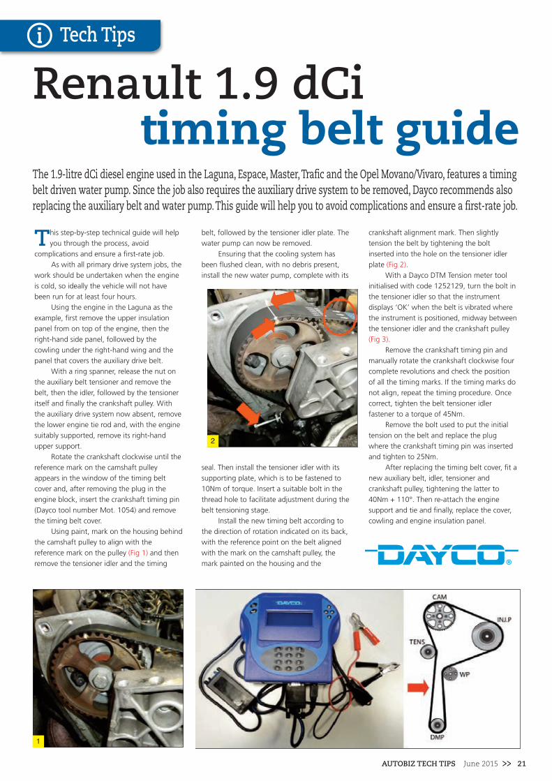
Using paint, mark on the housing behind
the camshaft pulley to align with the
reference mark on the pulley (Fig 1) and then
remove the tensioner idler and the timing
belt, followed by the tensioner idler plate. The
water pump can now be removed.
Ensuring that the cooling system has
been flushed clean, with no debris present,
install the new water pump, complete with its
seal. Then install the tensioner idler with its
supporting plate, which is to be fastened to
10Nm of torque. Insert a suitable bolt in the
thread hole to facilitate adjustment during the
belt tensioning stage.
Install the new timing belt according to
the direction of rotation indicated on its back,
with the reference point on the belt aligned
with the mark on the camshaft pulley, the
mark painted on the housing and the
crankshaft alignment mark. Then slightly
tension the belt by tightening the bolt
inserted into the hole on the tensioner idler
plate (Fig 2).
With a Dayco DTM Tension meter tool
initialised with code 1252129, turn the bolt in
the tensioner idler so that the instrument
displays ‘OK’ when the belt is vibrated where
the instrument is positioned, midway between
the tensioner idler and the crankshaft pulley
(Fig 3).
Remove the crankshaft timing pin and
manually rotate the crankshaft clockwise four
complete revolutions and check the position
of all the timing marks. If the timing marks do
not align, repeat the timing procedure. Once
correct, tighten the belt tensioner idler
fastener to a torque of 45Nm.
Remove the bolt used to put the initial
tension on the belt and replace the plug
where the crankshaft timing pin was inserted
and tighten to 25Nm.
After replacing the timing belt cover, fit a
new auxiliary belt, idler, tensioner and
crankshaft pulley, tightening the latter to
40Nm + 110°. Then re-attach the engine
support and tie and finally, replace the cover,
cowling and engine insulation panel.
The 1.9-litre dCi diesel engine used in the Laguna, Espace, Master, Trafic and the Opel Movano/Vivaro, features a timingbelt driven water pump. Since the job also requires the auxiliary drive system to be removed, Dayco recommends alsoreplacing the auxiliary belt and water pump. This guide will help you to avoid complications and ensure a first-rate job.
Renault 1.9 dCi timing belt guide
2
1

22 >> June 2015 AUTOBIZ TECH TIPS
Tech Tips
Aclutch replacement on the Mercedes can
be a little tricky, but with the guidance of
the LuK clutch clinic, the whole process will
become much easier. Nothing out of the
ordinary is needed to complete the job; the
only special tools required are a transmission
jack and a long axle stand. A four post ramp
was used in this example, however, a two post
ramp may also be suitable.
For safety reasons, it is considered best
practice to disconnect the battery earth lead
before commencing work. The vehicle may be
fitted with anti theft wheel bolts, so make sure
you have the key before you start.
Raise the vehicle and remove the small
rear under tray and the supporting bracket
attached to the chassis. Unbolt and remove
the exhaust mounting bracket (fig-1) and
remove the large clip (fig-2) securing the
exhaust assembly to the down pipe. While
supporting the exhaust, remove the supporting
rubber mountings near the rear silencer, and
lower the whole system to the floor.
Undo and remove the two central heat
shields to provide access to the prop-shaft.
Undo the centre support bracket for the prop-
shaft and remove the clips connecting the gear
change mechanism to the bracket.
While supporting the gearbox, undo the
large mounting (fig-3) and the large rubber
support. Unclip both the handbrake cable, and
the selector cable, and stow them to one side.
Mark the positions of the front and rear prop-
shaft flanges (fig-4) and remove the nut and
bolts attaching them. Unbolt and remove the
centre bearing support and carefully lower the
prop-shaft assembly to the floor. Release the
gearbox change mechanism from above the
gearbox, which is secured by a small clip and a
ball joint.
Unplug all the electrical connections from
the gearbox and near the bell-housing.
Disconnect the slave cylinder connection by
releasing the small clip (fig-5) and pulling out
the pipe. Plug the pipe to prevent leakage, and
undo all of the bell-housing bolts and, with
support, carefully lower the gearbox to the
floor.
With the clutch removed, check the dual
mass flywheel (DMF) for signs of heat stress
and evidence of grease loss. The DMF should
also be tested for freeplay and rock between
the primary and secondary masses; LuK tool
number 400 0080 10 is specifically designed
for this purpose on all LuK manufactured
DMFs. Full instructions and tolerance data for
all LuK DMFs are contained on a CD which
comes with this special tool.
Clean the first motion shaft splines and
any debris from the bell housing (especially
important when a release bearing has failed).
Remember, if the bearing or sleeve is made of
plastic, there is no need for lubrication. If both
parts are metal, then a high melting point
grease should be used, not a copper based
product.
Put a small dab of grease on the first
motion shaft splines, making sure the new
driven plate slides freely back and forth on the
splines. This not only spreads the grease
evenly, but also makes sure you have the
correct kit. Wipe any excess grease off the
shaft and driven plate hub. Using a universal
alignment tool, and checking the driven plate
is the correct way round (note “Getriebe
Seite” is German for “Gearbox Side”), the
clutch can be bolted to the flywheel, evenly
and sequentially.
Before fitting the gearbox, make sure the
locating dowels are in place and not damaged.
Refit any that have become dislodged and refit
the gearbox. Make sure the gearbox bell
housing bolts are secured before lowering the
jack. Refitting is the reverse of the removal.
For technical support and repairinstallation tips, go to www.RepXpert.comor you can call the LuKtechnical hotline on 0044-143-226-4264.
Introduced in 2000 to replace the aging W202 range, the Mercedes C Class W203 is a proven contenderfor the competitive executive compact market. As many vehicles are no longer covered by themanufacturer’s warranty, this makes the Mercedes a perfect candidate for a LuK clutch clinic.
Clutch ClinicMercedes C220 CDi
Malcolm Short, Schaeffler
1
3
4 4
2

AUTOBIZ TECH TIPS June 2015 >> 23
In this article we tackle the A4 2.0TDi, with an
engine code of CAGA. The engine on this
vehicle has been identified as an interference
type, so the likelihood of engine damage, if the
cambelt breaks is very high. It is very important
that the belt installation is performed on a cold
engine, so plan the job carefully. Always turn the
engine in the normal direction of rotation only
(unless advised otherwise by the OEM fitting
instructions), recommended manufacturers
torque values should always be used and it is
recommended to change the tensioners and the
pulleys when replacing the cambelt.
A two post ramp is ideal for carrying out
the replacement and it is vital that the
appropriate timing belt replacement tools are
used, these are readily available from most motor
factors. If the vehicle is equipped with alloy
wheels, it’s a good idea to locate the adapter key
before you start.
Before carrying out any work disconnect
the battery earth cable. Remove the bumper top
closing panel, the cold air intake duct and the
engine cover. Disconnect the air temp sensor
from behind the Audi logo attached to the front
grille. Raise the vehicle and remove both front
wheels. Remove the driveshaft guard and the
wheel arch liner fixings, there are quite a lot of
fixings to be removed. In this example we did not
remove the complete liner, but just enough to
carefully fold it towards the rear of the wheel
arch, to allow enough access to the drive system.
Remove the engine undertray.
Disconnect the front fog light multi plug
connectors on both sides. Remove the bumper
by removing the two bolts one in each wheel
arch and the two bolts from the brackets one on
each side next to the headlights. Disconnect both
headlight multi plugs and the bonnet release
sensor wire. Disconnect the bonnet release cable.
Remove two bolts located on the top of the
modular front end (MFE), next to the headlights.
Remove the bolts, there are three on each side
on the longitudinal member, and replace the top
two bolts on each side with either a longer bolt
or all thread to slide the MFE into its service
position. Disconnect the intercooler pipes and
slide the MFE forward into service position.
Remove the upper timing belt cover.
Release the auxiliary belt tensioner by
turning it clockwise, and remove the auxiliary
drive belt. Pop out the crankshaft pulley
centre cap, and remove retaining bolts and
crankshaft pulley. Remove the lower and
centre timing belt covers. Rotate crankshaft
clockwise to TDC on No. 1 cylinder, ensuring
that the TDC markings are in alignment with
the camshaft pulley windows positioned at
12 o`clock, rotate crankshaft one turn
clockwise if not. Lock the crankshaft using
the special tool and ensure the dowel on the
tool is located in the oil seal housing.
Slacken the camshaft and high pressure
pump bolts just enough to allow them to
rotate freely on their axis, but not enough to
allow them to tilt. Slacken the tensioner
pulley nut and remove the timing belt.
Replace all the tensioner and pulleys.
When installing the new tensioner, it is
imperative to locate it in the slot on the belt
cover back plate to avoid failure or damage.
Install the tensioner locking pin (if not already
fitted, ensuring the tensioner is in the right
starting position). Lock the camshaft and
pressure pump sprockets with timing pins. Turn
camshaft and high pressure pump sprockets fully
clockwise in slotted holes.
Install the timing belt in the following
order:
1. Crankshaft sprocket (CS)
2. Guide pulley (G1)
3. Tensioner pulley (TP)
4. Camshaft sprocket (Cam)
5. Water pump sprocket (WP)
6. Guide pulley (G3)
7. High pressure fuel pump sprocket (FP)
8. Guide pulley (G2)
Remove the locking pin. Rotate the
camshaft sprocket anti-clockwise, using an anti-
rotation tool to ensure the belt is taut between
the camshaft and high pressure pump sprockets.
Tighten the securing bolts for the camshaft and
high pressure pump pulleys, to a tightening
torque of 20Nm.
Slowly rotate the tensioner pulley
clockwise, until the pointer is aligned with the
locating notch. Make sure the tensioner nut does
not turn while aligning the pointer. Tighten the
tensioner nut to a torque of
20Nm + 45°.
Remove the camshaft, high pressure pump
and crankshaft locking tools. Rotate crankshaft
slowly, two turns clockwise until just before TDC
on number 1 cylinder. Refit the crankshaft
locking tool whilst slowly turning crankshaft to
TDC and make sure the locating dowel sits inside
the oil seal housing. Verify the timing marks are
aligned and the camshaft locking tool can be
easily inserted. (NOTE: do not insert high
pressure locking tool, as this could be slightly
misaligned and does not need adjustment).
Make sure the tensioner pointer is correctly
aligned with the locating notch, keeping in mind
a 5mm tolerance is permitted to the right of the
notch only. Repeat the procedure if this is not the
case.
The installation of the remaining parts is
the reverse order of removal, but it is strongly
advised to check the condition of the auxiliary
belt and driven components for excessive wear
and consider replacing them. Finally, it is
advisable to rotate the engine by hand a number
of times before starting the engine, to check for
any interference or noise.
For technical support andrepair installation tips, go towww.RepXpert.com or youcan call the INA technicalhotline on 0044-143-226-4264
The Audi A4 may sound like a daunting vehicle on which to change a cambelt, but with a little know howand the appropriate tools, it will prove to be an ideal repair. INA takes a closer look at this popular model.
Timing belt 2008 Audi A4 2.0TDi
Install the timing belt in the following order:CS, G1, TP, Cam, WP, G3, FP and G2
CS
G1
TPFP
WP
Cam
G2
G3
1
2
3
4
5
6
7
8
Malcolm Short, Schaeffler
Tech Tips
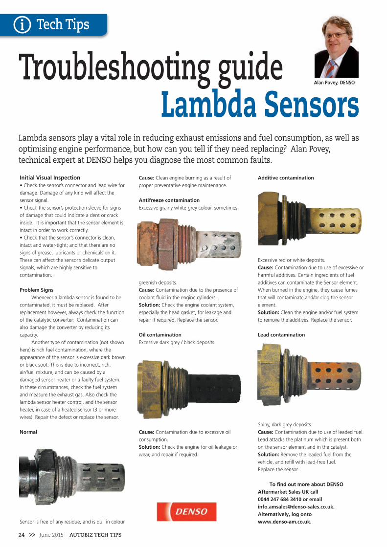
24 >> June 2015 AUTOBIZ TECH TIPS
Tech Tips
Initial Visual Inspection• Check the sensor’s connector and lead wire for
damage. Damage of any kind will affect the
sensor signal.
• Check the sensor’s protection sleeve for signs
of damage that could indicate a dent or crack
inside. It is important that the sensor element is
intact in order to work correctly.
• Check that the sensor’s connector is clean,
intact and water-tight; and that there are no
signs of grease, lubricants or chemicals on it.
These can affect the sensor’s delicate output
signals, which are highly sensitive to
contamination.
Problem SignsWhenever a lambda sensor is found to be
contaminated, it must be replaced. After
replacement however, always check the function
of the catalytic converter. Contamination can
also damage the converter by reducing its
capacity.
Another type of contamination (not shown
here) is rich fuel contamination, where the
appearance of the sensor is excessive dark brown
or black soot. This is due to incorrect, rich,
air/fuel mixture, and can be caused by a
damaged sensor heater or a faulty fuel system.
In these circumstances, check the fuel system
and measure the exhaust gas. Also check the
lambda sensor heater control, and the sensor
heater, in case of a heated sensor (3 or more
wires). Repair the defect or replace the sensor.
Normal
Sensor is free of any residue, and is dull in colour.
Cause: Clean engine burning as a result of
proper preventative engine maintenance.
Antifreeze contamination Excessive grainy white-grey colour, sometimes
greenish deposits.
Cause: Contamination due to the presence of
coolant fluid in the engine cylinders.
Solution: Check the engine coolant system,
especially the head gasket, for leakage and
repair if required. Replace the sensor.
Oil contamination Excessive dark grey / black deposits.
Cause: Contamination due to excessive oil
consumption.
Solution: Check the engine for oil leakage or
wear, and repair if required.
Additive contamination
Excessive red or white deposits.
Cause: Contamination due to use of excessive or
harmful additives. Certain ingredients of fuel
additives can contaminate the Sensor element.
When burned in the engine, they cause fumes
that will contaminate and/or clog the sensor
element.
Solution: Clean the engine and/or fuel system
to remove the additives. Replace the sensor.
Lead contamination
Shiny, dark grey deposits.
Cause: Contamination due to use of leaded fuel.
Lead attacks the platinum which is present both
on the sensor element and in the catalyst.
Solution: Remove the leaded fuel from the
vehicle, and refill with lead-free fuel.
Replace the sensor.
To find out more about DENSOAftermarket Sales UK call 0044 247 684 3410 or [email protected], log onto www.denso-am.co.uk.
Troubleshooting guideLambda Sensors
Lambda sensors play a vital role in reducing exhaust emissions and fuel consumption, as well asoptimising engine performance, but how can you tell if they need replacing? Alan Povey,technical expert at DENSO helps you diagnose the most common faults.
Alan Povey, DENSO

AUTOBIZ TECH TIPS June 2015 >> 25
DENSO A/C Compressors are new, filled with the right amount of oil and delivered as complete assemblies. DENSO is the world
leader in A/C compressors, selected by top vehicle manufacturers such as Audi, BMW, Fiat, Mercedes, Porsche, Toyota and VW.
Nine out of ten cars already feature original DENSO parts. If major car manufacturers place their trust in DENSO, why shouldn’t
you?
www.denso-am.co.uk
Get Inside ACCompressor
• Exact match to vehicle specifications
• High quality; low warranty ratio
• 100% OE aftermarket programme
• Market leading manufacturer

26 >> June 2015 AUTOBIZ TECH TIPS
Tech Tips
Acomplex setting up and alignment is
required of all the components on the
shaft, which include shim washers (choice of 8)
to get the precise levels of end play. Because of
this, Blue Print have manufactured a complete
halfshaft to OE specification which is fully
assembled and ready to fit, including a new axle
tube oil seal and new securing nuts with locking
washers.
This means labour time is considerably
reduced and there is far less risk of damaging
parts during fitment. The Blue Print part is
correct for all models fitted with a Limited Slip
Differential without the optional electronic
differential lock.
The following information is intended as a
guide only. For full fitting information, follow
vehicle manufacturer’s instructions.
Expect the job to take in the region of
45minutes.
CautionBefore removing the rear halfshaft, disconnect
and carefully remove the ABS sensor. Failure to
do so may result in damage to the sensor wires
and the sensor becoming inoperative.
• Raise the vehicle and remove the road wheel.
• Remove the rear brake drum followed by rear
ABS sensor.
• The halfshaft is secured to the axle via four
studs/nuts through the brake back plate.
Remove the 4 nuts. (Fig. 1)
• With the use of a slide hammer, disengage
the halfshaft from the axle housing, but do not
fully remove yet as the back plate is no longer
secured.
• Re-secure the back plate with an M10 nut and
bolt or similar and then fully remove the
halfshaft from the axle housing. (Fig. 2)
• Using an appropriate tool, remove the axle
tube oil seal and guide washer. (Fig. 3)
• Now is the ideal time to make sure the ABS
sensor area is free from dirt and debris.
• Ensure the axle tube is cleaned as necessary
and fit the new oil seal and guide washer using
an appropriate tool. (Fig. 4)
Note: The oil seal must be fitted with the seal
lip facing towards the differential and a light
coat of oil on the lip.
Note: : The guide washer must be fitted with
the chamfer side facing away from the
differential.
• Coat the new halfshaft spline with gear oil
and apply multi-purpose grease to the surface
of the shaft, that will come into contact with
the oil seal, once installed into the axle case.
• Insert the new halfshaft into the axle housing,
but not fully. Now remove the M10 nut and bolt
from the backing plate and fully insert the shaft.
• Tighten the four new halfshaft securing
studs/nuts in stages to an eventual torque of
70-75Nm. (50-55lb ft)
• Refit the ABS sensor and tighten bolt to
13Nm. (10lb ft)
• Refit the brake drum after ensuring the shoes
are not contaminated with diff oil.
• Refit road wheel and tighten nuts to 112Nm.
(83lb ft)
• Check differential oil level and top up as
required.
NOTE: It is advised to check that the rear axle
housing breather is clean and clear, as a blocked
breather can result in pressure build up within
the rear axle which may result in premature
failure of the oil seals. (Fig.5)
For technical support, information andrepair installation tips, go towww.blueprint-adl.com/workshops/technicallibrary/applications.
Noise and excessive play in the rear wheel bearings are a common problem with the 2005 onwardsNissan Navara D40 pick-up. Blue Print provides instructions on how to best handle this job.
Navara halfshaft replacement
1
2
3
4 5

AUTOBIZ TECH TIPS June 2015 >> 27
Tech Tips
AVW Polo TSI was dropped
off suffering a problem
with delayed crank starting. A
local independent dealer had
presented the car to a friend
working in the local dealership,
following which, a report of no
fault found was made. I can only
assume this deliberation came
from the absence of any DTCs –
are there technicians simply not
trained to examine actual data,
simply not trusted or worse,
allowed to think outside the
box?
Perhaps it’s just me, but I
couldn’t exist in an environment
where technical pride, respect
and ambition are suppressed.
The dealerships offer some
excellent training programmes,
not withstanding their access to
the relevant technical repair
information. So where and why
does it so often go wrong?
The startI promised the guys on a
recent weekend training course
to conclude the tests we carried
out with a repair solution. For
the benefit of everyone else, let’s
start at the beginning. The Polo
1.4 GTI DSG employs a recent
variant of the direct petrol injection
system, MED17.9.
The initial first look confirmed no DTCs
but the vehicle did suffer an extended
cranking prior to starting. Once started, it ran
smoothly. Some ten years ago I developed a
process of testing hydraulic high pressure
pumps, using analysis from the pressure
sensor profile. This was initially used on
common rail and later adapted for petrol high
pressure systems. Having no test data on this
system variant, it presented a perfect
challenge to the diagnostic process.
Direct petrol injection is very similar to
common rail diesel control and the initial test
sequence began by looking at the key critical
requirements, firstly the ignition drivers,
secondly injector drivers and third, rail
pressure. The result of this composite
observation, and we can now reveal our
involvement in developing the new ‘Rainbow’
Pico scope, confirmed an unusually slow
pressure build-up.
Normally pressure build (I refer to this as
rise time) should take no longer than 600
milliseconds and as little as 300 milliseconds –
our vehicle took up to three whole seconds.
CheckingThe next stage in the process involves
intrusive tests. This part of our
past development programme
was designing a low pressure
test gauge. The requirement
was to monitor suction or
positive pressure priming
systems, together with flow and
the ability to conduct pump
proof testing under real load
conditions. Applying this test
confirmed excellent low pressure
priming, with 6 bar available to
maintain high pressure pump
pressure.
The most interesting
aspect of our initial observations,
unique so far for petrol systems,
was that until a certain pressure
was reached, no triggering of
fuel or spark took place. We also
noted that no driver outputs
were present at the high
pressure control valve, so no
current was present either. This
further confirmed our training
group’s findings that the valve is
actually a volume control device.
Proving this theory also follows
our common rail pump proof
process; removing current at
2,000 rpm immediately caused
the pump to run at full pressure,
115 bar. The other intriguing
part of the waveform profile was
the accelerated decay time, not
normal for this pump type.
An outcomeThe decision? You need a new pump
mate, with just one caveat – check the
camshaft drive lobes and follower. Other non-
relevant issues found included a reduced
burn-time on coil three and no current
transition across the wideband sensor.
Replacing the pump reduced the rise
time to 630 milliseconds. It was also noted via
TPS that the pump had undergone several
part number
updates.
If a car doesn’t have any Diagnostic Trouble Codes (DTCs), does that mean that there isn’t aproblem? A long cranking Polo didn’t have any DTCs, but there was obviously something wrong.Autoinform’s Frank Massey explains his diagnostic process to get this Polo starting faster.
Frank Massey, Autoinform
DELAY: The old pump took three full seconds to build pressure
REPLACED: A new pump brought the figures back to the expected times
Having a good process

28 >> June 2015 AUTOBIZ TECH TIPS
Tech Tips
The Direct Shift Gearbox (DSG) is a semi-
automatic transmission manufactured by VAG.
This type of transmission has been utilised across the
range of VAGs models since being introduced in
2004. It has proven to be a very popular choice for
consumers and vehicles with this type of transmission
regularly show up in garages within the Irish
aftermarket scene. Unfortunately, many garages in
the aftermarket are not aware that this transmission
can be easily diagnosed and repaired, with a little
extra knowledge and very little cost.
Before commencing with the repair, ensure
that the vehicle you are working on does have a DSG
DQ250 type gearbox, as the below procedure does
differ for other variations. The gearbox code can be
identified on the data sticker in the handbook or in
the boot. If you are unsure, please call the LuK
technical hotline for advice.
Before starting the repair, you will need to
acquire a gearbox fluid re-filler tool, which screws
into the oil container and allows the oil to be pushed
into the gearbox. You will also need a transmission
jack, an engine support cradle and a long axle stand.
A two post ramp was used in this example, a four
post ramp may not provide enough clearance. If the
vehicle has alloy wheels. it may be fitted with anti
theft wheel bolts, so make sure you have the key
before you start.
Open the bonnet and lift off the engine cover.
Remove the battery cover and disconnect the battery
terminals. Undo the clamp holding the battery in
place and lift the battery out of the tray. Disconnect
the Mass Air-Flow sensor (MAF) and the air filter
housing attached to the front slam panel. Undo the
single Allen key bolt, securing the air filter housing
and release the clips securing the assembly to the
inlet manifold. Disconnect any attached breathers
and remove the entire air filter housing by pulling
sharply upwards, allowing the rubber fixings to
release.
Remove the front part of the plastic battery
surround and undo the fixing bolts in the base of the
battery tray. Release any attached wiring harnesses
and lift out the tray. Disconnect the gear linkage
cable, by marking the adjuster mechanism position
and undoing the nut. Remove the large circlip
retaining the cable onto the securing bracket and
release the cable and stow it to one side.
Remove the earth connection from the gearbox
mounting bolt and clamp the coolant pipes
connected to the cooler on top of the gearbox and
disconnect them. Remove the electrical connections
on the starter motor and both bolts securing it in
place allowing the starter to be removed. Disconnect
the large round electrical connecter attached to the
gearbox opposite the breather (Fig 1). Undo the bolts
securing the coolant pipes for the oil cooler and stow
them to one side. Use the engine cradle to support
the weight of the engine and undo the upper bell-
housing bolts. The gearbox mounting bracket can
now be removed.
Raise the vehicle and remove the nearside front
wheel and the wheel arch liner. Undo the nearside
front driveshaft bolt and remove the lower arm nuts
and release the lower arm. Undo the bolts securing
the flanges to both sides of the gearbox and remove
the nearside drive shaft. Unclip and remove the large
intercooler pipe in front of the radiator and undo the
single nut securing the electrical connectors (Fig 2)
attached to the side of the gearbox. Drain the
gearbox fluid and separate the two gearbox flanges
by undoing the Allen key bolt in the centre (Fig 3). If
the flanges are not removed, the one attached to the
long shaft fouls the DMF when trying to remove the
gearbox and it makes it very difficult to remove.
Undo the gearbox steady bar and the lower bell
housing bolts and while using the gearbox stand
lower the transmission to the floor.
With the gearbox removed, visually check the
DMF (Fig 4) for signs of excessive grease loss. The
splines at the centre on the DMF locate onto the
splines on the clutch attached to the gearbox. The
condition of these splines should be checked for
excessive wear. These types of DMF’s can’t be tested
in the same manner as a conventional DMF, so only a
visual and audible inspection is required.
No reprogramming is needed to replace the
DMF, simply unbolt the old unit and install the new
one. Check the spigot bearing in the crankshaft for
wear and replace if required. The seals on the clutch
centre shaft and around the outer lip need to be
checked for leaks, no fluid should be evident inside
the bell-housing.
Before refitting the gearbox, make sure the
locating dowels are in place and not damaged. Refit
any that have become dislodged and refit the
gearbox. Make sure the gearbox bell housing bolts
are secured before lowering the jack. Refitting is the
reverse of the removal.
For technical support and repairinstallation tips, go towww.RepXpert.com or youcan call the LuK technicalhotline on 0044-143-226-4264.
A Direct Shift Gearbox actually uses a Dual Mass Flywheel (DMF) which can be diagnosed in a similar manner to amanual gearbox. They are simple to replace and the parts are available from all local LuK supplying factors. In thismonths clutch clinic, we look at the replacement of the DMF on a Mk5 Golf GT TDi with the DQ250 wet transmission.
Malcolm Short, SchaefflerClutch Clinic
Golf GT TDi DSG
1
3
4
2

AUTOBIZ TECH TIPS June 2015 >> 29
Tech Tips
DSG filter & oil servicing
DSG gearboxes are becoming more
common, with many drivers assuming
that it is actually an automatic gearbox. To
many, no clutch means it’s an automatic.
While the shifting of gears is automatic, the
internal workings are actually two manual
gearboxes co-operating to supply engine
power to the wheels. Gear changes are all
carried out electronically by the vehicle, and
can occur in less than 0.4 seconds.
The advantage of a DSG is that precise
control over gear changes can be made
very quickly, in response to driver demand
and existing conditions. This will result in
better performance and a longer life, for
both of the clutches within the DSG.
Engine off - do not start• Place an oil collecting tray underneath the
transmission. Leave it in place until the end
of the procedure.
• Before removing the filter housing from
the transmission, tip it slightly in its seating.
This allows oil to flow back into the
transmission.
• After you have inserted the filter with
shoulder downwards (see illustration 2),
tighten housing to 20 Nm.
• Raise vehicle (wheels raised and not
touching any surface).
• Remove the noise insulation tray.
• Remove inspection plug "A" near the
pendulum support.
• A black plastic overflow tube (see
illustration 3) is located in the hole marked
"A" (see illustration 4) (with 8 mm hex
socket head, torque specification: 3 Nm). Its
length determines the oil level in the
transmission.
• Remove this oil tube.
• About 5 litres of oil will drain out.
• Reinstall overflow tube, tightening it to 3
Nm.
• Attach the febi DSG oil filling tool to
drain/fill hole "A" hand tight.
• Shake the oil containers before opening.
For a complete oil & filter change, you will
require 5.5 litres of DSG oil. To change
bottles, the shut-off valve can be closed or
oil filling tool T028811 can be held higher
than the transmission.
• Now start the engine; press and hold the
brake pedal while you shift into each
selector lever position for approximately 3
seconds per position. Place the lever in
position P again. Do not switch off engine.
• Let the engine run while the DSG is in the
P position, until the DSG oil temperature
reaches between 35 ° to 45 ° Celsius.
• Disconnect the febi DSG filling tool, be
cautious as engine will be running & the oil
will be hot.
• Let any excess oil drain out.
• As soon as the oil has run out (it slows to
a drip), install the bolt, making certain to
use a new seal on the bolt.
• The Tightening torque for the bolt is 45
Nm.
• Turn off the engine.
• Dispose of the used oil in an appropriate
manner.
• This completes changing the oil and filter.
Technical on this and othervehicles andcomponents can befound at febi-live.comor on the febiFacebook page.
A direct-shift gearbox (DSG) is an electronically controlled gearbox with 2 clutches, or in other wordstwo manual gearboxes in one unit, controlled by electronics. Not a manual, but also not a traditionalautomatic gearbox, febi’s Collin Kennedy explains how to service a DSG to keep it operating properly.
Colin Kennedy, febi
2
3 41

30 >> June 2015 AUTOBIZ TECH TIPS
Tech Tips
We used a two post ramp and engine
support beam and two transmission
jacks to assist with the repair. If the vehicle has
alloy wheels, then it is a good possibility that
they are secured with anti theft bolts, so make
sure the locking tool key is available before
starting the repair. Before removing the gearbox,
set the clutch actuator into a default mode so
that it will release the preload. To do this, install
the diagnostic tool and set to the clutch clamp
position, which will release the clutch fully.
Failure to do this can result in damage to the
adjustment mechanism.
Disconnect the battery terminals and stow
safely. Remove the battery support clamp and
battery. Release the five bolts that hold in place
the battery tray and remove. Disconnect the
three gear shift connector switches positioned
on the gear selector unit (fig 1). Disconnect the
clutch cable from the release lever. Remove the
bolt that holds the wiring loom bracket in place.
Disconnect the switch found at the front bottom
of the gearbox, and the switch found at the rear
of the gearbox, and stow the wiring loom aside.
Completely remove the gear selector unit by
removing the three securing bolts. It is a good
idea to mark the positioning of the bolts to
ensure the correct position when reinstalling the
unit (fig 2). Once removed, this will expose a
connector switch underneath, that can be
disconnected and stowed safely to the side.
Remove the earth lead bracket, held in
place with two bolts, and remove the oxygen
sensor connection and bracket and stow. While
the vehicle is still at ground level, it is a good
idea at this point to remove the top two
accessible bell housing bolts and one starter
motor bolt (fig 3). Remove the engine top
mount bolts and support the engine with the
support beam. Raise the vehicle and drain the
gearbox oil. Remove both front wheels, and on
the nearside release the inside wheel arch liner
by removing three bolts. Only the front section
needs to be released for better access when
lowering the gearbox.
Unbolt the bottom ball joints and release
from the lower suspension arms on both sides.
Remove the drive shafts from the gearbox and
the wheel hubs. Remove the bottom gearbox
stabiliser (fig 4) which is held by three bolts, two
at the front and one that secures from the rear
through the subframe, and slide the stabiliser
out from the subframe. Remove the back plate
from the gearbox, held by three bolts, and
remove the starter motor bolt from the rear (fig
5). Support the gearbox using the transmission
jacks, and remove the remaining three bell
housing bolts.
Carefully lower the gearbox to the floor
and remove the worn clutch cover, drive plate
and release bearing. With the clutch removed,
check the flywheel for signs of heat stress. Clean
the first motion shaft splines and any debris from
the bell housing (especially important when a
release bearing has failed).
Put a small dab of high melting point
grease (not a copper based product) on the first
motion shaft splines and make sure the new
driven plate slides freely back and forth. This not
only spreads the grease evenly, but also makes
sure you have the correct kit. Wipe any excess
grease off the shaft and driven plate hub. Using
a universal alignment tool and checking the
driven plate is the correct way round (note
“Getriebe Seite” is German for “Gearbox Side”)
the clutch can be bolted to the flywheel evenly
and sequentially.
Before fitting the gearbox make sure the
locating dowels are in place and not damaged.
Refit any that have become dislodged and refit
the gearbox. Make sure the gearbox bell housing
bolts are secured and the gearbox stabiliser is
installed before removing the transmission jacks.
Refitting is the reverse of the removal, not
forgetting to reset the clutch actuator and gears
using your diagnostic equipment.
For technical support and repairinstallation tips, go towww.RepXpert.com or youcan call the LuK technicalhotline on 0044-143-226-4264.
Clutch ClinicAygo 1.0 HC07 JUG
The Toyota Aygo 1.0 HC07 JUG was launched in 2005 and has proven to be a popular car. Thishandy article should prove useful to any independent garage undertaking the four hour repair.We tackle the semi automatic transmission in this article.
1
2
3
4 5
Malcolm Short, Schaeffler

AUTOBIZ TECH TIPS June 2015 >> 31
yyynlO
k i p p ol pass alaths tt par
eh tff t o
s stet
n e give ar
p markso t
s.
d and pestruAs a t
r woeh t,rnet parnicalchen tevo pr
eruactfa manueiclheading ves ld’s rl
seoors che
d and p
r OeTh.r.elflffaechS
s ut - tr paralngiiroofessio a prr fo,So
s uorgoist rothe m Itch,u clKu LyervE
si deor telflffaechSestruAs a t
r
.ntipmequ Eriginal
.GA FA &AN I,Kut L the qntainai mll that wirepai ralno
s avdard stantyial qud analiater m Fdt anennpom costemt syel bAN
cisioe prchet-igh hypplgn and su woeh t,rnet parnicalchen tevo pr
e
c anmrfo perd antyiliabiel r,ty,ial qu
s.’ermsto curue - olablai vd an testedeeng has bniear bGA F
.ntmeit firiginalr oos fotn paroruactf manueiclheading ves ld s rl
f the
se
ce o
toedvo appr
oors che
co.trpepXeR.www.
the tell calyplmSiW?er mo wantuoYo
rmarkeetaft-relfffaesch.www.mo
32 2 (0)144+4ne onitle honephop!le can heW
ku.co.t
@schaefffon-i hfdlai emro264 264
m.coerfl

SIMPLE,
POWERFUL &
INFORMATIVE02 Blue Print
febi UK Limited
Bilstein House | Green Lane Industrial Park | Featherstone
Pontefract | West Yorkshire | WF7 6TA | Great Britain
Tel. +44 (0)1977 699777
Fax +44 (0)1977 707222
febi is a bilstein group brand
Mercedes Benz Conductor Plate
An electronically shifted 5-speed overdrive automatic transmission that has
been around since 1996. It has been used by a number of vehicle manufacturers
and can be found in a variety of Mercedes, Chrysler, Jaguar, Jeep, Dodge and
Ssangyong models.
Replacing the Conductor Plate
febi parts required:
1 x
1 x
1 x
1 x
1 x
5 x
An assembled conductor plate layout and components:
S
P
I
Bilstein House | Green Lane Industrial Park | Featherstone
Pontefract | West Yorkshire | WF7 6TA | Great Britain
1 x
1 x
5 x
48 >> May 2015 AUTOBIZ
Tech Tips
The Direct Shift Gearbox (DSG) is a semi-
automatic transmission manufactured by VAG.
This type of transmission has been utilised across the
range of VAGs models since being introduced in
2004. It has proven to be a very popular choice for
consumers and vehicles with this type of transmission
regularly show up in garages within the Irish
aftermarket scene. Unfortunately, many garages in
the aftermarket are not aware that this transmission
can be easily diagnosed and repaired, with a little
extra knowledge and very little cost.
Before commencing with the repair, ensure
that the vehicle you are working on does have a DSG
DQ250 type gearbox, as the below procedure does
differ for other variations. The gearbox code can be
identified on the data sticker in the handbook or in
the boot. If you are unsure, please call the LuK
technical hotline for advice.
Before starting the repair, you will need to
acquire a gearbox fluid re-filler tool, which screws
into the oil container and allows the oil to be pushed
into the gearbox. You will also need a transmission
jack, an engine support cradle and a long axle stand.
A two post ramp was used in this example, a four
post ramp may not provide enough clearance. If the
vehicle has alloy wheels. it may be fitted with anti
theft wheel bolts, so make sure you have the key
before you start.
Open the bonnet and lift off the engine cover.
Remove the battery cover and disconnect the battery
terminals. Undo the clamp holding the battery in
place and lift the battery out of the tray. Disconnect
the Mass Air-Flow sensor (MAF) and the air filter
housing attached to the front slam panel. Undo the
single Allen key bolt, securing the air filter housing
and release the clips securing the assembly to the
inlet manifold. Disconnect any attached breathers
and remove the entire air filter housing by pulling
sharply upwards, allowing the rubber fixings to
release.
Remove the front part of the plastic battery
surround and undo the fixing bolts in the base of the
battery tray. Release any attached wiring harnesses
and lift out the tray. Disconnect the gear linkage
cable, by marking the adjuster mechanism position
and undoing the nut. Remove the large circlip
retaining the cable onto the securing bracket and
release the cable and stow it to one side.
Remove the earth connection from the gearbox
mounting bolt and clamp the coolant pipes
connected to the cooler on top of the gearbox and
disconnect them. Remove the electrical connections
on the starter motor and both bolts securing it in
place allowing the starter to be removed. Disconnect
the large round electrical connecter attached to the
gearbox opposite the breather (Fig 1). Undo the bolts
securing the coolant pipes for the oil cooler and stow
them to one side. Use the engine cradle to support
the weight of the engine and undo the upper bell-
housing bolts. The gearbox mounting bracket can
now be removed.
Raise the vehicle and remove the nearside front
wheel and the wheel arch liner. Undo the nearside
front driveshaft bolt and remove the lower arm nuts
and release the lower arm. Undo the bolts securing
the flanges to both sides of the gearbox and remove
the nearside drive shaft. Unclip and remove the large
intercooler pipe in front of the radiator and undo the
single nut securing the electrical connectors (Fig 2)
attached to the side of the gearbox. Drain the
gearbox fluid and separate the two gearbox flanges
by undoing the Allen key bolt in the centre (Fig 3). If
the flanges are not removed, the one attached to the
long shaft fouls the DMF when trying to remove the
gearbox and it makes it very difficult to remove.
Undo the gearbox steady bar and the lower bell
housing bolts and while using the gearbox stand
lower the transmission to the floor.
With the gearbox removed, visually check the
DMF (Fig 4) for signs of excessive grease loss. The
splines at the centre on the DMF locate onto the
splines on the clutch attached to the gearbox. The
condition of these splines should be checked for
excessive wear. These types of DMF’s can’t be tested
in the same manner as a conventional DMF, so only a
visual and audible inspection is required.
No reprogramming is needed to replace the
DMF, simply unbolt the old unit and install the new
one. Check the spigot bearing in the crankshaft for
wear and replace if required. The seals on the clutch
centre shaft and around the outer lip need to be
checked for leaks, no fluid should be evident inside
the bell-housing.
Before refitting the gearbox, make sure the
locating dowels are in place and not damaged. Refit
any that have become dislodged and refit the
gearbox. Make sure the gearbox bell housing bolts
are secured before lowering the jack. Refitting is the
reverse of the removal.
For technical support and repair
installation tips, go to
www.RepXpert.com or you
can call the LuK technical
hotline on
0044-143-226-4264.
A Direct Shift Gearbox actually uses a Dual Mass Flywheel (DMF) which can be diagnosed in a similar manner to a
manual gearbox. They are simple to replace and the parts are available from all local LuK supplying factors. In this
months clutch clinic, we look at the replacement of the DMF on a Mk5 Golf GT TDi with the DQ250 wet transmission.
Malcolm Short, Schaeffler
Clutch Clinic Golf GT TDi DSG
1
3
4
2
www.techtips.iePowered By
SIMShe gearbox and
al connections
curing it in
d. Disconnect
hed to the
do the bolts
and stow
upport
bell-
anhousing bolts and while using the gearbox stand
lower the transmission to the floor
With the gearbox removed, visu l
DMF (Fig 4) for signs of ex
splines at the c
spli
DMF) which can be diagnosed in a similar manner to a
available frrom all local LuK supplying faactors. In this
n a Mk5 Golf GT TDi with the DQ2250 wet transmission.
Malcolm Short, SchaefflernicGT TDi DSG
3
1 Website 1,900+ text searchable technical documents & videos Free to Use
Contributors
Copyright © 2022 FDOKUMEN