
5HL Yeast Room Brink / Propagation - Squarespace
157
PROCESS & PACKAGING, INC. 5450 Tech Circle, Moorpark, CA 93021 Tel: (805) 529-9890 Fax: (805) 529-9282 OPERATION MANUAL 5HL Yeast Room Brink / Propagation Serial No. 14OES60 380V-3PH-60HZ-30A
-
Upload
khangminh22 -
Category
Documents
-
view
0 -
download
0
Transcript of 5HL Yeast Room Brink / Propagation - Squarespace

PROCESS & PACKAGING, INC. 5450 Tech Circle, Moorpark, CA 93021 Tel: (805) 529-9890 Fax: (805) 529-9282
OPERATION MANUAL
5HL Yeast Room Brink / Propagation
Serial No. 14OES60 Keg cl eaner, keg cl eaning, Sankey keg, semi- automatic keg washing, sanitizi ng & filling, semi-automatic keg washi ng, sanitizi ng and filling, automatic keg washi ng, sanitizing & filling, semi- automatic keg washing, sanitizi ng and filling, stai nless s teel Sankey keg, American Sankey, European Sankey, Flash Pasteurizer, Fl ash Pas teurize, Flash Pasteurizati on, Brewing Sys tem, Br ew H ouse, Br ewer y, Micro Br ewer, Keg Washer, Fill By Weight, Wine on Tap, Winemaker, Fill By Weight Keg Filling, Fill By Weight Beer, Fill By Weight Wine Keg cleaner, keg cl eaning, Sankey keg, semi-automatic keg washing, sanitizi ng & filling, semi-automatic keg washi ng, sani tizing and filling, automatic keg washing, sanitizing & filling, semi-automatic keg washing, sanitizi ng and filling, stainl ess s teel Sankey keg, American Sankey, Eur opean Sankey, Flash Pasteurizer, Fl ash Pas teurize, Fl ash Pasteurizati on, Brewi ng Sys tem, Brew H ouse, Brewer y, Micr o Br ewer , Keg Washer, Fill By Weight, Wine on Tap, Winemaker, Fill By Weight Keg Filling, Fill By Weight Beer, Fill By Weight Wi ne Keg cleaner, keg cl eani ng, Sankey keg, semi-automatic keg washi ng, sanitizi ng & filling, semi-automatic keg washi ng, sanitizing and filling, automatic keg washing, sanitizi ng & filling, semi-automati c keg washi ng, sanitizi ng and filling, stainl ess steel Sankey keg, American Sankey, European Sankey, Fl ash Pas teurizer, Flash Pasteurize, Flash Pasteurization, Br ewing System, Brew House, Brewer y, Micro Brewer, Keg Washer , Fill By Weig ht, Wi ne on Tap, Wi nemaker, Fill By Weight Keg Filling, Fill By Weig ht Beer, Fill By Weight Wine Keg cleaner, keg cl eani ng, Sankey keg, semi-automatic keg washi ng, sanitizi ng & filling, semi-automatic keg washi ng, sanitizing and filling, automatic keg washing, sanitizi ng & filling, semi-automati c keg washi ng, sanitizi ng and filling, stainl ess steel Sankey keg, American Sankey, European Sankey, Fl ash Pas teurizer, Flash Pasteurize, Flash Pasteurization, Br ewing System, Brew House, Brewer y, Micro Brewer, Keg Washer , Fill By Weig ht, Wi ne on Tap, Wi nemaker, Fill By Weight Keg Filling, Fill By Weig ht Beer, Fill By Weight Wine
380V-3PH-60HZ-30A

PROCESS & PACKAGING, INC. www.iddeas.com
TABLE OF CONTENT
TITLE PAGE Table of contents 2 Preface /Disclaimer / Confidentiality and Copyrights 3 Operational Safety Notes / Training 4 Start-up and Shut-down Procedure 5 Layout 6 Elevation 7 Services 8 Electrical Section 9-17 Mechanical Section 18 Diaphragm Pump 19-31 Agitators (Turbine Mixer) 32-47 Pressure / Vacuum Valve 48-49 Load Cell 50-54 Temperature Control 55-86 VFD 87-134
HMI Remote 135-138 Sampling Valve 139-140 Oxine 141-154 Spares 155 Control Philosophy 156
Appendix Section 157

PROCESS & PACKAGING, INC. www.iddeas.com
PREFACE The SYSTEM has been designed as a self contained and reliable yeast storage/brinks and retrieval/pitching with four yeast strains at any one time. The following instructions and information have been prepared to clarify operational and maintenance procedures and should ensure long, reliable service from the machine if followed carefully. Proper maintenance and use of approved spare parts will extend the life of the system and it's reliability. The use of any non approved spare parts may void any warrants or guarantees, actual or implied.
DISCLAIMER The customer assumes all responsibility for the SYSTEM once delivered. The SYSTEM is tried and tested equipment. As such IDD Processing & Packaging will not be held responsible for alterations and modifications carried out by the customer without the written approval of IDD Processing & Packaging.
CONFIDENTIALITY & COPYRIGHT All information within is confidential and the copyright of IDD Process & Packaging, Inc. No portion of this data shall be released, disclosed, used or duplicated for use in procurement or manufacturing without the express written permission from IDD Process & Packaging, Inc.

PROCESS & PACKAGING, INC. www.iddeas.com
OPERATIONAL SAFETY NOTES WEAR SAFETY GOGGLES Wear Safety Goggles approved for use by your Safety and Operational Procedures Committees when operating or observing this system. WEAR CHEMICAL RESISTANT GLOVES & APRON Wear Chemical Resistant Gloves and Apron approved for use by your Safety and Operational Procedures Committee. WEAR BACK SUPPORT EQUIPMENT Wear Back Support Equipment approved for use by your Safety and Operational Procedures Committees and use proper lifting technique approved for use by your Safety and Operational Procedures Committees. VENTILATION Area should have adequate ventilation approved for use by your Safety and Operational Procedures Committees. Respirators should be used during cleaning and operations where fumes are present.
EMERGENCY STOP
MANUAL PROCESS STOPS To STOP the pump at any time, use the On / Off Switch, that is located on the Motor Conrol Panel.
TRAINING On-site training is available from our technical staff at the customers request.

PROCESS & PACKAGING, INC. www.iddeas.com
START UP AND SHUT DOWN PROCEDURES Below is a a typical CIP/SIP procedure: 1. Pre-Rinse: Rinse water clear to drain. (ambient or heated to 150ºF) 2. 2% Caustic wash at 120 to 150ºF for 30 to 45 mins. (recovered) 3. Rinse: Rinse water clear to drain. (ambient or heated to 150ºF) 4. 1% Acid wash at ambient to 150ºF for 15 to 30 mins. (recovered) 5. Post Rinse - Rinse water clear to drain. (ambient or heated to 150ºF) 6. Final Oxine Sanitizing: Dosed to 50 PPM for 10 mins. (recovered)
PROCESS & PACKAGING, INC. www.iddeas.com
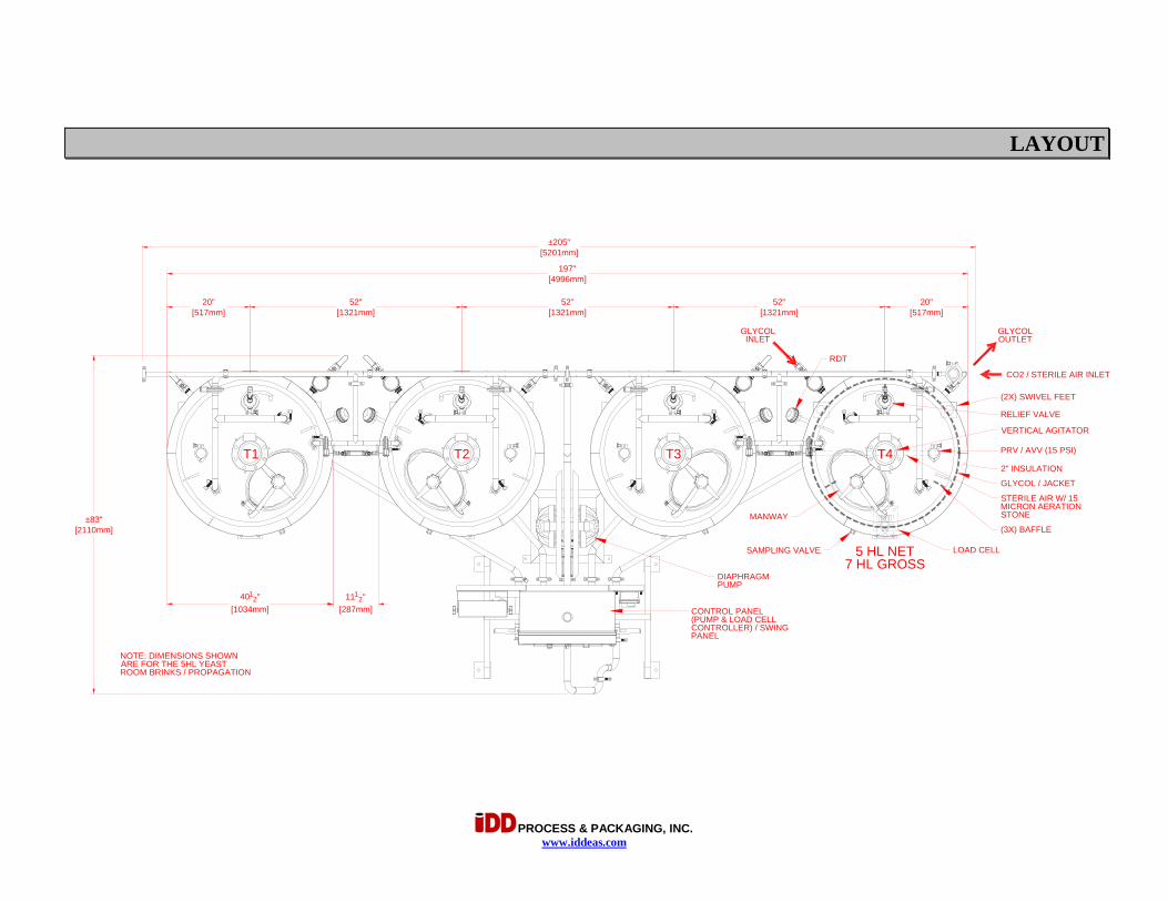
LAYOUT
(2X) SWIVEL FEET
LOAD CELL
GLYCOL / JACKET
2" INSULATION
RELIEF VALVE
STERILE AIR W/ 15MICRON AERATIONSTONEMANWAY(3X) BAFFLE
5 HL NET7 HL GROSS
CONTROL PANEL(PUMP & LOAD CELLCONTROLLER) / SWINGPANEL
GLYCOLINLET
GLYCOLOUTLET
±205"[5201mm]
VERTICAL AGITATOR
T1
RDT
SAMPLING VALVE
52"[1321mm]
52"[1321mm]
52"[1321mm]
197"[4996mm]
20"[517mm]
20"[517mm]
4012"
[1034mm]111
2"[287mm]
±83"[2110mm]
T2 T3 T4
DIAPHRAGMPUMP
PRV / AVV (15 PSI)
CO2 / STERILE AIR INLET
NOTE: DIMENSIONS SHOWNARE FOR THE 5HL YEASTROOM BRINKS / PROPAGATION

PROCESS & PACKAGING, INC. www.iddeas.com
ELEVATION
(2X) SWIVEL FEET
LOAD CELL
BAFFLEGLYCOL / JACKET
2" INSULATION
VERTICAL AGITATOR
PRV / AVV (15 PSI)
STERILE AIR W/15 MICRON AERATIONSTONE
SAMPLING VALVE
DIAPHRAGM PUMP(BEHIND)
RTD
SWING PANEL
5 HL - 30 HL CONTROL PANEL
LOADCELL
DISPLAY
CIP INLET
T1 T2 T3 T4
IN
OUT
0"
27"B.O. SAMPLE VALVE
75"B.O. MANWAY OPENING
103"
812"
1212"
C.L. TANKS 1-4
C.L. YEAST OR CIP OUTLET
24" C.L. INLET
33" C.L. CIP INLET
0"
65" T.O. PANEL
NOTE: HEIGHTS SHOWNARE FOR THE 5HL YEASTROOM BRINKS / PROPAGATION
50"GLYCOL OUTLET (REAR)
33"GLYCOL INLET (REAR )
83"CO2 / STERILE AIR INLET
41" AIR INLET
AIR FILTER

PROCESS & PACKAGING, INC. www.iddeas.com
SERVICES
CONNECTION
1/2" NPT (F)-
1-1/2" TC
DESCRIPTIONLINE
5
12
41-1/2" TC
3/4" NPT (F)
61-1/2" TC
3
7
ELECTRICAL - 380V-3PH-60HZ-30A
CIP OR YEAST OUTLETYEAST INLET
CIP INLET
AIR - 80 PSIG @ 30 SCFMGLYCOL INLET - 35 PSIG, - 6° C (PER TANK)
3/4" NPT (F)GLYCOL RETURN (PER TANK)
1/2" NPT (F)8 CO2 / STERILE AIR INLET - 15 PSIG

PROCESS & PACKAGING, INC. WWW.IDDEAS.COM
ELECTRICAL SECTION
IMPORTANT
ELECTRICAL NOTE:
1. CUSTOMER TO SUPPLY LOCAL DISCONNECT AND GROUND FAULT DEVICE.
2. IT IS RECOMMENDED THAT A SURGE PROTECTION DEVICE IS USED ON POWER SUPPLY TO THIS SYSTEM.
3. DURING INSTALLATION, ALL ELECTRICAL CONNECTIONS TO BE SECURELY FASTENED BEFORE POWER IS TURNED ON.


PROCESS & PACKAGING, INC. 2003
MECHANICAL SECTION
SEE SUPPLEMENTAL TECHNICAL DATA MANUAL
FOR ADDITIONAL INFORMATION IF PROVIDED

E4 1-1/2" Bolted Plastic Pumps Operating Instructions
E4 PolypropyleneE4 Kynar
Ver
sa-M
atic
E4 Non-Metallic Pumps• Polypropylene• Kynar
1 1/2" Elima-Matic Bolted Non-Metallicwith Metallic Center Section E4
VERSA-MATIC® • Warren Rupp, Inc. • A Unit of IDEX Corporation 800 North Main Street, Mansfield, OH 44902 USA • Phone: (419) 526-7296 • www.versamatic.com
© Copyright 2015 Warren Rupp, Inc. All rights reserved
1: P
UMP
SPEC
S2:
INST
AL &
OP
3: E
XP V
IEW
4: W
ARRA
NTY
Orig
inal
Inst
ruct
ions
Serv
ice
& O
per
ati
ng
Ma
nu
al

e4nmdlAsm-rev1015www.versamatic.com
IMPORTANT
Read the safety warnings and instructions in this manual before pump installation and start-up. Failure to comply with the recommendations stated in this manual could damage the pump and void factory warranty.
When used for toxic or aggressive fluids, the pump should always be flushed clean prior to disassembly.
Airborne particles and loud noise hazards. Wear eye and ear protection.
Before maintenance or repair, shut off the compressed air line, bleed the pressure, and disconnect the air line from the pump. Be certain that approved eye protection and protective clothing are worn at all times. Failure to follow these recommendations may result in serious injury or death.
To be fully groundable, the pumps must be ATEX Compliant. Refer to the nomenclature page for ordering information.
Optional 8 foot long (244 centimeters) Ground Strap is available for easy ground connection.
To reduce the risk of static electrical sparking, this pump must be grounded. Check the local electrical code for detailed grounding instruction and the type of equipment required.
Refer to nomenclature page for ordering information.
When the pump is used for materials that tend to settle out or solidify, the pump should be flushed after each use to prevent damage. In freezing temperatures the pump should be completely drained between uses.
Before pump operation, inspect all fasteners for loosening caused by gasket creep. Retighten loose fasteners to prevent leakage. Follow recommended torques stated in this manual.
CAUTION
WARNING
Nonmetallic pumps and plastic components are not UV stabilized. Ultraviolet radiation can damage these parts and negatively affect material properties. Do not expose to UV light for extended periods of time.
In the event of diaphragm rupture, pumped material may enter the air end of the pump, and be discharged into the atmosphere. If pumping a product that is hazardous or toxic, the air exhaust must be piped to an appropriate area for safe containment.
This pump is pressurized internally with air pressure during operation. Make certain that all fasteners are in good condition and are reinstalled properly during reassembly.
Take action to prevent static sparking. Fire or explosion can result, especially when handling flammable liquids. The pump, piping, valves, containers and other miscellaneous equipment must be properly grounded.
Safety Information
Grounding the Pump
WARNINGTake action to prevent static sparking. Fire or explosion can result, especially when handling flammable liquids. The pump, piping, valves, containers or other miscellaneous equipment must be grounded.
WARNINGPump not designed, tested or certified to be powered by compressed natural gas. Powering the pump with natural gas will void the warranty.
Use safe practices when liftingkg
UNIVERSAL ALL AODD

e4nmdlAsm-rev1015www.versamatic.com
Table of Contents
SECTION 1: PUMP SPECIFICATIONS ................1 • Nomenclature • Performance • Materials • Dimensional Drawings
SECTION 2: INSTALLATION & OPERATION ......5 • Principle of Pump Operation • Typical Installation Guide • Troubleshooting
SECTION 3: EXPLODED VIEW ...........................8 • Composite Drawings • Parts List • Materials Code
SECTION 4: WARRANTY & CERTIFICATES ....10 • Warranty • EC Declaration of Conformity - Machinery
Universal*
1: P
UMP
SPEC
S2:
INST
AL &
OP
3: E
XP V
IEW
4: W
ARRA
NTY
e4nmdlAsm-rev10151 • Model E4 Non-Metallic www.versamatic.com
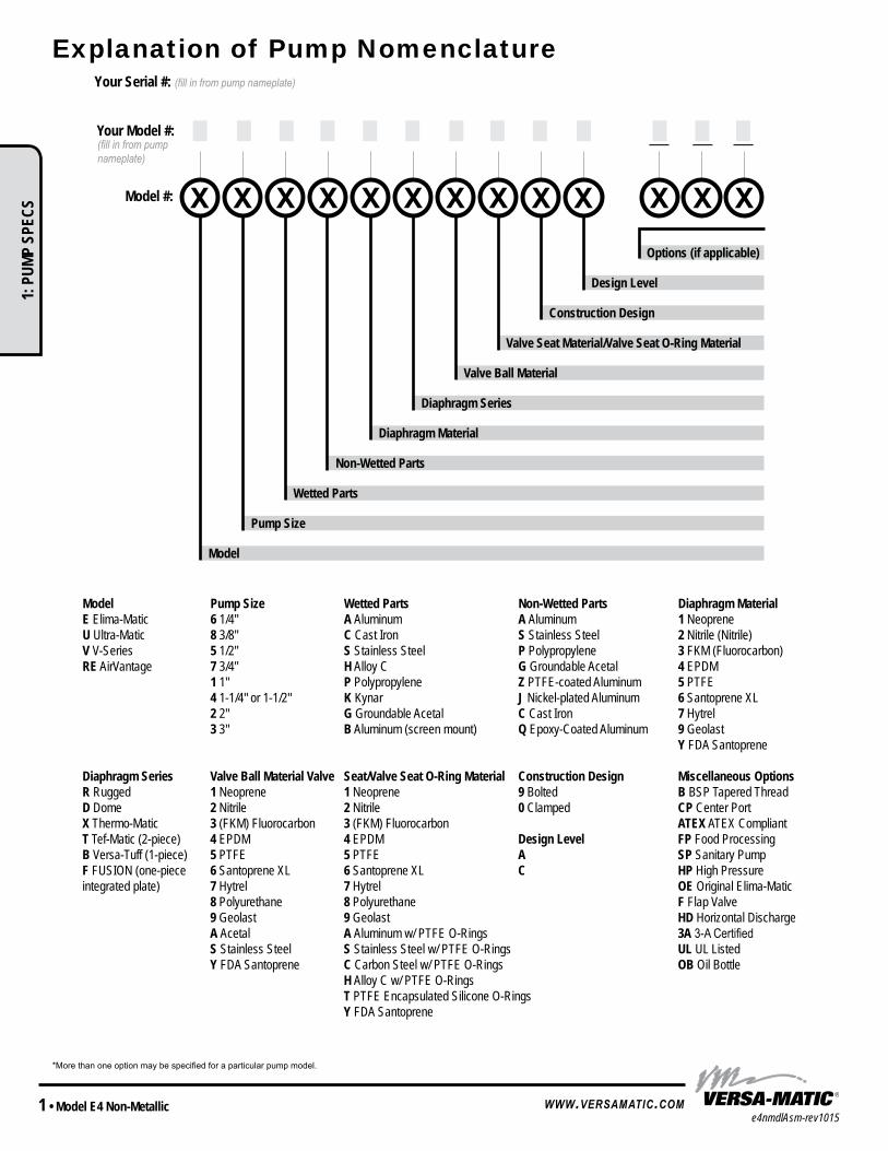
Explanation of Pump Nomenclature
*More than one option may be specified for a particular pump model.
Model Pump Size Wetted Parts Non-Wetted Parts Diaphragm MaterialE Elima-Matic 6 1/4" A Aluminum A Aluminum 1 NeopreneU Ultra-Matic 8 3/8" C Cast Iron S Stainless Steel 2 Nitrile (Nitrile)V V-Series 5 1/2" S Stainless Steel P Polypropylene 3 FKM (Fluorocarbon)RE AirVantage 7 3/4" H Alloy C G Groundable Acetal 4 EPDM
1 1" P Polypropylene Z PTFE-coated Aluminum 5 PTFE4 1-1/4" or 1-1/2" K Kynar J Nickel-plated Aluminum 6 Santoprene XL2 2" G Groundable Acetal C Cast Iron 7 Hytrel3 3" B Aluminum (screen mount) Q Epoxy-Coated Aluminum 9 Geolast
Y FDA Santoprene
Diaphragm Series Valve Ball Material Valve Seat/Valve Seat O-Ring Material Construction Design Miscellaneous OptionsR Rugged 1 Neoprene 1 Neoprene 9 Bolted B BSP Tapered ThreadD Dome 2 Nitrile 2 Nitrile 0 Clamped CP Center PortX Thermo-Matic 3 (FKM) Fluorocarbon 3 (FKM) Fluorocarbon ATEX ATEX CompliantT Tef-Matic (2-piece) 4 EPDM 4 EPDM Design Level FP Food ProcessingB Versa-Tuff (1-piece) 5 PTFE 5 PTFE A SP Sanitary PumpF FUSION (one-piece 6 Santoprene XL 6 Santoprene XL C HP High Pressureintegrated plate) 7 Hytrel 7 Hytrel OE Original Elima-Matic
8 Polyurethane 8 Polyurethane F Flap Valve9 Geolast 9 Geolast HD Horizontal DischargeA Acetal A Aluminum w/ PTFE O-Rings 3A 3-A CertifiedS Stainless Steel S Stainless Steel w/ PTFE O-Rings UL UL ListedY FDA Santoprene C Carbon Steel w/ PTFE O-Rings OB Oil Bottle
H Alloy C w/ PTFE O-RingsT PTFE Encapsulated Silicone O-RingsY FDA Santoprene
Model
Pump Size
Wetted Parts
Non-Wetted Parts
Diaphragm Material
Diaphragm Series
Valve Ball Material
Valve Seat Material/Valve Seat O-Ring Material
Construction Design
Design Level
Options (if applicable)
Your Serial #: (fill in from pump nameplate)
Model #:
__ __ __(fill in from pump nameplate)
Your Model #:
UNIVERSAL TO ALL VM
1: P
UMP
SPEC
S
e4nmdlAsm-rev1015Model E4 Non-Metallic • 2www.versamatic.com
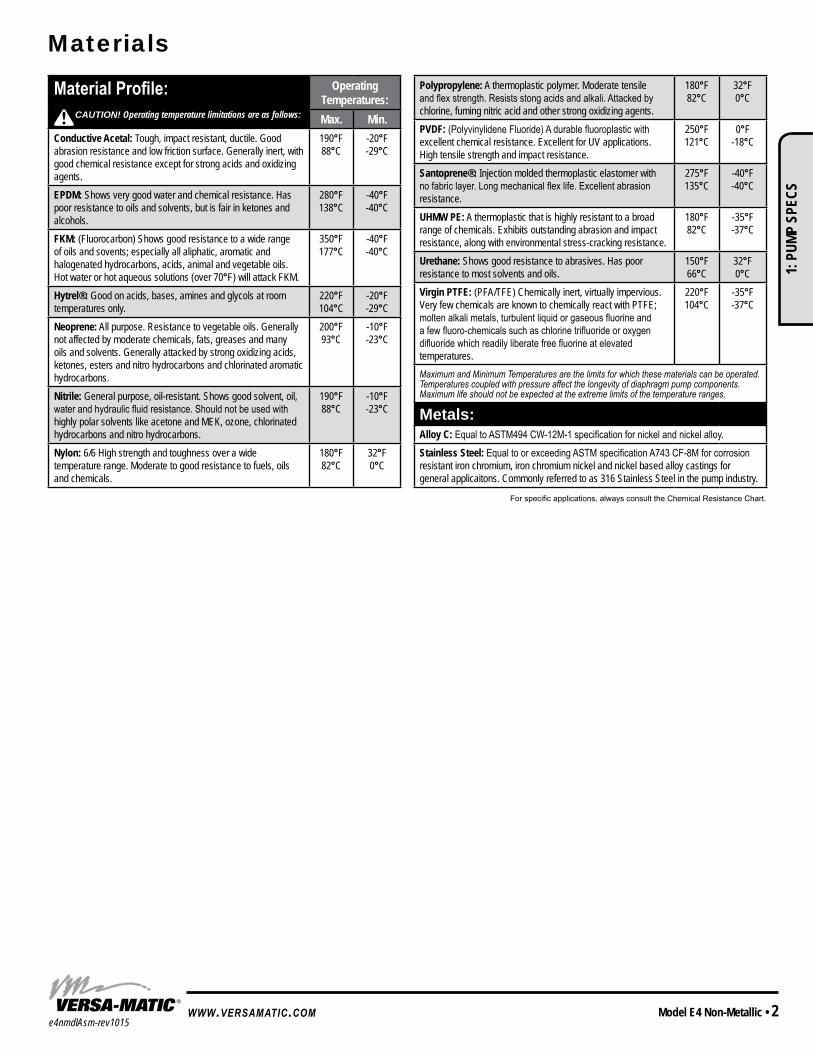
Materials
Material Profile: Operating Temperatures:Max. Min.
Conductive Acetal: Tough, impact resistant, ductile. Good abrasion resistance and low friction surface. Generally inert, with good chemical resistance except for strong acids and oxidizing agents.
190°F88°C
-20°F-29°C
EPDM: Shows very good water and chemical resistance. Has poor resistance to oils and solvents, but is fair in ketones and alcohols.
280°F138°C
-40°F-40°C
FKM: (Fluorocarbon) Shows good resistance to a wide range of oils and sovents; especially all aliphatic, aromatic and halogenated hydrocarbons, acids, animal and vegetable oils. Hot water or hot aqueous solutions (over 70°F) will attack FKM.
350°F177°C
-40°F-40°C
Hytrel®: Good on acids, bases, amines and glycols at room temperatures only.
220°F104°C
-20°F-29°C
Neoprene: All purpose. Resistance to vegetable oils. Generally not affected by moderate chemicals, fats, greases and many oils and solvents. Generally attacked by strong oxidizing acids, ketones, esters and nitro hydrocarbons and chlorinated aromatic hydrocarbons.
200°F93°C
-10°F-23°C
Nitrile: General purpose, oil-resistant. Shows good solvent, oil, water and hydraulic fluid resistance. Should not be used with highly polar solvents like acetone and MEK, ozone, chlorinated hydrocarbons and nitro hydrocarbons.
190°F88°C
-10°F-23°C
Nylon: 6/6 High strength and toughness over a wide temperature range. Moderate to good resistance to fuels, oils and chemicals.
180°F82°C
32°F0°C
Polypropylene: A thermoplastic polymer. Moderate tensile and flex strength. Resists stong acids and alkali. Attacked by chlorine, fuming nitric acid and other strong oxidizing agents.
180°F82°C
32°F0°C
PVDF: (Polyvinylidene Fluoride) A durable fluoroplastic with excellent chemical resistance. Excellent for UV applications. High tensile strength and impact resistance.
250°F121°C
0°F-18°C
Santoprene®: Injection molded thermoplastic elastomer with no fabric layer. Long mechanical flex life. Excellent abrasion resistance.
275°F135°C
-40°F-40°C
UHMW PE: A thermoplastic that is highly resistant to a broad range of chemicals. Exhibits outstanding abrasion and impact resistance, along with environmental stress-cracking resistance.
180°F82°C
-35°F-37°C
Urethane: Shows good resistance to abrasives. Has poor resistance to most solvents and oils.
150°F66°C
32°F0°C
Virgin PTFE: (PFA/TFE) Chemically inert, virtually impervious. Very few chemicals are known to chemically react with PTFE; molten alkali metals, turbulent liquid or gaseous fluorine and a few fluoro-chemicals such as chlorine trifluoride or oxygen difluoride which readily liberate free fluorine at elevated temperatures.
220°F104°C
-35°F-37°C
Maximum and Minimum Temperatures are the limits for which these materials can be operated. Temperatures coupled with pressure affect the longevity of diaphragm pump components. Maximum life should not be expected at the extreme limits of the temperature ranges.
Metals:Alloy C: Equal to ASTM494 CW-12M-1 specification for nickel and nickel alloy.Stainless Steel: Equal to or exceeding ASTM specification A743 CF-8M for corrosion resistant iron chromium, iron chromium nickel and nickel based alloy castings for general applicaitons. Commonly referred to as 316 Stainless Steel in the pump industry.
For specific applications, always consult the Chemical Resistance Chart.
CAUTION! Operating temperature limitations are as follows:
MODEL SPECIFIC UNIVERSAL ALL AODD
1: P
UMP
SPEC
S

e4nmdlAsm-rev10153 • Model E4 Non-Metallic www.versamatic.com
Performance
E4 1 1/2" Bolted Non-Metallic PumpPTFE Fitted
Flow Rate Adjustable to . . . . . . . 0-72 gpm (272.5 lpm)Port Size Suction . . . . . . . . . . . . . . . . . . . . 1 1/2" ANSI Discharge. . . . . . . . . . . . . . . . . . 1 1/2" ANSIAir Inlet . . . . . . . . . . . . . . . . . . . . . . 1/2" NPTAir Exhaust . . . . . . . . . . . . . . . . . . 3/4" NPTSuction Lift Dry . . . . . . . . . . . . . . . . . . . . . . . .10' (3.0 m) Wet. . . . . . . . . . . . . . . . . . . . . . . .27' (8.2 m)Max Solid Size (Diameter) . . . . . . . . . . . . . . . . . . . . . . 3/16" (4.76 mm)Max Noise Level . . . . . . . . . . . . . 96 dB(A)Shipping Weights Polypropylene . . . . . . . . . . . . 40 lbs (18 kg) Kynar . . . . . . . . . . . . . . . . . .41 lbs (18.6 kg)
NOTE: Performance based on the following: PTFE fitted pump, flooded suction, water at ambient conditions. The use of other materials and varying hydraulic conditions may result in deviations in excess of 5%.
E4 1 1/2" Bolted Non-Metallic PumpELASTOMERIC AND TPE FITTED
Flow Rate Adjustable to . . . . . . . . 0-75 gpm (284 lpm)Port Size Suction . . . . . . . . . . . . . . . . . . . . 1 1/2" ANSI Discharge. . . . . . . . . . . . . . . . . . 1 1/2" ANSIAir Inlet . . . . . . . . . . . . . . . . . . . . . . 1/2" NPTAir Exhaust . . . . . . . . . . . . . . . . . . 3/4" NPTSuction Lift Dry . . . . . . . . . . . . . . . . . . . . . . . .17' (5.2 m) Wet. . . . . . . . . . . . . . . . . . . . . . . .26' (7.9 m)Max Solid Size (Diameter) . . . . . . . . . . . . . . . . . . . . . . 3/16" (4.76 mm)Max Noise Level . . . . . . . . . . . . . 89 dB(A)Shipping Weights Polypropylene . . . . . . . . . . . . 40 lbs (18 kg) Kynar . . . . . . . . . . . . . . . . . .41 lbs (18.6 kg)
NOTE: Performance based on the following: elastomeric fitted pump, flooded suction, water at ambient conditions. The use of other materials and varying hydraulic conditions may result in deviations in excess of 5%.
Disc
harg
e Hea
d in
PSI
0
140
120
100
80
60
40
20
0
Capacity in Liters Per Minute
Capacity in U.S. Gallons Per Minute
Capacity Per Stroke, 0.24 Gal. (0.91 L)
AIR CONSUMPTION IN SCFMAIR PRESSURE IN PSI
SCFM M3/HR 10 17 20 34 30 51 40 68 50 85 60 101.9 70 118.9
0 10
40 80 120 160 200 240 280
Meters Feet0 0
40
80
120
160
200
240
280
320
10
20
30
40
50
60
80
90
70
0
1
2
3
4
5
6
7
8
9
10
BAR
1053020
40
50
60
70
20 30 40 50 60 70 80
0Capacity in Liters Per Minute
Capacity in U.S. Gallons Per Minute
Capacity Per Stroke, 0.16 Gal. (0.60 L)
AIR CONSUMPTION IN SCFMAIR PRESSURE IN PSI
SCFM M3/HR 10 17 20 34 30 51 40 68 50 85 60 101.9
0 10
40 80 120 160 200 240 280
105
3020
40
50
60
20 30 40 50 60 70 80
Disc
harg
e Hea
d in
PSI
Meters Feet
220 200 180 160 140 120 100
80 60 40 20
0
70 65 60 55 50 45 40 35 30 25 20 15 10
5 0 0
1
2
3
4
5
6
7
BAR0
20
40
60
80
100
1: P
UMP
SPEC
S

e4nmdlAsm-rev1015Model E4 Non-Metallic • 4www.versamatic.com
E4 Non-Metallic Dimensions in inches (metric dimensions in brackets) The dimensions on this drawing are for reference only. A certified drawing can be requested if physical dimensions are needed.
Dimensional Drawings
Model Specific
1: P
UMP
SPEC
S

e4nmdlAsm-rev10155 • Model E4 Non-Metallic www.versamatic.com
Air-Operated Double Diaphragm (AODD) pumps are powered by compressed air or nitrogen.
The main directional (air) control valve ① distributes compressed air to an air chamber, exerting uniform pressure over the inner surface of the diaphragm ②. At the same time, the exhausting air ③ from behind the opposite diaphragm is directed through the air valve assembly(s) to an exhaust port ④.
As inner chamber pressure (P1) exceeds liquid chamber pressure (P2), the rod ⑤ connected diaphragms shift together creating discharge on one side and suction on the opposite side. The discharged and primed liquid’s directions are controlled by the check valves (ball or flap)⑥ orientation.
The pump primes as a result of the suction stroke. The suction stroke lowers the chamber pressure (P3) increasing the chamber volume. This results in a pressure differential necessary for atmospheric pressure (P4) to push the fluid through the suction piping and across the suction side check valve and into the outer fluid chamber ⑦.
Suction (side) stroking also initiates the reciprocating (shifting, stroking or cycling) action of the pump. The suction diaphragm’s movement is mechanically pulled through its stroke. The diaphragm’s inner plate makes contact with an actuator plunger aligned to shift the pilot signaling valve. Once actuated, the pilot valve sends a pressure signal to the opposite end of the main directional air valve, redirecting the compressed air to the opposite inner chamber.
Principle of Pump Operation
SAFE AIREXHAUSTDISPOSALAREA
PUMP INSTALLATION AREA
1" DIAMETER AIREXHAUST PIPING
1" DIAMETER AIREXHAUST PIPING
1" DIAMETER AIREXHAUST PIPING
MUFFLER
LIQUIDLEVEL
SUCTIONLINE
LIQUIDLEVEL
SUCTIONLINE
MUFFLER
MUFFLER
SUBMERGED ILLUSTRATION
Pump can be submerged if the pump materials of construction are compatible with the liquid being pumped. The air exhaust must be piped above the liquid level. When the pumped product source is at a higher level than the pump (flooded suction condition), pipe the exhaust higher than the product source to prevent siphoning spills.
MODEL SPECIFIC
Air Line
Discharged Fluid
Discharged Stroke Suction Stroke
Primed Fluid
2: IN
STAL
& O
P

e4nmdlAsm-rev1015Model E4 Non-Metallic • 6www.versamatic.com
Installation And Start-Up Locate the pump as close to the product being pumped as possible. Keep the suction line length and number of fittings to a minimum. Do not reduce the suction line diameter.
Air Supply Connect the pump air inlet to an air supply with sufficient capacity and pressure to achieve desired performance. A pressure regulating valve should be installed to insure air supply pressure does not exceed recommended limits.
Air Valve Lubrication The air distribution system is designed to operate WITHOUT lubrication. This is the standard mode of operation. If lubrication is desired, install an air line lubricator set to deliver one drop of SAE 10 non-detergent oil for every 20 SCFM (9.4 liters/sec.) of air the pump consumes. Consult the Performance Curve to determine air consumption.
Air Line Moisture Water in the compressed air supply may cause icing or freezing of the exhaust air, causing the pump to cycle erratically or stop operating. Water in the air supply can be reduced by using a point-of-use air dryer.
Air Inlet And Priming To start the pump, slightly open the air shut-off valve. After the pump primes, the air valve can be opened to increase air flow as desired. If opening the valve increases cycling rate, but does not increase the rate of flow, cavitation has occurred. The valve should be closed slightly to obtain the most efficient air flow to pump flow ratio.
Recommended Installation Guide
Available Accessories: 1. Surge Suppressor 2. Filter/Regulator 3. Air Dryer
Note: Surge Suppressor and Piping must be supported after the flexible connection.
CAUTIONThe air exhaust should be piped to an area for safe disposition of the product being pumped, in the event of a diaphragm failure.
Surge Suppressor
Shut-Off Valve
Pressure Gauge
Drain PortShut-OffValve
CheckValve
Air Inlet
Discharge
Unregulated AirSupply to Surge
Suppressor
Pipe Connection(Style Optional)
Flexible Connector
Flexible Connector
VacuumGauge
Suction
Shut-Off Valve
Drain Port
Air Dryer
Filter Regulator
Muffler(Optional Piped Exhaust)
1
2
3
Principle of Pump Operation
SUBMERGED ILLUSTRATION
UNIVERSAL ALL AODD
2: IN
STAL
& O
P

e4nmdlAsm-rev10157 • Model E4 Non-Metallic www.versamatic.com
Troubleshooting GuideSymptom: Potential Cause(s): Recommendation(s):Pump Cycles Once Deadhead (system pressure meets or exceeds air
supply pressure).Increase the inlet air pressure to the pump. Pump is designed for 1:1 pressure ratio at zero flow. (Does not apply to high pressure 2:1 units).
Air valve or intermediate gaskets installed incorrectly. Install gaskets with holes properly aligned.Bent or missing actuator plunger. Remove pilot valve and inspect actuator plungers.
Pump Will Not Operate / Cycle
Pump is over lubricated. Set lubricator on lowest possible setting or remove. Units are designed for lube free operation.Lack of air (line size, PSI, CFM). Check the air line size and length, compressor capacity (HP vs. cfm required).Check air distribution system. Disassemble and inspect main air distribution valve, pilot valve and pilot valve actuators. Discharge line is blocked or clogged manifolds. Check for inadvertently closed discharge line valves. Clean discharge manifolds/piping.Deadhead (system pressure meets or exceeds air supply pressure).
Increase the inlet air pressure to the pump. Pump is designed for 1:1 pressure ratio at zero flow. (Does not apply to high pressure 2:1 units).
Blocked air exhaust muffler. Remove muffler screen, clean or de-ice, and re-install. Pumped fluid in air exhaust muffler. Disassemble pump chambers. Inspect for diaphragm rupture or loose diaphragm plate assembly. Pump chamber is blocked. Disassemble and inspect wetted chambers. Remove or flush any obstructions.
Pump Cycles and Will Not Prime or No Flow
Cavitation on suction side. Check suction condition (move pump closer to product).Check valve obstructed. Valve ball(s) not seating properly or sticking.
Disassemble the wet end of the pump and manually dislodge obstruction in the check valve pocket. Clean out around valve ball cage and valve seat area. Replace valve ball or valve seat if damaged. Use heavier valve ball material.
Valve ball(s) missing (pushed into chamber or manifold).
Worn valve ball or valve seat. Worn fingers in valve ball cage (replace part). Check Chemical Resistance Guide for compatibility.
Valve ball(s)/seat(s) damaged or attacked by product. Check Chemical Resistance Guide for compatibility.Check valve and/or seat is worn or needs adjusting. Inspect check valves and seats for wear and proper setting. Replace if necessary. Suction line is blocked. Remove or flush obstruction. Check and clear all suction screens or strainers.Excessive suction lift. For lifts exceeding 20’ of liquid, filling the chambers with liquid will prime the pump in most cases.Suction side air leakage or air in product. Visually inspect all suction-side gaskets and pipe connections.Pumped fluid in air exhaust muffler. Disassemble pump chambers. Inspect for diaphragm rupture or loose diaphragm plate assembly.
Pump Cycles Running Sluggish/Stalling, Flow Unsatisfactory
Over lubrication. Set lubricator on lowest possible setting or remove. Units are designed for lube free operation.Icing. Remove muffler screen, de-ice, and re-install. Install a point of use air drier. Clogged manifolds. Clean manifolds to allow proper air flowDeadhead (system pressure meets or exceeds air supply pressure).
Increase the inlet air pressure to the pump. Pump is designed for 1:1 pressure ratio at zero flow. (Does not apply to high pressure 2:1 units).
Cavitation on suction side. Check suction (move pump closer to product).Lack of air (line size, PSI, CFM). Check the air line size, length, compressor capacity.Excessive suction lift. For lifts exceeding 20’ of liquid, filling the chambers with liquid will prime the pump in most cases.Air supply pressure or volume exceeds system hd. Decrease inlet air (press. and vol.) to the pump. Pump is cavitating the fluid by fast cycling. Undersized suction line. Meet or exceed pump connections. Restrictive or undersized air line. Install a larger air line and connection. Suction side air leakage or air in product. Visually inspect all suction-side gaskets and pipe connections.Suction line is blocked. Remove or flush obstruction. Check and clear all suction screens or strainers.Pumped fluid in air exhaust muffler. Disassemble pump chambers. Inspect for diaphragm rupture or loose diaphragm plate assembly. Check valve obstructed. Disassemble the wet end of the pump and manually dislodge obstruction in the check valve pocket. Check valve and/or seat is worn or needs adjusting. Inspect check valves and seats for wear and proper setting. Replace if necessary.Entrained air or vapor lock in chamber(s). Purge chambers through tapped chamber vent plugs. Purging the chambers of air can be dangerous.
Product Leaking Through Exhaust
Diaphragm failure, or diaphragm plates loose. Replace diaphragms, check for damage and ensure diaphragm plates are tight.Diaphragm stretched around center hole or bolt holes. Check for excessive inlet pressure or air pressure. Consult Chemical Resistance Chart for compatibility
with products, cleaners, temperature limitations and lubrication.Premature Diaphragm Failure
Cavitation. Enlarge pipe diameter on suction side of pump.Excessive flooded suction pressure. Move pump closer to product. Raise pump/place pump on top of tank to reduce inlet pressure.
Install Back pressure device (Tech bulletin 41r). Add accumulation tank or pulsation dampener.Misapplication (chemical/physical incompatibility). Consult Chemical Resistance Chart for compatibility with products, cleaners, temperature limitations
and lubrication.Incorrect diaphragm plates or plates on backwards, installed incorrectly or worn.
Check Operating Manual to check for correct part and installation. Ensure outer plates have not been worn to a sharp edge.
Unbalanced Cycling Excessive suction lift. For lifts exceeding 20’ of liquid, filling the chambers with liquid will prime the pump in most cases.Undersized suction line. Meet or exceed pump connections.Pumped fluid in air exhaust muffler. Disassemble pump chambers. Inspect for diaphragm rupture or loose diaphragm plate assembly.Suction side air leakage or air in product. Visually inspect all suction-side gaskets and pipe connections.Check valve obstructed. Disassemble the wet end of the pump and manually dislodge obstruction in the check valve pocket. Check valve and/or seat is worn or needs adjusting. Inspect check valves and seats for wear and proper setting. Replace if necessary. Entrained air or vapor lock in chamber(s). Purge chambers through tapped chamber vent plugs.
For additional troubleshooting tips contact After Sales Support at [email protected] or 419-524-8388
UNIVERSAL ALL AODD, EXCEPT FLAP
2: IN
STAL
& O
P

e4nmdlAsm-rev1015Model E4 Non-Metallic • 8www.versamatic.com
Composite Repair Parts Drawing
16
17
18
21
15
18
21
PILOT ASY DETAIL
26
23
SEE PILOTDETAIL
3536
37
3330
32
8
3
4
7
6
5
2
8
27
29
3937
109
35
11
12
26
14
24
23
25
31
27
29
29
36
37
30
34
36
2019
32
38
13
27
22
PLASTIC SEAT ASY
28
27
28
FUSION DIAPHRAGM
ASY
16
17
18
21
15
18
21
PILOT ASY DETAIL
26
23
SEE PILOTDETAIL
3536
37
3330
32
8
3
4
7
6
5
2
8
27
29
3937
109
35
11
12
26
14
24
23
25
31
27
29
29
36
37
30
34
36
2019
32
38
13
27
22
PLASTIC SEAT ASY
28
27
28
FUSION DIAPHRAGM
ASY
16
17
18
21
15
18
21
PILOT ASY DETAIL
26
23
SEE PILOTDETAIL
3536
37
3330
32
8
3
4
7
6
5
2
8
27
29
3937
109
35
11
12
26
14
24
23
25
31
27
29
29
36
37
30
34
36
2019
32
38
13
27
22
PLASTIC SEAT ASY
28
27
28
FUSION DIAPHRAGM
ASY
16
17
18
21
15
18
21
PILOT ASY DETAIL
26
23
SEE PILOTDETAIL
3536
37
3330
32
8
3
4
7
6
5
2
8
27
29
3937
109
35
11
12
26
14
24
23
25
31
27
29
29
36
37
30
34
36
2019
32
38
13
27
22
PLASTIC SEAT ASY
28
27
28
FUSION DIAPHRAGM
ASY
General Model Specific
3: E
XP V
IEW
e4nmdlAsm-rev10159 • Model E4 Non-Metallic www.versamatic.com
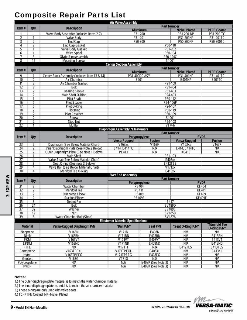
Composite Repair Parts ListAir Valve Assembly
Item # Qty. Description Part NumberAluminum Nickel Plated PTFE Coated
1 - Valve Body Assembly (includes items 2-7) P31-200 P31-200-NP P31-200-TC2 1 Valve Body P31-201 P31-201NP P31-201TC3 2 End Cap P50-300 P50-300NP P50-300TC4 2 End Cap Gasket P50-1105 1 Valve Body Gasket P31-2026 1 Valve Spool P50-1047 3 Glyde Ring Assembly P50-104C8 12 Mounting Screws S1001
Center Section AssemblyItem # Qty. Description Part Number
Aluminum Nickel Plated PTFE Coated9 1 Center Block Assembly (Includes item 13 & 14) P31-400DC ASY P31-401NP P31-401TC
10 2 Air Chamber E401 E401NP E401TC11 2 Air Chamber Gasket P31-10912 8 Bolt P31-40413 2 Bearing Sleeve P31-40314 2 Main Shaft O-Ring P24-40315 1 Pilot Shaft P50-11216 5 Pilot Spacer P24-106P17 6 Pilot O-Ring P24-10718 2 Pilot Ring P50-11919 2 Pilot Retainer P50-10920 2 Screw S100121 2 Stop Nut P24-10822 1 Muffler VTM-6
Diaphragm Assembly / Elastomers
Item # Qty. DescriptionPart Number
Polypropylene PVDFVersa-Rugged Fusion Versa-Rugged Fusion
23 2 Diaphragm (See Below Material Chart) V163xx V163F V163xx V163F24 2 Inner Diaphragm Plate (See Note 2 Below) E414, E414TC N/A E414, E414TC N/A25 2 Outer Diaphragm Plate (See Note 1 Below) PE413 N/A KE413 N/A26 1 Main Shaft P31-10327 4 Valve Seat (See Below Material Chart) E408xx28 8 Seat O-ring (See note 3 Below) E412TES29 4 Valve Ball (See Below Material Chart) V171xx30 4 Manifold Tee O-Ring E413xx
Wet End AssemblyItem # Qty. Description Part Number
Polypropylene PVDF31 2 Water Chamber PE404 KE40432 2 Manifold Tee PE411 KE41133 2 Discharge Elbow PE409 KE40934 2 Suction Elbow PE409F KE409F35 8 Detent Pin E41736 24 Bolt SV189D37 32 Washer SV189C38 12 Nut SV185B39 8 Water Chamber Bolt (Short) SV187A
Elastomer Material SpecificationsMaterial Versa-Rugged Diaphragm P/N "Ball P/N" Seat P/N "Seat O-Ring P/N" "Manifold Tee
O-Ring P/N"Neoprene V163N V171N E408N N/A N/A
Nitrile V163BN V171BN E408BN N/A E413BNFKM V163VT V171VT E408VT N/A E413VT
EPDM V163ND V171ND E408ND N/A E413NDPTFE N/A V171TF N/A E412TES E413TES
Santoprene V163TPEXL V171TPEXL E408XL N/A E413XLHytrel V163TPEFG V171TPEFG E408FG N/A N/A
Geolast V163G V171G N/A N/A N/APolypropylene N/A N/A E408P (See Note 3) N/A N/A
PVDF N/A N/A E408K (See Note 3) N/A N/A
Notes: 1.) The outer diaphragm plate material is to match the water chamber material 2.) The inner diaphragm plate material is to match the air chamber material 3.) These o-ring are only used with valve seats 4.) TC=PTFE Coated, NP=Nickel Plated
MODEL SPECIFIC
3: E
XP V
IEW
e4nmdlAsm-rev1015Model E4 Non-Metallic • 10www.versamatic.com
Written Warranty5 - YEAR Limited Product Warranty
Quality System ISO9001 Certified • Environmental Management Systems ISO14001 Certified Versa-Matic warrants to the original end-use purchaser that no product sold by
Versa-Matic that bears a Versa-Matic brand shall fail under normal use and service due to a defect in materialor workmanship within five years from the date of shipment from Versa-Matic’s factory.
~ See complete warranty at http://www.versamatic.com/pdfs/VM%20Product%20Warranty.pdf ~
DATE: August 10, 2011FECHA: DATUM:DATA:DATO:PÄIVÄYS:
AUTHORIZED / APPROVED BY: Approuve par: Aprobado por: Genehmigt von: approvato da: Goedgekeurd door: Underskrift: Valtuutettuna: Bemyndiget av: Autorizado Por:
04/19/2012 REV 07 VMQR 044FM
This product complies with the following European Community Directives: Ce produit est conforme aux directives de la Communauté européenne suivantes: Este producto cumple con las siguientes Directrices de la Comunidad Europea: Dieses produkt erfüllt die folgenden Vorschriften der Europäischen Gemeinschaft: Questo prodotto è conforme alle seguenti direttive CEE: Dir produkt voldoet aan de volgende EG-richtlijnen: Denna produkt överensstämmer med följande EU direktiv: Versa-Matic, Inc., erklærer herved som fabrikant, at ovennævnte produkt er i overensstemmelse med bestemmelserne i Direkktive:Tämä tuote täyttää seuraavien EC Direktiivien vaatimukstet:Dette produkt oppfyller kravene til følgende EC Direktiver:Este produto está de acordo com as seguintes Directivas comunitárias:
MANUFACTURED BY:FABRIQUE PAR:FABRICADA POR:HERGESTELLT VON:FABBRICATO DA:VERVAARDIGD DOOR:TILLVERKAD AV:FABRIKANT:VALMISTAJA:PRODUSENT:FABRICANTE:
DECLARATION DE CONFORMITE • DECLARACION DE CONFORMIDAD • ERKLÄRUNG BEZÜGLICH EINHALTUNG DER VORSCHRIFTENDICHIARAZIONE DI CONFORMITÀ • CONFORMITEITSVERKLARING • DEKLARATION OM ÖVERENSSTÄMMELSE
EF-OVERENSSTEMMELSESERKLÆRING • VAATIMUSTENMUKAISUUSVAKUUTUS • SAMSVARSERKLÄRING DECLARAÇAO DE CONFORMIDADE
VERSA-MATIC®
Warren Rupp, Inc.A Unit of IDEX Corporation 800 North Main Street P.O. Box 1568 Mansfield, OH 44901-1568 USA
Tel: 419-526-7296Fax: 419-526-7289
This product has used the following harmonized standards to verify conformance: EN809:1998+A1:2009Ce materiel est fabriqué selon les normes harmonisées suivantes, afin d’ en garantir la conformité:
Este producto cumple con las siquientes directrices de la comunidad europa:Dieses produkt ist nach folgenden harmonisierten standards gefertigtworden, die übereinstimmung wird bestätigt:Questo prodotto ha utilizzato i seguenti standards per verificare la conformita´:De volgende geharmoniseerde normen werden gehanteerd om de conformiteit van dit produkt te garanderen: För denna produkt har följande harmoniserande standarder använts för att bekräfta överensstämmelse:Harmoniserede standarder, der er benyttet:Tässä tuotteessa on sovellettu seuraavia yhdenmukaistettuja standardeja:Dette produkt er produsert i overenstemmelse med fløgende harmoniserte standarder:Este produto utilizou os seguintes padrões harmonizados para varificar conformidade:
PUMP MODEL SERIES: E SERIES, V SERIES, VT SERIES, VSMA3, SPA15, RE SERIES AND U2 SERIES
Dave RoseberryEngineering Manager
DECLARATION OF CONFORMITY
2006/42/ECon Machinery, according
to Annex VIII
MODEL SPECIFIC
7: W
ARRA
NTY


Bulletin No. 262B
LOADCELLS•USA-Made Quality
•Environmentally-Sealed
•Precision Engineering
•VCAP Certified
•Wide Selection of TypesModel 50K-SCA
Model DB-75000S
Model CB6-20KG
Model ZX-2500
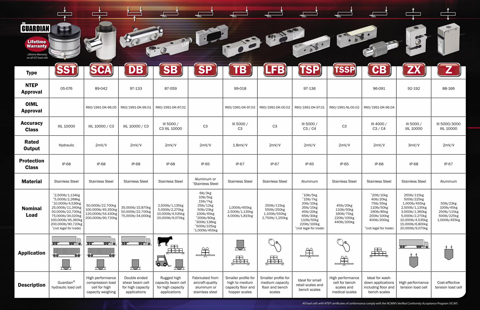
By utilizing proprietary strain gauge and sensor materials, maintaining strict environmental controls, and adhering to a rigid quality program, Cardinal Scale has succeeded in producing a full line of strain gauge load cells which are recognized by OIML and NTEP.
LifetimeWarranty
Type
NTEP Approval
05-076 89-042 97-133 87-059 99-018 97-136 96-091 92-192 88-166
OIML Approval
R60/1991-DK-96.05 R60/1991-DK-99.01 R60/1991-DK-97.02 R60/1991-DK-97.03 R60/1991-DK-00.02 R60/1991-DK-97.01 R60/1991-NL-00.02 R60/1991-DK-96.04
AccuracyClass
IIIL 10000 IIIL 10000 / C3 IIIL 10000 / C3 III 5000 / C3 IIIL 10000 C3 III 5000 /
C3 C3 III 5000 / C3 / C4 C3 III 4000 /
C3 / C4III 5000 / IIIL 10000
III 5000/3000 IIIL 10000
Rated Output
Hydraulic 2mV/V 2mV/V 2mV/V 2mV/V 1.8mV/V 2mV/V 2mV/V 2mV/V 2mV/V 3mV/V 2mV/V
Protection Class
IP-68 IP-68 IP-68 IP-68 IP-65 IP-67 IP-67 IP-65 IP-65 IP-68 IP-68 IP-67
Material Stainless Steel Stainless Steel Stainless Steel Stainless Steel Aluminum or *Stainless Steel Stainless Steel Stainless Steel Aluminum Stainless Steel Stainless Steel Stainless Steel Aluminum
Nominal Load
*2,500lb/1,134kg*5,000lb/2,268kg
*10,000lb/4,536kg25,000lb/11,340kg50,000lb/22,700kg75,000lb/34,020kg
100,000lb/45,360kg200,000lb/90,720kg
*(not legal for trade)
50,000lb/22,700kg100,000lb/45,350kg120,000lb/54,430kg200,000lb/90,720kg
35,000lb/15,870kg50,000lb/22,700kg75,000lb/34,000kg
2,500lb/1,135kg5,000lb/2,270kg
10,000lb/4,535kg20,000lb/9,070kg
6lb/3kg10lb/5kg15lb/7kg
25lb/12kg50lb/23kg
100lb/45kg*200lb/90kg
*300lb/136kg*500lb/225kg
*1,000lb/455kg
1,000lb/455kg2,500lb/1,135kg4,000lb/1,815kg
250lb/115kg550lb/250kg
1,100lb/550kg2,750lb/1,250kg
*10lb/5kg*15lb/7kg20lb/10kg35lb/15kg45lb/20kg65lb/30kg
110lb/50kg220lb/100kg
*(not legal for trade)
45lb/20kg110lb/50kg160lb/75kg
220lb/100kg440lb/200kg
*20lb/10kg40lb/20kg75lb/35kg
110lb/50kg190lb/85kg
200lb/100kg400lb/200kg
*(not legal for trade)
250lb/115kg500lb/225kg
1,000lb/455kg2,500lb/1,135kg3,000lb/1,360kg5,000lb/2,270kg
10,000lb/4,535kg15,000lb/6,800kg20,000lb/9,070kg
50lb/23kg100lb/45kg
250lb/115kg500lb/225kg
1,000lb/455kg
Application
Description Guardian®
hydraulic load cell
High performance compression load
cell for high capacity weighing
Double ended shear beam cell for high capacity
applications
Rugged high capacity beam cell for high capacity
applications
Fabricated from aircraft-quality aluminum or stainless steel
Smaller profile for high to medium
capacity floor and hopper scales
Smaller profile for medium capacity floor and bench
scales
Ideal for small retail scales and
bench scales
High performance cell for bench
scales and medical scales
Ideal for wash-down applications including floor and
bench scales
High performance tension load cell
Cost-effective tension load cell
SST SCA DB SB SP TB LFB TSP TSSP CB ZX Z
All load cells with NTEP certificates of conformance comply with the NCWM’s Verified Conformity Acceptance Program (VCAP).
Lifetime Warranty on all SST load cells

© Copyright 2010 Cardinal Scale Mfg. Co. • Printed in USA • CAR/00/1210/262B
CardinalCardinal Scale Manufacturing Co.
203 E. Daugherty, Webb City, MO 64870 USAPh: 417-673-4631 or 800-441-4237 • Fax: 417-673-5001
www.CardinalScale.com
®
SOLD BY:MADE IN USA
ISOISOREGISTERED 9001
Cardinal Scale reserves the right to improve, enhance or modify features and specifications without prior notice. All registered trademarks are the property of their respective owners.
Cardinal's load cell production facility employs the latest technology and was built for one purpose - to provide you with the best load cells available.
Cardinal utilizes several dead weight testers to verify load cell performance. The model SCA cell shown
here is being tested on equipment traceable to NIST.
Continuous monitoring of the load cell manufacturing process ensures
uniformity among the finished product.
Cardinal load cells are producedby automated CNC machines,
assuring accuracy and uniformity.
Strain gauges are produced under strict clean room conditions. Cardinal is the only U.S. load cell
manufacturer to produce all of their own strain gauges.
Cardinal load cells are all manufactured at their production facility in
Webb City, MO, USA.

Cardinal LOAD CELLS
Mechanical DataRated Capacity, (R.C.)Emax .450, 1100, & 1800 kgMinimum Dead Load ...........0 kgSafe Load Limit ....................150% R.C.Ultimate Load ......................300% R.C.Deflection at R.C. .................0.33 to 0.64 mmSpring Element Material ......17-4 PHNet Weight ...........................0.82 kg
Certificate DataIssuing Body ........................OIMLCertificate Number ..............R60/1991-DK-97.03Accuracy Class ....................C3Maximum Number of Load Cell Intervals, (nmax) ..........3000Single/Multiple .....................SHumidity Symbol ..................CHMinimum Load Cell Verification Interval (Vmin) ...0.08, 0.19, 0,32 kg
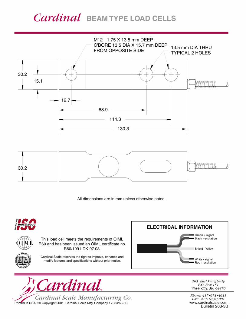
SERIES TB - BEAM TYPE - FOR MEDIUM TO HEAVY WEIGHING
• Capacities of 450 kg, 1100 kg, and 1800 kg
• Waterproof construction
• Stainless steel for corrosion resistance
• Direct mounting to weighing platform
• 3 m integral shielded cable
• 2 year warranty
Cardinal’s TB series, medium capacity beam load cells, are manufactured for medium to heavy weighing operations such as bench or floor scales. Stainless steel construction offers strength, and the ultimate in protection when caustic or corrosive environments are encountered. Heavy capacity single point cells are available in 450 kg to 1800 kg capacities. The unique design of these beam load cells offers cost-saving advantages for many weighing applications.
These cells are potted with a proprietary sealant that offers superior waterproofing, while remaining flexible over the life of the load cell. This special compound protects the load cell strain gages, and over a broad temperature range has no effect on load cell precision accuracy.
All load cells have threaded mounting holes, and a 3 m integral multiconductor cable secured by a strain relief seal.
SPECIFICATIONS
Color Code + Excitation ........... Red - Signal ...................White - Excitation ............ Black + Signal ..................Green
Electrical DataRated Output ............................. 2mV/VExcitation Voltage, Recommended ........................ 10 VDCExcitation Voltage, Maximum ................................. 15 VDCCable Length ............................. 3mTerminal Resistance Excitation ................................. 400 ± 7 ohms Signal ....................................... 350 ± 5 ohmsZero Load Output ...................... ± 1% R.C.Insulation Resistance ................ >5000 megohms at 50 VDC
Environmental DataTemperature Compensation Range ...................................... -10½ to +40½COperating Temperature Range .. -29½ to +93½CConstruction & Protection Code ........................................ CP-56 HU, IP67Barometric Pressure Effect on Zero Load Output ............... <1 v (min)/1kPa
Cardinal ®
Cardinal Scale Manufacturing Co.
203 East Daugherty P.O. Box 151
Webb City, Mo 64870
Phone: 417•673•4631Fax: 417•673•5001
www.cardinalscale.com
Cardinal
30.2
30.2
15.1
130.3
88.9
12.7
114.3
M12 - 1.75 X 13.5 mm DEEPC'BORE 13.5 DIA X 15.7 mm DEEPFROM OPPOSITE SIDE TYPICAL 2 HOLES
13.5 mm DIA THRU
Green + signalBlack - excitation
Shield - Yellow
White - signalRed + excitation
Printed in USA • © Copyright 2001, Cardinal Scale Mfg. Company • 708/263-3B
BEAM TYPE LOAD CELLS
Bulletin 263-3B
ELECTRICAL INFORMATION
All dimensions are in mm unless otherwise noted.
This load cell meets the requirements of OIML R60 and has been issued an OIML certificate no.
R60/1991-DK-97.03.
Cardinal Scale reserves the right to improve, enhance and modify features and specifications without prior notice.
UNAM&
EDSI
G
UNED
FACTRED
I N U S A...
UNAM&
EDSI
G
UNED
FACTRED
I N U S A...

LOVE CONTROLSA DIV. OF DWYER INSTRUMENTS INC. P.O. BOX 338 - MICHIGAN CITY, INDIANA 46361, U.S.A.
Series 4B, 8B, 16B and 32B MicroprocessorBased Temperature Process Control
Specifications - Installation and Operating Instructions
Phone: 219/879-8000 www.love-controls.com
Fax: 219/872-9057 e-mail:[email protected]
Bulletin E-90-BPC

Page 2
TABLE OF CONTENTS
Model Number Identification. . . . . . . . . . . . . . . . . . . . . . . . . . . . . . . . . . . . . . . . . . . 3
Getting Started . . . . . . . . . . . . . . . . . . . . . . . . . . . . . . . . . . . . . . . . . . . . . . . . . . . . . 3
Installation. . . . . . . . . . . . . . . . . . . . . . . . . . . . . . . . . . . . . . . . . . . . . . . . . . . . . . . . . 4
Panel Cutout Dimensions . . . . . . . . . . . . . . . . . . . . . . . . . . . . . . . . . . . . . . . . . . . . . . . . . 4
Mounting . . . . . . . . . . . . . . . . . . . . . . . . . . . . . . . . . . . . . . . . . . . . . . . . . . . . . 5
Wiring Diagrams . . . . . . . . . . . . . . . . . . . . . . . . . . . . . . . . . . . . . . . . . . . . . . . . . . . . . . 6-7
Front Panel Key Functions . . . . . . . . . . . . . . . . . . . . . . . . . . . . . . . . . . . . . . . . . . . . 8
Security Features . . . . . . . . . . . . . . . . . . . . . . . . . . . . . . . . . . . . . . . . . . . . . . . . . . . 8
Control Operation Description . . . . . . . . . . . . . . . . . . . . . . . . . . . . . . . . . . . . . . . 9-10
Programming and Operation for Ramp and Soak Feature . . . . . . . . . . . . . . . . 11-13
Programming and Operation for PID Function . . . . . . . . . . . . . . . . . . . . . . . . . . . . 14
Description of Menu Structure . . . . . . . . . . . . . . . . . . . . . . . . . . . . . . . . . . . . . . . . 15
Operation Menu. . . . . . . . . . . . . . . . . . . . . . . . . . . . . . . . . . . . . . . . . . . . . . . . . 15-16
Regulation Menu . . . . . . . . . . . . . . . . . . . . . . . . . . . . . . . . . . . . . . . . . . . . . . . . 17-19
Initial Setting Menu . . . . . . . . . . . . . . . . . . . . . . . . . . . . . . . . . . . . . . . . . . . . . . 20-22
Alarm Output Description . . . . . . . . . . . . . . . . . . . . . . . . . . . . . . . . . . . . . . . . . . . . 23
Communication Register List . . . . . . . . . . . . . . . . . . . . . . . . . . . . . . . . . . . . . . 24-25
Diagnostic Error Messages . . . . . . . . . . . . . . . . . . . . . . . . . . . . . . . . . . . . . . . . . . 26
Specifications . . . . . . . . . . . . . . . . . . . . . . . . . . . . . . . . . . . . . . . . . . . . . . . . . . . . . 29
Input Sensor Ranges . . . . . . . . . . . . . . . . . . . . . . . . . . . . . . . . . . . . . . . . . . . . . . . 30
Precautions. . . . . . . . . . . . . . . . . . . . . . . . . . . . . . . . . . . . . . . . . . . . . . . . . . . . . . . 31

Page 3
MODEL NUMBER IDENTIFICATION
GETTING STARTED
1. Install the control as described on page 4.
2. Wire your control following the instructions on pages 6-7. Please read the
Precautions section located at the end of this manual before wiring the control.
3. For best results when programming changes are necessary, make all changes to the
Initial Setting mode (Pages 20-22) before making changes to the Regulation Mode
(Pages 17-19) or Operation Mode (Pages 15-16). If any error messages occur, check
the Diagnostic Error Message Section (Page 26) for assistance.
32B
OUTPUT 22 = Voltage Pulse3 = Relay
OUTPUT 12 = Voltage Pulse3 = Relay5 = Current6 = Linear Voltage
16B
OUTPUT 22 = Voltage Pulse3 = Relay
OUTPUT 12 = Voltage Pulse3 = Relay5 = Current6 = Linear Voltage
OPTIONS
OPTIONSBlank = none1 = Event input2 = Current Transformer-LV = Low Voltage
8B
OUTPUT 22 = Voltage Pulse3 = Relay
OUTPUT 12 = Voltage Pulse3 = Relay5 = Current6 = Linear Voltage
OPTIONS
OPTIONSBlank = none1 = Event input2 = Current Transformer-LV = Low Voltage
4B
OUTPUT 22 = Voltage Pulse3 = Relay
OUTPUT 12 = Voltage Pulse3 = Relay5 = Current6 = Linear Voltage
OPTIONS
OPTIONSBlank = none1 = Event input2 = Current Transformer-LV = Low Voltage
OPTIONS
OPTIONS-LV = Low Voltage

Page 4
INSTALLATION
Mount the instrument in a location that will not be subject to excessive temperature, shock,
or vibration. All models are designed for mounting in an enclosed panel.
Select the position desired for the instrument on the panel. Prepare the panel by cutting and
deburring the required opening per the panel cut out dimensions listed below. Follow the
mounting instructions listed on page 5. Lastly, wire the controller per the appropriate wiring
diagram listed on page 6.
PANEL CUTOUT DIMENSIONS
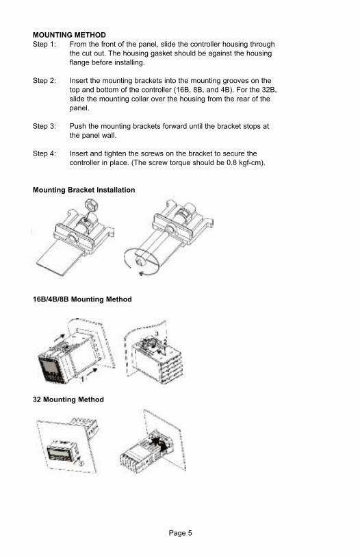
MOUNTING METHOD
Step 1: From the front of the panel, slide the controller housing through
the cut out. The housing gasket should be against the housing
flange before installing.
Step 2: Insert the mounting brackets into the mounting grooves on the
top and bottom of the controller (16B, 8B, and 4B). For the 32B,
slide the mounting collar over the housing from the rear of the
panel.
Step 3: Push the mounting brackets forward until the bracket stops at
the panel wall.
Step 4: Insert and tighten the screws on the bracket to secure the
controller in place. (The screw torque should be 0.8 kgf-cm).
Mounting Bracket Installation
16B/4B/8B Mounting Method
32 Mounting Method
Page 5

Page 6
WIRING
Do not run thermocouple or other class 2 wiring in the same conduit as power leads. Use
only the type of thermocouple or RTD probe for which the control has been programmed.
Maintain separation between wiring of sensor, auxiliary in or out, and other wiring. See the
Initial Setting Menu for input selection.
For thermocouple input always use extension leads of the same type designated for your
thermocouple.
For supply connections use No. 16 AWG or larger wires rated for at least 75˚ C. Use
conductors only. All line voltage output circuits must have a common disconnect and be
connected to the same pole of the disconnect.
Input wiring for thermocouple, current, and RTD; and output wiring for current 14 VDC is
rated CLASS 2.
Control wiring as show below:
Terminal Identification
32B
16B
140VDCOR
4-20MAOR
0-10V
-
+
OUT1NO
COM
1 6 11EV2
EV1
L
CT
N
AC 100-24OV50/60 HZ5VA122 7
RTD SG3 8
+ +
- -
Tc
13 OUT2
DATA-4 9
5 10
RS-485
DATA+
14
15COM
3A250VAC
ALM13A250VAC
AC, Event / CT InputAC, No Event / CT Input
AC DC
DC, No Event/CT Input

Page 7
Terminal Identification (Continued)
4B/8B
Wiring for 4 to 20 mA Transmitter Inputs
Note: 16B terminal layout used in above example. Use appropriate terminal layout for
selected controller.
TRANSMITTER
POWERSUPPLY A-277
250 OHMPRECISIONRESISTOR
1
2
3
4
5
6
7
8
9
10
11
12
13
14
10
AC DC

Page 8
FRONT KEY FUNCTIONS
Key functions are as follows:
INDEX: Pressing the INDEX key advances the display to the next menu item.
UP ARROW: Increments a value or changes a menu item. If pressed
during the Operation Mode, the set point value will be increased.
DOWN ARROW: Decrements a value or changes a menu item. If pressed
during the Operation Mode, the set point value will be decreased.
ENTER: Stores the value or item change. If not pressed, the previously
stored value or item will be retained. When pressed during the Operation
Mode, the controller switches to the Regulation Mode. If held for more
than 3 seconds during the Operation Mode, the controller switches to the
Initial Setting Mode. If pressed during the Regulation Mode or Initial Setting
Mode, the controller will return to the Operation Mode.
SECURITY FEATURES
The B series controller has two built in security lock settings to prevent unauthorized
personnel from changing parameter settings. These parameters are set in the Operation
Mode.
The LoC1 setting affects all parameters in the controller. If LoC1 setting is enabled, the
operator will have to unlock the controller to make any changes to the controller’s
parameters.
The LoC2 setting affects all parameters except the set point. If LoC2 setting is enabled, the
only parameter that the operator will be able to change is the set point. In order to change
any other parameters, the operator will have to unlock the control before making a change.
In order to unlock the control, the operator must depress the ENTER and INDEX key
simultaneously.

Page 9
CONTROL OPERATION DESCRIPTION
The HOME display is the normal display while the control is operating. If no errors or
functions are active, the HOME display will indicate the Process Variable (the temperature,
pressure, flow, %RH, etc.) that is being measured on the top display and the Set Variable on
the bottom display.
Items that can change the HOME display are the Ramp and Soak function and any error
messages. Descriptions of these special displays follow.
If the Ramp and Soak feature is active, then bottom display will show the current execution
pattern and current execution step. The UP and DOWN arrows can be pressed to change
the bottom display to show the Set Point (SP) of the current execution step or the Time
Remaining (r-ti) of the current execution step. After changing the bottom display to either the
Time Remaining or the Set Point, the ENTER key must be pressed to display the values.
Error Messages are shown on page 26.
OPTIONS
Event Input
When the controller is ordered with the Event Input Option (See page 3 for ordering
information), two event inputs are available. The event input is triggered by contact closure
between event 1 (EV1) or event (EV2) contact terminal and signal ground (SG) contact
terminal.
Event 1 controls the output operation of the control. When the event 1 contact terminals are
open, the output is active. When the event 1 contact terminals are closed, the output is de-
activated. The outputs can also be controlled via the Run/Stop parameter using the front
keypad or by using the RS-485 communications.
Event 2 allows the user to switch between two temperature set points. Each temperature set
point has independent control parameters.
Current Transformer Alarm Function
The current transformer option allows the user to have an alarm contact trigger due to a loss
of current or a surge in current to the control output. When using the current transformer
input, the desired alarm contact should be set to alarm type 13 in the Initial Setting Menu
(Page 21). The current transformer should be wired according to the appropriate wiring
diagram on page 6 and page 7. The high and low alarm set points can be set from 0.5 to 30
Amps. The display resolution is 0.1 Amps and the accuracy is ±0.5 Amps with the included
current transformer.

Page 10
Heating, Cooling or Dual Loop Control
Temperature Control can be achieved by either heating or cooling. In the B series controllers,
heating and cooling can be operated simultaneously using Dual Loop Output Control to
maintain a temperature set point. When Dual Loop Output Control is used, control outputs
must be connecting to the heating and cooling devices. Please refer to the following for the
operation of each setting.
Control Modes are selected by changing the S-HC parameter in the Initial Setting Mode.
Select HEAt, for heating or reverse acting control for output 1. If selected, output 2 will
become alarm 3.
Select CooL, for cooling or direct acting control for output 1. If selected, output 2 will become
alarm 3.
Select H1C2 or C1H2 for Dual Loop Output Control for output 1 and 2. If H1C2 is selected,
output 1 would be fore heating or reverse acting control and output 2 would be for cooling or
direct acting control. If C1H2 is selected, output 1 would be for cooling or direct acting control
and output 2 would be for heating or reverse acting control.
Setting the control mode to PID when the controller is set for Dual Loop Output Control
Activates the Proportional Band Coefficient (CoEF) parameter and the Dead Band (dead)
parameter.
The Proportional Band Coefficient (CoEF) sets the Proportional band value for Output 2
based on the Proportional band of output 1. The Proportional Band of Output 2 would be
equal to the Proportional Band (Pn) of Output 1 multiplied by the Proportional Band
Coefficient (CoEF). The Integral Time (in) and the Derivative Time (dn) will be the same for
both Outputs.
The Dead Band (dEAd) parameter sets an area in which the heating and cooling outputs are
operating at 0% on. The Dead Band is centered on the Set Point in Dual Loop Output Control
mode. Please see the Dead Band illustrated on page 19.

Page 11
RAMP/SOAK PROGRAMMING AND OPERATION
The ramp/soak feature offers a great deal of flexibility by allowing changes in the set point
to be made over a predetermined period of time.
Theory of Operation
The B series controls offer a very simple approach to programming a ramp function. Rather
than requiring the operation to calculate an approach rate (usually in degrees per minutes),
the B series does the calculation internally. Thus, the operator only needs to program the
target set point and the time desired to reach that point. When the ramp segment is executed
by the control, it calculates the ramp required to move the process from the starting value
(current PV) to the desired value (programmed SP) in the time allowed.
Soaks (or dwells) are ramp segments where the target set point is the same as the beginning
process value. This allows for multistage ramps without wasting intermediate soak steps.
Care must be taken, however, that the process does actually reach the soak value before
the soak time starts. If not, the next segment will calculate a slope from the starting PV to
the target SP. Depending on your process requirements, this difference may be important.
Make sure to test any program for desired results before running production material.
Do not operate auto-tuning while a ramp function is operating. The ramp function will
prevent self tune from operating properly. Make sure that all tuning is set up before
operating ramp/soak.

Page 12
Program Setup
All of the programming for the Ramp/Soak function is done in the Initial Setting Mode. You
may wish to work out your program on paper before going into the programmer menu
sequence.
In the Initial Setting Mode, go to the Control Mode (CtrL) parameter. Set the parameter to
ProG. Press INDEX to the Pattern Editing parameter (PAtn). Use the arrows to select the
desired pattern to edit. By setting the Pattern Editing parameter to off, pressing the INDEX
key brings up the next parameter in the Initial Setting mode. The Ramp and Soak function
is supported by 8 different patterns (pattern numbers 0 to 7). Each pattern contains 8 steps
(step numbers 0 to 7) for set point and execution times, one link pattern (Linn) parameter,
one cycle parameter (CyCn), and one actual step parameter (PSYn).
The default of step 0 in pattern 0 is a soak function. The control should be programmed to
reach the Set Point (SV) temperature, X, after the execution time, T. The unit will control the
process temperature (PV) to reach temperature X and the keep the temperature at
temperature X. The execution time T is determined by the execution time (ti00) for step
number 0. The target set point (SP00) for step number 0 should equal the Set Point (SV)
temperature.
After the first step, program SP01 and ti01 through SP07 and ti07 for the first pattern. The
target set point value (SP0n) is in actual units just like your Set Point (SV). If the control is
set for temperature, then the target set point displays are in temperature. If the control is
programmed for some other engineering unit, the target set point displays will be set in that
unit. The target execution time (ti0n) is in units of time, (hh.mm). The step parameters will
be followed by the Actual Step parameter, Cycle parameter, and the Link parameter for each
pattern.
The Actual Step parameter (PSYn) sets the last executable step for the current pattern. For
example, if the Actual Step parameter is set to 2 for pattern 0, then the program will only run
steps 0, 1, and 2 for pattern 0.
The Cycle parameter (CyCn) determines how many times the current pattern is repeated.
For example, if the Cycle parameter for pattern 0 is set to 2, the steps in pattern 0 will be
repeated twice before moving on to the next pattern.
The Link parameter (Linn) assigns the next pattern for the program to execute. For example,
if the Link parameter is set to 3 for pattern 0, the program will skip patterns 1 and 2 and start
executing pattern 3 after pattern 0 is complete. If the Link parameter is set to oFF, the
program will stop after executing the current pattern and the temperature will be maintained
at the set point of the last step executed.

Page 13
Execution
The execution of the ramp and soak feature is initiated through the Run/Stop parameter, (r-
S) in the Operation Mode. The Run/Stop parameter has four possible values.
If the Run/Stop parameter is set to rUn, the program will start to execute in order from step
0 of the start pattern.
If the Run/Stop parameter is set to Program Stop (PStP), the program will stop and maintain
the temperature of the last set point before the program was halted. When the Run/Stop
parameter is restarted, the program will restart and execute from step 0 of the start pattern.
The start pattern selection (Ptrn) is only available when the Run/Stop parameter is set to
Program Stop.
If the Run/Stop parameter is set to Program Hold (PHod), the program will be paused and
the temperature will be maintained at the set point temperature that was active prior to the
program hold. Once the Run/Stop parameter is set back to run, the program will follow the
step before the hold and start to execute through the rest of the program.
Display
During ramp and soak program control, the SV default display is P-XX, where P indicates
the current execution pattern and XX indicates the display item to Set Point Value (SP) or
Residual Time (r-ti). The Set Point Value will display the temperature set point of the current
execution step in the SV display. The Residual Time will display the remaining time of the
current execution step in the SV display. After selecting the Set Point Value or Residual
Time, the ENTER key must be pressed to accept the display change.

Page 14
PROGRAMMING AND OPERATION FOR PID
Theory of Operation
The PID method of control is based on the individual tuning of proportional band values,
integral time values, and derivative time values to help a unit automatically compensate for
changes in a control system. The proportional band is the range around the set point in
which the control’s proportioning takes place. The control increases or decreases the output
proportionately to the process temperature’s deviation from the set point. The integral time
eliminates undershoot and overshoot of the set point by adjusting the proportioning control
based on the amount of deviation from the set point during steady state operation. The
derivative time eliminates undershoot and overshoot by adjusting the proportioning control
based on the rate of rise or fall of the process temperature. The integral deviation offset
correction (ioFn) improves the speed in which the process value reaches the set point value.
If this parameter is set to zero, the output will be zero when the process value is equal to the
set point value. If the integral time parameter is used only to eliminate steady state error, it
may take a long time to reach the set point because it needs time to accumulate the error.
This parameter defines the default output level on start up. When the integral time is set at
0, then the proportional derivative offset correction (PdofF) would replace the integral
deviation offset correction, but serves the same function.
Program Set Up
In order to use the PID function in the B series controllers, the Control Mode will have to be
set to PID in the Initial Setting Menu. After changing the Control Mode, the PID parameters
can be accessed in the Regulation Menu. The PID parameters can either be programmed
manually or they can be set by the controller using the auto tune function. The auto tune will
use trial and error to tune the PID parameters to give the control the most precise control.
Since the time to accurately tune the control may differ depending on the process, the
controller can also be manually tuned to known PID values prior to running auto tune. The
Run/Stop parameter must be set to run in order to start auto tuning.
The B series controller has four user-defined profiles (PID0 to PID3) of PID values along with
an auto selection function (PID4). Each set of PID values includes a set point value (Svn),
proportional band (Pn), integral time (in), derivative time (dn), and integral deviation setting
(iofn). If PID4 is selected, the controller will pick which set of user defined parameters to use
based on how close the set point value of the profile is to the current process value.

Page 15
DESCRIPTION OF MENU STRUCTURE
The programming for the controller is broken down into three menus (Operation, Regulation,
and Initial Setting). Upon normal operation, control will be in the Operation Menu.
OPERATION MENU
Pressing the INDEX key will cycle through the below menu items. The parameter will be
displayed in the top display, while its value will be displayed in the bottom display, except for
the set point which is displayed in the bottom display on the Home Display. The UP and
DOWN arrows change the values of the parameters. The ENTER key must be pressed after
any changes.
Adjust the set point value - Can be any numerical value
between the upper and lower limit of the temperature range.
Select Run - Stop Output Control.
Activates outputs and Starts Ramp/Soak.
De-activates outputs and Stops Ramp/Soak.
Halts Ramp/Soak program, outputs remain active. Only
available during ramp/soak operation. Program restarts at
Step 0 of Start Pattern.
Pauses Ramp/Soak program, outputs remain active. Only
available during ramp/soak operation. Program restarts at step
prior to program being held.
Set Start pattern for Ramp/Soak. Only available when r - S set
to PStP.
Number of digits to the right of the decimal. Decimal Point
Position can be set for all Inputs except for B, S, and R type
thermocouples.
Alarm 1 High Set Point. May not appear depending on ALA1
setting in Initial Setting Menu.
1234
r-S
rUn
StoP
PStP
PHod
Ptrn
SP
AL1H

Page 16
Alarm 1 Low Set Point. May not appear depending on ALA1
setting in Initial Setting Menu.
Alarm 2 High Set Point. May not appear depending on ALA2
setting in Initial Setting Menu.
Alarm 2 Low Set Point. May not appear depending on ALA2
setting in Initial Setting Menu.
Alarm 3 High Set Point. May not appear depending on ALA3
setting in Initial Setting Menu.
Alarm 3 Low Set Point. May not appear depending on ALA3
setting in Initial Setting Menu.
Set front panel security lock.
Lock all settings.
Lock all settings except the set point.
Display the % output value for output 1. In manual mode, this
value can be changed using the up and down arrows.
Display the % output value for output 2. In manual mode, this
value can be changed using the up and down arrows.
AL1L
AL2H
AL2L
AL3H
AL3L
LoC
L0C1
L0C2
oUt1
oUt2

Page 17
REGULATION MENU
Press the ENTER key while at the Home Display in order to access the Regulation Menu.
Pressing the INDEX key will cycle through the below menu items. The parameter will be
displayed in the top display, while its value will be displayed in the bottom display. The UP
and DOWN arrows change the values of the parameters. The ENTER key must be pressed
after any changes.
Auto Tune. The controller will evaluate the process and select
the PID values to maintain good control. Only available when
the control mode is set to PID.
Start learning the process. After the process has been learned
the menu will revert to oFF.
Disables Auto Tune.
Selection of PID profile. The controller can store up to 4 PID
profiles. The top display will show the PID profile and the
bottom display will show the target set value for that profile.
When Pid4 is selected, the controller will automatically select
which PID profile to use based on the target set values. Only
available when control mode is set to PID. See Programming
and Operation of PID function for more information.
(n = 0 to 4)
Target Set Value associated with each PID Profile.
(n = 0 to 3).
Proportional Band Setting associated with each PID
Profile. (n =0 to 3).
Integral time (reset time) associated with each PID
Profile. (n = 0 to 3).
Derivative time (rate time) associated with each PID
Profile. (n = 0 - 3).
Integral Deviation Offset Correction associated with
each PID Profile. (n = 0 to 4)
AT
on
oFF
Pidn
Svn
Pn
in
dn
ioFn

PD Offset Correction Setting. only available when control
mode is set to PID and integral time = 0. See Programming
and Operation of PID function for moving information.
Heating Hysteresis (Differential) Setting. Sets the value for the
amount of difference between the turn off point (set point) and
the turn on point. Figure A shows the output behavior for a
heating (reverse acting) application. Only available when
control mode set to on/off control.
Cooling Hysteresis (Differential) Setting. Sets the value for the
amount of difference between the turn off point (set point) and
the turn on point. Figure A shows the output behavior for a
cooling (direct acting) application. Only available when control
mode set to on/off control.
Figure A: Output behavior for Heating/Cooling On/Off Applications
Heating Control Cycle Setting. Defines the duration for one
output period or cycle for output 1. Only available when control
mode is set to PID or ProG and Output 1 is set for heating.
Cooling Control Cycle Setting. Defines the duration for one
output period or cycle for output 1. Only available when control
mode is set to PID or ProG and Output 1 is set for cooling.
Control Cycle setting for output 2. Defines the duration for one
output period or cycle for output 2. Only available when control
mode is set to PID and Dual Loop Output Control.
Page 18
PdoF
HtS
CtS
HtPd
CLPd
HCPd

Page 19
Proportional Band Coefficient. Sets the value of the
proportional band for output 2. The proportional band of
output 2 is equal to the proportional band of output 1
multiplied by the proportional band coefficient. This parameter
is only available when the control mode is set to PID and Dual
Loop Output Control.
Dead Band. The zone centered on the set point in which the
control is thought to be at the desired set level. The outputs
will be turned off at this point unless there is an integral
deviation offset or the dead band is negative. This parameter
is only shown when the control is set to Dual Loop Output
Control.
Figure B: Output Operation during dual loop control
Process Temperature Offset. This feature allows the input value to
be changed to agree with an external reference or to compensate
for sensor error.
Analog Output High Limit: Sets the actual upper limit of the
analog output when the control’s output is operating at 100%.
Only available for analog output models.
Analog Output Low Limit. Sets the actual lower limit of the
analog output when the control’s output is operating at 0%.
Only available for analog output models.
Output operation of ON/OFF control during dual loop output control.
PID control Dead Band is positive. PID control, Dead Band is negative.
CoEF
dEAd
tPoF
Crh
CrLo

INITIAL SETTING MENU
Press and hold the ENTER key for at least 3 seconds while at the Home Display in order to
access the Initial Setting Menu. Pressing the INDEX key will cycle through the below menu
items. The parameter will be displayed in the top display, while its value will be displayed in
the bottom display. The UP and DOWN arrows change the values of the parameters. The
ENTER key must be pressed after any changes.
Input Selection. Select one of the following input types from
the below table. For Current inputs, a 250 Ohm Resistor must
be wired across the input terminals.
Temperature Units. This parameter is only available for
thermocouple or RTD inputs.
Scale Hight Limit. Sets the upper limit of the temperature
range. If the process temperature exceeds this setting, the
display will flash an error code.
Scale Low Limit. Sets the lower limit of the temperature range.
If the process temperature exceeds this setting, the display will
flash an error code.
Page 20
Input Temperature Sensor Type LED Display Temperature Range
Thermocouple TXK type -328 ~ 1472°F (-200 ~ 800°C)
Thermocouple U type -328 ~ 932°F (-200 ~ 500°C)
Thermocouple L type -328 ~ 1562°F (-200 ~ 850°C)
Thermocouple B type 212 ~ 3272°F (100 ~ 1800°C)
Thermocouple S type 32 ~ 3092°F (0 ~ 1700°C)
Thermocouple R type 32 ~ 3092°F (0 ~ 1700°C)
Thermocouple N type -328 ~ 2372°F (-200 ~ 1300°C)
Thermocouple E type 32 ~ 1112°F (0 ~ 600°C)
Thermocouple T type -328 ~ 752°F (-200 ~ 400°C)
Thermocouple J type -148 ~ 2192°F (-100 ~ 1200°C)
Thermocouple K type -328 ~ 2372°F (-200 ~ 1300°C)
Platinum Resistance (Pt100) -328 ~ 1112°F (-200 ~ 600°C)
Platinum Resistance (JPt100) -4 ~ 752°F (-20 ~ 400°C)
0~50mV Analog Input -999 ~ 9999
0V ~ 10V Analog Input -999 ~ 9999
0V ~ 5V Analog Input -999 ~ 9999
4 ~ 20mA Analog Input -999 ~ 9999
0~20mA Analog Input -999 ~ 9999
t
U
L
b
S
r
n
E
t
J
Pt
JPt
u
u10
u5
A4
A0
inPt
tPUn
tP-H
tP-L

Page 21
Control Mode. Select method of control operation. Can be set
to PID, On-Off, Manual, or Ramp/Soak Programming.
Ramp/Soak Pattern Selection. Allows user to select which of
the 8 ramp/soak patterns to program. Each pattern has 8 steps
which gives a total of 64 possible steps in a single program. When
finished programming all ramp and soak patterns, the parameter
should be set to off. (n = 0 to 7)
Segment Set Point for pattern n and step y. For example the
first step of the first pattern would be SP00. The last step would be
SP77. (n = 0 to 7, y = 0 to 7)
Segment Time for pattern n and step y. For example the first
step of the first pattern would be ti00. The last step would be Ti77.
The value of this parameter will be in HH:MM.
(n = 0 to 7, y = 0 to 7)
Last Step for pattern n. Sets the last step that will be performed in
the current pattern. (n = 0 to 7)
Pattern Loop Setting for pattern n. Sets the number of times
that the current pattern will be repeated. (n = 0 to 7)
Pattern Link for pattern n. Sets the next pattern that will be
performed after the current pattern. When set to off, the
program will end and maintain last set point. (n = to 7)
Heat/Cool Selection. Assigns output 1 and output 2 to be
either heat or cool.
HEAt = Output 1 = Heating
CooL = Output 1 = Cooling
H1C2 = Output 1 = Heating; Output 2 = Cooling
H2C1 = Output 1 = Cooling; Output 2 = Heating
Alarm 1 Setting. Sets operation for Alarm 1. Please see
selection on Alarm Outputs for description of the outputs.
Alarm 2 Setting. Sets operation for Alarm 2. Please see
selection on Alarm Outputs for description of the outputs.
Alarm 3 Setting. Sets operation for Alarm 3. Please see
selection on Alarm Outputs for description of the outputs.
(not available for Dual Loop Output Control)
CtrL
PAtn
SPnY
tinY
PSYn
CYCn
Linn
S-HC
ALA1
ALA2
ALA3

Page 22
System Alarm Setting. Selects which of the alarm outputs is
used if a system alarm occurs. The system alarms would be
an input error or a process control failure. This feature can be
disabled by turning this parameter to oFF.
Communications Write Function Feature. Allows parameters
to be changed via the RS-485 communications. Setting to oFF
prevents any changes from remote users.
Protocol Selection: Select whether to communicate using ASCII or
RTU Protocol. This value must match the protocol used by the host
computer.
Controller Address: Set from 1 to 247. This value must match
the controller address used by the host computer.
Communication Data Length. Choose either 7 or 8. This value
must match the communication data length of the host computer.
Communication Parity Bit. Set this value to even, odd, or none.
This value must match the communication parity bit of the host
computer.
Communication Stop Bit. Set this value to 1 or 2. This value
must match the communication stop bit of the host computer.
SALA
CoSH
C-SL
C-no
LEn
PrtY
StoP

Page 23
Alarm Output Configuration and Operation Table.
Alarm TypeAlarm function disabled Deviation upper- and lower-limit:This alarm output operates when PV value is higher than the setting value SV+(AL-H) or lower than the setting value SV-(AL-L).Deviation upper-limit:This alarm output operates when PV value is higher thanthe setting value SV+(AL-H).Deviation lower-limit:This alarm output operates when PV value is lower thanthe setting value SV-(AL-L).Reverse deviation upper- and lower-limit:This alarm output operates when PV value is in the range of the setting value SV+(AL-H) and the setting value SV-(AL-L).Absolute value upper- and lower-limit:This alarm output operates when PV value is higher than the setting value AL-H or lower than the setting value AL-L.Absolute value upper-limit:This alarm output operates when PV value is higher thanthe setting value AL-H.Absolute value lower-limit:This alarm output operates when PV value is lower than the setting value AL-L.Deviation upper- and lower-limit with standby sequence:This alarm output operates when PV value reaches set point (SV value )and the value is higher than the settingvalue SV+(AL-H) or lower than the setting value SV-(AL-L).Deviation upper-limit with standby sequence:This alarm output operates when PV value reaches setpoint (SV value) and the reached value is higher than the setting value SV+(AL-H).Deviation lower-limit with standby sequence:This alarm output operates when PV value reaches the set point (SV value) and the reached value is lower than the setting value SV-(AL-L).Hysteresis upper-limit alarm output:This alarm output operates if PV value is higher than the setting value SV+(AL-H). This alarm output is OFF when PV value is lower than the setting value SV+(AL-L).Hysteresis lower-limit alarm output:This alarm output operates if PV value is lower than the setting value SV-(AL-H). This alarm output is OFF when PV value is higher than the setting value SV-(AL-L).CT alarm output:This alarm operates when the current measured by transformer (CT) is lower than AL-L or higher than AL-H (This alarm output is available only for the controller with current transformer).When program control is end status, alarm output is ON.When RAMP UP status happens to PID program control, alarm output is ON.When RAMP DOWN status happens to PID programcontrol, alarm output is ON.When SOAK status happens to PID program control, alarm output is ON.When RUN status happens to PID program control, alarm output is ON.
Set Value1
2
3
4
5
6
7
8
9
10
11
12
13
1415
16
17
18
Alarm Output OperatingOutput is OFF
(Note: AL-H and AL-L include AL1H, AL2H, AL3H and AL1L, AL2L, AL3L)
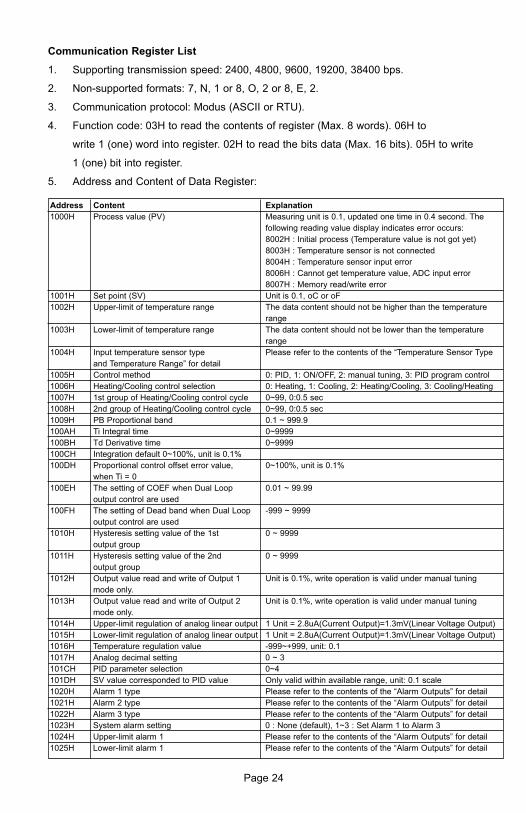
Page 24
Communication Register List
1. Supporting transmission speed: 2400, 4800, 9600, 19200, 38400 bps.
2. Non-supported formats: 7, N, 1 or 8, O, 2 or 8, E, 2.
3. Communication protocol: Modus (ASCII or RTU).
4. Function code: 03H to read the contents of register (Max. 8 words). 06H to
write 1 (one) word into register. 02H to read the bits data (Max. 16 bits). 05H to write
1 (one) bit into register.
5. Address and Content of Data Register:
Address Content Explanation
1000H Process value (PV) Measuring unit is 0.1, updated one time in 0.4 second. The
following reading value display indicates error occurs:
8002H : Initial process (Temperature value is not got yet)
8003H : Temperature sensor is not connected
8004H : Temperature sensor input error
8006H : Cannot get temperature value, ADC input error
8007H : Memory read/write error
1001H Set point (SV) Unit is 0.1, oC or oF
1002H Upper-limit of temperature range The data content should not be higher than the temperature
range
1003H Lower-limit of temperature range The data content should not be lower than the temperature
range
1004H Input temperature sensor type Please refer to the contents of the “Temperature Sensor Type
and Temperature Range” for detail
1005H Control method 0: PID, 1: ON/OFF, 2: manual tuning, 3: PID program control
1006H Heating/Cooling control selection 0: Heating, 1: Cooling, 2: Heating/Cooling, 3: Cooling/Heating
1007H 1st group of Heating/Cooling control cycle 0~99, 0:0.5 sec
1008H 2nd group of Heating/Cooling control cycle 0~99, 0:0.5 sec
1009H PB Proportional band 0.1 ~ 999.9
100AH Ti Integral time 0~9999
100BH Td Derivative time 0~9999
100CH Integration default 0~100%, unit is 0.1%
100DH Proportional control offset error value, 0~100%, unit is 0.1%
when Ti = 0
100EH The setting of COEF when Dual Loop 0.01 ~ 99.99
output control are used
100FH The setting of Dead band when Dual Loop -999 ~ 9999
output control are used
1010H Hysteresis setting value of the 1st 0 ~ 9999
output group
1011H Hysteresis setting value of the 2nd 0 ~ 9999
output group
1012H Output value read and write of Output 1 Unit is 0.1%, write operation is valid under manual tuning
mode only.
1013H Output value read and write of Output 2 Unit is 0.1%, write operation is valid under manual tuning
mode only.
1014H Upper-limit regulation of analog linear output 1 Unit = 2.8uA(Current Output)=1.3mV(Linear Voltage Output)
1015H Lower-limit regulation of analog linear output 1 Unit = 2.8uA(Current Output)=1.3mV(Linear Voltage Output)
1016H Temperature regulation value -999~+999, unit: 0.1
1017H Analog decimal setting 0 ~ 3
101CH PID parameter selection 0~4
101DH SV value corresponded to PID value Only valid within available range, unit: 0.1 scale
1020H Alarm 1 type Please refer to the contents of the “Alarm Outputs” for detail
1021H Alarm 2 type Please refer to the contents of the “Alarm Outputs” for detail
1022H Alarm 3 type Please refer to the contents of the “Alarm Outputs” for detail
1023H System alarm setting 0 : None (default), 1~3 : Set Alarm 1 to Alarm 3
1024H Upper-limit alarm 1 Please refer to the contents of the “Alarm Outputs” for detail
1025H Lower-limit alarm 1 Please refer to the contents of the “Alarm Outputs” for detail

Address Content Explanation
1026H Upper-limit alarm 2 Please refer to the contents of the “Alarm Outputs” for detail
1027H Lower-limit alarm 2 Please refer to the contents of the “Alarm Outputs” for detail
1028H Upper-limit alarm 3 Please refer to the contents of the “Alarm Outputs” for detail
1029H Lower-limit alarm 3 Please refer to the contents of the “Alarm Outputs” for detail
102AH Read LED status b0 : Alm3, b1: Alm2, b2: F, b3: _, b4: Alm1, b5: OUT2, b6:
OUT1, b7: AT
102BH Read push button status b0 : Set, b1 : Select, b2 : Up, b3 : Down. 0 is to push
102CH Setting lock status 0 : Normal, 1 : All setting lock, 11 : Lock others than SV value
102FH Software version V1.00 indicates 0x100
1030H Start pattern number 0 ~ 7
1040H~ Actual step number setting inside the 0 ~ 7 = N, indicate that this pattern is executed from step 0 to
1047H correspond pattern step N
1050H~ Cycle number for repeating the execution of 0 ~ 99 indicate that this pattern has been executed for 1~100
1057H the correspond pattern times
1060H~ Link pattern number setting of the 0 ~ 8, 8 indicates the program end. 0~7 indicates the next
1067H correspond pattern execution pattern number after executing the current pattern
2000H~ Pattern 0~7 temperature set point setting -999 ~ 9999
203FH Pattern 0 temperature is set to
2000H~2007H
2080H~ Pattern 0~7 execution time setting Time 0 ~ 900 (1 minute per scale)
20BFH Pattern 0 time is set to 2080H~2087H
6. Address and Content of Bit Register: ( First bit of reading will put into LSB, Write data =
FF00H for bit set, 0000H for bit clear)
Page 25
Address Content Explanation
0810H Communication write-in selection Communication write in disabled: 0 (default), Communication
write in enabled: 1
0811H Temperature unit display selection oC / linear input (default) : 1 , oF : 0
0812H Decimal point position selection Except for the thermocouple B, S, R type, all the other
thermocouple type are valid. (0 or 1)
0813H AT setting OFF: 0 (default), ON : 1
0814H Control RUN/STOP setting 0 : STOP, 1 : RUN (default)
0815H STOP setting for PID program control 0: RUN (default), 1: STOP
0816H Temporarily STOP for PID program control 0: RUN (default), 1: Temporarily STOP

Page 26
DIAGNOSTIC ERROR MESSAGES
Display Error Messages
Display
PV
SV
PV
SV
PV
SV
PV
SV
PV
SV
No Action Required
Verify that sensor is wired to proper
terminals. Next, check that the
controller is programmed for the correct
input type. Most commonly seen when
controller is programmed for a RTD,
while a thermocouple is connected.
Verify that the input is wired to the
proper terminals. Next check to see if
the input type is set to the proper value.
Most commonly seen when controller is
programmed for a 4 to 20 mA input and
0 to 20 mA signal is wired to the
controller.
Input signals may normally go above or
below range limits. If not check input
and correct the process temperature or
increase temperature range limits using
tP-H and tP-L.
Attempt to reset the factory default
settings using the instructions in the
next section. If still has error, call
customer service for a return goods
authorization number to have the
controller evaluated at the factory.
Display on Start Up
No Input Probe Connection
Input Error
Process Value Flashes
when outside of range
Error EEPROM
b150
rr
No
Cont
Err
inPt
2001
0.0
Err
Pron
Description Action Required

Communication Error Messages
Page 27
Error Status
102EH/4750H
0001H
0002H
0003H
0004H
0005H
0006H
0007H
PV read back
1000H/4700H
N/A
8002H
8003H
8004H
N/A
8006H
N/A
Error Status
PV Unstable
Re-initialize, no temperature at
this time
Input sensor did not connect
Input Signal Error
Over Input Range
ADC fail
EEPROM read/write error
Page 28
Reset Factory Default Settings
Note: Resetting Factory Default Settings erases all of the values entered by the user. Record
any necessary settings before proceeding.
Warning: Erasing the user entered values may result in a safety hazard and system
malfunction.
The following instructions will reset the controller to the original factory default settings.
Step 1. Press the INDEX KEY while at the Home Display until the
controller reads LoC in the process display. Use the UP
arrow to select LoC1. Press the ENTER KEY to save this
value.
Step 2. Press and hold the UP and DOWN arrows
simultaneously for one second. Upon releasing the
buttons, the display will read SHou in the PV display
and oFF in the SV display.
Step 3. Press the INDEX key once and the controller will read
PASS in the PV display and a 4321 in the SV display.
Adjust the value in the SV display to 1357 using the UP
and DOWN arrows. Press the ENTER KEY to save the value.
Step 4. Cycle the power on the controller. Upon power up, all of the
user set values have been erased.

Page 29
SPECIFICATIONSInput Voltage 100 to 240 VAC 50/60 Hz OR 24 VDC (depending on model).
Operation Voltage Range 85% to 110% of rated voltage.
Power Consumption 5VA max.
Memory Protection EEPROM 4K bit (non-volatile memory
(number of writes: 1000,000)).
Display Method 2 line x 4 character 7-segment LED display Process value
(PV): Red color, Set point (SV): Green color.
Sensor Type Thermocouple: K, J, T, E, N, R, S, B, L, U, TXK.
3-wire platinum RTD: Pt100, JPt100.
Analog input 0 to 5 V, 0 to 10 V, 0 to 20 mA, 0 to 50 mV.
Control Mode PID, ON/OFF, Manual or PID program control
(Ramp/Soak control).
Control Output Relay output: SPDT (SPST: 1/16 DIN and 1/32 DIN size),
Max. load 250 VAC, 5 A resistive load.
Voltage pulse output: DC 14 V, Max. output current 40 mA.
Current output: DC 4 to 20 mA output (Load resistance: Max.
600Ω).
Linear voltage output: 0 to 5 V, 0 to 10 V *(B Series only).
Display Accuracy 0 or 1 digit to the right of the decimal point (selectable).
Sampling Range Analog input: 150 msec/per scan Thermocouple or Platinum
RTD: 400 msec/per scan.
RS-485 Communication MODBUS® ASCII/RTU communication protocol.
Vibration Resistance 10 to 55 Hz, 10 m/s2 for 10 min, each in X, Y and Z directions.
Shock Resistance Max. 300 m/s2, 3 times in each 3 axes, 6 directions.
Ambient Temperature 32°F to 122°F (0°C to +50°C).
Storage Temperature -4°F to 150°F (-20°C to +65°C).
Altitude 2000 m or less.
Relative Humidity 35% tp 80% (non-condensing).
Modbus® is a registered trademark of schieder automation.

Page 30
Thermocouple Type and Temperature Range
Input Temperature Sensor Type LED Display Temperature Range
Thermocouple TXK type -328 ~ 1472°F (-200 ~ 800°C)
Thermocouple U type -328 ~ 932°F (-200 ~ 500°C)
Thermocouple L type -328 ~ 1562°F (-200 ~ 850°C)
Thermocouple B type -212 ~ 3272°F (-100 ~ 1800°C)
Thermocouple S type -32 ~ 3092°F (0 ~ 1700°C)
Thermocouple R type -32 ~ 3092°F (0 ~ 1700°C)
Thermocouple N type -328 ~ 2372°F (-200 ~ 1300°C)
Thermocouple E type -32 ~ 1112°F (0 ~ 600°C)
Thermocouple T type -328 ~ 752°F (-200 ~ 400°C)
Thermocouple J type -148 ~ 2192°F (-100 ~ 1200°C)
Thermocouple K type -328 ~ 2372°F (-200 ~ 1300°C)
RTD Type and Temperature Range
Input Temperature Sensor Type LED Display Temperature Range
Platinum Resistance (Pt100) -328 ~ 1472°F (-200 ~ 800°C)
Platinum Resistance (JPt100) -4 ~ 752°F (-20 ~ 400°C)
Voltage Input Type and Input Range
Voltage Input Range LED DIsplay Temperature Range
0~50mV Analog Input -999 ~ 9999
0V ~ 10V Analog Input -999 ~ 9999
0V ~ 5V Analog Input -999 ~ 9999
Current Input Type and Input Range
Current Input Type LED Display Temperature Range
4 ~ 20mA Analog Input -999 ~ 9999
0~20mA Analog Input -999 ~ 9999
t
U
L
b
S
r
n
E
t
J
Pt
JPt
u
u10
u5
A4
A0

Page 31
PRECAUTIONS
Electric Shock!
1. Do not touch the AC terminals while the power is supplied to the controller
to prevent an electric shock.
2. Make sure power is disconnected while checking the unit inside.
3. The symbol indicates that this Controller is protected throughout by
DOUBLE INSULATION or REINFORCED INSULATION (equivalent to Class II
of IEC 536).
Mount the controller in a location that will not be subject to excessive temperature,
shock, or vibration. All models are designed for mounting in an enclosed panel.
1. Always use recommended solder-less terminals: Fork terminals with isolation
(M3 screw, width is 7.0mm (6.0mm for 32B Series), hole diameter 3.2mm).
Screw size: M3 x 6.5 (With 6.8 x 6.8 square washer). Screw size for 32B
Series: M3 x 4.5 (With 6.0 x 6.0 square washer). Recommended tightening
orque: 0.4 N.m (4kgf.cm). Applicable wire: Solid/twisted wire of 2 mm2,
12AWG to 24AWG. Please be sure to tighten them properly.
2. Do not allow dust or foreign objects to fall inside the controller to prevent it
from malfunctioning.
3. Never modify or disassemble the controller.
4. Do not connect anything to the “No used” terminals.
5. Make sure all wires are connected to the correct polarity of terminals.
6. Do not install and/or use the controller in places subject to: Dust or corrosive
gases and liquid, high humidity and high radiation, vibration and shock, high
voltage and high frequency.
7. Power must be off when wiring and changing a temperature sensor.
8. Be sure to use compensating wires that match the thermocouple types when
extending or connecting the thermocouple wires.
9. Please use wires with resistance when extending or connecting a platinum
resistance sensor (RTD).
10. Please keep the wire as short as possible when wiring a platinum resistance
sensor (RTD) to the controller and please route power wires as far as
possible from load wires to prevent interference and induce noise.
11. This controller is an open-type unit and must be placed in an enclosure away
from high temperature, humidity, dripping water, corrosive materials, airborne
dust and electric shock or vibration.
12. Please make sure power cables and signals from instruments are all installed
properly before energizing the controller, otherwise serious damage may
occur.
13. Please do not use acid or alkaline liquids for cleaning. Please use a soft, dry
cloth to clean the controller.
14. Wait at least one minute after power is disconnected to allow capacitors to
discharge, and please do not touch any internal circuit within this period.
15. This instrument is not furnished with a power switch or fuse. Therefore, if a
fuse or power switch is required, install the protection close to the
instrument. Recommended fuse rating: Rated voltage 250 V, Rated current
1 A. Fuse type: Time-lag fuse.
16. Note: This controller does not provide overcurrent protection. Use of the
product requires that suitable overcurrent protection device(s) must be
added to ensure compliance with all relevant electrical standards and codes.
(Rated 250 V, 15 Amps max). A suitable disconnecting device should be
provided near the controller in the end-use installation.
DANGER
WARNING
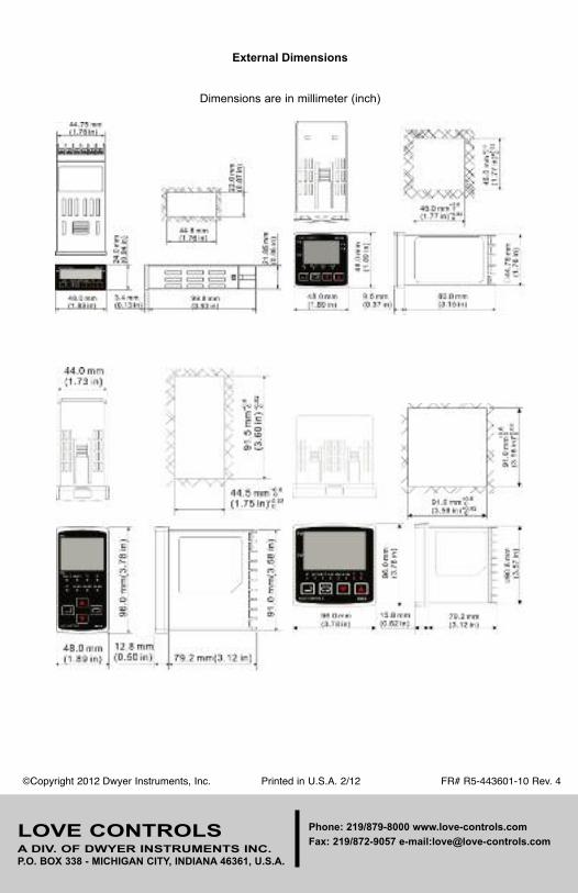
External Dimensions
Dimensions are in millimeter (inch)
©Copyright 2012 Dwyer Instruments, Inc. Printed in U.S.A. 2/12 FR# R5-443601-10 Rev. 4
LOVE CONTROLSA DIV. OF DWYER INSTRUMENTS INC. P.O. BOX 338 - MICHIGAN CITY, INDIANA 46361, U.S.A.
Phone: 219/879-8000 www.love-controls.com
Fax: 219/872-9057 e-mail:[email protected]

Technical Data
PowerFlex 520-Series AC Drive SpecificationsOriginal Instructions
Drive Features: AppView™, CustomView™, QuickView™, and MainsFree™ configuration and programming tools.
Topic Page
Product Overview 2
Catalog Number Explanation 8
Technical Specifications 9
Environmental Specifications 12
Certifications 13
Dimensions and Weights 14
Design Considerations 16
Fuses and Circuit Breaker Ratings 27
Accessories and Dimensions 32
Safe-Torque-Off Function 42
Additional Resources 47

PowerFlex 520-Series AC Drive Specifications
Product Overview
The PowerFlex® 520-Series AC drive delivers an innovative design that is remarkably versatile and can accommodate systems ranging from standalone machines to simple system integration. The PowerFlex 523 drive provides general purpose control for applications ranging up to 30 HP and 22 kW. The PowerFlex 525 drive provides maximum flexibility and performance ranging up to 30 HP and 22 kW.
By combining a variety of motor control options, communications, energy savings and standard safety features in a cost-effective drive, the PowerFlex 520-Series drive is suitable for a wide array of applications.
Maximize your system performance and productivity by taking advantage of the following key features offered in a PowerFlex 520-Series drive.
PowerFlex 520-Series AC Drives Feature
Modular Design• Detachable control module and power module allow simultaneous configuration and installation.• Each drive has a standard control module used across the entire power range.• MainsFree™ configuration allows you to simply connect your control module to a PC with a standard USB cable
and quickly upload, download, and flash the drive with new settings.• Support for accessory cards without affecting footprint.
(PowerFlex 523 drives support one, PowerFlex 525 drives support two)
Packaging and Mounting• Installation can be quick and easy using the DIN rail mounting feature on A, B, and C frame drives. Panel mounting
is also available, providing added flexibility.• Zero Stacking™ is allowed for ambient temperatures up to 45 °C, saving valuable panel space.• Integral filtering is available on all 200V and 400V ratings, providing a cost-effective means of meeting EN61800-3
Category C2 and C3 EMC requirements. External filters provide compliance to EN61800-3 Category C1, C2, and C3 EMC requirements for all PowerFlex 520-Series ratings.
• An optional IP 30, NEMA/UL Type 1 conduit box is easily adapted to the standard IP 20 (NEMA Type Open) product, providing increased environmental ratings.
Optimized Performance• Removable MOV to ground provides trouble-free operation when used on ungrounded distribution systems.• A relay pre-charge limits inrush current.• Integral brake transistor, available on all ratings, provides dynamic braking capability with simple low cost brake
resistors.• A jumper to switch between 24V DC sink or source control for control wiring flexibility.• Dual Overload Rating available for drives above 15 HP/11 kW. Normal duty: 110% overload for 60 seconds or
150% for 3 seconds. Heavy duty: 150% overload for 60 seconds or 180% overload (200% programmable) for 3 seconds provides robust overload protection.
• Adjustable PWM frequency up to 16 kHz ensures quiet operation.
2 Rockwell Automation Publication 520-TD001E-EN-E - July 2016

PowerFlex 520-Series AC Drive Specifications
PowerFlex 520-Series AC Drive Advanced Features
Control Performance• Variety of motor control options, including:
• Volts per hertz (V/Hz)• Sensorless Vector Control (SVC)• Closed loop velocity vector control (PowerFlex 525 drives only)• Permanent Magnet motor control (PowerFlex 525 drives only)
• Variety of Positioning Control, including:• PointStop™ stops motor load in a consistent position without encoder feedback• Closed loop feedback with an optional encoder card (PowerFlex 525 drives only)• Point-to-point positioning mode (PowerFlex 525 drives only)
• Integral PID functionality enhances application flexibility(PowerFlex 523 drives have one PID loop, PowerFlex 525 drives have two PID loops)
I/O Wiring
PowerFlex 523• One (1) Analog Input (unipolar voltage or current)
independently isolated from the rest of the drive I/O.• Five (5) Digital Inputs (four programmable) provide
application versatility.
• One (1) Analog Output(1) which is jumper selectable between either 0-10V or 0-20 mA. This scalable, 10-bit output is suitable for metering or as a speed reference to another device.
• One (1) Relay Output (form C) can be used to indicate various drive, motor or logic conditions.
(1) Analog output (terminal 15) is only available on PowerFlex 523 series B drive and requires firmware 3.001 and later to configure the analog output parameters.
PowerFlex 525• Two (2) Analog Inputs (one unipolar and one bipolar)
are independently isolated from the rest of the driveI/O. These inputs can be toggled via a digital input.
• Seven (7) Digital Inputs (six programmable) provide application versatility.
• One (1) Analog Output which is jumper selectable between either 0-10V or 0-20 mA. This scalable, 10-bit output is suitable for metering or as a speed reference to another drive.
• Two (2) Opto Outputs and two (2) Relay Outputs (one form A and one form B) can be used to indicate various drive, motor or logic conditions.
04
05
06
07
01
02
03
08
11
12
13
14
15
16
17
18
19
Digital Common
DigIn TermBlk 05
DigIn TermBlk 06
DigIn TermBlk 07/Pulse
Stop (1)
DigIn TermBlk 02/Start/Run FWD (2)
DigIn TermBlk 03/Direction/Run REV
DigIn TermBlk 08
R1
R2
S1
S2
S+
Relay 1 N.O.
Relay 1 Common
+24V DC
+10V DC
0-10V (or ±10V) Input
Analog Common
4-20mA Input
Analog Output
Opto Output 1
Opto Output 2
RJ45 Shield
Comm Common
Opto Common
+24V
+10V
Safety 1
Safety 2
Safety +24V
TypicalSNK wiring
TypicalSRC wiring
R1
S1 S2 S+ 11 12 13 14 15 16 17 18 19
R2 R5 R6 01 02 03 04 05 06 07 08 C1 C2
30V DC50 mANon-inductive
Common24V
(3)
Pot must be1...10 k ohm2 W min.0-10V
0/4-20 mA
SNK
Digi
tal I
n
DigI
n Te
rmBl
k 07 S
el
Anal
og O
ut
J10 J9 J5Pulse In
SRCDigitalInput
0/4-20mA
0-10V
SRCSNK
R5
R6
Relay 2 Common
Relay 2 N.C.
C1
C2
Safe-Torque-Off
PowerFlex 525 Control I/O Wiring Block Diagram
04
05
06
01
02
03
11
12
13
14
15
C1
C2
Digital Common
DigIn TermBlk 05/Pulse
DigIn TermBlk 06
Stop (1)
DigIn TermBlk 02/Start/Run FWD (2)
DigIn TermBlk 03/Direction/Run REV
R1
R2
Relay N.O.
Relay Common+24V DC
+10V DC
Analog Input
Analog Common
Analog Output (3)
RJ45 Shield
Comm Common
+24V
+10V
TypicalSNK wiring
TypicalSRC wiring
R1
11 12 13 14 15 C1 C2
R2
R3
01 02 03 04 05 06
Pot must be (4)1...10 k ohm2 W min.
4-20 mAsource
13
14
SNK
Digi
tal I
n
DigI
n Te
rmBl
k 05 S
el
J7J8Pulse In
SRC DigitalInput
SRCSNK
R3Relay N.C.
0/4-20 mA
Anal
og O
ut
J13
0-10V
4-20 mA
Anal
og In
J4
0-10V
81
RS485(DSI)
0-10V
4-20 mA
0-10V
0/4-20 mA
PowerFlex 523 Series B Control I/O Wiring Block Diagram
Rockwell Automation Publication 520-TD001E-EN-E - July 2016 3

PowerFlex 520-Series AC Drive Specifications
Communications• Embedded EtherNet/IP™ port allows easy configuration, control, and collection of drive data over the network.
(PowerFlex 525 drives only)• Dual port EtherNet/IP option card supports Device Level Ring (DLR) topologies, providing fault-tolerant
connectivity for optimum drive availability.• Integral RS485/DSI communications enable the drives to be used in a multi-drop network configuration.• Optional communication cards such as DeviceNet™, and PROFIBUS DP™ can improve machine performance.• Online EDS file creation with RSNetWorx™ providing ease of set-up on a network.
Optimized for Common DC Bus Installations
Enhanced Control of Internal Pre-charge
Common DC Bus offers additional inherent breaking capabilities by utilizing all the drives/loads on the bus for energy absorption offering higher efficiency and cost savings. The PowerFlex 520-Series drive has been optimized for use in Common DC Bus or Shared DC Bus installations.
• Configurable pre-charge control using digital inputs.• Direct DC Bus connection to power terminal blocks.
Improved Ride Through
Operation Down to 1/2 Line Voltage
The PowerFlex 520-Series drive allows for the selection of 1/2 DC Bus operation, for use in critical applications where continued drive output is desired even in the event of brown out or low voltage conditions. The PowerFlex 520-Series drive also supports enhanced inertia ride through for additional low voltage mitigation.
• Selectable 1/2 line voltage operation.• Increased power loss ride through.
4 Rockwell Automation Publication 520-TD001E-EN-E - July 2016

PowerFlex 520-Series AC Drive Specifications
Additional Features of PowerFlex 525 Drives
Closed Loop Feedback
Encoder/Pulse Train Input
The PowerFlex 525 drive allows for configurable closed loop control with an optional encoder card for either speed or position feedback for improved speed regulation, basic position control, or other pulse inputs for motor control.
• Improved speed regulation• Basic position control
Basic Position Control
Local Position Control• Position regulator with StepLogic™
• 8 positions (local logic)
Outer Position Control Loop• Analog input bipolar mode offers improved zero-cross performance.• Simple motion control applications with more complex position profiles.• Speed reference supplied to drive via Analog Input or multiple field bus network options.• Speed ratio available for simple draw applications.
Feedback Details
Line Driver Type Incremental Encoder Option Card• Quadrature (dual channel) or Single Channel• 5V/12V DC supply, 10 mA min per channel• Single Ended or Differential (A, B Channel)• Duty Cycle of 50%, +10%• Input Frequency up to 250 kHz
Pulse Train Input• Configurable Input Voltage 5V/12V/24V DC
autodetect• Input Frequency up to 100 kHz
Safety Inside using Safe-Torque-Off Function
Safe Torque-Off is a standard safety feature of the PowerFlex 525 drive to help protect personnel and equipment. Safe Torque-off allows you to restart your application faster after a safety-related situation.
• Safe Torque-Off functionality removes rotational power without powering down the drive.• Embedded safety reduces wiring and saves on installation space.• Meets ISO 13849-1 standards and provides safety ratings up to and including SIL 2/PLd.
I/O Connection Example I/O Connection Example
EncoderPower –Internal DrivePowerInternal (drive)12V DC, 250 mA
EncoderPower –ExternalPowerSource
EncoderSignal – Single-Ended,Dual Channel
EncoderSignal –Differential,Dual Channel
Common
+12V DC(250 mA)
A
A-
B
B-
Cm
+V
to SHLD+ Co
mm
onExternalPowerSupply
toSHLD
A NOT
A
B
B NOT
to SHLD
to Power SupplyCommon
A
A-
B
B-
Cm
+V to SHLD
A NOT
B
A
B NOT
A
A-
B
B-
Cm
+V
Encoder Wiring Examples
Rockwell Automation Publication 520-TD001E-EN-E - July 2016 5
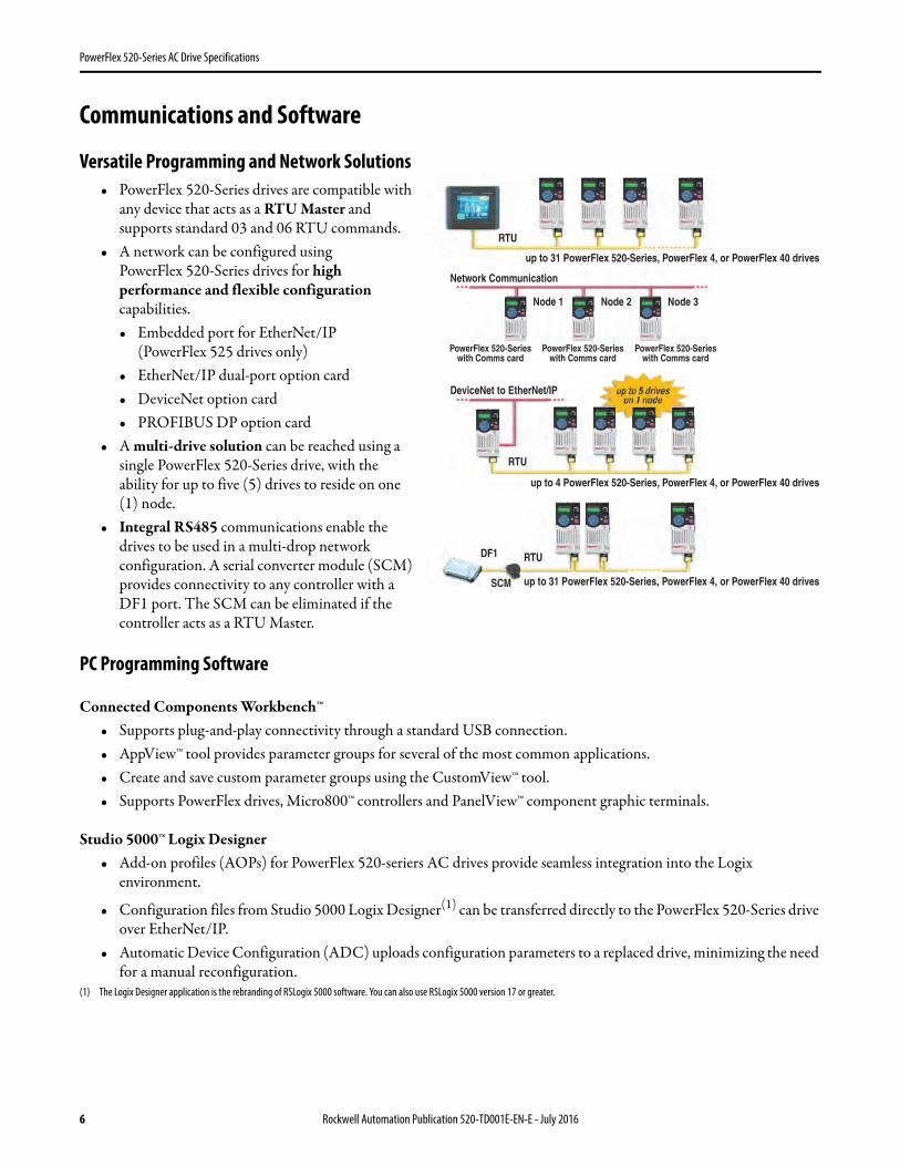
PowerFlex 520-Series AC Drive Specifications
Communications and Software
Versatile Programming and Network Solutions• PowerFlex 520-Series drives are compatible with
any device that acts as a RTU Master and supports standard 03 and 06 RTU commands.
• A network can be configured using PowerFlex 520-Series drives for high performance and flexible configuration capabilities.• Embedded port for EtherNet/IP
(PowerFlex 525 drives only)• EtherNet/IP dual-port option card• DeviceNet option card• PROFIBUS DP option card
• A multi-drive solution can be reached using a single PowerFlex 520-Series drive, with the ability for up to five (5) drives to reside on one (1) node.
• Integral RS485 communications enable the drives to be used in a multi-drop network configuration. A serial converter module (SCM) provides connectivity to any controller with a DF1 port. The SCM can be eliminated if the controller acts as a RTU Master.
PC Programming Software
Connected Components Workbench™• Supports plug-and-play connectivity through a standard USB connection.• AppView™ tool provides parameter groups for several of the most common applications.• Create and save custom parameter groups using the CustomView™ tool.• Supports PowerFlex drives, Micro800™ controllers and PanelView™ component graphic terminals.
Studio 5000™ Logix Designer• Add-on profiles (AOPs) for PowerFlex 520-seriers AC drives provide seamless integration into the Logix
environment.
• Configuration files from Studio 5000 Logix Designer(1) can be transferred directly to the PowerFlex 520-Series drive over EtherNet/IP.
• Automatic Device Configuration (ADC) uploads configuration parameters to a replaced drive, minimizing the need for a manual reconfiguration.
(1) The Logix Designer application is the rebranding of RSLogix 5000 software. You can also use RSLogix 5000 version 17 or greater.
DeviceNet to EtherNet/IP
RTU
RTU
Network Communication
Node 1 Node 2 Node 3
up to 4 PowerFlex 520-Series, PowerFlex 4, or PowerFlex 40 drives
up to 31 PowerFlex 520-Series, PowerFlex 4, or PowerFlex 40 drives
up to 31 PowerFlex 520-Series, PowerFlex 4, or PowerFlex 40 drives
RTU
SCM
DF1
PowerFlex 520-Serieswith Comms card
PowerFlex 520-Serieswith Comms card
PowerFlex 520-Serieswith Comms card
6 Rockwell Automation Publication 520-TD001E-EN-E - July 2016

PowerFlex 520-Series AC Drive Specifications
PowerFlex 523 Drive Family
PowerFlex 525 Drive Family
Frame A Frame B Frame C Frame D Frame E
Frame A Frame B Frame C Frame D Frame E
Rockwell Automation Publication 520-TD001E-EN-E - July 2016 7
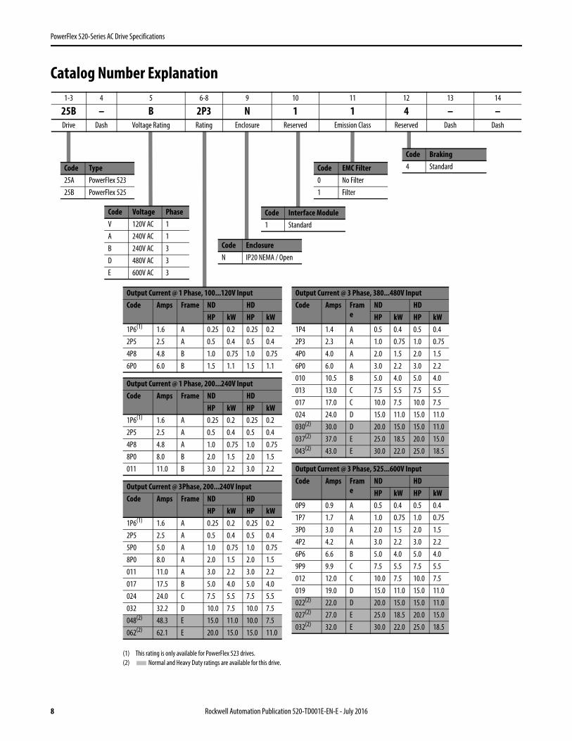
PowerFlex 520-Series AC Drive Specifications
Catalog Number Explanation
Code Type25A PowerFlex 52325B PowerFlex 525
(1) This rating is only available for PowerFlex 523 drives.(2) Normal and Heavy Duty ratings are available for this drive.
1-3 4 5 6-8 9 10 11 12 13 14
25B – B 2P3 N 1 1 4 – –Drive Dash Voltage Rating Rating Enclosure Reserved Emission Class Reserved Dash Dash
Output Current @ 3 Phase, 380...480V InputCode Amps Fram
eND HDHP kW HP kW
1P4 1.4 A 0.5 0.4 0.5 0.42P3 2.3 A 1.0 0.75 1.0 0.754P0 4.0 A 2.0 1.5 2.0 1.56P0 6.0 A 3.0 2.2 3.0 2.2010 10.5 B 5.0 4.0 5.0 4.0013 13.0 C 7.5 5.5 7.5 5.5017 17.0 C 10.0 7.5 10.0 7.5024 24.0 D 15.0 11.0 15.0 11.0030(2) 30.0 D 20.0 15.0 15.0 11.0037(2) 37.0 E 25.0 18.5 20.0 15.0043(2) 43.0 E 30.0 22.0 25.0 18.5
Output Current @ 3 Phase, 525...600V InputCode Amps Fram
eND HDHP kW HP kW
0P9 0.9 A 0.5 0.4 0.5 0.41P7 1.7 A 1.0 0.75 1.0 0.753P0 3.0 A 2.0 1.5 2.0 1.54P2 4.2 A 3.0 2.2 3.0 2.26P6 6.6 B 5.0 4.0 5.0 4.09P9 9.9 C 7.5 5.5 7.5 5.5012 12.0 C 10.0 7.5 10.0 7.5019 19.0 D 15.0 11.0 15.0 11.0022(2) 22.0 D 20.0 15.0 15.0 11.0027(2) 27.0 E 25.0 18.5 20.0 15.0032(2) 32.0 E 30.0 22.0 25.0 18.5
Code Voltage PhaseV 120V AC 1A 240V AC 1B 240V AC 3D 480V AC 3E 600V AC 3
Code EnclosureN IP20 NEMA / Open
Code Interface Module1 Standard
Code EMC Filter0 No Filter1 Filter
Code Braking4 Standard
Output Current @ 1 Phase, 100...120V InputCode Amps Frame ND HD
HP kW HP kW1P6(1) 1.6 A 0.25 0.2 0.25 0.22P5 2.5 A 0.5 0.4 0.5 0.44P8 4.8 B 1.0 0.75 1.0 0.756P0 6.0 B 1.5 1.1 1.5 1.1
Output Current @ 1 Phase, 200...240V InputCode Amps Frame ND HD
HP kW HP kW1P6(1) 1.6 A 0.25 0.2 0.25 0.22P5 2.5 A 0.5 0.4 0.5 0.44P8 4.8 A 1.0 0.75 1.0 0.758P0 8.0 B 2.0 1.5 2.0 1.5011 11.0 B 3.0 2.2 3.0 2.2
Output Current @ 3Phase, 200...240V InputCode Amps Frame ND HD
HP kW HP kW1P6(1) 1.6 A 0.25 0.2 0.25 0.22P5 2.5 A 0.5 0.4 0.5 0.45P0 5.0 A 1.0 0.75 1.0 0.758P0 8.0 A 2.0 1.5 2.0 1.5011 11.0 A 3.0 2.2 3.0 2.2017 17.5 B 5.0 4.0 5.0 4.0024 24.0 C 7.5 5.5 7.5 5.5032 32.2 D 10.0 7.5 10.0 7.5048(2) 48.3 E 15.0 11.0 10.0 7.5062(2) 62.1 E 20.0 15.0 15.0 11.0
8 Rockwell Automation Publication 520-TD001E-EN-E - July 2016

PowerFlex 520-Series AC Drive Specifications
Technical Specifications
Protection
Electrical
Control
Specifications PowerFlex 523 PowerFlex 525
Bus Overvoltage Trip100...120V AC Input:200...240V AC Input:380...480V AC Input:525...600V AC Input:
405V DC bus (equivalent to 150V AC incoming line)405V DC bus (equivalent to 290V AC incoming line)810V DC bus (equivalent to 575V AC incoming line)1005V DC bus (equivalent to 711V AC incoming line)
Bus Undervoltage Trip100...120V AC Input:200...240V AC Input:380...480V AC Input:525...600V AC Input
P038 = 3 “600V”:P038 = 2 “480V”:
190V DC bus (equivalent to 75V AC incoming line)190V DC bus (equivalent to 150V AC incoming line)390V DC bus (equivalent to 275V AC incoming line)
487V DC bus (equivalent to 344V AC incoming line)390V DC bus (equivalent to 275V AC incoming line)
Power Ride-Thru: 100 ms
Logic Control Ride-Thru: 0.5 s minimum, 2 s typical
Electronic Motor Overload Protection: Provides class 10 motor overload protection according to NEC article 430 and motor over-temperature protection according to NEC article 430.126 (A) (2). UL 508C File 29572.
Overcurrent: 200% hardware limit, 300% instantaneous fault
Ground Fault Trip: Phase-to-ground on drive output
Short Circuit Trip: Phase-to-phase on drive output
Specifications PowerFlex 523 PowerFlex 525
Voltage Tolerance: -15% / +10%
Frequency Tolerance: 47...63 Hz
Input Phases: Three-phase input provides full rating. Single-phase input provides 35% rating on three-phase drives.
Displacement Power Factor: 0.98 across entire speed range
Maximum Short Circuit Rating: 100,000 Amps Symmetrical
Actual Short Circuit Rating: Determined by AIC Rating of installed fuse/circuit breaker
Transistor Type: Isolated Gate Bipolar Transistor (IGBT)
Internal DC Bus Choke200...240V AC Input:380...480V AC Input:525...600V AC Input:
Only for Frame E drive ratings11 kW (15 HP)15...18.5 kW (20...25 HP) – Heavy Duty15...18.5 kW (20...25 HP) – Heavy Duty
Specifications PowerFlex 523 PowerFlex 525
Method Sinusoidal PWM, Volts/Hertz, Sensorless Vector Control, Economizer SVC motor control, Closed Loop Velocity Vector Control, Surface Mount and Interior Permanent Magnet Motor (without encoder), Interior Permanent Magnet Motor (with encoder)(Closed Loop Velocity Vector Control and PM motor control are not applicable to PowerFlex 523 drives)
Carrier Frequency 2...16 kHz, Drive rating based on 4 kHz
Frequency AccuracyDigital Input:Analog Input:Analog Output:
Within ±0.05% of set output frequencyWithin 0.5% of maximum output frequency, 10-Bit resolution±2% of full scale, 10-Bit resolution
Rockwell Automation Publication 520-TD001E-EN-E - July 2016 9

PowerFlex 520-Series AC Drive Specifications
Control Inputs
PerformanceV/Hz (Volts per Hertz):SVC (Sensorless Vector):SVC Economizer:
VVC (Velocity Vector Control):PM Motor(1):
±1% of base speed across a 60:1 speed range±0.5% of base speed across a 100:1 speed range±0.5% of base speed across a 100:1 speed range
(Applicable to PowerFlex 525 drives only)±0.5% of base speed across a 60:1 speed range±0.5% of base speed, up to a 20:1 speed range
Performance with EncoderSVC (Sensorless Vector):SVC Economizer:VVC (Velocity Vector Control):PM Motor (iPM motor, 10 HPrating and below)(1):
(Applicable to PowerFlex 525 drives only)±0.1% of base speed across a 100:1 speed range(2)
±0.1% of base speed across a 100:1 speed range(2)
±0.1% of base speed across a 1000:1 speed range(2)
±0.1% of base speed, up to a 60:1 speed range
Output Voltage Range: 0V to rated motor voltage
Output Frequency Range: 0...500 Hz (programmable)
Efficiency: 97.5% (typical)
Stop Modes: Multiple programmable stop modes including – Ramp, Coast, DC-Brake, and Ramp-to-Stop
Accel/Decel: Four independently programmable accel and decel times. Each time may be programmed from 0...600 s in 0.01 s increments.
Intermittent OverloadNormal Duty: 110% Overload capability for up to 60 s, 150% for up to 3 s
Applies for power rating above 15 kW (20 HP) only. Based on 480V drive rating.
Heavy Duty: 150% Overload capability for up to 60 s, 180% for up to 3 s (200% programmable)(1) For details on specific motor performance, see Knowledge Base article “PowerFlex 525 PM Motor Performance Testing Summary”.(2) For more information, see the PowerFlex 520-Series Adjustable Frequency AC Drive User Manual, publication 520-UM001.
Specifications PowerFlex 523 PowerFlex 525
Digital Bandwidth: 10 Rad/s for open and closed loop
Quantity: (1) Dedicated for stop(4) Programmable
(1) Dedicated for stop(6) Programmable
Current: 6 mA
TypeSource Mode (SRC):Sink Mode (SNK):
18...24V = ON, 0...6V = OFF0...6V = ON, 18...24V = OFF
Pulse TrainQuantity:Input Signal:Input Frequency:Current Consumption:
(1) Shared with one of the programmable digital input terminals.Transistor contact (open collector)0...100 kHz7 mA @ 24V DC maximum
Analog Quantity: (1) Isolated, 0-10V and 4-20 mA (2) Isolated, -10-10V and 4-20 mA
SpecificationResolution:0-10V DC Analog:4-20 mA Analog:External Pot:
10-bit100k ohm input impedance250 ohm input impedance1...10k ohm, 2 W minimum
Specifications PowerFlex 523 PowerFlex 525
10 Rockwell Automation Publication 520-TD001E-EN-E - July 2016

PowerFlex 520-Series AC Drive Specifications
Control Outputs
Encoder
Specifications PowerFlex 523 PowerFlex 525
Relay Quantity: (1) Programmable Form C (2) 1 Programmable Form A and 1 Programmable Form B
SpecificationResistive Rating:Inductive Rating:
3.0 A @ 30V DC, 3.0 A @ 125V, 3.0 A @ 240V AC0.5 A @ 30V DC, 0.5 A @ 125V, 0.5 A @ 240V AC
Opto Quantity: – (2) Programmable
Specification: 30V DC, 50 mA Non-inductive
Analog Quantity: (1) Non-Isolated 0-10V or 4-20 mA(1)
(1) Feature is not applicable to PowerFlex 523 series A drives.
SpecificationResolution:0-10V DC Analog:4-20 mA Analog:
10-bit1 k ohm minimum525 ohm maximum
Specifications PowerFlex 523 PowerFlex 525
Type: – Incremental, dual channel
Supply: 12V, 250 mA
Quadrature: 90°, ±27° @ 25 °C
Duty Cycle: 50%, +10%
Requirements: Encoders must be line driver type, quadrature (dual channel) or pulse (single channel), 3.5...26V DC output, single-ended or differential and capable of supplying a minimum of 10 mA per channel. Allowable input is DC up to a maximum frequency of 250 kHz. The encoder I/O automatically scales to allow 5V, 12V and 24V DC nominal voltages.
Rockwell Automation Publication 520-TD001E-EN-E - July 2016 11

PowerFlex 520-Series AC Drive Specifications
Environmental SpecificationsSpecifications PowerFlex 523 PowerFlex 525Altitude
Without derating:With derating:
See Current Derating Curves on page 18 for derating guidelines.1000 m (3300 ft) max.Up to 4000 m (13,200 ft) max., with the exception of 600V drives at 2000 m (6600 ft) max.
Surrounding Air Temperature, max.Without derating:With derating:
See Current Derating Curves on page 18 for derating guidelines.-20...50 °C (-4...122 °F)-20...60 °C (-4...140 °F) or -20...70 °C (-4...158 °F) with optional Control Module Fan kit.
Storage TemperatureFrame A...D:Frame E:
-40...85 °C (-40...185 °F)-40...70 °C (-40...158 °F)
Atmosphere:
Relative Humidity: 0...95% noncondensingShock:Vibration:
Complies with IEC 60068-2-27Complies with IEC 60068-2-6:1995
Conformal Coating: Complies with:IEC 60721-3-3 to level 3C2 (chemical and gases only)
Surrounding Environment Pollution DegreePollution Degree 1 & 2: All enclosures acceptable.
Sound Pressure Level (A-weighted)Frame A & B:Frame C:Frame D:Frame E:
Measurements are taken 1 m from the drive.Maximum 53 dBAMaximum 57 dBAMaximum 64 dBAMaximum 68 dBA
IMPORTANT Drive must not be installed in an area where the ambient atmosphere contains volatile or corrosive gas, vapors or dust. If the drive is not going to be installed for a period of time, it must be stored in an area where it will not be exposed to a corrosive atmosphere.
FrameSize
Operating and Nonoperating Nonoperating (Transportation)Force (Shock/Vibration) Mounting Type Force (Shock/Vibration) Mounting Type
A 15 g / 2 g DIN rail or screw 30 g/ 2.5 g Screw onlyB 15 g / 2 g DIN rail or screw 30 g/ 2.5 g Screw onlyC 15 g / 2 g DIN rail or screw 30 g/ 2.5 g Screw onlyD 15 g / 2 g Screw only 30 g/ 2.5 g Screw onlyE 15 g / 1.5 g Screw only 30 g/ 2.5 g Screw only
12 Rockwell Automation Publication 520-TD001E-EN-E - July 2016

PowerFlex 520-Series AC Drive Specifications
CertificationsCertification PowerFlex 523 PowerFlex 525c-UL-us Listed to UL508C and CAN/CSA-C22.2 No. 14-05.
RCM Australian Communications and Media AuthorityIn conformity with the following:
Radiocommunications Act: 1992Radiocommunications Standard: 2008Radiocommunications Labelling Notice: 2008
Standards applied:EN 61800-3
CE In conformity with the following European Directives:2014/35/EU Low Voltage Directive (LVD)2014/30/EU EMC Directive (EMC)2014/34/EU ATEX Directive (ATEX)2006/42/EC Machinery Directive (MD)
Standards applied:EN 61800-3EN 61800-5-1
TUV (Applicable to PowerFlex 525 drives only)TÜV RheinlandStandards applied:
EN ISO 13849-1EN 61800-5-2EN 61508 PARTS 1-7EN 62061EN 60204-1
Certified to ISO 13849-1 SIL2/PLd with embedded Safe-Torque-Off functionMeets Functional Safety (FS) when used with embedded Safe-Torque-Off function
ATEXII (2) G D
TUV 12 ATEX 7199 X
(Applicable to PowerFlex 525 drives only)Certified to ATEX directive 2014/34/EUGroup II Category (2) GD Applications with ATEX Approved Motors
KCC Korean Registration of Broadcasting and Communications EquipmentCompliant with the following standards:
Article 58-2 of Radio Waves Act, Clause 3EAC Standards applied:
Low Voltage TP TC 004/2011EMC TP TC 020/2011
AC 156 Tested by Trentec to be compliant with AC156 Acceptance Criteria for Seismic Qualification Testing of Nonstructural Components and 2003 International Building Code for worst-case seismic level for USA excluding site class F
SEMI F47 Electric Power Research InstituteCertified compliant with the following standards:
SEMI F47IEC 61000-4-11IEC 61000-4-34
Lloyds Register (Applicable to PowerFlex 525 drives only)Lloyd’s Register Type Approval Certificate 12/10068(E1)
RoHS Compliant with the European “Restriction of Hazardous Substances” DirectiveThe drive is also designed to meet the appropriate portions of the following specifications:
NFPA 70 - US National Electrical CodeNEMA ICS 7.1 - Safety standards for Construction and Guide for Selection, Installation and Operation of Adjustable Speed Drive Systems.
FunctionalSafetyTypeApproved
www.tuv.comID 0600000000
Rockwell Automation Publication 520-TD001E-EN-E - July 2016 13

PowerFlex 520-Series AC Drive Specifications
Dimensions and Weights
Frame/Rating Cross-Reference
Catalog Number Description
PowerFlex 520-Series Drive Ratings
25B - V 2P5 N 1 0 4Drive Voltage Rating Rating Enclosure HIM Emission Class Version
PowerFlex 523 PowerFlex 525Output Ratings
InputVoltage Range Total Watts Loss Frame Size
Normal Duty Heavy Duty OutputCurrent (A)Catalog No. Catalog No. HP kW HP kW
100...120V AC (-15%, +10%) – 1-Phase Input, 0...230V 3-Phase Output 25A-V1P6N104 – 0.25 0.2 0.25 0.2 1.6 85...132 20.0 A25A-V2P5N104 25B-V2P5N104 0.5 0.4 0.5 0.4 2.5 85...132 27.0 A25A-V4P8N104 25B-V4P8N104 1.0 0.75 1.0 0.75 4.8 85...132 53.0 B25A-V6P0N104 25B-V6P0N104 1.5 1.1 1.5 1.1 6.0 85...132 67.0 B200...240V AC (-15%, +10%) – 1-Phase Input, 0...230V 3-Phase Output25A-A1P6N104 – 0.25 0.2 0.25 0.2 1.6 85...132 20.0 A25A-A2P5N104 25B-A2P5N104 0.5 0.4 0.5 0.4 2.5 170...264 29.0 A25A-A4P8N104 25B-A4P8N104 1.0 0.75 1.0 0.75 4.8 170...264 50.0 A25A-A8P0N104 25B-A8P0N104 2.0 1.5 2.0 1.5 8.0 170...264 81.0 B25A-A011N104 25B-A011N104 3.0 2.2 3.0 2.2 11.0 170...264 111.0 B200...240V AC (-15%, +10%) – 1-Phase Input with EMC Filter, 0...230V 3-Phase Output25A-A1P6N114 – 0.25 0.2 0.25 0.2 1.6 85...132 20.0 A25A-A2P5N114 25B-A2P5N114 0.5 0.4 0.5 0.4 2.5 170...264 29.0 A25A-A4P8N114 25B-A4P8N114 1.0 0.75 1.0 0.75 4.8 170...264 53.0 A25A-A8P0N114 25B-A8P0N114 2.0 1.5 2.0 1.5 8.0 170...264 84.0 B25A-A011N114 25B-A011N114 3.0 2.2 3.0 2.2 11.0 170...264 116.0 B200...240V AC (-15%, +10%) – 3-Phase Input, 0...230V 3-Phase Output25A-B1P6N104 – 0.25 0.2 0.25 0.2 1.6 85...132 20.0 A25A-B2P5N104 25B-B2P5N104 0.5 0.4 0.5 0.4 2.5 170...264 29.0 A25A-B5P0N104 25B-B5P0N104 1.0 0.75 1.0 0.75 5.0 170...264 50.0 A25A-B8P0N104 25B-B8P0N104 2.0 1.5 2.0 1.5 8.0 170...264 79.0 A25A-B011N104 25B-B011N104 3.0 2.2 3.0 2.2 11.0 170...264 107.0 A25A-B017N104 25B-B017N104 5.0 4.0 5.0 4.0 17.5 170...264 148.0 B25A-B024N104 25B-B024N104 7.5 5.5 7.5 5.5 24.0 170...264 259.0 C25A-B032N104 25B-B032N104 10.0 7.5 10.0 7.5 32.2 170...264 323.0 D25A-B048N104 25B-B048N104 15.0 11.0 10.0 7.5 48.3 170...264 584.0 E25A-B062N104 25B-B062N104 20.0 15.0 15.0 11.0 62.1 170...264 708.0 E
380...480V AC (-15%, +10%) – 3-Phase Input, 0...460V 3-Phase Output(1)
25A-D1P4N104 25B-D1P4N104 0.5 0.4 0.5 0.4 1.4 323...528 27.0 A25A-D2P3N104 25B-D2P3N104 1.0 0.75 1.0 0.75 2.3 323...528 37.0 A25A-D4P0N104 25B-D4P0N104 2.0 1.5 2.0 1.5 4.0 323...528 62.0 A25A-D6P0N104 25B-D6P0N104 3.0 2.2 3.0 2.2 6.0 323...528 86.0 A25A-D010N104 25B-D010N104 5.0 4.0 5.0 4.0 10.5 323...528 129.0 B25A-D013N104 25B-D013N104 7.5 5.5 7.5 5.5 13.0 323...528 170.0 C25A-D017N104 25B-D017N104 10.0 7.5 10.0 7.5 17.0 323...528 221.0 C25A-D024N104 25B-D024N104 15.0 11.0 15.0 11.0 24.0 323...528 303.0 D25A-D030N104 25B-D030N104 20.0 15.0 15.0 11.0 30.0 323...528 387.0 D
14 Rockwell Automation Publication 520-TD001E-EN-E - July 2016

PowerFlex 520-Series AC Drive Specifications
(1) A non-filtered drive is not available for 380...480V AC 25 HP (18.5 kW) and 30 HP (22.0 kW) ratings. Filtered drives are available, however you must verify that the application will support a filtered drive.
380...480V AC (-15%, +10%) – 3-Phase Input with EMC Filter, 0...460V 3-Phase Output25A-D1P4N114 25B-D1P4N114 0.5 0.4 0.5 0.4 1.4 323...528 27.0 A25A-D2P3N114 25B-D2P3N114 1.0 0.75 1.0 0.75 2.3 323...528 37.0 A25A-D4P0N114 25B-D4P0N114 2.0 1.5 2.0 1.5 4.0 323...528 63.0 A25A-D6P0N114 25B-D6P0N114 3.0 2.2 3.0 2.2 6.0 323...528 88.0 A25A-D010N114 25B-D010N114 5.0 4.0 5.0 4.0 10.5 323...528 133.0 B25A-D013N114 25B-D013N114 7.5 5.5 7.5 5.5 13.0 323...528 175.0 C25A-D017N114 25B-D017N114 10.0 7.5 10.0 7.5 17.0 323...528 230.0 C25A-D024N114 25B-D024N114 15.0 11.0 15.0 11.0 24.0 323...528 313.0 D25A-D030N114 25B-D030N114 20.0 15.0 15.0 11.0 30.0 323...528 402.0 D25A-D037N114 25B-D037N114 25.0 18.5 20.0 15.0 37.0 323...528 602.0 E25A-D043N114 25B-D043N114 30.0 22.0 25.0 18.5 43.0 323...528 697.0 E525...600V AC (-15%, +10%) – 3-Phase Input, 0...575V 3-Phase Output25A-E0P9N104 25B-E0P9N104 0.5 0.4 0.5 0.4 0.9 446...660 22.0 A25A-E1P7N104 25B-E1P7N104 1.0 0.75 1.0 0.75 1.7 446...660 32.0 A25A-E3P0N104 25B-E3P0N104 2.0 1.5 2.0 1.5 3.0 446...660 50.0 A25A-E4P2N104 25B-E4P2N104 3.0 2.2 3.0 2.2 4.2 446...660 65.0 A25A-E6P6N104 25B-E6P6N104 5.0 4.0 5.0 4.0 6.6 446...660 95.0 B25A-E9P9N104 25B-E9P9N104 7.5 5.5 7.5 5.5 9.9 446...660 138.0 C25A-E012N104 25B-E012N104 10.0 7.5 10.0 7.5 12.0 446...660 164.0 C25A-E019N104 25B-E019N104 15.0 11.0 15.0 11.0 19.0 446...660 290.0 D25A-E022N104 25B-E022N104 20.0 15.0 15.0 11.0 22.0 446...660 336.0 D25A-E027N104 25B-E027N104 25.0 18.5 20.0 15.0 27.0 446...660 466.0 E25A-E032N104 25B-E032N104 30.0 22.0 25.0 18.5 32.0 446...660 562.0 E
PowerFlex 523 PowerFlex 525Output Ratings
InputVoltage Range Total Watts Loss Frame Size
Normal Duty Heavy Duty OutputCurrent (A)Catalog No. Catalog No. HP kW HP kW
Rockwell Automation Publication 520-TD001E-EN-E - July 2016 15

PowerFlex 520-Series AC Drive Specifications
Drive Dimensions and WeightDimensions are in mm and (in.). Weights are in kg and (lb).
Design Considerations
Mounting Considerations• Mount the drive upright on a flat, vertical and level surface.
• Protect the cooling fan by avoiding dust or metallic particles.• Do not expose to a corrosive atmosphere.• Protect from moisture and direct sunlight.
Frame Size A B C D E WeightA 72.0 (2.83) 152.0 (5.98) 172.0 (6.77) 57.5 (2.26) 140.0 (5.51) 1.1 (2.4)B 87.0 (3.43) 180.0 (7.09) 172.0 (6.77) 72.5 (2.85) 168.0 (6.61) 1.6 (3.5)C 109.0 (4.29) 220.0 (8.66) 184.0 (7.24) 90.5 (3.56) 207.0 (8.15) 2.3 (5.0)D 130.0 (5.12) 260.0 (10.24) 212.0 (8.35) 116.0 (4.57) 247.0 (9.72) 3.9 (8.6)E 185.0 (7.28) 300.0 (11.81) 279.0 (10.98) 160.0 (6.30) 280.0 (11.02) 12.9 (28.4)
Frame Screw Size Screw TorqueA M5 (#10...24) 1.56...1.96 Nm (14...17 lb-in.)B M5 (#10...24) 1.56...1.96 Nm (14...17 lb-in.)C M5 (#10...24) 1.56...1.96 Nm (14...17 lb-in.)D M5 (#10...24) 2.45...2.94 Nm (22...26 lb-in.)E M8 (5/16 in.) 6.0...7.4 Nm (53...65 lb-in.)
Esc Sel
A C
B
E
D
16 Rockwell Automation Publication 520-TD001E-EN-E - July 2016

PowerFlex 520-Series AC Drive Specifications
Minimum Mounting Clearances
See Dimensions and Weights on page 14 for mounting dimensions.
(1) For Frame E with Control Module Fan Kit only, clearance of 95 mm (3.7 in.) is required.(2) For Frame E with Control Module Fan Kit only, clearance of 12 mm (0.5 in.) is required.
Ambient Operating TemperaturesSee Accessories and Dimensions on page 32 for option kits.
(1) IP 30/NEMA 1/UL Type 1 rating requires installation of the PowerFlex 520-Series IP 30/NEMA 1/UL Type 1 option kit, catalog number 25-JBAx.(2) For catalogs 25x-D1P4N104 and 25x-E0P9N104, the temperature listed under the Max. (Derate) column is reduced by 5 °C (9 °F) for all mounting methods.(3) For catalogs 25x-D1P4N104 and 25x-E0P9N104, the temperature listed under the Max. with Control Module Fan Kit (Derate) column is reduced by 10 °C (18 °F) for vertical and vertical with zero stacking
mounting methods only.(4) Catalogs 25x-D1P4N104 and 25x-E0P9N104 cannot be mounted using either of the horizontal mounting methods.(5) Requires installation of the PowerFlex 520-Series Control Module Fan Kit, catalog number 25-FANx-70C.
Mounting Enclosure Rating(1)
Ambient Temperature
Minimum Maximum (No Derate) Maximum (Derate)(2)Maximum with Control ModuleFan Kit (Derate)(3)(5)
Vertical IP 20/Open Type
-20 °C (-4 °F)
50 °C (122 °F) 60 °C (140 °F) 70 °C (158 °F)IP 30/NEMA 1/UL Type 1 45 °C (113 °F) 55 °C (131 °F) –
Vertical, Zero Stacking IP 20/Open Type 45 °C (113 °F) 55 °C (131 °F) 65 °C (149 °F)IP 30/NEMA 1/UL Type 1 40 °C (104 °F) 50 °C (122 °F) –
Horizontalwith Control Module Fan Kit(4)(5)
IP 20/Open Type 50 °C (122 °F) – 70 °C (158 °F)
Horizontal, Zero Stackingwith Control Module Fan Kit(4)(5)
IP 20/Open Type 45 °C (113 °F) – 65 °C (149 °F)
25 mm(1.0 in.)
25 mm(1.0 in.)
(2)
(2)
25 mm(1.0 in.)
50 mm(2.0 in.)
50 mm(2.0 in.)(1)
50 mm(2.0 in.)(1)
50 mm(2.0 in.)(1)
50 mm(2.0 in.)
50 mm(2.0 in.)
50 mm(2.0 in.)
Esc Sel Esc SelEsc Sel Esc Sel
50 mm(2.0 in.)
50 mm(2.0 in.)
50 mm(2.0 in.)
50 mm(2.0 in.)
Esc
Se
lE
s cS
el
50 mm(2.0 in.)
50 mm(2.0 in.)
50 mm(2.0 in.)
50 mm(2.0 in.)
50 mm(2.0 in.)(1)
Esc
Se
lE
scS
el
Esc Sel Esc Sel Esc SelEsc Sel
Vertical, Zero StackingNo clearance between drives.
Horizontal, Zero Stacking with Control Module Fan KitNo clearance between drives.
Vertical Vertical, Zero Stacking withControl Module Fan KitNo clearance between drives.
Vertical with Control Module Fan Kit
Horizontal with Control Module Fan Kit
Rockwell Automation Publication 520-TD001E-EN-E - July 2016 17
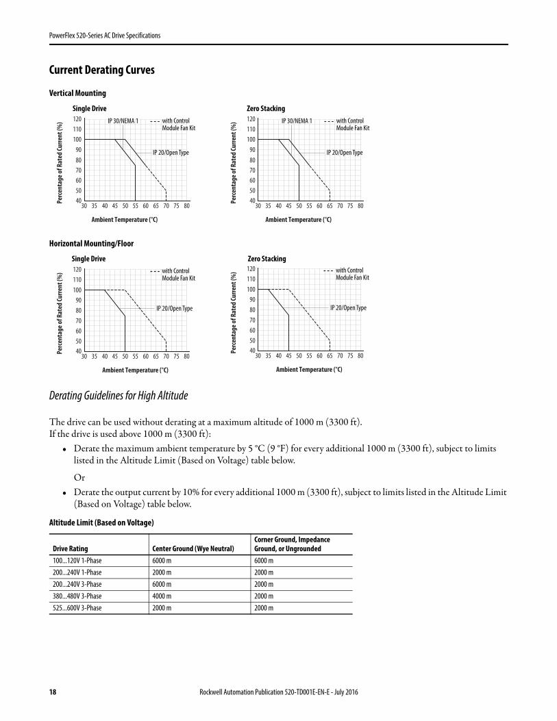
PowerFlex 520-Series AC Drive Specifications
Current Derating Curves
Vertical Mounting
Horizontal Mounting/Floor
Derating Guidelines for High Altitude
The drive can be used without derating at a maximum altitude of 1000 m (3300 ft).If the drive is used above 1000 m (3300 ft):
• Derate the maximum ambient temperature by 5 °C (9 °F) for every additional 1000 m (3300 ft), subject to limits listed in the Altitude Limit (Based on Voltage) table below.
Or• Derate the output current by 10% for every additional 1000 m (3300 ft), subject to limits listed in the Altitude Limit
(Based on Voltage) table below.
Altitude Limit (Based on Voltage)
Drive Rating Center Ground (Wye Neutral)Corner Ground, Impedance Ground, or Ungrounded
100...120V 1-Phase 6000 m 6000 m200...240V 1-Phase 2000 m 2000 m200...240V 3-Phase 6000 m 2000 m380...480V 3-Phase 4000 m 2000 m525...600V 3-Phase 2000 m 2000 m
Ambient Temperature (°C)
40
100
90
110
120
80
70
60
50
45403530 60 65 70 75 805550
Per
cen
tage
of R
ated
Cu
rren
t (%
) IP 30/NEMA 1 with ControlModule Fan Kit
IP 20/Open Type
Ambient Temperature (°C)
40
100
90
110
120
80
70
60
50
45403530 60 65 70 75 805550
Per
cen
tage
of R
ated
Cu
rren
t (%
) IP 30/NEMA 1 with ControlModule Fan Kit
IP 20/Open Type
Single Drive Zero Stacking
Ambient Temperature (°C)
40
100
90
120
110
80
70
60
50
30 35 70 75 8060 6550 5540 45
Per
cen
tage
of R
ated
Cu
rren
t (%
) with ControlModule Fan Kit
IP 20/Open Type
Ambient Temperature (°C)
40
100
90
120
110
80
70
60
50
30 35 70 75 8060 6550 5540 45
Per
cen
tage
of R
ated
Cu
rren
t (%
) with ControlModule Fan Kit
IP 20/Open Type
Single Drive Zero Stacking
18 Rockwell Automation Publication 520-TD001E-EN-E - July 2016
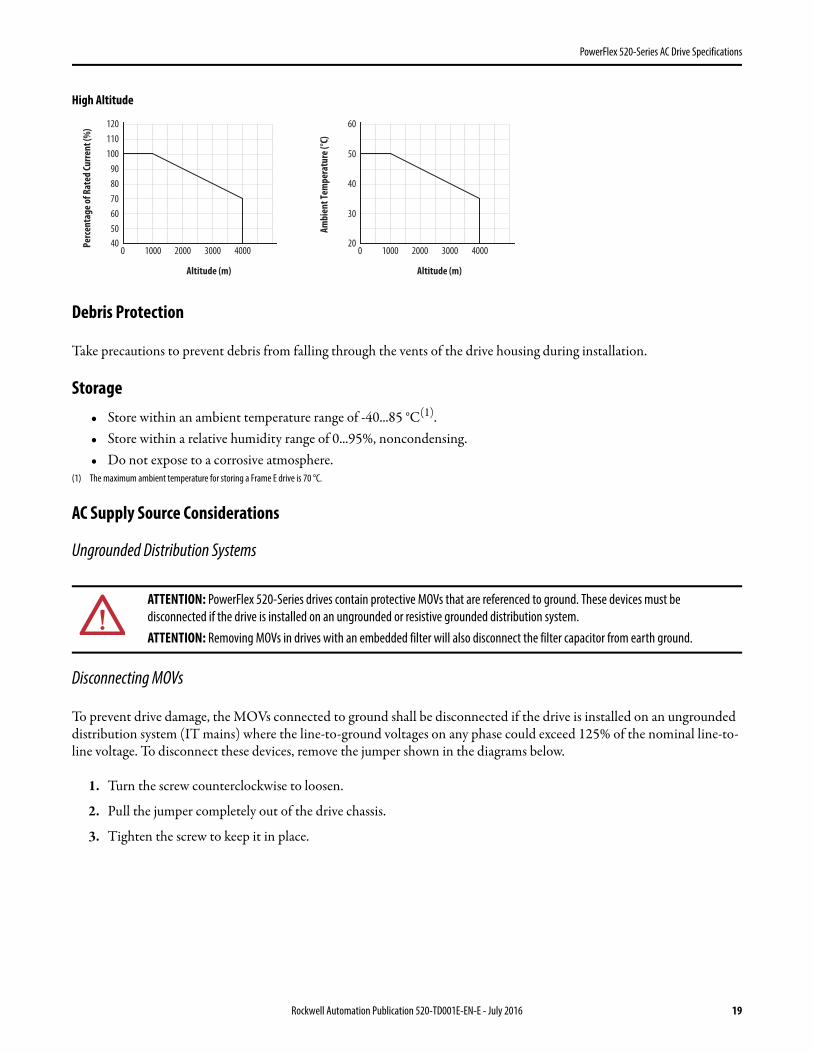
PowerFlex 520-Series AC Drive Specifications
High Altitude
Debris Protection
Take precautions to prevent debris from falling through the vents of the drive housing during installation.
Storage• Store within an ambient temperature range of -40...85 °C(1).• Store within a relative humidity range of 0...95%, noncondensing.• Do not expose to a corrosive atmosphere.
(1) The maximum ambient temperature for storing a Frame E drive is 70 °C.
AC Supply Source Considerations
Ungrounded Distribution Systems
Disconnecting MOVs
To prevent drive damage, the MOVs connected to ground shall be disconnected if the drive is installed on an ungrounded distribution system (IT mains) where the line-to-ground voltages on any phase could exceed 125% of the nominal line-to-line voltage. To disconnect these devices, remove the jumper shown in the diagrams below.
1. Turn the screw counterclockwise to loosen.
2. Pull the jumper completely out of the drive chassis.
3. Tighten the screw to keep it in place.
ATTENTION: PowerFlex 520-Series drives contain protective MOVs that are referenced to ground. These devices must be disconnected if the drive is installed on an ungrounded or resistive grounded distribution system.ATTENTION: Removing MOVs in drives with an embedded filter will also disconnect the filter capacitor from earth ground.
Altitude (m)
Per
cen
tage
of R
ated
Cu
rren
t (%
)
40
90
100
110
120
80
70
60
50
0 4000300020001000
Altitude (m)
Am
bien
t Te
mpe
ratu
re (°
C)
20
50
60
40
30
0 4000300020001000
Rockwell Automation Publication 520-TD001E-EN-E - July 2016 19
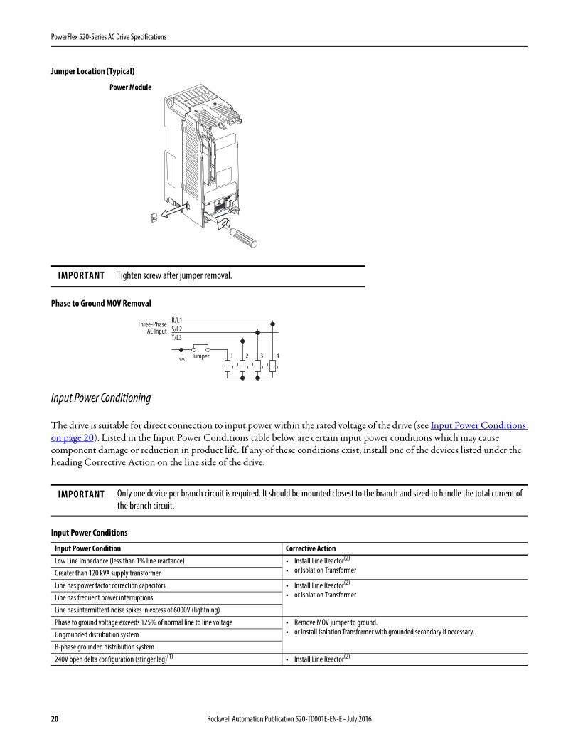
PowerFlex 520-Series AC Drive Specifications
Jumper Location (Typical)
Phase to Ground MOV Removal
Input Power Conditioning
The drive is suitable for direct connection to input power within the rated voltage of the drive (see Input Power Conditions on page 20). Listed in the Input Power Conditions table below are certain input power conditions which may cause component damage or reduction in product life. If any of these conditions exist, install one of the devices listed under the heading Corrective Action on the line side of the drive.
Input Power Conditions
IMPORTANT Tighten screw after jumper removal.
IMPORTANT Only one device per branch circuit is required. It should be mounted closest to the branch and sized to handle the total current of the branch circuit.
Input Power Condition Corrective ActionLow Line Impedance (less than 1% line reactance) • Install Line Reactor(2)
• or Isolation TransformerGreater than 120 kVA supply transformerLine has power factor correction capacitors • Install Line Reactor(2)
• or Isolation TransformerLine has frequent power interruptionsLine has intermittent noise spikes in excess of 6000V (lightning)Phase to ground voltage exceeds 125% of normal line to line voltage • Remove MOV jumper to ground.
• or Install Isolation Transformer with grounded secondary if necessary.Ungrounded distribution systemB-phase grounded distribution system240V open delta configuration (stinger leg)(1) • Install Line Reactor(2)
Power Module
R/L1
S/L2
T/L3
1 2 3 4
Three-PhaseAC Input
Jumper
20 Rockwell Automation Publication 520-TD001E-EN-E - July 2016

PowerFlex 520-Series AC Drive Specifications
(1) For drives applied on an open delta with a middle phase grounded neutral system, the phase opposite the phase that is tapped in the middle to the neutral or earth is referred to as the “stinger leg,” “high leg,” “red leg,” etc. This leg should be identified throughout the system with red or orange tape on the wire at each connection point. The stinger leg should be connected to the center Phase B on the reactor. See Bulletin 1321-3R Series Line Reactors on page 37 for specific line reactor part numbers.
(2) See Accessories and Dimensions on page 32 for accessory ordering information.
General Grounding Requirements
The drive Safety Ground - (PE) must be connected to system ground. Ground impedance must conform to the requirements of national and local industrial safety regulations and/or electrical codes. The integrity of all ground connections should be periodically checked.
Typical Grounding
Ground Fault Monitoring
If a system ground fault monitor (RCD) is to be used, only Type B (adjustable) devices should be used to avoid nuisance tripping.
Safety Ground - (PE)
This is the safety ground for the drive that is required by code. One of these points must be connected to adjacent building steel (girder, joist), a floor ground rod or bus bar. Grounding points must comply with national and local industrial safety regulations and/or electrical codes.
Motor Ground
The motor ground must be connected to one of the ground terminals on the drive.
Shield Termination - SHLD
Either of the safety ground terminals located on the power terminal block provides a grounding point for the motor cable shield. The motor cable shield connected to one of these terminals (drive end) should also be connected to the motor frame (motor end). Use a shield terminating or EMI clamp to connect the shield to the safety ground terminal. The earthing plate or conduit box option may be used with a cable clamp for a grounding point for the cable shield.
When shielded cable is used for control and signal wiring , the shield should be grounded at the source end only, not at the drive end.
SHLD
U/T1V/T2
W/T3
R/L1
S/L2
T/L3
Esc Sel
Rockwell Automation Publication 520-TD001E-EN-E - July 2016 21

PowerFlex 520-Series AC Drive Specifications
RFI Filter Grounding
Using a drive with filter may result in relatively high ground leakage currents. Therefore, the filter must only be used in installations with grounded AC supply systems and be permanently installed and solidly grounded (bonded) to the building power distribution ground. Ensure that the incoming supply neutral is solidly connected (bonded) to the same building power distribution ground. Grounding must not rely on flexible cables and should not include any form of plug or socket that would permit inadvertent disconnection. Some local codes may require redundant ground connections. The integrity of all connections should be periodically checked.
Power Wiring
Motor Cable Types Acceptable for 100...600 Volt Installations
A variety of cable types are acceptable for drive installations. For many installations, unshielded cable is adequate, provided it can be separated from sensitive circuits. As an approximate guide, allow a spacing of 0.3 m (1 ft) for every 10 m (32.8 ft) of length. In all cases, long parallel runs must be avoided. Do not use cable with an insulation thickness less than 15 mils (0.4 mm/0.015 in.). Do not route more than three sets of motor leads in a single conduit to minimize “cross talk”. If more than three drive/motor connections per conduit are required, shielded cable must be used.UL installations above 50 °C ambient must use 600V, 90 °C wire.UL installations in 50 °C ambient must use 600V, 75 °C or 90 °C wire.UL installations in 40 °C ambient should use 600V, 75 °C or 90 °C wire.
Use copper wire only. Wire gauge requirements and recommendations are based on 75 °C. Do not reduce wire gauge when using higher temperature wire.
Unshielded
THHN, THWN or similar wire is acceptable for drive installation in dry environments provided adequate free air space and/or conduit fill rates limits are provided. Any wire chosen must have a minimum insulation thickness of 15 mils and should not have large variations in insulation concentricity.
ATTENTION: National Codes and standards (NEC, VDE, BSI, etc.) and local codes outline provisions for safely installing electrical equipment. Installation must comply with specifications regarding wire types, conductor sizes, branch circuit protection and disconnect devices. Failure to do so may result in personal injury and/or equipment damage.ATTENTION: To avoid a possible shock hazard caused by induced voltages, unused wires in the conduit must be grounded at both ends. For the same reason, if a drive sharing a conduit is being serviced or installed, all drives using this conduit should be disabled. This will help minimize the possible shock hazard from “cross coupled” power leads.
ATTENTION: Do not use THHN or similarly coated wire in wet areas.
22 Rockwell Automation Publication 520-TD001E-EN-E - July 2016

PowerFlex 520-Series AC Drive Specifications
Shielded/Armored Cable
Shielded cable contains all of the general benefits of multi-conductor cable with the added benefit of a copper braided shield that can contain much of the noise generated by a typical AC Drive. Strong consideration for shielded cable should be given in installations with sensitive equipment such as weigh scales, capacitive proximity switches and other devices that may be affected by electrical noise in the distribution system. Applications with large numbers of drives in a similar location, imposed EMC regulations or a high degree of communications / networking are also good candidates for shielded cable.
Shielded cable may also help reduce shaft voltage and induced bearing currents for some applications. In addition, the increased impedance of shielded cable may help extend the distance that the motor can be located from the drive without the addition of motor protective devices such as terminator networks. Refer to Reflected Wave in “Wiring and Grounding Guide, (PWM) AC Drives,” publication DRIVES-IN001.
Consideration should be given to all of the general specifications dictated by the environment of the installation, including temperature, flexibility, moisture characteristics and chemical resistance. In addition, a braided shield should be included and be specified by the cable manufacturer as having coverage of at least 75%. An additional foil shield can greatly improve noise containment.
A good example of recommended cable is Belden® 295xx (xx determines gauge). This cable has four (4) XLPE insulated conductors with a 100% coverage foil and an 85% coverage copper braided shield (with drain wire) surrounded by a PVC jacket.
Other types of shielded cable are available, but the selection of these types may limit the allowable cable length. Particularly, some of the newer cables twist 4 conductors of THHN wire and wrap them tightly with a foil shield. This construction can greatly increase the cable charging current required and reduce the overall drive performance. Unless specified in the individual distance tables as tested with the drive, these cables are not recommended and their performance against the lead length limits supplied is not known.
Reflected Wave Protection
The drive should be installed as close to the motor as possible. Installations with long motor cables may require the addition of external devices to limit voltage reflections at the motor (reflected wave phenomena). Refer to Reflected Wave in “Wiring and Grounding Guide, (PWM) AC Drives,” publication DRIVES-IN001.
The reflected wave data applies to all carrier frequencies 2...16 kHz.
For 240V ratings and lower, reflected wave effects do not need to be considered.
Recommended Shielded Wire
Location Rating/Type DescriptionStandard (Option 1) 600V, 90 °C (194 °F) XHHW2/RHW-2
Anixter B209500-B209507, Belden 29501-29507, or equivalent• Four tinned copper conductors with XLPE insulation.• Copper braid/aluminum foil combination shield and tinned copper drain wire.• PVC jacket.
Standard (Option 2) Tray rated 600V, 90 °C (194 °F)RHH/RHW-2 Anixter OLF-7xxxxx or equivalent
• Three tinned copper conductors with XLPE insulation.• 5 mil single helical copper tape (25% overlap min.) with three bare copper grounds in
contact with shield.• PVC jacket.
Class I & II;Division I & II
Tray rated 600V, 90 °C (194 °F)RHH/RHW-2 Anixter 7V-7xxxx-3G or equivalent
• Three bare copper conductors with XLPE insulation and impervious corrugated continuously welded aluminum armor.
• Black sunlight resistant PVC jacket overall.• Three copper grounds on #10 AWG and smaller.
Rockwell Automation Publication 520-TD001E-EN-E - July 2016 23

PowerFlex 520-Series AC Drive Specifications
Output Disconnect
The drive is intended to be commanded by control input signals that will start and stop the motor. A device that routinely disconnects then reapplies output power to the motor for the purpose of starting and stopping the motor should not be used. If it is necessary to disconnect power to the motor with the drive outputting power, an auxiliary contact should be used to simultaneously disable drive (Aux Fault or Coast-to-Stop).
(1) Maximum/minimum sizes that the terminal block will accept – these are not recommendations.
Common Bus/Precharge Notes
If drives are used with a disconnect switch to the common DC bus, then an auxiliary contact on the disconnect must be connected to a digital input of the drive.
I/O Wiring
Motor Start/Stop Precautions
Important points to remember about I/O wiring:• Always use copper wire.• Wire with an insulation rating of 600V or greater is recommended.• Control and signal wires should be separated from power wires by at least 0.3 m (1 ft).
Power Terminal Block Wire Specifications
Frame Maximum Wire Size(1) Minimum Wire Size(1) Torque
A 5.3 mm2 (10 AWG) 0.8 mm2 (18 AWG) 1.76...2.16 Nm (15.6...19.1 lb-in.)
B 8.4 mm2 (8 AWG) 2.1 mm2 (14 AWG) 1.76...2.16 Nm (15.6...19.1 lb-in.)
C 8.4 mm2 (8 AWG) 2.1 mm2 (14 AWG) 1.76...2.16 Nm (15.6...19.1 lb-in.)
D 13.3 mm2 (6 AWG) 5.3 mm2 (10 AWG) 1.76...2.16 Nm (15.6...19.1 lb-in.)
E 26.7 mm2 (3 AWG) 8.4 mm2 (8 AWG) 3.09...3.77 Nm (27.3...33.4 lb-in.)
ATTENTION: A contactor or other device that routinely disconnects and reapplies the AC line to the drive to start and stop the motor can cause drive hardware damage. The drive is designed to use control input signals that will start and stop the motor. If used, the input device must not exceed one operation per minute or drive damage can occur.ATTENTION: The drive start/stop control circuitry includes solid-state components. If hazards due to accidental contact with moving machinery or unintentional flow of liquid, gas or solids exist, an additional hardwired stop circuit may be required to remove the AC line to the drive. When the AC line is removed, there will be a loss of any inherent regenerative braking effect that might be present - the motor will coast to a stop. An auxiliary braking method may be required. Alternatively, use the drive’s safety input function.
IMPORTANT I/O terminals labeled “Common” are not referenced to the safety ground (PE) terminal and are designed to greatly reduce common mode interference.
ATTENTION: Driving the 4-20 mA analog input from a voltage source could cause component damage. Verify proper configuration prior to applying input signals.
24 Rockwell Automation Publication 520-TD001E-EN-E - July 2016

PowerFlex 520-Series AC Drive Specifications
Signal and Control Wire Types
Recommendations are for 50 °C ambient temperature.75 °C wire must be used for 60 °C ambient temperature.90 °C wire must be used for 70 °C ambient temperature.
(1) Stranded or solid wire.(2) If the wires are short and contained within a cabinet which has no sensitive circuits, the use of shielded wire may not be necessary, but is always recommended.
Maximum Control Wire Recommendation
Do not exceed control wiring length of 30 m (100 ft). Control signal cable length is highly dependent on electrical environment and installation practices. To improve noise immunity, the I/O terminal block Common may be connected to ground terminal/protective earth. If using the RS485 (DSI) port, I/O Terminal C1 should also be connected to ground terminal/protective earth. Additionally, communication noise immunity can also be improved by connecting I/O Terminal C2 to ground terminal/protective earth.
(1) Maximum/minimum sizes that the terminal block will accept – these are not recommendations.
Machinery Directive (2006/42/EC)• EN ISO 13849-1 – Safety of machinery – Safety related parts of control systems -Part 1: General principles for
design.• EN 62061 – Safety of machinery – Functional safety of safety-related electrical, electronic and programmable
electronic control systems.• EN 60204-1 – Safety of machinery – Electrical equipment of machines - Part 1: General requirements.• EN 61800-5-2 – Adjustable speed electrical power drive systems - Part 5-2: Safety requirement – Functional.
Recommended Signal Wire
Signal Type/Where Used Belden Wire Type(s)(or equivalent)(1) Description Min. Insulation Rating
Analog I/O & PTC 8760/9460 0.750 mm2 (18 AWG), twisted pair, 100% shield with drain(2) 300V,60 °C (140 °F)Remote Pot 8770 0.750 mm2 (18 AWG), 3 conductor, shielded
Encoder/Pulse I/O 9728/9730 0.196 mm2 (24 AWG), individually shielded pairs
Recommended Control Wire for Digital I/O
Type Wire Type(s) Description Min. Insulation Rating
Unshielded Per US NEC or applicable national or local code – 300V,60 °C (140 °F)Shielded Multi-conductor shielded cable such as
Belden 8770 (or equivalent)0.750 mm2 (18 AWG), 3 conductor, shielded.
Control I/O Terminal Block Wire Specifications
Frame Maximum Wire Size(1) Minimum Wire Size(1) Torque
A...E 1.3 mm2 (16 AWG) 0.13 mm2 (26 AWG) 0.71...0.86 Nm (6.2...7.6 lb-in.)
Rockwell Automation Publication 520-TD001E-EN-E - July 2016 25
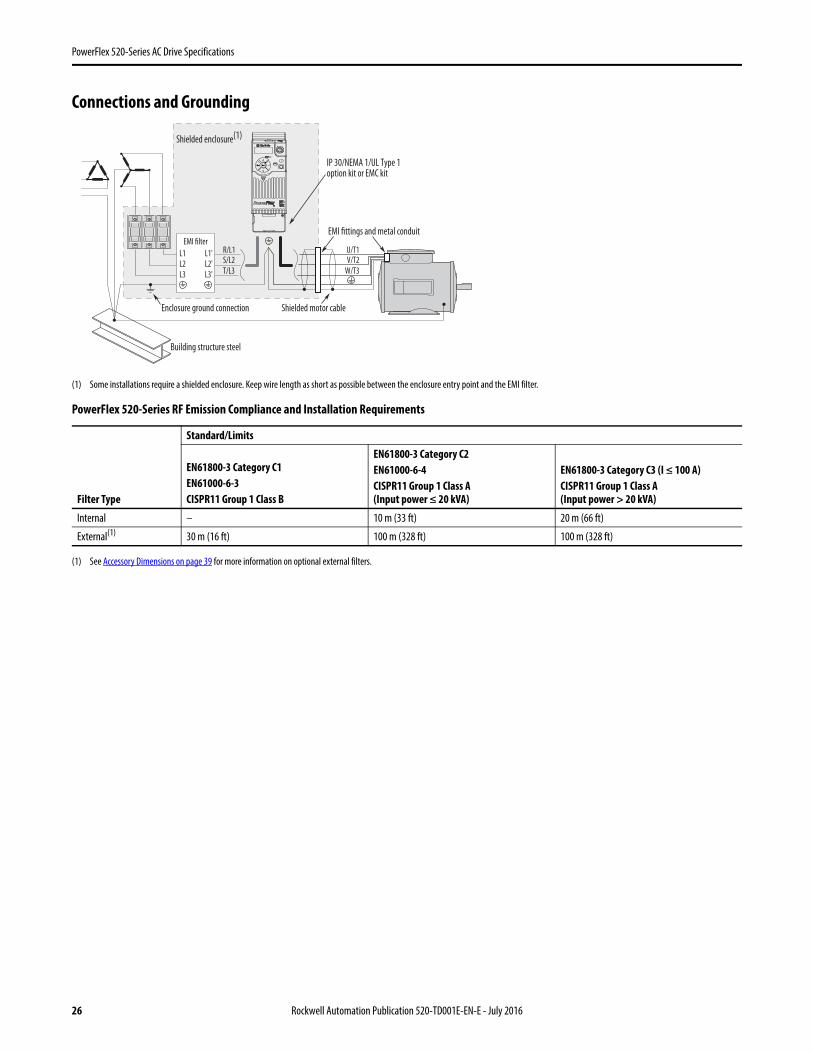
PowerFlex 520-Series AC Drive Specifications
Connections and Grounding
(1) Some installations require a shielded enclosure. Keep wire length as short as possible between the enclosure entry point and the EMI filter.
(1) See Accessory Dimensions on page 39 for more information on optional external filters.
PowerFlex 520-Series RF Emission Compliance and Installation Requirements
Filter Type
Standard/Limits
EN61800-3 Category C1EN61000-6-3CISPR11 Group 1 Class B
EN61800-3 Category C2EN61000-6-4CISPR11 Group 1 Class A(Input power ≤ 20 kVA)
EN61800-3 Category C3 (I ≤ 100 A)CISPR11 Group 1 Class A(Input power > 20 kVA)
Internal – 10 m (33 ft) 20 m (66 ft)
External(1) 30 m (16 ft) 100 m (328 ft) 100 m (328 ft)
R/L1S/L2
T/L3
U/T1V/T2
W/T3
EMI fittings and metal conduit
IP 30/NEMA 1/UL Type 1option kit or EMC kit
Shielded enclosure(1)
Building structure steel
Enclosure ground connection
EMI filter
L1'
L2'
L3'
L1
L2
L3
Shielded motor cable
Esc Sel
26 Rockwell Automation Publication 520-TD001E-EN-E - July 2016

PowerFlex 520-Series AC Drive Specifications
Fuses and Circuit Breaker Ratings
The PowerFlex 520-Series drive does not provide branch short circuit protection. This product should be installed with either input fuses or an input circuit breaker. National and local industrial safety regulations and/or electrical codes may determine additional requirements for these installations.
The tables on pages 28...31 provide drive ratings and recommended AC line input fuse and circuit breaker information. Both types of short circuit protection are acceptable for UL and IEC requirements. Sizes listed are the recommended sizes based on 40 °C (104 °F) and the U.S. N.E.C. Other country, state or local codes may require different ratings.
Fusing
The recommended fuse types are listed in the tables found on pages 28...31. If available current ratings do not match those listed in the tables provided, choose the next higher fuse rating.
• IEC – BS88 (British Standard) Parts 1 & 2(1), EN60269-1, Parts 1 & 2, type GG or equivalent should be used.• UL – UL Class CC, T, RK1, or J should be used.
(1) Typical designations include, but may not be limited to the following;Parts 1 & 2: AC, AD, BC, BD, CD, DD, ED, EFS, EF, FF, FG, GF, GG, GH.
Circuit Breakers
The “non-fuse” listings in the tables found on pages 28...31 include inverse time circuit breakers, instantaneous trip circuit breakers (motor circuit protectors) and 140M self-protected combination motor controllers. If one of these is chosen as the desired protection method, the following requirements apply:
• IEC – Both types of circuit breakers and 140M self-protected combination motor controllers are acceptable for IEC installations.
• UL – Only inverse time circuit breakers and the specified 140M selfprotected combination motor controllers are acceptable for UL installations.
Bulletin 140M (Self-Protected Combination Controller)/UL489 Circuit Breakers
When using Bulletin 140M or UL489 rated circuit breakers, the guidelines listed below must be followed in order to meet the NEC requirements for branch circuit protection.
• Bulletin 140M can be used in single motor applications.• Bulletin 140M can be used up stream from the drive without the need for fuses.
Rockwell Automation Publication 520-TD001E-EN-E - July 2016 27

28Rockwell Autom
ation Publication 520-TD001E-EN-E - July 2016
PowerFlex 520-Series AC Drive Specifications
ems.
Circuit Breakers Min.EnclosureVol. (in.3)140U/140G 140M(2)(3)(4)
15 140U-D6D2-B80 140M-C2E-B63 –20 140U-D6C2-C12 140M-C2E-C10 –40 140U-D6D2-C25 140M-D8E-C20 –50 140U-D6D2-C30 140M-F8E-C25 –
Circuit Breakers Min.EnclosureVol. (in.3)140U/140G 140M(2)(3)(4)
15 140U-D6D2-C10 140M-C2E-B63 –15 140U-D6D2-C10 140M-C2E-B63 –15 140U-D6D2-C10 140M-C2E-C10 –15 140U-D6D2-C10 140M-C2E-C10 –25 140U-D6D2-C15 140M-C2E-C16 –25 140U-D6D2-C15 140M-C2E-C16 –
140U-D6D2-C25 140M-F8E-C25 –140U-D6D2-C25 140M-F8E-C25 ––(5) 140M-F8E-C25 ––(5) 140M-F8E-C25 –
Fuses and Circuit Breakers for PowerFlex 520-Series Drives
100...120V 1-Phase Input Protection Devices – Frames A...B
200...240V 1-Phase Input Protection Devices – Frames A...B
(1) When the drive is controlling motors with lower amp ratings, refer to the drive nameplate for drive intput current rating.(2) The AIC ratings of the Bulletin 140M Motor Protector Circuit Breakers may vary. See Bulletin 140M Motor Protection Circuit Breakers Application Ratings.(3) Bulletin 140M with adjustable current range should have the current trip set to the minimum range that the device will not trip.(4) Manual Self-Protected (Type E) Combination Motor Controller, UL listed for 480Y/277 and 600Y/347 AC input. Not UL listed for use on 480V or 600V Delta/Delta, corner ground, or high-resistance ground syst(5) Circuit breaker selection is not available for this drive rating.
Catalog No. Output Ratings Input Ratings
Fram
e Size
Cont
acto
rCa
talo
g No.
IEC Applications (Non-UL) UL Applications
PF 523 PF 525 ND HD
Amps
kVA Max
Amps(1)
Fuses (Rating) Circuit Breakers Fuses (Max. Rating)HP kW HP kW Min. Max. 140U/140G 140M Class / Catalog No.
25A-V1P6N104 – 0.25 0.2 0.25 0.2 1.6 0.8 6.4 A 100-C09 10 16 140U-D6D2-B80 140M-C2E-B63 CLASS RK5, CC, J, or T / DLS-R-25A-V2P5N104 25B-V2P5N104 0.5 0.4 0.5 0.4 2.5 1.3 9.6 A 100-C12 16 20 140U-D6D2-C12 140M-C2E-C10 CLASS RK5, CC, J, or T / DLS-R-25A-V4P8N104 25B-V4P8N104 1.0 0.75 1.0 0.75 4.8 2.5 19.2 B 100-C23 25 40 140U-D6D2-C25 140M-D8E-C20 CLASS RK5, CC, J, or T / DLS-R-25A-V6P0N104 25B-V6P0N104 1.5 1.1 1.5 1.1 6.0 3.2 24.0 B 100-C23 32 50 140U-D6D2-C30 140M-F8E-C25 CLASS RK5, CC, J, or T / DLS-R-
Catalog No. Output Ratings Input Ratings
Fram
e Size
Cont
acto
rCa
talo
g No.
IEC Applications (Non-UL) UL Applications
PF 523 PF 525 ND HD
Amps
kVA Max
Amps(1)
Fuses (Rating) Circuit Breakers Fuses (Max. Rating)HP kW HP kW Min. Max. 140U/140G 140M Class / Catalog No.
25A-A1P6N104 – 0.25 0.2 0.25 0.2 1.6 1.4 5.3 A 100-C09 6 10 140U-D6D2-C10 140M-C2E-B63 CLASS RK5, CC, J, or T / DLS-R-25A-A1P6N114 – 0.25 0.2 0.25 0.2 1.6 1.4 5.3 A 100-C09 6 10 140U-D6D2-C10 140M-C2E-B63 CLASS RK5, CC, J, or T / DLS-R-25A-A2P5N104 25B-A2P5N104 0.5 0.4 0.5 0.4 2.5 1.7 6.5 A 100-C09 10 16 140U-D6D2-C10 140M-C2E-C10 CLASS RK5, CC, J, or T / DLS-R-25A-A2P5N114 25B-A2P5N114 0.5 0.4 0.5 0.4 2.5 1.7 6.5 A 100-C09 10 16 140U-D6D2-C10 140M-C2E-C10 CLASS RK5, CC, J, or T / DLS-R-25A-A4P8N104 25B-A4P8N104 1.0 0.75 1.0 0.75 4.8 2.8 10.7 A 100-C12 16 25 140U-D6D2-C15 140M-C2E-C16 CLASS RK5, CC, J, or T / DLS-R-25A-A4P8N114 25B-A4P8N114 1.0 0.75 1.0 0.75 4.8 2.8 10.7 A 100-C12 16 25 140U-D6D2-C15 140M-C2E-C16 CLASS RK5, CC, J, or T / DLS-R-25A-A8P0N104 25B-A8P0N104 2.0 1.5 2.0 1.5 8.0 4.8 18.0 B 100-C23 25 40 140U-D6D2-C25 140M-F8E-C25 CLASS CC, J, or T / 4025A-A8P0N114 25B-A8P0N114 2.0 1.5 2.0 1.5 8.0 4.8 18.0 B 100-C23 25 40 140U-D6D2-C25 140M-F8E-C25 CLASS CC, J, or T / 4025A-A011N104 25B-A011N104 3.0 2.2 3.0 2.2 11.0 6.0 22.9 B 100-C37 32 50 140G-G6C3-C35 140M-F8E-C25 CLASS CC, J, or T / 5025A-A011N114 25B-A011N114 3.0 2.2 3.0 2.2 11.0 6.0 22.9 B 100-C37 32 50 140G-G6C3-C35 140M-F8E-C25 CLASS CC, J, or T / 50

Rockwell Automation Publication 520-TD001E-EN-E - July 2016
29
PowerFlex 520-Series AC Drive Specifications
ems.ecified in this column. Application specific thermal
Circuit Breakers Min.Enclosure Vol. (in.3)140U/140G 140M(3)(4)(5)
15 140U-D6D3-B30 140M-C2E-B25 –6 140U-D6D3-B40 140M-C2E-B40 –15 140U-D6D3-B80 140M-C2E-B63 –20 140U-D6D3-C10 140M-C2E-C10 –30 140U-D6D3-C15 140M-C2E-C16 –
140U-D6D3-C25 140M-F8E-C25 ––(7) 140M-F8E-C32 –
70 –(7) 140M-F8E-C45 ––(7) 140M-F8E-C45 1416.0(6)
–(7) – –
Fuses and Circuit Breakers for PowerFlex 520-Series Drives (continued)
200...240V 3-Phase Input Protection Devices – Frames A...E
(1) Normal and Heavy Duty ratings are available for this drive.(2) When the drive is controlling motors with lower amp ratings, refer to the drive nameplate for drive intput current rating.(3) The AIC ratings of the Bulletin 140M Motor Protector Circuit Breakers may vary. See Bulletin 140M Motor Protection Circuit Breakers Application Ratings.(4) Bulletin 140M with adjustable current range should have the current trip set to the minimum range that the device will not trip.(5) Manual Self-Protected (Type E) Combination Motor Controller, UL listed for 480Y/277 and 600Y/347 AC input. Not UL listed for use on 480V or 600V Delta/Delta, corner ground, or high-resistance ground syst(6) When using a Manual Self-Protected (Type E) Combination Motor Controller with this drive power rating, the drive must be installed in a ventilated or non-ventilated enclosure with the minimum volume sp
considerations may require a larger enclosure.(7) Circuit breaker selection is not available for this drive rating.
Catalog No.(1) Output Ratings Input Ratings
Fram
e Size
Cont
acto
rCa
talo
g No.
IEC Applications (Non-UL) UL Applications
PF 523 PF 525 ND HD
Amps
kVA Max
Amps(2)
Fuses (Rating) Circuit Breakers Fuses (Max. Rating)HP kW HP kW Min. Max. 140U/140G 140M Class / Catalog No.
25A-B1P6N104 – 0.25 0.2 0.25 0.2 1.6 0.9 1.9 A 100-C09 3 6 140U-D6D3-B30 140M-C2E-B25 CLASS RK5, CC, J, or T / DLS-R-25A-B2P5N104 25B-B2P5N104 0.5 0.4 0.5 0.4 2.5 1.2 2.7 A 100-C09 6 6 140U-D6D3-B40 140M-C2E-B40 CLASS RK5, CC, J, or T / DLS-R-25A-B5P0N104 25B-B5P0N104 1.0 0.75 1.0 0.75 5.0 2.7 5.8 A 100-C09 10 16 140U-D6D3-B80 140M-C2E-B63 CLASS RK5, CC, J, or T / DLS-R-25A-B8P0N104 25B-B8P0N104 2.0 1.5 2.0 1.5 8.0 4.3 9.5 A 100-C12 16 20 140U-D6D3-C10 140M-C2E-C10 CLASS RK5, CC, J, or T / DLS-R-25A-B011N104 25B-B011N104 3.0 2.2 3.0 2.2 11.0 6.3 13.8 A 100-C23 20 32 140U-D6D3-C15 140M-C2E-C16 CLASS RK5, CC, J, or T / DLS-R-25A-B017N104 25B-B017N104 5.0 4.0 5.0 4.0 17.5 9.6 21.1 B 100-C23 32 45 140U-D6D3-C25 140M-F8E-C25 CLASS CC, J, or T / 4525A-B024N104 25B-B024N104 7.5 5.5 7.5 5.5 24.0 12.2 26.6 C 100-C37 35 63 140G-G6C3-C35 140M-F8E-C32 CLASS CC, J, or T / 6025A-B032N104 25B-B032N104 10.0 7.5 10.0 7.5 32.2 15.9 34.8 D 100-C43 45 70 140G-G6C3-C60 140M-F8E-C45 CLASS RK5, CC, J, or T / DLS-R-25A-B048N104 25B-B048N104 15.0 11.0 10.0 7.5 48.3 20.1 44.0 E 100-C60 63 90 140G-G6C3-C70 140M-F8E-C45 CLASS CC, J, or T / 9025A-B062N104 25B-B062N104 20.0 15.0 15.0 11.0 62.1 25.6 56.0 E 100-C72 70 125 140G-G6C3-C90 –(7) CLASS CC, J, or T / 125

30Rockwell Autom
ation Publication 520-TD001E-EN-E - July 2016
PowerFlex 520-Series AC Drive Specifications
ems.ecified in this column. Application specific thermal
Circuit Breakers Min.Enclosure Vol. (in.3)140U/140G 140M(3)(4)(5)
6 –(7) 140M-C2E-B25 –6 –(7) 140M-C2E-B25 –10 –(7) 140M-C2E-B40 –10 –(7) 140M-C2E-B40 –15 –(7) 140M-C2E-B63 –15 –(7) 140M-C2E-B63 –15 –(7) 140M-C2E-C10 –15 –(7) 140M-C2E-C10 –30 –(7) 140M-C2E-C16 –30 –(7) 140M-C2E-C16 –
–(7) 140M-D8E-C20 ––(7) 140M-D8E-C20 ––(7) 140M-D8E-C20 ––(7) 140M-D8E-C20 ––(7) 140M-F8E-C32 656.7(6)
–(7) 140M-F8E-C32 656.7(6)
–(7) 140M-F8E-C45 656.7(6)
–(7) 140M-F8E-C45 656.7(6)
–(7) 140M-F8E-C45 ––(7) 140M-F8E-C45 –
Fuses and Circuit Breakers for PowerFlex 520-Series Drives (continued)
380...480V 3-Phase Input Protection Devices – Frames A...E
(1) Normal and Heavy Duty ratings are available for this drive(2) When the drive is controlling motors with lower amp ratings, refer to the drive nameplate for drive intput current rating.(3) The AIC ratings of the Bulletin 140M Motor Protector Circuit Breakers may vary. See Bulletin 140M Motor Protection Circuit Breakers Application Ratings.(4) Bulletin 140M with adjustable current range should have the current trip set to the minimum range that the device will not trip.(5) Manual Self-Protected (Type E) Combination Motor Controller, UL listed for 480Y/277 and 600Y/347 AC input. Not UL listed for use on 480V or 600V Delta/Delta, corner ground, or high-resistance ground syst(6) When using a Manual Self-Protected (Type E) Combination Motor Controller with this drive power rating, the drive must be installed in a ventilated or non-ventilated enclosure with the minimum volume sp
considerations may require a larger enclosure.(7) Circuit breaker selection is not available for this drive rating.
Catalog No.(1) Output Ratings Input Ratings
Fram
e Size
Cont
acto
rCa
talo
g No.
IEC Applications (Non-UL) UL Applications
PF 523 PF 525 ND HD
Amps
kVA Max
Amps(2)
Fuses (Rating) Circuit Breakers Fuses (Max. Rating)HP kW HP kW Min. Max. 140U/140G 140M Class / Catalog No.
25A-D1P4N104 25B-D1P4N104 0.5 0.4 0.5 0.4 1.4 1.7 1.9 A 100-C09 3 6 140U-D6D3-B30 140M-C2E-B25 CLASS RK5, CC, J, or T / DLS-R-25A-D1P4N114 25B-D1P4N114 0.5 0.4 0.5 0.4 1.4 1.7 1.9 A 100-C09 3 6 140U-D6D3-B30 140M-C2E-B25 CLASS RK5, CC, J, or T / DLS-R-25A-D2P3N104 25B-D2P3N104 1.0 0.75 1.0 0.75 2.3 2.9 3.2 A 100-C09 6 10 140U-D6D3-B60 140M-C2E-B40 CLASS RK5, CC, J, or T / DLS-R-25A-D2P3N114 25B-D2P3N114 1.0 0.75 1.0 0.75 2.3 2.9 3.2 A 100-C09 6 10 140U-D6D3-B60 140M-C2E-B40 CLASS RK5, CC, J, or T / DLS-R-25A-D4P0N104 25B-D4P0N104 2.0 1.5 2.0 1.5 4.0 5.2 5.7 A 100-C09 10 16 140U-D6D3-B60 140M-C2E-B63 CLASS RK5, CC, J, or T / DLS-R-25A-D4P0N114 25B-D4P0N114 2.0 1.5 2.0 1.5 4.0 5.2 5.7 A 100-C09 10 16 140U-D6D3-B60 140M-C2E-B63 CLASS RK5, CC, J, or T / DLS-R-25A-D6P0N104 25B-D6P0N104 3.0 2.2 3.0 2.2 6.0 6.9 7.5 A 100-C09 10 16 140U-D6D3-C10 140M-C2E-C10 CLASS RK5, CC, J, or T / DLS-R-25A-D6P0N114 25B-D6P0N114 3.0 2.2 3.0 2.2 6.0 6.9 7.5 A 100-C09 10 16 140U-D6D3-C10 140M-C2E-C10 CLASS RK5, CC, J, or T / DLS-R-25A-D010N104 25B-D010N104 5.0 4.0 5.0 4.0 10.5 12.6 13.8 B 100-C23 20 32 140U-D6D3-C15 140M-C2E-C16 CLASS RK5, CC, J, or T / DLS-R-25A-D010N114 25B-D010N114 5.0 4.0 5.0 4.0 10.5 12.6 13.8 B 100-C23 20 32 140U-D6D3-C15 140M-C2E-C16 CLASS RK5, CC, J, or T / DLS-R-25A-D013N104 25B-D013N104 7.5 5.5 7.5 5.5 13.0 14.1 15.4 C 100-C23 20 35 140U-D6D3-C25 140M-D8E-C20 CLASS CC, J, or T / 3525A-D013N114 25B-D013N114 7.5 5.5 7.5 5.5 13.0 14.1 15.4 C 100-C23 20 35 140U-D6D3-C25 140M-D8E-C20 CLASS CC, J, or T / 3525A-D017N104 25B-D017N104 10.0 7.5 10.0 7.5 17.0 16.8 18.4 C 100-C23 25 40 140U-D6D3-C25 140M-D8E-C20 CLASS CC, J, or T / 4025A-D017N114 25B-D017N114 10.0 7.5 10.0 7.5 17.0 16.8 18.4 C 100-C23 25 40 140U-D6D3-C25 140M-D8E-C20 CLASS CC, J, or T / 4025A-D024N104 25B-D024N104 15.0 11.0 15.0 11.0 24.0 24.1 26.4 D 100-C37 35 63 140G-G6C3-C40 140M-F8E-C32 CLASS CC, J, or T / 6025A-D024N114 25B-D024N114 15.0 11.0 15.0 11.0 24.0 24.1 26.4 D 100-C37 35 63 140G-G6C3-C40 140M-F8E-C32 CLASS CC, J, or T / 6025A-D030N104 25B-D030N104 20.0 15.0 15.0 11.0 30.0 30.2 33.0 D 100-C43 45 70 140G-G6C3-C50 140M-F8E-C45 CLASS CC, J, or T / 7025A-D030N114 25B-D030N114 20.0 15.0 15.0 11.0 30.0 30.2 33.0 D 100-C43 45 70 140G-G6C3-C50 140M-F8E-C45 CLASS CC, J, or T / 7025A-D037N114 25B-D037N114 25.0 18.5 20.0 15.0 37.0 30.8 33.7 E 100-C43 45 70 140G-G6C3-C50 140M-F8E-C45 CLASS CC, J, or T / 7025A-D043N114 25B-D043N114 30.0 22.0 25.0 18.5 43.0 35.6 38.9 E 100-C60 50 80 140G-G6C3-C60 140M-F8E-C45 CLASS CC, J, or T / 80

Rockwell Automation Publication 520-TD001E-EN-E - July 2016
31
PowerFlex 520-Series AC Drive Specifications
ems.
ecified in this column. Application specific thermal
Circuit Breakers Min. Enclosure Vol. (in.3)140U/140G 140M(3)(4)(5)
6 –(8) 140M-C2E-B25 –6 –(8) 140M-C2E-B25 –10 –(8) 140M-C2E-B40 –15 –(8) 140M-D8E-B63 –20 –(8) 140M-D8E-C10 –25 –(8) 140M-D8E-C16(6) –30 –(8) 140M-D8E-C16 –
–(8) 140M-F8E-C25 656.7(7)
–(8) 140M-F8E-C32 656.7(7)
–(8) 140M-F8E-C32 1416.0(7)
–(8) 140M-F8E-C32 1416.0(7)
Fuses and Circuit Breakers for PowerFlex 520-Series Drives (continued)
525...600V 3-Phase Input Protection Devices – Frames A...E
(1) Normal and Heavy Duty ratings are available for this drive(2) When the drive is controlling motors with lower amp ratings, refer to the drive nameplate for drive intput current rating.(3) The AIC ratings of the Bulletin 140M Motor Protector Circuit Breakers may vary. See Bulletin 140M Motor Protection Circuit Breakers Application Ratings.(4) Bulletin 140M with adjustable current range should have the current trip set to the minimum range that the device will not trip.(5) Manual Self-Protected (Type E) Combination Motor Controller, UL listed for 480Y/277 and 600Y/347 AC input. Not UL listed for use on 480V or 600V Delta/Delta, corner ground, or high-resistance ground syst(6) When used with the 140M circuit breaker, the 25A-E9P9104 must be installed in a ventilated or non-ventilated enclosure with the minimum size of 457.2 x 457.2 x 269.8 mm (18 x 18 x 10.62 in.).(7) When using a Manual Self-Protected (Type E) Combination Motor Controller with this drive power rating, the drive must be installed in a ventilated or non-ventilated enclosure with the minimum volume sp
considerations may require a larger enclosure.(8) Circuit breaker selection is not available for this drive rating.
Catalog No.(1) Output Ratings Input Ratings
Fram
e Size
Cont
acto
rCa
talo
g No.
IEC Applications (Non-UL) UL Applications
PF 523 PF 525 ND HD
Amps
kVA Max
Amps(2)
Fuses (Rating) Circuit Breakers Fuses (Max. Rating)HP kW HP kW Min. Max. 140U/140G 140M Class / Catalog No.
25A-E0P9N104 25B-E0P9N104 0.5 0.4 0.5 0.4 0.9 1.4 1.2 A 100-C09 3 6 140U-D6D3-B20 140M-C2E-B25 CLASS RK5, CC, J, or T / DLS-R-25A-E1P7N104 25B-E1P7N104 1.0 0.75 1.0 0.75 1.7 2.6 2.3 A 100-C09 3 6 140U-D6D3-B30 140M-C2E-B25 CLASS RK5, CC, J, or T / DLS-R-25A-E3P0N104 25B-E3P0N104 2.0 1.5 2.0 1.5 3.0 4.3 3.8 A 100-C09 6 10 140U-D6D3-B50 140M-C2E-B40 CLASS RK5, CC, J, or T / DLS-R-25A-E4P2N104 25B-E4P2N104 3.0 2.2 3.0 2.2 4.2 6.1 5.3 A 100-C09 10 16 140U-D6D3-B80 140M-C2E-B63 CLASS RK5, CC, J, or T / DLS-R-25A-E6P6N104 25B-E6P6N104 5.0 4.0 5.0 4.0 6.6 9.1 8.0 B 100-C09 10 20 140U-D6D3-C10 140M-C2E-C10 CLASS RK5, CC, J, or T / DLS-R-25A-E9P9N104 25B-E9P9N104 7.5 5.5 7.5 5.5 9.9 12.8 11.2 C 100-C16 16 25 140U-D6D3-C15 140M-C2E-C16 CLASS RK5, CC, J, or T / DLS-R-25A-E012N104 25B-E012N104 10.0 7.5 10.0 7.5 12.0 15.4 13.5 C 100-C23 20 32 140U-D6D3-C20 140M-C2E-C16 CLASS RK5, CC, J, or T / DLS-R-25A-E019N104 25B-E019N104 15.0 11.0 15.0 11.0 19.0 27.4 24.0 D 100-C30 32 50 140G-G6C3-C30 140M-F8E-C25 CLASS CC, J, or T / 5025A-E022N104 25B-E022N104 20.0 15.0 15.0 11.0 22.0 31.2 27.3 D 100-C30 35 63 140G-G6C3-C35 140M-F8E-C32 CLASS CC, J, or T / 6025A-E027N104 25B-E027N104 25.0 18.5 20.0 15.0 27.0 28.2 24.7 E 100-C30 35 50 140G-G6C3-C35 140M-F8E-C32 CLASS CC, J, or T / 5025A-E032N104 25B-E032N104 30.0 22.0 25.0 18.5 32.0 33.4 29.2 E 100-C37 40 63 140G-G6C3-C50 140M-F8E-C32 CLASS CC, J, or T / 60

PowerFlex 520-Series AC Drive Specifications
Accessories and Dimensions
(1) The resistors listed in this tables are rated for 5% duty cycle.(2) Use of Rockwell Automation resistors is always recommended. The resistors listed have been carefully selected for optimizing performance in a variety of applications. Alternative resistors may be used,
however, care must be taken when making a selection. See the PowerFlex Dynamic Braking Resistor Calculator, publication PFLEX-AT001.(3) Requires two resistors wired in parallel.(4) Requires three resistors wired in parallel.
Dynamic Brake Resistors
Drive Ratings Minimum ResistanceΩ ± 10%
Resistance Ω ± 5% Catalog No.(1)(2)Input Voltage HP kW
100...120V50/60 Hz1-Phase
0.25 0.2 56 91 AK-R2-091P5000.5 0.4 56 91 AK-R2-091P5001.0 0.75 56 91 AK-R2-091P5001.5 1.1 41 91 AK-R2-091P500
200...240V50/60 Hz1-Phase
0.25 0.2 56 91 AK-R2-091P5000.5 0.4 56 91 AK-R2-091P5001.0 0.75 56 91 AK-R2-091P5002.0 1.5 41 91 AK-R2-091P5003.0 2.2 32 47 AK-R2-047P500
200...240V50/60 Hz3-Phase
0.25 0.2 56 91 AK-R2-091P5000.5 0.4 56 91 AK-R2-091P5001.0 0.75 56 91 AK-R2-091P5002.0 1.5 41 91 AK-R2-091P5003.0 2.2 32 47 AK-R2-047P5005.0 4.0 18 47 AK-R2-047P5007.5 5.5 16 30 AK-R2-030P1K210.0 7.5 14 30 AK-R2-030P1K215.0 11.0 14 15 AK-R2-030P1K2(3)
20.0 15.0 10 15 AK-R2-030P1K2(3)
380...480V50/60 Hz3-Phase
0.5 0.4 89 360 AK-R2-360P5001.0 0.75 89 360 AK-R2-360P5002.0 1.5 89 360 AK-R2-360P5003.0 2.2 89 120 AK-R2-120P1K25.0 4.0 47 120 AK-R2-120P1K27.5 5.5 47 120 AK-R2-120P1K210.0 7.5 47 120 AK-R2-120P1K215.0 11.0 43 60 AK-R2-120P1K2(3)
20.0 15.0 43 60 AK-R2-120P1K2(3)
25.0 18.5 27 40 AK-R2-120P1K2(4)
30.0 22.0 27 40 AK-R2-120P1K2(4)
525...600V50/60 Hz3-Phase
0.5 0.4 112 360 AK-R2-360P5001.0 0.75 112 360 AK-R2-360P5002.0 1.5 112 360 AK-R2-360P5003.0 2.2 112 120 AK-R2-120P1K25.0 4.0 86 120 AK-R2-120P1K27.5 5.5 59 120 AK-R2-120P1K210.0 7.5 59 120 AK-R2-120P1K215.0 11.0 59 60 AK-R2-120P1K2(3)
20.0 15.0 59 60 AK-R2-120P1K2(3)
25.0 18.5 53 60 AK-R2-120P1K2(3)
30.0 22.0 34 40 AK-R2-120P1K2(4)
32 Rockwell Automation Publication 520-TD001E-EN-E - July 2016

PowerFlex 520-Series AC Drive Specifications
(1) EMC Line Filter size is based on the input current of the drive. See the tables on page 30 and page 31 for more information.(2) This 600V drive rating needs to be matched with a frame B EMC Line Filter.
EMC Line Filters
Short Circuit Current Rating = 100 kADrive Ratings
Frame Size Catalog No.Input Voltage HP kW Current (A)100...120V50/60 Hz1-Phase
0.25 0.2 1.6 A 25-RF011-AL0.5 0.4 2.5 A 25-RF011-AL1.0 0.75 4.8 B 25-RF023-BL1.5 1.1 6.0 B 25-RF023-BL
200...240V50/60 Hz1-Phase
0.25 0.2 1.6 A 25-RF011-AL0.5 0.4 2.5 A 25-RF011-AL1.0 0.75 4.8 A 25-RF011-AL2.0 1.5 8.0 B 25-RF023-BL3.0 2.2 11.0 B 25-RF023-BL
200...240V50/60 Hz3-Phase
0.25 0.2 1.6 A 25-RF014-AL0.5 0.4 2.5 A 25-RF014-AL1.0 0.75 5.0 A 25-RF014-AL2.0 1.5 8.0 A 25-RF014-AL3.0 2.2 11.0 A 25-RF014-AL5.0 4.0 17.5 B 25-RF021-BL7.5 5.5 24.0 C 25-RF027-CL10.0 7.5 32.2 D 25-RF035-DL15.0 11.0 48.3 E 25-RF056-EL20.0 15.0 62.1 E 25-RF056-EL
380...480V50/60 Hz3-Phase
0.5 0.4 1.4 A 25-RF7P5-AL1.0 0.75 2.3 A 25-RF7P5-AL2.0 1.5 4.0 A 25-RF7P5-AL3.0 2.2 6.0 A 25-RF7P5-AL5.0 4.0 10.5 B 25-RF014-BL7.5 5.5 13.0 C 25-RF018-CL10.0 7.5 17.0 C 25-RF018-CL15.0 11.0 24.0 D 25-RF033-DL20.0 15.0 30.0 D 25-RF033-DL25.0 18.5 37.0 E 25-RF039-EL30.0 22.0 43.0 E 25-RF039-EL(1)
525...600V50/60 Hz3-Phase
0.5 0.4 0.9 A 25-RF8P0-BL(2)
1.0 0.75 1.7 A 25-RF8P0-BL(2)
2.0 1.5 3.0 A 25-RF8P0-BL(2)
3.0 2.2 4.2 A 25-RF8P0-BL(2)
5.0 4.0 6.6 B 25-RF8P0-BL7.5 5.5 9.9 C 25-RF014-CL10.0 7.5 12.0 C 25-RF014-CL15.0 11.0 19.0 D 25-RF027-DL20.0 15.0 22.0 D 25-RF027-DL25.0 18.5 27.0 E 25-RF029-EL30.0 22.0 32.0 E 25-RF029-EL(1)
Rockwell Automation Publication 520-TD001E-EN-E - July 2016 33

PowerFlex 520-Series AC Drive Specifications
EMC Plates
Item Description Frame Size Catalog No.EMC Plate Optional grounding plate for shielded cables. A 25-EMC1-FA
B 25-EMC1-FBC 25-EMC1-FCD 25-EMC1-FDE 25-EMC1-FE
Human Interface Modules (HIM) Option Kits and Accessories
Item Description Catalog No.LCD Display, Remote Panel Mount Digital speed control
CopyCat capableIP 66 (NEMA Type 4X/12) indoor use onlyIncludes 2.9 meter cable
22-HIM-C2S
LCD Display, Remote Handheld Digital speed controlFull numeric keyboardCopyCat capableIP 30 (NEMA Type 1)Includes 1.0 m cablePanel mount with optional Bezel Kit
22-HIM-A3
Bezel Kit Panel mount for LCD Display, Remote Handheld unit, IP 30 (NEMA Type 1)Includes 2.0 m DSI cable
22-HIM-B1
DSI HIM Cable(DSI HIM to RJ45 cable)
1.0 m (3.3 ft) 22-HIM-H102.9 m (9.51 ft) 22-HIM-H30
IP 30/NEMA 1/UL Type 1 Kit
Item Description Frame Size Catalog No.IP 30/NEMA 1/UL Type 1 Kit Field installed kit. Converts drive to IP 30/NEMA 1/UL Type 1 enclosure. Includes conduit box
with mounting screws and plastic top panel.A 25-JBAAB 25-JBABC 25-JBACD 25-JBADE 25-JBAE
Control Module Fan Kit
Item Description Frame Size Catalog No.Control Module Fan Kit For use with drive in environments with ambient temperatures up to 70 °C or horizontal
mounting.A...D 25-FAN1-70CE 25-FAN2-70C
Incremental Encoder Input Option
Item Description Catalog No.Incremental Encoder Incremental encoder input option board. 25-ENC-1
WARNING: Only the 25-ENC-1 Encoder will work properly in the PowerFlex 525 drive. Installing an incorrect encoder card, such as the PowerFlex 527 25-ENC-2 will cause damage to the PowerFlex 525 drive.
34 Rockwell Automation Publication 520-TD001E-EN-E - July 2016

PowerFlex 520-Series AC Drive Specifications
Replacement Parts
Bulletin 160 to PowerFlex 520-Series Mounting Adapter Plate
Item DescriptionB160Frame Size Catalog No.
Mounting Adapter Plate For use with drive when replacing Bulletin 160 drives in existing installations to a PowerFlex 520-Series drive. Select the catalog number based on the frame size of your Bulletin 160 drive.
A 25-MAP-FAB 25-MAP-FB
PowerFlex 520-Series Power Module
Item DescriptionPowerFlex 520-Series Power Module Replacement power module for use with PowerFlex 520-Series drives. Includes:
• Power Module• Power Module Front Cover• Power Terminal Guard• Heatsink Fan
Output Ratings
Input Voltage Range Frame Size Catalog No.Normal Duty Heavy Duty
Output Current (A)HP kW HP kW100...120V AC (-15%, +10%) – 1-Phase Input, 0...230V 3-Phase Output 0.25 0.2 0.25 0.2 1.6 85...132 A 25-PM1-V1P60.5 0.4 0.5 0.4 2.5 85...132 A 25-PM1-V2P51.0 0.75 1.0 0.75 4.8 85...132 B 25-PM1-V4P81.5 1.1 1.5 1.1 6.0 85...132 B 25-PM1-V6P0200...240V AC (-15%, +10%) – 1-Phase Input, 0...230V 3-Phase Output0.25 0.2 0.25 0.2 1.6 170...264 A 25-PM1-A1P60.5 0.4 0.5 0.4 2.5 170...264 A 25-PM1-A2P51.0 0.75 1.0 0.75 4.8 170...264 A 25-PM1-A4P82.0 1.5 2.0 1.5 8.0 170...264 B 25-PM1-A8P03.0 2.2 3.0 2.2 11.0 170...264 B 25-PM1-A011200...240V AC (-15%, +10%) – 1-Phase Input with EMC Filter, 0...230V 3-Phase Output0.25 0.2 0.25 0.2 1.6 170...264 A 25-PM2-A1P60.5 0.4 0.5 0.4 2.5 170...264 A 25-PM2-A2P51.0 0.75 1.0 0.75 4.8 170...264 A 25-PM2-A4P82.0 1.5 2.0 1.5 8.0 170...264 B 25-PM2-A8P03.0 2.2 3.0 2.2 11.0 170...264 B 25-PM2-A011200...240V AC (-15%, +10%) – 3-Phase Input, 0...230V 3-Phase Output0.25 0.2 0.25 0.2 1.6 170...264 A 25-PM1-B1P60.5 0.4 0.5 0.4 2.5 170...264 A 25-PM1-B2P51.0 0.75 1.0 0.75 5.0 170...264 A 25-PM1-B5P02.0 1.5 2.0 1.5 8.0 170...264 A 25-PM1-B8P03.0 2.2 3.0 2.2 11.0 170...264 A 25-PM1-B0115.0 4.0 5.0 4.0 17.5 170...264 B 25-PM1-B0177.5 5.5 7.5 5.5 24.0 170...264 C 25-PM1-B02410.0 7.5 10.0 7.5 32.2 170...264 D 25-PM1-B03215.0 11.0 10.0 7.5 48.3 170...264 E 25-PM1-B04820.0 15.0 15.0 11.0 62.1 170...264 E 25-PM1-B062380...480V AC (-15%, +10%) – 3-Phase Input, 0...460V 3-Phase Output0.5 0.4 0.5 0.4 1.4 323...528 A 25-PM1-D1P41.0 0.75 1.0 0.75 2.3 323...528 A 25-PM1-D2P3
Rockwell Automation Publication 520-TD001E-EN-E - July 2016 35

PowerFlex 520-Series AC Drive Specifications
2.0 1.5 2.0 1.5 4.0 323...528 A 25-PM1-D4P03.0 2.2 3.0 2.2 6.0 323...528 A 25-PM1-D6P05.0 4.0 5.0 4.0 10.5 323...528 B 25-PM1-D0107.5 5.5 7.5 5.5 13.0 323...528 C 25-PM1-D01310.0 7.5 10.0 7.5 17.0 323...528 C 25-PM1-D01715.0 11.0 15.0 11.0 24.0 323...528 D 25-PM1-D02420.0 15.0 15.0 11.0 30.0 323...528 D 25-PM1-D030380...480V AC (-15%, +10%) – 3-Phase Input with EMC Filter, 0...460V 3-Phase Output0.5 0.4 0.5 0.4 1.4 323...528 A 25-PM2-D1P41.0 0.75 1.0 0.75 2.3 323...528 A 25-PM2-D2P32.0 1.5 2.0 1.5 4.0 323...528 A 25-PM2-D4P03.0 2.2 3.0 2.2 6.0 323...528 A 25-PM2-D6P05.0 4.0 5.0 4.0 10.5 323...528 B 25-PM2-D0107.5 5.5 7.5 5.5 13.0 323...528 C 25-PM2-D01310.0 7.5 10.0 7.5 17.0 323...528 C 25-PM2-D01715.0 11.0 15.0 11.0 24.0 323...528 D 25-PM2-D02420.0 15.0 15.0 11.0 30.0 323...528 D 25-PM2-D03025.0 18.5 20.0 15.0 37.0 323...528 E 25-PM2-D03730.0 22.0 25.0 18.5 43.0 323...528 E 25-PM2-D043525...600V AC (-15%, +10%) – 3-Phase Input, 0...575V 3-Phase Output0.5 0.4 0.5 0.4 0.9 446...660 A 25-PM1-E0P91.0 0.75 1.0 0.75 1.7 446...660 A 25-PM1-E1P72.0 1.5 2.0 1.5 3.0 446...660 A 25-PM1-E3P03.0 2.2 3.0 2.2 4.2 446...660 A 25-PM1-E4P25.0 4.0 5.0 4.0 6.6 446...660 B 25-PM1-E6P67.5 5.5 7.5 5.5 9.9 446...660 C 25-PM1-E9P910.0 7.5 10.0 7.5 12.0 446...660 C 25-PM1-E01215.0 11.0 15.0 11.0 19.0 446...660 D 25-PM1-E01920.0 15.0 15.0 11.0 22.0 446...660 D 25-PM1-E02225.0 18.5 20.0 15.0 27.0 446...660 E 25-PM1-E02730.0 22.0 25.0 18.5 32.0 446...660 E 25-PM1-E032
PowerFlex 520-Series Control Module
Item Description Frame Size Catalog No.PowerFlex 523 Control Module Replacement control module for use with PowerFlex 520-Series drives. Includes:
• Control Module• Control Module Front Cover
A...E 25A-CTM1PowerFlex 525 Control Module 25B-CTM1
Other Parts
Item Description Frame Size Catalog No.PowerFlex 523 Control Module Front Cover
Replacement cover for the control module I/O terminals, EtherNet/IP and DSI ports. A...E 25A-CTMFC1
PowerFlex 525 Control Module Front Cover
25B-CTMFC1
PowerFlex 520-Series Power Module Front Cover
Replacement cover for the PowerFlex 520-Series power module. B 25-PMFC-FBC 25-PMFC-FCD 25-PMFC-FDE 25-PMFC-FE
Output Ratings
Input Voltage Range Frame Size Catalog No.Normal Duty Heavy Duty
Output Current (A)HP kW HP kW
36 Rockwell Automation Publication 520-TD001E-EN-E - July 2016

PowerFlex 520-Series AC Drive Specifications
PowerFlex 520-Series Power Terminal Guard
Replacement finger guard for power terminals. A 25-PTG1-FAB 25-PTG1-FBC 25-PTG1-FCD 25-PTG1-FDE 25-PTG1-FE
PowerFlex 520-Series Heatsink Fan Kit Replacement fan for drive power module. A 25-FAN1-FAB 25-FAN1-FBC 25-FAN1-FCD 25-FAN1-FDE 25-FAN1-FE
Communication Option Kits and Accessories
Item Description Catalog No.Communication Adapters Embedded communication options for use with the PowerFlex 520-Series drives:
• DeviceNet• Dual Port EtherNet/IP• PROFIBUS DP-V1
25-COMM-D25-COMM-E2P25-COMM-P
Compact I/O Module Three channel 1769-SM2Universal Serial Bus™ (USB)Converter Module
Provides serial communication via DF1 protocol for use with Connected Components Workbench software. Includes:• 2m USB cable (1)• 20-HIM-H10 cable (1)• 22-HIM-H10 cable (1)
1203-USB
Serial Converter Module(RS485 to RS232)
Provides serial communication via DF1 protocol for use with Connected Components Workbench software. Includes:• DSI to RS232 serial converter (1)• 1203-SFC serial cable (1)• 22-RJ45CBL-C20 cable (1)
22-SCM-232
DSI Cable 2.0 m RJ45 to RJ45 cable, male to male connectors. 22-RJ45CBL-C20Serial Cable 2.0 m serial cable with a locking low profile connector to connect to the serial converter and a
9-pin sub-miniature D female connector to connect to a computer.1203-SFC
Splitter Cable RJ45 one to two port splitter cable (Modbus only) AK-U0-RJ45-SC1Terminating Resistors RJ45 120 Ohm resistors (2 pieces) AK-U0-RJ45-TR1Terminal Block RJ45 Two position terminal block (5 pieces) AK-U0-RJ45-TB2PConnected Components Workbench Software(Download or DVD-ROM)
Windows-based software packages for programming and configuring Allen-Bradley drives and other Rockwell Automation products.Compatibility:
Windows XP, Windows Vista and Windows 7
http://ab.rockwellautomation.com/programmable-controllers/connected-components-workbench-software
Bulletin 1321-3R Series Line Reactors
Output Ratings(1) Input Line Reactor(3)(4) Output Line Reactor(3)(4)
Normal Duty Heavy Duty IP 00 (Open Style) IP 11 (NEMA/UL Type 1) IP 00 (Open Style) IP 11 (NEMA/UL Type 1)
HP kW HP kW Catalog No. Catalog No. Catalog No. Catalog No.
200...240V 50/60 Hz 1-Phase(2)
0.25 0.2 0.25 0.2 1321-3R4-A 1321-3RA4-A 1321-3R2-D 1321-3RA2-D
0.5 0.4 0.5 0.4 1321-3R8-A 1321-3RA8-A 1321-3R2-D 1321-3RA2-D
1.0 0.75 1.0 0.75 1321-3R8-A 1321-3RA8-A 1321-3R4-A 1321-3RA4-A
2.0 1.5 2.0 1.5 1321-3R18-A 1321-3RA18-A 1321-3R8-A 1321-3RA8-A
3.0 2.2 3.0 2.2 1321-3R18-A 1321-3RA18-A 1321-3R12-A 1321-3RA12-A
200...240V 50/60 Hz 3-Phase
Other Parts
Item Description Frame Size Catalog No.
Rockwell Automation Publication 520-TD001E-EN-E - July 2016 37

PowerFlex 520-Series AC Drive Specifications
(1) Normal Duty and Heavy Duty ratings for 15 HP (11 kW) and below are identical except for 200...240V 3-Phase 15 HP (11 kW) drive.(2) Standard 3-phase reactors can be used for 1-phase applications by routing each of the two supply conductors through an outside coil and leaving the center open.(3) Catalog numbers listed are for 3% impedance. 5% impedance reactor types are also available. See 1321 Power Conditioning Products Technical Data, publication 1321-TD001.(4) Input line reactors were sized based on the NEC fundamental motor amps. Output line reactors were sized based on the VFD rated output currents.
0.25 0.2 0.25 0.2 1321-3R2-D 1321-3RA2-D 1321-3R2-D 1321-3RA2-D
0.5 0.4 0.5 0.4 1321-3R2-D 1321-3RA2-D 1321-3R2-D 1321-3RA2-D
1.0 0.75 1.0 0.75 1321-3R4-A 1321-3RA4-A 1321-3R4-A 1321-3RA4-A
2.0 1.5 2.0 1.5 1321-3R8-A 1321-3RA8-A 1321-3R8-A 1321-3RA8-A
3.0 2.2 3.0 2.2 1321-3R12-A 1321-3RA12-A 1321-3R12-A 1321-3RA12-A
5.0 4.0 5.0 4.0 1321-3R18-A 1321-3RA18-A 1321-3R18-A 1321-3RA18-A
7.5 5.5 7.5 5.5 1321-3R25-A 1321-3RA25-A 1321-3R25-A 1321-3RA25-A
10.0 7.5 10.0 7.5 1321-3R35-A 1321-3RA35-A 1321-3R35-A 1321-3RA35-A
15.0 11.0 15.0 11.0 1321-3R45-A 1321-3RA45-A 1321-3R45-A 1321-3RA45-A
20.0 15.0 15.0 11.0 1321-3R55-A (ND)1321-3R45-A (HD)
1321-3RA55-A (ND)1321-3RA45-A (HD)
1321-3R55-A (ND)1321-3R45-A (HD)
1321-3RA55-A (ND)1321-3RA45-A (HD)
380...480V 50/60 Hz 3-Phase
0.5 0.4 0.5 0.4 1321-3R2-B 1321-3RA2-B 1321-3R2-B 1321-3RA2-B
1.0 0.75 1.0 0.75 1321-3R4-C 1321-3RA4-C 1321-3R4-C 1321-3RA4-C
2.0 1.5 2.0 1.5 1321-3R4-B 1321-3RA4-B 1321-3R4-B 1321-3RA4-B
3.0 2.2 3.0 2.2 1321-3R8-C 1321-3RA8-C 1321-3R8-C 1321-3RA8-C
5.0 4.0 5.0 4.0 1321-3R12-B 1321-3RA12-B 1321-3R12-B 1321-3RA12-B
7.5 5.5 7.5 5.5 1321-3R12-B 1321-3RA12-B 1321-3R12-B 1321-3RA12-B
10.0 7.5 10.0 7.5 1321-3R18-B 1321-3RA18-B 1321-3R18-B 1321-3RA18-B
15.0 11.0 15.0 11.0 1321-3R25-B 1321-3RA25-B 1321-3R25-B 1321-3RA25-B
20.0 15.0 15.0 11.0 1321-3R35-B (ND)1321-3R25-B (HD)
1321-3RA35-B (ND)1321-3RA25-B (HD)
1321-3R35-B (ND)1321-3R25-B (HD)
1321-3RA35-B (ND)1321-3RA25-B (HD)
25.0 18.5 20.0 15.0 1321-3R35-B 1321-3RA35-B 1321-3R35-B 1321-3RA35-B
30.0 22.0 25.0 18.5 1321-3R45-B (ND)1321-3R35-B (HD)
1321-3RA45-B (ND)1321-3RA35-B (HD)
1321-3R45-B (ND)1321-3R35-B (HD)
1321-3RA45-B (ND)1321-3RA35-B (HD)
525...600V 50/60 Hz 3-Phase
0.5 0.4 0.5 0.4 1321-3R1-C 1321-3RA1-C 1321-3R1-C 1321-3RA1-C
1.0 0.75 1.0 0.75 1321-3R2-B 1321-3RA2-B 1321-3R2-B 1321-3RA2-B
2.0 1.5 2.0 1.5 1321-3R4-C 1321-3RA4-C 1321-3R4-C 1321-3RA4-C
3.0 2.2 3.0 2.2 1321-3R4-B 1321-3RA4-B 1321-3R4-B 1321-3RA4-B
5.0 4.0 5.0 4.0 1321-3R8-C 1321-3RA8-C 1321-3R8-C 1321-3RA8-C
7.5 5.5 7.5 5.5 1321-3R12-B 1321-3RA12-B 1321-3R12-B 1321-3RA12-B
10.0 7.5 10.0 7.5 1321-3R12-B 1321-3RA12-B 1321-3R12-B 1321-3RA12-B
15.0 11.0 15.0 11.0 1321-3R18-B 1321-3RA18-B 1321-3R18-B 1321-3RA18-B
20.0 15.0 15.0 11.0 1321-3R25-B (ND)1321-3R18-B (HD)
1321-3RA25-B (ND)1321-3RA18-B (HD)
1321-3R25-B (ND)1321-3R18-B (HD)
1321-3RA25-B (ND)1321-3RA18-B (HD)
25.0 18.5 20.0 15.0 1321-3R35-C (ND)1321-3R25-C (HD)
1321-3RA35-C (ND)1321-3RA25-C (HD)
1321-3R35-C (ND)1321-3R25-C (HD)
1321-3RA35-C (ND)1321-3RA25-C (HD)
30.0 22.0 25.0 18.5 1321-3R35-C (ND)1321-3R25-B (HD)
1321-3RA35-C (ND)1321-3RA25-B (HD)
1321-3R35-C (ND)1321-3R25-B (HD)
1321-3RA35-C (ND)1321-3RA25-B (HD)
Bulletin 1321-3R Series Line Reactors
Output Ratings(1) Input Line Reactor(3)(4) Output Line Reactor(3)(4)
Normal Duty Heavy Duty IP 00 (Open Style) IP 11 (NEMA/UL Type 1) IP 00 (Open Style) IP 11 (NEMA/UL Type 1)
HP kW HP kW Catalog No. Catalog No. Catalog No. Catalog No.
38 Rockwell Automation Publication 520-TD001E-EN-E - July 2016

PowerFlex 520-Series AC Drive Specifications
Accessory DimensionsIP 30/NEMA 1/UL Type 1 Kit – Dimensions are in mm and (in.).
Frame Size A B C D E F G HA 72.0 (2.83) 219.0 (8.62) 172.0 (6.77) 57.5 (2.26) 152.0 (5.98) 92.7 (3.65) 6.0 (0.24) 140.0 (5.51)B 87.0 (3.43) 218.0 (8.58) 172.0 (6.77) 72.5 (2.85) 180.0 (7.09) 92.7 (3.65) 6.0 (0.24) 168.0 (6.61)C 109.0 (4.29) 255.0 (10.04) 184.0 (7.24) 90.5 (3.56) 222.0 (8.66) 92.7 (3.65) 6.0 (0.24) 207.0 (8.15)D 130.0 (5.12) 295.0 (11.61) 212.0 (8.35) 116.0 (4.57) 260.0 (10.24) – 6.0 (0.24) 247.0 (9.74)E 185.0 (7.28) 350.0 (13.78) 279.0 (10.98) 160.0 (6.30) 300.0 (11.81) – 7.6 (0.30) 280.0 (11.02)
C
F
G
Esc Sel
A
15.0
(0.5
9)
H
E
B
D51.1 (2.01)
21.0 (0.82)
135.
4 (5
.33)
111.
9 (4
.41)
88.2
(3.4
7)64
.7 (2
.55)
ø21.5 (ø0.85)
66.1 (2.60)63.1 (2.48)
33.5 (1.32)23.9 (0.94)
128.
5 (5
.06)
108.
5 (4
.27)
88.3
(3.4
8)67
.3 (2
.65)
ø21.5 (ø0.85)ø27.5 (ø1.08)
123.
3 (4
.85)
82.2
(3.2
4)
80.5 (3.17)66.5 (2.62)
34.5 (1.36)26.5 (1.04)
ø21.5 (ø0.85)
ø27.5 (ø1.08)10
9.8
(4.3
2)15
3.3
(6.0
4)
96.0 (3.78)
44.0 (1.73)30.0 (1.18)
70.0 (2.76)
ø21.5 (ø0.85)
ø33.5 (ø1.32)
127.5 (5.02)82.5 (3.25) 62.5 (2.46)
42.5 (1.67)
212.
0 (8
.35)
181.
0 (7
.13)
164.
0 (6
.46)
ø21.5 (ø0.85)ø43.7 (ø1.72)
Frame A
Frame B
Frame C
Frame D
Frame E
Rockwell Automation Publication 520-TD001E-EN-E - July 2016 39

PowerFlex 520-Series AC Drive Specifications
Control Module Fan Kit – Dimensions are in mm and (in.).
Frame Size A B C D E FA 72.0 (2.83) 152.0 (5.98) 57.5 (2.26) 140.0 (5.51) 56.0 (2.20) 99.8 (3.93)B 87.0 (3.43) 180.0 (7.09) 72.5 (2.85) 168.0 (6.61) 56.0 (2.20) 99.8 (3.93)C 109.0 (4.29) 220.0 (8.66) 90.5 (3.56) 207.0 (8.15) 56.0 (2.20) 99.8 (3.93)D 130.0 (5.12) 260.0 (10.24) 116.0 (4.57) 247.0 (9.72) 56.0 (2.20) 99.8 (3.93)E 196.0 (7.72) 300.0 (11.81) 185.0 (7.28) 280.0 (11.02) 196.0 (7.72) 114.3 (4.50)
Specifications 25-FAN1-70C 25-FAN2-70CRated Voltage 24V DCOperation Voltage 14...27.6V DCInput Current 0.1 A 0.15 ASpeed (Reference) 7000 rpm 4500 ± 10% rpmMaximum Air Flow (At zero static pressure) 0.575 m3/min 1.574 m3/minMaximum Air Pressure (At zero air flow) 7.70 mmH2O 9.598 mmH2OAcoustical Noise 40.5 dB-A 46.0 dB-AInsulation Type UL Class AFrame Size Frame A...D Frame EWire Size 0.32 mm2 (22 AWG)Torque 0.29...0.39 Nm (2.6...3.47 lb-in.)
Esc Sel
A
32.0
(1.2
6)
B
D
C
Esc Sel
CA
52.0
(2.0
5)
B
D
EE
F
A
F
Frame A...D Frame E
40 Rockwell Automation Publication 520-TD001E-EN-E - July 2016
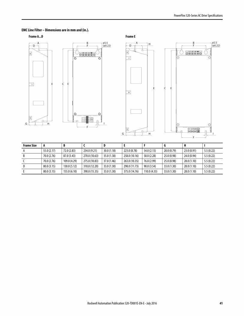
PowerFlex 520-Series AC Drive Specifications
EMC Line Filter – Dimensions are in mm and (in.).
Frame Size A B C D E F G H IA 55.0 (2.17) 72.0 (2.83) 234.0 (9.21) 30.0 (1.18) 223.0 (8.78) 54.0 (2.13) 20.0 (0.79) 23.0 (0.91) 5.5 (0.22)B 70.0 (2.76) 87.0 (3.43) 270.0 (10.63) 35.0 (1.38) 258.0 (10.16) 58.0 (2.28) 25.0 (0.98) 24.0 (0.94) 5.5 (0.22)C 70.0 (2.76) 109.0 (4.29) 275.0 (10.83) 37.0 (1.46) 263.0 (10.35) 76.0 (2.99) 25.0 (0.98) 28.0 (1.10) 5.5 (0.22)D 80.0 (3.15) 130.0 (5.12) 310.0 (12.20) 33.0 (1.30) 298.0 (11.73) 90.0 (3.54) 33.0 (1.30) 28.0 (1.10) 5.5 (0.22)E 80.0 (3.15) 155.0 (6.10) 390.0 (15.35) 33.0 (1.30) 375.0 (14.76) 110.0 (4.33) 33.0 (1.30) 28.0 (1.10) 5.5 (0.22)
AD
E
G H
AD
E
G H
H BF
F
C E
I
ø5.5(ø0.22)
B
C E
F
FI
ø5.5(ø0.22)
BLACK BLACK
L1 L2 L3BLACK
YELLOW&
GREEN
Frame A...D Frame E
Rockwell Automation Publication 520-TD001E-EN-E - July 2016 41

PowerFlex 520-Series AC Drive Specifications
Safe-Torque-Off Function
The PowerFlex 525 Safe-Torque-Off function, when used with other safety components, helps provide protection according to EN ISO 13849 and EN62061 for safe-off and protection against restart. The PowerFlex 525 Safe-Torque-Off function is just one component in a safety control system. Components in the system must be chosen and applied appropriately to achieve the desired level of operator safeguarding.
PowerFlex 525 Safe-Torque-Off Overview
The PowerFlex 525 Safe-Torque-Off function:• Provides the Safe-Torque-Off (STO) function defined in EN IEC 61800-5-2.• Blocks gate-firing signals from reaching the Insulated Gate Bipolar Transistor (IGBT) output devices of the drive.
This prevents the IGBTs from switching in the sequence necessary to generate torque in the motor.• Can be used in combination with other safety devices to fulfill the requirements of a system “safe torque off ”
function which satisfies Category 3 / PL (d) according to EN ISO 13849-1 and SIL CL2 according to EN 62061, IEC 61508, and EN 61800-5-2.
EC Type Examination Certification
TÜV Rheinland has certified the PowerFlex 525 Safe-Torque-Off function compliant with the requirements for machines defined in Annex I of the EC Directive 2006/42/EC, and that it complies with the requirements of the relevant standards listed below:
• EN ISO 13849-1 Safety of machinery – Safety related parts of control systems – Part 1: General principles for design. (PowerFlex 525 STO achieves Category 3 / PL(d))
• EN 61800-5-2 Adjustable speed electrical power drive systems – Part 5-2 Safety requirements – Functional. (PowerFlex 525 STO achieves SIL CL 2)
• EN 62061 Safety of machinery – Functional safety of safety-related electrical, electronic and programmable electronic control systems.
• IEC 61508 Part 1-7 Functional safety of electrical/electronic/programmable electronic safety-related systems – Parts 1-7.
TÜV also certifies that the PowerFlex 525 STO may be used in applications up to Category 3/ PL(d) according to EN ISO 13849-1 and SIL 2 according to EN 62061 / EN 61800-5-2 / IEC 61508.
The TÜV Rheinland certificate may be found at http://www.rockwellautomation.com/products/certification/.
IMPORTANT The function is suitable for performing mechanical work on the drive system or affected area of a machine only. It does not provide electrical safety.
42 Rockwell Automation Publication 520-TD001E-EN-E - July 2016

PowerFlex 520-Series AC Drive Specifications
Safety Concept
The PowerFlex 525 Safe-Torque-Off function is suitable for use in safety applications up to and including Category 3 / PL(d) according to EN ISO 13849-1 and SIL 2 according to EN 62061 / EN 61800-5-2 / IEC 61508.
In addition, the PowerFlex 525 STO function may be used together with other components in a safety application to achieve an overall Category 3 / PL(e) according to EN ISO 13849-1 and SIL 3 according to EN 62061 and IEC 61508. This is illustrated in Example 3 on page 46.
Safety requirements are based on the standards current at the time of certification.
The PowerFlex 525 STO function is intended for use in safety-related applications where the de-energized state is considered to be the safe state. All of the examples shown here are based on achieving de-energization as the safe state for typical Machine Safety and Emergency Shutdown (ESD) systems.
PFD and PFH Data
PFD and PFH calculations are based on the equations from Part 6 of EN 61508.
This table provides data for a 20-year proof test interval and demonstrates the worst-case effect of various configuration changes on the data.
Safety Reaction Time
The safety reaction time from an input signal condition that triggers a safe stop, to the initiation of the configured Stop Type, is 100 ms (maximum).
PFD and PFH for 20-year Proof Test Interval
Attribute ValuePFD 6.62E-05 (MTTF = 3593 years)PFHD 8.13E-10SFF 83%DC 62.5%CAT 3HFT 1 (1oo2)PTI 20 YEARSHardware Type Type A
Rockwell Automation Publication 520-TD001E-EN-E - July 2016 43

PowerFlex 520-Series AC Drive Specifications
Connection Examples
Example 1 – Safe-Torque-Off Connection with Coast-to-Stop Action, SIL 2/PL d
(1) Enclosure Recommended. Note: External wiring failure modes must be considered as described in EN ISO 13849-2. Enclosure or other measure to exclude these failure modes should be used.(2) In some situations, a safety relay is not required if both the switch and PowerFlex 525 are installed in the same enclosure.
Stop
StartA1 S21 S11 S52 41 13 23 33
A2
24V DCcommon
+24V DC
S22 S14 S34 42 14 24 34
MSR
GuardMasterTrojanGate
E-Stoplatchingbutton
+24V DC
PF 525
Stop
Start
Gate controlpower supply
Gate controlcircuit
AC lineinput power
S1
S2
M
(1)
Stop
Start
GuardMasterTrojanGate
E-Stoplatchingbutton
+24V DC
PF 525
Stop
Start
Gate controlpower supply
Gate controlcircuit
AC lineinput power
S1
S2
M
(2)
Stop Category 0 – Coast
44 Rockwell Automation Publication 520-TD001E-EN-E - July 2016

PowerFlex 520-Series AC Drive Specifications
(1) Enclosure Recommended. Note: External wiring failure modes must be considered as described in EN ISO 13849-2. Enclosure or other measure to exclude these failure modes should be used.(2) Each safety input draws 6 mA from the supply.
Example 2 – Safe-Torque-Off Connection with Controlled Stop Action, SIL 2/PL d
(1) Enclosure Recommended. Note: External wiring failure modes must be considered as described in EN ISO 13849-2. Enclosure or other measure to exclude these failure modes should be used.
Stop
Start
+24V DC
PF 525
Stop
Start
Dig. comm
Gate controlpower supply
Gate controlcircuit
AC lineinput power
S1
S2
M
Stop
Start
+24V DC
PF 525
Stop
Start
Dig. comm
Gate controlpower supply
Gate controlcircuit
AC lineinput power
S1
S2
M
(1)
(2)
(2)
S11
S21
S12
S22
13
14
23
24
L11
A1
S34
L12
A2
SI
24V DC Supply
24V DC COM
E-Stop
Y32
0
AM
MM
Reset
Reset
Stop Category 0 – Coast with Two PowerFlex 525 Drives
24V DCCommon
+24V DC
GuardMasterTrojan
Stop
Start
A1 S21 S11 S52 S12
A2 X1 X2
13 23
14 24
S33
Y2
S34
Y1X3
37 47 57
38 48 58X4
S22
Y39 Y40
MinotaurMSR138DP
Gate+24V DC
PF 525
Stop
Start
Gate controlpower supply
Gate controlcircuit
AC lineinput power
S1
S2
M
(1)
Stop Category 1– Controlled
Rockwell Automation Publication 520-TD001E-EN-E - July 2016 45
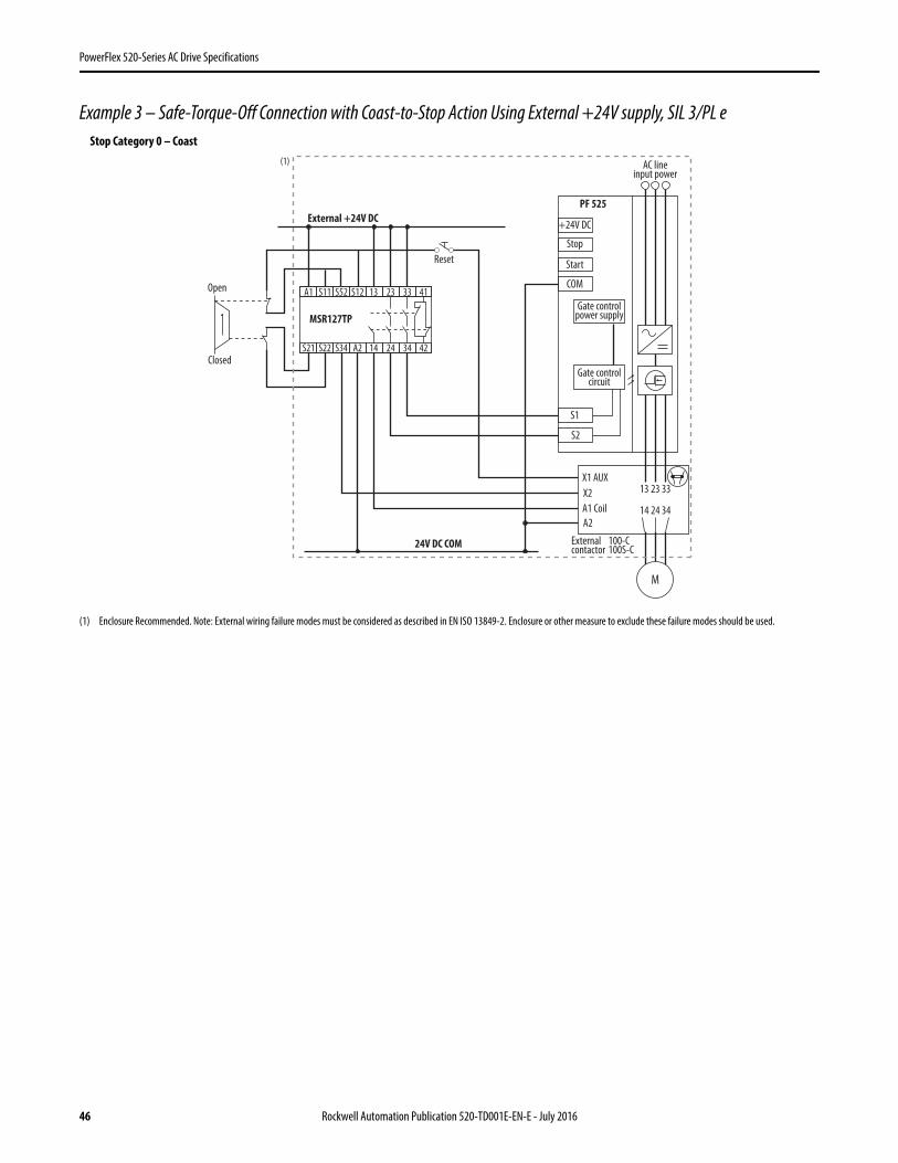
PowerFlex 520-Series AC Drive Specifications
Example 3 – Safe-Torque-Off Connection with Coast-to-Stop Action Using External +24V supply, SIL 3/PL e
(1) Enclosure Recommended. Note: External wiring failure modes must be considered as described in EN ISO 13849-2. Enclosure or other measure to exclude these failure modes should be used.
Closed
Open
External +24V DC
24V DC COM
MSR127TP
Reset
+24V DC
PF 525
Stop
Start
COM
Gate controlpower supply
Gate controlcircuit
AC lineinput power
S1
S2
X1 AUX
X2
A1 Coil
A2
Externalcontactor
100-C100S-C
13 23 33
14 24 34
M
A1 S11 S52 S12 13 23 33 41
S21 S22 S34 A2 14 24 34 42
(1)
Stop Category 0 – Coast
46 Rockwell Automation Publication 520-TD001E-EN-E - July 2016

PowerFlex 520-Series AC Drive Specifications
Additional Resources
These documents contain additional information concerning related products from Rockwell Automation.
You can view or download publications at http://www.rockwellautomation.com/literature/. To order paper copies of technical documentation, contact your local Allen-Bradley distributor or Rockwell Automation sales representative.
Title PublicationPowerFlex 520-Series Adjustable Frequency AC Drive User Manual 520-UM001 PowerFlex 4-Class Human Interface Module (HIM) DSI Quick Reference 22HIM-QR001 PowerFlex 525 Embedded EtherNet/IP Adapter User Manual 520COM-UM001 PowerFlex 25-COMM-D DeviceNet Adapter User Manual 520COM-UM002 PowerFlex 25-COMM-E2P EtherNet/IP Adapter User Manual 520COM-UM003 PowerFlex 25-COMM-P PROFIBUS DP Adapter User Manual 520COM-UM004 Dynamic Braking Resistor Calculator PFLEX-AT001 Wiring and Grounding Guidelines for PWM AC Drives DRIVES-IN001 Preventive Maintenance of Industrial Control and Drive System Equipment DRIVES-TD001 Safety Guidelines for the Application, Installation and Maintenance of Solid State Control SGI-1.1
Rockwell Automation Publication 520-TD001E-EN-E - July 2016 47

Allen-Bradley, Rockwell Software, Rockwell Automation, PowerFlex, Connected Components Workbench, Studio 5000, DriveTools SP, AppView, CustomView, QuickView, MainsFree Programming, and PointStop are trademarks of Rockwell Automation, Inc.
Trademarks not belonging to Rockwell Automation are property of their respective companies.
Publication 520-TD001E-EN-E - July 2016 Supersedes Publication 520-TD001D-EN-E – January 2014 Copyright © 2016 Rockwell Automation, Inc. All rights reserved.
Power, Control and Information Solutions HeadquartersAmericas: Rockwell Automation, 1201 South Second Street, Milwaukee, WI 53204-2496 USA, Tel: (1) 414.382.2000, Fax: (1) 414.382.4444Europe/Middle East/Africa: Rockwell Automation NV, Pegasus Park, De Kleetlaan 12a, 1831 Diegem, Belgium, Tel: (32) 2 663 0600, Fax: (32) 2 663 0640Asia Pacific: Rockwell Automation, Level 14, Core F, Cyberport 3, 100 Cyberport Road, Hong Kong, Tel: (852) 2887 4788, Fax: (852) 2508 1846
www.rockwel lautomation.com
Important Information
Solid-state equipment has operational characteristics differing from those of electromechanical equipment. Safety Guidelines for the Application, Installation and Maintenance of Solid State Controls (publication SGI-1.1 available from your local Rockwell Automation sales office or online at http://www.rockwellautomation.com/literature/) describes some important differences between solid-state equipment and hard-wired electromechanical devices. Because of this difference, and also because of the wide variety of uses for solid-state equipment, all persons responsible for applying this equipment must satisfy themselves that each intended application of this equipment is acceptable.
In no event will Rockwell Automation, Inc. be responsible or liable for indirect or consequential damages resulting from the use or application of this equipment.
The examples and diagrams in this publication are included solely for illustrative purposes. Because of the many variables and requirements associated with any particular installation, Rockwell Automation, Inc. cannot assume responsibility or liability for actual use based on the examples and diagrams.
No patent liability is assumed by Rockwell Automation, Inc. with respect to use of information, circuits, equipment, or software described in this manual.
Reproduction of the contents of this manual, in whole or in part, without written permission of Rockwell Automation, Inc., is prohibited.
Documentation Feedback
Your comments will help us serve your documentation needs better. If you have any suggestions on how to improve this document, complete this form, publication RA-DU002, available at http://www.rockwellautomation.com/literature/.

PowerFlex® 4-Class HIM (DSI) Quick ReferenceHuman Interface Modules (HIM)
Display Descriptions
22-HIM-A3 — IP20 (NEMA Type 1) 22-HIM-C2S — IP66 (NEMA Type 4X/12)
Display➊ Status Line: Direction | Operating Status | Drive Status | Auto/Manual Mode | Parameters Locked/Unlocked
➋ Process Display screen:• Output Frequency• User Display Line 1 (HIM Parameter 04)• User Display Line 2 (HIM Parameter 05)
➌ Programming screen
➍ Menu Navigation Tabs
➎ Large Format User Display screen:
SelEscEsc
7 8 9
4 5 6
1 2 3
. 0 +/-
Sel
Jog
Alt
Param #
View Lang Remove
DSI
Esc Sel
ALTLANG
DISP
Jog
|
DSI
REMOVE
Esc Sel
ALT
LANG DISP
Jog
|
DSI
SELDIAG DSEL MEM
Changed ParamsLinear List
ParametersGroups
PARAM
HzAV
F Stopped Auto
Hz
F At Reference Auto
Output Freq
➍
➎
➊
➋
➌
Esc
7 8 9
4 5 6
1 2 3
. 0 +/-
Sel
Jog
Alt
Param #
View Lang Remove
DSI
HzAV
F Stopped Auto

Key Descriptions
Menu Navigation Tabs
Keys DescriptionExit a menu, cancel a change to a parameter value, or acknowledge a fault/alarm.
Select a digit, select a bit, or select a menu tab.
Scroll through options, increase a value, or toggle a bit.
Scroll through options, decrease a value, or toggle a bit.
Enter a menu, enter edit mode in a parameter screen, or save a change to a parameter value.
plus…Toggle between the Process Display and Large Format Display.
Select an available language for text displayed on HIM screens.
Allow the HIM to be disconnected without causing a fault condition.
Enable direct parameter number entry.
Start the drive.
Stop the drive or clear a fault.
Change direction.
Jog the drive.
Type parameter numbers and values.
Increase or decrease the speed Reference to the drive after these keys are enabled by setting drive parameter P038 - [Speed Reference] as follows:• When the HIM is the DSI Master, set parameter P038 to “5” (Comm Port).• When the HIM is the DSI Slave, set parameter P038 to “1” (Internal Freq).To view the HIM’s active device type status (Master or Slave), see HIM Parameter 10 - [M/S Status].
Tabs DescriptionDIAG The Diagnostics tab is used to display faults, the device (drive or peripheral) status, and device version.PARAM The Parameters tab is used to edit parameters. Parameters can be displayed in groups, in a linear list,
or only those changed from their defaults.DSEL The Device Select tab is used to select the device (drive or peripheral) that the HIM is to access.MEM The Memory Storage tab is used for HIM CopyCat (uploading/downloading configurations to the HIM
EEPROM).HIM The HIM Setup tab is used to access HIM parameters, view the HIM version, and to edit the Reference
text when a user-defined Reference is used.
Esc
Sel
AltSel
View
Lang
Remove
+/-Param #
Jog
...0 9
. +/-

Parameter List ParameterNo. Name and Description Details01 [Startup Display]
Selects the display screen shown when the HIM is powered up.Default: 0 = Main MenuValues 0 = Main Menu
1 = Process Disp2 = Large Disp3 = Startup Param
Type: Read/Write02 [Startup Param]
Selects a desired drive parameter to be displayed if Parameter 01 - [Startup Display] is set to “3” (Startup Param).
Default: 1Minimum: 1Maximum: 65535Type: Read/Write
03 Reserved04 [User Disp Line 1]
Selects a desired drive parameter to be displayed on User Display Line 1 of the Process Display screen.For example, setting to “3” selects PowerFlex 4-Class drive Parameter 3 - [Output Current] to be displayed.
Default: 3Minimum: 1Maximum: 65535Type: Read/Write
05 [User Disp Line 2]Selects a desired drive parameter to be displayed on User Display Line 2 of the Process Display screen.For example, setting to “5” selects PowerFlex 4-Class drive Parameter 5 - [DC Bus Voltage] to be displayed.
Default: 5Minimum: 1Maximum: 65535Type: Read/Write
06 [Large Disp Param]Selects a desired drive parameter to be displayed on the Large Format User Display screen.For example, setting to “1” selects PowerFlex 4-Class drive Parameter 1 - [Output Freq] to be displayed. Setting to “0” enables the Scaled Reference to be displayed.
Default: 1Minimum: 0Maximum: 65535Type: Read/Write
07 [LCD Contrast]Sets the HIM LCD contrast level.
Default: 50%Minimum: 0%Maximum: 100%Type: Read/Write
08 [Reset HIM]1 (Reset): Resets the HIM.2 (Set Defaults): Resets HIM parameters to factory settings.This parameter returns to a value of “0” (Ready) after the reset function is complete.
Default: 0 = ReadyValues 0 = Ready
1 = Reset2 = Set Defaults
Type: Read/Write
09 [Device Type]Selects the HIM device type. When set to “0” (Auto), the HIM is automatically configured as either a DSI Master or Slave depending on the presence of other peripheral devices.
Default: 0 = AutoValues 0 = Auto
1 = Slave2 = Master
Type: Read/Write10 [M/S Status]
Displays the HIM active device type.Default: N/AValues 1 = Slave
2 = MasterType: Read Only
11 [HIM Ref Preset]0 (Zero Start): HIM Reference is always “0.0” at power on.1 (Host Output): HIM will assume the Host’s output feedback
(bumpless transfer) and preset its Reference when the Reference is configured to be received on the RS-485 port. This can be verified by viewing Diagnostics/Device Status/Remote Freq Ref = 1.
2 (Last HIM Ref): HIM will store the HIM Reference in EEPROM each time it is changed. HIM Reference is restored at power on.
Default: 0 = Zero StartValues 0 = Zero Start
1 = Host Output2 = Last HIM Ref
Type: Read/Write

NOTE: New settings to HIM parameters are implemented immediately. Resetting the HIM is not required for new values to take effect.
12 [Ref Scaling]
Enables or disables scaling the Reference to a user-defined value. When Parameter 12 - [Ref Scaling] is set to “1” (Enabled), use HIM Parameters 13…22 to scale the Reference.
Default: 0 = DisabledValues: 0 = Disabled
1 = EnabledType: Read/Write
13 [Ref Max Value]Sets the user-defined value to be displayed when the drive is running at 60 Hz.
Default: 600Minimum: 100Maximum: 65535Type: Read/Write
14 [Ref Dec Position]Sets the number of digits to be displayed to the right of the decimal point for the Reference.
Default: 1Minimum: 0Maximum: 3Type: Read/Write
1516171819202122
[Ref Units Char 1][Ref Units Char 2][Ref Units Char 3][Ref Units Char 4][Ref Units Char 5][Ref Units Char 6][Ref Units Char 7][Ref Units Char 8]Selects up to 8 characters (from the ISO 8859-1 character set) to use for the Reference units on the Process Display.Parameters 15…22 can also be configured using the “Edit Ref Text” selection in the HIM Setup tab.
Default: 72 (“H”)Default: 122 (“z”)Default: 32 (blank - no character)Default: 32 (blank - no character)Default: 32 (blank - no character)Default: 32 (blank - no character)Default: 32 (blank - no character)Default: 32 (blank - no character)
Minimum: 32Maximum: 255Type: Read/Write
23 [Fault Dspy Type]Selects the type of display flash to be shown when a drive or peripheral fault is detected.
Default: 0 = Flash BkliteValues: 0 = Flash Bklite
1 = Flash NoneType: Read/Write
24 [Alarm Dspy Type]Selects the type of display flash to be shown when a drive alarm is detected.
Default: 1 = Flash NoneValues: 0 = Flash Bklite
1 = Flash NoneType: Read/Write
ParameterNo. Name and Description Details
www.rockwellautomation.com
Americas: Rockwell Automation, 1201 South Second Street, Milwaukee, WI 53204-2496 USA, Tel: (1) 414.382.2000, Fax: (1) 414.382.4444Europe/Middle East/Africa: Rockwell Automation, Vorstlaan/Boulevard du Souverain 36, 1170 Brussels, Belgium, Tel: (32) 2 663 0600, Fax: (32) 2 663 0640Asia Pacific: Rockwell Automation, Level 14, Core F, Cyberport 3, 100 Cyberport Road, Hong Kong, Tel: (852) 2887 4788, Fax: (852) 2508 1846
Power, Control and Information Solutions Headquarters
U.S. Allen-Bradley Drives Technical SupportTel: (1) 262.512.8176, Fax: (1) 262.512.2222, Email: [email protected], Online: www.ab.com/support/abdrives
Publication 22HIM-QR001F – September 2009Supersedes 22HIM-QR001E-EN-P – April 2005 Copyright © 2009 Rockwell Automation, Inc. All rights reserved. Printed in USA.


Manual Oxine Dilution & Use
Useful figures to have available if you are diluting Oxine manually without a titration kit. These figures are applicable with Oxine that has been activated within 48 hours of dilution with a food grade acid at 2.5 to 3 pH . For keg sanitizing and use with the Super King, Mini King or Squire series machines: It is recommended that you start by using approximately 100 ppm of activated Oxine for keg sanitizing until you can determine through your own QC procedures whether you need to increase or decrease the amount based upon microbial results obtained. Experience indicates that normal usage will be in the range of 20 to 100 ppm. 1. Take a one gallon container with a screw lid and drill a hole in the cap to suit the dosing unit siphon tube. 2. Take 0.6 liter (20 ounces) of Oxine, add food grade acid to lower the pH to approximately 2.5 to 3.0 pH to activate the Oxine and stir. This will give you approximately 20,000 ppm of activated Oxine. CAUTION – Do so in a well ventilated area and do NOT breathe the fumes given off during activation. See the MSDS in this section for more details. 3. When activated (after 5 to 10 minutes) add 3 liters (101 ounces) of water to the activated Oxine (5:1 ratio). This will give you approximately 4,000 ppm of activated Oxine. Stir and replace cap with siphon tube into Oxine. 4. Using the chart supplied with the Oxine doser venturi kit select the colored venturi that will then give you a 40:1 reduction ratio. This will give you approximately 100 ppm of activated Oxine being supplied as your rinse and sanitizing water to the keg for pre and post rinse. 5. This can be verified with the Oxine test kit or Oxystix attainable from IDD Process & Packaging, Inc.

Other ratios of Oxine for general sanitizing purposes One unit of manually activated Oxine at 20,000ppm and you: Add 1 unit of water, the concentration reduces to 10000ppm – Ratio of water to Oxine 1:1. Add a further 2 units of water, the concentration reduces to 5000ppm – Ratio of water to Oxine 3:1. Add a further 4 units of water, the concentration reduces to 2500ppm – Ratio of water to Oxine7:1. Add a further 8 units of water, of the concentration reduces to 1250ppm – Ratio of water to Oxine 15:1. Add a further 16 units of water, the concentration reduces to 625ppm – Ratio of water to Oxine 31:1. Add a further 32 units of water, the concentration reduces to 312.5ppm – Ratio of water to Oxine 63:1. Add a further 64 units of water, the concentration reduces to 156.5ppm – Ratio of water to Oxine 127:1. Add a further 128 units of water, the concentration reduces to 78ppm – Ratio of water to Oxine 255:1. Add a further 256 units of water, the concentration reduces to 39ppm – Ratio of water to Oxine 511:1. Add a further 512 units of water, the concentration reduces to 19.5ppm – Ratio of water to Oxine 1023:1. Add a further 1024 units of water, the concentration reduces to 9.5ppm – Ratio of water to Oxine 2047:1. Add a further 2048 units of water, the concentration reduces to 5ppm – Ratio of water to Oxine 4095:1. Add a further 4096 units of water, the concentration reduces to 2.5ppm – Ratio of water to Oxine 8191:1. Add a further 8192 units of water, the concentration reduces to 1.25ppm – Ratio of water to Oxine 16382:1.

OXINE & PUROGENE SANITIZER
PROCESS & PACKAGING, INC. ©2003
The following information is offered as suggested uses of Oxine and Purogene and is
not intended to be definitive or accurate for all applications. IDD Process & Packaging, Inc. do not accept any liability for the use or application of Oxine or Purogene. OXINE AND PUROGENE...THE SANITIZERS FOR ALL REASONS. For years it has
been known that chlorine dioxide gas is a powerful anti-microbial agent. However, this gas is toxic and unstable in an aqueous solution. Modern technology has overcome these problems with Oxine and Purogene. Today, stabilized chlorine dioxide (ClO2) is available in a concentrated stable form with very low toxicity. As a powerful oxidant, stabilized ClO2 is virtually unaffected by organic load and hard water. These technical advances have resulted in the FDA, EPA and USDA approving stabilized ClO2 as an acceptable sterilant for numerous applications within the brewery, dairy and food processing plants. Properties which make stabilized ClO2 most attractive to the brewer, maltster and other beverage plant operators are: LOW ODOR - Unlike typical sanitizers such a hypochlorites, quaternary ammonium, or
even peroxy-acetic acid, stabilized ClO2 has an almost undetectable odor while surpassing the bacteriocidal efficacy of these other compounds. Hypochlorites can form chlorophenols (a medicinal flavor compound) when combined with organic material in beer: Quaternary ammonia compounds have well known negative effects on flavor; the end product of the reduction of peroxy-acetic acid is acetic acid, with its typically "vinegar-like" character. Even small amounts remaining in a tank and having the opportunity of coming in contact with beer, can have a deleterious effect on beer flavor. LOW CORROSIVITY - Stabilized ClO2 is not harmful to vessels or piping systems
when used at the recommended dosages. Typically, brewers like the effectiveness of hypochlorites but a major drawback is hypochlorites role in causing stress corrosion fatigue in stainless steel, particularly at weld joints. Stabilized ClO2 while actually being 4 to 7 times more effective as a sanitizer than hypochlorite, does not enhance or contribute to “stress corrosion fatigue” in the metal. Stabilized ClO2 is only slightly more corrosive than tap water at and much of this is due to the acid used in the activation of the product. When it is used as a final rinse in vessels, or piping systems, it is perfectly safe to leave a 10 ppm solution un-rinsed in a tank, pipe network or piece of process equipment, (i.e. bottle fillers, keg racking machines, sheet or pressure leaf filters, etc.). EASE OF HANDLING - While idophors, peroxy-acetic acid and hypochlorites are
popular sanitizers for tanks, fillers and other equipment, they have some handling drawbacks. Iodophors are really only effective at low pH, thus they are typically carried as a concentrate in a solution of phosphoric or nitric acid. This makes them hazardous to handle. Iodophors also have a tendency to stain equipment (and people). Pereoxy-

OXINE & PUROGENE SANITIZER
PROCESS & PACKAGING, INC. ©2003
acetic acid is actually quite volatile at moderately elevated temperatures (120_F/50_C) and can cause spontaneous explosions. It is also corrosive in its concentrated form. Hypochlorites as chlorine gas have a short-term exposure limit slightly higher than that of stabilized ClO2 (1.0 ppm versus 0.3 ppm respectively). However, since stabilized ClO2 is 4 to 7 times more effective than hypochlorites at normal use levels, it is less hazardous. NO ENVIRONMENTAL IMPACT - Stabilized ClO2 does not form the highly
carcinogenic trihalomethanes as do hypochlorites in the presence of organic materials. Oxine is environmentally and user friendly and has been accepted by the EPA has having no environmental impact upon disposal. It is not corrosive nor is it volatile in its concentrated (2%) form. EFFICACY - Stabilized ClO2 does not act by chlorination but by oxidation and has
proven effective against all common brewery, winery and beverage plant micro-organisms. It is an effective bacteriostat at use rates as low as 5 to 20 ppm against such common pests as Lactobacillus and Pediococcus sp. and at 50 ppm against Wild Yeasts and Mold strains. As with all gaseous products such as stabilized ClO2, Oxine can be monitored by
using a standard gas monitoring system such as those supplied by LAB SAFETY SUPPLIES COMPANY. Toll free telephone number 800-356-0722. It is necessary to take extra care with good ventilation during the "activation" process of Oxine. If it is considered necessary to monitor gas levels at this time for your safety records, we recommend that the chlorine "low range" (0.05 to 16ppm) tube be used to monitor gas levels. These tubes readily detect and measure all types of inorganic chlorine. MALTHOUSE: Stabilized ClO2 is an effective wash down sanitizer for walls and floors, germination
areas and steep tanks. At 100 to 500 ppm it will kill and bleach out mold and mildew common to these high-humidity areas. Stabilized ClO2 is successfully used in barley steep waters to inhibit microbial growth of all types. Typically at 10 to 50 ppm depending on the microbial load, one can assure a safe re-cyling of the steep water into subsequent batches. Stabilized ClO2's strong oxidizing capability actually reduces B.O.D. loads for disposal. BREWHOUSE: Safe for all vessels and piping systems, whether copper or stainless steel, stabilized
ClO2 can ensure a microbially free environment in coppers/kettles, mash filters or lauter tuns, swirl tanks, settlers and wort cooling systems when used at 50 to 100 ppm. The related piping systems for wort transfer to fermentation areas can be sanitized at 100 ppm. A 50 ppm solution is also safe to leave in the pipelines during periods of non-use, to keep them sanitized.
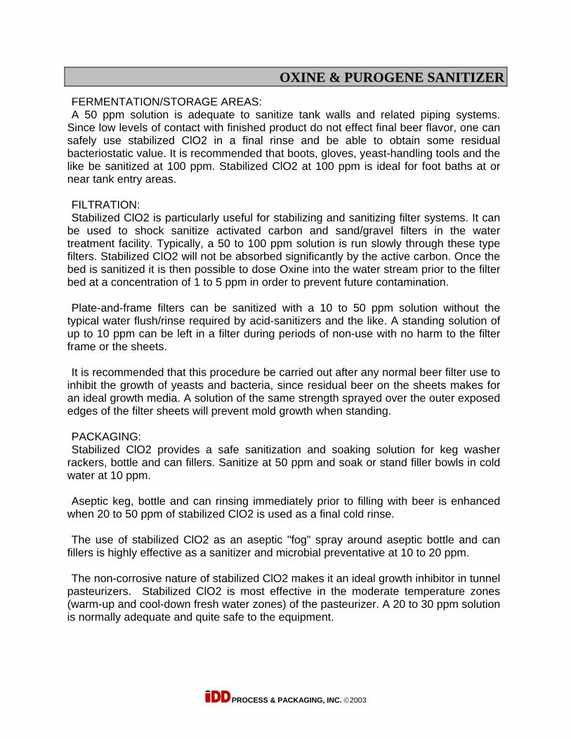
OXINE & PUROGENE SANITIZER
PROCESS & PACKAGING, INC. ©2003
FERMENTATION/STORAGE AREAS: A 50 ppm solution is adequate to sanitize tank walls and related piping systems.
Since low levels of contact with finished product do not effect final beer flavor, one can safely use stabilized ClO2 in a final rinse and be able to obtain some residual bacteriostatic value. It is recommended that boots, gloves, yeast-handling tools and the like be sanitized at 100 ppm. Stabilized ClO2 at 100 ppm is ideal for foot baths at or near tank entry areas. FILTRATION: Stabilized ClO2 is particularly useful for stabilizing and sanitizing filter systems. It can
be used to shock sanitize activated carbon and sand/gravel filters in the water treatment facility. Typically, a 50 to 100 ppm solution is run slowly through these type filters. Stabilized ClO2 will not be absorbed significantly by the active carbon. Once the bed is sanitized it is then possible to dose Oxine into the water stream prior to the filter bed at a concentration of 1 to 5 ppm in order to prevent future contamination. Plate-and-frame filters can be sanitized with a 10 to 50 ppm solution without the
typical water flush/rinse required by acid-sanitizers and the like. A standing solution of up to 10 ppm can be left in a filter during periods of non-use with no harm to the filter frame or the sheets. It is recommended that this procedure be carried out after any normal beer filter use to
inhibit the growth of yeasts and bacteria, since residual beer on the sheets makes for an ideal growth media. A solution of the same strength sprayed over the outer exposed edges of the filter sheets will prevent mold growth when standing. PACKAGING: Stabilized ClO2 provides a safe sanitization and soaking solution for keg washer
rackers, bottle and can fillers. Sanitize at 50 ppm and soak or stand filler bowls in cold water at 10 ppm. Aseptic keg, bottle and can rinsing immediately prior to filling with beer is enhanced
when 20 to 50 ppm of stabilized ClO2 is used as a final cold rinse. The use of stabilized ClO2 as an aseptic "fog" spray around aseptic bottle and can
fillers is highly effective as a sanitizer and microbial preventative at 10 to 20 ppm. The non-corrosive nature of stabilized ClO2 makes it an ideal growth inhibitor in tunnel
pasteurizers. Stabilized ClO2 is most effective in the moderate temperature zones (warm-up and cool-down fresh water zones) of the pasteurizer. A 20 to 30 ppm solution is normally adequate and quite safe to the equipment.

OXINE & PUROGENE SANITIZER
PROCESS & PACKAGING, INC. ©2003
TANK-TRUCK WASHING: As in the typical use for tank washing and sanitizing, stabilized ClO2 can be used for
the sanitization and cleanup of bulk tankers and their related piping and hoses. Wash down tank internals, pumps and hoses at 100 ppm, externals at 250 to 500 ppm. This will prevent transfer of micro-organisms to or from the connecting systems. MOLD AND MILDEW CLEANUP AND CONTROL: Clean off walls and floors as well as air handling units and machinery using a 200 to
500 ppm solution of stabilized ClO2. This effectively kills mold and mildew spores while still retaining some bleaching ability to remove tough black stains. This is good procedure prior to painting, or prior to the application of a mold and slime growth inhibitor such as Alltech's Mold-Zap. PROCESS WATER TREATMENT: The FDA has approved stabilized ClO2 for process water sanitization at between 100
to 200 ppm available ClO2. Potable water treatment is approved for human consumption at 4 ppm available ClO2. ACTIVE CARBON BED (ACB): Infected ACB's can be back flushed and soaked in a 100 ppm solution of ClO2 for 15
to 60 minutes, after which time a forward flush-out of 15 to 30 minutes with the process water can take place. It is then advisable to inject 1 to 3 ppm of activated ClO2 into the process water stream thereafter prior to the ACB to prevent future infections. GLASS WASHING/RINSING: Even at the final stage of the brewer's trade, where bars and pubs have a need for an
effective and safe drinking-glass sanitizer, stabilized ClO2 can fill the need. Since stabilized ClO2 can be safely consumed at 4 ppm, it makes an ideal glass rinse. Unlike typical quaternary ammonium rinses, it will not have any deleterious effect on beer flavor, nor on beer foam quality. Use at 20 to 50 ppm in final rinse water. WASHING OF YEAST SLURRY WITH STABILIZED ClO2 (OXINE): Stabilized ClO2 (Oxine) will effectively kill unwanted bacteria in yeast at 20 to 40 ppm,
while leaving the culture yeast unharmed. Because of stabilized ClO2's unique action, it does not have the drawbacks of phosphoric acid. It does not form chlorophenols (which contribute to a much feared medicinal character in beers) in the presence of organic materials. METHOD: Normally, an initial washing at 20 to 40 ppm (20 ppm for homogenous yeast, 40 ppm
for "clumpy" or highly flocculant strains) is effective against most Lactobacilli and Pediococci species. This "wash" is done by adding stabilized ClO2 directly to yeast slurry on a volume/ppm basis. It does not need to be activated as the pH of the yeast slurry is low enough to convert to ClO2.

OXINE & PUROGENE SANITIZER
PROCESS & PACKAGING, INC. ©2003
Stabilized ClO2 is supplied at a concentration of 20,000 ppm or 2% Chlorine Dioxide
when activated. Therefore, on a volume basis, one could essentially make up with one gallon of stabilized ClO2 concentrate, one thousand gallons of solution at 20 ppm. By this method, we can also assume with one gallon of concentrate to make up one thousand gallons of yeast slurry at 20 ppm. It is impractical to measure the concentration of ClO2 in the presence of yeast, so the dilution must be made based on the strength of the concentrate (20,000 ppm). Yeast slurry should be thin enough to allow for homogeneous mixing, usually 20 to
40% solids. The killing action of stabilized ClO2 is very fast compared to the traditional phosphoric acid wash. Only 15 to 30 minutes need be allowed for effective bactericidal effect of stabilized ClO2, with no resultant stress on yeast cells. DOSING RATE: NORMAL WASH: For regular washing of homogenous recycled brewers yeast, a 20
to 40 ppm wash for a minimum 30 minutes to 5 hours prior to pitching. Mix 1 to 2 ml of stabilized ClO2 concentrate with each liter of yeast slurry. Agitate thoroughly during the process. ACTIVATION OF CONCENTRATE: Since the ClO2 is in a stabilized form in concentrate, it must be "activated" before
using. To activate Oxine add acid to lower the pH in a well ventilated area to below 5 pH. Activation can be verified by a corresponding color change of the concentrate from clear to yellow/green. Any number of acids will activate the stabilized ClO2, however, food grade Citric or Phosphoric acid is recommended for this application. Normally it requires up to 200 grams of Citric Acid to activate one gallon of stabilized
ClO2 concentrate (up to 50 grams per liter of stabilized ClO2 concentrate). Following are the details for replacement chemicals for your Oxine Test Kits. 10% Potassium Iodide - 100 g diluted to 1,000 ml with distilled water. 0.2N Hydrochloric Acid - Add 16.6 ml Concentrated HCL (39%) to 800 ml water. Bring
to 1,000 ml with water. 0.00564N PAO (Phenylarsine Oxide). Oxine is available from IDD in 1, 5, 30, 55 gallon and tote containers. Test kits and
replacement materials can also be purchased from IDD.
OXINE & PUROGENE SANITIZER
PROCESS & PACKAGING, INC. ©2003
STORAGE: Concentrated ClO2 can be stored in a dry area away from acids for up to 3 years
under standard conditions. Activated ClO2 has a half-life of approximately 48 hours under standard conditions. Activated ClO2 can be added to cold water at 4,000 ppm. Under such conditions a
half-life of up to 2 weeks is possible under standard conditions. AUTOMATIC ACTIVATION SYSTEMS: A series of low cost, hands free, automated activation systems are available to provide
a continuous volume of activated ClO2 into a storage reservoir as needed. These systems eliminate the need for manual mixing, measuring and dispensing.

INTERNATIONAL, INC.
MATERIAL SAFETY DATA SHEETI
SECTION 1: CHEMICAL PRODUCT AND COMPANY IDENTIFICATION
PRODUCT NAMEOxine®
CHEMICAL FAMILYMixture of Oxychlorine Compounds
MANUFACTURERBio-Cide International, Inc., 2845 Broce Drive, Norman, OK 73072 U.S.A. (800.323.1398)
EPA REGISTRATION NUMBER:9804-1
EFFECTIVE DATE:June 2004
SUPERSEDES:April 2002
SECTION 2: COMPOSITIONIINFORMATION ON INGREDIENTS
Chemical NameSodium Chlorite
C.A.S. No.7758-19-2
% by Wt.3.35%
SECTION 3: HAZARDS IDENTIFICATION
EMERGENCY OVERVIEWClear liquid with very faint chlorinous odorMay cause skin reaction. May cause eye irritation.
POTENTIAL HEALTH EFFECTS
INHALATION: Prolonged inhalation of fog or mist may be irritating to nose and throat.
SKIN: Based on rabbit studies, product is listed as "practically not an irritant".Prolonged exposure may produce localized irritation, contact dermatitis, milderythema and edema.
EYE: Based on rabbit studies, product has been given an EPA Category III rating as amild irritant. Exposure can produce slight irritation of conjunctiva, cornea andeyelid.
INGESTION: Ingestion may produce gastric discomfort, nausea, vomiting and diarrhea. Intakeof large quantities may produce methemoglobinemia.
SYSTEMS OF OVER EXPOSURESkin and eye irritation. Exposures to chlorine dioxide from activation can produce coughing.
MEDICAL CONDITIONS AGGRAVATED BY EXPOSURESkin disorders, such as dermal allergies and dermatitis. Exposure to chlorine dioxide producedby activation can aggravate pulmonary disorders, such as emphysema.
- 1 -

CHRONIC EXPOSURE EFFECTSMay cause localized irritation to areas exposed to product.
,
SECTION 4: FIRST AID MEASURES
The following procedures are recommended as emergency first aid only. They are not intended toreplace or supplant the treatment advice of a physician or other authorized health care specialist.
Inhalation: Move person to fresh air. If person is not breathing, call 911 or an ambulance, and thengive artificial respiration, preferably mouth-to-mouth if possible. Call a poison control center or doctor forfurther treatment advice.
Skin Contact: Take off contaminated clothing. Rinse skin immediately with plenty of water for 15-20minutes. Call a poison control center or doctor for further treatment advice.
Eye Contact: Hold eye open and rinse slowly and gently with water for 15-20 minutes. Removecontact lenses, if present, after the first 5 minutes, then continue rinsing eye. Call a poison control centeror doctor for further treatment advice.
If Swallowed: Call a poison control center or doctor immediately for treatment advice. Have personsip a glass of water if able to swallow. Do not induce vomiting unless told to do so by a poison controlcenter of doctor. Do not give anything by mouth to an unconscious person.
NOTES TO PHYSICIAN
Chlorine dioxide vapors are emitted when this product contacts acids or chlorine. If these vaporsare inhaled, monitor patient closely for delayed development of pulmonary edema which mayoccur up to 48-72 hours post inhalation.
SECTION 5: FIRE FIGHTING MEASURES
FLAMMABLE PROPERTIESAutoignition temperatureFlash PointFlammable Limits - LELFlammable Limits - UEL
Not ApplicableNot ApplicableNot ApplicableNot Applicable
EXTINGUISHING MEDIAWater unless contraindicated by other materials involved in the fire.
FIRE-FIGHTING EQUIPMENT
Standard protective gear with self-contained breathing apparatus.
SPECIAL FIRE-FIGHTING PROCEDURESDo not allow product to evaporate to dryness. If chlorine dioxide gas is produced, vent toatmosphere. Open or vent any large containers.
UNUSUAL FIRE OR EXPLOSIVE HAZARDS
The sodium chlorite in dried Oxine~ is a strong oxidizer, which supports combustion. Chlorinedioxide, which may evolve from Oxine'" solutions, is explosive in the gaseous phase atconcentrations greater than 10% by volume. Do not allow chlorine dioxide gas to accumulatewithin a confined space.
Note: See STABILITY AND REACTIVITY (SECTION 10) for hazardous combustion andthermal decomposition information.
-2-

SECTION 6: ACCIDENTAL RELEASE MEASURES
ENVIRONMENTAL NOTIFICATIONAll spills and leaks involving more than 10 gallons should be reported to the nearest regional EPAoffice or designated state emergency response office with 24 hours. Spills from ocean vessels orwhich may contaminate U.S. costal waterways should be reported to the nearest Coast Guardoffice within 24 hours.
SPILL OR LEAK PROCEDURESmall spills, involving less than 10 gallons, may be flushed to a designated and permitted sewersystem with the amount of water that is about 10 times the amount of the spill.
Large spills, involving more than 10 gallons, should be contained and neutralized using anyoneof the three neutralizers: i) sodium sulfite, ii) sodium bisulfite, or iii) sodium thiosulfate. Theneutralization reaction can be extremely exothermic, and therefore, care should be taken to addthe neutralizer in small increments. Sodium sulfite is the most preferred (least exothermic)neutralizer that can be used in the ratio of 1 Ib per gallon of spilled material. Sodium thiosulfatecan be used in the ratio of 2 Ibs of anhydrous salt or 3 Ibs of pentahydrate salt per estimatedgallon of the spilled material. The neutralized solution can then be flushed to a designated andpermitted sewer system with double the amount of water. The product that is not neutralized maybe disposed of as chemical waste in the manner indicated below. The vicinity of the spill shouldbe thoroughly flushed with water after clean-up. At no time should the spilled material be allowedto dry to a crystalline salt. Do not discharge this product to storm drains or to any surface orgroundwater source unless specifically allowed under a valid NPDES permit.
If the neutralizer is not available, volumes larger than 10 gallons should be carefully transferredinto a container and taken to an authorized chemical disposal site (Class I or landfill) inaccordance with all federal, state, and local regulations. Consult with selected facility regardingthe need for prior neutralization of waste.
SECTION 7: HANDLING AND STORAGE
HANDLINGUse product only as directed by the label. Avoid contact with skin and eyes; avoid breathing anyvapors or fumes resulting from product activation. Wash thoroughly after handling. Thoroughly rinseall protective gear and handling equipment, such as transfer pumps and lines, with water prior toreuse or storage. Keep away from children, animals, and unauthorized personnel.
PRODUCT STORAGEStore in a cool, dry, well-ventilated location away from acids, chlorine and chlorine compounds,hypochlorites (bleach), organic solvents, sulfur and sulfite compounds, phosphorus,combustiblelflammable materials, and direct sunlight. Keep containers tightly closed when not inuse and open carefully to prevent spillage. Storage on wooden floors and pallets is notrecommended. Do not contaminate water, food or feed by storage or disposal.
SECTION 8: EXPOSURE CONTROLS/PERSONAL PROTECTION
ENGINEERING CONTROLSVENTILATION
Open air or good room ventilation is normally adequate for safe use of this product. Avoidbreathing any vapors or fumes resulting from acid activation.
-3 -

PERSONAL PROTECTIVE EQUIPMENT (PPE)
Eye/Face Protection
Good manufacturing practice recommends use of chemical safety goggles for all applicationsinvolving chemical handling.
Skin Protection
Good manufacturing practice recommends that, at a rmrumurn, rubber, neoprene, or otherchemically impervious gloves be worn for all applications involving chemical handling.
Respiratory Protection
In accordance with OSHA regulations (29 CFR 1910.134 and 29 CFR 1910.1000), fogging orspraying applications may require worker respiratory protection, such as: (1) NIOSH/MSHAapproved air-purifying respirators, or (2) NIOSH/MSHA approved canister/cartridge facialrespirators rated for chlorine/acid vapors or specified for chlorine dioxide.
General
Product should be stored and applied in close proximity to a safety shower, chemical eyewashstation or other fresh water source.
SECTION 9: PHYSICAL AND CHEMICAL PROPERTIES
Odor, Color, GradeGeneral Physical FormVolatile Organic CompoundsFlash PointEvaporation RateSolubility in WaterBoiling PointVapor DensityVapor PressureSpecific GravitypHMelting point:
Clear liquid with very faint chlorinous odorLiquid<0.1% by weightNot applicableComparable to waterComplete213°F (100.5°C)0.02 kglm3
23.7 mm Hg (25°C)1.03 glml (200C)8.0 - 8.5Not determined.
SECTION 10: STABILITY AND REACTIVITY
CHEMICAL STABILITYStable
Materials and Conditions to Avoid:Avoid storing product under conditions in which it could evaporate to crystalline salt. Avoidaccidental contact of concentrate with acids, chlorine compounds, hypochlorites (bleach), sulfurand sulfite compounds, phosphorous, organic solvents and combustiblelflammable material
Hazardous Reaction and Decomposition Products:Exposure to acids or chlorine compounds can produce uncontrolled generation of chlorine dioxidegas.
Hazardous Polymerization:Hazardous polymerization will not occur
-4-

SECTION 11: TOXICOLOGICAL INFORMATION
ANIMAL TOXICOLOGYInhalation LC50:
Dermal LD50:Oral LD50:
CARCINOGENICITYActive ingredients are not listed by ROTECS, OSHA, IARC, NTP or EPA. No evidence to dateimplicating product as a carcinogen or tumor promoter.
>5.61 mg/I>2,020 mg/kg (rabbit)4,360 mg/kg (rat)
MUTAGENICITYThough product active ingredient is a chemical oxidant, no evidence to date for mutagenicity fromwhole animal or in vitro studies.
REPRODUCTIVE/DEVELOPMENTAL TOXICITYNo known effects to date.
SECTION 12: ECOLOGICAL INFORMATION
ECOTOXICOLOGICAL INFORMATIONThis product is toxic to fish and aquatic organisms. Do not discharge effluent containing thisproduct into lakes, streams, ponds, estuaries, oceans or other waters unless in accordance withthe requirements of a National Pollutant Discharge Elimination System (NPDES) permit and thepermitting authority has been notified in writing prior to discharge. Do not discharge effluentcontaining this product to sewer systems without previously notifying the sewage treatment plantauthority. For guidance, contact your State Water Board or Regional office of the EPA.
SECTION 13: DISPOSAL CONSIDERATIONS
CONTAINER DISPOSALTriple rinse. Then offer for recycling or reconditioning; or puncture and dispose of in a sanitarylandfill; or by incineration; or, if allowed by state and local authorities, by burning. If burned, stayout of smoke.
PESTICIDE DISPOSALWastes resulting from the use of this product may be disposed of on site or at an approved wastedisposal facility.
DISPOSAL PROCEDURESmall quantities, less than 10 gallons, may be flushed to an authorized and permitted sewer withcopious amounts of water. Larger volumes should be taken to an authorized chemical disposalsite (Class I or landfill) in accordance with all federal, state and local regulations. Consult withselected facility regarding the need for prior neutralization of waste.
SECTION 14: TRANSPORT INFORMATION
Not DOT Regulated
-5 -

SECTION 15: REGULATORY INFORMATIONUS FEDERAL REGULATIONS
TSCAAll product ingredients are in inventory
SARA TITLE 312/313Neither the product nor its constituent ingredients are listed under SARA reporting requirements.Chlorine dioxide produced from activation is listed under SARA 313.
RCRA
Not considered a hazardous waste either categorically or by chemical listing.
FIFRAOxine" is an EPA registered sanitizer (EPA No. 9804-1)
FEDERAL OSHA REGULATIONS
Neither product nor constituent ingredients is classified as an acute or chronic health hazard byOSHA. Chlorine dioxide produced by activation is regulated with an air exposure limit of 0.1 ppmTL V and 0.3 ppm STEL.
STATE LAWS
CALIFORNIA: Not regulated under the provisions of Proposition 65 (Safe Drinking Water andToxic Enforcement Act of 1986)
NEW JERSEY: Sodium Chlorite is listed under New Jersey's Chemical Inventory NotificationRequirement (NJAC 7:1Z). Estimated release notification, however, is not required.
NOTE: Regulatory requirements are subject to change and may vary from one location toanother. It is the user's responsibility to ensure compliance with all applicable federal, state andlocal regulations pertaining to the purchase, transport, storage, use and disposal of this product.
CHEMICAL INVENTORIESThis material contains one or more substances listed on the TSCA Inventory. Commercial use ofthis material is regulated by the EPA.
This MSDS has been prepared to meet the U.S. OSHA Hazard Communication Standard, 29 CFR 1910.1200
SECTION 16: OTHER INFORMATON
NFPA Hazard ClassificationHealth: 1 Flammability: 0 Reactivity: 1 Special Hazards: None
National Fire Protection Association (NFPA) hazard ratings are designed for use by emergency responsepersonnel to address the hazards that are presented by short-term, acute exposure to a material underconditions of fire, spill, or similar emergencies. Hazard rating primarily based on the inherent physicaland toxic properties of the material but also include the toxic properties of combustion or decompositionproducts that are known to be generated in significant quantities.
NOTICE: Manufacturer believes the information contained herein is accurate; however we make noguarantees with respect to such accuracy and assume no liability in connection with the use of theinformation contained herein by any party. Any party using this product should review all such laws, rulesor regulations prior to use.
Product may bleach clothing and fabric materials, such as draperies and carpets.
NO WARRANTY IS MADE, EXPRESS OR IMPLIED FOR A PARTICULAR PURPOSEOR OTHERWISE
-6-

PROCESS & PACKAGING, INC. WWW.IDDEAS.COM
SPARES
PLEASE CALL IDD FOR SPARE PARTS NEEDS

PROCESS & PACKAGING, INC. www.iddeas.com
CONTROL PHILOSOPHY Every brewer has his own idea on how he/she wants to clean their tanks, packaging machinery etc. It suffices to say that the unit is a tank on wheels with control panel, pump, return filter and three dosing units for caustic, acid and sanitizer along with water. All of which can be heated with the immersion heater mounted in the tank. Below is a a typical CIP/SIP regime that I would suggest as follows: 1. Pre-rinse: Rinse water clear to drain (ambient or heated to 150ºF) 2. 2% Caustic wash at 120 to 150ºF for 30 to 45 mins. (recovered) 3. Rinse: Rinse water clear to drain (ambient or heated to 150ºF) 4. 1% Acid wash at ambient to 150ºF for 15 to 30 mins. (recovered) 5 Post rinse - Rinse water clear to drain (ambient or heated to 150ºF) 6. Final Oxine sanitizing: Dosed to 50 PPM for 10 mins (recovered)