4+Coro Hulls
32
Drawn 01-20-2014 Rev. 06-17-2014 PortableBoatPlans.com Print in Landscape Mode with ¼ inch borders. Page 1 of This is an experimental design drawn up by an untrained amateur. The Designer accepts no liability for any loss, harm or damage sustained during construction or use. Builders may use these plans to construct a small quantity of boats for their own use only. Commercial manufacturers must ask the Designer for permission. BASIC COROPLAST HULLS BASIC COROPLAST HULLS Ken Simpson Designs 4” draft 20” 30” 5” 18” 9” CUT these 2 lines First 9” 24” Fold to Inside these 2 lines First Fold to inside these 2 lines Next Removable 1x2 Lumber Outside Support Bars Bolted from Inside (3 places each side, page 4 for detail) Quick Assembly, Folds Up to a Small Package. Light Weight, Supports 215. Easy to Set-Up, and Easy to Paddle. Fits in any vehicle ! Poly-Tarp Cover Each End 48” Cut Corner Cut Corner Cut Corner Cut Corner 48” center fold (Transport – see text) 4MM COROPLAST Material 12 degrees 10 S.F. The KAYAK The KAYAK No Cuts in Hull, just Folds ! a ken simpson design Typical Hull Cross Section 80” waterline FOUR + HULLS, most single occupant designs. FOUR + HULLS, most single occupant designs. Choose the one that suites your needs. Choose the one that suites your needs. Solid Lines are Cuts Dotted Lines are Folds CB CB OAL= 92” OAW= 30” OAH = 9” Weight = 12 pounds Note: The “wedge” shape is designed to place the maximum buoyancy where the maximum load will be, your butt ! Optional Fold 8” 1” 9” Tape all hull seams and edges. NO Bulkhead or Transom necessary . Plus Seat and Paddles The build notes for one hull type should apply to all hull types. Removable 1x2 Lumber Spacer Bars Bolted in place. Page 18. 2” 2” 1/4” (6MM) Removable 2'x4' Plywood Floorboard Folds to 30” x 24” x 4” Weighs 12 pounds. Supports 200 pounds. 24” 9” 32 1 1
-
Upload
independent -
Category
Documents
-
view
2 -
download
0
Transcript of 4+Coro Hulls

Drawn 01-20-2014
Rev. 06-17-2014
PortableBoatPlans.com
Print in Landscape Mode with ¼ inch borders.
Page 1 of This is an experimental design drawn up by an untrained amateur. The Designer accepts no liability for any loss, harm or damage sustained during construction or use.
Builders may use these plans to construct a small quantity of boats for their own use only. Commercial manufacturers must ask the Designer for permission.
BASIC COROPLAST HULLSBASIC COROPLAST HULLS
Ken SimpsonDesigns
4” draft
20” 30”
5”
18” 9”
CUT these 2 lines
First
9”
24”
Fold to Inside these 2 lines First
Fold to inside these 2 lines Next
Removable 1x2 Lumber Outside Support Bars
Bolted from Inside(3 places each side,
page 4 for detail)
Quick Assembly, Folds Up to a Small Package.Light Weight, Supports 215. Easy to Set-Up, and
Easy to Paddle. Fits in any vehicle !
Poly-TarpCover
Each End
48”
CutCorner
CutCorner
CutCorner
CutCorner
48” center fold(Transport – see text)
4MM COROPLAST Material
12 degrees
10 S.F.
The KAYAKThe KAYAK
No Cuts in Hull,
just Folds !
a ken simpson design
Typical Hull Cross Section
80” waterline
FOUR + HULLS, most single occupant designs. FOUR + HULLS, most single occupant designs. Choose the one that suites your needs.Choose the one that suites your needs.
Solid Lines are CutsDotted Lines are Folds
CBCB
OAL= 92”OAW= 30”OAH = 9”Weight = 12 pounds
Note: The “wedge” shape is designed to place the maximum buoyancy where the maximum load will be, your butt !
Optional Fold
8”
1”
9”Tape all hull seams
and edges.
NO Bulkhead
or Transom
necessary.
Plus Seat and Paddles
The build notes for one hull
type should apply to all hull types.
Removable 1x2 Lumber Spacer BarsBolted in place. Page 18.
2”
2”
1/4” (6MM)Removable
2'x4' PlywoodFloorboard
Folds to 30” x 24” x 4”
Weighs 12 pounds.Supports
200 pounds.
24”
9”
32
11

PortableBoatPlans.com Page 2
NOTE: All of the designs shown use common assembly methods and materials. The difference is in the type of
hulls presented, their capacity and utility. Choose wisely.
4mm Coroplast can be purchased at your local Sign Company.
Basic Hull List of Materials (as of 6/2014) 4'x8' Coroplast, 4 MM (any color) $ 25Roll of Scotch Tough Duct Tape, No Residue $ 104'x4' ACX Plywood, ¼ inch (6 MM) thick $ 125' x 9' Poly-Tarp material $ 6Paint or Varnish for wood items $ 91 x 2 x 8' Framing Lumber (4) $ 8
Approx.Total = $ 70
PLEASE READ THE PLANS THOROUGHLY PRIOR TO STARTING CONSTRUCTION.PLEASE READ THE PLANS THOROUGHLY PRIOR TO STARTING CONSTRUCTION.
Each of the following designs is unique, and the
method of construction can vary. Please read
these instructions completely, and use them as a guide in building your
dreamboat. Good luck with the project, and always
practice safe boating !
It is very important that you personalize the boat of your
choice. Size does matter, and you want to be comfortable when out
paddling on the water. But remember, although Coroplast requires no finish, it does require
some occasional maintenance, like washing and inspection for
possible damage.

18”
PortableBoatPlans.com Page 3
Motorized Version
Batt.
75” waterline
4”-5” draft
Fold to the Inside these 2 lines First9”
5”
20”
9”
30”
9”
8”
1”
CutCorner
CutCorner
CutCorner
CutCorner
The PRAMThe PRAM
Similar to The KAYAK, with transom modifications, to accept a trolling motor.
No Cuts in Hull,just Folds !
20 degrees
a ken simpson design
Push/Pull Rope Steering
Solid Linesare Cuts
Dotted Linesare Folds
Folds to 30” x 24” x 4”Weighs just 16 pounds
215 pound capacity.Includes motor
and battery.
48” center fold(Transport – see text)
4MM COROPLAST Material
Plywood Mountbolted to outside of
Transom, page 5
CBCB
SteeringArm
Note: The “wedge” shape is designed to place the maximum buoyancy where the maximum load will be, your butt !
24”24”
Optional Fold
CUT these 2 lines
First
5”
Bulkhead
(Plywood)Motor Mount
Transom
11 S.F.
Fold to inside these 2 lines Next
Poly-TarpCover
30”25”
1/4” Ply Floor48” x width
It is recommended that you use
the folding seat design. See
page 16.
See pages
12 to 15 for
Transom details.
Removable 1x2 Spacer Bar
BULKHEAD
Best position for Bulkhead is at the
center fold line.
Removable 1x2 Lumber Outside Support Bars
Bolted from Inside(3 places each side,
page 4 for detail)
22

.
15 degreeseach end
REAL BASIC HULLAdvantage? Easier to fold, maximum buoyancy, and stable.
Dis-advantage ? Not much, just slower.
Great for a first attempt at Coroplast construction.
9”
9”
18”
A FUNboat for all ages !
Page 4a ken simpson design
30”
No Cuts in Hull, just Folds !
4 inch draft max.
72” waterline
Solid Lines are CutsDotted Lines are Folds
4MM COROPLAST Material
10.5 S.F. Buoyancy Area
Makes a great paddle boat, for kids of all ages.
CBCB
CenterFold
Optional Fold
24”
Poly-TarpCovers
PortableBoatPlans.com
18”
No Bulkhead
or Transom
necessary.
The poly-tarp cover should be pulled tight and taped
securely in place.
1/4” Ply Floor48” x 29” Poly-Tarp is
the plastic tarp material available in small sizes at your local
hardware store.
The JON BoatThe JON Boat
Folds to30” x 24” x 4”
Weighs12 pounds210 pound
capacity
48” center fold(Transport – see text)
Tough-Tape all edges of
the hull prior to
applying Tarp.
Removable1x2 lumber spacer bars,
bolted each end,for rigidity.
See Page 18
24”
2” 2”
Removable 1x2 Spacer Bars
4MM COROPLAST Material
Folds
It may be necessary to add a strip of wood along each forward edge for rigidity.
9”
9”
1/4-20 T-NUT
Removable 1x2 Lumber Outside Support Bars
Bolted from Inside(3 places each side)
Outside Surface
Top view ofSide Support Bar
Tape the PolyTarp covers in place. Insure they are tight
when the hull is open.
Note the option of different
materials for the Side
Support Bars. 33

10”
10”10”
9”
4” draft max.
FOLDED
28” W x 4' L x 15” H & 5 Pounds (hull only)
80” WLL
SPEC'SOAL = 7 feetOAW = 2-1/3 feetOAH = 10 inchesWeight = 18 pounds + gearCapacity = 225 pounds max (includes motor & battery)
Paddle or Trolling Motor PoweredHull Speed = 4 mph
Push-Pull Rope Steering
4”
Maximum Water Line Length, and Maximum Freeboard for a Powered 1 Sheet Boat that is Stable and Comfortable.
15” max
1x2 Side Supports
10”
18” 28”
Solid Lines are CutsDotted Lines are Folds
12.5 S.F.Total
BuoyancyArea
Batt.
10”
ASSEMBLY:*Cut Outline
*Crease Folds*Bend Folds*Tape Joints
*Make Supports*Cut Floorboard*Cut Deck Cover
*Put it all together and go to the lake.
Enjoy !
FOLDING COROPLAST HULLFOLDING COROPLAST HULL
Transom
Bulkhead and Transom are removable for
storage.
Taped Joints and Corners (folding is builders option)
Coro-Deck
Constructed of4 MM Coroplast
4/12/2014
a ken simpson design
The SKIFFThe SKIFF
Page 5PortableBoatPlans.com
10”
10”10”
48”
SteeringArm
Note:The rope steering
attaches to the transom & bulkhead
Folds to 28” x 48” x 15”
Fold on this line.
48”
CBCB
10”
10”
OptionalFolds
10”
36-1/2”
Bulkhead
Use scrap to construct Foredeck
12”
It is recommended that you use
the folding seat design. Plans
are free on the website.
1 x 2, 24”:long, Fixed
12”
1 x 2, 24”:longPermanent
Best position for Bulkhead is around the center fold line.
1/4” Ply Floor
See Page 25 for no-cut version.
44

PortableBoatPlans.com Page 6
FOLDING COROPLAST HULLSFOLDING COROPLAST HULLS PHOTO ASSEMBLY
I chose to build the more complex I chose to build the more complex SKIFFSKIFF, as shown, but the assembly process would be similar for any of the other designs presented., as shown, but the assembly process would be similar for any of the other designs presented.
Basic layout materials for the Coroplast sheet. Close-up showing intersecting pencil lines.
Note the bend at the 48 inch mark. I needed to fold the sheet in half, to fit in my PT Cruiser.It is also the bending
point for the folded hull.
Use a sharp utility knife to make cuts. Hull form cut to shape.
Note also the time stamps on the photos.
It took less than ½ hour to layout and cut
the hull form.
When marking the Coroplast sheet, do
not step or kneel on it, as this may leave a lasting impression.
Also, when cutting, always place a strip
of cardboard beneath the Coroplast. This prevents the knife from cutting into a
hard surface below, and dulling it prematurely.
Use a metal straightedge to
support the knife edge when cutting, as shown at left.

Page 7
FOLDING COROPLAST HULLSFOLDING COROPLAST HULLS PHOTO ASSEMBLY
PortableBoatPlans.com
Creasing tool and 2x3 straightedge support. Bending up a side panel.
Bow panels creased, ready for bending. Transom bent up, corner folds need to be creased.
Note that it is a little over 1 hour since the start of the process.
It is critical that all folds be creased prior to bending. I used a screen
assembly tool, which works quite well, but
any dull edge tool should work. Use a
straightedge to keep the tool on the
marked line while pressing down.
When bending, be sure to keep the panels flat, and
bend evenly along the panel length.
Take your time creasing and bending the panels. It is easy
to bend unevenly, and creating a bend line
where you don't want one. It is best if two people perform this
task. One holding the panels down with the
2x3, and the other bending them up
evenly.
Creased line

Page 8
FOLDING COROPLAST HULLSFOLDING COROPLAST HULLS PHOTO ASSEMBLY
PortableBoatPlans.com
Hull temporarily taped together, checking folds. Notice panel form, and general hull shape.
Bow seam holding tape. Inside bow triple taped seam.
Folding the seams requires that you bend them 180 degrees, and flatten the seam as best
you can, without crushing the material.
Once all the hull seams are folded, you can start
the taping process. Use only
SCOTCH TOUGH DUCT TAPE, NO RESIDUE
type. It is the best for
Maximum Weatherability !
,
I started by taping the outside of the transom
panel to the side panels. This gives the hull some form. Next I taped each side panel center seam, on the
outside, and finally the outside of the bow.
All seams will have at least double tape
application, and some triple tape, like the
bow and stern.
See sketches, text and photo on next page for more taping information.

Page 9
FOLDING COROPLAST HULLSFOLDING COROPLAST HULLS ASSEMBLY
PortableBoatPlans.com
All taped seams are described as follows: All seams have a single tape seal, spanning the gap between two panels, on both sides. Most will have an additional tape seal as reinforcement. Some, like the bow, will have a triple taped seam on the outside, for strength and durability. The simple sketches below should explain these variations. The samples are considered minimum tape requirements.
Typical Butt Joint (Side Panels) Single Taped SeamInside and Outside
(actual size)
Tape
4 MM Coroplast
Typical Corner Joint (Transom)Single Tape Seal Inside
Double Tape seal Outside
Typical Angled Bow JointTriple Tape Seal Outside
Double Seal Inside
Basic materials and tools needed to properly mark, cut, crease, form and tape the Coroplast hull. *Scotch Tough Duct Tape,
No Residue type.*Dark Pencil*Utility Knife*Scissors*Creasing Tool
alsoA good straightedge and a measuring tape.
All work should be performed on a clean, dry flat surface.
'Coroplast' can be purchased at your local Sign Company.
Refer to page 29 for folding corner details.
Basic Hull List of Materials (as of 6/2014) 4'x8' Coroplast, 4 MM (any color) $ 25Roll of Scotch Tough Duct Tape, No Residue $ 104'x4' ACX Plywood, ¼ inch (6 MM) thick $ 125' x 9' Poly-Tarp material $ 6Paint or Varnish for wood items $ 91 x 2 x 8' Framing Lumber (4) $ 8
Approx.Total = $ 70

Page 10
FOLDING COROPLAST HULLSFOLDING COROPLAST HULLS ASSEMBLY
PortableBoatPlans.com
It is important that all seams and edges be taped. This includes the top edges of the side panels, as shown at left, and all the bottom seams and edges, as shown at right. The tape not only seals cut edges, but it protects the outside corners from minor abrasion. Remember, if a taped edge gets damaged or the tape is compromised, it is easy to remove and replace the damaged area with fresh tape. I always carry a partial roll in the boat with me, just as a precaution.
As you can see, this completes the basic hull assembly. Do not step in it until you have the ¼” plywood floor inserted, and then only on the floor. At this point the hull should weigh under 5 pounds ! And, it is somewhat flimsy, with little torsional rigidity. This will improve once the floor is in place, and the bulkhead, poly-deck and transom are in place.
Note the internal
tape seals
Note the external
tape seals
27”12”
15”
48”
FLOORBOARD 1/4” ACX Plywood
Round and sand all corners and edges.
Complete with a waterproof finish, with a color of your choice.
Depending on how you use the Skiff, paddle or trolling motor, determines where you place the Floorboard in the hull. The seat should be placed to the back of the floorboard, with plenty of room for your feet to rest on the plywood. Move it back and forth, until you find the right balancing location, where the hull is level in the water. Mark it's location on the hull, so you remember where to place it next time.
Approximate weight: 5 pounds
Approximate weight: 4 pounds
See page 27 for larger floorboard

Page 11
FOLDING COROPLAST HULLSFOLDING COROPLAST HULLS ASSEMBLY
PortableBoatPlans.com
The next step is to construct the 2 side supports. Depending on the hull chosen, these can be made of either 1x2 Lumber, for the KAYAK, PRAM and JON BOAT, or 1” O.D. PVC water pipe, for the SKIFF. The primary difference is that the first 3 hulls all have straight gunwales (top of the side panels). The Skiff has a curved gunwale, requiring a material that can bend to conform, which the PVC Pipe does.
If you use the 1x2 lumber, each side will need to be about 4-1/2 feet long, with bolt holes about 1-1/2” from each end. The purpose of these supports is to hold the side panels together, bolted through, and to provide side stiffness. Refer to pages 1, 3, 4 & 5 for visual information.
The SKIFF supports need to be 5 feet long, which is a standard 10' pipe cut in half. The next step is to cut a 1/4” slot the entire length of the 5' pipe, as show in the photo on the right. This may not be easy. I loosely clamped the pipe to my workbench and used a thin, carbide tipped blade, in my small circular saw. Two passes and the slot was cut. This could also be cut using a 1/4” router bit, but the setup would be more complicated.
Once the slots are cut, file the slot edges smooth, so they do not upset the taped edged of the side panels. Next, starting at the transom end, press the support onto the side panel as shown at right. Note how the side panel bows out as the support is pressed in position. This will be amplified once the forward bulkhead is in place. These can be bolted in place, just like the 1x2's. I chose to also hold them down with small top extensions to the Transom and Bulkhead assemblies. See photos below for detail.
Bulkhead Extension Option Transom Extension Option
PVC Pipe Side Supports.
1x2 Lumber on outside is an option.
Bolt through option
Bolt-through is best for hull security.
Preferred method of mounting the PVC Pipe option.
NOTE: Although the PVC pipe worked well on my build, It was determined that fixed 1x2 wood supports would perform better, and take less time of assembly at the water.

Page 12
FOLDING COROPLAST HULLSFOLDING COROPLAST HULLS ASSEMBLY
PortableBoatPlans.com
The Bulkhead and Transom both can be made from 5 or 6 MM plywood, with 1x2 side supports, as sown in photos. The transom needs a 2x4 top support, only if you are going to use a Trolling Motor for propulsion. Below are the basic sketches of each.
Bulkhead with 1x2 supports Transom (back) with 1x2 vertical supports spaced 16” apart
Transom (inside) with 2x4 motor mount.
3-1/2”
6”
28”
10”
1-1/2”
28”
20”
4”
9-3/4”
Non-motorversion
Round and sand all edges and corners.Fits snug to inside.
5/16” Bolt Holes
NOTE: The photos show that there is a lot of individual options in constructing these components. The Transom is held in place, on the outside of the hull, by through bolting it to an internal 1x4 Support Bar (see next page). The Bulkhead is bolted to the lower front of the folding seat, for a fixed location and rigidity. If you use a different seat you should bolt the Bulkhead to the top of the hull side panels, once you determine the best balance location. This is a trial and error process, based on your weight and position in the boat. The important thing is to provide torsional and side panel rigidity for the hull. The Coroplast material is very flexible, and must be supported, as shown, with the addition of a rigid floorboard and side panel supports.
5/16” Bolt Holes
Approximate weight: 2 pounds Approximate weight: 3 pounds
Notches cut to clear PVC
side supports.
16”2”
Approximate Dimensions
All wood components must be waterproofed
prior to use.
Go to page 21 for latest details.

Page 13
FOLDING COROPLAST HULLSFOLDING COROPLAST HULLS ASSEMBLY
PortableBoatPlans.com
Transom Internal Support BarT-Nuts spaced 16” apart, on center.
28”
There are options when enclosing the ends of the hull. However, for the Kayak, Pram and Jon Boat, it is necessary to use the Poly-Tarp material, as shown at right, because it is very flexible and will fold-in when the hull is stored. It is important that it be pulled tight to the spacer bar, and taped in place, to maintain the hull shape. The dimensions are approximate, as you can modify to suite your needs. BUT remember, the need for the cover is critical to maintain hull shape and stiffness.The bow Foredeck for the SKIFF can be made of the same material, or can be constructed from the 2 scrap pieces left over from cutting the bow shape, page 5. Tape them together, and cut to size, as shown at right, and below. Make sure you tape the corners to the hull panels very securely, as they will take a lot of stress under use. It bears repeating; too much tape is better than too little tape !
1 x 4 Lumber
1/4-20 T-Nuts
22”
1/4-20 T-Nut
The Transom Support Bar serves two purposes; It adds necessary form to
the rear panel when used as a paddle boat, and clamps the transom when
used as a motor boat.
The drilling of the bolt holes in the support bar and transom should be done at the same time, for proper alignment. The T-Nuts should be glued in place, on the side of the support bar facing inside the hull.
Approximate finished weight: less than 15 pounds. Includes floorboard and seat.
About 24”
Best position for Bulkhead is at the
center fold line.

Page 14
FOLDING COROPLAST HULLSFOLDING COROPLAST HULLS ASSEMBLY
PortableBoatPlans.com
ROPE STEERING, TROLLING MOTOR POWERED1/4” Nylon Rope, from Motor to Tiller Detail of Tiller Assembly Under Power, Note Low Waterline
Pivot Bolt
Open 1” Screw Eyes
FULLY ASSEMBLED, PADDLE VERSION VIEW FROM AFT , SEATING AND LEG ROOM
Light Storage
Area
Folding Seat Floorboard
8 foot paddle
1” PVC Pipe14” long
Spring Clip Rope to Steering Arm
See later photos with the 1x2 side supports. They are stiffer, and offer more support.

Page 15
FOLDING COROPLAST HULLSFOLDING COROPLAST HULLS
PortableBoatPlans.com
Tiller Detail, Knotted Rope Inside Slot
Collapsed Hull, Ready to Fold. Folded Hull, Ready for Transport
Loaded Hull in Water.
Waterline
All 4 Hull Models
These Coroplast Hulls are the latest designs utilizing this tough material. All are constructed in much the same way. Each has it's attributes, and faults, but all are durable, safe, and fun to build and operate. Depending on the builders needs, changes to the internal layout, seating and steering can be modified to suite. The in-water performance is stable and comfortable, with a maximum speed of about 4 mph under power. Keep the seating low in the hull for best balance and stability. The paddle versions will wander slightly from side to side, but within reason. Pay attention to the maximum load capacities, and do not overload the hull, as it could deform. Taped seams should be checked each time the boat is used, for safety. It is relatively easy to replace torn or worn tape, and should be done when noticed. Always carry some spare tape with you in the boat. And always wear a PFD when in the boat, and promote on-water safety. Happy Boating !
Batt.
ROPE STEERING

Page 16
FOLDING COROPLAST HULLSFOLDING COROPLAST HULLS
PortableBoatPlans.com
MODIFICATIONS
In an attempt to “keep things simple”, I have re-designed the interior of the hulls, to include a unified floor, seat and bulkhead assembly. This will keep weight down, lessens the number of components to assemble, and insure hull safety and rigidity. The outline shape of the floorboard is different for each design, but the overall functional concept is the same. Where specified, the bulkhead must be installed for hull torsional rigidity.
1/4” Plywood27” wide x 48” long
See page 27 for longer floorboard
Alternate Shapes
Round all Corners and Edges
27”
1 x 4 LumberFwd.& Ctr.Supports
3/8” Plywood Seat Bottom & Back
18” Square
Nylon Support Strap
each side
To insure the hull is properly balanced on the water (level) when occupied, it may be necessary to move the whole floorboard assembly forward, or backward. Make sure the front of the floorboard will not interfere with the insides of the hull, so cut to fit..
Glue & screw the Forward and Center supports in place. Glue & screw the Seat Bottom to the supports, and the rear edge flush to the floor, as shown. The Back of the Seat should be hinged to the Seat Bottom, and should touch the floorboard when in the open position, as shown.
Seat positioned on the center
width of the floor
ForwardSupport
CenterSupport
3/4” Piano Hinge
Bulkhead
14” Steering Tiller
3/4” Piano Hinge
The Bulkhead assembly / Steering assembly should be placed just forward of the Seat assembly, as shown.Secure the Piano Style Hinge to a 1x2 mounted on the floorboard, as shown, using 3/4” flat head screws.
1 x 2
These modifications are suggested to simplify the hull assembly process at the water. You may have other ideas, and you should implement them to satisfy your needs. Take care in material selection, and overall weight. For example, by adding 1x2's on each top edge of the floorboard, many lightening holes could be made in the floorboard to reduce overall weight, and yet maintain floor rigidity. The same treatment could be applied to the seat assembly.
In contrast, changes to the hull should be kept to a minimum. The only exception is if you wish to fold some of the seams, rather than cut them, as described.
Seat panels constructed of 3/8” Plywood
minimum.
Place a cushion on seat for
more comfort.

Page 17
FOLDING COROPLAST HULLSFOLDING COROPLAST HULLS
PortableBoatPlans.com
ADDITIONAL PHOTOS
Cut Hull Form Taped & Folded Hull Hull Assembly Components
Fixed Forward Support Transom Support Bolt KnobsFixed Forward Support
Transom Support
Removable Floorboard
Folding SeatSteering Arm & Bulkhead
for Motorized Option
Screws

Page 18PortableBoatPlans.com
ASSEMBLY KNOBS
This drawing defines a typical assembly bolt-knob, usually used to connect 2 hull modules together. However, variations of this design are also commonly used to clamp sub-assemblies together, such as the Transom Support Bar to Motor Mount, and Side Support Bars to Hull. For those applications, the bolt size should be
1/4-20 thread, about 2-1/2 inches long, and the Knob should be 1-1/2 inches square, still made from the same 1 x 2 stock. The center hole size should be 1/4” dia., and the 3/8” deep hole should be 9/16” in diameter.
Use this type of bolt-knob for all component to component assemblies.
The sketch below is one method of attaching the side-to-side Spacer Bars to the Coroplast hull side panels. These bars provide hull rigidity, and must be secured in position well. The little alignment tab cap can be eliminated, as it might interfere with the Tarp cover.
You can modify this design to suite your needs, but make sure you have a tight connection.
Optional Design
CORO BOATCORO BOAT
Page 19
FOLDING COROPLAST HULLSFOLDING COROPLAST HULLS
PortableBoatPlans.com
ADDITIONAL PHOTOS
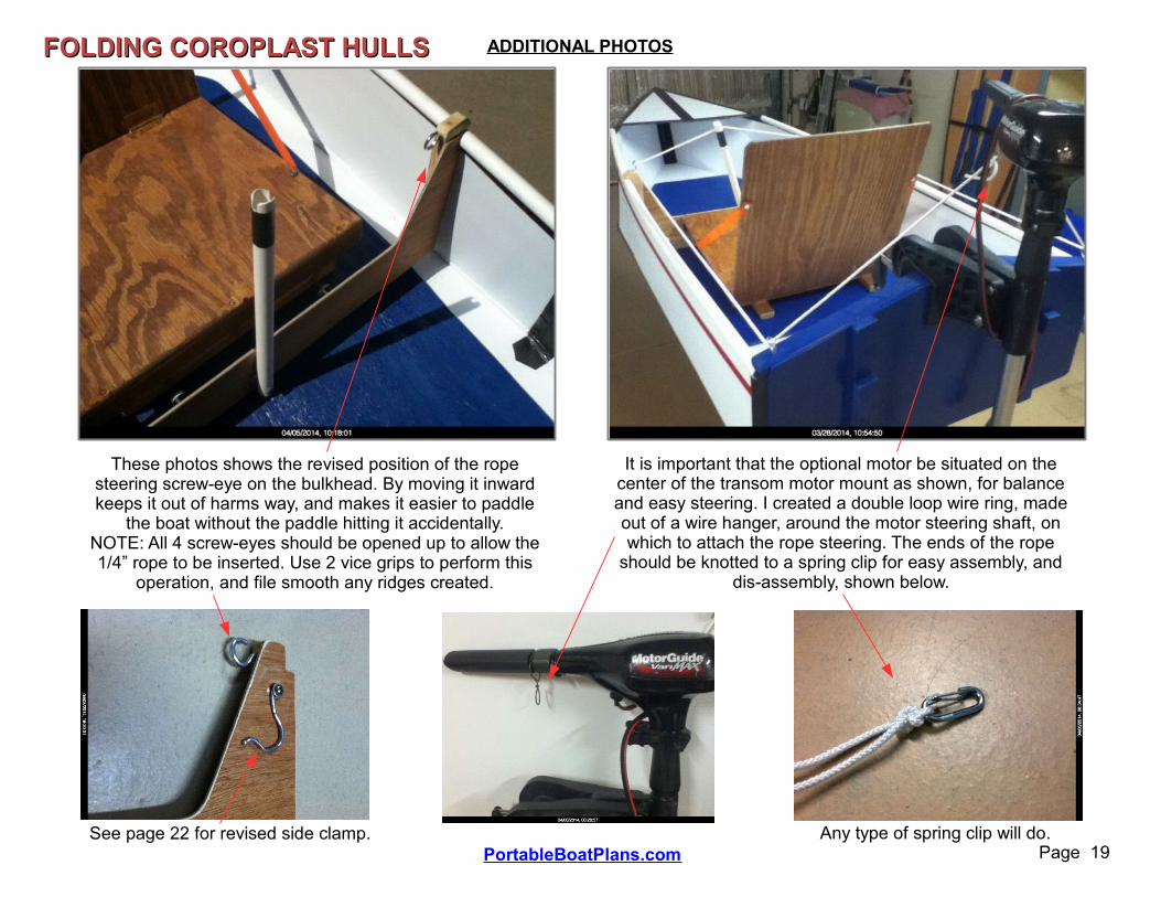
These photos shows the revised position of the rope steering screw-eye on the bulkhead. By moving it inward keeps it out of harms way, and makes it easier to paddle
the boat without the paddle hitting it accidentally.NOTE: All 4 screw-eyes should be opened up to allow the 1/4” rope to be inserted. Use 2 vice grips to perform this
operation, and file smooth any ridges created.
It is important that the optional motor be situated on the center of the transom motor mount as shown, for balance and easy steering. I created a double loop wire ring, made out of a wire hanger, around the motor steering shaft, on which to attach the rope steering. The ends of the rope
should be knotted to a spring clip for easy assembly, and dis-assembly, shown below.
See page 22 for revised side clamp. Any type of spring clip will do.

Page 20
FOLDING COROPLAST HULLSFOLDING COROPLAST HULLS
PortableBoatPlans.com
ADDITIONAL PHOTOS
After a few voyages with the SKIFF, I realized that it was a better power boat than a paddle boat, no surprise. The slightly higher side panels, which provide good freeboard for a loaded hull, were not as friendly when paddling, as it was necessary to hold the paddles higher to prevent them from hitting the PVC side supports. This being said, the boat still made good forward progress, although a bit uncomfortable. As a consequence, I have made the paddle versions of these hulls 9 inches high, which also provides a little more buoyancy. The KAYAK and JON BOAT should both be comfortable paddlers.
You will note that I modified the method of clamping the PVC side rails in place. The new method lowers the profile of the bulkhead assembly, thereby allowing more comfortable paddle position. The new pivoting wire clamps were made from
bending heavy-duty coat hanger wire to shape, and do a good job of snapping over the PVC pipe, and holding it in place. Use your imagination to create a secure method of insuring the PVC side supports do not come loose during use.
Wire Clamp
Clamp in lowered position Clamp secured over the pipe Low profile paddle clearance
Back on land after more in-water testing for stability and balance.
Assembled Skiff fits in my PT Cruiserwith passenger seat folded down.
These hulls can, and should, be modified to suite your boating style. However, do not make radical changes to the basic hull shape. Remember, the Coroplast material is tough, but flimsy, so pay particular attention to making sure the assembled structure is as rigid as can be, and that all the components are well secured together. You do not want this to un-fold while in the water. Always check the tape seals before, during and after a cruise, and repair as necessary. Happy Boating !
Note: Some of the photos are out of date. Refer to the improved 1x2 side supports.

Page 21
FOLDING COROPLAST HULLSFOLDING COROPLAST HULLS
PortableBoatPlans.com
ADDITIONAL ON-WATER PHOTOS
At Waters Edge On the Water
Under Motor Power
waterline
Fully Loaded

Page 22
FOLDING COROPLAST HULLSFOLDING COROPLAST HULLS
PortableBoatPlans.com
ADDITIONAL PHOTOS
These photos show the detail of the 1x2 side
supports. I would suggest the use of
these 1x2's for most applications.
They are removable for all versions. They can
be permanently mounted, as shown, for the SKIFF design only,
because it does not fold flat like the others.
A 6” gap between the forward supports and the rear supports is
required at the fold line.
About 6”
CenterFoldLine
Further, by attaching the center bulkhead to the side panels, eliminates the need for additional support. A horizontal 1x1, 2 inches long was glued and screwed to the cutout at the top of the bulkhead, as shown below. A 1/4” T-Nut was installed inside, and 2 new
Bolt-Knobs were made to clamp it all together, through the tape reinforced side panels. Using this method provides good side support and rigidity, while allowing some flex at the center fold line, necessary for folding, storage and transport.
Note: For the versions that utilize the full length removable side supports, no bulkhead is used, or required, only the spacer bars.
I have found that the bulkhead positioned
at the center fold line, is the best location for hull balance.
You may have to shift your seat, depending on your weight, fore or aft a little for final trim. It varies if you are motoring, or just paddling. But, it is
important to balance the boat level for best
performance !
#6 x 3/4” screws & washers, about every 8”

80” WLL
39”
24”
OPTIONAL CANOPYFOLDING COROPLAST HULLSFOLDING COROPLAST HULLS
Page 23PortableBoatPlans.com
38”
Canopy Bow Supports (2)1/2” Plywood
About 9” x 6” size
See photos next page
DowelHole
BoltHole
Can be made larger or longer, depending on your needs. Keep the material selection simple and lightweight.
Easily removable with the use of Bolt Knobs and T-Nuts to the 1x2
side supports.
Bolt Dowel
The dowel prevents the support from rotating.

OPTIONAL CANOPYFOLDING COROPLAST HULLSFOLDING COROPLAST HULLS
Page 24PortableBoatPlans.com
Canopy collapsed forward Canopy fully erected
Canopy support detail Canopy top taped to frame
Bungee Cord Hold
Downs
Nylon Cord Forward
Stay
This is but one of many designs possible. The actual size and support method is dependent on your specific needs.The cost of this design is less than $12, using 3/4” thin wall PVC pipe and a low cost tarp material.

8 feet
4 feet
10”
10”21” 3”
CORO POWER BOATCORO POWER BOAT6”
15”
a ken simpson design May 24-2014
TRANSOMFLOORBOARD2 x 4MotorMount
1x2 Side Rails (outside)
10”
All lines are Creasingand Bending lines.
4 MM Coroplast Material4' x 8' sheet
Up to a 2 HP Motor.
10”
ToughDuct TapeAll Edges & Seams
Closed
¼” plywood floor & plywood transom, 1 x 2 lumber side rails
Trolling Motor PoweredAll Bends, No CutsTape Ends Closed
Finished Hull Length = 7 feet Finished Hull Weight = 15 pounds
Suggest rope steering for
easier control
This is a Non-Fold-Up design. It should fit in all Trucks and SUV's, and some hatchbacks, like my PT Cruiser.
1x2 Support Bar
Tape floorboard to side walls
Through bolt transom to rear panel
Fold In
Fold In
Fold In
FoldOut
Fold InFold
In
Fold In
Page 25PortableBoatPlans.com
BATT.
Alternate mechanical methods of joining the panels together can be utilized for even greater security and reduced maintenance.A center bulkhead can also be used to enable a rope steering tiller and to provide additional structural rigidity.
SPEC'SOAL = 84”OAW = 30”OAH = 12”
Weight = 15Cost = $65
10”
Skids
PartialCreases
55
12” Similar to SKIFF, but does NOT fold in half.

16”
48”
28” sq.
MotorModule
MOTOR MODULE
2 OccupantsOAL = 10 feet
Page 26PortableBoatPlans.com
10”
10”
NOT TO SCALE
ELONGATED CORO BOATELONGATED CORO BOAT
Constructed similar to the Power Boat.
Requires 2 sheets of
4mmCoroplast
CENTER MODULE 4' long
FORWARD MODULE
CutOut
Forward or AftModule
10”
10”
CutOut
10”
10”
6”
CutOut
90 deg.
!/2 inch Plywood Bulkheads used to reinforce bolt together assembly.
PlywoodTransom
15”
Center Module similar, but 4 feet long,builders option.
1 x 2 rubrails on all modules
This module is for the Elongated or Canoe hulls.
CORO BOATCORO BOAT
Tape floorboard to side panels.
10”
6”
6”

4' x 8' Sheet of 1/4” plywood FLOORBOARD
FLOORBOARD
27”
Approx. 41”
66”
1”
Method of getting two (2) same size Long Floorboards & Transoms out of one (1) sheet of 1/4” 4 x 8 plywood.
Page 27PortableBoatPlans.com
2 Module, 9-3/4 foot long CANOEStandard Coro Power Boat Additional Aft Module (P 26)
Top View of CANOE
Bolted Together250 pound capacity
storage
storage
CANOECANOE
COROCOROBOATBOAT
TRANSOM
TRANSOM
Tape floorboard to side panels.
66

8”
15”
18”18”Min.
8' PVC Pipe1-1/2” Dia.
MAST
6' x 6' SAIL
I would prefer a slightly larger sail, 6 x 8,but this is about all you can get with an 8' mast.
Note: the center of the Leeboards should be slightly ahead of the
CP of the sail, for good tracking.
CPCP = Center of Pressure
Simple Kick-Up Rudder
8”
Flip-Up Tiller
Mast Step Floorboard
CORO POWER-SAILBOATCORO POWER-SAILBOAT
2 Leeboards
Pivot Point
Plywood DeckSupport
Bond floorboard to bottom & side panels.
(see page 30)
Apply forward stops for Leeboards, and kick-up bungee for
Rudder
Consider rope or offset rudder for
steering .
Page 28PortableBoatPlans.com
Leeboard Stop
It is important you shift weight while sailing, to maintain a
safe, upright condition.

CORNER BEND
Hole
Page 29PortableBoatPlans.com
CORO BOATCORO BOATThese are typical double bends of the Coroplast material, found at some corners and side folds.
These are the most difficult bends, and require much attention. It is best to compress the bend as much as possible, to produce a sharp bend, see attached photos. In both examples, it is necessary to fasten the folded
panels together, with connectors, for structural integrity. This can be done many different ways, as noted.Most of the methods require the drilling of holes through the folded assembly, as shown.
The Tough Duct Tape should be applied after the panel folds are mechanically secured together.
SIDE BEND
Tough Duct Tape
Aluminum Pop Rivet
Nut, Bolt & Washers
Nylon Cable Ties
The 3 examples shown at right are probably the most popular, but use whichever method you think will be best for your build. Do not over tighten the connectors, or over compress the layers of Coroplast, as this could cause premature material failure.
Refer to build photos on next page for more detail.
Seal all holes with Silicone & Tough Duct Tape after
assembly.
Connector goes here
Outside
Inside
Outside
Inside
Bonding the layers together would be ideal, but there are very few adhesives that bond well to the Coroplast material. See the next page.
Apply from Outside
Weigh down the assembly if necessary to achieve a
compressed fold.
Page 30PortableBoatPlans.com
CORO BOATCORO BOAT
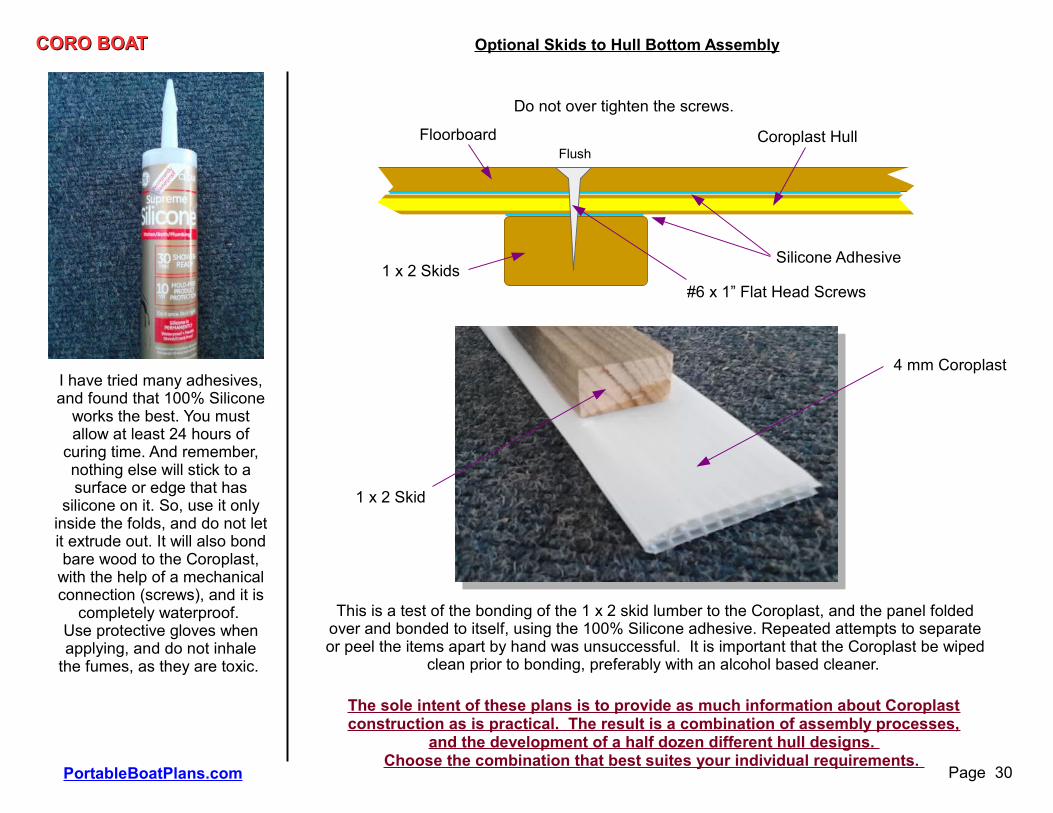
I have tried many adhesives, and found that 100% Silicone
works the best. You must allow at least 24 hours of
curing time. And remember, nothing else will stick to a surface or edge that has
silicone on it. So, use it only inside the folds, and do not let it extrude out. It will also bond bare wood to the Coroplast,
with the help of a mechanical connection (screws), and it is
completely waterproof. Use protective gloves when applying, and do not inhale
the fumes, as they are toxic.
Optional Skids to Hull Bottom Assembly
Coroplast HullFloorboard
1 x 2 SkidsSilicone Adhesive
#6 x 1” Flat Head Screws
Flush
Do not over tighten the screws.
This is a test of the bonding of the 1 x 2 skid lumber to the Coroplast, and the panel folded over and bonded to itself, using the 100% Silicone adhesive. Repeated attempts to separate or peel the items apart by hand was unsuccessful. It is important that the Coroplast be wiped
clean prior to bonding, preferably with an alcohol based cleaner.
1 x 2 Skid
4 mm Coroplast
The sole intent of these plans is to provide as much information about Coroplast construction as is practical. The result is a combination of assembly processes,
and the development of a half dozen different hull designs. Choose the combination that best suites your individual requirements.

ENDEND Page 31PortableBoatPlans.com
CORO BOATCORO BOAT PHOTOSPHOTOS

CORO KAYAK 2CORO KAYAK 26”
10” 36”
24”2-1/2”
4 MM Coroplast Material4' x 8' sheet
16”
No Cuts, All FoldsNo Cuts, All Folds