48307-001: Engro Fast Track LNG Regasification Project
415
Draft Environmental Impact Assessment Volume 3 Project Number: 48307-001 July 2014 PAK: Engro Fast Track LNG Regasification Project Prepared by Environmental Management Consultants (EMC) for Engro Elengy Terminal Private Limited The environmental impact assessment is a document of the borrower. The views expressed herein do not necessarily represent those of ADB's Board of Directors, Management, or staff, and may be preliminary in nature. Your attention is directed to the “Terms of Use” section of this website. In preparing any country program or strategy, financing any project, or by making any designation of or reference to a particular territory or geographic area in this document, the Asian Development Bank does not intend to make any judgments as to the legal or other status of any territory or area.
-
Upload
khangminh22 -
Category
Documents
-
view
0 -
download
0
Transcript of 48307-001: Engro Fast Track LNG Regasification Project

Draft Environmental Impact Assessment Volume 3
Project Number: 48307-001 July 2014
PAK: Engro Fast Track LNG Regasification Project
Prepared by Environmental Management Consultants (EMC) for Engro Elengy Terminal Private Limited The environmental impact assessment is a document of the borrower. The views expressed
herein do not necessarily represent those of ADB's Board of Directors, Management, or staff,
and may be preliminary in nature. Your attention is directed to the “Terms of Use” section of this
website.
In preparing any country program or strategy, financing any project, or by making any designation of or reference to a particular territory or geographic area in this document, the Asian Development Bank does not intend to make any judgments as to the legal or other status of any territory or area.

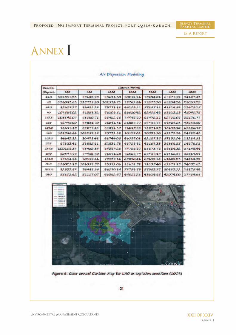
ANNEX – I (AIR DISPERSION MODELING)

An n e x I
Environmental Management Consultants I OF XXIV
P r o p o s e d L N G I m p o r t T e r m i n a l P r o j e c t , P o r t Q a s i m - K a r a c h iElengy TerminalPakistan Limited
ESIA Report
Annex I
AIR DISPERSION MODELING
FOR
ETPL LNG TERMINAL

An n e x I
Environmental Management Consultants II OF XXIV
P r o p o s e d L N G I m p o r t T e r m i n a l P r o j e c t , P o r t Q a s i m - K a r a c h iElengy TerminalPakistan Limited
ESIA Report
Annex I

An n e x I
Environmental Management Consultants III OF XXIV
P r o p o s e d L N G I m p o r t T e r m i n a l P r o j e c t , P o r t Q a s i m - K a r a c h iElengy TerminalPakistan Limited
ESIA Report
Annex I

An n e x I
Environmental Management Consultants IV OF XXIV
P r o p o s e d L N G I m p o r t T e r m i n a l P r o j e c t , P o r t Q a s i m - K a r a c h iElengy TerminalPakistan Limited
ESIA Report
Annex I

An n e x I
Environmental Management Consultants V OF XXIV
P r o p o s e d L N G I m p o r t T e r m i n a l P r o j e c t , P o r t Q a s i m - K a r a c h iElengy TerminalPakistan Limited
ESIA Report
Annex I

An n e x I
Environmental Management Consultants VI OF XXIV
P r o p o s e d L N G I m p o r t T e r m i n a l P r o j e c t , P o r t Q a s i m - K a r a c h iElengy TerminalPakistan Limited
ESIA Report
Annex I

An n e x I
Environmental Management Consultants VII OF XXIV
P r o p o s e d L N G I m p o r t T e r m i n a l P r o j e c t , P o r t Q a s i m - K a r a c h iElengy TerminalPakistan Limited
ESIA Report
Annex I

An n e x I
Environmental Management Consultants VIII OF XXIV
P r o p o s e d L N G I m p o r t T e r m i n a l P r o j e c t , P o r t Q a s i m - K a r a c h iElengy TerminalPakistan Limited
ESIA Report
Annex I

An n e x I
Environmental Management Consultants IX OF XXIV
P r o p o s e d L N G I m p o r t T e r m i n a l P r o j e c t , P o r t Q a s i m - K a r a c h iElengy TerminalPakistan Limited
ESIA Report
Annex I

An n e x I
Environmental Management Consultants X OF XXIV
P r o p o s e d L N G I m p o r t T e r m i n a l P r o j e c t , P o r t Q a s i m - K a r a c h iElengy TerminalPakistan Limited
ESIA Report
Annex I

An n e x I
Environmental Management Consultants XI OF XXIV
P r o p o s e d L N G I m p o r t T e r m i n a l P r o j e c t , P o r t Q a s i m - K a r a c h iElengy TerminalPakistan Limited
ESIA Report
Annex I

An n e x I
Environmental Management Consultants XII OF XXIV
P r o p o s e d L N G I m p o r t T e r m i n a l P r o j e c t , P o r t Q a s i m - K a r a c h iElengy TerminalPakistan Limited
ESIA Report
Annex I

An n e x I
Environmental Management Consultants XIII OF XXIV
P r o p o s e d L N G I m p o r t T e r m i n a l P r o j e c t , P o r t Q a s i m - K a r a c h iElengy TerminalPakistan Limited
ESIA Report
Annex I

An n e x I
Environmental Management Consultants XIV OF XXIV
P r o p o s e d L N G I m p o r t T e r m i n a l P r o j e c t , P o r t Q a s i m - K a r a c h iElengy TerminalPakistan Limited
ESIA Report
Annex I

An n e x I
Environmental Management Consultants XV OF XXIV
P r o p o s e d L N G I m p o r t T e r m i n a l P r o j e c t , P o r t Q a s i m - K a r a c h iElengy TerminalPakistan Limited
ESIA Report
Annex I

An n e x I
Environmental Management Consultants XVI OF XXIV
P r o p o s e d L N G I m p o r t T e r m i n a l P r o j e c t , P o r t Q a s i m - K a r a c h iElengy TerminalPakistan Limited
ESIA Report
Annex I

An n e x I
Environmental Management Consultants XVII OF XXIV
P r o p o s e d L N G I m p o r t T e r m i n a l P r o j e c t , P o r t Q a s i m - K a r a c h iElengy TerminalPakistan Limited
ESIA Report
Annex I

An n e x I
Environmental Management Consultants XVIII OF XXIV
P r o p o s e d L N G I m p o r t T e r m i n a l P r o j e c t , P o r t Q a s i m - K a r a c h iElengy TerminalPakistan Limited
ESIA Report
Annex I

An n e x I
Environmental Management Consultants XIX OF XXIV
P r o p o s e d L N G I m p o r t T e r m i n a l P r o j e c t , P o r t Q a s i m - K a r a c h iElengy TerminalPakistan Limited
ESIA Report
Annex I

An n e x I
Environmental Management Consultants XX OF XXIV
P r o p o s e d L N G I m p o r t T e r m i n a l P r o j e c t , P o r t Q a s i m - K a r a c h iElengy TerminalPakistan Limited
ESIA Report
Annex I

An n e x I
Environmental Management Consultants XXI OF XXIV
P r o p o s e d L N G I m p o r t T e r m i n a l P r o j e c t , P o r t Q a s i m - K a r a c h iElengy TerminalPakistan Limited
ESIA Report
Annex I
An n e x I
Environmental Management Consultants XXII OF XXIV
P r o p o s e d L N G I m p o r t T e r m i n a l P r o j e c t , P o r t Q a s i m - K a r a c h iElengy TerminalPakistan Limited
ESIA Report
Annex I

An n e x I
Environmental Management Consultants XXIII OF XXIV
P r o p o s e d L N G I m p o r t T e r m i n a l P r o j e c t , P o r t Q a s i m - K a r a c h iElengy TerminalPakistan Limited
ESIA Report
Annex I

An n e x I
Environmental Management Consultants XXIV OF XXIV
P r o p o s e d L N G I m p o r t T e r m i n a l P r o j e c t , P o r t Q a s i m - K a r a c h iElengy TerminalPakistan Limited
ESIA Report
Annex I

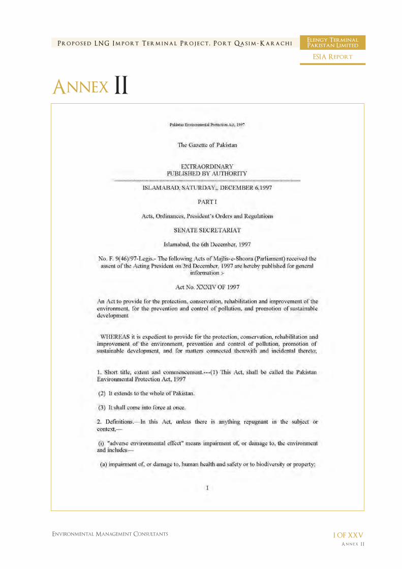
ANNEX – II
(PEPA 1997)
An n e x I I
Environmental Management Consultants I of XXV
P r o p o s e d L N G I m p o r t T e r m i n a l P r o j e c t , P o r t Q a s i m - K a r a c h iElengy TerminalPakistan Limited
ESIA Report
Annex II

An n e x I I
Environmental Management Consultants II of XXV
P r o p o s e d L N G I m p o r t T e r m i n a l P r o j e c t , P o r t Q a s i m - K a r a c h iElengy TerminalPakistan Limited
ESIA Report
Annex II

An n e x I I
Environmental Management Consultants III of XXV
P r o p o s e d L N G I m p o r t T e r m i n a l P r o j e c t , P o r t Q a s i m - K a r a c h iElengy TerminalPakistan Limited
ESIA Report
Annex II

An n e x I I
Environmental Management Consultants IV of XXV
P r o p o s e d L N G I m p o r t T e r m i n a l P r o j e c t , P o r t Q a s i m - K a r a c h iElengy TerminalPakistan Limited
ESIA Report
Annex II

An n e x I I
Environmental Management Consultants V of XXV
P r o p o s e d L N G I m p o r t T e r m i n a l P r o j e c t , P o r t Q a s i m - K a r a c h iElengy TerminalPakistan Limited
ESIA Report
Annex II

An n e x I I
Environmental Management Consultants VI of XXV
P r o p o s e d L N G I m p o r t T e r m i n a l P r o j e c t , P o r t Q a s i m - K a r a c h iElengy TerminalPakistan Limited
ESIA Report
Annex II

An n e x I I
Environmental Management Consultants VII of XXV
P r o p o s e d L N G I m p o r t T e r m i n a l P r o j e c t , P o r t Q a s i m - K a r a c h iElengy TerminalPakistan Limited
ESIA Report
Annex II

An n e x I I
Environmental Management Consultants VIII of XXV
P r o p o s e d L N G I m p o r t T e r m i n a l P r o j e c t , P o r t Q a s i m - K a r a c h iElengy TerminalPakistan Limited
ESIA Report
Annex II

An n e x I I
Environmental Management Consultants IX of XXV
P r o p o s e d L N G I m p o r t T e r m i n a l P r o j e c t , P o r t Q a s i m - K a r a c h iElengy TerminalPakistan Limited
ESIA Report
Annex II

An n e x I I
Environmental Management Consultants X of XXV
P r o p o s e d L N G I m p o r t T e r m i n a l P r o j e c t , P o r t Q a s i m - K a r a c h iElengy TerminalPakistan Limited
ESIA Report
Annex II

An n e x I I
Environmental Management Consultants XI of XXV
P r o p o s e d L N G I m p o r t T e r m i n a l P r o j e c t , P o r t Q a s i m - K a r a c h iElengy TerminalPakistan Limited
ESIA Report
Annex II

An n e x I I
Environmental Management Consultants XII of XXV
P r o p o s e d L N G I m p o r t T e r m i n a l P r o j e c t , P o r t Q a s i m - K a r a c h iElengy TerminalPakistan Limited
ESIA Report
Annex II

An n e x I I
Environmental Management Consultants XIII of XXV
P r o p o s e d L N G I m p o r t T e r m i n a l P r o j e c t , P o r t Q a s i m - K a r a c h iElengy TerminalPakistan Limited
ESIA Report
Annex II

An n e x I I
Environmental Management Consultants XIV of XXV
P r o p o s e d L N G I m p o r t T e r m i n a l P r o j e c t , P o r t Q a s i m - K a r a c h iElengy TerminalPakistan Limited
ESIA Report
Annex II

An n e x I I
Environmental Management Consultants XV of XXV
P r o p o s e d L N G I m p o r t T e r m i n a l P r o j e c t , P o r t Q a s i m - K a r a c h iElengy TerminalPakistan Limited
ESIA Report
Annex II

An n e x I I
Environmental Management Consultants XVI of XXV
P r o p o s e d L N G I m p o r t T e r m i n a l P r o j e c t , P o r t Q a s i m - K a r a c h iElengy TerminalPakistan Limited
ESIA Report
Annex II

An n e x I I
Environmental Management Consultants XVII of XXV
P r o p o s e d L N G I m p o r t T e r m i n a l P r o j e c t , P o r t Q a s i m - K a r a c h iElengy TerminalPakistan Limited
ESIA Report
Annex II

An n e x I I
Environmental Management Consultants XVIII of XXV
P r o p o s e d L N G I m p o r t T e r m i n a l P r o j e c t , P o r t Q a s i m - K a r a c h iElengy TerminalPakistan Limited
ESIA Report
Annex II

An n e x I I
Environmental Management Consultants XIX of XXV
P r o p o s e d L N G I m p o r t T e r m i n a l P r o j e c t , P o r t Q a s i m - K a r a c h iElengy TerminalPakistan Limited
ESIA Report
Annex II

An n e x I I
Environmental Management Consultants XX of XXV
P r o p o s e d L N G I m p o r t T e r m i n a l P r o j e c t , P o r t Q a s i m - K a r a c h iElengy TerminalPakistan Limited
ESIA Report
Annex II

An n e x I I
Environmental Management Consultants XXI of XXV
P r o p o s e d L N G I m p o r t T e r m i n a l P r o j e c t , P o r t Q a s i m - K a r a c h iElengy TerminalPakistan Limited
ESIA Report
Annex II

An n e x I I
Environmental Management Consultants XXII of XXV
P r o p o s e d L N G I m p o r t T e r m i n a l P r o j e c t , P o r t Q a s i m - K a r a c h iElengy TerminalPakistan Limited
ESIA Report
Annex II

An n e x I I
Environmental Management Consultants XXIII of XXV
P r o p o s e d L N G I m p o r t T e r m i n a l P r o j e c t , P o r t Q a s i m - K a r a c h iElengy TerminalPakistan Limited
ESIA Report
Annex II

An n e x I I
Environmental Management Consultants XXIV of XXV
P r o p o s e d L N G I m p o r t T e r m i n a l P r o j e c t , P o r t Q a s i m - K a r a c h iElengy TerminalPakistan Limited
ESIA Report
Annex II

An n e x I I
Environmental Management Consultants XXV of XXV
P r o p o s e d L N G I m p o r t T e r m i n a l P r o j e c t , P o r t Q a s i m - K a r a c h iElengy TerminalPakistan Limited
ESIA Report
Annex II

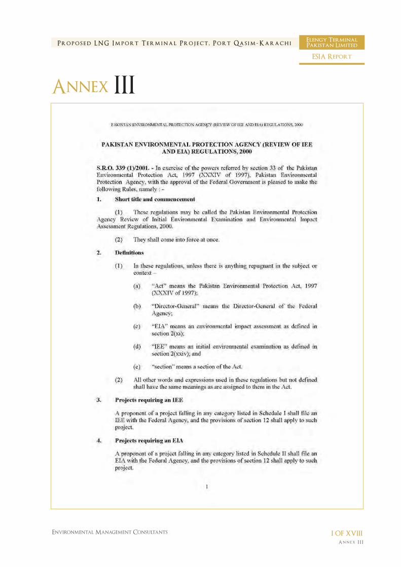
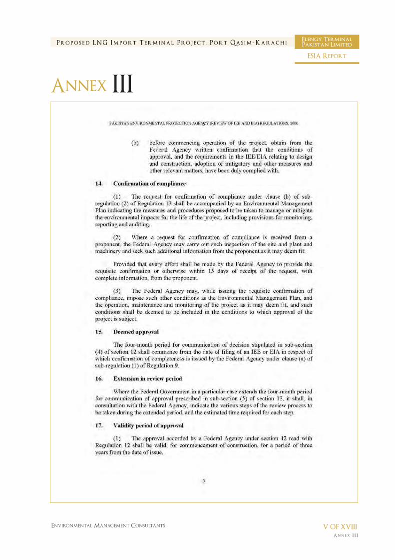
ANNEX – III (PEPA REVIEW OF IEE/EIA REGULATIONS
2000)
An n e x I I I
Environmental Management Consultants I of XVIII
P r o p o s e d L N G I m p o r t T e r m i n a l P r o j e c t , P o r t Q a s i m - K a r a c h iElengy TerminalPakistan Limited
ESIA Report
Annex III

An n e x I I I
Environmental Management Consultants II of XVIII
P r o p o s e d L N G I m p o r t T e r m i n a l P r o j e c t , P o r t Q a s i m - K a r a c h iElengy TerminalPakistan Limited
ESIA Report
Annex III

An n e x I I I
Environmental Management Consultants III of XVIII
P r o p o s e d L N G I m p o r t T e r m i n a l P r o j e c t , P o r t Q a s i m - K a r a c h iElengy TerminalPakistan Limited
ESIA Report
Annex III

An n e x I I I
Environmental Management Consultants IV of XVIII
P r o p o s e d L N G I m p o r t T e r m i n a l P r o j e c t , P o r t Q a s i m - K a r a c h iElengy TerminalPakistan Limited
ESIA Report
Annex III
An n e x I I I
Environmental Management Consultants V of XVIII
P r o p o s e d L N G I m p o r t T e r m i n a l P r o j e c t , P o r t Q a s i m - K a r a c h iElengy TerminalPakistan Limited
ESIA Report
Annex III

An n e x I I I
Environmental Management Consultants VI of XVIII
P r o p o s e d L N G I m p o r t T e r m i n a l P r o j e c t , P o r t Q a s i m - K a r a c h iElengy TerminalPakistan Limited
ESIA Report
Annex III

An n e x I I I
Environmental Management Consultants VII of XVIII
P r o p o s e d L N G I m p o r t T e r m i n a l P r o j e c t , P o r t Q a s i m - K a r a c h iElengy TerminalPakistan Limited
ESIA Report
Annex III

An n e x I I I
Environmental Management Consultants VIII of XVIII
P r o p o s e d L N G I m p o r t T e r m i n a l P r o j e c t , P o r t Q a s i m - K a r a c h iElengy TerminalPakistan Limited
ESIA Report
Annex III

An n e x I I I
Environmental Management Consultants IX of XVIII
P r o p o s e d L N G I m p o r t T e r m i n a l P r o j e c t , P o r t Q a s i m - K a r a c h iElengy TerminalPakistan Limited
ESIA Report
Annex III

An n e x I I I
Environmental Management Consultants X of XVIII
P r o p o s e d L N G I m p o r t T e r m i n a l P r o j e c t , P o r t Q a s i m - K a r a c h iElengy TerminalPakistan Limited
ESIA Report
Annex III

An n e x I I I
Environmental Management Consultants XI of XVIII
P r o p o s e d L N G I m p o r t T e r m i n a l P r o j e c t , P o r t Q a s i m - K a r a c h iElengy TerminalPakistan Limited
ESIA Report
Annex III

An n e x I I I
Environmental Management Consultants XII of XVIII
P r o p o s e d L N G I m p o r t T e r m i n a l P r o j e c t , P o r t Q a s i m - K a r a c h iElengy TerminalPakistan Limited
ESIA Report
Annex III

An n e x I I I
Environmental Management Consultants XIII of XVIII
P r o p o s e d L N G I m p o r t T e r m i n a l P r o j e c t , P o r t Q a s i m - K a r a c h iElengy TerminalPakistan Limited
ESIA Report
Annex III

An n e x I I I
Environmental Management Consultants XIV of XVIII
P r o p o s e d L N G I m p o r t T e r m i n a l P r o j e c t , P o r t Q a s i m - K a r a c h iElengy TerminalPakistan Limited
ESIA Report
Annex III

An n e x I I I
Environmental Management Consultants XV of XVIII
P r o p o s e d L N G I m p o r t T e r m i n a l P r o j e c t , P o r t Q a s i m - K a r a c h iElengy TerminalPakistan Limited
ESIA Report
Annex III

An n e x I I I
Environmental Management Consultants XVI of XVIII
P r o p o s e d L N G I m p o r t T e r m i n a l P r o j e c t , P o r t Q a s i m - K a r a c h iElengy TerminalPakistan Limited
ESIA Report
Annex III

An n e x I I I
Environmental Management Consultants XVII of XVIII
P r o p o s e d L N G I m p o r t T e r m i n a l P r o j e c t , P o r t Q a s i m - K a r a c h iElengy TerminalPakistan Limited
ESIA Report
Annex III

An n e x I I I
Environmental Management Consultants XVIII of XVIII
P r o p o s e d L N G I m p o r t T e r m i n a l P r o j e c t , P o r t Q a s i m - K a r a c h iElengy TerminalPakistan Limited
ESIA Report
Annex III

ANNEX – IV (NEQS 2010)

An n e x I V
Environmental Management Consultants I of VI
P r o p o s e d L N G I m p o r t T e r m i n a l P r o j e c t , P o r t Q a s i m - K a r a c h iElengy TerminalPakistan Limited
ESIA Report
Annex IV

An n e x I V
Environmental Management Consultants II of VI
P r o p o s e d L N G I m p o r t T e r m i n a l P r o j e c t , P o r t Q a s i m - K a r a c h iElengy TerminalPakistan Limited
ESIA Report
Annex IV

An n e x I V
Environmental Management Consultants III of VI
P r o p o s e d L N G I m p o r t T e r m i n a l P r o j e c t , P o r t Q a s i m - K a r a c h iElengy TerminalPakistan Limited
ESIA Report
Annex IV

An n e x I V
Environmental Management Consultants IV of VI
P r o p o s e d L N G I m p o r t T e r m i n a l P r o j e c t , P o r t Q a s i m - K a r a c h iElengy TerminalPakistan Limited
ESIA Report
Annex IV

An n e x I V
Environmental Management Consultants V of VI
P r o p o s e d L N G I m p o r t T e r m i n a l P r o j e c t , P o r t Q a s i m - K a r a c h iElengy TerminalPakistan Limited
ESIA Report
Annex IV

An n e x I V
Environmental Management Consultants VI of VI
P r o p o s e d L N G I m p o r t T e r m i n a l P r o j e c t , P o r t Q a s i m - K a r a c h iElengy TerminalPakistan Limited
ESIA Report
Annex IV

ANNEX – V (NEQS 2000)

An n e x V
Environmental Management Consultants I of VI
Elengy TerminalPakistan LimitedP r o p o s e d L N G I m p o r t T e r m i n a l P r o j e c t , P o r t Q a s i m - K a r a c h i
ESIA Report
Annex V

An n e x V
Environmental Management Consultants II of VI
Elengy TerminalPakistan LimitedP r o p o s e d L N G I m p o r t T e r m i n a l P r o j e c t , P o r t Q a s i m - K a r a c h i
ESIA Report
Annex V

An n e x V
Environmental Management Consultants III of VI
Elengy TerminalPakistan LimitedP r o p o s e d L N G I m p o r t T e r m i n a l P r o j e c t , P o r t Q a s i m - K a r a c h i
ESIA Report
Annex V

An n e x V
Environmental Management Consultants IV of VI
Elengy TerminalPakistan LimitedP r o p o s e d L N G I m p o r t T e r m i n a l P r o j e c t , P o r t Q a s i m - K a r a c h i
ESIA Report
Annex V

An n e x V
Environmental Management Consultants V of VI
Elengy TerminalPakistan LimitedP r o p o s e d L N G I m p o r t T e r m i n a l P r o j e c t , P o r t Q a s i m - K a r a c h i
ESIA Report
Annex V

An n e x V
Environmental Management Consultants VI of VI
Elengy TerminalPakistan LimitedP r o p o s e d L N G I m p o r t T e r m i n a l P r o j e c t , P o r t Q a s i m - K a r a c h i
ESIA Report
Annex V

ANNEX – VI (WB/WHO/IFC STANDARDS)

An n e x V I
Environmental Management Consultants I of I
P r o p o s e d L N G I m p o r t T e r m i n a l P r o j e c t , P o r t Q a s i m - K a r a c h iElengy TerminalPakistan Limited
ESIA Report
Annex VI
No. Receptor Day (07:00-22:00) Night (22:00-07:00)
1. Residential, institutional educational 55 45
2. Industrial, commercial 70 70
World bank Guidelines for Noise levels 3
Source: Pollution Prevention and Abatement Handbook World Bank Group (1998)
Notes: a Maximum allowable log equivalent (hourly measurements) in dB(A)
Specific Environment LAeq (dB) Averaging Time (hours) LAmax, Fast (dB)
Outdoor living area 55 16 -
Dwelling (indoors) 35 16 -
School classrooms (indoors) 35 During Class -
Hospital, ward rooms, night time (indoors) 30 8 40
Industrial, commercial, shopping and traffic areas
(indoors and outdoors) 70 24 110
WHO Guideline Values for Community Noise in Specific Environments
Pollutants Units Guideline Value
pH pH 6-9
Biological oxygen demand (BOD) mg/l 30
Chemical Oxygen demand (COD) mg/l 125
Total nitrogen mg/l 10
Total phosphorus mg/l 2
Oil and grease mg/l 20
Total suspended solids (TSS) mg/l 50
Total Coliform bacteria MPNb/100ml 400
Indicative IFC Values of Treated Sanitary Sewage Discharges 3
Notes
a Not applicable to centralized, municipal, wastewater treatment systems which are included in EHS Guidelines for
Water and Sanitation.
b MPN = Most Probable Number
INTERNATIONAL GUIDELINES FOR NOISE AND SEWAGE DISCHARGES

ANNEX – VII (LNG PROPERTIES AND HAZARDS)

An n e x V I I
Environmental Management Consultants I of XXXVIII
P r o p o s e d L N G I m p o r t T e r m i n a l P r o j e c t , P o r t Q a s i m - K a r a c h iElengy TerminalPakistan Limited
ESIA Report
Annex VII

An n e x V I I
Environmental Management Consultants II of XXXVIII
P r o p o s e d L N G I m p o r t T e r m i n a l P r o j e c t , P o r t Q a s i m - K a r a c h iElengy TerminalPakistan Limited
ESIA Report
Annex VII

An n e x V I I
Environmental Management Consultants III of XXXVIII
P r o p o s e d L N G I m p o r t T e r m i n a l P r o j e c t , P o r t Q a s i m - K a r a c h iElengy TerminalPakistan Limited
ESIA Report
Annex VII

An n e x V I I
Environmental Management Consultants IV of XXXVIII
P r o p o s e d L N G I m p o r t T e r m i n a l P r o j e c t , P o r t Q a s i m - K a r a c h iElengy TerminalPakistan Limited
ESIA Report
Annex VII

An n e x V I I
Environmental Management Consultants V of XXXVIII
P r o p o s e d L N G I m p o r t T e r m i n a l P r o j e c t , P o r t Q a s i m - K a r a c h iElengy TerminalPakistan Limited
ESIA Report
Annex VII
An n e x V
Environmental Management Consultants VI of XXXVIII
P r o p o s e d L N G I m p o r t T e r m i n a l P r o j e c t , P o r t Q a s i m - K a r a c h iElengy TerminalPakistan Limited
ESIA Report
Annex VII

An n e x V I I
Environmental Management Consultants VII of XXXVIII
P r o p o s e d L N G I m p o r t T e r m i n a l P r o j e c t , P o r t Q a s i m - K a r a c h iElengy TerminalPakistan Limited
ESIA Report
Annex VII
An n e x V I I
Environmental Management Consultants VIII of XXXVIII
P r o p o s e d L N G I m p o r t T e r m i n a l P r o j e c t , P o r t Q a s i m - K a r a c h iElengy TerminalPakistan Limited
ESIA Report
Annex VII

An n e x V I I
Environmental Management Consultants IX of XXXVIII
P r o p o s e d L N G I m p o r t T e r m i n a l P r o j e c t , P o r t Q a s i m - K a r a c h iElengy TerminalPakistan Limited
ESIA Report
Annex VII

An n e x V I I
Environmental Management Consultants X of XXXVIII
P r o p o s e d L N G I m p o r t T e r m i n a l P r o j e c t , P o r t Q a s i m - K a r a c h iElengy TerminalPakistan Limited
ESIA Report
Annex VII

An n e x V I I
Environmental Management Consultants XI of XXXVIII
P r o p o s e d L N G I m p o r t T e r m i n a l P r o j e c t , P o r t Q a s i m - K a r a c h iElengy TerminalPakistan Limited
ESIA Report
Annex VII

An n e x V I I
Environmental Management Consultants XII of XXXVIII
P r o p o s e d L N G I m p o r t T e r m i n a l P r o j e c t , P o r t Q a s i m - K a r a c h iElengy TerminalPakistan Limited
ESIA Report
Annex VII
An n e x V I I
Environmental Management Consultants XIII of XXXVIII
P r o p o s e d L N G I m p o r t T e r m i n a l P r o j e c t , P o r t Q a s i m - K a r a c h iElengy TerminalPakistan Limited
ESIA Report
Annex VII

An n e x V I I
Environmental Management Consultants XIV of XXXVIII
P r o p o s e d L N G I m p o r t T e r m i n a l P r o j e c t , P o r t Q a s i m - K a r a c h iElengy TerminalPakistan Limited
ESIA Report
Annex VII

An n e x V I I
Environmental Management Consultants XV of XXXVIII
P r o p o s e d L N G I m p o r t T e r m i n a l P r o j e c t , P o r t Q a s i m - K a r a c h iElengy TerminalPakistan Limited
ESIA Report
Annex VII

An n e x V I I
Environmental Management Consultants XVI of XXXVIII
P r o p o s e d L N G I m p o r t T e r m i n a l P r o j e c t , P o r t Q a s i m - K a r a c h iElengy TerminalPakistan Limited
ESIA Report
Annex VII

An n e x V I I
Environmental Management Consultants XVII of XXXVIII
P r o p o s e d L N G I m p o r t T e r m i n a l P r o j e c t , P o r t Q a s i m - K a r a c h iElengy TerminalPakistan Limited
ESIA Report
Annex VII

An n e x V I I
Environmental Management Consultants XVIII of XXXVIII
P r o p o s e d L N G I m p o r t T e r m i n a l P r o j e c t , P o r t Q a s i m - K a r a c h iElengy TerminalPakistan Limited
ESIA Report
Annex VII

An n e x V I I
Environmental Management Consultants XIX of XXXVIII
P r o p o s e d L N G I m p o r t T e r m i n a l P r o j e c t , P o r t Q a s i m - K a r a c h iElengy TerminalPakistan Limited
ESIA Report
Annex VII
An n e x V I I
Environmental Management Consultants XX of XXXVIII
P r o p o s e d L N G I m p o r t T e r m i n a l P r o j e c t , P o r t Q a s i m - K a r a c h iElengy TerminalPakistan Limited
ESIA Report
Annex VII

An n e x V I I
Environmental Management Consultants XXI of XXXVIII
P r o p o s e d L N G I m p o r t T e r m i n a l P r o j e c t , P o r t Q a s i m - K a r a c h iElengy TerminalPakistan Limited
ESIA Report
Annex VII

An n e x V I I
Environmental Management Consultants XXII of XXXVIII
P r o p o s e d L N G I m p o r t T e r m i n a l P r o j e c t , P o r t Q a s i m - K a r a c h iElengy TerminalPakistan Limited
ESIA Report
Annex VII

An n e x V I I
Environmental Management Consultants XXIII of XXXVIII
P r o p o s e d L N G I m p o r t T e r m i n a l P r o j e c t , P o r t Q a s i m - K a r a c h iElengy TerminalPakistan Limited
ESIA Report
Annex VII

An n e x V I I
Environmental Management Consultants XXIV of XXXVIII
P r o p o s e d L N G I m p o r t T e r m i n a l P r o j e c t , P o r t Q a s i m - K a r a c h iElengy TerminalPakistan Limited
ESIA Report
Annex VII

An n e x V I I
Environmental Management Consultants XXV of XXXVIII
P r o p o s e d L N G I m p o r t T e r m i n a l P r o j e c t , P o r t Q a s i m - K a r a c h iElengy TerminalPakistan Limited
ESIA Report
Annex VII

An n e x V I I
Environmental Management Consultants XXVI of XXXVIII
P r o p o s e d L N G I m p o r t T e r m i n a l P r o j e c t , P o r t Q a s i m - K a r a c h iElengy TerminalPakistan Limited
ESIA Report
Annex VII

An n e x V I I
Environmental Management Consultants XXVII of XXXVIII
P r o p o s e d L N G I m p o r t T e r m i n a l P r o j e c t , P o r t Q a s i m - K a r a c h iElengy TerminalPakistan Limited
ESIA Report
Annex VII

An n e x V I I
Environmental Management Consultants XXVIII of XXXVIII
P r o p o s e d L N G I m p o r t T e r m i n a l P r o j e c t , P o r t Q a s i m - K a r a c h iElengy TerminalPakistan Limited
ESIA Report
Annex VII

An n e x V I I
Environmental Management Consultants XXIX of XXXVIII
P r o p o s e d L N G I m p o r t T e r m i n a l P r o j e c t , P o r t Q a s i m - K a r a c h iElengy TerminalPakistan Limited
ESIA Report
Annex VII
An n e x V I I
Environmental Management Consultants XXX of XXXVIII
P r o p o s e d L N G I m p o r t T e r m i n a l P r o j e c t , P o r t Q a s i m - K a r a c h iElengy TerminalPakistan Limited
ESIA Report
Annex VII

An n e x V I I
Environmental Management Consultants XXXI of XXXVIII
P r o p o s e d L N G I m p o r t T e r m i n a l P r o j e c t , P o r t Q a s i m - K a r a c h iElengy TerminalPakistan Limited
ESIA Report
Annex VII

An n e x V I I
Environmental Management Consultants XXXII of XXXVIII
P r o p o s e d L N G I m p o r t T e r m i n a l P r o j e c t , P o r t Q a s i m - K a r a c h iElengy TerminalPakistan Limited
ESIA Report
Annex VII

An n e x V I I
Environmental Management Consultants XXXIII of XXXVIII
P r o p o s e d L N G I m p o r t T e r m i n a l P r o j e c t , P o r t Q a s i m - K a r a c h iElengy TerminalPakistan Limited
ESIA Report
Annex VII

An n e x V I I
Environmental Management Consultants XXXIV of XXXVIII
P r o p o s e d L N G I m p o r t T e r m i n a l P r o j e c t , P o r t Q a s i m - K a r a c h iElengy TerminalPakistan Limited
ESIA Report
Annex VII

An n e x V I I
Environmental Management Consultants XXXV of XXXVIII
P r o p o s e d L N G I m p o r t T e r m i n a l P r o j e c t , P o r t Q a s i m - K a r a c h iElengy TerminalPakistan Limited
ESIA Report
Annex VII

An n e x V I I
Environmental Management Consultants XXXVI of XXXVIII
P r o p o s e d L N G I m p o r t T e r m i n a l P r o j e c t , P o r t Q a s i m - K a r a c h iElengy TerminalPakistan Limited
ESIA Report
Annex VII
An n e x V I I
Environmental Management Consultants XXXVII of XXXVIII
P r o p o s e d L N G I m p o r t T e r m i n a l P r o j e c t , P o r t Q a s i m - K a r a c h iElengy TerminalPakistan Limited
ESIA Report
Annex VII

An n e x V I I
Environmental Management Consultants XXXVIII of XXXVIII
P r o p o s e d L N G I m p o r t T e r m i n a l P r o j e c t , P o r t Q a s i m - K a r a c h iElengy TerminalPakistan Limited
ESIA Report
Annex VII

ANNEX – VIII
(LNG POLICY 2011)

An n e x V I I I
Environmental Management Consultants I of XIII
P r o p o s e d L N G I m p o r t T e r m i n a l P r o j e c t , P o r t Q a s i m - K a r a c h iElengy TerminalPakistan Limited
ESIA Report
Annex VIII

An n e x V I I I
Environmental Management Consultants II of XIII
P r o p o s e d L N G I m p o r t T e r m i n a l P r o j e c t , P o r t Q a s i m - K a r a c h iElengy TerminalPakistan Limited
ESIA Report
Annex VIII

An n e x V I I I
Environmental Management Consultants III of XIII
P r o p o s e d L N G I m p o r t T e r m i n a l P r o j e c t , P o r t Q a s i m - K a r a c h iElengy TerminalPakistan Limited
ESIA Report
Annex VIII

An n e x V I I I
Environmental Management Consultants IV of XIII
P r o p o s e d L N G I m p o r t T e r m i n a l P r o j e c t , P o r t Q a s i m - K a r a c h iElengy TerminalPakistan Limited
ESIA Report
Annex VIII

An n e x V I I I
Environmental Management Consultants V of XIII
P r o p o s e d L N G I m p o r t T e r m i n a l P r o j e c t , P o r t Q a s i m - K a r a c h iElengy TerminalPakistan Limited
ESIA Report
Annex VIII

An n e x V I I I
Environmental Management Consultants VI of XIII
P r o p o s e d L N G I m p o r t T e r m i n a l P r o j e c t , P o r t Q a s i m - K a r a c h iElengy TerminalPakistan Limited
ESIA Report
Annex VIII

An n e x V I I I
Environmental Management Consultants VII of XIII
P r o p o s e d L N G I m p o r t T e r m i n a l P r o j e c t , P o r t Q a s i m - K a r a c h iElengy TerminalPakistan Limited
ESIA Report
Annex VIII

An n e x V I I I
Environmental Management Consultants VIII of XIII
P r o p o s e d L N G I m p o r t T e r m i n a l P r o j e c t , P o r t Q a s i m - K a r a c h iElengy TerminalPakistan Limited
ESIA Report
Annex VIII

An n e x V I I I
Environmental Management Consultants IX of XIII
P r o p o s e d L N G I m p o r t T e r m i n a l P r o j e c t , P o r t Q a s i m - K a r a c h iElengy TerminalPakistan Limited
ESIA Report
Annex VIII

An n e x V I I I
Environmental Management Consultants X of XIII
P r o p o s e d L N G I m p o r t T e r m i n a l P r o j e c t , P o r t Q a s i m - K a r a c h iElengy TerminalPakistan Limited
ESIA Report
Annex VIII

An n e x V I I I
Environmental Management Consultants XI of XIII
P r o p o s e d L N G I m p o r t T e r m i n a l P r o j e c t , P o r t Q a s i m - K a r a c h iElengy TerminalPakistan Limited
ESIA Report
Annex VIII

An n e x V I I I
Environmental Management Consultants XII of XIII
P r o p o s e d L N G I m p o r t T e r m i n a l P r o j e c t , P o r t Q a s i m - K a r a c h iElengy TerminalPakistan Limited
ESIA Report
Annex VIII

An n e x V I I I
Environmental Management Consultants XIII of XIII
P r o p o s e d L N G I m p o r t T e r m i n a l P r o j e c t , P o r t Q a s i m - K a r a c h iElengy TerminalPakistan Limited
ESIA Report
Annex VIII

ANNEX – IX (APPROVALS FROM EPA SINDH)


ANNEX – X (QRA STUDY)

Engro Vopak Terminal Ltd
Port Qasim LNG Regasification Terminal
Quantified Risk Assessment Report
Lloyd’s Register EMEA
QRA Report No. : TID7171 Rev. Final
April 2011

Lloyd's Register, its affiliates and subsidiaries and their respective officers, employees or agents are, individually and collectively, referred to in this clause as the 'Lloyd's Register Group'. The Lloyd's Register Group assumes no responsibility and shall not be liable to any person for any loss, damage or expense caused by reliance on the information or advice in this document or howsoever provided, unless that person has signed a contract with the relevant Lloyd's Register Group entity for the provision of this information or advice and in that case any responsibility or liability is exclusively on the terms and conditions set out in that contract. The contents of this report are for the confidential information of the client and members of the Lloyd’s Register Group. © Lloyd’s Register EMEA 2011

1. Report No. TID7171
2. Report date April 2011
3. Revision date
4. Type of report Technical –Rev. Final
6. Security classification of this report Commercial in Confidence
5. Title & Subtitle ENGRO VOPAK TERMINAL LTD PORT QASIM FLOATING LNG REGASIFICATION TERMINAL QUANTIFIED RISK ASSESSMENT REPORT 7. Security classification of this page
Commercial in Confidence
8. Author(s)
T Koliopulos Manager Special Projects , Energy M. Pavic Senior Marine Specialist Technical Investigation Dept
9. Authorisation Zahid Rahman General Manager Marine Business MEA
11. Reporting organisation reference(s) None
10. Reporting organisation name and address Lloyd’s Register EMEA 71 Fenchurch Street London EC3M 4BS
12. This report supersedes Rev.0
14. Sponsoring organisation reference(s)
13. Sponsoring organisation name and address Engro Vopak Terminal Ltd
15. No. of pages 262
16. Summary This binder report details the results of the Quantitative Risk Assessment (QRA) study which constitutes part of Engro Vopak Terminal Ltd’s work for the development of a LNG Regasification Terminal at Port Qasim, in Karachi, Pakistan. The major hazard events related to marine failure, regasification system and/or operating failure have been considered in all aspects of the proposed design. None of the scenarios assessed gave rise to a ‘high’ risk to members of the public.
17. Key words FSRU, LNGC, STS, ESD, PQA
18. Distribution statement Engro Vopak Terminal Ltd Lloyd’s Register EMEA

Lloyd’s Register EMEA TID7171 Rev. FINAL April 2011
abcd QRA for Engro Vopak LNG Terminal in Port Qasim Karachi
Executive Summary
This report details the results of the HAZID Study, Manoeuvrability Simulations Study and Risk Assessment Study, which constitute part of Engro Vopak Terminal Ltd’s Quantitative Risk Assessment (QRA) work for the development of a LNG Regasification Terminal at Port Qasim, in Karachi, Pakistan. The studies undertook a detailed examination of the LNG vessels jetty approach/berthing operations, the regas export system, the proposed jetty terminal facility and the ship-to-ship (STS) LNG transfer operations. The major hazard events related to marine failure, regasification system and/or operating failure have been considered in all aspects of the proposed design. None of the identified hazards are thought to be unusual and appropriate safety/operational measures to mitigate risk have been proposed. All off site risks from the site were found to be low; it was observed that none of the scenarios modelled has the potential to harm members of the public on the mainland. Furthermore, a 200m safety distance of other vessels from the facility provides mitigation of the potential effects of accidents on or from passing vessels.

Lloyd’s Register EMEA TID7171 Rev. FINAL April 2011
abcd QRA for Engro Vopak LNG Terminal in Port Qasim Karachi .
3
Table of Contents
Page
Summary ................................................................................................................iii
1. Introduction ......................................................................................................... 5
1.1 SCOPE 5
2. Overview.............................................................................................................. 6
2.1 GENERAL 6 2.2 ENVIRONMENTAL CONDITIONS 9 2.3 TERMINAL DESIGN OPTIONS 10 2.4 CODES AND STANDARDS 11 2.5 LNGC SIZE ASSESSMENT 14 2.6 CHANNEL AREAS 14
3. Hazard Identification (HAZID) ............................................................................. 18
3.1 METHODOLOGY 18 3.2 FINDINGS 19
4. Manoeuvring Simulations................................................................................... 21
4.1 SCOPE 21 4.2 METHODOLOGY 23 4.3 PRESENTATION OF RESULTS 24
5. Risk Assessment ................................................................................................. 27
5.1 OVERVIEW 27 5.2 CONSEQUENCE ASSESSMENT 28 5.3 FREQUENCY ASSESSMENT 28 5.4 MARINE EVENT FREQUENCY ASSESSMENT 29 5.5 RISK MATRIX 31
6. Recommendations ............................................................................................. 32
7. Overall Conclusions............................................................................................ 39
8. References.......................................................................................................... 40
Appendices
1. Hazard Identification Study Report No. OGL/DA/10026 Revision Final
2. Risk Assessment Study Report No. 2542214-R01 Revision Final
3. Manoeuvring Simulation Study Report No.L30090.1.2R Final

Lloyd’s Register EMEA TID7171 Rev. FINAL April 2011
abcd QRA for Engro Vopak LNG Terminal in Port Qasim Karachi .
4
Glossary of Terminology and Abbreviations
ALARP As Low As Reasonably Practicable
CFD Computerised fluid dynamics
ERS Emergency Release System
ESD Emergency Shut Down
ESDV Emergency Shut Down Valve
EVTL Engro Vopak Terminal Ltd.
EX Explosion
FF Flash fire
FSRU Floating Storage and Re-gasification Unit
HAZID Hazard Identification
HAZOP Hazard and Operability
HSE Health, Safety & Environmental
JF Jet Fire
LR Lloyd’s Register EMEA
LNG Liquefied Natural Gas
LNGC LNG Carrier
MAH Major Accident Hazard
NG Natural Gas
PF Pool Fire
PIANC International Navigation Association
PQA Port Qasim Authority
QC/QD Quick Connect/Quick Dissconect
QRA Quantitative Risk Assessment
RPT Rapid Phase Transition
SIGTTO Society of International Gas Tankers Terminal Operators
SIS Safety Instrumented System
SSL Ship-Shore link
STS Ship to Ship
UKC Under Keel Clearance
VTS Vessel Traffic Control System

Lloyd’s Register EMEA TID7171 Rev. FINAL April 2011
abcd QRA for Engro Vopak LNG Terminal in Port Qasim Karachi .
5
1. Introduction
1.1 Scope
At the request of Engro Vopak Terminals (EVTL), Lloyd's Register EMEA (LR) carried out a
Quantitative Risk Assessment for the proposed development of a floating LNG Regasification
(Regas) terminal in the area of Port Qasim Pakistan.
At this stage EVTL is conducting studies in order to establish the best feasible site for developing
the Regas LNG terminal. Three possible sites, the first located offshore at Khiprianwala Island, the
second located offshore at Chhan Waddo Creek and the third at the existing brown field site in
Port Qasim, are short listed. The selection of the final site will depend on site evaluation against
the International Safety Standards, risk assessment results and the required work for the site
development.
Based on the above the main objectives of LR’s QRA work were as follows:
• identify all hazards and critical issues related to LNG shipment, regasification
operations and gas export;
• undertake ship simulation study in order to establish the approach navigation and
safe manoeuvrability for the largest type of proposed vessel (FSRU and LNGC) and
finalise jetty size, location, area dredging and port tug requirements/supports;
• quantify all potential LNG/gas releases based on credible hazard scenarios identified
and establish that potential risk to PQA facilities, population and environment is at
an acceptable As Low As Reasonably Practicable (ALARP) level;
• establish project compliance with appropriate International Codes and Standards for
this type of Installation.
The QRA has been carried out in five key phases. These are:
Phase 1 - Local survey of the proposed sites and Port Qasim facility;
Phase 2 - Hazard Identification (HAZID) review with the participation of EVTL and
PQA;
Phase 3 - Navigational Simulation sessions for determination of the maximum size of
LNGC, size/position of jetty facility, extend of dredging, size/number of
tugs/support provisions;
Phase 4 - Comparison of the Port Qasim transit with industry criteria from PIANC,
SIGTTO and determination of marine failure frequencies;
Phase 5 - Hazard consequence analysis and overall risk quantification.

Lloyd’s Register EMEA TID7171 Rev. FINAL April 2011
abcd QRA for Engro Vopak LNG Terminal in Port Qasim Karachi .
6
2. Overview
2.1 General
Port Qasim is located in northwest wedge of Indus Delta system which is characterised of long and
narrow creeks. The access to existing port terminals is through a 45km long channel marked with
channel buoys. The port allows night navigation for 250 LOA vessels with draught 11.5 m having
bow thrusters (vessels without bow thrusters must have maximum LOA 115 m and 10 m draught)
, currently the maximum vessel operational draught is 12m. The proposed sites for the EVTL Regas
terminal are:
• Green field site at Khiprianwala Island – Latitude 24o46’50’’ N, Longitude
67o12’42’’ E - Phitti Creek channel;
• Green field site at Chhan Waddo Creek – Latitude 24o42’40’’ N, Longitude
67o11’30’’ E;
• Brown field site next to the existing EVTL chemical and LPG terminal - Lattitude
24o46’ N , Longitude 67
o 19’E
Approximate site positions are shown on Figure 1.
Figure 1: Approximate LNG Terminal site positions

Lloyd’s Register EMEA TID7171 Rev. FINAL April 2011
abcd QRA for Engro Vopak LNG Terminal in Port Qasim Karachi .
7
The key features related to shuttle LNG carrier (LNGc) operations at the proposed LNG Terminal
sites are as follows:
Existing channel features
• approach channel – two bend approach channel relatively unprotected from the
environment (Figure 2);
• approach channel width 200 m to 600 m, dredged depth to 14.5m;
• current port operations are carried out through Phitti Creek channel only;
• phitti Creek channel width 200 m to 320 m, dredged depth to 13 m;
• 45 km long Phitti Creek channel,
• negligible cross channel current in the Phitti Creek channel;
• existing turning area in the proximity of brown field site,
• ship traffic 4 ships per day, (average 1200 ships / year);
• VTMS system not existing,
• Port Qasim Authority requirements for channel depth / vessel draught ratio is
1.15 for outer channel and 1.1 for inner channel;
• Chhan Waddo Creek is not currently operational;
• unidirectional traffic.
Desirable Channel Features
• current port operational procedures need to be updated to include operations
with LNG ships;
• VTMS system;
• minimum four escort tugs should be introduced as follows: one for escort service,
two for extreme weather condition escort service and four for berthing. The tugs
minimum bollard pull should be 60t;
• new turning area in the proximity of Khiprianwala Island site;
• new turning area in Chhan Waddo Creek;
• widening of the approach channel.

Lloyd’s Register EMEA TID7171 Rev. FINAL April 2011
abcd QRA for Engro Vopak LNG Terminal in Port Qasim Karachi .
8
Figure 2: Two bend approach channel

Lloyd’s Register EMEA TID7171 Rev. FINAL April 2011
abcd QRA for Engro Vopak LNG Terminal in Port Qasim Karachi .
9
2.2 Environmental Conditions
Port Qasim weather conditions are characterized by southwest (SW) monsoon in the summer and
northeast (NE) monsoon in the winter. The port is located in a dry climate zone, the average of
two decades (70s and 80s) show that rainfall varies between 150 and 250 mm during the year
and the wettest months are July and August. Visibility in the port depends on dust storm, rainfall,
fog, clouds and haze. In general the visibility is governed by haze; mornings are often affected by
haze that disappears in mid day. Visibility in the port generally ranges up to 10 nautical miles. In
SW monsoon period however, the visibility is reduced to about 2 to 5 nautical miles with the sky
mostly cloudy while in NE monsoon period the sky is clear but the visibility is occasionally less than
1 nautical mile due to dust storms. The dust storms occur 3 to 4 days a month in a winter.
The southwest (summer) and north east (winter) monsoons are two distinct seasons that
characterize wind conditions in the area. The highest wind velocities have been recorded during
the summer months (from June to August), when the wind direction is southwest to west. Inter-
monsoon transitions occur from October to November and March to May. The wind direction and
speed between the summer and winter monsoon seasons are unsettled and large variations are
recorded both with respect to speed and direction. During winter or during the northeast
monsoon (from December to March), wind directions are northeast and north, shifting southwest
to west in the evening hours. The wind speed data for Karachi area are presented in Table 1
below.
Wind Speed (m/s) at 12:00 UTS
Year Jan Feb Mar Apr May Jun Jul Aug Sep Oct Nov Dec Annual
2001 2.6 3.4 4.3 5.6 7.5 8.1 6.8 7.3 5.5 3.7 2.0 2.4 4.9
2002 3.6 3.9 4.0 6.5 8.5 8.2 9.8 7.3 7.7 3.3 2.9 3.2 5.7
2003 4.0 5.0 5.4 5.2 7.7 8.8 6.7 7.1 6.0 3.2 3.1 3.0 5.4
2004 3.4 3.7 4.0 6.0 8.0 9.0 10.0 9.5 7.3 3.8 1.0 2.5 5.7
2005 3.6 4.2 4.8 5.1 7.1 7.5 9.0 6.9 6.4 3.9 2.0 1.5 5.2
2006 2.0 3.0 3.0 6.2 8.0 7.7 8.3 6.2 4.7 4.2 2.2 3.0 4.9
2007 2.0 3.7 4.0 4.0 6.0 6.3 N/A N/A N/A N/A N/A N/A 4.3
2008 4.3 7.6 8.2 10.5 12.6 7.6 11.0 9.3 8.7 6.6 5.1 3.9 7.9
2009 7.0 7.2 7.9 9.3 9.8 9.7 9.5 9.3 9.1 6.1 5.0 3.9 7.8
Source: Pakistan Meteorological Department
Table 1: Wind Speed Data – Karachi
During the southwest monsoon period the maximum wave height recorded in the approach
channel was between 3m and 4m. In the inner channel (creek system) the maximum wave height
is about 0.5m.
In the approach channel the maximum current velocity is 2 – 2.5 kn (1kn average) without much
difference between ebb and flood current velocity. In the creek system ebb tide is generally
stronger and the maximum recorded velocity was 3.6kn. At the entrance to the approach channel
the flood current direction is at an angle of about 40o to the navigational channel and the velocity
is less than 1kn. The ebb current is roughly in line with navigational channel.

Lloyd’s Register EMEA TID7171 Rev. FINAL April 2011
abcd QRA for Engro Vopak LNG Terminal in Port Qasim Karachi .
10
According to admiralty chart the tide levels are as follows:
Figure 3: Tide Levels
2.3 Terminal Design Options
The terminal development will involve the construction of an offshore jetty, dredging for vessels access, and the laying of a gas pipeline. It is proposed that a regasification vessel (FSRU) will remain moored to the pier for an intended period of (10 years due to lease contracts etc ) 3-5 years with continuous high gas demand. Supply LNGCs, using Ship-to-Ship (STS) cargo transfer, will periodically come alongside and unload LNG, which will be regasified and injected to the gas pipeline through a high pressure unloading arm. Gas export is expected to between 300-600 MMSCFD, being compatible with the maximum send-out capacity of the FSRU. The following Terminal Design Options are currently considered for development at the EVTL proposed sites: • Option 1 -
Offshore jetty facility able to berth FSRU/FSU and LNGC up to a size of 151,000 m3 in
a double banked STS mooring arrangement; • Option 2 - Offshore jetty facility able to berth and moor an FSRU/FSU at one side and a LNGC at
the opposite side (up to a size of 151,000 m3) of the jetty, in other words an across –
jetty arrangement; • Option 3 - Offshore jetty facility able to berth FSRU/FSU and LNGC up to a size of 151,000 m
3 in
a tandem STS mooring arrangement.
A berthing jetty with mooring dolphins will be constructed. The size of the jetty will be sufficient to provide berthing and mooring facility based on the FSRU and largest shuttle LNGC operating (length of QFLEX vessel). The available area of the jetty should be appropriate to accommodate as a minimum the re-gasification arm, export gas pipeline, pressure protection skid, service piping to the FSRU, local control room and boarding facility.
The turning basin will require the dredging of islands in order to fulfill the required area, equivalent to a turning platform of an elliptic form with a maximum axis (350 m radius to cover QFlex) which has been finalized by the navigation simulation studies.
The FSRU’s vaporisation (re-gasification) facilities are designed to deliver upto 600 MMSCFD of vaporised LNG at a maximum send-out pressure of 100 barg. The system is capable of operating at send-out rates between 100 MMSCFD and 600 MMSCFD, with an anticipated normal rate of 500 MMSCFD.

Lloyd’s Register EMEA TID7171 Rev. FINAL April 2011
abcd QRA for Engro Vopak LNG Terminal in Port Qasim Karachi .
11
The regas cargo transfer will take place via a high pressure (HP) gas unloading arm with the vessel moored at the terminal jetty. The arm is an “S” type double counterweighted design which is fully balanced in all positions. It is noted that EVTL will also consider the construction of a re-gasification plant on the jetty/land/barge. In this case, it will no longer be necessary to have a FSRU in port, but LNG carriers/FSU will remain moored to the pier as storage buffer tanks until all LNG has been re-gasified in the plant. This will require storage vessel in case of continuous supply of RLNG using either of the terminal designs.
2.4 Codes and Standards
2.4.1 Marine Standards
The standards published by the International Navigation Association (PIANC) and Society of
International Gas Tankers and Terminal Operators (SIGTTO) are well defined and practiced industry
standards and recommendations. These standards consider both the layout and operational
aspects of approaches to ports and LNG terminals. The specific aim of these standards is
minimising associated risks to ALARP (As Low As Reasonably Practical) levels.
SIGTTO
SIGTTO recommendations for channel and turning basin dimensions indicate the following:
• approach channels should have a uniform cross sectional depth, with minimum width of
five times the beam of the vessel;
• the channel depth depends on the site location and site particulars;
• where current effect is minimal the minimum diameter for turning circles is twice the
length of the vessel. Where the current is not minimal, the diameter should be increased
by anticipated drift.
SIGTTO also recommends a Vessel Traffic Control (VTS) System service in place for the ports with
LNG tanker operations. The number and size of tugs have to be sufficient to control a LNG vessel
in maximum permitted operating condition assuming the vessel’s engines are not available.
Usually the combined tug bollard pull is between 120 – 140 tonnes and the tugs should be able to
exert approximately half of total power at the each end of the ship.
LNG operation provisions suitable for a specific port have to be established by port authority prior
commencing the LNG operations. Operating limits expressed in terms of wind speed, wave height
and current should be established for each jetty. Separate sets of limits should be established for
berthing, stopping cargo transfer, hard arm disconnection and departure from the berth.

Lloyd’s Register EMEA TID7171 Rev. FINAL April 2011
abcd QRA for Engro Vopak LNG Terminal in Port Qasim Karachi .
12
PIANC
The following Table 2 establishes PIANC recommendations for a Channel Concept Design as it is
applicable to Port Qasim operations.
PIANC Channel Width Calculations
Approach Channel
Inner Channel
PQA characteristics
Basic manoeuvring lane 1.50 1.50 moderate
Vessel speed 0.00 0.00 slow to moderate speed 8 - 12kn
Cross wind 0.40 0.40 Moderate wind >
15kn - 33kn
Cross current 0.70 0.00 Negligible
Longitudinal current 0.00 0.10 moderate 1.5 - 3
kn
Wave height 1.00 0.00 3>Hs>1,
moderate speed
Aids to navigation 0.20 0.20 Average
Bottom surface smooth and soft
0.10 0.10 depth <1.5T
Depth of waterway 0.20 0.40 D<1.25T
approach, D<1.15T inner
Cargo hazard 1.00 0.80 High
Bank clearance 0.00 0.50 sloping edges
TOTAL 5.10 4.00
Additional width for two-way traffic
Vessel speed 1.60 1.40 moderate speed
8-12kn
Encounter traffic density 0.00 0.00 low 0-1 vessel
per hour
TOTAL 13.40 10.80
Table 2: PIANC Recommendations
Based on the table for unidirectional traffic and a ship with a high risk cargo (PIANC definition) the
channel width should be 5.1 times the breadth of the vessel for outer channel and 4 times the
breadth of a vessel for inner channel. This relates to the PIANC guidance and the ship transit
operating under moderate interpretation of conditions.
PIANC does not give explicit recommendations for turning circle.
However it specifies the bend radius for the channel. In calm water with no wind and current, a
hard-over turn can be accomplished with the ship with average – to – good manoeuvrability
within the channel bend radius of 1.8 to 2 times the ship length in deep water. For shallow

Lloyd’s Register EMEA TID7171 Rev. FINAL April 2011
abcd QRA for Engro Vopak LNG Terminal in Port Qasim Karachi .
13
water, depth/draught ratio this channel bend radius increases to 2.8 times the ship length. Both
specified radii assume that ship is unaided by tugs.
The minimum PIANC requirement for water depth / ship draught ratio is 1.10 for sheltered waters,
1.3 in waves up to 1m in height and 1.5 in higher waves. Froude Depth Number Fnh
has to be less
then 0.7. Froude Depth Number is defined as:
where,
V is ship speed through water in m/s,
H is water depth in m, and
g is acceleration due to gravity.
Table 3 below establishes conservative F values, assuming that vessel speed is 12kn (6.2m/s) for
Port Qasim inner and outer channel.
Minimum Water depth (m) Froude Depth Number Fnh
Outer Channel 13.5 0.54
Inner Channel 12.5 0.56
Table 3: Froude Number Calculations
Port Qasim current requirements are: water depth / ship draught ratio 1.15 for outer channel and
1.1 for inner channel and maximum ship draught 12m. The Port Qasim Froude Depth Number Fnh
is less than 0.7 and thus is acceptable according to PIANC.
2.4.2 Onshore Standards
As LNG ship regasification and export is a relatively new type of operation there are not specific
standards related to regas terminals. NFPA 59 A is considered the most commonly used code for
LNG terminal facilities but this code relates to LNG storage and LNG export facilities rather than to
regasification and HP gas export. However, the code provides useful information related to
Emergency Shut Down ESD isolation and LNG offloading systems which relate to operations
taking place on both the onshore and offshore regasification jetty.
hg
VFnh =

Lloyd’s Register EMEA TID7171 Rev. FINAL April 2011
abcd QRA for Engro Vopak LNG Terminal in Port Qasim Karachi .
14
2.5 LNGC Size Assessment
The following sizes of LNGCs have been assessed against industry standards: • 148k MOSS type vessel; • 151k Membrane type vessel; • QFLEX vessel (up to 210k).
2.5.1 Phitti Creek, Gharo Creek and Kadhiro Creek Channel (Inner Channel) Based on the PIANC and SIGTTO guidelines the assessment results for three the sizes of LNGCs are given in Table 4 below:
`
SIGGTO
(appoach
channels)
PIANC
(approach
channel)
PIANC
(inner
channel)
MOSS
148K
Membrane
151KQFLEX
Channel Width (m) 200 200
Ship Beam (m) 43.4 43.4 50.0
Ratio Channel width / ship beam > 5 > 5.1 > 4
PQA Approach Channel: channel width /
ship beam ratio4.61 4.61 4.00 N see Section 2.5.3
PQA Inner Channel: channel width / ship
beam ratio4.61 4.61 4.00 Y
PQA Maximum allowable draught (m) 12.0 12.0 12.0
Ship Design Draught (m) 11.5 11.5 12.2 Y see note 1
Turning Basin Size2 x ship
length
Ship Length LOA (m) 283.0 283.0 315.0
Required Turning basin diameter
SIGGTO566.0 566.0 630.0 Y
Industry Guidance
Minimum Actual
Channel size
(approach
channel) (m)
Minimum Actual
Channel size
(inner channel)
(m)
Typical LNGc Dimensions
Acceptable Y/N
Table 4: Comparison of Industry Standards vs. LNG ships
Note 1 on Table 4, refers to the 12m maximum ship draught already handled in Port Qasim,
deepening by 1 m will be needed to accommodate QFLEX size LNGCs. In general the turning diameter of two times ship length is adopted as an industry standard if the vessel is assisted with tugs. Furthermore, LNG terminal projects have been known to allow 1.5 times LOA after full risk assessments have been carried out. It is considered that SIGTTO recommendations for channel width are more conservative than those established by PIANC. SIGTTO recommends a minimum width of five times ship beam irrespective of actual site configuration and weather conditions. PIANC recommends more detailed assessment based on actual site particulars. As the assessment for the Phitti Creek Channel was carried out using PIANC recommendations it is concluded that the channel width is sufficient for all three assessed sizes of LNGCs (Table 2). According to information available from Port Qasim Authority’s website, the maximum vessel draught already handled is 12m. Hence it is expected that LNG vessels operating in the Port Qasim will require having a draught less then or equal to 12m.

Lloyd’s Register EMEA TID7171 Rev. FINAL April 2011
abcd QRA for Engro Vopak LNG Terminal in Port Qasim Karachi .
15
In general the design draught should not govern the selection of applicable size of the LNGC for the following reasons: • although the design draught of QFLEX LNG vessels in departure design condition
(condition leaving the loading terminal) can be 12.2 m, it is logical to expect that in the arrival condition (condition at the arrival at Port Qasim) the draught will be less then that (due to fuel consumption); • the LNGC can be loaded to meet Port Qasim requirements, ie partial loading; • Port Qasim intention is to deepen the channel in near future.
After the industry standards based assessment of Port Qasim particulars the following can be concluded: • 148k MOSS and 151K Membrane size LNGC can be operated in Phitti Creek Channel
without additional widening or deepening of the navigational channel, ie in existing channel conditions; • QFLEX size LNGC can be operated in Phitti Creek Channel after deepening; • QFLEX size FSRU can be operated in Phitti Creek Channel in existing channel conditions without additional widening or deepening of the channel (with tidal advantage, planned operational window, one time activity).
2.5.2 Chhan Waddo Creek Channel Chhan Waddo Creek Channel is currently not operational. The channel will need to be deepened in the short area north - east from the approach channel as indicated on Figure 4.
Figure 4: Area that needs to be deepened for Chhan Waddo Creek site
The proposed EVTL site is at the entrance of Chhan Waddo Creek Channel and the channel width at that position is larger than 250m. Which corresponds with PIANC and SIGTTO recommendations for a 50m breadth vessel.

Lloyd’s Register EMEA TID7171 Rev. FINAL April 2011
abcd QRA for Engro Vopak LNG Terminal in Port Qasim Karachi .
16
Assuming the deepening will be carried out to match the depths in the vicinity of the area required to be dredged, and using current Port Qasim water depth / ship draught requirements, the allowed ship draught would be: 15m / 1.15 = 13m, allowable draught. Based on the above assessment it is concluded that after undertaking deepening work QFlex size LNGC and QFlex size FSRU can be operated in Chhan Waddo Creek location. 2.5.3 Approach Channel – Ahsan Channel According to Port Qasim letter dated 22
nd October 2010, the dredged channel depth is 14.5m
indicating allowable draught of 14.5 / 1.15 = 12.6 m. This implies that based on design draught all assessed ship sizes can operate in the approach channel. The width of the channel is 200m to 600m, consequently in the sections of the channel with 200m width all three assessed ship sizes do not meet PIANC or SIGTTO recommendations for channel width / ship breadth ratio. According to PIANC the minimum channel width should be 220m for 148k MOSS and151k Membrane type vessel. For QFlex size vessel the minimum channel width should be 255m. However, it should be noted that PIANC assessment was undertaken using the adverse weather conditions for Port Qasim area with wind speed of 15 to 30kn and cross current of 3kn. Also it has been assumed that the vessel has moderate, manoeuvrability and that vessel is not assisted by tugs. In reality the wind speed (average of 15 kn) rarely exceeds 15kn and the tug support will be available. To assess the suitability of the approach channel the real time ship simulations were carried out for adverse condition used in the PIANC assessment. The simulation results are discussed in Section 5 of this report. PIANC channel width calculations for the mild wind, wind speed less the 15kn and waves less than 1m height, are given in Table 5 below.
Approach
Channel
Inner
Channel
Basic manoeuvring lane 1.50 1.50
Vessel speed 0.00 0.00slow to moderate
speed 8 - 12kn
Cross wind 0.00 0.00 mild wind < 15kn
Cross current 0.70 0.00moderate in the
approach channel
Longitudinal current 0.00 0.10 moderate 1.5 - 3 kn
Wave height 0.00 0.003>Hs>1, moderate
speed
Aids to navigation 0.20 0.20 average
Bottom surface smooth and soft 0.10 0.10 depth <1.5T
Depth of waterway 0.20 0.40D<1.25T approach,
D<1.15T inner
Cargo hazard 1.00 0.80 high
Bank clearance 0.00 0.50 sloping edges
TOTAL 3.70 3.60
PIANC Channel Width Calculations
Table 5 PIANC Recommendations – mild wind
According to Table 5, PIANC recommendations for mild wind conditions yield the following: • approach channel width 3.7 times ship breadth, or 185m required channel width for
QFLEX size vessel;

Lloyd’s Register EMEA TID7171 Rev. FINAL April 2011
abcd QRA for Engro Vopak LNG Terminal in Port Qasim Karachi .
17
• inner channel width 3.6 times ship breadth, or 180m required channel width for QFLEX vessel.
In case of adverse conditions of wind speeds higher then 20kn or cross currents higher then 2 kn, tug support is suggested in the approach channel. The minimum number of escort tugs should be two with 60t bollard pull.

Lloyd’s Register EMEA TID7171 Rev. FINAL April 2011
abcd QRA for Engro Vopak LNG Terminal in Port Qasim Karachi .
18
3. Hazard Identification (HAZID)
3.1 Methodology
The HAZID study took place in locations arranged by EVTL in Karachi, Pakistan. The team review was led by a Chairman (LR) assisted by a Recorder. The remainder of the HAZID team comprised specialists from EVTL’s project design and operations, PQA’s marine operators, PQA’s design consultants and LR Technical Investigation Department (TID) specialists. The objectives of the HAZID study were: • identify all potential hazards associated with the FSRU and LNGC port approach and
berthing operations at the proposed LNG terminal sites; • identify potential hazards associated with the proposed terminal Options with regards
to the near shore location, installation and operation of a regasification and gas export facility;
• identify potential hazards associated with the aspects of the design and operation of the STS LNG cargo system;
• assess the adequacy of the proposed marine facilities, layout design and piping systems for ensuring the integrity of the installation;
• assess the adequacy of the existing safeguards and port support assets and identify the Regulatory requirements for project compliance;
• perform a round table discussion of potential failure mode scenarios and emergency response procedures and identify remedial measures that will reduce the potential hazards and minimise risks.
Each part of the proposed operations and the area(s) which would take place either on the jetty or onboard the FSRU was reviewed in turn by the HAZID team, applying the guide words or considering potential scenarios, to identify potential hazards. Causes of the potential hazards and resultant consequences were then identified, together with any safeguards and mitigating measures. The following operations and related systems were examined:
1. EBRV/LNGC Marine Operations within Port Qasim; 2. EBRV/LNGC Berthing and Mooring Operations; 3. Jetty Safety Lay-out and Fire Protection; 4. Export Operations.

Lloyd’s Register EMEA TID7171 Rev. FINAL April 2011
abcd QRA for Engro Vopak LNG Terminal in Port Qasim Karachi .
19
3.2 Findings
The HAZID review findings and recommendations were recorded on the HAZID work sheets, which are presented in the HAZID Study Report No OGL/DA/100260, Appendix 1 of the QRA. In general the following apply:
• The proposed EVTL jetty regasification operations supported by LNG STS cargo transfer and export gas pipeline have been assessed for their suitability to handle major hazards and based on the findings of the HAZID study, is judged that the proposed installation generates potential hazards which are significantly less than those found to be acceptable for conventional LNG onshore terminals.
• The HAZID has identified a number of potential Major Accident Hazards (MAH) and their potential consequence and the frequency with which they might occur has been addressed by the Risk Assessment Study Appendix 3 of the QRA report.
• Based on the HAZID review and critical considerations on typical berthing conditions and turn around basins for up to 151,000 m3 vessels, both Options 1 and Options 3 (refer to section 2.3) have been identified as feasible for development at any of the proposed green sites at Khiprianwala Island or Chhan Waddo Creek and the existing EVTL Brown field site. Project to decide on commercial acceptability based on the results of the simulation navigation study and the extent for the necessary dredging and also the costs of the civil and LNG arms/piping engineering works for the proposed jetty sizes.
• The HAZID team examined the Brown field and identified a number of operational advantages: - Existing turning basin maintained at13.0 m depth - Potential of provision of anchorage pocket inside Chara Creek to facilitate bi-
directional traffic. - Full time monitoring traffic in the area by PQA control. - Close proximity to PQA’s support vessels jetty. - Most tug operations take place in the area, hence a high tug availability during
STS operations. - Existing high ‘awareness’ in the area of all shipping and offloading operations. - Successful long term LPG offloading operations at EVTL facility, with established
safety training and emergency response plans in place.
The main drawback of the Brown field is the close proximity of the LNG terminal to the main port terminal facilities, industrial facilities, working population and accommodation facilities. Any potential medium to large release of gas under the current prevailing wind conditions is likely to have a potential impact on to the adjacent facility. However, it can be argued that the closest facility to the future LNG terminal is the EVTL’s LPG/chemicals plant which has been purposely designed to mitigate against such type of hazard event. Also the proposed ‘GasPort’ facility is not like a typical LNG terminal as it is very small, employs only a gas export facility with limited volumes (600 mmscfd max) and does not have any onshore LNG storage tanks or processing facility.
• It is recommended that the lay-out area available by the options for any future onshore regasification equipment needs to be addressed by project at an early stage. It is noted that any future onshore expansion will benefit from pre-installed LNG arms and piping on the jetty as has been proposed for Option 3.

Lloyd’s Register EMEA TID7171 Rev. FINAL April 2011
abcd QRA for Engro Vopak LNG Terminal in Port Qasim Karachi .
20
• With regards to the extend of the dredging in order to establish an adequate turning basin it is also noted that future PQA plans include for a development of other gas ports one in the Korangi Creek opposite buoys 6 and 7 and one behind it facing the Korangi Fish Harbour area and two terminals before EVTL proposed site . There is justifications for the terminal developers to discuss with PQA the possibility of a common turning basin to be used for both facilities. The potential benefit on such arrangement would be the need to dredge only a channel connecting the basin with the proposed EVTL jetty in order to enable safe FSRU/LNGC berthing. The benefits of above against creating own turning basin in front of EVTL Green field site needs to addressed in the economic evaluation of the project.
Dedicated turning basin at the EVTL green field site is also an acceptable option.

Lloyd’s Register EMEA TID7171 Rev. FINAL April 2011
abcd QRA for Engro Vopak LNG Terminal in Port Qasim Karachi .
21
4. Manoeuvring Simulations
4.1 Scope
To fully understand the risks associated with all vessel movements, and the interaction with
terminal layout, and navigation aids, Lloyd's Register believe that simulation is the only viable
solution. This follows the recommendation on simulated assessment given by SIGTTO in their
guidance on terminal selection. Simulation has been used in this project to assess the following:
• the maximum size of the LNGCs that can be operated at three possible LNG
terminal sites;
• the maximum size of the floating LNG storage (re-gasification vessel) that can be
operated at three possible LNG Terminal sites;
• number and size of tugs required for transit and berthing operation of LNGC;
• consequences of the typical failure events for similar Re-gas LNG Terminal – LNG
shuttle tanker operations.
A navigation simulations study was carried out at BMT ARGOSS during February and March 2011,
the study is presented in Appendix 2 of this QRA. A total of 36 real time navigation simulation
runs were carried out using the “PC REMBRANDT” tool. PC REMBRANDT is a BMT ARGOSS
software based tool interacting with an electronic chart, covering the approach channel and
possible terminal areas. It is a PC based real time ship manoeuvring simulator where a project ship
is mathematically modelled to imitate the actual ship movement. The simulations take account of
bathymetry and introduced external factors of wind, current and wave height (Hs).
The manoeuvres that were considered in this study focused on a single ship that was selected as
being representative of the least manoeuvrable ship expected to operate at the EVTL LNG Regas
terminal jetty. This was a148K steam driven, LNG carrier with spherical tanks (MOSS type). The
main dimensions of this size MOSS type LNGC, match the main dimensions of the 151K
membrane type vessel. Additionally, at EVTL’s request, the simulations were carried out with a
QFLEX size LNG carrier. The typical particulars of 148k Moss LNG carrier and QFLEX size LNG
carrier are presented in Figures 5 and 6 below:
Length Overall 283.0 m
Beam 43.4 m
Depth 27.0 m
Design Draft 11.5 m
Capacity 148,000 cbm
DWT 77,351 tonnes
Displacement 107,000 tonnes
Speed 19.5 Kts
Complement 28
Figure 5: 148 k Moss Type LNG Carrier

Lloyd’s Register EMEA TID7171 Rev. FINAL April 2011
abcd QRA for Engro Vopak LNG Terminal in Port Qasim Karachi .
22
Length Overall 315.0 m
Beam 50.0 m
Depth 26.0 m
Design Draft 12.2 m
Capacity 210,000 cbm
DWT 87,300 tonnes
Displacement 123,700 tonnes
Speed 20.0 Kts
Complement 28
Figure 6: QFLEX Size LNG Carrier
The assistance of tugs was also appropriately simulated. In the report the convention for referring to tugs in use is as follows:
• Tug 1 bow centre lead;
• Tug 2 working at the ship’s shoulder (port or starboard side, as appropriate);
• Tug 3 working at the ship’s quarter (port or starboard side, as appropriate);
• Tug 4 stern centre lead. The turning area with a radius of 350m was assumed in the vicinity of the Khiprianwala site and in Chhan Waddo Creek. The simulation list is given in Table 6 below:
Wind Run Operation Ship
Dir Spd
Current
Tugs
1 Arrival Moss Ship (Loaded) 225 30kts Spring Flood - 2A, B, C Arrival Moss Ship (Loaded) 225 30kts Spring Flood -
3 Arrival Moss Ship (Loaded) 225 20kts Spring Flood 3 4 Arrival Moss Ship (Loaded) 225 30kts Spring Flood 3 5 Arrival Moss Ship (Loaded) 225 30kts Spring Flood 3 6 Arrival Moss Ship (Loaded) 225 30kts Spring Flood 4 7 Arrival Moss Ship (Loaded) 225 30kts Spring Flood 4 8 Arrival Moss Ship (Loaded) 225 30kts Spring Flood 4 9 Arrival Q-Flex (Loaded) 225 30kts Spring Flood -
10 Arrival Q-Flex (Loaded) 225 30kts Spring Flood 1 11 Arrival Q-Flex (Loaded) 225 30kts Spring Flood 4 12 Arrival Q-Flex (Loaded) 225 20kts Spring Flood 1 13 Departure Moss Ship (Ballast) 225 30kts Spring Flood 2 14 Departure Moss Ship (Ballast) 225 30kts Spring Ebb 2 15 Arrival Q-Flex (Loaded) 225 20kts Spring Flood - 16 Arrival Q-Flex (Loaded) 225 20kts Spring Flood 4 17 Arrival Moss Ship (Loaded) 225 30kts Spring Flood 4 18 Departure Moss Ship (Ballast) 225 30kts Spring Flood 4 19 Arrival Q-Flex (Loaded) 225 20kts Spring Flood 4

Lloyd’s Register EMEA TID7171 Rev. FINAL April 2011
abcd QRA for Engro Vopak LNG Terminal in Port Qasim Karachi .
23
20 Departure Q-Flex (Ballast) 225 20kts Spring Flood 2 21 Departure Q-Flex (Ballast) 225 20kts Spring Ebb 2 22 Arrival Q-Flex (Loaded) 225 20kts Slack Water 4 23 Arrival Moss Ship (Loaded) 225 20kts Spring Flood 1 24 Arrival Moss Ship (Loaded) 225 20kts Spring Flood 1 25 Arrival Moss Ship (Loaded) 225 20kts Spring Flood 1 26 Arrival Moss Ship (Loaded) 225 20kts Spring Flood 1 27 Arrival Moss Ship (Loaded) 225 20kts Spring Flood 1 28 Arrival Moss Ship (Loaded) 225 20kts Spring Flood 2 (3) 29 Arrival Moss Ship (Loaded) 225 20kts Slack Water 2 (3) 30 Arrival Moss Ship (Loaded) 225 20kts Spring Flood 1 31 Arrival Moss Ship (Loaded) 225 20kts Spring Flood 4 32 Arrival Q-Flex (Loaded) 225 20kts Slack Water 4 33 Arrival Q-Flex (Loaded) 225 20kts Spring Flood 1 34 Departure Q-Flex (Loaded) 225 20kts Spring Flood 2
Table 6: Simulation Matrix For each simulation run, the following variables were entered:
• wind speed and direction;
• current rate and direction;
• ballast or loaded condition;
• ship heading and initial speed;
• tugs as required.
4.2 Methodology
All simulations were conducted by a Pilot with experience of over 500 port entry and departures. The Pilot controlled the vessel directly (i.e. without issuing orders) through a control console replicating actual ship controls and manoeuvred the tugs using the external function display. The Pilot had the following information available in real-time:
• the electronic chart view (ECDIS) showing the position of the vessel on the chart
and other information such as the dredged channel, under keel clearance (UKC),
turning circles and exclusion zones;
• an out-of-the-window 3D view from the ship’s bridge (switched to the bridge
wings when required);
• run information such as the vessel speed over the ground (ahead/astern and
lateral), rate of turn, heading and course over the ground. Also, depth profile and
engine/rudder values (actual and demanded);
• position and percentage of power usage for each tug. The vessels initial speed, for the arrival, was set at around 10kts outside the approach channel entrance. For departure manoeuvres, the simulations started with the vessel alongside the berth (stopped) and the speed was gradually increased as appropriate to the conditions. It was recognised that the Pilot was aware of impending equipment failures, and so there was relatively little element of surprise. Therefore, in an attempt to ensure representative response times, the Pilot was not permitted to take any action or alert the tugs for 30 seconds immediately

Lloyd’s Register EMEA TID7171 Rev. FINAL April 2011
abcd QRA for Engro Vopak LNG Terminal in Port Qasim Karachi .
24
after a failure, to simulate the minimum time taken for an alert bridge crew to realise there was a problem, for the Pilot to verify that there was a problem and to start to react to the situation. To give an understanding of relative safety for each manoeuvre the difficulties grading matrix shown on Figure 7 has been introduced in order to establish the criticality of each manoeuvre (refer to Manoeuvring Simulation Appendix 2).
1 2 3 4 5 6 7 8
Easy Straight-forward Comfortable Not demanding Not easy Challenging Difficult Impossible
Figure 7: Grading Matrix
The difficulty level assigned to each manoeuvre was based on Pilot experience and observations
carried out during the actual simulation runs. It should be noted that the Pilot operated in Port
Qasim area for the first time; hence assigned difficulty levels are somewhat conservative. Port
Qasim pilots should comment on the manoeuvre grading based on their extensive experience of
operations in Port Qasim area.
In general the manoeuvres graded as difficult should be avoided or additional pilot training
provided.
4.3 Presentation of Results
4.3.1. 148k Vessel
The first simulations objective was to assess maximum size LNGC that can be operated in Port
Qasim. Special attention was given to the approach channel. The simulation runs 1, 2A and 2B
were carried out using 148K LNGC without tug support. The following environmental conditions
were entered:
• wind speed 30kn (for runs 2A and 2B);
• flood current 3kn;
• wave height 3.4m.
The difficulty grading for all three runs were ‘Not demanding’. The environmental conditions used
for the runs were matching considerably adverse environmental conditions for the Port Qasim
area, yet the vessel completed manoeuvres with ‘Not demanding’ difficulty grade. Consequently it
was concluded that 148k size MOSS type (151k size membrane type) LNGC can be navigated in
the approach channel and Phitty Creek channel up to the Khiprianwala green – field site.
The simulation runs 2C, 3, 4, 5 and 6 were carried out to assess the number of tugs required for
berthing operation and the size of the vessel that can be berthed at Khiprianwala green – field
site. The assumed turning area radius was 350m. The environmental conditions were as follows:
• wind speed 30kn (except for run 3 where the wind speed is reduced to 20kn);
• flood current 3kn.
The simulations showed that the swing manoeuvre under the above environmental conditions is
‘Challenging’ but achievable if the vessel is supported with three tugs. If the vessel is supported
with four tugs the manoeuvre was rated as ‘Not demanding’. As noted before, although the

Lloyd’s Register EMEA TID7171 Rev. FINAL April 2011
abcd QRA for Engro Vopak LNG Terminal in Port Qasim Karachi .
25
experienced pilot was performing manoeuvres he was not familiar with actual Port Qasim
particulars, hence it can be concluded that the appointed difficulty rating is conservative.
To investigate berthing issues at the Khiprianwala green – field site further, port side vessel
berthing and ‘swing when departing’ manoeuvres were carried out in the runs 17 and 18. These
proved to be very simple manoeuvres. As such it is recommended that this is adopted as the
standard arrival/departure technique for the Khiprianwala green – field site.
Runs number 7 and 8 investigated how difficult is to navigate 148k MOSS vessel to the existing
brown – field site and to swing the vessel at the existing turning area at IOCB. In order to simulate
the worst case scenario a vessel was placed on the LPG berth and the Oil terminal berth. Some
difficulty (scale not easy) was experienced both in making the initial turn in the channel and also in
swinging the vessel with 4 tugs.
Runs 13 and 14 were used to simulate emergency departure for starboard berthed 148k MOSS
vessel at Khiprianwala green – field site; this proved to be a very simple manoeuvre.
4.3.2 QFLEX Vessel
Runs 9 and 10 investigated QFLEX navigation through the approach channel. The environmental
conditions used were:
• wind speed 30kn for run 9 and 20kn for run 10;
• flood current 3kn;
• extra 1m tide was used to simulate future water depth after dredging.
For run 10 the escort tug was connected at position 4. In both runs difficulty was experienced in
making the dogleg turn at the start of the channel.
In runs 11 and 12 the QFLEX vessel was navigated to the Khiprianwala green field site and the
starboard swing was attempted using 4 support tugs. The wind speed of 30kn did not allow
successful swing and for run 12 it was reduced to 20kn. The swing at run 12 was successful with
the difficulty grade of ‘Not easy’.
Runs 19 investigated the possibility of berthing by the port at Khiprianwala green – field site. The
wind speed in the all three runs was set to 20kn. The manoeuvre was carried out with 4 tugs and
it was successful.
Runs 20 and 21 investigated the emergency departure of a port side berthed vessel. The wind
speed was set to 20kn and only two tugs were used for support. Manoeuvres proved possible but
challenging. Similarly as for the MOSS type vessel the port side berthing should be considered as
standard procedure at Khiprianwala green – field site
Run 22 investigated navigation of the QFLEX vessel to the existing brown-field site and swing at
the existing turning area. The wind speed was set to 20kn, and 4 tugs were used for support.
Manoeuvres proved possible but not easy.

Lloyd’s Register EMEA TID7171 Rev. FINAL April 2011
abcd QRA for Engro Vopak LNG Terminal in Port Qasim Karachi .
26
4.3.3. Failure Simulations
The following failure simulations were carried out:
Vessel Type Wind Speed (kn) Current Speed (kn) Failure
148K MOSS 20 2 Rudder failure, stuck at full defection in
the beginning of the approach channel
148K MOSS 20 2 Engine failure in the approach channel
148K MOSS 20 2 Crash stop
148K MOSS 20 2 Black out in Phitti Creek Channel
148K MOSS 20 2 Rudder failure, stuck at full defection in
Phitti Creek Channel
148K MOSS 20 2 Tug failure during swing manoeuvre
148K MOSS 20 - Tug failure during swing manoeuvre,
failure occurring later in the swing
Vessel passing Khiprianwala green – field
site and then having engine failure and
drifting to LNGC
148K MOSS 20 3 LNGC experiencing failure when passing
existing LPG berth
QFLEX 20 3 LNGC experiencing failure when passing
existing LPG berth
Table 7: List of failure simulations
In general all the manoeuvres required to control the ship after the above specified failures were
graded as ‘Not demanding’. It was assumed that the LNGC will always be supported with at least
one tug.
The likelihood of the failures is discussed in Section 5 of this report.
4.3.4 Chhan Waddo Creek - channel
Runs 33 and 34 investigate possibility of using the Chhan Waddo Creek channel. QFlex vessel was
used and the following environmental conditions were entered:
• Wind speed 20kn,
• Flood current 3kn.
The vessel was navigated into channel and swung at the berth place the manoeuvres were
conducted without any difficulties.
Detailed findings and conclusions are presented in the Manoeuvring Simulation Report No
L30090.1.1R in Appendix 2 of the QRA.

Lloyd’s Register EMEA TID7171 Rev. FINAL April 2011
abcd QRA for Engro Vopak LNG Terminal in Port Qasim Karachi .
27
5. Risk Assessment
5.1 Overview
The risk assessment study has comprised the following steps:
• identification of major accident hazards (MAHs);
• assessment of the consequences of potential MAHs;
• assessment of the frequency of potential MAHs;
• determination of the risks from potential MAHs (using risk matrices); and,
• consideration of further measures that might be taken to reduce the risks, where
appropriate.
The identified MAHs were assessed in terms of their potential consequences, and the frequency with which they might occur. Consequences were expressed in terms of a ‘Severity Category’, as defined in Table 2 of the Risk Assessment Study in Appendix 3.
The list of identified scenarios related to possible releases from equipment on board the FSRU or the jetty are presented in Table 7 below.
Reference Description Size / Type
S M L1
Release of LNG from the pipework between the FRSU tanks and the HP Pump Suction Drums.
L S M L2
Release of LNG from the HP Pump Suction Drums and pipework feeding the HP Pumps.
L S M L3 Release of LNG from the HP Pumps discharge pipework up to the Vaporisers. L S M L4 Release of LNG from a transfer hose during ship to ship transfer. L S M
G1
Release of natural gas from the pipework between the vaporiser outlets and the ship-side ESDV upstream of the gas unloading arm.
L S M G2
Release of natural gas from the pipework between the ship-side ESDV upstream of the gas unloading arm and the first jetty ESDV.
L S M G3
Release of natural gas from the pipework between the first jetty ESDV and the second Jetty ESDV.
L S M G4
Release of natural gas from the pipework between the second Jetty ESDV and the third Jetty ESDV (at the entry to the natural gas pipeline).
L
G5 Releases of natural gas from the FSRU relief system under fire conditions. Single valve
Key: S: Small, M: Medium, L: Large
Table 8: Major Accident Hazard Scenario List

Lloyd’s Register EMEA TID7171 Rev. FINAL April 2011
abcd QRA for Engro Vopak LNG Terminal in Port Qasim Karachi .
28
5.2 Consequence Assessment
Using the above scenarios and design specification data based on a similar regas facility utilising the same FSRU export capacity and equipment a list of cases for consequence assessment was developed. Each case was then modelled using the DNV PHAST software version 6.53.1. The list of cases for PHAST modelling is presented in the Risk Assessment Study in Appendix 3 of the QRA.
The PHAST results were used to select the appropriate severity category for each MAH scenario. Separate severity categories were assigned for on-site and off-site effects. When determining the appropriate severity category, the distance from the release source to potential receptors was taken into account. The results are displayed in the Risk Assessment Study in Appendix 3 of this QRA.
5.3 Frequency Assessment
Frequency categories have been assigned to each MAH scenario by reference to a range of frequency data sources related to hydrocarbon releases or equipment failures. In the majority of cases, the process followed was to:
• assign a frequency category for occurrence of the release (e.g. the frequency of a
small leak of gas from a piece of equipment);
• modify the frequency to account for the probability of a leak becoming an effect (e.g. ignition of a leak to give a jet fire); and,
• modify the frequency to account for the probability of the effect giving rise to a
defined outcome, namely the severity of the consequences defined in the
consequence assessment (e.g. a jet fire from an ignited leak pointing towards an
occupied area and causing a fatality).
Data were obtained from the Health and Safety Executive Hydrocarbon Release Database
(data for 1992 – 2009) and from Publication Series on Dangerous Substances (PGS 3).
Guideline for quantitative risk assessment ’Purple book’ CPR 18E, VROM, 2005. It was
assumed that there will be a delivery of LNG every 4 to 5 days and that small releases are a
factor of 10 more frequent than medium sized releases.

Lloyd’s Register EMEA TID7171 Rev. FINAL April 2011
abcd QRA for Engro Vopak LNG Terminal in Port Qasim Karachi .
29
5.4 Marine Event Frequency Assessment
Frequencies were evaluated for incidents that could result in a loss of control of the LNGC with possible grounding or collision consequence, and for collision by a passing vessel. Although other incidents such as collision with a tug could lead to a loss of life onboard the tug, this does not directly lead to a major incident for the LNGC itself. The results are established in Table 8 below:
EVENT PROBABILITY per year
Vessel passing the LNG offloading site and then having engine failure and drifting to LNGC.
61039.2 −⋅
Khiprianwala green – field site
6103.3 −⋅
Brown – field site 61047.7 −⋅
LNGC vessel experienced machinery failure; vessel control is lost and the vessel can run aground or collide with other vessel Chhan Waddo Creek site 61008.2 −⋅
Khiprianwala green – field site
71007.3 −⋅
Brown – field site 71096.6 −⋅
LNGC vessel experienced steering gear failure: vessel control is lost and the vessel can run aground or collide with other vessel
Chhan Waddo Creek site 71094.1 −⋅
LNGC vessel experienced steering gear or machinery failure during berthing: vessel control is lost and the vessel can collide with FSRU
7102.4 −⋅
Overall these failure frequencies should be compared against industry acceptable criteria.
In extreme cases a release of LNG from the LNGc could result from grounding of the LNGc or collision with another vessel. Collision between the FRSU and another vessel could also result in a release of LNG.
Marine accidents of this type have been subjected to detailed analysis by the Sandia National Laboratories in the USA (6). The study considered accidental and deliberate (i.e. due to terrorist attack) breaches of LNGc cargo tanks. Fine element modelling was used to calculate breach sizes. Spill rates and thermal flux hazard ranges from LNG pool fires on water were calculated. Dispersion of natural gas vapour following un-ignited LNG releases was analysed using computerised fluid dynamics (CFD).
The authors used the results of the analysis to generate a set of public safety zones, reproduced in Table 9 below.
Potential Impact on Public Safety Event Potential Ship Damage and Spill
Potential Hazard High Medium Low
Collisions: Low speed
Minor ship damage, no spill
Minor ship damage
None None None
Collisions: Low speed
LNG cargo tank breach and small – medium spill
Damage to ship and small fire
∼250 m ∼250-750 m > 750 m
Grounding: < 3m high object
Minor ship damage, no breach
Minor ship damage
None None None
Table 9 Recommended Public Safety Zones for Accidental Breaches (Sandia)

Lloyd’s Register EMEA TID7171 Rev. FINAL April 2011
abcd QRA for Engro Vopak LNG Terminal in Port Qasim Karachi .
30
All ship operations in Port Qasim area are considered low speed operations. Additionally restriction of 6kn ship speed is in place for ships passing the terminal. The Sandia Report (6) specifies the required velocity to cause a breach of an LNG cargo tank during a 90 deg collision with a large vessel to be 6-7 knots. Collisions at shallower angles would need to be several knots higher in order to penetrate an LNG cargo tank. This implies that passing vessel collision with FSRU can not cause a breach of the cargo tanks at FSRU.
LNGc vessel will have a tug escort during the passage and it is expected that the PQA procedures will address safe LNGc speed. Current passage speed is based on unassisted navigation and it is set to 10kn or less. Were 10kn is considered as a speed for the vessel effective manoeuvring under the adverse weather conditions. For the navigation assisted by the tugs this passage speed can be reduced as shown during the navigational simulation study.
Hence it is not expected that any of the incident events investigated can cause breach in the cargo tank of FSRU or LNGc.
To further investigate consequence of the marine incidents the event frequencies are compared with the acceptable frequency-fatality plots (FN curves), in the ports where explosives are handled (Figure 8). The plots are showing the cumulative frequencies (F) of events involving N or more fatalities, are taken from UK HSE’s “Risks from Handling Explosives in Ports” (note: (Sample chart)).
Figure 8. HSE Guidance on Acceptable risk Levels
Assuming the worst case scenario which may involve up to 60 personnel onboard FSRU and LNGC, frequency range of the marine incidents is shown on the Figure 8. All the frequencies are in the ‘broadly acceptable’ or ‘As low as reasonably practicable (ALRP)’ regions.
It should be noted that the frequencies calculated are the incident happening frequencies, actual frequencies for cargo tank breach and LNG spill will undoubtedly be much lower and all of them will lay in ‘broadly acceptable’ region.

Lloyd’s Register EMEA TID7171 Rev. FINAL April 2011
abcd QRA for Engro Vopak LNG Terminal in Port Qasim Karachi .
31
5.5 Risk Matrix
Each MAH scenario has been plotted on the on-site risk matrix and the off-site risk matrix using the assigned severity and frequency categories. The assigned severity, frequency and risk categories are summarised in of the Risk Assessment Study in Appendix 3 of the QRA. The on-site risk matrix is displayed in the off-site matrix is shown in of the Risk Assessment Study in Appendix 3 of the QRA.

Lloyd’s Register EMEA TID7171 Rev. FINAL April 2011
abcd QRA for Engro Vopak LNG Terminal in Port Qasim Karachi .
32
6. Recommendations
The detailed recommendations identified are presented in the integral studies of the QRA Report namely HAZID study, Manoeuvrability Simulations study and Risk Assessment study. A summary of the main findings is presented below: HAZID • Based on the HAZID review and critical considerations on typical berthing conditions
and turn around basins for upto 151,000 m3 vessels, both Options 1 and 3 have been
identified as feasible for development at any of the proposed green sites at Khiprianwala Island or Chhan Waddo Creek and also at EVTL’s existing brown field site. A project will be needed to decide on commercial acceptability based on the results of the simulation navigation study which will establish the extent for the necessary dredging and also the costs of the civil and LNG arms/piping engineering works for the proposed jetty sizes.
• For the preferred Option a project will be needed to provide the basic layout of the jetty facility to address the size (m
2) of the proposed jetty and the mooring
arrangement including the number and position of dolphins. The design will need to establish the distance: - between the jetty and the outer line of sailing channel; - between a 151,000 m
3 size FSRU moored at the jetty and the outer line of sailing
channel. It is recommended that based on the consequence analysis a minimum safety distance of 200m, to be maintained between the double banked ship arrangement and the channel traffic.
• A project will be needed to undertake mooring simulation studies to address and finalise the following: - size position and number of dolphins; - actual mooring lines configuration for double banked or tandem options; - load requirements and proposed size of hooks (single wire per hook
recommended); - wind, current impact on to double bank mooring arrangement; - impact on passing vessel on to mooring arrangement (worst case scenario) - Line pretension requirements; - verify mooring integrity with loss of one line as per OCIMF requirements - passing traffic scenarios should also be addressed by real time navigation
simulations as a part of FEED. • A project will be needed to establish a Safety and Fire Protection Philosophy. The
philosophy should identify the following as a minimum: - size of fire pumps based on maximum firewater requirement; - deluge system coverage; - size/reach of remote controlled water monitors; - coverage of dry powder and AFFF provisions; - number, type and position of the gas detectors on the jetty.

Lloyd’s Register EMEA TID7171 Rev. FINAL April 2011
abcd QRA for Engro Vopak LNG Terminal in Port Qasim Karachi .
33
Also project to address ESD function on gas detection (ESD1 for 2 out of 3 or 1 out of 2 detectors.). Cause and Effects to be examined by HAZOP with participation of the FSRU operator during the FEED Study.
• Emergency Procedures will need to be developed prior to commissioning to address
the disconnection and mooring release of shuttle vessel. Issues to be addressed include: - number of stand-by tugs available and sail time requirement; - necessity for mooring quick release of ships (ship from ship, and ship or ships from
jetty); - operation of jetty side quick release hooks, whether all together, singly, or group
release; - authorisation of sail away by ship captain or PQA; - sail away window of operations impact of tide, traffic convoy etc.
Manoeuvrability Simulations
• The maximum LNGC sizes that can be operated at the Khiprianwala green field
and existing brown field site are 148K MOSS type vessel and 151K membrane
type vessel.
• Consideration should be given to securing escort towage that is capable of
indirect towage shortly after the pilot boards as the width of the entrance
channel is such that any emergency that occurs in this area could block the
channel. The tug that is tasked for this may need to be rated at a higher bollard
pull (80 ton) than others, as it was shown that during all the berthing this tug
alone had the most work to do.
• After the dredging of the approach channel and Phitti Creek channel (1m
deepening), a QFlex size vessel can be operated at Khiprianwala green field and
the existing brown field site.
• The maximum size FSRU that can be currently used at the Khiprianwala green
field and the existing brown field site is QFLEX size FSRU – it is considered that
navigation of the FSRU through the approach channel and Phitti Creek channel is
a one time event and favourable tide and environmental conditions can be used,
• The Chhan Waddo Creek channel site is a realistic option for an LNG Regas
terminal and based only on evaluation of navigation risks this option is also a
practical one. After dredging ( see Figure 4) QFLEX size FSRU and LNGC can be
operated at the Chhan Waddo Creek site.

Lloyd’s Register EMEA TID7171 Rev. FINAL April 2011
abcd QRA for Engro Vopak LNG Terminal in Port Qasim Karachi .
34
On- Site Risk Assessment Three MAH scenarios were identified to give rise to a ‘high’ on site risk:
• pool or jet fires following a large continuous release from a ship to ship LNG
transfer hose and immediate ignition, with failure to isolate the release;
• flash fires following a large continuous release from a ship to ship LNG transfer
hose and delayed ignition, with failure to isolate the release; and,
• jet fires from the system on the FSRU, originating from releases between the
vaporisers and the ESDV upstream of the unloading arm.
The hazard contours of the above events are presented in Figures 9, 10, 11 and 12 below :
Figure 9 : Rupture of transfer hose, with failure of ESD. Pool fire radiation ellipse
SW Monsoon / Day-time conditions, SW wind
Blue: 4 kW/m2; Green: 12.5 kW/m2; Yellow: 37.5 kW/m2

Lloyd’s Register EMEA TID7171 Rev. FINAL April 2011
abcd QRA for Engro Vopak LNG Terminal in Port Qasim Karachi .
35
Figure 10: Rupture of transfer hose, with failure of ESD.Flash fire cloud footprintSW
Monsoon / Day-time conditions, SW wind
Blue: ½ LFL; Green: LFL; Yellow: UFL
Figure 11 : Rupture of gas pipe on jetty, with failure of ESD. Flash fire radii (max. distance)
SW Monsoon / Day-time conditions Blue: ½ LFL; Green: LFL

Lloyd’s Register EMEA TID7171 Rev. FINAL April 2011
abcd QRA for Engro Vopak LNG Terminal in Port Qasim Karachi .
36
Figure 12 : Rupture of gas pipe on jetty, with failure of ESD. Jet fire radiation ellipse
SW Monsoon / Day-time conditions, wind from SW Blue: 4 kW/m2; Green: 12.5 kW/m2; Yellow: 37.5 kW/m2
It is noted that all the above events are expected to be greatly reduced by the development of an appropriate Safety Fire Protection and Detection system as an integral part of the terminal’s detailed design process. A number of appropriate safety design recommendations have been identified by the HAZID study. It is noted that the proposed EVTL FSRU has already been provided with an Emergency Release System (ERS) on each hose. The QC/QD couplings are linked to a HPU on the upper deck of the FSRU vessel with hydraulic release mechanism manually operated by individual levers allowing greater control over hoses. An automatic system linked to the ESD system is also made available for use. It is also noted that the recommendation of a Hazard Operability (HAZOP) study to address STS operations and examine a most appropriate ESD system for the terminal has been adopted by EVTL as the next activity on the project as a part of the FEED Off- Site Risk Assessment Off-site risks from the site were found to be considerably lower than on-site risks. In particular, it was observed that none of the scenarios modelled has the potential to harm members of the public on the mainland. This is largely attributable to the distance to the nearest receptor on land (3.2 km from the Khiprianwala facility (Also brownfield site would effect only industrial population and not the residential public)). Furthermore, the distance of other vessels from the facility (200 m safety distance) provides mitigation of the potential effects of accidents on passing vessels. The following recommendations apply:

Lloyd’s Register EMEA TID7171 Rev. FINAL April 2011
abcd QRA for Engro Vopak LNG Terminal in Port Qasim Karachi .
37
• a project is needed to establish a 200m safety exclusion zone as minimum around the terminal site
• a project is needed to establish strict access rules to a berth and these will be controlled and required by the ISPS code. In addition all unauthorised and approved vessels should be excluded from the area very close to the berth (200 m distance) by a Permanent Exclusion zone.
Marine Operations Risk Assessment The risks identified fell within the ALARP zone of the risk matrix. While these are acceptable risks there are cost effective measures that can reduce them further. The following recommendations apply. • It is important that the movements of the commercial vessels are properly controlled as
they approach and leave their various berths. The Port and Pilots currently do this on basis hand-held communication devices. With traffic levels increasing and more LNGC’s visiting it is important that traffic movements are properly and formally controlled. Thus one of the recommendations is that a Vessel Traffic Control System (VTS) is established for the port.
• A number of navigational aids have been identified that will reduce risks, as listed below:
1. navigational warning lights on the jetty head and the trestle;
2. leading lights and marks to assist with positioning during the approach to the LNG berth. Alternatively an electronic pilot navigation and docking aid to plan monitor and execute the vessel passage and berthing, both inbound and outbound could be used;
3. installing a shore based Alarm and Information System (AIS) and radar monitoring system;
4. installing AIS equipment on tugs, pilot boats and Agents launches and other service craft;
5. preparation and dissemination of NAVWARNINGS and chart corrections on the position of the berth. (This is already a current practice).
• The tugs play a critical role in the safety of the approach, turning off the berth and
berthing. They can only undertake their role effectively as mooring tugs if they are in position and made fast before the LNGC begins the approach to the berth. The tugs effectively give a completely independent and additional braking and manoeuvring system. Thus it is most important that the tugs are of the right size, design and bollard pull to be able to perform this function effectively. The simulations and calculation have shown that these tugs must be certified effective static 60 t or more bollard pull ASD tugs with appropriate static winches to perform this role for the expected range of vessels.

Lloyd’s Register EMEA TID7171 Rev. FINAL April 2011
abcd QRA for Engro Vopak LNG Terminal in Port Qasim Karachi .
38
• Four tugs are recommended for the berthing operation. For the navigation through the channel one tug should be used as an escort as a minimum. The tug that is tasked for this may need to be rated at a higher bollard pull ( 80t) than others as it was shown that during all the berthing this tug alone had the most work to do.

Lloyd’s Register EMEA TID7171 Rev. FINAL April 2011
abcd QRA for Engro Vopak LNG Terminal in Port Qasim Karachi .
39
7. Overall Conclusions
The major hazard events related to marine failure, STS LNG Transfer, regasification system and operating failure have been considered in all aspects of the proposed design. None of the identified hazards are thought to be unusual and appropriate safety/operational measures have been proposed for inclusion in the design during FEED which will further reduce all hazards to an ALARP level. The identified hazards were subjected to a quantitative risk assessment in order to assess the potential risks to people on-site and off-site. Off site risks were found to be considerably lower than on-site risks. In particular, it was observed that none of the scenarios modelled has the potential to harm members of the public on the mainland.
It is noted that many of the proposed mitigating measures are operational and procedural, which can be readily introduced, but require a willingness from all parties to do so. The developers and the LNG terminal’s managers and staff will play a key role, but they will require the support and co-operation of the Port, Harbourmaster, other berth owners and operators, fishermen and other mariners who work and use the Port Qasim channels.

Lloyd’s Register EMEA TID7171 Rev. FINAL April 2011
abcd QRA for Engro Vopak LNG Terminal in Port Qasim Karachi .
40
8. References
1. SIGTTO ‘Site Selection and Design for LNG Ports and Jetties'. SIGGTO, 1997. 2. SIGGTO ‘LNG Operations in Port Areas’. Witherbys Publishing, 2003.
3. PIANC ‘Approach Channels – Preliminary Guidelines’. PIANC, 1993.
4. PQA Letter to EVTL ‘Support from PQA for Successful Completion of QRA’ 22
nd October
2010.
5. Environmental Management Consultants (EMC) Pakistan ‘Environmental & Social Impact Assessment Report for Proposed LNG Import Terminal Project, Port Qasim-Karachi, January 2011.
6. Hightower M, et al. (2004). Guidance on Risk Analysis and Safety Implications of a Large
Liquefied Natural Gas (LNG) Spill Over Water. Sandia National Laboratories Report SAND2004-6258.
7. Luketa A, et al. (2008). Breach and Safety Analysis of Spills Over Water from Large
Liquefied Natural Gas Carriers. Sandia National Laboratories Report SAND2008-3153.

1 Hazard Identification Study Report No. OGL/DA/10026 Revision Final 2 Risk Assessment Study Report No. 2542214-R01 Revision Final 3 Manoeuvring Simulation Study Report No.L30090.1.2R Final
Appendices

Engro Vopak LNG Terminals Ltd
Port Qasim LNG Regasification Terminal
Hazard Identification Study
Report No. OGL/DA/10026
Revision: Final Date: April 2011

Lloyd's Register, its affiliates and subsidiaries and their respective officers, employees or agents are, individually and collectively, referred to in this clause as the 'Lloyd's Register Group'. The Lloyd's Register Group assumes no responsibility and shall not be liable to any person for any loss, damage or expense caused by reliance on the information or advice in this document or howsoever provided, unless that person has signed a contract with the relevant Lloyd's Register Group entity for the provision of this information or advice and in that case any responsibility or liability is exclusively on the terms and conditions set out in that contract.

1. Report No. OGL/DA/10026
2. Report date February 2011
3. Revision date April 2011
4. Type of report Technical –Rev.Final
6. Security classification of this report Commercial in Confidence
5. Title & Subtitle ENGRO VOPAK TERMINAL LTD LNG REGASIFICATION TERMINAL RISK ASSESSMENT HAZARD IDENTIFICATION STUDY
7. Security classification of this page Commercial in Confidence
8. Author(s)
T Koliopulos Manager Special Projects , Energy
9. Authorisation Zahid Rahman General Manager Marine Business MEA
11. Reporting organisation reference(s) None
10. Reporting organisation name and address Lloyd’s Register EMEA 71 Fenchurch Street London EC3M 4BS
12. This report supersedes Rev.1
14. Sponsoring organisation reference(s)
13. Sponsoring organisation name and address
Engro Vopak Terminal Ltd
15. No. of pages 58
16. Summary This report details the results of the Hazard Identification (HAZID) for Engro Vopak LNG Regasification Terminal in Port
Qasim, Pakistan.
The objective of the HAZID was to address the various proposed Terminal Options and identify potential system failures and
hazard consequences associated with the proposed LNG regasification and LNG STS operations at port. The results of the
study show that the proposed systems and operations are considered to be acceptable provided that implementation of the
actions identified will be incorporated in the project scope of work and addressed by operation procedures as appropriate.
17. Key words FSRU, LNGC, STS, ESD, PQA
18. Distribution statement Engro Vopak Terminal Ltd Lloyd’s Register EMEA

EXECUTIVE SUMMARY
This report details the results of the marine HAZID study, which constitutes
part of Engro Vopak Terminal’s QRA for a LNG Regasification Terminal at
Port Qasim in Karachi, Pakistan.
The study undertook a detailed examination of the proposed Terminal Options,
the vessels jetty approach/berthing operations, the receiving terminal facilities
and the proposed ship-to-ship (STS) LNG transfer operations. The applied
review process was in compliance with the formal HAZID and HAZOP
methodologies.
The major events related to marine system failure and/or operating failure
have been considered in all aspects of the proposed design and appropriate
safety/operational measures have been proposed. The consequences of
potential hazards associated with all aspects of the LNG STS cargo transfer
and gas export operations have been critically examined and will be further
evaluated by QRA activities.
None of the identified hazards is thought to be unusual or to pose a level of
risk which is higher from typical LNG offloading jetty terminal operations and
all can be mitigated by appropriate design and operational measures.

EVTL LNG REGAS TERMINAL APRIL 2011 HAZID STUDY - FINAL OGL/DA/10026
Page 1 of 17
CONTENTS
1. INTRODUCTION..............................................................................................2
1.1 GENERAL ..........................................................................................................2
1.2 PORT QASIM CHANNEL ...................................................................................2
1.3 TERMINAL OPTIONS...........................................................................................3
2.1 TERMINAL FACILITIES .......................................................................................3
2. RISK ASSESSMENT.........................................................................................7
2.2 HAZID STUDY.................................................................................................7
2.3 HYDROCARBON INVENTORIES ...........................................................................9
3. CONCLUSIONS AND RECOMMENDATIONS......................................11
3.1 TERMINAL OPTIONS.........................................................................................11
3.2 MARINE AND JETTY SAFETY............................................................................13
3.3 OPERATIONS SAFETY.......................................................................................15
4. REFERENCES ...................................................................................................17
APPENDICES
Appendix 1 HAZID Work Sheets Appendix 2 Marine Charts Appendix 3 FSRU General Arrangement (typical)

EVTL LNG REGAS TERMINAL APRIL 2011 HAZID STUDY - FINAL OGL/DA/10026
Page 2 of 17
1. INTRODUCTION
1.1 General
Lloyd’s Register EMEA (LR) has been engaged by Engro Vopak Terminal
Ltd (EVTL) to carry out a Hazard Identification (HAZID) study on the marine
systems, the regas export and the LNG STS transfer operations which will
facilitate the LNG regasification and gas export at Khiprianwala island at Port
Qasim.
The LNG terminal will employ a new jetty/berthing facility with a regas arm
export installation, and a new gas pipeline. The terminal will enable a
regasification vessel (FSRU) to remain at berth for long term operations by
receiving LNG cargo from shuttle LNG carriers (LNGCs).
1.2 Port Qasim Channel
The main channel is part of numerous waterways constituting the historic
Indus Delta. The channel was initially dredged in 1978 and has a total length
of 43.7 km from Buoys Number 1 and Number 2 to the marginal wharf turning
basin. The channel can be considered in three sections, namely:
• The exposed Outer (Ahsan) Channel between the open sea and Bundal
Island
• The more sheltered Inner Channel from Bundal Island to the Iron Ore and
Coal Berth (IOCB)
• The ‘Reach’ from the IOCB to the marginal wharfs.
The EVTL proposed site for the LNG terminal is identified on the Marine
Chart in Appendix 2. A second proposed ‘Brown Option’ site is also shown
adjacent to the existing EVTL’s chemicals terminal.
The general issues with regards to Port Qasim Authority (PQA) navigation are
as follows.
• The existing channel depth at the entrance is about 14.5 m and up to 12m
maximum draft ships are currently allowed.
• The PQ channel is a tidal channel and currently the port allows night
navigation for 250 LOA vessels with draught 11.5 m having bow thrusters
(vessels without bow thrusters must have maximum LOA 115 m and 10 m
draught).

EVTL LNG REGAS TERMINAL APRIL 2011 HAZID STUDY - FINAL OGL/DA/10026
Page 3 of 17
• There are a few sharp bends in the channel and various other small bends
upstream in the channel where currents are strong (3 to 5 knots) and may
lead to vessel drift.
• High siltation occurs in the outer navigation channel (Ashan channel) in
particular during SW Monsoon season. Access is liable to shift as a result
of this situation.
• Due to the strong currents and windage effect during the Monsoon season
the transit ship traffic has to maintain high speeds in the channel (10 to 12
knots). This may result in high surge impact on to any moored ships/jetties
and speed limits may need to be introduced.
• There is not a VTMS system currently in operation by PQA.
• Potential environmental impact issues will need to be addressed as there
are extensive mangrove forests, sustaining rich marine and bird life in the
area.
1.3 Terminal Options
The terminal development will involve the construction of an offshore jetty,
the dredging for vessels access, and the laying of a gas pipeline. It is proposed
that a FSRU regasification vessel will remain moored to the pier for the period
of 3-5 years with continuous high gas demand. Supply LNGCs, using Ship-to-
Ship (STS) cargo transfer, will periodically come alongside and unload LNG,
which will be regasified and injected to the gas pipeline through a high
pressure unloading arm. Gas export is expected to between 400-600
MMSCFD, being compatible with the maximum send-out capacity of the
FSRU.
Khipriawala island is located at approximately 31 km from the PQA channel
entry. The site is composed of low-lying sand dunes that extend above the
high tide line. It is uninhabited. There are extended areas of mangroves, but
there is an area outside the main navigation channel approximately 500 m
wide and 1000 m long free of mangroves, which would suit the LNG terminal
development.
The following Terminal Design Options are currently considered for
development at the EVTL proposed sites:
• Option 1 -
Offshore jetty facility able to berth FSRU/FSU and LNGC up to a size of
151,000 m3 in a double banked STS mooring arrangement;

EVTL LNG REGAS TERMINAL APRIL 2011 HAZID STUDY - FINAL OGL/DA/10026
Page 4 of 17
• Option 2 -
Offshore jetty facility able to berth and moor an FSRU/FSU at one side
and a LNGC at the opposite side (up to a size of 151,000 m3) of the jetty,
in other words an across – jetty arrangement;
• Option 3 -
Offshore jetty facility able to berth FSRU/FSU and LNGC up to a size of
151,000 m3 in a tandem STS mooring arrangement.
2.1 Terminal Facilities
Jetty/Mooring
A berthing jetty with mooring dolphins will be constructed. The size of the
jetty will be sufficient to provide berthing and mooring facility based on the
FSRU and largest shuttle LNGC operating (length 315 m). The available
area of the jetty should be appropriate to accommodate as a minimum the
regasification arm, export gas pipeline, pressure protection skid, service
piping to the FSRU, local control room and boarding facility.
The turning basin will require the dredging of islands in order to fulfill the
required area, equivalent to a turning platform of an elliptic form with a
maximum axis which will be finalized by navigation simulation studies.
Regasification/Export
The FSRU’s vaporisation facilities are designed to deliver 600 MMSCFD of
vaporised LNG at a send-out pressure of 100 barg. The system is capable of
operating at send-out rates between 100 MMSCFD and 600 MMSCFD, with
an anticipated normal rate of 500 MMSCFD.
The regas cargo transfer will take place via a high pressure (HP) gas unloading
arm with the vessel moored at the terminal jetty.
The arm is an “S” type double counterweighted design which is fully balanced
in all positions. Two independent counterweight systems are used to balance
the inboard and outboard sections of the arm. The "S" or supported version is
designed to separate the 12 inch diameter gas carrying line from the
mechanical structure. The design of the arm is OCIMF compliant, the
structure weights approximately 65 tonnes incorporating gas swivels rated for
a design pressure of 134 barg.
It is noted that EVLT will also consider the construction of a regasification
plant on the jetty. In this case, it will no longer be necessary to have a FSRU
in port, but LNG carriers will remain moored to the pier as storage buffer
tanks until all LNG has been regasified in the plant.

EVTL LNG REGAS TERMINAL APRIL 2011 HAZID STUDY - FINAL OGL/DA/10026
Page 5 of 17
STS LNG Transfer
For continuous terminal operations it is proposed to provide shuttle LNGCs
offloading LNG to FSRU berthed at the terminal jetty. For double banked STS
arrangement (Option 1) the shuttle LNGCs will be moored and connected
portside of the FSRU as this will enable both vessels’ manifolds to be in line,
with a maximum tolerance of 2 m fore and aft.
The proposed transfer system is based on the use of standard 8" composite
hoses. The following typical data apply:
-type composite hose
-diameter 8"
-bending radius min 0.65m
-length 15 m
-max. capacity 1,000 m3/h
-quantity total 8 pieces
-supplier GUTTELING
The hoses will be connected by spool pieces on both the LNGC and the FSRU
manifolds. The spool pieces provide connection for two hoses on every liquid
line (3 x 2 hoses) and for two (2) hoses on the vapour return line; this also
allows one extra liquid line for redundancy.
A storage rack is provided on the deck of FSRU to allow for storage of the
hoses (8 hoses, 15 m length) and also to facilitate easy handling by the vessel’s
manifold crane.
For across the jetty and tandem STS arrangements (Options 2 and 3) it is
expected that the LNGC offloading and FSRU loading will take place by the
use of typical LNG ‘chicksan’ type loading arms and interconnecting LNG
piping on the jetty.
Control Systems
The emergency system of the FSRU and the LNGC will be connected to the
jetty’s system by the ship to shore interface which will drive the ESD system
and works as Ship to Shore data communication Link (SSL). A typical
programmable logic controller (PLC) with SCADA system may be installed.
This system will allow operating the entire system from the control room.
A control room integrated with all gas pipeline main services will be
provided, and it will typically include:
• VHF/UHF communications
• telephone service and computer network

EVTL LNG REGAS TERMINAL APRIL 2011 HAZID STUDY - FINAL OGL/DA/10026
Page 6 of 17
• control system (PLC-SCADA)
• safety instrumented system for ESD
• CCTV
• weather station with data record
• electrical equipment room
• instrumentation equipment room
• UPS for critical services
• fire system center for the jetty and the export facilities in general
• operating/service room
Safety Systems
All LNG and gas piping will be equipped with safety valves. Process
transmitters, alarms and push buttons connected with the process/safety
system will be provided. The safety system for the jetty facilities will
incorporate dedicated firewater pumps, water/foam deluge via two new
monitors, F&G and low temperature detectors and an ESD system capable to
trip transfer operations and to emergency disconnect the FSRU.
Additional safety redundancy will be provided by the ship-to-shore ESD
which can be activated both automatically and manually. The ESD system will
shutdown the ship’s unloading pumps and close the LNG and gas flow valves
both on the ship and shore within 30 seconds. In addition, the regasification
unloading arm is typically fitted with emergency release couplings which
allow for automatic disconnection. This disconnection can take place within
30 seconds limiting the amount of possible LNG spillage.

EVTL LNG REGAS TERMINAL APRIL 2011 HAZID STUDY - FINAL OGL/DA/10026
Page 7 of 17
2. RISK ASSESSMENT
2.2 HAZID Study
The HAZID study took place in EVTL’s offices in Karachi, Pakistan. The
team review was led by a Chairman assisted by a Recorder. The remainder of
the HAZID team comprised specialists from EVTL’s project design and
operations, PQA’s marine operators, PQA’s design consultants and LR
Technical Investigation (TID) specialists (see Appendix 1 for attendees).
The objectives of the HAZID study were:
• Identify potential hazards associated with the FSRU and LNGC port
approach and berthing operations at the proposed LNG Terminal facility
• Identify potential hazards associated with the proposed Terminal Options
with regards to the near shore location, installation and operation of a
regasification and gas export facility.
• Identify potential hazards associated with the aspects of the design and
operation of the STS LNG cargo system
• Assess the adequacy of the proposed marine facilities, layout design and
piping systems for ensuring the integrity of the installation.
• Assess the adequacy of the existing safeguards and port support assets and
identify the Regulatory requirements for project compliance.
• Perform a round table discussion of potential failure mode scenarios and
emergency response procedures and identify remedial measures that will
reduce the potential hazards and minimise risks.
The study was led by a Chairman whose main responsibilities were:
• Produce procedure schedule and plans study sequence to achieve the scope
of the HAZID
• Run and progress the study using an appropriate format of guide words.
Achieve the scope and schedule whilst limiting individual sessions to the
recommended duration.
• Summarise the main study findings and issue a HAZID Report in
conjunction with the Recorder.
The Chairman was assisted by a Recorder who suitably ‘word processed’ all
actions, recommendations and clarifications raised by the team during the
study sessions.

EVTL LNG REGAS TERMINAL APRIL 2011 HAZID STUDY - FINAL OGL/DA/10026
Page 8 of 17
Prior to HAZID study, the Chairman derived a series of guide words
comprising potential failures and consequences, which could be used for
identifying hazards associated with gas port operations. The guide words were
supplemented by discussion of potential hazards and scenarios based on the
project’s experience on engineering activities at similar regasification
terminals. The guide words used were as follows:
Marine Ops failure
Leakage/Rupture
Impacts/Loads
Release/Fire/Explosion
Structural integrity
Mechanical/system failure
Export Ops failure
Each part of the proposed operations and the area(s) which would take place
either on the jetty or onboard the FSRU was reviewed in turn by the HAZID
team, applying the guide words or considering potential scenarios, to identify
potential hazards. Causes of the potential hazards and resultant consequences
were then identified, together with any safeguards and mitigating measures.
The following operations and related systems were examined:
1. EBRV/LNGC Marine Operations within PQA
2. EBRV/LNGC Berthing and Mooring Operations
3. Jetty Safety Lay-out and Fire Protection
4. Export Operations
For the above phases of operations the safety controls, disconnection/release
and emergency response provisions were also identified and discussed.
Where necessary, recommendations were made with respect to changes in the
design and/or implementation of procedures to minimise risk levels.
The team discussions were recorded on the HAZID work sheets, which are
presented in Appendix 1. The work sheets are divided into the following
categories:
• Item( operation/system) • Hazard • Cause (of Hazard) • Potential Effects (of Hazard) • Safeguards • Recommendations (Action allocation)

EVTL LNG REGAS TERMINAL APRIL 2011 HAZID STUDY - FINAL OGL/DA/10026
Page 9 of 17
2.3 Hydrocarbon Inventories
An assessment of the LNG inventories has taken place in order to establish the
flammability and hence the probability of ignition of the gases and liquids
involved.
In order for a fire to start in the presence of a fuel-air mixture, there must be an
ignition source of sufficient heat intensity to cause ignition. However, after
the fire has started, the heat required to sustain combustion is usually supplied
by the combustion process itself.
A flammable gas or vapour burns in air only over a limited range of
concentration. Below a certain concentration of the flammable gas, the Lower
Flammability Limit (LFL), the mixture is too ‘lean’, whilst above a certain
concentration, the Upper Flammability Limit (UFL), it is too ‘rich’. The
concentrations between those limits constitute the flammable range.
The lower and upper flammability limits are also called, respectively, the
lower and upper explosive limits.
The actual flammable limits for hydrocarbons in air depend on the
composition of the fuel. For example, methane is flammable between 5 – 15
v/v% and propane between 2.1 – 9.5 v/v%. Ignition will only occur if a gas or
vapour cloud finds an ignition source within its flammable range.
The flash point of a flammable liquid is the temperature at which the vapour
pressure is sufficient to result in a concentration of vapour in the air
corresponding to the lower flammable limit. A hydrocarbon liquid, which has
a flash point below ambient temperature when released to atmospheric
pressure, has the potential to ignite. A liquid with a high flash point, such as
diesel or fuel oil, could also ignite if raised in temperature above its flash point
by an external heat source, or if the release is a high-pressure spray, which
encourages vaporisation. Flash point is the main parameter in the hazard
classification of flammable liquids.
A flammable gas, or vapour, can be readily ignited, by a small flame or spark,
whereas a non-volatile liquid would require a much more intensive heat
source. This is because it is necessary to first heat the liquid sufficiently to
cause vaporisation.
There is a minimum, ignition energy required in order to give rise to a
continuing flame through the remaining gas cloud. The minimum energy
varies with type of gas and concentration and usually occurs close to the
stoichiometric mixture. A minimum energy of approximately 0.25mJ is
necessary to ignite hydrocarbon vapours, whereas high flash point liquids,
such as diesel and fuel oil, require much higher energy ignition sources,
usually an existing fire, unless atomised or soaked into lagging.

EVTL LNG REGAS TERMINAL APRIL 2011 HAZID STUDY - FINAL OGL/DA/10026
Page 10 of 17
The flammability of fluids and material present at typical FSRU and LNGC
have been assessed using the Flammability Hazard Rating from NFPA 325M
under the categories as shown in the table below. Flammable liquid classes
referred to in the table below are explained in IP15.
In general, materials with a flammability rating of 3 and 4 represent fire
hazards that are relatively easily, ignited. Materials with flammability rating
of 1 or 2 require pre-heating. In general, these are only of concern from the
possibility of escalation, due to flame impingement from an existing fire.
Table 1 – NFPA 325M Flammability Rating
Flammability
Rating
Description
4 This degree includes flammable gases, pyrophoric liquids and class IA flammable liquids. The
preferred method of fire attack is to stop the flow of material or to protect exposures while allowing
the fire to burn itself out.
3 This degree includes Class IB and IIC flammable liquids and materials that can be easily ignited
under almost all normal temperature conditions. Water may be ineffective in controlling or
extinguishing fire in such materials.
2 This degree includes materials that must be moderately heated before ignition will occur and
includes Class II and IIIA combustible liquids and solids and semi-solids that readily give off
ignitable vapours. Water spray may be used to extinguish fire in these materials because the
materials can be cooled below their flash points.
1 This degree includes materials that must be pre-heated before ignition will occur, such as Class IIIB
combustible liquids and solids and semi-solids whose flash point exceeds 93.4°C, as well as most
ordinary combustible materials. Water may cause frothing if it sinks below the surface of the
burning liquid and turns to steam. However, a water fog that is gently applied to the surface of the
liquid will cause frothing that will extinguish the fire.
0 This degree includes any material that will not burn.
The properties of the various flammable inventories present on the
FSRU/LNGC are summarised in the Table 2.
Table 2- Physical Properties of FSRU Hydrocarbon Inventories
Fluid Mol
Wt
Flash
Point
Auto Ign
Temp (C)
Ign Energy
10-5 cal
Boil.
Point
(C)
Flammable
Concentration
Limits (%)
Den.
(kg/m³)
Spec.
Grav.
Liquid
Burn Rate
(kg/m²/s)
Heat of
Comb.
(MJ/kg)
NFPA
Flamm-
ability
Rating
Lower Upper Gas Liquid Methane 16 - 637 6.9 -162 5.3 15 0.71 0.55 0.078 50.2 4
Hexane 86 -22 225 5.5 69 1.0 7.4 N/A 0.66 0.074 44.2 3
Diesel - 38 - - - - - N/A 0.90 0.035 - 2
Lube
Oil
- 76 248 - - - - N/A 0.90 0.035 - 2

EVTL LNG REGAS TERMINAL APRIL 2011 HAZID STUDY - FINAL OGL/DA/10026
Page 11 of 17
3. CONCLUSIONS AND RECOMMENDATIONS
The proposed EVTL jetty regasification operations supported by LNG STS
cargo transfer and export gas pipeline have been assessed for their suitability
to handle major hazards and based on the findings of the HAZID study, is
judged not to present any intolerable risks, nor any risks significantly greater
than those found to be acceptable for conventional LNG onshore terminals.
The following conclusions apply:
3.1 Terminal Options
• For Option 1 project to provide the basic layout of the jetty facility to address
double banked mooring arrangement. The proposed arrangement should
identify the size (m2) of the proposed jetty including the number and position
of dolphins. The design to establish the distance:
- Between the jetty and the outer line of sailing channel.
- Between a 151,000 m3 size FSRU moored at the jetty and the outer line of
sailing channel.
It is recommended that a minimum safety distance of 200m to be maintained
between the double banked ship arrangement and the channel traffic. Passing
traffic scenarios should also be addressed by real time navigation simulations.
Based on the HAZID preliminary review and critical considerations on typical
berthing conditions and turn around basins for 138,000 m3 to 151,000 m
3
vessels, Option 1 is considered a feasible solution. Project would need to
address the commercial acceptability based on the civil engineering
development costs for the jetty/associated pipeline and also on the extent of
the necessary dredging.
It is noted that an adequately sized lay-out area on the jetty will be able to
accommodate a project expansion to include an onshore regasification module.
The terminal will operate without the need for a FSRU but a permanently
berthed LNGC will be required in order to provide the LNG buffer space
capacity to maintain continuous feed to the regasification and gas export
installation. Double banked STS operations with hoses may continue but LNG
offloading arms and piping will need to be provided to facilitate LNG transfer
from the buffer LNGC to the regasification system. It is noted that the
commercial benefits versus the drawbacks of such an installation will largely
depend on to the potential future growth of gas demand in the area.
• Based on the previous experience with STS /export operations at both sides of
a jetty Option 2 is also considered a feasible solution. However the HAZID
identified numerous critical issues, especially related to the extent of dredging
required in order for the FSRU to berth portside on the jetty side nearest to
shore. Potential limitations have also been identified due to the available space
for the LNGC to dock starboard side as it may be very close to the traffic
channel lane. The STS LNG transfer across the jetty will typically necessitate
the installation of LNG unloading/loading arms and LNG piping on the jetty.

EVTL LNG REGAS TERMINAL APRIL 2011 HAZID STUDY - FINAL OGL/DA/10026
Page 12 of 17
LNG transfer operation via rigid ‘chiksan’ type arms and piping substantially
improves cargo transfer times due to the system size and higher flow velocities
achieved. The feasibility of choosing Option 2 with an FSRU on site may
carry potentially more commercial drawbacks than benefits. However, with
onshore regasification such an installation will be able to operate without
additional changes to the LNG transfer arrangements and will benefit from a
substantial reduction in berthing, mooring and cargo transfer times.
• Project to provide basic layout of jetty facility for Option 3 to address tandem
mooring arrangement. The proposed arrangement should establish the
following:
- Length of berthing area to accommodate two (2) 151,000 LNGCs with a
minimum separation distance of 100 m
- Jetty area (m2) able to accommodate rigid LNG arms for shuttle LNG
carrier offloading and LNG arms for FSRU LNG loading. The two arm
systems will be connected with all the appropriate transfer and utilities
piping.
Based on the HAZID review and critical considerations on typical berthing
conditions and turn around basin, Option 3 is considered a feasible solution. It
is recommended that the lay-out area available for onshore regasification
equipment to be addressed by project at an early stage. Similarly with Option
2 any future onshore expansion will benefit from pre-installed LNG arms and
piping on the jetty. Project to decide on commercial acceptability based on the
results of the simulation navigation study which will establish the extent for
the necessary dredging and also the costs of the civil and LNG arms/piping
engineering works for the proposed jetty size.
• With regards to the extend of the dredging in order to establish an adequate
turning basin it is also noted that future PQA plans include for a development
of other gas ports one in the Korangi Creek opposite buoys 6 and 7 and one
behind it facing the Korangi Fish Harbour area and two terminals before
EVTL proposed site . There is justifications for the terminal developers to
discuss with PQA the possibility of a common turning basin to be used for
both facilities. The potential benefit on such arrangement would be the need to
dredge only a channel connecting the basin with the proposed EVTL jetty in
order to enable safe FSRU/LNGC berthing. The benefit of the above against
creating own turning basin in front of EVTL Green field site needs to
addressed in the economic evaluation of the project.
• The HAZID team examined the Brown Site Option and identified a number of
operational advantages:
- Existing turning basin maintained at13.0 m depth
- Potential of provision of anchorage pocket inside Chara Creek to facilitate
bi-directional traffic.
- Full time monitoring traffic in the area by PQA control.
- Close proximity to PQA’s support vessels jetty.
- Most tug operations take place in the area, hence a high tug availability
during STS operations.

EVTL LNG REGAS TERMINAL APRIL 2011 HAZID STUDY - FINAL OGL/DA/10026
Page 13 of 17
- Existing high ‘awareness’ in the area of all shipping and offloading
operations.
- Successful long term LPG offloading operations at EVTL facility, with
established safety training and emergency response plans in place.
The main drawback of the Brown Option is the close proximity of the LNG
terminal to the main port terminal facilities, industrial facilities, working
population and accommodation facilities. Any potential medium to large
release of gas under the current prevailing wind conditions is likely to have a
potential impact on to the adjacent facility. However, it can be argued that the
closest facility to the future LNG terminal is the EVTL’s LPG/chemicals plant
which has been purposely designed to mitigate against such type of hazard
event (hazardous area classification, non sparking certified ‘EXe’ equipment,
ESD system, F&G detection, safety procedures etc.).
It is likely that PQA will prefer the current industrial trend which favours the
separation of LNG terminals from refineries or port facilities within the same
area, but it should be noted that this trend applies only to full LNG storage and
processing terminals. The proposed ‘GasPort’ type terminal for PQ is in
comparison very small, employs only a gas export facility with limited
volumes (600 mmscfd max) and does not have any onshore LNG storage tanks
or processing facility.
3.2 Marine and Jetty Safety
The major events of marine failure, gas release, operational failure and
control/isolation failure have been considered in all aspects of the proposed
system, and mitigation measures were identified to reduce the risks.
The detailed recommendations and actions identified are presented in the
HAZID Work Sheets Appendix 1 of this report. A summary of the main
findings is presented below:
• Project to address maritime climate, wind and waves study for local
conditions and calculate wave height and period. Operability Analysis to
be undertaken in order to the define limit of local operations and establish
window of operations available with time (window % per year). It is
recommended that the operability analysis be based on the largest FSRU
design (151,000 m3) able to sail existing channel waters in order to define
limit of local operations. Project to request updated data for both Hs and
Tp (channel and jetty location) from PQA in order to be used in studies. • The PQA general requirement is for a safety allowance in outer channel of
15% (10% inner channel) of vessel’s draft measured from zero datum (0).
(1.8m clearance for 12m draught vessel). Project may consider the
minimum allowance factor of 10% equating to 1.2 m clearance inside the
channel (from bottom of the vessel’s draft). This would need the
confirmation of the FSRU and shuttle tanker operators.

EVTL LNG REGAS TERMINAL APRIL 2011 HAZID STUDY - FINAL OGL/DA/10026
Page 14 of 17
• A navigation simulation study to be conducted to analyse FSRU and
LNGC approach manoeuvring and docking with real time failure
scenarios. The following to be addressed:
- Basic speed of approach/speed reduction at passage of critical areas on
the channel and potential squat while maintaining keel clearance.
- Max turning circle and docking manoeuvre to determine number of
tugs, bollard size, effective tug assistance, and potential scenario
limitations with one tug failure.
- Potential restrictions due to insufficient area dredging, traffic
limitations, insufficient marking
- Potential for bi-directional traffic at predetermined channel areas and
limitations due to minimum speed of crossing requirements.
- Input/participation of masters and local port pilots is essential
• Project to identify PQA requirements and potential limitations and
address:
- Passive or active tug escorted passage (not current procedure by PQA).
- Number of pilots/ availability.
- Pilots training requirements for LNGC (up to FSRU size)
- Availability of tugs and time required for a tug to reach entry or mid-
channel locations.
- Requirement for full time stand-by fire tug and or pilot at jetty during
STS cargo transfer operations.
- Frequency of survey especially at high silting areas. Frequency of
dredging operations
- Any other location specific requirements
• It is noted that PQA’s current operating procedures would need to be
updated in order to address issues in line with typical LNG port operations
and any critical findings of the simulation studies. The following apply:
- Based on the existing experience from LNG operations within similar
channels and terminals and with the view of future increase traffic in
the area PQA should consider investing in a VTMS system
- PQA to address the provision of three (3) 60 tonnes bollard pull ESD
tugs (based on experience at similar size LNGCs), fendering tug and
provision of mooring personnel at site for the required time as a
minimum
- Also in line with common practice it is recommended that procedures
are reviewed and commented by LNGC operating companies.
• Project to undertake mooring simulation studies to address and finalise the
following:
- Size position and number of dolphins
- Actual mooring lines configuration for double banked or tandem
options
- Load requirements and proposed size of hooks (single wire per hook
recommended)
- Wind, current impact on to double bank mooring arrangement

EVTL LNG REGAS TERMINAL APRIL 2011 HAZID STUDY - FINAL OGL/DA/10026
Page 15 of 17
- Impact on passing vessel on to mooring arrangement (worst case
scenario)
- Line pretension requirements
- Verify mooring integrity with loss of one line as per OCIMF
requirements • Civils jetty design to provide available layout area to include the following
typical equipment as a minimum:
- Regas export arm (typically 65t weight, 2x10 m foot area),
- ESD valve skid
- Gas metering skid
- Pipe rack to include gas export pipeline, utilities piping to FSRU (fuel,
water)
- Crane pedestal with lay-down area for heavy equipment.
- Two (2) independent fire pumps.
- Two (2) tower fire monitors
- Gangway to FSRU
- Also consider available area for potential installation of a
regasification module (s).
• Project to establish a Fire Protection Philosophy. The philosophy should
identify the following as a minimum:
- Size of fire pumps based on maximum firewater requirement.
- Deluge system coverage
- Size/reach of remote controlled water monitors
- Coverage of dry powder and AFFF provisions
- Number, type and position of the gas detectors on the jetty.
Also project to address ESD function on gas detection (ESD1 for 2 out of
3 or 1 out of 2 detectors.). Cause and Effects to be examined by HAZOP
with participation of the FSRU operator.
• QRA study to address release scenarios from the FSRU, typical gas export
equipment and piping and estimate plume generation with time for the
predominant wind direction. The analysis to address ignition events with
resulting fire/explosions and establish potential pressure and thermal loads
within the jetty area. This study should be integral part of the overall QRA
required for the terminal installation.
3.3 Operations Safety
A summary of the main findings is presented below: • Project to develop Commissioning Procedure and issue to FSRU for
comments. The Procedure to address the following as a minimum:
- ESDV leak testing (without pressure on one side)
- Rump-up vaporisation process (steps up 100 mmscfd up to a max 450)
- Purging/venting process

EVTL LNG REGAS TERMINAL APRIL 2011 HAZID STUDY - FINAL OGL/DA/10026
Page 16 of 17
- Arm testing process in order to pressurize and operate the arm when
pressurizing the system. A minimum of two separate stops of
commissioning process are required for the arm commissioning.
- Drying operations after pressure testing /inerting to eliminate any
water traces
- Mutual Operation Procedure
- LNG Transfer Procedures • Project to address in detail ESD actuation for FSRU/LNGC combined
system. ‘Cause and Effect’ study to be updated to address the
interconnection and operation of the ESD system for both vessels when
they are connected and also FSRU ESD connection with the jetty Control
Room. Project to undertake HAZOP of P&IDs to ensure safe control/
shutdown, elimination of locked in inventories and ability to purge all
piping sections. • Emergency Procedures to be developed to address disconnection and
mooring release of shuttle vessel. Issues to be addressed:
- Number of stand-by tugs available and sail time requirement
- Necessity for mooring quick release of ships (ship from ship, and ship
or ships from jetty).
- Operation of jetty side quick release hooks, whether all together,
singly, or group release.
- Authorisation of sail away by ship captain or PQA
- Sail away window of operations impact of tide, traffic convoy etc. • Operation procedures to address potential LNG leakage and/or fire event
at manifolds. Emergency procedures to address the following:
- Requirement for standby fire tugs during the STS operations
- Requirement for standby engine operations for LNGC
- Ability of LNGC mooring lines disconnection and sail away with pilot
onboard
- Ability of jetty terminal to provide fire fighting assistance to the
permanently moored FSRU
- Address personnel escape/evacuation. For LNGC provision of escape
ladders at manifolds (fixed or temporary) enabling personnel to escape
without going under the hoses. For the FSRU position of gangway to
jetty
- Address escape/evacuation to sea on the LNGC via fwd lifeboat or via
supporting tug
- Safe communications between ships and with jetty • In case of emergency disconnection especially in adverse weather
conditions a cargo plan is required for LNGC to prevent sloshing effects
due to partial filling. (Note LNGC designed to carry an LNG ‘heel’ in one
tank). Project to establish best unloading sequence to avoid sloshing
effects with input from Class and tank designer. Operation procedures to
be established.

EVTL LNG REGAS TERMINAL APRIL 2011 HAZID STUDY - FINAL OGL/DA/10026
Page 17 of 17
4. REFERENCES
1. Marine Issues Associated with Safe Navigation of LNG Carriers
Through the PQ Channel, Rev2 by EVTL
2. Channel width of the Access Channel to the Port of Mohammed Bin
Qasim, Final Report by MARIN
3. Port Mohammed Bin Qasim, Admiralty Chart
4. Port Mohammed Bin Qasim, Tide Tables
5. Brief of Safety and Security Criteria foe Establishment of Terminals at
Port Qasim, by PQA
6. General Arrangement for Exmar 150,900 m3
LNG Regasification
Vessel, by DSME
7. NFPA 59A Standard for the Production, Storage and Handling of
Liquefied Natural Gas (LNG), 2009 Edition
8. Lloyd’s Register Rules for Ships for Liquefied Gases, 2009 Edition
EVTL LNG REGAS TERMINAL APRIL 2011 HAZID STUDY - FINAL OGL/DA/10026
Appendix 1
Appendix 1
HAZID Worksheets

EVTL LNG REGAS TERMINAL APRIL 2011 HAZID STUDY - FINAL OGL/DA/10026
Appendix 1
HAZID Review Team Members
1: Thanos Koliopulos, (Chair) LR
2: Mihailo Pavic, (Recorder) LR
3: Atiquddin Qadri, EVTL
4: Sheikh Rehan Afaq, EVTL
5: Ali Reza Hussein, ECIL
6: Omer Ahmed, EVTL
7: Syed Ammar Shah, EVTL
8: Muslim Yousuf Ali, VOPAK
9: M F Pasha, ECIL
10: Mehtab Zaidi, PQA
11: Kumail Mustafa, PQA
12: Ejaz Haq, EVTL
13: Cdr(R) S M Malik, ECIL
14: Jowad ud din, PQA
15: Capt Nouman, PQA
16: John Maguire, LR
17: Atique Baig, LR

EVTL LNG REGAS TERMINAL APRIL 2011 HAZID STUDY - FINAL OGL/DA/10026
Appendix 1
Project : EVTL LNG Terminal Drawings: Maritime Chart :
HAZID sheet 1
Area: PQA Revision: 1 Date: 17/01/2011
System : FSRU, LNGC marine operations
ITEM HAZARD CAUSE POTENTIAL
EFFECTS
SAFEGUARDS RECOMMENDATIONS
1.1
FSRU/LNGC
Approach to
channel entry
Inability to approach
entrance to channel
Pilot unable to board,
bad visibility/
weather
Uncontrolled approach,
Impact collision with
other vessel, grounding
Emergency dropped
anchors
Pilot service for all vessels,
pilot station operates requiring
12 hr notice prior to pilot’s
board. Pilot is boarding prior to
entering the channel area.
In case of delays there is
anchorage area 4 x 2 nm
available for use. This area is
shown on marine charts.
1.1.1 PQA to confirm the
operation and the method of
monitoring the number and the
exact position of vessels within
or outside the anchorage area.
Use of specified anchorage areas
would need to be enforced and
monitored especially with the
potential increase of traffic in the
area.
Action: PQA
High environmental
loads, reduced
navigation.
SW Monsoon affects
local operations,
between months
May to September
with
Max winds of 16-25
knots (gusting to
35kn)
Reduced manoeuvrability
due to wind and wave
height, reduced visibility,
inability to operate pilot
service, potential for
human and equipment
failure, potential for
grounding
As above
PQA states that based on
historical information pilots
manage to navigate vessels in
channel even during SW
monsoon (up to 12 m draught
size vessels already operated in
channel).
1.1.2 Project to address • Maritime climate, wind and
waves study for local
conditions and calculate wave
height and period • Operability Analysis to define limit of local operations
and establish window of
operations available in time
(%).
• Also with reference to sloshing

EVTL LNG REGAS TERMINAL APRIL 2011 HAZID STUDY - FINAL OGL/DA/10026
Appendix 1
Project : EVTL LNG Terminal Drawings: Maritime Chart :
HAZID sheet 1
Area: PQA Revision: 1 Date: 17/01/2011
System : FSRU, LNGC marine operations
ITEM HAZARD CAUSE POTENTIAL
EFFECTS
SAFEGUARDS RECOMMENDATIONS
limitations if partial cargos
involved confirm operating
envelope with the proposed
shuttle LNGC and FSRU
operators Action : EVTL
1.1.3 It is recommended that the
operability analysis be based on
the largest FSRU design
(151,000 m3) able to sail existing
channel waters in order to define
limit of local operations. It is
recommended that operability be
calculated for both time and
probability (window % per year).
LR to provide appropriate
documentation for guidance to
project.
Action : EVTL/LR
1.1.4 Project to request updated
data for both Hs and Tp (channel
and jetty location) from PQA in

EVTL LNG REGAS TERMINAL APRIL 2011 HAZID STUDY - FINAL OGL/DA/10026
Appendix 1
Project : EVTL LNG Terminal Drawings: Maritime Chart :
HAZID sheet 1
Area: PQA Revision: 1 Date: 17/01/2011
System : FSRU, LNGC marine operations
ITEM HAZARD CAUSE POTENTIAL
EFFECTS
SAFEGUARDS RECOMMENDATIONS
order to be used in studies.
Action: EVTL/PQA
Cyclonic weather.
Inability to enter
channel waters
Cyclonic conditions
( Historical evidence
of 47 storms in 90
years in Arabian sea)
Inability to sail within the
area, inability to safely
anchor at or near shore
areas.
Early weather notification of
cyclonic conditions and also
Cyclone Warning at the South
Pakistan area is expected to be
issued for all approaching
vessels to PQA and all sailing
activities near the area. No
vessel operations will take
place for the duration of the
event.
1.2
FSRU/LNGC
Channel
Entry
Ahsan to
Bundal island
buoy P-14
Shallow water depth
main channel
Insufficient draft
clearance from
seabed (all areas),
combined impact of
weather and tidal
conditions
Vessel grounding,
structural impact,
potential loss of cargo,
commercial impact and
environmental impact on
area/ port Qasim
operations
Current PQA operations
include 12 m draft vessel
which enter at mean and high
tide.
14.7 m depth currently water
depth in outer channel (Bundal
island FI CII beacon), 13m
depth in inner channel.
1.2.1 The PQA general
requirement is for a safety
allowance in outer channel of
15% (10% inner channel) of
vessel’s draft measured from zero
datum (0). (1.8m clearance for
12m draught vessel). Project may
consider the minimum allowance
factor of 10% equating to 1.2 m
clearance inside the channel

EVTL LNG REGAS TERMINAL APRIL 2011 HAZID STUDY - FINAL OGL/DA/10026
Appendix 1
Project : EVTL LNG Terminal Drawings: Maritime Chart :
HAZID sheet 1
Area: PQA Revision: 1 Date: 17/01/2011
System : FSRU, LNGC marine operations
ITEM HAZARD CAUSE POTENTIAL
EFFECTS
SAFEGUARDS RECOMMENDATIONS
(from bottom of the vessel’s
draft). This would need the
confirmation of the FSRU and
shuttle tanker operators.
Action: EVTL/FSRU/
LR to advice
1.2.2 Project to further analyse
real ship motions for other shuttle
LNGCs in order to finalise
common criteria which will apply
to all operating vessels. Issues to
be addressed are basic speed of
approach/speed of passage at
critical areas (to be defined by
PQA) in the channel and
potential squat while maintaining
1.2 m keel clearance.
Action: EVTL/LNGC/PQ.
Restricted channel
manoeuvrability due
to prevailing
environment and
also available
Insufficient speed
reduction, turning
ability, effects of
tide/waves/wind
during passage.
Vessel grounding,
structural impact,
potential loss of cargo,
commercial impact and
environmental impact on
Current PQA operating
procedures, existing traffic is
guided through marked
channel by floating buoys and
onshore beacons (at bends)
1.2.3 A navigation simulation
study to be conducted to address
approach manoeuvring and
docking with real time failure
scenarios. The following to be

EVTL LNG REGAS TERMINAL APRIL 2011 HAZID STUDY - FINAL OGL/DA/10026
Appendix 1
Project : EVTL LNG Terminal Drawings: Maritime Chart :
HAZID sheet 1
Area: PQA Revision: 1 Date: 17/01/2011
System : FSRU, LNGC marine operations
ITEM HAZARD CAUSE POTENTIAL
EFFECTS
SAFEGUARDS RECOMMENDATIONS
channel width and
depth at specific
areas.
Insufficient sail time
clearance in channel,
problems with bi-
directional traffic
operation.
area/ port Qasim
operations.
addressed: • Basic speed of approach/speed
reduction at passage of critical
areas on the channel and
potential squat while
maintaining keel clearance. • Max turning circle and
docking manoeuvre to
determine number of tugs,
bollard size, effective tug
assistance, and potential
scenario limitations with one
tug failure. • Potential restrictions due to
insufficient area dredging,
traffic limitations, insufficient
marking • Potential of bi-directional
traffic at certain predetermined
areas and any limitations due
to the minimum speed of
crossing requirements. • Input/participation of masters

EVTL LNG REGAS TERMINAL APRIL 2011 HAZID STUDY - FINAL OGL/DA/10026
Appendix 1
Project : EVTL LNG Terminal Drawings: Maritime Chart :
HAZID sheet 1
Area: PQA Revision: 1 Date: 17/01/2011
System : FSRU, LNGC marine operations
ITEM HAZARD CAUSE POTENTIAL
EFFECTS
SAFEGUARDS RECOMMENDATIONS
and local port pilots is
essential Action: LR/EVTL/PQA
Vessel at distress
condition inside
channel route
Loss of
power/steering,
Navaids failure,
onboard fire, human
error, bad visibility
or weather
Channel traffic will be
stopped for all vessels
with long delays on
overall PQA operations.
Channel traffic also
influenced by favourable
tide conditions and day
light operations.
Vessels entering channel
without tugs – current
procedure
1.2.4 Project to identify Port
Authority requirements and
potential limitations and address: • Passive or active tug escorted
passage (not current
procedure). • Number of pilots/ availability. • Pilots training requirements for
LNGC ( up to FSRU size) • Availability of tugs and
reduction of time required for a
tug to reach entry or mid-
channel locations. • Requirement for full time
stand-by tug and or pilot at
jetty • Frequency of survey especially
in high silting areas. Frequency

EVTL LNG REGAS TERMINAL APRIL 2011 HAZID STUDY - FINAL OGL/DA/10026
Appendix 1
Project : EVTL LNG Terminal Drawings: Maritime Chart :
HAZID sheet 1
Area: PQA Revision: 1 Date: 17/01/2011
System : FSRU, LNGC marine operations
ITEM HAZARD CAUSE POTENTIAL
EFFECTS
SAFEGUARDS RECOMMENDATIONS
of dredging. • Plus any other location specific
requirements Action : EVTL/PQA
Bi-directional traffic
within channel
Vessel drift due to
large windage
exposure or tide
impact
Potential impact collision
or vessel grounding,
structural impact,
commercial impact and
environmental impact on
area/ port Qasim
operations
One way traffic only. Due to
direction and speeds at passing
any potential of collision is for
side area with very low
possibility of LNG cargo tank
penetration and LNG
consequent release.
1.2.5 Project to examine potential
of bi-directional traffic between
LNG shuttle tankers and any
other traffic (including following
vessel) currently as operated by
PQA. In order to increase factor
of safety PQA to address
bidirectional traffic only at
certain areas and also at
minimum speeds in order to
avoid any possibility of drift
because of tide and wind
conditions. PQA to provide
specific data for inclusion in real
time simulation.
Action: LR/PQA
1.2.6 Based on the existing
experience from LNG operations

EVTL LNG REGAS TERMINAL APRIL 2011 HAZID STUDY - FINAL OGL/DA/10026
Appendix 1
Project : EVTL LNG Terminal Drawings: Maritime Chart :
HAZID sheet 1
Area: PQA Revision: 1 Date: 17/01/2011
System : FSRU, LNGC marine operations
ITEM HAZARD CAUSE POTENTIAL
EFFECTS
SAFEGUARDS RECOMMENDATIONS
within similar channels and
terminals and with the view of
future increase traffic in the area
PQA should consider investing in
a VTMS system.
Action: PQA
Inadequate LNG Port
Terminal procedures
in place
1.2.7 It is noted that PQA’s
current operating procedures
would need to be updated in
order to address issues in line
with typical LNG port operations
and any critical findings of the
simulation studies. Also in line
with common practice it is
recommended that procedures are
reviewed and commented by
LNG operating companies.
Action: PQA
EVTL LNG REGAS TERMINAL APRIL 2011 HAZID STUDY - FINAL OGL/DA/10026
Appendix 1
Project : EVTL LNG Terminal Drawings: Maritime Chart :
HAZID sheet 1
Area: PQA Revision: 1 Date: 17/01/2011
System : FSRU, LNGC marine operations
ITEM HAZARD CAUSE POTENTIAL
EFFECTS
SAFEGUARDS RECOMMENDATIONS

EVTL LNG REGAS TERMINAL APRIL 2011 HAZID STUDY - FINAL OGL/DA/10026
Appendix 1
System: EVTL LNG Terminal Drawings: GasPort GA (typical)
HAZID sheet 2
Area: Jetty Options Revision: 1
Equipment : FSRU/LNGC berthing, Mooring dolphins and gas export equipment
ITEM HAZARD CAUSE POTENTIAL
EFFECTS
SAFEGUARDS RECOMMENDATIONS
2.1 Option 1
FSRU/ LNGC
Docking &
Mooring
LNGC power/
steering, loss of tug
support, fendering
failure, mooring
line/hook/dolphins
failure, dock
structural integrity,
bad weather impact
at dock
Engine malfunction,
critical tug
malfunction Critical variable
wind speed. Insufficient jetty
onshore mooring
arrangements
Uncontrolled approach
fendering/pier integrity
loss
2.1.1 Project to provide basic
layout of jetty facility for Option
1 to address double banked
mooring arrangement. The
propose arrangement should
establish the size (m2) of the
proposed jetty including number
and position of dolphins. The
design to establish the distance: • Between the jetty and the outer
Line of sailing channel. • Between a 151,000 m3 size
FSRU (291 m) moored at the
jetty and the outer line of
sailing channel.
Action: EVTL/LR
2.1.2 Project to undertake
simulation study to address
maximum turning cycle
requirements for safe berth of

EVTL LNG REGAS TERMINAL APRIL 2011 HAZID STUDY - FINAL OGL/DA/10026
Appendix 1
System: EVTL LNG Terminal Drawings: GasPort GA (typical)
HAZID sheet 2
Area: Jetty Options Revision: 1
Equipment : FSRU/LNGC berthing, Mooring dolphins and gas export equipment
ITEM HAZARD CAUSE POTENTIAL
EFFECTS
SAFEGUARDS RECOMMENDATIONS
FSRU and LNGC for worst case
condition i.e. number of tugs, tide
wind and wave (PQA to provide
environmental input). Based on
the findings of the simulation
project to accept viable solution
for jetty and estimate the required
dredging area and depth.
Action: EVTL/LR
2.1.3 Based on the HAZID
preliminary review and critical
considerations on typical
berthing conditions and turn
around circle for 138K to 151K
FSRU, Option 1 is considered a
feasible solution. Project to
decide on commercial
acceptability based on the results
of the simulation navigation
study which will establish the
extent for the necessary dredging
and also costs of the civil

EVTL LNG REGAS TERMINAL APRIL 2011 HAZID STUDY - FINAL OGL/DA/10026
Appendix 1
System: EVTL LNG Terminal Drawings: GasPort GA (typical)
HAZID sheet 2
Area: Jetty Options Revision: 1
Equipment : FSRU/LNGC berthing, Mooring dolphins and gas export equipment
ITEM HAZARD CAUSE POTENTIAL
EFFECTS
SAFEGUARDS RECOMMENDATIONS
engineering works for the
proposed jetty size.
Action: EVTL
Loss of mooring
integrity
Line/hook/dolphins
failure, dock
structural integrity,
bad weather impact
at dock, passing
vessel impact at
mooring system
Excessive ship motions,
potential ESD initiation,
interruption of regas
operations
Typical arrangement wires and
hooks
2.1.2 Project to undertake
mooring simulation studies to
address and finalise the
following: • size position and number of
dolphins • actual mooring lines
configuration for double
banked option • load requirements and
proposed size of hooks (single
wire per hook recommended) • wind current impact on to
double bank mooring
arrangement • impact on passing vessel on to
mooring arrangement (worst

EVTL LNG REGAS TERMINAL APRIL 2011 HAZID STUDY - FINAL OGL/DA/10026
Appendix 1
System: EVTL LNG Terminal Drawings: GasPort GA (typical)
HAZID sheet 2
Area: Jetty Options Revision: 1
Equipment : FSRU/LNGC berthing, Mooring dolphins and gas export equipment
ITEM HAZARD CAUSE POTENTIAL
EFFECTS
SAFEGUARDS RECOMMENDATIONS
case scenario) • line pretension requirements • verify mooring integrity with
loss of one line as per OCIMF
requirements
Action: EVTL
.
2.2 Option 2
FSRU/ LNGC
Docking &
Mooring
LNGC power/
steering, loss of tug
support, fendering
failure, mooring
line/hook/dolphins
failure, dock
structural integrity,
bad weather impact
at dock
Engine malfunction,
critical tug
malfunction Critical variable
wind speed. Insufficient jetty
onshore mooring
arrangements
Uncontrolled approach
fendering/pier integrity
loss
2.2.1 Refer to actions 2.1.1 and
2.1.2 above
2.2.2 Based on the HAZID
preliminary review Option 2 is
also considered feasible solution.
However the HAZID review
identified numerous critical
issues, especially related to the
extend of dredging required in
order for the FSRU to berth on
the jetty side nearest to shore
tanker and also because of the

EVTL LNG REGAS TERMINAL APRIL 2011 HAZID STUDY - FINAL OGL/DA/10026
Appendix 1
System: EVTL LNG Terminal Drawings: GasPort GA (typical)
HAZID sheet 2
Area: Jetty Options Revision: 1
Equipment : FSRU/LNGC berthing, Mooring dolphins and gas export equipment
ITEM HAZARD CAUSE POTENTIAL
EFFECTS
SAFEGUARDS RECOMMENDATIONS
limitations of available space for
the LNGC to dock port side. The
review also identified that
additional equipment to be
installed will necessitate LNG
unloading arms and LNG piping
on the jetty. The feasibility of
choosing Option 2 with an FSRU
in place maybe entails more
commercial drawbacks than
benefits. However, Option 2
would appear to carry more
benefits with the regas system
installed on the jetty. EVTL to
consider commercial
acceptability.
Action: EVTL
2.3 Option 3
FSRU/ LNGC
Docking &
Mooring
LNGC power/
steering, loss of tug
support, fendering
failure, mooring
line/hook/dolphins
Engine malfunction,
critical tug
malfunction Critical variable
wind speed.
Uncontrolled approach
fendering/pier integrity
loss
2.3.1 Project to provide basic
layout of jetty facility for Option
3 to address tandem mooring
arrangement. The propose
arrangement should establish the

EVTL LNG REGAS TERMINAL APRIL 2011 HAZID STUDY - FINAL OGL/DA/10026
Appendix 1
System: EVTL LNG Terminal Drawings: GasPort GA (typical)
HAZID sheet 2
Area: Jetty Options Revision: 1
Equipment : FSRU/LNGC berthing, Mooring dolphins and gas export equipment
ITEM HAZARD CAUSE POTENTIAL
EFFECTS
SAFEGUARDS RECOMMENDATIONS
failure, dock
structural integrity,
bad weather impact
at dock
Insufficient jetty
onshore mooring
arrangements
following: • Length of Berthing area to
accommodate two (2) 151k
LNGCs with minimum
separation distance of 100 m • Jetty area (m2) able to
accommodate LNG arms
(chiksan type) for shuttle LNG
carrier offloading and LNG
arms for FSRU LNG loading.
The two arm systems will be
connected with all the
appropriate transfer and
utilities piping.
Action: EVTL
2.3.2 Based on the HAZID
preliminary review and critical
considerations on typical
berthing conditions and turn
around circle for 138K to 151K
vessels, Option 3 is considered a
feasible solution. It is noted that

EVTL LNG REGAS TERMINAL APRIL 2011 HAZID STUDY - FINAL OGL/DA/10026
Appendix 1
System: EVTL LNG Terminal Drawings: GasPort GA (typical)
HAZID sheet 2
Area: Jetty Options Revision: 1
Equipment : FSRU/LNGC berthing, Mooring dolphins and gas export equipment
ITEM HAZARD CAUSE POTENTIAL
EFFECTS
SAFEGUARDS RECOMMENDATIONS
in addition to marine/ access
issues related to Option 1 the
HAZID also identified additional
LNG loading arm and piping
lay-out issues which need to be
addressed by project. Project to
decide on commercial
acceptability based on the results
of the simulation navigation
study which will establish the
extend for the necessary
dredging and also costs of the
civil and arms/piping
engineering works for the
proposed jetty size
Action: EVTL
2.4 ‘Brown’
Site Option
FSRU/ LNGC
Docking &
Mooring
LNGC power/
steering, loss of tug
support, fendering
failure, mooring
line/hook/dolphins
failure, dock
Engine malfunction,
critical tug
malfunction Critical variable
wind speed. Insufficient jetty
Uncontrolled approach
fendering/pier integrity
loss
2.4.1 The Brown Site Option
potentially provides a number of
operational advantages. The main
drawback of the Brown Option is
the close proximity of the LNG
terminal to main port terminal

EVTL LNG REGAS TERMINAL APRIL 2011 HAZID STUDY - FINAL OGL/DA/10026
Appendix 1
System: EVTL LNG Terminal Drawings: GasPort GA (typical)
HAZID sheet 2
Area: Jetty Options Revision: 1
Equipment : FSRU/LNGC berthing, Mooring dolphins and gas export equipment
ITEM HAZARD CAUSE POTENTIAL
EFFECTS
SAFEGUARDS RECOMMENDATIONS
structural integrity,
bad weather impact
at dock
onshore mooring
arrangements
facilities, industrial facilities,
working population and
accommodation facilities. Any
potential medium to large release
of gas under the current
prevailing wind conditions is
likely to have a potential impact
on to the adjacent facility.
However, it can be argued that
the closest facility to the future
LNG terminal is the EVLT
LPG/chemicals plant which has
been purposely designed to
mitigate against such type of
event (hazardous area
classification, non ignition
electrical ‘Exe’ equipment, ESD
system, F&G detection etc.).
Project to further address based
on the QRA results for plume
dispersion.
Action: EVTL

EVTL LNG REGAS TERMINAL APRIL 2011 HAZID STUDY - FINAL OGL/DA/10026
Appendix 1
System: EVTL LNG Terminal Drawings: GasPort GA (typical)
HAZID sheet 2
Area: Jetty Options Revision: 1
Equipment : FSRU/LNGC berthing, Mooring dolphins and gas export equipment
ITEM HAZARD CAUSE POTENTIAL
EFFECTS
SAFEGUARDS RECOMMENDATIONS
2.5 FSRU to
LNGC
(double
banked)
mooring
Insufficient mooring
arrangement
Inadequacy of
mooring system to
support double
banked ships at jetty. Incompatible
mooring equipment
on between
FSRU/LNGC to
complete mooring
arrangement.
Inadequate number
and size of tugs to
complete mooring
manoeuvre.
Loss of moorings, loss of
line tensioning, impact
collision with jetty other
vessel , emergency
disconnection, potential
release of gas or LNG,
potential major accident
event
Fendering main equipment is
Yokohama (3.3m x 6.5m) which
is considered consumable
therefore maintained as per ISO
standard. FSRU/ host vessel is
fendered starboard using a
support vessel, which carries the
entire string of fenders. A safety
wire is rigged between the first
and second fender to prevent
losing the entire string in case of
lead wire failure. Fore and aft
placement of the fenders can be
further adjusted using the
mooring winch
Typical mooring lines
configuration for 138k/151k
vessels is a 2-4-2 arrangement
forward and a 4-4-2
arrangement aft in compliance to
OCIMF requirements.
2.5.1 Ship compatibility study to
ensure the compatibility of
FSRU and class of LNG shuttle
tanker. Based on these address: • Size, number, position of
fenders on FSRU • Exact number of mooring lines
and size of steel and soft lines
and pennants and address
mooring configurations to be
examined by mooring analysis,
(PORTMOOR or equivalent) It is recommended that project
should include compatibility
study as part of the contractual
agreement between FSRU and
LNGC.
Action: FSRU /LNGC owners
2.5.2 PQA to address the
provision of three 60t bollard pull
ESD tugs (based on experience at
similar facilities), fendering tug

EVTL LNG REGAS TERMINAL APRIL 2011 HAZID STUDY - FINAL OGL/DA/10026
Appendix 1
System: EVTL LNG Terminal Drawings: GasPort GA (typical)
HAZID sheet 2
Area: Jetty Options Revision: 1
Equipment : FSRU/LNGC berthing, Mooring dolphins and gas export equipment
ITEM HAZARD CAUSE POTENTIAL
EFFECTS
SAFEGUARDS RECOMMENDATIONS
An 18 hook/100-150 ton
arrangement is considered
capable to accommodate up to
Q-Max size of LNGC. Integrity of fendering system for
side collision to be based on
Rule and OCIMF requirement.
and provision of mooring
personnel at site for the required
time as a minimum
Action: PQA
2.5.3 STS procedures will have
to be developed by FSRU
operator and put forward to
approval by PQA and project.
Action: PQA
2.5.4 EVTL and LNGC operators
to discuss priority berthing
wrights with PQA.
Action: EVTL

EVTL LNG REGAS TERMINAL APRIL 2011 HAZID STUDY - FINAL OGL/DA/10026
Appendix 1
System: EVTL LNG Terminal Drawings:
HAZID sheet 3
Area: Integrity ,Safety and Fire Protection Revision: 1
Equipment : Regas arm, piping, controls, utilities, F&G, Safety equipment
ITEM HAZARD CAUSE POTENTIAL
EFFECTS
SAFEGUARDS RECOMMENDATIONS
3.1 Jetty
design
integrity
Integrity loss due to
impact loads,
Inadequacy in civils
specification
Deficiency in
platform lay-out
design
Inadequate safe
distances between
gas transfer
equipment and
piping
Inadequate Access
and Escape facilities
Inadequate vessel
utilities provisions
for FSRU
Impact on emergency
response, impact on
Escape, Evacuation
Rescue, impact on F&G
detection and fire
protection
The jetty will be a new
construction with new
fendering and mooring dolphins
system
Dolphins and fendering
capacity design will comply
with OCIMF requirements
3.1.1 Project to ensure that sea
bed integrity, foundation design
and bathymetric studies are in line
with jetty specification
requirements. Integrity of design
of jetty to include seismic loads,
side impact loads (ship), corrosion
aspects and environmental loads.
Action:EVTL/civil designer
3.1.2 Civils jetty design to
provide available layout area to
include the following typical
equipment: • Regas export arm (65t weight,
2x10m foot area), • ESD valve skid • Gas metering skid • Pipe rack to include gas export
pipeline, utilities piping to
FSRU (fuel, water) • Crane pedestal with lay down
area for heavy equipment.

EVTL LNG REGAS TERMINAL APRIL 2011 HAZID STUDY - FINAL OGL/DA/10026
Appendix 1
System: EVTL LNG Terminal Drawings:
HAZID sheet 3
Area: Integrity ,Safety and Fire Protection Revision: 1
Equipment : Regas arm, piping, controls, utilities, F&G, Safety equipment
ITEM HAZARD CAUSE POTENTIAL
EFFECTS
SAFEGUARDS RECOMMENDATIONS
• Two (2) independent fire
pumps. • Two (2) tower fire monitors • Gangway to FSRU.
Action:EVTL/civil designer
3.2 Terminal
Safety
Systems
Hydrocarbon release
onboard ships or
jetty
Leakage with high
pressure gas release
at jetty, EBRV tank
emergency venting
with plume impact
on jetty and LNGC,
impact collision with
cargo LNG release,
hose failure with
LNG release etc
Potential ignition leading
to jet fire, explosion
Potential LNG release on
water leading to RPT or
LNG thermal on ship’s
hull structure
Requirement for jetty
operating personnel
evacuation
Impact on escape routes
Arm coupling area surrounded
by water spray deluge system
aimed at the ERS system. F&G
detection system to be based on
a grid philosophy. Typically
fire protection is by water,
AFFF foam and dry powder.
Dedicated remote control fire
monitors positioned on both
sides of the jetty in accordance
to OCIMF requirements (
typically 350 m3 firewater for
cooling)
No personnel on platform
following connection
Ship’s side area to be covered
by water curtain
3.2.1 Project to establish a Fire
Protection Philosophy. The
philosophy should identify the
following as a minimum: • Size of fire pumps based on
max. firewater requirement. • Deluge system coverage • Size/coverage of remote
controlled water monitors • Coverage of dry powder and
AFFF provisions
Action:EVTL
3.2.2 Project to address number,
type and position of the gas
detectors on the jetty. Also
address ESD function on gas

EVTL LNG REGAS TERMINAL APRIL 2011 HAZID STUDY - FINAL OGL/DA/10026
Appendix 1
System: EVTL LNG Terminal Drawings:
HAZID sheet 3
Area: Integrity ,Safety and Fire Protection Revision: 1
Equipment : Regas arm, piping, controls, utilities, F&G, Safety equipment
ITEM HAZARD CAUSE POTENTIAL
EFFECTS
SAFEGUARDS RECOMMENDATIONS
Any gas release from arm and
jetty piping leading to jet fire
will be of very short duration
due to small isolatable sections.
detection (ESD1 for 2 out of 3 or
1out of 2 detectors.). Cause and
Effects to be examined by
HAZOP with participation of the
FSRU operator.
Action: EVTL/FSRU
3.2.3 QRA study to address
typical release scenarios from
equipment and piping and
estimate plume generation with
time for the predominant wind
direction.
QRA study to address
Fire/explosion event with ignition
and establish pressure and
thermal loads within the jetty area
(Based on typical GasPort
facility)
Action: LR
3.2.4 For Options 2 and 3 with

EVTL LNG REGAS TERMINAL APRIL 2011 HAZID STUDY - FINAL OGL/DA/10026
Appendix 1
System: EVTL LNG Terminal Drawings:
HAZID sheet 3
Area: Integrity ,Safety and Fire Protection Revision: 1
Equipment : Regas arm, piping, controls, utilities, F&G, Safety equipment
ITEM HAZARD CAUSE POTENTIAL
EFFECTS
SAFEGUARDS RECOMMENDATIONS
LNG transfer piping on the jetty a
cryogenic protection system will
be required. This should include
for concrete protection under
liquid flanges with stainless steel
plating and specific drainage to
eliminate pool formation under
equipment.
Action:EVTL
Hydrocarbon release
onboard ships or
jetty
Leakage with high
pressure gas release
at jetty, FSRU tank
emergency venting.
Potential of ignition, jet
fire, flash fire
3.2.5 Project to establish an
Escape Evacuation and Rescue
plan (EER) and address: • max number of operating
personnel on the jetty during
commissioning • the number of personnel during
normal operation and address
the available means of
evacuation from the jetty
facility; • Provide alternative jetty
evacuation route via the

EVTL LNG REGAS TERMINAL APRIL 2011 HAZID STUDY - FINAL OGL/DA/10026
Appendix 1
System: EVTL LNG Terminal Drawings:
HAZID sheet 3
Area: Integrity ,Safety and Fire Protection Revision: 1
Equipment : Regas arm, piping, controls, utilities, F&G, Safety equipment
ITEM HAZARD CAUSE POTENTIAL
EFFECTS
SAFEGUARDS RECOMMENDATIONS
dolphins and by a support
vessel from the port facility. • If the attending vessel is not
available the provision of the
davit launched lifeboat nearest
to the shore side should be
considered.
Action : EVTL
System: EVTL LNG Terminal Drawings: GasPort P&ID (typical)
HAZID sheet 4
Area: Operations Revision: 1
Equipment : LNGC STS system, FSRU, regas export system, jetty system
ITEM HAZARD CAUSE POTENTIAL
EFFECTS
SAFEGUARDS RECOMMENDATIONS

EVTL LNG REGAS TERMINAL APRIL 2011 HAZID STUDY - FINAL OGL/DA/10026
Appendix 1
System: EVTL LNG Terminal Drawings: GasPort P&ID (typical)
HAZID sheet 4
Area: Operations Revision: 1
Equipment : LNGC STS system, FSRU, regas export system, jetty system
ITEM HAZARD CAUSE POTENTIAL
EFFECTS
SAFEGUARDS RECOMMENDATIONS
4.1 FSRU
connection
and
commissionin
g
operations
Commissioning
programme imposes
flow variation –
ramping up and
down and
interruptions.
Downstream
consumers not able
to handle flow
variation
Unable to export 4.1.1 Commissioning process to
check maximum capacity that the
consumers/downstream people
can handle.
Action : EVTL
4.1.2 Project to develop
commissioning Procedure and
issue to FSRU for comments.
The Procedure to address the
following as a minimum: • ESDV leak testing (without
pressure on one side) • Rump-up vaporisation
process (steps up 100
mmscfd up to a max 450) • Purging/venting process • Arm testing process in order
to pressurize and operate the
arm when pressurizing the
system. A minimum of two
separate stops of
commissioning process are

EVTL LNG REGAS TERMINAL APRIL 2011 HAZID STUDY - FINAL OGL/DA/10026
Appendix 1
System: EVTL LNG Terminal Drawings: GasPort P&ID (typical)
HAZID sheet 4
Area: Operations Revision: 1
Equipment : LNGC STS system, FSRU, regas export system, jetty system
ITEM HAZARD CAUSE POTENTIAL
EFFECTS
SAFEGUARDS RECOMMENDATIONS
required for the arm
commissioning. • Drying operations after
pressure testing /inerting to
eliminate any water traces • Mutual Operation Procedure; • LNG Transfer Procedures.
Action : EVTL/FSRU
4.2 Gas
Export Start-
up
Operations
Valve malfunction.
High Pressure
differential between
FSRU and shore
Design Error
Insufficient
Operating
Procedures
Unable to start-up export Pressurization from ship side
will be take place by small
pump rated at 100 bar but with
low flow
Valve will open on 2 bar
differential pressure between
ship and terminal sides
4.2.1 Project to develop jetty
piping P&IDs to address
equalisation between two ESDVs
in line and pressure protection
equipment. Project need to
undertake HAZOP of design and
establish Operating Procedures to
cover the pressure equalisation
between upstream and
downstream of pressure
protection skid.
Action : EVTL

EVTL LNG REGAS TERMINAL APRIL 2011 HAZID STUDY - FINAL OGL/DA/10026
Appendix 1
System: EVTL LNG Terminal Drawings: GasPort P&ID (typical)
HAZID sheet 4
Area: Operations Revision: 1
Equipment : LNGC STS system, FSRU, regas export system, jetty system
ITEM HAZARD CAUSE POTENTIAL
EFFECTS
SAFEGUARDS RECOMMENDATIONS
4.3 Gas
Export
normal
operations
Inaccurate pressure
control
Design Error
Insufficient
Operating
Procedures
HH- pressure at onshore
skid will initiate ESD
and close SDVs.
Export shut downs
continuously due to
pressure limits
FSRU typical pressure control is
on the output of the vaporiser.
This is achieved by two totally
independent pressure
transmitters which throttle LNG
flow to the vaporisers.
The combined stream out of the
vaporisers is metered in order to
maintain set parameters.
4.3.1 Operating parameters Low
Temp, High Pressure and Flow
need to daily pre-set in a typical
FSRU regas system. Project to
establish process of
communications to define these
parameters
Action :EVTL/FSRU
4.3.2 Project to undertake
HAZOP of P&IDs to ensure safe
control/ shutdown, elimination of
locked in inventories and ability
to purge all piping sections
Action :EVTL
4.4
Operations
shutdown/
ESD
ESD initiated by
FSRU
ESD 1 due to:
- Arm event shut
down
- Spurious
- System fault
- Fire
Gas release, Fire
event, equipment
malfunction,
excessive arm
movement due to
excessive weather
conditions, loss of
mooring integrity,
Export shutdown, valve
isolation, potential arm
disconnection
Emergency Procedures 4.4.1. Project to address in detail
ESD actuation for FSRU/LNGC
combined system. ‘Cause and
Effect’ study to be updated to
address the interconnection and
operation of the ESD system for
both vessels when they are
connected and also FSRU ESD

EVTL LNG REGAS TERMINAL APRIL 2011 HAZID STUDY - FINAL OGL/DA/10026
Appendix 1
System: EVTL LNG Terminal Drawings: GasPort P&ID (typical)
HAZID sheet 4
Area: Operations Revision: 1
Equipment : LNGC STS system, FSRU, regas export system, jetty system
ITEM HAZARD CAUSE POTENTIAL
EFFECTS
SAFEGUARDS RECOMMENDATIONS
ESD 2 – Arm
disconnection
human error connection with jetty Control
Room. Action :EVTL/FSRU/LNGC
4.4.2 Emergency Procedures to
be developed to address
disconnection and mooring
release of shuttle vessel. Issues to
be addressed: • Number of stand-by tugs
available- sail time
requirement • Necessity for mooring quick
release of ships (ship from
ship, and ship or ships from
jetty). • Operation of jetty side quick
release hooks, whether all
together, singly, or group
release. • Authorisation of sail away by
ship captain or PQA

EVTL LNG REGAS TERMINAL APRIL 2011 HAZID STUDY - FINAL OGL/DA/10026
Appendix 1
System: EVTL LNG Terminal Drawings: GasPort P&ID (typical)
HAZID sheet 4
Area: Operations Revision: 1
Equipment : LNGC STS system, FSRU, regas export system, jetty system
ITEM HAZARD CAUSE POTENTIAL
EFFECTS
SAFEGUARDS RECOMMENDATIONS
• Sail away window of
operations impact of tide,
traffic convoy etc. Action :FSRU/LNGC/PQA
4.4.3 Operation procedures to
address potential LNG leakage
and/or fire event at manifolds.
Emergency procedures to address
the following: • Requirement for standby fire
tugs during the STS
operations • Requirement for standby
engine operations for LNGC • Ability of LNGC mooring
lines disconnection and sail
away with pilot onboard • Ability of jetty terminal to
provide fire fighting
assistance to the permanently
moored FSRU

EVTL LNG REGAS TERMINAL APRIL 2011 HAZID STUDY - FINAL OGL/DA/10026
Appendix 1
System: EVTL LNG Terminal Drawings: GasPort P&ID (typical)
HAZID sheet 4
Area: Operations Revision: 1
Equipment : LNGC STS system, FSRU, regas export system, jetty system
ITEM HAZARD CAUSE POTENTIAL
EFFECTS
SAFEGUARDS RECOMMENDATIONS
• Address personnel
escape/evacuation. For LNGC
provision of escape ladders at
manifolds (fixed or
temporary) enabling
personnel to escape without
going under the hoses. For the
FSRU position of gangway to
jetty • Address escape/evacuation to
sea on the LNGC via fwd
lifeboat or via supporting tug • Safe communications
between ships and with jetty Action: EVTL/FSRU/
LNGC/PQA
4.4.4 In case of emergency
disconnection especially in
adverse weather conditions a
cargo plan is required for LNGC
to prevent sloshing effects due to
partial filling. (Note LNGC

EVTL LNG REGAS TERMINAL APRIL 2011 HAZID STUDY - FINAL OGL/DA/10026
Appendix 1
System: EVTL LNG Terminal Drawings: GasPort P&ID (typical)
HAZID sheet 4
Area: Operations Revision: 1
Equipment : LNGC STS system, FSRU, regas export system, jetty system
ITEM HAZARD CAUSE POTENTIAL
EFFECTS
SAFEGUARDS RECOMMENDATIONS
designed to carry an LNG ‘heel’
in one tank). Project to establish
best unloading sequence to avoid
sloshing effects with input from
Class and tank designer.
Operation procedures to be
established. Action :FSRU/LNGC

EVTL LNG REGAS TERMINAL APRIL 2011 HAZID STUDY - FINAL OGL/DA/10026
Appendix 2
Appendix 2
Marine Charts

EVTL LNG REGAS TERMINAL APRIL 2011 HAZID STUDY - FINAL OGL/DA/10026
Appendix 2

EVTL LNG REGAS TERMINAL APRIL 2011 HAZID STUDY - FINAL OGL/DA/10026
Appendix 3
Appendix 3
FSRU General Arrangement (Typical)

EVTL LNG REGAS TERMINAL APRIL 2011 HAZID STUDY - FINAL OGL/DA/10026
Appendix 3

Engro Vopak LNG Terminal Risk Assessment Study
Engro Vopak, Port Qasim, Pakistan
Report No.: 2542214-R01 Rev Final
Date April 2011
LIFE MATTERS

I I
Technical Report Document Page 1. Report No.
2542214-R01
2. Report date
7th April 2011
3. Revision number
Final
4. Type of report
Technical: Final version 5. Title & subtitle
Engro Vopak LNG Terminal Risk Assessment Study
6. Security classification of this report
RESTRICTED to
Client and Lloyd’s Register EMEA
7. Security classification of this page
- 8. Prepared
C J Swift
Senior Consultant
T Koliopulos
Principal Consultant
9. Checked
Dr A P Franks
10. Authorised
Zahid Rahman General Manager Marine Business MEA
11. Reporting organisation name and address
Lloyd’s Register EMEA
12. Reporting organisation reference(s)
2542214-R01 Rev Final
Trident One Styal Road Manchester, MA22 5XB
13. This report supersedes
Rev.1
14. Sponsoring organisation name and address
Engro Vopak Terminal Ltd.
15. Sponsoring organisation reference(s) -
16. No of pages
63 17. Summary
This report describes a risk assessment study of a proposed LNG Terminal in Port Qasim, near Karachi, Pakistan. The development project comprises a Floating Storage and Re-gasification Unit (FRSU) that will be replenished by shuttle tanker. The major hazard risks have been assessed and plotted on risk matrices.
18. Key words
LNG Terminal, FRSU, risk assessment
19. Distribution statement
EVTL RISK ASSESSMENT STUDY
Lloyd's Register EMEA, its affiliates and subsidiaries and their respective officers, employees or
agents are, individually and collectively, referred to in this clause as the ‘Lloyd's Register
Group’. The Lloyd's Register Group assumes no responsibility and shall not be liable to any
person for any loss, damage or expense caused by reliance on the information or advice in this
document or howsoever provided, unless that person has signed a contract with the relevant
Lloyd's Register Group entity for the provision of this information or advice and in that case
any responsibility or liability is exclusively on the terms and conditions set out in that contract.
© Lloyd’s Register EMEA 2011

EVTL RISK ASSESSMENT STUDY
EVTL 2542214-R01 Rev FINAL
Lloyd’s Register EMEA April 2011
Contents
1. Introduction 3
1.1 Project Description 3
1.2 Hazards of Natural Gas and Liquefied Natural Gas 4
2. Overview of Risk Assessment Methodology 8
2.1 Project Documentation 11
3. Major Accident Hazard Scenarios 12
4. Consequence Assessment 14
4.1 Consequence Modelling 14
4.2 Severity Categories 21
4.3 Consequences of Marine Accidents 28
5. Frequency Assessment 30
5.1 Assessment Process 30
5.2 Frequency Data Sources 30
5.3 Results 31
5.4 Frequency of Marine Accidents 39
6. Risk Assessment 40
6.1 Risk from Marine Accidents 40
7. Conclusions and Recommendations 45
7.1 On-Site Risk 45
7.2 Off-Site Risk 46
7.3 Marine Risk 46
7.4 Recommendations 46
8. References 49

EVTL RISK ASSESSMENT STUDY
EVTL 2 2542214-R01 Rev FINAL
Lloyd’s Register EMEA April 2011
Glossary of Terminology and Abbreviations
ALARP As Low As Reasonably Practicable.
CFD Computerised fluid dynamics
ESD Emergency Shut Down
ESDV Emergency Shut Down Valve
EVTL Engro Vopak Terminal Ltd.
EX Explosion
FF Flash fire
FSRU Floating Storage and Re-gasification Unit
HAZID Hazard Identification
HAZOP Hazard and Operability
JF Jet Fire
LNG Liquefied Natural Gas
LNGc LNG Carrier
MAH Major Accident Hazard
NG Natural Gas
PF Pool Fire
RPT Rapid Phase Transition
SIS Safety Instrumented System
SSL Ship-Shore link
STS Ship to Ship
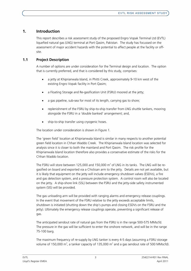
EVTL RISK ASSESSMENT STUDY
EVTL 3 2542214-R01 Rev FINAL
Lloyd’s Register EMEA April 2011
1. Introduction
This report describes a risk assessment study of the proposed Engro Vopak Terminal Ltd (EVTL)
liquefied natural gas (LNG) terminal at Port Qasim, Pakistan. The study has focussed on the
assessment of major accident hazards with the potential to affect people at the facility or off-
site.
1.1 Project Description
A number of options are under consideration for the Terminal design and location. The option
that is currently preferred, and that is considered by this study, comprises:
• a jetty at Khiprianwala Island, in Phitti Creek, approximately 9-10 km west of the
existing Engro Vopak facility in Port Qasim;
• a Floating Storage and Re-gasification Unit (FSRU) moored at the jetty;
• a gas pipeline, sub-sea for most of its length, carrying gas to shore;
• replenishment of the FSRU by ship-to-ship transfer from LNG shuttle tankers, mooring
alongside the FSRU in a ‘double banked’ arrangement; and,
• ship-to-ship transfer using cryogenic hoses.
The location under consideration is shown in Figure 1.
The ‘green field’ location at Khiprianwala Island is similar in many respects to another potential
green field location in Chhan Waddo Creek. The Khiprianwala Island location was selected for
analysis since it is closer to both the mainland and Port Qasim. The risk profile for the
Khiprianwala Island location therefore also provides a conservative estimate of the risks for the
Chhan Waddo location.
The FSRU will store between 125,000 and 150,000 m3 of LNG in its tanks. The LNG will be re-
gasified on board and exported via a Chicksan arm to the jetty. Details are not yet available, but
it is likely that equipment on the jetty will include emergency shutdown valves (ESDVs), a fire
and gas detection system, and a pressure protection system. A control room will also be located
on the jetty. A ship-shore link (SSL) between the FSRU and the jetty-side safety instrumented
system (SIS) will be provided.
The gas unloading arm will be provided with ranging alarms and emergency release couplings.
In the event that movement of the FSRU relative to the jetty exceeds acceptable limits,
shutdown is initiated (shutting down the ship’s pumps and closing ESDVs on the FSRU and the
jetty). Ultimately the emergency release couplings operate, preventing a significant release of
gas.
The anticipated sendout rate of natural gas from the FSRU is in the range 500-575 MMscfd.
The pressure in the gas will be sufficient to enter the onshore network, and will be in the range
75-100 barg.
The maximum frequency of re-supply by LNG tanker is every 4-5 days (assuming a FSRU storage
volume of 150,000 m3, a tanker capacity of 135,000 m
3 and a gas sendout rate of 500 MMscfd).

EVTL RISK ASSESSMENT STUDY
EVTL 4 2542214-R01 Rev FINAL
Lloyd’s Register EMEA April 2011
Ship-to-ship (STS) transfer is by means of cryogenic hoses. Typically up to 6 no. 8” diameter
hoses are used, with a total transfer rate of around 5000 m3/h. Each hose is equipped is
equipped with an emergency release coupling.
1.2 Hazards of Natural Gas and Liquefied Natural Gas
1.2.1 Properties of Natural Gas
Natural gas (NG) is a mixture of methane (the main constituent) and other low molecular weight
hydrocarbons (such ethane and propane). LNG is natural gas that is kept in liquid form at
extremely low temperatures and pressures close to atmospheric. The liquefaction process
requires that contaminants such as water and carbon dioxide are removed, so that the
concentration of such contaminants in LNG, and natural gas produced by vaporising LNG, is
extremely low. The physical properties of methane, ethane and propane are summarised in
Table 1.
Table 1: Physical Properties of Natural Gas Constituents
Substance Property
Methane Ethane Propane
Chemical Formula CH4 C2H6 C3H8
Molecular weight 16.04 30.07 44.09 Atmospheric boiling
point (°C)
-161.5 -88.6 -42.1
Liquid specific gravity (relative to water = 1)
0.422
(at -160°C)
0.546
(at -88.6°C)
0.590
(at -50°C)
Gas specific gravity (relative to air = 1)
0.55 1.1 1.5
Lower Flammable Limit (% v/v)
5 2.9 2.1
Upper Flammable Limit (% v/v)
15 13 9.5
Source: Cheremisinoff, N P (2000). Handbook of Hazardous Chemical Properties
Natural gas’s hazards arise from its flammability and vapour dispersion properties. LNG presents
an additional hazard in the form of extreme cold (being held at a temperature of approximately
-162°C). Note that natural gas is not toxic (although it may act as an asphyxiant by displacing
air).
1.2.2 Fire and Explosion Hazards
Natural gas, when released from containment as a gas, or when generated by vaporisation of a
release of LNG, forms flammable mixtures in air between concentrations of 5 and 15 % vol/vol.
Although natural gas at ambient temperature is less dense than air, the natural gas vapour
generated by LNG at -162°C is approximately 1.5 times denser than air at 25°C. Hence natural
gas as a gas under pressure at ambient temperature rapidly becomes buoyant upon release.
However, the cold vapour generated by vaporisation of LNG behaves as a dense cloud.
Although as the cold vapour mixes with air it becomes warmer and less dense, the cloud will
tend to remain negatively buoyant until after it has dispersed below its lower flammability limit
(LFL).

EVTL RISK ASSESSMENT STUDY
EVTL 5 2542214-R01 Rev FINAL
Lloyd’s Register EMEA April 2011
Different types of fire hazard may arise, depending on whether it is gaseous natural gas or LNG
that is released. These fire hazards include jet fires, flash fires and pool fires. In certain
circumstances, vapour cloud explosions (VCEs) may also occur.
1.2.2.1 Jet Fires
A jet fire is a strongly directional flame caused by burning of a continuous release of pressurised
flammable gas (in this case natural gas) close to the point of release. Ignition may occur soon
after the release begins; or may be delayed, with the flame burning back through the cloud (i.e.
as a flash fire, see below) to the source. Jet fires may result from ignited leaks from process
equipment (vessels, pipes, gaskets etc.) and pipelines.
A jet fire may be directed horizontally or vertically (or at some angle in between). A jet fire may
impinge on structures or other process equipment, giving a potential for escalation of the
incident. The intensity of thermal radiation emitted by jet fires can be sufficient to cause harm
to exposed persons.
1.2.2.2 Flash Fires
Flash fires result from ignition of a cloud of flammable gas or vapour, when the concentration
of gas within the cloud is within the flammable limits. In this case, the flammable cloud may be
generated by:
• A release of pressurised flammable gas (i.e. natural gas); or,
• Vaporisation of a pool of volatile flammable liquid (i.e., LNG).
Typically a flash fire occurs as a result of delayed ignition, once the flammable cloud has had
time to grow and reach an ignition source. In the absence of confinement or congestion,
burning within the cloud takes place relatively slowly, without significant over-pressure. It is
assumed that thermal effects are generally limited to within the flame envelope where there is a
very high probability of death.
1.2.2.3 Pool Fires
Ignited releases of flammable liquids (including LNG) tend to give rise to pool fires. As with jet
fires, ignition of the liquid pool may occur soon after the release begins, or may occur as a result
of flashback from a remote ignition source if the liquid is sufficiently volatile to generate a cloud
of flammable vapour.
1.2.2.4 Vapour Cloud Explosions
When a cloud of flammable gas occupies a region which is confined or congested, and is
ignited, a vapour cloud explosion results. The presence of confinement (in the form of walls,
floors and / or a roof) or congestion (such as the pipes, vessels and other items associated with
process plant) in and around the flammable cloud results in acceleration of the flame upon
ignition. This flame acceleration generates blast over-pressure. The strength of the blast
depends on a number of factors, including:
• The reactivity of the fuel;
• The degree of confinement or congestion;
• The size of the congested / confined region occupied by the flammable cloud; and,
• The strength of the ignition source.

EVTL RISK ASSESSMENT STUDY
EVTL 6 2542214-R01 Rev FINAL
Lloyd’s Register EMEA April 2011
It should be noted that a variety of objects may act as confinement / congestion, in addition to
those normally encountered on process plant. Investigation of the explosion and fire at
Buncefield, UK, in 2005 suggested that areas of dense vegetation bordering the site had
provided sufficient congestion to result in flame acceleration and generation of damaging levels
of overpressure.
1.2.3 Cryogenic Burns
The extremely low (cryogenic) temperature of LNG means that it can cause burns if it comes into
contact with exposed skin. Furthermore, inhalation of the cold vapours generated by LNG can
cause damage to the lungs (so-called ‘frosting of the lungs’).
1.2.4 Rapid Phase Transition
If LNG is spilt on to water it usually forms a boiling pool on the water surface. However, under
certain circumstances, LNG can released on to water can change from liquid to vapour virtually
instantaneously. The effect has been observed in some experiments involving LNG but is not
well understood. A Rapid Phase Transition (RPT) can generate overpressure and a ‘puff’ of
dispersing vapour. Any damage from the overpressure generated tends to be quite localised.
Rapid phase changes have not resulted in any known major incidents involving LNG.

EVTL RISK ASSESSMENT STUDY
EVTL 7 2542214-R01 Rev FINAL
Lloyd’s Register EMEA April 2011
Figure 1: Proposed Terminal Location

EVTL RISK ASSESSMENT STUDY
EVTL 8 2542214-R01 Rev FINAL
Lloyd’s Register EMEA April 2011
2. Overview of Risk Assessment Methodology
The risk assessment study has comprised the following steps:
• identification of major accident hazards (MAHs);
• assessment of the consequences of potential MAHs;
• assessment of the frequency of potential MAHs;
• determination of the risks from potential MAHs (using risk matrices); and,
• consideration of further measures that might be taken to reduce the risks, where
appropriate.
The identification of hazards has been reported separately (Lloyd's Register Report No.
OGL/DA/100260). Each of the subsequent steps is described in more detail in the remaining
sections of this report.
The identified MAHs were assessed in terms of their potential consequences, and the frequency
with which they might occur. Consequences were expressed in terms of a ‘Severity Category’,
as defined in Table 2. For each MAH, severity categories were assigned for both personnel at
the facility (i.e. ‘on-site’) and for members of the public (i.e. ‘off-site’). The corresponding
frequencies were expressed as a ‘Frequency Category’, as defined in Table 3.
Table 2: Severity Categories
Category Definition
A No fatalities. Some serious injuries or health effects. B At most 1 fatality. C More than one and up to ten fatalities. D More than ten fatalities and up to thirty fatalities E More than thirty fatalities
Table 3: Frequency Categories
Category Frequency, F (per year)
1 F < 10-6
2 10-6 ≤ F < 10
-5
3 10-5 ≤ F < 10
-4
4 10-4 ≤ F < 10
-3
5 F ≥ 10-3
Each MAH was then plotted on an on-site risk matrix and an off-site risk matrix, as shown in
Figure 2 and Figure 3 respectively.

EVTL RISK ASSESSMENT STUDY
EVTL 9 2542214-R01 Rev FINAL
Lloyd’s Register EMEA April 2011
Figure 2: On-Site Risk Matrix
Severity
A B C D E
5 M H H H H
4 M M M H H
3 L M M M H
2 L M M M M
Fre
qu
en
cy
1 L L L M M
Key
H High Risk. Actions required to reduce risk as a matter of priority
M Medium Risk. Consider whether further risk reduction would be beneficial.
L Low Risk. Check against regulatory compliance and relevant good practice.

EVTL RISK ASSESSMENT STUDY
EVTL 10 2542214-R01 Rev FINAL
Lloyd’s Register EMEA April 2011
Figure 3: Off-Site Risk Matrix
Severity
A B C D E
5 H H H H H
4 M H H H H
3 M M M H H
2 L M M M H
Fre
qu
en
cy
1 L L M M M
Key
H High Risk. Actions required to reduce risk as a matter of priority
M Medium Risk. Consider whether further risk reduction would be beneficial.
L Low Risk. Check against regulatory compliance and relevant good practice.

EVTL RISK ASSESSMENT STUDY
EVTL 12 2542214-R01 Rev FINAL
Lloyd’s Register EMEA April 2011
3. Major Accident Hazard Scenarios
Using the HAZID output, a set of major accident hazard scenarios was developed for risk
assessment. The scenarios related to leaks from equipment of either gaseous natural gas or
LNG, arising from a variety of causes. The list of scenarios is presented in Table 5.
A separate assessment of marine events (i.e. accidents involving the LNG carrier whilst in transit
and accidents involving vessels passing the FSRU location) has also been performed. The marine
events assessed were:
• Vessel experiencing engine failure whilst passing the LNG offloading facility and drifting
into the LNG carrier (LNGc);
• LNGc experiencing machinery failure resulting in loss of vessel control, LNGc runs
aground or collides with another vessel;
• LNGc experiencing steering failure resulting in loss of vessel control, LNGc runs aground
or collides with another vessel; and,
• LNGc experiencing machinery failure or steering failure resulting in loss of vessel control,
LNGc collides with FSRU.

EVTL RISK ASSESSMENT STUDY
EVTL 13 2542214-R01 Rev FINAL
Lloyd’s Register EMEA April 2011
Table 5: Major Accident Hazard Scenario List
Reference Description Size / Type
S M L1
Release of LNG from the pipework between the FRSU tanks and the HP Pump Suction Drums.
L S M L2
Release of LNG from the HP Pump Suction Drums and pipework feeding the HP Pumps.
L S M L3 Release of LNG from the HP Pumps discharge pipework up to the Vaporisers.
L S M L4 Release of LNG from a transfer hose during ship to ship transfer.
L S M
G1
Release of natural gas from the pipework between the vaporiser outlets and the ship-side ESDV upstream of the gas unloading arm.
L S M G2
Release of natural gas from the pipework between the ship-side ESDV upstream of the gas unloading arm and the first jetty ESDV.
L S M G3
Release of natural gas from the pipework between the first jetty ESDV and the second Jetty ESDV.
L S M G4
Release of natural gas from the pipework between the second Jetty ESDV and the third Jetty ESDV (at the entry to the natural gas pipeline).
L
G5 Releases of natural gas from the FSRU relief system under fire conditions. Single valve
Key: S: Small M: Medium L: Large

EVTL RISK ASSESSMENT STUDY
EVTL 14 2542214-R01 Rev FINAL
Lloyd’s Register EMEA April 2011
4. Consequence Assessment
4.1 Consequence Modelling
4.1.1 Modelling Cases
Using the Major Accident Hazard scenario list in Table 5 and the information sources in Table 4,
a list of cases for consequence assessment was developed. Each case was then modelled using
the DNV PHAST software version 6.53.1. The list of cases for PHAST modelling is presented in
Table 6.

EVTL RISK ASSESSMENT STUDY
EVTL 15 2542214-R01 Rev FINAL
Lloyd’s Register EMEA April 2011
Table 6: PHAST Modelling Cases
Ref. Description Size Hole Size
(mm)
Maximum Line Dia.
(mm)
Pressure (Bara)
Temp (
oC)
Released Material
Elevation above sea level (m)
Comments
S 5 M 25 L1
Release from pipework between the FRSU tanks and the HP Pump Suction Drums. L 300
300 10 -161.4 LNG 15 Liquid flow limited by system pump rate. Potential for explosion in regassification area.
S 5 M 25 L2
Release from the HP Pump Suction Drums and pipework feeding the HP Pumps. L 200
200 3 -161.4 LNG 20 Liquid flow limited by system pump rate. Potential for explosion in regassification area.
S 5 M 25 L3
Release from the HP Pumps discharge pipework up to the Vaporisers. L 100
100 100 -161.4 LNG 20 Liquid flow limited by system pump rate. Potential for explosion in regassification area.
S 5 M 25 L4
Release from a transfer hose during ship to ship transfer.
L 300
300 10 -161.4 LNG 10 Liquid flow limited by system pump rate.
S 5 M 25 G1
Release from the pipework between the vaporiser outlets and the ship-side ESDV upstream of gas unloading arm.
L 300 300 5 -161.4 LNG
5 (above deck)
Liquid flow limited by system pump rate. Potential for explosion in regassification area.
S 5 M 25
G2
Release from the pipework between the ship-side ESDV upstream of the gas unloading arm and the first jetty ESDV.
L 40 400 100 10
Natural Gas
20
Liquid flow limited by system pump rate. Section contains the articulated loading arm.
S 5 M 25 G3
Release from the pipework between the first jetty ESDV and the second Jetty ESDV. L 400
400 100 10 Natural
Gas 10
S 5 M 25 G4
Release from the pipework between the second Jetty ESDV and the third Jetty ESDV. L 400
400 100 10 Natural
Gas 5
G5 Release from the FSRU relief system under fire conditions.
Single Relief valve
490 (vent)
1.25 -158 Natural
Gas 30
Thermal effects from relief flame calculated under maximum flow conditions.

EVTL RISK ASSESSMENT STUDY
EVTL 16 2542214-R01 Rev FINAL
Lloyd’s Register EMEA April 2011
4.1.2 Weather
Detailed information on weather stability classes is not available. Inspection of the climate data
for the area provided in the Environmental and Social Impact Report (EMC, 2011), for the
proposed scheme leads to the following assumptions for the stability classes and wind speeds to
be used for modelling purposes are detailed in Table 7.
Table 7: Weather Conditions
Weather Conditions
Time of Day
Stability Class
Temperature
(°C)
Relative Humidity (%)
Wind Direction
(from) (°) Wind Speed
(m/s)
Day D 33 64 225 9 South West Monsoon Night D 27 28 225 2
Day B 27 4 45 4 North East Monsoon Night F 12 63 45 2
Many of the releases considered are momentum-driven releases of gas. Modelling of releases of
this type are not particularly sensitive to assumptions about stability class.
4.1.3 Assumptions
4.1.3.1 Maximum Flowrates
Where material is released from a system downstream of a pump it has been assumed that the
maximum flowrate is limited to the normal pumping rate plus 20%. This accounts for pump
operation at overspeed with reduced discharge head.
Where a PHAST ‘modelled case’ result gave a flowrate in excess of the assumed maximum, the
case was converted to a ‘user-defined’ case at the assumed maximum rate.
4.1.3.2 Release Duration and Release Limits
When assessing systems for the transfer of LNG or natural gas it has been assumed that releases
can be either isolated (i.e. emergency shutdown successful) or unisolated (i.e. emergency
shutdown fails). For the case of isolated releases it is assumed that isolation of the leak by
automated systems is relatively rapid, shutting down pumps and closing automatic valves
within either 30 or 60 seconds, depending upon the scenario being considered and information
from the system HAZID. Unisolated releases are assumed to be of 600 seconds duration; the
time required to manually shut down the process.
The maximum quantity of LNG or natural gas has been limited in each case to the quantity
released prior to isolation plus the quantity remaining in the isolated system (pipework, vessels
etc.).
It has also been assumed that the rate of release after isolation is the same as the release before
isolation. This is considered to be a worst case assumption as in reality the release rate will tend
to decrease following isolation.
4.1.3.3 Release Elevation and Orientation
Release elevations have been used are based on elevations that are typical for the FRSU,
associated offloading systems and jetty i.e.
� FRSU Deck: 15 m above water level.

EVTL RISK ASSESSMENT STUDY
EVTL 17 2542214-R01 Rev FINAL
Lloyd’s Register EMEA April 2011
� FRSU topside process: Average of 5 m above the FRSU deck.
� FRSU relief system vent: 15 m above deck level.
� Jetty: 4 m above water level.
Releases of LNG during ship to ship transfer are assumed to be released downwards onto water
and releases from relief system are assumed to be released vertically.
4.1.3.4 Bunding
It has been assumed that releases of LNG on the tanker deck can form pools. Modelling has
been based on these pools being unconfined.
4.1.3.5 Flammable clouds
Flammability has been assumed to extend to the concentration that is 50% of the lower
flammable limit.
4.1.3.6 Explosions
Explosions have been assessed where releases have the potential for a build up of gas in the
regassification area of the FRSU. These are the cases where LNG and natural gas (prior to
offloading) may be released; scenarios L1, L2, L3 and G1. As relatively small releases of liquid
can produce enough gas to fill this area only one explosion scenario has been considered for
each section.
4.1.3.7 Release Composition
LNG/natural gas has been assumed to be 100% methane for the purposes of modelling.
4.1.3.8 Impact Distances
Review of the area surrounding the proposed terminal location indicate the following features
that may be at risk from a release on LNG or NG.
Table 8: Location of Populations
Feature Distance (m)
Direction
Comments
Khiprianwala Island
FRSU Supply Vessel and Jetty
0-150 All directions
Personnel on tanker or involved in Jetty operations at risk.
Tanker safety distance
200 Towards traffic in
the shipping channel
Recommended safety distance (from Hazard Identification Study). Beyond this distance
other river users are at risk. Korangi Fish
Harbour 3200 North West
Closest land based routinely occupied area (members of the public)
Brown – field site FRSU Supply
Vessel and Jetty
0-150 All directions Personnel on tanker or involved in Jetty
operations at risk.
Tanker safety distance
200 Towards traffic in
the shipping channel
Recommended safety distance (from Hazard Identification Study). Beyond this distance
other river users are at risk. EVTL existing
Jetty 500 South West

EVTL RISK ASSESSMENT STUDY
EVTL 18 2542214-R01 Rev FINAL
Lloyd’s Register EMEA April 2011
FAP Terminal 850 South East IOCB Jetty 900 North West
Premises of QITC boundary
1200 South East
4.1.3.9 Impact Criteria
The criteria shown in Table 9 were used for the analysis.Table 9: Impact Criteria
Event Level 1 Level 2 Level 3 Units
Jet or Pool Fire 4 12.5 37.5 kW/m2
Flash Fire ½ LFL - - - Explosion 0.02068 0.1379 0.2068 bar Key: LFL: lower flammability limit
A description of the impact criteria effects is shown in Table 10, based on information presented
in Reference (3).
Table 10: Impact Criteria Effects
Impact Value
Units Effect
Thermal Impact 37.5 kW/m
2 Intensity at which damage is caused to process equipment
12.5 kW/m2 Intensity at which piloted ignition of wood occurs
4 kW/m2 Sufficient to cause pain in exposed skin after about 15s, blistering
after about 30s. Fire ½ LFL - Extent of flammable region of gas cloud Overpressure 0.02068 bar Window breakage 0.1379 bar Significant damage to masonry structures 0.2068 bar Distortion of steel framed structures
4.1.4 Results
The PHAST modelling results are displayed in Table 11.

EVTL RISK ASSESSMENT STUDY
EVTL 19 2542214-R01 Rev FINAL
Lloyd’s Register EMEA April 2011
Table 11: PHAST Results
SW Monsoon - Day SW Monsoon - Night NE Monsoon - Day NE Monsoon - Night
Ref. Description Size Outcome
Level 1
Level 2
Level 3
Level 1
Level 2
Level 3
Level 1
Level 2
Level 3
Level 1
Level 2
Level 3
S JF FL:8.7 FL:12.4 FL:10.2 FL:12.4 M JF 62 44 FL:34 76 57 FL:48 71 51 FL:40 76 57 FL:48 L JF 227 173 139 273 217 182 261 199 161 273 217 182
S FF 25 18 17 19.7 M FF 76 105 49 99 L FF 743 514 614 481
S PF 7.1 5.5 4.3 8.6 5.7 3.1 8.1 5.6 3.6 9.9 6.6 3.4 M PF 90 62 43 105 64 36 108 68 43 104 64 36 L PF 380 252 170 443 270 151 469 291 181 443 270 153
L1 Release from pipework between the FRSU tanks and the HP Pump Suction Drums.
L EX 676 131 98 680 132 99 680 132 99 692 134 101
S JF FL:7.2 FL:10.3 FL:8.5 FL:10.3 M JF 45 FL:28 m 56 FL:40 m 52 FL:33 m 56 FL:40 m L JF 233 177 141 286 226 186 271 206 165 286 226 187
S FF 27 20 16 21 M FF 90 56 49 71 L FF 341 728 893 745
S PF 3.6 3.1 3 5.1 3.6 2.8 4.6 3.4 3.3 7.7 5.2 3.1 M PF 64 44 31 75 46 26 76 48 31 75 47 26 L PF 179 121 82 182 112 62 199 124 78 180 110 62
L2
Release from the HP Pump Suction Drums and pipework feeding the HP Pumps.
L EX 676 131 98 680 132 99 680 132 99 692 134 101
S JF FL: 12 FL:17.1 FL:14.1 FL: 17.1 M JF 92 62 44 100 84 FL:69 103 77 FL:57 110 84 FL:68 L JF 102 274 52 121 94 75 114 85 FL 121 94 FL:
S FF 34 28 25 28 M FF 114 117 85 113 L FF 242 346 327 349
S PF 18 13 8.1 19 12 6.4 19 13 7.6 22 14 7.3 M PF 161 108 74 177 108 60 188 117 74 176 108 61 L PF 179 121 82 182 112 62 199 124 78 180 111 62
L3 Release from the HP Pumps discharge pipework up to the Vaporisers.
L EX 676 131 98 680 132 99 680 132 99 692 134 101
S JF FL: 7.8 FL:11 FL:9.2 FL: 11.2 M JF 57 41 FL: 30 69 53 43 65 48 Fl: 36 69 53 43 L JF 270 207 169 328 261 218 313 240 195 328 261 219
S FF 22 15 14 9.5
L4 Release from a transfer hose during ship to ship transfer.
M FF 61 171 60 115

EVTL RISK ASSESSMENT STUDY
EVTL 20 2542214-R01 Rev FINAL
Lloyd’s Register EMEA April 2011
SW Monsoon - Day SW Monsoon - Night NE Monsoon - Day NE Monsoon - Night
Ref. Description Size Outcome
Level 1
Level 2
Level 3
Level 1
Level 2
Level 3
Level 1
Level 2
Level 3
Level 1
Level 2
Level 3
L FF 1015 695 964 658
S PF 5.6 4.6 4.1 5.4 3.5 2.7 5.8 4.3 3.2 5.4 3.6 2.7 M PF 64 44 22 63 38 16 69 44 21 62 37 16 L PF 194 130 73 188 111 51 209 131 71 186 110 52
S JF FL: 6.1 FL: 7.7 FL: 7.7 FL: 7.5 M JF 48 FL: 37 47 FL: 32 50 FL: 33 47 FL: 37 L JF 183 140 105 191 130 89 200 140 99 191 130 90
S FF 13 13 11 12 M FF 57 62 52 57 L FF 196 213 166 217
G1
Release from the pipework between the vaporiser outlets and the ship-side ESDV upstream of gas unloading arm.
L EX 676 131 98 680 132 99 680 132 99 692 134 101
S JF FL: 8 FL: 7.7 FL: 7.7 FL: 7.5 M JF 53 39 FL: 37 52 35 FL: 32 54 38 FL: 33 52 35 FL: 31 L JF 181 143 113 192 135 99 200 144 105 192 135 100
S FF 12 12 11 11 M FF 54 60 51 56
G2
Release from the pipework between the ship-side ESDV upstream of the gas unloading arm and the first jetty ESDV.
L FF 217 245 202 241
S JF FL: 8 FL: 7.7 FL: 7.7 FL: 7.5 M JF 53 44 35 53 40 29 55 42 32 53 40 29 L JF 180 143 118 192 137 102 200 145 107 192 137 102
S FF 12 12 10 11 M FF 48 54 47 54
G3 Release from the pipework between the first jetty ESDV and the second Jetty ESDV.
L FF 305 27 264 270
S JF FL: 8 FL: 7.7 FL: 7.7 FL: 7.5 M JF 53 39 FL: 37 52 35 FL: 32 54 38 FL: 33 52 35 FL: 31 L JF 181 143 113 192 135 99 200 144 105 192 135 100
S FF 12 12 11 11 M FF 54 60 51 56
G4
Release from the pipework between the second Jetty ESDV and the third Jetty ESDV.
L FF 217 245 202 241
G5 Release from the FSRU relief system under fire conditions
Single Fire
JF 72 NR NR 49 NR NR 78 NR NR 49 NR NR
Key: NR: Impact level not reached JF: Jet Fire FF: Flash Fire
PF: Pool Fire EX: Explosion. Fl: Flame Length (Reported when the impact criteria is relatively close to the flame).

EVTL RISK ASSESSMENT STUDY
EVTL 21 2542214-R01 Rev FINAL
Lloyd’s Register EMEA April 2011
4.2 Severity Categories
The PHAST results were used to select the appropriate severity category for each MAH scenario.
Separate severity categories were assigned for on-site and off-site effects. When determining
the appropriate severity category, the distance from the release source to potential receptors
was taken into account. The severity categories used are defined in Table 2. The results are
displayed in Table 12 below.

EVTL RISK ASSESSMENT STUDY
EVTL 22 2542214-R01 Rev FINAL
Lloyd’s Register EMEA April 2011
Table 12: Assigned Severity Categories
No. Description Size Outcome On-Site Severity
Comment Off-Site Severity
Comment
S JF B Jet flame on FSRU. Potential for harm to personnel on the FSRU if close to the jet flame. Minimal impact at areas beyond the FSRU.
A No off-site impact.
M JF C
Flame and 12.5 kW/m2contour within FSRU area.
Potential for harm to personnel on the FSRU, possible harm to personnel on supply tanker depending on flame direction. Less potential for harm to people on jetty as they are at a lower level.
A 4 kW/m
2 contour could extend beyond
FSRU/supply tanker boundary but not beyond the river exclusion zone.
L JF D 4 kW/m
2contour in FSRU area and could impact the
supply tanker and jetty. Potential for harm to personnel on the FSRU, supply tanker and jetty.
B 4 kW/m
2 contour could extend beyond the river
exclusion zone. Some potential for harm to people on passing vessels if close to the site.
S FF C Flash fire limited to FSRU. Fatal to personnel if in the area affected.
A No off-site impact.
M FF D Flash fire within FSRU area. Potential for harm to personnel on the FSRU, possible harm to personnel on supply tanker or jetty,
A Flash fire could extend beyond FSRU/supply vessel boundary but not beyond river exclusion zone.
L FF E Flash fire extends up to 890 m. Severe impact on personnel on the FSRU, jetty and supply tanker
D Flash fire extent covers the river and would be harmful to people on passing vessels.
S PF B Potential for harm to personnel on the FSRU if close to the pool fire.
A No off-site impact.
M PF C 4 kW/m
2contour within FSRU area. Potential for
harm to personnel on the FSRU, possible harm to personnel on supply tanker or jetty.
A 4 kW/m
2 contour could extend beyond
FSRU/supply tanker boundary but not beyond river exclusion zone.
L PF D
4 kW/m2contour on the FSRU deck, could impact
the supply tanker and jetty. Potential for harm to personnel on the FSRU, supply tanker and jetty. Burning liquid could fall onto river surface and into FSRU.
B 4 kW/m
2 contour could extend beyond the river
exclusion zone. Some potential for harm to people on passing vessels if close to the site.
L1
Release from pipework between the FSRU tanks and the HP Pump Suction Drums.
L EX E Very high overpressures on the FSRU, jetty and supply vessel. 0.2068 bar contour covers the majority of the area.
C Damage to vessels on river if in the area. Possible fatalities / injuries on vessels.
S JF B Jet flame on FSRU. Potential for harm to personnel on the FSRU if close to the jet flame. Minimal impact at areas beyond the FSRU.
A No off-site impact. L2
Release from the HP Pump Suction Drums and pipework feeding the HP Pumps. M JF C Flame and 12.5 kW/m
2contour within FSRU area.
Potential for harm to personnel on the FSRU, possible harm to personnel on supply tanker depending on flame direction. Less potential for
A 4 kW/m2 contour could extend beyond
FSRU/supply tanker boundary but not beyond river exclusion zone.

EVTL RISK ASSESSMENT STUDY
EVTL 23 2542214-R01 Rev FINAL
Lloyd’s Register EMEA April 2011
No. Description Size Outcome On-Site Severity
Comment Off-Site Severity
Comment
harm to people on jetty as they are at a lower level.
L JF D 4 kW/m
2contour in FSRU area and could impact the
supply tanker and jetty. Potential for harm to personnel on the FSRU, supply tanker and jetty.
B 4 kW/m
2 contour could extend beyond the river
exclusion zone. Some potential for harm to people on passing vessels if close to the site.
S FF C Flash fire limited to FSRU. Fatal to personnel if in the area affected.
A No off-site impact.
M FF D Flash fire within FSRU area. Potential for harm to personnel on the FSRU, possible harm to personnel on supply tanker or jetty.
A Flash could extend beyond FSRU/supply tanker boundary but not beyond river exclusion zone.
L FF E Flash fire extends up to 743 m. Severe impact on personnel on the FSRU, jetty and supply tanker.
D Flash fire extent covers the river and would be harmful to people on passing vessels.
S PF B Potential for harm to personnel on the FSRU if close to the pool fire.
A No off-site impact.
M PF C 4 kW/m
2contour within FSRU area. Potential for
harm to personnel on the FSRU, possible harm to personnel on supply tanker or jetty.
A 4 kW/m
2 contour could extend beyond
FSRU/supply tanker boundary but not beyond river exclusion zone.
L PF D
4 kW/m2contour on the FSRU deck, could impact
the supply vessel and jetty. Potential for harm to personnel on the FSRU, supply tanker and jetty. Burning liquid could fall onto river surface and into FSRU.
A 4 kW/m
2 contour does not extend into the river
exclusion zone. Slight potential for harm to people on passing vessels if close to the site.
L EX E Very high overpressures on the FSRU, jetty and supply vessel. 0.2068 bar contour covers the majority of the area.
C Damage to vessels on river if in the area. Possible fatalities / injuries on vessels.
S JF B Jet flame on FSRU. Potential for harm to personnel on the FSRU if close to the jet flame. Minimal impact at areas beyond the FSRU.
A No off-site impact.
M JF C
Flame and 37.5 kW/m2contour within FSRU area.
Potential for harm to personnel on the FSRU, possible harm to personnel on supply tanker and jetty.
A 4 kW/m
2 contour could extend beyond
FSRU/supply tanker boundary but not beyond river exclusion zone.
L JF D
4 kW/m2contour on the FSRU deck, could impact
the supply tanker and jetty. Potential for harm to personnel on the FSRU, supply tanker and jetty. Burning liquid could fall onto river surface and into FSRU.
C
37.5 kW/m2 contour could extend beyond the
river exclusion zone. Significant potential for harm to people on passing vessels if close to the site.
S FF C Flash fire limited to FSRU. Fatal to personnel if in the area affected.
A No off-site impact.
L3 Release from the HP Pumps discharge pipework up to the Vaporisers.
M FF D Flash fire within FSRU area. Potential for harm to personnel on the FSRU, possible harm to personnel
A Flash could extend beyond FSRU/supply vessel boundary but not beyond river exclusion zone.

EVTL RISK ASSESSMENT STUDY
EVTL 24 2542214-R01 Rev FINAL
Lloyd’s Register EMEA April 2011
No. Description Size Outcome On-Site Severity
Comment Off-Site Severity
Comment
on supply tanker or jetty,
L FF E Flash fire extends up to 350 m. Severe impact on personnel on the FSRU, jetty and supply tanker.
C Flash fire extent reaches the river and would be harmful to people on passing vessels.
S PF B Potential for harm to personnel on the FSRU if close to the pool fire.
A No off-site impact.
M PF C 4 kW/m
2contour within FSRU area. Potential for
harm to personnel on the FSRU, possible harm to personnel on supply tanker or jetty.
A 4 kW/m
2 contour could extend beyond
FSRU/supply tanker boundary but not beyond river exclusion zone.
L PF D
4 kW/m2contour on the FSRU deck, could impact
the supply tanker and jetty. Potential for harm to personnel on the FSRU, supply tanker and jetty. Burning liquid could fall onto river surface and into FSRU.
A
4 kW/m2 contour could extend beyond
FSRU/supply tanker boundary and just into the river exclusion zone. Unlikely to cause harm on the river.
L EX E Very high overpressures on the FSRU, jetty and supply tanker. 0.2068 bar contour covers the majority of the area.
C Damage to vessels on river if in the area. Possible fatalities on vessels.
S JF B
Jet flame from hose/piping. Potential for harm to personnel on the FSRU or supply vessel if close to the jet flame/transfer area. Minimal impact at areas beyond the FSRU/supply vessel. Could strike the side of a vessel.
A No off-site impact.
M JF C
Flame and 37.5 kW/m2contour within the within
FSRU/supply vessel Potential for harm to personnel on the FSRU and supply vessel depending on flame direction. Less potential for harm to people on jetty as they are at a lower level and may be sheltered.
A 4 kW/m
2 contour could extend beyond
FSRU/supply tanker boundary but not beyond the river exclusion zone.
L JF D Severe damage to FSRU and supply vessel irrespective of flame direction. 37.5 kW/m
2contour
could extend beyond the vessels to the jetty. B
4 kW/m2 contour could extend beyond the river
exclusion zone. Some potential for harm to people on passing vessels if close to the site.
S FF B
Flash fire limited to the FSRU/supply tanker area with the main effects at river level between the vessels. Unlikely to lead to fatalities on the vessels. Could possibly affect the jetty.
A No off-site impact.
M FF C
Flash fire would be at river level the most significant risk would be to people on the jetty although there may be some protection as the main fire would be between the vessels. Some risk to personnel on the vessels.
A Flash could extend beyond FSRU/supply vessel boundary but not beyond river exclusion zone.
L4
Release from a transfer hose during ship to ship transfer.
L FF E Flash fire extends up to 1015 m. Severe impact on personnel on the FSRU, jetty and supply tanker
D Flash fire extent covers the river and would be harmful to people on passing vessels.

EVTL RISK ASSESSMENT STUDY
EVTL 25 2542214-R01 Rev FINAL
Lloyd’s Register EMEA April 2011
No. Description Size Outcome On-Site Severity
Comment Off-Site Severity
Comment
S PF B Pool fire between supply vessel and FSRU. Possible harm to someone on a vessel if on deck close to the area.
A No off-site impact.
M PF C Large pool fire between the FSRU and the supply tanker, this could envelop vessels and extend to the jetty area.
A 4 kW/m
2 contour could extend beyond
FSRU/supply tanker boundary but not beyond river exclusion zone.
L PF E
Very large pool fire surrounding vessels and potentially affecting the jetty area. 37.5 kW/m
2contour could extend for over 70 m, causing
severe damage to vessels and harm to personnel.
B 4 kW/m
2 contour could extend beyond the river
exclusion zone. Some potential for harm to people on passing vessels if close to the site.
S JF B Jet flame on FSRU. Potential for harm to personnel on the FSRU if close to the jet flame. Minimal impact at areas beyond the FSRU.
A No off-site impact.
M JF C
4 kW/m2contour within FSRU area. Potential for
harm to personnel on the FSRU, possible harm to personnel on supply tanker depending on flame direction. Less potential for harm to people on jetty as they are at a lower level.
A 4 kW/m
2 contour could extend beyond
FSRU/supply tanker boundary but not beyond the river exclusion zone.
L JF D 4 kW/m
2contour in FSRU area and could impact the
supply tanker and jetty. Potential for harm to personnel on the FSRU, supply tanker and jetty.
A 4 kW/m
2 contour could extend to the edge of
the river exclusion zone. No severe harm to someone on a river vessel.
S FF C Flash fire on vessel FSRU deck possible effects on the jetty if the vapour cloud is blown in that direction. Fatal to personnel if in the area affected.
A No off-site impact.
M FF D Large flash fire on vessel FSRU deck possible effects on the jetty if the vapour cloud is blown in that direction. Fatal to personnel if in the area affected.
A No off-site impact.
L FF E Very large flash fire affecting personnel on the vessels and jetty
B Could possibly extend into the river beyond the exclusion zone.
G1
Release from the pipework between the vaporiser outlets and the ship-side ESDV upstream of gas unloading arm.
L EX E Very high overpressures on the FSRU, jetty and supply vessel. 0.2068 bar contour covers the majority of the area.
C Damage to vessels on river if in the area. Possible fatalities on vessels.
S JF B
Jet flame on FSRU or jetty. Potential for harm to personnel on the FSRU or jetty if close to the jet flame. Minimal impact at areas beyond the FSRU/Jetty.
A No off-site impact.
M JF C 4 kW/m
2contour within FSRU and jetty area.
Potential for harm to personnel on the FSRU and jetty. Dependant upon flame direction.
A 4 kW/m
2 contour could extend beyond
FSRU/supply vessel boundary but not beyond the river exclusion zone.
G2
Release from the pipework between the ship-side ESDV upstream of the gas unloading arm and the first jetty ESDV
L JF D 4 kW/m2contour within FSRU and jetty area. A 4 kW/m
2 contour could extend to the edge of

EVTL RISK ASSESSMENT STUDY
EVTL 26 2542214-R01 Rev FINAL
Lloyd’s Register EMEA April 2011
No. Description Size Outcome On-Site Severity
Comment Off-Site Severity
Comment
Potential for harm to personnel on the FSRU and jetty. Dependant upon flame direction.
the river exclusion zone. No severe harm to someone on a river vessel.
S FF C Flash fire on vessel FSRU deck and the jetty. Fatal to personnel if in the area affected.
A No off-site impact.
M FF D Large flash fire on vessel FSRU deck and jetty cloud is blown in that direction. Fatal to personnel if in the area affected.
A No off-site impact.
(includes the gas unloading arm).
L FF E Very large flash fire affecting personnel on the vessels and jetty
B Could possibly extend into the river beyond the exclusion zone.
S JF B
Jet flame on FSRU or jetty. Potential for harm to personnel on the FSRU or jetty if close to the jet flame. Minimal impact at areas beyond the FSRU/Jetty.
A No off-site impact.
M JF C 4 kW/m
2contour within FSRU and jetty area.
Potential for harm to personnel on the FSRU and jetty. Dependant upon flame direction.
A 4 kW/m
2 contour could extend beyond
FSRU/supply tanker boundary but not beyond the river exclusion zone.
L JF D 4 kW/m
2contour within FSRU and jetty area.
Potential for harm to personnel on the FSRU and jetty. Dependant upon flame direction.
A 4 kW/m
2 contour could extend to the edge of
the river exclusion zone. No severe harm to someone on a river vessel.
S FF C Flash fire on the jetty. Fatal to personnel if in the area affected.
A No off-site impact.
M FF D Large flash fire on the jetty Fatal to personnel if in the area affected.
A No off-site impact.
G3
Release from the pipework between the first jetty ESDV and the second Jetty ESDV.
L FF E Very large flash fire affecting personnel on the jetty. Could harm the personnel on the vessels, although they may be protected.
B Could possibly extend into the river beyond the exclusion zone.
S JF B
Jet flame on FSRU or jetty. Potential for harm to personnel on the FSRU or jetty if close to the jet flame. Minimal impact at areas beyond the FSRU/Jetty.
A No off-site impact.
M JF C 4 kW/m
2contour within FSRU and jetty area.
Potential for harm to personnel on the FSRU and jetty. Dependant upon flame direction.
A 4 kW/m
2 contour could extend beyond
FSRU/supply vessel boundary but not beyond the river exclusion zone.
L JF D 4 kW/m
2contour within FSRU and jetty area.
Potential for harm to personnel on the FSRU and jetty. Dependant upon flame direction.
A 4 kW/m
2 contour could extend to the edge of
the river exclusion zone. No severe harm to someone on a river vessel.
S FF C Flash fire on the jetty. Fatal to personnel if in the area affected.
A No off-site impact.
G4
Release from the pipework between the second Jetty ESDV and the third Jetty ESDV.
M FF D Large flash fire on the jetty Fatal to personnel if in the area affected.
A No off-site impact.

EVTL RISK ASSESSMENT STUDY
EVTL 27 2542214-R01 Rev FINAL
Lloyd’s Register EMEA April 2011
No. Description Size Outcome On-Site Severity
Comment Off-Site Severity
Comment
L FF E Very large flash fire affecting personnel on the jetty. Could harm the personnel on the vessels, although they may be protected.
B Could possibly extend into the river beyond the exclusion zone.
G5
Release from the FSRU relief system under fire conditions
Single Fire
JF B
High levels of thermal radiation on the FSRU. Could lead to fatalities if unable to shelter. Note – in event of actual fire relief conditions the fire itself would have more severe consequences.
A No off-site impact.

EVTL RISK ASSESSMENT STUDY
EVTL 28 2542214-R01 Rev FINAL
Lloyd’s Register EMEA April 2011
4.3 Consequences of Marine Accidents
In extreme cases a release of LNG from the LNGc could result from grounding of the LNGc or
collision with another vessel. Collision between the FRSU and another vessel could also result in
a release of LNG. The frequencies of such events are very low, as discussed in Section 5.4.
Marine accidents of this type have been subjected to detailed analysis by the Sandia National
Laboratories in the USA (5). The study considered accidental and deliberate (i.e. due to terrorist
attack) breaches of LNGc cargo tanks. Fine element modelling was used to calculate breach
sizes. Spill rates and thermal flux hazard ranges from LNG pool fires on water were calculated.
Dispersion of natural gas vapour following un-ignited LNG releases was analysed using
computerised fluid dynamics (CFD). Note that intentional breaches fall outside the scope of this
risk assessment.
The authors used the results of the analysis to generate a set of public safety zones, reproduced
in Table 13 below.
Table 13 Recommended Public Safety Zones for Accidental Breaches (Sandia)
Potential Impact on Public Safety Event Potential Ship Damage and Spill
Potential Hazard High Medium Low
Collisions: Low speed
Minor ship damage, no spill
Minor ship damage
None None None
Collisions: Low speed
LNG cargo tank breach and small – medium spill
Damage to ship and small fire
∼250 m ∼250-750 m > 750 m
Grounding: < 3m high object
Minor ship damage, no breach
Minor ship damage
None None None
For a nominal accidental spill, the report indicates that hazard ranges (to LFL) from dispersing
vapour could extend up to 1700 m.
Sandia performed a re-assessment of their study in 2008, to account for the largest LNG carriers
that were then coming into service (6). The 2008 study did not result in any changes to the
Public Safety Zones; and focussed on intentional breaches.
With regards to the proposed EVTL facility, for the greenfield sites (Khiprianwala Island and
Chhan Waddo Creek) it is noted that the Public Safety Zones defined in Table 13 do not reach
members of the public on the mainland (see Table 8). The nearest point on the mainland is also
beyond the 1700 m distance quoted in the 2004 Sandia report for vapour dispersion from a
nominal accidental breach. However, there is clearly a potential for spills following accidental
breaches to impact other users of the shipping channel.
The closest facility to the brownfield site, 500m distance, is the EVTL’s LPG/chemicals plant.
According to Sandia Report this is outside the region of the most significant impact to public
safety and property. Furthermore EVTL’s LPG/chemicals plant has been purposely designed to
mitigate against such type of risk (hazardous area classification, non sparking certified ‘EXe’
equipment, ESD system, F&G detection, safety procedures etc.). The distance to other facilities

EVTL RISK ASSESSMENT STUDY
EVTL 29 2542214-R01 Rev FINAL
Lloyd’s Register EMEA April 2011
in the vicinity (Table 8) is above 750m i.e. in the region of Low Potential Impact to Public Safety
(Table 13). The facilities in question are not residential and potential upgrade or specific
operational procedures can be considered to further assure against the consequences of
accidental breaches. Similar to the greenfield sites there is clearly a potential for spills following
accidental breaches to impact other users of the shipping channel.
The detailed discussion about possible LNG Terminal sites is given in Section 3.1 of HAZID Study
OGL/DA/10026 (Appendix 1).

EVTL RISK ASSESSMENT STUDY
EVTL 30 2542214-R01 Rev FINAL
Lloyd’s Register EMEA April 2011
5. Frequency Assessment
5.1 Assessment Process
Frequency categories have been assigned to each MAH scenario by reference to a range of
frequency data sources, which are described later in this Section. In the majority of cases, the
process followed was to:
• assign a frequency category for occurrence of the release (e.g. the frequency of a small
leak of gas from a piece of equipment);
• modify the frequency to account for the probability of a leak becoming an effect (e.g.
ignition of a leak to give a jet fire); and,
• modify the frequency to account for the probability of the effect giving rise to a defined
outcome, namely the severity of the consequences defined in the consequence
assessment (e.g. a jet fire from an ignited leak pointing towards an occupied area and
causing a fatality).
5.2 Frequency Data Sources
5.2.1 Ignition Probabilities
Ignition probability assumptions are based on Appendix IX, Table IX.6.2 of Reference (1). These
data are reproduced in Table 14.
Table 14: Generic Ignition Probabilities
Release Rate Category
Release Rate (kg/s)
Ignition Probability (Immediate)
Ignition Probability (Delayed)
Small <5 0.005 0.02 Medium 5-25 0.04 0.2 Large >25 0.3 0.9
5.2.2 Failure Rates
5.2.2.1 Failures of Process Equipment
Data were obtained from Reference (2). While a full parts count has not been performed the
lengths of pipework have been included in the assessment.
These data have been used to inform the selection of a release frequency category during the
frequency assessment process, taking into account the equipment present.
5.2.2.2 Failures of the Natural Gas Offloading Arm
The UK Health and Safety Executive have developed a set of failure frequency data for failure of
LNG unloading arms on the basis of fault tree analysis. Hence data were obtained from
Reference (2), with the conservative assumption made that transfer of gas through the
offloading arm is continuous.

EVTL RISK ASSESSMENT STUDY
EVTL 31 2542214-R01 Rev FINAL
Lloyd’s Register EMEA April 2011
5.2.2.3 Failures of LNG Ship to Ship Transfer Hoses
It is noted that the ship-to-ship transfer method considered here, using cryogenic hoses, is
relatively new technology and therefore specific frequency data for such systems are not
available. This represents an area of uncertainty within the assessment.
Data were obtained from Reference (3), which contains generic frequency data for frequencies
of leaks during transfer of cargoes of dangerous substances. It was assumed that there will be a
delivery of LNG every 4 to 5 days and that small releases are a factor of 10 more frequent than
medium sized releases.
5.3 Results
The frequency assessment results are displayed in Table 15.

EVTL R ISK ASSESSMENT STUDY
EVTL 32 2542214-R01 Rev FINAL
Lloyd’s Register EMEA April 2011
Table 15: Frequency Assessment Results
Ref. Description Size Outcome Leak
Frequency Category
Effect Frequency Category
On-Site Outcome Frequency Category
Comments
Off-Site Outcome Frequency Category
Comments
S JF 4 2 1
Low probability of ignition for small leaks. Presence factor – someone would have to be close to the jet fire to be harmed.
1 No off site impact
M JF 4 3 2 Directional probability – jet flame would have to be directed towards occupied areas.
1 No off site impact
L JF 3 2 2 Directional probability – very likely to have personnel present within the areas that could be affected
1
Vessel would have to be close to the area for harm to occur. Jet would have to be towards the vessel.
S FF 4 1 1
Release would have to be undetected, low probability of ignition for small leaks. High chance of people in area affected.
1 No off site impact
M FF 4 1 1 Release would have to be undetected. High chance of people in area affected.
1 Vessel would have to be close to the area for harm to occur.
L FF 3 1 1
Release would have to be undetected. High probability of people in area affected. High probability of ignition of prolonged release.
1 Vessel would have to be close to the area for harm to occur.
S PF 4 2 1
Low probability of ignition for small leaks. Presence factor – someone would have to be close to the pool fire to be harmed.
1 No off site impact
M PF 4 3 3 Personnel will be present on the FSPU, high probability of personnel in area.
1 Vessel would have to be close to the area for harm to occur.
L PF 3 2 2 Personnel will be present on the FSPU, high probability of personnel in area.
1 Vessel would have to be close to the area for harm to occur.
L1
Release from pipework between the FRSU tanks and the HP Pump Suction Drums.
L EX 3 1 1 Release would have to be undetected, and lead to build up
1 Vessel would have to be close to the area for harm to occur.

EVTL R ISK ASSESSMENT STUDY
EVTL 33 2542214-R01 Rev FINAL
Lloyd’s Register EMEA April 2011
Ref. Description Size Outcome Leak
Frequency Category
Effect Frequency Category
On-Site Outcome Frequency Category
Comments
Off-Site Outcome Frequency Category
Comments
of gas in the congested area. High probability of people in area affected. High probability of ignition of prolonged release.
S JF 4 2 1
Low probability of ignition for small leaks. Presence factor – someone would have to be close to the jet fire to be harmed.
1 No off site impact
M JF 3 2 1 Directional probability – jet flame would have to be directed towards occupied areas.
1 No off site impact
L JF 2 1 1 Directional probability – very likely to have personnel present within the areas that could be affected
1 Directional probability – jet flame would have to be towards a vessel on the river.
S FF 4 1 1
Release would have to be undetected, low probability of ignition for small leaks. High chance of people in area affected.
1 No off site impact
M FF 3 1 1 Release would have to be undetected. High chance of people in area affected.
1 Vessel would have to be close to the area for harm to occur.
L FF 2 1 1
Release would have to be undetected. High probability of people in area affected. High probability of ignition of prolonged release.
1 Vessel would have to be close to the area for harm to occur.
S PF 4 2 1
Low probability of ignition for small leaks. Presence factor – someone would have to be close to the pool fire to be harmed.
1 No off site impact
M PF 3 2 2 Personnel will be present on the FSPU, high probability of personnel in area.
1 Vessel would have to be close to the area for harm to occur.
L PF 2 1 1 Personnel will be present on the FSPU, high probability of personnel in area.
1 Vessel would have to be close to the area for harm to occur.
L2
Release from the HP Pump Suction Drums and pipework feeding the HP Pumps.
L EX 4 2 2 Release would have to be 1 Vessel would have to be close to

EVTL R ISK ASSESSMENT STUDY
EVTL 34 2542214-R01 Rev FINAL
Lloyd’s Register EMEA April 2011
Ref. Description Size Outcome Leak
Frequency Category
Effect Frequency Category
On-Site Outcome Frequency Category
Comments
Off-Site Outcome Frequency Category
Comments
undetected, and lead to build up of gas in the congested area. High probability of people in area affected. High probability of ignition of prolonged release.
the area for harm to occur.
S JF 3 1 1
Low probability of ignition for small leaks. Presence factor – someone would have to be close to the jet fire to be harmed.
1 No off site impact
M JF 3 2 1 Directional probability – jet flame would have to be directed towards occupied areas.
1 No off site impact
L JF 3 2 2 Directional probability – very likely to have personnel present within the areas that could be affected
1
Vessel would have to be close to the area for harm to occur. Jet would have to be towards the vessel.
S FF 3 1 1
Release would have to be undetected, low probability of ignition for small leaks. High chance of people in area affected.
1 Unchanged, no off site impact
M FF 3 1 1 Release would have to be undetected. High chance of people in area affected.
1 Vessel would have to be close to the area for harm to occur.
L FF 3 2 2
Release would have to be undetected. High probability of people in area affected. High probability of ignition of prolonged release.
1 Vessel would have to be close to the area for harm to occur.
S PF 3 1 1
Low probability of ignition for small leaks. Presence factor – someone would have to be close to the pool fire to be harmed.
1 No off site impact
M PF 3 1 1 Personnel will be present on the FSPU, high probability of personnel in area.
1 Vessel would have to be close to the area for harm to occur.
L3
Release from the HP Pumps discharge pipework up to the Vaporisers.
L PF 3 2 2 Personnel will be present on the FSPU, high probability of
1 Vessel would have to be close to the area for harm to occur.

EVTL R ISK ASSESSMENT STUDY
EVTL 35 2542214-R01 Rev FINAL
Lloyd’s Register EMEA April 2011
Ref. Description Size Outcome Leak
Frequency Category
Effect Frequency Category
On-Site Outcome Frequency Category
Comments
Off-Site Outcome Frequency Category
Comments
personnel in area.
L EX 3 2 2
Release would have to be undetected, and lead to build up of gas in the congested area. High probability of people in area affected. High probability of ignition of prolonged release.
1 Vessel would have to be close to the area for harm to occur.
S JF 5 4 2
Directional probability – release would have to be directed towards personnel. Personnel may not be present.
1 No off site impact
M JF 5 4 3 Directional probability but large flame. Personnel would have to be in the area.
1 No off site impact
L JF 5 4 4
Very large jet fire, high probabilities of ignition and affecting areas where personnel are present.
2
Vessel would have to be close to the area for harm to occur. Jet would have to be towards the vessel.
S FF 5 3 1 Personnel would be unlikely to be in the area affected by the flash fire.
1 No off site impact
M FF 5 3 2 Personnel could be within the area affected.
1 No off site impact
L FF 5 3 3 Very large flash fire, likely that personnel would be in the area affected, particularly on the jetty.
2 Vessels would have to be present in the area for harm to occur.
S PF 5 3 1
Low probability of ignition for small leaks. Presence factor – as fire is between vessels there is a low probability of someone being present.
1 No off site impact
M PF 5 3 2 Personnel will be present on the FSPU, high probability of personnel in area.
1 No off site impact
L4
Release from a transfer hose during ship to ship transfer.
L PF 5 3 3 Personnel will be present on the FSPU and jetty.
2 Vessels would have to be present in the area for harm to occur.
G1 Release from the pipework S JF 5 3 1 Low probability of ignition for
small leaks. Presence factor – 1 No off site impact

EVTL R ISK ASSESSMENT STUDY
EVTL 36 2542214-R01 Rev FINAL
Lloyd’s Register EMEA April 2011
Ref. Description Size Outcome Leak
Frequency Category
Effect Frequency Category
On-Site Outcome Frequency Category
Comments
Off-Site Outcome Frequency Category
Comments
someone would have to be close to the jet fire to be harmed.
M JF 5 3 2 Directional probability – jet flame would have to be directed towards occupied areas.
1 No off site impact
L JF 4 4 4 Directional probability – very likely to have personnel present within the areas that could be affected
1
Vessel would have to be close to the area for harm to occur. Jet would have to be towards the vessel.
S FF 5 2 1
Release would have to be undetected, low probability of ignition for small leaks. High chance of people in area affected.
1 No off site impact
M FF 5 2 2 Release would have to be undetected. High chance of people in area affected.
1 Vessel would have to be close to the area for harm to occur.
L FF 4 2 2
Release would have to be undetected. High probability of people in area affected. High probability of ignition of prolonged release.
1 Vessel would have to be close to the area for harm to occur.
between the vaporiser outlets and the ship-side ESDV upstream of gas unloading arm.
L EX 4 2 2
Release would have to be undetected, and lead to build up of gas in the congested area. High probability of people in area affected. High probability of ignition of prolonged release.
1 Vessel would have to be close to the area for harm to occur.
S JF 5 3 1
Low probability of ignition for small leaks. Presence factor – someone would have to be close to the jet fire to be harmed.
1 No off site impact
M JF 5 3 2 Directional probability – jet flame would have to be directed towards occupied areas.
1 No off site impact
G2
Release from the pipework between the ship-side ESDV upstream of the gas unloading arm and the first jetty ESDV.
L JF 5 3 3 Directional probability – very likely to have personnel present within the areas that could be affected
1 Vessel would have to be close to the area for harm to occur. Jet would have to be towards the

EVTL R ISK ASSESSMENT STUDY
EVTL 37 2542214-R01 Rev FINAL
Lloyd’s Register EMEA April 2011
Ref. Description Size Outcome Leak
Frequency Category
Effect Frequency Category
On-Site Outcome Frequency Category
Comments
Off-Site Outcome Frequency Category
Comments
vessel.
S FF 5 2 1
Release would have to be undetected, low probability of ignition for small leaks. High chance of people in area affected.
1 No off site impact
M FF 5 2 2 Release would have to be undetected. High chance of people in area affected.
1 Vessel would have to be close to the area for harm to occur.
L FF 5 2 2
Release would have to be undetected. High probability of people in area affected. High probability of ignition of prolonged release.
1 Vessel would have to be close to the area for harm to occur.
S JF 2 1 1
Low probability of ignition for small leaks. Presence factor – someone would have to be close to the jet fire to be harmed.
1 No off site impact
M JF 2 1 1
Directional probability – jet flame would have to be directed towards occupied areas or personnel on the jetty.
1 No off site impact
L JF 1 1 1 Directional probability – very likely to have personnel present within the areas that could be affected
1
Vessel would have to be close to the area for harm to occur. Jet would have to be towards the vessel.
S FF 2 1 1
Release would have to be undetected, low probability of ignition for small leaks. High chance of people in area affected.
1 No off site impact
M FF 2 1 1 Release would have to be undetected. High chance of people in area affected.
1 Vessel would have to be close to the area for harm to occur.
G3
Release from the pipework between the first jetty ESDV and the second Jetty ESDV.
L FF 1 1 1
Release would have to be undetected. High probability of people in area affected. High probability of ignition of
1 Vessel would have to be close to the area for harm to occur.

EVTL R ISK ASSESSMENT STUDY
EVTL 38 2542214-R01 Rev FINAL
Lloyd’s Register EMEA April 2011
Ref. Description Size Outcome Leak
Frequency Category
Effect Frequency Category
On-Site Outcome Frequency Category
Comments
Off-Site Outcome Frequency Category
Comments
prolonged release.
S JF 3 1 1
Low probability of ignition for small leaks. Presence factor – someone would have to be close to the jet fire to be harmed.
1 No off site impact
M JF 3 1 1
Directional probability – jet flame would have to be directed towards occupied areas or personnel on the jetty.
1 No off site impact
L JF 2 1 1 Directional probability – very likely to have personnel present within the areas that could be affected
1
Vessel would have to be close to the area for harm to occur. Jet would have to be towards the vessel.
S FF 3 1 1
Release would have to be undetected, low probability of ignition for small leaks. High chance of people in area affected.
1 No off site impact
M FF 3 1 1 Release would have to be undetected. High chance of people in area affected.
1 Vessel would have to be close to the area for harm to occur.
G4
Release from the pipework between the second Jetty ESDV and the third Jetty ESDV.
L FF 2 1 1
Release would have to be undetected. High probability of people in area affected. High probability of ignition of prolonged release.
1 Vessel would have to be close to the area for harm to occur.
G5
Release from the FSRU relief system under fire conditions
Single Fire
JF 4 3 2
Personnel present on FSRU – may have evacuated if a fire starts.
1 No off site impact

EVTL R ISK ASSESSMENT STUDY
EVTL 39 2542214-R01 Rev FINAL
Lloyd’s Register EMEA April 2011
5.4 Frequency of Marine Accidents
Potential the frequencies of marine accidents have been calculated using the methodology
detailed in Appendix 1. The results are summarised in Table 16.
Table 16 Summary of Marine Accident Frequencies
Event Accident Frequency (per year) Vessel passing LNG facility, suffering engine failure and drifting into LNGc.
2.4 x 10⁻⁶
LNGc experiences machinery failure, loses control and runs aground or collides with another vessel.
3.3 x 10⁻⁶
LNGc experiences steering gear failure, loses control and runs aground or collides with another vessel.
3.1 x 10⁻⁷
LNGc experiences machinery or steering gear failure during berthing, loses control and collides with FSRU.
4.6 x 10⁻⁷
It should be noted that these are the frequencies of accidents (collision, grounding etc.) and not
the frequencies of spills as a result of an accident. Given the low relatively low vessel speeds in
the channel and the robust, double-hull construction of the LNGc / FSRU, only a small fraction
of accidents will result in breach of a cargo tank and spillage. Therefore, the frequency of
accidents resulting in spillage is judged to be very low (less than 1 x 10⁻⁶ per year).

EVTL RISK ASSESSMENT STUDY
EVTL 40 2542214-R01 Rev FINAL
Lloyd’s Register EMEA April 2011
6. Risk Assessment
Each MAH scenario has been plotted on the on-site risk matrix and the off-site risk matrix using
the assigned severity and frequency categories. Each MAH scenario has been assigned a ‘tag’ as
follows:
NN_SS_EE
Where:
• NN is the system reference (L1, G1 etc. as defined in Table 5);
• SS is the release size (S for Small, M for Medium, L for Large); and,
• EE is the effect type (JF for jet fire, PF for pool fire, FF for Flash Fire, EX for Explosion).
The assigned severity, frequency and risk categories are summarised in Table 17. The on-site
risk matrix is displayed in Figure 4; the off-site matrix is shown in Figure 5.
6.1 Risk from Marine Accidents
The frequency of marine accidents has been calculated to be very low (less than 1 x 10⁻⁶ per
year, or category 1), as described in Section 5.4. The studies conducted by the Sandia National
Laboratory in the USA (5, 6) indicate that members of the public on the mainland are unlikely to
be affected by accidental breaches of either the LNGc or the FSRU, although other vessels using
the shipping channel may be affected by such an accident (severity category D or E). Therefore
the risk from marine accidents is judged to be in the ‘medium’ region.

EVTL RISK ASSESSMENT STUDY
EVTL 41 2542214-R01 Rev FINAL
Lloyd’s Register EMEA April 2011
Table 17: Summary of Assigned Frequency and Severity Categories
On-Site Off-Site Ref. Description Size Outcome Tag
Frequency Severity Risk Frequency Severity Risk
S JF L1_S_JF 1 B L 1 A L M JF L1_M_JF 2 C M 1 A L L JF L1_L_JF 2 D M 1 B L
S FF L1_S_FF 1 C L 1 A L M FF L1_M_FF 1 D M 1 A L L FF L1_L_FF 1 E M 1 D M
S PF L1_S_PF 1 B L 1 A L M PF L1_M_PF 3 C M 1 A L L PF L1_L_PF 2 D M 1 B L
L1 Release from pipework between the FRSU tanks and the HP Pump Suction Drums.
L EX L1_L_EX 1 E M 1 C M
S JF L2_S_JF 1 B L 1 A L M JF L2_M_JF 1 C L 1 A L L JF L2_L_JF 1 D M 1 B L
S FF L2_S_FF 1 C L 1 A L M FF L2_M_FF 1 D M 1 A L L FF L2_L_FF 1 E M 1 D M
S PF L2_S_PF 1 B L 1 A L M PF L2_M_PF 2 C M 1 A L L PF L2_L_PF 1 D M 1 A L
L2
Release from the HP Pump Suction Drums and pipework feeding the HP Pumps.
L EX L2_L_EX 2 E M 1 C M
S JF L3_S_JF 1 B L 1 A L M JF L3_M_JF 1 C L 1 A L L JF L3_L_JF 2 D M 1 C L
S FF L3_S_FF 1 C L 1 A L M FF L3_M_FF 1 D L 1 A L L FF L3_L_FF 2 E M 1 C M
S PF L3_S_PF 1 B L 1 A L M PF L3_M_PF 1 C L 1 A L L PF L3_L_PF 2 D M 1 A L
L3 Release from the HP Pumps discharge pipework up to the Vaporisers.
L EX L2_L_EX 2 E M 1 C M
S JF L4_S_JF 2 B M 1 A L M JF L4_M_JF 3 C M 1 A L L JF L4_L_JF 4 D H 2 B M
S FF L4_S_FF 1 B L 1 A L M FF L4_M_FF 2 C M 1 A L
L4 Release from a transfer hose during ship to ship transfer.
L FF L4_L_FF 3 E H 2 D M

EVTL RISK ASSESSMENT STUDY
EVTL 42 2542214-R01 Rev FINAL
Lloyd’s Register EMEA April 2011
On-Site Off-Site Ref. Description Size Outcome Tag
Frequency Severity Risk Frequency Severity Risk
S PF L4_S_PF 1 B L 1 A L M PF L4_M_PF 2 C M 1 A L L PF L4_L_PF 3 E H 2 B M
S JF G1_S_JF 1 B L 1 A L M JF G1_M_JF 2 C M 1 A L L JF G1_L_JF 4 D H 1 A L
S FF G1_S_FF 1 C L 1 A L M FF G1_M_FF 2 D M 1 A L L FF G1_L_FF 2 E M 1 B L
G1
Release from the pipework between the vaporiser outlets and the ship-side ESDV upstream of gas unloading arm.
L EX G1_L_EX 2 E M 1 C M
S JF G2_S_JF 1 B L 1 A L M JF G2_M_JF 2 C M 1 A L L JF G2_L_JF 3 D M 1 A L
S FF G2_S_FF 1 C L 1 A L M FF G2_M_FF 2 D M 1 A L
G2
Release from the pipework between the ship-side ESDV upstream of the gas unloading arm and the first jetty ESDV.
L FF G2_L_FF 2 E M 1 B L
S JF G3_S_JF 1 B L 1 A L M JF G3_M_JF 1 C L 1 A L L JF G3_L_JF 1 D M 1 A L
S FF G3_S_FF 1 C L 1 A L M FF G3_M_FF 1 D M 1 A L
G3 Release from the pipework between the first jetty ESDV and the second Jetty ESDV.
L FF G3_L_FF 1 E M 1 B L
S JF G4_S_JF 1 B L 1 A L M JF G4_M_JF 1 C L 1 A L L JF G4_L_JF 1 D M 1 A L
S FF G4_S_FF 1 C L 1 A L M FF G4_M_FF 1 D M 1 A L
G4 Release from the pipework between the second Jetty ESDV and the third Jetty ESDV.
L FF G4_L_FF 1 E M 1 B L
G5 Release from the FSRU relief system under fire conditions
SRV JF G5_SRV_JF 2 B M
1 A L
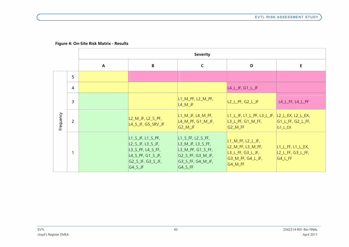
EVTL RISK ASSESSMENT STUDY
EVTL 43 2542214-R01 Rev FINAL
Lloyd’s Register EMEA April 2011
Figure 4: On-Site Risk Matrix - Results
Severity
A B C D E
5
4 L4_L_JF, G1_L_JF
3 L1_M_PF, L2_M_PF,
L4_M_JF L2_L_PF, G2_L_JF L4_L_FF, L4_L_PF
2 L2_M_JF, L2_S_PF,
L4_S_JF, G5_SRV_JF
L1_M_JF, L4_M_FF,
L4_M_PF, G1_M_JF,
G2_M_JF
L1_L_JF, L1_L_PF, L3_L_JF,
L3_L_PF, G1_M_FF,
G2_M_FF
L2_L_EX, L2_L_EX,
G1_L_FF, G2_L_FF,
G1_L_EX Freq
uen
cy
1
L1_S_JF, L1_S_PF,
L2_S_JF, L3_S_JF,
L3_S_PF, L4_S_FF,
L4_S_PF, G1_S_JF,
G2_S_JF, G3_S_JF,
G4_S_JF
L1_S_FF, L2_S_FF,
L3_M_JF, L3_S_FF,
L3_M_PF, G1_S_FF,
G2_S_FF, G3_M_JF,
G3_S_FF, G4_M_JF,
G4_S_FF
L1_M_FF, L2_L_JF,
L2_M_FF, L3_M_FF,
L3_L_FF, G3_L_JF,
G3_M_FF, G4_L_JF,
G4_M_FF
L1_L_FF, L1_L_EX,
L2_L_FF, G3_L_FF,
G4_L_FF
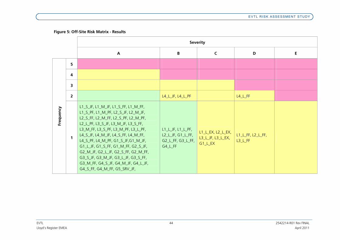
EVTL RISK ASSESSMENT STUDY
EVTL 44 2542214-R01 Rev FINAL
Lloyd’s Register EMEA April 2011
Figure 5: Off-Site Risk Matrix - Results
Severity
A B C D E
5
4
3
2 L4_L_JF, L4_L_PF L4_L_FF
Fre
qu
en
cy
1
L1_S_JF, L1_M_JF, L1_S_FF, L1_M_FF,
L1_S_PF, L1_M_PF, L2_S_JF, L2_M_JF,
L2_S_FF, L2_M_FF, L2_S_PF, L2_M_PF,
L2_L_PF, L3_S_JF, L3_M_JF, L3_S_FF,
L3_M_FF, L3_S_PF, L3_M_PF, L3_L_PF,
L4_S_JF, L4_M_JF, L4_S_FF, L4_M_FF,
L4_S_PF, L4_M_PF, G1_S_JF,G1_M_JF,
G1_L_JF, G1_S_FF, G1_M_FF, G2_S_JF,
G2_M_JF, G2_L_JF, G2_S_FF, G2_M_FF,
G3_S_JF, G3_M_JF, G3_L_JF, G3_S_FF,
G3_M_FF, G4_S_JF, G4_M_JF, G4_L_JF,
G4_S_FF, G4_M_FF, G5_SRV_JF,
L1_L_JF, L1_L_PF,
L2_L_JF, G1_L_FF,
G2_L_FF, G3_L_FF,
G4_L_FF
L1_L_EX, L2_L_EX,
L3_L_JF, L3_L_EX,
G1_L_EX
L1_L_FF, L2_L_FF,
L3_L_FF

EVTL R ISK ASSESSMENT STUDY
EVTL 45 2542214-R01 Rev FINAL
Lloyd’s Register EMEA April 2011
7. Conclusions and Recommendations
Potential major accident hazards associated with the Engro Vopak LNG Regasification Terminal
have been identified and subjected to a semi-quantitative risk assessment. Risks to people on-
site and off-site have been assessed. The findings are discussed below.
7.1 On-Site Risk
The following MAH scenarios were found to give rise to a ‘high’ on-site risk:
• Pool or jet fires following a large continuous release from a ship to ship LNG transfer
hose and immediate ignition, with failure to isolate the release;
• Flash fires following a large continuous release from a ship to ship LNG transfer hose
and delayed ignition, with failure to isolate the release; and,
• Jet fires from the system on the FSRU, originating from releases between the vaporisers
and the ESDV upstream of the unloading arm.
The pool fire generated on the river from a large release during ship-to-ship transfer would
envelop the vessels and jetty and escape from the area could be difficult. It is recommended
that measures to reduce the risk associated with this scenario are considered. This is discussed
further in Section 7.4. However, it is also noted that there is some uncertainty in the failure
frequencies for ship-to-ship transfers and it is recommended that this is investigated further as
the design of the facility progresses.
High pressure jet fires from the FSRU regas system have the potential to affect personnel on the
FSRU, on the jetty, and/or on a shuttle tanker offloading to the FSRU. The assessment of this
scenario had necessarily been based on relatively conservative assumptions, since there is
currently no detailed information on the likely distribution of personnel on the jetty, FSRU and
shuttle tanker. Clearly this is a scenario that will require further investigation as the design
progresses.
A number of scenarios were found to give rise to a ‘medium’ risk, including:
• flash fires, pool fires and some jet fires resulting from large or medium releases of LNG
or natural gas on the FSRU. If events of this type occur they have a high potential for
harming personnel on the FSRU and personnel on the shuttle tanker and jetty.
• pool and jet fires resulting from medium sized releases of LNG and flash fires resulting
from large and medium sized releases of LNG during ship to ship transfer operations.
These will mainly affect the area between the two vessels, with the consequences from
jet fires depending upon the leak direction.
• flash fires resulting from large releases of natural gas from the gas offloading arm and
pipework systems on the jetty. Personnel on the jetty would be at most risk from this
scenario.
• explosions from large releases of LNG and natural gas on the FSRU where the cloud of
gas formed is sufficient to fill the congested processing area prior to ignition.

EVTL R ISK ASSESSMENT STUDY
EVTL 46 2542214-R01 Rev FINAL
Lloyd’s Register EMEA April 2011
Explosions of this magnitude would have catastrophic consequences for the whole of
the jetty area, FSRU and supply vessel.
In view of the risks, it is considered appropriate to explore whether further risk reduction
measures for these scenarios would be reasonably practicable. This is discussed further in
Section 7.4. It is also clear that more detailed assessment of the risks to personnel associated
with the facility will be required as the design progresses.
7.2 Off-Site Risk
Off site risks from the site were found to be considerably lower than on-site risks. In particular, it
was observed that none of the scenarios modelled has the potential to harm members of the
public on the mainland. This is largely attributable to the distance to the nearest receptor on
land (3.2 km from the facility). For the brownfield site, the nearest facility is EVTL's chemical/LPG
handling jetty, which has been purposely designed to mitigate against such type of hazard event
(hazardous area classification, non sparking certified ‘EXe’ equipment, ESD system, F&G
detection, safety procedures etc.). The detailed discussion about brownfield site option is given
in Section 3.1 of HAZID Study OGL/DA/10026 (Appendix 1). Furthermore, the distance of other
vessels from the facility (200 m safety distance) provides some mitigation of the potential effects
of accidents on passing vessels.
None of the scenarios assessed gave rise to a ‘high’ risk to members of the public.
The scenarios giving rise to a ‘medium’ risk were those from flash fires resulting from large
releases of LNG on the FSRU and during ship to ship transfer. These flash fires could affect large
areas of the channel.
Explosion scenarios within the regas plant on the FSRU also have the potential to affect passing
vessels, if present at the time of the accident.
It is considered appropriate to explore whether further risk reduction measures for these
medium-risk scenarios would be reasonably practicable. This is discussed further in Section 7.4
below.
7.3 Marine Risk
The frequencies of marine accidents have been calculated as described in Appendix 1. The
consequences of marine accidents have been estimated on the basis of studies performed by
the Sandia National laboratories in the USA (5, 6). The results indicate that the frequencies of
marine accidents are very low, and that the risks are in the ‘medium’ region.
7.4 Recommendations
7.4.1 Reduction of On-Site Risks
As described in the preceding Sections, it is recommended that measures to reduce the risk
associated with the ‘high’ risk ship to ship LNG transfer accident scenario are considered. A
number of ‘good practice’ measures were detailed in the HAZID, as follows:
• safety shut off systems on the LNG transfer systems (process transmitters, alarms, push
buttons and shut-off valves);

EVTL R ISK ASSESSMENT STUDY
EVTL 47 2542214-R01 Rev FINAL
Lloyd’s Register EMEA April 2011
• ship to shore Emergency Shut Down (ESD); allowing remote shut down of the LNG
systems;
• firefighting systems on the jetty and FSRU (firewater pumps, water/foam deluge via
monitors);
• fire and gas and low temperature detection systems on the jetty with automatic
shutdown of the LNG STS transfer system, regassification unit and NG transfer system;
• the facility for emergency disconnection of the FSRU and emergency release couplings
on the gas outloading arm;
• minimisation of the numbers of personnel present during normal operation;
• leak testing of equipment prior to use;
• emergency procedures covering transfer operations, quick release and sail away, fire
fighting, escape and evacuation; and
• design of Safety Instrumented SIS to achieve the required Safety Integrity Level (SIL).
It is recommended that consideration be given to adopting all of these measures, if the
company has not already done so. A recommendation for a Hazard and Operability (HAZOP)
study of the system was also made during the HAZID, it is recommended that this study is
undertaken.
An alternative configuration, also discussed during the HAZID, was transfer of LNG via hard
arms over the jetty (as opposed to direct transfer from ship to ship using hoses). This may give
some reduction in risk, since failure frequencies associated with hard arms are generally
observed to be lower than those associated with hoses. It is recommended that such a
configuration be evaluated further.
It is clear from this assessment that the risks to personnel ‘on-site’ (i.e. at the facility) are
generally more significant than the risks to members of the public. Therefore it is recommended
that more detailed, quantitative assessment of the risks to personnel at the facility is undertaken
as the design progresses. Such studies may include:
• Escalation analysis (addressing the potential for small events at the jetty to escalate to
the FSRU, and vice versa);
• Escape, Evacuation and Rescue assessment (particularly for personnel on the jetty);
• Jetty Control Room impairment frequency assessment;
• Accommodation impairment frequency assessment (particularly for accommodation
facilities on the jetty, if provided); and,
• Quantitative risk assessment of the risks to personnel at the facility.

EVTL R ISK ASSESSMENT STUDY
EVTL 48 2542214-R01 Rev FINAL
Lloyd’s Register EMEA April 2011
7.4.2 Reduction of Off-Site Risks
Off-site risks fall into the 'medium' risk zone, primarily because of the distance between the
facility and land or river based populations. It is recommended that measures for excluding
people from the area around the facility are considered. Specifically;
� the enforcement of the safety exclusion zone for river traffic around the site; and
� whether it would be practicable to increase the size of the safety exclusion zone
around the facility (currently assumed to be 200 m).
As off site risks will be influenced by the measures taken to reduce on-site risks it is also
recommended that the measures detailed in 7.4.1 are also considered as means of reducing off-
site risks.

EVTL R ISK ASSESSMENT STUDY
EVTL 49 2542214-R01 Rev FINAL
Lloyd’s Register EMEA April 2011
8. References
1. Spouge J (1999). A Guide to Quantitative Risk Assessment for Offshore Installations.
CMPT Publication 99/100a.
2. Health and Safety Executive Hydrocarbon Release Database (data for 1992 – 2009,
downloaded from https://www.hse.gov.uk/hcr3/ ).
3. Publication Series on Dangerous Substances (PGS 3). Guideline for quantitative risk
assessment ’Purple book’ CPR 18E, VROM, 2005.
4. Lees F P (1996). Loss Prevention in the Process Industries. 2nd Edition, Elsevier.
5. Hightower M, et al. (2004). Guidance on Risk Analysis and Safety Implications of a
Large Liquefied Natural Gas (LNG) Spill Over Water. Sandia National Laboratories
Report SAND2004-6258.
6. Luketa A, et al. (2008). Breach and Safety Analysis of Spills Over Water from Large
Liquefied Natural Gas Carriers. Sandia National Laboratories Report SAND2008-3153.

EVTL R ISK ASSESSMENT STUDY
EVTL 2542214-R01 Rev FINAL
Lloyd’s Register EMEA April 2011
Appendices

EVTL R ISK ASSESSMENT STUDY
EVTL 2542214-R01 Rev FINAL
Lloyd’s Register EMEA April 2011
Appendix 1. Marine Accident Frequency Calculations

EVTL R ISK ASSESSMENT STUDY
EVTL 2542214-R01 Rev FINAL
Lloyd’s Register EMEA April 2011
Marine Accident Frequency Calculations
An assessment of typical marine accident frequencies has been carried out in this study for
inclusion in the wider EVTL assessment of the risks in future phases of the project.
The life of any mechanical and electrical system can be divided into three distinct periods. The
initial period occurring during the early life of the system is characterized by a high but rapidly
decreasing failure rate. This region is known as the Early Failure Period. After this period the
failure rate levels off and generally remains roughly constant for the majority of the useful life of
the system. This long period of near-constant failure rate is known as the Intrinsic Failure Period
(or Stable Failure Period) and the constant failure rate level is called the Intrinsic Failure Rate. It
should be noted that most systems spend the majority of their lifetimes operating in this period.
Finally, if the system remains in use long enough, the failure rate begins to increase as materials
wear out and degradation failures occur at an ever increasing rate. This is called Wear-out
Failure Period. This behaviour of the mechanical and electrical systems can be modelled by the
reliability curve showed in the figure below. This curve is also known as a ‘Bath tub curve’
because of its shape.
Weibull Analysis can be used as a method of determining where a population of failures is on
the bathtub curve. The Weibull distribution is a 3-parameter distribution. The three parameters
are: β, η, and time T. The Weibull distribution is given by:
[ ] βη
β
ηηβ ⎥⎦
⎤⎢⎣⎡−−
⋅⎥⎦⎤⎢⎣
⎡⋅⎥⎦⎤⎢⎣
⎡=T
eT
Tf
1
)(
The Weibull parameter η is the ‘characteristic life’ and β is the shape factor. When:
β < 1 the failure rate is decreasing
β = 1 the failure rate is constant
β > 1 the failure rate is increasing

EVTL R ISK ASSESSMENT STUDY
EVTL 2542214-R01 Rev FINAL
Lloyd’s Register EMEA April 2011
When β = 1, the failure rate is constant and the Weibull distribution becomes the exponential
distribution. The exponential distribution is the model used for the Intrinsic Failure Period,
signifying that failures are occurring randomly over time.
For sea going vessels most of the failures related to Early Failure Period are mitigated following
harbour trials and vessel sea trials.
The vessels are frequently inspected by the classification societies throughout their design life.
These inspections become more frequent if the owner wishes to use the vessel beyond its
design life. Also, special life extension studies are usually required before life extension is
approved. This provides some mitigation of failures during the ‘Wear-out’ period. Hence it can
be concluded that most of the vessel system failures will have constant failure rate and fall into
the Intrinsic Failure Period. As a result they can be modelled with exponential distribution.
The probability of failure of vessel systems, P(T), has been modelled using the exponential
distribution as follows:
TeTP
λ−−= 1)(
Where λ is the failure rate, and T is the time period of interest.
Lloyd's Register’s vessel systems failure data for the last five years were used as the basis for the
assessment.
Frequency of passing vessel system failure in the vicinity of the future LNG terminal
The frequency of a vessel passing the Khiprianwala green field site, experiencing engine failure
and drifting into the LNGc or FSRU has been calculated.
This event is simulated in simulation run 30. It was demonstrated that a single standby tug (if
sited by the LNG berth) would have sufficient time and power to prevent the passing ship
drifting towards the LNGc or FSRU.
The frequency of a passing ship drifting and then colliding with LNGc or FSRU is calculated as
follows:
tugfailuredriftshipfailure PPPNF __1 ⋅⋅⋅=
Where:
F1 = frequency of accident (per year)
N = number of times a ship passes the facility per year
Pfailure_ship
= probability of failure of the ship system whilst passing the facility
Pdrift
= probability that a drifting ship collides with the FSRU / LNGc
Pfailure_tug
= probability of tug failure

EVTL R ISK ASSESSMENT STUDY
EVTL 2542214-R01 Rev FINAL
Lloyd’s Register EMEA April 2011
According to the Port Qasim web site the maximum number of vessels handled in the port was
1238 in year 2008-2009. Assuming that the traffic will increase in the future, the number of
ships using the port in one year is calculated as:
1238 x 1.15 = 1424
Each vessel will pass the facility twice, once on its way into the Port and once on the way out.
Hence the number of times per year that a ship passes the facility is:
N = 2 x 1424 = 2848
It is conservatively assumed that every ship experiencing a failure within a distance of 1 nautical
mile either side of the terminal will drift towards the facility. Also, it is assumed that the FSRU
and LNGc cannot manoeuvre to avoid collision. Hence:
Pdrift
= 1
The probability of a ship’s system failure within 1 nm either side of the facility is calculated using
the exponential distribution. The time, T (hours) during which a failure would have to occur to
result in collision is the time spent by the vessel within the 1 nm ‘window’ either side of the
facility. Then, making a conservative assumption of a speed of 4kn:
5.04
12 =×=T hours
The vessel failure rate was calculated using Lloyd's Register’s failure database. The ships
considered were oil tankers, bulk carriers, container ships and LPG tankers with deadweight in
the range 10,000 to 50,000 t (i.e. the deadweight size that can be handled in Port Qasim port).
In the last five years, a total of 868 ships experienced 2041 failures that could be considered as
failures that would cause the vessel to be inoperable.
Hence the failure rate, λship
(per hour) is calculated as:
51037.5
243655868
2041 −×=×××=shipλ per hour
Inserting T and λship
into the expression for the exponential distribution gives:
5
_ 1068.21−− ×=−= T
shipfailure ePλ
A similar approach has been adopted for calculation of the probability of tug failure. The
relevant time ‘window’ for failure, T is estimated to be 3.5 hours, assuming that the tug works
as a stand by vessel for ½ hour per ship (arrival and departure) and adding an additional 3 hours
as a conservative time window of time to replace a failed stand by tug.
In terms of a failure rate, according to Lloyd's Register’s database, in the last 10 years, 1346
tugs experienced 1054 failures that could be considered as failures that would prevent them
performing their stand-by duty. Hence the tug failure rate (λtug
) is calculated as:

EVTL R ISK ASSESSMENT STUDY
EVTL 2542214-R01 Rev FINAL
Lloyd’s Register EMEA April 2011
61094.8
24365101346
1054 −×=×××=tugλ per hour
Inserting T and λtug
into the expression for the exponential distribution gives:
5
_ 1013.3)1(−− ×=−= T
tugfailure ePλ
Then, the frequency of failure and collision with the FSRU / LNGc is:
655
1 1039.21013.311068.22848−−− ×=×××××=F per year.
It should be noted that this event requires the failure on the ship and the failure on the tug to
occur within an extremely short period of time. This is because in the event of an incident on
one system interim precautions would be taken to control the ship, thus minimizing the
potential severity of an incident should further systems fail.
Frequency of loss of LNGc control due to machinery failure
The frequency of the LNGc vessel experiencing machinery failure, resulting in a loss of control
and then either running aground or colliding with another vessel, has been calculated.
This event is simulated in simulation runs 24, 26 and 31. These simulations demonstrate that a
single escort tug can successfully control the vessel.
The probability of the LNGc experiencing machinery failure and then running aground or
colliding with another vessel is calculated using:
tugfailureLNGcfailureLNGc PPNF __2 ..=
Where:
F2 = frequency of accident (per year)
NLNGc
= number of LNGc deliveries per year
Pfailure_LNGc
= probability of failure of the LNGc propulsion system during the period of interest
Pfailure_tug
= probability that a tug failure leads to an inability to provide assistance when required
It is assumed, conservatively, that every such failure results in either collision or grounding.
The number of LNG deliveries per year (NLNGc
) is estimated to be 122 (one every three days).
The time ‘window’ for failure is the time the LNGc spends in the channel, approaching and
departing from the facility. For the Khiprianwala site, the distance from the channel entrance to
the terminal site is 16.74 nm. Assuming that the LNGc travels at 6 kn, then the time spent in
the channel (T, hours) is:

EVTL R ISK ASSESSMENT STUDY
EVTL 2542214-R01 Rev FINAL
Lloyd’s Register EMEA April 2011
6.56
74.162 =×=T hours
The LNGc failure probability was calculated using Lloyd's Register’s failure database. In the last
five years a total of 117 ships had 494 propulsion related failures. Hence the failure rate (λLNGc
) is
calculated as:
51064.9
243655117
494 −×=×××=LNGcλ per hour
Then the probability of failure during the time window of interest is:
4
_ 104.5)1(−− ×=−= T
LNGcfailure ePλ
It is assumed that a single escort tug will escort the LNGc for the entire period of time in the
channel. The tug failure rate (λtug
) is as quoted in the previous calculation:
λtug
= 8.94 x 10⁻⁶ per hour
Then:
5
_ 1001.5)1(−− ×=−= T
tugfailure ePλ
Hence:
654
2 1030.31001.5104.5122−−− ×=××××=F per year.
Frequency of loss of LNGc control due to steering gear failure
The frequency of the LNGc vessel experiencing steering gear failure, resulting in a loss of control
and then either running aground or colliding with another vessel, has been calculated.
This event is simulated in simulation runs 23 and 27. These simulations demonstrate that a
single escort tug can successfully control the vessel.
The probability of the LNGc experiencing steering gear failure and then running aground or
colliding with another vessel is calculated using a similar expression to the previous case:
tugfailureLNGcfailureLNGc PPNF __3 ..=
Where:
F3 = frequency of accident (per year)
NLNGc
= number of LNGc deliveries per year
Pfailure_LNGc
= probability of failure of the LNGc steering system during the period of interest
Pfailure_tug
= probability that a tug failure leads to an inability to provide assistance when required

EVTL R ISK ASSESSMENT STUDY
EVTL 2542214-R01 Rev FINAL
Lloyd’s Register EMEA April 2011
It is assumed, conservatively, that every such failure results in either collision or grounding.
The number of LNG deliveries per year (NLNGc
) is estimated to be 122 (as before).
The time ‘window’ for failure is the same as the previous case (5.6 hours).
The LNGc failure probability was calculated using Lloyd's Register’s failure database. In the last
five years a total of 117 ships had 46 steering gear related failures. Hence the failure rate (λLNGc
)
is calculated as:
61098.8
243655117
46 −×=×××=LNGcλ per hour
Then the probability of failure during the time window of interest is:
5
_ 1003.5)1(−− ×=−= T
LNGcfailure ePλ
It is assumed that a single escort tug will escort the LNGc for the entire period of time in the
channel. The tug failure rate (λtug
) is and failure probability values are as quoted in the previous
calculation:
λtug
= 8.94 x 10⁻⁶ per hour
And:
5
_ 1001.5)1(−− ×=−= T
tugfailure ePλ
Hence:
755
3 1007.31001.51003.5122−−− ×=××××=F per year.
Frequency of loss of control of LNGc due to machinery and steering gear failure during
berthing
The frequency of the LNGc vessel experiencing machinery or steering gear failure during
berthing, resulting in a loss of control and collision with the FSRU, has been calculated.
This event is simulated in runs 28, 29 and 32. These simulations demonstrate that a single escort
tug can successfully control the vessel.
The probability of the LNGc experiencing machinery or steering gear failure during berthing and
then colliding with the FSRU is calculated using:
tugfailureLNGcfailureLNGc PPNF __4 ..=
Where:
F4 = frequency of accident (per year)
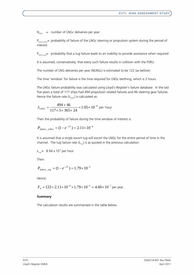
EVTL R ISK ASSESSMENT STUDY
EVTL 2542214-R01 Rev FINAL
Lloyd’s Register EMEA April 2011
NLNGc
= number of LNGc deliveries per year
Pfailure_LNGc
= probability of failure of the LNGc steering or propulsion system during the period of
interest
Pfailure_tug
= probability that a tug failure leads to an inability to provide assistance when required
It is assumed, conservatively, that every such failure results in collision with the FSRU.
The number of LNG deliveries per year (NLNGc) is estimated to be 122 (as before).
The time ‘window’ for failure is the time required for LNGc berthing, which is 2 hours.
The LNGc failure probability was calculated using Lloyd's Register’s failure database. In the last
five years a total of 117 ships had 494 propulsion related failures and 46 steering gear failures.
Hence the failure rate (λLNGc
) is calculated as:
41005.1
243655117
46494 −×=×××+=LNGcλ per `hour
Then the probability of failure during the time window of interest is:
4
_ 1011.2)1(−− ×=−= T
LNGcfailure ePλ
It is assumed that a single escort tug will escort the LNGc for the entire period of time in the
channel. The tug failure rate (λtug
) is as quoted in the previous calculation:
λtug
= 8.94 x 10⁻⁶ per hour
Then:
5
_ 1079.1)1(−− ×=−= T
tugfailure ePλ
Hence:
754
4 1060.41079.11011.2122−−− ×=××××=F per year.
Summary
The calculation results are summarised in the table below.

EVTL R ISK ASSESSMENT STUDY
EVTL 2542214-R01 Rev FINAL
Lloyd’s Register EMEA April 2011
Event Frequency (per year) Vessel passing the Khiprianwala green field site experiences engine failure and drifts into the LNGc or FSRU
2.4 x 10⁻⁶
LNGc vessel experiences machinery failure, resulting in a loss of control and then either runs aground or collides with another vessel
3.3 x 10⁻⁶
LNGc vessel experiences steering gear failure, resulting in a loss of control and then either runs aground or collides with another vessel
3.1 x 10⁻⁷
LNGc vessel experiences machinery or steering gear failure during berthing, resulting in a loss of control and collides with the FSRU
4.6 x 10⁻⁷

Lloyd’s Register EMEA
T +44 (0)1224 267400
F +44 (0)1224 267401
Denburn House
25 Union Terrace
Aberdeen AB10 1NN, UK
April 2011 Services are provided by members of the Lloyd’s Register Group. Lloyd’s Register, Lloyd’s Register EMEA and Lloyd’s Register Asia are exempt charities under the UK Charities Act 1993.
www.lr.org

A part of BMT in Maritime Transport

Port Qasim Lloyd‟s Register
2 Report No: L30090.1.2R
CONTENTS
1 TERMS OF REFERENCE ............................................................................................. 3
2 OBJECTIVES OF THE STUDY ..................................................................................... 4
3 METHODOLOGY .......................................................................................................... 4
3.1 The Electronic Chart .............................................................................................. 5
3.2 Current Modelling .................................................................................................. 6
3.3 Vessel Mathematical Models ................................................................................. 7
3.4 Use of Tugs ............................................................................................................ 8
3.4 The Simulation Matrix ............................................................................................ 9
3.5 Simulation Methodology .......................................................................................10
4 SIMULATION RESULTS ..............................................................................................11
5 KEY CONCLUSIONS & RECOMMENDATIONS .........................................................12
Document History
Version Changes By
1 Issue 1 MJW
1.1 Addressing client‟s comments MJW
1.2 Addressing client‟s comments MJW
Information contained in this document is commercial-in-confidence and should not be transmitted to a
third party without prior written agreement of BMT ARGOSS Ltd.
© Copyright BMT ARGOSS Ltd 2011
Document Information
Project Manoeuvring Simulation Study for Proposed Port Qasim LNG Terminal
Client Lloyd‟s Register EMEA
Report ref: L30090.1.2R
Prepared by: Mark Wilson Project Manager – Manoeuvring Simulations, BMT ARGOSS Ltd
Checked by: Hakan Sen Naval Architect, BMT ARGOSS Ltd
Approved by: Ian Fraser Operations Director, BMT ARGOSS Ltd.

Port Qasim Lloyd‟s Register
3 Report No: L30090.1.2R
1 TERMS OF REFERENCE
BMT ARGOSS Ltd (BMT) was instructed by Lloyd‟s Register EMEA (LR) on behalf of Engro
Vopak (EVTL) to conduct a manoeuvring simulation study at the Port Qasim, Karachi for the
proposed development of a new LNG terminal.
The study was undertaken by an experienced member of BMT staff and an independent
Master Mariner / Pilot with the simulations being conducted using the PC Rembrandt ship
handling and manoeuvring simulator, developed by BMT. This report describes the
methodology adopted for this project and includes full simulation results (including track-
plots) and appropriate recommendations for this project.

Port Qasim Lloyd‟s Register
4 Report No: L30090.1.2R
2 OBJECTIVES OF THE STUDY
The aim of the study was to test the entry and departure of various LNG vessels to several
proposed sites for the LNG berth in different weather conditions.
The project had the following specific objectives:
Inbound loaded to berth with introduced operational maximum parameters for wind,
wave and tide. Critical systems failures on LNG tanker and tugs to be introduced in
the approach channel, including the approach of other shipping.
Outbound ballast from berth with introduced operational maximum parameters for
wind, wave and tide. Critical systems failures on LNG tanker and tugs to be
introduced in the approach channel.
Inbound berthing with introduced operational maximum parameters for wind, wave
and tide. Critical systems failures on LNG tanker and tugs to be introduced in the
berthing and if applicable the turning basin.
Outbound unberthing with introduced operational maximum parameters for wind,
wave and tide. Critical systems failures on LNG tanker and tugs to be introduced in
the berthing and turning basin.
Staying berthed at the LNG berth with introduced operational maximum parameters
for wind, wave and tide. The resultant loading by the LNG tanker on each component
of the marine facilities to be confirmed against the individual component‟s maximum safe working load.
Additional objectives were added during the workshop including investigating the ease of
navigating to different terminal sites.
3 METHODOLOGY
The study was completed using BMT‟s ship-handling simulator, PC Rembrandt. The PC
Rembrandt system allows real and fast time simulations to be conducted using either „hands-
on‟ control (man-in-the-loop) or automated control using an auto-pilot function.
PC Rembrandt uses industry standard nautical electronic charts that provide the interactive
back-drop to the simulations. It combines a high-fidelity mathematical ship model with 3-D
„out of the window‟ visuals and detailed environmental data to provide accurate, dynamic simulation of marine operations. Full reports on all simulations are produced and each
simulation can be converted to a video replay file for presentation to interested parties.
The following sections describe the work undertaken in more detail.

Port Qasim Lloyd‟s Register
5 Report No: L30090.1.2R
3.1 The Electronic Chart
PC Rembrandt utilises standard Electronic Nautical Charts (ENC) produced to IHO 2-57 v3.1
standard. The latest chart was obtained and the coverage area is shown in Figure 1 below.
Figure 1 - Port Qasim Approach Channel
Figure 2 - 3D Visual Scene - LNGC Passing Moored Vessels
67° 0' E 67° 3' E 67° 6' E 67° 9' E 67° 12' E 67° 15' E 67° 18' E 67° 21' E 67° 24' E 67° 27' E24° 39' N
24° 42' N
24° 45' N
24° 48' N

Port Qasim Lloyd‟s Register
6 Report No: L30090.1.2R
3.2 Current Modelling
In order to produce a more accurate set of simulations based on the proposed terminal‟s
capabilities, BMT used assumed hydrodynamic current information. Figure 3 & Figure 4
show the currents inputted into PC Rembrandt for both a flood and ebb current at springs.
Springs were chosen as they are classed as the extreme current conditions within which to
manoeuvre a vessel.
Figure 3 - Spring Ebb with a 1.0m Height of Tide
Figure 4 - Spring Flood with a 1.0m Height of Tide

Port Qasim Lloyd‟s Register
7 Report No: L30090.1.2R
3.3 Vessel Mathematical Models
PC Rembrandt provides mathematical modelling of ships and other floating craft in 4
Degrees of Freedom (DoF), namely surge, sway, yaw and roll. Whilst wave effects are
included, this is currently limited to the slowly varying wave drift forces and it does not
provide rapidly varying motions associated with waves, i.e. vertical „seakeeping„ motions such as heave and pitch.
Two vessels were used for the simulation based on BMT‟s library of pre-modelled and
validated ships. These vessels were a Steam Turbine driven Moss Ship (LNG 005) and a
more modern and larger Q-Flex LNG Carrier (LNGC)(LNG 004). The ship models and their
principal particulars are provided in Table 1 below.
Parameter Length Overall (m) Breadth (m) Draught (m)
Moss Ship (LNG 005) 283.0 43.4 11.5 (loaded)
9.5 (ballast)
Q-Flex (LNG 004) 315.2 50.0 12.2 (loaded)
9.5 (ballast)
Table 1 - Vessel Model Principal Particulars
The steam-driven LNG 005 was chosen as it represents the „worst case scenario‟ of a relatively un-manoeuvrable and slow-to-respond vessel.

Port Qasim Lloyd‟s Register
8 Report No: L30090.1.2R
3.4 Use of Tugs
Within PC Rembrandt the tug force is assumed to be a vectored force acting at a specific
location on the ship.
Tug forces in the longitudinal and lateral (X and Y respectively) are determined from the tug
force set by the user (as a % of bollard pull) and the angle of the tug relative to the ships
heading (see Figure 5) The tug moment is calculated from the tug force and the offset of the
tugs attachment to the ship from the ships centre of rotation. The tug moment is the turning
moment (yaw) applied to the ship by the tug.
Tugs are programmed with a maximum bollard pull (tonnes) and selected from the on-screen
panel by “clicking and dragging” to the attachment point on the vessel model. The tugs can push at any suitable location but can only pull at bollards. By colour coding the tugs the
operator can adjust the angle to the vessel and percentage of maximum bollard pull upon the
pilot‟s order.
fTug
ΨTug
fXTug
fYTug
xTug
yTug
Ship Centre of Rotation
Figure 5 - Tug Forces and Moments

Port Qasim Lloyd‟s Register
9 Report No: L30090.1.2R
Figure 6 – Directionality Effects on Available Bollard Pull by Tug Type
In real life, the percentage of tug bollard pull achievable will depend upon the tug type (e.g.
azimuthing stern drive, Voith - Schneider etc.) and the directional application of its power with
relation to the wind/wave conditions and direction and the speed and aspect of the subject
vessel. Figure 6 illustrates the directionality effect on the available bollard pull for different tug
types. In PC Rembrandt this degradation of power is applied by the operator adjusting the
percentage power manually. Thus when the pilot requests full power, the operator will only
apply the appropriate percentage of power applicable to the circumstances.
Within PC Rembrandt the tugs can be shown on the track plots in outline when not in use
and filled in their respective colour when power is applied .Although the track plots show that
the tugs are made fast from the beginning of the simulation, this is to facilitate the simulator
operator during the exercise set-up. In practice the tugs were only assumed available just
before entering the outer turning basin, when the vessel speed is reduced. Generally, the
tugs orders were issued in a realistic and conservative manner based on the Pilot‟s experience and practice and tugs were never used in a way that would not be applicable in
reality.
Four tugs were assumed available at Port Qasim. They were all deemed to be 60 tonnes
bollard pull.
3.4 The Simulation Matrix
The simulation matrix was made up of 34 scenarios using the most extreme weather and
current conditions. The table below shows the simulation matrix for the vessels used.
Directionality effect on available Bollard Pull
0.00
0.10
0.20
0.30
0.40
0.50
0.60
0.70
0.80
0.90
1.00
0
510
15
20
25
30
35
40
45
50
55
60
65
70
75
80
85
90
95
100
105
110
115
120
125
130
135
140
145
150
155
160
165170
175
180
185190
195
200
205
210
215
220
225
230
235
240
245
250
255
260
265
270
275
280
285
290
295
300
305
310
315
320
325
330
335
340
345350
355
Voith Tractor Tug Azimuth prop with nozzles tractor Stern-drive Aziprop with nozzels
Voith reverse tractor tug Aziprop with nozzles reverse tractor tug Twin Screw (CPP) + nozzles + Bow Thruster
Twin Screw (CPP) + nozzles

Port Qasim Lloyd‟s Register
10 Report No: L30090.1.2R
Run Operation Ship Wind
Current Tugs
Dir Spd
1 Arrival Moss Ship (Loaded) 225 30kts Spring Flood - 2A, B, C Arrival Moss Ship (Loaded) 225 30kts Spring Flood 3
3 Arrival Moss Ship (Loaded) 225 20kts Spring Flood 3 4 Arrival Moss Ship (Loaded) 225 30kts Spring Flood 3 5 Arrival Moss Ship (Loaded) 225 30kts Spring Flood 3 6 Arrival Moss Ship (Loaded) 225 30kts Spring Flood 4 7 Arrival Moss Ship (Loaded) 225 30kts Spring Flood 4 8 Arrival Moss Ship (Loaded) 225 30kts Spring Flood 4 9 Arrival Q-Flex (Loaded) 225 30kts Spring Flood - 10 Arrival Q-Flex (Loaded) 225 30kts Spring Flood 1 11 Arrival Q-Flex (Loaded) 225 30kts Spring Flood 4 12 Arrival Q-Flex (Loaded) 225 20kts Spring Flood 1 13 Departure Moss Ship (Ballast) 225 30kts Spring Flood 2 14 Departure Moss Ship (Ballast) 225 30kts Spring Ebb 2 15 Arrival Q-Flex (Loaded) 225 20kts Spring Flood - 16 Arrival Q-Flex (Loaded) 225 20kts Spring Flood 4 17 Arrival Moss Ship (Loaded) 225 30kts Spring Flood 4 18 Departure Moss Ship (Ballast) 225 30kts Spring Flood 4 19 Arrival Q-Flex (Loaded) 225 20kts Spring Flood 4 20 Departure Q-Flex (Ballast) 225 20kts Spring Flood 2 21 Departure Q-Flex (Ballast) 225 20kts Spring Ebb 2 22 Arrival Q-Flex (Loaded) 225 20kts Slack Water 4 23 Arrival Moss Ship (Loaded) 225 20kts Spring Flood 1 24 Arrival Moss Ship (Loaded) 225 20kts Spring Flood 1 25 Arrival Moss Ship (Loaded) 225 20kts Spring Flood 1 26 Arrival Moss Ship (Loaded) 225 20kts Spring Flood 1 27 Arrival Moss Ship (Loaded) 225 20kts Spring Flood 1 28 Arrival Moss Ship (Loaded) 225 20kts Spring Flood 2 (3) 29 Arrival Moss Ship (Loaded) 225 20kts Slack Water 2 (3) 30 Arrival Moss Ship (Loaded) 225 20kts Spring Flood 1 31 Arrival Moss Ship (Loaded) 225 20kts Spring Flood 4 32 Arrival Q-Flex (Loaded) 225 20kts Slack Water 4 33 Arrival Q-Flex (Loaded) 225 20kts Spring Flood 1 34 Departure Q-Flex (Loaded) 225 20kts Spring Flood 2
Table 2 - Simulation Run Matrix
3.5 Simulation Methodology
All simulations were conducted by Chris Bordas, a pilot with experience of over 500 port
entry and departures. The simulations were conducted as follows: the Pilot (Chris Bordas)
controlled the vessel directly (i.e. without issuing orders) through a control console replicating
actual ship controls and manoeuvred the tugs using the external function display. The Pilot
had the following information available in real-time:
The electronic chart view (ECDIS) showing the position of the vessel on the chart and
other information such as the dredged channel, under keel clearance (UKC), turning
circles and exclusion zones.

Port Qasim Lloyd‟s Register
11 Report No: L30090.1.2R
An out-of-the-window 3D view from the ship‟s bridge (switched to the bridge wings
when required).
Run information such as the vessel speed over the ground (ahead/astern and lateral),
rate of turn, heading and course over the ground. Also, depth profile and
engine/rudder values (actual and demanded).
Position and percentage of power usage for each tug.
The screen which is available to the pilot during the simulation is shown on Figure 7 below:
Figure 7 - Simulation Screen
Each run was set up with the met-ocean conditions and the ship‟s initial position, speed and course. The vessels initial speed, for the arrival, was set at around 10kts outside the harbour
entrance. For departure manoeuvres, the simulations started with the vessel alongside the
berth (stopped) and the speed was gradually increased as appropriate to the conditions.
At the end of each run, a run report form was completed. The run report forms are included
in Annex A. They include a rudimentary grading (see Figure 8) as to the difficulty of
performing each manoeuvre as a means of comparison for the study. The contents of the
report forms and the grading were completed upon the conclusion of each manoeuvre.
Figure 8 - Simulation Grading Method
4 SIMULATION RESULTS
The run report forms for each run are presented in Annex A.
1 2 3 4 5 6 7 8
Easy Straight-forward Comfortable Not demanding Not easy Challenging Difficult Impossible

Port Qasim Lloyd‟s Register
12 Report No: L30090.1.2R
5 KEY CONCLUSIONS & RECOMMENDATIONS
All runs were conducted at the most extreme weather and current conditions. During
berthing manoeuvres' that involved swinging a loaded vessel this often necessitated
all tugs running at 100% for prolonged periods. Care should be exercised to develop
working procedures with regard to environmental conditions that mitigates this, such
as berthing close to slack water.
It is recommended that a standby tug be made available by the proposed LNG berth.
This would be used to aid any vessel which experiences difficulties whilst passing the
berth as shown in Run 30.
Consideration should be given to securing escort towage that is capable of indirect
towage shortly after the pilot boards as the width of the entrance channel is such that
any emergency that occurs in this area could block the channel. The tug that is
tasked for this may need to be rated at a higher bollard pull than others as it was
shown that during all the berthings this tug alone had the most work to do.
The simulations showed that berthing port side alongside the greenfield and
brownfield site was much more effectively controlled and that swinging the tanker in
ballast condition for the outward passage was also routinely achieved. The port will
need to be consulted in order to develop suitable working practices for berthing,
towage, line handling and VTS that will benefit all stakeholders.

Port Qasim Lloyd’s Register
Report No: L30090
Port Qasim LNG TerminalStudy
Simulation Run Reports

Port Qasim Lloyd’s Register
Report No: L30090
Project: Port Qasim LNG TerminalStudy
Job No.: L30090 Captain/Pilot: Chris Bordas
Subject: PC Rembrandt Simulation Study for Lloyd’s Register
Date: 28/02/2011
Vessel Access Condition Environmental Conditions Manoeuvre Run No.
Ship Condition Type No of Tugs
Used Current
Wind Speed (Direction from)
Waves (Ht/Period)
Thrusters used?
1 LNG 005 Loaded (11.5m)
Arrival
3kt Flood - 3.4m No
Approach channel navigation conducted with flood tide and no wind. Rough sea state. No difficulties experienced.
1 2 3 4 5 6 7 8
Ratings Easy
Straight-forward
Comfortable Not demanding Not easy Challenging Difficult Impossible

Port Qasim Lloyd’s Register
Report No: L30090
Vessel Track With Tugs
Vessel: LNG Carrier 005 (L)Harbour: QasimCreated: 28/02/2011
Wind: 0.00 kts 0 °Current: 3 kts FloodDepth: 1.0 m above Chart Datum

Port Qasim Lloyd’s Register
Report No: L30090
Vessel Track With Tugs
Vessel: LNG Carrier 005 (L)Harbour: QasimCreated: 28/02/2011
Wind: 0.00 kts 0 °Current: 3 kts FloodDepth: 1.0 m above Chart Datum
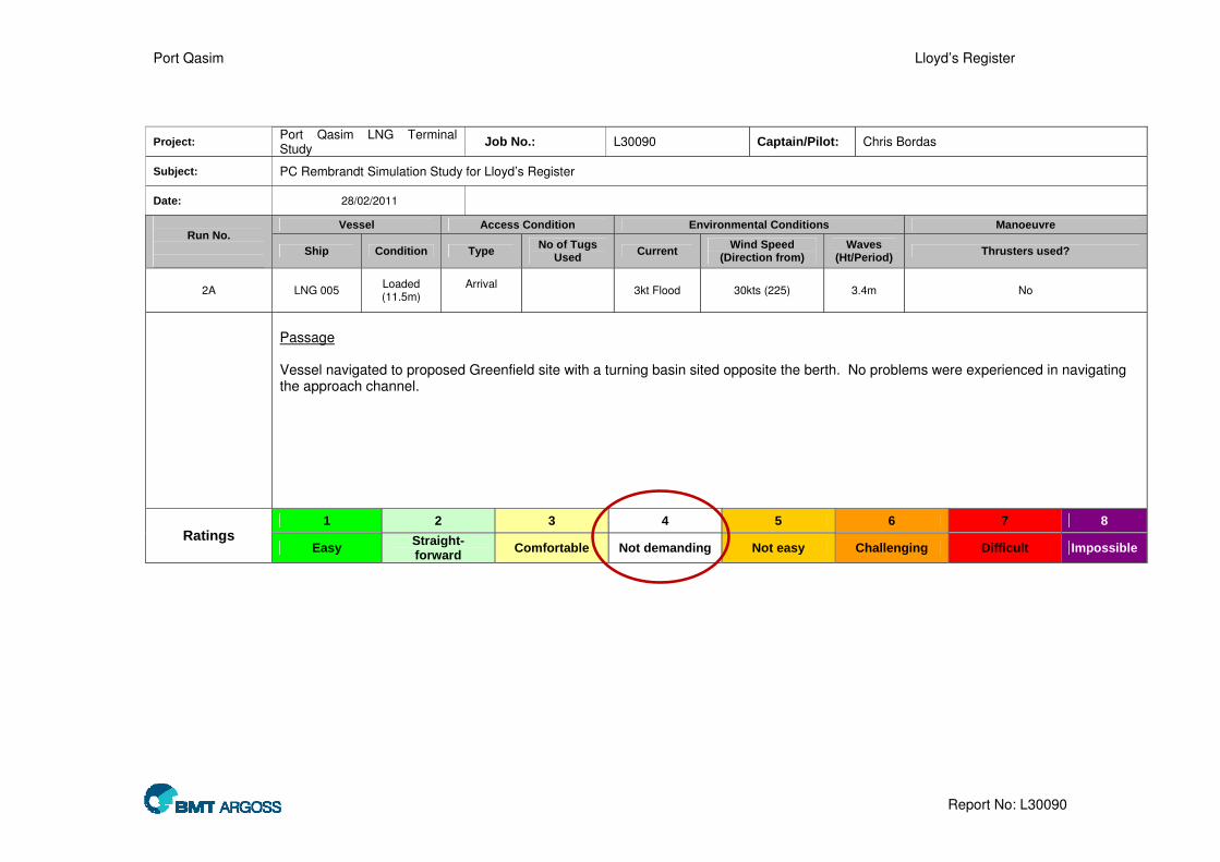
Port Qasim Lloyd’s Register
Report No: L30090
Project: Port Qasim LNG Terminal Study
Job No.: L30090 Captain/Pilot: Chris Bordas
Subject: PC Rembrandt Simulation Study for Lloyd’s Register
Date: 28/02/2011
Vessel Access Condition Environmental Conditions Manoeuvre Run No.
Ship Condition Type No of Tugs
Used Current
Wind Speed (Direction from)
Waves (Ht/Period)
Thrusters used?
2A LNG 005 Loaded (11.5m)
Arrival
3kt Flood 30kts (225) 3.4m No
Passage Vessel navigated to proposed Greenfield site with a turning basin sited opposite the berth. No problems were experienced in navigating the approach channel.
1 2 3 4 5 6 7 8
Ratings Easy
Straight-forward
Comfortable Not demanding Not easy Challenging Difficult Impossible

Port Qasim Lloyd’s Register
Report No: L30090
Vessel Track With Tugs
Vessel: LNG Carrier 005 (L) (+Tugs)Harbour: QasimCreated: 28/02/2011
Wind: 30.00 kts 225 °Current: 3 kts FloodDepth: Variable

Port Qasim Lloyd’s Register
Report No: L30090
Vessel Track With Tugs
Vessel: LNG Carrier 005 (L) (+Tugs)Harbour: QasimCreated: 28/02/2011
Wind: 30.00 kts 225 °Current: 3 kts FloodDepth: Variable

Port Qasim Lloyd’s Register
Report No: L30090
Project: Port Qasim LNG Terminal Study
Job No.: L30090 Captain/Pilot: Chris Bordas
Subject: PC Rembrandt Simulation Study for Lloyd’s Register
Date: 28/02/2011
Vessel Access Condition Environmental Conditions Manoeuvre Run No.
Ship Condition Type No of Tugs
Used Current
Wind Speed (Direction from)
Waves (Ht/Period)
Thrusters used?
2B LNG 005 Loaded (11.5m)
Arrival
3kt Flood 30kts (225) 3.4m No
Approach to Berth No difficulty was experienced in approaching the berth.
1 2 3 4 5 6 7 8
Ratings Easy
Straight-forward
Comfortable Not demanding Not easy Challenging Difficult Impossible

Port Qasim Lloyd’s Register
Report No: L30090
Project: Port Qasim LNG Terminal Study
Job No.: L30090 Captain/Pilot: Chris Bordas
Subject: PC Rembrandt Simulation Study for Lloyd’s Register
Date: 28/02/2011
Vessel Access Condition Environmental Conditions Manoeuvre Run No.
Ship Condition Type No of Tugs
Used Current
Wind Speed (Direction from)
Waves (Ht/Period)
Thrusters used?
2C LNG 005 Loaded (11.5m)
Arrival
3 3kt Flood 30kts (225) - Yes
Berthing Swing Some difficulty was experienced due to the combined effect of tide and wind pushing the vessel further up the channel. The pilot was unable to keep the vessel within the turning circle.
1 2 3 4 5 6 7 8
Ratings Easy
Straight-forward
Comfortable Not demanding Not easy Challenging Difficult Impossible

Port Qasim Lloyd’s Register
Report No: L30090
Vessel Track With Tugs
Vessel: LNG Carrier 005 (L) (+Tugs)Harbour: QasimCreated: 28/02/2011
Wind: 30.00 kts 225 °Current: 3 kts FloodDepth: Variable

Port Qasim Lloyd’s Register
Report No: L30090
Project: Port Qasim LNG Terminal Study
Job No.: L30090 Captain/Pilot: Chris Bordas
Subject: PC Rembrandt Simulation Study for Lloyd’s Register
Date: 28/02/2011
Vessel Access Condition Environmental Conditions Manoeuvre Run No.
Ship Condition Type No of Tugs
Used Current
Wind Speed (Direction from)
Waves (Ht/Period)
Thrusters used?
3 LNG 005 Loaded (11.5m)
Arrival
3 3kt Flood 20kts (225) - Yes
The same as Run 2 except a slightly lower wind was used (20kts) and reduced sea state. The swing was far more comfortable than Run 2 but was still only achieved with some difficulty.
1 2 3 4 5 6 7 8
Ratings Easy
Straight-forward
Comfortable Not demanding Not easy Challenging Difficult Impossible

Port Qasim Lloyd’s Register
Report No: L30090
Vessel Track With Tugs
Vessel: LNG Carrier 005 (L) (+Tugs)Harbour: QasimCreated: 28/02/2011
Wind: VariableCurrent: 3 kts FloodDepth: Variable

Port Qasim Lloyd’s Register
Report No: L30090
Vessel Track With Tugs
Vessel: LNG Carrier 005 (L) (+Tugs)Harbour: QasimCreated: 28/02/2011
Wind: VariableCurrent: 3 kts FloodDepth: Variable

Port Qasim Lloyd’s Register
Report No: L30090
Project: Port Qasim LNG Terminal Study
Job No.: L30090 Captain/Pilot: Chris Bordas
Subject: PC Rembrandt Simulation Study for Lloyd’s Register
Date: 28/02/2011
Vessel Access Condition Environmental Conditions Manoeuvre Run No.
Ship Condition Type No of Tugs
Used Current
Wind Speed (Direction from)
Waves (Ht/Period)
Thrusters used?
4 LNG 005 Loaded (11.5m)
Arrival
3 3kt Flood 30kts (225) - Yes
For Run 4 it was decided to attempt to swing the vessel in the mouth of the channel to the north of the proposed Greenfield site. Initially a swing to port was tried but this was unsuccessful due to the action of tide and wind. The vessel was unable to generate steerage power without moving too far north.
1 2 3 4 5 6 7 8
Ratings Easy
Straight-forward
Comfortable Not demanding Not easy Challenging Difficult Impossible

Port Qasim Lloyd’s Register
Report No: L30090
Vessel Track With Tugs
Vessel: LNG Carrier 005 (L) (+Tugs)Harbour: Khiprianwala IslandCreated: 28/02/2011
Wind: 30.00 kts 225 °Current: 3 kts FloodDepth: Variable

Port Qasim Lloyd’s Register
Report No: L30090
Project: Port Qasim LNG Terminal Study
Job No.: L30090 Captain/Pilot: Chris Bordas
Subject: PC Rembrandt Simulation Study for Lloyd’s Register
Date: 28/02/2011
Vessel Access Condition Environmental Conditions Manoeuvre Run No.
Ship Condition Type No of Tugs
Used Current
Wind Speed (Direction from)
Waves (Ht/Period)
Thrusters used?
5 LNG 005 Loaded (11.5m)
Arrival
3 3kt Flood 30kts (225) - Yes
This run was identical to run 4 except the vessel was swung to starboard. This proved far more effective and the vessel was successfully turned, albeit with difficulty.
1 2 3 4 5 6 7 8
Ratings Easy
Straight-forward
Comfortable Not demanding Not easy Challenging Difficult Impossible

Port Qasim Lloyd’s Register
Report No: L30090
Vessel Track With Tugs
Vessel: LNG Carrier 005 (L) (+Tugs)Harbour: Khiprianwala IslandCreated: 28/02/2011
Wind: 30.00 kts 225 °Current: 3 kts FloodDepth: Variable

Port Qasim Lloyd’s Register
Report No: L30090
Project: Port Qasim LNG Terminal Study
Job No.: L30090 Captain/Pilot: Chris Bordas
Subject: PC Rembrandt Simulation Study for Lloyd’s Register
Date: 28/02/2011
Vessel Access Condition Environmental Conditions Manoeuvre Run No.
Ship Condition Type No of Tugs
Used Current
Wind Speed (Direction from)
Waves (Ht/Period)
Thrusters used?
6 LNG 005 Loaded (11.5m)
Arrival
4 3kt Flood 30kts (225) - Yes
This run was identical to run 3except and additional tug was used in order to see if this made the swing any easier/achievable. This proved to be the case and the vessel was swung within the turning basin and without too much difficulty.
1 2 3 4 5 6 7 8
Ratings Easy
Straight-forward
Comfortable Not demanding Not easy Challenging Difficult Impossible

Port Qasim Lloyd’s Register
Report No: L30090
Vessel Track With Tugs
Vessel: LNG Carrier 005 (L) (+Tugs)Harbour: Khiprianwala IslandCreated: 28/02/2011
Wind: 30.00 kts 225 °Current: 3 kts FloodDepth: Variable

Port Qasim Lloyd’s Register
Report No: L30090
Project: Port Qasim LNG Terminal Study
Job No.: L30090 Captain/Pilot: Chris Bordas
Subject: PC Rembrandt Simulation Study for Lloyd’s Register
Date: 28/02/2011
Vessel Access Condition Environmental Conditions Manoeuvre Run No.
Ship Condition Type No of Tugs
Used Current
Wind Speed (Direction from)
Waves (Ht/Period)
Thrusters used?
7 LNG 005 Loaded (11.5m)
Arrival
4 3kt Flood 30kts (225) - Yes
Run 7 was used to see how difficult navigation to the propose Brownfield site would be. In order to simulate a worst case scenario a vessel was placed on the LPG berth and the Oil terminal berth. It later transpired that these were incorrectly identified at the time and so later Runs were used to correct this. 4 tugs were used. Some difficulty was experienced both in making the initial turn in the channel and also in swinging the vessel opposite the last berth.
1 2 3 4 5 6 7 8
Ratings Easy
Straight-forward
Comfortable Not demanding Not easy Challenging Difficult Impossible

Port Qasim Lloyd’s Register
Report No: L30090
Vessel Track With Tugs
Vessel: LNG Carrier 005 (L) (+Tugs)Harbour: Port QasimCreated: 28/02/2011
Wind: 30.00 kts 225 °Current: 3 kts FloodDepth: Variable

Port Qasim Lloyd’s Register
Report No: L30090
Vessel Track With Tugs
Vessel: LNG Carrier 005 (L) (+Tugs)Harbour: Port QasimCreated: 28/02/2011
Wind: 30.00 kts 225 °Current: 3 kts FloodDepth: Variable

Port Qasim Lloyd’s Register
Report No: L30090
Project: Port Qasim LNG Terminal Study
Job No.: L30090 Captain/Pilot: Chris Bordas
Subject: PC Rembrandt Simulation Study for Lloyd’s Register
Date: 28/02/2011
Vessel Access Condition Environmental Conditions Manoeuvre Run No.
Ship Condition Type No of Tugs
Used Current
Wind Speed (Direction from)
Waves (Ht/Period)
Thrusters used?
8 LNG 005 Loaded (11.5m)
Arrival
4 3kt Flood 30kts (225) - Yes
Run 8 was identical to Run 7 except the stationary vessels were placed on their correct berths. Some difficulty was experienced in staying to the south of the channel and a minimum clearance of 100m from the stationary Suezmax was seen.
1 2 3 4 5 6 7 8
Ratings Easy
Straight-forward
Comfortable Not demanding Not easy Challenging Difficult Impossible

Port Qasim Lloyd’s Register
Report No: L30090
Vessel Track
Vessel: LNG Carrier 005 (L) (+Tugs)Harbour: Port QasimCreated: 2/28/2011
Wind: 30.00 kts 225 °Current: 3 kts FloodDepth: Variable
100m

Port Qasim Lloyd’s Register
Report No: L30090
Project: Port Qasim LNG Terminal Study
Job No.: L30090 Captain/Pilot: Chris Bordas
Subject: PC Rembrandt Simulation Study for Lloyd’s Register
Date: 28/02/2011
Vessel Access Condition Environmental Conditions Manoeuvre Run No.
Ship Condition Type No of Tugs
Used Current
Wind Speed (Direction from)
Waves (Ht/Period)
Thrusters used?
9 LNG 004 Loaded (12.2m)
Arrival
- 3kt Flood 30kts (225) - -
Run 9 was used to see if a Q-Flex LNGC could successfully navigate the entrance channel. An extra 1m of tide was input in order to simulate planned dredging. Sufficient under keel clearance (UKC) was available for the whole channel but some difficulty was experienced in making the dogleg turn at the start of the channel.
1 2 3 4 5 6 7 8
Ratings Easy
Straight-forward
Comfortable Not demanding Not easy Challenging Difficult Impossible

Port Qasim Lloyd’s Register
Report No: L30090
Vessel Track With Tugs
Vessel: LNG Carrier 004 (L)Harbour: QasimCreated: 28/02/2011
Wind: 30.00 kts 225 °Current: 3 kts FloodDepth: 2.5 m above Chart Datum

Port Qasim Lloyd’s Register
Report No: L30090
Vessel Track With Tugs
Vessel: LNG Carrier 004 (L)Harbour: QasimCreated: 28/02/2011
Wind: 30.00 kts 225 °Current: 3 kts FloodDepth: 2.5 m above Chart Datum

Port Qasim Lloyd’s Register
Report No: L30090
Project: Port Qasim LNG Terminal Study
Job No.: L30090 Captain/Pilot: Chris Bordas
Subject: PC Rembrandt Simulation Study for Lloyd’s Register
Date: 28/02/2011
Vessel Access Condition Environmental Conditions Manoeuvre Run No.
Ship Condition Type No of Tugs
Used Current
Wind Speed (Direction from)
Waves (Ht/Period)
Thrusters used?
10 LNG 004 Loaded (12.2m)
Arrival
1 3kt Flood 30kts (225) - -
Run 10 was repeat of Run 9 with an escort tug attached to the centre lead aft. This helps the vessel stay within the channel although the dogleg section still proved a challenge.
1 2 3 4 5 6 7 8
Ratings Easy
Straight-forward
Comfortable Not demanding Not easy Challenging Difficult Impossible

Port Qasim Lloyd’s Register
Report No: L30090
Vessel Track With Tugs
Vessel: LNG Carrier 004 (L) (+Tugs)Harbour: QasimCreated: 28/02/2011
Wind: 30.00 kts 225 °Current: 3 kts FloodDepth: 2.5 m above Chart Datum

Port Qasim Lloyd’s Register
Report No: L30090
Vessel Track With Tugs
Vessel: LNG Carrier 004 (L) (+Tugs)Harbour: QasimCreated: 28/02/2011
Wind: 30.00 kts 225 °Current: 3 kts FloodDepth: 2.5 m above Chart Datum

Port Qasim Lloyd’s Register
Report No: L30090
Project: Port Qasim LNG Terminal Study
Job No.: L30090 Captain/Pilot: Chris Bordas
Subject: PC Rembrandt Simulation Study for Lloyd’s Register
Date: 28/02/2011
Vessel Access Condition Environmental Conditions Manoeuvre Run No.
Ship Condition Type No of Tugs
Used Current
Wind Speed (Direction from)
Waves (Ht/Period)
Thrusters used?
11 LNG 004 Loaded (12.2m)
Arrival
4 3kt Flood 30kts (225) - -
In Run 11 the Q-Flex was taken all the way to the Greenfield site and swung to starboard. And escort tug was used during the navigation section and 4 tugs were used to swing the vessel. The swing to starboard could not be completed successfully.
1 2 3 4 5 6 7 8
Ratings Easy
Straight-forward
Comfortable Not demanding Not easy Challenging Difficult Impossible

Port Qasim Lloyd’s Register
Report No: L30090
Vessel Track With Tugs
Vessel: LNG Carrier 004 (L) (+Tugs)Harbour: QasimCreated: 01/03/2011
Wind: 30.00 kts 225 °Current: 3 kts FloodDepth: Variable

Port Qasim Lloyd’s Register
Report No: L30090
Vessel Track With Tugs
Vessel: LNG Carrier 004 (L) (+Tugs)Harbour: QasimCreated: 01/03/2011
Wind: 30.00 kts 225 °Current: 3 kts FloodDepth: Variable

Port Qasim Lloyd’s Register
Report No: L30090
Project: Port Qasim LNG Terminal Study
Job No.: L30090 Captain/Pilot: Chris Bordas
Subject: PC Rembrandt Simulation Study for Lloyd’s Register
Date: 28/02/2011
Vessel Access Condition Environmental Conditions Manoeuvre Run No.
Ship Condition Type No of Tugs
Used Current
Wind Speed (Direction from)
Waves (Ht/Period)
Thrusters used?
12 LNG 004 Loaded (12.2m)
Arrival
4 3kt Flood 20kts (225) - -
Run 12 was identical to run 11 except a slower wind speed (20kts) was used. This allowed the swing to starboard to be successfully completed.
1 2 3 4 5 6 7 8
Ratings Easy
Straight-forward
Comfortable Not demanding Not easy Challenging Difficult Impossible

Port Qasim Lloyd’s Register
Report No: L30090
Vessel Track
Vessel: LNG Carrier 004 (L) (+Tugs)Harbour: New RegionCreated: 3/1/2011
Wind: 20.00 kts 225 °Current: 3 kts FloodDepth: Variable

Port Qasim Lloyd’s Register
Report No: L30090
Project: Port Qasim LNG Terminal Study
Job No.: L30090 Captain/Pilot: Chris Bordas
Subject: PC Rembrandt Simulation Study for Lloyd’s Register
Date: 28/02/2011
Vessel Access Condition Environmental Conditions Manoeuvre Run No.
Ship Condition Type No of Tugs
Used Current
Wind Speed (Direction from)
Waves (Ht/Period)
Thrusters used?
13 LNG 005 Ballast (9.5m)
Emergency Departure
2 3kt Flood 30kts (225) - Yes
Run 13 was used to simulate an emergency departure from the Greenfield site using the Moss Ship LNG 005 in a ballast condition. The vessel was assumed to be berthed starboard side to so no swing was required. 2 tugs were used to aid the ship getting off the berth. No problems were experienced.
1 2 3 4 5 6 7 8
Ratings Easy
Straight-forward
Comfortable Not demanding Not easy Challenging Difficult Impossible

Port Qasim Lloyd’s Register
Report No: L30090
Vessel Track With Tugs
Vessel: LNG Carrier 005 (B) (+Tugs)Harbour: Khiprianwala IslandCreated: 01/03/2011
Wind: 30.00 kts 225 °Current: 3 kts FloodDepth: 1.0 m above 12.5 m

Port Qasim Lloyd’s Register
Report No: L30090
Vessel Track With Tugs
Vessel: LNG Carrier 005 (B) (+Tugs)Harbour: Khiprianwala IslandCreated: 01/03/2011
Wind: 30.00 kts 225 °Current: 3 kts FloodDepth: 1.0 m above 12.5 m

Port Qasim Lloyd’s Register
Report No: L30090
Project: Port Qasim LNG Terminal Study
Job No.: L30090 Captain/Pilot: Chris Bordas
Subject: PC Rembrandt Simulation Study for Lloyd’s Register
Date: 28/02/2011
Vessel Access Condition Environmental Conditions Manoeuvre Run No.
Ship Condition Type No of Tugs
Used Current
Wind Speed (Direction from)
Waves (Ht/Period)
Thrusters used?
14 LNG 005 Ballast (9.5m)
Departure
2 3kt Flood 30kts (225) - Yes
Run 14was similar to run 13 except a 3kt ebb current was used. Additionally the vessel was navigated all the way to the mouth of the channel. No difficulties were experienced.
1 2 3 4 5 6 7 8
Ratings Easy
Straight-forward
Comfortable Not demanding Not easy Challenging Difficult Impossible

Port Qasim Lloyd’s Register
Report No: L30090
Vessel Track With Tugs
Vessel: LNG Carrier 005 (B) (+Tugs)Harbour: Khiprianwala IslandCreated: 01/03/2011
Wind: 30.00 kts 225 °Current: 3.5 kts EbbDepth: Variable

Port Qasim Lloyd’s Register
Report No: L30090
Vessel Track With Tugs
Vessel: LNG Carrier 005 (B) (+Tugs)Harbour: Khiprianwala IslandCreated: 01/03/2011
Wind: 30.00 kts 225 °Current: 3.5 kts EbbDepth: Variable

Port Qasim Lloyd’s Register
Report No: L30090
Project: Port Qasim LNG Terminal Study
Job No.: L30090 Captain/Pilot: Chris Bordas
Subject: PC Rembrandt Simulation Study for Lloyd’s Register
Date: 28/02/2011
Vessel Access Condition Environmental Conditions Manoeuvre Run No.
Ship Condition Type No of Tugs
Used Current
Wind Speed (Direction from)
Waves (Ht/Period)
Thrusters used?
15 LNG 004 Loaded (12.2m)
Arrival
- 3kt Flood 20kts (225) - -
A number of chart and current anomalies were experience during Run 15. For this reason the run was abandoned.
1 2 3 4 5 6 7 8
Ratings Easy
Straight-forward
Comfortable Not demanding Not easy Challenging Difficult Impossible

Port Qasim Lloyd’s Register
Report No: L30090
Project: Port Qasim LNG Terminal Study
Job No.: L30090 Captain/Pilot: Chris Bordas
Subject: PC Rembrandt Simulation Study for Lloyd’s Register
Date: 28/02/2011
Vessel Access Condition Environmental Conditions Manoeuvre Run No.
Ship Condition Type No of Tugs
Used Current
Wind Speed (Direction from)
Waves (Ht/Period)
Thrusters used?
16 LNG 004 Loaded (12.2m)
Arrival
4 3kt Flood 20kts (225) - -
For Run 16 the Q-Flex was taken from the Greenfield site to the Brownfield site. No problems were experienced either in navigating the channel or swinging the vessel.
1 2 3 4 5 6 7 8
Ratings Easy
Straight-forward
Comfortable Not demanding Not easy Challenging Difficult Impossible

Port Qasim Lloyd’s Register
Report No: L30090
Vessel Track With Tugs
Vessel: LNG Carrier 004 (L) (+Tugs)Harbour: Port QasimCreated: 01/03/2011
Wind: 20.00 kts 225 °Current: 3 kts FloodDepth: 1.0 m above Chart Datum

Port Qasim Lloyd’s Register
Report No: L30090
Project: Port Qasim LNG Terminal Study
Job No.: L30090 Captain/Pilot: Chris Bordas
Subject: PC Rembrandt Simulation Study for Lloyd’s Register
Date: 28/02/2011
Vessel Access Condition Environmental Conditions Manoeuvre Run No.
Ship Condition Type No of Tugs
Used Current
Wind Speed (Direction from)
Waves (Ht/Period)
Thrusters used?
17 LNG 005 Loaded (11.5m)
Arrival
4 3kt Flood 30kts (225) - Yes
Run 17 was used to investigate the ease with which a standard LNGC could be berthed port-side to in adverse weather conditions. 4 tugs were available for the manoeuvre. This proved to be a very simple manoeuvre. For this it was decided that Run 18 would investigate the ease of departing by swinging off the berth in the same conditions.
1 2 3 4 5 6 7 8
Ratings Easy
Straight-forward
Comfortable Not demanding Not easy Challenging Difficult Impossible

Port Qasim Lloyd’s Register
Report No: L30090
Vessel Track With Tugs
Vessel: LNG Carrier 005 (B) (+Tugs)Harbour: Khiprianwala IslandCreated: 01/03/2011
Wind: 30.00 kts 225 °Current: 3 kts FloodDepth: 1.0 m above 12.5 m

Port Qasim Lloyd’s Register
Report No: L30090
Project: Port Qasim LNG Terminal Study
Job No.: L30090 Captain/Pilot: Chris Bordas
Subject: PC Rembrandt Simulation Study for Lloyd’s Register
Date: 28/02/2011
Vessel Access Condition Environmental Conditions Manoeuvre Run No.
Ship Condition Type No of Tugs
Used Current
Wind Speed (Direction from)
Waves (Ht/Period)
Thrusters used?
18 LNG 005 Ballast (9.5m)
Departure
4 3kt Flood 30kts (225) - Yes
Run 18 investigated the ease of departing by swinging off the berth in the same conditions as Run 17. Again this proved a relatively simple manoeuvre. As such it is recommended that this is adopted as the standard arrival/departure technique for this berth.
1 2 3 4 5 6 7 8
Ratings Easy
Straight-forward
Comfortable Not demanding Not easy Challenging Difficult Impossible

Port Qasim Lloyd’s Register
Report No: L30090
Vessel Track With Tugs
Vessel: LNG Carrier 005 (B) (+Tugs)Harbour: Khiprianwala IslandCreated: 01/03/2011
Wind: 30.00 kts 225 °Current: 3.5 kts EbbDepth: 1.0 m above 12.5 m

Port Qasim Lloyd’s Register
Report No: L30090
Project: Port Qasim LNG Terminal Study
Job No.: L30090 Captain/Pilot: Chris Bordas
Subject: PC Rembrandt Simulation Study for Lloyd’s Register
Date: 28/02/2011
Vessel Access Condition Environmental Conditions Manoeuvre Run No.
Ship Condition Type No of Tugs
Used Current
Wind Speed (Direction from)
Waves (Ht/Period)
Thrusters used?
19 LNG 004 Loaded (12.2m)
Arrival
4 3kt Flood 20kts (225) - -
Following on from run 17 it was decided to investigate using a similar approach technique for the Q-Flex. Again thus proved to be successful.
1 2 3 4 5 6 7 8
Ratings Easy
Straight-forward
Comfortable Not demanding Not easy Challenging Difficult Impossible

Port Qasim Lloyd’s Register
Report No: L30090
Vessel Track With Tugs
Vessel: LNG Carrier 004 (L) (+Tugs)Harbour: Khiprianwala IslandCreated: 02/03/2011
Wind: 20.00 kts 225 °Current: 3 kts FloodDepth: 1.0 m above 12.5 m

Port Qasim Lloyd’s Register
Report No: L30090
Project: Port Qasim LNG Terminal Study
Job No.: L30090 Captain/Pilot: Chris Bordas
Subject: PC Rembrandt Simulation Study for Lloyd’s Register
Date: 28/02/2011
Vessel Access Condition Environmental Conditions Manoeuvre Run No.
Ship Condition Type No of Tugs
Used Current
Wind Speed (Direction from)
Waves (Ht/Period)
Thrusters used?
20 LNG 004 Ballast (9.5m)
Arrival
2 3kt Flood 20kts (225) - -
The vessel was swung off the berth as per previous runs. However on this occasion it was decided to try the manoeuvre with only 2 tugs. This proved to be possible but only with some difficulty.
1 2 3 4 5 6 7 8
Ratings Easy
Straight-forward
Comfortable Not demanding Not easy Challenging Difficult Impossible

Port Qasim Lloyd’s Register
Report No: L30090
Vessel Track With Tugs
Vessel: LNG Carrier 004 (B) (+Tugs)Harbour: Khiprianwala IslandCreated: 02/03/2011
Wind: 20.00 kts 225 °Current: 3 kts FloodDepth: 1.0 m above 12.5 m

Port Qasim Lloyd’s Register
Report No: L30090
Project: Port Qasim LNG Terminal Study
Job No.: L30090 Captain/Pilot: Chris Bordas
Subject: PC Rembrandt Simulation Study for Lloyd’s Register
Date: 28/02/2011
Vessel Access Condition Environmental Conditions Manoeuvre Run No.
Ship Condition Type No of Tugs
Used Current
Wind Speed (Direction from)
Waves (Ht/Period)
Thrusters used?
21 LNG 004 Ballast (9.5m)
Departure
2 3.5kt Ebb 20kts (225) - -
This run was repeated Run 20 but in a 3.5kt ebb tide instead of flood. Again the manoeuvre proved possible but challenging.
1 2 3 4 5 6 7 8
Ratings Easy
Straight-forward
Comfortable Not demanding Not easy Challenging Difficult Impossible
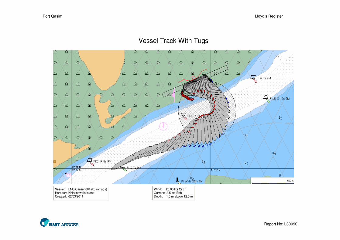
Port Qasim Lloyd’s Register
Report No: L30090
Vessel Track With Tugs
Vessel: LNG Carrier 004 (B) (+Tugs)Harbour: Khiprianwala IslandCreated: 02/03/2011
Wind: 20.00 kts 225 °Current: 3.5 kts EbbDepth: 1.0 m above 12.5 m

Port Qasim Lloyd’s Register
Report No: L30090
Project: Port Qasim LNG Terminal Study
Job No.: L30090 Captain/Pilot: Chris Bordas
Subject: PC Rembrandt Simulation Study for Lloyd’s Register
Date: 28/02/2011
Vessel Access Condition Environmental Conditions Manoeuvre Run No.
Ship Condition Type No of Tugs
Used Current
Wind Speed (Direction from)
Waves (Ht/Period)
Thrusters used?
22 LNG 004 Loaded (12.2m)
Arrival
4 Slack water 20kts (225) - -
This run was an attempted repeat of Run 15. In order to avoid some technical issues the run was assumed to be carried out at slack water (and with an extra 1m of tidal height). The south westerly wind pushed the vessel towards the north of the channel (and the moored vessels) which had to be overcome using frequent rudder inputs and tug corrections.
1 2 3 4 5 6 7 8
Ratings Easy
Straight-forward
Comfortable Not demanding Not easy Challenging Difficult Impossible

Port Qasim Lloyd’s Register
Report No: L30090
Vessel Track With Tugs
Vessel: LNG Carrier 004 (L) (+Tugs)Harbour: Port QasimCreated: 02/03/2011
Wind: 20.00 kts 225 °Current: 0.00 kts 0 °Depth: Variable

Port Qasim Lloyd’s Register
Report No: L30090
Vessel Track With Tugs
Vessel: LNG Carrier 004 (L) (+Tugs)Harbour: Port QasimCreated: 02/03/2011
Wind: 20.00 kts 225 °Current: 0.00 kts 0 °Depth: Variable

Port Qasim Lloyd’s Register
Report No: L30090
Project: Port Qasim LNG Terminal Study
Job No.: L30090 Captain/Pilot: Chris Bordas
Subject: PC Rembrandt Simulation Study for Lloyd’s Register
Date: 02/03/2011
Vessel Access Condition Environmental Conditions Manoeuvre Run No.
Ship Condition Type No of Tugs
Used Current
Wind Speed (Direction from)
Waves (Ht/Period)
Thrusters used?
23 LNG 005 Loaded (11.5m)
Arrival
1 2kt flood 20kts (225) - No
Run 23 was used to determine how a rudder failure (stuck on full defection) would affect a vessel transiting the port entrance. Both anchors were let go and the escort tug was used to ensure the vessel stayed clear of the main channel.
1 2 3 4 5 6 7 8
Ratings Easy
Straight-forward
Comfortable Not demanding Not easy Challenging Difficult Impossible
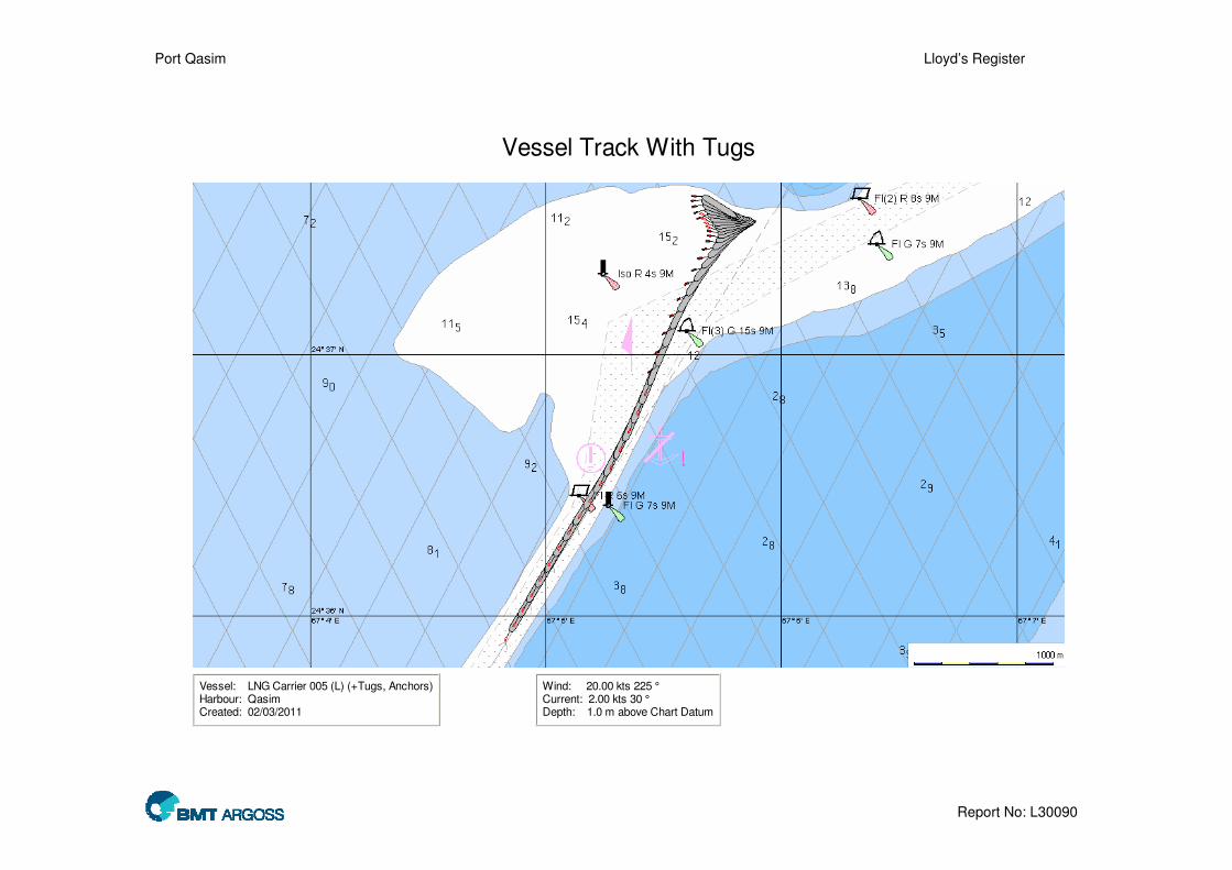
Port Qasim Lloyd’s Register
Report No: L30090
Vessel Track With Tugs
Vessel: LNG Carrier 005 (L) (+Tugs, Anchors)Harbour: QasimCreated: 02/03/2011
Wind: 20.00 kts 225 °Current: 2.00 kts 30 °Depth: 1.0 m above Chart Datum

Port Qasim Lloyd’s Register
Report No: L30090
Vessel Track With Tugs
Vessel: LNG Carrier 005 (L) (+Tugs, Anchors)Harbour: QasimCreated: 02/03/2011
Wind: 20.00 kts 225 °Current: 2.00 kts 30 °Depth: 1.0 m above Chart Datum

Port Qasim Lloyd’s Register
Report No: L30090
Project: Port Qasim LNG Terminal Study
Job No.: L30090 Captain/Pilot: Chris Bordas
Subject: PC Rembrandt Simulation Study for Lloyd’s Register
Date: 02/03/2011
Vessel Access Condition Environmental Conditions Manoeuvre Run No.
Ship Condition Type No of Tugs
Used Current
Wind Speed (Direction from)
Waves (Ht/Period)
Thrusters used?
24 LNG 005 Loaded (11.5m)
Arrival
1 2kt flood 20kts (225) - No
Run 24 was another failure test. Starting further in the channel an engine failure was simulated. Again using anchors and the escort tug the vessel as controlled albeit ending in the channel.
1 2 3 4 5 6 7 8
Ratings Easy
Straight-forward
Comfortable Not demanding Not easy Challenging Difficult Impossible

Port Qasim Lloyd’s Register
Report No: L30090
Vessel Track With Tugs
Vessel: LNG Carrier 005 (L) (+Tugs, Anchors)Harbour: QasimCreated: 02/03/2011
Wind: 20.00 kts 225 °Current: 2.00 kts 40 °Depth: 1.0 m above Chart Datum

Port Qasim Lloyd’s Register
Report No: L30090
Vessel Track With Tugs
Vessel: LNG Carrier 005 (L) (+Tugs, Anchors)Harbour: QasimCreated: 02/03/2011
Wind: 20.00 kts 225 °Current: 2.00 kts 40 °Depth: 1.0 m above Chart Datum
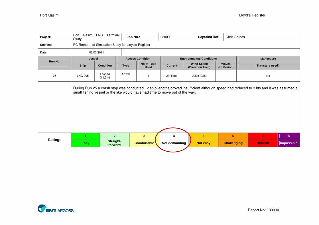
Port Qasim Lloyd’s Register
Report No: L30090
Project: Port Qasim LNG Terminal Study
Job No.: L30090 Captain/Pilot: Chris Bordas
Subject: PC Rembrandt Simulation Study for Lloyd’s Register
Date: 02/03/2011
Vessel Access Condition Environmental Conditions Manoeuvre Run No.
Ship Condition Type No of Tugs
Used Current
Wind Speed (Direction from)
Waves (Ht/Period)
Thrusters used?
25 LNG 005 Loaded (11.5m)
Arrival
1 2kt flood 20kts (225) - No
During Run 25 a crash stop was conducted. 2 ship lengths proved insufficient although speed had reduced to 3 kts and it was assumed a small fishing vessel or the like would have had time to move out of the way.
1 2 3 4 5 6 7 8
Ratings Easy
Straight-forward
Comfortable Not demanding Not easy Challenging Difficult Impossible

Port Qasim Lloyd’s Register
Report No: L30090
Vessel Track With Tugs
Vessel: LNG Carrier 005 (L) (+Tugs, Anchors)Harbour: QasimCreated: 02/03/2011
Wind: 20.00 kts 225 °Current: 2.00 kts 30 °Depth: 1.0 m above Chart Datum

Port Qasim Lloyd’s Register
Report No: L30090
Project: Port Qasim LNG Terminal Study
Job No.: L30090 Captain/Pilot: Chris Bordas
Subject: PC Rembrandt Simulation Study for Lloyd’s Register
Date: 02/03/2011
Vessel Access Condition Environmental Conditions Manoeuvre Run No.
Ship Condition Type No of Tugs
Used Current
Wind Speed (Direction from)
Waves (Ht/Period)
Thrusters used?
26 LNG 005 Loaded (11.5m)
Arrival
1 (possibly 4) 2kt flood 20kts (225) - No
A blackout was simulated at a point higher up the channel. Using the single tug and the ship’s rudder good control was maintained. In addition the vessel passed the point in the channel where it was assumed the berthing tugs would join. As such it is likely that the vessel would be fully controllable using only tugs.
1 2 3 4 5 6 7 8
Ratings Easy
Straight-forward
Comfortable Not demanding Not easy Challenging Difficult Impossible

Port Qasim Lloyd’s Register
Report No: L30090
Vessel Track With Tugs
Vessel: LNG Carrier 005 (L) (+Tugs, Anchors)Harbour: QasimCreated: 02/03/2011
Wind: 20.00 kts 225 °Current: 2.00 kts 40 °Depth: 1.0 m above Chart Datum

Port Qasim Lloyd’s Register
Report No: L30090
Vessel Track With Tugs
Vessel: LNG Carrier 005 (L) (+Tugs, Anchors)Harbour: QasimCreated: 02/03/2011
Wind: 20.00 kts 225 °Current: 2.00 kts 40 °Depth: 1.0 m above Chart Datum

Port Qasim Lloyd’s Register
Report No: L30090
Project: Port Qasim LNG Terminal Study
Job No.: L30090 Captain/Pilot: Chris Bordas
Subject: PC Rembrandt Simulation Study for Lloyd’s Register
Date: 02/03/2011
Vessel Access Condition Environmental Conditions Manoeuvre Run No.
Ship Condition Type No of Tugs
Used Current
Wind Speed (Direction from)
Waves (Ht/Period)
Thrusters used?
27 LNG 005 Loaded (11.5m)
Arrival
1 2kt flood 20kts (225) - No
This was a repeat of Run 23 but with the vessel further in the channel. The vessel was brought under control using anchors and tugs. At this point it was decided that a standby tug should be provided at all times in case of tug failure.
1 2 3 4 5 6 7 8
Ratings Easy
Straight-forward
Comfortable Not demanding Not easy Challenging Difficult Impossible

Port Qasim Lloyd’s Register
Report No: L30090
Vessel Track With Tugs
Vessel: LNG Carrier 005 (L) (+Tugs, Anchors)Harbour: New RegionCreated: 3/2/2011
Wind: 20.00 kts 225 °Current: 2.00 kts 40 °Depth: 1.0 m above Chart Datum

Port Qasim Lloyd’s Register
Report No: L30090
Project: Port Qasim LNG Terminal Study
Job No.: L30090 Captain/Pilot: Chris Bordas
Subject: PC Rembrandt Simulation Study for Lloyd’s Register
Date: 02/03/2011
Vessel Access Condition Environmental Conditions Manoeuvre Run No.
Ship Condition Type No of Tugs
Used Current
Wind Speed (Direction from)
Waves (Ht/Period)
Thrusters used?
28 LNG 005 Loaded (11.5m)
Arrival
3 then 2 2kt flood 20kts (225) - Yes
Run 28 was a simulation of a tug failure during an arrival swing manoeuvre. It was assumed that halfway through the swing the tug attached to the vessel’s stern failed. At this point the swing was abandoned and the vessel was berth port-side to with no further problems.
1 2 3 4 5 6 7 8
Ratings Easy
Straight-forward
Comfortable Not demanding Not easy Challenging Difficult Impossible

Port Qasim Lloyd’s Register
Report No: L30090
Vessel Track With Tugs
Vessel: LNG Carrier 005 (L) (+Tugs)Harbour: Khiprianwala IslandCreated: 02/03/2011
Wind: 20.00 kts 225 °Current: 2.00 kts 60 °Depth: 1.0 m above 12.5 m

Port Qasim Lloyd’s Register
Report No: L30090
Project: Port Qasim LNG Terminal Study
Job No.: L30090 Captain/Pilot: Chris Bordas
Subject: PC Rembrandt Simulation Study for Lloyd’s Register
Date: 02/03/2011
Vessel Access Condition Environmental Conditions Manoeuvre Run No.
Ship Condition Type No of Tugs
Used Current
Wind Speed (Direction from)
Waves (Ht/Period)
Thrusters used?
29 LNG 005 Loaded (11.5m)
Passing
1 Slack water 20kts (225) - Yes
Run 29 was a repeat of Run 28 but with slack water and the tug failure occurring later in the swing. This was completed with no problems.
1 2 3 4 5 6 7 8
Ratings Easy
Straight-forward
Comfortable Not demanding Not easy Challenging Difficult Impossible

Port Qasim Lloyd’s Register
Report No: L30090
Vessel Track With Tugs
Vessel: LNG Carrier 005 (L) (+Tugs)Harbour: Khiprianwala IslandCreated: 02/03/2011
Wind: 20.00 kts 225 °Current: 0.00 kts 60 °Depth: Variable

Port Qasim Lloyd’s Register
Report No: L30090
Project: Port Qasim LNG Terminal Study
Job No.: L30090 Captain/Pilot: Chris Bordas
Subject: PC Rembrandt Simulation Study for Lloyd’s Register
Date: 02/03/2011
Vessel Access Condition Environmental Conditions Manoeuvre Run No.
Ship Condition Type No of Tugs
Used Current
Wind Speed (Direction from)
Waves (Ht/Period)
Thrusters used?
30 LNG 005 Loaded (11.5m)
Passing
1 Slack water 20kts (225) - No
Run 30 simulated a vessel passing the Greenfield LNG berth and then having an engine failure. It was demonstrated that a single standby tug (if sited by the LNG berth) would have sufficient time and power to prevent the passing ship drifting towards the LNGCs.
1 2 3 4 5 6 7 8
Ratings Easy
Straight-forward
Comfortable Not demanding Not easy Challenging Difficult Impossible

Port Qasim Lloyd’s Register
Report No: L30090
Vessel Track With Tugs
Vessel: LNG Carrier 005 (L) (+Tugs)Harbour: Khiprianwala IslandCreated: 02/03/2011
Wind: 20.00 kts 225 °Current: 0.00 kts 60 °Depth: 1.0 m above 12.5 m

Port Qasim Lloyd’s Register
Report No: L30090
Project: Port Qasim LNG Terminal Study
Job No.: L30090 Captain/Pilot: Chris Bordas
Subject: PC Rembrandt Simulation Study for Lloyd’s Register
Date: 02/03/2011
Vessel Access Condition Environmental Conditions Manoeuvre Run No.
Ship Condition Type No of Tugs
Used Current
Wind Speed (Direction from)
Waves (Ht/Period)
Thrusters used?
31 LNG 005 Loaded (11.5m)
Arrival
4 3kt Flood 20kts (225) - No
Run 31 simulated a vessel engine failure on passing the LPG berth. Using the 4 tugs assumed to be available the vessel was easily controlled and even successfully swung in the turning basin.
1 2 3 4 5 6 7 8
Ratings Easy
Straight-forward
Comfortable Not demanding Not easy Challenging Difficult Impossible

Port Qasim Lloyd’s Register
Report No: L30090
Vessel Track With Tugs
Vessel: LNG Carrier 005 (L) (+Tugs)Harbour: New RegionCreated: 02/03/2011
Wind: 20.00 kts 225 °Current: 3.00 kts 115 °Depth: Variable

Port Qasim Lloyd’s Register
Report No: L30090
Vessel Track With Tugs
Vessel: LNG Carrier 005 (L) (+Tugs)Harbour: New RegionCreated: 3/2/2011
Wind: 20.00 kts 225 °Current: 3.00 kts 115 °Depth: Variable

Port Qasim Lloyd’s Register
Report No: L30090
Project: Port Qasim LNG Terminal Study
Job No.: L30090 Captain/Pilot: Chris Bordas
Subject: PC Rembrandt Simulation Study for Lloyd’s Register
Date: 02/03/2011
Vessel Access Condition Environmental Conditions Manoeuvre Run No.
Ship Condition Type No of Tugs
Used Current
Wind Speed (Direction from)
Waves (Ht/Period)
Thrusters used?
32 LNG 004 Loaded (12.2m)
Arrival
4 Slack water 20kts (225) - No
This run was a repeat of Run 28 (a tug failure during berthing swing) except a starting number of 4 tugs was used and a Q-Flex vessel. In this situation the vessel proved very easy to control and in fact only 2 tugs were employed for the vast majority of the manoeuvre.
1 2 3 4 5 6 7 8
Ratings Easy
Straight-forward
Comfortable Not demanding Not easy Challenging Difficult Impossible

Port Qasim Lloyd’s Register
Report No: L30090
Vessel Track With Tugs
Vessel: LNG Carrier 004 (L) (+Tugs)Harbour: Khiprianwala IslandCreated: 3/2/2011
Wind: 20.00 kts 225 °Current: 0.00 kts 115 °Depth: 1.0 m above 13.5 m

Port Qasim Lloyd’s Register
Report No: L30090
Project: Port Qasim LNG Terminal Study
Job No.: L30090 Captain/Pilot: Chris Bordas
Subject: PC Rembrandt Simulation Study for Lloyd’s Register
Date: 02/03/2011
Vessel Access Condition Environmental Conditions Manoeuvre Run No.
Ship Condition Type No of Tugs
Used Current
Wind Speed (Direction from)
Waves (Ht/Period)
Thrusters used?
33 LNG 004 Loaded (12.2m)
Arrival
1 3kt Flood 20kts (225) - No
Run 33 tested an arrival at the currently-unused Southern Channel. A berth was placed on the southern bank and the vessel navigated up the channel and swung. This was conducted without and difficulties.
1 2 3 4 5 6 7 8
Ratings Easy
Straight-forward
Comfortable Not demanding Not easy Challenging Difficult Impossible

Port Qasim Lloyd’s Register
Report No: L30090
Vessel Track With Tugs
Vessel: LNG Carrier 005 (L) (+Tugs)Harbour: QasimCreated: 02/03/2011
Wind: 20.00 kts 225 °Current: VariableDepth: 1.0 m above Chart Datum

Port Qasim Lloyd’s Register
Report No: L30090
Vessel Track With Tugs
Vessel: LNG Carrier 005 (L) (+Tugs)Harbour: QasimCreated: 02/03/2011
Wind: 20.00 kts 225 °Current: VariableDepth: 1.0 m above Chart Datum
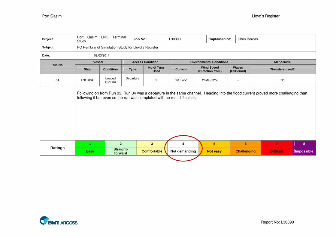
Port Qasim Lloyd’s Register
Report No: L30090
Project: Port Qasim LNG Terminal Study
Job No.: L30090 Captain/Pilot: Chris Bordas
Subject: PC Rembrandt Simulation Study for Lloyd’s Register
Date: 02/03/2011
Vessel Access Condition Environmental Conditions Manoeuvre Run No.
Ship Condition Type No of Tugs
Used Current
Wind Speed (Direction from)
Waves (Ht/Period)
Thrusters used?
34 LNG 004 Loaded (12.2m)
Departure
2 3kt Flood 20kts (225) - No
Following on from Run 33, Run 34 was a departure in the same channel. Heading into the flood current proved more challenging than following it but even so the run was completed with no real difficulties.
1 2 3 4 5 6 7 8
Ratings Easy
Straight-forward
Comfortable Not demanding Not easy Challenging Difficult Impossible

Port Qasim Lloyd’s Register
Report No: L30090
Vessel Track With Tugs
Vessel: LNG Carrier 005 (L) (+Tugs)Harbour: QasimCreated: 02/03/2011
Wind: 20.00 kts 225 °Current: VariableDepth: Variable

Port Qasim Lloyd’s Register
Report No: L30090
Vessel Track With Tugs
Vessel: LNG Carrier 005 (L) (+Tugs)Harbour: QasimCreated: 02/03/2011
Wind: 20.00 kts 225 °Current: VariableDepth: Variable