4009 IDNet NAC Extender for Control with ... - FireAlarm.com
10
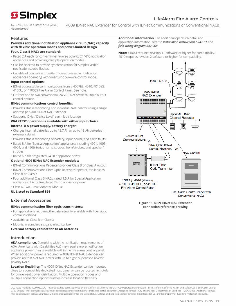
4009 IDNet NAC Extender for Control with IDNet Communications or Conventional NACs ULC listed model is 4009-9202CA. This product has been approved by the California State Fire Marshal (CSFM) pursuant to Section 13144.1 of the California Health and Safety Code. See CSFM Listing 7300-0026:214 for allowable values and/or conditions concerning material presented in this document. Accepted for use – City of New York Department of Buildings – MEA35-93E. Additional listings may be applicable; contact your local Simplex product supplier for the latest status. Listings and approvals under Simplex Time Recorder Co. are the property of Tyco Fire Protection Products. UL, ULC, CSFM Listed; MEA (NYC) Acceptance* LifeAlarm Fire Alarm Controls S4009-0002 Rev. 15 9/2019 Features Provides additional notification appliance circuit (NAC) capacity with flexible operation modes and power-limited design Four, Class B NACs are standard: • Rated 2 A each for conventional reverse polarity 24 VDC notification appliances and providing multiple operation modes. • Can be selected to provide synchronization for Simplex visible notification strobe flashes. • Capable of controlling TrueAlert non-addressable notification appliances operating with SmartSync two-wire control mode. Input control options: • IDNet addressable communications from a 4007ES, 4010, 4010ES, 4100U, or 4100ES Fire Alarm Control Panel. See note. • Or from one or two conventional 24 VDC NACs with multiple output control options IDNet communications control benefits: • Provides status monitoring and individual NAC control using a single address per 4009 IDNet NAC Extender • Supports IDNet “Device Level” earth fault location WALKTEST operation is available with either input choice Internal 8 A power supply/battery charger: • Charges internal batteries up to 12.7 Ah or up to 18 Ah batteries in external cabinet • Provides status monitoring of battery, input power, and earth faults • Rated 8 A for “Special Application” appliances; including 4901, 4903, 4904, and 4906 Series horns, strobes, horn/strobes, and speaker/ strobes • Rated 6 A for “Regulated 24 DC” appliance power Optional 4009 IDNet NAC Extender modules: • IDNet Communications Repeater provides Class B or Class A output • IDNet Communications Fiber Optic Receiver/Repeater, available as Class B or Class X • Four additional Class B NACs, rated 1.5 A for Special Application appliances; 1 A for Regulated 24 DC appliance power • Class A, Two Circuit Adapter Module UL Listed to Standard 864 External Accessories IDNet communication fiber optic transmitters: • For applications requiring the data integrity available with fiber optic communications • Available as Class B or Class X • Mounts in standard six-gang electrical box External battery cabinet for 18 Ah batteries Introduction ADA compliance. Complying with the notification requirements of ADA (Americans with Disabilities Act) may require more notification appliance power than is available within the fire alarm control panel. When additional power is required, a 4009 IDNet NAC Extender can provide up to 8 A of NAC power with up to eight, supervised reverse polarity NACs. Location flexibility. The 4009 IDNet NAC Extender can be mounted close to a compatible dedicated host panel or can be located remotely for convenient power distribution. Multiple operation modes and multiple connection options further increase location flexibility. Additional information. For additional operation detail and application information, refer to Installation Instructions 574-181 and field wiring diagram 842-068. Note: 4100U requires revision 11 software or higher for compatibility. 4010 requires revision 2 software or higher for compatibility. Figure 1: 4009 IDNet NAC Extender connection reference drawing
-
Upload
khangminh22 -
Category
Documents
-
view
5 -
download
0
Transcript of 4009 IDNet NAC Extender for Control with ... - FireAlarm.com
4009 IDNet NAC Extender for Control with IDNet Communications or Conventional NACs
ULC listed model is 4009-9202CA. This product has been approved by the California State Fire Marshal (CSFM) pursuant to Section 13144.1 of the California Health and Safety Code. See CSFM Listing7300-0026:214 for allowable values and/or conditions concerning material presented in this document. Accepted for use – City of New York Department of Buildings – MEA35-93E. Additional listingsmay be applicable; contact your local Simplex product supplier for the latest status. Listings and approvals under Simplex Time Recorder Co. are the property of Tyco Fire Protection Products.
UL, ULC, CSFM Listed; MEA (NYC)Acceptance*
LifeAlarm Fire Alarm Controls
S4009-0002 Rev. 15 9/2019
FeaturesProvides additional notification appliance circuit (NAC) capacitywith flexible operation modes and power-limited designFour, Class B NACs are standard:• Rated 2 A each for conventional reverse polarity 24 VDC notification
appliances and providing multiple operation modes.• Can be selected to provide synchronization for Simplex visible
notification strobe flashes.• Capable of controlling TrueAlert non-addressable notification
appliances operating with SmartSync two-wire control mode.Input control options:• IDNet addressable communications from a 4007ES, 4010, 4010ES,
4100U, or 4100ES Fire Alarm Control Panel. See note.• Or from one or two conventional 24 VDC NACs with multiple output
control optionsIDNet communications control benefits:• Provides status monitoring and individual NAC control using a single
address per 4009 IDNet NAC Extender• Supports IDNet “Device Level” earth fault locationWALKTEST operation is available with either input choiceInternal 8 A power supply/battery charger:• Charges internal batteries up to 12.7 Ah or up to 18 Ah batteries in
external cabinet• Provides status monitoring of battery, input power, and earth faults• Rated 8 A for “Special Application” appliances; including 4901, 4903,
4904, and 4906 Series horns, strobes, horn/strobes, and speaker/strobes
• Rated 6 A for “Regulated 24 DC” appliance powerOptional 4009 IDNet NAC Extender modules:• IDNet Communications Repeater provides Class B or Class A output• IDNet Communications Fiber Optic Receiver/Repeater, available as
Class B or Class X• Four additional Class B NACs, rated 1.5 A for Special Application
appliances; 1 A for Regulated 24 DC appliance power• Class A, Two Circuit Adapter ModuleUL Listed to Standard 864
External AccessoriesIDNet communication fiber optic transmitters:• For applications requiring the data integrity available with fiber optic
communications• Available as Class B or Class X• Mounts in standard six-gang electrical boxExternal battery cabinet for 18 Ah batteries
IntroductionADA compliance. Complying with the notification requirements ofADA (Americans with Disabilities Act) may require more notificationappliance power than is available within the fire alarm control panel.When additional power is required, a 4009 IDNet NAC Extender canprovide up to 8 A of NAC power with up to eight, supervised reversepolarity NACs.Location flexibility. The 4009 IDNet NAC Extender can be mountedclose to a compatible dedicated host panel or can be located remotelyfor convenient power distribution. Multiple operation modes andmultiple connection options further increase location flexibility.
Additional information. For additional operation detail andapplication information, refer to Installation Instructions 574-181 andfield wiring diagram 842-068.
Note: 4100U requires revision 11 software or higher for compatibility.4010 requires revision 2 software or higher for compatibility.
Figure 1: 4009 IDNet NAC Extenderconnection reference drawing

Page 2 S4009-0002 Rev. 15 9/2019
4009 IDNet NAC Extender for Control with IDNet Communications or Conventional NACs
Application and operation informationIDNet addressable communications compatible. Up to 10, 4009 IDNet NAC Extenders can be controlled for each 4007ES, 4010ES, 4100U, or4100ES IDNet communications channel; up to 5 can be controlled on the 4010 IDNet communications channel. Each output NAC can be individuallycontrolled for general alarm or selective area notification requiring only one point address for each Extender. Individual Extender NACs can also bemanually controlled from the host panel. IDNet controlled extenders will inform the host panel of troubles using IDNet communications. 4007ES,4010ES, 4100ES, and 4100U control panels control using multi-point rules, refer to data sheet S4090-0011 for details.Optional IDNet repeaters. IDNet communications can be repeated with the optional IDNet Repeater Module or with the optional Fiber OpticReceiver Module. Up to 100 of the IDNet channel points can be repeated once (refer to Typical IDNet connection example and 4009 IDNet NACExtender specifications for details). Repeated IDNet communications also support the "device level" earth fault location utility of the host panel.Hardwire control applications. For applications where an existing (or new) conventional NAC needs additional power, the 4009 IDNet NACExtender can be controlled directly from the NAC. Either one or two NACs, from either the same, or from different host fire alarm control panels, canbe connected to control the 4009 IDNet NAC Extender output NACs. Multiple control selections provide flexible operation. (See Hardwire ControlConnection Information for more detail.) Alarms from the host panel will activate the four, 4009 IDNet NAC Extender NACs (or optionally, 8 NACs) toextend the alarm.The 4009 IDNet Extender monitors itself and each of its output NACs for trouble conditions, including earth faults. Extenders wired to conventionalNACs will indicate a trouble by opening the path to the NAC's end-of-line resistor, but retaining the ability to respond to alarms. Individual troublesare also annunciated by LEDs located on the 4009 IDNet NAC Extender main circuit board. Refer to Service diagnostic features for more diagnosticinformation.
Product selectionTable 1: Standard models
Model Description4009-9201** 120 VAC input4009-9301 240 VAC input
4009 IDNet NAC Extender with 4, Class B NACsand 8 A power supply
4009-9202CA (ULC listed model) 120 VAC input -** 4009-9201 has been seismic tested and is certified to IBC and CBC standards as well as to ASCE 7 categories A through F, requires battery bracketsas detailed on data sheet S2081-0019
Table 2: Optional modules (for on-site installation)
Model Description Comments
4009-9807 Additional four point NAC module, rated 1.5 A Special Applicationappliances; 1 A for Regulated 24 DC appliance power, Class B 1 maximum
4009-9808 Dual Class A adapter (for two NAC outputs) Select as required (4 maximum)4009-9809 IDNet Repeater, output is Class A or Class B4009-9810 Class B4009-9811
Fiber Optic ReceiverClass A (IDNet), Class X (fiber)
Select either an IDNet Repeater or a Fiber OpticReceiver as required; one transmitter can connectto one receiver
4009-9805 Red Appliqué for door Select if required2975-9801 Beige trim2975-9802
Semi-Flush Trim KitRed trim
1 7/16 in. wide (78 mm), use if required for semi-flush installations
Table 3: Battery selection (select battery size using system requirements)
Model Description Comments2081-9272 6.2 Ah Battery, 12 VDC2081-9274 10 Ah Battery, 12 VDC2081-9288 12.7 Ah Battery, 12 VDC
Two batteries are required, 24 VDC operation
2081-9275 18 Ah Battery, 12 VDC Requires external battery cabinet, two batteries arerequired, 24 VDC operation
Table 4: External accessories (select using system requirements)
Model Description Comments4090-9105 Class B operation
4090-9107IDNet Fiber OpticTransmitter Class X operation
Mounts in six-gang electrical box, refer to4090-9105/9107 IDNet fiber optic transmittermounting information for mounting details
Note: Class B Fiber Transmitter Rev C or higher,IS NOT COMPATIBLE with Class B Fiber Receiverbefore Rev J.
4009-9801 External battery cabinet for up to 18 Ah batteries, beige 16-1/4 in. W x 13-1/2 in. H x 5-3/4 in. D (413 mm x343 mm x 146 mm)
4081 series End-of-Line resistor harnesses; see data sheet S4081-0003 for details

Page 3 S4009-0002 Rev. 15 9/2019
4009 IDNet NAC Extender for Control with IDNet Communications or Conventional NACs
Typical IDNet connection example
Figure 2: Typical IDNet connection example
Note: Up to 10 4009 IDNet NAC Extenders may be connected using 4007ES, 4010ES, 4100U, or 4100ES IDNet channel, up to 5 on the 4010 IDNetchannel. IDNet communications can be repeated only once (can pass through only one series connected repeater or one fiber optic receiver).

Page 4 S4009-0002 Rev. 15 9/2019
4009 IDNet NAC Extender for Control with IDNet Communications or Conventional NACs
Typical fiber optic system connections
Figure 3: Typical fiber optic system connections
Note: Up to 10 4009 IDNet NAC Extenders may be connected per 4007ES, 4100ES, or 4010ES. Up to 5 4009 IDNet NAC Extenders may be connectedon the 4010 IDNet channel. IDNet communications can be repeated only once (can pass through only one series connected repeater or one fiberoptic receiver). Fiber optic transmitters connect to only one receiver in a 4009 IDNet NAC Extender.
Hardwire Control Connection InformationNAC Input Selections. The 4009 IDNet NAC Extender can be selected to:• Track input NAC operation or to provide a locally generated code, selectable using NAC input.• If selected for local coding, NAC outputs can be either Temporal Coded or 60 Beats/min March Time Coded, one code selection per extender
(input NACs must be on continuous with Alarm).• Additionally, NAC outputs can be selected to provide the Simplex strobe synchronization signal. This signal will synchronize the flashes of
synchronized strobes but will be ignored by free-run strobes and audible devices. (Strobes are for operation by noncoded NACs.)NAC input to NAC output control can be selected for standard and optional NACs per the following table:
Table 5: Conventional NAC Output Operation Options
Input A B CNAC 1 NACs 1 and 2, 5 and 6 NACs 1 - 4 NACs 1 - 8NAC 2 NACs 3 and 4, 7 and 8 NACs 5 - 8 -
Table 6: SmartSync NAC Output Operation
Input NAC Control FunctionNAC 1 Strobe ControlNAC 2 Horn Control
All NAC outputs (1 - 8)

Page 5 S4009-0002 Rev. 15 9/2019
4009 IDNet NAC Extender for Control with IDNet Communications or Conventional NACs
SmartSync Notification Appliance ControlThe TrueAlert Notification Appliance product line includes addressable and non-addressable operation. Non-addressable models are availablewith 2-wire SmartSync operation or conventional 4-wire operation. The following details apply to use with the 4009 IDNet NAC Extender:• TrueAlert non-addressable models with SmartSync operation allow audible notification to be separately controlled over the same wire pair that
controls visible notification.• 4009 IDNet NAC Extenders can be selected to provide SmartSync operation whether controlled by IDNet communications or conventional NACs.• IDNet control allows output NACs to be individually selected for conventional or SmartSync operation.• With NAC input control, all output NACs are selected for either conventional or SmartSync operation.• Refer to data sheet S4009-0003 for TrueAlert Addressable operation details, contact your local Simplex product supplier for further information on
specific TrueAlert notification appliances.
Hardwire control NAC connection cne-line reference diagram
Figure 4: Hardwire control NAC connection one-line reference diagram
Note:1. For separate audible and visible output NAC control, or SmartSync NAC output operation, 2 input NACs are required. NAC 1 is "on-until-reset" and
NAC 2 is "on-until-silenced".
2. To synchronize strobe flash outputs for up to 4 4009 IDNet NAC Extenders, use the synchronized strobe output from a Synchronized Flash Module(4905-9914 for Class B operation, 4905-9922 for Class A operation) or, if available, from a NAC selected to provide synchronized strobe flashoutput. NOTE: DO NOT USE a NAC selected for SmartSync operation for this function.
Refer to Installation Instructions 574-181 for additional information and application guidance.

Page 6 S4009-0002 Rev. 15 9/2019
4009 IDNet NAC Extender for Control with IDNet Communications or Conventional NACs
4009 IDNet NAC Extender specificationsTable 7: Input ratings
Specification Rating120 VAC input (4009-9201) 3A @ 102 VAC -132 VAC, 60 Hz240 VAC input (4009-9301) 1.5A @ 204 VAC -264 VAC, 50 Hz /60 Hz
Conventional reverse polarity operationHardwire control from external NACs, input requirements
5 mA maximum; 16 VDC to 33 VDC
Table 8: Output ratings
Specification RatingTotal rating 8 A, Special application appliances 6 A, regulated 24 DC appliance powerStandard NACs 2 A each, special application or regulated 24 DC appliance powerOptional NACs (requires 4009-9807 ) 1.5 A each, Special Application appliances 1 A each, Regulated 24 DC appliance power
Special application appliances Simplex non-addressable horns, strobes, and combination horn/strobes and speaker/strobes(contact your Simplex product representative for compatible appliances)
Regulated 24 DC appliances Power for other UL listed appliances; use associated external synchronization modules whererequired
Strobe operation Up to 33 strobes for each NAC can be synchronized; output NACs configured for Simplexsynchronized strobe operation are synchronized to each other
Auxiliary output 500 mA @ 24 VDC nominal
Table 9: Optional modules ratings
Specification RatingInput power 70 mA @ 24 VDC, system suppliedIDNet input, one address Maximum distance from IDNet source is 2,500 ft (762 m)
Repeated IDNet output for up to 100 devices (total IDNet devices not to exceed 250 foreach channel)Maximum distance to farthest device is 2,500 ft (762 m)Total distance including "T-taps" is 10,000 ft (3048 m)
IDNet RepeaterModule( 4009-9809 ) IDNet output specifications
Class A loop maximum distance is 2,500 ft (762 m), no "T" taps
Table 10: Fiber optic receiver modules
Specification Rating4009-9810 , Class B, 65 mA @ 24 VDC, system supplied
Input current4009-9811 , Class X, 80 mA @ 24 VDC, system supplied
IDNet output specifications Same as those for repeater moduleFiber optic transmission distance 3000 ft (914 m) maximum
Table 11: General specifications
Specification RatingOperating temperature 32° F to 120° F (0° C to 49° C)Operating humidity range 10% to 90% RH from 32° F to 104° F (0° C to 40° C)Wiring Connections*
Note: * Metric wire equivalents: 18 AWG = 0.82 mm2; 12 AWG = 3.31 mm2Terminal blocks for 18 AWG (stranded) to 12 AWG (solid)
Page 7 S4009-0002 Rev. 15 9/2019
4009 IDNet NAC Extender for Control with IDNet Communications or Conventional NACs
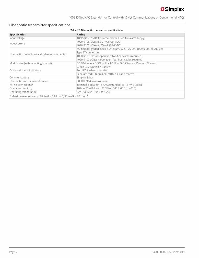
Fiber optic transmitter specificationsTable 12: Fiber optic transmitter specifications
Specification RatingInput voltage 18.9 VDC -32 VDC from compatible listed fire alarm supply
4090-9105, Class B, 30 mA @ 24 VDCInput current
4090-9107 , Class X, 35 mA @ 24 VDCMultimode, graded index, 50/125µm, 62.5/125 µm, 100/40 µm, or 200 µmType ST connectors4090-9105, Class B operation, two fiber cables required
Fiber optic connections and cable requirements
4090-9107 , Class X operation, four fiber cables requiredModule size (with mounting bracket) 6-13/16 in. W x 3-3/4 in. H x 1-1/8 in. D (173 mm x 95 mm x 29 mm)
Green LED flashing = transmitRed LED flashing = receiveOn-board status indicatorsSeparate red LED on 4090-9107 = Class X receive
Communications Simplex IDNetFiber optic transmission distance 3000 ft (914 m) maximumWiring connections* Terminal blocks for 18 AWG (stranded) to 12 AWG (solid)Operating humidity 10% to 90% RH from 32° F to 104° F (0° C to 40° C)Operating temperature 32° F to 120° F (0° C to 49° C)
* Metric wire equivalents: 18 AWG = 0.82 mm2; 12 AWG = 3.31 mm2

Page 8 S4009-0002 Rev. 15 9/2019
4009 IDNet NAC Extender for Control with IDNet Communications or Conventional NACs
4009 IDNet NAC Extender mounting and module placement informationAdditional four point module shown model 4009-9807 .
Figure 5: 4009 IDNet NAC Extender mounting and module placement information
Note: Recommended conduit entrance varies with module selection. Refer to general installation instructions 574-181, specific module installationinstructions, and to field wiring diagrams 842-068 before locating conduit entrance.
4009 IDNet NAC extender cabinet with door detail
Figure 6: 4009 IDNet NAC extender cabinet with door detail

Page 9 S4009-0002 Rev. 15 9/2019
4009 IDNet NAC Extender for Control with IDNet Communications or Conventional NACs
4090-9105/9107 IDNet fiber optic transmitter mounting information
Service diagnostic featuresPower-up self-diagnostics. Upon power-up, the 4009 IDNet NAC Extender tests each module and performs earth fault diagnostics. Troubleconditions are communicated to the host control panel and are also displayed on diagnostic status LEDs in the 4009 IDNet NAC Extender. Whenconnected via IDNet communications, detailed status information is available at the host. When controlled with conventional NAC inputs, commontroubles are signaled by providing a polarized open circuit that disconnects the NAC wiring from its end-of-line resistor but still allows a reversedpolarity alarm to be received.Door mounted reference label. The 4009 IDNet NAC Extender has a detailed programming and diagnostic label inside the front door that providesa quick reference for both installation and checkout.LED Status Indicators are provided for the following:• Each NAC (standard and optional) has a dedicated yellow LED that:
- During supervision provides a slow flash to indicate a short circuit condition and a fast flash to indicate an open circuit.
- During an alarm, the LED follows the NAC output (on steady or flashing with coded output).
• Four, general status yellow LEDs provide nine separate indications listed in priority of urgency. As a trouble is eliminated, any remaining troublewill then be indicated until the 4009 IDNet NAC Extender is returned to normal operation.
• AC power status is indicated by a green LED that is on when AC is normal. During low AC (brownout) conditions or with no AC, the LED is off.Additional power and battery status is indicated by the general status LEDs.

S4009-0002 Rev. 15 9/2019
© 2019 Johnson Controls. All rights reserved. All specifications and other information shown were current as of document revision and are subject to change withoutnotice. Additional listings may be applicable, contact your local Simplex® product supplier for the latest status. Listings and approvals under Simplex Time Recorder Co.Simplex, and the product names listed in this material are marks and/or registered marks. Unauthorized use is strictly prohibited. NFPA 72 and National Fire Alarm Code areregistered trademarks of the National Fire Protection Association (NFPA).
4009 IDNet NAC Extender for Control with IDNet Communications or Conventional NACs
4009 IDNet NAC extender current calculation chartStep 1. Calculate the basic extender battery requirements (minus NAC loads)Panel, NAC Options, and Auxiliary Power (underlined model numbers are optional modules).
Model Description Supervisorycurrent
Actualsupervisory Alarm current Actual alarm
4009-9201 120 VAC input4009-9301 240 VAC input
Basic Panel 85 mA 85 mA 185 mA 185 mA
4009-9807 Additional four point NAC 40 mA +_______ 40 mA +_______4009-9808 Dual class A adapter (no additional current) – – – –
Auxiliary power output (500 mAmaximum) +_______ (500 mA
maximum) + [A1] _______Basic panel supervisory current = [S1] _____Basic panel alarm current = [A2] ______Step 2. Calculate IDNet output module and device current (if used)
4009-9809 IDNet Repeater 70 mA 70 mA4009-9810 * Fiber Optic Receiver, Class B 65 mA 65 mA4009-9811 * Fiber Optic Receiver, Class X
Select one foreach extender
80 mA+_______
80 mA+_______
IDNet devices (connected to repeater or receiver above), 0.7 mA each,maximum of 100
Total devices x 0.7mA each +_______ Total devices x 0.7
mA each +_______
IDNet module supervisory current [S2] = ____Note: IDNet Fiber Optic Transmitter currentis supplied from the host fire alarm controlpanel IDNet module alarm current = [A3] ______
Maximum available current = 8 A*Subtract auxiliary power output - [A1] ______Step 2. Calculate available NAC currentSubtract IDNet module current - [A3] ______
* 8 A for special application appliances; 6 A for regulated 24 DC appliances Available NAC current = [A4] ______Step 3. Calculate actual NAC loading (Limited to available NAC current per Step 2.)
NAC type NAC circuit # NAC alarmcurrent
Circuit 1 +_______Circuit 2 +_______Circuit 3 +_______
Standard panel NACS, 2 A maximum for each NAC
Circuit 4 +_______Circuit 5 +_______Circuit 6 +_______Circuit 7 +_______
Optional four point NAC module, 1.5 A maximum special application rating, 1 A maximumregulated 24 DC rating, per NAC
Circuit 8 +_______Total actual NAC load alarm current = [A5] _______Step 4. Calculate total supervisory current
Total supervisory current = Basic panel current [S1] + IDNet Module current [S2] = ________Step 5. Calculate total alarm current
Total alarm current = Basic panel current [A2] + IDNet module current [A3] + actual NAC Current [A5] = ________