£310 coNyENnoN19L
11
JiUr'lz Flt-62A 1 United States Patent 119] Johnson OR PERMANENT MAGNET MOTOR Inventor: Howard R. Johnson, 3300 Mt. Hope _ Rd., Grass Lake, Mich. 49240 Appl. No.: 422,306 Filed: Dec. 6, 1973 Int. Cl.2 .................... .. H02K 41/00; H02N 11/00 US. Cl. ..................................... .. 310/12; 310/152 Field of Search ........... .. 24/D1G. 9; 415/DIG. 2; 46/236; 273/118 A, 119 A, 120 A, 121 A, 122 A, 123 A, 124,125 A, 126 A, 130 A, 131A, 131 AD, 134 A, 135 A, 136 B, 137 AB, 138 A References Cited U.S. PATENT DOCUMENTS 4,074,153 2/1978 Baker et a1. .......................... .. 310/12 Primary Examiner-Donovan F. Duggan Attorney, Agent. or Firm—Beaman & Beaman [57] ABSTRACT [54] 176] [211 [22] [5 1] [52] [53] [56] [l l] [45] 4,151,431 Apr. 24, 1979 unpaired electron spins in ferro magnetic and other materials as a source of magnetic ?elds for producing power without any electron ?ow as occurs in normal conductors, and to permanent magnet motors for utiliz~ ing this method to produce a power source. In the prac tice of the invention the unpaired electron spins occur ring within permanent magnets are utilized to produce a motive power source solely through the superconduc ting characteristics of a permanent magnet and the mag netic ?ux created by the magnets are controlled and concentrated to orient the magnetic forces generated in such a manner to do useful continuous work, such as the displacement of a rotor with respect to a stator. The timing and orientation of magnetic forces at the rotor and stator components produced by permanent magnets to ‘produce a motor is accomplished with the proper geometrical relationship of these components. The invention is directed to the method of utilizing the 28 Claim, 10 Drawing Figures 0 z _I I1. 8 O _l Q40 .. 53 FERRITE 0F EI- THIS INVENTION :5 Q30 * 0.. “12 so. mtg 02o - £310 coNyENnoN19L d 0| 0 _ NI FERRI E 0 I0 20 30 } BIASSING MAGNETIC FIELD H108‘)
-
Upload
khangminh22 -
Category
Documents
-
view
0 -
download
0
Transcript of £310 coNyENnoN19L

JiUr'lz
Flt-62A
1
United States Patent 119] Johnson
OR
PERMANENT MAGNET MOTOR
Inventor: Howard R. Johnson, 3300 Mt. Hope _ Rd., Grass Lake, Mich. 49240
Appl. No.: 422,306
Filed: Dec. 6, 1973
Int. Cl.2 .................... .. H02K 41/00; H02N 11/00 US. Cl. ..................................... .. 310/12; 310/152 Field of Search ........... .. 24/D1G. 9; 415/DIG. 2;
46/236; 273/118 A, 119 A, 120 A, 121 A, 122 A, 123 A, 124,125 A, 126 A, 130 A, 131A, 131
AD, 134 A, 135 A, 136 B, 137 AB, 138 A
References Cited
U.S. PATENT DOCUMENTS
4,074,153 2/1978 Baker et a1. .......................... .. 310/12
Primary Examiner-Donovan F. Duggan Attorney, Agent. or Firm—Beaman & Beaman
[57] ABSTRACT
[54] 176]
[211 [22] [5 1] [52] [53]
[56]
[l l]
[45]
4,151,431 Apr. 24, 1979
unpaired electron spins in ferro magnetic and other materials as a source of magnetic ?elds for producing power without any electron ?ow as occurs in normal conductors, and to permanent magnet motors for utiliz~ ing this method to produce a power source. In the prac tice of the invention the unpaired electron spins occur ring within permanent magnets are utilized to produce a motive power source solely through the superconduc ting characteristics of a permanent magnet and the mag netic ?ux created by the magnets are controlled and concentrated to orient the magnetic forces generated in such a manner to do useful continuous work, such as the displacement of a rotor with respect to a stator. The timing and orientation of magnetic forces at the rotor and stator components produced by permanent magnets to ‘produce a motor is accomplished with the proper geometrical relationship of these components.
The invention is directed to the method of utilizing the 28 Claim, 10 Drawing Figures
0 z _I I1.
8 O
_l Q40 ..
53 FERRITE 0F EI- THIS INVENTION :5 Q30 * 0.. “12 so. mtg 02o -
£310 coNyENnoN19L d 0| 0 _ NI FERRI E
0 I0 20 30
} BIASSING MAGNETIC FIELD H108‘)
US. Patent Apr. 24, 197_§ Sheet 1 of2 4,151,431
gé #16. 9


4,151,431 1
PERMANENT MAGNET MOTOR
FIELD OF THE INVENTION
The invention pertains to the ?eld of permanent mag net motor devices solely using the magnetic ?elds cre ated thereby to product motive power.
BACKGROUND OF THE INVENTION
Conventional electric motors employ magnetic forces to produce either rotative or linear motion. Elec tric motors operate on the principle that when a con ductor is located in a magnetic ?eld which carries cur rent a magnetic force is exerted upon it.
Normally, in a conventional electric motor, the rotor, or stator, or both, are so wired that magnetic ?elds created by electromagnetics may employ attraction, repulsion, or both types of magnetic forces, to impose a force upon the armature to cause rotation, or to cause the armature to be displaced in a linear path. Conven tional electric motors may employ permanent magnets either in the armature or stator components, but in the art heretofore known the use of permanent magnets in either the stator or armature require the creation of an electromagnetic ?eld to act upon the ?eld produced by the permanent magnets, and switching means are em ployed to control the energization of the electromag nets and the orientation of the magnetic ?elds, to pro duce the motive power. '
It is my belief that the full potential of magnetic forces existing in permanent magnets has not been rec ognized or utilized because of incomplete information and theory with respect to the atomic motion occurring within a permanent magnet. It is my belief that a pres ently unnamed atomic particle is associated with the electron movement of a superconducting electromagnet and the lossless current How of Amperian currents in permanent magnets. The unpaired electron ?ow is simi lar in both situations. This small particle is believed to be opposite in charge and to be located at right angles to the moving electron, and the particle would be very small as to penetrate all known elements, in their vari ous states as well as their known compounds, unless they have unpaired electrons which capture these parti cles as they endeavor to pass therethrough.
Ferro electrons differ from those of most elements in that they are unpaired, and being unpaired they spin around the nucleus in such a way that they respond to magnetic ?elds as well as creating one themselves. If they were paired, their magnetic ?elds would cancel out. However, being unpaired they create a measurable magnetic ?eld if their spins have been oriented in one direction. The spins are at right angles to their magnetic ?elds.
In niobium superconductors at a critical state, the magnetic lines of force cease to be at right angles. This change must be due to establishing the required condi tions for unpaired electronic spins instead of electron ?ow in the conductor, and the fact that very powerful electromagnets that can be formed with superconduc tors illustrates the tremendous advantage of producing the magnetic ?eld by unpaired electron spins rather than conventional electron ?ow.
In a superconducting metal, wherein the electrical resistance becomes greater in the metal than the proton resistance, the ?ow turns to electron spins and the posi— tive particles flow parallel in the metal in the manner occurring in a permanent magnet where a powerful
25
30
35
40
45
60
65
2 ?ow of magnetic positive particles or magnetic ?ux causes the unpaired electrons to spin at right angles. Under cryogenic superconduction conditions the freez ing of the crystals in place makes it possible for the spins to continue, and in a permanent magnet the grain orien tation of the magnetized material results in the spins permitting them to continue and for the flux to flow parallel to the metal. .
In a superconductor, at ?rst the electron is flowing and the positive particle is spinning; later, when critical, the reverse occurs, i.e., the electron is spinning and the ‘positive particle is ?owing at right angles. These posi tive particles will thread or work their way through the electron spins present in the metal. -
In a sense, a pennanent magnet may be considered the only room temperature superconductor. It is a su perconductor because the electron ?ow does not cease, and this electron flow can be made to do work because of the magnetic ?eld it supplies. Previously, this source of power has not been used because it was not possible to modify the electron ?ow to accomplish the switching functions of the magnetic ?eld. Such switching func tions are common in a conventional electric motor where electrical current is employed to align the much greater electron current in the iron pole pieces and concentrate the magnetic ?eld at the proper places to give the thrust necessary to move the motor armature. In a conventional electric motor, switching is accom plished by the use of brushes, commutators, alternating current, or other known means. -
In order to accomplish the switching function in a permanent magnet motor, it is necessary to shield the magnetic leakage so that it will not appear as too great a loss factor at the wrong places. The best method to accomplish this is to use the superconductor of mag netic flux and concentrate it to the place where it will be the most effective. Timing and switching can be achieved in a permanent magnet motor by concentrat ing the flux and using the proper geometry of the motor rotor and stator to make most effective use of the mag netic ?elds generated by the electron spins. By the proper combination of materials, geometry and mag netic concentration, it is possible to achieve a mechani cal advantage of high ratio, greater than 100 to l, capa ble of producing a continuous motive force. To my knowledge, previous work done with perma
nent magnets, and motive devices utilizing permanent magnets, have not achieved the result desired in the practice of the inventive concept, and it is with the proper combination of materials, geometry and mag netic concentration that the presence of the magnetic spins within a permanent magnet may be utilized as a motive force.
SUMMARY OF THE INVENTION
It is an object of the invention to utilize the magnetic spinning phenomenon of unpaired electrons occurring in ferro magnetic material to produce the movement of a mass in a unidirectional manner as to permit a motor to be driven solely by magnetic forces as occurring within permanent magnets. In the practice of the inven tive concepts, motors of either linear or rotative types may be produced.
It is an object of the invention to provide the proper combination of materials, geometry and magnetic con centration to utilize the force generated by unpaired electron spins existing in permanent magnets to power a motor. Whether the motor constitutes a linear embodi
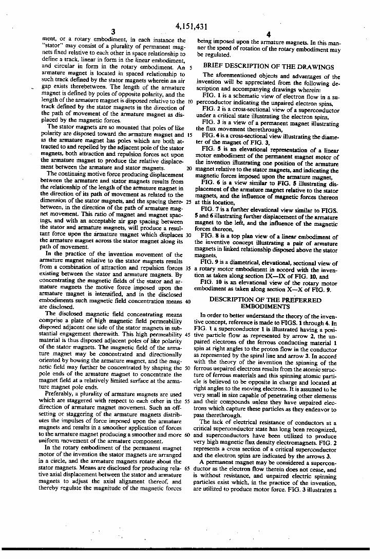
4,151,431 3 ment, or a rotary embodiment, in each instance the “stator” may consist of a plurality of permanent mag nets ?xed relative to each other in space relationship to de?ne a track, linear in form in the linear embodiment, and circular in form in the rotary embodiment. An armature magnet is located in spaced relationship to such track defined by the stator magnets wherein an air gap exists therebetween. The length of the armature magnet is de?ned by poles of opposite polarity, and the length of the armature magnet is disposed relative to the track de?ned by the stator magnets in the direction of the path of movement of the armature magnet as dis placed by the magnetic forces. The stator magnets are so mounted that poles of like
polarity are disposed toward the armature magnet and as the armature magnet has poles which are both at tracted to and repelled by the adjacent pole of the stator magnets, both attraction and repulsion forces act upon the armature magnet to produce the relative displace ment between the armature and stator magnets. The continuing motive force producing displacement
between the armature and stator magnets results from the relationship of the length of the armature magnet in the direction of its path of movement as related to the dimension of the stator magnets, and the spacing there between, in the direction of the path of armature mag~ net movement. This ratio of magnet and magnet spac ings, and with an acceptable air gap spacing between the stator and armature magnets, will produce a resul tant force upon the armature magnet which displaces the armature magnet across the stator magnet along its path of movement.
In the practice of the invention movement of the armature magnet relative to the stator magnets results from a combination of attraction and repulsion forces existing between the stator and armature magnets. By concentrating the magnetic ?elds of the stator and ar mature magnets the motive force imposed upon the armature magnet is intensi?ed, and in the disclosed embodiments such magnetic ?eld concentration means are disclosed.
The disclosed magnetic ?eld concentrating means comprise a plate of high magnetic ?eld permeability disposed adjacent one side of the stator magnets in sub stantial engagement therewith. This high permeability material is thus disposed adjacent poles of like polarity of the stator magnets. The magnetic ?eld of the anna ture magnet may be concentrated and directionally oriented by bowing the armature magnet, and the mag netic ?eld may further be concentrated by shaping the pole ends of the armature magnet to concentrate the magnet ?eld at a relatively limited surface at the arma ture magnet pole ends.
Preferably, a plurality of armature magnets are used which are staggered with respect to each other in the direction of armature magnet movement. Such an off setting or staggering of the armature magnets distrib utes the impulses of force imposed upon the armature magnets and results in a smoother application of forces to the armature magnet producing a smoother and more unifonn movement of the armature component.
In the rotary embodiment of the permanent magnet motor of the invention the stator magnets are arranged in a circle, and the armature magnets rotate about the stator magnets. Means are disclosed for producing rela tive axial displacement between the stator and armature magnets to adjust the axial alignment thereof, and thereby regulate the magnitude of the magnetic forces
0
30
35
45
60
65
4 being imposed upon the armature magnets. In this man ner the speed of rotation of the rotary embodiment may be regulated.
BRIEF DESCRIPTION OF THE DRAWINGS The aforementioned objects and advantages of the
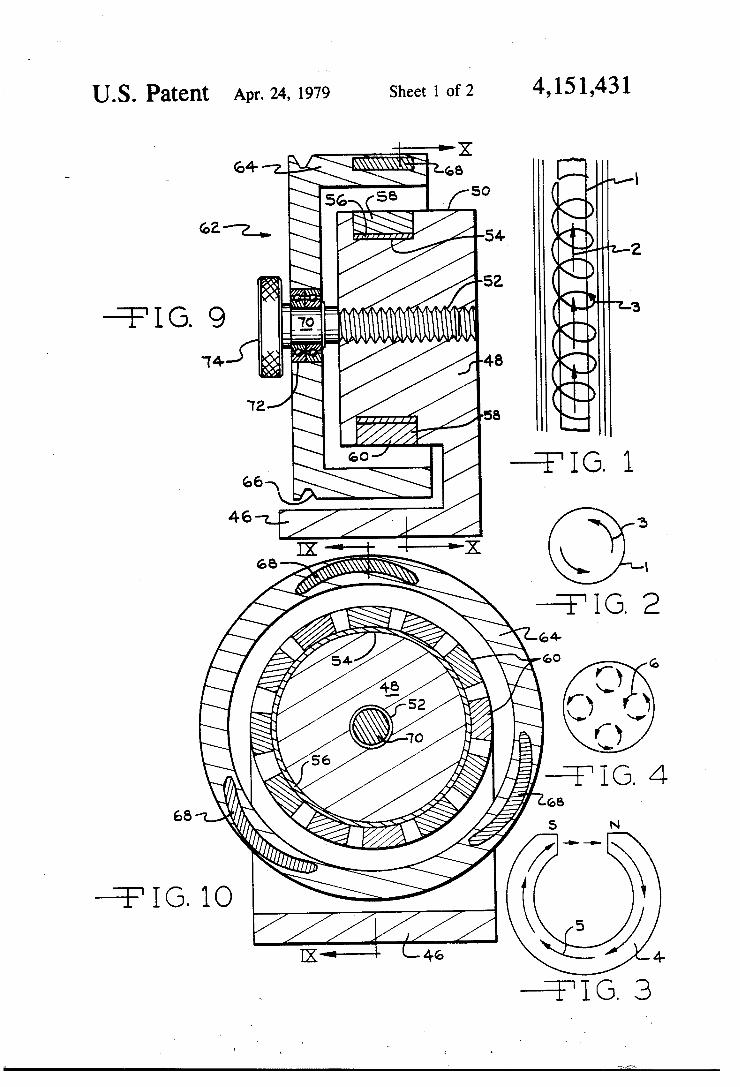
invention will be appreciated from the following de scription and accompanying drawings wherein: FIG. 1 is a schematic view of electron ?ow in a su
perconductor indicating the unpaired electron spins, FIG. 2 is a cross-sectional view of a superconductor
under a critical state illustrating the electron spins, FIG. 3 is a view of a permanent magnet illustrating
the flux movement therethrough, FIG. 4 is a cross-sectional view illustrating the diame
ter of the magnet of FIG. 3, FIG. 5 is an elevational representation of a linear
motor embodiment of the permanent magnet motor of the invention illustrating one position of the armature magnet relative to the stator magnets, and indicating the magnetic forces imposed upon the armature magnet, FIG. 6 is a view similar to FIG. 5 illustrating dis
placement of the armature magnet relative to the stator magnets, and the in?uence of magnetic forces thereon at this location, FIG. 7 is a further elevational view similar to FIGS.
5 and 6 illustrating further displacement of the armature magnet to the left, and the influence of the magnetic forces thereon, FIG. 8 is a top plan view of a linear embodiment of
the inventive concept illustrating a pair of armature magnets in linked relationship disposed above the stator magnets, FIG. 9 is a diametrical, elevational, sectional view of
a rotary motor embodiment in accord with the inven tion as taken along section IX-IX of FIG. 10, and FIG. 10 is an elevational view of the rotary motor
embodiment as taken along section X-X of FIG. 9.
DESCRIPTION OF THE PREFERRED EMBODIMENTS
In order to better understand the theory of the inven tive concept, reference is made to FIGS. 1 through 4. In FIG. 1 a superconductor 1 is illustrated having a posi tive particle flow as represented by arrow 2, the un paired electrons of the ferrous conducting material 1 spin at right angles to the proton flow in the conductor as represented by the spiral line and arrow 3. In accord with the theory of the invention the spinning of the ferrous unpaired electrons results from the atomic struc ture of ferrous materials and this spinning atomic parti cle is believed to be opposite in charge and located at right angles to the moving electrons. It is assumed to be very small in size capable of penetrating other elements and their compounds unless they have unpaired elec trons which capture these particles as they endeavor to pass therethrough. The lack of electrical resistance of conductors at a
critical superconductor state has long been recognized, and superconductors have been utilized to produce very high magnetic flux density electromagnets. FIG. 2 represents a cross section of a critical superconductor and the electron spins are indicated by the arrows 3. A permanent magnet may be considered a supercon
ductor as the electron ?ow therein does not cease, and is without resistance, and unpaired electric spinning particles exist which, in the practice of the invention, are utilized to produce motor force. FIG. 3 illustrates a
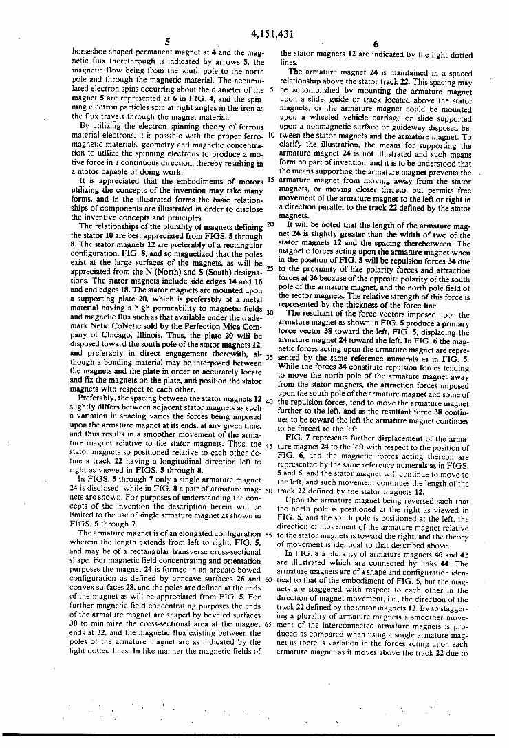
4,151,431 5
horseshoe shaped permanent magnet at 4 and the mag netic ?ux therethrough is indicated by arrows S, the magnetic flow being from the south pole to the north pole and through the magnetic material. The accumu lated electron spins occurring about the diameter of the magnet S-are represented at 6 in FIG. 4, and the spin ning electron particles spin at right angles in the iron as the flux travels through the magnet material. By utilizing the electron spinning theory of ferrous
material electrons, it is possible with the proper ferro magnetic materials, geometry and magnetic concentra tion to utilize the spinning electrons to produce a mo tive force in a continuous direction, thereby resulting in a motor capable of doing work.
It is appreciated that the embodiments of motors utilizing the concepts of the invention may take many forms, and in the illustrated forms the basic relation ships of components are illustrated in order to disclose the inventive concepts and principles. The relationships of the plurality of magnets de?ning
the stator 10 are best appreciated from FIGS. 5 through 8. The stator magnets 12 are preferably of a rectangular con?guration, FIG. 8, and so magnetized that the poles exist at the large surfaces of the magnets, as will be appreciated from the N (North) and S (South) designa tions. The stator magnets include side edges 14 and 16 and end edges 18. The stator magnets are mounted upon a supporting plate 20, which is preferably of a metal material having a high permeability to magnetic ?elds and magnetic flux such as that available under the trade mark Netic CoNetic sold by the Perfection Mica Com pany of Chicago, Illinois. Thus, the plate 20 will be disposed toward the south pole of the stator magnets 12, and preferably in direct engagement therewith, al though a bonding material may be interposed between the magnets and the plate in order to accurately locate and ?x the magnets on the plate, and position the stator magnets with respect to each other.
Preferably, the spacing between the stator magnets 12 slightly differs between adjacent stator magnets as such a variation in spacing varies the forces being imposed upon the armature magnet at its ends, at any given time, and thus results in a smoother movement of the arma ture magnet relative to the stator magnets. Thus, the stator magnets so positioned relative to each other de ?ne a track 22 having a longitudinal direction left to right as viewed in FIGS. 5 through 8.
In FIGS. 5 through 7 only a single armature magnet 24 is disclosed, while in FIG. 8 a pair of armature mag nets are shown. For purposes of understanding the con cepts of the invention the description herein will be limited to the use of single armature magnet as shown in FIGS. 5 through 7. The armature magnet is of an elongated con?guration
wherein the length extends from left to right, FIG. 5, and may be of a rectangular transverse cross-sectional shape. For magnetic ?eld concentrating and orientation purposes the magnet 24 is formed in an arcuate bowed con?guration as de?ned by concave surfaces 26 and convex surfaces 28, and the poles are de?ned at the ends of the magnet as will be appreciated from FIG. 5. For further magnetic ?eld concentrating purposes the ends of the armature magnet are shaped by beveled surfaces 30 to minimize the cross-sectional area at the magnet ends at 32, and the magnetic flux existing between the poles of the armature magnet are as indicated by the light dotted lines. In like manner the magnetic ?elds of
5
35
40
45
55
65
6 the stator magnets 12 are indicated by the light dotted lines. The armature magnet 24 is maintained in a spaced
relationship above the stator track 22. This spacing may be accomplished by mounting the armature magnet upon a slide, guide or track located above the stator magnets, or the armature magnet could be mounted upon a wheeled vehicle carriage or slide supported upon a nonmagnetic surface or guideway disposed be tween the stator magnets and the armature magnet. To clarify the illustration, the means for supporting the armature magnet 24 is not illustrated and such means form no part of invention, and it is to be understood that the means supporting the armature magnet prevents the armature magnet from moving away from the stator magnets, or moving closer thereto, but permits free movement of the armature magnet to the left or right in a direction parallel to the track 22 de?ned by the stator magnets.
It will be noted that the length of the armature mag net 24 is slightly greater than the width of two of the stator magnets 12 and the spacing therebetween. The magnetic forces acting upon the armature magnet when in the position of FIG. 5 will be repulsion forces 34 due to the proximity of like polarity forces and attraction forces at 36 because of the opposite polarity of the south pole of the armature magnet, and the north pole ?eld of the sector magnets. The relative strength of this force is represented by the thickness of the force line. The resultant of the force vectors imposed upon the
armature magnet as shown in FIG. 5 produce a primary force vector 38 toward the left, FIG. 5, displacing the armature magnet 24 toward the left. In FIG. 6 the mag netic forces acting upon the armature magnet are repre sented by the same reference numerals as in FIG. 5. While the forces 34 constitute repulsion forces tending to move the north pole of the armature magnet away from the stator magnets, the attraction forces imposed upon the south pole of the armature magnet and some of the repulsion forces, tend to move the armature magnet further to the left. and as the resultant force 38 contin ues to be toward the left the armature magnet continues to be forced to the left.
FIG. 7 represents further displacement of the arma ture magnet 24 to the left with respect to the position of FIG. 6, and the magnetic forces acting thereon are represented by the same reference numerals as in FIGS. 5 and 6, and the stator magnet will continue to move to the left, and such movement continues the length of the track 22 de?ned by the stator magnets 12. Upon the armature magnet being reversed such that
the north pole is positioned at the right as viewed in FIG. 5, and the south pole is positioned at the left, the direction of movement of the armature magnet relative to the stator magnets is toward the right, and the theory of movement is identical to that described above.
In FIG. 8 a plurality of armature magnets 40 and 42 are illustrated which are connected by links 44. The armature magnets are ofa shape and con?guration iden tical to that of the embodiment of FIG. 5, but the mag nets are staggered with respect to each other in the direction of magnet movement, i.e., the direction of the track 22 de?ned by the stator magnets 12. By so stagger ing a plurality of armature magnets a smoother move ment of the interconnected armature magnets is pro duced as compared when using a single armature mag net as there is variation in the forces acting upon each armature magnet as it moves above the track 22 due to
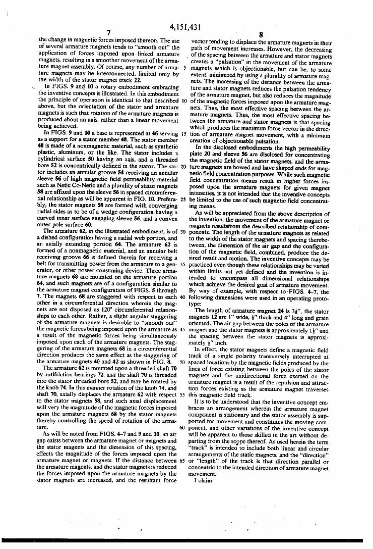
4,151,431 7
the change in magnetic forces imposed thereon. The use of several armature magnets tends to “smooth out” the application of forces imposed upon linked armature magnets, resulting in a smoother movement of the arma ture magnet assembly. Of course, any number of anna ture magnets may be interconnected, limited only by the width of the stator magnet track 22.
In FIGS. 9 and 10 a rotary embodiment embracing the inventive concepts is illustrated. In this embodiment the principle of operation is identical to that described above, but the orientation of the stator and armature magnets is such that rotation of the armature magnets is produced about an axis, rather than a linear movement being achieved.
In FIGS. 9 and 10 a base is represented at 46 serving as a support for a stator member 48. The stator member 48 is made of a nonmagnetic material, such as synthetic plastic, aluminum, or the like. The stator includes a cylindrical surface 50 having an axis, and a threaded bore 52 is concentrically de?ned in the stator. The sta tor includes an annular groove 54 receiving an annular sleeve 56 of high magnetic ?eld permeability material such as Netic Co-Netic and a plurality of stator magnets 58 are af?xed upon the sleeve 56 in spaced circumferen tial relationship as will be apparent in FIG. 10. Prefera bly, the stator magnets 58 are formed with converging radial sides as to be of a wedge con?guration having a curved inner surface engaging sleeve 56, and a convex outer pole surface 60. The armature 62, in the illustrated embodiment, is of
a dished con?guration having a radial web portion, and an axially extending portion 64. The armature 62 is formed of a nonmagnetic material, and an annular belt receiving groove 66 is de?ned therein for receiving a belt for transmitting power from the armature to a gen erator, or other power consuming device. Three arma ture magnets 68 are mounted on the armature portion 64, and such magnets are of a con?guration similar to the armature magnet con?guration of FIGS. 5 through 7. The magnets 68 are staggered with respect to each other in a circumferential direction wherein the mag nets are not disposed as 120° circumferential relation ships to each other. Rather, a slight angular staggering of the armature magnets is desirable to “smooth out” the magnetic forces being imposed upon the armature as a result of the magnetic forces being simultaneously imposed upon each of the armature magnets. The stag gering of the armature magnets 68 in a circumferential direction produces the same effect as the staggering of the armature magnets 40 and 42 as shown in FIG. 8. The armature 62 is mounted upon a threaded shaft 70
by antifriction bearings 72, and the shaft 70 is threaded into the stator threaded bore 52, and may be rotated by the knob 74. In this manner rotation of the knob 74, and shaft 70, axially displaces the armature 62 with respect to the stator magnets 58, and such axial displacement will very the magnitude of the magnetic forces imposed upon the armature magnets 68 by the stator magnets thereby controlling the speed of rotation of the arma ture.
As will be noted from FIGS. 4-7 and 9 and 10, an air gap exists between the armature magnet or magnets and the stator magnets and the dimension of this spacing, effects the magnitude of the forces imposed upon the armature magnet or magnets. If the distance between the armature magents, and the stator magnets is reduced the forces imposed upon the armature magnets by the stator magnets are increased, and the resultant force
8 vector tending to displace the armature magnets in their path of movement increases. However, the decreasing
_ of the spacing between the armature and stator magnets
20
40
65
creates a "pulsation” in the movement of the armature magnets which is objectionable, but can be, to some extent, minimized by using a plurality of armature mag nets. The increasing of the distance between the arma ture and stator magnets reduces the pulsation tendency of the armature magnet, but also reduces the magnitude of the magnetic forces imposed upon the armature mag nets. Thus, the most effective spacing between the ar mature magnets. Thus, the most effective spacing be tween the armature and stator magnets is that spacing which produces the maximum force vector in the direc tion of armature magnet movement, with a minimum creation of objectionable pulsation.
In the disclosed embodiments the high permeability plate 20 and sleeve 56 are disclosed for concentrating the magnetic ?eld of the stator magnets, and the arma ture magnets are bowed and have shaped ends for mag netic ?eld concentration purposes. While such magnetic ?eld concentration means result in higher forces im posed upon the armature magnets for given magnet intensities, it is not intended that the inventive concepts be limited to the use of such magnetic ?eld concentrat ing means. As will be appreciated from the above description of
the invention, the movement of the armature magnet or magnets resultsfrom the described relationship of com ponents. The length of the armature magnets as related to the width of the stator magnets and spacing therebe tween, the dimension of the air gap and the con?gura tion of the magnetic ?eld, combined, produce the de sired result and motion. The inventive concepts may be practiced even though these relationships may be varied within limits not yet de?ned and the invention is in tended to encompass all dimensional relationships which achieve the desired goal of armature movement. By way of example, with respect to~FIGS. 4-7, the following dimensions were used in an operating proto WW 1
The length of armature magnet 24 is 35'', the stator magnets 12 are 1'' wide, I" thick and 4" long and grain oriented. The air gap between the poles of the armature magnet and the stator magnets is approximately 15" and the spacing between the stator magnets is approxi mately Q" inch.
In effect, the stator magnets de?ne a magnetic ?eld track of a single polarity transversely interrupted at spaced locations by the magnetic ?elds produced by the lines of force existing between the poles of the stator magnets and the unidirectional force exerted on the armature magnet is a result of the repulsion and attrac tion forces existing as the armature magnet traverses this magnetic ?eld track.
It is to be understood that the inventive concept em braces an arrangement wherein the armature magnet component is stationary and the stator assembly is sup ported for movement and constitutes the moving com ponent, and other variations of the inventive concept will be apparent to those skilled in the art without de parting from the scppe thereof. As used herein the term “track" is intended to include both linear and circular arrangements of the static magnets, and the “direction” or "length” of the track is that direction parallel or concentric to the intended direction of armature magnet movement.
I claim:

4,151,431 1. A permanent magnet motor comprising, in combi
nation. a stator track de?ning a track direction and having ?rst and second sides and composed of.a plural ity of track permanent magnets each having ?rst and second poles of opposite polarity, said magnets being disposed in side-by-side relationship having a spacing between adjacent magnets and like poles de?ning said track sides, an elongated armature permanent magnet located on one of said track sides for relative movement thereto and in spaced relationship to said track side wherein an air gap exists between said annature magnet and said track magnets, said armature magnet having ?rst and second poles of opposite polarity located at the opposite ends of said armature magnet de?ning the length thereof, the length of said armature magnet being disposed in a direction in general alignment with the direction of said track, the spacing of said armature magnet poles from said track associated side and the length of said armature magnet as related to the width and spacing of said track magnets in the direction of said track being such as to impose a continuous force on said armature magnet in said general direction of said track.
2. In a permanent magnet motor as in claim 1 wherein the spacing between said poles of said armature magnet and the adjacent stator track side are substantially equal.
3. In a permanent magnet motor as in claim 1 wherein the spacing between adjacent track magnets varies.
4. In a permanent magnet motor as in claim 1 wherein a plurality of armature magnets are disposed on a com mon side of said stator track, said armature magnets being mechanically interconnected.
5. In a permanent magnet motor as in claim 4 wherein said armature magnets are staggered with respect to each other in the direction of said track.
6. In a permanent magnet motor as in claim I wherein magnetic ?eld concentrating means are associated with said track magnets.
7. In a permanent magnet motor as in claim 6 wherein said ?eld concentrating means comprises a sheet of magnetic material of high magnetic ?eld permeability engaging side and pole of said track magnets opposite to that side and pole disposed toward said armature mag net.
8. In a pennanent magnet motor as in claim 1 wherein said armature magnet is of an arcuate con?guration in its longitudinal direction bowed toward said track, said said armature magnet having ends shaped to concen trate the magnetic ?eld at said ends.
9. In a permanent magnet motor as in claim 1 wherein said stator track is of a generally linear con?guration, and means supporting said armature magnet relative to said track for generally linear movement of said arma ture magnet.
10. In a permanent magnet motor as in claim 1 wherein said stator track magnets de?ne a circle having an axis, an armature rotatably mounted with respect to said track and concentric and coaxial thereto, said arma ture magnet being mounted upon said armature.
11. In a permanent magnet motor as in claim 10, means axially adjusting said armature relative to said track whereby the axial relationship of said armature magnet and said stator magnets may be varied to adjust the rate of rotation of said armature.
12. In a permanent magnet motor as in claim 10 wherein a plurality of armature magnets are mounted on said armature.
25
30
35
40
45
55
65
10 13. In a permanent magnet motor as in claim 12
wherein said armature magnets are circumferentially nonuniformily spaced on said armature.
14. A permanent magnet motor comprising, in combi nation, a stator comprising a plurality of circumferen tially spaced stator permanent magnets having poles of opposite polarity, said magnets being arranged to sub stantially de?ne a circle having an axis, the poles of said magnets facing in a radial direction with respect to said axis and poles of the same polarity facing away from said axis and the poles of opposite polarity facing toward said axis, an armature mounted for rotation about said axis and diposed adjacent said stator, at least one armature permanent magnet having poles of oppo site polarity mounted on said armature and in radial spaced relationship to said circle of stator magnets, said armature magnet poles extending in the circumferential direction of armature rotation, the spacing of said arma ture magnet poles from said stator magnets and the circumferential length of said armature magnet and the spacing of said stator magnets being such as to impose a continuing circumferential force on said armature mag net to rotate said armature.
15. In a permanent magnet motor as in claim 14 wherein a plurality of armature magnets are mounted upon said armature.
16. In a permanent magnet motor as in claim 14 wherein said armature magnets are asymmetrically cir cumferentially spaced on said armature.
17. In a permanent magnet motor as in claim 14 wherein the poles of said armature magnet are shaped to concentrate the magnetic ?eld thereof.
18. In a permanent magnet motor as in claim 14, mag netic ?eld concentrating means associated with said stator magnets concentrating the magnetic ?elds thereof at the spacings between adjacent stator mag nets.
19. In a permanent magnet motor as in claim 18 wherein said magnet ?eld concentrating means com prises an annular ring of high magnetic ?eld permeabil ity material concentric with said axis and in substantial engagement with poles of like polarity of said stator magnets.
20. In a permanent magnet motor as in claim 14 wherein said armature magnet is of an arcuate bowed con?guration in the direction of said poles thereof de ?ning a concave side and a convex side, said concave side being disposed toward said axis, and said poles of said armature magnet being shaped to concentrate the magnetic ?eld between said poles thereof.
21. In a permanent magnet motor as in claim 14, means for axially displacing said stator and armature relative to each other to adjust the axial alignment of said stator and armature magnets.
’ 22. The method of producing a unidirectional motive force by permanent magnets using a plurality of spaced stator permanent magnets having opposite polarity poles de?ning a track having a predetermined direction, and an armature magnet having a length de?ned by poles of opposite polarity movably mounted for move ment relative to the track in the direction thereof, and of a predetermined length determined by the width and dimensions of said stator magnets comprising forming a magnetic ?eld track by said stator magnets having a magnetic ?eld of common polarity interrupted at spaced locations in a direction transverse to the direc tion of said magnetic ?eld track by magnetic ?elds cre ated by magnetic lines of force existing between the
4,151,431 11 poles of the stator magnets and positioning the armature magnet in spaced relation to said magnetic ?eld track longitudinally related to the direction of the magnetic ?eld track such a distance that the repulsion and attrac tion forces imposed on the armature magnet by said magnetic ?eld track imposes a continuing unidirectional force on the armature magnet in the direction of the magnetic ?eld track.
23. The method of producing a unidirectional motive force as in claim 22 including concentrating the mag netic ?elds created by magnetic lines of force between the poles of the stator magnets.
24. The method of producing a unidirectional motive force as in claim 22 including concentrating the mag netic ?eld existing between the poles of the armature magnet.
25. The method of producing a unidirectional motive force as in claim 22 including concentrating the mag netic ?elds created by magnetic lines of force between the poles of the stator magnets and concentrating the
5
20
25
30
45
55
65
12 magnetic ?eld existing between the poles of the arma ture magnet.
26. The method of producing a motive force by per manent magnets wherein the unpaired electron spinning particles existing within a permanent magnet are uti~ lized for producing a motive force comprising forming a stator magnetic ?eld track by means of at least one permanent magnet, producing an armature magnetic ?eld by means of‘a permament magnet and shaping and locating said magnetic ?elds in such a manner as to produce relative continuous unidirectional motion be tween said stator and armature ?eld producing magnets.
27. The method of producing a motive force by per manent magnets as in claim 26 wherein said stator mag netic ?eld is substantially of a single polarity.
28. The method of producing a motive force by per manent magnets as in claim 26 including concentrating the magnetic ?eld of said stator ?eld track and armature magnetic ?eld. s
‘ i I I 1 .

UNITED STATES PATENT AND TRADEMARK OFFICE
CERTEFICATE 0F CORRECTION PATENT NO. 1 4,151,431
DATED : April 24, 1979
INVENTOR(S) : Howard R. Johnson
It is certified that error appears in the above-identi?ed patent and that said Letters Patent is hereby corrected as shown below;
The title page should be deleted to insert the attached title page therefor.
Column 12, claims 26, 27 and 28 should be deleted inclusively.
Signed and Scaled this Twenty-sixth D a y 0[ August I980
[SEA L] A nest:
SIDNEY A. DIAMOND
Arresting Of?cer Commissioner of Patents and Trademarks

tates Unite tent [19] Johnson
PERMANENT MAGNET MOTOR
Howard R. Johnson, 3300 Mt. Hope Rd, Grass Lake, Mich. 49240
[21] Appl. No: 422,306
[54] [76] Inventor:
[22] Filed: Dec.6,1l9'73 [51] int. c1.2 .................... .mozn 41/00;H02N11/00 [-52] U.S.Cl. ..................................... ..a1o/12;s10/1s2 [58] Field of Search ........... .. 24/DIG.9;4l5/DIG.2;
46/236; 273/118 A, 119 A, 120 A, 121 A, 122 A, 123A, 124, 125 A, 126 A, 130 A, 131 A, 131
AD, 134 A, 135 A, 136 B, 137 AB, 138 A
[56] References Cited U.S. PATENT DOCUMENTS
4,074,153 2/l978 Baker et al. .......................... .. 3l0/l2
Primary Examiner-Donovan F. Duggan Attorney, Agent, or Firm—Beaman & Beaman
[57] ABSTRACT The invention is directed to the method of utilizing the
[111
[45]
unpaired electron spins in ferro magnetic and other materials as a source of magnetic ?elds for producing power without any electron ?ow as occurs in normal conductors, and to permanent magnet motors for utiliz ing this method to produce a power source. In the prac tice of the invention the unpaired electron spins occur ring within permanent magnets are utilized to produce a motive power source solely through the superconduc ting characteristics of a permanent magnet and the mag netic ?ux created by the magnets are controlled and concentrated to orient the magnetic forces generated in such a manner to do useful continuous work, such as the displacement of a rotor with respect to a stator. The timing and orientation of magnetic forces at the rotor and stator components produced by permanent magnets to produce a motor is accomplished with the proper geometrical relationship of these components.
25 Claims, 10 Drawing Figures