27” router table assemblies - owner's manual - SawStop
68
OWNER’S MANUAL 27” ROUTER TABLE ASSEMBLIES MODEL RT-TGP/RT-BT
-
Upload
khangminh22 -
Category
Documents
-
view
0 -
download
0
Transcript of 27” router table assemblies - owner's manual - SawStop

OWNER’S MANUAL27” ROUTER TABLE ASSEMBLIES
MODEL RT-TGP/RT-BT

The saw shown on the front cover is the Professional Cabinet Saw, Model PCS with Industrial Mobile Base. Your saw may look different.
The Benchtop Router Table Assembly shown on the front cover includes the Single Vertical Feather Board and Flip Stop. These are optional accessories that do not come included with your Benchtop Router Table Assembly. The Four-Post Router Lift with Lock and Downdraft Dust Collection Box for Router Lift are also shown
with the Benchtop Router Table Assembly and TGP2 In-Line Router Table Assembly configurations. The Four-Post Router Lift with Lock and Downdraft Dust Collection Box for Router Lift are not included and your Router Table setup may look different.
Copyright SawStop, LLCAll Rights Reserved
Updates of this manual may be available at www.sawstop.com
3rd printing, September 2021
SawStop, the SawStop blade logo, and the configuration of this product are either registered trademarks or trademarks of SawStop, LLC. Software copyright by
SawStop, LLC. All rights reserved.

TO OUR CUSTOMERS
Thank you for purchasing the SawStop Benchtop Router Table Assembly or TGP2 In-Line Router Table Assembly. We are confident you will be pleased with this assembly’s quality and performance.
This manual tells you more about the Benchtop Router Table Assembly and TGP2 In-Line Router Table Assembly for the Professional Cabinet Saw (PCS) or Contractor Saw (CNS) and how to operate and maintain them. Please read the manual carefully. The manual also includes our warranty and important safety information.
If you ever have any questions or comments, feel free to contact us at the address below.
SawStop, LLC11555 SW Myslony Street | Tualatin, Oregon 97062 USA
Phone: (503) 570-3200
Fax: (503) 570-3303
Email: [email protected]
www.sawstop.com

HOW TO GET HELP
Missing Parts? Have Questions?
Our technical support team is standing byM-F, 6:30am-5pm PST
to help with whatever you need.
503.582.9934Give us a call at
[email protected] us at

TABLE OF CONTENTS
Product Specifications...........................................................................
Assembly Options.................................................................................. Benchtop Stand ............................................................................................................. In-Line Left of Left Wing (PCS or CNS)............................................................................ In-Line Right: Between 36” Rails (PCS ONLY)............................................................... In-Line Right: Between 52” Rails (PCS ONLY)...............................................................
Parts Inventory....................................................................................... Parts & Hardware Lists.....................................................................................................
Assembly & Installation.......................................................................... Assembling the Table........................................................................................................ Assembling the Benchtop Stand...................................................................................... Installing the Table on the Benchtop Stand....................................................................... Assembling and Installing the Support Legs and Power Switch..................................... Installing In-Line Left of Left Wing (PCS or CNS).......................................................... Rail Requirements: In-Line Right of PCS Right Wing....................................................... Installing In-Line Right: Between PCS 36” Rails........................................................... Installing In-Line Right: Between PCS 52” Rails........................................................... Assembling the Fence......................................................................................................
Reference..............................................................................................
Warranty........................................................................................................................... Safety................................................................................................................................ Warnings.......................................................................................................................... Exploded View 1: Cast Iron Router Table (RT-C27) ........................................................... Parts List 1: Cast Iron Router Table (RT-C27) .................................................................. Exploded View 2: Benchtop Stand (RT-STB) .................................................................. Parts List 2: Benchtop Stand (RT-STB) .............................................................................. Exploded View 3: Support Legs (RT-ST2) ........................................................................ Parts List 3: Support Legs (RT-ST2) ................................................................................ Exploded View 4: Power Switch (RT-PSW) ...................................................................... Parts List 4: Power Switch (RT-PSW) ............................................................................... Exploded View 5: 27” Fence Assembly (RT-F27) .............................................................. Parts List 5: 27” Fence Assembly (RT-F27) ...................................................................... Exploded View 6: Intermediate Cast Iron Wing (RT-ICW) ................................................. Parts List 6: Intermediate Cast Iron Wing (RT-ICW) ..........................................................
Available Accessories............................................................................
1
22344
510
11111318192427283440
45454646495051525354555657585960
61

1 RT-TGP/RT-BT OWNER’S MANUAL
PRODUCT SPECIFICATIONS
27” x 16” Cast Iron Router Table
Cast Iron Table 27” x 16”
Maximum Fence Travel 5 ½”
Front T-Slot to Arbor Center 6 ½”
Width of Front T-Slot½” at top, 3⁄8” at bottom
Rear T-Slot to Arbor Center 5”
Width of Rear T-Slot1” at top, ¾” at bottom
27” Fence Assembly
Length 30 ¾”
Height 3 ½”
Depth 4”
Benchtop Stand
Stand Height (Without Table) 14 ½”
Stand Footprint (Without Table) 23” (Front) x 15 ½” (Side)
The 27” x 16” Cast Iron Router Table is compatible with the Benchtop Stand, the Professional Cabinet Saw, and the Contractor Saw with cast iron wings.

2RT-TGP/RT-BT OWNER’S MANUAL
ASSEMBLY OPTIONS PAGES:
2-4
Benchtop Stand Option 1 of 4
The 27” x 16” Cast Iron Router Table can be mounted to the Benchtop Stand or to your SawStop table saw in any of four different configurations depending on your needs. The 27” Fence Assembly for Router Tables is compatible with all four configurations.
This configuration maximizes the portability and placement flexibility of your router assembly.
The picture shows the Benchtop Stand for Router Table (RT-STB) with the 27” x 16” Cast Iron Router Table (RT-C27).

3 RT-TGP/RT-BT OWNER’S MANUAL
In-Line Left of Left Wing (PCS or CNS) Option 2 of 4
This configuration extends the table surface of your SawStop table saw, maintains the existing table to the right of the blade, and includes:
• 27” x 16” Cast Iron Router Table (RT-C27)• Support Legs (RT-ST2) • Power Switch (RT-PSW)
Professional Cabinet Saw (PCS) Contractor Saw (CNS)
The 27” x 16” Cast Iron Router Table is only compatible with the SawStop Contractor Saw if cast iron wings are installed.
The standard stamped wings on the Contractor Saw cannot support the weight of the 27” x 16” cast iron router table.
istamped
wing
4RT-TGP/RT-BT OWNER’S MANUAL
In-Line Right: Between 52” Rails (PCS ONLY)
In-Line Right: Between 36” Rails (PCS ONLY)
Option 4 of 4
Option 3 of 4
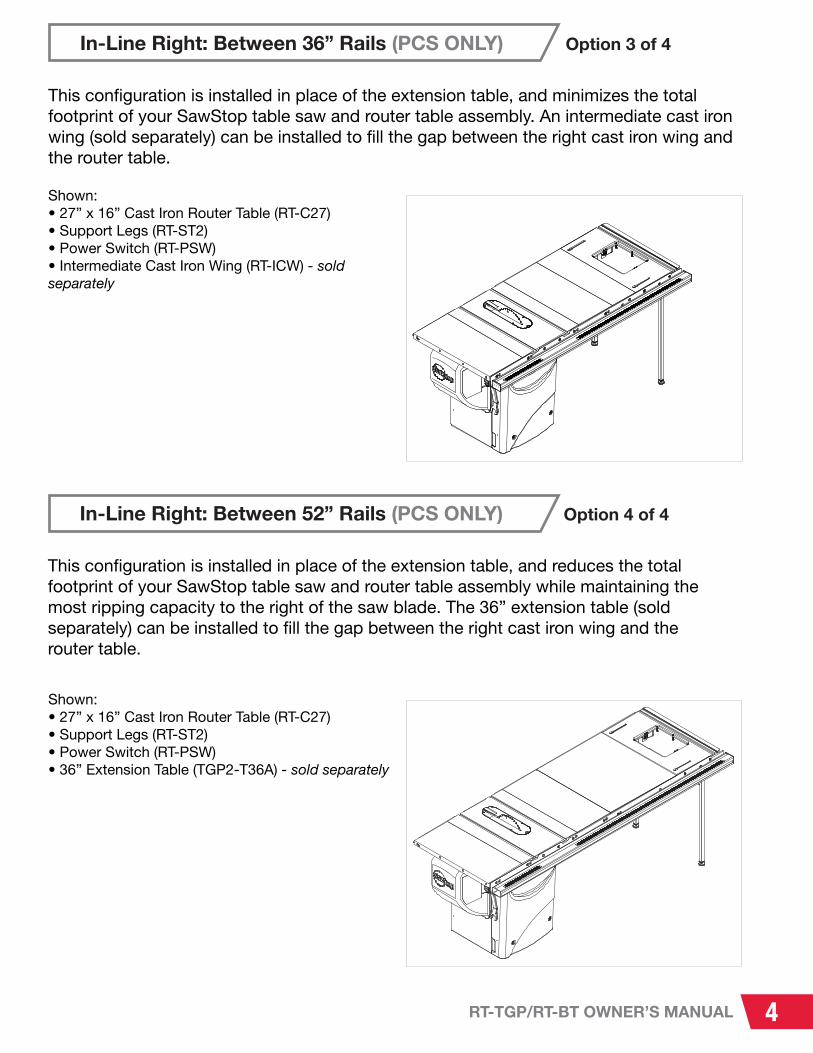
This configuration is installed in place of the extension table, and reduces the total footprint of your SawStop table saw and router table assembly while maintaining the most ripping capacity to the right of the saw blade. The 36” extension table (sold separately) can be installed to fill the gap between the right cast iron wing and the router table.
Shown:• 27” x 16” Cast Iron Router Table (RT-C27)• Support Legs (RT-ST2)• Power Switch (RT-PSW)• 36” Extension Table (TGP2-T36A) - sold separately
This configuration is installed in place of the extension table, and minimizes the total footprint of your SawStop table saw and router table assembly. An intermediate cast iron wing (sold separately) can be installed to fill the gap between the right cast iron wing and the router table.
Shown:• 27” x 16” Cast Iron Router Table (RT-C27)• Support Legs (RT-ST2)• Power Switch (RT-PSW)• Intermediate Cast Iron Wing (RT-ICW) - sold separately
A
B
C
5 RT-TGP/RT-BT OWNER’S MANUAL
PARTS INVENTORY
Parts and Hardware Lists
PAGES:
5-10
IF YOU CANNOT FIND AN ITEM ON THIS LIST, CHECK THE MOUNTING
LOCATIONS OR EXAMINE THE PACKAGING MATERIALS VERY CAREFULLY.
CERTAIN COMPONENTS MAY HAVE BEEN PRE-INSTALLED FOR
SHIPPING PURPOSES.
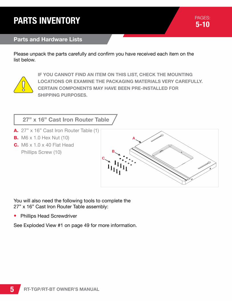
27” x 16” Cast Iron Router Table
27” x 16” Cast Iron Router Table (1)
M6 x 1.0 Hex Nut (10)
M6 x 1.0 x 40 Flat Head
Phillips Screw (10)
A.
B.
C.
Please unpack the parts carefully and confirm you have received each item on the list below.
You will also need the following tools to complete the 27” x 16” Cast Iron Router Table assembly:
• Phillips Head Screwdriver
See Exploded View #1 on page 49 for more information.

B
C
D
I K LO
N
P
M
R
Q
J
EF
G
H
STHARDWARE PACK
A
6RT-TGP/RT-BT OWNER’S MANUAL
Benchtop Stand for Router Table
Upper Front/Rear Bracket (2)
Rear Panel (1)
Upper Side Bracket (2)
Tool Storage Plate (1)
Lower Side Bracket (2)
Front Panel (1)
Benchtop Stand Switch Box (1)
Stand Leg (4)
Pre-installed on Switch Box:M5 x 0.8 x 8 Pan Head Phillips Screw (2)
M5 x 12 x 1 Washer (2)
Hardware Pack:M6 x 1.0 Hex Nut (38)
M6 x 16 x 2 Washer (42)
Support Foot (4)
M6 x 1.0 x 20 Pan Head Phillips Screw (4)
M6 x 1.0 x 15 Carriage Head Bolt (34)
M4 x 0.7 x 20 Pan Head Phillips Screw (2)
M4 x 0.7 Hex Nut (2)
Handle Mounting Bracket (1)
M6 Lock Washer (4)
M6 x 1.0 x 16 Socket Head Cap Screw (4)
A.
B.
C.
D.
E.
F.
G.
H.
S.
T.
I.
J.
K.
L.
M.
N.
O.
P.
Q.
R.
You will also need the following tools to complete the Benchtop Stand assembly:
• Phillips Head Screwdriver
• 8mm Wrench (x2)
See Exploded View #2 on page 51 for more information.
• 10mm Wrench
• 5mm Hex Wrench
BC
A
7 RT-TGP/RT-BT OWNER’S MANUAL
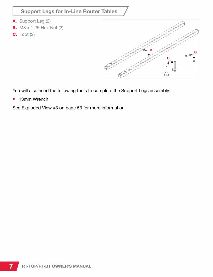
Support Legs for In-Line Router Tables
Support Leg (2)
M8 x 1.25 Hex Nut (2)
Foot (2)
A.
B.
C.
You will also need the following tools to complete the Support Legs assembly:
• 13mm Wrench
See Exploded View #3 on page 53 for more information.

A
BC
D
F
E
8RT-TGP/RT-BT OWNER’S MANUAL
Power Switch for In-Line Router Tables
Power Switch Box with Mounting
Bracket Assembly (1)
Handle Mounting Bracket (1)
Leg Mounting Bracket (1)
Leg Mounting Hardware Pack (1)• M10 x 1.5 x 45 Hex Head Bolt (4)• M10 x 19 x 2 Washer (8)• M10 x 1.5 Lock Nut (4)• M6 Lock Washer (4)• M6 x 1.0 x 12 Socket Head Cap
Screw (4)• M5 x 0.8 x 30 Pan Head Phillips
Screw (1)• M5 Lock Washer (2)• M5 x 12 x 1 Washer (2)• M5 x 0.8 x 8 Pan Head Phillips
Screw (1)
Wing Mounting Hardware Pack (1)• M8 x 1.25 x 45 Hex
Head Bolt (4)• M8 x 19 x 2 Washer (8)• M8 Lock Washer (4)• M8 x 1.25 x 12 Hex Nut (4)
Rail Mounting Hardware Pack (1)• M8 x 1.25 x 25 Flat Head
Socket Screw (4)• M8 x 19 x 2 Washer (4)• M8 Lock Washer (4)• M8 x 1.25 x 12 Hex Nut (4)
A.
B.C.D.
E.
F.
You will also need the following tools to complete the Power Switch for Router Tables assembly:
• Phillips Head Screwdriver
• 16mm Wrench (x2)
• 13mm Wrench (x2)
See Exploded View #4 on page 55 for more information.
• 5mm Hex Wrench
• Level or Straight Edge

A
B
CD
E
F
G
H
I
J
N
M
L
K
9 RT-TGP/RT-BT OWNER’S MANUAL
27” Fence Assembly for Router Tables
27” Router Table Fence (1)
Fence Lock Knob (2)
M8 x 23 x 2 Washer (2)
23mm Wide Lock Knob Nut (2)
Fence Face Plate Lock Knob (8)
M6 x 16 x 2 Washer (8)
M6 x 1.0 x 35 T-Bolt (8)
2 1/2” Dust Port (1)
1/4” - 20 x 3/4” Pan Head Phillips Screw (2)
1/4” - 20 Square Nut (2)
Face Plate Space Bar (2)
Router Fence Face Plate (2)
Router Fence Guard (1)
Router Fence Guard Spacer (2)
A.B.C.D.E.F.G.
H.I.J.K.L.M.N.
You will also need the following tools to complete the 27” Fence Assembly for Router Tables:
• Phillips Head Screwdriver
See Exploded View #5 on page 57 for more information.
A
BC
DE
F
10RT-TGP/RT-BT OWNER’S MANUAL
Throughout the manual, the exploded views are referenced to clarify the location and name of each part. There are multiple exploded views in this manual, so a decimal point system is used. The number before the decimal point refers to the exploded view number (in this case, 1 through 6). The number after the decimal point refers to the part number (as indicated by the number in the balloon in the exploded view). For example, a part referenced as “1.1” would be the part labeled with a “1.1” balloon in the exploded view #1.
• Exploded View #1: 27” x 16” Cast Iron Router Table – See page 49
• Exploded View #2: Benchtop Stand for Router Table – See page 51
• Exploded View #3: Support Legs for In-Line Router Tables – See page 53
• Exploded View #4: 32” Power Switch for In-Line Router Tables – See page 55
• Exploded View #5: 27” Fence Assembly for Router Tables – See page 57
• Exploded View #6: Intermediate Cast Iron Wing – See page 59
Important Part Identification Note:i
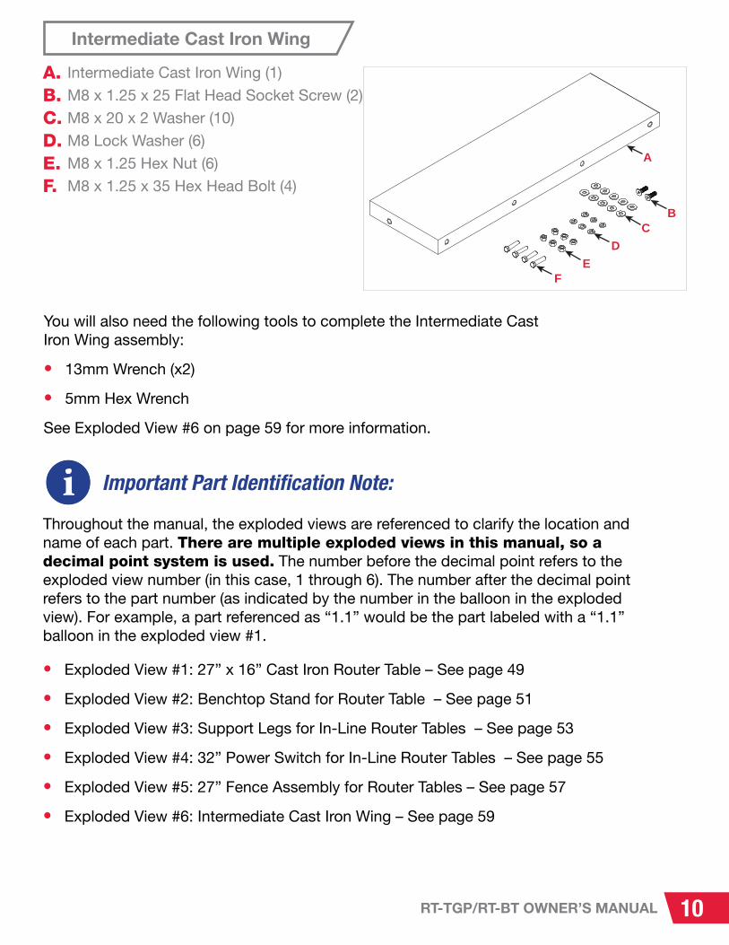
Intermediate Cast Iron Wing
Intermediate Cast Iron Wing (1)
M8 x 1.25 x 25 Flat Head Socket Screw (2)
M8 x 20 x 2 Washer (10)
M8 Lock Washer (6)
M8 x 1.25 Hex Nut (6)
M8 x 1.25 x 35 Hex Head Bolt (4)
A.B.C.D.E.F.
You will also need the following tools to complete the Intermediate Cast Iron Wing assembly:
• 13mm Wrench (x2)
• 5mm Hex Wrench
See Exploded View #6 on page 59 for more information.

x10
11 RT-TGP/RT-BT OWNER’S MANUAL
ASSEMBLY & INSTALLATION PAGES:
11-44
Assembling the 27” x 16” Cast Iron Router Table
Requires: 27” x 16” Cast Iron Router Table with Hardware
Phillips Head Screwdriver
1
2
3
Remove the protective covering from the table. (1.1) Wipe off the oil with a soft, clean cloth.
Thread ten hex nuts (1.2) halfway onto ten flat head Phillips screws (1.3).
Place the router table (1.1) upside down on a flat surface and thread the flat head Phillips screws (1.3) into the threaded holes around the insert opening in the table until they extend about ¼” below the table’s top surface. These screws will support and level the router lift relative to the table top. The 2 holes in the center of the opening (shown in red) do not receive leveling screws; they will be used later to attach the router lift to the router table.
1.1
1.1
1.2
1.3
1.3

12RT-TGP/RT-BT OWNER’S MANUAL
NEXT: INSTALL THE ROUTER TABLE on either the Benchtop Stand or in-line. See page 2 for details.
4 Finger tighten the hex nuts up against the bottom of the table. You will adjust the screws and fully tighten the hex nuts later, after you install your router lift.
• •
•
For mounting to the Benchtop Stand, proceed to the next page.
For mounting to the left extension wing of your Professional Cabinet Saw or Contractor Saw, proceed to page 19.
For right mounting between the rails of your Professional Cabinet Saw, proceed to page 19.
Never place fingers,
toes or other body parts
under the mobile base.! WARNING
5 If you plan on installing the router table in-line on your SawStop Professional Cabinet Saw and you have the ICS Mobile Base with PCS Conversion Kit already installed on your saw, ensure that the hold-down straps on the mobile base have been secured to the saw cabinet (these hold-down straps were included with your ICS Mobile Base with PCS Conversion Kit). If you did not install them and no longer have access to these straps, please contact our Service Department for assistance: [email protected] or 503-582-9934.
The router table is only compatible with the SawStop Contractor Saw if cast iron wings are installed. The standard stamped wings on the Contractor Saw cannot support the weight of the router table.i
stamped wing

13 RT-TGP/RT-BT OWNER’S MANUAL
Assembling the Benchtop Stand for Router Table
Requires: Components and Hardware for Benchtop Stand
Phillips Head Screwdriver
8mm Wrench
10mm Wrench
Benchtop Stand for Router Table Hardware Pack
THE BENCHTOP STAND SHOULD ONLY BE USED ON A FLAT SURFACE (SUCH
AS A STURDY WORK BENCH) THAT IS STABLE AND STRONG ENOUGH TO
SUPPORT THE COMBINED WEIGHT OF THE ROUTER, CAST IRON TABLE,
BENCHTOP STAND, AND WORKPIECE.
THE BENCHTOP STAND SHOULD NEVER BE PLACED NEAR THE EDGE OF AN
ELEVATED SURFACE (SUCH AS A BENCHTOP OR TABLE), SINCE IT COULD
FALL AND CAUSE SERIOUS DAMAGE AND/OR PERSONAL INJURY.
THE BENCHTOP STAND CAN BE USED IN TWO DIFFERENT WAYS:
1. THE RUBBER SUPPORT FEET (INCLUDED) CAN BE INSTALLED AT THE
BASE OF ALL FOUR STAND LEGS. THE SUPPORT FEET CAN HELP
PREVENT THE BENCHTOP STAND FROM SHIFTING.
2. THE RUBBER SUPPORT FEET (AND ACCOMPANYING HARDWARE) CAN BE
SET ASIDE, AND ALTERNATE HARDWARE (NOT INCLUDED) CAN BE USED.
IN THIS CASE, DRILL FOUR HOLES IN YOUR WORK BENCH OR TABLE
THAT ALIGN WITH THE FOUR HOLES IN THE BASES OF THE STAND LEGS,
ALIGN THE BENCHTOP STAND WITH THOSE HOLES, AND MOUNT THE
BENCHTOP STAND TO THE TABLE USING A BOLT, TWO FLAT WASHERS, A
LOCK WASHER, AND A HEX NUT (OR A BOLT, TWO FLAT WASHERS, AND A
LOCK NUT) ON EACH STAND LEG.

14RT-TGP/RT-BT OWNER’S MANUAL
x4
1
2
3
Using your Benchtop Stand Hardware Pack and labeled parts, insert one of the four, pan head Phillips screws (L) up through a support foot (K), then through the hole in the bottom of a stand leg (H), a washer (J), and a hex nut (I). Use a Phillips screwdriver and a 10 mm wrench to tighten the hex nut. Repeat this process for the remaining three stand legs.
Arrange the upper front/rear brackets (A), upper side brackets (C), stand legs (H), front panel (F), rear panel (B), lower side brackets (E), and tool storage plate (D) on a flat surface (such as a floor or table). All of the brackets and panels will be attached to the outside of the stand legs, and all the folded sections will extend in between the stand legs.
Assemble the front of the stand by attaching two of the stand legs (H) to an upper front/rear bracket (A) and the front panel (F). Make sure that the legs are behind the bracket and panel. Attach the legs to the bracket and panel using eight carriage head bolts (M), eight washers (J), and eight hex nuts (I). Only finger tighten the nuts at this time. Leaving the nuts loose will make it easier to align holes as you assemble the rest of the stand.
C C
H
E
E
D
A
F
B
L
K
J
I
H
A
H
F
M
J
I

15 RT-TGP/RT-BT OWNER’S MANUAL
4
5
6
Assemble the rear of the stand by attaching the remaining two stand legs (H) to the remaining upper front/rear bracket (A) and the rear panel (B). Make sure that the bracket and panel are on the outside of the legs. Attach the legs to the bracket and panel using eight carriage head bolts (M), eight washers (J), and eight hex nuts (I). Only finger tighten the nuts. If you are planning on installing the Downdraft Dust Collection Box, wait to install the rear panel (B) until after you have installed the Downdraft Dust Collection Box.
Attach one of the upper side brackets (C) and lower side brackets (E) between the front and rear portions of the stand using eight carriage head bolts (M), eight washers (J), and eight hex nuts (I). Make sure that the brackets are on the outside of the legs. Do not fully tighten the nuts.
Repeat the prior step to attach the remaining upper side bracket (C) and lower side bracket (E) to the opposite side of the stand.
A
J
I M
B
H
C
JI
E
C
E
M

16RT-TGP/RT-BT OWNER’S MANUAL
7
9
Next, attach the tool storage plate (D) to the left side of the stand, and attach the handle mounting bracket (P) at the front edge of the plate. Insert a carriage head bolt (M) through the handle mounting bracket (P) and tool storage plate (D), then through the hole in the front, left stand leg (H). Secure the bolt with a washer (J) and a hex nut (I).
Attach the other side of the tool storage plate (D) to the other stand leg (H) using another carriage head bolt (M), washer (J), and hex nut (I).
The shaft of the elevation handle for your router lift can be inserted through the holes in the tool storage plate in order to store the elevation handle.
Thread a hex nut (O) partway onto each of the two pan head Phillips screws (N), then thread the screws into each of the two threaded holes near the front end of the tool storage plate. Use a Phillips screwdriver to hold the screws still, and use an 8mm wrench to tighten the nuts against the tool storage plate.
Use a 10mm wrench to tighten the 34 nuts on the bolts in the stand legs.8
D
P
M
D P
J
I
FRONT-LEFT STAND LEG (H)
N O

17 RT-TGP/RT-BT OWNER’S MANUAL
10 Use a Phillips screwdriver to remove the two pan head Phillips screws (S) and washers (T) that are pre-installed in the side of your switchbox mounting bracket assembly (G). Position the switchbox mounting bracket assembly (G) next to the front, right stand leg (H), so the mounting holes in the switchbox mounting bracket align with two exposed mounting holes on the right edge of the stand leg. Insert each pan head Phillips screw (S) through a washer (T), and thread each into one of the exposed mounting holes in the stand leg and switchbox mounting bracket.
Make sure the switchbox assembly is facing the same way as the “SawStop” logo on the front of the stand.i
You should now have four socket head cap screws (R), four washers (J), and four lock washers (Q) leftover from your Benchtop Stand hardware bag. They will be used to attach the benchtop stand to the router table.
i
G
ST
H

18RT-TGP/RT-BT OWNER’S MANUAL
Installing the Table on the Benchtop Stand
Requires: Assembled Router Table and Benchtop Stand
Remaining Hardware from Benchtop Stand
1
2
3
If you wish to install the optional Downdraft Dust Collection Box For Router Lift, do so at this time, following the instructions in your Four-Post Router Lift with Lock manual. You can download copies of your manuals at www.sawstop.com.
Set the upside-down benchtop stand on the upside-down router table, and align the four threaded stand mounting holes in the underside of the table with the threaded hole at each end of the assembled table. Make sure that the front of the table (the side with the miter slots) is facing the same direction as the switchbox on the benchtop stand. Attach the benchtop stand to the router table using four socket head cap screws (R), four lock washers (Q), and four washers (J). Use a 5 mm hex wrench to tighten the screws.
Turn over the table and stand, so the stand rests on the four support feet.
Congratulations! You have completed the 27” x 16” Cast Iron Router Table – Benchtop Stand Assembly and Installation. Continue to page 40 for next steps.
R
Q
J

19 RT-TGP/RT-BT OWNER’S MANUAL
Assembling and Installing the Support Legs and Power Switch
Requires: Assembled Router Table Components and Hardware for Power Switch and Support Legs
Phillips Head Screwdriver
5mm Hex Wrench
17mm Wrench (x2)
x2
1 Begin by assembling the two support legs. Thread a hex nut (3.2) all the way onto a foot (3.3), then thread the foot all the way into the base of a support leg (3.1). Repeat this process with another hex nut, foot, and support leg.
The hardware for step 1 can be found in the box for the Support Legs for In-Line Router Tables (RT-ST2).i
If you are planning on installing your router table on the right side of your Professional Cabinet Saw, and your 36” or 52” extension table is already installed, refer to your table saw fence manual for instructions on how to remove the extension table and support legs. You can reuse the support legs, if you wish. Remove the brackets from the top of the support legs. You can then skip step 1, if you have two assembled support legs with feet.
i
3.2
3.3
3.1

20RT-TGP/RT-BT OWNER’S MANUAL
The hardware for the following steps can be found in the “Leg Mounting Hardware” bag from the Power Switch for In-Line Router Tables box.i
2
3
4
Align two holes in one of the support legs with the two holes on the inside of the right edge of the in-line switch box mounting bracket assembly (4.1) (from the perspective of the front of the power switch).
Insert a hex head bolt (4.2) through a washer (4.3), then through one of the exposed mounting holes in the bracket (4.1) and support leg (3.1), through another washer (4.3), and then through a lock nut (4.4). Repeat this process for the other set of exposed mounting holes in the bracket and support leg. Use two 17mm wrenches to tighten the lock nuts on the bolts.
Align two of the holes in the other support leg with the two holes on the left side of the leg mounting bracket (4.7) (from the perspective of the flat edge of the bracket).
4.1
3.1
4.7
4.4
4.1
4.3
4.3
4.2

21 RT-TGP/RT-BT OWNER’S MANUAL
5
6
7
Insert a hex head bolt (4.2) through a washer (4.3), then through one of the exposed mounting holes in the leg mounting bracket (4.7) and support leg (3.1), through another washer (4.3), and then through a lock nut (4.4). Repeat this process for the other set of exposed mounting holes in the bracket and support leg. Use two 17mm wrenches to tighten the lock nuts on the bolts.
Next, mount the handle mounting bracket (4.11) to the front of the leg mounting bracket without the power switch (4.7). Align the square hole in the handle mounting bracket with the left of the two holes in the front of the bracket.
Insert the shorter pan head Phillips screw (4.12) through one of the two smaller lock washers (4.9) and a washer (4.10), then through the exposed mounting holes in the handle mounting bracket and leg mounting bracket. Use a Phillips screwdriver to secure the screw.
4.2
4.34.3 4.4
4.7
4.7
4.9
3.1
4.11
4.12
4.10
22RT-TGP/RT-BT OWNER’S MANUAL
8
9
10
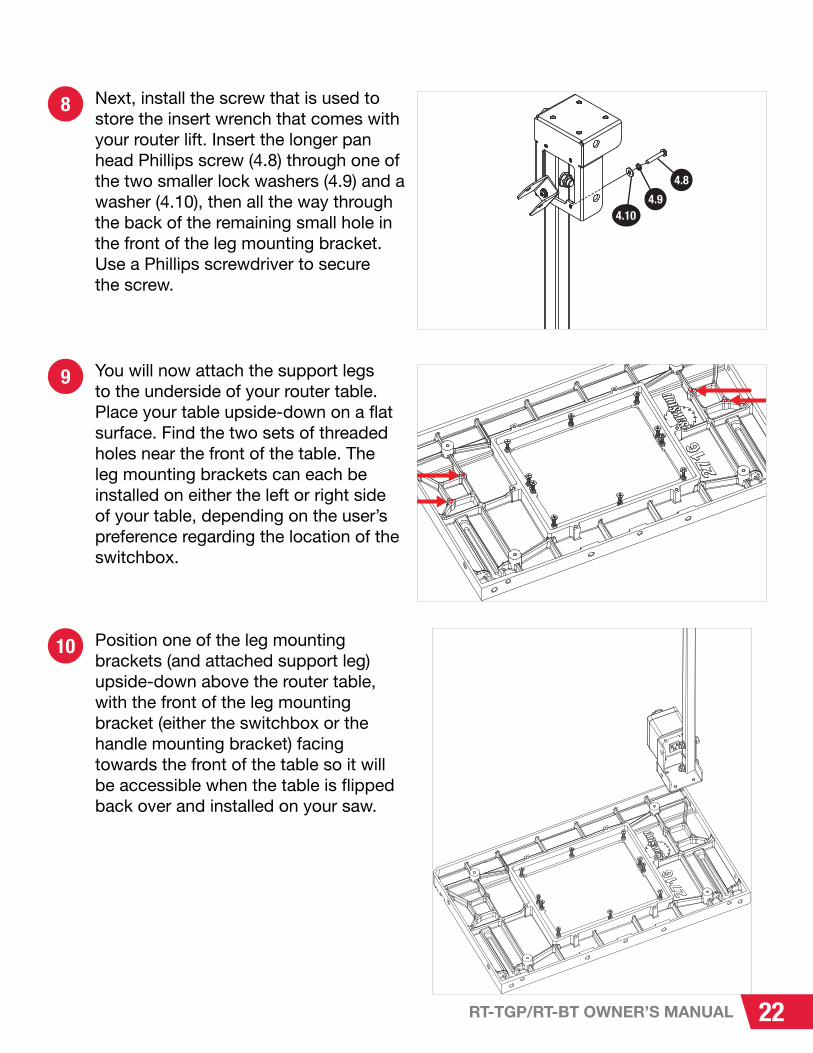
Next, install the screw that is used to store the insert wrench that comes with your router lift. Insert the longer pan head Phillips screw (4.8) through one of the two smaller lock washers (4.9) and a washer (4.10), then all the way through the back of the remaining small hole in the front of the leg mounting bracket. Use a Phillips screwdriver to secure the screw.
You will now attach the support legs to the underside of your router table. Place your table upside-down on a flat surface. Find the two sets of threaded holes near the front of the table. The leg mounting brackets can each be installed on either the left or right side of your table, depending on the user’s preference regarding the location of the switchbox.
Position one of the leg mounting brackets (and attached support leg) upside-down above the router table, with the front of the leg mounting bracket (either the switchbox or the handle mounting bracket) facing towards the front of the table so it will be accessible when the table is flipped back over and installed on your saw.
4.8
4.94.10

23 RT-TGP/RT-BT OWNER’S MANUAL
11
12
Insert a socket head cap screw (4.6) through a lock washer (4.5) and then through one of the exposed holes in the leg mounting bracket and router table. Use a 5mm hex wrench to tighten the screw. Repeat this process for the other hole in the leg mounting bracket that lines up with a threaded hole in the table.
Repeat the previous two steps with the other support leg and leg mounting bracket, but install it on the other end of the router table.
Next, install the router table in one of the three in-line configurations for your Professional Cabinet Saw or Contractor Saw with T-Glide Professional Series II (TGP2) rails and cast iron wings. See page 2-4 for details regarding the configurations and the figures on page 27 for the correct rail requirements.
• For mounting in-line left of the left wing on a Professional Cabinet Saw or Contractor Saw, proceed to the next page.
•
•
For mounting in-line right: between Professional Cabinet Saw 36” rails, with or without the optional intermediate cast iron wing, verify your rails on page 27 and then proceed to page 28.
For mounting in-line right: between Professional Cabinet Saw 52” rails, verify your rails on page 27 and then proceed to page 34.
4.6
4.5
The router table is only compatible with the Contractor Saw if cast iron wings are installed on the saw. The standard stamped metal wings on the Contractor Saw cannot support the weight of the router table.i
stamped wing

24RT-TGP/RT-BT OWNER’S MANUAL
In-Line Left of Left Wing (PCS or CNS)
Requires: “Wing Mounting Hardware” Bag for Power Switch for In-Line Router Tables
Assembled Router Table with Support Legs
Installed Left Cast Iron Wing (CNS)
Straight Edge
13mm Wrench (x2)
THIS PROCEDURE REQUIRES TWO PEOPLE. THE CAST IRON TABLE IS HEAVY
AND CAN CAUSE SERIOUS PERSONAL INJURY OR DAMAGE IF DROPPED.
The figures show a Professional Cabinet Saw, but the procedure is the same for a Contractor Saw with cast iron wings.i
1 Align four of the mounting holes in the router table (indicated by the red arrows in Figure A) with the four holes in the left extension wing of your saw (as indicated by the red arrows in Figure B).
A
B

25 RT-TGP/RT-BT OWNER’S MANUAL
The hardware for the following step can be found in your “Wing Mounting Hardware” bag (4.21) from your Power Switch for In-Line Router Tables box.i
2
3
Insert a hex head bolt (4.13) through a washer (4.14), through one of the holes in the extension wing, then through one of the holes in the router table. Secure the bolt with another washer (4.14), a lock washer (4.15), and a hex nut (4.16). Only finger tighten the nut at this time. Repeat this process for the remaining three holes in the extension wing and router table.
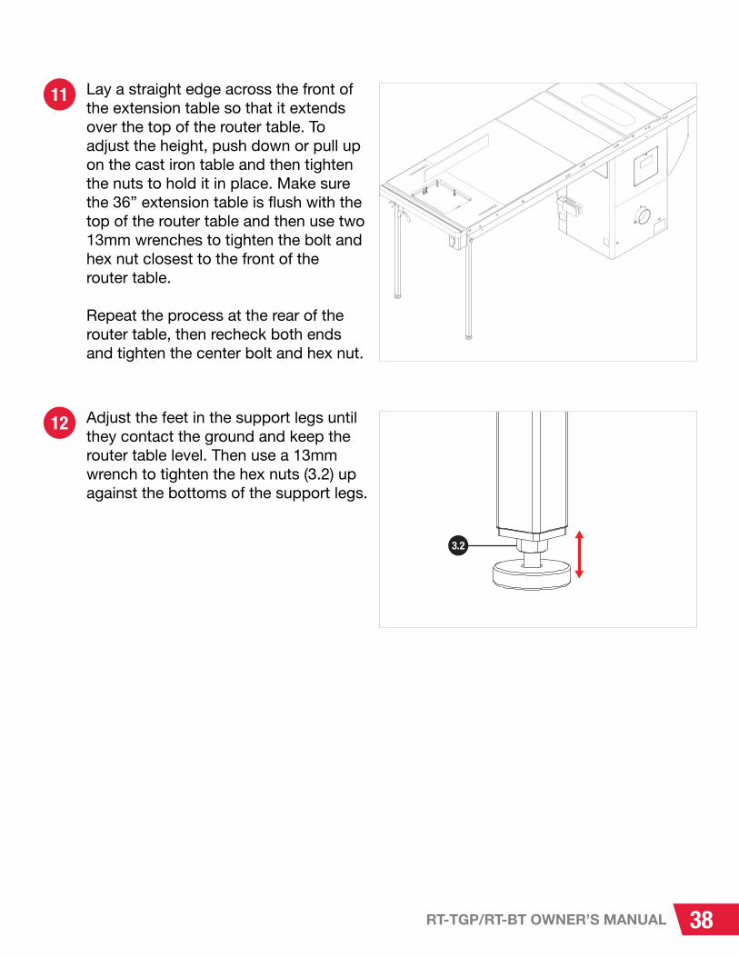
Lay a straight edge across the front of the extension wing so that it extends over the top of the router table. Ensure the router table is flush with the top of the extension wing and then use two 13mm wrenches to tighten the bolt and hex nut closest to the front of the extension wing. Repeat the process at the rear of the extension wing, then recheck both ends and tighten the two center bolts and hex nuts.
4.13
4.13
4.15
4.15
4.16
4.16
4.14
4.144.14

26RT-TGP/RT-BT OWNER’S MANUAL
4 Adjust the feet in the support legs until they contact the ground and keep the router table level. Then use a 13mm wrench to tighten the hex nuts (3.2) up against the bottoms of the support legs.
Congratulations! You have completed the In-Line Left of Left Wing setup. Continue to page 40 for the next steps.
3.2

27 RT-TGP/RT-BT OWNER’S MANUAL
Rail Requirements: In-Line, Right-Hand Side Installation
36” Rails
52” Rails
Use the figures below to verify your rails are compatible with the In-Line configuration on the right-hand side of your Professional Cabinet Saw. If your rails are not already compatible, you may choose to: • Install your In-Line Router Table to the left of the left wing• Purchase new Rail Assemblies with notched end and compatible hole patterns (in green below)• Modify your existing rails. NOTE: SawStop-approved installation requires using SawStop-manufactured RT rails. No cut templates for rail modification are available from SawStop.
36" TGP2 RailsPart Number: TGP2-R36A
NOT COMPATIBLE
36" TGP2 RailsPart Number: TGP2-R36A2
COMPATIBLE (Notice notched ends and additional mounting holes in front and rear rails)
FRONT RAIL
TUBE
TUBE
REAR RAIL REAR RAIL
FRONT RAIL
FRONT RAIL
CORRECT HOLE PATTERNS
CORRECT HOLE PATTERNS
52" TGP2 RailsPart Number: TGP2-R52A
NOT COMPATIBLE
52" TGP2 RailsPart Number: TGP2-R52A2
COMPATIBLE (Notice notched ends and additional mounting holes in front and rear rails)
FRONT RAIL
REAR RAIL
REAR RAIL

28RT-TGP/RT-BT OWNER’S MANUAL
1
If you are installing the intermediate cast iron wing, proceed to step 2 below. Otherwise, start at step 10.
If your rails are not installed on your saw, install them now according to the instructions in your table saw fence manual, but do not fully tighten the hardware. If your rails are already installed, use a 5mm hex wrench and a 13mm wrench to loosen the hardware securing your rear rail to your table saw. See your table saw fence manual for further information. Copies of your manuals can be downloaded at www.sawstop.com. SawStop recommends removing the main tube and loosening the hardware securing your front rail to your table saw.
In-Line Right: Between PCS 36” Rails
Requires: “Wing Mounting Hardware” Bag for Power Switch for In-Line Router Tables
“Rail Mounting Hardware” Bag from Power Switch for In-Line Router Tables
Assembled Router Table with Support Legs
Straight Edge
13mm Wrench (x2)
5mm Hex Wrench
Sold Separately: Intermediate Cast Iron Wing and Accompanying Hardware
Sold Separately: 36” RT-Ready TGP2 SawStop rail kit. Refer to the figure on the previous page for reference.
THIS PROCEDURE REQUIRES TWO PEOPLE. THE ROUTER TABLE AND
OPTIONAL INTERMEDIATE CAST IRON WING ARE HEAVY AND CAN CAUSE
SERIOUS PERSONAL INJURY OR DAMAGE IF DROPPED.

29 RT-TGP/RT-BT OWNER’S MANUAL
3
4
Align four of the holes in the intermediate cast iron wing (indicated by the red arrows) with the four holes in the left extension wing of your Professional Cabinet Saw. The chamfered edge of the intermediate cast iron wing should align with the chamfered edge of the front of the extension wing, and the hole in each end of the intermediate cast iron wing should align with holes in the front and rear rails.
Mount the intermediate cast iron wing to the extension wing using four hex head bolts (6.6), eight washers (6.3), four lock washers (6.4), and four hex nuts (6.5). Insert the four hex head bolts through four washers, then through the intermediate cast iron wing and extension wing. Then install four washers, four lock washers, and four hex nuts (in that order) on the bolts. Only finger tighten the nuts at this time.
2 The intermediate cast iron wing is shipped with a coating of oil to prevent the cast iron from rusting. Remove the protective covering wipe the oil off with a soft, clean cloth. The wing comes with hardware to mount it to the right extension wing of your Professional Cabinet Saw.
The hardware for the next steps can be found in the hardware bag that came with the intermediate cast iron wing.i
6.6
6.46.5
6.3
6.1
6.1

30RT-TGP/RT-BT OWNER’S MANUAL
6
5
Lay a straight edge across the front of the extension wing so that it extends over the top of the intermediate cast iron wing.
To adjust for a flush installation, push down or pull up on the intermediate cast iron wing and then tighten the nuts to hold it in place. Make sure the intermediate cast iron wing is flush with the top of the extension wing and then use two 13mm wrenches to tighten the hex head bolt and hex nut closest to the front of the extension wing. Use a 5mm hex wrench and a 13mm wrench to tighten the socket head screw and hex nut at the front edge of the intermediate cast iron wing.
Repeat the process at the rear of the extension wing, then recheck both ends and tighten the two center bolts and hex nuts.
Attach the intermediate cast iron wing to the front and rear rails. Insert a flat head socket screw (6.2) through the exposed mounting hole in the front rail and front edge of the intermediate cast iron wing. Secure the screw with a washer (6.3), a lock washer (6.4), and a hex nut (6.5). Repeat this process for the exposed mounting hole in the rear rail and intermediate cast iron wing. Only finger tighten the nuts at this time.
6.3
6.4
6.5
6.2

31 RT-TGP/RT-BT OWNER’S MANUAL
7
8
Align the four upper mounting holes in the router table (indicated by the red arrows) with the four holes in the intermediate cast iron wing.
Next, mount the router table to the intermediate cast iron wing using the hardware from the “Wing Mounting Hardware” bag (4.21) from your Power Switch (RT-PSW) box.
Insert four hex head bolts (4.13) through four washers (4.14), then through the intermediate cast iron wing and router table. Secure the bolts with four more washers (4.14), four lock washers (4.15), and four hex nuts (4.16). Only finger tighten the nuts at this time.
The hardware for the next steps can be found in the “Wing Mounting Hardware” bag from your Power Switch for In-Line Router Tables (RT-PSW) box.i
4.134.144.154.16

32RT-TGP/RT-BT OWNER’S MANUAL
10
9
Next, attach the router table to the front and rear rails using the hardware from the “Rail Mounting Hardware” bag (4.22). Insert a flat head socket screw (4.17) through both holes in the front rail and router table. Secure each screw with a washer (4.18), a lock washer (4.19), and a hex nut (4.20).
Lay a straight edge across the front of the right extension wing and intermediate cast iron wing (if installed), so that it extends over the top of the router table. Adjust the height of the router table relative to the intermediate cast iron wing. To do this, you can push down or pull up on the cast iron table and then tighten the nuts to hold it in place.
Make sure the router table is flush with the top of the optional intermediate cast iron wing and then use two 13mm wrenches to tighten the bolt and hex nut closest to the front of the router table.
Repeat the process at the rear of the router table, then recheck both ends and tighten the two center bolts and hex nuts.
The hardware for the next steps can be found in the “Rail Mounting Hardware” bag from your Power Switch for In-Line Router Tables (RT-PSW) box. You will not use all of the hardware in the bag.i
4.17
4.194.18 4.20

33 RT-TGP/RT-BT OWNER’S MANUAL
11
12
13
Repeat the previous step for the holes in the rear rail and rear edge of the router table. Use a 5mm hex wrench and a 13mm wrench to tighten the hex nuts.
Adjust the feet in the support legs until they contact the ground and keep the cast iron table level. Then use a 13mm wrench to tighten the hex nuts (3.2) up against the bottoms of the support legs.
See your table saw fence manual for instructions on how to re-tighten the hardware securing your rear rail to your table saw and how to reinstall the main tube. It is very important to install and align the main tube correctly.
Congratulations! You have completed the In-Line Right: Between PCS 36” Rails Installation. Continue to page 40 for the next steps.
3.2

34RT-TGP/RT-BT OWNER’S MANUAL
1 If your rails are not installed on your saw, install them now according to the instructions in your table saw fence manual, but do not fully tighten the hardware. If your rails are already installed on your saw, use a 13mm wrench to remove the main tube (set it aside) and use a 13mm wrench and a 5mm hex wrench to loosen the hardware securing the rear rail to the saw. See your table saw fence manual for further information. (Copies of your manuals can be downloaded at www.sawstop.com.)
If you do not wish to install the 36” Extension Table, skip ahead to step 13. You will need a 5mm hex wrench and a 13mm wrench. Otherwise, proceed to the next page.
In-Line Right: Between PCS 52” Rails
Requires: “Wing Mounting Hardware” Bag for Power Switch for In-Line Router Tables
“Rail Mounting Hardware” Bag from Power Switch for In-Line Router Tables
Assembled Router Table with Support Legs
Straight Edge
5mm Hex Wrench
13mm Wrench (x2)
C-Clamp (x2)
Drill
3/8” Drill Bit
Sold Separately: 36” Extension Table
Sold Separately: 52” RT-Ready TGP2 SawStop rail kit. Refer to the figure on page 27 for reference.
THIS PROCEDURE REQUIRES TWO PEOPLE. THE ROUTER TABLE IS HEAVY
AND CAN CAUSE SERIOUS PERSONAL INJURY OR DAMAGE IF DROPPED.
The hardware for the following steps can be found in the box for your 36” extension table.i

35 RT-TGP/RT-BT OWNER’S MANUAL
front rail
rear rail
rear rail
front rail
clamp table to front rail
clamp table to rear rail
2
3
Place the extension table between the rails and carefully slide it towards the extension wing, making sure it does not fall. The extension table mounts to the rails with bolts that pass through holes in the rails and extension table. Take two M8 x 1.25 x 40 flat head socket screws from your extension table hardware, and insert one through the hole in the front rail closest to the saw and the other through the hole in the rear rail closest to the saw. Place an M8 washer, M8 lock washer, and an M8 hex nut on the threaded end of each bolt, keeping them loose.
Use a level or straight edge to make sure the extension table is flush with the right wing of your saw. Then use two C-clamps to secure the right end of the extension table to the rails. Mark the extension table in the center of each of the holes in the front and rear rails.
Once the rails are in place, you can mount the extension table to the rails. You will not use all the hardware or brackets that are included with your 36” extension table. Follow the instructions in your table saw fence manual to install the table. First, drill holes in the sides of the table to mount it to the rails.
i

36RT-TGP/RT-BT OWNER’S MANUAL
5
6
7
Follow the instructions in your table saw fence manual to install the 36” extension table between your 52” rails.
Align the router table (with attached support legs) with the right edge of the 36” extension table. Make sure that the tops of the router table and extension table are flush.
There are two sets of holes in the edge of your router table. Mark the 36” extension table in the center of each of the three lower holes in the router table. Then set the router table (and attached support legs) aside.
For this step, please referto your table saw fence manual.
4 Remove the C-clamps and the extension table. Use a 3/8” drill bit to drill holes in the extension table in the locations you marked in the previous step.

37 RT-TGP/RT-BT OWNER’S MANUAL
8
9
10
Use a 3/8” drill bit to drill holes in the edge of the 36” extension table at the three spots you marked in the previous step, as indicated by the red arrows.
Align the three lower holes in the router table with the holes you just drilled in the 36” extension table.
Next, mount the router table to the 36” extension table. Insert three hex head bolts (4.13) through three washers (4.14), then through the router table and 36” extension table. Secure the bolts with three more washers (4.14), three lock washers (4.15), and three hex nuts (4.16). Only finger tighten the hex nuts at this time.
The hardware for the next steps can be found in the “Wing Mounting Hardware” bag from your Power Switch for In-Line Router Tables (RT-PSW) box. You will not use all the hardware to attach the cast iron table to the extension table.i
4.13
4.14
4.15
4.16
38RT-TGP/RT-BT OWNER’S MANUAL
11
12
Lay a straight edge across the front of the extension table so that it extends over the top of the router table. To adjust the height, push down or pull up on the cast iron table and then tighten the nuts to hold it in place. Make sure the 36” extension table is flush with the top of the router table and then use two 13mm wrenches to tighten the bolt and hex nut closest to the front of the router table.
Repeat the process at the rear of the router table, then recheck both ends and tighten the center bolt and hex nut.
Adjust the feet in the support legs until they contact the ground and keep the router table level. Then use a 13mm wrench to tighten the hex nuts (3.2) up against the bottoms of the support legs.
3.2

39 RT-TGP/RT-BT OWNER’S MANUAL
13
14
Next, mount the router table to the front and rear rails of your saw. Insert two flat head socket screws (4.17) through the holes in the front rail and router table. Secure the screws with two washers (4.18), two lock washers (4.19), and two hex nuts (4.20). Repeat the previous step for the holes in the rear rail and rear edge of the cast iron table. Use a 5mm hex wrench and a 13mm wrench to tighten the hex nuts.
See your table saw fence manual for instructions on how to re-tighten the hardware securing your rear rail to your table saw and how to reinstall the main tube. It is very important to install and align the front tube correctly.
The hardware for the next steps can be found in the “Rail Mounting Hardware” bag from your Power Switch for In-Line Router Tables (RT-PSW) box.i
Congratulations! You have completed the In-Line Right: Between PCS 52” Rails Installation. Continue to the following page for the next steps.
4.17
4.18
4.19
4.20

40RT-TGP/RT-BT OWNER’S MANUAL
1
2
Thread a pan head Phillips screw (5.11) into one of the two holes on the side of the 2 ½” dust port (5.10), then thread a square nut (5.12) partway onto the end of the screw. Repeat this process with another pan head Phillips screw and square nut, but thread the screw in the hole on the other side of the dust port.
Slide the two square nuts into the lower T-slot on the back of the router table fence (5.1) until the dust port is aligned with the large opening in the back of the fence. Use a Phillips screwdriver to tighten the screws to secure the dust port to the router table fence.
Assembling the 27” Fence Assembly for Router Tables
Requires: Hardware and Components for 27” Fence Assembly for Router Tables
Phillips Head Screwdriver
5.11
5.12
5.10
5.1

41 RT-TGP/RT-BT OWNER’S MANUAL
3
4
5
Insert a T-bolt (5.8) through one of the six holes in the vertical portion of the router table fence, so the head of the T-bolt is on the front of the fence (the side with three T-slots) and the threaded portion of the T-bolt is on the rear of the fence (the side with two T-slots and the bent edge). Slide one of the eight smaller washers (5.7) onto the end of the T-bolt and then thread a fence face plate lock knob (5.6) onto the T-bolt, until the end of the T-bolt is flush with the outer edge of the lock knob. Repeat this process for the remaining five holes in the vertical portion of the router table fence.
Slide the T-slot in the back of a router fence face plate (5.14) onto three of the T-bolts installed in Step 3.
Slide the other router fence face plate onto the other three T-bolts installed in Step 3. The two router fence face plates should now completely cover the front of the router fence.
5.8
5.7
5.6
5.14

42RT-TGP/RT-BT OWNER’S MANUAL
6
7
Tighten the six lock knobs to secure the router fence face plates. To adjust the router fence face plates, loosen the lock knobs on the back of the fence and slide the router fence face plates away from each other until they do not interfere with the router bit, then re-tighten the lock knobs.
Insert a T-bolt (5.8) through a router fence guard spacer (5.16), with the square part of the spacer adjacent the head of the T-bolt and the rounded part of the spacer facing away from the head of the T-bolt. Repeat this process with another T-bolt and another router fence guard spacer. Slide the router fence guard (5.15) onto the two T-bolts, so the rounded parts of the spacers extend into the elongated vertical holes in the router fence guard. Secure each T-bolt with one of the two remaining smaller washers (5.7) and a fence face plate lock knob (5.6), but do not tighten the lock knobs.
ALWAYS MAKE SURE THE LOCK KNOBS ARE FULLY TIGHTENED BEFORE
USING THE FENCE!
5.8
5.6
5.7
5.16
5.15

43 RT-TGP/RT-BT OWNER’S MANUAL
8
10
11
Slide the heads of the T-bolts into the top T-slot in the front of the vertical section of the router fence. The semicircular, bent portion of the router fence guard should face away from the router table fence. The height of the router fence guard relative to the cast iron table can be adjusted by loosening the lock knobs, moving the router fence guard up or down, and re-tightening the lock knobs.
Attach the router table fence to the router table: Insert a fence lock knob (5.2) through one of the two larger washers (5.3), then through one of the two elongated holes in the rear of the router table fence, then through one of the round ends of the elongated fence mounting holes in the router table. Thread a 23mm wide lock knob nut (5.4) partway onto the end of the fence lock knob. Repeat this process with another fence lock knob (5.2), washer (5.3), and lock knob nut (5.4). Slide the lock knob nuts into the round ends of the elongated holes in your router table, then slide the router table fence forward. Use the fence lock knobs to lock the router table fence in place.
If you have a Downdraft Dust Collection Box (RT-DCB) installed, use the dust hose and hose clamps that came with the dust box to secure the 2 ½” dust port in the router table fence to the dust port splitter on the Downdraft Dust Collection Box. Further information can be found in your Router Lift manual, which includes information about the Dust Collection Box as well. Copies of your manuals can be downloaded at www.sawstop.com.
If you do NOT have the Dust Collection Box, use a 2 ½” dust hose (not provided) and two dust hose clamps (not provided) to attach the 2 1/2” dust port directly to a dust collection system.
5.2
5.3
5.4

44RT-TGP/RT-BT OWNER’S MANUAL
If there is excess dust hose length between the 27” fence and the Downdraft Dust Collection Box for Router Lift, you can shorten the dust hose.i
Congratulations! You have completed the assembly for the 27” Fence Assembly for Router Tables. Your router table setup is now complete.
When making jointer cuts, it can be useful to offset one router fence face plate (5.14) relative to the other router fence face plate. Two fence face plate space bars (5.13) are used to do this, and they can be installed to offset the router fence face plates by either 0.7mm or 1.5mm. It is important to install both fence face plate space bars facing the same direction, so they both extend either 0.7mm or 1.5mm beyond the edge of the fence. To install the fence face plate space bars (5.13), loosen the three lock knobs (5.6) on one side of the back of the router table fence (5.1), and slide the two fence face plate space bars onto the two T-shaped extensions behind the fence face plate. Then re-tighten the three lock knobs to secure the fence face plate in place.
i
5.6
5.1
5.13
5.13

45 RT-TGP/RT-BT OWNER’S MANUAL
REFERENCE PAGES:
45-60
Warranty
SawStop warrants to the original retail purchaser of a new Benchtop Router Table Assembly/TGP2 In-Line Router Table Assembly from an authorized SawStop distributor that the Benchtop Router Table Assembly/TGP2 In-Line Router Table Assembly will be free from defects in material and workmanship for ONE YEAR from the date of purchase. SawStop warrants to the original retail purchaser of a refurbished, demonstration or floor model Benchtop Router Table Assembly/TGP2 In-Line Router Table Assembly from an authorized SawStop distributor that the Benchtop Router Table Assembly/TGP2 In-Line Router Table Assembly will be free from defects in material and workmanship for SIX MONTHS from the date of purchase.
This warranty does not apply to defects arising from misuse, abuse, negligence, accidents, normal wear-and-tear, unauthorized repair or alteration, or lack of maintenance. This warranty is void if the Benchtop Router Table Assembly/TGP2 In-Line Router Table Assembly or any portion of the Benchtop Router Table Assembly/TGP2 In-Line Router Table Assembly is modified without the prior written permission of SawStop, LLC, or if the Benchtop Router Table Assembly/TGP2 In-Line Router Table Assembly is located or has been used outside of the country where the authorized SawStop distributor from whom the Benchtop Router Table Assembly/TGP2 In-Line Router Table Assembly was purchased resides.
Please contact SawStop to take advantage of this warranty. If SawStop determines the Benchtop Router Table Assembly/TGP2 In-Line Router Table Assembly is defective in material or workmanship, and not due to misuse, abuse, negligence, accidents, normal wear-and-tear, unauthorized repair or alteration, or lack of maintenance, then SawStop will, at its expense and upon proof of purchase, send replacement parts to the original retail purchaser necessary to cure the defect. Alternatively, SawStop will repair the Benchtop Router Table Assembly/TGP2 In-Line Router Table Assembly provided it is returned to SawStop, shipping prepaid, with proof of purchase and within the warranty period.
SawStop disclaims any and all other express or implied warranties, including merchantability and fitness for a particular purpose. SawStop shall not be liable for death, injuries to persons or property, or incidental, consequential, contingent or special damages arising from the use of the Benchtop Router Table Assembly/TGP2 In-Line Router Table Assembly.
This warranty gives you specific legal rights. You may have other rights which, in the United States, vary from state to state.

46RT-TGP/RT-BT OWNER’S MANUAL
Safety
Warnings
Table saws and routers are dangerous tools and there are hazards inherent with using them. Some of these hazards are discussed below. Use common sense when operating your table saw and router and use them only as instructed. You are responsible for your own safety!
1. Read and understand the instruction manual and all safety warnings before operating the saw and Benchtop Router Table Assembly/TGP2 In-Line Router Table Assembly. Failure to follow instructions or heed warnings may result in electric shock, fire, serious personal injury or property damage. Save these instructions and refer to them whenever necessary.
2. Read and understand the instruction manual and all safety warnings of your router before using it with the Benchtop Router Table Assembly/TGP2 In-Line Router Table Assembly.
3. WARNING: This product contains one or more chemicals known to the State of California to cause cancer and birth defects or other reproductive harm. In addition, some types of dust created by sawing, power sanding, grinding, drilling, and other construction activities also contain chemicals known to cause cancer, birth defects or other reproductive harm. Some examples of these chemicals are lead from lead-based paints, crystalline silica from bricks, cement, and other masonry products, and arsenic and chromium from chemically treated lumber. In addition, wood dust has been listed as a known human carcinogen by the U.S. government. The risk from exposure to these chemicals and to dust varies depending on how often you do this type of work. To reduce your exposure, work in a well ventilated area and work with approved safety equipment including dust masks or respirators designed to filter out such dust and chemicals.
4. Keep guards in place and in working order.
5. Wear proper apparel when using the saw and Benchtop Router Table Assembly/TGP2 In-Line Router Table Assembly. Do not wear loose clothing, gloves, neckties, rings, bracelets, or other jewelry which may get caught in moving parts. Non-slip footwear is recommended. Wear a protective hair covering to contain long hair.

47 RT-TGP/RT-BT OWNER’S MANUAL
6. Always wear safety glasses when using the Benchtop Router Table Assembly/TGP2 In-Line Router Table Assembly. Also use a face or dust mask if the cutting operation is dusty. Everyday eyeglasses are not safety glasses.
7. Keep hands away from router bits. Never reach around or over the router. Use feather boards and/or push sticks to keep your hands away from the router bit. Keep proper footing and balance at all times.
8. Always run your workpiece against the rotation direction of the router bit. Never cut pieces between the fence and the router bit.
9. Always ensure the router bit is in good working condition before use. Examine the router bit prior to use and replace the bit if it is damaged.
10. Ensure the TGP2 In-Line Router Table Assembly is installed securely when mounted in-line on your Professional Cabinet Saw or Contractor Saw. If you are using the Benchtop Router Table Assembly with the benchtop stand, be sure that it is secured to a table or work surface before use.
11. Maintain the Benchtop Router Table Assembly/TGP2 In-Line Router Table Assembly as specified in this manual. Use only identical replacement parts when servicing the Benchtop Router Table Assembly/TGP2 In-Line Router Table Assembly.
12. Turn the power disconnect switch to OFF before servicing the Benchtop Router Table Assembly/TGP2 In-Line Router Table Assembly or router. Always ensure the power is OFF before changing components or accessories such as router bits, guards, and the like.
13. Check to make sure the Benchtop Router Table Assembly/TGP2 In-Line Router Table Assembly is in proper working order before use. For example, check the alignment of moving parts, look to see whether moving parts are binding or rubbing, check to see whether parts are broken, make sure accessories are properly mounted in the saw, and check any other conditions that may affect the operation of the Benchtop Router Table Assembly/TGP2 In-Line Router Table Assembly. Any parts that are damaged should be properly repaired or replaced.
14. Never use the Benchtop Router Table Assembly/TGP2 In-Line Router Table Assembly if your saw is raised off the floor (i.e. if the wheels on a mobile base are supporting the saw) and the Benchtop Router Table Assembly/TGP2 In-Line Router Table Assembly is installed in the in-line configuration.

48RT-TGP/RT-BT OWNER’S MANUAL
This page is intentionally blank.

49 RT-TGP/RT-BT OWNER’S MANUAL
Exploded View 1: 27” x 16” Cast Iron Router Table (RT-C27)
RT-C27 27” x 16” Cast Iron Table
27” Router Table Assemblies Owner’s
Manual
1.1
1.2
1.3
1.4

50RT-TGP/RT-BT OWNER’S MANUAL
Parts List 1: 27” x 16” Cast Iron Router Table (RT-C27)
No. Description Part No. Qty.
N/A 27" Router Table Assembly RT-C27 11.1 27" Router Table RT-C27-001 1
1.2 M6 x 1.0 Hex Nut RT-C27-002 10
1.3 M6 x 1.0 x 40 Flat Head Phillips Screw RT-C27-003 10
1.4 27” Router Table Assemblies Owner’s Manual RT-C27-004 1

51 RT-TGP/RT-BT OWNER’S MANUAL
Exploded View 2: Benchtop Stand for Router Table (RT-STB)
RT-S
TB B
ench
top
Stan
d
2.22
2.5
2.8
2.7
2.18
2.3
2.9
2.1
2.2
2.14
2.11
2.3
2.11
2.18
2.19
2.4 2.
5
2.16
2.15
2.16 2.
14
2.10
2.11
2.20
2.21
2.1
2.17
2.10
2.10
2.11
2.12
2.13
2.19
2.11
2.6
2.14

52RT-TGP/RT-BT OWNER’S MANUAL
Parts List 2: Benchtop Stand for Router Table (RT-STB)
No. Description Part No. Qty.
N/A Benchtop Stand for Router Table RT-STB 1
2.1 Upper Front/Rear Bracket RT-STB-001 2
2.2 Rear Panel RT-STB-002 1
2.3 Upper Side Bracket RT-STB-003 2
2.4 Tool Storage Plate RT-STB-004 1
2.5 Lower Side Bracket RT-STB-005 2
2.6 Front Panel RT-STB-006 1
2.7 Benchtop Stand Switch Box Mounting Bracket Assembly RT-STB-007 1
2.8 Power Cord RT-STB-008 1
2.9 Stand Leg RT-STB-009 4
2.10 M6 x 1.0 Hex Nut RT-STB-010 38
2.11 M6 x 16 x 2 Washer RT-STB-011 42
2.12 Support Foot RT-STB-012 4
2.13 M6 x 1.0 x 20 Pan Head Phillips Screw RT-STB-013 4
2.14 M6 x 1.0 x 15 Carriage Head Bolt RT-STB-014 34
2.15 M4 x 0.7 x 20 Pan Head Phillips Screw RT-STB-015 2
2.16 M4 x 0.7 Hex Nut RT-STB-016 2
2.17 Handle Mounting Bracket RT-STB-017 1
2.18 M6 Lock Washer RT-STB-018 4
2.19 M6 x 1.0 x 16 Socket Head Cap Screw RT-STB-019 4
2.20 M5 x 0.8 x 8 Pan Head Phillips Screw RT-STB-020 2
2.21 M5 x 12 x 1 Washer RT-STB-021 2
2.22 SawStop Label RT-STB-022 1
A
C
D
E
G
F
H
I
J
K
L
M
O
P
Q
R
S
T
N
B

53 RT-TGP/RT-BT OWNER’S MANUAL
Exploded View 3: Support Legs for In-Line Router Tables (RT-ST2)
RT-ST2 Extension Legs
3.1
3.2
3.3

54RT-TGP/RT-BT OWNER’S MANUAL
Parts List 3: Support Legs for In-Line Router Tables (RT-ST2)
No. Description Part No. Qty.
N/A Support Legs for In-Line Router Tables RT-ST2 1
3.1 Support Leg RT-ST2-001 2
3.2 M8 x 1.25 Hex Nut RT-ST2-002 2
3.3 Foot RT-ST2-003 2

55 RT-TGP/RT-BT OWNER’S MANUAL
Exploded View 4: Power Switch for In-line Router Tables (RT-PSW)
RT-PSW Power Switch
Wing Mounting Hardware
Rail Mounting Hardware
4.2
4.3 4.7
4.54.6 4.3
4.3
4.4
4.4
4.54.6
4.8
4.94.10
4.11
4.14.3
4.2
4.20
4.19
4.18
4.17
4.22
4.16
4.15
4.14
4.13
4.21
4.10
4.9
4.12

56RT-TGP/RT-BT OWNER’S MANUAL
Parts List 4: Power Switch for In-line Router Tables (RT-PSW)
No. Description Part No. Qty.
N/A Power Switch for Router Tables RT-PSW 1
4.1 Power Switch Box with Mounting Bracket Assembly RT-PSW-001 1
4.2 M10 x 1.5 x 45 Hex Head Bolt RT-PSW-002 4
4.3 M10 x 19 x 2 Washer RT-PSW-003 8
4.4 M10 x 1.5 Lock Nut RT-PSW-004 4
4.5 M6 Lock Washer RT-PSW-005 4
4.6 M6 x 1.0 x 12 Socket Head Cap Screw RT-PSW-006 4
4.7 Leg Mounting Bracket RT-PSW-007 1
4.8 M5 x 0.8 x 30 Pan Head Phillips Screw RT-PSW-008 1
4.9 M5 Lock Washer RT-PSW-009 2
4.10 M5 x 12 x 1 Washer RT-PSW-010 2
4.11 Handle Mounting Bracket RT-PSW-011 1
4.12 M5 x 0.8 x 8 Pan Head Phillips Screw RT-PSW-012 1
4.13 M8 x 1.25 x 45 Hex Head Bolt RT-PSW-013 4
4.14 M8 x 19 x 2 Washer RT-PSW-014 8
4.15 M8 Lock Washer RT-PSW-015 4
4.16 M8 x 1.25 x 12 Hex Nut RT-PSW-016 4
4.17 M8 x 1.25 x 25 Flat Head Socket Screw RT-PSW-017 4
4.18 M8 x 19 x 2 Washer RT-PSW-018 4
4.19 M8 Lock Washer RT-PSW-019 4
4.20 M8 x 1.25 x 12 Hex Nut RT-PSW-020 4
4.21 Wing Mounting Hardware Bag (Includes 4.13-4.16) RT-PSW-021 1
4.22 Rail Mounting Hardware Bag (Includes 4.17-4.20) RT-PSW-022 1
4.23 Leg Mounting Hardware Bag (Includes 4.2-4.6, 4.7-4.12) RT-PSW-023 1

57 RT-TGP/RT-BT OWNER’S MANUAL
Exploded View 5: 27” Fence Assembly for Router Tables (RT-F27)
RT-F
72 2
7” F
ence
Ass
embl
y
5.13
5.14
5.6
5.7
5.15
5.16
5.8
5.17
5.8
5.14
5.4
5.5
5.1
5.3
5.2
5.6
5.7
5.10
5.11
5.12
5.3
5.9
5.2

58RT-TGP/RT-BT OWNER’S MANUAL
Parts List 5: 27” Fence Assembly for Router Tables (RT-F27)
No. Description Part No. Qty.
N/A 27" Fence Assembly for Router Tables RT-F27 1
5.1 27" Router Table Fence RT-F27-001 1
5.2 Fence Lock Knob RT-F27-002 2
5.3 M8 x 23 x 2 Washer RT-F27-003 2
5.4 23mm Wide Lock Knob Nut RT-F27-004 2
5.5 Router Fence Glide Pad RT-F27-005 4
5.6 Fence Face Plate Lock Knob RT-F27-006 8
5.7 M6 x 16 x 2 Washer RT-F27-007 8
5.8 M6 x 1.0 x 35 T-Bolt RT-F27-008 8
5.9 27" Router Table Fence Ruler RT-F27-009 1
5.10 2 1/2 Inch Dust Port RT-F27-010 1
5.11 1/4"-20 x 3/4" Pan Head Phillips Screw RT-F27-011 2
5.12 1/4"-20 Square Nut RT-F27-012 2
5.13 Face Plate Spacer Bar RT-F27-013 2
5.14 Router Fence Face Plate RT-F27-014 2
5.15 Router Fence Guard RT-F27-015 1
5.16 Router Fence Guard Spacer RT-F27-016 2
5.17 Spring Pin (3mm x 10mm) RT-F27-017 4

59 RT-TGP/RT-BT OWNER’S MANUAL
Exploded View 6: Intermediate Cast Iron Wing (RT-ICW)
6.1
6.2
6.6
6.3
6.3
6.46.5
6.5
6.46.3
6.2

60RT-TGP/RT-BT OWNER’S MANUAL
Parts List 6: Intermediate Cast Iron Wing (RT-ICW)
No. Description Part No. Qty.
N/A Intermediate Cast Iron Wing Assembly RT-ICW 1
6.1 Intermediate Cast Iron Wing RT-ICW-001 1
6.2 M8 x 1.25 x 25 Flat Head Socket Screw RT-ICW-002 2
6.3 M8 x 20 x 2 Washer RT-ICW-003 10
6.4 M8 Lock Washer RT-ICW-004 6
6.5 M8 x 1.25 Hex Nut RT-ICW-005 6
6.6 M8 x 1.25 x 35 Hex Head Bolt RT-ICW-006 4

61 RT-TGP/RT-BT OWNER’S MANUAL
AVAILABLE ACCESSORIES
Double Horizontal Feather Board for Router TablesRT-HFD• Holds your workpiece safely against the router fence for
added stability
• Stackable featherboards for extra support for taller stock
• Easy-grip lock knobs
• Compatible with all SawStop Router Tables and Fences
Single Vertical Feather Board for Router TablesRT-VFS• Holds your workpiece safely against the router fence for
added stability
• Easy-grip lock knobs
• Compatible with all SawStop Router Tables and Fences
9 Piece Brass Precision Template Guide SetRT-TGS• Includes 8 template guides for various routing applications:
1 19/64", 5/8", 27/32", 17/32", 17/64", 9/32", 11/32", 13/32"
• Includes 1 locking nut
• Includes 1 3/8" Insert Ring
• Designed to fit most routers
Stock Guide for Router Table FenceRT-STP• Compatible with all SawStop Router Fences
• Provides added safety and stability for moving your material through the router bit
PAGES:
61-62

62RT-TGP/RT-BT OWNER’S MANUAL
Downdraft Dust Collection Box for Router TablesRT-DCB• Collects below-table dust
• Connects to 4" dust tube
• Compatible with all SawStop Router Tables
Flip Stop for Router FenceRT-FLS• Designed to quickly give you accurate, repeatable
measurements
• Compatible with all SawStop Router Fences
4 Piece Phenolic Zero Clearance Insert Ring Set for Rout-er LiftRT-PZR• Ultra-strong phenolic core material to reduce tear out and
chip out
4 Piece Phenolic Insert Ring Set for Router LiftRT-PIR• Ultra-strong phenolic core material to reduce tear out and
chip out

January 2021M RT-TGP/RT-BT 21 0001 00
SawStop, LLC11555 SW Myslony St | Tualatin, Oregon 97062 USA
www.sawstop.com
(503) 570-3200(503) 582-9934(503) [email protected]
Main Phone:Service:
Fax: Email: