
258/278 VISTA OWNERS MANUAL - Four Winns® Boats
259
258/278 VISTA OWNERS MANUAL 090-2823 ® ® ®
-
Upload
khangminh22 -
Category
Documents
-
view
1 -
download
0
Transcript of 258/278 VISTA OWNERS MANUAL - Four Winns® Boats
2 5 8 / 2 7 8 V I S T A O W N E R S M A N U A L0 9 0 - 2 8 2 3
®
®
®


Dear Four Winns Owner,
On behalf of everyone at Four Winns, congratulations – and thank you for choosing a Four Winns boat.
Four Winns is committed to customer satisfaction. If you are not completely satisfied with any aspect of your boat’s condition upon delivery – or if it does not meet your expectations at any time during your ownership experience – please contact your Four Winns Dealer or our customer service department. In the event they are unable to assist you, or if you do not receive the response you expect, I invite you to contact me directly. Your feedback is invaluable to us as we strive to become the world’s most customer-focused recreational boat brand.
A thorough review of this Owner’s Manual will help you make the most of your boating experience. It not only includes information specific to the model you have purchased, but guidelines for better boating as well. Please take time to familiarize yourself with its contents, and to read – and reread often – important sections.
Once again, thank you and welcome to the Four Winns family.
Sincerely,
Jeffrey OlsonPresident
Phone: 231 775-1351Fax: 231 779-2345Email: [email protected]


Table of Contents Owner’s Manual Page �
PREFACE .........................................................................................................................................................10
SAFETY MESSAGES ......................................................................................................................................11
OPERATION ....................................................................................................................................................18
A - 1 GENERAL ................................................................................................................................... 18A - 2 COMPONENT SYSTEMS ........................................................................................................... 18A - 3 SAFETY EQUIPMENT ................................................................................................................ 18A - 4 PASSENGER SAFETY ............................................................................................................... 18A - 5 RULES OF THE ROAD ............................................................................................................... 18A - 6 LIGHTNING ................................................................................................................................. 18A - 7 DRUGS AND ALCOHOL ............................................................................................................. 19A - 8 PRE-CRUISE SYSTEM CHECK ................................................................................................. 19
A. Before Starting the Engines ................................................................................................... 19B. After Starting the Engine ....................................................................................................... 19
A - 9 ENGINE OPERATIONAL PROCEDURES .................................................................................. 20A. Before Starting ...................................................................................................................... 20B. Cold/Warm Engine Start (EFI) ............................................................................................... 20C. Shifting and Control Speed.................................................................................................... 20D. Stopping Engine .................................................................................................................... 21
A - 10 GROUNDING AND TOWING ...................................................................................................... 21A - 11 BOATING EDUCATION .............................................................................................................. 22
A. Boating Courses .................................................................................................................... 22B. Boating Manuals or Literature .................................................................................................22C. Charts and Maps .....................................................................................................................22D. Laws and Regulations .............................................................................................................22
A - 12 BOAT OWNER REGISTRATION ..................................................................................................23A - 13 ACCIDENT REPORTING ............................................................................................................ 23A - 14 DISCHARGE OF OIL .................................................................................................................. 23A - 15 DISPOSAL OF PLASTICS & OTHER GARBAGE ....................................................................... 23A - 16 MARPOL TREATY ...................................................................................................................... 24
BOATING SAFETY ........................................................................................................................................ 25
B - 1 GENERAL ................................................................................................................................... 25A. Required Safety Equipment .................................................................................................. 25B. Personal Flotation Devices (PFD’s) ....................................................................................... 25C. PFD Types ............................................................................................................................ 25D. PFD Pointers ........................................................................................................................ 26E. Fire Extinguisher ................................................................................................................... 26F. Fire Extinguisher System ...................................................................................................... 27G. Visual Distress Signal Devices .............................................................................................. 27H. Sound Signaling Devices ...................................................................................................... 27I. Navigation Lights ................................................................................................................... 28J. Additional Recommended Equipment ................................................................................... 28
B - 2 CARBON MONOXIDE ................................................................................................................. 28A. Properties and Characteristics of Carbon Monoxide .............................................................. 29B. What Makes Carbon Monoxide ............................................................................................. 29C. How a Person is Affected by Carbon Monoxide ..................................................................... 29D. Effects of Carbon Monoxide .................................................................................................. 29E. Symptoms ............................................................................................................................. 29F. Treatment (Evaluate, Ventilate, Evacuate, Investigate, Take Corrective Action) .................... 29G. Inspection .............................................................................................................................. 30
Table of Contents

Owner’s Manual Page �Table of Contents
H. Operation .............................................................................................................................. 30I. Boathouses, Sea Walls and Confined Spaces ...................................................................... 30J. The Effect of Boats Moored Along Side ...................................................................................31K. Backdrafting (Station Wagon Effect) ........................................................................................31L. Accumulation of Exhaust Gases-Swim Platform ......................................................................32M. Dangerous Activity - “Teak Surfing”/“Dragging” .......................................................................32N. Cabin Appliances ....................................................................................................................32O. Air Conditioning (Applicable Models Only) ...............................................................................32P. Ventilation of Accommodation (Occupied) Spaces ..................................................................32Q. Running of Engines in Idle.......................................................................................................32R. Altitude and Sea Conditions ....................................................................................................32S. Portable Generator Sets ..........................................................................................................33T. Maintenance - Engine Performance ........................................................................................33U. Maintenance - External Conditions ..........................................................................................33V. Maintenance - Exhaust System Integrity .................................................................................33W. Maintenance - Ventilation Systems ........................................................................................34X. Maintenance - Bulkhead and Deck Integrity ............................................................................34Y. Maintenance - Air Conditioning Systems (If Applicable) ...........................................................34Z. Maintenance - Liquid Drains ....................................................................................................34
AA. Carbon Monoxide Detection Systems ....................................................................................34 B - 3 SAFE BOATING PRACTICES .......................................................................................................35
A. Drugs and Alcohol ...................................................................................................................35B. Safe Operation ........................................................................................................................35C. Passenger Safety ....................................................................................................................35D. Propeller ..................................................................................................................................36E. First Aid ...................................................................................................................................36F. Operation By Minors ...............................................................................................................36G. “Rules of the Road” .................................................................................................................36H. Voluntary Inspections ..............................................................................................................36I. Safe Boating Courses .............................................................................................................36
B - 4 WATER SPORTS ..........................................................................................................................37A. Water Sport Guidelines ...........................................................................................................37B. Water Skiing/Wakeboarding/Kneeboarding .............................................................................37
BASIC SEAMANSHIP ......................................................................................................................................39
C - 1 GENERAL .....................................................................................................................................39A. Boating Regulations ..................................................................................................................39B. Rules of Seamanship ................................................................................................................39
C - 2 NAVIGATIONAL AIDS ...................................................................................................................41A. International Association of Lighthouse Authorities System B (IALA-B) .....................................41B. Lateral Markers .........................................................................................................................41C. Safe Water Markers ..................................................................................................................41D. The Uniform State Waterway Marking System ..........................................................................42E. A Special Sign ...........................................................................................................................42F. Noise .........................................................................................................................................42G. Anchoring..................................................................................................................................42
C - 3 RECOMMENDED READING ........................................................................................................43C - 4 CONTACTS ...................................................................................................................................43C - 5 OWNER’S LOGS AND RECORDS ...............................................................................................44C - 6 NAVIGATIONAL AIDS CHART......................................................................................................44

Table of Contents Owner’s Manual Page �
WARRANTY AND SERVICE .......................................................................................................................... 45
D - 1 FOUR WINNS WARRANTY POLICY .......................................................................................... 45D - 2 DECK/HULL STRUCTURE WARRANTY .................................................................................... 45D - 3 WARRANTY REGISTRATION .................................................................................................... 45D - 4 TRANSFER OF WARRANTY ..................................................................................................... 45D - 5 PRE-OWNED UNIT REGISTRATION ......................................................................................... 45D - 6 INSURANCE COVERAGE .......................................................................................................... 46D - 7 SERIAL NUMBER RECORD ....................................................................................................... 46D - 8 PRE-DELIVERY SERVICE .......................................................................................................... 46D - 9 REPLACEMENT PARTS ............................................................................................................. 46D - 10 OWNER’S RESPONSIBILITIES .................................................................................................. 46D - 11 CONSTRUCTION STANDARDS ................................................................................................. 47D - 12 WINNGEAR ................................................................................................................................. 47 NAME/ADDRESS CHANGE FORM ............................................................................................ 49 WARRANTY REGISTRATION TRANSFER REQUEST .............................................................. 51
ENGINES AND INSTRUMENTATION ............................................................................................................ 53
E - 1 GENERAL ................................................................................................................................... 53E - 2 ENGINE EXHAUST ..................................................................................................................... 53
A Carbon Monoxide .................................................................................................................. 53B Carbon Monoxide Monitor ..................................................................................................... 54
E - 3 ENGINES & Drive System .......................................................................................................... 54A Engine ................................................................................................................................... 54B. Stern Drive ............................................................................................................................ 55
E - 4 PROPELLERS ............................................................................................................................ 55A. Diameter ............................................................................................................................... 55B. Pitch ...................................................................................................................................... 55C. Prop Slip .............................................................................................................................. 55
E - 5 ENGINE COOLING SYSTEMS ................................................................................................... 56A. Raw Water Cooling ............................................................................................................... 56B. Fresh Water Cooling ............................................................................................................. 56
E - 6 RUNNING ANGLE & POWER TRIM/TILT ................................................................................... 57A. Power Trim ........................................................................................................................... 57B. Power Tilt ............................................................................................................................. 58
E - 7 TRIM TABS ................................................................................................................................ 58A. Control Listing ....................................................................................................................... 58B. Induced Planning & Controlling Trim Angle ........................................................................... 58C. Trim Tab Maintenance ......................................................................................................... 59
E - 8 ENGINE INSTRUMENTATION ................................................................................................... 59A. Tachometer .......................................................................................................................... 59B. Speedometer ....................................................................................................................... 60C. Temperature Gauge ............................................................................................................. 60D. Oil Pressure Gauge .............................................................................................................. 60E. Voltmeter - (Included in 4-in-1 Gauge) ................................................................................... 61F. Fuel Gauge - (Included in 4-in-1 Gauge) ............................................................................... 61G. Power Trim Gauge ............................................................................................................... 61H. Gas Vapor Detector ............................................................................................................. 61I. Engine Hour Meter ............................................................................................................... 61J. Ignition Switch ...................................................................................................................... 61K. Emergency Stop Switch ....................................................................................................... 61L. Alarm System ....................................................................................................................... 62M. Navigational Equipment ....................................................................................................... 62N. Instrument Maintenance ....................................................................................................... 65

Owner’s Manual Page �Table of Contents
CONTROL SYSTEMS .................................................................................................................................... 66
F - 1 GENERAL ................................................................................................................................... 66F - 2 CONTROL OPERATION ............................................................................................................. 66
A. General ................................................................................................................................. 66B. Maneuvering of Side-Mount Control ..................................................................................... 66C. Shifting and Control Speed ................................................................................................... 67
F - 3 NEUTRAL SAFETY SWITCH ........................................................................................................68F - 4 CONTROL SYSTEM MAINTENANCE ........................................................................................ 68
STEERING SYSTEMS.................................................................................................................................... 69
G - 1 GENERAL ................................................................................................................................... 69A. Tilt Steering ........................................................................................................................... 69B. Rotary Steering ..................................................................................................................... 69C. Power Steering ..................................................................................................................... 69
G - 2 PROPELLER TORQUE .............................................................................................................. 70G - 3 STEERING SYSTEM MAINTENANCE ........................................................................................ 70
A. General Maintenance ............................................................................................................ 70B. Rotary System Maintenance ................................................................................................. 70C. Winter Storage ..................................................................................................................... 71
ELECTRICAL SYSTEMS ............................................................................................................................... 72
H - 1 GENERAL ................................................................................................................................... 72H - 2 SINGLE ENGINE - DUAL BATTERY SYSTEM ........................................................................... 72
A. Installation ............................................................................................................................. 72B. Operation - Single Engine with Dual Battery System ............................................................. 73
H - 3 BATTERY CHARGER ................................................................................................................ 74H - 4 VOLTMETER ............................................................................................................................. 74H - 5 12 VOLT ELECTRICAL EQUIPMENT ........................................................................................ 74
A. Helm Equipment......................................................................................................................74B. Installation of Additional 12 Volt Equipment ............................................................................75C. Interior Equipment ..................................................................................................................75
H - 6 12 VOLT ELECTRICAL SYSTEM SHUTDOWN PROCEDURES ................................................ 76H - 7 120 (220) VOLT ELECTRICAL SYSTEM .................................................................................... 76H - 8 DOCKSIDE OPERATION ........................................................................................................... 76
A. Shore Power Connections .................................................................................................... 77B. 120 Volt AC Equipment ........................................................................................................ 77C. Reverse Polarity Indicator .................................................................................................... 78D. Ground Fault Current Interrupters (GFCI) .............................................................................. 79
H - 9 GENERATOR ............................................................................................................................. 79H - 10 ELECTRICAL SYSTEM MAINTENANCE ................................................................................... 79
A. Battery Maintenance ............................................................................................................ 79B. Electrical Wiring Maintenance .............................................................................................. 80
H - 11 STRAY CURRENT CORROSION ............................................................................................... 80A. General ................................................................................................................................ 80B. Galvanic Corrosion ............................................................................................................... 81C. Corrosion Prevention ............................................................................................................ 81
FUEL SYSTEMS ............................................................................................................................................ 88
I - 1 GASOLINE FUEL SYSTEMS ...................................................................................................... 88A. System Testing ..................................................................................................................... 88B. Fuel Fills ................................................................................................................................ 88
Table of Contents Owner’s Manual Page �
C. Anti-Syphon Valves ............................................................................................................... 89D. Fuel Gauge ........................................................................................................................... 89E. Fuel Senders ........................................................................................................................ 89F. Fuel Filters ............................................................................................................................ 90G. Use and Maintenance .......................................................................................................... 90
I - 2 FUEL STANDARDS .................................................................................................................... 90A. Problems With Alcohol in Gasoline ........................................................................................ 91B. Recommendations ................................................................................................................ 91
I - 3 FUELING INSTRUCTIONS ......................................................................................................... 91
WATER AND WASTE SYSTEMS .................................................................................................................. 93
J - 1 GENERAL ................................................................................................................................... 93J - 2 PRESSURIZED WATER SYSTEM .............................................................................................. 94
A. Priming the System ............................................................................................................... 94B. System Operation ................................................................................................................. 94C. Water Heating Systems ......................................................................................................... 94D. Using The Shower ................................................................................................................ 95
J - 3 GREY WATER SYSTEMS .......................................................................................................... 95J - 4 SHORE WATER CONNECTION ................................................................................................ 95J - 5 TRANSOM SHOWER ................................................................................................................ 96J - 6 HEADS ....................................................................................................................................... 96
A. Porcelain Head - Standard ................................................................................................... 96B. VacuFlush® Sanitation System (Optional) .............................................................................. 97C. Head With Overboard Discharge .......................................................................................... 98D. Dockside Waste Pump Out ................................................................................................... 98
J - 7 SYSTEM MAINTENANCE ........................................................................................................... 99A. Clean Vents and Screens ...................................................................................................... 99B. Winterizing the Water System ............................................................................................. 100
VENTILATION AND DRAINAGE SYSTEMS ............................................................................................... 136
K - 1 ENGINE COMPARTMENT VENTILATION ................................................................................ 136A. Natural Ventilation System .................................................................................................. 136B. Forced Air Ventilation .......................................................................................................... 136C. Engine Ventilation System Maintenance ............................................................................. 136
K - 2 CABIN VENTILATION ............................................................................................................... 136K - 3 HULL DRAINAGE SYSTEM ..................................................................................................... 136
A. Transom Drain ................................................................................................................... 136B. Bilge Pumps ....................................................................................................................... 137C. Sump ................................................................................................................................. 137D. Bilge Compartment Drainage .............................................................................................. 137E. Cockpit Drainage ................................................................................................................ 137
INTERIOR EQUIPMENT ............................................................................................................................... 138
L - 1 GALLEY EQUIPMENT .............................................................................................................. 138A. Electric Stove ...................................................................................................................... 138B. Microwave Oven ................................................................................................................. 138C. Refrigerator ........................................................................................................................ 138
L - 2 REFRESHMENT CENTER ........................................................................................................ 139L - 3 ENTERTAINMENT ......................................................................................................................139
A. Stereo System ......................................................................................................................139B. TV and DVD Player Optional .................................................................................................139

Owner’s Manual Page �Table of Contents
L - 4 AIR CONDITIONING OPTION.....................................................................................................140
EXTERIOR AND SAFETY EQUIPMENT ........................................................................................................148
M - 1 RAILS & DECK HARDWARE .................................................................................................... 148M - 2 TRANSOM DOOR ..................................................................................................................... 148M - 3 COMPANIONWAY DOOR......................................................................................................... 149M - 4 WINDOWS ............................................................................................................................... 150
A. Windshield and Cabin Windows ......................................................................................... 150B. Plexiglass ........................................................................................................................... 150
M - 5 FORDECK HATCHES ............................................................................................................... 150M - 6 SWIM PLATFORM .................................................................................................................... 151M - 7 HELM SEAT STORAGE ............................................................................................................ 151M - 8 TRANSOM STORAGE LOCKER .............................................................................................. 152M - 9 BOW PLATFORM .................................................................................................................... 152M - 10 WINDLASS OPTION - 278 VISTA ONLY .................................................................................. 152M - 11 RADAR ARCH - 278 VISTA ONLY ............................................................................................ 153M - 12 SPOTLIGHT .............................................................................................................................. 153M - 13 ENGINE HATCH w/ ELECTRIC LIFT ........................................................................................ 153
UPHOLSTERY ...............................................................................................................................................155
N - 1 INTERIOR SEATING ...................................................................................................................155A. Dinette Table .........................................................................................................................155B. V-berth or Forward Cabin .................................................................................................... 155C. Mid Cabin (Aft Cabin) Berth ...................................................................................................156
N - 2 EXTERIOR SEATING .................................................................................................................157A. Helm Seat .............................................................................................................................157B. U-Shaped Stern Seat - 278 Vista (Standard) & 258 Vista (Optional) .....................................157C. Mediterranean SunSport Seating - 258 Vista Only ................................................................157D. Cockpit Table ........................................................................................................................158E. Deck Sunpads .......................................................................................................................158
N - 3 INTERIOR UPHOLSTERY CARE ...............................................................................................159A. Cleaning Interior Fabric/Upholstery .......................................................................................159B. Interior Carpets .....................................................................................................................159C. Privacy Curtains ....................................................................................................................160
N - 4 EXTERIOR UPHOLSTERY CARE ..............................................................................................160A. Cleaning Vinyl .......................................................................................................................160B. Exterior Carpets ....................................................................................................................161C. Cleaning and Maintenance ....................................................................................................162D. Stain Removal Testing ..........................................................................................................162E. Stain Removal Procedures ....................................................................................................162
N - 5 REPLACEMENT UPHOLSTERY ................................................................................................162
WEATHER COVERS ......................................................................................................................................163
O - 1 GENERAL INFORMATION .........................................................................................................163O - 2 GENERAL CANVAS INSTALLATION GUIDELINES ...................................................................163O - 3 TRAILERING ...............................................................................................................................164O - 4 BIMINI TOP .................................................................................................................................164O - 5 CAMPER ....................................................................................................................................165O - 6 COCKPIT COVER .......................................................................................................................167O - 7 USE OF WEATHER COVERS AND CARBON MONOXIDE .......................................................168O - 8 WINTER STORAGE ....................................................................................................................169

Table of Contents Owner’s Manual Page �
O - 9 MAINTENANCE ..........................................................................................................................169
FIBERGLASS AND HULL ..............................................................................................................................170
P - 1 HULL DESIGN INFORMATION ...................................................................................................170P - 2 FIBERGLASS CONSTRUCTION ................................................................................................170P - 3 EQUIPMENT INSTALLATION .....................................................................................................170P - 4 FIBERGLASS CARE & MAINTENANCE .....................................................................................170
A. General Maintenance ............................................................................................................170B. Weathering Effects on Gel Coat ............................................................................................171C. Stains ....................................................................................................................................172
P - 5 FIBERGLASS REPAIRS .............................................................................................................172A. Scratches .............................................................................................................................172B. Gouges & Cracks ..................................................................................................................173C. Osmotic Blistering ................................................................................................................173
P - 6 ANTI-FOULING PAINT ................................................................................................................174P - 7 HULL SUPPORT .........................................................................................................................174
WOODWORK AND COMPOSITES ................................................................................................................176
Q - 1 HIGH-PRESSURE LAMINATE CARE ........................................................................................176Q - 2 CHERRY .....................................................................................................................................176Q - 3 STAR BOARD .............................................................................................................................176Q - 4 LAMINATED FIBERGLASS .........................................................................................................176Q - 5 WOODGRAIN ENHANCEMENTS ...............................................................................................177Q - 6 FIBERGLASS COUNTERTOP ....................................................................................................177Q - 7 ACRYLIC PLASTIC - (PLEXIGLASS) ..........................................................................................177Q - 8 FLEXITEEK .................................................................................................................................178
GENERAL MAINTENANCE ...........................................................................................................................179
R - 1 WINTERIZATION ........................................................................................................................179A. Prior to Lifting for Winter Lay up ............................................................................................179B. After Lifting ............................................................................................................................179C. Prior to Winter Storage ..........................................................................................................180
R - 2 ENGINE FLUSH OUT .................................................................................................................180 A. Volvo Penta® Engine Flush Out (Four Winns Installation) ......................................................180 B. MerCruiser® Engine Flush Out Option ...................................................................................181R - 3 GENERAL MAINTENANCE SCHEDULE ....................................................................................182
TRAILER INFORMATION ..............................................................................................................................185
S - 1 GENERAL TRAILER INFORMATION .........................................................................................185A. Regulations ...........................................................................................................................185B. Load Carrying Capacity .........................................................................................................185C. Hitches ..................................................................................................................................186
S - 2 TRAILER COMPONENTS ...........................................................................................................186A. Bunk Supports ......................................................................................................................186B. Tongue ..................................................................................................................................186C. Swivel Jack ...........................................................................................................................188D. Coupling Assembly ...............................................................................................................189E. Surge Breaks ........................................................................................................................189F. Winch ....................................................................................................................................190G. Tires and Wheels ..................................................................................................................190H. Spare Tire Carrier .................................................................................................................191

Owner’s Manual Page �Table of Contents
I. Lights ....................................................................................................................................191J. Tie-downs .............................................................................................................................191
S - 3 OPERATION ...............................................................................................................................192A. Hitching Trailer ......................................................................................................................192B. Backing up with Surge Breaks ...............................................................................................194
S - 4 TRAILERING ...............................................................................................................................195A. Checklist ...............................................................................................................................195B. Tactics ..................................................................................................................................196
S - 5 MAINTENANCE ..........................................................................................................................196A. Care of Exterior Finish ...........................................................................................................196B. Bunks ....................................................................................................................................196C. Swivel Jack ...........................................................................................................................197D. Brake Actuator & Coupling Assembly ....................................................................................197E. Winch ....................................................................................................................................197F. Lights ....................................................................................................................................197G. Tie-downs .............................................................................................................................197H. Wheels ..................................................................................................................................197I. Brakes ...................................................................................................................................197J. Bearings ................................................................................................................................198
S - 6 AXEL INSPECTION AND REPAIRS ...........................................................................................198A. Removal of Hub ....................................................................................................................198B. Hub Reinstallation .................................................................................................................199
PRE-LAUNCH AND UNDERWAY .................................................................................................................200
T - 1 LAUNCH & CRUISE CHECKLIST ...............................................................................................200T - 2 FUELING .....................................................................................................................................201
A. Recommendations ................................................................................................................201B. Preliminary Guidelines ..........................................................................................................201C. Pumping Fuel ........................................................................................................................201D. After Fueling ..........................................................................................................................201
T - 3 LOADING PASSENGERS & GEAR ............................................................................................202T - 4 STARTING PROCEDURES ........................................................................................................202
A. Preliminary Checks ...............................................................................................................202B. Starting..................................................................................................................................202
T - 5 MANEUVERING ..........................................................................................................................203A. Leaving the Dock ..................................................................................................................203B. Stopping ................................................................................................................................203
T - 6 ACCELERATION.........................................................................................................................204T - 7 TRIMMING YOUR BOAT ............................................................................................................204
A. Trim Tabs .............................................................................................................................204B. Tilt/Trim Control Switches - Stern Drive Models Only ............................................................205
T - 8 NAVIGATION LIGHTS.................................................................................................................205T - 9 HAZARDOUS CONDITIONS .......................................................................................................206
A. Storms ..................................................................................................................................206B. Fog........................................................................................................................................206C. Running Aground ..................................................................................................................207B. Warning Markers ...................................................................................................................207
T - 10 REACTING TO EMERGENCIES .................................................................................................207A. Flooding ................................................................................................................................207B. Capsizing and Man Overboard ..............................................................................................207C. Capsizing ..............................................................................................................................207D. Man Overboard .....................................................................................................................207E. Collision ................................................................................................................................208

Table of Contents Owner’s Manual Page �
F. Fire ........................................................................................................................................208G. Medical Emergency ...............................................................................................................209H. Propulsion Failure .................................................................................................................209I. Control Failure .......................................................................................................................209J. Steering Failure .....................................................................................................................209K. Additional Underway Information ...........................................................................................209
T - 11 RETURNING TO SHORE ............................................................................................................209A. Docking .................................................................................................................................209B. Mooring .................................................................................................................................210
GLOSSARY ....................................................................................................................................................211
FLOAT PLAN .................................................................................................................................................218
FUEL LOG ......................................................................................................................................................219
SERVICE LOG ...............................................................................................................................................222
SERVICE INFORMATION ..............................................................................................................................225
258 VISTA® LOCATOR DRAWING ................................................................................................................226
278 VISTA® LOCATOR DRAWING ................................................................................................................227
ELECTRICAL SCHEMATICS .........................................................................................................................228

Owner’s Manual Page 10Preface
Congratulations on your new boat purchase and welcome to our boating family!
We want your boating experience to be the most enjoyable possible. The more you know about your new boat, the more you’ll enjoy the time you spend aboard. That’s why we prepared this manual. It’s your guide for safe operation as well as understanding your boat’s system and equipment. It has been written for the beginning boater but experienced boaters will find helpful information as well. Be sure to read the contents thoroughly.
This manual will acquaint you with the use and maintenance of your new Four Winns boat. This manual also provides special information critical to the safety of the passengers, and longevity of the equipment. The infor-mation on the following page lists the graphics used to increase the visibility of these important messages. Also included in your owner’s packet is the “Boating Basics, A Guide to Responsible Boating”. This guide covers boating basics and should be read along with your Four Winns Owner’s Manual before operating your boat. Review this information completely before using your new boat.
Four Winns continually strives to improve its products. Unit specifications, including standard and optional equipment are constantly being modified. Equipment availability is also subject to change without notice. The most current and accurate information available at the time of publication is included in this manu-al. Some variation in material, equipment, description, location, and details can result.
The information in this manual focuses upon the equipment designed and manufactured by Four Winns on specific models. When appropriate, please utilize the information pertinent to your specific boat model.
Equipment such as engines, and other accessories are manufactured by others. The information provided in this manual is intended to be used in conjunction with the information provided by the manufacturers of this equipment. All information available at the time of manufacture has been included with your owner’s packet. In many cases, replacement of manufacturer’s literature may be obtained via their respective websites.
Read this entire manual carefully before operating your new boat. Many instructions may require direct performance of the activity to fully understand the correct method. If you choose to read this manual at home, remember to take it to the boat with you.
Your Four Winns Dealer knows your boat best and is committed to your complete satisfaction. Return to the dealer for service or other assistance. If you find it necessary to contact Four Winns directly, please refer to the contact information listed below. Be sure to include the boat model, hull identification number, your daytime telephone number, and specifics of the information desired.
This manual has been specifically developed for the 258 and 278 Vista® models. Please record the model and hull identification number information below.
Model Hull Identification Number
This manual should be considered part of the boat. Should you sell the boat, pass this manual on to the new owner. Take special care of this manual. Certain information in this manual may not be available in a replace-ment manual. An electronic version of this manual may be viewed on our website at www.fourwinns.com.
Thank you for joining the Four Winns family. We appreciate your purchase and welcome the opportunity to demonstrate our commitment to you.
Preface
Four Winns Customer Service Department925Frisbie StreetCadillac, Michigan 49601231 775-1343 (Phone) 231 779-2345 (Fax)
E-Mail Address: [email protected]©FOUR WINNS LLC 2006. All Rights Reserved.

Owner’s Manual Page 11Preface
The popularity of boating and other water sports has grown tremendously in the past few years. Because of this, safety is an important issue for everyone who shares our waterways.
Remember that along with the freedom and exhilaration of boating comes the responsibility that you have for the safety of your passengers and the other boaters who share the water with you. Throughout this manual, specific precautions and symbols identify safety-related information. Be sure to pay close attention to them.
IMPORTANT HEALTH AND SAFETY INFORMATION ABOUT YOUR NEW BOAT
NOTICEBoxes that are gray require your special attention. Notice boxes include helpful boating practices and law reminders.
This symbol means “pay attention!” Here is important information for your safety. If you don’t follow these instructions, you can damage your boat, hurt yourself or someone else or, even worse, have a fatal accident.
This symbol and signal word indicate a potentially hazardous situation. If you ignore this safety message, property damage or minor or moderate personal injury MAY or CAN result.
This symbol and signal word indicate a potential hazard. If you ignore this safety message, serious injury or death CAN result.
This symbol and signal word indicates an immediate hazard. If you ignore this safety message, serious personal injury or death WILL result.
The precautions in this manual can not and do not cover every boating situation. If a specific method or procedure is not recommended, you must make sure that what you do is safe for you and others. Always use common sense when boating! Remember to make sure that every safe boating excursion is a happy experience.
We’d also like to remind you to be kind to our environment while you’re boating. Don’t throw garbage and other refuse overboard. Do your best to keep harmful compounds like gasoline, oil and antifreeze out of the water. Please see the notifications below:
DISCHARGE OF OIL PROHIBITEDTHE FEDERAL WATER POLLUTION CONTROL ACT PROHIBITS THE DISCHARGE OF OIL OR OILY WASTE INTO OR UPON THE NAVIGABLE WATERS OF THE UNITED STATES, OR THE WATERS OF THE CONTIGUOUS ZONE, OR WHICH MAY EFFECT NATURAL RESOURCES BELONGING TO, APPERTAINING TO, OR UNDER THE EXCLUSIVE MANAGEMENT AUTHOR-ITY OF THE UNITED STATES, IF SUCH DISCHARGE CAUSES A FILM OR DISCOLORATION OF THE SURFACE OF THE WATER OR CAUSES A SLUDGE OR EMULSION BENEATH THE SURFACE OF THE WATER. VIOLATORS ARE SUBJECT TO SUBSTANTIAL CIVIL PENALTIES AND/OR CRIMINAL SANCTIONS INCLUDING FINES AND IMPRISONMENT.
Oil Discharge Plate - (Specific Models Only - Location Not Shown)
Safety Messages
Owner’s Manual Page 12Preface
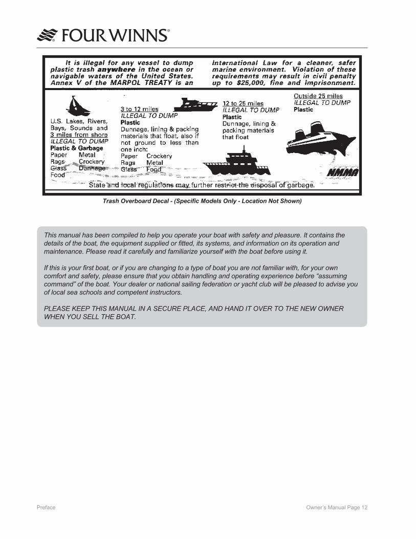
Trash Overboard Decal - (Specific Models Only - Location Not Shown)
This manual has been compiled to help you operate your boat with safety and pleasure. It contains the details of the boat, the equipment supplied or fitted, its systems, and information on its operation and maintenance. Please read it carefully and familiarize yourself with the boat before using it.
If this is your first boat, or if you are changing to a type of boat you are not familiar with, for your own comfort and safety, please ensure that you obtain handling and operating experience before “assuming command” of the boat. Your dealer or national sailing federation or yacht club will be pleased to advise you of local sea schools and competent instructors.
PLEASE KEEP THIS MANUAL IN A SECURE PLACE, AND HAND IT OVER TO THE NEW OWNER WHEN YOU SELL THE BOAT.

Owner’s Manual Page 13Preface
LABEL LOCATIONS
Various warning labels are placed at different locations on each model for your safety. Additional warnings for fuel leakage, blower operation, and other important information will be imprinted or located on the dash. Many of these stickers and labels are not required by the US Coast Guard but are important to ensure the safe operation of your Four Winns® boat. In addition, the Hull Identification Number plate is permanently attached below the deck-hull joint on the starboard aft corner.
Below are letters corresponding to the various locations for each item on the drawings. See the following pages of this section for the actual wording of each of the various warning labels found on your boat.
Figure 1: Warning Labels and Other Label Locations - Reference Only(Location may vary depending on model)
C
(A) Hull Identification Number Plate (B) Gasoline Vapor Blower Warning (C) Helm Boarding Ladder Warning (Imprinted) (D) Rotating Prop Boarding Ladder (E) Leaking Fuel (F) NMMA Yacht Certification Plate
(G) Helm Boarding Ladder Warning (H) NMMA Certified Sticker (I) Winning Edge Sticker (J) CO - Cabin Doors Warning (K) CO - Transom Warning Label (L) Prevent Falls Overboard Label
BA D
E HGF
I KJ L

Owner’s Manual Page 14Preface
YACHT CERTIFICATION & WARNING LABELS
Gasoline Vapors - Blower Warning Label(applicable models only)
NMMA Yacht Certification Plate
GASOLINE VAPORS CAN EXPLODE RESULTING IN INJURY OR DEATH. BEFORE STARTING ENGINE
- CHECK ENGINE BILGE COMPART-MENT FOR GASOLINE OR VAPORS, AND
- OPERATE BLOWER FOR FOUR MINUTES, AND VERIFY BLOWER OPERATION.
RUN BLOWER WHEN VESSEL IS OPERATING BELOW CRUISING SPEED.
Canadian Conformity Label EU Builders Plate - CE Certification Plate (Export)

Owner’s Manual Page 15Preface
No Ventilation - Do Not Store Fuel Warning Label
Shore Power Inlet Warning Label
Ensure slings are in proper location as indicated by the sling label location. Failure to do so may result in permanent hull structure damage and will invalidate the hull structure warranty.
Carbon Monoxide - Canvas Warning Label
Carbon Monoxide - Cabin Doors Warning Label
Dockside Air Conditioning Inlet Label
Microwave Caution Label
Owner’s Manual Page 16Preface
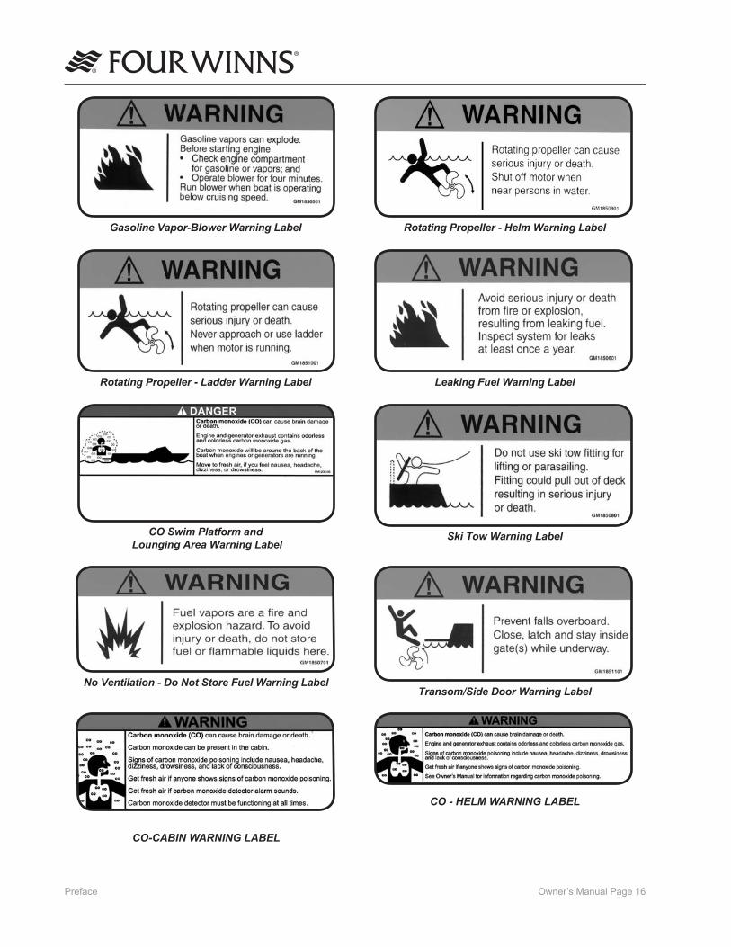
Leaking Fuel Warning LabelRotating Propeller - Ladder Warning Label
Gasoline Vapor-Blower Warning Label
CO Swim Platform and Lounging Area Warning Label
Ski Tow Warning Label
No Ventilation - Do Not Store Fuel Warning LabelTransom/Side Door Warning Label
Rotating Propeller - Helm Warning Label
CO-CABIN WARNING LABEL
CO - HELM WARNING LABEL

Owner’s Manual Page 17Preface
Winning Edge Sticker NMMA Certified Sticker
Flush Out Warning Label (Optional)

Owner’s Manual Page ��Operation - Section A
A - 1 GENERAL
Before starting the boat, become familiar with all of the various systems and related operations. Be sure all necessary safety equipment is on-board. Know the “Rules of the Road”. Have an experienced operator brief you on the general operation of your new boat. Perform a “pre-cruise systems check”. This manual is a part of your boat’s equipment. Always keep it on board.
A - 2 COMPONENT SYSTEMS
Before you can really enjoy your boat, a thorough understanding of its systems and their operation is essential. This manual and the associated manu-facturers information are included in the owner’s packet. This information is provided to enhance your knowledge of the boat. Read this information carefully.
After becoming familiar with the boat and its systems, reread this manual and other material provided in the owner’s packet. Maintenance and service tips are included to help keep the boat in like-new condition.
A - 3 SAFETY EQUIPMENT
Besides the equipment installed on the boat by Four Winns certain other equipment is required for passenger safety. A booklet listing the Federal equipment requirements is included in the owner’s packet or is available through your local US Coast Guard Station. Remember that these laws are for your protection and are minimum requirements. Check your local and state regulations, also. More information on safety equipment is provided in Section B.
Items like a sea anchor, working anchor, extra dock lines, flare pistol, a line permanently secured to your ring buoy, etc. could at some time save your passen-gers lives, or save your boat from damage.
The Coast Guard Auxiliary offers a “Courtesy Examination.” This inspection will confirm the boat is equipped with all of the necessary safety equipment.
A - 4 PASSENGER SAFETY
You are responsible for the safety of your passengers as well as for their behavior while aboard. Make sure:
1. Each passenger is properly instructed in Personal Flotation Device (PFD) use and keeps one within reach in case of emergency. All non-swimmers and children should wear a PFD at all times when underway.
2. Passengers do not sit on gunwales, open decks, elevated pedestal seats or on seat backs when the boat is underway. This could cause them to be thrown overboard during a sudden maneuver.
3. At least one other person knows how to operate the boat in case of an emergency.
A - 5 “RULES OF THE ROAD”
As in driving an automobile, there are a few rules that must be known if safe boating operation is to be maintained. The Coast Guard, Coast Guard Auxiliary, Department of Natural Resources or your local boat club sponsor courses in boat handling, including “rules of the road”. Such courses are strongly recommend-ed. Books on this subject are also available from local libraries.
A - 6 LIGHTNING
When boating, it is important to be aware of the weather around you. When the weather changes for the worse, DO NOT jeopardize your safety by trying to “ride out the storm”. If possible, return to safe harbor and dock your vessel immediately.
If caught in a storm, seek shelter inside the cabin and wait for the storm to pass. With certain models, campers will provide some protection, but should not be relied on if you are able to return to shore. Exercise care when high winds are present!
NOTICEFour Winns boats are not equipped with a lightning protection system.
Operation

Owner’s Manual Page ��Operation - Section A
DO NOT swim or dangle legs or arms into the water during a lightning storm. Stay out of the water!
Lightning will seek a ground when it strikes. Avoid contact with metal parts such as bow rails, control handle, or windshield.
A - 7 DRUGS AND ALCOHOL
Please keep in mind that along with the fun of boating comes responsibility. As the owner or operator of a pleasure boat, you are obligated (morally and legally) to use good judgement while underway in providing for the safety and well-being of your passengers and other boaters around you.
A common and flagrant violation of good judgement and the law by boaters involves the use of alcohol or drugs. Each year, about half of all accidents involving fatalities involve the use of alcohol or drugs.
It is a federal offense to operate a boat while intoxi-cated. Criminal penalties may include the termination of operating privileges for up to one year. Many states have passed similar laws.
Alcohol or drugs have an inhibiting effect on the judgement and reaction time of the boat operator and his/her passengers. Heed the advice of experts and statisticians...DO NOT drink or use drugs when operating a boat. NEVER allow an obviously intoxicated person to take the helm.
Have fun in your Four Winns® boat, but also have the good sense to be mentally alert and physically capable of operating the boat in a safe manner.
A - 8 PRE-CRUISE SYSTEMS CHECK
Before leaving the dock, the following items should be checked:
A. Before Starting The Engine
1. Check the weather forecast. Determine if the cruise planned can be made safely.
2. Be sure all necessary safety equipment is on board and operative. This includes items such as the running lights, horn, spotlight, life saving devices, etc.
3. Check the bilge water level and bilge pump operation. Check the engine and drive fluid levels (if applicable). Look for other signs of potential problems. Check for the scent of fuel fumes.
4. Activate the Bilge Blower. Check the blower output.
Gasoline vapors can explode resulting in injury or death. Before starting the engine, check engine compartment bilge for gasoline or vapors. Operate blower for four minutes, and verify blower operation. ALWAYS run the blower when the vessel is operating below cruising speed.
5. Ensure an adequate amount of fuel is on board.
6. Be sure you have sufficient water and other provisions on board for the cruise planned.
7. Leave a written message listing details of the planned cruise with a close friend ashore.
B. After Starting The Engine
1. Visibly check the engine to be sure there are no apparent water or oil leaks.
2. Check the gauges. Make sure the oil pressure, water temperature, voltmeter, etc. are reading normally.
3. Have a safe cruise and enjoy yourself.
Always be sure to raise the anchor and ensure the chain stop is engaged prior to operating your boat. Failure to raise and secure anchor before getting underway could result in damage to boat and even severe injury or death from a rebounding anchor.

Owner’s Manual Page �0Operation - Section A
B. Cold / Warm Engine Start (EFI)
1. Move the control handle to NEUTRAL detent position.
2. Turn the key switch to start and hold until engine starts, for no longer than 10 seconds. If engine does not start, let go momentarily, then try again.
2b. For diesel engines, you must first turn the ignition key to the ON position and wait 30 seconds, allowing preheaters to activate. After 30 seconds, turn key switch to START position and hold until engine starts. DO NOT hold in START position for more than ten seconds.
3. As soon as engine starts, release key to ON or RUN.
NOTICEPriming is not necessary for EFI engines. Refer to the engine owner’s manual for additional information.
NOTICENEVER turn key to START position when engine is running.
NOTICEWhen starting engine, do not allow engine to “over-rev”. Engine damage could result. “Over-revving” engine after off-season storage could also damage the water pump impeller.
NOTICEWhen starting engine for the first time after off-season storage, always idle engine for ten minutes to allow the water pump to prime.
C. Shifting and Control Speed
NOTICEIf your boat is equipped with a non-OEM remote control system, ask your dealer how to properly operate it.
A - 9 ENGINE OPERATIONAL PROCEDURES
NOTICEConsult engine operator’s manual for specific procedure for your particular model. The following information is general in nature. Additional general information is located in Section S.
A. Before Starting
1. Check the engine compartment for water, gas, and/or oil leaks of any kind. Keep the bilge in a clean condition to prevent blower and bilge pump damage, and fire hazards.
2. Check the fluid levels of the engine oil and power steering system daily. Fill oil or steering fluid as required by the indications on the dip sticks. Refer to the Table 1: “SAE Viscosity Chart - Gas” and your engine manual included in the owner’s packet. DO NOT USE MULTIGRADE OIL.
IF THE LOWESTANTICIPATED
TEMPERATURE IS*
THE FOLLOWINGSAE VISCOSITY OILSARE RECOMMENDED
32O F (0o C) and above SAE 30
0O F (-18O C) to 32O F (0O C) SAE 20W-20
Below 0O F (-18O C) SAE 10W
*Temperature range you expect to operate.Note: Use only single viscosity oils.
Table 1: SAE Viscosity Chart - Gas
Diesel engines use a Series IIID oil, SAE15W/40. Refer to your diesel engine owner’s manual for further information.
3. Power steering and power trim use automatic transmission fluid. Check the fluid levels in the vertical drive units or transmission as often as practical.
4. Start and operate the bilge blower system for at least four (4) minutes before start-up.
5. Lower the vertical outdrive units (on applicable models) making sure the water intakes are under the water.

Owner’s Manual Page ��Operation - Section A
1. Move shift/throttle lever(s) to the neutral idle position. Placing the shift/throttle levers in the neutral detent position will engage neutral start switch and allow engine to start.
2. To go FORWARD - move the shift/throttle lever(s) forward. Once forward gear engagement is complete, push shift/throttle lever(s) forward until desired speed is achieved.
3. To go in REVERSE - move the shift/throttle lever(s) rearward. Once rearward gear engage-ment is complete, push shift/throttle lever(s) rearward until desired speed is achieved.
DO NOT shift from forward to reverse when the boat is planing.
NOTICEDO NOT shift if engine speed is above �00 RPM.
4. To go from FORWARD to REVERSE, or REVERSE to FORWARD; always pause at NEUTRAL and allow engine speed to return to idle.
5. After shifting is completed, slowly push throttle lever(s) forward/rearward until desired speed is achieved.
Any time the boat is operated, be aware of changes in shift system operation. A sudden increase in shift effort of the shifter levers, or other abnormal operation, indicates a possible problem in the shift system. If this occurs, the following precautions must be taken:
• With engine running and boat securely tied to the dock, shift drive into forward and reverse to ensure there is gear engagement.
• When docking the boat, all docking maneuvers must be performed at slow speed. Pay special attention to other boaters. Passengers should be informed of potential problems and precautions taken.
If you suspect there is a problem, see your engine manufacturer’s authorized service center as soon as possible for proper diagnosis and required service or adjustment. Continued operation could result in damage to the shift mechanism and loss of control.
D. Stopping Engine
1. Move shifter lever(s) to the NEUTRAL position. Place throttle levers (if applicable) in idle position.
2. Turn ignition key to the OFF position.
NOTICEDO NOT stop engine at speeds above idle or “speed up” engine while turning off ignition. Engine damage could result.
A - 10 GROUNDING AND TOWING
If the boat should become disabled, or if assisting another craft that is disabled, great care must be taken. The stress applied to a boat during towing may become excessive. Excessive stress can damage the structure of the boat and create a safety hazard for those aboard.
Four Winns® boats are not designed nor intended to be used as a towing vessel. The mooring cleats on Four Winns® boats are not designed or intended to be used for towing purposes. These cleats are specifically designed as mooring cleats for securing the boat to a dock, pier, etc. DO NOT use these fittings for towing or attempting to free a grounded vessel.
Freeing a grounded vessel or towing a boat that is disabled requires specialized equipment and knowl-edge. Line failure and structural damage caused by improper towing have resulted in fatal injuries. Because of this, Four Winns strongly suggests that these activities be left to those who have the equip-ment and knowledge such as the US Coast Guard or Sea Tow®, to safely accomplish the towing task.

Owner’s Manual Page ��Operation - Section A
Running aground can cause serious damage to a boat and associated underwater gear. If the boat should become grounded, distribute personal flotation devices and inspect the boat for possible damage. Thoroughly inspect the bilge area for signs of leakage. An experienced service facility should check the hull and underwater gear at the first opportunity. DO NOT continue to use the boat if the condi-tion of the hull or underwater equipment is questionable.
If towing or being towed is absolutely necessary, use the strongest lines available, and attach them to the bow eyes or stern eyes only. Have all passengers slip on life jackets and take a seat in the cabin or other protected area.
Lines can snap or other hardware can be loosened or broken while towing. Under certain conditions, this can cause severe injury or fatality.
A - 11 BOATING EDUCATION
A. Boating Courses
Boating education classes are offered throughout the country. The United States Coast Guard Auxiliary offers free courses on different topics usually during the off-season. The most popular course is the “Boating Skills & Seamanship Course,” and informa-tion can be obtained by calling 1 800-336-BOAT (2628) or by visiting their website at: www.boatus.com/courseline.
The United States Power Squadron also offers free courses ranging from basic seamanship to celestial navigation. For information, contact your local Power Squadron, or write: USPS, P.O. Box 30423, Raleigh, NC 27622 or visit their website at: www.usps.org.
The World Wide Web contains many websites devoted to boating and boating safety. One such site is www.discoverboating.com which contains many informative articles and website links for both the new boater as well as the experienced boater alike.
The Canadian Power and Sail Squadron offers seamanship courses. Information may be obtained by visiting their website at www.cps-ecp.ca/.
B. Boating Manuals or Literature
A good source of information is the US Coast Guard’s home study book called “The Skipper’s Course”. This book may be purchased through Superintendent of Documents, US Government Printing Office, Washington, DC 20402, Stock # 050-012-00159-6.
Another good source of boating information is Chapman’s “Piloting, Seamanship and Small Boat Handling”. Also, check the local library or bookstore for additional information on boating.
C. Charts and Maps
US nautical charts are sold throughout the country at Governmental Printing Office stores and other agents. Chart catalogs are available by visiting the National Oceanic and Atmospheric Administration website at http://nauticalcharts.noaa.gov/mcd/ccatalogs.htm#state.
In addition, many federal agencies publish recre-ational maps, including the US Army Corp of Engi-neers, the Forest Service, the National Park Service, and the Tennessee Valley Authority.
Addresses of all state boating law administration offices are found in the “Boating Basics, A Guide to Responsible Boating”, included in your owner’s packet. Additional copies may be purchased by contacting Outdoor Empire Publishing at www.outdoor-empire.com.
D. Laws and Regulations
The US Coast Guard is the authority of the water-ways; they are there to help the boating public. State boating regulations are enforced by local authorities. You are subject to marine traffic laws and “Rules of the Road” for both federal and state waterways; you must stop if signaled to do so by enforcement officers, and permit to be boarded if asked.
There are many pamphlets, prepared by the US Coast Guard, available to you. These pamphlets explain “Rules of the Road,” signal lights, buoys, safety, international and inland regulations and other informa-tion which goes beyond the scope of this manual. For more information contact your local US Coast

Owner’s Manual Page ��Operation - Section A
Guard Unit or call the Coast Guard info line at 1 800 368-5647, or visit the US Power Squadron website at www.usps.org.
A - 12 BOAT OWNER REGISTRATION
Federal and state laws require that every boat equipped with propulsion machinery of any type must be registered in the primary state of usage. Registration numbers and validation stickers must be displayed on the boat according to regulations. In most states, this means registration with the designated state agency. In a few jurisdictions, the Coast Guard retains registration authority. Your dealer will either supply registration forms or tell you where they may be obtained. The registration agency will issue you a certificate that must be carried on board when the boat is in use. Some states require additional registration when an out of state boat is used within their boundaries.
Your boat has a hull identification number on the starboard side of the hull. Figure A-1 shows a typical identification number. Use this hull identification number for registration and to identify your boat for warranty service.
Figure A-1: HIN
In most states, the boat owner is legally responsible for damages or injuries he or she causes, even if someone else is operating the boat at the time of the accident. Common sense dictates that you carry adequate personal liability and property damage insur-ance on your boat, just as you would on an automo-bile. You should also protect your investment by insuring your boat against physical damage or theft.
A - 13 ACCIDENT REPORTING
The operator of the boat is responsible for filing a report with the appropriate authorities. In general, reports are necessary for accidents involving loss of life, injury, or damage over $500. In the case of accidents with reportable injuries or death, a formal report is required within 48 hours. If only property damage is involved, a report must be made within ten days. The 1971 Boating Safety Act may impose a $1,000 civil fine for people who fail to submit a boating accident report. Ask your insurance agent for more information.
If you see a distress signal, you must assume it is a real emergency and render assistance immediately. The master or person in charge of a boat is obligated by law to provide assistance to any individual in dan-ger at sea. However, you should not put your boat or crew in a dangerous situation which exceeds your capabilities or those of your boat. The 1971 Boating Safety Act grants protection to a Good Samaritan boater offering good faith assistance, and absolves a boater from any civil liability arising from assistance given.
A - 14 DISCHARGE OF OIL
The Federal Water Pollution Control Act prohibits the discharge of oil waste into or upon the navigable waters of the United States or the waters of the contiguous zone if such discharge causes a film or sheen upon or a discoloration of the surface of the water or causes a sludge or emulsion beneath the surface of the water. Violators are subject to a penalty of $5,000.
A - 15 DISPOSAL OF PLASTICS & OTHER GARBAGE
Plastic refuse dumped in the water can kill fish and marine wildlife and can foul boat propellers and cooling water intakes. Other forms of waterborne garbage can litter our beaches and make people sick. US Coast Guard and most state regulations prohibit the dumping of plastic refuse or other garbage mixed with plastic into the water anywhere, and restrict the dumping of other forms of garbage within specified distances from shore.

Owner’s Manual Page ��Operation - Section A
A - 16 MARPOL TREATY
Boats 26 feet or longer must display a sign stating the disposal regulations of the Federal Water Pollution Control Act. The US Coast Guard has issued these regulations to implement Annex V of the International Convention for the Prevention of Pollution from Ships, 1973, commonly known as Annex V of the MARPOL (Marine Pollution) Treaty 73/78. They apply to all US boats wherever they operate (except waters under the exclusive jurisdiction of a State) and foreign boats operating in US waters out to and including the Exclusive Economic Zone (200 miles). It is important to know these regulations and adhere to them.
The regulations require US recreational boaters, if your boat is 26 feet or more in length, to affix one or more USCG Trash Dumping Restrictions placards to your boat. The placard warns against the discharge of plastic and other forms of garbage within the navigable waters of the United States and specify discharge restrictions beyond the territorial sea. (The territorial sea generally ends three nautical miles from the seashore.) In addition, the placard must contain the warning that a person who violates these requirements is liable to civil ($25,000) and criminal (imprisonment) penalties. The placard also must note that State and local regulations may further restrict the disposal of garbage.
Operators shall display one or more placards in a prominent location and in sufficient numbers so they can be observed and read by crew and passengers. These locations might include embarkation points, food service areas, galleys, garbage handling spaces and common deck spaces frequented by crew and passengers. We recommend that these placards may be purchased from local marinas, boat dealerships and marine equipment suppliers. A special placard is available for boats operating on the Great Lakes.
NOTICEIMPORTANT: It is illegal to discharge waste from your marine sanitary device (toilet) into the water in most areas. It is your responsibility to be aware of and adhere to all local laws concerning waste discharge. Consult with the Coast Guard, local marina or your dealer for additional information.
NOTICENOTE: Some states and localities have legal limits on speed, noise and trailer specifications. It is your responsibility to be aware of these laws and limits and to insure that your boat (and trailer) comply. Consult with your local Marine Patrol or local Coast Guard office.

Owner’s Manual Page ��Boating Safety - Section B
B - 1 GENERAL
As the owner/operator of the boat, you are responsible for assuring that all required safety equipment is aboard. You should also consider supplying additional equipment as needed for your safety and that of your passengers. Check state and local regulations and call the US Coast Guard Boating Safety Hotline at 1-800-368-5647 for information about required safety equipment.
A. Required Safety Equipment
Most of the safety equipment required by federal regulations is provided as standard equipment. Personal Floatation Devices (life jackets) must fit the person wearing it. If local regulations require additional equipment, it must be approved by the US Coast Guard (USCG). Minimum requirements include the following: • Personal Floatation Devices • Visual Distress Signal • Bell or Whistle • Fire Extinguisher • Navigation Lights
NOTICEAs the owner/operator of the boat, you are responsible for assuring that all required safety equipment is aboard and meets the boating regulations as prescribed by both federal and local authorities in your area.
B. Personal Floatation Devices (PFDs)
Federal regulations require that you have at least one Coast Guard approved personal floatation device (PFD) for each person in a recreational boat. You should not use your boat unless all PDFs are in serviceable condition, readily accessible, legibly marked with the Coast Guard approval number, of an appropriate size (within the weight range and chest size marked on the PDF) for each person aboard.
A PFD provides buoyancy to help keep your head above the water and to help you remain in a satisfac-tory position while in the water. Body weight and age should be considered when selecting a PFD. The buoyancy provided by the PFD should support the person’s weight in the water.
The size of the PFD should be appropriate for the wearer. Body weight or chest size are common methods used to size PFDs. It is your responsibility to ensure that you have the proper number and types of PFDs on board and that your passengers know where and how to use them.
C. PFD Types
Five types of PFDs have been approved by the US Coast Guard. The PFDs are described as follows:
PFD Type 1, Wearable (Figure B1) has the greatest required buoyancy. Its design allows for turning most unconscious persons in the water from face down position to a vertical or slightly backward, face-up position. It can greatly increase the chances of survival. Type 1 is most effective for all waters, especially offshore when rescue may be delayed. It is also the most effective in rough waters.
Figure B1: Type I, Wearable
PFD Type II, Wearable (Figure B2) turns its wearer in the same way as Type I, but not as effectively. The Type II does not turn as many persons under the same conditions as a Type I. You may prefer to use this PFD where there is a probability of quick rescue such as in areas where other people are commonly involved in water activities.
Figure B2: Type II, Wearable
PFD Type III, Wearable (Figure B3) allows the wearer to place themselves in a vertical or slightly backward position. It does not turn the wearer. It maintains the wearer in a vertical or slightly backward position and has no tendency to turn the wearer face down. It has the same buoyancy as a Type II PFD and may be appropriate in areas where other people are com-monly involved in water activities.
Boating Safety

Owner’s Manual Page ��Boating Safety - Section B
3. Teach children how to put a PFD on and allow them to try it in the water. That way, they know what the PFD is for and how it works. They will feel more comfortable with it if they suddenly find themselves in the water.
4. If the PFD is wet, allow it to dry thoroughly before storing it. Do not dry it in front of a radiator or heater. Store it in a well ventilated area.
5. Keep PFDs away from sharp objects which can tear the fabric or puncture the floatation pads.
6. For their own safety and the safety of others, all nonswimmers, poor swimmers, and small children should wear PFD’s at all times, whether the boat is stationary or moving.
7. Check the PFD frequently to make sure that it is not torn, that floatation pads have no leaks, and that all seams and joints are securely sewn.
8. If a PFD contains kapok, the kapok fibers may become waterlogged and lose their buoyancy after the vinyl inserts are punctured. If the kapok becomes hard or if it is soaked with water, replace it. It may not work when you need it.
E. Fire Extinguisher
As the owner/operator of the boat, you are responsible for supplying a fire extinguisher approved by the US Coast Guard.
Hand-held portable extinguisher(s) should be mount-ed in a readily accessible location(s) away from the engine compartment. All persons aboard should know the location(s) and proper operation of the fire extinguisher(s).
Fire!In case of fire do not open the engine compart-ment. Shut down engine(s), generator(s), and blower(s). Models with fixed fire suppression system will automatically discharge its entire contents. If using portable CO2 fire exting-uisher continuously discharge entire contents.
Figure B3: Type III, Wearable
PFD Type IV, Throwable (Figure B4) is required in addition to the PFDs previously discussed. The most common Type IV PFD is a buoyant cushion or ring buoy. It is designed to be thrown to a person in the water, grasped and held by the user until he or she is rescued. A Type IV PFD should always be in serviceable condition and immediately available for use. Grasping this PFD may be difficult if the rescue is delayed or if the user is overcome by hypothermia (loss of body heat).
Figure B4: Type IV, Throwable
PFD Type V, Wearable (Figure B5) when inflated, it provides buoyancy equivalent to Type I, II, or III PFDs. When it is deflated, however, it may not support some people.
Figure B5: Type V, Wearable
D. PFD Pointers
The purpose of a PFD is to help save your life. If you want it to support you when you are in the water, it needs to fit, float, and be in good condition.
1. Try the PFD on and adjust it until it fits comfortably in and out of the water. Mark your PFD if you are the only wearer.
2. To make sure the PFD works, wear it in the water. This will show you how it works and give you confidence when you use it.

Owner’s Manual Page ��Boating Safety - Section B
NOTICEDo not test fire extinguishers by squirting small amounts of the extinguishing compound. The fire extinguisher might not work when you really need it.
The Vista® models that measure 26 to less than 40 feet are considered Class 2 powerboats. All Class 2 powerboats are required to carry two (2) B-1 type approved hand portable fire extinguishers or one (1) B-2 type approved hand portable fire extinguisher. When a fixed fire extinguishing system is installed in machinery space(s), at least one (1) B-1 type ap-proved hand portable fire extinguisher is required.
F. Fire Extinguisher System
An automatic FE241 agent fire extinguisher system is an available option on the 258 and 278 Vista® models. If applicable, the equipment utilized has been so chosen, and located, to provide sufficient volume and coverage of the entire engine compartment. While the system ensures excellent overall bilge fire protection, it does not eliminate the USCG requirement for hand-held fire extinguishers. Refer to the manu-facturer’s literature included in the owner’s packet if this feature has been installed.
G. Visual Distress Signal Devices
Visual distress signal devices approved by the US Coast Guard are required on all recreational boats operating on coastal waters and to boats owned in the United States when they are operating on the high seas. Coastal waters include territorial seas and those waters directly connected to the Great Lakes and the territorial seas up to a point where the waters are less than two miles (3.2km) wide. Visual distress signal equipment may be of the pyrotechnic or non-pyrotech-nic type. Regulations prohibit display of visual distress signals on the water under any circumstances except when assistance is required to prevent immediate or potential danger to persons on board a vessel.
The equipment must be approved by the US Coast Guard, be in serviceable condition, and be stowed in a readily accessible location. Equipment having a date for serviceable life must be within the specified usage date shown. Careful selection and proper stowage of visual distress equipment is very important if young children are aboard.
DAY USE ONLY NIGHT USEONLY
DAY ANDNIGHT USE
Three orangesmoke signals(one hand heldand two floating)or one orangeflag with blacksquare and disk.
One S-O-Selectric distresslight.
Three flares ofthe hand held,meteor orparachute type.
Distress Signal Table
The minimum visual distress signals required in coastal waters for a Class 1 or Class 2 powerboat is the following: One orange flag with black square-and disc
(daytime); and an S-O-S electric light (nighttime); or three orange smoke signals, hand held or floating (daytime); or three red flares of hand held, meteor, or parachute type (daytime/nighttime).
NOTICENo single signaling device is appropriate for all purposes. Consider keeping various types of equipment on board.
H. Sound Signaling Devices
Class 1 and Class 2 powerboats are required to carry a hand, mouth or power operated horn or whistle. It must produce a blast of two-second duration and audible at a distance of at least one-half (1/2) mile. The 258 and 278 Vista® models are equipped with a concealed horn which meets this requirement. See Figure B6.
Figure B6: Horn (Concealed)
Horn

Owner’s Manual Page ��Boating Safety - Section B
B - 2 CARBON MONOXIDE
Carbon Monoxide!
Carbon monoxide (CO) can be harmful or fatal if inhaled. Brain damage or death can result from prolonged exposure to carbon monoxide. Keep exhaust outlets clear of blockage. Provide adequate ventilation. Open hatches, doors, windows and vents to insure adequate ventilation. Close engine compartment doors and hatches when engine or generator is running. Avoid operating the boat for extended periods of time at idle speed, and be sensitive to weather conditions that may prevent CO from dissipating into the air. Do not stand or swim near engine or generator exhausts when engines are running.
Carbon monoxide accumulation is affected by many variables (e.g., boat geometry, hatch, window and door opening, ventilation openings, proximity to other structures, swim platforms, canvas enclosures, location of exhaust outlets, vessel attitude, wind direction, vessel speed, boat systems maintenance, etc.) The technical information included in this section is to inform the boat owner of possible cause and effects of carbon monoxide exposure. This information has been reprinted with permission from the American Boat and Yacht Council’s (ABYC) technical informa-tion report: “Educational Information About Carbon Monoxide”. This information pertains to all gasoline powered boats manufactured by Four Winns.
NOTICEThe boat owner should be aware that other factors may contribute to carbon monoxide accumulation. The most common ones are listed in this section. If a person is exhibiting carbon monoxide-type symptoms (Refer to B-�E Symptoms), be sure to take the necessary precautions as prescribed later in this section.
NOTICEBoats fueled by diesel have limited carbon monoxide present in the exhaust in compari-son to gasoline engine exhaust. However, the boat owner should still be aware of the causes and effects of carbon monoxide which may occur in different boating situations.
The following are standard whistle signals:
• One Prolonged Blast = Warning Signal• One Short Blast = Pass on my Port Side• Two Short Blasts.= Pass on my Starboard Side• Three Short Blasts = Engines in Reverse• Five or More Blasts = Danger Signal
I. Navigation Lights
Navigation lights are intended to keep other vessels informed of your presence and course. If you are out on the water between sunset and sunrise, you are required to display appropriate navigation lights.
J. Additional Recommended Equipment
Four Winns recommends that you acquire additional equipment for safe, enjoyable cruising. This list, which is not all inclusive, includes items you should consider acquiring.
Basic GearFlashlight Spare batteries Tow lineOar, paddle Mooring lines CompassDock fenders Distress signals First aid kitBoat hook VHF radio EPIRB*Sunscreen Extra warm clothing ChartsSecond anchor & line Dewatering device (pump or bailer)Emergency supply of drinking water and food.*Emergency Position Indicating Radio Beacon
ToolsSpark plug wrench Hammer ScrewdriverJackknife Pliers Electrical tape Duct tapeAdjustable wrench Lubricating oil Prop wrench
Spare PartsExtra bulbs Spare prop Extra fusesExtra drain plug Spark plugs Spare wireExtra prop nut/washer
Gear For Extended CruisesFoul weather gear Parallel rulers DividersGlobal Positioning System navigation equipment

Owner’s Manual Page ��Boating Safety - Section B
Certain health related problems and age will increase the effects of CO. People who smoke or are exposed to high concentrations of cigarette smoke, consume alcohol or have lung disorders or heart problems, are particularly susceptible to an increase in the effects from CO. However, all occupants’ health should be considered. Physical exertion accelerates the rate at which the blood absorbs CO.
E. Symptoms
One or more of the following symptoms can signal the adverse effect of CO accumulation:
1. Watering and itchy eyes2. Flushed appearance3. Throbbing temples4. Inattentiveness5. Inability to think coherently6. Loss of physical coordination7. Ringing in the ears8. Tightness across the chest9. Headache10. Drowsiness11. Incoherence12. Slurred speech13. Nausea14. Dizziness15. Fatigue16. Vomiting17. Collapse18. Convulsions
NOTICEThe order of the above list is generally the sequence of appearance of symptoms. However, the order of appearance may change for different people.
NOTICEThe symptoms of Carbon monoxide poisoning may easily be mistaken for seasickness.
F. Treatment (Evaluate, Ventilate, Evacuate, Investigate, Take Corrective Action)
1. Evaluate the situation and ventilate the area if possible.
2. Evacuate the area and move affected person(s) to a fresh air environment.
3. Observe the victim(s).
A. Properties and Characteristics of Carbon Monoxide
1. Carbon Monoxide is a colorless, odorless and tasteless gas. It is commonly referred to as CO.
2. Its weight is about the same as air so it cannot be expected to rise or fall like some other gases, but will distribute itself throughout the space.
NOTICEDO NOT rely on the use of smell or sight of other gases to detect CO, because it diffuses in the air much more rapidly than easily detectable vapors (i.e. visible and aromatic vapors).
B. What Makes Carbon Monoxide
Any time a material containing carbon burns such as gasoline, natural gas, oil, propane, coal, or wood, CO is produced.
Common sources of carbon monoxide are:
1. Internal combustion engines such as: a. Propulsion engines b. Generators (if applicable)
2. Open flame devices such as:
a. Cooking ranges b. Central heating plants c. Space heaters d. Water heaters e. Fireplaces f. Charcoal grills
C. How a Person is Affected by Carbon Monoxide
Carbon monoxide is absorbed by the lungs and reacts with blood hemoglobin to form carboxyhemoglobin, which reduces the oxygen carrying capacity of the blood. The result is a lack of oxygen for the tissues with the subsequent tissue death and, if exposure is prolonged, death of the individual.
D. Effects of Carbon Monoxide
Carbon monoxide in high concentrations can be fatal in a matter of minutes. Lower concentrations must not be ignored because the effects of exposure to CO are cumulative and can be just as lethal.

Owner’s Manual Page �0Boating Safety - Section B
The following are examples of possible situations where carbon monoxide can accumulate within your boat while docked, anchored, or underway. Become familiar with these examples and their precautions to prevent dangerous accidents or death.
I. Boathouses, Sea Walls and Confined Spaces
A boat operator should be aware that dangerous concentrations of CO can accumulate when a boat, generator or other engine operated device is operated while the boat is moored in a confined area such as:
1. Boathouses,
2. Proximity to sea walls, or
3. Proximity to other boats.
Keep engine room hatches and doors closed when operating engines, including the generator.
Pay attention to prevailing conditions and provide for ventilation to induce fresh air and minimize exhaust re-entry. Orient the boat for maximum dissipation of the exhaust. DO NOT run the boat or boat equipment for extended periods under these conditions. See Figure B7.
Figure B7: The effect of sea walls and other confined spaces.
Be aware that cockpit and deck drains can be a source of CO ingress into boats, especially boats with cockpit or decks enclosed with canvas or permanent boat structures.
4. Administer oxygen if available.
5. Contact medical help. If the victim is not breathing, perform rescue breathing or approved cardiopul-monary resuscitation (CPR), as appropriate, until medical help arrives and takes over.
NOTICEPrompt action can make the difference between life and death.
6. Investigate source of CO and take corrective action.
G. Inspection
Look and listen for leaks in the exhaust systems of both the generator and propulsion engine(s). Look for discoloration around joints in the system (water leaks, carbon, stains, etc.).
1. Make sure all exhaust clamps are in place and secured.
2. Make sure ventilation systems work and are not obstructed or restricted.
3. Make sure gaps around the engine room plumbing and cableways and exhaust system doors, hatches, and access panels are minimized to reduce the opportunity for CO to enter the accom-modation space(s).
H. Operation
Cold Start vs. Warm Start: CO production is greater while the combustion chamber surfaces and gas passages are cold versus when they are warm. A boat operator should:
1. Pay attention to ventilating the boat.
2. Orient the boat so it will allow the maximum dissipation of CO.
3. Minimize the time spent on getting underway.
4. In order to minimize CO buildup, do not warm up or run propulsion engine(s) for extended periods while the vessel is stationary.

Owner’s Manual Page ��Boating Safety - Section B
Figure B10: Inefficient trim angles.
3. Canvas Configurations - Under various conditio-ns, adding or removing canvas may raise or lower CO levels. See Figures B9, B10 & B12.
Exhaust Fumes!Hull exhaust from your boat can cause excessive accumulation of poisonous carbon monoxide gas within cockpit areas when using protective weather coverings (while underway or while stationary). Provide adequate ventilation when the canvas top, side curtains and/or back (aft) curtains are in their closed protective positions.
4. Opening and closing ports, hatches, doors, and windows may raise or lower CO levels on board a boat. When airflow is moving forward inside the boat, CO may be entering the boat. See Figures B11 and B12.
Figure B11: Desired air flow through the boat.
Figure B12: The effect of canvas configurations.
5. Operating a boat at slow speeds with a following wind should be avoided. Consider changing direction, adjusting speed, or both. See Figures B13.
J. The Effect of Boats Moored Alongside
A boat operator should be aware that carbon monox-ide is emitted from any boat’s exhaust. The operation, mooring, and anchoring in an area containing other boats may be in an atmosphere containing CO not of the operator’s making. An operator likewise needs to be aware of the effect of their boat on other boats in the area. Of prime concern is the operation of an auxiliary generator where boats are moored along side each other. Be aware of the effect your exhaust may have on other boats and be aware that the operation of other boats’ equipment may affect the carbon monoxide concentration on your boat. See Figure B8.
Figure B8: The effect of boats moored along side.
K. Backdrafting (Station Wagon Effect)
Backdrafting or the “station wagon effect” is caused by air movement over or around a boat creating a low pressure area or suction area around the stern that can increase CO level on the boat. Backdrafting can be affected by relative wind direction , boat speed, and boat trim angle. See Figure B9 Backdrafting - Airflows Over Boat and Behind Transom”.
Under certain speed and operating conditions the low pressure area may form in other regions and permit carbon monoxide to enter the hull through openings that are not on the back of the boat. Boat factors which may affect CO concentration:
Figure B9: Backdrafting - Air flows over boat and behind transom.
1. Intentional or unintentional excessive trim angle causing high bow angle. See Figure B10.
2. Excessive or unequally distributed weight.

Owner’s Manual Page ��Boating Safety - Section B
Figure B15: Exhaust Gas Accumulation - Dangerous Activity
N. Cabin Appliances
Boats having fuel burning appliances in accommo-dation areas should be provided with adequate ventilation and the appliance should be maintained to function properly.
O. Air Conditioning
Lack of system maintenance may cause CO to be brought into the air-conditioned spaces by the air conditioner. Please refer to the air conditioner manu-facturer’s literature for additional information (if applicable).
P. Ventilation of Accommodation (Occupied) Spaces
Accommodation spaces need to be ventilated to introduce fresh air into the spaces. Ventilation meth-ods (e.g. windows, hatches, doors, and blowers) used to accomplish this may, under certain conditions, bring hazardous levels of CO into the occupied spaces. Care should be taken to be aware of all prevailing conditions when using these ventilating methods.
Q. Running of Engines in Idle
Engines running in idle exhaust carbon monoxide that can accumulate near the hull of the boat. Do not stand or swim near the engine exhaust or outdrive when engines are idling or generator is running.
R. Altitude and Sea Conditions
Operation at altitudes greater than 5,000 feet con-tributes to inefficient engine performance and may require adjustments to the ignition systems, fuel systems, or changing the propeller’s size or gear ratio.
1. Failure to make adjustments to ignition systems and/or fuel systems for altitude conditions may cause an increase in CO production.
Figure B13: Operating at Slow Speed with Following Wind
6. Be aware that cockpit and deck drains can be a source of CO ingress into boats, especially boats with cockpit or decks enclosed with canvas or permanent boat structures.
L. Accumulation of Exhaust Gases- Swim Platform
When the propulsion engine(s) or generator is running, CO is produced and may remain in the vicinity of the exhaust outlet (including underwater exhaust outlets such as sterndrives and outboards). Refer to Figure B14.
1. Do not occupy aft lounging area(s) or swim platform.
2. Do not swim under or around swim platform.
3. Do not swim in the vicinity of the exhaust outlet.
Figure B14: Exhaust Gas Accumulation at Swim Platform
M. Dangerous Activity - “Teak Surfing”/“Dragging”
Do not sit on, occupy or hang on any stern append-ages (e.g., swim platforms, boarding ladders, etc.) while underway. Do not body surf, commonly known as “teak surfing” or “dragging”, etc. in the wake of the boat. Do not tow persons in close proximity to the stern of the boat. See Figure B15.

Owner’s Manual Page ��Boating Safety - Section B
4. General
a. Worn piston rings and valves
b. Engine temperature - Cold running engines increase CO production. Engine cooling water system design and selection of thermostat(s) are primary considerations affecting engine operating temperature. Generally, an engine produces less CO if it operates at a relatively high temperature within manufacturer’s specifications.
c. Exhaust Back-Pressure - Certain alterations to the exhaust system may increase engine exhaust back pressure and CO production.
d. Restricted engine room or compartment ventilation
U. Maintenance - External Conditions
External conditions that contribute to inefficient engine performance can include:
1. Fouled hull bottom
2. Damaged and fouled running gear (i.e., shaft, strut propeller, rudder and trim tabs)
3. Incorrect selection of propeller size
V. Maintenance - Exhaust System Integrity
Gas tight integrity of exhaust systems must be maintained to insure that leakage of CO within the boat does not occur. Disassembly may be required to carry out a thorough inspection. Repair or replace components as indicated. Inspect the following:
1. Gaskets at cylinder head connection
2. Casting and pipe fittings in the dry section
3. All joints
4. Hoses
5. Clamps
6. Mufflers and their drain plugs
7. Thru-hull fittings
8. Hangers and other supports
2. Reduced power resulting from increased altitude may require adjustments to propeller size.
3. Heavy sea or out of trim conditions tend to load engines resulting in reduced performance and thereby increasing their CO production.
S. Portable Generator Sets
Never use a portable generator on a boat.
Gasoline powered portable generators are available in the marine market place and are not an option available through Four Winns. Portable generators will produce CO. These sets discharge their exhaust products in locations which can lead to an increase in the accumulation of carbon monoxide in the accommodation (occupied) space. Do not use gasoline powered portable generators on Four Winns® boats.
T. Maintenance - Engine Performance
Efficient engine performance is vital to minimizing CO production. The following items are those consid-ered to have the greatest effect on increased CO production:
1. Fuel Systems - Fuel that is contaminated, stale or incorrect octane number
2. Carburetors/Injectors
a. Dirty or clogged flame arrester
b. Malfunctioning automatic choke plate or faulty adjustment of manual choke plate
c. Worn float needle valve and seat
d. High float level
e. Incorrect idle mixture adjustment
f. Dirty or worn injectors
3. Ignition System
a. Fouled or worn spark plug.
b. Worn points or incorrect gap on points
c. Shorted or opened circuit high tension spark plug cables
d. Incorrect ignition timing.

Owner’s Manual Page ��Boating Safety - Section B
3. Check that water traps and condensate drains are present. These may be in the form of a double loop in the drain line or prefabricated p-traps. Any drain that discharges below the waterline when the boat is underway is sealed, by virtue of its design, against CO intrusion.
Z. Maintenance - Liquid Drains
Sink, shower and condensate drains can be a source of CO ingress. Ensure that water traps are present and contain fluid. These traps may be in the form of a double loop in the drain line or prefabricated p-traps. Any drain that terminates below the waterline is, by virtue of its design, sealed against CO intrusion. Some drains that are below the waterline when boat is underway will be above the waterline when the boat is at rest. The location of drains, relative to the waterline, can be affected by the dynamics of boat motion (i.e., underway or at rest).
AA. Carbon Monoxide Detection Systems
Four Winns has included two CO detectors as a standard feature. One of the CO detectors is located in the forward V-berth and the other is located in the aft/mid cabin. Check systems and maintain in accordance with the manufacturer’s instructions.
Never disarm a CO detector. If a CO detector alarms, immediately ventilate the area and check passengers for symptoms of CO intoxication. See your Four Winns dealer for assistance in diagnosing the cause for the alarm.
NOTICEFor information on CO Detection Systems, see American Boat and Yacht Council (ABYC Manual) Section A-��, “Carbon Monoxide Detectors”.
Even with the best of boat design and construction along with the utmost care in inspection, operation, and maintenance of boat systems, hazardous levels of CO may still be present in accommodation spaces and exterior areas under certain conditions. Vigilant observation of passengers for CO sickness symptoms should be supplemented by a marine CO detection device in the accommodation space.
W. Maintenance - Ventilation Systems
Boats are equipped with ventilation systems to eliminate gasoline vapors. Blowers and fans may also be provided for ventilation and to mitigate the migra-tion of CO into occupied compartments. Attention should be paid to the following:
1. Keeping ventilation intakes clear of debris
2. Replacing damaged hardware
3. Maintaining the integrity of the ducting material and its connections
4. Ensuring that position of ducting intake is not obstructed or restricted, collapsed, kinked, or crushed.
5. Eliminating sags in ducting that can form a water trap
6. Checking hangers and other supports
7. Ensuring blower/fan is operational
8. Ensuring that airflow is present at discharge
9. Inspecting wiring to equipment
X. Maintenance - Bulkhead and Deck Integrity
1. Seal all visible openings (e.g., cracks, crevices, holes, including openings around wiring and piping runs) in bulkheads and decks that separate machinery compartments from occupied compart-ments. These openings can permit migration of CO vapors.
2. Check gaskets and sealing surfaces on hatches, doors, and access panels.
Y. Maintenance - Air Conditioning Systems (If Applicable)
These systems can be a source of CO ingress and migration of CO vapors.
1. Keep grilles and filters clean.
2. Seal bulkhead voids and openings at wiring and piping runs in return air ducting, plenums, and air handling equipment enclosures, especially those adjacent to machinery compartment bulkheads.

Owner’s Manual Page ��Boating Safety - Section B
• Observe all safety signs and warnings both inside the boat and in the immediate boating area.
• Become familiar with, and adhere to, the “Rules of the Road”.
• Maintain boat speed at or below the legal limits. Avoid excessive speed or speeds not appropriate for operating conditions.
• Be sure at least one other passenger is familiar with the operation and the safety aspects of the boat in case of an emergency.
• Load the boat within the limits listed on the capacity plate. Balance loads bow and stern and port to starboard.
• Do not use the boat in bad weather or sea conditions beyond the skill or experience of the operator or the comfortable capability of the boat or passengers.
• Make sure the passengers and gear do not obstruct the operator’s view or impede his ability to move.
• Do not exceed the maximum engine power rating stated on the certification plate located inside the boat.
C. Passenger Safety
Before getting underway, show all passengers where emergency and safety equipment is stowed, and explain how to use it. Everyone aboard should wear rubber-soled shoes which resist slipping on wet surfaces. While underway, passengers should remain seated inside the deck rails and gates. Do not allow passengers to drag their feet or hands in the water. Always use handholds and other safety hardware to prevent falls. All nonswimmers, poor swimmers and small children should wear PFDs at all times.
A CO detector is not a gas/fuel vapor detector. Gas/fuel vapor detectors do not monitor the buildup of carbon monoxide in an enclosed area. For further information on the design, construction, and testing of boats in consider-ation of carbon monoxide, see ABYC TH-��.
NOTICEDetection devices shall meet the requirements of ABYC A-�� “Carbon Monoxide Detection Systems on Boats”.
B - 3 SAFE BOATING PRACTICES
NOTICEYOU are responsible for your own safety, the safety of your passengers, and the safety of fellow boaters.
A. Drugs and Alcohol
Alcohol consumption and boating do not mix! Operating under the influence endangers the lives of your passengers and other boaters. Federal laws prohibit operating a boat under the influence of alcohol or drugs.
Do not use drugs or drink alcohol while operating a boat. Like driving a car, driving a boat requires sober, attentive care. Operating a boat while intoxicated or under the influence of drugs is not only dangerous, but it is also a Federal offense carrying a significant penalty. These laws are vigorously enforced. The use of drugs and alcohol, singly or in combination, decreases reaction time, impedes judgement, impairs vision, and inhibits your ability to operate a boat.
B. Safe Operation
Safe operation means that you do not misuse your boat nor do you allow your passengers to do so. Safe operation means using good judgement at all times. It includes, without limitation, the following actions:

Owner’s Manual Page ��Boating Safety - Section B
D. Propeller
Personal Injury!Do not allow anyone near a propeller, even when the engine is off. Propeller blades can be sharp and continue to turn even after the engine is shut off. Do not allow anyone near the propeller when the throttle is in neutral position. Accidently engaging the shift can result in a serious injury or death. (See actual ladder warning labels and helm boarding ladder warning label below).
Never approach or use ladder when motor is running. Severe injury or death will result from contact with rotating propeller.
Ladder Warning Label
Shut off motor when near swimmers. Severe injury or death will result from contact with rotating propeller.
Helm Boarding Ladder Warning Label
When pulling skiers do not turn on the engine until you are at least a boat length away from the person in the water. When approaching a downed skier, turn off the engine at least one boat length away before reaching the skier in the water.
E. First Aid
As a boater, you should be familiar with the basic first aid procedures that may be needed while you are out far from help. Fish hook accidents or minor cuts and abrasions may be the most serious mishaps on board a boat but you should also learn the proper proce-dures and be ready to deal with the truly serious problems like mouth-to-mouth resuscitation, excessive bleeding, hypothermia, and burns. First aid literature and courses are available through most Red Cross chapters.
F. Operation By Minors
Minors should always be supervised by an adult whenever operating a boat. Many states have laws regarding the minimum age and licensing require-ments of minors. Be sure to check local laws or contact the state boating authorities for information.
G. “Rules of the Road”
As a responsible boater, you must comply with the “Rules of the Road,” the marine traffic laws enforced by the US Coast Guard. Navigating a boat is much the same as driving an automobile. Operating either one responsibly means complying with a set of rules intended to prevent accidents. Just as you assume other car drivers know what they are doing, other boaters assume you know what you are doing. Information regarding navigational rules and the “Rules of the Road” are discussed in further detail in C-1 & C-2 of the next section.
H. Voluntary Inspections
State boating officials in many states or the US Coast Guard Auxiliaries offer courtesy inspections to check out your craft. They will check for compliance with safety standards and required safety equipment. You may voluntarily consent to one of these inspections, and you are allowed to make corrections without prosecution. Check with the appropriate state agency or the Coast Guard Auxiliary for details.
I. Safe Boating Courses
The local US Coast Guard Auxiliary and the US Power Squadrons offer comprehensive safe boating classes several times a year. You may contact the Boat/US Foundation at 1-800-336-BOAT (2628) or, in Virginia, 1-800-245-BOAT (2628) for a course scheduled in your area. Also contact the US Coast Guard Auxiliary or Power Squadron Flotilla for the time and place of their next scheduled class.

Owner’s Manual Page ��Boating Safety - Section B
B - 4 WATER SPORTS
PERSONAL INJURYFour Winns® boats are not designed for and should not be used for pulling parasails, kites, gliders or any device which can become airborne. Use boat only for appropriate water sports. (See Preface for actual warning label).
Water skiing, wakeboarding, kneeboarding, or riding a towed, inflatable apparatus are some of the more popular water sports. Taking part in any water sport requires increased safety awareness by the partici-pant and the boat operator. If you have never pulled someone behind your boat before, it is a good idea to spend some hours as an observer, working with and learning from an experienced driver. It is also impor-tant to be aware of the skill and experience of the person being pulled. Always have a second person on board to observe the person in the water so the driver can concentrate on operating the boat.
A. Water Sport Guidelines
Everyone participating in a water sport should observe these guidelines:
1. Allow only capable swimmers to take part in any water sport.
2. Always wear a personal floatation device (PFD) approved by the US Coast Guard. Wearing a properly designed PFD helps a stunned or unconscious person stay afloat.
3. Be considerate of others with whom you share the water.
4. Give immediate attention to a person who has fallen. He or she is vulnerable in the water alone and may not be seen by other boaters.
5. Approach a person in the water from the lee side (opposite the direction of the wind). Turn off the motor at least a boat length from the person.
6. Turn engine off and anchor before swimming.
7. Always participate in water sports in safe areas. Stay away from other boats, beaches, restricted areas, swimmers and heavily traveled waterways.
8. Swim only in areas designated as safe for swim-ming. These are usually marked with a swim area buoy (see Figure B-15). Do not swim alone or at night.
SWIM AREA
Figure B-15: Swim Area Buoy
Rotating Propeller!Rotating propeller can cut or sever causing serious injury or death. Shut engine off and remove ignition key when anyone is swimming nearby. (See Section B-�D).
9. Do not allow anyone near the propeller(s), even when the engine is off. Propeller blades are sharp and can continue to turn even after the engine is off. Stay at least 150 feet away from areas marked by diver down float. See Figure B-16.
Figure B-16: Diver Down Float
10. Do not drive the boat directly behind a water skier. At 25 miles per hour, the boat will overtake a fallen skier who was 200 feet in front in about 5 seconds.
B. Water Skiing/Wakeboarding/Kneeboarding
The popular sport of water skiing has brought a special set of safety precautions to observe in boating. The following guides help prevent accidents while water skiing.
1. Water ski only in safe areas, away from other boats and swimmers, out of channels, and in water free of underwater obstructions.

Owner’s Manual Page ��Boating Safety - Section B
2. Allow no one who can not swim to water ski. Skiers must wear a USCG approved floatation device. A Type III water-ski vest is an approved and practical PFD.
3. Have a second person aboard to observe the skier and inform the driver about the skier’s hand signals (Figure B-17). The driver must give full attention to operating the boat and the waters ahead.
4. Give immediate attention to a fallen skier. Be careful not to swamp the boat while taking the skier on board.
5. Always participate in water sports in safe areas. Stay away from other boats, beaches, swimmers, and heavily traveled waterways.
6. Be considerate of others with whom you share the water.
7. Give immediate attention to a person who has fallen. He or she is vulnerable in the water alone and may not be seen by other boaters.
8. Approach a person in the water from the lee side (opposite the direction of the wind). Stop the motor at least a boat length from the person.
9. Turn off engine and anchor your boat before swimming.
Rotating Propeller!Rotating propeller can cut or sever causing serious injury or death. Switch engine off before skiers enter the water and before taking skiers aboard. Do not leave engine running in neutral. Accidently engaging shift can seriously injure skier.
Figure B-17: Skier’s Hand Signals

Owner’s Manual Page ��Basic Seamanship - Section C
2. Meeting Head-On
When two boats meet head-on neither boat has right-of-way. Both boats should decrease speed and pass; port to port. However, if both boats are on the left side of a channel, each vessel should sound two short horn blasts and pass to starboard to starboard. See Figure C-1.
Figure C-1: Meeting Head-On
3. Crossing Situations
In a crossing situation, the boat on the right from the 12-4 o’clock position has the right-of-way. It must hold course and speed. The boat without the right- of-way must keep clear and pass to the stern. See Figure C-2.
C - 1 GENERAL
Basic rules of seamanship, general information about navigational aids, and sources for additional reading and boater education are presented in this portion of your owner’s manual.
A. Boating Regulations
The US Coast Guard is the authority of the waterways. State boating regulations are enforced by local authori-ties. Your boat is subject to the marine traffic laws known as “Rules of the Road,” which are enforced by the US Coast Guard. You are subject to marine traffic laws and “Rules of the Road” for both federal and state waterways; you must stop if signaled to do so by enforcement officers, and permit them to board if asked. The “Navigational Rules, International-Inland Rules of the Road” can be obtained from the US Coast Guard website at www.uscgboating.org.
Many pamphlets prepared by the US Coast Guard are available. They explain signal lights, buoys, safety, international and inland regulations and other informa-tion which goes beyond the scope of this manual. “Aids to Navigation” (US Coast Guard pamphlet #123) explains the significance of various lights and buoys. Because of proposed alterations to buoys and markers, contact the US Coast Guard or visit their website to stay informed of changes. Other pamphlets, including the “Boating Safety Training Manual” and “Federal Requirements For Recreational Boats,” are also available from the US Coast Guard.
NOTICEThe spoken word “MAYDAY” is the international signal for distress. “MAYDAY” should NEVER be used unless there is grave or imminent danger, and you are in need of immediate assistance.
B. Rules of Seamanship
1. Right-of-way
In general, boats with less maneuverability have right-of-way over a more agile craft. You must stay out of the way of the following vessels:
Basic Seamanship
HonkHonk
HonkHonkHonk
HonkHonk
Honk

Owner’s Manual Page �0Basic Seamanship - Section C
Figure C-2: Crossing Situation
4. Overtaking
The boat overtaking the one ahead must yield the right-of-way to the boat being passed. The overtaking boat must make necessary adjustments to keep out of its path. The boat being passed should hold its course and speed. See Figure C-3.
Inland Rules
“I want to pass you on your port side.
2 short blasts (1 sec.)
“Proceed”
2 short blasts (1 sec.)
International Rules
“I am altering my course to port.”
2 short blasts (1 sec.)
International Rules in Narrow Channels
“I intend to pass you on your port side.”
2 prolonged blasts (4-6 sec.)2 short blasts (1 sec.)
“Proceed.”
1 prolonged, 1 short1 prolonged, 1 short
Stand-on (Privileged)Vessel Being Overtaken
Give-way (Burdened)Vessel Overtaking
Inland Rules
“I want to pass you on your starboard side.
1 short blast (1 sec.)
“Proceed”
1 short blast (1 sec.)
International Rules
“I am altering my course to starboard.”
1 short blast (1 sec.)
International Rules in Narrow Channels
“I intend to pass you on your starboard side.”
2 prolonged blasts (4-6 sec.)1 short blast (1 sec.)
“Proceed.”
1 prolonged, 1 short1 prolonged, 1 short blast
Figure C-3: Overtaking
5. The General Prudential Rule
The general prudential rule regarding right-of-way is that if a collision appears unavoidable, neither boat has right-of-way. As prescribed in the “Rules of the Road”, both boats must act to avoid collision.
6. Night Running
Boats operating between sunset and sunrise (hours vary by state), or in conditions of reduced visibility, must use navigational lights. Nighttime operation, especially during bad weather or fog, can be danger-ous. All “Rules of the Road” apply at night, but it is best to slow down and stay clear of all boats regard-less of who has right-of-way.
To see more easily at night, avoid bright lights when possible. Also, it is helpful to have a passenger keep watch for other boats, water hazards, and naviga-tional aids.
To determine the size, speed and direction of other vessels at night, you should use running lights. A green light indicates the starboard side, and the red light indicates the port side. Generally, if you see a green light, you have the right-of-way; if you see a red light, give way to the other vessel. See Figure C-4.
Figure C-4: Night Running
7. Whistle Signal
Out on the water, whistle signals are commonly used. Although using a whistle signal is not neces-sary every time a boat is nearby, operators must signal their intentions when necessary to avoid potentially confusing or hazardous situations. Use whistle blasts early enough to be noticed and under-stood by other boaters. It is customary for the privileged boat to signal first and the yielding boat to return the same signal to acknowledge she understands and will comply. Use the danger signal (five or more short and rapid
Danger Zone112.5o

Owner’s Manual Page ��Basic Seamanship - Section C
NOTICEBuoys are anchored floating objects and may not always be in exactly the same position.
Daymarks are red or green boards with numbers. They are on posts or groups of pilings tied together and called dolphins. Daymarks and their supports are daybeacons. Daybeacons may or may not have lights. If a red or green daybeacon has a light, it is the same color as the marker-red or green. Red daymarks are triangular and have even numbers. Green daymarks are square and have odd numbers.
Red Right Returning is a basic rule to assist you in using lateral markers. When you are returning from seaward, keep red markers on the starboard (right) side when you pass them. Keep green markers to the port side.
Returning from seaward is very clear if you have been on the ocean. You are returning to port. By agreement, going upstream on a navigational river is returning from seaward. The outlet ends of the Great Lakes are also the seaward ends. Traveling from a large body of water to a smaller one is considered returning from seaward.
C. Safe Water Markers
Safe water markers have vertical red and white stripes and mark the center of navigable channels and fairways. Safe water markers included both lighted and unlighted buoys and daymarks. If a marker is lighted, the light is white and flashes the letter “A” is Morse Code.
Preferred Channel markers have horizontal red and green bands. If lighted, the color of the light is the same as the top of the band. They show the pre-ferred channel for you to use at a junction point. Be sure to notice the color of the top of the band, and treat it as any other marker you would of that color. If the band is red and you are returning from sea-ward, keep the marker to the right.
Most lights on markers flash on and off. Others such as lights on aids with no lateral significance are fixed. They stay on all night. ATON lights flash in regular patterns. For example, they may flash every three seconds, or in groups such as two flashes and a pause. There are a number of flashing patterns, which help you identify the light at night. To identify
blasts) if intent is not clear. A short blast is one or two seconds long. A long blast is 4 to 6 seconds long. The Navigational Aids Chart at the end of this section lists the meanings of the various whistle signals.
C - 2 NAVIGATIONAL AIDS
Aids to navigation (ATONS) help you to travel safely on the water. They help you get from one place to another and are most helpful if you have a nautical chart. A navigational aids chart is at the end of this section.
NEVER tie your vessel to an ATON. It is illegal because it blocks the ATON from view of other boaters. Decreased visiblility can contribute to a serious accident which may result in property damage, personal injury, or death.
There are two ATON systems. The system used on federal waters is known as the International Associa-tion of Lighthouse Authorities System B (IALA-B). The Coast Guard maintains this system. The second system is the Uniform State Waterway Marking System (USWMS). This system is maintained by state authorities.
A. International Association of Lighthouse Authorities System B (IALA-B)
IALA-B uses four types of ATONS. This section discusses the two most common markers: lateral markers and safe water markers. Other federal markers include special markers and isolated danger markers. The Navigational Aids Chart at the end of this section shows these aids.
B. Lateral Markers
Lateral markers indicate the sides of navigable channels. They consist of lighted can or nun buoys and daymarks. Each has a number and is either red or green. The numbers on the green markers are odd. Red markers have even numbers.
Buoys are red or green floating ATONS. If lighted, they have either red or green lights. Unlighted green buoys, called cans, look like cylinders. Unlighted red nun buoys have a cone shaped top with their points cut off. Do not pass too close to a buoy. You may foul the propeller in its chain.
Owner’s Manual Page ��Basic Seamanship - Section C
a light, note its color and pattern or timing of flashes, and compare it to your chart to find its location.
D. The Uniform State Waterway Marking System
This section discusses three kinds of markers in this system: Regulatory, Informational, and Lateral.
Regulatory markers in this system are either signs or buoys. Signs are square with orange borders. Regula-tory buoys are white and shaped like cylinders. They have horizontal orange bands near their tops and just above the water’s surface. An orange circle on a marker means a controlled area. A message such as ”No Wake, Idle Speed, No Skiing, or 5 M.P.H.” may appear on a marker. An orange diamond means danger. If a diamond has an orange cross inside it, do not enter the area. The reason you should stay out, such as “Swim Area” may be printed in black on the marker.
Informational Markers are white signs with orange borders. They give information such as direction, distance, and location.
Lateral markers in the USWMS system are either numbered red or black buoys. Black buoys may have green reflectors or lights. They are the equivalent of green buoys in the IALA-B system. Red buoys may have red reflectors or lights. They are the same as red buoys in the IALA-B system. Red or black buoys are usually found in pairs – pass between them.
E. A Special Sign
In Florida, you may see a special sign: “Caution, Manatee Area”. When you see this sign, slow down to idle speed. Manatees, an endangered species, are passive, large, slow-moving mammals. Many mana-tees are seriously injured or killed each year by boat propellers.
F. Noise
Always be aware of local laws on noise limits. Noise means engine noise, radio noise or even yelling by people on your boat. Good seamanship demands that you operate your boat quietly so as not to infringe on the rights of others. Do not use thru-hull exhaust unless you are well offshore.
G. Anchoring
The weight of the anchor and diameter of anchor line should be governed by the size and weight of your boat. Keep anchor secure while underway to prevent damage or injury due to sudden shifting in the boat’s attitude.
Use two or more anchors if anchoring overnight or for extended periods. If not using two anchors, make certain there is sufficient clearance for your boat to swing in a full circle to prevent damage in case of shifting winds.
Make certain you have enough anchor line (or scope) for the depth of water. Your anchor line should be 6 to 7 times the depth of water anchored in. For example, if you are in 20 feet of water, use 120 to 140 feet of anchor line.
Secure anchor line to bow eye or deck cleat. Never tie anchor line to a rail, rail fitting or other hardware not designed to support this stress.
To drop anchor:
Approach your selected anchoring site from down-wind and come to a dead stop over the spot where you want to drop anchor. Lower the anchor manually or by using the windlass if applicable.
Maneuver the boat slowly backwards until length of anchor line is 6 or 7 times the depth of the water.
Fasten the anchor line around the bow eye or deck cleat. Anchor flukes should dig in and catch. Watch for anchor drag by checking shoreline landmarks at the time the anchor is dropped and one-half hour later. If the boat has drifted away from these refer-ence marks, the anchor is dragging and must be reset.
To weigh anchor:
Start the engine running before pulling in anchor.
Slowly maneuver the boat forward to reduce tension on the line and make retrieval of the anchor line easier.

Owner’s Manual Page ��Basic Seamanship - Section C
Raise the anchor manually or by using the windlass if applicable. Make sure the chain stop is engaged if windlass is used. Properly stow anchor and anchor line.
Always be sure to raise and secure the anchor prior to operating your boat. Failure to raise and secure anchor before getting underway could result in severe injury or damage to boat from rebounding anchor.
Always utilize the chain stop provided with the windlass/bow roller combination. The chain stop prevents the anchor from accidently releasing while the boat is moving thus preventing damage to the boat or possible injury or death to individual(s) aboard the boat.
If the anchor becomes stuck, attach the vertical line to the mooring cleat. Wave action on the bow may lift flukes from the bottom and free the anchor. If the anchor is still stuck, feed out a few feet of line and attach it to the bow cleat. Maneuver the boat around the anchor, keeping the line firm. Determine the angle that will work to pull the anchor free.
Anchors are available in different shapes, sizes and weights to fit different boats, uses, and conditions. Your Four Winns dealer can tell you which anchor will work best for your boat.
C - 3 RECOMMENDED READING
We recommend that you read the boating literature published by your state boating agency and the US Coast Guard. Other suggested reading includes the following:
Damford, Don. Anchoring. (ISBN 0-915160-64-1). Seven Seas.
United States Coast Guard Auxiliary. Boating Skills and Seamanship. LC74-164688.(illus.). (ISBN 0-930028-00-7). US Coast Guard.
Bottomley, Tom. Boatman’s Handbook, (illus.). 316 p. (ISBN 0-688-03925-1, Hearst Marine Book). Morrow.
Whiting, John and Bottomley, Tom. Chapman’s Log and Owner’s Manual. 192 p.(ISBN 0-686-96737-2). Hearst Marine Book.
Chapman, Charles F. and Maloney, E.S. Chapman’s Piloting, Seamanship and Small Boat Handling. (illus.). 62 p. (ISBN 0-87851-814-2, Pub. by Hearst Bks.); deluxe ed. (ISBN 0-87851-815-0). Morrow.
National Fire Protection Association. Fire Protection Standard for Pleasure and Commercial Motor Craft. (ISBN 0-317-07388-5, NFPA 302). National Fire Protection Association.
Brotherton, Miner. Twelve-Volt Bible. (ISBN 0-915160-81-1). Seven Seas.
C - 4 CONTACTS
There are many good boating publications that have information about your area and what other boats are doing, such as clubs and other activities. Educational programs are sponsored by publications and organi-zations such as the US Power Squadron, US Coast Guard Auxiliary and the American Red Cross. See your dealer about special courses available in the area. For detailed information contact:
American Red CrossLocal address (see local telephone directory)website: www.redcross.org
Boat US Foundation for Boating Safety1 800-336-BOATwebsite: www.boatus.com/courseline
US Coast Guard Info Line1 800 368-5647
Skippers CourseGPO Superintendent of DocumentsWashington, DC 20012202 512-1800202 512-2250 (fax)
United States Coast Guard AuxiliaryLocal Flotilla or contact appropriate Coast Guard District Headquarterswebsite: www.cgaux.org

Owner’s Manual Page ��Basic Seamanship - Section C
United States Coast Guard Headquarters2100 2nd St., SWWashington, D.C. 20593-0001202 267-1060website: www.uscgboating.org
United States Power SquadronP.O. Box 30423Raleigh, NC 27617website: www.usps.org
C - 5 OWNER’S LOGS AND RECORDS
At the end of this owner’s manual are several forms which you will find very helpful.
The Float Plan provides a record of your destination, departure and return times, boat description, passen-ger list, and other information about the trip you have planned. At the bottom of the form is space for listing emergency telephone numbers in case your return is delayed past the expected time. It also has space for indicating information about the person filing this report. Leave the completed form ashore with a responsible person. We recommend you make several copies of this form each boating season to assure an ample supply.
The Fuel Log is a handy way to record information covering engine hours, fuel consumption, miles traveled, as well as RPM (revolutions per minute), average MPH (miles per hour) and GPH (gallons per hour).
The Service/Maintenance Log provides a record of maintenance work completed, the date of completion, and the engine hour reading. This log also helps you identify the frequency of routine maintenance work, such as engine oil changes. If you should decide to sell your boat, it demonstrates to perspective buyers that you have done a good job taking care of it.
The Service Information Sheet allows you to record all the pertinent information regarding your Four Winns® boat. This sheet will be extremely helpful when ordering additional/optional parts for your boat or when having service work done.
C - 6 NAVIGATIONAL AIDS CHART
The illustrated Navigational Aids Charts contain information concerning whistle signals, storm warnings, bridge signals, and buoy descriptions. See the inside back cover of this manual.

Owner’s Manual Page ��Warranty and Service - Section D
D - 1 FOUR WINNS WARRANTY POLICY
The Four Winns Winning Edge™ Owner Protection Plan provides the new Four Winns purchaser with one of the most comprehensive corporate commitments in the marine industry today. The Winning Edge™ Owner Protection Plan defines the warranty coverage on all units manufactured by Four Winns. It thoroughly describes the warranty policies and those procedures to be followed to obtain warranty coverage. Review the Four Winns Owner Protection Plan and limited warranty statements carefully.
All engines utilized in the Four Winns® product are warranted by the engine manufacturer. Your Four Winns dealer is authorized to repair your engines and will work closely with the engine manufacturer to resolve any problems you have.
D - 2 DECK/HULL STRUCTURE WARRANTY
Each unit manufactured by Four Winns is encompassed by a separate warranty providing specific coverage on the deck/hull structure. The Winning Edge™ Owner Protection Plan thoroughly describes this coverage.
D - 3 WARRANTY REGISTRATION
A Four Winns Warranty Registration Card is attached to the Winning Edge™ Owner Protection Plan state-ment. Your Four Winns Dealer is responsible for com-pleting and mailing the warranty card at the time of purchase. The receipt of the warranty card is the sole basis for establishing proof of ownership of the boat and corresponding warranty validation.
By signing the warranty registration card you, the new owner, indicate an understanding of the terms and conditions of the Limited Warranty. The warranty registration card should be properly completed by the dealer, signed by the new owner, and returned to us within fifteen (15) days after the original purchase in order to validate the warranty. This is a dealership’s responsibility. Be sure to keep the Owner’s Registration Card for your records.
All boat manufacturers are required by The Federal Boat Safety Act of 1971 to notify first time owners in the event any defect is discovered “which creates a substantial risk of personal injury to the public.” In order for us to notify you if necessary, be sure to verify the accuracy of the embossed Winning Edge™ card upon receipt. You should receive your Winning Edge™ card
within approximately 30 days from the day of your boat purchase. If you have not received your Winning Edge™ card within this time frame please contact your Four Winns selling dealer for resolution. If upon receipt of the card you discover a discrepancy, please notify Four Winns at 231 775-1343. A correct-ed Winning Edge™ card will then be sent to you.
Other equipment manufacturers also require that their products be registered with the respective companies. Warranty registration cards are provided in the owner’s information packet.
D - 4 TRANSFER OF WARRANTY
Four Winns’ confidence in the product and our warranty commitments can extend after the original purchaser may choose to move on to a new boat. The remainder of the Four Winns warranty coverage is transferable to the second owner of the boat for a fee. The warranty may be transferred only once. Registration of the second owner is required and the amount of the transfer fee is indicated on the warranty statement of the Warranty Registration Card. Transfer of the remainder of the warranty must occur within five (5) years of the original retail sale. The transfer fee must be paid within fifteen (15) days of purchase of the used boat by check, money order or cashier’s check payable to Four Winns. Proof of purchase date is required. We will notify the appropriate engine manufacturer of the boat warranty transfer. The Winning Edge™ Owner Protection Plan thoroughly describes the action required to transfer warranty coverage.
D - 5 PRE-OWNED UNIT REGISTRATION
Section E-4 Transfer of Warranty discusses the need to properly register the purchase of a pre-owned boat with Four Winns in order to transfer applicable warranty coverage.
Purchasers of all Pre-Owned Four Winns models, regardless of the decision to transfer warranty cover-age, are encouraged to register ownership with Four Winns. To register ownership of a “Pre-Owned Four Winns® boat,” provide Four Winns with your name, address, daytime phone number, e-mail address, purchase date, and hull serial number of the boat purchased. The hull serial number plate is perma-nently affixed to the starboard side of the transom. Registration of a Pre-Owned Four Winns® boat does not extend or in any way affect or modify the specific
Warranty and Service

Owner’s Manual Page ��Warranty and Service - Section D
terms of the Winning Edge™ Owner Protection Plan or Limited Warranties. We provide this service to the purchasers of Pre-Owned Four Winns® boats in the interest of better boating. Four Winns welcomes every purchaser of a Four Winns® boat, new or used, to our family.
D - 6 INSURANCE COVERAGE
One of your responsibilities as a new boat owner is to acquire proper insurance protection. Insurance should include comprehensive and general liability coverage appropriate to your financial needs. Please contact your local agent for assistance on insurance coverage.
D - 7 SERIAL NUMBER RECORD
The manufacturer, model, and serial number of major components are recorded during the assembly of each Four Winns® boat. A copy of this form is included in the owner’s packet. Using this form, you may want to have your dealer help you complete the service information form at the back of this manual. A copy of the serial number record should be made and kept by the dealer in his records. This can assist the dealer in processing warranty claims, or obtaining necessary information. The original copy of the serial number record should be kept in the owner packet. The service information form should remain in the owners manual for easy reference.
D - 8 PRE-DELIVERY SERVICE
Four Winns makes every effort to deliver your boat in “turn key” condition to the dealer. The process of transporting and handling the boat necessitates certain inspections and adjustments prior to delivery to you. Also, various aspects of operation must be checked and adjusted immediately prior to final delivery and use.
The selling Four Winns dealer must perform this thorough review of the boat and its numerous systems during the commissioning or “dealer pre-delivery service” of the craft.
A Four Winns Pre-Delivery Inspection Form is part of the Warranty Registration Card. It lists the many items encompassed by the pre-delivery service previously described. The dealer is to check off the items as they are completed, and complete the form as indicated providing specific performance related information appropriately.
Your Four Winns dealer will sign the Pre-Delivery Inspection Form of the Warranty Registration Card upon completion of the work. You will also be asked to sign the Pre-Delivery Inspection Form upon ac-cepting delivery of the boat. You are to retain the two copies marked “Boat Owner”. Your dealer is to retain the copy marked “Dealer copy” for his records. The Manufacturer’s copy is electronically sent to the Four Winns Customer Service Department.
D - 9 REPLACEMENT PARTS
Four Winns dealers are equipped with a Four Winns parts manual that details the components of each model and their appropriate part numbers. Many Four Winns dealers inventory common replacement components.
In addition, Four Winns maintains specific records on the components used in the manufacture of each unit and makes a concerted effort to maintain compo-nents specifically to fill replacement part needs.
The Four Winns dealer from whom you purchased your boat is in the best position to meet your needs. If the dealer does not have the needed item, the dealer has the capability, through direct contact with the Four Winns Customer Service Department, to obtain it quickly. Four Winns will only sell replace-ment parts to established Four Winns dealers. If you relocate and cannot find a Four Winns dealer close to you, contact the Four Winns Customer Service Department for information on the nearest dealer in your area.
D - 10 OWNER’S RESPONSIBILITIES
1. Sign the warranty registration card verifying your address, model and hull serial number. The dealer is responsible for mailing the warranty registration card to us.
2. Inspect the boat at the time of delivery to verify that all systems and components are operating safely and acceptably. Read all manuals and instructions.
3. Operate all equipment in compliance with the manufacturer’s instructions.
4. Review the pre-delivery checklist for the boat and engine with your dealer when you take delivery.
5. Schedule your 20-hour boat and engine checkup with your dealer.

Owner’s Manual Page ��Warranty and Service - Section D
6. Know how to safely operate your boat and the rules of the road before you use your boat.
IMPORTANT: Make sure that your dealer checks the engine alignment during your boat’s 20-hour checkup. The engine alignment check should be performed in accordance with recommended procedures as stated by the engine manufacturer in your engine owner’s manual. Failure to do so could result in drive train damage which is not covered under the warranty.
7. We recommend that you review your engine own-ers manual and warranty certificate for break-in advice, initial inspection and service requirements.
8. Perform or provide for the scheduled maintenance checks outlined in this manual and all related ser-vice guides and manuals.
9. You are responsible for any modifications made to the boat or its equipment that could affect the safe operation of the boat.
Along with boating, comes responsibility. Responsibility for safety, boating laws, and the environment. Please think about the future of our waterways, oceans and marine life while you’re out enjoying them and take all necessary measures to help protect what natural habi-tats we have left. Keeping our waterways and marine habitats free from debris, and showing consideration for the creatures who thrive in these environments are some ways you can help assure the pleasure of boat-ing for years to come.
The operator is also responsible for complying with the following procedures and operational requirements:
• State registration• Insurance• Warranty registration• Warranty terms and conditions• Rules of the road• Break-in procedure• Proper maintenance of the boat and its systems• Safety equipment• Safety training of passengers and crews• Knowledge of boat systems• Seaworthiness/operational inspection• Safe operating practices• Avoiding use of drugs/alcohol• Environmental regulations• Accident reporting
D - 11 CONSTRUCTION STANDARDS
All Four Winns® boats meet or exceed the construc-tion standards set by the US Coast Guard and the American Boat and Yacht Council (ABYC) con-cerning:
• Navigational lights• Factory-installed fuel systems• Engine and fuel tank compartment ventilation• Flotation• Steering systems• Backfire flame arresters
We recommend that you see your dealer if you wish to modify factory-installed equipment or add new equipment. Your dealer is qualified to make such modifications or additions without placing the safety or design integrity of your boat at risk and without invalidating the warranty.
D - 12 WINNGEAR
Show your colors! Four Winns offers a complete line of sports clothing designed to complement your new boat. The WinnGear™ line is on display on our web-site at www.fourwinns.com.

Owner’s Manual Page ��Warranty and Service - Section D

Owner’s Manual Page ��Warranty and Service - Section D
NAME / ADDRESS CHANGE FORMName & Address: ___________________________________________________ ___________________________________________________
___________________________________________________
___________________________________________________
Telephone & E-Mail Address: ___________________________________________________
Hull Identification Number: ___________________________________________________
Boat Model: ___________________________________________________
Date of Purchase: ___________________
NAME / ADDRESS CHANGE FORMName & Address: ___________________________________________________ ___________________________________________________
___________________________________________________
___________________________________________________
Telephone & E-Mail Address: ___________________________________________________
Hull Identification Number: ___________________________________________________
Boat Model: ___________________________________________________
Date of Purchase: ___________________NOTE: For warranty transfer please use the Warranty Transfer Request Form also included in this manual.
NOTE: For warranty transfer please use the Warranty Transfer Request Form also included in this manual.
NOTE: For warranty transfer please use the Warranty Transfer Request Form also included in this manual.
Ple
ase
plac
e in
env
elop
e an
d m
ail t
o: F
our W
inns
92
5 Fr
isbi
e S
treet
| C
adill
ac, M
I 49
601
Ple
ase
plac
e in
env
elop
e an
d m
ail t
o: F
our W
inns
92
5 Fr
isbi
e S
treet
| C
adill
ac, M
I 49
601
Please print clearly.
Please print clearly.
Please print clearly.

Owner’s Manual Page �0Warranty and Service - Section D
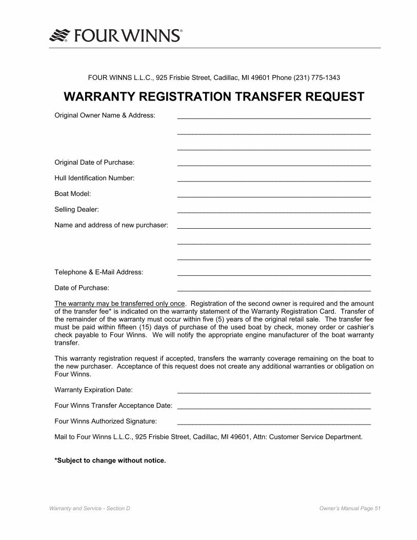
Owner’s Manual Page ��Warranty and Service - Section D
FOUR WINNS L.L.C., 925 Frisbie Street, Cadillac, MI 49601 Phone (231) 775-1343
WARRANTY REGISTRATION TRANSFER REQUEST Original Owner Name & Address: ___________________________________________________
___________________________________________________
___________________________________________________
Original Date of Purchase: ___________________________________________________
Hull Identification Number: ___________________________________________________
Boat Model: ___________________________________________________
Selling Dealer: ___________________________________________________
Name and address of new purchaser: ___________________________________________________
___________________________________________________
___________________________________________________
Telephone & E-Mail Address: ___________________________________________________
Date of Purchase: ___________________________________________________
The warranty may be transferred only once. Registration of the second owner is required and the amount of the transfer fee* is indicated on the warranty statement of the Warranty Registration Card. Transfer ofthe remainder of the warranty must occur within five (5) years of the original retail sale. The transfer fee must be paid within fifteen (15) days of purchase of the used boat by check, money order or cashier’scheck payable to Four Winns. We will notify the appropriate engine manufacturer of the boat warranty transfer.
This warranty registration request if accepted, transfers the warranty coverage remaining on the boat tothe new purchaser. Acceptance of this request does not create any additional warranties or obligation onFour Winns.
Warranty Expiration Date: ___________________________________________________
Four Winns Transfer Acceptance Date: ___________________________________________________
Four Winns Authorized Signature: ___________________________________________________
Mail to Four Winns L.L.C., 925 Frisbie Street, Cadillac, MI 49601, Attn: Customer Service Department.
*Subject to change without notice.

Owner’s Manual Page ��Warranty and Service - Section D

Owner’s Manual Page ��Engines, Drives and Instrumentation - Section E
created by exhaust fumes. Familiarize yourself with the symptoms of individuals overcome by carbon monoxide, and most importantly, ways you can protect yourself and your guests.
DO NOT inhale exhaust fumes! Exhaust contains carbon monoxide which is colorless and odorless. Carbon monoxide is a dangerous gas that is potentially lethal.
Persons overcome by carbon monoxide may exhibit the following symptoms:
a. Watering and itchy eyes b. Flushed appearance c. Throbbing temples d. Inattentiveness e. Inability to think coherently f. Ringing in the ears g. Tightness across the chest h. Headache i. Drowsiness j. Incoherence k. Nausea l. Dizziness m. Fatigue n. Vomiting o. Collapse p. Convulsions
IF YOU THINK EXHAUST FUMES ARE ENTERING YOUR BOAT, DETERMINE THE CAUSE AND HAVE IT CORRECTED IMMEDIATELY!
The following suggestions can help prevent exhaust fumes from entering the boat or injuring people in the vicinity:
1. DO NOT allow the boat to remain stationary with the engines running for an extended period of time. Do not stand or swim near the exhaust output or outdrive when the engine is idling.
2. Use extreme caution while operating the engines in confined areas such as enclosed slips, congest-ed piers, or in any area where the exhaust outlets are facing or near a bulkhead or wall structure of any kind. Operation under such conditions could easily lead to exhaust gasses (carbon monoxide) entering even though you may have all the hatches, windows, doors and portholes closed.
E - 1 GENERAL
DO NOT attempt to service any engine without being totally familiar with the safe and proper service procedures. Do not attempt to maintain or adjust an engine while it is running. Certain moving parts are exposed and failing to shut off the engine can result in serious injury or death.
Four Winns does not manufacture engines or drives. Because of the technical nature of the engine and drive systems, all manufacturers of these items require that warranty and service problems be taken directly to an authorized dealer for resolution. The Four Winns dealer from whom you purchased your boat, will handle all warranty and service matters with the engine manufacturer for you.
In compliance with the Federal Boat Safety Act of 1971 all engine manufacturers require their products to be registered. A registration card is furnished with each new engine. When selling a Four Winns® boat, the dealer, along with the purchaser, should complete the information requested on these cards and return them to the respective engine manufacturers. Engine registration cards are provided with the engine and will usually be found with the boat literature.
Each manufacturer of the various marine power components provides an owner’s information manual with their product. This publication is included with this manual. It is important that you read the manual(s) carefully and become completely familiar with proper care and operation of the engine and drive system. Be sure to read the section on winterization. Replace-ment costs associated with frozen engine blocks, drive systems and other components are quite substantial.
Also review the other sections in this manual, espe-cially Sections I on Fuel Systems, and Section F on Control Systems.
E - 2 ENGINE EXHAUST
A. Carbon Monoxide
The carbon monoxide in exhaust fumes can be hazardous. It is important for you and your pas-sengers to be aware of the potential safety hazard
Engines, Drives and Instrumentation
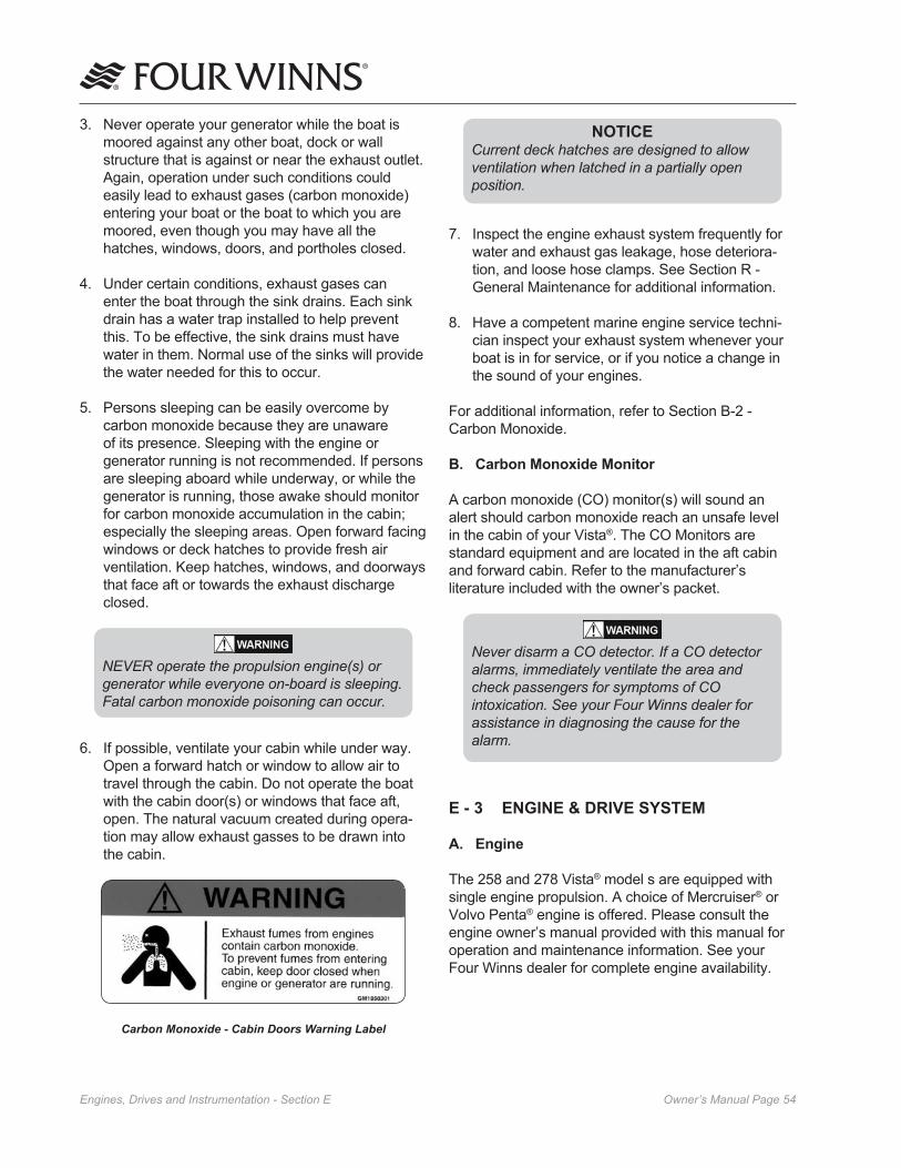
Owner’s Manual Page ��Engines, Drives and Instrumentation - Section E
NOTICECurrent deck hatches are designed to allow ventilation when latched in a partially open position.
7. Inspect the engine exhaust system frequently for water and exhaust gas leakage, hose deteriora-tion, and loose hose clamps. See Section R - General Maintenance for additional information.
8. Have a competent marine engine service techni-cian inspect your exhaust system whenever your boat is in for service, or if you notice a change in the sound of your engines.
For additional information, refer to Section B-2 - Carbon Monoxide.
B. Carbon Monoxide Monitor
A carbon monoxide (CO) monitor(s) will sound an alert should carbon monoxide reach an unsafe level in the cabin of your Vista®. The CO Monitors are standard equipment and are located in the aft cabin and forward cabin. Refer to the manufacturer’s literature included with the owner’s packet.
Never disarm a CO detector. If a CO detector alarms, immediately ventilate the area and check passengers for symptoms of CO intoxication. See your Four Winns dealer for assistance in diagnosing the cause for the alarm.
E - 3 ENGINE & DRIVE SYSTEM
A. Engine
The 258 and 278 Vista® model s are equipped with single engine propulsion. A choice of Mercruiser® or Volvo Penta® engine is offered. Please consult the engine owner’s manual provided with this manual for operation and maintenance information. See your Four Winns dealer for complete engine availability.
3. Never operate your generator while the boat is moored against any other boat, dock or wall structure that is against or near the exhaust outlet. Again, operation under such conditions could easily lead to exhaust gases (carbon monoxide) entering your boat or the boat to which you are moored, even though you may have all the hatches, windows, doors, and portholes closed.
4. Under certain conditions, exhaust gases can enter the boat through the sink drains. Each sink drain has a water trap installed to help prevent this. To be effective, the sink drains must have water in them. Normal use of the sinks will provide the water needed for this to occur.
5. Persons sleeping can be easily overcome by carbon monoxide because they are unaware of its presence. Sleeping with the engine or generator running is not recommended. If persons are sleeping aboard while underway, or while the generator is running, those awake should monitor for carbon monoxide accumulation in the cabin; especially the sleeping areas. Open forward facing windows or deck hatches to provide fresh air ventilation. Keep hatches, windows, and doorways that face aft or towards the exhaust discharge closed.
NEVER operate the propulsion engine(s) or generator while everyone on-board is sleeping. Fatal carbon monoxide poisoning can occur.
6. If possible, ventilate your cabin while under way. Open a forward hatch or window to allow air to travel through the cabin. Do not operate the boat with the cabin door(s) or windows that face aft, open. The natural vacuum created during opera-tion may allow exhaust gasses to be drawn into the cabin.
Carbon Monoxide - Cabin Doors Warning Label

Owner’s Manual Page ��Engines, Drives and Instrumentation - Section E
B. Stern Drive
A stern drive or inboard/outboard propulsion system has a piston engine equipped with special marine components mounted near the transom and coupled to an external outdrive-type transmission unit. Shifting is performed within the outdrive upper gear case. This type of system is depicted in Figure E1.
Figure E1: Stern Drive
NOTICEAlways return the engine throttle lever to the extreme low speed position before shifting. NEVER shift the unit while engine speed is above �00 rpm.
E - 4 PROPELLERS
Knowledge of the propeller is most easily gained through better understanding of the terminology used to refer to the aspects of propeller size and performance. It should be noted on most 258 and 278 Vista® models include stainless steel propellers.
A. Diameter
Diameter is twice the distance from the center of the prop shaft to the extreme tip of a propeller blade. Increasing or decreasing propeller size will have a direct bearing on the RPM’s an engine will develop.
This is due to the greater amount of propeller blade surface in contact with the water. See Figure E2.
Figure E2: Propeller Pitch & Diameter
B. Pitch
Pitch is a measure of helix angle, or angle of attack, of the rotating blade. Pitch is easily understood if one imagines the propeller rotating through a semisolid such as butter or gelatin. The distance the propeller will travel in one revolution is called “Pitch.” Increasing or decreasing pitch will also have a direct bearing on engine RPM’s because of the greater bite taken by the blade with each rotation. See Figure E2.
C. Prop Slip
When traveling through water a propeller is unable to get a complete bite because of the fluidity of water. “Prop slip” is usually expressed as a percent of the computed theoretical speed. Twenty-five to thirty-five percent prop slip is common for a cruiser-type boat operating at cruising speed.
Changing either diameter or pitch will have an effect on engine speed and prop slip, and in turn, directly effect the performance of a boat. The propellers included with each Four Winns® boat provide the best general performance based on data obtained from on-the-water testing of that model. Variations in load, operating conditions, environment, the individual engine and hull performance may necessitate the purchase and use of another propeller(s).

Owner’s Manual Page ��Engines, Drives and Instrumentation - Section E
Under your normal load conditions, the engines should turn within the maximum RPM range when at full throttle. If the engines exceed the recommended RPM, an increase in pitch or diameter is required. If the engine RPM is too low, a decrease in pitch or diameter is required.
The load carried in a boat will directly affect perfor-mance of the engine. If an engine that is not develop-ing full power, be sure the engine is properly tuned and load conditions are those normally experienced, before changing propellers.
For shipping reasons, the propellers are not factory installed. Initial installation of the propellers will be performed by the dealer during pre-delivery service. See Figure E3.
Figure E3: Prop Installation
NOTICEShould it be necessary to change propellers, always use an appropriate propeller removal tool or “Prop Puller.” DO NOT attempt removal using a hammer. Damage to the propeller or propeller shaft can result.
Always check shaft rotation before propeller installa-tion. A right hand rotation propeller must be installed on the prop shaft connected to a starboard engine. Similarly, a left hand prop must be connected to the port engine shaft. The propellers must rotate outboard not inboard.
Be sure the propellers are of the correct blade configuration, diameter, pitch, and shaft size to assure good performance. For additional information on factors affecting performance and/or assistance with your selection, please consult your Four Winns dealer.
E - 5 ENGINE COOLING SYSTEMS
A. Raw Water Cooling
Certain stern drive engines utilize a raw water cooling system. This cooling system is a seawater system. Seawater (raw) water is taken in through water inlets on the both sides of the lower gear unit of the stern drives models. Water pumped to the engine by the seawater pump is circulated through the engine by the engine circulating pump. A thermostat controls the engine operating temperature by determining the amount of water to be taken in, recirculated and discharged. The water is discharged through an idle exhaust relief and the exhaust through the propeller hub. A temperature gauge(s) located on your instru-ment panel monitors engine(s) temperatures.
Never operate your engine without a thermostat. Engine damage can occur and is considered operator negligence and therefore not covered under the engine warranty.
If engine should overheat, turn off engine, look for obstructions to water pick-up. If any obstructions are found, clear the obstructions and run engine again at ��00 RPM in neutral and check temperature gauge to verify condition. If overheating still occurs, return to port at low RPM to prevent excessive over-heating and engine damage. Consult with your certified engine dealer for service.
NOTICEWhen laying up the boat for winter it is important that the cooling system be flushed with fresh water so that deposits do not dry and to prevent the buildup of salt crystals. Please consult your engine owner’s/operator’s manual for proper engine and cooling system winterization procedures.
B. Fresh Water Cooling
Certain Vista® stern drive models include a “closed water cooling” system. This system provides adequate engine cooling without exposing the internal engine to the detrimental effects of surface water, including salt, highly polluted or silt-laden water. The engine owners

Owner’s Manual Page ��Engines, Drives and Instrumentation - Section E
The running angle can be controlled through the use of power trim (stern drives) and/or trim tabs. See Section E-8 - Trim Tabs and Section S-7 - Trimming Your Boat for information on the use of trim tabs and tilt/trim control switches.
Figure E4: Running Angle
A. Power Trim
Trim angle is how far in or out, the lower unit is positioned in relation to the bottom of the boat. The trim angle of the lower unit has a distinct affect on the running angle of the boat.
The power trim system permits control of the trim angle of the drive unit relative to the boat, at the touch of a button.
It allows the drive unit to be raised (trimmed out) for shallow water operation. Power trim also allows the operator to adjust the drive unit while underway to provide the ideal running angle for a given load and water condition. Additional information can be found in the engine owner’s manual.
manual provides additional information regarding service and maintenance of this equipment. See your Four Winns dealer for availability.
These Vista® models use surface water as a cooling medium for the heat exchanger. The cooling water employed enters the system through a water intake and is relinquished through the exhaust manifold system. Some boating areas require that additional water intake filters be installed. Reference Section P-3 - Equipment Installation, in this manual for installation instructions and consult your Four Winns dealer regarding any special equipment that may be re-quired.
Should an engine intake or an exhaust or cooling hose rupture, turn the engine off and close the seacock immediately. Proceed under tow, if necessary, to a service facility for appropriate repairs; maintain a close visual watch on the problem hose and also on the bilge water level.
E - 6 RUNNING ANGLE & POWER TRIM/TILT
Hull planing surfaces have the least amount of drag at a three to five degree angle with the water. This is the preferred running angle when boating. The running angle has a significant impact on top speed and handling. Heavy load or certain water conditions may make it difficult to achieve the optimum running angle. See Figure E4.
Owner’s Manual Page ��Engines, Drives and Instrumentation - Section E
Pressing the lower port trim tab switch will move the starboard trim tab upward. This will result in the port bow of the boat being allowed to rise.
Pressing the lower starboard trim tab switch will cause the port trim tab to move upward and will result in the starboard bow being allowed to rise.
Pressing the upper port trim tab switch will cause the starboard trim tab to move downward and will force the port bow downward.
Pressing the upper starboard trim tab switch will cause the port trim tab to move downward and will force the starboard bow downward.
Always establish your intended heading and attain desired cruising speed before trying to adjust running attitude (using the trim tabs).
Always press the trim tab switches in short one (�) second bursts. If pressed too long, you can overcompensate, and potentially lose control. DO NOT try to correct the situation by pressing the other upper trim tab switch. Instead, raise the tab slightly by pressing the appropriate lower half of the trim tab switch.
After stabilization of speed and direction, press the upper half of the appropriate trim tab switch to achieve a level side to side running attitude. Be sure to press the correct trim tab switch to obtain the desired result.
After pressing a trim tab switch, always wait and allow time for the change in trim tab position to take effect. DO NOT continue to press the trim tab switch while awaiting trim tab reaction. By the time the effect is noted, the trim tab will move too far and thus overcom-pensate.
B. Induce Planing & Controlling Trim Angle
Trim tabs can also be used to facilitate faster planing and allow better control of the running angle.
Before accelerating and trying to gain plane, press both upper trim tab switches. This will cause both trim tabs to move downward and force the bow down when running. This can also be used when running the boat with a heavy load aboard.
B. Power Tilt
Power tilt allows the operator to raise and lower the drive unit for trailering, launching, and beaching. Additional information on power tilt can be found in the engine manufacturer’s manual included with this manual.
NOTICEDO NOT operate the engine with the stern drive tilted up. Severe damage to the engine drive system can result. Consult the Engine Owner’s manual for specific information.
E - 7 TRIM TABS
Electric/hydraulic trim tabs are standard equipment and help provide maximum control of the hull in all water and load conditions. If used properly, trim tabs can:
a. Compensate for wind and load listing (level the boat side to side).
b. Induce faster planing and help achieve optimum running angle (see Section E-7 - Running Angle & Power Trim/Tilt).
The proper use of electric/hydraulic trim tabs requires a basic understanding of trim tab operation and some practice in calm water. Be sure to read the manufac-turer’s literature included in the owner’s packet.
The trim tab control uses two (2) momentary-type rocker switches. The trim tab switches control the attitude or position of the boat. The trim tab switches are labeled by position such as “Bow Up” and “Bow Down”. They are also labeled for “Port” and “Stbd”. When pressed, the label indicates what happens to the bow of the boat.
Before leaving the dock and utilizing the trim tabs, ensure the trim tabs are in the full up position. Press both lower halves of the trim tab switches and hold (for approximately 10 seconds) until the tabs are full up.
A. Control Listing
Wind, loading and many other factors can result in the boat tilting or leaning towards one side while running. This is called listing and can be negated using trim tabs.

Owner’s Manual Page ��Engines, Drives and Instrumentation - Section E
to constantly monitor the operational condition of the engine. Close observation of these instruments could save the engine from damage.
The 258 and 278 Vista® models have individual gauges in the dash panel as standard instrumentation. See Figure E5.
Figure E5: Vista Helm Station (Representative View - Models May Vary)
A. Tachometer
The tachometers indicate the speed of the engines in revolutions per minute (RPM) and are preset by Four Winns. This speed is not the boat speed or necessar-ily the speed of the propeller. They may not register zero with the ignition key in the OFF position. Note: The 258 and 278 Vista® models come with a tachom-eter/hour meter combination gauge which allows for hour meter viewing at the helm. Please refer to Section E-9J - Engine Hour Meter for information regarding the engine hour meter.
NOTICENever exceed the maximum recommended operating RPM of your engines. Maintaining maximum, or close to maximum RPM for extended periods can reduce the life of the engines.
Some engines are equipped with devices that limit engine RPM in accordance with the oil pressure or engine temperature. Refer to the engine owner’s manual for additional information.
The tachometer must be set for different engines installed. This is typically done at the factory. The tachometer gauge is shown along with the table detailing the tachometer settings. See Figure E6.
Moving the trim tabs downward will increase the lift and the boat will achieve plane faster, or stay on plane at a lower engine and boat speed.
After gaining plane and establishing cruising speed, pressing both lower trim tab switches will cause both trim tabs to move upward and will allow the bow to rise. This should be used to adjust the running attitude of the boat to decrease the drag at cruising speed or above, or when running in a following sea.When running at an engine speed that results in the boat falling off plane or causes the boat to plane inefficiently, lowering both tabs slightly (bow down) will improve the running angle and improve operating efficiency.
Optimum efficiency is obtained when operating at a 3 to 5 degree running angle. Utilizing too much “Bow Down” trim tab can reduce operating efficiency and cause substantial steering and handling difficulties. Be extremely careful when running in a following sea. The effect of trim tabs is amplified under such condi-tions. Steering and handling difficulties can result from improper trim tab usage, especially in a following sea. If unsure of proper trim tab positioning, raise the trim tabs to the full-up position.
When running at high engine speeds, be sure the trim tabs are in the full up position. Trim tab action should be only enough to compensate for any listing. Trim tab adjustments at high speeds are extremely critical. Be prepared to slow down should handling difficulties arise.
When running in a displacement (very slow speed) mode, better efficiency will be obtained with the trim tabs in the full-up position.
C. Trim Tab Maintenance
Check the fluid level of the trim tab reservoir often. Always keep the fluid level between the designated marks on the trim tab pump-reservoir. Refer to the manufacturers information for specifications on the type of fluid to be used and other operation and maintenance information.
E - 9 ENGINE INSTRUMENTATION
The helm station is equipped with a complete set of engine instruments. These instruments allow the pilot

Owner’s Manual Page �0Engines, Drives and Instrumentation - Section E
Figure E6: Tachometer - Rear View
B. Speedometer
The speedometer is a water pressure sensitive unit. It has a pick-up (pitot tube) assembly mounted on the transom and a small plastic hose (speedo tube) that connects it to the speedometer gauge on the dash. See Figure E-7. The pitot tube extends below the hull. Water strikes the tube inlet and creates positive pressure. The faster the boat speed, the greater the pressure, and the higher the speed indication on the speedometer.
Figure E-7: Speedo Sender
If the pick-up becomes clogged, the speedometer will not register. Clean the opening with a piece of wire or disconnect the tubing and blow out the pick-up with compressed air.
When winterizing the boat, the speedometer tubing must be drained of water. Disconnect the speedome-ter hose at the pick-up assembly and at the gauge and blow through the tubing to remove the water.
With the optional GPS/Navigational package the ability to monitor your speed is also available. Please refer to the manufacturer’s literature for programming the GPS unit for speed readings. This information is included in the owner’s packet when the boat is ordered with the navigation package.
NOTICESpeedometers/speed indicators are not precision instruments. The indications are relative and should never be used for naviga-tional purposes or similar critical situations alone. Use other navigation systems in conjunction with the speedometer.
NOTICEDO NOT rely on the speed indicator when trying to achieve a “NO WAKE” condition in a harbor or other enclosed waterway. ALWAYS be cognizant of the size of your waves your boat is making and reduce throttle until you are sure that they will not cause any damage. You are responsible for damage caused by the wake of your boat.
C. Temperature Gauge
The temperature gauge monitors the cooling system of the engine. A sudden increase in the temperature could be a signal of a blocked cooling passage or a water pump malfunction.
NOTICEOperation of an overheated engine can result in engine seizure. If an unusually high temperature reading occurs, shut the engine off immediately.
D. Oil Pressure Gauge
The oil pressure gauge indicates the pressure in the engine lubrication system. A drop in oil pressure is a possible indication of oil pump or leakage problems.

Owner’s Manual Page ��Engines, Drives and Instrumentation - Section E
H. Gas Vapor Detector
A gas vapor detector is optional equipment on the 258 and 278 Vista®. If equipped, the gauge mounts in the dash. Additional information can be found in Section I-1H - Gas Vapor Detector in this manual.
I. Engine Hour Meter
Engine hour meters are standard on the 258 and 278 Vista® models and provides a numeric record of elapsed engine operating time. This information is important in determining scheduled maintenance intervals, ships log data, cruise information, etc. The hour meter is located at the helm with the tachometer/hour meter combination gauge.
J. Ignition Switch
The ignition switch has three positions: OFF, RUN, and START. The START position is spring loaded and the key should be held in this position until the engine starts. The key will return to the RUN position once released. Always turn the key to the OFF position when the engine is not running. This will prevent discharging of the batteries. Additional information on ignition switch operation is covered in Section A - Operation of this manual.
K. Emergency Stop Switch
This safety device automatically stops the engine if the lanyard is attached to the operator and the operator falls from his work station. Refer to the engine manual for detailed information about using this switch.
The emergency stop switch (Figure E-8) incorporates a shutoff switch, switch clip, lanyard, and lanyard clip. The lanyard clip must be securely attached to the operator’s PFD, clothing, arm, or leg. Be sure to attach the lanyard to a place where it is free of ob-structions and to something that will move with the operator if he or she leaves the helm station. If the engine shuts down because this switch was activated, the clip may have to be reinstalled on the interrupter switch before the engine can be started.
NOTICEOperation of an engine with abnormally low oil pressure can lead to engine damage and possible seizure. Have the engine serviced immediately upon a reduced oil pressure indication.
E. Voltmeter
The voltmeter monitors battery condition and thus alternator performance. See Section H - Electrical Systems for additional information on voltmeter operation.
F. Fuel Gauge
The fuel gauge displays the level of fuel that is present in the fuel tank. Refer to Section I - Fuel System for additional information.
Due to the mechanical nature of the fuel sender, varia-tions in readings during various speeds of operation may occur. This system is merely a relative indication of the available fuel supply and not a calibrated instrument. Refer to Section I-1F - Fuel Senders for additional information.
NOTICEFuel gauges are not precision instruments. The reading is relative, and should never be relied upon as the sole indicator of fuel availability.
NOTICEUse only clean, dry fuel of the type and grade recommended by the engine manufacturer. The use of incorrect or contaminated fuel can cause engine malfunction and serious damage. Refer to Section I - Fuel System for additional information.
G. Power Trim Gauge
The 258 and 278 Vista® models equipped with stern drives have a “power trim gauges.” This gauge provides a visual indication of the inward-outward (trim angle) position of the outdrive. There is not a trailer travel mode on the gauge.

Owner’s Manual Page ��Engines, Drives and Instrumentation - Section E
Keep emergency stop switch lanyard free from obstructions that could interfere with its operation. Do not modify or remove emergency stop switch or bypass its safety features. The proper use of the emergency stop switch will prevent a runaway boat situation which can cause severe personal injury or death.
Figure E-8: Emergency Stop Switch The emergency stop switch can only be effective when in good working condition. Observe the following:
1. Lanyard must always be free of entanglements that could hinder its operation.
2. Once a month, check the switch for proper operation. With engine running, pull lanyard. If the engine does not stop, see your Four Winns Dealer.
3. Once a month, inspect both the clip and lanyard for cuts, breaks or wear. Replace worn or dam-aged parts.
In an emergency situation, any occupant of the boat can restart the engine. Just press in and hold the emergency stop switch button, then follow normal starting procedures. When the button is released, the engine will stop.
Avoid knocking or pulling the clip or lanyard from the switch during regular boating opera-tion. Occupants may be thrown forward or possible engine damage may occur by the sudden loss of engine power.
L. Alarm System
The 258 and 278 Vista® models have an engine alarm system installed. This is an audible alarm that is mounted in the helm area; it is actuated by engine water temperature and engine oil pressure senders. The alarm will sound in the event of low engine oil pressure or high engine coolant temperature.
The engine alarm will sound during engine start-up, or whenever the ignition switch is positioned to ON and the engine is not operating. The alarm sounds under these conditions because engine oil pressure is low; the alarm will cease to sound as soon as engine oil pressure rises to the proper level.
NOTICEThe engine alarm monitors only engine water temperature and engine oil pressure. Always maintain a close visual watch on the drive(s), transmission(s), engine fluid levels, bilge water level, etc. Refer to the engine manufacturer’s literature for additional information.
M. Navigational Equipment
Four Winns offers a navigational package as an option. See Figure E9. Please consult the manufactur-er’s literature included in the owner’s packet for operation and maintenance of these navigational systems (if installed).
NOTICEFour Winns does not limit you to this specific navigational package mentioned above. There are many navigational systems on the market today. You may desire to use a different system based on your needs, personal preference, and mounting space available.
NOTICEFour Winns continually strives to improve its products. Unit specifications, including standard and optional equipment are constantly being modified. Equipment availability is also subject to change. The most current and accurate information available at the time of publication is included in this manual. Some variation in equipment, description, location, and details can result.
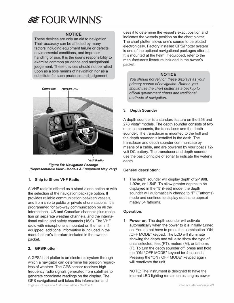
Owner’s Manual Page ��Engines, Drives and Instrumentation - Section E
uses it to determine the vessel’s exact position and indicates the vessels position on the chart plotter. The chart plotter allows one’s course to be plotted electronically. Factory installed GPS/Plotter system is one of the optional navigational packages offered. It is mounted at the helm. If equipped, refer to the manufacturer’s literature included in the owner’s packet.
NOTICEYou should not rely on these displays as your primary source of navigation. Rather, you should use the chart plotter as a backup to official government charts and traditional methods of navigation.
3. Depth Sounder
A depth sounder is a standard feature on the 258 and 278 Vista® models. The depth sounder consists of two main components, the transducer and the depth sounder. The transducer is mounted to the hull and the depth sounder is installed in the dash. The transducer and depth sounder communicate by means of a cable, and are powered by your boat’s 12-volt DC battery. The transducer and depth sounder use the basic principle of sonar to indicate the water’s depth.
General description:
1 The depth sounder will display depth of 2-199ft, 1-92m, or 1-54F. To allow greater depths to be displayed in the “ft” (Feet) mode, the depth sounder will automatically change to “F” (Fathoms) mode and continue to display depths to approxi-mately 54 fathoms.
Operation:
1. Power on. The depth sounder will activate automatically when the power to it is initially turned on. You do not have to press the combination “ON /OFF MODE” keypad. The LCD will illuminate showing the depth and will also show the type of units selected, feet (FT), meters (M), or fathoms (F). To turn the depth sounder off, press and hold the “ON / OFF MODE” keypad for 4 seconds. Pressing the “ON / OFF MODE” keypad again will reactivate the unit.
NOTE: The instrument is designed to have the internal LED lighting remain on as long as power
.
NOTICEThese devices are only an aid to navigation. Their accuracy can be affected by many factors including equipment failure or defects, environmental conditions, and improper handling or use. It is the user’s responsibility to exercise common prudence and navigational judgement. These devices should not be relied upon as a sole means of navigation nor as a substitute for such prudence and judgement.
Compass
VHF Radio
GPS/Plotter
Figure E9: Navigation Package (Representative View - Models & Equipment May Vary)
1. Ship to Shore VHF Radio
A VHF radio is offered as a stand-alone option or with the selection of the navigation package option. It provides reliable communication between vessels, and from ship to public or private shore stations. It is programmed for two-way communication on all the International, US and Canadian channels plus recep-tion on separate weather channels, and the interna-tional calling and safety channels (16/9). The VHF radio with microphone is mounted on the helm. If equipped, additional information is included in the manufacturer’s literature included in the owner’s packet.
2. GPS/Plotter
A GPS/chart plotter is an electronic system through which a navigator can determine his position regard-less of weather. The GPS sensor receives high frequency radio signals generated from satellites to generate coordinate readings on the display. The GPS navigational unit takes this information and

Owner’s Manual Page ��Engines, Drives and Instrumentation - Section E
is supplied even if the unit is turned “off” at the keypad.
2 Depth alarm – Shallow mode: Pressing the “ON / OFF MODE” keypad again displays the “SH” shallow depth alarm setting. This is the shallowest water that will activate the alarm. Press and hold the up or down arrow keypads to adjust the reading to the desired depth.
Depth alarm – Deep mode: Pressing the “ON /
OFF MODE” keypad again displays the “DP” deep depth alarm setting. This is the deepest water that will activate the alarm. Press and hold the “Up” or ‘Down” arrow keypads to adjust the reading to the desired depth. When the shallow depth setting is read by the depth sounder, the “SH” will flash on the LCD and the audible alarm will sound rapidly. When the deep depth setting is read by the depth sounder, the “DP” will flash on the LCD and the audible alarm will sound at 2 beeps per second.
NOTE: To fully deactivate an alarm, reset it to zero. Pressing the “ON / OFF MODE” keypad temporarily deactivates the alarm. To reactivate the alarm press the “ON / OFF MODE” keypad until the depth reading appears.
3. Keel offset. Pressing the “ON / OFF MODE” keypad again displays the “KL” keel offset setting. This can be set so that the depth sounder either shows the depth below the keel or the depth below the transducer. Press the up or down arrow keypads to adjust the reading to the desired depth no more than 19.9 ft. For example if the bottom of the keel is 2 feet below the transducer and you want the depth sounder to read the depth below the keel, the display should be adjusted to read 2.0 FT.
NOTE: Once a keel offset is programmed, the shallow and deep alarms will be activated by the depth below the keel.
4. Units. pressing the “ O N / O F F MODE” keypad again displays “Un” on the LCD indicating the units mode. Press either the up or down arrow keypads to set the units desired to feet (FT), meters (M), or fathoms (F). These units once set, will remain the same for all modes. Pressing the “ON / OFF MODE” keypad again returns the depth sounder to normal operation.
Do not rely on depth sounder to avoid submerged objects. Depth sounders provide a relative indication of water depth only.
NOTICEDO NOT depend solely upon the depth sounder for water depth. It is important to have navigational charts of the waters in which you are operating.
4. Compass
A compass is standard on the 258 and 278 Vista® models. See Figure E10. The compass can provide directional information when operating offshore, in unfamiliar waters, or in adverse weather conditions.
Figure E10: Compass
After all personal equipment is installed, including all electronics (VHF radio, GPS, chart plotter, etc.), the compass must be properly calibrated. DO NOT rely on the compass readings until initial adjustment (compensation) has been performed. The boat has a factory installed compass, the manufacturer’s instruc-tions are provided in the owner’s packet. Most areas have local companies that specialize in compass adjustment. If unsure of the proper compensation techniques, consider having the adjustment done professionally to insure accuracy and confidence in the compass.
NOTICEDuring use, keep all extraneous metal objects away from the compass. The close proximity of metal objects (e.g., beverage cans) can cause compass deviation.

Owner’s Manual Page ��Engines, Drives and Instrumentation - Section E
N. Instrument Maintenance
Electrical protection for instruments and ignition circuitry is provided by a circuit breaker on the ignition panel. Periodically, spray the ignition switches with a contact cleaner. The ignition switches and all instru-ments, controls, etc. should be protected from the weather when not in use. Four Winns offers appropri-ate weather covers for each model. Excessive expo-sure can lead to gauge and ignition switch difficulties.
DO NOT use a product such as WD-�0 as a contact cleaner. Be sure to read the label before using any product.
Electronic gauges are affected by static electricity that builds-up on the glass face. Periodic washing of the gauge face with warm water and mild liquid detergent will help eliminate the static electricity problem and improve gauge accuracy.

Owner’s Manual Page ��Control Systems - Section F
F - 1 GENERAL
Control systems permit operation of the engine’s throttle and shift mechanisms. Typically, they consist of three major components; the control, the throttle and shift cables.
The 258 and 278 Vista® stern drive models are equipped with single engine side-mount control with trim. See Figures F1 and F2. The left lever controls the port engine and the right lever controls the star-board engine. Moving the lever forward will shift the drive into forward. Moving it aft will shift the drive into reverse. Moving the lever further will increase engine speed.
Figure F1: Dual Engine Binnacle Control
Figure F2: Helm Station
NOTICEAllow the engine to warm up before engaging the shift control. Monitor all instruments while engine is idling during warm-up.
F - 2 CONTROL OPERATION
A. General
NOTICEThe control information included in this section is general only. For specific operation of the controls on your boat, refer to the control manufacturer’s literature and engine manufacturer’s literature included in your owner’s packet. Ensure you completely understand the operation of the controls before operating your boat. Also consult your dealer should any questions arise regarding the operation of the control unit.
NOTICEIf your boat is equipped with a non-OEM remote control system, ask your dealer how to properly operate it.
NOTICEReduce throttle as soon as motor starts. Do not run a cold motor any faster than necessary to keep motor from stalling. Do not exceed �000 RPM in NEUTRAL.
B. Maneuvering of Side-Mount Control
Shifting and engine speed are controlled with the same lever (1). See Figure F3.
N - Neutral position. Drive/Reverse gear dis- engaged.
F - Drive/reverse gear engaged for forward movement (ahead). R - Drive/reverse gear engaged for backward movement (astern).
T - Engine speed control.
Trim/Tilt Switch - Push top of switch or where indicated to trim out and tilt up, or push bottom of switch or where indicated to tilt down and trim in.
Control Systems

Owner’s Manual Page ��Control Systems - Section F
Figure F3: Side-Mount Control Operation
To disengage the shift function:
1) Move lever (1) to the neutral position (N).
2) Press in button (2), press the gear shift release lever and move the lever slightly forward and release the button.
The shift function is now disengaged the lever only effects engine speed. When the lever is moved back to the neutral position it will automatically re-engage the shift function. The shift function is then enabled.
C. Shifting and Control Speed
1. Move shift/throttle lever(s) to the neutral idle position. Placing the shift/throttle levers in the neutral detent position will engage neutral start switch and allow engine to start.
NOTICEFor additional information, refer to the section on “Starting and Operation” in the engine manu-facturer’s manual.
DO NOT shift into FORWARD or REVERSE unless engine is running. Damage to the shift system could result from trying to shift without the engine running. Carefully check function of all control and engine systems before leaving the dock.
2. To go FORWARD - move the shift/throttle lever(s) forward. Once forward gear engagement is complete, push shift/throttle lever(s) forward until desired speed is achieved.
3. To go in REVERSE - move the shift/throttle lever(s) rearward. Once rearward gear engage-ment is complete, push shift/throttle lever(s) rearward until desired speed is achieved.
DO NOT shift from forward to reverse when the boat is planing.
NOTICEDO NOT shift if engine speed is above �00 RPM.
4. To go from FORWARD to REVERSE, or RE-VERSE to FORWARD; always pause at NEU-TRAL and allow engine speed to return to idle.
5. After shifting is completed, slowly push throttle lever(s) forward/rearward until desired speed is achieved.
Any time the boat is operated, be aware of changes in shift system operation. A sudden increase in shift effort of the shifter levers, or other abnormal operation, indicates a possible problem in the shift system. If this occurs, the following precautions must be taken:
• With engine running and boat securely tied to the dock, shift drive into forward and reverse to ensure there is gear engage-ment.
• When docking the boat, all docking maneu-vers must be performed at slow speed. Pay special attention to other boaters. Passen-gers should be informed of potential problems and precautions taken.
Trim/Tilt Switch

Owner’s Manual Page ��Control Systems - Section F
If you suspect there is a problem, see your MerCruiser® or Volvo Penta® dealer as soon as possible for proper diagnosis and required service or adjustment. Continued operation could result in damage to the shift mechanism and loss of control.
F - 3 NEUTRAL SAFETY SWITCH
Every control system has a neutral safety switch incor-porated into it. This device prohibits the engine from being started while the shift lever is in any position other than the neutral position. If the engine will not start, slight movement of the shift lever may be necessary to locate the neutral position and disen-gage the safety cutout switch. Control or cable adjustments are required to correct this condition should it persist. See your Four Winns dealer for necessary control and cable adjustments.
F - 4 CONTROL SYSTEM MAINTENANCE
Periodic inspections of the controls, cables, and all connections should be made. Signs of looseness, rust, corrosion, wear, cable jacket cracks or other deterioration require immediate system servicing. Replace all damaged components.
Generally, periodic lubrication of all moving parts and connections with a light, waterproof grease is in order. Cables can be lubricated by positioning them to their fullest extension and applying light grease to the inner cable near the jacket. Working the cables back and forth will distribute the grease in the inner cable. Reapply the grease if necessary.
Lubrication should be performed as often as neces-sary to keep the system operating smoothly. Cable manufacturers such as Teleflex and Morse often offer special tools to make cable lubrication easier.
Cable and control adjustments may become neces-sary. Adjustment screws in the control, on the cables and in the linkage are provided.

Owner’s Manual Page ��Steering Systems - Section G
B. Rotary Steering
In the rotary system, a rotary drum assembly is mounted under the dash behind the steering wheel. A one piece cable runs from the drum assembly through the boat into the engine compartment. At the transom, the cable turns and is connected to the drive tiller and the power steering unit.
C. Power Steering
Power steering is featured on these Vista models and is comprised of an engine-mounted pump, hoses and steering cylinder. Power steering works in conjunction with the helm and steering cable to move the transom mount tiller arm and vertical drive more smoothly.
This is a “power assist” system and can greatly reduce steering effort required. It is not, however, a full power steering system as is used in automobiles. Some steering tension remains in the system.
On these models with power steering, restricting movement of the steering cable will limit or stop the steering system’s hydraulic assist.
NOTICEDO NOT interfere with or restrict steering cable movement through the last �0o of bend at the engine. DO NOT use cable retainers, clamps or tie straps. Using one or all of these could restrict the cable movement near the engine. DO NOT tie wiring harnesses or other control cables to the steering cable. Make sure the deck coaming pads and bulkheads allow for steering cable movement in all positions of trim.
If the power steering becomes inoperative, steering will be harder and more effort will be needed to steer the boat. Check for a broken or loose belt on the power steering pump. Also, low fluid levels in the power steering pump reservoir will cause hard steer-ing. If these items are not the source of the problem, check for equipment or other items lying on or up against the steering cable at the back of the boat. The cable must be free and clear to slide back and forth. Any item blocking free movement of the cable will result in harder steering and possible damage to the steering cable.
G - 1 GENERAL
The stern drive Vista® models are equipped with rotary-type steering systems. A tilt steering wheel is standard on the 258 and 278 Vista® models.
A. Tilt Steering
The steering wheel can be tilted up or down so as to enhance the driver’s comfort and enjoyment. To tilt the steering wheel, depress the release lever with your thumb. See Figure G1. Be sure to hold the top of the wheel to assist in positioning. Refer to the steering manufacturer’s literature for additional information.
Figure G1: Tilt Steering
The tilt mechanism should not be adjusted when the boat is moving. Sudden boat move-ment may cause loss of balance resulting in loss of control and/or injury.
The tilt mechanism is spring loaded. Due to the variation in steering wheel offerings, the wheel may spring up rapidly when depressing the release lever. ALWAYS KEEP ONE HAND ON THE WHEEL DURING TILT ADJUSTMENT OR INJURY MAY OCCUR.
Steering Systems

Owner’s Manual Page �0Steering Systems - Section G
If the power steering system cannot be corrected on board, proceed at a reduced speed. The boat will be steerable, but with increased effort. Return the boat to your Four Winns dealer as soon as possible to correct the power steering system.
Check the fluid level in the reservoir periodically. Low power steering fluid levels may increase steering difficulty.cables to the steering cable. Make sure the deck coaming pads and bulk-heads allow for steering cable movement in all positions of trim.
After the first two hours of running time, check the entire steering system for loose bolts, nuts and fasteners which could adversely affect steering control.
NOTICEWhen storing equipment in the engine compart-ment, be sure to avoid contact with the steering cable. Cables may become kinked or damaged and may increase steering effort.
NOTICEDO NOT force the steering unit to either extreme. This can place undue strain on the unit and can lead to hydraulic line or seal failure.
It is important that the power steering fluid be main-tained at the proper level. Do not over fill the power steering pump reservoir. Please consult the section in the engine manual regarding steering system and maintenance. The engine manual is included in the owner’s packet.
G - 2 PROPELLER TORQUE
The propeller rotation of a single engine operation will exert a directional force on the steering system. This can cause the steering to be harder in one direction than the other, and is called propeller torque. If this occurs, adjust the drive or trim tabs as neces-sary. Refer to the engine manual, included in the owner’s packet, for information on adjusting the trim tab.
Propeller torque can also cause the boat to wander (not follow a straight line) when operated at low speeds. This condition is normal and can be corrected only by increasing engine RPM. Wind, water currents and play in steering components can cause equivalent effects.
Steering effort can vary significantly with engine acceleration, steering angle, trim angle, and sea condition. Be prepared for additional steering loads at all times.
G - 3 STEERING SYSTEM MAINTENANCE
A. General Maintenance
A periodic inspection of all steering cables, linkage and helm assemblies should be made. Signs of corrosion, cracking, loosening of fastenings, excessive wear, or deterioration should be immediately correct-ed. Failure to do so could lead to steering system failure and corresponding loss of control.
NOTICECheck all bolts, nuts and fasteners for tightness.
B. Rotary System Maintenance
The helm and cable assembly should be so adjusted that the steering wheel is centered with the drive or outboard engine in the straight ahead position. There should be an equal number of turns to port and starboard from the straight ahead position. If adjustment becomes necessary, see your Four Winns dealer.
Check all metal parts at the cable output end for corrosion. Remove any old grease from the cable ram and motor swivel connections using a mild solvent such as WD-40. Spray the cleaned areas with a moisture-displacing lubricant and apply a light coat of good quality marine grease. Do this with the ram fully extended. See Figure G-2.

Owner’s Manual Page ��Steering Systems - Section G
Figure G-2: Steering Cable
C. Winter Storage
If the boat is placed in winter storage or used infrequently, clean the cable ram as instructed earlier. Cycle the steering several times when applying lubricant. If at any time the steering system becomes stiff, has an excessive amount of freeplay or shows any change in its operating characteristics, contact your Four Winns dealer to have the system inspected.

Owner’s Manual Page ��Electrical Systems - Section H
A. Installation
1. Connect each of the red (positive) battery cables leading from the battery selector switch to the positive (+) terminal on each of the two batteries. Refer to Figure H1.
Figure H1: Dual Battery Systems
NOTICE Be sure the two red (positive) cables are in- stalled on the positive (+) battery terminals.
2. Connect each of the black (negative) battery cables leading to the engine block to the negative (-) battery terminal on each of the two batteries.
When disconnecting the cables from the battery, make sure all switches are off and disconnect the black negative cable(s) first to prevent spark.
H - 1 GENERAL
All electrical equipment on the Four Winns 258 & 278 Vista® models operates on 12 volts DC or 120 volts (220 volts on 50 Hertz models) AC electrical power. The 258 and 278 Vista® models are equipped with dual battery systems along with dockside power (including battery charger) as standard features. Batteries are located in the engine compartment.
Fire or Explosion Hazard!Electrical system parts are designed by and manufactured to comply with the US Coast Guard requirements to minimize risks of fire or explosion. Never substitute automotiveparts for marine parts. Automotive parts donot provide the necessary ignition spark protection.
DO NOT tamper with any electrical connection, panel or harness, or attempt installation of any electrical equipment unless thoroughly familiar with the systems and experienced in making such installations.
Circuit breakers are installed on the battery switch to protect various system components. The SHIP SYS-TEMS breaker supplies power to all DC electrical components except the aft bilge pump and forward bilge pump (if applicable), stereo, ignition, and instru-mentation. Additional breakers are located in the cabin circuit breaker panel. The circuit breakers and/or fuses are labeled for amperage and use.
The dash components are protected by a fuse panel. Refer to Figure to the wiring schematics in the back of this manual.
H - 2 SINGLE ENGINE - DUAL BATTERY SYSTEM
A battery selector switch is installed on the dual battery system. This allows DC power to be used from either one or both batteries. Refer to the schematics in the back of the manual.
Electrical Systems
258 Vista
278 Vista

Owner’s Manual Page ��Electrical Systems - Section H
B. Operation - Single Engine w/ Dual Battery System
Power to the engines and all 12 volt electrical equip-ment is controlled at the battery selector panel. On certain Vista® models, separate circuit breakers are provided on the battery selector switch panel to protect the windlass (if applicable), forward and/or aft bilge pump, stereo, 12 volt receptacle, and ship systems (if applicable). Note: The quantity and use of circuit breakers may vary depending upon the Vista® model, equipment availability and battery selector switch panel used.
1. 1, 2 & BOTH Position Battery Selector Switch - 258 Vista®
A description of the various positions for this battery switch is as follows:
“OFF” - With the battery selector switch in the “OFF” position, all 12 volt power to the engine is shut off except to the automatic bilge pump, stereo and 12 volt receptacle. Circuit breakers are provided on the battery selector switch panel to protect the aft bilge, and stereo. Always turn the battery selector switch and the ship systems breaker switch (if applicable) to the “OFF” position when the boat is unattended for an extended period.
NOTICE DO NOT turn the battery selector switch to the “OFF” position while the engine is running. Alternator and wiring damage could result.
1” - Turning the switch to position “1” will use battery #1 to power the engine and 12 volt equipment. Battery #2 will be isolated and remain in reserve. Only battery #1 will be charged by the alternator.
“2” - Turning the switch to position “2” will use battery #2. Battery #1 is isolated and remains in reserve. Only battery #2 will be charged by the alternator.
“BOTH” - With the battery selector switch in the “BOTH” position, the batteries are connected in parallel. Both batteries will be used by the engine and all 12 volt equipment. Both batteries will be charged by the alternator. However, the batteries will charge at a slower rate compared to setting the switch in the other positions.
The use of one battery at a time is recommended. Position the battery selector switch to either the #1 or #2 position.
Under normal conditions, avoid using the “BOTH” position. Use the “BOTH” position only when a single battery is not capable of starting the engine.
If one of the designated engine batteries fails to start its respective engine, engage the “EMERGENCY START” switch at the helm and attempt to start the engine. Current is drawn from the other batteries to start the engine. Once engine has been started return the “EMERGENCY START” switch to the “OFF” position. Once back at port, be sure to have the failed engine battery checked out for possible service or replacement.
Four Winns recommends alternating between batter-ies during boating. Depending upon boating use, this may increase battery longevity . Use battery #1 for the first day of a cruise and switch to battery #2 on the second day.
Position the battery selector switch to the battery that has sufficient power to start the engine (normally position “1”). After the engine is running, turn the battery selector switch to the battery that has the lowest charge. This will allow the alternator to charge the low battery. Utilizing the battery selector switch in this manner (instead of using the “BOTH” position) will supply a greater charge to the battery.
FOR EXAMPLE: If battery #1 is fully charged and battery #2 is in need of a charge, use battery #1 to start the engine. After the engine is running and warmed-up, turn the battery selector switch to the #2 position. This will permit the alternator to charge the low, #2 battery.
2. OFF/ON Battery Switch Operation - 278 Vista®
A description of the various positions for this battery switch is as follows:
“OFF” - With the battery selector switch in the “OFF” position and the “SHIPS SYSTEMS” circuit breaker in the “OFF” position, all 12 volt power to the boat is shut off except to the automatic bilge pumps, stereo and windlass (if applicable). Always turn the battery selector switch and the ship systems breaker switch (if applicable) to the “OFF” position when the boat is unattended for an extended period.

Owner’s Manual Page ��Electrical Systems - Section H
H - 4 VOLTMETER
A single gauge with voltmeter is installed in the dash panel to monitor the condition of the engine battery(s). When the voltage is checked during engine operation, the voltage of the battery will be indicated on the voltmeter. Additional information on voltmeters may be found in the engine owner’s manual.
H - 5 12 VOLT ELECTRICAL EQUIPMENT
A. Helm Equipment
Ignitions are protected by circuit breakers on the 258 & 278 Vista® models. Other equipment is protected by fuses located in the fuse block at the helm, below the dash, on the starboard side.
To assist you, we have listed the descriptions of individual switches, receptacles and their uses:
To prevent electrical problems, use only replacement fuses or breakers that are of equal rating to the originals.
Accessories - Additional 12 volt equipment may be added to the boat by the using the accessory switch-es. Depending on the model, certain accessories may be wired directly to the fuse block below the dash. For additional information on adding accessories, refer to Section H-5B.
12 Volt DC Receptacle - Permits the use of additional 12 volt equipment such as a cell phone. Using the appropriate adaptor, the equipment draws power from the boat’s battery.
Aft Bilge Pump - The BILGE PUMP switch is used to manually activate the bilge pump in the engine compartment. The bilge pump is used to remove water from the bilge (bottom of the hull) area of the boat by pumping that water overboard. The aft bilge pump is equipped with an automatic bilge switch and will operate whenever bilge water rises to a level that will cause the float to move upward.
This automatic bilge pump is active even if the battery selector switch is in the “OFF” position. The automatic bilge pump is connected directly to the battery and is protected by a circuit breaker located on the battery switch panel. When leaving your boat unattended for
NOTICE Twelve volt power to the cabin panel is supplied by the “SHIPS SYSTEMS” circuit breaker on the battery selector panel. This must be turned on to operate any 12 volt accessories on the cabin panel. The bilge pumps and stereo receive power from the ships system battery and remain on at all time regardless of battery selector or ship systems switch position.
NOTICE DO NOT turn the battery selector switch to the “OFF” position while the engine is running. Alternator and wiring damage could result.
“ON” - Turning the switch to position “ON” will use the engine battery to power the engine and 12 volt engine related equipment. The ships system battery will not be used for any engine related equipment, but will power all other 12 volt equipment on the boat (when “SHIP SYSTEM” circuit breaker is on). The isolator will allow the alternator to fully charge the two batter-ies, but not allow the operator to drain down the engine start battery.
If the designated engine battery fails to start the engine, engage the “EMERGENCY START” switch at the helm and attempt to start the engine. Current is drawn from both batteries (the engine and ship’s systems batteries) to start the engine. Once engine has been started return the “EMERGENCY START” switch to the “OFF” position. Once back at port, be sure to have the failed engine battery checked out for possible service or replacement.
H - 3 BATTERY CHARGER
The battery charger is standard on the 258 and 278 Vista® models and is located in engine compartment. The batteries will be charged by the battery charger when the boat is connected to dockside power and the AC circuit breakers are “ON”. If a generator is available and operating, it too will allow the batteries to be charged by the battery charger.
Additional information on the battery charger can be found in Section H-8B - 120 Volt AC Equipment in this manual and refer to the manufacturer’s literature included with the owner’s packet.

Owner’s Manual Page ��Electrical Systems - Section H
Wiper (Starboard) - This feature is either standard or optional depending upon on Vista® model. The WIPER switch activates the windshield wiper. The wiper will self park.
B. Installation of Additional 12 Volt Equipment
Non-factory installed 12 volt accessory equipment may be connected to the “ACC” switch(s) on the dash.
Be sure to provide proper fuse or circuit breaker protection for all �� volt equipment that is installed. DO NOT overload the accessory circuitry by installing too much additional �� volt equipment.
C. Interior Equipment
CO Monitor - The CO monitors are protected by the fuse in the fuse block at the helm.
Cabin Lights - To turn the cabin lights on, activate the CABIN LIGHTS “ON/OFF” switch located on cabin lights panel to activate.. Additional cabin light “ON/OFF” switches may be located in various areas of the cabin i.e. forward berthing area.
Forward Bilge Pump (278 Vista® only) - The forward bilge pump can be activated manually by placing the FORWARD BILGE switch in the “ON” position. This forward bilge pump switch is located on the cabin lights switch panel in the cabin. Additionally, a forward bilge circuit breaker is located on the 278’s battery switch panel
Any water from the stringers or from other sources within the 278 Vista® cabin will drain into the forward bilge compartment. The pump is equipped with an automatic float switch and will operate whenever bilge water rises to a level that will cause the float to move upward. The water will be pumped overboard.
Pressure Water - A pressure water pump delivers water to the sink faucet, shower and transom wash-down. The pressure water pump will operate automatically as long as the FRESH WATER switch, located on the cabin lights switch panel, is in the “ON” position. The fresh water pump is protected by a fuse located in the fuse block.
an extended period, check the charge on the battery(s) periodically. Also check the water level in the bilge and make sure the float switch is functional.
If the automatic bilge pump must be disabled, discon-nect the wiring plug near the bilge pump.
Blower - The BLOWER switch is used to activate the bilge blower. Pressing the switch to the “ON” position, activates the electric bilge blowers, changing the air in the engine compartment that may contain gas vapors.
Gasoline vapors can explode resulting in injury or death. Before starting the engine, check engine compartment bilge for gasoline or vapors. Operate blower for four minutes, and verify blower operation. ALWAYS run the blower when the vessel is operating below cruising speed.
Cockpit Lights - The COCKPIT LTS switch is used to activate the cockpit (courtesy) lights. An additional cockpit light switch is typically located on the cabin light switch panel.
Horn - To sound the horn, press the HORN switch.
Navigation & Anchor Lights - Moving the NAV/ANC LTS switch towards the NAV position activates the bow lights, the all-around light and the instrument lights on the dash. Move the switch to the ANC position to activate the all-around light. The center switch position is “OFF”.
Trim Tabs - The boat is equipped with electric-hydraulic trim tabs, the trim tabs are controlled by the TRIM TAB switches. Refer to Section E-8 - Trim Tabs for more information.
Windlass (Optional 278 Only) - The WINDLASS switch activates the windlass. A circuit breaker is located on the battery switch panel. Refer to the Section M-12 in this manual and the manufacturer’s literature for additional information.
Engine Hatch - The ENGINE HATCH switch is used to raise and lower the engine lid by activating a linear screw jack. Pressing the upper portion of the switch marked “UP” allows the engine lid to be raised. Pressing the lower portion of switch marked “DOWN” lowers the engine lid.

Owner’s Manual Page ��Electrical Systems - Section H
Turn the FRESH WATER switch “OFF” when the water tank becomes empty or when water will not be required for an extended period or when connected to shore water while at dockside. A tank monitoring system is optional to check water level. Refer to Section J-1 and J-2 in this manual for additional information.
Stereo - The stereo has a separate switch on the unit and is protected by a circuit breaker labeled STEREO on the battery switch panel. A fuse located in the helm fuse block helps to protect the circuitry.
Sump Pump - A sump pump is used to discharge water from the shower and sink drains overboard. The sump pump has a float switch which will activate the pump when the water level rises to a certain level in the sump. The sump pump is connected directly to the battery and is protected by a circuit breaker located on the battery switch panel for the bilge.
If the boat is equipped with a grey water system, the water from the shower and sinks is pumped into a holding tank instead of overboard.
H - 6 12 VOLT ELECTRICAL SYSTEM SHUTDOWN PROCEDURES
When leaving your boat unattended for an extended period of time it is advisable to shutdown the electrical system to reduce battery drainage and/or possible electrical draw.
To shutdown:
1. Turn the battery switch(s) to the “OFF” position.
2. If your battery switch has a SHIP SYSTEMS circuit breaker switch, move the switch to the “OFF” position.
H - 7 120 (220) VOLT ELECTRICAL SYSTEM
The boat is equipped with 30 amp, 120 volt, 60 Hertz (or 15 amp, 220 volt, 50 Hertz) AC electrical wiring. When the boat is connected to a shore power outlet, the AC system supplies electrical power to the following items: battery charger, galley refrigerator, water heater, range, microwave, outlets, and air condi-tioning (if applicable). The dockside system uses three-wire, color-coded circuitry. The black or hot wire is the ungrounded current carrying conductor. The white or neutral wire is the grounded current carrying
conductor. The green wire, referred to as the “equip-ment ground,” is a grounded conductor, and under normal conditions is not a current carrying wire. The neutral wires are connected together at a buss bar. The equipment grounds are similarly connected together at another buss bar. Each hot wire is con-nected to, and protected by, a circuit breaker in the distribution box located in the AC cabin panel identi-fied “120V 60Hz”.
The SHORE POWER dockside inlet is located on the port side of the deck. The standard dockside system has a main circuit breaker which protects the overall distribution network. The 258 and 278 Vista® models have SHORE POWER (main) circuit breakers on the 120V AC cabin panel. In order to have AC system operation, the SHORE POWER breakers must be turned “ON” and the boat must be connected to shore power or have the generator (if applicable) running and generator breakers “ON”.
The SHORE POWER circuit breakers protects both the hot and neutral input leads. This breaker is sensitive. The resulting power surge which occurs when connecting the shore power cord may cause the SHORE POWER breakers to trip. To avoid this power spike, turn off the SHORE POWER breakers before plugging in the shore power cord. Securely connect the power inlet of the boat and the shore power receptacle. Once the shore power is securely con-nected, turn the SHORE POWER breakers back on. If the connection is broken and later re-secured, the circuit breaker may trip. Connections must be secure for uninterrupted dockside service.
The AC voltage for the generator, or shore power AC systems may be monitored with the AC voltmeter in the AC panel.
H - 8 DOCKSIDE OPERATION
If any abnormalities appear during dockside operation, DISCONNECT the system immedi-ately to prevent electric shock hazards! Have the boat’s electrical system and the shoreside receptacles checked as soon as possible.

Owner’s Manual Page ��Electrical Systems - Section H
4. To disconnect shore power, turn off the main breaker switch on the AC electrical panel and disconnect the power cord from the shore power dockside receptacle first. Then, disconnect the cord from the boat.
NOTICEAlways disconnect the shore power cord from the dockside first before disconnecting from the boat.
NOTICEAlways remember to disconnect the shore power cord from the dockside first before leaving the dock. Properly store shore power cord.
B. 120 Volt AC Equipment
All 12 volt equipment is isolated from the 120 volt AC system (except the refrigerator which is dual voltage). Appropriately labeled circuit breakers protect all AC systems on the boat. The receptacles can be used for 120 volt (220 volts on 50 Hertz models) household appliances. Refer to the following list for information on appliances and other equipment.
Battery Charger - The battery charger is controlled by a circuit breaker on the AC electrical panel in the cabin labeled CHARGER. In order for the charger to charge the battery(s) the circuit breaker must be “ON” while connected to dockside power. If a generator is available and operating it too will allow the batteries to be charged by the battery charger. Refrigerator - The REFRIGERATOR circuit breaker must be on to operate on 120 voltage. If this breaker is off, the galley refrigerator will automatically operate on the 12 volt system. This can deplete the battery. Excessive drain on the battery may cause irreparable battery damage. The refrigerator will automatically operate on 120 volts when provided. Refer to Section L-1C - Galley Equipment in this manual for more information.
A. Shore Power Connections
To prevent electric shock hazards, use only equipment with approved three wire electrical plug connections. Be sure each item being used has been tested and is free of electrical shorts and ground faults.
Fifty foot, ten gauge, three-wire, shore power cords are provided with dockside wiring. The shore power cords on 60 Hertz systems have 30 amp twistlock-type connectors. They have a power ”ON” indicator light to ease in connecting and troubleshooting. This connector complies with the American Boat and Yacht Council (ABYC) standards.
Some marinas are not equipped with approved twistlock-type receptacles. An adaptor is available from Four Winns which converts the twist-lock shore plug to a three-wire grounded household type plug. Use only an approved adaptor when an adaptor is necessary.
DO NOT use a two-wire adaptor to connect to a three-wire system. These adaptors do not provide adequate grounding.
Shore power connection procedure is as follows:
1. Turn off the boat’s SHORE POWER (main) breaker switch before connecting or disconnecting the shore power cable.
2. Connect shore power cable to the dockside inlet receptacle of the boat first, then connect it to dockside shore power outlet.
NOTICEAlways connect the cord to the power inlet receptacle of the boat before making connec-tions to the shore power source.
3. Check for reversed polarity on the AC panel. If the reversed polarity light is activated, immedi-ately disconnect the shore power cord. See Section H-8C - Reverse Polarity Indicator.

Owner’s Manual Page ��Electrical Systems - Section H
EQUIPMENT ELECTRICAL LOADSAir Conditioners See motor load plate
Battery Chargers Up to 800 watts (7.3 amps)
Blankets (Electric) 50 to 200 watts (2 amps)
Coffee Makers 550 to 700 watts (6.3 amps)
Electrical Drills See motor load plate
Fans 25 to 75 watts (0.7 amps
Fry Pan 1350 watts (12.3 amps)
Heater 1500 watts (13.7 amps)
Lights Wattage as marked
Television 1500 watts (10.5 amps)
Vacuum Cleaners See motor load plate
Table III: Electrical Equipment
C. Reverse Polarity Indicator
Improper grounds or reversed polarity at shore power are a source of serious electrical hazard. The reverse polarity light will indicate if a problem exists at the 120 AC electrical system shore connection.
If a problem exists, the reverse polarity indicator light will come on when the shore power cable is attached to the inlet. DO NOT activate the SHORE POWER switch in the cabin when the reverse polarity light is on.
ALWAYS check the reverse polarity indicator light in the AC distribution panel immediately upon connecting the shore power cord before turning on the AC SHORE POWER circuit breaker. If the light is on, a problem with a reversed electrical connection exists. Disconnect the shore power cord immediately. Notify the marina and have the dock’s shore power connection inspected.
Under proper operating conditions, the reverse polarity indicator light will not be on. A green light is provided for the shore power and will be “ON” when dockside power is being used.
NOTICESome marina shore power systems may be improperly grounded to retard electrolysis (see Section H-�� - Stray Current Corrosion). Before using any ��0 volt equipment, make sure the reverse polarity light does not activate when connecting the cord to the inlet.
NOTICEDO NOT supply electrical power to an empty water heater. Activate the FRESH WATER switch to start the water pump and prime the system. Be sure there is adequate water in the system before turning on the water heater. Failure to comply will result in immediate damage to the heater element.
Electric Stove - The RANGE circuit breaker must be activated while the boat connected to dockside power or use the generator (if applicable) to supply power to the electric stove. Refer to Section L-1A - Galley Equipment in this manual for more information.
Water Heater - The WATER HEATER circuit breaker supplies power to the water heater. Refer to Section J-2C - Water Heating Systems in this manual for more information.
Panel Lights - The PANEL LIGHTS circuit breaker supply power to the lighting system.
Microwave - The MICROWAVE breaker must be activated while the boat connected to dockside power or use the generator (if applicable) to supply power to the microwave.
Air Conditioner (Optional) - The AIR CONDITIONER circuit breaker must be activated while the boat connected to dockside power or use the generator (if applicable) to supply power to the air conditioner. Refer to Section L-4 - Air Conditioning in this manual for more information.
Receptacles - The OUTLETS circuit breaker supply power to the corresponding receptacles in the AC system.
Most receptacle circuits are capable of handling 15 amperes. Refer to Table III for a list of equipment and the electrical currents usually required to operate these items. For 220 volt, 50 Hertz models, divide all of the current ratings by 2. Usually, the power require-ment is specified on the electrical item. This is only an approximation of the electric current usage normally experienced.

Owner’s Manual Page ��Electrical Systems - Section H
D. Ground Fault Current Interrupters (GFCI)
The ground fault current interrupter (GFCI) is a device which protects against hazardous electrical shock from improper ground. An appliance electrical cord with worn insulation or damp equipment may have stray current which will run through electrical grounds. Stray current as above will result in an electrical shock.
One GFCI receptacle will protect all of the receptacles on the circuit. A GFCI may be used as a receptacle as well as an interrupter.
To test:
Push the black test button and the red reset button should pop out from the inner surface. The receptacle and the circuit are now off.
Push the reset button in until it clicks to reset it. If it does not reset, there is either a short in the circuit or the equipment being used, or a ground fault in the equipment. Unplug all appliances and reset the GFCI. One at a time, plug the equipment back in and turn it on. The item that causes the GFCI to trip is the problem item and should not be used.
H - 9 GENERATOR
A generator is optional on the 258 and 278 Vista® models. It provides 120 Volt (220V) AC power when the boat is away from the dock. The generator can be operated while running at or below cruising speed. The generator should not be operated when the boat is being run at high speeds. Insufficient cooling water may be available due to the speed.
A generator factory installed by Four Winns is capable of providing sufficient power for most electrical needs including cooking, refrigeration, and air conditioning. It is possible to overload the generator by trying to operate too much equipment at one time. The circuit breaker that protects the output circuits on the generator set will trip should that occur. See the generator manufacturers information for specifications and additional details.
If you wish to use dockside power, be sure the generator is off, connect the shore power cords as explained in Section H-8A, and turn on the SHORE POWER breakers on the AC cabin panel. If you wish to use generator power:
1. Be sure the shore power cord(s) are disconnected.
2. Check the bilge for fumes, operate the blower for at least 4 minutes, and verify blower operation.
3. Open the generator’s seacock valve (labeled GENERATOR) to allow water flow to the genera-tor for cooling purposes.
NOTICEIn order to use the generator, you must first open the seacock valve (handle parallel to the flow of valve). Failure to open seacock valve while running generator will cause generator to overheat and possible failure. When not using the generator be sure to close the seacock.
4. Start the generator using the remote generator start switch on the 120V AC cabin panel.
5. Turn on the generator’s main breakers located in the AC cabin panel.
Be sure to operate the bilge blower for at least four (�) minutes before starting engine or generator, or whenever operating the engine(s) at idle speed. Check the bilge blower output before each use.
Generator exhaust contains carbon monoxide. Review information regarding carbon monoxide at Section B-� - Carbon Monoxide and Section E-� - Engine Exhaust.
Periodic generator maintenance as outlined in the generator owner’s manual is necessary. Refer to the manufacturer’s literature for more information. General generator installation diagrams are included at the end of this section.
H - 10 ELECTRICAL SYSTEM MAINTENANCE
A. Battery Maintenance
Be sure to keep the batteries charged. Also, keep the batteries clean, especially the terminals and

Owner’s Manual Page �0Electrical Systems - Section H
B. Electrical Wiring Maintenance
Periodically, inspect all wiring for nicks, chaffing, brittleness, improper support, etc. Examine the shore power cord closely for insulation cracks and corrosion in the electrical devices. Spraying the receptacles and electrical connections with an electrical connection cleaner will reduce corrosion and improve electrical continuity.
DO NOT allow corrosion to build up on connec-tions. Shorts or ground faults can result.
The entire 120 (220) volt circuitry, especially the shore power cord, should be seasonally tested for proper continuity by an experienced marine electrician. This will help detect any short, open wire, or ground fault. Also, check the polarity indicator system for proper operation.
��0 (��0) volt AC electrical power can be danger-ous. DO NOT attempt to service a system unless you are familiar with, and experienced in, perform-ing such service.
H - 11 STRAY CURRENT CORROSION
A. General
Electrically induced underwater corrosion occasionally affects boats and their related components. This is referred to as “Stray Current Corrosion” and appears as surface pitting or deterioration. Stray current corrosion is the decomposition of chemical com-pounds by electric current.
Stray current corrosion can be caused by surrounding boats; an improperly wired battery/charger installation or other boats that are in close proximity which have electrical power leakages. Stern drive units are especially vulnerable to stray current corrosion. Periodically inspect the engine components to deter-mine if corrosion damage exists. If stray current corrosion damage is found, determine and correct the cause of the stray current to prevent further damage. Consult an experienced marine electrician or contact your Four Winns dealer for assistance.
connection lugs. Be sure the batteries are fastened securely while in use.
Check the battery fluid level often, especially when a charger/converter is being used. Replenish a battery indicating a low charge. Determine the reason for the discharge. Lack of battery usage is as detrimental to battery longevity as is overuse. Alternating battery usage is important. Refer to the battery manufactur-er’s instructions included with your battery.
Batteries produce hydrogen and oxygen gases when being charged. These explosive gases escape through the vent/fill caps and may form an explosive atmosphere around the battery if the ventilation is poor. This gas may remain around the battery for several hours after charging. Sparks or flames can ignite the gas and cause an explosion.
Fire or Explosion Hazard!Only qualified personnel should install batteries and perform electrical system maintenance. Do not expose batteries to open flame or sparks. Do not smoke near batteries.
Poison!Sulfuric acid in batteries can cause severe burns. Avoid contact with skin, eyes, or clothing. Wear goggles, rubber gloves and protective apron when working with batteries. In case of skin contact, flush with water at least �� minutes. If swallowed, drink large quantities of water or milk. Follow with Milk of Magnesia, beaten egg or vegetable oil. Get medical attention immediately.
Disconnect the battery before working on electrical or ignition system to prevent electrical shock and accidental ignition.

Owner’s Manual Page ��Electrical Systems - Section H
The use of some shore power battery chargers, while the boat is in the water and the battery is connected to the system, can cause stray current corrosion. Have an experienced marine electrician review any battery charger installation to ensure a stray current corrosion problem will not develop. An improper battery connec-tion is a common cause of stray current corrosion.
NOTICEUse only UL Marine-ignition protected battery charger(s) designed to meet US Coast Guard regulations for external ignition protection.
Corrosion is usually more prevalent in polluted or salt water than in fresh water. It is also more likely to occur when dockage is in an area with steel piers, large metal boats, or where shore power is in use.
B. Galvanic Corrosion
Galvanic corrosion results from a potential electrical difference existing between dissimilar metals im-mersed in a conductive solution (e.g., salt or brackish water). If these metals touch or are otherwise electri-cally connected, this potential difference produces an electron flow between them. The attack on the more active metal is usually increased and the attack on the less active metal is decreased, as compared to when these metals are not touching.
C. Corrosion Prevention
Anticorrosion anodes are attached to the bottom of the gimbal housing of your stern drive to prevent corrosion to your electrical systems and underwater parts. These anodes will be slowly eroded away by galvanic action and require periodic inspection. Please refer to the section on “Anti-Corrosion Anodes” in your engine manufacturer’s manual for additional informa-tion.

Owner’s Manual Page ��Electrical Systems - Section H
FIGURE H2: 258V GENERATOR OPTION (1 0F 3)
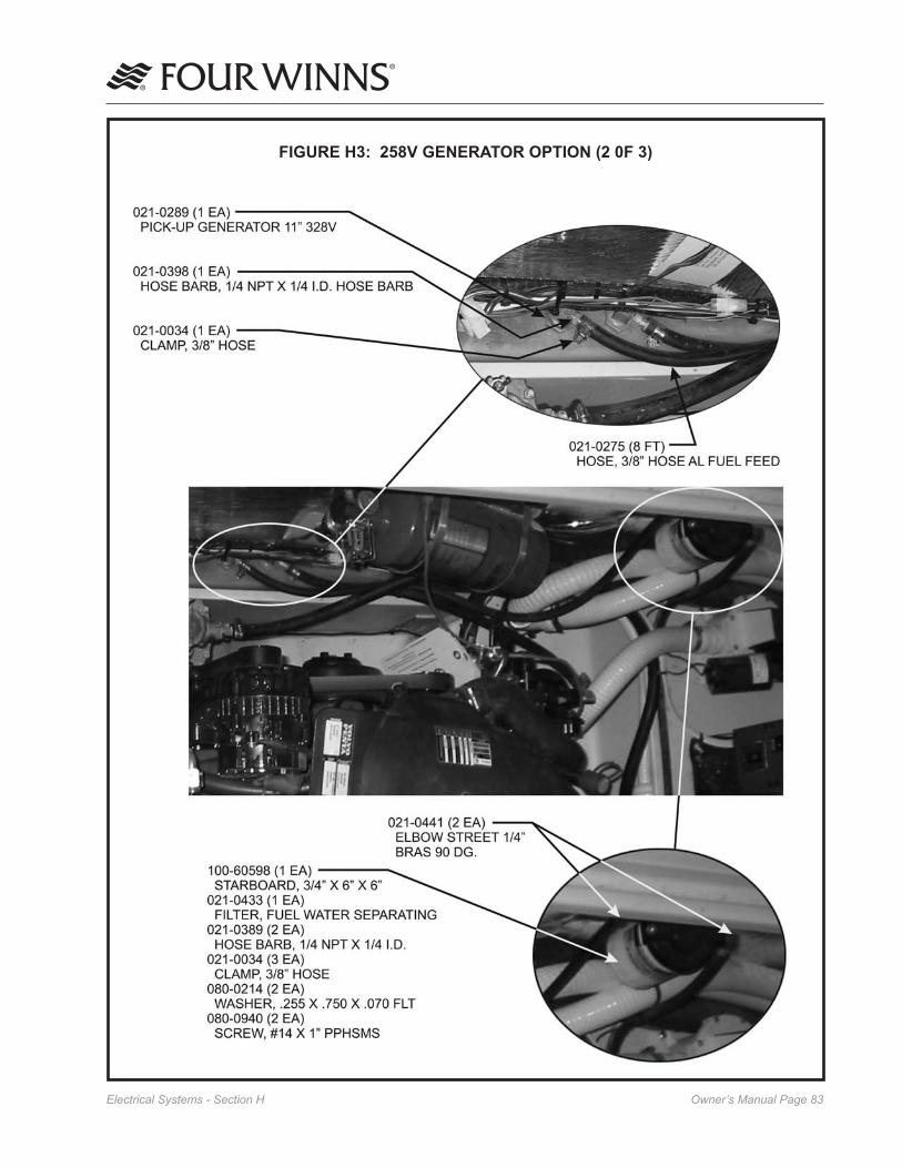
Owner’s Manual Page ��Electrical Systems - Section H
FIGURE H3: 258V GENERATOR OPTION (2 0F 3)

Owner’s Manual Page ��Electrical Systems - Section H
FIGURE H4: 258V GENERATOR OPTION (3 0F 3)
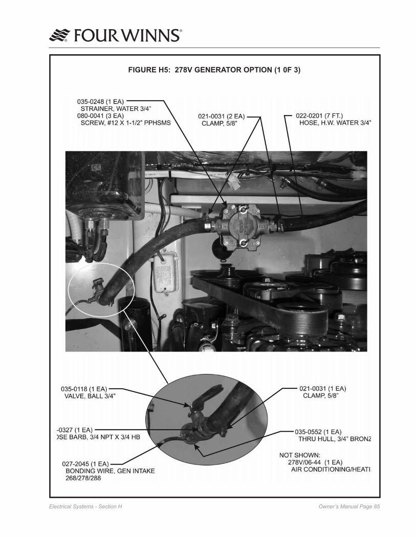
Owner’s Manual Page ��Electrical Systems - Section H
FIGURE H5: 278V GENERATOR OPTION (1 0F 3)

Owner’s Manual Page ��Electrical Systems - Section H
FIGURE H6: 278V GENERATOR OPTION (2 0F 3)

Owner’s Manual Page ��Electrical Systems - Section H
FIGURE H7: 278V GENERATOR OPTION (3 0F 3)

Owner’s Manual Page ��Fuel Systems - Section I
I - 1 GASOLINE FUEL SYSTEMS
Gasoline fuel systems used in Four Winns® boats are designed to meet or exceed the requirements of the US Coast Guard, the National Marine Manufacturers Association, and the American Boat and Yacht Coun-cil in effect at the time of manufacture.
NOTICEUse only clean, dry fuel of the type and grade recommended by the engine manufacturer. The use of incorrect or contaminated fuel can cause engine malfunction and serious dam-age. Engine damage resulting from the use of a lower octane gasoline is considered misuse of the engine and will void the engine warranty. Refer to the section on Gasoline Requirements in the engine manual for information on octane specifications.
The 258 & 278 Vista® models are equipped with a single fuel tank. See Figure I1. The capacity of the fuel tank(s) may be found on our website at www.fourwinns.com. The generator (if applicable) uses a separate fuel pick-up.
Figure I1: Fuel Tank Location
A. System Testing
All gasoline fuel systems have been factory inspected and pressure tested in accordance with regulations in effect at the time of manufacture. Additionally, each fuel tank must pass rigid tests and inspections performed by the fuel tank manufacturer.
Prior to taking delivery, it is important that a full in-spection be made of the entire fuel system by the sell-ing dealer. An entry on the Four Winns® Pre-Delivery Inspection Form portion of the Warranty Registration Card will attest to the dealer’s performance of this service.
B. Fuel Fills
Fuel fill deck plates are located either on the aft deck or side decks, and are marked “GAS”. To open, insert the deck plate key into the holes on the cap and rotate counterclockwise. A bead chain connects the cap to body to help prevent loss overboard. Be sure to utilize the proper type and grade of fuel as recommended by the engine manufacturer. See Section I-2 for additional information.
The fuel fill fitting allows for venting below the fill cap. While the tank is being filled, the air displaced by the fuel escapes through the fuel fill/vent. This reduces the amount of fuel spillage. Always open the lid slowly to allow air to escape. See Figure I-2.
Check Valve prevents spills from fuel surge.
Baffles allow air ventilation but trap water
Splash Shield sends overflow from vent back to tank
Figure I-2: Fuel Fill
The gasket seal on the fuel fill cap assists in sealing when closed. A missing or damaged gasket can allow water on the surrounding surfaces to run into the tank. Periodically inspect the gasket and the fuel deck plate for damage.
DO NOT confuse GAS deck fill plate with WATER or WASTE deck plates. Deck fill plates are labeled according to the intended use.
Fuel Systems
Bow
Fuel VentFuelFill
Fuel Tank

Owner’s Manual Page ��Fuel Systems - Section I
The fuel withdrawals are positioned in the fuel tanks to achieve optimum fuel usage, and fuel line routing. At certain speeds and hull trim angles, the fuel supply at the withdrawal tank location can increase or decrease accord-ingly. Be extremely careful when attempting to operate the boat on a minimum amount of fuel. Though some fuel may be in the tank, the rela-tive trim angle of the boat may cause the fuel to flow away from the withdrawal.
NOTICEAccess plates or lids are provided in the floor for easier access to the fuel pick-up, anti-sy-phon valve and sender.
D. Fuel Gauge
The fuel gauge indicates the amount of fuel in the tank. See Section E-6F - Fuel Gauge (4-in-1-Gauge) for additional information on fuel gauge use.
E. Fuel Senders
The fuel sender consists of a float which travels up and down a stationary tube. The float measures the level of the fuel in the tank and sends a signal to the fuel gauge. See Figure I-3.
Figure I-3: Fuel Sender Operation
Due to the mechanical nature of the fuel sender, variations in readings during various speeds of operation may occur. This system is merely a relative indication of the available fuel supply and not a calibrated instrument. With this type of sending unit a more accurate measurement of fuel level is obtained with the boat in a level position.
The gauge readings will also vary with the trim angle of the boat. When sitting at a dock and the boat is nearly level, the fuel gauge will register accurately. Refer to Figure I-3. When boating, the trim angle of the boat changes and affects the gauge readings. Under these conditions, the fuel sender will register “full” for the first few hours of running time until the fuel
Spilled fuel is a fire hazard. DO NOT overfill or overflow the tank, or allow fuel spills into the hull or bilge. If spillage occurs, clean up immediately and dispose of soiled rags/towels in a proper container.
NOTICEWhen fueling at a marina, DO NOT overfill. Fuel may spill into the water.
Avoid overboard spills. When tank is almost full the sound from the fuel vent will change. The pitch will become higher indicating the tank is close to being full. Stop pumping fuel into tank. DO NOT TOP OFF.
After fueling, replace the fill cap, and wash the areas around the fuel fill plate. Residual fuel left on the deck and hull sides can be dangerous, and will yellow the fiberglass. It will also damage the tape stripes and logos.
C. Anti-Syphon Valves
The fuel withdrawal line is equipped with an anti- syphon valve where the line attaches to the fuel tank. This valve prevents gasoline from syphoning out of the fuel tank should a line rupture. See Figure I-2 for anti-syphon location.
Figure I-2: Fuel Tank Fittings

Owner’s Manual Page �0Fuel Systems - Section I
level drops below the 3/4 or 1/2 mark. This is caused by the angle of the fuel in the tank as shown in Figure I-4.
Figure I-4: Effects of Trim Angle
It is very important to keep track of hours and fuel consumption to obtain an average gallon per hour consumption figure. Refer to the fuel log located at the back of this manual. This will help to prevent any problems with running out of fuel on the water.
Dealers are equipped with some general figures on consumption which can be used as a guide until spe-cific information on your boat is determined. Because of boating conditions, speed, weight and other factors common to your situation, fuel consumption will vary between your boat and consumption figures devel-oped by Four Winns.
When the fuel gauge begins to register below the“full” mark, the gauge readings will drop much faster until it reads” empty”. When this occurs, the trim angle has affected the sender reading. When the gaugeregisters “empty”, the sender has bottomed out and there may be 3 to 4 gallons of fuel in the tank. See Figure I-5.
Figure I-5: Trim Angle Effect with Low Fuel
F. Fuel Filters
Fuel filters are installed on each engine. Filters should changed frequently to assure an adequate supply of fuel to the engine. Refer to the engine manual for ad-ditional information. The engine manual is included in the owner’s information packet.
NOTICECanister-type filters should be changed annually.
G. Use and Maintenance
DO NOT let the odor of gasoline go un-checked. If the odor of gasoline is noted, DO NOT START ENGINE. If engine is running, SHUT OFF ENGINE, ELECTRICAL AND HEAT GENERATING EQUIPMENT. Investi-gate and correct the situation immediately! Have all passengers put on personal flotation devices and keep fire extinguishers at hand until the situation is resolved.
Avoid serious injury or death from fire or explosion resulting from leaking fuel. Inspect systems for leaks at least once a year.
To help guard against damage, avoid the storage or handling of gear near the fuel lines, fittings and tanks.
I - 2 FUEL STANDARDS
Be cautious when using gasoline that contains alco-hol. Refer to the section on gasoline requirements in your engine manual for additional information.
To conform to Federal Air Quality Standards, the petroleum industry reduced the amount of tetraethyl lead in gasoline. Alcohol is be-ing blended with gasoline to help restore the octane rating lost when the lead was removed. While blending alcohol with gasoline increases the octane level of the fuel, it can also create certain safety and performance related problems for boaters.

Owner’s Manual Page ��Fuel Systems - Section I
Avoid serious injury or death from fire or explosion resulting from leaking fuel. Inspect system for leaks at least once a year.
If areas are found within the fuel system that appear questionable, have a qualified marine technician in-spect the system. A thorough fuel system examination should be made by an experienced marine technician at least once a year.
I - 3 FUELING INSTRUCTIONS
1. Avoid fueling at night except in emergencies.
2. When moored at fueling pier:
a. Do not smoke, strike matches, or throw-switches.
b. Stop all engines, motors, fans, and devices that could produce sparks.
c. Put out all lights.
3. Before starting to fuel:
a. Ensure that boat is moored securely.
b. Be sure the proper type and grade of fuel as recommended by your Engine Owners Manual is used.
c. Determine how much additional fuel is required to avoid overflow.
4. During fueling: Keep the fill nozzle in contact with the fuel opening at all times to guard against possible static spark. See Figure I-6.
Spilled fuel is a fire or explosion hazard. DO NOT overflow the tank or allow fuel spills into the hull or bilges. Avoid overboard spills. When tank is almost full the sound from the fuel vent will change. The pitch will become higher indicating the tank is close to being full. Stop pumping fuel into the tank. DO NOT TOP OFF.
A. Problems with Alcohol in Gasoline
Below is a list of problems which may be experienced when using blended gasoline.
1. Premature deterioration of fuel system compo-nents may occur. Alcohol will attack rubber fuel hoses, fuel tanks, fuel filters, fuel pumps and rubber gaskets. This deterioration will lead to fuel system leakage.
2. Phase separation of fuel will cause contamination. Water which accumulates in the tank through contamination or condensation will be absorbed by the alcohol. This water-heavy alcohol will settle at the bottom of the tank. This phase separation will lead to fuel tank corrosion. This may also result in a lean mixture to the carburetor and cause engine stalling or possible engine damage.
The use of alcohol additives in gasoline has become more widespread. Regulations on public notification of the existence of additives is currently controlled by the Environmental Protection Agency (EPA). Some states do require that gasoline pumps display information on additives (especially alcohol). If alcohol content is not posted, ask and avoid using fuel containing alcohol if possible.
B. Recommendations
Assume blended gasoline is being used and follow these recommendations below.
1. Inspect fuel hoses often. A deteriorated hose containing alcohol blended gasoline will normally be soft and swollen. A deteriorating hose contain-ing no fuel will normally be hard and brittle. In both cases the hose should be replaced.
2. Ventilate the engine compartment before starting the engine(s). Operate the engine compartment blower for four (4) minutes. Then, prior to starting the engine(s), check the bilge area for the scent of gasoline fumes; DO NOT start the engine(s) if the odor of gasoline is detected.
3. Frequently inspect the fuel system fittings. Inspect the fuel tank, pump and filter for signs of leaks or corrosion. Visually inspect for deteriorating metal fittings at the fuel hose connections.

Owner’s Manual Page ��Fuel Systems - Section I
(Nozzle in contact with fuel opening. Grounding the fuel hose - proper)
(Nozzle not in contact with fuel opening. Not grounding the fuel hose - Improper)
Figure I-6: Grounding Fuel Hose
5. After fueling:
a. Replace all fill caps securely.
b. Wipe up any spilled fuel.
c. Determine that there is no odor of gasoline in the engine compartment or below decks before starting machinery, turning on lights or lighting stove. Operate the bilge blower sys-tem for at least four (4) minutes before engine start-up.
d. Be prepared to cast off moorings as soon as engine is started.

Owner’s Manual Page ��Water and Waste Systems - Section J
J - 1 GENERAL
All Four Winns Vista® models are equipped with a fresh water supply system. This system consists of a water supply tank, water distribution lines and a distribution pump. The water fill deck plate for the fresh water system is located on the deck and labeled accordingly. Always fill the tank slowly. See Figure J1.
Figure J1: Fresh Water Fill & Vent
The water deck plate is appropriately labeled. DO NOT fill the system with anything other than water. Should the system become contaminated with fuel or other toxic solution, component replacement may be necessary.
The water tank is equipped with an overboard vent (Figure J1). Maintain a close visual watch on the overboard vent while filling the water tank. Always fill the tank slowly. When the tank is almost full, water will spurt out of the vent.
NOTICEWhen filling the tank, never seal the hose to the deck plate. The tank will become pressuized and could rupture.
DO NOT overfill the water tank. Tank damage may result. Water capacity and tank location may vary due to other equipment that may be installed on the boat.
For the potable water capacity, please refer to our Four Winns website at www.fourwinns.com. Tank monitoring systems are optional on the 258 and 278 Vista® models. These indicator gauges are typically located in the head for monitoring the water/waste levels. Refer to Figure J2 and the locator drawing in the back of this manual for the fresh water tank
location. Access to the tank is gained through the forward berth’s under berth storage drawer.
Figure J2: Fresh (Potable) Water Tank Location
The materials from which the components of the water system are made may give the water supply a pecu-liar taste, especially when new. This condition is normal and can be reduced somewhat through the use of a water filter; such as that produced by PuriTec™. The taste will completely dissipate in time.
The fresh (potable) water system should be disinfected prior to initial use.
The water system should be disinfected before first use and at the beginning of each season. The follow-ing information is a general guide to disinfecting the fresh water system.
1. Flush the boat’s water system thoroughly with fresh water. Make sure all nontoxic antifreeze is removed from the system.
2. The water system should be drained completely.
3. To disinfect the water system, use one gallon of water and 1/4 cup of Clorox™ or Purex™ household bleach (5% sodium hypochlorite solution). This is recommended for each 15 gallons of tank capacity.
4. Allow to stand for three (3) hours. If time is a factor, greater concentrations of chlorine solution will be needed to disinfect the water system.
Water and Waste Systems
Fresh Water Vent
FreshWaterFill
Fresh Water TankFresh
Water Pump
Fresh Water VentFreshWaterFill
Fresh Water VentFreshWaterFill
258 Vista®
278 Vista®

Owner’s Manual Page ��Water and Waste Systems - Section J
5. Drain the system.
6. Flush the system thoroughly with fresh water.
7. Fill the system with fresh water.
To remove excessive chlorine taste or odor which might remain in the system, prepare a solution of one quart vinegar to five gallons water and allow this solution to agitate in the tank for several days during boating. Then drain tank and refill with fresh water.
All drains are equipped with traps, and the water will drain slowly. If the system is not operating properly, have it checked by your authorized Four Winns dealer.
J - 2 PRESSURIZED WATER SYSTEM
The water pump is an automatic, on-off, self-priming pump that can service several outlets at once. The pump will build up water pressure and will turn off when it reaches 35 psi. Refer to Figure J2 and the drawings at the end of this section.
A. Priming the System
After filling the water tank, open all faucets partially. Activate the FRESH WATER switch on the cabin lights panel to supply the system with water. Let the pump run until water comes out of the galley faucet, head faucet and transom shower.
After all the air has been purged from the system and a steady flow of water is coming from each outlet, turn off the faucets one by one. Begin with the cold water faucets and continue until all faucets are shut off. As the pressure builds, the pump will automatically shut off at 35 psi. Refer to Section H-5 - 12 Volt Electrical Equipment and the manufacturer’s literature included in the owner’s packet for additional information.
B. System Operation
When properly primed and activated, the pressurized water system can be used in the same manner as the water system in a home. An automatic pressure sensor in the water pump keeps the system pressur-ized. Simply turn on the faucet and water will be delivered. If the system has been recently filled, or has not been used for an extended period of time, air bubbles may accumulate at the pump and/or in the waterlines. If this should happen, re-priming may
be necessary. Refer to the preceding subsection regarding priming the system.
To obtain the most consistent mixture of hot and cold water, turn the cold water on full, then mix in hot water until the desired temperature is obtained. If water pump cycling occurs, some minor variations in water temperature can be expected.
Whenever the boat will be left unattended for an extended period, the water pump switch should be turned to the OFF position. This switch should also be turned OFF whenever the water tank is to remain empty for an extended period of time.
C. Water Heating Systems
A water heater is a standard feature available on the 258 and 278 Vista® models. The capacity of the water heater may be found on our website at www.four-winns.com. Refer to Figure J3 and to the drawings at the end of this section.
NOTICEWater heater location may vary due to the installation of optional equipment.
The water heater utilizes 120 volt (220 volt on 50 Hertz models) power. The water heater breaker switch is located on the cabin 120 Volt AC panel.
NOTICEDO NOT supply ��0 volt power to an empty water heater. Damage to the heater will result immediately. The water system must be filled and primed before attempting to use the water heater.
Figure J3: Water Heater Location
On the 258 and 278 Vista® models, the water heater incorporates a heat exchanger. The heat exchanger allows the engine coolant to heat a portion of the fresh
Water Heater

Owner’s Manual Page ��Water and Waste Systems - Section J
Periodically check the sump pump screen for clogs to prevent drainage problems from occurring in the shower drain. Refer to the manufacturer’s literature included in the owner’s packet.
J - 3 GREY WATER SYSTEM
The grey water system is optional on Vista® models. The water from the galley sink, head sink and shower will drain into a sump and is pumped into a grey water holding tank respectively. The waste level indicator is located in the head compartment. A pumpout fitting labeled WASTE but designated for grey water is provided on the deck. Refer to the drawings at the end of this section.
NOTICECertain geographical areas have restrictions on grey water being pumped or drained overboard. Be sure to check all local, state and federal laws in the boating area.
J - 4 SHORE WATER CONNECTION
Shore water connection is standard on the 258 and 278 Vista® models. This feature allows the direct connection of a city or shoreside water supply to the boat’s water system to provide a constant supply of fresh water without the need to constantly refill the water supply tank. This minimizes pressure pump operation thus extending the life span of the pump.
Dockside shore water pressure can vary dramatically. Excess pressure could damage the boat’s water system so the shore connection also regulates the water pressure to a maximum of 35 psi.
The shore water inlet/regulator fitting is located outboard, on the starboard side of the transom above the swim platform. See Figures J3 and the drawings at the end of this section.
To use shore water, connect a hose from the shore water faucet to the shore water fitting on the boat and turn on the shore water. The water system of the boat will then be pressurized by city water if the system was previously primed.
The water pump should be turned off when using city water. If the pump is OFF, the pump will not function and the water in the storage tank of the boat will not be utilized.
water supply while the engine is operating. This option will provide hot water at times when 120 volt power is not available. Additional information on heat exchang-ers is covered in the engine and hot water heater manufacturers’ manuals. Please refer to Section H on Electrical Systems for additional information.
D. Using The Shower
Turn on the faucets to desired temperature, remove the shower spout from its holder, move the diverter lever on the shower head, and the shower is operational.
When using the shower, draw the shower curtain before using the shower. Damage to the finish can result if surrounding walls and flooring are allowed to become excessively wet. Thoroughly dry these areas after showering.
The water temperature can vary during shower use as the pressure pump cycles on and off. For greatest consistency, turn the cold water on full, then mix in hot water until the desired temperature is obtained.
A shower sump pump is incorporated into the drain system of the shower. The shower drains into the sump pump located forward of the aft cabin. The water will then be pumped overboard. If a grey water system is installed, the water will be pumped into the grey water holding tank.
The sump pump includes an automatic bilge switch and is protected by a circuit breaker located on the battery switch panel for the bilge. The sump pump will automatically start as soon as the water in the sump reaches a level that will cause the float on the switch to rise.
After showering, let the water flow for a period of time to flush the pump of soap residue. Check the sump for excess residue. When rinsed out, the pump will automatically shut off.
If water flow from the shower head appears to be restricted, it may be due to sediment accumulating at the shower head. If necessary, remove the head and clean the discharge holes with a fine wire.

Owner’s Manual Page ��Water and Waste Systems - Section J
NOTICEAlways remember to disconnect the shore water supply hose before leaving the dock.
Always turn off the shore water whenever the boat is left unattended. If a major water leak did occur and went undetected, the boat could fill with water and sink.
DO NOT alter or repair the pressurized water system or shore water connection without having proper knowledge of the system. Damage to the water system can occur.
See Section J-1 for general water system information and instructions on filling the water tank. The water tank will not be filled while connected to shore water.
J - 5 TRANSOM SHOWER
A transom shower with a choice of hot/cold water is standard on the 258 and 278 Vista® models. The shower unit is located either on the port side, at the transom walk-thru or on the starboard side of the transom storage locker. Refer to Figures J4 and to the drawings at the end of this section.
Transom Shower
Head/Handle
Transom Shower
(Cold & Hot Faucets)
Figure J4: Transom Shower
The water supply system can be used for showering or washing down the transom area. As long as there is water pressure, the shower faucet will operate. Fresh water tank capacity is limited. Connect the boat to shore water before using large amounts of water as required when washing down the transom/swim platform area.
J - 6 HEADS
The various anti-pollution laws presently in effect have necessitated the use and availability of a wide variety of heads. The heads that have been factory installed in Four Winns® boats have been chosen to provide reasonable longevity and reliable service, at a realistic cost. Refer to the drawings at the end of this section. Also, refer to the manufacturers literature included in the owner’s packet.
A. Porcelain Head - Standard
The 258 and 278 Vista® models comes with a porce-lain head and a black/gray water holding tank. For the holding capacity, please refer to our Four Winns website at www.fourwinns.com. The toilet is a left hand, manually-operated toilet and is surprisingly easy to operate. The toilet obtains sea/fresh water from a pick-up for rinsing the bowl. The pick-up and strainer are located below the mid cabin floor on the 258/278 Vista® models. Tank level indicators are optional and are located in the head if so ordered. Please refer to the following toilet operation instruc-tions, the manufacturer’s literature in the owner’s packet, and Figures J5 - J7.
To operate toilet:
1. Move the wet/dry selector to the WET bowl position (left) and pump handle up and down a few times to add some water to the bowl prior to use.
2. After using, flush again by pumping the handle up and down (in WET bowl position) until bowl is thoroughly rinsed and evacuated.
3. Then move the wet/dry bowl selector to the DRY bowl position (right) and continue pump ing until only about one cup of water remains in the bottom of the bowl.
4. Leave the wet/dry bowl selector in the dry bowl position when not in use.
Figure J5: Wet/Dry Toilet Operations Label
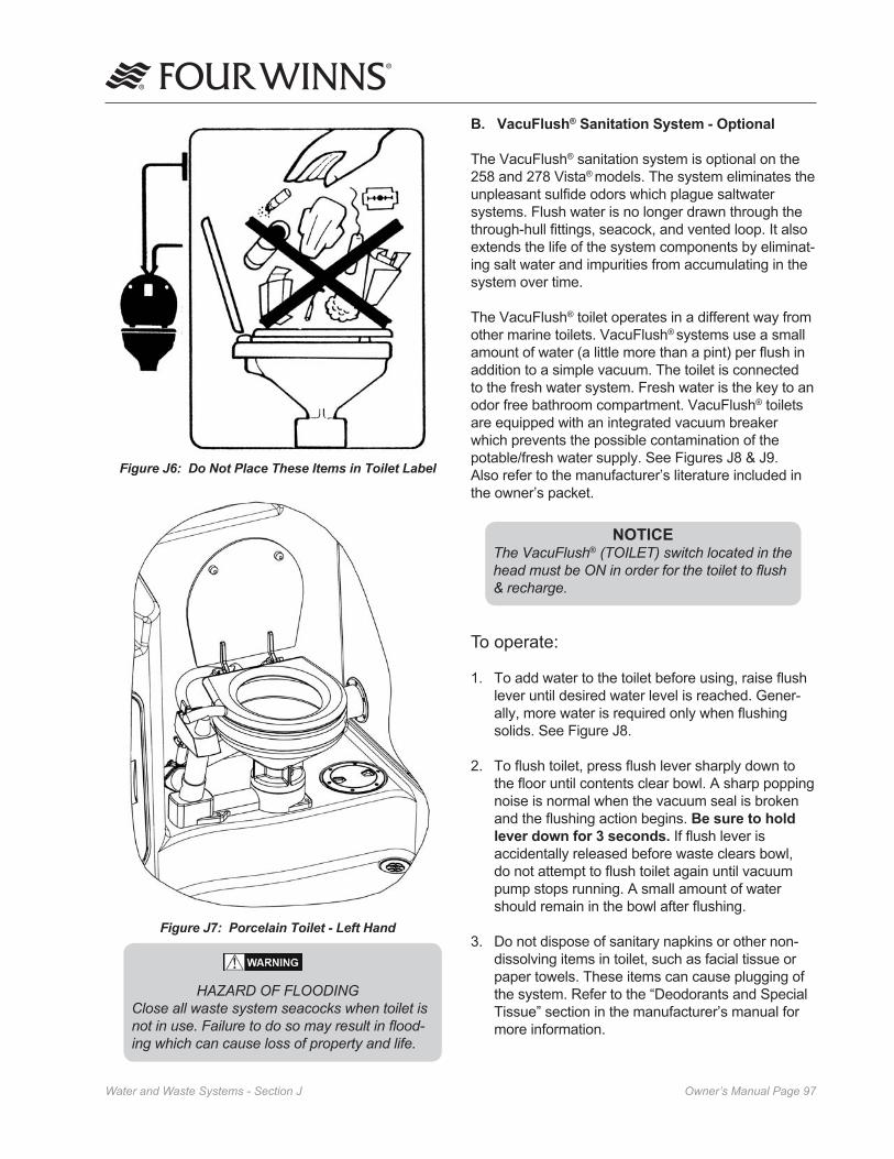
Owner’s Manual Page ��Water and Waste Systems - Section J
Figure J6: Do Not Place These Items in Toilet Label
Figure J7: Porcelain Toilet - Left Hand
HAZARD OF FLOODING Close all waste system seacocks when toilet is not in use. Failure to do so may result in flood- ing which can cause loss of property and life.
B. VacuFlush® Sanitation System - Optional
The VacuFlush® sanitation system is optional on the 258 and 278 Vista® models. The system eliminates the unpleasant sulfide odors which plague saltwater systems. Flush water is no longer drawn through the through-hull fittings, seacock, and vented loop. It also extends the life of the system components by eliminat-ing salt water and impurities from accumulating in the system over time.
The VacuFlush® toilet operates in a different way from other marine toilets. VacuFlush® systems use a small amount of water (a little more than a pint) per flush in addition to a simple vacuum. The toilet is connected to the fresh water system. Fresh water is the key to an odor free bathroom compartment. VacuFlush® toilets are equipped with an integrated vacuum breaker which prevents the possible contamination of the potable/fresh water supply. See Figures J8 & J9. Also refer to the manufacturer’s literature included in the owner’s packet.
NOTICEThe VacuFlush® (TOILET) switch located in the head must be ON in order for the toilet to flush & recharge.
To operate:
1. To add water to the toilet before using, raise flush lever until desired water level is reached. Gener-ally, more water is required only when flushing solids. See Figure J8.
2. To flush toilet, press flush lever sharply down to the floor until contents clear bowl. A sharp popping noise is normal when the vacuum seal is broken and the flushing action begins. Be sure to hold lever down for 3 seconds. If flush lever is accidentally released before waste clears bowl, do not attempt to flush toilet again until vacuum pump stops running. A small amount of water should remain in the bowl after flushing.
3. Do not dispose of sanitary napkins or other non-dissolving items in toilet, such as facial tissue or paper towels. These items can cause plugging of the system. Refer to the “Deodorants and Special Tissue” section in the manufacturer’s manual for more information.

Owner’s Manual Page ��Water and Waste Systems - Section J
NOTICEThe discharge pump must be used to discharge waste overboard. However, DO NOT use the discharge pump to discharge waste at a pumping station.
To operate the overboard discharge system:
1. The discharge valve is located in the engine compartment labeled HEAD DISCHARGE. To open, turn the valve so that the handle is parallel to the flow of the valve. The waste deck plate cover must be tightened securely for the over-board discharge system to operate.
2. Turn ON the overboard discharge switch which is located in the head on the switch panel. Allow the discharge pump to run until the storage tank is empty. The sound of the pump’s motor load and speed will change when the tank becomes empty.
3. Turn the overboard discharge switch off.
4. Turn the head discharge valve handle to the closed position, and secure it. This thru-hull valve (seacock) must be closed to prevent water from being forced back into the system.
NOTICEDischarging waste overboard is illegal in most US waters today. Discharge is limited to certain coastal waters, a designated distance offshore. Check with your local boating regulations before proceeding with any discharge activities.
Some local regulations require overboard discharge systems be physically secured in a closed position during use of the boat in waters designated as “no discharge” areas. Check with local boating regulations. Refer to the manufacturer’s literature for additional information.
D. Dockside Waste Pump Out
On most Vista® models waste pump out capability is available. Waste can be removed from the holding tank by taking the boat to a dockside waste pumping station. Most marina fueling facilities provide such services.
Figure J8: VacuFlush Operations
C. Head With Overboard Discharge
This option is available on the 258 and 278 Vista® models. The head toilet operations are the same as the systems described earlier. The head operates the same as the porcelain head system described earlier but an additional line with a “wye” has been installed for overboard discharge. The waste will be pumped into the holding tank from the head. The macerator pump is installed after the “wye”. Refer to Figure J10.
Figure J10: Overboard Discharge Option
Figure J9: VacuFlush® Waste Holding Tank System
1. Add Water
Lift
2. Flush For 3 Seconds
3. Do Not
Press

Owner’s Manual Page ��Water and Waste Systems - Section J
The waste holding tank should be emptied upon visual inspection of the waste holding tank and determining the waste holding tank’s capacity is almost full or by using the waste level indicator if so equipped. Waste level indicators are typically located in the head. DO NOT ALLOW THE WASTE TANK TO BECOME OVERFILLED.
To pump out the holding tank:
1. Be sure the head has some water in the bowl.
2. Connect the dockside pump out connection to the WASTE plate located on the deck.
NOTICEUsually the dockside pump out connection will screw into the waste deck plate or has a rubber sleeve that inserts into the plate and must be held in position during the pump out operation. If the hose is not air tight or connect-ed properly, waste could spurt out or leak around the deck fitting and into the boat.
3. Have the pumping station operator activate the pumping equipment. The waste will be drawn from the holding tank and into the pumping station’s disposal tank.
4. Remove the pump out connection from the deck plate. Add at least 5 gallons of clean water to the holding tank on most models through the waste deck fitting using a dockside water hose.
5. Repeat steps 2 & 3 above to pump out the water used in step 4 to flush the holding tank.
6. Add waste holding tank treatment chemical to the head bowl. It is available from the dockside pumping station or can be obtained from your dealer. Flush at least twice.
Be careful when handling and storing treatment chemicals. Not only are they toxic, but they will also stain and damage surrounding surface.
J - 7 SYSTEM MAINTENANCE
Information supplied with water and waste system components by the equipment manufacturers is included with this manual. Refer to this literature for additional operation and service information.
Be sure the batteries in the boat are properly charged. Operating the pressure pump from a battery with a low charge will result in pump cycling. This could lead to premature pump failure.
The decomposition of waste produces a colorless, odorless gas, methane, that is lighter than air, combustible, and extremely lethal. Always provide sufficient ventilation when effecting repairs to the waste system and allow no odor from the waste system to go unresolved.
A. Clean Vents and Screens
Periodically, inspect the water tank vents and thru-hull vent fittings for any dirt, wax, etc. Carefully remove any obstruction with a pipe cleaner or similar device. Be sure not to puncture the screen. The stainless steel vent cap is not removable.
NOTICEFailure to keep the water tank vent fittings clean will cause excessive pressure buildup within the tank during filling. This can cause water tank damage.
Periodically remove the filter screens from the faucet discharge spouts and shower head. Remove the accumulation of sediment from the screens. If neces-sary, clean out the holes using a fine wire. A buildup of debris in the faucet filter screens can create enough restriction to cause the pump to cycle on and off.
Check the in-line water filter/screen for sediment and blockage. It is located between the water tank and the pressure water pump. If obstructed, remove from the water line and either clean or replace the part. The filter unit will twist apart.

Owner’s Manual Page �00Water and Waste Systems - Section J
Inspect and clean the shower sump every 30 days. Some water will always be in the compartment. Sediment and other debris will buildup and affect the automatic bilge switch and pump operation. Remove the pump’s cover and clean the screen. The screen will become blocked and the pump will not operate properly. To clean the compartment, use baking soda and a fine wire brush to remove dirt and other debris. This will also serve to disinfect the area.
B. Winterizing the Water System
Winter lay-up service procedures should include a thorough draining of the water system. Disconnect all accessible fittings. Blow out all lines. Be sure the hot water heater, fresh and grey water tanks, transom shower, pumps and lines are completely dry. Leave all faucets open. Freezing water can cause severe damage to all water system components.
NOTICEAlways winterize the fresh water system prior to winterization of the hull drainage (bilge pump) system.
Draining the system as mentioned can be very tedious and an incomplete job can result in expensive repairs. The use of nontoxic antifreeze (such as R.V. anti-freeze) designed for fresh water systems considerably reduces the work necessary and is a more positive means of winterizing the system. Follow the directions included with the antifreeze solution.

Owner’s Manual Page �0�Water and Waste Systems - Section J
FIGURE J11: 258V FRESH WATER SYSTEM (1 OF 6)
Refer to the following 258V - Fresh Water System pages for detail views.

Owner’s Manual Page �0�Water and Waste Systems - Section J
FIGURE J12: 258V FRESH WATER SYSTEM (2 OF 6)
ROUTING LAYOUT

Owner’s Manual Page �0�Water and Waste Systems - Section J
FIGURE J13: 258V FRESH WATER SYSTEM (3 OF 6)

Owner’s Manual Page �0�Water and Waste Systems - Section J
FIGURE J14: 258V FRESH WATER SYSTEM (4 OF 6)
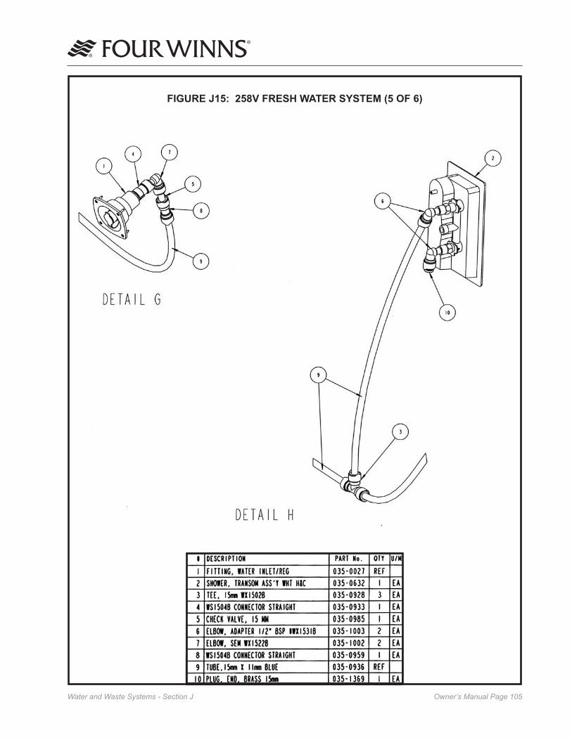
Owner’s Manual Page �0�Water and Waste Systems - Section J
FIGURE J15: 258V FRESH WATER SYSTEM (5 OF 6)

Owner’s Manual Page �0�Water and Waste Systems - Section J
FIGURE J16: 258V FRESH WATER SYSTEM (6 OF 6)

Owner’s Manual Page �0�Water and Waste Systems - Section J
FIGURE J17: 258V FRESH WATER SYSTEM - HOT (1 OF 3)
Refer to the following 258V - Fresh Water System - Hot pages for detail views.

Owner’s Manual Page �0�Water and Waste Systems - Section J
FIGURE J18: 258V FRESH WATER SYSTEM - HOT (2 OF 3)
ROUTING LAYOUT

Owner’s Manual Page �0�Water and Waste Systems - Section J
FIGURE J19: 258V FRESH WATER SYSTEM - HOT (3 OF 3)
AFT SHOWER - FRONT VIEW

Owner’s Manual Page ��0Water and Waste Systems - Section J
FIGURE J20: 258V HEAD HARDWARE

Owner’s Manual Page ���Water and Waste Systems - Section J
FIGURE J21: 258 WASTE WATER SYSTEM (1 OF 5)
Refer to the following 258V - Waste Water System pages for detail views.

Owner’s Manual Page ���Water and Waste Systems - Section J
FIGURE J22: 258V WASTE WATER SYSTEM (2 OF 5
ROUTING LAYOUT

Owner’s Manual Page ���Water and Waste Systems - Section J
FIGURE J23: 258V WASTE WATER SYSTEM (3 OF 5)

Owner’s Manual Page ���Water and Waste Systems - Section J
FIGURE J24: 258V WASTE WATER SYSTEM (4 OF 5)

Owner’s Manual Page ���Water and Waste Systems - Section J
FIGURE J25: 258V WASTE WATER SYSTEM (5 OF 5)

Owner’s Manual Page ���Water and Waste Systems - Section J
FIGURE J26: 258V GREY WATER SYSTEM OPTION (1 OF 2)
Refer to the following 258V - Grey Water System Option page for detail views.

Owner’s Manual Page ���Water and Waste Systems - Section J
FIGURE J27: 258V GREY WATER SYSTEM OPTION (2 OF 2)

Owner’s Manual Page ���Water and Waste Systems - Section J
FIGURE J28: 278V FRESH WATER SYSTEM OPTION (1 OF 6)
Refer to the following 278V - Fresh Water System pages for detail views.
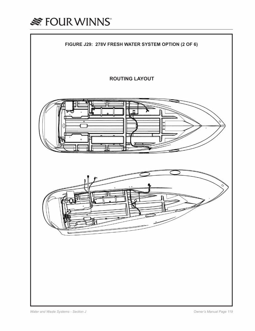
Owner’s Manual Page ���Water and Waste Systems - Section J
FIGURE J29: 278V FRESH WATER SYSTEM OPTION (2 OF 6)
ROUTING LAYOUT

Owner’s Manual Page ��0Water and Waste Systems - Section J
FIGURE J30: 278V FRESH WATER SYSTEM (3 OF 6)

Owner’s Manual Page ���Water and Waste Systems - Section J
FIGURE J31: 278V FRESH WATER SYSTEM (4 OF 6)

Owner’s Manual Page ���Water and Waste Systems - Section J
FIGURE J32: 278V FRESH WATER SYSTEM (5 OF 6)

Owner’s Manual Page ���Water and Waste Systems - Section J
FIGURE J33: 278V FRESH WATER SYSTEM (6 OF 6)

Owner’s Manual Page ���Water and Waste Systems - Section J
FIGURE J34: 278V HEAD HARDWARE

Owner’s Manual Page ���Water and Waste Systems - Section J
FIGURE J35: 278V WASTE WATER SYSTEM (1 OF 5)
Refer to the following 278V - Wsste Water System pages for detail views.

Owner’s Manual Page ���Water and Waste Systems - Section J
FIGURE J36: 278V WASTE WATER SYSTEM (2 OF 5)
ROUTING LAYOUT

Owner’s Manual Page ���Water and Waste Systems - Section J
FIGURE J37: 278V WASTE WATER SYSTEM (3 OF 5)
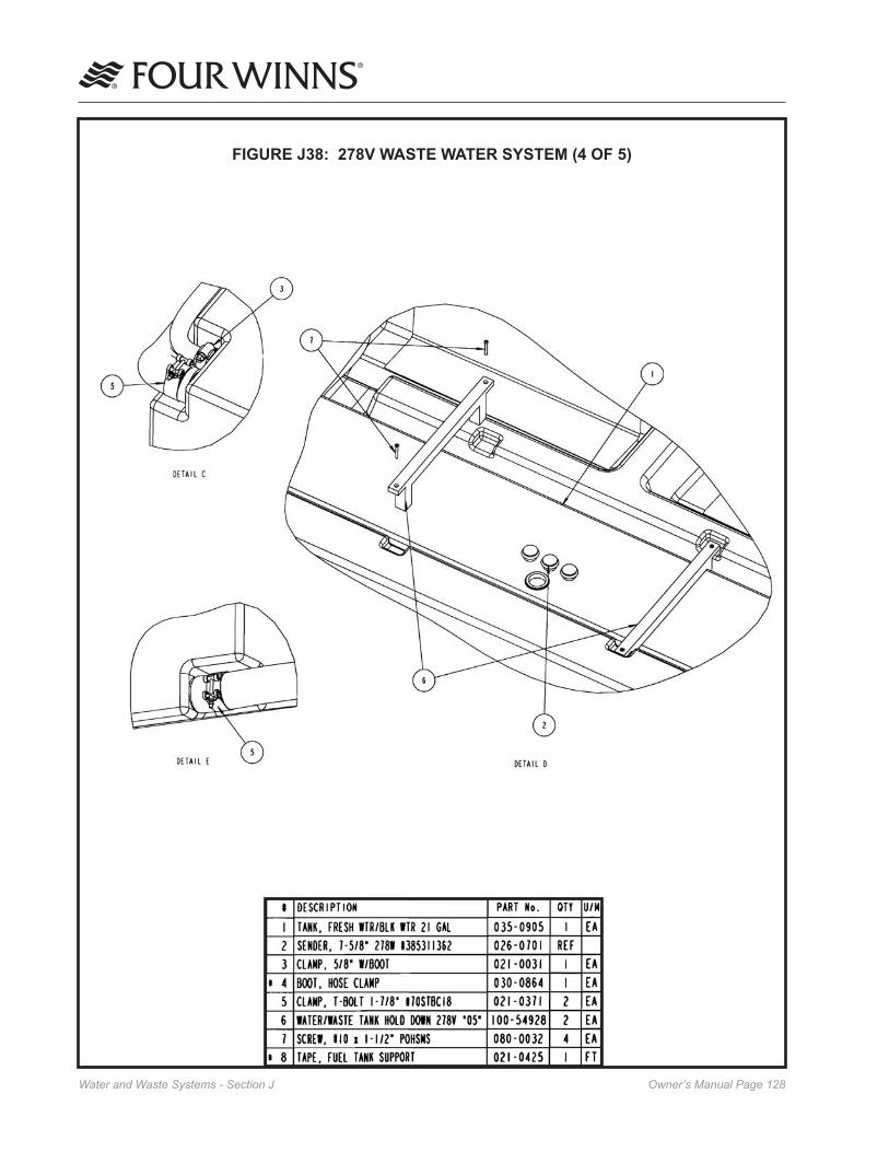
Owner’s Manual Page ���Water and Waste Systems - Section J
FIGURE J38: 278V WASTE WATER SYSTEM (4 OF 5)

Owner’s Manual Page ���Water and Waste Systems - Section J
FIGURE J39: 278V WASTE WATER SYSTEM (5 OF 5)

Owner’s Manual Page ��0Water and Waste Systems - Section J
FIGURE J40: 278V GREY WATER SYSTEM OPTION (1 OF 2)
Refer to the following 278V - Grey Water System Option page for detail views.

Owner’s Manual Page ���Water and Waste Systems - Section J
FIGURE J41: 278V GREY WATER SYSTEM OPTION (2 OF 2)

Owner’s Manual Page ���Water and Waste Systems - Section J
FIGURE J42: 258/278V HEAD VACUFLUSH SYSTEM OPTION (1 OF 2)

Owner’s Manual Page ���Water and Waste Systems - Section J
FIGURE J43: 258/278V HEAD VACUFLUSH SYSTEM OPTION (2 OF 2)
ROUTING LAYOUT

Owner’s Manual Page ���Water and Waste Systems - Section J
FIGURE J44: 258/278V HEAD OVERBOARD DISCHARGE SYSTEM OPTION (1 OF 2)
Refer to the following 258/278V - Overboard Discharge System Option page for detail views.

Owner’s Manual Page ���Water and Waste Systems - Section J
FIGURE J45: 258/278V HEAD OVERBOARD DISCHARGE SYSTEM OPTION (2 OF 2)

Owner’s Manual Page ���Ventilation and Drainage Systems - Section K
C. Engine Ventilation System Maintenance
Periodic inspection and cleaning of the ventilation ducts is necessary to ensure adequate air circulation. A buildup of leaves, twigs, or other debris can severe-ly reduce ventilation. Be sure bilge water does not accumulate to a level that would obstruct the ventila-tion ducts.
Blower operation can be tested by placing a hand over the vents. DO NOT rely on the sound of the blower. Be sure a substantial amount of air is being exhausted by the bilge blower. Check the bilge blower system often, preferably before each cruise.
K - 2 CABIN VENTILATION
The 258 and 278 Vista® cabins are equipped with a deck hatch for ventilation. The aft cabin window also opens to provide ventilation. The cabin side windows (portlight) on these Vista® models may be opened to provide additional ventilation.
Failure to properly ventilate the boat while the engines or generator are operating may permit carbon monoxide to accumulate inside of the cabin. Refer to Section E-� - Engine Exhaust and Section B-� - Carbon Monoxide for additional information.
A screen for the forward deck hatch is a standard feature. The screen is removable and must be stored properly when not in use.
NOTICEBe sure deck hatch is secured while underway. Damage to the hatch may result. When not in use store screen in a safe place to prevent damage.
K - 3 HULL DRAINAGE SYSTEMS
A. Transom Drain
A transom drain with plug is provided in the engine compartment to allow water drainage. When boat is out of the water, the boat and cradle should be positioned so any bilge water accumulation during dry storage will flow towards the transom.
K - 1 ENGINE COMPARTMENT VENTILATION
All Four Winns Vista® models are equipped with engine compartment ventilation. This system is designed to meet or exceed the requirements (in effect at the time of manufacture) of the US Coast Guard, the National Marine Manufacturers Associa-tion, and the American Boat and Yacht Council.
A. Natural Ventilation System
This system includes air intake and exhaust com-ponents. The exhaust ducting reaches to the lower bilge area. This provides adequate air movement while underway and during bilge blower operation.
B. Forced Air Ventilation
All Four Winns Vista® models are equipped with an electric bilge blower. The bilge blower provides the ventilation required prior to starting the engines and while at idle. See Section H - Electrical Systems for blower operation instructions.
Before starting the engine(s) or generator, operate the engine compartment bilge blower for four (�) minutes. Then check the engine compartment for gasoline vapors. ALWAYS operate the bilge blower while the engines are at idle or the generator is in use. Failure to comply could cause explosion and thereby inflict serious injury or death.
Fumes can come from batteries while charging. A concentration of hydrogen fumes can be explosive under the right conditions. Ensure to follow the above warning.
NOTICEA gas vapor detector is a monitor which will alert the operator of an accumulation of gasoline fumes in the engine compartment. It is optionally available on the ��� and ��� Vista® models. DO NOT rely solely on detectors or similar equipment. ALWAYS conduct a physical inspection of the engine compartment.
Ventilation and Drainage Systems

Owner’s Manual Page ���Ventilation and Drainage Systems - Section K
Be sure the drain plug is securely in place prior to launching the boat. Upon shipment of the boat, the drain plug is usually taped to the steering wheel.
B. Bilge Pumps
Forward and aft bilge pumps are provided in the bottom of the hull to remove miscellaneous water accumulations that might occur during normal boating or weather conditions. The aft bilge pump is controlled by the BILGE PUMP switch located on the port helm switch panel. Refer to Section H for further information regarding bilge pumps.
The bilge pumps are equipped with an automatic switch to control pump operation. As the water level rises, the automatic float switch will activate the pump. Separate circuit breakers are provided on the battery switch to supply power directly from the “SHIP SYS-TEMS” battery to the forward and aft bilge pumps regardless of battery selector switch position.
NOTICEWhile at rest, any bilge water accumulation may flow forward. DO NOT allow bilge water to accumulate. Damage to the engine or other components may result. Periodically operate the bilge pump to remove bilge water accumulation.
When leaving the boat unattended for long periods of time or during excessive rain storms, it is a good idea to check on the boat for excessive water accumula-tion. Be sure the bilge pumps and automatic float switches are operating properly. The operating time of the bilge pumps will be limited to the battery capacity.
Periodically, clean the bilge pump strainers. DO NOT allow dirt and debris to clog the bilge pump intakes. Check operation of the bilge pump float switch often to ensure movement of the switch is not restricted by debris, portions of the hull, etc.
Wipe up any oil accumulation in the bilge prior to activation of the bilge pumps. Pumping oil overboard will pollute the water, and is subject to fine.
After winterization of the fresh water systems, be sure the bilge area, bilge pumps and associated hoses are thoroughly dry. Damage to the hull, bilge pumps and
other equipment could occur if water is allowed to freeze in the bilge. Refer to the manufacturers litera-ture included in the owner’s packet for additional information.
C. Sump
A sump box is installed in the floor, just forward of the aft cabin. See the 258 and 278 Vista® locator drawing at the back of this manual. It is equipped with an automatic float switch and will pump water overboard or into the grey water tank (if available). Refer to Section J-2D on using the shower and for additional information on sump pump operation.
D. Bilge Compartment Drainage
Certain bulkhead areas of Four Winns® boats are sealed in accordance with US Coast Guard regula-tions effective at the date of manufacture. Drainage is provided and water can be removed with the bilge pump.
E. Cockpit Drainage
The 258 and 278 Vista® models incorporate a fiber-glass self-bailing cockpit. This feature minimizes water entry to the bilge or engine compartment areas by providing means for water to be drained overboard.
Periodically open the engine hatch and clean the aft bilge compartment. Be sure the drains, tubes and fittings are clean and free of leaves, dirt, or other debris.

Owner’s Manual Page ���Interior Equipment - Section L
Interior Equipment
Figure L1: 258V Galley
Figure L2: 278V Galley
C. Refrigerator
A galley refrigerator is standard equipment. The refrigerator is designed to operate efficiently on AC Shore Power (120 volt or 220VAC - international) or battery power (12 volt). The refrigerator will auto-matically transfer to 12 volt operation when dockside power is not available.
Most refrigerator models have a thermostat that will maintain the temperature desired. According to the refrigerator manufacturer’s operations manual, select the temperature setting by turning the thermostat dial to the various numbered positions. The refrigerator may be turned off by turning the thermostat to the “OFF” position. See the manufacturer’s literature included in the owner’s packet for specific information on the model used in your Vista®.
L - 1 GALLEY EQUIPMENT
Care must be exercised while around stoves and other appliances. Keep children away from burners.
Care must be exercised while around stoves and other appliances. Keep children away from burners.
A. Electric Stove
A flush-mount electric stove with a single-burner is standard on the 258 and 278 Vista® models. See Figures L1 and L2 for stove and other appliance locations. A circuit breaker (RANGE) is provided in the 120 Volt AC cabin electrical panel. The circuit breaker must be activated and the boat must be connected to dockside power or utilize the generator (if applicable) in order to operate the microwave. Refer to the Section H of this manual and the manufacturer’s litera-ture included in the owner’s packet for operation and safety procedures.
B. Microwave Oven
A microwave oven is standard on the 258 and 278 Vista® models. The circuit breaker on the 120 Volt AC cabin electrical panel must be activated and the boat must be connected to dockside power or utilize the generator (if applicable) in order to operate the microwave. Refer to the manufacturer’s literature provided in the owner’s packet.
Do not restrict air flow while microwave is in use, or damage to microwave oven or cabinet may result.
Refrigerator
1-Burner ElectricStove
Microwave
Refrigerator
1-Burner ElectricStove
Microwave
AC Cabin Panel
Cockpit Lights Panel
Air Conditioner Control Panel
(Optional)
AC Cabin Panel
Cockpit Lights Panel
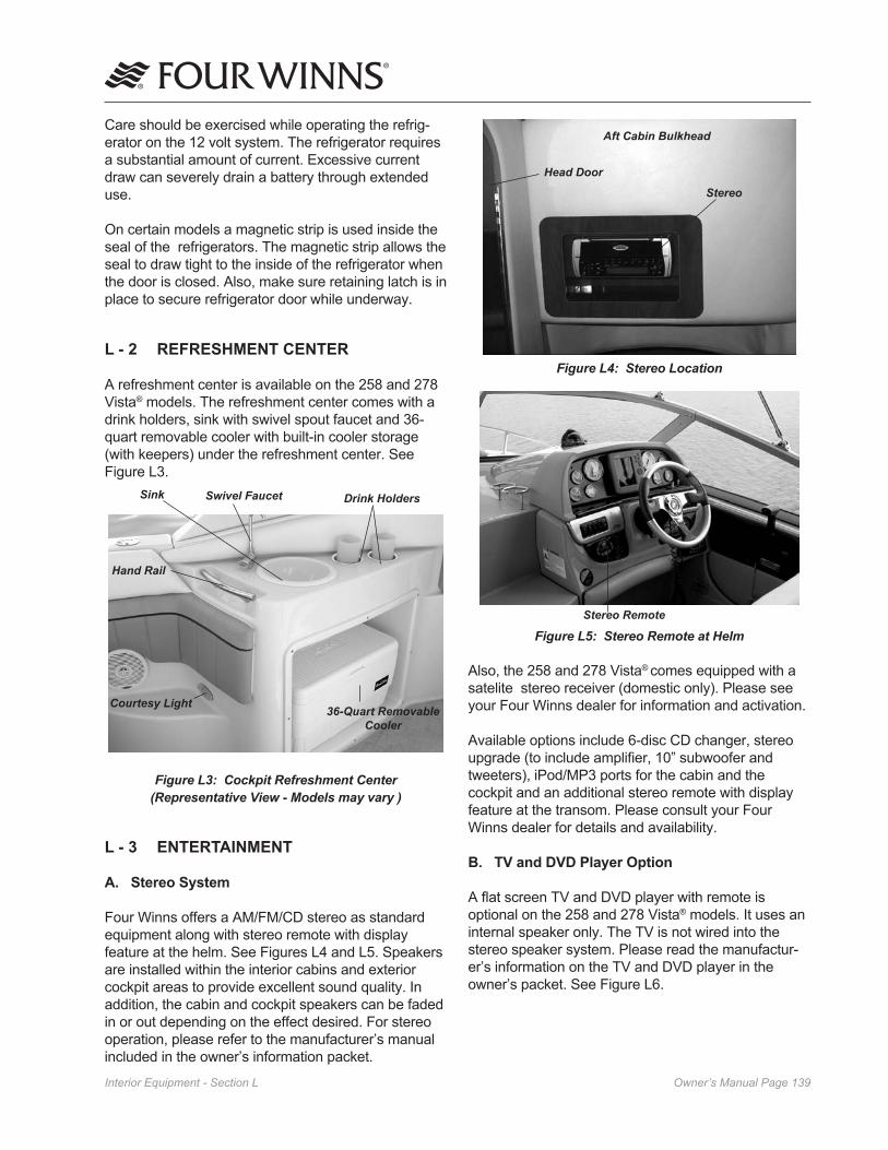
Owner’s Manual Page ���Interior Equipment - Section L
Figure L4: Stereo Location
Figure L5: Stereo Remote at Helm
Also, the 258 and 278 Vista® comes equipped with a satelite stereo receiver (domestic only). Please see your Four Winns dealer for information and activation.
Available options include 6-disc CD changer, stereo upgrade (to include amplifier, 10” subwoofer and tweeters), iPod/MP3 ports for the cabin and the cockpit and an additional stereo remote with display feature at the transom. Please consult your Four Winns dealer for details and availability.
B. TV and DVD Player Option
A flat screen TV and DVD player with remote is optional on the 258 and 278 Vista® models. It uses an internal speaker only. The TV is not wired into the stereo speaker system. Please read the manufactur-er’s information on the TV and DVD player in the owner’s packet. See Figure L6.
Care should be exercised while operating the refrig-erator on the 12 volt system. The refrigerator requires a substantial amount of current. Excessive current draw can severely drain a battery through extended use.
On certain models a magnetic strip is used inside the seal of the refrigerators. The magnetic strip allows the seal to draw tight to the inside of the refrigerator when the door is closed. Also, make sure retaining latch is in place to secure refrigerator door while underway.
L - 2 REFRESHMENT CENTER
A refreshment center is available on the 258 and 278 Vista® models. The refreshment center comes with a drink holders, sink with swivel spout faucet and 36-quart removable cooler with built-in cooler storage (with keepers) under the refreshment center. See Figure L3.
Figure L3: Cockpit Refreshment Center(Representative View - Models may vary )
L - 3 ENTERTAINMENT
A. Stereo System
Four Winns offers a AM/FM/CD stereo as standard equipment along with stereo remote with display feature at the helm. See Figures L4 and L5. Speakers are installed within the interior cabins and exterior cockpit areas to provide excellent sound quality. In addition, the cabin and cockpit speakers can be faded in or out depending on the effect desired. For stereo operation, please refer to the manufacturer’s manual included in the owner’s information packet.
Sink Drink Holders
Hand Rail
36-Quart Removable Cooler
Swivel Faucet
Courtesy Light
Stereo
Aft Cabin Bulkhead
Head Door
Stereo Remote

Owner’s Manual Page ��0Interior Equipment - Section L
Refer to the Figure L6 for the location of the air conditioning control panel. Please read the manufac-turer’s information on the air conditioner contained in the owner’s packet for operation instructions.
Figure L7: Air Conditioner Control Panel Location
NOTICEMost air conditioners utilize surface water as the cooling medium. Prior to using the air conditioning, the boat must be in the water and the seacock to the air conditioning water intake must be in the open position. The air conditioning seacock for water intake is located in the bilge compartment. Operating air conditioners without proper cooling water will cause damage to the air conditioning system.
Air conditioners utilized in Four Winns® Vista® models are equipped with reverse cycle heat. Thus, some heat effect can be derived from the unit. It must be noted that the amount of heat that can be obtained is limited by the temperature of the raw cooling water pumped through the system. When the water tem-perature drops to 40 degrees Fahrenheit, the output is about 50% of the maximum. At 36 degrees Fahren-heit, the output is very low.
Flat ScreenTelevision
Figure L6: Flat Screen TV and DVD Player Option
L - 4 AIR CONDITIONING OPTION
Air conditioner/heater is an optional feature and if installed provides either cooling or heating. The unit operates on 120 volt (220 volt on 50 hertz on export models) AC power. The output of the air conditioner may be found on our website at www.fourwinns.com. Either have the shore power cord connected or the generator running with the circuit breaker (located on the AC cabin panel) in the “ON” position to operate the air conditioner. Depending upon humidity, the air conditioner will condense 5 to 15 gallons of water a day and this water drains into the sump pump.
The air conditioner is located behind the companion-way steps in the aft cabin cabinet, Air conditioner vents are located throughout the cabin to provide good air circulation. There is a vent in the head for additional air circulation on most models. The vents are adjustable to change air flow direction and can be closed. See Figures L8 - L13 and the locator drawings in the back of this manual.
The seawater inlet valve is identified with a plate inscribed with the words “Air Conditioner Seawater”. The seacock is located in the bilge compartment.
NOTICEIn order to use the air conditioner, you must first open the seawater inlet valve - seacock (handle parallel to the flow of valve). When not using the air conditioner be sure to close the valve/seacock.
DVD Player
Air Conditioner Control Panel

Owner’s Manual Page ���Interior Equipment - Section L
NOTICEDuring cold conditions, an alternate or supple-mental heating system should be used.
Clean the sea water strainer often. Also, clean the return air filter screens, located behind the louvered doors and grills, at least once a month.
To winterize, refer to the manufacturer’s literature included in the owner’s packet.

Owner’s Manual Page ���Interior Equipment - Section L
FIGURE L8: 258V AIR CONDITIONING SYSTEM OPTION (1 of 3)

Owner’s Manual Page ���Interior Equipment - Section L
FIGURE L9: 258V AIR CONDITIONING SYSTEM OPTION (2 of 3)

Owner’s Manual Page ���Interior Equipment - Section L
FIGURE L10: 258V AIR CONDITIONING SYSTEM OPTION (3 of 3)

Owner’s Manual Page ���Interior Equipment - Section L
FIGURE L11: 278V AIR CONDITIONING SYSTEM OPTION (1 of 3)

Owner’s Manual Page ���Interior Equipment - Section L
FIGURE L12: 278V AIR CONDITIONING SYSTEM OPTION (2 of 3)

Owner’s Manual Page ���Interior Equipment - Section L
FIGURE L13: 278V AIR CONDITIONING SYSTEM OPTION (3 of 3)

Owner’s Manual Page ���Exterior Equipment - Section M
NOTICEAll fittings must be periodically inspected for loosening, wear, and damage. Problems should be corrected immediately!
The cleats that have been installed are specifically designed and are intended to be used as mooring cleats. Their purpose is for securing the vessel to a dock, pier, mooring, or anchor.
Four Winns® boats are not equipped with any hardware designed for towing purposes. The mooring cleats that are installed on the boat are not to be used for towing another vessel or having the boat towed. Refer to Section A - Operation for additional precautions regarding grounding and towing.
M - 2 TRANSOM DOOR
A transom door is provided and allows access from the cockpit to the swim platform. The 258 Vista® model uses a lift and lock style transom door. In order to close this style of door, you must lift the door upward from its locked position and swing the door shut until it locks into the closed position. To open the same procedure is used. To prevent a possible man overboard situation, make sure the transom door is securely locked in the closed position before each cruise. See Figure M2.
Figure M2: 258V Transom Door
Exterior EquipmentM - 1 RAILS & DECK HARDWARE
Hand and bow rails have been installed to provide security for passengers while outside the cockpit area (i.e. swim platform and bow areas). Limiting passen-ger movement while underway is recommended. All those on board should be safely seated whenever possible. Additional care must be taken when in rough seas or foul weather. Access to the foredeck should be through the foredeck hatch when running in adverse conditions.
Four Winns does not recommend occupying the foredeck during bad weather or on rough seas. DO NOT use walk-thru instead use deck hatches and only if absolutely necessary during any bad weather or on rough sea conditions.
The rail system and hardware fittings have been selected and installed to perform specific functions. Fenders or mooring lines should not be secured to the rails or stanchions. Be certain that a clear lead exists when running dock lines or an anchor line. A line inadvertently threaded around a stanchion or over the rail could cause damage.
The majority of the hardware installed is made of stainless steel. See Figure M1. Regardless of the type of hardware used, periodic maintenance is necessary.
Figure M1: Stainless Steel Fittings
Cleaning the hardware with a nonabrasive cleaner will help keep the original shine and beauty. Stainless steel hardware, while quite durable, can become superficially rusted. This can be controlled by cleaning the fittings and applying a coat of wax. Any future rusting can be removed by polishing and rewaxing.

Owner’s Manual Page ���Exterior Equipment - Section M
The 278 Vista® model, uses a slide bolt to secure the transom door closed and a strap with snap to keep the door in the open position. See Figure M3.
Figure M2: 278V Transom Door
To prevent personal injury, swim platform must not be occupied and transom door must be closed while engines are running.
Prevent falls overboard. Close, latch, and stay inside gate(s) while underway.
To prevent personal injury, DO NOT sit on or lean against the transom door.
M - 3 COMPANIONWAY DOOR
258 and 278 Vista® models have a combination hinged door (w/screen) and sliding hatch assembly for gain-ing access to and from the cabin. See Figure M4. A lift pin secures the hatch in different positions. The door may be kept open with the use of a strap with snap. To utilize the screen door, simply separate the two doors. Strap the solid door open and close the screen door.
Figure M4: Companionway Door
NOTICE To prevent damage to the companionway’s hatch track, the companionway hatch must be opened and closed slowly and carefully during use.
A lock is provided on the companionway door to secure the cabin.
NOTICEAlways secure companionway door and hatch before operating the boat. Rough water or significant wake could cause the hatch or door to slam shut and break. Acrylic plastic is impact resistant but in extreme cases it can crack and/or hardware such as hinges may become damaged if not secured.
To clean acrylic plastic (plexiglass):
1) Rinse with plenty of water to wash off as much dirt as possible.
2) Using your bare hand, along with plenty of water, feel and remove any dried on dirt or mud.
3) Wash using a soft, grit free cloth or sponge and mild, nonabrasive soap or detergent.
4) Blot dry using a clean, damp chamois.
NOTICENever use a dry cloth, duster, glass cleaning solutions or citrus cleaner on acrylic plastic.
See Section Q - 7 for additional information on the care of acrylic plastic.
Transom Door Slide Bolt
Companionway Door
Companionway Hatch
Lock
Track
Screen
Threshold
Locking Pin

Owner’s Manual Page ��0Exterior Equipment - Section M
Secure walk-thru windshield with strap (if applicable) when in open position. Securing the walk-thru windshield will help prevent the windshield from accidently slamming closed due to high wind and/or wake condition, thus reducing the chance of damage to windshield or injury.
Windshields made of tempered glass can be cleaned with automotive glass cleaners or dishwashing soap and water. Ensure that a clean cloth is used to prevent scratching the glass.
Aluminum can be cleaned with similar products or with nonabrasive cleaners such as Fantastik™.
NOTICERead the label before using any product. DO NOT use abrasive cleaners.
B. Plexiglass
Plexiglass (acrylic plastic) is used for port holes, companionway door assemblies, transom doors, sliding storage doors, electrical panel doors, cabinets and cabin windows. Plexiglass will scratch easily and must be handled with care.
To clean, follow the instructions located in Sections M-3 and Q-7. DO NOT use paper towels. They will scratch the plexiglass.
Plexiglass or plastic polish may also be used. Read the label first before using any cleaning product.
NOTICEDO NOT use harsh chemicals or strong cleaning solutions on plexiglass. The surface can be etched, scratched, disfigured, or clouded. See Section Q - � Acrylic Plastic - (Plexiglass).
M - 5 FOREDECK HATCH
The foredeck hatch consist of a translucent plexiglass. The hatch is supported by one locking hinge and can be secured in a partially open position for ventilation. See Figure M6. Follow the cleaning directions for plexiglass described in Sections M - 3 and Q - 7 of this manual.
M - 4 WINDOWS
A. Windshields and Cabin Windows
The windshield consist of tempered safety glass and cabin port lights consist of plexiglass. The windshield frame consists of a painted or polished aluminum.
A walk-thru windshield is standard. Steps are provided between the companionway and helm station to allow easy access through the walk-thru windshield open-ing. See Figure M5.
Figure M5: Access to Walk-Thru Windshield
Four Winns does not recommend occupying the foredeck during bad weather or on rough seas. DO NOT use walk-thru instead use deck hatches and only if absolutely necessary during any bad weather or on rough sea conditions.
Make sure deck hatches are closed or be aware of their location when using walk-thru and moving around the foredeck to prevent possible injury.
We recommend you close and secure the walk-thru windshield while underway. Damage to the windshield could result.

Owner’s Manual Page ���Exterior Equipment - Section M
Trim Ring
Locking Hinge
Deck Hatch
Latch
Figure M6: Forward Deck Hatch
NOTICEBe sure deck hatch(s) is secured while under-way. Damage to the hatch may result.
M - 6 SWIM PLATFORM
Four Winns provides an aft, integrated swim platform on the 258-278 Vista® models. For better footing, a skid-resistant surface is provided. The ladder is angled with wide step pads and deep reaching for ease of use and comfort. When not in use the ladder can be folded and concealed in a ladder storage compartment of the swim platform under the ladder lid. A grab handle is located in the ladder lid to assist while boarding. See Figures M7 and M8.
Figure M7: Swim Platform
Figure M8: Boarding Ladder
To prevent personal injury, DO NOT use the boarding ladder or swim platform while the engines are operating or the boat is in motion. Engines must be off when using the swim platform or boarding ladder. See Preface for specific label information.
Keep hands and fingers away from ladder supports and hinges to prevent injury.
NOTICEAlways secure the ladder before boating. Damage to the ladder may otherwise result.
M - 7 HELM SEAT STORAGE
Storage compartments are provided under the double-wide helm seat. See Figure M9. Storage space is design to be easily accessible.
Figure M9: Cockpit Storage Compartments
Ladder Lid & Grab Handle
Storage
(Note: Bolsters flip-up for access to storage compartments).

Owner’s Manual Page ���Exterior Equipment - Section M
M - 8 TRANSOM STORAGE LOCKER
The transom storage provides storage for such things as dock fenders, personal floatation devices, dockside power cord(s) etc. The storage lockers use latches for easy access. To open, lift the handle. The latches are flush mounted to prevent injury or accidental opening. See Figure M10.
Figure M10: Transom Storage Locker
M - 9 BOW PLATFORM
The 258 and 278 Vista® models are designed with an integrated bow platform. This bow platform provides a functional base for anchoring. The anchor is stored in the anchor chute of the platform. The anchor roller provides support for the chain/rope and anchor. Note the anchor with rope and chain is optional for the 258 Vista®. An anchor line locker is standard for anchor line storage. See Figure M11. Refer to Chapman’s Piloting, Seamanship and Small Boat Handling or local anchorage authority for anchor type and size recommendation.
To prevent a possible man overboard situation, NEVER stand on, or try to utilize the bow platform in any way while the boat is under-way.
Figure M11: Integrated Bow Platform
M - 10 WINDLASS OPTION - 278 Vista® ONLY
An optional windlass is an electrically controlled winch mechanism for retrieving the anchor available on the 278 Vista® model. The mechanical winch portion is mounted inside the anchor locker, at the bow. See Figure M12. The windlass can be controlled by a set of foot pads (electrical switches) mounted on the foredeck or it can be operated from the helm. A circuit breaker on the battery switch is provided to protect the windlass from a possible overload situation. A circuit breaker at the 12VDC helm breaker panel is also provided to protect the windlass circuit. Refer to the manufacturer’s literature included in the owner’s packet for windlass operation (if applicable).
Windlass
Chain Stop
WindlassFoot
Switches
Anchor Locker Lid
Along with the windlass comes an anchor, rope and chain. The anchor line is stored in the anchor line locker located underneath the anchor locker. The locker keeps the line secure while underway and keeps the deck clear of unsightly anchor line when docked. A deck plate provides access to the anchor line locker.
Anchor Chute
Bow Roller
Anchor
Chain Stop
Rope & Chain
Anchor Line Storage Chute
Figure M12: Windlass Option
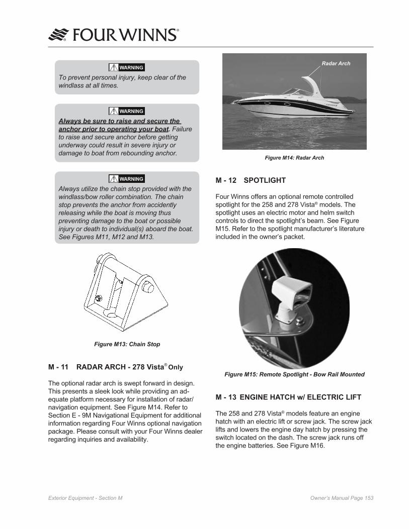
Owner’s Manual Page ���Exterior Equipment - Section M
To prevent personal injury, keep clear of the windlass at all times.
Always be sure to raise and secure the anchor prior to operating your boat. Failure to raise and secure anchor before getting underway could result in severe injury or damage to boat from rebounding anchor.
Always utilize the chain stop provided with the windlass/bow roller combination. The chain stop prevents the anchor from accidently releasing while the boat is moving thus preventing damage to the boat or possible injury or death to individual(s) aboard the boat. See Figures M��, M�� and M��.
Figure M13: Chain Stop
M - 11 RADAR ARCH - 278 Vista® Only
The optional radar arch is swept forward in design. This presents a sleek look while providing an ad-equate platform necessary for installation of radar/navigation equipment. See Figure M14. Refer to Section E - 9M Navigational Equipment for additional information regarding Four Winns optional navigation package. Please consult with your Four Winns dealer regarding inquiries and availability.
Figure M14: Radar Arch
M - 12 SPOTLIGHT
Four Winns offers an optional remote controlled spotlight for the 258 and 278 Vista® models. The spotlight uses an electric motor and helm switch controls to direct the spotlight’s beam. See Figure M15. Refer to the spotlight manufacturer’s literature included in the owner’s packet.
Figure M15: Remote Spotlight - Bow Rail Mounted
M - 13 ENGINE HATCH w/ ELECTRIC LIFT
The 258 and 278 Vista® models feature an engine hatch with an electric lift or screw jack. The screw jack lifts and lowers the engine day hatch by pressing the switch located on the dash. The screw jack runs off the engine batteries. See Figure M16.
Radar Arch

Owner’s Manual Page ���Exterior Equipment - Section M
The engine hatch can be lifted without the screw jack. Use care and proper lifting techniques to prevent possible back injury.
Do not have person(s) sitting in stern seat or standing on engine hatch while attempting to raise engine hatch. Possible injury to person(s) and/or damage to engine hatch and components may result.
NOTICENever operate or trailer your boat with the engine hatch in its open position. Doing so could result in damage to the engine hatch, hardware, and/or loss of cushions.
To lower the engine hatch:
1. Press the engine hatch switch (“DOWN”) to lower the engine hatch to its closed position.
1b. If lowering engine hatch manually, raise the hatch slightly and remove the engine hatch support (if applicable). Carefully lower the engine hatch to its closed position. Do not allow it to just drop to the deck.
If closing the engine hatch manually, do not allow the engine hatch to “slam” shut. Allowing the engine hatch to “slam” shut can damage the fiberglass and/or cause bodily injury.
2. Reinstall the cockpit table or aft fill-in cushion (if applicable).
NOTICECushions, if not properly stored and secured, can blow out of the boat.
Screw Jack
Figure M15: Electric Lift for Engine Hatch(Representative View - Models May Vary).
To raise the engine hatch:
1. Remove the cockpit table or aft fill-in cushion (if applicable)).
2. Press the engine hatch switch (“UP”) to raise the engine hood to its open position.
The engine hatch can be lifted manually if the screw jack fails to operate.
To raise the engine hatch manually:
1. Carefully raise the engine hatch using the hand hold and prop open.
Without properly propping engine hatch open during manual lifting procedure, engine hatch may fall resulting in possible personal injury and/or damage to engine hatch and components.

Owner’s Manual Page ���Upholstery - Section N
Figure N3: V-Berth Access Lids
The forward cabin may be converted from a dining area to a berthing space by using either support boards or V-berth fill-in support table (not to be confused with the cherry dinette table) and fill-in cushions. (Note: The fill-in cushions are also the backrest cushions). See Figures N4 and N5.
Figure N4: 258 Vista® V-Berth w/ Fill-In Cushions
Figure N5: 278 Vista® V-Berth w/ Fill-In Cushions
N - 1 INTERIOR SEATING
A. Dinette Table
A cherry dinette is standard on 258 and 278 Vista® models located in the V-berth /forward cabin area Table bases are “flush” mounted for convenience. Table legs are removable. Rotating the leg while lifting will ease the removal. See Figures N1 and N2. Table leg storage is provided underneath the V-berth cushions.
Figure N1: 258 Vista® V-Berth w/ Dinette Table
Figure N2: 278 Vista® V-Berth w/ Dinette Table
B. V-berth or Forward Cabin
Four Winns provides cushions for the V-berth/forward cabin area. These cushions simply drop into place. To gain access to the V-berth storage below simply remove these cushions and storage lids. See Figure N3.
Upholstery

Owner’s Manual Page ���Upholstery - Section N
The cherry dinette table,V-berth fill-in table or fill-in support boards can be stored in the aft cabin when not in use.
C. Mid Cabin (Aft Cabin) Berth
The mid cabin provides sleeping quarters with the use of fill-in cushions. Privacy can be obtained through the use of the privacy curtain. The mid cabin also includes a window with screen for ventilation. Storage in the mid cabin consists of an sidewall cabinet and a hanging closet. Overhead storage is found in the 278 Vista®. Also, access lids are installed below mid cabin cushions for gaining access to and the servicing of various plumbing systems and other equipment. See Figures N8 and N9 and the locator drawings in the back of this manual.
Figure N8: 258 Vista® Mid Cabin
Figure N9: 278 Vista® Mid Cabin
To convert the V-berth area into a sleeping berth follow the steps below:
1. Remove the cherry dinette table from the table leg.
2. Remove the leg from its floor mount. Rotating the leg while lifting will ease the removal.
3. Place the V-berth support boards or fill-in support table (depending on the model) into the recessed portion of the V-berth storage compartments. See Figures N6 and N7.
Figure N6: 258 Vista® V-Berth Support Boards
Figure N7: 278 Vista® V-Berth Fill-In Support Table
4. Remove the backrest cushions and place them on the support boards or fill-in support table
Reverse this procedure to return the berth back into a dinette.
To prevent personal injury, be sure the V-berth fill-in support(s) is/are secure before use.

Owner’s Manual Page ���Upholstery - Section N
Make sure legs are vertical and locked before using the aft stern seat (if applicable).
Additionally, an aft fill-in seat cushion is an available option for the 278 Vista® model. This feature extends the cushion area of the stern seat for such things as sunbathing, napping or overnight sleeping. Refer to Figure N11.
Figure N11: 278 Vista® Aft Fill-In Cushion
To install:
1. Insert the fill-in leg (13” short leg) into the floor mount.
2. Mount the fill-in support onto the fill-in support leg.
3. Place the aft fill-in cushion on the fill-in support.
To remove the aft fill-in cushion, simply reverse the procedure.
C. Mediterranean SunSport Seating - 258 Vista® Only
Standard on the 258 is the Mediterranean SunSport seating. The stern seat converts to a lounge with a reclining seat back. See Figure N12.
N - 2 EXTERIOR SEATING
A. Helm Seat
The helm seat is adjustable and double wide so it can seat two people comfortably. A manual, slider mechanism is mounted under the driver’s seat. This allows the driver of the boat to adjust the driver's portion of the helm seat to meet his or her needs. To adjust, pull the adjustment lever below the driver's seat towards the helm and slide the seat forward or aft to the desired position. There is approximately six inches of adjustment available. The helm seat includes flip-up bolsters. By simply flipping up the bolster the driver and/or passenger is able to sit higher in the seat. This is designed to give the driver and passenger greater flexibility, increased visibility, and riding comfort. See Figure N10.
Figure N10: Helm Seat & Bolster
DO NOT sit on the backrest portion of any cockpit seat. The operator could lose control of the boat or passengers could be thrown from the boat. The seat could also be dam-aged if excessive force is applied.
B. U-Shaped Stern Seat - 278 Vista®-
(Standard) & 258 Vista® (Optional)
The custom U-shape stern seat includes a fiberglass base. The U-shape seating arrangement continues around the back of the boat to create more seating area. Note: The 258 Vista® transom storage locker incorporates the stern seat base to provide storage for the cockpit table and legs.
On the 278 Vista® model Vista aft cockpit stern seat cushion folds up against the transom to allow for more floor space and access to the engine lid. The star-board cockpit cushion can also be removed.
Manual Adjustment Lever
Aft Fill-In Cushion
Fill-In Support
Support Mount
Fill-In Support Leg
Floor Mount
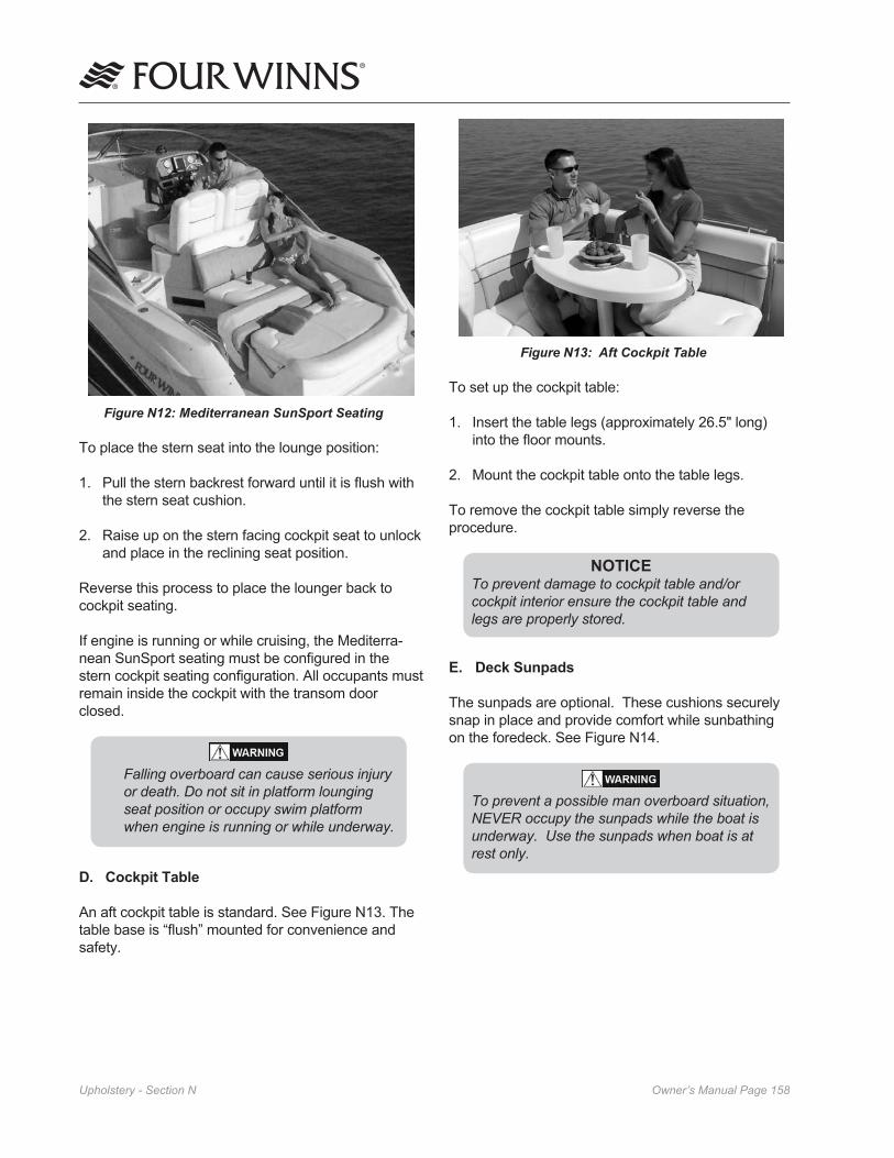
Owner’s Manual Page ���Upholstery - Section N
Figure N12: Mediterranean SunSport Seating
To place the stern seat into the lounge position:
1. Pull the stern backrest forward until it is flush with the stern seat cushion.
2. Raise up on the stern facing cockpit seat to unlock and place in the reclining seat position.
Reverse this process to place the lounger back to cockpit seating.
If engine is running or while cruising, the Mediterra-nean SunSport seating must be configured in the stern cockpit seating configuration. All occupants must remain inside the cockpit with the transom door closed.
Falling overboard can cause serious injury or death. Do not sit in platform lounging seat position or occupy swim platform when engine is running or while underway.
D. Cockpit Table
An aft cockpit table is standard. See Figure N13. The table base is “flush” mounted for convenience and safety.
Figure N13: Aft Cockpit Table
To set up the cockpit table:
1. Insert the table legs (approximately 26.5" long) into the floor mounts.
2. Mount the cockpit table onto the table legs.
To remove the cockpit table simply reverse the procedure.
NOTICETo prevent damage to cockpit table and/or cockpit interior ensure the cockpit table and legs are properly stored.
E. Deck Sunpads
The sunpads are optional. These cushions securely snap in place and provide comfort while sunbathing on the foredeck. See Figure N14.
To prevent a possible man overboard situation, NEVER occupy the sunpads while the boat is underway. Use the sunpads when boat is at rest only.

Owner’s Manual Page ���Upholstery - Section N
Figure N14: 258 and 278 Vista®Sundeck Pads
N - 3 INTERIOR UPHOLSTERY CARE
A. Cleaning Interior Fabric/Upholstery
The fabric used in the cabin should be treated the same as fabrics in your home. Periodic vacuuming and gentle cleaning will keep the fabric and upholstery clean and odor free. Spraying the fabric/upholstery with Lysol Spray Disinfectant™ will help retard mildew. For vinyl care see N-4A.
A recommended “Cleaning Kit” includes:
• Westley’s Clear Magic™ (for ordering information call 1-800-416-1600 or 800-321-8577; website address www.westleys.com)
• Fast & Easy Glass Cleaner™ (to locate the nearest distributor, call 800-537-8990)
• Tough Duty Cleaner™ (to locate the nearest distributor, call 800-537-8990)
• Clean, white towels
• Portable/Compact Deep Cleaner Vacuum (Bissell Spot Lifter™ or similar product)
• Air hose (if available)
To remove stains, please refer to the following list for recommended cleaners.
1. Basic Stains/Ink/Grease/Pencil/Dirt:
Westley’s Clear Magic™2. Adhesives/Teak Oil/Gum/Tar:
Tough Duty Cleaner™
3. Water Stains:
a. While fabric is still wet, use a deep cleaner vacuum to go over the wet area. This will remove the stain from the fabric. It is always best to get the stain before it dries.
b. For water stains that have dried, use a deep cleaner vacuum system. Follow the instruc-tions that come with the deep cleaner system. Repeat if necessary.
c. If this does not work we recommend a professional cleaning service. One such service is Service Master®. Please call 1-800-937-3783 for the Service Master location nearest you.
4. Tough Stains/Set Water Stains:
a. Spray Westley’s Clear Magic™ on the area, going two (2) inches around the stain or if possible, bring wetness to a break point, such as a bulkhead, etc. Spray water on the same area as directed on the bottle.
b. Let set approximately five (5) minutes.
c. Rub the area with a clean towel, rotating the towel as the stain is removed. As you rub, go a little beyond the wetness with the towel, flaring the edges.
d. Use a deep cleaner type vacuum to remove excess wetness. Allow to dry.
e. Repeat if necessary.
f. If stain still persists, use a professional cleaning service.
B. Interior Carpets
Four Winns Vista® cruisers use a high quality interior grade carpeting. Interior carpeting should be cleaned in the same manner as the carpeting in your home. Vacuuming and occasional rug shampooing are recommended for extended life and appearance.
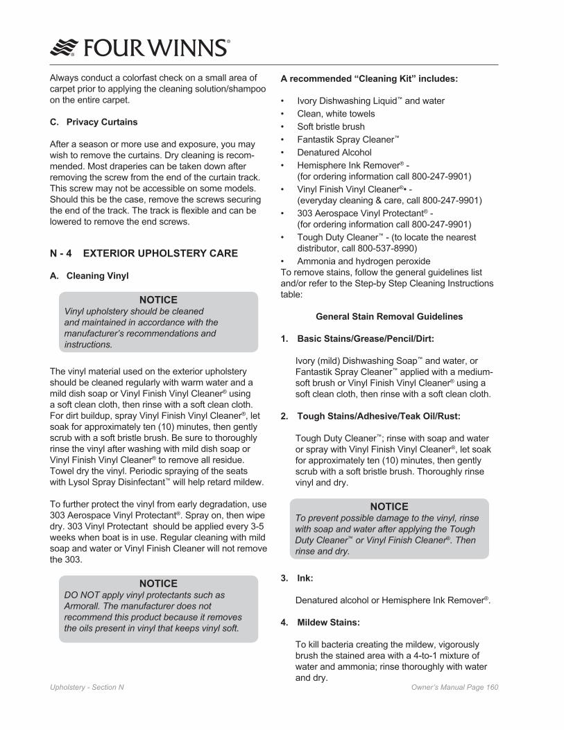
Owner’s Manual Page ��0Upholstery - Section N
Always conduct a colorfast check on a small area of carpet prior to applying the cleaning solution/shampoo on the entire carpet.
C. Privacy Curtains
After a season or more use and exposure, you may wish to remove the curtains. Dry cleaning is recom-mended. Most draperies can be taken down after removing the screw from the end of the curtain track. This screw may not be accessible on some models. Should this be the case, remove the screws securing the end of the track. The track is flexible and can be lowered to remove the end screws.
N - 4 EXTERIOR UPHOLSTERY CARE
A. Cleaning Vinyl
NOTICEVinyl upholstery should be cleaned and maintained in accordance with the manufacturer’s recommendations and instructions.
The vinyl material used on the exterior upholstery should be cleaned regularly with warm water and a mild dish soap or Vinyl Finish Vinyl Cleaner® using a soft clean cloth, then rinse with a soft clean cloth. For dirt buildup, spray Vinyl Finish Vinyl Cleaner®, let soak for approximately ten (10) minutes, then gently scrub with a soft bristle brush. Be sure to thoroughly rinse the vinyl after washing with mild dish soap or Vinyl Finish Vinyl Cleaner® to remove all residue. Towel dry the vinyl. Periodic spraying of the seats with Lysol Spray Disinfectant™ will help retard mildew.
To further protect the vinyl from early degradation, use 303 Aerospace Vinyl Protectant®. Spray on, then wipe dry. 303 Vinyl Protectant should be applied every 3-5 weeks when boat is in use. Regular cleaning with mild soap and water or Vinyl Finish Cleaner will not remove the 303.
NOTICEDO NOT apply vinyl protectants such as Armorall. The manufacturer does not recommend this product because it removes the oils present in vinyl that keeps vinyl soft.
A recommended “Cleaning Kit” includes:
• Ivory Dishwashing Liquid™ and water• Clean, white towels• Soft bristle brush• Fantastik Spray Cleaner™
• Denatured Alcohol• Hemisphere Ink Remover® -
(for ordering information call 800-247-9901) • Vinyl Finish Vinyl Cleaner®• -
(everyday cleaning & care, call 800-247-9901)• 303 Aerospace Vinyl Protectant® -
(for ordering information call 800-247-9901)• Tough Duty Cleaner™ - (to locate the nearest
distributor, call 800-537-8990)• Ammonia and hydrogen peroxideTo remove stains, follow the general guidelines list and/or refer to the Step-by Step Cleaning Instructions table:
General Stain Removal Guidelines
1. Basic Stains/Grease/Pencil/Dirt:
Ivory (mild) Dishwashing Soap™ and water, or Fantastik Spray Cleaner™ applied with a medium-soft brush or Vinyl Finish Vinyl Cleaner® using a soft clean cloth, then rinse with a soft clean cloth.
2. Tough Stains/Adhesive/Teak Oil/Rust:
Tough Duty Cleaner™; rinse with soap and water or spray with Vinyl Finish Vinyl Cleaner®, let soak for approximately ten (10) minutes, then gently scrub with a soft bristle brush. Thoroughly rinse vinyl and dry.
NOTICETo prevent possible damage to the vinyl, rinse with soap and water after applying the Tough Duty Cleaner™ or Vinyl Finish Cleaner®. Then rinse and dry.
3. Ink: Denatured alcohol or Hemisphere Ink Remover®.
4. Mildew Stains:
To kill bacteria creating the mildew, vigorously brush the stained area with a 4-to-1 mixture of water and ammonia; rinse thoroughly with water and dry.

Owner’s Manual Page ���Upholstery - Section N
NOTICEAll cleaning methods must be followed by a thorough rinse with water and drying.
Additional cleaning information is provided by the manufacturer and is included with this manual in the owner’s packet.
Four Winns offers a variety of weather covers for protection of the boat and associated equipment. Continued exposure can damage the upholstery and seating. The seating can become thoroughly saturated with water if not adequately protected. Refer to Section O - Weather Covers for more information.
NOTICEThe appearance and longevity of the exterior upholstery will be affected by water saturation. Protect these items appropriately.
B. Exterior Carpets
The removable exterior grade carpeting may be periodically washed with mild laundry soaps or shampooed, dried and reinstalled. It is 100% UV stabilized Olefin™ polypropylene fiber with rubber backing. See Figure N-15.
NOTICEPrior to using any mild laundry soaps or carpet shampoo, always conduct a colorfast test on a small inconspicuous portion of carpet before applying to entire carpet.
NOTICEDO NOT dry carpeting in an automatic dryer.
Figure N15: Cockpit Lay-in Carpets
5. Tough Mildew Stains:
Apply a mixture of one (1) teaspoon ammonia, one-fourth (1/4) cup of hydrogen peroxide, and three-fourths (3/4) cup of distilled water; rinse with water and dry.
All cleaning methods must be followed by a thorough rinse with clean warm water.
Certain household cleaners, powdered abrasives, steel wool and industrial cleaners can cause damage and discoloration and are not recommended. Dry cleaning fluids and lacquer solvents should not be used as they will remove the printed pattern and gloss. Waxes should be used with caution as many contain dyes or solvents that can permanently damage the protective coating.
*Suntan lotion, tree pollen, wet leaves and some other products can contain dyes that stain permanently. Care should be exer-cised and boat covers should be utilized.
Step-By-Step Vinyl Cleaning Instructions Table
NOTICEWhen docking or mooring your boat be aware of your surroundings i.e. trees with pollen, wet leaves, berries etc. These and other items can contain dyes that stain permanently. Utilize weather covers whenever possibly to protect vinyl from potential stains.
NOTICEALWAYS CLEAN STAINS IMMEDIATELY! DO NOT use �0� Cleaner™ or Armorall™ on vinyl. Do not use kerosine, gasoline or acetone as they will remove the protective marine topcoat.
Forward Lay-In Carpet
Helm Cockpit Lay-In Carpet
Aft Lay-In Carpets
Swim Platform Lay-In Carpet(Optional)
258 Vista® 278 Vista®

Owner’s Manual Page ���Upholstery - Section N
N - 5 REPLACEMENT UPHOLSTERY
Should upholstery become severely soiled, torn, or in some manner damaged, replacement upholstery cushions are available. Larger upholstery items have separate component parts for easier serviceability.
Depending upon the year and model of the boat, most upholstery parts can be obtained through your Four Winns servicing dealer within a short period of time.
NIATS ERUDECORPLAVOMER
esaerGevitomotuA A
)desUroweN(liOevitomotuA A
esaerGnocaB A
niatSyrreB A
doolB A
rettuB A
dratsuMropustaC A
muGgniwehC )taepeR(A
)%5(hcaelBenirolhC A
)detleM(etalocohC A
yalC A
aeTroeeffoC A
aloC A
noyarC B
eyD A
ggE A
seceF A
alumroFhsiF A
eciuJtiurF A
hsiloPerutinruF A
yvarG A
maerCecI A
)kcalBtnenamreP(knI B
)tniopllaB,otpircS(knI B
tsuRnorI A
kcitspiL B
esiannoyaM A
kliM A
tniaPxetaL A
tniaPesaBliO B
hsiloP B
tsuR A
gnisserDdalaS A
noitoLromaerCgnivahS A
raT B
enirU A
timoV A
sroloCretaW A
xaW B
eniW A
C. Cleaning and Maintenance
The following information should be useful in helping you keep your carpet looking well maintained.Carpet made with Olefin™ fiber possesses built-in stain and soil release for easy, less costly mainte-nance. Regular vacuuming and occasional sham-pooing will help it stay attractive and serviceable.
D. Stain Removal Testing
Even the most stubborn stains can be removed from Olefin fiber following the procedures outlined. Stains were selected as being representative of spills commonly occurring on carpets. Stains were pressed into the carpet to simulate foot pressure following a spill. Stains were applied to a two-inch square section and allowed to penetrate. Removal was performed after two weeks. Carpets were tested for stain removal by an independent laboratory. Stain removal was effective for the all the stains selected. Results are shown in the table on the following page.
E. Stain Removal Procedures
Regular maintenance such as vacuuming, hosing or washing should be performed. Most stains and mildew are easily removed from carpet made with Olefin fiber using common household cleaners. Refer to Table I. Olefin™ fiber is so resistant to chemical attack that Clorox™ bleach may be used to clean up any mildew that may result from excessive wetness.
Code for stain removal procedure (See Table 1):
“A” Apply warm water and household detergent in minimal amounts to stained area. Sponge or scrape until stain is removed. Rinse with clean water.
“B” Apply warm water and household detergent. Work well into stained area then flush with warm water.
Most stains should be easily removed however, if the stain persists, the cleaning procedure should be repeated to insure stain removal. Remember, the sooner the stain removal process begins, the easier the stain will be to remove.
NOTICEDo not use dry cleaning solvents on carpet or vinyl. Permanent damage to the fiber will result.
Table I: Stain Removal

Owner’s Manual Page ���Weather Covers - Section O
O - 1 GENERAL INFORMATION
Weather covers for the cockpit areas are available on all Four Winns® models. A bimini top and camper is standard on the 258 & 278 Vista® models. Four Winns® covers are designed and intended to provide protection of the cockpit seating areas.
Four Winns utilizes 100% acrylic-type material for most of its canvas. During the manufacturing of the weather covers, the smallest possible needle and highest quality UV stabilized, bonded polyester thread is used in the stitching.
Never use any form of open flame cooking device in any area fully enclosed or near weather covers. This material is flammable.
The weather cover is water repellent but not water proof. During a hard rain, you may notice a light mist permeating through a weather cover. This is normal. If the seams leak, they can be sprayed with Scotch-guard™ or similar type water repellent or a seam sealing compound can be applied. Keep objects from contacting the inside of the cover. Leakage may occur at point of contact.
Weather covers must be installed “snug” to prevent sags. The material relies on swelling to seal itself. If too taut or overly tight, the material will not seal and may tear.
NOTICEPeriodically check weather covers for accumulation of water. Damage to the bow assemblies may otherwise result. Make sure cover is snug to avoid puddling of water.
After use, the top canvas should be rolled up into the boot (supplied) and secured.
NOTICENEVER fold or store a wet weather cover. This can lead to mildew or shrinkage. Roll rather than fold the enclosure curtains. Sharp folds increase the chance of cracking the clear vinyl.
WEATHER COVERS
NOTICEDO NOT use the weather covers for outdoor winter storage. The weight of the snow or heavy rain can cause severe damage to the material or top structure. Refer to O-� - Winter Storage in this manual for more information.
Four Winns is utilizing snaps for the canvas. The snap sockets are a standard type. To unsnap, gently lift on the snap.
NOTICERemove snaps one at a time to prevent damage. DO NOT rip off or pull the weather cover as a whole; acrylic material will tear at snaps.
O - 2 GENERAL CANVAS INSTALLATION GUIDELINES
1) For safety and ease, it is recommended that two or more people are available to install or remove the canvas.
2) Ideally, canvas should be installed while the boat is in the slip or moored securely.
3) Be sure to observe all safety precautions to prevent the build-up of Carbon Monoxide - an invisible, odorless gas while the boat is running or underway.
4) Store canvas pieces flat, or if necessary, rolled; do not fold.
5) Bimini top, valances (arch boats) and/or camper top must be installed first; all other pieces attach to these pieces.
6) Partially zip zippers until all sides of a canvas piece are in position.
7) Support poles are adjustable; a button-release lets you slide the inner and outer tube to longer or shorter settings for a snug fit.
8) Unsnap canvas by lifting at the button to prevent damage; do not pull/yank.

Owner’s Manual Page ���Weather Covers - Section O
9) Clean canvas with warm water, mild soap and a soft brush. For the clear Isinglass pieces use a soft, clean cloth. Be certain to rinse cloth often to remove any dirt collected in the cloth that could scratch the clear vinyl.
10) Make sure your bimini top and camper top are
properly centered prior to installing the Isinglass enclosure.
O - 3 TRAILERING
High winds encountered during trailering your boat can severely damage most weather covers. If an extended trip at highway speeds is planned, the top and other weather covers should be booted or removed entirely. This will prevent damage and/or loss. See Figure O1.
Bimini Boot
Camper Boot
Figure O1: Bimini & Camper Tops - Booted
NOTICEDO NOT tow your boat at highway speeds with weather covers in place. High winds encountered during trailering your boat can severely damage most weather covers. Damage to weather covers incurred as a result of trailering your boat is not covered under warranty.
O - 4 BIMINI TOP
The bimini top is standard and provides cover/shade for the forward cockpit area. It is designed to be fastened to the radar arch (if applicable) and deck with the use of a track with valance and stainless steel bows and hardware. For boats without a radar arches stainless steel bows, stainless steel hardware and straps are used. See Figure O2.
Bimini Top
Figure O2: Bimini Top
A clear plastic visor is provided and once installed it connects the forward windshield and the bimini top. Side bimini curtains are also made of clear plastic for visibility and connect the side portion of the windshield to the bimini top. The helm area is protected from the elements once the bimini top, forward windshield connector and bimini side curtains are installed.
The bimini top is factory installed, therefore, minimal adjustment should be necessary.
To install the bimini top:
1) Attach the bimini frame using the ball and socket mounts. See Figure O3.
2) Release the support pole and place in the forward mount; adjust upward to make it easier to zip canvas pieces.
3) Slide zippered valance into flexarail awning track on radar arch (if applicable); center visually, zip bimini to valance, snap to the radar arch. Omit this step on Vistas without radar arches.
4) Place zipper pocket over forward frame.
5) Lower the rear adjustable support pole to create tension on the bimini top.
6) Hint: If installing visor and side curtains, you may want to lower the adjustable support pole by 1-2 more notches.

Owner’s Manual Page ���Weather Covers - Section O
Installing valances:
1) Valances (Arch Boats) - small areas of canvas curtain -are use to attach larger canvas pieces to the vessel. There are valances for the bimini side curtains, camper top and camper side curtains. See Figure O4.
2) The bimini side curtain valance attaches with the velcro facing out.
3) The camper top valance attaches with the velcro facing in.
4) The camper side curtain attaches with the velcro facing out.
zippered valancein flexarail awning
Figure O4: Installing Valences
To install bimini side curtains & visor:
1) Install the bimini top and bimini side curtain valance (see previous installation instructions).
2) Locate the center, left and right windshield visors.
3) Attach the center visor piece to the bimini top, then each of the side visors - zipping each piece about 3” until all the parts are in position. See Figure O5.
4) Finish zipping all the visor pieces.
5) Snap to the top of the windshield (from the outside if possible).
6) Locate the starboard and port side curtains.
NOTICE Adjustable Bow Style Models
When attaching windshield connector and side curtains you may want to adjust your bows to provide more slack and thus ease the installation process. Press the spring pin to adjust accordingly. Once the windshield connector and curtains are installed, extend the bows to make the canvas taught and remove sags.
NOTICE Non-Adjustable Bow Style Models
When attaching windshield connector and side curtains you may need to unzip a portion of the bimini canvas from the arch (if applicable) to provide some slack thus ease the installation process. Do not unzip completely. Once the windshield connector and curtains are installed, zip the bimini top completely to the arch.
For bimini top removal, reverse the previously described procedure.
NOTICECanvas should be snug. If too taut or extremely tight, canvas could tear or pull at seams.
ball & socketmount
pull-pin
front adjustable support pole
flexarailawning
Biminitop
Figure O3: Bimini Top Installation

Owner’s Manual Page ���Weather Covers - Section O
NOTICEIn the event the canvas requires some maintenance or repair, remove the bimini camper canvas from the bow assembly. Unzip the bow sleeves, unsnap all snaps and straps, and remove the canvas.
O - 5 CAMPER
The camper is standard and provides cover/shade for the aft portion of the cockpit area. It too, is designed to be fastened to the radar arch (if applicable) with the use of a track with valance and stainless steel bows and hardware. For boats without a radar arches stainless steel bows, stainless steel hardware and straps are used. The camper aft curtain and camper side curtains can be installed to enclose the aft cockpit area. The camper and camper curtains used in conjunction with the bimini top, forward connector and bimini side curtains completely encloses the cockpit area when desired. See Figure O6.
Camper Canvas
Figure O6: Camper Canvas
To install the camper canvas:
1) With the long support poles in the back and the smaller, storage poles in the front (toward the radar arch or bow of boat), attach the camper top frame to the side mounts. See Figure O7.
2) Tighten the bolt, first with your fingers and then with a wrench or other appropriate tool.
3) Release the storage poles and mount them using the ball and socket provided; secure with the pin.
4) Unzip canvas boot, if necessary.
5) Extend storage poles to reduce tension on the top.
7) Zip each partially in place in all directions, then complete the zipping.
8) Snap to the boat (from the outside if possible).
9) Secure and smooth all velcro closures.
Bimini sidecurtains
windshieldvisors
Figure O5: Bimini Side Curtain & Visor Installation
NOTICEBoth the bimini and camper canvas have been designed and are intended to remain installed on the boat in the upright “stored” position. Four Winns does not recommend the bimini and/or camper assembly be removed from the boat unless absolutely necessary ie. winter storage.
NOTICEThe bimini and camper canvas is designed as temporary shelter only. It should not be left up unattended for any length of time. Violent weather could result in expensive damage. Misues is not covered under warranty.
NOTICETwo people are recommended if removal or installation becomes necessary. Care must be exercised so the radar arch (if applicable) or interior cockpit area does not become damaged. Use a protective covering to prevent damage to arch if necessary.

Owner’s Manual Page ���Weather Covers - Section O
10) Snap to boot.
11) Secure and smooth all velcro.
campertop
side curtain
aft curtain
aft railing
straps
Figure O8: Camper Side & Aft Curtain Installation
For camper removal, reverse the procedure described above.
This camper canvas is designed as temporary shelter only. It should not be left up unattended for any extended length of time. Violent weather could result in expensive damage. Misuse is not covered under warranty.
O - 6 COCKPIT COVER
The cockpit cover is optional and is used to cover the complete cockpit area and is intended as a short term storage cover. See Figure O9.
Figure O9: Cockpit Cover
6) Zip the camper top to the camper top valance for radar arch boats) or zip the camper top to the bimini top on boats without a radar arch.
7) Adjust the support poles to create tension on the top.
8) Center the canvas.
9) Secure and smooth all velcro closures.
campertop valance
storage polesrear support poles(adjustable)
side mount(tighten bolts)
Figure O7: Camper Canvas Installation
To install the camper side & aft curtain:
1) Follow directions for camper top installation (see previous installation instructions).
2) Starting at the top, start each zipper.
3) When aII zippers have been started, complete zipping.
4) Snap the side curtains to the boat.
5) Smooth all velcro down.
6) Locate the aft curtain. See Figure O8.
7) Zip the aft curtain to the curtain top, starting at the center.
8) Secure with a strap to the aft railing or snap to transom.
9) Zip to port and starboard curtains.

Owner’s Manual Page ���Weather Covers - Section O
NOTICEIt is recommended that you retain your canvas locator tags (certain models only). In the event that replacement parts are needed, contact your Four Winns dealer.
O - 7 USE OF WEATHER COVERS AND CARBON MONOXIDE
When an engine is running, a natural vacuum may exist with the right wind and sea conditions to allow exhaust gases (which includes carbon monoxide) to seep into the boat. When canvas is utilized, this compounds the possibility of this occurring and inhibits natural ventilation. For more information, refer to Section B-2 - Carbon Monoxide in this manual.
The carbon monoxide in exhaust fumes can be hazardous. It is important for you and your pas-sengers to be aware of the potential safety hazard created by exhaust fumes. Familiarize yourself with the symptoms of individuals overcome by carbon monoxide, and most importantly, ways you can protect yourself and your guests. See Figure O11 - Carbon Monoxide Canvas Warning Label and Figure O12 - Carbon Monoxide Warning Label.
Figure O11: Carbon Monoxide Canvas Warning Label
To install the cockpit canvas:
1) A cockpit cover is intended for short term storage only. Do not operate the vessel with the cockpit cover installed due to the potential for carbon monoxide gas build-up.
2) Find the center point on the canvas and attach it to the center point of the windshield.
3) Working outward equally in both directions, continue snapping the canvas in position.
4) When the canvas extends far enough, separate the velcro strips and install the cover around the bimini support poles. Reattach and smooth out the velcro. If applicable, slide the awning track into the flexarail and attach to the inside of the radar arch.
5) Install support poles loosely - without a lot of tension at this point.
6) Attach straps to aft rail and pull to adjust. See Figure O10.
7) Raise support poles to keep water from pooling on top of canvas.
8) Snap walk-thru area and visually check all your work.
straps
cockpit cover
support poles
Figure O10: Cockpit Cover Installation

Owner’s Manual Page ���Weather Covers - Section O
Moisture, dirt, chemicals from industrial fallout, heat, ultraviolet rays and in some cases, salt water are factors which affect the longevity of acrylic covers. See Figure O13.
1. Moisture can cause shrinkage and mildew. Allow the cover to dry thoroughly before disassembling tops. Keep it clean and well ventilated to prevent mildew. Spraying the weather cover with Lysol Disinfectant™ or similar product will help prevent mildew.
Figure O12: Carbon Monoxide Warning Label
O - 8 WINTER STORAGE
The boat must be properly protected during winter dry dock storage. A winter storage cover is advisable. Many marine dealers offer shrinkwrap enclosures for outdoor storage. See a Four Winns dealer for informa-tion on the availability of winter storage covers or other alternatives for storage.
When storing outdoors, make sure the supporting framework keeps the weight of the snow and rain from accumulating on the storage cover. Proper ventilation must also be provided or dry rot and mildew will occur. See Section R - General Maintenance for additional winter storage information.
O - 9 MAINTENANCE
Figure O13: Canvas Care & Maintenance Tag
2. Dirt creates a starting point for mildew when mois-ture is present. Clean the top with a sponge or soft scrub brush and mild detergent when the cover is installed. Make sure cover is snug to help prevent shrinkage.
3. Chemicals cause decay if allowed to accumulate for long periods of time. Keep the cover clean to prevent decay.
4. Heat can cause cracks in vinyl components and stiffening of fabric when enclosed in plastic or polyethylene. DO NOT store the weather cover in polyethylene under direct sunlight or high tempera-ture situations.
5. Ultraviolet degradation may occur under prolonged exposure to direct sunlight. Store the top in the boot when not in use.
6. Salt water can corrode brass, aluminum, or stainless steel fittings and fasteners. Keep fittings clean, lubricated, and waxed to prevent corrosion.
Clear vinyl curtains and windows demand extra care to prevent scratching. Hose clean water onto vinyl to rinse off salt, dirt, or grime prior to using a soft, clean cloth. Dirt or grit in the cloth will scratch the vinyl window. Be sure to rinse cloth often.
NOTICEDO NOT use hot water. DO NOT dry in an automatic dryer. DO NOT dry clean or steam press.
Leakage after cleaning may be the result of insuffi-cient rinsing. Re-rinse. If leakage continues, apply a coat of silicone air drying water repellent, such as Scotchguard™. See your Four Winns dealer for additional information on weather covers.

Owner’s Manual Page ��0Exterior Equipment - Section P
P - 1 HULL DESIGN INFORMATION
Four Winns® boats are designed using the sound engineering and mathematical principles of hydro-statics, hydrodynamics, structure, and strength of materials. The materials utilized provide optimum strength at the lightest possible weight. The exact fiberglass laminate schedule and construction techniques of each part is determined in accordance with the strength and rigidity required.
P - 2 FIBERGLASS CONSTRUCTION
The fiberglass components of Four Winns® boats are of the finest quality materials, workmanship and construction techniques available. This ensures the structural integrity to provide years of boating enjoyment with minimal maintenance.
The construction of a Four Winns® hull begins with the application of gel coat to the mold. The gel coat is approximately 25 mils thick. A coat of resin and chopped fiberglass is then sprayed into the hull and carefully hand rolled until it is securely affixed to the gel coat.
A number of fiberglass layers and woven roving are applied to the above laminate. Each layer is hand laid and hand rolled. The keel and chine areas have fiberglass woven roving overlapped in these areas to provide additional strength. Most Vista® models utilize encapsulated end-grain balsa core or coremat laminates to achieve additional rigidity. Others utilize additional laminations of woven roving to maintain strength and rigidity.
The hull support stringers are located using special tools, and are fiberglassed and/or bonded into place. This ensures a strong, rigid hull, permanently formed into a solid assembly, free of distortions.
Fiberglass cockpit liners and seat base are construct-ed similar to the hull. Balsa core or coremat lamin-ations are utilized when necessary.
In addition to a thorough visual inspection of each fiberglass component, samples are measured using special equipment, for fiberglass reinforcement to resin ratio, laminate configuration, weight and thick-ness. By these procedures Four Winns ensures proper composition.
P - 3 EQUIPMENT INSTALLATION
Many boats are used for specific purposes or under conditions which require the addition of special equipment to the hull or deck. Special care must be taken during the installation of any equipment to a fiberglass component. A polysulfide or butyl based sealant should be used to seal installations below the water line. Silicone “marine” seal or similar bedding compound should be used elsewhere.
NOTICEDO NOT install any item onto or through the hull without adequately sealing the hull area penetrated by the installed item or related fasteners. Improper installations could cause leakage or allow water absorption and thus cause serious hull damage.
Always pre-drill fastening holes with a proper size bit. Pre-drilling will help prevent the fiberglass from splintering and thus causing unsightly damage. Also, countersink holes to prevent the gel coat from chipping.
Any equipment which will be subjected to cyclic loading or significant force should be through-bolted to a fiberglass component. A butt block or backing plate should be used to strengthen any area onto which an item will be mounted.
P - 4 FIBERGLASS CARE & MAINTENANCE
Fiberglass is affected by weathering processes and requires maintenance on a periodic basis to help maintain the beauty and shine. The effects upon the gel coat will be dependent upon boating conditions, storage, type of use, and the care given to the boat during the boating season.
Four Winns utilizes fade-fighting gel coat in the exterior finish. It is specially formulated to resist fading and yellowing, and retain more of its original gloss than better grade gel coats. However, it is still impor-tant to maintain the gel coat to protect the finish.
A. General Maintenance
For fresh water use, the boat should be washed once or twice a month. When using in a salt water environ-ment, considerable more care will be necessary. Be careful when selecting a cleaning agent. Hand dish
Fiberglass and Hull Information

Owner’s Manual Page ���Exterior Equipment - Section P
Waxing decks, cockpit floors or other walking areas is not recommended. Waxing will produce a very slippery surface, especially when wet. Wax may also buildup in the skid-resistant surfaces. Be sure all persons wear deck shoes while aboard the boat. Footing will be improved and feet will be protected from accidental cuts and bruises.
A darkening or discoloration of the skid-resistant surfaces can sometimes occur as a result of wax buildup. Exposure to the sun and elements can turn the wax darker, or occasionally can cause it to become flaky or powdery. To remove, use fine rubbing compound and a low rpm buffer (1200 to 2000 rpm). Apply light pressure and keep the buffer moving at all times to prevent heat build- up. Read the directions before using any equipment.
B. Weathering Effects on Gel Coat
Weathering occurs from direct sunlight, water, chemi-cals, and dust. Some of the terms below describe the changes that can occur to the gel coat surface.
Chalking is a result of the gel coat’s top surface being broken down into an extremely fine powder. When this happens, the color whitens. The chalk is present on the surface only.
Fading is the uniform change in color. This happens when the actual pigments have changed color, especially from excessive chalking, or when the gel coat has either been stained or bleached by something.
Yellowing is gel coat which has a yellow cast and streaking usually deals with a stain or contact with another surface.
Gloss refers to the shine of the surface. This can change from sanding action, chalk, residues, or exposure.
Blistering refers to a condition in which the unpro-tected gel coat surface below the waterline has absorbed water and formed bubbles. See Section P-5 for additional information.
Follow the instructions below for boats that have weathered and chalked.
washing detergents are usually gentle and are recommended for cleaning gel coat. Cleaning prod-ucts such as Ivory™ or Dawn™ hand dish washing liquid can be safely used. Always read the label before using any product.
NOTICEDO NOT use acetone, paint thinner, solvents, or strong alkaline based detergents, nor cleaners with a “gritty” and abrasive texture. Avoid products which contain sodium phosphate. Common examples of these types of household cleaning agents are: Tide™, Oxydol™, Janitor-in-a-Drum™, Fantastik™, Clorox™, etc. Always read the label before using an agent.
There are several products available which are specifically designed to clean fiberglass exterior finishes. Many companies like Johnson & Johnson®, Turtle Wax®, etc. manufacture cleaning fluids mild enough to clean without stripping the wax.
NOTICETreading on a soiled fiberglass surface can severely scratch and mar the finish. Keep the fiberglass as clean as possible.
When cleaning skid-resistant areas, DO NOT attempt to use a wire brush or sandpaper because this will remove the skid-resistant gel.
Apply wax once or twice a year to maintain gel coat lustre. Read the label before using any product. Make sure product is formulated for gel coat surfaces. Also, consult a Four Winns dealer for their recom-mendations.
NOTICEDo not use carnuba based waxes. This type of wax yellows over time and makes the fiberglass appear yellow.

Owner’s Manual Page ���Exterior Equipment - Section P
1. Wash.
2. Wax. If this does not work, then use a fine rubbing compound. If this does not work use 400 or 600 wet or dry sandpaper, followed by fine rubbing compound and wax.
When using wax or fine rubbing compounds, make sure to read the label and follow the directions. Some helpful tips are listed below.
1. Avoid working in direct sunlight. This dries out the wax or compound, and can stain the surface.
2. Use clean pads or cloths to apply a thin coating of wax or rubbing compound to a small area such as three feet by three feet. Remove any excess, and then rub the area with a buffing pad, or power buffer. Apply pressure only as necessary to restore the surface finish. Applying too much pressure or buffing in one place too long can permanently damage the surface.
3. After applying compound, always follow with waxing.
NOTICEIf using a power buffer, use a low RPM buffer with light pressure. Keep the pad wet and the buffer moving at all times to prevent heat buildup.
NOTICETo prevent gouges, uneven areas, or other damage from occurring, DO NOT use a power or belt sander when sanding. For best results, block sand the gel coat.
C. Stains
Stains can appear anywhere on the exterior of the boat and may be a result of contact with tar, plant sap, leaves, rust from metal fittings, and other materials. Surface stains may be removed with hand dish washing soap, mild cleansers, or some household detergents. DO NOT use chlorine or ammonia products. These products can affect the color of gel coat. Commercial car washes use strong cleaners and should be avoided.
To remove stains, refer to the procedures below.
1. Wash area with hand dish washing soap.
2. Begin with a small area such as three feet by three feet and apply a mild cleanser.
3. Rinse with clean water.
4. Follow with compound and waxing as outlined in procedure above.
If the stain is not removed by the hand dish washing soap or mild cleanser, then the next procedure is to use either denatured or rubbing alcohol. If this does not work, consult your Four Winns dealer for profes-sional assistance.
NOTICEDO NOT use acetone, ketone, or other solvents to remove stains. These chemicals are flammable and may damage the gel coat.
P - 5 FIBERGLASS REPAIRS
Fiberglass is one of the most durable, strong, and forgiving construction materials afloat. It is resilient and normal repairs can be made without affecting the strength or structural integrity of the boat.
Striking docks, other boats, or submerged objects could create a very hazardous situation or severely damage the fiberglass. In the event an object is struck below or near the waterline, proceed directly and cautiously to the nearest service facility and remove the boat from the water. Closely inspect the hull for damage. If the outer fiberglass laminate was penetrated, repairs must be made prior to relaunch.
Occasionally, blisters, crazing, scratches or damage to fiberglass can occur. Repairs may be necessary to correct the problem.
A. Scratches
Scratches occur during normal use. The following is a step by step procedure to repair scratches.
1. Clean area with soap and water.
2. Apply a fine rubbing compound and buff.
3. Wax.

Owner’s Manual Page ���Exterior Equipment - Section P
If this does not work, clean the area and sand lightly with 400 to 600 wet or dry sandpaper and follow with rubbing compound and wax.
B. Gouges & Cracks
Stress cracks and crazing are the appearance of hairline cracks in the gel coat surface. When present, these problems usually occur in the gel coat finish or the outer “skin coat” fiberglass laminate. The appear-ance of these cracks does not pose a threat to the structural integrity of the boat. In most cases, they are cosmetic and can be treated.
Cosmetic surface damage can be repaired as follows:
1. Sand the surrounding area with medium or fine grit sandpaper. Clean all marine growth, dirt, antifouling paint, etc. from the immediate area. DO NOT excessively scratch or gouge the surrounding area.
2. Use a hard, pointed tool to open the gel crack. Take care not to damage the surrounding gel coat.
3. Sand the crack or gouge so the edges are smooth and will allow proper “feathering” of the area.
4. Clean the area thoroughly. Make sure the area is dry before proceeding.
NOTICEBe sure the structure and the ambient temperature are above �0 degrees F (�� degrees C) and the relative humidity below �0% immediately before, during, and after the repair.
5. If the nick or gouge is deep and penetrates through the gel coat, fill the area with fiberglass patching paste. Follow the directions on the can when mixing the paste with the catalyst.
6. After the gouge is filled and has dried, sand the patched area. Begin by using medium-fine grade sandpaper. Progressively use finer grade sandpa-per until the surface is very smooth. If necessary, add filler and then sand the surface again.
7. Apply two or three light coats of matching fiber-glass gel coat to the repaired area. Enough gel coat should be used so that the entire area is
covered. The gel coat must be catalyzed using up to 2% MEK Peroxide which can be purchased at a supplier handling fiberglass reinforced products. Contact your Four Winns dealer for assistance.
8. After ample drying time, sand the area using very fine wet/dry sandpaper. If the appearance of the area is still not satisfactory, repeat steps 2 through 4 as necessary.
9. If above the waterline, polish the area using a fiberglass rubbing compound and then wax. If the repaired area is below the waterline, the area should be primed and painted in accordance with the antifouling paint manufacturer’s instructions.
Gel coat, like paint, will change colors with time and exposure to sunlight (ultraviolet). For this reason, “matching” gel coat obtained from Four Winns may not match the gel color of a boat that has been exposed. However, this is the closest match commer-cially available. A fiberglass technician can tint the gel to be used in the repair to provide a closer color match.
More severe fiberglass damage, especially when structural, requires the expertise of an experienced fiberglass repair technician. See your Four Winns dealer for assistance.
NOTICEImproper repair techniques can lead to further fiberglass component damage.
C. Osmotic Blistering
Osmotic blistering or “boat pox” is an unfortunate but not uncommon occurrence in fiberglass boats. Fiberglass is water retardant, not waterproof. When a boat is left in the water for a period of time, the fiberglass will absorb water. It is a natural process that can not be eliminated in production methods or material selection and usage. However, there are ways to control and possibly prevent blisters (see Sec-tion P-6). If you do encounter blisters, be assured that the blisters are merely cosmetic. They do not indicate a defect in the boat structure or lamination. Four Winns, along with most boat manufacturers, regard gel blisters as a standard maintenance item.
The repair procedure for gel coat blisters is similar to the procedures outlined in the previous section on cracks and gouges. There is an exception however, in

Owner’s Manual Page ���Exterior Equipment - Section P
Prior to application of the antifouling paint, the boat owner may consider coating the hull bottom with an epoxy coating. Four Winns recommends this proce-dure as a preventive and effective means of control-ling osmotic blistering. Most major antifouling paint manufacturers also supply a line of epoxy undercoat-ings. Consult your Four Winns dealer for recom-mendations on epoxy undercoatings.
P - 7 HULL SUPPORT
Proper support of the hull while it is out of the water is imperative. Due to the design complexities, Four Winns does not recommend trailers or storage cradles be homemade. The boat is a valuable piece of equipment. DO NOT risk permanent damage to the hull structure in an attempt to save the cost of an adequate support. Improper support can lead to serious and permanent hull deformation.
While lifting the boat, ensure slings are in the proper locations as indicated by the sling location labels. Failure to do so may result in permanent hull structure damage and will invalidate the hull structure warranty.
NOTICEWhen attempting to raise the hull, never allow one end of the boat to rise first, while letting the opposite rest momentarily on the underwa-ter gear. Serious damage to these components could result. DO NOT place lifting straps on underwater gear. Be sure the strap is against the hull surface only and are in proper location as indicated by the sling label location.
A trailer, or storage cradle designed for a larger or smaller boat will not provide proper support for the hull. This could lead to hull deformation and thus serious performance deficiencies.
that the hull must dry out for several days or possibly weeks before repairs can proceed.
To determine if the hull has dried sufficiently, tape one square foot of household plastic wrap securely to the hull bottom. Make sure all edges are sealed and let it stand for twenty-four hours. If condensation has accumulated under the plastic, the hull is still “wet” and must be allowed to dry longer before repairing.
When the repair is completed, an application of an epoxy barrier coat should be considered. This will help prevent the possibility of reoccurrence of blisters. Your Four Winns dealer or local ship store will have informa-tion on barrier coat products.
P - 6 ANTIFOULING PAINT
Four Winns recommends antifouling or bottom paint for boats which will be kept in the water for extended periods of time. Antifouling paint reacts with water to retard the growth of algae, barnacles and other marine growth on the hull. In addition to marine growth, it offers protection against excessive water pollution.
Antifouling paint begins reaction upon contact with water. After a season’s use or sooner under certain conditions, the antifouling paint may appear to be dissolving. This is due to the paint’s chemical emis-sion that in turn retards marine growth. When this occurs, refinishing is in order. For bottom paint line locations, refer to the Figures P2 and P3 at the end of this section.
Four Winns recommends reapplication of the antifoul-ing paint seasonally. The effectiveness of the paint will be drastically reduced if used longer. Though Four Winns has found the antifouling paints used to provide good marine growth protection in most water, other paints may be more effective in certain water conditions. See a Four Winns dealer for recommenda-tions on antifouling paint use in your area.
NOTICEDuring surface preparation, the hull should be sanded only enough to remove any foreign matter, and loose paint. DO NOT sand deeply into the gel coat, fiberglass cosmetic problems could later result. After sanding, the surface should be wiped with a rag treated with a cleaner recommended by the antifouling paint manufacturer. The surface must be clean and slightly rough to ensure paint adhesion.

Owner’s Manual Page ���Exterior Equipment - Section P
Figure P2: 258 Vista® Bottom Paint Line Location
Figure P3: 278 Vista® Bottom Paint Line Location

Owner’s Manual Page ���Woodwork and Composites - Section Q
Q - 3 STAR BOARD
Star board is a high density polyethylene (plastic) and is very durable and fade resistant. Star board requires little maintenance, and is being used in place of wood in many areas of the boat.
To clean star board, use a solvent-free, nonabrasive cleaner such as hand dish washing soap or Fantastic™. Read the label before using any cleaning product.
NOTICEStar board will stain when exposed to certain oils or chemicals. Always wipe up any spills immediately.
Q - 4 LAMINATED FIBERGLASS
Certain components such as cockpit tables, seat bases, storage tubs, storage lids/doors, ect. may consist of a laminated fiberglass material. These components may be cleaned with mild dishwashing soap and water. After washing, a light coat of wax may be applied as necessary. Always read the label before using any product. See Figure Q2.
Figure Q2: Cockpit Table
NOTICEDO NOT use abrasive cleaners or solvents on cockpit table. DO NOT use Soft Scrub™ soap or similar cleaning products; they will scratch the surface and remove the shine.
NOTICEDO NOT use cockpit table as a cutting board. The knife will leave gouges/marks in the surface of the table.
WOODWORK AND COMPOSITES
Q - 1 HIGH-PRESSURE LAMINATE CARE
Much of the 258 and 278 Vista® interior components such as the shelving, cabinets, hanging lockers and drawer fronts consist of a high pressure laminate material. The finish is that of a synthetic cherry and can be cleaned with hand dish washing soap and water or other cleaning solutions such as Fantastik™. Always read the label before using any product.
NOTICEDO NOT use abrasive cleaners or solvents on laminate. DO NOT use Soft Scrub soap or similar cleaning products; they will scratch the surface and remove the shine.
Q - 2 CHERRY
Four Winns uses actual cherry wood for the dinette table. The wood is prepared with a light stain followed by a polyurethane finish. To clean, a damp cloth will usually suffice. Care should be similar for cherry as it is for fine, household furniture. See Figure Q1.
Figure Q1: 258 & 278 Cherry Dinette Tables & Interiors (Respectively)

Owner’s Manual Page ���Woodwork and Composites - Section Q
NOTICEDO NOT use abrasive cleaners or solvents on countertop. DO NOT use Soft Scrub™ soap or similar cleaning products; they will scratch the surface and remove the shine.
NOTICEDO NOT set hot pans or dishes directly on the countertop. The countertop may become burnt and/or discolored. Use of a hot pad will prevent any discoloration from occurring.
NOTICEDO NOT use countertop as a cutting board. The knife will leave gouges/marks in the surface of the countertop. A cutting board that fits over the sink is provided.
Q - 7 ACRYLIC PLASTIC - (PLEXIGLASS)
Acrylic plastic is utilized in the companionway doors, companionway hatches, transom doors, deck hatch-es, portlight windows, storage doors, electrical panel doors, and cabin windows. See Figure Q5.
Figure Q5: Companionway Door & Hatch
To clean acrylic plastic:
1) Rinse with plenty of water to wash off as much dirt as possible.
2) Using your bare hand, along with plenty of water, feel and remove any dried on dirt or mud. Do not use fingernails to scrape as this could scratch the plexiglass.
Q - 5 WOODGRAIN ENHANCEMENTS
Woodgrain enhancements are available on the 258 & 278 Vista® models. They consist of a finished synthet-ic burlwood. This burlwood may be found in the optional woodgrain steering wheel (not shown), and the ignition switch panel. To clean, a damp, clean cloth will usually suffice. See Figure Q3.
Figure Q3: Burlwood Helm
Q - 6 FIBERGLASS COUNTERTOP
The countertops for the cabin galley is made of laminated fiberglass. The exterior of the countertop is gel coat. This makes for an extremely strong yet lightweight countertop. It can be cleaned with mild hand dish washing soap and water or other cleaning solutions such as Fantastik™. Always read the label before using any product. Please read the following notices. See Figure Q4.
Figure Q4: Galley Countertop
Companionway Door
Companionway Hatch
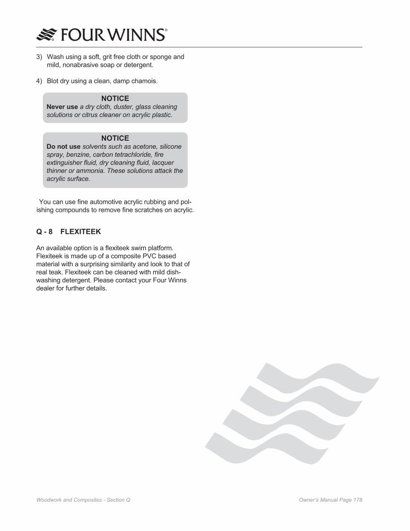
Owner’s Manual Page ���Woodwork and Composites - Section Q
3) Wash using a soft, grit free cloth or sponge and mild, nonabrasive soap or detergent.
4) Blot dry using a clean, damp chamois.
NOTICENever use a dry cloth, duster, glass cleaning solutions or citrus cleaner on acrylic plastic.
NOTICEDo not use solvents such as acetone, silicone spray, benzine, carbon tetrachloride, fire extinguisher fluid, dry cleaning fluid, lacquer thinner or ammonia. These solutions attack the acrylic surface.
You can use fine automotive acrylic rubbing and pol-ishing compounds to remove fine scratches on acrylic.
Q - 8 FLEXITEEK
An available option is a flexiteek swim platform. Flexiteek is made up of a composite PVC based material with a surprising similarity and look to that of real teak. Flexiteek can be cleaned with mild dish-washing detergent. Please contact your Four Winns dealer for further details.

Owner’s Manual Page ���General Maintenance - Section R
R - 1 WINTERIZATION
A. Prior to Lifting for Winter Lay-up
1. Pump out the head (dockside discharge), and be sure the holding tank is empty. Flush the head holding tank with soap, water and a deodorizer (e.g., Lysol Liquid™). Add more water if neces-sary. Have the cleaning solution pumped out.
2. Have the fuel tank either full or completely empty. See the Engine Owner’s manual for recom-mendations. Also, check with the dry dock opera-tors for recommendations. If winter storing with a full fuel tank, gasoline winterizer such as Sta-bil® fuel conditioner, will reduce varnishing, condensa-tion, etc.
NOTICEIf the fuel has been treated with winterizer, run engines for ten minutes to make sure the treated fuel is present in all lines and parts of the engines.
3. Drain water from the fresh water system and the hot water heater.
4. Winterize the engine and drive systems as recommended in the engine owner’s manual (applies to both gas and diesel systems). Portions of this winterization procedure may require that the boat be lifted. Winterization of engine and boat systems should be performed by qualified service personnel.
5. Lift the boat only at the designated “sling” labels. See Section P-7 - Hull Support and the Preface page 14 of this manual for additional details.
B. After Lifting
1. Remove the drain plug.
2. Thoroughly wash the fiberglass exterior, especially the hull bottom. Remove as much marine growth as possible. Wax lightly.
3. Lower boat onto cradle properly or place boat on trailer. Be sure boat is adequately supported. The boat should be raised slightly under the forward supports or trailer tongue to improve drainage to the transom drain.
4. Be sure all the water is completely drained from the fresh water system. Disconnect all hoses, check valves, etc. and blow all the water from the system using very low air pressure. The use of nontoxic, fresh water system antifreeze is recom-mended as an alternative to disassembling the water system. Refer to Section J-7 - System Maintenance in this manual for information on winterizing the water system.
5. Winterize the head as recommended by the head manufacturer. If the boat is equipped with a holding tank, mix some antifreeze solution and pour it into the head. Transfer some of the anti-freeze to the holding tank by flushing the head. Also, refer to Section J-7 - System Maintenance for additional information.
6. Drain or winterize the air conditioning and genera-tor system. Follow the appropriate manufacturer’s directions. Be sure all water intake filters are drained thoroughly.
7. Ensure that all water is removed from the sump pump, bilge pump and bilge pump lines. Dry the hull bilge, and self-bailing cockpit drain troughs. Water freezing in these areas could cause dam-age. See Section K-3 - Hull Drainage Systems.
8. Remove the batteries and store in a cool place. Clean the batteries using clear, clean water. Be sure the battery has sufficient water and clean terminals. Keep the batteries charged throughout the storage period. DO NOT store the batteries on a concrete floor or other damp or conductive surface.
9. Drain the alcohol out of the stove (if applicable) and store alcohol in a cool, dry place away from heat or spark.
10. Clean the boat interior thoroughly. Vacuum carpets, and dry clean drapes and upholstery jackets as necessary.
11. Wash exterior fiberglass components, wax lightly.
12. Clean exterior upholstery with hand dish washing soap and water, rinse, and dry thoroughly.
13. Remove all oxidation from exterior hardware and apply a light film of moisture - displacing lubricant.
General Maintenance

Owner’s Manual Page ��0General Maintenance - Section R
C. Prior to Winter Storage
1. Remove as many cushions as possible. Remove storage lids or hatches. Open as many locker doors, as possible. Open the refrigerator door. Leave these areas open to improve ventilation.
2. Spray the weather covers and the boat upholstery with Lysol Spray Disinfectant™. Enclosed areas such as the refrigerator, shower basin, storage locker areas, etc. should also be sprayed with Lysol Disinfectant™.
3. Place small dishes of rodent poison such as D-Con™ in a number of areas around the boat. Be sure dishes are placed near the head and the engines, as rodents will destroy upholstery, water intake and discharge hoses.
4. If the boat will be in outside storage, properly support a storage cover and secure it over the boat. DO NOT secure the cover tightly to the boat. This does not allow adequate ventilation and can lead to dry rot. DO NOT store the boat in a damp storage enclosure. Excessive damp-ness can cause electrical problems, corrosion, and dry rot.
Placing an electric or fuel burning heating unit in the bilge of the boat during cold weather could cause fire or explosion and is not recommended.
5. DO NOT use the bimini top or camper top as a winter storage cover. The life of these covers may be significantly shortened if exposed to harsh weather elements for long periods.
NOTICEBoats stored outside in areas with heavy snow accumulation are more susceptible to damage, and should be inspected regularly during the winter months.
R - 2 ENGINE FLUSH OUT
The optional engine flush out (if applicable) should be used to clean the engine of unwanted salt, mud, sludge, etc. which may have accumulated in the engine cooling system. Before winterizing the engine, flush out the system for about ten minutes.
A. Volvo Penta® Engine Flush Out (Four Winns Installation)
Make sure that no section of flush hoses is in contact with moving or hot engine parts or abrasive surfaces such as screw threads, sharp edges, etc., which could damage the hoses. Damage to the hoses could cause leaks and possible flooding of the engine compartment. Periodically check hoses for abrasions.
NOTICEThe Four Winns installed flush out kit for Volvo Penta® engines is identified by a transom deck mounted coupler & cap. This type of flush out may be used with the boat in or out of the water and the engine OFF.
Volvo Penta’s engine flush out is directly attached to the engine itself and is identified by a blue cap. If the engine comes with this type of flush out kit installed from Volvo Penta, follow the procedure included in the engine operator’s manual only.
To flush out the engine with Four Winns installed flush out kit, follow the instructions below:
1. Do not run engine during flushing procedure.
2. Remove cap from coupling and attach water supply hose.
3. Turn water on and allow water to flush the engine and exhaust manifold for about ten minutes.
4. Turn water off. Disconnect hose; replace and tighten cap securely.
Reinstall cap onto coupler after flushing for both types of flush outs. The cap must be secured after flushing of engine to prevent air from entering the system and resulting in possible engine damage.

Owner’s Manual Page ���General Maintenance - Section R
B. MerCruiser® Engine Flush Out Option
MerCruiser® engine flush out procedures if not followed in accordance to their specific instructions can result in costly engine damage. Follow MerCruiser’s specific instructions for flush-out procedures located in the Engine operator’s manual. Consult engine manufactuer’s authorized service center for additional assistance should further questions arise.
Make sure that no section of flush hoses is in contact with moving or hot engine parts or abrasive surfaces such as screw threads, sharp edges, etc., which could damage the hoses. Damage to the hoses could cause leaks and possible flooding of the engine compartment. Periodically check hoses for abrasions.
NOTICEThe Four Winns installed flush out kit for MerCruiser® engines may be used with the boat in or out of the water and the engine ON. See MerCruiser’s engine operator’s manual for the specific engine flushout procedure.
For out of water flushing, avoid possible injury by removing the propeller and ensure that no people or animals are in the area of the drive unit while flushing. Contact with moving drive components and the propeller can cause personal injury or death.
To flush out the Mercruiser® engine follow the guide-lines below as well as the specific procedure outlined in MerCruiser’s engine operator’s manual:
1. Remove cap from coupling and attach water supply hose.
2. Turn on water supply - See Engine owner’s manual.
3. The engine must be running at idle during flushing procedure.
4. Allow water to flush the engine and exhaust manifold for about ten minutes.
5. Turn engine OFF and turn water off. Disconnect hose; replace and tighten cap securely.
Reinstall cap onto coupler after flushing. The cap must be secured after flushing of engine to prevent air from entering the system and resulting in possible engine damage.

Owner’s Manual Page ���General Maintenance - Section R
ECIVRESHCNUALTATSRIFDNA
*NOITAREPO
RUOH52HCAEKCEHC
*NOSAES
-LANOSAES-IBYREVEROYLROSHTNOM6
001YREVE*SRUOH
YLLANOSAES21YREVERO
ROSHTNOM002YREVE
*SRUOH
noitatnemurtsnIdnaenignE EnoitceSotrefeR
ecnanetniaMenignE rerutcafunaMehtybdednemmoceRsA
snoitcennoCdnasesoHmetsyStsuahxEtcepsnI
srellepmIdnasnoitcennoC,sesoHmetsySgnilooCtcepsnI
srelleporPkcehC
sgnittiFlluH-urhTllAkcehC
hctiwSffO-tuhSycnegremEtseT
gninaelCeguaG
smetsySslortnoC FnoitceSotrefeR
tnemtsujdAtfihSdnaelttorhT
tseThctiwSytefaSlartueN
noitacirbuLlortnoCdnaelbaC
smetsySgnireetS GnoitceSotrefeR
noitcepsnInoitcennoCdnaegakniL
tnemtsujdAbaTeuqroTevirDnretS
ecivreSgnireetSrewoP rerutcafunaMehtybdednemmoceRsA
stnemtsujdAgnireetS
noitacirbuLmetsySgnireetS
smetsySlacirtcelE HnoitceSotrefeR
snoitcennoCyrettaBtcepsnI
retaWyrettaBkcehC
noitcepsnIelbaCyrettaB
noitarepOtnempiuqElacirtcelEtloV21
noitcepsnInoitcennoCdnagniriWtloV21
noitarepOtnempiuqElacirtcelEtloV021
noitcepsnIgniriWtloV021
tseTytiunitnoCmetsyStloV021
noitcepsnIretpadAdnadroCrewoPerohS
noitarepOthgiLytiraloP
noitcepsnInoitcennoCdnaelcatpeceR
ecnanetniaMrotareneG rerutcafunaMehtybdednemmoceRsA
tsuahxEdnaekatnIretaWrotareneGtcepsnI
R - 3 GENERAL MAINTENANCE SCHEDULE
* Or as Required
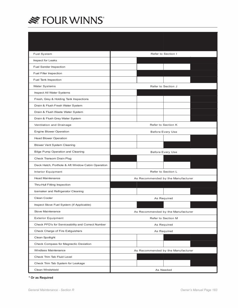
Owner’s Manual Page ���General Maintenance - Section R
* Or as Required
ECIVRESHCNUALTATSRIFDNA
*NOITAREPO
RUOH52HCAEKCEHC
*NOSAES
-LANOSAES-IBYREVEROYLROSHTNOM6
001YREVE*SRUOH
YLLANOSAES21YREVERO
ROSHTNOM002YREVE
*SRUOH
metsySleuF InoitceSotrefeR
skaeLroftcepsnI
noitcepsnIredneSleuF
noitcepsnIretliFleuF
noitcepsnIknaTleuF
smetsySretaW JnoitceSotrefeR
smetsySretaWllAtcepsnI
snoitcepsnIknaTgnidloH&yerG,hserF
metsySretaWhserFhsulF&niarD
metsySretaWetsaWhsulF&niarD
metsySretaWyerGhsulF&niarD
eganiarDdnanoitalitneV KnoitceSotrefeR
noitarepOrewolBenignE esUyrevEerofeB
noitarepOrewolBdaeH
gninaelCmetsyStneVrewolB
gninaelCdnanoitarepOpmuPegliB esUyrevEerofeB
gulPniarDmosnarTkcehC
noitarepOnibaCwodniWtfA&elohtroP,hctaHkceD
tnempiuqEroiretnI LnoitceSotrefeR
ecnanetniaMdaeH rerutcafunaMehtybdednemmoceRsA
noitcepsnIgnittiFlluH-urhT
gninaelCrotaregirfeRdnarekamecI
relooCnaelC deriuqeRsA
m (If Applicable)etsySleuFevotStcepsnI
ecnanetniaMevotS rerutcafunaMehtybdednemmoceRsA
tnempiuqEroiretxE MnoitceSotrefeR
rebmuNtcerroCdnaytilibaecivreSrofs'DFPkcehC deriuqeRsA
srehsiugitxEeriFfoegrahCkcehC deriuqeRsA
thgiltopSnaelC
noitaiveDcitcengaMrofssapmoCkcehC
ecnanetniaMssaldniW rerutcafunaMehtybdednemmoceRsA
leveLdiulFbaTmirTkcehC
egakaeLrofmetsySbaTmirTkcehC
dleihsdniWnaelC dedeeNsA

Owner’s Manual Page ���General Maintenance - Section R
* Or as Required
ECIVRESHCNUALTATSRIFDNA
*NOITAREPO
RUOH52HCAEKCEHC
*NOSAES
-LANOSAES-IBYREVEROYLROSHTNOM6
001YREVE*SRUOH
YLLANOSAES21YREVERO
ROSHTNOM002YREVE
*SRUOH
yretslohpU NnoitceSotrefeR
yretslohpUnaelC
tepraCnaelC
losyLhtiwyretslohpUyarpS
erawdraHgnitnuoMdnasegniHtaeSkcehC
srevoCrehtaeW OnoitceSotrefeR
srevoCrehtaeWhsaW
losyLhtiwsrevoCrehtaeWyarpS
lluHdnastnenopmoCssalgrebiF PnoitceSotrefeR
).cte,staes,sliargniruces(sgninetsaFllAkcehC
ylhguorohTssalgrebiFnaelC
saerAdaerT-noNllAdnasediSlluHxaW
egamaDrofsaerAssalgrebiFtcepsnI
sriapeRpU-hcuoTroniMmrofreP
tniaPgniluoF-itnAylppA-eRdnalluHdnaS
ecnanetniaMetisopmoC&krowdooW QnoitceSotrefeR
elbaTdooW&mirTdooWnaelC dedeeNsA
draoBratSnaelC dedeeNsA
spotretnuoC/selbaTtipkcoCnaelC dedeeNsA
dedeeNsAClean Plexiglass Components

Owner’s Manual Page ���Trailer Information - Section S
Laws covering such items as trailer brakes, lights, safety chains, etc., will vary from state to state. Please contact the motor vehicle department in your state for additional information.
B. Load Carrying Capacity
The certification label shows the maximum load-carrying capacity and is located on the port forward side of the trailer. The Gross Vehicle Weight Rating (GVWR) is the load-carrying capacity plus the weight of the trailer itself. DO NOT exceed the GVWR rating for the trailer.
NOTICEWhen using or choosing a tow vehicle with the correct GVWR, you must consider not only the weight of the boat and trailer but also the weight of the fuel, water, equipment, etc. Refer to Table � below:
TNEMPIUQETHGIEW
)EGAREVA(
yrettaB .sbL06
leuF .laG/.sbL5.6
retaW .laG/.sbL8
seirosseccA .sbL051)etamixorppA(
Table 1: Average Equipment Weight
If selecting a trailer from another manufacturer, check the load-carrying capacity. A trailer with a load-carrying capacity that is too low will be unsafe on the highway and could cause sudden failure of critical trailer components or abnormal tire wear. A trailer with too high of a load-carrying capacity that is sprung for heavy loads can damage a lighter boat.
NOTICEDO NOT overload your trailer by placing camping gear or other heavy equipment in the boat. DO NOT exceed the GVWR rating. Damage to the hitch, coupler, or trailer may occur.
S - 1 GENERAL TRAILER INFORMATION
The trailer must properly “match” the boat’s weight and hull design. Four Winns® trailers are designed specifically for certain models only. Please consult our website at www.fourwinns.com or your Four Winns dealer for applicable trailer models. Four Winns® trailers meet or exceed the National Marine Manufacturers Association’s trailer requirements.
Four Winns manufactures bunk type trailers for the applicable models only. The bunks are located specifically for Four Winns® boats and adequately support all parts of the boat. It is a “drive-on” type trailer which means winching the boat from the water is not necessary.
NOTICEWhen winching the boat onto the trailer, be sure the bunks are wet to prevent damage to the boat or trailer. DO NOT attempt to winch the boat forward when out of the water. Damage to the winch stand/assembly or tongue could occur.
Four Winns offers both painted and galvanized trailers with GatorHyde™ protective coating. The painted trailer is intended to be used in fresh water and the galvanized trailer in salt/brackish water.
NOTICEFour Winns does not recommend the usage of painted trailers for salt/brackish water conditions, as trailer life may be substantially reduced.
A. Regulations
Federal law requires that the trailer and tire regis-tration information be compiled and recorded. The Four Winns® boat registration card includes trailer registration information. A trailer tire warranty card included in the owner’s packet, is to be filled out and returned to the tire manufacturer.
NOTICEManufacturer’s Tire Registry
Ensure to fill out your name and address on the tire registration form provided in your owners packet. Mail it to the tire manufacturer for the purposes of compliance with Federal defect notification regulations.
Trailer Information

Owner’s Manual Page ���Trailer Information - Section S
before purchasing a trailer hitch for your towing vehicle.
To help guard against a sudden failure while in use, do not use a worn hitch ball. Replace all worn or damaged parts.
S - 2 TRAILER COMPONENTS
A. Bunk Supports
All bunk boards are made of pressure treated wood. This wood is rot resistant. All boards are covered with a high quality exterior grade carpet to protect the boat from damage during normal use.
Bunk supports run parallel to the keel and support the hull, extending beyond the transom. See Figure S2.
Figure S2: Trailer Bunks
Outer bunk supports provide stability for the boat. The inside bunks are the main weight bearing mem-bers. Side guide-on supports (certain models only) help to keep the boat straight while driving the boat onto the trailer. Keeping the tie-downs tightly fastened will prevent the boat from bouncing against the bunk supports.
NOTICEImproper trailer setup can cause hull damage.
B. Tongue
Four Winns® trailers are designed with tongue weights between 5% and 10% of the total weight of the boat, fuel, gear and trailer. If the downward weight on the
For trailers, the steps to determining correct load limit are:
(1) Locate the statement “The weight of cargo should never exceed the XXX kg or XXX lbs.” on your vehicle’s placard. See Figure S1.
(2) This figure equals the available amount of cargo and luggage load capacity.
(3) Determine the combined weight of luggage and cargo being loaded on the vehicle. That weight may not safely exceed the available cargo and luggage load capacity.
Figure S1: Vehicle Placard
Improper weight distribution can place excessive strain on the towing vehicle and trailer. It can also cause the trailer to “fishtail” (sway side to side). Be sure gear and other items are distributed evenly in the boat.
C. Hitches
The load-carrying capacity of trailer hitches will vary between manufacturers and must equal or exceed the GVWR. Four Winns® trailers use surge brake systems and require a fixed hitch. Refer to Section S-2E Surge Brakes for more information.
Before hitching the trailer to the vehicle, make sure the proper size hitch ball is installed to match the coupler. The ball size is determined by the Gross Vehicle Weight Rating or GVWR. The GVWR is printed either on the trailer plate or embossed on the tongue, coupler or actuator. For trailers with a GVWR of 7000 pounds or less a 2” ball is used. For trailers with a GVWR over 7000 pounds a 2 5/16” ball is used. This information may also be obtained on our website at www.fourwinns.com. Refer to Section S-3 Opera-tion for additional information on hitches. Also, consult your Four Winns dealer for his recommendation

Owner’s Manual Page ���Trailer Information - Section S
coupling ball does not fall within this range, coupler failure and towing instability may occur. If using another manufacturer’s trailer, have the dealer check the tongue weight before trailering.
NOTICEDO NOT use a bent or damaged tongue or coupler. Replacement parts may be ordered through a Four Winns dealer.
The trailer tongue is hinged or removable on our painted trailers and galvanized trailers. This allows for easier storage. The tongue is attached with clevis pin(s) with locking hair pin(s) or clevis pin keeper(s) to the trailer frame. Refer to Figure S3.
Figure S3: Trailer Tongue Assembly
To pivot the tongue on trailers models with hinge located inside the receiver:
1. Make sure the trailer jack is supporting the trailer load properly. Refer to Section S-2C on Swivel Jacks for additional information.
2. Unplug the wire harness at the trailer cross member.
3. Disconnect the brake line coupler.
4. Remove the locking hair pins and clevis pins. Please note, the locking hair pins must be rotated away from clevis pin and then removed.
NOTICEThe tongue will exert some pressure on the clevis pins. It may be necessary to lift, push or wiggle the tongue to remove the clevis pins.
5. Slide trailer tongue out of receiver until the hinge is exposed. Pivot the tongue towards the trailer as far as it will go.
To reinstall, follow this procedure in reverse order.
1. Pivot the tongue so that it extends straight and is in alignment with the receiver.
NOTICEWhen extending tongue ensure that the brake line and wire harness are not pinched. Failure to check could result in damage.
2. Slide the trailer tongue into the receiver until the clevis pin holes are aligned.
3. Insert clevis pins with washers and locking hair pins.
NOTICEThe tongue will exert some pressure on the clevis pins. It may be necessary to lift, push or wiggle the tongue to insert the clevis pins.
4. Reconnect the brake line coupler.
5. If towing the trailer, remember to plug the 5-wire tongue harness to the trunk connector wire harness of your tow vehicle.
Make sure the trailer tongue is secure before hitching to the towing vehicle.
To pivot the tongue on trailers models with exposed hinges:
1. Make sure the trailer jack is supporting the trailer load properly. Refer to Section S-2C on Swivel Jacks for additional information.
2. Unplug the wire harness at the trailer cross member.

Owner’s Manual Page ���Trailer Information - Section S
NOTICEThe tongue will exert some pressure on the clevis pins. It may be necessary to lift, push or wiggle the tongue to remove the clevis pin.
5. Slide trailer tongue out of receiver and store in a proper place. If the trailer has brakes, store the tongue upright to prevent brake fluid from leaking.
To reinstall, follow this procedure in reverse order.
Make sure the trailer tongue is secure before hitching to the towing vehicle.
C. Swivel Jack
The jack is designed to lift, lower and support the tongues of the trailers when not connected to the towing vehicle. Before unhitching the trailer, use the following guidelines when setting up the jack.
1. Pull on the lock pin. See Figure S4.
2. Swivel jack to the vertical position.
Figure S4: Swivel Jack
3. Release the lock pin and make sure the pin fully engages the attached tongue bracket.
Be sure dirt, sand, ice, etc., does not obstruct the proper seating of the lock pin.
3. Disconnect the brake line coupler.
4. Remove the clevis pin keeper and clevis pin.
NOTICEThe tongue will exert some pressure on the clevis pins. It may be necessary to lift, push or wiggle the tongue to remove the clevis pins.
5. Pivot the tongue towards the trailer as far as it will go.
To reinstall, follow this procedure in reverse order.
1. Pivot the tongue until the clevis pin holes aligned.
NOTICEWhen extending tongue ensure that the brake line and wire harness are not pinched. Failure to check could result in damage.
2. Insert clevis pin. Always be sure to insert clevis pin from the top and insert the clevis pin keeper.
NOTICEThe tongue will exert some pressure on the clevis pins. It may be necessary to lift, push or wiggle the tongue to insert the clevis pins.
4. Reconnect the brake line coupler.
5. If towing the trailer, remember to plug the 5-wire tongue harness to the trunk connector wire harness of your tow vehicle.
To remove the tongue on painted or galvanized trailers:
1. Make sure the trailer jack is supporting the trailer load properly. Refer to Section S-2C on Swivel Jacks for additional information.
2. Unplug the wire harness at the trailer cross member.
3. Disconnect the brake line coupler.
4. Remove the locking hair pin and clevis pin. Please note, the locking hair pin must be rotated away from clevis pin and then removed.
Lock Pin

Owner’s Manual Page ���Trailer Information - Section S
E. Surge Brakes
Surge brakes are available on certain model trailers manufactured by Four Winns. Surge brakes operate automatically when the tow vehicle’s brakes are applied. When the tow vehicle slows down or stops, the forward momentum or “surge” of the trailer against the hitch ball applies pressure to a master cylinder in the trailer coupler. The master cylinder supplies hydraulic pressure through the hydraulic system which activates the trailer’s brakes. See Figures S5 and S6. Please refer to the manufacturer’s literature included in your owner’s packet for further details regarding operation and maintenance.
Figure S5: Brake Actuator & Coupling Assembly
For boat models with the Surge Brake Actuator and Coupling Assembly shown in Figure S7, place the coupler latch in the open position to unlock the coupler. Push down on the coupler latch to lock the trailer to the ball hitch. Push coupler latch back until the latch engages and is properly seated. The safety pin, pro-vided with the trailer, or a padlock must be inserted completely in the coupler latch hole. This ensures the coupler’s latch remains in the locked position during towing of the trailer. Refer to Section S-3 Operation for additional information on couplers and hitching to the tow vehicle.
NOTICEAnti-sway devices as used on recreational vehicles (RV’s) are not applicable to surge brake systems and should not be used on Four Winns® trailers.
DO NOT use a trailer hitch with moving parts. The brakes could activate when traveling downhill. Always use a fixed hitch.
If the brakes are wet from loading, travel at a slow speed and apply the brakes on your towing vehicle several times to “dry” out the trailer brakes.
Safety Pin
4. When raising or lowering the jack, prevent the caster from rotating while cranking. Make sure the jack is planted on a firm and level surface before unhitching the trailer.
To prevent personal injury or damage to the boat and trailer, observe the following:
• NEVER pull on the lock pin when any trailer weight is on the trailer jack.
• DO NOT move the trailer when resting on the swivel jack. Use towing vehicle to move the boat and trailer.
• Keep body and feet clear of trailer tongue when raising or lowering jack.
Always remember to swivel jack to the horizontal position before towing the trailer. Damage to the caster and jack may result.
The swivel jack provided on the Four Winns® trailer can be removed from the trailer to allow for mainte-nance or repairs. Follow the manufacturer’s recom-mendations provided in the owner’s packet.
D. Coupling Assembly
To unlock the coupler, pull the locking trigger upward with your index finger and lift the locking lever. To lock, push the locking lever down. See Figure S5.
Figure S5: Coupling Assembly
This may also be applicable to certain types of Surge Brake Actuator and Coupling Assemblies.
Coupler Latch

Owner’s Manual Page ��0Trailer Information - Section S
Ball Socket
Release handle must be in open position to remove from or place on ball.
Open
Closed
Always insert safety pin.
Release handle must be fully closed and pin inserted before towing.
Figure S7: Surge Brake Actuator & Coupling Assembly
The brake actuator and coupling assembly comes with a 5-wire plug for connecting to the tow vehicle’s traile-ring harness. Figure S8 depicts the 5-wire plug, the color of the individual wires, and the designated circuit for each wire.
Figure S8: 5-Wire Plug Harness
For maintenance and other information, refer to the manufacturer’s literature included with in the owner’s packet.
F. Winch
Winch operating instructions are listed below.
To release the winch, place the ratchet in the REVERSE or NEUTRAL position. The winch handle may spin when pulling on the winch line.
To prevent personal injury, observe the following:
A spinning winch handle can cause injury. Be sure the area is clear.
DO NOT release the handle when the ratchet is disengaged. Be sure the ratchet is engaged or no load is on the winch before releasing the handle.
To prevent personal injury, ALWAYS inspect the winch line and hook before each use. NEVER use line that is worn or frayed. NEV-ER let anyone stand in or behind a boat while pulling with the winch.
To rewind the winch, ALWAYS engage the ratchet first. Turn the handle in the appropriate direction to rewind the line.
A clicking sound will be heard when the winch is properly engaged. If a clicking sound is not heard, DO NOT release the handle. Handle may spin backwards. Lower the load into a safe position before releasing the handle.
Refer to the manufacturer’s literature, included in the owner’s packet, for more information on winch operation.
G. Tires & Wheels
Trailer wheel rims are available in three types of finishes: white, aluminum and galvanized. The white, powder coat finish is standard. Aluminum rims (Mags) are optional on painted trailers. Galvanized trailers are equipped with matching galvanized rims. Spare tire covers are available as an option and will match the trailer.
The tires installed on Four Winns® trailers meet the trailer load requirements for each model. Before trailering, make sure the tires are inflated according to the manufacturer’s recommendation. Tire pressure
Ball Socket

Owner’s Manual Page ���Trailer Information - Section S
H. Spare Tire Carrier
Spare tires are optional on all Four Winns® trailers. A spare tire carrier is bolted to the trailer frame and is available in painted or galvanized finish. A spare tire carrier and wheel can be ordered from your Four Winns dealer. Refer to Figure S10.
Figure S10: Spare Tire Carrier
I. Lights
Four Winns® trailers are equipped with taillights, brake lights, turning signals, and clearance lights. All lights are sealed to prevent moisture from entering. The taillight bulb and/or assemblies may be replaced. The bulb to the taillight is enclosed in a sealed housing which can be opened for bulb replacement. Contact your Four Winns dealer for assistance.
NOTICEUse a heavy duty turning signal flasher on towing vehicles. Check with your local auto parts store or ask your Four Winns dealer for assistance.
Consult your dealer for state trailer regulations concerning lighting and other optional equipment.
J. Tie-downs
The boat should be secured to the trailer by tie-downs to prevent damage to the hull. The boat may shift or bounce against the bunks or hull supports if not secured. It may also slide or fall off the trailer while being towed.
information is noted on the tire and in the manufactur-er’s literature included in the owner’s packet.
Mag wheels include a locking-type nut to help deter theft. This nut requires a special key or socket to remove. The socket will be included with your trailer when mag wheels are ordered. Refer to Figure S9.
Figure S9: Mag Wheel & Mag Wheel Key (Socket)
NOTICEDO NOT use an air wrench or other power equipment to install lug nuts on aluminum (Mag) wheels. Damage to the wheel may result. Lug nuts should be torqued to �� foot pounds.
Examine the tires frequently for snags, bulges, excessive tread wear, separations or cuts.
Refer to the manufacturer’s literature included in the owner’s packet for more information.
NOTICEThe warranty of the tire is administered by the manufacturer of the tire. The manufacturer of the tires on your trailer is Carlisle Tire. Please call �-�00-��0-���� regarding any warranty concerns relating to your tires.

Owner’s Manual Page ���Trailer Information - Section S
The tie-down is a mechanical ratchet device. To allow line out, follow the procedures below:
1. Place two fingers on spring-loaded release, and pull release away from spindle/gear.
2. Open tie-down to a flat, 180° position.
NOTICESpring-loaded release should click into a notch on the painted handle. Both spring releases should clear the inner gear.
3. Pull line out. The inner spindle/gear should move freely.
To ratchet line or tighten down the strap on the boat:
1. Place two fingers on spring-loaded release, and pull release away from spindle/gear.
2. Bring both handles together. Both handles should ride on the inner gear.
3. Open (to approximately 110°) and close handles to ratchet. Leave in closed position to maintain pressure on line.
S - 3 OPERATION
A. Hitching Trailer
Before towing, the trailer must be properly hitched to the tow vehicle.
To ensure proper engagement of the actuator’s coupler to the tow ball, DO NOT use a multi-piece ball, an incorrectly sized ball, or a worn/damaged ball. Please refer to the trailer’s certification plate, coupler or actuator on the trailer for Gross Vehicle Weight Rating (GVWR) or visit our website at www.fourwinns.com. Trailers with a GVWR of �000 pounds or below require a �” tow ball and trailers above a GVWR of �000 pounds require a � �/��” tow ball.
1. Position actuator ball socket above ball hitch.
There are two types of tie-downs being used:
1. Bow Tie-downs: A bow stop to hold the front of your boat in place is located on the winch stand. It should be positioned so that the winch line pulls straight and is parallel to the trailer frame. A separate tie-down should then be attached to hold the boat. See Figure S11.
Figure S11: Bow Tie Down Strap
NOTICEDO NOT rely on the winch cable (or line) alone to hold the bow of the boat against the bow stop. A bow tie-down is provided with the Four Winns® trailer.
2. Rear Tie-downs: It is very important that the transom is resting securely on the bunk supports at the rear of the trailer. Rear tie-downs are provided to secure the boat to the trailer. Tighten the tie-downs to prevent the boat from moving. See Figure S12.
Figure S12: Rear Tie Down Straps

Owner’s Manual Page ���Trailer Information - Section S
2. Open the coupler latch fully to allow the ball latch to rotate open. Note: You will have to remove the safety pin from the coupler latch hole to fully extend the coupler latch. The coupler latch will remain up to indicate that it is not yet attached to the ball. See Figure S7.
3. Lower trailer tongue until ball is seated or rests in ball socket. Ensure the ball latch is in the correct position to retain the hitch ball.
4. Close coupler latch by pushing latch down until latch engages properly.
The coupler latch should close and secure freely with finger pressure when ball is properly seated in the ball socket. If the coupler latch does not close freely or does not engage properly, do not tow trailer. DO NOT force the coupler latch into closed position, otherwise damage could result. Inspect actuator for bent parts or cause of improper operation.
NOTICEKeep the coupler clean and lubricated to prevent damage to the coupler.
5. Make sure the actuator is secure. If unsure, extend
the trailer tongue jack to the ground and lift (with the jack) the car and trailer combination approxi-mately 2” to 4”. If the ball does not disengage and remains secured, the actuator is latched properly.
NOTICETo prevent back injury, DO NOT PHYSICALLY LIFT the trailer tongue when loaded.
6. The safety pin, provided with the trailer, or a padlock must be inserted completely in the coupler latch hole. This ensures the coupler’s locking latch remains in the locked position during towing of the trailer. Use of a padlock will help to deter theft.
7. Connect actuator break-away cable S-hook se-curely to one of the tow vehicle hitch’s safety chain connection points. Do not connect S-hook to the safety cables or chains. The cable should hang clear of trailer tongue and be long enough to permit short radius turns without pulling the break-away cable. DO NOT loop the break-away cable around a bracket and loop it back onto itself.
8. If the break-away system is accidently applied while unhitching, insert a flat-bladed screwdriver into the slot of the break-away catch hole under the actuator and pry down to release. See Figure S13.
Flat-Bladed Screw Driver
Figure S13: Emergency Break-Away System Manual Release
When resetting the break-away system keep hands and fingers clear as you reset the mechanism. Hydraulic pressure held in the system may cause the assembly to snap back suddenly.
The break-away system is not designed to operate if the trailer does not separate com-pletely from the tow vehicle, or if the trailer tongue “submarines” and goes beneath the tow vehicle. DO NOT use break-away cable as a parking brake.
�. Safety chains or cables (depending on which model you have) are provided and must be used. Cross the safety chains/cables under the coupling and attach to the towing vehicle’s frame or bum-per. See Figure S��. Always allow slack for turns. Four Winns provides securement clips for the safety chain/cable hooks and recommends you use them. Regulations vary from state to state. Please check the local laws in your state.

Owner’s Manual Page ���Trailer Information - Section S
Be sure the tow vehicle and trailer are level and have a positive tongue load. This will allow the brake actuators to function properly on trailer models having such braking systems.
Be sure to read the manufacturer’s literature, included in the owner’s packet, before towing your Four Winns® boat and trailer.
B. Backing Up With Surge Brakes
Follow the steps listed above for hitching the trailer before backing up.
1. Before backing up a slope or through soft ground, pull the trailer forward slightly to assure the actuator socket is in the fully forward position.
2. Back the trailer up.
Avoid sharp turns. This could bend, create extreme stress or fracture either the actuator or trailer tongue.
NOTICEBe sure to check for obstacles or persons behind the trailer before backing up. Also, adjust your mirrors for clear view of the area behind the trailer.
3. If the trailer is to be uncoupled from the tow vehicle after backing, block all trailer wheels and pull forward slightly to take strain off the actuator.
Uncouple the actuator by lifting the release handle
and raise the trailer tongue with the jack.
For most trailering conditions, the brake actuator will allow you to back up normally. However, if the coupler is not wired or if there is a failure the trailer can still be backed up by using the manual brake lockout.
The trailer’s safety chain/cable length MUST be set short enough so the actuator’s break-away cable is NOT pulled if the coupler separates from the tow vehicle’s hitch but remains connected by the safety chains/cables. The break-away system should only be activated after BOTH the trailer’s coupler and safety chains/cables have failed and allowed the trailer to completely separate from the tow vehicle. Provide just enough slack in the trailer safety chains/cables to allow short radius turns. The chains/cables should not drag on the ground. Safety chains/cables must be used.
Figure S14: Crossing the Safety Chains/Cables
To reduce the risk of break-away accidents, be sure coupler is seated and safety chains/cables crisscrossed before trailering.
NOTICERubber safety chain straps are included on the “S” hooks to prevent chains/cables from bouncing off the tow vehicle and must be used.
10. Retract jack fully and place in trailering or horizontal position.
11. Check for proper tow vehicle-trailer hookup. The tow vehicle and trailer should be level with a positive tongue load. Four Winns® trailers are designed with tongue weights between 5% and 10% of the total weight of the boat, fuel, gear and trailer. The trailer should be close to level. If unsure of tongue load and trailer position, consult your Four Winns dealer before proceeding.

Owner’s Manual Page ���Trailer Information - Section S
To use your lockout, check that no force is being applied to the actuator. This is achieved by positioning the towing vehicle and the trailer on a flat service, or with the trailer downhill from the tow vehicle. Set the vehicle’s parking brake.
Insert a 5” x 7/16” bolt or screwdriver into the reverse lockout position hole (upper hole on side of actuator). This will then block movement of the actuator. See Figure S15. Reverse lockout option must only be used when moving in reverse and when braking is not required. Immediately remove bolt or screwdriver prior to towing after backing up is completed.
NOTICEThe reverse lockout position hole and actuator hole may not be in alignment. You may have to block the trailer’s wheels and pull the trailer forward enough so the holes are aligned and a bolt or screwdriver may be inserted completely into the reverse lockout position holes.
Figure S15: Reverse Manual Brake Lockout
Never allow the bolt or screwdriver to remain in the reverse lockout position hole. After reverse maneuvering, always remove bolt or screw-driver from the reverse lockout position hole. Failure to remove bolt or screwdriver from reverse lockout position hole will prevent forward movement braking which can result in serious property damage, injury or death.
NOTICETrailer components may be different between models and may change during the model year. Be sure to read all manufacturer’s literature supplied with your Four Winns® trailer.
S - 4 TRAILERING
A. Checklist
Before trailering, the trailer should be inspected for the following:
1. Check tires for proper inflation. Under-inflated tires heat up rapidly and may blowout or cause uncon-trolled swaying. Also, make sure lug nuts are tight.
2. Be sure the coupler is secured to the trailer hitch and safety chains are attached.
3. Be sure trailer taillights and turning signals are operational.
4. Check the brakes for proper operation prior to departure.
5. Check lug nuts for proper tightness.
6. Check tie-downs and make sure boat is secured to the trailer.
7. Check the springs and under carriage for loose parts.
8. Before towing, close and secure all hatches, doors, and windows. Securely store all equipment and canvas. Installed tops, side curtains, and aft curtains can be damaged while towing.
9. Carry a spare tire for both the trailer and towing vehicle. On extended trips, carry spare wheel bearings, seals, and races. Be sure and carry the proper tools to complete the repairs.
To avoid bearing failure and possible wheel loss, keep wheel bearings properly lubricated. Inspect the wheel bearings periodically and check for damage.

Owner’s Manual Page ���Trailer Information - Section S
6. If the trailer begins to “fishtail” when accelerating, reduce speed until it ceases. If the trailer “fishtails” again during acceleration, stop to investigate the cause of the problem. Check for improper trailer load and uneven weight distribution inside the boat. Check the winch line and tie-downs. Also check the tires for proper inflation or damage. If necessary, redistribute the load before continuing.
For additional information on trailering, refer to the “Boating Basics” manual included in the owner’s packet.
S - 5 MAINTENANCE
A. Care of Exterior Finish
When using the trailer, keep in mind the paint can scratch and become marred during normal use. In most cases, touch-up paint can be ordered. Please contact a Four Winns dealer for assistance.
Some maintenance is required to maintain the finish and minimize rusting. The trailer should be washed and rinsed with clean water immediately after each use. Depending upon use, waxing is recommended twice a year. Use paste wax designed for enamel paint.
On galvanized trailers with GatorHyde™, rinse all exposed metal parts thoroughly with only clean water after use. The Gatorhyde™ protective coating may cleaned with mild dishwashing soap in a bucket of water and nylon boat brush. Rinse thoroughly with clean water.
To rejuvenate as well as UV protect worn and faded GatorHyde™ you may purchase a product called GatorGloss™. To place an order you can phone Elastomer Specialties, Inc. at 918-485-2835 or Fax 918-485-2856.
B. Bunks
The bunks should be replaced if they are cracked, warped, or evidence of dry-rot is found. The replace-ment boards should be treated lumber of the same length and width.
10. Before trailering, inspect the bearings for wear and adequate lubrication. When traveling, check the wheel hubs during stops at gas stations, res-taurants or other places. If the hub feels abnor-mally hot, the bearing should be inspected before continuing the trip.
B. Tactics
NOTICEBe sure to check the towing vehicle manufactu-rer’s literature for recommendations on towing.
1. Install outside rear view mirrors on both sides of the towing vehicle to improve vision. Check the rear view mirrors at frequent intervals to be sure trailer and boat are riding smoothly.
2. Allow at least one car and trailer length between vehicles for each 10 mph. DO NOT tailgate.
3. Use low gear (on manual transmissions) when traveling up steep hills or over sand, gravel, or dirt roads.
4. Use care if shifting to a lower gear while traveling downhill. This could activate the trailer’s surge brakes for the duration of the downhill run and cause overheating. Extended overheating could result in complete loss of the trailer brakes.
To help prevent overheating, slow down while approaching the crest of a hill and maintain a slow, controlled downhill speed. Apply brakes in short intervals to allow time between braking for the brakes to cool off.
In mountain regions, extra care is required due to extreme braking conditions. If not equipped with a “rugged duty towing package” use turnouts often to allow brakes to cool otherwise loss of trailer brakes could result. Consult with your Four Winns dealer regarding a “rugged duty towing package” for your towing require-ments.
5. When rounding turns on highways or streets, DO NOT cut corners. Also, travel slowly over railroad tracks.

Owner’s Manual Page ���Trailer Information - Section S
Replace any worn or damaged parts. For more information on maintenance, refer to the manufact-urer’s literature included in the owner’s packet.
F. Lights
Inspect wiring for cuts or bare wire which could cause electrical shorts. Repair or replace defective wiring. Replace cracked or damaged lens and always carry spare bulbs. Replacement parts may be ordered through a Four Winns dealer. G. Tie-downs
Replace frayed or damaged tie-downs. Periodically, lubricate the ratchet mechanism with a fine oil or silicone spray. Replacement parts may be ordered through a Four Winns dealer.
H. Wheels
Some maintenance is required to maintain the finish and retard rusting of painted rims. The wheels should be cleaned with dishwashing soap and water and rinsed with clean water immediately after each use. Waxing is recommended three to four times each year.
Aluminum wheel rims may be cleaned with dishwas-hing soap and water. However, cleaning products specifically for aluminum are available and can be used. Cleaners may be obtained from Four Winns dealers and your local auto parts stores. The Mag wheel manufacturer recommends a product by Priority One® called Pro-Long Aluminum/Chrome Wheel Protectant™. Galvanized rims should be rinsed only with clean water immediately after each use.
NOTICEALWAYS read the manufacturer’s instructions on the label before using any product.
I. Brakes
Keep the actuator clean of dirt, tar, and mud. The actuator and internal parts should be lubricated at all times with SAE 30 weight oil. The hitch ball may be lubricated with automotive grease or lubricant made for hitch balls.
Periodically inspect the brake system for leaks. Check all hoses for cuts or wear. Replace all defective
DO NOT burn damaged or broken bunks. Toxic fumes will be released. Dispose of bunks properly.
C. Swivel Jack
Keep the swivel jack clean of dirt, tar, and mud. Lubricate every six months. The swivel jack’s inner ram should be lubricated with SAE 30 weight oil. The top cover may be removed to lubricate the gears with wheel bearing grease.
Replace all worn and damaged parts. ALWAYS use the manufacturer’s replacement parts. Replacement parts may be ordered through your Four Winns dealer.
For more information on maintenance, refer to the manufacturer’s literature included in the owner’s packet.
D. Brake Actuator & Coupling Assembly
When storing or parking your trailer, keep the brake actuator and coupling assembly (coupler) off the ground to prevent dirt buildup in the ball socket. Keep the coupler clean of dirt, tar, and mud. Lubricate the coupler with SAE 30 weight oil every six months or as often as necessary. Replace any worn or defective parts. If the coupler is damaged, contact your Four Winns dealer for replacement parts. DO NOT use a damaged or bent coupler assembly.
For more information on maintenance, refer to the manufacturer’s literature included in the owner’s packet.
NOTICEThe trailer should be set up at a slight angle to allow for water to drain aft in the boat.
E. Winch The winch should be kept clean of dirt, ice, paint, etc., and the spur gears should have a film of grease on them at all times. Apply several drops of SAE 30 weight oil to the ratchet pawl mechanism, bushings and pinion shaft threads twice per season.

Owner’s Manual Page ���Trailer Information - Section S
S - 6 AXLE INSPECTION & REPAIRS
As a general rule, repairs and maintenance should be performed by qualified servicing personnel. Our axle manufacturer recommends that a certified mechanic should be consulted on the following items:
1. Broken axle
2. Broken spring
3. Worn spring eye bushing parts
4. Sagging springs
5. Welding fatigue
6. Serious leakage of seal
7. Tire wear
8. Loose or worn suspension parts
9. All brake related adjustments, inspections and problems
A. Removal of Hub
The following instructions pertain only to trailers manufactured by Four Winns. To remove the hub to inspect the bearings and seals, refer to Figure S16 and the following instructions:
Figure S16: Axle Components
1. Remove lug nuts.
2. Remove wheel.
3. Remove grease cap.
4. Remove lock tab washer.
5. Unscrew the spindle nut counter clockwise.
6. Remove spindle washer.
7. Remove hub from spindle.
hoses. The master cylinder should be filled within 1/2 inch from the top of the reservoir. At the beginning of each year, inspect the brakes for excessive wear, have linings replaced if necessary.
If the brakes need bleeding, consult your Four Winns dealer for assistance. If unavailable, a brake or auto repair facility can perform the repair.
Refer to the manufacturer’s literature included in the owner’s packet for additional information on the brake system.
J. Bearings
Wheel bearings and seals should be inspected at the same time as brakes. Have worn or defective parts replaced. Grease bearings and seals at this time and at the end of the boating season. Bearing Protectors should be greased three to four times a year. A grease fitting is provided.
Four Winns uses the Accu-Lube™ bearing protection system on its trailers. The Accu-Lube™ design is submersible and provides for grease flow that com-pletely repacks and protects the bearings. This lubrication system disallows water entry, thus extend-ing the life of the bearings, spindle and hub.
Lubricate the bearings as follows:
1. Remove the rubber plug.
2. Insert the grease gun into the grease fitting. Pump grease until old grease comes back out the front.
3. Remove old grease and reinstall rubber plug.
NOTICEMost bearing failures are due to improper maintenance. Be sure to inspect bearings and seals as noted in Section S-�B and refer to the manufacturer’s literature included with your trailer.

Owner’s Manual Page ���Trailer Information - Section S
B. Bearing/Seal Inspection and Replacement
When inspecting bearings or seals:
1. Inspect the grease seal for damage, tears, or cracks. If there is no damage or leakage is not occurring, the seal is in good condition.
If the seal is torn or cracked, then it should be replaced. The seal can be pried out of the hub with a screw driver. Be sure to replace the seal using the recommended replacement parts. Parts can be obtained from your Four Winns dealer.
2. When inspecting the bearing, check for corrosion and wear. If any rust or wear exists on the bear-ing, then remove and replace with the recom-mended parts listed in the table above.
3. If the bearings are in good condition, repacking the grease should be done at this time. Hand pack each bearing individually using a premium water resistant wheel bearing grease.
C. Hub Reinstallation
1. To reinstall hub, reverse the procedures listed above.
2. It is important to tighten the spindle nut to approxi-mately 50 ft. lbs. (12” wrench with full hand force). Loosen the nut then finger tighten.
3. Replace the cotter.
4. When reinstalling wheel, the following tightening procedure is recommended by the manufacturer:
a. Place wheel lug nuts on by hand to start.
b. Tighten initially to 15 - 20 ft. lbs. (Apply 20 pounds of pressure to wrench 12” long) using cross tightening sequence. Proceed to finish tightening to 85 ft. lbs. (Applying 85 pounds of pressure to wrench 12” long will yield 85 ft. lbs. of torque).
c. Re-torque after first 50 miles of use.
Refer to Section S-2G for additional information on wheel requirements.
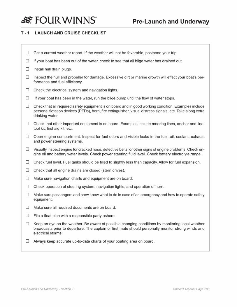
Owner’s Manual Page �00Pre-Launch and Underway - Section T
Pre-Launch and Underway
T - 1 LAUNCH AND CRUISE CHECKLIST
Get a current weather report. If the weather will not be favorable, postpone your trip.
If your boat has been out of the water, check to see that all bilge water has drained out.
Install hull drain plugs.
Inspect the hull and propeller for damage. Excessive dirt or marine growth will effect your boat’s per-formance and fuel efficiency.
Check the electrical system and navigation lights.
If your boat has been in the water, run the bilge pump until the flow of water stops.
Check that all required safety equipment is on board and in good working condition. Examples include personal flotation devices (PFDs), horn, fire extinguisher, visual distress signals, etc. Take along extra drinking water.
Check that other important equipment is on board. Examples include mooring lines, anchor and line, tool kit, first aid kit, etc.
Open engine compartment. Inspect for fuel odors and visible leaks in the fuel, oil, coolant, exhaust and power steering systems.
Visually inspect engine for cracked hose, defective belts, or other signs of engine problems. Check en-gine oil and battery water levels. Check power steering fluid level. Check battery electrolyte range.
Check fuel level. Fuel tanks should be filled to slightly less than capacity. Allow for fuel expansion.
Check that all engine drains are closed (stern drives).
Make sure navigation charts and equipment are on board.
Check operation of steering system, navigation lights, and operation of horn.
Make sure passengers and crew know what to do in case of an emergency and how to operate safety equipment.
Make sure all required documents are on board.
File a float plan with a responsible party ashore.
Keep an eye on the weather. Be aware of possible changing conditions by monitoring local weather broadcasts prior to departure. The captain or first mate should personally monitor strong winds and electrical storms.
Always keep accurate up-to-date charts of your boating area on board.

Owner’s Manual Page �0�Pre-Launch and Underway - Section T
C. Pumping Fuel
Follow engine manufacturer’s recommenda-tions for types of fuel and oil. Use of improper products can damage the engine and void the warranty.
1. Be sure to fuel in a well-lit area gasoline spills are unnoticeable under poor lighting or in the dark.
2. Remove the gas fill cover.
3. Insert the fuel supply nozzle, keeping it in contact with the fuel fill plate to guard against static produced sparks.
4. Stand away from the fuel tank vent and gas fill during fueling. Splashback may occur and can be an eye irritant and/or a fire hazard.
5. Avoid spillage. Wipe up any excess fuel immedi-ately.
6. After pumping approximately 10 gallons of fuel into the fuel tank, inspect the engine and fuel tank area for any signs of leakage. If no leaks or other problems are detected, resume fueling.
7. Allow space at the top of the tank for thermal expansion.
8. If fuel cannot be pumped in at a reasonable rate, check for fuel vent blockage or a kink in the line.
D. After Fueling
1. Replace the gas fill cover and wipe up any fuel spilled. Discard rags used in a safe place ashore.
2. Open the engine compartment and all hatches, windows, doors and other compartments that were closed during fueling. Inspect these areas for the odor of fuel vapors and visible fuel leakage.
Investigate and correct any sign of fuel leakage or indication of vapors before starting engine. Do not run blower or operate any electrical switch until problem is corrected. Fire or explosion may result.
T - 2 FUELING
Do not smoke, extinguish all open flames, STOP all engines and other devices that could cause sparks, including the bilge blower. Do not use electrical switches or accessories. Shut OFF all stoves that may produce a spark or flame. Close all openings into the cabin area of the boat.
A. Recommendations
When fueling or having your boat fueled by an attendant, be sure the waste pump-out or fresh water fitting is not mistaken for the gas fill.
Although alcohol boosts the octane level of gasoline, it also attacks the rubber fuel distribution lines and even metal fuel system components. Alcohol will permeate most fuel hoses and other components such as fuel pump, gaskets and seals, and can also contribute to fuel system contamination.
The hoses we use in our boats are alcohol-resistant as are the materials used by the engine manufacturers. If only fuel containing alcohol is available, or the presence of alcohol is unknown, you must perform more frequent inspections for leaks and abnormalities. Any sign of leakage or deterioration requires your immediate attention. Refer to the engine manufactur-er’s recommendations on fuel type and octane ratings.
B. Preliminary Guidelines
1. Safely secure your boat to the dock.
2. Close all hatches, windows, doors and compart-ments to prevent accumulation of fuel vapors.
3. Ensure that a fire extinguisher is readily available.
4. Do not store fuel in areas that are not adequately ventilated.
5. Use only fuel lubricants recommended by the engine manufacturer.

Owner’s Manual Page �0�Pre-Launch and Underway - Section T
A. Preliminary Checks
1. Secure boat to the dock before attempting to start engine. The boat should be kept secure until the engine is running and warmed up.
2. Operate the bilge pump until the flow of water stops.
3. Make sure the throttle is in the neutral position and stern drive or outboard is lowered into water.
4. Make sure passengers seated in the bow area do not obstruct the driver’s vision.
B. Starting
To prevent excessive exposure and reduce the possibility of carbon monoxide accumulation in the cockpit areas of the boat, the operator should provide adequate ventilation in each of these areas. Utilize hatches, doors, windows and side vents to increase air movement. See Section B-� for information about the dangers of Carbon Monoxide.
Notice: Additional starting information is located in Section A.
1. Check all electrical systems and navigation lights.
2. Turn the battery switches to the ON position. If one of the designated engine batteries fails to start its respective engine, engage the “EMER-GENCY START” switch at the helm and attempt to start the engine.
3. If your boat has fuel injection, turn the key to start the engine. Engine will not turn over if throttle is not in the neutral position.
4. Once engine has warmed up, check water temperature gauge to ensure engine temperature stays within optimum range. If temperature reading is abnormally high, stop engine immedi-ately and inspect for cause of high reading.
5. With engine running, voltmeter should show a reading between 12 and 15 volts.
6. Check steering operation. Turn steering wheel full to port and starboard while observing outdrive movement.
T - 3 LOADING PASSENGERS AND GEAR
When loading your boat, remember to distribute the load evenly. Keep the load low and do not overload. On certain Vista® models a capacity plate affixed to your boat states the maximum load capacity. The plate shows in pounds, the amount of persons and gear that the boat will safely handle under normal conditions. U. S. Coast Guard regulations establishes these load capacity ratings. Position passengers and gear so that the load is balanced.
NOTICEThe NMMA Yacht Certification rating (indicated by a yacht certification plate - see Preface page ��) places the responsibility on the captain to make the determination as to the appropriate load, load placement and number of passengers permitted aboard the vessel.
When loading, always step into the boat, never board by jumping. Have someone on the dock pass your gear aboard. Secure all gear firmly so it doesn’t move or interfere with operation of the boat. Passengers should board the boat one-at-a-time and be seated.
IMPORTANT: Passengers are prohibited from riding on the bow with feet hanging over the side or ride while sitting on the stern, gunwales or seatbacks. The Coast Guard considers these acts to be negligent or grossly negligent operation. They are prohibited by law be-cause falls from moving boats are a major cause of fatal recreational boating accidents.
IMPORTANT: The presence of the capacity plate does not relieve the boat operator from the responsibility of using common sense or sound judgment. Turbulent waters and adverse weather conditions will reduce the maximum load capacity rating of the boat.
T - 4 STARTING PROCEDURES
The operation and maintenance manual supplied with your engine provides pre-start, starting and cold-starting instructions. The following information is merely a guide and not intended to explain in detail all starting procedures and instructions. Refer to your engine owner’s manual.

Owner’s Manual Page �0�Pre-Launch and Underway - Section T
If you move the bow out first, watch that the stern of the boat does not swing into the dock or a piling.
Once away from the dock, devote some time to learning how to maneuver. Practice docking using an imaginary dock. Practice stopping and reversing.
B. Stopping
Boats have no brakes. Stopping is accomplished by backing down on the throttle. Practice stopping maneuvers and learn early how your boat reacts. From forward motion, pull the throttle back towards NEUTRAL. Depending on your speed, the distance the boat travels until it comes to a complete stop will vary. The ability to measure the distance will only be acquired through experience.
Once the boat has slowed and motor is idling, place the shift in REVERSE. Gradually increasing reverse power with the throttle will allow you to stop the boat in a very short distance.
NOTE: A boat will not respond to steering in reverse nearly as well as it does when going forward, so do not expect to accomplish tight turning maneuvers when backing up.
Remember that all boats steer by the stern (the feeling is much like steering your automobile in reverse). This means that the stern of your boat will swing in the direction opposite to your turn. For example, when you turn the helm wheel to the left, the stern of your boat will swing in the direction opposite to your turn. This is especially important to keep in mind when docking, operating in close quarters with other boats, or when approaching a swimmer or downed skier in the water.
Always look behind you and to both sides of the boat before slowing down. Tell your passengers your intentions to allow them time to make adjustments to their balance or positions.
Slowly pull back on throttles, glance back and see if a large following wave is approaching the transom. If so give the engines a little throttle as the wave arrives to keep wave from rolling over the transom.
Once you have spent enough time practicing maneu-vers and have a feel for how the boat handles, you will be ready to run in open waters.
7. Inspect for fuel odors and visible leaks in the fuel, oil, coolant, exhaust and power steering systems.
8. Make sure boat is securely moored to the dock and engine is idling. Then move the throttle forward and then aft and back to neutral to check for proper operation of the shifting motion. Be careful. Leave the engine in gear for only a second or two.
T - 5 MANEUVERING
Boat steering is not self-centering. Steering is effected by engine and propeller torque, trim tab setting, wave and current action and the speed of the hull through the water. Constant attention to steering is required for safe operation.
When all your pre-departure checks have been com-pleted and the engine has warmed up, you will be ready to leave the dock. Take into account the amount of wind, tide current, and other forces that may affect your maneuvering as you leave the dock. Idle speeds work best when maneuvering to and from the dock. Do not forget to release the mooring lines.
A. Leaving the Dock
You are ready to leave the dock after the engine has warmed up. Check all gauges for appropriate readings before casting off. If oil pressure is abnormally low or engine temperature is abnormally high, stop the engine immediately. Check voltmeter to be sure the charging system is working properly. Check for fuel, oil, and exhaust leaks. Correct the cause of any abnormal condition before getting underway.
To prevent personal injury, swim platform must not be occupied and transom door must be closed while engines are running.
After making sure your boat is ready, check wind, tide, current and other forces that will affect the way you maneuver your boat away from the dock. Throw mooring lines off to your boat. Shift your boat’s engine into forward or reverse depending on whether you want to move the bow or the stern away from the dock first. Run your engine at a slow speed as you move away from the dock.

Owner’s Manual Page �0�Pre-Launch and Underway - Section T
T - 6 ACCELERATION
Before accelerating to bring you boat on plane, be sure that the area in front of your boat is clear. The bow will rise out of the water momentarily before you plane and may temporarily obstruct your vision.
If you have never had your boat on plane before, choose a calm day for your first on plane experience. Never boat beyond your ability and experience.
Before bringing your boat “on plane”, check the entire area to make sure you have a clear, safe path. As you throttle up to accelerate, your boat will increase its angle of trim, causing the bow to ride high. From a maximum angle, the boat will level out to its planing attitude with continued acceleration. This maximum angle is known as the “hump”. Because visibility, handling, and performance are reduced, it is advisable to get “over the hump” as soon as possible. A few seconds at full throttle should get the boat over the hump and into its planing attitude.
After getting over the hump, accelerate until reaching a comfortable plane, then throttle down to cruising speed. This also will provide for better fuel efficiency.
T - 7 TRIMMING YOUR BOAT
A. Trim Tabs
Trim tabs are used to add lift to the boat’s stern, thereby changing the boat’s attitude (see Figure S1). This lift can help the boat get on plane faster and remain on plane at slower speeds than if no tabs were used. Used independently, tabs can also correct listing conditions caused by crosswinds, unbalanced loading and quartering seas. Trimming your boat properly involves two separate procedures, trimming or tilting the lower unit (stern drives) and setting the trim tabs.
When you are sitting dead in the water, your drive should be down and the trim tab switches are in the BOW UP position. Accelerate until you get onto plane. At this point your boat will be plowing through the water with the bow down too far. Trim the lower unit up slightly until the bow comes up. If you trim the lower unit out too far, your boat will porpoise or the propeller will cavitate, and the bow will slam up and down on the water. Your boat is trimmed correctly when it is just
short of porpoising or propeller cavitation, under ideal running conditions.
Trim your boat to compensate for seas, winds, or uneven loads.
Head Seas Trim drives in more than usual. Use tabs to keep bow down and go at a slower speed.
Following Seas To prevent taking seawater
The bow, trim drives out and keep tabs up to keep bow down
Listing Due to Quartering Seas, Beam Wind, or Uneven Load
Use tabs independently to adjust for list. If listing to star-board, press port bow down switch. If listing to port, press starboard bow down switch.
Remember that most boats react very slowly to trim tabs. Often boat owners do not give trim tabs time to work. Press the trim tab switches for only one second at a time and then allow some time for the boat to react. If the boat is still listing after a minute or two, press the trim tab switch again for a one second interval. The labels on the trim tab switches indicate what you want your boat to do, not what you want the tabs to do.
It is a good idea to take your boat out onto open water shortly after you get it and experiment with the trim tabs. After you get your boat onto plane, set the tabs in various positions and note how your boat reacts. This will give you a feel for how the trim tabs work.
It is possible to extend the cylinder life expectancy on your trim tabs. To do this, keep the cylinders retract-ed while at dockside. Press both trim tab controls down until tabs reach their full up position.
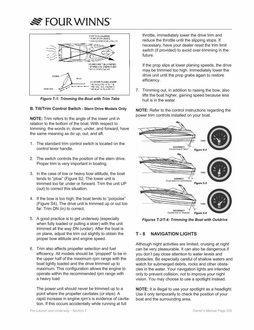
Owner’s Manual Page �0�Pre-Launch and Underway - Section T
throttle, immediately lower the drive trim and reduce the throttle until the slipping stops. If necessary, have your dealer reset the trim limit switch (if provided) to avoid over-trimming in the future.
If the prop slips at lower planing speeds, the drive may be trimmed too high. Immediately lower the drive unit until the prop grabs again to restore efficiency.
7. Trimming out, in addition to raising the bow, also lifts the boat higher, gaining speed because less hull is in the water.
NOTE: Refer to the control instructions regarding the power trim controls installed on your boat.
Figures T-2/T-4: Trimming the Boat with Outdrive
T - 8 NAVIGATION LIGHTS
Although night activities are limited, cruising at night can be very pleasurable. It can also be dangerous if you don’t pay close attention to water levels and obstacles. Be especially careful of shallow waters and watch for submerged debris, rocks and other obsta-cles in the water. Your navigation lights are intended only to prevent collision, not to improve your night vision. You may choose to use a spotlight instead.
NOTE: It is illegal to use your spotlight as a headlight. Use it only temporarily to check the position of your boat and the surrounding area.
Figure T-1: Trimming the Boat with Trim Tabs
B. Tilt/Trim Control Switch - Stern Drive Models Only
NOTE: Trim refers to the angle of the lower unit in relation to the bottom of the boat. With respect to trimming, the words in, down, under, and forward, have the same meaning as do up, out, and aft.
1. The standard trim control switch is located on the control lever handle.
2. The switch controls the position of the stern drive. Proper trim is very important in boating.
3. In the case of low or heavy bow attitude, the boat tends to “plow” (Figure S2. The lower unit is trimmed too far under or forward. Trim the unit UP (out) to correct this situation.
4. If the bow is too high, the boat tends to “porpoise” (Figure S4). The drive unit is trimmed up or out too far. Trim DN (in) to correct.
5. A good practice is to get underway (especially when fully loaded or pulling a skier) with the unit trimmed all the way DN (under). After the boat is on plane, adjust the trim out slightly to obtain the proper bow attitude and engine speed.
6. Trim also affects propeller selection and fuel efficiency. All models should be “propped” to be in the upper half of the maximum rpm range with the boat lightly loaded and the drive trimmed up to maximum. This configuration allows the engine to operate within the recommended rpm range with a heavy load.
The power unit should never be trimmed up to a point where the propeller cavitates (or slips). A rapid increase in engine rpm’s is evidence of cavita-tion. If this occurs accidentally while running at full

Owner’s Manual Page �0�Pre-Launch and Underway - Section T
• Close and secure all portals and hatches. Stow all loose gear below deck and tie down any gear required to remain on deck.
• Reduce speed as the seas build. Make sure all passengers are wearing their PFDs.
• If you lose power, keep the boat headed into the waves by rigging a sea anchor off the bow. If there is no sea anchor on board, use a canvas bucket or any object that will offer resistance.
• Radar reflectors (if installed on your boat) should be 18 inches diagonally and placed 12 feet above the waterline.
B. Fog
Fog is a result of either warm surface or cold surface conditions. You can judge the likelihood of fog formation by periodically measuring the air tempera-ture and dew point temperature. If the spread (difference) between these two temperatures is small, you likely will incur a fog situation. Remember the following guidelines:
• Turn on running lights.
• As fog sets in, take bearings and mark your position on the chart while continuing to log your course and speed.
• Make sure all persons aboard are wearing their PFDs.
• If your boat has depth finding equipment, take sounding and match them with soundings on your charts.
• Station a person forward on the boat as a lookout.
• Reduce your speed. From time to time, stop engine and listen for fog signals.
• Sound the proper horn or fog bell at proper intervals to warn other boaters.
• If there is any doubt in continuing boat move-ment, anchor. Listen for other fog signals while continuing to sound the proper fog horn or bell for a boat at anchor.
Your boat has one white (stern), one red (port) and one green (starboard) light. The stern light may be a removable pole light. To use the light, line up the two-prong plug in the pole with the receptacle in the base. Plug the light in, and lock it into place with lever/slide lock. When not in use, stow the light inside your boat for safekeeping. This light can be turned on or off at the helm.
Check lights for proper operation before heading out at night. You should also learn to identify the running light combinations for other vessels. We recommend that you participate in a boating safety course to further learn about navigation lights and safe boating prac-tices.
The anchor lights and navigation lights are controlled by a switch at the helm. The anchor light switch allows you to turn on just the stern (white) light when an-chored or moored. While underway, use the navigation light switch to turn on the stern (white), port (red) and starboard (green) lights. Lights are off when switches are in the OFF position.
T - 9 HAZARDOUS CONDITIONS
A. Storms
Storms sometimes appear without advance notice. Although weather information from meteorological observation and reporting stations is available, weather bureaus are known to have failures in their predictions or information gathering equipment. There is no substitute for a strong understanding of what action to take when the weather takes a turn for the worse. Many marinas fly weather signals. You should learn to recognize these signals and monitor your local weather forecasts before leaving port.
The present and forecasted weather conditions are of primary consideration, but a threat of possible storms should always be a concern. Observance of the following information will help in your safety afloat if storms do occur:
• Keep a watch on the horizon for approaching storm indicators.
• Turn radio ON. Dial in local weather station and monitor forecast. If your boat has a VHF radio, check the weather channels.
• The best possible situation is to return to a safe port if time allows.

Owner’s Manual Page �0�Pre-Launch and Underway - Section T
• Navigation markers serve as a means of identify-ing navigable routes and indicate water hazards. Boaters should become familiar with navigation markers and stay within marked boundaries and clear of hazards.
T - 10 REACTING TO EMERGENCIES
Be prepared to deal with emergencies before they happen. Try to formulate a plan for each type of emergency in advance so that decisions can be made quickly and without hesitation. Precious moments lost can mean the difference between losing and saving a life.
A. Flooding
If your boat starts taking on water, activate the bilge pump immediately. Make sure all passengers are wearing their PFDs. Open the engine compartment, look for the cause of the flooding. Check all hoses, through hull fittings, seacocks and strainers. If flooding occurs as a result of collision or grounding damage, call for assistance and head for shore if possible.
B. Capsizing and Man Overboard
By far, the largest number of boating fatalities involve capsizing and falling overboard accidents. By being prepared ahead of time with an appropriate plan of action, you can greatly lower your chances and your passengers’ chances of becoming seriously injured.
C. Capsizing
Wear PFDs or have them readily available at all times. If your boat capsizes, and others were on board, locate them and guide them to the safety of the hull. Even if the boat floats in an upside-down position, stay with it. The boat hull is much easier for rescuers to spot than a human head sticking out of the water. DO NOT attempt to swim ashore, it may be further than it looks.
D. Man Overboard
Think through and follow these procedures if someone in your boat falls overboard.
• Remember, every second counts, you must act fast.
C. Running Aground
To prevent boat damage, DO NOT use deck hardware or water ski pylon for towing. Use a commercial towing service.
Operating in shallow water can present a number of hazards. Sand bars in narrow inlets are constantly shifting, making it difficult to mark them with buoys. Sometimes sand bars are indicated by waves as they form into breakers when passing over sand bars. In coastal areas, tides can change water levels by as much as 30 feet. Check with local marinas or Coast Guard stations for tide tables and current charts.
If your boat runs aground, first check persons aboard for injury. Then check for damage to the boat. If the drive unit strikes an underwater hazard, check for boat and drive unit damage. If the engine vibrates exces-sively after striking an underwater obstruction, it may indicate a damaged propeller. If vibration is noticeable, return to port slowly to prevent further drive and engine damage from an out-of-balance condition. Watch the temperature gauge to make sure you do not overheat the engine.
If the boat is not taking on any water, it may be possible to rock the boat by shifting the weight of the passen-gers and gear and by raising the drive unit while reversing the engine.
If you ground your boat on a sand bar, shut down the engine and seek help from another boater or radio for help. See your dealer as soon as possible, as sand ingested in the engine cooling system can cause major engine damage.
D. Warning Markers
It is a good idea to find out about hazardous areas and how they are marked by asking your local authorities.
• Boaters must also recognize the flag designs which indicate that scuba divers are present and keep well clear of the area.
• Watch for swimmers. Swimming areas may not be marked. Steer clear from the area and always remain alert.
• Distress flags indicate a fellow boater is in need of assistance.

Owner’s Manual Page �0�Pre-Launch and Underway - Section T
• Move throttles to idle position immediately and yell “MAN OVERBOARD. ”
• Throw some floating object overboard immedi-ately. Keep your required Type IV PFD accessible at all times for such an emergency.
• Keep the person in the water in sight at all times. Have a passenger do nothing but watch the person. Do not go into the water to help the victim. One person in the water is enough trouble.
• Circle around quickly, approaching into the wind and waves. When the person is alongside, put the engine in neutral and throw them a Type IV PFD with a line attached or extend a paddle or boat hook within his/her reach.
E. Collision
If a serious collision occurs, you should first check the condition of all passengers aboard, then inspect your boat to determine the extent of damage.
1. Make sure all persons aboard are wearing their PFDs.
2. If you need help and your boat has a ship-to-shore radio, first contact the U. S. Coast Guard (VHF Channel 16) or other rescue authorities immedi-ately.
3. Prepare to assist the other vessel unless your passengers and/or boat are in danger.
4. If the bow of the other boat penetrated your boat’s hull, prepare to block the opening once the boats are separated.
5. Shore up the hole with a spare PFD or bunk cushion from your boat.
6. While blocking the hole, trim the boat so that the hole is out of the water.
F. Fire
Most fires are caused by electrical problems or careless fueling practices. A fire on board your boat is a serious emergency. You must work quickly to implement safety procedures. If a fire occurs, immedi-ately stop the engine.
1. Make sure all persons aboard are wearing their PFDs.
2. If the fire is small, attempt to put it out with your fire extinguisher. If the fire is in the engine com-partment, turn off the bilge blower. Do not open the engine compartment. This feeds oxygen to the fire and may cause it to flare up.
3. If the fire gets out of control, execute a distress signal and call for help if equipped with a ship-to-shore radio.
4. All persons aboard should jump overboard and swim a safe distance away from the flames.
IMPORTANT: All persons aboard should know the location and proper operation of the fire extinguishers.
Guidelines
• Use only approved marine cooking and heating systems.
• Open flames demand constant attention.
• Keep flammable materials in approved containers in a overboard vented locker sealed from the interior of the boat.
• Ensure ventilation systems are unobstructed.
• Remove mooring covers before starting engine.
• Check the bilge for fuel leaks.
• Extinguish smoking materials carefully.
• Use special care with flame or high temperatures around urethane foam.
• Check cleaning products for flammability.
• Ventilate when cleaning or painting.
• Disconnect electrical system from its power source before performing maintenance.
• Replace breaker or fuse with same amperage device.
• Electrical appliances must be within rated amper-age of boat circuits. Observe the boat carefully while the electrical system is being energized.

Owner’s Manual Page �0�Pre-Launch and Underway - Section T
level of reservoir and drive pump belt. If the steering is not operating properly, do not operate the boat and call for assistance.
K. Additional Underway Information
• Always be aware of local laws on noise limits. Noise means engine noise, radio noise or even yelling by people on your boat. Good seamanship demands that you operate your boat quietly so as not to infringe on the rights of others. Don’t use thru-transom exhaust unless you are well off shore.
• You are responsible for any damage or injury caused by your boat’s wake. Observe no wake speed zone warnings. Operate your boat with regard for the safety of other boats and people in your boating area.
• Keep your engine well tuned to decrease exhaust hydrocarbon emissions that pollute the air and water.
T - 11 RETURNING TO SHORE
A. Docking
Always approach the dock slowly. Think before acting. If you are wondering whether your boat will fit in a space against a dock, remember that pilings are often (but not always) spaced 10 feet apart.
Remember that it is easier to control a boat in reverse because a boat steers from the stern. When backing into a slip, back so that bow swings into the wind if possible. You will have more control.
If possible, come in against the wind or current, whichever is stronger. Approach the dock at a 30-45° angle. As the boat nears the dock, slowly swing parallel to it. Tie the bow line first; then the stern.
If wind or current is moving toward the dock, move parallel to the dock further out. Let the wind or current push you in. Tie the stern first, then the bow.
Use extreme caution if wind or current is from your stern. Back in towards the dock slowly at a slight angle with engine in slow reverse. Gently swing parallel. Tie stern first, then the bow.
• Allow only a qualified marine electrician to service the boats electrical system.
G. Medical Emergency
Accidents while boating can and may happen. Be prepared to handle these emergencies when they happen. Keeping a first aid kit and dry blankets on board can assist during these situations. It is also a good idea to contact your local Red Cross for informa-tion and training on first aid and CPR.
H. Propulsion Failure
Before you call for help regarding an engine or drive unit failure, it is a good idea to eliminate the possibility of simple problems. Turn off the engine and check to see that (1) there is fuel in the tank; (2) the engine cooling intakes on the outdrive are not clogged; (3) props are clean and free of weeds, netting, etc. ; (4) no hoses are leaking; (5) there is oil in the engine.
Once you have checked out the possibilities listed above and find they are not the problem, call for help giving your position and a detailed description of your boat.
I. Control Failure
In the unlikely event of a shift/throttle failure, shut down the engine immediately. Carefully check the control connections in the engine compartment to see if they are secure. If not, try to locate the attaching hardware and reassemble. If that is not possible, try to use whatever is available such as paper clips, hair clips, tape, etc. , to secure the connections. If a temporary repair is made, return to port at the slowest steerable speed and be prepared to take emergency action should the temporary repair fail also. Have your dealer make repairs before using the boat again.
J. Steering Failure
If a problem with the steering occurs, shut down the engine immediately. Check the connections to the drive unit in the engine compartment. Some boats have a push/pull cable while others will have hydraulic hose connections. With cable connections, check the attaching hardware and tighten it if necessary. If you have hydraulic hose connections, check to see if they are leaking. If so, tighten the connections and check the hydraulic fluid reservoir level. Most stern drives are power assisted and have their own hydraulic reservoir and engine mounted drive pump; check the

Owner’s Manual Page ��0Pre-Launch and Underway - Section T
If the weather looks bad, use spring-lines from the bow and stern to dock amidships of the boat. Tie up on the downwind side of the dock. If the wind is changeable, place fenders over the side between the boat and the dock.
B. Mooring
After you have positioned your boat next to the dock, you must secure it with mooring lines to keep it in position. Mooring lines must be long enough to secure your boat in any docking situation. For example, the length of the lines for a 16-foot runabout should be at least 15 feet. An eye splice at the end of each line works well with bow or stern cleats.
The mooring lines you will use most often are the bow line, the stern line, and spring lines as shown on Figure S5. Each line has a specific purpose. The bow line and the stern line secure your boat’s bow and stern. The two spring lines keep your boat from moving forward or backward when you are moored alongside a dock.
If you are mooring your boat for a short time, bow and stern lines may be the only lines you will need. If you are mooring your boat for a longer time or the currents are swift, you should use spring lines. The stern spring line leads from the boat’s stern cleat forward to the piling or cleat on the dock. The bow spring line leads from the bow cleat aft to the dock.
If you are mooring your boat in a slip, bow and spring lines, port and starboard, will keep your boat in position.
NOTE: If tides are a consideration, be sure to leave slack in the lines to make up for the rise and fall of the water while your boat is docked.
Figure T-5: Mooring Lines

Owner’s Manual Page ���Glossary
GlossaryABAFT - Toward the rear of a boat.
ABEAM - At right angles to the keel of the boat.
ABOARD - On the boat.
ABREAST - Side by side.
ADRIFT - Loose, not on moorings or towline.
AFT - Moving toward the stern, you are going aft.
AGROUND - Stuck fast to the bottom.
AHEAD - In a forward direction.
ALEE - Away from the direction of the wind; opposite of windward.
ALOFT - Above the deck.
AMIDSHIPS - 1. An object or area midway between the bow and stern. 2. An object or area midway between the port side and the starboard side of a vessel.
AMPERE - The standard unit used to measure the draw of an electrical current.
ANCHOR RODE OR ROPE - The line (chain) connecting a vessel to its anchor.
ANCHOR BALL - A black, circular, day signal hoisted to show that a vessel is anchored. Replaced at dusk by the anchor light.
ASTERN - Anywhere behind the boat, a reverse direction, opposite of ahead.
ATHWARTSHIPS - A line, or anything else, running perpendicular to the fore-and-aft center line of a boat.
BATTEN - A strip of wood or metal used to secure tarpaulin(s) in place over a hatch. To batten down means to secure for rough weather.
BEAM - 1. The widest distance across a boat from the outside skin on one side to the outside skin on the other. 2. A transverse structural member that stiffens and supports a portion of the deck.
BEAM WIND - A wind blowing against the side of the vessel, perpendicular to the long axis of the vessel.
BILGE - The lowest interior area of a hull, used to collect water that has entered.
BILGE PUMP - A pump intended for removal of spray, rainwater, and the normal accumulation of water due to seepage and spillage; not intended for damage control.
BINNACLE - The stand or support for a magnetic compass occasionally used to mean helm.
BITT - A heavy and firmly mounted piece of wood or metal used for securing lines.
BLOCK - A wooden or metal case enclosing one or more pulleys and having a hook, eye, or strap by which it may be attached.
BOLLARD - A single post (wood, metal, or concrete) on a dock, pier, or wharf used to secure a vessel’s lines.
BONDING - The electrical connection of exposed metallic, non-current carrying components to a common point on the main engine block.
BOW - The front end of the boat.
BOW LINE - A docking line leading from the bow.
BREAKER - A single breaking, plunging or spilling wave.
BREAKER LINE - The outer limit of the surf. However, all breakers may not be in a line. They can occur outside the breaker line.
BRIDGE - The main vessel control station.
BROACH - The turning of a boat parallel to the waves, subjecting it to possible capsizing.
BULKHEADS - The interior walls of a boat.
BULWARK - The side of a vessel when carried above the level of the deck.
BUOY - An anchored float used for marking a position on the water, a hazard, or a shoal.
CAPSIZE - To turn over.

Owner’s Manual Page ���Glossary
CAPSTAN - A machine that moves a cylindrical device on a shaft for the purpose of hauling up an anchor.
CAST OFF - To let go.
CATAMARAN - A twin-hulled boat, with the hulls being side-by-side.
CHINE - The intersection of a boat’s bottom and side. If this intersection is rounded, it is a “soft” chine. If the intersection is squared off, it is a “hard” chine.
CHOCK - 1. A fitting or hole in a railing or deck through which a mooring or anchor line is routed. 2. A wedge used to secure an item in place.
CIRCUIT BREAKER - A device used to interrupt an electrical circuit when current flow exceeds a predeter-mined level.
CLEAT - A double-ended deck fitting to which lines are secured; usually anvil-shaped.
COAMINGS - Raised lips around cockpits or hatches used to keep water from entering
COCKPIT - An exposed deck area (usually aft) that is substantially lower than the adjacent deck.
COMBER - A wave on the point of breaking. A comber has a thin line of white water on its crest, known as “feathering.”
COMPANIONWAY - The steps or ladder leading downward from a deck.
COMPARTMENTS - Rooms divided by bulkheads.
COUNTER - The overhang at the stern of a boat.
CRADLE - A framework, generally made of wood, used to support a boat when it is out of the water.
CREST - The top of a wave, breaker or swell.
CUDDY - A small sheltered cabin in a boat.
CURRENT - 1. The movement of water, 2. The flow of electrical charge.
DEAD AHEAD - Directly in front of the boat.
DEAD RECKONING - A plot of courses steered and distances traveled through the water.
DECK - A permanent covering over a compartment, hull or any part thereof.
DESIGNATOR - Model identifier or model name.1. to mark or point out; indicate; show; specify. 2. to denote; indicate; signify. 3. to name; entitle; style.
DINGHY - A small, open boat used for ship to shore transportation.
DISPLACEMENT - The weight of water dislocated by the hull of a vessel.
DISPLACEMENT HULL - A hull that “displaces” a volume of water equal to the weight of the boat. A hull designed to run in the water rather than on top of the water. When a displacement hull moves through the water, it pushes that water out of the way. Water will then flow around the hull and fill the “hole” the boat leaves astern.
DOCUMENTED VESSEL - Documented yachts have been specially registered with the U.S. Coast Guard. All documented yachts must have their name and home (hailing) port marked on some conspicuous place on the hull. Numbering is not required. Advan-tages include legal authority to fly the yacht ensign, privilege of recording bills of sale, and other instru-ments of title with federal officials, and preferred status for mortgages. Documentation does not exempt the unit from any State or Federal taxes. All safety and equipment regulations still apply.
DOLPHIN - A group of piles driven close together and bound with wire cables into a single structure.
DRAFT - 1. The depth of a boat from the actual water line to the bottom of the lowest part of the boat (e.g., the propeller tip or rudder). 2. The depth of water necessary to float a boat.
DROGUE - Any device streamed astern to check a vessel’s speed, or to keep its stern up to the waves in a following sea.
DYE MARKER - A brightly colored chemical that spreads when released into water; normally used to attract attention.
EBB TIDE - A receding tide.
Owner’s Manual Page ���Glossary
EVEN KEEL - To be floating evenly without listing to either side.
EXHAUST SYSTEM - The means by which the hot engine (or generator) exhaust gases are moved from the engine to an outboard port and then released into atmosphere.
EYE SPLICE - A permanent loop spliced in the end of a line.
FAST - Said of an object that is secured to another.
FATHOM - Six feet.
FENDER - A device (usually constructed of rubber or plastic) positioned so as to absorb the impact between vessels or dock.
FETCH - The unobstructed distance that the wind can blow over the water to create waves.
FLARE - 1. Outboard curve of the hull as it comes up the side from the waterline; the reverse of tumble home. 2. A pyrotechnic device used for emergency signaling.
FLAT - A small deck that is built below decks, specifically to support a piece of equipment.
FLEMISH - To coil down a line or rope on deck in a flat, circular, concentric arrangement.
FLOTSAM - Floating wreckage, trash or debris.
FLUKE - The palm of an anchor.
FOAM CREST - The top of the foaming water that speeds toward the beach after a wave has broken, commonly referred to as “white water.”
FOLLOWING SEA - A sea (waves) moving in the same direction as a vessel.
FORE-AND-AFT - A line, or anything else, that runs parallel to the longitudinal center line of a boat.
FOREFOOT - The portion of a vessel’s keel that curves upward to meet the stem.
FOREPEAK - A compartment in the bow of a boat.
FORWARD - Toward the bow.
FREEBOARD - The minimum vertical distance from the surface of the water to the gunwale.
FREQUENCY - The number of crests passing a fixed point at a given time.
FRONTS - Where opposing warm and cold air masses meet, generally producing a band of wet, stormy weather wherever they meet.
GALLEY - The kitchen area of a boat.
GALVANIC CORROSION - A potential electrical difference exists between dissimilar metals immersed in a conductive solution (e.g., salt water). If these metals touch or are otherwise electrically connected, this potential difference produces an electron flow between them. The attack on the less corrosion resistant metal is usually increased and the attack on the more resistant metal is decreased, as compared to when these metals are not touching.
GANGWAY - The area of a ship’s side where people board and disembark.
GASKET - A strip of sealing material, usually rubber, set along the edge of a water or gas tight door, port, cover or hatch.
GELCOAT - The thin outer layer of pigmented plastic covering a fiberglass vessel.
GLAND - The movable part of a stuffing box, which when tightened, compresses the packing.
GROUND - Electrical term meaning the electrical potential of the earth’s surface, which is zero.
GROUND SPEED - A vessel’s speed made good over the earth’s surface along a course or track.
GROUND TACKLE - The anchor, anchor rodes, and other fittings that are used to secure a vessel at anchor or dockside.
GUNWALE - 1. The line where the upper deck and the hull meet. 2. The upper edge of a boat’s side.
HALYARD - A line used to hoist a flag or pennant.
HATCHES - Cover on hatchways.
HATCHWAYS - Access ways through decks.

Owner’s Manual Page ���Glossary
HARDTOP - A permanent cover over the cabin or cockpit.
HAWSER - A heavy rope or cable used for mooring or towing.
HEAD - A toilet or lavatory area.
HEADING - The direction that a vessel is going with reference to true, magnetic, or compass north.
HEADWAY - The forward motion of a vessel through the water.
HEAVE TO - To bring a vessel up in a position where it will maintain little or no headway, usually with the bow into the wind.
HEAVY WEATHER - Stormy weather with high seas and strong winds.
HEEL - To tip to one side.
HELM - The wheel or tiller that manually controls the boat’s steering system.
HELMSMAN - The individual steering the vessel.
HIGHS - A center of pressure surrounded by lower pressure on all sides. Caused by a mass of cooler, sinking, drier air. This raises the area ground level air pressure and provides clear skies.
HULL - The main body of a boat.
INBOARD - 1. From either the port or starboard side of a boat toward the fore-and-aft centerline of a boat. 2. The dock side of a moored boat.
INLAND RULES - Nautical “Rules-of-the-Road” that apply in U.S. lakes, rivers, and coastal waters.
INTERNATIONAL RULES - Nautical “Rules-of-the-Road” that are in effect by international agreement to the high seas.
ISOBARS - Lines of equal air pressure that connect all the local points on a weather map. These lines are usually closed and define high or low pressure air masses.
ISOTHERMS - Isotherms are lines that are similar to Isobars except that Isotherms connect all the points that are of equal temperature.
JETSAM - Refuse that sinks when discharged overboard.
KEDGE(S) - One or more anchors set out from a grounded vessel, usually astern, to 1) keep it from being driven further aground and 2) to aid in refloating.
KEEL - 1. The centerline of a boat hull bottom running fore and aft, 2. The backbone of a vessel.
KNOT - 1. A maritime unit of speed equal to one nautical mile per hour (6076 feet). 2. A term for hitches and bends.
LANYARD - A short line made fast to an object to secure it.
LATITUDE - The measure of angular distance in degrees, minutes, and seconds, north or south of the equator.
LAZARETTE - Storage compartment in the deck at the stern.
LEADLINE - A weighted line used to take depth measurements.
LEE - The direction opposite that of the wind.
LEEWARD - Away from the wind.
LIST - A vessel that inclines to port or starboard.
LORAN - Long Range Navigation. An electronic system whereby a navigator can determine position regardless of weather.
LONGITUDINAL - Running lengthwise.
LOWS - A region of low atmospheric pressure. Hurricanes are extremely concentrated low pressure systems.
LUBBER LINE - A mark or line on the compass parallel to the keel indicating forward.
MAST - A spar that is set upright to support lighting, rigging, or sails.

Owner’s Manual Page ���Glossary
MODEL DESIGNATOR - Model identifier or model name.
MOORING - An arrangement for securing a boat to a mooring buoy or pier.
NAVIGATION LIGHTS - A set of red and green or white lights which must be shown by all vessels between dusk and dawn.
OVERHEAD - A ceiling or roof of a vessel.
OVERBOARD - Over the side of the boat.
OUTBOARD - 1. From the fore-and-aft centerline of a boat toward both the port and starboard sides. 2. The seaward side of a moored boat. 3. An engine that is mounted externally onto the transom of a boat.
PAINTER - A line to the bow of a small boat used for making fast.
PASSAGEWAY - A corridor or hallway aboard ship.
PENNANT - The line by which a boat is made fast to a mooring buoy; also pendant.
PERSONAL FLOATATION DEVICE (PFD) - A life preserver.
PIER - A loading platform that extends at an angle from the shore.
PILASTER - A rectangular structural support column that is an extension of the port and starboard aft cabin sides and which supports the hardtop and flybridge.
PILING - Support, or protection for wharves, piers, etc.
PITCH - 1. The vertical (up and down) motion of a bow in a seaway, about the athwartships axis. 2. The axial advance of a propeller during one complete revolution.
PITCHPOLING - A boat being thrown end-over-end.
PLACARD - A board or stiff card bearing a notice, advertisement, message, etc.
PLANING HULL - At slow speeds, a planing hull will displace water in the same manner as a displacement hull. As speed is increased, the hull provides a lifting effect up onto the surface of the water.
POINT - One of 32 points of the compass that is equal to 11-1/4 degrees.
PORT - 1. Looking forward, the left side of a boat, 2. A harbor, 3. An opening for light or ventilation or passage of material in the side of a boat.
PORT BEAM - The left-center of a boat.
PORT BOW - Facing the bow, the front left side.
PORT QUARTER - Looking forward, a vessel’s left rear section.
QUARTER - The sides of a boat aft of amidships.
QUARTERING SEA - Sea coming on a boat’s quarter.
RED-RIGHT-RETURNING - A term for helmsmen that buoys and day markers are on the right when returning from seaward.
REEF - A shallow underwater barrier.
REEVE - To pass a line through a block or other opening.
RIDGES - High pressure fingers extending out from a high.
RODE - The anchor line or chain.
RUNNING LIGHTS - Lights required to be shown on boats underway between sundown and sunup.
RUDDER - A vertical plate for steering a boat.
SALON - The main social cabin on a vessel, usually the largest area, occasionally referred to as the deckhouse.
SCREW - A propeller.
SCUPPER - A drain from the edge of a deck that discharges overboard.
SEACOCK - A positive action shut-off valve connected directly to the hull seawater intake and discharge piping.
SERIES - A group of waves which seem to travel together and at about the same speed.

Owner’s Manual Page ���Glossary
SHACKLE - A “U” shaped connector with a pin or bolt across the open end.
SHAFT - The long, round member that connects the engine or transmission to the propeller.
SHAFT LOG - A fitting at the hull bottom where the shaft connecting an engine to its propeller penetrates the hull. A shaft log permits the shaft to rotate while simultaneously preventing water from entering the hull.
SHEER - The top of the hull’s curvature at the deck line from the bow to the stern.
SHEER STRAKE - The upper edge of the hull, immediately below the deck.
SHEET BEND - A knot used to join tow ropes.
SHOAL - An area of shallow water.
SILENCER - A baffled chamber installed in an exhaust system to reduce the noise.
SOLE - Term for deck, cabin or cockpit floor.
SPAR - A general term for booms, masts, yards etc.
SPRING LINE - A pivot line used in docking, undocking, or to prevent the boat from moving forward or astern while made fast to a dock.
STARBOARD - Looking forward, the right side of a boat.
STARBOARD BEAM - The right-center of a boat.
STARBOARD BOW - When facing the bow, the front right side.
STARBOARD QUARTER - When looking forward, the right rear section of the boat.
STEERAGEWAY - The lowest speed at which a vessel can be controlled by the steering wheel.
STEM - The leading edge of a boat’s hull.
STERN - The back of a boat.
STRINGER - A fore and aft continuous member used to provide a vessel longitudinal strength.
STRUT - A propeller shaft support that is below the hull.
SUMP - A pit or well into which water is drained.
SUPERSTRUCTURE - Deck houses and other structures extending above the deck.
THWART - A seat or brace running laterally across a boat.
THWARTSHIPS - At right angles to the centerline.
TILLER - A bar or handle for turning a boat’s rudder, or motor.
TOPSIDE - To go up to the top deck.
TRANSOM - The stern cross-section of a square sterned boat
TRANSVERSE - Across the vessel; athwartships.
TRIM - Fore and aft balance of a boat.
TROUGH - 1. The valley that exists between waves. 2. A trough is the opposite of a ridge in that it is an elongated low-pressure area extending out from a low. A trough normally indicates unsettled weather.
TUMBLE HOME - The opposite of flare. The shape of the hull as it moves outboard going down from the gunwale to the waterline or chine.
UNDERWAY - Movement. Usually referring to a vessel proceeding forward.
V-BOTTOM - A hull with the bottom section in the shape of a “V.”
V DRIVE - A drive system that has the output of the engine facing forward and coupled to a transmission. The prop shaft is then coupled to the transmission.
WAKE - Moving waves, track or path that a boat leaves behind it when moving across the water.

Owner’s Manual Page ���Glossary
WATER LINE - The line of the water on the hull when the vessel is afloat.
WATCH - A 4 hour duty period while at sea.
WAVES - Waves are periodic disturbances of the sea’s surface, caused by wind, seaquakes, and the gravitational pull of the moon and the sun.
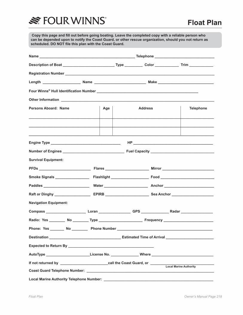
Owner’s Manual Page ���Float Plan
Name ________________________________________________ Telephone ______________________________
Description of Boat __________________________ Type _________ Color ____________ Trim ____________
Registration Number ___________________________________________________________________________
Length ___________________ Name __________________________ Make ____________________________
Four Winns® Hull Identification Number ___________________________________________________
Other Information _____________________________________________________________________________
Persons Aboard: Name Age Address Telephone _____________________________________________________________________________________________
_____________________________________________________________________________________________
_____________________________________________________________________________________________
Engine Type ___________________________________ HP ________________________________________
Number of Engines _______________________________ Fuel Capacity ________________________________
Survival Equipment:
PFDs __________________________ Flares ______________________ Mirror __________________________
Smoke Signals _________________ Flashlight ___________________ Food ___________________________
Paddles _______________________ Water ______________________ Anchor _________________________
Raft or Dinghy __________________ EPIRB ______________________ Sea Anchor _____________________
Navigation Equipment:
Compass ____________________ Loran ________________ GPS ______________ Radar ________________
Radio: Yes ________ No ________ Type ______________________ Frequency _________________________
Phone: Yes _______ No ________ Phone Number ________________________________________________
Destination ____________________________________ Estimated Time of Arrival ________________________
Expected to Return By ___________________________________________
AutoType ______________________License No. ______________ Where _______________________________
If not returned by ________________________call the Coast Guard, or ________________________________ Local Marine AuthorityCoast Guard Telephone Number: ________________________________________________________________
Local Marine Authority Telephone Number: _______________________________________________________
Copy this page and fill out before going boating. Leave the completed copy with a reliable person who can be depended upon to notify the Coast Guard, or other rescue organization, should you not return as scheduled. DO NOT file this plan with the Coast Guard.
Float Plan

Owner’s Manual Page ���Fuel Log
Fuel Log
ETAD SRUOHNUR
LEUF).LAG(
EGNAR)SELIM( MPR HPM HPG

Owner’s Manual Page ��0Fuel Log
Fuel Log
ETAD SRUOHNUR
LEUF).LAG(
EGNAR)SELIM( MPR HPM HPG

Owner’s Manual Page ���Fuel Log
Fuel Log
ETAD SRUOHNUR
LEUF).LAG(
EGNAR)SELIM( MPR HPM HPG

Owner’s Manual Page ���Service Log
Service Log
ETAD SRUOH DEMROFREPECNANETNIAM

Owner’s Manual Page ���Service Log
Service Log
ETAD SRUOH DEMROFREPECNANETNIAM

Owner’s Manual Page ���Service Log
Service Log
ETAD SRUOH DEMROFREPECNANETNIAM
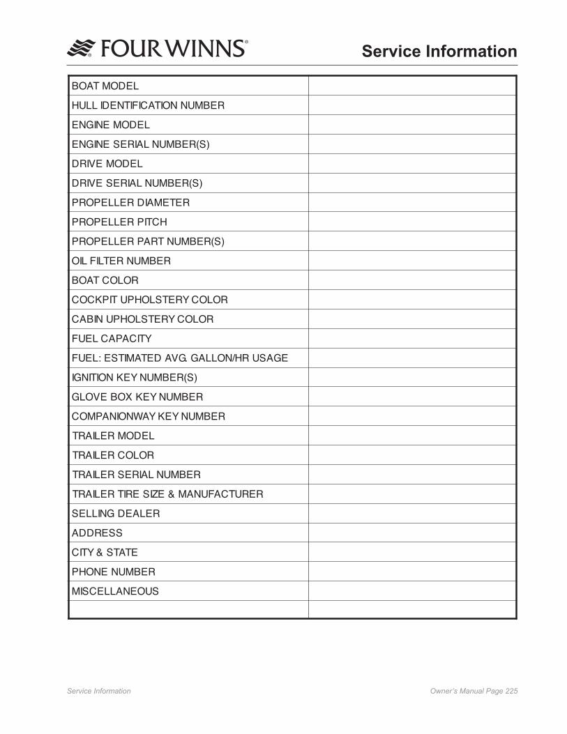
Owner’s Manual Page ���Service Information
Service Information
LEDOMTAOB
REBMUNNOITACIFITNEDILLUH
LEDOMENIGNE
)S(REBMUNLAIRESENIGNE
LEDOMEVIRD
)S(REBMUNLAIRESEVIRD
RETEMAIDRELLEPORP
HCTIPRELLEPORP
)S(REBMUNTRAPRELLEPORP
REBMUNRETLIFLIO
ROLOCTAOB
ROLOCYRETSLOHPUTIPKCOC
ROLOCYRETSLOHPUNIBAC
YTICAPACLEUF
EGASURH/NOLLAG.GVADETAMITSE:LEUF
)S(REBMUNYEKNOITINGI
REBMUNYEKXOBEVOLG
REBMUNYEKYAWNOINAPMOC
LEDOMRELIART
ROLOCRELIART
REBMUNLAIRESRELIART
RERUTCAFUNAM&EZISERITRELIART
RELAEDGNILLES
SSERDDA
ETATS&YTIC
REBMUNENOHP
SUOENALLECSIM

Owner’s Manual Page ���Locator Drawing
258 Vista® Locator Drawing(Note: Representative Location Only - availability and locations of equipment may vary depending on optional equipment installed. Locations and availability is subject to change without notice).

Owner’s Manual Page ���Locator Drawing
278 Vista® Locator Drawing(Note: Representative Location Only - availability and locations of equipment may vary depending on optional equipment installed. Locations and availability is subject to change without notice).

Electrical Schematics Owner’s Manual Page 228
258/278 VISTA INSTRUMENT PANEL ASSEMBLY
GRA
M08OIL PRESSURE
S
LT
GND
IPUR
BLK
BLU
08
02
08
08
LT BLU
M07WATER TEMPERATURE
M06VOLTMETER
LT08S
LT
GND
I
GND
I
PUR
BLK
BLU
PUR
BLK
BLU
02
08
08
02
08
08
M02FUELLT
08PNK S
BLKLT -
ORN
BLK
GAS VAPOR
FUEL QUANTITY
TRIM POSITION
OIL PRESSURE
WATER TEMPERATURE
TACHOMETER
DASH LIGHTS
POWER
DASH RET 1
2
3
4
5
6
7
8
9
BLK
PUR
BLU
GRA
ORN
TAN
LT BLU
PUR/WHT
PNK
J01INSTRUMENTS9S
LT
GND
I
M04TACHOMETER
S
M03SPEEDOMETER
LT
GND
IM01TRIM POSITION
GND
I
PUR
BLK
BLU
PUR/WHT
PUR
BLK
BLU
TAN
PUR
BLK
BLU
S
1
2
GVD RET
GVD
J14GAS VAPOR DETECTOR2S
BLK
PUR1
2
DEPTH RET
DEPTH POWER
J13DEPTH SOUNDER2S
M05DEPTH SOUNDER
BLK
PUR1
2
P13DEPTH SOUNDER2P
BLULT +
42
08
02
08
08
41
08
42
02
02
02
08
08
02
08
08
42
PUR
BLK
BLU
TAN
LT BLU
GRA
1
2
3
4
5
6
J90INSTRUMENTS6S 42
PUR
BLK
BLU
TAN
LT BLU
GRA
1
2
3
4
5
6
41
P90INSTRUMENTS6P
DASH RET
POWER
DASH LIGHTS
WATER TEMPERATURE
OIL PRESSURE
TACHOMETER
DASH RET
POWER
DASH LIGHTS
WATER TEMPERATURE
OIL PRESSURE
TACHOMETER
J14GAS VAPOR DETECTOR2S
J01INSTRUMENTS9S
J90INSTRUMENTS6S
P90INSTRUMENTS6P
FOUR WINNS PARTS LISTITEM
-----J01J13J14J90M01M02M03M04M05M06M07M08P13P90
QUANTITY
817819111111111111111
MANUFACTURER
AMPAMPAMPAMP
AMPAMPAMPAMPFARIAFARIAFARIAFARIAFARIAFARIAFARIAFARIAAMPAMP
PART NUMBER
028-0177028-0189028-0390028-0454025-3271028-0443028-0441028-0441028-1933024-0563024-0555024-0559024-0552024-0551024-0557024-0556024-0554028-0447028-0389
DESCRIPTION
RECEPT,FASTON,.250,18-14TERM, RING, PG, #8, 16-14PIN,UMNL,18-14SOCKET,UMNL,18-14PANEL,BLANK,INSTR, RECEPT,UMNL 9 CKTRECEPT,UMNL 2 CKTRECEPT,UMNL 2 CKTRECEPT,UMNL 6 CKTGAUGE,TRIM FARIA#GP7928GUAGE,FUEL LEVEL FARIA #7926GAUGE,50 MPH SPEEDO FARIA#SE9908GAUGE,TACH W/HOUR 6000 FARIA#TCH260DEPTH FINDER 2" FARIA#DS0110GAUGE,VOLTMETER FARIA #VP7129GAUGE,WATER TEMP FARIA #GP7927GAUGE,OIL PRESSURE FARIA #GH7925PLUG,UMNL,2 CKTHOUSING,6 CKT UMNL
FUNCTION
02084142PANEL BLANK INSTRUMENTDEPTH SOUNDERGAS VAPOR DETECTORINSTRUMENTTRIM POSITIONFUEL LEVELSPEEDOMETERTACHOMETERDEPTH SOUNDERVOLTAGEWATER TEMPOIL PRESSUREDEPTH SOUNDERINSTRUMENT
66
66
24
24
J13DEPTH SOUNDER2S
P13DEPTH SOUNDER2P
M06
M08M07
M02
M01
M04
M03
M05
025-3271

Electrical Schematics Owner’s Manual Page 229
NOT USED
NOT USEDNOT USED
STEREO REMOTE
J92IGN PANEL9S
P92IGN PANEL9P
J42IGNITION SWITCH15S
J91SWITCH PANEL6S
J41SWITCH/HELM SYSTEMS15S
P30TRIM TABS9P
P91SWITCH PANEL6P
BLK/REDRED/BLKORNRED/BLUORN/TAN
WINDLASS DOWNWINDLASS UPWINDLASS INWIPER RUNWIPER IN
GRA/GRN
GRA/GRN
ORN/BLK 14AWG
GRA/GRN
YEL 14AWGSTEREO REMOTE
J92IGN PANEL9S
P92IGN PANEL9P
PANEL RETSTERN LTNOT USED
789
NOT USEDSTERN LTPANEL RET7
89
654321
12V RECEPTACLESTARTIGNITIONESS INIGNITION BREAKERIGNITION BREAKER INRED/PUR 12AWG
RED/PUR 12AWGRED/PUR 12AWGPUR 14AWGYEL/REDORN/RED 14AWG
12V RECEPTACLESTARTIGNITIONESS INIGNITION BREAKERIGNITION BREAKER IN1
23456
RED/PUR 12AWGRED/PUR 12AWGRED/PUR 12AWGPUR 14AWGYEL/REDORN/RED 14AWG
WIPER INWIPER RUNWINDLASS INWINDLASS UPWINDLASS DOWN
BLK/REDRED/BLKORN/BLKRED/BLUORN/TAN
NAV LTS 6
NAV LTS6
J91SWITCH PANEL9S
54321
WHT/YELPORT TAB SELECT
WHT/BRN 14AWGWHT/PNK 14AWGWHT/BLK
ORN 14AWG
987654321 TAB POWER
STBD TAB SELECTTAB UPTAB DOWNNOT USEDNOT USEDNOT USEDNOT USED
P30TRIM TABS9P
NOT USED
ORN/RED 14AWG
HORN INHORN
ORN/WHTWHT/ORN
151413
9RED/BLUORN/BLK
WINDLASS UPRED/BLK
WINDLASS DOWNBLK/REDORN/RED 14AWGORN/GRN 14AWG
101112131415
8ORN/TAN7GRA/TAN6GRA/TAN5ORN/PUR4GRA/BLU3GRA/GRN2ORN/GRA1 PANEL RETYEL 14AWG
J41SWITCH/HELM SYSTEMS15S
WIPER RUNWINDLASS IN
ENGINE HATCHENG HATCH UP
WIPER INCOCKPIT LTCOCKPIT LTCOCKPIT LT INSTERN LTBOW LTNAV/ANC LT IN
ENG HATCH DOWN
RED/PUR 12AWG15
CB05IGNITION BREAKER
J42IGNITION SWITCH15S
12V RECEPTACLE
PUR 14AWG
IGNITION BREAKER
PANEL RETBLOWER INBLOWERBLOWER SWITCH LT RETAFT BILGE INAFT BILGE
123BRN/YEL 14AWG
4BLK/YEL
5BRN/ORN 14AWG
6BRN/RED 14AWG
7
RED/PUR 12AWG89 IGNITION BREAKER IN
YEL 14AWGORN/YEL 14AWG
ESS IN10
IGNITION11
START12
RED/PUR 12AWGRED/PUR 12AWG
PUR 14AWG
YEL/REDSB I
S19IGNITION
R0512V RECEPTACLE
YEL 1
4AW
G
ORN/RED 14AWG
YEL/RED
RED/PUR 12AWGRED/PUR 12AWG
12345
P91SWITCH PANEL6P
YEL 14AWG
YEL 14AWG
YEL 14AWG
987
GRA/BLUSTERN LT
789
STERN LTGRA/BLU
GRA/BLU
GRA/BLU
MANUFACTURER
AMPAMPAMPAMPAMPAMPAMPAMP-AMPAMPAMPAMPAMPAMPAMPAMPCARLCARLCARLCARLCARLCARLCARLCARLGENERALCARLCARLCARLCARLAFIMP
FUNCTION
0213070940414243-SW/HELM SYSTEMIGNITION SWITCHSWITCH PANELIGNITION PANELTRIM TABSSWITCH PANELIGNITION PANELEMERGENCY STARTNAV/ANCHOR LTSCOCKPIT LTSWIPERENG HATCHWINDLASSBLOWERBILGEHORNIGNITION SWITCHTRIM TABSTRIM TABSACCESSORYACCESSORY12V RECEPTACLEIGNITION
DESCRIPTION
RECEPT,FASTON,.250,16-14TERM,RING,#10,12-10RECEPT,FASTON,.250,12-10TERM,RING,#10,16-14PIN,UMNL,12-10PIN,UMNL,18-14SOCKET,UMNL,18-14SOCKET,UMNL,12-10PANEL,BLANK,IGN/SWITCH W/O SEAKEYRECEPT,UMNL 15 CKTRECEPT,UMNL 15 CKTRECEPT,UMNL 9 CKTRECEPT,UMNL 9 CKTPLUG,UMNL 9 CKTPLUG,UMNL 9 CKTPLUG,UMNL 9 CKTPLUG,UMNL,2 CKTSWITCH,DPDT,ON-OFF-ONSWITCH,DPDT,ON-ONSWITCH,SPST,ON-OFFSWITCH,DPDT,(ON)-OFF-(ON)SWITCH,DPDT,(ON)-OFF-(ON)SWITCH,SPST,ON-OFFSWITCH,SPST,ON-OFFSWITCH,SPST,(ON)-OFFSWITCH,IGNITIONSWITCH,DPDT,(ON)-OFF-(ON)SWITCH,DPDT,(ON)-OFF-(ON)SWITCH,SPST,ON-OFFSWITCH,SPST,ON-OFFRECEPT,12V AFIBREAKER,15A
QUANTITY
3533013193311111111111111111111111111
PART NUMBER
028-0177028-0195028-0179028-0191028-0453028-0390028-0454028-0455025-3519028-0446028-0446028-0443028-0443028-0449028-0449028-0449028-0447028-1899028-1909028-1895028-1898028-1906028-1901028-1897028-1896025-2000028-1902028-1902028-1907028-1907028-1100028-0467
ITEM
---------J41J42J91J92P30P91P92P110S10S11S12S13S15S16S17S18S19S20S21S22S23R05CB05
FOUR WINNS PARTS LIST
42
41
41
42
42
40
42
13
02
07
02
09
6
6
667 7
3
3
7 6
7 6
16 6
P110EMERGENCY START2P
67
1
2
3
4
5
6
7 8
2
3
7 8
87
3
2
2
3
7 8
2
3
7 8
41
RED/GRA 14AWGRED/PNK 14AWG
21
EMERGENCY STARTEMERGENCY START IN
P110EMERGENCY START2P
1
2
3
4
5
6
7 8
1
2
3
4
5
6
7 8
1
2
3
4
5
6
7 8
87
3
2
1
87
6
5
4
3
2
1
02
S10NAV/ANC LTS
02
S11COCKPIT LTS
02
S13ENGINE HATCH
02
S20PORT TAB CONTROL
02
S21STBD TAB CONTROL
02
S22EMERGENCY START
02
S16BLOWER
02
S17BILGE PUMP
02
S18HORN
02
S12WIPER
02
S15WINDLASS
07
07
07
07
07
07
07
07
07
07
2
7
3
8
43
43
41
43
S19
025-3519
S15 S12 S18 S17 S16S20 S21 S10 S11 S13
R05
CB05
S23 S22
TIE EMERGENCY STARTWIRES HERE
258/278 VISTA IGNITION SWITCH PANEL ASSEMBLY W/OUT SEAKEY

Electrical Schematics Owner’s Manual Page 230
NOT USED
NOT USEDNOT USED
STEREO REMOTE
J92IGN PANEL9S
P92IGN PANEL9P
J42IGNITION SWITCH15S
J91SWITCH PANEL6S
J41SWITCH/HELM SYSTEMS15S
P30TRIM TABS9P
P91SWITCH PANEL6P
BLK/REDRED/BLKORNRED/BLUORN/TAN
WINDLASS DOWNWINDLASS UPWINDLASS INWIPER RUNWIPER IN
GRA/GRN
GRA/GRN
ORN/BLK 14AWG
GRA/GRN
YEL 14AWGSTEREO REMOTE
J92IGN PANEL9S
P92IGN PANEL9P
PANEL RETSTERN LTNOT USED
789
NOT USEDSTERN LTPANEL RET7
89
654321
12V RECEPTACLESTARTIGNITIONESS INIGNITION BREAKERIGNITION BREAKER INRED/PUR 12AWG
RED/PUR 12AWGRED/PUR 12AWGPUR 14AWGYEL/REDORN/RED 14AWG
12V RECEPTACLESTARTIGNITIONESS INIGNITION BREAKERIGNITION BREAKER IN1
23456
RED/PUR 12AWGRED/PUR 12AWGRED/PUR 12AWGPUR 14AWGYEL/REDORN/RED 14AWG
WIPER INWIPER RUNWINDLASS INWINDLASS UPWINDLASS DOWN
BLK/REDRED/BLKORN/BLKRED/BLUORN/TAN
NAV LTS 6
NAV LTS6
J91SWITCH PANEL9S
54321
WHT/YELPORT TAB SELECT
WHT/BRN 14AWGWHT/PNK 14AWGWHT/BLK
ORN 14AWG
987654321 TAB POWER
STBD TAB SELECTTAB UPTAB DOWNNOT USEDNOT USEDNOT USEDNOT USED
P30TRIM TABS9P
NOT USED
ORN/RED 14AWG
HORN INHORN
ORN/WHTWHT/ORN
151413
9RED/BLUORN/BLK
WINDLASS UPRED/BLK
WINDLASS DOWNBLK/REDORN/RED 14AWGORN/GRN 14AWG
101112131415
8ORN/TAN7GRA/TAN6GRA/TAN5ORN/PUR4GRA/BLU3GRA/GRN2ORN/GRA1 PANEL RETYEL 14AWG
J41SWITCH/HELM SYSTEMS15S
WIPER RUNWINDLASS IN
ENGINE HATCHENG HATCH UP
WIPER INCOCKPIT LTCOCKPIT LTCOCKPIT LT INSTERN LTBOW LTNAV/ANC LT IN
ENG HATCH DOWN
RED/PUR 12AWG15
CB05IGNITION BREAKER
J42IGNITION SWITCH15S
12V RECEPTACLE
PUR 14AWG
IGNITION BREAKER
PANEL RETBLOWER INBLOWERBLOWER SWITCH LT RETAFT BILGE INAFT BILGE
123BRN/YEL 14AWG
4BLK/YEL
5BRN/ORN 14AWG
6BRN/RED 14AWG
7
RED/PUR 12AWG89 IGNITION BREAKER IN
YEL 14AWGORN/YEL 14AWG
ESS IN10
IGNITION11
START12
RED/PUR 12AWGRED/PUR 12AWG
PUR 14AWG
YEL/REDSB I
S19IGNITION
R0512V RECEPTACLE
YEL 1
4AW
G
ORN/RED 14AWG
YEL/RED
RED/PUR 12AWGRED/PUR 12AWG
12345
P91SWITCH PANEL6P
YEL 14AWG
YEL 14AWG
YEL 14AWG
987
GRA/BLUSTERN LT
789
STERN LTGRA/BLU
GRA/BLU
GRA/BLU
MANUFACTURER
AMPAMPAMPAMPAMPAMPAMPAMP-AMPAMPAMPAMPAMPAMPAMPAMPCARLCARLCARLCARLCARLCARLCARLCARLGENERALCARLCARLCARLCARLAFIMP
FUNCTION
0213070940414243-SW/HELM SYSTEMIGNITION SWITCHSWITCH PANELIGNITION PANELTRIM TABSSWITCH PANELIGNITION PANELEMERGENCY STARTNAV/ANCHOR LTSCOCKPIT LTSWIPERENG HATCHWINDLASSBLOWERBILGEHORNIGNITION SWITCHTRIM TABSTRIM TABSACCESSORYACCESSORY12V RECEPTACLEIGNITION
DESCRIPTION
RECEPT,FASTON,.250,16-14TERM,RING,#10,12-10RECEPT,FASTON,.250,12-10TERM,RING,#10,16-14PIN,UMNL,12-10PIN,UMNL,18-14SOCKET,UMNL,18-14SOCKET,UMNL,12-10PANEL,BLANK,IGN/SWITCH W/SEAKEYRECEPT,UMNL 15 CKTRECEPT,UMNL 15 CKTRECEPT,UMNL 9 CKTRECEPT,UMNL 9 CKTPLUG,UMNL 9 CKTPLUG,UMNL 9 CKTPLUG,UMNL 9 CKTPLUG,UMNL,2 CKTSWITCH,DPDT,ON-OFF-ONSWITCH,DPDT,ON-ONSWITCH,SPST,ON-OFFSWITCH,DPDT,(ON)-OFF-(ON)SWITCH,DPDT,(ON)-OFF-(ON)SWITCH,SPST,ON-OFFSWITCH,SPST,ON-OFFSWITCH,SPST,(ON)-OFFSWITCH,IGNITIONSWITCH,DPDT,(ON)-OFF-(ON)SWITCH,DPDT,(ON)-OFF-(ON)SWITCH,SPST,ON-OFFSWITCH,SPST,ON-OFFRECEPT,12V AFIBREAKER,15A
QUANTITY
3533013193311111111111111111111111111
PART NUMBER
028-0177028-0195028-0179028-0191028-0453028-0390028-0454028-0455025-3517028-0446028-0446028-0443028-0443028-0449028-0449028-0449028-0447028-1899028-1909028-1895028-1898028-1906028-1901028-1897028-1896025-2000028-1902028-1902028-1907028-1907028-1100028-0467
ITEM
---------J41J42J91J92P30P91P92P110S10S11S12S13S15S16S17S18S19S20S21S22S23R05CB05
FOUR WINNS PARTS LIST
42
41
41
42
42
40
42
13
02
07
02
09
6
6
667 7
3
3
7 6
7 6
16 6
P110EMERGENCY START2P
67
1
2
3
4
5
6
7 8
2
3
7 8
87
3
2
2
3
7 8
2
3
7 8
41
RED/GRA 14AWGRED/PNK 14AWG
21
EMERGENCY STARTEMERGENCY START IN
P110EMERGENCY START2P
1
2
3
4
5
6
7 8
1
2
3
4
5
6
7 8
1
2
3
4
5
6
7 8
87
3
2
1
87
6
5
4
3
2
1
02
S10NAV/ANC LTS
02
S11COCKPIT LTS
02
S13ENGINE HATCH
02
S20PORT TAB CONTROL
02
S21STBD TAB CONTROL
02
S22EMERGENCY START
02
S16BLOWER
02
S17BILGE PUMP
02
S18HORN
02
S12WIPER
02
S15WINDLASS
07
07
07
07
07
07
07
07
07
07
2
7
3
8
43
43
41
43
S19
025-3517
S15 S12 S18 S17 S16S20 S21 S10 S11 S13
R05
CB05
S23 S22
TIE EMERGENCY STARTWIRES HERE
258/278 VISTA IGNITION SWITCH PANEL ASSEMBLY W/SEAKEY

Electrical Schematics Owner’s Manual Page 231
43
41
43
43
07
07
07
07
07
07
07
07
07
07
S15WINDLASS
02
S12WIPER
02
S18HORN
02
S17BILGE PUMP
02
S16BLOWER
02
S22EMERGENCY START
02
S21STBD TAB CONTROL
02
S20PORT TAB CONTROL
02
S13ENGINE HATCH
02
S11COCKPIT LTS
02
S10NAV/ANC LTS
02
1
2
3
4
5
6
7 8
1
2
3
7 8
87
6
5
4
3
2
1
87
6
5
4
3
2
1
87
6
5
4
3
2
1
P110EMERGENCY START2P
EMERGENCY START INEMERGENCY START
12
RED/PNK 14AWGRED/GRA 14AWG
41
87
3
2
87
3
2
2
3
7 8
87
3
2
87
6
5
4
3
2
1
7 6
P110EMERGENCY START2P
616
67
67
3
3
77 6 6
6
6
09
02
02
42
40
42
42
41
41
42
FOUR WINNS PARTS LISTITEM
--------J41J42J91J92P30P91P92P110S10S11S12S13S15S16S17S18S19S20S21S22S23R05
PART NUMBER
028-0177028-0179028-0191028-0453028-0390028-0454028-0455025-3523028-0446028-0446028-0443028-0443028-0449028-0449028-0449028-0447028-1899028-1909028-1895028-1898028-1906028-1901028-1897028-1896-028-1902028-1902028-1959028-1907028-1100
QUANTITY
3528131931811111111111111111111111
DESCRIPTION
RECEPT,FASTON,.250,16-14RECEPT,FASTON,.250,12-10TERM,RING,#10,16-14PIN,UMNL,12-10PIN,UMNL,18-14SOCKET,UMNL,18-14SOCKET,UMNL,12-10PANEL,BLANK,IGN/SWITCH W/O SEAKEYRECEPT,UMNL 15 CKTRECEPT,UMNL 15 CKTRECEPT,UMNL 9 CKTRECEPT,UMNL 9 CKTPLUG,UMNL 9 CKTPLUG,UMNL 9 CKTPLUG,UMNL 9 CKTPLUG,UMNL,2 CKTSWITCH,DPDT,ON-OFF-ONSWITCH,DPDT,ON-ONSWITCH,SPST,ON-OFFSWITCH,DPDT,(ON)-OFF-(ON)SWITCH,DPDT,(ON)-OFF-(ON)SWITCH,SPST,ON-OFFSWITCH,SPST,ON-OFFSWITCH,SPST,(ON)-OFFSWITCH,IGN VOLVO D4, D6 278VSWITCH,DPDT,(ON)-OFF-(ON)SWITCH,DPDT,(ON)-OFF-(ON)SWITCH,SPST,(ON)-OFFSWITCH,SPST,ON-OFFRECEPT,12V AFI
FUNCTION
02070940414243-SW/HELM SYSTEMIGNITION SWITCHSWITCH PANELIGNITION PANELTRIM TABSSWITCH PANELIGNITION PANELEMERGENCY STARTNAV/ANCHOR LTSCOCKPIT LTSWIPERENG HATCHWINDLASSBLOWERBILGEHORNIGNITION SWITCHTRIM TABSTRIM TABSEMERGENCY STARTACCESSORY12V RECEPTACLE
MANUFACTURER
AMPAMPAMPAMPAMPAMPAMP-AMPAMPAMPAMPAMPAMPAMPAMPCARLCARLCARLCARLCARLCARLCARLCARLVOLVOCARLCARLCARLCARLAFI
GRA/BLU
GRA/BLU
GRA/BLUSTERN LT
987
STERN LTGRA/BLU
789
YEL 14AWG
YEL 14AWG
YEL 14AWG
P91SWITCH PANEL6P
54321
YEL/RED
ORN/RED 14AWG
YEL 1
4AW
G
R0512V RECEPTACLE
RED/PUR 12AWGRED/PUR 12AWG
12START
11IGNITION
10ESS IN
ORN/YEL 14AWGYEL 14AWG
IGNITION BREAKER IN98
RED/PUR 12AWG
7
BRN/RED 14AWG 6
BRN/ORN 14AWG 5
BLK/YEL 4
BRN/YEL 14AWG 321
AFT BILGEAFT BILGE INBLOWER SWITCH LT RETBLOWERBLOWER INPANEL RET
IGNITION BREAKER
PUR 14AWG
12V RECEPTACLE
J42IGNITION SWITCH15S
ENG HATCH DOWN
NAV/ANC LT INBOW LTSTERN LTCOCKPIT LT INCOCKPIT LTCOCKPIT LTWIPER IN
ENG HATCH UPENGINE HATCH
WINDLASS INWIPER RUN
J41SWITCH/HELM SYSTEMS15S
YEL 14AWG PANEL RET1ORN/GRA 2GRA/GRN 3GRA/BLU 4ORN/PUR 5GRA/TAN 6GRA/TAN 7ORN/TAN 8
151413121110
ORN/GRN 14AWGORN/RED 14AWGBLK/RED WINDLASS DOWN
RED/BLK WINDLASS UP
ORN/BLKRED/BLU 9
131415
WHT/ORNORN/WHT
HORNHORN IN
ORN/RED 14AWG
NOT USED
P30TRIM TABS9P
NOT USEDNOT USEDNOT USEDNOT USEDTAB DOWNTAB UPSTBD TAB SELECT
TAB POWER123456789
ORN 14AWG
WHT/BLKWHT/PNK 14AWGWHT/BRN 14AWG
PORT TAB SELECTWHT/YEL
12345
J91SWITCH PANEL9S
6 NAV LTS
6NAV LTS
ORN/TANRED/BLUORN/BLKRED/BLKBLK/RED
WINDLASS DOWNWINDLASS UPWINDLASS INWIPER RUNWIPER IN
ORN/RED 14AWGYEL/REDPUR 14AWGRED/PUR 12AWGRED/PUR 12AWGRED/PUR 12AWG
654321 IGNITION BREAKER IN
IGNITION BREAKERESS INIGNITIONSTART12V RECEPTACLE
ORN/RED 14AWG 12V RECEPTACLE
123456
987 PANEL RET
STERN LTNOT USED
987
NOT USEDSTERN LTPANEL RET
P92IGN PANEL9P
J92IGN PANEL9S
STEREO REMOTE
YEL 14AWG
GRA/GRN
ORN/BLK 14AWG
GRA/GRN
GRA/GRN
WIPER INWIPER RUNWINDLASS INWINDLASS UPWINDLASS DOWN
ORN/TANRED/BLUORNRED/BLKBLK/RED
P91SWITCH PANEL6P
P30TRIM TABS9P
J41SWITCH/HELM SYSTEMS15S
J91SWITCH PANEL6S
J42IGNITION SWITCH15S
P92IGN PANEL9P
J92IGN PANEL9S
STEREO REMOTE
NOT USEDNOT USED
NOT USED
87
3
2
S22S23
R05
S13S11S10S21S20 S16S17S18S12S15
025-3523
S19
258/278 VISTA IGNITION SWITCH PANEL ASSEMBLY W/OUT SEAKEY

Electrical Schematics Owner’s Manual Page 232
43
41
43
43
07
07
07
07
07
07
07
07
07
07
S15WINDLASS
02
S12WIPER
02
S18HORN
02
S17BILGE PUMP
02
S16BLOWER
02
S22EMERGENCY START
02
S21STBD TAB CONTROL
02
S20PORT TAB CONTROL
02
S13ENGINE HATCH
02
S11COCKPIT LTS
02
S10NAV/ANC LTS
02
1
2
3
4
5
6
7 8
1
2
3
7 8
87
6
5
4
3
2
1
87
6
5
4
3
2
1
87
6
5
4
3
2
1
P110EMERGENCY START2P
EMERGENCY START INEMERGENCY START
12
RED/PNK 14AWGRED/GRA 14AWG
41
87
3
2
87
3
2
2
3
7 8
87
3
2
87
6
5
4
3
2
1
7 6
P110EMERGENCY START2P
616
67
67
3
3
77 6 6
6
6
09
02
02
42
40
42
42
41
41
42
FOUR WINNS PARTS LISTITEM
--------J41J42J91J92P30P91P92P110S10S11S12S13S15S16S17S18S19S20S21S22S23R05
PART NUMBER
028-0177028-0179028-0191028-0453028-0390028-0454028-0455025-3521028-0446028-0446028-0443028-0443028-0449028-0449028-0449028-0447028-1899028-1909028-1895028-1898028-1906028-1901028-1897028-1896-028-1902028-1902028-1959028-1907028-1100
QUANTITY
3528131931811111111111111111REF11111
DESCRIPTION
RECEPT,FASTON,.250,16-14RECEPT,FASTON,.250,12-10TERM,RING,#10,16-14PIN,UMNL,12-10PIN,UMNL,18-14SOCKET,UMNL,18-14SOCKET,UMNL,12-10PANEL,BLANK,IGN/SWITCH W/SEAKEYRECEPT,UMNL 15 CKTRECEPT,UMNL 15 CKTRECEPT,UMNL 9 CKTRECEPT,UMNL 9 CKTPLUG,UMNL 9 CKTPLUG,UMNL 9 CKTPLUG,UMNL 9 CKTPLUG,UMNL,2 CKTSWITCH,DPDT,ON-OFF-ONSWITCH,DPDT,ON-ONSWITCH,SPST,ON-OFFSWITCH,DPDT,(ON)-OFF-(ON)SWITCH,DPDT,(ON)-OFF-(ON)SWITCH,SPST,ON-OFFSWITCH,SPST,ON-OFFSWITCH,SPST,(ON)-OFFSWITCH,IGN VOLVO D4, D6 278VSWITCH,DPDT,(ON)-OFF-(ON)SWITCH,DPDT,(ON)-OFF-(ON)SWITCH,SPST,(ON)-OFFSWITCH,SPST,ON-OFFRECEPT,12V AFI
FUNCTION
02070940414243-SW/HELM SYSTEMIGNITION SWITCHSWITCH PANELIGNITION PANELTRIM TABSSWITCH PANELIGNITION PANELEMERGENCY STARTNAV/ANCHOR LTSCOCKPIT LTSWIPERENG HATCHWINDLASSBLOWERBILGEHORNIGNITION SWITCHTRIM TABSTRIM TABSEMERGENCY STARTACCESSORY12V RECEPTACLE
MANUFACTURER
AMPAMPAMPAMPAMPAMPAMP-AMPAMPAMPAMPAMPAMPAMPAMPCARLCARLCARLCARLCARLCARLCARLCARLVOLVOCARLCARLCARLCARLAFI
GRA/BLU
GRA/BLU
GRA/BLUSTERN LT
987
STERN LTGRA/BLU
789
YEL 14AWG
YEL 14AWG
YEL 14AWG
P91SWITCH PANEL6P
54321
YEL/RED
ORN/RED 14AWG
YEL 1
4AW
G
R0512V RECEPTACLE
RED/PUR 12AWGRED/PUR 12AWG
12START
11IGNITION
10ESS IN
ORN/YEL 14AWGYEL 14AWG
IGNITION BREAKER IN98
RED/PUR 12AWG
7
BRN/RED 14AWG 6
BRN/ORN 14AWG 5
BLK/YEL 4
BRN/YEL 14AWG 321
AFT BILGEAFT BILGE INBLOWER SWITCH LT RETBLOWERBLOWER INPANEL RET
IGNITION BREAKER
PUR 14AWG
12V RECEPTACLE
J42IGNITION SWITCH15S
ENG HATCH DOWN
NAV/ANC LT INBOW LTSTERN LTCOCKPIT LT INCOCKPIT LTCOCKPIT LTWIPER IN
ENG HATCH UPENGINE HATCH
WINDLASS INWIPER RUN
J41SWITCH/HELM SYSTEMS15S
YEL 14AWG PANEL RET1ORN/GRA 2GRA/GRN 3GRA/BLU 4ORN/PUR 5GRA/TAN 6GRA/TAN 7ORN/TAN 8
151413121110
ORN/GRN 14AWGORN/RED 14AWGBLK/RED WINDLASS DOWN
RED/BLK WINDLASS UP
ORN/BLKRED/BLU 9
131415
WHT/ORNORN/WHT
HORNHORN IN
ORN/RED 14AWG
NOT USED
P30TRIM TABS9P
NOT USEDNOT USEDNOT USEDNOT USEDTAB DOWNTAB UPSTBD TAB SELECT
TAB POWER123456789
ORN 14AWG
WHT/BLKWHT/PNK 14AWGWHT/BRN 14AWG
PORT TAB SELECTWHT/YEL
12345
J91SWITCH PANEL9S
6 NAV LTS
6NAV LTS
ORN/TANRED/BLUORN/BLKRED/BLKBLK/RED
WINDLASS DOWNWINDLASS UPWINDLASS INWIPER RUNWIPER IN
ORN/RED 14AWGYEL/REDPUR 14AWGRED/PUR 12AWGRED/PUR 12AWGRED/PUR 12AWG
654321 IGNITION BREAKER IN
IGNITION BREAKERESS INIGNITIONSTART12V RECEPTACLE
ORN/RED 14AWG 12V RECEPTACLE
123456
987 PANEL RET
STERN LTNOT USED
987
NOT USEDSTERN LTPANEL RET
P92IGN PANEL9P
J92IGN PANEL9S
STEREO REMOTE
YEL 14AWG
GRA/GRN
ORN/BLK 14AWG
GRA/GRN
GRA/GRN
WIPER INWIPER RUNWINDLASS INWINDLASS UPWINDLASS DOWN
ORN/TANRED/BLUORNRED/BLKBLK/RED
P91SWITCH PANEL6P
P30TRIM TABS9P
J41SWITCH/HELM SYSTEMS15S
J91SWITCH PANEL6S
J42IGNITION SWITCH15S
P92IGN PANEL9P
J92IGN PANEL9S
STEREO REMOTE
NOT USEDNOT USED
NOT USED
87
3
2
S22S23
R05
S13S11S10S21S20 S16S17S18S12S15
025-3521
S19
278 VISTA (DIESEL) IGNITION SWITCH PANEL ASSEMBLY W/SEAKEY

Electrical Schematics Owner’s Manual Page 233
258/278 VISTA - DIESEL (SINGLE D3)FIREBOY CONNECTIONS
8
32
7
211 2
2121
1 21 2
FIREBOY
BLOWER
027-2904HARNESS ASSY, FIREBOY INTERCONNECT, DIESEL
027-2907HARNESS ASSY,FIREBOY-D3 DIESELJUMPER
INST
. DIS
PLAY
CIRC
UIT #
3CI
RCUI
T #2
CIRC
UIT #
1
C
C
C
NC
NC
NC
NO
NO
NO
SYSTEM ES-3000-01ENGINE SHUTDOWN
FIREBOY AUTOMATIC
GEN. IGN.+12V. DC
STRBD. IGN.+12V. DC
PORT IGN.+12V. DC
PRESSURESW. GROUND
PRESSURESWITCH
BLK
WHT
BRN
181716151413121110
987654321
YEL/BLKBLK/YEL
BLK/YEL
BRN
BLK
BLK/
YEL
WHT
PUR
VOLVO D3 SINGLE
RED/BLU
FIREBOY INDICATOR UNITBLOWER
10A
BLOWER SWITCH
B+
OFF
I
S
00A
TO VOLVO HARNESSPUR
TO VOLVO HARNESSRED/BLU
065-1603
SHUTDOWN, VP SINGLE DSL ENG

Electrical Schematics Owner’s Manual Page 234
258/278 VISTA - DIESEL (SINGLE D4/D6)FIREBOY CONNECTIONS
8
32
7
123456789
101112131415161718
BRN
WHT
BLK
PRESSURESWITCH
PRESSURESW. GROUND
PORT IGN.+12V. DC
STRBD. IGN.+12V. DC
GEN. IGN.+12V. DC
FIREBOY AUTOMATICENGINE SHUTDOWN
SYSTEM ES-3000-01
NO
NO
NO
NC
NC
NC
C
C
C CIRC
UIT #
1CI
RCUI
T #2
CIRC
UIT #
3
INST
. DIS
PLAY
ACCESSORY
10A
BLK - VOLVO HARNESSRED IGNITION - VOLVO HARNESS
868530
87a
87
211 2
2121
1 21 2
FIREBOY
BLOWER
BLOWER SWITCH
10A
BLOWER
027-2904HARNESS ASSY, FIREBOY INTERCONNECT, DIESEL
YEL/BLKBLK/YEL
BLK/YEL
BRN
BLK
BLK/
YEL
WHT
BLU
VOLVO D4/D6 SINGLE
FIREBOY INDICATOR UNIT
REDYEL
12
027-2906HARNESS ASSY, STBDDIESEL ENGINE STOP
065-1603
SHUTDOWN, VP SINGLE DSL ENG

Electrical Schematics Owner’s Manual Page 235
258 VISTA BATTERY SWITCH PANEL ASSEMBLY
B
B
B43
3 6 3 6
BATT 2
BOTH
1
BATTERY 1
STEREO
RED 14AWG
S01BATTERYSWITCH
BATT 1
FEEDER
BRN/ORN 14AWG
2
P85BATTERY SWITCH6P
1ORN 14AWGBRN/ORN 14AWG AFT BILGECB01
BILGE
5
RED 14AWG
CB02STEREO
20 ORN 14AWG
11
02
0241
02
02
RED
14AW
G
BATTERY 2
FEEDER
2
OFF
STEREOBILGE
BATTERY SWITCHMOUNTING DETAIL
P62BATTERY SWITCH
12 6
MANUFACTURER
AMPAMPAMPAMP-AMPAMPBUSSBUSSPACKARDPACKARDETAETA-BLUE SEA
FUNCTION
02114143-BATTERY CHARGERBATTERY SWITCHBATTERY CHARGERBATTERY CHARGERBATTERY CHARGERBATTERY CHARGERBILGE PUMPSTEREOWINDLASSBATTERY SWITCH
DESCRIPTION
TERM,FASTON,.250,18-14TERM,RING,3/8,16-14PIN,UMNL,18-14SOCKET,UMNL,12-10PANEL,BLANK,BATT SW 258V '05RECEPT,UMNL,2 CKTPLUG, UMNL, 6 CKTFUSE,ATC,15AFUSE,ATC,15AFUSE HOLDER,PACKARD,ATCFUSE HOLDER,PACKARD,ATCBREAKER,5ABREAKER,20ABREAKER BLANKSWITCH,DUAL BATTERY, ON/OFF/1/2
QUANTITY
412211111111111
PART NUMBER
028-0177028-0193028-0390028-0455025-3301028-0441028-0389028-0510028-0510028-0526028-0526028-1879028-1881-028-1923
ITEM
-----J80P62F01F02FH01FH02CB01CB02CB03S01
FOUR WINNS PARTS LIST
12 6
J80BATTERY CHARGER2S
A A
43
12RED 12AWG
RED 12AWG
J80BATTERY CHARGER2S
15A
15A
RED 12AWG
RED 12AWG
F01
F02
A
56
CB03
CB01CB02
S01
025-3301
S01BATTERY SWITCH
025-3145PANEL BLANK
WASHER, LOCK, EXTERNAL TOOTH#10 BRASS, F.W. P/N 080-0289
NUT, #10-32, BRASSF/W P/N 080-0288
BOLT, FHOHMS, 10-32 X 1"
FH01FH02

Electrical Schematics Owner’s Manual Page 236
278 VISTA BATTERY SWITCH PANEL ASSEMBLY
65 EMERGENCY STARTRED/GRA 14AWG
12 6
3 6 3 6
2 AWG
P62AUTO BILGE/STEREO
BATTERY SWITCHMOUNTING DETAIL
FOUR WINNS PARTS LIST
QUANTITY
42212125211111REF111111111
ITEM
-----------J80P62CB30CB31CB32CB33CB35F01F02FH01FH02S01RY01
PART NUMBER
028-0177028-0179028-0191018-0192--028-0399028-0390028-0455025-3462028-1969028-0441028-0389028-1887038-1888028-1879028-1879028-1881028-0510028-0510028-0526028-0526028-1912028-1753
DESCRIPTION
TERM,FASTON,.250,18-14TERM,FASTON,.250,12-10TERM,RING,#10,16-14TERM,RING,1/4,16-14TERM,RING,1/4,4TERM,RING,3/8,4TERM,RING,3/8,2PIN,UMNL,18-14SOCKET,UMNL,12-10PANEL,BLANK,BATTERY SWITCHTOGGLE GUARD,CIRCUIT BREAKERRECEPT,UMNL,2 CKTPLUG,UMNL,6 CKTBREAKER,40A BREAKER,80ABREAKER,5ABREAKER,5ABREAKER,20AFUSE,ATC,15AFUSE,ATC,15AFUSE HOLDER,PACKARD,ATCFUSE HOLDER,PACKARD,ATCSWITCH, BATTERYRELAY, BATTERY SWITCH PANEL
FUNCTION
020709103533184143--BATTERY CHARGERSTEREOSHIPS SYSTEMSWINDLASSAFT BILGEFWD BILGESTEREOBATTERY CHARGERBATTERY CHARGERBATTERY CHARGERBATTERY CHARGERBATTERY SWITCHEMERGENCY START
MANUFACTURER
AMPAMPAMPAMPAMPAMPAMPAMPAMP-BLUE SEAAMPAMPCARL SWCARL SWETACARL SWETABUSSBUSSPACKARDPACKARDBLUE SEASIERRA
4
3
2
118
33RED/GRA 14AWGYEL 14AWG
RELAY RETURN
STEREO
RED 4AWGRED 14AWG
RED 14AWG
RED 14AWG
S01BATTERY SWITCH
BATTERY FEEDER
BRN/ORN 14AWG
BRN/BLK 14AWG
FWD BILGE2
P62AUTO BILGE/STEREO6P
1ORN 14AWGBRN/ORN 14AWG AFT BILGE
CB30SHIPS SYSTEMS
40CB31WINDLASS
80
CB32AFT BILGE
5CB33FWD BILGE
5
RED 14AWG
CB35STEREO
20 ORN 14AWG
43BRN/BLK 14AWG
RED 4AWG
WINDLASS
SHIP'S SYSTEMS FORWARD
AFT
STEREO
BILGE
OFFOFF
OFF
ON
BILGE
FEEDERBATTERY
YEL 14AWG
3510
18
07
02
07
35
0909
41
02
02
02
J80BATTERY CHARGER2S
12 6
15A
15A
RED 12AWG
RED 12AWG
43
12 RED 12AWG
RED 12AWG
J80BATTERY CHARGER2S
F01
F02
NOTE: CONNECT SHIP SYSTEMS BATTERY CABLE HERE
BOLT, FHOHMS, 10-32 X 1"
NUT, #10-32, BRASSF/W P/N 080-0288
WASHER, LOCK, EXTERNAL TOOTH#10 BRASS, F.W. P/N 080-0289
025-3145PANEL BLANK
S01BATTERY SWITCH
RY01EMERGENCY STARTRELAY
RY01 025-3462
S01
CB30
CB31
CB33
CB32
CB35
FH02
FH01

Electrical Schematics Owner’s Manual Page 237
OUTLETS
OUTLETS
20
SHORE IN
GEN IN
SHORE IN
GEN IN
WATER HEATER
MICOWAVE
AIR CONDITIONING
CHARGER
REFRIGERATOR
RANGE
OUTLETS
OUTLETS
RANGE
REFRIGERATOR
CHARGER
AIR CONDITIONING
MICOWAVE
WATER HEATEROFFOFF
AC VOLTS
00 00
01
15
5
12
3
J90PANEL LTS
LTS
MICROWAVE
CONDITIONERAIR
HEATERWATER
OUTLETS
RANGE
REFRIGERATOR
CHARGER PANELOFFOFF
OFFOFF
OFFOFF
OFFOFF
1.118
6
9
3
33
3GALVANICISOLATOR
P91NEUTRAL
P92REMOTEINDICATOR
P93DC POWER
A
A
A
P10
TB03
TB02
TB01
TB03
TB02
BACK PLATE
BACK PLATE
STAND OFFPANEL BLANK
P09
P06
P04
P03
P08
P07
P05
TB01
025-3141
DS04DS03
DS02
DS01
CB09
CB01
CB02
CB04
CB07CB06
CB05
CB03
CB08
MM01
BOAT GRN
SHORE GND
258/278 VISTA AC PANEL ASSEMBLY W/OUT GENERATOR (1 of 2)

Electrical Schematics Owner’s Manual Page 238
258/278 VISTA AC PANEL ASSEMBLY W/OUT GENERATOR (2 of 2)
WHT 12AWGGRN 12AWGBLK/RED 12AWG
WHT 12AWG
GRN 12AWG
120
P10OUTLETS
P08AIR CONDITIONING
120
P09OUTLETS
120
120
120
120
120
120
GRN 12AWGWHT 12AWG
BLK/RED 12AWG
P07MICROWAVEGRN 12AWG
WHT 12AWG
YEL 12AWG
P06RANGE
P05WATER HEATER
GRN 12AWGWHT 12AWG
RED 12AWG
P04REFRIGERATOR
P03BATTERY CHARGERGRN 12AWG
WHT 12AWG
ORN 12AWG
BLU 12AWG
WHT 12AWGGRN 12AWG
YEL/RED 12AWG
WHT 12AWGGRN 12AWG
GRA 12AWG
WHT 12AWGGRN 12AWG
WHT14AWG
BLK 10AWG
BLK
BLK
BLK
BLK
BLK
BLK
10AW
G
TB03SHOREGROUND
TB02SHORE 1NEUTRAL
BLK 10AWG
GRN 10AWGWHT 10AWGBLK 10AWG 10
CB01BATTERY CHARGER
CB09SHORE 1 MAIN
DS02REVERSEPOLARITY
DS01AC#1ON
CB02REFRIGERATOR
10
CB03WATER HEATER
20
CB04RANGE
20
CB05MICROWAVE
20
CB07OUTLETS
20
CB06AIR CONDITIONING
123
GRN 10AWG 12345678910
WHT 10AWG 12345678910
ORN 12AWG
BLU 12AWG
RED 12AWG
YEL/RED 12AWG
YEL 12AWG
BLK/RED 12AWG
WHT
BLK
GRN 12AWG
WHT 12AWGWHT 12AWGWHT 12AWGWHT 12AWGWHT 12AWGWHT 12AWGWHT 12AWG
GRN 12AWGGRN 12AWGGRN 12AWGGRN 12AWGGRN 12AWGGRN 12AWG
20 GRA 12AWG
FOUR WINNS PARTS LIST
ITEM
-------CB01CB02CB03CB04CB05CB06CB07CB08CB09P03P04P05P06P07P08P09P10P91P92P93J90TB03TB02TB01MM01DS01DS02DS03DS04
PART NUMBER
028-0390028-0177028-0454028-0196028-0195028-1932025-3141028-0416028-0416028-0418028-0418028-0418028-0418028-0418028-0415028-0484028-0094028-0094028-0094028-0094028-0094028-0094028-0094028-0094028-1970028-1971028-0447028-0441028-0302028-0302028-04752W-AVV-300028-0531028-0530028-1760028-1759
QUANTITY
64237124111111111111111111111111111111
DESCRIPTION
PIN,UMNL,18-14RECEPT,FASTON,.250SOCKET,UMNL,18-14TERM,RING,1/4,12-10TERM,RING,#10,12-10PIN,UMNL,.140,14-10PANEL,BLANK,278V, AC CABINCIRCUIT BREAKER, 10ACIRCUIT BREAKER, 10ACIRCUIT BREAKER, 20ACIRCUIT BREAKER, 20ACIRCUIT BREAKER, 20ACIRCUIT BREAKER, 20ACIRCUIT BREAKER, 20ACIRCUIT BREAKER, 5ACIRCUIT BREAKER, 30A, DPPIN,HOUSING 3 CKTPIN,HOUSING 3 CKTPIN,HOUSING 3 CKTPIN,HOUSING 3 CKTPIN,HOUSING 3 CKTPIN,HOUSING 3 CKTPIN,HOUSING 3 CKTPIN,HOUSING 3 CKTPLUG, UMNL 1 CKTPLUG, UMNL 3 CKTPLUG, UMNL 2 CKTRECEPT,UMNL 2 CKTBUSS BAR, 10 POSBUSS BAR, 10 POSBLOCK,TERMINAL 3 POSMETER, AC VOLTS 0-300INDICATOR, NEONINDICATOR, NEONLAMP, LED, RED, SoLiCoLAMP, LED, GREEN, SoLiCo
FUNCTION
410242141389-CHARGERREFRIGERATORWATER HEATERRANGEMICOWAVEAIR CONDITIONINGOUTLETSPANEL LIGHTSAC MAINCHARGERREFRIGERATORWATER HEATERRANGEMICOWAVEAIR CONDITIONINGOUTLETSOUTLETSNEUTRALREMOTE INDICATORDC POWERPANEL LIGHTSSHORE GROUNDSHORE NEUTRALAC LINE INAC LINE VOLTAGESHORE ONREVERSE POLARITYGALVANIC FAULT LTGALVANIC NORMAL LT
MANUFACTURER
AMPAMPAMPAMPAMPAMP-CARLINGSWITCHCARLINGSWITCHCARLINGSWITCHCARLINGSWITCH CARLINGSWITCHCARLINGSWITCHCARLINGSWITCHCARLINGSWITCHCARLINGSWITCHAMPAMPAMPAMPAMPAMPAMPAMPAMPAMPAMPAMPBUSSBUSSBEAUMODUTECSOLICOSOLICOSOLICOSOLICO
13
13
13
13
13
13
1313
13
13
WHT BLK
13TB01AC LINE IN
21
-12V DC RET YEL 14AWG41+12V DC IN BLU 14AWG
DS04DS03RED/YELYEL/PURBLU 14AWG
WHT 14AWG
FAULTGROUNDNORM
WHT 14AWG
TO BOAT GND
REDLED
GREENLED
41
41
14
GALVANICISOLATOR
GRN 10AWG
GRN 10AWG14SHORE GND
J90PANEL LTS
13
BLU 14AWG5
CB08PANEL LTS
DS00PNL LT
DS00PNL LT.
DS00PNL LT.
DS00PNL LT.
42
BLU 14AWGBLU 14AWG
YEL 14AWGBLU 14AWG
1
123
12
P91NEUTRAL
P92REMOTEINDICATOR
P93DC POWER
A
A
A
MM01AC LOAD VOLTAGE

Electrical Schematics Owner’s Manual Page 239
OUTLETS
OUTLETS
20
GEN IN
SHORE IN
SHORE IN
GEN IN
CHARGER
REFRIGERATOR
RANGE
OUTLETS
WATER HEATER
MICOWAVE
AIR CONDITIONING
REFRIGERATOR
AIR CONDITIONING
MICOWAVE
WATER HEATER CHARGER
RANGE
OUTLETS
6
1
2
3
4
5
6
78
1
2
3
4
5
6
78
1.118
OFFOFF
OFFOFF
OFFOFF
OFFOFF
OFFOFF
OFFOFF PANELCHARGER
REFRIGERATOR
RANGE
OUTLETS
WATERHEATER
AIRCONDITIONER
MICROWAVE
BLOWER START
LTS
3
P01 GENERATOR
J90PANEL LTS
P02BLOWER
3 3
12
55
11
0000
0
AC VOLTS
9
3
33
3GALVANICISOLATOR
P91NEUTRAL
P92REMOTEINDICATOR
P93DC POWER
A
A
A
P10
TB01
TB04
TB03
TB02
TB03
TB02
TB04
CB10
S01S02
MM01
PANEL BLANKSTAND OFF
BACK PLATE
P09
P06
P04
P03P05
P07
P08
TB01
DS03 DS04
025-3143
CB09
CB01
CB02
CB04
CB07
DS01
DS02
CB08
CB03
CB05
CB06
BACK PLATE
BOAT GRN
SHORE GND
258/278 VISTA AC PANEL ASSEMBLY W/ GENERATOR (1 of 2)258 Vista Stop Date: 12/12/05

Electrical Schematics Owner’s Manual Page 240
WHT 12AWGGRN 12AWGBLK/RED 12AWG
WHT 12AWG
GRN 12AWG
120
P10OUTLETS
P08AIR CONDITIONING
120
P09OUTLETS
120
120
120
120
120
120
GRN 12AWGWHT 12AWG
BLK/RED 12AWG
P07MICROWAVEGRN 12AWG
WHT 12AWG
YEL 12AWG
P06RANGE
P05WATER HEATER
GRN 12AWGWHT 12AWG
RED 12AWG
P04REFRIGERATOR
P03BATTERY CHARGERGRN 12AWG
WHT 12AWG
ORN 12AWG
BLU 12AWG
WHT 12AWGGRN 12AWG
YEL/RED 12AWG
WHT 12AWGGRN 12AWG
GRA 12AWG
WHT 12AWGGRN 12AWG
P01GENERATOR
P02BLOWER
41
41
GEN STARTGEN OFF
GEN NEU
BLOWER SWBLOWER IN
8 7
41
2 5
63
8 7
41
2 5
63
GEN IGNGRAPUR/GRABLK/GRAYEL/RED
YEL/BLK 14AWGORN/YEL 14AWG
BLU 14AWGYEL 14AWG
TB04GEN LINE IN
13
TB01AC LINE IN
13
BLKWHT
13
13
13
1313
13
13
13
13
13
13
MANUFACTURER
AMPAMPAMPAMPAMPAMP-CARLINGSWITCHCARLINGSWITCHCARLINGSWITCHCARLINGSWITCH CARLINGSWITCHCARLINGSWITCHCARLINGSWITCHCARLINGSWITCHCARLINGSWITCHCARLINGSWITCHAMPAMPAMPAMPAMPAMPAMPAMPAMPAMPAMPAMPAMPAMPBEAUBUSSBUSSBEAUMODUTECCARLINGSWITCHCARLINGSWITCHSOLICOSOLICOSOLICOSOLICO
FUNCTION
024142141389-CHARGERREFRIGERATORWATER HEATERRANGEMICOWAVEAIR CONDITIONINGOUTLETSPANEL LIGHTSAC MAINGENERATORGEN REMOTECHARGERBLOWERREFRIGERATORWATER HEATERRANGEMICOWAVEAIR CONDITIONINGOUTLETSOUTLETSNEUTRALREMOTE INDICATORDC POWERPANEL LIGHTSGEN LINE INSHORE GROUNDSHORE NEUTRALAC LINE INAC LINE VOLTAGEBLOWER SWITCHGENERATOR START-STOPSHORE ONREVERSE POLARITYGALVINIC FAULT LTGALVINIC NORMAL LT
DESCRIPTION
RECEPT,FASTON,.250PIN,UMNL,18-14SOCKET,UMNL,18-14TERM,RING,1/4,12-10TERM,RING,#10,12-10PIN,UMNL,.140,14-10PANEL,BLANK,278V, AC CABINCIRCUIT BREAKER, 10ACIRCUIT BREAKER, 10ACIRCUIT BREAKER, 20ACIRCUIT BREAKER, 20ACIRCUIT BREAKER, 20ACIRCUIT BREAKER, 20ACIRCUIT BREAKER, 20ACIRCUIT BREAKER, 5ACIRCUIT BREAKER, 30A, DPCIRCUIT BREAKER, 30A, DPPLUG,UMNL 4 CKTPLUG,UMNL 2 CKTPIN,HOUSING 3 CKTPIN,HOUSING 3 CKTPIN,HOUSING 3 CKTPIN,HOUSING 3 CKTPIN,HOUSING 3 CKTPIN,HOUSING 3 CKTPIN,HOUSING 3 CKTPIN,HOUSING 3 CKTPLUG, UMNL 1 CKTPLUG, UMNL 3 CKTPLUG, UMNL 2 CKTRECEPT,UMNL 2 CKTBLOCK,TERMINAL 3 POSBUSS BAR, 10 POSBUSS BAR, 10 POSBLOCK,TERMINAL 3 POSMETER, AC VOLTS 0-300SWITCH,SPST,ON-OFF,BLOWERSWITCH,SPDT,(ON)-OFF-ON,GENERATORINDICATOR, NEONINDICATOR, NEONLAMP, LED, RED, SoLiCoLAMP, LED, GREEN, SoLiCo
QUANTITY
136237124111 111111111111111111111111111111111
PART NUMBER
028-0177028-0390028-0454028-0196028-0195028-1932025-3143028-0416028-0416028-0418028-0418028-0418028-0418028-0418028-0415028-0484028-0484028-0448028-0447028-0094028-0094028-0094028-0094028-0094028-0094028-0094028-0094028-1970028-1971028-0447028-0441028-0475028-0302028-0302028-04752W-AVV-300028-1901028-1966028-0531028-0530028-1760028-1759
ITEM
-------CB01CB02CB03CB04CB05CB06CB07CB08CB09CB10P01P02P03P04P05P06P07P08P09P10P91P92P93J90TB04TB03TB02TB01MM01S01S02DS01DS02DS03DS04
FOUR WINNS PARTS LIST
WHT 10AWG
BLK 10AWG
321
CB10GENERATOR 1
WHT
10AW
GBL
K 10
AWG
BLK 10AWGWHT 10AWGGRN 10AWG
GRA 12AWG20
GRN 12AWGGRN 12AWGGRN 12AWGGRN 12AWGGRN 12AWGGRN 12AWG
WHT 12AWGWHT 12AWGWHT 12AWGWHT 12AWGWHT 12AWGWHT 12AWGWHT 12AWG
GRN 12AWG
BLK
WHT
BLK/RED 12AWG
YEL 12AWG
YEL/RED 12AWG
RED 12AWG
BLU 12AWG
ORN 12AWG
10987654321WHT 10AWG
10987654321GRN 10AWG
321
CB06AIR CONDITIONING
20
CB07OUTLETS
20
CB05MICROWAVE
20
CB04RANGE
20
CB03WATER HEATER
10
CB02REFRIGERATOR
DS01AC#1ON
DS02REVERSEPOLARITY
CB09SHORE 1 MAIN CB01
BATTERY CHARGER
10BLK 10AWGWHT 10AWGGRN 10AWG
BLK 10AWG
TB02SHORE 1NEUTRAL
TB03SHOREGROUND
BLK
10AW
G
BLK
BLK
BLK
BLK
GRN 10AWGBLK
GRN 10AWG
BLK 10AWG
YEL 14AWG
WHT 14AWG
-12V DC RET YEL 14AWG41+12V DC IN BLU 14AWG
DS04DS03RED/YELYEL/PURBLU 14AWG
WHT 14AWG
FAULTGROUNDNORM
WHT 14AWG
TO BOAT GND
REDLED
GREENLED
41
41
14
GALVANICISOLATOR
GRN 10AWG
GRN 10AWG14SHORE GND
1
123
12
P91NEUTRAL
P92REMOTEINDICATOR
P93DC POWER
A
A
A
21
J90PANEL LTS
13
BLU 14AWG5
CB08PANEL LTS
DS00PNL LT
DS00PNL LT.
DS00PNL LT.
DS00PNL LT.
42
BLU 14AWGBLU 14AWG
YEL 14AWGBLU 14AWG
BLU 14AWG
S01BLOWER SW
S02GEN SW
MM01AC LOAD VOLTAGE
258/278 VISTA AC PANEL ASSEMBLY W/ GENERATOR (2 of 2)
258 Vista Stop Date: 12/12/05

Electrical Schematics Owner’s Manual Page 241
WATER PUMP RET
WATER PUMPWATER PUMP
WATERPUMP RET
P05TO AFTHARNESS
J05TO WATERPUMP
12
12
P05J05
36 144186
J02
BLOWER RET
BLOWER RET
BLOWER SW
BLOWER SW
GEN NEU
BLOWER SW
GEN OFF
GEN START
J04BLOWERMOTOR
P04TO AFTHARNESS
P03GEN CONTROL
J01GENERATORSWITCH
12
12
123456
1234
3
3
P04
J04
P03
J01
437
FOUR WINNS WIRE LIST
COLOR
YEL/REDBLK/GRAGRAYELORN/YELBLK/YELORN/YELBLKBRN/GRN
GA
141414141414141414
FIRST
J01J01J01J02J02J04J04J05J05
PIN
124121212
PIN
561-21212
TERM
424242424242424242
TERM
414141
4141414141
NOTE NOTE
SA
SA
SECOND
P03P03P03 -P04P04P04P05P05
FUNCTION
GEN STARTGEN OFFBLOWER SWBLOWER INGEN NEUBLOWER SWBLOWER RETWATER PUMP RETWATER PUMP
MANUFACTURER
AMPAMPAMPAMPAMPAMPAMPAMPAMP
FUNCTION
- - - - - - - 42 41
DESCRIPTION
RECEPTACLE, UMNL 4 CKTRECEPTACLE, UMNL 2 CKTRECEPTACLE, UMNL 2 CKTRECEPTACLE, UMNL 2 CKTPLUG, UMNL 2 CKTPLUG, UMNL 2 CKTPLUG, UMNL 6 CKTSOCKET,UMNL, 18-14PIN, UMNL, 18-14
QUANTITY
111111197
PART NUMBER
028-0442028-0441028-0441028-0441028-0447028-0447028-0389028-0454028-0390
ITEM
J01J02J04J05P04P05P03--
FOUR WINNS PARTS LIST
48
155
12
J02GENERATORBLOWER SW
BLOWER INTO HELM SYSTEMSP42 IGNITION SWITCHPIN 2 BLOWER IN
48
TERMINATE WITH BLOWER INAT IGNITION SWITCH PLUG P42PIN 2
A
B
Stop Date: 12/12/05258 VISTA GENERATOR DCHARNESS ASSEMBLY

Electrical Schematics Owner’s Manual Page 242
OUTLETS
OUTLETS
20
GEN IN
SHORE IN
SHORE IN
GEN IN
CHARGER
REFRIGERATOR
RANGE
OUTLETS
WATER HEATER
MICOWAVE
AIR CONDITIONING
REFRIGERATOR
AIR CONDITIONING
MICOWAVE
WATER HEATER CHARGER
RANGE
OUTLETS
6
1
2
3
4
5
6
78
1
2
3
4
5
6
78
1.118
OFFOFF
OFFOFF
OFFOFF
OFFOFF
OFFOFF
OFFOFF PANELCHARGER
REFRIGERATOR
RANGE
OUTLETS
WATERHEATER
AIRCONDITIONER
MICROWAVE
BLOWER START
LTS
3
P54GENERATOR
J90PANEL LTS
P55BLOWER
3 3
12
55
11
0000
0
AC VOLTS
9
3
33
3GALVANICISOLATOR
P70NEUTRAL
P71REMOTEINDICATOR
P93DC POWER
P10
TB01
TB04
TB03
TB02
TB03
TB02
TB04
CB10
S01S02
MM01
PANEL BLANKSTAND OFF
BACK PLATE
P09
P06
P04
P03P05
P07
P08
TB01
DS03 DS04
025-3143
CB09
CB01
CB02
CB04
CB07
DS01
DS02
CB08
CB03
CB05
CB06
BACK PLATE
BOAT GRN
SHORE GND
258 VISTA AC PANEL ASSEMBLY W/ GENERATOR (1 of 2)
258 Vista Start Date: 12/12/05

Electrical Schematics Owner’s Manual Page 243
WHT 12AWGGRN 12AWGBLK/RED 12AWG
WHT 12AWG
GRN 12AWG
120
P10OUTLETS
P08AIR CONDITIONING
120
P09OUTLETS
120
120
120
120
120
120
GRN 12AWGWHT 12AWG
BLK/RED 12AWG
P07MICROWAVEGRN 12AWG
WHT 12AWG
YEL 12AWG
P06RANGE
P05WATER HEATER
GRN 12AWGWHT 12AWG
RED 12AWG
P04REFRIGERATOR
P03BATTERY CHARGERGRN 12AWG
WHT 12AWG
ORN 12AWG
BLU 12AWG
WHT 12AWGGRN 12AWG
YEL/RED 12AWG
WHT 12AWGGRN 12AWG
GRA 12AWG
WHT 12AWGGRN 12AWG
P54GENERATOR
P55BLOWER
41
41
GEN STARTGEN OFF
GEN NEU
BLOWER SWBLOWER IN
8 7
41
2 5
63
8 7
41
2 5
63
GEN IGNGRA
BLK/GRAYEL/RED
YEL/BLK 14AWGORN/YEL 14AWG
BLU 14AWGYEL 14AWG
TB04GEN LINE IN
13
TB01AC LINE IN
13
BLKWHT
13
13
13
1313
13
13
13
13
13
13
MANUFACTURER
AMPAMPAMPAMPAMPAMP-CARLINGSWITCHCARLINGSWITCHCARLINGSWITCHCARLINGSWITCH CARLINGSWITCHCARLINGSWITCHCARLINGSWITCHCARLINGSWITCHCARLINGSWITCHCARLINGSWITCHAMPAMPAMPAMPAMPAMPAMPAMPAMPAMPAMPAMPAMPAMPBEAUBUSSBUSSBEAUMODUTECCARLINGSWITCHCARLINGSWITCHSOLICOSOLICOSOLICOSOLICO
FUNCTION
024142141389-CHARGERREFRIGERATORWATER HEATERRANGEMICOWAVEAIR CONDITIONINGOUTLETSPANEL LIGHTSAC MAINGENERATORGEN REMOTECHARGERBLOWERREFRIGERATORWATER HEATERRANGEMICOWAVEAIR CONDITIONINGOUTLETSOUTLETSNEUTRALREMOTE INDICATORDC POWERPANEL LIGHTSGEN LINE INSHORE GROUNDSHORE NEUTRALAC LINE INAC LINE VOLTAGEBLOWER SWITCHGENERATOR START-STOPSHORE ONREVERSE POLARITYGALVINIC FAULT LTGALVINIC NORMAL LT
DESCRIPTION
RECEPT,FASTON,.250PIN,UMNL,18-14SOCKET,UMNL,18-14TERM,RING,1/4,12-10TERM,RING,#10,12-10PIN,UMNL,.140,14-10PANEL,BLANK,278V, AC CABINCIRCUIT BREAKER, 10ACIRCUIT BREAKER, 10ACIRCUIT BREAKER, 20ACIRCUIT BREAKER, 20ACIRCUIT BREAKER, 20ACIRCUIT BREAKER, 20ACIRCUIT BREAKER, 20ACIRCUIT BREAKER, 5ACIRCUIT BREAKER, 30A, DPCIRCUIT BREAKER, 30A, DPPLUG,UMNL 4 CKTPLUG,UMNL 2 CKTPIN,HOUSING 3 CKTPIN,HOUSING 3 CKTPIN,HOUSING 3 CKTPIN,HOUSING 3 CKTPIN,HOUSING 3 CKTPIN,HOUSING 3 CKTPIN,HOUSING 3 CKTPIN,HOUSING 3 CKTPLUG, UMNL 1 CKTPLUG, UMNL 3 CKTPLUG, UMNL 2 CKTRECEPT,UMNL 2 CKTBLOCK,TERMINAL 3 POSBUSS BAR, 10 POSBUSS BAR, 10 POSBLOCK,TERMINAL 3 POSMETER, AC VOLTS 0-300SWITCH,SPST,ON-OFF,BLOWERSWITCH,SPDT,(ON)-OFF-(ON),GENERATORINDICATOR, NEONINDICATOR, NEONLAMP, LED, RED, SoLiCoLAMP, LED, GREEN, SoLiCo
QUANTITY
136237124111 111111111111111111111111111111111
PART NUMBER
028-0177028-0390028-0454028-0196028-0195028-1932025-3143028-0416028-0416028-0418028-0418028-0418028-0418028-0418028-0415028-0484028-0484028-0448028-0447028-0094028-0094028-0094028-0094028-0094028-0094028-0094028-0094028-1970028-1971028-0447028-0441028-0475028-0302028-0302028-04752W-AVV-300028-1901028-2067028-0531028-0530028-1760028-1759
ITEM
-------CB01CB02CB03CB04CB05CB06CB07CB08CB09CB10P54P55P03P04P05P06P07P08P09P10P70P71P93J90TB04TB03TB02TB01MM01S01S02DS01DS02DS03DS04
FOUR WINNS PARTS LIST
WHT 10AWG
BLK 10AWG
321
CB10GENERATOR 1
WHT
10AW
GBL
K 10
AWG
BLK 10AWGWHT 10AWGGRN 10AWG
GRA 12AWG20
GRN 12AWGGRN 12AWGGRN 12AWGGRN 12AWGGRN 12AWGGRN 12AWG
WHT 12AWGWHT 12AWGWHT 12AWGWHT 12AWGWHT 12AWGWHT 12AWGWHT 12AWG
GRN 12AWG
BLK
WHT
BLK/RED 12AWG
YEL 12AWG
YEL/RED 12AWG
RED 12AWG
BLU 12AWG
ORN 12AWG
10987654321WHT 10AWG
10987654321GRN 10AWG
321
CB06AIR CONDITIONING
20
CB07OUTLETS
20
CB05MICROWAVE
20
CB04RANGE
20
CB03WATER HEATER
10
CB02REFRIGERATOR
DS01AC#1ON
DS02REVERSEPOLARITY
CB09SHORE 1 MAIN CB01
BATTERY CHARGER
10BLK 10AWGWHT 10AWGGRN 10AWG
BLK 10AWG
TB02SHORE 1NEUTRAL
TB03SHOREGROUND
BLK
10AW
G
BLK
BLK
BLK
BLK
GRN 10AWGBLK
GRN 10AWG
BLK 10AWG
WHT 14AWG
-12V DC RET YEL 14AWG41+12V DC IN BLU 14AWG
DS04DS03RED/YELYEL/PURBLU 14AWG
WHT 14AWG
FAULTGROUNDNORM
WHT 14AWG
TO BOAT GND
REDLED
GREENLED
41
41
14
GALVANICISOLATOR
GRN 10AWG
GRN 10AWG14SHORE GND
1
123
12
P70NEUTRAL
P71REMOTEINDICATOR
P93DC POWER
21
J90PANEL LTS
13
BLU 14AWG5
CB08PANEL LTS
DS00PNL LT
DS00PNL LT.
DS00PNL LT.
DS00PNL LT.
42
BLU 14AWGBLU 14AWG
YEL 14AWGBLU 14AWG
BLU 14AWG
PUR/GRA
10 9
S01BLOWER SW
S02GEN SW
MM01AC LOAD VOLTAGE
258 VISTA AC PANEL ASSEMBLY W/ GENERATOR (2 of 2)258 Vista Start Date: 12/12/05

Electrical Schematics Owner’s Manual Page 244Start Date: 12/12/05258 VISTA GENERATOR DCHARNESS ASSEMBLY

Electrical Schematics Owner’s Manual Page 245
Shore Power Inlet Installation Galvanic Isolator Installation
SHORE POWER INLET & GALVANIC ISOLATOR INSTALLATION

Electrical Schematics Owner’s Manual Page 246
258/278 VISTA HEAD LIGHT/TOILET PANEL ASSEMBLY
FOUR WINNS PARTS LISTITEM
P03S05S06
PART NUMBER
028-0177028-0390025-2456028-0449028-0457028-0457
QUANTITY
651111
DESCRIPTION
RECEPT,FASTON,.250,18-14PIN,UMNL,18-14PANEL,BLANK,HEAD,LIGHT/TOILETPLUG,UMNL,9 CKTSWITCH,SPST,CONT IIISWITCH,SPST,CONT III
FUNCTION
0241
CABIN SWITCHHEAD LIGHTTOILET
MANUFACTURER
AMPAMP
AMPCARL SWCARL SW
FUNCTION
PANEL LT RETPANEL LT RETHEAD LT INHEAD LTTOILET INTOILET
SECOND
S05S06S05S05S06S06
NOTE
SA
NOTE
SA
TERM
020202020202
TERM
410241414141
PIN
772323
PIN
172345
FIRST
P03S05P03P03P03P03
GA
161616161414
COLOR
BLKBLKBLU/REDBLU/GRAORN/BRNBRN
FOUR WINNS WIRE LIST2
7
3
S05HEAD LIGHT
BLU/GRA
BLU/RED
BLK
BLU/RED
BLU/GRA
ORN/BRN 14AWG
BRN 14AWG
BLK
NOT USED
TOILET
TOILET IN
HEAD LT
HEAD LT IN
PANEL RET
P03HEAD SWITCH9P
9
8
7
6
5
4
3
2
1
NOT USED
NOT USED
NOT USED
LIGHT
1
2
3
7
3
2
1
12 6
P03HEAD SWITCH
32
ORN/BRN 14AWG
BRN 14AWG
S06TOILET
7
3
7
BLK
TOILET
S05LIGHT
S06TOILET
024-2456

Electrical Schematics Owner’s Manual Page 247
258 VISTA CABIN LIGHTSPANEL ASSEMBLY
FOUR WINNS PARTS LISTITEM
P19S01S02S03
PART NUMBER
028-0177028-0390025-2288028-0451028-0457028-1135028-0504
QUANTITY
12911111
DESCRIPTION
RECEPT,FASTON,.250,18-14PIN,UMNL,18-14PANEL,BLANK,CABIN LTSPLUG,UMNL,12 CKTSWITCH,SPST,CONT IIISWITCH,ON-ON CONT IIISWITCH ,DPDT,CONT III
FUNCTION
0241
CABIN SWITCHFRESH WATER PUMPCOCKPIT LTSCABIN LTS
MANUFACTURER
AMPAMP
AMPCARL SWCARL SWCARL SW
2
3
S01FRESH WATER
BRN/GRN 14AWG
GRA/TAN1
BLK
7 3
2
5
4
6
1 S03CABIN LIGHTS
23
S02COCKPIT LTS GRA/TAN
BLU/RED 14AWG
BLU/BLK
BLU/RED 14AWG
BLU/BLK
BLU/
RED
14AW
G
GRA/BRN
1
2
3 6
5
4
7
1
2
3 6
5
4
7
1
2
3 6
5
4
7
1
2
3
4
5
6
7
8
9
P19CABIN SWITCH12P
PANEL RET
CABIN LTS IN
CABIN LTS
STRIP LIGHTS
COCKPIT LTS
COCKPIT LTS
FRESH WATER PUMP IN
FRESH WATER PUMP
BLK
BRN/GRN 14AWG
BRN/GRN 14AWG
GRA/TAN
GRA/BRN
GRA/TAN
BLU/BLK
BLU/RED 14AWG
BLU/RED 14AWG
COCKPIT LTS OUT
LOW LEVEL LIGHTS
CABINLIGHTS
FRESH WATER PUMP
COCKPIT LIGHTS
P19CABIN SWITCH
7
BLK
BRN/GRN 14AWG
12 6
10
11
12
S03CABIN LIGHTS
S02COCKPIT LIGHTSS01
FRESH WATERPUMP
025-2288

Electrical Schematics Owner’s Manual Page 248
278 VISTA CABIN LIGHTSPANEL ASSEMBLY
12 6
BRN/GRN
BLK
7
BLK
BRN/BLK 14AWG
P19CABIN SWITCH
COCKPIT LIGHTS
FRESH WATER PUMP
FORWARD BILGE
CABINLIGHTS
LOW LEVEL LIGHTS
COCKPIT LTS OUT
BRN/BLK 14AWG
BRN/GRA 14AWG
BLU/RED 14AWG
BLU/RED 14AWG
BLU/BLK
GRA/TAN
GRA/BRN
GRA/TAN
BRN/GRN
BRN/GRN
BLK
NOT USED
FRESH WATER PUMP
FRESH WATER PUMP IN
COCKPIT LTS
COCKPIT LTS
STRIP LIGHTS
CABIN LTS
CABIN LTS IN
FWD BILGE
FWD BILGE IN
PANEL RET
P19CABIN SWITCH12P
12
11
10
9
8
7
6
5
4
3
2
1
1
2
3 6
5
4
7 7
4
5
63
2
1
7
4
5
63
2
1
7
4
5
63
2
1
GRA/BRN
BLU/
RED
14AW
G
BLU/BLK
BLU/RED 14AWG
BLU/BLK
BLU/RED 14AWG
BRN/GRA 14AWG
GRA/TAN
S02FORWARD BILGE
3
7
2
S03COCKPIT LTS 3
2
S04CABIN LIGHTS
1
6
4
5
2
37
BLK
1 GRA/TAN
BRN/GRN
S01FRESH WATER
3
2
FOUR WINNS WIRE LISTCOLOR
BLKBRN/BLKBRN/GRABLU/REDBLU/REDBLU/BLKGRA/BRNGRA/TANGRA/TANBRN/GRNBRN/GRNBLKBLKBLU/REDBLU/BLK
GA
161414141416161616161616161416
FIRST
P19P19P19P19P19P19P19P19P19P19P19S02S04S04S04
PIN
12345678910117724
PIN
723534213237756
TERM
414141414141414141414102020202
TERM
020202020202020202020202020202
NOTE
SASB
SC
NOTE
SA
SD
SC
SB
SD
SECOND
S02S02S02S04S04S04S03S03S03S01S01S04S01S04S04
FUNCTION
PANEL RETFWD BILGE INFWD BILGECABIN LTS INCABIN LTSSTRIP LTSCOCKPIT LTS OUTCOCKPIT LTSCOCKPIT LTSFRESH WATER PUMP INFRESH WATER PUMPSWITCH LT RETSWITCH LT RETCABIN LT SWITCH JUMPERCABIN LT SWITCH JUMPER
MANUFACTURER
AMPAMP
AMPCARL SWCARL SWCARL SWCARL SW
FUNCTION
0241
CABIN SWITCHFRESH WATER PUMPFORWARD BILGECOCKPIT LTSCABIN LTS
DESCRIPTION
RECEPT,FASTON,.250,18-14PIN,UMNL,18-14PANEL,BLANK,CABIN LTSPLUG,UMNL,12 CKTSWITCH,SPST,CONT IIISWITCH,SPST,CONT IIISWITCH,ON-ON CONT IIISWITCH ,DPDT,CONT III
QUANTITY
1511111111
PART NUMBER
028-0177028-0390025-2183028-0450028-0457028-0457028-1135028-0504
ITEM
P65S01S02S03S04
025-2183
S01FRESH WATERPUMP
S02FORWARDBILGE
S03COCKPIT LIGHTS
S04CABIN LIGHTS

Electrical Schematics Owner’s Manual Page 249
258/278 VISTA DECK SYSTEMHARNESS ASSEMBLY

Electrical Schematics Owner’s Manual Page 250
258/278 VISTA PORT HULL SYSTEMHARNESS ASSEMBLY
C
C
C 43 C
C
C43
C
A
C
A
C
A
A
A
ORN/RED
P90PANEL LTS12
41
P90PANEL LTS2P
ORN/RED
YEL 14AWG
YEL 14AWG
21
07
07
07
07
45
42
42
42
42
J65GALLEY4S
ORN/RED 14AWGRED/GRN 14AWGYEL 14AWGYEL 14AWG
CABIN 12V RECEPTACLEREFRIGERATORCABIN SWITCH RETREFRIGERATOR RET
4321
COCKPIT LTS OUT
R01CABIN 12V RECEPTACLE
ORN/RED 14AWG
BRN/BLK 14AWGBRN/GRA 14AWGBLU/RED 14AWGBLU/RED 14AWGBLU/BLK
GRA/TAN
GRA/BRNGRA/TAN
BRN/GRN 14AWGBRN/GRN 14AWG
YEL 14AWG
NOT USEDFRESH WATER PUMPFRESH WATER PUMP INCOCKPIT LTSCOCKPIT LTS
STRIP LIGHTSCABIN LTSCABIN LTS INFWD BILGEFWD BILGE INPANEL RET
J19CABIN SWITCH12S
121110987654321
21YEL 14AWG
J31REFRIGERATOR2S
FRIG RETFRIGRED/GRN 14AWG
BLU/BLK STRIP LTSTRIP LT RET
P29STRIP LT2S
YEL 14AWG 12
YEL 14AWG
GL81GALLEY LT
GALLEY LT RETGALLEY LTBLU/BLK
FWD BILGEFWD BILGE IN
32
BRN/BLK 14AWGBRN/GRA 14AWGBLU/RED 14AWG
456789
101112
BLU/RED 14AWG
J64GALLEY12S
CABIN LTS INCABIN LTSSTRIP LTS
BLU/BLKGRA/BRN
GRA/TANBRN/GRN 14AWGBRN/GRN 14AWG
COCKPIT LTS OUTCOCKPIT LTS
GRA/TAN
COCKPIT LTSFRESH WATER PUMP INFRESH WATER PUMPNOT USED
1
6 6
J64GALLEY
J65GALLEY
36
8
18
16
89
82
J31REFRIGERATOR
J19CABIN SWITCH
R01CABIN12V RECEPTACLE
60GL81GALLEY LT
104
P29STRIP LT
MANUFACTURER
AMPAMPAMPAMPAMPAMPAMPAMPAMPAMPAMP--
FUNCTION
0741424345CABIN SWITCHREFRIGERATORGALLEYGALLEYSTRIP LTPANEL LTSGALLEY LTCABIN 12V RECEPTACLE
DESCRIPTION
TERM,FASTON,.250,12-10PIN, UMNL, 18-14SOCKET,UMNL,18-14SOCKET,UMNL,12-10SOCKET,CMNL,20-14RECEPT,UMNL,12 CKTRECEPT,UMNL,2 CKTRECEPT,UMNL,12 CKTRECEPT,UMNL,4 CKTPLUG,CMNL,2 CKTPLUG, UMNL, 2CKTFLOURESCENT LIGHTRECEPT,12V AFI
QUANTITY
422432111111REFREF
PART NUMBER
028-0179028-0390028-0454028-0455028-0159028-0445028-0441028-0445028-0442028-0161028-0447-028-1100
ITEM
J19J31J64J65P29P90GL81R01
FOUR WINNS PARTS LIST
B
B
C
A
C

Electrical Schematics Owner’s Manual Page 251
LT BLU/GRN 14AWGLT BLU/BLU 14AWG
NOT USEDENG HATCH DOWNENG HATCH UP
LT BLU/GRN 14AWGLT BLU/BLU 14AWG
151413
02
02
42
02
09
41
41
02
42
41
42
PART NUMBER
028-0177028-0191028-0390028-0454028-0507028-0507028-0507028-0507028-0507028-0509028-0509028-0507028-0511028-0511028-0506028-0509028-0509028-0509028-0509028-0509028-0506028-0507028-0507028-0507028-0507028-0505028-0446028-0446028-0441028-0441028-0451028-0452028-0452---
FUNCTION
02094142BLOWERNAV LTSCTSY LTSHORNWIPERHELM RECEPTSPOTLIGHTWINDLASSTRIM TABSENG HATCHCO MONITORFRESH WATEROB DISCHARGECABIN LTSREFRIGERATORCABIN RECEPTSTEREO SWITCHTANK MONITORGAS VAPOR DETECTORTV/DVDEMERGENCY STARTHELM FUSE BLOCKSWITCH/HELM SYSTEMSHELM/HULL SYSTEMSSPOTLIGHTEMERGENCY STARTHELM/DECK SYSTEMSSWITCH/HELM SYSTEMSIGNITION SWITCHHELM DC RETFIRSTMATESTEREO REMOTE
DESCRIPTION
TERM,FASTON,.250,18-14TERM,RING,#10,16-14PIN,UMNL,18-14SOCKET,UMNL,18-14FUSE,ATC.5AFUSE,ATC 5AFUSE,ATC,5AFUSE,ATC,5AFUSE,ATC,5AFUSE,ATC,10AFUSE,ATC,10AFUSE,ATC,5AFUSE,ATC,20AFUSE,ATC,20AFUSE,ATC,3AFUSE,ATC,10AFUSE,ATC,10AFUSE,ATC,10AFUSE,ATC,10AFUSE,ATC,10AFUSE,ATC,3AFUSE,ATC,5AFUSE,ATC,5AFUSE,ATC,5AFUSE,ATC,5AFUSE BLOCK,28 POSRECEPT,UMNL,15 CKTRECEPT,UMNL,15 CKTRECEPT,UMNL,2 CKTRECEPT,UMNL,2 CKTPLUG,UMNL,12 CKTPLUG,UMNL,15 CKTPLUG,UMNL,15 CKTTERM BUSS,14 POSFIRSTMATE MODULEHELM REMOTE
FOUR WINNS PARTS LISTMANUFACTURER
AMPAMPAMPAMPBUSSBUSSBUSSBUSSBUSSBUSSBUSSBUSSBUSSBUSSBUSSBUSSBUSSBUSSBUSSBUSSBUSSBUSSBUSSBUSSBUSSAMPAMPAMPAMPAMPAMPAMPAMP---
QUANTITY
3413133111111111111111111111111111111REFREF
ITEM
----F01F02F03F04F05F06F07F08F09F13F15F16F18F19F20F21F22F23F24F25F26FB01J05J06J88J110P33P41P42TB01FM01HR01
18
HR01HELM REMOTE
HR01HELM REMOTEBLK
GRA/BLU
BLK
FM01FIRSTMATE MODULE
MODULE POWER (PIN 1)
MODULE GND (PIN 2)
MODULE LTS (PIN 6)
HIGH LEVEL SWITCH (PIN 4)
BRN/YEL
BRN/YEL
BLU
BLK
BRN/ORN
5
43
2
1 BLK 14AWG
TB01DC RETURNS
BLU/RED 14AWG
RED/LT BLU
WIPER
F13ENG HATCH
ORN 14AWG
20A
10A 10AENG HATCH
GRA/TANGRA/TAN
151413
COCKPIT LTSCOCKPIT LTSGAS VAPOR DETECTOR
WHT/ORNGRA/BLUBLU/GRN
ORN/RED
WIPER PARKWIPER RUNCABIN LT RETWIPER RETBLK 14AWG
987654321
BLK 14AWGRED/BLU
P33HELM/DECK SYSTEMS12P
RED/LT BLU
WINDLASS UPWINDLASS DOWN
101112
RED/BLKBLK/RED
NAV LTSGRA/GRN
SPOTLIGHT POWERTV/DVDAFT CABIN LTSSTERN LTHORN
GVD
21
10A
5A
BRN
F23TANK MONITOR
3A
ORN/GRN
F22STEREO SWITCH
10A
ORN/RED 14AWG
F21CABIN RECEPTACLE
10A
RED/GRN
F20REFRIGERATOR
10A
BLU/GRN
F19CABIN LTS
10A
ORN/BRN 14AWG
F18OB DISCHARGE
10A
BRN/GRN
F16FRESH WATER
3A
RED/YEL
F15CO MONITOR
20A
ORN 14AWG
F9TRIM TABS
5A
ORN
F08WINDLASS
10A
ORN/RED
F07SPOTLIGHT
10A
ORN/RED 14AWG
F06HELM RECEPTACLE
5A
ORN/TAN
F05WIPER
5A
ORN/WHT
F04HORN
5AORN/PUR
F03CTSY LTS
5A
ORN/GRA
F02NAV LTS
5A5A5A 5ABLOWERNAV. LTS.HORN CTSY LTS
10AHELM RECEPT
5A
5A 3ACABIN LTS
10AOB DISCHARGE
10A10AREFRIGERATOR SHOWER SUMP FRESH WATER CO MONITOR
SPOTLIGHT10A
WINDLASS5A
TRIM TABS20A
GPSFISH FINDERVHFACC
CABIN RECEPT3A
STEREO SW5A
TANK MONITORACC ACC ACC TV/DVD
J05HELM/HULL SYSTEMS15S
6
FUSE SCHEDULE1. BLOWER 5A2. NAV/ANC LTS. 5A3. COURTESY LTS. 5A4. HORN 5A5. WIPER 5A6. HELM RECEPT 10A7. STOPLIGHT 10A8. WINDLASS 5A9. TRIM TABS 20A13. ENG HATCH 20A15. CO MONITOR 3A16. FRESH WATER 10A18. OB DISCHARGE 10A19. CABIN LIGHTS 10A20. REFRIGERATOR 10A21. CABIN RECEPT 10A22. STEREO SWITCH 3A23. TANK MONITOR 5A24. GAS VAPOR DECTECTOR 5A 25. TV/DVD 5A26. EMERGENCY START 5A
J06HELM/HULL SYSTEMS15S
P41SWITCH/HELM SYSTEMS15P
8
1413
1211
109
87
65
43
21
15
12346
10A
16192022
FB01FUSE BLOCK
F01BLOWER
ORN/YEL 14AWG
5A
ORN 14AWGRED/YELBRN/GRNBRN/ORN 14AWGORN/BRN 14AWG
BRN
BLU/RED 14AWGRED/GRNORN/RED 14AWGORN/GRN
121110
123456789
EMER START
TRIM TABS
TANK MONITORSTEREOCABIN 12V RECEPTACLEREFRIGERATORCABIN LTSOVERBOARD DISCHARGESHOWER SUMPFRESH WATER PUMPCO MONITOR
DASH RETBLK 14AWG
J06HELM/HULL SYSTEMS15S
ENG HATCH DOWN
NAV/ANC LT INBOW LTSTERN LTCOCKPIT LT INCOCKPIT LTCOCKPIT LTWIPER IN
ENG HATCH UPENG HATCH
WINDLASS INWIPER RUN
P41SWITCH/HELM SYSTEMS15P
BLK 14AWG PANEL LT RET1ORN/GRA 2GRA/GRN 3GRA/BLU 4ORN/PUR 5GRA/TAN 6GRA/TAN 7ORN/TAN 8
151413121110
ORN 14AWGBLK/RED WINDLASS DOWN
RED/BLK WINDLASS UP
ORNRED/BLU 9
YEL/RED
RED/PUR 12AWGRED/PUR 12AWG
12START
11IGNITION
10ESS
ORN/YEL 14AWG
BLK 14AWG
IGNITION BREAKER IN98
RED/PUR 12AWG
7
BRN/RED 14AWG 6
BRN/ORN 14AWG5
BLK/YEL 4
YEL 14AWG 321
AFT BILGEAFT BILGE INBLOWER LT RETBLOWERBLOWER INPANEL RET
IGNITION BREAKER
PUR 14AWG
12V RECEPTACLE
P42IGNITION SWITCH15P
131415
WHT/ORNORN/WHT
HORNHORN IN
ORN/RED 14AWG
NOT USED
YEL/RED
BLK/YELBLOWER LT RET
PUR 14AWGRED/PUR 12AWGRED/PUR 12AWGRED/PUR 12AWGBRN/RED 14AWGBRN/ORN 14AWG
YEL 14AWG
987654321 BLOWER
BILGE INBILGEIGNITION INESS INESS OUTIGNITIONSTART
J05HELM/HULL SYSTEMS15S
10 DASH LIGHTS1112
BLU
HIGH LEVEL SWHIGH LEVEL SW
J88SPOTLIGHT2S
SPOTLIGHT RET12
BLK
SPOTLIGHTORN/RED
6
6
P33HELM/DECK SYSTEMS12P
18
P42IGNITION SWITCH15P
18 18
J88SPOTLIGHT2S
18
5A
6
BLK 14AWG
BLK 14AWGBLK 14AWG
BLKBLK 14AWG
F24GAS VAPOR DETECTOR
ORN
5A
ORN
5A
ORN
F25TV/DVD
ORN
5A
FM01FIRSTMATE MODULE
36
3
HIGH LEVEL SWITCH (PIN 3)BRN/YEL
BRN/YEL
513 789
232425 18
F26EMERGENCY START
RED/PNK 14AWG
5A
RED/GRA 14AWG EMERGENCY START
RED/PNK 14AWG
21 EMERGENCY START IN
J110EMERGENCY START2S 42
RED/GRA 14AWG
26
J110EMERGENCY START2S
6
FB01HELM FUSE BLOCK
TB01DC RETURNS
258/278 VISTA HELM SYSTEMHARNESS ASSEMBLY

Electrical Schematics Owner’s Manual Page 252
258/278 VISTA AFT SYSTEMHARNESS ASSEMBLY

Electrical Schematics Owner’s Manual Page 253
258/278 VISTA CLARION STEREO HARNESS ASSEMBLY
VENDOR PINNED OUT
RIGHT REAR SPKR RETURN
RIGHT REAR SPKR
LEFT REAR SPKR RETURN
LEFT REAR SPKR
RIGHT FRONT SPKR RETURN
RIGHT FRONT SPKR
LEFT FRONT SPKR RETURN
LEFT FRONT SPKR
AMP SWITCH
STEREO RETURN
STEREO 12V+ SWITCHED
STEREO 12V+
PUR/BLK 20AWG
PUR/BLK 20AWG
PUR 20AWG
PUR 20AWG
GRN/BLK 20AWG
GRN/BLK 20AWG
GRN 20AWG
GRN 20AWG
GRA/BLK 20AWG
GRA/BLK 20AWG
GRA 20AWG
GRA 20AWG
WHT/BLK 20AWG
WHT/BLK 20AWG
WHT 20AWG
WHT 20AWG
BLU/WHT 20AWG
BLU/WHT 20AWG
BLK
BLK
RED 20AWG
RED 20AWG
YEL
YEL
15A
1A
1616
1515
1414
1313
1212
1111
1010
99
88
77
66
55
44
33
22
11
XX
NOTES:1. LENGTHS SHOWN IN INCHES +/- 1.5 INCH.2. WIRE COLOR PER FOUR WINNS COLOR CODE 125-60000.3. TERMINATIONS PER FOUR WINNS SPEC. 125-601534. WIRE TYPE PER SAE J1128.5. ALL WIRES 16AWG UNLESS INDICATED.
FUNCTION
9293STEREO ADAPTORSTEREO
DESCRIPTION
TERM, FEMALE GT 280 16AWGTERM, FEMALE GT 280 20AWGCONN, GT280, 16CKT FEMALEHARN ASSY, CLARION CMD4 STEREO PLUG
ITEM
--J84S01
MANUFACTURER
PACKARDPACKARDPACKARDCLARION
QUANTITY
21011
PART NUMBER
028-2005028-2006028-2010027-2680
FOUR WINNS PARTS LIST
J84STEREO16S
J84STEREO16S
S01CLARION STEREO HARNESS
S01CLARION STEREO HARNESS
PRODUCTION RELEASE
ADRAWN BY:
CHECKED BY:
APPROVED BY:
DATE:
DATE:
DATE:
DWG NUMBER:
TOLERANCES: TITLE:
SIZE:
REVISIONSREVISIONLEVEL
DATE DESCRIPTIONREVISEDBY
905 FRISBIE STREET
CADILLAC,MI 49601
EN#
SCALE:
DO NOT SCALE DRAWING.
DISCLOSURE OF THIS INFORMATION WITHOUT PERMISSION OF FOUR WINNS IS PROHIBITED.
ALL DIMENSIONS ARE IN INCHES UNLESS OTHERWISE NOTED.
1/16
.06
.020
.5°
FRACT +/-
2 PLCS +/-
3 PLCS +/-
ANG +/-
SHEET: OF
HARNESS ASSY, CLARION STEREO ADAPTOR CMD4
GED 04/06/05 NTS 1 1
027-2677
92 93*
*
*
*
*
*
*
*
*
*
*
2386804/06/05GED


®
®