EQ7-278 E 13 December 1996 Page i Table of Contents 1.0 ...
101
EQ7-278 E 13 December 1996 Page i Table of Contents 1.0 SCOPE ...................................................................................................... 1 2.0 APPLICABLE DOCUMENTS................................................................. 2 2.1 MSFC Specifications................................................................................. 2 2.2 NASA Standards ....................................................................................... 2 2.3 Military Standards ..................................................................................... 3 2.4 Other Government Publications ................................................................. 3 2.5 TRW Documents....................................................................................... 4 2.6 Other Items ................................................................................................ 5 3.0 REQUIREMENTS.................................................................................... 6 3.1 Item Definition........................................................................................... 6 3.1.1 Item Diagrams ........................................................................................... 8 3.1.2 Interface Definitions .................................................................................11 3.1.2.1 OBC Software Interface............................................................................11 3.1.2.1.1 Constraint on Search Commands..............................................................11 3.1.2.1.2 (Reserved).................................................................................................11 3.1.2.1.3 Functional Inputs ......................................................................................11 3.1.2.1.4 Constraints on On-Orbit Calibration.........................................................11 3.1.2.1.5 Data Requests ...........................................................................................12 3.1.2.1.6 Science Header Pulses ..............................................................................12 3.1.2.1.7 Command Timing .....................................................................................12 3.1.2.1.8 Command Count.......................................................................................12 3.1.2.1.9 Command Checksum................................................................................12 3.1.2.1.10 Multiple Word Commands .......................................................................12 3.1.2.2 Ground Operations Interface ....................................................................13 3.1.2.2.1 Dark Current Calibration Integration Time ...............................................13 3.1.2.2.2 Line-of-Sight to the Sun ...........................................................................13 3.1.2.2.3 Fiducial Light Commanded Intensity ........................................................13 3.1.2.2.4 Upload/Download Starting Address .........................................................13 3.1.2.3 Thermal Interface ......................................................................................13 3.1.2.4 PCAD Interface ........................................................................................13 3.1.2.4.1 Absolute Pointing .....................................................................................13 3.1.2.4.2 Pointing Stability ......................................................................................13 3.1.2.5 Electrical Power Interface..........................................................................14 3.1.2.5.1 Power Connectors.....................................................................................14 3.1.2.5.2 Primary/Backup Power .............................................................................14 3.1.2.6 Communication, Command and Data Management Interface....................14 3.1.2.6.1 Commands................................................................................................14 3.1.2.6.2 Data transfer .............................................................................................14 3.1.2.6.3 PEA Power Relay .....................................................................................14 3.1.2.6.4 Calibration Data Acquisition .....................................................................14 3.1.2.6.5 Flip Mirror Control...................................................................................16 3.1.2.7 Mechanical Interface .................................................................................16 3.1.2.7.1 Mechanical Interface Definitions ..............................................................16 3.1.2.7.2 Line-of-Sight to the HRMA Door ............................................................16 3.1.2.7.3 (Reserved).................................................................................................16 3.2 Characteristics...........................................................................................16 3.2.1 Performance..............................................................................................16 3.2.1.1 Error Allocations.......................................................................................17 3.2.1.2 Star Background .......................................................................................18 3.2.1.3 Image Intensity Dynamic Range ...............................................................18 3.2.1.4 (Reserved).................................................................................................18 3.2.1.5 (Reserved).................................................................................................18
-
Upload
khangminh22 -
Category
Documents
-
view
0 -
download
0
Transcript of EQ7-278 E 13 December 1996 Page i Table of Contents 1.0 ...

EQ7-278 E13 December 1996
Page i
Table of Contents
1.0 SCOPE......................................................................................................12.0 APPLICABLE DOCUMENTS.................................................................22.1 MSFC Specifications.................................................................................22.2 NASA Standards .......................................................................................22.3 Military Standards .....................................................................................32.4 Other Government Publications.................................................................32.5 TRW Documents.......................................................................................42.6 Other Items................................................................................................53.0 REQUIREMENTS....................................................................................63.1 Item Definition...........................................................................................63.1.1 Item Diagrams ...........................................................................................83.1.2 Interface Definitions .................................................................................113.1.2.1 OBC Software Interface............................................................................113.1.2.1.1 Constraint on Search Commands..............................................................113.1.2.1.2 (Reserved).................................................................................................113.1.2.1.3 Functional Inputs......................................................................................113.1.2.1.4 Constraints on On-Orbit Calibration.........................................................113.1.2.1.5 Data Requests...........................................................................................123.1.2.1.6 Science Header Pulses..............................................................................123.1.2.1.7 Command Timing.....................................................................................123.1.2.1.8 Command Count.......................................................................................123.1.2.1.9 Command Checksum................................................................................123.1.2.1.10 Multiple Word Commands.......................................................................123.1.2.2 Ground Operations Interface ....................................................................133.1.2.2.1 Dark Current Calibration Integration Time ...............................................133.1.2.2.2 Line-of-Sight to the Sun ...........................................................................133.1.2.2.3 Fiducial Light Commanded Intensity........................................................133.1.2.2.4 Upload/Download Starting Address .........................................................133.1.2.3 Thermal Interface......................................................................................133.1.2.4 PCAD Interface ........................................................................................133.1.2.4.1 Absolute Pointing .....................................................................................133.1.2.4.2 Pointing Stability ......................................................................................133.1.2.5 Electrical Power Interface..........................................................................143.1.2.5.1 Power Connectors.....................................................................................143.1.2.5.2 Primary/Backup Power.............................................................................143.1.2.6 Communication, Command and Data Management Interface....................143.1.2.6.1 Commands................................................................................................143.1.2.6.2 Data transfer .............................................................................................143.1.2.6.3 PEA Power Relay .....................................................................................143.1.2.6.4 Calibration Data Acquisition.....................................................................143.1.2.6.5 Flip Mirror Control...................................................................................163.1.2.7 Mechanical Interface.................................................................................163.1.2.7.1 Mechanical Interface Definitions ..............................................................163.1.2.7.2 Line-of-Sight to the HRMA Door ............................................................163.1.2.7.3 (Reserved).................................................................................................163.2 Characteristics...........................................................................................163.2.1 Performance..............................................................................................163.2.1.1 Error Allocations.......................................................................................173.2.1.2 Star Background.......................................................................................183.2.1.3 Image Intensity Dynamic Range...............................................................183.2.1.4 (Reserved).................................................................................................183.2.1.5 (Reserved).................................................................................................18
EQ7-278 E13 December 1996Page ii
Table of Contents (Continued)
3.2.1.6 Warm-up Time .........................................................................................183.2.1.7 Timing ......................................................................................................183.2.1.7.1 Update Period...........................................................................................183.2.1.7.2 Update Intervals for Pixel Data.................................................................183.2.1.7.3 Extended Update Intervals ........................................................................193.2.1.8 (Reserved).................................................................................................203.2.1.9 Dim Stars..................................................................................................203.2.1.10 ACA Functions.........................................................................................203.2.1.10.1 Search.......................................................................................................203.2.1.10.1.1 Definitions................................................................................................203.2.1.10.1.1.1 Search Command......................................................................................203.2.1.10.1.1.2 Search Command Sequence......................................................................203.2.1.10.1.1.3 Search Region...........................................................................................223.2.1.10.1.1.4 Candidate Images......................................................................................223.2.1.10.1.1.5 Best Image................................................................................................223.2.1.10.1.1.6 Best Available Image.................................................................................223.2.1.10.1.2 Start of Search ..........................................................................................223.2.1.10.1.2.1 Terminate Previous Search........................................................................223.2.1.10.1.2.2 Continue Tracking and Monitoring...........................................................233.2.1.10.1.2.3 Update Image Function Bits .....................................................................233.2.1.10.1.2.4 Initialize Command Progress....................................................................233.2.1.10.1.2.5 Set Automatic Integration Time.................................................................233.2.1.10.1.2.6 Override Integration Time.........................................................................233.2.1.10.1.2.7 Search Commanded Regions....................................................................233.2.1.10.1.3 During Search...........................................................................................233.2.1.10.1.3.1 Update Command Progress......................................................................243.2.1.10.1.3.2 Initiate Tracking........................................................................................243.2.1.10.1.4 Completion of Search ...............................................................................243.2.1.10.1.4.1 Zero Command Progress Bits...................................................................243.2.1.10.1.4.2 Update Image Function Bits .....................................................................243.2.1.10.1.5 Search Time..............................................................................................243.2.1.10.1.5.1 Full field with No Candidate Images.........................................................243.2.1.10.1.5.2 Full Field with 16 Candidate Images.........................................................253.2.1.10.1.5.3 Minimum Size Search Areas.....................................................................253.2.1.10.1.6 Image Rates ..............................................................................................253.2.1.10.2 Monitor.....................................................................................................253.2.1.10.2.1 Begin Monitoring .....................................................................................253.2.1.10.2.2 Report Aspect Telemetry...........................................................................253.2.1.10.2.3 Convert to Track .......................................................................................263.2.1.10.2.4 Continue Monitoring ................................................................................263.2.1.10.2.5 Modification of Monitor Windows...........................................................263.2.1.10.3 Track.........................................................................................................263.2.1.10.4 Calibrate....................................................................................................273.2.1.10.5 Diagnostics - The Extended Command.....................................................273.2.1.11 Commands................................................................................................273.2.1.11.1 Serial-Digital Commands..........................................................................273.2.1.11.1.1 Command Word Groups..........................................................................273.2.1.11.1.1.1 Command Checksum and Count ..............................................................273.2.1.11.1.1.2 Command Error Processing......................................................................283.2.1.11.1.1.3 Search Command Processing ...................................................................283.2.1.11.1.1.4 Calibrate Command Processing................................................................28
EQ7-278 E13 December 1996
Page iii
Table of Contents (Continued)
3.2.1.11.1.2 Command Formats ...................................................................................283.2.1.11.1.3 Search Command......................................................................................293.2.1.11.1.3.1 Search Command Format .........................................................................293.2.1.11.1.3.2 Default Search Command Sequence.........................................................303.2.1.11.1.4 Monitor Command ...................................................................................313.2.1.11.1.5 Calibrate Command ..................................................................................323.2.1.11.1.6 Extended Command..................................................................................323.2.1.11.1.6.1 Check Interface Outputs ...........................................................................333.2.1.11.1.6.2 Full Field Search Command .....................................................................343.2.1.11.1.6.3 IU Channel Select Command....................................................................343.2.1.11.1.6.4 Download Command................................................................................353.2.1.11.1.6.4.1 Download Function ..................................................................................353.2.1.11.1.6.4.2 Data Location............................................................................................353.2.1.11.1.6.4.3 Data Bytes per Image................................................................................353.2.1.11.1.6.4.4 Checksums ...............................................................................................353.2.1.11.1.6.4.5 Download Duration ..................................................................................363.2.1.11.1.7 Integration Time Command ......................................................................363.2.1.11.1.8 Data Input Command................................................................................363.2.1.11.1.8.1 IU Header Data.........................................................................................373.2.1.11.1.8.2 Memory Upload .......................................................................................373.2.1.11.1.8.3 CCD Temperature Control........................................................................373.2.1.11.1.8.4 CCD Parallel Shift Rate Control...............................................................373.2.1.11.2 High Level Discrete Commands ...............................................................383.2.1.11.3 Low Level Discrete Commands ................................................................383.2.1.12 Data ..........................................................................................................383.2.1.13 Optical Requirements................................................................................383.2.1.13.1 Spectral Sensitivity....................................................................................383.2.1.13.2 Field-of-View and Limiting Star Magnitude .............................................383.2.1.13.3 Aperture....................................................................................................393.2.1.13.4 AC Line-of-Sight Stability........................................................................393.2.1.13.5 Bright Earth Recovery...............................................................................393.2.1.13.6 Dark Earth/Moon Recovery......................................................................393.2.1.13.7 Solar Angle and Field-of-View Intrusion..................................................393.2.1.13.8 Fiducial Lights..........................................................................................403.2.1.14 Thermal Control System...........................................................................403.2.1.15 Outputs.....................................................................................................403.2.1.15.1 Star and Fiducial Positions .......................................................................403.2.1.15.2 Star and Fiducial Magnitudes ...................................................................403.2.1.15.3 Image Function and Status Data ...............................................................413.2.1.15.4 (Reserved).................................................................................................413.2.1.15.5 Global Status ............................................................................................413.2.1.15.6 Command Status Words...........................................................................423.2.1.15.6.1 Command Count.......................................................................................423.2.1.15.6.2 Command Progress ..................................................................................423.2.1.15.7 Integration Time, Track.............................................................................433.2.1.15.8 Pixel Data, Track.......................................................................................433.2.1.15.8.1 Pixel Data Arrays......................................................................................433.2.1.15.8.2 Average Background.................................................................................433.2.1.15.8.3 RMS Background.....................................................................................463.2.1.15.8.4 Pixel Data Scaling.....................................................................................463.2.1.15.8.5 Background Pixel Outliers........................................................................463.2.1.15.9 Integration Time, Calibrate........................................................................473.2.1.15.10 Pixel Data, Calibrate..................................................................................47
EQ7-278 E13 December 1996Page iv
Table of Contents (Continued)
3.2.1.15.11 OBC Data Format.....................................................................................473.2.1.15.12 Aspect Data Format ..................................................................................483.2.1.15.13 Calibrate Data Format...............................................................................563.2.1.15.14 Thermistors...............................................................................................573.2.1.15.15 Bilevels .....................................................................................................573.2.1.16 Interface Unit (IU)....................................................................................573.2.1.16.1 Channel Characteristics.............................................................................573.2.1.16.2 Filler Data.................................................................................................583.2.1.16.3 Interface Unit Format................................................................................583.2.1.16.4 Calibration Failure ....................................................................................583.2.1.16.4.1 Calibration Failure Indication....................................................................583.2.1.16.4.2 Duration of Calibration Failure.................................................................583.2.2 Physical Characteristics ............................................................................583.2.2.1 Flip Mirror................................................................................................583.2.2.2 Mass Properties........................................................................................593.2.2.3 Locations ..................................................................................................593.2.2.4 Electrical Interface Requirements..............................................................593.2.2.4.1 Power........................................................................................................593.2.2.4.2 Power Relay Signal...................................................................................593.2.2.5 Venting .....................................................................................................603.2.2.6 Dynamics..................................................................................................603.2.2.7 SLS Mounting Struts................................................................................603.2.2.8 (Reserved).................................................................................................603.2.2.9 Mechanical Interface Requirements ..........................................................603.2.3 Reliability..................................................................................................603.2.3.1 On-Orbit Life............................................................................................603.2.3.2 Shelf Life..................................................................................................603.2.3.3 Redundancy..............................................................................................613.2.4 Maintainability..........................................................................................613.2.4.1 Separable Assemblies ...............................................................................613.2.4.2 Access.......................................................................................................613.2.5 Environmental Conditions.........................................................................613.2.5.1 Non-Operating Environment.....................................................................613.2.5.1.1 Random Vibration, Non-Operating...........................................................613.2.5.1.2 Acoustics, Non-Operating.........................................................................613.2.5.1.3 Shock, Non-Operating..............................................................................613.2.5.1.4 Transportation and Handling, Non-Operating...........................................623.2.5.1.5 Storage Environment, Non-Operating.......................................................623.2.5.1.6 Temperature, Non-Operating ....................................................................623.2.5.1.7 Pressure, Non-Operating ..........................................................................623.2.5.1.8 Quasi-static Load Factors, Non-Operating................................................623.2.5.1.9 Combined Loads, Non-Operating.............................................................623.2.5.2 Operating Environment.............................................................................623.2.5.2.1 Temperature, Operating.............................................................................633.2.5.2.2 Pressure, Operating...................................................................................633.2.5.2.3 Natural Environment, Operating................................................................633.2.6 Transportability.........................................................................................633.3 Design and Construction ..........................................................................633.3.1 Parts, Materials, and Processes .................................................................633.3.1.1 Outgassing................................................................................................633.3.1.2 Nuclear Radiation .....................................................................................643.3.1.3 Dissimilar Metals......................................................................................643.3.1.4 Finish........................................................................................................64
EQ7-278 E13 December 1996
Page v
Table of Contents (Continued)
3.3.1.5 Flammability.............................................................................................643.3.1.6 Corrosion of Metal Parts ..........................................................................643.3.1.7 Corrosion Resistant Metals.......................................................................643.3.1.8 Stress Corrosion.......................................................................................653.3.1.9 Contamination Control..............................................................................653.3.1.10 Connector Usage ......................................................................................653.3.1.11 Flight Articles ...........................................................................................653.3.1.11.1 Electrical ...................................................................................................653.3.1.11.1.1 Electrical, Electronic and Electromagnetic Parts ........................................663.3.1.11.1.2 Electrical Grounding.................................................................................663.3.1.11.1.3 Corona Suppression .................................................................................663.3.1.11.1.4 (Reserved).................................................................................................663.3.1.11.1.5 Electrostatic Discharge Sensitive Elements ...............................................663.3.1.11.1.6 Minimum Dose Design Margin................................................................673.3.1.11.1.7 Rate of Upsets ..........................................................................................673.3.1.11.1.8 Single Event Induced Latchups.................................................................673.3.1.11.2 Mechanical................................................................................................673.3.1.11.2.1 Factors of Safety.......................................................................................673.3.1.11.2.2 Strength ....................................................................................................673.3.1.11.2.3 Fasteners...................................................................................................683.3.1.11.2.4 Fatigue and Fracture Mechanics ...............................................................683.3.1.11.2.5 Mating ......................................................................................................693.3.1.11.3 Optical ......................................................................................................693.3.1.11.3.1 Scratch/Dig Requirements ........................................................................693.3.1.11.3.2 Aluminum or Aluminized Optical Surfaces...............................................693.3.2 Electromagnetic Compatibility ..................................................................693.3.3 Nameplate and Product Marking ..............................................................693.3.4 Workmanship...........................................................................................693.3.5 Interchangeability......................................................................................693.3.6 Safety........................................................................................................694.0 QUALITY ASSURANCE PROVISIONS...............................................704.1 General .....................................................................................................704.1.1 Responsibility for Tests............................................................................704.1.2 Calibration Verification.............................................................................704.1.3 Verification Documentation ......................................................................704.1.4 Verification Conditions.............................................................................704.1.5 Failure Criteria..........................................................................................704.1.6 Test Reports..............................................................................................714.1.7 Verification Methods ................................................................................714.1.7.1 Functional Tests........................................................................................714.1.7.2 Environmental Tests..................................................................................714.1.7.3 Similarity ..................................................................................................724.1.7.4 Analysis....................................................................................................724.1.7.5 Inspection .................................................................................................724.1.7.6 Demonstration ..........................................................................................724.1.7.7 Validation of Records ...............................................................................724.1.8 Verification Facilities and Equipment........................................................734.1.9 Verification of Software/Firmware............................................................734.2 Quality Conformance Inspections.............................................................734.2.1 Performance Test and Image Calibration ..................................................734.2.2 Limited Functional Test ............................................................................804.3 Verification Requirements.........................................................................804.3.1 Development Verification..........................................................................80
EQ7-278 E13 December 1996Page vi
Table of Contents (Continued)
4.3.2 Engineering Model Verification................................................................804.3.3 Protoflight Verification .............................................................................804.3.3.1 Material Properties....................................................................................814.3.3.2 Redundancy Tests.....................................................................................814.3.3.3 Interface Verification.................................................................................814.3.4 Acceptance Verification.............................................................................814.4 Test Plan and Procedures..........................................................................814.5 Failure and Retest .....................................................................................81`5.0 PREPARATION FOR DELIVERY .........................................................835.1 General .....................................................................................................835.2 Preservation and Packaging ......................................................................835.2.1 Cleaning....................................................................................................835.2.2 Attaching Parts..........................................................................................835.2.3 Electrical Connectors ................................................................................835.2.4 Critical Surfaces........................................................................................835.2.5 Wrapping..................................................................................................845.2.6 Cushioning ...............................................................................................845.3 Packing.....................................................................................................845.4 Marking for Shipment ..............................................................................845.5 Documentation..........................................................................................856.0 NOTES.....................................................................................................866.1 Indication of a Revision or Change...........................................................866.2 Acronyms and Abbreviations....................................................................86
EQ7-278 E13 December 1996
Page vii
List of Figures
Figure 1. ACA Coordinate System.......................................................7Figure 2. Aspect Camera Assembly Equipment Identification..............9Figure 3. Aspect Determination System - Concept Layout...................9Figure 4. Aspect Determination Detail. ...............................................10Figure 5. ACA Electrical Interfaces.....................................................15Figure 6. PEA Power Relay ................................................................15Figure 7. ACA-RCTU Timing ............................................................19Figure 8A&B. Aspect Data Pixel Designations (Page 1 of 2) .....................44Figure 8C. Aspect Data Pixel Designations (Page 2 of 2) .....................45
List of Tables
Table I. One-Axis Error Allocations ....................................................17Table II. Aspect Camera Functions .......................................................21Table III. Image Function Bits................................................................41Table IV. Image Status Bits....................................................................41Table V. Global Status Bits...................................................................42Table VI. Background Pixel Status Bits .................................................46Table VII. OBC Data Format...................................................................47Table VIIIA. Aspect Data Format, 4 x 4 Array.............................................49Table VIIIB. Aspect Data Format, First Half of a 6 x 6 Array .....................50Table VIIIC. Aspect Data Format, Second Half of a 6 x 6 Array.................51Table VIIID. Aspect Data Format, First Segment of an 8 x 8 Array.............52Table VIIIE. Aspect Data Format, Second Segment of an 8 x 8 Array ........53Table VIIIF. Aspect Data Format, Third Segment of an 8 x 8 Array ...........54Table VIIIG. Aspect Data Format, Fourth Segment of an 8 x 8 Array .........55Table IX. Temperatures to be Reported in Aspect Data ..........................56Table X. Aspect Camera Assembly Verification Matrix ........................74Table XI. Aspect Camera Assembly Testing Sequence...........................79

EQ7-278 E13 December 1996Page viii
THIS PAGE INTENTIONALLY LEFT BLANK

EQ7-278 E13 December 1996
Page 1
EQUIPMENT SPECIFICATION FORASPECT CAMERA ASSEMBLY
ADVANCED X-RAY ASTROPHYSICS FACILITY - IMAGINGConfiguration Item No. L70701P
1.0 SCOPE
This document establishes the performance, design, development, and verification requirements ofthe Aspect Camera Assembly (ACA) for the Advanced X-ray Astrophysics Facility - Imaging(AXAF-I).
Throughout this specification the term "Section" refers to a part of this document and the term"Paragraph" refers to a part of a different document. A reference to any section or paragraphincludes its subsections or subparagraphs. Acronyms are defined only at their first occurrences,but are summarized in Section 6.2.

EQ7-278 E13 December 1996Page 2
2.0 APPLICABLE DOCUMENTS
The following documents and items of the exact issue and date form a part of this specification tothe extent specified herein. In the event of conflict between the documents referenced below andthis specification, the requirements specified herein shall govern. Safety documents referenced inSection 3.3.6 shall be an exception and shall govern over this specification. TRW may considercontractor specifications or other documentation which satisfy the intent of the documents anditems listed below as replacements of these documents and items.
2.1 MSFC Specifications
Specification Title
MSFC-SPEC-250A Protective Finishes for Space Vehicles Structures and1 Oct 77 Associated Flight Equipment, General Specification
MSFC-SPEC-494A Installation of Harness Assembly (Electrical Wiring)30 Apr 73 Space Vehicle, General
MSFC-SPEC-522B Design Criteria for Controlling Stress Corrosion1 Mar 88 Cracking
MSFC-SPEC-1238 Thermal Vacuum Bakeout Specification for Contamination1 Nov 86 Sensitive Hardware
2.2 NASA Standards
NASA Standard Title
MSFC-STD-156(1) Riveting and Fabrication Inspection, Standard for 15 Nov 63 ASME Boiler Code
MSFC-STD-486A(2) Torque Limits for Threaded Fasteners11 Dec 87
MSFC-STD-557 Threaded Fasteners, 6 AL-4V Titanium Alloy, Usage21 Sep 82 Criteria for Spacecraft Applications
MSFC-STD-561 Threaded Fastener, Securing of Safety Critical Flight15 Sep 82 Hardware
MSFC-STD-1249 Nondestructive Evaluation Guidelines and Requirements11 Sep 85 for Fracture Control Programs

EQ7-278 E13 December 1996
Page 3
2.3 Military Standards
Military Standard Title
MIL-B-7883B Brazing of Steel, Copper, Copper Alloys, and Nickel20 Feb 68 Alloys
MIL-C-17E(1) Cables, RF, Coaxial, Dual Coaxial, Twin Conductors,9 Oct 79 and Twin Lead
MIL-M-13508 Mirrors, Glass, Front Surface Aluminized, for Optical Elements
MIL-O-13830 Optical Components for Fire Control Instruments
MIL-STD-454K General Requirements for Electronic Equipment14 Feb 85
MIL-STD-975G Standard Parts List for Flight and Mission Essential1 Oct 86 Ground Support Equipment
MIL-STD-45662A Calibration System Requirements1 Aug 88
MIL-W-22759D(1) Wire, Electric, Fluoropolymer-Insulated, Copper or29 Jun 73 Copper Alloy
MIL-W-81381A Wire, Electric, Polymide-Insulated, Copper or Copper4 Jan 82 Alloy
2.4 Other Government Publications
Publication Title
FED-STD-209B(1) Clean Room and Work Station Requirements, Controlled24 Apr 73 Environments
JSC-SN-C-0005A NSTS Specification, Contamination Control Requirements1 Mar 74 for the Space Shuttle Program
JSC-SP-R-0022A General Specification, Vacuum Stability Requirements9 Sep 84 of Polymeric Materials for Spacecraft Applications
MIL-HDBK-5E Metallic Materials and Elements For Aerospace Vehicle1 Jan 87 Structures
MIL-HDBK-978 (NASA) Parts Application Handbook(To be used as a reference only)
MM-8070.2H Specification and Standards for Approved Baseline List30 Mar 87
MSFC-HDBK-505A Structural Strength Design and Verification Program1 Jan 81 Requirements
EQ7-278 E13 December 1996Page 4
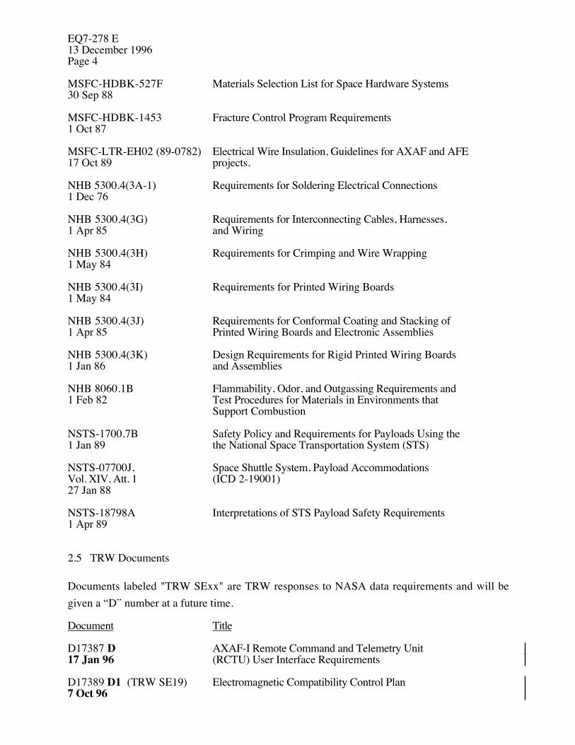
MSFC-HDBK-527F Materials Selection List for Space Hardware Systems30 Sep 88
MSFC-HDBK-1453 Fracture Control Program Requirements1 Oct 87
MSFC-LTR-EH02 (89-0782) Electrical Wire Insulation, Guidelines for AXAF and AFE17 Oct 89 projects.
NHB 5300.4(3A-1) Requirements for Soldering Electrical Connections1 Dec 76
NHB 5300.4(3G) Requirements for Interconnecting Cables, Harnesses,1 Apr 85 and Wiring
NHB 5300.4(3H) Requirements for Crimping and Wire Wrapping1 May 84
NHB 5300.4(3I) Requirements for Printed Wiring Boards1 May 84
NHB 5300.4(3J) Requirements for Conformal Coating and Stacking of1 Apr 85 Printed Wiring Boards and Electronic Assemblies
NHB 5300.4(3K) Design Requirements for Rigid Printed Wiring Boards1 Jan 86 and Assemblies
NHB 8060.1B Flammability, Odor, and Outgassing Requirements and1 Feb 82 Test Procedures for Materials in Environments that
Support Combustion
NSTS-1700.7B Safety Policy and Requirements for Payloads Using the1 Jan 89 the National Space Transportation System (STS)
NSTS-07700J, Space Shuttle System, Payload AccommodationsVol. XIV, Att. 1 (ICD 2-19001)27 Jan 88
NSTS-18798A Interpretations of STS Payload Safety Requirements1 Apr 89
2.5 TRW Documents
Documents labeled "TRW SExx" are TRW responses to NASA data requirements and will begiven a “D” number at a future time.
Document Title
D17387 D AXAF-I Remote Command and Telemetry Unit17 Jan 96 (RCTU) User Interface Requirements
D17389 D1 (TRW SE19) Electromagnetic Compatibility Control Plan7 Oct 96
EQ7-278 E13 December 1996
Page 5
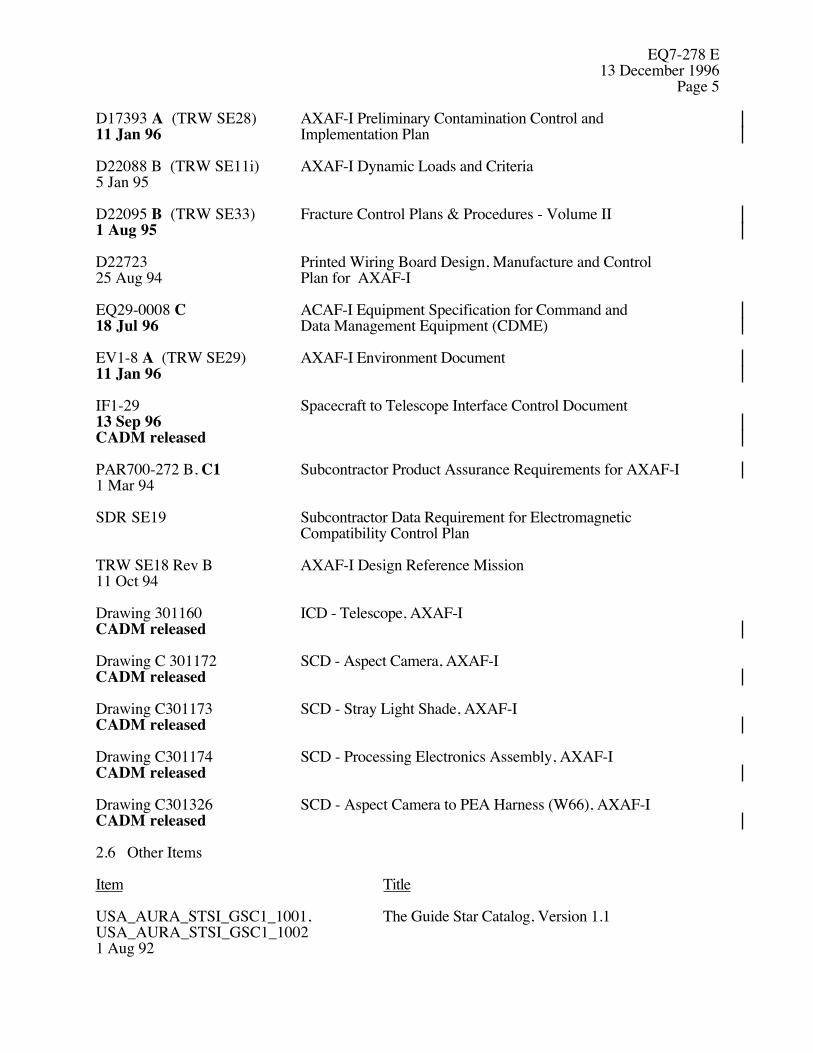
D17393 A (TRW SE28) AXAF-I Preliminary Contamination Control and11 Jan 96 Implementation Plan
D22088 B (TRW SE11i) AXAF-I Dynamic Loads and Criteria5 Jan 95
D22095 B (TRW SE33) Fracture Control Plans & Procedures - Volume II1 Aug 95
D22723 Printed Wiring Board Design, Manufacture and Control25 Aug 94 Plan for AXAF-I
EQ29-0008 C ACAF-I Equipment Specification for Command and18 Jul 96 Data Management Equipment (CDME)
EV1-8 A (TRW SE29) AXAF-I Environment Document11 Jan 96
IF1-29 Spacecraft to Telescope Interface Control Document13 Sep 96CADM released
PAR700-272 B, C1 Subcontractor Product Assurance Requirements for AXAF-I1 Mar 94
SDR SE19 Subcontractor Data Requirement for ElectromagneticCompatibility Control Plan
TRW SE18 Rev B AXAF-I Design Reference Mission11 Oct 94
Drawing 301160 ICD - Telescope, AXAF-ICADM released
Drawing C 301172 SCD - Aspect Camera, AXAF-ICADM released
Drawing C301173 SCD - Stray Light Shade, AXAF-ICADM released
Drawing C301174 SCD - Processing Electronics Assembly, AXAF-ICADM released
Drawing C301326 SCD - Aspect Camera to PEA Harness (W66), AXAF-ICADM released
2.6 Other Items
Item Title
USA_AURA_STSI_GSC1_1001, The Guide Star Catalog, Version 1.1USA_AURA_STSI_GSC1_10021 Aug 92

EQ7-278 E13 December 1996Page 6
3.0 REQUIREMENTS
3.1 Item Definition
The ACA consists of these assemblies:
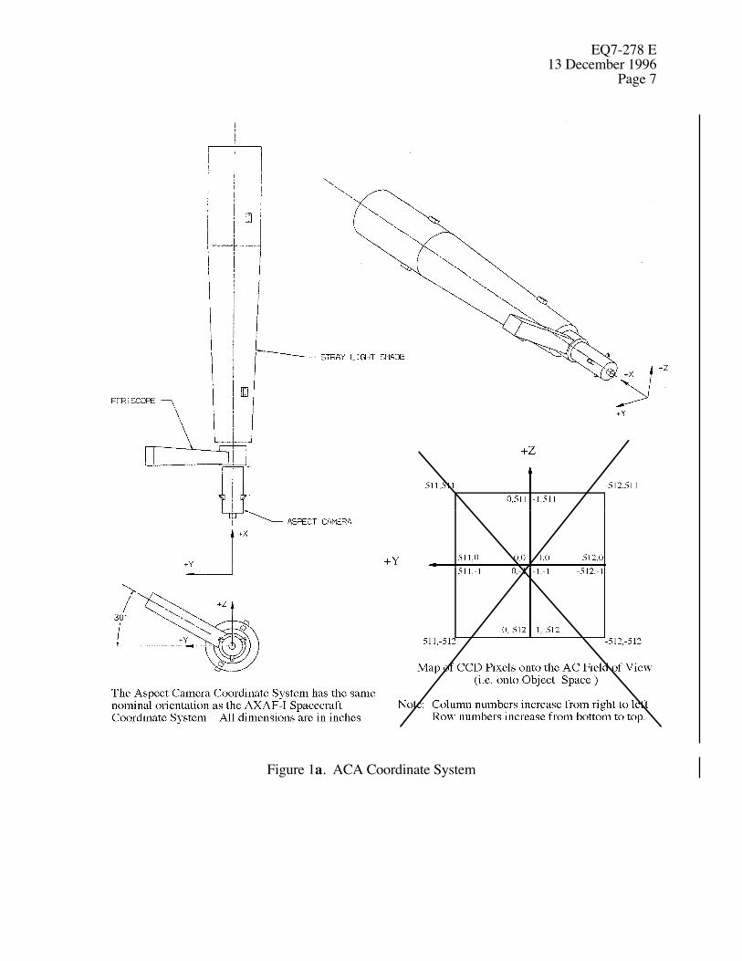
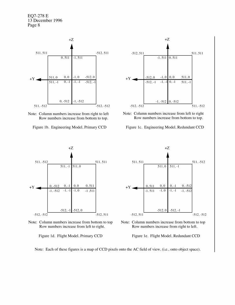
a. The Aspect Camera (AC), includes an Optical Telescope Assembly (OTA), redundantfocal plane assemblies (FPAs) and a flip mirror to use the redundant FPA. The FPArecords up to 8 images. The FPA contains a charge coupled device (CCD) having1024 rows of 1024 columns of pixels. The CCD is electrically partitioned into foursquare quadrants. Columns of pixels are numbered from -512 to +511. Rows ofpixels are also numbered from -512 to +511. The orientation of rows andcolums is different for the AC engineering model than for the AC flight unit,and for the primary and redundant focal planes within either unit. SeeFigures 1b, c, d and e. The OTA forms real star andfiducial light images at the CCD surface.
b. The Processing Electronics Assemblies (PEAs), interface the AC to the AXAF-IElectrical Power Subsystem (EPS), to two ports of a Remote Command and TelemetryUnit (RCTU), and to an Interface Unit (IU). The RCTU and IU are parts of theCommunications, Command, and Data Management (CCDM) subsystem. The PEAexecutes the four basic flight functions - search, monitor, track and calibrate. Itprovides image centroids to the on-board computer (OBC) and image data to theCCDM downlink for post facto aspect determination by ground based computers. ThePEA also executes extended command, a function used both in flight and on theground.
c. The Stray Light Shade (SLS), which protects the AC from stray light.
d. Cables, which connect the PEAs to the AC.
The AXAF-I mission profile is described in TRW SE18. The primary objective of the ACA duringthe mission phase is to measure the image positions of selected target stars and fiducial lights in itsfield-of-view (FOV). The AXAF-I OBC will use the image centroids provided by the ACA forreal-time pointing. The ground based AXAF Science Center (ASC) will use the image distributionsand inertial reference unit (IRU) and star catalog data for post facto aspect determination.
EQ7-278 E13 December 1996
Page 7
Figure 1a. ACA Coordinate System
EQ7-278 E13 December 1996Page 8
+Z
+Y
+Z
+Y
+Z
+Y
+Z
+Y
511, 511 -512, 511
511, -512 -512, -512
0, 511 -1, 511
0, 0 -1, 00, -1 -1, -1
0, -512 -1, -512
-512, 0-512, -1
511, 0511, -1
Note: Column numbers increase from right to left Row numbers increase from bottom to top.
Figure 1b. Engineering Model, Primary CCD Figure 1c. Engineering Model, Redundant CCD
Figure 1d. Flight Model, Primary CCD Figure 1e. Flight Model, Redundant CCD
Note: Column numbers increase from left to right Row numbers increase from bottom to top.
Note: Column numbers increase from bottom to top Row numbers increase from left to right.
Note: Column numbers increase from bottom to top Row numbers increase from right to left.
-512, 511 511, 511-1, 511 0, 511
-1, 0 0, 0-1, -1 0, -1
511, 0511, -1
-512, 0-512, -1
-512, -512 511, -512-1, -512 0, -512
511, -512 511, 511511, -1 511, 0
0, -1 0, 0-1, -1 -1, 0
0, 511-1 ,511
0, -512-1, -512
-512, -512 -512, 511-512, -1 -512, 0
511, 511 511, -512511, 0 511, -1
0, 0 0, -1-1, 0 -1, -1
0, -512-1, -512
0, 511-1, 511
-512, 511 -512, -512-512, 0 -512, -1
Note: Each of these figures is a map of CCD pixels onto the AC field of view, (i.e., onto object space).
EQ7-278 E13 December 1996
Page 9
The ACA will simultaneously view multiple star images and accurately track their positions duringan observation. Star centroids are used by the Pointing Control and Aspect Determination (PCAD)onboard attitude reference system which is used for real time pointing of the x-ray telescope line-of-sight (LOS) at an x-ray source within the errors and to the stability specified herein.
Post facto aspect determination is required for x-ray observations lasting longer than 100continuous seconds. Aspect determination locates x-ray event positions with respect to known starpositions as follows. The ACA provides relative positions of known observed stars and fiduciallights through its pixel image data. These data are later smoothed by IRU data. ScienceInstruments (SI) locate x-ray event positions relative to fiducial lights. The x-ray event positionsare then located relative to the known stars by using the fiducial light data common to both scenes.
The AXAF-I orbit will be elliptical from 10,000 KM to 140,000 KM altitude, 28.5 degreesinclination.
3.1.1 Item Diagrams
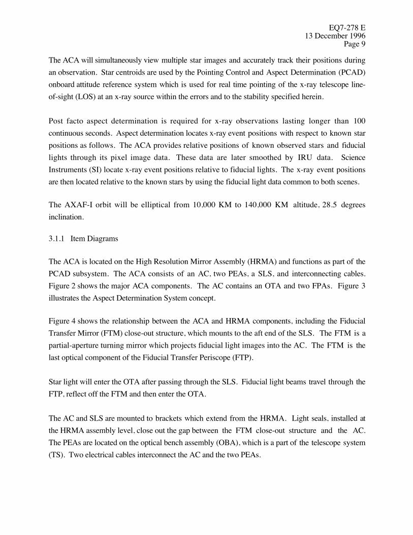
The ACA is located on the High Resolution Mirror Assembly (HRMA) and functions as part of thePCAD subsystem. The ACA consists of an AC, two PEAs, a SLS, and interconnecting cables.Figure 2 shows the major ACA components. The AC contains an OTA and two FPAs. Figure 3illustrates the Aspect Determination System concept.
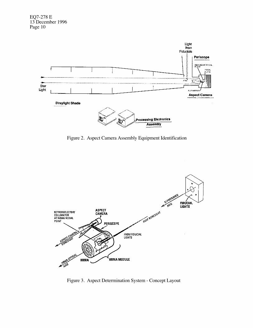
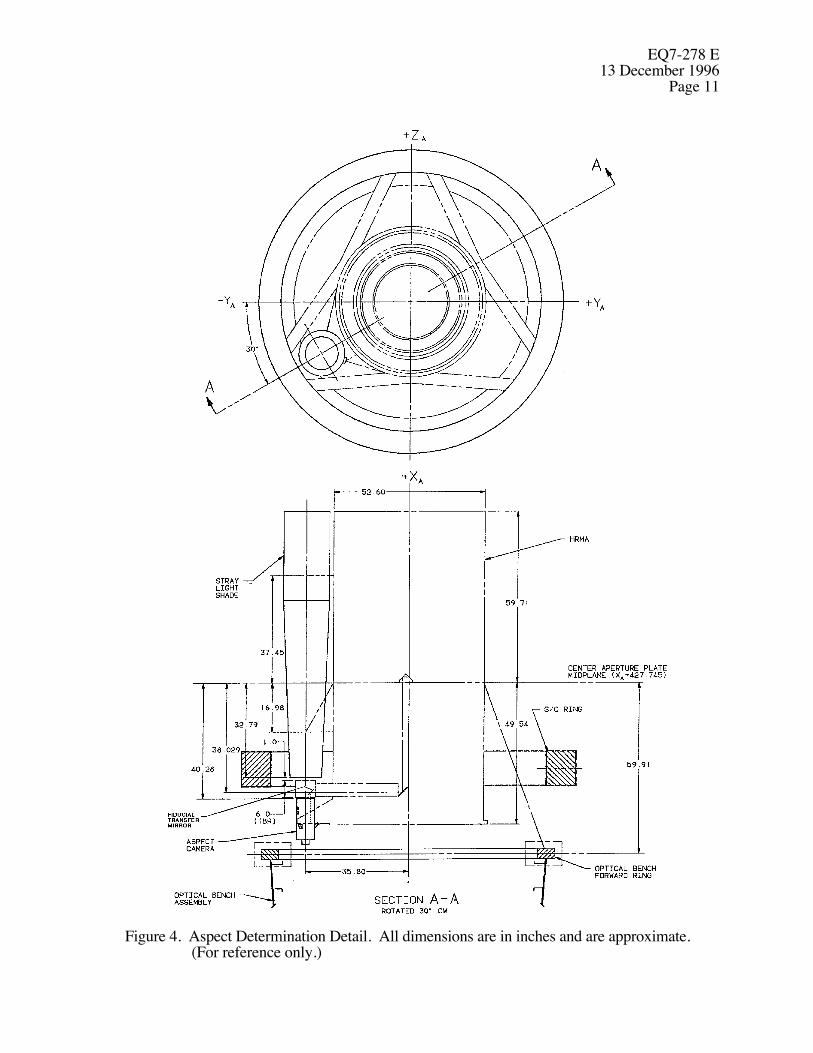
Figure 4 shows the relationship between the ACA and HRMA components, including the FiducialTransfer Mirror (FTM) close-out structure, which mounts to the aft end of the SLS. The FTM is apartial-aperture turning mirror which projects fiducial light images into the AC. The FTM is thelast optical component of the Fiducial Transfer Periscope (FTP).
Star light will enter the OTA after passing through the SLS. Fiducial light beams travel through theFTP, reflect off the FTM and then enter the OTA.
The AC and SLS are mounted to brackets which extend from the HRMA. Light seals, installed atthe HRMA assembly level, close out the gap between the FTM close-out structure and the AC.The PEAs are located on the optical bench assembly (OBA), which is a part of the telescope system(TS). Two electrical cables interconnect the AC and the two PEAs.
EQ7-278 E13 December 1996Page 10
Figure 2. Aspect Camera Assembly Equipment Identification
Figure 3. Aspect Determination System - Concept Layout
EQ7-278 E13 December 1996
Page 11
Figure 4. Aspect Determination Detail. All dimensions are in inches and are approximate.(For reference only.)

EQ7-278 E13 December 1996Page 12
Figure 1 defines the ACA coordinate system and TRW Drawing 301160 references it to thespacecraft coordinate system. The origin of the FOV is the intersection of the four quadrants of theCCD as shown in Figure 1. Figure 1 also defines focal plane row and column numbers.
3.1.2 Interface Definitions
The statements in this section are requirements on AXAF-I entities other than the ACAsubcontractor and can be relied on by the ACA subcontactor as the ACA design progresses and asimplementation details are selected.
3.1.2.1 OBC Software Interface
3.1.2.1.1 Constraint on Search Commands
It will be ensured that any search command image location (see Section 3.2.1.11.1.3) willbe separated by at least 65 arc seconds from all other tracked or monitored imagelocations. If this constraint is violated ACA accuracy cannot be assured.
3.1.2.1.2 (Reserved)
3.1.2.1.3 Functional Inputs
It will be ensured that the inputs listed in Section 3.2.1.10, Table II which allow the ACA to performthe functions of Search, Monitor, Track, Calibrate and Extended Command will be supplied.Violations will be indicated as a syntax error (see Section 3.2.1.15.6).
3.1.2.1.4 Constraints on On-Orbit Calibration
3.1.2.1.4.1 Responsivity Calibration Constraints
During responsivity calibration it will be ensured that the FOV will contain no star brighter thaninstrument magnitude 6 and the nominal commanded integration time will be chosen so that pixels1
shall accumulate 70% to 80% of full well capacity at beginning of life.
3.1.2.1.4.2 Dark Current Calibration Constraints
1 Exclusive of anomolous pixels (i.e. pixels with no output or abnormally high dark current).
EQ7-278 E13 December 1996
Page 13
For dark current calibration the commanded integration time will be 20 to 80 sec. If 20 sec ischosen, then the FOV will contain no star brighter than instrument magnitude 8.5, but if 80 sec ischosen then the FOV will contain no star brighter than instrument magnitude 10.0. Violation ofany of these star magnitude constraints may result in local saturation of the CCD around the imageof the bright star(s) during the calibration.
3.1.2.1.4.3 Calibration Telemetry Rate
During calibration it will be ensured that the spacecraft telemetry rate is set at 512 kbps,resulting in an IU data rate at the ACA interface of 593,920 bps. Use of any othertelemetry rate will result in the loss of calibration data.
3.1.2.1.4.4 Calibration Command Sequence and Timing
It shall be ensured that the sequence delineated below will be followed when conductingan ACA calibration:
1. A real-time command will be issued to the IU to begin calibration,
2. A real-time command to the ACA will be issued to begin calibration (see Section3.2.1.11.1.5) with the constraint that the command to the ACA should be receivedno earlier than the command to the IU,
3. Sufficient time will be allowed for all of the commanded calibration data to beclocked out by the IU. Denote this time period as Twait, with units of seconds.
Twait = Tint + 5.0 = 0.020 * N,
where Twait = waiting time,Tint = integration time andN = the number of CCD rows to be read out
4. Following a delay of at least Twait, a real-time command will be issued to theACA to stop calibration (see Section 3.2.1.16.1),
5. A real-time command will be issued to the IU to stop clocking calibration datawith the constraint that sufficient time will be allowed so that there is at least a 2
EQ7-278 E13 December 1996Page 14
second delay between when the ACA receives the command to stop calibrationand the IU receives the command to stop clocking.
3.1.2.1.5 Data Requests
During each 1.025-second period, the OBC will issue data requests sufficient to exhaust the datalisted in Sections 3.2.1.15.11 to the first of two ACA-dedicated RCTU ports. During each 1.025second period telemetry will issue data requests sufficient to exhaust the data listed in Section3.2.1.15.12 to the second ACA-dedicated RCTU port. If either of these constraints is not met thedata that has not been requested will be lost.
3.1.2.1.6 Science Header Pulses
RCTU science header pulses will be provided every 2.050 seconds (nominal). See D17387,Paragraph 4.2.
3.1.2.1.7 Command Timing
There will be a time gap of at least two science header pulse periods (nominally 4.100 seconds)between the end of one group of command words (see Section 3.2.1.11.1.1) and the start of thenext group. There will never be a time gap of more than one half of a science header pulse periodbetween any two commanded words within the same group.
3.1.2.1.8 Command Count
The count field in the first word of each group of command words (described in Section3.2.1.11.1.1) will contain the number of 16-bit words in the group that follow the first word. Thecount cannot exceed 63 since the field is 6 bits wide.
3.1.2.1.9 Command Checksum
The checksum field in the first word of each group of command words, described in Section3.2.1.11.1.1, will be computed so that the least significant eight bits of the sum of all 8-bit bytes inthe group, including the checksum and count, is zero.

EQ7-278 E13 December 1996
Page 15
3.1.2.1.10 Multiple Word Commands
Any multiple word command defined in Subsections of 3.2.1.11 will always be completelycontained within one of the command word groups described in Section 3.2.1.11.1.1.
3.1.2.2 Ground Operations Interface
3.1.2.2.1 Dark Current Calibration Integration Time
Ground Operations will ensure that during dark current calibration the commanded integration timewill cause pixel dark charge to accumulate to a nominal value of 10% of full well capacity when noimage is on the pixel.
3.1.2.2.2 Line-of-Sight to the Sun
During normal operation the AC LOS will be maintained at least 45 deg from the sun line.
3.1.2.2.3 Fiducial Light Commanded Intensity
The fiducial light intensity will be controlled to ensure that each fiducial light image on the ACAfocal plane will generate a minimum of 80,000 electrons at the end of an integration period.
3.1.2.2.4 Upload/Download Starting Address
The starting address for a memory upload or download must be an even number. SeeSections 3.2.1.11.1.6.4 and 3.2.1.11.1.8.2.
3.1.2.3 Thermal Interface
The ACA design can rely on the thermal interface details defined in Paragraph 3.2.2.3.3 of IF1-29.
3.1.2.4 PCAD Interface
3.1.2.4.1 Absolute Pointing
The PCAD subsystem will maintain the AXAF-I boresight within a 30 arcsec radius of the x-raysource during 99% of the viewing time within an observation period.
EQ7-278 E13 December 1996Page 16
3.1.2.4.2 Pointing Stability
The PCAD subsystem will maintain the AXAF-I boresight, with respect to the commandeddirection, to within a 0.25 arcsec rms half-cone angle over 95% of all 10-second periods comprisingan observation.
3.1.2.5 Electrical Power Interface
3.1.2.5.1 Power Connectors
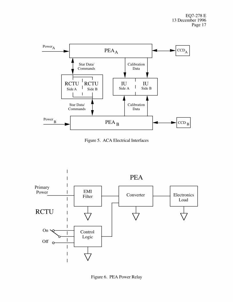
The ACA will be supplied primary and backup power from the EPS on separate connectors asshown in Figure 5.
3.1.2.5.2 Primary/Backup Power
The ACA will be supplied primary/backup power that conforms to Paragraph 4.9 of D17389(TRW SE19).
3.1.2.6 Communication, Command and Data Management Interface
3.1.2.6.1 Commands
The ACA will be supplied commands via an internally redundant RCTU from the AXAF-I CCDMsubsystem.
3.1.2.6.2 Data transfer
All data will be transferred from the ACA to the AXAF-I CCDM subsystem through an internallyredundant RCTU and an internally redundant IU.
3.1.2.6.3 PEA Power Relay
Primary power will be continuously supplied to the input filter of the PEA. A latching relay in theRCTU will provide a “PEA On” signal to the PEA regulator. When closed (PEA regulatorinhibited), the relay will have a maximum impedance of < 1 ohm and a current carrying capacity ofat least 1 ma. When open (PEA regulator enabled), it will exhibit an impedence of > 100 Kohmsand will withstand a potential of at least 40 volts. See Paragraph 2.4 of D17387 and Figure 6.
EQ7-278 E13 December 1996
Page 17
CCDA
CCD B
IURCTU
Star Data/Commands
Star Data/Commands
CalibrationData
CalibrationData
PEAA
PEA B
PowerA
PowerB
Side A Side B Side A Side BRCTU IU
Figure 5. ACA Electrical Interfaces
EMIFilter Converter Electronics
Load
ControlLogic
PEA
RCTU
On
Off
PrimaryPower
Figure 6. PEA Power Relay
EQ7-278 E13 December 1996Page 18
3.1.2.6.4 Calibration Data Acquisition
An IU described in EQ29-0008 will provide for the acquisition of the formatted serial-digitalcalibration data defined in Section 3.2.1.15.13.
3.1.2.6.5 Flip Mirror Control
Each PEA of the ACA will receive two high level pulsed discrete commands through a channel ofthe PCAD RCTU to enable or disable power to the AC flip mirror driver. See Section 3.2.1.11.2and Paragraph 2.2 of D17387. Each PEA of the ACA will also receive two low level discretecommands through a channel of the PCAD RCTU to command the flip mirror to either thedeployed or stowed position.
3.1.2.7 Mechanical Interface
3.1.2.7.1 Mechanical Interface Definitions
The ACA mechanical interfaces with the TS are defined in five TRW interface control drawings.The AC mechanical interfaces are defined in TRW Drawing C301172. The SLS mechanicalinterfaces are defined in TRW Drawing C301173. The PEA mechanical interfaces are defined inTRW Drawing C301174. The cabling mechanical interfaces are defined in TRW DrawingC301326. The AC to FTM mechanical interfaces are defined in TRW Drawing 301160 and inParagraphs 3.2.2.1.3 and 3.2.2.7 of IF1-29. Connector locations, connector types, and pinassignments are defined in TRW Drawings C301172, C301174 and C301326.
3.1.2.7.2 Line-of-Sight to the HRMA Door
The mechanical design of the AXAF-I will ensure the HRMA sunshade door is at least 20 deg fromthe AC line-of-sight when the HRMA door is open.
3.1.2.7.3 (Reserved)
EQ7-278 E13 December 1996
Page 19
3.2 Characteristics
3.2.1 Performance
Errors in the image position data specified in Section 3.2.1.15.11 affect spacecraft pointing and arecalled real-time errors. Errors in the pixel data specified in Section 3.2.1.15.12 affect aspectdetermination and are called post facto errors. Post facto processing uses updated calibration dataand more sophisticated algorithms to determine image positions.
The error budget for star and fiducial light images is divided into spatial and temporal components.Temporal errors are variations over time at a single location in the field of view while staring at anunchanging scene. Spatial errors are variations over the field-of-view while staring at anunchanging scene that would remain if temporal errors were zero.
3.2.1.1 Error Allocations
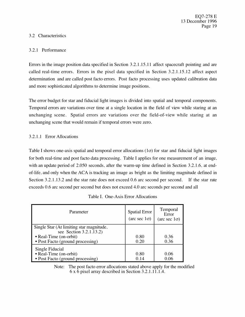
Table I shows one-axis spatial and temporal error allocations (1σ) for star and fiducial light imagesfor both real-time and post facto data processing. Table I applies for one measurement of an image,with an update period of 2.050 seconds, after the warm-up time defined in Section 3.2.1.6, at end-of-life, and only when the ACA is tracking an image as bright as the limiting magnitude defined inSection 3.2.1.13.2 and the star rate does not exceed 0.6 arc second per second. If the star rateexceeds 0.6 arc second per second but does not exceed 4.0 arc seconds per second and all
Table I. One-Axis Error Allocations
Parameter Spatial Error(arc sec 1σ)
TemporalError
(arc sec 1σ)Single Star (At limiting star magnitude, see Section 3.2.1.13.2) • Real-Time (on-orbit) • Post Facto (ground processing)
0.800.20
0.360.36
Single Fiducial • Real-Time (on-orbit) • Post Facto (ground processing)
0.800.14
0.060.06
Note: The post facto error allocations stated above apply for the modified 6 x 6 pixel array described in Section 3.2.1.11.1.4.
EQ7-278 E13 December 1996Page 20
other aforementioned conditions are met, the real-time error allocations shall be 1.0 arc second (1σ),each, for spatial and temporal errors, and there is no post facto error requirement. Errors shall notexceed these limits after exposure to the environments specified in Section 3.2.5.1, nor during orafter those specified in Section 3.2.5.2, nor with the additional stars referenced in Section 3.2.1.2 inthe FOV.
3.2.1.2 Star Background
The presence of bright stars in the FOV shall not degrade accuracy beyond that specified in Section3.2.1.1. Saturation of one or more pixels shall not deteriorate the performance for a star within thesame quadrant centered four or more columns away from all saturated pixels.
3.2.1.3 Image Intensity Dynamic Range
The ACA shall have an image intensity dynamic range of 4 instrument magnitudes brighter than thedimmest star being tracked.
3.2.1.4 (Reserved)
3.2.1.5 (Reserved)
3.2.1.6 Warm-up Time
The error allocations specified in Section 3.2.1.1 shall apply after a warm-up period of no morethan two hours, following power turn-on.
3.2.1.7 Timing
3.2.1.7.1 Update Period
The ACA shall update output data in the search function every 1.025 seconds. Updates shall occur1.0 ± 0.5 msec prior to an RCTU science header pulse and 1.0 ± 0.5 msec prior to the midpointbetween two RCTU science header pulses. See Figure 7. The beginning of integration shall beadjusted in time so that integration will always end within 1 msec of a science header pulse orwithin 1 msec of the midpoint between two science header pulses. RCTU science header pulses aredescribed in Paragraph 3.1.2.1.3.5 of EQ29-0008.
EQ7-278 E13 December 1996
Page 21
3.2.1.7.2 Update Intervals for Pixel Data
Pixel data for each image shall be commandable in the search function (see Section 3.2.1.10.1) aseither a 4 x 4 array, a modified 6 x 6 array (i.e. without the four corner pixels) or an 8 x 8 array; seeSection 3.2.1.11.1.4. The ACA shall update 4 x 4 pixel array data in the search or track functionsevery 1.025, 2.050, 3.075, or 4.100 seconds.
The ACA shall select the shortest update period consistent with the sum of flush, integration andreadout times. The ACA shall completely update modified 6 x 6 pixel array data every 2.050,3.075, or 4.100 seconds. Each complete update shall be done during two consecutive 1.025-second periods. The ACA shall completely update 8 x 8 pixel array data every 4.100 seconds.
3.2.1.7.3 Extended Update Intervals
A series of data requests from the first ACA-dedicated RCTU port and from the second ACA-dedicated RCTU port will exhaust the data listed in Sections 3.2.1.15.11 and 3.2.1.15.12,respectively, during each 1.025-second period commencing or ending with an RCTU scienceheader pulse. When the choice of integration time causes the update period to exceed 1.025seconds for a 4 x 4 image, 2.050 seconds for a modified 6 x 6 image or 4.100 seconds for an 8 x 8image, the ACA shall repeat the image data most recently provided to the two ACA-dedicatedRCTU ports until new image data is available. For modified 6 x 6 pixel data, the repeated imagedata is that data described in Table VIIIC. For 8 x 8 pixel data, the repeated image data is that datadescribed in Table VIIIG.
3.2.1.8 (Reserved)
3.2.1.9 Dim Stars
The ACA shall be able to monitor (see Section 3.2.1.10.2) stars dimmer than the limiting starmagnitude defined in Section 3.2.1.13.2. The error allocations specified in Section 3.2.1.1 do notapply for these dim stars.

EQ7-278 E13 December 1996Page 22
Data Available to OBC fromIntegration Time Shown
MidpointBetween Science
Header Pulses
0 1.025 2.050 3.075 4.100
Integration Time 0 +/-1 msec
1.0 +/- 0.5 msec
Science Header Pulses
MidpointBetween Science
Header PulsesStart Integration
Figure 7. ACA-RCTU Timing
3.2.1.10 ACA Functions
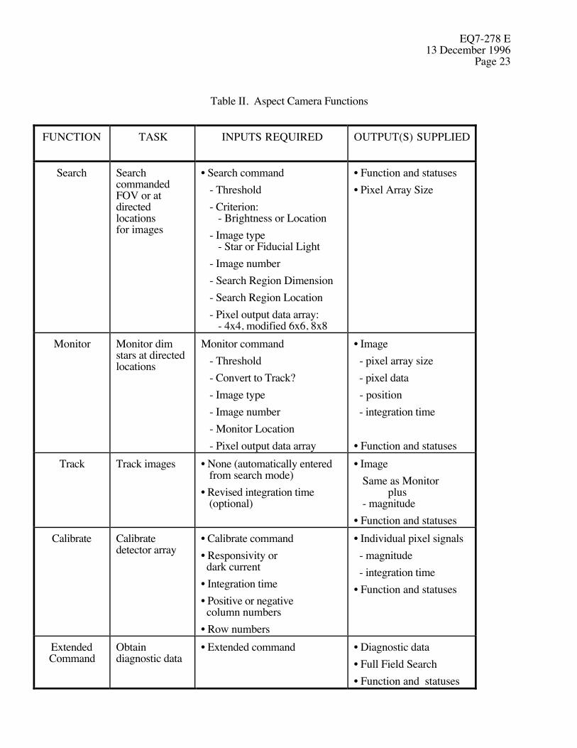
The ACA shall have four basic flight functions — search, monitor, track and calibrate. The ACAshall simultaneously record up to 8 images; each one may be used independently withany of the flight functions except calibrate. The ACA shall have one function used both in flightand on the ground — extended command. Table II and Sections 3.2.1.10.1 to 3.2.1.10.5 describethese functions. Section 3.2.1.11.1.2 describes command formats.
3.2.1.10.1 Search
3.2.1.10.1.1 Definitions
The following definitions shall be used in specifying the ACA search operation.
3.2.1.10.1.1.1 Search Command
The complete three command word sequence specified in Section 3.2.1.11.1.3 shall define onesearch command.
EQ7-278 E13 December 1996
Page 23
Table II. Aspect Camera Functions
FUNCTION TASK INPUTS REQUIRED OUTPUT(S) SUPPLIED
Search SearchcommandedFOV or atdirectedlocationsfor images
• Search command- Threshold- Criterion:
- Brightness or Location- Image type
- Star or Fiducial Light- Image number- Search Region Dimension- Search Region Location- Pixel output data array:
- 4x4, modified 6x6, 8x8
• Function and statuses• Pixel Array Size
Monitor Monitor dimstars at directedlocations
Monitor command- Threshold- Convert to Track?- Image type- Image number- Monitor Location- Pixel output data array
• Image - pixel array size - pixel data - position - integration time
• Function and statusesTrack Track images • None (automatically entered
from search mode)• Revised integration time (optional)
• ImageSame as Monitor
plus- magnitude
• Function and statusesCalibrate Calibrate
detector array• Calibrate command• Responsivity or dark current• Integration time• Positive or negative column numbers• Row numbers
• Individual pixel signals - magnitude - integration time• Function and statuses
ExtendedCommand
Obtaindiagnostic data
• Extended command • Diagnostic data• Full Field Search• Function and statuses
EQ7-278 E13 December 1996Page 24
3.2.1.10.1.1.2 Search Command Sequence
All consecutive search commands within one command group, as defined in Section 3.2.1.11.1.1,shall be a search command sequence.
3.2.1.10.1.1.3 Search Region
The search region for any image number shall be a square centered at the commanded angular Zand Y coordinates. (See Figure 1.) When the high resolution flag (H) in command word 3 is true(=1), the half-width of the square, in arc seconds, is (20 + 5D) where D is the dimension field incommand word 2. (See Section 3.2.1.11.1.3.1.) When the H flag is false (=0), the half-width is(20 + 40D) arc seconds.
3.2.1.10.1.1.4 Candidate Images
Candidate images for each search region shall be defined as images within the region that are atleast as bright as the commanded threshold for that region. The term "bright" in this definitionrefers to brightness as measured with the CCD and averaged over three consecutive CCDexposures. For some search regions there may be no candidate images.
3.2.1.10.1.1.5 Best Image
The best image for each search region shall be the brightest candidate image in that region if the Bflag in command word 1 is true (=1), or the candidate image nearest the center of the search regionif the B flag is false (=0). There will be no best image for those regions that have no candidateimages.
3.2.1.10.1.1.6 Best Available Image
The best available image for any one region shall be defined as the best image for that region that isnot assigned to any adjacent overlapping region for tracking. In the case of overlapping searchregions, it is possible that there may be no best available image for a region, even though it doeshave a best image, since all candidate images may be assigned to adjacent overlapping regions.
EQ7-278 E13 December 1996
Page 25
3.2.1.10.1.2 Start of Search
Upon receipt of a search command sequence, the ACA shall do the following:
3.2.1.10.1.2.1 Terminate Previous Search
The ACA shall terminate any previously commanded search still in progress.
3.2.1.10.1.2.2 Continue Tracking and Monitoring
The ACA shall continue all tracking or monitoring operations for image numbers not addressed inthe search command sequence.
3.2.1.10.1.2.3 Update Image Function Bits
The ACA shall set the image function bits (see Section 3.2.1.15.3) in the OBC data to the searchstate for all image data slots addressed in the search command sequence.
3.2.1.10.1.2.4 Initialize Command Progress
The ACA shall initialize the Command Progress (see Section 3.2.1.15.6.2) to a non-zero valueindicating the approximate number of CCD rows to be searched as specified in Section3.2.1.15.6.2.
3.2.1.10.1.2.5 Set Automatic Integration Time
The ACA shall automatically set the CCD integration time at the start of a search operation to avalue that will allow acquisition at the dimmest threshold contained within the search commandsequence.
3.2.1.10.1.2.6 Override Integration Time
If an integration time command within the same command group is appended to the end of a searchcommand sequence, the ACA shall use the commanded integration time in lieu of the automaticallyset integration time specified above.
EQ7-278 E13 December 1996Page 26
3.2.1.10.1.2.7 Search Commanded Regions
The ACA shall begin searching the commanded regions of the field-of-view for candidate images.
3.2.1.10.1.3 During Search
While the search is in progress, the ACA shall do the following:
3.2.1.10.1.3.1 Update Command Progress
The ACA shall keep the Command Progress updated to a non-zero value showing the approximatenumber of CCD rows remaining to be searched as specified in Section 3.2.1.15.6.2.
3.2.1.10.1.3.2 Initiate Tracking
The ACA shall convert the status of each image number from searching to tracking as soon as thebest available image for that number is identified.
3.2.1.10.1.4 Completion of Search
At the completion of the search, the ACA shall do the following:
3.2.1.10.1.4.1 Zero Command Progress Bits
The ACA shall set the Command Progress bits to zero.
3.2.1.10.1.4.2 Update Image Function Bits
The ACA shall set the Image Function Bits (see Section 3.2.1.15.3) in the OBC data to “00” forall images addressed by the search command that were not converted to track status during thesearch.
3.2.1.10.1.5 Search Time
The ACA shall meet the search time specifications in the subparagraphs below when the integrationtime is automatically set by the ACA for a +10.2 magnitude threshold.
EQ7-278 E13 December 1996
Page 27
3.2.1.10.1.5.1 Full field with No Candidate Images
The maximum time required to complete the default search command sequence defined in section3.2.1.11.1.3.2 shall not exceed 45 seconds when no candidate images are found in the full field-of-view.
3.2.1.10.1.5.2 Full Field with 16 Candidate Images
The maximum time required to complete the default search command sequence defined in section3.2.1.11.1.3.2 shall not exceed 60 seconds when the field-of-view contains 16 uniformly distributedcandidate images.
3.2.1.10.1.5.3 Minimum Size Search Areas
The maximum time required to complete a search command sequence consisting of eight searchcommands (see Section 3.2.1.11.1.3.1) with D set to 0 or 1 in each command and H set equal to 1,shall be 8 seconds when each search region contains one candidate image.
3.2.1.10.1.6 Image Rates
The ACA shall be successful in acquiring images that meet the commanded search criteria forimage rates up to 8 arc seconds per second in any direction for any integration time that allowscomplete pixel data updates every 1.025 seconds.
3.2.1.10.2 Monitor
Upon receipt of a monitor command defined in Section 3.2.1.11.1.4, the ACA shall do thefollowing:
3.2.1.10.2.1 Begin Monitoring
The ACA shall begin monitoring 8x8 blocks of CCD pixels centered on the commanded locationsfor the image numbers specified in the command(s).
EQ7-278 E13 December 1996Page 28
3.2.1.10.2.2 Report Aspect Telemetry
While monitoring, the ACA shall report raw pixel images in the aspect telemetry data as either thecentral 4x4 or the central modified 6x6 or the full 8 x 8 block of pixels depending on the state ofthe S code in the monitor command. See Section 3.2.1.11.1.4.
3.2.1.10.2.3 Convert to Track
If an image appears within a monitored 8x8 pixel block with a brightness exceeding thecommanded threshold, and if the C flag in the monitor command (see Section 3.2.1.11.1.4.) forthat block is true (=1), then the ACA shall immediately convert the status of that image frommonitoring to tracking.
3.2.1.10.2.4 Continue Monitoring
For all monitored images with false (=0) C flags in the monitor command, or brightnesses belowthe threshold, the ACA shall continue monitoring the commanded location until another commandis received that changes the status of the image data slot.
3.2.1.10.2.5 Modification of Monitor Windows
The coordinates of each monitor window shall be modified over time to reflect motion of adesignated tracked star (e.g. if the designated tracked star moves 5 arcsec along the +Y-axis of theAC, each monitor window shall move one column in the +Y direction on the AC focal plane). If notracked image is designated as a star, all monitor windows shall remain fixed in AC coordinates.The star to be tracked is designated in the Monitor Command; see Section 3.2.1.11.1.4.
3.2.1.10.3 Track
The ACA shall track up to eight images and output the data specified in Sections 3.2.1.15.1 to3.2.1.15.8 at the update rate specified in Section 3.2.1.7. The ACA shall continue to track anyimage found with a search command until it receives a command to another function for that image.The ACA shall use the integration time most recently commanded, if any; otherwise, the integrationtime last used in the search function.
EQ7-278 E13 December 1996
Page 29
Upon loss of an image within the FOV, the ACA shall attempt to track the image at its last knownlocation. Upon recovery of the image, tracking shall continue. Upon loss of an image outside theFOV, the ACA shall cease tracking that image and await a new command for that image number.
3.2.1.10.4 Calibrate
The ACA shall implement two kinds of detector array calibration — one for responsivity, the otherfor dark current. The ACA shall not employ internal shutters nor require closure of the AXAF-Isunshade door. Data will be read out at a rate of 593.92 Kbits/sec and shall include start-of-frameand start-of-row codes. Calibration shall occur in blocks of consecutive complete rows within thesame quadrant of the CCD. A row or column number of zero shall be treated as positive.Successive exposure frames will be used until all pixels are calibrated. For responsivity, extra rowswill be calibrated in the next block for overlap with successive exposures. In order to assureadequate statistics, the entire CCD calibration may be replicated up to eight times for responsivityand up to two times for dark current. Replicas shall be numbered consecutively starting with 0.The replica number is for bookkeeping purposes only. No action is required other thanreporting the replica number with the data as described in Section 3.2.1.15.13.
3.2.1.10.5 Diagnostics - The Extended Command
Upon receipt of an extended command, the ACA shall perform the diagnostic tasks defined inSection 3.2.1.11.1.6.
3.2.1.11 Commands
3.2.1.11.1 Serial-Digital Commands
3.2.1.11.1.1 Command Word Groups
The ACA shall accept groups of 16-bit serial digital command words through the PCAD RCTU,separated in time as described in Section 3.1.2.1.7. See Paragraph 2.1 of D17387. The ACA shallexecute all commands within the group sequentially except as specified in subsections below.

EQ7-278 E13 December 1996Page 30
3.2.1.11.1.1.1 Command Checksum and Count
The ACA shall interpret the first word in each command word group as shown below, where thechecksum and count fields are as described in Sections 3.1.2.1.8 and 3.1.2.1.9 respectively.
Checksum 0 0 Count0 1 2 3 4 5 6 7 8 9 10 11 12 13 14 15
MSB LSB
3.2.1.11.1.1.2 Command Error Processing
An invalid checksum indicates an error in transmission of a group of commands to theACA. A syntax error indicates an invalid command was issued to the ACA. If the checksum for any group of command words is invalid, or if a syntax error is detected in anycommand within the group, the error shall be reported as defined in Section 3.2.1.15.6.1, and theACA shall not execute any command in the group.
3.2.1.11.1.1.3 Search Command Processing
Any search command sequence containing more than 8 consecutive 3-word search commands shallbe treated as a syntax error. Any search command sequence not completely contained within onecommand word group shall be treated as a syntax error. If a command word group contains one ormore search command sequences, the ACA shall ignore all commands in that group preceding thelast search sequence.
3.2.1.11.1.1.4 Calibrate Command Processing
If a command word group contains calibrate commands, the ACA shall ignore all search andextended commands in the group preceding the first calibrate command.
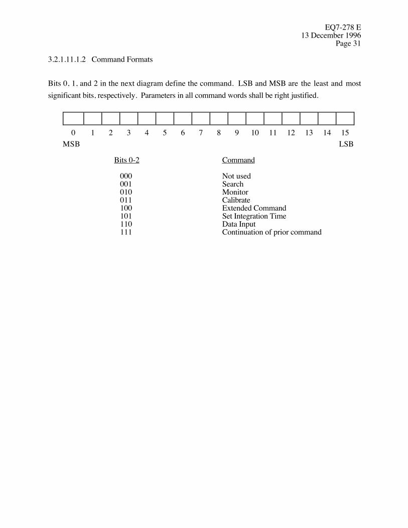
EQ7-278 E13 December 1996
Page 31
3.2.1.11.1.2 Command Formats
Bits 0, 1, and 2 in the next diagram define the command. LSB and MSB are the least and mostsignificant bits, respectively. Parameters in all command words shall be right justified.
0 1 2 3 4 5 6 7 8 9 10 11 12 13 14 15MSB LSB
Bits 0-2 Command
000 Not used001 Search010 Monitor011 Calibrate100 Extended Command101 Set Integration Time110 Data Input111 Continuation of prior command
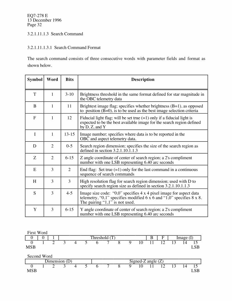
EQ7-278 E13 December 1996Page 32
3.2.1.11.1.3 Search Command
3.2.1.11.1.3.1 Search Command Format
The search command consists of three consecutive words with parameter fields and format asshown below.
Symbol Word Bits Description
T 1 3-10 Brightness threshold in the same format defined for star magnitude inthe OBC telemetry data
B 1 11 Brightest image flag; specifies whether brightness (B=1), as opposedto position (B=0), is to be used as the best image selection criteria
F 1 12 Fiducial light flag; will be set true (=1) only if a fiducial light isexpected to be the best available image for the search region definedby D, Z, and Y
I 1 13-15 Image number; specifies where data is to be reported in theOBC and aspect telemetry data.
D 2 0-5 Search region dimension; specifies the size of the search region asdefined in section 3.2.1.10.1.1.3
Z 2 6-15 Z angle coordinate of center of search region; a 2's complimentnumber with one LSB representing 6.40 arc seconds
E 3 2 End flag: Set true (=1) only for the last command in a continuoussequence of search commands
H 3 3 High resolution flag for search region dimension; used with D tospecify search region size as defined in section 3.2.1.10.1.1.3
S 3 4-5 Image size code: “0,0” specifies 4 x 4 pixel image for aspect datatelemetry, “0,1” specifies modified 6 x 6 and “1,0” specifies 8 x 8.The pairing “1,1” is not used.
Y 3 6-15 Y angle coordinate of center of search region; a 2's complimentnumber with one LSB representing 6.40 arc seconds
First Word0 0 1 Threshold (T) B F Image (I)0 1 2 3 4 5 6 7 8 9 10 11 12 13 14 15
MSB LSB
Second WordDimension (D) Signed-Z angle (Z)
0 1 2 3 4 5 6 7 8 9 10 11 12 13 14 15MSB LSB
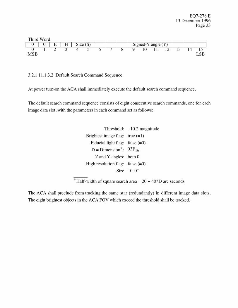
EQ7-278 E13 December 1996
Page 33
Third Word0 0 E H Size (S) Signed-Y angle (Y)0 1 2 3 4 5 6 7 8 9 10 11 12 13 14 15
MSB LSB
3.2.1.11.1.3.2 Default Search Command Sequence
At power turn-on the ACA shall immediately execute the default search command sequence.
The default search command sequence consists of eight consecutive search commands, one for eachimage data slot, with the parameters in each command set as follows:
Threshold: +10.2 magnitudeBrightest image flag: true (=1)
Fiducial light flag: false (=0)D = Dimension*: 03F16
Z and Y-angles: both 0High resolution flag: false (=0)
Size “0,0”______*Half-width of square search area = 20 + 40*D arc seconds
The ACA shall preclude from tracking the same star (redundantly) in different image data slots.The eight brightest objects in the ACA FOV which exceed the threshold shall be tracked.

EQ7-278 E13 December 1996Page 34
3.2.1.11.1.4 Monitor Command
The monitor command consists of three consecutive words with parameter fields and format asshown below.
Symbol Word Bits Description
T 1 3-10 Brightness threshold in the same format defined for star magnitude inthe OBC telemetry data
C 1 11 Convert-to-track flag; true (=1) specifies monitoring should beconverted to tracking if and when the threshold is exceeded
F 1 12 Fiducial light flag; will be set true (=1) only if a fiducial light image isexpected at the location to be monitored
I 1 13-15 Image number; specifies where data is to be reported in theOBC and aspect telemetry data.
S 2 4-5 Image size code: “0,0” specifies 4 x 4 pixel image for aspect datatelemetry, “0,1” specifies modified 6 x 6 and “1,0” specifies 8 x 8.The pairing “1,1” is not used.
Z 2 6-15 Z angle coordinate of center of monitor region; a 2's complimentnumber with one LSB representing 6.40 arc seconds
Y 3 6-15 Y angle coordinate of center of monitor region; a 2's complimentnumber with one LSB representing 6.40 arc seconds
DTS 3 3-5 Designated Tracked Star; indicates which tracked image the monitorwindow will follow
First Word0 1 0 Threshold (T) C F Image (I)0 1 2 3 4 5 6 7 8 9 10 11 12 13 14 15
MSB LSB
Second Word1 1 1 0 Size (S) Signed Z-angle (Z)0 1 2 3 4 5 6 7 8 9 10 11 12 13 14 15
MSB LSB
Third Word1 1 1 DTS Signed Y-angle (Y)0 1 2 3 4 5 6 7 8 9 10 11 12 13 14 15
MSB LSB
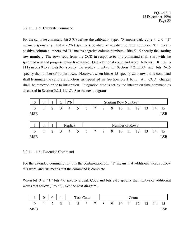
EQ7-278 E13 December 1996
Page 35
3.2.1.11.1.5 Calibrate Command
For the calibrate command, bit 3 (C) defines the calibration type. "0" means dark current and "1"means responsivity. Bit 4 (P/N) specifies positive or negative column numbers; “0” meanspositive column numbers and “1” means negative column numbers. Bits 5-15 specify the startingrow number. The rows read from the CCD in response to this command shall start with thespecified row and progress towards row zero. One additional command word follows. It has a1112 in bits 0 to 2. Bits 3-5 specify the replica number in Section 3.2.1.10.4 and bits 6-15specify the number of output rows. However, when bits 6-15 specify zero rows, this commandshall terminate the calibrate function as specified in Section 3.2.1.16.1. All CCD chargesshall be removed prior to integration. Integration time is set by the integration time command asdiscussed in Section 3.2.1.11.1.7. See the next diagrams.
0 1 1 C P/N Starting Row Number0 1 2 3 4 5 6 7 8 9 10 11 12 13 14 15
MSB LSB
1 1 1 Replica Number of Rows0 1 2 3 4 5 6 7 8 9 10 11 12 13 14 15
MSB LSB
3.2.1.11.1.6 Extended Command
For the extended command, bit 3 is the continuation bit. "1" means that additional words followthis word, and "0" means that the command is complete.
When bit 3 is "1," bits 4-7 specify a Task Code and bits 8-15 specify the number of additionalwords that follow (1 to 62). See the next diagram.
1 0 0 1 Task Code Count0 1 2 3 4 5 6 7 8 9 10 11 12 13 14 15
MSB LSB
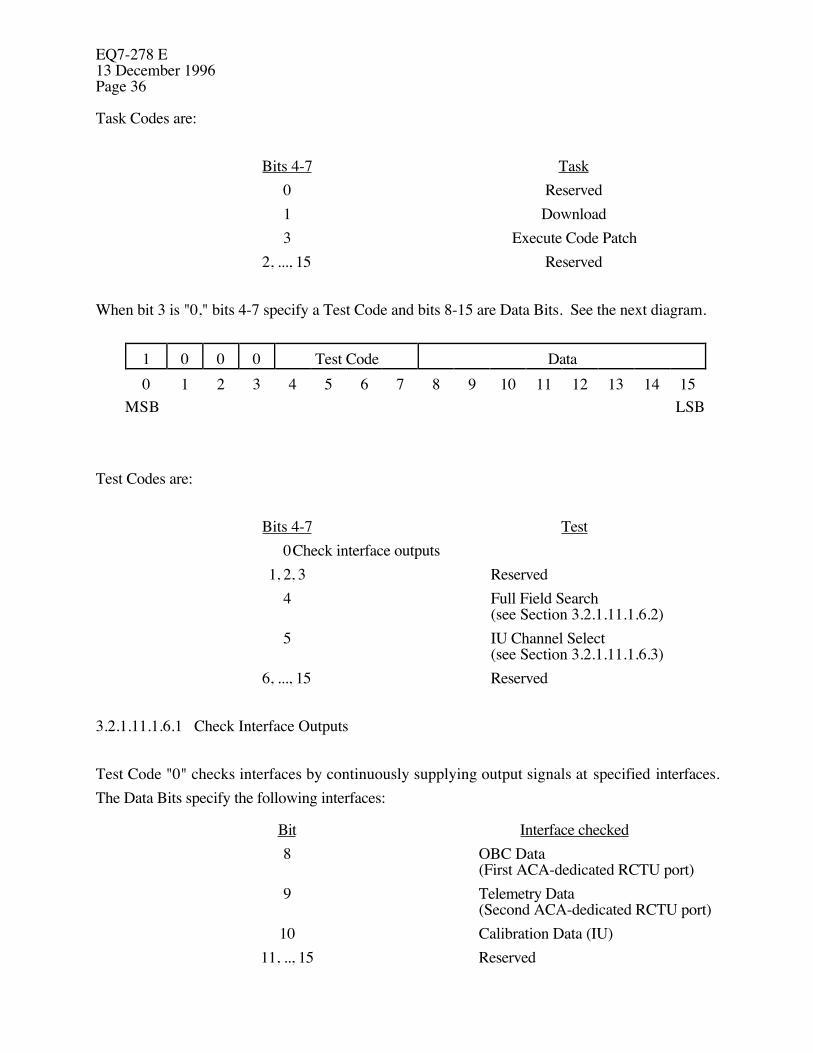
EQ7-278 E13 December 1996Page 36
Task Codes are:
Bits 4-7 Task0 Reserved1 Download3 Execute Code Patch
2, ..., 15 Reserved
When bit 3 is "0," bits 4-7 specify a Test Code and bits 8-15 are Data Bits. See the next diagram.
1 0 0 0 Test Code Data0 1 2 3 4 5 6 7 8 9 10 11 12 13 14 15
MSB LSB
Test Codes are:
Bits 4-7 Test0Check interface outputs
1, 2, 3 Reserved4 Full Field Search
(see Section 3.2.1.11.1.6.2)5 IU Channel Select
(see Section 3.2.1.11.1.6.3)6, ..., 15 Reserved
3.2.1.11.1.6.1 Check Interface Outputs
Test Code "0" checks interfaces by continuously supplying output signals at specified interfaces.The Data Bits specify the following interfaces:
Bit Interface checked8 OBC Data
(First ACA-dedicated RCTU port)9 Telemetry Data
(Second ACA-dedicated RCTU port)10 Calibration Data (IU)
11, .., 15 Reserved
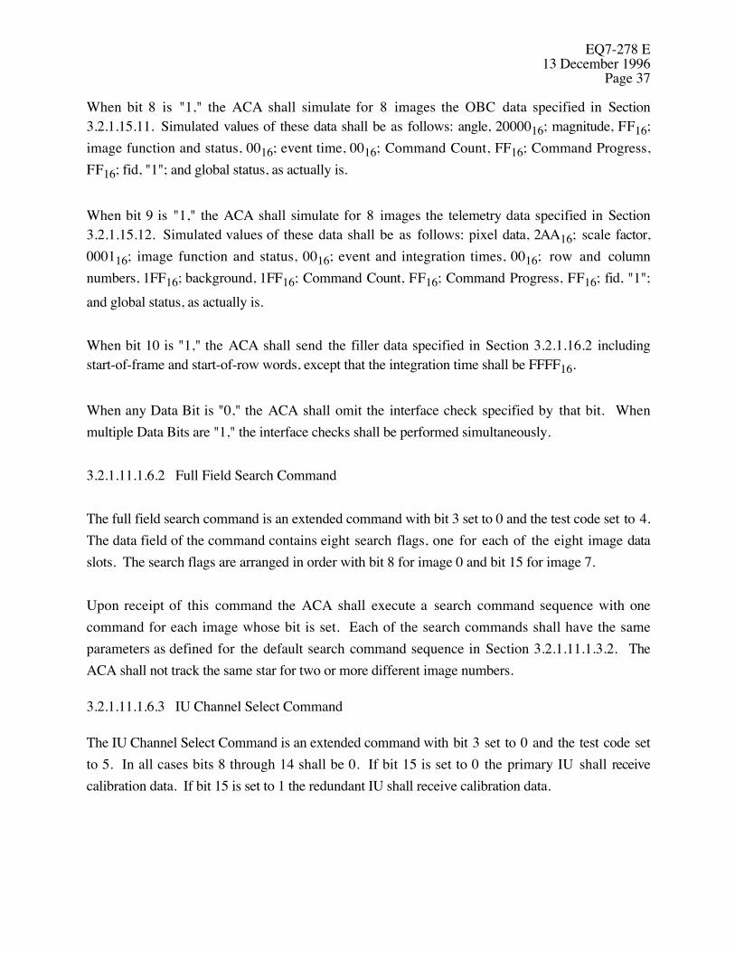
EQ7-278 E13 December 1996
Page 37
When bit 8 is "1," the ACA shall simulate for 8 images the OBC data specified in Section3.2.1.15.11. Simulated values of these data shall be as follows: angle, 2000016; magnitude, FF16;image function and status, 0016; event time, 0016; Command Count, FF16; Command Progress,FF16; fid, "1"; and global status, as actually is.
When bit 9 is "1," the ACA shall simulate for 8 images the telemetry data specified in Section3.2.1.15.12. Simulated values of these data shall be as follows: pixel data, 2AA16; scale factor,000116; image function and status, 0016; event and integration times, 0016; row and columnnumbers, 1FF16; background, 1FF16; Command Count, FF16; Command Progress, FF16; fid, "1";and global status, as actually is.
When bit 10 is "1," the ACA shall send the filler data specified in Section 3.2.1.16.2 includingstart-of-frame and start-of-row words, except that the integration time shall be FFFF16.
When any Data Bit is "0," the ACA shall omit the interface check specified by that bit. Whenmultiple Data Bits are "1," the interface checks shall be performed simultaneously.
3.2.1.11.1.6.2 Full Field Search Command
The full field search command is an extended command with bit 3 set to 0 and the test code set to 4.The data field of the command contains eight search flags, one for each of the eight image dataslots. The search flags are arranged in order with bit 8 for image 0 and bit 15 for image 7.
Upon receipt of this command the ACA shall execute a search command sequence with onecommand for each image whose bit is set. Each of the search commands shall have the sameparameters as defined for the default search command sequence in Section 3.2.1.11.1.3.2. TheACA shall not track the same star for two or more different image numbers.
3.2.1.11.1.6.3 IU Channel Select Command
The IU Channel Select Command is an extended command with bit 3 set to 0 and the test code setto 5. In all cases bits 8 through 14 shall be 0. If bit 15 is set to 0 the primary IU shall receivecalibration data. If bit 15 is set to 1 the redundant IU shall receive calibration data.
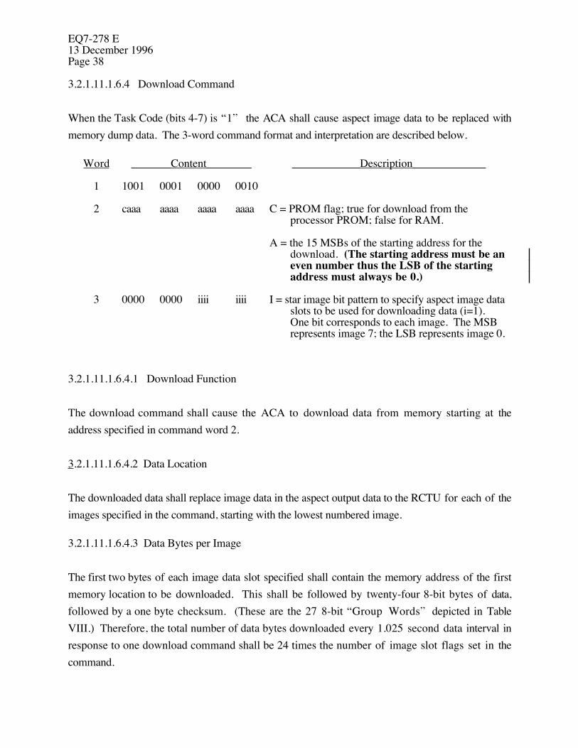
EQ7-278 E13 December 1996Page 38
3.2.1.11.1.6.4 Download Command
When the Task Code (bits 4-7) is “1” the ACA shall cause aspect image data to be replaced withmemory dump data. The 3-word command format and interpretation are described below.
Word _______Content________ ____________Description_____________
1 1001 0001 0000 0010
2 caaa aaaa aaaa aaaa C = PROM flag; true for download from theprocessor PROM; false for RAM.
A = the 15 MSBs of the starting address for thedownload. (The starting address must be aneven number thus the LSB of the startingaddress must always be 0.)
3 0000 0000 iiii iiii I = star image bit pattern to specify aspect image dataslots to be used for downloading data (i=1).One bit corresponds to each image. The MSBrepresents image 7; the LSB represents image 0.
3.2.1.11.1.6.4.1 Download Function
The download command shall cause the ACA to download data from memory starting at theaddress specified in command word 2.
3.2.1.11.1.6.4.2 Data Location
The downloaded data shall replace image data in the aspect output data to the RCTU for each of theimages specified in the command, starting with the lowest numbered image.
3.2.1.11.1.6.4.3 Data Bytes per Image
The first two bytes of each image data slot specified shall contain the memory address of the firstmemory location to be downloaded. This shall be followed by twenty-four 8-bit bytes of data,followed by a one byte checksum. (These are the 27 8-bit “Group Words” depicted in TableVIII.) Therefore, the total number of data bytes downloaded every 1.025 second data interval inresponse to one download command shall be 24 times the number of image slot flags set in thecommand.

EQ7-278 E13 December 1996
Page 39
3.2.1.11.1.6.4.4 Checksums
The one byte checksum specified in section 3.2.1.11.1.6.4.3 shall be computed so that the sum ofthe checksum plus the preceeding 26 bytes of data, modulo 256, shall be zero.
3.2.1.11.1.6.4.5 Download Duration
After receipt of this command, new download data shall replace aspect data each update period untilanother download command with all image bits set to zero is received or the last address in memoryis reached, at which time the reporting of aspect data shall resume.
3.2.1.11.1.7 Integration Time Command
For the integration time command, bits 3-15 specify the integration time. The LSB shall be 16milliseconds. The commanded integration time shall supersede the existing integration time. In theabsence of this command, the track and calibrate functions shall use the integration time lastcommanded in any function. See the next diagram. This command may be used within anyfunction.
1 0 1 Integration Time0 1 2 3 4 5 6 7 8 9 10 11 12 13 14 15
MSB LSB
3.2.1.11.1.8 Data Input Command
For the data input command, bits 3-7 define a data location and bits 8-15 specify the number of datawords to follow.
1 1 0 Location Data Count0 1 2 3 4 5 6 7 8 9 10 11 12 13 14 15
MSB LSB
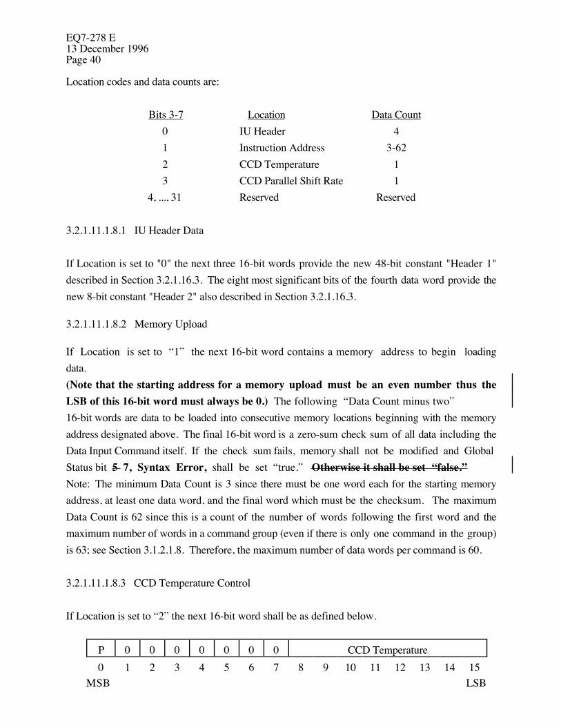
EQ7-278 E13 December 1996Page 40
Location codes and data counts are:
Bits 3-7 Location Data Count0 IU Header 41 Instruction Address 3-622 CCD Temperature 13 CCD Parallel Shift Rate 1
4, ..., 31 Reserved Reserved
3.2.1.11.1.8.1 IU Header Data
If Location is set to "0" the next three 16-bit words provide the new 48-bit constant "Header 1"described in Section 3.2.1.16.3. The eight most significant bits of the fourth data word provide thenew 8-bit constant "Header 2" also described in Section 3.2.1.16.3.
3.2.1.11.1.8.2 Memory Upload
If Location is set to “1” the next 16-bit word contains a memory address to begin loadingdata. (Note that the starting address for a memory upload must be an even number thus theLSB of this 16-bit word must always be 0.) The following “Data Count minus two”16-bit words are data to be loaded into consecutive memory locations beginning with the memoryaddress designated above. The final 16-bit word is a zero-sum check sum of all data including theData Input Command itself. If the check sum fails, memory shall not be modified and GlobalStatus bit 5 7, Syntax Error, shall be set “true.” Otherwise it shall be set “false.” Note: The minimum Data Count is 3 since there must be one word each for the starting memoryaddress, at least one data word, and the final word which must be the checksum. The maximumData Count is 62 since this is a count of the number of words following the first word and themaximum number of words in a command group (even if there is only one command in the group)is 63; see Section 3.1.2.1.8. Therefore, the maximum number of data words per command is 60.
3.2.1.11.1.8.3 CCD Temperature Control
If Location is set to “2” the next 16-bit word shall be as defined below.
P 0 0 0 0 0 0 0 CCD Temperature0 1 2 3 4 5 6 7 8 9 10 11 12 13 14 15
MSB LSB

EQ7-278 E13 December 1996
Page 41
EQ7-278 E13 December 1996Page 42
If P is true (=1), TEC power shall be commanded “on” and if false (=0) TEC power shall becommanded “off.” (Default = “off.”) CCD temperature shall be expressed in degrees C, signed,2’s compliment. Range = -128 deg C to +127 deg C. The ACA design may dictate thatallowable CCD temperature values occupy only part of this range. Command of a non-allowed temperature value is a syntax error.
3.2.1.11.1.8.4 CCD Parallel Shift Rate Control
If Location is set to “3” the next 16-bit word shall indicate the CCD parallel shift rate. TheLSBshall be 1 microsecond. (Default = 24 microseconds.) Allowable values shall be 6, 12, 18 and 24and 48 microseconds. Command of a non-allowed value is a syntax error.
3.2.1.11.2 High Level Discrete Commands
High level discrete commands shall be used to enable/disable flip mirror power.
3.2.1.11.3 Low Level Discrete Commands
Low level discrete commands are functional only when flip mirror power is enabled. See Section3.2.1.11.2. Within 30 minutes of receipt of low level discrete command DC-1, the ACA shallremove the flip mirror from the optical path (primary FPA). Within 30 minutes of receipt of lowlevel discrete command DC-2, the ACA shall insert the flip mirror in the optical path (redundantFPA).
3.2.1.12 Data
The ACA shall send all the image data defined in Sections 3.2.1.15.1 to 3.2.1.15.8 to the PCADRCTU. See Paragraph 3.1 of D17387. The ACA shall send all the calibration data defined inSections 3.2.1.15.9 and 3.2.1.15.10 to the IU. See Section 3.2.1.16. All these data shall be sentMSB first.
3.2.1.13 Optical Requirements
3.2.1.13.1 Spectral Sensitivity
EQ7-278 E13 December 1996
Page 43
For selection, identification, spectral class, and celestial positions of stars, the Guide Star Catalog,version 1.1 shall be used. Optical characteristics of the FTP and fiducial light beams are defined inParagraph 3.2.2.7 of IF1-29. A zero magnitude star has a total irradiance over all wavelengths of2.50 x 10-12 W/cm2. Zero instrument magnitude is defined as the AC response to a zeromagnitude star of spectral class G0 V (6030˚ K).
3.2.1.13.2 Field-of-View and Limiting Star Magnitude
The FOV and limiting star magnitude shall provide a 95% probability (minimum) of detecting aminimum of 5 stars anywhere on the celestial sphere. The FOV and limiting magnitude shall beconsistent with Paragraph 3.2.2.7 of IF1-29. Nominal values for the FOV, pixel angularsubtense, and limiting star magnitude are 1.40 degrees square, 5.0 arc seconds, and 10.2 instrumentmagnitude, respectively.
3.2.1.13.3 Aperture
The AC effective aperture shall be compatible with the limiting star magnitude defined in Section3.2.1.13.2, the error allocations defined in Section 3.2.1.1, and the fastest update rate defined inSection 3.2.1.7 for the track function.
3.2.1.13.4 AC Line-of-Sight Stability
The AC LOS is defined as a ray from a single on-axis star projected through the AC telescope andimaged at the origin of the FOV. The AC LOS shall be normal to a rigid mounting plane within 80arc seconds (radial, 3 sigma) after exposure to any of the non-operating environments stated inSection 3.2.5.1. This tolerance includes original misalignments. The AC LOS shall remain stablewith respect to its mounting surface to within 3 arcsec (radial, 3 sigma) in the operationalenvironment stated in Section 3.2.5.2 over any six month period.
3.2.1.13.5 Bright Earth Recovery
The ACA shall meet performance requirements when the AC LOS is 20 degrees or more from thelimb of the bright earth. During normal operation, the bright earth may track across the AC FOV.The ACA shall accept commands and return to normal operation 2 seconds after the bright earthlimb is at least 20 degrees from the AC LOS.

EQ7-278 E13 December 1996Page 44
3.2.1.13.6 Dark Earth/Moon Recovery
The ACA shall meet performance requirements when the AC LOS is 6.0 degrees or more from thedark earth/moon. During normal operation, the dark earth/moon may track across the AC FOV.The ACA shall accept commands and return to normal operation 2 seconds after the darkearth/moon is at least 6.0 degrees from the AC LOS.
3.2.1.13.7 Solar Angle and Field-of-View Intrusion
The ACA shall meet performance requirements when the AC LOS is 20 degrees or more from theHRMA sunshade door.
During an emergency, the sun may track across the AC FOV. The ACA shall survive anemergency mode where the sun tracks across the FOV at 0.5 arcminute per second and shallrecover and accept commands and return to normal operation 2 seconds after the sun is at least 20degrees from the AC LOS.
3.2.1.13.8 Fiducial Lights
The ACA shall be capable of simultaneously tracking a total of eight stars and fiducial lights. Themaximum number of fiducial lights to be tracked is 4. Each fiducial light will meet therequirements of Section 3.1.2.2.3.
3.2.1.14 Thermal Control System
The telescope thermal environment, within which the ACA must function, is specified in Sections3.2.5.1.6 and 3.2.5.2.3 and in Paragraph 3.2.2.3.3 of IF1-29. Given this thermal environment, theACA shall provide the necessary thermal control required to maintain the performance specified inSection 3.2.1. Heaters may be used where it can be demonstrated that performance requirementscannot be met by passive techniques alone. The FPA may employ thermoelectric coolers forachieving the required focal plane temperature.
Heat transfer from the AC and PEA will be primarily by radiation to the telescope interior. Thesurface temperature of the SLS will be less than 20˚ C. Part of the SLS will radiate to space. Thespace thermal environment is defined in Paragraph 3.1.4.4.1 of EV1-8 (TRW SE29). The surfacetemperature of the AC shall not exceed 20˚ C. AC heater power shall not exceed 5 watts. The PEAshall not use heater power while operating.
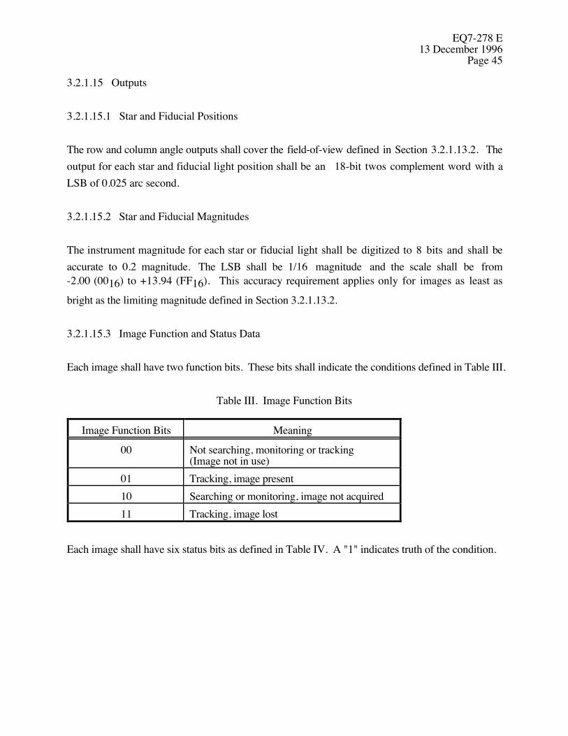
EQ7-278 E13 December 1996
Page 45
3.2.1.15 Outputs
3.2.1.15.1 Star and Fiducial Positions
The row and column angle outputs shall cover the field-of-view defined in Section 3.2.1.13.2. Theoutput for each star and fiducial light position shall be an 18-bit twos complement word with aLSB of 0.025 arc second.
3.2.1.15.2 Star and Fiducial Magnitudes
The instrument magnitude for each star or fiducial light shall be digitized to 8 bits and shall beaccurate to 0.2 magnitude. The LSB shall be 1/16 magnitude and the scale shall be from-2.00 (0016) to +13.94 (FF16). This accuracy requirement applies only for images as least as
bright as the limiting magnitude defined in Section 3.2.1.13.2.
3.2.1.15.3 Image Function and Status Data
Each image shall have two function bits. These bits shall indicate the conditions defined in Table III.
Table III. Image Function Bits
Image Function Bits Meaning
00 Not searching, monitoring or tracking(Image not in use)
01 Tracking, image present10 Searching or monitoring, image not acquired11 Tracking, image lost
Each image shall have six status bits as defined in Table IV. A "1" indicates truth of the condition.

EQ7-278 E13 December 1996Page 46
Table IV. Image Status Bits
Image Status Bit Meaning
0 Saturated pixel(s)1 Defective pixel(s)2 Quadrant boundary3 Common column with another image4 Multiple stars suspected5 Ionizing radiation suspected
3.2.1.15.4 (Reserved)
3.2.1.15.5 Global Status
The ACA shall provide an 8-bit global status with each set of star and fiducial light measurementsand with each set of calibration data as defined in Table V. A "1" indicates truth of the condition.The “Reset Occurred” flag shall remain in the “1” state for 2.05 seconds following a reset.
Table V. Global Status Bits
Global Status Bit Meaning
0 High background1 RAM failure2 ROM failure3 Power supply failure4 Calibration Failure5 Check Sum Failure6 Reset Occurred7 Syntax Error Reserved

EQ7-278 E13 December 1996
Page 47
3.2.1.15.6 Command Status Words
The ACA shall provide two 8-bit command status words, called Command Count and CommandProgress, with each set of image measurements as described below.
3.2.1.15.6.1 Command Count
The command count shall remain zero except on the first two outputs to the OBC following receiptof the last word in a group of command words, as described in Section 3.2.1.11.1.1. When thecommand count is non-zero, the 6 highest order bits shall contain a copy of the count shown inSection 3.2.1.11.1.1.1. The next bit shall be 1 only if a syntax error is found in any of thecommands in the group (same as Global Status bit 7). The final bit shall be 1 only if thechecksum for the command word group is invalid (same as Global Status bit 5).
3.2.1.15.6.2 Command Progress
The first six bits of Command Progress is an 6-bit integer. One LSB is 16 CCD rows. Fractionalvalues of Command Progress shall be rounded up to the next whole number so that CommandProgress will not become zero until the function is completed. The last two bits shall be the numberof 1.025-second periods for which the OBC data described in Section 3.2.1.15.11 has beenrepeated. If the number of such periods exceeds three, the last two bits of Command Progress shallremain 1,1 until new data is available.
During a search, Command Progress bits shall represent the approximate number of CCD rowsremaining to be searched.
During a calibration, Command Progress bits shall indicate the approximate number of rows ofCCD data remaining to be read.
3.2.1.15.7 Integration Time, Track
The ACA shall provide a 16-bit integration time with each set of star and fiducial lightmeasurements. The LSB shall be 16 milliseconds.
EQ7-278 E13 December 1996Page 48
3.2.1.15.8 Pixel Data, Track
3.2.1.15.8.1 Pixel Data Arrays
Pixel data may be commanded to be output in either a full 4 x 4 array, a modified 6 x 6 array or afull 8 x 8 array (see Section 3.2.1.11.1.4). These three possibilities are depicted in Figure 8. Pixeldata shall be centered on each image and shall be digitized to 10 bits. For a 4 x 4 array or an 8 x 8array, the lowest row and column numbers of the array shall be provided in 10 bits each. For amodified 6 x 6 array, the lowest row and column numbers of the central 4 x 4 portion of the arrayshall be provided in 10 bits each. For any of the three types of array, the lead pixel row and columnnumbers indicate the pixel designated “A1" in Figure 8 (8A, 8B or 8C as appropriate). (When anarray contains pixels with negative row or column numbers, the lowest row or column number is themost negative row or column number.)
3.2.1.15.8.2 Average Background
The average background for any image shall be calculated by averaging the pixel data from pixelsA1, B1, G1, H1, I4, J4, O4 and P4 in Figure 8C. This average shall be compared with the pixel datafrom each of the eight pixels that contributed to the average. If any of the comparisons yields adifference in excess of ±30% of the average, those pixels shall be designated as outliers and theaverage shall be recalculated without the data from the one furthest outlier. This process shall berepeated until no more outliers are found.
3.2.1.15.8.3 RMS Background
The rms value of the background pixel data, about the average, shall be calculated based on N-1degrees of freedom, where N equals the number of pixels in the calculations (i.e. 8 minus thenumber of outliers).
3.2.1.15.8.4 Pixel Data Scaling
The average background for the image shall be digitized to 10 bits. Each image shall have a 14-bitfixed binary scale factor with five places to the right of the binary point. The pixel data shall beoffset and scaled so that Ne, the number of electrons given in a pixel is given by:
Ne = (scale factor)*(pixel data) - 250
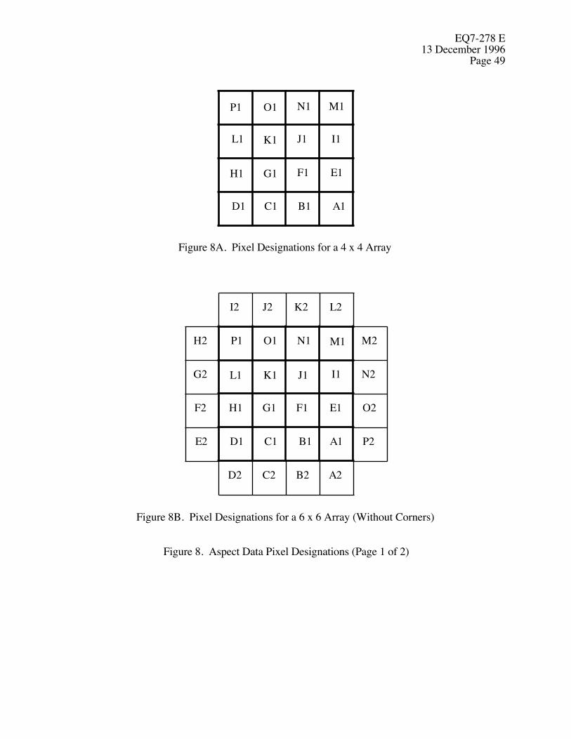
EQ7-278 E13 December 1996
Page 49
Figure 8A. Pixel Designations for a 4 x 4 Array
Figure 8B. Pixel Designations for a 6 x 6 Array (Without Corners)
A1B1C1D1
E1F1G1H1
I1J1K1L1
M1N1O1P1
A1B1C1D1
E1F1G1H1
I1J1K1L1
M1N1O1P1
A2B2C2D2
E2
F2
G2
H2
I2 J2 K2 L2
M2
N2
O2
P2
Figure 8. Aspect Data Pixel Designations (Page 1 of 2)
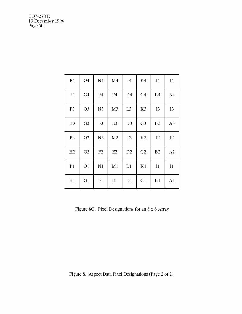
EQ7-278 E13 December 1996Page 50
Figure 8C. Pixel Designations for an 8 x 8 Array
A1B1C1D1E1F1G1H1
I1J1K1L1M1N1O1P1
A2B2C2D2E2F2G2H2
I2J2K2L2M2N2O2P2
A3B3C3D3E3F3G3H3
I3J3K3L3M3N3O3P3
A4B4C4D4E4F4G4H1
I4J4K4L4M4N4O4P4
Figure 8. Aspect Data Pixel Designations (Page 2 of 2)

EQ7-278 E13 December 1996
Page 51
The scale factor shall be chosen such that the largest pixel data value is 1023. The rms value of thebackground shall be digitized to 10 bits using the same scale factor as above.
3.2.1.15.8.5 Background Pixel Outliers
The ACA shall provide an 8-bit word indicating which of the pixels nominally included in thebackground calculations have been included and which have been declared outliers, and thusexcluded as shown in Table VI. A “1” indicates inclusion and a “0” indicates and excludedoutlier.
Table VI. Background Pixel Status Bits
Background Pixel Status Bit Pixel
0 A11 B12 G13 H14 I45 J46 O47 P4
3.2.1.15.9 Integration Time, Calibrate
The ACA shall provide a 16-bit integration time with each set of calibration data. The LSB shall be16 milliseconds.
3.2.1.15.10 Pixel Data, Calibrate
The pixel data specified in Section 3.2.1.10.4 resulting from the calibrate function shall beprovided through the IU as specified in Section 3.2.1.16. Pixel data shall be digitized to 12 16bits.
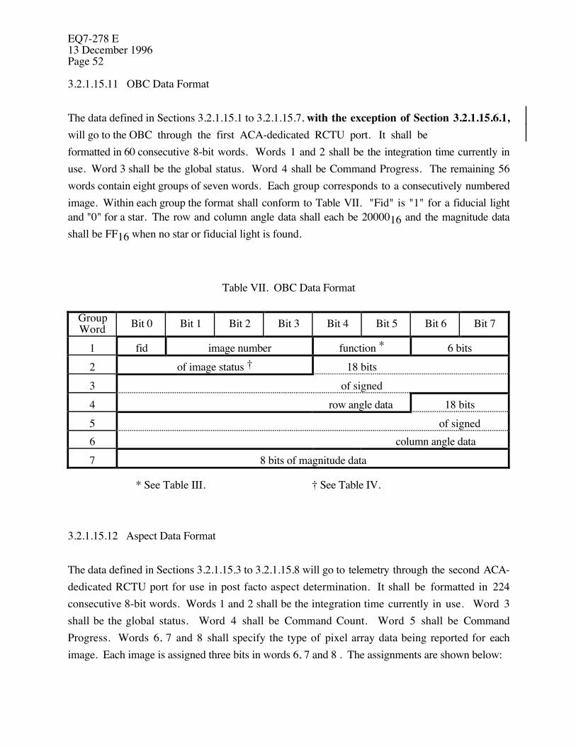
EQ7-278 E13 December 1996Page 52
3.2.1.15.11 OBC Data Format
The data defined in Sections 3.2.1.15.1 to 3.2.1.15.7, with the exception of Section 3.2.1.15.6.1,will go to the OBC through the first ACA-dedicated RCTU port. It shall beformatted in 60 consecutive 8-bit words. Words 1 and 2 shall be the integration time currently inuse. Word 3 shall be the global status. Word 4 shall be Command Progress. The remaining 56words contain eight groups of seven words. Each group corresponds to a consecutively numberedimage. Within each group the format shall conform to Table VII. "Fid" is "1" for a fiducial lightand "0" for a star. The row and column angle data shall each be 2000016 and the magnitude datashall be FF16 when no star or fiducial light is found.
Table VII. OBC Data Format
GroupWord Bit 0 Bit 1 Bit 2 Bit 3 Bit 4 Bit 5 Bit 6 Bit 7
1 fid image number function * 6 bits2 of image status † 18 bits3 of signed4 row angle data 18 bits5 of signed6 column angle data7 8 bits of magnitude data
* See Table III. † See Table IV.
3.2.1.15.12 Aspect Data Format
The data defined in Sections 3.2.1.15.3 to 3.2.1.15.8 will go to telemetry through the second ACA-dedicated RCTU port for use in post facto aspect determination. It shall be formatted in 224consecutive 8-bit words. Words 1 and 2 shall be the integration time currently in use. Word 3shall be the global status. Word 4 shall be Command Count. Word 5 shall be CommandProgress. Words 6, 7 and 8 shall specify the type of pixel array data being reported for eachimage. Each image is assigned three bits in words 6, 7 and 8 . The assignments are shown below:

EQ7-278 E13 December 1996
Page 53
Word 6Bit 0 Bit 1 Bit 2 Bit 3 Bit 4 Bit 5 Bit 6 Bit 7
Image 0 Image 1 Image 2...
Word 7Bit 0 Bit 1 Bit 2 Bit 3 Bit 4 Bit 5 Bit 6 Bit 7
Image 2 Image 3 Image 4 Image 5
Word 8Bit 0 Bit 1 Bit 2 Bit 3 Bit 4 Bit 5 Bit 6 Bit 7
...Image 5 Image 6 Image 7
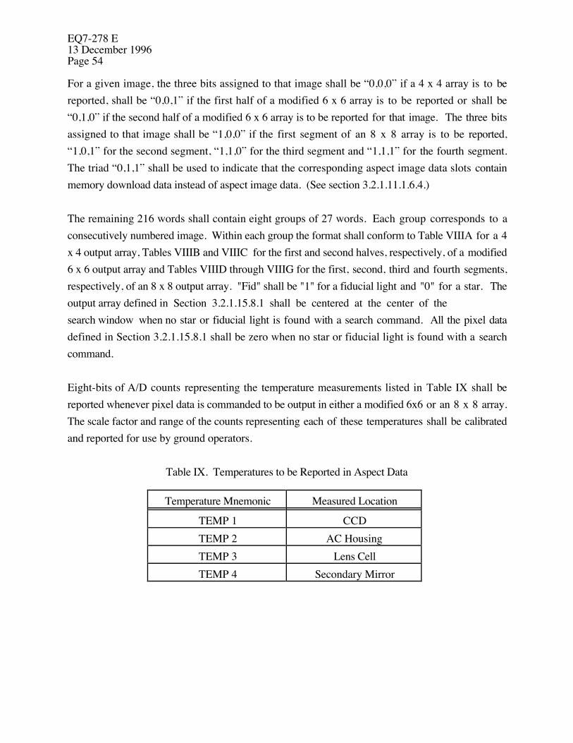
EQ7-278 E13 December 1996Page 54
For a given image, the three bits assigned to that image shall be “0,0,0” if a 4 x 4 array is to bereported, shall be “0,0,1” if the first half of a modified 6 x 6 array is to be reported or shall be“0,1,0” if the second half of a modified 6 x 6 array is to be reported for that image. The three bitsassigned to that image shall be “1,0,0” if the first segment of an 8 x 8 array is to be reported,“1,0,1” for the second segment, “1,1,0” for the third segment and “1,1,1” for the fourth segment.The triad “0,1,1” shall be used to indicate that the corresponding aspect image data slots containmemory download data instead of aspect image data. (See section 3.2.1.11.1.6.4.)
The remaining 216 words shall contain eight groups of 27 words. Each group corresponds to aconsecutively numbered image. Within each group the format shall conform to Table VIIIA for a 4x 4 output array, Tables VIIIB and VIIIC for the first and second halves, respectively, of a modified6 x 6 output array and Tables VIIID through VIIIG for the first, second, third and fourth segments,respectively, of an 8 x 8 output array. "Fid" shall be "1" for a fiducial light and "0" for a star. Theoutput array defined in Section 3.2.1.15.8.1 shall be centered at the center of thesearch window when no star or fiducial light is found with a search command. All the pixel datadefined in Section 3.2.1.15.8.1 shall be zero when no star or fiducial light is found with a searchcommand.
Eight-bits of A/D counts representing the temperature measurements listed in Table IX shall bereported whenever pixel data is commanded to be output in either a modified 6x6 or an 8 x 8 array.The scale factor and range of the counts representing each of these temperatures shall be calibratedand reported for use by ground operators.
Table IX. Temperatures to be Reported in Aspect Data
Temperature Mnemonic Measured Location
TEMP 1 CCDTEMP 2 AC HousingTEMP 3 Lens CellTEMP 4 Secondary Mirror
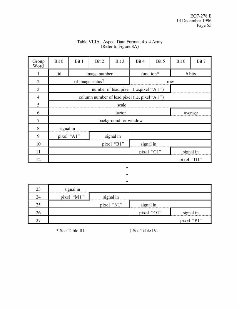
EQ7-278 E13 December 1996
Page 55
Table VIIIA. Aspect Data Format, 4 x 4 Array(Refer to Figure 8A)
GroupWord
Bit 0 Bit 1 Bit 2 Bit 3 Bit 4 Bit 5 Bit 6 Bit 7
1 fid image number function* 6 bits2 of image status† row3 number of lead pixel (i.e.pixel “A1”)4 column number of lead pixel (i.e. pixel“A1”)5 scale6 factor average7 background for window8 signal in9 pixel “A1” signal in10 pixel “B1” signal in11 pixel “C1” signal in12 pixel “D1”
•••
23 signal in24 pixel “M1” signal in25 pixel “N1” signal in26 pixel “O1” signal in27 pixel “P1”
* See Table III. † See Table IV.

EQ7-278 E13 December 1996Page 56
Table VIIIB. Aspect Data Format, First Half of a 6 x 6 Array(Refer to Figure 8B)
GroupWord
Bit 0 Bit 1 Bit 2 Bit 3 Bit 4 Bit 5 Bit 6 Bit 7
1 fid image number function* 6 bits2 of image status† row number3 of lead pixel (i.e. pixel “A1”)4 column number of lead pixel (i.e. pixel“A1”)5 scale6 factor average7 background for window8 signal in pixel “A1”9 signal in pixel “B1”10 signal in11 pixel “C1” signal in12 pixel “D1”
•••
23 signal in pixel “M1”24 signal in pixel “N1”25 signal in26 pixel “O1” signal in27 pixel “P1”
* See Table III. † See Table IV.
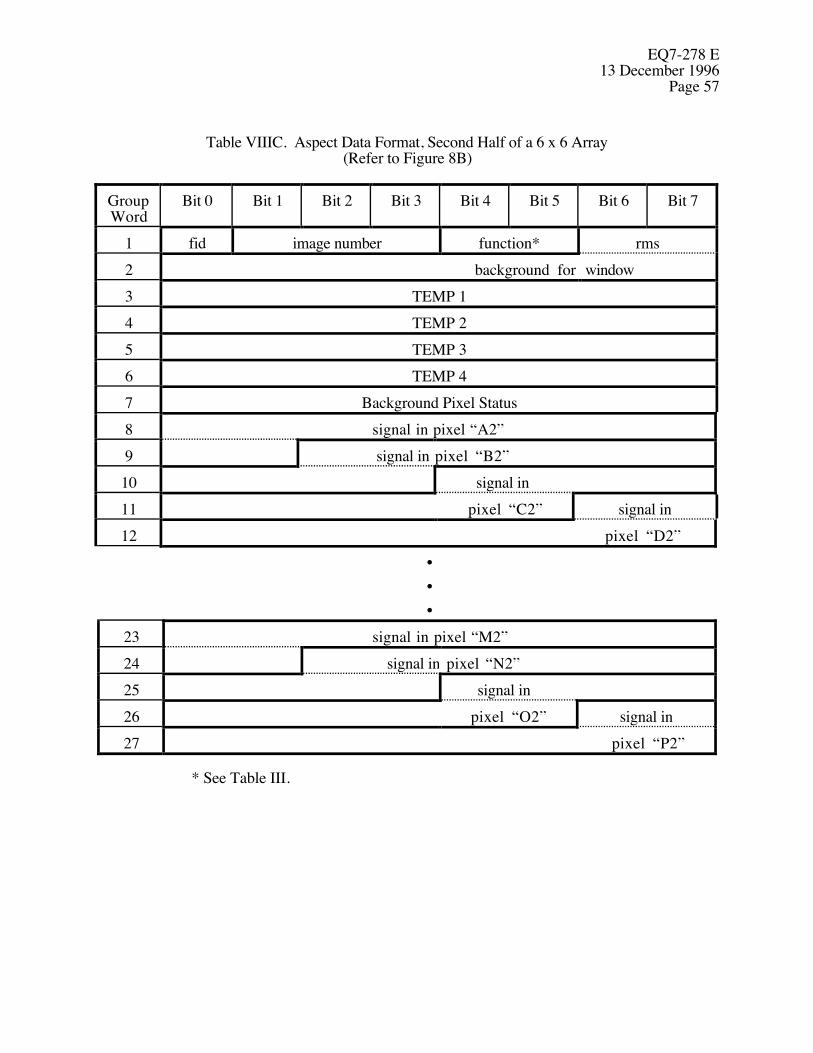
EQ7-278 E13 December 1996
Page 57
Table VIIIC. Aspect Data Format, Second Half of a 6 x 6 Array(Refer to Figure 8B)
GroupWord
Bit 0 Bit 1 Bit 2 Bit 3 Bit 4 Bit 5 Bit 6 Bit 7
1 fid image number function* rms2 background for window3 TEMP 14 TEMP 25 TEMP 36 TEMP 47 Background Pixel Status8 signal in pixel “A2”9 signal in pixel “B2”10 signal in11 pixel “C2” signal in12 pixel “D2”
•••
23 signal in pixel “M2”24 signal in pixel “N2”25 signal in26 pixel “O2” signal in27 pixel “P2”
* See Table III.
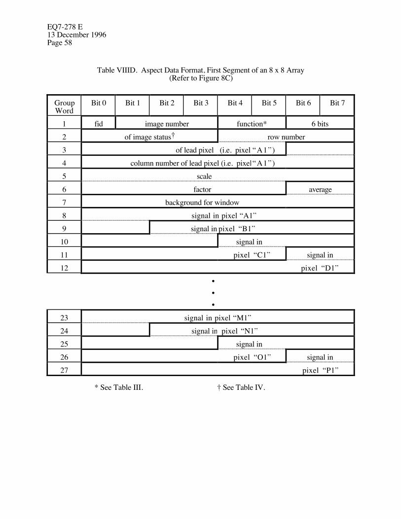
EQ7-278 E13 December 1996Page 58
Table VIIID. Aspect Data Format, First Segment of an 8 x 8 Array(Refer to Figure 8C)
GroupWord
Bit 0 Bit 1 Bit 2 Bit 3 Bit 4 Bit 5 Bit 6 Bit 7
1 fid image number function* 6 bits2 of image status† row number3 of lead pixel (i.e. pixel “A1”)4 column number of lead pixel (i.e. pixel“A1”)5 scale6 factor average7 background for window8 signal in pixel “A1”9 signal in pixel “B1”10 signal in11 pixel “C1” signal in12 pixel “D1”
•••
23 signal in pixel “M1”24 signal in pixel “N1”25 signal in26 pixel “O1” signal in27 pixel “P1”
* See Table III. † See Table IV.
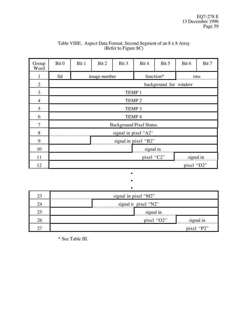
EQ7-278 E13 December 1996
Page 59
Table VIIIE. Aspect Data Format, Second Segment of an 8 x 8 Array(Refer to Figure 8C)
GroupWord
Bit 0 Bit 1 Bit 2 Bit 3 Bit 4 Bit 5 Bit 6 Bit 7
1 fid image number function* rms2 background for window3 TEMP 14 TEMP 25 TEMP 36 TEMP 47 Background Pixel Status8 signal in pixel “A2”9 signal in pixel “B2”10 signal in11 pixel “C2” signal in12 pixel “D2”
•••
23 signal in pixel “M2”24 signal in pixel “N2”25 signal in26 pixel “O2” signal in27 pixel “P2”
* See Table III.

EQ7-278 E13 December 1996Page 60
Table VIIIF. Aspect Data Format, Third Segment of an 8 x 8 Array(Refer to Figure 8C)
GroupWord
Bit 0 Bit 1 Bit 2 Bit 3 Bit 4 Bit 5 Bit 6 Bit 7
1 fid image number function*234 Not Defined5678 signal in pixel “A3”9 signal in pixel “B3”10 signal in11 pixel “C3” signal in12 pixel “D3”
•••
23 signal in pixel “M3”24 signal in pixel “N3”25 signal in26 pixel “O3” signal in27 pixel “P3”
* See Table III.
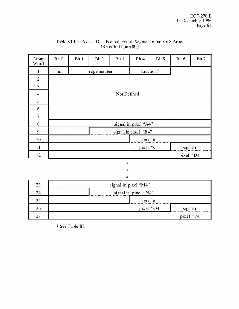
EQ7-278 E13 December 1996
Page 61
Table VIIIG. Aspect Data Format, Fourth Segment of an 8 x 8 Array(Refer to Figure 8C)
GroupWord
Bit 0 Bit 1 Bit 2 Bit 3 Bit 4 Bit 5 Bit 6 Bit 7
1 fid image number function*234 Not Defined5678 signal in pixel “A4”9 signal in pixel “B4”10 signal in11 pixel “C4” signal in12 pixel “D4”
•••
23 signal in pixel “M4”24 signal in pixel “N4”25 signal in26 pixel “O4” signal in27 pixel “P4”
* See Table III.

EQ7-278 E13 December 1996Page 62
3.2.1.15.13 Calibrate Data Format
The calibration data stream will go to telemetry through the IU. It shall be formatted intorecords that are each comprised of 520 16-bit words. One row of CCD data shall bereported in each record. The first pixel data transmitted shall be from the pixel furthestfrom the origin of the focal plane, within the block of commanded data; see Figure 1.When normal calibration data is not available, fill data (defined below) shall besubstituted in its place. Whenever fill data is substituted for actual data, fill data shallbe sent in whole row records of 520 words, the same as CCD data. The term "calibrationdata" refers to the whole stream of data, including both CCD data and fill data, for aslong as it takes to complete a sequence of calibration commands. Each record shall beformatted as follows:
Word 1: Start of Record Synchronizing word = hex FF00(same value whether fill data or CCD data is being reported).
Word 2: 16-bit A/D converter zero offset (use hex AAAA for fill data).Word 3: Integration time, as defined in Section 3.2.1.15.9
(use hex AAAA for fill data).Word 4: C, Replica, and P/N parameters from the Calibrate Command
(see Section 3.2.1.11.1.5) along with the CCD row number, packed intoone 16-bit word as shown below(use hex AAAA for fill data).
C Replica P/N CCD Row Number0 1 2 3 4 5 6 7 8 9 10 11 12 13 14 15
MSB LSB
Words 5, 6, and 7:Time Tag, 48-bits, 2 microsecond resolution; indicates starttime for each row readout(use hex AAAA AAAA AAAA for fill data).
Word 8: Spare 16-bit word (value = hex AAAA).Words 9 - 520:
Pixel Data, as defined in Section 3.2.1.10.4, one 16-bitword for each pixel in one row of 512 pixels(set all values to hex AAAA for fill data).
The data defined in Sections 3.2.1.15.9 and 3.2.1.15.10 will go to telemetry through the IU for postfacto aspect determination. It shall be formatted into 8-bit words. The data shall be sent incomplete rows of pixels in one quadrant. The first pixel data transmitted shall be from the pixelfurthest from the origin of the focal plane, within the block of commanded data; see Figure 1. Datashall be sent starting with the specified row and progress towards row zero. There shall be two
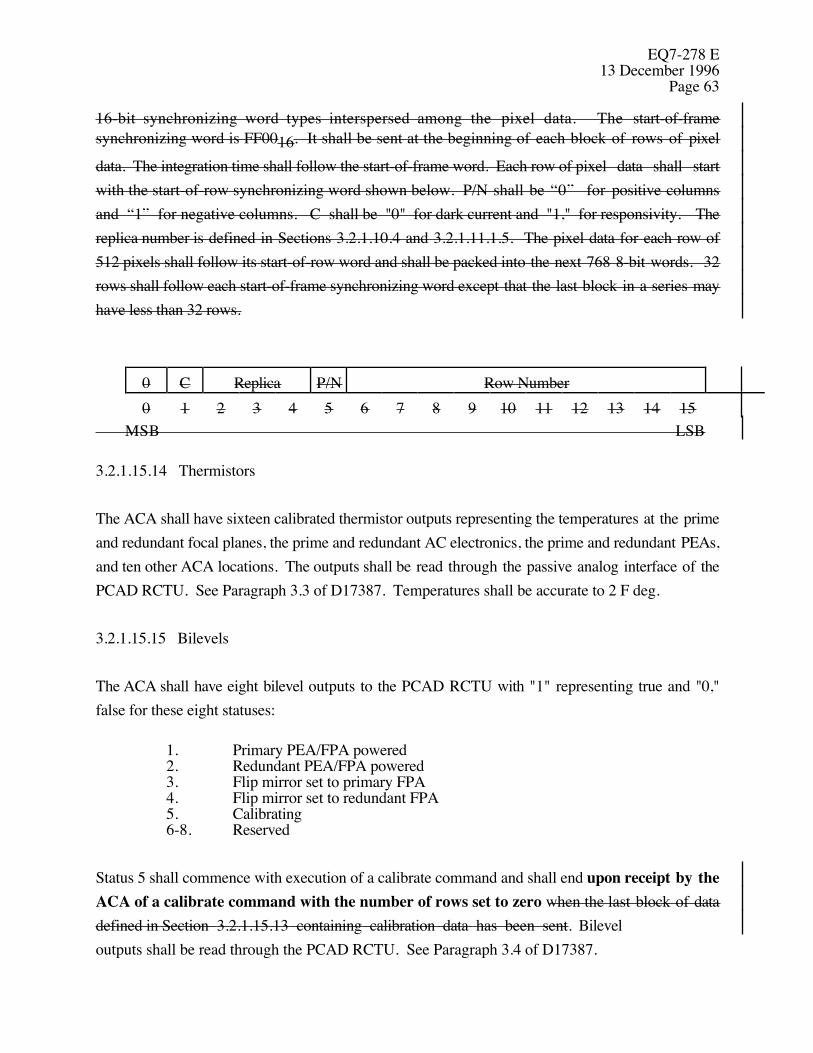
EQ7-278 E13 December 1996
Page 63
16-bit synchronizing word types interspersed among the pixel data. The start-of-framesynchronizing word is FF0016. It shall be sent at the beginning of each block of rows of pixel
data. The integration time shall follow the start-of-frame word. Each row of pixel data shall startwith the start-of-row synchronizing word shown below. P/N shall be “0” for positive columnsand “1” for negative columns. C shall be "0" for dark current and "1," for responsivity. Thereplica number is defined in Sections 3.2.1.10.4 and 3.2.1.11.1.5. The pixel data for each row of512 pixels shall follow its start-of-row word and shall be packed into the next 768 8-bit words. 32rows shall follow each start-of-frame synchronizing word except that the last block in a series mayhave less than 32 rows.
0 C Replica P/N Row Number0 1 2 3 4 5 6 7 8 9 10 11 12 13 14 15
MSB LSB
3.2.1.15.14 Thermistors
The ACA shall have sixteen calibrated thermistor outputs representing the temperatures at the primeand redundant focal planes, the prime and redundant AC electronics, the prime and redundant PEAs,and ten other ACA locations. The outputs shall be read through the passive analog interface of thePCAD RCTU. See Paragraph 3.3 of D17387. Temperatures shall be accurate to 2 F deg.
3.2.1.15.15 Bilevels
The ACA shall have eight bilevel outputs to the PCAD RCTU with "1" representing true and "0,"false for these eight statuses:
1. Primary PEA/FPA powered2. Redundant PEA/FPA powered3. Flip mirror set to primary FPA4. Flip mirror set to redundant FPA5. Calibrating6-8. Reserved
Status 5 shall commence with execution of a calibrate command and shall end upon receipt by theACA of a calibrate command with the number of rows set to zero when the last block of datadefined in Section 3.2.1.15.13 containing calibration data has been sent. Bilevel outputs shall be read through the PCAD RCTU. See Paragraph 3.4 of D17387.
EQ7-278 E13 December 1996Page 64
3.2.1.16 Interface Unit (IU)
3.2.1.16.1 Channel Characteristics
The ACA shall send 256 rows Calibration Records with of the filler data as defined in Section3.2.1.16.2 3.2.1.15.13 immediately after receipt of the first of a series of calibratecommands to establish the communications channel. Thereafter, IU data transmission shall becontinuous to maintain the communications channel. Whenever the calibration data is not available,the ACA shall send filler data instead. The ACA shall terminate IU data upon, andonly upon, receipt of another calibrate command with the number of rows set to zero. Terminationof data transmission shall occur after transmission of the last record defined in Section 3.2.1.16.3has been completed.
3.2.1.16.2 Filler Data Reserved
Filler data shall conform to Section 3.2.1.15.13 except that the start-of-row synchronizing wordshall be 380116 and all pixel data shall be AAA16. The integration time shall be the most recent
integration time used by the ACA.
3.2.1.16.3 Interface Unit Format Deep Space Network Record Format
The calibration data stream defined in Section 3.2.1.15.13 shall be formatted into recordsfor the Deep Space Network (DSN). Only complete DSN records are accepted. Each DSNrecord shall consist of:
1) an 80-bit header, consisting of a 48-bit constant (Header 1), followed by a 24-bit record counter and completed by an 8-bit constant (Header 2). Header 1and Header 2 will be preset by a data input command. The record countershall initialize at zero at ACA turn-on and increment by one with each recordsent.
2) a 1019 8-bit byte data block (see below) , and
3) 1280 bits of A16 replicated 320 times.
The following steps shall be followed to fill the 1019 8-bit byte data block:
a) The calibration data stream shall be divided into units of 509 16-bit wordseach.
b) The 1019-byte data block in each EVEN numbered DSN record shall be filledwith 509 words of calibration data followed by AB16.

EQ7-278 E13 December 1996
Page 65
c) The 1019-byte data block in each ODD numbered DSN record shall be filledwith CD16 followed by 509 words of calibration data.
The formatted data defined in Section 3.2.1.16.1 shall be formatted into records for the Deep SpaceNetwork. A record consists of an 80-bit header, followed by 8,152 bits of data, and completed by1280 bits of A16 replicated 320 times. Only complete DSN records are accepted. The header
word is a 48-bit constant (Header 1), followed by a 24-bit record counter and completed by an 8-bitconstant (Header 2). Header 1 and Header 2 will be preset by a data input command. The recordcounter shall initialize at zero at ACA turn-on and increment by one with each record sent.
3.2.1.16.4 Calibration Failure
3.2.1.16.4.1 Calibration Failure Indication
If data is not read from the ACA by the IU at the nominal rate specified in Section 3.2.1.10.4, theACA shall set the Calibration Failure bit “True” in the Global Status word defined in Section3.2.1.15.5.
3.2.1.16.4.2 Duration of Calibration Failure
If the Calibration Failure bit is set “True” during any calibration sequence, it shall remain “True”until, and only until, receipt of the command specified in Section 3.2.1.16.1 to terminate calibration.
3.2.2 Physical Characteristics
3.2.2.1 Flip Mirror
The OBC will command the position of the flip mirror with the commands of Sections 3.2.1.11.2and 3.2.1.11.3. The flip mirror shall be a part of the optical path to the redundant FPA, but not apart of the optical path to the primary FPA.

EQ7-278 E13 December 1996Page 66
3.2.2.2 Mass Properties
The weight of the ACA shall not exceed 90 lbs, with maxima of 26.5 lbs for the AC, 21 lbs for bothPEAs, 35 lbs for the SLS, and 7.5 lbs for the cabling.
3.2.2.3 Locations
Electrical circuits shall be located in the PEA to the maximum extent possible to minimize ACweight and FPA power dissipation.
3.2.2.4 Electrical Interface Requirements
Figure 5 shows the relationship of the ACA electrical subsystem to the EPS. Each PEA shallincorporate 5 separate connectors to support the following functions:
1) To connect to the EPS to receive primary power2) To connect to the RCTU (both redundant halves) for receipt of commands and
transmission of star data,3) To connect to side A of the IU for transmission of pixel data,4) To connect to side B of the IU for transmission of pixel data, and5) To connect to one optical channel of the AC.
3.2.2.4.1 Power
The ACA and its heaters shall operate on an average power not exceeding 20 watts. The ACA shallnot draw more than 25 watts peak power at any voltage in the range specified in Section 3.1.2.5.2.
3.2.2.4.2 Power Relay Signal
Power will be continuously supplied to the input filter of the PEA. The PEA shall be on in thepresence of the power relay signal described in Section 3.1.2.6.3 and shall be off in its absence.See Figure 6.
EQ7-278 E13 December 1996
Page 67
3.2.2.5 Venting
Where necessary the ACA shall provide venting ports to prevent damage due to pressure changesduring testing, transportation, launch, and landing. The launch and landing pressure profiles aredefined in Paragraph 3.1.3.3 of EV1-8 (TRW SE29). Venting shall meet the requirements definedin Paragraph 4.1.1.5 of D17393 (TRW SE28) and avoid contamination of the HRMA.
3.2.2.6 Dynamics
The AC, PEA and SLS shall be designed so that their lowest natural frequencies are each greaterthan 50 Hz. This requirement applies to the AC and PEA when they are attached to a rigid structureat their interface mounting points. This requirement applies to the SLS when it is mounted on itssupport struts which, in turn, are attached to a rigid structure.
3.2.2.7 SLS Mounting Struts
SLS mounting struts shall be supplied that have the properties delineated on TRW drawing301160.
3.2.2.8 (Reserved)
3.2.2.9 Mechanical Interface Requirements
The ACA shall meet all the mechanical interface requirements defined on TRW drawings 301172,301173, 301174, 301326 and 301160.
3.2.3 Reliability
3.2.3.1 On-Orbit Life
The ACA shall be designed to attain a mission life of 5 years on orbit.
3.2.3.2 Shelf Life
Shelf life is defined as the period of time the ACA can retain its required performance and reliabilitycharacteristics prior to launch. The ACA shall be designed with a minimum shelf life of 4 yearsfrom date of delivery to TRW.

EQ7-278 E13 December 1996Page 68
3.2.3.3 Redundancy
The ACA design shall contain no single point electrical, electromechanical or electronics failurewhich could degrade performance or propagate to other AXAF-I components.
3.2.4 Maintainability
3.2.4.1 Separable Assemblies
The AC, the PEA, the SLS and the cables shall be separable assemblies.
3.2.4.2 Access
Removal and replacement of the AC, SLS, and PEA shall not require shims or optical techniques.The AC mounting bracket is a part of the AXAF-I and not a part of the ACA.
3.2.5 Environmental Conditions
3.2.5.1 Non-Operating Environment
The ACA shall meet all the requirements of this specification after being subjected to any possiblecombination of the following non-operational environmental conditions.
3.2.5.1.1 Random Vibration, Non-Operating
The ACA will experience the random vibration defined in Paragraph 3.1.3.1.2 of EV1-8 (TRWSE29); Figures 3.1.3.1.2-4 and 3.1.3.1.2-8 define the PEA and AC/SLS spectra, respectively.
3.2.5.1.2 Acoustics, Non-Operating
The ACA will experience the acoustics defined in Paragraph 3.1.3.1.1 of EV1-8 (TRW SE29).
3.2.5.1.3 Shock, Non-Operating
The ACA shock spectra are shown in Figure 3.1.3.1.3.3 of EV1-8 (TRW SE29). The PEAexperiences the “OB, SIM & IRU” level. The AC and SLS experience the “HRMA” level.

EQ7-278 E13 December 1996
Page 69
3.2.5.1.4 Transportation and Handling, Non-Operating
The ACA will experience the transportation and handling environments defined in Paragraph3.1.2.1 of EV1-8 (TRW SE29).
3.2.5.1.5 Storage Environment, Non-Operating
The ACA will experience the storage environment defined in Paragraph 3.1.2.2 of EV1-8 (TRWSE29).
3.2.5.1.6 Temperature, Non-Operating
The ACA will experience the ground, launch, and prelaunch temperatures defined in Paragraph3.1.4.4.2 of EV1-8 (TRW SE29). During survival conditions on orbit, the HRMA and OBAtemperatures will be as defined in Paragraph 3.2.2.3.3 of IF1-29.
3.2.5.1.7 Pressure, Non-Operating
The ACA will experience the pressure defined in Paragraph 3.1.3.3 of EV1-8 (TRW SE29).
3.2.5.1.8 Quasi-static Load Factors, Non-Operating
The PEAs will experience the design limit loads defined in Table 4.0-6 of D22088 (TRW SE11i,Vol 1) during lift-off and abort landing. The AC and SLS will experience the design limit loadsdefined in Table 4.0-10 of D22088 during liftoff and abort landing. Angular accelerationsexperienced by the AC and SLS have been omitted from Table 4.0-10 because they are negligible.
3.2.5.1.9 Combined Loads, Non-Operating
The ACA will experience the combined loads defined in Paragraph 3.1.3.4 of EV1-8 (TRW SE29).
3.2.5.2 Operating Environment
The ACA shall meet the performance requirements of this specification during and after anypossible combination of the following operational environments.

EQ7-278 E13 December 1996Page 70
3.2.5.2.1 Temperature, Operating
The HRMA and OBA operating temperatures will be as defined in Paragraph 3.2.2.3.3 of IF1-29.
3.2.5.2.2 Pressure, Operating
The ACA will experience the pressure defined in Paragraph 3.1.4.1 of EV1-8 (TRW SE29).
3.2.5.2.3 Natural Environment, Operating
The ACA will experience the particle radiation environment and the meteoroid environment definedin Paragraphs 3.1.4.2 and 3.1.4.3 of EV1-8 (TRW SE29).
3.2.6 Transportability
ACA subsystems shall be transportable by common commercial carrier when packaged asdescribed in Section 5.
3.3 Design and Construction
All flight hardware parts shall be procured to approved specifications. All parts shall be procured toapproved drawings. Approved process specifications shall control critical manufacturing andassembly operations. All materials, parts and processes shall conform to the standards,specifications and procedures of MM-8070.2 and PAR700-272.
3.3.1 Parts, Materials, and Processes
Parts, materials and processes used in construction of the ACA shall meet the requirements definedin Paragraph 4.0 of PAR700-272.
3.3.1.1 Outgassing
All materials used in construction of the ACA shall meet the thermal-vacuum stability requirementsof JSC-SP-R-0022.
EQ7-278 E13 December 1996
Page 71
3.3.1.2 Nuclear Radiation
Any materials, components or subsystems containing natural or man-made sources of nuclearradiation shall require prior approval from TRW.
3.3.1.3 Dissimilar Metals
When dissimilar metals, as defined in MSFC-SPEC-250, are in direct contact, their facing surfacesshall be adequately insulated by an approved sealing compound to assure protection fromelectrolytic corrosion. Additional organic finishing or barrier tapes may be used, subject to MSFC-SPEC-250.
3.3.1.4 Finish
The ACA finish shall conform to MSFC-SPEC-250, except for SLS baffle finishes.
3.3.1.5 Flammability
The ACA shall not use flammable materials without prior TRW approval. Material flammabilityshall be determined according to NHB-8060.1. The ACA design shall use MFSC-HDBK-527,which provides flammability characteristics of various materials.
3.3.1.6 Corrosion of Metal Parts
Metal parts shall be protected from corrosion by stress relieving, plating, anodizing, chemicalcoating, organic finishes, or a combination thereof, according to MSFC-SPEC-250, providing thatsuch protection is compatible with the operating and space environmental requirements.
3.3.1.7 Corrosion Resistant Metals
Metals in contact with fluid media shall be corrosion resistant and shall be compatible with themedia to which they are exposed. Use of metals and their weldments subject to embrittlement atcryogenic temperatures shall be avoided in all cryogenic applications.

EQ7-278 E13 December 1996Page 72
3.3.1.8 Stress Corrosion
The requirements of MSFC-SPEC-522 shall apply for stress corrosion susceptibility of variousmetallic materials.
3.3.1.9 Contamination Control
The ACA shall be designed, fabricated, assembled, and tested according to D17393 (TRW SE28).All ACA components shall be baked out according to MSFC-SPEC-1238 prior to the verificationsdefined in Sections 4.3.3 and 4.3.4. The ACA shall be maintained in a Class 10,000 environmentaccording to FED-STD-209. The ACA shall provide protective devices for subsequenttransportation and integration and for the contamination environments specified in Paragraph 10.6of NSTS 07700, Volume XIV, Attachment 1 (ICD 2-19001) and in JSC-SN-C-0005, Table A.1(Level 500A).
3.3.1.10 Connector Usage
Connectors shall comply with Paragraphs 5.7.3 to 5.7.5 of PAR700-272. When a unit utilizesmore than one connector, each connector shall be unique, either by choosing different sized ordifferent shaped connectors for that unit or by the use of unique connector keying.
3.3.1.11 Flight Articles
3.3.1.11.1 Electrical
Wire used in cable harnesses shall conform to MIL-C-17, MIL-W-22759, and MIL-W-81381.Electrical wire insulation shall conform to MSFC-Ltr-EH02 (89-0782) and kapton insulated wireshall not be used for applications described therein. The ACA shall not use distribution andbussing junction devices. Crimping and wire wrap shall conform to NHB 5300.4(3H). Solderingshall conform to NHB 5300.4(3A-1). Printed circuit boards shall be designed according to NHB5300.4(3K) and fabricated according to NHB 5300.4(3I). D22723 may be used as an alternative to NHB 5300.4(3I) and NHB 5300.4(3K). Conformal coating shall conform to NHB5300.4(3J). Brazing shall conform to MIL-B-7883.
Redundant paths in the cabling shall be routed through separate connectors.

EQ7-278 E13 December 1996
Page 73
Electrical wiring harness assemblies shall conform to NHB 5300.4(3G) and be installed perMSFC-SPEC-494. Splices are not allowed without prior TRW approval. Protective circuitry shallbe provided to ensure the safe and reliable operation of the electrical system and to prevent faultpropagation and damage. Analog circuits which require remote signal conditioning shall be routedon a twisted-wire pair and shall not use structure as return. Continuity, insulation resistance, anddielectric withstanding voltage shall conform to NHB 5300.4(3G).
3.3.1.11.1.1 Electrical, Electronic and Electromagnetic Parts
Electrical, electronic and electromagnetic parts shall conform to Paragraph 4 of PAR700-272. Theuse of used parts is prohibited. Removed parts shall be replaced with new parts. Parts shall bederated according to MIL-STD-975. Circuit designs shall withstand worst case conditions withrespect to part tolerances, environmental effects, end - of - life effects, and the extremes ofinput/output signals, and power. Information regarding MIL-STD-975 parts may be found inMIL-HDBK-978 (NASA).
3.3.1.11.1.2 Electrical Grounding
Electrical grounding shall conform to Paragraph 4.2 of D17389 (TRW SE19). The ACA ismounted on the telescope structure.
3.3.1.11.1.3 Corona Suppression
The ACA design shall conform to the corona suppression requirements defined in Paragraph 3.1.7of EV1-8 (TRW SE29).
3.3.1.11.1.4 (Reserved)
3.3.1.11.1.5 Electrostatic Discharge Sensitive Elements
All electrical components utilizing electrostatic discharge sensitive elements shall conform to therequirements of subcontractor's plan for the control of electrostatic discharge. (See SDR SE19).

EQ7-278 E13 December 1996Page 74
3.3.1.11.1.6 Minimum Dose Design Margin
The ACA shall be designed with a minimum end of life design margin of two (2) for all electronicparts. For those with a design margin of less than three (3), radiation lot acceptance testing perMIL-STD-883, Method 1019 shall be performed. Total design margin is defined as the ratio of theradiation level at which the part is derated to the predicted radiation level seen by the part at end oflife. The total dose curve, without margin, for AXAF-I is shown in Figure 3.1.4.2.4 and Table3.1.4.2.4 of EV1-8 (TRW SE29).
3.3.1.11.1.7 Rate of Upsets
The ACA electronics shall have less than one (1) upset per 30 days in the cosmic ray environmentspecified in Figure 3.1.4.2.5 of EV1-8 (TRW SE29). The upset rate includes the effects of errordetection and correction coding and memory scrubbing, if applicable. An upset is defined as anunintended behavior that requires the issuance of one or more ground commands to correct.
3.3.1.11.1.8 Single Event Induced Latchups
There shall be no single event induced latchup or burnout in the anomalously large solar flareenvironment specified in Paragraph 3.1.4.2.5 of EV1-8 (TRW SE29). A latchup is defined as anunintended behavior that requires the ACA to be powered-down and restarted to correct.
3.3.1.11.2 Mechanical
3.3.1.11.2.1 Factors of Safety
All ACA structural elements shall be designed to the safety factors in MSFC-HDBK-505.Structural elements are those parts, including brackets, fasteners, and light shields, that experienceloads during ground operations, launch, landing, ascent, or on-orbit operations. For nonmetallicstructures, "A" values shall be developed using the statistical methods of MIL-HDBK-5.
3.3.1.11.2.2 Strength
The structure shall be designed to have sufficient strength to withstand the yield and ultimate loads,each with other accompanying environmental phenomena for each design condition. With TRWapproval, certain nonmetallic materials may meet the ultimate loads criterion only. All nonmetallic

EQ7-278 E13 December 1996
Page 75
flight structures require a static structural test. These tests shall be run on the appropriate structuralassembly, subassembly, joint, or discontinuity area. Coupon tests to establish material allowableswill not suffice to satisfy this structural test requirement. With TRW approval the contractor shalldetermine microyield design criteria for optically critical structures.
Glass and optical assemblies containing glass are special cases of nonmetals. For the structuralverification of glass by analysis only, an ultimate safety factor of 5.0 shall be used. Specificationsfor glass components shall be submitted one month prior to preliminary design audit for approvalby TRW.
For emergency landing loads, the structure may yield but not fracture.
3.3.1.11.2.3 Fasteners
Values used for fastener strength shall conform to MIL-HDBK-5. The limits of fastener capabilityshall include the effects of fastener preload, externally induced loads, and thermally induced loads.Installation and torque values for threaded fasteners shall conform to MSFC-STD-486 and MSFC-STD-557. Securing of threaded fasteners shall conform to MSFC-STD-561. Rivets and rivet typefasteners shall be installed according to MSFC-STD-156.
3.3.1.11.2.4 Fatigue and Fracture Mechanics
All structural elements shall withstand the effects of repeated loads and pressure cycles caused byground handling, transportation and testing, two launches, and one return to Earth due to anaborted mission and subsequent transportation back to the launch site. D22095 (TRW SE33)shall be used to implement the requirements of MSFC-HDBK-505 and MSFC-HDBK-1453. Allrequired nondestructive evaluation shall be performed according to MSFC-STD-1249.
3.3.1.11.2.5 Mating
All attachment points and surfaces except connectors shall be capable of being mated 50 timeswithout degradation and without exceeding the dimensional, mounting surface flatness orcoplanarity tolerances of TRW Drawings C301172, C301173, and 301160.
EQ7-278 E13 December 1996Page 76
3.3.1.11.3 Optical
3.3.1.11.3.1 Scratch/Dig Requirements
For optical surfaces, scratch/dig requirements shall be defined per MIL-O-13830.
3.3.1.11.3.2 Aluminum or Aluminized Optical Surfaces
Aluminum or aluminized optical surfaces shall be manufactured per MIL-M-13508.
3.3.2 Electromagnetic Compatibility
The ACA shall meet the requirements of section 5.0 of D17389 (TRW SE19), the AXAF-IElectromagnetic Compatibility Control Plan.
3.3.3 Nameplate and Product Marking
ACA components shall be identified according to Paragraph 6.2 of PAR700-272.
3.3.4 Workmanship
Workmanship standards shall comply with MIL-STD-454. All contractor specifications shallcontain a design and construction section detailing the specifications, standards and procedures tobe used in the ACA.
3.3.5 Interchangeability
ACA subassemblies shall be interchangeable with respect to form, fit and function. In particular,any flight PEA shall be compatible with either AC optical channel.
3.3.6 Safety
The ACA shall meet the safety requirements of NSTS 1700.7, NSTS 18798 and PAR700-272.
EQ7-278 E13 December 1996
Page 77
4.0 QUALITY ASSURANCE PROVISIONS
4.1 GeneralThe verification program shall assure that ACA hardware and software conform to the requirementscontained herein and to the requirements of PAR700-272. Each requirement specified orreferenced in Sections 3.2 and 3.3 shall be verified by the method specified in this section.
4.1.1 Responsibility for Tests
The contractor is responsible for verifying compliance with all requirements specified herein. TRWreserves the right to have its personnel and/or its representatives observe all tests. TRW shall benotified at least three working days prior to any testing of the ACA.
4.1.2 Calibration Verification
The contractor shall maintain a calibration system according to MIL-STD-45662.
4.1.3 Verification Documentation
All verification documentation shall be readily available to inspection and test station personnel.The documentation shall also verify the calibration of the instruments used to perform thequalification and acceptance tests. All verification specifications and procedures shall be physicallylocated at the applicable test station at the time of test.
4.1.4 Verification Conditions
All test conditions shall be as specified or referenced in this specification.
4.1.5 Failure Criteria
The unit shall exhibit no failure, malfunction or out-of-tolerance performance degradation as aresult of the examinations and tests as specified herein. Any such failure, malfunction or out-of-tolerance performance or degradation shall be cause for rejection.

EQ7-278 E13 December 1996Page 78
4.1.6 Test Reports
Test reports shall be prepared evaluating the results of tests following development, engineeringmodel, protoflight, and acceptance testing.
4.1.7 Verification Methods
Protoflight and acceptance verification shall be accomplished by one or more of the followingmethods as specified in Table X.
A. Functional TestsB. Environmental TestsC. SimilarityD. AnalysisE. InspectionF. DemonstrationG. Validation of Records
4.1.7.1 Functional Tests
Functional testing is an individual or series of performance tests conducted at conditions equal to orless than design specifications. Its purpose is to establish that the hardware performs satisfactorilyaccording to design and performance specifications.
4.1.7.2 Environmental Tests
Environmental testing is an individual or series of tests conducted to assure that the hardware willperform satisfactorily in its flight environment. Protoflight units shall be tested to protoflightenvironmental levels and spare units shall be tested to acceptance levels. Environmental testingmay or may not be combined with functional testing depending upon the test objectives. Allenvironmental testing shall meet the requirements defined in Paragraphs 3.2 and 4.0 of EV1-8(TRW SE29). The ACA is nonoperative during launch. EMC testing shall meet the requirementsdefined in Paragraph 6.0 of D17389 (TRW SE19) except that subparagraphs 6.2 and 6.3 do notapply.
EQ7-278 E13 December 1996
Page 79
4.1.7.3 Similarity
Verification by similarity assesses that the article is similar to or identical in design andmanufacturing process to another article which was previously qualified to equivalent or morestringent specifications. The assessment shall review the test data or hardware configurations andapplications.
4.1.7.4 Analysis
Verification by analysis may include systems engineering analysis, statistics and qualitativeanalysis, computer and hardware simulations and analog modeling. Analysis may be used when itcan be determined that
• Rigorous and accurate analysis is possible,• Test is not cost effective,• Similarity is not applicable, and• Verification by inspection is not adequate.
4.1.7.5 Inspection
Verification by inspection, e.g., physical verification of compliance with drawings, is a processwhich may be used to verify design features such as workmanship, dimensions, weight, physicalcondition or contamination.
4.1.7.6 Demonstration
Verification by demonstration is a process used to ensure that the hardware can perform observablefunctions in accordance with performance requirements such as serviceability, accessibility,transportability and human engineering requirements.
4.1.7.7 Validation of Records
Verification by validation of records uses manufacturing records at acceptance to verifyconstruction features and processes for flight hardware.
EQ7-278 E13 December 1996Page 80
4.1.8 Verification Facilities and Equipment
Existing facilities and equipment shall be utilized to the maximum extent practicable. Maximumuse of the same equipment shall be made for testing at multiple locations to assure uniformity oftest results. All test equipment shall be designed with a fail-safe goal that equipment failure cannotdegrade flight hardware. All test equipment, including software/firmware, shall be verified prior tointerfacing with flight equipment to ensure that no damage nor degradation to flight hardware canbe induced.
4.1.9 Verification of Software/Firmware
All software/firmware which is a part of the ACA shall be verified according to Paragraph 8.0 ofPAR700-272.
4.2 Quality Conformance Inspections
The Verification Matrix (Table X) defines protoflight and acceptance verification requirements forSections 3.2 and 3.3 and the methods to be used to verify conformance. The Testing Sequence(Table XI) defines the order of AC/PEA and SLS tests.
4.2.1 Performance Test and Image Calibration
A performance test consists of all the tests listed in Table X citing method "A". The test shallinclude sufficient measurements over the field of view, temperature, image intensity, and sourcewavelength to verify that the ACA meets all requirements listed in Table X citing method "A". Thetest shall include one source with a polychromatic spectrum.
Image calibration consists of pixel data in a 8 x 8 window centered at an image location. Thecalibration shall include sufficient measurements over the field-of-view, temperature, image intensityand source wavelength to define the point spread function and optical distortion for post-factoprocessing.
A performance test and image calibration may be combined. A visual examination shall precedeand follow the testing.
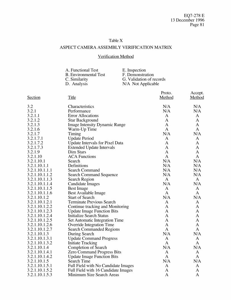
EQ7-278 E13 December 1996
Page 81
Table XASPECT CAMERA ASSEMBLY VERIFICATION MATRIX
Verification Method
A. Functional Test E. InspectionB. Environmental Test F. DemonstrationC. Similarity G. Validation of records
D. Analysis N/A Not Applicable
Proto. Accept.Section Title Method Method
3.2 Characteristics N/A N/A3.2.1 Performance N/A N/A3.2.1.1 Error Allocations A A3.2.1.2 Star Background A A3.2.1.3 Image Intensity Dynamic Range A A3.2.1.6 Warm-Up Time A A3.2.1.7 Timing N/A N/A3.2.1.7.1 Update Period A A3.2.1.7.2 Update Intervals for Pixel Data A A3.2.1.7.3 Extended Update Intervals A A3.2.1.9 Dim Stars A A3.2.1.10 ACA Functions A A3.2.1.10.1 Search N/A N/A3.2.1.10.1.1 Definitions N/A N/A3.2.1.10.1.1.1 Search Command N/A N/A3.2.1.10.1.1.2 Search Command Sequence N/A N/A3.2.1.10.1.1.3 Search Region A A3.2.1.10.1.1.4 Candidate Images N/A N/A3.2.1.10.1.1.5 Best Image A A3.2.1.10.1.1.6 Best Available Image A A3.2.1.10.1.2 Start of Search N/A N/A3.2.1.10.1.2.1 Terminate Previous Search A A3.2.1.10.1.2.2 Continue tracking and Monitoring A A3.2.1.10.1.2.3 Update Image Function Bits A A3.2.1.10.1.2.4 Initialize Search Status A A3.2.1.10.1.2.5 Set Automatic Integration Time A A3.2.1.10.1.2.6 Override Integration Time A A3.2.1.10.1.2.7 Search Commanded Regions A A3.2.1.10.1.3 During Search N/A N/A3.2.1.10.1.3.1 Update Command Progress A A3.2.1.10.1.3.2 Initiate Tracking A A3.2.1.10.1.4 Completion of Search N/A N/A3.2.1.10.1.4.1 Zero Command Progress Bits A A3.2.1.10.1.4.2 Update Image Function Bits A A3.2.1.10.1.5 Search Time N/A N/A3.2.1.10.1.5.1 Full Field with No Candidate Images A A3.2.1.10.1.5.2 Full Field with 16 Candidate Images A A3.2.1.10.1.5.3 Minimum Size Search Areas A A

EQ7-278 E13 December 1996Page 82
Table X (Continued)
ASPECT CAMERA ASSEMBLY VERIFICATION MATRIX
Verification Method
A. Functional Test E. InspectionB. Environmental Test F. DemonstrationC. Similarity G. Validation of records
D. Analysis N/A Not Applicable
Proto. Accept.Section Title Method Method
3.2.1.10.1.6 Image Rates A A3.2.1.10.2 Monitor N/A N/A3.2.1.10.2.1 Begin Monitoring A A3.2.1.10.2.2 Report Aspect Telemetry A A3.2.1.10.2.3 Convert to Track A A3.2.1.10.2.4 Continue Monitoring A A3.2.1.10.2.5 Modification of Monitor Windows A A3.2.1.10.3 Track A A3.2.1.10.4 Calibrate A A3.2.1.10.5 Extended Command A A3.2.1.11 Commands N/A N/A3.2.1.11.1 Serial-Digital Commands N/A N/A3.2.1.11.1.1 Command Word Groups A A3.2.1.11.1.1.1 Command Checksum and Count A A3.2.1.11.1.1.2 Command Error Processing A A3.2.1.11.1.1.3 Search Command Processing A A3.2.1.11.1.1.4 Calibrate Command Processing A A3.2.1.11.1.2 Command Formats N/A N/A3.2.1.11.1.3 Search Command N/A N/A3.2.1.11.1.3.1 Search Command Format A A3.2.1.11.1.3.2 Default Search Command Sequence A A3.2.1.11.1.4 Monitor Command A A3.2.1.11.1.5 Calibrate Command A A3.2.1.11.1.6 Extended Command A A3.2.1.11.1.6.1 Check Interface Outputs A A3.2.1.11.1.6.2 Full Field Search Command A A3.2.1.11.1.6.3 IU Channel Select Command A A3.2.1.11.1.6.4 Download Command A A3.2.1.11.1.6.4.1 Download Function A A3.2.1.11.1.6.4.2 Data Location A A3.2.1.11.1.6.4.3 Data Bytes per Image A A3.2.1.11.1.6.4.4 Checksums A A3.2.1.11.1.6.4.5 Download Duration A A3.2.1.11.1.7 Integration Time Command A A3.2.1.11.1.8 Data Input Command A A3.2.1.11.1.8.1 IU Header Data A A3.2.1.11.1.8.2 Memory Upload A A3.2.1.11.1.8.3 CCD Temperature Control A A
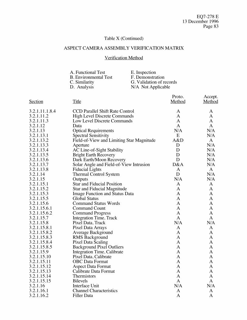
EQ7-278 E13 December 1996
Page 83
Table X (Continued)
ASPECT CAMERA ASSEMBLY VERIFICATION MATRIX
Verification Method
A. Functional Test E. InspectionB. Environmental Test F. DemonstrationC. Similarity G. Validation of records
D. Analysis N/A Not Applicable
Proto. Accept.Section Title Method Method
3.2.1.11.1.8.4 CCD Parallel Shift Rate Control A A3.2.1.11.2 High Level Discrete Commands A A3.2.1.11.3 Low Level Discrete Commands A A3.2.1.12 Data A A3.2.1.13 Optical Requirements N/A N/A3.2.1.13.1 Spectral Sensitivity E N/A3.2.1.13.2 Field-of-View and Limiting Star Magnitude A&D A3.2.1.13.3 Aperture D N/A3.2.1.13.4 AC Line-of-Sight Stability D N/A3.2.1.13.5 Bright Earth Recovery D N/A3.2.1.13.6 Dark Earth/Moon Recovery D N/A3.2.1.13.7 Solar Angle and Field-of-View Intrusion D&A N/A3.2.1.13.8 Fiducial Lights A A3.2.1.14 Thermal Control System D N/A3.2.1.15 Outputs N/A N/A3.2.1.15.1 Star and Fiducial Position A A3.2.1.15.2 Star and Fiducial Magnitude A A3.2.1.15.3 Image Function and Status Data A A3.2.1.15.5 Global Status A A3.2.1.15.6 Command Status Words A A3.2.1.15.6.1 Command Count A A3.2.1.15.6.2 Command Progress A A3.2.1.15.7 Integration Time, Track A A3.2.1.15.8 Pixel Data, Track N/A N/A3.2.1.15.8.1 Pixel Data Arrays A A3.2.1.15.8.2 Average Background A A3.2.1.15.8.3 RMS Background A A3.2.1.15.8.4 Pixel Data Scaling A A3.2.1.15.8.5 Background Pixel Outliers A A3.2.1.15.9 Integration Time, Calibrate A A3.2.1.15.10 Pixel Data, Calibrate A A3.2.1.15.11 OBC Data Format A A3.2.1.15.12 Aspect Data Format A A3.2.1.15.13 Calibrate Data Format A A3.2.1.15.14 Thermistors A A3.2.1.15.15 Bilevels A A3.2.1.16 Interface Unit N/A N/A3.2.1.16.1 Channel Characteristics A A3.2.1.16.2 Filler Data A A
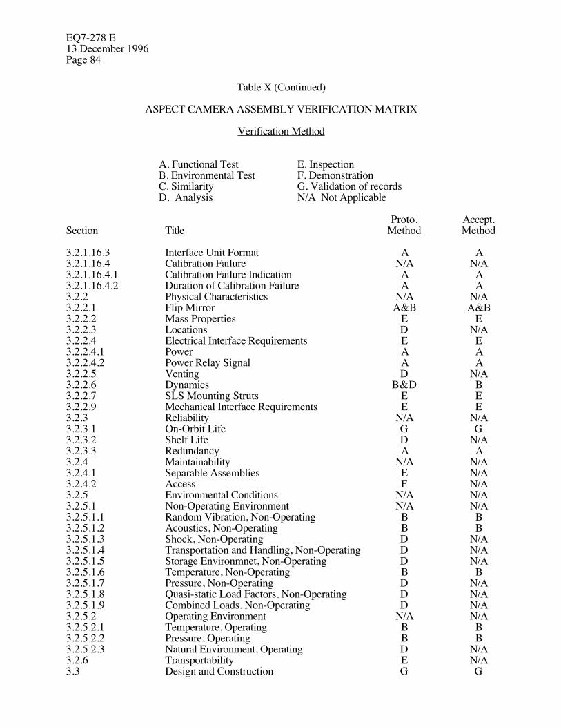
EQ7-278 E13 December 1996Page 84
Table X (Continued)
ASPECT CAMERA ASSEMBLY VERIFICATION MATRIX
Verification Method
A. Functional Test E. InspectionB. Environmental Test F. DemonstrationC. Similarity G. Validation of records
D. Analysis N/A Not Applicable
Proto. Accept.Section Title Method Method
3.2.1.16.3 Interface Unit Format A A3.2.1.16.4 Calibration Failure N/A N/A3.2.1.16.4.1 Calibration Failure Indication A A3.2.1.16.4.2 Duration of Calibration Failure A A3.2.2 Physical Characteristics N/A N/A3.2.2.1 Flip Mirror A&B A&B3.2.2.2 Mass Properties E E3.2.2.3 Locations D N/A3.2.2.4 Electrical Interface Requirements E E3.2.2.4.1 Power A A3.2.2.4.2 Power Relay Signal A A3.2.2.5 Venting D N/A3.2.2.6 Dynamics B&D B3.2.2.7 SLS Mounting Struts E E3.2.2.9 Mechanical Interface Requirements E E3.2.3 Reliability N/A N/A3.2.3.1 On-Orbit Life G G3.2.3.2 Shelf Life D N/A3.2.3.3 Redundancy A A3.2.4 Maintainability N/A N/A3.2.4.1 Separable Assemblies E N/A3.2.4.2 Access F N/A3.2.5 Environmental Conditions N/A N/A3.2.5.1 Non-Operating Environment N/A N/A3.2.5.1.1 Random Vibration, Non-Operating B B3.2.5.1.2 Acoustics, Non-Operating B B3.2.5.1.3 Shock, Non-Operating D N/A3.2.5.1.4 Transportation and Handling, Non-Operating D N/A3.2.5.1.5 Storage Environmnet, Non-Operating D N/A3.2.5.1.6 Temperature, Non-Operating B B3.2.5.1.7 Pressure, Non-Operating D N/A3.2.5.1.8 Quasi-static Load Factors, Non-Operating D N/A3.2.5.1.9 Combined Loads, Non-Operating D N/A3.2.5.2 Operating Environment N/A N/A3.2.5.2.1 Temperature, Operating B B3.2.5.2.2 Pressure, Operating B B3.2.5.2.3 Natural Environment, Operating D N/A3.2.6 Transportability E N/A3.3 Design and Construction G G
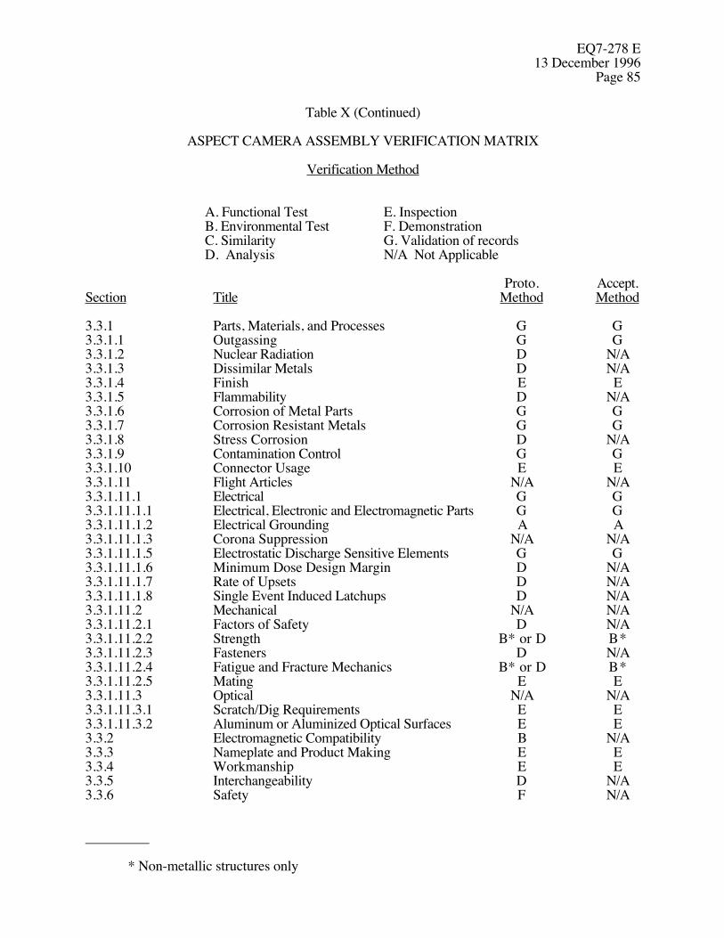
EQ7-278 E13 December 1996
Page 85
Table X (Continued)
ASPECT CAMERA ASSEMBLY VERIFICATION MATRIX
Verification Method
A. Functional Test E. InspectionB. Environmental Test F. DemonstrationC. Similarity G. Validation of records
D. Analysis N/A Not Applicable
Proto. Accept.Section Title Method Method
3.3.1 Parts, Materials, and Processes G G3.3.1.1 Outgassing G G3.3.1.2 Nuclear Radiation D N/A3.3.1.3 Dissimilar Metals D N/A3.3.1.4 Finish E E3.3.1.5 Flammability D N/A3.3.1.6 Corrosion of Metal Parts G G3.3.1.7 Corrosion Resistant Metals G G3.3.1.8 Stress Corrosion D N/A3.3.1.9 Contamination Control G G3.3.1.10 Connector Usage E E3.3.1.11 Flight Articles N/A N/A3.3.1.11.1 Electrical G G3.3.1.11.1.1 Electrical, Electronic and Electromagnetic Parts G G3.3.1.11.1.2 Electrical Grounding A A3.3.1.11.1.3 Corona Suppression N/A N/A3.3.1.11.1.5 Electrostatic Discharge Sensitive Elements G G3.3.1.11.1.6 Minimum Dose Design Margin D N/A3.3.1.11.1.7 Rate of Upsets D N/A3.3.1.11.1.8 Single Event Induced Latchups D N/A3.3.1.11.2 Mechanical N/A N/A3.3.1.11.2.1 Factors of Safety D N/A3.3.1.11.2.2 Strength B* or D B*3.3.1.11.2.3 Fasteners D N/A3.3.1.11.2.4 Fatigue and Fracture Mechanics B* or D B*3.3.1.11.2.5 Mating E E3.3.1.11.3 Optical N/A N/A3.3.1.11.3.1 Scratch/Dig Requirements E E3.3.1.11.3.2 Aluminum or Aluminized Optical Surfaces E E3.3.2 Electromagnetic Compatibility B N/A3.3.3 Nameplate and Product Making E E3.3.4 Workmanship E E3.3.5 Interchangeability D N/A3.3.6 Safety F N/A
_________
* Non-metallic structures only

EQ7-278 E13 December 1996Page 86
TABLE XI.
ASPECT CAMERA ASSEMBLY TESTING SEQUENCE
AC/PEA SLS
Performance Test and Image All items Inspect onlyCalibration(Section 4.2.1)
EMC Test All items N/A(Paragraph 6.0 of D17389 (protoflight only)(TRW SE19);references to MSFC are to TRW)
Limited Functional Test All items N/A(Section 4.2.2) (protoflight only)
Thermal-Vacuum 11 cycles 11 cycles,(Paragraph 4.1.1.5 of EV1-8 All items Non-operating(TRW SE29) and Section 4.2.2)
Limited Functional Test All items Inspect only(Section 4.2.2)
Random Vibration (Paragraph 4.1.1.6 All items Non-operatingof EV1-8 (TRW SE29)
Limited Functional Test N/A Inspect only(Section 4.2.2) (protoflight only)
Acoustic Test (Paragraph 4.1.1.7 N/A Non-operatingof EV1-8 (TRW SE29)
Performance Test and Image All items Inspect onlyCalibration (Section 4.2.1)

EQ7-278 E13 December 1996
Page 87
4.2.2 Limited Functional Test
A limited functional test assures that all electrical aspects of a unit are functioning properly. Thetest shall nclude all input channels, all output channels, the flip mirror, the soft switch, a continuouspower monitor, and all primary and redundant paths. A visual examination shall precede and followthe testing.
4.3 Verification Requirements
4.3.1 Development Verification
Development verification is the process that verifies the feasibility of the design approach andprovides confidence in the ability of the hardware to comply with the requirements specified inSections 3.2 and 3.3. AC/PEA development verification shall include, but is not limited to, testingand assessment of the proposed detector array and tests of critical components. Testing andassessment of the proposed detector array shall include radiation modeling with radiation test dataof the proposed detector array.
4.3.2 Engineering Model Verification
Engineering model verification for the AC/PEA consists of a performance test and image calibrationdefined in Section 4.2.1, a random vibration test defined in Paragraph 4.1.1.6 of EV1-8 (TRWSE29), followed by a second performance test and image calibration.
Engineering model verification for the SLS consists of a random vibration test and an acoustics testdefined respectively in Paragraphs 4.1.1.6 and 4.1.1.7 of EV1-8 (TRW SE29).
4.3.3 Protoflight Verification
Protoflight verification is that which verifies that selected flight-type items meet the performanceand design requirements under environments which are greater than anticipated, but less than designlimits. Protoflight verification of the ACA shall include Section 4.2 to verify conformance to therequirements in Sections 3.2 and 3.3. It shall also include the tests listed in Sections 4.3.3.1 to4.3.3.3. Protoflight verification of the ACA shall be performed prior to delivery to TRW.
EQ7-278 E13 December 1996Page 88
4.3.3.1 Material Properties
Static structural tests of nonmetallic materials used in the ACA and referenced in Sections3.3.1.11.2.1 and 3.3.1.11.2.2 shall be performed according to MSFC-HDBK-505. With TRWapproval these tests may be performed prior to formal verification.
4.3.3.2 Redundancy Tests
All redundant elements and paths shall be tested to verify that redundant elements performaccording to the requirements defined in Section 3.2.3.3.
4.3.3.3 Interface Verification
Thermal, structural, electrical and optical interfaces between the AC, SLS, and PEA and the HRMAand/or OBA shall be verified as specified in Table X to assure compliance with Sections 3.2.2.4 and3.2.2.9.
4.3.4 Acceptance Verification
Acceptance verification is the process that verifies the flight hardware will perform satisfactorily atconditions less than or equal to the specified requirements. Acceptance verification of the ACAshall include Section 4.2 to verify conformance to the requirements of Sections 3.2 and 3.3. It shallalso include the tests defined in Section 4.3.3.2. Acceptance verification of the ACA shall beperformed prior to delivery to TRW.
4.4 Test Plan and Procedures
All qualification, protoflight and acceptance testing shall be performed according to an approved testplan and according to approved, released procedures. The acceptable performance limits in the testprocedures shall include sufficient margins for expected performance degradation due to orbitalenvironmental conditions.
4.5 Failure and Retest
If a failure occurs during a test, the failure shall be documented and testing shall be discontinueduntil an analysis is performed to determine if the condition merits continuing the tests or delayingthe tests for a more detailed failure analysis. Failures during the verification required in Sections

EQ7-278 E13 December 1996
Page 89
4.3.3 and 4.3.4 shall be processed and controlled as specified in Paragraph 3.2.10 of PAR700-272.TRW shall be notified of such failures within 24 hours of their occurrences. The test shall berepeated after correcting the cause of failure. If the corrective action substantially affects thesignificance of the results of previously completed tests, such tests shall be repeated also.
EQ7-278 E13 December 1996Page 90
5.0 PREPARATION FOR DELIVERY
5.1 General
The ACA components packaged as specified herein shall be protected from degradation byenvironments anticipated during shipment, handling, and storage. Unless otherwise specified in thecontract, standard commercial packaging practices are acceptable provided they fulfill theserequirements.
5.2 Preservation and Packaging
5.2.1 Cleaning
ACA components shall be clean and free of contaminants according to Section 3.3.1.9 prior topackaging.
5.2.2 Attaching Parts
When attaching parts, such as nuts, bolts, washers, etc., accompany a component, they shall bepreserved, bagged, appropriately identified, and attached to or adjacent to the fitting for which theyare intended.
5.2.3 Electrical Connectors
Connector savers and dust caps shall be used and delivered on all external electrical connectorsaccording to Paragraph 5.7.3 of PAR700-272. Prior to delivery to TRW, all ACA socket contactsshall be tested according to Paragraphs 5.7.4 and 5.7.5 of PAR700-272.
5.2.4 Critical Surfaces
External machined surfaces and mounting surfaces of the ACA components shall be protected withprotective pads. Materials used for pads shall not cause component deterioration.

EQ7-278 E13 December 1996
Page 91
5.2.5 Wrapping
Wrapping or bagging for ACA components shall be clean (level 100 A) aclar film and shallconform to Paragraph 3.4.1 of D17393 (TRW SE28).
5.2.6 Cushioning
ACA components shall be cushioned using a suitable resilient foam cushioning material such aspolyethylene. Polyurethane or polystyrene foams are acceptable only if bagged in acceptablepolyethylene.
5.3 Packing
Each component shall be packed in a suitable shipping container designed for one component only.The shipping containers shall provide protection for the ACA components against corrosion,deterioration, contamination, and damage during shipment from the source of supply to thereceiving activity. Containers shall comply with Paragraphs 3.4.2 and 3.4.3 of D17393 (TRWSE28) and with applicable tariffs and regulations for particular modes of transportation when soshipped.
5.4 Marking for Shipment
Each unit container and shipping container shall be marked in accordance with PAR700-272 oneach side, top and bottom with the following:
(a) Item Nomenclature (g) Prime contract number: NAS8-37710(b) TRW part number and serial number (h) Manufacturer’s part number(c) FRAGILE - HANDLE WITH CARE (i) Equipment specification no.: EQ7-278(d) ITEMS FOR SPACE FLIGHT USE (j) Program name: AXAF-I(e) Manufacturer’s name (k) Configured end item no.: L70701P(f) Manufacturer’s CAGE code number

EQ7-278 E13 December 1996Page 92
All marking for space flight items shall be blue in color. In addition, one NASA Critical Item Labelshall be affixed to each exterior container. This label may be obtained from MSFC in the followingsizes:
(a) NASA Form 1368 - 4 by 8 inches(b) NASA Form 1368A - 3 by 6 inches(c) NASA Form 1368B - 2 by 3-1/2 inches
5.5 Documentation
All required reliability and test documentation such as test reports, certifications, shipping invoices,etc., shall be either packed in the item container or attached to the exterior surface of the shippingcontainer. Attachment shall be in such a manner as to preclude the loss of this data during handlingand shipment by common carrier.

EQ7-278 E13 December 1996
Page 93
6.0 NOTES
6.1 Indication of a Revision or Change
The margins of this specification are marked with the appropriate symbol where modifications ofthe previous issue have been made.
6.2 Acronyms and Abbreviations
AC Aspect CameraACA Aspect Camera AssemblyASC AXAF Science CenterAXAF-I Advanced X-ray Astrophysics Facility - ImagingCCD Charge Coupled DeviceCCDM Communications, Command, and Data ManagementEPS Electrical Power SubsystemFOV Field-of-ViewFPA Focal Plane AssemblyFTM Fiducial Transfer MirrorFTP Fiducial Transfer PeriscopeHRMA High Resolution Mirror AssemblyIRU Inertial Reference UnitIU Interface UnitLOS Line-of-SightLSB Least Significant BitMSB Most Significant BitOBA Optical Bench AssemblyOBC On-Board ComputerOTA Optical Telescope AssemblyPCAD Pointing Control and Attitude DeterminationPEA Processing Electronics AssemblyRCTU Remote Command and Telemetry UnitSI Science InstrumentSLS Stray Light ShadeTBR To Be ResolvedTS Telescope System