2500 A.D. Linker Description - Mikrocontroller.net
36
2500 A.D. Linker - Version 4.02 2500 A.D. Linker Description The 2500 A.D. Linker enables the user to write assembly language programs consisting of several modules. The Linker will resolve external references and perform address relocation. The Linker is capable of generating all of the most used file formats, eliminating the need for an additional format conversion utility. Except for when generating an executable output file, the Linker runs entirely in RAM. There is no limit on the size of file that can be linked, as long as enough memory is available. In the case of an executable file, the Linker creates as many scratchpad files as required to sort the different program sections in ascending order. Each object file may have up to 256 different user defined sections. The Linker can search up to fifty separate library files for resolving external symbol references. The Linker can process a combination of 256 input files and library modules, and 256 different section names. There is no limit on the size of each section. Files may be linked at the address specified in the file or, relocated at link time. Specific sections of files may be used for reference only. That is, the information from the section needed to link will be used but the section will not be included in the output file. Sections of files may also be linked at different run-time and load addresses. This feature can be used to generate romable code that must be moved to read/write memory at run time. For more information see the section entitled Indirect Linking. Listings with the Linker may be relocated using LINKLIST. This directive, when listing to disk is specified, will relocate the listing with the actual addresses at Run-Time. Please see the Linker Control section for more information. 2 - 1
-
Upload
khangminh22 -
Category
Documents
-
view
0 -
download
0
Transcript of 2500 A.D. Linker Description - Mikrocontroller.net

2500 A.D. Linker - Version 4.02
2500 A.D. Linker Description
The 2500 A.D. Linker enables the user to write assembly language programs consisting
of several modules. The Linker will resolve external references and perform address
relocation. The Linker is capable of generating all of the most used file formats,
eliminating the need for an additional format conversion utility.
Except for when generating an executable output file, the Linker runs entirely in RAM.
There is no limit on the size of file that can be linked, as long as enough memory is
available. In the case of an executable file, the Linker creates as many scratchpad files
as required to sort the different program sections in ascending order.
Each object file may have up to 256 different user defined sections. The Linker can
search up to fifty separate library files for resolving external symbol references. The
Linker can process a combination of 256 input files and library modules, and 256
different section names. There is no limit on the size of each section.
Files may be linked at the address specified in the file or, relocated at link time. Specific
sections of files may be used for reference only. That is, the information from the
section needed to link will be used but the section will not be included in the output file.
Sections of files may also be linked at different run-time and load addresses. This
feature can be used to generate romable code that must be moved to read/write
memory at run time. For more information see the section entitled Indirect Linking.
Listings with the Linker may be relocated using LINKLIST. This directive, when listing to
disk is specified, will relocate the listing with the actual addresses at Run-Time. Please
see the Linker Control section for more information.
2 - 1

2500 A.D. Linker - Version 4.02
The Linker r•-•,v be invoked using Prompt mode, Command Line mode or Data File
mode. The output format is selectable from a directive in the source file or from the
Linker options list. The Load Map, an alphabetized global symbol list and all link errors
may be saved in a disk file.
The Linker may be directed to output several different types of symbol table files. These
formats are relocated 10 character global symbols, relocated 32 character global
symbols, Zax format which includes all symbols and the Microtek format which includes
all symbols.

2 - 2
2500 A.D. Linker - Version 4.02 Prompt Mode
Linker Operating instructions
Prompt Mode
To run the Linker in prompt mode type Link. The Linker will respond with a prompt
requesting an input filename. The default extension for a Linker input file is 'obj'. After
opening the object file, the Linker will prompt for the offset address for each program
section that has a non-zero size. This offset value is added to the value of any ORG
statements in the file. A carriage return only response will cause the Linker to stack
each program section on top of the preceding section. A minus sign causes the Linker
to relocate the section, but not include it in the output file. A semi-colon after any offset
address causes the Linker to automatically stack each section on top of the previous
section. Since the best way to explain all of this is with examples, please refer to the
Linker Examples section of this manual.
The input phase can be terminated by responding to the input filename prompt with just
a carriage return. The Linker will then prompt for an output filename. A carriage return
only response to the output filename prompt will cause the Linker to generate an output
file with the same name as the first input file and an extension that is determined by the
output file type.
After the output filename has been entered, the Linker will prompt for library filenames.
The Linker can search up to 50 libraries for external symbol references. A carriage
return only response to the library filename prompt will terminate library filename input.
After any library filenames have been entered, the Linker will prompt for any Linker
options. The Linker options are described in the section entitled Linker Options.

2 - 3
2500 A.D. Linker - Version 4.02 Prompt Mode
NOTE to VMS users:
Assuming the linker is located in a directory named $disk-1:[link], the following
command must be entered for the examples shown above to work:
link == "$diskl Mink]link.exe"
If you use the VMS Link program, one of the linkers should be renamed.
2 - 4
2500 A.D. Linker - Version 4.02 Data File Mode
Data File Mode
Data File mode is included for large or complex linking. This mode can be viewed as
being identical to prompt mode, except that all of the responses to the prompts are
placed in a file and the file is submitted to the Linker. The command is as follows:
Link data_file
This causes the Linker to read the file data_fileink and uses the responses in the file,
line by line. The Linker assumes an extension of Ink on the data file. Since carriage
return only responses may be difficult to see in a data file, an underbar character ('_')
may be placed on a carriage return only line. If Linker options are specified, they are
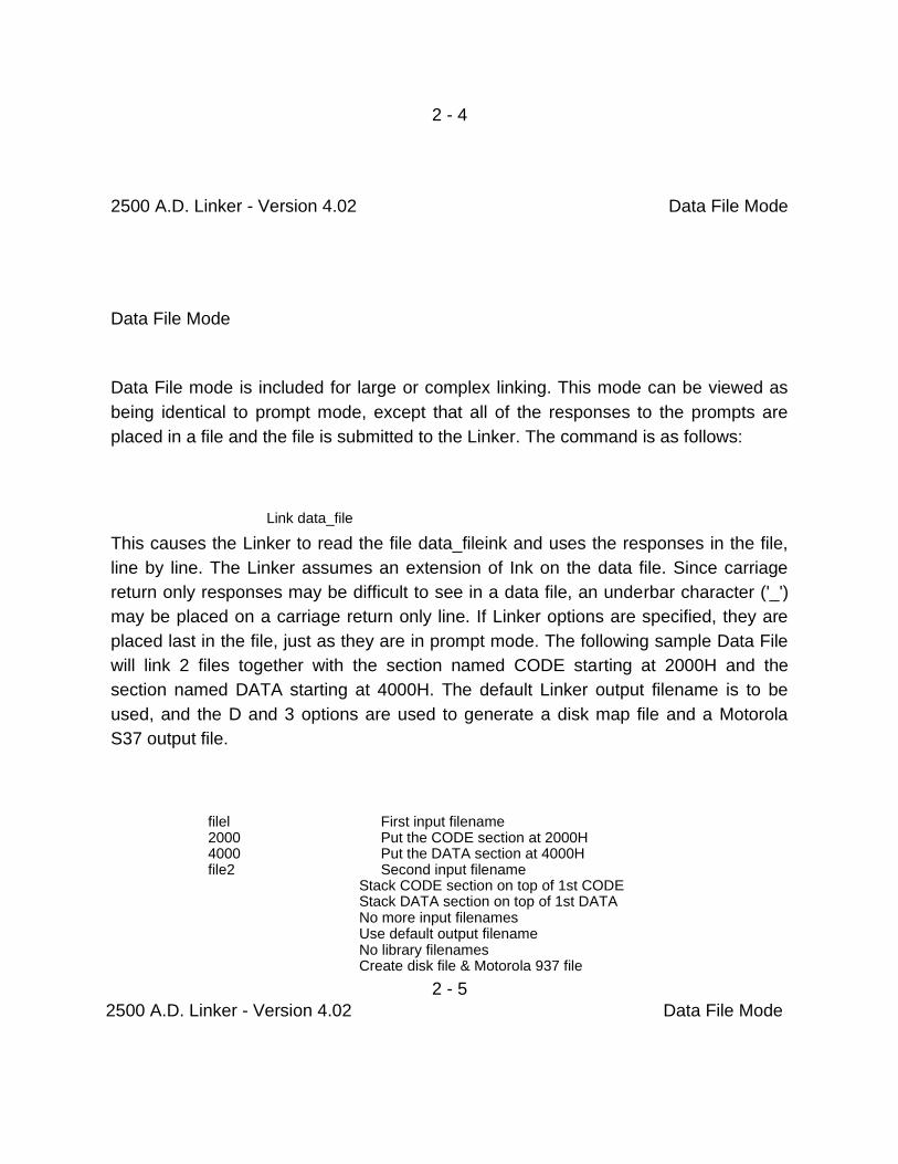
placed last in the file, just as they are in prompt mode. The following sample Data File
will link 2 files together with the section named CODE starting at 2000H and the
section named DATA starting at 4000H. The default Linker output filename is to be
used, and the D and 3 options are used to generate a disk map file and a Motorola
S37 output file.
filel First input filename 2000 Put the CODE section at 2000H 4000 Put the DATA section at 4000H file2 Second input filename
Stack CODE section on top of 1st CODE Stack DATA section on top of 1st DATA No more input filenames Use default output filename No library filenames Create disk file & Motorola 937 file
2 - 5
2500 A.D. Linker - Version 4.02 Data File Mode

The easiest way to construct a Data File is to run through the link process in Prompt
mode, and write down each response. Then, using a text editor, create a file with each
response on a line by itself. This file should have an extension of Ink.
Any line that has a semi-colon or an asterisk in column 1 will be considered to be a
comment line.
NOTE to VMS users:
Assuming the linker is located in a directory named $diskt[link], the following command
must be entered for the examples shown above to work:
link == "$diskl :flinkpink.exe"
If you use the VMS Link program, one of the linkers should be renamed.
2 - 6
2500 A.D. Linker - Version 4.02 Command Line Mode

Command Line Mode
The Linker may be invoked by using a command line. The form of this command is
shown below, with optional fields shown in brackets.
Link [-q] -c [-Innnn] fiIe2 [-Innnn] ...[-ofile] [-options]
The -q option puts the Linker in Quiet mode. In this case the only output to the
terminal from the Linker are link errors.
The -c option is required, and informs the Linker that it is running in Command Line
mode instead of Data File mode.
Following the -c is the list of input files, denoted in the above command line by filel and
file2. Each input file may be followed by an offset address by using the , -I option. If the
address offset is not included, each file is stacked on top of the previous file according
to matching section names.
The -o option can be used to specify an output filename. This field is optional. If no
output filename is specified, the Linker will create an output file with the same name
as the first input file, with an extension determined by the output file format.
The -L option can be used to specify library filenames. A maximum of 50 library
filenames can be specified.
The options field allows any of the Linker options to be specified. A minus sign is
required in front of the list, and as many options as desired may be specified. See the
Linker Options section of this manual for a description of the options.
2 - 7 2500 A.D. Linker - Version 4.02 Command Line Mode
NOTE to VMS users:

Assuming the linker is located in a directory named $diskl :[link], the following command
must be entered for the examples shown above to work:
link = "$diskl :flinkilink.exe"
If you use the VMS Link program, one of the linkers should be renamed.
2 - 8 2500 A.D. Linker - Version 4.02 Linker Options

Linker Options
In prompt mode, the linker options prompt appears after the output filename prompt.
The options below are also available in Command Line and Data File mode. When
more than one option is specified the final option will override the previous options.
Options (D, S, A, M, 2, X, H, E, T, 1, 2,3, <CR,. = Default)
D - Create a disk file containing any link errors, an alphabetized global symbol table, and the Load Map. The file created has the same name as the Linker output file with an extension of 'map'.
S - Create a symbol file for debugging purposes. The file contains all the global symbols and relocated values. Each symbol is 32 characters in length. See the Symbol Table Output Format section of this manual for exact details.
A - Create a symbol file for debugging purposes, but limit the symbols to the first 10 characters. This is used for compatability with the 3.0 2500 A.D. series of Linkers. See the Symbol Table Output Format section of this manual for exact details.
M - Create a symbol file for debugging purposes in the Microtek format. This file includes all symbols, both local and global. The SYMBOLS ON directive must be included n the source file for this format to be generated.
Z - Create a symbol file for debugging purposes in the Zax format.This file includes all symbols, both local and global. The SYMBOLS ON directive must be included in the source file for this format to be generated.
X - Generate an Executable output file. H - Generate an Intel Hex output file. E - Generate an Extended Intel Hex output file. T - Generate a Tektronix Hex output file.
1 - Generate a Motorola S19 output file. 2 - Generate a Motorola S28 output file. 3 - Generate a Motorola S37 output file.
2 - 9 2500 A.D. Linker - Version 4.02 Address Relocation

Address Relocation
Addresses are relocated by adding the offset address to the address decoded by the
2500 A.D. Assembler. Normally the program would be assembled starting at location
0000, but it doesn't have to be. The offset address will simply be added to any address
generated by-the Assembler.
The Assembler maintains a table of attributes associated with each symbol used in the
program. If the label simply preceds an instruction, then it is tagged as relocatable. If the
label is defined in an .EQUAL directive, then the relocatability of it depends on the
operand field type. If the operand contains no relocatable tokens, then the expression is
not relocatable. If the operand contains only one relocatable token, then the expression
is relocatable. If the operand contains two or more relocatable tokens, then the
expression is not relocatable.
Byte values are only relocatable candidates if the unary greater than > sign is used for
the high byte and/or the unary less than < sign is used for the low byte. These operands
are subject to the same relocation rules as full 16 bit address values.
Following are some examples illustrating these points.
LABEL1: NOP ; The label is defined to be equal to the address of an instruction and therefore is relocatable. LABEL2: .EQUAL LABEL1 ; The label is defined to equal a value that was tagged as reloc-atable. Therefore, LABEL2 is also relocatable.
LABEL3: .EQUAL 10 ; The label is defined to equal a constant. Therefore, LABEL3 is not relocatable.
2-10

2500 A.D. Linker - Version 4.02 Address Relocation
LABEL4: .EQUAL $+10 ; The label is defined to equal a relocatable
; value plus a non-relocatable value. Since
; only one value is relocatable, the symbol
; LABEL4 is relocatable.
LABELS: .EQUAL 10+$ ; The label is defined to equal a non-relocatable
; value plus a relocatable value. Since only one
; value is relocatable, LABELS is relocatable.
LABEL6: .EQUAL LABELS-LABEL2 ; The label is defined to equal a relocatable value ; minus another relocatable value, producing a ; non-relocatable result.
The last example is worth remembering when using the Assembler to do things such as
calculate data sizes. Consider the following example of a table of data values, with the number
of bytes being calculated automatically at assembly time by the Assembler, allowing the
programmer to add or delete from the table without having to remember to change the data
block size.
DATA: .BYTE 0 .WORD 10 .BYTE 20 .BLKB 5
DATA_SIZE: .EQUAL $-DATA
The Assembler will calculate the size of the data block, and because the result is not
relocatable, the Linker will not alter the data block size.

2-11
2500 A.D. Linker Version 4.02 Linker Examples
Linker. Examples
This section consists of examples intended to demonstrate the use of the Linker. The
<CR> symbol denotes a carriage return and is shown only when no other response to a
prompt is desired. Otherwise, all inputs are assumed to be terminated with a carriage
return. In all cases, a Data File can be constructed with exactly the same responses as
when running in Prompt mode.
Single File Assembled At Desired Run Address
The first example is the case of just one file which has been assembled at the desired
run address by the use of the ORIGIN directive. Also, assume the default output file
type is Executable, and no Linker options are desired. If no additional sections were
defined, and there was no switching between the predefined sections, the Linker
prompts would be as follows:
Input Filename : filename Enter Offset for 'CODE' :0 Input Filename : <CR>
Output Filename : <C11>
Library Filename: <CR>
Options (D, S, A, M, Z, X, H, E, T, 1, 2, 3, <CR>. Default) : x
The above will cause the Linker to read the file filename.obj, add 0 to all relocatable
addresses, and output a file with the name filename.tsk.

2-12 2500 A.D. Linker Version 4.02 Linker Examples
The following example shows the case where everything is the same as in the previous
examole except the desired output format is Intel Hex. Note that the default Linker
output format may be changed with the OPTIONS Assembler directive.
Input Filename: filename Enter Offset for 'CODE' : 0 Input Filename : <CR>
Output Filename :<CR>
Library Filename:<CR>
Options (D, S. A, M, Z, X, H, E, T, 1, 2, 3, <CR>= Default) : h
The last example for this type of file is the same as in the previous example with the
addition of a disk Load Map file, user specified output filename, and a library to search
for unresolved external references. The options may be specified in any order.
Input Filename : filename Enter Offset for 'CODE' : 0 Input Filename :<CR>
Output Filename :user_filename
Library Filename: lib_filename
Options (D, S, A, M, Z, X, H, E, T, 1, 2, 3, <CR>= Default) : hd
2-13 2500 A.D. Linker Version 4.02 Linker Examples
Single File With Multiple Sections
This example demonstrates how the Linker handles multiple program sections. If the
predefined CODE and DATA sections were used, and the DATA section is to be
stacked on top of the CODE section, then the Linker prompts would be as follows:
Input Filename: filename Enter Offset for 'CODE' :0
Enter Offset for 'DATA' : <CR> Input Filename: <CR>

Output Filename :<CR>
Library Filename: <CR>
Options (D, S, A, M, Z, X, H, E, T, 1, 2,3, <CR>= Default) :
If instead of using the predefined sections CODE and DATA, the user defined
sections Program_section1 and Program_section2 were used, and
Program_section2 is to be stacked on top of Program_sectiont the prompts would
be as follows:
Input Filename: filename Enter Offset for 'Program_section1' : 0
Enter Offset for 'Program_section2' :<CR> Input Filename : <CR>
Output Filename : <CR>
Library Filename: <CR>
Options (D, S, A, M, 2, X, H, E, T, 1, 2, 3, <CR>. Default) :
One important item to keep in mind is that sections are stacked in the order in which
they are defined. Therefore, in this example there is no way to stack
Program_section2 on top of Program_sectionl. If the need arises to reverse the
order, then order of the SECTION directives in the source file must be changed.
2-14 2500 A.D. Linker Version 4.02 Linker Examples
If in the above example, Program_section1 was to be relocated to run at 2000H and
Program_section2 was to be relocated to run at 4000H, the following responses would be
used.
Input Filename : filename Enter Offset for 'Program_sectionl' : 2000
Enter Offset for 'Program_section2' : 4000 Input Filename : <CR>
Output Filename : <CR>
Library Filename: <CR>

Options (D, S, A, M, Z, X, H, E, T, 1, 2, 3, <CR>. Default) :
Note that the addresses are always specified in Hexadecimal. If the output file format was
Executable, the gap from the end of Program_section1 to the start of Program_section2
would be filled in with the default fill character, which is FF Hex. This may be changed with
the FILLCHAR Assembler directive.
2-15
2500 A.D. Linker Version 4.02 Linker Examples
Multiple Files With Multiple Sections
This example illustrates how the Linker handles section names in multiple files.
Assume filel and file2 use both CODE and DATA sections, and file1 is to be linked
starting at 0. The prompts will appear as follows:
Input Filename : filel Enter Offset for 'CODE' : 0
Enter Offset for 'DATA' :<CR>

Input Filename : file2 Enter Offset for 'CODE' :<CR> Enter Offset for 'DATA' : <CR>
Output Filename : <CR>
Library Filename: <CR>
Options (D, S, A, M, Z, X, H, E, T, 1, 2, 3, <CR> = Default) :
This will produce a file with both CODE sections stacked on top of each other,
followed by both DATA sections being stacked on top of each other, then stacked
on top of both CODE sections. This shows the general rule of stacking sections.
Sections are stacked according to name, and are stacked in the order in which they
are defined in the source file. All CODE sections will be grouped together, then all
DATA sections, etc. CODE sections will always be stacked before DATA sections,
since that is the order they are predefined in. If DATA must be placed before CODE,
then CODE should not be used and a user defined section should be used. This is
true for stacking only. !f CODE and DATA are to be stacked, but placed at specific
addresses, this would be done as follows, assuming CODE is to start at E000H and
DATA is to start at 1000H.
2-16 2500 A.D. Linker Version 4.02 Linker Examples
Input Filename : filel Enter Offset for 'CODE' : E000 Enter Offset for 'DATA' : 1000
Input Filename: file2 Enter Offset for 'CODE' : <CR>
Enter Offset for 'DATA' : <CR>
Output Filename : <CR>

Library Filename:<CR>
Options (D, S, A, M, Z, X, H, E, T, 1, 2, 3, <CR>-, Default) :
The rules described in this example hold true regardless of how many input files there
are. Sections can be used to separate program sections according to function, or to
assist in complex linking, since any section may be placed at any address.
2-17
2500 A.D. Linker Version 4.02 Linker Examples
Single File With One Section Used For Reference Only
A reference only section is a section that is relocated so that any globals defined in the
section can be used for linking purposes, however the section is not included in the

output file. Reference only sections are useful in cases such as where the program
resides in ROM or EPROM and the data areas reside in RAM. It is desirable to have the
output file contain only that part of the program that is to be stored in ROM. Using an
example along the same lines as the previous examples, assume that the program only
uses the predefined CODE and DATA sections, that the CODE is to start at 1000H and
the DATA is to be stacked on top of the CODE, used for linking purposes, and then
discarded. A minus sign before a section address specifies that section as reference
only. A minus sign before the section name indicates a reference only section in the
Load Map.
Input Filename : filename Enter Offset for 'CODE' :1000
Enter Offset for 'DATA' : -<CR> Input Filename : <CR>
Output Filename : <CR>
Library Filename: <CR>
Options (OS, A, M, Z ,X, H, E, T, 1, 2, 3, <CR>= Default) :
If the DATA section was to be placed at 4000H instead of stacked on top of the CODE
section, and was to be used for reference only, this could be accomplished as follows:
Input Filename : filename Enter Offset for 'CODE' :1000
Enter Offset for 'DATA' : -4000 Input Filename : <CR>
Output Filename : <CR>
Library Filename: <CR>
Options (D, S, A, M, Z, X, H, E, T, 1, 2, 3, <CR>= Defauft) :
2-18
2500 A.D. Linker Version 4.02 Linker Examples
Any section of any file may be used for reference only with one exception. The first
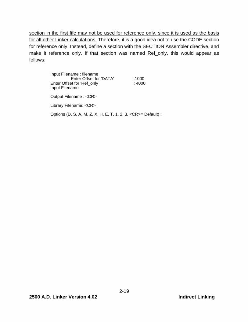
section in the first fife may not be used for reference only. since it is used as the basis
for alLother Linker calculations. Therefore, it is a good idea not to use the CODE section
for reference only. Instead, define a section with the SECTION Assembler directive, and
make it reference only. If that section was named Ref_only, this would appear as
follows:
Input Filename : filename Enter Offset for 'DATA' :1000
Enter Offset for 'Ref_only : 4000 Input Filename
Output Filename : <CR>
Library Filename: <CR>
Options (D, S, A, M, Z, X, H, E, T, 1, 2, 3, <CR>= Default) :
2-19 2500 A.D. Linker Version 4.02 Indirect Linking

Indirect Linking
Indirect Linking is the term 2500 A.D. uses to describe a section of a file that is linked to
run at an address other than the actual load address. This may be called phase and
dephase also, however there is one major difference, namely that phase and dephase
change the address at the assembly level, and indirect linking changes the address at
link time.
This concept can be fairly confusing, and it is extremely easy to generate an output file
that has the addresses so messed up it will never run. Despite this fact, there are times
when this linking method is required.
Assume a single board controller application of some sort, where the program resides in
ROM. If all of the data consists of lookup tables or constants, then there is no reason to
move the data out of ROM, since it will never be written to. But if there is data that has
been initialized to some value, but that value will change as the program runs, then that
data must be moved from ROM to RAM by some sort of run time startup routine. If the
address in RAM is the same as the address in ROM, then there is no problem, since the
addresses generated by the Linker will be correct. However, in many cases the data
that must be moved will simply be stacked on top of the previous section and burned
into the ROM at that address. Now, it would be desirable to move this data to the same
place every time, regardless of how the size of the other sections of the program
change, and a likely candidate for this location would be either low or high RAM. The
problem is, the Linker linked the data addresses to be where the data resides in the
ROM, not where it is going to be moved to run in RAM.
Indirect Linking solves this problem. Any section of a file can be linked to run at an
address other than where it resides in the load file (the ROM). The '@' sign before the
load address is used to convey to the Linker that this is what is desired. All indirect
addresses are automatically stacked on top of the previous section, or a section by the
same name in a previous fie.
Following is a list of rules that should be remembered when using the indirect linking
feature.
2 - 20 2500 A.D. Linker Version 4.02 Indirect Linking

Important Indirect Linking Rules
1) Once a section name has been tagged as indirect, every
indentical section name in following files will automatically be
tagged as indirect also.
2) Indirect sections are stacked in the order they would be stacked
in if they were not indirect.
3) Indirect sections cannot be reference only, since the whole point
is to include the section in the load file.
Assume that there are three files, named file1.obj, file2.obj and file3.obj, each of
which have three sections , called program, const_data and init_data. If section
program resides at 0, and the constant data section const_data is to be stacked on
top of program, and section init_data is supposed to run at 1000H in RAM, but will
be stored in ROM on power up, the following link procedure would be used.
Input Filename : filel Enter Offset for 'program' : 0000 Enter Offset for 'const_data' : <cram
Enter Offset for 'init_data' @1000 Input Filename : file2
Enter Offset for 'program' : <cr-a• Enter Offset for 'const_data' : <cr>
Enter Offset for 'in it_data' : <cr). Input Filename : file3
Enter Offset for 'program' : <cr.> Enter Offset for 'const_data' : iccra•
Enter Offset for Init_data' : <cr> Input Filename : <CFla.
Output Filename : <CR>
Library Filename: <CR,
Options (D, S. A, M, Z, X, H, E, T, 1, 2, 3, <CR>= Default) : <cr).
The resulting output file will contain all the sections, with init_data stacked on top of
const_data, and both of these sections stacked on top of program. The Load Map
will show the actual load addresses, however a look at the global symbol list will
show that all global symbols defined in init_data are linked starting at 1000H.
Therefore, the program will not run as is. The init_data section must be moved to
location 1000H. In order to do this, the size of the init_data section must
2 - 21 2500 A.D. Linker Version 4.02 Indirect Linking

be known. The easiest and most versatile way of finding the size of a section is to
bracket it with other sections, even if they are empty. The Linker will not prompt for the
load address of an empty section, but will if there is at least one equate in it. Therefore,
the first file can be used to set the section link order. The following lines of code would
be put in filel easm to do this.
program: .section program addr: .equal $ const_dita: .section const_data_addr: .equal $ const_data_end: .section const_data_end_addr: .equal $ init_data: .section 'nit data_addr: .equal $ inic_data_end: .section init_data_end_addr: .equal $
program
There are two sections in the above example that have no purpose other than address
calculation. The section const_data_end provides the address in the ROM where
init_data starts. The init_data section cannot be used directly because it has been
linked at a different address, so all labels associated with
init_data have been relocated with respect to that address. The section
init_data_end provides the size of the init_data section. So, the following will provide
the necessary information:
Size of Initialized Data = init_data_end_addr init_data_addr Address in Rom of Initialized Data = const_data_end_addr
Since the labels used to calculate the size of the initialized data section reside in
different sections, the subtraction to calculate the size of the initialized data section
must be performed by the run time startup routine.
The procedure to link the files together would be to link the files as shown in the
previous example, with the addition of stacking const_data_end on top of const_data
and stacking ,'-‘'t_crata_end on top of init_data. In order for the size of init_data to
come out correctly, the section init_data_end must be linked as indirect and stacked.
This can be done by specifying '@' followed by a carriage return, as shown in the
following example.
2 -22

2500 A.D. Linker Version 4.02 Indirect Linking
Since a file that is linked using indirect sections will usually have all sections
stacked on top of the previous one, the linker can be put in auto-stack mode by
specifying a semi-colon (;) after any of the load addresses, or before any of the
carriage return only responses. After this, all sections will automatically be
stacked.
Input Filename : filel Enter Offset for 'program' Enter Offset for 'const_data' Enter Offset for 'const_data_end' Enter Offset for 'init_data' Enter Offset for Init_data end'
Input Filename : file2 Enter Offset for 'program' Enter Offset for 'const_data' Enter Offset for 'const_data_end' Enter Offset for Init_data' Enter Offset for Init_data_end'
Input Filename : file3 Enter Offset for 'program' Enter Offset for 'const_data' Enter Offset for 'const_data_end' Enter Offset for 'init_data' Enter Offset for Init_data_end'
Input Filename : <CR>
: 0000 : .ccr>

: <CT's
:1000
: <Cr> : ccr>
: : <CTs>
: <cr>
: <Cr> : <Cr>
: <cm. : <cr). : <cr>
Output Filename : <CR>
Library Filename: <CR>
Options (D, S, A, M, Z, X, H, E, T, 1, 2,3, <CR>= Default) : <cr>
2 - 23 2500 A.D. Linker - Version 4.02
Linker Symbol Table Output Formats
The following sections describe the Symbol Table output formats from the Linker when
one of the Linker Symbol Table options are chosen.
Symbol Table Output Format
This section describes the format of the Global Symbol Table that is produced when the
S Linker option is selected. The Symbol Table always receives the same filename as
the Linker output filename, with an extension of SYN1. The first byte of this file is the i.d.
code, which is EON. The following bytes, relative to the start of each entry, are repeated
for each entry.
Bytes 0-31 Global Symbol Name. The name is padded with zeros to fill ou! the 32 character positions. The end of the entries can be detected by an FFH in byte 0.
Byte 32 Most significant byte of relocated Global Symbol value.
Byte 33 Least significant byte of relocated Globol Symbol value.
Byte 34 File number in which the Global was defined. This is used by the linker to output the filename along with

the value. This byte may be deleted or used for other purposes if desired.
Byte 35 Flag byte. This byte is unused at the current time but may be used in the future by 2500 A.D.
2 - 24
2500 A.D. Linker - Version 4.02
Abbreviated Global Symbol Table Output Format
This section describes the format of the Global Symbol Table that is produced when
the A Linker option is selected. The Symbol Table always receives the same
filename as the Linker output filename, with an extension of SYM. This is the same
symbol table as produced by the 3.0 series of 2500 A.D. Linkers.
Bytes 0 - 9 Global Symbol Name. The name is padded with zeros to fill out the 10 character positions. The end of the entries can be detected by an FFH in byte 0.
Byte 10 Most significant byte of relocated Global Symbol value.
Byte 11 Least significant byte of relocated Global Symbol value
Byte 12 File number in which the Global was defined. This is used by the Linker to output the filename along with the value.This byte may deleted or used for other purposes if desired.
Byte 13 Flag byte. This byte is unused at the current time but may be used in the future by 2500 A.D. products.

2 - 25 2500 A.D. Linker - Version 4.02
Microtek Symbol Table Output Format
This section describes the MicroTek Symbol Table format which is selected by the M
Linker option. The Symbol Table always receives the same filename as the Linker
output filename, with an extension of SYM.
FEH
Size of Module Name
Module Name
Rest of Module Name
Size of Symol Address
Size of Symbol
Symbol Name
High Byte of Address
Low Byte of Address
. . .
Rest of Symbols & Values
FEH
Next Module Information
(Same as described above)
FFH

Start of Module 3 Bytes in Length
2 = 16 Bits
3 = 24 Bits
4 = 8086,80186,80286
5 = 32 bits
1 Byte in Length End of Module End of File
2 - 26
2500 A.D. Linker - Version 4.02
Zax Symbol Table Output Format
This section describes the format of the Zax Symbol Table that is produced when
the Z Linker option is selected. The Symbol Table always receives the same
filename as the Linker output filename with an extension of .SYNI.
$$ Module_Name
<CR> <LF>
Symbol Name
Space
<CR> <LF>
. . .
Rest of Symbols
And Values
. . .
$$ Module_Name
<CR> <LF>
Next Module Information
(Same as described above)
. . .

Start of Module End of Module
2 - 27 2500 A.D. Linker - Version 4.02
Linker Output Formats
The following sections describe the output formats from the Linker when one of the
Linker output formats are chosen
Intel Hex Format
The Intel Hex Format is described below.
Record Mark Field - This field signifies the start of a record, and con- sists of an Ascii colon (:).
Record Length Field - This field consists of two Ascii characters which indicate the number of data bytes in this record. The characters are the result of converting the number of data bytes in binary to two Ascii chara-cters, high digit first. An end of file record contains two Ascii zeros in this field. The maximim number of data bytes in a record is 255. Th:s can be changed by using the RECSIZE directive.
Load Address Field - This field consists of the four Ascii characters which result from converting the binary value of the address in which to begin loading this record. The order is as follows:
High digit of high byte of address. Low digit of high byte of address High digit of low byte of address. Low digit of low byte of address.
In an end of file record, this field consists of either four Ascii zeros, or the program entry address.

2 - 28
2500 A.D. Linker - Version 4.02
Record Type Field - This field identifies the record type, which is either 00 for data records or 01 for an end of file record. It consists of two Ascii characters, with the high digit of the record type first, followed by the low digit of the record type.
Data Field-
Checksum Field -
This field consists of the actual data, converted to two Ascii characters, high digit first. There are no data bytes in the end of file record.
The checksum field is the 8 bit binary sum of the record length field, the load address field, the record type field and the data field. This sum is then negated (2's complement) and converted to two Ascii characters, high digit first.

2 - 29
2500 A.D. Linker - Version 4.02
Motorola S19 Format
The Motorola Si - S9 Format is described below.
Record Type Field - This field signifies the start of a record and the record type as follows:
Ascii Si - Data Record Ascii S9 - End of File Record
Record Length Field - This field specifies the record length which includes the Address, Data and Checksum fields. The 8 bit Record Length value is converted to two Ascii characters, high digit first. Since the smallest object file record size is 128 bytes, the Record Length field always consists of 128 data bytes, 2 address bytes and 1 checksum byte, resulting in a record length of 131 bytes. This can be changed with the RECSIZE directive.
Load Address Field - This field consists of the four Ascii characters which result from converting the binary value of the address in which to begin loading this record. The order is as follows:
High digit of high byte of address Low digit of high byte of address High digit of low byte of address Low digit of low byte of address
In an end of file record, this field cons,sts of four Ascii zeros.

2 - 30 2500 A.D. Linker - Version 4.02 2500 A.D. Linker -Version 4.02
Data Field -
Checksum Field -
This field consists of the actual data, converted to two Ascii characters, high digit first. There are no data bytes in an end of file record.
The checksum field is the 8 bit binary sum of the record length field, the load address field and the data field. This sum is then comp-lemented (1's complement) and converted to two Ascii characters, high digit first.

2 - 31
2500 A.D. Linker - Version 4.02
Motorola S28 Format
The Motorola S2 - S8 Format is described below.
Record Type Field - This field signifies the start of a record and identifies the record type as follows:
Ascii S2 - Data Record Ascii S8 - End of File Record
Record Length Field - This field specifies the record length which includes the Address, Data and Checksum fields. The 8 bit Record Length value is converted to two Ascii characters, high digit first.
Load Address Field - This field consists of the six Ascii characters which result from converting the binary value of the address in which to begin loading this record. The order is as follows:
High digit of high byte of address Low digit of high byte of address High digit of mid byte of address Low digit of mid byte of address High digit of low byte of address Low digit of low byte of address
In an end of file record, this field consists of six Ascii zeros.

2 - 32 2500 A.D. Linker - Version 4.02 Data Field -
Checksum Field -
This field consists of the actual data, converted to two Ascii characters, high digit first. There are no data bytes in an end of file record.
The checksum field is the 8 bit binary sum of the record length field, the load address field and the data field. This sum is comp-lemented (1's complement) and converted to two Ascii characters, high digit first.

2 - 33
2500 A.D. Linker - Version 4.02
Motorola S37 Format
The Motorola S3 - S7 Format is described below.
Record Type Field - This field signifies the start of a record and identifies the record type as follows:
Ascii S3 - Data Record Ascii S7 - End of File Record
Record Length Field - This field specifies the record length which includes the Address, Data and Checksum fields. The 8 bit Record Length value is converted to two Ascii characters, high digit first.
Load Address Field - This field consists of the eight Ascii characters which result from converting the binary value of the address in which to begin loading this record. The order is as follows:
High digit of high byte of high word Low digit of high byte of high word High digit of low byte of high word Low digit of low byte of high word High digit of high byte of low word Low digit of high byte of low word High digit of low byte of low word Low digit of low byte of low word
In an end of file record, this field consists of eight Ascii zeros.

2 -34
2500 A.D. Linker - Version 4.02
Data Field - This field consists of the actual data, convert- ed to two Ascii characters, high digit first. There are no data bytes in an end of file record.
Checksum Field - The checksum field is the 8 bit binary sum of the record length field, the load address field and the data field. This sum is complemented (1's complement) and converted to two Ascii characters, high digit first.

2 - 35