2014 RAM Truck 1500/2500/3500 User's Guide
244
-
Upload
khangminh22 -
Category
Documents
-
view
0 -
download
0
Transcript of 2014 RAM Truck 1500/2500/3500 User's Guide

Download a free electronic copy of the Owner’s Manual or Warranty Booklet by visiting the Owners tab at www.ramtrucks.com (U.S.) or www.ramtruck.ca (Canada).
14D241-926-AARAM Trucks 1500/2500/3500Second EditionUser Guide
1372814_14b_RAM 15253500_UG_080113.indd 1 8/1/13 4:32 PM

If you are the first registered retail owner of your vehicle, you may obtain a complimentary printed copy of the Owner’s Manual, Navigation/Uconnect® Manuals or Warranty Booklet by calling 1-866-726-4636 (U.S.) or 1-800-387-1143 (Canada) or by contacting your dealer.
IMPORTANTThis User Guide is intended to familiarize you with the important features of your vehicle. The DVD enclosed contains your Owner’s Manual, Navigation/Uconnect® Manuals, Warranty Booklets, Tire Warranty and Roadside Assistance (new vehicles purchased in the U.S.) or Roadside Assistance (new vehicles purchased in Canada) in electronic format. We hope you find it useful. Replacement DVD kits may be purchased by visiting www.techauthority.com. Copyright 2013 Chrysler Group LLC.
The driver’s primary responsibility is the safe operation of the vehicle. Driving while distracted can result in loss of vehicle control, resulting in a collision and personal injury. Chrysler Group LLC strongly recommends that the driver use extreme caution when using any device or feature that may take their attention off the road. Use of any electrical devices such as cell phones, computers, portable radios, vehicle navigation or other devices by the driver while the vehicle is moving is dangerous and could lead to a serious collision. Texting while driving is also dangerous and should never be done while the vehicle is moving. If you find yourself unable to devote your full attention to vehicle operation, pull off the road to a safe location and stop your vehicle. Some States or Provinces prohibit the use of cellular telephones or texting while driving. It is always the driver’s responsibility to comply with all local laws.
DRIvINg AND AlcOhOlDrunken driving is one of the most frequent causes of collisions. Your driving ability can be seriously impaired with blood alcohol levels far below the legal minimum. If you are drinking, don’t drive. Ride with a designated non-drinking driver, call a cab, a friend, or use public transportation.
WARNINgDriving after drinking can lead to a collision. Your perceptions are less sharp, your reflexes are slower, and your judgment is impaired when you have been drinking. Never drink and then drive.
This guide has been prepared to help you get quickly acquainted with your new RAM and to provide a convenient reference source for common questions. However, it is not a substitute for your Owner’s Manual.
For complete operational instructions, maintenance procedures and important safety messages, please consult your Owner’s Manual, Navigation/Uconnect® Manuals and other Warning Labels in your vehicle.
Not all features shown in this guide may apply to your vehicle. For additional information on accessories to help personalize your vehicle, visit www.mopar.com (U.S.), www.mopar.ca (Canada) or your local RAM dealer.
1372814_14b_RAM 15253500_UG_080113.indd 2 8/1/13 4:32 PM

INTRODUCTION/WELCOMEWELCOME FROM CHRYSLERGROUP LLC . . . . . . . . . . . . . . . . . . 3
CONTROLS AT A GLANCEDRIVER COCKPIT . . . . . . . . . . . . . . . 6INSTRUMENT CLUSTER . . . . . . . . . . 8
GETTING STARTEDKEY FOB . . . . . . . . . . . . . . . . . . . 10KEYLESS ENTER-N-GO™ . . . . . . . . . 12REMOTE START . . . . . . . . . . . . . . 13SECURITY ALARM . . . . . . . . . . . . . 14SEAT BELT . . . . . . . . . . . . . . . . . . 15SUPPLEMENTAL RESTRAINTSYSTEM (SRS) — AIR BAGS . . . . . . . 16CHILD RESTRAINTS . . . . . . . . . . . . 17FRONT SEATS . . . . . . . . . . . . . . . . 24HEATED/VENTILATED SEATS . . . . . . . 26HEATED STEERING WHEEL . . . . . . . . 28TILT STEERING COLUMN . . . . . . . . . 29
OPERATING YOUR VEHICLEENGINE BREAK-INRECOMMENDATIONS . . . . . . . . . . . 30TURN SIGNALS/WIPER/WASHER/HIGHBEAMS LEVER . . . . . . . . . . . . . . . . 31HEADLIGHT SWITCH . . . . . . . . . . . . 32SPEED CONTROL . . . . . . . . . . . . . . 33EIGHT–SPEED AUTOMATICTRANSMISSION — IF EQUIPPED . . . . 34ELECTRONIC RANGE SELECT (ERS)OPERATION . . . . . . . . . . . . . . . . . 351500 AIR SUSPENSION SYSTEM . . . . 372500-3500 AIR SUSPENSIONSYSTEM . . . . . . . . . . . . . . . . . . . . 39MANUAL CLIMATE CONTROLS WITHOUTTOUCHSCREEN . . . . . . . . . . . . . . . 40MANUAL CLIMATE CONTROLS WITHTOUCHSCREEN . . . . . . . . . . . . . . . 41AUTOMATIC CLIMATE CONTROLS WITHTOUCHSCREEN . . . . . . . . . . . . . . . 42PARKSENSE® FRONT AND REARPARK ASSIST . . . . . . . . . . . . . . . . 43PARKVIEW® REAR BACK-UPCAMERA . . . . . . . . . . . . . . . . . . . 44POWER SLIDING REAR WINDOW . . . . 45POWER SUNROOF . . . . . . . . . . . . . 45WIND BUFFETING . . . . . . . . . . . . . 47
ELECTRONICSYOUR VEHICLE'S SOUND SYSTEM . . . 48IDENTIFYING YOUR RADIO . . . . . . . . 50Uconnect® Access (AVAILABLE ONUconnect® 8.4A AND Uconnect® 8.4AN)(IF EQUIPPED) . . . . . . . . . . . . . . . . 51Uconnect® 3.0 . . . . . . . . . . . . . . . . 67Uconnect® 5.0 . . . . . . . . . . . . . . . . 70
Uconnect® 8.4A . . . . . . . . . . . . . . . 76Uconnect® 8.4AN . . . . . . . . . . . . . . 95STEERING WHEEL AUDIOCONTROLS . . . . . . . . . . . . . . . . . 116ELECTRONIC VEHICLE INFORMATIONCENTER (EVIC) . . . . . . . . . . . . . . 117PROGRAMMABLE FEATURES . . . . . . 117UNIVERSAL GARAGE DOOR OPENER(HomeLink®) . . . . . . . . . . . . . . . . 119POWER INVERTER . . . . . . . . . . . . 122POWER OUTLETS . . . . . . . . . . . . 123
OFF-ROAD CAPABILITIESFOUR WHEEL DRIVE OPERATION . . . 125
UTILITYTONNEAU COVER . . . . . . . . . . . . . 128EASY-OFF TAILGATE . . . . . . . . . . . 128PICKUP BOX . . . . . . . . . . . . . . . . 129RAMBOX® . . . . . . . . . . . . . . . . . . 130TOWING & PAYLOAD . . . . . . . . . . . 134TOW/HAUL MODE . . . . . . . . . . . . 137INTEGRATED TRAILER BRAKEMODULE . . . . . . . . . . . . . . . . . . 137RECREATIONAL TOWING(BEHIND MOTORHOME, ETC.) . . . . . 139
1500 3.0L DIESELDIESEL ENGINE BREAK-INRECOMMENDATIONS . . . . . . . . . . . 144DIESEL ENGINE STARTINGPROCEDURES . . . . . . . . . . . . . . . 153DIESEL FUEL FILTER/WATERSEPARATOR . . . . . . . . . . . . . . . . 145EXHAUST REGENERATION . . . . . . . 146COOL-DOWN IDLE CHART . . . . . . . . 159ADDING FUEL – DIESEL ENGINEONLY . . . . . . . . . . . . . . . . . . . . . 160DIESEL EXHAUST FLUID . . . . . . . . 161
6.7L CUMMINS® DIESELDIESEL ENGINE BREAK-INRECOMMENDATIONS . . . . . . . . . . . 153DIESEL ENGINE STARTINGPROCEDURES . . . . . . . . . . . . . . . 153DIESEL EXHAUST BRAKE(ENGINE BRAKING) . . . . . . . . . . . 154IDLE-UP FEATURE (AUTOMATICTRANSMISSION ONLY) . . . . . . . . . 155ENGINE MOUNTED FUELFILTER/WATER SEPARATOR . . . . . . . 156UNDERBODY MOUNTED FUELFILTER/WATER SEPARATOR . . . . . . . 157EXHAUST REGENERATION . . . . . . . 158COOL-DOWN IDLE CHART . . . . . . . . 159ADDING FUEL – DIESEL ENGINEONLY . . . . . . . . . . . . . . . . . . . . . 160DIESEL EXHAUST FLUID . . . . . . . . 161
TABLE OF CONTENTS

WHAT TO DO IN EMERGENCIESROADSIDE ASSISTANCE . . . . . . . . . 166INSTRUMENT CLUSTER WARNINGLIGHTS . . . . . . . . . . . . . . . . . . . 166IF YOUR ENGINE OVERHEATS . . . . . 172JACKING AND TIRE CHANGING . . . . 173JUMP-STARTING . . . . . . . . . . . . . . 186EMERGENCY TOW HOOKS . . . . . . . 188SHIFT LEVER OVERRIDE . . . . . . . . 189TOWING A DISABLED VEHICLE . . . . 192FREEING A STUCK VEHICLE . . . . . . 193EVENT DATA RECORDER (EDR) . . . . 194
MAINTAINING YOUR VEHICLEOPENING THE HOOD . . . . . . . . . . 195ENGINE COMPARTMENT . . . . . . . . 196FLUIDS AND CAPACITIES . . . . . . . . 202MAINTENANCE SCHEDULE –GASOLINE ENGINE . . . . . . . . . . . . 209MAINTENANCE SCHEDULE —1500 3.0L DIESEL ENGINE . . . . . . . 214MAINTENANCE SCHEDULE —6.7L CUMMINS® DIESEL ENGINE . . . 220
FUSES . . . . . . . . . . . . . . . . . . . . 225TIRE PRESSURES . . . . . . . . . . . . . 229WHEEL AND WHEEL TRIM CARE . . . 230EXTERIOR BULBS . . . . . . . . . . . . 230
CUSTOMER ASSISTANCECHRYSLER GROUP LLCCUSTOMER CENTER . . . . . . . . . . . 231CHRYSLER CANADA INC.CUSTOMER CENTER . . . . . . . . . . . 231ASSISTANCE FOR THE HEARINGIMPAIRED . . . . . . . . . . . . . . . . . 231PUBLICATIONS ORDERING . . . . . . . 231REPORTING SAFETY DEFECTS INTHE UNITED STATES . . . . . . . . . . . 232
MOPAR ACCESSORIESAUTHENTIC ACCESSORIES BYMOPAR® . . . . . . . . . . . . . . . . . . 233
INDEX . . . . . . . . . . . . . . . . . . . . 234
FAQ (How To?)FREQUENTLY ASKED QUESTIONS . . . 237
TABLE OF CONTENTS
2

WELCOME FROM CHRYSLER GROUP LLCCongratulations on selecting your new Chrysler Group LLC vehicle. Be assured that itrepresents precision workmanship, distinctive styling, and high quality - all essen-tials that are traditional to our vehicles.
Your new Chrysler Group LLC vehicle has characteristics to enhance the driver'scontrol under some driving conditions. These are to assist the driver and are never asubstitute for attentive driving. They can never take the driver's place. Always drivecarefully.
Your new vehicle has many features for the comfort and convenience of you and yourpassengers. Some of these should not be used when driving because they take youreyes from the road or your attention from driving. Never text while driving or take youreyes more than momentarily off the road.
This guide illustrates and describes the operation of features and equipment that areeither standard or optional on this vehicle. This guide may also include a descriptionof features and equipment that are no longer available or were not ordered on thisvehicle. Please disregard any features and equipment described in this guide that arenot available on this vehicle. Chrysler Group LLC reserves the right to make changesin design and specifications and/or make additions to or improvements to itsproducts without imposing any obligation upon itself to install them on productspreviously manufactured.
This User Guide has been prepared to help you quickly become acquainted with theimportant features of your vehicle. It contains most things you will need to operateand maintain the vehicle, including emergency information.
INTRODUCTION/WELCOME
3

The DVD includes a computer application containing detailed owner's informationwhich can be viewed on a personal computer or MAC computer. The multimedia DVDalso includes videos which can be played on any standard DVD player (including theUconnect® Touchscreen Radios). Additional DVD operational information is locatedon the back of the DVD sleeve.
For complete owner information, refer to your Owner's Manual on the DVD in the owner’skit provided at the time of new vehicle purchase. For your convenience, the informationcontained on the DVD may also be printed and saved for future reference.
Chrysler Group LLC is committed to protecting our environment and natural re-sources. By converting from paper to electronic delivery for the majority of the userinformation for your vehicle, together we greatly reduce the demand for tree-basedproducts and lessen the stress on our environment.
VEHICLES SOLD IN CANADA
With respect to any vehicles sold in Canada, the name Chrysler Group LLC shall bedeemed to be deleted and the name Chrysler Canada Inc. used in substitution.
WARNING!
• Pedals that cannot move freely can cause loss of vehicle control and increasethe risk of serious personal injury.
• Always make sure that objects cannot fall into the driver foot well while thevehicle is moving. Objects can become trapped under the brake pedal andaccelerator pedal causing a loss of vehicle control.
• Failure to properly follow floor mat installation or mounting can cause inter-ference with the brake pedal and accelerator pedal operation causing loss ofcontrol of the vehicle.
• Never leave children alone in a vehicle, or with access to an unlocked vehicle.Allowing children to be in a vehicle unattended is dangerous for a number ofreasons. A child or others could be seriously or fatally injured. Children shouldbe warned not to touch the parking brake, brake pedal or the shift lever.
• Never use the ‘PARK’ position as a substitute for the parking brake. Alwaysapply the parking brake fully when parked to guard against vehicle movementand possible injury or damage.
• Refer to your Owner's Manual on the DVD for further details.
INTRODUCTION/WELCOME
4

USE OF AFTERMARKET PRODUCTS (ELECTRONICS)
The use of aftermarket devices including cell phones, MP3 players, GPS systems, orchargers may affect the performance of on-board wireless features including KeylessEnter-N-Go™ and Remote Start range. If you are experiencing difficulties with any ofyour wireless features, try disconnecting your aftermarket devices to see if thesituation improves. If your symptoms persist, please see an authorized dealer.
CHRYSLER, DODGE, JEEP, RAM TRUCK, SRT, ATF+4, MOPAR and Uconnect areregistered trademarks of Chrysler Group LLC.
COPYRIGHT ©2013 CHRYSLER GROUP LLC
INTRODUCTION/WELCOME
5
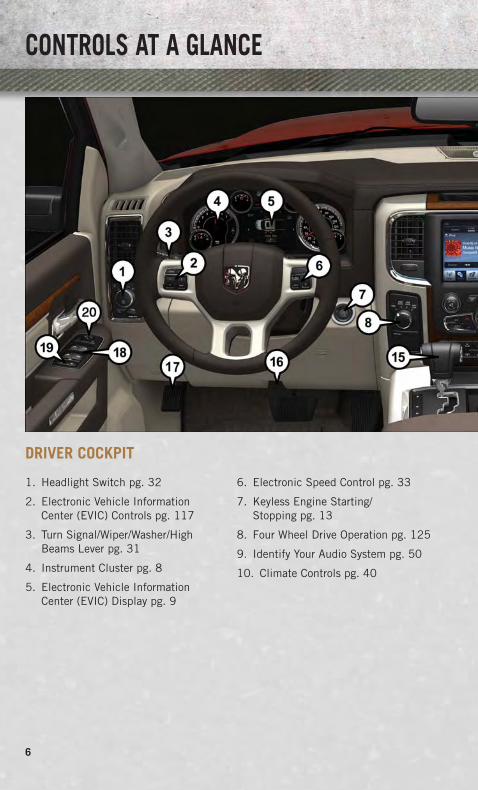
DRIVER COCKPIT
1. Headlight Switch pg. 32
2. Electronic Vehicle InformationCenter (EVIC) Controls pg. 117
3. Turn Signal/Wiper/Washer/HighBeams Lever pg. 31
4. Instrument Cluster pg. 8
5. Electronic Vehicle InformationCenter (EVIC) Display pg. 9
6. Electronic Speed Control pg. 33
7. Keyless Engine Starting/Stopping pg. 13
8. Four Wheel Drive Operation pg. 125
9. Identify Your Audio System pg. 50
10. Climate Controls pg. 40
CONTROLS AT A GLANCE
6

11. Switch Panel
• Diesel Exhaust Brake
• Tow/Haul pg. 137
• Electronic Stability Control pg. 166
• Air Suspension System
• ParkSense® Rear Park Assist pg. 43
• Tire Pressure Monitoring System(TPMS) pg. 166
• Front Heated Seats pg. 26
• Front Ventilated Seats pg. 27
• Heated Steering Wheel pg. 28
• Integrated Trailer BrakeModule pg. 137
• Engine Stop Start
12. Power Inverter Outlet pg. 122
13. Glove Compartment
14. Power Outlet
15. Shifter
16. Hood Release (below steeringwheel at base of instrumentpanel) pg. 195
17. Parking Brake Release
18. Power Windows
19. Power Door Locks
20. Power Mirrors
CONTROLS AT A GLANCE
7
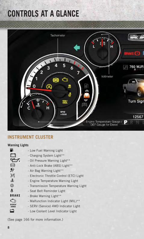
INSTRUMENT CLUSTER
Warning Lights
- Low Fuel Warning Light
- Charging System Light**
- Oil Pressure Warning Light**
- Anti-Lock Brake (ABS) Light**
- Air Bag Warning Light**
- Electronic Throttle Control (ETC) Light
- Engine Temperature Warning Light
- Transmission Temperature Warning Light
- Seat Belt Reminder LightBRAKE - Brake Warning Light**
- Malfunction Indicator Light (MIL)**
- SERV (Service) 4WD Indicator Light
- Low Coolant Level Indicator Light
(See page 166 for more information.)
CONTROLS AT A GLANCE
8

Indicators
- Turn Signal Indicators- High Beam Indicator- Park/Headlight ON
Indicator*- Front Fog Light Indicator- Vehicle Security Indicator*- TOW/HAUL Indicator*- Four-Wheel Drive LOW
Mode Indicator- Four-Wheel Drive and
4LOCK Mode Indicator- 4WD Auto Indicator
- Electronic Stability Control(ESC) Indicator Light*
- Electronic Stability Control(ESC) Off Indicator
- Cargo Lamp On Indicator- Door Ajar Indicator- Electronic Speed Control
Set Indicator- Check Fuel Filler
* If equipped** Bulb Check with Key On
EVIC Messages
NOTE:Refer to Electronic Vehicle Information Center (EVIC) in this guide or your ownersmanual for additional information.
CONTROLS AT A GLANCE
9

KEY FOB• This feature allows the driver to oper-
ate the ignition switch with the push ofa button, as long as the Remote Key-less Entry (RKE) transmitter is in thepassenger compartment.
• The Keyless Ignition Node (KIN) hasfour operating positions, three ofwhich are labeled and will illuminatewhen in position. The three positionsare OFF, ACC, and ON/RUN. The fourthposition is START, during start, RUNwill illuminate.
NOTE:In case the ignition switch does not changewith the push of a button, the RKE trans-mitter (Key Fob) may have a low or deadbattery. In this situation a back up methodcan be used to operate the ignition switch.Put the nose side (side opposite of theemergency key) of the Key Fob against theENGINE START/STOP button and push tooperate the ignition switch.
• The Ignition Node Module (IGNM) op-erates similar to an ignition switch. Ithas four operating positions, three withdetents and one that is spring-loaded.The detent positions are OFF, ACC, andON/RUN. The START position is aspring-loaded momentary contact po-sition. When released from the STARTposition, the switch automatically re-turns to the ON/RUN position.
Locking And Unlocking The Doors
• Press and release the UNLOCK buttonon the RKE transmitter once to unlockthe driver’s door. Press the unlock but-ton twice within five seconds to unlockall doors, the tailgate and the Ram-Box® (if equipped). The turn signallights will flash to acknowledge theunlock signal. The illuminated entrysystem will also turn on.
1 — Air Suspension 4 — RemoteStart2 — Unlock5 — Panic3 — Lock
1 — Lock 4 — EmergencyKey Release2 — Unlock5— EmergencyKey
3 — Remote Start
GETTING STARTED
10

NOTE:The EVIC can be setup for driver door first, otherwise this will unlock all doors.
• All doors can be programmed to unlock on the first press of the UNLOCK button.Refer to Programmable Features in this guide.
Panic Alarm
• Press the PANIC button once to turn the panic alarm on.
• Wait approximately three seconds and press the button a second time to turn thepanic alarm off.
RKE Air Suspension (Remote Lowering Of Vehicle) — If Equippedx2
• This vehicle is equipped with a feature that can lower the vehicle to a height whichwill improve ease of passenger entry/exit and cargo loading/unloading. The featureis accessed by pressing the air suspension lowering button twice on the key fob.
• When remote key fob lowering is requested the vehicle will send a series of chirpsand flashes to alert the customer that the operation has begun and will continuethese alerts until it successfully lowers.
• If the feature is unable to lower the vehicle due to certain conditions not beingmet, the horn will chirp twice and the vehicle will not lower.
Emergency Key
• Should the battery in the vehicle or the Key Fob transmitter go dead, there is anemergency key located in the Key Fob that can be used for locking and unlockingthe doors. To remove the emergency key, slide the button at the top of the Key Fobsideways with your thumb and then pull the key out with your other hand.
WARNING!
• Never leave children alone in a vehicle, or with access to an unlocked vehicle.Allowing children to be in a vehicle unattended is dangerous for a number ofreasons. A child or others could be severely injured or killed. Children shouldbe warned not to touch the parking brake, brake pedal, or the shift lever. Do notleave the Key Fob in or near the vehicle, or in a location accessible to children,and do not leave the ignition of a vehicle equipped with Keyless Enter-N-G0™in the ACC or ON/RUN mode. A child could start the vehicle, operate powerwindows, other controls, or move the vehicle.
• Do not leave children or animals inside parked vehicles in hot weather. Interiorheat build-up may cause them to be severely injured or killed.
GETTING STARTED
11

KEYLESS ENTER-N-GO™• The Keyless Enter-N-Go™ system is an enhancement to the vehicle's Key Fob.
This feature allows you to lock and unlock the vehicle's door(s) without having topress the Key Fob lock or unlock buttons, as well as starting and stopping thevehicle with the press of a button.
To Unlock From The Driver or Passenger Side:
• With a valid Keyless Enter-N-Go™ KeyFob located outside the vehicle andwithin 5 ft (1.5m) of the driver orpassenger side door handle, grab ei-ther front door handle to unlock thedoor automatically.
To Lock The Vehicle’s Doors
• With a valid Keyless Enter-N-Go™ KeyFob transmitter within 5 ft (1.5 m) ofthe driver or passenger front doorhandles, press the door handle LOCKbutton to lock all doors.
• DO NOT grab the door handle, when pressing the door handle lock button.This could unlock the door(s).
NOTE:
• After pressing the door handle LOCK button, you must wait two seconds beforeyou can lock or unlock the doors, using either Passive Entry door handle. This isdone to allow you to check if the vehicle is locked by pulling the door handlewithout the vehicle reacting and unlocking.
• The Passive Entry system will not operate if the RKE transmitter battery is dead.
The vehicle doors can also be locked by using the RKE transmitter lock button or thelock button located on the vehicles interior door panel.
GETTING STARTED
12

Engine Starting/Stopping
Starting
• With a valid Keyless Enter-N-Go™ KeyFob inside the vehicle.
• Shift the transmission into PARK orNEUTRAL.
• While pressing the brake pedal, pressthe ENGINE START/STOP button once.If the engine fails to start, the starter willdisengage automatically after 10 sec-onds.
• To stop the cranking of the engineprior to the engine starting, press the button again.
NOTE:In case the ignition switch does not change with the push of a button, the RKEtransmitter (Key Fob) may have a low or dead battery. In this situation a back upmethod can be used to operate the ignition switch. Put the nose side of the Key Fob(side opposite of the Emergency Key) against the ENGINE START/STOP button andpush to operate the ignition switch.
Stopping
• Bring the vehicle to a complete stop.
• Shift the transmission to PARK (P).
• Press the ENGINE START/STOP button once. The ignition switch will return to theOFF position.
NOTE:If the transmission is not in PARK and the vehicle is in motion, the ENGINE START/STOPbutton must be held for two seconds with the vehicle speed above 5 mph (8 km/h) beforethe engine will shut off.
REMOTE START• Press the REMOTE START button x2 on the Key Fob twice within five seconds.
Pressing the REMOTE START x2 button a third time shuts the engine off.
• To drive the vehicle, press the UNLOCK button, insert the Key Fob in the ignitionand turn to the ON/RUN position.
• With remote start, the engine will only run for 15 minutes (timeout) unless theignition Key Fob is placed in the ON/RUN position.
• The vehicle must be started with the Key Fob after two consecutive timeouts.
GETTING STARTED
13
WARNING!
• Do not start or run an engine in a closed garage or confined area. Exhaust gascontains Carbon Monoxide (CO) which is odorless and colorless. CarbonMonoxide is poisonous and can cause you or others to be severely injured orkilled when inhaled.
• Keep Key Fob transmitters away from children. Operation of the Remote StartSystem, windows, door locks or other controls could cause you and others to beseverely injured or killed.
SECURITY ALARM
To Arm:
• Lock the door using either the power door lock switch (one door must be open) orthe LOCK button on the Remote Keyless Entry (RKE) transmitter (doors can beopen or closed), and close all doors.
NOTE:The Vehicle Security Alarm will not arm if you lock the doors with the manual doorlock plungers.
• The Vehicle Security Light in the instrument cluster will flash for 16 seconds. Thisshows that the Vehicle Security Alarm is arming. During this period, if a door isopened, the ignition is cycled to ON/RUN, or the power door locks are unlocked inany manner, the Vehicle Security Alarm will automatically disarm.
NOTE:
• During the 16-second arming period, if a door is opened or the ignition is cycledto ON/RUN, the Vehicle Security Alarm will automatically disarm.
• Once armed, the Vehicle Security Alarm disables the unlock switch on the driverdoor trim panel and passenger door trim panel.
To Disarm The System:
• Press the Key Fob UNLOCK button or cycle the ignition to the ON/START position.
• The Vehicle Security Alarm is designed to protect your vehicle; however, you cancreate conditions where the Vehicle Security Alarm will give you a false alarm.If one of the previously described arming sequences has occurred, the VehicleSecurity Alarm will arm regardless of whether you are in the vehicle or not. If youremain in the vehicle and open a door, the alarm will sound. If this occurs, disarmthe Vehicle Security Alarm.
• If the Vehicle Security Alarm is armed and the battery becomes disconnected theVehicle Security Alarm will remain armed when the battery is reconnected.The exterior lights will flash, and the horn will sound. If this occurs, disarm theVehicle Security Alarm.
GETTING STARTED
14

SEAT BELT• Be sure everyone in your vehicle is in a seat and using a seat belt properly.
• Position the lap belt across your thighs, below your abdomen. To remove slack inthe lap portion, pull up a bit on the shoulder belt. To loosen the lap belt if it is tootight, tilt the latch plate and pull on the lap belt. A snug belt reduces the risk ofsliding under the belt in a collision.
• Position the shoulder belt on your chest so that it is comfortable and not restingon your neck. The retractor will withdraw any slack in the belt.
• A shoulder belt placed behind you will not protect you from injury during acollision. You are more likely to hit your head in a collision if you do not wear yourshoulder belt. The lap and shoulder belt are meant to be used together.
• A belt that is too loose will not protect you properly. In a sudden stop you couldmove too far forward, increasing the possibility of injury. Wear your seat beltsnugly.
• A frayed or torn belt could rip apart in a collision and leave you with no protection.Inspect the belt system periodically, checking for cuts, frays, or loose parts.Damaged parts must be replaced immediately. Do not disassemble or modify thesystem. Seat belt assemblies must be replaced after a collision if they have beendamaged (bent retractor, torn webbing, etc.).
• The seat belts for both front seating positions are equipped with pretensioningdevices that are designed to remove slack from the seat belt in the event of acollision.
• A deployed pretensioner or a deployed air bag must be replaced immediately.
NOTE:When the ignition switch is first turned to the ON/RUN position, this light will turn onfor four to eight seconds as a bulb check. During the bulb check, if the driver's seatbelt is unbuckled, a chime will sound. After the bulb check or when driving, if thedriver or front passenger seat belt remains unbuckled, the Seat Belt Indicator Lightwill flash or remain on continuously.
WARNING!
In a collision, you and your passengers can suffer much greater injuries if you arenot buckled up properly. You can strike the interior of your vehicle or otherpassengers, or you can be thrown out of the vehicle. Always be sure you and othersin your vehicle are buckled up properly.
GETTING STARTED
15
SUPPLEMENTAL RESTRAINT SYSTEM (SRS) — AIR BAGS• This vehicle has Advanced Front Air Bags for both the driver and right front
passenger as a supplement to the seat belt restraint system. The Advanced FrontAir Bags will not deploy in every type of collision.
• Advanced Front Air Bags are designed to provide additional protection bysupplementing the seat belts in certain frontal collisions depending on severalfactors, including the severity and type of collision. Advanced Front Air Bags arenot expected to reduce the risk of injury in rear, side, or rollover collisions.
• This vehicle may be equipped with Supplemental Side Air Bag Inflatable Curtainsto protect the driver, front and rear passengers sitting next to a window.
• This vehicle is equipped with Supplemental Seat-Mounted Side Air Bags toprovide enhanced protection to help protect an occupant during a side impact.
• If the Air Bag Warning Light is not on during starting, stays on, or turns on whiledriving, have the vehicle serviced by an authorized service center immediately.
• Refer to the Owner's Manual on the DVD for further details regarding theSupplemental Restraint System (SRS).
WARNING!
• Relying on the air bags alone could lead to more severe injuries in a collision.The air bags work with your seat belt to restrain you properly. In somecollisions, the air bags won't deploy at all. Always wear your seat belts eventhough you have air bags.
• Being too close to the steering wheel or instrument panel during AdvancedFront Air Bag deployment could cause serious injury, including death. Air bagsneed room to inflate. Sit back, comfortably extending your arms to reach thesteering wheel or instrument panel.
• Supplemental Side Air Bag Inflatable Curtains and Supplemental Seat-Mounted Side Air Bags need room to inflate. Do not lean against the door orwindow. Sit upright in the center of the seat.
• Being too close to the Supplemental Side Air Bag Inflatable Curtain and/orSeat-Mounted Side Air Bag during deployment could cause you to be severelyinjured or killed.
• Do not drive your vehicle after the air bags have deployed. If you are involvedin another collision, the air bags will not be in place to protect you.
• After any collision, the vehicle should be taken to an authorized dealerimmediately.
GETTING STARTED
16

CHILD RESTRAINTS• Children 12 years or younger should ride properly buckled up in a rear seat, if
available. According to crash statistics, children are safer when properly restrainedin the rear seats rather than in the front.
• Every state in the United States and all Canadian provinces require that smallchildren ride in proper restraint systems. This is the law, and you can beprosecuted for ignoring it.
NOTE:
• For additional information, refer to www.seatcheck.org or call 1–866–SEATCHECK(1–866–732–8243).
• Canadian residents, should refer to Transport Canada’s website for additional informa-tion: http://www.tc.gc.ca/eng/roadsafety/safedrivers-childsafety-index-53.htm
LATCH — Lower Anchors And Tethers For CHildren (Crew/Quad Cab Full Bench Seat)
• Your vehicle is equipped with the child restraint anchorage system called LATCH,which stands for Lower Anchors and Tethers for CHildren.
• The rear outboard seating positions have lower anchors and top tether anchors.The rear center seating position has a top tether anchor only.
LATCH — Lower Anchors And Tethers For CHildren (Crew/Quad Cab Split Bench Seat)
• Your vehicle is equipped with the child restraint anchorage system called LATCH,which stands for Lower Anchors and Tethers for CHildren.
• All rear seating positions have lower anchors and top tether anchors.
Crew/Quad Full Bench Seat Or Split Bench Seat
• You may use the LATCH anchorage system until the combined weight of the childand the child restraint is 65 lbs (29.5 kg). Use the seat belt and tether anchorinstead of the LATCH system once the combined weight is more than 65 lbs(29.5 kg).
Standard Cab Or Mega Cab
• You may use the LATCH anchorage system until the combined weight of the childand the child restraint is 65 lbs (29.5 kg). Use the seat belt alone instead of theLATCH anchorage system once the combined weight is more than 65 lbs (29.5 kg).
GETTING STARTED
17
Crew/Mega/Quad Cab Full Or Split Bench Seat
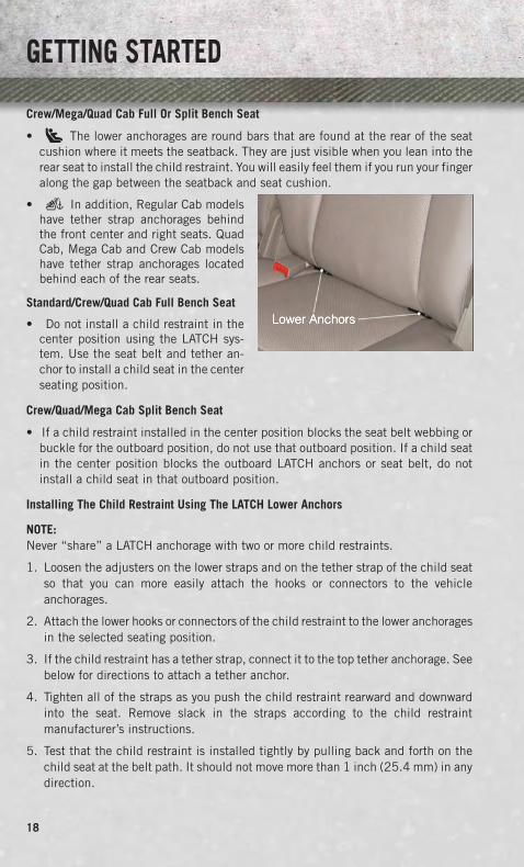
• The lower anchorages are round bars that are found at the rear of the seatcushion where it meets the seatback. They are just visible when you lean into therear seat to install the child restraint. You will easily feel them if you run your fingeralong the gap between the seatback and seat cushion.
• In addition, Regular Cab modelshave tether strap anchorages behindthe front center and right seats. QuadCab, Mega Cab and Crew Cab modelshave tether strap anchorages locatedbehind each of the rear seats.
Standard/Crew/Quad Cab Full Bench Seat
• Do not install a child restraint in thecenter position using the LATCH sys-tem. Use the seat belt and tether an-chor to install a child seat in the centerseating position.
Crew/Quad/Mega Cab Split Bench Seat
• If a child restraint installed in the center position blocks the seat belt webbing orbuckle for the outboard position, do not use that outboard position. If a child seatin the center position blocks the outboard LATCH anchors or seat belt, do notinstall a child seat in that outboard position.
Installing The Child Restraint Using The LATCH Lower Anchors
NOTE:Never “share” a LATCH anchorage with two or more child restraints.
1. Loosen the adjusters on the lower straps and on the tether strap of the child seatso that you can more easily attach the hooks or connectors to the vehicleanchorages.
2. Attach the lower hooks or connectors of the child restraint to the lower anchoragesin the selected seating position.
3. If the child restraint has a tether strap, connect it to the top tether anchorage. Seebelow for directions to attach a tether anchor.
4. Tighten all of the straps as you push the child restraint rearward and downwardinto the seat. Remove slack in the straps according to the child restraintmanufacturer’s instructions.
5. Test that the child restraint is installed tightly by pulling back and forth on thechild seat at the belt path. It should not move more than 1 inch (25.4 mm) in anydirection.
GETTING STARTED
18

Installing The Child Restraints Using The Vehicle Seat Belts (Standard Cab)
• The seat belts in the passenger seating positions are equipped with a SwitchableAutomatic Locking Retractor (ALR) that is designed to keep the lap portion of theseat belt tight around the child restraint. Any seat belt system will loosen withtime, so check the belt occasionally, and pull it tight if necessary.
Installing The Child Restraints Using The Vehicle Seat Belts (Crew/Quad/Mega Cab)
• The seat belts in the outboard passenger seating positions are equipped with aSwitchable Automatic Locking Retractor (ALR). The center seating positions areequipped with a cinching latch plate. Both types of seat belts are designed to keepthe lap portion of the seat belt tight around the child restraint. Any seat belt systemwill loosen with time, so check the belt occasionally, and pull it tight if necessary.
Crew/Quad Cab
• Always use the tether anchor when using the seat belt to install a forward facingchild restraint, up to the recommended weight limit of the child restraint.
Standard/Mega Cab
• The Tether Anchor can be used with the seat belt until the combined weight of thechild and the child restraint is 65 lbs (29.5 kg). Use the seat belt without theTether Anchor once the combined weight is more than 65 lbs (29.5 kg).
To Install A Child Seat Using An ALR:
1. Pull enough of the seat belt webbing from the retractor to pass it through the beltpath of the child restraint. Do not twist the belt webbing in the belt path.
2. Slide the latch plate into the buckle until you hear a “click.”
3. Pull on the webbing to make the lap portion tight against the child seat.
4. To lock the seat belt, pull down on the shoulder part of the belt until you havepulled all the seat belt webbing out of the retractor. Then, allow the webbing toretract back into the retractor. As the webbing retracts, you will hear a clickingsound. This means the seat belt is now in the Automatic Locking mode.
5. Try to pull the webbing out of the retractor. If it is locked, you should not be ableto pull out any webbing. If the retractor is not locked, repeat the last step.
6. Finally, pull up on any extra webbing to tighten the lap portion around the childrestraint while you push the child restraint rearward and downward into thevehicle seat.
7. If the child restraint has a top tether strap and the seating position has a top tetheranchorage, connect the tether strap to the anchorage and tighten the tether strap.See below for directions to attach a tether anchor.
8. Test that the child restraint is installed tightly by pulling back and forth on thechild seat at the belt path. It should not move more than 1 inch (25.4 mm) in anydirection.
GETTING STARTED
19

To Install A Child Seat Using A Cinching Latch Plate:
1. Place the child seat in the center of the seating position.
2. Next, pull enough of the seat belt webbing from the retractor to pass it through thebelt path of the child restraint. Do not twist the belt webbing in the belt path.
3. Slide the latch plate into the buckle until you hear a “click.”
4. Finally, pull up on any excess webbing to tighten the lap portion around the childrestraint while you push the child restraint rearward and downward into thevehicle seat.
5. If the child restraint has a top tether strap and the seating position has a top tetheranchorage, connect the tether strap to the anchorage and tighten the tether strap.See below for directions to attach a tether anchor.
6. Test that the child restraint is installed tightly by pulling back and forth on thechild seat at the belt path. It should not move more than 1 inch (25.4 mm) in anydirection.
Installing The Top Tether Strap (With Either Lower Anchors Or Vehicle Seat Belt):
• When installing a forward-facing child restraint, always secure the top tetherstrap, up to the tether anchor weight limit, whether the child restraint is installedwith the lower anchors or the vehicle seat belt.
Regular And Mega Cab Trucks:
• In the regular cab truck, the top tether anchorages are located behind the centerand right passenger seats. In the mega cab truck, the top tether anchorages arelocated behind each rear seating position. There is a plastic cover over eachanchorage. To attach the tether strap of the child restraint:
1. Place the child restraint on the seat and adjust the tether strap so that it will reachover the seat back, under the head restraint and to the tether anchor directlybehind the seat.
2. Route the tether strap to provide the most direct path between the anchorage andthe child seat. The tether strap should go between the head restraint postsunderneath the head restraint. You may need to adjust the head restraint to theupward position to pass the tether strap underneath the head restraint andbetween its posts.
3. Lift the cover (if so equipped), and attach the hook to the square opening in thesheet metal. Tighten the tether strap according to the child seat manufacturer’sinstructions.
Quad Or Crew Cab Trucks:
• The top tether anchorages in this vehicle are tether strap loops located betweenthe rear glass and the back of the rear seat. There is a tether strap loop locatedbehind each seating position. Follow the steps below to attach the tether strap ofthe child restraint.
GETTING STARTED
20

Right or Left Outboard Seats:
1. Raise the head restraint and reach between the rear seat and rear glass to accessthe tether strap loop.
2. Place a child restraint on the seat and adjust the tether strap so that it will reachover the seat back, under the head restraint, through the tether strap loop behindthe seat and over to the tether strap loop behind the center seat.
3. Pass the tether strap hook under the head restraint behind the child seat, thoughthe tether strap loop behind the seat and over to the center tether strap loop.
Head Restraint In Raised Position Tether Strap Loop With Center HeadRestraint In Raised Position
Tether Strap Through Outboard Tether StrapLoop
GETTING STARTED
21

4. Attach the hook to the center tether strap loop (see diagram). Tighten the tetherstrap according to the child seat manufacturer’s instructions.
NOTE:If there are child seats in both of theoutboard (left and right) seating posi-tions, the tether strap hooks of both childseats should be connected to the centertether strap loop. This is the correct wayto tether two outboard child seats.
Center Seat:
1. Raise the head restraint and reach between the rear seat and rear glass to accessthe tether strap loop
2. Place a child restraint on the seat andadjust the tether strap so that it willreach over the seat back, under thehead restraint, through the tetherstrap loop behind the seat and over tothe tether strap loop behind either theright or left outboard seat.
3. Pass the tether strap hook under thehead restraint behind the child seat,though the tether strap loop behindthe seat and over to the right or leftoutboard tether strap loop.
Tether Strap Through Outboard Tether StrapLoop And Attached To Center Tether Strap
Loop
Tether Strap Loop With Head Restraint InRaised Position
Tether Strap Through Center Tether StrapLoop
GETTING STARTED
22
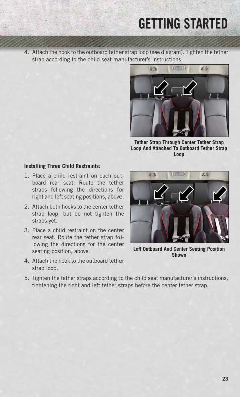
4. Attach the hook to the outboard tether strap loop (see diagram). Tighten the tetherstrap according to the child seat manufacturer’s instructions.
Installing Three Child Restraints:
1. Place a child restraint on each out-board rear seat. Route the tetherstraps following the directions forright and left seating positions, above.
2. Attach both hooks to the center tetherstrap loop, but do not tighten thestraps yet.
3. Place a child restraint on the centerrear seat. Route the tether strap fol-lowing the directions for the centerseating position, above.
4. Attach the hook to the outboard tetherstrap loop.
5. Tighten the tether straps according to the child seat manufacturer’s instructions,tightening the right and left tether straps before the center tether strap.
Tether Strap Through Center Tether StrapLoop And Attached To Outboard Tether Strap
Loop
Left Outboard And Center Seating PositionShown
GETTING STARTED
23

WARNING!
• In a collision, an unrestrained child, even a tiny baby, can become a projectileinside the vehicle. The force required to hold even an infant on your lap couldbecome so great that you could not hold the child, no matter how strong youare. The child and others could be severely injured or killed. Any child riding inyour vehicle should be in a proper restraint for the child's size.
• Rearward-facing child seats must never be used in the front seat of a vehiclewith a front passenger air bag. An air bag deployment could cause severe injuryor death to infants in this position.
• Only use a rearward-facing child restraint in a vehicle with a rear seat.• Improper installation of a child restraint to the LATCH anchorages can lead to
failure of an infant or child restraint. The child could be severely injured orkilled. Follow the manufacturer’s directions exactly when installing an infant orchild restraint.
• An incorrectly anchored tether strap could lead to increased head motion andpossible injury to the child. Use only the anchor positions directly behind thechild seat to secure a child restraint top tether strap.
• If your vehicle is equipped with a split rear seat, make sure the tether strapdoes not slip into the opening between the seatbacks as you remove slack inthe strap.
FRONT SEATS
Power Seats
• The seat switch controls forward/back-ward and up/down.
• The recline switch controls the angleof the seatback. Push switch forwardor rearward and the seatback will movein either direction.
Power Lumbar
• The lumbar controls are located on theoutboard side of the seat cushion. Thelumbar support can be increased bypressing the front of the switch anddecreased by pressing the back of the switch.
GETTING STARTED
24

Memory Seat
• The memory seat feature allows you tosave the driver's seat position (exclud-ing lumbar position), driver's outsidemirror position, adjustable brake andaccelerator pedals, Automatic Tem-perature Control (ATC) temperaturesetting and radio station preset set-tings. The driver's memory buttons arelocated on the outboard side of thedriver's seat cushion.
• Adjust all memory profile settings,press the middle button S (SET), thenpress 1 or 2 within five seconds.
• To program a Key Fob to the memory position, place the ignition switch in theLOCK position and remove the Key Fob, press and release the LOCK button on theKey Fob to be programmed within five seconds of pressing button 1 or 2.
• Press 1 or 2 to recall the saved positions, or press UNLOCK on the programmedKey Fob.
• Refer to the Owner's Manual on the DVD for further details.
Manual Seats
Forward/Rearward
• Lift up on the adjusting bar located atthe front of the seat near the floor andrelease it when the seat is at the de-sired position. Then, using body pres-sure, move forward and backward onthe seat to be sure that the seat adjust-ers have latched.
Recliner
• Lift the recliner lever located on theoutboard side of the seat, lean backand release at the desired position.
CAUTION!
Do not place any article under a power seat or impede its ability to move as it maycause damage to the seat controls. Seat travel may become limited if movementis stopped by an obstruction in the seat’s path.
GETTING STARTED
25

WARNING!
• Adjusting a seat while the vehicle is moving is dangerous. The suddenmovement of the seat could cause you to lose control. The seat belt might notbe properly adjusted, and you could be severely injured or killed. Only adjust aseat while the vehicle is parked.
• Actuating the recliner handle will allow the seatback to swing (dump) forwardon manual recliner seats. Do not stand or lean in front of the seat whileactuating the handle. The seatback may swing forward and hit you, causinginjury. This dump feature allows access to the storage bin behind the seat.To avoid injury, place your hand on the seatback and actuate the handle, thenposition the seatback in the desired position.
• Do not ride with the seatback reclined so that the seat belt is no longer restingagainst your chest. In a collision, you could slide under the seat belt and beseverely injured or killed. Use the recliner only when the vehicle is parked.
HEATED/VENTILATED SEATS
Front Heated Seats
• The controls for the front heated seatsare located on the center instrumentpanel below the climate controls andthere are soft-keys in the radio thatcontrol the front heated seats.
• Press the switch once to select High-level heating. Press the switch a sec-ond time to select Low-level heating.Press the switch a third time to shutthe heating elements Off.
• If the High-level setting is selected,the system will automatically switch toLow-level after approximately 20 min-utes. The Low-level setting will turnOff automatically after approximately40 minutes.
1 – Drivers HeatedSeat Switch
3 – PassengersVentilated SeatSwitch2 – Drivers Venti-
lated Seat Switch 4 – PassengersHeated SeatSwitch
GETTING STARTED
26
Front Ventilated Seats
• Located in the seat cushion are small fans that draw the air from the passengercompartment and pull air through fine perforations in the seat cover to help keepthe driver and front passenger cooler in higher ambient temperatures.
• The ventilated seat switches are located in the switch bank in the center stack ofthe instrument panel just below the climate controls as well as soft-keys in theradio. The fans operate at two speeds, HIGH and LOW. Press the switch once toselect High speed. Press the switch a second time to select Low speed. Press theswitch a third time to turn the fans Off.
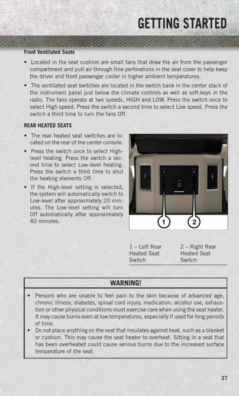
REAR HEATED SEATS
• The rear heated seat switches are lo-cated on the rear of the center console.
• Press the switch once to select High-level heating. Press the switch a sec-ond time to select Low-level heating.Press the switch a third time to shutthe heating elements Off.
• If the High-level setting is selected,the system will automatically switch toLow-level after approximately 20 min-utes. The Low-level setting will turnOff automatically after approximately40 minutes.
WARNING!
• Persons who are unable to feel pain to the skin because of advanced age,chronic illness, diabetes, spinal cord injury, medication, alcohol use, exhaus-tion or other physical conditions must exercise care when using the seat heater.It may cause burns even at low temperatures, especially if used for long periodsof time.
• Do not place anything on the seat that insulates against heat, such as a blanketor cushion. This may cause the seat heater to overheat. Sitting in a seat thathas been overheated could cause serious burns due to the increased surfacetemperature of the seat.
1 – Left RearHeated SeatSwitch
2 – Right RearHeated SeatSwitch
GETTING STARTED
27

HEATED STEERING WHEEL• The steering wheel contains a heating
element that heats the steering wheelto one temperature setting.
• The heated steering wheel switch islocated on the center instrument panelbelow the climate controls.
• The heated steering wheel is also con-trolled by soft-keys in the radio screen.
• Press the switch once to turn the heat-ing element On. Press the switch a sec-ond time to turn the heating elementOff.
• Once the heated steering wheel hasbeen turned on, it will operate for ap-proximately 30 to 95 minutes beforeautomatically shutting off. The heatedsteering wheel can shut off early ormay not turn on when the steeringwheel is already warm.
1 – Heated Steering Wheel Switch
GETTING STARTED
28

TILT STEERING COLUMN• The tilt lever is located on the steering
column below the turn signal lever.
• To tilt the column, simply pull the tiltlever rearward toward you and thenmove the steering wheel upward ordownward as desired.
• Release the tilt lever to lock the steer-ing wheel into position.
ADJUSTABLE PEDALS
• Press the switch located on the leftside of the steering column forward tomove the brake and accelerator pedalsaway from the driver and press theswitch rearward to move the pedalscloser to the driver.
NOTE:The pedals cannot be adjusted when the vehicle is in REVERSE or when theElectronic Speed Control is set.
CAUTION!
Do not place any article under the adjustable pedals or impede its ability to move,as it may cause damage to the pedal controls. Pedal travel may become limited ifmovement is stopped by an obstruction in the adjustable pedal's path.
WARNING!
• Tilting the steering column while the vehicle is moving is dangerous. Withouta stable steering column, you could lose control of the vehicle and have acollision. Adjust the column only while the vehicle is stopped. Be sure it islocked before driving.
• Do not adjust the pedals while the vehicle is moving. You could lose control andhave a collision. Always adjust the pedals while the vehicle is parked.
GETTING STARTED
29

ENGINE BREAK-IN RECOMMENDATIONS• A long break-in period is not required for the engine and drivetrain (transmission
and axle) in your vehicle.
• Drive moderately during the first 300 miles (500 km). After the initial 60 miles(100 km), speeds up to 50 or 55 mph (80 or 90 km/h) are desirable.
• While cruising, brief full-throttle acceleration within the limits of local traffic lawscontributes to a good break-in. Wide-open throttle acceleration in low gear can bedetrimental and should be avoided.
• The engine oil installed in the engine at the factory is a high-quality energyconserving type lubricant. Oil changes should be consistent with anticipatedclimate conditions under which vehicle operations will occur. For the recom-mended viscosity and quality grades, refer to “Maintaining Your Vehicle”.
NOTE:A new engine may consume some oil during its first few thousand miles (kilometers)of operation. This should be considered a normal part of the break-in and notinterpreted as an indication to an engine problem or malfunction.
CAUTION!
Never use Non-Detergent Oil or Straight Mineral Oil in the engine or damage mayresult.
DIESEL ENGINE BREAK-IN RECOMMENDATIONS
• For 3.0L diesel engine break-in recommendations, refer to Diesel Engine Break-InRecommendations on pg. 144
• For 6.7L Cummins diesel engine break-in recommendations, refer to DieselEngine Break-In Recommendations on pg. 153
OPERATING YOUR VEHICLE
30

TURN SIGNALS/WIPER/WASHER/HIGH BEAMS LEVER
Turn Signals/Lane Change Assist
• Tap the lever up or down once and the turn signal (right or left) will flash threetimes and automatically turn off.
Wipers
Intermittent, Low And High Operation
• Rotate the end of the lever to the first detent position for one of five intermittentsettings, the second detent for low wiper operation and the third detent for highwiper operation.
Washer Operation
• Push the end of the lever inward to the second detent and hold for as long as sprayis desired.
Mist Feature
• When a single wipe to clear off road mist or spray from a passing vehicle is needed,push the washer knob, located on the end of the multifunction lever, inward to thefirst detent and release. The wipers will cycle one time and automatically shut off.
High Beams
• Push the lever away from you to activate the high beams.
• A high beam symbol will illuminate in the cluster to indicate the high beams are on.
NOTE:For safe driving, turn off the high beams when oncoming traffic is present to preventheadlight glare and as a courtesy to other motorists.
OPERATING YOUR VEHICLE
31

HEADLIGHT SWITCH
Automatic Headlights/ParkingLights/Headlights
• Rotate the headlight switch, locatedon the instrument panel to the left ofthe steering wheel, to the first detent
for parking lights and to thesecond detent for headlights .
• With the parking lights or low beamheadlights on, push the headlightswitch once for fog lights.
• Rotate the headlight switch to “AUTO”for AUTO headlights.
• When set to AUTO, the system auto-matically turns the headlights on or offbased on ambient light levels.
Automatic High Beams
• The Automatic High Beams system provides increased forward lighting at night byautomating high beam control through the use of a digital camera mounted on theinside rearview mirror. This camera detects vehicle specific light and automati-cally switches from high beams to low beams until the approaching vehicle is outof view. Refer to Programmable Features in Electronics for further details.
Instrument Panel Dimmer
• Rotate the dimmer control to the extreme left position to fully dim the instrumentpanel lights and prevent the interior lights from illuminating when a door is opened.
• Rotate the dimmer control right to increase the brightness of the instrument panelwhen the parking lights or headlights are on.
• Rotate the dimmer control right to the next detent position to fully brighten theodometer and radio when the parking lights or headlights are on. Refer to yourMedia Center/Radio User Manual on the DVD for display dimming.
• Rotate the dimmer control right to the last detent position to turn on the interiorlighting.
Cargo Light
• The cargo light is strategically placed lighting that helps illuminate the bed areaof the truck. A cargo light symbol will illuminate in the cluster to indicate the lightis on.
• Push the button to turn ON/OFF the cargo lighting.
OPERATING YOUR VEHICLE
32

SPEED CONTROL
• The Speed Control switches are located on the steering wheel.
Cruise ON/OFF
• Push the ON/OFF switch to activate the Speed Control.
• The cruise symbol will appear on the instrument cluster to indicate the SpeedControl is on.
• Push the ON/OFF switch a second time to turn the system off.
Set
• With the Speed Control on, push and release the SET/DECEL switch to set adesired speed.
Accel/Decel
• Push and hold the RESUME/ACCEL switch to accelerate or push and hold theSET/DECEL switch to decelerate the vehicle; release the switch to save the new setspeed.
• Once a speed is set, pushing the RESUME/ACCEL switch once or the SET/DECELswitch once will increase or decrease the set speed approximately 1 mph (2 km/h).
Resume
• To resume a previously selected set speed in memory, push the RESUME/ACCELswitch and release.
OPERATING YOUR VEHICLE
33
Cancel
• Push the CANCEL switch or apply the brakes to cancel the set speed and maintainthe set speed memory.
• Push the ON/OFF switch to turn the system off and erase the set speed memory.
WARNING!
• Leaving the Electronic Speed Control system on when not in use is dangerous.You could accidentally set the system or cause it to go faster than you want. Youcould lose control and have a collision. Always leave the Electronic SpeedControl system off when you are not using it.
• Electronic Speed Control can be dangerous where the system cannot maintaina constant speed. Your vehicle could go too fast for the conditions, and youcould lose control. A collision could be the result. Do not use Electronic SpeedControl in heavy traffic or on roads that are winding, icy, snow-covered orslippery.
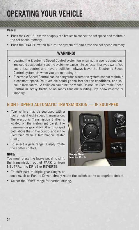
EIGHT–SPEED AUTOMATIC TRANSMISSION — IF EQUIPPED• Your vehicle may be equipped with a
fuel efficient eight-speed transmission.The electronic Transmission Shifter islocated on the instrument panel. Thetransmission gear (PRND) is displayedboth above the shifter control and in theElectronic Vehicle Information Center(EVIC).
• To select a gear range, simply rotatethe shifter control.
NOTE:You must press the brake pedal to shiftthe transmission out of PARK or fromNEUTRAL into DRIVE or REVERSE.
• To shift past multiple gear ranges atonce (such as Park to Drive), simply rotate the switch to the appropriate detent.
• Select the DRIVE range for normal driving.
OPERATING YOUR VEHICLE
34

ELECTRONIC RANGE SELECT (ERS) OPERATION• Electronic Range Select (ERS) allows
you to limit the highest available trans-mission gear, and can be activatedduring any driving condition. Whentowing a trailer or operating the vehiclein off-road conditions, using ERS shiftcontrol will help you maximize bothperformance and engine braking.
OPERATING YOUR VEHICLE
35

• Move the console shift lever left (-) or right (+), or toggle the switch on the columnshift lever down (-) or up (+) to select the desired top gear.
• For maximum deceleration (engine braking) move the console shift lever left (-)and hold, or toggle the switch on the column shift lever down (-) and hold. Yourvehicle will automatically select the lowest safe gear for optimal engine braking.
• To disable ERS, push and hold the console shift lever to the right (+) or push andhold the column shift lever switch up (+) until “D” is displayed in the odometer.
• Switching between ERS and DRIVE mode can be done at any vehicle speed.
• Refer to your Owner's Manual on the DVD for further details.
ELECTRONIC RANGE SELECT (ERS) OPERATION – 8 SPEED TRANSMISSION
• The Electronic Range Select (ERS)shift control allows the driver to limitthe highest available gear when thetransmission shifter switch is in theDRIVE position
• You can switch between DRIVE andERS mode at any vehicle speed.
• Tapping the ERS (-) switch (on thesteering wheel) will activate ERS mode.
• Once in ERS mode, tapping the ERS(-) or (+) switch will change the topavailable gear.
• To exit ERS mode, simply press andhold the ERS (+) switch until “D” isonce again displayed in the transmis-sion gear position indicator in the instrument cluster.
OPERATING YOUR VEHICLE
36

1500 AIR SUSPENSION SYSTEM• The air suspension system provides full time load leveling capability along with
the benefit of being able to adjust vehicle height by the push of a button.
• Automatic height changes will occur based on vehicle speed and the currentvehicle height. The indicator lamps and EVIC messages will operate the same forautomatic changes and user requested changes.
Description
• Normal Ride Height (NRH) - This is thestandard position of the suspensionand is meant for normal driving.
• Off-Road 1 (OR1) (Raises the vehicleapproximately 1 in (26 mm) - This posi-tion should be the primary position forall off-road driving until Off Road 2(OR2) is needed. A smoother and morecomfortable ride will result. To enterOR1, press the “Up” button once fromthe NRH position while the vehicle speed is below 35 mph (56 km/h). When in theOR1 position, if the vehicle speed remains between 40 mph (64 km/h) and50 mph (80 km/h) for greater than 20 seconds or if the vehicle speed exceeds50 mph (80 km/h), the vehicle will be automatically lowered to NRH. Off-Road 1may not be available due to vehicle payload, an EVIC message will be displayedwhen this occurs. Refer to “Electronic Vehicle Information Center (EVIC)” in“Understanding Your Instrument Panel” for further information.
• Off-Road 2 (OR2) (Raises the vehicle approximately 2 in (51 mm) - This position isintended for off-roading use only where maximum ground clearance is required.To enter OR2, press the “Up” button twice from the NRH position or once from theOR1 position while vehicle speed is below 20 mph (32 km/h). While in OR2, if thevehicle speed exceeds 25 mph (40 km/h) the vehicle height will be automaticallylowered to OR1. Off-Road 2 may not be available due to vehicle payload, an EVICmessage will be displayed when this occurs. Refer to “Electronic Vehicle Informa-tion Center (EVIC)” in “Understanding Your Instrument Panel” for further infor-mation.
• Aero Mode (Lowers the vehicle approximately .6 in (15 mm) – 1500 Models Only - Thisposition provides improved aerodynamics by lowering the vehicle. The vehicle willautomatically enter Aero Mode when the vehicle speed remains between 62 mph(100 km/h) and 66 mph (106 km/h) for greater than 20 seconds or if the vehiclespeed exceeds 66 mph (106 km/h). The vehicle will return to NRH from Aero Modeif the vehicle speed remains between 30 mph (48 km/h) and 35 mph (56 km/h) forgreater than 20 seconds or if the vehicle speed falls below 30 mph (48 km/h).
OPERATING YOUR VEHICLE
37

NOTE:Automatic Aero Mode may be disabled through vehicle settings in the ElectronicVehicle Information Center (EVIC) when equipped with Uconnect 3.0, or yourUconnect® Radio when equipped with UConnect® 5.0, 8.4A, or 8.4AN.
• Entry/Exit Mode (Lowers the vehicle approximately 2 in (51 mm) - This position lowersthe vehicle for easier passenger entry and exit as well as lowering the rear of thevehicle for easier loading and unloading of cargo. To enter Entry/Exit Mode, pressthe “Down” button once from the NHR while the vehicle speed is below 33 mph(53 km/h). Once the vehicle speed goes below 15 mph (24 km/h) the vehicleheight will begin to lower. If the vehicle speed remains between 15 mph (24 km/h)and 25 mph (40 km/h) for greater than 60 seconds, or the vehicle speed exceeds25 mph (40 km/h) the Entry/Exit change will be cancelled. To return to NormalHeight Mode, press the “Up” button once while in Entry/Exit or drive the vehicleover 15 mph (24 km/h). Entry/Exit mode may not be available due to vehiclepayload, an EVIC message will be displayed when this occurs. Refer to "ElectronicVehicle Information Center (EVIC)" in "Understanding Your Instrument Panel" forfurther information.
• Refer to your Owner’s Manual on the DVD for further details.
Air Suspension Modes
• The Air Suspension system has multiple modes to protect the system in uniquesituations:
Tire Jack Mode
• To assist with changing a spare tire, the air suspension system has a feature whichallows the automatic leveling to be disabled. Refer to “Electronic Vehicle Infor-mation Center (EVIC)” in “Understanding Your Instrument Panel” for furtherinformation.
NOTE:This mode is intended to be enabled with engine running.
Transport Mode
• To assist with flat bed towing, the air suspension system has a feature which willput the vehicle into Entry/Exit height and disable the automatic load levelingsystem. Refer to “Electronic Vehicle Information Center (EVIC)” in “Understand-ing Your Instrument Panel” for further information.
NOTE:This mode is intended to be enabled with engine running.
Wheel Alignment Mode
• Before performing a wheel alignment this mode must be enabled. Refer to“Electronic Vehicle Information Center (EVIC)” in “Understanding Your Instru-ment Panel” for further information.
OPERATING YOUR VEHICLE
38

NOTE:This mode is intended to be enabled with engine running.
Protection Mode
• In order to “protect” the air suspension system, the vehicle will enter ProtectionMode when the payload has been exceeded or load leveling cannot be achieved.Refer to “Electronic Vehicle Information Center (EVIC)” in “Understanding YourInstrument Panel” for further information.
NOTE:This mode is intended to be enabled with engine running.
2500-3500 AIR SUSPENSION SYSTEM• The air suspension system provides full time rear load leveling capability for all
loading conditions including towing.
Description
• Normal Ride Height (NRH) - This is the standard position of the suspension and ismeant for normal driving.
• Trailer Mode (Lowers the vehicle approximately 1 in (25 mm) - This position will lowerthe rear suspension and provide load leveling for all loading conditions includingtowing a trailer. The trailer button will blink continuously until trailer height hasbeen achieved. The system requires that the ignition be in ON/RUN position or theengine running for all user requested changes. After the engine is turned off, itmay be noticed that the air suspension system operates briefly, this is normal.The system is correcting the position of the vehicle to ensure a proper appearance.
• Refer to your Owner’s Manual on the DVD for further details.
Air Suspension Modes
• The Air Suspension system has multiple modes to protect the system in uniquesituations:
Tire Jack Mode
• To assist with changing a spare tire, the air suspension system has a feature whichallows the automatic leveling to be disabled. Refer to “Electronic Vehicle Infor-mation Center (EVIC)” in “Understanding Your Instrument Panel” for furtherinformation.
NOTE:This mode is intended to be enabled with engine running.
Transport Mode
• To assist with flat bed towing, the air suspension system has a feature which willput the vehicle into Entry/Exit height and disable the automatic load levelingsystem. Refer to “Electronic Vehicle Information Center (EVIC)” in “Understand-ing Your Instrument Panel” for further information.
OPERATING YOUR VEHICLE
39
NOTE:This mode is intended to be enabled with engine running.
Wheel Alignment Mode
• Before performing a wheel alignment this mode must be enabled. Refer to“Electronic Vehicle Information Center (EVIC)” in “Understanding Your Instru-ment Panel” for further information.
NOTE:This mode is intended to be enabled with engine running.
Protection Mode
• In order to “protect” the air suspension system, the vehicle will enter ProtectionMode when the payload has been exceeded or load leveling cannot be achieved.Refer to “Electronic Vehicle Information Center (EVIC)” in “Understanding YourInstrument Panel” for further information.
NOTE:This mode is intended to be enabled with engine running.
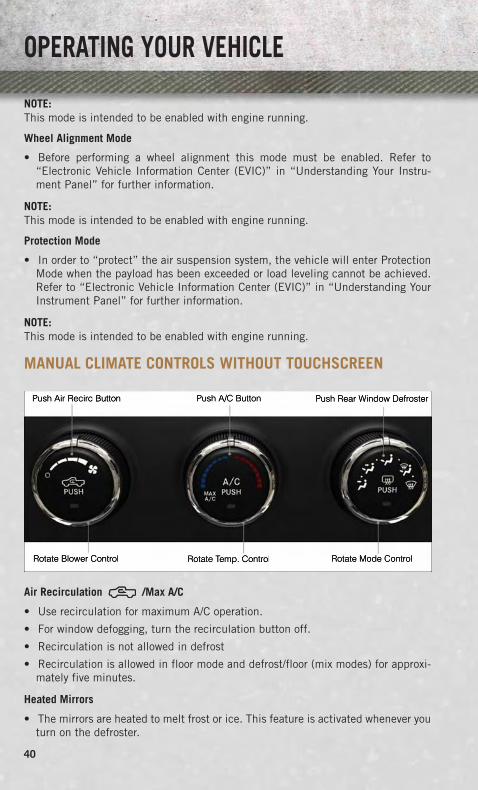
MANUAL CLIMATE CONTROLS WITHOUT TOUCHSCREEN
Air Recirculation /Max A/C
• Use recirculation for maximum A/C operation.
• For window defogging, turn the recirculation button off.
• Recirculation is not allowed in defrost
• Recirculation is allowed in floor mode and defrost/floor (mix modes) for approxi-mately five minutes.
Heated Mirrors
• The mirrors are heated to melt frost or ice. This feature is activated whenever youturn on the defroster.
OPERATING YOUR VEHICLE
40
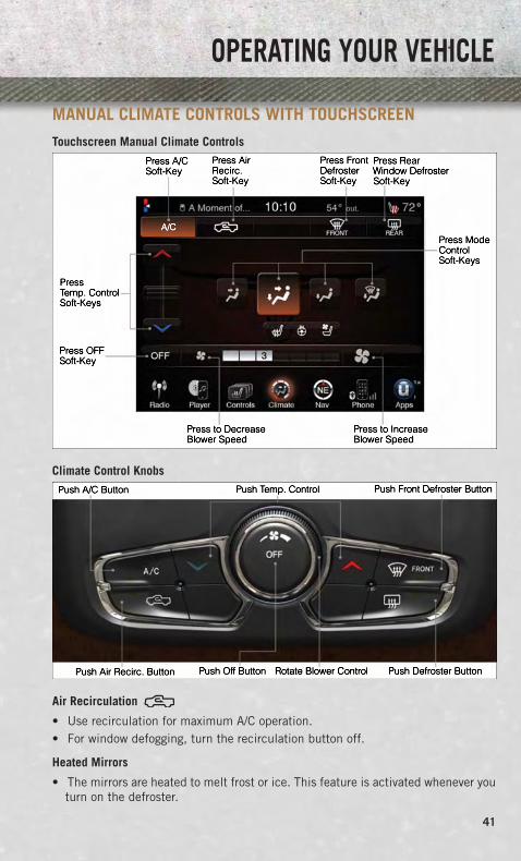
MANUAL CLIMATE CONTROLS WITH TOUCHSCREENTouchscreen Manual Climate Controls
Climate Control Knobs
Air Recirculation
• Use recirculation for maximum A/C operation.• For window defogging, turn the recirculation button off.
Heated Mirrors
• The mirrors are heated to melt frost or ice. This feature is activated whenever youturn on the defroster.
OPERATING YOUR VEHICLE
41

AUTOMATIC CLIMATE CONTROLS WITH TOUCHSCREEN
Touchscreen Automatic Climate Controls
Climate Control Knobs
• Press the AUTO button or AUTO soft-key.
• Select the desired temperature by pushing the up or down temperature buttons forthe driver or passenger.
• The system will maintain the set temperature automatically.
OPERATING YOUR VEHICLE
42

Air Conditioning (A/C)
• If the air conditioning button is pressed while in AUTO mode, the system will exitAUTO mode and stay in A/C. The mode and blower will be set at the closest modeand blower position that the system was operating in AUTO.
SYNC Temperature Soft-Key
• Touch the SYNC soft-key on the Uconnect® radio to control the driver andpassenger temperatures simultaneously. Touch the SYNC soft-key a second time tocontrol the temperatures individually.
Air Recirculation
• Use recirculation for maximum A/C operation.
• For window defogging, turn the recirculation button off.
• If the Recirculation button is pushed while in the AUTO mode, the indicator lightmay flash three times to indicate the cabin air is being controlled automatically.
Heated Mirrors
• The mirrors are heated to melt frost or ice. This feature is activated whenever youturn on the defroster.
PARKSENSE® FRONT AND REAR PARK ASSIST• ParkSense® can be enabled and disabled by pressing the ParkSense® switch
located below the climate controls, on the switch panel.
• The four ParkSense® sensors, located in the rear fascia/bumper, monitor the areabehind the vehicle that is within the sensors’ field of view. The sensors can detectobstacles from approximately 12 in (30 cm) up to 79 in (200 cm) from the rearfascia/bumper in the horizontal direction, depending on the location, type andorientation of the obstacle.
• The six ParkSense® sensors, located in the front fascia/bumper, monitor the areain front of the vehicle that is within the sensors’ field of view. The sensors candetect obstacles from approximately 12 in (30 cm) up to 47 in (120 cm) from thefront fascia/bumper in the horizontal direction, depending on the location, typeand orientation of the obstacle.
• When an object is detected within two meters behind the rear bumper while thevehicle is in REVERSE, a warning will display in the Electronic Vehicle InformationCenter (EVIC) and a chime will sound (when Sound and Display is selected fromthe Customer Programmable Features section of the Uconnect® System screen).As the vehicle moves closer to the object, the chime rate will change from single1/2 second tone (for rear only), to slow (for rear only), to fast, to continuous.
OPERATING YOUR VEHICLE
43

Cleaning The ParkSense® Sensors
• If “CLEAN PARK ASSIST SENSORS” appears in the Electronic Vehicle Informa-tion Center (EVIC), clean the ParkSense® sensors with water, car wash soap and asoft cloth. Do not use rough or hard cloths. Do not scratch or poke the sensors.Otherwise, you could damage the sensors.
NOTE:When the Instrument Cluster reads either Clean Sensor or Blinded, please clean offthe bumper sensors to see if the condition is corrected.
PARKVIEW® REAR BACK-UP CAMERA• You can see an on-screen image of the rear surroundings of your vehicle whenever
the shift lever is put into REVERSE. The ParkView® Rear Back-Up Camera imagewill be displayed in the rearview mirror or touchscreen display along with a cautionnote to “check entire surroundings” across the top of the screen. After five secondsthis note will disappear.
• If the rearview mirror or touchscreen display appears foggy, clean the ParkView®
camera located to the left of the tailgate handle.
WARNING!
Drivers must be careful when backing up; even when using the ParkView® RearBack-Up Camera. Always check carefully behind your vehicle, and be sure tocheck for pedestrians, animals, other vehicles, obstructions, or blind spots beforebacking up. You must continue to pay attention while backing up. Failure to do socan result in serious injury or death.
OPERATING YOUR VEHICLE
44

POWER SLIDING REAR WINDOW• The switch for the power sliding rear
window is located on the overheadconsole.
• Push the switch right to open the glassand pull the switch left to close theglass.
POWER SUNROOF• The power sunroof switch is located on
the overhead console.
Opening Sunroof
Express Open
• Press the switch rearward and releaseit within one-half second. The sunroofwill fully open and stop automatically.
Manual Open
• Press and hold the switch rearward toopen the sunroof. Any release of theswitch will stop the movement, and thesunroof will remain in a partially openposition until the switch is pressedagain.
1 – Opening Sunroof2 – Venting Sunroof3 – Closing Sunroof
OPERATING YOUR VEHICLE
45

Venting Sunroof
• Press and release the button and the sunroof will open to the vent position. Thisis called “Express Vent” and will occur regardless of sunroof position. DuringExpress Vent operation, any movement of the switch will stop the sunroof.
Closing Sunroof
Express Closing
• Press the switch forward and release it within one-half second. The sunroof willfully close automatically from any position.
Manual Closing
• Press and hold the switch forward to close the sunroof. Any release of the switchwill stop the movement, and the sunroof will remain in a partially closed positionuntil the switch is pressed again.
Pinch Protection Feature
• This feature will detect an obstruction in the opening of the sunroof duringExpress Close operation. If an obstruction in the path of the sunroof is detected,the sunroof will automatically retract. Remove the obstruction if this occurs. Next,press the switch forward and release to Express Close.
NOTE:If three consecutive sunroof close attempts result in Pinch Protect reversals, thefourth close attempt will be a Manual Close movement with Pinch Protect disabled.
OPERATING YOUR VEHICLE
46

WARNING!
• Do not let children play with the sunroof. Never leave children unattended in avehicle, or with access to an unlocked vehicle. Do not leave the key fob in ornear the vehicle, and do not leave the ignition of a vehicle equipped withKeyless Enter-N-Go™ in the ACC or ON/RUN mode. Occupants, particularlyunattended children, can become entrapped by the power sunroof whileoperating the power sunroof switch. Such entrapment may result in seriousinjury or death.
• In a collision, there is a greater risk of being thrown from a vehicle with an opensunroof. You could also be severely injured or killed. Always fasten your seatbelt properly and make sure all passengers are properly secured.
• Do not allow small children to operate the sunroof. Never allow your fingers,other body parts, or any object to project through the sunroof opening. Injurymay result.
WIND BUFFETING• Wind buffeting can be described as a helicopter-type percussion sound. If buffeting
occurs with the rear windows open, adjust the front and rear windows together.
• If buffeting occurs with the sunroof open, adjust the sunroof opening, or adjustany window. This will minimize buffeting.
OPERATING YOUR VEHICLE
47

YOUR VEHICLE'S SOUND SYSTEM
1. Uconnect® Phone Button pg. 108
2. Uconnect® Voice Command Button pg. 111
3. Steering Wheel Audio Controls (Left) pg. 116
4. Steering Wheel Audio Controls (Right) pg. 116
5. Volume Knob / Audio Mute Button
6. Assist Button pg. 58
ELECTRONICS
48

7. 9-1-1 Button pg. 58
8. Uconnect® 8.4 Radio pg. 76
9. Screen Off Button
10. Back Button
11. Tune / Scroll Knob / Browse / Enter Button
12. Media Hub: Audio Jack, USB Port, and SD Card Slot (located centerconsole) pg. 81
13. CD Player Inside Center Console (If Equipped) pg. 100
ELECTRONICS
49

IDENTIFYING YOUR RADIOUconnect® 3.0
• Two hard-keys on either side of thedisplay
Uconnect® 5.0
• 5” Touchscreen
• Three hard-keys on either side of thedisplay
Uconnect® 8.4A
• 8.4” Touchscreen
• Climate soft key in lower menu bar
• HD Button will NOT be visible on rightside of screen when viewing AM or FM
• SiriusXM Travel Link feature NOT listedwithin Apps
Uconnect® 3.0
Uconnect® 5.0
Uconnect® 8.4A
ELECTRONICS
50

Uconnect® 8.4AN
• 8.4” Touchscreen
• Climate soft key in lower menu bar
• HD Button will be visible on right sideof screen when viewing AM or FM
• SiriusXM Travel Link feature listedwithin Apps
Uconnect® Access (AVAILABLE ON Uconnect® 8.4A ANDUconnect® 8.4AN) (IF EQUIPPED)• Uconnect® Access enhances your ownership and driving experience by connect-
ing your vehicle with a built-in 3G cellular connection. Uconnect® Accessprovides:• The ability to remotely lock/unlock your doors and start your vehicle from
virtually anywhere, with the Uconnect® Access App, Owner Connect websiteand Uconnect® Care (Vehicle must be within the United States and havenetwork coverage).
• The option to turn your vehicle into a WiFi Hotspot on demand.• Theft Alarm Notification via text or E-mail.• Voice Texting so you can compose, send and receive text messages with your
voice while keeping your hands on the wheel. Requires a cell phone thatsupports Bluetooth Message Access Profile (MAP). iPhone® (iOS) does notsupport Bluetooth Message Access Profile (MAP).
Before you drive, familiarize yourself with the easy-to-use Uconnect® System.
1. The ASSIST and 9-1-1 buttons are located on your rearview mirror. The ASSISTButton is used for contacting Roadside Assistance, Vehicle Care and Uconnect®Care. The 9-1-1 Button connects you directly to emergency assistance.
NOTE:Vehicles sold in Canada and Mexico DO NOT have 9-1-1 Call system capabilities. 9-1-1or other emergency line operators in Canada and Mexico may not answer or respond to9-1-1 system calls.
2. The Uconnect® “Apps” soft-key located in the bottom right corner of the radiotouchscreen is where you should begin the registration process for your included trialof Uconnect® Access. From here, you can also manage your Apps and purchase WiFi.
Uconnect® 8.4AN
ELECTRONICS
51

3. The Uconnect® Voice Command and Uconnect® Phone buttons are located on theleft side of your steering wheel. These buttons allow you to use your voice to makephone calls, send and receive text messages, control your media, enter navigationdestinations and more all without taking your hands off the steering wheel.
Included Trial Period for New Vehicles
• Your new vehicle may come with an included trial period for use of the Uconnect®Access Services starting at the date of vehicle purchase (date based on vehiclesales notification from your dealer). To activate the trial, you must first registerwith Uconnect® Access. Once registered, Uconnect® Access customers canpurchase additional Services and Apps over the lifetime of their vehicle ownership.
Features and Packages
• After the trial period, you can subscribe to continue your service by visiting theUconnect® Store located within the Mopar Owner Connect website (MoparOwner-Connect.com). If you need assistance, U.S. residents can call Uconnect® Care at855-792-4241.
• For the latest information on packages and pricing information: U.S. residentsvisit www.DriveUconnect.com.
Uconnect® Access Registration (U.S. Residents Only)
NOTE:To unlock the full potential of Uconnect® Access in your vehicle, you first need toregister with Uconnect® Access.
1. From the parked vehicle with the radio touchscreen powered on, select the “Apps”soft-key located near the bottom right-hand corner of the radio touchscreen.
NOTE:Should you require assistance anytime during the registration process, simply pressthe ASSIST button located on the rear view mirror to be connected with a Uconnect®Care agent.
2. Press “Register” on the reminder screen or select “Uconnect Registration” underthe “Favorites Tab.”
3. The Uconnect® Access Registration App will open and display step-by-stepinstructions to begin registration.
4. Enter your email address into the radio touchscreen.
5. A message will display on the touchscreen indicating your email submission wasaccepted. In a few minutes, you will receive an email which will allow you toregister your vehicle for Uconnect® Access. You should open this email and beginyour Uconnect® Access registration within 24 hours.
ELECTRONICS
52

6. A final message will display on the touchscreen allowing you to check on thestatus of your email submission. To exit the registration, press the X in the upperright corner.
NOTE:For security reasons, this link is valid for 24 hours from the time you submit youremail address into the radio touchscreen. If the link has expired, simply re-enter youremail address into the Uconnect® Registration App on the radio touchscreen toreceive another link.
7. Check for an email from Uconnect® Access that contains your personalizedregistration link. If you don't see it, check your spam or junk email folder. Openthe email and click on the link to continue registering.
• The secured registration link will take you through the Uconnect® Accessregistration process step by step.
• To unlock the full potential of Uconnect® Access in your vehicle, you will need tocreate or validate an existing Mopar Owner Connect account (previously OwnerCenter). Uconnect® along with Mopar Owner Connect have joined forces to createone destination to manage all of your vehicle needs - from managing yourUconnect® Access account to tracking service history and finding recommendedaccessories for your vehicle. If you already have a Mopar Owner Connect account,log in to the website with your existing user name and password. For assistancewith this web based registration process, U.S. residents can call Uconnect® Careat 855-792-4241.
• At this point your vehicle is registered with Uconnect® Access. Apps will bedownloaded the next time you start your vehicle. It may take over 30 minutes forall of the apps to install. If the apps have not appeared after 24 hours, pleasecontact Uconnect® Care. The recommended next steps are to:
• Set up your Payment Account. (Provides the option to purchase packages andapps, such as WiFi Hotspot)
• Download the Uconnect® Access App. (Allows you to utilize the Remote Servicessuch as Remote Door Unlock)
Download the Uconnect® Access App
• If you own a compatible Apple or Android® powered device, the Uconnect AccessApp allows you to remotely lock or unlock your doors, start your engine or activateyour horn and lights from virtually anywhere (Vehicle must be within the UnitedStates and have network coverage). You can download the App from Mopar OwnerConnect or from the Apple App or Google Play store. For Uconnect® phonecompatibility - visit www.UconnectPhone.com or call 1–877–855–8400.
ELECTRONICS
53

Set Up Your Via Mobile Profile
NOTE:Complete your Via Mobile Profile online during registration of your Uconnect Accesssystem. You can come back to this page by logging into your Mopar Owner Connectaccount (www.moparownerconnect.com), going to Edit Profile, then Via MobileProfile.
1. Download the Uconnect® Access App.
• If you haven’t done so already, download the Uconnect Access App to an Apple orAndroid® compatible smartphone. This is required to use Via Mobile Apps in yourvehicle. Enter your mobile phone number to receive a text message containing alink to download the app, or visit iTunes Apps Store (iPhone) or Google Play(Android) to download the app by searching for “Uconnect Access App.”
2. Set up your Via Mobile Apps. If you already have an account with these apps, click“Set Up” to enter your information. If you do not have an account, you can createa new one.
• Aha (www.aharadio.com)
• Enter your email address and password for Aha, or create a new Aha account.
• You can link your Facebook or Twitter accounts on Aha’s website.
• iHeartRadio (www.iheart.com)
• Click “Sign Up” if you’re new to iHeartRadio, or “Log In” to enter youriHeartRadio account information.
• Select “Activate” to continue,
• Select “Close” to complete activation.
• Pandora® (www.pandora.com)
• Enter your Pandora® username/email address and password, then click“Save.”
• Slacker Radio (www.slacker.com)
• Enter your Slacker Radio username/email address and password, then click“Save.”
3. Invite Family and Friends.
• Invite family and friends to use the Via Mobile Apps in your vehicle using theirown account preferences (vehicle must be setup for Via Mobile).
ELECTRONICS
54
Purchasing Apps and WiFi
NOTE:Apps and WiFi can be purchased from the Uconnect® Store within your vehicle, andonline at Mopar Owner Connect. You must first register and set up a Uconnect®Payment account.
Purchasing Apps and WiFi for your vehicle
1. With the vehicle parked and the radio powered on, select the “Apps” soft-keylocated near the bottom right-hand corner of the radio touchscreen.
2. To launch the Uconnect® Store, select Tools and then select Uconnect® Store.
3. From the Uconnect® Store, select the Application (App) you wish to purchase.
4. This will launch the selected App into purchase mode along with providingadditional information. The purchase process begins when you touch the “Buy”soft-key.
5. The Uconnect® Store will display a “Purchase Overview” message confirming thefinancial details for the App you are about to purchase. Touch the “Purchase” keyto continue.
6. The Uconnect® Store will ask you to “Confirm Payment” using your defaultpayment method on file in your Payment Account. Touch the Complete key tocontinue.
7. The Uconnect® Payment Account will then ask for your “Payment Account PIN”.After entering this four digit PIN, touch the Complete key to make the purchase.
8. You will receive a confirmation message that your purchase has been submitted.Touch the OK to end the process.
NOTE:Purchased apps can take up to 30 minutes to download, depending on your vehicle’scellular coverage at time of purchase. If your download takes more than 30 minutes,please contact Uconnect® Care by pressing the ASSIST button on the rear viewmirror.
• You can also purchase apps or renew your subscription to a package from theMopar Owner Connect website. Log In to the Mopar Owner Connect website(www.moparownerconnect.com) with your user name and password, and click onthe “Store” tab.
ELECTRONICS
55
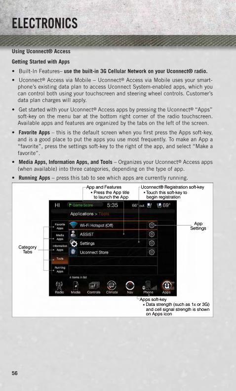
Using Uconnect® Access
Getting Started with Apps
• Built-In Features– use the built-in 3G Cellular Network on your Uconnect® radio.
• Uconnect® Access via Mobile – Uconnect® Access via Mobile uses your smart-phone’s existing data plan to access Uconnect System-enabled apps, which youcan control both using your touchscreen and steering wheel controls. Customer’sdata plan charges will apply.
• Get started with your Uconnect® Access apps by pressing the Uconnect® “Apps”soft-key on the menu bar at the bottom right corner of the radio touchscreen.Available apps and features are organized by the tabs on the left of the screen.
• Favorite Apps – this is the default screen when you first press the Apps soft-key,and is a good place to put the apps you use most frequently. To make an App a“favorite”, press the settings soft-key to the right of the app, and select “Make afavorite”.
• Media Apps, Information Apps, and Tools – Organizes your Uconnect® Access apps(when available) into three categories, depending on the type of app.
• Running Apps – press this tab to see which apps are currently running.
ELECTRONICS
56

Maintaining Your Uconnect® Access Account
Reinstalling an App
• You can easily correct many Application related issues you may be experiencing byresetting the App back to the factory setting. From the vehicle’s radio touchscreen,complete the following steps:
1. Touch the Uconnect® App and open the Uconnect® Store and go to My Apps.
2. In My Apps, select Settings and then Reinstall App and lastly, Continue.
3. Your Apps have been successfully re-installed.
Canceling Your Subscription
• Should you want to cancel your subscription, you can remove your account informa-tion using the same procedure contained in the Selling Your Vehicle section.
Selling Your Vehicle
• When you sell your vehicle, we recommend that you remove your Uconnect® AccessAccount information from the vehicle. You can do this using the radio touchscreen inthe vehicle or on the Mopar Owner Connect website (www.MoparOwnerConnect.com).Removing your account information cancels your subscription and makes your vehiclefactory-ready for a new owner/subscriber.
1. From your vehicle’s radio touchscreen, select the Uconnect® Store from the Appsicon.
2. Select My apps, then Settings, and then Remove Uconnect® Account.
3. Enter your Uconnect® Security PIN, select “Proceed to Remove Vehicle fromUconnect Account”.
• For additional information on Uconnect®:U.S. residents - visit DriveUconnect.com or call 1-877-855-8400.
ELECTRONICS
57

Built-In Features
1. Assist Call – The rear view mirror contains an ASSIST push button which (onceregistered) automatically connects the vehicle occupants to one of these pre-defined destinations for immediate support:
• Roadside Assistance Call – If you get aflat tire, or need a tow, you’ll be con-nected to someone who can help any-time. Additional fees may apply. Addi-tional information in this section.
• Uconnect® Care – In vehicle supportfor Uconnect® Access System, Appsand Features.
• Vehicle Care – Total support for yourChrysler Group LLC vehicle.
2. Emergency 9-1-1 Call (If Equipped) – The rear view mirror contains a 9-1-1 buttonthat, when pressed, will place a call to a local 9-1-1 operator to request help fromlocal police, fire or ambulance personnel in the event of an emergency. If thisbutton is accidentally pressed, you will have 10 seconds to cancel the call.To cancel, press the 9-1-1 Call button again or press the cancellation buttonshown on the touchscreen. After 10 seconds has passed, the 9-1-1 call will beplaced and only the 9-1-1 operator can cancel it. The LED light on the RearviewMirror will turn green once a connection to a 9-1-1 operator has been made. Thegreen LED light will turn off once the 9-1-1 call is terminated. Have an authorizeddealer service the vehicle if the Rearview Mirror light is continuously red. If aconnection is made between a 9-1-1 operator and your vehicle, you understand andagree that 9-1-1 operators may, like any other 9-1-1 call, record conversations andsounds in and near your vehicle upon connection.
3. Roadside Assistance (If Equipped) - If your vehicle is equipped with this feature andwithin wireless range, you may be able to connect to Roadside Assistance bypressing the “Assist” button on the Rearview Mirror. You will be presented withAssist Care options. Make a selection by touching the prompts displayed on theradio If Roadside Assistance is provided to your vehicle, you agree to beresponsible for any additional roadside assistance service costs that you mayincur. In order to provide Uconnect® Services to you, we may record and monitoryour conversations with Roadside Assistance, Uconnect® Care or Vehicle Care,whether such conversations are initiated through the Uconnect® Services in yourvehicle, or via a landline or mobile telephone, and may share informationobtained through such recording and monitoring in accordance with regulatoryrequirements. You acknowledge, agree and consent to any recording, monitoringor sharing of information obtained through any such call recordings.
ELECTRONICS
58

4. Yelp® - Customers have the ability to search for nearby destinations or a point ofinterest (POI) either by category or custom search by using keywords (for example,“Italian restaurant”). Searching can be done by voice or using the touchscreenkeypad. Using the touchscreen, launch Yelp® by selecting the Apps icon, touchInformation Apps tab, and then touch Yelp®. Using voice recognition press the VRbutton on the steering wheel and say “Launch Yelp” to launch the app.
5. Theft Alarm Notification - The Theft Alarm Notification feature notifies you viaE-mail or text message (SMS) when the vehicle’s factory-installed theft alarmsystem has been set-off. There are a number of reasons why your alarm may havebeen triggered, one of which could be that your vehicle was stolen. If so, pleasesee the details of the Stolen Vehicle Assistance service below. When you register,Theft Alarm Notification is automatically set to send you an E-mail at the mailaddress you provide should the alarm go off. You may also opt to have a textmessage sent to your mobile device.
6. Stolen Vehicle Assistance - If your vehicle is stolen, contact local law enforcementimmediately to file a stolen vehicle report. Once this report has been filed,Uconnect® care can help locate your vehicle. The Uconnect® Care agent will askfor the stolen vehicle report number issued by local law enforcement. Then, usingGPS technology and the built-in wireless connection within your vehicle, theUconnect® Care agent will be able to locate the stolen vehicle and work with lawenforcement to help recover it. (Vehicle must be within the United States, havenetwork coverage and must be registered with Uconnect® Access with an activesubscription that includes the applicable feature).
7. WiFi Hotspot - WiFi Hotspot is on-demand WiFi 3G connectivity that's built-in andready to go whenever you are. Once your vehicle is registered for Uconnect®Access, you can purchase a Wifi Hotspot subscription at the Uconnect® Store.After you've made your purchase, turn on your signal and connect your devices.It's never been easier to bring your home or office with you.
• Your vehicle must have a working electrical system in order for any of the in vehicleUconnect® features to operate.
ELECTRONICS
59

Uconnect® Access Remote Features
• If you own a compatible iPhone or Android® powered device, the Uconnect® AccessApp allows you to remotely lock or unlock your doors, start your engine or activate yourhorn and lights from virtually anywhere (Vehicle must be within the United States,have network coverage and must be registered with Uconnect® Access with an activesubscription that includes the applicable feature). You can download the App fromfrom the Apple App or Google Play store. Visit www.UconnectPhone.com to determineif your device is compatible. For Uconnect® Phone customer support and todetermine if your device is compatible:
U.S. residents - visit www.UconnectPhone.com or call 1–877–855–8400.
1. Remote Start – This feature provides the ability to start the engine on your vehicle,without the keys and from virtually any distance. You can send a request to yourvehicle in one of two ways:
• Using the Uconnect® Access App from a compatible smartphone
• From the Mopar Owner Connect website
• You can also send a command to turn-off an engine that has been remotestarted.
• After 15 minutes if you have not entered your vehicle with the key, the enginewill shut off automatically.
• This remote function requires your vehicle to be equipped with a factory-installed Remote Start system. To use this feature after the Uconnect® AccessApp is downloaded, login with your user name and Uconnect® Security PIN.
• You can set-up notifications for your account to receive an E-mail or text (SMS)message every time a command is sent. Log in to Mopar Owner Connect(www.MoparOwnerConnect.com) and click on Edit Profile to manage UconnectNotifications.
2. Remote Door Lock/Unlock – This feature provides the ability to lock or unlock thedoor on your vehicle, without the keys and from virtually any distance. You cansend a request to your vehicle in one of three ways:
• Using the Uconnect® Access App from a compatible smartphone
• From the Mopar Owner Connect website
• By contacting the Uconnect® Care on the phone
• To use this feature after the Uconnect® Access App is downloaded, login usingyour user name and Uconnect Security PIN. Touch the App button on yoursmartphone with the closed lock icon to lock the door, and touch the open lockicon to unlock the driver’s door.
• You can set-up notifications for your account to receive an E-mail or text (SMS)message every time a command is sent. Log in to Mopar Owner Connect(www.MoparOwnerConnect.com) and click on Edit Profile to manage UconnectNotifications.
ELECTRONICS
60

3. Remote Horn and Lights – It’s easy to locate a vehicle in a dark, crowded or noisyparking area by activating the horn and lights. It may also help if you need to drawattention to your vehicle for any reason. You can send a request to your vehicle inone of three ways:
• Using the Uconnect® Access App from a compatible smartphone
• From the Mopar Owner Connect website
• By contacting the Uconnect® Care on the phone
• To use this feature after the Uconnect® Access App is downloaded, login usingyour user name and Uconnect® Security PIN. You can set-up notifications foryour account to receive an E-mail or text (SMS) message every time a commandis sent. Log in to Mopar Owner Connect (www.MoparOwnerConnect.com) andclick on Edit Profile to manage Uconnect Notifications.
4. Voice Texting (U.S. Residents Only) – Want to dictate a personal message? Registerwith Uconnect® Access to take advantage of a new, cloudbased Voice Textingservice, an enhancement to Voice Text Reply.
• Voice Texting allows you to compose a new text or reply to an incoming textmessage. Before you attempt to use the Voice Texting feature, check to ensureyou have the following:
a. A paired, Bluetooth® enabled phone with the Message Access Profile (MAP).Not all Bluetooth® enabled phones support MAP, including all iPhones®
(Apple iOS). Visit www.UconnectPhone.com for system and device compat-ibility information.
b. An active Uconnect® Access trial or paid subscription. Press the ‘U’ button onthe lower right hand corner of the touchscreen to begin the registrationprocess.
c. Accept the Allow MAP profile request on your smart phone. (Please refer todevice manufacturer instructions for details).
ELECTRONICS
61
To send a text message:
a. Press the Uconnect® Phone button.
b. Wait for the beep.
c. Say “Text.”
d. Uconnect® will prompt you “Say the phone number, or full name and phonetype of the contact you want to send a message to.”
e. Wait for the beep and say a contact that is in your phonebook, or a mobilephone number that you would like to send the message to.
f. Uconnect® will prompt you “Please say the message that you would like tosend” (If you do not hear this prompt, you may not have an active subscriptionwith Uconnect® Access).
g. Wait for the beep, and then dictate any message up to 140 characters. If youexceed 140 characters, you will hear the following prompt: “Message was toolong; your message will be truncated.”
h. Uconnect® will then repeat the message back to you.
i. Uconnect® will prompt you: “To add to your message, say ‘Continue’; To deletethe current message and start over, say ‘Start Over’; to send the currentmessage, say ‘Send’; to hear the message again, say ‘Repeat’.
j. If you are happy with your message and would like to send it, wait for the beepand say ‘Send’.
k. Uconnect® will then say “Sending your message.”
Sample Commands For Voice Text Reply And Voice Texting
Example Command Action
“Text John Smith” Send a message to specific contact inaddress book
“Text 123 - 456 - 7890” Send 123 - 456 - 7890 a message fromyour phonebook
“Show messages” See recent text messages listed bynumber on Uconnect® screen
“Listen to/view (message number four,for example)”
Hear messages or read it on Uconnect®screen
“Reply” Send a voice text reply to a currentmessage
“Forward text/message to ‘John Smith” Forward current text to specific contactin address book
“Forward text/message to‘123 - 456 - 7890”
Forward current text to specific phonenumber
ELECTRONICS
62

WARNING!
• ALWAYS drive safely with your hands on the steering wheel. You have fullresponsibility and assume all risks related to the use of the Uconnect® featuresand applications in this vehicle. Only use Uconnect® when it is safe to do so.Failure to do so may result in an accident involving serious injury or death.
• Ignoring the Rearview Mirror light could mean you may not have 9-1-1 Callservice when you need it. If the Rearview Mirror light is illuminated, have anauthorized dealer service the 9-1-1 Call system immediately.
• The Occupant Restraint Controller (ORC) turns on the Air Bag Warning Light onthe instrument panel if a malfunction is detected in any part of the air bagsystem. If the Air Bag Warning Light is illuminated, the air bag system may notbe working properly and the 9-1-1 system may not be able to send a signal toa 9-1-1 operator. If the Air Bag Warning Light is illuminated, have anauthorized dealer service your vehicle immediately.
• If anyone in the vehicle could be in danger (e.g., fire or smoke is visible,dangerous road conditions or location), do not wait for voice contact from a9-1-1 operator. All occupants should exit the vehicle immediately and move toa safe location.
• The 9-1-1 Call system is embedded into the vehicle’s electrical system. Do notadd any aftermarket electrical equipment to the vehicle’s electrical system.This may prevent your vehicle from sending a signal to initiate an emergencycall. To avoid interference that can cause the 9-1-1 Call system to fail, neveradd aftermarket equipment (e.g., two-way mobile radio, CB radio, datarecorder, etc.) to your vehicle’s electrical system or modify the antennas onyour vehicle. IF YOUR VEHICLE LOSES BATTERY POWER FOR ANY REASON(INCLUDING DURING OR AFTER AN ACCIDENT), THE UCONNECT® FEA-TURES, APPS AND SERVICES, AMONG OTHERS, WILL NOT OPERATE.
Uconnect® Access Via Mobile (If Equipped, Available On Uconnect® 8.4A And 8.4AN)
• Uconnect® Access via Mobile offers additional apps such as Aha, iHeartRadio,Pandora and Slacker Radio. It uses your smartphone’s existing data plan to accessUconnect® System-enabled apps, which you can control using both your touch-screen and steering wheel controls. Customer’s data plan charges will apply.
• To get started using Via Mobile apps, first register your Uconnect® Access systemwhere you'll be guided through the setup of your Via Mobile (requires a compatibleAndroid or iPhone smartphone). Please refer to “Uconnect® Access Registration”for more information.• If using an Android smartphone, the Apps will function using a Bluetooth
connection. Pair your smartphone to the radio.• If using an iPhone smartphone, plug the iPhone into the radio using a USB
cable.
ELECTRONICS
63

• Launch the Uconnect® Access App on your smartphone, and log in with yourusername and password that was set up during registration. Accept the Terms andConditions.• Ensure that Via Mobile data has
been turned on under “Settings” inthe Uconnect® Access App.
• A green indicator next to the wordsVia Mobile will show when it is readyto provide data to the radio (a blueindicator when data is being sent).A red indicator means that it is notready to provide data.
• Each time you want to use a Via Mobile app in your vehicle, the Uconnect® AccessApp must be running on your smartphone and the smartphone must be paired orconnected to the radio. (Bluetooth® connection for Android, USB cable foriPhone).
ELECTRONICS
64

• If equipped, the Via Mobile apps can be found by selecting the “Apps” soft-key inthe lower right corner of the radio touchscreen. Via Mobile apps are listed underthe “All Apps” tab. The words “Via Mobile” will appear after the app nameindicating it is a Via Mobile app.
• Via Mobile apps can also be launched through Voice Recognition by pressing theVR button on the steering wheel and stating “launch” and then the name of theapp. For example, you can say “launch Aha via Mobile.”
NOTE:For detailed information on how to use Via Mobile apps visit the Mopar OwnerConnect website (www.moparownerconnect.com) and log in using the username andpassword you set up when registering for Uconnect® Access.
• A message will be displayed to remind you that Via Mobile apps utilize the dataplan on your connected smartphone to provide content. Many smartphones have alimit to how much data they can utilize before incurring additional charges. Theamount of data being used varies by smartphone device, cellular service providerand specific app. Check your mobile phone service plan for more details.* Touch“OK” to continue or the “X” to exit.
(*Additional smartphone data usage charges may apply.)
ELECTRONICS
65

Via Mobile Apps (If Equipped)
• Aha
• Easily access and organize your favorite content from the web into personalized,live and on-demand stations. Choose from stations spanning Internet radio,personalized music, hotels, weather, audiobooks, Facebook®, Twitter® andmore.
• iHeartRadio
• iHeartRadio provides instant access to more than 1,500 live radio stations fromacross the country and allows listeners to create their own stations inspired bytheir favorite artists or songs.
• Pandora®
• Pandora® gives people the music and comedy they love anytime, anywhere.Personalized stations launch instantly, with the input of a favorite artist, track,comedian, or genre. Easily control Pandora® through an intuitive interface viathe radio touchscreen and steering wheel controls.
• Slacker
• Slacker is the most complete music service on Earth. Enjoy millions of songsand hundreds of expert-programmed stations - anytime, anywhere throughUconnect® Access via Mobile.
• For detailed information on how to use Via Mobile apps visit the Mopar OwnerConnect website (www.moparownerconnect.com) and log in using the usernameand password you set up when registering for Uconnect® Access.
ELECTRONICS
66

Uconnect® 3.0
Clock Setting
1. Press the Menu button at the bottom of the radio, and push the Enter/Browsebutton for System Settings. Next, select the Time and Format setting and thenselect Set Time by pushing the Enter/Browse button.
2. Adjust the hours or minutes by turning the Tune/Scroll knob, then pressing theEnter/Browse button to move to the next entry. You can also select 12hr or 24hrformat by turning the Tune/Scroll knob, then pressing the Enter/Browse button onthe desired selection.
3. Once the time is set press the “Back” button to exit the time screen.
Audio
• Press the AUDIO button on the radio faceplate.
• The Audio Menu shows the following options for you to customize your audiosettings.
Treble, Mid, Bass, Fade, Balance, Speed Adjusted Volume, Loudness
• Select the desired setting to adjust, then push the Enter/Browse button. Turn theTune/Scroll knob to adjust the setting + or - 9. Press the back button when done.
ELECTRONICS
67

Radio Operation
Seek Up/Down Buttons
• Press to seek through radio stations in AM, FM or SXM bands.
• Hold either button to bypass stations without stopping.
Store Radio Presets
• The Presets are available for all Radio Modes, and are activated by touching anyof the six Preset buttons.
• When you are receiving a station that you wish to commit into memory, press andhold the desired numbered button for more than two seconds, or until you hear aconfirmation beep.
• The Radio stores up to 18 presets in each of the Radio modes. Press the A-B-Chard-key to select the A, B or C preset list.
Disc Operation (if equipped)
• Your vehicle may have a remote CD player located in the lower center consolestorage bin, or in the lower center bench seat bin.
• CD/Disc Mode is entered by either inserting a CD/Disc or by touching the Mediabutton located on the side of the display. Once in Media Mode, select Disc.
• Gently insert one CD into the CD player with the CD label facing as indicated onthe illustration located on the Disc player.
Seek Up/Down Buttons
• Press to seek through CD tracks.
• Hold either button to bypass tracks without stopping.
ELECTRONICS
68

USB/Audio Jack (AUX) Operation
USB/iPod®
• USB/iPod® Mode is entered by either inserting a USB Jump Drive or iPod® cableinto the USB port or by touching the Media button located left of the display. Oncein Media Mode, select USB/iPod® for the source.
• Pressing the Media button, then select USB/iPod® to change the mode to the USBdevice if the device is connected, allowing the music from your portable device toplay through the vehicle's speakers.
Audio Jack (AUX)
• The AUX allows a portable device, such as an MP3 player or an iPod®, to beplugged into the radio and utilize the vehicle’s audio system, using a 3.5 mm audiocable, to amplify the source and play through the vehicle’s speakers.
• Pressing the Media button, then touch the Source soft-key and then select AUX tochange the mode to auxiliary device if the audio jack is connected, allowing themusic from your portable device to play through the vehicle's speakers.
• The functions of the portable device are controlled using the device buttons, notthe buttons on the radio. The volume may be controlled using the radio or portabledevice.
Uconnect® 3.0 Available Media Hubs
Uconnect®3.0
Media Hub(USB, AUXPorts)
Media Hub(SD, USB,AUX Ports)
Remote USBPort (FullyFunctional)
Remote USBPort (Charg-ing Only)
Dual Charg-ing Ports
S - - O O
S = Standard Equipment
O = Optional Equipment
ELECTRONICS
69

Uconnect® 5.0
Clock Setting
1. To start the clock setting procedure, perform either of the following:
• Press the More hard-key on the right side of the display, next press the Timesoft-key and then press the Set soft-key.
• Press the Settings hard-key on the right side of the display, then press the Clocksoft-key. The Time setting screen is displayed and the clock can be adjusted asdescribed in the following procedure.
NOTE:In the Clock Setting Menu you can also select Display Clock. Display Clock turns theclock display in the status bar on or off.
2. Touch the Up or Down arrows to adjust the hours or minutes, next select the AMor PM soft-key. You can also select 12hr or 24hr format by touching the desiredsoft-key.
3. Once the time is set press the “Done” soft-key to exit the time screen.
Equalizer, Balance and Fade
1. Press the SETTINGS hard-key on the right side of the unit.
2. Then scroll down and press the Audio soft-key to get to the Audio menu.
3. The Audio Menu shows the following options for you to customize your audiosettings.
ELECTRONICS
70

Equalizer
• Touch the Equalizer soft-key to adjust the Bass, Mid and Treble. Use the + or -soft-key to adjust the equalizer to your desired settings. Press the back arrowsoft-key when done.
Balance/Fade
• Touch the Balance/Fade soft-key to adjust the sound from the speakers. Use thearrow soft-key to adjust the sound level from the front and rear or right and left sidespeakers. Touch the Center “C” soft-key to reset the balance and fade to thefactory setting. Press the back arrow soft-key when done.
Speed Adjustable
• Touch the Speed Adjusted Volume soft-key to select between OFF, 1, 2 or 3. Thiswill decrease the radio volume relative to a decrease in vehicle speed. Press theback arrow soft-key when done.
Loudness
• Touch the Loudness soft-key to select the Loudness feature. When this feature isactivated it improves sound quality at lower volumes.
Radio Operation
Seek Up/Down Buttons
• Press to seek through radio stations in AM, FM or SXM bands.
• Hold either button to bypass stations without stopping.
Store Radio Presets
• When you are receiving a station that you wish to commit into memory, press andhold the desired numbered soft-key for more that 2 seconds or until you hear aconfirmation beep.
• The Radio stores up to 12 presets in each of the Radio modes. 4 presets are visibleat the top of the radio screen. Touching the “all” soft-key on the radio home screenwill display all of the preset stations for that mode.
SiriusXM Premier Over 160 channels
• Get every channel available on your satellite radio, and enjoy all you want, all inone place. Hear commercial-free music plus sports, news, talk and entertainment.Get all the premium programming, including Howard Stern, every NFL game,Oprah Radio®, every MLB® and NHL® game, every NASCAR® race, MarthaStewart and more. And get 20+ extra channels, including SiriusXM Latino,offering 20 channels of commercial free music, news, talk, comedy, sports andmore dedicated to Spanish language programming.
• To access SiriusXM Satellite Radio, press the “RADIO” hard-key and then the SXMsoft-key.
ELECTRONICS
71

• SiriusXM services require subscriptions, sold separately after the 12-month trialincluded with the new vehicle purchase. If you decide to continue your service at theend of your trial subscription, the plan you choose will automatically renew and bill atthen-current rates until you call SiriusXM at 1-866-635-2349 for U.S. residents and1-888-539-7474 for Canadian residents to cancel. See SiriusXM Customer Agreementfor complete terms at www.siriusxm.com for U.S. residents and www.siriusxm.ca forCanadian residents. All fees and programming subject to change. Our satelliteservice is available only to those at least 18 and older in the 48 contiguous USAand D.C. Our Sirius satellite service is also available in PR (with coveragelimitations). Our Internet radio service is available throughout our satellite servicearea and in AK and HI. © 2013 Sirius XM Radio Inc. Sirius, XM and all relatedmarks and logos are trademarks of Sirius XM Radio Inc.
Disc Operation (if equipped)
• Your vehicle may have a remote CD player located in the lower center consolestorage bin, or in the lower center bench seat bin.
• CD/Disc Mode is entered by either inserting a CD/Disc or by touching the Mediabutton located on the side of the display. Once in Media Mode, select Disc.
• Gently insert one CD into the CD player with the CD label facing as indicated onthe illustration located on the Disc player.
Seek Up/Down Buttons
• Press to seek through Disc tracks.
• Hold either button to bypass tracks without stopping.
Browse
• Touch the Browse soft-key to scroll through and select a desired track on the Disc.Touch the Exit soft-key if you wish to cancel the browse function.
USB/Audio Jack (AUX)/Bluetooth® Operation
USB/iPod®
• USB/iPod® Mode is entered by either inserting a USB Jump Drive or iPod® cableinto the USB port or by touching the Media hard-key located left of the display.Once in Media Mode, touch the source soft-key and select USB/iPod®.
• Pressing the Media hard-key, then touch the source soft-key and then selectUSB/iPod® to change the mode to the USB device if the device is connected,allowing the music from your portable device to play through the vehicle'sspeakers.
ELECTRONICS
72

Audio Jack (AUX)
• The AUX allows a portable device, such as an MP3 player or an iPod®, to beplugged into the radio and utilize the vehicle’s audio system, using a 3.5 mm audiocable, to amplify the source and play through the vehicle speakers.
• Pressing the Media hard-key, then touch the source soft-key and then select AUXto change the mode to auxiliary device if the audio jack is connected, allowing themusic from your portable device to play through the vehicle's speakers.
• The functions of the portable device are controlled using the device buttons, notthe buttons on the radio. The volume may be controlled using the radio or portabledevice.
Bluetooth®
• If using a Bluetooth® - equipped device, you may also be able to stream music toyour vehicle's sound system.
• Press the Media hard-key, then touch the Source soft-key. Select Bluetooth® tochange the mode to Bluetooth® if the device is paired, allowing the music fromyour portable device to play through the vehicle's speakers.
Uconnect® 5.0 Available Media Hubs
Uconnect®5.0
Media Hub(USB, AUXPorts)
Media Hub(SD, USB,AUX Ports)
Remote USBPort (FullyFunctional)
Remote USBPort (Charg-ing Only)
Dual Charg-ing Ports
S - - S O
S = Standard Equipment
O = Optional Equipment
VOICE COMMAND QUICK REFERENCE
Uconnect® 5.0 Voice Command Quick Reference
• If the Uconnect® Voice Command button exists on your steering wheel, youhave the Voice Command feature, which is optimized for the driver. The VoiceCommand feature lets you keep your hands on the wheel, and your eyes on the road.
• When you press the Voice Command button located on the steering wheel,you will hear a beep. After the beep, give your command. If you do not know whatcommands to say, you can say “help” and the system will provide options to you.If you ever wish to interrupt the system while it lists options, press the VoiceCommand button, after the beep, say your command.
NOTE:All phone oriented voice commands are accessible by first pressing the Phone PickUp button, not the Voice Command button. To end a call, simply press thePhone Hang Up button. In some vehicles, the Phone Pickup button servesthe dual purpose of ending calls as well.
ELECTRONICS
73

Voice Command (VR) User TIPs
• To hear available commands, press the Uconnect® Voice Command button andsay “Help”. You will hear available commands for the menu displayed.
• At any time, you can say the words “Cancel” or “Help”. These commands areuniversal and can be used from virtually any menu. All other specific commandscan be used depending upon the active application.
• You can interrupt the system prompts at any time by pressing the Uconnect® VoiceCommand button while the system is speaking. After the beep, you can say acommand.
• You can ‘chain’ commands together for faster results. Say “Call Joe Doe mobile”,for example.
• For best performance, adjust the rearview mirror to provide at least ½ in (1 cm)gap between the overhead console (if equipped) and the mirror.
• Always wait for the beep before speaking.
• Speak normally, without pausing, just as you would speak to a person sitting a fewfeet/meters away from you.
• Make sure that no one other than you is speaking during a Voice Command period.
Steering Wheel Buttons
• You can control many of your radio features using your voice. Press either the VRor Phone Pick Up button on your steering wheel.
Available Radio Button Voice Commands
Types of VoiceCommandsAvailable
Steering WheelButtons to
Press:Radio Mode Media Mode Phone Mode
Uconnect®Voice
Command (VR)Button
AM/FM &Satellite Band
Control
Media DevicesControl -
GENERAL
Uconnect®Phone Pick Up
Button- -
Call Initiation,Call Manage-ment, Pre-
defined VoiceText Reply
ELECTRONICS
74

Voice Command Examples – Uconnect® 5.0
GENERALAnytime “Go to Radio” (Media, Phone) – Compass, Settings, and
More functions are not Voice Command accessible“Cancel”
“Help” (to listen to suggested commands specific tocurrent need
“Repeat”RADIO
AM/FM “Tune to AM950”, “Tune to 95.5FM (preset 5)Satellite Band Control “Tune to Satellite Channel 80's on 8”, Tune to Satellite
Channel 32 (preset 4)MEDIA
Media Devices Control(Functionality is dependenton compatibility between
devices and radio)
“Browse” (show) “artist” (albums, music)“Show paired phones” (devices)
“Play song – Maple Leaf Rag” (artist - Scott Joplin,genre - rock, album - Ragtime Favorites)
PHONECall Initiation (Requiresthat phone has been
Bluetooth® paired withradio)
“Dial 123-456-7890” (phone number)“Call John Smith mobile” (home, office, other)
“Redial”“Show outgoing” (recent) “calls”
Call Management “Search for John Smith” (any contact name in addressbook)
“Show (display list) contacts”Voice Text Reply (Radio
audibly recognizes these18 pre-defined SMS mes-
sages as you speak)NOTE: Requires a compat-ible mobile device enabled
with Bluetooth MessageAccess Profile (MAP).iPhone and some other
smartphones do notcurrently support
Bluetooth® MAP. Visitwww.UconnectPhone.com
for system and devicecompatibility.
Forward one of 18 pre-defined SMS messages toincoming calls/text messages:
“Yes.”“No.”
“Okay.”“I can’t talk right now.”
“Call me.”“I’ll call you later.”“I’m on my way.”
“Thanks.”“I’ll be late.”
“I will be <number> minutes late.”“See you in <number> minutes”
“Stuck in traffic.”“Start without me.”“Where are you?”
“Are you there yet?”“I need directions.”
“I’m lost.”“See you later.”
ELECTRONICS
75

Uconnect® 8.4A
Uconnect® 8.4A AT A GLANCE
Displaying the Time
• If the time is not currently displayed on the radio or player main page, touch theSettings soft-key or the Apps soft-key and then the Settings soft-key. In theSettings list, touch the Clock soft-key then touch the check box next to Show Timein Status Bar.
Setting the Time
• Model 8.4AN synchronizes time automatically via GPS, so it should not requireany time adjustment. If you do need to set the time manually, follow theinstructions below for Model 8.4A.
• For Model 8.4A, turn the unit on, then touch the time display at the top of thescreen. Touch Yes.
• If the time is not displayed at the top of the screen, touch the Controls soft-key orthe Apps soft-key and then the Settings soft-key. In the Settings screen, touch theClock soft-key, then check or uncheck this option.
• Touch + or – next to Set Time Hours and Set Time Minutes to adjust the time.
• If these features are not available, uncheck the Sync with GPS box.
• Touch X to save your settings and exit out of the Clock Setting screen.
ELECTRONICS
76

Audio Settings
• Touch the Audio soft-key to activate the Audio settings screen to adjustBalance\Fade, Equalizer, and Speed Adjusted Volume.
• You can return to the Radio screen by touching the X located at the top right.
Balance/Fade
• Touch the Balance/Fade soft-key to Balance audio between the front speakers orfade the audio between the rear and front speakers.
• Touching the Front, Rear, Left, or Right soft-keys or touch and drag the SpeakerIcon to adjust the Balance/Fade.
Equalizer
• Touch the Equalizer soft-key to activate the Equalizer screen.
• Touch the + or - soft-keys, or by touching and dragging over the level bar for eachof the equalizer bands. The level value, which spans between plus or minus 9, isdisplayed at the bottom of each of the Bands.
Speed Adjusted Volume
• Touch the Speed Adjusted Volume soft-key to activate the Speed Adjusted Volumescreen. The Speed Adjusted Volume is adjusted by touching the + and - buttons orby touching and dragging over the level bar. This alters the automatic adjustmentof the audio volume with variation to vehicle speed.
RADIO
• To access the Radio mode, touch the Radio soft-key at the lower left of the screen.
ELECTRONICS
77

Selecting Radio Stations
• Touch the desired radio band (AM, FM or SXM) soft-key.
Seek Up/Seek Down
• Touch the Seek arrow soft-keys for less than two seconds to seek through radiostations.
• Touch and hold either arrow soft-key for more than two seconds to bypass stationswithout stopping. The radio will stop at the next listenable station once the arrowsoft-key is released.
Direct Tune
• Tune directly to a radio station by pressing the Tune soft-key on the screen, andentering the desired station number.
Store Radio Presets
• Your radio can store 36 total preset stations, 12 presets per band (AM, FM andSXM). They are shown at the top of your radio screen. To see the 12 preset stationsper band, press the arrow soft-key at the top right of the screen to toggle betweenthe two sets of six presets.
• To set a station into memory press and hold the desired numbered soft-key formore than two seconds or until you hear a confirmation beep.
SiriusXM PREMIER OVER 160 CHANNELS
• Get every channel available on your satellite radio, and enjoy all you want, all inone place. Hear commercial-free music plus sports, news, talk and entertainment.Get all the premium programming, including Howard Stern, every NFL game,Oprah Radio®, every MLB® and NHL® game, every NASCAR® race, MarthaStewart and more. And get 20+ extra channels, including SiriusXM Latino,offering 20 channels of commercial free music, news, talk, comedy, sports andmore dedicated to Spanish language programming.
• To access SiriusXM Satellite Radio, touch the SXM soft-key on the main Radioscreen.
• The following describes features that are available when in SiriusXM SatelliteRadio mode.
Seek Up/Seek Down
• Touch the Seek arrow soft-keys for less than two seconds to seek through channelsin SXM mode.
• Touch and hold either arrow soft-key for more than two seconds to bypass channelswithout stopping. The radio will stop at the next listenable channel once the arrowsoft-key is released.
Direct Tune
• Tune directly to a SXM channel by pressing the Tune soft-key on the screen, andentering the desired station number.
ELECTRONICS
78

Jump
• Automatically tells you when Traffic & Weather for a favorite city is available, andgives you the option to switch to that channel. Touch Jump to activate the feature.After listening to Traffic and Weather, touch Jump again to return to the previouschannel.
Fav
• Activates the favorites menu. You can add up to 50 favorite artists or songs. Justtouch Add Fav Artist or Add Fav Song while the song is playing. You will then bealerted any time one of these songs, or works by these artists, is playing on otherSiriusXM channels.
SiriusXM Parental Controls
• You can skip or hide certain channels from view if you do not want access to them.Touch the More soft-key, then the Settings soft-key, next touch the Sirius Setupsoft-key, then select Channel Skip. Touch the box, check-mark, next to the channelyou want skipped. They will not show up in normal usage.
• SiriusXM also offers the option to permanently block selected channels. Call(1-888-601-6297 for U.S. customers, 1-877-438-9677 for Canadian custom-ers) and request the Family-Friendly Package.
Browse
• Lets you browse the SiriusXM channel listing or Genre listing. Favorites, GameZone, Weather and Jump settings also provide a way to browse the SiriusXMchannel list.
BrowseSub-Menu
Sub-Menu Description
All Shows the channel listing.Genre Provides a list of all genres, and lets you jump to a channel within the
selected genre.Presets Lets you scroll the list of Preset satellite channels. Touch the channel, or
press Enter on the Tune knob, to go to that channel. Touch the trash canicon to delete a preset. Your presets are also shown at the top of the mainSatellite Radio screen.
Favorites Lets you manage artists and songs in the Favorites list and configure AlertSettings to let you know when favorite songs or artists are playing on otherchannels. Also, view a list of channels airing any of your Favorites.
Game Zone Provides alerts when your favorite sports teams are starting a game whichis being aired on other SiriusXM channels, or when their game score isannounced. You can select and manage your Teams list here, andconfigure alerts.
Jump Lets you select your favorite cities for Traffic & Weather information,which is used by the Jump feature on the main satellite radio screen.
ELECTRONICS
79

Replay
• Lets you replay up to 44 minutes of the content of the current SiriusXM channel.
ReplayOption
Option Description
Play/Pause Touch to Pause content playback. Touch Pause/Play again to resumeplayback.
Rewind/RW Rewinds the channel content in steps of five seconds. Touch and hold torewind continuously, then release to begin playing content at that point.
FastForward/FW
Forwards the content, and works similarly to Rewind/RW. However, FastForward/FW can only be used when content has been previously rewound.
Replay Time Displays the amount of time in the upper center of the screen by whichyour content lags the Live channel.
Live Resumes playback of Live content at any time while replaying rewoundcontent.
• SiriusXM services require subscriptions, sold separately after the 12-month trialincluded with the new vehicle purchase. If you decide to continue your service at theend of your trial subscription, the plan you choose will automatically renew and bill atthen-current rates until you call SiriusXM at 1-866-635-2349 for U.S. residents and1-888-539-7474 for Canadian residents to cancel. See SiriusXM Customer Agreementfor complete terms at www.siriusxm.com (US residents) or www.siruisxm.ca (Canadianresidents). All fees and programming subject to change. Our satellite service isavailable only to those at least 18 and older in the 48 contiguous USA and D.C.Our Sirius satellite service is also available in PR (with coverage limitations). OurInternet radio service is available throughout our satellite service area and in AKand HI. © 2013 Sirius XM Radio Inc. Sirius, XM and all related marks and logosare trademarks of Sirius XM Radio Inc.
Disc Operation — If Equipped
• Your vehicle may have a remote CD player located in the lower center consolestorage bin, or in the lower center bench seat bin.
• CD/Disc Mode is entered by either inserting a CD/Disc or by touching the Mediabutton located on the side of the display. Once in Media Mode, select Disc.
• Gently insert one CD into the CD player with the CD label facing as indicated onthe illustration located on the Disc player.
Seek Up/Down Buttons
• Press to seek through Disc tracks.
• Hold either button to bypass tracks without stopping.
Browse
• Touch the Browse soft-key to scroll through and select a desired track on the Disc.Touch the Exit soft-key if you wish to cancel the browse function.
ELECTRONICS
80
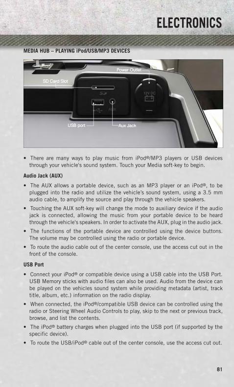
MEDIA HUB – PLAYING iPod/USB/MP3 DEVICES
• There are many ways to play music from iPod®/MP3 players or USB devicesthrough your vehicle's sound system. Touch your Media soft-key to begin.
Audio Jack (AUX)
• The AUX allows a portable device, such as an MP3 player or an iPod®, to beplugged into the radio and utilize the vehicle’s sound system, using a 3.5 mmaudio cable, to amplify the source and play through the vehicle speakers.
• Touching the AUX soft-key will change the mode to auxiliary device if the audiojack is connected, allowing the music from your portable device to be heardthrough the vehicle's speakers. In order to activate the AUX, plug in the audio jack.
• The functions of the portable device are controlled using the device buttons.The volume may be controlled using the radio or portable device.
• To route the audio cable out of the center console, use the access cut out in thefront of the console.
USB Port
• Connect your iPod® or compatible device using a USB cable into the USB Port.USB Memory sticks with audio files can also be used. Audio from the device canbe played on the vehicles sound system while providing metadata (artist, tracktitle, album, etc.) information on the radio display.
• When connected, the iPod®/compatible USB device can be controlled using theradio or Steering Wheel Audio Controls to play, skip to the next or previous track,browse, and list the contents.
• The iPod® battery charges when plugged into the USB port (if supported by thespecific device).
• To route the USB/iPod® cable out of the center console, use the access cut out.
ELECTRONICS
81

NOTE:When connecting your iPod® device for the first time, the system may take severalminutes to read your music, depending on the number of files. For example, thesystem will take approximately five minutes for every 1000 songs loaded on thedevice. Also during the reading process, the Shuffle and Browse functions will bedisabled. This process is needed to ensure the full use of your iPod® features andonly happens the first time it is connected. After the first time, the reading processof your iPod® will take considerably less time unless changes are made or new songsare added to the playlist.
• The USB port supports certain Mini, Classic, Nano, Touch, and iPhone® devices.The USB port also supports playing music from compatible external USB MassStorage Class memory devices. Some iPod® software versions may not fullysupport the USB port features. Please visit Apple’s website for iPod® softwareupdates.
SD Card
• Play songs stored on an SD card inserted into the SD card slot.
• Song playback can be controlled using the radio or Steering Wheel Audio Controlsto play, skip to the next or previous track, browse, and list the contents.
Bluetooth® Streaming Audio
• If equipped with Uconnect® Voice Command, your Bluetooth-equipped iPod®
devices, cell phones or other media players, may also be able to stream music toyour vehicle's sound system. Your connected device must be Bluetooth-compatible, and paired with your system (see Uconnect® Phone for pairinginstructions). You can access the music from your connected Bluetooth® device bytouching the Bluetooth® soft-key while in Media mode.
Uconnect® 8.4A & 8.4AN Available Media Hubs
Uconnect®8.4A &8.4AN
Media Hub(USB, AUXPorts)
Media Hub(SD, USB,AUX Ports)
Remote USBPort (FullyFunctional)
Remote USBPort (Charg-ing Only)
Dual Charg-ing Ports
- S S O O
S = Standard Equipment
O = Optional Equipment
ELECTRONICS
82
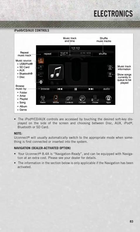
iPod®/CD/AUX CONTROLS
• The iPod®/CD/AUX controls are accessed by touching the desired soft-key dis-played on the side of the screen and choosing between Disc, AUX, iPod®,Bluetooth or SD Card.
NOTE:Uconnect® will usually automatically switch to the appropriate mode when some-thing is first connected or inserted into the system.
NAVIGATION (DEALER-ACTIVATED OPTION)
• Your Uconnect® 8.4A is “Navigation-Ready”, and can be equipped with Naviga-tion at an extra cost. Please see your dealer for details.
• The information in the section below is only applicable if the Navigation has beenactivated.
ELECTRONICS
83

Changing the Navigation Voice Prompt Volume
1. Touch the Settings soft-key.
2. In the Settings menu, touch the Guidance soft-key.
3. In the Guidance menu, adjust the Nav Volume by touching the + or – Nav VolumeAdjustment soft-keys.
Finding Points of Interest (POI)
• From the main Navigation menu, touch the Where To? soft-key, then touch thePoints of Interest soft-key.
• Select a Category and then a subcategory, if necessary.
• Select your destination and touch the Yes soft-key.
ELECTRONICS
84

Finding a Place by Spelling the Name
• From the Main Navigation Menu touch the Where to? soft-key, touch the Points ofInterest soft-key and then touch the Spell Name soft-key.
• Enter the name of your destination.
• Touch the List soft-key.
• Select your destination and touch the Yes soft-key.
Entering a Destination Address
• From the main Navigation menu touch the Where To? soft-key, then touch theAddress soft-key.
• Follow the on-screen prompts (country, state/province, city, street) to enter theaddress and touch the Yes soft-key.
• Destination entry is not available while your vehicle is in motion. However, you canalso use Voice Command to enter an address while moving. See Voice CommandTips for more information.
Setting Your Home Location
• Touch the NAV soft-key in the menu bar to access the Navigation system and theMain Navigation menu.
• Touch the Where To? soft-key, then touch the Go Home soft-key.
• You may enter your address directly, use your current location as your homeaddress, or choose from recently found locations.
• To delete your Home location (or other saved locations) so you can save a newHome location, touch the Where To? soft-key from the Main Navigation menu, thentouch the Go Home soft-key, and in the Yes screen touch the Options soft-key. Inthe Options menu touch Clear Home. Set a new Home location by following theprevious instructions.
ELECTRONICS
85

Go Home
• A Home location must be saved in the system. From the Main Navigation menu,touch the Where To? soft-key, then touch the Go Home soft-key.
• Your route is marked with a blue line on the map. If you depart from the originalroute, your route is recalculated. A speed limit icon could appear as you travel onmajor roadways.
Adding a Stop
• To add a stop you must be navigating a route.
• Touch the Menu soft-key to return to the Main Navigation menu.
• Touch the Where To? soft-key, then search for the extra stop. When anotherlocation has been selected, you can choose to cancel your previous route, add asthe first destination or add as the last destination.
• Touch the desired selection and touch the Yes soft-key.
Taking a Detour
• To take a detour you must be navigating a route.
• Touch the Detour soft-key.
NOTE:If the route you are currently taking is the only reasonable option, the device mightnot calculate a detour.
• For more information, see your Uconnect® Supplement Manual.
ELECTRONICS
86

Uconnect® Phone (Bluetooth® HANDS FREE CALLING)
• If the Uconnect® Phone Button exists on your steering wheel, then you havethe Uconnect® Phone features.
• The Uconnect® Phone is a voice-activated, hands-free, in-vehicle communica-tions system with Voice Command Capability (see Voice Command section).
• The Uconnect® Phone allows you to dial a phone number with your mobile phoneusing simple voice commands or using screen soft-keys.
• Refer to the Understand The Features Of Your Vehicle section of your vehicle'sOwner's Manual on the DVD for further details.
NOTE:The Uconnect® Phone requires a mobile phone equipped with the Bluetooth®
Hands-Free Profile, Version 1.0 or higher. For Uconnect® Customer Support: U.S.residents visit www.UconnectPhone.com or call 1–877–855–8400. Canadian Resi-dents – visit www.UconnectPhone.com or call, 1-800-465–2001 (English) or1-800-387-9983 (French).
Pairing a Phone
• To use the Uconnect® Phone feature, you must first pair your Bluetooth® phonewith the Uconnect® system.
Start pairing procedure on the radio
• Touch the Phone soft-key and then the Settings soft-key. Next, touch Add Device.
• Uconnect® Phone will display an “In progress” screen while the system isconnecting.
Start pairing procedure on mobile phone
• Search for available devices on your Bluetooth® enabled mobile phone. This isusually within Settings or Options under “Bluetooth”. See your mobile phone’smanual for details.
• When your phone finds the system, select “Uconnect” as the paired device. Youmay be prompted by your phone to download the phonebook. This is so you canmake calls by saying the name of your contact (PBAP-Phone Book Access Profile).
Complete the pairing procedure
• When prompted on the phone, verify with the radio password shown on theUconnect® Screen.
• If your phone asks you to accept a connection request from Uconnect®, select“Yes”. If available, check the box telling it not to ask again – that way your phonewill automatically connect each time you start the vehicle.
ELECTRONICS
87

Select the mobile phone's priority level
• When the pairing process has successfully completed, the system will prompt you tochoose whether or not this is your favorite phone. Selecting Yes will make this phonethe highest priority. This phone will take precedence over other paired phones withinrange. Only one phone can be paired at a time.
• You are now ready to make hands-free calls. Press the Uconnect® Phone button onyour steering wheel to begin.
Making A Phone Call
• Press the Uconnect® Phone button .• After the BEEP, say “dial” then the number (or “call” then the name as listed in
your phone; see Phonebook).
NOTE:You can also initiate a call by using the touchscreen on the Phone main screen.
Receiving A Call – Accept (And End)
• When an incoming call rings/is announced on Uconnect®, press the Phonebutton .
• To end a call, press the Phone button .
Mute (Or Unmute) Microphone During Call• During a call, touch the mute soft-key on the Phone main screen to mute and
unmute the call.
Transfer Ongoing Call Between Handset And Vehicle• During an on-going call, touch the Transfer soft-key on the Phone main screen to
transfer an on-going call between handset and vehicle.
Common Phone Commands (Examples)• “Call John Smith”• “Call John Smith mobile”• “Dial 1 248 555 1212”• “Call Emergency”• “Call Towing Assistance”• “Redial”
Phonebook
• Uconnect® radios will automatically download your phonebook from your paired phone,if this feature is supported by your phone. Entries are updated each time that the phoneis connected. If your phone book entries do not appear, check the settings on yourphone. Some phones require you to enable this feature manually.
• Your phonebook can be browsed on your radio screen, but editing can only be doneon your phone. To browse, touch the Phone soft-key, then the Phonebook soft-key.
• Favorite phonebook entries can be saved as Favorites for quicker access. Favoritesare shown at the top of your main phone screen.
ELECTRONICS
88
Voice Command Tips (8.4 and 8.4N ONLY)
• Using complete names (i.e; Call John Doe vs. Call John) will result in greatersystem accuracy.
• You can “chain” commands together for faster results. Say “Call John Doe, mobile”,for example.
• If you are listening to available voice command options, you do not have to listento the entire list. When you hear the command that you need, press thebutton on the steering wheel, wait for the beep and say your command.
Changing The Volume
• Start a dialogue by pressing the Phone button , then say a command forexample - "Help".
• Use the radio VOLUME/MUTE rotary knob to adjust the volume to a comfortablelevel while the Uconnect® system is speaking. Please note the volume setting forUconnect® is different than the audio system.
NOTE:To access help, press the Uconnect® Phone button on the steering wheel andsay "help." Touch the display or push either or button and say "cancel"to cancel the help session.
Voice Text Reply
• Uconnect® Phone can read or send new text messages on your mobile phone.
• Your mobile phone must be MAP (Message Access Profile) compatible to supportSMS via Bluetooth® to use this feature. If the Uconnect® Phone determines yourphone is not compatible with SMS messaging over Bluetooth® the “Messaging”button will be greyed out and the feature will not be available for use.
NOTE:For mobile phone compatibility and pairing instructions, please visitwww.UconnectPhone.com
WARNING!
• Any voice commanded system should be used only in safe driving conditionsfollowing applicable laws regarding phone use. Your attention should befocused on safely operating the vehicle. Failure to do so may result in acollision causing you and others to be severely injured or killed.
• In an emergency, to use Uconnect® Phone, your mobile phone must be:• turned on,• paired to Uconnect® Phone,• and have network coverage.
ELECTRONICS
89

VOICE COMMAND QUICK REFERENCE
Uconnect® 8.4A Voice Command Quick Reference
• If the Uconnect® Voice Command button exists on your steering wheel,you have the Voice Command feature, which is optimized for the driver. The VoiceCommand feature lets you keep your hands on the wheel, your eyes on the road,and control navigation and media sources.
• When you press the Voice Command button located on the steering wheel,you will hear a beep. After the beep, give your command. If you do not know whatcommands to say, you can say “help” and the system will provide options to you.If you ever wish to interrupt the system while it lists options, press the VoiceCommand button, after the beep, say your command.
NOTE:All phone oriented voice commands are accessible by first pressing the Phone PickUp button, not the Voice Command button. To end a call, simply press thePhone Hang Up button. In some vehicles, the Phone Pickup buttonserves the dual purpose of ending calls as well.
Voice Command (VR) User TIPs
• To hear available commands, press the Uconnect® Voice Command button andsay “Help”. You will hear available commands for the menu displayed.
• At any time, you can say the words “Cancel” or “Help”. These commands areuniversal and can be used from virtually any menu. All other specific commandscan be used depending upon the active application.
• You can interrupt the system prompts at any time by pressing the Uconnect® VoiceCommand button while the system is speaking. After the beep, you can say acommand.
• You can ‘chain’ commands together for faster results. Say “Navigate to 1234 MainStreet Hometown, California”, for example.
• For best performance, adjust the rearview mirror to provide at least ½ in (1 cm)gap between the overhead console (if equipped) and the mirror.
ELECTRONICS
90
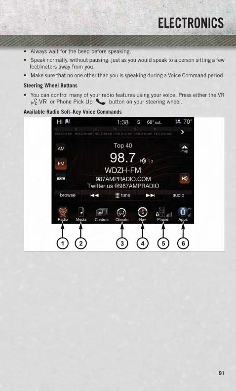
• Always wait for the beep before speaking.
• Speak normally, without pausing, just as you would speak to a person sitting a fewfeet/meters away from you.
• Make sure that no one other than you is speaking during a Voice Command period.
Steering Wheel Buttons
• You can control many of your radio features using your voice. Press either the VRor Phone Pick Up button on your steering wheel.
Available Radio Soft–Key Voice Commands
ELECTRONICS
91

Type
sof
Voic
eCo
mm
ands
Avai
labl
e
Stee
ring
Whe
elBu
ttons
toPr
ess:
(1)
Radi
oM
ode
(2)
Med
iaM
ode
(3)
Clim
ate
Cont
rols
(4)
Nav
igat
ion
(5)
Phon
eM
ode
(6)
APPS
Uco
nnec
t®Vo
ice
Com
-m
and
(VR
)B
utto
n
AM
/FM
&S
atel
lite
Ban
dC
ontr
ol
Med
iaD
evic
esC
ontr
olTe
mpe
ratu
reC
ontr
ol
Des
tina
tion
Sel
ecti
onan
dVi
ew-
Yelp
®
GEN
ERAL
Uco
nnec
t®P
hone
Pic
kU
pB
utto
n-
--
-
Cal
lIni
tiat
ion,
Cal
lMan
age-
men
t,P
re-
defi
ned
Voic
eTe
xtR
eply
-
ELECTRONICS
92

Voice Command Examples – Uconnect® 8.4A
GENERALAnytime “Go to Radio” (Media, Climate, Navigation, Phone,
Apps) – Settings, and Controls are not Voice Commandaccessible“Cancel”
“Help” (to listen to suggested commands specific tocurrent need
“Repeat”“Launch Yelp®” – Required 1st voice command to
launch Yelp® app“Yelp® Search” – Required 2nd voice command to
activate app functionality using Steering Wheel VoiceControl Button
RADIOAM/FM “Tune to AM950”, “Tune to 95.5FM (preset 5)
Satellite Band Control “Tune to Satellite Channel 80's on 8”, Tune to SatelliteChannel 32 (preset 4)
MEDIAMedia Devices Control
(Functionality is dependenton compatibility between
devices and radio)
“Browse” (show) “artist” (albums, music)“Show paired phones” (devices)
“Play song – Maple Leaf Rag” (artist - Scott Joplin,genre - rock, album - Ragtime Favorites)
“Shuffle” – available with iPod®, USB and SD CardCLIMATE
Temperature Control “Set temperature to 70 degrees” – single climate zonevehicles
“Set driver” (passenger) “temperature to 75 degrees” –dual climate zone vehicles
NAVIGATIONDestination Selection &
View“Go Home” – destination previously defined by driver“Repeat guidance” – hear the last navigation prompt
“Cancel Route”“View Map”
PHONECall Initiation (Requiresthat phone has been
Bluetooth® paired withradio)
“Dial 123-456-7890” (phone number)“Call John Smith mobile” (home, office, other)
“Redial”“Show outgoing” (recent) “calls”
Call Management “Search for John Smith” (any contact name inaddress book)
“Show (display list) contacts”
ELECTRONICS
93

PHONEVoice Texting (Requires
registration withUconnect® Access and a
current subscription.)NOTE: Requires a compat-ible mobile device enabled
with Bluetooth MessageAccess Profile (MAP).iPhone and some other
smartphones do notcurrently support
Bluetooth® MAP. Visitwww.UconnectPhone.com
for system and devicecompatibility.
Create a text message using Voice Command Capability“Send a message to John Smith (123-456-7890)”
“Show Messages”“Listen to” (view) “number 4”
“Reply”“Forward text” (message) “to John Smith”
(phone type, number)
Voice Text Reply (Radioaudibly recognizes these
18 pre-defined SMS mes-sages as you speak)
NOTE: Requires a compat-ible mobile device enabled
with Bluetooth MessageAccess Profile (MAP).iPhone and some other
smartphones do notcurrently support
Bluetooth® MAP. Visitwww.UconnectPhone.com
for system and devicecompatibility.
Forward one of 18 pre-defined SMS messages toincoming calls/text messages:
“Yes.”“No.”
“Okay.”“I can’t talk right now.”
“Call me.”“I’ll call you later.”“I’m on my way.”
“Thanks.”“I’ll be late.”
“I will be <number> minutes late.”“See you in <number> minutes”
“Stuck in traffic.”“Start without me.”“Where are you?”
“Are you there yet?”“I need directions.”
“I’m lost.”“See you later.”
APPSYelp® (Yelp® adds it's own
audible prompts, andresponse time variesdepending on carrier
coverage speed)
“Launch Yelp®” – Required 1st voice command tolaunch Yelp® app
“Yelp® Search” – Required 2nd voice command toactivate app functionality using Steering Wheel Voice
Control Button“Hotel” (restaurant, gas station, mail, hospital) – for
nearest desired general POI“Italian restaurants” – for nearest specified POI category“Hotels” (restaurants, hospitals, Starbucks) “in Miami”
(location) – specified distance POI
ELECTRONICS
94

Uconnect® 8.4AN
Uconnect® 8.4AN AT A GLANCE
Displaying the Time
• If the time is not currently displayed on the radio or player main page, touch theControls soft-key or the Apps soft-key and then the Settings soft-key. In theSettings list, touch the Clock soft-key then touch the check box next to Sync Time.
Setting the Time
• Model 8.4AN synchronizes time automatically via GPS, so it should not requireany time adjustment. If you do need to set the time manually, follow theinstructions below for Model 8.4A.
• For Model 8.4A, turn the unit on, then touch the time display at the top of thescreen. Touch Yes.
• If the time is not displayed at the top of the screen, touch Controls soft-key or theApps soft-key and then the Settings soft-key. In the Settings screen, touch theClock soft-key, then check or uncheck this option.
• Touch + or – next to Set Time Hours and Set Time Minutes to adjust the time.
• If these features are not available, uncheck the Sync Time box.
• Touch X to save your settings and exit out of the Clock Setting screen.
ELECTRONICS
95

Audio Settings
• Touch of the Audio soft-key to activate the Audio settings screen to adjustBalance\Fade, Equalizer, and Speed Adjusted Volume.
• You can return to the Radio screen by touching the X located at the top right.
Balance/Fade
• Touch the Balance/Fade soft-key to Balance audio between the front speakers orfade the audio between the rear and front speakers.
• Touching the Front, Rear, Left, or Right soft-keys or touch and drag the SpeakerIcon to adjust the Balance/Fade.
Equalizer
• Touch the Equalizer soft-key to activate the Equalizer screen.
• Touch the + or - soft-keys, or touch and drag over the level bar for each of theequalizer bands. The level value, which spans between plus or minus 9, isdisplayed at the bottom of each of the Bands.
Speed Adjusted Volume
• Touch the Speed Adjusted Volume soft-key to activate the Speed Adjusted Volumescreen. The Speed Adjusted Volume is adjusted by touching the volume level indicator.This alters the automatic adjustment of the audio volume with variation to vehicle speed.
RADIO
• To access the Radio mode, touch the Radio soft-key at the lower left of the screen.
ELECTRONICS
96

Selecting Radio Stations
• Touch the desired radio band (AM, FM or SXM) soft-key.
Seek Up/Seek Down
• Touch the Seek arrow soft-keys for less than two seconds to seek through radiostations.
• Touch and hold either arrow soft-key for more than two seconds to bypass stationswithout stopping. The radio will stop at the next listenable station once the arrowsoft-key is released.
Direct Tune
• Tune directly to a radio station by pressing the “Tune” button on the screen, andentering the desired station number.
Store Radio Presets
• Your radio can store 36 total preset stations, 12 presets per band (AM, FM andSXM). They are shown at the top of your radio screen. To see the 12 preset stationsper band, press the arrow soft-key at the top right of the screen to toggle betweenthe two sets of six presets.
• To set a station into memory press and hold the desired numbered soft-key formore than two seconds or until you hear a confirmation beep.
HD Radio (US RESIDENTS ONLY)
• HD Radio (available on Uconnect 8.4AN) operates similar to conventional radioexcept it allows broadcasters to transmit a high-quality digital signal.
• With an HD radio receiver, the listener is provided with a clear sound thatenhances the listening experience. HD radio can also transmit data such as songtitle or artist.
SiriusXM PREMIER OVER 160 CHANNELS
• Get every channel available on your satellite radio, and enjoy all you want, all inone place. Hear commercial-free music plus sports, news, talk and entertainment.Get all the premium programming, including Howard Stern, every NFL game,Oprah Radio®, every MLB® and NHL® game, every NASCAR® race, MarthaStewart and more. And get 20+ extra channels, including SiriusXM Latino,offering 20 channels of commercial free music, news, talk, comedy, sports andmore dedicated to Spanish language programming.
• To access SiriusXM Satellite Radio, touch the SXM soft-key on the main Radioscreen.
• The following describes features that are available when in SiriusXM SatelliteRadio mode.
ELECTRONICS
97
Seek Up/Seek Down
• Touch the Seek arrow soft-keys for less than two seconds to seek through channelsin SXM mode.
• Touch and hold either arrow soft-key for more than two seconds to bypass channelswithout stopping. The radio will stop at the next listenable channel once the arrowsoft-key is released.
Direct Tune
• Tune directly to a SXM channel by pressing the Tune soft-key on the screen, andentering the desired station number.
Jump
• Automatically tells you when Traffic & Weather for a favorite city is available, andgives you the option to switch to that channel. Touch Jump to activate the feature.After listening to Traffic and Weather, touch Jump again to return to the previouschannel.
Fav
• Activates the favorites menu. You can add up to 50 favorite artists or songs. Justtouch Add Fav Artist or Add Fav Song while the song is playing. You will then bealerted any time one of these songs, or works by these artists, is playing on otherSiriusXM channels.
SiriusXM Parental Controls
• You can skip or hide certain channels from view if you do not want access to them.Touch the More soft-key, then the Settings soft-key, next touch the Sirius Setupsoft-key, then select Channel Skip. Touch the box, check-mark, next to the channelyou want skipped. They will not show up in normal usage.
• SiriusXM also offers the option to permanently block selected channels. Call(1-888-601-6297 for U.S. customers, 1-877-438-9677 for Canadian custom-ers) and request the Family-Friendly Package.
ELECTRONICS
98

Browse
• Lets you browse the SiriusXM channel listing or Genre listing. Favorites, GameZone, Weather and Jump settings also provide a way to browse the SiriusXMchannel list.
BrowseSub-Menu
Sub-Menu Description
All Shows the channel listing.Genre Provides a list of all genres, and lets you jump to a channel within the
selected genre.Presets Lets you scroll the list of Preset satellite channels. Touch the channel, or
press Enter on the Tune knob, to go to that channel. Touch the trash canicon to delete a preset. Your presets are also shown at the top of the mainSatellite Radio screen.
Favorites Lets you manage artists and songs in the Favorites list and configure AlertSettings to let you know when favorite songs or artists are playing on otherchannels. Also, view a list of channels airing any of your Favorites.
Game Zone Provides alerts when your favorite sports teams are starting a game whichis being aired on other SiriusXM channels, or when their game score isannounced. You can select and manage your Teams list here, andconfigure alerts.
Jump Lets you select your favorite cities for Traffic & Weather information,which is used by the Jump feature on the main satellite radio screen.
Replay
• Lets you replay up to 44 minutes of the content of the current SiriusXM channel.
ReplayOption
Option Description
Play/Pause Touch to Pause content playback. Touch Pause/Play again to resumeplayback.
Rewind/RW Rewinds the channel content in steps of five seconds. Touch and hold torewind continuously, then release to begin playing content at that point.
FastForward/FW
Forwards the content, and works similarly to Rewind/RW. However, FastForward/FW can only be used when content has been previously rewound.
Replay Time Displays the amount of time in the upper center of the screen by whichyour content lags the Live channel.
Live Resumes playback of Live content at any time while replaying rewoundcontent.
ELECTRONICS
99

• SiriusXM services require subscriptions, sold separately after the 12-month trialincluded with the new vehicle purchase. If you decide to continue your service at theend of your trial subscription, the plan you choose will automatically renew and bill atthen-current rates until you call SiriusXM at 1-866-635-2349 for U.S. residents and1-888-539-7474 for Canadian residents to cancel. See SiriusXM Customer Agreementfor complete terms at www.siriusxm.com (US residents) or www.siruisxm.ca (Canadianresidents). All fees and programming subject to change. Our satellite service isavailable only to those at least 18 and older in the 48 contiguous USA and D.C.Our Sirius satellite service is also available in PR (with coverage limitations). OurInternet radio service is available throughout our satellite service area and in AKand HI. © 2013 Sirius XM Radio Inc. Sirius, XM and all related marks and logosare trademarks of Sirius XM Radio Inc.
Disc Operation — If Equipped
• Your vehicle may have a remote CD player located in the lower center consolestorage bin, or in the lower center bench seat bin.
• CD/Disc Mode is entered by either inserting a CD/Disc or by touching the Mediabutton located on the side of the display. Once in Media Mode, select Disc.
• Gently insert one CD into the CD player with the CD label facing as indicated onthe illustration located on the Disc player.
Seek Up/Down Buttons
• Press to seek through Disc tracks.
• Hold either button to bypass tracks without stopping.
Browse
• Touch the Browse soft-key to scroll through and select a desired track on the Disc.Touch the Exit soft-key if you wish to cancel the browse function.
ELECTRONICS
100

MEDIA HUB – PLAYING iPod/USB/MP3 DEVICES
• There are many ways to play music from iPod®/MP3 players or USB devicesthrough your vehicle's sound system. Touch your Media soft-key to begin.
Audio Jack (AUX)
• The AUX allows a portable device, such as an MP3 player or an iPod®, to beplugged into the radio and utilize the vehicle’s sound system, using a 3.5 mmaudio cable, to amplify the source and play through the vehicle speakers.
• Touching the AUX soft-key will change the mode to auxiliary device if the audiojack is connected, allowing the music from your portable device to be heardthrough the vehicle's speakers. To activate the AUX, plug in the audio jack.
• The functions of the portable device are controlled using the device buttons.The volume may be controlled using the radio or portable device.
• To route the audio cable out of the center console, use the access cut out in thefront of the console.
USB Port
• Connect your iPod® or compatible device using a USB cable into the USB Port.USB Memory sticks with audio files can also be used. Audio from the device canbe played on the vehicles sound system while providing metadata (artist, tracktitle, album, etc.) information on the radio display.
• When connected, the iPod®/compatible USB device can be controlled using theradio or Steering Wheel Audio Controls to play, skip to the next or previous track,browse, and list the contents.
• The iPod® battery charges when plugged into the USB port (if supported by thespecific device).
• To route the USB/iPod® cable out of the center console, use the access cut out.
ELECTRONICS
101

NOTE:When connecting your iPod® device for the first time, the system may take severalminutes to read your music, depending on the number of files. For example, thesystem will take approximately five minutes for every 1000 songs loaded on thedevice. Also during the reading process, the Shuffle and Browse functions will bedisabled. This process is needed to ensure the full use of your iPod® features andonly happens the first time it is connected. After the first time, the reading processof your iPod® will take considerably less time unless changes are made or new songsare added to the playlist.
• The USB port supports certain Mini, Classic, Nano, Touch, and iPhone® devices.The USB port also supports playing music from compatible external USB MassStorage Class memory devices. Some iPod® software versions may not fullysupport the USB port features. Please visit Apple’s website for iPod® softwareupdates.
SD Card
• Play songs stored on an SD card inserted into the SD card slot.
• Song playback can be controlled using the radio or Steering Wheel Audio Controlsto play, skip to the next or previous track, browse, and list the contents.
Bluetooth® Streaming Audio
• If equipped with Uconnect® Voice Command, your Bluetooth-equipped iPod®
devices, cell phones or other media players, may also be able to stream music toyour vehicle's sound system. Your connected device must be Bluetooth-compatible, and paired with your system (see Uconnect® Phone for pairinginstructions). You can access the music from your connected Bluetooth® device bytouching the Bluetooth® soft-key while in Media mode.
Uconnect® 8.4A & 8.4AN Available Media Hubs
Uconnect®8.4A &8.4AN
Media Hub(USB, AUXPorts)
Media Hub(SD, USB,AUX Ports)
Remote USBPort (FullyFunctional)
Remote USBPort (Charg-ing Only)
Dual Charg-ing Ports
- S S O O
S = Standard Equipment
O = Optional Equipment
ELECTRONICS
102

iPod®/CD/AUX CONTROLS
• The iPod®/CD/AUX controls are accessed by touching the desired soft-key dis-played on the side of the screen and choosing between Disc, AUX, iPod®,Bluetooth or SD Card.
NOTE:Uconnect® will usually automatically switch to the appropriate mode when some-thing is first connected or inserted into the system.
ELECTRONICS
103

NAVIGATION
• Touch the Nav soft-key in the menu bar to access the Navigation system.
Changing the Navigation Voice Prompt Volume
1. Touch the View Map soft-key from the Nav Main Menu.
2. With the map displayed, touch the Settings soft-key in the lower right area of thescreen.
3. In the Settings menu, touch the Guidance soft-key.
4. In the Guidance menu, adjust the Nav Volume by touching the + or – soft-keys.
Finding Points of Interest
• From the main Navigation menu, touch the Where To? soft-key, then touch thePoints of Interest soft-key.
• Select a Category and then a subcategory, if necessary.
• Select your destination and touch the Yes soft-key.
ELECTRONICS
104

Finding a Place by Spelling the Name
• From the Main Navigation Menu touch the Where to? soft-key, touch the Points ofInterest soft-key, then touch the Spell Name soft-key.
• Enter the name of your destination.
• Touch the Done soft-key.
• Select your destination and touch the Yes soft-key.
One-Step Voice Destination Entry
• Enter a navigation destination without taking your hands off the wheel.
• Just press the VR button on the steering wheel, wait for the beep and saysomething like, "800 Chrysler Drive Auburn Hills MI."
NOTE:Destination entry is not available while your vehicle is in motion. However, you canalso use Voice Commands to enter an address while moving. Refer to CommonNavigation Voice Commands in the Uconnect® Voice Command section.
Setting Your Home Location
• Touch the NAV soft-key in the menu bar to access the Navigation system and theMain Navigation menu.
• Touch the Where To? soft-key, then touch the Go Home soft-key.
• You may enter your address directly, use your current location as your homeaddress, or choose from recently found locations.
• To delete your Home location (or other saved locations) so you can save a newHome location, touch the Where To? soft-key from the Main Navigation menu, thentouch the Go Home soft-key, and in the Yes screen touch the Options soft-key. Inthe Options menu touch the Clear Home soft-key. Set a new Home location byfollowing the previous instructions.
ELECTRONICS
105

Go Home
• A Home location must be saved in the system. From the Main Navigation menu,touch the Where To? soft-key, then touch the Go Home soft-key.
• Your route is marked with a blue line on the map. If you depart from the originalroute, your route is recalculated. A speed limit icon could appear as you travel onmajor roadways.
Adding a Stop
• To add a stop you must be navigating a route.
• Touch the Menu soft-key to return to the Main Navigation menu.
• Touch the Where To? soft-key, then search for the extra stop. When anotherlocation has been selected, you can choose to cancel your previous route, add asthe first destination or add as the last destination.
• Touch the desired selection and touch the Yes soft-key.
ELECTRONICS
106

Taking a Detour
• To take a detour you must be navigating a route.
• Touch the Detour soft-key.
NOTE:If the route you are currently taking is the only reasonable option, the device may notcalculate a detour. For more information, see your Uconnect® User's Manual.
SiriusXM TRAFFIC (US Market Only)
Don't drive through traffic. Drive around it.
• Avoid congestion before you reach it. By enhancing your vehicle's navigationsystem with the ability to see detailed traffic information, you can pinpoint trafficincidents, determine average traffic speed and estimate travel time along yourroute. Since the service is integrated with a vehicle's navigation system, SiriusXMTraffic can help drivers pick the fastest route based on traffic conditions.
1. Detailed information on traffic speed, accidents, construction, and road closings.
2. Traffic information from multiple sources, including police and emergencyservices, cameras and road sensors.
3. Coast-to-coast delivery of traffic information.
4. View conditions for points along your route and beyond. Available in over 130markets.
SiriusXM TRAVEL LINK (US Market Only)
• In addition to delivering over 130 channels of the best sports, entertainment, talk,and commercial-free music, SiriusXM offers premium data services that work inconjunction with compatible navigation systems. SiriusXM Travel Link brings awealth of useful information into your vehicle and right to your fingertips.
• Weather -- Check variety of local and national weather information from radarmaps to current and 5-day forecast.
• Fuel Prices -- Check local gas and diesel prices in your area and route to thestation of your choice.
• Sports Scores -- In-game and final scores as well as weekly schedules.
• Movie Listings -- Check local movie theatres and listings in your area and route tothe theater of your choice.
• SiriusXM Travel Link feature is completely integrated into your vehicle. A few minutesafter you start your vehicle, Travel Link information arrives and updates in thebackground. You can access the information whenever you like, with no waiting.
• To access SiriusXM Travel Link, touch Apps soft-key, then the SiriusXM Travel Linksoft-key.
ELECTRONICS
107
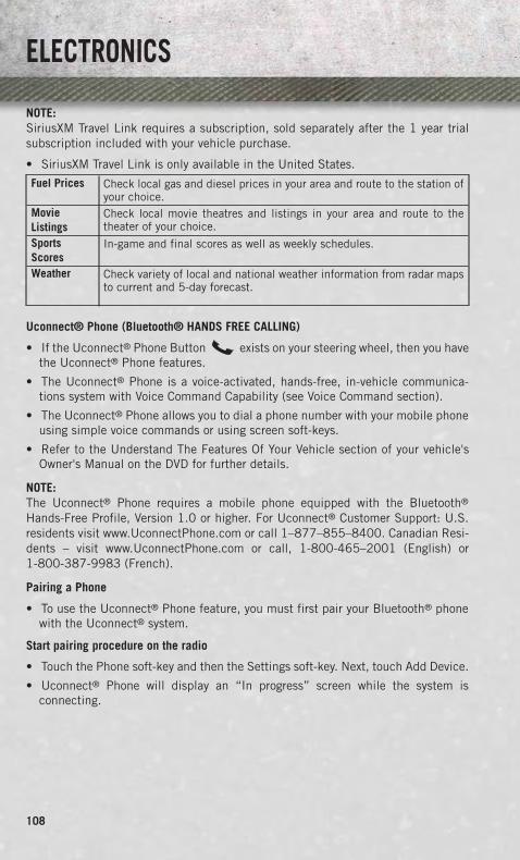
NOTE:SiriusXM Travel Link requires a subscription, sold separately after the 1 year trialsubscription included with your vehicle purchase.
• SiriusXM Travel Link is only available in the United States.
Fuel Prices Check local gas and diesel prices in your area and route to the station ofyour choice.
MovieListings
Check local movie theatres and listings in your area and route to thetheater of your choice.
SportsScores
In-game and final scores as well as weekly schedules.
Weather Check variety of local and national weather information from radar mapsto current and 5-day forecast.
Uconnect® Phone (Bluetooth® HANDS FREE CALLING)
• If the Uconnect® Phone Button exists on your steering wheel, then you havethe Uconnect® Phone features.
• The Uconnect® Phone is a voice-activated, hands-free, in-vehicle communica-tions system with Voice Command Capability (see Voice Command section).
• The Uconnect® Phone allows you to dial a phone number with your mobile phoneusing simple voice commands or using screen soft-keys.
• Refer to the Understand The Features Of Your Vehicle section of your vehicle'sOwner's Manual on the DVD for further details.
NOTE:The Uconnect® Phone requires a mobile phone equipped with the Bluetooth®
Hands-Free Profile, Version 1.0 or higher. For Uconnect® Customer Support: U.S.residents visit www.UconnectPhone.com or call 1–877–855–8400. Canadian Resi-dents – visit www.UconnectPhone.com or call, 1-800-465–2001 (English) or1-800-387-9983 (French).
Pairing a Phone
• To use the Uconnect® Phone feature, you must first pair your Bluetooth® phonewith the Uconnect® system.
Start pairing procedure on the radio
• Touch the Phone soft-key and then the Settings soft-key. Next, touch Add Device.
• Uconnect® Phone will display an “In progress” screen while the system isconnecting.
ELECTRONICS
108

Start pairing procedure on mobile phone
• Search for available devices on your Bluetooth® enabled mobile phone. This isusually within Settings or Options under “Bluetooth”. See your mobile phone’smanual for details.
• When your phone finds the system, select “Uconnect” as the paired device. Youmay be prompted by your phone to download the phonebook. This is so you canmake calls by saying the name of your contact (PBAP-Phone Book Access Profile).
Complete the pairing procedure
• When prompted on the phone, verify with the radio password shown on theUconnect® Screen.
• If your phone asks you to accept a connection request from Uconnect®, select“Yes”. If available, check the box telling it not to ask again – that way your phonewill automatically connect each time you start the vehicle.
Select the mobile phone's priority level
• When the pairing process has successfully completed, the system will prompt youto choose whether or not this is your favorite phone. Selecting Yes will make thisphone the highest priority. This phone will take precedence over other pairedphones within range. Only one phone can be paired at a time.
• You are now ready to make hands-free calls. Press the Uconnect® Phone button onyour steering wheel to begin.
Making A Phone Call
• Press the Uconnect® Phone button .
• After the BEEP, say “dial” then the number (or “call” then the name as listed inyour phone; see Phonebook).
NOTE:You can also initiate a call by using the touchscreen on the Phone main screen.
Receiving A Call – Accept (And End)
• When an incoming call rings/is announced on Uconnect®, press the Phonebutton .
• To end a call, press the Phone button .
Mute (Or Unmute) Microphone During Call
• During a call, touch the mute soft-key on the Phone main screen to mute andunmute the call.
Transfer Ongoing Call Between Handset And Vehicle
• During an on-going call, touch the Transfer soft-key on the Phone main screen totransfer an on-going call between handset and vehicle.
ELECTRONICS
109

Common Phone Commands (Examples)
• “Call John Smith”
• “Call John Smith mobile”
• “Dial 1 248 555 1212”
• “Call Emergency”
• “Call Towing Assistance”
• “Redial”
Phonebook
• Uconnect® radios will automatically download your phonebook from your pairedphone, if this feature is supported by your phone. Entries are updated each timethat the phone is connected. If your phone book entries do not appear, check thesettings on your phone. Some phones require you to enable this feature manually.
• Your phonebook can be browsed on your radio screen, but editing can only be doneon your phone. To browse, touch the Phone soft-key, then the Phonebook soft-key.
• Favorite phonebook entries can be saved as Favorites for quicker access. Favoritesare shown at the top of your main phone screen.
Voice Command Tips (8.4 and 8.4N ONLY)
• Using complete names (i.e; Call John Doe vs. Call John) will result in greatersystem accuracy.
• You can “chain” commands together for faster results. Say “Call John Doe, mobile”,for example.
• If you are listening to available voice command options, you do not have to listento the entire list. When you hear the command that you need, press thebutton on the steering wheel, wait for the beep and say your command.
Changing The Volume
• Start a dialogue by pressing the Phone button , then say a command forexample - "Help".
• Use the radio VOLUME/MUTE rotary knob to adjust the volume to a comfortablelevel while the Uconnect® system is speaking. Please note the volume setting forUconnect® is different than the audio system.
NOTE:To access help, press the Uconnect® Phone button on the steering wheel andsay "help." Touch the display or push either or button and say "cancel"to cancel the help session.
ELECTRONICS
110

Voice Text Reply
• Uconnect® Phone can read or send new text messages on your mobile phone.
• Your mobile phone must be MAP (Message Access Profile) compatible to supportSMS via Bluetooth® to use this feature. If the Uconnect® Phone determines yourphone is not compatible with SMS messaging over Bluetooth® the “Messaging”button will be greyed out and the feature will not be available for use.
NOTE:For mobile phone compatibility and pairing instructions, please visitwww.UconnectPhone.com
WARNING!
• Any voice commanded system should be used only in safe driving conditionsfollowing applicable laws regarding phone use. Your attention should befocused on safely operating the vehicle. Failure to do so may result in acollision causing you and others to be severely injured or killed.
• In an emergency, to use Uconnect® Phone, your mobile phone must be:• turned on,• paired to Uconnect® Phone,• and have network coverage.
VOICE COMMAND QUICK REFERENCE
Uconnect® 8.4AN Voice Command Quick Reference
• If the Uconnect® Voice Command button exists on your steering wheel, youhave the Voice Command feature, which is optimized for the driver. The VoiceCommand feature lets you keep your hands on the wheel, and your eyes on the road.
• When you press the Voice Command button located on the steering wheel,you will hear a beep. After the beep, give your command. If you do not know whatcommands to say, you can say “help” and the system will provide options to you.If you ever wish to interrupt the system while it lists options, press the VoiceCommand button, after the beep, say your command.
NOTE:All phone oriented voice commands are accessible by first pressing the Phone PickUp button, not the Voice Command button. To end a call, simply press thePhone Hang Up button. In some vehicles, the Phone Pickup buttonserves the dual purpose of ending calls as well.
ELECTRONICS
111

Voice Command (VR) User TIPs
• To hear available commands, press the Uconnect® Voice Command button andsay “Help”. You will hear available commands for the menu displayed.
• At any time, you can say the words “Cancel” or “Help”. These commands areuniversal and can be used from virtually any menu. All other specific commandscan be used depending upon the active application.
• You can interrupt the system prompts at any time by pressing the Uconnect® VoiceCommand button while the system is speaking. After the beep, you can say acommand.
• You can ‘chain’ commands together for faster results. Say “Call Joe Doe mobile”,for example.
• For best performance, adjust the rearview mirror to provide at least 1⁄2 in (1 cm)gap between the overhead console (if equipped) and the mirror.
• Always wait for the beep before speaking.
• Speak normally, without pausing, just as you would speak to a person sitting a fewfeet/meters away from you.
• Make sure that no one other than you is speaking during a Voice Command period.
Steering Wheel Buttons
• You can control many of your radio features using your voice. Press either the VRor Phone Pick Up button on your steering wheel.
Available Radio Soft–Key Voice Commands
ELECTRONICS
112

Type
sof
Voic
eCo
mm
ands
Avai
labl
e
Stee
ring
Whe
elBu
ttons
toPr
ess:
(1)
Radi
oM
ode
(2)
Med
iaM
ode
(3)
Clim
ate
Cont
rols
(4)
Nav
igat
ion
(5)
Phon
eM
ode
(6)
APPS
Uco
nnec
t®Vo
ice
Com
-m
and
(VR
)B
utto
n
AM
/FM
&S
atel
lite
Ban
dC
ontr
ol
Med
iaD
evic
esC
ontr
olTe
mpe
ratu
reC
ontr
ol
Des
tina
tion
Sel
ecti
onan
dVi
ew-
Yelp
®
GEN
ERAL
Uco
nnec
t®P
hone
Pic
kU
pB
utto
n-
--
-
Cal
lIni
tiat
ion,
Cal
lMan
age-
men
t,P
re-
defi
ned
Voic
eTe
xtR
eply
-
ELECTRONICS
113

Voice Command Examples – Uconnect® 8.4AN
GENERALAnytime “Go to Radio” (Media, Climate, Navigation, Phone,
Apps) – Settings, and Controls are not Voice Commandaccessible“Cancel”
“Help” (to listen to suggested commands specific tocurrent need)
“Repeat”“Launch Yelp®” – Required 1st voice command to
launch Yelp® app“Yelp® Search” – Required 2nd voice command to
activate app functionality using Steering Wheel VoiceControl Button
RADIOAM/FM “Tune to AM950”, “Tune to 95.5FM (preset 5)
Satellite Band Control “Tune to Satellite Channel 80's on 8”, Tune to SatelliteChannel 32 (preset 4)
MEDIAMedia Devices Control
(Functionality is dependenton compatibility between
devices and radio)
“Browse” (show) “artist” (albums, music)“Show paired phones” (devices)
“Play song – Maple Leaf Rag” (artist - Scott Joplin,genre - rock, album - Ragtime Favorites)
“Shuffle” – available with iPod, USB and SD CardCLIMATE
Temperature Control “Set temperature to 70 degrees” – single climate zonevehicles
“Set driver” (passenger) “temperature to 75 degrees” –dual climate zone vehicles
NAVIGATIONDestination Selection &
View“Navigate to” (Destination) 123 Any Street, Any town,
Any State (any full address)“Go Home” – destination previously defined by driver“Repeat guidance” – hear the last navigation prompt
“Cancel Route”“View Map”
PHONECall Initiation (Requiresthat phone has been
Bluetooth® paired withradio)
“Dial 123-456-7890” (phone number)“Call John Smith mobile” (home, office, other)
“Redial”“Show outgoing” (recent) “calls”
Call Management “Search for John Smith” (any contact name inaddress book)
“Show (display list) contacts”
ELECTRONICS
114

PHONEVoice Texting (Requires
registration withUconnect® Access and a
current subscription)NOTE: Requires a compat-ible mobile device enabled
with Bluetooth MessageAccess Profile (MAP).iPhone and some other
smartphones do notcurrently support
Bluetooth® MAP. Visitwww.UconnectPhone.com
for system and devicecompatibility.
Create a text message using Voice Command Capability“Send a message to John Smith (123-456-7890)”
“Show Messages”“Listen to” (view) “number 4”
“Reply”“Forward text” (message) “to John Smith”
(phone type, number)
Voice Text Reply (Radioaudibly recognizes these
18 pre-defined SMS mes-sages as you speak)
NOTE: Requires a compat-ible mobile device enabled
with Bluetooth MessageAccess Profile (MAP).iPhone and some other
smartphones do notcurrently support
Bluetooth® MAP. Visitwww.UconnectPhone.com
for system and devicecompatibility.
Forward one of 18 pre-defined SMS messages toincoming calls/text messages:
“Yes.”“No.”
“Okay.”“I can’t talk right now.”
“Call me.”“I’ll call you later.”“I’m on my way.”
“Thanks.”“I’ll be late.”
“I will be <number> minutes late.”“See you in <number> minutes”
“Stuck in traffic.”“Start without me.”“Where are you?”
“Are you there yet?”“I need directions.”
“I’m lost.”“See you later.”
ELECTRONICS
115

APPSSiriusXM Travel Link (Trafficfunction is not voice com-mand accessible withinSiriusXM Travel Link)
“Show Fuel prices”“Show Current Weather” – provides access to
Forecast as well“Show Weather map” – multiple map formats available
“Show Sports”“Show Movie listings”“Show My favorites”
Yelp® (Yelp® adds it's ownaudible prompts, andresponse time variesdepending on carrier
coverage speed)
“Launch Yelp®” – Required 1st voice command tolaunch Yelp® app
“Yelp® Search” – Required 2nd voice command toactivate app functionality using Steering Wheel Voice
Control Button“Hotel” (restaurant, gas station, mail, hospital) –
for nearest desired general POI“Italian restaurants” – for nearest specified POI category“Hotels” (restaurants, hospitals, Starbucks) “in Miami”
(location) – specified distance POI
STEERING WHEEL AUDIO CONTROLS• The steering wheel audio controls are
located on the rear surface of the steer-ing wheel.
Right Switch
• Press the switch up or down to increaseor decrease the volume.
• Press the button in the center to changemodes AM/FM/CD/SXM.
Left Switch
• Press the switch up or down to searchfor the next listenable station or selectthe next or previous CD track.
• Press the button in the center to selectthe next preset station (radio) or to change CDs if equipped with a CD Changer.
ELECTRONICS
116
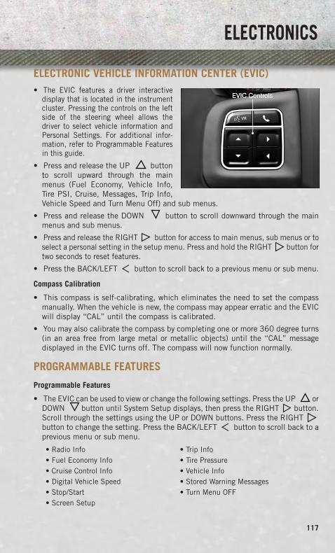
ELECTRONIC VEHICLE INFORMATION CENTER (EVIC)• The EVIC features a driver interactive
display that is located in the instrumentcluster. Pressing the controls on the leftside of the steering wheel allows thedriver to select vehicle information andPersonal Settings. For additional infor-mation, refer to Programmable Featuresin this guide.
• Press and release the UP buttonto scroll upward through the mainmenus (Fuel Economy, Vehicle Info,Tire PSI, Cruise, Messages, Trip Info,Vehicle Speed and Turn Menu Off) and sub menus.
• Press and release the DOWN button to scroll downward through the mainmenus and sub menus.
• Press and release the RIGHT button for access to main menus, sub menus or toselect a personal setting in the setup menu. Press and hold the RIGHT button fortwo seconds to reset features.
• Press the BACK/LEFT button to scroll back to a previous menu or sub menu.
Compass Calibration
• This compass is self-calibrating, which eliminates the need to set the compassmanually. When the vehicle is new, the compass may appear erratic and the EVICwill display “CAL” until the compass is calibrated.
• You may also calibrate the compass by completing one or more 360 degree turns(in an area free from large metal or metallic objects) until the “CAL” messagedisplayed in the EVIC turns off. The compass will now function normally.
PROGRAMMABLE FEATURES
Programmable Features
• The EVIC can be used to view or change the following settings. Press the UP orDOWN button until System Setup displays, then press the RIGHT button.Scroll through the settings using the UP or DOWN buttons. Press the RIGHTbutton to change the setting. Press the BACK/LEFT button to scroll back to aprevious menu or sub menu.
• Radio Info • Trip Info• Fuel Economy Info • Tire Pressure• Cruise Control Info • Vehicle Info• Digital Vehicle Speed • Stored Warning Messages• Stop/Start • Turn Menu OFF• Screen Setup
ELECTRONICS
117

Uconnect® Customer Programmable Features
• The Uconnect® system allows you to access Customer Programmable featuresettings such as Display, Clock, Safety/Assistance, Lights, Doors & Locks, Auto-OnComfort & Remote Start, Engine Off Operation, Compass Settings, Audio, TrailerBrake, Phone/Bluetooth®, Suspension and SiriusXM Setup and System Informa-tion through soft-keys.
• Touch the More soft-key to on the bottom of the screen, then touch the Settingssoft-key to access the Settings screen. When making a selection, scroll up or downuntil the preferred setting is highlighted, then press and release the preferredsetting until a check-mark appears next to the setting, showing that setting hasbeen selected. The following feature settings are available:
• Display • Clock• Safety/Assistance • Doors & Locks• Auto-On Comfort & Remote Start • Engine Off Options• Compass • Audio• Phone/Bluetooth® • SiriusXM Setup• Lights • Trailer Brake• Suspension • System Information
EVIC Reconfigurable Screen Setup
• The following settings allow you to change what information is displayed in theinstrument cluster as well as the location that information is displayed.
Digital Speedometer
• Press and release the UP or DOWN arrow button until the Digital display icon ishighlighted in the EVIC. Press and release the RIGHT arrow button to change thedisplay between km/h and mph.
Vehicle Info (Customer Information Features)
• Press and release the UP or DOWN button until the Vehicle Info icon is highlightedin the EVIC. Press and release the RIGHT button and Coolant Temp will bedisplayed. Press the UP or DOWN arrow button to scroll through the followinginformation sub-menus:• Tire Pressure• Coolant Temperature
Trip A
• Press and release the UP or DOWN arrow button until the Trip A icon is highlightedin the EVIC. Press and release the RIGHT arrow button to display the Trip Ainformation.
ELECTRONICS
118

Trip B
• Press and release the UP or DOWN arrow button until the Trip B icon is highlightedin the EVIC. Press and release the RIGHT arrow button to display the Trip Binformation.
Fuel Economy
• Press and release the UP or DOWN arrow button until the Fuel Economy icon ishighlighted. Press the RIGHT arrow button and the next screen will display thefollowing:• Average Fuel Economy/Miles Per Gallon (MPG Bargraph)• Range To Empty (RTE)• Current Miles Per Gallon (MPG)
Stop/Start
• Press and release the UP or DOWN arrow button until the Stop/Start icon ishighlighted in the EVIC. Press and release the RIGHT arrow button to display theStop/Start status.
Trailer Tow
• Press and release the UP or DOWN arrow button until the Trailer Tow icon ishighlighted. Press the RIGHT arrow button and the next screen will display thefollowing trailer trip information:• Trailer Trip• Trailer Brake• Multimeter
Audio
• Press and release the UP or DOWN arrow button until the Audio display icon ishighlighted in the EVIC. Press and release the RIGHT arrow button to display theactive source and the audio information.
Screen Setup
• Press and release the UP or DOWN arrow button until the Screen Setup displayicon is highlighted in the EVIC. Press and release the RIGHT arrow button to enterthe Screen Setup sub-menu. The Screen Setup feature allows you to change whatinformation is displayed in the instrument cluster as well as the location thatinformation is displayed.
UNIVERSAL GARAGE DOOR OPENER (HomeLink®)• HomeLink® replaces up to three hand-held transmitters that operate devices such
as garage door openers, motorized gates, lighting or home security systems. TheHomeLink® unit is powered by your vehicles 12 Volt battery.
• The HomeLink® buttons that are located in the overhead console or sunvisordesignate the three different HomeLink® channels.
• The HomeLink® indicator is located above the center button.
ELECTRONICS
119

Before You Begin ProgrammingHomeLink®
• Ensure that your vehicle is parked out-side of the garage before you beginprogramming.
• For efficient programming and accuratetransmission of the radio-frequency sig-nal, it is recommended that a new bat-tery be placed in the hand-held trans-mitter of the device that is beingprogrammed to the HomeLink® system.
• Erase all channels before you beginprogramming. To erase the channels,place the ignition switch into the ON/RUN position, then press and hold thetwo outside HomeLink® buttons (I and III) for up to 20 seconds or until the redindicator flashes.
NOTE:Erasing all channels should only be performed when programming HomeLink® forthe first time. Do not erase channels when programming additional buttons.
• If you have any problems, or require assistance, please call toll-free 1–800–355–3515or, on the Internet at www.HomeLink.com for information or assistance.
Programming A Rolling Code
NOTE:For programming Garage Door Openers that were manufactured after 1995. TheseGarage Door Openers can be identified by the “LEARN” or “TRAIN” button locatedwhere the hanging antenna is attached to the Garage Door Opener. It is NOT thebutton that is normally used to open and close the door. The name and color of thebutton may vary by manufacturer.
1. Place the ignition switch into the ON/RUN position.
2. Place the hand-held transmitter 1 to 3 in (3 to 8 cm) away from the HomeLink®
button you wish to program while keeping the HomeLink® indicator light in view.
3. Simultaneously press and hold both the Homelink® button you want to programand the hand-held transmitter button.
4. Continue to hold buttons until the EVIC display changes from “CHANNEL #TRAINING” to “CHANNEL # TRAINED”, then release both buttons.
ELECTRONICS
120

NOTE:If the EVIC displays “DID NOT TRAIN” repeat from Step 2.
5. At the garage door opener motor (in the garage), locate the “LEARN” or“TRAINING” button. This can usually be found where the hanging antenna wireis attached to the garage door opener motor. Firmly press and release the“LEARN” or “TRAINING” button.
NOTE:You have 30 seconds in which to initiate the next step after the LEARN button hasbeen pressed.
6. Return to the vehicle and press the programmed HomeLink® button twice (holdingthe button for two seconds each time). The EVIC will display “CHANNEL #TRANSMIT”. If the garage door opener/device activates, programming is complete.
NOTE:If the device does not activate, press the button a third time (for two seconds) tocomplete the training.
7. To program the remaining two HomeLink® buttons, repeat each step for eachremaining button. DO NOT erase the channels.
Programming A Non-Rolling Code
NOTE:For programming Garage Door Openers manufactured before 1995.
1. Turn the ignition switch to the ON/RUN position.
2. Place the hand-held transmitter 1 to 3 in (3 to 8 cm) away from the HomeLink®
button you wish to program while keeping the HomeLink® indicator light in view.
3. Simultaneously press and hold both the HomeLink® button you want to programand the hand-held transmitter button.
4. Continue to hold buttons until the EVIC display changes from “CHANNEL #TRAINING” to “CHANNEL # TRAINED”, then release both buttons.
5. Press and hold the programmed HomeLink® button and observe the indicatorlight.
NOTE:If the EVIC displays “DID NOT TRAIN” repeat from Step 2.
• To program the two remaining HomeLink® buttons, repeat each step for eachremaining button. DO NOT erase the channels.
ELECTRONICS
121

Using HomeLink®
• To operate, press and release the programmed HomeLink® button. Activation willnow occur for the programmed device (i.e., garage door opener, gate operator,security system, entry door lock, home/office lighting, etc.,). The hand-heldtransmitter of the device may also be used at any time.
WARNING!
• Your motorized door or gate will open and close while you are programming theuniversal transceiver. Do not program the transceiver if people or pets are in thepath of the door or gate.
• Do not run your vehicle in a closed garage or confined area while programmingthe transceiver. Exhaust gas from your vehicle contains Carbon Monoxide (CO)which is odorless and colorless. Carbon Monoxide is poisonous when inhaledand can cause you and others to be severely injured or killed.
POWER INVERTER• A 115 Volt, 150 Watt power inverter
outlet is located on the lower instru-ment panel next to the climate controlknob. This outlet can power cellularphones, electronics and other lowpower devices requiring power up to150 Watts.
• To turn on the power outlet, simplyplug in the device. The outlet auto-matically turns off when the device isunplugged.
NOTE:The power inverter is designed withbuilt-in overload protection. If the powerrating of 150 Watts is exceeded, thepower inverter will automatically shut down. Once the electrical device has beenremoved from the outlet, the inverter should automatically reset.
WARNING!
To Avoid Serious Injury or Death DO NOT:• insert any objects into the receptacles• touch with wet handsClose the lid when not in use. If this outlet is mishandled, it may cause an electricshock and failure.
ELECTRONICS
122

POWER OUTLETS• The auxiliary 12 Volt (13 Amp) power outlets can provide power for in-cab
accessories designed for use with the standard “cigar lighter” plug. The 12 Voltpower outlets have a cap attached to the outlet indicating “12V DC”, together witheither a key symbol or a battery symbol.
• The auxiliary power outlets can be found in the following locations:• Lower left and lower right in the center of the instrument panel – if equipped
with a column or a eight-speed electronic shifter.• Inside the top storage tray.• Inside the upper lid of the center stor-
age compartment — if equipped.• Rear of the center console storage
compartment — Quad Cab® or CrewCab.
NOTE:
• Do not exceed the maximum power of160 Watts (13 Amps) at 12 Volts. Ifthe 160 Watt (13 Amp) power rating isexceeded, the fuse protecting the sys-tem will need to be replaced.
• Power outlets are designed for acces-sory plugs only. Do not insert any otherobject in the power outlet as this willdamage the outlet and blow the fuse.Improper use of the power outlet cancause damage not covered by your newvehicle warranty.
ELECTRONICS
123

• The rear center console power outlet can be switched to “battery” powered all thetime by switching the power outlet right rear quarter panel fuse in the fuse panel.
ELECTRONICS
124

FOUR WHEEL DRIVE OPERATION
FOUR-POSITION/PART TIME TRANSFER CASE
• The transfer case provides four modepositions:• Two-wheel drive high range (2WD)• Four-wheel drive high range
(4WD LOCK)• NEUTRAL (N)• Four-wheel drive low range
(4WD LOW)
• This transfer case is intended to bedriven in the 2WD position for normalstreet and highway conditions, such asdry, hard-surfaced roads.
• When additional traction is required,the 4WD LOCK and 4WD LOW posi-tions can be used to lock the front andrear driveshafts together.
• When operating your vehicle in 4WD LOW, do not exceed 25 mph (40 km/h).
Shifting Procedure
• Shifting between 2WD and 4WD LOCK can be made with the vehicle stopped orin motion at speeds up to 55 mph (88 km/h).
• Shifting between 2WD or 4WD LOCK into 4WD LOW must be made with thetransmission in NEUTRAL and the vehicle stopped or rolling at 2 to 3 mph (3 to5 km/h).
OFF-ROAD CAPABILITIES
125

FIVE-POSITION/ON-DEMAND TRANSFER CASE
• This electronically shifted transfercase provides five mode positions:• Two-wheel drive high range (2WD)• Four-wheel drive automatic range
(4WD AUTO)• Four-wheel drive lock range
(4WD LOCK)• Four-wheel drive low range
(4WD LOW)• NEUTRAL (N)
• This electronically shifted transfercase is designed to be driven in thetwo-wheel drive position (2WD) or four-wheel drive position (4WD AUTO) fornormal street and highway conditionson dry, hard-surfaced roads.
• Driving the vehicle in 2WD will have greater fuel economy benefits as the frontaxle is not engaged in 2WD.
Shifting Procedure
• Shifting between 2WD and 4WD AUTO or 4WD LOCK can be made with thevehicle stopped or in motion at speeds up to 55 mph (88 km/h).
• Shifting between 2WD, 4WD AUTO and 4WD LOCK into 4WD LOW must be madewith the transmission in NEUTRAL and the vehicle stopped or rolling at 2 to 3 mph(3 to 5 km/h).
NOTE:It is preferred to have the engine running and the vehicle moving at 2 to 3 mph (3 to5 km/h).
WARNING!
You or others could be injured if you leave the vehicle unattended with the transfercase in the NEUTRAL position without first fully engaging the parking brake. Thetransfer case NEUTRAL position disengages both the front and rear driveshaftsfrom the powertrain and will allow the vehicle to move regardless of the transmis-sion position. The parking brake should always be applied when the driver is notin the vehicle.
OFF-ROAD CAPABILITIES
126

FIVE-POSITION/ON-DEMAND TRANSFER CASE
• This electronically shifted transfercase provides five mode positions:• Two-wheel drive high range (2WD)• Four-wheel drive automatic range
(4WD AUTO)• Four-wheel drive lock range
(4WD LOCK)• Four-wheel drive low range
(4WD LOW)• NEUTRAL (N)
• This electronically shifted transfercase is designed to be driven in thetwo-wheel drive position (2WD) or four-wheel drive position (4WD AUTO) fornormal street and highway conditionson dry, hard-surfaced roads.
• Driving the vehicle in 2WD will have greater fuel economy benefits as the frontaxle is not engaged in 2WD.
Shifting Procedure
• Shifting between 2WD and 4WD AUTO or 4WD LOCK can be made with thevehicle stopped or in motion at speeds up to 55 mph (88 km/h).
• Shifting between 2WD, 4WD AUTO and 4WD LOCK into 4WD LOW must be madewith the transmission in NEUTRAL and the vehicle stopped or rolling at 2 to 3 mph(3 to 5 km/h).
NOTE:It is preferred to have the engine running and the vehicle moving at 2 to 3 mph (3 to5 km/h).
WARNING!
You or others could be injured if you leave the vehicle unattended with the transfercase in the NEUTRAL position without first fully engaging the parking brake. Thetransfer case NEUTRAL position disengages both the front and rear driveshaftsfrom the powertrain and will allow the vehicle to move regardless of the transmis-sion position. The parking brake should always be applied when the driver is notin the vehicle.
OFF-ROAD CAPABILITIES
127

TONNEAU COVER• The Tonneau Cover can be removed and reinstalled by using the locking clamps
located underneath the Tonneau Cover.
NOTE:Be sure that the Tonneau Cover is secured before driving.
EASY-OFF TAILGATE• To simplify mounting of a camper unit with an overhang, the tailgate can be
removed.
NOTE:If your vehicle is equipped with a rear camera or RKE the electrical connector mustbe disconnected prior to removing the tailgate.
Removing the Tailgate
• Disconnect the wiring harness for the rear camera or RKE (if equipped).
• Unlatch the tailgate and remove the support cables by releasing the lock tang fromthe pivot.
• Raise the right side of the tailgate until the right side pivot clears the hangerbracket.
• Slide the entire tailgate to the right to free the left side pivot.
• Remove the tailgate from the vehicle.
NOTE:Do not carry the tailgate loose in the truck pickup box.
Locking Tailgate
• The lock is located next to the tailgate handle. The tailgate can be locked using thevehicle key.
WARNING!
To avoid inhaling carbon monoxide, which is deadly, the exhaust system onvehicles equipped with “Cap or Slide-In Campers” should extend beyond theoverhanging camper compartment and be free of leaks.
UTILITY
128

PICKUP BOX• You can carry wide building materials (sheets of plywood, etc.) by building a raised
load floor. Place lumber across the box in the indentations provided above thewheel housings and in the bulkhead dividers to form the floor.
• There are stampings in the sheet metal on the inner side bulkheads of the box infront of and behind both wheel housings. Place wooden boards across the box fromside to side to create separate load compartments in the pickup box.
• There are four tie-down cleats bolted to the lower sides of the pickup box that cansustain loads up to 1000 lbs (450 kg) total.
WARNING!
• The pickup box is intended for load carrying purposes only, not for passengers,who should sit in seats and use seat belts.
• Care should always be exercised when operating a vehicle with unrestrainedcargo. Vehicle speeds may need to be reduced. Severe turns or rough roads maycause shifting or bouncing of the cargo that may result in vehicle damage. Ifwide building materials are to be frequently carried, the installation of asupport is recommended. This will restrain the cargo and transfer the load tothe pickup box floor.
• If you wish to carry more than 600 lbs (272 kg) of material suspended abovethe wheelhouse, supports must be installed to transfer the weight of the loadto the pickup box floor or vehicle damage may result. The use of propersupports will permit loading up to the rated payload.
• Unrestrained cargo may be thrown forward in an accident causing serious orfatal injury.
UTILITY
129

RAMBOX®
• The RamBox® system is an integrated pickup box storage and cargo managementsystem consisting of three features:
• Integrated box side storage bins
• Cargo extender/divider
• Bed rail tie-down system
RamBox® Integrated Box Side Storage Bins
• The cargo storage bins provide watertight, lockable, illuminated storage for up to150 lbs (68 kg) of evenly distributed cargo.
• To open a storage bin, press and release the pushbutton located on the lid.
• The interior of the RamBox® will automatically illuminate when the lid is opened.Pushing the switch once will turn off the bin lights, pushing the switch again willturn the lights back on.
UTILITY
130

• Storage bins feature two removable drain plugs (to allow water to drain from bins). Toremove plug, pull up on the edge. To install, push plug downward into drain hole.
• The RamBox® storage bins can be locked and unlocked using the vehicle key orthe remote keyless entry transmitter.
NOTE:Provisions are provided in the bins for cargo dividers and shelf supports. Theseaccessories (in addition to other RamBox® accessories) are available from MOPAR®.
RamBox® Storage Bin Cover Emergency Release Lever
• As a security measure, a Storage Bin Cover Emergency Release is built into thestorage bin cover latching mechanism.
NOTE:In the event of an individual being locked inside the storage bin, the storage bin covercan be opened from inside of the bin by pulling on the glow-in-the-dark leverattached to the storage bin cover latching mechanism.
Bed Extender
• The bed extender has three functional positions:
• Storage Position
• Divider Position
• Extender Position
Storage Position
• The storage position for the bed extender is at the front of the truck bed.
• To install the bed extender into the storage position, perform the following:
• Make sure the center handle is unlocked using the vehicle key and rotate thecenter handle vertically to release the extender side gates.
• With the side gates open, position the extender fully forward in the bed againstthe front panel.
• Rotate the side gates closed allowing the outboard ends to be positioned in frontof the cargo tie-down loops.
• Rotate the center handle horizontally to secure the side gates in the closedposition.
• Lock the center handle using the vehicle key to secure the panel into place andassist against theft.
UTILITY
131

Divider Position
• There are 11 divider slots along the bed inner panels which allow for variouspositions to assist in managing your cargo.
• To install the bed extender into a divider position perform the following:
• Make sure the center handle is unlocked using the vehicle key and rotate thecenter handle vertically to release the extender side gates.
• With the side gates open, position the extender so the outboard ends align withthe intended slots in the sides of the bed.
• Rotate the side gates closed so that the outboard ends are secured into theintended slots of the bed.
• Rotate the center handle horizontally to secure the side gates in the closedposition.
• Lock the center handle to secure the panel into place and assist against theft.
Extender Position
• The bed extender will add an additional 15 in (38 cm) in the back of the truckwhen additional cargo room is needed.
• To install the bed extender into the extender position, perform the following:
• Lower the tailgate.
• Make sure the center handle is unlocked and rotate the center handle verticallyin order to release the extender side gates.
• Fit the end of the side gate ends onto the pin and handle.
• Rotate the handles to the horizontal position to secure into place.
Bed Rail Tie-Down System
• There are two adjustable cleats on each side of the bed that can be used to assistin securing cargo.
• Each cleat must be located and tightened down in one of the detents, along eitherrail, in order to keep cargo properly secure.
• To move the cleat to any position on the rail, turn the nut counterclockwise,approximately three turns. Then, pull out on the cleat and slide it to the detentnearest the desired location. Make sure the cleat is seated in the detent andtighten the nut.
• To remove the cleats from the utility rail, remove the end cap by pushing up on thelocking tab, located on the bottom of the end cap. Slide the cleat off the end of the rail.
UTILITY
132

CAUTION!
• Failure to follow the following items could cause damage to the vehicle:• Assure that all cargo inside the storage bins is properly secured.• Do not exceed cargo weight rating of 150 lb (68 kg) per bin.• Leaving the lid open for extended periods of time could cause the vehicle
battery to discharge. If the lid is required to stay open for extended peri-ods of time, it is recommended that the bin lights be turned off manuallyusing the on/off switch.
• Ensure cargo bin lids are closed and latched before moving or drivingvehicle.
• Loads applied to the top of the bin lid should be minimized to preventdamage to the lid and latching/hinging mechanisms.
• Damage to the RamBox® bin may occur due to heavy/sharp objectsplaced in bin that shift due to vehicle motion. In order to minimizepotential for damage, secure all cargo to prevent movement and protectinside surfaces of bin from heavy/sharp objects with appropriate padding.
• The maximum load per cleat should not exceed 250 lbs (113 kg) and theangle of the load on each cleat should not exceed 60 degrees above hori-zontal, or damage to the cleat or cleat rail may occur.
WARNING!
• Always close the storage bin covers when your vehicle is unattended or inmotion.
• Do not allow children to have access to the storage bins. Once in the storagebin, young children may not be able to escape. If trapped in the storage bin,children can die from suffocation or heat stroke.
• In a collision, serious injury could result if the storage bin covers are notproperly latched.
• Do not use a storage bin latch as a tie down.• To reduce the risk of potential injury or property damage:
• Cargo must be secured.• Do not exceed cargo load rating of your vehicle.• Secure all loads to truck utilizing cargo tie-downs.• Extender should not be used as cargo tie-down.• When vehicle is in motion do not exceed 150 lbs (68 kg) load on the
tailgate.• The bed extender is not intended for off road use.• When not in use, the extender/divider should be in stowed or divider
position with the tailgate closed.• When in use, all handles are to be in the locked position.
UTILITY
133

TOW
ING
&PA
YLOA
DRa
m15
004x
2
STSL
T/Ou
tdoo
rsm
anSp
ort/L
aram
ie
3.6L
V-6
8–Sp
eed
Auto
mat
icTr
ansm
issi
on
Sta
ndar
dTo
win
g:5
,00
0lb
s(2
26
8kg
)M
axTo
win
g:7
,40
0lb
s(3
35
7kg
)M
axP
aylo
ad:1
,92
0lb
s(8
71
kg)
Sta
ndar
dTo
win
g:5
,00
0lb
s(2
26
8kg
)M
axTo
win
g:7
,40
0lb
s(3
35
7kg
)M
axP
aylo
ad:
1,9
00
lbs
(86
2kg
)
—
5.7L
HEM
I®V-
86–
Spee
dAu
tom
atic
Tran
smis
sion
Sta
ndar
dTo
win
g:5
,00
0lb
s(2
26
8kg
)M
axTo
win
g:1
0,4
50
lbs
(47
40
kg)
Max
Pay
load
:1
,73
0lb
s(7
84
kg)
Sta
ndar
dTo
win
g:5
,00
0lb
s(2
26
8kg
)M
axTo
win
g:1
0,4
50
lbs
(47
40
kg)
Max
Pay
load
:1
,70
0lb
s(7
71
kg)
Sta
ndar
dTo
win
g:5
,00
0lb
s(2
26
8kg
)M
axTo
win
g:1
0,2
50
lbs
(46
49
kg)
Max
Pay
load
:1
,60
0lb
s(7
26
kg)
3.0L
Dies
elEn
gine
8–Sp
eed
Auto
mat
icTr
ansm
issi
on
Sta
ndar
dTo
win
g:5
,00
0lb
s(2
26
8kg
)M
axTo
win
g:9
,25
0lb
s(4
19
6kg
)M
axP
aylo
ad:1
,52
0lb
s(6
89
kg)
Sta
ndar
dTo
win
g:5
,00
0lb
s(2
26
8kg
)M
axTo
win
g:9
,25
0lb
s(4
19
6kg
)M
axP
aylo
ad:
1,5
20
lbs
(68
9kg
)
Sta
ndar
dTo
win
g:5
,00
0lb
s(2
26
8kg
)M
axTo
win
g:9
,25
0lb
s(4
19
6kg
)M
axP
aylo
ad:1
,52
0lb
s(6
89
kg)
UTILITY
134

Ram
1500
4x4
STSL
T/Ou
tdoo
rsm
anSp
ort/L
aram
ie
3.6L
V-6
8–Sp
eed
Auto
mat
icTr
ansm
issi
on
Sta
ndar
dTo
win
g:5
,00
0lb
s(2
26
8kg
)M
axTo
win
g:7
,25
0lb
s(3
28
9kg
)M
axP
aylo
ad:
1,9
30
lbs
(87
5kg
)
Sta
ndar
dTo
win
g:5
,00
0lb
s(2
26
8kg
)M
axTo
win
g:7
,20
0lb
s(3
26
6kg
)M
axP
aylo
ad:
1,9
00
lbs
(86
1kg
)
—
5.7L
HEM
I®V-
86–
Spee
dAu
tom
atic
Tran
smis
sion
Sta
ndar
dTo
win
g:5
,00
0lb
s(2
26
8kg
)M
axTo
win
g:1
0,3
50
lbs
(46
95
kg)
Max
Pay
load
:1
,50
0lb
s(6
80
kg)
Sta
ndar
dTo
win
g:5
,00
0lb
s(2
26
8kg
)M
axTo
win
g:1
0,3
50
lbs
(46
95
kg)
Max
Pay
load
:1
,48
0lb
s(6
71
kg)
Sta
ndar
dTo
win
g:5
,00
0lb
s(2
26
8kg
)M
axTo
win
g:1
0,0
50
lbs
(45
58
kg)
Max
Pay
load
:1
,39
0lb
s(6
30
kg)
3.0L
Dies
elEn
gine
8–Sp
eed
Auto
mat
icTr
ansm
issi
on
Sta
ndar
dTo
win
g:5
,00
0lb
s(2
26
8kg
)M
axTo
win
g:9
,25
0lb
s(4
19
6kg
)M
axP
aylo
ad:
1,5
20
lbs
(68
9kg
)
Sta
ndar
dTo
win
g:5
,00
0lb
s(2
26
8kg
)M
axTo
win
g:9
,25
0lb
s(4
19
6kg
)M
axP
aylo
ad:
1,5
20
lbs
(68
9kg
)
Sta
ndar
dTo
win
g:5
,00
0lb
s(2
26
8kg
)M
axTo
win
g:9
,25
0lb
s(4
19
6kg
)M
axP
aylo
ad:1
,52
0lb
s(6
89
kg)
UTILITY
135

Ram
2500
&35
00
STSL
T/OU
TDOO
RSM
AN/
LARA
MIE
5.7L
HEM
I®V-
86-
Spee
dAu
tom
atic
Tran
smis
sion
Max
Tow
ing:
13
,85
0lb
s(6
28
2kg
)M
axP
aylo
ad:4
,48
0lb
s(2
03
2kg
)
Max
Tow
ing:
13
,81
0lb
s(6
28
2kg
)M
axP
aylo
ad:
4,4
40
lbs
(20
14
kg)
Max
Tow
ing:
13
,35
0lb
s(6
05
5kg
)M
axP
aylo
ad:4
,41
0lb
s(2
00
0kg
)
6.4L
HEM
I®V-
86-
Spee
dAu
tom
atic
Tran
smis
sion
Max
Tow
ing:
16
,45
0lb
s(7
46
2kg
)M
axP
aylo
ad:7
,22
0lb
s(3
27
5kg
)
Max
Tow
ing:
16
,40
0lb
s(7
43
9kg
)M
axP
aylo
ad:
7,1
70
lbs
(32
52
kg)
Max
Tow
ing:
15
,81
0lb
s(7
17
1kg
)M
axP
aylo
ad:6
,95
0lb
s(3
15
2kg
)
6.7L
Cum
min
s®Di
esel
2500
STSL
TBi
ghor
n/Lo
nest
arLa
ram
ieOu
tdoo
rsm
an35
00ST
SLT
Bigh
orn/
Lone
star
Lara
mie
Outd
oors
man
6.7L
Cum
min
s®Tu
rbo
Dies
el6-
Spee
dM
anua
lTr
ansm
issi
onM
axTo
win
g:1
6,7
10
lbs
(75
79
kg)
Max
Pay
load
:2
,88
0lb
s(1
30
6kg
)M
axTo
win
g:1
8,2
00
lbs
(82
55
kg)
Max
Pay
load
:6
,64
0lb
s(3
01
1kg
)6.
7LCu
mm
ins®
Turb
oDi
esel
6-Sp
eed
Auto
mat
icTr
ansm
issi
onM
axTo
win
g:1
7,8
10
lbs
(80
78
kg)
Max
Pay
load
:2
,98
0lb
s(1
35
1kg
)M
axTo
win
g:3
0,0
60
lbs
(13
63
4kg
)M
axP
aylo
ad:
6,7
10
lbs
(30
43
kg)
NOT
E:Fo
rad
diti
onal
trai
ler
tow
ing
info
rmat
ion
(max
imum
trai
ler
wei
ght
rati
ngs)
refe
rto
the
follo
win
gw
ebsi
tead
dres
ses:
•ht
tp://
ww
w.r
amtr
ucks
.com
.
•ht
tp://
ww
w.r
amtr
uck.
ca(C
anad
a).
UTILITY
136

TOW/HAUL MODE• When driving in hilly areas, towing a trailer, carrying a heavy load, etc., and
frequent transmission shifting occurs, press the TOW/HAUL switch to selectTOW/HAUL mode. This will improve performance and reduce the potential fortransmission overheating or failure due to excessive shifting. When operating inTOW/HAUL mode, transmission upshifts are delayed, and the transmission willautomatically downshift (for engine braking) during steady braking maneuvers.
• The “TOW/HAUL Indicator Light” willilluminate in the instrument cluster toindicate that TOW/HAUL mode hasbeen activated. Pressing the switch asecond time restores normal opera-tion. If the TOW/HAUL mode is de-sired, the switch must be pressed eachtime the engine is started.
INTEGRATED TRAILER BRAKE MODULE• The Integrated Trailer Brake Controller allows you to automatically or manually
activate the Electric Trailer Brakes and Electric Over Hydraulic Trailer Brakes for abetter braking performance when towing a trailer.
NOTE:The Integrated Trailer Brake Controller is located in the center stack below theclimate controls.
• This module will have four different options depending on the type of trailer youwant to tow and can be selected through the 3.5” Electronic Vehicle InformationCenter (EVIC) or touchscreen radio – if equipped with a 7” EVIC.• Light Electric• Heavy Electric• Light EOH (Electric Over Hydraulic)• Heavy EOH (Electric Over Hydraulic)
• Setting with a 7” EVIC To make the proper selection in the Uconnect® touchscreenradio, press the More hard-key (Uconnect® 5.0) or the Apps soft-key (Uconnect®8.4), then press the Settings soft-key to display the menu setting screen. Foradditional information, refer to your Owner’s Manual on the DVD.
UTILITY
137
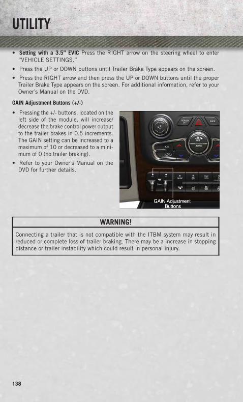
• Setting with a 3.5” EVIC Press the RIGHT arrow on the steering wheel to enter“VEHICLE SETTINGS.”
• Press the UP or DOWN buttons until Trailer Brake Type appears on the screen.
• Press the RIGHT arrow and then press the UP or DOWN buttons until the properTrailer Brake Type appears on the screen. For additional information, refer to yourOwner’s Manual on the DVD.
GAIN Adjustment Buttons (+/-)
• Pressing the +/- buttons, located on theleft side of the module, will increase/decrease the brake control power outputto the trailer brakes in 0.5 increments.The GAIN setting can be increased to amaximum of 10 or decreased to a mini-mum of 0 (no trailer braking).
• Refer to your Owner's Manual on theDVD for further details.
WARNING!
Connecting a trailer that is not compatible with the ITBM system may result inreduced or complete loss of trailer braking. There may be a increase in stoppingdistance or trailer instability which could result in personal injury.
UTILITY
138

RECREATIONAL TOWING (BEHIND MOTORHOME, ETC.)
Towing This Vehicle Behind Another Vehicle
TowingCondition
Wheels OFF TheGround
Two-WheelDrive Models
Four-Wheel Drive Models
Flat Tow NONE NOT ALLOWED
See Instructions:• Automatic transmission in
PARK• Manual transmission in gear
(NOT in NEUTRAL)• Transfer case in
NEUTRAL (N)• Tow in forward direction
Dolly TowFront NOT ALLOWED NOT ALLOWEDRear OK NOT ALLOWED
On Trailer ALL OK OK
Recreational Towing – Two-Wheel Drive Models
• DO NOT flat tow this vehicle. Damage to the drivetrain will result.
• Recreational towing (for two-wheel drive models) is allowed ONLY if the rearwheels are OFF the ground. This may be accomplished using a tow dolly or vehicletrailer. If using a tow dolly, follow this procedure:
1. Properly secure the dolly to the tow vehicle, following the dolly manufacturer'sinstructions.
2. Drive the rear wheels onto the tow dolly.
3. Firmly apply the parking brake. Place automatic transmission in PARK, manualtransmission in gear (not in NEUTRAL).
4. Properly secure the rear wheels to the dolly, following the dolly manufacturer'sinstructions.
5. Turn the ignition switch to the OFF position and remove the key fob.
6. Install a suitable clamping device, designed for towing, to secure the front wheelsin the straight position.
UTILITY
139

Recreational Towing – Four-Wheel Drive Models
NOTE:Both the manual shift and electronic shift transfer cases must be shifted intoNEUTRAL (N) for recreational towing. Automatic transmissions must be shifted intoPARK for recreational towing. Manual transmissions must be placed in gear (NOT inNEUTRAL) for recreational towing. Refer to the Owner’s Manual on the DVD forfurther information.
CAUTION!
• Front or rear wheel lifts should not be used while recreational towing. Towingwith only one set of wheels on the ground (front or rear) will cause severedamage to the transmission and or transfer case. Tow with all four wheels eitherON the ground, or OFF the ground (using a vehicle trailer). Damage fromimproper towing is not covered under the New Vehicle Limited Warranty.
• Do not disconnect the driveshaft because fluid may leak from the transmission,causing damage to internal parts.
• Front or rear wheel lifts should not be used. Internal damage to the transmis-sion or transfer case will occur if a front or rear wheel lift is used whenrecreational towing.
• Tow only in the forward direction. Towing this vehicle backwards can causesevere damage to the transfer case.
• Before recreational towing, the transfer case must be in NEUTRAL. To becertain the transfer case is fully in NEUTRAL, perform the procedure outlinedunder “Shifting Into NEUTRAL”. Internal transmission damage will result, ifthe transfer case is not in NEUTRAL during towing.
• Manual transmissions must be placed in gear (not in Neutral) for recreationaltowing.
• Before recreational towing, perform the procedure outlined under “ShiftingInto NEUTRAL” to be certain that the transfer case is fully in NEUTRAL.Otherwise, internal damage will result.
• Towing this vehicle in violation of the above requirements can cause severetransmission and/or transfer case damage. Damage from improper towing isnot covered under the New Vehicle Limited Warranty.
• Do not disconnect the rear driveshaft because fluid will leak from the transfercase, causing damage to internal parts.
• Do not use a bumper-mounted clamp-on tow bar on your vehicle. The bumperface bar will be damaged.
UTILITY
140

Shifting Into NEUTRAL (N)
Use the following procedure to prepare your vehicle for recreational towing.
WARNING!
You or others could be injured or killed if you leave the vehicle unattended with thetransfer case in the NEUTRAL (N) position without first fully engaging the parkingbrake. The transfer case NEUTRAL (N) position disengages both the front and reardriveshafts from the powertrain and will allow the vehicle to move, even if thetransmission is in PARK. The parking brake should always be applied when thedriver is not in the vehicle.
CAUTION!
It is necessary to follow these steps to be certain that the transfer case is fully inNEUTRAL (N) before recreational towing to prevent damage to internal parts.
1. Bring the vehicle to a complete stop, with the engine running. Firmly apply theparking brake.
2. Shift the transmission to NEUTRAL.
3. Press and hold the brake pedal.
4. Depress the clutch pedal on a manual transmission.
5. Place the transfer case into NEUTRAL:
• With manual shift transfer case, shift the transfer case lever into NEUTRAL (N).
• With electronic shift transfer case, press and hold the transfer case NEUTRAL(N) button. Some models have a small, recessed "N" button (at the center of thetransfer case switches) that must be pressed using a ballpoint pen or similarobject. Other models have a rectangular NEUTRAL switch, below the rotarytransfer case control knob. The NEUTRAL (N) indicator light will blink while theshift is in progress. The light will stop blinking (stay on solid) when the shift toNEUTRAL (N) is complete. After the shift is completed and the NEUTRAL (N)light stays on, release the NEUTRAL (N) button.
6. Release the parking brake.
7. Shift the transmission into REVERSE.
8. Release the brake pedal (and clutch pedal on manual transmissions) for fiveseconds and ensure that there is no vehicle movement.
9. Repeat steps 7 and 8 with automatic transmission in DRIVE or manual transmis-sion in first gear.
10. Shift the transmission to NEUTRAL. Firmly apply the parking brake. Turn OFFthe engine. For vehicles with Keyless Enter-N-Go™, press and hold the ENGINESTART/STOP button until the engine shuts off.
UTILITY
141
11. Shift the transmission into PARK or place manual transmission in gear (NOT inNeutral). On 8-speed transmissions the shifter will automatically select PARKwhen the engine is turned off.
12. Turn the ignition switch to the OFF position, then cycle the key or the KeylessEnter-N-Go™ button to the RUN position and back to the OFF position. Removethe key fob from the ignition switch.
Attach the vehicle to the tow vehicle using a suitable tow bar.
13. Release the parking brake.
NOTE:With electronic shift transfer case:
• Steps 2 through 4 are requirements that must be met prior to pressing theNEUTRAL (N) button, and must continue to be met until the shift has beencompleted. If any of these requirements are not met prior to pressing theNEUTRAL (N) button or are no longer met during the shift, the NEUTRAL (N)indicator light will flash continuously until all requirements are met or until theNEUTRAL (N) button is released.
• The ignition switch must be in the ON/RUN position for a shift to take place andfor the position indicator lights to be operable. If the ignition switch is not in theON/RUN position, the shift will not take place and no position indicator lights willbe on or flashing.
• A flashing NEUTRAL (N) position indicator light indicates that shift requirementshave not been met.
Shifting Out Of NEUTRAL (N)
Use the following procedure to prepare your vehicle for normal usage.
1. Bring the vehicle to a complete stop, leaving it connected to the tow vehicle.
2. Firmly apply the parking brake.
3. Press and hold the brake pedal.
4. Start the engine. Shift the transmission into NEUTRAL. Depress the clutch pedalon a manual transmission.
• With manual shift transfer case, shift the transfer case lever to the desiredposition.
• With electronic shift transfer case with rotary selector switch, press and hold thetransfer case NEUTRAL (N) button until the NEUTRAL (N) indicator light turnsoff. After the NEUTRAL (N) indicator light turns off, release the NEUTRAL (N)button. After the NEUTRAL (N) button has been released, the transfer case willshift to the position indicated by the selector switch.
• With electronic shift transfer case with pushbutton selector switch, press andhold the switch for the desired transfer case position, until the NEUTRAL (N)indicator light turns off and the desired position indicator light turns on.
UTILITY
142

NOTE:When shifting out of transfer case NEUTRAL (N), turning the engine OFF is notrequired, but may be helpful to avoid gear clash. With the 8-speed automatictransmission, the engine must remain running, since turning the engine OFF willshift the transmission to PARK (and the transmission must be in NEUTRAL for thetransfer case to shift out of NEUTRAL).
5. Turn the engine OFF. Shift automatic transmission into PARK. On 8-speedtransmissions the shifter will automatically select PARK when the engine isturned off.
6. Release the brake pedal (and clutch pedal on a manual transmission).
7. Disconnect vehicle from the tow vehicle.
8. Start the engine.
9. Press and hold the brake pedal.
10. Release the parking brake.
11. Shift the transmission into gear, release the brake pedal (and clutch pedal onmanual transmissions), and check that the vehicle operates normally.
NOTE:With electronic shift transfer case:
• Steps 3 and 4 are requirements that must be met prior to pressing the button toshift out of NEUTRAL (N), and must continue to be met until the shift has beencompleted. If any of these requirements are not met before pressing the button orare no longer met during the shift, the NEUTRAL (N) indicator light will flashcontinuously until all requirements are met or until the button is released.
• The ignition switch must be in the ON/RUN position for a shift to take place andfor the position indicator lights to be operable. If the ignition switch is not in theON/RUN position, the shift will not take place and no position indicator lights willbe on or flashing.
• A flashing NEUTRAL (N) position indicator light indicates that shift requirementshave not been met.
UTILITY
143

DIESEL ENGINE BREAK-IN RECOMMENDATIONS• The 3.0 turbocharged diesel engine does not require a break-in period due to its
construction. Normal operation is allowed, providing the following recommenda-tions are followed:• Warm up the engine before placing it under load.• Do not operate the engine at idle for prolonged periods.• Use the appropriate transmission gear to prevent engine lugging.• Observe vehicle oil pressure and temperature indicators.• Check the coolant and oil levels frequently.• Vary throttle position at highway speeds when carrying or towing significant
weight.
NOTE:Light duty operation such as light trailer towing or no load operation will extend thetime before the engine is at full efficiency. Reduced fuel economy and power may beseen at this time.
• The engine oil installed in the engine at the factory is a high-quality energyconserving type lubricant. Oil changes should be consistent with anticipatedclimate conditions under which vehicle operations will occur. The recommendedviscosity and quality grades are shown under “FLUIDS AND CAPACITIES”, under“MAINTAINING YOUR VEHICLE” in this User Guide. NON-DETERGENT ORSTRAIGHT MINERAL OILS MUST NEVER BE USED.
DIESEL ENGINE STARTING PROCEDURES
Normal Starting Procedure
1. Apply the parking brake.
2. Ensure the shift lever is in the PARK position.
3. Press and hold the brake pedal while pressing the ENGINE START/STOP buttononce.
4. The system will take over and attempt to start the vehicle. If the vehicle fails tostart, the starter will disengage automatically after 30 seconds.
5. If you wish to stop the cranking of the engine prior to the engine starting, press thebutton again.
6. Check that the oil pressure warning light has turned off.
7. Release the parking brake.
NOTE:A delay of the start-up can be as long as five seconds under very cold conditions.The "Wait to Start" telltale will be illuminated during the pre-heat process and thestart will commence upon the telltale going out.
1500 3.0L DIESEL
144

CAUTION!
If the “Water in Fuel Indicator Light” remains on, DO NOT START the enginebefore you drain the water from the fuel filters to avoid engine damage. Refer to“Maintenance Procedures/Draining Fuel/Water Separator Filter” in “MaintainingYour Vehicle” for further information.
Extreme Cold Weather
• The engine block heater is a resistance heater installed in the water jacket of theengine. It requires a 110–115 Volt AC electrical outlet with a grounded, three-wireextension cord.
• Its use is recommended for environments that routinely fall below -10°F. It shouldbe used when the vehicle has not been running overnight or longer periods andshould be plugged in two hours prior to start. Its use is required for cold starts withtemperatures under -20°F.
• A 12 Volt heater built into the fuel filter housing aids in preventing fuel gelling.It is controlled by a built-in thermostat.
• A Diesel Pre-Heat system both improves engine starting and reduces the amountof white smoke generated by a warming engine.
NOTE:The engine block heater cord is a factory installed option. If your vehicle is notequipped, heater cords are available from your authorized MOPAR® dealer.
Water In Fuel Message
• If a Water In Fuel message or indicator appears in the cluster and a chimesounds five times, the fuel/water separator will need to be drained immediately toprevent engine damage.
• Refer to “Draining Fuel Water Separator” in this guide for draining instructions orsee your dealer.
DIESEL FUEL FILTER/WATER SEPARATOR
Draining Fuel/Water Separator
• If the “Water in Fuel” indicator light is illuminated and an audible chime isheard five times, you should stop the engine and drain the water from theseparator.
• The drain plug is located on the bottom of the Fuel Filter and Water Separatorassembly which is located above the rear axle next to the fuel tank.
• Loosen the drain plug (located on the bottom filter assembly) then turn theignition switch to the ON/RUN position to allow any accumulated water to drain.
• When clean fuel is visible, close the drain and switch the ignition to the OFFposition.
• Refer to the Owner's Manual on the DVD for further details.
1500 3.0L DIESEL
145

Fuel Filter Replacement
1. Ensure engine is turned off.
2. Place drain pan under the fuel filter assembly.
3. Open the water drain valve, and let any accumulated water drain.
4. Close the water drain valve.
5. Remove bottom cover using a strap wrench. Rotate counterclockwise for removal.Remove the used o-ring and discard it.
6. Remove the used filter cartridge from the housing and dispose of according toyour local regulations.
7. Wipe the sealing surfaces of the lid and housing clean.
8. Install new o-ring back into ring groove on the filter housing and lubricate withclean engine oil.
NOTE:The WIF (Water In Fuel) sensor is re-usable. Service kit comes with new o-ring forfilter canister and WIF (Water In Fuel) sensor.
CAUTION!
• Diesel fuel will damage blacktop paving surfaces. Drain the filter into anappropriate container.
• Do not prefill the fuel filter when installing a new fuel filter. There is apossibility debris could be introduced into the fuel filter during this action.It is best to install the filter dry and allow the in-tank lift pump to prime the fuelsystem.
• If the “Water In Fuel Indicator Light” remains on, DO NOT START the enginebefore you drain water from the fuel filter to avoid engine damage.
EXHAUST REGENERATION• This engine meets all required EPA diesel engine emissions standards. To achieve
these emissions standards, your vehicle is equipped with a state-of-the-art engineand exhaust system. These systems are seamlessly integrated into your vehicle andmanaged by the Powertrain Control Module (PCM).
• Additionally, your vehicle has the ability to alert you to additional maintenancerequired on your vehicle or engine. Refer to the following messages that may bedisplayed on your Electronic Vehicle Information Center (EVIC).
1500 3.0L DIESEL
146

Perform Service
• Your vehicle will require emissions maintenance at a set interval. To help remindyou when this maintenance is due, the Electronic Vehicle Information Center(EVIC) will display “Perform Service”.
• When the “Perform Service” message is displayed on the EVIC it is necessary tohave the emissions maintenance performed.
Exhaust System – Regeneration Required Now
• Indicates that the Diesel Particulate Filter (DPF) reached 80% of its maximumstorage capacity.
• By simply driving your vehicle at highway speeds for up to 20 minutes, you canremedy the condition in the particulate filter system and allow your diesel engineand exhaust after-treatment system to cleanse the filter to remove the trapped PMand restore the system to normal operating condition.
Exhaust System — Regeneration in Process Exhaust Filter XX% Full
• Indicates that the Diesel Particulate Filter (DPF) is self-cleaning. Maintain yourcurrent driving condition until regeneration is completed.
Exhaust System — Regeneration Completed
• Indicates that the Diesel Particulate Filter (DPF) self-cleaning is completed. Ifthis message is displayed, you will hear one chime to assist in alerting you of thiscondition.
Exhaust Service Required — See Dealer Now
• Regeneration has been disabled due to a system malfunction. The Powertraincontrol Module (PCM) will register a fault code and the instrument panel willdisplay the Malfunction Indicator Light (MIL).
Exhaust Filter Full — Power Reduced See Dealer
• The PCM derates the engine in order to limit the likelihood of permanent damageto the after-treatment system. If this condition is not corrected and a dealer serviceis not performed, extensive exhaust after-treatment damage can occur. Have yourvehicle serviced by your local authorized dealer.
CAUTION!
See your authorized dealer, as damage to the exhaust system could occur with theexhaust filter full.
1500 3.0L DIESEL
147
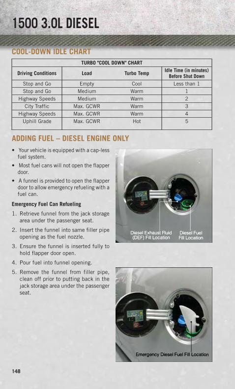
COOL-DOWN IDLE CHARTTURBO "COOL DOWN" CHART
Driving Conditions Load Turbo Temp Idle Time (in minutes)Before Shut Down
Stop and Go Empty Cool Less than 1Stop and Go Medium Warm 1
Highway Speeds Medium Warm 2City Traffic Max. GCWR Warm 3
Highway Speeds Max. GCWR Warm 4Uphill Grade Max. GCWR Hot 5
ADDING FUEL – DIESEL ENGINE ONLY• Your vehicle is equipped with a cap-less
fuel system.
• Most fuel cans will not open the flapperdoor.
• A funnel is provided to open the flapperdoor to allow emergency refueling with afuel can.
Emergency Fuel Can Refueling
1. Retrieve funnel from the jack storagearea under the passenger seat.
2. Insert the funnel into same filler pipeopening as the fuel nozzle.
3. Ensure the funnel is inserted fully tohold flapper door open.
4. Pour fuel into funnel opening.
5. Remove the funnel from filler pipe,clean off prior to putting back in thejack storage area under the passengerseat.
1500 3.0L DIESEL
148

DIESEL EXHAUST FLUID• Diesel Exhaust Fluid (DEF) sometimes known simply by the name of its active
component, UREA—is a key component of selective catalytic reduction (SCR)systems, which help diesel vehicles meet stringent emission regulations. DEF is aliquid reducing agent that reacts with engine exhaust in the presence of a catalystto convert smog-forming nitrogen oxides (NOx) into harmless nitrogen and watervapor.
• Your vehicle is equipped with a Selective Catalytic Reduction system in order tomeet the very stringent diesel emissions standards required by the EnvironmentalProtection Agency. Selective Catalytic Reduction (SCR) is the first and onlytechnology in decades to be as good for the environment as it is good for businessand vehicle performance.
• The purpose of the SCR system is to reduce levels of NOx (oxides of nitrogenemitted from engines) that are harmful to our health and the environment to analmost near-zero level. Small quantities of Diesel Exhaust Fluid (DEF) are injectedinto the exhaust upstream of a catalyst where, when vaporized, convert smog-forming nitrogen oxides (NOx) into harmless nitrogen (N2) and water vapor (H2O),two natural components of the air we breathe. You can operate with the comfortthat your vehicle is contributing to a cleaner, healthier world environment for thisand generations to come.
System Overview
• This vehicle is equipped with a Diesel Exhaust Fluid (DEF) injection system anda Selective Catalytic Reduction (SCR) catalyst to meet the emission requirements.
• The DEF injection system consists of the following components:• DEF tank• DEF pump• DEF injector• Electronically-heated DEF lines• NOx sensors• Temperature sensors• SCR catalyst
• The DEF injection system and SCR catalyst enable the achievement of dieselemissions requirements; while maintaining outstanding fuel economy, drivability,torque and power ratings.
NOTE:
• Your vehicle is equipped with a DEF injection system. You may occasionally hearan audible clicking noise. This is normal operation.
• The DEF pump will run for a period of time after engine shutdown to purge the DEFsystem. This is normal operation.
1500 3.0L DIESEL
149
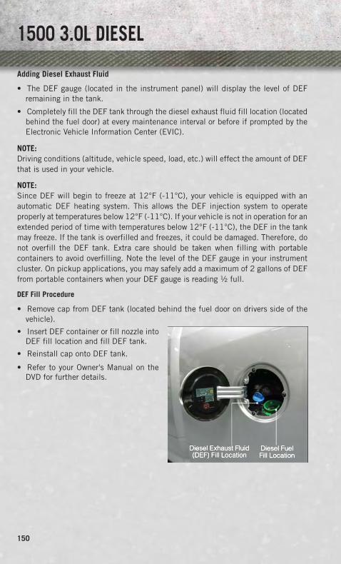
Adding Diesel Exhaust Fluid
• The DEF gauge (located in the instrument panel) will display the level of DEFremaining in the tank.
• Completely fill the DEF tank through the diesel exhaust fluid fill location (locatedbehind the fuel door) at every maintenance interval or before if prompted by theElectronic Vehicle Information Center (EVIC).
NOTE:Driving conditions (altitude, vehicle speed, load, etc.) will effect the amount of DEFthat is used in your vehicle.
NOTE:Since DEF will begin to freeze at 12°F (-11°C), your vehicle is equipped with anautomatic DEF heating system. This allows the DEF injection system to operateproperly at temperatures below 12°F (-11°C). If your vehicle is not in operation for anextended period of time with temperatures below 12°F (-11°C), the DEF in the tankmay freeze. If the tank is overfilled and freezes, it could be damaged. Therefore, donot overfill the DEF tank. Extra care should be taken when filling with portablecontainers to avoid overfilling. Note the level of the DEF gauge in your instrumentcluster. On pickup applications, you may safely add a maximum of 2 gallons of DEFfrom portable containers when your DEF gauge is reading ½ full.
DEF Fill Procedure
• Remove cap from DEF tank (located behind the fuel door on drivers side of thevehicle).
• Insert DEF container or fill nozzle intoDEF fill location and fill DEF tank.
• Reinstall cap onto DEF tank.
• Refer to your Owner's Manual on theDVD for further details.
1500 3.0L DIESEL
150

CAUTION!
• To avoid DEF spillage and overfilling, do not “top off” the DEF tank after filling.• When DEF is spilled, clean the area immediately with water or a mild solvent.• DO NOT OVERFILL. DEF will freeze below 12 degrees F (-11 degrees C). The
DEF system is designed to work in temperatures below the DEF freezing point,however, if the tank is overfilled and freezes, the system could be damaged.
Diesel Exhaust Fluid (DEF) Warning Messages
• Your vehicle will begin displaying warning messages when the DEF level reachesa driving range of approximately 500 miles (800 km).
• If the following warning message sequence is ignored, your vehicle may not restartunless DEF is added with in the displayed mileage shown in the EVIC message.• Engine Will Not Restart in XXXX mi DEF Low Refill Soon – This message will display
when DEF driving range is less than 500 miles, DEF fluid top off is required within the displayed mileage. The message will be displayed in the EVIC duringvehicle start up with the current allowed mileage and accompanied by a singlechime. The remaining mileage can be pulled up anytime by way of the“Messages” list within the EVIC.
• Engine Will Not Restart in XXXX mi Refill DEF – This message will display when DEFdriving range is less than 200 miles. It is also displayed at 150 miles and100 miles. DEF fluid top off is required with in the displayed mileage. The messagewill be displayed in the EVIC during vehicle start up with an updated distancemileage, and it will be accompanied by a single chime. Stating at 100 miles,remaining range will be continuously displayed while operating the vehicle. Chimeswill also accompany the 75, 50 and 25 mile remaining distances. The DEF Lowtelltale will be on continuously until DEF fluid is topped off.
• Engine Will Not Restart Refill DEF – This message will display when the DEFdriving range is less than 1 mile, DEF fluid top off is required or the engine willnot restart. The message will be displayed in the EVIC during vehicle start up,and it will be accompanied by a single chime. The DEF Low telltale will beilluminated continuously until DEF fluid tank is filled with a minimum of twogallons of DEF.
1500 3.0L DIESEL
151

Diesel Exhaust Fluid (DEF) Fault Warning Messages
• There are different messages which are displayed if the vehicle detects that theDEF system has been filled with a fluid other than DEF, has experiencedcomponent failures, or when tampering has been detected.
• When the DEF system needs to be serviced the following warnings will display:• Service DEF System See Dealer — This message will display when the fault is
initially detected and each time the vehicle is started. The message will beaccompanied by a single chime and the Malfunction Indicator Light. Werecommend you drive to your nearest authorized dealer and have your vehicleserviced immediately. If not corrected in 50 miles, vehicle will enter the“Engine Will not restart in XXXmi Service DEF See dealer” warning stage andmessage.
• Incorrect DEF Detected See Dealer — This message will display if the DEF systemhas detected the incorrect fluid has been introduced to the DEF tank. Themessage will be accompanied by a single chime. We recommend you drive toyour nearest authorized dealer and have your vehicle serviced immediately. Ifnot corrected in 50 miles, vehicle will enter the Engine Will not restart in XXX miService DEF See dealer warning stage and message.
• Engine Will Not Restart in XXX mi Service DEF See Dealer — This message is firstdisplayed if the fault detected is not serviced after 50 miles of operation. It isalso displayed at 150 miles 125 miles and 100 miles. System service isrequired within the displayed mileage. The message will be displayed in theEVIC during vehicle start up with an updated distance mileage, and it will beaccompanied by a single chime. Starting at 100 miles, remaining range will becontinuously displayed while operating the vehicle. Chimes will also accompanythe 75, 50 and 25 mile remaining distances. We recommend you drive to yournearest authorized dealer and have your vehicle serviced immediately.
• Engine Will Not Restart Service DEF System See Dealer — This message willdisplay if the DEF system issue detected is not serviced during the allowedperiod. Your engine will not restart unless your vehicle is serviced by yourauthorized dealer. This message will be displayed when under 1 mile until theengine will not start and each time the vehicle is started. The message will becontinuously displayed and be accompanied by a single chime. Your Malfunc-tion Indicator Light will also be continuously illumined. We highly recommendyou drive to your nearest authorized dealer immediately if the message appearswhile engine is running.
• Engine Will Not Start Service DEF System See Dealer — This message will displaywhen the fault detected is not serviced after the Engine will not restart ServiceDEF System See Dealer message is displayed on the next subsequent restart.Your engine will not start unless you vehicle is serviced by your authorizeddealer. The message will be accompanied by a single chime. Your MalfunctionIndicator Light will be continuously illuminated. If the message appears and youcan not start the engine, we recommend you have your vehicle towed to yournearest authorized dealer immediately.
1500 3.0L DIESEL
152

DIESEL ENGINE BREAK-IN RECOMMENDATIONS• The Cummins® turbocharged diesel engine does not require a break-in period due
to its construction. Normal operation is allowed, providing the following recom-mendations are followed:• Warm up the engine before placing it under load.• Do not operate the engine at idle for prolonged periods.• Use the appropriate transmission gear to prevent engine lugging.• Observe vehicle oil pressure and temperature indicators.• Check the coolant and oil levels frequently.• Vary throttle position at highway speeds when carrying or towing significant
weight.
NOTE:Light duty operation such as light trailer towing or no load operation will extend thetime before the engine is at full efficiency. Reduced fuel economy and power may beseen at this time.
• Because of the construction of the Cummins® turbocharged diesel engine, enginerun-in is enhanced by loaded operating conditions which allow the engine parts toachieve final finish and fit during the first 6,000 miles (10 000 km).
DIESEL ENGINE STARTING PROCEDURES
Engine Block Heater
• For ambient temperatures below 0°F (-18°C), engine block heater usage isrecommended.
• For ambient temperatures below –20°F (-29°C), engine block heater usage isrequired.
• The engine block heater cord is routed under the hood to the right side and can belocated just behind the grille near the headlamp.
• Connect the heater cord to a ground-fault interrupter protected 110–115 volt ACelectrical outlet with a grounded, three-wire extension cord.
NOTE:The block heater will require 110 volts AC and 6.5 amps to activate the heaterelement.
• The block heater must be plugged in at least one hour to have an adequatewarming effect on the coolant.
Water In Fuel Message
• If a Water In Fuel message or indicator appears in the cluster and a chimesounds five times, the fuel/water separator will need to be drained immediately toprevent engine damage.
• Refer to “Draining Fuel Water Separator” in this guide for draining instructions orsee your dealer.
6.7L CUMMINS® DIESEL
153
Cold Start Procedure
• Turn the ignition switch to the ON position. If the Wait To Start light appearsin the cluster, wait for the light to turn off before starting.
• In extremely cold weather below 0°F (-18°C) it may be beneficial to cycle themanifold heaters twice before attempting to start the engine. This can beaccomplished by turning the ignition OFF for at least five seconds and then backON after the “Wait To Start Light” has turned off, but before the engine is started.However, excessive cycling of the manifold heaters will result in damage to theheater elements or reduced battery voltage.
• Refer to the Owner's Manual Diesel Supplement on the DVD for further details.
Engine Idling
• Avoid prolonged engine idling. Long periods of idling may be harmful to yourengine because combustion chamber temperatures can drop so low that the fuelmay not burn completely.
• Incomplete combustion allows carbon and varnish to form on piston rings, enginevalves, and injector nozzles. Also, the unburned fuel can enter the crankcase,diluting the oil and causing rapid wear to the engine.
• If the engine is allowed to idle, under some conditions the idle speed may increaseto 900 RPM then return to normal idle speed. This is normal operation.
WARNING!
Remember to disconnect the cord before driving. Damage to the 110–115 voltelectrical cord could cause electrocution.
DIESEL EXHAUST BRAKE (ENGINE BRAKING)• The Exhaust Brake switch is located on the switch bank below the audio system.
This switch is used to enable exhaust brake modes.
• Pressing the exhaust brake switch once will enable full strength exhaust brake mode,indicated by a yellow icon in the EVIC. This mode applies full exhaust braking when theaccelerator pedal is released. This is most useful for slowing the vehicle.
• Pressing the exhaust brake switch again will enable the Smart Brake feature,indicated by a green icon in the EVIC. This feature is intended to maintain thevehicle speed present when the accelerator pedal is released. However, when thebrakes are applied, full exhaust braking is still enabled to slow the vehicle.
• A third press of the brake switch will turn the exhaust brake off, and will extinguishthe exhaust brake icon in the EVIC.
NOTE:In general, higher engine speeds result in higher exhaust braking force. For optimumbraking power, it is recommended to use the exhaust brake while in TOW/HAUL mode.
6.7L CUMMINS® DIESEL
154

CAUTION!
Use of aftermarket exhaust brakes is not recommended and could lead to enginedamage.
WARNING!
Do not use the exhaust brake feature when driving in icy or slippery conditions as theincreased engine braking can cause the rear wheels to slide and the vehicle to swingaround with the possible loss of vehicle control, which may cause a collision possiblyresulting in personal injury or death.
IDLE-UP FEATURE (AUTOMATIC TRANSMISSION ONLY)
• The Idle-Up Feature uses the speed control switches to increase engine idle speed andquickly warm the vehicle’s interior. This feature must be enabled by your dealer. Seeyour local dealer.
• With the transmission in PARK, the parking brake applied, and the engine running,push the speed control ON/OFF switch on, then push the SET switch.
• The engine RPM will go up to 1100 RPM. To increase the RPM, push and hold theRESUME/ACCEL switch and the idle speed will increase to approximately 1500 RPM.To decrease the RPM, push and hold the SET/DECEL switch and the idle speed willdecrease to approximately 1100 RPM.
• To cancel the Idle Up Feature, either push the CANCEL switch, push the ON/OFFswitch or push the brake pedal.
6.7L CUMMINS® DIESEL
155

ENGINE MOUNTED FUEL FILTER/WATER SEPARATOR
Draining Fuel/Water Separator
• If the “Water in Fuel” indicator light is illuminated and an audible chime isheard five times, you should stop the engine and drain the water from theseparator.
• The drain is located on the bottom of the Fuel Filter and Water Separator assemblywhich is located on the driver's side of the engine.
• Turn the drain valve (located on the side of the filter) counterclockwise 1/4 turn,then turn the ignition switch to the ON/RUN position to allow any accumulatedwater to drain.
• When clean fuel is visible, close the drain and switch the ignition to OFF.
• Refer to the Owner's Manual on the DVD for further details.
Fuel Filter Replacement
• With the engine off and a drain pan under the fuel filter drain hose, open the waterdrain valve 1/4 turn counterclockwise and completely drain fuel and water into theapproved container.
• Close the water drain valve and remove the lid using a socket or strap wrench;rotate counterclockwise for removal. Remove the used o-ring and discard it.
• Remove the used filter cartridge from the housing and dispose of according to yourlocal regulations.
• Wipe clean the sealing surfaces of the lid and housing and install the new o-ringinto ring groove on the filter housing and lubricate with clean engine oil.
• Install a new filter in the housing. Push down on the cartridge to ensure it isproperly seated. Do not pre-fill the filter housing with fuel.
• Install the lid onto the housing and tighten to 22.5 ft lbs (30.5 N·m). Do notovertighten the lid.
• Start the engine and confirm no leaks are present.
The engine mounted filter housing is equipped with a No-Filter-No-Run (NFNR)feature. Engine will not run if:
1. No filter is installed.
2. Inferior/Non-approved filter is used. Use of OEM filter is required to ensurevehicle will run.
6.7L CUMMINS® DIESEL
156

CAUTION!
• Diesel fuel will damage blacktop paving surfaces. Drain the filter into anappropriate container.
• Do not prefill the fuel filter when installing a new fuel filter. There is apossibility debris could be introduced into the fuel filter during this action. Itis best to install the filter dry and allow the in-tank lift pump to prime the fuelsystem.
• If the “Water In Fuel Indicator Light” remains on, DO NOT START the enginebefore you drain water from the fuel filter to avoid engine damage.
UNDERBODY MOUNTED FUEL FILTER/WATER SEPARATOR
Draining Fuel/Water Separator
• If the “Water in Fuel” indicator light is illuminated and an audible chime isheard five times, you should stop the engine and drain the water from the separator.
• The drain is located on the bottom of the Fuel Filter and Water Separator assemblywhich is located in front of the rear axle above the drive shaft on pick up models.The Chassis Cab models second filter location is on the frame behind the frontaxle. The best access to this water drain valve is from under the vehicle.
• Turn the drain valve (located on the side of the filter) counterclockwise 1 full turn,then turn the ignition switch to the ON/RUN position to allow any accumulatedwater to drain.
• When clean fuel is visible, close the drain and switch the ignition to OFF.
• Refer to the Owner's Manual on the DVD for further details.
Underbody Fuel Filter Replacement
• With the engine off and a drain pan under the fuel filter drain hose, open the waterdrain valve 1 full turn counterclockwise and completely drain fuel and water intothe approved container.
• Close the water drain valve and remove the lid using a socket or strap wrench;rotate counterclockwise for removal. Remove the used o-ring and discard it.
• Remove the used filter cartridge from the housing and dispose of according to yourlocal regulations.
• Wipe clean the sealing surfaces of the lid and housing and install the new o-ringinto ring groove on the filter housing and lubricate with clean engine oil.
• Install a new filter in the housing. Push down on the cartridge to ensure it isproperly seated. Do not pre-fill the filter housing with fuel.
• Start the engine and confirm no leaks are present.
6.7L CUMMINS® DIESEL
157

The underbody mounted filter housing will cause the engine not to run if:
1. No filter is installed.
NOTE:
• Using a fuel filter that does not meet the manufacturer's filtration and waterseparating requirements can severely impact fuel system life and reliability.
• The WIF sensor is re-usable. Service kit comes with new o-ring for filter canisterand WIF sensor.
CAUTION!
• Diesel fuel will damage blacktop paving surfaces. Drain the filter into anappropriate container.
• Do not prefill the fuel filter when installing a new fuel filter. There is apossibility debris could be introduced into the fuel filter during this action.It is best to install the filter dry and allow the in-tank lift pump to prime the fuelsystem.
• If the “Water In Fuel Indicator Light” remains on, DO NOT START the enginebefore you drain water from the fuel filter to avoid engine damage.
EXHAUST REGENERATION• Under certain conditions, your Cummins® diesel engine and exhaust after-
treatment system may never reach the conditions required to remove the trappedparticulate matter. If this occurs, the “Exhaust System — Regeneration RequiredNow” message will be displayed on the EVIC screen in your cluster and you willhear one chime to alert you of this condition. Driving your vehicle at highwayspeeds for as little as 45 minutes can remedy the condition and allow the engineand exhaust after-treatment system to remove the trapped particulate matter.
• PLEASE NOTE: Under typical operating conditions, NO indications of regenera-tion state will be displayed. If you do reach 80% of filter capacity, the followingmessages will assist you in inducing and understanding the regeneration process.
Perform Service
• Your vehicle will require emissions maintenance at a set interval. To help remindyou when this maintenance is due, the Electronic Vehicle Information Center(EVIC) will display “Perform Service”. When the “Perform Service” message isdisplayed on the EVIC it is necessary to have the emissions maintenanceperformed. Emissions maintenance may include replacing the Closed CrankcaseVentilation (CCV) filter element, and cleaning of the EGR Cooler. The procedure forclearing and resetting the "Perform Service" indicator message is located in theappropriate Service Information.
6.7L CUMMINS® DIESEL
158

Exhaust System — Regeneration Required Now
• “Exhaust System—Regeneration Required Now” will be displayed on the EVIC ifthe exhaust particulate filter reaches 80% of its maximum storage capacity.
Exhaust Filter XX% Full
• Indicates that the Diesel Particulate Filter (DPF) is approaching full.
Exhaust System — Regeneration in Process Exhaust Filter XX% Full
• Indicates that the Diesel Particulate Filter (DPF) is self-cleaning. Maintain yourcurrent driving condition until regeneration is completed.
Exhaust System — Regeneration Completed
• Indicates that the Diesel Particulate Filter (DPF) self-cleaning is completed.If this message is displayed, you will hear one chime to assist in alerting you of thiscondition.
Exhaust Service Required — See Dealer Now
• Regeneration has been disabled due to a system malfunction. The Powertraincontrol Module (PCM) will register a fault code and the instrument panel willdisplay the Malfunction Indicator Light (MIL).
Exhaust Filter Full — Power Reduced See Dealer
• The PCM derates the engine in order to limit the likelihood of permanent damageto the after-treatment system. If this condition is not corrected and a dealer serviceis not performed, extensive exhaust after-treatment damage can occur. Have yourvehicle serviced by your local authorized dealer.
CAUTION!
See your authorized dealer, as damage to the exhaust system could occur with theexhaust filter full.
COOL-DOWN IDLE CHARTTURBO "COOL DOWN" CHART
Driving Conditions Load Turbo Temp Idle Time (in minutes)Before Shut Down
Stop and Go Empty Cool Less than 1Stop and Go Medium Warm 1
Highway Speeds Medium Warm 2City Traffic Max. GCWR Warm 3
Highway Speeds Max. GCWR Warm 4Uphill Grade Max. GCWR Hot 5
6.7L CUMMINS® DIESEL
159

ADDING FUEL – DIESEL ENGINE ONLY• Your vehicle is equipped with a cap-less
fuel system.
• Most fuel cans will not open the flapperdoor.
• A funnel is provided to open the flap-per door to allow emergency refuelingwith a fuel can.
Emergency Fuel Can Refueling
1. Retrieve funnel from the jack storagearea under the passenger seat.
2. Insert the funnel into same filler pipeopening as the fuel nozzle.
3. Ensure the funnel is inserted fully tohold flapper door open.
4. Pour fuel into funnel opening.
5. Remove the funnel from filler pipe,clean off prior to putting back in thejack storage area under the passengerseat.
6.7L CUMMINS® DIESEL
160
DIESEL EXHAUST FLUID• Diesel Exhaust Fluid (DEF) sometimes known simply by the name of its active
component, UREA—is a key component of selective catalytic reduction (SCR)systems, which help diesel vehicles meet stringent emission regulations. DEF is aliquid reducing agent that reacts with engine exhaust in the presence of a catalyst toconvert smog-forming nitrogen oxides (NOx) into harmless nitrogen and water vapor.
• Your vehicle is equipped with a Selective Catalytic Reduction system in order tomeet the very stringent diesel emissions standards required by the EnvironmentalProtection Agency. Selective Catalytic Reduction (SCR) is the first and onlytechnology in decades to be as good for the environment as it is good for businessand vehicle performance.
• The purpose of the SCR system is to reduce levels of NOx (oxides of nitrogenemitted from engines) that are harmful to our health and the environment to analmost near-zero level. Small quantities of Diesel Exhaust Fluid (DEF) are injectedinto the exhaust upstream of a catalyst where, when vaporized, convert smog-forming nitrogen oxides (NOx) into harmless nitrogen (N2) and water vapor (H2O),two natural components of the air we breathe. You can operate with the comfortthat your vehicle is contributing to a cleaner, healthier world environment for thisand generations to come.
System Overview
• This vehicle is equipped with a Diesel Exhaust Fluid (DEF) injection system anda Selective Catalytic Reduction (SCR) catalyst to meet the emission requirements.
• The DEF injection system consists of the following components:• DEF tank• DEF pump• DEF injector• Electronically-heated DEF lines• DEF control module• NOx sensors• NH3 sensor• Temperature sensors• SCR catalyst
• The DEF injection system and SCR catalyst enable the achievement of dieselemissions requirements; while maintaining outstanding fuel economy, drivability,torque and power ratings.
NOTE:
• Your vehicle is equipped with a DEF injection system. You may occasionally hearan audible clicking noise. This is normal operation.
• The DEF pump will run for a period of time after engine shutdown to purge the DEFsystem. This is normal operation.
6.7L CUMMINS® DIESEL
161

Diesel Exhaust Fluid Storage
• Diesel Exhaust Fluid (DEF) is considered a very stable product with a long shelflife. If DEF is kept in temperatures between 10° to 90°F (-12° to 32°C), it will lasta minimum of one year.
• DEF is subject to freezing at the lowest temperatures. For example, DEF mayfreeze at temperatures at or below 12° F (-11° C). The system has been designedto operate in this environment.
NOTE:When working with DEF, it is important to know that:
• Any containers or parts that come into contact with DEF must be DEF compatible(plastic or stainless steel). Copper, brass, aluminum, iron or non-stainless steelshould be avoided as they are subject to corrosion by DEF.
• If DEF is spilled, it should be wiped up completely.
Adding Diesel Exhaust Fluid
• The DEF gauge (located in the instrument cluster) will display the level of DEFremaining in the tank.
• Completely fill the DEF tank through the diesel exhaust fluid fill location at everymaintenance interval or before if prompted by the Electronic Vehicle InformationCenter (EVIC).
NOTE:Driving conditions (altitude, vehicle speed, load, etc.) will effect the amount of DEFthat is used in your vehicle.
NOTE:Since DEF will begin to freeze at 12°F (-11°C), your vehicle is equipped with anautomatic DEF heating system. This allows the DEF injection system to operateproperly at temperatures below 12°F (-11°C). If your vehicle is not in operation for anextended period of time with temperatures below 12°F (-11°C), the DEF in the tankmay freeze. If the tank is overfilled and freezes, it could be damaged. Therefore, donot overfill the DEF tank. Extra care should be taken when filling with portablecontainers to avoid overfilling. Note the level of the DEF gauge in your instrumentcluster. On pickup applications, you may safely add a maximum of 2 gallons of DEFfrom portable containers when your DEF gauge is reading ½ full. On Chassis Cabapplications a maximum of 2 gallons may be added when the DEF gauge is reading¾ full
6.7L CUMMINS® DIESEL
162

DEF Fill Procedure
• Remove cap from DEF tank (located behind the fuel door on drivers side of thevehicle).
• Insert DEF container or fill nozzle intoDEF fill location and fill DEF tank.
• Reinstall cap onto DEF tank.
• Refer to your Owner's Manual on theDVD for further details.
CAUTION!
• To avoid DEF spillage and overfilling, do not “top off” the DEF tank after filling.• When DEF is spilled, clean the area immediately with water or a mild solvent.• DO NOT OVERFILL. DEF will freeze below 12 degrees F (-11 degrees C). The
DEF system is designed to work in temperatures below the DEF freezing point,however, if the tank is overfilled and freezes, the system could be damaged.
Diesel Exhaust Fluid (DEF) Warning Messages
Your vehicle will begin displaying warning messages when the DEF level reaches adriving range of approximately 350 miles (563 km). If the following warning messagesequence is ignored, your vehicle may be limited to a maximum speed of 5 MPH(8 km/H) unless DEF is added.
• DEF Low Refill Soon – This message will display when the low level is reached,during vehicle start up, and with increased frequency during vehicle operation. Itwill be accompanied by a single chime. Approximately 5 gallons (19 Liters) of DEFis required to refill the tank when this message is initially displayed. on pickupapplications, and approximately 7 gallons (28 Liters) are required on chassis-cabapplications.
• Speed Limited to 5 MPH in XXX mi Refill DEF – This message will continuouslydisplay if the “DEF Low Refill Soon” message is ignored, and the frequency ofoccurance of the chime will increase unless up to 2 gallons (7.5 Liters) of DEF isadded to the tank.
6.7L CUMMINS® DIESEL
163

• 5 MPH Max Speed on Restart, Long Idle or Refuel Refill DEF – This message willcontinuously display when the counter reaches zero, and will be accompanied bya periodic chime.
The vehicle will only be capable of a maximum speed of 5 MPH upon the first of thefollowing conditions to occur:
• If the vehicle is shutoff and restarted.• If the vehicle is idled for an extended period of time, approximately one hour or
greater.• If the system detects that the level of fuel in the tank has increased.
Add a minimum of 2 gallons (9.5 Liters) of DEF to the tank in order to avoid vehicleoperation at a maximum speed of 5 MPH (8 km/H).
• 5 MPH Max Speed Refill DEF – The vehicle will only be capable of a maximum speedof 5 MPH (8 km/H) when this message is displayed. Add up to 2.5 gallons(9.5 Liters) of DEF to the tank to restore normal vehicle operation.
NOTE:A minimum of 2 gallons (9.5 Liters) may be required to restore normal vehicleoperation. Although the vehicle will start normally and can be placed in gear after thismessage has been initially displayed, extreme caution should be utilized since thevehicle will only be capable of maneuvering at a maximum speed of 5 MPH (8 km/H).
Diesel Exhaust Fluid (DEF) Fault Warning Messages
There are four different messages which are displayed if the vehicle detects that theDEF system has been filled with a fluid other than DEF, has experienced componentfailures, or when tampering has been detected. The vehicle may be limited to amaximum speed of 5 MPH (8 km/H) if the DEF system is not serviced within less than250 miles (402 km) of the fault being detected.
When the DEF system needs to be serviced the following warnings will display:
• Service DEF System – See Dealer — This message will display when the fault isinitially detected, each time the vehicle is started, and periodically during driving.The message will be accompanied by a single chime. We recommend you drive toyour nearest authorized dealer and have your vehicle serviced as soon as possible.
• 5 MPH Max Speed in 150 mi Service DEF System See Dealer — This message willdisplay if the DEF system has not been serviced after the “Service DEF System –See Dealer” message is displayed. This message will continuously display until themileage counter reaches zero, and will be accompanied by a periodic chime. Themessage will continue to countdown until it reaches zero unless the vehicle isserviced. We recommend you drive to your nearest authorized dealer and have yourvehicle serviced immediately.
6.7L CUMMINS® DIESEL
164
NOTE:
Under some circumstances this mileage counter may start with a value of less than150 miles (241 km). For example, if recurring faults are detected in a time intervalof less than 40 hours, the counter may restart at the value where it stopped when aprevious fault was temporarily remedied, or at a minimum of 50 miles (80 km).
• 5 MPH Max Speed on Restart, Long Idle or Refuel Service DEF See Dealer — Thismessage will continuously display when the mileage counter reaches zero, and willbe accompanied by a periodic chime.
The vehicle will only be capable of a maximum speed of 5 MPH upon the first of thefollowing conditions to occur:
• If the vehicle is shutoff and restarted.• If the vehicle is idled for an extended period of time, approximately one hour or
greater.• If the system detects that the level of fuel in the tank has increased.
• 5 MPH Max Speed Service DEF System See Dealer — This message will continuouslydisplay, and will be accompanied by a periodic chime. Although the vehicle can bestarted and placed in gear, the vehicle will only operate at a maximum speed of5 MPH. Your vehicle will require towing, see your authorized dealer for service.
NOTE:When this message is displayed, the engine can still be started. However, the ve-hicle will only operate at a maximum speed of 5 MPH.
6.7L CUMMINS® DIESEL
165

ROADSIDE ASSISTANCE• Dial toll-free 1-800-521-2779 for U.S. Residents or 1-800-363-4869 for Cana-
dian Residents.
• Provide your name, vehicle identification number, license plate number, and yourlocation, including the telephone number from which you are calling.
• Briefly describe the nature of the problem and answer a few simple questions.
• You will be given the name of the service provider and an estimated time of arrival.If you feel you are in an “unsafe situation”, please let us know. With your consent,we will contact local police or safety authorities.
INSTRUMENT CLUSTER WARNING LIGHTS
- Electronic Stability Control (ESC) Activation/Malfunction Indicator Light
• If this indicator light flashes during acceleration, apply as little throttle aspossible. While driving, ease up on the accelerator. Adapt your speed and drivingto the prevailing road conditions. To improve the vehicle's traction when startingoff in deep snow, sand or gravel, it may be desirable to switch the ESC system off.
- Tire Pressure Monitoring System (TPMS) Light
• Each tire, including the spare (if provided), should be checked monthly, when coldand inflated to the inflation pressure recommended by the vehicle manufactureron the vehicle placard or tire inflation pressure label. (If your vehicle has tires ofa different size than the size indicated on the vehicle placard or tire inflationpressure label, you should determine the proper tire inflation pressure for thosetires.)
• As an added safety feature, your vehicle has been equipped with a Tire PressureMonitoring System (TPMS) which display in the Electronic Vehicle InformationCenter (EVIC) when one or more of your tires is significantly under-inflated.Accordingly, when the low tire pressure EVIC display illuminates, you should stopand check your tires as soon as possible, and inflate them to the proper pressure.Driving on a significantly under-inflated tire causes the tire to overheat and canlead to tire failure. Under-inflation also reduces fuel efficiency and tire tread life,and may affect the vehicle’s handling and stopping ability.
• IF THE LIGHT STARTS FLASHING INDICATING A LOW TIRE PRESSURE, ADJUST THE AIRPRESSURE IN THE LOW TIRE TO THE AIR PRESSURE SHOWN ON THE VEHICLE PLACARDOR TIRE INFLATION PRESSURE LABEL LOCATED ON THE DRIVER'S DOOR. NOTE: AFTERINFLATION, THE VEHICLE MAY NEED TO BE DRIVEN FOR 20 MINUTES BEFORE THEFLASHING LIGHT WILL TURN OFF.
• Please note that the TPMS is not a substitute for proper tire maintenance, and itis the driver’s responsibility to maintain correct tire pressure, even if under-inflation has not reached the level to trigger illumination of the TPMS low EVICdisplay.
WHAT TO DO IN EMERGENCIES
166

• Your vehicle has also been equipped with a TPMS malfunction indicator toindicate when the system is not operating properly. The TPMS malfunctionindicator is combined with the low tire pressure telltale. When the system detectsa malfunction, the telltale will flash for approximately one minute and then remaincontinuously illuminated. This sequence will continue each time the vehicle isrestarted as long as the malfunction exists.
• When the malfunction indicator is illuminated, the system may not be able todetect or signal low tire pressure as intended. TPMS malfunctions may occur for avariety of reasons, including the installation of replacement or alternate tires orwheels on the vehicle that prevent the TPMS from functioning properly. Alwayscheck the TPMS malfunction telltale after replacing one or more tires or wheels onyour vehicle, to ensure that the replacement or alternate tires and wheels allow theTPMS to continue to function properly.
NOTE:Tire pressures change by approximately 1 psi (7 kPa) per 12° F (7° C) of airtemperature change. Keep this in mind when checking tire pressure inside a garage,especially in the Winter. Example: If garage temperature is 68°F (20°C) and theoutside temperature is 32°F (0°C), then the cold tire inflation pressure should beincreased by 3 psi (21 kPa), which equals 1 psi (7 kPa) for every 12°F (7°C) for thisoutside temperature condition.
CAUTION!
The TPMS has been optimized for the original equipment tires and wheels. TPMSpressures and warning have been established for the tire size equipped on yourvehicle. Undesirable system operation or sensor damage may result when usingreplacement equipment that is not of the same size, type, and/or style. Aftermar-ket wheels can cause sensor damage. Do not use tire sealant from a can, orbalance beads if your vehicle is equipped with a TPMS, as damage to the sensorsmay result.
- Engine Temperature Warning Light
• This light warns of an overheated engine condition.
• If the light turns on and a warning chime sounds while driving, safely pull over andstop the vehicle. If the A/C system is on, turn it off. Also, shift the transmission intoNEUTRAL and idle the vehicle. If the temperature reading does not return tonormal, turn the engine off immediately.
• We recommend that you do not operate the vehicle or engine damage will occur.Have the vehicle serviced immediately.
WARNING!
A hot engine cooling system is dangerous. You or others could be badly burned bysteam or boiling coolant.
WHAT TO DO IN EMERGENCIES
167

BRAKE - Brake Warning Light
• This light monitors various brake functions, including brake fluid level and parkingbrake application. If the brake light turns on it may indicate that the parking brakeis applied, that the brake fluid level is low, or that there is a problem with theanti-lock brake system reservoir.
• If the light remains on when the parking brake has been disengaged, and the fluidlevel is at the full mark on the master cylinder reservoir, it indicates a possiblebrake hydraulic system malfunction or that a problem with the Brake Booster hasbeen detected by the Anti-Lock Brake System (ABS) / Electronic Stability Control(ESC) system. In this case, the light will remain on until the condition has beencorrected. If the problem is related to the brake booster, the ABS pump will runwhen applying the brake and a brake pedal pulsation may be felt during each stop.
• The dual brake system provides a reserve braking capacity in the event of a failureto a portion of the hydraulic system. A leak in either half of the dual brake systemis indicated by the Brake Warning Light, which will turn on when the brake fluidlevel in the master cylinder has dropped below a specified level.
• The light will remain on until the cause is corrected.
• Vehicles equipped with the Anti-Lock Brake System (ABS), are also equipped withElectronic Brake Force Distribution (EBD). In the event of an EBD failure, theBrake Warning Light will turn on along with the ABS Light. Immediate repair to theABS system is required.
• Operation of the Brake Warning Light can be checked by turning the ignitionswitch from the OFF position to the ON/RUN position. The light should illuminatefor approximately two seconds. The light should then turn off unless the parkingbrake is applied or a brake fault is detected. If the light does not illuminate, havethe light inspected by an authorized dealer.
• The light also will turn on when the parking brake is applied with the ignitionswitch in the ON/RUN position.
NOTE:This light shows only that the parking brake is applied. It does not show the degreeof brake application.
WARNING!
Driving a vehicle with the red brake light on is dangerous. Part of the brake systemmay have failed. It will take longer to stop the vehicle. You could have a collision.Have the vehicle checked immediately.
WHAT TO DO IN EMERGENCIES
168

- Malfunction Indicator Light (MIL)
• The Malfunction Indicator Light (MIL) is part of an onboard diagnostic systemcalled OBD II that monitors engine and automatic transmission control systems.The light will illuminate when the key is in the ON/RUN position before enginestart. If the bulb does not come on when turning the key from OFF to ON/RUN,have the condition checked promptly.
• Certain conditions, poor fuel quality, etc., may illuminate the light after enginestart. The vehicle should be serviced if the light stays on through several of yourtypical driving cycles. In most situations, the vehicle will drive normally and willnot require towing.
CAUTION!
Prolonged driving with the Malfunction Indicator Light (MIL) on could causedamage to the engine control system. It also could affect fuel economy anddriveability. If the MIL is flashing, severe catalytic converter damage and powerloss will soon occur. Immediate service is required.
WARNING!
A malfunctioning catalytic converter, as referenced above, can reach highertemperatures than in normal operating conditions. This can cause a fire if youdrive slowly or park over flammable substances such as dry plants, wood,cardboard, etc. This could result in death or serious injury to the driver, occupantsor others.
- Electronic Stability Control (ESC) OFF Indicator Light
• If the ESC OFF indicator light comes on when the Electronic Stability Control(ESC) is off.
- Charging System Light
• This light shows the status of the electrical charging system. If the chargingsystem light remains on, it means that the vehicle is experiencing a problem withthe charging system.
• We recommend you do not continue driving if the charging system light is on. Havethe vehicle serviced immediately.
- Oil Pressure Warning Light
• This light indicates low engine oil pressure. If the light turns on while driving, stopthe vehicle and shut off the engine as soon as possible. A chime will sound for fourminutes when this light turns on.
• We recommend you do not operate the vehicle or engine damage will occur. Havethe vehicle serviced immediately.
WHAT TO DO IN EMERGENCIES
169

- Anti-Lock Brake (ABS) Light
• This light monitors the Anti-Lock Brake System (ABS). The light will turn on whenthe ignition switch is turned to the ON/RUN position and may stay on for as longas four seconds.
• If the ABS light remains on or turns on while driving, it indicates that theAnti-Lock portion of the brake system is not functioning and that service isrequired. However, the conventional brake system will continue to operate nor-mally if the BRAKE warning light is not on.
• If the ABS light is on, the brake system should be serviced as soon as possible torestore the benefits of Anti-Lock brakes. If the ABS light does not turn on when theignition switch is turned to the ON/RUN position, have the light inspected by anauthorized dealer.
- Electronic Throttle Control (ETC) Light
• This light informs you of a problem with the Electronic Throttle Control (ETC)system.
• If a problem is detected, the light will come on while the engine is running. Cyclethe ignition when the vehicle has completely stopped and the shift lever is placedin the PARK position; the light should turn off.
• If the light remains lit with the engine running, your vehicle will usually bedrivable; however, see an authorized service center immediately. If the light isflashing when the engine is running, immediate service is required and you mayexperience reduced performance, an elevated/rough idle or engine stall and yourvehicle may require towing.
- Air Bag Warning Light
• This light will turn on for four to eight seconds as a bulb check when the ignitionswitch is first turned to the ON/RUN position. If the light is either not on duringstarting, stays on, or turns on while driving, have the system inspected at anauthorized dealer as soon as possible. Refer to “Occupant Restraints” in “ThingsTo Know Before Starting Your Vehicle” of your owners manual for furtherinformation.
- SERV (Service) 4WD Indicator Light
• The SERV 4WD light monitors the electric shift four-wheel drive system. If theSERV 4WD light stays on or comes on during driving, it means that the four-wheeldrive system is not functioning properly and that service is required.
• For vehicles equipped with a premium cluster this indicator will display in theElectronic Vehicle Information Center (EVIC).
WHAT TO DO IN EMERGENCIES
170

- Transmission Temperature Warning Light
• This light indicates that there is excessive transmission fluid temperature thatmight occur with severe usage such as trailer towing. If this light turns on, stop thevehicle and run the engine at idle, with the transmission in NEUTRAL, until thelight turns off. Once the light turns off, you may continue to drive normally.
CAUTION!
Continuous driving with the Transmission Temperature Warning Light illuminatedwill eventually cause severe transmission damage or transmission failure.
WARNING!
If you continue operating the vehicle when the Transmission Temperature WarningLight is illuminated you could cause the fluid to boil over, come in contact with hotengine or exhaust components and cause a fire.
OIL CHANGE EVIC INDICATOR
Message
• If an “oil change” message (shown as "Change Oil Soon" and "Oil ChangeNeeded") appears and a single chime sounds, it is time for your next required oilchange.
Resetting The Light After Servicing
• Turn the ignition switch to the ON/RUN position (do not start engine).
• Fully depress the accelerator pedal three times within 10 seconds.
• Turn the ignition switch to the OFF/LOCK position.
- Low Coolant Level Indicator Light
• This light indicates low coolant level. If the light turns on while driving, stop thevehicle and shut off the engine as soon as possible.
• We recommend you do not operate the vehicle or engine damage will occur. Havethe vehicle serviced immediately.
WHAT TO DO IN EMERGENCIES
171
IF YOUR ENGINE OVERHEATS• In any of the following situations, you can reduce the potential for overheating by
taking the appropriate action.
• On the highways — slow down.
• In city traffic — while stopped, shift the transmission to NEUTRAL, but do notincrease engine idle speed.
NOTE:There are steps that you can take to slow down an impending overheat condition:
• If your air conditioner (A/C) is on, turn it off. The A/C system adds heat to theengine cooling system and turning the A/C off can help remove this heat.
• You can also turn the temperature control to maximum heat, the mode control tofloor and the blower control to high. This allows the heater core to act as asupplement to the radiator and aids in removing heat from the engine coolingsystem.
CAUTION!
Driving with a hot cooling system could damage your vehicle. If the temperaturegauge reads HOT (H), pull over and stop the vehicle. Idle the vehicle with the airconditioner turned off until the pointer drops back into the normal range. If thepointer remains on HOT (H), and you hear continuous chimes, turn the engine offimmediately, and call for service.
WARNING!
You or others can be badly burned by hot engine coolant (antifreeze) or steam fromyour radiator. If you see or hear steam coming from under the hood, do not openthe hood until the radiator has had time to cool. Never try to open a cooling systempressure cap when the radiator or coolant bottle is hot.
WHAT TO DO IN EMERGENCIES
172

JACKING AND TIRE CHANGING
Jack Location
• The jack and jack tools are stored under the front passenger seat.
Removal Of Jack And Tools
• To access the jack and jack tools you must remove the plastic access cover,located on the side of the seat. To remove the cover, pull the front part of the cover(closest to the front of the seat) toward you to release a locking tab. Once the frontof the cover is loose, slide the cover toward the front of the seat until it is free fromthe seat frame.
1500 Series Trucks
• Remove the jack and tool bag by removing the wing bolt and sliding the jack andtool bag from under the seat.
WHAT TO DO IN EMERGENCIES
173

2500/3500 Series Trucks
• Remove the jack and tool bracket assembly by removing the wing bolt and slidingthe jack and tool bracket assembly from under the seat.
Removing The Spare Tire
• Remove the spare tire before attempting to jack up the truck. Attach the wheelwrench to the jack extension tube. Insert the tube through the access hole betweenthe lower tailgate and the top of the bumper and into the winch mechanism tube.Rotate the wheel wrench handle counterclockwise until the spare tire is on theground with enough cable slack to allow you to pull it out from under the vehicle.When the spare is clear, tilt the retainer at the end of the cable and pull it throughthe center of the wheel.
NOTE:Always stow the spare tire with the valve stem facing the ground.
1. Wheel Wrench
2. Spare Tire
• It is recommended that you stow theflat or spare to avoid tangling the loosecable.
NOTE:The winch mechanism is designed foruse with the jack extension tube only.Use of an air wrench or other power toolsis not recommended and can damage thewinch.
WHAT TO DO IN EMERGENCIES
174

Preparations
1. Park the vehicle on a firm, level surface. Avoid ice or slippery areas.
2. Turn on the Hazard Warning flasher.
3. Set the parking brake.
4. Place the shift lever into PARK. On four-wheel drive vehicles, shift the transfercase to the 4L position.
5. Turn the ignition OFF.
• Block both the front and rear of the wheel diagonally opposite the jacking position.For example, if the right front wheel is being changed, block the left rear wheel.
NOTE:Passengers should not remain in the ve-hicle when the vehicle is being jacked.
Instructions
1. Remove the spare wheel, jack, andtools from storage.
2. Using the wheel wrench, loosen, butdo not remove, the wheel nuts byturning them counterclockwise oneturn while the wheel is still on theground.
WHAT TO DO IN EMERGENCIES
175

3. Placement of the jack:
1500 Series Trucks
• When changing a front wheel, place the scissors jack under the rear portion of thelower control arm as shown below.
WHAT TO DO IN EMERGENCIES
176

• Operate the jack using the jack drive tube and the wheel wrench. The tubeextension may be used but is not required.
• For 4x2 and 4x4 trucks, when changing a rear wheel, assemble the jack drive tubeto the jack and connect the drive tube to the extension tube. Place the jack underthe axle between the wheel and the shock bracket with the drive tubes extendingto the rear.
• Connect the jack tube extension and wheel wrench.
WHAT TO DO IN EMERGENCIES
177

2500/3500 Series Trucks
• For 2500/3500 4x2 series trucks, when changing a front wheel, place the bottlejack under the frame rail behind the wheel. Locate the jack as far forward aspossible on the straight part of the frame.
• Operate the jack using the jack drive tube and the wheel wrench. The tubeextension, may be used, but is not required.
• For 2500/3500 4x4 series trucks, when changing the front wheel, assemble thejack drive tube to the jack and connect the drive tube to the extension tube. Placethe jack under the axle as close to the tire as possible with the drive tubesextending to the front. Connect the jack tube extension and wheel wrench.
WHAT TO DO IN EMERGENCIES
178

• For 4x2 and 4x4 trucks, when changing a rear wheel, assemble the jack drive tubeto the jack and connect the drive tube to the extension tube. Place the jack underthe axle between the spring and the shock absorber with the drive tubes extendingto the rear.
• Connect the jack tube extension and wheel wrench.
NOTE:If the bottle jack will not lower by turning the dial (thumbwheel) by hand, it may benecessary to use the jack drive tube in order to lower the jack.
• By rotating the wheel wrench clockwise, raise the vehicle until the wheel justclears the surface.
• Remove the wheel nuts and pull the wheel off. On single rear-wheel (SRW) trucks,install the spare wheel and wheel nuts with the cone shaped end of the wheel nutstoward the wheel. On 3500 dual rear-wheel models (DRW) the wheel nuts are atwo-piece assembly with a flat face. Lightly tighten the wheel nuts. To avoid therisk of forcing the vehicle off the jack, do not fully tighten the wheel nuts until thevehicle has been lowered.
• Using the lug wrench, finish tightening the wheel nuts using a crisscross pattern.The correct wheel nut tightness is 130 ft lbs (175 N·m) torque (1500 Series),135 ft lbs (183 N·m) torque for 2500/3500 single-rear wheel (SRW) models, and140 ft lbs (190 N·m) for 3500 dual rear-wheel models. If in doubt about thecorrect tightness, have them checked with a torque wrench by your authorizeddealer or at a service station.
• Install the wheel center cap and remove the wheel blocks. Do not install chromeor aluminum wheel center caps on the spare wheel. This may result in cap damage.
• Lower the jack to its fully closed position. If the bottle jack will not lower byturning the dial (thumbwheel) by hand, it may be necessary to use the jack drivetube in order to lower the jack. Stow the replaced tire, jack, and tools as previouslydescribed.
• Adjust the tire pressure when possible.
NOTE:Do not oil wheel studs. For chrome wheels, do not substitute with chrome platedwheel nuts.
WHAT TO DO IN EMERGENCIES
179

Reinstalling The Jack And Tools
1500 Series Trucks
1. Tighten the jack all the way down by turning the jack turn-screw clockwise untilthe jack is snug.
2. Position the jack and tool bag. Make sure the lug wrench is under the jack near thejack turn-screw.
3. Secure the tool bag straps to the jack.
4. Place the jack and tools in the storage position holding the jack by the jackturn-screw, slip the jack and tools under the seat so that the bottom slot engagesinto the fastener on the floor.
NOTE:
Ensure that the jack slides into thefront hold down location.
WHAT TO DO IN EMERGENCIES
180

5. Turn the wing bolt clockwise to secure to the floor pan. Reinstall the plastic cover.
2500/3500 Series Trucks
1. Tighten the jack all the way down by turning the jack turn-screw clockwise untilthe jack is snug.
2. Position the jack and tools into bracket assembly. Make sure the lug wrench isunder the jack near the jack turn-screw. Snap tools into bracket assembly clips.Install the jack into bracket assembly and turn screw until jack is snug intobracket assembly.
3. Place the jack and tool bracket assembly in the storage position holding the jackby the jack turn-screw, slip the jack and tools under the seat so that the bottomslot engages into the fastener on the floor.
NOTE:
Ensure that the jack and tool bracketassembly slides into the front hold downlocation.
4. Turn the wing bolt clockwise to secureto the floor pan. Reinstall the plasticcover.
WHAT TO DO IN EMERGENCIES
181

Hub Caps/Wheel Covers
• The hub caps must be removed before raising the vehicle off the ground.
• For single rear-wheel (SRW) models, use the blade on the end of the lug wrenchto pry the hub cap off. Insert the blade end into the pry-off notch and carefully popoff the hub cap with a back-and-forth motion.
• On models with dual rear wheels (DRW), you must first remove the hub caps.The jack handle driver has a hook at one end that will fit in the pry off notch of therear hub caps. Position the hook and pull out on the ratchet firmly. The hub capshould pop off. The wheel skins can now be removed. For the front hub cap use theblade on the end of the lug wrench to pry the caps off. The wheel skin can now beremoved.
• You must use the flat end of the lug wrench to pry off the wheel skins. Insert theflat tip completely and using a back-and-forth motion, loosen the wheel skin.Repeat this procedure around the tire until the skin pops off.
• Replace the wheel skins first using a rubber mallet. When replacing the hub caps,tilt the cap retainer over the lug nut bolt circle and strike the high side down witha rubber mallet. Be sure that the hub caps and wheel skins are firmly seatedaround the wheel.
Wheel Nuts
• All wheel nuts should be tightened occasionally to eliminate the possibility ofwheel studs being sheared or the bolt holes in the wheels becoming elongated.This is especially important during the first few hundred miles/kilometers ofoperation to allow the wheel nuts to become properly set. All wheel nuts shouldfirst be firmly seated against the wheel. The wheel nuts should then be tightenedto recommended torque. Tighten the wheel nuts to final torque in increments.Progress around the bolt circle, tightening the wheel nut opposite to the wheel nutjust previously tightened until final torque is achieved. Recommended torques areshown in the following chart.
Disc Wheels
Nut Type Stud Size Hex Size Torque Ft Lbs TorqueNewton Meters
Cone M14 x 1.5 22 mm 120-140 160-190Flanged M14 x 1.5 22 mm 130-160 175-215
WHAT TO DO IN EMERGENCIES
182

8-Stud — Dual Rear Wheels
• Dual wheels are flat-mounted and center-piloted. The lug nuts are a two-pieceassembly. When the tires are being rotated or replaced, clean these lug nuts andadd two drops of oil at the interface between the hex and the washer.
• Slots in the wheels will assist in prop-erly orienting the inner and outerwheels. Align these slots when assem-bling the wheels for best access to thetire valve on the inner wheel. The tiresof both dual wheels must be com-pletely off the ground when tightening,to ensure wheel centering and maxi-mum wheel clamping.
• Dual wheel models require a specialheavy-duty lug nut tightening adapter(included with the vehicle) to correctlytighten the lug nuts. Also, when it is necessary to remove and install dual rearwheels, use a proper vehicle lifting device.
NOTE:When installing a spare tire as part of a dual rear wheel end combination, the tirediameter of the two individual tires must be compared. If there is a significantdifference, the larger tire should be installed in a front location. The correct directionof rotation for dual tire installations must also be observed.
These dual rear wheels should be tightened as follows:
1. Tighten the wheel nuts in the num-bered sequence to a snug fit.
2. Retighten the wheel nuts in the samesequence to the torques listed in thetable. Go through the sequence a sec-ond time to verify that specific torquehas been achieved. Retighten to speci-fications at 100 miles (160 km) andafter 500 miles (800 km).
• It is recommended that wheel studnuts be kept torqued to specificationsat all times. Torque wheel stud nuts to specifications at each lubrication interval.
WHAT TO DO IN EMERGENCIES
183

To Stow The Flat Or Spare
NOTE:RAM 1500 vehicles equipped with aluminum wheels cannot be stored under thevehicle because the wheel retainer will not fit through the wheel pilot hole. Securethe flat tire in the bed of the truck. Have the flat tire repaired or replacedimmediately.
• Turn the wheel so that the valve stem is down. Slide the wheel retainer through thecenter of the wheel and position it properly across the wheel opening.
• For convenience in checking the spare tire inflation, stow with the valve stemtoward the rear of the vehicle.
• Attach the wheel wrench to the extension tube. Rotate the winch mechanism untilthe wheel is drawn into place against the underside of the vehicle. Continue torotate until you feel the winch mechanism slip, or click three or four times.It cannot be overtightened. Push against the tire several times to be sure it is firmlyin place.
CAUTION!
• Do not attempt to raise the vehicle by jacking on locations other than thoseindicated in the Jacking Instructions for this vehicle.
• Before raising the wheel off the ground, make sure that the jack will notdamage surrounding truck parts and adjust the jack position as required.
• Use a back and forth motion to remove the hub cap. Do not use a twistingmotion when removing the hub cap, damage to the hub cap; finish may occur.
• The rear hub caps on the dual rear wheel has two pry off notches. Make surethat the hook of the jack handle driver is located squarely in the cap notchbefore attempting to pull off.
WHAT TO DO IN EMERGENCIES
184

WARNING!
• Do not attempt to change a tire on the side of the vehicle close to movingtraffic. Pull far enough off the road to avoid the danger of being hit whenoperating the jack or changing the wheel.
• Being under a jacked-up vehicle is dangerous. The vehicle could slip off thejack and fall on you. You could be crushed. Never put any part of your bodyunder a vehicle that is on a jack.
• Never start or run the engine while the vehicle is on a jack. If you need to get undera raised vehicle, take it to an authorized dealer where it can be raised on a lift.
• The jack is designed to be used as a tool for changing tires only. The jackshould not be used to lift the vehicle for service purposes. The vehicle shouldbe jacked on a firm level surface only. Avoid ice or slippery areas.
• Do not attempt to change a tire on the side of the vehicle close to movingtraffic, pull far enough off the road to avoid the danger of being hit whenoperating the jack or changing the wheel.
• Carefully follow these tire changing warnings to help prevent personal injury ordamage to your vehicle:
• Always park on a firm, level surface as far from the edge of the roadway aspossible before raising the vehicle.
• Turn on the Hazard Warning flashers.• Block the wheel diagonally opposite the wheel to be raised.• Set the parking brake firmly and set an automatic transmission in PARK; a
manual transmission in REVERSE.• Do not let anyone sit in the vehicle when it is on a jack.• Do not get under the vehicle when it is on a jack.• Only use the jack in the positions indicated and for lifting this vehicle during
a tire change.• If working on or near a roadway, be extremely careful of motor traffic.• To assure that spare tires, flat or inflated, are securely stowed, spares must be
stowed with the valve stem facing the ground.• Raising the vehicle higher than necessary can make the vehicle less stable.
It could slip off the jack and hurt someone near it. Raise the vehicle onlyenough to remove the tire.
• To avoid the risk of forcing the vehicle off the jack, do not fully tighten thewheel bolts until the vehicle has been lowered. Failure to follow this warningmay result in personal injury.
• To avoid possible personal injury, handle the wheel covers with care to avoidcontact with any sharp edges.
• A loose tire or jack thrown forward in a collision or hard stop could endanger theoccupants of the vehicle. Always stow the jack parts and the spare tire in theplaces provided.
• A loose tire thrown forward in a collision or hard stop could injure the occupants inthe vehicle. Have the deflated (flat) tire repaired or replaced immediately.
WHAT TO DO IN EMERGENCIES
185

JUMP-STARTING• If your vehicle has a discharged bat-
tery it can be jump-started using a setof jumper cables and a battery in an-other vehicle or by using a portablebattery booster pack.
• Jump-starting can be dangerous ifdone improperly so please follow theprocedures in this section carefully.
NOTE:When using a portable battery boosterpack follow the manufacturer’s operatinginstructions and precautions.
Preparations for Jump-Start
• The battery in your vehicle is located in the front of the engine compartment,behind the left headlight assembly.
NOTE:The positive battery post is covered with a protective cap. Lift up on the cap to gainaccess to the positive battery post.
• Set the parking brake, shift the automatic transmission into PARK and turn theignition to OFF.
• Turn off the heater, radio, and all unnecessary electrical accessories.
• If using another vehicle to jump-start the battery, park the vehicle within thejumper cables reach, set the parking brake and make sure the ignition is OFF.
Jump-Starting Procedure
1. Connect the positive (+) end of the jumper cable to the positive (+) post of thedischarged vehicle.
2. Connect the opposite end of the positive (+) jumper cable to the positive (+) postof the booster battery.
3. Connect the negative end (-) of the jumper cable to the negative (-) post of thebooster battery.
4. Connect the opposite end of the negative (-) jumper cable to a good engine ground(exposed metal part of the discharged vehicle’s engine) away from the battery andthe fuel injection system.
5. Start the engine in the vehicle that has the booster battery, let the engine idle afew minutes, and then start the engine in the vehicle with the discharged battery.
WHAT TO DO IN EMERGENCIES
186

Once the engine is started, remove the jumper cables in the reverse sequence:
1. Disconnect the negative (-) jumper cable from the engine ground of the vehiclewith the discharged battery.
2. Disconnect the negative end (-) of the jumper cable from the negative (-) post ofthe booster battery.
3. Disconnect the opposite end of the positive (+) jumper cable from the positive (+)post of the booster battery.
4. Disconnect the positive (+) end of the jumper cable from the positive (+) post ofthe discharged vehicle.
NOTE:If frequent jump-starting is required to start your vehicle you should have the batteryand charging system inspected at your authorized dealer.
CAUTION!
• Do not use a portable battery booster pack or any other booster source with asystem voltage greater than 12 Volts or damage to the battery, starter motor,alternator or electrical system may occur.
• Failure to follow these procedures could result in damage to the chargingsystem of the booster vehicle or the discharged vehicle.
• Accessories that can be plugged into the vehicle power outlets draw power fromthe vehicle’s battery, even when not in use (i.e., cellular phones, etc.).Eventually, if plugged in long enough, the vehicle’s battery discharges suffi-ciently to degrade battery life and/or prevent the engine from starting.
WHAT TO DO IN EMERGENCIES
187

WARNING!
• When temperatures are below the freezing point, electrolyte in a dischargedbattery may freeze. Do not attempt jump-starting because the battery couldrupture or explode and cause personal injury. Battery temperature must bebrought above the freezing point before attempting a jump-start.
• Take care to avoid the radiator cooling fan whenever the hood is raised. It can startanytime the ignition switch is on. You can be injured by moving fan blades.
• Remove any metal jewelry, such as watch bands or bracelets, that might makean inadvertent electrical contact. You could be severely injured.
• Batteries contain sulfuric acid that can burn your skin or eyes and generatehydrogen gas which is flammable and explosive. Keep open flames or sparksaway from the battery.
• Do not allow vehicles to touch each other as this could establish a groundconnection and personal injury could result.
• Failure to follow this procedure could result in personal injury or propertydamage due to battery explosion.
• Do not connect the cable to the negative post (-) of the discharged battery. Theresulting electrical spark could cause the battery to explode and could result inpersonal injury.
EMERGENCY TOW HOOKS• If your vehicle is equipped with tow hooks, they are mounted in the front.
• For off-road recovery, it is recommended to use both of the front tow hooks tominimize the risk of damage to the vehicle.
CAUTION!
Tow hooks are for emergency use only, to rescue a vehicle stranded off-road. Do notuse tow hooks for tow truck hookup or highway towing. You could damage yourvehicle. Tow straps are recommended when towing the vehicle; chains may causevehicle damage.
WARNING!
• Chains are not recommended for freeing a stuck vehicle. Chains may break,causing serious injury or death.
• Stand clear of vehicles when pulling with tow hooks. Tow straps and chains maybreak, causing serious injury.
WHAT TO DO IN EMERGENCIES
188

SHIFT LEVER OVERRIDE• If a malfunction occurs and the shift lever cannot be moved out of the PARK
position, you can use the following procedure to temporarily move the shift lever.
• Have your vehicle inspected by your local authorized dealer immediately if theshift lever override has been used.
Column Shifter
• Tilt the steering wheel to the full upposition and firmly set the parkingbrake.
• Turn the Key Fob to the ACC orON/RUN position without starting theengine.
• Press and maintain firm pressure onthe brake pedal.
• Using a screwdriver, press and holdthe override tab through the accessport (ringed circle) on the bottom ofthe steering column.
• Move the shift lever into the NEUTRALposition and start the vehicle.
• Release the parking brake.
Center Console Shifter
• Firmly set the parking brake.
• Turn the Key Fob to the ACC orON/RUN position without starting theengine.
• Press and maintain firm pressure onthe brake pedal.
• Using a screwdriver, press and holdthe override tab through the accessport on the center console.
• Move the shift lever into the NEUTRALposition and start the vehicle.
• Release the parking brake.
WHAT TO DO IN EMERGENCIES
189

MANUAL PARK RELEASE — EIGHT SPEED TRANSMISSION
• In order to push or tow the vehicle in cases where the transmission will not shiftout of PARK (such as a dead battery), a Manual Park Release is available.
• Follow these steps to use the Manual Park Release:• Firmly apply the parking brake.• Using a small screwdriver or similar tool, remove the Manual Park Release
access cover, which is just above the parking brake release handle, below and tothe left of the steering column.
• Using the screwdriver or similar tool, push the Manual Park Release leverlocking tab (just below the middle of the lever) to the right.
WHAT TO DO IN EMERGENCIES
190
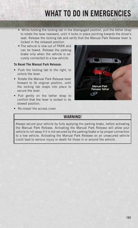
• While holding the locking tab in the disengaged position, pull the tether strapto rotate the lever rearward, until it locks in place pointing towards the driver'sseat. Release the locking tab and verify that the Manual Park Release lever islocked in the released position.
• The vehicle is now out of PARK andcan be towed. Release the parkingbrake only when the vehicle is se-curely connected to a tow vehicle.
To Reset The Manual Park Release:
• Push the locking tab to the right, tounlock the lever.
• Rotate the Manual Park Release leverforward to its original position, untilthe locking tab snaps into place tosecure the lever.
• Pull gently on the tether strap toconfirm that the lever is locked in itsstowed position.
• Re-install the access cover.
WARNING!
Always secure your vehicle by fully applying the parking brake, before activatingthe Manual Park Release. Activating the Manual Park Release will allow yourvehicle to roll away if it is not secured by the parking brake or by proper connectionto a tow vehicle. Activating the Manual Park Release on an unsecured vehiclecould lead to serious injury or death for those in or around the vehicle.
WHAT TO DO IN EMERGENCIES
191

TOW
ING
ADI
SABL
EDVE
HIC
LETo
win
gCo
nditi
onW
heel
sOF
Fth
eGr
ound
2WD
Mod
els
4WD
Mod
els
Flat
Tow
NO
NE
Iftr
ansm
issi
onis
oper
able
:•
Tran
smis
sion
inN
EUTR
AL•
30
mph
(48
km/h
)m
ax•
15
mile
s(2
4km
)m
axdi
stan
ce
•A
uto
Tran
smis
sion
inPA
RK•
Man
ualT
rans
mis
sion
inge
ar(N
OTN
EUTR
AL)
•Tr
ansf
erC
ase
inN
EUTR
AL•
Tow
inFO
RWAR
Ddi
rect
ion
Whe
elLi
ftor
Dol
lyTo
wFr
ont
NOT
ALLO
WED
Rea
rOK
NOT
ALLO
WED
Flat
bed
ALL
BEST
MET
HOD
BEST
MET
HOD
WHAT TO DO IN EMERGENCIES
192

FREEING A STUCK VEHICLE• If your vehicle becomes stuck in mud, sand or snow, it can often be moved by a
rocking motion. Turn your steering wheel right and left to clear the area around thefront wheels. Then, move the shift lever back and forth between REVERSE andDRIVE. Using minimal accelerator pedal pressure to maintain the rocking motion,without spinning the wheels, is most effective.
• Allow the engine to idle with the transmission shift lever in NEUTRAL for at leastone minute after every five rocking-motion cycles. This minimizes overheating andreduce the risk of transmission failure during prolonged efforts to free a stuckvehicle.
NOTE:If your vehicle is equipped with Electronic Stability Control (ESC) then press the"ESC Off" switch, to place the Electronic Stability Control (ESC) system in "PartialOff" mode, before rocking the vehicle.
CAUTION!
Revving the engine or spinning the wheels too fast may lead to transmissionoverheating and failure. It can also damage the tires. Do not spin the wheels above30 mph (48 km/h) while in gear (no transmission shifting occurring).
WARNING!
Fast spinning tires can be dangerous. Forces generated by excessive wheel speedsmay cause tire damage or failure. A tire could explode and injure someone. Do notspin your vehicle's wheels faster than 30 mph (48 km/h) when you are stuck.Do not let anyone near a spinning wheel, no matter what the speed.
WHAT TO DO IN EMERGENCIES
193

EVENT DATA RECORDER (EDR)• This vehicle is equipped with an Event Data Recorder (EDR). The main purpose of
an EDR is to record, in certain crash or near crash-like situations, such as an airbag deployment or hitting a road obstacle, data that will assist in understandinghow a vehicle’s systems performed. The EDR is designed to record data relatedto vehicle dynamics and safety systems for a short period of time, typically30 seconds or less. The EDR in this vehicle is designed to record such data as:• How various systems in your vehicle were operating.• Whether or not the driver and passenger safety belts were buckled/fastened.• How far (if at all) the driver was depressing the accelerator and/or brake pedal.• How fast the vehicle was traveling.
• These data can help provide a better understanding of the circumstances in whichcrashes and injuries occur.
NOTE:EDR data are recorded by your vehicle only if a non-trivial crash situation occurs; nodata are recorded by the EDR under normal driving conditions and no personal data(e.g. name, gender, age, and crash location) are recorded. However, other parties,such as law enforcement, could combine the EDR data with the type of personallyidentifying data routinely acquired during a crash investigation.
• To read data recorded by an EDR, special equipment is required, and access to thevehicle or the EDR is needed. In addition to the vehicle manufacturer, other partiessuch as law enforcement, that have the special equipment, can read the informa-tion if they have access to the vehicle or the EDR.
WHAT TO DO IN EMERGENCIES
194

OPENING THE HOOD• Pull the hood release lever located
below the steering wheel at the base ofthe instrument panel.
• Reach into the opening beneath thecenter of the hood and move the safetylatch lever while lifting the hood at thesame time.
WARNING!
Be sure the hood is fully latched before driving your vehicle. If the hood is not fullylatched, it could open when the vehicle is in motion and block your vision. Failureto follow this warning could result in serious injury or death.
MAINTAINING YOUR VEHICLE
195

ENGI
NE
COM
PART
MEN
T3.
6LEn
gine
MAINTAINING YOUR VEHICLE
196

5.7L
ENGI
NE
MAINTAINING YOUR VEHICLE
197

6.4L
ENGI
NE
MAINTAINING YOUR VEHICLE
198

3.0L
DIES
ELEN
GIN
EMAINTAINING YOUR VEHICLE
199

6.7L
DIES
ELEN
GIN
E–
2500
/350
068
RFE
TRAN
SMIS
SION
–IF
EQU
IPPE
D
MAINTAINING YOUR VEHICLE
200
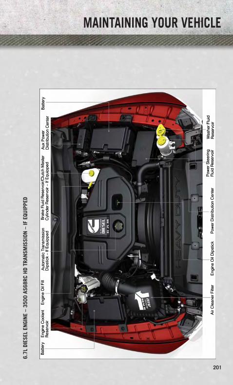
6.7L
DIES
ELEN
GIN
E–
3500
AS68
RCH
DTR
ANSM
ISSI
ON–
IFEQ
UIP
PED
MAINTAINING YOUR VEHICLE
201

FLUIDS AND CAPACITIES
Gasoline Versions
Component Fluid, Lubricant, or Genuine Part Capacities
Engine Coolant3.6L Engine
We recommend you use MOPAR®
Antifreeze/Coolant 10 Year/150,000 MileFormula OAT (Organic Additive
Technology).
14 Quarts(13 Liters)
Engine Coolant5.7L 1500 Models
We recommend you use MOPAR®
Antifreeze/Coolant 10 Year/150,000 MileFormula OAT (Organic Additive
Technology).
16 Quarts(15 Liters)
Engine Coolant5.7L 2500/3500 Models
We recommend you use MOPAR®
Antifreeze/Coolant 10 Year/150,000 MileFormula OAT (Organic Additive
Technology) .
18.7 Quarts(17.7 Liters)
Engine Coolant5.7L 2500/3500 Modelsw/Heavy Duty
We recommend you use MOPAR®
Antifreeze/Coolant 10 Year/150,000 MileFormula OAT (Organic Additive
Technology) .
19.2 Quarts(18.2 Liters)
Engine Coolant6.4L 2500/3500 Models
We recommend you use MOPAR®
Antifreeze/Coolant 10 Year/150,000 MileFormula OAT (Organic Additive
Technology) .
18.7 Quarts(17.7 Liters)
Engine Coolant6.4L 2500/3500 Modelsw/Heavy Duty
We recommend you use MOPAR®
Antifreeze/Coolant 10 Year/150,000 MileFormula OAT (Organic Additive
Technology) .
19.2 Quarts(18.2 Liters)
Engine Oil withFilter 3.6L, 5.7L
We recommend you use API Certified SAE5W-20 Engine Oil, meeting the require-
ments of Chrysler Material StandardMS-6395 such as MOPAR®, Pennzoil®,
and Shell Helix®. Refer to your engine oilfiller cap for correct SAE grade.
3.6L Engine -6 Quarts (5.7 Liters)
5.7L Engine -7 Quarts (6.6 Liters)
Engine Oil withFilter 5.7LFor 2500/3500trucks operatingwith a grosscombined weightrating greater than14,000 lbs/(6,350 kg)
We recommend you use API Certified SAE5W-30 Engine Oil, meeting the require-
ments of Chrysler Material StandardMS-6395 such as MOPAR, Pennzoil®,
and Shell Helix®. Refer to your engine oilfiller cap for correct SAE grade.
5.7L Engine -7 Quarts (6.6 Liters)
MAINTAINING YOUR VEHICLE
202

Component Fluid, Lubricant, or Genuine Part Capacities
Engine Oil withFilter 6.4L
For best performance and maximum pro-tection under all types of operating condi-tions, the manufacturer only recommends
full synthetic engine oils that meet theAmerican Petroleum Institute (API) cat-egories of SN. The manufacturer recom-
mends the use of Pennzoil Ultra™ 0W-40or equivalent MOPAR® engine oil meeting
the requirements of Chrysler MaterialStandard MS-12633 for use in all
operating temperatures.
6.4L Engine -7 Quarts (6.6 Liters)
Engine Oil Filter3.6L, 5.7L, 6.4L
We recommend you use MOPAR® EngineOil Filters. —
Spark Plug 3.6L We recommend you use MOPAR® SparkPlugs (Gap 0.043 in [1.1 mm]) —
Spark Plug 5.7L We recommend you use MOPAR® SparkPlugs (Gap 0.043 in [1.1 mm]) —
Spark Plug 6.4L We recommend you use MOPAR® SparkPlugs (Gap 0.043 in [1.1 mm]) —
Automatic Trans-mission – Eight-Speed Automatic
Use only MOPAR® ZF 8&9 Speed ATF™Automatic Transmission Fluid, or equiva-lent. Failure to use the correct fluid may
affect the function or performance of yourtransmission.
—
AutomaticTransmission –Six-SpeedAutomatic withGasoline Engine
We recommend you use only ATF+4®
Automatic Transmission Fluid. Failure touse ATF+4® fluid may affect the function
or performance of your transmission.We recommend MOPAR® ATF+4® fluid.
—
Transfer Case We recommend you use MOPAR®
BW44–44 Transfer Case Fluid. —
Front Axle 1500Four-Wheel DriveModels
We recommend you use MOPAR® GL-5Synthetic Axle Lubricant SAE 75W-85. —
Rear Axle 1500Models
We recommend you use MOPAR® Syn-thetic Gear Lubricant SAE 75W-140(MS-8985). Limited-Slip Rear Axles
require the addition of 5 oz. (148 ml)MOPAR® Limited Slip Additive
(MS-10111).
—
Front and RearAxle – 2500/3500Models
We recommend you use Synthetic, GL-5SAE 75W-90. Limited-Slip 10.5/11.5 inch Rear Axles Limited slip
additive is not required.
—
Brake MasterCylinder
We recommend you use MOPAR® DOT 3and SAE J1703. If DOT 3 is not
available, then DOT 4 is acceptable.—
MAINTAINING YOUR VEHICLE
203

Component Fluid, Lubricant, or Genuine Part CapacitiesPower SteeringReservoir – 2500/3500 Models
We recommend you use MOPAR® PowerSteering Fluid +4 or MOPAR® ATF+4®
Automatic Transmission Fluid.—
Fuel Selection 3.6L 87 Octane
1500 Regular CabShortbed/Crew
Quad Cab - 26 Gal-lons (98 Liters)(Approximate)
1500 Regular CabLongbed/Crew Quad
Cab (Optional) -32 Gallons(121 Liters)
(Approximate)2500/3500 Short-bed - 34 Gallons
(129 Liters)(Approximate)
2500/3500 Long-bed - 35 Gallons
(132 Liters)(Approximate)
Fuel Selection 5.7L 87 Octane Acceptable. 89 OctaneRecommended.
1500 Regular CabShortbed/Crew
Quad Cab - 26 Gal-lons (98 Liters)(Approximate)
1500 Regular CabLongbed/Crew Quad
Cab (Optional) -32 Gallons(121 Liters)
(Approximate)2500/3500 Short-bed - 34 Gallons
(129 Liters)(Approximate)
2500/3500 Long-bed - 35 Gallons
(132 Liters)(Approximate)
Fuel Selection 6.4L 87 Octane
2500/3500 Short-bed - 34 Gallons
(129 Liters)(Approximate)2500/3500
Longbed - 35 Gal-lons (132 Liters)
(Approximate)
MAINTAINING YOUR VEHICLE
204

Diesel Versions
Component Fluid, Lubricant, or Genuine Part CapacitiesEngine Coolant3.0 L Turbo DieselEngine – 1500Models Only
We recommend you use MOPAR® Antifreeze/Coolant Ten Year/150,000 Mile Formula OAT
(Organic Additive Technology).
11.6 Quarts(11 Liters)
Engine Coolant6.7L Turbo DieselEngine
We recommend you use MOPAR® Antifreeze/Coolant Ten Year/150,000 Mile Formula OAT
(Organic Additive Technology).
5.7 Gallons(21.4 Liters)
Engine Oil withFilter 3.0L TurboDiesel Engine –1500 Models Only
We recommend you use ACEA C3 5W-30engine oil meeting Chrysler materialstandard MS-11106 or Penzoil UltraEuro L full sythetic 5W-30 motor oil.
8 Quarts(7.7 Liters)
Engine Oil withFilter 6.7L TurboDiesel Engine
In ambient temperatures below 0°F(-18°C), We recommend you use 5W-40synthetic engine oil that meets ChryslerMaterials Standard MS-10902 and theAPI CJ-4 engine oil category is requiredsuch as MOPAR®, Shell Rotella® and
Shell Rimula®.In ambient temperatures above 0°F (-18°C),We recommend you use 15W-40 engine oil
that meets Chrysler Materials StandardMS-10902 and the API CJ-4 engine oilcategory is required such as MOPAR®,
Shell Rotella® and Shell Rimula®.
12 Quarts(11.4 Liters)
MAINTAINING YOUR VEHICLE
205
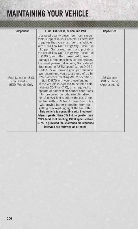
Component Fluid, Lubricant, or Genuine Part Capacities
Fuel Selection 3.0LTurbo Diesel –1500 Models Only
Use good quality diesel fuel from a repu-table supplier in your vehicle. Federal lawrequires that you must fuel this vehicle
with Ultra Low Sulfur Highway Diesel fuel(15 ppm Sulfur maximum) and prohibitsthe use of Low Sulfur Highway Diesel fuel
(500 ppm Sulfur maximum) to avoiddamage to the emissions control system.For most year-round service, No. 2 dieselfuel meeting ASTM specification D-975
Grade S15 will provide good performance.We recommend you use a blend of up to5% biodiesel, meeting ASTM specifica-
tion D-975 with your diesel engine.If the vehicle is exposed to extreme cold(below 20°F or -7°C), or is required to
operate at colder-than-normal conditionsfor prolonged periods, use climatized
No. 2 diesel fuel or dilute the No. 2 die-sel fuel with 50% No. 1 diesel fuel. Thiswill provide better protection from fuel
gelling or wax-plugging of the fuel filter.This vehicle is compatible with biodiesel
blends greater than 5% but no greater than20% biodiesel meeting ASTM specificationD-7467 provided the shortened maintenance
intervals are followed as directed.
26 Gallons(98.5 Liters)(Approximate)
MAINTAINING YOUR VEHICLE
206
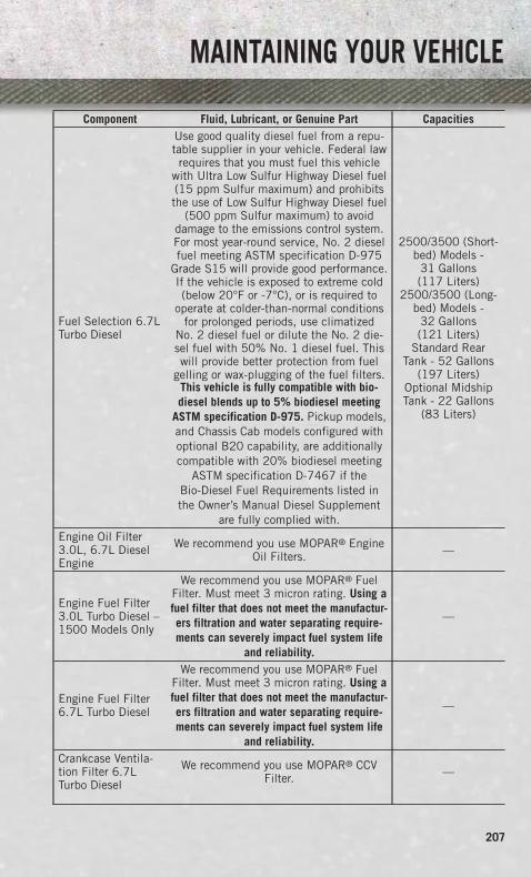
Component Fluid, Lubricant, or Genuine Part Capacities
Fuel Selection 6.7LTurbo Diesel
Use good quality diesel fuel from a repu-table supplier in your vehicle. Federal lawrequires that you must fuel this vehicle
with Ultra Low Sulfur Highway Diesel fuel(15 ppm Sulfur maximum) and prohibitsthe use of Low Sulfur Highway Diesel fuel
(500 ppm Sulfur maximum) to avoiddamage to the emissions control system.For most year-round service, No. 2 dieselfuel meeting ASTM specification D-975
Grade S15 will provide good performance.If the vehicle is exposed to extreme cold(below 20°F or -7°C), or is required to
operate at colder-than-normal conditionsfor prolonged periods, use climatized
No. 2 diesel fuel or dilute the No. 2 die-sel fuel with 50% No. 1 diesel fuel. Thiswill provide better protection from fuel
gelling or wax-plugging of the fuel filters.This vehicle is fully compatible with bio-diesel blends up to 5% biodiesel meeting
ASTM specification D-975. Pickup models,and Chassis Cab models configured withoptional B20 capability, are additionallycompatible with 20% biodiesel meeting
ASTM specification D-7467 if theBio-Diesel Fuel Requirements listed inthe Owner’s Manual Diesel Supplement
are fully complied with.
2500/3500 (Short-bed) Models -
31 Gallons(117 Liters)
2500/3500 (Long-bed) Models -
32 Gallons(121 Liters)
Standard RearTank - 52 Gallons
(197 Liters)Optional MidshipTank - 22 Gallons
(83 Liters)
Engine Oil Filter3.0L, 6.7L DieselEngine
We recommend you use MOPAR® EngineOil Filters. —
Engine Fuel Filter3.0L Turbo Diesel –1500 Models Only
We recommend you use MOPAR® FuelFilter. Must meet 3 micron rating. Using afuel filter that does not meet the manufactur-ers filtration and water separating require-ments can severely impact fuel system life
and reliability.
—
Engine Fuel Filter6.7L Turbo Diesel
We recommend you use MOPAR® FuelFilter. Must meet 3 micron rating. Using afuel filter that does not meet the manufactur-ers filtration and water separating require-ments can severely impact fuel system life
and reliability.
—
Crankcase Ventila-tion Filter 6.7LTurbo Diesel
We recommend you use MOPAR® CCVFilter. —
MAINTAINING YOUR VEHICLE
207

Component Fluid, Lubricant, or Genuine Part CapacitiesAutomatic Trans-mission – Eight-Speed Automatic3.0 Turbo Diesel –1500 Models Only
We recommend you use MOPAR® ZF 8&9Speed ATF™ Automatic Transmission
Fluid.—
AutomaticTransmission –Six-Speed Auto-matic – 68RFE
We recommend you use MOPAR® ATF+4®
Automatic Transmission Fluid. —
AutomaticTransmission –Six-Speed AISINHD Automatic
MOPAR® ASRC Automatic TransmissionFluid or equivalent. —
Clutch Linkage We recommend you use MOPAR®
Multi-Purpose Grease, NLGI Grade 2 E.P. —
Manual Transmis-sion G-56 – 6.7LDiesel Engine
We recommend you use MOPAR® ATF+4®
Automatic Transmission Fluid. —
Transfer Case We recommend you use MOPAR®
BW44–44 Transfer Case Fluid. —
Front Axle 1500Four-Wheel DriveModels
We recommend you use MOPAR® GL-5Synthetic Axle Lubricant SAE 75W-85. —
Rear Axle 1500Models
We recommend you use MOPAR® Syn-thetic Gear Lubricant SAE 75W-140MS-8985. Limited-Slip Rear Axles
require the addition of 118 ml (4 oz) ofMOPAR® Limited Slip Additive
MS-10111.
—
Front and RearAxle – 2500/3500Models
We recommend you use Synthetic,GL-5 SAE 75W-90. Limited-Slip
10.5/11.5 inch Rear Axles Limited slipadditive is not required.
—
Diesel ExhaustFluid Tank (3.0LDiesel EngineApproximate)
We recommend you use MOPAR® DieselExhaust Fluid (API Certified) (DEF) or
equivalent that has been API Certified tothe ISO 22241 standard. Use of fluidsnot API Certified to ISO 22241 may
result in system damage.
—
Diesel ExhaustFluid Tank (6.7LDiesel EngineApproximate)
We recommend you use MOPAR® DieselExhaust Fluid (API Certified) (DEF) or
equivalent that has been API Certified tothe ISO 22241 standard. Use of fluidsnot API Certified to ISO 22241 may
result in system damage.
5.5 Gallons(21 Liters)
MAINTAINING YOUR VEHICLE
208

CAUTION!
• Mixing of engine coolant (antifreeze) other than specified Organic AdditiveTechnology (OAT) engine coolant (antifreeze), may result in engine damage andmay decrease corrosion protection. Organic Additive Technology (OAT) enginecoolant is different and should not be mixed with Hybrid Organic AdditiveTechnology (HOAT) engine coolant (antifreeze) or any “globally compatible”coolant (antifreeze). If a non-OAT engine coolant (antifreeze) is introduced intothe cooling system in an emergency, the cooling system will need to be drained,flushed, and refilled with fresh OAT coolant (conforming to MS-12106), by anauthorized dealer as soon as possible.
• Do not use water alone or alcohol-based engine coolant (antifreeze) products.Do not use additional rust inhibitors or antirust products, as they may not becompatible with the radiator engine coolant and may plug the radiator.
• This vehicle has not been designed for use with propylene glycol-based enginecoolant (antifreeze). Use of propylene glycol-based engine coolant (antifreeze)is not recommended.
E-85 Flexible Fuel – 3.6L Engine Only
CAUTION!
Only vehicles with the E-85 fuel filler door label or a yellow gas cap can operate onE-85.
Refer to your Owner's Manual on the DVD for further details.
MAINTENANCE SCHEDULE – GASOLINE ENGINE
Your vehicle is equipped with an automatic oil change indicator system. The oilchange indicator system will remind you that it is time to take your vehicle in forscheduled maintenance.
Based on engine operation conditions, the oil change indicator message willilluminate. This means that service is required for your vehicle. Operating conditionssuch as frequent short-trips, trailer tow, extremely hot or cold ambient temperatures,and E85 fuel usage will influence when the “Oil Change Required” message isdisplayed. Severe Operating Conditions can cause the change oil message toilluminate as early as 3,500 miles (5,600 km) since last reset. Have your vehicleserviced as soon as possible, within the next 500 miles (805 km).
Your authorized dealer will reset the oil change indicator message after completingthe scheduled oil change. If a scheduled oil change is performed by someone otherthan your authorized dealer, the message can be reset by referring to the stepsdescribed under “Electronic Vehicle Information Center (EVIC)/Oil Change Re-quired” in “Understanding Your Instrument Panel” for further information.
MAINTAINING YOUR VEHICLE
209

NOTE:
1500 Models Only• Under no circumstances should oil change intervals exceed 10,000 miles
(16,000 km) or twelve months on 1500 trucks, whichever comes first.
2500 – 3500 Models• Under no circumstances should oil change intervals exceed 8,000 miles
(13,000 km) or twelve months on 2500 – 3500 trucks, whichever comes first.
Severe Duty All Models• Change Engine Oil at 4000 miles (6,500 km) if the vehicle is operated in a dusty
and off road environment. This type of vehicle use is considered Severe Duty
Once A Month Or Before A Long Trip:
• Check engine oil level
• Check windshield washer fluid level
• Check tire pressure and look for unusual wear or damage. Rotate tires at the firstsign of irregular wear, even if it occurs before the oil indicator system turns on.
• Check the fluid levels of the coolant reservoir, brake master cylinder, powersteering (2500/3500 Models Only) and automatic transmission (six-speed only) asneeded
• Check function of all interior and exterior lights
Required Maintenance
Refer to the Maintenance Schedules on the following pages for required mainte-nance.
At Every Oil Change Interval As Indicated By Oil Change Indicator System:• Change oil and filter.• Rotate the tires. Rotate at the first sign of irregular wear, even if it occurs before the oil
indicator system turns on.• Inspect battery and clean and tighten terminals as required.• Inspect automatic transmission fluid if equipped with dipstick.• Inspect brake pads, shoes, rotors, drums, hoses and park brake.• Inspect engine cooling system protection and hoses.• Inspect exhaust system.• Inspect engine air cleaner if using in dusty or off-road conditions.• Lube the front drive shaft fitting (2500/3500 (4x4) models only).
MAINTAINING YOUR VEHICLE
210
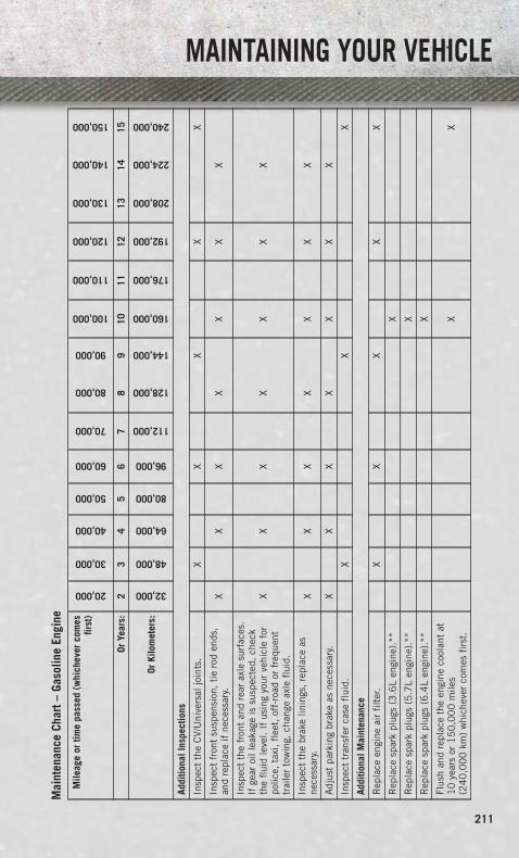
Mai
nten
ance
Char
t–Ga
solin
eEn
gine
Mile
age
ortim
epa
ssed
(whi
chev
erco
mes
first
)
20,000
30,000
40,000
50,000
60,000
70,000
80,000
90,000
100,000
110,000
120,000
130,000
140,000
150,000
OrYe
ars:
23
45
67
89
1011
1213
1415
OrKi
lom
eter
s:
32,000
48,000
64,000
80,000
96,000
112,000
128,000
144,000
160,000
176,000
192,000
208,000
224,000
240,000
Addi
tiona
lIns
pect
ions
Insp
ect
the
CV/
Uni
vers
aljo
ints
.X
XX
XX
Insp
ect
fron
tsu
spen
sion
,ti
ero
den
ds,
and
repl
ace
ifne
cess
ary.
XX
XX
XX
X
Insp
ect
the
fron
tan
dre
arax
lesu
rfac
es.
Ifge
aroi
llea
kage
issu
spec
ted,
chec
kth
efl
uid
leve
l.If
usin
gyo
urve
hicl
efo
rpo
lice,
taxi
,fl
eet,
off-
road
orfr
eque
nttr
aile
rto
win
g,ch
ange
axle
flui
d.
XX
XX
XX
X
Insp
ect
the
brak
elin
ings
,re
plac
eas
nece
ssar
y.X
XX
XX
XX
Adj
ust
park
ing
brak
eas
nece
ssar
y.X
XX
XX
XX
Insp
ect
tran
sfer
case
flui
d.X
XX
Addi
tiona
lMai
nten
ance
Rep
lace
engi
neai
rfi
lter
.X
XX
XX
Rep
lace
spar
kpl
ugs
(3.6
Len
gine
).**
X
Rep
lace
spar
kpl
ugs
(5.7
Len
gine
).**
X
Rep
lace
spar
kpl
ugs
(6.4
Len
gine
).**
X
Flus
han
dre
plac
eth
een
gine
cool
ant
at1
0ye
ars
or1
50
,00
0m
iles
(24
0,0
00
km)
whi
chev
erco
mes
firs
t.X
X
MAINTAINING YOUR VEHICLE
211

Mile
age
ortim
epa
ssed
(whi
chev
erco
mes
first
)
20,000
30,000
40,000
50,000
60,000
70,000
80,000
90,000
100,000
110,000
120,000
130,000
140,000
150,000
OrYe
ars:
23
45
67
89
1011
1213
1415
OrKi
lom
eter
s:
32,000
48,000
64,000
80,000
96,000
112,000
128,000
144,000
160,000
176,000
192,000
208,000
224,000
240,000
Cha
nge
auto
mat
ictr
ansm
issi
onfl
uid
and
filt
er(s
)(s
ix-s
peed
auto
mat
icon
ly),
ifus
ing
your
vehi
cle
for
polic
e,ta
xi,
flee
t,or
freq
uent
trai
ler
tow
ing.
X
Cha
nge
auto
mat
ictr
ansm
issi
onfl
uid
and
filt
er(s
ix-s
peed
auto
mat
icon
ly).
X
Insp
ect
the
tran
sfer
case
flui
d,ch
ange
for
any
ofth
efo
llow
ing:
polic
e,ta
xi,
flee
t,or
freq
uent
trai
ler
tow
ing.
X
Cha
nge
the
tran
sfer
case
flui
d.X
Insp
ect
and
repl
ace
PC
Vva
lve
ifne
cess
ary.
X
**Th
esp
ark
plug
chan
gein
terv
alis
mile
age
base
don
ly,ye
arly
inte
rval
sdo
not
appl
y.
WAR
NIN
G!
•Yo
uca
nbe
badl
yin
jure
dw
orki
ngon
orar
ound
am
otor
vehi
cle.
Do
only
serv
ice
wor
kfo
rwhi
chyo
uha
veth
ekn
owle
dge
and
the
righ
tequ
ipm
ent.
Ifyo
uha
vean
ydo
ubta
bout
your
abili
tyto
perf
orm
ase
rvic
ejo
b,ta
keyo
urve
hicl
eto
aco
mpe
tent
mec
hani
c.•
Failu
reto
prop
erly
insp
ecta
ndm
aint
ain
your
vehi
cle
coul
dre
sult
ina
com
pone
ntm
alfu
ncti
onan
def
fect
vehi
cle
hand
ling
and
perf
orm
ance
.Th
isco
uld
caus
ean
acci
dent
.
MAINTAINING YOUR VEHICLE
212

MAI
NTE
NAN
CERE
CORD O
dom
eter
Dat
eSi
gnat
ure,
Auth
oriz
edSe
rvic
eCe
nter
20
,00
0M
iles
(32
,00
0km
)or
2Ye
ars
30
,00
0M
iles
(48
,00
0km
)or
3Ye
ars
40
,00
0M
iles
(64
,00
0km
)or
4Ye
ars
50
,00
0M
iles
(80
,00
0km
)or
5Ye
ars
60
,00
0M
iles
(96
,00
0km
)or
6Ye
ars
70
,00
0M
iles
(11
2,0
00
km)
or7
Year
s8
0,0
00
Mile
s(1
28
,00
0km
)or
8Ye
ars
Odo
met
erD
ate
Sign
atur
e,Au
thor
ized
Serv
ice
Cent
er9
0,0
00
Mile
s(1
44
,00
0km
)or
9Ye
ars
10
0,0
00
Mile
s(1
60
,00
0km
)or
10
Year
s1
10
,00
0M
iles
(17
6,0
00
km)
or1
1Ye
ars
12
0,0
00
Mile
s(1
92
,00
0km
)or
12
Year
s1
30
,00
0M
iles
(20
8,0
00
km)
or1
3Ye
ars
14
0,0
00
Mile
s(2
24
,00
0km
)or
14
Year
s1
50
,00
0M
iles
(24
0,0
00
km)
or1
5Ye
ars
MAINTAINING YOUR VEHICLE
213
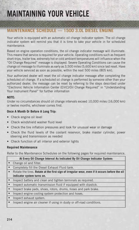
MAINTENANCE SCHEDULE — 1500 3.0L DIESEL ENGINEYour vehicle is equipped with an automatic oil change indicator system. The oil changeindicator system will remind you that it is time to take your vehicle in for scheduledmaintenance.
Based on engine operation conditions, the oil change indicator message will illuminate.This means that service is required for your vehicle. Operating conditions such as frequentshort-trips, trailer tow, extremely hot or cold ambient temperatures will influence when the“Oil Change Required” message is displayed. Severe Operating Conditions can cause thechange oil message to illuminate as early as 3,500 miles (5,600 km) since last reset. Haveyour vehicle serviced as soon as possible, within the next 500 miles (805 km).
Your authorized dealer will reset the oil change indicator message after completing thescheduled oil change. If a scheduled oil change is performed by someone other than yourauthorized dealer, the message can be reset by referring to the steps described under“Electronic Vehicle Information Center (EVIC)/Oil Change Required” in “UnderstandingYour Instrument Panel” for further information
NOTE:Under no circumstances should oil change intervals exceed 10,000 miles (16,000 km)or twelve months, whichever comes first.
Once A Month Or Before A Long Trip:
• Check engine oil level
• Check windshield washer fluid level
• Check the tire inflation pressures and look for unusual wear or damage
• Check the fluid levels of the coolant reservoir, brake master cylinder, powersteering and transmission as needed
• Check function of all interior and exterior lights
Required Maintenance
Refer to the Maintenance Schedules on the following pages for required maintenance.
At Every Oil Change Interval As Indicated By Oil Change Indicator System:• Change oil and filter.• Completely fill the Diesel Exhaust Fluid tank.• Rotate the tires. Rotate at the first sign of irregular wear, even if it occurs before the oil
indicator system turns on.• Inspect battery and clean and tighten terminals as required.• Inspect automatic transmission fluid if equipped with dipstick.• Inspect brake pads, shoes, rotors, drums, hoses and park brake.• Inspect engine cooling system protection and hoses.• Inspect exhaust system.• Inspect engine air cleaner if using in dusty or off-road conditions.
MAINTAINING YOUR VEHICLE
214

Mai
nten
ance
Char
t—Di
esel
Fuel
Up
ToB5
Biod
iese
l(15
00Di
esel
)
Mile
age
ortim
epa
ssed
(whi
chev
erco
mes
first
)
10,000
20,000
30,000
40,000
50,000
60,000
70,000
80,000
90,000
100,000
110,000
120,000
130,000
140,000
150,000
OrYe
ars:
12
34
56
78
910
1112
1314
15
OrKi
lom
eter
s:
16,000
32,000
48,000
64,000
80,000
96,000
112,000
128,000
144,000
160,000
176,000
192,000
208,000
224,000
240,000
Addi
tiona
lIns
pect
ions
Com
plet
ely
fill
the
Die
selE
xhau
stFl
uid
tank
.X
XX
XX
XX
XX
XX
XX
XX
Insp
ect
the
CV
join
ts.
XX
XX
X
Insp
ect
fron
tsu
spen
sion
,tie
rod
ends
,and
repl
ace
ifne
cess
ary.
XX
XX
XX
X
Insp
ect
the
fron
tan
dre
arax
lefl
uid.
Ifge
aroi
llea
kage
issu
spec
ted,
chec
kth
efl
uid
leve
l.If
usin
gyo
urve
hicl
efo
rpo
lice,
taxi
,fl
eet,
off-
road
orfr
eque
nttr
aile
rto
win
gch
ange
the
axle
flui
d.
XX
XX
XX
X
Insp
ect
the
brak
elin
ings
,pa
rkin
gbr
ake
func
tion
.X
XX
XX
XX
Insp
ect
tran
sfer
case
flui
d.X
XX
X
MAINTAINING YOUR VEHICLE
215

Mile
age
ortim
epa
ssed
(whi
chev
erco
mes
first
)
10,000
20,000
30,000
40,000
50,000
60,000
70,000
80,000
90,000
100,000
110,000
120,000
130,000
140,000
150,000
OrYe
ars:
12
34
56
78
910
1112
1314
15
OrKi
lom
eter
s:
16,000
32,000
48,000
64,000
80,000
96,000
112,000
128,000
144,000
160,000
176,000
192,000
208,000
224,000
240,000
Addi
tiona
lMai
nten
ance
Rep
lace
fuel
filte
ran
ddr
ain
wat
erfr
omth
efu
elfil
ter
asse
mbl
y.X
XX
XX
Rep
lace
engi
neai
rfi
lter
.X
XX
XX
Rep
lace
the
air
cond
itio
ning
filt
er.
XX
XX
XX
X
Flus
han
dre
plac
eth
een
gine
cool
ant
at1
0ye
ars
or1
50
,00
0m
iles
(24
0,0
00
km)
whi
chev
erco
mes
firs
t.X
X
Rep
lace
acce
ssor
ydr
ive
belt
(s).
X
Cha
nge
tran
sfer
case
flui
d.X
WAR
NIN
G!
•Yo
uca
nbe
badl
yin
jure
dw
orki
ngon
orar
ound
am
otor
vehi
cle.
Do
only
serv
ice
wor
kfo
rwhi
chyo
uha
veth
ekn
owle
dge
and
the
righ
tequ
ipm
ent.
Ifyo
uha
vean
ydo
ubta
bout
your
abili
tyto
perf
orm
ase
rvic
ejo
b,ta
keyo
urve
hicl
eto
aco
mpe
tent
mec
hani
c.•
Failu
reto
prop
erly
insp
ecta
ndm
aint
ain
your
vehi
cle
coul
dre
sult
ina
com
pone
ntm
alfu
ncti
onan
def
fect
vehi
cle
hand
ling
and
perf
orm
ance
.Th
isco
uld
caus
ean
acci
dent
.
MAINTAINING YOUR VEHICLE
216

MAINTENANCE SCHEDULE — B6 TO B20 BIODIESEL (1500 DIESEL)
NOTE:
• Under no circumstances should oil change intervals exceed 8,000 miles (12 875 km)or six months, whichever comes first when using Biodiesel blends greater than 5%(B5).
• The owner is required to monitor mileage for B6-B20 biodiesel, the automatic oilchange indicator system does not reflect the use of biofuels.
Once A Month Or Before A Long Trip:
• Check engine oil level
• Check windshield washer fluid level
• Check the tire inflation pressures and look for unusual wear or damage
• Check the fluid levels of the coolant reservoir, brake master cylinder, power steeringand transmission as needed
• Check function of all interior and exterior lights
Required Maintenance
Refer to the Maintenance Schedules on the following pages for required maintenance.
At Every Oil Change Interval As Indicated By Oil Change Indicator System:• Change oil and filter.• Completely fill the Diesel Exhaust Fluid tank.• Rotate the tires. Rotate at the first sign of irregular wear, even if it occurs before the oil
indicator system turns on.• Inspect battery and clean and tighten terminals as required.• Inspect automatic transmission fluid if equipped with dipstick.• Inspect brake pads, shoes, rotors, drums, hoses and park brake.• Inspect engine cooling system protection and hoses.• Inspect exhaust system.• Inspect engine air cleaner if using in dusty or off-road conditions.
MAINTAINING YOUR VEHICLE
217
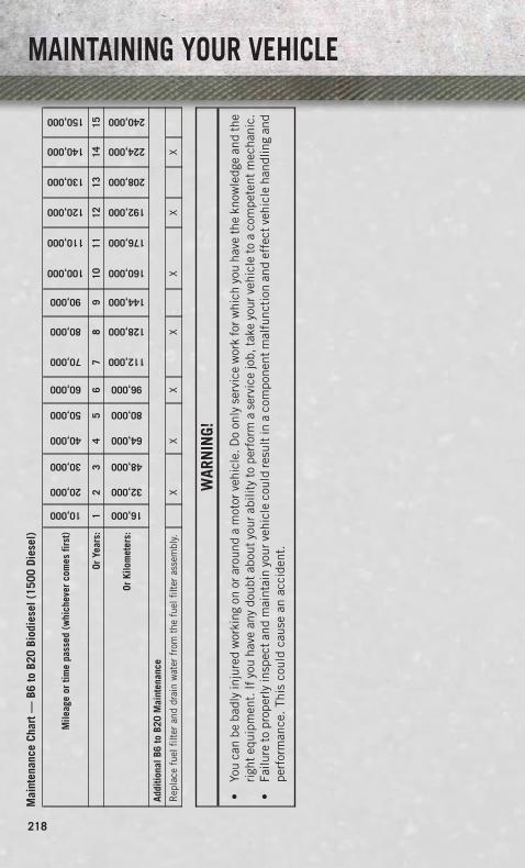
Mai
nten
ance
Char
t—B6
toB2
0Bi
odie
sel(
1500
Dies
el)
Mile
age
ortim
epa
ssed
(whi
chev
erco
mes
first
)
10,000
20,000
30,000
40,000
50,000
60,000
70,000
80,000
90,000
100,000
110,000
120,000
130,000
140,000
150,000
OrYe
ars:
12
34
56
78
910
1112
1314
15
OrKi
lom
eter
s:
16,000
32,000
48,000
64,000
80,000
96,000
112,000
128,000
144,000
160,000
176,000
192,000
208,000
224,000
240,000
Addi
tiona
lB6
toB2
0M
aint
enan
ce
Rep
lace
fuel
filte
ran
ddr
ain
wat
erfr
omth
efu
elfil
ter
asse
mbl
y.X
XX
XX
XX
WAR
NIN
G!
•Yo
uca
nbe
badl
yin
jure
dw
orki
ngon
orar
ound
am
otor
vehi
cle.
Do
only
serv
ice
wor
kfo
rwhi
chyo
uha
veth
ekn
owle
dge
and
the
righ
tequ
ipm
ent.
Ifyo
uha
vean
ydo
ubta
bout
your
abili
tyto
perf
orm
ase
rvic
ejo
b,ta
keyo
urve
hicl
eto
aco
mpe
tent
mec
hani
c.•
Failu
reto
prop
erly
insp
ecta
ndm
aint
ain
your
vehi
cle
coul
dre
sult
ina
com
pone
ntm
alfu
ncti
onan
def
fect
vehi
cle
hand
ling
and
perf
orm
ance
.Th
isco
uld
caus
ean
acci
dent
.
MAINTAINING YOUR VEHICLE
218

MAI
NTE
NAN
CERE
CORD O
dom
eter
Dat
eSi
gnat
ure,
Auth
o-riz
edSe
rvic
eCe
nter
20
,00
0M
iles
(32
,00
0km
)or
2Ye
ars
30
,00
0M
iles
(48
,00
0km
)or
3Ye
ars
40
,00
0M
iles
(64
,00
0km
)or
4Ye
ars
50
,00
0M
iles
(80
,00
0km
)or
5Ye
ars
60
,00
0M
iles
(96
,00
0km
)or
6Ye
ars
70
,00
0M
iles
(11
2,0
00
km)
or7
Year
s8
0,0
00
Mile
s(1
28
,00
0km
)or
8Ye
ars
Odo
met
erD
ate
Sign
atur
e,Au
tho-
rized
Serv
ice
Cent
er9
0,0
00
Mile
s(1
44
,00
0km
)or
9Ye
ars
10
0,0
00
Mile
s(1
60
,00
0km
)or
10
Year
s1
10
,00
0M
iles
(17
6,0
00
km)
or1
1Ye
ars
12
0,0
00
Mile
s(1
92
,00
0km
)or
12
Year
s1
30
,00
0M
iles
(20
8,0
00
km)
or1
3Ye
ars
14
0,0
00
Mile
s(2
24
,00
0km
)or
14
Year
s1
50
,00
0M
iles
(24
0,0
00
km)
or1
5Ye
ars
MAINTAINING YOUR VEHICLE
219

MAINTENANCE SCHEDULE — 6.7L CUMMINS® DIESELENGINE
CAUTION!
Failure to perform the required maintenance items may result in damage to thevehicle.
At Each Stop For Fuel
• Check the engine oil level at least 30 minutes after a fully warmed engine is shutoff. Checking the oil level while the vehicle is on level ground will improve theaccuracy of the oil level reading. Add oil only when the level is at or below the ADDor MIN mark.
Once A Month
• Inspect the batteries, and clean and tighten the terminals as required.
• Check the fluid levels of the coolant reservoir, brake master cylinder, andautomatic transmission (if equipped), and add as needed.
At Each Oil Change
• Change the engine oil filter.
• Inspect the exhaust system.
• Check the coolant level, hoses, and clamps.
• Lubricate outer tie rod ends.
Inspection and service should also be performed anytime a malfunction is observedor suspected. Retain all receipts.
Oil Change Indicator System — Cummins® Diesel
Your vehicle is equipped with an engine oil change indicator system. This system willalert you when it is time to change your engine oil by displaying the words “OilChange Due” on your Electronic Vehicle Information Center (EVIC). The oil changereminder will remind the owner to change the engine oil every 15,000 miles or500 hours, whichever comes first, except for the Chassis Cab models that are usingB20 biodiesel, which are 12,500 miles or 400 hours, whichever comes first. Failureto change the engine oil per the maintenance schedule can result in internal enginedamage.
MAINTAINING YOUR VEHICLE
220

For information on resetting the Oil Change Indicator message, refer to “Oil ChangeDue” under “Electronic Vehicle Information Center (EVIC)/EVIC Warning Lights” in“Understanding Your Instrument Panel” for further information.
Replace the engine oil and oil filter every 15,000 miles (24 000 km) or six months, orsooner if prompted by the oil change indicator system. Under no circumstances should oilchange intervals exceed 15,000 miles (24 000 km) or six months, whichever comes first.
NOTE:
• Under no circumstances should oil change intervals exceed 15,000 miles (24,000 km) orsix months or 500 Hours, whichever comes first.
• Replace the engine oil and oil filter every 12,500 miles (20 000 km) whenrunning B20 fuel (Chassis Cab Only).
If Chassis Cab models are operated with greater than 5% levels of Biodiesel, the oilchange interval must not exceed 12,500 miles (20 000 km) under any circum-stances. See the Fuel Requirements section for more information regarding opera-tion of Chassis Cab models configured for use with Biodiesel blend (B6-B20) fuelmeeting ASTM specification D-7467.
Perform Service Indicator — Cummins® Diesel
Your vehicle will require emissions maintenance at a set interval. To help remind youwhen this maintenance is due, the Electronic Vehicle Information Center (EVIC) willdisplay “Perform Service”. When the “Perform Service” message is displayed on theEVIC it is necessary to have the emissions maintenance performed. Emissionsmaintenance may include replacing the Closed Crankcase Ventilation (CCV) filterelement. The procedure for clearing and resetting the “Perform Service” indicatormessage is located in the appropriate Service Information.
MAINTAINING YOUR VEHICLE
221

Mai
nten
ance
Char
t–Cu
mm
ins®
Dies
elEn
gine
Mile
s:
7,500
15,000
22,500
30,000
37,500
45,000
52,500
60,000
67,500
75,000
82,500
90,000
97,500
OrM
onth
s:6
1218
2430
3642
4854
6066
7278
OrKi
lom
eter
s:
12,000
24,000
36,000
48,000
60,000
72,000
84,000
96,000
108,000
120,000
132,000
144,000
156,000
Rot
ate
the
tire
s.X
XX
XX
XX
XX
XX
XX
Lubr
icat
efr
ont
driv
esh
aft
fitt
ing
(4x4
).X
XX
XX
XX
XX
XX
XX
Lubr
icat
eou
ter
tie
rod
ends
.X
XX
XX
XX
XX
XX
XX
Rep
lace
engi
nefu
elfi
lter
elem
ent.
XX
XX
XX
Rep
lace
chas
sis
mou
nted
fuel
filt
erel
emen
t.X
XX
XX
X
Insp
ect
the
brak
elin
ings
.X
XX
X
Insp
ect
and
adju
stpa
rkin
gbr
ake.
XX
XX
Insp
ect
the
fron
tan
dre
arax
lesu
rfac
es.
Ifge
aroi
llea
kage
issu
spec
ted,
chec
kth
efl
uid
leve
l.If
usin
gyo
urve
hicl
efo
rpo
lice,
taxi
,fl
eet,
off-
road
orfr
eque
nttr
aile
rto
win
gch
ange
the
axle
flui
d.
XX
XX
XX
Insp
ect
driv
ebe
lt;
repl
ace
asre
quir
ed.
XX
XX
Che
ckth
etr
ansf
erca
sefl
uid
(4x4
).X
X
Cha
nge
the
tran
sfer
case
flui
d(4
x4).
X
Insp
ect
the
fron
tsu
spen
sion
,ti
ero
den
dsan
dbo
otse
als
for
crac
ksor
leak
san
dal
lpar
tsfo
rda
mag
e,w
ear,
impr
oper
loos
enes
sor
end
play
;re
plac
eif
nece
ssar
y.X
XX
XX
X
Insp
ect
whe
elbe
arin
gs.
XX
X
Chan
geau
tom
atic
tran
smis
sion
fluid
(AS6
9RC
tran
smis
sion
only
).X
XX
MAINTAINING YOUR VEHICLE
222

Mile
s:
7,500
15,000
22,500
30,000
37,500
45,000
52,500
60,000
67,500
75,000
82,500
90,000
97,500
OrM
onth
s:6
1218
2430
3642
4854
6066
7278
OrKi
lom
eter
s:
12,000
24,000
36,000
48,000
60,000
72,000
84,000
96,000
108,000
120,000
132,000
144,000
156,000
Cha
nge
auto
mat
ictr
ansm
issi
onfl
uid
and
filt
er(s
)if
usin
gyo
urve
hicl
efo
ran
yof
the
follo
win
g:po
lice,
flee
t,or
freq
uent
trai
ler
tow
ing
(68
RFE
tran
smis
sion
only
).X
Cha
nge
the
man
ualt
rans
mis
sion
flui
dif
usin
gyo
urve
hicl
efo
ran
yof
the
follo
win
g:po
lice,
flee
t,or
freq
uent
trai
ler
tow
ing.
X
Che
ckth
eD
iese
lExh
aust
Flui
d(D
EF)
tank
;re
fill
ifne
cess
ary.
XX
XX
XX
XX
XX
XX
X
Rep
lace
Cra
nkca
seVe
ntila
tion
Filt
er(C
CV)
.X
Flus
han
dre
plac
epo
wer
stee
ring
flui
d.X
MAINTAINING YOUR VEHICLE
223
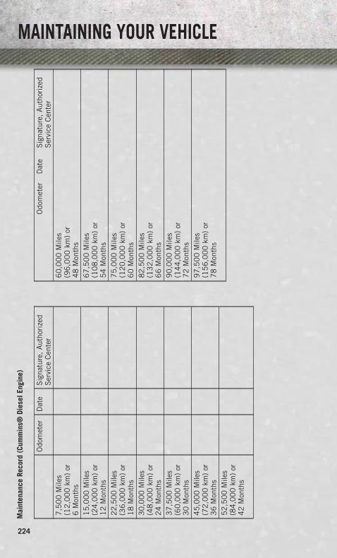
Mai
nten
ance
Reco
rd(C
umm
ins®
Dies
elEn
gine
)
Odo
met
erD
ate
Sig
natu
re,
Aut
hori
zed
Ser
vice
Cen
ter
7,5
00
Mile
s(1
2,0
00
km)
or6
Mon
ths
15
,00
0M
iles
(24
,00
0km
)or
12
Mon
ths
22
,50
0M
iles
(36
,00
0km
)or
18
Mon
ths
30
,00
0M
iles
(48
,00
0km
)or
24
Mon
ths
37
,50
0M
iles
(60
,00
0km
)or
30
Mon
ths
45
,00
0M
iles
(72
,00
0km
)or
36
Mon
ths
52
,50
0M
iles
(84
,00
0km
)or
42
Mon
ths
Odo
met
erD
ate
Sig
natu
re,
Aut
hori
zed
Ser
vice
Cen
ter
60
,00
0M
iles
(96
,00
0km
)or
48
Mon
ths
67
,50
0M
iles
(10
8,0
00
km)
or5
4M
onth
s7
5,0
00
Mile
s(1
20
,00
0km
)or
60
Mon
ths
82
,50
0M
iles
(13
2,0
00
km)
or6
6M
onth
s9
0,0
00
Mile
s(1
44
,00
0km
)or
72
Mon
ths
97
,50
0M
iles
(15
6,0
00
km)
or7
8M
onth
s
MAINTAINING YOUR VEHICLE
224

FUSES
POWER DISTRIBUTION CENTER (FUSES)
• The Power Distribution Center is lo-cated in the engine compartment nearthe battery. This center contains car-tridge fuses and mini fuses. A descrip-tion of each fuse and component maybe stamped on the inside cover, other-wise the cavity number of each fuse isstamped on the inside cover that cor-responds to the following chart.
Cavity Cartridge Fuse Micro Fuse DescriptionF01 80 Amp Red Rad Fan Control Module –
If equippedF03 60 Amp Yellow Rad Fan – If EquippedF05 40 Amp Green Compressor for Air
Suspension – If EquippedF06 40 Amp Green Antilock Brakes/Electronic
Stability Control PumpF07 40 Amp Green Starter SolenoidF08 40 Amp Green
(Gas & CumminsDiesel)
20 Amp Yellow(1500 LD Diesel)
Emissions Diesel – If Equipped
F09 40 Amp Green(Gas & Cummins
Diesel)30 Amp Pink
(1500 LD Diesel)
Diesel Fuel Heater –If Equipped
F10 40 Amp Green Body Controller / ExteriorLighting #2
F10 50 Amp Red Body Controller / ExteriorLighting #2 – If Equipped with
Stop/StartF11 30 Amp Pink Integrated Trailer Brake Module
– If EquippedF12 40 Amp Green Body Controller #3 / Interior
LightsF13 40 Amp Green Blower MotorF14 40 Amp Green Body Controller #4 / Power
Locks
MAINTAINING YOUR VEHICLE
225

Cavity Cartridge Fuse Micro Fuse DescriptionF15 30 Amp Pink Electric Park Brake Right Side
– If EquippedF19 30 Amp Pink SCR – If EquippedF20 30 Amp Pink Passenger Door ModuleF21 30 Amp Pink Drive Train Control ModuleF22 20 Amp Yellow Engine Control ModuleF23 30 Amp Pink Body Controller #1F24 30 Amp Pink Driver Door ModuleF25 30 Amp Pink Front Wiper Low SpeedF25 30 Amp Pink Front Wiper High SpeedF26 30 Amp Pink Antilock Brakes/Stability
Control Module/ValvesF28 20 Amp Yellow Trailer Tow Backup Lights –
If EquippedF29 20 Amp Yellow Trailer Tow Parking Lights –
If EquippedF30 30 Amp Pink Trailer Tow ReceptacleF32 30 Amp Pink Drive Train Control Module –
If EquippedF33 20 Amp Yellow Cummins Diesel Fuel
Heater #1 – If Equipped / RearBlower – If Equipped
F34 30 Amp Pink Vehicle System InterfaceModule #2 – If Equipped
F35 30 Amp Pink Sunroof – If EquippedF36 30 Amp Pink Rear Defroster– If EquippedF37 30 Amp Pink Cummins Diesel Fuel
Heater #2 - if equippedF38 30 Amp Pink Power Inverter 115V AC –
If EquippedF39 30 Amp Pink Vehicle System Interface
Module #1– If EquippedF41 10 Amp Red Active Grill ShutterF42 20 Amp Yellow HornF43 10 Amp Red Snow Plow (Left) – If EquippedF44 10 Amp Red Diagnostic PortF46 10 Amp Red Tire Pressure MonitorF47 10 Amp Red Snow Plow (Right) –
If EquippedF49 10 Amp Red Instrument Panel ClusterF50 20 Amp Yellow Air Suspension Control
Module – If Equipped
MAINTAINING YOUR VEHICLE
226
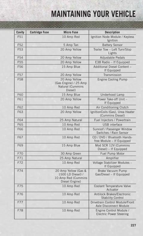
Cavity Cartridge Fuse Micro Fuse DescriptionF51 10 Amp Red Ignition Node Module / Keyless
IgnitionF52 5 Amp Tan Battery SensorF53 20 Amp Yellow Trailer Tow – Left Turn/Stop
LightsF54 20 Amp Yellow Adjustable PedalsF55 20 Amp Yellow E38 Radio – If EquippedF56 15 Amp Blue Additional Diesel Content –
If EquippedF57 20 Amp Yellow TransmissionF58 20 Amp Yellow
(Gas Engine) / 25 AmpNatural (Cummins
Diesel)
Engine Cooling Pump
F60 15 Amp Blue Underhood LampF61 20 Amp Yellow Power Take-off Unit –
If EquippedF62 10 Amp Red Air Conditioning ClutchF63 20 Amp Yellow IgnitionCoils (Gas), Urea Heater
(Cummins Diesel)F64 25 Amp Natural Fuel Injectors / PowertrainF65 10 Amp Red USB interfaceF66 10 Amp Red Sunroof / Passenger Window
Switches / Rain SensorF67 10 Amp Red CD / DVD / Bluetooth Hands-
free Module – If EquippedF69 15 Amp Blue Mod SCR 12V (Cummins
Diesel) – If EquippedF70 30 Amp Green Fuel Pump MotorF71 25 Amp Natural AmplifierF72 10 Amp Red Voltage Stabilizer Modules –
If EquippedF74 20 Amp Yellow (Gas &
1500 LD Diesel) /10 Amp Red (Cummins
Diesel Engine)
Brake Vacuum PumpGas/Diesel – If Equipped
F75 10 Amp Red Coolant Temperature ValveActuator
F76 10 Amp Red Antilock Brakes/ElectronicStability Control
F77 10 Amp Red Drivetrain Control Module/FrontAxle Disconnect Module
F78 10 Amp Red Engine Control Module /Electric Power Steering
MAINTAINING YOUR VEHICLE
227

Cavity Cartridge Fuse Micro Fuse DescriptionF79 15 Amp Blue Clearance LightsF80 10 Amp Red Universal Garage Door Opener /
CompassF81 20 Amp Yellow Trailer Tow Right Turn/Stop
LightsF82 10 Amp Red Steering Column Control
Module/ Cruise ControlF84 15 Amp Blue Switch Bank/Instrument ClusterF85 10 Amp Red Airbag ModuleF86 10 Amp Red Airbag ModuleF87 10 Amp Red Air Suspension / Trailer
Tow / Steering Column ControlModule
F88 15 Amp Blue Instrument Panel ClusterF90/F91
20 Amp Yellow Power Outlet (Rear seats)Customer Selectable
F93 20 Amp Yellow Cigar LighterF94 10 Amp Red Shifter / Transfer Case ModuleF95 10 Amp Red Rear Camera / Park AssistF96 10 Amp Red Rear Seat Heater SwitchF97 25 Amp Natural Rear Heated Seats & Heated
Steering Wheel – If EquippedF98 25 Amp Natural Front Heated Seats –
If EquippedF99 10 Amp Red Climate ControlF101 15 Amp Blue Electrochromatic Mirror / Smart
High Beams – If EquippedF104 20 Amp Yellow Power Outlets (Instrument
Panel/Center Console)
CAUTION!
• When installing the power distribution center cover, it is important to ensurethe cover is properly positioned and fully latched. Failure to do so may allowwater to get into the power distribution center and possibly result in anelectrical system failure.
• When replacing a blown fuse, it is important to use only a fuse having the correctamperage rating. The use of a fuse with a rating other than indicated may resultin a dangerous electrical system overload. If a properly rated fuse continues toblow, it indicates a problem in the circuit that must be corrected.
MAINTAINING YOUR VEHICLE
228

TIRE PRESSURES• Check the inflation pressure of each tire, including the spare tire, at least monthly
and inflate to the recommended pressure for your vehicle.
• The tire pressures recommended for your vehicle are found on the “Tire andLoading Information” label located on the driver’s side door opening.
NOTE:Refer to the Owner's Manual on the DVDfor more information regarding tire warn-ings and instructions.
WARNING!
• Overloading of your tires is dangerous. Overloading can cause tire failure,affect vehicle handling, and increase your stopping distance. Use tires of therecommended load capacity for your vehicle. Never overload them.
• Improperly inflated tires are dangerous and can cause collisions. Under-inflation is the leading cause of tire failure and may result in severe cracking,component separation, or “blow out”. Over-inflation reduces a tire’s ability tocushion shock. Objects on the road and chuck holes can cause damage thatresults in tire failure. Unequal tire pressures can cause steering problems.You could lose control of your vehicle. Over-inflated or under-inflated tires canaffect vehicle handling and can fail suddenly, resulting in loss of vehiclecontrol.
MAINTAINING YOUR VEHICLE
229

WHEEL AND WHEEL TRIM CARE• All wheels and wheel trim, especially aluminum and chrome plated wheels,
should be cleaned regularly with a mild soap and water to prevent corrosion.
• To remove heavy soil and/or excessive brake dust, use MOPAR® Wheel Cleaner orequivalent or select a non-abrasive, non-acidic cleaner.
CAUTION!
Do not use scouring pads, steel wool, a bristle brush, or metal polishes. Do not useoven cleaner. These products may damage the wheel's protective finish. Avoidautomatic car washes that use acidic solutions or harsh brushes that may damagethe wheel's protective finish. Only MOPAR® Wheel Cleaner or equivalent isrecommended.
EXTERIOR BULBSLIGHT BULBS – Exterior Bulb NumberBase Quad Headlamp – Low Beam H11Base Quad Headlamp – High Beam 9005Front Turn Signal Lamp (Base QuadHeadlamp) 3157NA
Premium Bi Halogen ProjectorHeadlamp - Low Beam HIR2
Premium Bi Halogen ProjectorHeadlamp - High Beam 9005
Front Turn Signal Lamp (PremiumHeadlamp) LED (Serviced at Authorized Dealer)
Fog Lamp (Horizontal shape) 9145Fog Lamp (Vertical shape) 9006Center High Mounted Stop Lamp(CHMSL) 921
Rear Cargo Lamp 921LED Center High Mounted Stop Lamp(CHMSL)/Cargo Lamp LED (Serviced at Authorized Dealer)
Cab Roof Marker Lamps 194NABase Rear Tail/Turn and Stop Lamp 3157KPremium Rear Tail/Turn and Stop Lamp LED (Serviced at Authorized Dealer)Premium Backup Lamp T20Rear Lamp Bar ID Marker Lamp 194Side Marker Lamps (Dual Rear Wheels) 194Backup Lamp 921Rear License Plate Lamp 194
MAINTAINING YOUR VEHICLE
230

CHRYSLER GROUP LLC CUSTOMER CENTERP.O. Box 21–8004 Auburn Hills, MI 48321–8004 Phone: 1–866–726–4636
CHRYSLER CANADA INC. CUSTOMER CENTERP.O. Box 1621 Windsor, Ontario N9A 4H6 Phone: 1–800–465–2001 (English)Phone: 1–800–387–9983 (French)
ASSISTANCE FOR THE HEARING IMPAIRED• To assist customers who have hearing difficulties, the manufacturer has installed
special TDD (Telecommunication Devices for the Deaf) equipment at its customercenter. Any hearing or speech impaired customer, who has access to a TDD or aconventional teletypewriter (TTY) in the United States, can communicate with themanufacturer by dialing 1–800–380–CHRY. Canadian residents with hearingdifficulties that require assistance can use the special needs relay service offeredby Bell Canada. For TTY teletypewriter users, dial 711 and for Voice callers, dial1–800–855–0511 to connect with a Bell Relay Service operator.
WARNING!
Engine exhaust, some of its constituents, and certain vehicle components con-tain, or emit, chemicals known to the State of California to cause cancer and birthdefects, or other reproductive harm. In addition, certain fluids contained invehicles and certain products of component wear contain, or emit, chemicalsknown to the State of California to cause cancer and birth defects, or otherreproductive harm.
PUBLICATIONS ORDERING• If you are the first registered retail owner of your vehicle, you may obtain one free
printed copy of the Owner's Manual, Warranty Booklet or Radio Manuals on yourDVD by calling 1–866–726–4636 (U.S.) or 1–800–387–1143 (Canada) or bycontacting your dealer.
• Replacement User Guide kits or DVDs or, if you prefer, additional printed copies of theOwner's Manual, Warranty Booklet or Radio Manuals may be purchased by visitingwww.techauthority.com or by calling 1–800–890–4038 (U.S.) or 1–800–387–1143(Canada). Visa, Master Card, American Express and Discover orders are accepted. If youprefer mailing your order, please call the above numbers for an order form.
CUSTOMER ASSISTANCE
231
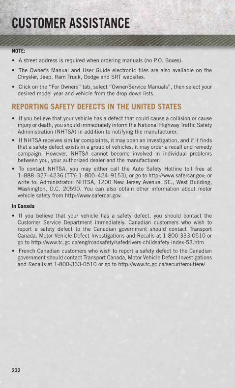
NOTE:
• A street address is required when ordering manuals (no P.O. Boxes).
• The Owner's Manual and User Guide electronic files are also available on theChrysler, Jeep, Ram Truck, Dodge and SRT websites.
• Click on the “For Owners” tab, select “Owner/Service Manuals”, then select yourdesired model year and vehicle from the drop down lists.
REPORTING SAFETY DEFECTS IN THE UNITED STATES• If you believe that your vehicle has a defect that could cause a collision or cause
injury or death, you should immediately inform the National Highway Traffic SafetyAdministration (NHTSA) in addition to notifying the manufacturer.
• If NHTSA receives similar complaints, it may open an investigation, and if it findsthat a safety defect exists in a group of vehicles, it may order a recall and remedycampaign. However, NHTSA cannot become involved in individual problemsbetween you, your authorized dealer and the manufacturer.
• To contact NHTSA, you may either call the Auto Safety Hotline toll free at1–888–327–4236 (TTY: 1–800–424–9153), or go to http://www.safercar.gov; orwrite to: Administrator, NHTSA, 1200 New Jersey Avenue, SE., West Building,Washington, D.C. 20590. You can also obtain other information about motorvehicle safety from http://www.safercar.gov.
In Canada
• If you believe that your vehicle has a safety defect, you should contact theCustomer Service Department immediately. Canadian customers who wish toreport a safety defect to the Canadian government should contact TransportCanada, Motor Vehicle Defect Investigations and Recalls at 1-800-333-0510 orgo to http://www.tc.gc.ca/eng/roadsafety/safedrivers-childsafety-index-53.htm
• French Canadian customers who wish to report a safety defect to the Canadiangovernment should contact Transport Canada, Motor Vehicle Defect Investigationsand Recalls at 1-800-333-0510 or go to http://www.tc.gc.ca/securiteroutiere/
CUSTOMER ASSISTANCE
232

AUTHENTIC ACCESSORIES BY MOPAR®The following highlights just some of the many Authentic Ram Truck Accessories byMopar® featuring a fit, finish, and functionality specifically for your Ram Truck. Inchoosing Authentic Accessories you gain far more than expressive style, premiumprotection, or extreme entertainment, you also benefit from enhancing your vehiclewith accessories that have been thoroughly tested and factory-approved. For the fullline of Authentic Ram Truck Accessories by Mopar®, visit your local Ram Truckdealership or online at mopar.com for U.S residents and mopar.ca for Canadianresidents.
CHROME:• Exhaust Tip • Tubular Side Steps • Fuel Filler Door• Cast Aluminum Wheels • Front Air Deflector • Grille• Body Side Molding
EXTERIOR:
• Bedliners • Running Boards • Bed Mat & Bed Rug• Composite Tonneau Cover • Bed Extender • Tool Box• Roll-up Tonneau Cover • Bed Step • Sports Performance Hood• Folding Tonneau Cover • Hitch Receiver • Body Kit• Molded Splash Guards • Tailgate Lock
INTERIOR:
• Premium Carpet Mats • Door Sill Guards • Slush Mats• Ambient Light Kit • Bright Pedal Kit • Heated Seats
ELECTRONICS:
• Kicker® Sound Systems • Electronic Vehicle Tracking • Remote Start• Mopar Web (Wi-fi)
CARRIERS:
• Bed Mounted BikeCarrier
• Bed Mounted CargoBasket With Cargo Net
• Cargo Ramps
• Bed Mounted Ski andSnowboard Carrier
• Cargo Bed Divider
Kicker® is a registered trademark of Stillwater Designs and Audio, Inc.
MOPAR ACCESSORIES
233

Adjustable Pedals . . . . . . . . . . .29Airbag . . . . . . . . . . . . . . . . . .16Air Conditioning . . . . .40, 41, 42, 43Air Suspension. . . . . . . . . . .37, 39Alarm (Security Alarm). . . . . . . . .14Anti-Lock Brake System (ABS) . . .170Arming System (Security Alarm) . . .14Automatic Headlights . . . . . . . . .32Automatic High Beams . . . . . . . .32Automatic Temperature
Control (ATC) . . . . . . . . . . . .42Automatic Transmission
Fluid Type . . . . . . . . . . . .202Axle Fluid . . . . . . . . . . . . . . .202
Back-Up Camera . . . . . . . . . . . .44Battery
Charging System Light . . . . .169Belts, Seat . . . . . . . . . . . . . . .15Brake Fluid . . . . . . . . . . . . . .202Brake System
Warning Light . . . . . . . . . .168Break-In Recommendations,
New Vehicle . . . . . . . . . . . . .30Bulb Replacement . . . . . . . . . .230
Calibration, Compass . . . . . . . . .117Cargo Light . . . . . . . . . . . . . . .32Change Oil Indicator . . . . . . . . .171Charging System Light . . . . . . . .169Check Engine Light (Malfunction
Indicator Light) . . . . . . . . . .169Child Restraint . . . . . . . . . . . . .17Climate Control . . . . . . . .40, 41, 42Compass Calibration . . . . . . . . .117Cooling System
Coolant Capacity . . . . . . . . .202Crankcase Emission Control
System . . . . . . . . . . . . . . . .32Cruise Control (Speed Control) . . . .33Cruise Light . . . . . . . . . . . . . . .33Customer Assistance . . . . . . . . .231Customer Programmable
Features . . . . . . . . . . . . . .118
Defects, Reporting . . . . . . . . . .232Defroster, Rear Window . . . . . .40, 41Defroster, Windshield . . . . . . .40, 41
Dimmer Control. . . . . . . . . . . . .32Disarming, Security System . . . . . .14
Electronic Range Select (ERS). .35, 36Electronic Speed Control
(Cruise Control) . . . . . . . . . . .33Electronic Throttle Control
Warning Light . . . . . . . . . . .170Electronic Vehicle Information
Center (EVIC) . . . . . . . . . . .117Emergency, In Case of
Overheating . . . . . . . . . . . .172Engine
Block Heater . . . . . . . . . . .153Break-In Recommendations . . .30,
144, 153Compartment . . . . . . . . . . .196Malfunction Indicator(Check Engine) . . . . . . . . . .169Oil Selection . . . . . . . . . . .202Overheating . . . . . . . . . . . .172Starting . . . . . . . . . . . . . . .13Stopping . . . . . . . . . . . . . .13
Event Data Recorder . . . . . . . . .194Exhaust Brake. . . . . . . . . . . . .154Exterior Lights. . . . . . . . . . . . .230
Flat Tire Stowage . . . . . . . . . . .184Fluid Capacities. . . . . . . . . . . .202Fluids . . . . . . . . . . . . . . . . .202Fog Lights . . . . . . . . . . . . . . . .32Freeing A Stuck Vehicle . . . . . . .193Front And Rear ParkSense System . .43Front Heated Seats. . . . . . . . . . .26Front ParkSense System. . . . . . . .43Fuel
Specifications . . . . . . . . . .202Fuse . . . . . . . . . . . . . . . . . .225Fuses. . . . . . . . . . . . . . . . . .225
Garage Door Opener(HomeLink®) . . . . . . . . . . . .119
Headlight . . . . . . . . . . . . . . . .32Headlights
Automatic . . . . . . . . . . . . .32Dimmer Switch . . . . . . . . . .32
INDEX
234

High Beam . . . . . . . . . . . . .31Switch . . . . . . . . . . . . . . .32
Heated Steering Wheel . . . . . . . .28Heater, Engine Block . . . . . . . . .153High Beam/Low Beam Select
(Dimmer) Switch . . . . . . . . . .31HomeLink® (Garage Door
Opener) . . . . . . . . . . . . . . .119Hood Release . . . . . . . . . . . . .195Hub Caps . . . . . . . . . . . . . . .182
Idle Up Feature . . . . . . . . . . . .155Integrated Trailer Brake Controls . .137Interior and Instrument Lights. . .7, 49Intermittent Wipers (Delay Wipers) . .31Introduction . . . . . . . . . . . . . . .3Inverter Outlet (115V) . . . . . . . .122Inverter, Power . . . . . . . . . . . .122
Jack Location . . . . . . . . . . . . .173Jump Starting . . . . . . . . . . . . .186
Key Fob . . . . . . . . . . . . . . . . .10Keyless Enter-N-Go. . . . . . . . . . .12
Lock/Unlock . . . . . . . . . . . .12Starting/Stopping . . . . . . . . .13
Lane Change and Turn Signals . . . .31Lane Change Assist . . . . . . . . . .31Lap/Shoulder Belts . . . . . . . . . . .15LATCH (Lower Anchors and
Tether for CHildren) . . . .17, 18, 19Lights
Engine Temperature Warning . .167Turn Signal . . . . . . . . . . . . .31
Maintenance Record . .213, 219, 224Maintenance
Schedule . . . .209, 214, 220, 222Malfunction Indicator Light
(Check Engine) . . . . . . . . . .169Memory Seat . . . . . . . . . . . . . .25Message Center
Water in Fuel . . . . . . .145, 153MOPAR® Accessories. . . . . . . . .233
Navigation . . . . . . . . . . . .83, 104
New Vehicle Break-InPeriod . . . . . . . . . .30, 144, 153
Oil Change Indicator . . . . . .171, 220Oil Change Indicator, Reset . . . . .171Oil, Engine
Capacity . . . . . . . . . . . . . .202Outlet
Power . . . . . . . . . . . . . . .123Overheating, Engine . . . . . . . . .172
ParkSense System, Front AndRear . . . . . . . . . . . . . . . . .43
ParkSense System, Rear. . . . . . . .43Pedals, Adjustable . . . . . . . . . . .29Perform Service Indicator, Reset . .221Pickup Box . . . . . . . . . . . . . .128Placard, Tire and Loading
Information. . . . . . . . . . . . .229Power
Distribution Center (Fuses) . . .225Glass Sunroof . . . . . . . . . . .45Inverter . . . . . . . . . . . . . .122Outlet (Auxiliary ElectricalOutlet) . . . . . . . . . . . . . .123Seats . . . . . . . . . . . . . . . .24Sliding Rear Window . . . . . . .45Steering . . . . . . . . . . . . . .202
Preparation for Jacking. . . . . . . .175Programmable Electronic
Features . . . . . . . . . . . . . .117
Rain Sensitive Wiper System . . . . .31Rear Camera . . . . . . . . . . . . . .44Rear Heated Seats . . . . . . . . . . .27Rear Park Assist System. . . . . . . .43Rear ParkSense System. . . . . .43, 44Recreational Towing . . . . . . . . .139
Shifting into Transfer CaseNeutral (N) . . . . . . . . . . . .141Shifting out of Transfer CaseNeutral (N) . . . . . . . . . . . .142
Remote Starting System . . . . . . . .13Replacement Bulbs. . . . . . . . . .230Reporting Safety Defects. . . . . . .232Resetting Perform Service
Indicator . . . . . . . . . . . . . .221
INDEX
235

Schedule, Maintenance . . . .209, 214Seat Belts . . . . . . . . . . . . . . . .15Seats. . . . . . . . . . . . . . . . . . .24
Heated . . . . . . . . . . . . . . .26Lumbar Support . . . . . . . . . .24Memory . . . . . . . . . . . . . . .25Power . . . . . . . . . . . . . . . .24Ventilated . . . . . . . . . . . . .27
ShiftingTransfer Case, Shifting intoTransfer Case Neutral (N) . . . .141Transfer Case, Shifting out ofTransfer Case Neutral (N) . . . .142
Shift Lever Override . . . . . . . . .189Signals, Turn . . . . . . . . . . . . . .31SIRIUS Travel Link . . . . . . . . . .107Spark Plugs . . . . . . . . . . . . . .202Speed Control (Cruise Control) . . . .33Starting
Cold Weather . . . . . . . .145, 154Remote . . . . . . . . . . . . . . .13
Starting Procedures(Diesel Engines). . . . . . .144, 153
Sun Roof . . . . . . . . . . . . . . . .45
Tailgate . . . . . . . . . . . . . . . .128Temperature Control,
Automatic (ATC). . . . . . . . . . .42Tether Anchor, Child Restraint . . . .18Tires
Air Pressure . . . . . . . . . . .229Changing . . . . . . . . . . . . .175Flat Changing . . . . . . . . . .175Jacking . . . . . . . . . . . . . .175Pressure Warning Light . . . . .166
Tow/Haul . . . . . . . . . . . . . . . .137Tow Hooks, Emergency. . . . . . . .188Towing
Disabled Vehicle . . . . . . . . .192Recreational . . . . . . . . . . .139
Towing Vehicle Behind aMotorhome . . . . . . . . . . . . .139
Trailer TowingTrailer and Tongue Weight . . .134
Transfer CaseFluid . . . . . . . . . . . . . . . .202
TransmissionFluid . . . . . . . . . . . . . . . .202Warning Light . . . . . . . . . .171
Turn Signals. . . . . . . . . . . . . . .31
Uconnect® 3.0 . . . . . . . . . . . . .67Uconnect® 5.0 . . . . . . . . . . . . .70Uconnect® 8.4A . . . . . . . . . . . .76Uconnect® 8.4AN . . . . . . . . . . .95
Vehicle Security Alarm Arming . . . .14Vehicle Security Alarm Disarming . .14Ventilated Seats . . . . . . . . . . . .27
Washers, Windshield . . . . . . . . . .31Water in Fuel . . . . . . . . . .145, 153Wheel and Wheel Trim Care . . . . .230Wheel Cover . . . . . . . . . . . . . .182Wheel Nut Torque. . . . . . . . . . .182Wind Buffeting . . . . . . . . . . . . .47Windshield Washers . . . . . . . . . .31Windshield Wipers . . . . . . . . . . .31
INDEX
236
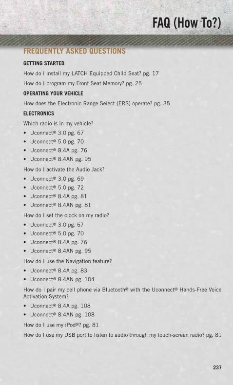
FREQUENTLY ASKED QUESTIONSGETTING STARTED
How do I install my LATCH Equipped Child Seat? pg. 17
How do I program my Front Seat Memory? pg. 25
OPERATING YOUR VEHICLE
How does the Electronic Range Select (ERS) operate? pg. 35
ELECTRONICS
Which radio is in my vehicle?
• Uconnect® 3.0 pg. 67
• Uconnect® 5.0 pg. 70
• Uconnect® 8.4A pg. 76
• Uconnect® 8.4AN pg. 95
How do I activate the Audio Jack?
• Uconnect® 3.0 pg. 69
• Uconnect® 5.0 pg. 72
• Uconnect® 8.4A pg. 81
• Uconnect® 8.4AN pg. 81
How do I set the clock on my radio?
• Uconnect® 3.0 pg. 67
• Uconnect® 5.0 pg. 70
• Uconnect® 8.4A pg. 76
• Uconnect® 8.4AN pg. 95
How do I use the Navigation feature?
• Uconnect® 8.4A pg. 83
• Uconnect® 8.4AN pg. 104
How do I pair my cell phone via Bluetooth® with the Uconnect® Hands-Free VoiceActivation System?
• Uconnect® 8.4A pg. 108
• Uconnect® 8.4AN pg. 108
How do I use my iPod®? pg. 81
How do I use my USB port to listen to audio through my touch-screen radio? pg. 81
FAQ (How To?)
237

OFF-ROAD CAPABILITIES
How do I shift into different four-wheel drive selections? pg. 125
UTILITY
How do I know how much I can tow with my Ram Truck? pg. 134
How do I adjust the gain on the Integrated Trailer Brake Module? pg. 137
WHAT TO DO IN EMERGENCIES
How do I change a flat tire? pg. 175
How do I Jump-Start my vehicle? pg. 186
MAINTAINING YOUR VEHICLE
Where is my Fuse Block located? pg. 225
What type of oil do I use? pg. 202
How often should I change my engine’s oil?
• Gasoline Engine pg. 209
• Cummins® Diesel Engine pg. 220
• 1500 Diesel Engine pg. 214
FAQ (How To?)
238

NOTES
239

NOTES
240

If you are the first registered retail owner of your vehicle, you may obtain a complimentary printed copy of the Owner’s Manual, Navigation/Uconnect® Manuals or Warranty Booklet by calling 1-866-726-4636 (U.S.) or 1-800-387-1143 (Canada) or by contacting your dealer.
IMPORTANTThis User Guide is intended to familiarize you with the important features of your vehicle. The DVD enclosed contains your Owner’s Manual, Navigation/Uconnect® Manuals, Warranty Booklets, Tire Warranty and Roadside Assistance (new vehicles purchased in the U.S.) or Roadside Assistance (new vehicles purchased in Canada) in electronic format. We hope you find it useful. Replacement DVD kits may be purchased by visiting www.techauthority.com. Copyright 2013 Chrysler Group LLC.
The driver’s primary responsibility is the safe operation of the vehicle. Driving while distracted can result in loss of vehicle control, resulting in a collision and personal injury. Chrysler Group LLC strongly recommends that the driver use extreme caution when using any device or feature that may take their attention off the road. Use of any electrical devices such as cell phones, computers, portable radios, vehicle navigation or other devices by the driver while the vehicle is moving is dangerous and could lead to a serious collision. Texting while driving is also dangerous and should never be done while the vehicle is moving. If you find yourself unable to devote your full attention to vehicle operation, pull off the road to a safe location and stop your vehicle. Some States or Provinces prohibit the use of cellular telephones or texting while driving. It is always the driver’s responsibility to comply with all local laws.
DRIvINg AND AlcOhOlDrunken driving is one of the most frequent causes of collisions. Your driving ability can be seriously impaired with blood alcohol levels far below the legal minimum. If you are drinking, don’t drive. Ride with a designated non-drinking driver, call a cab, a friend, or use public transportation.
WARNINgDriving after drinking can lead to a collision. Your perceptions are less sharp, your reflexes are slower, and your judgment is impaired when you have been drinking. Never drink and then drive.
This guide has been prepared to help you get quickly acquainted with your new RAM and to provide a convenient reference source for common questions. However, it is not a substitute for your Owner’s Manual.
For complete operational instructions, maintenance procedures and important safety messages, please consult your Owner’s Manual, Navigation/Uconnect® Manuals and other Warning Labels in your vehicle.
Not all features shown in this guide may apply to your vehicle. For additional information on accessories to help personalize your vehicle, visit www.mopar.com (U.S.), www.mopar.ca (Canada) or your local RAM dealer.
1372814_14b_RAM 15253500_UG_080113.indd 2 8/1/13 4:32 PM

Download a free electronic copy of the Owner’s Manual or Warranty Booklet by visiting the Owners tab at www.ramtrucks.com (U.S.) or www.ramtruck.ca (Canada).
14D241-926-AARAM Trucks 1500/2500/3500Second EditionUser Guide
1372814_14b_RAM 15253500_UG_080113.indd 1 8/1/13 4:32 PM