Real-time queue length estimation for congested signalized intersections
Upload
khangminh22Category
view
3download
0
Topic #625-000-002 FDOT Design Manual
212-Intersections
212 Intersections
212.1 General
This chapter provides design criteria and guidance for the geometric layout of at-grade conventional intersections. Conventional intersections include, 3-leg (T), 4-leg, and Multi-leg (5 or more legs).
Multi-leg conventional intersections should be avoided. Alternatives to existing multi-leg intersections include:
(1) Converting to a roundabout.
(2) Converting one or more legs to a one-way operation
(3) Reconfiguring or realigning the intersection to create separate intersections, each with no more than four legs.
See FDM 201 for design vehicle selection and design speed requirements.
See FDM 210 for lane width, median width, and deflection angle requirements.
See FDM 222 for requirements concerning pedestrian facilities and FDM 223 for bicycle facilities.
212.1.1 Alternative Intersections
Alternative intersection design is a key component of upgrading our transportation facilities and improving the mobility and safety of all road users. These innovative designs are becoming more common as increasing traffic demand exceed the limitations of traditional intersection solutions.
Alternative intersections offer the potential to improve safety and reduce delay at lower cost and with fewer impacts than traditional solutions such as adding lanes or grade separation. Three of the more common alternative intersection types are:
• Displaced Left Turn (a.k.a. Continuous Flow Intersection)
• Restricted Crossing U-Turn (RCUT)
• Median U-Turn (MUT)
January 1, 2018
1

Topic #625-000-002 FDOT Design Manual
212-Intersections
The FHWA has published comprehensive informational guides for alternative intersections which include guidance on how to plan, design, construct, and operate them. The following link provides access to these guides: FHWA Alternative Designs.
These types of alternate intersection designs should be coordinated with the Central Office Roadway Design.
212.2 Intersection Control
Conventional intersections utilize one of four control types; yield, stop, all-way stop and signal.
212.2.1 Yield Control
Certain channelized movements at intersections and interchanges, and all approaches to roundabouts are often yield controlled. Refer to the MUTCD for information on the locations where yield control traffic control devices may be appropriate.
212.2.2 Stop Control
Stop-controlled intersections have one or more legs of the intersection controlled by a "STOP" sign (R1-1).
Intersections with stop control are a common, low-cost control, which require the traffic on the minor roadway to stop before entering the major roadway. It is used where application of the normal R/W rule is not appropriate for certain approaches at the intersection.
To meet the requirements for the assigned access classification, or where U-turn opportunities exist within a corridor, consider limiting stop controlled minor roads or driveways to “right-in, right-out” only.
212.2.3 All-Way Stop Control
For an all-way stop intersection, traffic approaching it from all directions is required to stop before proceeding through the intersection. An all-way stop may have multiple approaches and typically marked with a supplemental signing stating the number of approaches.
January 1, 2018
2

Topic #625-000-002 FDOT Design Manual
212-Intersections
All-way stop control is most effective at the intersection of low-speed, 2-lane roadways not exceeding 1,400 vehicles during the peak hour. All-way stop control should not be used on multilane highways. Guidance for consideration of the application of all-way stop control is provided in the MUTCD.
All-way stop control may be used as an interim measure when a traffic signal or roundabout is warranted, but the installation is delayed.
212.2.4 Signal Control
Signalization provides an orderly and predictable movement of motorized and non-motorized traffic throughout the highway transportation system. It also provides guidance and warnings to ensure the safe and informed operation of the traffic stream.
Refer to FDM 232 for design criteria for signalization.
212.3 Intersection Types
Conventional intersection configurations include flared and channelized intersections (divided and undivided). Flared intersections are illustrated in Figure 212.3.1 and channelized intersections in Figure 212.3.2.
Figure 212.3.1 Flared Intersections
Ref: Figure 9-5, 2011 AASHTO Green Book
January 1, 2018
3

Topic #625-000-002 FDOT Design Manual
212-Intersections
Figure 212.3.2 Channelized Intersections
212.4 Intersection Functional Area
The functional area of an intersection extends in both directions including auxiliary lanes and their associated channelization. This is illustrated in Figures 212.4.1 and 212.4.2.
The functional area on the approach to an intersection or driveway consists of three basic elements:
(1) Perception-reaction-decision distance
(2) Maneuver distance
(3) Queue-storage distance (see FDM 212.14.2)
These elements are shown in Figure 212.4.3. The maneuver distance includes the length needed for both braking and lane changing when there is a left or right turning lane. In the absence of turn lanes, the maneuver distance is the distance to brake to a comfortable stop. The storage length includes the most distant extent of any intersection-related queue expected to occur during the design period.
Ref: Figure 9-6, 2011 AASHTO Green Book
January 1, 2018
4

Topic #625-000-002 FDOT Design Manual
212-Intersections
Figure 212.4.1 Physical Definition Figure 212.4.2 Functional Definition
Figure 212.4.3 Elements of the Functional Area
Ref: Figure 9-1, 2011 AASHTO Green Book Ref: Figure 9-1, 2011 AASHTO Green Book
Ref: Figure 9-2, 2011 AASHTO Green Book
January 1, 2018
5

Topic #625-000-002 FDOT Design Manual
212-Intersections
212.5 Intersection Angle
The intersection angle between two roadways has a significant influence on the safety and operation of an intersection. Intersection angles are to be as close to 90 degrees as practical. Intersection angles less than 75 degrees should be avoided for the following reasons:
(1) Heavy skew angles increase the intersection crossing length, exposing vehicles, pedestrians, and cyclists to conflicting traffic streams for longer periods of time. This is of particular concern at stop-controlled approaches on high speed facilities.
(2) The road user’s sight angle to the crossing leg becomes restricted due to the skew, making it difficult to see conflicting vehicles and to perceive safe crossing gaps.
(3) Turning movements are difficult because of the skew. Additional pavement may be necessary to accommodate the turning of large trucks.
(4) Turning movements or positioning may be confusing and require additional channelization.
(5) Increased open pavement areas of highly skewed intersections increase construction and maintenance costs.
Evaluate intersections with severe skew angles and crash histories for geometric improvements as shown in Figure 212.5.1. A high incidence of right-angle crashes is an indicator that improvements may be justified.
Figure 212.5.1 Intersection Reconfigurations
Ref: Figure 9-14, 2011 AASHTO Green Book
January 1, 2018
6

Topic #625-000-002 FDOT Design Manual
212-Intersections
212.6 Lane Tapers
Standard taper lengths for auxiliary lanes are given in FDM 212.14. Taper length is based on the following equations:
(1) Merging Taper (L):
(a) For design speeds ≤ 40 mph: L = (W*S2)/60
(b) For design speeds ≥ 45 mph: L = W*S
Where: L = Taper length (feet) W = Width of offset (feet) S = Design speed (mph)
(2) Shifting Taper is equal to Merging Taper (L) / 2.
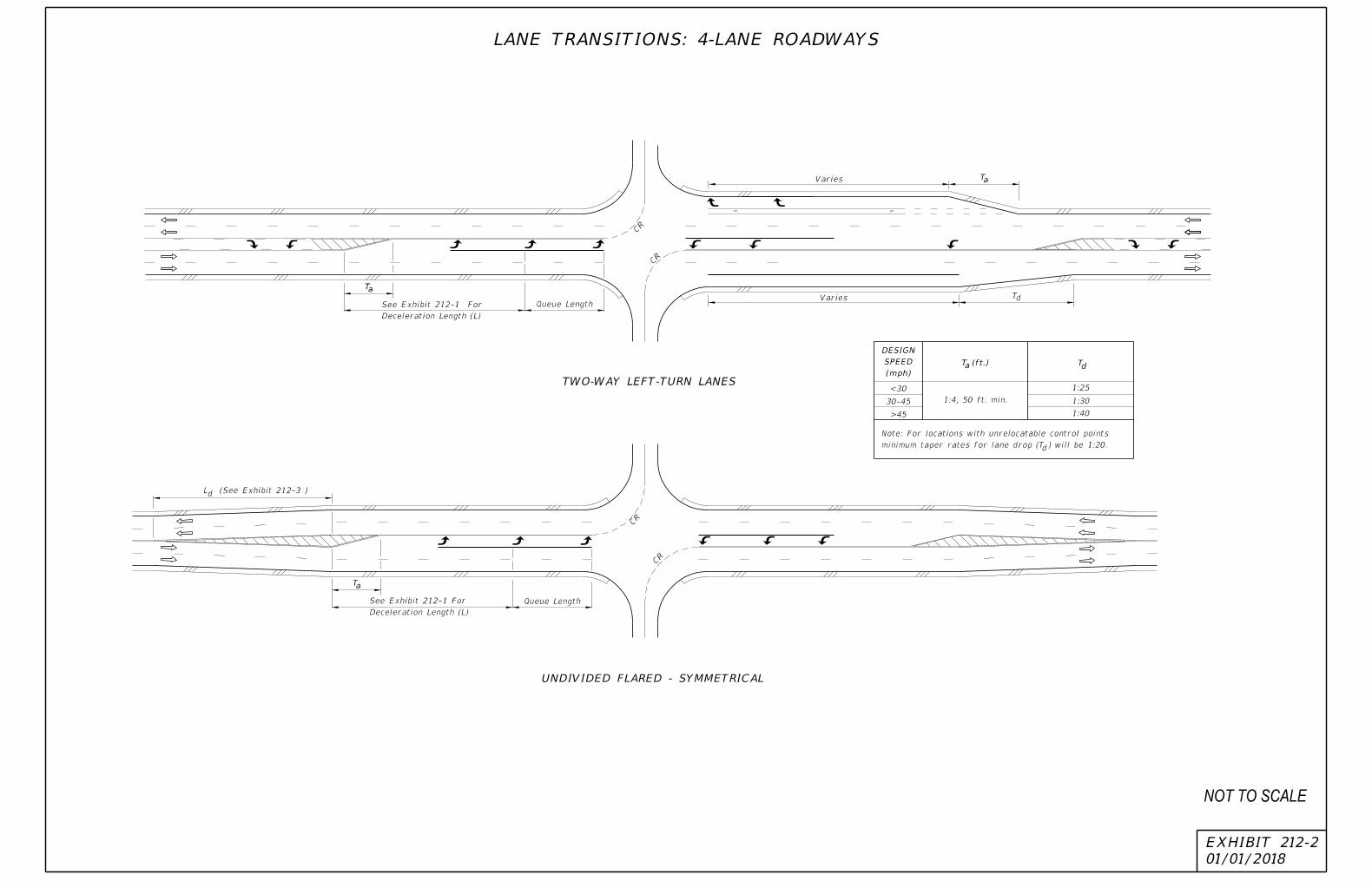
Minimum deceleration lengths are illustrated in Exhibit 212-1. Additional information on lane transitions (add or drop) are provided in Exhibits 212-2 and 212-3.
January 1, 2018
7

01/01/2018
EXHIBIT 212-1
(mph)
Speed
Entry
(mph)
Speed
Design
URBAN CONDITIONS RURAL CONDITIONS
55 48 125
135 240
45 35 100 185
35 25 145
60
225 350 195
135
110
65 55 170 290 460
50
40 120
160 160
230
270
30
405
290
260
185
155
145
105
52
40/44
Bar Location)
(Measured From Stop
Queue LengthL�
L
L�
L�
L�
L
L�
Begin Lane Line Begin Lane Line
2" Misc. Asphalt Pavt.
Begin Lane Line Stop Bar (If Required)
10'
Vehicle Clears Through Lane;
Brakes Applied After Turning
Vehicle Clears Through Lane
Brakes Applied After Turning
Rural Condition
Average Running Speed For
For Urban Condition
10 mph Below Design Speed
Entry Speed:
Rural Condition
Average Running Speed For
For Urban Condition
10 mph Below Design Speed
Entry Speed:
MEDIAN TURN LANES
MINIMUM DECELERATION LENGTHS
MEDIAN TURN LANES
DOUBLE LEFT TURN
Queue Length
Taper 50'
L� (ft.)
Distance
Clearance
L� (ft.)
Distance
Stop
Brake To
L (ft.)
Distance
Decel.
Total
L� (ft.)
Distance
Clearance
L� (ft.)
Distance
Stop
Brake To
L (ft.)
Distance
Decel.
Total
L� (ft.)
Distance
Clearance
70
80
85
75
75
Taper 100'
SINGLE LEFT TURN
Concrete Curb
Traffic Separator
Delineator Post
Concrete Curb
NOT TO SCALE
01/01/2018
EXHIBIT 212-2
Deceleration Length (L)
See Exhibit 212-1 For
CR
CR
Varies
Varies
Queue Length
dT
CR
CR
d
Queue Length
dminimum taper rates for lane drop (T ) will be 1:20.
Note: For locations with unrelocatable control points
T (ft.) Tda
(mph)
SPEED
DESIGN
<30
30-45
>45
1:25
1:30
1:40
LANE TRANSITIONS: 4-LANE ROADWAYS
TWO-WAY LEFT-TURN LANES
UNDIVIDED FLARED - SYMMETRICAL
L (See Exhibit 212-3 )
1:4, 50 ft. min.
Deceleration Length (L)
See Exhibit 212-1 For
aT
aT
aT
NOT TO SCALE

01/01/2018
EXHIBIT 212-3
LEFT SIDE WIDENING
CENTERED WIDENING
RIGHT SIDE WIDENING
L (Ft.)
(mph)
SPEED
DESIGN
STANDARD
a
30
40
60 720
50 500
180
320
120
150
180
240
Queue Length
Queue Length
Queue Length
300' (Desirable) (1: 25)
La
CR
CR
CR
aL
Ld
Ld
Ld
dL
CONSTRAINTS
MINIMUM UNDER
LANE TRANSITIONS: 2-LANE ROADWAYS
50'
50'
50'
For Deceleration Length (L)
See Exhibit 212-1
For Deceleration Length (L)
See Exhibit 212-1
For Deceleration Length (L)
See Exhibit 212-1
FLARED & PAINTED LEFT TURNS FOR 2-LANE ROADWAYS
L (Ft.)
STANDARD
d
CONSTRAINTS
MINIMUM UNDER
180
240
120
150
480
360 180
240
NOT TO SCALE

Topic #625-000-002 FDOT Design Manual
212-Intersections
212.7 Lane Shifts
Lane shifts through intersections should meet the requirements for non-merging conditions. Pavement markings should be used through the intersection to provide positive guidance to the motorist. The shifting taper length is controlled by the size of the intersection and the deflection angle. Although deflections through intersections are discouraged, there may be conditions where they are necessary.
The maximum deflection angles at intersections to be used in establishing the horizontal alignment are given in Table 212.7.1.
Table 212.7.1 Maximum Deflection Angle Through Intersection
Maximum Deflection Angle Through Intersection (DM)
Design Speed (mph)
≤ 20 25 30 35 40 45
16° 00' 11° 00' 8° 00' 6° 00' 5° 00' 3° 00'
(1) Deflection angle used is not to cause a lane shift (W) of more than 6 feet from stop bar to stop bar.
January 1, 2018
11

Topic #625-000-002 FDOT Design Manual
212-Intersections
212.8 Profile Grades
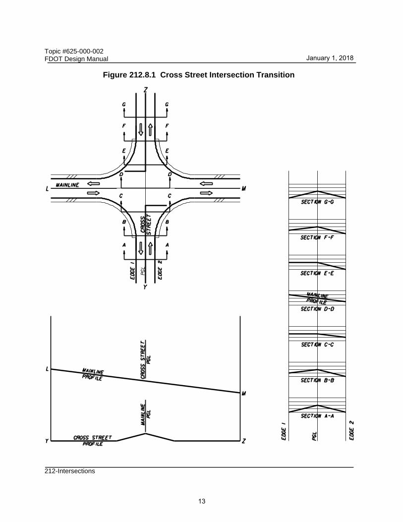
The profile grade line defines the vertical alignment for construction. The grade line of the mainline road is typically carried through the intersection and the minor cross road (or cross street) is adjusted to it. This design involves a transition in the crown of the cross road to an inclined cross section at its junction with the mainline road, as illustrated in Figure 212.8.1.
The break in the cross road profile at the center of the intersection should be accomplished with a vertical curve.
Vertical alignments at or near intersections should provide traffic lanes that are:
(1) Clearly visible and understandable to drivers for any desired direction of travel,
(2) Free from sudden appearance of potential conflicts, and
(3) Consistent in design with the portions of the highway just traveled.
Steep grades at intersections may increase or decrease stopping or acceleration distance.
Avoid grades in excess of 3% on intersecting roads in the vicinity of the intersection. Where conditions make such designs impractical, grades should not exceed 6%.
Provide adequate sight distance along both intersecting roads and across their included corners, even where one or both intersecting roads are on vertical curves. The gradients of intersecting roads should be as flat as practical on those sections that are to be used for storage of stopped vehicles.
January 1, 2018
12
Topic #625-000-002 FDOT Design Manual
212-Intersections
Figure 212.8.1 Cross Street Intersection Transition
January 1, 2018
13

Topic #625-000-002 FDOT Design Manual
212-Intersections
212.8.1 Special Profiles
Special profiles for certain roadway elements may be necessary to ensure a safe, efficient, well-drained and smooth roadway system. Elements that may require special profiles include pavement edges or gutter flow lines at street intersections, profile grade lines, intersection plateaus, curb returns, and special superelevation details. Special profiles are developed at close intervals and large scale to clearly identify all construction details of these elements.
212.8.2 Plateauing
In some instances, it is desirable for the cross road to receive the same profile considerations as the mainline road. To provide this "equal treatment", with respect to profile, a technique commonly known as intersection plateauing is applied. Plateauing refers to flattening of the intersection and the transition of both roadway profiles and cross slopes on the intersection approaches.
Provide a profile combination that provides a smooth transition and adequate drainage when applying intersection plateauing. Transition slope rates are to meet the values provided in Table 212.8.1; however, the minimum length of cross slope transition is 50 feet for design speeds less than or equal to 35 mph and 75 feet for design speeds of 40 mph or greater.
An example of a plateaued intersection is illustrated in Figure 212.8.2.
Table 212.8.1 Slope Rates for Intersection Approaches
Design Speed (mph) Slope Ratio
25-35 1:100
40 1:125
45-50 1:150
55-60 1:170
65-70 1:190
January 1, 2018
14

Topic #625-000-002 FDOT Design Manual
212-Intersections
Figure 212.8.2 Example of Plateaued Intersection
January 1, 2018
15

Topic #625-000-002 FDOT Design Manual
212-Intersections
212.9 Median Openings
Locate and design median openings to meet traffic requirements in accordance with the access management plan for the facility. See FDM 201.3 for more information on access management plans and decision making.
See FDM 210.3 for additional requirements for medians at intersections.
The following conditions may require additional median width:
• accommodation for trees (provide space above and below ground for growth)
• offset turn lanes
• directional median openings
• dual and triple left turn lanes
The overall length of a full median opening is typically the same width as the intersecting road (including shoulders) which is sufficient to accommodate the swept path of left turning vehicles. Median functions and minimum widths are provided in Table 212.9.1.
For un-signalized intersections, median openings should not be longer than the required length to avoid multiple vehicles attempting to stop within the opening.
Table 212.9.1 Minimum Median Width
Median Function Minimum Width (feet)
Separation of opposing traffic 4
Provision for pedestrian refuge 6
Provision for storage of left-turning vehicles See Table 210.3.1
Provision for protection of vehicles crossing through lanes 22
Provision for U-turns, left turn lane to outside lanes 30
Provision for Dual Left Turn Lanes and U Turns 42
The control radius refers to a radius that must be considered in establishing the location of median or traffic separator ends on divided highways and the stop bar on undivided highways. Provide this radius for left-turn movements when appropriate.
Design guidance on minimum edge-of-traveled-way design for various design vehicles is provided in FDM 212.12.1.
January 1, 2018
16

Topic #625-000-002 FDOT Design Manual
212-Intersections
For the central part of the turn the use of compound curves is not necessary and the use of simple curves is satisfactory. Table 212.9.2 provides control radii for minimum-speed turns (10 to 15 mph) that can be used for establishing the location of the median ends.
Table 212.9.2 Control Radii for Minimum Speed Turns
Design Vehicles Accommodated
Control Radius (feet)
50 (40 min) 60 (50 min) 75 130
Predominant P SU-30 SU-40, WB-40 WB-62FL
Occasional SU-30 SU-40, WB-40 WB-62 WB-67
212.9.1 U-Turns
Median width should accommodate passenger vehicle (P) left-turn and U-turn maneuvers. If adequate median width does not exist for accommodating U-turns, then consider adding extra pavement width such as a taper or additional shoulder width. See FDM 210.3 for information on median width criteria.
In cases where U-turn traffic volumes are high, consider the use of jug handles, loop designs, or indirect left turn designs.
212.10 Stopping Sight Distance
See FDM 210.11.1 for stopping sight distance requirements.
212.11 Clear Sight Triangles
Establish clear sight triangles to assure that drivers are provided a sufficient view of the intersecting highway to identify gaps in traffic and decide when it is safe to proceed. Document the analysis of sight distance for all intersections.
Clear sight triangles are the areas along intersection approach legs and across their common corners that should be clear of visual hindrances. Dimensions of clear sight triangles are based on design speed, design vehicle, and the type of traffic control used at the intersection.
January 1, 2018
17
Topic #625-000-002 FDOT Design Manual
212-Intersections
212.11.1 Stop Control (AASHTO Case B)
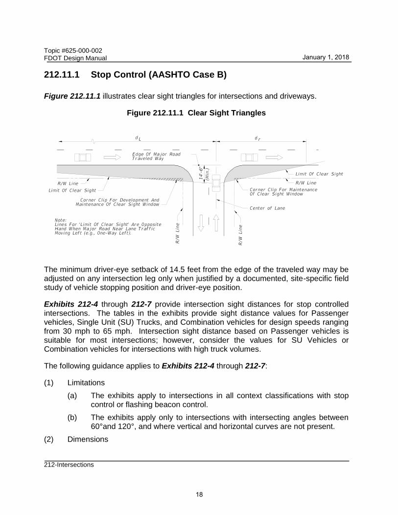
Figure 212.11.1 illustrates clear sight triangles for intersections and driveways.
Figure 212.11.1 Clear Sight Triangles
The minimum driver-eye setback of 14.5 feet from the edge of the traveled way may be adjusted on any intersection leg only when justified by a documented, site-specific field study of vehicle stopping position and driver-eye position.
Exhibits 212-4 through 212-7 provide intersection sight distances for stop controlled intersections. The tables in the exhibits provide sight distance values for Passenger vehicles, Single Unit (SU) Trucks, and Combination vehicles for design speeds ranging from 30 mph to 65 mph. Intersection sight distance based on Passenger vehicles is suitable for most intersections; however, consider the values for SU Vehicles or Combination vehicles for intersections with high truck volumes.
The following guidance applies to Exhibits 212-4 through 212-7:
(1) Limitations
(a) The exhibits apply to intersections in all context classifications with stop control or flashing beacon control.
(b) The exhibits apply only to intersections with intersecting angles between 60°and 120°, and where vertical and horizontal curves are not present.
(2) Dimensions
January 1, 2018
18

Topic #625-000-002 FDOT Design Manual
212-Intersections
(a) Sight distance (d) is measured from the center of the entrance lane of the crossroad to the center of the near approach lane (right or left) of the highway.
(b) Distances ‘dL’ and ‘dr’ are measured from the centerline of the entrance lane of the crossroad to a point on the edge of the near side outer traffic lane on the highway.
(c) Distance ‘dm’ is measured from the centerline of the entrance lane of the crossroad to a point on the median clear zone limit or horizontal clearance limit for the far side road of the highway.
(3) Vertical limits
(a) Provide a clear sight window throughout the limits of all intersection sight triangles.
(b) Provide a clear line of sight between vehicles at intersection stop locations and vehicles on the highway throughout the limits of all intersection sight triangles.
(c) The reference datum between roadways is 3’-6” above respective pavements since observations are made in both directions along the line of sight.
January 1, 2018
19

01/01/2018
EXHIBIT 212-4
2 LANE UNDIVIDED
2-LANE UNDIVIDED
SIGHT DISTANCE (d) AND RELATED DISTANCES (d , d ) (FEET)L r
SIGHT DISTANCE (d) AND RELATED DISTANCES (d , d ) (FEET)L r LEGEND
dd
Ld dr
Ld dr
d d
Areas Free Of Sight Obstructions
Limit Of Clear Sight Limit Of Clear Sight
¡ Crossroad
¡ Crossroad
Limit Of Clear Sight Limit Of Clear Sight
335 240 155 420 300 190 510 365 230
390 275 175 490 350 220 595 420 265
445 315 200 560 400 250 680 480 305
500 355 225 630 450 285 765 545 345
555 395 250 700 495 315 845 600 380
610 435 275 770 545 345 930 660 415
665 470 300 840 595 375 1015 720 455
720 510 325 910 645 410 1100 780 495
Passenger Vehicle SU Vehicle Combination Vehicle
d dL
dr
30 355 195 135 450 250 170 540 295 205
35 415 230 160 525 290 200 630 345 240
40 475 260 180 600 330 230 720 395 275
45 530 290 200 675 370 255 810 445 305
50 590 325 225 750 410 285 900 495 340
55 650 355 245 825 455 315 990 545 375
60 710 390 270 900 495 340 1080 590 410
65 765 420 290 975 535 370 1170 640 440
Passenger Vehicle SU Vehicle Combination Vehicle
INTERSECTION SIGHT DISTANCE: 2-LANE UNDIVIDED
2-LANE WITH LEFT TURN LANE
(mph)
Speed
Design
(Ft.) (Ft.) (Ft.)
2-LANE WITH LEFT TURN
30
35
40
45
50
55
60
65
(mph)
Speed
Design
d
(Ft.)
dL
(Ft.)
dr
(Ft.)
30
35
40
45
50
55
60
65
(mph)
Speed
Design
d
(Ft.)
dL
(Ft.)
dr
(Ft.)
30
35
40
45
50
55
60
65
(mph)
Speed
Design
d
(Ft.)
dL
(Ft.)
dr
(Ft.)
30
35
40
45
50
55
60
65
(mph)
Speed
Design
d
(Ft.)
dL
(Ft.)
dr
(Ft.)
30
35
40
45
50
55
60
65
(mph)
Speed
Design
d
(Ft.)
dL
(Ft.)
dr
(Ft.)
1. See Figure 212.11.1 for origin of clear sight line on the minor road.
NOTE:
NOT TO SCALE
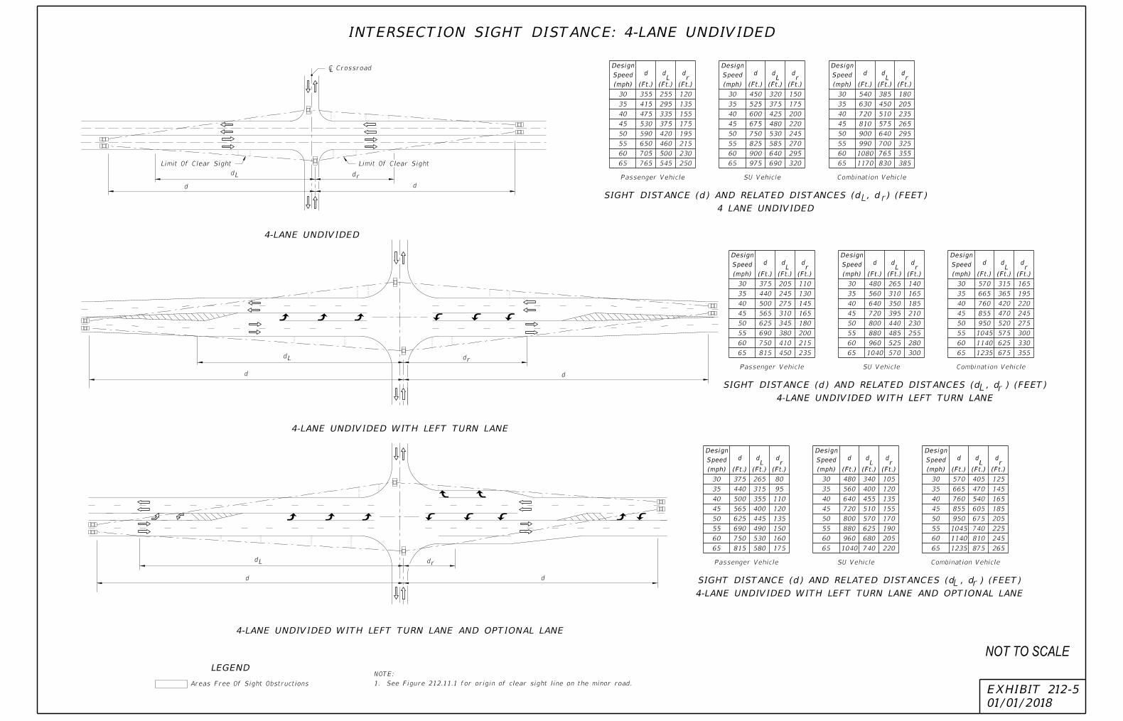
4-LANE UNDIVIDED
SIGHT DISTANCE (d) AND RELATED DISTANCES (d , d ) (FEET)
4 LANE UNDIVIDED
SIGHT DISTANCE (d) AND RELATED DISTANCES (d , d ) (FEET)
L r
LEGEND
SIGHT DISTANCE (d) AND RELATED DISTANCES (d , d ) (FEET)
L r
L rd d
dd
d d
dL dr
drdL
drdL
Areas Free Of Sight Obstructions
Limit Of Clear Sight Limit Of Clear Sight
¡ Crossroad
375 265 80 480 340 105 570 405 125
440 315 95 560 400 120 665 470 145
500 355 110 640 455 135 760 540 165
565 400 120 720 510 155 855 605 185
625 445 135 800 570 170 950 675 205
690 490 150 880 625 190 1045 740 225
750 530 160 960 680 205 1140 810 245
815 580 175 1040 740 220 1235 875 265
375 205 110 480 265 140 570 315 165
440 245 130 560 310 165 665 365 195
500 275 145 640 350 185 760 420 220
565 310 165 720 395 210 855 470 245
625 345 180 800 440 230 950 520 275
690 380 200 880 485 255 1045 575 300
750 410 215 960 525 280 1140 625 330
815 450 235 1040 570 300 1235 675 355
355 255 120 450 320 150 540 385 180
415 295 135 525 375 175 630 450 205
475 335 155 600 425 200 720 510 235
530 375 175 675 480 220 810 575 265
590 420 195 750 530 245 900 640 295
650 460 215 825 585 270 990 700 325
705 500 230 900 640 295 1080 765 355
765 545 250 975 690 320 1170 830 385
Passenger Vehicle SU Vehicle Combination Vehicle
01/01/2018
EXHIBIT 212-5
INTERSECTION SIGHT DISTANCE: 4-LANE UNDIVIDED
(mph)
Speed
Design
d
(Ft.)
dL
(Ft.)
dr
(Ft.)
30
35
40
45
50
55
60
65
(mph)
Speed
Design
d
(Ft.)
dL
(Ft.)
dr
(Ft.)
30
35
40
45
50
55
60
65
(mph)
Speed
Design
d
(Ft.)
dL
(Ft.)
dr
(Ft.)
30
35
40
45
50
55
60
65
(mph)
Speed
Design
d
(Ft.)
dL
(Ft.)
dr
(Ft.)
30
35
40
45
50
55
60
65
(mph)
Speed
Design
d
(Ft.)
dL
(Ft.)
dr
(Ft.)
30
35
40
45
50
55
60
65
(mph)
Speed
Design
d
(Ft.)
dL
(Ft.)
dr
(Ft.)
30
35
40
45
50
55
60
65
(mph)
Speed
Design
d
(Ft.)
dL
(Ft.)
dr
(Ft.)
30
35
40
45
50
55
60
65
(mph)
Speed
Design
d
(Ft.)
dL
(Ft.)
dr
(Ft.)
30
35
40
45
50
55
60
65
(mph)
Speed
Design
d
(Ft.)
dL
(Ft.)
dr
(Ft.)
30
35
40
45
50
55
60
65
Passenger Vehicle SU Vehicle Combination Vehicle
Passenger Vehicle SU Vehicle Combination Vehicle
4-LANE UNDIVIDED WITH LEFT TURN LANE
4-LANE UNDIVIDED WITH LEFT TURN LANE AND OPTIONAL LANE
4-LANE UNDIVIDED WITH LEFT TURN LANE
4-LANE UNDIVIDED WITH LEFT TURN LANE AND OPTIONAL LANE
1. See Figure 212.11.1 for origin of clear sight line on the minor road.
NOTE:
NOT TO SCALE

01/01/2018
EXHIBIT 212-6
INTERSECTION SIGHT DISTANCE: 4-LANE DIVIDED
INSET A
NOTES FOR 4-LANE DIVIDED ROADWAY
INSET B
LEGEND
VLmrLvSIGHT DISTANCES (d) & (d ) AND RELATED DISTANCES (d , d , d & d ) (FEET)
V
r m
dv
dvL
d
dL
dr
dm
d
Areas Free Of Sight Obstructions
Sight Obstruction
Limit Of Median
d dL
dr
dm
30 395 280 90 325 355 255 330 240
35 460 325 100 380 415 295 390 280
40 525 375 115 430 470 335 445 320
45 590 420 130 485 530 375 500 360
50 655 465 145 540 590 420 550 400
55 720 510 160 590 650 460 610 440
60 785 555 175 645 705 500 665 480
65 850 605 185 700 765 545 720 520
540 385 110 460 450 320 420 330
630 450 125 535 525 375 490 385
720 510 145 615 600 425 560 440
810 575 160 685 675 480 630 490
900 640 180 760 750 530 700 545
990 700 195 840 825 585 770 600
1080 765 215 915 900 640 840 655
1170 830 230 990 975 690 910 710
615 435 120 520 670 475 105 585 540 385 510 435
720 510 140 605 780 555 120 680 630 450 595 500
820 580 160 690 890 630 140 780 720 510 680 575
925 655 180 780 1000 710 155 875 810 575 760 645
1025 725 200 860 1110 790 170 970 900 640 845 720
1130 800 220 950 1225 870 190 1070 990 700 930 790
1230 870 240 1035 1335 945 205 1165 1080 765 1015 865
1335 945 260 1120 1445 1025 225 1265 1165 825 1100 935
Vehicle Type Vehicle Length (Ft.)
Passenger (P) 19
Single Unit (SU) 30
Large School Bus 40
WB-40 45.5
WB-50 55
¡ Crossroad
See INSET A See INSET B
*
*
Limit Of Clear Sight
Limit Of Clear Sight
*
*
Pause Location, i.e., Not From The Cross Road Stop Position; Distances d & d Do Not Apply.
Length Plus 6' Min.) The Clear Line Of Sight To The Right (d ) Is Measured From The Vehicle
Where The Median Is Sufficiently Wide For The Design Vehicle To Pause In The Median (Vehicle
Passenger Vehicle
SU Vehicle
Combined Vehicles
Minor Road.'
Intersection with Stop Control on the
calculated based on 'AASHTO Case B -
governing (controlling) sight distances
Values shown in the tables are the2.
sight line on the minor road.
See Figure 212.11.1 for origin of clear1.
(mph)
Speed
Design
(Ft.) (Ft.) (Ft.) (Ft.)
Median 22' or Less
d dL
d d
(mph)
Speed
Design
(Ft.) (Ft.) (Ft.) (Ft.)
30
35
40
45
50
55
60
65
d dL
dr
dm
(mph)
Speed
Design
(Ft.) (Ft.) (Ft.) (Ft.)
Median 35' or Less
30
35
40
45
50
55
60
65
d dL
d d
(mph)
Speed
Design
(Ft.) (Ft.) (Ft.) (Ft.)
30
35
40
45
50
55
60
65
d dL
dr
dm
(mph)
Speed
Design
(Ft.) (Ft.) (Ft.) (Ft.)
Median 30' or Less
30
35
40
45
50
55
60
65
d dL
d dm
(mph)
Speed
Design
(Ft.) (Ft.) (Ft.) (Ft.)
30
35
40
45
50
55
60
65
d dL
d d
(mph)
Speed
Design
(Ft.) (Ft.) (Ft.) (Ft.)
30
35
40
45
50
55
60
65
25'-64' Median
40'-64' Median
35'-50' Median 64' Median
v vL
v
r v vL
vL
Clear Zone For Nonrestricted Conditions
* Lateral Offset For Restricted Conditions
4-LANE DIVIDED
NOT TO SCALE

01/01/2018
EXHIBIT 212-7
INTERSECTION SIGHT DISTANCE: 6-LANE DIVIDED
INSET B
NOTES FOR 6-LANE DIVIDED ROADWAY
INSET A
SIGHT DISTANCES (d), (d ) & (d ) AND RELATED DISTANCES (d , d , d & d ) (FEET)V X L r m vL
v
r mPause Location, i.e., Not From The Cross Road Stop Position; Distances d & d Do Not Apply.
Length Plus 6' Min.) The Clear Line Of Sight To The Right (d ) Is Measured From The Vehicle
Where The Median Is Sufficiently Wide For The Design Vehicle To Pause In The Median (Vehicle
dvL
dv
d (d For One-Step Crossing) d (d For One-Step Crossing)xx
dL dm
drSight Obstruction
Limit Of Median
¡ Crossroad
See INSET A See INSET B
*
*
*
*
Limit Of Clear SightLimit Of Clear Sight
x
570 405 90 495 480 340 420 330
665 470 105 580 560 400 490 385
760 540 120 660 640 455 560 440
855 605 135 745 720 510 630 490
955 675 155 830 805 570 700 545
1050 745 170 915 885 625 770 600
1145 810 185 995 965 685 840 665
1240 880 200 1080 1045 740 910 710
650 460 110 560 700 495 95 625 570 405 510 435
755 535 130 655 815 580 115 725 665 470 590 500
865 615 145 745 930 660 130 825 760 540 680 575
970 690 165 835 1045 740 145 930 855 605 760 645
1080 765 185 930 1165 825 160 1035 950 675 845 720
1185 840 200 1025 1280 905 175 1140 1045 740 930 790
1290 915 220 1115 1395 990 190 1240 1140 805 1015 865
1400 990 235 1210 1510 1070 210 1340 1235 875 1100 935
25'-64' MEDIAN
Desig
n
Speed
d dL
dv
dvL
415 295 80 355 30 375 265 330 240
485 345 90 415 35 440 315 385 280
555 395 105 470 40 500 355 445 320
625 445 115 530 45 565 400 500 360
690 490 130 585 50 625 445 555 400
760 540 140 645 55 690 490 610 440
830 590 155 705 60 750 530 665 480
900 640 170 765 65 815 580 720 520
d dL
dr
dm
(mph)
Speed
Design
(Ft.) (Ft.) (Ft.) (Ft.)
Median 22' or Less
30
35
40
45
50
55
60
65
Passenger Vehicle
SU Vehicle
Combined Vehicles
x
x xd d
Ldr
dm
(mph)
Speed
Design
(Ft.) (Ft.) (Ft.) (Ft.)
Median 30' or Less
30
35
40
45
50
55
60
65
d dL
d dm
(mph)
Speed
Design
(Ft.) (Ft.) (Ft.) (Ft.)
30
35
40
45
50
55
60
65
d dL
d d
(mph)
Speed
Design
(Ft.) (Ft.) (Ft.) (Ft.)
30
35
40
45
50
55
60
65
35'-50' Median 64' Median
r v vL
d dL
dr
dm
(mph)
Speed
Design
(Ft.) (Ft.) (Ft.) (Ft.)
Median 35' or Less
30
35
40
45
50
55
60
65
d dL
d d
(mph)
Speed
Design
(Ft.) (Ft.) (Ft.) (Ft.)
30
35
40
45
50
55
60
65
40'-64' Median
v vL
Clear Zone For Nonrestricted Conditions
* Lateral Offset For Restricted Conditions
LEGEND
Areas Free Of Sight Obstructions
6-LANE DIVIDED
Vehicle Type Vehicle Length (Ft.)
Passenger (P) 19
Single Unit (SU) 30
Large School Bus 40
WB-40 45.5
WB-50 55 Minor Road.'
Intersection with Stop Control on the
calculated based on 'AASHTO Case B -
governing (controlling) sight distances
Values shown in the tables are the2.
sight line on the minor road.
See Figure 212.11.1 for origin of clear1.
NOT TO SCALE

Topic #625-000-002 FDOT Design Manual
212-Intersections
212.11.2 All-Way Stop Control (AASHTO Case E)
Provide clear sight lines on each of the approach legs for all-way stop controlled intersections.
212.11.3 Signal Control (AASHTO Case D)
For signalized intersections incorporate the following:
(1) Develop sight distances based on AASHTO ‘Case D-Intersections with Signal Control’.
(2) The first vehicle stopped on any approach leg is visible to the driver of the first vehicle stopped on each of the other approach legs.
(3) For permissive left turns provide sufficient sight distance for left turning vehicles to select gaps in oncoming traffic and complete left turns.
(4) If a traffic signal is to be placed on two-way flashing operation (i.e. flashing yellow on the major road approaches and flashing red on the minor road approaches) under off peak or nighttime conditions, then provide the appropriate departure sight triangles for AASHTO Case B (Stop Control on the Minor Road).
(5) If right turns on red are permitted from any approach leg then provide the appropriate departure sight triangle to the left for AASHTO Case B above.
212.11.4 Left Turn from Highway (AASHTO Case F)
Provide sufficient sight distance to accommodate a left turn maneuver for locations where left turns across opposing traffic are permitted. Table 212.11.1 provides clear sight distance values for left turn from highway.
For additional information on determining the sight distance refer to Chapter 9 of
AASHTO’s A Policy on Geometric Design of Highways and Streets.
January 1, 2018
24

Topic #625-000-002 FDOT Design Manual
212-Intersections
Table 212.11.1 Sight Distance for Left Turn from Highway
Design Speed (mph)
da (feet)
1 Lane Crossed 2 Lane Crossed 3 Lane Crossed
P SU Comb. P SU Comb. P SU Comb.
25-30 245 290 330 265 320 365 290 350 395
35 285 335 385 310 370 425 335 410 460
40 325 385 440 355 425 485 385 465 525
45 365 430 495 400 475 545 430 525 590
Notes:
(1) Provide a lateral offset (LO) of 6' as shown in the diagram above. db may be determined by the equation db = da (w/(w+12)). For roadways with non-restricted conditions, da and db should be based on the geometry for the left turn storage and on clear zone widths.
(2) For wide medians where the turning vehicle can approach the through lane at or near 90°, use d values from tables in Exhibits 212-6 and 212-7. (The clear sight line origin is assumed to be 14.5 feet from the edge of the near travel lane.
212.11.5 On-Street Parking
Table 212.11.2 provides parking restrictions for intersections; including mid-block crossings and roundabout approaches. For additional information, see the following:
• FDM 210.2.3 for additional information concerning on-street parking.
• FDM 222.2.6 for information concerning curb extensions (bulb-outs).
• Chapter 316, Florida Statutes (F.S.), for laws governing parking spaces.
January 1, 2018
25

Topic #625-000-002 FDOT Design Manual
212-Intersections
Table 212.11.2 Parking Restrictions for Driveways and Intersections
Control Type Posted Speed
(mph) A - Up Stream (ft)
B – Down Stream (ft)
2-Lane 4-Lane or more
Unsignalized
< 35 90 60 45
35 105 70 50
Signalized
< 35 30 30 30
35 50 50 50
Notes:
(1) For entrances to one-way streets, the downstream restriction (B) may be reduced to 20 feet.
(2) Do not place parking within 20 feet of a marked crosswalk.
January 1, 2018
26

Topic #625-000-002 FDOT Design Manual
212-Intersections
212.11.6 Trees and Vegetation
Intersections should be designed to accommodate the placement of trees and other desired vegetation in urbanized context classifications. Space above and below ground is necessary for trees to grow and provide shade. Coordinate the placement of vegetation with the Project Landscape Architect so that clear sight triangles are maintained for all approaches.
The clear sight window concept may provide opportunities for vegetation within the limits of intersection sight triangles. This concept is illustrated in Figure 212.11.2. This detail provides the required vertical clear sight limits with respect to the sight line datum. The horizontal limits of the window are defined by clear sight triangles. Within the limits of clear sight triangles, the tree canopy must be at least 5 feet above the sight line datum and the top of the ground cover must be at least 1.5 feet below the sight line datum. Maintaining these limits will provide a clear line of sight for approaches to an intersection.
Figure 212.11.2 Window Detail
* Since observations are made in both directions, the line of sight datum between roadways is 3.5 feet above both pavements.
January 1, 2018
27

Topic #625-000-002 FDOT Design Manual
212-Intersections
When trees are located in the median of a divided roadway and fall within the limits of a clear sight triangle, conform to Table 212.11.3 for tree size and spacing. Spacing values for trees with diameter of 11 inches or less were derived assuming a maximum 6-foot wide shadow band on a vehicle at the stop bar location when viewed by a mainline driver beginning at sight distance ‘d’. This is illustrated in Figure 212.11.3. Spacing values for trees with diameter greater than 11 inches and less than or equal to 18 inches were derived assuming a 2 second full view of the vehicle at the stop bar when viewed by the mainline driver beginning at sight distance ‘d’. (See Figure 212.11.4).
Do not place trees within the hatched-out areas as shown in Figure 212.11.5. The hatched-out area is for ground cover only.
Table 212.11.3 Minimum Tree Spacing
Design Speed (mph)
Minimum Tree Spacing (Center-to-Center of Trunk)
(feet)
4” < Tree Diameter ≤ 11” 11” < Tree Diameter ≤ 18”
25-30 25 90
35 30 105
40 35 120
45 40 135
50 50 150
55 55 165
60 60 180
Notes:
(1) Size and spacing are based on the following conditions:
(a) A single line of trees in the median parallel to but not necessarily collinear with the centerline.
(b) A straight approaching mainline and intersection angle between 60° and 120°.
(c) Space trees with 4” < Dia. ≤ 11” intermixed with trees with 11” < Dia. ≤ 18” based on trees with 11” < Dia. ≤ 18”.
(2) Detail tree size, spacing, and location in the plans for any other conditions.
January 1, 2018
28

Topic #625-000-002 FDOT Design Manual
212-Intersections
Figure 212.11.3 Shadow Diagram
Figure 212.11.4 Perception Diagram
January 1, 2018
29

Topic #625-000-002 FDOT Design Manual
212-Intersections
Figure 212.11.5 Special Areas Limited to Ground Cover
212.12 Turning Roadways
Turning roadways are typically designed for use by right-turning traffic at intersections. There are three types of right-turning roadways:
• edge-of-traveled-way design
• design with a corner triangular island
• free-flow design using a simple radius or compound radii
The turning radii and the pavement cross slopes for free-flow right turns are functions of design speed and design vehicle.
212.12.1 Edge-of-Traveled-Way Design
When selected design vehicle is to be accommodated within minimum space, corner radii should be based on the required turning path.
Table 212.12.1 provides simple curve radii with and without tapers. Table 212.12.2 provides symmetric and asymmetric three centered compound curve radii for a range of design vehicles. These values provide the minimum turning paths attainable at design speeds of 10 mph and less.
Figure 212.12.1 demonstrates the angle of turn for use in these tables.
The minimum edge-of-traveled-way values provided in these tables are based on the assumption that the vehicle is properly positioned within the traffic lane at the beginning and end of the turn (2 feet from the edge-of-traveled-way on the tangents approaching
January 1, 2018
30

Topic #625-000-002 FDOT Design Manual
212-Intersections
and leaving the intersection curve). Such designs follow closely the inner wheel path of the selected design vehicle, with a clearance of 2 feet or more throughout most of the turn, and with a clearance at no point less than 9 inches. Differences in the inner paths of vehicles turning left and right are not sufficient to be significant in design. For this reason these edge designs also apply to left-turn maneuvers, such as a left turn by a vehicle leaving a divided highway at a very low speed.
Figure 212.12.1 Turn Angle for Turning Roadway Designs
January 1, 2018
31

Topic #625-000-002 FDOT Design Manual
212-Intersections
Table 212.12.1 Edge-of-Traveled-Way, Simple Curve Radii
Angle of Turn (degrees)
Design Vehicle
Simple Curve Radius (feet)
Simple Curve Radius with Taper
Radius (feet) Offset (feet) Taper H:V
30
P 60 ---- ---- ----
SU-30 100 ---- ---- ----
SU-40 140 ---- ---- ----
WB-40 150 ---- ---- ----
WB-62 360 220 3.0 15:1
WB-62FL 380 220 3.0 15:1
WB-67 380 220 3.0 15:1
WB-92D 365 190 3.0 15:1
WB-100T 260 125 3.0 15:1
WB-109D 475 260 3.5 20:1
45
P 50 ---- ---- ----
SU-30 75 ---- ---- ----
SU-40 115 ---- ---- ----
WB-40 120 ---- ---- ----
WB-62 230 145 4.0 15:1
WB-62FL 250 145 4.5 15:1
WB-67 250 145 4.5 15:1
WB-92D 270 145 4.0 15:1
WB-100T 200 115 2.5 15:1
WB-109D ---- 200 4.5 20:1
60
P 40 ---- ---- ----
SU-30 60 ---- ---- ----
SU-40 100 ---- ---- ----
WB-40 90 ---- ---- ----
WB-62 170 140 4.0 15:1
WB-62FL 200 140 4.5 15:1
WB-67 200 140 4.5 15:1
WB-92B 230 120 5.0 15:1
WB-100T 150 95 2.5 15:1
WB-109D ---- 180 4.5 20:1
January 1, 2018
32

Topic #625-000-002 FDOT Design Manual
212-Intersections
Table 212.12.1 Edge-of-Traveled-Way, Simple Curve Radii, con’t
Angle of Turn (degrees)
Design Vehicle
Simple Curve Radius (feet)
Simple Curve Radius with Taper
Radius (feet) Offset (feet) Taper H:V
75
P 35 25 2.0 10:1
SU-30 55 45 2.0 10:1
SU-40 90 60 2.0 10:1
WB-40 ---- 60 2.0 15:1
WB-62 ---- 145 4.0 20:1
WB-62FL 145 4.0 20:1
WB-67 ---- 145 4.5 20:1
WB-92D ---- 110 5.0 15:1
WB-100T ---- 85 3.0 15:1
WB-109D ---- 140 5.5 20:1
90
P
SU-30 50 40 2.0 10:1
SU-40 80 45 4.0 10:1
WB-40 ---- 45 4.0 10:1
WB-62 ---- 120 4.5 30:1
WB-62FL 125 4.5 30:1
WB-67 ---- 125 4.5 30:1
WB-92D ---- 95 6.0 10:1
WB-100T ---- 85 2.5 15:1
WB-109D ---- 115 2.9 15:1
105
P ---- 20 2.5 8:1
SU-30 ---- 35 3.0 10:1
SU-40 ---- 45 4.0 10:1
WB-40 ---- 40 4.0 10:1
WB-62 ---- 115 3.0 15:1
WB-62FL 115 3.0 15:1
WB-67 ---- 115 3.0 15:1
WB-92B ---- 80 8.0 10:1
WB-100T ---- 75 3.0 15:1
WB-109D ---- 90 9.2 20:1
January 1, 2018
33

Topic #625-000-002 FDOT Design Manual
212-Intersections
Table 212.12.1 Edge-of-Traveled-Way, Simple Curve Radii, con’t
Angle of Turn (degrees)
Design Vehicle
Simple Curve Radius (feet)
Simple Curve Radius with Taper
Radius (feet) Offset (feet) Taper H:V
120
P ---- 20 2.0 10:1
SU-30 ---- 30 3.0 10:1
SU-40 ---- 35 6.0 8:1
WB-40 ---- 35 5.0 8:1
WB-62 ---- 100 5.0 15:1
WB-62FL 105 5.2 15:1
WB-67 ---- 105 5.2 15:1
WB-92D ---- 80 7.0 10:1
WB-100T ---- 65 3.5 15:1
WB-109D ---- 85 9.2 20:1
135
P ---- 20 1.5 10:1
SU-30 ---- 30 4.0 10:1
SU-40 ---- 40 4.0 8:1
WB-40 ---- 30 8.0 15:1
WB-62 ---- 80 5.0 20:1
WB-62FL 85 5.2 20:1
WB-67 ---- 85 5.2 20:1
WB-92D ---- 75 7.3 10:1
WB-100T ---- 65 5.5 15:1
WB-109D ---- 85 8.5 20:1
150
P ---- 18 2.0 10:1
SU-30 ---- 30 4.0 8:1
SU-40 ---- 35 7.0 8:1
WB-40 ---- 30 6.0 8:1
WB-62 ---- 60 10.0 10:1
WB-62FL 65 10.2 10:1
WB-67 ---- 65 10.2 10:1
WB-92B ---- 65 11.0 10:1
WB-100T ---- 65 7.3 10:1
WB-109D ---- 65 15.1 10:1
January 1, 2018
34

Topic #625-000-002 FDOT Design Manual
212-Intersections
Table 212.12.1 Edge-of-Traveled-Way, Simple Curve Radii, con’t
Angle of Turn (degrees)
Design Vehicle
Simple Curve Radius (feet)
Simple Curve Radius with Taper
Radius (feet) Offset (feet) Taper H:V
180
P ---- 15 0.5 20:1
SU-30 ---- 30 1.5 10:1
SU-40
WB-40 ---- 20 9.5 5:1
WB-62 ---- 55 10.0 15:1
WB-62FL ---- 55 13.8 10:1
WB-67 ---- 55 13.8 10:1
WB-92D ---- 55 16.8 10:1
WB-100T ---- 55 10.2 10:1
WB-109D ---- 55 20.0 10:1
Table 212.12.2 Edge-of-Traveled-Way, 3-Centered Compound Curves
Angle of Turn (degrees)
Design Vehicle
3-Centered Compound Curve
Curve Radii (ft)
Symmetric Offset (ft)
Curve Radii (ft)
Asymmetric (ft)
30
P ---- ---- ---- ----
SU-30 ---- ---- ---- ----
SU-40 ---- ---- ---- ----
WB-40 ---- ---- ---- ----
WB-62 ---- ---- ---- ----
WB-62FL 460-175-460 4.0 300-175-550 2.0-4.5
WB-67 460-175-460 4.0 300-175-550 2.0-4.5
WB-92D 550-155-550 4.0 200-150-500 2.0-6.0
WB-100T 220-80-220 4.5 200-80-300 2.5-5.0
WB-109D 550-250-550 5.0 250-200-650 1.5-7.0
January 1, 2018
35

Topic #625-000-002 FDOT Design Manual
212-Intersections
Table 212.12.2 Edge-of-Traveled-Way, 3-Centered Compound Curves, cont.
Angle of Turn (degrees)
Design Vehicle
3-Centered Compound Curve
Curve Radii (ft)
Symmetric Offset (ft)
Curve Radii (ft)
Asymmetric (ft)
45
P P ---- ---- ----
SU-30 SU-30 ---- ---- ----
SU-40 SU-40 ---- ---- ----
WB-40 WB-40 ---- ---- ----
WB-62 WB-62 460-240-460 2.0 120-140-500
WB-62FL WB-62FL 460-175-460 4.0 250-125-600
WB-67 WB-67 460-175-460 4.0 250-125-600
WB-92D WB-92D 525-155-525 5.0 200-140-500
WB-100T WB-100T 250-80-250 4.5 200-80-300
WB-109D WB-109D 550-200-550 5.0 200-170-650
60
P ---- ---- ---- ----
SU-30 ---- ---- ---- ----
SU-40 ---- ---- ---- ----
WB-40 ---- ---- ---- ----
WB-62 400-100-400 15.0 110-100-220 10.0-12.5
WB-62FL 400-100-400 8.0 250-125-600 1.0-6.0
WB-67 400-100-400 8.0 250-125-600 1.0-6.0
WB-92D 480-110-480 6.0 150-110-500 3.0-9.0
WB-100T 250-80-250 4.5 200-80-300 2.0-5.5
WB-109D 650-150-650 5.5 200-140-600 1.5-8.0
75
P 100-25-100 2.0 ---- ----
SU-30 120-45-120 2.0 ---- ----
SU-40 200-35-200 5.0 60-45-200 1.0-4.5
WB-40 120-45-120 5.0 120-45-195 2.0-6.5
WB-62 440-75-440 15.0 140-100-540 5.0-12.0
WB-62FL 420-75-420 10.0 200-80-600 1.0-10.0
WB-67 420-75-420 10.0 200-80-600 1.0-10.0
WB-92B 500-95-500 7.0 150-100-500 1.0-8.0
WB-100T 250-80-250 4.5 100-80-300 1.5-5.0
WB-109D 700-125-700 6.5 150-110-550 1.5-11.5
January 1, 2018
36

Topic #625-000-002 FDOT Design Manual
212-Intersections
Table 212.12.2 Edge-of-Traveled-Way, 3-Centered Compound Curves, cont.
Angle of Turn (degrees)
Design Vehicle
3-Centered Compound Curve
Curve Radii (ft)
Symmetric Offset (ft)
Curve Radii (ft)
Asymmetric (ft)
90
P 35 25 2.0 10:1
SU-30 55 45 2.0 10:1
SU-40 90 60 2.0 10:1
WB-40 ---- 60 2.0 15:1
WB-62 ---- 145 4.0 20:1
WB-62FL 145 4.0 20:1
WB-67 ---- 145 4.5 20:1
WB-92D ---- 110 5.0 15:1
WB-100T ---- 85 3.0 15:1
WB-109D ---- 140 5.5 20:1
105
P
SU-30 50 40 2.0 10:1
SU-40 80 45 4.0 10:1
WB-40 ---- 45 4.0 10:1
WB-62 ---- 120 4.5 30:1
WB-62FL 125 4.5 30:1
WB-67 ---- 125 4.5 30:1
WB-92D ---- 95 6.0 10:1
WB-100T ---- 85 2.5 15:1
WB-109D ---- 115 2.9 15:1
120
P ---- 20 2.5 8:1
SU-30 ---- 35 3.0 10:1
SU-40 ---- 45 4.0 10:1
WB-40 ---- 40 4.0 10:1
WB-62 ---- 115 3.0 15:1
WB-62FL 115 3.0 15:1
WB-67 ---- 115 3.0 15:1
WB-92B ---- 80 8.0 10:1
WB-100T ---- 75 3.0 15:1
WB-109D ---- 90 9.2 20:1
January 1, 2018
37

Topic #625-000-002 FDOT Design Manual
212-Intersections
Table 212.12.2 Edge-of-Traveled-Way, 3-Centered Compound Curves, cont.
Angle of Turn (degrees)
Design Vehicle
3-Centered Compound Curve
Curve Radii (ft)
Symmetric Offset (ft)
Curve Radii (ft)
Asymmetric (ft)
135
P 100-20-100 1.5 ---- ----
SU-30 100-30-100 4.0 ---- ----
SU-40 200-40-200 4.0 60-40-180 1.5-5.0
WB-40 120-30-120 6.5 100-25-180 3.0-13.0
WB-62 600-60-600 12.0 100-60-640 14.0-7.0
WB-62FL 550-45-550 16.0 200-60-600 2.0-12.5
WB-67 550-45-550 16.0 200-60-600 2.0-12.5
WB-92D 450-70-450 9.0 150-65-450 7.0-13.5
WB-100T 250-60-250 5.5 100-60-300 2.5-7.0
WB-109D 700-70-700 12.5 150-65-500 14.0-18.4
150
P 75-20-75 2.0 ---- ----
SU-30 100-30-100 4.0 ---- ----
SU-40 200-35-200 6.5 60-40-200 1.0-4.5
WB-40 100-30-100 6.0 90-25-160 1.0-12.0
WB-62 480-55-480 15.0 140-60-560 8.0-10.0
WB-62FL 550-45-550 19.0 200-55-600 7.0-16.4
WB-67 550-45-550 19.0 200-55-600 7.0-16.4
WB-92D 350-60-350 15.0 120-65-450 6.0-13.0
WB-100T 250-60-250 7.0 100-60-300 5.0-8.0
WB-109D 700-65-700 15.0 200-65-500 9.0-18.4
180
P 50-15-50 0.5 ---- ----
SU-30 100-30-100 1.5 ---- ----
SU-40 150-35-150 6.2 50-35-130 5.5-7.0
WB-40 100-20-100 9.5 85-20-150 6.0-13.0
WB-62 800-45-800 20.0 100-55-900 15.0-15.0
WB-62FL 600-45-600 20.5 100-55-400 6.0-15.0
WB-67 600-45-600 20.5 100-55-400 6.0-15.0
WB-92B 400-55-400 16.8 120-60-400 9.0-14.5
WB-100T 250-55-250 9.5 100-55-300 8.5-10.5
WB-109D 700-55-700 20.0 200-60-500 10.0-21.0
January 1, 2018
38

Topic #625-000-002 FDOT Design Manual
212-Intersections
For curbed intersections, corner radii should follow the guidance in Table 212.12.3, and accommodate the following:
• The design vehicle and design speed for each street
• Available R/W
• Angle of turn between intersection legs
• The number of pedestrians using the crosswalk
• The width and number of lanes on the intersecting street
Table 212.12.3 Recommended Corner Radii
Corner Radius (ft)
Operational Characteristics
25 - 30 P vehicles and SU vehicles with minor lane encroachment
40 P vehicles, SU vehicles, and WB-40 vehicles with minor encroachment
50 All vehicles up to WB-40
Often it is not practical to provide designs that do not require larger design vehicles to encroach on adjacent or opposing lanes. Guidelines for corner radii in urbanized context classifications are as follows:
(1) Radii of 15 to 25 feet are adequate for passenger vehicles. These radii are suitable for minor cross streets where there is little occasion for trucks to turn and at major intersections where there are parking lanes;
(2) Radii of 25 feet or more should be provided at minor cross streets on new construction or reconstruction projects;
(3) Radii of 30 feet or more should be provided at minor cross streets where practical so that an occasional truck can turn without too much encroachment;
(4) Radii of 40 feet or more or preferably three-centered curves or simple curves with tapers to fit the paths of large truck combinations, should be provided where such combinations or buses turn frequently. Where speed reductions would cause problems, larger radii should be considered; and,
(5) Curb radii should be coordinated with crosswalk distances or special designs should be used to make crosswalks efficient for all pedestrians. Where larger radii are used, an intermediate refuge or median island is desirable or crosswalks may need to be offset so that crosswalk distances are not excessive.
January 1, 2018
39

Topic #625-000-002 FDOT Design Manual
212-Intersections
212.12.2 Free-Flow Design
Provide superelevation on free-flow turning roadways. An important part of the design on some intersections is the design of a free-flow alignment for turns. Ease and smoothness of operation can result when the free-flow turning roadway is designed with compound curves preceded by a deceleration lane. Turning radii and pavement cross slope for free-flow right turns at speeds greater than 10 mph are a function of the design speed and design vehicle. In general, the design speed of the turning roadway should be equal to, or within 10 to 20 mph less than the through roadway design speed.
It is desirable to provide as much superelevation as practical on intersection curves, particularly where the intersection curve is sharp and on a downgrade. However, the short curvature and short lengths of turning roadways often prevents the development of a desirable rate of superelevation. Table 212.12.4 provides the minimum superelevation rates in relation to design speed. The wide variation in likely speeds on intersection curves precludes the need for precision, so only the minimum superelevation rate is given for each design speed and intersection curve radius.
Table 212.12.4 Superelevation Rates for Turning Roadways
Design Speed (mph)
10 15 20 25 30 35 40 45
Minimum Superelevation Rate NC NC 0.02 0.04 0.06 0.08 0.09 0.10
Minimum Radius (feet) 25 50 90 150 230 310 430 540
See FDM 210.9 for additional superelevation criteria.
212.12.3 Dual and Triple Left Turns
Double and triple turn lanes require turning radii that will accommodate the selected design vehicles turning simultaneously. The radius of curvature in combination with the track width of the design vehicles will establish the required width within the turn. Lane lines (i.e., guide lines) and width requirements should be determined by plotting the swept paths of the selected design vehicles. For preliminary layout of intersection geometry, use the swept path of the design vehicle on the inside turning lane to locate the median nose on the crossing street (at the receiving point of the left turn).
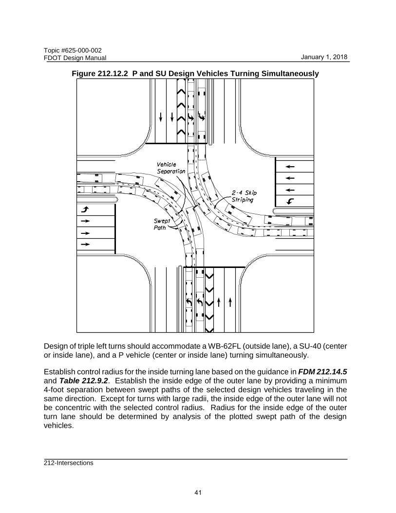
Design of dual turns should accommodate a SU-40 vehicle and a P vehicle turning simultaneously, as illustrated in Figure 212.12.2.
January 1, 2018
40
Topic #625-000-002 FDOT Design Manual
212-Intersections
Figure 212.12.2 P and SU Design Vehicles Turning Simultaneously
Design of triple left turns should accommodate a WB-62FL (outside lane), a SU-40 (center or inside lane), and a P vehicle (center or inside lane) turning simultaneously.
Establish control radius for the inside turning lane based on the guidance in FDM 212.14.5 and Table 212.9.2. Establish the inside edge of the outer lane by providing a minimum 4-foot separation between swept paths of the selected design vehicles traveling in the same direction. Except for turns with large radii, the inside edge of the outer lane will not be concentric with the selected control radius. Radius for the inside edge of the outer turn lane should be determined by analysis of the plotted swept path of the design vehicles.
January 1, 2018
41

Topic #625-000-002 FDOT Design Manual
212-Intersections
Provide minimum 8-foot separation between vehicles traveling in opposing direction. Separation may be less than 8 feet when:
(1) Turning paths are highly visible and speeds are low, or
(2) Signal left turn phases are not concurrent for the opposing directions.
212.13 Islands
An island is an area between traffic lanes that provide one or more of these primary functions:
(1) Channelization – to control and direct traffic movement (usually turning).
(2) Division (Median Islands and Traffic Separators) – to divide opposing or same direction traffic (usually through movements).
(3) Refuge – to provide refuge for pedestrians.
Islands are generally elongated or triangular in shape and located in areas where vehicle use is restricted. The placement of mast arms in channelizing islands is discouraged. The placement of mast arms in median islands is not permitted.
Island delineation is divided into three types:
(1) Curbing that raises the island
(2) Pavement markings or reflectorized markers placed on paved areas
(3) Pavement edges, possibly supplemented by flexible delineators or other flexible guideposts, or a mounded-earth treatment beyond and adjacent to the pavement edges.
Delineation of small islands is primarily by curbs. Large curbed islands may be sufficiently delineated by color and texture contrast of vegetative cover, mounded earth, shrubs, guideposts, tubular markers, signs or any combination of these. Curbed islands should not be used on high speed flush shoulder roadways. Standard markings for islands are provided in the Standard Plans, Index 711-001.
212.13.1 Channelization Islands
Meet the following requirements when designing channelization islands:
(1) Size of island should be:
(a) 50 square feet or larger within curbed intersections
January 1, 2018
42
Topic #625-000-002 FDOT Design Manual
212-Intersections
(b) 75 square feet or larger for flush shoulder intersections.
(c) 100 square feet or larger for all other locations.
(2) Triangular islands should be at least 15 feet on a side, but not less than 12 feet, after rounding of corners.
(3) Side dimensions should not exceed 100 feet.
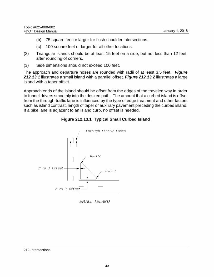
The approach and departure noses are rounded with radii of at least 3.5 feet. Figure 212.13.1 illustrates a small island with a parallel offset. Figure 212.13.2 illustrates a large island with a taper offset.
Approach ends of the island should be offset from the edges of the traveled way in order to funnel drivers smoothly into the desired path. The amount that a curbed island is offset from the through-traffic lane is influenced by the type of edge treatment and other factors such as island contrast, length of taper or auxiliary pavement preceding the curbed island. If a bike lane is adjacent to an island curb, no offset is needed.
Figure 212.13.1 Typical Small Curbed Island
January 1, 2018
43

Topic #625-000-002 FDOT Design Manual
212-Intersections
Figure 212.13.2 Typical Large Curbed Island
Where there are no curbs on the approach traveled way, the minimum offset of the edge of the curbed island to the through lane should be 1.5 to 3.5 feet. Where the approach roadway has a Type E curb, a similar curb on the island may be located at the edge of the through lane if there is sufficient length of curbed island to provide a gradual taper from the nose offset. Type F curbs should be offset from the through traveled way edge, regardless of the size of the curbed island. For intermediate and large-size islands that are uncurbed, offsets are desirable but not required. Fixed objects within the island areas must meet clear zone and lateral offset criteria found in FDM 215.2.3 and 215.2.4.
212.13.2 Median Islands and Traffic Separators
Meet the following requirements when designing median islands and traffic separators:
(1) A minimum of 4 feet wide and 25 feet long.
(2) 100 feet or more in length is allowed on high speed roadways when providing high visibility for the islands.
(3) Approach noses should be offset 2 to 6 feet from the through (approach) lanes to minimize impacts. Pavement markings in advance of the nose can be used to transition from the centerline to the edge of island.
January 1, 2018
44

Topic #625-000-002 FDOT Design Manual
212-Intersections
(4) The shape of the island should be based on design turning paths and the island function. Curvilinear tapers comprised of parabolic or circular curves generally suffice.
(5) The length of the island should be related to the approach speed. An estimate is to use the length based on 3-second driving time to the intersection.
(6) Median islands should begin on tangent alignments and on upgrades or beyond crest vertical curves. In some cases it is appropriate to extend a median island to avoid its introduction on a horizontal curve or within an area of limited sight distance.
Standard Plans, Index 520-020 provides detailed dimensional design for traffic separators.
212.13.3 Refuge Islands
Refuge islands aid and assist pedestrians and bicyclists crossing a roadway. Raised curb corner islands and center channelizing or divisional islands can provide refuge areas. Refuge islands should be a minimum of 6 feet wide when they will be used for bicyclists. Pedestrians and bicyclists should have a clear path through the island and should not be obstructed by objects such as poles, sign posts, or utility boxes.
Roundabout splitter islands provide pedestrian refuge and are discussed in FDM 213.5.
212.13.4 Corner Islands
Where the inside edges of the traveled way for right turns are designed to accommodate semi-trailer combinations or where the design permits passenger vehicles to turn at speeds greater than 10 mph, the pavement area within the intersection may become excessively large and may create longer crossing paths for pedestrians. This may also occur at intersections with turning angles greater than 90 degrees. To avoid this condition, a corner channelizing island can be provided to form a separate turning roadway.
FDM 212.12 provides information on the design of turning roadways with corner islands.
212.14 Auxiliary Lanes
The primary function of auxiliary lanes at intersections is to accommodate speed changes, storage and maneuvering of turning traffic. The length of the auxiliary lanes is the sum of the deceleration length, queue length and approach end taper. Pavement marking requirements for auxiliary lanes are included in Standard Plans, Index 711-001.
January 1, 2018
45

Topic #625-000-002 FDOT Design Manual
212-Intersections
212.14.1 Deceleration Length
The required total deceleration length is that needed for a safe and comfortable stop from the design speed of the highway. See Exhibit 212-1 for minimum deceleration lengths (including taper) for left turn lanes.
Right turn lane tapers and lengths are identical to left turn lanes under stop control conditions. Right turn lane tapers and lengths are site-specific for free-flow or yield conditions.
212.14.2 Queue Length
The queue length provided should be based on a traffic study.
For low volume intersections where a traffic study is not justified, a minimum 50-foot queue length (2 vehicles) should be provided for rural context classifications. A minimum 100-foot queue length (4 vehicles) should be provided in urbanized context classifications. Locations with over 10% truck traffic should accommodate at least one car and one truck.
For queue lengths at signalized intersections, refer to FDM 232.2.
212.14.3 Approach End Taper
The length of approach end tapers is 50 feet for a single turn lane and 100 feet for two or more turn lanes, as shown Exhibit 212-1. These taper lengths apply to all design speeds.
212.14.4 Offset Left Turn Lanes
The alignment of opposing left-turn lanes and the horizontal and vertical curvature on the approaches are the principal geometric design elements that determine how much sight distance is available to a left-turning driver. Vehicles queuing in opposing left-turn lanes restrict each other’s view of oncoming traffic in the through lanes. The level of restricted view depends on the alignment of opposing left-turn lanes with respect to each other and the type of vehicles in the opposing queue.
The offset distance is defined as the distance between the left edge of the turn lane and the right edge of the opposing turn lane. If the offset distance is to the left of the turn lane it is considered a negative offset, and if it is to the right of turn lane it is considered a positive offset, as illustrated in Figure 212.14.1.
January 1, 2018
46

Topic #625-000-002 FDOT Design Manual
212-Intersections
Figure 212.14.1 Negative and Positive Offset Left Turns
The conventional method of designing left turn lanes is to place the left turn lanes adjacent to the through lanes. This design creates a negative offset which restricts the sight distance of the left-turning driver’s view of oncoming traffic when another vehicle is in the opposing turn lane. Figure 212.14.2 indicates the negative offset when the conventional design is used.
Figure 212.14.2 Opposing Left Turns (22’ Median with Negative 10’ Offset)
On curbed roadway designs, offset left-turn lanes should be used with median widths greater than 18 feet. A 4-foot traffic separator should be used when possible to channelize the left turn and provide separation from opposing traffic.
Consider offset left-turn lanes at rural intersections with high turning movements. For median widths 30 feet or less, use a parallel offset left-turn lane. Stripe the area between the offset left-turn lane and the traffic lane where vehicles are moving in the same direction. For medians wider than 30 feet, consider a tapered offset left-turn lane. An offset left is illustrated in Figure 212.14.3.
2011 AASHTO Green Book Figure 9-52 illustrates the design of parallel and tapered left turn lanes.
January 1, 2018
47

Topic #625-000-002 FDOT Design Manual
212-Intersections
Figure 212.14.3 Typical Opposing Left Turns (22’ Median with Negative 1’ Offset)
At locations where the full offset distances cannot be obtained, it is recommended that the minimum offset distances shown in Table 212.14.1 be provided to achieve minimum required sight distances according to design speed. It is recommended that the “Opposing Truck” values be used where the opposing left-turn traffic includes a moderate to heavy volume of large trucks.
Table 212.14.1 Minimum Offset Distances for Left-Turn Lanes
Design Speed
(mph)
Minimum Offset (feet)
Opposing Car Opposing Truck
≤ 30 1.0 3.0
35 1.5 3.5
40 - 45 2.0 4.0
50 - 55 2.5 4.5
60 - 65 3.0 4.5
70 3.0 5.0
212.14.5 Directional Median Openings
Directional (channelized) median openings are designed to accommodate left-turn movements from the through roadway and prevent or discourage left-turn and crossing movements by traffic from a side road or driveway. Directional median openings are to be provided in accordance with the access management plan for the roadway.
The design of a directional median opening must accommodate the swept path of the predominant design vehicle. Channelization may be achieved using a combination of traffic separators, raised islands, or high performance traffic delineators. See Standard Plans, Index 520-020 for standard details for 4 feet, 6 feet and 8.5 feet wide traffic separators. See FDM 230.2.7 for additional information on high performance delineators.
January 1, 2018
48

Topic #625-000-002 FDOT Design Manual
212-Intersections
Typical layouts for directional median openings for high speed roadways with 40-feet-wide medians are provided in Exhibits 212-8, 212-9 and 212-10. Type E curb and raised islands in conjunction with the minimum offsets shown in these figures may be used on high speed roadways for directional median openings.
January 1, 2018
49

RETURN NO. 1 RETURN NO. 2
RETURN NO. 3RETURN NO. 4
QUADRANT NOS. 1 & 2 VACANT
RETURN NO. 3RETURN NO. 4
WB 40
SU
20'4'
21' 62'
R
45'
62'
R
45'21'
20' 4'
12'
4'
62'
R
60'
CR
60'
CR
70'
WB-40 Expected In Storage
Add 70' For Each Additional*
40'
4'
20'
60'
CR
4'
40'
2' And 8' Offsets Tested (Practical Fit)
40' Radius; 1:15 And 1:8 Tapers With
Simple Curve With Tapers Not Shown:
120'-40'-200' Radii; 2' And 8' Offsets
Three Centered Compound Curves For All Returns Depicted:
Returns Depicted:
RETURNS:
SWEPT PATH LEGEND:
Curb Type E Separator Wing (Optional) Chevrons (Optional)
Curb Type E
Curb Type E Separator Wing (Optional) Chevrons (Optional)
Curb Type E
01/01/2018
EXHIBIT 212-8
PARALLEL TURN BAY
DIRECTIONAL MEDIAN OPENING: SU & WB-40
tractor-semitrailer.
common with the opposing road or street. Swept paths are by AutoTURN 4.0 for the AASHTO 2001 SU and WB-40
The depicted design only applies where roads and streets intersect at 90° to the mainline and have centerlines
pavement for semi-trailer inside tracking and for 4' minimum clearance between trucks making opposing movement.
Return configurations for each quadrant must be analyzed independently to assure adequate return NOTE:
are by AutoTURN 4.0 for the AASHTO 2001 SU and WB-40 tractor-semitrailer.
only applies where roads and streets intersect at 90° to the mainline. Swept paths
assure adequate return pavement for semi-trailer inside tracking. The depicted design
Return configurations for each quadrant must be analyzed independently to NOTE:
L� FDM 212 *
NOT TO SCALE

01/01/2018
EXHIBIT 212-9
PARALLEL TURN BAY
DIRECTIONAL MEDIAN OPENING: WB-50
RETURN NO. 1 RETURN NO. 2
RETURN NO. 3RETURN NO. 4
QUADRANT NOS. 1 & 2 VACANT
RETURN NO. 3
RETURN NO. 4
70'
WB-50 Expected In Storage
* Add 70' For Each Additional
4'
20'
33' 70'
R
48'
48'
70'
R 33'4'
12'
20' 4'
70'
R
75'
CR
75' CR
40'
40'
75' CR
20'
4'
4'
4'
120'-60'-200' Radii; 2' And 13' Offsets
Three Centered Compound Curves For Return No. 3:
2' And 6' Offsets
70' Radius; 1:15 And 1:12 Tapers
Simple Curve With Tapers For Returns Nos. 1, 2 & 4 (Best Configuration):
Returns Depicted:
RETURNS:
Curb Type E Separator Wing (Optional) Chevrons (Optional)
Curb Type E
Curb Type E Separator Wing (Optional) Chevrons (Optional)
Curb Type E
WB-50 tractor-semitrailer.
centerlines common with the opposing road or street. Swept paths are by AutoTURN 4.0 for the AASHTO 2001
movement. The depicted design only applies where roads and streets intersect at 90° to the mainline and have
pavement for semi-trailer inside tracking and for 4' minimum clearance between trucks making opposing
Return configurations for each quadrant must be analyzed independently to assure adequate return NOTE:
the AASHTO 2001 WB-50 tractor-semitrailer.
where roads and streets intersect at 90° to the mainline. Swept paths are by AutoTURN 4.0 for
adequate return pavement for semi-trailer inside tracking. The depicted design only applies
Return configurations for each quadrant must be analyzed independently to assure NOTE:
L� FDM 212 *
NOT TO SCALE

01/01/2018
EXHIBIT 212-10
TAPERED TURN BAY
DIRECTIONAL MEDIAN OPENING: SU & WB-40
QUADRANT NOS. 1 & 2 VACANT
RETURN NO. 3 RETURN NO. 4
RETURN NO. 2RETURN NO. 1
RETURN NO. 3 RETURN NO. 4
SWEPT PATH LEGEND:
WB 40
SU
70'
4'
4'
4'
60' CR
55'
R
60' C
R
4'
24'
40'
24'
4'
20' 55'
R
60' CR
4'
4'
24'
40'
24'
4' R
55'
R
55'
R
4' R
WB-40 Expected In Storage
* Add 70' For Each Additional
2' And 8' Offsets Tested (Practical Fit)
40' Radius; 1:15 And 1:8 Tapers With
Simple Curve With Tapers Not Shown:
120'-40'-200' Radii; 2' And 8' Offsets
Three Centered Compound Curves For All Returns Depicted:
Returns Depicted:
RETURNS:
Curb Type E Chevrons (Optional)
Curb Type E
Curb Type E Chevrons (Optional)
Curb Type E
and WB-40 tractor-semitrailer.
centerlines common with the opposing road or street. Swept paths are by AutoTURN 4.0 for the AASHTO 2001 SU
movement. The depicted design only applies where roads and streets intersect at 90° to the mainline and have
pavement for semi-trailer inside tracking and for 4' minimum clearance between trucks making opposing
Return configurations for each quadrant must be analyzed independently to assure adequate return NOTE:
tractor-semitrailer.
intersect at 90° to the mainline. Swept paths are by AutoTURN 4.0 for the AASHTO 2001 SU and WB-40
return pavement for semi-trailer inside tracking. The depicted design only applies where roads and streets
Return configurations for each quadrant must be analyzed independently to assure adequate NOTE:
L� FDM 212 *
NOT TO SCALE
Copyright © 2022 FDOKUMEN