2100 / 3200 / 3200A / 3200B - Transmille
89
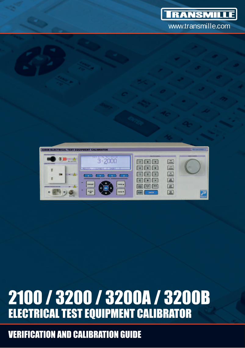
www.transmille.com 2100 / 3200 / 3200A / 3200B ELECTRICAL TEST EQUIPMENT CALIBRATOR VERIFICATION AND CALIBRATION GUIDE
-
Upload
khangminh22 -
Category
Documents
-
view
1 -
download
0
Transcript of 2100 / 3200 / 3200A / 3200B - Transmille
www.transmille.com
2100 / 3200 / 3200A / 3200BELECTRICAL TEST EQUIPMENT CALIBRATORVERIFICATION AND CALIBRATION GUIDE
2100 / 3200 / 3200A / 3200B Verification & Calibration Guide For Use With Calibration Control Panel & Calibration Lead Set
2100-3200-3200A-3200B Verification & Calibration Guide.doc V5.00 Page 1
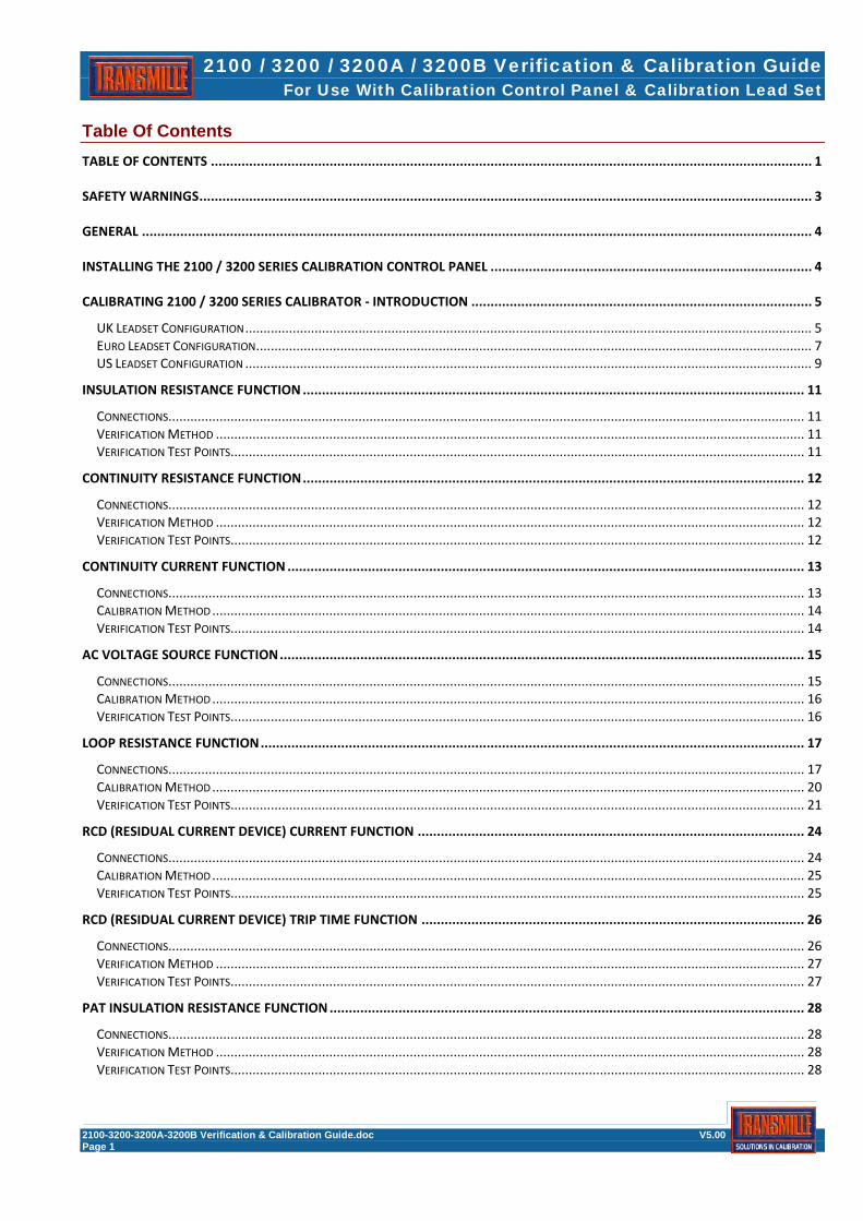
Table Of Contents TABLE OF CONTENTS ............................................................................................................................................................. 1
SAFETY WARNINGS ................................................................................................................................................................ 3
GENERAL ............................................................................................................................................................................... 4
INSTALLING THE 2100 / 3200 SERIES CALIBRATION CONTROL PANEL .................................................................................... 4
CALIBRATING 2100 / 3200 SERIES CALIBRATOR - INTRODUCTION ......................................................................................... 5
UK LEADSET CONFIGURATION ........................................................................................................................................................... 5 EURO LEADSET CONFIGURATION ........................................................................................................................................................ 7 US LEADSET CONFIGURATION ........................................................................................................................................................... 9
INSULATION RESISTANCE FUNCTION ................................................................................................................................... 11
CONNECTIONS .............................................................................................................................................................................. 11 VERIFICATION METHOD ................................................................................................................................................................. 11 VERIFICATION TEST POINTS ............................................................................................................................................................. 11
CONTINUITY RESISTANCE FUNCTION ................................................................................................................................... 12
CONNECTIONS .............................................................................................................................................................................. 12 VERIFICATION METHOD ................................................................................................................................................................. 12 VERIFICATION TEST POINTS ............................................................................................................................................................. 12
CONTINUITY CURRENT FUNCTION ....................................................................................................................................... 13
CONNECTIONS .............................................................................................................................................................................. 13 CALIBRATION METHOD .................................................................................................................................................................. 14 VERIFICATION TEST POINTS ............................................................................................................................................................. 14
AC VOLTAGE SOURCE FUNCTION ......................................................................................................................................... 15
CONNECTIONS .............................................................................................................................................................................. 15 CALIBRATION METHOD .................................................................................................................................................................. 16 VERIFICATION TEST POINTS ............................................................................................................................................................. 16
LOOP RESISTANCE FUNCTION .............................................................................................................................................. 17
CONNECTIONS .............................................................................................................................................................................. 17 CALIBRATION METHOD .................................................................................................................................................................. 20 VERIFICATION TEST POINTS ............................................................................................................................................................. 21
RCD (RESIDUAL CURRENT DEVICE) CURRENT FUNCTION ..................................................................................................... 24
CONNECTIONS .............................................................................................................................................................................. 24 CALIBRATION METHOD .................................................................................................................................................................. 25 VERIFICATION TEST POINTS ............................................................................................................................................................. 25
RCD (RESIDUAL CURRENT DEVICE) TRIP TIME FUNCTION .................................................................................................... 26
CONNECTIONS .............................................................................................................................................................................. 26 VERIFICATION METHOD ................................................................................................................................................................. 27 VERIFICATION TEST POINTS ............................................................................................................................................................. 27
PAT INSULATION RESISTANCE FUNCTION ............................................................................................................................ 28
CONNECTIONS .............................................................................................................................................................................. 28 VERIFICATION METHOD ................................................................................................................................................................. 28 VERIFICATION TEST POINTS ............................................................................................................................................................. 28

2100 / 3200 / 3200A / 3200B Verification & Calibration Guide For Use With Calibration Control Panel & Calibration Lead Set
2100-3200-3200A-3200B Verification & Calibration Guide.doc V5.00 Page 2
PAT EARTH BOND RESISTANCE FUNCTION ........................................................................................................................... 29
CONNECTIONS .............................................................................................................................................................................. 29 CALIBRATION METHOD .................................................................................................................................................................. 30 VERIFICATION TEST POINTS ............................................................................................................................................................. 30
PAT EARTH BOND CURRENT FUNCTION ............................................................................................................................... 31
CONNECTIONS .............................................................................................................................................................................. 31 CALIBRATION METHOD .................................................................................................................................................................. 32 VERIFICATION TEST POINTS ............................................................................................................................................................. 32
PAT LOAD FUNCTION ........................................................................................................................................................... 33
CONNECTIONS .............................................................................................................................................................................. 33 VERIFICATION METHOD ................................................................................................................................................................. 34 VERIFICATION TEST POINTS ............................................................................................................................................................. 34
PAT LEAKAGE CURRENT FUNCTION ..................................................................................................................................... 35
CONNECTIONS .............................................................................................................................................................................. 35 VERIFICATION METHOD ................................................................................................................................................................. 36 VERIFICATION TEST POINTS ............................................................................................................................................................. 36
2100 / 3200 Series Verification Sheets Appendix A 2100 / 3200 Series Extended Specifications Appendix B
2100 / 3200 / 3200A / 3200B Verification & Calibration Guide For Use With Calibration Control Panel & Calibration Lead Set
2100-3200-3200A-3200B Verification & Calibration Guide.doc V5.00 Page 3
SAFETY WARNINGS
HIGH VOLTAGES
CONNECTIONS TO LINE
THIS VERIFICATION AND CALIBRATION GUIDE INVOLVES CONNECTIONS TO LINE AND
MEASUREMENT OF HIGH VOLTAGES
FOR THIS REASON VERIFICATION AND CALIBRATION SHOULD ONLY BE UNDERTAKEN
BY QUALIFIED PERSONNEL
THIS VERIFICATION AND CALIBRATION KIT IS PROVIDED ‘AS-IS’ AND TRANSMILLE SHALL
NOT BE LIABLE FOR ANY INCIDENTAL, INDIRECT, SPECIAL OR CONSEQUENTIAL DAMAGES
OR LOSS AS A RESULT OF USING THIS GUIDE OR VERIFICATION AND CALIBRATION LEAD SET.

2100 / 3200 / 3200A / 3200B Verification & Calibration Guide For Use With Calibration Control Panel & Calibration Lead Set
2100-3200-3200A-3200B Verification & Calibration Guide.doc V5.00 Page 4
General The steps detailed below will allow adjustment of a 2100 / 3200 Series Electrical Test Equipment Calibrator. This requires the use of the 2100 / 3200 Series Calibration Control Panel program (supplied digitally via email link) and the 2100 / 3200 Series calibration lead set kit supplied by Transmille. Installing the 2100 / 3200 Series calibration control panel
Click OK to proceed
Click button to begin install
Click OK to complete installation

2100 / 3200 / 3200A / 3200B Verification & Calibration Guide For Use With Calibration Control Panel & Calibration Lead Set
2100-3200-3200A-3200B Verification & Calibration Guide.doc V5.00 Page 5
Calibrating 2100 / 3200 Series calibrator - Introduction The 2100 / 3200 Series Calibration kit comprises of a set of test leads as follows :
UK Leadset Configuration UK LEADSET CONFIGURATION SET A COAX SCREENED TO 4MM GOLD PLUGS
SET B COAX SCREENED TO 4MM GOLD PLUGS
SET C 4MM PLUGS TO LINE PLUG EARTH PIN (3 SETS) SET C1 COMMON SET FOR ALL CALIBRATORS
SET C2 LEAD FOR NORMAL EARTH-EARTH CONFIGURATION (FOR USE ON UNPROTECTED SUPPLIES ONLY)
SET C3 LEAD FOR NO-TRIP EARTH-NEUTRAL CONFIGURATION (FOR USE ON PROTECTED SUPPLIES) NOTE : THESE
CALIBRATORS WILL BE LABELLED EARTH-NEUTRAL ON THE OPTIONS LABEL ON THE REAR PANEL
SET C4 LOOP SUPPLY CONNECTION : REQUIRED FOR 3200B ONLY

2100 / 3200 / 3200A / 3200B Verification & Calibration Guide For Use With Calibration Control Panel & Calibration Lead Set
2100-3200-3200A-3200B Verification & Calibration Guide.doc V5.00 Page 6
SET D 4mm PLUGS TO4mm PLUG & LINE PLUG
SET E 4mm PLUGS TO 4mm PLUG & IEC POWER OUTLET
SET F LINE PLUG TO IEC POWER OUTLET WITH EARTH BREAKOUT
SET G 4mm PLUGS TO IEC POWER OUTLET
SET H 4mm PLUGS TO IEC POWER OUTLET
In addition a performance verification sheet is provided – this allows the 2100 / 3200 Series to be compared against manufacturers specifications.

2100 / 3200 / 3200A / 3200B Verification & Calibration Guide For Use With Calibration Control Panel & Calibration Lead Set
2100-3200-3200A-3200B Verification & Calibration Guide.doc V5.00 Page 7
Euro Leadset Configuration EURO LEADSET CONFIGURATION SET A COAX SCREENED TO 4MM GOLD PLUGS
SET B COAX SCREENED TO 4MM GOLD PLUGS
SET C 4MM PLUGS TO LINE PLUG EARTH PIN (3 SETS) SET C1 COMMON SET FOR ALL CALIBRATORS
SET C2 LEAD FOR NORMAL EARTH-EARTH CONFIGURATION (FOR USE ON UNPROTECTED SUPPLIES ONLY)
SET C3 LEAD FOR NO-TRIP EARTH-NEUTRAL CONFIGURATION (FOR USE ON PROTECTED SUPPLIES)
NOTE : THESE CALIBRATORS WILL BE LABELLED EARTH-NEUTRAL ON THE OPTIONS LABEL ON THE REAR PANEL
NOTE : THIS LEAD MUST BE CONNECTED AT THE LINE PLUG END IN THE CORRECT ORIENTATION – THIS IS INDICATED BY A LIT NEON BUILT INTO THE PLUG
SET C4 LOOP SUPPLY CONNECTION : REQUIRED FOR 3200B ONLY

2100 / 3200 / 3200A / 3200B Verification & Calibration Guide For Use With Calibration Control Panel & Calibration Lead Set
2100-3200-3200A-3200B Verification & Calibration Guide.doc V5.00 Page 8
SET D 4mm PLUGS TO4mm PLUG & LINE PLUG
SET E 4mm PLUGS TO 4mm PLUG & IEC POWER OUTLET
SET F LINE PLUG TO IEC POWER OUTLET WITH EARTH BREAKOUT
SET G 4mm PLUGS TO IEC POWER OUTLET
SET H 4mm PLUGS TO IEC POWER OUTLET
In addition a performance verification sheet is provided – this allows the 2100 / 3200 Series to be compared against manufacturers specifications.

2100 / 3200 / 3200A / 3200B Verification & Calibration Guide For Use With Calibration Control Panel & Calibration Lead Set
2100-3200-3200A-3200B Verification & Calibration Guide.doc V5.00 Page 9
US Leadset Configuration US LEADSET CONFIGURATION SET A COAX SCREENED TO 4MM GOLD PLUGS
SET B COAX SCREENED TO 4MM GOLD PLUGS
SET C 4MM PLUGS TO LINE PLUG EARTH PIN (3 SETS) SET C1 COMMON SET FOR ALL CALIBRATORS
SET C2 LEAD FOR NORMAL EARTH-EARTH CONFIGURATION (FOR USE ON UNPROTECTED SUPPLIES ONLY)
SET C3 LEAD FOR NO-TRIP EARTH-NEUTRAL CONFIGURATION (FOR USE ON PROTECTED SUPPLIES)
NOTE : THESE CALIBRATORS WILL BE LABELLED EARTH-NEUTRAL ON THE OPTIONS LABEL ON THE REAR PANEL
SET C4 LOOP SUPPLY CONNECTION : REQUIRED FOR 3200B ONLY

2100 / 3200 / 3200A / 3200B Verification & Calibration Guide For Use With Calibration Control Panel & Calibration Lead Set
2100-3200-3200A-3200B Verification & Calibration Guide.doc V5.00 Page 10
SET D 4mm PLUGS TO4mm PLUG & LINE PLUG
SET E 4mm PLUGS TO 4mm PLUG & IEC POWER OUTLET
SET F LINE PLUG TO IEC POWER OUTLET WITH EARTH BREAKOUT
SET G 4mm PLUGS TO IEC POWER OUTLET
SET H 4mm PLUGS TO IEC POWER OUTLET
In addition a performance verification sheet is provided – this allows the 2100 / 3200 Series to be compared against manufacturers specifications.
2100 / 3200 / 3200A / 3200B Verification & Calibration Guide For Use With Calibration Control Panel & Calibration Lead Set
2100-3200-3200A-3200B Verification & Calibration Guide.doc V5.00 Page 11
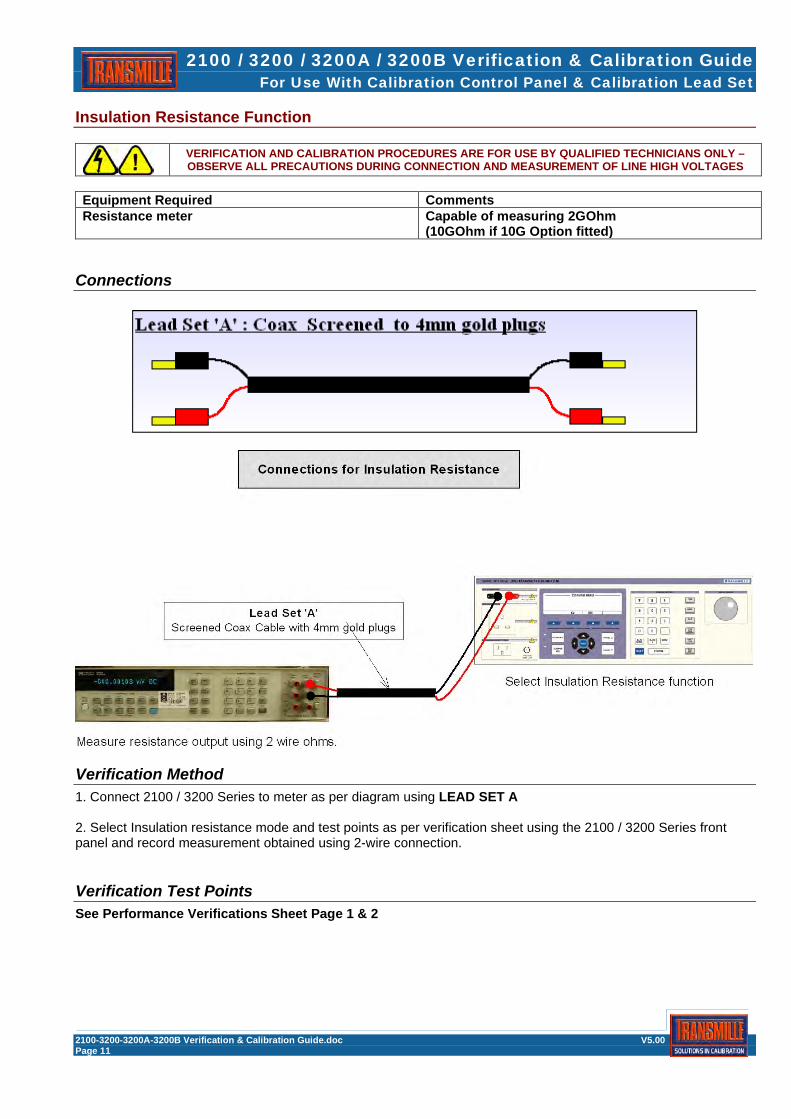
Insulation Resistance Function
VERIFICATION AND CALIBRATION PROCEDURES ARE FOR USE BY QUALIFIED TECHNICIANS ONLY – OBSERVE ALL PRECAUTIONS DURING CONNECTION AND MEASUREMENT OF LINE HIGH VOLTAGES
Equipment Required Comments Resistance meter Capable of measuring 2GOhm
(10GOhm if 10G Option fitted)
Connections
Verification Method 1. Connect 2100 / 3200 Series to meter as per diagram using LEAD SET A 2. Select Insulation resistance mode and test points as per verification sheet using the 2100 / 3200 Series front panel and record measurement obtained using 2-wire connection.
Verification Test Points See Performance Verifications Sheet Page 1 & 2
2100 / 3200 / 3200A / 3200B Verification & Calibration Guide For Use With Calibration Control Panel & Calibration Lead Set
2100-3200-3200A-3200B Verification & Calibration Guide.doc V5.00 Page 12
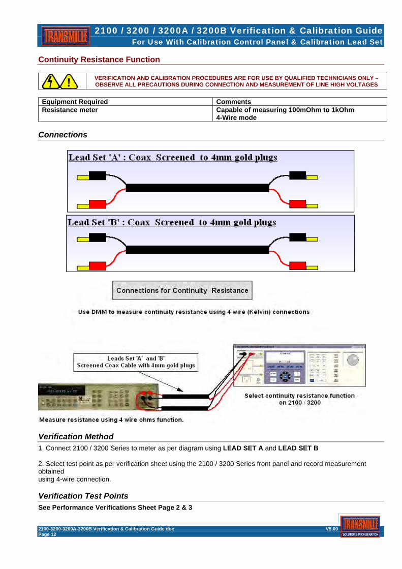
Continuity Resistance Function
VERIFICATION AND CALIBRATION PROCEDURES ARE FOR USE BY QUALIFIED TECHNICIANS ONLY – OBSERVE ALL PRECAUTIONS DURING CONNECTION AND MEASUREMENT OF LINE HIGH VOLTAGES
Equipment Required Comments Resistance meter Capable of measuring 100mOhm to 1kOhm
4-Wire mode
Connections
Verification Method 1. Connect 2100 / 3200 Series to meter as per diagram using LEAD SET A and LEAD SET B 2. Select test point as per verification sheet using the 2100 / 3200 Series front panel and record measurement obtained using 4-wire connection.
Verification Test Points See Performance Verifications Sheet Page 2 & 3
2100 / 3200 / 3200A / 3200B Verification & Calibration Guide For Use With Calibration Control Panel & Calibration Lead Set
2100-3200-3200A-3200B Verification & Calibration Guide.doc V5.00 Page 13
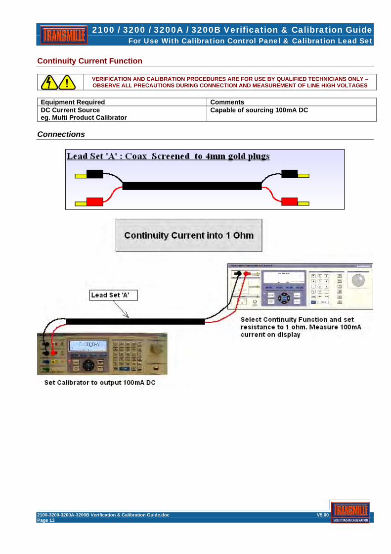
Continuity Current Function
VERIFICATION AND CALIBRATION PROCEDURES ARE FOR USE BY QUALIFIED TECHNICIANS ONLY – OBSERVE ALL PRECAUTIONS DURING CONNECTION AND MEASUREMENT OF LINE HIGH VOLTAGES
Equipment Required Comments DC Current Source eg. Multi Product Calibrator
Capable of sourcing 100mA DC
Connections
2100 / 3200 / 3200A / 3200B Verification & Calibration Guide For Use With Calibration Control Panel & Calibration Lead Set
2100-3200-3200A-3200B Verification & Calibration Guide.doc V5.00 Page 14
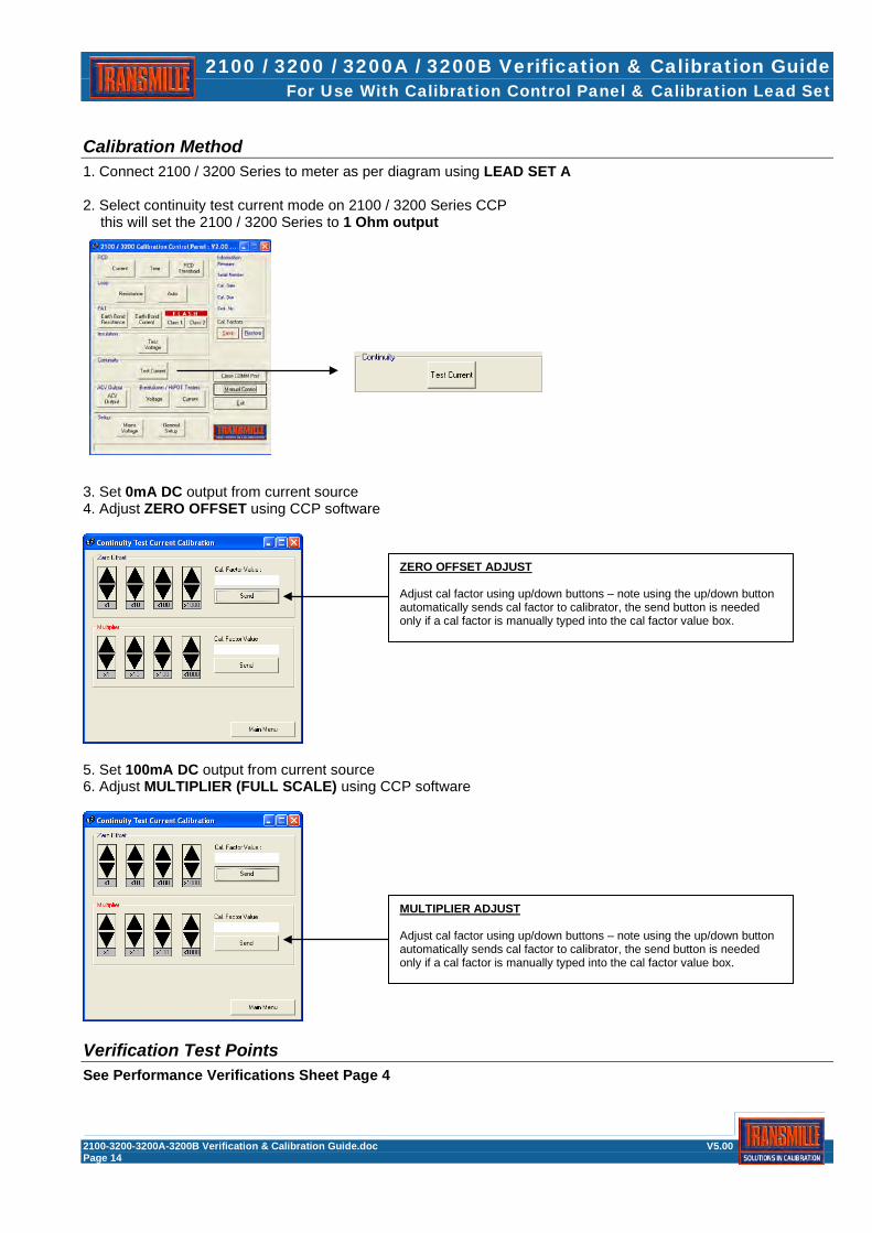
Calibration Method 1. Connect 2100 / 3200 Series to meter as per diagram using LEAD SET A 2. Select continuity test current mode on 2100 / 3200 Series CCP this will set the 2100 / 3200 Series to 1 Ohm output
3. Set 0mA DC output from current source 4. Adjust ZERO OFFSET using CCP software
5. Set 100mA DC output from current source 6. Adjust MULTIPLIER (FULL SCALE) using CCP software
Verification Test Points See Performance Verifications Sheet Page 4
ZERO OFFSET ADJUST Adjust cal factor using up/down buttons – note using the up/down button automatically sends cal factor to calibrator, the send button is needed only if a cal factor is manually typed into the cal factor value box.
MULTIPLIER ADJUST Adjust cal factor using up/down buttons – note using the up/down button automatically sends cal factor to calibrator, the send button is needed only if a cal factor is manually typed into the cal factor value box.

2100 / 3200 / 3200A / 3200B Verification & Calibration Guide For Use With Calibration Control Panel & Calibration Lead Set
2100-3200-3200A-3200B Verification & Calibration Guide.doc V5.00 Page 15
AC Voltage Source Function
VERIFICATION AND CALIBRATION PROCEDURES ARE FOR USE BY QUALIFIED TECHNICIANS ONLY – OBSERVE ALL PRECAUTIONS DURING CONNECTION AND MEASUREMENT OF LINE HIGH VOLTAGES
Equipment Required Comments AC Voltage meter Capable of measuring up to 400V AC
Connections

2100 / 3200 / 3200A / 3200B Verification & Calibration Guide For Use With Calibration Control Panel & Calibration Lead Set
2100-3200-3200A-3200B Verification & Calibration Guide.doc V5.00 Page 16
Calibration Method 1. Connect 2100 / 3200 Series to meter as per diagram using LEAD SET A 2. Select ACV Output mode on 2100 / 3200 Series CCP - this will set the 2100 / 3200 Series to 100V Output initially
3. Adjust cal factor using CCP software adjustment control
4. Select 200V, 230V, 300V and 400V ranges in turn and adjust each range in turn
Verification Test Points See Performance Verifications Sheet Page 4
RANGE SELECTION Select range to be calibrated here
ADJUSTMENT CONTROL Adjust cal factor using up/down buttons – note using the up/down button automatically sends cal factor to calibrator, the send button is needed only if a cal factor is manually typed into the cal factor value box.

2100 / 3200 / 3200A / 3200B Verification & Calibration Guide For Use With Calibration Control Panel & Calibration Lead Set
2100-3200-3200A-3200B Verification & Calibration Guide.doc V5.00 Page 17
Loop Resistance Function
VERIFICATION AND CALIBRATION PROCEDURES ARE FOR USE BY QUALIFIED TECHNICIANS ONLY – OBSERVE ALL PRECAUTIONS DURING CONNECTION AND MEASUREMENT OF LINE HIGH VOLTAGES
Equipment Required Comments DC Voltage meter DC Current Source Capable of sourcing up to1A DC 2x 12V LEAD ACID BATTERIES FOR 3200B ONLY : BATTERIES NOT SUPPLIED
Connections
NOTES FOR USE WITH LEAD SET ‘C’ Set C1 COMMON SET OF TEST LEADS (RED & BLACK LEADS) IS A COMMON SET FOR USE WITH ANY TYPE OF 2100 / 3200 CALIBRATOR. DEPENDING ON THE CONFIGURATION OF THE 2100 / 3200 CALIBRATOR THE SECOND LEAD SHOULD BE EITHER : Set C2 LEAD MARKED FOR ‘NORMAL’ CONFIGURATION EARTH-EARTH OR Set C3 LEAD MARKED FOR ‘EARTH-NEUTRAL’ (NO TRIP) CONFIGURATION – NOTE THESE CALIBRATORS WILL BE MARKED AS EARTH-NEUTRAL ON THE REAR PANEL OPTION LABEL IF CONFIGURED THIS WAY. Set C4 3200B ONLY : 12V SUPPLY CONNECTION : REQUIRES 2x 12V LEAD ACID BATTERIES (NOT SUPPLIED)

2100 / 3200 / 3200A / 3200B Verification & Calibration Guide For Use With Calibration Control Panel & Calibration Lead Set
2100-3200-3200A-3200B Verification & Calibration Guide.doc V5.00 Page 18
LOOP SUPPLY CONFIGURATION USING LEAD SET C4 : 3200B ONLY
Danger – mains voltage potentials within the instrument on the main board, ensure the instrument is switched off and the mains plug removed from the supply.
To calibrate the loop resistance values, an external isolated ± 12V power supply is required to energise the loop circuit for longer periods during testing. A supplied connection lead can be used with two 12V lead acid batteries (batteries not supplied). Alternatively an isolated power supply may be used – contact Transmille technical service for further assistance. Remove the lid of the electrical test calibrator by removing the two hex screws on either side of the front panel and the six screws on the bottom of the unit. Slide the lid towards the back of the instrument and remove. Use lead set C4 to connect loop supply batteries (2x 12V – not supplied) to the connector just above the two TO3 transistors (TR2 & TR3), ensure that the connector is in the correct orientation :
SEE LEAD SET C4 LABELLING FOR CORRECT POSITIVE AND NEGATIVE 12V SUPPLY CONNECTION
POSITIVE SUPPLY
12V BATTERY
NEGATIVE SUPPLY
12V BATTERY

2100 / 3200 / 3200A / 3200B Verification & Calibration Guide For Use With Calibration Control Panel & Calibration Lead Set
2100-3200-3200A-3200B Verification & Calibration Guide.doc V5.00 Page 19
2100 / 3200 / 3200A / 3200B SETTING UP FOR LOOP FUNCTION CALIBRATION Connect the instrument to mains supply and switch on, allow the instrument to warm up and stabilise prior to calibration of the loop resistance. (maximum 20 minutes) Connect the Electrical Calibrator (2100/3200/3200A/3200B) to the multi product calibrator as per the diagram using LEAD SET C1
Connect the Electrical Calibrator to the multi meter as per the diagram using LEAD SET as per guidance below :
Set C2 LEAD FOR NORMAL EARTH-EARTH CONFIGURATION (FOR USE ON UNPROTECTED SUPPLIES ONLY) LEAD MARKED FOR ‘NORMAL’ CONFIGURATION EARTH-EARTH OR Set C3 LEAD FOR NO-TRIP EARTH-NEUTRAL CONFIGURATION (FOR USE ON PROTECTED SUPPLIES) NOTE : THESE CALIBRATORS WILL BE LABELLED EARTH-NEUTRAL ON THE OPTIONS LABEL ON THE REAR PANEL LEAD MARKED FOR ‘EARTH-NEUTRAL’ (NO TRIP) CONFIGURATION – NOTE THESE CALIBRATORS WILL BE MARKED AS EARTH-NEUTRAL ON THE REAR PANEL OPTION LABEL IF CONFIGURED THIS WAY.
Loop resistance should be measured by passing current through a resistor and measuring the voltage drop, then calculate the resistance using ohms law V/I = R
The 4 terminal resistance measurement is made from the earth of the mains input to the 3200B to the Earth pin of the output socket of the 3200B. Note : The measurement of loop resistance is the difference between 'Range 1’, Zero and the selected range
2100 / 3200 / 3200A / 3200B Verification & Calibration Guide For Use With Calibration Control Panel & Calibration Lead Set
2100-3200-3200A-3200B Verification & Calibration Guide.doc V5.00 Page 20
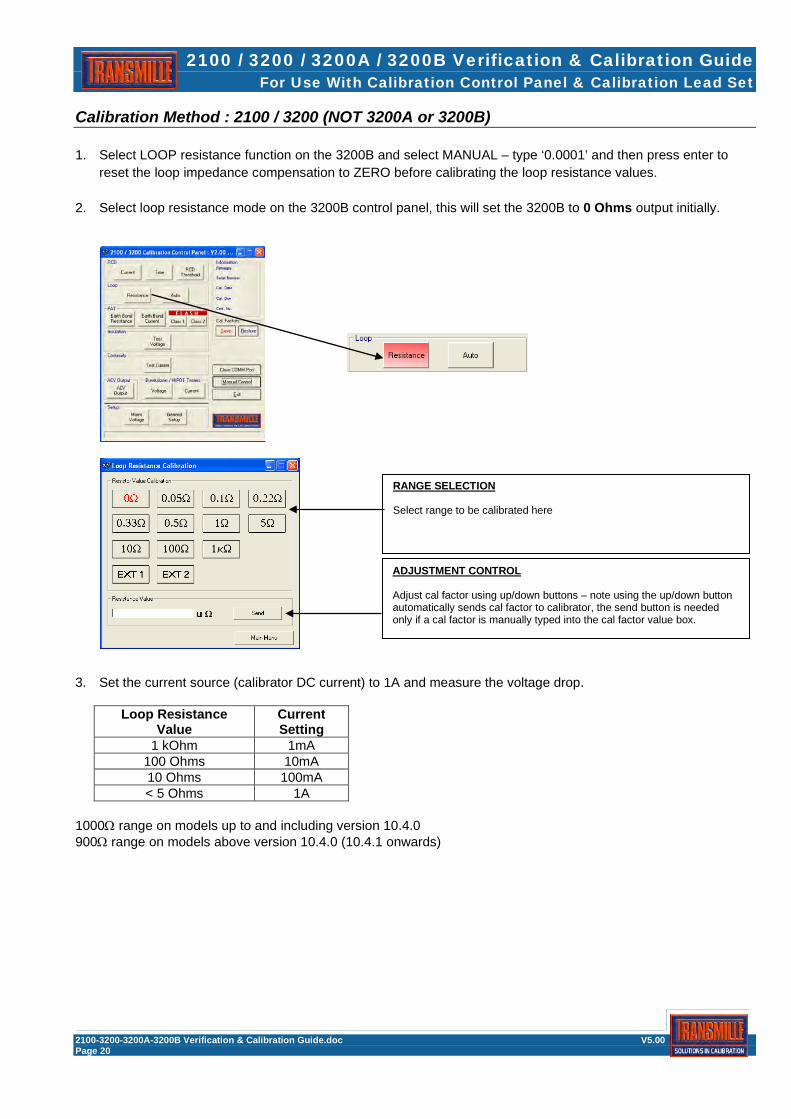
Calibration Method : 2100 / 3200 (NOT 3200A or 3200B) 1. Select LOOP resistance function on the 3200B and select MANUAL – type ‘0.0001’ and then press enter to
reset the loop impedance compensation to ZERO before calibrating the loop resistance values. 2. Select loop resistance mode on the 3200B control panel, this will set the 3200B to 0 Ohms output initially.
3. Set the current source (calibrator DC current) to 1A and measure the voltage drop.
Loop Resistance Value
Current Setting
1 kOhm 1mA 100 Ohms 10mA 10 Ohms 100mA < 5 Ohms 1A
1000Ω range on models up to and including version 10.4.0 900Ω range on models above version 10.4.0 (10.4.1 onwards)
RANGE SELECTION Select range to be calibrated here
ADJUSTMENT CONTROL Adjust cal factor using up/down buttons – note using the up/down button automatically sends cal factor to calibrator, the send button is needed only if a cal factor is manually typed into the cal factor value box.

2100 / 3200 / 3200A / 3200B Verification & Calibration Guide For Use With Calibration Control Panel & Calibration Lead Set
2100-3200-3200A-3200B Verification & Calibration Guide.doc V5.00 Page 21
4. Calculate the zero resistance value (X) of the system using Ohms law (V / I = Ω).
5. Select the next value on the control panel (0.05Ω) and apply the current as stated in the table.
6. Calculate the value as before using Ohms law (Y) and then subtract the zero resistance value (X) from this
new value (Y) to arrive at the value for that resistor (Z) i.e. Z = Y – X
7. Enter the calculated value in uOhms into the resistance value box on the control panel and click ‘Set Value’ 8. Repeat this process (steps 11 to 13 inclusive) for each value (0.1Ω, 0.22Ω, 0.33Ω, 0.5Ω and 1Ω 9. Select 0Ω and set the current source to 100mA and measure the voltage drop. 10. Calculate the zero resistance value (X) of the system using Ohms law (V / I = Ω). 11. Select the next value on the control panel 5Ω and apply the current as stated in the table. 12. Calculate the value as before using Ohms law (Y) and then subtract the zero resistance value (X) from this new value (Y) to arrive at the value for that resistor (Z) i.e. Z = Y – X 13. Enter the calculated value in uOhms into the resistance value box on the control panel and click ‘Set Value’ 14. Repeat this process (steps 17 to 19 inclusive) for the 9Ω range. 15. Select 0Ω and set the current source to 10mA and measure the voltage drop. 16. Calculate the zero resistance value (X) of the system using Ohms law (V / I = Ω). 17. Select the next value on the control panel 90Ω and apply the current as stated in the table. 18. Calculate the value as before using Ohms law (Y) and then subtract the zero resistance value (X) from this new value (Y) to arrive at the value for that resistor (Z) i.e. Z = Y – X 19. Enter the calculated value in uOhms into the resistance value box on the control panel and click ‘Set Value’ 20.Select 0Ω and set the current source to 1mA and measure the voltage drop. 21. Calculate the zero resistance value (X) of the system using Ohms law (V / I = Ω). 22. Select the next value on the control panel 900Ω or 1000Ω depending on the version you have) and apply the current as stated in the table. 23. Calculate the value as before using Ohms law (Y) and then subtract the zero resistance value (X) from this new value (Y) to arrive at the value for that resistor (Z) i.e. Z = Y – X
Verification Test Points See Performance Verifications Sheet Page 5

2100 / 3200 / 3200A / 3200B Verification & Calibration Guide For Use With Calibration Control Panel & Calibration Lead Set
2100-3200-3200A-3200B Verification & Calibration Guide.doc V5.00 Page 22
3200A / 3200B Autoloop Adjustment [Requires 3200A / 3200B Autoloop adjust software]
1. Connect the 3200A/B to the mains voltage (AC) supply via an adjustable source i.e. via a Regavolt or Variac, as the supply needs to be varied between 210V and 240V, monitor the supply with a True RMS voltmeter and set the supply to 240V.
2. Start the calibration software and select the ‘Loop Resistance’ button, followed by the ‘Autoloop Setup’ button, the following screen will appear.
3. The mains voltage as measured by the 3200A/B will be displayed (Mains Voltage (V) Measurement) as shown above.
4. To adjust the Autoloop, the 3200A/B must be able to measure the mains voltage accurately, this is achieved by entering two calibration point values.
Mains Voltage (V) Measurement
Calibration Point 1 (210V)
Calibration Point 2 (240V)

2100 / 3200 / 3200A / 3200B Verification & Calibration Guide For Use With Calibration Control Panel & Calibration Lead Set
2100-3200-3200A-3200B Verification & Calibration Guide.doc V5.00 Page 23
5. Adjust the input supply (mains) to 210V and enter the measured value in the calibration point 1 box
(no units) and click the ‘Set Cal Point 1’ button.
6. Adjust the input supply to 240V and enter the measured value in the calibration point 2 box (no units) and click the ‘Set Cal Point 2’ button.
7. Adjust the input supply to 225V and check that the ‘Mains Voltage (V) Measurement’ is within ± 0.5V of the measured value on the reference voltmeter.
8. If the value is outside ± 0.5V, repeat steps 5 to 7 until the desired value is achieved.
9. Check the values at 210V and 240V are within ± 0.5V of the measured values,
if this is not the case repeat steps 5 to 8.
10. When the measurements have been completed click the ‘Store’ button.
11. ‘Exit’ the screen and then exit the ‘Loop Resistance’ screen.
12. Disconnect the instrument from the variable mains supply (Regavolt / Variac) and plug the instrument directly into the mains source.
13. Select the loop function and set to Range 1 and switch on the output. Measure the loop impedance of the system at the output mains (on the front panel) socket.
14. Run the ‘Autoloop’ function using the softkey and compare the value on the 3200A/B with the measured loop impedance, the values should be within ± 18mΩ.
15. If there is a slight discrepancy the autoloop value can be adjusted by changing the offset impedance (Autoloop Offset, default 5000uΩ) via the software. (run the software again, change the offset value, click ‘Set’ and then ‘Store’), the value on the front panel will change depending on the value of the offset, repeat steps 13 and 14.
16. Check the loop impedance at approximately 0.3Ω and 0.6Ω to ensure that the system is linear.

2100 / 3200 / 3200A / 3200B Verification & Calibration Guide For Use With Calibration Control Panel & Calibration Lead Set
2100-3200-3200A-3200B Verification & Calibration Guide.doc V5.00 Page 24
RCD (Residual Current Device) Current Function
VERIFICATION AND CALIBRATION PROCEDURES ARE FOR USE BY QUALIFIED TECHNICIANS ONLY – OBSERVE ALL PRECAUTIONS DURING CONNECTION AND MEASUREMENT OF LINE HIGH VOLTAGES
Equipment Required Comments AC Current Source Capable of sourcing up to 3A AC 50Hz
Connections

2100 / 3200 / 3200A / 3200B Verification & Calibration Guide For Use With Calibration Control Panel & Calibration Lead Set
2100-3200-3200A-3200B Verification & Calibration Guide.doc V5.00 Page 25
Calibration Method 1. Connect 2100 / 3200 Series to meter as per diagram using LEAD SET D 2. Select RCD Current mode on 2100 / 3200 Series CCP this will set the 2100 / 3200 Series to 10mA Range in calibration mode (continuous reading)
3. Set the current source to the current range full scale 4. Adjust cal factor using CCP software adjustment control
5. Repeat process for each RCD current range
Verification Test Points See Performance Verifications Sheet Page 6
RANGE SELECTION Select range to be calibrated here
ADJUSTMENT CONTROL Adjust cal factor using up/down buttons – note using the up/down button automatically sends cal factor to calibrator, the send button is needed only if a cal factor is manually typed into the cal factor value box.

2100 / 3200 / 3200A / 3200B Verification & Calibration Guide For Use With Calibration Control Panel & Calibration Lead Set
2100-3200-3200A-3200B Verification & Calibration Guide.doc V5.00 Page 26
RCD (Residual Current Device) Trip Time Function
VERIFICATION AND CALIBRATION PROCEDURES ARE FOR USE BY QUALIFIED TECHNICIANS ONLY – OBSERVE ALL PRECAUTIONS DURING CONNECTION AND MEASUREMENT OF LINE HIGH VOLTAGES
Equipment Required Comments Digital Storage Oscilloscope RCD & oscilloscope Trigger Box Supplied with calibration kit
Connections

2100 / 3200 / 3200A / 3200B Verification & Calibration Guide For Use With Calibration Control Panel & Calibration Lead Set
2100-3200-3200A-3200B Verification & Calibration Guide.doc V5.00 Page 27
Verification Method 1. Connect 2100 / 3200 Series to meter as per diagram using RCD & OSCILLOSCOPE TRIGGER BOX 2. Select RCD Function on 2100 / 3200 Series : 230V Line Voltage : Set 20mA / 40ms trip current / time 110V Line Voltage : Set 10mA / 40ms trip current / time 3. Adjust setting on oscilloscope for storage mode and to use external trigger input
Set 5V/Div Amplitude, 5ms Timebase. Select external trigger and single shot storage mode as to view waveform as shown in screenshot below. Adjust to trigger oscilloscope on a 5V rising edge.
4. Press the TEST soft key on the 2100 / 3200 Series to begin the test If the button is pressed at the wrong part of the mains cycle an obviously incorrect time period will result. Simply reset the oscilloscope / 2100 / 3200 Series and press button again to retest. 5. Read the timing from the oscilloscope – target value is 40ms ± 0.7ms
Verification Test Points See Performance Verification Sheet Page 6

2100 / 3200 / 3200A / 3200B Verification & Calibration Guide For Use With Calibration Control Panel & Calibration Lead Set
2100-3200-3200A-3200B Verification & Calibration Guide.doc V5.00 Page 28
PAT Insulation Resistance Function
VERIFICATION AND CALIBRATION PROCEDURES ARE FOR USE BY QUALIFIED TECHNICIANS ONLY – OBSERVE ALL PRECAUTIONS DURING CONNECTION AND MEASUREMENT OF LINE HIGH VOLTAGES
Equipment Required Comments Resistance Meter Capable of measuring up to 1kOhm
Connections
Verification Method 1. Connect 2100 / 3200 Series to meter as per diagram using LEAD SET G 2. Select PAT Insulation Resistance mode and test points as per verification sheet using the 2100 / 3200 Series front panel and record measurement obtained using 2-wire connection.
Verification Test Points See Performance Verifications Sheet Page 6

2100 / 3200 / 3200A / 3200B Verification & Calibration Guide For Use With Calibration Control Panel & Calibration Lead Set
2100-3200-3200A-3200B Verification & Calibration Guide.doc V5.00 Page 29
PAT Earth Bond Resistance Function
VERIFICATION AND CALIBRATION PROCEDURES ARE FOR USE BY QUALIFIED TECHNICIANS ONLY – OBSERVE ALL PRECAUTIONS DURING CONNECTION AND MEASUREMENT OF LINE HIGH VOLTAGES
Equipment Required Comments DC Voltage meter DC Current Source Capable of sourcing up to1A DC
Connections

2100 / 3200 / 3200A / 3200B Verification & Calibration Guide For Use With Calibration Control Panel & Calibration Lead Set
2100-3200-3200A-3200B Verification & Calibration Guide.doc V5.00 Page 30
Calibration Method 1. Connect 2100 / 3200 Series to meter as per diagram using LEAD SET G 2. Select PAT Earth Bond Resistance mode on 2100 / 3200 Series CCP this will set the 2100 / 3200 Series to 0Ohms Output initially
3. Set the current source to the current as specified in the table below and measure voltage drop
Loop Resistance Value
Current Setting
1 kOhm 1mA 100 Ohms 10mA 10 Ohms 100mA < 5 Ohms 1A
4. Calculate resistance value using Ohms Law (V/I = R) 5. Enter calculated resistance into resistance value box on CCP in uOhms and click SEND
6. Repeat steps 3 to 5 for all resistance values.
Verification Test Points See Performance Verifications Sheet Page 7
RANGE SELECTION Select range to be calibrated here
ADJUSTMENT CONTROL Adjust cal factor using up/down buttons – note using the up/down button automatically sends cal factor to calibrator, the send button is needed only if a cal factor is manually typed into the cal factor value box.

2100 / 3200 / 3200A / 3200B Verification & Calibration Guide For Use With Calibration Control Panel & Calibration Lead Set
2100-3200-3200A-3200B Verification & Calibration Guide.doc V5.00 Page 31
PAT Earth Bond Current Function
VERIFICATION AND CALIBRATION PROCEDURES ARE FOR USE BY QUALIFIED TECHNICIANS ONLY – OBSERVE ALL PRECAUTIONS DURING CONNECTION AND MEASUREMENT OF LINE HIGH VOLTAGES
Equipment Required Comments DC Current Source Capable of sourcing up to 20A DC
Connections

2100 / 3200 / 3200A / 3200B Verification & Calibration Guide For Use With Calibration Control Panel & Calibration Lead Set
2100-3200-3200A-3200B Verification & Calibration Guide.doc V5.00 Page 32
Calibration Method 1. Connect 2100 / 3200 Series to meter as per diagram using LEAD SET E 2. Select PAT Earth Current mode on 2100 / 3200 Series CCP this will set the 2100 / 3200 Series to 100mA Range initially
3. Set the current source to the current as specified in the table below : Earth Bond current
Range Current Setting
100mA 100mA 10A 10A 30A 20A
4. Press the button on the 2100/3200 CCP PAT Earth Bond Current screen to begin the 5s test. Note : To abort the test at any time press 5. When the test has completed check the measured value displayed by the 2100 / 3200 Series. If adjustment is required use the button to automatically calculate the cal factor. 6. Press to re-run the test to confirm the cal factor is correct
7. Repeat steps 3 to 6 for all current ranges.
Verification Test Points See Performance Verifications Sheet Page 7
RANGE SELECTION Select range to be calibrated here
ADJUSTMENT CONTROL Adjust cal factor using up/down buttons – note using the up/down button automatically sends cal factor to calibrator, the send button is needed only if a cal factor is manually typed into the cal factor value box.
START/ABORT TEST CONTROL Use these buttons to start or stop the Earth Bond Current test sequence.

2100 / 3200 / 3200A / 3200B Verification & Calibration Guide For Use With Calibration Control Panel & Calibration Lead Set
2100-3200-3200A-3200B Verification & Calibration Guide.doc V5.00 Page 33
PAT Load Function
VERIFICATION AND CALIBRATION PROCEDURES ARE FOR USE BY QUALIFIED TECHNICIANS ONLY – OBSERVE ALL PRECAUTIONS DURING CONNECTION AND MEASUREMENT OF LINE HIGH VOLTAGES
Equipment Required Comments Resistance Meter
Connections

2100 / 3200 / 3200A / 3200B Verification & Calibration Guide For Use With Calibration Control Panel & Calibration Lead Set
2100-3200-3200A-3200B Verification & Calibration Guide.doc V5.00 Page 34
Verification Method 1. Connect 2100 / 3200 Series to meter as per diagram using LEAD SET H 2. Select PAT mode on 2100 / 3200 Series using front panel 3. Select the NEXT button to move to the next menu 4. Select the LOAD function using the soft key on the 2100 / 3200 Series 5. Select 0.13kVA – reading on meter should be 440kOhms 6. Select S/C (short circuit) 7. Select O/C (open circuit)
Verification Test Points See Performance Verifications Sheet Page 7
BOND RES BOND I INS RES NEXT
CONNECT PAT TO IEC INLET SOCKET PAT TESTING
LOAD FLASH LEAKAGE BACK
CONNECT PAT TO IEC INLET SOCKET PAT TESTING
0.13KVA S/C O/C BACK
MODE : 0.13kVA LOAD PAT LOAD TESTS
PAT LOAD 0.13kVA
(440 Ohms)
SHORT CIRCUIT
OPEN CIRCUIT

2100 / 3200 / 3200A / 3200B Verification & Calibration Guide For Use With Calibration Control Panel & Calibration Lead Set
2100-3200-3200A-3200B Verification & Calibration Guide.doc V5.00 Page 35
PAT Leakage Current Function
VERIFICATION AND CALIBRATION PROCEDURES ARE FOR USE BY QUALIFIED TECHNICIANS ONLY – OBSERVE ALL PRECAUTIONS DURING CONNECTION AND MEASUREMENT OF LINE HIGH VOLTAGES
Equipment Required Comments AC Current Meter Battery powered meter required
Connections

2100 / 3200 / 3200A / 3200B Verification & Calibration Guide For Use With Calibration Control Panel & Calibration Lead Set
2100-3200-3200A-3200B Verification & Calibration Guide.doc V5.00 Page 36
Verification Method 1. Connect 2100 / 3200 Series to meter as per diagram using LEAD SET F 2. Select PAT mode on 2100 / 3200 Series using front panel 3. Select the NEXT button to move to the next menu 4. Select the LEAKAGE using soft key 4. Compare current measured on battery powered meter with value displayed on 2100 / 3200 Series calibrator
Verification Test Points See Performance Verifications Sheet Page 8
BOND RES BOND I INS RES NEXT
CONNECT PAT TO IEC INLET SOCKET PAT TESTING
LOAD FLASH LEAKAGE BACK
CONNECT PAT TO IEC INLET SOCKET PAT TESTING
2100 / 3200 / 3200A / 3200B Verification & Calibration Guide For Use With Calibration Control Panel & Calibration Lead Set
2100-3200-3200A-3200B Verification & Calibration Guide.doc V5.00
APPENDIX A

Tra
nsm
ille
3200
A E
lect
rica
l Tes
t C
alib
rato
r P
ER
FO
RM
AN
CE
VE
RIF
ICA
TIO
N
DA
TE
TE
ST
ED
BY
SE
RIA
L N
UM
BE
R12
-Oct
ober
-201
1
CO
NN
ECTI
ON
S / N
OTE
SR
EAD
ING
TOTA
LZE
RO
% F
S%
REA
DIN
GTE
ST
TITL
EA
CC
UR
AC
Y=
Pag
e 1
of 8
FREQ
N
o
Insu
lati
on R
esis
tanc
e
10kR
10kR
10R
=C
onne
ct to
320
0 fo
r Ins
ulat
ion
Test
s0.
1%-
-4
20kR
20kR
20R
=0.
1%-
-5
30kR
30kR
30R
=0.
1%-
-6
40kR
40kR
40R
=0.
1%-
-7
60kR
60kR
60R
=0.
1%-
-8
100k
R10
0kR
100R
=0.
1%-
-9
200k
R20
0kR
200R
=0.
1%-
-10
400k
R40
0kR
400R
=0.
1%-
-11
600k
R60
0kR
600R
=0.
1%-
-12
1MR
1MR
1kR
=0.
1%-
-13
2MR
2MR
2kR
=0.
1%-
-14
3MR
3MR
3kR
=0.
1%-
-15
4MR
4MR
4kR
=0.
1%-
-16
5MR
5MR
50kR
=1%
--
176M
R6M
R60
kR=
1%-
-18
7MR
7MR
70kR
=1%
--
198M
R8M
R80
kR=
1%-
-20
9MR
9MR
90kR
=1%
--
2110
MR
10M
R10
0kR
=1%
--
2220
MR
20M
R20
0kR
=1%
--
2330
MR
30M
R30
0kR
=1%
--
2440
MR
40M
R40
0kR
=1%
--
2550
MR
50M
R50
0kR
=1%
--
26
Proc
edur
e Ve
rsio
n : 1
.2/N
18/
04/2
011
Page
1 o
f 8

Tra
nsm
ille
3200
A E
lect
rica
l Tes
t C
alib
rato
r P
ER
FO
RM
AN
CE
VE
RIF
ICA
TIO
N
CO
NN
ECTI
ON
S / N
OTE
SR
EAD
ING
TOTA
LZE
RO
% F
S%
REA
DIN
GTE
ST
TITL
EA
CC
UR
AC
Y=
Pag
e 2
of 8
No
FREQ
60M
R60
MR
600k
R=
1%-
-27
70M
R70
MR
700k
R=
1%-
-28
80M
R80
MR
800k
R=
1%-
-29
90M
R90
MR
900k
R=
1%-
-30
100M
R10
0MR
1MR
=1%
--
3120
0MR
200M
R2M
R=
1%-
-32
400M
R40
0MR
4MR
=1%
--
3360
0MR
600M
R6M
R=
1%-
-34
800M
R80
0MR
8MR
=1%
--
351G
R1G
R10
MR
=1%
--
362G
R#
2GR
20M
R=
1%-
-37
10G
Ohm
Opt
ion
4GR
#4G
R20
0MR
=5%
--
406G
R#
6GR
300M
R=
5%-
-41
8GR
#8G
R40
0MR
=5%
--
4210
GR
#10
GR
500M
R=
5%-
-43
Con
tinu
ity
Res
ista
nce
Con
nect
ion
to t
he 3
200
insu
lati
on t
est
term
inal
s w
as m
ade
usin
g 4
wir
e oh
ms
wit
h th
e sy
stem
nul
led
whe
n sh
orte
d at
the
ter
min
als.
The
rea
ding
s
reco
rded
are
the
res
ista
nce
mea
sure
d at
the
ter
min
als
and
incl
ude
any
resi
dual
res
ista
nce
of t
he 3
200.
20m
R20
mR
25.1
mR
=C
onne
ct in
4-w
ire c
onfig
urat
ion
0.25
%-
25m
R51
200m
R20
0mR
25.5
mR
=C
ontin
uity
0.2
R -
1kR
0.25
%-
25m
R53
210m
R21
0mR
25.5
mR
=0.
25%
-25
mR
5422
0mR
220m
R25
.6m
R=
0.25
%-
25m
R55
Proc
edur
e Ve
rsio
n : 1
.2/N
18/
04/2
011
Page
2 o
f 8

Tra
nsm
ille
3200
A E
lect
rica
l Tes
t C
alib
rato
r P
ER
FO
RM
AN
CE
VE
RIF
ICA
TIO
N
CO
NN
ECTI
ON
S / N
OTE
SR
EAD
ING
TOTA
LZE
RO
% F
S%
REA
DIN
GTE
ST
TITL
EA
CC
UR
AC
Y=
Pag
e 3
of 8
No
FREQ
230m
R23
0mR
25.6
mR
=0.
25%
-25
mR
5624
0mR
240m
R25
.6m
R=
0.25
%-
25m
R57
250m
R25
0mR
25.6
mR
=0.
25%
-25
mR
5826
0mR
260m
R25
.7m
R=
0.25
%-
25m
R59
270m
R27
0mR
25.7
mR
=0.
25%
-25
mR
6028
0mR
280m
R25
.7m
R=
0.25
%-
25m
R61
290m
R29
0mR
25.7
mR
=0.
25%
-25
mR
6230
0mR
300m
R25
.8m
R=
0.25
%-
25m
R63
400m
R40
0mR
26m
R=
0.25
%-
25m
R64
500m
R50
0mR
26.3
mR
=0.
25%
-25
mR
6560
0mR
600m
R26
.5m
R=
0.25
%-
25m
R66
700m
R70
0mR
26.8
mR
=0.
25%
-25
mR
6780
0mR
800m
R27
mR
=0.
25%
-25
mR
6890
0mR
900m
R27
.3m
R=
0.25
%-
25m
R69
1R1R
27.5
mR
=0.
25%
-25
mR
702R
2R30
mR
=0.
25%
-25
mR
714R
4R35
mR
=0.
25%
-25
mR
726R
6R40
mR
=0.
25%
-25
mR
738R
8R45
mR
=0.
25%
-25
mR
7410
R10
R50
mR
=0.
25%
-25
mR
7520
R20
R75
mR
=0.
25%
-25
mR
7610
0R10
0R27
5mR
=0.
25%
-25
mR
771k
R1k
R2.
5R=
0.25
%-
25m
R78
Con
tinu
ity
Cur
rent
50m
A50
mA
1.3m
A=
1.3%
--
8410
0mA
100m
A1.
9mA
=1.
3%-
-85
200m
A20
0mA
3.2m
A=
1.3%
--
86
Proc
edur
e Ve
rsio
n : 1
.2/N
18/
04/2
011
Page
3 o
f 8

Tra
nsm
ille
3200
A E
lect
rica
l Tes
t C
alib
rato
r P
ER
FO
RM
AN
CE
VE
RIF
ICA
TIO
N
CO
NN
ECTI
ON
S / N
OTE
SR
EAD
ING
TOTA
LZE
RO
% F
S%
REA
DIN
GTE
ST
TITL
EA
CC
UR
AC
Y=
Pag
e 4
of 8
No
FREQ
300m
A30
0mA
4.5m
A=
1.3%
--
87
AC
Vol
tage
Out
put
100
Volts
Nom
@ 5
0Hz
100V
200m
V=
Mea
sure
100
V A.
C. O
/P fr
om 3
200
with
DM
M0.
2%-
-96
200
Volts
Nom
@ 5
0Hz
200V
400m
V=
Mea
sure
200
V A.
C. O
/P fr
om 3
200
with
DM
M0.
2%-
-97
Line
Vol
ts @
50H
z24
0V48
0mV
=M
easu
re 2
40V
A.C
. O/P
from
320
0 w
ith D
MM
0.2%
--
9830
0 Vo
lts N
om @
50H
z30
0V60
0mV
=M
easu
re 3
00V
A.C
. O/P
from
320
0 w
ith D
MM
0.2%
--
9940
0 Vo
lts N
om @
50H
z40
0V80
0mV
=M
easu
re 4
00V
A.C
. O/P
from
320
0 w
ith D
MM
0.2%
--
100
Insu
lati
on R
esis
tanc
e V
olta
ge M
easu
rem
ent
Insu
lati
on R
esis
tanc
e V
olta
ge M
easu
rem
ent
-16t
h E
diti
on
50V
50V
1.3V
=C
onne
ct c
alib
rato
r to
3200
insu
latio
n te
rmin
als
1%-
-11
010
0V10
0V1.
8V=
Con
nect
cal
ibra
tor t
o 32
00 in
sula
tion
term
inal
s1%
--
111
250V
150V
2.3V
=C
onne
ct c
alib
rato
r to
3200
insu
latio
n te
rmin
als
1%-
-11
225
0V20
0V2.
8V=
Con
nect
cal
ibra
tor t
o 32
00 in
sula
tion
term
inal
s1%
--
113
250V
250V
3.3V
=C
onne
ct c
alib
rato
r to
3200
insu
latio
n te
rmin
als
1%-
-11
450
0V50
0V5.
8V=
Con
nect
cal
ibra
tor t
o 32
00 in
sula
tion
term
inal
s1%
--
115
1000
V10
00V
10.8
V=
Con
nect
cal
ibra
tor t
o 32
00 in
sula
tion
term
inal
s1%
--
116
Insu
lati
on R
esis
tanc
e C
urre
nt M
easu
rem
ent
-16t
h E
diti
on 5
00V
/ 10
00V
Ran
ges
1.0m
A @
500
V1.
000m
A18
uA=
Con
nect
cal
ibra
tor t
o 32
00 in
sula
tion
term
inal
s us
e cu
rrent
met
er1%
--
119
1.0m
A @
100
0V1.
000m
A18
uA=
Con
nect
cal
ibra
tor t
o 32
00 in
sula
tion
term
inal
s us
e cu
rrent
met
er1%
--
120
Insu
lati
on R
esis
tanc
e V
olta
ge M
easu
rem
ent
-17t
h E
diti
on
50V
50V
1.3V
=C
onne
ct c
alib
rato
r to
3200
insu
latio
n te
rmin
als
1%-
-12
310
0V10
0V1.
8V=
Con
nect
cal
ibra
tor t
o 32
00 in
sula
tion
term
inal
s1%
--
124
250V
150V
2.3V
=C
onne
ct c
alib
rato
r to
3200
insu
latio
n te
rmin
als
1%-
-12
525
0V20
0V2.
8V=
Con
nect
cal
ibra
tor t
o 32
00 in
sula
tion
term
inal
s1%
--
126
250V
250V
3.3V
=C
onne
ct c
alib
rato
r to
3200
insu
latio
n te
rmin
als
1%-
-12
7
Proc
edur
e Ve
rsio
n : 1
.2/N
18/
04/2
011
Page
4 o
f 8

Tra
nsm
ille
3200
A E
lect
rica
l Tes
t C
alib
rato
r P
ER
FO
RM
AN
CE
VE
RIF
ICA
TIO
N
CO
NN
ECTI
ON
S / N
OTE
SR
EAD
ING
TOTA
LZE
RO
% F
S%
REA
DIN
GTE
ST
TITL
EA
CC
UR
AC
Y=
Pag
e 5
of 8
No
FREQ
500V
500V
5.8 V
=C
onne
ct c
alib
rato
r to
3200
insu
latio
n te
rmin
als
1%-
-12
810
00V
1000
V10
.8V
=C
onne
ct c
alib
rato
r to
3200
insu
latio
n te
rmin
als
1%-
-12
9
Insu
lati
on R
esis
tanc
e C
urre
nt M
easu
rem
ent
-17t
h E
diti
on 5
00V
/ 10
00V
Ran
ge
0.5m
A @
500
V0.
500m
A13
uA=
Con
nect
cal
ibra
tor t
o 32
00 in
sula
tion
term
inal
s us
e cu
rrent
met
er1%
--
132
1.0m
A @
100
0V1.
000m
A18
uA=
Con
nect
cal
ibra
tor t
o 32
00 in
sula
tion
term
inal
s us
e cu
rrent
met
er1%
--
133
Loop
Res
ista
nce
Loop
impe
danc
e w
as m
easu
red
usin
g 4
wir
e oh
ms
conn
ecti
ons
betw
een
the
eart
h pi
n of
the
320
0 lo
op t
est
sock
et a
nd t
he e
arth
pin
of
the
3200
mai
ns s
uppl
y le
ad. T
he s
uppl
y lo
op im
peda
nce
was
man
ually
ent
ered
as
zero
and
the
mea
sure
men
t sy
stem
was
nul
led.
The
rec
orde
d re
adin
gs a
re t
he
diff
eren
ces
reco
rded
fro
m t
he z
ero
valu
e.
Loop
Res
.0.
05R
4.3m
R=
Use
Hig
h C
urre
nt T
erm
inal
s - 0
.05R
0.5%
-4m
R15
8Lo
op R
es.
0.1R
4.5m
R=
Use
Hig
h C
urre
nt T
erm
inal
s - 0
.1R
0.5%
-4m
R15
9Lo
op R
es.
0.22
R5.
1mR
=U
se H
igh
Cur
rent
Ter
min
als
- 0.2
2R0.
5%-
4mR
160
Loop
Res
.0.
33R
5.7m
R=
Use
Hig
h C
urre
nt T
erm
inal
s - 0
.33R
0.5%
-4m
R16
1Lo
op R
es.
0.50
R6.
5mR
=U
se H
igh
Cur
rent
Ter
min
als
- 0.5
0R0.
5%-
4mR
162
Loop
Res
.1R
9mR
=U
se L
ow C
urre
nt T
erm
inal
s - 1
R0.
5%-
4mR
164
Loop
Res
.5R
29m
R=
Use
Low
Cur
rent
Ter
min
als
- 5R
0.5%
-4m
R16
6Lo
op R
es.
10R
54m
R=
Use
Low
Cur
rent
Ter
min
als
- 10R
0.5%
-4m
R16
7Lo
op R
es.
100R
504m
R=
Use
Low
Cur
rent
Ter
min
als
- 100
R0.
5%-
4mR
169
Loop
Res
.10
00R
5R=
Use
Low
Cur
rent
Ter
min
als
- 100
0R0.
5%-
4mR
171
RC
D C
urre
nt
10m
A @
50H
z10
mA
200u
A=
Con
nect
210
0 to
cal
ibra
tor u
sing
RC
D le
ad
(cus
tom
test
lead
)1%
-0.
1mA
183
50
30m
A @
50H
z30
mA
400u
A=
1%-
0.1m
A18
450
Proc
edur
e Ve
rsio
n : 1
.2/N
18/
04/2
011
Page
5 o
f 8

Tra
nsm
ille
3200
A E
lect
rica
l Tes
t C
alib
rato
r P
ER
FO
RM
AN
CE
VE
RIF
ICA
TIO
N
CO
NN
ECTI
ON
S / N
OTE
SR
EAD
ING
TOTA
LZE
RO
% F
S%
REA
DIN
GTE
ST
TITL
EA
CC
UR
AC
Y=
Pag
e 6
of 8
No
FREQ
100m
A @
50H
z90
mA
1000
uA=
1%-
0.1m
A18
550
100m
A @
50H
z10
0mA
1.1m
A=
1%-
0.1m
A18
650
100m
A @
50H
z11
0mA
1.2m
A=
1%-
0.1m
A18
750
300m
A @
50H
z30
0mA
4mA
=1%
-1m
A18
850
1000
mA
@ 5
0Hz
1000
mA
11m
A=
1%-
1mA
189
5020
00m
A @
50H
z20
00m
A21
mA
=1%
-1m
A19
050
RC
D T
rip
curr
ent
150m
A @
300
mA
Ran
ge15
0mA
2.5m
A=
1%-
1mA
195
50
RC
D T
rip
tim
e
20m
s20
ms
700u
s=
--
0.7m
s19
840
ms
40m
s70
0us
=-
-0.
7ms
199
200m
s20
0ms
700u
s=
--
0.7m
s20
039
0ms
390m
s70
0us
=-
-0.
7ms
201
900m
s90
0ms
700u
s=
--
0.7m
s20
2
PA
T :
Insu
lati
on R
esis
tanc
e
The
PA
T I
nsul
atio
n R
esis
tanc
e is
pro
duce
d fr
om t
he s
ame
deca
de r
esis
tanc
e ar
m
as u
sed
for
the
Insu
lati
on R
esis
tanc
e ou
tput
. The
fol
low
ing
Tes
ts a
re o
nly
to
conf
irm
the
ope
rati
on o
f th
e ou
tput
sw
itch
ing.
For
the
Ful
l ran
ge o
f va
lues
,
use
the
Insu
lati
on m
easu
rem
ents
on
this
cer
tifi
cate
.
1MR
1MR
1kR
=0.
1%-
-20
92M
R2M
R2k
R=
0.1%
--
210
4MR
4MR
4kR
=0.
1%-
-21
16M
R6M
R60
kR=
1%-
-21
28M
R8M
R80
kR=
1%-
-21
310
MR
10M
R10
0kR
=1%
--
214
Proc
edur
e Ve
rsio
n : 1
.2/N
18/
04/2
011
Page
6 o
f 8

Tra
nsm
ille
3200
A E
lect
rica
l Tes
t C
alib
rato
r P
ER
FO
RM
AN
CE
VE
RIF
ICA
TIO
N
CO
NN
ECTI
ON
S / N
OTE
SR
EAD
ING
TOTA
LZE
RO
% F
S%
REA
DIN
GTE
ST
TITL
EA
CC
UR
AC
Y=
Pag
e 7
of 8
No
FREQ
PA
T :
Ear
th B
ond
Res
ista
nce
The
res
ista
nces
rec
orde
d in
clud
e th
e re
sist
ance
of
the
PA
T t
est
mai
ns le
ad (
appr
ox 2
5mill
iohm
s)
PAT
Lead
No
1000
a10
000a
=Lo
op L
ead
No:
<Q
>-
-10
000
219
PAT
Lead
Res
ista
nce
25m
R25
mR
=PA
T Le
ad R
esis
tanc
e: <
Q>
100%
--
220
Bond
Res
.0.
00R
4mR
=C
onne
ct u
sing
Ear
th b
ond
lead
to m
eter
neg
s (c
onne
ct b
oth
met
er p
os to
PAT
GN
D)
0.5%
-4m
R23
3Bo
nd R
es.
0.05
R4.
3mR
=0.
05R
nom
inal
resi
stor
0.5%
-4m
R23
4Bo
nd R
es.
0.1R
4.5m
R=
0.1R
nom
inal
resi
stor
0.5%
-4m
R23
5Bo
nd R
es.
0.22
R5.
1mR
=0.
22R
nom
inal
resi
stor
0.5%
-4m
R23
6Bo
nd R
es.
0.33
R5.
7mR
=0.
33R
nom
inal
resi
stor
0.5%
-4m
R23
7Bo
nd R
es.
0.5R
6.5m
R=
0.5R
nom
inal
resi
stor
0.5%
-4m
R23
8Bo
nd R
es.
1R9m
R=
1R n
omin
al re
sist
or lo
w c
urre
nt te
rmin
als
0.5%
-4m
R23
9Bo
nd R
es.
5R29
mR
=5R
nom
inal
resi
stor
low
cur
rent
term
inal
s0.
5%-
4mR
240
Bond
Res
.10
R54
mR
=10
R n
omin
al re
sist
or lo
w c
urre
nt te
rmin
als
0.5%
-4m
R24
1Bo
nd R
es.
100R
504m
R=
100R
nom
inal
resi
stor
low
cur
rent
term
inal
s0.
5%-
4mR
242
Bond
Res
.10
00R
5R=
1000
R n
omin
al re
sist
or lo
w c
urre
nt te
rmin
als
(A.C
. @
53H
z)0.
5%-
4mR
243
PA
T :
Ear
th B
ond
Cur
rent
500m
A R
n g @
50H
z10
0mA
7.5m
A=
Con
nect
to C
alib
rato
r 2A
(Use
Thi
ck T
est L
eads
be
twee
n PA
T Ea
rth &
PAT
GN
D)
1.5%
--
252
50
500m
A R
ng @
50H
z20
0mA
9mA
=C
onne
ct to
Cal
ibra
tor 2
A (U
se T
hick
Tes
t Lea
ds
betw
een
PAT
Earth
& P
AT G
ND
)1.
5%-
-25
350
500m
A R
ng @
50H
z40
0mA
12m
A=
Con
nect
to C
alib
rato
r 2A
(Use
Thi
ck T
est L
eads
be
twee
n PA
T Ea
rth &
PAT
GN
D)
1.5%
--
254
50
10A
Rng
@ 5
0Hz
4A12
0mA
=C
ON
NEC
T TO
CAL
IBR
ATO
R 2
0 AM
P TE
RM
INAL
S1.
5%-
-25
550
10A
Rng
@ 5
0Hz
8A18
0mA
=C
ON
NEC
T TO
CAL
IBR
ATO
R 2
0 AM
P TE
RM
INAL
S1.
5%-
-25
650
10A
Rng
@ 5
0Hz
10A
210m
A=
CO
NN
ECT
TO C
ALIB
RAT
OR
20
AMP
TER
MIN
ALS
1.5%
--
257
5030
A R
ng @
50H
z20
A36
0mA
=C
ON
NEC
T TO
CAL
IBR
ATO
R 3
0 AM
P TE
RM
INAL
S1.
5%-
-25
850
PA
T: L
OA
D T
ES
TS
Proc
edur
e Ve
rsio
n : 1
.2/N
18/
04/2
011
Page
7 o
f 8

Tra
nsm
ille
3200
A E
lect
rica
l Tes
t C
alib
rato
r P
ER
FO
RM
AN
CE
VE
RIF
ICA
TIO
N
CO
NN
ECTI
ON
S / N
OTE
SR
EAD
ING
TOTA
LZE
RO
% F
S%
REA
DIN
GTE
ST
TITL
EA
CC
UR
AC
Y=
Pag
e 8
of 8
No
FREQ
S/C
TES
T0R
500m
R=
--
0.50
R26
1O
/C T
EST
PASS
=IS
O/C
AT
O/C
--
-26
20.
13kV
A TE
ST44
0R22
R=
5%-
-26
3
PA
T: L
EA
KA
GE
CU
RR
EN
T T
ES
T
Leak
a ge
@ 2
40V
2.0m
A32
uA=
Use
Var
iac
and
curre
nt m
eter
1.5%
--
266
Leak
age
@ 2
40V
4.7m
A72
.5uA
=U
se V
aria
c an
d cu
rrent
met
er1.
5%-
-26
7Le
akag
e @
240
V7.
7mA
117.
5uA
=U
se V
aria
c an
d cu
rrent
met
er1.
5%-
-26
8
End
of
resu
lts
Proc
edur
e Ve
rsio
n : 1
.2/N
18/
04/2
011
Page
8 o
f 8

Tra
nsm
ille
3200
A E
lect
rica
l Tes
t C
alib
rato
r P
ER
FO
RM
AN
CE
VE
RIF
ICA
TIO
N
DA
TE
TE
ST
ED
BY
SE
RIA
L N
UM
BE
R12
-Oct
ober
-201
1
CO
NN
ECTI
ON
S / N
OTE
SR
EAD
ING
TOTA
LZE
RO
% F
S%
REA
DIN
GTE
ST
TITL
EA
CC
UR
AC
Y=
Pag
e 1
of 8
FREQ
N
o
Insu
lati
on R
esis
tanc
e
10kR
10kR
10R
=C
onne
ct to
320
0 fo
r Ins
ulat
ion
Test
s0.
1%-
-4
20kR
20kR
20R
=0.
1%-
-5
30kR
30kR
30R
=0.
1%-
-6
40kR
40kR
40R
=0.
1%-
-7
60kR
60kR
60R
=0.
1%-
-8
100k
R10
0kR
100R
=0.
1%-
-9
200k
R20
0kR
200R
=0.
1%-
-10
400k
R40
0kR
400R
=0.
1%-
-11
600k
R60
0kR
600R
=0.
1%-
-12
1MR
1MR
1kR
=0.
1%-
-13
2MR
2MR
2kR
=0.
1%-
-14
3MR
3MR
3kR
=0.
1%-
-15
4MR
4MR
4kR
=0.
1%-
-16
5MR
5MR
50kR
=1%
--
176M
R6M
R60
kR=
1%-
-18
7MR
7MR
70kR
=1%
--
198M
R8M
R80
kR=
1%-
-20
9MR
9MR
90kR
=1%
--
2110
MR
10M
R10
0kR
=1%
--
2220
MR
20M
R20
0kR
=1%
--
2330
MR
30M
R30
0kR
=1%
--
2440
MR
40M
R40
0kR
=1%
--
2550
MR
50M
R50
0kR
=1%
--
26
Proc
edur
e Ve
rsio
n : 1
.2/N
18/
04/2
011
Page
1 o
f 8

Tra
nsm
ille
3200
A E
lect
rica
l Tes
t C
alib
rato
r P
ER
FO
RM
AN
CE
VE
RIF
ICA
TIO
N
CO
NN
ECTI
ON
S / N
OTE
SR
EAD
ING
TOTA
LZE
RO
% F
S%
REA
DIN
GTE
ST
TITL
EA
CC
UR
AC
Y=
Pag
e 2
of 8
No
FREQ
60M
R60
MR
600k
R=
1%-
-27
70M
R70
MR
700k
R=
1%-
-28
80M
R80
MR
800k
R=
1%-
-29
90M
R90
MR
900k
R=
1%-
-30
100M
R10
0MR
1MR
=1%
--
3120
0MR
200M
R2M
R=
1%-
-32
400M
R40
0MR
4MR
=1%
--
3360
0MR
600M
R6M
R=
1%-
-34
800M
R80
0MR
8MR
=1%
--
351G
R1G
R10
MR
=1%
--
362G
R#
2GR
20M
R=
1%-
-37
10G
Ohm
Opt
ion
4GR
#4G
R20
0MR
=5%
--
406G
R#
6GR
300M
R=
5%-
-41
8GR
#8G
R40
0MR
=5%
--
4210
GR
#10
GR
500M
R=
5%-
-43
Con
tinu
ity
Res
ista
nce
Con
nect
ion
to t
he 3
200
insu
lati
on t
est
term
inal
s w
as m
ade
usin
g 4
wir
e oh
ms
wit
h th
e sy
stem
nul
led
whe
n sh
orte
d at
the
ter
min
als.
The
rea
ding
s
reco
rded
are
the
res
ista
nce
mea
sure
d at
the
ter
min
als
and
incl
ude
any
resi
dual
res
ista
nce
of t
he 3
200.
20m
R20
mR
25.1
mR
=C
onne
ct in
4-w
ire c
onfig
urat
ion
0.25
%-
25m
R51
200m
R20
0mR
25.5
mR
=C
ontin
uity
0.2
R -
1kR
0.25
%-
25m
R53
210m
R21
0mR
25.5
mR
=0.
25%
-25
mR
5422
0mR
220m
R25
.6m
R=
0.25
%-
25m
R55
Proc
edur
e Ve
rsio
n : 1
.2/N
18/
04/2
011
Page
2 o
f 8

Tra
nsm
ille
3200
A E
lect
rica
l Tes
t C
alib
rato
r P
ER
FO
RM
AN
CE
VE
RIF
ICA
TIO
N
CO
NN
ECTI
ON
S / N
OTE
SR
EAD
ING
TOTA
LZE
RO
% F
S%
REA
DIN
GTE
ST
TITL
EA
CC
UR
AC
Y=
Pag
e 3
of 8
No
FREQ
230m
R23
0mR
25.6
mR
=0.
25%
-25
mR
5624
0mR
240m
R25
.6m
R=
0.25
%-
25m
R57
250m
R25
0mR
25.6
mR
=0.
25%
-25
mR
5826
0mR
260m
R25
.7m
R=
0.25
%-
25m
R59
270m
R27
0mR
25.7
mR
=0.
25%
-25
mR
6028
0mR
280m
R25
.7m
R=
0.25
%-
25m
R61
290m
R29
0mR
25.7
mR
=0.
25%
-25
mR
6230
0mR
300m
R25
.8m
R=
0.25
%-
25m
R63
400m
R40
0mR
26m
R=
0.25
%-
25m
R64
500m
R50
0mR
26.3
mR
=0.
25%
-25
mR
6560
0mR
600m
R26
.5m
R=
0.25
%-
25m
R66
700m
R70
0mR
26.8
mR
=0.
25%
-25
mR
6780
0mR
800m
R27
mR
=0.
25%
-25
mR
6890
0mR
900m
R27
.3m
R=
0.25
%-
25m
R69
1R1R
27.5
mR
=0.
25%
-25
mR
702R
2R30
mR
=0.
25%
-25
mR
714R
4R35
mR
=0.
25%
-25
mR
726R
6R40
mR
=0.
25%
-25
mR
738R
8R45
mR
=0.
25%
-25
mR
7410
R10
R50
mR
=0.
25%
-25
mR
7520
R20
R75
mR
=0.
25%
-25
mR
7610
0R10
0R27
5mR
=0.
25%
-25
mR
771k
R1k
R2.
5R=
0.25
%-
25m
R78
Con
tinu
ity
Cur
rent
50m
A50
mA
1.3m
A=
1.3%
--
8410
0mA
100m
A1.
9mA
=1.
3%-
-85
200m
A20
0mA
3.2m
A=
1.3%
--
86
Proc
edur
e Ve
rsio
n : 1
.2/N
18/
04/2
011
Page
3 o
f 8
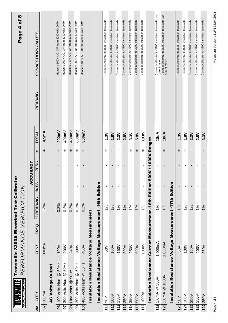
Tra
nsm
ille
3200
A E
lect
rica
l Tes
t C
alib
rato
r P
ER
FO
RM
AN
CE
VE
RIF
ICA
TIO
N
CO
NN
ECTI
ON
S / N
OTE
SR
EAD
ING
TOTA
LZE
RO
% F
S%
REA
DIN
GTE
ST
TITL
EA
CC
UR
AC
Y=
Pag
e 4
of 8
No
FREQ
300m
A30
0mA
4.5m
A=
1.3%
--
87
AC
Vol
tage
Out
put
100
Volts
Nom
@ 5
0Hz
100V
200m
V=
Mea
sure
100
V A.
C. O
/P fr
om 3
200
with
DM
M0.
2%-
-96
200
Volts
Nom
@ 5
0Hz
200V
400m
V=
Mea
sure
200
V A.
C. O
/P fr
om 3
200
with
DM
M0.
2%-
-97
Line
Vol
ts @
50H
z24
0V48
0mV
=M
easu
re 2
40V
A.C
. O/P
from
320
0 w
ith D
MM
0.2%
--
9830
0 Vo
lts N
om @
50H
z30
0V60
0mV
=M
easu
re 3
00V
A.C
. O/P
from
320
0 w
ith D
MM
0.2%
--
9940
0 Vo
lts N
om @
50H
z40
0V80
0mV
=M
easu
re 4
00V
A.C
. O/P
from
320
0 w
ith D
MM
0.2%
--
100
Insu
lati
on R
esis
tanc
e V
olta
ge M
easu
rem
ent
Insu
lati
on R
esis
tanc
e V
olta
ge M
easu
rem
ent
-16t
h E
diti
on
50V
50V
1.3V
=C
onne
ct c
alib
rato
r to
3200
insu
latio
n te
rmin
als
1%-
-11
010
0V10
0V1.
8V=
Con
nect
cal
ibra
tor t
o 32
00 in
sula
tion
term
inal
s1%
--
111
250V
150V
2.3V
=C
onne
ct c
alib
rato
r to
3200
insu
latio
n te
rmin
als
1%-
-11
225
0V20
0V2.
8V=
Con
nect
cal
ibra
tor t
o 32
00 in
sula
tion
term
inal
s1%
--
113
250V
250V
3.3V
=C
onne
ct c
alib
rato
r to
3200
insu
latio
n te
rmin
als
1%-
-11
450
0V50
0V5.
8V=
Con
nect
cal
ibra
tor t
o 32
00 in
sula
tion
term
inal
s1%
--
115
1000
V10
00V
10.8
V=
Con
nect
cal
ibra
tor t
o 32
00 in
sula
tion
term
inal
s1%
--
116
Insu
lati
on R
esis
tanc
e C
urre
nt M
easu
rem
ent
-16t
h E
diti
on 5
00V
/ 10
00V
Ran
ges
1.0m
A @
500
V1.
000m
A18
uA=
Con
nect
cal
ibra
tor t
o 32
00 in
sula
tion
term
inal
s us
e cu
rrent
met
er1%
--
119
1.0m
A @
100
0V1.
000m
A18
uA=
Con
nect
cal
ibra
tor t
o 32
00 in
sula
tion
term
inal
s us
e cu
rrent
met
er1%
--
120
Insu
lati
on R
esis
tanc
e V
olta
ge M
easu
rem
ent
-17t
h E
diti
on
50V
50V
1.3V
=C
onne
ct c
alib
rato
r to
3200
insu
latio
n te
rmin
als
1%-
-12
310
0V10
0V1.
8V=
Con
nect
cal
ibra
tor t
o 32
00 in
sula
tion
term
inal
s1%
--
124
250V
150V
2.3V
=C
onne
ct c
alib
rato
r to
3200
insu
latio
n te
rmin
als
1%-
-12
525
0V20
0V2.
8V=
Con
nect
cal
ibra
tor t
o 32
00 in
sula
tion
term
inal
s1%
--
126
250V
250V
3.3V
=C
onne
ct c
alib
rato
r to
3200
insu
latio
n te
rmin
als
1%-
-12
7
Proc
edur
e Ve
rsio
n : 1
.2/N
18/
04/2
011
Page
4 o
f 8

Tra
nsm
ille
3200
A E
lect
rica
l Tes
t C
alib
rato
r P
ER
FO
RM
AN
CE
VE
RIF
ICA
TIO
N
CO
NN
ECTI
ON
S / N
OTE
SR
EAD
ING
TOTA
LZE
RO
% F
S%
REA
DIN
GTE
ST
TITL
EA
CC
UR
AC
Y=
Pag
e 5
of 8
No
FREQ
500V
500V
5.8 V
=C
onne
ct c
alib
rato
r to
3200
insu
latio
n te
rmin
als
1%-
-12
810
00V
1000
V10
.8V
=C
onne
ct c
alib
rato
r to
3200
insu
latio
n te
rmin
als
1%-
-12
9
Insu
lati
on R
esis
tanc
e C
urre
nt M
easu
rem
ent
-17t
h E
diti
on 5
00V
/ 10
00V
Ran
ge
0.5m
A @
500
V0.
500m
A13
uA=
Con
nect
cal
ibra
tor t
o 32
00 in
sula
tion
term
inal
s us
e cu
rrent
met
er1%
--
132
1.0m
A @
100
0V1.
000m
A18
uA=
Con
nect
cal
ibra
tor t
o 32
00 in
sula
tion
term
inal
s us
e cu
rrent
met
er1%
--
133
Loop
Res
ista
nce
Loop
impe
danc
e w
as m
easu
red
usin
g 4
wir
e oh
ms
conn
ecti
ons
betw
een
the
eart
h pi
n of
the
320
0 lo
op t
est
sock
et a
nd t
he e
arth
pin
of
the
3200
mai
ns s
uppl
y le
ad. T
he s
uppl
y lo
op im
peda
nce
was
man
ually
ent
ered
as
zero
and
the
mea
sure
men
t sy
stem
was
nul
led.
The
rec
orde
d re
adin
gs a
re t
he
diff
eren
ces
reco
rded
fro
m t
he z
ero
valu
e.
Loop
Res
.0.
05R
4.3m
R=
Use
Hig
h C
urre
nt T
erm
inal
s - 0
.05R
0.5%
-4m
R15
8Lo
op R
es.
0.1R
4.5m
R=
Use
Hig
h C
urre
nt T
erm
inal
s - 0
.1R
0.5%
-4m
R15
9Lo
op R
es.
0.22
R5.
1mR
=U
se H
igh
Cur
rent
Ter
min
als
- 0.2
2R0.
5%-
4mR
160
Loop
Res
.0.
33R
5.7m
R=
Use
Hig
h C
urre
nt T
erm
inal
s - 0
.33R
0.5%
-4m
R16
1Lo
op R
es.
0.50
R6.
5mR
=U
se H
igh
Cur
rent
Ter
min
als
- 0.5
0R0.
5%-
4mR
162
Loop
Res
.1R
9mR
=U
se L
ow C
urre
nt T
erm
inal
s - 1
R0.
5%-
4mR
164
Loop
Res
.5R
29m
R=
Use
Low
Cur
rent
Ter
min
als
- 5R
0.5%
-4m
R16
6Lo
op R
es.
10R
54m
R=
Use
Low
Cur
rent
Ter
min
als
- 10R
0.5%
-4m
R16
7Lo
op R
es.
100R
504m
R=
Use
Low
Cur
rent
Ter
min
als
- 100
R0.
5%-
4mR
169
Loop
Res
.10
00R
5R=
Use
Low
Cur
rent
Ter
min
als
- 100
0R0.
5%-
4mR
171
RC
D C
urre
nt
10m
A @
50H
z10
mA
200u
A=
Con
nect
210
0 to
cal
ibra
tor u
sing
RC
D le
ad
(cus
tom
test
lead
)1%
-0.
1mA
183
50
30m
A @
50H
z30
mA
400u
A=
1%-
0.1m
A18
450
Proc
edur
e Ve
rsio
n : 1
.2/N
18/
04/2
011
Page
5 o
f 8

Tra
nsm
ille
3200
A E
lect
rica
l Tes
t C
alib
rato
r P
ER
FO
RM
AN
CE
VE
RIF
ICA
TIO
N
CO
NN
ECTI
ON
S / N
OTE
SR
EAD
ING
TOTA
LZE
RO
% F
S%
REA
DIN
GTE
ST
TITL
EA
CC
UR
AC
Y=
Pag
e 6
of 8
No
FREQ
100m
A @
50H
z90
mA
1000
uA=
1%-
0.1m
A18
550
100m
A @
50H
z10
0mA
1.1m
A=
1%-
0.1m
A18
650
100m
A @
50H
z11
0mA
1.2m
A=
1%-
0.1m
A18
750
300m
A @
50H
z30
0mA
4mA
=1%
-1m
A18
850
1000
mA
@ 5
0Hz
1000
mA
11m
A=
1%-
1mA
189
5020
00m
A @
50H
z20
00m
A21
mA
=1%
-1m
A19
050
RC
D T
rip
curr
ent
150m
A @
300
mA
Ran
ge15
0mA
2.5m
A=
1%-
1mA
195
50
RC
D T
rip
tim
e
20m
s20
ms
700u
s=
--
0.7m
s19
840
ms
40m
s70
0us
=-
-0.
7ms
199
200m
s20
0ms
700u
s=
--
0.7m
s20
039
0ms
390m
s70
0us
=-
-0.
7ms
201
900m
s90
0ms
700u
s=
--
0.7m
s20
2
PA
T :
Insu
lati
on R
esis
tanc
e
The
PA
T I
nsul
atio
n R
esis
tanc
e is
pro
duce
d fr
om t
he s
ame
deca
de r
esis
tanc
e ar
m
as u
sed
for
the
Insu
lati
on R
esis
tanc
e ou
tput
. The
fol
low
ing
Tes
ts a
re o
nly
to
conf
irm
the
ope
rati
on o
f th
e ou
tput
sw
itch
ing.
For
the
Ful
l ran
ge o
f va
lues
,
use
the
Insu
lati
on m
easu
rem
ents
on
this
cer
tifi
cate
.
1MR
1MR
1kR
=0.
1%-
-20
92M
R2M
R2k
R=
0.1%
--
210
4MR
4MR
4kR
=0.
1%-
-21
16M
R6M
R60
kR=
1%-
-21
28M
R8M
R80
kR=
1%-
-21
310
MR
10M
R10
0kR
=1%
--
214
Proc
edur
e Ve
rsio
n : 1
.2/N
18/
04/2
011
Page
6 o
f 8

Tra
nsm
ille
3200
A E
lect
rica
l Tes
t C
alib
rato
r P
ER
FO
RM
AN
CE
VE
RIF
ICA
TIO
N
CO
NN
ECTI
ON
S / N
OTE
SR
EAD
ING
TOTA
LZE
RO
% F
S%
REA
DIN
GTE
ST
TITL
EA
CC
UR
AC
Y=
Pag
e 7
of 8
No
FREQ
PA
T :
Ear
th B
ond
Res
ista
nce
The
res
ista
nces
rec
orde
d in
clud
e th
e re
sist
ance
of
the
PA
T t
est
mai
ns le
ad (
appr
ox 2
5mill
iohm
s)
PAT
Lead
No
1000
a10
000a
=Lo
op L
ead
No:
<Q
>-
-10
000
219
PAT
Lead
Res
ista
nce
25m
R25
mR
=PA
T Le
ad R
esis
tanc
e: <
Q>
100%
--
220
Bond
Res
.0.
00R
4mR
=C
onne
ct u
sing
Ear
th b
ond
lead
to m
eter
neg
s (c
onne
ct b
oth
met
er p
os to
PAT
GN
D)
0.5%
-4m
R23
3Bo
nd R
es.
0.05
R4.
3mR
=0.
05R
nom
inal
resi
stor
0.5%
-4m
R23
4Bo
nd R
es.
0.1R
4.5m
R=
0.1R
nom
inal
resi
stor
0.5%
-4m
R23
5Bo
nd R
es.
0.22
R5.
1mR
=0.
22R
nom
inal
resi
stor
0.5%
-4m
R23
6Bo
nd R
es.
0.33
R5.
7mR
=0.
33R
nom
inal
resi
stor
0.5%
-4m
R23
7Bo
nd R
es.
0.5R
6.5m
R=
0.5R
nom
inal
resi
stor
0.5%
-4m
R23
8Bo
nd R
es.
1R9m
R=
1R n
omin
al re
sist
or lo
w c
urre
nt te
rmin
als
0.5%
-4m
R23
9Bo
nd R
es.
5R29
mR
=5R
nom
inal
resi
stor
low
cur
rent
term
inal
s0.
5%-
4mR
240
Bond
Res
.10
R54
mR
=10
R n
omin
al re
sist
or lo
w c
urre
nt te
rmin
als
0.5%
-4m
R24
1Bo
nd R
es.
100R
504m
R=
100R
nom
inal
resi
stor
low
cur
rent
term
inal
s0.
5%-
4mR
242
Bond
Res
.10
00R
5R=
1000
R n
omin
al re
sist
or lo
w c
urre
nt te
rmin
als
(A.C
. @
53H
z)0.
5%-
4mR
243
PA
T :
Ear
th B
ond
Cur
rent
500m
A R
n g @
50H
z10
0mA
7.5m
A=
Con
nect
to C
alib
rato
r 2A
(Use
Thi
ck T
est L
eads
be
twee
n PA
T Ea
rth &
PAT
GN
D)
1.5%
--
252
50
500m
A R
ng @
50H
z20
0mA
9mA
=C
onne
ct to
Cal
ibra
tor 2
A (U
se T
hick
Tes
t Lea
ds
betw
een
PAT
Earth
& P
AT G
ND
)1.
5%-
-25
350
500m
A R
ng @
50H
z40
0mA
12m
A=
Con
nect
to C
alib
rato
r 2A
(Use
Thi
ck T
est L
eads
be
twee
n PA
T Ea
rth &
PAT
GN
D)
1.5%
--
254
50
10A
Rng
@ 5
0Hz
4A12
0mA
=C
ON
NEC
T TO
CAL
IBR
ATO
R 2
0 AM
P TE
RM
INAL
S1.
5%-
-25
550
10A
Rng
@ 5
0Hz
8A18
0mA
=C
ON
NEC
T TO
CAL
IBR
ATO
R 2
0 AM
P TE
RM
INAL
S1.
5%-
-25
650
10A
Rng
@ 5
0Hz
10A
210m
A=
CO
NN
ECT
TO C
ALIB
RAT
OR
20
AMP
TER
MIN
ALS
1.5%
--
257
5030
A R
ng @
50H
z20
A36
0mA
=C
ON
NEC
T TO
CAL
IBR
ATO
R 3
0 AM
P TE
RM
INAL
S1.
5%-
-25
850
PA
T: L
OA
D T
ES
TS
Proc
edur
e Ve
rsio
n : 1
.2/N
18/
04/2
011
Page
7 o
f 8

Tra
nsm
ille
3200
A E
lect
rica
l Tes
t C
alib
rato
r P
ER
FO
RM
AN
CE
VE
RIF
ICA
TIO
N
CO
NN
ECTI
ON
S / N
OTE
SR
EAD
ING
TOTA
LZE
RO
% F
S%
REA
DIN
GTE
ST
TITL
EA
CC
UR
AC
Y=
Pag
e 8
of 8
No
FREQ
S/C
TES
T0R
500m
R=
--
0.50
R26
1O
/C T
EST
PASS
=IS
O/C
AT
O/C
--
-26
20.
13kV
A TE
ST44
0R22
R=
5%-
-26
3
PA
T: L
EA
KA
GE
CU
RR
EN
T T
ES
T
Leak
a ge
@ 2
40V
2.0m
A32
uA=
Use
Var
iac
and
curre
nt m
eter
1.5%
--
266
Leak
age
@ 2
40V
4.7m
A72
.5uA
=U
se V
aria
c an
d cu
rrent
met
er1.
5%-
-26
7Le
akag
e @
240
V7.
7mA
117.
5uA
=U
se V
aria
c an
d cu
rrent
met
er1.
5%-
-26
8
End
of
resu
lts
Proc
edur
e Ve
rsio
n : 1
.2/N
18/
04/2
011
Page
8 o
f 8

2100 / 3200 / 3200A / 3200B Verification & Calibration Guide For Use With Calibration Control Panel & Calibration Lead Set
2100-3200-3200A-3200B Verification & Calibration Guide.doc V5.00 Page 38
APPENDIX B

2100 / 3200 / 3200A / 3200B Verification & Calibration Guide For Use With Calibration Control Panel & Calibration Lead Set
2100-3200-3200A-3200B Verification & Calibration Guide.doc V5.00
APPENDIX B


3200B EXTENDED SPECIFICATIONS General Specifications Transmille Ltd
Due to continuous development specifications may be subject to change : 3200B Extended Specifications : V1.20 www.transmille.com Page 1
Warm Up Time Double the time since last used up to 20 minutes maximumStandard Interfaces USB (Universal Serial Bus)
Temperature Performance Storage : -5°C to +60°COperation : 0°C to +50°C
Relative Humidity Operation : <80% to 30°C, <70% to 40°C, <40% to 50°CStorage : <95%, non-condensing
Altitude Operation : 3000m (10,000ft) MaximumTransit : 12000m (40,000ft) Maximum
EMC & Safety The calibrator line input plug must be earthedSee D.O.C for full details
Line Power Line Voltage : 100V or 110V or 230VLine Frequency : 50Hz / 60HzLine Voltage Variation : -6% +10%
Power Consumption 100 WattsConnections PAT Testing Connection 1x IEC Plug
LOOP & RCD Testing Connection 1x UK / European / Australian / USA type socketInsulation Tester Connection 1xBlack : 1xRed 4mm Low Thermal SocketsPAT Ground Connection 1x 4mm terminal postUSB Interface 1x Female 'B' type socket
Display Information Type Blacklit blue on white STN TypeViewing Area 133mm * 39mmResolution 240 x 64 dotsBacklight Type LEDBrightness 230 to 260 cd/m2
Indicators PAT Testing Connection Red LED above plugLOOP & RCD Testing Connection Red LED above socketInsulation Tester Connection Red LED above terminals
Keyboard Rubber KeyFuses Loop (Live) 5A Anti-Surge
Mains 2ALoop (Neutral) 5A Anti-SurgeRCD 2AACV 100mAPAT 1AInsulation Resistance 100mA
Isolation Outputs are opto-isolated from mains earth and the USB interfaceMaximum common mode voltage between earth and thelow terminals 30 Volts ac/dc.
Dimensions & Weights Calibrator Only 43cm x 46cm x 14cm : 12kgsCalibrator in Shipping Box 81cm x 60cm x 35cm : 15kgs
Warranty Period 1 YearRecommended Service Interval 1 YearSupplied Connections 1x USB Interface Lead
1x 1m PAT Test LeadMounting Kit (optional) 3U rack mount kitCase Colour Cream (RAL9002)

3200B EXTENDED SPECIFICATIONS Continuity Resistance Transmille Ltd
Due to continuous development specifications may be subject to change : 3200B Extended Specifications : V1.20 www.transmille.com Page 2
Continuity Resistance
Standard Accuracy†
Range Type Resolution 1 Year Accuracy% ± mΩ
0 - 9.999 Ω Continuously Variable 1mΩ 1 ± 2510 - 99.99Ω Continuously Variable 10mΩ 1 ± 25
100 - 999.9 Ω Continuously Variable 100mΩ 1 ± 2501 - 4.999 kΩ Continuously Variable 1Ω 1 ± 2500
5 - 50 kΩ Continuously Variable 10Ω 1 ± 25000
High Accuracy (Option)†
Range Type Resolution 1 Year Accuracy% ± mΩ
0 - 9.999 Ω Continuously Variable 1mΩ 0.25 ± 1010 - 99.99Ω Continuously Variable 10mΩ 0.25 ± 10
100 - 999.9 Ω Continuously Variable 100mΩ 0.25 ± 1001 - 4.999 kΩ Continuously Variable 1Ω 0.25 ± 1000
5 - 50 kΩ Continuously Variable 10Ω 0.25 ± 10000
Maximum Test Current 300mATest current maximum can be exceeded for a maximum of 5 seconds
Continuity Current Measurement
Accuracy†
Range Load Accuracy% ± Counts
0 to 320mA 1Ω 1.3 ± 6
† Note : All specifications specified relative to calibration standards

3200B EXTENDED SPECIFICATIONS Insulation Resistance Transmille Ltd
Due to continuous development specifications may be subject to change : 3200B Extended Specifications : V1.20 www.transmille.com Page 3
Insulation Resistance
Standard Accuracy†
Range Type Resolution Maximum 1 Year AccuracyVoltage/Power1 %
ContinuouslyVariable
ContinuouslyVariable
High Accuracy (Option)†
Range Type Resolution Maximum 1 Year AccuracyVoltage/Power1 %
ContinuouslyVariable
ContinuouslyVariable
Note 1 : An option is available to increase the maximum insulation test voltage for Testersincorporating Active Guard.
10GΩ Range (Option)†
Range Type Resolution Maximum 1 Year AccuracyVoltage/Power1 %
2GΩ to 10GΩ Continuously(Option) Variable
Note : Can be fitted to Standard or High accuracy models
Insulation Test Voltage Measurement
Accuracy†
Ranges Current Resolution 1 Year AccuracyLoad % ± Counts
50V • 100V • 250V • 500V • 1kV 0.5mA / 1mA 0.1V 1 ± 8
AC Voltage Output
Accuracy†
Ranges Resolution 1 Year Accuracy% ± Counts
100V • 200V • 230V • 300V • 400V 0.1V 0.2 ± 1
† Note : All specifications specified relative to calibration standards
0.10.01Ω to 5MΩ
10kΩ
10kΩ
5.01MΩ to 2GΩ
5.01MΩ to 2GΩ 10kΩ 1.1kV or 1 Watt
0.01Ω to 5MΩ
10kΩ 1.1kV or 1 Watt 5
0.3
31.1kV or 1 Watt
1.1kV or 1 Watt
1.1kV or 1 Watt
10kΩ
1

3200B EXTENDED SPECIFICATIONS RCD Transmille Ltd
Due to continuous development specifications may be subject to change : 3200B Extended Specifications : V1.20 www.transmille.com Page 4
RCD Trip Time
RCD Time can be selected from pre-set points or via keyboard in 10ms steps
Accuracy†
Range Resolution Accuracy
20ms to 5s 10ms ±0.7ms
RCD (Residual Current Device) Current MeasurementTrip Current Range 2mA to 3000mACurrent Multiplier 0.5, 1, 2, 53200 Keypad Input : 2mA to 1000mA in 1mA steps
Accuracy†
% ± Counts2mA to 10mA 100 Ohms 1.2 ± 6
10.01mA to 30mA 100 Ohms 1.2 ± 630.1mA to 100mA 10 Ohms 1.2 ± 6
100.1mA to 300mA 10 Ohms 1.2 ± 6300.1mA to 1A 1 Ohm 1.2 ± 6
1.01A to 3A 0.1 Ohm 1.2 ± 6
Range selection automatic, depending on trip value : All ranges 15% Overrange
Additional FeaturesCurrent Modes ½I • I •2I •5IDisplay Modes 0°, 180° of Phase & Half Wave / DC
Intelligent Protection :The 3200 incorporates a pre-test scan where power is ramped up to the UUT - the test is automatically aborted if a faulty UUT is detected.This avoids further damage to the UUT and safeguards the 3200.
Current measurement :DC coupled True RMS allowing accurate measurement of bothsinusoidal current and half wave (positive or negative)
Intelligent firmware captures and analyses the current waveform automatically discardingpre-test (no-trip) currents and switch on spikes automatically capturingand measuring only the true test current.
RCD Current DurationRCD current duration is the measurement of the period the fault current flowsRCD Current DurationMeasurement Range 10ms to 5sResolution 0.1ms1 Year Timing Accuracy† 0.4ms
† Note : All specifications specified relative to calibration standards
Series ResistanceResolutionRange 1 Year Accuracy
0.01mA

3200B EXTENDED SPECIFICATIONS Loop & Earth Resistance Transmille Ltd
Due to continuous development specifications may be subject to change : 3200B Extended Specifications : V1.20 www.transmille.com Page 5
Loop Resistance
Accuracy†
Nominal Resolution 1 Year AccuracyResistance Values % ± mΩ
0.05Ω 0.1mΩ 0.5 ± 40.1Ω 0.1mΩ 0.5 ± 40.22Ω 0.1mΩ 0.5 ± 40.33Ω 0.1mΩ 0.5 ± 40.5Ω 0.1mΩ 0.5 ± 41Ω 0.1mΩ 0.5 ± 45Ω 0.1mΩ 0.5 ± 4
10Ω 0.1mΩ 0.5 ± 4100Ω 1mΩ 0.5 ± 41kΩ 1mΩ 0.5 ± 4
Power Dissipation :All resistors are 50W : Maximum test current for 200ms = 40AThermal protection is provided in the event of overheating.
Intelligent Protection :The 3200 incorporates a pre-test scan where power is ramped up to the UUT - the test is automatically aborted if a faulty UUT is detected.This avoids further damage to the UUT and safeguards the 3200.
Manual Loop Correction
Correction range 0.001 to 2 Ohms - manually entered using 3200 keypad
Auto Loop (Option)
The auto loop function automatically corrects for supplied loop impedance.
Maximum Correction 2ΩResolution 100uΩAccuracy ±18mΩMeasurement Current 4A
† Note : All specifications specified relative to calibration standards

3200B EXTENDED SPECIFICATIONS PAT Resistance Transmille Ltd
Due to continuous development specifications may be subject to change : 3200B Extended Specifications : V1.20 www.transmille.com Page 6
PAT Earth Bond Resistance
Accuracy†
Nominal Resolution 1 Year AccuracyResistance Values % ± mΩ
0.05Ω 0.1mΩ 0.5 ± 40.1Ω 0.1mΩ 0.5 ± 40.22Ω 0.1mΩ 0.5 ± 40.33Ω 0.1mΩ 0.5 ± 40.5Ω 0.1mΩ 0.5 ± 41Ω 0.1mΩ 0.5 ± 45Ω 0.1mΩ 0.5 ± 410Ω 0.1mΩ 0.5 ± 4100Ω 1mΩ 0.5 ± 41kΩ 1mΩ 0.5 ± 4
PAT Earth Bond Current Measurement
Range Resolution 1 Year Accuracy% ± Counts
100mA 1mA 1.5 ± 610A 10mA 1.5 ± 630A 10mA 1.5 ± 6
Load Resistance : 0.1Ω or 0.02Ω
PAT Insulation Resistance
Standard Accuracy†
Range Type Resolution Maximum 1 Year AccuracyVoltage/Power1 %
0Ω to 5MΩ ContinuouslyVariable 10kΩ 1.1kV or 1 Watt 0.3
5MΩ to 2GΩ ContinuouslyVariable 10kΩ 1.1kV or 1 Watt 3
High Accuracy (Option)†
Range Type Resolution Maximum 1 Year AccuracyVoltage/Power1 %
0Ω to 5MΩ ContinuouslyVariable 10kΩ 1.1kV or 1 Watt 0.1
5MΩ to 2GΩ ContinuouslyVariable 10kΩ 1.1kV or 1 Watt 1
† Note : All specifications specified relative to calibration standards
All PAT functions are isolated from mains earth to enable calibration of PAT testers which cannot function with connections to ground.

3200B EXTENDED SPECIFICATIONS PAT Leakage Transmille Ltd
Due to continuous development specifications may be subject to change : 3200B Extended Specifications : V1.20 www.transmille.com Page 7
PAT Leakage Current
Accuracy†
Range Resolution 1 Year Accuracy% ± Counts
2mA 1uA 1.5 ± 24.7mA 1uA 1.5 ± 27.7mA 1uA 1.5 ± 2
PAT Leakage Test Voltage
Accuracy†
Range Resolution 1 Year Accuracy(RMS) % ± Counts
100V to 300V 0.01V 1.5 ± 9
PAT Load Testing
Accuracy†
Range 1 Year AccuracyOhms ± %
Short Circuit - - -Open Circuit - - -
0.13kΩ 440Ω ± 5
PAT Flash Voltage Measurement (Accessory)
Accuracy†
Class Range Resolution Load 1 Year AccuracyResistance % ± Counts
Class 1 (1.5kV) 1kV to 1.8kV 1V 600kΩ 4 ± 10([email protected])
Class 2 (3kV) 2kV to 3.6kV 1V 1.2MΩ 4 ± 10(2.5mA@3kV)
PAT Flash Current Measurement (Accessory)
Accuracy†
Range Resolution
1mA to 3mA 10uA
† Note : All specifications specified relative to calibration standards
1 Year Accuracy
5%

3200B EXTENDED SPECIFICATIONS AC Voltage Transmille Ltd
Due to continuous development specifications may be subject to change : 3200B Extended Specifications : V1.20 www.transmille.com Page 8
AC Voltage Output
Accuracy†
Ranges Resolution 1 Year Accuracy% ± Counts
100V • 200V • 230V • 300V • 400V 0.1V 0.2 ± 1
Line Voltage Measurement
Accuracy†
Range Resolution% ± Counts
Nominal Line Voltage ± 30V* 0.1V 0.8 ± 6
* Example - For 230V Line voltage, range is 200V to 260V
† Note : All specifications specified relative to calibration standards
1 Year Accuracy

3200B EXTENDED SPECIFICATIONS Breakdown Adapter Transmille Ltd
Due to continuous development specifications may be subject to change : 3200B Extended Specifications : V1.20 www.transmille.com Page 9
AC/DC VOLTAGE MEASUREMENT
Range Resolution Accuracy (1 Year Rel.)% ± Counts
3kV 10V 0.5 ± 312kV 10V 0.5 ± 3
AC/DC CURRENT MEASUREMENT
Range Resolution Accuracy (1 Year Rel.)% ± Counts
200uA 100nA 0.5 ± 42mA 1uA 0.5 ± 320mA 10uA 0.5 ± 3
Due to continuous development specifications may be subject to change.


ELECTRICAL TEST EQUIPMENT CALIBRATOR
3200 SERIES
EXTENDED SPECIFICATIONS

DECLARATION OF CONFORMITY
Manufacturer's Name: Transmille Ltd.Manufacturer's Address: Unit 4, Select Business Centre
Lodge RoadStaplehurstTN12 0QW.United Kingdom.
Declares, that the product
Product Name: Electrical Test CalibratorModel Number: 3200Product Options:This declaration covers all options of the above product(s)
EMC
Conforms with the following European Directives:
The product herewith complies with the requirements of theLow Voltage Directive 73/73EEC and the EMC Directive89/336/EEC (including 93/68/EEC) and carries the CEMarking accordingly
Conforms with the following product standards:
IEC616326-1:1997+A1:1998 / EN 61326-1:1997+A1:1998 EN55011:1991
Standard LimitIEC 61000-4-2:1995+A1:1998 / EN 61000-4-2:1995 Group 1Class AIEC 61000-4-3:1995 / EN 61000-4-3:1995 4kV CD, 8kV ADIEC 61000-4-4:1995 / EN 61000-4-4:1995 3 V/m, 80-1000 MHzIEC 61000-4-5:1995 / EN 61000-4-5:1995 0.5kV signal lines, 1kV power linesIEC 61000-4-6:1996 / EN 61000-4-6:1996 0.5kV line-line, 1kV line-groundIEC 61000-4-11:1994 / EN 61000-4-11:1994 3V, 0.15-80 MHz I cycle, 100%
Dips: 30% 10ms; 60% 100msInterrupt > 95%@5000ms
IEC 61010-1:1990+A1:1992+A2:1995 / EN 61010-1:1993+A2:1995
SAFETY
Date Of Issue Managing Director
06/03/2006
Revision No: 1.10 : 06/03/2006

Warm Up Time Double the time since last used up to 20 minutes maximumStandard Interfaces RS232Optional Interfaces USB (Universal Serial Bus)Temperature Performance Storage : -5°C to +60°C
Operation : 0°C to +50°CRelative Humidity Operation : <80% to 30°C, <70% to 40°C, <40% to 50°C
Storage : <95%, non-condensingAltitude Operation : 3000m (10,000ft) Maximum
Transit : 12000m (40,000ft) MaximumEMC & Safety The calibrator line input plug must be earthed
See D.O.C for full detailsLine Power Line Voltage Selectable : 110V / 230V
Line Frequency : 50Hz to 60HzLine Voltage Variation : -6% +10%
Power Consumption 28 WattsConnections PAT Testing Connection 1x IEC Plug
LOOP & RCD Testing Connection 1x UK / European / Australian type socketInsulation Tester Connection 1xBlack : 1xRed 4mm Low Thermal SocketsPAT Ground Connection 1x 4mm terminal postRS232 Interface 1x Female 'D' type socket
RS232 Settings Baud Rate 9600Parity NoneData Bits 8Stop Bits 1
Display Information Type Backlit Black on white film STN typeViewing Area 124.3mm * 34mmResolution 256 * 94 dotsBacklight Type Cold fluorescent lampBrightness 70 to 90 cd/m2
Indicators PAT Testing Connection Red LED above plugLOOP & RCD Testing Connection Red LED above socketInsulation Tester Connection Red LED above terminals
Keyboard Membrane type with tactile feedbackFuses Loop (Live) 5A Anti-Surge
Mains 2ALoop (Neutral) 5A Anti-SurgeRCD 2AACV 100mAPAT 1AInsulation Resistance 100mA
Isolation Outputs are opto-isolated from mains earth and the RS-232 interfaceMaximum common mode voltage between earth and thelow terminals 30 Volts ac/dc.
Dimensions & Weights Calibrator Only 45cm x 44cm x 14cm : 10kgsWarranty Period 1 YearRecommended Service Interval 1 YearSupplied Connections 1x Serial Interface Connection
1x 1m PAT Test LeadMounting Kit (optional) 3U rack mount kitCase Colour Cream (RAL9002)
Due to continuous development specifications may be subject to change.
3200 ELECTRICAL TEST EQUIPMENT CALIBRATOR :: GENERAL SPECIFICATIONS TRANSMILLE LTD.
3200 Extended Specifications General Specifications : V1.30 Page 1

3200 ELECTRICAL TEST EQUIPMENT CALIBRATOR :: CONTINUITY SPECIFICATIONS TRANSMILLE LTD.
Continuity Resistance*
Standard Accuracy - Relative to Calibration Standards SpecificationsRange Type Resolution Accuracy
% ± mΩ
0.2Ω to 20Ω ContinuouslyVariable 10mΩ 1 ± 25
100Ω Fixed 10mΩ 1 ± 251kΩ Fixed 10mΩ 1 ± 25
High Accuracy (option) - Relative to Calibration Standards SpecificationsRange Type Resolution Accuracy
% ± mΩ0.2Ω to 20Ω Continuously
Variable 10mΩ 0.25 ± 25100Ω Fixed 10mΩ 0.25 ± 251kΩ Fixed 10mΩ 0.25 ± 25
* Maximum Test Current 300mATest current maximum can be exceeded for a maximum of 5 secondsContinuity Current Measurement
Accuracy - Relative to Calibration Standards SpecificationsRange Load Accuracy
% ± Counts0 to 320mA 1Ω 1.3 ± 6
Due to continuous development specifications may be subject to change.
3200 Extended Specifications Continuity Specifications : V1.30 Page 2

3200 ELECTRICAL TEST EQUIPMENT CALIBRATOR :: INSULATION SPECIFICATIONS TRANSMILLE LTD.
Insulation Resistance
Standard Accuracy - Relative to Calibration Standards SpecificationsRange Type Resolution Maximum Accuracy
Voltage/Power1 %0Ω to 5MΩ Continuously
Variable 10kΩ 1.1kV or 1 Watt 0.35MΩ to 2GΩ Continuously
Variable 10kΩ 1.1kV or 1 Watt 3
High Accuracy (option) - Relative to Calibration Standards SpecificationsRange Type Resolution Maximum Accuracy
Voltage/Power1 %0Ω to 5MΩ Continuously
Variable 10kΩ 1.1kV or 1 Watt 0.15MΩ to 2GΩ Continuously
Variable 10kΩ 1.1kV or 1 Watt 1Note 1 : A 5kV option is available for Insulation Testers incorporating Active Guard .
10GΩ Range (Option) - Relative to Calibration Standards SpecificationsRange Type Resolution Maximum Accuracy
Voltage/Power1 %2GΩ to 10GΩ Continuously
(Option) Variable 10kΩ 1.1kV or 1 Watt 5
Note : Can be fitted to Standard or High accuracy models
Insulation Test Voltage Measurement
Accuracy - Relative to Calibration Standards SpecificationsRanges Current Resolution Accuracy
Measurement % ± Counts50V • 100V • 250V • 500V • 1kV 0.5mA • 1mA 0.1V 1 ± 8
AC Voltage Output
Accuracy - Relative to Calibration Standards SpecificationsRanges Accuracy
% ± Counts100V • 200V • 230V • 300V • 400V 0.2 ± 1
Resistance Multiplier Option 5KVMultiplies resistance output of 3200 by 100Accuracy - Relative to Calibration Standards SpecificationsRange Resolution Accuracy
1GOhm to 1TOhm1 1MOhm 1.50% ± RCAL
1Requires 10GOhm Option fitted to 3200, otherwise maximum resistance = 200GOhmsRCAL = Resistance set on 3200Due to continuous development specifications may be subject to change.
Maximum Voltage
10kVPeak AC+DC
3200 Extended Specifications Insulation Specifications : V1.30 Page 3
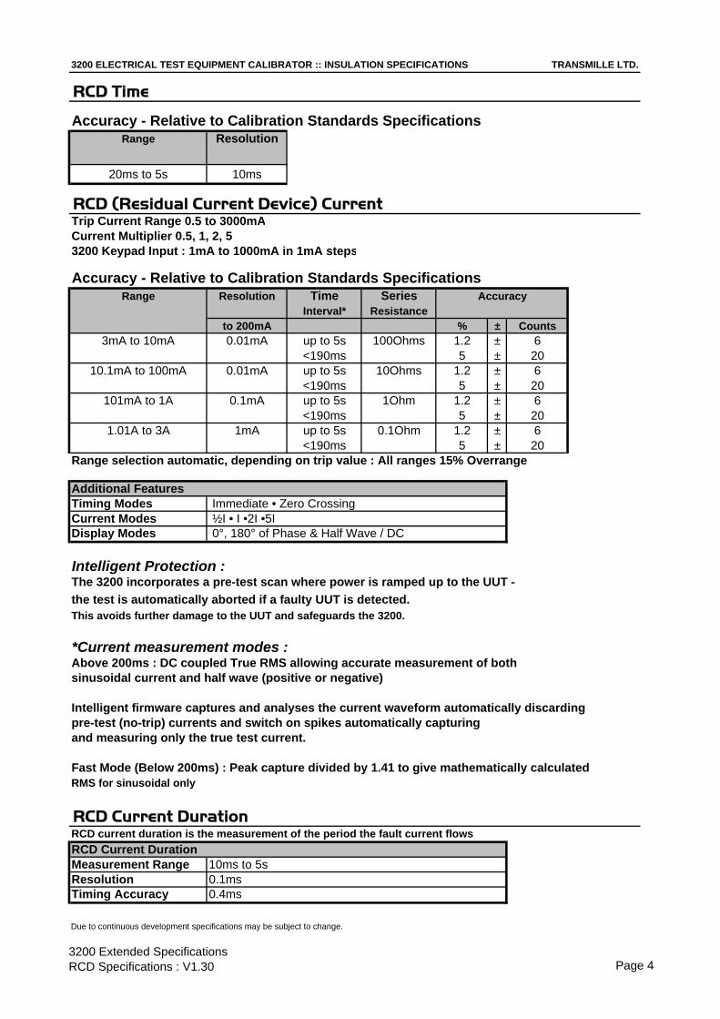
3200 ELECTRICAL TEST EQUIPMENT CALIBRATOR :: INSULATION SPECIFICATIONS TRANSMILLE LTD.
RCD Time
Accuracy - Relative to Calibration Standards SpecificationsRange Resolution
20ms to 5s 10ms
RCD (Residual Current Device) CurrentTrip Current Range 0.5 to 3000mACurrent Multiplier 0.5, 1, 2, 53200 Keypad Input : 1mA to 1000mA in 1mA steps
Accuracy - Relative to Calibration Standards SpecificationsRange Resolution Time Series
Interval* Resistanceto 200mA % ± Counts
3mA to 10mA 0.01mA up to 5s 100Ohms 1.2 ± 6<190ms 5 ± 20
10.1mA to 100mA 0.01mA up to 5s 10Ohms 1.2 ± 6<190ms 5 ± 20
101mA to 1A 0.1mA up to 5s 1Ohm 1.2 ± 6<190ms 5 ± 20
1.01A to 3A 1mA up to 5s 0.1Ohm 1.2 ± 6<190ms 5 ± 20
Range selection automatic, depending on trip value : All ranges 15% Overrange
Additional FeaturesTiming Modes Immediate • Zero CrossingCurrent Modes ½I • I •2I •5IDisplay Modes 0°, 180° of Phase & Half Wave / DC
Intelligent Protection :The 3200 incorporates a pre-test scan where power is ramped up to the UUT - the test is automatically aborted if a faulty UUT is detected.This avoids further damage to the UUT and safeguards the 3200.
*Current measurement modes :Above 200ms : DC coupled True RMS allowing accurate measurement of bothsinusoidal current and half wave (positive or negative)
Intelligent firmware captures and analyses the current waveform automatically discardingpre-test (no-trip) currents and switch on spikes automatically capturingand measuring only the true test current.
Fast Mode (Below 200ms) : Peak capture divided by 1.41 to give mathematically calculatedRMS for sinusoidal only
RCD Current DurationRCD current duration is the measurement of the period the fault current flowsRCD Current DurationMeasurement Range 10ms to 5sResolution 0.1msTiming Accuracy 0.4ms
Due to continuous development specifications may be subject to change.
Accuracy
3200 Extended Specifications RCD Specifications : V1.30 Page 4

3200 ELECTRICAL TEST EQUIPMENT CALIBRATOR :: LOOP SPECIFICATIONS TRANSMILLE LTD.
Loop Resistance
Accuracy - Relative to Calibration Standards SpecificationsNominal Resolution Accuracy
Resistance Values % ± mΩ0.05Ω 0.1mΩ 0.5 ± 40.1Ω 0.1mΩ 0.5 ± 40.22Ω 0.1mΩ 0.5 ± 40.33Ω 0.1mΩ 0.5 ± 40.5Ω 0.1mΩ 0.5 ± 41Ω 0.1mΩ 0.5 ± 45Ω 0.1mΩ 0.5 ± 410Ω 0.1mΩ 0.5 ± 4100Ω 1mΩ 0.5 ± 41kΩ 1mΩ 0.5 ± 4
Power Dissipation :All resistors are 50W : Maximum test current for 200ms = 40AThermal protection is provided in the event of overheating.
Intelligent Protection :The 3200 incorporates a pre-test scan where power is ramped up to the UUT - the test is automatically aborted if a faulty UUT is detected.This avoids further damage to the UUT and safeguards the 3200.
Manual Loop Correction
Correction range 0.001 to 2 Ohms - manually entered using 3200 keypad
Auto Loop (Option)
The auto loop function automatically corrects for supplied loop impedance.
Maximum Correction 2ΩResolution 100uΩAccuracy ±18mΩMeasurement Current 4A
Due to continuous development specifications may be subject to change.
3200 Extended Specifications LOOP Specifications : V1.30 Page 5

3200 ELECTRICAL TEST EQUIPMENT CALIBRATOR :: PAT SPECIFICATIONS TRANSMILLE LTD.
All PAT functions are isolated from mains earth to enable calibration of PAT testerswhich cannot function with connections to ground.
PAT Earth Bond Resistance
Accuracy - Relative to Calibration Standards SpecificationsNominal Resolution Accuracy
Resistance Values % ± mΩ0.05Ω 0.1mΩ 0.5 ± 40.1Ω 0.1mΩ 0.5 ± 40.22Ω 0.1mΩ 0.5 ± 40.33Ω 0.1mΩ 0.5 ± 40.5Ω 0.1mΩ 0.5 ± 41Ω 0.1mΩ 0.5 ± 45Ω 0.1mΩ 0.5 ± 410Ω 0.1mΩ 0.5 ± 4100Ω 1mΩ 0.5 ± 41kΩ 1mΩ 0.5 ± 4
PAT Earth Bond Current Measurement
Range Resolution Accuracy% ± Counts
100mA 1mA 1.5 ± 610A 10mA 1.5 ± 630A 10mA 1.5 ± 6
PAT Insulation Resistance
Standard Accuracy - Relative to Calibration Standards SpecificationsRange Type Resolution Maximum Accuracy
Voltage/Power1 %0Ω to 5MΩ Continuously
Variable 10kΩ 1.1kV or 1 Watt 0.35MΩ to 2GΩ Continuously
Variable 10kΩ 1.1kV or 1 Watt 3
High Accuracy (Option) - Relative to Calibration Standards SpecificationsRange Type Resolution Maximum Accuracy
Voltage/Power1 %0Ω to 5MΩ Continuously
Variable 10kΩ 1.1kV or 1 Watt 0.15MΩ to 2GΩ Continuously
Variable 10kΩ 1.1kV or 1 Watt 1
PAT Leakage Current
Range Resolution Accuracy% ± Counts
2mA 1uA 1.5 ± 24.7mA 1uA 1.5 ± 27.7mA 1uA 1.5 ± 2
Due to continuous development specifications may be subject to change.
3200 Extended Specifications PAT Specifications : V1.30 Page 6

3200 ELECTRICAL TEST EQUIPMENT CALIBRATOR :: PAT SPECIFICATIONS TRANSMILLE LTD.
PAT Leakage Test Voltage
Range Resolution Accuracy(RMS) % ± Counts
100V to 300V 0.1V 1.5 ± 9
PAT Load Testing
Range AccuracyOhms ± %
Short Circuit - - -Open Circuit - - -
0.13kW 440Ω ± 5
PAT Flash Voltage Measurement
Class Range Resolution Load AccuracyResistance % ± Counts
Class 1 (1.5kV) 1kV to 1.8kV 1V 600kΩ 4 ± 10([email protected])
Class 2 (3kV) 2kV to 3.6kV 1V 1.2MΩ 4 ± 10(2.5mA@3kV)
PAT Flash Current Measurement
Range Resolution
1mA to 3mA 10uA
Due to continuous development specifications may be subject to change.
Accuracy
5%
3200 Extended Specifications PAT Specifications Cont'd : V1.30 Page 7

3200 ELECTRICAL TEST EQUIPMENT CALIBRATOR :: MAINS V MEASURE SPECIFICATIONS TRANSMILLE LTD.
Line Voltage Measurement
Range Resolution Accuracy
200V to 260V 0.1V 0.8% ± 6 Counts
Due to continuous development specifications may be subject to change.
3200 Extended Specifications Mains Voltage Measure : V1.30 Page 8

3200 ELECTRICAL TEST EQUIPMENT CALIBRATOR :: BREAKDOWN ADAPTER SPECIFICATIONS TRANSMILLE LTD.
AC/DC VOLTAGE MEASUREMENT
Range Resolution Accuracy (1 Year Rel.)% ± Counts
3kV 10V 0.5 ± 312kV 10V 0.5 ± 3
AC/DC CURRENT MEASUREMENT
Range Resolution Accuracy (1 Year Rel.)% ± Counts
200uA 100nA 0.5 ± 42mA 1uA 0.5 ± 320mA 10uA 0.5 ± 3
Due to continuous development specifications may be subject to change.
3200 Extended Specifications Breakdown Adapter : V1.30 Page 9

2100 ELECTRICAL TEST EQUIPMENT CALIBRATOR2100 ELECTRICAL TEST EQUIPMENT CALIBRATOR
INTEGRATED ELECTRICAL EQUIPMENT CALIBRATION SOLUTIONINTEGRATED ELECTRICAL EQUIPMENT CALIBRATION SOLUTIONStandard Interfaces RS232Optional Interfaces GPIB (IEEE-488) : USB (Universal Serial Bus)Temperature Performance Storage : -5°C to +60°C
Operation : 0°C to +50°CRelative Humidity Operation : <80% to 30°C, <70% to 40°C, <40% to 50°C
Storage : <95%, non-condensingAltitude Operation : 3000m (10,000ft) Maximum
Transit : 12000m (40,000ft) MaximumEMC & Safety The calibrator line input plug must be earthed
See D.O.C for full detailsLine Power Line Voltage Selectable : 110V / 230V
Line Frequency : 50Hz to 60HzLine Voltage Variation : -6% +10%
Power Consumption 28 Watts (Standby) 200 Watts (Maximum)Low Analogue Isolation 100VConnections Voltage / 2 Wire Resistance 1x Black : 1x White 4mm Safety sockets
Low Current (<=2A) 1x Black : 1x Red 4mm Safety socketsHigh current (>2A) 1x Blue : 1x Yellow 4mm Safety socketsEarth Connection 1x Green 4mm Safety SocketOscilloscope Functions 1x BNC terminalFeature (Ext. Pod) 1x Female 'D' type socketRS232 Interface 1x Female 'D' type socket
RS232 Settings Baud Rate 9600Parity NoneData Bits 8Stop Bits 1
Display Information Type Backlit Black on white film STN typeViewing Area 124.3mm * 34mmResolution 256 * 94 dotsBacklight Type Cold fluorescent lampBrightness 70 to 90 cd/m2
Indicators Voltage / Current / High Current Red LED (between terminals)Negative to ground Green LED (left of Earth terminal)Oscilloscope Green LED (right of BNC Connector)Feature Connector (Ext. Pod) Green LED (right of 'D' type connector)
Keyboard Membrane type with tactile feedbackFuses Mains Inlet 3A A/S (240 Volt)
5A A/S (110 Volt operation)Isolation Outputs are opto-isolated from mains earth and the RS-232 interface
Maximum common mode voltage between earth and the
Dimensions & Weights Calibrator Only
Calibrator in Shipping Box
Calibrator in Soft Carry Case
Calibrator in Hard Transit case
Warranty Period 3 Years (Parts & Labour)
Recommended Service Interval 1 Year
Supplied Connections 1x Serial Interface Connection
Optional Lead Set Kit 1x RCD / LOOP Adaptor Lead ; 1x 1m PAT Test Lead
EXTENDED SPECIFICATIONS EXTENDED SPECIFICATIONSTRANSMILLE LTD., UNIT 4 SELECT BUSINESS CENTRE, LODGE ROAD, STAPLEHURST, KENT. TN12 0QW. UK.
www.transmille.com : [email protected] : Tel : +44 (0) 1580 890700 : Fax : +44 (0) 1580 890711Case Colour Matt Dark Grey (RAL7016)

DECLARATION OF CONFORMITY Manufacturer’s Name: Transmille Ltd. Manufacturer’s Address: Unit 4, Select Business Centre Lodge Road Staplehurst TN12 0QW Declares, that the product Product Name: Electrical Test Calibrator Model Number: 2100 Product Options: This declaration covers all options of the above product(s) Conforms with the following European Directives: The product herewith complies with the requirements of the Low Voltage Directive 73/73EEC and the EMC Directive 89/336/EEC (including 93/68/EEC) and carries the CE Marking accordingly Conforms with the following product standards: EMC Standard Limit IEC616326-1:1997+A1:1998 / EN 61326-1 :1997+A1:1998 EN55011:1991
IEC 61000-4-2:1995+A1:1998 / EN 61000-4-2:1995 Group 1 Class A
IEC 61000-4-3:1995 / EN 61000-4-3:1995 4kV CD, 8kV AD
IEC 61000-4-4:1995 / EN 61000-4-4:1995 3 V/m, 80-1000 MHz
IEC 61000-4-5:1995 / EN 61000-4-5:1995 0.5kV signal lines, 1kV power lines
IEC 61000-4-6:1996 / EN 61000-4-6:1996 0.5kV line-line, 1kV line-ground
IEC 61000-4-11:1994 / EN 61000-4-11:1994 3V, 0.15-80 MHz I cycle, 100%
Dips: 30% 10ms; 60% 100ms
Interrupt > 95%@5000ms
SAFETY IEC 61010-1:1990+A1:1992+A2:1995 / EN 61010-1:1993+A2:1995 12/12/2001 Revision No: 1.1 Managing Director Date :12/12/2001

2100 General Specifications2100 General Specifications
Warm Up Time Double the time since last used up to 20 minutes maximumStandard Interfaces RS232Optional Interfaces USB (Universal Serial Bus)Temperature Performance Storage : -5°C to +60°C
Operation : 0°C to +50°CRelative Humidity Operation : <80% to 30°C, <70% to 40°C, <40% to 50°C
Storage : <95%, non-condensingAltitude Operation : 3000m (10,000ft) Maximum
Transit : 12000m (40,000ft) MaximumEMC & Safety The calibrator line input plug must be earthed
See D.O.C for full detailsLine Power Line Voltage Selectable : 110V / 230V
Line Frequency : 50Hz to 60HzLine Voltage Variation : -6% +10%
Power Consumption 28 WattsConnections PAT Testing Connection 1x IEC Plug
LOOP & RCD Testing Connection 1x IEC SocketInsulation Tester Connection 1xBlack : 1xRed 4mm Low Thermal Sockets
PAT Ground Connection 1x Blue 4mm terminal postRS232 Interface 1x Female 'D' type socket
RS232 Settings Baud Rate 9600Parity NoneData Bits 8Stop Bits 1
Display Information Type Backlit Black on white film STN typeViewing Area 124.3mm * 34mmResolution 256 * 94 dotsBacklight Type Cold fluorescent lampBrightness 70 to 90 cd/m2
Indicators PAT Testing Connection Red LED above plugLOOP & RCD Testing Connection Red LED above socketInsulation Tester Connection Red LED above terminals
Keyboard Membrane type with tactile feedbackFuses Loop (Live) 5A Anti-Surge
Mains 2ALoop (Neutral) 5A Anti-SurgeRCD 2AACV 100mAPAT 1AInsulation Resistance 100mA
Isolation Outputs are opto-isolated from mains earth and the RS-232 interfaceMaximum common mode voltage between earth and thelow terminals 30 Volts ac/dc.
Dimensions & Weights Calibrator Only 14cm x 43cm x 46cm : 8kgsCalibrator in Shipping Box 58cm x 56cm x 37cm : 10.5kgsCalibrator in Soft Carry Case 49cm x 50cm x 19cm : 11.5kgsCalibrator in Hard Transit case 55cm x 56cm x 26cm : 19kgs
Warranty Period 3 Years (Parts & Labour)Recommended Service Interval 1 YearSupplied Connections 1x Serial Interface Connection
1x RCD / LOOP Adaptor Lead ; 1x 1m PAT Test LeadMounting Kit (optional) 3U rack mount kitCase Colour Matt Dark Grey (RAL7016)
Due to continuous development specifications may be subject to change.
TRANSMILLESolutions In Calibration
2100 Extended Specifications General Specifications : V4.00 Page 2

2100 Continuity Testing Specifications2100 Continuity Testing Specifications
Continuity ResistanceContinuity Resistance
Standard Accuracy - Relative to Calibration Standards SpecificationsRange Type Resolution Accuracy
% ± mΩΩ
0.1Ω to 20Ω Continuously
Variable 10mΩ 1 ± 25
100Ω Fixed 10mΩ 1 ± 251kΩ Fixed 10mΩ 1 ± 25
High Accuracy (option) - Relative to Calibration Standards SpecificationsRange Type Resolution Accuracy
% ± mΩΩ0.1Ω to 20Ω Continuously
Variable 10mΩ 0.25 ± 25100Ω Fixed 10mΩ 0.25 ± 251kΩ Fixed 10mΩ 0.25 ± 25
Continuity Current MeasurementContinuity Current Measurement
Accuracy - Relative to Calibration Standards SpecificationsRange Load Accuracy
% ± Counts0 to 320mA 1Ω 1.3 ± 6
Due to continuous development specifications may be subject to change.
TRANSMILLESolutions In Calibration
2100 Extended Specifications Continuity Specifications : V4.00 Page 3

2100 Insulation Testing Specifications2100 Insulation Testing Specifications
Insulation ResistanceInsulation Resistance
Standard Accuracy - Relative to Calibration Standards SpecificationsRange Type Resolution Maximum Accuracy
Voltage/Power1%
0Ω to 5MΩ Continuously
Variable 10kΩ 1.1kV or 1 Watt 0.3
5MΩ to 2GΩ ContinuouslyVariable 10kΩ 1.1kV or 1 Watt 3
High Accuracy (option) - Relative to Calibration Standards SpecificationsRange Type Resolution Maximum Accuracy
Voltage/Power1 %0Ω to 5MΩ Continuously
Variable 10kΩ 1.1kV or 1 Watt 0.15MΩ to 2GΩ Continuously
Variable 10kΩ 1.1kV or 1 Watt 1
Note 1 : A 5kV option is available for Insulation Testers incorporating Active Guard .
10GΩΩ Range (Option) - Relative to Calibration Standards SpecificationsRange Type Resolution Maximum Accuracy
Voltage/Power1%
2GΩ to 10GΩ Continuously(Option) Variable 10kΩ 1.1kV or 1 Watt 5
Note : Can be fitted to Standard or High accuracy models
Insulation Test Voltage MeasurementInsulation Test Voltage Measurement
Accuracy - Relative to Calibration Standards SpecificationsRanges Current Resolution Accuracy
Measurement % ± Counts50V • 100V • 250V • 500V • 1kV 0.5mA • 1mA 0.1V 1 ± 8
AC Voltage OutputAC Voltage Output
Accuracy - Relative to Calibration Standards SpecificationsRanges Accuracy
% ± Counts100V • 200V • 230V • 300V • 400V 0.2 ± 1
Due to continuous development specifications may be subject to change.
TRANSMILLESolutions In Calibration
2100 Extended Specifications Insulation Specifications : V4.00 Page 4

2100 RCD Testing Specifications2100 RCD Testing Specifications
RCD TimeRCD Time
Accuracy - Relative to Calibration Standards SpecificationsRange Resolution Accuracy
20ms to 5s 10ms ± 0.7ms
RCD CurrentRCD Current
Accuracy - Relative to Calibration Standards SpecificationsRange Resolution Accuracy
to 200mA to 3A Setting % ± Counts3mA to 3A 0.01mA 0.1mA <190ms 5 ± 20
up to 5s 1.2 ± 6
Additional FeaturesTiming Modes Immediate • Zero CrossingCurrent Modes ½I • I •2I •5IDisplay Modes 0° and 180° of Phase
Due to continuous development specifications may be subject to change.
TRANSMILLESolutions In Calibration
2100 Extended Specifications RCD Specifications : V4.00 Page 5

2100 Loop Testing Specifications2100 Loop Testing Specifications
Loop ResistanceLoop Resistance
Standard Accuracy - Relative to Calibration Standards SpecificationsNominal Resolution Accuracy
Resistance Values % ± mΩΩ0.05Ω 0.1mΩ 0.5 ± 40.1Ω 0.1mΩ 0.5 ± 40.22Ω 0.1mΩ 0.5 ± 40.33Ω 0.1mΩ 0.5 ± 40.5Ω 0.1mΩ 0.5 ± 41Ω 0.1mΩ 0.5 ± 45Ω 0.1mΩ 0.5 ± 4
10Ω 0.1mΩ 0.5 ± 4100Ω 1mΩ 0.5 ± 41kΩ 1mΩ 0.5 ± 4
Auto Loop (Option)Auto Loop (Option)
The auto loop function automatically corrects for supplied loop impedance.
Maximum Correction 2ΩResolution 100uΩAccuracy ±18mΩMeasurement Current 4A
Due to continuous development specifications may be subject to change.
TRANSMILLESolutions In Calibration
2100 Extended Specifications LOOP Specifications : V4.00 Page 6

2100 PAT Testing Specifications2100 PAT Testing Specifications
PAT Earth Bond ResistancePAT Earth Bond Resistance
Standard Accuracy - Relative to Calibration Standards SpecificationsNominal Resolution Accuracy
Resistance Values % ± mΩΩ0.05Ω 0.1mΩ 0.5 ± 40.1Ω 0.1mΩ 0.5 ± 40.22Ω 0.1mΩ 0.5 ± 40.33Ω 0.1mΩ 0.5 ± 40.5Ω 0.1mΩ 0.5 ± 41Ω 0.1mΩ 0.5 ± 45Ω 0.1mΩ 0.5 ± 4
10Ω 0.1mΩ 0.5 ± 4100Ω 1mΩ 0.5 ± 41kΩ 1mΩ 0.5 ± 4
PAT Earth Bond Current MeasurementPAT Earth Bond Current Measurement
Range Resolution Accuracy% ± Counts
100mA 1mA 1.5 ± 610A 10mA 1.5 ± 630A 10mA 1.5 ± 6
PAT Insulation ResistancePAT Insulation Resistance
Standard Accuracy - Relative to Calibration Standards SpecificationsRange Type Resolution Maximum Accuracy
Voltage/Power1 %0Ω to 5MΩ Continuously
Variable 10kΩ 1.1kV or 1 Watt 0.35MΩ to 2GΩ Continuously
Variable 10kΩ 1.1kV or 1 Watt 3
High Accuracy (Option) - Relative to Calibration Standards SpecificationsRange Type Resolution Maximum Accuracy
Voltage/Power1 %0Ω to 5MΩ Continuously
Variable 10kΩ 1.1kV or 1 Watt 0.15MΩ to 2GΩ Continuously
Variable 10kΩ 1.1kV or 1 Watt 1
PAT Leakage CurrentPAT Leakage Current
Range Resolution Accuracy% ± Counts
240uA 1uA 1.5 ± 21mA 1uA 1.5 ± 23mA 1uA 1.5 ± 2
Due to continuous development specifications may be subject to change.
TRANSMILLESolutions In Calibration
2100 Extended Specifications PAT Specifications : V4.00 Page 7
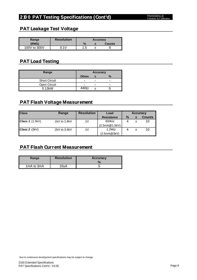
2100 PAT Testing Specifications (Cont'd)2100 PAT Testing Specifications (Cont'd)
PAT Leakage Test VoltagePAT Leakage Test Voltage
Range Resolution Accuracy(RMS) % ± Counts
100V to 300V 0.1V 1.5 ± 9
PAT Load TestingPAT Load Testing
Range AccuracyOhms ± %
Short Circuit - - -Open Circuit - - -
0.13kW 440Ω ± 5
PAT Flash Voltage MeasurementPAT Flash Voltage Measurement
Class Range Resolution Load AccuracyResistance % ± Counts
Class 1 (1.5kV) 1kV to 1.8kV 1V 600kΩ 4 ± 10([email protected])
Class 2 (3kV) 2kV to 3.6kV 1V 1.2MΩ 4 ± 10(2.5mA@3kV)
PAT Flash Current MeasurementPAT Flash Current Measurement
Range Resolution
1mA to 3mA 10uA
Due to continuous development specifications may be subject to change.
Accuracy
5%
TRANSMILLESolutions In Calibration
2100 Extended Specifications PAT Specifications Cont'd : V4.00 Page 8

2100 Loop Testing Specifications2100 Loop Testing Specifications
Line Voltage MeasurementLine Voltage Measurement
Range Resolution Accuracy
200V to 260V 0.1V 0.8% ± 6 Counts
Due to continuous development specifications may be subject to change.
TRANSMILLESolutions In Calibration
2100 Extended Specifications Mains Voltage Measure : V4.00 Page 9

www.transmille.com
Main Office : +44 (0) 1580 890700 [email protected] www. transmille.com
LimitedUnit 4, Select Business Centre, Lodge Road, Staplehurst, KentTN12 0QW. United Kingdom
We truly believe in offering Solutions in Calibration, offering bespoke solutions for calibration laboratories and manufacturers across the globe.
Our mission statement is not just a phrase, it is our design and support philosophy, offering support and advice that cannot be found elsewhere with a friendly atmosphere.
Transmille was founded over 20 years ago as a commercial calibration service, and soon after began to develop and manufacture a range of electrical calibration products and software to answer a growing requirement for solutions to common problems. Following this small beginning, Transmille has worked year on year to provide unique equipment and software to benefit calibration laboratories and manufacturers across the globe.
Ever since releasing the very first products Transmille have continued to innovate and develop new products for the metrology community, from world first products such as the 2100 Electrical Test Equipment calibrator, through to the worlds lowest cost multi product calibrator the 1000 series.
Transmille now produce over 600+ calibration instruments per year, shipping instruments to customers ranging from National Standards Laboratories and manufacturers through to small calibration test houses around the world.
An unrivalled commitment to quality and innovation drives Transmille forwards, with a dedicated design and support team in house with a combined experience of over 60 years in manufacture and design of electrical calibration products and software.
With local distributors across the globe, we can offer one to one personalised support, no matter how large or small the customer.