20MM MK 4 MOD O GUN POD FLIGHT TEST OF THREE ...
39
UNCLASSIFIED AD 427049 DEFENSE DOCUMENTATION CENTER FOR SCIENTIFIC AND TECHNICAL INFORMATION CAMERON STATION, ALEXANDRIA, VIRGINIA UNCLASSIFIED
-
Upload
khangminh22 -
Category
Documents
-
view
2 -
download
0
Transcript of 20MM MK 4 MOD O GUN POD FLIGHT TEST OF THREE ...
UNCLASSIFIED
AD 427049
DEFENSE DOCUMENTATION CENTERFOR
SCIENTIFIC AND TECHNICAL INFORMATION
CAMERON STATION, ALEXANDRIA, VIRGINIA
UNCLASSIFIED
NOTICE: Wnen government or other drawings, speci-fications or other data are used for any purposeother than in connection with a definitely relatedgovernment procurement operation, the U. S.Government thereby incurs no responsibility, nor anyobligation whatsoever; and the fact that the Govern-ment may have formulated, furnished, or in any waysupplied the said drawings, specifications, or otherdata is not to be regarded by implication or other-wise as in any manner licensing the holder or anyother person or corporation, or conveying any rightsor permission to manufacture, use or sell anypatented invention that may in any way be relatedthereto.
IMI
S.G9 TOO COMAN - CRF DIVSN
Culver ~ ~ -ii,,alfr i
Report No. HTC-63-56
ZOMM MK 4 MOD 0 GUN PODFLIGHT TEST OF THREE PODS INSTALLED
ON A4 AIRPLANE
At Naval Ordnance Test StationChina Lake, California
15 April to 20 July 1963
IiUGHES TOOL COMPANY -- AIRCRAFT DIVISIONCulver City, California
/
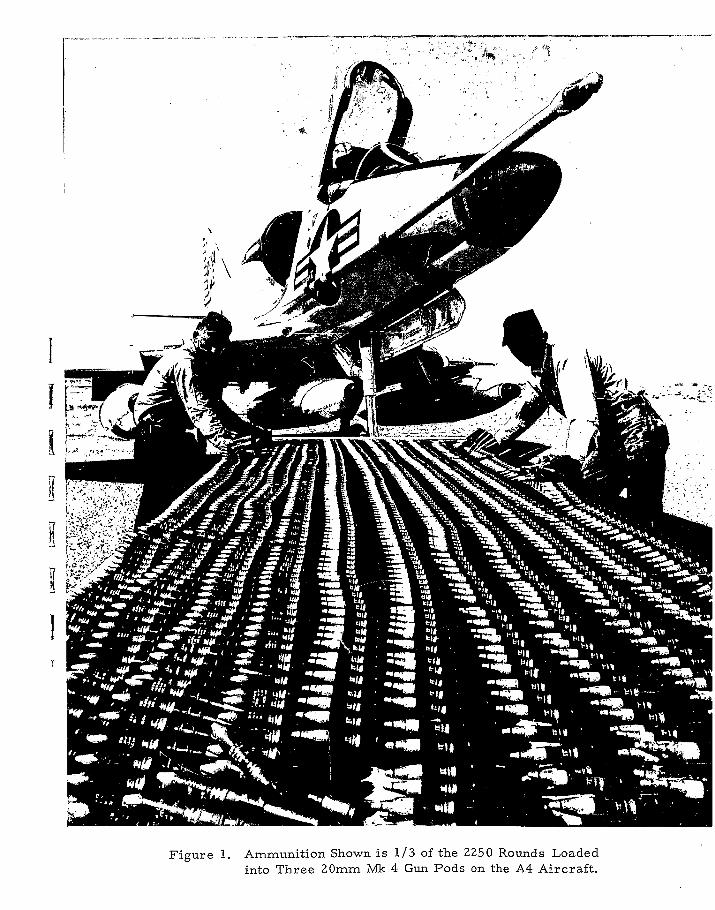
Figure 1. Ammunition Shown is 1/3 of the 2250 Rounds Loadedinto Three 20mm Mk 4 Gun Pods on the A4 Aircraft.
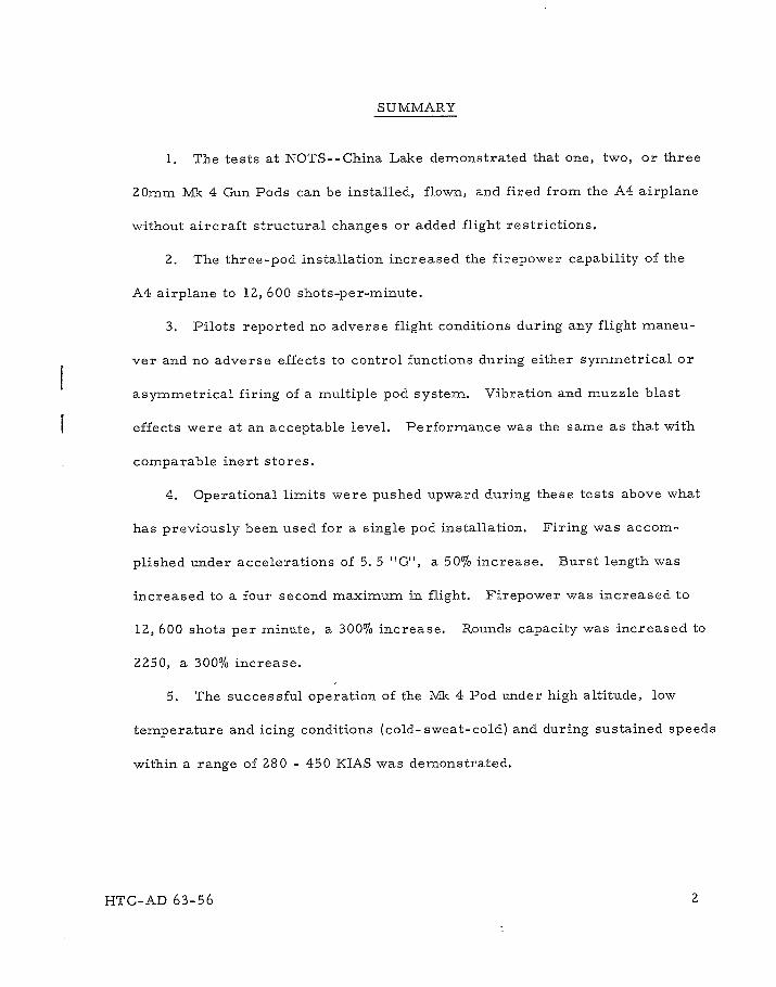
SUMMARY
1. The tests at NOTS--China Lake demonstrated that one, two, or three
20mm MIk 4 Gun Pods can be installed, flown, and fired from the A4 airplane
without aircraft structural changes or added flight restrictions.
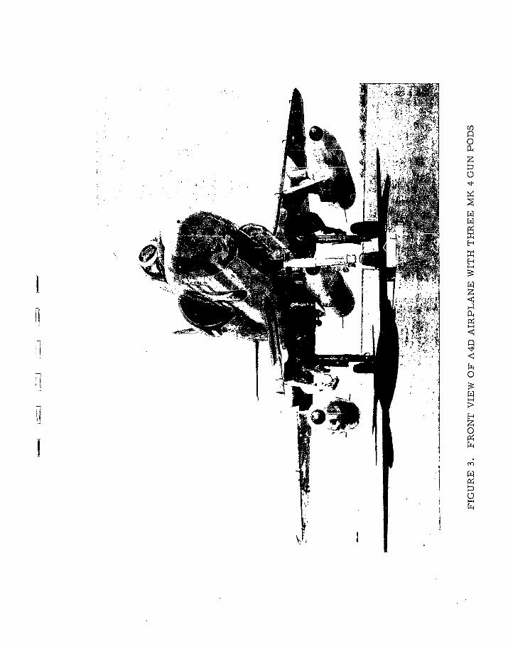
2. The three-pod installation increased the firepower capability of the
A4 airplane to 12, 600 shots-per-minute.
3. Pilots reported no adverse flight conditions during any flight maneu-
ver and no adverse effects to control functions during either symmetrical or
asymmetrical firing of a multiple pod system. Vibration and muzzle blast
effects were at an acceptable level. Performance was the same as that with
comparable inert stores.
4. Operational limits were pushed upward during these tests above what
has previously been used for a single pod installation. Firing was accom-
plished under accelerations of 5. 5 "G", a 50% increase. Burst length was
increased to a four second maximum in flight. Firepower was increased to
1Z, 600 shots per minute, a 300% increase. Rounds capacity was increased to
Z250, a 300% increase.
5. The successful operation of the Mk 4 Pod under high altitude, low
temperature and icing conditions (cold-sweat-cold) and during sustained speeds
within a range of 280 - 450 KIAS was demonstrated.
HTC-AD 63-56 2
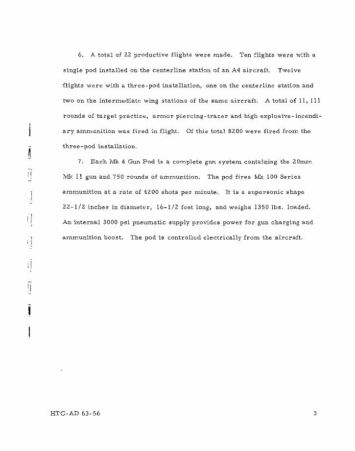
6. A total of 22 productive flights were made. Ten flights were with a
single pod installed on the centerline station of an A4 aircraft. Twelve
flights were with a three-pod installation, one on the centerline station and
two on the intermediate wing stations of the same aircraft. A total of 11, 111
rounds of target practice, armor piercing-tracer and high explosive-incendi-
ary ammunition was fired in flight. Of this total 8200 were fired from the
three-pod installation.
7. Each Mk 4 Gun Pod is a complete gun system containing the 20mm
Mk 11 gun and 750 rounds of ammunition. The pod fires Mhk 100 Series
ammunition at a rate of 4200 shots per minute. It is a supersonic shape
22-1/2 inches in diameter, 16-1/2 feet long, and weighs 1350 lbs. loaded.
An internal 3000 psi pneumatic supply provides power for gun charging and
ammunition boost. The pod is controlled electrically from the aircraft.
I6
--T C- AD 63-56 3
n0
Ct
[A[A
p
H
H
[A
4 4RI-'
cCI
I-I
r
[AI-H
U)
z
mUI-H
N
-" 5 [A
CIA
11A * 'A
II
f4
jnIl 0
[A
[AIH
[A
0
4> [A
I _
- Hil I [AA1 I-i
[A
U

TEST OBJECTIVES
1
I
TEST OBJECTIVES
GENERAL
The purpose of the test was threefold:
(1) Flight test the improvements made in the pod system since the previous
flight tests.
(2) Establish the feasibility of the three-pod installation on an A4 air-
plane.
(3) Demonstrate the three-pod system in a weapons presentation for the
President of the United States and Military and Defense officials.
DISCUSSION
The previous flight tests were made at the Naval Air Test Station,
Patuxent River, Maryland, in the spring of 1961. In the two years elapsed
time, a number of improvements had been incorporated into the gun and pod
and tested by ground firing. Flight tests were required to complete the
verification of the design changes.
A combined study by NOTS--China Lake, Douglas Aircraft Company, and
Hughes Tool Company- -Aircraft Division, indicated that a three-pod installa-
tion on the centerline and intermediate wing stations of an A4 aircraft was
feasible without any structural changes. The flight tests were conducted as
an initial checkout of the three-pod installation.
KTC-AD 63-56 8
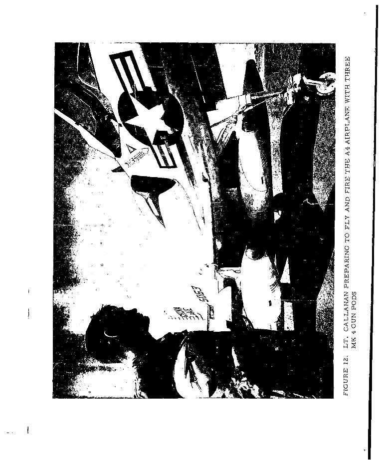
On 7 June 1963, a weapon demonstration for the President of the United
States and other Government and Military officials was conducted to demon-
strate new weapons under development by the Navy. The three-pod installa-
tion on an A4 airplane was entered as an event and flown by Lt. David Callahan
in this demonstration. The purpose of the event was to demonstrate 12, 600
shots-per-minute 20mm gun firepower from the A4 airplane as compared to
the existing 4000 shots-per-minute from the F8B.
SPECIFIC
Specific purposes of the tests were as follows:
(1) Determine the effects of muzzle blast on the aircraft structure and
any other objectionable effects such as noise, vibration, or flashing.
(Z) Determine the capability of firing under high "G" loads, high
altitudes, low temperatures, and icing conditions (cold-sweat-cold).
(3) Determine qualitatively the handling and performance characteristics
of the aircraft with a three-pod installation during both normal flying con-
ditions and while firing.
(4) Evaluate qualitatively the tactical use of the three-pod system.
Determine any effects on aircraft handling such as excessive vibration,
pitching or yawing while firing the three-pod installation.
(5) Record firing results by means of chase plane and ground cameras.
HTC-AD 63-56 9

TEST SETUP
TEST SETUP
The excellent cooperation provided by NOTS--China Lake, BuWeps, and
Douglas Aircraft made possible a successful test program in the very short
time available. Douglas provided the necessary go-ahead authority on a
tight schedule. Three airplanes were wired for the pods by NOTS so that
test flexibility was provided.
Three Mk 4 Mod 0 Gun Pods (converted from EX-l) were used in the test.
Mk 6 Mod 3 ammunition links fitted with radhaz caps were also used. These
links in final form were later designated as Mk 6 Mod 4. The mounting of the
pods at the wing stations required adapters. These were supplied as a no-cost
item by Hughes Tool Company to expedite the tests. The items used in the tests
are described in the following paragraphs.
AIRCRAFT
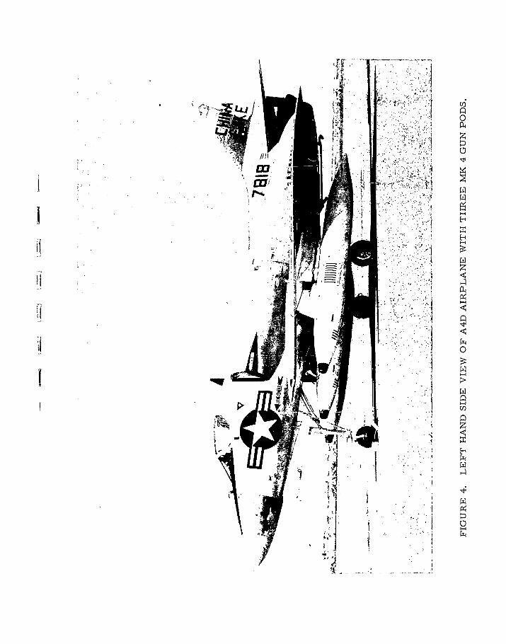
Two of the three A4 aircraft (Tail Nos. 818 and 063) that were modified
for mounting three Mk 4 Gun Pods by NOTS--China Lake, were used in the1flight tests. The only modification necessary was electrical to provide control
power to the pods and the switch in the cockpit. The pylons themselves were
not altered except to supply an electrical pigtail to connect to the pod. Struc-
turally there were no changes.
Instrumentation. A three-camera rack was mounted on each of the out-
board wing stations. 16mm cameras running at 64 frames per second were
HTC-AD 63-56 11
used. Usually the muzzle and ejection areas of the pods were photographed
by the cameras. At times one camera was oriented to a forward direction
showing aim line and target views. Pod or aircraft structure instrumentation
was not used.
A photo-chase airplane and long range ground cameras were used on some
flights. Radar and optical tracking devices were used at the target ranges.
MK 4 GUN POD
In the elapsed time between the last flight tests and these tests, a number
of major design improvernents were made. These included a new blast deflec-
tor, pneumatic ammunition feed system, radhaz link, valveless gun booster
block, new gun round retainer, and numerous smaller changes in the gun and
in the electrical system.
The Mk 4 pods which contained all these changes were being manufactured
but not available in time for tests. The EX- 1 pods used had been modified to
include the changes. The flight tests were productive in verifying the design
changes.
The pods assigned to the test were Serial Nos. 5, 6, and 7, and were
the same ones used during the 300, 000 round reliability test at HTC. The
pod design improvements had been incorporated during the reliability test,
but not all of the gun improvements had been so tested. The pods had a con-
siderable firing history (approaching 100, 000 rounds each) prior to this flight
test and had reached the end of their reliable life.
HTC-AD 63-56 1Z
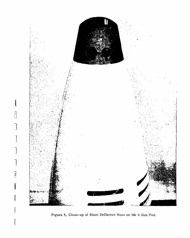
Blast Deflector. Of particular concern was the checkout of new steel
blast deflector. The previous blast deflector, made from aluminum, was
not satisfactory from a life standpoint and did not give quite the desired
protection to the fuselage structure.
The functions of the new deflector, pictured in Figure 5, are shown
in the diagram, Figure 6. In addition to serving as a blast protector, the
deflector has three additional features - (1) a muzzle brake to lessen the
recoil forces of pod to the aircraft (2) upward reaction to lessen the tuck
tendencies and (3) a barrel guide to control dispersion.
The results from these ZZ flights indicate that the blast protection
provided is excellent. No damage to the fuselage structure could be
found.
6
HTC-AD 63-56 13
7;
Figure 5. Close-up of Blast Deflector Nose on M~k 4 Gun Pod.
MUZZLE BREAK
BARREL GUIDE
DOWNWARD BLAST DEFLECTION1
UPWARD0REACTION
Figure 6. Functions of the Blast Deflector
There was speculation that the exhaust ports in the blast deflector might
produce a siren effect in the airstream. The purging air used at the Hughes
firing tunnel during ground firing did produce a whistle as it passed over the
nose. No such effect was observed during the air tests.
Ammunition Feed System. The new ammunition feed system is shown
schematically in Figure 7. A pneumatic drive replaces the previous pulsating
electric drive. This change eliminated the a-c power requirement from the
aircraft and permitted the feed chuting in the pod to be made rigid instead of
flexible. A peripheral magazine drive was incorporated to eliminate back-
lash problems inherent to the former central drive shaft drive. The pneumatic
boost system performed successfully at 5-1/2 "G" at China Lake and at 6 "G"
in later tests at Eglin AFB.
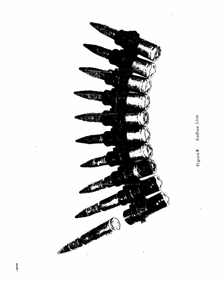
RADHAZ LINKS
A new ammunition link incorporating a cap which covers the primer of
the round was developed to increase the safety of handling linked ammunition
in high level electromagnetic radiation areas such as exist on carrier decks.
This link is shown in Figure 8. The radhaz link was introduced after the
start of testing.
Concurrently, a simplified booster block had been incorporated into the gun,
primarily to eliminate troublesome gas valves but incidentally to improve case
ejection by increased case ejection velocity. The higher ejection velocities
made it mandatory that the stronger link with the radhaz cap be used. An
HTC-AD 63-56 16
older lot of links was reworked to include the radhaz cap. These less-than-
optimum links were directly responsible 6r contributing factors in a third
of the malfunctions in these tests. In the later tests at Eglin Field, where
production run links were used, only one stoppage was attributed to links.
The old hardware in use (approximately 100, 000 rounds on each pod) and
the experimental nature of some components used in the NOTS test also
contributed to stoppages.
HTC-AD 63-56 17
MAGAZINE DRIVE CRANK
WORM GEAR SPROCKET
DE-CLUTCH LEVER RING GEAR\ \\ RION GEAR
S LAR LIE -PROC MAGCANE
oo65ooo o
S000 000 00
PNEUMATIC MOTOR
SOLENOID ACTUATE VALVE l SROKT RN
FILTER
Figure 7. Ammunition Feed System Schematic Diagram
00
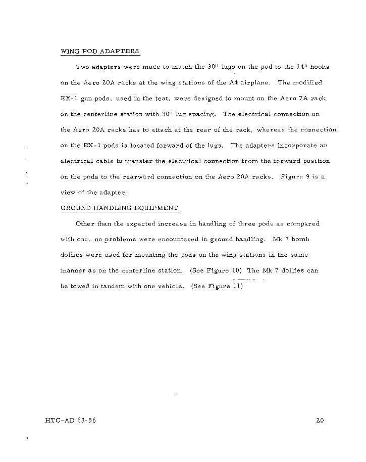
WING POD ADAPTERS
Two adapters were made to match the 30" lugs on the pod to the 14" hooks
on the Aero 20A racks at the wing stations of the A4 airplane. The modified
EX-1 gun pods, used in the test, were designed to mount on the Aero 7A rack
on the centerline station with 30" lug spacing. The electrical connection on
the Aero 20A racks has to attach at the rear of the rack, whereas the connection
on the EX-1 pods is located forward of the lugs. The adapters incorporate an
electrical cable to transfer the electrical connection from the forward position
on the pods to the rearward connection on the Aero 20A racks. Figure 9 is a
view of the adapter.
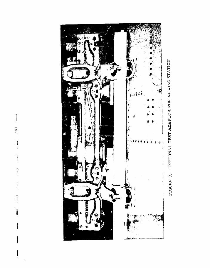
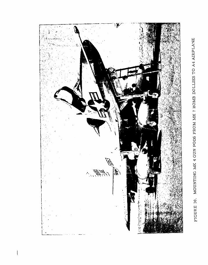
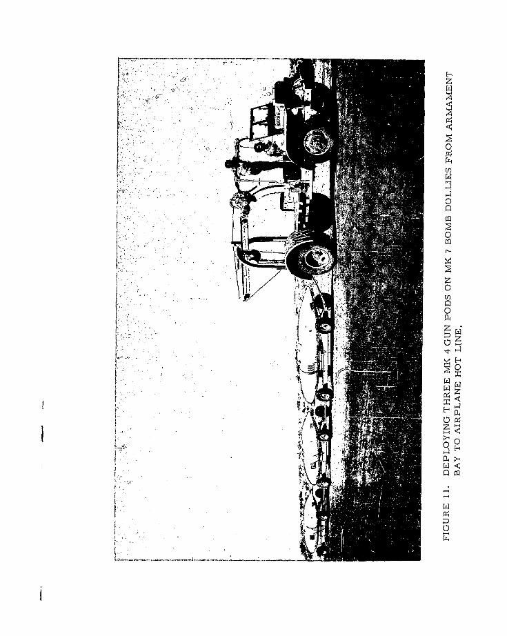
GROUND HANDLING EQUIPMENT
Other than the expected increase in handling of three pods as compared
with one, no problems were encountered in ground handling. Mk 7 bomb
dollies were used for mounting the pods on the wing stations in the same
manner as on the centerline station. (See Figure 10) The Mk 7 dollies can
be towed in tandem with one vehicle. (See Figure 11)
HTC-AD 63-56 20
E-
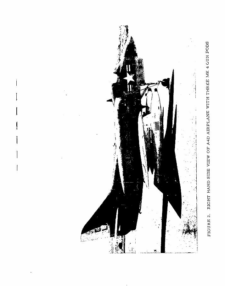
IUE-4
I ~ 7w
jj;~ '7 p-I
0Hr~t,H
0
!~j 0~k~f ~I; Z
4,
UI-I
V H
~ 2
z
02
C4

RESULTS OF TESTS
[ A
x4
0
H4
IR
RESULTS OF TESTS
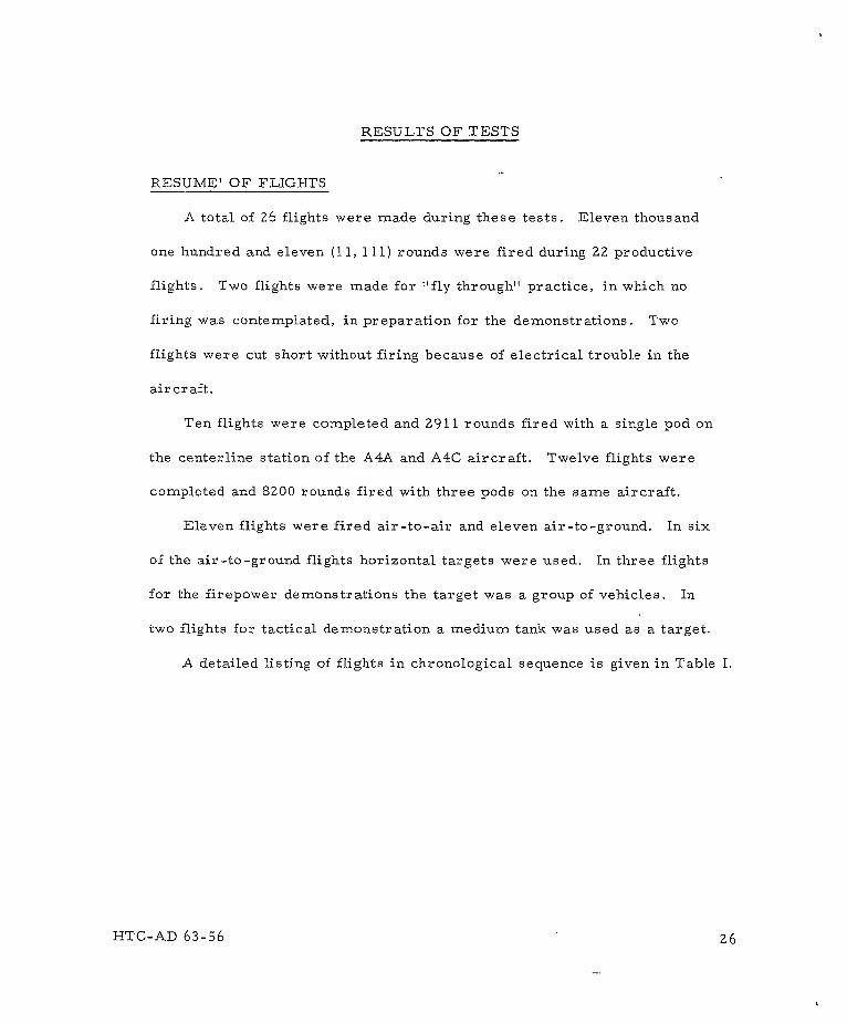
RESUME' OF FLIGHTS
A total of 26 flights were made during these tests. Eleven thousand
one hundred and eleven (11, 111) rounds were fired during Z2 productive
flights. Two flights were made for "fly through" practice, in which no
firing was contemplated, in preparation for the demonstrations. Two
flights were cut short without firing because of electrical trouble in the
aircraft.
Ten flights were completed and Z911 rounds fired with a single pod on
the centerline station of the A4A and A4C aircraft. Twelve flights were
completed and 8Z00 rounds fired with three pods on the same aircraft.
Eleven flights were fired air-to-air and eleven air-to-ground. In six
of the air-to-ground flights horizontal targets were used. In three flights
for the firepower demonstrations the target was a group of vehicles. In
two flights for tactical demonstration a medium tank was used as a target.
A detailed listing of flights in chronological sequence is given in Table I.
HTC-AD 63-56 Z6
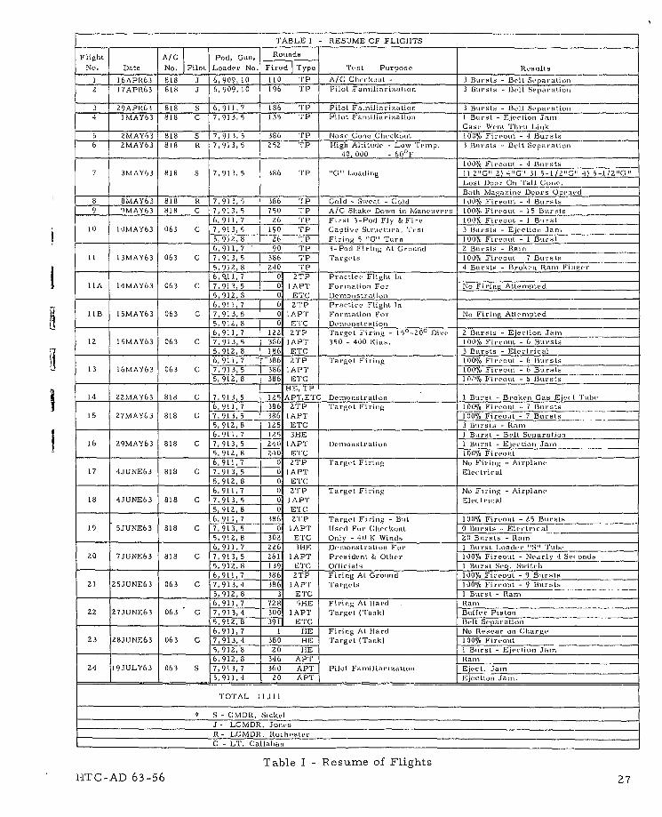
TABLE I -RESUJME OF FLIGHTS
Flight A/C Pod, Cuei, Rounds
No. Date No. Pilot Loader No. Fired Type 'rest PurposeRelt
1 16APR63 818 3 6,909 10 110 TIP A/C Checkout - 3 B~ursts -Belt Separatiot)2 17APR63 818 .1 6, 909, 10 196 TP Pilot .Eanilinriy~ntion 3 Bursts -Belt Separation
3 29APR61 818 S 6, 911, 7 186 '1' P Pilot Fanilinri rationl 3 Buirsts -Belt Separationi4 1MAY63 818 C 7,913, 5 135 'p Pilot Faniiljnrirzation I Burst - Ejectioni Jam
Case Wenit Thru Lik5 j2MAY63 818 S 7,911, 5 386 'p Nose Gonie Checkout 100% Fireout - 4 Bursts6 ZMAY63 818 R 7,913, 5 Z52 t'P 1-igh Altitude -Lowv Teminp. 3 Bursts - Belt Separatico
S'10, 000 -60"~F
100% Firewut - 4 Bursts7 3MIAY63 818 S 7,913, 5 186 T11 ''C'' Loadinig 1) V" 2) '10'3) 5-1 /2"G"' -1) 5-1/2""
Lost Boor On 'rail G;nu'.___________Both Magzrie Boors tOpetied
8 8MAY63 818 R 7,910, 5 386 ' C old - Siveat -Cold 100% Firout -4 Bursts9 OluAY63 818 C 7,913, 5 750 'IP A/C Shake Downi ini Maneuivers 100%/ Fireout -15 Bursts
6, 911,7 26 '1' Fi rst 3-Poti Fly & Fire 100% Fireout -I Burst10 1OMAY63 063 C 7,913,5 190 'rp Gaptive Structural 'lest 3 Bursts - Ejectioni Jain
____5, 912,8 26 'rP Firitip 5 "C"' Turn 100% Fircout - I Burst6,911,7 90 'lW 3-Pod Firinig At. Ground 2 Bursts - Ranm
it 13MAY63 063 C 7,913,S5 386 'lW 'T'ar gets 100% Fireout 7 Bursts
____5,912,8 240 'lW 4 Bursts -Broku'n Rain Fiigt'r6, o11, 7 0 2TP Pratle' Flight tIn______________________
I lA 14MAY63 063 C 7, 913, 5 0 lAPT Formationi For No Firing Attempted5, 912, 8 0 ETC -Demonstration6,911, 7 0 2'tP Practice Fligtht In
11lB 15MAY63 063 C -7, 913, 5 0 lAPI' Formation For No Firig Attempted
6,911,7 122 ZIP Target Firing - 15S0-ZO' Dive 2 Bursts -Ejection Jain
12 15MAY63 063 C 7,'913,5 3861 IAPT 350 - 400 Kins. 100% Firenot - 6 Bursts______5,912,8 186 E'TC 3 Bursts - Electrical
6, 911,7 1 386 a'rP T1arget Firing 100% Firrout - 6 Bursts13 1MAY3 03 C 7,91,5 86 APT100% Fireout - 6 Bursts
5,912,8 386 E'TC I IT"!, Fireout - 6 B~ursts
14 22MAY63 818 C 7,913, 5 125 AP'1'E'C Bemnonstration 1 Burst - Broki Gas tEje, t rut,'6,911,7 386 2'rP T larget Firing 100% Firvout - 7 Bursts
15 27MAY63 818 C 7, 913, 5 386 1 APT 100% Fireout - 7 Btursts5,912,8 125 E'1C 3 Bursts -Rain
6,911,7 125 311IE I Buirst Belt Separation ____
16 29MAY63 818 C 7,913, 5 240 LAPT Denmunstratioti 1 Buirut -Ejection Jain5,912,8 2-10 E'PG 100%. Fireoit
6,911,7 -0 tI'P 'Target Firinig No Firing - Airplane17 4JUNE63 818 C 17,913, 5 0 1 API' Elctrical
5,92,8 __0 ETC6, 911,7 0 ZYlP Target Ftiring No Firinig - Airplane'
18 4JUNE63 818 C 7,913, 5 0. 1APT Electrical______5, 91Z, 8 A tt E'(; I___________________
6, 911,7 186 2'1P 'Tnrge't Firing - But 100% Fireoul - Z5 Bursts_____19 5JUNE63 818 C 7, 913, 5 0 lAPT Ulsed For Checkot 0 Bursts - Electrical
____ ______5,912, 8 302 ETC Only - 10 K Winds, 20 Bursts - Rain6, 911,7 226 3H-E Demronstrationi For 1 Burst Loader 'IS Tube
20 7JUNE63 818 C _7, 913, 5 261 lAP'I Prisident & Other 100% Fircout - Nearly '1 Se, onds____ _______5, 91z2,8 139 E TC Officials I Burst Seq. Switch
6,911,7 586 2TP Firinig At Ground 100% Fireout - 9 Bursts21 25JUNE63 063 C 7,913,4' 386 1APT' 'Targe'ts 100%/ Fireotit - 9 Bur st
5, 912, 8 __3 E'I'C I Burst - Rain6,911,7 728 SHE Firinig At hlard Rain
22 27JUNE63 063 C 7,913,4 -300 1lAPT1 la r g vt ('lan k) Buffer Pistoi5, 912, 8 391 E'lC Bill Separationi6,911,7 1 HE Firinig At lHned No Resear oni Charge
23 28JUNE63 063 C 7,913,4 380 HE Target ('raok) 100% Fireout
1____5, 912, 8 20z HE II Burst - Ejiction Jamn6,912, 8 1346 APT IRain
24 19JULY63 063 S 17, 913, 7 1360 API' Pilot Familiarizationl Eject, Jamn5, 911,4 1_ 20 A PT Ejectioni Jam.
T1OT1AL 11,111
S - CMuDli. Sicket.
J - LCMDR. JonecsR - LCMDIS. Rutt,,'stvr
C - LT1. Callahani
Table I - Resume of FlightsHTC-AD 63-56 27
AIR-TO-AIR FIRING
Air-to-air firing was used for:
(a) Pilot familiarization.
(b) Checking out airplane performance and handling
characteristics.
(c) Checking capabilities of the pod under environmental
conditions.
Pilot Comments. The single-pod installation was flown by four different
pilots, LCDR Jones, LCDR Rochester, Lt. Callahan and CDR Sickel. The
three-pod installation was flown by Lt. Callahan and CDR Sickel. The majority
of the flights were flown by Lt. Callahan.
These pilots concurred in reporting the following:
Normal flight conditions were encountered during all maneuvers attempted.
No adverse control functions were experienced during either symmetrical or
asymmetrical firing. A noticeable yaw did occur during the firing of a single
wing pod. It was not determined Whether the resulting yaw could be compensated
for, during accuracy firing. Vibrations were at acceptable levels and independent
of the number of guns firing. It was not possible to tell by vibration alone
whether one, two or three guns were firing. Muzzle blast of wing pods was not
noticeable. Handling of aircraft with pods is the same as with inert stores of
similar weight and configuration. A degradation in aircraft speed of 5 to 10
knots per pod occurred.
HTC-AD 63-56 28
Environmental Tests. During the air-to-air phase of the tests, the
Mk 4 pod--A4 Aircraft System was subjected to the environmental conditions
listed below. Stoppages that occurred were not attributed to the environmental
condition.
(a) Non-firing runs.
(1) Attained speed of .92 IMN from 20, 000' to 10, 000' MSL.
(2) Maximum rudder deflection in both directions at 350 KIAS
at 10, 000' MSL.
(3) Entered moderate buffet during rapid "G" application.
(4) Applied partial and full aileron deflection at high and low
airspeeds and accelerations.
(5) Subjected to zero "G" acceleration at 300 KIAS at 10, 000'
MSL.
(b) Firing runs.
(1) Fired three 1-1/4 second bursts (90 rounds) at 40, 000' MSL
after soaking for 35 minutes at same altitude. Estimated air
temperature was -600 F. Lubriplate #215 grease was in gun
at the time.
(2) Fired f 2c 1-1/4 second bursts (90 rounds) after cold soaking
for 30 minutes at 30, 000' MSL, descending to surface at
Pt. Mugu for sweating, and again climbing to 30, 000' MSL
and soaking for 35 minutes before firing.
HTC-AD 63-56 Z9
Estimated air temperature was -40 0 F. A special low
temperature lubrication, N343Z, developed at the Naval
Research Laboratory, was used in the gun. This lubricant
appears to have good lubricating qualities at low temperature,
but has a shorter life (perhaps 1000 rounds) than Lubriplate
(over 3000 rounds). A slight leak (150 PSI drop per hour)
developed in an aluminum pneumatic fitting in one pod. The
fitting was later changed to steel.
(3) Fired two 1-1/4 second bursts under an acceleration of 5.5
;'G" obtained by pulling out of a dive. Fired one burst in a
5 "G" acceleration turn. The magazine inspection doors
opened, and the pneumatic reservoir service door in the
tail cone opened and ripped off'in the airstream during the
5. 5 "G" acceleration. It may have been a combination of
high speed, vibration, and "G" loads that caused the doors
to open. A similar tail cone door opened when firing in
level flight at 580 KIAS during later tests at Eglin Field
AFB on the F100 aircraft. These doors have since been
improved by stiffening the door and using a double-action
latch.
(4) Firing at sustained speeds of a minimum of Z80 KIAS and
a maximum of 450 KIAS at 6000' to 3000' MSL.
HTC-AD 63-56 30
AIR- TO- GROUND FIRING
Information on air-to-ground accuracy of the three-pod system was limited
to a qualitative evaluation due to the short time available and the limited bore-
sight adjustment in the interim wing rack adapters. Small ground targets
(4' pylons and vehicles) were shot at in typical attacks and were hit. Most
attacks were made at 350 to 400 knots at 100 to 150 dive angle with firing
initiated at 30001 range.
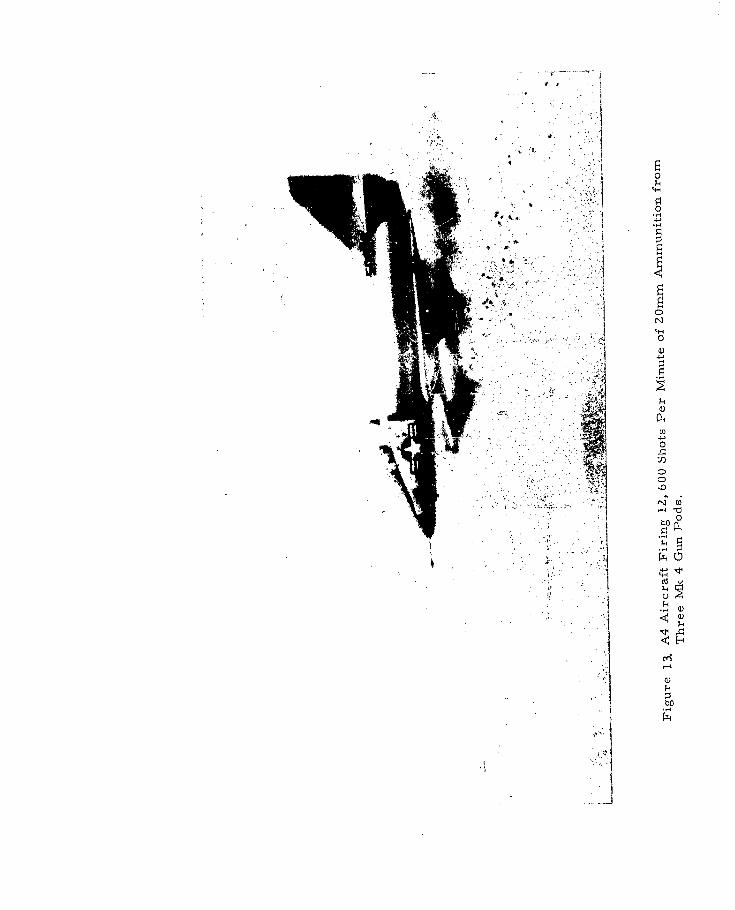
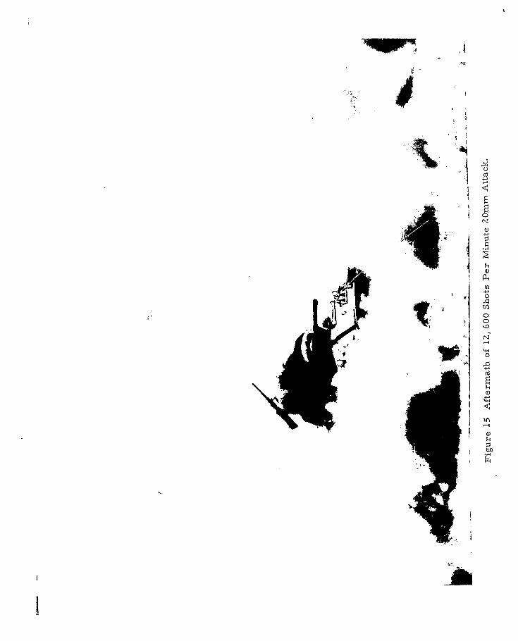
Two firing runs with three pods were made against a light tank for photo-
graphic coverage of a tactical application. (See photographs, Figures 13, 14
and 15)
Both of the three-pod firing passes in the NOTS weapon demonstrations
produced hits as evidenced by fires resulting in the target vehicles. The
long bursts (three to four seconds) used in the demonstration were effective
in emphasizing the firepower of the three Mk 4 Pods on an A4 aircraft.
These long bursts, however, are unrealistic for the efficient use of the
system in combat work since the commence-firing range has to be extended
to approximately 4500' where effectivity is questionable.
In the later Air Force evaluation tests of two Mk 4 pods on the F100
airplane at Eglin Field, the accuracy of wing mounted gun pods was demon-
strated in rigorously controlled air-to-ground firing against vertical
30' x 30' targets. The pilots quickly learned to compensate for tuck by
applying force to the stick at the same time the trigger was depressed.
HTC-AD 63-56 31
-- 441
II41
Cj
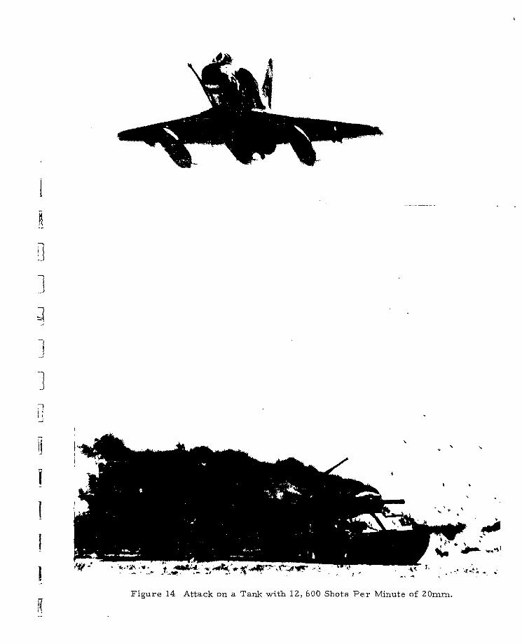
Figure 14 Attack on a Tank with 12, 600 Shots Per Minute of Z0mm.
~0
-Af
Yawing did not occur with the Mk 4 Gun Pods since reaction fo'ce from each
pod was equal and constant throughout the burst. Yaw occurred when one wing
pod was fired alone. It was not completely correctable with rL.dder in steady
state. However respectable hit ratios were obtained when the .?ilot anticipated
firing a single pod.
The FI00 tests proved that the accuracy of wing mounted I k 4 Gun Pods
is as good as fuselage installed guns. Prior to this test, there: was concern
that the wing mount would sacrifice accuracy due to wing deflection, aircraft
yaw and pitch (tuck) from gun firing, and parallax. The wing pod accuracy
was demonstrated by LCDR Duane Varner and Air Force Capt. Reddoch.
The tests with three Mk L r,, Pods on the A4 airplane we:,e an unqualified
success. The way is now clear for multiple gun pod installations. The Tesailt-
ing increase in aircraft firepower by three fold and more is the Navy's
bonus for developing the 4200 Shot-per-minute Mk 11 gun and i:s Mk 4 pod.
The greater firepower expands the capability of the 20mm gun by adding the
armored vehicle (in particular, the tank) to its list of targets. The anti-armor
capability combined with the recognized softer target versatility, low cost and
ease of use projects the 20mm gun inrto the forefront of proven -. ir-to-ground
r weapons.
HTC-AD 63-56