2025 Digiflow Airfluid Manual Powder System ... - KJ Auktion
37
4/2/2014 Manual Powder System 2025 Digiflow Airfluid http://anaengineering.com/wagner_lit/bal/2025_af/0265825e.htm 1/37 2025 Digiflow Airfluid Manual Powder System 06/99 Danger! High voltage! Turn power off before servicing! Read rules for safe operation and instructions carefully! back Operating Manual Table of contents Overview 2025 Digiflow Airfluid 1. Introduction 1.1. Safety Regulations 1.2. General Safety Rules 1.3 Information concerning harmless discharge 2. Preparing the manual powder system for initial use 2.1. Assemble the manual powder system and connect the spraygun 2.2. Grounding the manual powder system 2.2.1 If the manual powder system is operated within zone 11
-
Upload
khangminh22 -
Category
Documents
-
view
4 -
download
0
Transcript of 2025 Digiflow Airfluid Manual Powder System ... - KJ Auktion

4/2/2014 Manual Powder System 2025 Digiflow Airfluid
http://anaengineering.com/wagner_lit/bal/2025_af/0265825e.htm 1/37
2025 Digiflow Airfluid
Manual Powder System
06/99
Danger!
High voltage!Turn power offbefore servicing!Read rules for
safe operation andinstructions carefully!
back
Operating Manual
Table of contents
Overview 2025 Digiflow Airfluid
1. Introduction
1.1. Safety Regulations
1.2. General Safety Rules
1.3 Information concerning harmless discharge
2. Preparing the manual powder system for initial use
2.1. Assemble the manual powder system and connect the spraygun
2.2. Grounding the manual powder system
2.2.1 If the manual powder system is operated within zone 11

4/2/2014 Manual Powder System 2025 Digiflow Airfluid
http://anaengineering.com/wagner_lit/bal/2025_af/0265825e.htm 2/37
3. Working with the manual powder system
3.1 This is how the manual powder system is switched on and off
3.2 Make the basic settings for the manual powder system
3.3 Corona or Tribo
3.4 Setting the powder cloud for your coating
3.5 This is how you interrupt the coating process
3.6 This is how to carry out a change of color
3.6.1 Clean the manual powder system
3.6.2 Re-starting the system with the new powder
4. Maintenance and cleaning
4.1. Periodically inspecting and cleaning the manual powder system
4.2. Check the spraygun
5. Trouble shooting
6. Spare parts lists and accessories
6.1. How to order
6.2. Manual powder system 2025 Digiflow Airfluid
6.3 Equipment trolley
6.4 Feed unit mount
6.5 Feed unit Integral ME 1
7. Specification
8. Supplement
8.1 Applicable Safety Regulations and List of Sources
8.2 Warranty
Manual powder system 2025 Digiflow Airfluid
4/2/2014 Manual Powder System 2025 Digiflow Airfluid
http://anaengineering.com/wagner_lit/bal/2025_af/0265825e.htm 3/37
1 Equipment trolley 2010 Airfluid 4 Feed unit Integral ME1
2 Control unit EPG Digiflow 5 Powder injector PJ-D1
3 Spraygun
The manual powder system 2025 Digiflow Airfluid is designed for use in laboratories and low volume
production in industry and trade. You can operate this manual powder system with the following types
of sprayguns:
Corona Spraygun: Airmatic PEM-C2
Tribo Spraygun: PEM-T1
The major advantages are:
Powder supply from the original powder box
Re-coating in addition to prior automatic coating
Quick and easy cleaning
The feed unit (4) is inserted directly into the original powder box. The powder is supplied to the
powder gun (3) via the powder injector (5). Due to the special arrangement of the fluid hoses in front of
the suction tube and the vibration of the entire container, a homogeneous powder/air mixture is ensured
4/2/2014 Manual Powder System 2025 Digiflow Airfluid
http://anaengineering.com/wagner_lit/bal/2025_af/0265825e.htm 4/37
during the entire operation.
The powder quantity and its electrostatic charging are regulated from the control unit EPG Digiflow (2).
What coating powder can be used?
All types of coating powder can be processed with the manual powder system 2025 Digiflow
Airfluid. The powder has to be selected depending on the type of spraygun:
With Airmatic spraygun PEM-C2: epoxy, polyester, blended powder EP / PES, PUR etc.
With Tribo spraygun PEM-T1: powders which are suitable for friction charging, such as epoxyresin powder or PUR lacquers.
Caution
Powders containing metal pigments may only be processed in compliance with the powder
manufacturer's instructions.
Detailed information on configuration can be found in the operating instructions of the EPG Digiflow
2007 control unit.
1. Introduction
This technical manual contains information and hints for the service, repair and maintenance of the
equipment. The observation of this manual is element of the warranty agreements.
Wagner powder systems are designed to meet the most stringent safety requirements. They can beoperated in compliance with generally applicable safety codes and applicable national safety
regulations.
Please pay particular attention to the parts marked by the following symbols. Follow the instructionsexactly, in the interests of both your own safety and the correct functioning of the unit.
This symbol draws attention to the fact that if the operating instructions, working
4/2/2014 Manual Powder System 2025 Digiflow Airfluid
http://anaengineering.com/wagner_lit/bal/2025_af/0265825e.htm 5/37
Warning instructions, prescribed working sequences etc. are not followed exactly, this can lead toinjury or even fatal accidents.
Caution
This warning indicates that if the operating instructions, working instructions,
prescribed working sequences etc. are not followed exactly, this can lead to damageto the unit.
HintThis symbol draws your attention to useful additional information and tips.
Wagner hereby declares that the unit described in these operating instructions has beendesigned and manufactured according to the provisions of EU Directive 89/392/EEC.
The following European standards have been applied:
EN 50014 EN 50050 EN 50053
The following German standards or guidelines have been applied:
ZH 1/443 VDMA 2371 Part 1
VDE 0165
1.1 Safety Regulations
Warning
This equipment can be dangerous if it is not operated in accordance with this operatingmanual! There might be additional regulations to be observed, put into effect bygovernmental, state or other official agencies or local security (fire) departments!
The following rules must be observed in order to ensure a safe and efficient use of the equipment:
· Under no circumstance may persons with a · In the event of faults or defects, repair work is to
4/2/2014 Manual Powder System 2025 Digiflow Airfluid
http://anaengineering.com/wagner_lit/bal/2025_af/0265825e.htm 6/37
cardiac pacemaker come close to the area betweenthe tip of the spraygun and the workpiece to becoated.
The user has to observe particularly the safetyguidelines of the VdS or the local professional andsecurity institutions. 2) 3) 6) 9)
· The spraygun may only be operated in the hazardzone created by operation of the manual sprayingequipment itself. 2) 3) 6)
· The spraygun may only be operated in powderspray booths or powder spray benches equippedwith industrial ventilation. 2) 3) 6
· The user has to ensure that the medium value ofthe powder/air concentration does not exceed 50%
of the LEL u ) (maximum allowed concentration ofpowder in air). If the LEL is not known, the usershould assume a value of 20 g/m³. 2) 3) 6)
· The main power connection for operation of theWagner powder equipment must be electricallyinterlocked with the exhaust system of the powdercoating booth. 2) 3) 6)
· The Wagner control unit must be installed outsidethe hazard area. 2) 3)
· The user must conduct periodic checks of thepowder spray equipment (at least every year) withregard to explosion-protection. 5) 7)
be performed at the user's discretion. 7)
· The user must keep a test certificate of the devicetype on file at the installation site. 7)
· The execution of repairs must not lead to analteration in the explosion-protection. 5) 7)
· Repairs may only be carried out by speciallytrained personnel. 7)
· Repairs must never be performed in an explosion-hazard area. 7)
· The work area must have an electrostaticallyconductive floor (measured in accordance with DIN51953) 2) 3) 6)
· All conductive parts in the work area must beelectrostatically grounded (work area = 1.5 m at thesides, 2.5 m to the front and rear of every spraylocation or opening in the booth). 3)
· All persons inside the work area must wearelectrostatically conductive footwear. 2) 3)
· If gloves are used, they must be of antistaticmaterial or have cut-out palm areas. 2) 3)
x) See paragraph 8.1 "Applicable Safety Regulations and List of Sources"
HAZARD PREVENTION
4/2/2014 Manual Powder System 2025 Digiflow Airfluid
http://anaengineering.com/wagner_lit/bal/2025_af/0265825e.htm 7/37
Electrostatic arcing may cause an explosion or fire. Mixtures of powder and air can explode or ignite causingproperty damage and/or severe injury.
Operator must be grounded. Grounding straps must be usedwhen wearing rubber soled shoes.
Operator must be in contact with the spraygun handle; cut outpalm section and trigger fingers of any work gloves to be used.
Operator must remove all metal objects from his or her person,which are not grounded.
The object being sprayed must be grounded.
All metal objects within the spray area must be grounded(including spray booth, part hangers, fire extinguishers, etc.)
Grounded conductive floor must be provided in spray area.
Turn off the Power Pack and unplug from outlet before flushingout the gun, cleaning or replacing parts on the gun such aschanging tips.
Explosion or fire. Mixtures of powderand air can explode or ignite causingproperty damage and/or severe injury.
Exhaust and fresh air introduction must be provided to keep theair within the spray area free of accumulation of flammableatmosphere.
Smoking must not be allowed in spray area.
Fire extinguishing equipment must be present and in workingorder.
Electrostatic arcing must be prevented. (See Electrostatic arcing)
When cleaning the system, use only materials recommended bythe coatings manufacturer. Be sure Power Pack is turned off andunplugged.
Avoid all ignition sources such as static electricity sparks, openflames such as pilot lights, hot objects such as cigarettes andsparks from connecting and disconnecting power cords andworking light switches.
To prevent hazardous concentrations of flammable atmospheres,
4/2/2014 Manual Powder System 2025 Digiflow Airfluid
http://anaengineering.com/wagner_lit/bal/2025_af/0265825e.htm 8/37
spray only in a properly ventilated spray booth.
Never operate spraygun unless ventilation fans are operatingproperly.
Check and follow all National, State and Local codes regardingair exhaust velocity requirements.
Ventilation must be maintained during the cleaning operation.
Toxic Substances: Some materialsmay be harmful if swallowed or come in contact with the skin.
Follow the requirements of the Material Safety Data Sheetsupplied by the coatings manufacturer.
Exhaust and fresh air introduction must be provided within thespray area to keep the air free of high powder accumulations.
Wear a mask or respirator. Read all instructions for the mask toinsure that it will provide the necessary protection against theinhalation of powder.
General Read all instructions and safety precautions before operating.
Comply with all appropriate local, state and national codesgoverning ventilation, fire prevention, and operation ofElectrostatic equipment usage.
The United States Government Safety Standards have beenadopted under the Occupational Safety and Health Act. Thesestandards, particularly the General Standards, Part 1910 and theConstruction Standard, Part 1926, should be consulted.
NFPA Standard No. 33 is to be followed when setting up yourspray area. Contact the National Fire Protection Association,Batterymarch Park, Quincy, Massachusetts, 02269 for moreinformation.
Check with insurance company for additional requirements.
Use only identical replacement parts.
4/2/2014 Manual Powder System 2025 Digiflow Airfluid
http://anaengineering.com/wagner_lit/bal/2025_af/0265825e.htm 9/37
Personnel must be given training in accordance with therequirements of NFPA Standard No. 33 chapter 15.
It is the duty of all personnel responsible for the sprayequipment operation and maintenance to read and understand allsafety information furnished with this equipment.
1.2 General Safety Rules
Keep your workplace well organizedA disorganized workplace creates a hazard.
Take the environmental influences intoconsiderationDo not expose the manual system to rain. Do notuse the manual system in a damp or wetenvironment. Ensure good illumination. Do not usepower tools near flammable liquids or gases
Store your tools carefullyUnused tools should be stored in a dry, lockedroom and out of the reach of unauthorized persons.
Do not use the cable for purposes other than thoseintendedDo not carry the spraygun by the cable and do notuse it to pull the plug out of the socket. Protect thecable from heat, oil and sharp objects.
Do not over-reach your standing positionAvoid abnormal body positions. Ensure stablefooting and always keep your balance.
Wear suitable work clothing
Use breathing protection for work which producespowder
Take good care of the systemKeep the system clean to ensure that it works welland safely. Check the plug and line cord regularlyand have them replaced by customer service ifdamaged. Check the extension cord regularly andreplace it when damaged.
Always remain alertWatch your work. Proceed in a reasonable manner.Do not use tools when you lack concentration.
Check your equipment for damageBefore using the system, carefully inspect slightlyworn parts for proper operation. Check whether themoving parts operate properly, whether they jamand whether parts are damaged.
All parts must be properly assembled in order toensure proper operation of the unit. Damaged partsshould be repaired or replaced by a Wagnercustomer service.
4/2/2014 Manual Powder System 2025 Digiflow Airfluid
http://anaengineering.com/wagner_lit/bal/2025_af/0265825e.htm 10/37
Warning
For your own safety, use only accessories and equipment listed in the operating manual. Theuse of individual parts other than those recommended in the operating manual may create ahazard to personal safety.
Use only original Wagner replacement parts!
1.3 Information concerning harmless discharge
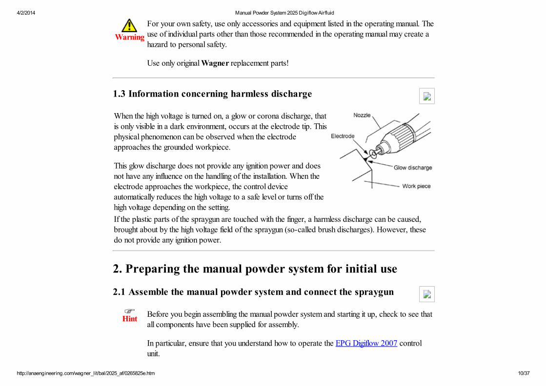
When the high voltage is turned on, a glow or corona discharge, thatis only visible in a dark environment, occurs at the electrode tip. Thisphysical phenomenon can be observed when the electrodeapproaches the grounded workpiece.
This glow discharge does not provide any ignition power and doesnot have any influence on the handling of the installation. When theelectrode approaches the workpiece, the control deviceautomatically reduces the high voltage to a safe level or turns off thehigh voltage depending on the setting.
If the plastic parts of the spraygun are touched with the finger, a harmless discharge can be caused,brought about by the high voltage field of the spraygun (so-called brush discharges). However, thesedo not provide any ignition power.
2. Preparing the manual powder system for initial use
2.1 Assemble the manual powder system and connect the spraygun
HintBefore you begin assembling the manual powder system and starting it up, check to see thatall components have been supplied for assembly.
In particular, ensure that you understand how to operate the EPG Digiflow 2007 control
unit.
4/2/2014 Manual Powder System 2025 Digiflow Airfluid
http://anaengineering.com/wagner_lit/bal/2025_af/0265825e.htm 11/37
Assembly of this manual powder system is the same for both the Corona and the Tribospraygun.
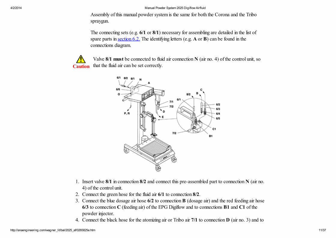
The connecting sets (e.g. 6/1 or 8/1) necessary for assembling are detailed in the list ofspare parts in section 6.2. The identifying letters (e.g. A or B) can be found in theconnections diagram.
Caution
Valve 8/1 must be connected to fluid air connection N (air no. 4) of the control unit, sothat the fluid air can be set correctly.
1. Insert valve 8/1 in connection 8/2 and connect this pre-assembled part to connection N (air no.4) of the control unit.
2. Connect the green hose for the fluid air 6/1 to connection 8/2.3. Connect the blue dosage air hose 6/2 to connection B (dosage air) and the red feeding air hose
6/3 to connection C (feeding air) of the EPG Digiflow and to connections B1 and C1 of thepowder injector.
4. Connect the black hose for the atomizing air or Tribo air 7/1 to connection D (air no. 3) and to

4/2/2014 Manual Powder System 2025 Digiflow Airfluid
http://anaengineering.com/wagner_lit/bal/2025_af/0265825e.htm 12/37
the spraygun.5. Connect the transparent hose for the powder delivery 7/2 to the spraygun and to the powder
injector.6. Connect the gun cable to socket E of the control unit.7. Connect the shaker motor cable to socket G of the EPG Digiflow and secure it with the bar.8. Connect the equipment trolley ground cable to ground screw K.
9. Connect the short black hose 6/6 to connection A (air inlet) of the control unit and to connectionO of the equipment trolley.
HintScrew fitting O has been provided on the equipment trolley for connecting the compressed
air supply, and this has an R 1/4" internal thread on the connecting side.
For safe operation of the manual powder system, high quality compressed air is required, asdescribed in the technical data in section 7.
If your compressed air generator does not achieve this quality of compressed air, you mustconnect an oil filter / water separator.
10. If necessary, connect an oil filter / water separator P between connection O and compressed airR.
11. Connect the mains lead to socket F (mains power input) of the control unit and secure it with thebar.
Caution
High ambient temperatures must be avoided; in particular, the hoses must not be routed
through factory areas exposed to direct sunlight!
Powders with a gelling tendency should be processed at low temperatures. The hosesshould be flushed with compressed air every day in order to prevent powder fromsintering.

4/2/2014 Manual Powder System 2025 Digiflow Airfluid
http://anaengineering.com/wagner_lit/bal/2025_af/0265825e.htm 13/37
4/2/2014 Manual Powder System 2025 Digiflow Airfluid
http://anaengineering.com/wagner_lit/bal/2025_af/0265825e.htm 14/37
Caution
The mains power connection must be electrically interlocked with the exhaust air systemof the powder spray booth.
2.2 Grounding the manual powder system
In order to achieve a good powder coating and for security reasons, the manual powder equipmentmust be properly grounded. Normally, this occurs through the mains cable.
A poorly grounded workpiece causes:
very bad wrap-arounduneven coatingback-spray onto spraygun and userdangerous electric charging of the workpiece
Warning
If the mains cable does not have a separate protective ground terminal, it is absolutelynecessary to connect the control unit to the system ground by a separate grounding cablevia the grounding screw at the back plate of the EPG Digiflow!
Sparks between workpieces and conveyor hooks (hangers) can occur if hooks or other
hanger parts are not completely cleaned! These sparks can cause heavy radio frequencyinterferences!
Preconditions for good grounding as well as coating are:
good grounding of the workpiece to be coated, of conveyors and hangers
grounding of the spraybooth, hooks and hanger parts with a 16 mm2 cooper cable to the system
groundregular cleaning of hangers from powder depositsresistance to ground of the workpiece less than 1 Mega Ohm
2.2.1 If the manual powder system is operated within zone 11
4/2/2014 Manual Powder System 2025 Digiflow Airfluid
http://anaengineering.com/wagner_lit/bal/2025_af/0265825e.htm 15/37
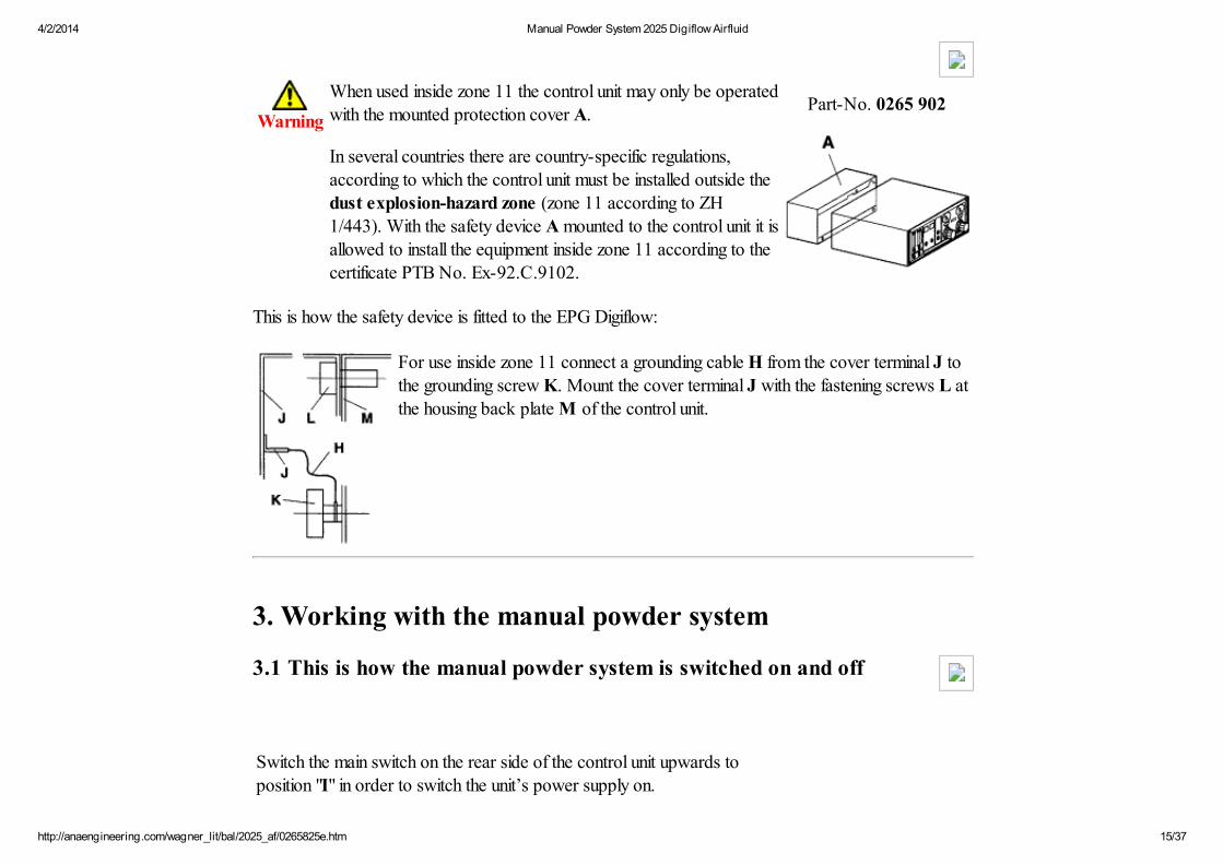
Warning
When used inside zone 11 the control unit may only be operatedwith the mounted protection cover A.
In several countries there are country-specific regulations,according to which the control unit must be installed outside thedust explosion-hazard zone (zone 11 according to ZH
1/443). With the safety device A mounted to the control unit it isallowed to install the equipment inside zone 11 according to thecertificate PTB No. Ex-92.C.9102.
Part-No. 0265 902
This is how the safety device is fitted to the EPG Digiflow:
For use inside zone 11 connect a grounding cable H from the cover terminal J tothe grounding screw K. Mount the cover terminal J with the fastening screws L at
the housing back plate M of the control unit.
3. Working with the manual powder system
3.1 This is how the manual powder system is switched on and off
Switch the main switch on the rear side of the control unit upwards toposition "I" in order to switch the unit’s power supply on.
4/2/2014 Manual Powder System 2025 Digiflow Airfluid
http://anaengineering.com/wagner_lit/bal/2025_af/0265825e.htm 16/37
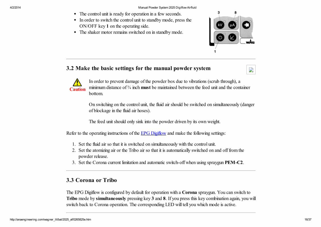
The control unit is ready for operation in a few seconds.In order to switch the control unit to standby mode, press theON/OFF key 1 on the operating side.The shaker motor remains switched on in standby mode.
3.2 Make the basic settings for the manual powder system
Caution
In order to prevent damage of the powder box due to vibrations (scrub through), aminimum distance of ¾ inch must be maintained between the feed unit and the containerbottom.
On switching on the control unit, the fluid air should be switched on simultaneously (dangerof blockage in the fluid air hoses).
The feed unit should only sink into the powder driven by its own weight.
Refer to the operating instructions of the EPG Digiflow and make the following settings:
1. Set the fluid air so that it is switched on simultaneously with the control unit.2. Set the atomizing air or the Tribo air so that it is automatically switched on and off from the
powder release.
3. Set the Corona current limitation and automatic switch-off when using spraygun PEM-C2.
3.3 Corona or Tribo
The EPG Digiflow is configured by default for operation with a Corona spraygun. You can switch toTribo mode by simultaneously pressing key 3 and 8. If you press this key combination again, you willswitch back to Corona operation. The corresponding LED will tell you which mode is active.
4/2/2014 Manual Powder System 2025 Digiflow Airfluid
http://anaengineering.com/wagner_lit/bal/2025_af/0265825e.htm 17/37
3.4 Setting the powder cloud for your coating
1. Check to see if the power supply is switched off, and if necessary, switch it off with the mainswitch on the rear side of the control unit.
2. Place an opened powder box (25 ... 30 kg) on the shaker table and secure it with the retainingstrap.
3. Switch the power supply on.· The control unit will be switched on.· The shaker motor will be will be switched on simultaneously.
4. Close the fluid air.
5. Lower the feed unit until it is on the surface of the powder.6. Slowly open the fluid air, but only so by much (1 ... 2 bar), that the feed system sinks into the
powder under its own weight.
HintThe necessary fluid air quantity depends on the powder quality.The powder should be moving in the suction area of the feed unit (lightly flurrying).A development of dust in the powder box must be avoided!
7. Hold the spraygun in the spray booth, pull the trigger on the spraygun and adjust the powdercloud.
8. Adjust the feeding air, dosage air and the atomizing air or Tribo air on the control unit.· For this, refer to the operating instructions for the EPG Digiflow and / or the spraygun.
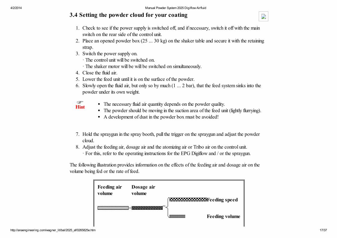
The following illustration provides information on the effects of the feeding air and dosage air on thevolume being fed or the rate of feed.
Feeding air volume
Dosage air volume
Feeding speed
+ =
Feeding volume

4/2/2014 Manual Powder System 2025 Digiflow Airfluid
http://anaengineering.com/wagner_lit/bal/2025_af/0265825e.htm 18/37
Feeding speed
+ =
Feeding volume
Feeding speed
+ =
Feeding volume
3.5 This is how you interrupt the coating process
HintThe spraygun and the powder feeding parts should be blown through and cleaned frompowder deposits with every interruption of work
1. Release the trigger of the spraygun.· The high voltage and the powder delivery will be switched off.· The fluid air and the shaker motor remain switched on.
Caution
Before turning off the manual powder system, you must first pull the feed unit out of thepowder box (danger of blockage of the fluid air hoses)!
2. Move the feed system out of the box so that no more powder can be fed.3. Hold the spraygun in the spray booth, pull the trigger of the spraygun and free it from powder.4. Now you can switch the control unit to standby mode with the ON/OFF button.
· The fluid air will be switched off· The shaker motor remains switched on.
4/2/2014 Manual Powder System 2025 Digiflow Airfluid
http://anaengineering.com/wagner_lit/bal/2025_af/0265825e.htm 19/37
(see paragraph 3.1)
Hint
If you want to leave the manual powder system switched off for a long period, it is better toswitch off the shaker motor as well. By doing this, you prolong the service life of the shakertable and prevent the powder in the box from compacting unnecessarily.
5. Switch the control unit off with the main switch on the rear side.· The shaker motor is now switched off.
If you switch the control unit or manual powder system on again, you can continue coating with thesame powder cloud. The last coating parameters which have been set are stored in the control unit andare called again on switching on.
3.6 This is how to carry out a change of color
3.6.1 Clean the manual powder system
HintWhen changing colors, all powder transporting components must be cleaned thoroughly.
1. Release the trigger of the spraygun.2. Move the feed system out of the box so that no more powder can be fed.3. Hold the spraygun in the spray booth, pull the trigger and free the gun from powder.4. Now you can switch the EPG Digiflow off with the main switch on the rear side.5. Clean all powder transporting parts, such as the spraygun, the powder injector, the powder feed
hose and the feed system.
3.6.2 Re-starting the system with the new powder
If you want to carry out a change of color and want to continue coating with an unchanged powdercloud, you do not need to alter the existing settings, provided the powder characteristics are identical.
4/2/2014 Manual Powder System 2025 Digiflow Airfluid
http://anaengineering.com/wagner_lit/bal/2025_af/0265825e.htm 20/37
1. Place an opened box (25 ... 30 kg) with the new powder on the shaker table and secure it withthe retaining strap.
2. You can now switch on the control unit with the main switch on the rear side of the unit.3. Lower the feed system on to the surface of the powder.4. Hold the spraygun in the spray booth and begin coating.
Re-starting with a new type of powder:
If you change the type of powder when changing the color, you have to re-set the powder cloudas well.The other basic settings, as described in section 3.2 do not need to be altered.
HintIt is possible to store and re-call two settings for the powder cloud with the EPG Digiflowcontrol unit.
If you want to use the present powder cloud setting again later, then make a second settingon the control unit.
For this, refer to the operating instructions of the EPG Digiflow.
1. Place an opened box (25 ... 30 kg) with the new powder on the shaker table and secure it withthe retaining strap.
2. You can now switch on the control unit with the main switch on the rear side of the unit.3. Switch on the power supply.4. Close the fluid air.5. Lower the feed system until it is on the surface of the powder.6. Slowly open the fluid air, but only by so much (1 ... 2 bar), that the feed system sinks into the
powder under its own weight.7. Hold the spraygun in the spray booth, pull the trigger and adjust the powder cloud.
4. Maintenance and cleaning
Maintenance, repair or replacement of the powder spray unit or its components may only

4/2/2014 Manual Powder System 2025 Digiflow Airfluid
http://anaengineering.com/wagner_lit/bal/2025_af/0265825e.htm 21/37
Caution be performed by trained personnel in a suitable location outside the hazard area.
Weekly cleaning of the manual powder system ensures trouble-free operation.
The control unit is maintenance-free, when used according to this operating manual.
The wear parts of the powder spraygun and the powder injector must be checked and replaced ifnecessary.
A list of spare parts can be found in section "Spare parts lists and accessories" in the corresponding
operating instructions.
Warning Caution
WHEN CLEANING THE ELECTROSTATICSYSTEM, THESE SAFETY PROCEDURES MUSTBE FOLLOWED. FAILURE TO FOLLOW THESEPROCEDURES MAY RESULT IN ANEXPLOSION/FIRE.
Turn power pack to the "OFF" position and unplugfrom power source before starting to clean.
Exhaust and fresh air introduction must bemaintained during the clean up operation.
Keep cleaning materials in approved safetycontainers.
All personnel and cleaning equipment, includingcontainer used in cleaning operation, must begrounded.
DO NOT turn on the POWER PACK until thecleaning operation has been completed, all cleaningmaterials have been removed from spray area, andspray area is free of any mixtures of powder and air
Clean equipment immediately after use.
NEVER IMMERSE SPRAYGUN OR PARTS OF ITIN ANY FLUID AT ANY TIME.
Be sure the Power Pack is turned off andunplugged from the power source.
NOTE
The powder passages of the spraygun should becleaned while cleaning the powder hose and powderpump, following instructions, provided with thepowder pump (injector).
(See operating manual PJ - D1)
Clean the spray tip by removing from spraygun,flushing with air and replacing on spraygun.
4/2/2014 Manual Powder System 2025 Digiflow Airfluid
http://anaengineering.com/wagner_lit/bal/2025_af/0265825e.htm 22/37
produced by the cleaning operation.
If defects in the equipment are found, DO NOT useuntil repairs are completed.
4.1 Periodically inspecting and cleaning the manual powder system
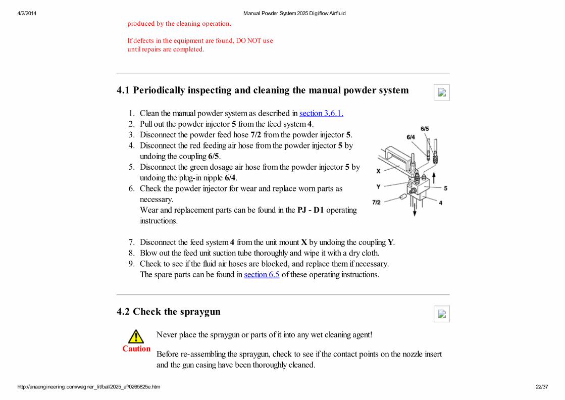
1. Clean the manual powder system as described in section 3.6.1.2. Pull out the powder injector 5 from the feed system 4.3. Disconnect the powder feed hose 7/2 from the powder injector 5.4. Disconnect the red feeding air hose from the powder injector 5 by
undoing the coupling 6/5.5. Disconnect the green dosage air hose from the powder injector 5 by
undoing the plug-in nipple 6/4.6. Check the powder injector for wear and replace worn parts as
necessary.
Wear and replacement parts can be found in the PJ - D1 operatinginstructions.
7. Disconnect the feed system 4 from the unit mount X by undoing the coupling Y.8. Blow out the feed unit suction tube thoroughly and wipe it with a dry cloth.9. Check to see if the fluid air hoses are blocked, and replace them if necessary.
The spare parts can be found in section 6.5 of these operating instructions.
4.2 Check the spraygun
Caution
Never place the spraygun or parts of it into any wet cleaning agent!
Before re-assembling the spraygun, check to see if the contact points on the nozzle insertand the gun casing have been thoroughly cleaned.

4/2/2014 Manual Powder System 2025 Digiflow Airfluid
http://anaengineering.com/wagner_lit/bal/2025_af/0265825e.htm 23/37
Disconnect the air connections from the spraygun.Disconnect the electrical connections from the spraygun and the control unit.
You can now begin cleaning the spraygun.· For this, refer to the operating instructions for the spraygun.· The wear and spare parts can also be found in the corresponding operating instructions.
5. Trouble shooting
Malfunction Cause Remedy
Power indicator does not lightup
- Mains power not turned on
- 1 AT slow blow fuses defective
- Turn on mains power
- Replace fuses
No Corona current reading - Break in the interconnect cable tospraygun.
- The Spraygun is too close to theworkpiece.
- The Grounding between control unitand spraygun is interrupted.
- Notify Wagner service center ortrained personnel for the replacementof the interconnect cable.
- Turn off high voltage. Increasedistance between spraygun andworkpiece. Turn on high voltage again.Inform Wagner service center if errormessage reoccurs.
- Inform Wagner service center.
Powder output bursts (spatters) - Air speed in powder hose too low.
- Reduced diameter of powder hose dueto bending.
- Fluctuations in compressed air causedby short-term increase in compressedair consumption in the supply network.
- Increase the sum of the feed anddosage air and re-set the ratios theflows have to each other.
- Use a quality of powder hose wherethe diameter cannot pinch (choose onewith thicker walls).
- Immediately before extensive use, fit apressure accumulator for thecompressed air supply.
Dust build-up in powder box - Too much fluid air volume - Reduce fluid air volume at controlunit.

4/2/2014 Manual Powder System 2025 Digiflow Airfluid
http://anaengineering.com/wagner_lit/bal/2025_af/0265825e.htm 24/37
- The valve is not connected to thecontrol unit fluid air connection.
- Connect the valve to the control unitfluid air connection and re-set thevolume of the flow of fluid air.
Poor wrap-around
Back-spray
- Bad or no grounding - See paragraph 2.2
No powder output - The powder box is empty
- The spraygun is blocked
- The powder hose is blocked.
- The powder suction system isplugged up in powder container.
- The feeding air hose is kinked.
- The powder hose is kinked.
- Refill powder box
- Blow through spraygun.
- Blow through powder hose.
- Blow through powder suction system.
- Straighten hose or replace.
- Straighten hose or replace.
Feed unit does not sink intopowder
- Guide rod of the mount for the feedunit binds.
- Improve guide rod smoothness.
6. Spare parts lists and accessories
6.1 How to order
Faulty and useless parts are replaced according to our general delivery conditions.
To ensure a correct spare part order and delivery, the following information is required:
Billing address
Delivery addressName of contact persons for further inquiriesWay of delivery

4/2/2014 Manual Powder System 2025 Digiflow Airfluid
http://anaengineering.com/wagner_lit/bal/2025_af/0265825e.htm 25/37
Caution
To order any spare parts and for further information refer to the drawings mentioned in thespare parts list.
We can only accept liability for original Wagner spare parts supplied by the factory.
We wish to point out specifically that only Wagner original spare parts and accessories aretested and approved by Wagner. It is therefore possible that the installation and/or use of
other products may detrimentally affect the design characteristics of the equipment andmay therefore jeopardize their active and/or passive safety. All liability and any guaranteeis excluded for damage resulting from the use of spare parts and accessories from othermanufacturers.
6.2 Manual powder system 2025 Digiflow Airfluid
Manual powder system 2025 Digiflow Airfluid C2:
Standard Japan USA
(shaker motor version) (230 V/ 50 Hz) (100 V/ 50-60 Hz) (120 V/ 60 Hz)
Part No. 0265 006 0265 026 0265 016
Manual powder system 2025 Digiflow Airfluid T1:
Standard Japan USA
(shaker motor version) (230 V/ 50 Hz) (100 V/ 50-60 Hz) (120 V/ 60 Hz)
Part No. 0265 007 0265 027 0265 017

4/2/2014 Manual Powder System 2025 Digiflow Airfluid
http://anaengineering.com/wagner_lit/bal/2025_af/0265825e.htm 26/37
Item Part No. Quantity Description
1 0264 1880264 1890264 190
111
Equipment trolley 2010 Airfluid (standard)Equipment trolley 2010 Airfluid (Japan)Equipment trolley 2010 Airfluid (USA)
2 0265 1110265 1120265 113
111
Control unit EPG Digiflow (standard)Control unit EPG Digiflow (Japan)Control unit EPG Digiflow (USA)
3 0351 0210259 003
11
Airmatic spraygun PEM-C2 1.)Tribo spraygun PEM-T1 2.)
4 0264 193 1 Feed unit Integral ME 1
5 0241 294 1 Powder injector PJ - D1
6 0264 326 1 Airfluid connecting parts consisting of: Item 6/1 ... 6/6
6/1 9982 077 1.5 m Hose green (5.5 x 8)

4/2/2014 Manual Powder System 2025 Digiflow Airfluid
http://anaengineering.com/wagner_lit/bal/2025_af/0265825e.htm 27/37
6/2 9982 062 1.5 m Hose blue (5.5 x 8)
6/3 9982 063 1.5 m Hose red (5.5 x 8)
6/4 9992 200 1 Fitting plug-in nipple
6/5 9992 711 1 Coupling joint
6/6 9982 078 0.35 m Hose black (5.5 x 8)
7 0264 417 1 Powder hose-Set 2020 consisting of: Item 7/1 ... 7/2
7/1 9982 079 6 m Hose black (4 x 6)
7/2 9998 259 6 m Powder hose transparent (inner Ø 11 mm)
8 0265 199 1 Set 2025 Airfluid consisting of: Item 8/1 ... 8/2
8/1 0263 403 1 Valve
8/2 9998 553 1 Double hose socket
9 0264 329 1 Retaining strap
1.) included in the manual powder system 2025 Digiflow Airfluid C2.2.) included in the manual powder system 2025 Digiflow Airfluid T1.
A powder container made of plastic which exactly fits the shaker table is available as a specialaccessory.
Plastic container 3130 567
The following operating instructions are necessary for this manual powder system:
4/2/2014 Manual Powder System 2025 Digiflow Airfluid
http://anaengineering.com/wagner_lit/bal/2025_af/0265825e.htm 28/37
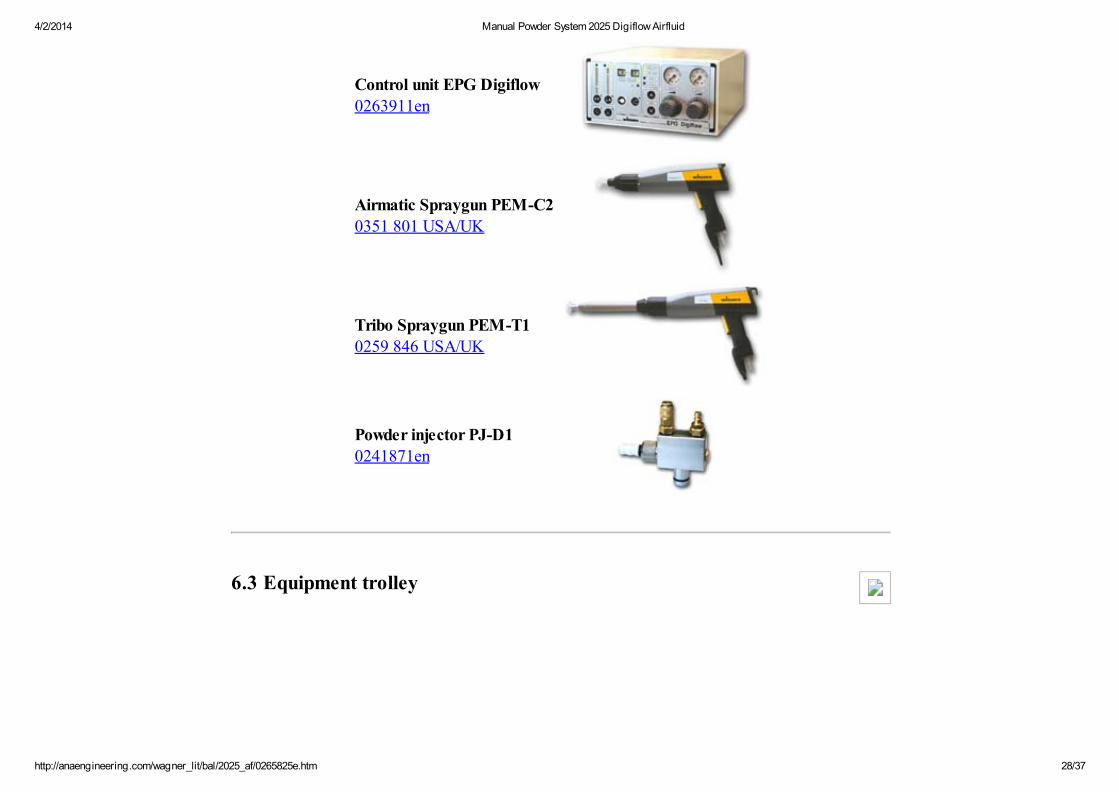
Control unit EPG Digiflow0263911en
Airmatic Spraygun PEM-C20351 801 USA/UK
Tribo Spraygun PEM-T1 0259 846 USA/UK
Powder injector PJ-D10241871en
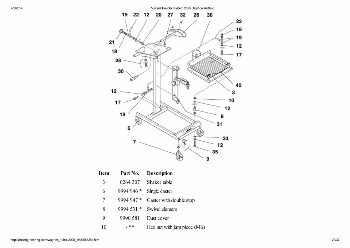
6.3 Equipment trolley
4/2/2014 Manual Powder System 2025 Digiflow Airfluid
http://anaengineering.com/wagner_lit/bal/2025_af/0265825e.htm 29/37
Item Part No. Description
3 0264 307 Shaker table
6 9994 946 * Single caster
7 9994 947 * Caster with double stop
8 9994 531 * Swivel element
9 9990 581 Dust cover
10 - ** Hex nut with jam piece (M6)
4/2/2014 Manual Powder System 2025 Digiflow Airfluid
http://anaengineering.com/wagner_lit/bal/2025_af/0265825e.htm 30/37
11 - ** Filister head screw (M6x40)
12 - ** Serrated lock washer (A6.4)
17 - ** Filister head screw (M6x20)
18 - ** Hex nut (M6)
19 - ** Washer (A6.4)
20 - ** Filister head screw (M6x30)
21 9910 522 Lug nut (M6)
22 - ** Grounding cable (assembly)
26 0264 330 Tubular holder (assembly)
27 - ** Hex bolt (M6x10)
28 9992 741 Fitting straight (R1/4"-D8)
30 - *** Shaker motor (230V/50Hz)
30 - *** Shaker motor (100V/50-60Hz)
30 - *** Shaker motor (120V/60Hz)
31 0264 202 Feed Unit Mount
32 9950 817 Cable socket
33 - ** Washer (6.4)
40 0264 329 Retaining strap
* wear part** no wear part (just for information); not available as spare part!*** ask Wagner service center
6.4 Feed unit mount

4/2/2014 Manual Powder System 2025 Digiflow Airfluid
http://anaengineering.com/wagner_lit/bal/2025_af/0265825e.htm 31/37
Item Part No. Description
1 - ** Bar
2 - ** Guide rod
3 - ** Clamp
4 0236 360 * Pressure piece
5 - ** Adapter plate
9 0264 243 Fluid air valve
11 9991 638 Quick coupling (R3/8)
12 9910 512 Compact control knob
13 9994 110 Handle
15 - ** O-ring (12x2)
16 - ** Dust cover
17 - ** Hex nut (M12)
4/2/2014 Manual Powder System 2025 Digiflow Airfluid
http://anaengineering.com/wagner_lit/bal/2025_af/0265825e.htm 32/37
18 - ** Serrated lock washer (J12.5)
20 - ** Phillips head self tapping screw (4.2x25)
21 - ** Hex bolt (M8x20)
22 - ** Serrated lock washer (A8.4)
25 9990 533 Stop
* wear part** no wear part (just for information); not available as spare part!
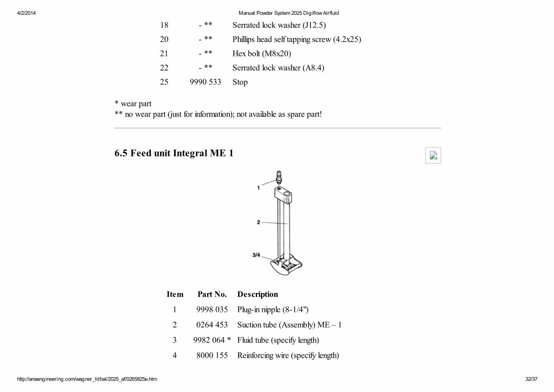
6.5 Feed unit Integral ME 1
Item Part No. Description
1 9998 035 Plug-in nipple (8-1/4")
2 0264 453 Suction tube (Assembly) ME – 1
3 9982 064 * Fluid tube (specify length)
4 8000 155 Reinforcing wire (specify length)
4/2/2014 Manual Powder System 2025 Digiflow Airfluid
http://anaengineering.com/wagner_lit/bal/2025_af/0265825e.htm 33/37
* wear part
7. Specification
Dimensions:
Width: 466 mm
Height: 1182 mm
Depth: 770 mm
Weight: approx. 39 kg
Electrical:
Mains power: * 220 V ... 240 V110 V ... 120 V100 V
Frequency: 50 ... 60 Hz
Input power: max. 130 W
EMI filter: EN 55022 class BVDE 0878 PT3 class B
* For corresponding countries see paragraph 6.2 .
Display:
actual reference
High voltage: 0 ... 100 kV Resolution: 5 kV 1 kV
Corona current: 0 ... 200 µA Resolution: 10 µA 5 µA
4/2/2014 Manual Powder System 2025 Digiflow Airfluid
http://anaengineering.com/wagner_lit/bal/2025_af/0265825e.htm 34/37
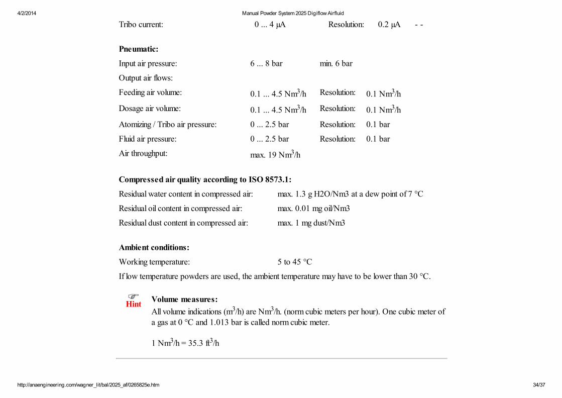
Tribo current: 0 ... 4 µA Resolution: 0.2 µA - -
Pneumatic:
Input air pressure: 6 ... 8 bar min. 6 bar
Output air flows:
Feeding air volume: 0.1 ... 4.5 Nm3/h Resolution: 0.1 Nm3/h
Dosage air volume: 0.1 ... 4.5 Nm3/h Resolution: 0.1 Nm3/h
Atomizing / Tribo air pressure: 0 ... 2.5 bar Resolution: 0.1 bar
Fluid air pressure: 0 ... 2.5 bar Resolution: 0.1 bar
Air throughput: max. 19 Nm3/h
Compressed air quality according to ISO 8573.1:
Residual water content in compressed air: max. 1.3 g H2O/Nm3 at a dew point of 7 °C
Residual oil content in compressed air: max. 0.01 mg oil/Nm3
Residual dust content in compressed air: max. 1 mg dust/Nm3
Ambient conditions:
Working temperature: 5 to 45 °C
If low temperature powders are used, the ambient temperature may have to be lower than 30 °C.
HintVolume measures:
All volume indications (m3/h) are Nm3/h. (norm cubic meters per hour). One cubic meter ofa gas at 0 °C and 1.013 bar is called norm cubic meter.
1 Nm3/h = 35.3 ft3/h
4/2/2014 Manual Powder System 2025 Digiflow Airfluid
http://anaengineering.com/wagner_lit/bal/2025_af/0265825e.htm 35/37
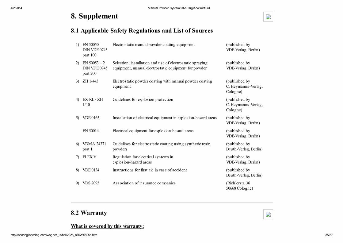
8. Supplement
8.1 Applicable Safety Regulations and List of Sources
1) EN 50050DIN VDE 0745 part 100
Electrostatic manual powder coating equipment (published by VDE-Verlag, Berlin)
2) EN 50053 – 2DIN VDE 0745 part 200
Selection, installation and use of electrostatic sprayingequipment, manual electrostatic equipment for powder
(published by VDE-Verlag, Berlin)
3) ZH 1/443 Electrostatic powder coating with manual powder coatingequipment
(published by C. Heymanns-Verlag, Cologne)
4) EX-RL / ZH1/10
Guidelines for explosion protection (published by C. Heymanns-Verlag, Cologne)
5) VDE 0165 Installation of electrical equipment in explosion-hazard areas (published by VDE-Verlag, Berlin)
EN 50014 Electrical equipment for explosion-hazard areas (published by VDE-Verlag, Berlin)
6) VDMA 24371 part 1
Guidelines for electrostatic coating using synthetic resinpowders
(published by Beuth-Verlag, Berlin)
7) ELEX V Regulation for electrical systems in explosion-hazard areas
(published by VDE-Verlag, Berlin)
8) VDE 0134 Instructions for first aid in case of accident (published by Beuth-Verlag, Berlin)
9) VDS 2093 Association of insurance companies (Riehlerstr. 36 50668 Cologne)
8.2 Warranty
What is covered by this warranty:

4/2/2014 Manual Powder System 2025 Digiflow Airfluid
http://anaengineering.com/wagner_lit/bal/2025_af/0265825e.htm 36/37
Faulty parts are replaced according to our general delivery conditions.
Within the applicable warrant period, Wagner will repair or replace, defective parts without charge ifsuch parts are returned with transportation charges prepaid to the nearest authorized service center. IfWagner is unable to repair this product so as to conform to this limited warranty after a reasonablenumber of attempts, Wagner will provide, either a replacement for this product or a full refund of thepurchase price of this product.
These remedies are the sole and exclusive remedies available for breach of express andimplied warranties.
What is not covered by this warranty:
This warranty does not cover any damage or defects:
1. Caused by use or installation of repair or replacement parts or accessories not manufactured byWagner,
2. Caused by repair performed by anyone other than a Wagner authorized service center, or3. Caused by or related to abrasion, corrosion, abuse, misuse, negligence, accident, normal wear,
faulty installation or tampering in a manner which impairs normal operation.
Limitation of remedies:
IN NO CASE SHALL WAGNER BE LIABLE FOR ANY INCIDENTAL, SPECIAL ORCONSEQUENTIAL DAMAGES OR LOSS, INCLUDING TRANSPORTATION COSTS,WHETHER SUCH DAMAGES ARE BASED UPON A BREACH OF EXPRESS OR IMPLIEDWARRANTIES, BREACH OF CONTRACT, NEGLIGENCE, STRICT TORT, OR ANY OTHERLEGAL THEORY.
Disclaimer of implied warranties:
THE FOREGOING WARRANTIES ARE IN LIEU OF ALL OTHER WARRANTIES, EXPRESSOR IMPLIED, INCLUDING BUT NOT LIMITED TO THE IMPLIED WARRANTIES OFMERCHANTABILITY AND FITNESS FOR A PARTICULAR PURPOSE.

4/2/2014 Manual Powder System 2025 Digiflow Airfluid
http://anaengineering.com/wagner_lit/bal/2025_af/0265825e.htm 37/37
No ability to transfer:
This warranty is extended to the original purchaser only and is not transferable.
Your rights under state law:
Some states do not allow limitations on how long an implied warranty lasts or the exclusion of incidentalor consequential damages, so the above limitation and exclusion may not apply to you. This warrantygives you specific legal rights, and you may also have other rights which vary from state to state.