
2008-2013 Corvette C6 (LS3) Instruction Manual Turbo Systems
93
2 2008-2013 Corvette C6 (LS3) Instruction Manual STS2002 2008 Corvette C6 (LS3) STS2003 2009-2013 Corvette C6 (LS3) STS2002T 2008 Corvette C6 (LS3) STS2003T 2009-2013 Corvette C6 (LS3) 5/21/18 Turbo Systems
-
Upload
khangminh22 -
Category
Documents
-
view
0 -
download
0
Transcript of 2008-2013 Corvette C6 (LS3) Instruction Manual Turbo Systems

2
2008-2013 Corvette C6 (LS3)
Instruction Manual
STS2002 2008 Corvette C6 (LS3) STS2003 2009-2013 Corvette C6 (LS3)
STS2002T 2008 Corvette C6 (LS3) STS2003T 2009-2013 Corvette C6 (LS3)
5/21/18
Turbo Systems

Page 1
2008-13 C6 LS3 Corvette
IMPORTANT: It is the responsibility of the owner of the turbo system to make any necessary upgrades to the
vehicle’s fuel system, engine and drive-train components, etc. to ensure optimal performance and reliability, and
to prevent damage to engine and drive-train components. By installing this turbocharger system, the owner
understands and acknowledges the severity of the vehicle damage that may occur by turbocharging an
improperly modified and tuned vehicle and accepts ALL risk and responsibility.
Our systems are designed for vehicles in good mechanical condition only. Installation on worn or damaged
engines is not recommended and may result in engine failure, for which we cannot be held responsible . STS
Turbo is NOT responsible for the engine or consequential damages. By proceeding with this install you
accept full responsibility for any damage that may occur.
It is also the responsibility of the owner to comply with all emissions laws in their state.
Before you drive your vehicle we recommend:
• Your vehicle be in good running condition
• Change your fuel filter
• Tune-up with spark plugs gapped to .035”
• 91 or higher octane fuel in the tank
• Proper tuning and fuel system modifications
• Install a boost gauge and test boost levels @ 5-6 psi
• Test air/fuel ratios using a wideband O2 gauge (11.5:1 recommended)
• Use caution until you are familiar with the system
Please remember to follow all safety rules that apply when working, including:
• Wear eye protection
• Do not work on a hot engine
• Keep sparks and flames away from your work area - fuel is highly flammable

Page 2
2008-13 C6 LS3 Corvette
Congratulations on your purchase of a STS Turbo System!
We’re confident you’ll be happy with the ease of installation and the performance of the patented remote
mounted STS Turbo System.
The installation is a straight-forward process, but it is critical that you read through ALL of the instructions
carefully. If you do have any issues during the installation process, please contact your local STS dealer where
you purchased the system. If they are not available, please call our customer service department at 1-866-464-
6553. We appreciate your business and would like to hear from you regarding your experience with the STS
Turbo System.
Holley Performance Products, Inc.
1801 Russellville Road
Bowling Green, KY 42101
Phone 866-464-6553 (Toll Free)
Monday through Friday, 8:00am to 5:30 pm and Saturday 8:00am to 2:00pm CST
We encourage you to read this manual completely for a couple reasons:
• Verify the parts list to make certain your kit is complete before starting the installation (See the kits parts page
of this manual). If you discover shipping damage or shortage, please call us immediately.
• Take a look at what is required for tools, time, and experience.
• Review our limited parts warranty.
All STS Turbo Systems are protected by US patent # 7,134,282 and # 6,745,568. Any infringement of patent will
be pursued to the fullest effect of the US patent law.
U.S. Patent No. 6,745,568, Foreign Patents Pending
Page 3
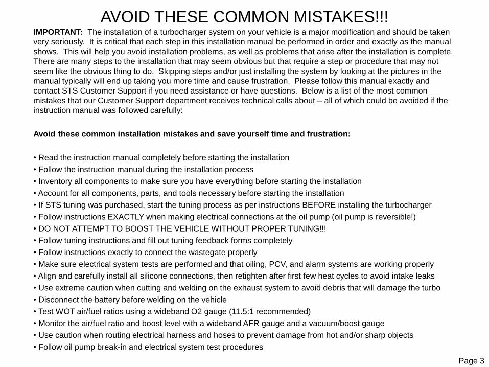
AVOID THESE COMMON MISTAKES!!!IMPORTANT: The installation of a turbocharger system on your vehicle is a major modification and should be taken
very seriously. It is critical that each step in this installation manual be performed in order and exactly as the manual
shows. This will help you avoid installation problems, as well as problems that arise after the installation is complete.
There are many steps to the installation that may seem obvious but that require a step or procedure that may not
seem like the obvious thing to do. Skipping steps and/or just installing the system by looking at the pictures in the
manual typically will end up taking you more time and cause frustration. Please follow this manual exactly and
contact STS Customer Support if you need assistance or have questions. Below is a list of the most common
mistakes that our Customer Support department receives technical calls about – all of which could be avoided if the
instruction manual was followed carefully:
Avoid these common installation mistakes and save yourself time and frustration:
• Read the instruction manual completely before starting the installation
• Follow the instruction manual during the installation process
• Inventory all components to make sure you have everything before starting the installation
• Account for all components, parts, and tools necessary before starting the installation
• If STS tuning was purchased, start the tuning process as per instructions BEFORE installing the turbocharger
• Follow instructions EXACTLY when making electrical connections at the oil pump (oil pump is reversible!)
• DO NOT ATTEMPT TO BOOST THE VEHICLE WITHOUT PROPER TUNING!!!
• Follow tuning instructions and fill out tuning feedback forms completely
• Follow instructions exactly to connect the wastegate properly
• Make sure electrical system tests are performed and that oiling, PCV, and alarm systems are working properly
• Align and carefully install all silicone connections, then retighten after first few heat cycles to avoid intake leaks
• Use extreme caution when cutting and welding on the exhaust system to avoid debris that will damage the turbo
• Disconnect the battery before welding on the vehicle
• Test WOT air/fuel ratios using a wideband O2 gauge (11.5:1 recommended)
• Monitor the air/fuel ratio and boost level with a wideband AFR gauge and a vacuum/boost gauge
• Use caution when routing electrical harness and hoses to prevent damage from hot and/or sharp objects
• Follow oil pump break-in and electrical system test procedures

Picture Key:
1: 3/8” PCV Vent Hoses
2: Stainless Oil Hoses
3: 1/4” Wastegate Hose
4: 3/8” Oil Return Hoses
5: 1/4” BOV Hose
6: Dry Charger Covers
7: Air Filters
8: LH Turbo
9: RH Turbo
10: Wiring Harness
11: Bolt/Hardware Kit
12: T3 Gaskets
13: Oil Adapter Flange
14: Check Valve T
15: LH Oil Pump
16: RH Oil Pump
17: Wastegates
18: 1 PSI Switch
19: PCV Switch Valve
20: Accel Spark Plugs
21: Silicone Hoses
22: Hose Clamps
23: Blow Off Valve (BOV)
Unpack the turbo kit and account for all parts as per Diagram 1. Inspect parts for shipping damage and make sure there is nodebris or packing material in any of the components that could potentially cause damage to the engine and/or turbochargers. It is recommended to blow through all hoses with compressed air to make sure there isn't any debris that could cause engine and/or turbocharger damage.
Diagram 1
Page 4

Unpack the turbo kit and account for all parts as per Diagram 2. Specifically check the insides of ALL tubing for any debris that could potentially enter the engine and/or cause damage to the turbochargers. Unpack all silicone hoses and hose clamps. Organize and match up the hoses with the appropriate clamps as some clamps will fit more than one size of hose.
Picture Key:
1: LH Exhaust Inlet
2: LH Tailpipe
3: LH Wastegate Pipe
4: LH Upper Intake
5: LH Middle Intake
6: LH Lower Intake
7: LH Pipe 1
8: LH Pipe 2
9: LH Pipe 3
10: LH Pipe 4
11: RH Exhaust Inlet
12: RH Tailpipe
13: RH Wastegate Pipe
14: RH Upper Intake
15: RH Middle Intake
16: RH Lower Intake
17: RH Pipe 1
18: RH Pipe 2
19: RH Pipe 3
20: RH Pipe 4
21: Weld-on Exhaust Tips
Diagram 2
Page 5

WASTEGATE INSTALLATION WARNING!
Unpack the wastegate and read the manufacturer’s directions.
The boost hose from the intake manifold must be connected to the Bottom Boost Port fitting on the wastegate. The Top Vent Port on the wastegate must be vented to atmosphere. Applying boost pressure to the Top Vent Port of the wastegate and/or not applying boost pressure to the Bottom Boost Port will cause the wastegate to stay closed and the turbo to over-boost uncontrollably. This will cause IMMEDIATE SEVERE damage to the vehicle’s engine!
It is the responsibility of the vehicle owner to frequently inspect the wastegate and wastegate hoses to ensure that the wastegate hoses are connected properly and in good condition, and that the wastegate is functioning properly. The easiest way to monitor boost levels is with a boost gauge.
Bottom Boost Port
Top Vent Port
The wastegate MUST be connected as shown or IMMEDIATE SEVERE engine damage will result!
Page 6

Page 7
READ COMPLETELY THROUGH INSTRUCTION MANUAL BEFORE STARTING THE INSTALLATION!
Note: It is recommended that the factory ECU be updated at the dealership with the latest factory tune
calibration prior to the installation of the STS Turbo Base Tune. In some cases, older calibrations may not be
compatible with the Diablosport tuner and there may be critical factory updates that need to be applied to your
vehicle. You may be able to contact your dealer with your VIN number and have them check to see if the vehicle
needs critical updates. It is recommended that the STS Turbo Base Tune be installed onto the vehicle prior to
starting the installation process. The STS Turbo Base Tune and the upgraded STS fuel injectors must be
installed together. Do not attempt to start the vehicle with the STS tune and the stock injectors or with the STS
injectors and the stock tune. If you experience any problems with the STS tune loading onto the vehicle, please
contact customer support at 866-464-6553 (Toll Free).
IMPORTANT: Use the provided anti-seize on all of the exhaust related bolts.
NOTE: When installing the intake tubing and hoses, align all hoses so that they are centered over the tube gaps
and position so that pipe gaps are at a minimum. Tighten clamps enough to hold hoses and tubes in place with
clamp bolts positioned for maximum clearance and accessibility. Final tightening of clamps will be done after
assembly is complete.
IMPORTANT: The exhaust components of a turbocharged engine get EXTREMELY HOT and will melt any parts
that are within a few inches of the exhaust system. Make sure that any hoses, wiring, or other components that
could be damaged are mounted away from the exhaust and/or shielded to prevent damage.

Page 8
INTENTIONALLY LEFT BLANK
Page 9
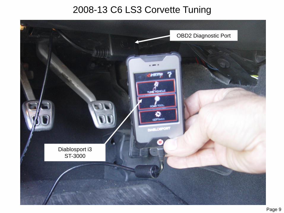
2008-13 C6 LS3 Corvette Tuning
OBD2 Diagnostic Port
Diablosport i3
ST-3000

Page 10
Before starting the tuning process, open your DiabloSport i3 and read through all of the DiabloSport instructions. Once you understand the operation of the i3, proceed with the tuning process.
Connect your DiabloSport i3 to your PC using the supplied USB cable. Once connected, the i3 will boot up and create a new "i3" folder on your PC. Open the "Updater" folder and the appropriate "Windows" or "MAC" folder and click on the "Updater.exe" file or the "IgnitionInstaller.cmd" file. This will run the updater program and load the latest updates onto your i3. When finished, press the "CONTINUE" button on the i3 to reboot the i3. When the i3 has rebooted, disconnect the i3 from your PC.
Once updated, connect your i3 to your vehicle's OBD2 port which is typically located under the driver's side of the dash. Turn your ignition to the "RUN" position with the engine "OFF". Do NOT start the engine. Follow the on-screen prompts as per the DiabloSport instructions and select "YES" to agree to the Diablosport Terms and Conditions. Select "TUNE VEHICLE" and follow the on-screen prompts. Select "ADVANCED TUNE" and then "INSTALL STANDARD TUNE". Select the "STS Turbo Base Tune" and follow the on-screen prompts and select "YES" to install the STS Turbo Base Tune. Follow the on-screen prompts and the device will read, store, and export your factory tune. Once the factory backup process is complete, select "APPLY TUNE" to install the STS Turbo Base Tune. Once complete, turn the ignition “OFF" and follow the on-screen prompts to reboot the i3. Leave the ignition in the "OFF" position during the reboot process and do not start the vehicle until the reboot is complete.
CAUTION: Do not do anything that would disrupt the voltage of the vehicle during the tune writing process or severe damage may occur to the PCM. Do NOT attempt to start the vehicle with the STS Turbo Base Tune installed until the STS fuel injectors have been installed.
(IMPORTANT: DO NOT INSTALL THE DIABLOSPORT TUNING FOR NON TURBOCHARED VEHICLES as these are tunes for a STOCK naturally aspirated vehicle and not a TURBOCHARGED vehicle. In this case, IMMEDIATE and SEVERE engine damage and DRIVABILILTY PROBLEMS may result! Contact STS Customer Support at 866-464-6553 for further information regarding tuning.)
(WARNING: Tuning is critical on turbocharged vehicles and needs to be done carefully. DO NOT BOOST the vehicle until tuning parameters are correct. If the WOT fuelling and/or spark timing parameters are not correct or vehicle is getting detonation, SEVERE ENGINE DAMAGE CAN RESULT!!! PREMIUM FUEL IS REQUIRED!!!)
Page 11
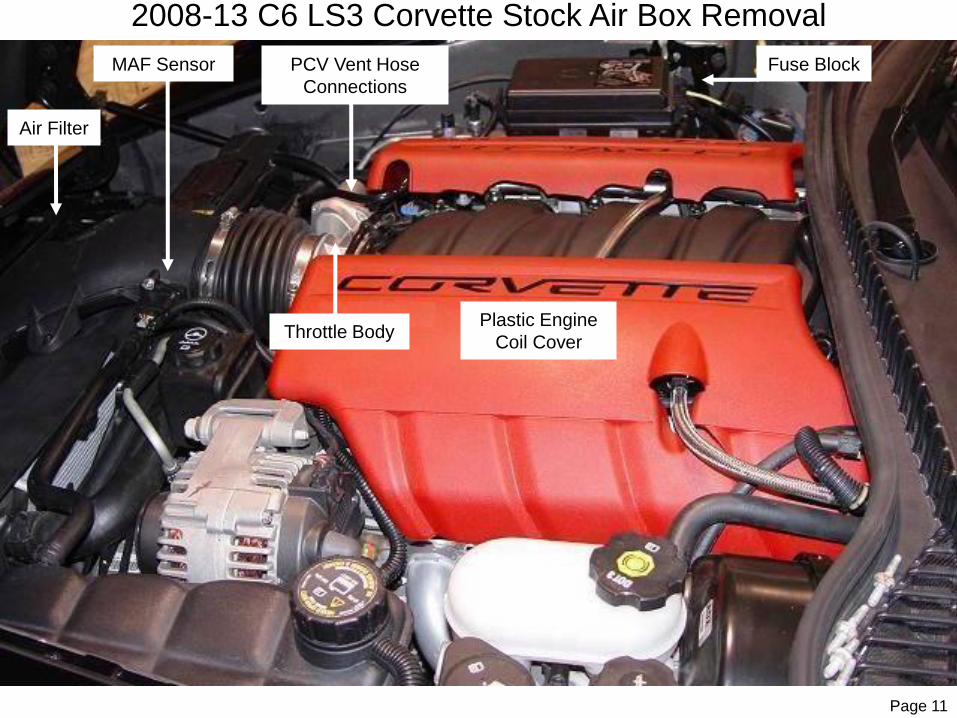
2008-13 C6 LS3 Corvette Stock Air Box Removal
Throttle Body
Air Filter
MAF Sensor PCV Vent Hose
Connections
Plastic Engine
Coil Cover
Fuse Block

Page 12
Remove the PCV vent hose that runs from the intake duct just in front of the throttle body over to the valve cover by releasing
the lock tabs on the connectors.
Unplug the MAF sensor electrical connector.
Remove the air box and intake ducting from the air filter to the throttle body. Remove the MAF sensor from the intake ducting.
The MAF sensor should be clean and free of oil and contamination (clean sensor if necessary with MAF sensor cleaner) and set
aside.
Remove both of the plastic engine/coil covers.

Page 13
#2 Injector Plug
Blue Pigtail
#2 Injector
Injector Common Power Wire
2008-13 C6 LS3 Corvette Injector Power Wire
Page 14
Unplug the #2 injector plug from the injector on cylinder number 2 (this is the passenger side front cylinder). The common power wire will be the same color wire on all of the injectors. Find this wire on the #2 injector then probe it with a test light. Start the car. The test light should light up with the car running and remain on for approximately 2 seconds after the ignition is turned off.
Once the correct wire is located connect the provided BLUE pigtail wire marked IGN 12V by stripping off about 1/4” of the insulation from the injector power wire. Solder the provided BLUE pigtail wire onto the injector power wire for a permanent connection and wrap the connection with high quality electrical tape.
Page 15
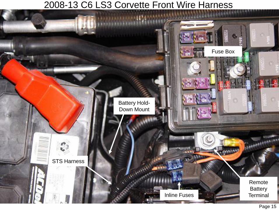
2008-13 C6 LS3 Corvette Front Wire Harness
Fuse Box
Inline Fuses
Remote
Battery
Terminal
Battery Hold-
Down Mount
STS Harness

Page 16
Disconnect both positive and negative leads from the battery.
Remove the battery from the car.
Open the fuse box lid and remove the factory nut from the remote battery terminal on the fuse box. Install the 2 RED inline-fused wires with the large ring terminals marked 12V BATT from the STS wiring harness onto the remote battery terminal as shown in the above diagram. Reinstall the factory nut and install the fuse box lid. Leave the 15 amp inline fuses out at this time.
Route the STS harness towards the firewall and secure the STS relays to the factory wiring harness under the passenger’s side
hood latch using the provided nylon ties.
Route the front section of the STS harness with the GROUND, PCV SWITCH and BLUE wires under the fuse box, along the
factory A/C lines, and toward the front of the engine compartment to just behind the radiator support bolts.
Leave the rear section of the STS harness with the 4 pin plugs coiled on the top of the engine at this time.
(IMPORTANT: Route and secure the harness so that it does not come in contact with any Hot, Sharp or Moving
objects.)

Page 17
2008-13 C6 LS3 Corvette Wiring Harness
Factory Ground Terminal
RED PCV SWITCH Wire
Blue IGN 12V Wire
(do not connect)
STS Harness

Page 18
Remove the factory ground terminal nut located on the top of the passenger side frame rail near the side of the radiator cover.
Install the BLACK GROUND wire from the STS harness onto the factory ground terminal as shown in the above diagram and
secure with the factory nut.
Route the BLUE IGN 12V wire to the previously installed BLUE pigtail on the #2 injector but do not install at this time. This
connection will be made at the end of the installation process.
Allow the RED PCV SWITCH wire to hang loose in the position shown in the above diagram.

Page 19
2008-13 C6 LS3 Corvette Oil Alarm Buzzer
Oil Alarm Buzzer
Electrical Harness
Outer Grommet
Electrical Harness
Inner Grommet

Page 20
From inside the passenger side of the vehicle, pull back the top of the floor mat and remove the kick panel below the glove box
to allow access to the firewall. Pull back the rubber backed insulation to expose where the factory wiring harness goes through
the firewall grommet. This is a 2 piece grommet with the inner piece being a thick rubber circle which can be removed from the
outer grommet. This thick circle can be difficult to run wires through so it is recommended that you pull the entire grommet
assembly out of the firewall. Peel the outer grommet off of the inner piece and then pull the inner piece out away from the outer
grommet. Carefully cut a U shaped slot in the lower portion of the outer grommet just below where the factory harness goes
through the firewall. Replace the outer grommet back into the firewall.
From the engine bay, remove the red ALARM buzzer from the STS harness and route this ALARM section of the harness
through the hole in the firewall grommet and into the passenger compartment as shown in the above diagram.
(Note: This is also a good place to route the vacuum/boost hose through for a boost gauge. This is a good time to
install any gauges or accessories which require routing through the firewall. It is recommended to install a
vacuum/boost gauge in ALL turbocharged vehicles so that the boost level can be constantly monitored to prevent any
over-boost conditions. A wideband air fuel ratio gauge is also recommended to be able to constantly monitor the air
fuel ratio to prevent lean conditions under boost. An over-boost or Lean condition can cause IMMEDIATE SEVERE
ENGINE DAMAGE! It is the responsibility of the owner/operator to constantly monitor boost, air fuel ratio and tuning
parameters to prevent engine damage.)
From inside the passenger compartment, install the alarm buzzer back onto the white and blue ALARM wires with the white wire
on the negative side and the blue wire on the positive side (The positive terminal is coated RED). Use the provided nylon tie to
secure the alarm buzzer under the dash in a location that allows the buzzer to be unobstructed so the driver can hear the alarm,
while making sure that it clears any sharp and/or moving objects.
Replace the insulation and reinstall the kick panel.

Page 21
2008-13 C6 LS3 Corvette Valve Cover Removal
Coil Pack Spark
Plug Wires
5 Coil Pack
Bracket
Studs
Coil Pack Connector

Page 22
Carefully remove the spark plug wires from the coil packs and spark plugs. Twist the spark plug wire boots to loosen the boot from the spark plug and the coil prior to pulling the connection apart. Unplug the coil pack electrical connector. Remove the 5 studs from the coil pack mounting brackets. Remove coil pack mounting bracket with coil packs still attached and set aside.
Remove the stock spark plugs and replace with new Accel spark plugs 0524-4 (pack of 4) gapped at .035”. Use a small amount of anti-seize compound on the spark plug threads and torque to factory recommended specs.
Remove the 4 valve cover bolts and carefully pull the valve covers off without damaging the gaskets.
(Note: The valve cover gasket can typically be cleaned and reused. If gasket is damaged, replace with new gaskets from Mr. Gasket P/N 61040G.)

Page 24
2008-13 C6 LS3 Corvette Valve Cover Modifications
Page 23
Bend Baffle Here To Seal Against Cover
Same View For LH and RH Valve Cover

Page 24
After removing both valve covers, make sure to cover the valve train with a clean cloth to prevent debris from getting into the engine. Turn the valve covers over and cut the baffle back just enough to expose the location of the new oil return fitting to be installed. Cut slots in the baffle and bend the end of the baffle down as shown in the above diagram so that it seals against the valve cover to isolate the returning oil from the PCV venting. This will prevent oil from getting on top of the baffle and allow oil to flow freely back into the engine.
(IMPORTANT: The oil return fitting on the passenger’s side will return to the rear of the valve cover – the opposite end as the valve cover vent tube. The oil return fitting on the driver’s side will return to the front of the valve cover – the opposite end as the valve cover vent tube. Both valve covers will look the same as the picture in the diagram.)
Clean off any of the sealant used to seal the baffle to the valve cover.
Mark and drill a 7/16” hole in the top rear of each valve cover at the location shown in the above diagram. Carefully tap the valve cover using the ¼” NPT tap provided.
Use an appropriate cleaner such as “Brake Parts Cleaner” to flush out any debris in the valve cover, including the baffled part of the valve cover. Thoroughly deburr and clean the new hole and valve cover of all metal shavings. Then use compressed air to blow out the valve cover and baffle entirely.
(WARNING: ANY METAL SHAVINGS LEFT IN VALVE COVER CAN CAUSE SEVERE ENGINE DAMAGE!)
Wrap the threads on the 90 degree #6 AN fitting with the thread tape and install into each valve cover with the fitting pointingtoward the rear of the engine. Clean the gasket surfaces, remove any protective cover put over the valve train, and inspect to make sure no foreign debris entered the engine. Reinstall both of the valve covers and torque hardware to factory specs.
Install one steel AN swivel adapter fitting into each of the 150 inch long 3/8” Push-Lock hoses. Cover the other end of each hose with tape to prevent debris from entering. Route the taped end of the hoses behind the engine, on the top of the bell housing towards the ground staying away from hot, sharp, or moving objects. Install the fittings onto each of the valve cover oil return ports, but do not tighten at this time. Make sure that both return lines are free of any obstructions and are not pinched or kinked in any way.
Leave the coil packs off at this time.

Page 25
2008-13 C6 LS3 Corvette Injectors
8” PCV Vent Hose
Fuel Rail
Fuel Rail Mounting Bolts
Fuel
Injectors Fuel Injector
Connector
Rear Fuel Rail Brackets
Fuel Rail
Pressure
PortBracket Bolt

Page 26
WARNING: Any fire or smoking is absolutely prohibited during this process. Use extreme caution as fuel hoses and lines are pressurized and will leak when disconnected. Take all necessary precautions when servicing pressurized fuel lines and working with open fuel containers!
Depressurize the fuel system by removing the cap on the front of the driver’s side fuel rail and depressing the Schrader valve at the fuel pressure port shown in the above diagram. Drain the pressurized fuel in to a suitable container. Once the pressure isout of the fuel system, replace the protective cap on the fuel rail.
Make sure that the intake manifold is clean around the fuel injectors so that no debris can fall into the intake manifold. Any debris that gets into the intake manifold could cause immediate SEVERE engine damage!
Referring to the above diagram, remove the wiring harness mounting connectors from the LH fuel rail studs. Disconnect the 8 fuel injector harness electrical connectors from the fuel injectors. Remove the front bolts from the rear fuel rail brackets and loosen the rear bolts completely so that the brackets can be swivelled out of the way to access the fuel rails and fuel rail bolts.
Remove the 4 fuel rail mounting bolts/studs. Remove the bolt and bracket shown in the diagram. Remove the fuel rails and 8 injectors from the intake manifold, taking care that no debris falls into the holes in the intake manifold. Remove the metal fuel injector retaining clips from each of the injectors. Using a small container to catch the fuel, remove each fuel injector one by one and drain the fuel into the container. Make sure that the O-ring seals come out of the manifold and the rail with the injectors.
Install the metal retaining clips onto the new fuel injectors at the same location which they came off of the factory injectors.Lubricate the upper and lower seals on the new injectors with silicone grease provided and carefully insert the injectors into the fuel rails until the metal retaining clips lock onto the rail.
Clean each of the injector ports in the rails to prevent any dirt or debris from entering the manifold or damaging the O-ring. Reinstall the fuel rails onto the intake manifold making sure not to damage the injector seals as the injectors fit into the manifold ports. Reinstall the fuel rail bolts and reinstall the fuel rail brackets and torque hardware to factory specifications. Reconnect the injector electrical harness connectors.
Install the coil packs in reverse order of removal and make electrical connections. Wipe a small amount of dielectric grease into the spark plug boots then install the spark plug wires onto the new spark plugs and coils.
(Note: Once the injectors have been installed, the STS Tune must be loaded onto the vehicle prior to starting the vehicle. Do NOT attempt to start the vehicle until the STS Turbo Base Tune has been installed.)

Page 27
2008-13 C6 LS3 Corvette PCV Check Valve
PCV Check
Valve is
Pre-Installed
Factory Molded
PCV Hose
(Lower Port End)
Molded PCV Hose
Factory Molded
PCV Hose
(Manifold Port End)

Page 28
Remove the molded factory plastic PCV hose between the intake manifold port directly behind the throttle body and the crank
case vent port under the intake manifold by releasing the clip locks at each fitting. Note the direction which the hose was
installed from the factory.
Clean the hose port and intake manifold port of any oil. Install the new PCV hose with pre-installed check valve onto the vent
port and the intake manifold port as shown in the diagram and secure the hose to the intake manifold port with the small hose
clamp provided.
(NOTE: This valve will prevent the flow of boost from the intake manifold into the crank case, but will allow the proper
venting of crank case gasses to flow through the check valve into the intake manifold.)
Recheck the wiring and hose routing under the hood to make sure all hoses and wires are routed properly and cannot be damaged by hot, sharp, and/or moving objects. Do final tightening of all hose clamps and brackets.

Page 29
2008-13 C6 LS3 Corvette PCV
1# Pressure Switch
BROWN Jumper Wire
16” Hose To Switch Valve PCV Hump Hose
STS
Harness
8” Hose To RH Valve
Cover Vent Fitting
PCV Switch Valve BLUE Wire to Fuel Injector

Page 30
Bolt the PCV switch valve to the front of the passenger’s side cylinder head as shown in the above diagram using the 10mm x
20mm bolt and lockwasher supplied.
Connect the 8” long 3/8 inch hose from the PCV vent port on the passenger’s valve cover to the single port on the side of the
PCV Switch Valve and secure with the clamps provided.
Install the 1 PSI pressure switch into the 1/8” NPT brass T fitting middle port. Install the 1/8” NPT brass 90 degree hose barb
into the end port of the T fitting as shown in the diagram. Install the remaining 1/8” NPT brass straight barb fitting into the
remaining open end of the brass T fitting.
Connect the 1.5” long 3/8 inch hose onto the 90 degree fitting on the pressure switch assembly and secure with a hose clamp.
Cut a 16” long piece off of the 24” long 3/8 inch hose and connect the 16” long 3/8 inch hose to the straight fitting on the
pressure switch assembly. Install the pressure switch assembly as shown with the short hose connected to the port on the PCV
switch valve closest to the metal switch valve body (on dual port side) and secure the hoses with hose clamps.
Route the 16” long 3/8 inch hose under the switch valve to the under side of the throttle body.
Route the RED PCV SWITCH wire from the STS harness to one of the terminals on the 1 PSI pressure switch. Connect one
end of the short BROWN jumper wire to the other terminal on the pressure switch. Connect the other end of the short BROWN
extension wire to the terminal on the PCV Switch Valve. Secure the harness with the provided nylon ties away from any HOT,
SHARP, and/or MOVING objects. Leave the protective rubber cap off at this time.
For RACE-ONLY systems, install the small filter onto the remaining port of the 3 port PCV Switch Valve as shown. For CARB
Emissions certified systems, install the 180” long 3/8” emissions hose onto the remaining port of the 3 port PCV Switch Valve
and secure with the hose clamp provided. Cover the open end of the emissions hose and route this emissions hose along the
frame rail and the STS wire harness towards the rear passenger’s side of the engine bay. Drop the hose down behind the
battery area and behind the RF wheel near the fender.
Page 31
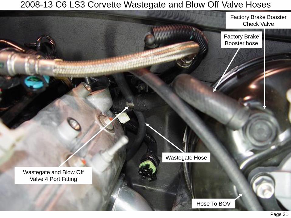
2008-13 C6 LS3 Corvette Wastegate and Blow Off Valve Hoses
Wastegate and Blow Off
Valve 4 Port Fitting
Wastegate Hose
Factory Brake
Booster hose
Factory Brake Booster
Check Valve
Hose To BOV

Page 32
Cut the factory brake booster hose near the rear of the engine as shown in the above diagram and install one of the provided #6
clamps onto each section of the factory brake hose. Pivot the brake booster section of the hose out of the way.
Install the 124” long ¼ inch wastegate hose onto one of the small ports of the 4 port X fitting and secure with one of the small
hose clamps provided. Cover the open end of the WG hose and route the wastegate hose down along the firewall behind the
engine along the driver’s side of the rear of the engine. The WG hose should exit under the vehicle just behind the engine at
this point.
Install the large port of the X fitting into the engine side of the brake booster hose and secure with the clamp.
From the passenger’s side of the engine compartment, route the section of the STS wiring harness with the 2 quick connectors
around the rear of the engine toward the brake booster as shown in the diagram. Route the connectors down past the firewall
along with the WG hose under the vehicle and leave hanging loose at this time.
(NOTE: If you have difficulty getting the connectors down the firewall, the rear K-member nuts can be removed which
will allow the rear of the engine to drop about ½ inch and give more clearance between the body and the clutch bell
housing.)
Install the remaining large port on the X fitting into the other section of the brake booster hose and secure with the clamp.
Install the 60” long ¼ inch BOV hose onto the remaining small X fitting port and secure with a small hose clamp. Route the
BOV hose toward the front of the vehicle along the driver frame rail and over in front of the radiator.
(IMPORTANT: Use caution when routing the wastegate and BOV hoses. Make sure that all hoses are routed away
from any HOT, SHARP, and/or MOVING objects which could damage the hoses. If this hose gets damaged, it can
cause the turbo to boost uncontrollably and cause SEVERE and IMMEDIATE engine damage! Inspect this hose
frequently and monitor boost levels at all times to prevent accidental over-boost conditions.)
Page 33
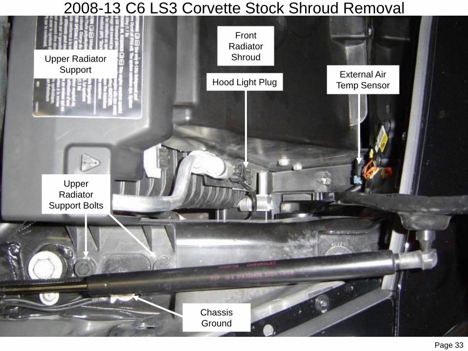
2008-13 C6 LS3 Corvette Stock Shroud Removal
External Air
Temp Sensor
Chassis
Ground
Hood Light Plug
Upper Radiator
Support
Upper
Radiator
Support Bolts
Front
Radiator
Shroud
Page 34
Unplug the external air temperature sending unit from the passenger’s side of the front radiator shroud next to the horns as
shown in the above diagram. Remove the 4 bolts that secure the plastic upper radiator support then unclip the coolant hoses
and remove the upper support.
Remove the 2 push connectors that secure the front radiator shroud to the air conditioning condenser brackets (one on each
side). Remove the hood light electrical connector from the radiator shroud.
(NOTE: This plug may be terminated from the factory and not actually be plugged into a light on the hood.)

Page 35
2008-13 C6 LS3 Corvette RH Air Intake #1
RH Air Intake Pipe
Mounting Bolt &
Fender Washer
STS Air Filter
RR Outer Tail
Light Harness
RR Outer Tail
Light Hole

Page 36
Remove the 4 screws retaining the 4 tail lights and remove the tail light assemblies. Remove the factory bolt as shown in the
above diagram.
Install the Right Air Intake #1 tube (STS2000-SS02) into the tail light cavity (mounting bracket first – then short end – followed
by the large end) and secure to the body using the 6mm x 25mm bolt, lock-washer, and fender-washer supplied, as well as
using 3 additional flat-washers for spacers between the pipe bracket and the body as shown.
(NOTE: Factory wiring can be adjusted out of the way as to not interfere with the intake pipes.)
Install the new STS air filter onto the expanded end of the air intake pipe as shown in the diagram.
Repeat this process to install the Left Air Intake #1 tube (STS2000-SS01) and STS air filter.
The Dry Charger filter covers can be installed at this time if desired or can be installed at a later date by removing the tail lights.
Reinstall the tail lights.
(NOTE: Air filter covers are supplied with the turbo system and can be installed on the air filters for added protection
against dust and wet weather. They have a water-resistant coating which repels water. This coating is not permanent
and will wear off. Washing the covers with strong chemicals will decrease the effectiveness of the covers. We
recommend periodically cleaning with water and/or a very mild soap.
(NOTE: Because of the lack of moving air under the vehicle during dyno testing, it is recommended to leave the tail
lights out during dyno testing to allow the filters to be able to draw fresh cool air in.)
Taking all necessary precautions recommended by the vehicle manufacturer and the equipment manufacturer, raise the vehicle
on a suitable vehicle hoist to allow access to the under-side of the vehicle.
(IMPORTANT: Before lifting the vehicle, read through the instruction manual and review the illustrations as to the
work that will need to be performed while on the vehicle hoist. It will be necessary to place the hoist arms in specific
locations to allow access to specific areas of the vehicle to facilitate the installation and to prevent having to readjust
the location of the hoist lift points during the installation. Always use appropriate lifting equipment, jack stands, or
vehicle support equipment as well as proper lift points and take necessary precautions to prevent accidental damage
to the vehicle and/or personal injury!)

Page 37
2008-13 C6 LS3 Corvette Front ValenceValence Nut
Side Air Dam
and Brake Duct
Front Valence ScrewsValence Nut
Front Fender Liners
Air Dam
Lower Panel

Page38
Remove all 4 wheels from the vehicle.
Remove the 5 screws and the 2 outer nuts securing the lower valence as shown in the above diagram. Remove the 3 bolts to
remove the lower center panel.
(NOTE: The center panel will not be reinstalled.)
Remove the 4 push connectors to then remove the front air dam (passenger’s side first). Remove the 2 screws securing the
lower brake duct inlets (leave the outer air dam attached to the brake duct inlet) and remove the brake cooling duct, duct inlet
and lower side air dam as one assembly. Repeat to remove the other side.

Page 39
2008-13 C6 LS3 Corvette Front Air Duct
Radiator Fan
4 Air Duct Screws
Lower Front Valence
Air Duct Grill

Page 40
Pull the lower front valence down and remove the 4 screws from on top of the plastic duct between the front shroud and the grill
as shown in above diagram. Remove the 2 push connectors at each side to release the duct from the outer edge of the grill
then remove the 2 rear push connectors to release the duct from the shroud and remove the ducting.
(NOTE: The plastic center air duct will not be reinstalled.)
Carefully remove the external air temperature sensor from the radiator shroud.

Page 41
2008-13 C6 LS3 Corvette Horn Relocation
Lower Radiator
Support
Factory
Horns
Diagram 9
Horn
Bracket Bolt
External Air Temp Sensor
1/8” Water Drain
Hole Drilled
Page 42
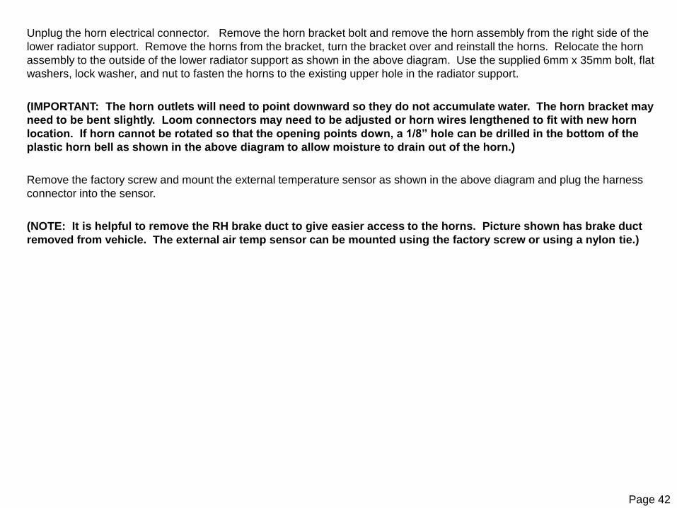
Unplug the horn electrical connector. Remove the horn bracket bolt and remove the horn assembly from the right side of the
lower radiator support. Remove the horns from the bracket, turn the bracket over and reinstall the horns. Relocate the horn
assembly to the outside of the lower radiator support as shown in the above diagram. Use the supplied 6mm x 35mm bolt, flat
washers, lock washer, and nut to fasten the horns to the existing upper hole in the radiator support.
(IMPORTANT: The horn outlets will need to point downward so they do not accumulate water. The horn bracket may
need to be bent slightly. Loom connectors may need to be adjusted or horn wires lengthened to fit with new horn
location. If horn cannot be rotated so that the opening points down, a 1/8” hole can be drilled in the bottom of the
plastic horn bell as shown in the above diagram to allow moisture to drain out of the horn.)
Remove the factory screw and mount the external temperature sensor as shown in the above diagram and plug the harness
connector into the sensor.
(NOTE: It is helpful to remove the RH brake duct to give easier access to the horns. Picture shown has brake duct
removed from vehicle. The external air temp sensor can be mounted using the factory screw or using a nylon tie.)

Page 43
2008-13 C6 LS3 Corvette Intercooler
4 Radiator
Support Bolts
Lower Front Valence
Diagram 10
Intercooler
Intercooler Bolts

Page 44
Loosen the 4 lower radiator support mounting bolts shown in the above diagram. Remove the bolts one at a time and install 4
of the 3/8” flat washers between the frame and the radiator support on the rear bolts and 2 of the 3/8” flat washers between the
frame and the radiator support on the front bolts. This will lower the radiator cradle approximately ¼” to give adequate
clearance for Intake #5 tube where it crosses over the radiator. Once all the spacers have been installed, tighten the support
mounting bolts.
(NOTE: Use caution when removing and installing the rear radiator cradle bolts as the flat washer on the bolt must
remain in the groove near the upper surface or it can cause the bolt to cross thread into the frame.)
Pull the valence down and install the intercooler as shown. Hold the intercooler up snugly against the bottom of the front cross
member. Do NOT center the intercooler. For added clearance between the silicone intercooler hose and the oil cooler hoses,
the intercooler can be mounted toward the driver’s side of the vehicle 1/8 to 1/4”. The silicones will pass between the radiator
and the radiator cradle. Line up the intercooler inlets with the gaps between the radiator and the radiator cradle. Mark the
location of the 2 mounting holes through the intercooler brackets onto the cross member. Remove the intercooler.
(IMPORTANT: The intercooler can be lowered to rest against the radiator support to allow sufficient room to drill and
tap the mounting holes. If cooler is left in place, BEFORE DRILLING HOLES - COVER THE INTERCOOLER OUTLET
PORT to prevent debris from entering the intercooler.)
Center punch and drill the holes with a 5mm drill bit then tap to 6mm x 1.0 with the drill and tap supplied. Use lubrication on the
tap. Reinstall the cooler and secure to the cross member with the 6mm x 20mm bolts, lock washers, and flat washers supplied.
Torque to no more than 45 inch pounds as the cross member can strip threads easily.
Install the 1.75” x 10” silicone hose and 2 hose clamps onto the driver’s side inlet of the intercooler and secure with the hose
clamp. Install the 1.75” x 9” silicone hose and 2 clamps onto the passenger’s side inlet of the intercooler and secure with the
hose clamp.

Page 45
INTERCOOLER INSTALLATION WARNING!
The installation of an intercooler is a great addition to any turbocharger system and can dramatically increase the efficiency, power, and reliability of your turbocharger system by lowering intake temperatures and creating a denser intake charge. There is, however, a slight possibility that under some very specific conditions that water may accumulate in the bottom of the intercooler. Because of the cooling and condensing effect of the intercooler on the air inside the cooler during some driving conditions as well as after the engine has been shut off, accumulation of liquid inside the intercooler can occur. Due to the airflow characteristics of an intercooler, the airflow through the bottom of the core may not be enough to keep this liquid cleared out and could allow it to build to a substantial level. If this occurs, this liquid could be pulled up into the engine during a high airflow demand. A large amount of liquid can cause a hydra-lock condition which will cause IMMEDIATE SEVERE damage to the engine as the engine will not be able to compress the liquid during the compression stroke which will cause a mechanical failure of the engine components. Conditions that could cause this problem would be extreme wet driving conditions, submerging the air intake system in water, high humidity and/or extreme temperatures.
The possibility of this rare condition can be greatly reduced and/or prevented. It is highly recommended that you perform one of the following methods:
1- Regularly inspect the intake system and intercooler for signs of water accumulation and clean out any water and/or oil (fluid) that is found inside the intake system.
2- Drill a 1/8” hole in the rear-bottom corner of the center intercooler tank and install a small sheet metal screw that can be removed on a regular basis to inspect for liquid accumulation inside the intercooler and allow that fluid to be drained from the cooler. (NOTE: The cooler will only drain when you physically remove this screw. If left unchecked, it could accumulate enough liquid inside the cooler to cause engine damage.)
3- Drill a small 1/16” hole in the rear-bottom corner of the center intercooler which will allow the boost pressure within the intercooler to automatically purge any liquid from the system through the hole. (NOTE: This small hole will not allow enough airflow to pass through it to affect performance but should allow any fluid in the system to automatically drain. There is a risk that the hole could become plugged so it is recommended that the hole be checked to make sure it remains clear periodically.)
(NOTE: There is a remote possibility that this condition could occur in the intake tubing of the turbocharger system without an intercooler. The above precautions could be taken by drilling a small hole in the lowest point of the turbocharger intake tubing as described in step 2 or 3.)

Page 46
Page intentionally left blank

Page 47
2008-13 C6 LS3 Corvette Front Radiator Shroud
Cut Off Front
Extensions
Notch Here
Cut Hole Here
Slots Extended
A
B
2008-13 C6 LS3 Corvette Front Radiator Shroud

Page 48
The radiator shroud must be reinstalled to aid the engine’s cooling system. Once modified, the radiator shroud can be installedfrom under the hood and carefully slipped down into place.
Lower the vehicle to access under the hood. Install a clean rag into the intercooler outlet to prevent debris from entering theintercooler. Trim the shroud as shown in the above diagram. It is best to take small amounts off and test fit with each small amount taken off rather than take too much off the first time. Try to make the hole in the center fit as tightly as possible to Intake #5 tube so that the maximum amount of air will pass through the radiator. Both sides of the shroud will need to be trimmed the same.
The shroud will have to be notched at the leading edge for clearance at the intercooler brackets. Once the shroud is close, install the shroud and test fit Intake #5 tube between the intercooler and the throttle body and make any necessary modifications. When modifications are close, install the 3.5” x 3” silicone and 2 clamps onto the intercooler outlet and securethe lower hose clamp. Trim the shroud as necessary so the shroud clears the silicone. Once the shroud modifications are finished, install the two push connectors to secure the shroud to the AC condenser.
Install the MAF sensor into Intake #5 tube using the supplied 4mm bolts, and then install Intake #5 tube for final adjustments to the shroud. Line up Intake #5 tube to make sure it fits, but do not install the silicone at the throttle body at this time.
(NOTE: Make sure flow direction arrow on the MAF sensor is pointing toward throttle body. Do not connect the MAF sensor electrical connector at this time.)
Locate the factory notches in the rear of the plastic upper radiator support bracket. Cut both notches deeper as shown in the
above diagram allowing the radiator hold down to be lower when installed.

Page 49
2008-13 C6 LS3 Corvette Shroud, Intake #5 and BOV
Throttle
Body
Intercooler
Mounts
MAF Sensor
Blow Off
Valve
Radiator
Mount Spacer
Bent Radiator Lip
Radiator Shroud
Reinstalled w/
Additional
Trimming
Radiator
Mount Spacer

Page 50
Rotate Intake #5 tube out of the way as shown in the above diagram.
Carefully bend the front upper aluminum lip of the radiator rearward and down with a small adjustable wrench to allow adequate
clearance for Intake #5 tube as shown in the above diagram.
(IMPORTANT: Be careful not to damage the radiator.)
Install the two supplied blue radiator spacer bushing under the factory upper radiator rubber mounts as shown in the diagram.
Re-install the plastic upper radiator support bracket and secure with the 4 factory bolts. Install the coolant hose into the support
bracket clips.
Read the Blow Off Valve instructions that came with the BOV. Install the O-ring onto the small V-band flange on the front side of
Intake #5 tube then install the BOV and secure with the V-band clamp. Install the hose barb fitting onto the top of the BOV and
the NPT fitting into the open port which won't be used. Secure to the BOV with the fitting port facing toward the driver’s side of
the vehicle.
Install the 3/8” 90 degree dual hose barb fitting into the port on the 4” x 3.75” silicone hump hose along with 2 clamps and install
the large end onto the throttle body. Rotate the barb fitting to point between the water pump pulley and tensioner pulley and
secure with clamp. Swivel Intake #5 tube to align the outlet with the throttle body. Use a smooth hook tool to work the silicone
over the outlet of Intake #5 tube as you slip it into place. Center Intake #5 tube between the intercooler and the throttle body
and secure in place with the clamps at the throttle body and the intercooler silicones. Plug in the MAF sensor connector.
Connect the previously installed 16” long 3/8 inch hose to the 90 degree hose barb at the throttle body silicone hump hose and
secure with a small clamp.
Route the BOV hose over to the BOV, cut to length, and install onto the fitting and secure with a small clamp.
(NOTE: High altitude BOV springs may be required for proper BOV response for elevations over 4000 feet.)
(IMPORTANT: Use caution when routing the wastegate and BOV hoses. Make sure that all hoses are routed away
from any HOT, SHARP, and/or MOVING objects which could damage the hoses. If this hose gets damaged, it can
cause an over-boost condition which can cause SEVERE and IMMEDIATE engine damage!)

Page 51
2008-13 C6 LS3 Corvette Front Bumper Cover
Optional
Large Oil
Cooler
Cut Out In Lower
Valence
Modified Radiator
Shroud
Valence Mount
Lower Radiator
Support Bracket

Page 52
Install the 2 plastic push connectors to secure the radiator shroud to the front cross member.
(NOTE: On models with a factory oil cooler: Carefully bend the top oil cooler line to allow more clearance for the
silicone hose. Carefully cut a notch in the radiator shroud to allow the line to be pulled over closer to the radiator.
Reinstall the metal retaining clips and the oil cooler lines.)
Using a suitable cutting device, cut a notch out of each side of the lower front valence as shown in the above diagram so that
the edges match up when the lower valence is secured to the mount.
Install the center air dam onto the lower radiator support by inserting the driver’s side first, and then pushing the piece into
place. Secure the center air dam with the 3 factory bolts and the two plastic push connectors.
Reinstall the screws to secure the front lower valence to the mounts shown in the diagram.
Reinstall the brake ducts and front lower air dam assemblies. Line up the locator tabs into the slots on the lower brake duct
inlet. Install the front inner fender liner, the air duct inlet, and the lower valence holes over the stud. Secure the two screws and
the lower valence nut on each side. Install the 2 push connectors to secure the outer air dams to the center air dam.

Page 53
2008-13 C6 LS3 Corvette Exhaust System Removal
Differential
4 Rubber Exhaust Mounts
K-Member
Nuts
Sway Bar Bracket
Rear K-Member
Brake Duct
Fender Liner
Transmission
Vacuum Lines
Front Heat Shield Bolts

Page 54
With the vehicle raised, remove the splash shields at the rear of the front fender wells.
Remove the rear wheel well liners. Remove the rear brake ducts and the insulation packs from the rocker panels.
Loosen the factory exhaust clamps that secure the mufflers to the H-Pipe and remove the 2 sprung exhaust hanger nuts just in
front of the transmission.
Remove the factory H-Pipe front flange bolts to lower the front of the H-Pipe and disconnect the rear O2 sensors. Label the
connectors L & R. With help from an assistant, pull the H-Pipe out of the mufflers and remove from the vehicle.
Remove the vacuum lines from the exhaust valve actuators on the rear of the mufflers (if equipped).
Remove the 4 rear sway bar bracket bolts/nuts from the rear K-Member. Pull the sway bar back and off the bolt, and then lower
it down out of the way. Remove the rear rubber hangers from the mufflers and then remove the mufflers from the vehicle. Be
careful not to damage any of the wires or hoses that are up above the rear differential.
(Note: It may be helpful to loosen the rear K-Member nuts to allow the K-Member to be lowered slightly from the
frame. This will give more clearance over the differential to aid in removal of the mufflers. Be sure to tighten these
nuts once system is installed and before driving vehicle!)
Securely install the provided 5/16” vacuum caps onto the open plastic vacuum lines for the exhaust valve actuators (if
equipped).
Remove the 2 front heat shield bolts shown in the above diagram. These will be used for supplied hangers once the turbo
assemblies are installed.

Page 55
2008-13 C6 LS3 Corvette Oil Supply at Engine
Stainless Oil
Supply Hose
Oil Filter
New Adapter
Plate Bolts
Oil Supply
Adapter Plate
Factory Oil
Cooler Lines

Page 56
Remove the nuts securing the driver’s side factory catalytic converter to the exhaust manifold. Unplug the oxygen sensor from
the factory harness and remove the catalytic converter pipe to allow adequate access to the oil cooler adapter plate bolts shown
in the above diagram.
Remove the 2 factory bolts securing the oil cooler adapter plate to the engine right above the oil filter. Remove the plate and
factory gasket. Clean the plate, engine, and gasket surfaces.
Install the provided 90 degree AN fitting into the oil adapter plate as shown using thread sealing tape on the threads, being
careful not to let the thread sealing tape extend past the threads into the oil cavity. Install the 127” #6 stainless oil supply line to
the oil supply adapter plate before installing adapter plate on car. Test fit the adapter plate and make any adjustments to fitting
angle and/or the hose hex for proper fit.
(NOTE: The oil outlet fitting should be located on top of the plate. The fitting should point toward the front of the
vehicle. These factory gaskets are reusable if not damaged. Vehicles equipped with aftermarket headers may require
that the oil cooler lines be CAREFULLY bent to clear headers.)
Install the 6mm x 50mm bolts provided through the cooler adapter plate, the factory gasket, the oil supply adapter plate, and the
new gasket provided in that order. (NOTE: For models without an oil cooler, 40mm bolts are provided and can be used.)
Install the assembly onto the engine as shown in the above diagram and tighten the bolts to secure in place.
Cover the open ends of the stainless oil supply hose with tape to prevent debris from entering the hose. Route the oil supply
hose, oil return hoses, WG hose, & wiring harness through the driveshaft tunnel towards the back of the car as shown in the
diagram keeping them away from any hot, sharp, and/or moving objects. Continue routing the harness and hoses along the
factory brake lines up and over the rear differential to the back side of the rear differential, securing the harness and hoses
along the way with the nylon ties provided. (NOTE: The center support plate can be removed for this process if desired.)
Reinstall the catalytic converter pipe and plug the oxygen sensor back into the factory wiring harness. Tighten the flange bolts
of the catalytic converter pipe evenly to keep pipes aligned properly.

Page 57
2008-13 C6 LS3 Oil Pump Mounting
Oil Pump Inlet
3# Pressure Switch
Oil Pump Inlet Oil Pump Outlet Oil Pump Outlet
Factory Heat Shield
3# Pressure Switch
Oil Return Hoses
To Motor
Oil Return Hose
From Turbo
Passenger’s Side Pump Driver’s Side Pump
Passenger’s Side Plug Driver’s Side Plug
Page 58
Install the rubber insulator mounts into the oil pump brackets and install the oil pump fittings into the oil pump inlet and outlet ports with the O-ring side inserted into the oil pump housing.
(IMPORTANT: Do NOT wrap the O-ring side of the fittings with thread sealing tape. Do NOT overtighten the fittings into the oil pump or you can damage the oil pump. When installing NPT fittings onto the pump, use a wrench on the pump fitting so that no pressure is applied to the pump head. Using the pump as leverage as you install the pipe fittings will damage the pump.)
Wrap thread sealing tape on the threads of the oil pump fittings to be used). Assemble the 1/8” to 3/8” NPT adapter fitting intothe middle port of the T fitting. Install the 90 degree male adapter fitting into the end port of the T fitting then install the T fitting onto the inlet port of the oil pump as shown in the above diagram. Install the 3 psi pressure switch into the adapter fitting asshown with the terminals facing to the front for easy access when installing the wire harness. Install the female 90 degree AN fitting onto the oil pump outlet fitting as shown. Repeat for the other side pump as a mirror image.
Install the ring terminals of the WHITE and BLACK wires of the pump harness onto the terminals of the 3 PSI pressure switchesand secure with the screws provided. The protective rubber caps will be installed later in the installation.
Cover one end of the 24” long #6 stainless hoses with tape. Install the 24 inch long #6 stainless hoses onto the inlet ports of the oil pumps (port with pressure switch).
While holding the oil pump up into position, with the top of the pump close to the heat shield, mark the frame where the holes of the oil pump are located. Once the holes are marked you can then lower the pump and drill 1/8” pilot holes in the frame. Now using the self tapping screws provided, mount the oil pumps as shown in the above diagram. DO NOT over tighten the screws! Tighten screws until they lightly compress the rubber insulator mounts on the pump bracket. Make sure the pumps are as close to both the heat shield and adjacent frame rails as possible. (NOTE: Make sure that there is still adequate clearance for the return lines on the inlet side of the pump.)
Install the 2 plugs from the front harness to the pumps. Make sure the plugs go to their respective pumps according the C6 PASSENGER’s side and C6 DRIVER’s side labels on the plugs. (NOTE: It is critical that these plugs are installed on the correct side or the pumps will spin backwards and create immediate oiling system problems.)
Route the 2 oil return hoses to the outlet sides of the pump. Cut the hoses to length, and then install a steel Push-Lock swivel fittings into the end of each of the oil return hoses. Install the hoses onto the pumps and secure the fittings.

Page 59
2008-13 C6 LS3 Corvette RH Turbo Assembly
Exhaust Outlet (RE2)
Wastegate
Compressor Outlet
Vent This Port To
Atmosphere
Exhaust Hanger
Exhaust Inlet Pipe
(RE1)
Oil Inlet
Supply Hose
Wastegate Dump Pipe
Turbocharger Shown with Optional Polished and Coated Housings and Upgrade Pipes

Page 60
Wrap the threads of the turbocharger pipe thread fittings with thread sealing tape. Install the #4 90 degree AN fitting into the oil inlet
port of the RH turbocharger. Install the #6 90 degree AN fitting into the oil outlet flange. Secure the oil outlet flange to the oil outlet
port on the turbocharger using the provided gasket, 8mm x 1.25 x 20mm bolts and lock washers as shown in the above diagram. The
oil inlet fitting should point towards the front of the vehicle and the oil outlet fittings should point towards the rear of the vehicle.
Assemble the RH turbocharger, T3 flange gasket, wastegate, and Right Exhaust #1 pipe as shown in the above diagram.
Tighten all bolts evenly to facilitate lining up flanges evenly. Do NOT do final tightening until the turbo assemblies are in place on the
vehicle.
(IMPORTANT: Make sure that the wastegate valve seat ring is properly positioned into the wastegate and the gasket is in
place before installing the wastegate to the flange. Make sure that there is 1 barb fitting and 1 pipe thread plug in the lower
portion of the wastegate housing and also in the top cap portion of the wastegate cap.)
The 6 turbine housing bolts can be loosened to allow the center section of the turbocharger to be rotated. Rotate the center section
so that the oil outlet flange of the turbo faces straight down once the turbo assembly has been installed on the vehicle. Final
tightening of the turbine housing bolts is 12 ft./lbs. once aligned properly.
Loosen the 6 compressor housing bolts and rotate the compressor housing so that the outlet of the compressor lines up with Right
Intake #1 tube once the turbo assembly has been installed on the vehicle. Final tightening of the compressor bolts is 10 ft./lbs. once
aligned properly.
Clean the 16 inch long #4 stainless steel oil supply hose of any debris (compressed air works well) and install the hose onto the fitting
at the top of the turbocharger as shown.
(NOTE: The following 2 steps can be done now but installation is easier with the following 2 pipes not installed yet. These
can also be installed after the turbo assembly has been installed onto the vehicle.)
Install the Right Tailpipe (Right Exhaust #2) onto the turbine housing using the four 8mm x 1.25 x 20mm bolts and lock washers.
Install the Right Wastegate Dump tube onto the wastegate using the Allen bolts supplied with the wastegate.

Page 61
2008-13 C6 LS3 Corvette LH Turbo Assembly
Exhaust Outlet (LE2)
Wastegate
Compressor Outlet
Vent This Port To
Atmosphere
Exhaust Hanger
Exhaust Inlet Pipe
(LE1)
Oil Inlet
Supply Hose
Wastegate Dump Pipe
Turbocharger Shown with Optional Polished and Coated Housings and Upgrade Pipes

Page 62
Wrap the threads of the turbocharger pipe thread fittings with thread sealing tape. Install the #4 90 degree AN fitting into the oil inlet
port of the LH turbocharger. Install the #6 90 degree AN fitting into the oil outlet flange. Secure the oil outlet flange to the oil outlet
port on the turbocharger using the provided gasket, 8mm x 1.25 x 20mm bolts, and lock washers as shown in the above diagram.
The oil inlet fitting should point towards the front of the vehicle and the oil outlet fittings should point towards the rear of the vehicle.
Assemble the LH turbocharger, T3 flange gasket, wastegate, and Left Exhaust #1 pipe as shown in the above diagram.
Tighten all bolts evenly to facilitate lining up flanges evenly. Do NOT do final tightening until the turbo assemblies are in place on the
vehicle.
(IMPORTANT: Make sure that the wastegate valve seat ring is properly positioned into the wastegate and the gasket is in
place before installing the wastegate to the flange. Make sure that there is 1 barb fitting and 1 pipe thread plug in the lower
portion of the wastegate housing and also in the top cap portion of the wastegate cap.)
The 6 turbine housing bolts can be loosened to allow the center section of the turbocharger to be rotated. Rotate the center section
so that the oil outlet flange of the turbo faces straight down once the turbo assembly has been installed on the vehicle. Final
tightening of the turbine housing bolts is 12 ft./lbs. once aligned properly.
Loosen the 6 compressor housing bolts and rotate the compressor housing so that the outlet of the compressor lines up with Left
Intake #1 tube once the turbo assembly has been installed on the vehicle. Final tightening of the compressor bolts is 10 ft./lbs. once
aligned properly.
Clean the 16 inch long #4 stainless steel oil supply hose of any debris (compressed air works well) and install the hose onto the fitting
at the top of the turbocharger as shown.
(NOTE: The following 2 steps can be done now but installation is easier with the following 2 pipes not installed yet. These
can also be installed after the turbo assembly has been installed onto the vehicle.)
Install the Left Tailpipe (Left Exhaust #2) onto the turbine housing using the four 8mm x 1.25 x 20mm bolts and lock washers.
Install the Left Wastegate Dump pipe onto the wastegate using the Allen bolts supplied with the wastegate.

Page 63
2008-13 C6 LS3 Corvette Exhaust
Stainless Oil
Supply Line
Rear Wiring
Harnesses
STS L&R Exhaust #1
Wastegate Hose
Factory Exhaust Clamps
Transmission
Page 64
Install the factory H-Pipe exhaust back on the car by connecting the sprung exhaust hangers, connecting the oxygen sensors,
and lining up the front exhaust flanges. Line up all exhaust components evenly and tighten the front flange bolts to factory
specifications.
Carefully install the finished turbocharger assemblies over the differential and into the factory H-Pipe. Install the exhaust
hangers on the Left and Right Exhaust #2 pipes into the factory rubber exhaust mounts located at the back of the car.
(NOTE: Leave the factory exhaust clamps at the Exhaust #1 connection loose at this time so that the Exhaust #1 and
Exhaust #2 (tailpipes) can be lined up properly. Depth of the tailpipe tips can be adjusted with the depth of Exhaust #1
pipe into the factory H-Pipe.)
(IMPORTANT: Use anti-seize compound on all exhaust related bolts/hardware.)
Page 65
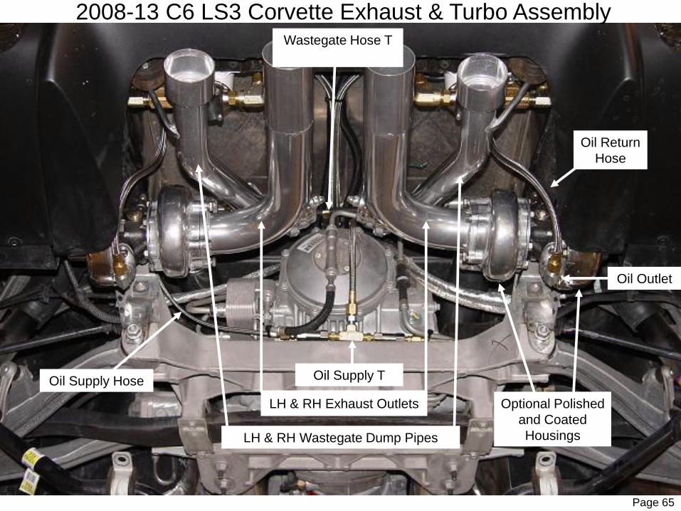
2008-13 C6 LS3 Corvette Exhaust & Turbo Assembly
LH & RH Exhaust Outlets Optional Polished
and Coated
Housings
Wastegate Hose T
Oil Outlet
LH & RH Wastegate Dump Pipes
Oil Supply Hose
Oil Return
Hose
Oil Supply T

Page 66
Use the supplied thread tape on the fittings and assemble the oil supply T and check valve assembly as shown in the above
diagram. Make sure that the Arrows on the check valves point away from the T fitting in the direction of flow to the turbos.
Connect the stainless oil supply hose from the engine to the center port of the T fitting as shown in the above diagram. Connect
the two 16 inch long #4 stainless oil supply hoses from the top oil inlet port on the turbochargers to the outlet ports on the oil
supply T fitting as shown in the diagram. Fasten the oil supply hoses to the differential cooler lines using the nylon ties
provided.
(IMPORTANT: The supply hose from the engine must be flushed out before final assembly. Note the flow direction
ARROW on each check valve – it should point TOWARD the turbocharger.)
Connect the open ends of the 24 inch long #6 stainless hoses to the 90 degree fittings on the oil outlet ports at the bottom of the
turbochargers as shown in the above diagram.
Install an 8 inch long 1/4” hose onto each side port of the wastegate T fitting. Install the open end of the hoses onto the Front
Boost Port of each wastegate as shown in the above diagram. Cut the wastegate hose coming from the front of the car to
length and install onto the center port of the T fitting as shown.
The turbo housings must be clocked so that the oil inlet is straight up and the oil outlet is straight down. Once installed, if the
center section isn’t aligned properly, loosen the 6 turbine housing bolts and the 6 compressor housing bolts. Rotate the center
section until it is clocked so that the oil inlet/outlets are aligned vertically as shown. Retighten the turbine housing bolts to 12
ft./lbs. Leave the compressor housings loose at this time.
Install the metal encapsulated hangers onto the Exhaust #1 hangers (not shown) and reinstall the factory heat shield bolts
through the hangers & secure.
(NOTE: When the turbocharger and all the tubing has been installed correctly, the installation should be identical to
the picture in the above. Make sure that the front edge of the factory heat shield has been rolled up in the middle to
prevent damage to the hoses and wiring harnesses.)
(IMPORTANT: If the rear K-Member nuts were loosened to lower the K-Member then tighten those nuts to factory
specifications now. Do not install the weld on exhaust tips at this time. Do not install the rear sway bar yet.)

Page 67
2008-13 C6 LS3 Corvette Air Intake #2 and #3
AI #2
RH Fender Bracket
Right
Intake #1
Not In
Position
Ground
Wire
RH AI #1
Fender Bracket Studs
Bend LH Bracket End Up Here
LH AI #1

Page 68
Remove the 2 factory bolts and the 2 nuts from the 6mm studs shown in the above diagram and remove the rear fender brackets.
Install a 2.5” x 3” silicone hose and 2 clamps onto the lower end of each Air Intake #1 tubes and secure the clamp. Install theAir Intake #2 tubes up into the silicone hose on the outlet of the Air Intake #1 tubes. Temporarily hold the Air Intake #3 tubes in place between the turbocharger and Air Intake #2 tube. Line up the tubes and tighten the clamp to secure the Air Intake #2 tubes in place as shown in the diagram then remove the Air Intake #3 tubes.
(NOTE: Orient the clamps so that they can be accessed after the other pipes have been installed.)
Page 69
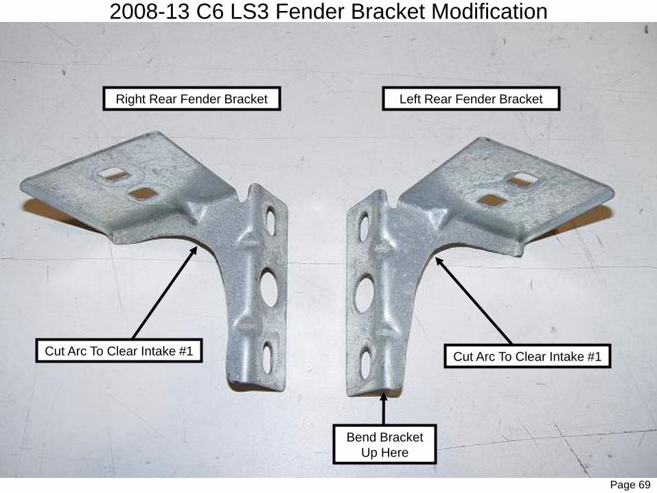
2008-13 C6 LS3 Fender Bracket Modification
Bend Bracket
Up Here
Cut Arc To Clear Intake #1
Left Rear Fender BracketRight Rear Fender Bracket
Cut Arc To Clear Intake #1

Page 70
Cut an arc shape out of the rear fender brackets as shown in the above diagram so that Intake #1 tube will clear the bracket.
The front end of the LH fender bracket must be trimmed so that it is flat with the bracket mounting surface or the lip of thebracket must be bent up flat with the mounting surface as shown in the previous diagram.
Deburr the edges of the brackets and reinstall the brackets onto the vehicle.
(NOTE: On the driver’s side, reinstall the factory ground wire back in position with the factory bolt as shown in the diagram.)
Tighten the 2 bolts and the rear nut onto the rear stud only (leave front nut off at this time).

Page 71
2008-13 C6 LS3 Corvette Intake #1 & Air Intake #3
Right Air
Intake #2
Modified RH Fender Bracket
Right Air
Intake
O2 #3
Right Intake #1
Right Air Intake #1
C.A.R.B.
Only PCV
Fitting

Page 72
Install a 2” x 2.5” silicone hose and 2 clamps onto each turbocharger outlet and secure with clamp.
(NOTE: The compressor bolts should be loose at this time. Rotate and ‘clock’ the compressor cover so that it lines up properly with Pipe 1. Do not tighten the compressor cover bolts until all pipes are lined up properly.)
Slide the inlet end of Intake #1 into the compressor outlet and rotate the pipe rearward to install the mounting bracket over the factory stud as shown. Line Intake #1 up and secure to the stud with the 1/4” fender washer and the factory nut as shown in theabove diagram. Secure Intake #1 into the compressor by tightening the hose clamp.
Install a 2.5” x 3” silicone and 2 clamps onto the outlet end of each Air Intake #2 tube and secure the clamps.
(NOTE: Orient the clamps so that they can be accessed after the pipes have been installed.)
Install the 2.75” x 3” silicone hose and 2 clamps all the way onto the outlet end (larger end) of each Air Intake #3 tube. Install the inlet end of Right Air Intake O2 #3 (Note: For CARB certified systems, this right side tube has a pipe bung welded into it) into the outlet end of Right Air Intake #2. Slide the silicone hose onto the RH compressor inlet. Align the Air Intake pipes and secure all the hose clamps as shown in the diagram. Repeat this process for the LH air intake pipes.
(NOTE: Check the tailpipes for proper alignment. Make sure that the turbochargers are sitting level. If the turbochargers need adjustment, loosen the hose clamps and then align the pipes properly. Tighten the hose clamps to help hold the turbochargers in place. Final tightening and alignment will be done later, but turbochargers need to be very close to their final position at this time.)

Page 73
2008-13 C6 LS3 Corvette Rear Suspension
Left
Intake
#3
Cut Notch In
Factory Pinch
Weld
Right Intake #2
Factory Lower Ball Joint Nut
Right Intake #3
View of LH Rocker Panel
From Inside LR Wheel Well
Rear View of RR Brake Rotor

Page 74
Remove the rear lower ball joint nuts. Use a ball joint separator or pry between the CV axle and the ball joint stud to separate
the lower ball joint from the spindle.
(WARNING: Do NOT pound on the side of the aluminum knuckle because it will weaken the knuckle and could cause
serious damage to the vehicle.)
Raise the right rear spindle and rotor assembly up off of the lower control arm to allow clearance for Intake #3 to pass under the
brake rotor and into the rocker panel. Securely support the spindle in this raised position.
Using a ‘saws-all’, cut approximately a 1/2” x 2” section of the factory pinch weld at each rocker panel as shown in the above
diagram. This will allow adequate clearance for Intake #3 to slide into the rocker panel cavity. Clean debris from rocker panel
then paint the exposed metal surface to prevent rust.
Insert a clean rag into the long end (outlet) of each Intake #3 tube to prevent any debris from entering the tube during
installation.
Slide each Intake #3 tube into the rocker panel as shown in the above diagram.
Reassemble the spindle onto the ball joint and secure with the factory nut according to factory specifications. Repeat this
process for the other side.
Page 75
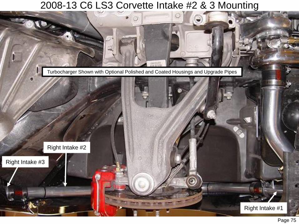
2008-13 C6 LS3 Corvette Intake #2 & 3 Mounting
Right Intake #2
Right Intake #3
Right Intake #1
Turbocharger Shown with Optional Polished and Coated Housings and Upgrade Pipes

Page 76
Install a 1.75” x 3” silicone hose and 2 clamps onto the outlet end of Intake #1 and secure the clamp. Install a 1.75” x 3” silicone
hose and 2 clamps all the way onto the inlet end of Intake #3 (do not secure clamp yet). Install Intake #2 into Intake #1 and
then install the long end of Intake #2 into the inlet end of Intake #3. Slide the silicone hose up onto the outlet of Intake #2 and
secure with clamp. Adjust Intake #2 so that the top of Intake #2 is flush with the top of the wheel well and loosely secure in
place with the clamps. Repeat this process for the other side.
(NOTE: At this time, the outlet end of Intake #3 should be resting on the bottom of the rocker panel so that it will align
properly with Intake #4. If the front of Intake #3 is up too high, adjust Intake #2 so that the outlet is NOT being held up
too high. Once all intake tubes are connected, align and secure the intake tubes. Final adjustment and tightening of
the intake tubes will be done once Intake #4s have been installed.)
(NOTE: Optional coated and polished turbocharger compressor and turbine housings shown in diagram.)

Page 77
2008-13 C6 LS3 Corvette Intake #4 and Front View
Rear K-Member
Mounting Nuts
Diagram 27
Dry Sump
Reservoir
(Z06 Only)
Sway Bar Brackets
Left and Right Intake #4
Rear Splash
Panels Removed
Front K-Member
Fender Screw

Page 78
Remove the screws at the lower rear corner of the front fenders to allow easier access to install the silicone hoses on the Intake
#3’s.
(NOTE: Be careful flexing the front fenders when accessing the connection between Intake #3 and Intake #4 as the
fender can crack or be damaged!)
Remove the rags from the outlet ends of each Intake #3 and clean out any debris that may have entered the tubes. Install a
1.75” x 3.75” silicone hose and 2 hose clamps onto the outlet ends of Intake #3's and secure the rear clamp in a position where
it can be accessed for tightening.
(NOTE: The front hose clamps can be accessed and tightened from below between the frame and the loosened fender.
To access the rear clamps, it is recommended that the hose clamps be tightened from above through the splash panel
access to prevent hose clamp bolts from rubbing on the fender.)
Remove the large nut (21mm wrench) from the LR corner of the front K-Member and remove the rear bolt (13mm wrench) from
the LF sway bar frame bracket as shown in the above diagram. Install the Left Intake #4 as shown in the diagram by installing
the inlet end of Left Intake #4 into the outlet end of Left Intake #3. Guide Left Intake #4 into place as you install Left Intake #4
rear mounting bracket over the K-Member stud and insert the outlet of Left Intake #4 into the silicone hose at the intercooler
inlet. Loosely install the factory K-Member nut. Secure the front bracket to the sway bar mount using the factory bolt and two
3/8” flat washers as spacers between the pipe bracket and the sway bar frame bracket. Align Left Intake #4 for maximum
clearance and tighten the factory nut & bolt. Make sure the silicone hose is installed far enough onto the outlet of Intake #4
(adjust hose back on the intercooler inlet to center the hose between Intake #4 and the intercooler if necessary) then tighten the
hose clamps. Repeat this process to install Right Intake #4.
(Note: Check for adequate clearance for the silicone hoses as they run past the radiator.)

Page 79
2008-13 C6 LS3 Corvette Intake #1, 2, and Turbo
Left Intake
#1
Left Air Intake #3
Left Intake #2
Left Exhaust #2
& Wastegate
Dump Pipe

Page 80
Position Intake #2 so that it is flush with the top of the wheel well as shown in the above diagram. Center Intake #2 so it fits
evenly in the wheel well. Position the silicone hoses at the inlet and outlet ends of Intake #2 so that the gaps are centered and
that there is pressure applied upward to push the tubes against the body to hold them secure. Tighten the hose clamps to hold
the tubes in position against the body. Do final tightening of the hose clamps at the silicone hoses at Intake tubes 1, 2, 3, and 4.
(NOTE: It may be necessary to adjust the position of Intake # 3 slightly forward or back to facilitate proper alignment of Intake #1 to Intake #2 and to keep proper pressure against the top so that the tubes don’t rattle. Make sure that all tubes are secure and have enough pressure against them to keep them from rattling. It is recommended to ‘test fit’ the rear brake ducts so that any adjustments to Intake #2 and Intake #3 can be made at this time to allow adequate clearance so that the ducts will fit on final assembly when the inner fender liners are installed. Moving Intake #3 forward can help with clearance issues. Hose clamps can be tightened to 100 in./lbs.)
Repeat this process for the other side. Reinstall the screws at the lower rear edge of the front fenders.
(IMPORTANT: Make sure that all silicone hoses are spaced evenly over the tube gaps and that tube gaps are at a
minimum. Hose clamps need to be at least 1/8” away from the end of the silicone hose and at least 1/4” from the end
of the tube. Rotate clamps so that they can be easily accessed for maintenance tightening. Hose clamps need to be
retightened after several drive cycles and tightened periodically after that.)
(NOTE: Installation of the rear inner fender shields, as well as the rear splash shields on the front wheels can be done after the installation is complete and after the final tightening of the brackets and hose clamps have been done. The hose clamps should also be retightened after several drive cycles. Keep this in mind when installing the factory shields as they will need to be removed again to check the clamps.)

Page 81
2008-13 C-6 LS3 Corvette Exhaust & Turbo Assembly
LH Oil Supply
STS Exhaust Tips
RH Oil Supply
Oil Supply T and Check Valves
RH Oil ReturnLH Oil Return

Page 82
Align the Exhaust #2 and Wastegate Dump (tailpipes) as straight as possible using the following adjustments:
• In and Out adjustment of the Exhaust #1 Pipes to the factory H-Pipe to position turbos forward or back (watch clearance
at compressor housing and sway bar)
• Rotational adjustment of the Exhaust #1 Pipes to the factory H-Pipe to align tailpipes and turbochargers horizontally
(watch clearance of Exhaust #1 to transmission and to frame rail)
• Rotational adjustment at the 4-bolt turbine housing flange at Exhaust #1 to align tailpipes and turbochargers horizontally
• Rotational adjustment at the 2-bolt wastegate flange at Exhaust #1 to align the Wastegate Dump pipes vertically
• Rotational adjustment at the 2-bolt wastegate flange at Wastegate Dump pipe to equalize space between the Wastegate
Dump pipe and the turbocharger tailpipe (Exhaust #2)
• Bend the exhaust hangers on the tailpipes to line up the turbochargers and tailpipes vertically and horizontally
• Rotational adjustment at the 6-bolt compressor housing and turbine housing adjustment to align the compressor outlet
with Intake #1 and also to align the center section so that the oil outlet is straight down as shown in diagrams
Tighten 6 compressor housing bolts to 10 ft./lbs. and the 6 turbine housing bolts to 12 ft./lbs.
Do final tightening of all exhaust and intakes pipes. Do final tightening of all silicone hoses and clamps. Reinstall the rear sway
bar onto the K-Member. Check front and rear K-Member bolts for proper torque.
(IMPORTANT: Make sure turbochargers are mounted level and symmetrical. Check the turbocharger housings for
proper clocking and check tightness of the compressor and turbine housing bolts. Make sure all tubes and silicones
are installed properly and lined up correctly to prevent any flow restrictions and the possibility of connections coming
apart. Disconnect the battery before welding as PCM damage may result!)
DISCONNECT THE BATTERY BEFORE WELDING! With the help of an assistant, install the ‘Weld-on’ stainless STS exhaust
tips provided by aligning the tips and welding the tips onto the tailpipes (Exhaust #2 and Wastegate Dump) as shown in the
diagram. Make sure there is adequate clearance between the tips and the body. Make sure tips are spaced evenly and aligned
correctly for best appearance. Use stainless welding wire/rod to prevent rust. 3 evenly spaced solid tack welds is sufficient to
secure the tips to the tailpipes. Final installation should look as shown in the above diagram.

Page 83
2008-13 C6 LS3 Corvette Wheel Well Liners
C
Front Wheel
Well Splash
Guard
Rear Wheel Well Liner
Rear Wheel Well Liner
B
A
Cut Or Heat
This Area

Page 85
2008-13 C6 LS3 Corvette Engine View
BOV Hose
Blow Off Valve
Install the 15 amp fuse(s) into the fuse holders located next to the relay(s). Using a jumper wire, connect the BLUE IGN 12V wire in the STS harness (NOT the BLUE soldered pigtail) to the 12V remote battery terminal. When the BLUE wire is powered the oil pump(s) should turn on and you can start the electrical system tests. If the pumps do not turn on make sure that the 15 amp fuse(s) are installed, the relay(s) are completely inserted into their sockets and the oil pump plug(s) are completely inserted in to the wiring harness plug(s).
Once the oil pump(s) are running remove the temporarily installed oil return lines from the valve covers or oil fill cap and make sure the air is being blown out of the oil return outlet(s) as opposed to being sucked in. If the air is being sucked in at the oil return outlet then refer to oil pump installation section of the manual and reverse the flow of the pumps. If the pumps are blowing air out of the oil return outlet(s) then reinstall the oil return lines onto the valve covers or oil fill cap and secure.
With the oil pump(s) still running conduct the following electrical tests. (NOTE: The oil pump(s) will be doing their initial dry break in during this time but DO NOT let the pump(s) run dry for more than 5 minutes.)
1. PCV System Electrical Tests:Use a jumper wire to connect both terminals on the 1PSI pressure switch. You should be able to hear the PCV Switch Valve switching. If the PCV switch valve is not switching complete the following tests:
a. Make sure the RED PCV wire is secured to one side of the 1PSI pressure switch. Also make sure that the RED PCV wire has 12 volts of power when the BLUE IGN 12V wire is powered and the oil pump(s) are running.
b. Make sure the short BROWN PCV wire is secured to the other side of the 1PSI switch. Also make sure that the other end of theBROWN PCV wire is secured to the terminal on the PCV Switch Valve and that it has not been over tightened. (NOTE: Make sure that the terminal on the switch valve has not been over tightened as it will damage the internals of the switch valve!)
c. Make sure that the switch valve is mounted to a grounded metal surface or has a auxiliary ground strap hooked to the PCV Switch Valve mounting tabs. (NOTE: The auxiliary ground strap is only necessary when mounting the switch valve to a NON-grounded object, refer to the PCV Switch Valve installation portion of the manual.)
d. Make sure that the terminal on the switch valve is secure but not over tightened and that it has power when the 1PSI switch is jumped.
1. Oiling System Electrical Tests:Use a jumper wire to connect the 2 terminals of the 3PSI Oil Alarm Switch(s) located on the inlet side of the oil pump(s). Use a jumper wire to connect the terminals of the 3PSI Oil Alarm Switch. You should hear the Oil Alarm Buzzer sound inside the passenger compartment. If you do not hear the Oil Alarm Buzzer, then complete the following tests:
– Make sure that the oil alarm buzzer is plugged into the BLUE and WHITE ALARM wires previously routed into the passenger compartment. (NOTE: The Oil Alarm Buzzer has a specific polarity. The BLUE wire in the passenger compartment should be connected to the POSITIVE (+) side and the WHITE wire should be connected to the NEGATIVE (-) side.)
– Make sure that the BLUE wire in the passenger compartment has power while the oil pumps are running.Make sure the 18 gauge WHITE & BLACK wires are connected to opposite sides of the 3PSI pressure switch(s).
Electrical System Tests

Once all of the electrical system tests are complete install the protective rubber caps onto the pressure switches and connect the BLUE IGN 12V wire onto the soldered BLUE pigtail wire. If you have installed larger injectors you will need to upload the tuning before starting the vehicle. Refer to the tuning section of the manual.
With the tuning installed on the vehicle, remove the stainless oil supply line(s) from the oil inlet of the turbo and insert into a suitable container. Start the vehicle and let it IDLE ONLY until the oil lines are flushed out well (usually about ½ quart) then shut off the engine. Clean the fittings and reinstall the oil line(s) onto the oil inlet(s) of the turbo fitting(s).
Check the oil level in the engine and fill to the manufactures specifications. Start the car and let it IDLE ONLY for 5 minutes. If the oil alarm buzzer sounds or you see any oil coming out of the tailpipes shut the vehicle off immediately and refer to the electrical system test page.
While idling, check under the vehicle, as well as in the engine compartment for any oil or fuel leaks. If there are any leaks shut the vehicle down and address the leak before continuing to run the engine.
After the car has run for 5 minutes shut it off and check the oil level again and fill if necessary. The STS oiling system will take ½ - 1 quart of oil.
Connect the STS Diablosport i3 tuner to the vehicle's OBD2 diagnostic port and let the tuner power up and start the engine. When the the tuner has booted up, follow the on-screen prompts to accept the terms and conditions and proceed to the main menu. Select “SCAN TOOL” and select “DATA LOGGING”. Select “RECORD” to start data logging. Familiarize yourself with the various parameters by selecting the UP and DOWN arrows to scroll through the various PID's.
(IMPORTANT: DO NOT ATTEMPT TO DRIVE THE VEHICLE WITHOUT THE PROPER TUNING AND FUEL SYSTEM UPGRADES!)
Test drive vehicle as per the tuning instructions which you received with your STS tune. If you are not using the STS tune, make sure that the tuning is correct BEFORE boosting the vehicle! Make sure that the turbocharger is working properly and producing the proper amount of boost. The standard kit should produce about 5psi of boost. The air fuel ratio at WOT and/or under boost should be at least 11.5:1 or richer (.920v+ on OBDII O2 sensors). There should be NO consistent knock retard under boost and absolutely NO audible detonation. Boosted timing should be in the 12-14 degree range. If you experience lean air fuel ratios and/or knock retard or audible detonation during boost, DO NOT DRIVE THE VEHICLE as SEVERE ENGINE DAMAGE WILL OCCUR!!! Contact STS Customer Support immediately!
After the test drive, recheck ALL connections, clamps and brackets for proper tightness and routing.
(IMPORTANT: Inspect the wiring harness routing near the engine and exhaust system for any evidence of the loom melting due to high heat. If the loom is getting too hot, reroute the harness and secure harness to protect it from excessive heat.)
Vehicle performance should increase over the next few days of driving as the turbocharger breaks in, allowing quicker spool-up, and as the computer relearns and adjusts to boost conditions. It is recommended that you check and keep track of any trouble codes that are set in the
Starting the Vehicle

Once all of the electrical system tests are complete, install the protective rubber caps onto the pressure switches and connect the BLUE IGN 12V wire onto the soldered pigtail on the vehicle. If you have installed larger injectors you will need to upload the tuning before starting the vehicle. Refer to the tuning installation manual supplied with your kit.
With the tuning installed on the vehicle, remove the stainless oil supply line(s) from the oil inlet of the turbo and insert into a suitable container. Start the vehicle and let it IDLE ONLY until the oil lines are flushed out well (usually about ½ quart) then shut off the engine. Clean the fittings and reinstall the oil line(s) onto the oil inlet(s) of the turbo fitting(s).
Check the oil level in the engine and fill to the manufacturer’s specifications. Start the car and let it IDLE ONLY for 5 minutes. If the oil alarm buzzer sounds or you see any oil coming out of the tailpipes shut the vehicle off immediately and refer to the electrical system test page.
While idling, check under the vehicle, as well as in the engine compartment for any oil or fuel leaks. If there are any leaks shut the vehicle down and address the leak before continuing to run the engine.
After the car has run for 5 minutes shut it off and check the oil level again and fill if necessary. The STS oiling system will take ½ - 1 quart of oil.
First Drive: (DO NOT ATTEMPT TO DRIVE THE VEHICLE WITHOUT THE PROPER TUNING AND FUEL SYSTEM UPGRADES!)
Test drive vehicle as per the tuning instructions which you received with your STS tune. If you are not using the STS tune, make sure that the tuning is correct BEFORE boosting the vehicle! Make sure that the turbocharger is working properly and producing the proper amount of boost. The standard kit should produce about 5PSI of boost. The air fuel ratio at WOT and/or under boost should be at least 11.5:1 or richer (.920v+ on OBDII O2 sensors). There should be NO consistent knock retard under boost and absolutely NO audible detonation. Boosted timing should be in the 12-14 degree range. If you experience lean air fuel ratios and/or knock retard or audible detonation during boost, DO NOT DRIVE THE VEHICLE as SEVERE ENGINE DAMAGE WILL OCCUR!!! Contact STS Customer Support immediately!
After the test drive, recheck ALL connections, clamps and brackets for proper tightness and routing.
(IMPORTANT: Inspect the wiring harness routing near the engine and exhaust system for any evidence of the loom melting due to high heat. If the loom is getting too hot, reroute the harness and secure harness to protect it from excessive heat.)
Vehicle performance should increase over the next few days of driving as the turbocharger breaks in, allowing quicker spool-up, and as the computer relearns and adjusts to boost conditions. It is recommended that you check and keep track of any trouble codes that are set in the computer to make sure that no damage is done to your vehicle. Report any trouble codes to your tuner.
If you experience any problems refer to the Trouble Shooting Guide. If you can’t solve the problem that is related to the turbocharger system please email or contact STS Technical Support at [email protected] or (866) 464-6553.
Starting & Driving the Vehicle
Page 88

Once all of the initial testing has been done and you are ready to test the tuning parameters, connect the Diablosport STS i3 to the OBD2 diagnostic port to power up the i3. Start the engine and let the vehicle idle and warm up to operating temperature.
Follow the on-screen prompts on the i3 and select “SCAN TOOL” and then select “DATA LOGGING” and “RECORD”. You will then see a list of PIDs (engine parameters) and the values for those parameters which the i3 will display and record while the engine is running. It is helpful to have an assistant watch the values while you drive the vehicle, however it does record the values so that you can go back and review the data log later by downloading the Data Viewer program from www.Diablosport.com and importing this data log into that program.
WARNING: Do NOT attempt to drive the vehicle while being distracted by monitoring the data on the i3!
Monitor the Long Term Fuel trim percentage while normally driving (NO Boost). These values should be within -10% and +10%. If these values are out of this specified range, you will need to do diagnostics to find out why the vehicle is running too rich or too lean. If these values are more negative than -10%, the tuning is too rich and will most likely be too rich when you test wide open throttle (WOT). If these values are more positive than +10%, the tuning is too lean and will most likely be dangerously lean when you test WOT. Drive the vehicle in the idle to 3000 RPM range with varied throttle, not to exceed 40% throttle. During these conditions, the fuel trims should stay within the specified range.
IMPORTANT: It is highly recommended that you have a wideband air fuel ratio gauge installed along with a boost gauge to monitor AFR and Boost levels. Lean conditions and/or over-boost conditions can cause severe engine damage very quickly.
Test WOT in 1st gear and watch the following PID's:Spark Advance (should be in the 10-14 degree range at WOT)Knock Retard and Total Knock Spark (should be in the 0-2 degree range at WOT)Oxygen Sensor B1S1 and B2S1 (should be in the .90 to .92 volt range at WOT)Boost Gauge (should be in the 4-7 psi range at WOT)Air Fuel Ratio (AFR) Gauge (should be approximately 14.7:1 during normal driving and in the 10.5:1 to 11.5:1 range at WOT)
WARNING: O2 Sensor values lower than .88 volts and AFR higher than 12:1 at WOT with boost are considered too lean and can cause engine damage! Knock Retard values higher than 3 degrees are indicating that the engine is Detonating and can cause severe engine damage!
If values are within specification, you can test in 2nd gear and then in 3rd gear, etc. to insure that all parameters are within safe ranges. If you do not see the above parameters, you can use the “ADD PIDs TO LIST” function on the i3 and add the required parameters to data log.
WARNING: All testing should be done using the data logging feature and on a closed course. Do NOT drive in traffic on public roads while distracted by tuning parameters. Operate the vehicle safely and obey all traffic laws.
If you experience any problems and/or the tuning parameters are not within the above specifications and you can’t solve the problem please save a data log file along with your boost and AFR information and email or contact STS Technical Support at (866) 464-6553.
Data Logging and Verifying Tuning
Page 89

TROUBLESHOOTING GUIDE• Oil pump alarm sounds
• IMMEDIATELY turn the engine OFF as quickly as can be done safely
• Check to see if oil pump is working while the vehicle is running
• If pump is working, check to see that the oil pump is spinning in the correct direction
• If pump is not working, check inline fuse(s) in main harness and electrical harness connections
• Check relays to make sure they are plugged in properly
• If everything is working properly, check wire harness for a short in the WHITE wire or a faulty Oil Alarm pressure switch.
• Oil pump is noisy
• Oil pump will be slightly noisy upon startup and when cold but should get quieter as system warms and as pump breaks in
• Check to make sure that the pump mounting hardware is not to tight causing the pump to transmit noise through its mounting surface
• Check to see if oil pump or housing are rubbing on frame and that rubber insulators are in good shape
• Turbo won’t boost, produces low boost, or has excessive spool time
• Check intake tubing for any leaks at tubes or hose connections
• Check exhaust system for any leaks
• Check wastegate to see that valve isn’t stuck open
• Spool up time will decrease as the turbocharger breaks in and should improve over first few days of driving
• Check condition of air filter or pre-charger filter cover
• Detonation
• Check for lean condition, AFR should be 11.5:1 or richer and O2 readings should be above .900 volts at WOT
• Check Octane rating of fuel and use PREMIUM fuel only
• Check boost level to see that it isn’t running too much boost
• Check wastegate and hose connections
• Squeaking or rattling noise
• Check to see that all mounts and tubing are secure
• Check to see that tubing and hose clamps are not rubbing on any moving partsPage 90

TROUBLESHOOTING GUIDE• Check engine light
• Check all sensor electrical connections
• Pull codes with diagnostic scanner and follow diagnostic flow charts
• If MAF code appears, check and clean MAF sensor of any oil residue or contaminants
• Trouble code may reset on it’s own with time as computer relearns and recognizes higher sensor readings as normal values
• Clear out code and let computer relearn new values and see if code reoccurs
• Have a competent repair shop diagnose and repair the Trouble code
• Gas smell and fuel tank pressurization
• Check to see that injectors were installed correctly and that O-ring seals are not damaged
• Check fuel lines and connections for leaking
• Check to see that fuel tank Evap solenoid is working properly
• Excessive engine blow-by or smoking
• Check condition of gaskets and seals and look for oil leaks
• Check condition of PCV valve. A bad valve will let boost into crank case (also refer to the electrical system tests)
• Check to see that the PCV Switch Valve hoses are routed correctly and that the valve is switching properly
• Check the 1 PSI pressure switch to see that it is powering the BROWN wire at 1 PSI
• Check cylinder compression to verify engine is in good condition
• Check oil pump operation and for any flow restrictions
• Burning smell
• Check to see that all wiring harnesses and hoses are routed properly and away from hot exhaust
• Check to see that there are no shorts in electrical wiring harness
• Check oil pump operation and for any flow restrictions
Page 91

STS Turbo Systems – Safety Warning - Please Read!
IMPORTANT
Oil System Warning Buzzer
Your STS™ Turbo System is equipped with a safety system that will alert you in the event that your oil pump fails. This system is a buzzer that will be heard inside your vehicle. If you hear the Oil Alarm sound, immediately shut the engine off and safely pull over to the side of the road and contact STS Tech Support. Serious engine damage can occur if the pump stops while your engine is running. With the pump stopped, oil will flow out of the turbo and will not return to the engine.
Premium Fuel
STS Turbo recommends that you only use Premium Fuel, 91 Octane or higher, on vehicles equipped with the STS™ Turbo System. Premium fuel reduces pinging and detonation which can cause significant damage to your vehicle.
Engine Pinging or Detonation
If you hear pinging in your engine, back off the throttle immediately. Pinging is the sound of Detonation and can cause significant damage to the engine. If you hear pinging, do NOT drive the vehicle during this condition and call your local STS dealer immediately.
Heavy Towing
The STS Turbo System, like other turbo and supercharger systems, under certain heavy towing situations can create more power than a stock engine can handle. STS Turbo does not recommend using this system for heavy towing purposes.
Vehicle modifications
STS Turbo Systems were designed to fit stock vehicles. If you have modified your vehicle, modifications to the turbo system or your vehicle may be necessary to ensure the proper fit and safe use of the STS Turbo System. Inform your dealer of any aftermarket changes to your vehicle.
The STS turbo system is designed to provide enhanced power and engine performance. It could cause severe damage to your
vehicle if it is not properly installed or if your vehicle is not properly tuned and maintained for the system. Under some
circumstances, improper installation or use of the STS turbo system could result in serious personal injury or even death.
STS Turbo Systems can not accept responsibility for the proper maintenance or the proper operation of your vehicle. Please take all
necessary precautions to use the STS Turbo System strictly in accordance with all instructions and warnings.
Page 92

Page 93
STS Turbo products are covered by a Limited One-Year Warranty that covers certain defects in workmanship and materials.
Who is covered? This warranty covers the original purchaser of STS Turbo products in the United States and Canada.
What is covered and for how long? Holley Performance Products Inc. (“Holley”) warrants that STS Turbo products will be free from defects in material
and workmanship for the life of the product on the original car on which it was installed. Blemishes, marring of appearance, discoloration, internal rust, or
surface rust due to weather, road hazards, lack of maintenance, or extremes of heat of cold are not be considered defects under this Limited One-Year
Warranty. Holley warrants moving parts such as valves and actuators for one year. All claimed warranty products must have a return goods
authorization (RGA) number and returned to the place of purchase. The returned product must be accompanied with a copy of the original purchase
receipt and the original purchasers contact information.
What will Holley do? If there is a defect in material or workmanship, Holley will choose either to repair the defective part or replace it with a
comparable, new part, without charge for the repair or the replacement product. Purchaser’s remedies under this Limited One-Year Warranty are strictly
limited to the repair or replacement of the defective product. You must pay the cost of shipping the product back to Holley and for any labor or other
costs, including any additional parts, associated with removing the allegedly defective part and with the installation of the repaired or replacement part.
What is NOT covered? This warranty does not cover STS Turbo products that have been installed on any commercial or racing vehicle or that have
been damaged due to misuse, abuse, neglect, or accident, such as having been modified or altered; improperly installed, adjusted or repaired; welded;
exposed to corrosion, corrosive materials, other contaminants; or used in applications other than those recommended by STS Turbo on our website
(www.holley.com).
How do I start the warranty claim process? To initiate the warranty process, the consumer must return the alleged defective product to the place of purchase with a dated receipt and completed applicable warranty claim tag. Warranty claims will be rejected if the date of purchase cannot be established by the consumer. Do not send products directly to Holley Performance Products. Holley Performance Products assumes no responsibility for products sent directly to Holley Performance Products.
What other conditions and exclusions apply? This warranty does not provide compensation for loss of time, loss of use of vehicle, labor cost, cost of
additional parts, shipping, inconvenience or other consequential or incidental damage. Some states do not allow the exclusion or limitation of incidental
or consequential damages, so these limitations or exclusions may not apply to you.
Holley’s maximum liability under this Limited One-Year Warranty shall not exceed the original cost of the product to the consumer. This Limited
Warranty gives you specific legal rights and you may also have other rights which vary under state or provincial laws.
This Limited Warranty is exclusive and in lieu of all others, whether oral or written and whether express or implied. Any implied warranties, including
implied warranties of merchantability and fitness for a specific purpose are hereby disclaimed. Some states do not allow the exclusion or limitation of
implied warranties, so these exclusions or limitations may not apply to you.
199R11594
Date: 6-21-18
STS TURBO LIMITED ONE-YEAR WARRANTY