2004-01 perfect AR2theo ao04
10
Toward perfect antireflection coatings. 2. Theory Daniel Poitras and J. A. Dobrowolski Recently we performed a numerical investigation of antireflection coatings that reduce significantly the reflection over a wide range of wavelengths and angles of incidence, and we proposed some experiments to demonstrate their feasibility. We provide a theoretical description of omnidirectional antireflection coatings that are effective over a wide range of wavelengths. © 2004 Optical Society of America OCIS codes: 310.1210, 310.6860. 1. Introduction In 1880 Lord Rayleigh was one of the first to math- ematically recognize the potential of gradual transi- tion layers as antireflection AR coatings. 1 He stated, “No one would expect a ray of light to undergo reflection in passing through the earth’s atmosphere as a consequence of the gradual change of density with elevation.” Many decades later, his idea was implemented in devices for eliminating reflections of sound 2 and light. 3 However, a few years after Lord Rayleigh’s publication, Wood proved experimentally Fig. 1 that even graded atmospheric layers are, in fact, reflective at grazing angles of incidence. 4,5 As magnificent as this type of reflection at grazing angles can appear in nature, it does limit seriously the performance of antireflection devices. At a time when papers on omnidirectional mirrors have become popular, we suggest a general method for enhancing the efficiency of existing AR designs at grazing angles of incidence, making them quasi-omnidirectional, with only minor effects on their properties at normal incidence. 2. Theory We have shown numerically in a previous paper that it is possible, starting with an AR coating of the grad- ual transition-layer type, to arrive at a multilayer AR coating consisting of only a few layers and that is effective over a wide range of angles of incidence. 6 Such solutions require layers with refractive indices that are close to that of the ambient medium. In this section we propose to modify the expression for an inhomogeneous transition layer to explain theoreti- cally the refractive-index profiles with good high- angle performances calculated in Ref. 6. We present here a set of inhomogeneous layer designs with low reflectance over a wide range of wavelengths and angles of incidence. We explore the properties of this type of coating and use them to deduce solutions that are relatively thin and consist of only a few layers. For easier correlation with the results of Ref. 6, the AR coatings that we consider in this paper correspond for the most part to an interface between two media of refractive indices 3.0 and 1.0. A. Theoretical Aspects of Optical Coatings at Oblique Angles Procedures for the calculation of optical thin-film properties at oblique angles of incidence are well known and can be found in many textbooks. 7,8 We will review and comment on the few simple rules that affect the properties of omnidirectional AR coatings. i Snell–Descartes law. This rule, generally rep- resented for an inhomogeneous medium by the ex- pression d dz n z sin z 0, (1) indicates that large variations of n with z within the layer will induce large variations in the propagating angle of the beam. We will see later in Subsection 2.3C that large variations of z must be avoided in omnidirectional AR coatings. ii Effect of polarization. At oblique angles of in- cidence, the refractive index of each material is split The authors are with the Institute for Microstructural Sciences, National Research Council of Canada, 1200 Montreal Road, Ot- tawa, Ontario K1A 0R6, Canada. The e-mail address of D. Poi- tras is [email protected]. Received 7 June 2003; revised manuscript received 23 October 2003; accepted 28 October 2003. 0003-693504061286-10$15.000 © 2004 Optical Society of America 1286 APPLIED OPTICS Vol. 43, No. 6 20 February 2004
Transcript of 2004-01 perfect AR2theo ao04

T
D
1
IetsrawisR�f
atwptowi
2
Wiuce
Ntt
2
1
oward perfect antireflection coatings. 2. Theory
aniel Poitras and J. A. Dobrowolski
Recently we performed a numerical investigation of antireflection coatings that reduce significantly thereflection over a wide range of wavelengths and angles of incidence, and we proposed some experimentsto demonstrate their feasibility. We provide a theoretical description of omnidirectional antireflectioncoatings that are effective over a wide range of wavelengths. © 2004 Optical Society of America
OCIS codes: 310.1210, 310.6860.
Stsicahrattl6ct
AA
Ppkwa
rp
ila2o
c
. Introduction
n 1880 Lord Rayleigh was one of the first to math-matically recognize the potential of gradual transi-ion layers as antireflection �AR� coatings.1 Hetated, “No one would expect a ray of light to undergoeflection in passing through the earth’s atmospheres a consequence of the gradual change of densityith elevation.” Many decades later, his idea was
mplemented in devices for eliminating reflections ofound2 and light.3 However, a few years after Lordayleigh’s publication, Wood proved experimentally
Fig. 1� that even graded atmospheric layers are, inact, reflective at grazing angles of incidence.4,5
As magnificent as this type of reflection at grazingngles can appear in nature, it does limit seriouslyhe performance of antireflection devices. At a timehen papers on omnidirectional mirrors have becomeopular, we suggest a general method for enhancinghe efficiency of existing AR designs at grazing anglesf incidence, making them quasi-omnidirectional,ith only minor effects on their properties at normal
ncidence.
. Theory
e have shown numerically in a previous paper thatt is possible, starting with an AR coating of the grad-al transition-layer type, to arrive at a multilayer ARoating consisting of only a few layers and that isffective over a wide range of angles of incidence.6
The authors are with the Institute for Microstructural Sciences,ational Research Council of Canada, 1200 Montreal Road, Ot-
awa, Ontario K1A 0R6, Canada. The e-mail address of D. Poi-ras is [email protected].
Received 7 June 2003; revised manuscript received 23 October003; accepted 28 October 2003.0003-6935�04�061286-10$15.00�0© 2004 Optical Society of America
286 APPLIED OPTICS � Vol. 43, No. 6 � 20 February 2004
uch solutions require layers with refractive indiceshat are close to that of the ambient medium. In thisection we propose to modify the expression for annhomogeneous transition layer to explain theoreti-ally the refractive-index profiles with good high-ngle performances calculated in Ref. 6. We presentere a set of inhomogeneous layer designs with loweflectance over a wide range of wavelengths andngles of incidence. We explore the properties ofhis type of coating and use them to deduce solutionshat are relatively thin and consist of only a fewayers. For easier correlation with the results of Ref., the AR coatings that we consider in this paperorrespond for the most part to an interface betweenwo media of refractive indices 3.0 and 1.0.
. Theoretical Aspects of Optical Coatings at Obliquengles
rocedures for the calculation of optical thin-filmroperties at oblique angles of incidence are wellnown and can be found in many textbooks.7,8 Weill review and comment on the few simple rules thatffect the properties of omnidirectional AR coatings.
�i� Snell–Descartes law. This rule, generally rep-esented for an inhomogeneous medium by the ex-ression
ddz
�n� z�sin �� z�� � 0 , (1)
ndicates that large variations of n with z within theayer will induce large variations in the propagatingngle of the beam. We will see later in Subsection.3C that large variations of ��z� must be avoided inmnidirectional AR coatings.
�ii� Effect of polarization. At oblique angles of in-idence, the refractive index of each material is split

i�
Acc�d
fimag
wqd
Otr
fiiniarc
Hr
Fpmmt
Fm
Fc
Fam
nto two effective refractive indices, or admittancesFig. 2�:
�s � n� z�cos �� z�,(2)
�p � n� z��cos �� z�.
s a consequence, the absolute value of the Fresneloefficient �or complex-amplitude reflection coeffi-ient� will increase significantly at grazing anglessee Fig. 3�, and this complicates the design of omni-irectional AR coatings.
�iii� Phase thickness. The beam entering a thinlm at an oblique angle of incidence sees a differentaterial admittance and a different film thickness,
nd, as a result, a new effective optical thickness isiven by
�n� z�dz�� � n� z�dz cos �� z�, (3)
here ��z� is given by Eq. �1�. Figure 4 shows theuantity sec � �z� for six refractive indices n and forifferent angles of incidence on the surface of the film.
ig. 1. Schematic drawings and pictures adapted from Wood’sublication in 18994 illustrating �a� the physical cause leading to airage effect, �b� an experimental setup for artificially creatingirage effects, and �c� some pictures showing the effect obtained as
he sand was heated �from left to right�.
ig. 2. Polarization effect at oblique incidence: splitting of ad-ittance for materials with different refractive indices.
ne can see that the largest effect on the opticalhickness will occur at grazing angles and for lowefractive-index materials.
�iv� Total internal reflection. Consider the thin-lm system depicted in Fig. 5. Here the refractive
ndices of the substrate and of the ambient media ares, na, and those of the layers on either side of the ith
nterface are ni�1, ni. An incident beam arriving atn ith interface at which ni�1�ni � 1 will be totallyeflected if the angle of incidence is larger than theritical angle for this interface, given by
�c � arcsin�ni�1�ni�. (4)
owever, this critical angle must also correspond to aealistic angle of incidence within the ambient me-
ig. 3. Polarization effect at oblique incidence: Fresnel coeffi-ients at interfaces with different refractive-index-step sizes.
ig. 4. Reduction factor sec��� for the phase thickness at obliquengles of incidence, as a function of �, the angle of propagation inaterials of different refractive indices.
20 February 2004 � Vol. 43, No. 6 � APPLIED OPTICS 1287

di
Aauaiae
B
AriomSr
atf
m�bfi
arrR
wotppaEOsrtclm
sttnatqlniictp�sni
wol
CP
Ic
Ft
1
ium, and so the overall critical angle at the surfaceof the coating will be
�Cinc arcsin�ni�1�na�. (5)
s can be seen from Fig. 6, the critical angle willsymptotically approach 90° as ni� 1�na gets closer tonity. As a result, abrupt step-down interfaces arellowed in ideal omnidirectional AR coatings, provid-ng that the refractive indices of the coating materialsre not exceeded by the refractive index of the ambi-nt medium.
. Inhomogeneous Antireflection Layer
s noted in Section 1, graded transition layers areegarded by many as excellent AR devices for normalncidence of light. Some studies have been carriedut to find the refractive-index profiles n�z� of inho-ogeneous layers that yield the lowest reflectance.outhwell found that quintic profiles of the type rep-esented by the expression9
nQ� z� � nmax � �nmax � nmin��10� zd�
3
� 15� zd�
4
� 6� zd�
5� (6)
ct as efficient AR coatings. Here z, the metrichickness, has its origin at the substrate–film inter-ace and d is the total metric thickness of the inho-
Fig. 5. Schematic representation of a multilayer system.
ig. 6. Variation of the critical angle of incidence as a function ofhe ratio n �n .
i a288 APPLIED OPTICS � Vol. 43, No. 6 � 20 February 2004
ogeneous layer. The quintic profile given by Eq.6� has a continuously varying refractive index atoth the substrate and the ambient medium inter-aces with zero first- and second derivatives at thesenterfaces.
Another efficient profile consists of a half-period ofn exponential sine �ES�.10 By making use of theugate filter theory developed by Bovard11 and of aescaling method found by Larouche and described inef. 12, we can write
nES� x� � �max exp(12 ln��max��min�
� �sin�� xxtot
� � �2� � sin��2��) , (7)
here x � �0
zn� z��dz� and xtot�0
dn�z��dz� are theptical distances from the substrate and total opticalhickness, respectively. When this equation is ex-ressed in the form of a Taylor series, a 20th-orderolynomial is needed to reproduce adequately thebove refractive-index profile. This means thatq.�6� is not a polynomial approximation for Eq. �7�.ne should also note that, although changing the
in��2� phase term in Eq.�7� would alter theefractive-index matching at the interface so thathe coating would no longer be a transition layer, theoating will still have reflectance minima at wave-engths corresponding to 4xtot��2m 1�, for values of
1, 2, 3. . . .10
A minimum thickness of the inhomogeneous tran-ition layer is required for achieving a low reflec-ance. Although the exact value of this minimumhickness depends on the profile of the inhomoge-eous transition layer and on the reflectance requiredt a target wavelength �0, it is generally acceptedhat a minimum optical thickness of �0�2 is re-uired.7 In much thinner transition layers �or atonger wavelengths� in which d �� �, the electromag-etic field does not vary significantly inside the coat-
ng, and so an abrupt interface is perceived by thencident electromagnetic radiation.3 In the oppositease in which d �� �, the refractive index n appearso vary slowly with the layer thickness when com-ared with the wavelength of the incident radiationthe WKBJ approximation holds3�, and for this rea-on internal reflections within the coating can beeglected. This permits one to establish an approx-
mate lower limit on the reflectance R,
R � � �
2d�2m
, (8)
hich is valid when all derivatives up to the mthrder are continuous at the boundaries of the gradedayer.3
. Novel Modified Inhomogeneous Transition-Layerrofiles
n Fig. 3 are shown the calculated Fresnel coeffi-ients, plotted as a function of angle of incidence, of

ai1itc
Tfgosfi
tetphar
Tet
Hat�ts�rwfip
rfistlat
Foa
n interface in which the media on either side of thenterface differ in refractive index by 0.01, 0.1, and.0. This diagram suggests that eliminating abruptnterfaces in multilayer coatings can reduce polariza-ion effects. For such coatings, the Fresnel coeffi-ients are given by
�s �1
2�s
d�s
dz�
n�
2n�
��
2tan �,
(9)
�p �1
2�p
d�p
dz�
n�
2n�
��
2tan � .
hese expressions show that not only abrupt inter-aces but also large variations of the propagation an-le in the coating must be avoided to reduce the effectf polarization. According to Eqs. �9�, the solutionhould have a smooth monotonic refractive-index pro-le.In addition to the splitting of the admittance owing
o polarization, the cos ��z� factor �Eq. �3�� for theffective optical thickness will significantly deformhe refractive-index profile at grazing angles. Toartly overcome this problem, we introduce new in-omogeneous transition-layer profiles generated bypplying a transformation to the z axis describing theefractive-index profiles of quintic and ES coatings.
ig. 7. Original and modified quintic and ES refractive-index prof the coatings as a function of angle of incidence, for a wavelengthngles of incidence �column �3��.
o calculate the new z axis, we apply the followingquation to each sublayer thickness dz �or opticalhickness dx�:
dznew �dz
�1 �nM
2
n� z�2 sin��0max�2�1�2 . (10)
ere nM and n�z� are the refractive indices of thembient medium and of the inhomogeneous transi-ion layer at a position z within it, respectively, and0max is the largest angle of incidence considered athe surface of the coating. It is important to empha-ize that the transformation of the axis given in Eq.10� could be applied to any other inhomogeneousefractive-index profile, such as rugate filters, whichould then become similar to the power-sine rugatelters found by Bovard,13 or to the refractive-indexrofiles found numerically by Verly.14
Thick quintic and ES profiles, given by Eqs. �6� and �7�,espectively, and the new modified refractive-index pro-les, obtained after Eq. �10� and rescaling are applied, arehown in Fig. 7.15 In Figs. 7�a3� and 7�b3� we see thathe average reflectance near normal incidence can reachower values for the ES profile than for the quintic profilet specific wavelengths.10 However, the overall reflec-ance of the modified quintic is lower than that of the
of inhomogeneous transition layers �column �1��; the performance.01625d �column �2��, and as a function of wavelength, for various
files� 0
20 February 2004 � Vol. 43, No. 6 � APPLIED OPTICS 1289

mFrl
daalpvtsrTddcu1ta
tishm
rwprt
o
DP
Oi
efi�tpot9aAmF
Famodified quintic profiles divided by the wavelength.
FpF
1
odified ES at all angles �see Fig. 7, rows �c� and �d��.igures 7�b2� and 7�b3� show the oscillatory nature of theeflectance of the ES profile, which acts as an absenteeayer at several wavelengths.
The distribution of the points used for numericallyescribing the modified refractive-index profiles canlso affect the calculated spectral properties. Afterpplying Eq. �10� to an inhomogeneous transitionayer, one obtains a curve with fewer points in theart of the new profile that corresponds to the loweralues of the refractive index. The main effect ofhis is a large increase in the reflectance at thehorter wavelengths and a narrowing of the spectralegion in which the coating has a good performance.his will be further discussed in Subsection 2.F oniscretization. Another consequence of this is theeterioration of the performance of the AR at angleslose to 89°. One can avoid these effects either bysing a very large number of points �more than0,000� or by redistributing the points evenly withinhe new profile, through the use of an interpolationlgorithm, such as a cubic spline.16
From a comparison of the performances of the quin-ic and modified quintic profiles at different angles ofncidence shown in Figs. 7�a2� and 7�c2�, it can beeen that the performance of the modified profiles atigh angles is significantly improved, leading to al-ost perfect AR coatings.In Fig. 8 are shown plotted the average calculated
eflectances at an angle of incidence of 89° of layersith quintic and modified quintic refractive-indexrofiles when plotted against the ratio d�� �total met-ic thickness�wavelength�. Note that the higherhis ratio, the lower the resulting average reflectance.
In the following subsections, we will describe somether properties of the modified quintic profile.
. Understanding the Performance of the Modifiedrofiles
ne can better understand the behavior of the mod-fied quintic refractive-index profiles by looking at the
290 APPLIED OPTICS � Vol. 43, No. 6 � 20 February 2004
ffective profiles that are “seen” by the light at dif-erent angles of incidence. Figure 9 shows, for var-ous oblique angles of incidence, the admittancesfrom Eqs. �2�� as a function of the effective opticalhickness �given by Eq. �3��. At higher angles, the-polarized light sees two adjacent graded layers, onef which gets thinner as the angle increases andends toward a large abrupt interface at 89° �see Fig.�l��. The effect on s-polarized light is less apparentt first glance, but it is nevertheless still pronounced:s the admittance at the surface of the coating at theedium interface gets closer to zero, the value of theresnel coefficient at this point is substantially in-
ig. 9. Variation with thickness of the admittances for s- and-polarized light of the modified quintic refractive-index profile ofig. 7�c1�, plotted for different angles of incidence.
ig. 8. Variation of the reflectance at an angle of incidence of 89°,s a function of the total metric thicknesses of the original and

csrftthntancgra5hl
tqscrtiF
wrnnrTerfs
amitttpdss
padt1pao6
Et
ArAssmogmg
Fdm
FAbcfai
reased �see Fig. 10�. As a result, Fig. 9 demon-trates that the performance of the modified quinticefractive-index profile at high angles of incidence is,or both polarizations, mainly dominated by the con-ribution of the ambient-side portion of the coating tohe reflectance. To reduce the overall reflectance atigh angles, one has to extend significantly the thick-ess of that portion of the coating so that its refrac-ive index approximates the ambient index as closelys possible. We noted earlier that an inhomoge-eous transition layer starts to act as a good ARoating when its optical thickness is equal to orreater than half the target wavelength. Using thisule of thumb and assuming that the large increase indmittance seen in Fig. 9�l� is linear between 4 and7.5, we found that this part of the coating only mustave a metric thickness greater than 25�0 to obtain a
ow reflectance at 89°.Because the thicknesses of the nonflat portions of
he inhomogeneous transition layers of the modifieduintic and ES curves �Figs. 7�c1� and 7�d1�� aremaller than those in the corresponding originalurves �Figs. 7�a1� and 7�b1��, one would expect theeflectances of the modified curves to be higher thanhose of the original curves at near-normal angles ofncidence. An inspection of the second column ofig. 7 shows that this is so.A surprising phenomenon is seen in Fig. 11, inhich a large portion of the modified quintic profile is
emoved from the substrate side of the coating, and aew substrate material is introduced to match thisew truncated profile: As shown in Fig. 11�b�, theeflectance is almost unaffected by these changes.his has also been demonstrated numerically in ourarlier paper.6 The reason for this is that theefractive-index profile continues to change graduallyrom that of the ambient medium to that of the newubstrate, and this is true for all angles of incidence
ig. 10. Variation of the Fresnel reflection coefficient for differentepartures of the admittance of the inhomogeneous layer from theedium admittance at the interface of the layer and the medium.
nd for both polarizations of the incident light. Theain effect of the refractive-index truncation shown
n Fig. 11�a� is the introduction of a discontinuity ofhe profile derivative at the substrate interface, andhis leads to an increase of the Fresnel coefficient athis interface �Eqs. �9��. As a result, an interferenceattern becomes apparent at large angles of inci-ence, for which an abrupt profile is seen close to theurface �Fig. 9�, and the lower limit of the reflectancehould increase �expression �8��.A last comment concerning the modified quintic
rofile is that the refractive-index sensitivity of thembient-side portion of the coating will not be re-uced significantly in the case of a solid–solid in-erface, with an ambient index that is greater than. Although the observations made so far in thisaper concerned AR coatings designed for use inir, they still hold for solid–solid inhomogene-us layer AR coatings, as also demonstrated in Ref..
. Thickness Truncation of the Modified Quintic Profile athe Ambient Medium End
n obvious problem with the use of a modified quinticefractive-index profile to produce an omnidirectionalR in air is that the required low refractive indexhould be ideally equal to unity. This led us to thetudy of the effect of truncation of the thickness of theodified quintic refractive-index profile of Fig. 7�c1�
n the resulting reflectance. Figures 9 and 10 sug-est that the truncation of the profile at the ambientedium side will strongly affect the reflectance for
razing angles of incidence. Figure 12 shows the
ig. 11. Comparison of the performances of an inhomogeneousR coating with a modified quintic profile designed for an interfaceetween media of refractive indices 3.0 and 1.0 and of an ARoating for a substrate of refractive index 1.5, which consists of araction of the same quintic profile: �a� refractive-index profilesnd �b� average reflectance spectra for 0–80° and 89° angles ofncidence.
20 February 2004 � Vol. 43, No. 6 � APPLIED OPTICS 1291

earfsa
lotitca
F
TgshsptmArmddcamitrsd
Fcfia
Fldm
1
ffect on the calculated average reflectance �at threengles of incidence� of truncating the modified quinticefractive-index profile at the ambient medium inter-ace by different amounts. Truncation has the mostignificant effect on the reflectance of the coating atn angle of 89°. However, the performance at angles
ig. 12. Effect of truncation of the overall thickness of an ARoating with a modified quintic refractive-index profile on the per-ormance at angles of incidence of 0°, 80°, and 89°: �a� refractive-ndex profile and �b� reflectance at � 0.01625d as a function of themount of truncation.
ig. 13. Effect of discretization of the refractive-index profile onayers, and �row c� 5 layers and �column 1� refractive-index profiliagrams at wavelengths of 15 and 5 �m, respectively. The thicknore closely those shown in �a2� and �b2�.
292 APPLIED OPTICS � Vol. 43, No. 6 � 20 February 2004
ower than 80° is only slightly affected even when halff the refractive-index profile is removed. Providedhat the coating is graded and matches the refractivendex of the emergent medium at the substrate in-erface, the main contribution to the reflectance willome from the interface with the ambient medium,nd it will be given by
R ��d� � �a
��d� � �a2
. (11)
. Discretization of the Modified Profile
he solutions presented so far consisted of inhomo-eneous layers in which interference does not play aignificant role. The inhomogeneous layer solutionsave the advantage of being effective over a broadpectral region. However, achieving a good angularerformance for a wavelength �0 requires a minimumhickness of approximately 50�0 �Fig. 8�, which, inost cases, is inconvenient for thin-film solutions.
practical implementation of the continuousefractive-index profiles of Fig. 7 may be difficult withost fabrication techniques. For that reason, it is
esirable to approximate the continuous profiles withiscrete layers. Figure 13 �column 2� shows the cal-ulated average reflectance spectra for light incidentt angles of 0, 80°, and 89° obtained when an inho-ogeneous modified quintic refractive-index profile
s approximated by 1000, 10, and 5 layers with equalhicknesses �column 1 in Fig. 13�. Although theefractive-index profiles are similar, the reflectancepectra of the multilayer solutions are significantlyifferent from that of an inhomogeneous coating, par-
average spectral reflectance: �row a� 1000 sublayers, �row b� 10olumn 2� reflectance spectra, and �columns 3 and 4� admittancethe five-layer solution was reduced so that its reflectance matched
thees, �cess of
ttdlp
cdd
t
wi�
m�
CdsTcoi1bvdfrdvtlcaar
ttatcTlit
aii
rccpFtOd
Ftdmtrccbntsbsltbct
G
Dw
tq
Fflas
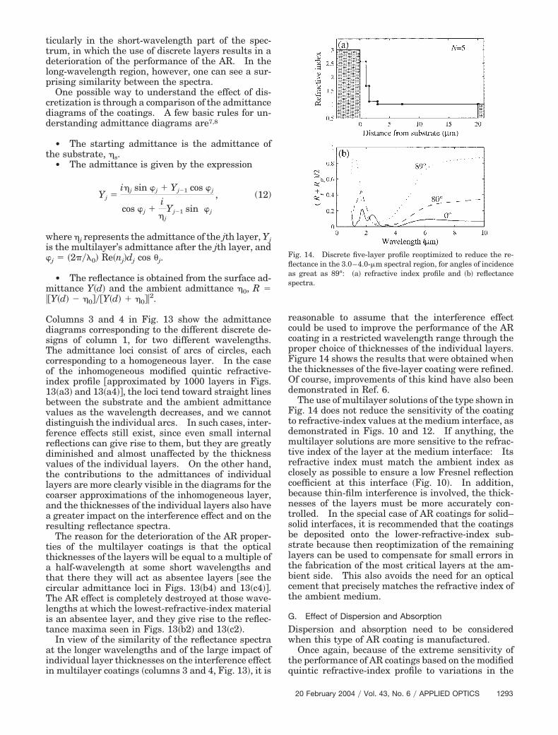
icularly in the short-wavelength part of the spec-rum, in which the use of discrete layers results in aeterioration of the performance of the AR. In theong-wavelength region, however, one can see a sur-rising similarity between the spectra.One possible way to understand the effect of dis-
retization is through a comparison of the admittanceiagrams of the coatings. A few basic rules for un-erstanding admittance diagrams are7,8
• The starting admittance is the admittance ofhe substrate, �s.
• The admittance is given by the expression
Yj �i�j sin �j � Yj�1 cos �j
cos �j �i�j
Yj�1 sin �j
, (12)
here �j represents the admittance of the jth layer, Yjs the multilayer’s admittance after the jth layer, andj �2��0� Re�nj�dj cos �j.
• The reflectance is obtained from the surface ad-ittance Y�d� and the ambient admittance �0, R
�Y�d� � �0���Y�d� �0��2.
olumns 3 and 4 in Fig. 13 show the admittanceiagrams corresponding to the different discrete de-igns of column 1, for two different wavelengths.he admittance loci consist of arcs of circles, eachorresponding to a homogeneous layer. In the casef the inhomogeneous modified quintic refractive-ndex profile �approximated by 1000 layers in Figs.3�a3� and 13�a4��, the loci tend toward straight linesetween the substrate and the ambient admittancealues as the wavelength decreases, and we cannotistinguish the individual arcs. In such cases, inter-erence effects still exist, since even small internaleflections can give rise to them, but they are greatlyiminished and almost unaffected by the thicknessalues of the individual layers. On the other hand,he contributions to the admittances of individualayers are more clearly visible in the diagrams for theoarser approximations of the inhomogeneous layer,nd the thicknesses of the individual layers also havegreater impact on the interference effect and on the
esulting reflectance spectra.The reason for the deterioration of the AR proper-
ies of the multilayer coatings is that the opticalhicknesses of the layers will be equal to a multiple of
half-wavelength at some short wavelengths andhat there they will act as absentee layers �see theircular admittance loci in Figs. 13�b4� and 13�c4��.he AR effect is completely destroyed at those wave-
engths at which the lowest-refractive-index materials an absentee layer, and they give rise to the reflec-ance maxima seen in Figs. 13�b2� and 13�c2�.
In view of the similarity of the reflectance spectrat the longer wavelengths and of the large impact ofndividual layer thicknesses on the interference effectn multilayer coatings �columns 3 and 4, Fig. 13�, it is
easonable to assume that the interference effectould be used to improve the performance of the ARoating in a restricted wavelength range through theroper choice of thicknesses of the individual layers.igure 14 shows the results that were obtained whenhe thicknesses of the five-layer coating were refined.f course, improvements of this kind have also beenemonstrated in Ref. 6.The use of multilayer solutions of the type shown in
ig. 14 does not reduce the sensitivity of the coatingo refractive-index values at the medium interface, asemonstrated in Figs. 10 and 12. If anything, theultilayer solutions are more sensitive to the refrac-
ive index of the layer at the medium interface: Itsefractive index must match the ambient index aslosely as possible to ensure a low Fresnel reflectionoefficient at this interface �Fig. 10�. In addition,ecause thin-film interference is involved, the thick-esses of the layers must be more accurately con-rolled. In the special case of AR coatings for solid–olid interfaces, it is recommended that the coatingse deposited onto the lower-refractive-index sub-trate because then reoptimization of the remainingayers can be used to compensate for small errors inhe fabrication of the most critical layers at the am-ient side. This also avoids the need for an opticalement that precisely matches the refractive index ofhe ambient medium.
. Effect of Dispersion and Absorption
ispersion and absorption need to be consideredhen this type of AR coating is manufactured.Once again, because of the extreme sensitivity of
he performance of AR coatings based on the modifieduintic refractive-index profile to variations in the
ig. 14. Discrete five-layer profile reoptimized to reduce the re-ectance in the 3.0–4.0-�m spectral region, for angles of incidences great as 89°: �a� refractive index profile and �b� reflectancepectra.
20 February 2004 � Vol. 43, No. 6 � APPLIED OPTICS 1293

impswbHtoscdmgarclott
tmimirmcfFnb11ptmdnhtptact3sswlopo
3
Tioc
toatomtalifistdeag
cn
Frn�cci�t
1
ndex, especially in the vicinity of the incidenceedium, it is certain that dispersion will affect the
erformance of the coatings. A dramatic demon-tration of this was the narrowing of the spectralidth of the AR region in the wide-angle AR coatingased on a reststrahlen material presented in Ref. 6.owever, even in the visible and ultraviolet parts of
he spectrum, dispersion causes the refractive indexf coating materials to increase significantly athorter wavelengths. This is also true for the criti-al low-refractive-index material at the ambient me-ium side. As a consequence, with real dispersiveedia, one should expect an increase in reflectance at
razing angles of incidence at shorter wavelengths,n effect that can only be partially compensated byefinement of the layer thicknesses in multilayer ARoatings. At normal incidence and short wave-engths, dispersion may also increase the reflectancef the inhomogeneous coating, since it will increasehe ratio �max��min and will require a thicker transi-ion layer at the substrate side.
It has been shown numerically that absorption inhe layer also results in deterioration of the perfor-ance of the AR coating, particularly if the substrate
s transparent and if the transmittance should beaximized. However, more interesting is the case
n which the substrate is absorbing and in whicheflectance is the only parameter that needs to beinimized. We will consider here the particular
ase of an AR coating for amorphous silicon designedor wavelengths in the visible part of the spectrum.or such a case it has been shown numerically forormal incidence of light that a lower reflectance cane achieved when not only the refractive index �Figs.5 �column 1�� but also the extinction coefficient �Fig.5 �column 2�� is graded.17 Figures 15�c1� and 15�c2�rovide an explanation for this observation: Owingo the complex admittance of the substrate, itsatching with the ambient admittance cannot be
one smoothly if k is not graded. As a result, theonabsorbing quintic gives rise to interference andas a performance that is significantly worse thanhat of an absorbing quintic. An alternative ap-roach is to use a phase-correction layer whose func-ion is to match the substrate admittance with andmittance located on the real axis; a quintic profilean then be used to match this real admittance valueo that of the ambient material. Figure 15 �column� illustrates the application of this technique andhows the resulting performance centered at a pre-elected wavelength �600 nm�. We observed thathen the refractive index of the phase-correction
ayer is high, its thickness is small compared with theverall thickness of the coating and that the resultingerformance does not change significantly with anglef incidence.
. Conclusion
he theory of large-bandwidth quasi-omnidirectionalnhomogeneous-layer AR coatings has been devel-ped. It was shown that to obtain a wide-angle ARoating one has to distort the thickness axis of tradi-
294 APPLIED OPTICS � Vol. 43, No. 6 � 20 February 2004
ional inhomogeneous transition-layer profiles. Tobtain a coating that has a good performance for allngles of incidence as great as 89°, one would needhe optical thickness of the coating to be of the orderf 50�0 or more. During fabrication, the perfor-ance of such a coating would be especially sensitive
o fabrication errors in the refractive index at thembient side of the coating. If the inhomogeneousayer is approximated by a multilayer system and ifnterference effects caused by the finite Fresnel coef-cients at the layer interfaces are exploited, we havehown that the number of layers, and the overallhickness of the AR coating, can be significantly re-uced, providing that one is willing to reduce theffective bandwidth of the resulting AR coating andccept some deterioration in its performance at an-les close to 89°.The applicability of the multilayer AR coatings in
ases of solid–solid and air–solid interfaces has beenumerically studied in Ref. 6. In the case of an air–
ig. 15. Effect of absorption on the performance of gradedefractive-index AR coatings. �Column 1� transparent inhomoge-eous layer matches the real part of the substrate refractive index,column 2� layer with a graded refractive index and extinctionoefficient, and �column 3� graded transparent coating with a thinorrection layer �with n Re��s� and d 18.3 nm� at the substratenterface. Row �b� shows the refractive-index profiles, and rowsa� and �c� show their respective reflectance spectra and admit-ance diagrams at the wavelength of 600 nm.

stcpbttsf
R
1
1
1
1
1
1
1
1
olid interface, it was shown that it should be possibleo fabricate a quasi-omnidirectional AR coating effi-ient at a specific wavelength, by use of the opticalroperties of materials around their reststrahlenands in the mid-IR. A future paper will describehe experimental manufacture of such coatings andheir performances. Other approaches to produceuch coatings could involve the use of structured sur-aces.
eferences and Notes1. Lord Rayleigh, “On reflection of vibrations at the confines of
two media between which the transition is gradual,” Proc.London Math. Soc. 11, 51–56 �1880�.
2. R. N. Gupta, “Reflection of sound waves from transition lay-ers,” J. Acoust. Soc. Am. 39, 255–260 �1965�.
3. R. Jacobsson, “Light reflection from films of continuously vary-ing refractive index,” in Progress in Optics, E. Wolf, ed. �North-Holland, Amsterdam, 1966�, Vol. 5, pp. 247–286.
4. R. W. Wood, “Some experiments on artificial mirages and tor-nadoes,” Philos. Mag. 47, 349–353 �1899�.
5. R. W. Wood, Physical Optics �Macmillian, New York, 1934�, p.88.
6. J. A. Dobrowolski, D. Poitras, P. Ma, M. Acree, and H. Vakil,“Toward perfect antireflection coatings: numerical investiga-tion,” Appl. Opt. 41, 3075–3083 �2002�.
7. H. A. Macleod, Thin-Film Optical Filters, 3rd ed. �Institute ofPhysics, Bristol, UK, 2001�.
8. Sh. A. Furman and A. V. Tikhonravov, Basics of Optics of
Multilayer Systems �Editions Frontieres, Gif-sur-Yvette,France, 1992�.
9. W. H. Southwell, “Gradient-index antireflection coatings,” Opt.Lett. 8, 584–586 �1983�.
0. D. Poitras, “Admittance diagrams of accidental and premedi-tated optical inhomogeneities in coatings,” Appl. Opt. 41,4671–4679 �2002�.
1. B. G. Bovard, “Rugate filter theory: an overview,” Appl. Opt.32, 5427–5442 �1993�.
2. D. Poitras, S. Larouche, and L. Martinu, “Design and plasmadeposition of dispersion-corrected multiband rugate filters,”Appl. Opt. 41, 5249–5255 �2002�.
3. B. G. Bovard, “Graded index rugate filters: power-sine rugatestructures,” in Inhomogeneous and Quasi-Inhomogeneous Op-tical Coatings, J. A. Dobrowolski and P. G. Verly, eds., Proc.SPIE 2046, 109–125 �1993�.
4. P. G. Verly, “Optical coating synthesis by simultaneousrefractive-index and thickness refinement of inhomogeneousfilms,” Appl. Opt. 37, 7327–7333 �1998�.
5. It is worth noting that when the ratio �max��min under theexponent in Eq. �7� is increased, the profile of the ES transitionlayer becomes similar to the modified profile �Fig. 7�d1��.
6. It may be preferable to use an uneven distribution of points,since �i� its effect on the performance at short wavelengths andlarge angles of incidence is not critical and �ii� because manylayers with close indices would be hard to achieve in practice.
7. P. V. Adamson, “Antireflecting surface coatings with continu-ously varying complex refractive index,” Tech. Phys. Lett. 26,1003–1006 �2000�.
20 February 2004 � Vol. 43, No. 6 � APPLIED OPTICS 1295