1996 AP-S International Symposium & URSI Radio Science ...
442
-
Upload
khangminh22 -
Category
Documents
-
view
1 -
download
0
Transcript of 1996 AP-S International Symposium & URSI Radio Science ...

/l
J ·-, i. _, '
/ 11!-
17 2-.,.
We{come to the
1996 AP-S International Symposium & URSI Radio
Science Meeting
We are proud to serve as host company and prime
corporate sponsor.
NORTHROP GRUIWIWAN

National Academies of Science and Engineering National Research Council of the United States of America
United States National Committee International Union of Radio Science
1996 Digest
USNC/URSI Radio Science Meeting
July 21 - July 26, 1996 Baltimore, Maryland
Sponsored by USNC/URSI in conjunction with: IEEE-APS International Symposium

ii

Chairman's Welcome
Jon Moellers
On behalf of the Joint Symposia Steering Committee, it is my privilege to welcome you to the 1996 IEEE Antennas and Propagation Society International Symposium and URSI Radio Science Meeting. Participating this year are USNC/URSI Commissions A, B, C, D, E, F, and K. The Joint Symposia is being held at the Hyatt Regency Hotel at the Inner Harbor, in Baltimore, Maryland, during the week of July 21-26, 1996.
An interesting and informative technical program has been assembled by the Technical Program Committee under the leadership of Dr. Joe Frank and Dr. Julius Goldhirsch. Approximately 900 papers are scheduled to be presented during the Joint Symposia, with submittals from countries all around the world. Almost half of the accepted papers have non-United States authors. This statistic underscores the true international flavor of the AP-S/URSI Joint Symposia. All technical sessions will be c-onducted in spacious hotel meeting rooms that are conveniently located.
In keeping with tradition, nine short courses and workshops are scheduled during the Symposia. To increase participation in this educational forum, the short courses and workshops will be given on two separate days. Sunday, July 21, is the first day for short courses/workshops, with seven topics being offered. Friday, July 26, is the.second day, with two additional topics. A detailed listing for each item is included in this program.
An entertaining and affordable social program has been developed for the attendees, their guests, and their families. The Baltimore/Washington area offers a wealth of extended vacation opportunities for individuals and entire families. The Symposia hotel is located on the famous Baltimore Inner Harbor. The Inner Harbor area offers the Fort McHenry National Monument, National Aquarium, Maryland Science Center, Oriole Park at Camden Yards, museums, restaurants, and boat rides. I hope that you are able to take time to experience the unsurpassed assortment of recreational, historical, and educational opportunities in this area.
The 1996 Joint Symposia Steering Committee has ·planned an excellent technical program, enjoyable social events, and educational short courses and workshops. We look forward to seeing you at the Symposia.
iii
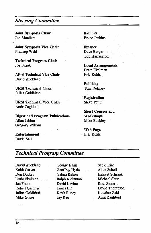
Steering Committee
Joint Symposia Chair Jon Moellers
Joint Symposia Vice Chair Pradeep W ahi
Technical Program Chair Joe Frank
AP-S Technical Vice Chair David Auckland
ORSI Technical Chair Julius Goldhirsh
ORSI Technical Vice Chair Amir Zaghloul
Digest and Program Publications Allan Jablon Gregory Wilkins
Entertainment David Sall
Technical Program Committee
David Auckland George Hagn Keith Carver Geoffrey Hyde Don Dudley Galina Kelner Ernie Ekelman Ralph Kleinman Joe Frank David Levine Robert Gardner James Lin Julius Goldhirsh Keith Raney Mike Gosse Jay Rao
iv
Exhibits Bruce Jenkins
Finance Dave Berger Tim Harrington
Local Arrangements Ernie Ekelman Eric Kohls
Publicity Tom Delaney
Registration Steve Pettit
Short Courses and Workshops Mike Buckley
Web Page Eric Kohls
SedkiRiad Allan Schell Helmut Schrank Michael Shur Ross Stone David Thompson Kawthar Zaki Amir Zaghloul
APS Reviewers
David Auckland Keith Carver Ernest Ekelman YehyaEnter Stephen Gedney Michael Gosse Philip Hacker Richard Hall Jeffrey Herd Peter Hrycak Andrew Human
Geoffrey Hyde Eric Kohls Kevin Leahy David Levine Eric Lucas Thomas Milligan Stephen Moraites Kenneth O'Haver Wahid Parveen Dilip Paul David Pozar
Special Session Organizers
G.Brown N. Engheta J.Huang
R.·E. Kleinman J. F. Lee R. Mittra
Administrative Assistance
Audrey Bullock Cornelia Carlisle Libby Croston Judith Goldhirsh Michael Goldhirsh
Diana Malinowski Deborah Seibert Virginia Stephens Pat Wade
Keith Raney Jaganmohan Rao . Victor Sanchez Daniel Schaubert Allan Schell Helmut Schrank Robert Stilwell Leonard Taylor John Volakes Amir Zaghloul Kawthar Zaki
R. D. Nevels A. Taflove M. L. Van Blaricum
3 Dimensions Meeting Planners: Mary Ellen Vegter Theodora Dirksen Bonnie Grosek
Morgan State University IEEE Student Chapter
V

vi
Session URSI-B Session 1 URSI-B Session 2 URSI-B Session 3 AP/URSI-B Session 1
AP/URSI-F Session 1 URSI-B Session 4 URSI-B Session 5 URSI-A Session 1 AP/URSI-B Session 2 AP/URSI-B Session 3 AP/URSI-B Session 4 AP/URSI-F Session 2
URSI-B Session 6 URSI-K Session 1 URSI-B Session 7
AP/URSI-B Session 5 AP/URSI-A Session 1 URSI-E Session 1 URSI-C Sesston 1 URSI~A Session 2 URSI-B Session 8 URSI-B Session 9 URSI-B Session 10 URSI-B Session 11 URSI-B Session 12 AP/URSI-F Session 3 AP/URSI-D Session 1
Contents
Monday
Title Page Antenna Arrays ............................................................ 1 Radar and Target Identification ................................. 13 Integral Equations ...................................................... 23 Wavelet Methods for Differential and Integral Equations ............................................................. .' ..... 33 Propagation Modeling ............................................... 41 Finite Element Methods ............................................ .47 Micro.strip I ................................................................ 59 EM Measurements ..................................................... 69 Image Reconstruction from Real Data ....................... 79 In Honor of Kane Yee 30th Anniversary ofFDTD ... 89 Theoretical Electromagnetics I .................................. 99 Propagation Measurements - Over Land and Water ....................................................................... 107
Tuesday
Finite Difference Time Domain Methods ................ 115 Electromagnetics in Biology and Medicine ............. 123 Low Grazing Angle Scattering from Rough Surfaces ................................................................... 135 Antennas I ................................................................. 147 EM Properties of Materials ...................................... 157 EM Noise and Interference ...................................... 163 Signals and Systems ................................................ 169 Pulse Radar Techniques ........................................... 177 Finite Methods ......................................................... 185 Integral Equation Applications ................................ 193 Complex Media ....................................................... 203 Transients ................................................................ 213 Inhomogeneous Waveguides ................................... 223 Mobile Propagation Effects ...................................... 231 Microwave and Millimeter Wave Devices and Circuits .............................................................. 237
vii

Session
URSI-B Session 13 URSI-B Session 14 URSI-B Session 15 AP/URSI-B Session 6 AP/URSI-F Session 4 AP/URSI-D Session 2 AP/URSI-B Session 7
URSI-B Session 16
AP/URSI-B Session 8 AP/URSI-F Session 5 AP/URSI-B Session 9 AP/URSI-D Session 3 URSI-B Session 17
URSI-B Session 18 URSI-B Session 19 URSI-A Session 3 AP/URSI-B Session 10 AP/URSI-A Session 2 AP/URSI-F Session 6
viii
Wednesday
Title Page
Microstrip II ............................................................. 247 Hybrid Numerical Methods ..................................... 257 Guided Waves ......................................................... 267 Novel Mathematical Techniques in EM Theory ...... 277 Personal Access System Propagation Effects .......... 285 Photonics Applications to Antennas ......................... 293 Scattering and Diffraction ........................................ 301
Thursday
Inverse Scattering .................................................... 311 Antennas II .............................................................. 323 Earth-Satellite Propagation Effects .......................... 333 Computational Speed and Efficiency ...................... 341 Photonic and Quasi-Optical Devices ....................... 353
Recent Progress in PML Absorbing Boundary Condition in FEM and FDTD ................................. 359 High Frequency Techniques .................................... 371 Theoretical Electromagnetics II ............................... 383 EM Modeling and Simulation ................................. 391 Antennas III ............................................................. 397 Transmission Lines and Devices ............................ .407 Propagation in the Ionosphere ................................. 409
Monday AM URSI-B Session 1 Constel. Ballroom E
Antenna Arrays W. A. Davis Page
8:20 Approaches to Pattern Multiplication for Non-Ideal Phased ................ 2 Phased Array Antennas James W. LaPean, Jr., William A. Davis, Wa"en L. Stutzman, Virginia Polytechnic Institute and State University
8:40 Beam Synthesis of Conformal Arrays ......................................... .3 John P. Casey, Naval Undersea Warfare Center Detachment New London, CT, Roy L. Streit, Naval Underseas Warfare Center, Newport; RI
9:00 Mutual Coupling in Coplanar Parasitic Arrays ............................... .4 Richard Q. Lee, Afroz Zaman, NASA Lewis Research Center, Kai-Fong Lee, University of Missouri
9:20 Low-Profile Broadband Radiating Array Element with ...................... .5 Integrated Circulator Reza M. Najafabadi, Michael A. Acree, Johnson J. H. Wang, Wang Electro-Opto Corporation (WEO)
9:40 Mechanically Steerable Phased Array Antenna for Mobile ................. 6 Satellite Applications Radha Telikepalli, CAL Corporation
10: 20 Circularly Polarized Dielectric Resonator Antenna Array ................... 7 M. G. Keller, M. Fleury, E. Philippouci, A. Petosa, Royal Military College of Canada, M. B. Oliver, Aerospace Engineering Test Establishment Canadian Forces Base Cold Lake
10:40 Analysis of Finite Planar. Array of Rectangular Cavity-Backed ............ 8 Antenna Elements H. Moheb, J. Shaker, University of Manitoba
11 :00 Wide Angle Scan Characteristics of Small and Compact Spiral ............ 9 Arrays L. Shafai, Leili Shafai, H. Moheb, University of Manitoba, W. Chamma, InfoMagnetics Technologies Corporation
11 :20 Null Control of an Otherwise Omnidirectional Pattern Using a .......... 10 Circular Array Roberto Vescovo, Universita' di Trieste
11 :40 Genetic Algorithms for the Synthesis of Planar Arrays .................... 11 D. Marcano, A. Nieto, Universidad Simon Bolivar
12:00 Antenna Array of Slot Metal-Dielectric Elements ... , ....................... 12 N. N. Kolchigin, D. D. Ivanchenko, S. N. Pivnenko, Kharkov State University
1
APPROACHES TO PATTERN MULTIPLICATION FOR NON-IDEAL
PHASED ARRAY ANTENNAS
James W. LaPean, Jr.*, William A. Davis, and Warren L. Stutzman
Antenna Laboratory Satellite Communications Group
The Bradley Department of Electrical Engineering Virginia Polytechnic Institute and State University
Blac\sburg, VA, 24061-0111
The relationship between the element pattern, array factor, and total array pattern is clearly defined in classical ideal array theory. The assumed lack of element interactions reduces the total array pattern to the simple pattern multiplication expression
F(B, ¢) = g;(B, ¢) f(B, ¢)
where g; ( (), ¢) is the element pattern and f ( (), ¢) is the normalized array factor. This assumption implies that pattern of each element of the array is identical and equal to the element pattern in the absence of other elements and that the normalized array factor is determined by simple superposition of the element excitation weights. Unfortunately, most practical array antennas exhibit mutual coupling interactions between the radiating elements especially for phase scanned operation. These interactions introduce errors in the classic ideal array theory pattern multiplication expression which can dominate the result under certain circumstances. Fortunately, the usefulness of pattern multiplication for the design and analysis of non-ideal phased array antennas can be largely restored by including the mutual coupling effects in the pattern multiplication. The effects of mutual coupling on the array pattern can be included in either the element pattern or the array factor
This paper will briefly discuss the significance of the effects of mutual coupling on the pattern of a non-ideal phased array. Also, this paper will show how these mutual coupling effects can be included in either the element pattern or the array factor. Finally, the assumptions which are used to develop these two approaches for accounting for the mutual coupling in the pattern will be discussed.
2
BEAM SYNTHESIS OF CONFORMAL ARRAYS
John P. Casey* Submarine Electromagnetic Systems Department Communications Antennas Branch, Code 3413
Naval Undersea Warfare Center Detachment New London, CT 06320
Roy L. Streit Combat Control Systems Department, Code 2214
Naval Undersea Warfare Center Newport; RI 02841
For arrays conformal to nonplanar surfaces, the radiation patterns and polarizations of individual antenna elements are not identical because of their dissimilar orientations and because they couple differently with the host surface. Consequently, neither the principle of pattern multiplication nor conventional beam synthesis methods apply. Unfortunately, no proven synthesis technique is available fot;<;onfopnal anteµna ~y.s CH. H.1Kummer, Proc,JEEE, 80, p. 137, Jan. 1992). ·
In this paper, an optimization procedure is applied .in the determination of the complex excitations to prod~ce a beam pattern which has high gain, desired polarization across the main beam, sufficiently low sidelobes, and which satisfies practical excitation restrictions. Optimization methods have been successfully applied to the synthesis of conformal sonar arrays (Streit and Nuttall, J. Acoust. Soc. of Am., 72, pp. 181-190, July 1982).
' The optimization model is based on the minimization of the total radiated power in the sidelobe region S {defined by the designer) subject to the following constraints: {i) restrictions on the variations in magnitude and phase of the antenna excitation currents ; {ii) the polarization loss factor {PLF), i.e., the loss associated with the mismatch between the array polarization and the desired polarization, must be less than or equal to a specified upper bound throughout the main beam region M (defined by the designer); (iii) the directive gain of the array must be greater than or equal to a specified lower bound. Sidelobe constraints may be added as needed. The effect of the individual element patterns and polarization in the presence of the host suµace is,incoqx>qtted. ·
The optimization model is carried out via a sequential quadratic programming (SQP) algorithm, in which the search direction is the solution of a quadratic programming subproblem. SQP algorithms are generally superior to gradient descent methods as they exhibit a higher rate of convergence in the vicinity of the solution. In addition, an SQP algorithm is well suited to this application since the objective and constraint functions are quadratic functions of the excitation variables. The algorithm is applied to the synthesis of an arbi~ phased array antenna conformal to a convex three-dimensional surface. However, the algorithm is potentially applicable to arbitrary volumetric arrays.
The optimization model is validated through comparison with conventional procedures for the synthesis of various linear and planar arrays. Results will be presented for the synthesis of phased arrays conformal to both cylindrical and spherical surfaces. Slot elements are considered in the conformal array examples.
3
MUTUAL COUPLING IN COPLANAR PARASmc ARRAYS
Richard Q. Lee and Afroz Zaman* NASA Lewis Research Center, Cleveland OH 44135
Kai-Fong Lee Dept. of Elect. Eng., University ofMissouri, Columbia, Missouri 65211
It has been demonstrated that parasitic patch antennas when placed adjacent to a fed microstrip patch in a coplanar configuration can enhance the directivity of the antenna by several dB and produce a pattern resembling that ofan array [R. Q. Lee, R Acosta and K. F. Lee, Electronics Letters, Vol. 23, No. 16, pp. 835-837, July 1987]. Using parasitic elements to achieve higher directivity has advantage over conventional array approach in terms offeeding network losses and unwanted radiation from bends and junctions. Furthermore, for a specified beamwidth, the physical size of the array can be much smaller since very close element spacing is required. Over the years, research on parasitic arrays has been focused on arrays of stacked configurations, and very little has been done on parasitic arrays of coplanar geometry. As a result, coupling mechanism and antenna parameters required to produce a highly directive beam are not well understood. In this paper, we will report an experimental investigation of the mutual coupling effects between adjacent elements in a linear, coplanar parasitic array of7 elements. The parasitic patches having same dimensions as the fed patch are fabricated on 0.0254 RT/Duroid substrate with e, = 2.2. The center patch is excited to produce a linearly polarized wave which in tum e,ccites the parasitic elements through mutual coupling. In the experiment, 1'Mo1 ,TM10 and both (1'Mo1 andTM10 ) modes are excited so couplings along the E-, the H- and both planes can be studied. Preliminary results indicate that all three types of couplings produce radiation patterns similar to that produced by a conventional array. However, high sidelobes will be produced if proper element spacings.are not used. Details of the experimental findings will be presented and discussed at the meeting.
4
Low-Profile Broadband Radiating Array · Element with Integrated Circulator ·
Reza M. Najafabadi, Michael A. Acree, and Johnson J. H. Wang
Wang Electro-Opto Corporation (WEO) 1335 Capital Circle, Suite G
Marietta, GA 30067
Existing broadband phased array radiating elements, especially in the field of airborne applications, require a depth of at least 0.151. over the entire band. As a result, existing phased arrays have a thickness larger than can be accommodated in many airborne platforms. For example, the commonly used flared notch array antennas with integrated circulators operating down to 2 GHz. have a thickness of two inches or more. In certain applications, it is desirable to reduce this antenna/circulator element to less than one inch. To accomplish this· reduction of array thickness, the newly invented spiral-mode microstrip (SMM) antenna (J. J. H. Wang and V. K. Tripp, IEEE AP Trans. 39, 332-335, 1991; patents awarded) appears to be the only feasible solution. A typical SMM antenna is only 0.125 to 0.3 inches in thickness. However, application of the SMM antenna to phased arrays has not been made in the past.
In this research, a 2-18 GHz SMM antenna with an integrated circulator is designed, fabricated, and tested for use as a modular radiating element for a planar phased array with a total thickness of less than one inch. However, because the state-of-the-art circulators are limited to a 3: 1 bandwidth, the current experimental model is also limited to a 3: l bandwidth. It is worth pointing out that, in many applications, this bandwidth limitation due to the circulator can be circumvented by using a T/R switch.
The radiation patterns of this SMM antenna array are calculated by using the radiation zone concept well established for the spiral antenna. The characteristics of the balun, the circulator, and the transition between them are calculated and simulated on the basis of TEM mode propagation with higher order modes ignored. The measurements of the array module are carried out in WEO's anechoic chamber. Both calculated and measured results are presented to demonstrate that the use of the SMM antenna enables us to reduce drastically the thickness of multioctave wideband arrays not achievable by other means, including the flared notch arrays.
5
MECHANICALLY STEERABLE PHASED ARRAY ANTENNA FOR MOBILE SATELLITE APPLICATIONS
Radha Telikepalli CAL Corporation 1050 Morrison Drive Ottawa, ON K2H 8K7 CANADA
A phased array of quadrifilar helices was designed to give a
10° - 80° elevation and 360° azimuth coverage. Purpose of this antenna
was to provide voice communications from an automobile. Non electrical
features considered in design include a compact size, low cost and light
weight. It was mechanically steered in both elevation and azimuth planes
with the help of a motor. Th~ antenna has an impedance bandwidth of
8.5 % and a minimum gain to noise temperature of-12 dBK at any point of
coverage. As a quadrifilar helix is insensitive to the ground plane, this
particular array has the advantage of minimum coupling to the
suroundings like automobile roof and other RF components. Individual
elements were fed with a combination of coaxial cables located in the
center of the helix and a 3 dB hybrid with a 90° phase difference between
two arms.
The array occupies a space of 25 - 30 cm in length and 5 - 1 O cm
in width. A highly efficient beam steering unit was used to focus the beam
with gain to noise temperature levels of - 12 dBK towards the satellite.
The present paper gives the design of the element from method of
moments, synthesized array and the respective radiation patterns.
6
Circularly Polarized Dielectric Resonator Antenna Array
+M.G. Keller*, +M. Fleury, +E. Philippouci, +A. Petosa, +++M.B. Oliver,
+Royal Military College of Canada Kingston, Ontario K7K 5LO, Canada
++communications Research Centre P.O. Box 11490, Station H, Ottawa, Ontario K2H 8S2, Canada
+++Aerospace Engineering Test Establishment Canadian Forces Base Cold Lake, Medley, Alberta, TOA 2MO, Canada
Lately, the concept of utilizing dielectric resonators as antennas has been the focus of much research. Ihe dielectric resonator antenna {DRA) has many attractive characteristics such as large bandwidth, high radiatio'l,
,:efficiency, small physical siz~ and sime_!e couQHng schemes. Recent DRA developments incluae a novel circularly polarized DRA (CPDRA) configuration fed by a single probe or slot (M.B. Oliver, Y.M.M. Antar, R.K. Mongia, A lttipiboon, Elect. Lett., 16 Mar 95, Vol. 31, No. 6, pp. 418-419), and a microstripfed DRA array configuration consisting of up to twelve antenna elements (R.K. Mongia, A lttipiboon, M.Cuhaci, ANTEM 94 Conference Proceeding, pg 81-83, Aug 1994).
This paper reports the results of !'!xperimental investigations on~ microstrip-fed series array configuration of CPDRAs. The dimensions of the rectangular resonator were selected, using the dielectric waveguide model as applied by Mongia (R.K Mongia et. al., Conf. Proc. IEEE APS Int. Symp. 1994, pp 764-767), such that the DRAs can support two nearly degenerate orthogonal modes and thus radiate a circularly polarized wave. These antenna elements were excited by JID>ximity couru!ru! by placing them near the microstrip transmission feed line. Proximity coupling simplifies the feeding of the CPDRA elements by eliminating the need for probes or slots
Several different configurations of CPDRA sub-arrays are being examined. Preliminary experimental results show that the axial ratio performance of an individual CPDRA can be improved when placed in certain sub-array configurations.
7

ANALYSIS OF FINITE PLANAR ARRAY OF RECTANGULAR CAVITY-BACKED ANTENNA ELE:MENTS
H. Moheb* and J. Shaker Department of Electrical & Computer Engineering
University of Manitoba, Winnipeg, Manitoba, Canada R 3T 2N2
Recent advances in EHF personal communications satellite industry requires highly efficient antenna arrays with smaller aperture size and suitable for integration with active components. The antenna element itself can be single/multi-layered microstrip structure, metallic cavity or their combinations. However, the cavity-backed antenna seems the most promising candidate for array integration at EHF frequencies. Once in an array environment the radiation pattern, the element driving impedance, and polarization variation with scan angle is usually affected by the mutual coupling interactions between the antenna elements. The degree of coupling depends on the element type, scan angle, array geometry, excitation and polarization of each element. The analysis therefore should include all these factors for better modeling and design of an array.
The available theoretical analyses are usually based on infinite or finite array methods. The infinite array approach is useful for electrical characteristics of the elements near the center of an array, but it breaks down when the informations on the element near the edge are required. Also, as the number of array elements decreases, the infinite array model tends to be less accurate due to the presence of mutual coupling between the array elements. On the other hand, in the finite array approach modeling the analysis includes the mutual coupling irrespective of array geometry or positioning of the element in the array. Previous works on finite planar arrays are mainly on waveguides (F. Arndt, K.H. Wolff, IEEE Trans., AP37, 3, 329-338, 1989) excited by their dominant mode.
In this paper, we use the combination of Integral Equation and Modal Expansion Method (IE/MEM) to study the electrical performance of an array of rectangular cavity-backed aperture antennas of irregular shapes. The excitation is an infinitesimal dipole located inside the cavities or a narrow slot etched on the bottom plate of each cavity. The analysis applies the equivalence principle to decompose a two region problem into two independent problems. Application of the boundary conditions, namely the continuity of the tangential electric and magnetic fields results in an integral equation. This operator can be solved numerically by the method of moments to determine the equivalent magnetic current on each cavity. Once the equivalent magnetic current is computed, one can determine other parameters, such as the array radiation pattern, gain, aperture field distribution, and the input impedance of each array element. A design example will be provided to illustrate the capability of the developed analysis.
8
Wide Angle Scan Characteristics of Small and Compact Spiral Arrays
L. Shafai*, W. Chamma**, Leili Shafai* and H. Moheb*
* Dept. of Electrical and Computer Engineering University of Manitoba
Winnipeg, Manitoba, Canada, R3T 5V6
** lnfoMagnetics Technologies Corporation Winnipeg, Manitoba, Canada, R2J 3T4
Excessive scanning of the array beam in phased arrays introduces a number of practical difficulties, that prevents the actual beam scan. Normally, the mutual coupling between the array elements increases in the directions of the beam, and results in an excessive variation of the array element input impedances. In the scan direction they increase rapidly, but decrease behind the array beam, even approaching zero or becoming negative. This results in severe impedance mismatch losses and a decrease in the array gain. Increasing the element spacing reduces the mutual coupling, but is not effective for large beam scans, since it causes grating lobes and a further reduction in the gain.
The problem is more severe in planar arrays, where the element beam is in the broadside, such as the waveguides, horns and microstrip antennas. Here, the element radiation pattern has a reasonable gain and thus, its beamwidth is moderately small. This results in a rapid pattern role off at large beam angles away from the broadside, and a further reduction of the array gain. With circularly polarized array elements one normally experiences an additional problem of the axial ratio degradation with the beam scan. For broadside radiators, as the array elements, the beamwidths in the principal plane patterns are usually different and result in progressively poor axial ratios away from the broadside.
A possible solution for these problems may be found by shaping the radiation pattern of the array elements. In the present study we have investigated the problem fou,mall and compact arrays of planar spira~ The element patterns are shaped to JmRrove their axial ratio at large angles from the broadside and also tilt their radiation patterns towards the scan direction. The influences of such remedies on the array scan gain, radiation pattern and axial ratio are studied numerically and examined experimentally. The results are also compared with conventional microstrip arrays.
)"~~t~ ~- (~,,J
9
NULL CONTROL OF AN OTHERWISE OMNIDIRECTIONAL PATTERN USING A CIRCULAR ARRAY
Roberto Vescovo Dipartimento di Elettrotecnica Elettronica ed Informatica
Universita' di Trieste Via A. Valerio, 10 - 34127 Trieste - Italy
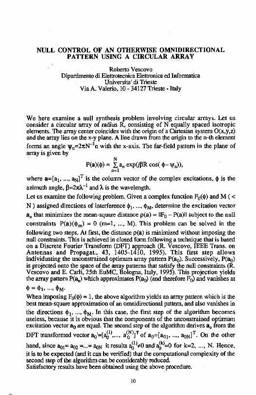
We here examine a null synthesis problem involving circular arrays. Let us consider a circular array of radius R, consisting of N equally spaced isotropic elements. The array center coincides with the origin of a Cartesian system O(x,y,z) and the array lies on the x-y plane. A line drawn from the origin to then-th element
forms an angle '1'n=2xN-1n with the x-axis. The far-field pattern in the plane of array is given by
N P(a)($) = I. an exp(j~R cos($- 'l'n)),
n=l
where a=[a1, ... , aN]T is the column vector of the complex excitations, $ is the
azimuth angle, ~=21t11.-1 and A is the wavelength.
Let us examine the following problem Given a complex function F0( $) and M ( < N) assigned directions of interference $1, ... , $M, determine the excitation vector
ae that minimizes the mean-square distance p(a) = IIF0 - P(a)II subject to the null
constraints P(a)($m) = 0 (m=l, ... , M). This problem can be solved in the
following two steps. At first, the distance p(a) is minimized without imposing the null constraints. This is achieved in closed form following a technique that is based on a Discrete Fourier Transform (DFT) approach (R. Vescovo, IEEE Trans. on Antennas and Propagat., 43, 1405-1410, 1995). This first step allows individuating the unconstrained optimum array pattern P(a0). Successively, P(ao) is projected onto the space of the array patterns that satisfy the null constraints (R. Vescovo and E. Carli, 25th EuMC, Bologna, Italy, 1995). This projection yields the array pattern P(ae) which approximates P(a0) (and therefore F0) and vanishes at
$ = $1, ... , $M· When imposing F0($) = 1, the above algorithm yields an array pattern which is the
. best mean-square approximation of an omnidirectional pattern, and also vanishes in
the directions $1, ... , $M· In this case, the first step of the algorithm becomes useless, because it is obvious that the components of the unconstrained optimum excitation vector ao are equal. The second step of the algorithm derives ae from the
DFT transformed vector ao'=[ag>, ... , a~1T of a0=[a01 , ... , aoN]T. On the other
hand, since ao1= aoz = ... = aoN it results ~ 1>:;,o and ~k)=O for k=2, ... , N. Hence, it is to be expected (and it can be verified) that the computational complexity of the second step of the algorithm can be considerably reduced. Satisfactory results have been obtained using the above procedure.
10
GENETIC ALGORITHMS FOR THE SYNTHESIS OF PLANAR ARRAYS
D. Marcano and A. Nieto Universidad Sim6n Bolivar. Dpto. Electr6nica y Circuitos
Grupo de Telecomunicaciones. Apdo. Postal 89000. Caracas 1080-A. Venezuela
The synthesis of planar arrays is an interesting topic for the antenna designer. The specialized litterature presents various methods for the synthesis of linear and planr antenna arrays based on deterministics rules. In this work we present the use of a genetic algorithm for the synthesis of a planar array with rectangular cells. Unlike the classical methods Genetic Algorithms are based on aleatory search rules which avoid local minima problems. We consider the radiating elements to be arranged in a regular rectangular array in the x-y plane, with an interelement spacing d='JJ2 in the x and y directions. In the Genetic Algorithm a population of 30 arrays was used with a mutation of 1 %. The phase of each element was coded in 12 bits. An individual is defined as an array of MxN elements, each with an amplitude Ai and phase Pi controlled by the genetic algorithm.The amplitudes of all the elements are equal while the phase of each element is obtained genetically until a desired radiation pattern specified by various points in 0,q> positions, is obtained. For the selection operator we have developed a dynamic window approach which selects the individuals for the genetic mechanisms of reproduction. A fitness Fi for each individual was calculated from the objective function: ·
Fi= N 1
1+ Le/<e.cp) i=I
where ei (0,<p) is the individual relative error and N is the total number of target points. Results are presented for an array of 4 x 4 and 6 x 6 elements with radiation patterns specified by 20 desired points. The maximun error obtained was 17.5% for the target values below -40 dB and 2.5% otherwise. The calculation time is approximately 25 minutes on a 486 DX2 66 machine with 16 Mbytes of RAM. Genetic Algorithms are capable of solve complicated problems of synthesis of antenna arrays.
11
1Ju S}N( ANTfflNA ARRAY OF SLOT METAL-DIELECTRIC EI.DENTS
N.N.Kolchigin, D.D.Ivanchenko, S.N.Pivnenko
Chair of Theoretical Radiophysics Kharkov State University
Svobody Sq. 4, Kharkov 310077, Ukraine
In recent period an antenna arrays based on slot metal-dielectric elements, which radiatipg characteristics defined by the geometry of electrods and substrate, are actively developed. The properties of slot radiators with the constant slot width or with that varying linearly or exponentially (the Vivaldi aerial) are well known. The study of a single slot element with heterogeneous dielectric substrate and antenna arrays made of such elements presents practical interest.
As it follows from the experiments these radiators provide with the opportunity of effective matching in the wide frequency oand at their minimal length. The radiators are also characterised by the II - shaped radiation pattern at E-plane with low level of lateral side lobes. For single radiators with linearly varying slot and the substrate's width equal to 3 .•• 5 wave le~th the width of the pattern at H-plane is 35 .•. 40° ., An equidistant antenna arrays of matched elements located on the isolated dielectric substrate has been studied. The distance between radiators was less than 0.6 of wave lel'lgth in the investigated frequency range. The parallel curcuit using T-branches on a slot line was applied for excitation. Two alternative constructions of antenna array were tested. In the first case the consistent location of heterogeneous sections was used: first the extention of slot, and then the constriction of substate. In the second case heterogeneous sections were located above each other and it gave rise to the extention of radiation pattern at H-plane, and to its constriction at E-plane. The obtained values of radiation directivity coefficients are slightly different and equal to 23.4 and 26.2 respectivefy. The patterns are symmetrical at both planes 1n contrast to the previous resUlts. Also it was been found that the dependence of radiation directivity at H-plane from the frequency is much stronger in comparison with other antennas.
12
Monday AM URSI-B Session 2 Chesapeake A
Radar and Target Identification L. Carin Page
8:20 Matched-Pursuits Time-Frequency Processing of ....................... 14 Electromagnetic Scattering Data Mark McClure, Lawrence Carin, Duke University
8:40 3D Scattering Center Model of Complex Targets ...................... 15 R. Bhalla, H. Ling, University of Texas at Austin, J. Moore, DEMACO
9:00 Detection of Buried Objects Using X-Band Radar and ................. 16 Angular Memory Effect Chris Penwell, Tsz-King Chan, Yasuo Kuga, University of Washington
9:20 Multipath Analysis for Short-Pulse Interrogation of Targets ........ 17 Above a Sea Surface A. Kizilay, A. Norman, E. J. Rothwell, D. P. Nyquist, K. M. Chen, Michigan State University
9:40 Average Received Signal Power After Two-Way Radar ............... 18 Propagation Through Ionized Turbulence Dennis L. Knepp, Mission Research Corporation
10:20 Application of Time-Frequency Methods to RCS Minimization ... 19 Olivier Boiteau, Commissariat a l'Energie Atomique (CEA)
10:40 Target Classification by a Time-Frequency Analysis .................. 20 T. Ince, K. Leblebicioglu, G. T. Sayan, Middle East Technical University
11 :00 The Use of Genetic Algorithms in Input Signal Shaping for ....... 21 Target Identification Gonul Turhan-Sayan, Kemal Leblebicioglu, Serhat !nan, Middle East Technical University ""
11 :20 Characterization of Radar Clutter as a Spherically Invariant ......... 22 Random Process
Jay Kyoon Lee, Mary C. Taylor, Syracuse University
13
Matched-Pursuits Time-Frequency Processing of Electromagnetic Scattering Data
Mark McClure and Lawrence Carin Department of Electrical and Computer Engineering
Duke Vniversity Durham, NC 27708-0291
Time-frequency processing has been investigated for several years, primarily in the form of windowed Fourier transforms and wavelet transforms; its success on real (measured) data has been mixed. In all such transforms, the data is projected onto a basis (a dictionary). However, in most cases the elements of the phase-space dictionary are not well matched to the underlying wave physics embodied in the scattered fields. This can be likened to processing a speech waveform, which is simply a time-dependent series of sounds. These timedependent sounds can be projected onto any basis (Fourier, Gabor, wavelet, French, German, etc.), but it is preferable to project the speech onto a basis understood by the user (English, for example), which hopefully correlates to the language used in the original speech. For sonar and radar data, we know the "language" being spoken: wave scattering and propagation. Thus, it is natural that the basis (dictionary) onto which the data is optimally projected should compactly embody the underlying wave physics. While windowed Fourier transforms, wavelet transforms, and other time-frequency architectures are mathematically interesting and have important applications in data compression (for example), they are generally not well matched to the wave physics characteristic of sonar and radar signatures.
Fields scattered from a target can be parametrized in terms of 1) wavefronts, 2) resonances, and 3) chirped (cavity modes) waveforms. Thus, these are natural dictionary elements for implementation of the method of matched pursuits for scattered fields. The algorithm is summarized as follows. We define a dictionary as a family D=(g.,)yer, where r is the set of indexes for the expansion functions g.,(t). The dictionary is composed of the wavefronts, resonances, and chirped waveforms discussed above. The algorithm is implemented with successive approximations of the scattered field f(t) with projections on elements of D. Let g.,
0ED. After the first iteration, the scattered
signal f(t) can be decomposed into
</, g10
>=f J(t)g1
/ (t)dt -oo
where Rf is the residual vector after projecting f on ~· Results will be presented for several radar scattering examples.
14
3D SCATTERING CENTER MODEL OF COMPLEX TARGETS
R. Bhallal*, J. Moore2 and H. Lingl
1Department of Electrical and Computer Engineering The University of Texas at Austin
Austin, TX 78712-1084
2DEMACO 100 Trade Centre Drive, Suite 303
Champaign, IL 61820
In radar cross section studies, it is well known that the electromagnetic scattering from an electrically large target can be approximately modeled as if it is emanating from a discrete set of points on the target called scattering centers. The scattering center model, while only an approximation, is conceptually simple and provides a sparse abstraction of the actual target for numerous radar applications. For instance, by storing the strength and position of the scattering centers, the lD range profile and 2D inverse synthetic aperture radar (ISAR) imagery of the target can be easily reconstructed in real time, alleviating the need for the storage of large data sets. In addition, a full 3D scattering center model allows multi-aspect signature extrapolation, target glint computation and target signature simulation under various operating conditions.
We have recently developed a technique to extract the 3D scattering center model of a target from the target CAD geometry model (R. Bhalla and H. Ling, 1995 IEEE AP-S Symposium Digest, pp. 1906-1909). The technique is based on the shooting and bouncing ray (SBR) technique. Using SBR, we first generate the 3D ISAR image of the target based on an one-look !SAR algorithm. In step two, we use the image processing algorithm CLEAN to extract the 3D position and strength of the scattering centers from the 3D !SAR image. This extraction algorithm has been tested on canonical targets sets and successfully implemented into the SBR code Xpatch.
In this paper, we will present the results of the scattering center data extracted from very complex targets (i.e., those whose CAD models consist of over 20,000 facets) over the full 360-degree azimuth view of the target and at multiple elevation angles. By postprocessing the resulting scattering center data sets, we will present a study of the behavior and stability of the scattering centers as a function of aspect.
15
URS! Commission B and F (rough surfaces and sub-surface remote sensing)
Detection of Buried Objects Using X-band Radar and Angular Memory Effect
Chris Penwell, Tsz-King Chan and Yasuo Kuga Department of Electrical Engineering, Box 352500,
University of Washington, Seattle, WA 98195-2500
Tel: (206)543-0478, Fax: (206)543-6185 Email: [email protected]
Waves scattered from disordered random media were recently identified as exhibiting the angular memory effect [Feng et al., 1988] which states that the angular changes of the scattered waves are correlated to those of the incident waves. The strength of this correlation can be expressed in terms of the angular correlation function (ACF).
In this paper we propose a novel approach to detecting buried objects based on this correlation phenomenon. An X-band radar was constructed in an experimental study, and ACF measurements were performed for scattering by a cylinder buried under sand. We examined the scattering by both conducting and non-conducting cylinders, each of which has a size comparable to the wavelength and was buried just below the sand surface with moderate roughness. Since the dimension and location of the cylinders used are similar to those of the small mines commonly found in battle fields, these experimental settings should yield reasonable physical insights into the feasibility of this method in practical applications.
From our earlier analytical, experimental and numerical studies, we devised a special antenna scanning scheme in which, together with some simple spectraldomain signal processing techniques, the undesirable scattering by the rough sand surface can be significantly suppressed whereas the desirable scattering by the cylinder can be significantly enhanced. It is this sharp contrast between the returned scattering power levels from the cylinder and the surface that forms the underlying basis for this target detection technique. As an illustration of the effectiveness of this method, our experimental data indicated a contrast factor of up to 40, or 16 dB for the scattered power when the cylinder was buried under the sand surface.
16
Multipath Analysis for Short-Pulse Interrogation of Targets Above a Sea Surface
A. Kizilay, A. Norman, E.J. Rothwell, D.P. Nyquist and K.M. Chen Department of Electrical Engineering
Michigan State University East Lansing, MI 48824
The multipath problem for a radar target above a sea surface has been studied in great detail, and the effects of surface roughness on narrow-band scattering from the sea have been analyzed. However, the deterministic problem of transient, short-pulse scattering from a disturbed seads not as well understood. In the time domain, individual ocean swells contribute to the scattered field which is incident on a target, making the multipath phenomenon more complicated.
This paper will undertake a theoretical analysis of the transient scattering of a short pulse from a simulated sea surface, and its interaction with a simple target located close to the surface. For simplicity, the sea will be considered to be perfectly conducting, and horizontal polarization will be used (thus, there will be no Brewster's phenomenon). A transient, short-pulse plane wave is assumed to be incident on a cylinder of arbitrary cross-section above a two-dimensional periodically-varying conducting surface. If the cylinder is close to the surface, the current induced on the surface will be nearly identical to that induced by a plane wave without the cylinder present, except within a region of finite extent immediately beneath the cylinder (the region of multiple interactions). A set of coupled Electric-Field Integral Equations for the current induced on the cylinder and on the surface within the finite region beneath the cylinder has been derived and can be solved in the frequency domain using the method of moments (MoM). This formulation requires the knowledge of the scattered field produced by the plane wave interacting with the infinite surface without the cylinder present, a problem which has been solved previously using a Floquet analysis and the MoM (A. Norman, et. al., 1995 USNC/URSI Radio Science Meeting, Newport Beach, CA). Transient fields are subsequently obtained using an inverse Fourier transform of the spectral data.
Results will be presented for targets above a calm sea, and above a rough, periodic sea. Comparison will be made to see the effect of surface roughness on the transient multipath phenomenon. Considerable emphasis will be place on the interpretation of multipath in the time domain as a superposition of temporal events arising from direct and indirect scattering paths.
17
Average Received Signal Power After Two-Way Radar Propagation Through Ionized Turbulence
Dennis L. Knepp Mission Research Corporation
Monterey, California 93940
This work considers the case of a structured ionosphere separating a monostatic or bistatic radar and its target. An analytic calculation of the correlation function of the received signal is presented. This result is a function of the difference in locations of the transmit and receive apertures and of time during the duration of the received pulse. Strong, saturated, scattering is assumed where the one-way scintillation index is unity; the quadratic approximation for the phase structure-function is used in the strong scatter approximation to obtain tractable results for the mutual coherence function (MCF). In this work the two-position, two-time, two-frequency MCF for two-way spherical wave propagation is used to obtain results that simultaneously describe all interaction between the propagating radar signal and the ionospheric propagation medium.
The result for the correlation function of the received signal is a function of the basic parameters that describe the effects of spherical wave propagation through the ionospheric structure, including the channel correlation distance, the channel decorrelation time, and the channel coherence bandwidth. This result also includes the aperture averaging effect of the transmit and receive apertures to reduce the received signal energy in the case of narrow beams (large antennas) that reject off-axis scattered energy.
To obtain tractable results for an important problem, the transmitted signal is assumed to be a linear frequency modulated pulse (LFM) or chirp pulse. This waveform is used in over-the-horizon radar systems as well as many modern long-range radar systems.
In addition to aperture effects, this calculation simultaneously includes the effects of the relationship between the propagation channel characteristics and the transmitted signal characteristics. For example, loss in peak power and spread in the received pulse occurs for cases in which the pulse duration exceeds the channel decorrelation time, and/or the instantaneous pulse bandwidth exceeds the channel coherence bandwidth.
For the case of a transmitted chirp, the correlation function of the received signal is given as a one-dimensional Fourier transform that is straightforward to evaluate numerically. Additional analytic expressions are given for the cases of strictly frequency-selective or time-selective channels.
18
Application of time-frequency methods to RCS minimization
Abstract
Olivier BOITEAU Commissariat a l'Energie Atomique (CEA)
CEST A/DAA/SYS/EIO, BP n°2 33114 Le Barp, FRANCE
Tel: (33) 56 68 41 57 Fax: (33) 57 71 54 27
We perform two different applications of time-frequency methods to electromagnetism, in order to minimize the monostatic RCS of a scatterer due to an incident stationary wave (e.g. a wave emitted by a radar antenna at infinity).
First, we develop an algorithm (refered as MP for Matching Pursuit; see S. Mallat and Z. Zhang, IEEE Trans.S.P, dee. 1993, 43p) and its main variants, in order to compute efficient adaptive decompositions of any signal as a linear expansion of atoms (belonging to a redundant complete dictionary). We applied it to the RCL reduction of a 2D scatterer (an infinite perfectly conducting cylinder of triangular section), just by modelling some antenna arrangements that fit with the decomposition of the RCL signal. An insight of antenna pattern model appears, but it is rather theoretical and, in order to implement MP, one needs some additional optimization processes ( as convenient groupings of such patterns).
Secondly, we develop an optimal control algorithm (see M. Mandallena, PhD dissertation, Grenoble I University, oct. 1993, 234p), using a BI method, in order to obtain the most favourable surface impedance coating on a given 3D perfectly conducting scatterer minimizing its RCS. The optimality system, resulting from a Lagrangian approach, turns this complex problem into a sequence of line searches through standard descent methods. Then we may compute an optimal solution corresponding to a local minimum of the scatterer's RCS according to several electromagnetic configurations.
In order to analyse the 'coherent structures' found in the optimal surface impedance, we perform their multilevel decomposition by means of wavelets. We are applying a powerful time-frequency tool: the MultiResolution Analysis (MRA) using spline functions. Once the main level described, we should devote all our energy to decompose the associated surface impedance part among a dictionary of surface impedances corresponding to several materials. Then such an adaptive decomposition may be computed efficiently by a MP algorithm.
19
Target Classification by a Time-Frequency Analysis
T. ince*, K. Leblebicioglu, G.T. Sayan Middle East Technical University
Department of Elecrical & Electronics Engineering 06531, ANKARA / TURKEY
phone : {312) 2102358, fax : {312) 2101261 e-mail : [email protected]
~
In this study a method is proposed for recognition of objects using their radar backscattered signals which are strongly aspect and polarization dependent. Furthermore, the radar returns of any two targets in a classification catalog may be quite similar calling for an elaborate classification technique. Our main idea is the introduction of time-frequency representation of scattered signals as a means of feature extraction. In particular, autoWigner Transforms (WT) of incoming signals are evaluated.
loo . T T
W1(t,w)= exp-JwTf(t+-)f*(t--)dT -oo 2 2
{1)
There are various reasons of why we have based our study on WT. It has many useful mathematical properties among which the following two are especially important and have been utilized in our approach :
1. The integral of the WT" over the frequency variable at a certain time yields the instantaneous power at that time :
1 1"" 2
ir _00
W1(t, w)dw = lf(t)l2 {2)
2. Similarly, the integral of the WT over the time variable at a certain frequency w yields the energy density spectrum off at this frequency :
{3)
By evaluating the integral in equation (3) over finite time intervals t1 , · · ·, tN at a prespecified finite number of frequencies w1 , ···,WM, one can extract a matrix A of order M x N, which may be considered as a feature of the signal. Assuming there are K objects and L possible incidence angles, one can obtain K x L, A matrices to be fed as data for a multilayer perceptron (MLP). MLP performs the classification job by identifying the object associated with a signal or it simply states that it is unable to recognize the object.
Since it is important to accomplish the identification in real time special attention was given to shorten the time spent for extraction of the feature matrix A. Studies are still going on in that direction. Besides, it is also (equivalently) possible to utilize equation (2) for feature extraction. Lastly one may fuse the information coming from equations {2) and (3) as well. Experiments still continue and results will be presented in the conference.
20
The Use of Genetic Algorithms in Input Signal Shaping for Target Identification
Gonill Turhan-Sayan*, Kemal Leblebicioltlu and Serhat inan Department of Electrical and Electronics Engineering
Middle East Technical University, 06531 Ankara, Turkey
The set of complex natural resonance (CNR) frequencies is an aspect and polarization independent identifier of an electromagnetic scatterer, With noisy measurement data, however, this set can not be used directly in target identification due to difficulties of accurate determination of CNR frequencies. Instead, the CNR concept is used indirectly to design a time-limited input signal called a K-pulse or E-pulse in the literature, The convolution of this signal with the target's impulse response produces a timelimited output due to the annihilation of natural resonances. This process corresponds to the cancellation of target's system poles by the input signal's spectrum zeros in the complex frequency domain, Within this context, input signal shaping for target identification is equivalent to designing natural resonance annihilation filters for each candidate target in an identification group. Each filter in this process is characterized by the K-pulse of the related target. When a test signal from an unknown target is passed through these filters, only the matching filter produces a time-limited response as it is free of natural oscillations.
The standard approach in this input signal shaping problem is to expand the signal in time domain into a suitable set of basis functions and to determine the expansion coefficients by minimizing the target's late time natural response energy, While this approach produces successful results when a reliable estimate of the input signal duration is available, such an estimate may be very difficult to obtain especially for geometrically complicated targets. The present paper overcomes this difficulty by taking the input signal duration as a variable to be determined during the minimization process. Classical optimization algorithms based on gradient search are found to be very inefficient to handle this optimization problem due to the nature and complexity of the resulting gradient vector, Serious convergence problems are encountered as the algorithms get trapped at the local minima of the cost function. The genetic algorithms, however, are found to be definitely superior in obtaining the global solution of the problem without requiring gradient vector computations,
21
CHARACTERIZATION OF RADAR CLUTTER AS A SPHERICALLY INVARIANT RANDOM PROCESS
Jay Kyoon Lee and Mary C. Taylor· Department of Electrical and Computer Engineering
Syracuse University Syracuse, New York 13244-1240, USA
(Tel) 315-443-4395 (E-mail) [email protected]
The characterization of radar clutter has been an important study for radar engineers from the inception of radar to the present Due to the random nature of background terrain, statistical characterization seems appropriate from both theoretical and experimental considerations. Gaussian models have been commonly used, but they become inadequate in many cases of interest Other characterizations have been proposed on the basis of empirical studies, examples being Rician, Weibull, log-normal, and K-distribution. More recently it has been proposed that radar clutter be modeled as a complex random process, more specifically as a spherically invariant random process (SIRP). SIRPs seem well suited to this role since by variation of certain parameters the Weibull, K- or Rayleigh distributed clutter envelopes are obtained. These distributions are significant since they fit well with experimental radar clutter data under different circumstances.
In this paper, we develop a mathematical model for clutter from electromagnetic theory, suitable as a basis for an SIRP characterization. For the received signal from clutter, we calculate the electromagnetic field scattered from the rough surface terrain. To accommodate analysis of more realistic surfaces, a two-scale or composite model bas been proposed, which is viewed as a superposition of a small scale variation on a large scale variation. The small perturbation analysis of a two-scale randomly rough surface is chosen because it follows that the backscattered field bas the proper form for an SIRP, under certain conditions. Specifically, the form of the scattered field, or equivalently the received signal, is shown to be v(t) = G(t)· s where G(t) is a Gaussian random process and s is a scalar random variable. The result is an important step in being able to predict the proper statistical distribution of radar clutter based on surface geometry and electromagnetic principles.
22

Monday AM URSI-B Session 3 Chesapeake B
Integral Equations A. Q. Martin Page
8:20 Spatial Decomposition for the Analysis of Electrically ............... 24 Large Structures J. H. Williams, Anthony Q. Martin, Clemson University, D. E. Brown, Naval Research Laboratory
8:40 The Multiple Sweep Method of Moments (MSMM) Solution ...... 25 for Electrically Large Bodies D. Torrungrueng, E. H. Newman, W. D. Burnside, Ohio State University
9:00 An Efficient Solution Method for Volume Integral Equations ...... 26 Kristopher T. Kim, Rome Laboratory
9:20 Enhanced CARLOS-3D Code Development--Parallel ................. 27 Performance and Results J.M. Putnam, McDonnell Douglas Corporation, J. D. Kotulski, Sandia National Laboratories
9:40 A Recursive Green's Function Method for Efficient Solution ....... 28 of the Volume Integral Equation Michael A. Jensen, Jim D. Freeze, Brigham Young University
10:20 Mixed Potential Integral Equation Using Both Scalar and ............ 29 Vector Elements Din-Kow Sun, Ansoft Corporation
10:40 ALPS: An Adaptive Lanczos-PadE Approximation for the ......... 30 Spectral Solution of Mixed-Potential Integral Equations Din-Kow Sun, Ansoft Corporation
11 :00 Combined Field Integral Equations for the Electromagnetic ........ .31 Interaction with Rotating Axially Symmetric Bodies Roberto D. Graglia, Laura Roberti, Politecnico di Torino
11 :20 Stability and Error Criteria for Path Integral Solutions of ........... 32 Scalar Helmholtz Equations R. D. Nevels, Texas A&M University
23
SPATIAL DECOMPOSIDON FOR THE ANALYSIS OF
ELECTRICALLY LARGE STRUCTURES
J. H. Williams* and Anthony Q. Martin Department of Electrical & Computer Engineering
Clemson University Clemson SC 29630
D.E.Brown Naval Research Laboratory
Washington, DC 20375
The spatial decomposition technique (SDT) as presented by Umashanker et al. (''Numerical Analysis of Electromagnetic Scattering by Electrically Large Objects Using Spatial Decomposition Technique," IEEE Trans. Antennas Propagat., Vol. 40, No. 8, Aug. 1992.) offers the potential for efficient electromagnetic analysis of electrically large structures by integral equation methods. It is well known that the moment method, when applied to analysis of electrically large structures, is limited in its application by the size of the densely populated, complex-valued impedance matrix and by the computer resources needed to solve the corresponding matrix equation. In SDT, potential gains are achieved by decomposing a structure into a set of much smaller subobjects and employing the moment method for the solution of each subobject with an account made for the presence of the other subobjects. The MoM is applied to each object in an sequential manner until a solution for every object created from the decomposition is obtained. This process is repeated until convergence is achieved in the solution. Since each subobject can require far less memory and CPU time for its solution than the original structure, it is possible to address larger structures than otherwise possible given a fixed computer resource.
In this paper we present further investigations into the SDT as an electromagnetic analysis tool. In particular, we look at SDT as it applies to perfectly conducting 2D cylinders under TM and TE excitation and also to thinwire scatterers and antennas. We look further into some of the convergence issues of the SDT as well as into its application to finite arrays ofidentical objects such as flat and curved strips (finite frequency selective surfaces) and arrays of wires.
24
The Multiple Sweep Method of Moments (MSMM) Solution for Electrically Large Bodies
D. Torrungrueng and E.H. Newman and W.D. Burnside Ohio State University
Department of Electrical Engineering ElectroScience Lab 1320 Kinnear Rd.
Columbus, OH 43212
This paper presents a rapidly converging iterative solution to the large matrix equations arising in the method of moments (MM) solution of electrically large bodies. In the MM, the number of unknowns, N, needed to represent the current on a body increases as the electrical size of the body increases. The major factor limiting the ability of the MM to treat electrically large bodies is the order O(N3 ) CPU time needed to solve the order N MM matrix equation [Z]J = V.
Similar to the spatial decomposition technique (SDT) (K.R. Umashankar, et.al. IEEE Trans. Ant. and Prop., Vol. 40, pp. 867-877, Aug. 92), in the MSMM the large body is divided into P sections of approximately N / P unknowns per section. The first or k = l sweep begins by computing the current Jk=l,p=l on the first or p = l section caused by the incident fields. Unlike the SDT, tapered resistive cards are used remove the unphysical effects of the edges of the sections. Next, one computes the current Jk=l,p=2 on the p = 2 section, produced by the incident fields plus the current Jk=l,p=l
previously computed on section p = l. The first sweep continues until all the currents Jk=l,p, p = l, 2, ... , P have been computed. The second or k = 2 sweep computes the section currents in reverse order, i.e., Jk=2,p, p = P, ... , 2, 1 since this is the natural order in which the currents would change with time. In addition, resistive cards are no longer needed since previously computed currents enforce continuity of currents at the section edges.
On electrically large bodies the MSMM is found to produce currents to engineering accuracy in only k = 2 sweeps. Further, the CPU time is of O(P). The method will be illustrated for 2D TE to z scattering by a strip and a circular cylinder. An additional advantage of the MSMM is that one can identify points of reflection on the body. It is felt that this will make the MSMM an excellent tool for antenna design. This will be illustrated by the MSMM analysis of a 2D horn antenna.
25
AN EFFICIENT SOLUTION METHOD FOR VOLUME INTEGRAL EQUATIONS
Kristopher T. Kim Rome Laboratory 31 Grenier Street
Hanscom AFB, MA 01731-3010
We present an efficient solution method for the volume electric-field integral equation,
. J -G (- "") -:( "")dV' Er( r) + 2 -:( ;;'\ iwµ 0 e r,r ·Jr + 3. [ (;;'\ ] Jr, V -5V iw f r 1 - €0
rE V. (1)
Here, fv-ov represents a shape-dependent principal-value integration where a small cubic volume, 8V, is excluded.
In the present method, as in other fast scattering algorithms, the impedance matrix is separated into near- and far-field matrices. The near-field matrix is sparse, and therefore each matrix-vector multiplication requires only 0( N) operations, when an iterative technique is used to solve the matrix equation indirectly. N is the number of unknowns used in the discretization of Eq. (1). The far-field impedance matrix, zFAR, is generally dense, and thus the far-field impedance matrix-vector multiplication is the most computationally intensive part of the solution process. The present method makes use of the spherical-wave expansion of the electric dyadic Green's function Ge( r;, f_;) and the translational addition theorem of the vector spherical wave functions to sparcify zFAR into the form
FAR ~ ~ - l',m' - - -Z;,i "' L, L, A1,m(R;) a1,m (R; - Rj) At',-m,(Rj), l,ml1,m1
l'm' - -where a1,;,, ( R; - Rj) is the translation coefficient of the vector spherical wave func-
tions. The field and source points, r; and fj, are written as f; = R; + d~ and Tj = Rj + dj, where R; and Rj are the regular grid points nearest tor; and f_;, respectively. If O(N) regular grid points are used, then ld~,il is small and only a small
I' I - -number of modes are required in the above expansion. Since a1,,;:: (R; - Rj) is a Toepltiz matrix for a given set of {l, m, l', m'}, the far-field impedance matrix-vector multiplication can be performed using the FFT algorithm at the cost of 0( N log N) operations per iteration, and the overall memory requirement of the method is O(N).
We note that the present method is similar to the techniques proposed by C.H. Chan and L. Tsang (IEEE APS '95 Symp. Dig., Newport Beach, June, 1995, pp. 1716-1719) and W.C. Chew et al .. (ibid., pp. 386-389) in that the translational addition theorem is used to express appropriate field quantities on regular grid points in order to take advantage of the FFT algorithm. Unlike these two techniques, however, the present method is not based on the T-matrix approach.
26
Enhanced CARLOS-3D Code Development-- Parallel Performance and Results
J.M.Putnam McDonnell Douglas Corporation
POBox516 MC064-2263
St. Louis, MO 63166-0516
J. D. Kotulski Sandia National Laboratories
Radiation and Electromagnetic Analysis Department MS 1166
POBox5800 Albuquerque, NM 87185-1166
CARLOS-3D is a three-dimensional electromagnetic scattering code based on a Galerkin method of moments formulation employing roof-top basis functions developed by Rao, Wilton, and Glisson to model arbitrary geometries composed of multiple conducting and homogeneous dielectric regions. Various boundary conditions including conducting, dielectric, resistive, and impedance can be specified on surfaces composing the scatterer. The code is cast using operator notation that allows the addition of different formulations of the moment method be done in a straightforward manner. This presentation discusses the addition of a quad-patch as well as a BOR(body of revolution) formulation to the CARLOS-3D code.
These enhancements to the code have been done with goal of portability across different computing platforms. These platforms include workstations to massively parallel machines. The parallelization has been discussed previously for the matrix fill as well as the far-field computation. The solution for the matrix equation depends on the available parallel solver packages. Two will be discussed and include the Intel Pro-Solver DES package for out-of core solutions, and an in-core solver developed at Sandia.
Results will be presented demonstrating the performance for the different formulations of the code for large scattering problems. Comparisons between the different formulations will also be shown where appropriate and issues related to the parallel implementation of these new formulations will be discussed.
27
A Recursive Green's Function Method for Efficient Solution of the Volume Integral Equation
Michael A. Jensen* and Jim D. Freeze Department of Electrical and Computer Engineering
Brigham Young University Provo, UT 84602
The numerical simulation of electromagnetic phenomena in continuously varying inhomogeneous domains is an important problem which finds application in optical device simulation and design, radar cross section studies, inverse scattering and remote sensing, antenna applications, and high-frequency circuit designs. One technique suitable for such simulations involves a moment method solution of the volume integral equation. This approach is often highly favorable since it automatically satisfies the radiation condition and is efficient for multiple excitation configurations. However, despite the considerable recent advances in numerical computing technology and the available supporting comp1,1.ter hardware, the computational time and storage requirements incurred when simulating electrically large inhomogeneous domains often makes such an approach prohibitive.
I
This paper presents a new approach to solving the scalar volume integral equation for inhomogeneous domains which allows substantial reduction in the computational storage and complexity requirements as compared to conventional techniques. This algorithm, called the Recursive Green's Function method (RGFM), first solves Dyson's equation for the Green's function on small subdomains of the original domain. A clever recursive formulation, also derived from Dyson's equation, is then used to combine the subdomain Green's functions into a single Green's function applicable to the entire domain. The fields scattered by or propagating in the inhomogeneous medium can then be obtained using a simple surface moment method technique for any given incident field. If only the fields exterior to the domain are required, then the RGFM is highly efficient since only the Green's function for source and observation points on the boundary are computed, resulting in an asymptotic computational complexity of O(N) in one dimension and O(Nl.5 ) in two dimensions.
The presentation will address the fundamental formulation _of the RGFM and its application to different representative geometries. Variations of the technique will be discussed for accommodating scenarios where determination of the fields internal to the structure is desired. Examples of computations performed on oneand two-dimensional domains will be presented and compared to the standard moment method technique in terms of accuracy and computational resource requirements. Implementation of the algorithm on massively parallel computational platforms will also be addressed, and it will be shown that the technique provides a very efficient parallel scheme for solution of the volume integral equations.
28
Mixed-Potential Integral Equation Using Both Scalar and Vector Elements
Din-Kow Sun, Member, IEEE Ansoft Corporation
Pittsburgh, PA 15219
The Mixed-Potential Integral Equation (MPIE) combined with the triangular patch provides an excellent procedure for solving electromagnetic problems. However, the matrix generated by the integral equation is full and results in large solution times using direct matrix solution procedures. To reduce solution times, attempts have been made to replace the direct full matrix solution algorithm with an efficient iterative solver. However, to date, these attempts have met with only limited success. Several researchers (D.R. Wilton and A.W .Glisson, 1981 Spring URSI Meeting, Los Angeles, CA, 1981, J.R. Mautz and R.F. Harrington, IEEE AP-32, 330-339, 1984) have recognized that the impedance matrix becomes very ill conditioned when the dimension of triangular patch is much smaller· than the wavelength. Hence, the iterative solution procedure does not converge when the triangular mesh is refined as is needed to obtain accurate field solutions.
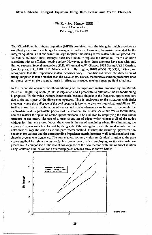
In this paper, the origin of the ill-conditioning of the impedance matrix produced by the MixedPotential Integral Equation (MPIE) is explained and a procedure to eliminate this ill-conditioning is proposed. We show that the impedance matrix becomes singular as the frequency approaches zero due to the nullspace of the divergence operator. This is analogous to the situation with finite elements where the nullspace of the curl operator is known to produce numerical instabilities. We further show that a combination of vector and scalar elements can be used to decouple the electrostatic and magnetostatic portions of the solution. In the new scalar and vector formulation, one can restrict the space of vector approximations to be curl-free by employing the tree-cotree structure of the mesh. The tree of a mesh is any set of edges which connects all of the nodes without forming any closed loops; the cotree is the set of remaining edges. By eliminating the vector unknowns on a tree formed by the graph of the triangular mesh, the total number of the unknowns is kept the same as in the pure vector method. Further, the resulting approximation becomes irrotational and the corresponding impedance matrix becomes well conditioned and nonsingular even at zero frequency. The new method not only yields an identical solution to the pure vector method but shows remarkably fast convergence when employing an iterative solution procedure. A comparison of the rate of convergence of the new method with that of direct solution using Gaussian elimination for a microstrip patch antenna array is shown below. ,a•
-- lhrollwSolVEr • • • • • • • Gwsslcn Ellmfnaflcn ..... ., •••• MQrrlxFllllng
./ .. ,.··
.. ···· ...... . .......•... ,········
.. ·· -.·· ... ········ .•· .... ····•··•
... ~::::~::::>··· , ....
29
fl.4atrix Si2e ,a•
ALPS: An Adaptive Lanczos-PadE Approximation for the Spectral Solution of Mixed-Potential Integral Equations
Din-Kow Sun Ansoft Corporation
Pittsburgh, PA 15219
The Mixed-Potential Integral Equation (MPIE) and the triangular patch are widely used to solve electromagnetic field problems with arbitrary metalization. However, solving in the frequency domain requires the problem to be solved at many frequencies to obtain a broad bandwidth, especially when there are sharp resonances. At each frequency, the matrix must be evaluated and matrix solution performed. This process is time consuming and is unreliable because sharp resonances may be missed. To reduce the matrix computation time, Newman (IEEE AP-30, 1820-1824, 1988) and Kottapalli et. al. (IEEE MTT-39, 682-687, 1991) interpolated values from a set of solutions and their high-order derivatives computed at only a few sample frequencies. Unfortunately, both methods lack a theoretical foundation for estimating the locations of the sample frequencies and the accuracy of the interpolated solutions. Moreover, the Green's functions become highly singular when computing high-order derivatives of the solution.
Recently Asymptotic Waveform Evaluation (AWE) has become widely used to model the wideband frequency response of linear circuits. It has also been used to compute the spectral response of electromagnetic systems using finite element methods (X. Yuan and Z. Cendes, URSI Meeting, 196, 1993). However, recent work has shown that AWE is limited by the numerical precision required in the computation. Because of the numerical instability of AWE, Feldmann and Freund (European Design Automation Conference, 1994) have proposed using the Lanczos procedure to compute the PadE approximation of the system, called the resulting method PVL - Pade via Lanczos.
In this paper, we extend the PVL algorithm and apply this procedure to the MixedPotential Integral Equation (MPIE) for solving electromagnetic fields. First, we improve upon PVL by introducing selective orthogonalization. Although PVL is numerically more stable than AWE, the Krylov vectors generated eventually lose orthogonality and the method stagnates. This loss of orthogonality has long been addressed by Parlett and Scott (Math. Comp. 33, (145), 217-238, 1979) who found that the Krylov vectors lose their mutually orthogonal property when the Lanczos process converges to one of the eigenvectors of the system. By inventing a measure to identify which vector is converged, the newly computed Krylov vectors need only to be kept orthogonal to the set of converged vectors. This procedure is called selective orthogonalization. Second, we develop an adaptive process to determine optimal frequencies for the direct computation of the fields. In this procedure, the spectral response is first computed by solving at two different frequency points and then interrogated to determine the frequency where the difference between two spectral solutions is maximum. If needed, a third field solution is directly computed at this frequency and the process repeated. Third, we apply the resulting ALPS process to the MPIE by assuming a constant frequency parameter for the Green's functions.
Typically, ALPS requires less than five adaptive solutions for convergence. As is shown by examples, time savings over the direct method can be enormous and excellent agreement is obtained between the ALPS solutions and direct solutions.
30
Combined Field Integral Equations for the Electromagnetic Interaction
with Rotating Axially Symmetric Bodies
Roberto D. Graglia* and Laura Roberti
Dipartimento di Elettronica, Politecnico di Torino, C.so Duca degli Abruzzi 24, 10129 Torino, Italy
In this paper we consider the electromagnetic interaction with an impenetrable impedance body of revolution (BOR) that rotates around its symmetry axis with a constant angular velocity n. The body is illuminated by a monochromatic electromagnetic signal with angular frequency w, and the problem is solved by working in the frequency domain.
In the comoving frame, for an observer rotating with the body, the impedance bounday condition relates the tangential components of the magnetic and electric field on the surface of the body. The boundary conditions are then transformed to obtain the conditions valid in the laboratory reference frame. Use of these conditions permits one to formulate the problem in the laboratory frame in terms of two coupled integro-differential equations, one for the electric field (EFIE), the other for the magnetic field (HFIE).
The integral equations are derived for arbitrary incident fields, by expanding the equivalent surface electric and magnetic currents induced on the body surface in Fourier series of the azimuthal variable. The integration on the surface of the BOR is then performed first along the azimuthal variable and then along the profile of the scatterer. Thus, the problem to find the induced currents can be reduced to the superposition of many uncoupled onedimensional problems, one for each component of the Fourier spectrum.
The source terms of the integral equations can be expressed in terms of Bessel functions for the case of plane wave incidence. In case of axial plane wave incidence, and for relatively small rotation velocity (!t/w ~ 1), a perturbation integral formulation is obtained. The perturbation approach has the great advantage to clearly show those coupling phenomena due to rotation that cause cross-polarization of the scattered fields.
The integral equations are solved numerically by use of the moment method and by expanding. the Fourier components of the induced currents along the scatterer profile in terms of cubic Hermite functions. Since we use a combined field integral equation approach, the numerical solutions are not affected by internal resonances.
Several numerical results will be presented and discussed for both the perturbation approach and the exact approach.
31
Stability and Error Criteria for Path Integral Solutions of Scalar Helmholtz Equations
Robert D. Nevels Department of Electrical Engineering
Texas A&M University College Station, TX 77843-3128
Recently a Fourier transform path integral method was proposed for evaluating Helmholtz equation. This method allows complete :frequency domain scalar electromagnetic scattering calculations (RD. Nevels, C. Huang, Z. Wu, IEE Proc., Part H,488-492,1993). Its mathematical formulation requires Fourier transformation ofHelmholtz equation in order to obtain a necessary parabolic equation whose solution is then inverse transformed. The parabolic equation can be placed in the form of a path integral, whose phase space expression is a nested sequence ofFourier and inverse Fourier transforms. This expression can be directly evaluated by fast Fourier transform (FFT) techniques; Often this technique for · evaluating the parabolic equation is referred to as the split-step method, which is a numerical method previous1y developed to solve parabolic equations, whose limit as step size goes to zero is identically the path integral.
Fourier transform path integral method has some advantages over currently used techniques. However research on several aspects of the method will be required in order to determine whether it is a viable general improvement or simply more useful under particular restricted conditions. In this paper we will be presenting a stability analysis and error criterion for the method as well as an investigation of two alternative path integral operator forms that provide greater accuracy. These operator forms are based on generalizations of the Trotter product formula. A necessary and sufficient condition for the stability of the stepping numerical procedure is
unitarity of the operator (jjUjj ~ 1 ). It will be shown that the alternative
forms provide operator unitarity.
32
Monday AM AP/URSI-B Session 1 MD Suite Baltimore
Special Session Wavelet Methods for Differential and Integral Equations R. D. Nevels Page
8:20 Current Distribution on a Scatterer Obtained by Integral ................ APS Equations with Semi-Orthogonal and Orthogonal Wavelet Basis Sets Robert D. Nevels, Texas A&M University, Jaideva C. Goswami, University of Illinois
8:40 Analysis of Thin-Wire Antennas and Scatterers Using ................... APS Orthogonal lntervallic Wavelets Gaofeng Wang, Tanner Research, Inc., Jiechang Hou, Wuhan University
9:00 Wavelet Analysis of Scattering fron:i Simple Shapes and .................. 34 Combinations of Simple Shapes Randy L. Haupt, James L. Rassmussen, USAF Academy
9:20 Analysis of Conducting Bodies of Revolution Using .................... .35 Orthogonal Wavelet Expansions Gaofeng Wang, Tanner Research, Inc.
9:40 Wavelet Techniques for CAD Modeling of Microwave ..................... 36 Circuits and Antennas Kazem F. Sabet, EMAG Technologies, Linda P. B. Katehi, University of Michigan
10,:20 On the Use of Weighted Wavelet Expansion for Integral .................. 37 Equations on Bounded Intervals M. Toupikov, G. W. Pan, Ariwna State University
10:40 Impedance Matrix Compression (IMC) Using Iteratively ............... APS Selected Wavelet Basis for MFIE Formulations Z. Baharav, Y. Leviatan, Technion-Israel Institute of Technology
11 :00 On the Use of Coordinate Transformation with Wavelet .................. .38 Expansion for Integral Equations on Bounded Intervals Jianyuan Du, Guangwen Pan, Ariwna State University
11 :20 An FDTD Multigrid Based on Multiresolution Analysis ........ , ......... APS Kavita Goverdhanam, Emmanouil Tentzeris, Michael Krumpholz, Linda P. B. Katehi, University of Michigan
11 :40 Analysis of Scattering from Curvilinear Surfaces Using ................... 39 Wavelet Concepts Kazem F. Sabet, Kamal Sarabandi, University of Michigan
12:00 A Combined Wavelet/Impedance Matrix Localization .................... .40 (IML) Method Francis X. Canning, James F. Scholl, Rockwell Science Center
33
Wavelet Analysis of Scattering from Simple Shapes and Combinations of Simple Shapes
Randy L. Haupt and James L. Rasmussen Department of Electrical Engineering
USAF Academy, CO
Automatic target recognition (A 1R) algorithms compare radar returns with a data base of returns from known targets in order to make a match. Even simple targets have a lot of distinguishing features in the time and frequency domains that are a function of polarization and aspect angle. In order for the A 1R algorithm to be successful in a reasonable amount of time, it must work with a small data base. Many pieces of data can be input to the A 1R algorithm, including target speed, distance, maneuverability, and RCS. The first three quantities are of manageable size; however, the RCS is a huge data base that is difficult to store and manage. Techniques are needed to reduce the size of this data base while keeping salient features important for target recognition.
Wavelets can be used to compress the large amount of RCS data while keeping salient features at both low and high frequencies. We have taken frequency domain RCS measurements (amplitude and phase) over a range of angles for simple conducting objects in an anechoic chamber. The complex data is converted to the time domain using a chirp-Z transform. Our first step finds wavelet coefficients for these simple targets using a denoising algorithm. Next we place multiple simple shapes together and measure the RCS of these combinations. We compare the wavelet coefficients obtained for the simple shapes with the wavelet coefficients obtained from combinations of simple shapes. Our goal is to separate the response of the simple shapes from the interactions between the simple shapes.
34
Analysis of Conducting Bodies of Revolution Using Orthogonal
Wavelet Expansions
Gaofeng Wang
Tanner Research, Inc., 180 N. Vinedo Avenue, Pasadena, CA 91107, USA
The applications of wavelets in computational electromagnetics have recently attracted a
great deal of attention. Extremely salient features of the wavelets are that sparse matrix
equations and multilevel representations are obtained when the wavelets are used as basis
functions in the numerical solution of integral equations (B. Z. Steinberg & Y. Leviatan,
IEEE Trans., AP-41(5), 610-619, 1993) (G. Wang, IEEE Trans., AP-43(2), 170-178,
1995) (J.C. Goswami, A. K. Chan, C. K. Chui, IEEE Trans., AP-43(6), 614-622, 1995).
The multilevel representation and the sparse structures in the impedance matrix can
greatly speed up the solution of the integral equation.
Here, the orthogonal wavelets on the interval, constructed from Daubechies compactly
supported wavelets (I. Daubechies, Commun. Pure Appl. Math., 41(11), 909-996, 1988),
are employed to study the electromagnetic scattering from conducting bodies of
revolution. The magnetic field integral equation (MFIE) is employed in this analysis.
The induced surface currents are expressed in terms of Fourier series of uncoupled modes
of the azimuthal angle <p • By virtue of the modal analysis, a simplified MFIE is then
obtained for each unknown mode current which varies along the curved profile of the
scatterer. By applying the geometrical representation of the boundary element method,
the curved profile of the scatterer is mapped into the definition domain [O, 1] of the
orthogonal wavelets on the interval. Both the scaling functions and the wavelet functions
on [O, l] are employed to form multilevel wavelet expansions. The unknown mode
currents are then expressed using such multilevel wavelet expansions, and thus an
orthogonal multiresolution analysis is generated. Numerical examples show that this
wavelet technique exhibits the merits of the sparse matrix and the multilevel iteration.
35
WAVELET TECHNIQUES FOR CAD MODELING OF MICROWAVE CIRCUITS AND ANTENNAS
Kazem F. Sabet*t and Linda P.B. Katehit t EMAG Technologies, Inc. 2901 Hubbard, Suite E-116, Ann Arbor, MI 48105
t EECS Dept., The University of Michigan, Ann Arbor, MI 48109-2122
ABSTRACT
The computer aided design (CAD) of microwave circuits and antennas is increasingly relying on rigorous numerical techniques. In this regard, the integral equation (IE) technique in conjunction with the method of moments (MoM) has long established itself as an accurate and ver;atile computational tool for the full-wave simulation of electromagnetic problems. Due to the intensity of numerical work, however, full-wave simulations are very time-consuming and demand enormous computing resources. In particular, the lack of sparsity in the matrices resulting from conventional moment method implementations often imposes serious limitations on the size and complexity of the problems that can be handled by this technique. Thus, design-through-analysis processes based on such full-wave simulations are usually quite inefficient.
I
In the past couple of years, several authors including ourselves have applied the concepts of multiresolution analysis (MRA) theory to various electromagnetic problems. It has been demonstrated that the use of multiresolution expansions for the moment method solution of integral equations can produce highly sparse linear systems among other interesting features. Although the published results show a great potential for the application of wavelet techniques to computational electromagnetics, these findings have not yet stirred much interest on behalf of CAD developers. This may be attributed mostly to the fact that the wavelet functions and procedures described in most of the existing literature are highly complicated and often hard-to-understand concrete mathematical entities. Moreover, the development of wavelet-based CAD tools would require an entirely new code development effort which may not prove economical.
In this paper we introduce rooftop multiresolution expansions. These two-dimensional expansions are constructed in a non-standard form from one-dimensional intervallic B-spline MRAs. The 2-D scaling functions associated with the rooftop MRA are indeed the conventional rooftop basis functions which have been used extensively in the past for the MoM modeling of microstrip structures and printed antennas. Many of the existing microwave CAD software are based on this type of basis functions. It will be shown that using fast wavelet transforms (FWT), it is possible to convert a conventional MoM implementation using regular rooftop basis functions into a wavelet-based MoM formulation using a rooftop MRA. This conversion leads to the generation of highly sparse moment matrices, whereby the resulting linear systems can be solved very efficiently using sparse iterative solvers such as the bi-conjugate gradient (BiCG) method. It is important to note that fast wavelet transforms involve only very simple algebraic operations such as discrete convolutions. Using the proposed approach, we do not need to modify or reformulate the entire moment method implementation, but take the matrices generated by the conventional CAD program and export it to an FWT ·code to convert it into a sparse system. Numerical examples will be presented for three-dimensional microstrip-based planar circuits and antennas.
36
ON THE USE OF WEIGHTED WAVELET EXPANSION FOR INTEGRAL EQUATIONS ON BOUNDED INTERVALS
M. Toupikov and G.-W. Pan
As basis functions, wavelets have been applied to many problems in electromagnetics [1],[2], [3]. Different types of wavelets have been used to determine the unknowns on finite intervals. This includes Battle-Lemarie wavelets, Daubechies wavelets , Coi:8.ets, etc., and their periodical versions. The matrix obtained by a wavelet expansion is rendered sparsely populated. Wavelet transforms have been employed in the context of integral equations of the second kind and first kind, e.g.
i f(:c')K(:c,:c')d:c' = g(:c), :c EL (1)
where K(:c, :c') is the known kernel of the integral equation, g(:c) is a give~rsource of excitation, L is the domain of integration, and f ( :c) is the unknown response to be determined.
In this paper we use the lifting scheme [4] to build a wavelet system, without using the Fourier transform. The new wavelets which are referred to as the second generation wavelets, are not obtained from translations and dilations of the generating function, yet still preserve the multiresolution analysis (MRA) and all other properties· of the ordinary wavelets.
For the above problem (1) we suggest use a new biorthogonal wavelet system as basis functions in the method of moments .. These wavelets are biorthogonal with respect to a weighted inner product
(2)
where 1P;,1c and 'ifJ;w denote the primary and dual wavelet functions which are defined on a finite interval Land w(:c) is the weight function. For the weighted wavelets, Fast wavelet transform exists and their properties depend on the property of the weight function. With certain restrictions on the weight function we can adjust it to improve the convergence behavior of our solution. For example, the solution of equation (1) may have singular points within the interval L. Because of the singularity, for ordinary wavelet expansion the convergence of the solution is usually slow, with order O(h ), h = 2-;, independent of the number of vanishing moments N. In other words, there is no significant improvement if higher order wavelets are used. However, for weighted wavelets if the integrand, i.e., the product of the weight and the unknown function, is an analytic function one can expect 0( hN) convergence.
[1]
[2]
[3]
[4]
REFERENCES
K.Sabetfakhri and L.P.B.Katehi, • Analysis of integrated millimeter-wave and submillimiter-wave waveguides using orthonormal wavelet expansions,• IEEE Tran.,. on Microwave Theory Tech., vol. 42, pp. 2412-2422, Dec. 1994. . · G.Wang and G.Pan, "Full wave analysis of microstrip :floating line structw:es b:r wavelet expansion method," IEEE Tran•. on Microwave Theory Tech., vol. 43, pp. 131-142, Jan. 1995. G.Pan, "Orthogonal wavelets with applications in electromagnetics,• IEEE Trans. on Magnetics, to appear in Ma:r 1996. W.Sweldens, ~The lifting scheme: A construction of second generation wavelets,"Tech. rep., Department of Mathematics, Univenit:r of S. Carolina, 1995.
37
On the Use of Coordinate Transformation with Wavelet Expansion for Integral Equations on
Bounded Intervals
Jianyuan Du and Guangwen Pan Department of Electrical Engineering
Arizona State University, Tempe, AZ 85287-7206
abstract Orthonormal wavelets have been successfully used as basis and testing functions for the
integral equations [1], [2], [3]. Very sparse coefficient matrices have been obtained, due to the multiresolution analysis (MRA), orthogonality, vanish moments, etc. of the wavelets. However, in many practical problems, the solution domain is confined on bounded intervals, while the wavelets are defined on the entire real line. To overcome this problem, periodic wavelets and intervallic wavelets have been described in the literature. Nonetheless, these methods either attach restrictions, or increase the computational complexity of the algorithms. Most importantly, the singular behaviors of the unknown functions can not be properly addressed by the wavelet basis functions.
In this paper we present an alternative approach, the use of mapping functions along with locally singular weighting functions. The mapping converts the finite intervals onto real lines, where standard wavelets are then allocated. The singular weighting functions improve the behavior of the unknown functions, rendering fast convergence of the solutions. Examples of electromagnetic coupling through double slots are presented, in which the ordinary Coifman wavelets are employed. Both normal and oblique incident cases are discussed. Numerical results demonstrate the sparsity of the coefficient matrices. The artificial oscillation of the magnetic current in the previous work [1] has disappeared, showing the improvement.
REFERENCES
[i] B.Z.Steinberg and Y.Leviatan,"On the use of wavelet equivalent circuit expansions in the method of moments,• IEEE Tran,. Antennas and Propagat., vol. 41, pp. 610-619, May 1993.
(2] G.Wang, G.Pan, and B. Gilbert, • A Hybrid Wavelet Expansion and Boundary Element Analysis for Multiconductor Transmission Lines in Multilayered Dielectric Media," IEEE Trans. on Microwave Theory Tech., voL 43, NO. 3, pp. 664-675, March 1995.
(3] G.Pan, "Orthogonal wavelets with applications in electromagnetics," IEEE Trans. on Magnetics, to appear in May 1996.
38
ANALYSIS OF SCATTERING FROM CURVILINEAR SURFACES USING WAVELET CONCEPTS
Kazem F. Sabet* and Kamal Sarabandi
EECS Dept., The University of Michigan, Ann Arbor, MI 48109-2122
ABSTRACT
The numerical solution of electromagnetic scattering from general curvilinear surfaces is often hampered by enormous computing resource requirements. This problem becomes even more challenging when electrically large irregular geometries or random rough surfaces are considered. The integral equation (IE) technique in conjunction with the method of moments (MoM) has long been used as a powerful tool for the full-wave analysis of scattering from various two- and threedimensional objects. The major advantage of this technique over other numerical methods is its inherent capability for the treatment of open boundaries. Moreover, by confining the discretization domain to the surface or volume of the scatterer, this technique usually offers substantial computational savings. However, due to the lack of sparsity in the moment matrices, the application of the integral formulations has tr~ditionally been limited to small- to medium-scale problems.
Recently, the application of wavelet expansions to moment method formulations has opened new horizons for this technique due to the possibility of generating highly sparse linear systems. The wavelet concepts have been utilized for the study of a variety of electromagnetic problems. The implementation of multiresolution expansions for the analysis of scattering from bodies with curved boundaries has already been reported. These studies, which involve periodic or intervallic wavelet expansions, deal with closed boundaries and are useful for surfaces satisfying some sort of periodicity. Using the boundary element technique, the curved boundary is then mapped into the principal interval.
In this paper, we discuss a wavelet-based implementation of the method of moments which can treat open curvilinear surfaces. The integral equation over the curved surface is transformed into one over the coordinate plane, where the projection of the unknown current is expanded in a suitable multiresolution basis. If the surface is bounded, then an intervallic multiresolution analysis (MRA) defined over a finite interval is used. For infinite surfaces, the natural choice is of course a multiresolution analysis with an infinite support such as the Battle-Lemarie MRA. Applying Galer kin's technique to test the discretized integral equation then leads to a highly sparse linear system, which can be solved very efficiently using iterative solvers such as the bi-conjugate gradient method. To illustrate the concepts, TE and TM scattering from a Gaussian hump is considered. Both intervallic B-spline and Battle-Lemarie MRAs will be used and the effects of a truncated hump on the scattering characteristics will be explored. Also, the importance of the order of MRA in the sparsity of the moment matrices will be investigated. The ultimate goal is to develop an efficient methodology for the study of scattering from random surfaces. For irregular surfaces, the surface parameterization is carried out locally using interpolation schemes.
39
A COMBINED WAVELET / IMPEDANCE MATRIX LOCALIZATION (IML) METHOD
Francis X. Canning* James F. Scholl
Rockwell Science Center 1049 Camino Dos Rios
Thousand Oaks, CA 91360
A computer program has been written combining wavelet and Impedance Matrix Localization (IML) methods to calculate scattering from plates. For solution of the Helmholtz equation by the moment method, wavelets are useful in creating a sparse matrix for the part of a problem involving more than two points per wavelength. IML generates a matrix which is sparse with respect to both basis functions with low (propagating) and high frequency content. However, there are computational expenses in using the longer IML functions. One expense is in calculating matrix elements. Another is that near discontinuities, there is more fill in when more functions overlap the discontinuity. Thus, a combination of wavelet methods and IML is optimum for a problem like a plate many wavelengths in size.
The way wavelets and IML are combined is conceptually simple. First, a description of the problem solely in wavelets is produced, where there are just over two scaling functions per wavelength. Then, an orthogonal IML transformation is done on just the scaling function part of the problem. When an orthogonal form of IML is used with orthogonal wavelets, the resulting functions are also orthogonal. The Fourier transform of these wavelets is band limited to greater than the frequency of propagation. The Fourier transform of each IML function is nearly a delta function, centered near or below the frequency of propagation.
Numerical results show the efficiency of the resulting formulation, for matrix generation, matrix storage, and solution of the matrix equation.
40
Monday AM AP/URSI-F Session 1 Pratt/Calvert
Propagation Modeling G.D. Dockery Page
8:20 When the Leading Term is Sufficient: The Residue Series ................. 42 Revisited Joel L. Ekstrom, Retired
8:40 Piecewise Conformal Mapping Techniques for Electromagnetic ......... 43 Propagation over Terrain Using Fourier Split-Step Solutions to the Parabolic Equation James R. Kuttler, G. Daniel Dockery, The Johns Hopkins University Applied Physics Laboratory
9:00 Propagation Modeling over Terrain by Coordinate ........................ .44 Transformation of the Parabolic Wave Equation D. J. Donohue, The Johns Hopkins University Applied Physics Laboratory
9:20 A Hybrid MoM/FDTD Approach to UHFNHF Propagation .............. APS Problems Keith A. Lysiak, James K. Breakall, The Pennsylvania State University, James Zmyslo, Kaman Sciences Corporation
9:40 Radiowave Propagation through an Obstacle Using the .................. .45· Parabolic Equation Method C. C. Constantinou, C. Mias, C. A. Zelley, The University of Birmingham, M. F. Levy, Rutherford Appleton Lab
10:20 A Method of Moments Model for VHF Propagation ...................... APS Joel T. Johnson, J. A. Kong, Massachusetts Institute of Technology, R. T. Shin, J. Eidson, Lincoln Laboratory MIT, L. Tsang, University of Washington
10:40 Using Perfectly Matched Layers for Elastodynamics ..................... APS W. C. Chew, University of Illinois, Q. H. Liu, Schlumberger-Doll Research
11 :00 PEM Coverage Predictions Compared to Measurements ................. APS N. Geng, W. Wiesbeck, University of Karlsruhe
11 :20 The Propagation Effects ofBends in Tropospheric Ducts ............... APS Sherman W. Marcus, RAFAEL
11 :40 EM-Wave Scattering by a Coastal Wedge--A Physical Optics .......... APS Approximation A. I. Papadopoulos, D. ·p. Chrissoulidis, Aristotle University.of Thessaloniki
12:00 Towards Absorbing Boundary Condition Implementation in ............. .46 the Parabolic Equation Sava V. Savov, Technical University of Varna
41
WHEN THE LEADING TERM IS SUFFICIEI\T:
THE RESIDUE SERIES REVISITED
Joel L. Ekstrom (Retired)
P.O. Box 391, Cabin John MD 20818
wben EM waves undergo scatter- and duct-f'ree propagation beyond the earth's horizon into the diffraction zone, the field strength can be expressed in the Corm of a so-called residue series, each term of which contains the product of three factors - a distance factor involving the transmitter-receiver distance, and two height-gain factors involving the altitudes of' the transmit and receive antennas above the earth's surface; each of' these contains an Airy function of complex argument.
When the transmit-receive distance and operating frequency are "large enough" and the ante·nna heights are 11 smal.l enough", the residue series is dominated by the first term, and the others may be discarded. In an attempt to put the issue on a firmer quantitative basis, we consider the distance and altitude restrictions required ·to keep the second term magnitude at least 20 dB below that of the first. The latter is easily obtained with the aid of height-gain data published in Kerr (MIT Rad. Lab. Series Vol. 13) and tabulated in Logan (LMSD-288087, 12-59, AD 241228).
For th~ se~ond term, the height-gain function arguments and magnitudes will be different, and the computational approach taken here is to develop a simple~ bound to the magnitudes of the constituent Airy functions. To do this we begin with the integral definition (
A ... {t):: "2~;_ JcExf'[~ "t -s-t:3]d "i: where the contour begins at infinity in the sector between -90 and -150 degrees, and ends at infinity in the sector between 90 and 150 degrees. The contour may be deformed into a straight line parallel to the imaginary axis of the t-plane, and passing through the LHP saddl.e point of the integrand. Then the Schwartz Inequal.ity may be used to obtain the simple result
IA ( "'qi)\< l:~Pl~i-r/12cos(3J-)]
.c..Re - zffe"R.'"*,Jt!os(t)' which is val.id for~ in the range Oto l.80 degrees.
Il.lustrative examples wil.l be presented, al.ong with a tighter bound useful. for st near 180 degrees.
42
PIECEWISE CONFORMAL MAPPING TECHNIQUES FOR ELECTROMAGNETIC PROPAGATION OVER TERRAIN
USING FOURIER SPLIT-STEP SOLUTIONS TO THE PARABOLIC EQUATION
James R. Kuttler G. Daniel Dockery
The Johns Hopkins University Applied Physics Laboratory
Johns Hopkins Road, Laurel, MD 20723 USA
This paper describes a technique for modeling electromagnetic propagation over a rough surface specified by a given height profile. The physical domain above the surface is mapped to a computational domain with rectangular coordinates, where the modified problem is then solved using the Fourier split-step parabolic equation (see, e.g., Kuttler and Dockery (Radio Science 26(1991), pp. 381-393)). The solution is then transplanted back to real space. The mapping used is piecewise conformal, i.e., strips with curved lower edges in real space are sequentially mapped to rectangular strips in computation space. Piecewise conformal maps were used earlier by Dozier (JASA 75(1984), pp. 1415-1432], who employed Schwarz-Christoffel transforms taking strips with straight, angled ends to rectangular strips. We introduce transforms for strips withs-curved ends. These have several nice features which the SchwarzChristoffel do not have: they fit together smoothly; they remain analytic at the corners; and they have an explicit inverse. The latter is particularly useful as it is necessary to interpolate the solution from the back edge of the previous strip to the front edge of the new strip as the solution is marched along in range. This is done using cubic interpolation onto the explicitly determined new grid points. Since the mapping is conformal, the only modification to the usual form of the parabolic equation itself is that the index of refraction n is multiplied by the modulus of the derivative of the mapping function lf'I· It is critical in the split-step that the index of refraction is nearly one. We will examine how near it needs to be to give good results, how to control the size of lf'I, and what geometric limitations this places on the slopes of terrain profiles, as well as showing some sample calculations.
43

PROPAGATION MODELING OVER TERRAIN BY COORDINATE TRANSFORMATION OF THE
PARABOLIC WA VE EQUATION
D. J. Donohue Applied Physics Laboratory Johns Hopkins University
Johns Hopkins Road Laurel, MD 20723
We are investigating various techniques for incorporating a rough boundary within a parabolic equation based propagation model. As a first approach, we examine a coordinate transformation (A. Beilis and F. D. Tappert, J. Acoust. Soc. Am. 66, 811, 1979) that maps the rough boundary to a flat surface. The fluctuations due to surface roughness are incorporated into a modified refractivity term containing the second derivative of the surface height. In addition, a new phase term is· introduced into the envelope of the field. The purpose of the coordinate transformation is to remove the range-dependent boundary condition, thereby retaining the parabolic form of the wave equation, which may be solved by numerically efficient marching techniques. We use the split-step Fourier algorithm (A. E. Barrios, IEEE Trans. Antennas Propagat. 42, 90-98, 1994, J. R. Kuttler and G. D. Dockery, Radio Science 26, 381-393, 1991), which has been generalized to vertical and horizontal polarization over imperfectly conducting surfaces. Our initial calculations are limited to Dirichlet boundary conditions and the use of the narrow angle propagator in the Fourier domain. The theoretical difficulties of deriving a wide angle version of the transformed wave equation, and the practical limitations of using a narrow angle propagator over an irregular boundary, will be discussed. The initial calculations are also limited to a fixed range step, however, adaptive range stepping based on the terrain profile will eventually be considered. We will report our progress on the numerical implementation of the coordinate transform method, which will first be applied to example problems using standard atmosphere and simple terrain profiles.
44
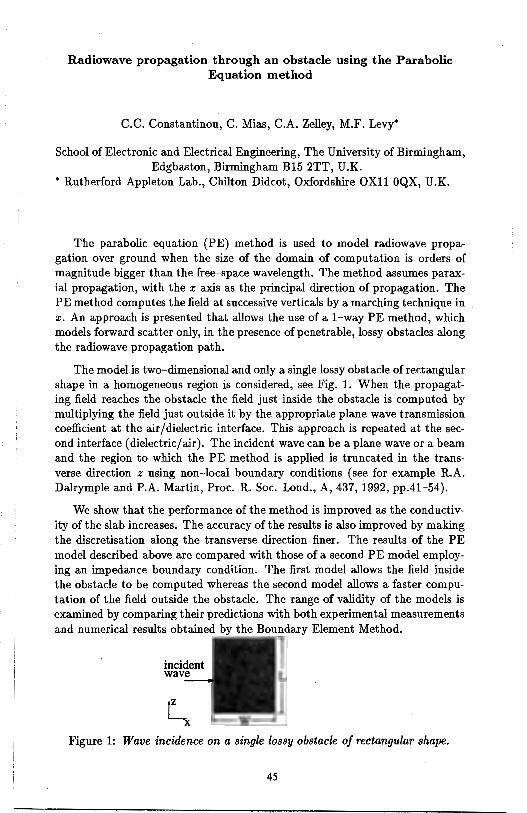
Radiowave propagation through an obstacle using the Parabolic Equation method
C.C. Constantinou, C. Mias, C.A. Zelley, M.F. Levy*
School of Electronic and Electrical Engineering, The University of Birmingham, Edgbaston, Birmingham Bl5 2TT, U.K.
* Rutherford Appleton Lab., Chilton Didcot, Oxfordshire OXll OQX, U .K.
The parabolic equation (PE) method is used to model radiowave propagation over ground when the size of the domain of computation is orders of magnitude bigger than the free-space wavelength. The method assumes paraxial propagation, with the x axis as the principal direction of propagation. The PE method computes the field at successive verticals by a marching technique in x. An approach is presented that allows the use of a 1-way PE method, which models forward scatter only, in the presence of penetrable, lossy obstacles along the radiowave propagation path.
The model is two-dimensional and only a single lossy obstacle of rectangular shape in a homogeneous region is considered, see Fig. 1. When the propagating field reaches the obstacle the field just inside the obstacle is computed by multiplying the field just outside it by the appropriate plane wave transmission coefficient at the air/ dielectric interface. This approach is repeated at the second interface (dielectric/air). The incident wave can be a plane wave or a beam and the region to which the PE method is applied is truncated in the transverse direction z using non-local boundary conditions ( see for example R.A. Dalrymple and P.A. Martin, Proc. R. Soc. Land., A, 437, 1992, pp.41-54).
We show that the performance of the method is improved as the conductivity of the slab increases. The accuracy of the results is also improved by making the discretisation along the transverse direction finer. The results of the PE model described above are compared with those of a second PE model employing an impedance boundary condition. The first model allows the field inside the obstacle to be computed whereas the second model allows a faster computation of the field outside the obstacle. The range of validity of the models is examined by comparing their predictions with both experimental measurements and numerical results obtained by the Boundary Element Method.
incident wave -
1--W...:.___.l
l 1
Figure 1: Wave incidence on a single lossy obstacle of rectangular shape.
45
Towards Absorbing Boundary Condition Implementation In the Parabolic Equation
Sava V. Savov Dept Electrical Engineering Technical University ofVama
Varna 9010, Bulgaria phone: +359 52 253 703 , fax: +359 52 871 910, e-mail: svsavov@tu-vamabg
Introduction
The parabolic equation (PE) approximation of the scalar Helmholtz equation gives an advantage to obtain the numerical solution by a leap-frog scheme. There are two main versions of1his method:
a) Finite Difference (FD); b) Fourier Transform (FT) or Split-Step. It is necessmy to restrict the computational domain by suitab!e bmmdaries because
of the open nature of the propagation problem. There is a standard Impedance Boundmy Condition (IBC) imposed on the terrain. A new Absorbing Boundmy Condition (ABC) is imposed in the air.
Modeling
The wide-angle PE(M.F.Levy,Electron. Lett.,26,1153-1155,1990) is applied to predict the path losses in mban environment using a FT scheme instead of the FD one (J.RKuttler and G.D.Dockery,Radio Sci.,26,381-393,1991). This makes the numerical technique more efficient but the IBC implementation becomes more di:fficult(G.D.Dockery, IEEE Trans.Antennas Prop.,36,1464-1470,1988). A careful choice for the spectral step according to the Nyquist criterion is crucial for the algorithm where the horizontal space step is many wavelengths. The clue is the choice of an appropriate window in the vertical space domain which allows to model the ABC accurately(RJanaswamy, IEEE Trans. Antennas Prop.,40,1416-1422,1992).
A simple example with a block-shaped obstacle(G.A.J.Van Dooren,C.J.Haslett and M.F.Levy,Electron.Lett.,29,1334-1335,1993) is considered The nwnerical results obtained by both methods are compared and good agreement is found for a frequency f=lGHz.
Conclusion
The proposed nwnerical model based on the PE technique is tested in one canonical two-dimensional case (block-shaped obstacle) and good results are found Further development of the method to extend 1his model to the real three-dimensional case remains.
46
Monday PM URSI-B Session 4 Constel. Ballroom E
Finite Element Methods T. Cwik Page
1 :20 Towards Adaptive Methods in Finite Element Modeling ................. .48 Tom Cwik, Cinzia Zuffada, Vahraz Jamnejad, California Institute of Technology Jet Propulsion Laboratory
I :40 Finite Element Solution of Scattering Using Coupled Pair ............... .49 of Basis Functions on Elliptic Enclosure Jian-Ming Jin, Ninglong Lu, University of Illinois at Urbana-Champaign
2:00 Finite Element Solution of Electromagnetic Problems over a ........... 50 Wide Frequency Range with a Minimal Number of LU Decompositions M. Kuzuoglu, R. Mittra, University of Illinois at Urbana-Champaign, J. Brauer, G. Lizalek, The MacNeal Schwendler Corporation
2:20 Driving Point Impedance in a 3-D H-Field Vector Finite Element ....... 51 Analysis that Uses Variational Properties Thomas P. Fontana, Eric W. Lucas, Westinghouse Electric Corporation
2:40 A Simplification of Field Method, from Moment to MEI .................. 52 Y. L. Chow, University of Waterloo,, Y. W. Liu, Y. L. Luo, K. M. Luk, K. K. Mei, E. K. N. Yung, City University of Hong Kong
3:20 Finite Element Modeling of Infinite Planar Arrays Using Periodic ..... .53 and Absorbing Boundary Conditions John Manges, Lawrence Williams, Zoltan Cendes, Ansoft Corporation, Xingchao Yuan, Cadence Design Systems
3 :40 Iterative Procedure for Finite Element Mesh Termination in 3D ........ .54 Open Region Problems L. E. Garcia Castillo, M. Salazar-Palma, Polytechnic University of Madrid, T. K. Sarkar, T. Toy, Syracuse University, A. Djorjevic, University of Belgrade
4:00 Finite Element Solution of Scattering Problems on a Massively ....... 55 Parallel Supercomputer William Dearholt, Steven Castillo, Vrushali Bukil, New Mexico State University
4:20 A New Stable Galerkin Formulation for the Finite Element Method ..... 56 A. Chatterjee, P. Petre,• Compact Software
4:40 A Three Dimensional, Edge Based, Finite Element Formulation ......... 57 for Discrete Bodies of Revolution Daniel C. Ross, John L. Volakis, Hristos Anastassiu, University of Michigan
5:00 JPL-FEM3D: Fully Scaleable Solutions to Scattering Problems ....... ,58 J. W. Parker, California Institute of Technology Jet Propulsion Laboratory
47
Towards Adaptive Methods in Finite Element Modeling
Tom Cwik*, Cinzia Zuffada and Vahraz Jamnejad
Jet Propulsion Laboratory California Institute of Technology
Pasadena, CA 91109
Finite element modeling has proven useful for accurately simulating scattered or radiated electromagnetic fields from complex three-dimensional objects whose geometry varies on the scale of a fraction of a wavelength. Convergence of the simulation can be assessed ,by uniformly increasing the mesh density until an observable quantity stabilizes. · Depending on the electrical size of the problem, uniform refinement of the mesh may be computationally infeasible due to memory limitations. Similarly, depending on the geometric complexity of the object being modeled, uniform refinement can be inefficient since regions that do not need refinement add to the· computational expense. In either case, convergence to the correct (measured) solution is not guaranteed.
Adaptive methods attempt to selectively refine the region of the mesh that is estimated to contain proportionally higher solution errors. The refinement may be obtained by decreasing the element size (h-refinement), by increasing the order of the element (prefinement) or by a combination of the two (h-p refinement). A successful adaptive strategy refines the mesh to produce an accurate solution measured against the correct fields without undue computational expense. This is accomplished by the use of a) reliable a posteriori error estimates, b) hierarchal elements, and c) automatic adaptive mesh generation. Various a posteriori error estimates have been used in internal region problems ii) the past. In this paper, mathematical developments of a posteriori error estimates developed in structural mechanics and fluid dynamics (M. Ainsworth and T. Oden, Comput. Methods Appl. Mech. Engrg., 101, 73-96, 1992), and tried in electromagnetic problems (F. Meyer and D. Davidson, Electr. Lett., 30, 936-938, 1994) will be examined for internal and external scatteri_ng problems.
48
FINITE ELEMENT SOLUTION OF SCATTERING USING COUPLED PAIR OF BASIS FUNCTIONS
ON ELLIPTIC ENCLOSURE
Jian-Ming Jin* and Ninglong Lu Center for Computational Electromagnetics
Department of Electrical and Computer Engineering University of Illinois at Urbana-Champaign
Urbana, Illinois 61801-2991
When solving open-region scattering problems using the finite element method, the infinite region exterior to the scatterer must be truncated with an artificial boundary to limit the number of unknowns. Consequently, a boundary condition must be introduced at this artificial boundary for a unique finite element solution. Such a condition should make the boundary appear as transparent as possible to the scattered field. Among various boundary conditions proposed in the past, only two can lead to an accurate and reliable solution. One is derived from the eigenfunction expansion of the exterior field (K. K. Mei, IEEE Trans. Antennas Propagat., vol. AP-22, pp. 760-766, Nov. 1974) and the other is derived from the boundary integral representation of the exterior field (J. M. Jin and V. V. Liepa, IEEE Trans. Antennas Propagat., vol. AP-36, pp. 50-54, Jan. 1988). In the first approach (known as the unimoment method), a circle is used as the artificial boundary to separate the interior and exterior regions. The field in the interior region is formulated using the finite element method and the field in the exterior region is represented by the eigenfunction expansion involving Bessel functions. The major disadvantage of the approach is that when the scatterer has an elongated cross section, there is a large free-space region between the scatterer and the artificial boundary that requires the finite element discretization, thus resulting in a large number of unknowns for the finite element analysis. In the second approach, the boundary integral equation involving Green's functions is used to formulate the exterior field. As a result, the artificial boundary can have an arbitrary shape and hence the size of the interior region can be kept to a minimum. The major disadvantage of this approach is the dense matrices produced by the boundary integrals, whose dimension is the same as the number of unknowns on the artificial boundary. In this paper we propose to employ an ellipse as the artificial boundary to tightly enclose elongated scatterers. The field in the exterior region is represented by an expansion of the elliptic cylinder functions also known as Mathieu functions and the interior field is again discretized using the finite element method. To enhance the efficiency of the method we then propose a coupled pair of basis functions that contain all information about the interior field. Compared to the unimoment method, this method can reduce the number of unknowns for the finite element analysis. Compared to the finite element method using a boundary integral equation, this method can reduce the size of the full matrix by a factor of 20 for two-dimensional scattering problems because the number of harmonics capable of representing the exterior far field is substantially smaller than the number of boundary unknowns. Furthermore, this method is immune to the interior resonance corruption suffered by the boundary integral equation. The formulation is especially suited for parallel computation. Numerical examples will be given to demonstrate the accuracy, efficiency, and capability of the method.
49
Finite Element Solution of Electromagnetic Problems over a Wide Frequency Range with a Minimal Number of LU Decompositions
M. Kuzuoglu* and R. Mittra J. Brauer and G. Lizalek Electromagnetic Communication Laboratory The MacNeal Schwendler Corporation University of Illinois at Urbana-Champaign 4300 West Brown Deer Road
1406 W. Green St., Urbana, IL 61801 Milwaukee, WI 53223
Finite element approximation of electromagnetic boundary value problems defined over a closed spatial domain, yields a matrix equation of the form
A(co)x(co) = [Ao+ A,co + Aza>2]x(co) = f(co) (1)
where Ao, A, and Az are complex-valued n x n matrices, co is the angular frequency, x(co) is the unknown vector and f(co) is the excitation vector.
Typically, the solution x( co) is desired over a frequency band I = [ co1, coh]. It is, however, numerically very expensive to solve ( 1) for a large number of frequencies
{co;}:, in /, since an LU decomposition of A(co;) is required to construct each
solutionx(co;). In this work, we propose a scheme based on a power series expansion which avoids this difficulty, and yields x(co) for any co E /, by performing the LU decomposition at a minimal number of frequencies. Let co0 be any arbitrary frequency in /, and let the vectors x(co), f(co) as well as the matrix A(co) be expanded in power series as
x(co) = lx/co-co0t f(co) = Lh(co-co0t k=O k=O (2)
where the matrices f\i, ii; and ~ can be obtained from Ao, A, and Az by simple addition and multiplication operations. The coefficients x0 , x1 , x2 , ••• can be evaluated recursively, and the radius of convergence of the power series x(co)
can be estimated in terms of the norms of f\i-1, ii; and ~. In short, x( co) can be
evaluated in an efficient way for any co within the region of convergence, via a single LU-decomposition of f\i. Thus, it is possible to cover the frequency interval
I by a minimal number of frequencies {co;}:1
, such that the union of the
convergence regions of power series expansiohs of x(co) about CO;, i = 1,2, .. . ,M, contain I. Several numerical experiments verify the hypothesis that the solution vector x(co) can be calculated very efficiently over a band of frequencies by using the power series approach. Techniques for analytically continuing the range of solution beyond the radius of convergence of the power series also will be discussed in the presentation.
* Supported by Turkish Scientific and Technical Research Council (TUBIT AK) as a NATO B2 scholar.
50
Driving Point Impedance in a 3-D H-Field Vector Finite Element Analysis that Uses Variational Properties
Thomas P. Fontana and Eric W. Lucas Antenna Department
Westinghouse Electric Corporation P.O. Box 746
Baltimore, Maryland 21203
In this work, the power-current driving point impedance in an H-field vector finite element formulation is presented. A ribbon of facets on a mesh of the tetrahedra or wedges is used to describe the electric currents, and tangential vector edge elements are used for the field bases.
The H-field variational formulation has been developed based upon the partial variational principle, PVP (S. J. Chung and C.H. Chen, IEEE, MTT-36, March 1988):
Here, the subscript o denotes the true current, J and M are the trial currents, and Ea and Ha are the variational adjoint fields. From the reaction of the adjoint electric field with the currents, the fields can be derived. In an E-field formulation this is straightforward. However, in the H-field formulation this generally involves the curl of the basis. We have found that when the ribbon current is exactly represented by the tangential H-field basis discontinuity, that the field calculation is greatly simplified because one can apply the point-wise constraint
(3) J -J0 =0
The application of the perturbation in (2) results in a set of linear equations.
Complex power is obtained as a secondary calculation. One of the features of our variational formulation is that true and trial currents have identical projections onto any combination of the adjoint bases. By using this fact, and by using the same basis for the adjoint and. conjugated fields, an efficient formulation for the complex power delivered to the system has been derived. The complex power calculation reduces to a constant plus the dot product of row vector of basis field coefficients with a once-calculated column vector. Moreover, the formulation is valid for tensor media and non-self-adjoint problems.
51
A Simplification of Field Method, from Moment to MEI
Y.L. Chow*, Y. W. Liu, Y.L. Luo, K. M. Luk, K.K. Mei and E. K. N. Yung Electronic Engineering, City Univ. of Hong Kong
*Electrical and Computer Engineering, Univ. of Waterloo
The basic form of MEI method is a finite difference (FD) method of field computation but only with one or two layers of grid cells around the conductor (or dielectric) boundary. Outside the thin layers there is no absorbing boundary, and for the inside, the matrix resulted is just as sparse as that of the original FD method. Thus we have a sparse matrix that is quite small.
This simplification is very desirable if it were generally valid, this paper proves that it is indeed valid. The reason is that MEI method is derivable from a standard moment method formulation. The proof also points to why a filled moment method matrix leads to a sparse MEI matrix .
For clearness in the logic, we shall conduct the proof for the scalar electrostatic field in 20. It is easy to see after that the proof naturally extends itself to the vector EM wave case in 30.
Standard Moment Method Solution CMoM}
Assume a 2D conductor with V=O subjected to an exciting voltage distribution Vi from a nearby source (Fig. I). Let each segment n on the conductor s has an induced charge Q,. Then
{Vi)= (V,)=[G;,](QJ
where G;, is the Greens function. The above can be solved for Q..
Derivation of MEI Method
Let V, be the voltage on nodes one cell outside the boundary. With Q. known, V, can be found by a direct matrix multiplication as below.
A combination of the two equations above gives
(V,) = [G;.][G,.]"1(Vr) = [A)(Vr)
Perfect Conductor
Fig. I Geometry of the Problem
The matrix [A] is the sparse matrix of MEI. The reason the matrix is sparse is evident in the asymptotic case of having the cell width from the boundary be reduced to zero, i.e. a rectangular cell of zero width. In this case [G,.J becomes identical to [G;,] and thus the matrix [A] becomes a unity matrix. A unity matrix is the sparsest matrix possible.
The paper will demonstrate numerically that for square cells, the matrix [A) is indeed the sparse tridiagonal MEI matrix that is only twice as large as ~e moment method matrix. Thus, the desirable property of sparse and small matrix of the MEI method is proven to be valid. It is as valid and as general as the moment method of the same .segmentation on the boundary.
It is evident that the above proof can be used for vector EM wave fields, with a change to a dyadic Green's function to relate the vector potential or electric field to a vector current.
52
Finite Element Modelling of Infinite Planar Arrays Using Periodic and Absorbing
Boundary Conditions
John Manges Lawrence Williams Zoltan Cendes Ansoft Corporation
Pittsburgh, PA 15219
Xingchao Yuan Cadence Design Systems Chelmford, MA 01824
This paper presents a finite element method for predicting the radiation and scattering characteristics of an infinite periodic planar array of radiating elements. The approach consists of a three-dimensional vector finite element solution of the scattered electric field within a unit cell of the periodic array lattice. First-order complete vector elements are used in the finite element formulation to provide highly accurate solutions. This approach has the advantage of simplicity over other techniques such as moment methods in handling complicated geometries and material inhomogeneities for the individual radiating elements.
A combination of several types of boundary conditions is used in the analysis. The antenna ports are modelled by using the transfinite element method (Cendes and Lee, IEEE MTT-36, 1639-49,1988). In this method, a twodimensional eigenanalysis is performed on each port cross section and the resulting eigensolutions are matched to the interior three-dimensional fields during the solution process. Field periodicity in the horizontal coordinates is strongly enforced on the unit cell walls as required by the array geometry and scan angle. Finally, in contrast to hybrid finite element approaches using boundary elements and Floquet modes (E. Lucas and T. Fontana, 1993 URSI Radio Science Meeting), a second-order absorbing boundary condition is enforced over a plane above the radiating element. This has the advantage of maintaining matrix sparsity with a resulting increase in solution efficiency.
The approach outlined above allows antenna port S-parameters, unit cell radiation patterns, and array scattering characteristics under user selected loading conditions to be accurately calculated. Experimental data and numerical results from other calculations are used to validate the analysis.This has the advantage of maintaining matrix sparsity with a resulting increase in solution efficiency.
53
ITERATIVE PROCEDURE FOR FINITE ELEMENT MESH TERMINATION IN 3D OPEN REGION PROBLEMS
L.E. Garcia-Castillo·, T.K. Sarkar .. , M. Salazar-Palma·, T. Toy .. , A. Djorjevic ... -Polytechnic University of Madrid, .. Syracuse University, .. *university of Belgrade
Email: [email protected] Tel. 34-1-3367358, Fax. 34-1-3367362
Finite Element Method (FEM) has been demonstrated to be a very flexible and powerful tool in analyzing a wide variety of electromagnetic problems. However, when dealing with open region problems an artificial boundary must be used to truncate the mesh in order to keep the number of unknowns finite. Two main kinds of boundary conditions can be used. First type is derived from the boundary integral equations and provide an exact boundary condition for mesh tennination. These are the so called hybrid FEM/BEM methods. However, the use of Green's function leads to dense matrices, which are expensive to solve and store. On the other hand, local boundary conditions, also known as "Absorbing Boundary Conditions" (ABC), come from the discretization of the differential operator in which the sparsity of the matrices is retained but are not exact and the boundary must be placed at some distance from the sources in order to obtain an accurate solution. Also, there are undesirable effects at reentrant comers.
In this paper an iterative procedure is proposed for the truncation of the FEM mesh in 3D scattering and radiation problems. FEM equations are written inside the artificial boundary, S). At the first step, the degrees of freedom on S are fixed to some initial values and the system of equations is solved. From the field solution, equivalent sources (electric and magnetic currents) are calculated over an auxiliary surface, S'. New values for the degrees of freedom on S are computed from the equivalent currents using the Green's function and the Equivalence principle. For the general case the new values of the degrees of freedom on the external boundary, S will be different from those previously imposed; a new iteration takes place. The process continues until a certain error criteria is satisfied. Surface S' is placed in such a way that all inhomogeneities are kept inside S' allowing the use of the Green function in a homogeneous media (in the scattering problem S' is usually the scatter surface and in a radiation problem S' will contain the radiation sources). Therefore, sparse matrices are obtained because boundary conditions on the external boundary appears as Dirichlet conditions at each iteration step. Also, the use of the infonnation of the boundary integral equation through the Green's function allows to tenninate the mesh close to the original sources of the problem (the scatter or the radiation sources), just a few layers between S and S', providing thus a mesh with less number of unknowns than a conventional ABC approach.
Double curl fonnulations with the electric or magnetic field as the vectorial variational unknown have been employed in the implementation of the described iterative procedure. Tethraedral edge elements are used for the field discretization, providing a consistent approximation of the electromagnetic field thus avoiding the problem of spurious modes. During the presentation several results of the application of the proposed approach to different structures will be presented, showing the features of the method.
54
FINITE ELEMENT SOLUTION OF SCATTERING PROBLEMS ON A MASSIVELY PARALLEL
SUPERCOMPUTER
William Dearhott·, Steven Castillo, and Vrushali Bukil Electrical and Computer Engineering Dept.
Dept. 3-0, Box 30001 New Mexico State University
Las Cruces, NM 88003
The finite element method (FEM) can be used to solve electromagnetic problems without restrictions in geometry, material parameters, or excitation. While the ability to treat very general scattering problems with FEM is an advantage over other methods such as finite differences or boundary integral methods, the resulting system of linear algebraic equations is sparse and unstructured. The solution to the system of equations can be found using either a Krylov method such as conjugate gradients or by using LU factorization. In either case, taking advantage of the sparsity of the system to reduce memory requirements results in alogrithms not well suited to state-of-the-art vector or massively parallel processors (MPP).
In this paper, we examine the use of the finite element method on a massively parallel supercomputer for solving electromagnetic scattering problems. Gaussian elimination in the form of LU factorization is used to solve the resulting sparse system of equations. The advantage of using LU factorization over Krylov methods is the ability to treat multiple right-hand sides simultaneously for a single factorization. This is useful when doing an RCS analysis using either a frequency-domain or time-domain finite element method. The particular computer used for this research is the Cray T3D which uses the DEC 21064 'Alpha' microprocessor arranged in a three-dimensional wrapped torus topology. A one-way dissection of the finite element mesh results in a decomposition well-suited for a message-passing MPP.
Results will be presented showing both scaled and unscaled speedup for various types of geometries. The effect of the decomposition on load balance and efficiency will be examined as well.
55
A NEW STABLE G ALERKIN FORMULATION FOR THE FINITE ELEMENT METHOD
A. Chatterjee* and P. Petre Compact Software
201 McLean Boulevard Paterson, NJ 07504
[email protected] ; [email protected]
Finite elements are usually the method of choice for modeling EM field interactions in three dimensions. Full-wave solutions for microwave circuits, antenna radiation and scattering are obtained by solving the vector wave equation throughout the computational domain. On using the Galerkin weighted residual approach to cast the wave equation in matrix form, the resulting differential equation to be solved can be written in the form
l [:r (v'xE) · (v'xE) - k~ErE · E] dv - fs E · (ii x v'xE) ds = 0 (1)
Since the Galerkin method is an approximation of the wave equation, system stability can be degraded for certa,in values of the wave number k0 and consequently the quality of the numerical solution. Moreover, from (R. Lee and A.C. Cangellaris, AP-40, pp. 542-549, May 92) and (W.R. Scott, Jr., AP-42, pp.1565-1571, Nov 94), it is observed that the Galerkin formulation leads to dispersion errors, even for simple plane wave propagation through free space. The authors show that dispersion errors decrease as higher order elements are introduced; however, this is achieved only through increased computational expense.
In this presentation, we will prppose a new stable Galerkin formulation that uses a mesh-dependent stability parameter to provide an extra degree of freedom in avoiding the undesirable aspects of the Galerkin method. This can be achieved while maintaining the consistency of the Galerkin technique. In the case of dispersion errors for plane wave propagation through an uniform 2D mesh, the stability parameter can be derived analytically and permits us to remove dispersion errors completely and enforce nodal exactness throughout the mesh. The problem gets more complicated for the general vector wave equation : the stability parameter cannot be derived analytically but is obtained numerically. This is not unexpected for an arbitrary mesh. The determination of the stability parameter is dependent on the degree of instability which is governed by the wave number k0 and the specific finite element mesh. We expect the new formulation to provide greater accuracy and faster convergence than the traditional Galerkin technique for an identical mesh. The error bounds of the formulation will also be shown and application of the new formulation to practical problems will be demonstrated.
56
A THREE DIMENSIONAL EDGE-BASED FINITE ELEMENT FORMULATION FOR
DISCRETE BODIES OF REVOLUTION Daniel C. Ross*, John L. Volakis and Hristos Anastassiu
Radiation Laboratory
University of Michigan, Ann Arbor MI 48109-2122
For electrically large objects, brute force application of the Finite Element Method (FEM) for scattering and radiation problems leads to very large systems. Even though the resulting CPU and memory requirements are O(N), these requirements still grow as a cubic power of the frequency. Thus, for some classes of large problems, it is important to scale down the domain of the FEM solution by taking advantage of symmetries. Ideally, this scaling should be done without introducing any approximations as is the case for the new technique presented here.
In this presentation, an extension to the FEM method for three dimensional, edgebased analysis is given for electrically large, fan-like bodies that can be modeled as a Discrete Body of Revolution (DBOR). No approximations are introduced when using the DBOR formulation to solve the scattering problem for fan-like structures within a cylindrical guide. A finite number of discrete modes exist in the guided structure, making the exact solution possible by treating the problem on a mode-by-mode basis. For open DBOR structures (such as a fan in free space) the same technique can be used but an approximation must be introduced since there are physically, a continuous spread of modes in the free space case.
The key feature of our implementation is the application of a local, periodic, phase boundary condition applied to the faces of the mesh describing a single lobe (unique section) of the body. This condition must be applied to both the electric and magnetic fields for a robust solution and our implementation is one of the first to make use of the phase boundary conditions for wave applications. Details of the implementation of the local, phase boundary conditions will be given along with a utility mesh pre-processing algorithm. Results will be presented which validate the overall technique and these will be used to show the importance of enforcing the phase boundary condition on both the electric and magnetic fields.
57
JPL-FEM3D: FULLY SCALABLE SOLUTIONS TO SCATIERING PROBLEMS
J. W. Parker, Jet Propulsion Laboratory, California Institute of Technology Pasadena, California, USA 91109
JPL-FEM3D denotes a mature software system that enables users to solve arbitrarily large finite element scattering problems (up to numerical limitations) on high-performance parallel processing systems, including the Intel Paragon and the Cray T3D. The system has unusual generality, including support for either E or H fields, perfectly conducting boundaries, lossy, lossless, and fully anisotropic dielectric and magnetic materials. Lossless gyrotropic behavior has been validated in modeling resonant cavities. Results are free of spurious modes and so-called vector parasites.
Preprocessing reduces commercial mesh generator output files to a minimal binary input mesh description appropriate for the parallel computer. A partitioning step is performed on the parallel computer, which separates the mesh into compact, low-surface area submeshes, assigned to each of the parallel processors. The technique is inertial partitioning, and is implemented for parallel operation in a fully scalable form; that is, a mesh of arbitrary size may be partitioned in a reasonable time by a proportionate number of processors.
Finite element solution is by complex bi-conjugate gradient iteration using Whitney tetrahedral edge elements for discrete 3-D field representation. Convergence is found to be robust for well-meshed objects. The scattering object of interest is enclosed in a spherical truncation surface where the Webb-Kanellopoulos second-order vector wave absorbing boundary is imposed. The same surface is used to transform the final solution to a compact set of complex spherical harmonic coefficients. These are regarded as the product of the parallel computation. Post-processing uses these coefficients to produce the bistatic RCS on the unit sphere; other far-field display options include the magnitude and phase of each of the two polarizations of the far field. This solution process is also scalable, due to attention to the rates and forms of input/output, communication patterns at each stage of the iterative solver, and the sparsity of all parts of the matrix system, including the wave abs9rption boundary. No bottlenecks arise as extremely large problems are contemplated.
Objects validated to date include conducting spheres up to diameter four wavelengths, conducting cubes to two wavelengths, a composite conducting-relative permeability 4 split sphere, and an anisotropic (relative ex = 4) dielectric plate with dimension 1 x 1 x 0.25 wavelengths. Also, more than 20 modes of an idealized gyrotropic cylinder have been produced and validated by a variant of JPL-FEM3D.
58
Monday PM URSI-B Session 5 Constel. Ballroom F
Microstrip I C. G. Christodoulou Page
1 :20 Bandwidth Enhancement for Stacked Concentric Ring ................ 60 Microstrip Antennas J. Gomez-Tagle, C. G. Christodoulou, University of Central Florida
1:40 Design of a Microstrip Antenna Array for A Direct .................... 61 Broadcast Satellite Receiver M. Robelj, P. F. Wahid, C. G. Christodoulou, University of Central Florida
2:00 Analysis of Microstrip Antennas on Finite Ground Planes .......... 62 W. Zhou, P. F. Wahid, University of Central Florida
2:20 Impedance Matching of a Double-Layer Microstrip Antenna ........ 63 by a Stripline Feed Choon Sae Lee, Tung-Hung Hsieh, Southern Methodist University, Vahakn Nalbandian, U. S. Army CECOM
2:10 A Study of Microstrip Resonators Embedded in ....................... 64 Inhomogeneous Dielectrics T. E. van Deventer, Hany M. Fahmy, University of Toronto
3:20 A New Broadband Slot Coupled Notch Microstrip Antenna ........ 65 S. K. Palit, A. Hamadi, J. P. Rayner, University of Canberra
3:40 Suppressing the Spurious Modes in a Packaged Microstrip ......... 66 Circuit by Using a Partially Sealed Absorbing Cavity Her-Shuenn Chung, Shyh-Jong Chung, Hao-Hui Chen, National Chiao Tung University
4:00 Modal Analysis of Coupled Cylindrical Microstrip .................... 67 Transmission Lines Ching-Her Lee, Ching-Jui Lai, National Changhua University of Education
4:20 FDTD Analysis of Gain Enhancement Method for ..................... 68 Microstrip Antennas of High Dielectric Constant Terry Kin-Chung Lo, Yue-Ping Zhang, Yeong-Ming Hwang, City University of Hong Kong
59
BANDWIDTH ENHANCEMENT FOR STACKED CONCENTRIC RING MICROSTRIP ANTENNAS
J. G6mez:Tagle • and C. G. Christodoulou Electrical and Computer Engineering Department
University of Central Florida Orlando, Fl. 32816
Abstract
Microstrip ring antennas have been experimentally tested by several researchers due to their specific radiation characteristics that make them very suitable for many applications, from medical uses to mobile communications.
They have been . found to have a larger bandwidth compared to the other conventional types of microstrip patch antennas (A. K. Bhattacharyya & R. Garg, IEEE Trans. Antennas Propag., vol. 33, June 1985).
Further more, dual mode and stacked concentric ring patch antennas have been investigated and by switching the TM21 and TM41 modes, omnidirectional azimuth coverage with elevation beam steering has been obtained. This is a feature that renders them useful for mobile communications (J.C. Bachelor, K. Voudouris and R.J. Langley, Electronics Letters, vol. 29, July 1993).
In this work various feeding mechanisms are presented to increase the bandwidth of the antenna. The analysis is carried out using the cavity model as well as integral equations. The results are compared with experimental and other published data (J. C. Bachelor & R.J. Langley, IEE Proc. Mierow. Antennas Propag., vol. 142, No. 2, April 1995).
60
DESIGN OF A MICROSTRIP ANTENNA ARRAY FOR A DIRECT BROADCAST SATELLITE RECEIVER
M. Rubelj, P. F. Wahid and C. G. Christodoulou Electrical and Computer Engineering Department
University of Central Florida Orlando, Florida 32816
Direct Broadcast Satellite (DBS) systems operate worldwide in the 10.9 to 12. 7 GHz range with bandwidths ranging from 250 MHz to 1 GHz. The low profile and ease of manufacturing that the microstrip antenna offers makes it very suitable for application in a DBS system. The microstrip antenna array considered in this paper is a dual layer radiator. Local subarrays are fed by a microstrip feed network. All the subarrays have a common feed port to allow transition to the array. The array aperture was selected to be 50 ems. The subarray approach allows for modular increases in the aperture size. The array is designed for near uniform illumination with the elements arranged in a rectangular grid approximately 0.8A apart.
The design for the microstrip antenna array is presented for circularly polarized circular patch antennas. The frequency of interest is 12. 2 to 12. 7 GHz. The design goal is for a VSWR of 1.5: 1, a gain of 3 5 dbi with an axial ratio of 3. 0 db. These design goals are based on published literature and for power density contours over a typical geographical coverage area and the required signal margins in the receiver for reliable performance. The radiation patterns of the antenna subarray will be presented along with the results on the measured axial ratios and gain.
61
ANALYSIS OF MICROSTRIP ANTENNAS ON FINITE GROUND PLANES
W. Zhou and P. F. Wahid Electrical and Computer Engineering Department
University of Central Florida Orlando, Florida 32816
In recent years, there has been increasing interest in microstrip antennas on finite size ground planes and in cases where the patch and the ground plane are almost of the same size because of the miniaturization requirement for mobile and personal communication systems. Although several approaches for the analysis of these antennas were presented in the past decade, including methods such as the GTD, integral equation, and hybrid-methods, these approaches all assume that there is no coupling between the ground plane and the patch. Experimental radiation patterns of microstrip antennas on finite ground planes have been reported in the literature. (M. Sanad, IEEE AP-S Proceedings, 810-813, 1994)
The significant differences between microstrip antennas on infinite ground planes and on finite ground planes are the coupling effects between patch and ground plane, the effect of the truncated ground plane and the sensitivity of the antenna to horizontally and vertically polarized waves. In this paper, the integral equation is adopted and the current densities on the patch and the ground plane are taken into consideration. The Green's function for the finite dielectric layer is derived and the Galerkin method is used to find the unknown currents on the patch and ground plane. The polarization current in the dielectric layer is then calculated and the radiation pattern is determined from the current distributions. The radiation patterns obtained for different dimensions of the finite ground plane are compared with published experimental results.
62
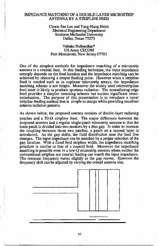
IMPEDANCE MATCHING OF A DOUBLE-LA YER MICROSTRIP . ANTENNA BY A STRIPLINE FEED
Choon Sae Lee and Tung-Hung Hsieh Electrical Engineering Departnient
Southern Methodist University Dallas, Texas 75275
Vahakn Nalbandian* US Anny CECOM
Fort Monmouth, New Jersey 07703
One of the simplest methods for impedance matching of a microstrip antenna is a coaxial feed. In this feeding technique, the input impedance strongly depends on the feed location and the impedance matching can be achieved by choosing a proper feeding point. However when a stripline feed is needed such as in coplanar microstrip arrays, the impedance matching scheme is not simple. Moreover the widely used microstripline feed inset is likely to produce spurious radiation. The nonradiating-edge feed provides a simpler matching scheme but excites significant crosspolarization. The purpose of thi:s presentation is to introduce a novel stripline feeding method that is simple to design while providing excellent antenna radiation patterns.
As shown below, the proposed antenna consists of double-layer radiating patches and a 50-Q stripline feed. The major difference between the proposed antenna and a regular single-patch microstrip antenna is that the main patch is divided into two sections by a thin gap. In order to increase the coupling between those two patches, a patch on a second layer is introduced. As the gap shifts, the field distribution near the feed line changes. The input impedance can be matched by a proper selection of the gap location. With a fixed feed stripline width, the impedance matching procdure is similar to that of a coaxial feed. Moreover the impedance matching is possible even in a low-Q microstrip antenna where neither the conventional stripline nor coaxial feeding can match the input impedance. The resonant frequency varies slightly as the gap moves. However the frequency shift can be adjusted by varying the overall antenna size.
63
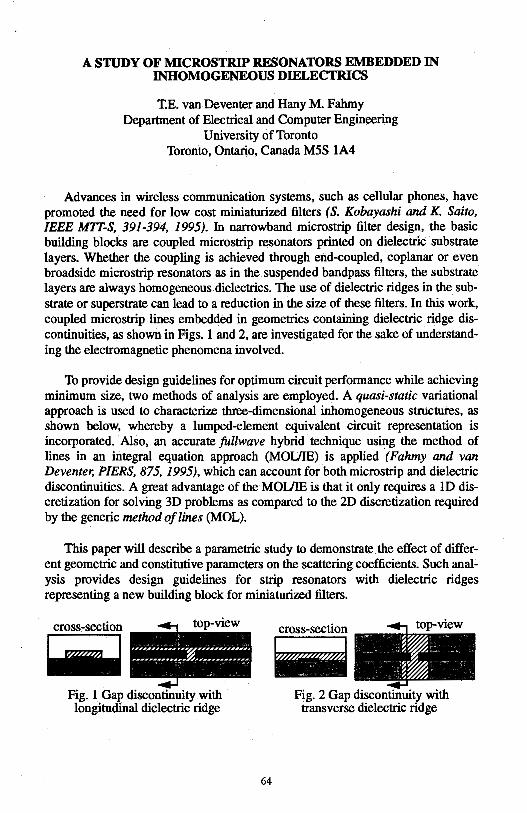
A STUDY OF MICROSTRIP RESONATORS EMBEDDED IN INHOMOGENEOUS DIELECTRICS
T.E. van Deventer and Hany M. Fahmy Department of Electrical and Computer Engineering
University of Toronto Toronto, Ontario, Canada M5S 1A4
Advances in wireless communication systems, such as cellular phones, have promoted the need for low cost miniaturized filters (S. Kobayashi and K Saito, IEEE MIT-S, 391-394, 1995). In narrowband microstrip filter design, the basic building blocks are coupled microstrip resonators printed on dielectric substrate layers. Whether the coupling is achieved through end-coupled, coplanar or even broadside microstrip resonators as in the suspended bandpass filters, the substrate layers are always homogeneous dielectrics. The use of dielectric ridges in the substrate or superstrate can lead to a reduction in the size of these filters. In this work, coupled microstrip lines embedded in geometries containing dielectric ridge discontinuities, as shown in Figs. 1 and 2, are investigated for the sake of understanding the electromagnetic phenomena involved.
To provide design guidelines for optimum circuit performance while achieving minimum size, two methods of analysis are employed. A quasi-static variational approach is used to characterize three-dimensional inhomogeneous structures, as shown below, whereby a lumped-element equivalent circuit representation is incorporated. Also, an accurate fullwave hybrid technique using the method of lines in an integral equation approach (MOUIE) is applied (Fahmy and van Deventer, PIERS, 875, 1995), which can account for both microstrip and dielectric discontinuities. A great advantage of the MOUIE is that it only requires a lD discretization for solving 3D problems as compared to the 2D discretization required by the generic method of lines (MOL).
This paper will describe a parametric study to demonstrate the effect of different geometric and constitutive parameters on the scattering coefficients. Such analysis provides design guidelines for strip resonators with dielectric ridges representing a new building block for miniaturized filters.
cross-section
-Fig. 1 Gap discontinuity with longitudinal dielectric ridge
64
cross-section top vie
-Fig. 2 Gap discontinuity with transverse dielectric ridge
A New Broadband Slot Coupled Notch Microstrip Antenna
Palit S K, Hamadi A, and Rayner J P
Advanced Telecommunications Research Centre, Faculty of Information Sciences and Engineering, University of
Canberra, P,O. Box: 1, Belconnen, ACT-2616, Australia. Fax: 61-6-2015041, E-Mail: [email protected]
Abstract
Microstrip antennas have inherently narrow bandwidth. In this paper, to improve the bandwidth of microstrip antenna a new slot coupled stacked notch microstrip antenna is proposed. Theoretical and experimental investigations of the resonant frequency, input impedance, VSWR and impedance bandwidth of a single and stacked rectangular microstrip antennas with or without a notch employing either microslrip line or coax feeds were undertaken. The measured val.ues were compared with the computed values found using the Method of Moments (MoM) and the Ensemble 4 - a simulation package.
The patches arc realised on the RT Duroid substrate of 1.6 mm thickness with e r = 2.2 al fr = 1.9 GHz. The simulation was done using MoM with the following dimensions calculated using some empirical expressions (T.C. Edwards, John Wiley & Sons, 1992); Width, W= 65 mm, Length, L = 54.5 mm for rectangular patch (fr = 1.9 GHz). The notch dimensions were also calculated as; length, S = 25 mm and depth, U= 10 mm The optimum feed location for minimum VSWR has been determined. It is observed that in a rectangular-patch antenna the feed point location changes the input impedance but does not effect the resonant frequency. In the notch patch, it is observed that the resonant frequency is dependent on the notch dimensions which is found to be fn = 1.8 GHz. The measured radiation patterns for rectangular and notch patches are almost the same which confirms that the current distribution is not significantly changed by the notch.
For a single patch antenna, the impedance bandwidth is generally about 2 to 3%. To increase the bandwidth further the dimensions of the second upper patch were chosen to be 20% smaller than the main lower patch (rectangular/notch). The impedance bandwidth was measured and the maximum bandwidth for notch patch was found to be about 38% which also agreed well with the predicted one. To achieve a further increase in bandwidth, two gap-coupled patches were constructed and placed on top of the two-layered notch patch antenna. The first patch on the top is 15% smaller than the lower (middle) patch. The second top patch, placed in front of the radiating edge was chosen to be 10% smaller than the first top patch. It has been found that the input impedance of gap-coupled patches is very sensitive to gap widtli (X) of the two top patches. The maximum measured impedance bandwidth of about 40% for X = 1.0 mm was achieved for the stacked composite notch microstrip antenna. This significant increase in bandwidth is considered to be a major breakthrough in microstrip antenna design.
65
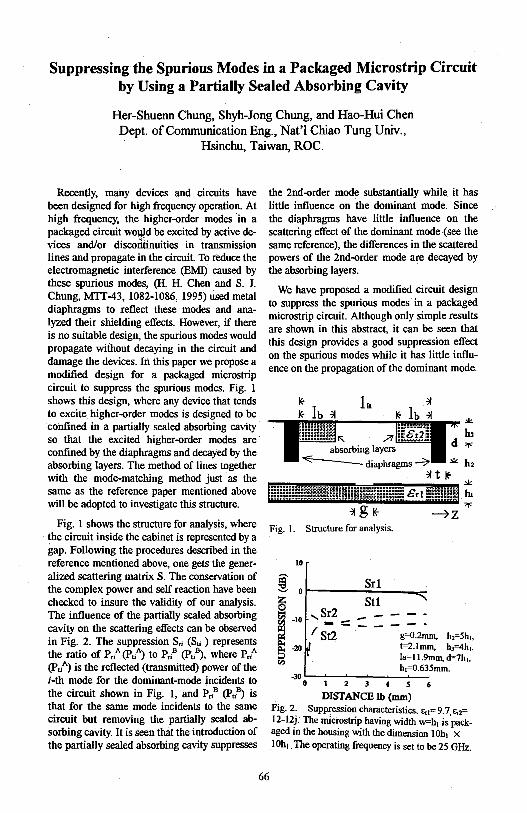
Suppressing the Spurious Modes in a Packaged Microstrip Circuit by Using a Partially Sealed Absorbing Cavity
Her-Shuenn Chung, Shyh-Jong Chung, and Hao-Hui Chen Dept. of Communication Eng., Nat'! Chiao Tung Univ.,
Hsinchu, Taiwan, ROC.
Recently, many devices and circuits have been designed for high frequency operation. At high frequency, the higher-order modes in a packaged circuit wouJd be excited by active devices and/or discorttinuities in transmission lines and propagate in the circuit. To reduce the electromagnetic interference (EMI) caused by these spurious modes, (H. H. Chen and S. J. Chung, MIT-43, 1082-1086, 1995) used metal diaphragms to xeflect these modes and analyzed their shielding effects. However, if there is no suitable design, the spurious modes would propagate without decaying in the circuit and damage the devices. In this paper we propose a modified design for a packaged microstrip circuit to suppress the spurious modes. Fig. l shows this design, where any device that tends to excite higher-order modes is designed to be confined in a partially sealed absorbing cavity so that the excited higher-order modes are · confined by the diaphragms and decayed by the absorbing layers. The method of lines together with the mode-matching method just as the same as the reference paper mentioned above will be adopted to investigate this structure.
Fig. 1 shows the structure for analysis, where the circuit inside the cabinet is represented by a gap. Following the procedures described in the reference mentioned above, one gets the generalized scattering matrix S. The conservation of the complex power and self reaction have been checked to insure the validity of our analysis. The influence of the partially sealed absorbing cavity on the scattering effects can be observed in Fig. 2. The suppression S,; (Su ) represents the ratio of P,/ (P./) to Pl (Pl), where P,/ (PuA) is the reflected (transmitted) power of the i-th mode for the dominant-mode incidents to the circuit shown in Fig. 1, and Pn8 (Pu8) is that for the same mode incidents to the same circuit but removing the partially sealed absorbing cavity. It is seen that the introduction of the partially sealed absorbing cavity suppresses
the 2nd-order mode substantially while it has little influence on the dominant mode. Since the diaphragms have little influence on the scattering effect of the dominant mode (see the same reference), the differences in the scattered powers of the 2nd-order mode are decayed by the absorbing layers.
We have proposed a modified circuit design to suppress the spurious modes in a packaged microstrip circuit. Although only simple results are shown in this abstract, it can be seen that this design provides a good suppression effect on the spurious modes while it has little influence on the propagation of the dominant mode.
Fig. I. Structure for analysis.
i z 0
! ~ l;f.)
10
0
-10
-20
,Sr2 I s7i:::::
I
Srl
St1
g=0.2mm. h2=5h,, t=2.lmm, h3=4h1,
Ia=l l.9mm, d=7h1, h,=0.635mm.
-30 ..__.__...,___.~_.__.._____. 0 2 3 4 5 6
DISTANCE lb (mm) Fig. 2. Suppression characteristics. i:,1=9.7,Ea= 12-12j. The microstrip having width w=h1 is packaged in the housing with the dinlension I Oh1 x I Oh, . The operating frequency is set to be 25 GHz.
66
Modal Analysis of Coupled Cylindrical Microstrip Transmission Lines
Ching-Her Lee*, Ching-Jui Lai Department of Industrial Education
National Changhua University of Education Changhua, 500, Taiwan, R. 0. C.
Cylindrical microstrip transrmss1on line is the canonical structure of many integrated microstrip devices on curved substrates. It finds many applications in microwave and communication circuits with cylindrically shaped substrates. In this paper, a spectral domain, full-wave approach is used to accurately analyze the modal characteristics of the coupled microstrip transmission lines with cylindrical multidielectric-layered background structure. The system governing equation expresses the electric field as a product of the strip currents and an electric dyadic Green's function which is appropriate to the cylindrical-layered background structure. To obtain numerical solutions, a Galerkin's method of moments is implemented. The trigonometric functions incorporated appropriate edge factors are chosen for transverse and longitudinal current expansion and testing.
Some example structures are computed in this work. The dimension parameters used are as follows: the substrate thickness h, the thickness of superstrate t, and the microstrip line width (for both) .w are all about 3 mm; the ratio of the radius of the conducting cylinder to that of the substrate, alb, varies from 0.8 to 0.95. The dielectric constants used for substrate is 9.6, and that for superstrate is 2.32 or 5.0. It is seen that the solution using the electric dyadic Green's function approach relies on the substrate surface electric field and current, so when considering the closely coupled microstrip lines, the transverse electric field is no longer negligible. In this case, the field strength of the odd mode between the two lines becomes strong enough to compensate for the weak transverse current, and full-wave (including transverse and longitudinal wave components) computation should be implemented (A. Nakatani and N. G. Alexopoulos, IEEE MTT-35, 1392-1398, 1987). In our work, both current components are considered, and three expansion functions are used for numerical computation.
In this paper, we will present the effective dielectric constants and the current distributions of the fundamental and higher-order modes. From the obtained results, we see that the effective dielectric constants of the even and odd modes diverge increasingly from that of single strip line as the spacing decreased. The effective dielectric . constant of the odd mode increases relatively speed than that of the even mode as the dielectric constant of the superstrate increased.
67
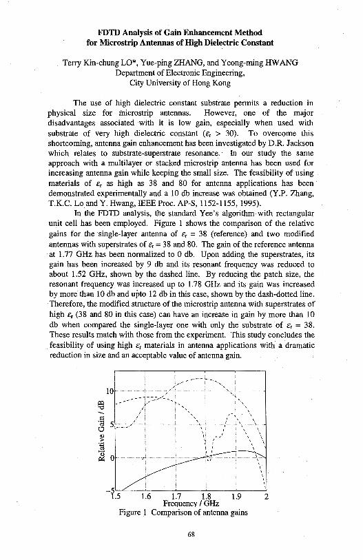
FDTD Analysis of Gain Enhancement Method for Microstrip Antennas of High Dielectric Constant
Terry Kin-chungLO*, Yue-ping ZHANG, and Yeong-ming HWANG Department of Electronic Engineering,
City University of Hong Kong
The use of high dielectric constant substrate permits a reduction in physical size for inicrostrip antennas. However, one of the major disadvantages associated with it is low gain, especially when used with substrate of very high dielectric constant (Er > 30). To overcome this shortcoming, antenna gain enhancement has been investigated by D.R. Jackson which relates to substrate-superstrate resonance. In our study the same approach with a multilayer or stacked microstrip antenna has been used for increasing antenna gain while keeping the small size. The feasibility of using materials of c:, as high as 38 and 80 for antenna applications has been demonstrated experimentally and a 10 db increase was obtained (Y.P. Zhang, T.K.C. Lo and Y. Hwang, IEEE Proc. AP-S, 1152-1155, 1995).
In the FDTD analysis, the standard Yee's algorithm with rectangular unit cell has been employed. Figure 1 shows the comparison of the relative gains for the single-layer antenna of cr = 38 (reference) and two modified antennas with superstrates of Er= 38 and 80. The gain of the reference antenna at 1.77 GHz has been normalized to O db. Upon adding the superstrates, its gain has been increased by 9 db and its resonant frequency was reduced to about 1.52 GHz, shown by the dashed line. By reducing the patch size, the resonant frequency was increased up to 1.78 GHz and its gain was increased by more than 10 db and upto 12 db in this case, shown by the dash-dotted line. Therefore, the modified structure of the microstrip antenna with superstrates of high Er (38 and 80 in this case) can have an increase in gain by more than 10 db when compared the single-layer one with only the substrate of cr = 38. These results match with those from the experiment. This study concludes the feasibility of using high cr materials in antenna applications with a dramatic reduction in size and an acceptable value of antenna gain.
Jil "O
--C ·a 5 c., Cl) ;,.
:E ~
1.6 1.7 1.8 1.9 2 Frequency / GHz
Figure I Comparison of antenna gains
68
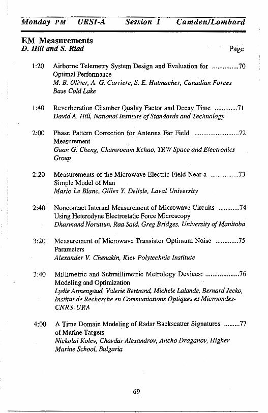
Monday PM URSI-A Session I Camden/Lombard
EM Measurements D. Hill and S. Riad Page
1:20 Airborne Telemetry System Design and Evaluation for ............... 70 Optimal Performance M. B. Oliver, A. G. Carriere, S. E. Hutmacher, Canadian Forces Base Cold Lake
1:40 Reverberation Chamber Quality Factor and Decay Time ............. 71 David A. Hill, National Institute of Standards and Technology
2:00 Phase Pattern Correction for Antenna Far Field ......................... 72 Measurement Guan G. Cheng, Chamroeum Kchao, TRW Space and Electronics Group
2:20 Measurements of the Microwave Electric Field Near a ................ 73 Simple Model of Man Mario Le Blanc, Gilles Y. Delisle, Laval University
2:40 Noncontact Internal Measurement of Microwave Circuits ............ 74 Using Heterodyne Electrostatic Force Microscopy Dharmand Noruttun, Raa Said, Greg Bridges, University of Manitoba
3:20 Measurement of Microwave Transistor Optimum Noise ............. 75 Parameters Alexander V. Chenakin, Kiev Polytechnic Institute
3:40 Millimetric and Submillimetric Metrology Devices: ................... 76 Modeling and Optimization Lydie Armengaud, Valerie Bertrand, Michele Lalande, Bernard Jecko, Institut de Recherche en Communiations Optiques et MicroondesCNRS- URA
4:00 A Time Domain Modeling of Radar Backscatter Signatures ......... 77 of Marine Targets Nickolai Kolev, Chavdar Alexandrov, Ancho Draganov, Higher Marine School, Bulgaria
69
Airborne Telemetry System Design and Evaluation for Optimal Performance
M.B. Oliver, P.Eng.*, A.G. Carriere, S.E. Hutmacher Aerospace Engineering Test Establishment
Canadian Forces Base Cold Lake Medley, Alberta
TOA 2MO
Real-time telemetry of aircraft data to a ground station forms a cornerstone of flight test. Telemetry allows the dynamic control of testing by a team of specialists on the ground and more importantly, helps ensure the safety of flight particularly during high-risk tests such as flutter envelope expansion. The quality of a telemetry link is therefore not only critical for effective and efficient test and evaluation, but also for the safety of flight.
To achieve the optimal design of a telemetry link requires a systems approach. On-aircraft, the quality of the telemetry depends on the entire instrumentation system. Proper design and integration of the aircraft system will reduce the transmission bit rate, and therefore limit the spectral bandwidth required. The quality of the telemetry system also depends on the setup of ground stations.
In an anechoic chamber the tester has measurable control over all variables, a much different environment from an airborne test. To obtain quantifiable results, telemetry test requires the integration of several independent variables: aircraft position relative to the ground station; aircraft attitude (roll, pitch, yaw) and altitude; tracking antenna azimuth and elevation along with signal strength at the receiver. The test regime requires establishing controlled, repeatable and representative flight profiles. These profiles must be repeatable over the life of the telemetry system, since changes to system components will require periodic re-qualification.
While the Aerospace Engineering Test Establishment (AETE) has a need to form a quantifiable baseline of system performance, we are also interested in testing the changes in link performance resulting from some simple modifications: antenna or frequency band changes, band-limiting the data stream, and implementing frequency and spatial diversity techniques.
This paper describes the design and evaluation of AETE L-Band telemetry systems as installed on the CF-188. We present a methodology that may be applied to qualify any airborne telemetry system. This methodology has been validated by a series of test flights conducted on the Primrose Lake Evaluation Range (PLER). Some simple predictive modelling of the link has been done using numerical EM software such as MiniNEC. Our experience also suggests some simple changes that can be made to improve the performance of any airborne telemetry system.
70
REVERBERATION CHAMBER QUALITY FACTOR AND DECAY TIME
David A. Hill Electromagnetic Fields Division
National Institute of Standards and Technology Boulder, CO 80303
Reverberation chambers (also called mode-stirred chambers) are multimoded cavities that are used for radiated emissions or immunity measurements (P. Corona et al., IEEE Trans. Electromag. Compat. 22, 2-5, 1980). They typically use mechanical stirring (paddle wheel) or frequency stirring (D.A. Hill, IEEE Trans. Electromag. Compat. 36, 294-299, 1994) to create a statistically uniform field. The quality factor (Q) is an important performance factor for reverberation chambers because it determines the field enhancement and the decay time (R.E. Richardson, IEEE Trans. Instrum. Meas. 34, 573-580, 1985).
The purpose of this paper is to present a new and more general derivation and expression for the Q of reverberation chambers. The derivation uses a local plane wave expansion and reflection coefficient approximation at the chamber walls to determine the chamber loss by averaging over incidence angle and polarization. The resultant expression for the chamber Q does not invoke the skin depth approximation, but it reduces to the known expression based on skin depth theory when the wall conductivity is high. This previously known expression was derived by modal averaging (B.H. Liu et al., NBS Tech. Note 1066, 1983) and by local plane wave averaging (J.M. Dunn, IEEE Trans. Electromag. Compat. 32, 53-58, 1990). The new theory is applicable to multi-layered walls where the reflection coefficient includes the layering effects. A practical example is the analysis of metal walls with a paint coating.
The same reflection coefficient method has been used to derive the decay time, r - Q/w, for reverberation chambers where Q is now the more general expression. Experimental results have been obtained for Q and decay time for an aluminum cavity with mechanical stirring. The Q measurement using power transmission between a pair of antennas can be degraded by antenna loss and impedance mismatch, but the decay time measurement is relatively independent of these effects. An independent measurement of the conductivity of the aluminum walls was made to obtain an improved agreement between theory and measurements for both Q and decay time. Results will be presented for frequencies from 1 to 18 GHz.
71
Phase Pattern Correction for Antenna Far Field Measurement
Guan G. Cheng and Chamroeum Kchao TRW Space and Electronics Group
One Space Park, 02/2356 Redondo Beach, CA 90278
Antenna far field measurement in most cases normally refers to the gain or amplitude pattern acquisition. However, the far field phase pattern measurement is of its significance in some antenna applications. For the adaptive nulling antenna systems in particular, the verification of the nulling performance is a major issue because that the nulling performance is statistical in nature and cannot be reasonably measured. The nulling antenna performance assessment therefore relies on intensive computer simulations. For the purpose of validation of a simulation model in high degree of accuracy, a nulling antenna system would require the far field phase data in some of its antenna pattern measurement tests.
The far field phase contour pattern measurement is not valid in the conventional antenna ranges unless the antenna phase center lies on all three rotation axes of the positioner for elevation, azimuth, and polarization angles respectively. Unfortunately, it is impractical and probably infeasible to build an antenna positioner with a single point center for three rotation axes. Noticed that the phase patterns can be easily corrected if the measurement is taken in two principle planes, however, for the contour measurement the correction is not trivial and needed to be found.
An algorithm for the correction to the measured phase contour has been developed and verified. A measured antenna far field phase pattern can therefore be predicted and constructed for a positioner geometry with arbitrary three rotation axes. Further, a measured phase contour can thus be corrected such that the true phase pattern originated from the actual antenna phase center can be obtained. Moreover, this technique can also be used to locate the antenna phase center.
In this paper, predicted phase contours for different types of positioner configuration are calculated for comparison. The calculated phase patterns has been verified by the measurement. Good agreement between predicted and measured results is evident.
72
Measurements of the Microwave Electric Field Near a Simple ModelofMan
Mario Le Blanc, Gilles Y. Delisle Department of Electrical and Computer Engineering
Laval University, Quebec City (QC), Canada GlK 7P4
The possibility of biological effects of microwave radiation on the human body makes it desirable to develop reliable and practical techniques for determining the amount of power absorbed in the body. Over the past few years, the development of various wireless networks has increased the public concern over the possible effects of microwaves on health. The purpose of this communication is to present a number of improvements on previously proposed methods, and especially to suggest the simultaneous use of several electric field probes near the body.
The response of a single E-field probe near a model of the human body was studied by Misra and Chen (IEEE Trans. Microwave Theory Tech., 33, 6, 447-452, 1985), at frequencies between 2 and 3 GHz. The model used was a circular cylindrical shell made of low-loss dielectric, of inner and outer radii 14.6 and 15.24 cm, respectively, filled with saline water. The same model is used in the present work, but at a frequency of 10 GHz. It is clear that a measurement of the total Efield ( or of one vector component of the field) near the surface of the model does not lead to an accurate estimation of the internal field, which is required in order to determine the Specific Absorption Rate (SAR). In order to address this problem, it is proposed to sample the E-field using, for each of the three orthogonal components of the field, an array of 8 probes located on a line normal to the surface of the model, with quarter-wave spacing between the probes. The field is therefore sampled over a region of about 6 cm length. The spatial distribution of field magnitude can then be regarded as a signal characterized by the values of the first three coefficients of a Fourier series. Assuming that the incident radiation is a plane wave, and that the physical properties of the model are known, an inverse problem can be formulated in which the unknowns are the amplitude of the incident signal and three angles. It has been shown previously (Proc. Canadian Conf. Electrical and Computer Engineering, Sept. 1994, pp. 572-575) that this problem has a unique solution under certain conditions. Once the inverse problem is solved, it is a simple matter to compute the field distribution inside the model, and therefore the SAR.
The experimental results to be presented will focus on the case of normal incidence with TE polarization, which exhibits the practical advantage that the axial E-field is everywhere zero, thus minimizing scattering by the structure supporting the probes (Proc. Canadian Conf. Electrical and Computer Engineering, Sept. 1995, pp. 257-260). The inverse problem is also simplified, with only two unknowns (amplitude and azimuth angle). The difficulties associated with calibration of the probe arrays, finite distance of the source, as well as measurement of the properties of the model will be discussed.
73
Noncontact Internal Measurement of Microwave Circuits Using Heterodyne Electrostatic Force Microscopy
Dharmand Noruttun, Raa Said, and Greg Bridges
Department of Electrical and Computer Engineering University of Manitoba
Winnipeg, Canada R3T 2N2
The ability to noninvasively measure the internal points of an integrated circuit is important in performing diagnostics of monolithic microwave circuits and devices. Conventional microwave measurement methods rely on direct electrical contact using matched impedance on-wafer probes and are usually performed only at the external ports of the circuit or device being measured. However, techniques capable of monitoring the internal operation at any point of an entire circuit are desirable in order to determine mutual coupling effects between components and devices on a common substrate. The use of direct contact probing at high frequencies is difficult to perform without disturbing the circuits normal operation, and is often impossible in the presence of a passivation layer. To overcome this problem several noninvasive techniques have been developed such as, electron beam probing, electro-optic probing, and capacitive and inductive nearfield imaging. In the last decade many novel scanning probe microscopy (SPM) techniques have been proposed for performing a wide array of microelectronics diagnostics [H.K. Wickramasinghe, Scientific American, 98-105, Oct., 1989]. These techniques have the potential for both extremely high spatial and temporal resolution measurement capabilities.
We have recently been developing SPM techniques [G.E. Bridges, R.A. Said, D.J. Thomson, Electronics Lett., 29, 1448-1449, 1993] which are capable of noncontact measurement of the internal voltage waveforms in integrated circuits. We will present a high frequency version of this technique for performing noninvasive internal node measurements of monolithic microwave integrated circuits. The developed instrument can be considered as an internal-circuit network analyser. Vector voltage amplitude and phase are extracted by sensing the electrostatic force interaction between a small localized noncontact probe and the point in the circuit being tested. We have employed a heterodyne detection technique, which exploits the non-linear dependence of the electrostatic for~e on the ·probe-circuit potentials, to enable the measurement of high frequency forces. A force-nulling methodology is used in our instrument. This allows the local circuit voltage to be accurately measured without the need for complex calibration and also enables voltages to be measured when there is a passivation dielectric over the test point. We will present vector voltage measurement results for several microwave integrated circuits.
74
MEASUREMENT OF MICROWAVE TRANSISTOR OPTIMUM NOISE PARAMETERS
Abstract
Alexander V. Chenakin
Kiev Polytechnic Institute TOR, Building 17, RTF
Pr. Pobedi-37, Kiev-252056, UKRAINE
This paper presents investigations for determination of optimum noise impedance of field-effect transistors placed into H-waveguide at millimeter wave frequency range.
Introduction Due to special features the original microwave integrated circuit
(A. Chenakin, V. Skachko -ISRAMT'95 Proc.,p. 337 - 340) allows to achieve an extremely low noise figure of millimeter wave H-waveguide transistor amplifiers. For calculation these amplifiers it is desirable to use active device parameters measured in the same transition line. In this connection the problem concerning measurement of optimum noise impedance of millimeter wave field-effect transistors placed in the H-waveguide system is urgent currently.
Measurements A new measurement method for determination of input and output
transistor impedance on millimeter waves was developed (A. Chenakin - The 45thARFTG Conf Dig., p. 12-18). This method is based on the measurement of standing wave minimum shift and realized through a special H-waveguide measurement section. It consists of rectangular waveguide section with inserting plate which formed H-waveguide ridges. There are two inserting plates. The first one is a metal substrate with the thin filmed passive integrated circuit and field-effect transistor. The second plate is shorted at the points of the input and output of the transistor.
For determination of transistor optimum noise impedance the usage of set of inserting plates with various configuration is proposed. The active qqptponent of input transistor impedance is determined with distance between J1id.ses of H-waveguide by appropriate choice of slot width cut off in the metal ll'fat,. The reactive one is compensated by appropriate selection of length of short-circuit stub. The noise figure of the H-waveguide measurement section with various inserting plates is measured. The optimum noise impedance is calcul1ned for a plate with minimal noise figure. The necessary technique was developed.
75
MILLIMETRIC AND SUBMILLIMETRIC METROLOGY DEVICES : MODELING AND OPTIMIZATION
Lydie ARMENGAUD, Valerie BER~, Michele LALANDE, Bernard JECKO Institut de Recherche en Communications Optiques et Microondes-CNRS-URA n° 356
IR COM Limoges, 123 avenue Albert Thomas, 87065 LIMOGES Cedex (France)
Introduction With the development of mode-locked lasers and new methods for preparing high
speed materials, it has become possible to extend the response time of photoconductors into the picosecond range. These photoconductors which can convert ultra-fast optical pulses to ultrafast electric pulses can be used as pulse generators or as sampling gates. The paper deals with an optoelectronic sampler whose expected time resolution is 1 ps (bandwidth : 230 GHz) and an exponentially tapered coplanar strip antenna used in a coherent broadband microwave spectroscopy method. For the theoretical analysis and for the considered frequency bands, the Finite Difference Time Domain (F.D.T.D.) method is a suitable method.
Electric single pulse optoelectronic sampler The application of this device (figure 1) is to analyse an ultra fast pulse which is
emitted once only for fusion experiments. Sampling consists in simultaneously switching off N photoconductor elements with a short laser and reading the collected electric charges. The charge stored by the capacitors makes it possible to reconstitute the sampled signal. To suit the applications of this device, the propagation line must be able to transmit without distortion a signal whose bandwidth is up to 230 GHz and the sampling lines must be able to transmit the charge of ultra fast pulses.
prop~tion hnc
r'\ electrical signal ~ '-- 200ps c:==;;:==::;;::=r=======::c:=;;;;;;:::J-,
photoconductor _,.:;, ~ clement /
sampling line
memory capacitor
cleclronic acquisilion
figure 1 : electric single pulse optoelectronic sampler
Exponentially tapered coplanar strip antenna Commutating devices of optoelectronic pulses associated with appropriate antennas
can be used to generate, control and detect picosecond bursts of electromagnetic radiation. That leads to various applications as the transient radiation properties of antennas or as the characterization of material J:>y coherent microwave transient spectroscopy technique. The experimental configuration is shown schematicaly in figure 2. The transmitter is DC-biased. The optical beam is focused in the feedline of the transmitter, where it generates an ultra-fast electrical pulse. All or part of the spectrum contained in tlJis pulse in radiated, depending on the characteristics of the transmitting antenna. For the theoretical analysis, radiation pattern and time evolution of the electric field in free space are calculated for different antenna geometries.
salle 1);: Ji._-
Transmitter Receiver current lock-in amplifier amplifier
figure 2 : coherent microwave transient spectroscopy experiment
76
A Time Domain Modeling of Radar Backscatter Signatures of Marine Targets
(Abstract, URSI AlO)
Nickolai Kolev, Chavdar Alexandrov and Ancho Draganov Higher Marine School, Dep. of Radar and Acoustic Engineering,
73 Vassil Drumev Street 9026 Varna, Bulgaria
A method and program are described for rapid simulation of radar backscatter signatures of marine targets. A time domain physical optics approach is used to estimate the radar return from a detailed target A geometric model of the target is used, consisting of flat plates, the so called facet model. The profile function of a given geometric modelisderivedbymeansofcomputergraphicsalgorithms. The impulse response of a radar is approximated by discrete two dimensional Gaussian cure. The impulse response of the target for a given orientation is derived by a digital convolution. Experimental results showing a coincidence between the real and simulated images are exposed.
In applying the physical optics method for the estimation of the backscattered signal of a target a geometric model is used consisting offlat panels. The model in the 3D space is stored in the computer memory as a set of panels ..
Fig.I
40
Fig.3
77
Each panel is defined by the list of its comer points. Each corner point is given by its Descart coordinates. The panels are restricted to be triangles or quadrangles and not allowed to intersect each other. Such a geometric model ofupwater part of a naval vessel is ilustrated on fig.2.
A computer system was employed to form images of targets using a surveillance marine radar. The images were formed as matrixes 32x32 points using a flash 6 bits ND Converter. The sampling rate was 8.1MHz which gave distance between two samples 0.0lNM. The radar sweep signals followed at every 0.2·. The distance to the target (a Ticonderoga class AEGIS cruiser shown on fig. I) was about 2.0NM. The experimental result is shown on fig.3). On fig.4 is shown a simulated time domain image of the backscattered radar signal. A 2D correlation estimation between the two images is made showing a good
Fig.2
40 40
0 0
Fig.4

THIS PAGE INTENTIONALLY LEFT BLANK.
78
Monday PM AP/URSI-B Session 2 MD Suite Frederick
Special Session
Image Reconstruction from Real Data R. V. McGahan and R. E. Kleinman Page
1 : 20 Imaging of Strongly Scattering Targets from Real Data by ............... 80 Nonlinear Filtering J. B. Morris, R. V. McGahan, Rome Laboratory Hanscom AFB, D. A. Pommet, M. A. Fiddy, University of Massachusetts-Lowell
1 :40 Image Reconstruction from Ipswich Data-II .................................. 81 P. M. van den Berg, B. J. Kooij, Delft University of Technology, R. E. Kleinman, University of Delaware
2:00 Inversion of the 1996 Ipswich Data Using Binary .......................... 82 Specializations of Modified Gradient Methods B. Duchene, D. Lesselier, Laboratoire des Signaus et Systemes (CNRS-Supelec), R. Kleinman, University of Delaware
2:20 Conjugate Gradient Algorithm with Edge-Preserving .................... APS Regularization for Image Reconstruction from Experimental Data P. Lobel, L. Blanc-Feraud, M. Barlaud, Laboratoire lnformatique Signaux et Systemes de Sophia Antipolis, Ch. Pichot, Universite de Nice-Sophia Antipolis
2:~0 Experimental Verification of Two Inverse Scattering Algorithms ..... APS R. D. Murch, Hong Kong University of Science and Technology, D. G. H. Tan, DAMTP University of Cambridge
3:20 Reconstruction of Obstacles and Nonhomogeneous Media from ......... 83 Real Electromagnetic Scattering Data Pierluigi Maponi, Universita di Camerino, Graziella Pacelli, Universita di Ancona, Maria Cristina Recchioni, Universita di Ancona, Francesco
Zirilli, Universita di Roma "La Sapeinza"
3 :40 Imaging Using Limited-Angle Backscattered Data from Real Targets ... 84 R. A. Marr, U. H. W. Lammers, R. V. McGahan, J. B. Morris, Rome Laboratory, D. A. Pommet, M. A. Fiddy, University of MassachusettsLowell
4:00 Imaging of Targets from Experimental Far Field Intensity Data .......... 85 C. W. Liao, M. A. Fiddy, University of Massachusetts-Lowell
4:20 Inverse Scattering Imaging Using Time-Domain Ultra- ................... 86 Wideband Radar Fu-Chiamg Chen, Weng Cho Chew, University of Illinois, William H. Weedon, Northeastern University
4:40 Profile Reconstruction of Inhomogeneous Refractive ..................... 87 Indices Using Genetic Algorithms K. Barkeshli, E. Mehrshahi, Sharif University of Technology
79
IMAGING OF STRONGLYSCATIERING TARGETS FROM REAL DATA BY NONLINEAR FILTERING
J. B. Morris: D.A. Pommet, R. V. McGahan* and M. A. Fiddy Department of Electrical Engineering, University of Massachusetts-Lowell, Lowell, MA 01854 * Rome Laboratory, Hanscom AFB, MA 01731
Using the real scattering data provided, we employ two inverse scattering methods to recover an estimate of the scattering permittivity distribution. We compare the recontruction obtained using the first Born approximation which assumes a very weak scatterer, with that obtained using a nonlinear filter.
Linearizing approximations such as the Born approximation are usually inappropriate for most scattering targets of interest, but approximations of this type lead to simple Fourier inversion procedures. Assuming the Born approximation, one can shown that the recovered target estimate is the product of the permittivity distribution with a function representing the total field inside the target. We present a modification to the Born inversion procedure which attempts to remove this multiplicative field function, thus recovering an image of the permittivity. We implement this approach both on simulated and real microwave scattering measurements taken from the mystery penetrable targets. Due to the limited scattered field data available, we also assume some a priori knowledge of the support of the target and incorporate this into the inversion step. A differential cepstral filtering technique is applied to the data. In the cepstral domain, spectral information about the sum of these functions is available. By filtering backpropagated images in the differential cepstral domain, one can remove the contribution from the internal field and recover the target distribution.
80
Image Reconstruction from Ipswich Data-II
P.M. van den Berg* and B.J. Kooij Laboratory of Electromagnetic Research, Centre for Technical Geoscience
Faculty of Electrical Engineering, Delft University of Technology P.O. Box 5031, 2600 GA Delft, The Netherlands
R.E. Kleinman Center for the Mathematical of Waves
University of Delaware, Newark, Delaware 19716, USA
In this paper we describe the results obtained by using variants of the modified gradient algorithm developed earlier ( e.g. R.E. Kleinman and P.M. van den Berg, J. Comp. and Appl. Math., 42, 17-35, 1992) together with some of the Ipswich data sets to reconstruct the shape, location, and/or index of refraction of the unknown scattering object.
This method was used previously in connection with three Ipswich data sets, corresponding to TM polarization ( electric field polarized along the cylinder axis. of the cylindrical 2-D scatterer) or VV in the Ipswich designation for two perfectly conducting objects, the circular cylinder and the strip, and one penetrable object, the square polystyrene cylinder. These results were reported last year. Good reconstructions were obtained for the perfectly conducting objects but not for the penetrable case, possibly because the data in the latter case was presented in a different form. The data was renormalized by multiplying the circular cylinder data by an unknown complex constant and this constant is determined by minimizing the L2 difference with the exact data as computed using the representation in cylindrical wave functions. This constant, which is essentially a phase correction, was then used as a multiplier of the measured data for all other cases. However the data sets for the conducting bodies were already phase modified while the data set for the penetrable case was not, thus the renormalization was undoubtedly inappropriate in the latter case.
The new Ipswich data sets are all given in the same form and a perfectly conducting cylinder set was also given which enables a consistent renormalization. Reconstructions using these data sets with the modified gradient method will be reported. The modified gradient algorithm consists of constructing two sequences of functions, one representing the unknown field and one representing the unknown contrast by linearly updating the previous term. The direction of the updates are taken as conjugate gradient directions for a functional consisting of the normalized errors in both the domain integral equation and the error in matching the measured data. The magnitude of the correction step is determined by minimizing the functional at each step. A priori information about the contrast is incorporated into the functional by assuming that the contrast is positive imaginary in cases of perfect conductivity and positive real in the penetrable case. The starting values for the contrast and field are obtained by back propagating the measured data.
A recent improvement in the technique involves the addition of a penalty term, the total variation of the contrast, which has the effect of sharpening the resolution of jumps in the contrast. The method has also been extended to the TE (HH) case (magnetic field polarized along the cylinder axis). It is planned to report on the performance of these variants of the algonthm using the Ipswich data.
81
Inversion of the 1996 Ipswich Data Using Binary Specializations of Modified Gradient Methods
B. Ducb&le 1, D. Lesselier 1, and R. Kleinman 2 1 Division Ondes - Laboratoire des Signaux et Systemes (CNRS-Supelec)
ESE - Plateau de M9ulon, 91192 Gif-sur-Yvette Cedex, France 2 Center for the Mathematics of Waves, Department of Mathematical Sciences
University of Delaware, Newark, DE 19716, USA
Binary-based modified gradient solution methods are applied to the new set of experimental Ipswich Data. As is now well-known, nonlinearized modified gradient methods attempt to solve both the observation equation and the coupling equation, this being done simultaneously for all available excitations. (The first equation relates the scattered field data to the sources induced inside the target which are proportional to the unknown contrast function; the second equation links these sources to themselves.) Extensions of such methods that are capable to iteratively build up "binary" structures whose contrast function is allowed to take only two values (say, 0 and 1) have been demonstrated to apply to a variety of situations in both electromagnetics and acoustics.
Free space and stratified embeddings have in particular been dealt with. In the first case the target is usually viewed at a number of incidences and one given frequency (e.g., B. Duchine and D. Lesselier, Proc. 1995 IEEE AP-S Symposium and URSI Meeting, Newport Beach, 235). In the second one, the lack of information due to the availability of aspect-limited data only is compensated by frequencydiversity (e.g., R. K/,einman et al., Proc. IEEE 1994 Ultrasonics Symposium, Cannes, 1169-1172). And these extensions have been proved robust with synthetically generated noisy nearfield data or with experimental farfield data (RCS) while they suitably handle high-contrast or perfectly conducting targets though a domain integral formulation of the wavefield is chosen in the analysis.
Their effectiveness is related to the appropriate choice of a cooling parameter 9. This parameter is introduced in order to transform the search of the 0/1 contrast function at every space point inside the image zone into one where a new contrast function varies continuously between the known bounds (0 and 1). The needed functional derivatives with respect to the contrast now exist, and a standard modified gradient method applies. When a stable result is reached, decreasing 9 pushes the values of the contrast function towards O or 1, and the inversion is started again from the resulting contrast map, and so on until convergence.
Derivation of methods tailored for the Ipswich experimental set-up, numerical implementations of these methods, and results of inversions carried out on both known and mystery targets will be discussed in the presentation.
82

Reconstruction of obstades and nonhomogeneous media from real electromagnetic scattering data
Pierluigi Maponi Dipartimento di Matematica e Fisica Universita di Camerino 62032 Camerino, Italy
Graziella Pacelli Istituto di Matematica e Statistica Universita di Ancona 60100 Ancona, Italy
Maria Cristina Recchioni Istituto di Matematica e Statistica Universita di Ancona 60100 Ancona, Italy
Francesco Zirilli Dipartimento di Matematica G. Castelnuovo Universita di Roma "La Sapienza" 00185 Roma, Italy
We report on our results on the reconstruction of obstacles and nonhomogeneous media from real electromagnetic scattering data provided by Rome Laboratory, Hanscom Air Force Base.
The algorithms developd by the authors in the recent past to solve inverse problems are adapted to treat AIR Force data. In particolar results obtained from the numerical solution of ill posed integral equations with multigrid techniques are presented.
83
IMAGING USING LIMITED-ANGLE BACKSCATTERED DATA FROM REAL TARGEfS
* * * R.A. Marr, D. A. Pommet, U. H. W. Lammers, R. V. McGahan ,
J. B. Morris: and M.A. Fiddy
Department of Electrical Engineering, University of Massachusetts-Lowell, Lowell, MA 01854 * Rome Laboratory, Hanscom AFB, MA 01731
Most previously developed imaging methods, based on inverting scattered field data, rely on assumptions of weak or spatially slowly varying inhomogeneities. The method we have developed has been designed to recover images of strongly scattering targets while remaining computationally efficient, being based on well-understood FFf routines. In this paper we use this technique for the recovery of information about the structure of a 3D penetrable target. This need occurs in many radar applications, as well as medical imaging, remote sensing, and non-destructive testing requirements, in which only a limited amount of measured data are typically available.
We have also developed Fourier-based methods for image restoration, phase estimation and superresolution. These techniques have been directly built into our methods for inversion of scattered field data, thereby compensating for limited and noisy measurements. We consider these techniques for a J-band radar system designed to study general scattering phenomena and to image scale model targets. The sophisticated data collection procedure which has been developed and will be described, makes measurements only in a small solid angle around the backscatter direction over a range of wavelengths. Given that the object is known to be located in a specific region of space and is precessed relative to the backscatter direction, we determine the k-space coverage associated with these data. With these data defined, k-space data extrapolation and filtering is presented to recover the object permittivity profile.
84
IMAGING OF TARGETS FROM EXPERIMENTAL FAR FIELD INTENSITY DATA
C-W. Liao and M.A. Fiddy Department of Electrical Engineering, University of Massachusetts-Lowell, Lowell, MA 01854
In many imaging applications, it is only possible to acquire data about the target in the far zone. Moreover, at high frequencies, it is sometimes only possible to measure the intensity of the scattered field. In practice the inverse scattering problem is difficult to solve, but in the absence of the phase information about the field, it becomes seriously ill-posed. This so-called phase retrieval problem is well known and there exist many ad hoc technqiues for attempting to estimate the missing phase information from the measured intensity samples.
If one can estimate data from the power spectrum about the complex spectrum of an image, then it is possible to solve the phase retrieval problem. We present a new method for this based on using the locations of the points in the intensity distribution at which the intensity is zero. These points are the only points which are common to both the intensity data and the complex spectral or scattered field data required to recover the image. A procedure has been developed which permits this, based on a factorizable polynomial model. Zero crossings of the intensity function, i.e. zeros on the real plane, are points at which an irreducible zero line passes through the real plane from the associated complex space. Strictly the zero line's co-ordinates are needed to fully represent the function. However, adopting this factorizable model is consistent with the Weierstrass factorization theorem, when the real x-y plane alone is considered. Provided there is a snfficiently large number of real point zeros, which tends to be the case especially for coherent fields (i.e. speckled fields), these zero locations can provide a complete representation of the complex spectral function's phase. This is sufficiently accurate to permit an iterative (error reduction) algorithm to converge to a unique estimate of the true phase distribution.
85
Inverse Scattering Imaging Using Time-Domain Ultra-Wideband Radar
Fu-CHIARNG CHEN* AND WENG CHO CHEW
ELECTROMAGNETICS LABORATORY
CENTER FOR COMPUTATIONAL ELECTROMAGNETICS
DEPARTMENT OF ELECTRICAL AND COMPUTER ENGINEERING
UNIVERSITY OF ILLINOIS
URBANA, IL 61801
WILLIAM H. WEEDON
DEPARTMENT OF ELECTRICAL AND COMPUTER ENGINEERING
NORTHEASTERN UNIVERSITY
BOSTON, MA 02115
Abstract
Much progress has been made in developing inverse scattering imaging algorithms, and,so the need has arisen for pratical implementations of these methods. Recently, a new time-domain ultra-wideband radar scattering measurement system is developed to serve as a new inverse scattering imaging tool for nondestructive evaluation (NDE). This time-domain ultra-wideband radar scattering measurement system consists of a Picosecond Pulse Lab (PSPL) 4050B step generator, a PSPL 4050RPH remote pulse head, two PSPL 5210 impulse forming networks, a Hewlett-Packard (HP) 54120B digitizing oscilloscope mainframe, an HP 5412iA 20 GHz four-channel test set, a broadband Vivaldi antenna array, two ultra-wideband amplifiers and two microwave switches. The system is automated and controlled by a computer via the IEEE-488 bus. Two iterative nonlinear recoristruction algorithms, the distorted Born iterative method (DBIM) and the local shape function (LSF) method, are used to process the time-domain measurement data to reconstruct the image of the target object. The DBIM and LSF methods account for multiple scattering effects of the test targets and show a high relolution image reconstruction capability. However, when the multiple scattering phenomenon is not important, the first order Born approximation method such as diffraction tomography can be used in order to save the intensive computational time of DMIM and LSF. In the past, the DBIM and LSF methods have been demonstrated to generate high quality reconstruction images for both metallic and dielectric objects located in air. In this paper, we will consider the more difficult problem of imaging objects embedded in the concrete rebar. The aggregation of the time-domain ultra-wideband pulse radar scattering measurement system and the inverse scattering algorithms will provide a good means for NDE with high resolution imaging capability.
86
Profile Reconstruction of Inhomogeneous Refractive Indices Using Genetic Algotrithms
K. Barkeshli and E. Mehrshahi Electrical Engineering Department, Sharif University of Technology
P.O. Box 11365-9363, Tehran, Iran [email protected]
For an· inhomogeneous lossless dielectric slab occupying the region O :5 z :5 -d and illuminated by a plane wave, the reflection coefficient R(z) satisfies a nonlinear ordinary differential equation of Riccati type
dR · /3' - = -j2/3R+ -(1-R.2) dz 2/3
(1)
where R( z) is .the local reflection coefficient and /3( z) is the corresponding phase factor. The above equation is subject to the appropriate boundary condition on the bottom face of the slab, and the TE polarization is assumed.
Assuio.ing that the reflection coefficient has been measured in front of the slab (z = 0) at certain frequencies w,, we are interested in the reconstruction of the unknown refractive i;,_dex profile from the measured data. Thus, the profile is first expanded in terms of linearly independent expansion functions with unknown coefficients {ao, ... , aL} and a performance index is defined as
F(ao,···,aL) = liz.({a,})-R.({a,})12
=O (2)
In the above, the estimated reflection coefficients R( {ai}) are calculated by a direct integration routine and R. = R( w,, n( z)) represent the ~easured data. The strategy is, therefore, to estimate {at} so as to minimize F.
We apply a simple genetic algorithm to the solution of the inverse profiling problem. Unlike the deterministic optimization methods, the genetic algorithms are semi-probabilistic in nature and are based on the process of natural evolution. They have the advantage of not requiring any gradient information in their search and being ~pable of solving global optimization problems.
Our preliminary results show that for profiles exhibiting relatively fast variations, this method gives superior results in comparison with deterministic techniques such as the conjugate gradient method.
87

THIS PAGE INTENTIONALLY LEFT BLANK.
88

Monday PM AP/URSI-B Session 3 MD Suite Columbia
Special Session
In Honor of Kane Yee on the Occasion of the 30th Anniversary of His Paper that Launched the FDTD Method A. Taflove and R. Luebbers Page
1 :20 From Staircasing FDTD to Conformal FDTD ................................. 90 Kane Yee
1 :40 Thirty Years After: Kane Yee and FDTD ...................................... 91 Raymond Luebbers, The Pennsylvania State University
2:00 Fidelity, Elegance and Reach of Yee's Lattice ................................ 92 Kenneth K. Mei, City University of Hong Kong
2:20 Absorbing Boundary Conditions for Finite-Difference .................... 93 Methods Gerrit Mur, Delft University of Technology
2:40 Human Body Modeling for FDTD Evaluation of Electromagnetic ...... APS Hazards Richard Holland, Shield Rite, Inc., Joe Fogler, Gregory W. Donohoe, University of New Mexico
3 :20 A Self-Consistent Electromagnetic-Acoustic Finite Difference .......... 94 Time Domain Code K. S. Kunz, Pennsylvania State University
3:40 A Novel Technique for FDTD on a Non-Orthogonal Grid .................. 95 Siva Chebolu, Raj Mittra, Supriyo Dey, University of Illinois
4:00 Application of the FDTD Method on Active Circuit ........................ 96 Simulation Chien-Nan Kuo, Tatsuo Itoh, University of California Los Angeles, Bijan Houshmand, California Institute of Technology Jet Propulsion Laboratory
4:20 Advanced FDTD Methods on High Performance Parallel ................... 97 Computers Stephen D. Gedney, University of Kentucky, Faiza Lansing, California Institute of Technology Jet Propulsion Laboratory
4:40 FD-TD: A Personal Journey and Beyond ...................................... 98 Allen Taflove, Northwestern University
89
FROM STAIRCASING FDTD TO CONFORMAL FDTD / FVTD
Kane S. Yee and J. S. Chen Lockheed Palo Alto Research Laboratory
Palo Alto, CA 94304
In 1966, one of the present authors published the FDTD numerical algorithm to solve Maxwell's equations in rectangular coordinates. He did no further work on it until 1984 when he returned to the Lawrence-Livermore National Laboratory to work on applications requiring the numerical solutions of Maxwell's equations. Meanwhile, during the decade 1970 to 1980, a number of workers including Kunz, Holland, Lee, and Merewether in the electromagnetic pulse area and Taflove in the bioeffects area used the 1966 algorithm and introduced a number of extensions and auxiliary results needed to make it a useful tool for practical engineering problems. In 1980 Taflove coined the acronym FD-TD and has since contributed greatly to the techniques and applications of this method. In fact, the original application of FDTD to radar cross section calculations was due to him and his coworkers, chiefly, K. Umashankar.
The rounding of FDTD into a practical modeling tool seems to have been completed by the publication of the radiation boundary condition approximation by Mur in 1981. Since the mid-1980's, there has been explosive growth in the application of FDTD to solve electromagnetic wave problems in many application areas. The number of citations of the 1966 paper by journal articles is now well over 800; and if one includes citations due to talks at conferences, the number of citations easily tops 1000! By the mid-1990's, numerous researchers worldwide have contributed to the improvement of the 1966 FDTD algorithm.
One of the most appealing features of FDTD seems to be its simplicity and its affinity to "first principles." With the generalization of the original FDTD algorithm through the use of the surface-curve and the volume-surface integral forms of the Maxwell's equations, the inclusion of the physics into the numerical algorithm seems to be natural. As computer capability increases, the use of FDTD will very likely become even more popular, continuing the strong upward trend witnessed during the last five years or so from publications in the technical journals and conferences.
One of the features found wanting in the 1966 FDTD algorithm was its inability to accurately model boundary conditions on curved material surfaces. It is the purpose of this presentation to give a coherent account of the historical development of FDTD leading to the present conformal FDTD and FVTD (finite volume time domain) methods. Numerical results demonstrating the superior accuracy of the conformal FDTD method versus the staircasing FDTD will be presented.
90
THIRTY YEARS AFTER: KANE YEE AND FDTD
Raymond Luebbers Department of Electrical Engineering
The Pennsylvania State University University Park, PA 16802
The appearance of the original paper describing what is now known as the Finite Difference Time Domain method (K. S. Yee, IEEE AP-S, vol 14, no. 3, pp 302-307, May 1966) was not much noticed at the time. Figure 1 of that paper, the first appearance in print of the "Yee" cell, is probably one of the most copied figures ever appearing in an engineering journal. Yet no best paper awards were considered for this paper. We are here convened to try, 30 years later, to remedy this situation. In some scientific journals there are awards for "Best Paper of the Decade". If the AP-S were wise enough to institute such an award, this paper should receive it. But even so, we are still 20 years late. Why has the recognition deserved by this paper been delayed so long? It was a breakthrough of thought, elegant, yet simple.
The impact of this original paper, and of subsequent work by Kane Yee, on computational electromagnetics will be described from both personal and general viewpoints. Special attention will be given to some recent applications in antennas, propagation, special materials, and biological effects of electromagnetic fields.
But general coverage of the FDTD method is certainly beyond the scope of one presentation. The list of applications to which the FDTD method has been adapted covers nearly the entire list of topics of this conference. Of the 33 suggested topics for APS, FDTD has been applied, to my knowledge, to all but 3, and of these 3 there probably have been FDTD applications of which I am ignorant.
FDTD is arguably the most widely used computational electromagnetics approach, and the fastest growing. Perhaps Kane Yee's original paper was ahead of its time. But Kane himself is here with us. Congratulations on this anniversary.
91
FIDELITY, ELEGANCE AND REACH OF YEE'S LATTICE
By Kenneth K. Mei Department of Electronic Engineering
City University of Hong Kong Kowloon, Hong Kong
Fidelity, elegance and reach are the three basic criteria used by ancient Chinese scholar to judge scholarly prose, essays and poetries. They are used in this talk to judge field computation methods, in particular the FDTD method originated by Yee. Fidelity means accuracy; elegance means cleverness, terseness; reach means a broad range of applications. Very few computational methods can score highly in all three criteria. Yee's space time lattice was thought to be low fidelity, clumsy and of limited application when it was first proposed. It is now one of the most popular mode of computation. In reality, after 30 years, the method is hardly changed, rather the advance in computational environment and the evolution of the mentality of the researchers have made the difference. One can't help but appreciate the foresight of Dr. K. S. Yee, who bucked the trend of the time to open the door for us.
92
ABSORBING BOUNDARY CONDITIONS FOR FINITE-DIFFERENCE METHODS
GerritMur Laboratory of Electromagnetic Research
Faculty of Electrical Engineering Delft University of Technology P.O. Box 5031, 2600GA Delft
The Netherlands
Finite difference methods, and in particular the Yee algorithm, provide simple and very efficient tools for computing electromagnetic fields. A major limitation of finite-difference methods for electromagnetics, however, lies in the fact that they can be applied to bounded domains only. Unfortunately many, or perhaps most, electromagnetic field problems are in unbounded domains. This difficulty is solved by truncating the domain of computation to a size that is small enough to be modeled on the computer that is available. This truncation should be carried out such that the most interesting features of the problem at hand are located inside the domain of computation. The truncation of the domain of computation causes the introduction of an artificial outer boundary to it. The challenge of absorbing boundary conditions is to model radiation through the artificial boundary into the unbounded environment as accurately as possible.
An overview of the history of the development of absorbing boundary conditions for finite-difference approximations of the electromagnetic field equations will be given. Finally some interesting new developments will be discussed.
93
A SELF-CONSISTENT ELECTROMAGNETIC-ACOUSTIC FINITE DIFFERENCE TIME DOMAIN CODE
K. S. Kunz Dept. of Electrical Engineering, Penn State University
313 Elect. Engr. East Bldg., University Park, PA 16802
Recently a finite difference time domain electromagnetic algorithm has been developed that treats atomistic behavior mechanistically so as to incorporate linear and nonlinear dielectric behavior at the atomic and molecular level. An acoustic finite difference time domain algorithm has also been developed to treat small vibrations in gases, liquids and solids including bending modes in solids. It is now possible to combine these two time domain codes into one self-consistent, nonlinear, electromagnetic-acoustic finite difference time domain code.
In such a self-consistent code the electromagnetic fields in the material produce a polarization P that is acted on by the electric fields producing a force on the media. This force is included in the equations governing the material's macroscopic motions and so results in small signal variations in pressure and velocity. These material variations produce an additional change in the polarization P. This change can then be incorporated into the Maxwell curl equations that govern the time dependent behavior of the fields, in particular the curl of H equation. The result is a self-consistent treatment of coupled electromagnetic and acoustic fields.
The electromagnetic treatment of the dielectric properties is mechanistic so that a classical harmonic oscillator behavior to the atoms or the molecules is assumed. This approach has exactly matched an earlier frequency dependent lossy dielectric finite difference time domain formulation based on recursive convolution. The new mechanistic formulation allows direct substitution of nonlinear restoring forces, direct evaluation of saturation and breakdown effects. If needed it could be quantized, so that not only classical, but also quantum mechanical effects could be incorporated.
Since both the electromagnetic portion and the acoustic portion of the algorithm are time domain formulations, transient behavior is treated properly. There is no restriction to a single frequency, so that mixing phenomena do not have to be restricted to a single frequency. The algorithm, just as for its parts, can be fully three dimensional.
The equations governing the two domains, electromagnetic and acoustic, when coupled, are respectively given by
(1)
(2)
for electromagnetics, using the x component as an example, and
op/at = (A + 2µ/3)V · v (3)
fJv/iJt = (1/p)[((A + 2µ)/(A + 2µ/3))Vp-µ(V x V x s) + ~V(E · P)]. (4)
for acoustics. E and H are the electric and magnetic fields, P is the polarization, u the conductivity, e0 and l'o are the permittivity and permeability of free space while p is pressure, v is velocity, A and µ are the Lame constants and s the displacement. These equations form a self-consistent treatment in the time domain of electrostrictively coupled electromagnetic fields.
94
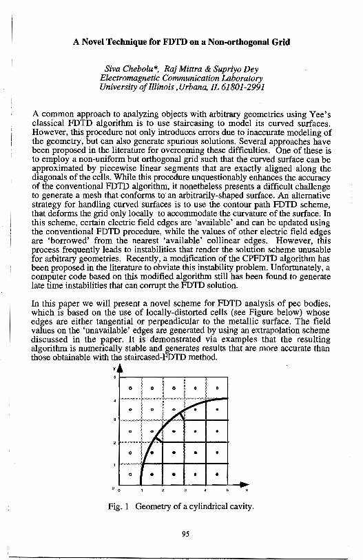
A Novel Technique for FDTD on a Non-orthogonal Grid
Siva Chebolu*, Raj Mittra & Supriyo Dey Electromagnetic Communication Laboratory University of Illinois, Urbana, IL 61801-2991
A common approach to analyzing objects with arbitrary geometries using Yee's classical FDTD algorithm is to use staircasing to model its curved surfaces. However, this procedure not only introduces errors due to inaccurate modeling of the geometry, but can also generate spurious solutions. Several approaches have been proposed in the literature for overcoming these difficulties. One of these is to employ a non-uniform but orthogonal grid such that the curved surface can be approximated by piecewise linear segments that are exactly aligned along the diagonals of the cells. While this procedure unquestionably enhances the accuracy of the conventional FDTD algorithm, it nonetheless presents a difficult challenge to generate a mesh that conforms to an arbitrarily-shaped surface. An alternative strategy for handling curved surfaces is to use the contour path FDTD scheme, that deforms the grid only locally to accommodate the curvature of the surface. In this scheme, certain electric field edges are 'available' and can be updated using the conventional FDTD procedure, while the values of other electric field edges are 'borrowed' from the nearest 'available' collinear edges. However, this process frequently leads to instabilities that render the solution scheme unusable for arbitrary geometries. Recently, a modification of the CPFDTD algorithm has been proposed in the literature to obviate this instability problem. Unfortunately, a computer code based on this modified algorithm still has been found to generate late time instabilities that can corrupt the FDTD solution.
In this paper we will present a novel scheme for FDTD analysis of pee bodies, which is based on the use of locally-distorted cells (see Figure below) whose edges are either tangential or perpendicular to the metallic surface. The field values on the 'unavailable' edges are generated by using an extrapolation scheme discussed in the paper. It is demonstrated via examples that the resulting algorithm is numerically stable and generates results that are more accurate than those obtainable with the staircased-FDTD method.
0 • • 0 0
Fig. 1 Geometry of a cylindrical cavity.
95
APPLICATION OF THE FDID METIIOD ON ACTIVE CIRCUIT SIMULATION
Chien-Nan Kuo, *Bijan Houshmand, and Tatsuo ltoh
Department of Electrical Engineering University of California
Los Angeles, CA 90095-1595
*Jet Propulsion Laboratory Pasadena, CA 91109
This paper reports recent progress in the application of the Fmite-Difference Time-Domain (FDID) method to the analysis of microwave circuits. Being generally developed, the FDID method exhibits its versatility in the modeling of complicated structures. The trend of circuit design leads to full-wave analysis of the entire structure to provide more physical insights into electromagnetic characteristics in the design phase. Full-wave analysis is especially useful to analyze circuits with strong field coupling such as active antennas.
The conventional leapfrog algorithm has been extended to include lumped devices. In the simulation of active circuits, the active device has significant effect on circuit performance. Reliable analysis depends on the modeling of interactions between the device and electromagnetic fields. Recognizing that the size of the device is typically much smaller than a wavelength, the device circuit model can be employed to represent the device. For two-terminal devices such as diodes, the circuit model can be incorporated into the coefficients ofFDID algorithm directly. To incorporate three-terminal devices, a general method is to apply equivalent sources at the input/output ports in the device region. The values of these equivalent sources are determined by the circuit model to satisfy the voltagecurrent relationship and provide die same response as the active device when waves arrive at the device region. There are two different approaches to implement the equivalent sources. One uses equivalent current sources according to the integral form of Ampere's law; the other uses equivalent voltage sources according to Faraday's law. Being derived differently, two approaches have the same degree of accuracy. The extended FDID method has been successfully applied to small-signal analysis of microwave amplifiers. Results of large-signal analysis will also be presented.
The resulting technique of the FDID method is a good simulation tool. The method is able to perform full-wave analysis of the entire circuit, and thus provide an alternative approach of circuit design for microwave engineers.
96
Advanced FDTD methods on High Performance Parallel Computers
Stephen D. Gedney* Electromagnetic Laboratory
Department of Electrical Engineering University of Kentucky Lexington, KY 40506
FaizaLansing Spacecrqft Telecommunications
Equipment Section Jet Propulsion Laboratory
Pasadena, CA 91109
Over the last decade, the Finite-Difference Time-Domain (FDTD) method has become one of the most widely used computational techniques for the full wave analysis of electromagnetic phenomena. Its popularity can be accredited to the simplicity of the algorithm, while providing a robust and accurate analysis of electromagnetic fields. One principal factor that has delayed the extensive application of the FDTD method is that substantial computational resources are required for the analysis of practical three-dimensional problems. In the last decade, the introduction of inexpensive high-speed memory, powerful vector processors, high-speed RISC processors, and the maturation of high-performance parallel computers has provided the economical and powerful computational resources that are necessary to perform the analysis of practical engineering applications via the FDTD method. Correspondingly, the FDTD method has received extraordinary popularity. Secondly, generalization of the FDTD method to non-Cartesion lattices, including non-orthogonal structured and unstructured grids, has provided the means for accurate analyses of the electromagnetic interaction with structures with complex geometries. In this paper, we will look at the development of efficient parallel FDTD algorithms for high performance computers. Of concern will be both the development of efficient algorithms for both structured grid FDTD algorithms, as well as unstructured grid based algorithms, such as the planar generalized Yee (PGY) algorithm. It will be demonstrated that highly scalable parallel algorithms are easily acheivable. A concern that will be addressed is what is the limitations of the scalability of FDTD algorithms - specifically, how large can a problem be scale before reaching the limits of current computational resources (both memory and CPU time), as well as numerical rounding error due to dispersion. Techniques for reducing dispersion, including higher-order algorithms, will be addressed.
97
FD-TD: A PERSONAL JOURNEY AND BEYOND
Allen Taflove Department of Electrical Engineering and Computer Science
McCormick School of Engineering, Northwestern University 2145 Sheridan Rd., Evanston, IL 60208
Almost twenty-two years ago, I submitted the first two journal papers of my research career to IEEE Trans. Microwave Theory and Techniques (MTT). These papers described my initial explorations of what later became known as the finite-difference time-domain method for Maxwell's equations. The papers grew from a graduate seminar course at Northwestern University in bioelectromagnetic hazards that Prof. Morris Brodwin had conducted in 1972. During my independent study for this seminar, I sought to obtain a model for UHF and microwave penetration into the human eye to better understand the formation of "microwave cataracts." At first, there appeared to be no viable means to solve Maxwell's equations for the complex, three-dimensional biological tissue geometry represented by the eye and its surrounding tissues. The complexity of this geometry ruled out either analytical modeling or existing moment method numerical approaches.
Almost having given up on the project, I found myself randomly leafing through back issues of IEEE Trans. Antennas and Propagation. It was then that I stumbled upon Kane Y ee's 1966 paper. Six years had gone by since its publication with very few references to it recorded in Science Citation Index. And yet, I sensed that the Yee algorithm was the Grail. It could handle material inhomogeneities and did not require matrix inversion, meaning that I could use the University's Control Data CDC 6400 computer to crunch the problem to its conclusion. Of course, a few "minor" details had to be solved, such as sourcing a plane wave, obtaining a rudimentary absorbing boundary condition, understanding the algorithm's numerical stability properties, and progressing from one to two to three dimensions in my code development
So, my 1975 papers in MTT were published. And landed with a thud. Being eager, brash, and absolutely naive, I had expected the electromagnetics community to seize upon the marvelous Yee algorithm and app\y it to everything. However, with the exception of the few industrial research firms and Government agencies active in the electromagnetic pulse area, FD-TD remained essentially unused until the mid-1980's. Now, in the mid-1990's, after much hard work by a rapidly growing user community, FD-TD is being used worldwide. And for just about everything!
However, the FD-TD story is only beginning. Let's move on to develop detailed FD-TD electromagnetics models of microchips, microlasers, and microcells, and bring the power of Maxwell's equations to bear upon society's needs in ultrahigh-speed communications technology. In this manner, electromagnetic wave specialists can augment their current role in enabling people to freely communicate with each other wo.rldwide, at the speed of light
This abstract is adapted from the preface of A. Taflove, Computational Electrodynamics: The FiniteDifference Time-Domain Method (Artech House, Norwood, Mass., 1995).
98
Monday PM AP/URSI-B Session 4 Chesapeake B
Theoretical Electromagnetics I P. L. E. Uslenghi Page
1 :20 A Peculiar Dielectric Wedge ................................................ 100 Piergiorgio L. E. Uslenghi, University of Illinois at Chicago
1:40 Complex Power in Radiation Fields ...................................... 101 Dale M. Grimes, Craig A. Grimes, The University of Kentucky
2:00 The Riemann Black Screen and Classical Models ..................... 102 of Black Bodies P. Y. Ufimtsev, University of California Los Angeles
2:20 (Parabolic Equation) - (Gaussian Beam) Analysis of ................. 103 Tropospheric Electromagnetic Propagation Bimba S. Rao, Lawrence Carin, Duke University
2:40 Numerical UTD Diffraction Coefficients with Hybrid .............. APS Topologic Method Benoit Roturier, Bernard Souny, Ecole Nationale de /'Aviation Civile
3:20 Electromagnetic Field Behavior at Edges of Dielectric Bodies ..... 104 Andrey V. Osipov, St. Petersburg State University
3:40 Complex Waves Strong Theory of Coupled Cylindrical Slot ..... 105 and Strip Lines Alexander Y. Svezentsev, Ukranian Academy of Sciences
99
A PECULIAR DIELECTRIC WEDGE
Piergiorgio L. E. U slenghi Department of Electrical Engineering and Computer Science
University of Illinois at Chicago, 851 South Morgan Street, Chicago, IL 60607-7053
In a recent paper (IEEE Trans. Antennas Propagat., vol. 44, no.l, Jan. 1996) the author has proven that certain categories of dielectric wedge structures have geometrical optics as the exact solution when subjected to plane wave incidence in a specific direction and with a specific polarization. In this work, a particular dielectric wedge is considered for which the opposite is true: geometrical optics fails completely when a certain wedge is under plane wave incidence from a certain direction and with a certain polarization, even at very large distances from the edge.
Consider a dielectric wedge with an aperture angle of 1( /3 radian , made of a homogeneous isotropic material with a relative permittivity equal to three (and a relative permeability equal to one), surrounded by free space. If a plane primary wave is incident in a direction parallel to the symmetry plane of the structure and normal to the edge of the wedge and is polarized with its electric field normal to the edge, then it is easily seen that total transmission occurs across both faces of the wedge. Each totally transmitted wave across one face propagates inside the wedge in a direction parallel to the other face, and no other geometrical optics contributions occur. It is easily seen that the boundary condition requiring continuity of the tangential component of the magnetic field is grossly violated on both wedge faces, and this failure of geometrical optics to even approximate a correct solution is present independently of the distance from the edge.
In order to understand what corrections · are needed to geometrical optics, we consider the canonical problem of two homogeneous dielectric half-spaces separated by an infinite planar interface, when the primary field consists of a lateral wave in the denser medium. We conclude that the total field in the denser half-space is just the primary lateral wave, whereas in the other half-space a wave exists whose amplitude grows exponentially with the distance from the interface, thus violating the condition of a finite field everywhere. When this situation is applied to our wedge, we conclude that no edge-diffracted field exists inside the wedge, where the total field consists of two plane waves, each lateral to one of the edge faces. In air, however, the total field consists of the primary plane wave plus a leaky wave emanating from the edge of the wedge. Considerations of power conservation are developed to bolster our conclusion.
100
COMPLEX POWER IN RADIATION FIELDS
Dale M. Grimes 1204 Sheffield Place, Lexington KY 40509, USA Ph: 606.263.8846 email: [email protected]
It follows using the time dependent Poynting theorem that steady state radiation from a localized region produces three power terms at each point: a constant term, a term proportional to cos(2rot), and a term proportional to sin(2rot). Because of the great convenience of working in the complex plane, and since the complex plane supports only two numbers, a modified power expression is desired that consists of only two terms. To go from three terms to two, trigonometric identities are used to transform the coefficients of each time-varying term in such a way that the constant term and the coefficient of the cosine term are equal; accompanying changes in phase angle are the same in both time-varying terms. The result is that the three initial power terms have been changed to two magnitudes and one phase angle. Historically, the magnitudes of the cosine and sine terms respectively are put equal to the real and imaginary parts of a complex number, and that number is the complex Poynting vector. The third component of the power, the phase angle, is ignored.
Although this technique has proved its worthiness in numerous applications, special care is necessary when combining powers from different sources or regions; complex powers combine according to the rules of simple addition or integration if and only if the phase angles of the combining powers are the same (D.M. Grimes and C.A. Grimes, IEEE Trans. EMC 37, 217-226, 1995). As an important example, if the phase angle of the complex Poynting vector is a function of angular position on a spherical surface of integration, the surface integral of the complex Poynting vector is not equal to the complex surface power. Instead complex surface power is obtained by evaluating the surface integral in the time domain then making the transformation to complex power. Since the phase angle does not explicitly appear in the complex Poynting vector, it is not obvious whether the surface integral of the complex Poynting vector is or is not equal to the complex surface power. This is learned from the three time domain terms. Still another important example is a radiating sphere generating two irreducible planes of polarizations. The total complex power on a surface is equal to the simple sum of the complex powers in the two polarizations if and only if the phase angles of the two polarizations are the same.
In summary, the reactive powers of different sources do not combine by simple addition; the relative phase differences must be taken into account .. This paper provides a detailed discussion of how complex powers combine in radiation fields with multiple sources.
101
THE RIEMANN BLACK SCREEN and CLASSICAL MODELS of BLACK BODIES
P.Ya. Ufimtsev Electrical Engineering Department
University of California at Los Angeles Los Angeles, California 90095-1594, USA
also with Northrop-Grumman Corporation
8900 East Washington Blvd, T20JIXC Pico Rivera, California 90660, USA
Abstract
In diffraction theory the black bodies are considered as idealized models of absorbing objects and for this reason they continue to attract attention, especially in connection with the problem of low observable objects. A nice review of classical models of black bodies was presented by Baker and Copson (B.B. Baker, E.T. Copson, The Mathematical Theory of Huygen's Principle, Oxford, Claredon Press, 1938). An extension of the Kichhoff-Kottler model to arbitrary volumetric black bodies was done by the author (P.Ya. Ufimtsev, Radiophysics and Quantum Electronics, vol. 11, no. 6, pp. 527- 538, 1968; Soviet Journal of Communications Technology and Electronics, vol. 35, no. 5, pp. 108-116, 1990).
In the present paper two new notions are introduced: the Riemann black screen and primary shadow radiation. The Riemann screen is located on the boundary between two neighboring Riemann spaces and consists of two faces. These faces together are not transparent to the wave field; but, each separately is transparent. The primary shadow radiation is the wave field arising due to transverse diffusion of the incident wave in the vicinity of the shadow boundary behind the Riemann screen. This is a further development of the notion of Fresnel diffraction which has been studied in detail since the 17th century (Grimaldi, Newton, Young, Fresnel, Pock). The goal of the paper is to demonstrate that the classical models of black screens can be interpreted in terms of Riemann black screens. Details are presented in the article accepted for publication (P.Ya. Ufimtsev, Primary shadow radiation and classical models ofblack bodies, Electromagnetics, vol. 16, 1996).
102
(Parabolic Equation) - (Gaussian Beam) Analysis of Tropospheric Electromagnetic Propagation
Bimba S. Rao and Lawrence Carin Department of Electrical and Computer Engineering
Duke µniversity Durham, NC 27708-0291
The parabolic equation (PE), an approximation to the full wave equation, is an important tool for the analysis of one-way radio-wave propagation over terrain and through the atmosphere. Further, recently the PE has been augmented for the approximate analysis of two-way propagation. However, in many scenarios one is interested in wave propagation from the terrain well into the atmosphere. For such problems, it is intractable computationally to model the entire atmosphere via PE. Thus, recently several investigators have considered schemes by which the terrain interaction is modeled using PE, and above a particular height the fields are modeled using an alternative approach. As examples, authors have considered ray-based schemes, surface Green's function models (S.H. Marcus, IEEE Trans. AP-40, 1451-1458, 1992), and a horizontal PE formulation (M.F. Levy, IEEE Trans. AP-43, 137-144, 1995). Here we present a new algorithm based on the use of Gaussian beams.
The fields below a fixed height are calculated using the wide-angle PE, with the fields at that height stored. These fields are subsequently projected onto a complete Gaussian basis (in space), as a function of the spatial coordinate perpendicular to the vertical direction. The projection can be implemented, for example, via a Morlet wavelet transform or a Gabor transform. These Gaussian beams are subsequently propagated through the atmosphere using complex ray tracing. This scheme is similar to the ray-based extensions alluded to above, but it provides an exact projection of the PE-calculated fields onto a Gaussian basis, and does not suffer from artifacts at caustics, for example. Further, the complex ray tracing can be implemented in a manner analogous to conventional ray tracing, providing a convenient extension of existing ray-based codes. Results will be presented for several terrain and atmospheric profiles.
103
ELECTROMAGNETIC FIELD BEHA VIQR AT EDGES OF DIELECTRIC BODIES
Andrey V. Osipov Institute of Radiophysics, St. Petersburg State University
Uljanovskaja 1 - 1, Petrodvorets, 198904 Russia
The behavior of electromagnetic field at edges of dielectric and conducting bodies has been attracting considerable attention of both engineers and mathematicians for about a century, since appearing classical papers by H. Poincare and A. Sommerfeld on diffraction by perfectly conducting screens and wedges. Their solutions have shown singular behavior of certain field components according to the power low pr-l with O < Re T < 1. J. Meixner ( IEEE Trans., AP-20, 442-446, 1972 ) has projected this behavior onto dielectric edges, having introduced an analytical procedure that allows determining the parameter T by solving the Maxwell's equation in a small vicinity of the edge via power series. However, as it has been demonstrated by Makarov and Osipov ( Radio Phys. Quantum Electron., 29, 544-549, 1986 ), the Meixner's approach does not work if the wedge angle is a rational multiple of 1r, since logarithmic terms of the form pr+m logn p with integer m and n occur in field expansions. Nevertheless, the mathematical evidence for the presence of such terms remains to be an urgent problem which has been clearly indicated by numerical examples given by E. Marx ( IEEE Trans., AP-41, 1001-1008, 1993 ).
This paper is intended to close this gap by developing a new approach that modifies the Kontorovich-Lebedev method. Its distinctive features as opposed to the classical one may be summarized as follows. Within each wedge involved, the potential of the electromagnetic field is represented through the integral
1-S.jS.N,
that includes the Hankel function. When constructing the solution it is supposed that the wave numbers kj are entirely imaginary, and at a point 11 = 0 the integral above is understood in the principal value sense, which is necessary to guarantee its convergence. Imposing continuity conditions at each interface leads to a system of linear singular integral equations which can be transformed into a pair of regular integral equations of the form
c\(11) = (i-T1(11)r1
(h1(11)+t1C1(11))
where C1(11) = ( a1 (11 ), b1 (11 )f, i, T1 (11) are algebraic 2 by 2 matrices, h1 (11) is a given vector, and t1 denotes a linear integral operator with a meromorphic kernel. It follows from these equations that their solutions in the complex 11-plane possess a two parametric family of poles which may be written as llpq = llp + 2q, p, q = 0, 1, ... , 0 = 110 < Re 111 < Re 112 < ... where
llp are roots of the equation det [i- T1 (11)] = 0 that cover the Meixner's transcendental equations for the parameter T. The pole 111 of the integrand of the Kontorovich - Lebedev integral, nearest to the imaginary axis in the complex 11-plane, specifies the behavior of the electromagnetic field at the edge of a given dielectric wedge-like configuration. Logarithmic terms appear if among the numbers llp there are those that differ by an even number because this results in higher order poles of the coefficients aj(v), bj(v).
104
COMPLEX WAVES STRONG THEORY OF COUPLED CYLINDRICAL SLOT AND STRIP LINES
Alexander Ye.Svezentsev Institute of Radiophysics & Electronics
Ukrainian Academy of Sciences 12, Ac.Proskura st., Kharkov 85, 310085,Ukraine
Introduction The rigorous solution of wave propagation problem posed for coupled cylindrical slot and strip
lines (CSIL and CStL) is derived. The natural waves spectrum is obtained. Phenomenon of the waves coupling is explained on a theory of critical points of dispersion equation.
The problem formulation The spectral problem for single CSlL and CStL was considered earlier (A. Nosich and
A. Svezhentsev. Microwave and Opt. Techn. Lettrs., 4, N7, 274-276,1991). Now the problem is stated for the coupled transmission lines shown below
7.. e{ me-I.at ~bi / :I" 82 -,; I fii ,~i, 7' Q ',I
I f/ fr I
(.,, - / '/- , " / - -
2e!?. 81
1-/e" 'ft 2 1
\ f "'i:' 2(~
For coupled lines the fields are determined in local coordinate systems by means of the separated variables method. Using addition theorem for the cylindrical functions and the Riemann-Hilbert problem method we obt:iin characteristic equation det[l-A(h))=O, where A(h) is kernel 01;crator function representable by matrix of 4x4 size with elements as complex cells; I is unit operator; h is propagation constant.
Discussion and conclusions The solution was found by means of effective algorithm created. Both slow and complex waves
with different values of the spectral parameter corresponding to the Riemann sheets were decribed.
It was shown if B,f)2 << 1, then the coupled waves spectrum for CSlL and CStL contains: quasi-
E (l)± E(2)± HO}± Hc2)± . . XE<l)± XEc2J± XHc1J± mn , pq , mn , pq waves of the lilller wavegmdes; nm , pq , nm ,
XH~)± waves of the outside region;six quasi-T waves; and quasi-H6b) ,H6~) waves. When
8 1, 8 2 < < 1 the spectrum contains six quasi-T waves and the coupled waves excited by the dielectric
rods and disturbed by the narrow strips lying on the rods. The numerical investigations of the spectral parameter were made under change of nonspectral parameters
ka1 ,ka2 ,E1 ,E2 ,B1,B2 (k = 27r I A, A is free-space wavelength). Phenomenon of the coupling
was found both among slow waves and complex ones. Besides there is the coupling between slow and complex waves, too. The key ·result of interest is that the coupling phenomenon can be described on concept of critical points of dispersion equation (A. Svezhentsev. Proc. of the 1992 !SAP, 4, 1285-1287, 1992).
The research was supported by Grant N K6Y I 00 from the Joint Fund of the Goverment of Ukraine and International Science Foundation.
105

THIS PAGE INTENTIONALLY LEFT BLANK.
106
Monday PM AP/URSI-F Session 2 Pratt/Calvert
Propagation Measurements - Over Water and Land J. Stapleton Page
1:20 Coupled RF and IR Propagation Characteristics for the ............. 108 Persian Gulf Julius Goldhirsh, The Johns Hopkins University Applied Physics Laboratory
1 :40 Comparison and Correlation of Directly Measured ................... 109 Microwave and Infrared Low Altitude Propagation J. K. Stapleton, S. Kang, W. Trahan, H. Rivera, Naval Su,face Warfare Center Dahlgren Division
2:00 Evaporation Duct Models at the Ocean Surface Derived from ..... 110 Temperature and Humidity Measurements J. R. Rowland, R. J. Rottier, R. T. Bolling, J. H. Meyer, The Johns Hopkins University Applied Physics Laboratory
2:20 A Disposable Ship Launched Free-Floating Air/Water .............. 111 Interface Probe J. H. Meyer, J. R .. Rowland, The Johns Hopkins University Applied Physics Laboratory
2:40 Statistical Distributions of Surface Duct Heights for ................ 112 Wallops Island, Virginia, Over a Ten Year Period Steven M. Babin, The Johns Hopkins University Applied Physics Laboratory
3:20 Measurements of Multipath Fading in Brazil .......................... 113 L.A. R. Silva Mello, C. M. Einloft, N. R. Dhein, E. Costa, V. N. Costa, Center for Telecommunication Studies - CETUC
3:40 AK-Band Spectral Radiometer for Profiling Atmospheric ........ APS Water Vapor Timothy M. Scheve and Calvin T. Swift, University of Massachusetts
107
COUPLED RF AND IR PROPAGATION CHARACTERISTICS FOR THE PERSIAN GULF
Julius Goldhirsh The Johns Hopkins University, Applied Physics Laboratory
Johns Hopkins Road, Laurel, Maryland, 20723-6099
In this paper, the following question is addressed: "Given a multi-frequency system comprised of an RF radar and an IR sensor, what is the probability of good multi-sensor propagation?" Good multi-sensor propagation is defined as one in which there is no fog and/or the RF propagation conditions are at the same time superrefractive. In addressing this question, good IR propagation is defined as that occurring in the absence of fog, and good RF propagation as the condition in which the propagation is superrefractive.
Data were analyzed from approximately 1000 radiosondes launched during 1973 and 1974 by the Air Force at three Iranian coastal locations in the vicinity of the Persian Gulf. Statistics were derived which demonstrate that 98% of the time good multisensor propagation will exist, with 99% likelihood during the summer, and 94% during the winter. The methodology is described which the above and related statistics were derived. Ancillary statistics associated with the likelihood of occurrence of the following environmental and propagation features are discussed: the potential for fog, good RF propagation, temperature inversions, extreme subrefraction, and ducting.
108
Comparison and Correlation of Directly Measured Microwave and Infrared Low Altitude Propagation
J. K. Stapleton, S. Kang, W. Trahan, H. Rivera Naval Surface Warfare Center Dahlgren Division, Code F40 W. Thornton LORAL Defense Systems - Eagan
Recent interest in the integration of shipboard microwave and infrared (IR) sensors in order to better detect and track low altitude cruise missiles has raised questions about the effects of the propagation environment on the relative performance of the two sensor types. Previous analysis of microwave and IR propagation has indicated that propagation in the two frequency regimes may be negatively correlatedfor certain environmental conditions. The propagation environment often drives the performance of microwave and IR sensors in the low altitude region, and therefore, understanding the correlation of propagation effects between the two frequency regions will allow assessment of the relative performance of the two sensor types in a given environment and may help quantify the overall benefits of sensor integration.
During recent sensor integration experiments held at Wallops Island Virginia, measurements of microwave and IR propagation conditions were made simultaneously for collocated sensors and sources. The microwave propagation measurements were made across the 2 to 18 GHz band, and the IR propagation measurements were made in the mid-IR band (3 to 5 micrometers). The microwave and IR propagation characteristics were compared for the data set as a whole and for the data set categorized by microwave duct type. The results of these comparisons are presented in the subject presentation.
Enclosure (1)
109
EVAPORATION DUCT MODELS AT THE OCEAN SURFACE DERIVED FROM TEMPERATURE AND HUMIDITY
MEASUREMENTS
J. R. Rowland, R. J. Rottier, R. T. Bolling, J. H. Meyer The Johns Hopkins University, Applied Physics Laboratory
Johns Hopkins Road, Laurel, Maryland, 20723-6099
An extensive set of fine scale meteorological data has been collected over the last several years in an attempt to characterize the microwave evaporation duct. These measurements include water temperature at a depth of 2 cm and air temperature and humidity at heights of 2-4 cm, 1 m, 2 m, 6 m, 10 m, and 30 m along with wind speed at a height of 6 m. This data set includes measurements made in the vicinity of Wallops Island, Virginia, Gulfport, Mississippi, Southern California, Hawaii, and Puerto Rico.
Statistics for the various measurements will be presented as well as methods for making evaporation duct predictions using bulk techniques which are superior to presently accepted methods. New instrumentation has been developed which provides detailed profiles of refractivity from the surface to a height of 1 m as well as air temperature and humidity at a height of 5 mm above the surface. Results of tests with this instrumentation will also be presented.
110
A DISPOSABLE SHIP LAUNCHED FREE-FLOATING AIR/WATER INTERFACE PROBE
J. H. Meyer and J. R. Rowland
The Johns Hopkins University, Applied Physics Laboratory Johns Hopkins Road, Laurel, Maryland, 20723-6099
During the investigation of the evaporation ducts over the ocean surface with reference to electromagnetic wave propagation characteristics, a need for near ocean surface measurements of temperature, humidity, pressure and water temperature were required. In response to this requirement the Applied Physics Laboratory, Johns Hopkins University developed several instruments for investigating the air/water interface. The disposable ship launched free-floating air/water interface probe (FA WIP-3) is the most recent instrument developed for making meteorological measurements within a few centimeters of the ocean surface. FAWIP-3 uses an Atmospheric Instrumentation Research, Inc. rocket radiosonde package to measure and telemeter the air temperature, humidity and pressure, and water temperature data back to a receiver aboard ship for data reduction and analysis. An innovative air baffling system is used to keep the sensors from salt water contamination and allows the air measurements to be made within two to five centimeters of the water surface. The FA WIP-3 data combined with shipboard meteorological data and low level rocketsonde profile data are used to calibrate and test evaporation duct refractivity models. This paper describes the FA WIP-3 instrument, its use and some of the data gathered during sea trials.
111
Statistical Distributions of Surface Duct Heights for Wallops Island, Virginia, Over a Ten Year Period
Steven M. Babin The Johns Hopkins University Applied Physics Laboratory
Laurel, Maryland 20723-6099
A surface duct is a layer of air lying just above the Earth's surface in which the vertical profiles of temperature and humidity result in trapping of microwave energy within this layer. This duct behaves like a waveguide and causes microwaves traveling within this layer to propagate along the surface and over the radio horizon. Failure to consider the effects of surface ducts may lead to erroneous radar meteorological measurements. Since 1985, over 3700 profiles of temperature, humidity, and pressure have been measured over the Atlantic Ocean off the coast of Wallops Island, Virginia, using an instrumented helicopter. These atmospheric variables are used to derive radio refractivity profiles. The height of the surface duct is then determined by examining these profiles and determining the height of the critical refractivity gradient for ducting. This critical gradient causes the microwaves to be refracted enough to be trapped within the surface layer. The use of a helicopter for data acquisition provides higher resolution measurements than those obtained from radiosondes.
This paper presents the frequency distributions of surface duct heights determined from this helicopter data. Seasonal and diurnal variations in surface duct statistics are examined. Such statistical distributions are useful for characterizing the climatology of radar and communications ducting phenomena for this region. Similar statistics have been used in microwave propagation prediction models and in radar design. Surface ducts were most commonly observed and had the largest mean height in the AprilJune and July-September quarters. The median duct height was higher in the afternoon than in the morning, except for the October-December quarter. For this quarter, the median duct heights were the same in the afternoon as in the morning.
112
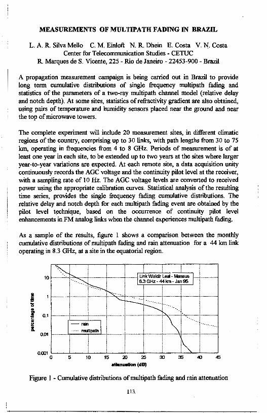
MEASUREMENTS OF MULTIPAffl FADING IN BRAZIL
L. A R. Silva Mello C. M. Einloft N. R. Dhein E. Costa V. N:. Costa Center for Telecommunication Studies - CETUC
R. Marques de S. Vicente, 225 - Rio de Janeiro - 22453-900 - Brazil
A propagation measurement campaign is being carried out in Brazil to provide long term cumulative distributions of single frequency multipath fading and statistics of the parameters of a two-ray multipath channel model (relative delay and notch depth). At some sites, statistics of refractivity gradient are also obtained, using pairs of temperature and humidity sensors placed near the ground and near the top of microwave towers.
The complete experiment will include 20 measurement sites, in different climatic regions of the country, comprising up to 30 links, with path lengths from 30 to 75 km, operating in frequencies from 4 to 8 GHz. Periods of measurement is of at least one year in each site, to be extended up to two years at the sites where larger year-to-year variations are expected. At each remote site, a data acquisition unity continuously records the AGC voltage and the continuity pilot level at the receiver, with a sampling rate of IO Hz. The AGC voltage levels are converted to received power using the appropriate calibration curves. Statistical analysis of the resulting time series, provides the single frequency fading cumulative distributions. The relative delay and notch depth for each multipath fading event are obtained by the pilot level technique, based on the occurrence of continuity pilot level enhancements in FM analog links when the channel experiences multipath fading.
As a sample of the results, figure 1 shows a comparison between the monthly cumulative distributions of multipath fading and rain attenuation for a 44 km link operating in 8.3 GHz, at a site in the equatorial region.
attanuatlon (dB)
Figure 1 - Cumulative distributions of multipath fading and rain attenuation
113

THIS PAGE INTENTIONALLY LEFT BLANK.
114
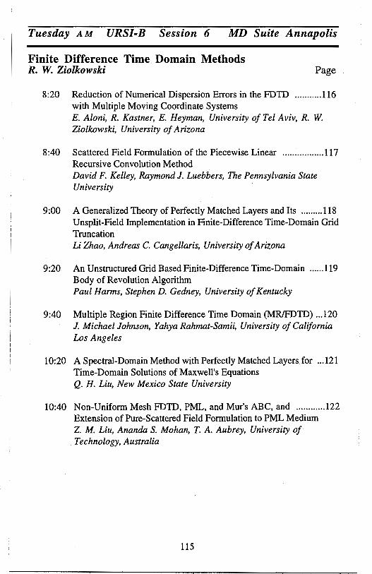
Tuesday AM URSI-B Session 6 MD Suite Annapolis
Finite Difference Time Domain Methods R. W. Ziolkowski Page
8:20 Reduction of Numerical Dispersion Errors in the FDTD ........... 116 with Multiple Moving Coordinate Systems E. Aloni, R. Kastner, E. Heyman, University of Tel Aviv, R. W. Ziolkowski, University of Arizana
8:40 Scattered Field Formulation of the Piecewise Linear ................. 117 Recursive Convolution Method David F. Kelley, Raymond J. Luebbers, The Pennsylvania State University
9:00 A Generalized Theory of Perfectly Matched Layers and Its ......... 118 Unsplit-Field Implementation in Finite-Difference Time-Domain Grid Truncation Li Zhao, Andreas C. Cangellaris, University of Arizana
9:20 An Unstructured Grid Based Finite-Difference Time-Domain ...... 119 Body of Revolution Algorithm Paul Harms, Stephen D. Gedney, University of Kentucky
9:40 Multiple Region Finite Difference Time Domain (MR/FDTD) ... 120 J. Michael Johnson, Yahya Rahmat-Samii, University of California Los Angeles
10:20 A Spectral-Domain Method with Perfectly Matched Layersfor ... 121 Time-Domain Solutions of Maxwell's Equations Q. H. Liu, New Mexico State University
10:40 Non-Uniform Mesh FDTD, PML, and Mur's ABC, and ............ 122 Extension of Pure-Scattered Field Formulation to PML Medium Z M. Liu, Ananda S. Mohan, T. A. Aubrey, University of Technology, Australia
llS
Reduction of Numerical Dispersion Errors in the FDTD with Multiple Moving Coordinate Systems
E. Aloni, R. Kastner*, E. Heyman
Department of Electrical Engineering - Physical Electronics, Tel Aviv
University, Tel Aviv 69978, Israel
R. W. Ziolkowski
Department of Electical and Computer Engineering, Universitry
of Arizona, Tucson, AZ 85721
In a recent work on a moving window FDTD approach (B. Fidel, E. Heyman, R. Kastner, and R. W. Ziolkowski, 1994 IEEE/AP-S International Symposium), the one dimensional FDTD Lagrangian (moving window) formulation was developed. It has been proven that when the window motion is synchronized with the pulse, the solution is inherently free of numerical dispersion errors. In this work, this basic property is generalized in an approximate fashion for non-local waves with an arbitrary spectral content. Theoretically, if no numerical dispersion is present, the sampling rate in the FDTD algorithm can be reduced by about five to ten times for a comparable error level, thereby relaxing the demands on computational resources by a similar factor. By this we gain either (a) larger computational domains, e.g., for accommodating larger scatterers or for increasing the size of the "white space" around the scatterer for better utilization of Radiating/ Absorbing Boundary Conditions, (b) reduction of the error for a given size of the computational domain, or (c) solution of a given problem with significantly reduced computational resources. In the two dimensional case, described herein, we split the wave into several portions, each one having a dominant direction of propagation associates with a so-called "basic spectral component". Attached to each one of these portions is a moving coordinate system, moving at the free space velocity. Consequently, the basic spectral component, traveling synchronously at the same speed, experiences no numerical dispersion. Other spectral componc)nts, traveling at different speeds or directions, will have dispersion errors that increase with the deviation from the basic spectral component. During the propagation process, additional spectral components are generated, including reflections which propagate at a speed of the order of down to -2c relative to the moving frame and thus suffer from severe numerical dispersion errors. This calls for a process whereby the moving system analysis will be halted periodically, say every eight to sixteen time steps, and the field recombined and then split again. This "combine and separate" step is performed quasi-locally, extracting the main directions of propagation from, a combination of the electric and magnetic fields and splitting the field correspondingly. The exchange step is performed at such time steps that the sampling points of the coordinate systems coincide. This poses a constraint on the Courant factor which should be chosen as an appropriate fraction close to the Lagrangian stability limit of 0.414. The approach also calls for restart of the FDTD process after each exchange, using a bootstrap procedure. This approach is demonstrated for the two dimensional case with numerical simulations which validate the error calculations and operation count.
116

SCATTERED FIELD FORMULATION OF THE PIECEWISE LINEAR RECURSIVE CONVOLUTION METHOD
David F. Kelley* and Raymond J. Luebbers
The Pennsylvania State University University Park, Pennsylvania 16802
The scattered field formulation of the Finite Difference Time Domain (FDTD) method, in which the electric and magnetic fields are decomposed into incident and scattered components, enjoys several advantages over the total field formulation that make it preferable for use in many cases. These advantages include the wide dynamic range of the computed scattered field data and the ease of application of outer radiation boundary conditions. However, most of the popular methods for modeling frequency-dependent media in the FDTD method have been derived onlyfor the total field formulation.
A scattered field formulation can be derived for those methods that are based on evaluating the convolution of the electric field with the dielectric susceptibility function, such as the Piecewise Linear Recursive Convolution method (Kelley and Luebbers, IEEE Trans. Antennas Propagat., accepted for publication). When the field is decomposed into scattered and incident components, the resulting formulation requires the calculation of the convolution of the susceptibility with each component. The convolution involving the scattered field can be carried out for a number of types of media using any of the methods based on recursion; however, the convolution involving the incident field can be evaluated in a more efficient manner using the a priori knowledge of the incident field waveform.
It is tempting to derive an analytical function for the incident field convolution and then use a function call in the FDTD program to evaluate the convolution at each point in space and time where it is needed. Although its accuracy is excellent, this approach yields an algorithm that is costly in program execution time and limited to a specific incident waveform and susceptibility function. In this paper, a general procedure is presented for efficiently accommodating the convolution of any form of excitation field with any form of susceptibility function. The approach views the convolution as representing a filtered waveform and applies digital signal processing techniques to produce a method that uses few computer memory resources yet provides good accuracy.
117
A GENERALIZED THEORY OF PERFECTLY MATCHED LAYERS AND ITS UNSPLIT-FIELD IMPLEMENTATION IN
FINITE-DIFFERENCE TIME-DOMAIN GRID TRUNCATION
Li Zhao and Andreas C. Cangellaris
Electromagnetics Laboratory Department of Electrical and Computer Engineering
University of Arizona Tucson, AZ 85721
Phone: 520-621-4521 FAX: 520-621-2999
e-mail: [email protected]
Over the past two years, Berenger's perfectly matched layer (PML) for the refiectionless truncation of differential equation-based wave simulations has become the focus of extensive research. In addition to Berenger's original split-field formulation (Berenger, J. Comput. Physics, Oct, 1994), as well as its interpretation in terms of a modified Maxwellian system with coordinate stretching (Chew and Weedon, Microwave and Optical Tech. Lett., Sept. 1994), attempts have been made to avoid the need for :field-splitting either in terms of the development of some type of anisotropic medium (Sacks et al, IEEE Trans. Antennas & Propag., Dec. 1995), or by the development of an alternative form of Berenger's equations in terms of time- and :field-dependent sources (Veihl and Mittra, IEEE Microwave & Guided Wave Lett., in press). These attempts have been only partially successful. The anisotropic medium approach works well for frequency-domain applications; however, its application in time-domain simulation has so far been hindered by stability problems. The time-dependent source implementation of Berenger's equations reported by Veihl and Mittra appears to have difficulties with edge and comer regions, and thus maintains the use of the split-field formulation at these regions.
In this talk, a new mathematical formulation is presented for the systematic development of perfectly matched layers from Maxwell's equations in properly constructed anisotropic media. This formulation is motivated by the work of Sacks et al. However, it is more general and it helps us establish in a rather straightforward manner the equivalence between the anisotropic PML theory and the stretched-coordinate PML theory. In addition, it leads in a direct way to the implementation of PMLs in the time domain without field splitting everywhere in the PML space, including edges and comers. Results from three-dimensional simulations are used to illustrate the effectiveness of the proposed medium as an absorber for numerical grid truncation. The presentation concludes with a comparison in CPU time and memory requirements between the proposed unsplit-field formulation and the split-field formuljl,tion of PMLs.
118
An Unstructured Grid Based Finite-Difference Time-Domain Body of Revolution Algorithm
Paul Harms* and Stephen D. Gedney Electromagnetic Laboratory, Department of Electrical Engineering
University of Kentucky, Lexington, KY 40506-0046
The fundamental advantage of treating an electromagnetic boundary value problem with axial symmetry as a body of revolution (BOR) is that the threedimensional problem space can be reduced to a series of two-dimensional problems. This often leads to a significant savings in computational time and memory. Classically, the electromagnetic scattering or radiation from BORs is treated in the frequency domain (A. W. Glisson and D.R. Wilton, IEEE. T. on AP, Sept: 1960). Frequency domain algorithms can be very accurate, but if results are needed over a wide band of frequencies, the algorithms must be run for each frequency of interest which can result in excessive CPU times. The orthogonal finite-difference time-domain (FDTD) algorithm has been adapted to the BOR problem (A. Taflove, Computational Electrodynamics, Artech House, Inc., 1995) which allows results to be readily computed over wide frequency bandwidths. However for complex nonrectangular structures such as a flared corrugated cylindrical horn antenna, the discrete representation of boundaries using an orthogonal grid may require staircasing. High mesh densities are needed to reduce staircasing error and can lead to significant memory requirements and small time steps which result in computational inefficiencies.
In this work these problems will be addressed by developing an unstructured grid based FDTD BOR algorithm. The formulation of this technique will be presented, and a stability condition will be derived. The implementation of accurate absorbing boundary conditions in the radial and z axial directions will also be discussed. It will be shown that the perfectly matched layer (PML).ABC can be implemented on the z axial boundaries (Taflove 1995); however, it causes erroneous reflections when employed for the radial boundary and is less accurate than the Bayliss-Turkel ABC. Some examples of antenna radiation and waveguide analysis by the unstructured FDTD BOR will be presented.
119
Multiple Region Finite Difference Time Domain (MR/FDTD)
J. Michael Johnson* and Yahya Rahmat-Samii Department of Electrical Engineering University of California, Los Angeles
Los Angeles, CA 90095-1594
This paper introduces a new, powerful extension of FDTD to multiple, independent sub-regions that seeks to avoid the memory and computational inefficiencies of classical FDTD when applied to large, sparsely filled modeling problems. In the multiple region FDTD (MR/FDTD) method, the problem space being modeled is divided into several, independent sub-regions distributed in otherwise homogenous free space. The fields in the sub-regions are determined by time stepping fields in localized FDTD lattices confined to the sub-regions. The sub-regions' lattices are terminated using integral boundary conditions where the integration is performed over a simply connected surface enclosing all subregions. The use of the integral boundary condition eliminates the need for approximate, local boundary conditions and automatically accounts for the interaction between the sub-regions. Sparsely filled problem domains can be handled with less computer memory than would be necessary for classical FDTD and the accuracy of the modeling results is improved due to the improved accuracy of the integral boundary conditions. MR/FDTD represents a significant modeling flexibility and accuracy while simultaneously decreasing required memory for many classes of large (in terms of number of grid points), sparse problems.
The key to MR/FDTD is the application of the surface equivalence principle yielding a surface integral used to calculate the terminating fields on the region lattices. The surface equivalence principle also ensures that the regions are independent. Lattice spacing, orientation, and even coordinate systems within each of the sub-regions may be chosen to best suit the modeling requirements of that region. Use of the integral equation terminates the FDTD lattice of the subregions enclosed in surfaces, S1, S2, ... , S0 , providing an exact, global radiating boundary condition eliminating the need for buffer layers. Lattices are established only in close proximity to the actual objects being modeled in each of these subregions. These factors greatly reduce the total FDTD lattice area in large sparse problem domains and allow more flexibility in lattice application.
This paper will present the details of the development and implementation of MR/FDTD. Comparisons between MR/FDTD and classical FDTD will be presented in terms of memory usage, accuracy and computational efficiency. Finally, some results of the application of MR/FDTD to actual problems and a comparison to results for the same problem using classical FDTD will be presented.
120

A SPECTRAL-DOMAIN METHOD WITH PERFECTLY MATCHED LAYERS FOR TIME-DOMAIN
SOLUTIONS OF MAXWELL'S EQUATIONS
Q. H. LIU
KLIPSCH SCHOOL OF ELECTRICAL AND COMPUTER ENGINEERING NEW MEXICO STATE UNIVERSITY
LAS CRUCES, NM 88003
Many applications require large-scale time-domain numerical solutions of Maxwell's
equations. Traditionally, these solutions are obtained by finite-difference time-domain
(FDTD) methods which approximate the spatial derivatives in Maxwell's equations by
finite differences. Although they are very versatile, the FDTD methods require very fine
discretization in order to produce accurate results. For example, numerical experiences
show that sampling of 10-20 grids per wavelength is required for second-order finite
difference methods. Hence, the FDTD methods are inefficient for large-scale problems.
especially when the scatterers are larger than the characteristic wavelength of electromag
netic waves. Many attempts have been made to improve the efficiency of FDTD methods. Among
them, two spectral-domain methods, the pseudo-spectral (PS) and the generalized k-space
(GKS) methods, have been proposed. The former solves the differential form. while the
latter the integral form of Maxwell's equations. These spectral-domain methods use the
fast Fourier transform (FFT) instead of finite differences for the spatial derivatives. Since
the Fourier transform has an infinite order of accuracy, the only approximation in the PS
and GKS methods are due to the FFT. Therefore, the spatial discretization in the PS
and GKS methods is only limited by the Nyquist rate and the representation of material
properties. Thus, if each piecewise homogeneous scatterer in a problem is larger than
one wavelength, the discretization in the PS and GKS methods requires only 2 grids per
wavelength for accurate solutions. Hence, these methods are much more efficient than
FDTD methods for problems with large scatterers.
However, since the PS and GKS methods use FFT, they both assume periocity in
spatial dimensions; the late-time solutions are therefore corrupted by waves propagating
from other periods and become useless. To overcome this problem, we propose the use of
perfectly matched layers to attenuate waves coming from other periods. Numerical results
for the pseudo-spectral method with perfectly matched layers will be shown to demonstrate
the efficiency of the method.
121
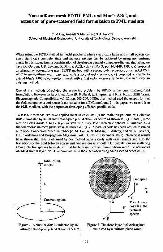
Non-uniform mesh FDTD, PML and Mur's ABC, and extension of pure-scattered field formulation to PML medium
Z M Liu, Ananda S Mohan and TA Aubrey School of Electrical Engineering, University of Technology, Sydney, Australia
When using the FDTD method to model problems where electrically large and small objects coexist, significant computer time and memory savings can be achieved by using non-uniform mesh. In this paper, from a consideration of developing parallel-computer-efficient algorithm, we have (R. Gordon, J. F. Lee, and R. Mittra, AEU, vol. 47, No. 3, pp. 143-148, 1993), a) proposed an alternative non-uniform mesh FDTD method with a second order accuracy, b) extended PML ABC to non-uniform mesh case also with a second order accuracy, c) proposed a scheme to extend Mur's ABC to non-uniform mesh with a first order accuracy as an improvement over an existing method.
One of the methods of solving the scattering problem by FDTD is the pure scattered-field formulation. However in its original form (R. Holland, L. Simpson, and K. S. Kunz, IEEE Trans. Electromagnetic Compatibility, vol. 22, pp. 203-209, 1980), this method used the unsplit form of the field components and hence is not suitable for a PML medium. In this paper, we extend it to the PML medium, with the purpose of developing efficient parallel code.
To test our methods, we have applied them to calculate, (i) the radiation patterns of a circular disk illuminated by an infinitesimal dipole placed above its centre as shown in Fig. 1 and, (ii) the electric fields inside a single layer as well as a three layer dielectric spheres illuminated by a time-harmonic uniform plane wave as shown in Fig. 2. A parallel code has been written to run· on a 32 node Connection Machine CM-5 (Z. M. Liu, A. S. Mohan, T. Aubrey, and W.R. Belcher, IEEE Antennas and Propagation Magazine, vol. 37, No. 6, December 1995). Numerical results have shown that results obtained by our method agree closely with exact results and also the transitions of the field between coarse and fine regions is smooth. Our calculations on scattering from dielectric spheres have shown that for both uniform and non-uniform mesh the accuracies obtained from 8 layer PMLs are comparable to those obtained using Mur's second order ABC.
Infinitesimal +r dipole
h
Conducting disc
r
Figure 1. A circular disk illuminated by an infinitesimal dipole placed above its centre.
Free space
The reference po int is at the centre of spheres
Figure 2. The three layer dielectric sphere illuminated by a uniform plane wave.
122
Tuesday AM URSI-K Session 1 Chesapeake A
Electromagnetics in Biology and Medicine J. M. Jin and K. T. Ng Page
8:20 Finite Element Analysis of RF Field in Human Body for ................ 124 MRI Application Ninglong Lu, Jian-Ming Jin, University of Illinois at Urbana-Champaign
8:40 Parallel Finite-Difference Bidomain Modeling of General .............. 125 Inhomogeneous Anisotropic Cardiac Tissue H. I. Saleheen, K. T. Ng, New Mexico State University
9:00 Birefringence Calculation Using the Finite Element Method ........... 126 Z. Pantie-Tanner, Don Eden, San Francisco State University
9:20 Transient Microwave Propagation in Biological Media ................. 127 Dr. David C. Stoudt, Dr. Frank E. Peterkin, Dahlgren Division, Naval Surface Warfare Center '
9:40 Electromagnetic Absorption in a Multi-Layer Lossy ..................... 128 Cylindrical Model of Human and Comparison with Planar Model S. S. Seker, Bogazici University, 0. Cerezci, Sakarya Univedity
10:20 Design of an IDA with Enhanced SAR Distribution ....................... 129 Lin-Kun Wu, David Wen-Feng Su, Frank I-Chen Wu, National Chiao Tung University
10;40 Analysis of Array Applicator Composed of Coaxial-Slot ............... 130 Antennas for Interstitial Microwave Hyperthermia Koichi Ito, Lira Hamada, Haruo Kasai, Chiba University
11 :00 A Shaped Dual-Reflector Antenna for Non-Contacting ................... 131 Radiometry of Human Body E. Di Giampaolo, G. Marrocco, Universita dell'Aquila, F. Bardati, Universita di Roma "Tor Vergata"
11 :20 EM Wave Life-Detection System for Post Earthquake Rescue ............ 132 Operations--Field Test and Modifications K. M. Chen, Y. Huang, A. Norman, Y. Yerramilli, Michigan State University
11 :40 Heliogeophysical Stipulation of 27-Day Variations of a ................ 133 Trauma Level Under Urban Conditions I. G. Zakharov, 0. F. Tyrnov, Kharkiv State University, V. L. Gaevsky, V. V. Nikonov, Kharkav City Clinical Hospital of Ambulance and FirstAid Service
12:00 A 3-D Model for Laser Heating of a Heterogeneous Turbid Medium .... 134 Michael J. Rossacci, Scott C. Lindberg, Charles A. DiMarzio, Northeastern. University
123
FINITE ELEMENT ANALYSIS OF RF FIELD IN HUMAN BODY FOR MRI APPLICATION
Ninglong Lu* and Jian-Ming Jin Center for Computational Electromagnetics
Department of Electrical and Computer Engineering University of Illinois at Urbana-Champaign
Urbana, Illinois 61801-2991
In magnetic resonance imaging (MRI), the homogeneity of the radio-frequency (RF) magnetic field, known as B1 field excited by an RF resonator, is a very important factor for high quality MR images. In the past, the B 1 field was often evaluated without considering the presence of the object to be imaged. This calculation is adequate for low-field MRI systems such as those whose static magnetic field (Bo field) is less than 0.3T. At such a field strength, the Larmor frequency of protons is less than 15 MHz, or in other words, the wavelength of the B 1 field is longer than 20 m. Since the dimension of an object to be imaged is only a small fraction of the wavelength, it is safe to assume a negligible interaction between the B 1 field and the object and thus calculate the B 1 field without considering the presence of the object. However, because of the limitation of the signal-to-noise ratio (SNR) associated with low frequencies, low-field MRI systems cannot produce high resolution MR images. To obtain high resolution images, MRI systems using a high Bo field, such as 1.5T, 3T, and 6T, have been developed. In such systems, the wavelength of the B1 field is comparable to or even smaller than the dimension of the object to be imaged. As a result, a strong interaction has been observed between the B1 field and the object to be imaged. Such an interaction can degrade substantially the image quality and lead to erroneous diagnosis. A remedy is either to design new RF resonators that can produce a homogeneous B 1 field within the region of interest or design new imaging schemes to compensate the B1 field inhomogeneity. Both solutions require a prediction of the B1 field within the region of interest. In this paper we present our preliminary study of using the finite element method (FEM) to predict the B1 field distribution in human body. We first constructed two-dimensional anatomical models for human head, trunk, and leg based on an anatomy book (A. C. Eycleshymer and D. M. Schoemaker, A Cross-Section Anatomy. New York: Appleton, 1911) and examined the effect of increasing Larmor frequency on the field homogeneity. Computer simulation showed that the field homogeneity degrades significantly when the frequency increases from 64 MHz to 256 MHz and the degradation is caused by both dielectric resonance and eddy currents. We then applied the three-dimensional finite element method to a three-dimensional model of human head constructed using MRI images. A similar phenomenon was observed. The calculation of the electric field was also considered to provide important information for safety design of RF resonators.
124
PARALLEL FINITE-DIFFERENCE BIDOMAIN MODELING OF GENERAL INHOMOGENEOUS ANISOTROPIC CARDIAC TISSUE
HI. Saleheen andK.T. Ng* Klipsch School of Electrical & Computer Engineering
New Mexico State University Las Cruces, NM 88003
Numerical modeling can provide important information about various phenomenons in a cardiac tissue, e.g., cardiac propagation and fibrillation. One common model that has been used to represent the cardiac tissue is the bidomain model, where the tissue is considered as two overlapping domains, representing the volume averaged properties of the intracellular and interstitial regions. Each domain is a volume conductor with its own conductivity tensor, and current can flow from one domain to the other only through a continuous membrane which is represented by a capacitance and a nonlinear ionic component. Conservation of currents then gives the coupled nonlinear partial differential equations for the bidomain. One major numerical technique that has been used to solve the bidomain equations is the · finite-difference method. Previous finite-difference formulations, however, have been limited mainly to orthotropic conductivities, i.e., diagonal conductivity tensors. This does not allow a realistic modeling of the detailed fiber structure of the cardiac tissue, where the fibers can lie in any direction that can also vary with position. In order to enhance the capability of finite-difference bidomain modeling, we have developed a new three-dimensional finite-difference formulation that is valid for a general inhomogeneous anisotropic medium, i.e., filled conductivity tensors that also vary with position. In addition, a data-parallel computer is used to implement the new formulation to provide the computational power and memory required for solving large bidomain problems.
An explicit finite-difference technique is used to solve the bidomain equations. Spatial operators are discretized with a new finite-difference formulation that allows the (arbitrary) conductivity tensor to be different in different elements of the grid. To obtain the finite-difference representation for a node, an inhomogeneous transition layer of thickness 't' is interposed between the surrounding elements, which creates a small cubic box around the node with a length 't' for each side. Taylor series expansions are used to obtain the algebraic approximation of the spatial operator at each vertex node of the box. In the limit t ~ 0, these algebraic· approximations can be combined to obtain the finite-difference representation of the spatial operator. The finite-difference equations at each time step are solved with the Preconditioned Conjugate Gradient technique. As the same :finite-difference equation is used at each node, it is natural to map a group of nodes to one processor of the data-parallel computer. Each processor is then responsible for all the data storage and arithmetic operations associated with its corresponding nodes. Details of the numerical procedure will be presented together with various simulation results.
125
BIREFRINGENCE CALCULATION USING THE FINITE ELEMENT METHOD
Z. Pantie-Tanner* [email protected] Don Eden School of Engineering Chemistry Department
San Francisco State University San Francisco, CA 94132
Birefiingence is one of the simplest properties that may be obtained from the Mueller matrices that describe the interaction of polarized light with matter. At present the modeling of optical properties of macromolecules relies upon analysis of aITays of a small number of cylinders or ellipsoids of revolution. Real biological macromolecules are much more complicated. There is a need to have more realistic and easily applied methods to predict optical properties of real molecules and to relate them to their structure and function. The finite element analysis, which has been successfully used for elecu·omagnetics problems, is readily applicable to these biological problems.
Birefringence of a suspension of arbitrarily oriented particles can be calculated as the product of the birefringence for the fully oriented (aligned) particles, '1nsat, and the orientational order parameter, S, obtained by averaging of the dist1ibution function of the particles over all angles of orientation. The saturation birefringence, '1nsat, is, in turn, equal to the difference in the refractive index of the suspension when all the pruticles are respectively pru·allel or n01mal to the polruization direction of the polarized light, t.llsat = nu - n.L. Protein solutions, that are of interest in this research, can be treated as suspensions of arbitrarily shaped particles in a solvent. It is assumed that the suspended particles ru·e small compared with the wavelength of light. Accordingly, a quasi-static approximation for the refractive index is used, i.e., that it is equal to the square root of the average dielectric constant of the mixture, n=•fr.. Hence, the
biref1ingence can be calculated after the average dielecu·ic constants eJI and e.L are determined for the two cases when the particles are respectively parallel or normal to a uniform external electtic field. Calculation of the average dielecu·ic constant is pe1formed using the finite element method (FEM) since it is one of the most powerful nume1ical techniques. The advantage of the FEM over analytical and other numerical methods used in biochemistry for birefringence calculation is that it can treat inhomogeneous, arbitrarily shaped and arbitrarily oriented particles. The suspended pruticles, as well as the solvent, can be isou·opic or anisotropic.
In order to find the effective dielectric constant of the aligned pruticles it is sufficient to evaluate the energy/capacitance of just one cell containing a single macromolecule of the appropriate orientation and the surrounding solvent. This capacitance divided by the capacitance of the air filled cell will yield the effective dielectric constru1t (Collin, Field The01y of Guided Waves).
Some results of FEM calculations based upon the overall macromolecule shape as determined from electron diffraction or x-ray diffraction structures will be presented. They should permit a dete1mination of the shape birefringence and hopefully intrinsic birefringence of the proteins to aid in biological data interpretation.
126
TRANSIENT MICROWAVE PROPAGATION IN BIOLOGICAL MEDIA
Dr. David C. Stoudt and Dr. Frank E. Peterkin Dahlgren Division, Naval Surface Warfare Center
Pulsed Power Systems & Technology Group, Code B20 Dahlgren, Virginia 22448-5100
We examine short-pulse propagation in a dispersive Debye medium. Transient fields that result when square-wave modulated radio frequency (RF) pulses propagate in water, characterized by the Debye model, have been examined both numerically and experimentally. Water was selected as the medium to be studied since it is the major constituent in most biological tissues, and in several respects the dielectric properties of tissues are governed by the water that they contain. The strong frequency dependence of the attenuation coefficient of pure water, over the frequency range being investigated (0-3 GHz), leads to a nonuniform attenuation of the frequency components contained in the RF pulse. Our numerical results show that the amplitude and temporal character of the propagating transient fields are the result of the low-frequency harmonic components in the initial RF pulse. This result was obtained by using a frequency-domain filtering technique where each frequency component of the initial RF waveform was attenuated exponentially by its associated attenuation coefficient for a particular propagation distance in water. The effects of group-velocity dispersion, when added, appear to have little effect on the solution. This arises from the fact that the index of refraction of water in the frequency range being investigated is nearly constant. However, in the same frequency range, the attenuation coefficient of water increases roughly with the square of the frequency. The transient fields, sometimes referred to as Brillouin precursors, can propagate much farther than would be expected if only the carrier frequency of the RF pulse is considered.
We first describe how a plane wave propagates in a lossy dielectric halfspace, comprised of water, through the use of Maxwell's equations. Next, using frequency-domain filtering, we demonstrate how pulse distortion occurs when a square-wave modulated pulse propagates in water. Trapezoidal pulse modulation is also examined to illustrate the effect of a finite RF-pulse rise and fall time. Finally, we describe experiments performed with 16 MQ-cm deionized water in a 50-Q coaxial test cell, fitted with appropriate high-speed diagnostics. The amplitude of the transient fields generated by a 1-GHz square-wave modulated pulse was measured as a function of propagation distance in the test cell. The measured transients are compared with those generated numerically and are found to be in very good agreement.
127
ELECTROMAGNETIC ABSORPTION IN A MULTI-LAYER LOSSY CYLINDRICAL MODEL OF HOMAN AND COMPARISON WITH PLANAR MODEL
S.S.f?eker Professor B0gazi9i Universty Dept.of ElectricalElectronic Engineering
o.<;erezci Associate Professor Sakarya University Dept.of.Computer Engineering Fax: 90.264.3431306 or 90.264.3431307
Istanbul, TURKEY Adapazari, TURKEY
ABSTRACT.The expanding usage of electromagnetic (EM) radiation has necessitated an understanding of its interactions with humans. such knowledge is vital in evaluating and establishing radiation safety standarts, determining definitive hazard levels and understanding several of biological effects. To quantify interactions of EM fields with biological system Specific absorption rate (SAR) is important to concept. In this paper we report the results of calculation of SAR at varius frequencies using with multilayered finite length cylindrical model of man. The internal fields of each layer are obtained by matching electric and magnetic fields across each cylindrical boundary. The simulation results of this model have been compared to infinite size cylinder and planar models by using realistic parameters encountered in the field of dosimetry. The results also compared and discussed with experimantal and published results available in litrature. A good consistency are obtained.
128

Design of an IDA with Enhanced SAR Distribution
Lin-Kun Wu, David Wen-Feng Su, and Frank I-Chen Wu Institute of Communication Engineering
National Chiao Tung University Hsinchu, Taiwan 30050
Abstract------Traditional insulated dipole antennas (IDAs) are constructed from coaxial cables. They can be either uniformly- (e.g., Zhang et al., IEEE T-MTT, 36, 1438-1444, 1988) or nonuniformly-insulated (e.g., Iskander & Tumeh, IEEE T-BME, 36, 238-246, 1989; Camart et al., IEEE T-MTT, 40, 2243-2250, 1992). Although the latter type is designed to control axial SAR distribution over the tip portion of the applicator, both designs lack the mechanism to control the SAR distribution between the feed gap and power source; this defiency also affects the impedance matching performance of the applicator. A remedy may be found in installing a quarter-wavelength choke at a certain distance away from the feed gap (toward the generator side; e.g., Hurter et al., IEEE TMTT, 39, 1048-1054, 1991).
Design of ID As that incorporate both the choke and nonuniform insulation to achieve a well-defined and controllable axial SAR distribution is under development. UTI MICRO-COAX's UT 78-50-25 semi-ridge triaxial cables are used to construct the antennas with performance tested in a saline water tank. In one preliminary design, the outermost conductor of the cable is used to form the tip portion of the dipole while the other arm of the dipole is formed by the second conductor of the triaxil cable; the overall length of the dipole (from tip to the openning of the choke) is 6.5 cm. Experimental results measured along 4 different longitudinal lines with radial distances of 3, 4, 5, and 7 mm away from the axis of the dipole are found to exhibit more uniform axial SAR distributions extending over almost the entire length of the antenna and sharp falloffs near the two ends. Further tests are underway to examine the radial heating performance as a function of catheter size (i.e., inner and outer radii). Design principle and results will be presented in this talk.
129
Analysis of Array Applicator Composed of Coaxial-slot Antennas for Interstitial Microwave Hyperthermia
Koichi Ito·, Lira Hamada and Haruo Kasai Department of Electrical and Electronics Engineering
Faculty of Engineering, Chiba University 1-33 Yayoi-cho, lnage-ku, Chiba, 263 Japan
Hyperthermia is one of the promising cancer treatments to heat tumors up to therapeutic temperatures ( 42 - 45 °C) without overheating the surrounding normal tissue. Microwave interstitial hyperthermia is considered to be an effective and practical technique for treating deep-seated or large-volumed tumors in combination with radiation therapy.
Various types of interstitial microwave antennas have been reported and tested. The authors et al. proposed an interstitial antenna made of a thin semirigid coaxial cable (less than 1 mm in diameter) with multiple coaxial slots, which will radiate microwave power directly into a tumor. In clinical use, the antenna is loaded into a thin plastic catheter and then an array applicator of the antennas is inserted into the tumor.
A square array composed of four identical antennas is considered to understand its basic characteristics. To simplify the moment method calculation, each antenna has a single slot. The antenna is covered with a dielectric catheter and penetrating the interface between the air and a lossy medium. In calculation, the catheter is replaced with an unknown equivalent polarization current. Electric current distributions along the antennas are derived taking into account the mutual coupling among the four antennas. Then, electric field distributions or SAR ( specific absorption rate) distributions in and around the array can be estimated.
Some parameters, such as the spacing between the antennas and the insertion depth, have been varied to discuss their influences on the electric current distributions on the antennas as well as SAR distributions in and around the array. The deference between the operating frequencies of 430 and 915 MHz has also been calculated. It has been found analytically that a square array can heat the tumors up to 3 - 4 cm in diameter and that the SAR distribution along the antenna is dependent on its insertion depth. Choice of the right number and positions of the antennas enables us to treat larger and/or irregular-shaped tumors.
130
A SHAPED DUAL-REFLECTOR ANTENNA FOR NON-CONT ACTING RADIOMETRY OF HUMAN BODY
E. Di Giampaolo0, G. Marrocco0 and F. Bardati#
0 Dipatimento di Ingegneria Elettrica, Universita dell'Aquila, L'Aquila, Italy # DISP, Universita di Roma "Tor Vergata", Roma, Italy
Multi-frequency radiometry is the spectral measurement of the electromagnetic field spontaneously irradiated by a lossy body in the microwave frequency range. The spectrum of the radiation detected by a radiometer is dependent on the local temperature distribution inside the body. It is this dependency that allows multi-frequency radiometry to be used as a tool for thermal measurements. In fact, information about interior temperature is contained in radiometric data measured externally to the body and can be extracted through a temperature retrieval.
A major source of system errors or even impracticability of microwave radiometry for body temperature measurement is the antenna. The antenna may be of either non-contacting or contacting type, usually a truncated waveguide filled with high-permittivity low-loss material to give a good matching between the antenna and the body. This means that the antenna is an additional source of thermal noise. Other drawbacks to contacting antennas exist, namely the disturbance due to the effect of the antenna heat capacity on the temperature pattern to be measured and the tissue structure deformation due to the pressure exercised by the antenna on the skin surface. The main problem in the design of a non-contacting radiometric antenna is the mismatch at the skin-air boundary. A way to overcome partially the problem is to receive vertically-polarized thermal radiation at the pseudo-Brewster angle (F. Bardati and D. Solimini, Radio Sci. 18, 1393-1401, 1983).
In this paper we present a cylindrical dual-reflector antenna as a possible device to collect thermal raqiation at proper angle and polarization. Preliminary 2-D design and analysis have been performed on a cross-section of the antenna system including a TEM pyramidal horn, two reflectors and a layered lossy cylinder simulating a human body. The synthesis has been performed by using a method founded on geometrical optics to shape both reflectors. The method has been originally developped by P.-S. Kildal (IEEE Trans. Antenna Propagat. 38, 1587-1599, 1990) for the Arecibo radio telescope. Basically, a step-wise procedure maps a given ray congruence (the spherical wave on the horn aperture) into a ray-field focused to the target. Due to practical management of the system for radiometric applications, the antenna sizes should not exceed ten wavelengths, so diffraction effects cannot be neglected. Therefore, the system behaviour has been verified by a full-wave electromagnetic analysis. To this purpose, the 2-D Finite-Difference TimeDomain method has been used with a 400x400 mesh and Mur first order absorbing conditions at the boundaries of the computation domain.
131
EM WA VE LIFE-DETECTION SYSTEM FOR POST EARTHQUAKE RESCUE OPERATIONS--FIELD TEST AND
MODIFICATIONS
K.M. Chen*, Y. Huang, A. Norman, and Y. Yerramilli Department of Electrical Engineering
Michigan State University, E. Lansing, MI 48824 Tel: (517) 355-6502, Fax: (517) 353-1980
A life-detection system utilizing continuous EM wave at 450 MHz was constructed for the purpose of locating victims trapped under earthquake rubble. The EM wave radiated by an antenna penetrates the rubble to reach the victim. The reflected wave received by the same antenna consists of a large clutter signal reflected from the rubble and a weak signal reflected from the victim's body. The latter is modulated by the victim's body movements which include breathing and heartbeat. Therefore, if the large clutter from the rubble is cancelled and the reflected wave from the victim's body is properly demodulated, the breathing and heartbeat signals of the victim can be extracted.
The main components of the system consists of (1) a phase-locked generator which produces an EM Wave at 450 MHz with a power of lOOmW, (2) a probing antenna which can penetrate into the rubble and a reflector antenna which can be placed on the rubble surface, (3) a microprocessor-controlled cancellation unit, and ( 4) a signal processing and monitor system.
This system was tested in simulated earthquake rubble in the laboratory with very good results. Recently, a field test using realistic earthquake rubble in an open field was conducted at Montgomery County, Rockville, Maryland with the cooperation of FEMA Task Force. The results of the field test will be presented in the meeting. From the experience of the field test, we will make some modifications to improve the performance of the life-detection system in the actual earthquake rubble consisting of reinforced concrete layers with embedded metallic mesh. The modifications are (1) the raising of operating frequency to 1.15 GHz, (2) the increase ofradiated power, (3) the design of a dual-antenna system, and (4) the improvement of signal processing schemes.
132
Heliogeophysical stipulation of 27-day variations of a trauma level under urban conditions
1.G.Zakharov, O.F.Tyrnov, l V.L.Gaevsky, V.V.Nikonov 2
1 Kha.rkiv State University, 310077 Kha.rkiv, Ukraine 2 Kha.rkiv City Clinical Hospital of Ambulance and
First-Aid Seroice, 310018, Kha.rkiv, Ukraine
There were investigated effects of the heliogeophysical factors (solar and geomagnetic activities, an interplanetary magnetic field) on a trauma level (Kharkov taken as an example) using the data obtained in 1993 (more than 14 000 cases). Main attention was paid to variations of 27-day revolutions of the Sun round its axis; our calculations were carried out for several kinds of traumas using an epoch-superposition method, spectrum and correlation analyses. Our theoretical calculations were compared with the data obtained from March to May in 1994.
There were obtained the following main results.
1. For conditions requiring people to be more attentive (in streets, cars, and at work), there are observed trauma-level variations having the amplitude of about 30 % if compared with the mean level; these variations consist of the following two components: a) 27-day harmonic variations being maximum in the period of increasing flare activity of the Sun; b) local increases after the commencements of geomagnetic storms related to flares achieving maximum values at the final stage of these storms. Corresponding variations for daily life traumas are neglegible. Geomagnetic storms related to flows from coronal holes do not lead to a considerable change in the trauma level.
2. The pointed out features of the trauma-level variations may be explained by effects of Pel-type geomagnetic pulsations on a nervous system of person, resulting in inhibition his reaction to external events. Under conditions existing in modern towns or cities when person often has to make a quick decision, such effects may lead to a considerable number of accidents.
133
Submitted to URSI (International Union of Radio Science) Meeting, July 21-26, 1996 ref: 1956 - 7 February 1996
A 3-D Model for Laser Heating of a Heterogeneous Turbid Medium
by
Michael J; Rossacci Scott C. Lindberg
Charles A. DiMarzio Center for Electromagnetics Research
235 Forsyth Building Northeastern University 360 Huntington Avenue
Boston, Massachusetts 02115 USA 617-373-2034
electronic mail to [email protected]
In order to better understand the interactiob of electromagnetic radiation (such as laser light or microwaves) with biological tissue, an energy distribution model is being integrated with a heat-transport model. The outputs include temperature as a function of position and time, given the electromagnetic illumination conditions and the electromagnetic and thermal properties of the tissue. The electromagnetic portion of the algorithm currently used for calculations at optical wavelengths is based on the theory of radiative transfer through a turbid medium. Furthermore, our computer program models multiple scattering in three dimensions using seven discrete fluxes which approximate the radiative transport equation. The distribution of absorbed energy in the biological sample is calculated and used as the source term in a discrete approximation to the thermal diffusion equation. Recently, we have been using the model to better understand the laser-heating of heterogeneous tissue. Rather than modeling a homogeneous mixture having properties given by weighted averages of those of tissue and blood, we model this medium as an array of blood vessels in a bloodless tissue background. We are currently analyzing temporal and spatial variations of temperature in homogenous and heterogeneous tissue models having identical blood concentrations. A particular application of the model is to the study of Laser Coagulation Tonsillectomy (LCT), an alternative to the conventional surgical removal of chronically inflamed tonsils. This procedure involves irradiating the tonsils sufficiently causing atrophy, meanwhile, reducing the risk of post-operative bleeding and discomfort associated with conventional surgical removal. In order to understand the exact mechanism of atrophy for the tonsils, it is necessary to have a firm understanding of the laser-heating process. In the future, we plan to include wave-based electromagnetic propagation as a alternative to a seven-flux model. This model will be useful for studying the heating of tissue by energy of longer wavelengths.
134
Tuesday AM URSI-B Session 7 Pratt Calvert
Special Session Low Grazing Angle Scattering from Rough G. S. Brown
Surfaces Page
8: 20 Fully Polarimetric Bistatlc Radar Scattering Behavior of ............... 136 Forested Hills David J. McLaughlin, Yuliang Wu, Northeastern University
8:40 Low Angle Scattering Phenomena and Its Impact on Army ............ .137 Systems H. Bruce Wallace, U.S. Army Research Laboratory
9:00 Dual Polarized Low Grazing Angle Radar and Video Imaging ........... 138 of Small Scale Breaking Features During the High-Res II Experiment D. B. Trizna, J. Kaiser, Naval Research Laboratory, Washington, DC
9:20 High-Resolution Dual Polarization X-Band Radar Imagery .............. 139 Obtained During the MBL Phase-II Experiment Yong Liu, Stephen Frasier, Robert McIntosh, University of Mass.
9:40 The Polarization Dependence of Microwave Doppler Spectra ........... 140 of the Sea William J. Plant, William C. Keller, Vahid Hesany, University of Washington Applied Physics Laboratory
10:20 The Operator Expansion for Rough Surface Scattering at Low .......... 141 Grazing Angles Ralph A. Smith, Arete Associates
10:40 Backscattering at Low Grazing Angles; The Role of Curvature ........ 142 of Undulating Surface A. Voronovich, University of Colorado/CIRES
11 :00 Sea Spike Backscatter from a Breaking Wave .............................. 143 Dennis Holliday, Lester L. DeRaad, Jr., Gaetan J. St-Cyr, Logicon R&D Associates
11: 20 The Effect of Surface Curvature on the Sampling Interval and ........... 144 Convergence Rate of the Method of Ordered Multiple Interactions Gary S. Brown, David A. Kapp, Virginia Polytechnic Institute and State University
11 :40 A Study of Low-Grazing Angle Microwave Sea Scatter ................... 145 Phenomena Based on an Exact Unifield Modal Method Donald E. Barrik, CODAR Ocean Sensors, Ltd.
12:00 Numerical Simulation of LGA Polarization Reversals ..................... 146 Hoc Ngo, Charles Rino, Vista Research, Inc
135

FULLY POLARIMETRIC BISTATIC RADAR SCATTERING BEHAVIOR OF FORESTED HILLS
David J. McLaughlin and Yuliang Wu Department of Electrical and Computer Engineering
Northeastern University Boston, Massachusetts 02115
This paper presents fully polarimetric bistatic radar scattering measurements of forested hills. The measurements were performed at grazing incidence and at azimuth scattering angles ranging from 28 degrees to 66 degrees from the forward scatter pliµie. The radar used in this experiment employs pulseto-pulse switching between orthogonal transmitted polarizations and simultaneously measures two orthogonally polarized components of the scattered wave to obtain full polarimetric information about the scattering process. To our knowledge, these are the first fully polarimetric terrain clutter measurements to be conducted at large bistatic angles. The complete Stokes matrix, computed by averaging successive realizations of the polarization scattering matrix, is used to examine the polarization sensitivity of the bistatic clutter, and it is found that the polarization state of the electromagnetic wave scattered out of the plane of incidence is strongly dependent on the polarization orientation of the incident electric field. Unlike the monostatic case, in which vertically and horizontally polarized waves incident on tree canopies each produce highly polarized backscattered waves having similar cross-section values, these two incident wave polarization states are found to produce substantially different scattered wave behavior when trees are viewed at large bistatic angles. Scattered fields resulting from vertically oriented incident fields are found to be highly polarized and to produce bistatic clutter power levels that are strongly dependent on the polarization of the receiving antenna. In contrast, horizontally oriented fields are found to produce weakly polarized scattered waves with bistatic clutter power levels that are insensitive to the polarization of the receiving antenna.
136
LOW ANGLE SCATTERING PHENOMENA AND ITS IMPACT ON ARMY SYSTEMS
H. Bruce Wallace US Army Research Laboratory Aberdeen Proving Ground, MD
The US Army has historically utilized visual techniques _for location of ground targets. Recent advances in target acquisition for ground forces have been built around the enhancement of the soldier::, visual senses to extend its utility to night time and some reduced visibility conditions. It has been recognized for years that the use of millimeter wave (MMW) systems could extend these mission capabilities in times when optical systems would no longer provide adequate performance.
The Army is once again in developing concepts for ground to ground MMW radar target acquisition and fire control systems to extend capabilities during adverse weather. Performance ofMMW systems have been historically limited by component technology, atmospheric effects, target glint, clutter, and multipath fading. Recent advances in component technology have served to make a capable and affordable system realizable. Atmospheric effects on radar tracking in the MMW region are well understood now so that major limitations to our ability to develop a capable system is the effects of the clutter and scattering on false alarms, fading and tracking.
This paper will review some of the historical problems encountered in these systems related to the near earth environment and specifically scattering problems of multipath fading, clutter, and aimpoint bias due to both effects. Examples of data from some previously reported investigations will be presented as well as some recent efforts to bound or even overcome these problems.
137
Dual Polarized Low Grazing Angle Radar and Video Imaging of Small Scale Breaking Features
During the High-Res II Experiment
DB Trizna (Code 7255, Naval Research Laboratory, Washington, D.C. 20375-5000; 202-404-7891;
email: [email protected]) J. Kaiser (Code 7254, Naval Research Laboratory,
Washington, D.C.20375; (202) 767-2176)
Radar experiments were conducted aboard research vessels far offshore of Cape Hatteras, NC, where coastal processes mix cool shelf waters with warmer surface waters from the Gulf Stream. These experiments used marine radars with horizontal (HH) and vertical (VV) polarizations to study the radar echo from submesoscale hydrodynamic surface features, both convergence fronts and internal waves. Small scale breaking appeared to be responsible for the HH echo for these large scale features, and were imaged using two video cameras during the experiment. Initial analyses of white water coverage due to breaking were not sufficient to explain all of the strong HH echoes, so that other steep features were considered. Types of such features included small bores that did not create a significant amount of white water, steep pyramidal shaped waves that appeared near the strong convergence zones due to wave current interactions. These results suggest that ocean surface models that are used to predict radar image characteristics must go beyond the spectral approach using the composite scattering model that has been so successful in higher grazing angle radar experiments •
138
IDGH-RESOLUTION DUAL POLARIZATION X-BAND RADAR IMAGERY OBTAINED DURING THE MBL PHASE-II EXPERIMENT
Yong Liu, Stephen Frasier, Robert McIntosh Microwave Remote Sensing Laboratory
University of Massachusetts Amherst, MA 01003
FOP.AIR, a high-resolution, dual-polarization X-band phased array radar was deployed on RIP FLIP during the Marine Boundary Layer Phase II Experiment in April - May 1995 off the coast ofMonterey, California to study ocean surface wave dynamics. During the experiment, the FOP AIR array was deployed on a boom 12 m above the water surface and oriented into the prevailing wind and waves. A 96 x 84 m area of ocean surface centered 200 m from the radar was imaged with 1.5 m resolution. At the minimum and maximum ranges, the grazing angles were 4.6 and 2.8 degrees respectively. VV and HH radar images were obtained simultaneously at 24 frames per second. In this talk, we present and characterize the imagery obtained during this deployment.
The radar imagery clearly shows the different backscattering mechanisms dominating vertical and horizontal polarizations. Bragg scattering dominates in VV images while HH images consist of spatially isolated, lifetime limited scatterers. Doppler analysis shows a nearly Gaussian power spectral density for vertical polarization centered at a frequency consistent with that predicted by composite surface theory, HH Doppler spectra have a non-Gaussian shape peaking at a significantly higher velocity than that ofVV. Through selective sampling of VV image pixels based upon corresponding HH pixels, this higher velocity scattering is also observed in the VV imagery, but it is overshadowed by the dominant Bragg scattering. These "fast" scatterers also have a generally higher than unity polarization ratio (HIV) which occasionally exceeds 10 dB. Current analysis of this data centers on spatial and temporal properties of these "fast" events.
139
THE POLARIZATION DEPENDENCE OF MICROWAVE DOPPLER SPECTRA OF THE SEA
William J. Plant, William C. Keller, and Vahid Hesany Applied Physics Laboratory University of Washington
Seattle, Washington 98105-6698
Microwave Doppler spectra from the sea should be nearly identical at HH and VY polarizations according io the composite surface scattering model. We present data indicating that this is not the case even at incidence angles as low as 40 degrees. We show Doppler spectra of microwave return backscattered from the sea at Ku and Ka-bands which were obtained during Phase II of the SAXON-FPN experiment in the North Sea in 1991. Froni these Doppler spectra, we calculate centroids and plot them as a function of azimuth angle with wind speed as a parameter. These data indicate that the difference between HH and VY centroids maximizes when the antenna is directed into the wind, falls to zero when the antenna looks cross wind, and changed sign when the antenna look direction has a downwind component. The maximum difference increases with increasing incidence angle but cannot be accounted for by differences in a mean horizontal scatterer velocity at HH and VY polarizations since it does not have the proper dependence on incidence angle. For all azimuth angles except crosswind, the magnitude of the centroid difference increases slowly with wind speed. We show that these data are consistent with a later data set collected at Ku-band from an airship.
140
THE OPERATOR EXPANSION FOR ROUGH SURFACE SCATTERING AT LOW GRAZING ANGLES
Ralph A. Smith Arete' Associates
Sherman Oaks, California
The operator expansion (OE) method ofMilder (J. Acoust. Soc. Am. 89, 529-541, 1991) leads to efficient schemes for calculating scattering amplitudes from rough surfaces of moderate slope. It can accurately treat surfaces which are too rough for perturbation or Kirchhoff theory, and too complicated for exact methods.
The expansion used in the ordinary OE can behave badly when a significant fraction of the flux propagates near to the horizontal direction. In particular, when the total field obeys a Neumann-like boundary condition (as for vertically polarized electromagnetic radiation) computation of the scattered field involves the inversion of a normal differentiation operator. At low grazing angles, the leading-order approximation (the flat-surface differentiator) is effectively smaller than the finiteslope corrections, so the usual perturbative inversion formula is inconsistent.
The small-angle inversion problem has been addressed with singular operator techniques. The resulting algorithm accurately handles vertically polarized electromagnetic scattering at very low grazing angles for some simple perfectly conducting surfaces. Extensions to more complicated dielectric surfaces and applications to low-grazing-angle radar scattering are discussed.
141
BACKSCATTERING AT LOW GRAZING ANGLES: THE ROLE OF CURVATURE OF UNDULATING SURFACE
A. Voronovich NOAA/ERL/Environmental Technology Laboratory
University of Colorado/CIRES 325 Broadway
Boulder, Colorado 80303
Backscattering of waves from rough surfaces is very often considered with the help of a two-scale model. The role of the large-scale components of the surface roughness (undulating surface) reduces within the framework of this model, to the modulation of the local grazing angle.
Such an approximation neglects actual diffraction of the incident field at the undulating surface. However, the validity of such an approximation ( often called the tangent plane or Kirchhoff approximation) becomes very questionable at low grazing angles and in practical situations can be easily violated. In the latter case, the local curvature of the undulating surface starts to be an important parameter.
Corresponding effects are considered for the case of electromagnetic (EM) waves scattering from rough sea surface. It is shown that the effects of curvature cannot be neglected for grazing angles less than about 20 degrees. Due to the particular form of the sea roughness spectrum, this estimate does not depend on the wavelength of radiation or wind speed.
The model case of the scattering of EM waves from the rough surface of a dielectric cylinder in 2-D situation is considered first. It is shown, that the local curvatute of the undulating surface can be taken into account by introducing into the conventional formulas for backscattering cross-sections an additional correction factor which depends on grazing angle and the ratio of the wavelength of radiation to the local radius of curvature. This factor is different for vertical and horizontal polarizations. For small curvature it reduces to unity in both cases. For practical values of curvature of the sea roughness and X-band, the values of backscattering cross-section at low grazing angles should be significantly increased for horizontal polarization and slightly decreased for vertical polarization.
142
SEA SPIKE BACKSCATTER FROM A BREAKING WA VE
Dennis Holliday, Lester L. DeRaad,Jr., and Gaetan J. St-Cyr · Logicon R&D Associates
POBox92500 Los Angeles, California 90009
Low grazing angle X-band (10 GHz, >. = 3cm) backscatter cross-sections are computed from a series of simulated sea waves that ate undergoing breaking. The Forward-Backward method of performing scattering calculations (Holliday et al., IEEE Trans. Ant. Propag., May 1996 - in the press), which has been extended to imperfectly conducting surfaces, is used, with a dielectric constant e = 65 + i40. The characteristics of the computed backscatter are consistent with sea spike measurements reported in the scientific and technical literature.
Wang, Yao, and Tulin at the Ocean Engineering Laboratory of the University of California at Santa Barbara have developed a numerical wavetank, which is called LONGTANK, for the study ofnonlinear wave phenomena including breaking. One set of their results, Case 2.4, which we have used in our backscatter calculation, was provided to us in the fonn of fourteen digitized wavefonns representing the evolution of a wave group of 2.3 meter wavelength waves that is followed for an interval of 156 ms, corresponding to a time beginning near the inception of the breaking process and ending with jet fonnation at the crest of the wave.
Our scattering calculations indicate that the backscatter by the breaking wave is due to effects at the crest region of the wave with the majority of the rise (i.e., the "spike") in backscatter cross section occurring before incipient jet fonnation becomes significant.
143
NUMERICAL SIMULATION OF LGA POLARIZATION REVERSALS
Hoc Ngo and Charles Rino Vista Research, Inc.
POBox998 Mountain View, California 94042
A known non-Bragg characteristic oflow-grazing-angle microwave backscatter has been reproduced by numerically calculating the backscatter from simulated breaking wave groups generated by a hydrodynamic code. In particular, the backscatter from the facing side of the steepened wave crest shows a very large reversal of the HH/VV polarization ratio that would be expected from Braggresonant backscatter. In this paper we investigate the source of this reversal by studying the frequency and grazing angle dependence of the backscatter from both the facing and back side of the steepened wave crest. The results clearly show that a polarization sensitive interference mechanism is operative. That is, in the polarization reversals, W polarization is being strongly attenuated relative to HH. The Brewster effect has long been hypothesized as a possible source of this type of polarization selective absorption, but the effect can be produced with a perfectly conducting surface realization; moreover, the patterns of the Brewster effect are not consistent with observations from real data.
We present evidence that the source of the polarization selectivity is the tip of the breaking wave itself By isolating the scatter that is redirected downward toward the surface, we find that the HH and W polarized contributions typically have than 60 to 100 degrees of phase separation. When the reflected waves recombine with the direct backscatter, there are many combinations of frequency and grazing angle that produce nearly perfect cancellation. Because the backscatter is normally observed with a pulse effectively or directly reconstricted from the highly dispersive frequency content, one observes HH dominant backscatter. The same effect can be reproduced by calculating the backscatter from a large ka cylinder above a conducting or dielectric surface, although we do not suggest that the backscatter from the wave crest is otherwise cylinder-like.
146
Tuesday AM AP!URSI-B Session S MD Suite Baltimore
Antennas I ]. K. Breakall Page
8: 20 The Optimized Wideband Antenna (OW A) and Its Applications ........ 148 to Dipoles, Monopoles, and Yagis J. K. Breakall, The Pennsylvania State University
8:40 Directional VLF Antenna for Communicating with Submarines ....... .149 Ronold W. P. King, Harvard University
9:00 A Dual Band Reduced Surface Wave Antenna ................................ 150 Vickie B. Davis, Jeffery T. Williams, David R. Jackson, Stuart A. Long, University of Houston
9:20 Dielectric Archimedian Spiral Traveling Wave Antenna ................. 151 I. D. Hawes, Y. M. M. Antar, Royal Military College of Canada, A. Ittipiboon, N. Simons, Communication Research Centre, Canada
9:40 Finite Element Analysis of Frequency Independent Antennas ......... .152 Tayfun Ozdemir, John L. Volakis, University of Michigan, Jeffrey Berrie, Leo C. Kempel, Mission Research Corporation
10:20 Helical Antenna Tightly Coupled to a Conducting Choke .............. .153 David Nghiem, Michel Schnetzer, David C. Stillinger, Patrick J. Connor, Robert H. MacLyman, Joe C. Le, QUALCOMM Incorporated
10:40 Analysis of Handset Antennas for Personal Communications .......... 154 Jean-Fu Kiang, National Chung-Hsing University
11 :00 Linear Wire Antenna on the Earth's Surface for Underground ............ 155 Mine Communication A. K. Gogoi, Assam Engineering College, H. Goswami, Gauhati University
11 :20 Ultrasparse, Ultrawideband Phased Arrays .................................. APS Jodi L. Schwartz, Bernard D. Steinberg, University of Pennsylvania
11 :40 Gaussian Beam Scattering from a Semicircular Channel in a ............ APS Ground Plane Tao Shen, Zhongliang Sun, Wenbin Dou, Southeast University, China
147
THE OYI'IMIZED WIDEBAND ANTENNA (OWA) AND ITS APPLICATIONS TO DIPOLES, MONOPOLES, AND YAGIS
J. K. Breakall Department of Electrical Engineering
The Pennsylvania State University University Park, PA 16802
A new and unique optimized wideband antenna (OW A) is introduced in this presentation which has very wide bandwidth obtained by optimization of the geometrical structure configuration.
While looking similar to the conventional open-sleeve dipole or monopole, this antenna is significantly different in VSWR performance characteristics. Modem computer optimization methods and algorithms were used to achieve the best globally chosen set of lengths and spacings to obtain a minimization of the peak VSWR in a selected frequency band. Designs which are far superior to past configuration choices will be shown in this presentation.
A sophisticated computer optimization program, NEC-OPT, which is based on the Numerical Electromagnetics Code (NEC}, was used for the modeling of the various antenna wires or cylindrical tubing in the structure. A global method is used for determining the absolutely best possible choice of lengths, spacings, diameters, and matching impedance if desired.
This presentation, will first show results for antennas similar to classified dipoles in gain and pattern performance. With simple wire forming the elements of the structure, bandwidths of 13 % can easily be achieved in the lower High Frequency (HF - 3 to 30 MHz) range for VSWR under 1.5.
Finally, this paper will show a unique application of the OW A which can be used as a driven element in yagi antennas. This results in much better VSWR bandwidth and direct 50 ohm impedance level as opposed to conventional techniques of matching (gamma, beta, omega, etc.). Results will be shown for 3, 6, and 7 element designs with bandwidths of 5 to 10% for VSWR under 1.5.
148
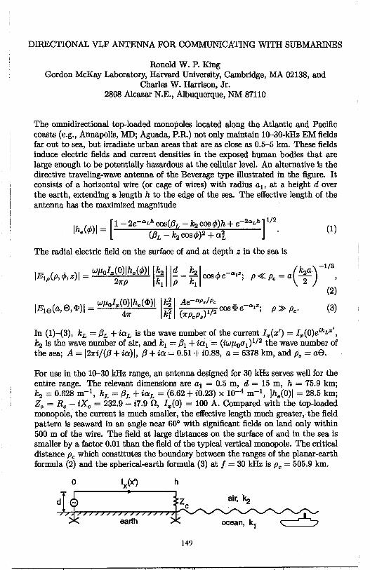
DIRECTIONAL VLF ANTENNA FOR COMMUNICATING WITH SUBMARINES
Ronold W. P. King Gordon McKay Laboratory, Harvard University, Cambridge, MA 02138, and
Charles W. Harrison, Jr. 2808 Alcazar N.E., Albuquerque, NM 87110
The omnidirectional top-loaded monopoles located along the Atlantic and Pacific coasts (e.g., Annapolis, MD; Aguada, P.R.) not only maintain 10-30-kHz EM fields far out to sea, but irradiate urban areas that are as close as 0.5-5 km. These fields induce electric fields and current densities in the exposed human bodies that are large enough to be potentially hazardous at the cellular level. An alternative is the directive traveling-wave antenna of the Beverage type illustrated in the figure. It consists of a horizontal wire (or cage of wires) with radius a1 , at a height dover the earth, extending a length h to the edge of the sea. The effective length of the antenna has the maximized magnitude
_ [ 1 - 2e-ctLh cos(f3L - k2 cos <j,)h + e-2ctLh] 112
lhe(</>)1- (/3L - ~ cos<j,)2 + o/j, . (1)
The radial electric field on the surface of and at depth z in the sea is
wµ I (O)lh (A..)l lk I Id k I _ (k a,)-11
3
IE1p(P,</>,z)I= 0
"'21rp e"' k:. p- k: cos<j,e ct1"; P~Pc=a-}- ,
(2)
IE (a e cl>)I = wµol.,(O)ihe(cl>)I 1k~ I Ae-ctP,!Pc coscl>e-ct1Z. p ~ p
18 , ' 47f kf (7rPcPs)1/2 ' c· (3)
In (1)~(3), kL = /3L + iaL is the wave number of the current I.,(x') = I.,(O)eikL"'1
,
k2 is the wave number of air, and k1 = /31 + ia1 = (iwµ 0u1) 112 the wave number of the sea; A= l21ri/(/3 + ia)I, /3 + ia = 0.51 + i0.88, a= 6378 km, and Ps = ae.
For use in the 10-30 kHz range, an antenna designed for 30 kHz serves well for the entire range. The relevant dimensions are a1 = 0.5 m, d = 15 m, h = 75.9 km; k2 = 0.628 m-1, kL = /3L + iaL = (6.62 + i0.23) x 10-4 m-1, lhe(O)I = 28.5 km; Zc = Re - iXc = 232.9 - i7.9 n, I.,(O) = 100 A. Compared with the top-loaded monopole, the current is much smaller, the effective length much greater, the field pattern is seaward in an angle near 60° with significant fields on land only within 500 m of the wire. The field at large distances on the surface of and in the sea is smaller by a factor 0.01 than the field of the typical vertical monopole. The critical distance Pc which constitutes the boundary between the ranges of the planar-earth formula (2) and the spherical-earth formula (3) at f = 30 kHz is Pc= 505.9 km.
149
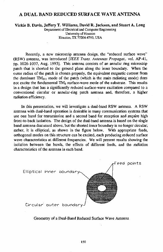
A DUAL BAND REDUCED SURFACE WAVE ANTENNA
Vickie B. Davis, Jeffery T. Williams, David R. Jackson, and Stuart A. Long Department of Electrical and Computer Engineering
University of Houston Houston, TX 77204-4793, USA
Recently, a new microstrip antenna design, the "reduced surface wave" (RSW) antenna, was introduced [IEEE Trans. Antennas Propagat., vol. AP-41, pp. 1026-1037, Aug. 1993]. This antenna consists of an annular ring microstrip patch that is shorted to the ground plane along the inner boundary. When the outer radius of the patch is chosen properly, the equivalent magnetic curren.t from the dominant TM011 mode of the patch (which is the main radiating mode) does not excite the fundamental TM0 surface-wave mode of the substrate. This results in a design that has a significantly reduced surface-wave excitation compared to a conventional circular or annular-ring patch antenna and, therefore, a higher radiation efficiency.
In this presentation, we will investigate a dual-band RSW antenna. A RSW antenna with dual-band operation is desirable in many communication systems that use one band for transmission and a second band for reception and require high front-to-back isolation. The design of the dual-band antenna is based on the single band antenna discussed above, but the shorted inner boundary is no longer circular; rather, it is elliptical, as shown in the figure below. With appropriate feeds, orthogonal modes on this structure can be excited, each producing reduced surface wave characteristics at different frequencies. We will present results showing the isolation between the bands, the effects of different feeds, and the radiation characteristics of the antenna in each band.
Feed points
Elliptical inner boundo.ry
Circulo.r· outer bouncfory
Geometry of a Dual-Band Reduced Surface Wave Antenna
150
U\ /2SZ ~~e,, v:v1 (Q. Y)1Q_r;J~':J ( .t&:fo J¥01rv _7 uJ4; l9t£ )
No ShrJVJ
Dielectric Archimedian Spiral Travellina= Wave Antenna
+i.D. Hawes*, +v.M.M. Antar, *A. Ittipiboon, ~. Simons
+Royal Military College of Canada
Kingston, Ontario K7K SLO, Canada
++communication Research Centre
P.O. Box 11490, Station H, Ottawa, Ontario K2H 8S2, Canada
0 ver the past few years dielectric antennas have gained a certain degree
of popularity due in large part to their high radiation efficiency, small physi
cal size, simple coupling sch em es and low conductor losses. This last char
acteristic is of great relevance given that it is a limiting factor with current
micro strip technology in the millimeter frequency band.
Recently it has been shown that dielectric resonator antennas (DRAs)
can produce circularly polarized radiation by properly exciting two modes in
space and phase quadrature. This paper investigates a new dielectric antenna
structure which relies on travelling waves instead of resonant modes to
achieve circular polarization. The antenna structure is an archimedian spiral
frabricated out of a block of dielectric material and placed over a ground
plane. An electromagnetic wave is launched within this structure using either ~
a probe, slot or waveguide feed network. The geometry of the archimedian
spiral has the potential of producing circularly polarized radiation with a low
axial ratio over a wide frequency band.
Modelling of the complete antenna design was achieved using the trans
mission-line matrix (TLM) approach, which, simplifies the task of modelling
complex 3-D shapes at the expense of demanding large computing resources.
The experimental and,numerical results will be presented here for vari
ou.s configurations of this new type of antenna.
151
FINITE ELEMENT ANALYSIS OF FREQUENCY INDEPENDENT ANTENNAS
~ 1*, John L. Volakis1 , Jeffrey Berrie2 and Leo C. Kempel2
1 Radiation Laboratory 2 Mission Research Corporation EECS Dept.,University of Michigan 3975 Research Bldv. Ann Arbor, MI 48109-2122 Dayton, OH 45430-2108 [email protected] [email protected]
" [email protected] [email protected] "·I
1 ~20/'r 5~!111( ~ Wide bandwidth is a very desirable feature of an antenna, and log periodic
ft and spiral antennas have the capacity to offer multi-octave bandwidths (P. 1 \ S. Hall, IEE Proc., H, 133, 127-137, 1986). In this paper, we will present a t ~ finite e~ement-artificial a~sorber_ (FE-AA~ a~pro.i,ch for the characterization of
v· slot spiral and stacked microstrzp log periodic antennas (see the figure below). 'N The FE-AA technique can be an efficient approach for analyzing printed an~ -iJ tenna geometries by growing the volume mesh along surface normals starting :§ from a surface grid. of triangular elements coinciding with the antenna sur-~ face. The resulting volume element is the triangular prism and edge-based ~ vector basis functions .. are used to interpolate the electric field components in
side each prism (T. Ozdemir & J.L. Volakis, IEEE AP-S Int. Symp. Dig., 1, 48-51, 1995). The finite element mesh is terminated a fraction of a wavelength away from the antenna by using an artificial absorber consisting of a lossy metal-backed dielectric layer. The metallic boundary makes it possible to terminate the mesh with less unknowns while the lossy layer absorbs the incoming electromagnetic energy and thereby simulates a transparent boundary.
Numerical data will be presented illustrating the resonance behavior and radiation pattern as a function of growth rate 7, angles a and /3 as well as substrate/ superstrate thickness, constitutive parameters and ferrite DC biasing. Stacked log-periodic configuration will be also examined for added bandwidth performance and finite ground plane effects will be considered.
Stacked microstrip log periodic antenna Two-arm slot spiral antenna
152
l)J2_5k ~ 5 vl&J/t~ !'!/<? etyn.g[iJ£r'yit1 or-e~T ~ l°f t76 Helical Antenna Tightly Coupled to a Conducting
Choke
David Nghiem, Michel Schnetzer*, David C. Stillinger, Patrick J. Connor, Robert H. MacLyman, and Joe C. Le QUALCOMM Incorporated San Diego, CA 92121-2779
The purpose of this study is to improve gain of a conventional axial-mode helical antenna without increasing the length of the antenna. To do this, one could place a conducting wall around first few turns of a helix, as shown in Figure j. This is aue to the fact that a presence of the conducting wall will reshape (lower sidelobe, narrower beamwidth) a radiation pattern corresponding to a decayingwave surface current of the helix. An ideal height for a conducting wall should be equal to a distance from a feed point to a cut-off point of the decaying-wave region, as shown in Figure 2. Intuitively, to increase antenna directivity the conducting wall should be placed as close as possible, to the helix. However, one should keep in mind that a presence of the conducting wall will alter the input impedance, and also degrade the axial ratio. In this presentation, a design procedure for a helix with a conducting choke will be outlined. As an example, both numerical (l!l~_!hod-o -moment and experimental results for a Ku-band 8-turn helix wm be presented. U£;oJ2 re-~ :f ~3 D
z
t I Z 7 5 Gff z:, '
Cut-off point of a decaying-wave
ZLocation
Figure 1. Helix with a conducting choke. Figure 2. Typical surface-current of a conventional helix.
v,mi) ~ IA l t) 5~J1,,,/V~J0/1/t~ / ~w-~ ""-~,2_,ct/1 ~VV\.~ ~~ 11~1 ~
,j ~ ~ '"J:.1)5' :z:_, 153 )

Analysis of Handset Antennas IL- / (rfl.4:.-
·~.~-;:;::"__,,./-\ fo. r Personal Communications , <h~:~ i/ ! c..(f'J' ""' Y1 /V<.' §M I -, ~ r,. ~. '2.600.fL.- r-r7·, • / Jean-Fu Kiang @ I (J.P..~)
Department of Electrical Engineering / ,1;.9A. Y'~i'..()/1'-' National Chung-Hsing University ' 0'1
., a:A (J ? , ~- • ;,...Taichung, Taiwan, ROC /) 1 _ ~- o- , '<A... PZrrrr ."' Z::./r,.~ {-o ~ ~,,, J'{I'C/.LUJfW,
5 ,...;1,cu?f!a,,~ CLt 0/v'/ 215A~ CUV'-d 13 1.11/ JJo-€'1.. ~//' Q/.)._ Jl,,;2...\ '}(I'~,~ (2, Vl ;jtrl24-~ ~ fl f/V fr'c/v?.. d.,JwVI-.
::r: 1- A:xi-4 Iiv-~ If\ vi C 6 oo Jl) In traditional handset designs for cellular telephone and citizen band (CB) radios,
extendable antenna like whip and sleeve dipoles are generally used because they are easy to build and maintain. Loop antennas are usually implemented in a pager to receive paging signal. For today's personal communications systems, compact handsets with weight less than seven ounces are plausible,. hence, compact and low-profile built-in antennas are desirable. Planar inverted F antennas ( PIFA ) have been studied for their advantages of compactness and reasonable range of input impedance to match the feeding circuits. a coarse wire-grid model has been used to analyze a PIFA antenna. Moments method and FDTD approaches have also been applied to study the radiation properties of monopole, spiral, and PIFA.
In this work,_we develop a wire-grid model to investigate the input impedance and radiation patterns of six antennas ~edon the ps>rtable handset case : side-mounted
inverted F', toi)=moiiiile<1mverted F, inverted-1, monopole, loop, and spiral antennas. The input impedance of both inverted F antennas is close to the characteristic impedance of typical coaxial cable, hence they are easy to match with the feeding circuits. The monopole has a higher peak input resistance, bµt the resistance around other resonance frequencies are compatible to the 500 coaxial system. The inverted L, loop, and spiral antennas have a wide range of input impedance. Impedance matching around resonance frequencies with the peak resistance is difficult, but they have a wide frequency range over which the input resistance variation is small and the input reactance is a linear function of frequency.
The input imQedance o( Pllli._ is closetoJypjcJ!L cable. characteristic iml!~~ap.C_E:,, h<ep.ce they ~e easy to 1!1_':t~h-~_i_~~he fE!eQLl_l$.fir.£!lits. The i~ver~~~_b.J.QQp .. and spi~,l ~~ ct~~.f~igher peak inp~tI.e~j~1<!:9:£!:JPe-AJbi!t~JJ.h~1If.1· Loop and spiral antennas have-.;, wide frequency f!l,Ilge-over which the input resistance variation is small and the input reactance is close to linear. The Eo pattern of a side-mounted PIFA has a directional pattern in the xy plane, and can be used for direction finding. The inverted L antenna radiates stronger in the ±y directions than in the ±x directions. The field patterns of the other four types are close to omnidirectional in the xy plane.
154
Linear Wire Antenna on the Earth's Surface For Underground Mine Communication
A.K. Gogoi Assam Engineering College Guwahati - 781013, Assam, INDIA
ABSTRACT
If, Goswami Gauhati University Guwalm-781014,As.wni,INDIA
This paper presents an analysis of linear wire antenna on the earth's surface for wireless underground mine communication. The requirement of an uninterrupted communication to and from the underground miners is of critical importance. This becomes more evident during the time of rescue operation due to mine disaster. · Wireless communication at the RF frequency range is not possible due to the finite conductivity of the earth. This necessitates the utilization of VLF / ELF range of frequencies for underground mine communication. A linear wire antenna may be very conveniently laid on the earth's surface within a very short tiine in the event of a mine disaster.
The current distribution of the linear antenna on the earth's surface is obtained following a mixed potential (vector and scalar) integral equation formulation. This formulation is based on Sommerfeld equation. In general, Sommerfeld equation is highly· oscillatory for a horizontal dipole radiating over a lossy half-space. The dipole has both horizontal and vertical components of magnetic vector potential. However, only the horizontal component is necessary in the mixed potential approach and it is obtained in a closed form. The scalar potential is also obtained in a closed form using a quasi-static approach. The current distribution in the antenna is obtained numerically by the method of moments. It is found that due to lossy earth, current distribution in the antenna drops very fast away from the feed point even for a moderately sized antenna. This suggests that the end points need not necessarily be grounded as usually thought of. Field inside the earth is computed numerically by integrating the Sommerfeld equation. This can be accomplished without much difficulty as the convergence of the numerical integration is reasonably fast since the observation point is deep inside the earth.
155

THIS PAGE INTENTIONALLY LEFT BLANK.
156
Tuesday AM AP/URSI-A Session 1 Camden/Lombard
EM Properties of Materials K. Sparks and S. Riad Page
8:20 A Novel Approach for Determining the Dielectric Properties .......... APS of Cylindrical Rods .1
William R. Humbert, Waymond R. Scott, Jr., Georgia Institute of Technology
8:40 Effect of Air Gap on Measurement Accuracy of Dielectric Constant ... APS ei Luo, Hui-Wen Yao, Kawthar A. Zaki, University of Maryland College Park
9:00 FDTD Analysis of Dielectric Properties Measurements Using .......... APS Open-Ended Coaxial Probes Shane Bringhurst, Magdy F. lskander, University of Utah
9:20 A Free Space Approach for Extracting the Equivalent Dielectric ....... APS Constants of the Walls in Buildings Chang-Fa Yang, Chuen-Jyi Ko, Boau-Cheng Wu, National Taiwan Institute of Technology
9:40 Electromagnetic Probe for Insitu Measurement of the Complex ....... 158 Dielectric Constant of Materials E. Nassar, R. Lee, J. L. Young, The Ohio State University
10:20 Intercomparison of Dielectric and Magnetic Material .................... 159 Characterization Using the Air-Filled Stripline Resonator Technique Chriss A. Jones, Claude M. Weil, National Institute of Standards and Technology
10:40 Problems in Material Characterization Using Stripline .................. 160 Resonator Method Iman Salama, Fred Barlow, Wansheng Su, Aicha Elshabini-Riad, Sedki Riad, Virginia Polytechnic Institute and State University
11 :00 A Time Domain Measuring Method of Mmwave Permittivity .......... 161 Ding Hanyi, Shi Fangzhou, Wu Hongxiong, Zhang Guangzhao, Zhongshan University
11 : 20 Percolation Theory in the Design of Artificial Dielectrics ............... APS Nicolaos G. Alexopoulos, Rodolfo E. Diaz, William M. Merrill, University of California Los Angeles
11 :40 Effect of Splintering of Oscillations in Disk Dielectric .................. 162 Resonators V. S. Dobromyslov, Moscow Power Engineering Institute
157
ELECTROMAGNETIC PROBE FOR INSITU MEASUREMENT OF THE
COMPLEX DIELECTRIC CONSTANT OF MATERIALS
E. Nassar, R. Lee, and J. 1. Young
ElectroScience Laboratory Department of Electrical Engineering
The Ohio State University 1320 Kinnear Rd.
Columbus, Ohio 43212-1191
In this study we develop a calibration technique for a new Ultra-WideBand, Hand-Held probe for measuring the complex dielectric constant of materials. The probe consists of two stub antennas mounted on a copper cylinder. To perform a measurement the probe is inserted in the material under study after drilling a hole of the same diameter as the probe. The antennas are connected to the transmitting and receiving ports of a network analyzer. An electromagnetic signal is transmitted from one of the antennas and received by the other. From the attenuation and phase delay of the transmission coefficient one can extract the complex dielectric constant of the material. However immersing the probe in different materials will affect the radiation patterns and impedance of the antennas; therefore, in addition to attenuation and phase delay we need a calibration tool to account for the material antenna interaction. We developed a numerical model for the probe using the finite difference time domain technique. By running the code for several different materials we can obtain factors to calibrate the measured data. This probe has applications in many areas where information about the dielectric constant is desired such as remote sensing and backscatter studies on soil, ice, snow, and vegetation. The operation bandwidth of the probe is between 1 and 10 GHz. We will present several examples for artificial and natural occurring materials.
158
INTERCOMPARISON OF DIELECTRIC AND MAGNETIC MATERIAL CHARACTERIZATION USING THE AIR-FILLED STRIPLINE RESONATOR TECHNIQUE.
Chriss A. Jones and Claude M. Weil* Electromagnetic Fields Division (813.08)
National Institute of standards and Technology Boul.der, co 80303-3328
In an attempt to assess the quality of RF material characterization being performed by industrial and government laboratories, NIST has organized several national measurement intercomparisons of permittivity €/ and permeability µ. *. One of these studies involved measuring the compiex permittivity properties of four different low-loss dielectric materials that were circulated amongst 12 participating laboratories, using a standardized Transmission/Reflection (T/R) method in 7-nun diameter coaxial air line (see E.J. Vanzura et al, IEEE Trans. MTT, 42, 2063-2070, 1994). A recently completed follow-on study involved complex permittivity and permeability measurements of four different ferrite materials using the same technique (publication in preparation) .
This talk discusses a third intercomparison effort involving complex permittivity and permeability measurements of both dielectric and magnetic materials using the air-filled stripline resonator method, a technique widely used in aerospace and federal laboratories for accurately characterizing low-to-medium loss materials in the 100-5000 MHz frequency range. Bulk pieces of two dielectric and three magnetic materials were supplied to six participating laboratories (including NIST). From these, participants prepared samples to fit into their own particular measurement fixture, the design of which varied from one laboratory to another. Comparison data will be presented for the five materials used in the intercomparison. The preliminary conclusions of this study are as follows: a) the stripline resonator method is not a reliable technique for permi tti vi ty measurements, due to depolarization errors caused by air gaps, but does work satisfactorily for permeability measurements, b) imbalanced loading of the resonator can lead to radiation losses and resulting errors, c) exceeding the limits of Waldren' s small perturbation theory ( caused by, for example, use of too large a sample) leads to significant errors, and d) inclusion of the demagnetization correction is essential for accurate permeability measurements.
159
PROBLEMS IN MATERIAL CHARACTERIZATION USING STRIPLINE RESONATOR MEfflOD
Iman Salama, Ahmed El-Bakly, Wansheng Su Aicha Elshabini-Riad and Sedki Riaa The Bradley Department of Electrical Engineering Virginia Polytechnic Institute and State University Blacksburg, Virginia 24061-0111 Phone: 540-231-4463 Fax: 540-231-3531 Email: [email protected]
The stripline resonator method is one of the most popular methods to characterize the dielectric properties of microwave circuit substrates. It has become an industrial standard as recommended by the ASTM [1]. In the practical implementation of the method, however, two main problems cause difficulties with the use of this technique. One problem relates to proper design of the resonator gap as to allow for covering the frequency band of interest. The second problem relates to the accuracy of separation of the dielectric and conductor losses. The second problem is two fold; one aspect of it is related to proper design of the line dimensions as to allow the separation, while another is related to using adequate models for the separation of the two loss terms.
In this paper, these two problems are discussed in detail along with recommendations of how to deal with them. Examples of resonators where these problems are addressed successfully are given along with computer simulations demonstrating the resonator design criteria.
The issue of loss separation is given a special attention in this presentation. In order to improve the accuracy of loss tangent evaluation, several main issues related to the error have been examined. They include the geometrical dimensions, conductor loss, syst~ loading effects and radiation. Since the loss of a stripline resonator is a complicated function of the geometrical structure and materials used, several approaches are used in this investigation. An analytical approach is used to derive the loss effects for a well defined or ideal resonator structure and materials. A numerical approach is used to account for the practical deviations from the ideal cases, such as the finite conductivity of the metal strip as well as the system loading and radiation.
References 1. Annual book of standards, "ASTM 03380-75 Standard Test Method for Permittivity (Dielectric Constant) and Dissipation Factor of Plastic-Based Microwave Circuit Substrates," Amer. Soc. Testing Materials, part 39 (1980).
160
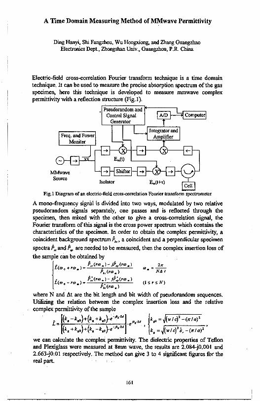
A Time Domain Measuring Method of MM wave Permittivity
Ding Hanyi, Shi Fangzhou, Wu Hongxiong, and Zhang Guangzhao Electronics Dept., Zhongshan Univ., Guangzhou, P.R. China
Electric-field cross-correlation Fourier transform technique is a time domain technique. It can be used to measure the precise absorption spectrum of the gas specimen, here this technique is developed to measure mmwave complex permittivity with a reflection structure (Fig.1 ).
Fig. I Diagram of an electric-field cross-correlation Fourier transform spectrometer
A mono-frequency signal is divided into two ways, modulated by two relative pseudorandom signals separately, one passes and is reflected through the specimen, then mixed with the other to give a cross-correlation signal, the Fourier transform of this signal is the cross power spectrum which contains the characteristics of the specimen. In order to obtain the complex permittivity, a coincident background spectrum it, a coincident and a perpendicular specimen
spectra fa.., and fa,,, are needed to be measured, then the complex insertion loss of
the sample can be obtained by
I . P,. (ro,. )- jP,, (ro,.) L(o, 0 + ro,.) = ---.-. ---"-
Pt, (ro, •)
• fo,; (ro, • )- jP,; (ro,.) L(o, 0 - ro, •) = --••• ---"-
P., (ro,.)
2,r 0) =--
• N,J I
(Is rs N)
where N and At are the bit length and bit width of pseudorandom sequences. Utilizing the relation between the complex insertion loss and the relative complex permittivity of the sample
L= -·e • • [(k,-k10)+(k, +k10 )·e~ft,·2J]
11 •24 lk10 =J(wtc)2-(,r/a)2
[(k, +k,.)+(k,-k,.)·e-Jk,·2J] ' k, =J(w!c)2 e, -(,r/a)2 '
we can calculate the complex_ permittivity. The dielectric properties of Teflon and Plexiglass were measured at 8mm wave, the results are 2.084-j0.001 and 2.663-j0.01 respectively. The method can give 3 to 4 significant figures for the real part.
161
EFFECT OF SPLINTERING OF OSCILLATIONS IN DISK DIELECTRIC RESONATORS
V.S. Dobromyslov Moscow Power Engineering Institute, Department of Radioengineering
Higb Q disk dielectric resonators (DR) with azimuthal modes are adopted in various directions of microwave and millimeter-wave electronics. These are precise dielectric parameters measurements, narrow-band filtration of signals, frequency control, stabilization of generators and others.
The intrinsic peculiarity of disk DR with azimuthal modes is a brightly displaied effect of splintering of degenerated oscillations caused by an azimuthal inhomogeneity. It is conditioned that two oscillations can be excited at the same frequency in the disk DR differing by azimuthal field distribution. One oscillation have the field distribution along the azimuthal coordinate cp as sin ncp, another - cos ncp (n - azimuthal mode index). These two oscillations have the same resonant frequency if there are not any azimuthal inhomogeneities in resonator.
This work discusses the effect of splintering of azimuthal modes in disk DR. It can be used for several purposes: measurement of dielectric parameters of film and fibrous materials, forming the desired amplitude-frequency characteristic, stabilization of frequency of generators.
The effect of splintering of azimuthal resonant modes for measurement parameters of the film and fibrous materials can be realized by fabricating disk DR with the radial cut or hole in axled direction in the edge region of the disk. When exciting such a resonator one may observe two oscillations: one of them has· zero field amplitude in the place of disposition of inhomogeneity, the other has the maximum field amplitude. The frequency of the former oscillation does not practically differ from resonant frequency of unperturbed resonator, frequency of the latter depends on value of inhomogeneity. It is easy ·to defme dielectric permittivity of the investigated material by measuring the difference between these frequencies.
Forming of the desired amplitude-frequency characteristic of a filtering device based on the disk DR can be realized by tuning of value of inserted inhomogeneity (for example, the film inside cut in resonator). The more the value of inhomogeneity, the more the splintering of resonance. In this situation the frequency response changes from traditional "Lorentz" to that having two divided resonant splashes.
The effect of splintering of oscillations can also be used in a system of frequency stabilization based on higb Q resonators. More higb steepness of phase characteristic of the reflected signal from such a resonator can be realized by choosing the value of inhomogeneity so that splintering of frequancy is of the same order as passband of single resonance. It is similarly to raising of Q-factor of a single-mode disk DR without an inhomogeneity. The value of inhomogeneity for disk DR with radial cut depend on thickness and dielectric permittivity of film introduced in the cut.
The considered variants of using of effect of mode splintering in disk DR can be applied to designing of various functional microwave and millimeter-wave devices.
162
Tuesday PM URSI-E Session 1 Constel. Ballroom D
EM Noise and Interference R. Gardner Page
1:20 Non-Linear Algorithms for the Estimation of High-Order .......... 164 Statistics of Non-Gaussian Markov Processes V. Kontorovich, CINVESTAV-IPN (Communications), V. Lyandres, Ben-Gurion University
1 :40 Performance of ELFNLF 'Coherent Receivers in ..................... 165 Atmospheric Noise A. K. Gogoi, Assam Engineering College, A. K. Mahanta, IIT Kanpur
2:00 An Interference Prediction Method for Spectrum ...................... 166 Management of Non-Geostationary Satellite Networks Sharing the Same Frequency Bands Jay Gibble, Robert Combs, Stanford Telecom
2:20 Radiation and Reception of Pulsed Signals Involving ............... 167 Thin Half-Wave Orthogonal Dipoles Ajit K. Choudhury, Howard University, Eric L. Mokole, Suren N. Samaddar, Naval Research Laboratory, Washington, DC
2:40 External Coupling to Shielded Underground Multi-Cables ......... 168 of Finite Length Fang Han, NOKIA Research Center
163
NON-LINEAR ALGORITHMS FOR THE ESTIMATION OF ffiGB-ORDER STATISTICS
OF NON-GAUSSIAN MARKOV PROCESSES
V. KONTOROVICB, CINVESTAV-IPN (Communications),
Av. Politecnico Nacional, 2508, C. P. 0700, Mexico, D. F. Fax: 15257477002, E-mail: valery@mvaxl. red.cinvestav.mx
V.LYANDRES, BEN-GURION UNIVERSITY (El.&Comp. Eng. Dept.)
P. 0. Box 653, Beer-Sheva, 84105, Israel Fax: 97207472949, E-mail: [email protected]
The main goal of the work is to present an approach which enables us to obtain algorithms for the estimation of the high order statistics of the signal parameter, if the latter one is described by a solution of certain stochastic differential equation (SDE) and the signal itself is corrupted by an additive white Gaussian noise (WGN).
The SDE generating random process with the previously known probability density function and auto correlation function may be obtained with help of the procedure considered in ( V. Kontorovich and V. Lyandres, IEEE Transactions on Signal Processing, . 43, No. 10, 2372-1285, 1995). It can be written out as
x=f(x)+g(x)~t) (1)
where ~t) is WGN with unit spectral density. The received signal is
y(t) = s(x,t)+n(t) (2)
where n(t) is additive WGN with the known intensity ands(.) is the a priori known signal shape. With the help of generalization of the equations of non-linear filtering presented in (V. S. Pugachev and I. N. Sinitsyn, Stochastic Differential Systems, Analysis and filtering, John Wiley & SOI\$, N. Y., 1987) one can get differential equations for the arbitrary order a posteriori qumulant function of the process x( t) . These equations are defined by the Fokker-Planck differential operator appropriate to SDE (1).
The SDE approach allows us to obtain all kinds of quasi-optimal filtration algorithms in continuous and in discrete time. The results considered generalize the well knoWn Stratonovich equation for non-linear filtering of Markov processes.
164
PERFORMANCE OF ELF/ VLF COHERENT RECEIVERS IN ATMOSPHERIC NOISE
A.K. Gogoi Assam Engineering College Guwahati - 781013, Assam, INDIA
ABSTRACT
A.K. Mahanta IITKanpur Kanpur-208016,UP,INDIA
Wide band observation of atmospheric noise_ at ELF and VLF bands reveals intermittent, non-overlapping, large amplitude and spike-like pulses over a comparatively smooth background. It is difficult to devise a rigorous method for evaluation of receiver performance under such a noise, because of its nonGaussian characteristics. To study the receiver performance, two approaches are
, usually taken to develop an appropriate noise model at ELF and VLF bands, depending on the bandwidth of the receiver. At VLF the ratio of bandwidth to center frequency is usually small and therefore the received noise may be considered as narrow band process. However, at ELF this ratio is not small and the noise is to be treated as a wide band process. Both intuitive and rigorous methods are in use for evaluation of receiver performance with several noise models. The rigorous methods have to take recourse to several approximations without sufficient justification. These methods can be used primarily for non coherent receivers.
The paper describes a rigorous treatment for performance evaluation of coherent receivers at ELF and VLF bands. To accomplish this the atmospheric noise is considered to be a wide band process having two components. One component is assumed to be zero mean Gaussian process to represent the background noise which is due to large number of relatively unresolved pulses from distant lightning flashes. The other component is considered to be Poisson arrival process of pure impulses and it represents the non-overlapping pulses which are due to local thunderstorm activity. Performance of a coherent receiver with the noise model used is evaluated by separately computing the distribution of both the components at the receiver output and then convolving them to obtain the necessary distribution for the composite random process.
165
An Interference Prediction Method for Spectrum Management ofNonGeostationary Satellite Networks Sharing the Same Frequency Bands
Jay Gibble Robert Combs
Stanford Telecom 1761 Business Center Drive
Reston, VA 22090
In recent years, the need for satellite radio spectrum has increased dramatically in the private sector, especially in the area of non-geostationary satellite systems. International filings for dozens of systems with thousands of satellites have been submitted to the International Telecommunications Union (ITU). However, the military and scientific demands on spectrum are also increasing. One possible solution to this problem is spectrum sharing, in which part of the spectrum is allocated for more than one user. Sharing introduces the possibility of cochannel interference, where the emissions of one system may be received by another system which has also been allocated the same frequency band. The ITU has recommended methods for determining interference potential between geostationary satellite networks sharing the same frequency bands (ITU, Radio Regulations. Volume II, Appendices to the Radio Regulations, Appendix 29, Geneva 1994), but no accepted method currently exists to quantify the interference potential between non-geostationary satellite networks sharing the same frequency bands.
This paper presents a method for determining the potential for interference between non-geostationary satellite networks sharing the same frequency bands. The first step of the method is static analysis (link budget) to determine the worst case conditions for interference. If it is determined that the worst case interference exceeds the system specifications of the "victim" network, a second step is required. The second step uses an object-oriented computer program to model the interfering and the victim networks through a discrete-time simulation, in which the interference levels from each emitter in the interfering network are calculated and summed. ITU recommendations on coordination (such as antenna patterns) are included in the model where applicable. Multiple statistics characterizing the relationship between the networks are collected. From these statistics the potential for interference can be identified.
The interference from the intersatellite links of the Teledesic low-earth orbiting system to a NASA passive weather sensor satellite is evaluated. The results show that coordination is required for these two systems to share the same frequency bands.
166
RADIATION AND RECEPTION OF PULSED SIGNALS INVOLVING THIN HALF-WAVE ORTHOGONAL DIPOLES
AJIT K. CHOUDHURY DEPARTMENT OF ELECTRICAL ENGINEERING
HOWARD UNIVERSITY WASHINGTON, DC 20059
ERIC L. MoKOLE SUREN N. SAMAD DAR
RADAR DIVISION (CODE 5340) NAVAL RESEARCH LABORATORY WASHINGTON, DC 20375-5336
In a previous presentation [Choudhury et al., Nat. Radio Sci. Mtg., Boulder, Jan. 1996], the feasibility of radiating circularly polarized fields was established. The intent of this work is to examine through analytical means whether the circular polarization of the radiated field is preserved for some period of time when it is received by a similar pair of orthogonal dipoles. To this end, the transient behavior of the signal received by a pair of coplanar, thin, uncoupled, orthogonal dipoles that lie in the far field of a duplicate transmitting pair of orthogonal dipoles is studied. From a geometric standpoint, the receiving antenna is assumed to be a translated replica of the transmitting antenna. A coordinate frame for each antenna is selected so that the origin lies at the center of the corresponding orthogonaldipole pair and the associated x- and z-axes are the axes of the dipoles. Additionally, both pairs of dipoles are perfectly matched to their respective feed networks. The transmitting dipoles are excited by a finite-cycle sine: [U(t) - U(t - NT0 )] sin(211Jot), where U is the unit step function, To = 1/ lo, the carrier frequency lo is chosen so that the dipoles are a half-wavelength long with respect to lo, and the positive integer N indicates the number of cycles. The aforementioned excitation is the input to the dipole along the z-axis, whereas the input to the dipole along the x-axis is the same function delayed by a quarter cycle. To obtain a closed-form expression for the received voltage, a zero-order approximation of the frequency-domain current distribution along each dipole is applied.
Based on results from earlier work on transient radiation/reception by half-wave dipoles [Samaddar, J. Franklin Inst., V.329, N.2, 1992; Samaddar, J. Franklin Inst., V.330, N.1, 1993] and on the radiated far field for orthogonal dipoles [Choudhury et al., Nat. Radio Sci. Mtg., Boulder, Jan. 1996], the induced voltag~ at the receiving pair of orthogonal dipoles is derived for arbitrary angle of incidence. In addition to the temporal extension to the duration NI o of the finite-cycle sine induced by the time-delayed input at the transmitting dipole along the x-axis, further temporal extensions arise from delayed radiations and receptions at the endpoints and feedpoints of the dipoles from the radiating and receiving antennas. Because the single-cycle sine is an idealized ultrawideband signal, the behavior of its received voltage is highlighted.
167
EXTERNAL COUPLING TO SHIELDED UNDERGROUND MULTI-CABLES OF FINITE LENGTH
Fang Han NOKIA Research Center, P.O. Box 45, FIN-00211 Helsinki, Finland
Tel.: +358 0 4376 6301, FAX:+ 358 0 4376 6856, E-mail: [email protected]
In recent years, the significance of coupling and interference of external electromagnetic field sources to underground network systems has increased due to the rapid development of underground technologies for various applications. As such, the interference problems of the coupling present special difficulties and challenges to engineers who concerned with EMC problems. Unfortunately, such problems are usually ignored and seldom taken into consideration at the initial stages of design (A. K. Agrawal, IEEE Trans. EMC, 24, 1982).
Previous publications have discussed methods for analysing fields generated from the above active sources in the air and the earth. Most of these are confined to models which mainly target the field calculations from overhead transmission lines. Some studies employed conventional TLM to deal with underground coupling problems. Other methods were formulated for specific applications such as a single conductor at the earth's surface and did not consider the coupling effect from other conductors and their images. Furthermore, those methods could not simply lead to a close form representations as will be addressed in this paper. Circuit approaches (C. R. Paul, John Wiley and Sons, New York, 1994.) are sufficiently useful for analysis of coupling to long homogeneous conductors, but may not be valid for inhomogeneous systems with arbitrary terminations. These systems may be inhomogeneously distributed or of finite length and terminated with arbitrary passive impedances. Furthermore, a model is especially needed to solve such problems which would become more complicated if the coupling to both shield and core conductors ofmulticables are to be account for simultaneously.
Coupling to underground cables by an external EM source can be regarded to be realised via two loops. One is the 'sheath-earth' loop, in which current and potential are generated along the shield conductors of the cables directly by the source. The other is the 'sheathcore' loop formed by shield and core conductors of the cables, in which, current in the core conductor and voltage between the shield and core conductor are induced as a result of coupling between the two loops. The objective of this paper is to present a novel model for analysis of the above couplings to the two loops. The ETLEs (F. Han, et al., IEE Proc.-A, 24, 1996) are employed to describe the coupling to the 'sheath-earth' loop of the cables and conventional TLM is used to describe the coupling to the 'sheath-core' loop. The validity of the model for finite length situation is implemented by taking into account the arbitrary passive terminating impedance of the two loops, i.e., the impedance between the earth and shield conductor of the cables and impedance between the outer and inner conductors. Earth conduction effect, earth surface boundary, and mutual coupling among all the cables are accounted for in the model with the implementation of the equivalent transmission parameters in ETLEs for 'sheath-earth' loop and of the distributed parameters in conventional TLM for 'sheath-core' loop. Finally, the model is illustrated by conductive coupling ofa two-cable system of both infinite and finite length cables. The computational results are shown to be in good agreement with experimental results.
168
Tuesday PM URSI-C Session 1 Constel. Ballroom D
Signals and Systems C. McCormack Page
3:20 Blind Adaptive Beamformer for Codelength-Division ................ 170 Multiple Access Communications Ta-Sung Lee, Su-Min Hsu, Tsui-Tsai Lin, National Chiao Tung University
3:40 Complex-Direction Search of Radio Propagation in ................. 171 Microcells I-Tai Lu, Jaeyoung Kwak, Weber Research Institute, Robert C. Qiu, GTE Laboratories, Inc.
4:00 A New Adaptive Antenna Array Structure for CDMA ............... 172 Wireless Communications Xiaoming Yu, John Litva, McMaster University
4:20 Maximum Likelihood Coordinate Registration for Over-the ....... 173 Horizon Radar Jeffrey L. Kralik, Richard H. Anderson, Duke University
4:40 On the Validation of a Multiple-Beam Adaptive Nulling .......... .174 Antenna Simulator Chamroeun Kchao, Guan G. Cheng, TRW Space and Electronics Group
5:00 Using Time-Frequency Distributions for Dynamic Target .......... 175 Analysis of Noise Corrupted Signals Christopher J. McCormack, Valdis V. Liepa, William J. Williams, The University of Michigan
169
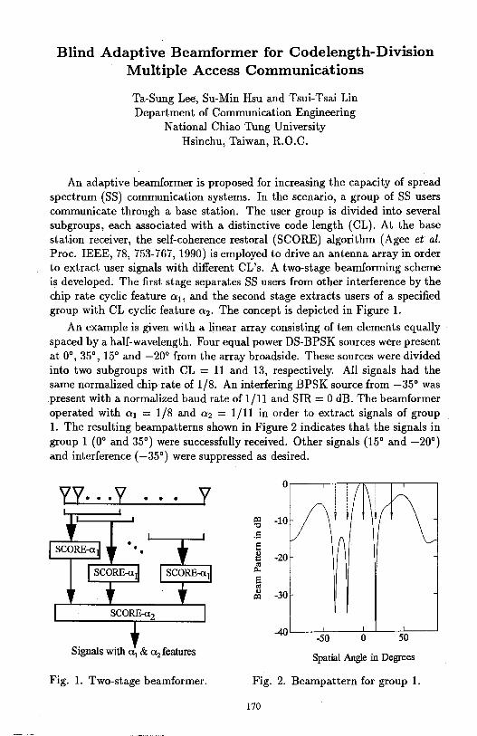
Blind Adaptive Beamformer for Codelength-Division Multiple Access Communications
Ta-Sung Lee, Su-Min Hsu and Tsui-Tsai Lin Department of Communication Engineering
National Chiao Tung University Hsinchu, Taiwan, R.O.C.
An adaptive beamformer is proposed for increasing the capacity of spread spectrum (SS) communication systems. In the scenario, a group of SS users communicate through a base station. The user group is divided into several subgroups, each associated with a distinctive code length (CL). At the base station receiver, the self-coherence restoral (SCORE) algorithm (Agee et al. Proc. IEEE, 78, 753-767, 1990) is employed to drive an antenna array in order to extract user signals with different CL's. A two-stage beamforming scheme is developed. The first stage separates SS users from other interference by the chip rate cyclic feature o:1 , and the second stage extracts users of a specified group with CL cyclic feature o:2 • The concept is depicted in Figure 1.
An example is given with a linear array consisting of ten elements equally spaced by a half-wavelength. Four equal power DS-BPSK sources were present at 0°, 35°, 15° and -20° from the array broadside. These sources were divided into two subgroups with CL = 11 and 13, respectively. All signals had the same normalized chip rate of 1/8. An interfering BPSK source from -35° was present with a normalized baud rate of 1/11 and SIR= 0 dB. The beamformer operated with o:1 = 1/8 and o:2 = 1/11 in order to extract signals of group 1. The resulting beampatterns shown in Figure 2 indicates that the signals in group 1 (0° and 35°) were successfully received. Other signals (15° and -20°) and interference (-35°) were suppressed as desired.
y
Signals with a 1 & Clz features
Fig. 1. Two-stage beamformer.
0
~ -10 "O
.s i:: ... !! -20 "' p..
s "' .,
-30 ~
-40 -50 0 50
Spatial Angle in Degrees
Fig. 2. Beampattern for group 1.
170
Complex-Direction Search of Radio Propagation in Microcells
I-Tai Lu, Robert C. Qiu* and Jaeyoung Kwak
Weber Research Institute/Department of Electrical Engineering, Polytechnic University, Route llO, Farmingdale, NY ll735
*He is currently with the GTE Laboratories Inc., 40 Sylvan Rd., Waltham, MA02254
ABSTRACT A linear receiving array can be employed to discern and to evaluate the arriving angles of multi-path arrivals in wireless channels. The conventional models usually assume that each of the incoming waves has planar wavefront and constant amplitude. This assumption may not be practical for radio propagation in microcells because the incoming waves may be beam-like fields, the incoming wavefronts may not be on plain surfaces, or there may be more than two waves coming from very close directions, etc. The received field magnitude is, therefore, a function of the locations of the receivers. In this paper, the location dependent factor is modeled as an extra "loss" factor in the complex spectral variable. A high-resolution algorithm combining the Singular Value Decomposition Method and the Eigen-Matrix Pencil Method is then employed to find the complex directions representing the incoming directions and the location dependent factors of multipath arrivals. Five key features (namely, noise immunity, robustness, resolution, accuracy, and physical insight) of the proposed algorithm are studied using numerical examples.
171
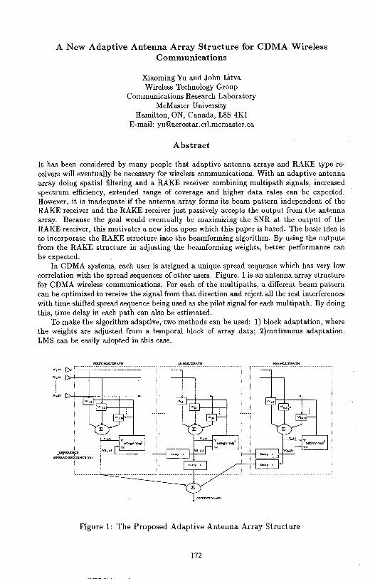
A New Adaptive Antenna Array Structure for CDMA Wireless Communications
Xiaoming Yu and John Litva Wireless Technology Group
Communications Research Laboratory McMaster University
Hamilton, ON, Canada, L8S 4Kl E-mail: yu@aerostar .crl.mcmaster .ca
Abstract
It has been considered by many people that adaptive antenna arrays and RAKE type receivers will eventually be necessary for wireless communications. With an adaptive antenna array doing spatial filtering and a RAKE receiver combining multipath signals, increased spectrum efficiency, extended range of coverage and higher data rates can be expected. However, it is inadequate if the antenna array forms its beam pattern independent of the RAKE receiver and the RAKE receiver just passively accepts the output from the antenna array. Because the goal would eventually be maximizing the SNR at the output of the RAKE receiver, this motivates a new idea upon which this paper is based. The basic idea is to incorporate the RAKE structure into the beamforming algorithm. By using the outputs from the RAKE structure in adjusting the beamforming weights, better performance can be expected.
In CDMA systems, each user is assigned a unique spread sequence which has very low correlation with the spread sequences of other users. Figure. 1 is an antenna array structure for CDMA wireless communications. For each of the multipaths, a different beam pattern can be optimized to receive the signal from that direction and reject all the rest interferences with time-shifted spread sequence being used as the pilot signal for each multipath. By doing this, time delay in each path can also be estimated.
To make the algorithm adaptive, two methods can be used: 1) block adaptation, where the weights are adjusted from a temporal block of array data; 2)continuous adaptation. LMS can be easily adopted in this case.
x 1 o>
(SPREADSll~Cl!Yd}
Figure 1: The Proposed Adaptive Antenna Array Structure
172
Maximum Likelihood Coordinate Registration for Over-the-Horizon Radar
Jeffrey L. Krolik and Richard H. Anderson Department of Electrical and Computer Engineering
Duke University, Durham, N.C. 27708 E-mail: [email protected]
Over-the-horizon radar performs wide-area surveillance by taking advantage of the refractive and multipath nature of high frequency propagation through the ionosphere. Typically, target detection is accomplished by tracking returns in slant range, slant azimuth, and radial velocity. The coordinate registration (CR) process, which converts target slant ranges and slant azimuths to ground coordinates, is then performed using a raytrace propagation model. The ionospheric parameters of the propagation model are determined using estimates obtained from vertical and backscatter sounders. Not surprisingly, errors in the estimates of down-range ionospheric parameters can seriously degrade the accuracy of the target location estimate. The coordinate registration method presented here is designed to achieve improved target localization accuracy by employing a statistical model for uncertainties in the ionospheric propagation conditions. Modeling down-range ionospheric parameters as random variables with known statistics facilitates maximum likelihood (ML) target location estimation which is much more robust to errors in the measured ionospheric conditions. In particular, the statistics of down-range ionospheric parameters such as the heights, critical frequencies, and thicknesses of the E, Fl, and F2 layers can be determined using both current and historical sounder data as well as global ionospheric models. Maximum likelihood coordinate registration is then used to determine the most likely target ground coordinates over the ensemble of ionospheric conditions consistent with the data. For greater computational efficiency, the likelihood function is approximated by a hidden Markov model (HMM) for the probability of a sequence of observed slant coordinates given a hypothesized target location. The parameters of the HMM are determined via Monte Carlo execution of the Jones-Stephenson raytracing program for random realizations of the ionosphere. A simulation study performed using a random ionospheric model derived from ionogram measurements made at Wallops Island suggests that the ML method can potentially achieve average absolute miss distances as much as five times better than the conventional coordinate registration technique.
173
On the Validation of a Multiple-Beam Adaptive Nulling Antenna Simulator
Chamroeun Kchao and Guan G. Cheng TRW Space and Electronics Group
One Space Park, 02/2338 Redondo Beach, CA 90278
Performance and design trade-offs of a multiple-beam nulling antenna system are typically analyzed via a software-based simulator. The integrity of such simulator, and consequently the performance results and trade-off decisions relies on the accurate modeling of the system hardwares. It is often, however, difficult to accurately model the various elements of a multiple-beam nulling antenna system. Such difficulties may ranges from the modeling of both amplitude and phase of each element of the multiple beam antenna to the modeling of the correlator used in a nulling antenna system employing an algorithm that requires correlation information of an interfering source. This paper addresses issues involved in the modeling and validation of a multiple-beam nulling antenna and presents data comparing measured results against predictions for all elements of a multiple-beam nulling antenna system as well as system characteristics including dynamic null-depth and percent coverage area.
174
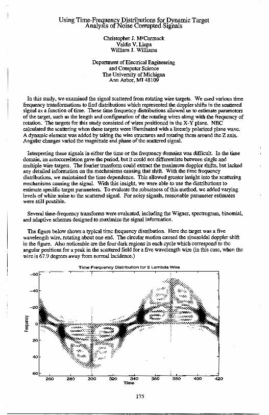
Using Time-Frequency _Distributions for Dynamic Target Analysis of Noise Corrupted Signals
Christopher J. MCCormack Valdis V. Liepa
William J. Williams
Department of Electrical Engineering and Computer Science
The University of Michigan Ann Arbor, Ml 48109
In this study, we examined the signal scattered from rotating wire targets. We used various time frequency transformations to find distributions which represented the doppler shifts in the scattered signal as a function of time. These time frequency distributions allowed us to estimate parameters of the target, such as the length and configuration of the rotating wires along with the frequency of rotation. The targets for this study consisted of wires positioned in the X-Y plane. NEC calculated the scattering when these targets were illuminated with a linearly polarized plane wave. A dynamic element was added by taking the wire structures and rotating them around the Z axis. Angular changes varied the magnitude and phase of the scattered signal.
Interpreting these signals in either the time or the frequency domains was difficult. In the time domain, an autocorrelation gave the period, but it could not differentiate between single and multiple wire targets. The fourier transform could extract the maximum doppler shifts, but lacked any detailed information on the mechanisms causing that shift. With the time frequency distributions, we maintained the time dependence. This allowed greater insight into the scattering mechanisms causing the signal. With this insight, we were able to use the distributions to estimate specific target parameters. To evaluate the robustness of this method, we added varying levels of white noise to the scattered signal. For noisy signals, reasonable parameter estimates were still possible.
Several time-frequency transforms were evaluated, including the Wigner, spectrogram, binomial, and adaptive schemes designed to maximize the signal information.
The figure below shows a typical time frequency distribution. Here the target was a five wavelength wire, rotating about one end. The circular motion caused the sinusoidal doppler shift in the figure. Also noticeable are the four dark regions in each cycle which correspond to the angular positions for a peak in the scattered field for a five wavelength wire (in this case, when the wire is 67.9 degrees away from normal incidence.)
Time Frequency Distribution for 5 Lambda Wire
-60
-40
-20
i',-55 :,
I 20
260 280 300 320 340 360 380 400 420 Time
175

THIS PAGE INTENTIONALLY LEFT BLANK.
176
Tuesday PM URSI-A Session 2 MD Suite Annapolis
Pulse Radar Techniques L. Carin Page
1 :20 Characteristics of UWB Radar Signals and Radiation that .......... 178 Differ from Conventional-Bandwidth Radar Merrill Skolnik, Naval Research Laboratory
1:40 Time-Domain Ultra-Wideband Radar System for ...................... 179 Nondestructive Evaluation Fu-Chiamg Chen, Weng Cho Chew, University of Illinois
2:00 Short-Pulse Scattering from Surface Anti-Personnel and ........... 180 Buried Anti-Tank Mines Stanislav Vitebskiy, Lawrence Carin, Duke University
2:20 Modeling and Processing of Short-Pulse Scattering from .......... 181 Buried Targets Under a Rough Air-Ground Interface Traian V. Dogaru, Lawrence Carin, Duke University
2:40 Target Detection in a Clutter Environment from a Stepped- ....... 182 Ultra-Wideband Signal Using E-Pulse Extraction Techniques G. Wallinga, E. J. Rothwell, D. P. Nyquist, K. M. Chen, A. Norman, Michigan State University
3:20 Monostatic and Bistatic Impulse Radar Signatures of ................ 183 Conducting Cylindrical Cavities M. Piette, Royal Military Academy Brussels, M. Perrot, Ecole Militaire de Saint-Cyr
3:40 Aspects of Introduction of Pulse Compression in .................... 184 Conventional Pulse Radar Aleksa J. Zejak, Zoran T. Golubicic, Institute IMTEL
177
Characteristics of UWB Radar Signals and Radiation that Differ from Conventional-Bandwidth Radar
Merrill Skolnik Radar Division, Naval Research Laboratory
Washington, D. C.
The large relative bandwidths - of the order of 100% - that are characteristic of ultrawideband (UWB) radar result in considerably different properties than are common with conventional bandwidth radar. The purpose of this paper is to review these differences. For example, the widely used approximation applied in most signal analyses, which states that the bandwidth is small compared to the center frequency, is not applicable to UWB signals. Topics to be discussed also include the limitations of the traditional matched filter for detection of UWB signals in noise (since the received waveform is not completely known); the inability to use the conventional superheterodyne receiver (because it is based on narrow-band signals); limitations in using the envelope of the signal rather than the RF; and the inability to use the (narrow band) concept of phase as well as the classical concept of the doppler frequency shift in UWB radar. Rather than the doppler frequency shift, the detection of moving targets in clutter is based on change detection or on the ability of high-resolution UWB signals to see targets in the clear between resolved patches of clutter. The apparent inability to synthesize in practice a desired waveform from a collection of oscillators (as an approximation to the inverse Fourier transform) without loss will be discussed along with the apparent inability to use a single antenna in UWB radar for both transmission and reception without degradation of radar performance. The nature of UWB sea echo will be briefly mentioned along with the special characteristics of UWB radiation from low-gain antennas and arrays; the measurement of the angle of arrival based on the shape of the received UWB waveform; and the apparent inability to faithfully radiate, without distortion, signals from UWB antennas unless there is loss present in the antenna.
178

Time-Domain Ultra-Wideband Radar System For Nondestructive Evaluation
FU-CHIARNG CHEN* AND WENG CHO CHEW
ELECTROMAGNETICS LABORATORY
CENTER FOR COMPUTATIONAL ELECTROMAGNETICS
DEPARTMENT OF ELECTRICAL AND COMPUTER ENGINEERING
UNIVERSITY OF ILLINOIS
URBANA, IL 61801
Abstract
A new time-domain ultra-wideband radar scattering measurement system for nondestructive evaluation (NDE) purpose has been developed at the University of Illinois recently. This pulse radar scattering measurement system consists of a Picosecond Pulse Lab (PSPL) 4050B step generator, a PSPL 4050RPH remote pulse head, two PSPL 5210 impulse forming networks, a Hewlett-Packard (HP) 54120B digitizing oscilloscope mainframe, an HP 54121A 20 GHz four-channel test set, a broadband Vivaldi antenna array, two ultra-wideband amplifiers and two microwave switches. The system is automated and controlled by a computer via the IEEE-488 bus. The pulse source is a monocycle pulse provided by the PSPL 4050B step generator with a PSPL 4050RPH remote pulse head and two PSPL 5210 impulse forming networks. The PSPL 4050B step generator with the PSPL 4050RPH remote pulse head provides a 10 V, 45 ps pulse. A 2.5 V, 50 ps impulse and a 1.5 V monocycle pulse are obtained by attaching 1 or 2 PSPL 5210 impluse froming networks to the 4050RPH pulse head output. The monocycle pulse is chosen for the operational bandwidth of the Vivaldi antenna array. The broadband Vivaldi antenna array consists of 5 antennas for the transmitting port and 6 antennas for the receiving port. The Vivaldi antenna array is switched by the two microwave switches. Two ultra-wideband amplifiers are attached to the transmitting port and the receiving port of the Vivaldi antenna array in order to increase the dynamic range of the measurement system.
In this paper, the experimental evaluation of this pulse radar scattering measurement system will be shown by collecting useful measurement data of different test targets including metallic and dielectric objects. In addition, the data acquisition process and signal calibration of the measurement system will be shown. The time-domain ultra-wideband radar scattering measurement system offers a less expensive alternative to the other coherent steppedfrequency radar scattering measurement system developed at the University of Illinois.
179
Short-Pulse Scattering from Surface Anti-Personnel and Buried Anti-Tank Mines
Stanislav Vitebskiy and Lawrence Carin Department of Electrical and Computer Engineering
Duke University Durham, NC 27708-0291
The method of moments is used to analyze short-pulse plane-wave scattering from perfectly conducting bodies of revolution on the surface of and buried within a lossy, dispersive half space. The analysis is performed in the frequency domain, with the time-domain fields synthesized via Fourier transform. To make this analysis efficient, the method of complex images is used to compute the frequency-dependent components of the half-space dyadic Green's function. Results are presented for short-pulse scattering from perfectly conducting model anti-personnel and anti-tank mines, after calibration with various canonical targets (spheres and cylinders). The electrical parameters of the model-soil halfspace are measured from several soil types.
Ground penetrating radar (GPR) has been a topic of intense research for several decades. As part of these studies, significant attention has been directed toward understanding electromagnetic propagation in the earth, as well as on the study of scattering from buried targets. The insight gained from such phenomenological studies can be applied to the development of new signal processing and imaging schemes, as well as to the design of new GPR systems.
Most previous investigations of GPR phenomenology have examined narrowband operating conditions. Recently, however, there has been .an interest in ultra-wideband short-pulse radar for ground penetrating applications. Such systems generate short pulse waveforms with large instantaneous bandwidth, giving rise to time-domain phenomenology which is fundamentally different than that of narrowband systems. As a first step toward understanding the wave physics associated with short-pulse scattering from buried targets, we consider here shortpulse plane-wave scattering from surface and buried perfectly conducting mines (modeled as a body of revolution, or BOR). To make such a study tractable, the soil is modeled as a lossy, dispersive halfspace, and the axis of revolution of the buried target is assumed normal to the air-ground interface; this assumption restricts the target orientation but allows one to view the target-halfspace composite as a single BOR. Anti-personnel mines are often found on the airground surface, while anti-tank mines are usually buried. Thus, in this study the mines will be so modeled.
180
Modeling and Processing of Short-Pulse Scattering from Burled Targets under a Rough Air-Ground Interface
Traian V. Dogaru and Lawrence Carin Department of Electrical and Computer Engineering
Duke {Jniversity Durham, NC 27708-0291
The detection of underground targets has been receiving increased attention recently, caused in large part by the global proliferation of buried ordnance. Ground penetrating radar (GPR) has been investigated for several decades as a tool for the identification of such buried targets. Early research focused on the analysis of wave propagation in lossy, dispersive soil, and more recently researchers have been investigating the scattered fields from buried targets. In most of these previous studies, the scattering environment was necessarily idealized: homogeneous soil, simple targets, smooth air-ground interface. With the recent advent of such numerical tools as the Finite Difference Time Domain (FDTD) method, more complicated and realistic GPR scenarios can be investigated. A particular problem faced in GPR involves the detection of buried targets under soil characterized by a rough air-ground interface. This constitutes an interesting problem because it represents the merging of two issues which are usually considered separately: a) scattering from a rough surface, which is usually parametrized statistically, and b) scattering from localized targets, which is generally treated deterministically. The investigation of this problem is the subject of this talk.
A two-dimensional FDTD algorithm is used to model short-pulse scattering from underground targets. The fields are calculated in the far-zone, using a nearto-far-zone transformation that accurately accounts for the effects of the soil. Particular interest is placed on scenarios for which the air-ground interface is rough, the scattered fields from which introduce significant background clutter.
In addition to investigating the phenomenological aspects of such a scattering scenario, processing options are explored for detecting the buried targets. Particular attention is placed on array-signal processing algorithms which seek to identify the direction of arrival of fields scattered from targets, in the presence of additive noise. We utilize a statistical parametrization for the fields scattered off the rough air-ground surface, while the angle of arrival of the fields from the buried target is parametrized as unknown but deterministic. Such a model of the scattered fields is well suited to such array-processing algorithms as MUSIC and ESPRIT. A parametric study is presented which demonstrates the efficacy of such an approach, as a function of soil, target, and interface-roughness characteristics.
181
TARGET DETECTION IN A CLUTTER ENVIRONMENT FROM A STEPPED, ULTRA-WIDEBAND SIGNAL
USING E-PULSE EXTRACTION TECHNIQUES
G. Wallinga, E.J. Rothwell, D.P. Nyquist, K.M. Chen and A. Norman Department of Electrical Engineering
Michigan State University East Lansing, MI 48824
The time-domain sea clutter signal measured by a short-pulse radar consists of a dominant periodic set of specular signals from the periodic sea swell, superposed with a wide spatial-frequency band surface roughness signal due to the fine structure on the ocean waves (chop). The functions of a short-pulse radar can be emulated using an ultra-wideband frequency stepping scheme. This system is less susceptible to noise and allows selection of frequency bands which are more convenient.
This paper will present a study of target detection in a sea clutter environment produced by realistic surfaces from a stepped, ultra-wideband signal using E-pulse extraction techniques. A moment method analysis on a small scale, perfectly conducting, finite length, two-dimensional surface will be used to simulate the short-pulse radar clutter signal. The resulting signal will be divided into bandlimited segments and E-pulse techniques will be applied to annihilate the surface response. The sea-wave profile will be described by sinusoidal type surfaces and the model proposed by Donelan and Pierson (J. Geophysical Res., vol. 92(C5) pp 4971-5029, 1987).
The scattered field from a finite length, perfectly conducting, twodimensional surface produced using the Donelan-Pierson model will be measured. Bandlimited sections of the resulting signal will be used to determine if the Epulse cancellation techniques can be used to detect a target in the cluttered environment. Results will be compared to the earlier treatment which was based on moment method analysis. Finally, a physical optics model will be used to generate scattered field data for sea surfaces of realistic dimensions. The E-pulse extraction techniques will be applied to sections of the resulting signal to simulate the stepped ultra-wideband signal.
182
Monostatic and Bistatic Impulse Radar Signatures of Conducting Cylindrical Cavities
M. PIETTE* Royal Military Academy Brussels 30, avenue de la Renaissance B-1040 Brussels, Belgium
M. PERROT Ecole Militaire de Saint-Cyr Coetquidan F- 56381 Guer Cedex, France
The Royal Military Academy Brussels has developed an Impu!se Radar Scattering Range for measuring directly in the time-domain the monostatic and bistatic impulse response of complex targets. After calibration with conducting and dielectric canonical targets (M. Piette, E. Schweicher, A. Vander Vorst, IEEE AP-S/URSI Conference 1995, URSI-A p. 268), the TD-Scattering Range is now used to measure the impulse response and analyse the transient scattering mechanisms on bodies which are not strictly canonical but are relevant as main contributors to the RCS of a complex target. This is the case of reentrant cavities like the jet inlets and the cockpit.
This paper presents recent results of TD-scattering measurements carried out on cylindrical cavities which can be seen as a simple model for the jet inlet. Both monostatic and bistatic impulse responses of a conducting cylinder open at one end and shorted at the other end are measured with a gaussian plane wave excitation pulse having a duration from 90 to 300 ps. The length of the cylinders ranges from 2 to 8 times the pulse length and the diameter of the cavity ranges from 0,5 to 2 times the pulse length. The analysis of the waveform obtained in the monostatic case for endon incidence shows clearly (because they are time separated) the relative contributions of the different scattering mechanisms to the total RCS : diffraction on the cavity aperture, backscattering of the creeping wave travelling along the outer surface of the cylinder and backscattering due to the reflection on the bottom of the cylinder of the energy coupled into the cavity. The measurements carried out with other angles of incidence (monostatic) and also in the bistatic configuration show the dynamic range of the amplitude of each of these contributions. Because the cavity is a quite difficult body with regard to the exact calculation of the scattered field, the measurements reported here and that will be detailed in the oral presentation can help to have a better understanding of the physical mechanisms contributing to the RCS of a cavity. At last, a special shaping technique experienced for reducing the amplitude of the backscattered creeping wave will be described.
183
Aspects of Introduction of Pulse Compression in Conventional Pulse Radar
Aleksa J. Zejak Zoran T. Golubicic
Institute IMfEL, 11070 N. Belgrade, Lenjinov Bui. 165B, Yugoslavia E-mail: [email protected]
In this paper problems arising in modernization of the conventional radar related to introduction of pulse compression are analyzed. Procedure of introduction of pulse compression in conventional pulse radar is realised in two separate phases. The first is related to introduction of complex modulation in RF output signal, while the other is related to adjusting of the spread spectrum signal detection process. Modulation of RF carrier may be performed at low power RF level or at high power RF level.
First method was applied at radars designed with broad band linear beam amplifier tubes (TWT or CFA) while the second is suitable for those generating RF signals by high power pulse oscillators (magnetron). Spectrum of output signals was spreading by means of phase and frequency modulation of simple RF carrier during the conventional pulse. For example, moderate power (about 15 kW in 'pulse) radar with TWT tube in C band (5 .25- 5 .85 GHz) is used. RF carriers were obtained by direct synthesis from synchronous frequency generator with equidistant frequency step of JO MHz. Switching time between any two frequencies was less than JO ns. Behind frequency generator double balance mixer for BPSK modulation is used.
Microwave part of the radar receiver is broadband enough so that spreading of the receiving filters is performed only at intermediate frequency. High speed AID conversion (80 Msample/sec) is applied for I and Q components. Processing of received signal is based on standard DSP-boards. Digital processing unit has a possibility of the output anvelope storage and standard COHO oscillators used in quazi coherent radar is not needed.
184
Tuesday PM URSI-B Session 8 MD Suite Frederick
Finite Methods Y. Rahmat-Samii Page
1 :20 Real Time Simulation of the Interaction of Electromagnetic ...... 186 Waves with a Human Head Atef Z. Elsherbeni, Clayborne D. Taylor, University of Mississippi, Yahya Rahmat-Samii; University of California Los Angeles
1 :40 An Improved Finite Difference Helmholtz Equation ................. 187 J. Jevtic, R. Lee, The Ohio State University
2:00 Comparison of FDTD Thin-Slot Algorithms for Modeling ....... 188 Slots on Corners in Shielding Enclosures Kuang-Ping Ma, H. Shi, M. Li, D. Hockanson, J. L. Drewniak, University of Missouri-Rolla
2:20 Near and Far Field Calculations in FDTD Simulations ............. 189 Using Kirchoffs Surface Integral Representation Omar M. Ramahi, Digital Equipment Corporation
2:40 Numerical Modeling of Multi-Chip Modules .......................... 190 M. Piket-May, J. Dunn, ~. T. Thiele, P. Vichot, Z. Schoeborn, University of Colorado
3:20 New Results Obtained by TLM and FD-TD Methods ............... 191 A. E. Ros, N. Calve, S. El Khoury, Laboratoire d'Electronique et Sytemes de Telecommunications
3:40 A Monotone Admittance Method for Fast Implicit ................. 192 Nonlinear Integration within the FDTD Environment M. Celuch-Marcysiak, W. K. Gwrek, Warsaw University of Technology
185
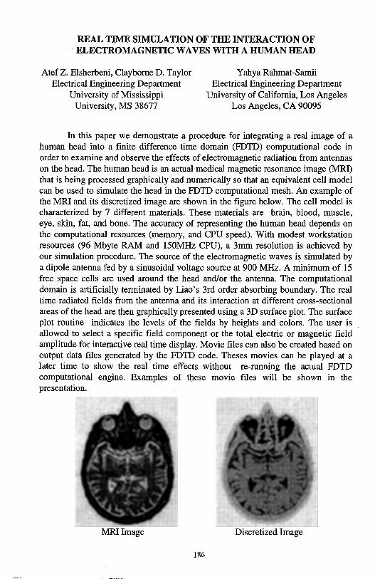
REAL TIME SIMULATION OF THE INTERACTION OF ELECTROMAGNETIC WAVES WITH A HUMAN HEAD
Atef Z. Elsherbeni, Clayborne D. Taylor Electrical Engineering Department
University of Mississippi University, MS 38677
Y ahya Rahmat-Samii Electrical Engineering Department
University of California, Los Angeles Los Angeles, CA 90095
In this paper we demonstrate a procedure for integrating a real image of a human head into a finite difference time domain (FDTD) computational code in order to examine and observe the effects of electromagnetic radiation from antennas on the head. The human head is an actual medical magnetic resonance image (MRI) that is being processed graphically and numerically so that an equivalent cell model can be used to simulate the head in the FDTD computational mesh. An example of the MRI and its discretized image are shown in the figure below. The cell model is characterized by 7 different materials. These materials are brain, blood, muscle, eye, skin, fat, and bone. The accuracy of representing the human head depends on the computational resources (memory, and CPU speed). With modest workstation resources (96 Mbyte RAM and 150MHz CPU), a 3mm resolution is achieved by our simulation procedure. The source of the electromagnetic waves is simulated by a dipole antenna fed by a sinusoidal voltage source at 900 MHz. A minimum of 15 free space cells are used around the head and/or the antenna. The computational domain is artificially terminated by Liao's 3rd order absorbing boundary. The real time radiated fields from the antenna and its interaction at different cross-sectional areas of the head are then graphically presented using a 3D surface plot. The surface plot routine indicates the levels of the fields by heights and colors. The user is allowed to select a specific field component or the total electric or magnetic field amplitude for interactive real time display. Movie files can also be created based on output data files generated by the FDTD code. Theses movies can be played at a later time to show the real time effects without re-running the actual FDTD computational engine. Examples of these movie files will be shown in the presentation.
MRI Image Discretized Image
186
An Improved Finite Difference Helmholtz Equation
J. Jevtic and R. Lee
ElectroScience Laboratory Department of Electrical Engineering
The Ohio State University 1320 Kinnear Rd.
Columbus, Ohio 43212-1191
The numerical analysis of fields invariably involves finite difference approximations of the first and higher order derivatives of the field. The ultimate accuracy of the numerical scheme is thus highly dependent on the accuracy of the individual finite difference approximation. This is especially true in the case of wave-like fields where the phenomena of numerical dispersion leads to cumulative effect; the error in the overall solution is now proportional not only to the errors introduced at individual discretization nodes, but is also proportional to the size of the computational domain, a feature especially undesirable for the analysis of large problems.
For two dimensional frequency-domain problems a five-point stencil finite difference equation is usually used to approximate the Helmholtz equation. It is rarely appreciated that this is not the only second order accurate formula that can be formed with the given set of five nodes. This should not be surprising since it is well known that the slight tuning of the numerical wavenumber for one-dimensional problems leads to an error free formulation. An equivalent approach is almost never used in practical, higher-dimensional problems, although it should significantly improve the accuracy, and costs nothing in terms of memory and computation time. One of the major reasons for this apparent paradox lies in the fact that the finite difference equation is anisotropic in higher dimensions which makes the selection of the correct wave-number ambiguous.
Our analysis of the residual of the five-point stencil equation shows that it consists of both isotropic and anisotropic terms. In fact, the isotropic term dominates and can be completely removed by changing the central coefficient from 4 - k2 h2 to 4J0 (kh). The remaining anisotropic residual is not only several times smaller in magnitude, but also has different signs in different directions. This leads to a breakup of the cumulative effect of the numerical dispersion, as demonstrated by numerical results which improve much more than one might expect based on a mere comparison of the magnitude of the residuals. Furthermore, we have been able to extend the same approach of removing the isotropic part of the residual to other types of finite difference equations, such as those occurring at material interfaces. The extension to 3-dimensional problems is straightforward. The extension to time-domain and finite element formulations is not trivial, but might benefit from the results of the present analysis.
187
Comparison of FDTD Thin-Slot Algorithms for Modeling Slots on Corners in Shielding Enclosures
Kuang-Ping Ma, H. Shi, M. Li, D. Hockanson, and J. L. Drewniak Electromagnetic Compatibility Laboratory
Department of Electrical Engineering University of Missouri-Rolla
Rolla, MO 65401
The integrity of shielding enclosures for RF, microwave and digital designs is compromised by apertures and seams resulting from heatvents, cable penetration, and modular construction, among other. possibilities. These perforations allow energy to be radiated to the external environment from interior electronic devices, or energy to be coupled from the exterior to interfere with interior components. An understanding of energy coupling mechanisms to and from the enclosure is essential to minimize potential radiation and susceptibility problems. Numerical methods including the finite-difference time-domain method have been applied to enclosure modeling for better understanding of these problems. In many cases, the aperture is typically modeled with widths on the order of the mesh dimension. In order to model a thin slot, or seam, the mesh dimension must be made small in the vicinity of the slot, consuming significant computational resources.
Subcellular FDTD methods for modeling thin slots have previously been introduced by Riley and Turner [D.J. Riley and C. D. Turner, IEEE Trans. Antennas Prop., vol. 38, pp. 1943-1950], and Gilbert and Holland [J. Gilbert and R. Holland, IEEE Trans. Nuclear Sci., vol. 28, ppL 4269-4274]. The Gilbert/Holland capacitive thin-slot formalism (C-TSF) is based on an equivalent slot capacitance, and has the advantage that it is easily implemented and adds virtually no computational overhead to the basic FDTD algorithm. The slot capacitance is incorporated into the FDTD algorithm through Er, The Riley/Turner hybrid thin-slot algorithm (HTSA) is a hybrid FDTD/integral equation approach that is based on equivalent magnetic currents for the slot. These two methods are compared with each other and experimental results available in the literature. Good agreement has been shown for scattering from a slot in a plane and coupling to a loaded enclosure when the slot is located away from a corner.
Slots and seams located on or near corners are of considerable interest as well. Slots on the corner of a bent plate are modeled for two dimensional gometries with both the C-TSF and the method of moments. Good agreement is obtained between the FDTD results employing C-TSF for the slot and the MOM results. Threedimensional enclosures with a slot on the corner and loaded with a resistively terminated wire connecting opposite walls have also been modeled with both the C-TSF and HTSA approaches and show excellent agreement. Coupling to the loaded enclosure illuminated by a plane wave. is being studied for various locations of the slots and interior loading. Experimental results for a loaded cavity are currently being pursued and will be presented.
188
Near and Far Field Calculations in FDTD Simulations Using Kirchhoff's Surface Integral Representation
Omar M. Ramahi Digital Equipment Corporation
PK03-l/Rll 129 Parker St.
Maynard, MA 01754, U. S. A. [email protected]
When using the Finite Difference Time Domain (FDTD) technique to solve electromagnetic radiation problems, the physical location where the field of interest to be observed can lie within the scattering/radiating structure, in the far zone region, or in the near-zone region exterior to the structure. In the first case, the field of interest is the direct product of FDTD simulation. In the second case, near-zone to farzone field transformation can be employed. For the third case, which is the focus of this work, the field can be obtained either directly from the FDTD simulation, which requires inclusion of the observation points of interest within the computational domain, or through field extension methods. Allowing a large enough computational domain to include the points of interest can be computationally very expensive, if not impossible. If the FDTD is intended to simulate the response of the system over a considerably large band of frequencies, the same observation point which is in the near-field over part of the spectrum can be in the far-field for the lower frequencies. Since the discretization density should be compatible with the highest significantenergy frequency, the computational domain can grow without bounds. Field extension techniques, on the other hand, allow for maintaining a relatively small computational domain, however, the associated overhead can be significant.
Field extension techniques are based on the integration of the Huygens's (equivalent) current sources over a surface that fully encloses the scatterer. In this, work, we develop a field extension scheme by bypassing the use of Huygens's currents and work directly with Kirchhoff's Surface Integral Representation (KSIR). The KSIR offers several advantages: First, it does not involve time integration terms, and thus can be very efficient to implement. Second, each of the six field components can be calculated independently, thus allowing the integration to be performed over an imaginary closed surface that can be chosen conveniently for each component. This advantage eliminates the extra computation and also eliminates the source of error that arise from interpolating the field when evaluating the traditional J and Mon a single surface as would be the case when using Huygens's equivalent current sources. Additionally, we show that that the KSIR formulation is automatically well-suited for parallelizable computation, and more significantly, it can reduce the effect of Absorbing Boundary Conditions, especially the errors that arise due to the reflection of evanescent waves.
189
Numerical Modeling of Multi-Chip Modules
M. Piket-May, J. Dunn, E.T. Thiele, P. Vichot* and Z. Schoenborn
Department of Electrical and Computer Engineering Campus Box 425
University of Colorado Boulder,CO 80309
fu this study, we are considering various design aspects of an MCM which will serve as a 1024 x 1024 switching network to facilitate rapid communication between parallel processors and shared memory chips. Key desired features of this design include low power requirements, low latency, and a high data rate (2.5 Gbits/sec/channel) built into a modular design featuring asynchronous timing and conflict resolution. To achieve these objectives, a novel MCM design has been created which incorporates both conventional technologies and superconducting technologies.
Our research has specifically focused on the design of a clock distribution network whose signal serves as the logic-latching mechanism at the input to the shared memory chips. This clock network is located in a nonsuperconducting layer of the MCM, with its outputs distributed to circuitry in the superconducting strata of the MCM.
Since the clock is being used for high speed digital applications, it is critical to maintain a certain degree of signal integrity at the outputs of this clock network. The clock signal must be fed along a single 32 ohm line to some network which will distribute this signal to eight 6 ohm lines. Therefore, the clock must provide a transition from this single, high impedance input to multiple, low impedance outputs, with the realization that the lower impedance requires wider lines. Due to the limited amount of "real estate" within the MCM for each clock and its distribution network, this requires that the impedance transition from the input to the wide, low impedance outputs be done as compactly as possible.
A circuit simulator is being used for the initial designs. Field simulations are then conducted using a combination of frequency and time-domain techniques. The frequency-domain analysis is implemented through the use of a packaged moment method code, while the time-domain analysis employs the FD-TD method.
This talk will highlight the evolution of different designs for the clock distribution network which attempt to meet the specifications given above. Field simulation results for these different designs will be shown to give reasonable agreement between FD-TD and moment method techniques.
190
New Results Obtained by TLM and FD-TD Methods
by A.E.ROS, N.Calve and S.El Khoury Laboratoire d'Electronique et Sytemes de
Telecommunications 6,Av.Le Gorgeu - BP 809 - Brest Cedex - France Phone :+33-98 01 61 26 - Fax: +33- 98 01 63 95
E-mail-: Alain.Rosalest-gw.univ-brest.fr
Abstract: Since about twenty years, numerical techniques
such as TLM or FD-TD methods have been extensively used for the modelization of microwave components .
Nevertheless, the memory size of the computers give a limitation to their use and it becomes necessary to introduce absorbing boundaries in order to simulate open space . On the other hand, very few results have been published in the case of anisotropic media.
On account of the very fast increasing of power of microcomputers in terms of CPU time and memory size, numerical methods using a discretization of space in order to simulate the propagation of the electromagnetic field regained interest during the 80's . Two of them, the Transmission Line Matrix method and the Finite Difference-Time Domain method are among the most used for the microwave components characterization
Many results have already been published for resonant cavities, microstrip lines, fin lines, discontinuities.in homogeneous or inhomogeneous media. Many authors debated on the ability of each of these methods to give accurate results compared to theoretical ones and the notion of "dispersion" is one of the criteria to define the "best method" .
Nevertheless, difficulties introduced by open media are not conveniently solved at this time In order to simulate radiation instead of propagation of the EM field, it is necessary to introduce absorbing boundaries .
In this paper, we intend to compare the solutions proposed by authors in terms of efficiency, dispersion, spurious modes, ... These solutions will be introduced in TLM and FD-TD metp.ods, and in each case, in the expanded nodes and 'condensed nodes formulations . We shall give our own solution, based on the optical point of view of the EM field and we shall compare this method of absorbing boundaries simulation to the previous ones .
Moreover, for finite cavities filled with anisotropic substrate, we intend two compare the efficiency of TL~ and FD-TD methods in their two versions (Expanded or Condensed Nodes) . The results will be given for ~agnetic or dielectric substrate.
191
A MONOTONE ADMITTANCE METHOD FOR FAST IMPLICIT NONLINEAR INTEGRATION WITHIN THE FDTD ENVIRONMENT
M.Celuch-Marcysiak, W.K.Gwarek Institute ofRadioelectronics, Warsaw University of Technology,
Nowowiejska 15/19, 00-665 Warsaw, Poland.
In recent years several papers have been devoted to the problem of incorporating nonlinear components into 3D structures modelled by the FDTD method. Such an approach permits a unified time-domain electromagnetic simulation of many practical circuits including microwave mixers and amplifiers or digital inverters. It provides a valuable physical insight into the circuits' behaviour in both steady state and transient regimes. Unfortunately, the reported algorithms suffer from instability problems due to explicit or semi-implicit treatment of the nonlinearity, at each iteration represented either by terminal voltage/current (Sui et al., IEEE Trans.MTT 40, 724-730, 1992) or by differential parameters (M.Piket-May, IEEE Trans.MTT 42, 1514-1523, 1994) obtained at a previous time-step. In an earlier paper (MIOP Conj, Stuttgart, Germany 1992) we have postulated implicit solution of a system of nonlinear equations at each time-step. This ensures unconditional stability of the numerical process, however, it extensively prolongs the CPU time per iteration if standard implicit integration schemes requiring local time-step subdivision are used.
In this contribution, we discuss a novel method for implicit nonlinear integration which restores the numerical efficiency. We refer to it as a monotone admittance method (MA) since it is applicable to nonlinear devices described by characteristics monotone in a finite number of intervals, specified prior to the simulation. The key point resides in applying different integration procedures depending on increase/decrease of voltage, current and differential parameters of the nonlinear device. Correspondingly, either a voltage-controlled or a currentcontrolled nonlinear characteristic is instantenously used. At each time-step, the algorithm produces successive estimates which always approach the solution monotonically, creeping along the characteristics. No hazard of erroneous overflows exists, and no convergence problems have been encountered.
In the presentation, we shall focus on the following issues: • convergence properties of the monotone admittance method extended to
multiport devices including nonlinear reactivities, • comparison with standard implicit integration schemes based on time-step
subdivision (Chua&Lin, 'Computer-aided analysis for electronic circuits', Prentice-Hall,, Inc., 197 5),
• examples of application to nonlinear MMICs. These will show that the FDTD-MA method opens new horizons for efficient simulation of strongly nonlinear circuits, driven by high-voltage short-rise-time pulses, and at coarse discretization.
192
Tuesday PM URSI-B Session 9 MD Suite Columbia
Integral Equation Applications S. R. Rengarajan Page
1:20 Analysis of a Thin-Wire Antenna Exciting a Conducting ......... 194 Tube Containing a Finite-Length Narrow Slot Yi-Qun Jiang, Anthony Q. Martin, Clemson University
1:40 Fields and Currents Excited by a Dipole Directed Normal .......... 195 to the Surface of a Conducting Screen Containing A Finite-Length Narrow Slot A. Kustepeli, A. Q. Martin, C. M. Butler, Clemson University
2:00 Method of Moments Solution for the Electric and Magnetic ...... 196 Shielding Factors of a Conducting Shield at ELF I. Tekin, E. H. Newman, Ohio State University
2:20 Method of Moments Solution for a Wire Attached to an ........... 197 Arbitrary Faceted Surface /. Tekin, E. H. Newman, Ohio State University
2:~0 On the Application of Numerical Methods to Hallen's ............. 198 Equation George Fikioris, Rome La.boratory, Tai Tsun Wu, Harvard University
3:20 Analysis of Mutual Coupling Between Sidewall Slots in .......... 199 Spectral Domain Sembiam R. Rengarajan, California State University
3:40 Numerical Investigation of the Capacitance of Dielectric- .......... 200 Coated Rectangular Conducting Plates Tsung-Lung Lin, Dipak L. Sengupta, Chun-Ju Lin, University of Detroit Mercy
4:00 MoM Analysis of EM Scattering Due to a Thin Conducting ..... 201 Square Plate Bharoti Sinha, G. Dhanesh, University of Roorkee
193
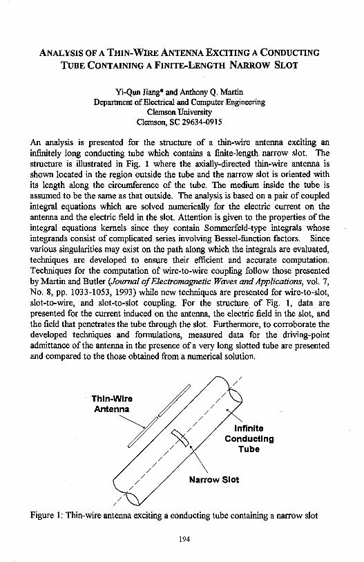
ANALYSIS OF A TmN-WIRE ANTENNA EXCITING A CONDUCTING
TUBE CONTAINING A FINITE-LENGTH NARROW SLOT
Yi-Qun Jiang* and Anthony Q. Martin Department of Electrical and Computer Engineering
Clemson University Clemson, SC 29634-0915
An analysis is presented for the structure of a thin-wire antenna exciting an infinitely long conducting tube which contains a finite-length narrow slot. The structure is illustrated in Fig. 1 where the axially-directed thin-wire antenna is shown located in the region outside the tube and the narrow slot is oriented with its length along the circumference of the tube. The medium inside the tube is assumed to be the same as that outside. The analysis is based on a pair of coupled integral equations which are solved numerically for the electric current on the antenna and the electric field in the slot. Attention is given to the properties of the integral equations kernels since they contain Sommerfeld-type integrals whose integrands consist of complicated series involving Bessel-function factors. Since various singularities may exist on the path along which the integrals are evaluated, techniques are developed to ensure their efficient and accurate computation. Techniques for the computation of wire-to-wire coupling follow those presented by Martin and Butler (Journal of Electromagnetic Waves and Applications, vol. 7, No. 8, pp. 1033-1053, 1993) while new techniques are presented for wire-to-slot, slot-to-wire, and slot-to-slot coupling. For the structure of Fig. 1, data are presented for the current induced on the antenna, the electric field in the slot, and the field that penetrates the tube through the slot. Furthermore, to corroborate the developed techniques and formulations, measured data for the driving-point admittance of the antenna in the presence of a very long slotted tube are presented and compared to the those obtained from a numerical solution.
Infinite Conducting
Tube
Narrow Slot
Figure 1: Thin-wire antenna exciting a conducting tube containing a narrow slot
194
FIELDS AND CURRENTS EXCITED BY A DIPOLE DIRECTED NORMAL
TO THE SURFACE OF A CONDUCTING SCREEN CONTAINING A FINITE
LENGTH NARROW SLOT
A. Kustepeli*, A. Q. Martin, and C. M. Butler Department of Electrical and Computer Engineering
Clemson University Clemson, SC 29634-0915
It is known that a properly modulated laser beam illuminating a conducting surface causes electrons to be emitted in such a way that the resulting electromagnetic radiation is equivalent to that from a distribution of electric dipoles oriented normal to the surface and located on or near the surface. The distribution of these dipoles over the illuminated spot is dictated by the laser-light intensity distribution and their spatial oscillation is controlled by the laser modulation. If an appropriate modulation is used then oscillation will occur at a selected angular frequency @ • The distribution of dipoles, at an angular frequency @ , on the conducting surface over a region which is illuminated by a laser beam can be treated as an electromagnetic source in an analysis where one attempts to predict the fields and currents induced on and in the medium around the conducting surface.
As a preliminary attempt to understand the characteristics of fields and currents induced in the medium around and on conducting objects due to a modulated laser beam striking its surface, considered in this paper is the excitation of a conducting object by a single dipole oriented normal to the surface. The structures used in this study are a finite-length narrow slot in a conducting screen and a thin-wire probe located behind the slotted screen on the side opposite that on which the dipole is located. The properties of a slotted screen and probe behind the screen are well understood for plane wave excitation and, hence, serve as a good basis of comparison with those of the dipole excitation. It is expected that results from this work can be readily extended to the case of a distribution of electric dipoles oriented normal to a conducting surface.
To solve for the fields and currents due to a dipole excitation of a conducting structure, integral equations are formulate and solved numerically. The integral equations appropriate for the slotted screen and thin-wire probe behind the slotted screen are presented as are the techniques employed for their solution. A variety of data are presented and discussed which elucidate the properties. of the fields and currents excited due to a normally directed dipole on the surface of the screen.
195
Method of Moments Solution for the Electric and Magnetic Shielding Factors of a Conducting Shield at ELF
I. Tekin and E.H. Newman Ohio State University
Department of Electrical Engineering ElectroScience Lab 1320 Kinnear Rd.
Columbus, OH 43212
This paper will describe numerically stable formulations for the integral equation and method of moments (MM) computation of the electric and magnetic shielding factors of a conducting shield at extremely low frequen° cies (ELF). Electromagnetic shields are used to reduce electromagnetic interference to sensitive equipment and to reduce the potentially harmful health effects of ELF radiation. The MM solution presented is based upon representing the shield by the volume equivalent polarization currents
J = jw( E - Eo)ET in the shield region R. (1)
Here E and Eo are the permittivities of the shield region and free space, respectively, and ET is the unknown total electric field in the shield. Once J has been determined, the total fields interior to the shield can be expressed as the superposition of the incident fields (Ei, Hi) plus scattered fields, i.e.,
(2)
where the scattered fields (EJ, HJ) are the free space fields of J. Interior to the shield, where the total fields are much smaller than the incident fields, Equation 2 represents a numerically unstable method for computing the total fields since the scattered fields are essentially the negative of the incident fields, and extreme accuracy is required to perform the resulting subtraction of two nearly identical numbers.
Once J is known, a numerically stable method for computing the total electric field in the shield region R is to use the volume equivalence theorem of Equation 1. The total electric field interior to the shield can then be found using continuity of tangential ET. Unfortunately when Maxwell's curl equation is used to find the total magnetic field in the shield region R, the results are not accurate. Instead, a different equivalent problem is formulated in which the magnetic fields interior to the shield are found from equivalent magnetic surface currents flowing on the interior surface of the shield replaced by a perfect electric conductor. Numerical data will illustrate the ability of the methods to compute shielding factors as small as -100 dB.
196
Method of Moments Solution for a Wire Attached to an Arbitrary Faceted Surface
I. Tekin and E.H. Newman Ohio State University
Department of Electrical Engineering ElectroScience Lab 1320 Kinnear Rd.
Columbus, OH 43212
This paper presents an integral equation and method of moments (MM) solution to the problem of a wire to plate junction near the edge of one or more plates. In the MM a curved surface is usually modeled as a piecewise fl.at or faceted surface. Typically, the facets or. plates are between 0.1>, to 0.2.A in size, and thus a wire to plate junction point is likely to be close to one or more plate edges. Wire to plate junctions near edges also occur, for example, when a monopole antenna is mounted near the edge of a metallic transceiver box or near the edge of a metallic roof.
The authors present Electromagnetic Surface Patch Gode: Version IV (ESP-4) can treat a wire to plate junction, provided it is ~ 0.1.A from the edge of a plate, by using a planar circular disk attachment mode which enforces continuity of current at the wire to plate junction and also the p/ p near singularity of the plate surface current density in the vicinity of the attachment point. This paper will describe a non planar disk attachemt mode, which will allow ESP-5 to treat a wire to plate junction which is close to one or more plate edges. When the attachment point is close to one more edges, the new attachment disk becomes non planar as it is folded onto the faceted geometry in the vicinity of the junction point. Numerical data will illustrate the accuracy of this new attachment mode when used in conjunction with a general purpose code such as ESP.
197
ON THE APPLICATION OF NUMERICAL METHODS TO HALLEN'S EQUATION
George Fikioris Rome Laboratory
Electromagnetics and Reliability Directorate Hanscom AFB, MA, 01731
Tai Tsun Wu Gordon McKay Laboratory
Harvard University Cambridge, MA, 02138
The integral equation for the current on a finite linear antenna center-driven by a delta-function generator takes two forms depending on the choice of kernel. The two kernels are usually referred to as the exact, and the approximate or reduced kernel. With the approximate kernel, the integral equation has no solution (T. T. Wu, ch. 8 in Antenna Theory, Part I, R. E. Collin and F. J. Zucker, Eds., 1969). Nevertheless, the same numerical method is often applied to both forms of the integral equation. In this paper, the behavior of the numerical solutions thus obtained is investigated, and the similarities and differences between the two numerical solutions are discussed. The numerical procedure under consideration is Galerkin's method with pulse functions.
For the approximate kernel, the behavior of the numerical solutions is not at all evident. As a first step in our investigation, we apply the numerical method to the two corresponding forms of the integral equation for the current on an antenna of infinite length. Here, one obtains an infinite Toeplitz system of algebraic equations in which the width of the pulse basis functions enters as a parameter. We solve the infinite system exactly for nonzero pulse width; we then develop the exact solution asymptotically for the case where the pulse width is small. The behavior of the numerical solutions is thus determined analytically.
The understanding obtained from the infinite antenna is subsequently used to predict the behavior for the case of the finite antenna. For the latter case, we confirm and supplement our predictions by numerical calculations. The nontrivial problem of choosing the width of the pulse functions is discussed, and the relevance of our investigation to the more complicated case of arrays of finite linear antennas is pointed out.
198
Analysis of Mutual Coupling Between Sidewall Slots in Spectral Domain
Sembiam R. Rengarajan Department of Electrical and Computer Engineering
California State University Northridge, CA 91330-8346
e-mail: [email protected]
We present an accurate analysis of the external mutual coupling between slots cut in the side wall of rectangular waveguides. The slots are tilted with respect to the vertical (transverse to the waveguide axis) and they extend into the two broadwalls so that they are long enough to produce resonance. Clearly the exterior problem is difficult to solve since there is no simple analytical or numerical procedure to apply to this geometry. Previous publications that addressed this problem in the literature employed various approximations which are rather crude.
We consider two slots in the same waveguide. Both slots are closed by perfect electric conducting sheets. In the place of the first slot we place an equivalent magnetic conductor. We need to determine the magnetic field in place of the aperture of the second slot and then weight it with the aperture distribution of the electric field of the second slot and integrate. The required magnetic field is evaluated in kz spectrum by performing a Fourier transform
of all fields and sources with respect to the ( axial) z-direction. This reduces the field problem to a spectrum of two dimensional solutions which are then inverse Fourier-transformed to obtain the required spatial domain fields. Two forms of 2D integral equations are formulated. These are EFIE/.MFIE in terms of the axial fields and/or their normal derivatives and MFIE/.MFIE in terms of the tangential magnetic fields. Good agreement between the two methods are found. The spectrum is truncated by employing the stationary phase integration technique.
Some numerical results will be presented in the symposium. The me~\>d may be easily ext~nded for slots c~t ~ different rec™:1-gular wave~des. tm~y also be applied to the detenmnatlon of the extenor problem m the ~ case of evaluating the admittance characteristics of an isolated slot.
199
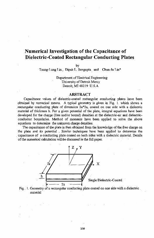
Numerical Investigation of the Capacitance of Dielectric-Coated Rectangular Conducting Plates
by Tsung-Lung Lin , Dipak L. Sengupta and Chun-Ju Lin*
Department of Electrical Engineering University of Detroit Mercy Detroit, MI 48219 U.S.A.
ABSTRACT Capacitance values of dielectric-coated rectangular conducting plates have been
obtained by numerical means. A typical geometry is given in Fig. 1. which shows a rectangular conducting plate of dimension 2a*2a, coated on one side with a dielectric material of thickness h. For a given potential of the plate, integral equations have been developed for the charge (free and/or bound) densities at the dielectric-air and dielectricconductor boundaries. Method of moments have been applied to solve the above equations to detennine the unknown charge densities.
The capacitance of the plate is then obtained from the knowledge of the free charge on the plate and its potential . Similar techniques have been applied to detennine the capacitance of a conducting plate coated on both sides with a dielectric material. Details of the numerical calculation will,be discussed in the full paper.
X
h Single Dielectric-Coated
14 2a Fig . 1. Geometry of a rectangular conducting plate coated on one side with a dielectric
material
200
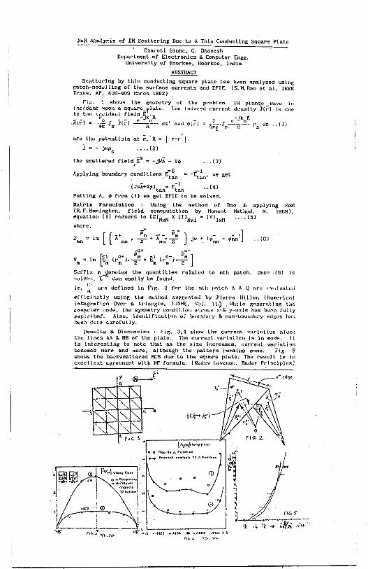
MoM Anal~is 0£ EM Scattering Due to A Thin Conducting Square Plate
Bharotl Sinha, G. Dhanesh D.-~partment. of Electronics & Computer Engg.
University of ~oorkee. Roorkce, India
~ Scatte,'ing by thin conducting square plate has b,~en analyzed using
patch-modC'lllng of the surface currents and EFIE. (S.M.Rao ct al, IEEE Trans. AP. 408-409 1"..:i.rch 1S82}
Fig. 1 shows the ~eometry · of the problem. TH plnncc wave h::; Lncidcnt 11pou a squarc_~lo.le. The lnlluc,!d ,:urrcnt denslly JCC') ls due
:a_ the iIJ~ider,~ :iel~-Jk~R . _ -Jk R AlY') a:; "+··,,- f,. JlrJ --1;- ds' i1.11d ,;,,1·i -··---r -~ 0
. fl~.~ tlr; .• (1) l. I\Jr1 "s I\ ••
are th'= pot~ntl:.ils o.t r.: R = I r-/ ! . • • • • (2)
the scattered fl.eld, E5 = -J~A - v,i, ... (3)
Applying boundary condltlons E~~ -E~~n' we get
C J~ii+v,i, \an= E;!0
•• ( 4 l
Putting A, tp from (1) we gel EFIE to be solved.
Matrix Formulation Using· the method of Rao & applying MoM (R.F.HaJ'l.1ngton, field comoputatJon by Moment Method, M. 1968). equation ( 1) rr,duces to (ZJNxN X ( I JNxl ( YI !xii .... (5)
.• (6)
-C+ -C-
[ i c+, Pm ... 1 c-. Pm ]
vm ~ lm Em (rm ••2 + Em (rm ''2
Suffix m -~enoles the quantities relatl!d lo mlh patch. OncQ (fi) ls •:.Jlvc,·;, E can co.sl ly be found.
,:-lm,
111 o.rc defined ln Fl~. 2 fr.r lhr. mlh patch A x. IJ h1"1: Pv:.Ju;tl.,:ti
~ff~cl1~ntly using lhe method sugeesled by Pierre Hlllun (Numl•ric:al ·j."t-egrai"lon Over a. triangle, IJUME, Vr.1l. 11.)
1 \.lhile gent:ratJng tin"':
co~rH::.er ,:od~. the symmetry condlt\vn. c.v.:.-uss x-S. y-a;.cls has bc.::n fully ev.:plolCed.. Also, identlftc.:i.t.l•:m or bouad.at'Y" & non-bourn.Jary edcc~ ha:; been dor,e C'.~rcful ly.
Hesults & Uiscus~.ii:-n : Fig. 3,4 sl1ow the current varla.liun alon,: the lines A}\ & BB of the plate. lhe current varinticn ls in code. l l is interesting to note that as the size increases. current var!ation becomes mor~ and mo.-e, al though the pal tern remains srune. Fig. 5 shows the ba-:kscatter-ed RCS due-·.to the square plate. The result is in c:-:.celh~!lt &.~reument-_ with HF formula. (Nadev Levcnon, Radar PrlnclplesJ

THIS PAGE INTENTIONALLY LEFT BLANK.
202
Tuesday PM URSI-B Session 10 Chesapeake A
Complex Media D. L. laggard Page
1 :20 The Matrix Riccati Equation for Scattering from Stratified ........ 204 Chiral Cylinders J. C. Liu, D. L. laggard, University of Pennsylvania
1:40 Constraint on the Constitutive Relations of a General, .............. 205 Linear, Spatiotemporally Nonlocal Medium Akhlesh Lakhtakia, Pennsylvania State University, Werner S. Weiglhofer, University of Glasgow
2:00 Exact Analytic Solution for Oblique Propagation in ................. 206 Helicoidal Bianisotropic Mediums Akhlesh Lakhtakia, Pennsylvania State University, Werner S. Weiglhofer, University of Glasgow
2:20 Characterization of Lossy Anisotropic Materials in .................. 207 Conjunction with Finite Element Method M. D. Desphande, Vigyan, Inc., Y. Y. Botros, J. L. Volakis, The University of Michigan
2:40 The Cross Correlation of Fields Scattered by Anisotropic .......... 208 Refractive Index Irregularities Richard J. Doviak, NOAAIERUNational Severe Storms Laboratory, Richard J. Lataitis, NOAAIERUEnvironmental Technology Laboratory, Christopher L. Holloway, NT/A/Institute of Telecommunication Sciences
3:20 Dipole Antennas on an Impedance Sphere Coated by a .. ; ........... 209 Uniaxial Layer Piergiorgio L. E. Uslenghi, Soma Roy, University of Illinois at Chicago
3:40 Treatment of Gyro-Anisotropic Properties by Condensed ........... 210 Node Spatial Network for Vector Potential Norinobu Yoshida, Hokkaido University
203
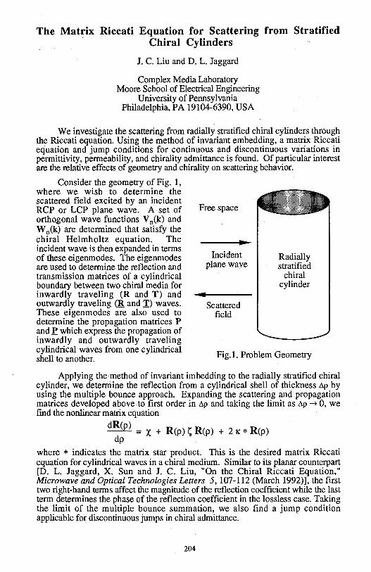
The Matrix Riccati Equation for Scattering from Stratified Chiral Cylinders
J.C. Liu and D. L. Jaggard
Complex Media Laboratory Moore School of Electrical Engineering
University of Pennsylvania Philadelphia, PA 19104-6390, USA
We investigate the scattering from radially stratified chiral cylinders through the Riccati equation. Using the method of invariant embedding, a matrix Riccati equation and jump conditions for continuous and discontinuous variations in permittivity, permeability, and chirality admittance is found. Of particular interest are the relative effects of geometry and chirality on scattering behavior.
Consider the geometry of Fig. 1, where we wish to determine the scattered field excited by an incident RCP or LCP plane wave. A set of orthogonal wave functions V n(k) and W n(k) are determined that satisfy the chiral Helmholtz equation. The incident wave is then expanded in terms of these eigenmodes. The eigenmodes are used to determine the reflection and transmission matrices of a cylindrical boundary between two chiral media for inwardly traveling (R and T) and outwardly traveling CR and I) waves. These eigenmodes are also used to determine the propagation matrices P and£ which express the propagation of inwardly and outwardly traveling cylindrical waves from one cylindrical shell to another.
Free space
Incident plane wave
Scattered field
Radially stratified
chiral cylinder
Fig. I. Problem Geometry
Applying the method of invariant imbedding to the radially stratified chiral cylinder, we determine the reflection from a cylindrical shell of thickness ~P by using the multiple bounce approach. Expanding the scattering and propagation matrices developed above to first order in ~P and taking the limit as ~P ~ 0, we find the nonlinear matrix equation
dR(p) = X + R(p); R(p) + 2 K * R(p) dp
where * indicates the matrix star product. This is the desired matrix Riccati equation for cylindrical waves in a chiral medium. Similar to its planar counterpart [D. L. Jaggard, X. Sun and J. C. Liu, "On the Chiral Riccati Equation," Microwave and Optical Technologies Letters 5, 107-112 (March 1992)], the first two right-hand terms affect the magnitude of the reflection coefficient while the last term determines the phase of the reflection coefficient in the lossless case. Taking the limit of the multiple bounce summation, we also find a jump condition applicable for discontinuous jumps in chiral admittance.
204
CONSTRAINT ON TIIE CONSTITUTIVE RELATIONS OF
A GENERAL, LINEAR, SPATIOTEMPORALLY NONLOCAL MEDIUM
Akhlesh Lakhtakia
Department of Engineering Science and Mechanics,
Pennsylvania State University, University Park, PA 16802-1401, USA.
Werner S. Weiglhofer
Department of Mathematics,
University of Glasgow, Glasgow G12 8QW, Scotland, UK.
Abstract
At first glance, 36 constitutive functions may be considered necessary to
describe the electromagnetic response of a general, linear, spationtemporally
nonlocal, material medium. However, its constitutive relations are
constrained by the structure of modern electromagnetic theory. The Lorentz
force decides that t;'.(r,t) and t3(r,t) must be considered the primitive or basic
fields, while O(r,t) and 8(r,t) are the induction or secondary fields which are
strictly unnecessary because of the microscopic basis of the Maxwell
postulates.
Do the induction fields contain artifacts? A constraint on the constitutive
relations is derived by resorting to the Lorentz covariance of the Maxwell
postulates as well as by using Occam's razor to arrive at a parsimonious
description of general linear media. As a result, only 35 constitutive functions
suffice.
205
EXACT ANALYTIC SOLUTION FOR OBLIQUE PROPAGATION IN
HELICOIDAL BIANISOTROPIC MEDIUMS
Akhlesh Lakhtakia
Department of Engineering Science and Mechanics,
Pennsylvania State University, University Park, PA 16802-1401, USA.
Werner S. Weiglhofer
Department of Mathematics,
University of Glasgow, Glasgow G12 8QW, Scotland, UK.
Abstract
The constitutive properties of a helicoidal bianisotropic medium (HBM)
vary helicoidally about a fixed axis; thus, a HBM is a periodically
inhomogenous linear medium. Almost two years ago, we had obtained the
exact closed-form solution for axial propagation in a general HBM. The
recent fabrication of thin-film HBMs has created an impetus for
understanding oblique propagation therein as well.
Using the Oseen transformation, we have now derived a 4x4 matrix
ordinary differential equation for oblique (i.e., nonaxial) propagation in
general linear HBMs. An exact analytic solution of this matrix differential
equation has been obtained. Our use of the Oseen transformation amounts to
viewing oblique propagation not by itself but as a graft on axial propagation.
206
Characterization of Lossy Anisotropic Materials in Conjunction with Finite Element
Method
M. D. Desphande* Vigyan Inc.
Hampton VA 23681
Y. Y. Botros and J.L. Volakis Radiation Laboratory
Department of Electrical Engineering and Computer Science The University of Michigan, Ann Arbor, MI 48109-2122
In the past, a number of techniques have been investigated for determining the dielectric constant of material samples. In most of these cases, the material samples are isotropic but recently, there is a need for methods to extract the dielectric constants of materials which have complex dielectric and magnetic properties, possibly anisotropic.
In this paper, we will present two new approaches for determining the dielectric constant of such complex materials both of which rely on the use of reference data based on a finite element analysis approach. One of the two methods to be presented employs a waveguide and the other is based on cavity analysis. For the waveguide approach, the reflection coefficient in the presence of the material is measured. Then, using the finite element method, the exact reflection coefficient is computed as a function of the dielectric constant and by matching these data with the measured results, an estimate of the dielectric constants can be extracted. In the case of the cavity approach, the FEM is again used to compute the resonance characteristics in the presence of the sample. For complex materials, data for several cavity sizes can be extracted which can then be correlated with measurements to estimate the complex dielectric properties. We will present numerical results which validate the new methods and curves will be given for several material samples.
207
The cross correlation of Fields scattered by Anisotropic Refractive Index Irregularities
Richard J. Doviak NOAA/ERL/National Severe Storms Laboratory
Richard J. Lataitis NOAA/ERL/Environmental Technology Laboratory
Christopher L. Holloway NTIA/Institute of Telecommunication Sciences
Using the integral expressions for the correlation functions given by Doviak et al. (Radio Sci. 30(1), 1996), and a geometric transformation, we developed a closed form analytic solution for the auto and cross correlation of signals in spaced antennas if scatter is from horizontally anisotropic irregularities of refractive index advected by uniform and/or isotropic turbulent flow. We assume that the spatial correlation function of the refractive index irregularities can be described by product separable Gaussian functions. our solution is identical in form to the heuristic one presented by Briggs (J. Atmos. Terr. Phys. 54(2), 153-165,1992). We relate the Bragg scatterers' horizontal correlation lengths, the orientation of the scatterers, the wind speed and direction, and the level of turbulence, as well as those parameters (e.g., transmitting and receiving antenna diameters) of the spaced antenna wind profiler, to Briggs' parameters that describe the diffraction pattern correlation ellipse.
We show that the correlation timer is the same ' • C ' for auto and cross correlation functions, and is
independent of receiver pair orientation and . separation. But, re is a function of the orientation of the correlation ellipse relative to the wind direction. The time delay r to the peak of the cross correlation function dependspon the orientations of both the wind vector and scatterers relative to the direction of the receiver pair. We demonstrate how the derived cross correlation function can be applied to signals measured in three spaced receivers to solve for the wind and turbulence which advect the Bragg scatterers, and to obtain the scatterers correlation lengths and orientation. If the outer scale of a Kolmogorov spectrum of the refractive index field is large compared to the radar wavelength, the anisotropy of the diffraction pattern is then principally dependent on asymmetry in the radiation pattern of the transmitting antenna, even though the outer scales of the refractive index field are strongly anisotropic.
208
DIPOLE ANTENNAS ON AN IMPEDANCE SPHERE COATED BY A UNIAXIAL LAYER
Piergiorgio L. E. Uslenghi and Soma Roy Department of Electrical Engineering and Computer Science
University of Illinois at Chicago, 851 South Morgan Street, Chicago, IL 60607-7053
A sphere of radius r=a on whose surface an impedance boundary condition holds is coated with a layer of homogeneous penetrable material having uniform thickness d, while free space occupies the region from r=b=a+d to infinity. The material of the coating layer is characterized by uniaxial permittivity and/or permeability tensors, the principal axis of the anisotropic medium being the radial direction from the center of the sphere. The elements of the permittivity and permeability tensors may be complex, thus allowing for the possibility ofuniaxial conductivity. This model is of interest in providing a canonical problem to simulate and analyze some practical configurations, such as propagation over a curved earth consisting of uniaxial conductivity layers, or over a curved ceramic or fiber-like substrate for millimeter wave applications.
A dipole antenna is located at a distance r0~b and is directed radially from the center
of the sphere. No limitation is incurred by assuming the antenna to be located on the positive z-axis of a coordinate system with origin at the center of the spherical structure, i.e. at 'a =O in a spherical coordinate system r, ~ , '1 · The ensuing boundary value problem is solved by working directly from Maxwell's equations and exploiting the symmetries of the field that are dictated by the source and structure. Specifically, we may assume Eg,= Hr= He =O everywhere for an electric dipole source and H~ = E r = E a =O everywhere for a magnetic dipole source. This procedure yields simple field expressions that are compared to the results for a general rotationally anisotropic material obtained by Monzon (IEEE Trans. AP, vol. 37, no. 6, pp. 728-735, June 1989). Note also that a uniaxial spherically layered resonator was studied by Wolff (Digest 1987 URS! Meeting, Blacksburg, VA; p.127).
The electric and magnetic fields inside the coating layer and in the surrounding free space are determined exactly, and the results are then extended to multiple coating layers of different uniaxial materials. Approximations are developed at low and high frequencies for one and two coating layers, and the influence of the coating material parameters on the radiated field is studied.
209
TREATMENT OF GYRO-ANISOTROPIC PROPERTIES BY CONDENSED NODE SPATIAL NETWORK FOR VECTOR POTENTIAL
Norinobu Yoshida Department of Electronics and Information Engineering
Hokkaido University, Sapporo 060 Japan
In the time-dependent analysis of three-dimensional electromagnetic fields, easiness in treating many types of medium conditions, such as dispersive and gyro-anisotropic properties, is essentially the important factor. I have already proposed the treatment of such properties in the Spatial Network Method (SNM) for the vector potential, which is composed of the conventional expanded node. [N.Yoshida; "Formulation of Dispersive and Gyro-anisotropic Properties in Spatial Network for Vector Potential", Proc. of URSI Int. Symp. on E/M Theory, pp.230-232, 1995]. In that paper, it is presented that the utilization of both the current continuity law including polarization vector itself and the conservation law of generalized momentum including vector potential fields can introduce simpler expression for each property than that by electromagnetic field variables.
In the formulation of gyro-anisotropic properties in the expanded node SNM, at the node where the coupled field components exist as equivalent current ones, the coupling mechanism is expressed by equivalent mutual inductance inserted in series at each line. But this formulation results in complicated expressions because of use of many variables including ,the characteristic equations of four inductances and their coupling properties in each node.
On the other hand, in the condensed node SNM in which all field components exist as equivalent voltage variables at each node, the formulation has simpler expression without current variables by the direct coupling between voltages of capacitanc of each directional component to be connected in parallel to each internal node. Resultant improvement shown by comparison of numbers of used variables for the formulation of magnetized ferrite is presented in Table and shows the remarkable advantage of formulation by the condensed node spatial network method for vector potential.
Nllllber Expanded Node Condensed Node
Fonrulation by E/M variables by Vector Potential by Vector Potential
For Basic Equation 5 (3) 4 (2) 4 (2)
Variables for Present value t Previous one 1 0 ·(8) 8 (4) 8 (4)
per node 3 4 (3 2) 26 ( 1 6) 1 2 (8)
Table Comparison of Numbers of Stored Variables in each kind of Spatial Network Formulation for Magnetized Ferrite
(in parenthesis: increment m.mbers by the anisotropic medium)
210

THIS PAGE INTENTIONALLY LEFT BLANK.
211

THIS PAGE INTENTIONALLY LEFT BLANK.
212
Tuesday PM URSI-B Session 11 Chesapeake B
Transients M.A. Morgan Page
1:20 Time-Domain Leaky-Wave Antennas .................................... 214 David Kralj, Polytechnic University, Lawrence Carin, Duke University
1:40 Impulse Receiving Antenna Design and Measurement .............. 215 Michael A. Morgan, R. Clark Robertson, Naval Postgraduate School
2:00 Unified Antenna Parametrization in the Time and .................... 216 Frequency Domains Amir Shlivinski, Ehud Heymn, Raphael Kastner, Tel Aviv University
2:20 Huygen's Reconstruction of Time-Limited FWM, PFWM, ........ 217 and MFWM Localized Waves Using Circular Arrays of Independently Addressable Elements Mohamed Abdel-Rahman, Ioannis M. Besieris, Virginia Polytechnic Institute and State University, Amr M. Shaarawi, Cairo University
2:40 On the Diffraction Length of Localized Waves Generated by ...... 218 Dynamic Apertures Sherif M. Sedky, Amr M. Shaarawi, Fawzia M. M. Taiel, Cairo University, Ioannis M. Besieris, Virginia Polytechnic Institute and State University
3 :20 Experimental Measurements of Transient Scattering from ......... 219 Periodic Water Waves Adam Norman, D. P. Nyquist, E. J. Rothwall, K. M. Chen, G. Wallinga, Michigan State University
3:40 Extrapolation of Time Domain Responses from ...................... 220 Electromagnetic Systems Utilizing the Matrix Pencil Technique R. S. Adve, Tapan K. Sarkar, 0. M. Pereira-Filho, Syracuse University, S. M. Rao, Auburn University
4:00 Transient Excitation of a Straight Thin-Wire Segment at .......... 221 the Interface of Two Half-Spaces Jean-Paul van Gestel, Evert C. Slob, Delft University of Technology
213
Time-Domain Leaky-Wave Antennas
David Kralj Dept. of Electrical Engineering Polytechnic University Brooklyn, NY 11201
Lawrence Carin Dept. of Electrical Engineering Duke University Durham, NC 27708-0291
Leaky-wave antennas have been investigated and utilized for several decades. Recently, there has been a significant interest in time-domain electromagnetic systems, for which the time-domain performance and properties of conventional antennas are of interest. We here present an experimental and theoretical investigation on the time-domain properties of leaky-wave antennas. Although the ideas and concepts are relevant to general leaky wave antennas, concentration is placed on one of the first and simplest such antennas: a rectangular waveguide with a continuous slit cut along one of its sides. The experimental data is measured using a short-pulse optoelectronic facility, and theoretical results are calculated via the method of moments. Additionally, the physical concepts involved are presented via time-frequency processing of the transient radiated fields.
It is demonstrated that the time-domain fields radiated from such a leakywave antenna are characterized by time-dependent frequencies, reflective of the dispersive leaky waveguide modes. If f:l(w) represents the real part of the complex longitudinal wavenumber of the leaky waveguide mode, as a function of frequency w, the frequency-dependent angle of leakage 0(w), as measured from the vertical, is given by
(1)
where k is the free-space wavenumber. Due to the dispersive properties of f:l(w), the leaked energy radiates at a frequency-dependent angle. Under time-domain conditions, the radiated field's time-dependent angle of arrival is ascertained directly from geometrical considerations (without recourse to the frequency domain). Therefore, coupling this time-dependent angle of arrival with (1) yields the result that the radiated fields are characterized by a time-dependent frequency; i.e., the transient fields radiated by a leaky-wave antenna, or any dispersive antenna, are characterized by a chirp. These issues will be demonstrated formally in the talk.
214
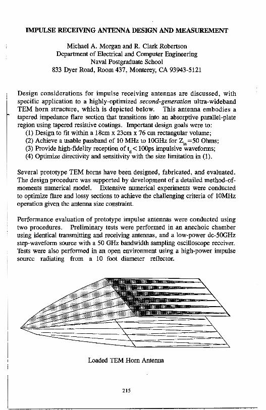
IMPULSE RECEIVING ANTENNA DESIGN AND MEASUREMENT
Michael A. Morgan and R. Clark Robertson Department of Electrical and Computer Engineering
Naval Postgraduate School 833 Dyer Road, Room 437, Monterey, CA 93943-5121
Design considerations for impulse receiving antennas are discussed, with specific application to a highly-optimized second-generation ultra-wideband TEM horn structure, which is depicted below. This antenna embodies a tapered impedance flare section that transitions into an absorptive parallel-plate region using tapered resistive coatings. Important design goals were to:
(1) Design to fit within a 18cm x 23cm x 76 cm rectangular volume; (2) Achieve a usable passband of 10 MHz to 10GHz for Zin =50 Ohms; (3) Provide high-fidelity reception of td < lOOps impulsive waveforms; (4) Optimize directivity and sensitivity with the size limitation in (1).
Several prototype TEM horns have been designed, fabricated, and evaluated. The design procedure was supported by development of a detailed method-ofmoments numerical model. Extensive numerical experiments were conducted to optimize flare and lossy sections to achieve the challenging criteria of 10MHz operation given the antenna size constraint.
Performance evaluation of prototype impulse antennas were conducted using two procedures. Preliminary tests were performed in an anechoic chamber using identical transmitting and receiving antennas, and a low-power dc-50GHz step-waveform source with a 50 GHz bandwidth sampling oscilloscope receiver. Tests were also performed in an open environment using a high-power impulse source radiating from a 10 foot diameter reflector.
Loaded TEM Hom Antenna
215
Unified Antenna Parametrization in the Time and Frequency Domains
Amir Shlivinski, Ehud Heyman and Raphael Kastner* Department of Electrical Engineering- Physical Electronics
Tel Aviv University, Tel Aviv 69978, Israel
Recently (A. Shlivinski, E. Heyman and R. Kastner, 1995 URSI Meeting), a full set of antenna parameters in the time domain (TD) has been presented in the context of a complete transmit-receive system representation. The theory has been derived entirely in the TD field equations. In this work, a more refined version of the parameters is presented, with the transmitting and receiving effective heights being defined with respect to incident or reflected currents and voltages at the antenna terminals, as opposed to terminal currents or open circui1 voltages. Modification of the frequency domain (FD) definitions provides ~ unified system representation. Central .to this TD development is the evaluatior
of the transmitting effective height ht ( i-, t) by the Slant Stack Transform (SST) oJ the time dependent current distribution, in the manner equivalent to the F:C Fourier transform evaluation of the far·field. TD reciprocity then leads to th~ interrelation of the receiving and the transmitting effective heights by a tempora integration. The vector autocorrelation of the transmitting effective height, denotec <Jlh1 (r,;), is then used to define the time dependent gain operator under impulsivt
source excitation as g1(r,;) =-=1-z.21.~,(r,;)' where lo is the line impedanc( 4n-c lo
at the antenna port and T/ = JµTe. g1 is incorporated in the following TD Friis, like operator
(1
such that the ratio between the energy transmitted to the receiver load, EL, t<
ER, the maximwn energy available at the source, is EL I ER = f ( s)* ~ (~)I IJ - ~=()
Here, iili,11 (;) is the autocorrelation of the source pulse, normalized to a uni
energy. Upon Fourier transforming (1), we reconstruct an FD (Friis multiplicative operator
F(w) = -{cl 2r )2GHr,w) -Gk(i-,w)(-iwr2 (2
which is seen to operate on the power spectrum of the source. Integration of (2 over w then yields the total energy ratio. In this way, the TD and FI representations have been unified. The aforementioned succession of concepts wi] be demonstrated for the example of a short antenna.
216
HUYGENS' RECONSTRUCTION OF TIME-LIMITED FWM, PFWM AND MFWM LOCALIZED WAVES USING CIRCULAR ARRAYS OF INDEPENDENTLY ADDRESSABLE ELEMENTS
by
Mohamed Abdel-Rahman and Ioannis M. Besieris The Bradley Department of Electrical Engineering Virginia Polytechnic Institute and State University
Blacksburg, VA 24061
and
Amr M. Sbaarawi Department of Engineering Physics and Mathematics Faculty of Engineering, Cairo University, Giza, Egypt
Localiz:ed waves are ultra-wideband, carrier-free pulses having large focusing depths and exhibiting extended ranges of localization. Recently, it has been demonstrated analytically that a number of localized waves (L W) can be generated from dynamic aperture antennas characteriz:ed by a time variation of their effective radii. Using an approach analogous to that followed by Ziolkowski in connection with the modified power spectrum (MPS) pulse, a Huygens' reconstruction has been undertaken of the finite time focus wave mode (FWM), the polynomial focus wave mode (PFWM) and the modified focus wave mode (MFWM) localized wave pulses using finite circular arrays of independently addressable elements. Particular emphasis is placed on the region of stability for each radius of the circular arrays and the behavior beyond the stable region is discussed. The decay with range of the peak amplitudes of the reconstructed fields is studied in detail and comparisons are made with analytical results generated from continuous dynamic apertures. The reconstructed fields are also used to establish diffraction lengths.
217
ON THE DIFFRACTION LENGTH OF LOCALIZED WAVES GENERAIBD BY DYNAMIC APERTURES
by
SherifM. Sedky, Amr M Shaarawi and Fawzia M. M. Taiel Department of Engineering Physics and Mathematics Faculty of Engineering, Cairo University, Giza, Egypt
and
Ioannis M. Besieris* The Bradley Department ofElectrical Engineering Virginia Polytechnic Institute and State University
Blacksburg, VA24061, USA
A definition of the diffraction ·1ength characterizing the propagation of localized wave (L W) pulses launched from dynamic apertures is provided. Sue!). pulsed fields exhibit extended ranges of localization. The aperture fields generating these localized waves are characterized by an ultra-wide bandwidth and a strong coupling between their spatial and temporal spectral components. This spectral coupling results in an aperture that is effectively, dynamic, i.e., its size varies with time.
In an attempt to determine the diffraction length of localized waves generated by dynamic apertures, Hafizi and Sprangle [ J. Opt. Soc. Am. A 8, 705 (1991)] have utilized a criterion based on the distance at which the extension of the illuminated region of the initial field is doubled. In a study of a Gaussian dynamic aperture [AM. Shaarawi, R W. Ziolkowski and I. M. Besieris, J. Math. Phys. 36, 5664 (1995)], it has been shown that the Hafizi-Sprangle definition of the diffraction length may be related to the maximum and minimum radii of the aperture, together with the temporal bandwidth of the e..xcitation wavefield However, the Gaussian illumination scheme is not the only possible one. Other excitation fi~ld:s .il~ i:,o.sibie a,id may l.:.ad to sigr.ificant differences in the decay patterns of the c::i:!.ci:! :i: :;ic radiated pulses. Such differences may not be captured by the Hafizi-Sprangle criterion .
The Hafizi-Sprangle definition of the diffraction range depicts the performance of LW pulses in a broad sense. The spectral analysis presented in our work complements such an inclusive approach and helps in providing a more complete picture of the manner in which a L W pulse decays with distance. Utilizing the information incorporated in the spectra of the radiated wavefields, we have formulated a novel approach for estimating the diffraction length of L W pulses radiated by dynamic apertures. This approach makes use of a spectral depletion analysis in order to establish when the pulse starts to enter into the far region. This happens when the oscillations introduced with distance cancel out the contributions of the temporal frequency windows covering the main bulk of the spatial spectrum. Such a criterion makes the estimates of the diffraction lengths of different types of L W pulses more precise. Furthermore, it captures some of the details of their decay patterns that might be missed by other formulations.
218

Experimental Measurements of Transient Scattering from Periodic Water Waves
Adam Norman, D.P. Nyquist, E.J. Rothwell, K.M. Chen, and G. Wallinga Department of Electrical Engineering
Michigan S~te University, East Lansing, Ml, USA, 48824
Experimental measurements of transient scattering of a short electromagnetic pulse from periodic water waves will be compared to theoretical scattering models developed previously. Three types of water waves will be examined, perfectly conducting, lossless (fresh water), and lossy (sea water). A number of periodic surfaces will be tested, including sinusoidal and a more realistic Donelan Pierson surface realization (See figure below). Both frequency synthesizer.!, and true time-domain measurement~ will be performed. The measurements will be performed in an anechoic chamber for the spectral domain, and on a ground plane for the time-domain.
The experimental water surfaces have been constructed out of machined expanded polystyrene ("styrofoam"). The perfectly conducting waves were created by gluing aluminum foil to the machined foam. The liquid waves were created by machining a cavity into a foam block, which can hold water. Therefore the water waves will have finite depth, which may affect the measurements for the fresh water case.
The theoretical mpdels to be validated consider both finite and infinite surfaces and are formulated by frequency domain Integral Equation techniques. These methods were presented at the last URSI Meeting (Norman, et. al. "Transient Scattering from a Periodic Sea Surface," 1995 URSI Digest, pg. 424). The Integral Equations are solved via the Method of Moments. Theoretical transient results are obtained via a frequency synthesis. Comparisons of both infinite and finite surface will be made to the experimental results, in the hope of establishing a link between the theoretical scattering from an infinite surface and the experimental and theoretical scattering from a finite surface. In, addition the experimental results should help to verify the
0.15
0.10
0.05
- rti:,r:e!,:r.-Pier:.cn ·---- Stokes Wove - sinusoids
~ 0.00 scattering models. "' .iii
.c -0.05
-0.10
-0.15
219
-0.20 '1-n,~,.,.,.,..Tn"nn-nTrnTOTn"nn-nT~.,,.n,~ 0.00 0.20 0.40 0.60 0.80 1.00
x-locotion
Extrapolation of Time Domain Responses from Electromagnetic Systems Utilizing the Matrix Pencil Technique
R. S. Adve, Tapan K. Sarkar·, 0. M. Pereira-Filho Department of Electrical and Computer Engineering
Syracuse University Syracuse, New York 13244-1240, USA
Phone: 315-443-3775; Fax: 315-443-4441; e-mail: [email protected]
Abstract
S. M. Rao Department of Electrical Engineering
Auburn University; Auburn, AL 36849
In this paper we use the Matrix Pencil approach to extrapolate time domain response from three dimensional conducting objects that arise in the numerical solution of electromagnetic field problems. By modeling the time functions as a sum of complex exponentials, we can eliminate some of the instabilities that arise in late times for the electric field integral equation in the time domain. However, this method can also be utilized for extending the responses obtained using a FDTD formulation.
In this work we present the use of the Matrix Pencil algorithm to eliminate the late time instabilities. The approach is to model the free response (the time domain response after the excitation has died down) as a sum of complex exponentials. The input to the Matrix Pencil algorithm is the output from the MOT code for a short period of time after the excitation has died down. Usually, in this short period the instabilities have not set in. Modeling the free response as a sum of complex exponentials results in a stable time domain response for all times. Hence, we use the Matrix Pencil to eliminate the late-time high-frequency oscillations. Also, since now the MOT code needs to be run for a short time after the excitation dies down, this approach results in significant savings in program execution time. It has been assumed in this presentation that we are dealing with three dimensional conducting bodies.
Examples will be presented to illustrate how the currents on a scatterer can be extrapolated from the calculated currents as a function of time over a limited region.
220
Transient excitation of a straight thinswire segment at the interface of two half-spaces
Jean-Paul van Gestel and Evert C. Slob Section of Applied Geophysics, Faculty of Mining and Petroleum Engineering
Centre for Technical Geoscience, Delft University of Technology P.O. Box 5028, 2600 GA Delft, The Netherlands
The transient excitation of a straight thin-wire segment, by either a voltage gap or an incident electric field, has been analyzed by many people. In these cases, a wire segment is located in free space and the analysis leads to a one-dimensional integral equation for the current along the wire. Several versions of Pocklington's and Hallen's original formulations exist. We have derived a general form of the integral equation using the field reciprocity theorem. This theorem interrelates two non-identical states that occur in the same background, one is the actual state to be computed while the other is an auxiliary state, to be chosen freely. We show that both Pocklington's and Hallen's integral equation formulations follow from different choices of this auxiliary state.
For applications in Ground Penetrating Radar, GPR, we have derived an integral equation for the transient excitation of the wire segment placed at the air/earth interface, where the earth is modeled as a lossy homogeneous half-space. Most commonly used GPR antennas are tuned to a center frequency of the excitation signal. GPR field data obtained with antennas with different center frequencies at fixed positions on the ground, provide information about the same subsurface, but with different frequency contents. It is not clear if the use of these different center frequencies effectively provides additional information about the subsurface compared to data obtained with a single antenna combination. We investigate the radiation characteristics of an antenna as a function of the frequency content of the excitation signal. The importance of the analysis is to see if data obtained with one antenna can be understood as a scaled version of data obtained with an antenna using a different center frequency. If this is the case, then the effective source signature that is radiated into the ground can be computed from multi center frequency data. If this is not the case, then there is additional information in the data that can be used to obtain a better image of the subsurface. Finally, we will show radiation characteristics of the antenna as a function of frequency and of the electric permittivity and conductivity of the half-space. This shows the need for antenna shielding and is of great importance to understand the antenna coupling to the ground, which is one of the key problems in the successful processihg of GPR data.
221

THIS PAGE INTENTIONALLY LEFT BLANK.
222
Tuesday PM URSI-B Session 12 Pratt/Calvert
Inhomogeneous Waveguides D. G. Dudley Page
1 :20 Some Mathematical Aspects of Waveguide Modeling ............... 224 Applicable to Sunfish's Retinal Cone Photoreceptors C. A. Moses, N. Engheta, University of Pennsylvania
1:40 Lattice Gas Automata Analysis of Inhomogeneous .................. 225 Waveguides Neil Simons, Michel Cuhaci, Communications Research Centre, Nikhil Adnanai, Greg Bridges, University of Manitoba
2:00 Efficient Analysis of Lossy Inhomogeneous Anisotropic .......... 226 Waveguides Using the Finite Element Method Luis Valor, Juan Z.apata, Universidad Politecnica de Madrid
2:20 Efficient Analysis of Waveguides with Lossy ......................... 227 Inhomogeneous Bi-Anisotropic Materials Characterized by Arbitrary Tensors Using the Finite Element Method Luis Valor, Juan Z.apata, Universidad Politecnica de Madrid
2:40 Effects of Lossy Inhomogeneous Substrate on the ................... 228 Coplanar Waveguide Properties Jean-Fu Kiang, National Chung-Hsing University
3:20 Axisymmetric Modes in an Inhomogeneous Coaxial ................ 229 Waveguide Jean-Fu Kiang, National Chung-Hsing University
3:40 Depolarization of Radiation in Inhomogeneous Isotropic ........... 230 Medium Nikolai I. Petrov, All-Russian Electrotechnical Institute
223
SOME MATHEMATICAL ASPECTS OF WAVEGUIDE MODELING APPLICABLE TO SUNFISH'S RETINAL
CONE PHOTORECEPTORS
C. A. Moses* and N. Engheta
Moore School of Electrical Engineering University of Pennsylvania
Philadelphia, Pennsylvania 19104, U.S.A.
It is well known that retinal photoreceptors of many species act as optical waveguides [see, e.g., J. M. Enoch, "Visualization of Wave-Guide Modes in Retinal Receptors", American Journal of Ophthalmology, 51,1107-1118 (1961)]. Progress in measurement techniques in biological sciences has enabled researchers to determine precise dimensions and physical characteristics of retinal guided-wave elements in many animals. Recent scanning interferometric measurements of cone photoreceptors isolated from the green sunfish (Lepomis cyanellus) by Rowe et al. have indicated that the average refractive index variation in these elements may possess certain inhomogeneities [M. P. Rowe, J.M. Corless, N. Engheta, and E. N. Pugh, Jr., "Scanning Interferometry of Sunfish Cones I: Longitudinal Variations in Single Cone Refractive Index", submitted to Journal of Optical Society of America A, December 1995]. It is our interest to study theoretically the electromagnetic roles of these inhomogeneities accompanied with nonuniformities (such as tapering present in cone photoreceptors) in optical guided waves in these photoreceptors.
Our theoretical work involves applying the technique of invariant imbedding in guided-wave structures and mode-matching to write matrix Riccati equations for the reflection and transmission matrix coefficients of guided modes in photoreceptors. We first considered unbounded focusing media in which we incorporate both certain transverse inhomogeneities and a general longitudinal inhomogeneity and nonuniformity in our formulation: for transverse inhomogeneity certain specific index profiles are considered (e.g., parabolic index profile); and for longitudinal direction general arbitrary inhomogeneities and nonuniformities (e.g., tapered and/or lateral displacement) are assumed. We also plan to study, using the method of invariant embedding, the case of open optical waveguides with transverse step index and general longitudinal inhomogeneity and nonuniformities, and take into account some aspects of radiation modes in such structures. This can have interesting applications in studying retinal photoreceptors as well as in the design of tapered optical waveguides in devices and components.
In this talk, some of the results of our theoretical work in this area will be presented and physical insights into these results will be given.
224
Lattice Gas Automata Analysis of Inhomogeneous Waveguides
Neil Simons, Nikhil Adnanit, Greg Bridgest and Michel Cuhaci
Directorate of Antennas and Integrated Electronics Communications Research Centre
3701 Carling Avenue, P.O. Box 11490, Station H Ottawa, Canada K2H 8S2
tDepartment of Electrical and Computer Engineering University of Manitoba
Winnipeg, Canada R3T 2N2
Lattice gas automata are an alternative to the traditional differential equation based numerical methods now widely used in computational electromagnetics. A Lattice Gas Automaton (LGA) is a discrete dynamical system comprised of a large regular lattice of cells. The cells are very simple, with only a few bits being used to represent all possible states of the cell. All cells are updated in synchronism according to the same deterministic rule which is local spatially and temporally. Some LGAs are capable of accurately simulating fluid dynamics, and we have previously applied these to the modelling of two-dimensional electromagnetic field problems [N. Simons, N. Adnani, G. Bridges, M. Cuhaci, Intl. J. Num. Modelling, 8, 301, 1995]. Lattice gas automata are inherently parallel systems. Unlike their difference equation counterparts, LGA cells require only a few bits of memory and simple logical operations (rather than floating point) for their evaluation. This makes LGAs ideally suited to computation using fine-grained, parallel architectures. We implement and present LGA simulation results using special purpose computing architectures, referred to as cellular automata machines [N. Margolus, in Pattern Formation and Lattice Gas Automata, Am. Math Soc. Fields Inst. Ser., 1995].
We have recently developed new lattice gas based models for the simulation of both two- and three-dimensional electromagnetic fields in inhomogeneous media. We report on the application of these models to the analysis of two- and three-dimensional waveguides and cavities. Due to its fine lattice structure, the lattice gas approach has the ability to model fine geometrical details. This advantage enables the boundaries of a structure to be defined with a high precision within the spatial grid. A wide variety of structures have been modelled including: homogeneous and heterogeneous rectangular, cylindrical, and finned waveguides and cavities. Quantitative numerical results, such as resonant frequencies, obtained using the LGA approach will be presented and compared to results obtained using traditional numerical methods such as the transmission line matrix and finite-difference time-domain methods. The prediction of resonant frequencies can provide insight into the dispersive nature of differential equation based numerical methods [R. Allen, A. Mallik, P. Johns, IEEE Trans. MTT, 35, 378, 1987].
225
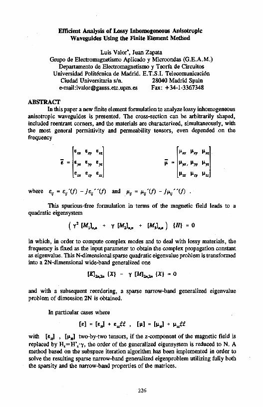
Efficient Analysis of ~y Inhomogeneous Anisotropic Waveguides Using the Finite Element Method
Luis Valor•, Juan Zapata Grupo de Electromagnetismo Aplicado y Microondas (G.E.A.M.)
Departamento de Electromagnetismo y Teorfa de Circuitos Universidad Polit~nica de Madrid. E.T.S.I. Telecomunicaci6n
Ciudad Universitaria sin. 28040 Madrid Spain e-mail:[email protected] Fax: +34-1-3367348
ABSTRACT In this paper a new finite element formulation to analyze lossy inhomogeneous
anisotropic waveguides is presented. The cross-section can be arbitrarily shaped, included reentrant comers, and the materials are characterized, simultaneously, with the most general permittivity and permeability tensors, even depended on the frequency
E.a E;iy Exz 11.a !.L;iy llxz
£ = £)11 E» £:,,z µ = 11)11, !.Lyy !.L:,,z
E.te £%)' Ett I.Lir I.Ley I.Lu
where cu = c/(f) - jc/ '(f) and µij = µ/(f) - j µ/ '(f)
This spurious-free formulation in terms of the magnetic field leads to a quadratic eigensystem
( y1 [M1],,,,. + y [MJ,,,,. + [MJn.n ) {H} = 0
in which, in order to compute complex modes and to deal with lossy materials, the frequency is fixed as the input parameter to obtain the complex propagation constant as eigenvalue. This N-dimensional sparse quadratic eigenvalue problem is transformed into a 2N-dimensional wide-band generalized one
CK11n,2n {X} - y [MJ1n,2n {X} = O
and with a subsequent reordering, a sparse narrow-band generalized eigenvalue problem of dimension 2N is obtained.
In particular cases where
[e] = [e,,] + e:Jf , [µ] = [µ11] + µ:Jf
with [e,,] , [µ11] two-by-two tensors, if the z-component of the magnetic field is replaced by H,=H'.·-y, the order of the generalized eigensystem is reduced to N. A method based on the subspace iteration algorithm has been implemented in order to solve the resulting sparse narrow-band generalized eigenproblem utilizing fully both the sparsity and the narrow-band properties of the matrices.
226
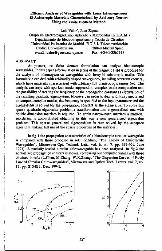
Efficient Analysis of Waveguides with Lossy Inhomogeneous Bi-Anisotropic Materials Characterized by Arbitrary Tensors
Using the Finite Element Method
Luis Valor*, Juan Zapata Grupo de Electromagnetismo Aplicado y Microondas (G.E.A.M.)
Departamento de Electromagnetismo y Teorfa de Circuitos Universidad Polit6cnica de Madrid. E.T.S.I. Telecomunicaci6n
Ciudad Universitaria sin. 28040 Madrid Spain e-mail:[email protected] Fax: +34-1-3367348
ABSTRACT At present, no finite element formulation can analyze bianisotropic
waveguides. In this paper a formulation in terms of the magnetic field is proposed for the analysis of inhomogeneous waveguides with lossy bi-anisotropic media. This formulation can deal with arbitrarily shaped waveguides, including reentrant comers, which have materials characterized with arbitrary full bianisotropic tensor 6x6. The analysis can cope with spurious-mode suppression, complex mode computation and the possibility of treating the frequency or the propagation constant as eigenvalues of the resulting quadratic eigensystem. However, in order to deal with lossy media and to compute complex modes, the frequency is specified as the input parameter and the eigensystem is solved for the propagation constant as the eigenvalue. To solve this sparse quadratic eigenvalue problem,a transformation into a generalized one with double dimension matrices is required. To attain narrow-band matrices a matricial reordering is accomplished obtaining in this way a new generalized eigenvalue problem. This sparse generalized eigenproblem is then solved by the subspace algorithm making full use of the sparse properties of the matrices.
In fig. l the propagation characteristics of a bianisotropic circular waveguide is compared with those proposed in ref.: (Z.Shen, "The Theory of Chiroferrite Waveguides", Microwave Opt. Technol. Lett., vol. 6, no. 7, pp. 397-401, June 1993). A partially loaded circular chirowaveguide has been analyzed. In fig.2 the normalized propagation constant is shown, comparing our computed values with those obtained in ref.: (L.Chen, M.Zhang, W.X.Zhang, "The Dispersion Curves of Partly Loaded Circular Chirowaveguides", Microwave and Optical Tech. Letters, vol. 7, no. 17, pp. 810-812, Dec. 1994).
1.5
.!:,t,o 1 -c::l.
0.5
HE1,1
O '---"--'-2-----1----'<CJ..3 ____ _,_4_,
k 0 R
227
6~--~---~
5
4
,g_ 3
2
4 k.,b
6
Effects of Lossy Inhomogeneous Substrate on the Coplanar Waveguide Properties
Jean-Fu Kiang Department of Electrical Engineering
National Chung-Hsing University · Taichung, Taiwan, ROC
In contrast to microstrip lines, the characteristic impedance of coplanar waveguides is less sensitive to the substrate thickness. The propagation characteristics of coplanar waveguides fabricated on an insulator-semiconductor substrate and microstrip lines on a semiconductor substrate forming a Schottky-contact have been studied. Due to the conductive loss ·in semiconductor, slow wave modes with attenuation have been observed by using parallel plate waveguide approximation, finite element methods, FDTD, and method of lines. The doping profile in the semiconductor layer affects the slow wave factor and the attenuation constant significantly, but only few literatures analyzing this effect.
The main contribution of this work is to formulate .,i, quasi-TEM approach to study the propagation properties of coplanar waveguides with a lossy inhomogenous substrate. A Laplace's equation with a complex permittivity is first derived to be solved for the eigenmodes of potential distribution. Then impose continuity conditions at the interface between contiguous layers to solve for the charge distribution on the center conductor. Reflection matrices are defined to reduce the number of unknowns. The complex capacitance thus obtained are used to calculate the slow wave factor and the attenuation constant.
This approach is then used to analyze the propagation constant with different semiconductor conductivities and insulator depths. Since the semiconductor attenuates the dominant mode, an insulator region can be fabricated into the semiconductor substrate to reduce the loss. Less loss is incurred as the insulator depth increases, hence the phase velocity increases and the attenuation constant decreases. We also observe that the attenuation constant reaches a maximum then decreases as the frequency increases. It is because the field distribution concentrates more around the center conductor at high frequencies. Next, we analyze the same structure with different semiconductor conductivities. A fr~quency range exists where the phase velocity rises from a low plains to a high plateau, and the attenuation constant rises to a maximum then decreases. The transit frequency is higher with higher semiconductor conductivity.
228
Axisymmetric Modes in an Inhomogeneous Coaxial Waveguide
Jean-Fu Kiang Department of Electrical Engineering
National Chung-Hsing University Taichung, Taiwan, ROC
Coaxial cables have been widely used as a probe to measure the dielectric constant of materials or as a hyperthermia applicator. Quasi-static approximation, power conservation method, mode-matching method, and finite element method have been used to solve the boundary value problem at the coaxial open-end or its junction with other waveguides. In all these works, only homogeneous dielectrics are considered. Variational method has been applied to solve the propagation constant of the lowest order mode in a rectangular waveguide loaded with an inhomogeneous dielectric slab. But the propagation constant of the higher order modes are usually difficult to obtain, which must be included in the region around discontinuities to obtain accurate results.
The main contribution of this work is to formulate a general numerical scheme to calculate the propagation constants of the higher order axisymmetric TM and TE modes of coaxial waveguides with an inhomogeneous dielectric profile. A matrix eigen equation is formulated by expanding the DP and E4> components in terms of the wave modes in an empty coaxial waveguide. The effects of various profile parameters on the propagation constant are analyzed.
Choose two dielectric constant profiles : one has a higher permittivity near the inner conductor, the other has a higher permittivity near the outer conductor. A transition phenomenon is observed for the former case along a narrow strip surrounding k. = k0
in the k. - k0 plane, especially for the higher order modes. This is caused by the field variation with frequency in the coaxial cross section. This phenomenon is more obvious with a sharper contrast between the dielectric and the air or with a narrower dielectric region. The ratio of radii between the inner and outer conductor affects the separation between dispersion curves in the k0 - k. plane.
229

Depolarization of Radiation in Inhomogeneous Isotropic Medium
Nikolai I.Petrov All-Russian Electrotechnical Institute,
19-39, Lenina str., lstra, Moscow region, Russia
Phone: (095) 5603400; Fax: (095) 5603134; e-mail: [email protected]
Abstract
Polarization properties of radiation in optical waveguides are investigated in many papers. Usually the birefringence as a reason of change of polarization in optical waveguides is considered [1].In this paper it is shown, that the depolarization occurs also in an isotropic multimode waveguide due to the diffractional effects.
Maxwell equation in weakly inhomogeneous medium (i.e. such that the relative index difference on/n < l,for distances of order of wavelength ..\) in a paraxial approximation can be reduced to the equivalent time-independent Schrodinger equation for the two-component wave function. The quantum mechanical method of coherent states is used to describe the effect of depolarization of radiation in a graded-index multimode two-dimensional isotropic optical waveguide.Solving an evolution equation for the coherency matrix we obtain the expression for the degree of polarization
P 1 w5:z:5 2 1 ,.,; . 2
~ 1 - 2 kng z - 2 k2ng sm wz,
where w is the gradient parameter of waveguide, :z:0 is the axis displacement of beam, k = ,, z is the longitudinal coordinate, no is the refractive index on the axis of waveguide.
For the optical fibre with the gradient parameter w = 1 · 10-3 µm-1 (fiber with radius ro ~ :z:o = 25µm) and,\= 0.63µm we obtain, that 50% decrease of the polarization degree takes place on the distance l,1 ~ 8.3cm.Such depolarization was observed also experimentally.
Depolarization has wave nature and is vanished at ,\ -+ 0. Depolarization is enhanced at the increase of axis displacement of beam,gradient parameter of waveguide and wavelength of radiation.The effect of asymmetry with respect to the sign of twisting of the trajectory of sagittal rays is found in the case of circularly polarized radiation.Diffractiona.l mechanism of depolarization considered here allows to explain also the experimentally observed depolarization of a laser beam in an atmosphere [2].
Thus the decrease of the degree of polarization in the multimode isotropic optical waveguide has a diffractiona.l origin and may be interpreted as a result of interaction between polarization (spin) and trajectory (orbital moment).The degree of polarization of both linear and circular polarized beams decreases by the quadratic law with distance. ·
References [1] P.Kaminow, IEEE J. Quant. Electr., QE - 17, pp.15- 22, 1981. [2] D.L.Fried and G.E.Mevers, J. Opt. Soc. Amer., 55, pp.740- 741, 1965.
230
Tuesday PM APIURSI-F Session 3 Constel. Ballroom F
Mobile Propagation Effects C. E. Mayer Page
1 :20 Multipathing Effects on a Low Elevation Angle Mobile ................. 232 Experiment at Ka-Band Charles E. Mayer, University of Alaska Fairbanks
1 :40 Comparison of Site-Specific Radio Propagation Path Loss ............. APS Predictions to Measurements in an Urban Area Joseph Schuster, Raymond Luebbers, The Pennsylvania State University
2:00 A Propagation Modeling for Microcellular Communications in ........ APS Urban Environments with Vehicles and Trees Shiun-Chi Jan, Shyh-Kang Jeng, National Taiwan University
2:20 Prediction of LOS Characteristics in the Urban Environment with .... 233 Regularly Distributed Buildings N. Blaunstein, Ben-Gurion University of the Negev, M. Levin, Tadiran Communication, Ltd.
2:40 Relations Between Antenna Radiation Patterns and Average ........... 234 Receive Power in Line-of -Sight Indoor Path Jun-Ichi Takada, ICCST, Tokyo Institute of Technology, Hiroyuki Arai, Yokohama National University
3:20 Field Simulator for Rayleigh/Rician Fading Reproduction .............. APS Hiroyuki Arai,Yokahama National University
3 :40 Discussion on the Spatial Mean and Spectral Mean Power .............. 235 Fading for Mobile Radio Channel Characterization Hsueh-Jyh Li, Rong-Yuan Lane, National Taiwan University
4:00 Ray Tracing Analysis of Propagation Characteristics in Tunnels ..... APS Including Transmitting Antenna Kazuhiro Fujimori, Hiroyuki Arai, Yokohama National University
4:20 A k-Ray Model for Mobile Systems in Environments with ............. APS Abrupt Terrain Discontinuities Daniel Cardoso de Souza, Gervasio Protasio dos Santos Cavalcante, Federal University of Para, Belem
4:40 Theory of the Propagation of Electromagnetic Waves in a .............. APS Railway Tunnel Y. P. Zang, Y. Hwang, City University of Hong Kong
5:00 Bandwidth Characteristics of UHF Radio Propagation Channels ...... APS Channels in Rectangular Tunnels Y. P. Zang, Y. Hwang, City University of Hong Kong
231
MULTIPATHING EFFECTS ON A LOW ELEVATION ANGLE MOBILE EXPERIMENT AT KA-BAND
Charles E. Mayer University of Alaska Fairbanks
Electrical Engineering Department PO Box 755900
217 Duckering Building Fairbanks, AK 99775-5900
(907) 474-6091, Fax (907) 474-6087 E-mail: [email protected]
Low elevation angle (-8 degrees) mobile propagation measurements were made in Fairbanks, Alaska during June 1994. The transmitting source was the geostationary satellite, ACTS. The 20 GHz CW signal transmitted from ACTS was received through a radome-enclosed antenna mounted on the roof of a modified passenger van. The mobile van traveled along highways, city streets, suburbs, and country roads. The direction of van travel was chosen to be in-line with the direction to the satellite, or orthogonal to the satellite direction. Three different antennas were sequentially used to couple the signal into the receiver front end. After downconversion, the receiver provided I and Q outputs, and well as a directly digitized sample stream of the data at 48 ksamples/s.
The three antenna apertures (2, 4, and 6 inches) produced different beamwidths in the receiver antenna pattern. Thus spatial filters of different solid angles were used to couple the incoming waves into the receiver. The antennas were mounted on a tracking platform, and stayed pointed at the satellite as the van changed travel directions. The smallest antenna, with the widest antenna pattern, coupled in the largest amount of multipathing off of the surrounding terrain. The main sources of multipathing include reflections off the road and the van roof. Roadside trees produced significant shadowing at this low elevation angle.
232
PREDICTION OF LOS CHARACTERISTICS IN THE URBAN
ENVIRONMENT WITH REGULARLY DISTRIBUTED
BUILDINGS
N. Blaunstein Department of Electrical and Computer Engineering, ~en-Gurion University of the Negev, P.O. Box 653
Beer Sheva 84105, Israel M.Levin
Tadiran Communication Ltd., P.O. Box 500, Petakh-Tikva 49104, Israel
Abstract
The character of the propagation in the microcellular urban environments at the frequency band of 902-928 MHz in Line-of-Sight (LOS) conditions investigated both theoretically and experimentally for the purpose of Radio Local Loop (RLL) prediction. The field intensity attenuation and path loss, the range of a break point, at which is changed the character of field intensity attenuation along the street level and which was proposed as an effective scale of micro-cell in LOS conditions are analysed for various parameters of street widths, for different average building heights and for the actual electrical impedance properties of building walls. A multislit waveguide with randomly distributed gaps between the sides of buildings is considered as a model of straight streets. Results of experiments for VHF/UHF wave propagation along the straight streets in urban environments in the conditions of direct visibility between receiver and transmitter are compared with theoretical analysis of the field intensity attenuation, the path loss and of the dependence of the break point on street topography in LOS conditions.
233
Relations between Antenna Radiation Patterns and Average Receive Power in Line-of-Sight Indoor Path
Jun-ichi TAKADA ICCST, Tokyo Institute of Technology
Meguro-ku, Tokyo 152, JAPAN Hiroyuki ARAI
Faculty of Engineering, Yokohama National University Yokohama-shi, Kanagawa 240, JAPAN
This paper discusses the relations between the average receive power and the antenna radiation patterns of mobile and base stations in indoor line-of-sight (LOS) path for mobile communication, both experimentally and theoretically.
The experiments were done to discuss the following subjects on the average receive power:
1. Space diversity and polarization diversity in up-link (base station antenna di-versity).
2. Gain of base station antenna.
3. Radiation pattern of mobile terminal.
In the microcellular environment with LOS, the effect of the diversity reception is small from a viewpoint of the fading reduction. On the other hand, portable radio terminal like PCS does not radiate/receive pure vertical polarization in the practical situation, the polarization diversity technique is proved to be effective from a viewpoint of average receive power.
In the multipath environment, the antenna radiation pattern itself has no straightforward information of receive power. However, it is very important to clarify the optimal radiation pattern for the given environment. For this purpose, the propagation measurements using the practical antennas are highly required.
The experiments were done in the corridor. The base station antennas for space and polarization diversities were installed on the ceiling, and mobile terminal with various sizes were moved along the corridor. The inclined angle of the mobile terminal is the parameter in the estimation of average receive power. The advantage of polarization diversity is confirmed by these experiments. The effect of gain/radiation pattern of base/mobile antennas diverges in various manner, and it seems some optimal directivity exists when the scale of the propagation environment is specified.
The raytracing technique is introduced to estimate these effects theoretically1 .
The numerical results will be presented and compared with experiments.
1The authors acknowledge Mr. K. Fujimori of Yokohama Natonal University for his offer of raytracing software.
234
Discussion on the Spatial Mean and Spectral Mean Power Fading for Mobile Radio Channel Characterization
Hsueh-Jyh Li and Rong-Yuan Lane Department of Electrical Engineering
National Taiwan Univ. Taipei, Taiwan, R.O.C.
Power fading and delay spread are important channel characteristics for mobile communications. Power fading is usually characterized by the mean power received over an
area with radius about 10 - 20 wavelengths for outdoor environments and 5 - 10 wavelengths
for indoor environments. The mean power so obtained is referred to as the spatial mean power.
Obviously it will take much time to obtain the spatial means if many small areas are to be
measured.
Power fading is a narrowband measurement, while delay spread requires a wideband
measurement bandwidth is much greater than the channel coherent bandwidth. The delay
profile at a given pair of transmitter and receiver locations provides information about the amplitudes and delay times of multipaths. It is expected that multipath components at all receiver locations over a small area are highly correlated. Therefore the delay profile at a point
can represent the delay profiles of other points in this small areas. Delay profiles can be obtained either by the frequency domain measurement or the time
domain measurement. By the Parsaval theorem the total signal energy in the time domain
should be equal to the total signal energy in the frequency domain. Accordingly integration of
the power delay profile shouid give the total signal energy and the spectral mean power can
therefore be derived. In this paper we will demonstrate that the spectral mean power and the
spatial mean power are highly correlated under certain conditions. Once the above statement is true then we can use the spectral mean power at a point to replace the spatial mean power over a small area so that the measurement time can be much reduced.
In this paper we will analyze relations between the spectral mean power and the spatial
mean power. We will propose measurement method for obtaining spectral mean power from
delay spread measurement. Numerical simulation and experimental results will be
demonstrated in the presentation.
235

THIS PAGE INTENTIONALLY LEFT BLANK.
236
Tuesday PM AP/URSI-D Session 1 Camden/Lombard
Microwave and Millimeter Wave Devices and Circuits G. Haussmann Page
1:20 Band-Pass Filters Mounted with Cylindrical Dielectric .............. 238 Resonators in Cut-Off Waveguide Sachihiro Toyoda, Osaka Institute of Technology
1 :40 A New Optimization Method for the Design of Non- ............... 239 Uniform Impedance Matching Section Using Wavelet Transform !sin Erer, Tayfun Gunel, Bingul Yazgan, Istanbul Technical University
2:00 A 2.45 GHz Microwave link for Automatic Debiting ............... 240 Applications Deyun Lin, Changsheng Shi, Tsinghua University
2:20 3mm Waveguide Y-Junction Circulator with a Magnetized ........ 241 Ferrite Sphere Edward K. N. Yung, H. Y. Ding, City University of Hong Kong
2:40 Modulation Techniques for Semiconductor Lasers .................... 242 Dr. Salim Akbar, PAF Academy, Pakistan
3:20 Modes in Elliptic Fibers of Step Index Profile ........................ 243 T. Do-Nhat, S. K. Chaudhuri, University of Waterloo, F. Alhargan, Research Institute of Computers and Electronics, King Abdulaziz City for Science and Technology
3:40 FDTD Modeling of Electromagnetic Packaging Effects ............. 244 M. Piket-May, E. Thiele, G. Haussmann, Jason Mix, University of Colorado
4:00 Microwave Waveguide-Grating Dielectric Filters .................... APS S. Tibuleac, R. Magnusson, T. A. Maldonado, The University of Texas at Arlington
4:20 Finite Element Modeling of Multilayered Semiconductor .......... 245 Structures for Time of Flight Measurements C. J. Scott, R. Green, A. A. Millings, Morgan State University
237
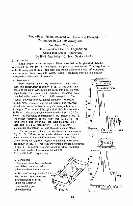
Band- Pass Filters Mounted with Cylindical Dielectric Resonators in Cut- off Waveguide
Sachlhlro Toyoda Department of Electrical Engineering
Osaka Institute of Thecnology 5-16-1 Asahi- ku, Omiya, Osaka JAPAN.
1. Introduction In this paper, new band- pass filters mounted with cylindrical dielectric
resonators in the cut- off waveguide are proposed and tested. The height of the cut-off waveguide is 5mm. The input and output sides of this cut-off waveguide are connected to a waveguide which tapers gradually from the rectangular waveguide of standard dimensions.
2. Experiment Two types of filters are considered. For the first
filter, the construction is shown in Fig. 1. The width and length of the cutoff waveguide are 12. 96 mm and 35 mm, respectively. Four cylindrical dielectric resonators were mounted in the center of this cutoff waveguide. The interval between four cylindrical dielectric resonators is 11. 6 mm. The input and output sides of this resonant circuit was connected to a rectangular waveguide 4 mm in length. The mode of the cylindrical dielectric resonator is TM o, ,. The experiments were carried out at the 10 GHz band. The frequency characteristics are shown in Fig. 1. The center frequency of this filter was 9. 32 GHz. The band-width and insertion loss were obtained O. 54 GHz and 0. 1 dB, respectively. · This frequency attenuation characteristics was obtained a steep slope.
For the second filter, the construction is shown in Fig. 2. Six TM o, • mode cylindrical dielectric resonators were mounted in the cutoff waveguide. The sizes of the cutoff waveguide and the location of dielectric resonators are shown in Fig. 2. This frequency characteristics are shown in Fig. 3. The center frequency was 9. 74 GHz. The bandwidth and insertion loss were obtained O. 98 GHz and O. 1 dB, respectively.
3. Conclution The paper describes new band
pass filters mounted with cylindrical dielectric resonators
in the cutoff waveguide for 10 11~,N.,,,,,'"" GHz band. The frequency ~,.,.,,,;,,
characteristics of these filters are obtained comparativity good characteristics.
238
"' .,, JO
.::.: 20
Fig. 1.
10
-~ 20 C 0
j 30
< 40
50
Frequency GHz
6:.'-=o-s""."'ssc-=s~. 1=s-1~0~. s-,-11,_. s-2-1~2.,
Fig. 3. Frequency GHz
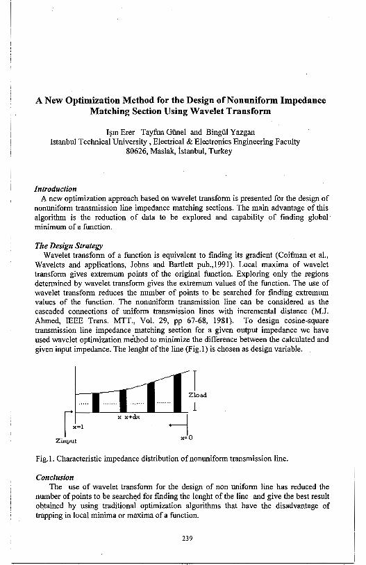
A New Optimization Method for the Design of Nonuniform Impedance Matching Section Using Wavelet Transform
1~m Erer Tayfun Giinel and Bingiil Yazgan Istanbul Technical University, Electrical & Electronics Engineering Faculty
80626, Maslak, istanbul, Turkey
Introduction A new optimization approach based on wavelet transform is presented for the design of
nonuniform transmission line impedance matching sections. The main advantage of this algorithm is the reduction of data to be explored and capability of finding global minimum of a function.
The Design Strategy Wavelet transform of a function is equivalent to finding its gradient (Coifman et al.,
Wavelets and applications, Johns and Bartlett pub.,1991). Local maxima of wavelet transform gives extremum points of the original function. Exploring only the regions determined by wavelet transform gives the extremum values of the function. The use of wavelet transform reduces the number of points to be searched for fmding extremum values of the function. The nonuniform transmission line can be considered as the cascaded connections of uniform transmission lines with incremental distance (M.J. Ahmed, IEEE Trans. MTT., Vol. 29, pp 67-68, 1981). To design cosine-square transmission line impedance matching section for a given output impedance we have used wavelet optimization me'thod to minimize the difference between the calculated and given input impedance. The lenght of the line (Fig.I) is chosen as design variable.
i Zload
r1------x--x_+_~---'--,--'-1 j I x=l
x=O Zinput
Fig. I. Characteristic impedance distribution of nonuniform transmission line.
Conclusion The use of wavelet transform for the design of non uniform line has reduced the
number of points to be search~d for fmding the lenght of the line and give the best result oqtained by using traditional optimization algorithms that have the disadvantage of trapping in local minima or maxima of a function.
239
A 2.45GHz Microwave Link for Automatic Debiting Applications
Deyun Lin Changsheng Shi Department of Electronic Engineering
Tsinghua University Beijing China
Abstract
This paper will present the design and experiment of a 2.45GHz microwave link for automatic debiting applications in China. The link using a dual mixer and a subcarrier modulation system has been developed to realize stable and high quality data transmission between a roadside unit (interrogetor) and an onboard unit(wireless card) fixed inside the vehicle. The wireless card in this system has no microwave carrier source, it detects a microwave signal radiated from the interrogetor and activates a MCU mounted in the card. The MCU in turn activates a phase modulator by sending a 64Kb/s digital modulation signal. When e (t) is the phase angle of the RF signal mQdulated by the card's digital data, the signal s(t) detected by the homodyne detector of the interrogetor, is expressed by the following expresion:
s(t)=Asin{8 (t)+4n (d/A)} where dis the distance between the interrogetor and the card and A is the wavelength. From this equation, we can see that the polarity and the amplitude of the detected signal is changes due to the changing distanced. This will result in error in regenerated deta signal.
To realize stable data transmission between the card and interrogetor by using simple modulation method, we developed a double modulation system using a subcarrier in the card and a dual mixer circuitry in the roadside unit. By using these technologies, we can get a stable demodulated signal. This system uses both of the vertical and horizontal linear polarization for the purpose of the frequency reuse and isolation between the transmitter and receiver of the roadside unit. It has been studied theoretically and experimentally, its effectiveness has been demonstrated with good performance.
240
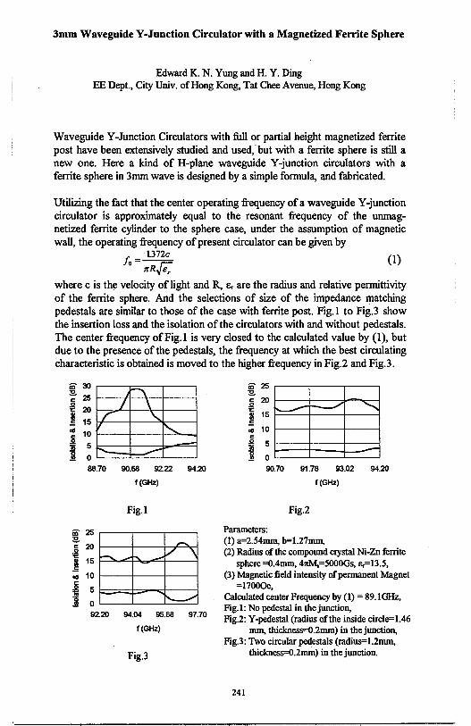
3mm Waveguide Y-Junction Circulator with a Magnetized Ferrite Sphere
Edward K. N. Yung and H. Y. Ding EE Dept., City Univ. of Hong Kong, Tat Chee Avenue, Hong Kong
Waveguide Y-Junction Circulators with full or partial height magnetized ferrite post have been extensively studied and used;but with a ferrite sphere is still a new one. Here a kind of H-plane waveguide Y-junction circulators with a ferrite sphere in 3mm wave is designed by a simple formula, and fabricated.
Utilizing the fact that the center operating frequency ofa waveguide Y-junction circulator is approximately equal to the resonant frequency of the unmagnetized ferrite cylinder to the sphere case, under the assumption of magnetic wall, the operating frequency of present circulator can be given by
f, = 1372c (1) 0 trR..{i;
where c is the velocity of light and R, e,. are the radius and relative permittivity of the ferrite sphere. And the selections of size of the impedance matching pedestals are similar to those of the case with ferrite post. Fig. I to Fig.3 show the insertion loss and the isolation of the circulators with and without pedestals. The center frequency of Fig. I is very closed to the calculated value by (1 ), but due to the presence of the pedestals, the frequency at which the best circulating characteristic is obtained is moved to the higher frequency in Fig.2 and Fig.3.
in ~ r---.::=-----.---, :E.. ~ 1-----fi-~>---+-----l
!i ~ ~I--:="'-+-~+----, I 15 1+----+--~-----1
"" 10 r----+-----i-~i 5c----+-----::::J;,,--====j
90.68 92.22 94.~
f(GHz)
Fig.I
in~~----~-~ :E.. i ~ I 15 i----: ...... e:::::+-'._.=-if-----:i
.., 10 l----+-----ll-----1
C
~ 5 !;;;::=;:::j:;;;;.,,-;;t--------j 1 0 '----'--__J'----'
92.~ 94.04 95.88 97.70
f(GHz)
Fig.3
in ~ :E.. i ~ 1 15 .., 10 C ,g 5 .!!! j 0
-- ~
"" -
90.70 91.76 93.02 94.~
Fig.2
Parameters:
f(GHz)
(1) a=2.54mm, b=l.27mm, (2) Radius of the compound crystal Ni-Zn ferrite
sphere =0.4mm, 47tM.=5000Gs, s.=13.5, (3) Magnetic field intensity of permanent Magnet
=17000e, Calculated center Frequency by (1) = 89.1 GHz, Fig. I: No pedestal in the junction, Fig.2: Y-pedestal (radius of the inside circle=l.46
mm, thickness=0.2mm) in the junction, Fig.3: Two circular pedestals (radius=l.2mm,
thickness=0.2mm) in the junction.
241
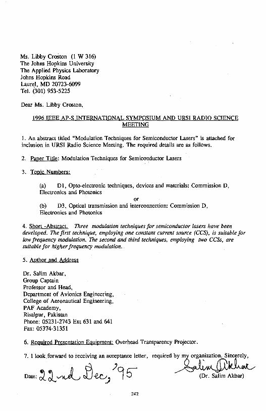
Ms. Libby Croston (1 W 316) The Johns Hopkins University The Applied Physics Laboratory Johns Hopkins Road Laurel, MD 20723-6099 Tel. (301) 953-5225
Dear Ms. Libby Croston,
1996 IEEE AP-S INTERNATIONAL SYMPOSIUM AND URSI RADIO SCIENCE MEETING
1. An abstract titled "Modulation Techniques for Semiconductor Lasers" is attached for inclusion in URSI Radio Science Meeting. The required details are as follows.
2. Paper Title: Modulation Techniques for Semiconductor Lasers
3. Topic Numbers:
(a) Dl, Opto-electronic techniques, devices and materials: Commission D, Electronics and Photonics
or (b) D3, Optical transmission and interconnection: Commission D, Electronics and Photonics
4. Short -Abstract. Three modulation techniques for semiconductor lasers have· been developed. The first technique, employing one constant current source (CCS), is suitable for low frequency modulation. The second and third techniques, employing two CCSs, are suitable for higher frequency modulation.
5. Author and Address
Dr. Salim Akbar, Group Captain Professor and Head, Department of Avionics Engineering, College of Aeronautical Engineering, PAF Academy, Risalpur, Pakistan Phone: 05231-2743 Ext 631 and 641 Fax: 05374-31351
6. Required Presentation Equipment: Overhead Transparency Projector.
7. I look .forward to receiving an acceptance letter,
242
required~
(Dr. Salim Akbar)
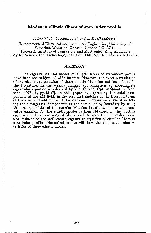
Modes in elliptic fibers of step index profile
T. Do-Nhat', F. Alhargan .. and S. K. Chaudhuri'
'Department of Electrical and Computer Engineering, University of Waterloo, Waterloo, Ontario, Canada N2L 3Gl.
.. Research Institute of Computers and Electronics, King Abdulaziz City for Science and Technology, P.O. Box 6086 Riyadh 11442 Saudi Arabia.
ABSTRACT
The eigenvalues and modes of elliptic fibers of step-index profile have been the subject of wide interest. However, the exact formulation of the eigenvalue equation of these elliptic fibers has not been found in the literature. In the weakly guiding approximation an approximate eigenvalue equation was derived by Yed [C. Yed, Opt. & Quantum Electron, 1976, 8, pp.43-47]. In this paper by expressing the axial components of the EM fields in the core and cladding of the fibers in terms of the even and odd modes of the Mathieu functions we arrive at matching their tangential components at the core-cladding boundary by using the orthogonalities of the angular Mathieu functions. The exact eigenvalue equation for the elliptic modes is then obtained. In the limiting case, when the eccentricity of fibers tends to zero, the eigenvalue equation reduces to the well known eigenvalue equation of circular fibers of step index profiles. Numerical results will show the propagation characteristics of these elliptic modes.
243

FDTD Modeling of Electromagnetic Packaging Effects
M. Piket-May, E. Thiele, G. Haussmann* and Jason Mix
Department of Electrical and Computer Engineering Campus Box 425
University of Colorado Bou!der,CO 80309
Previously we presented an interface between an FDTD electromagnetic simulation and a circuit simulator (SPICE). This provides a method for modeling lumped elements and linearly controlled sources within the FDTD grid using SPICE, without having to simulate the circuit elements in our internal FDTD code. Examples include a SPICE simulated resistor used in terminating a microstrip transmission line, and the embedding of a transmission line lumped element model (using SPICE) within an FDTD simulated microstrip.
The strength of this method is that it allows the definition of circuits more complex than simple lumped elements, allowing us access to all of the abilities available in SPICE, such as simulating larger circuits and modeling nonlinear devices such as BJT and FET elements. The relative simplicity of specifying devices to SPICE allows us to change the configuration and parameters of a complex circuit more quickly than modifying FDTD simulation code.
Here we present FDTD simulations using more complex SPICE circuit models, such as a transistor amplifier. We can study the viability of certain packaging configurations with such circuits; depending on the packaging geometry, certain undesirable effects, such as oscillation or instability, may be observed. Using these simulations, we hope to observe such undesirable effects and find configurations to avoid them. Specifically, we are looking for effects due to the more complex field interactions - effects that would not appear using only circuit simulations and simpler models (i.e., approximations on waveguide propagation using only lower order modes).
244
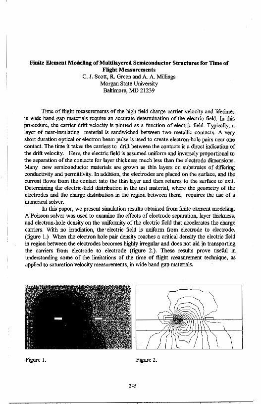
Finite Element Modeling ofMultilayered Semiconductor Structures for Time of Flight Measurements
C. J. Scott, R. Green and A. A. Millings Morgan State University
Baltimore, MD 21239
Time of flight measurements of the high field charge carrier velocity and lifetimes in wide band gap materials require an accurate determination of the electric field. In this procedure, the carrier drift velocity is plotted as a function of electric field. Typically, a layer of near-insulating material is sandwiched between two metallic contacts. A very short duration optical or electron beam pulse is used to create electron-hole pairs near one contact. The time it takes the carriers to drift between the contacts is a direct indication of the drift velocity. Here, the electric field is assumed uniform and inversely proportional to the separation of the contacts for layer thickness much less than the electrode dimensions. Many new semiconductor materials are grown as thin layers on substrates of differing conductivity and permittivity. In addition, the electrodes are placed on the surface, and the current flows from the contact into the thin layer and then returns to the surface to exit. Determining the electric, field distribution in the test material, where the geometry of the electrodes and the charge distnbution in the region between them, requires the use of a numerical solver.
In this paper, we present simulation results obtained from fmite element modeling. A Poisson solver was used to examine the effects of electrode separation, layer thickness, and electron-hole density on the uniformity of the electric field that accelerates the charge carriers. With no irradiation, the· electric field is uniform from electrode to electrode. (figure 1.) When the electron hole pair density reaches a critical density the electric field in region between the electrodes becomes highly irregular and does not aid in transporting the carriers from electrode to electrode (figure 2.). These results prove useful in understanding some of the limitations of the time of flight measurement technique, as applied to saturation velocity measurements, in wide band gap materials.
Figure 1. Figure 2.
245

THIS PAGE INTENTIONALLY LEFT BLANK.
246
Wednesday PM URSI-B Session 13 Constel. Ballroom F
Microstrip II A. Hoorfar Page
1:20 A Semi-Analytical Method for Evaluation of Microstrip ........... 248 Green's Functions in Multi-Layered Media Ahmad Hoorfar, Villanova University
1 :40 Effect of Superstrate Thickness and Permittivity on ................. 249 Coplanar Microstrip Parasitic Subarrays Kai-Fong Lee, University of Missouri-Columbia, Frank Kollarits, Wei Chen, University of Toledo, Richard Q. Lee, NASA Lewis Research Center
2:00 Cylindrical Multiconductor Transmission Lines Above ............. 250 a Perfectly Conducting Ground Plane Omer D. Khan, Ate/ Z. Elsherbeni, Charles E. Smith, Darko Kajfez, University of Mississippi
2:20 Closed-Form Asymptotic Extraction of Dispersion .................. 251 Characteristics of Open Microstrip Lines Seong-Ook Park, Constantine A. Balanis, Arizona State University
2:40 Analysis of the Resonant Modes of Circular Microstrip ............ 252 Patches Over Ground Planes with Circular Apertures Rafael R. Boix, Vecente Losada, Manuel Homo, Universidad de Sevilla
3:20 Capacitance Matrix of Thick Microstrip Patches ...................... 253 Gonzalo Plaza, Francisco Mesa, Manuel Hqrno, Microwave Group, Department of Electronics and Electromagnetism
3:40 Input Impedance of Rectangular Patch Antennas with ............... 254 a Laminated Ground Plane Jean-Fu Kiang, National Chung-Hsing University
4:00 Analysis of a 4-Coupled Line Microstrip Meander Line ............ 255 Using Equivalent Circuits for the Bends Jin Hong Yi, Sansung Electronics Co., Ltd., Wee Sang Park, Pohang University of Science and Technology
247
A SEMI-ANALYTICAL METHOD FOR EVALUATION OF MICROSTRIP GREEN'S FUNCTIONS IN MULTI-LAYERED MEDIA
Ahmad Hoorfar Department of Electrical and Computer Engineering
Villanova University, Villanova, PA 19085
An efficient methdd for characterization of microstrip antennas and associated feed structures in a multi-layered substrate medium is the mixed-potential integral equation (MPIE) technique. In a typical moment method solution using MPIE, one has to numerically compute the Green's functions of the so-called electric and magnetic types that appear in the kernel of the integral equation. These Green's functions are of the
Sommerfeld integral type and have the form, G(p) = f G(J... )Jo(k0p'A,)d'J.... One general 0
integration scheme well-suited for the case of a multi-layered structure is to deform the contour of integration above the real axis of the complex A-plane in order to avoid the surface-wave poles, located in the region 1 <A< nmax where nmax corresponds to the largest refractive index of the dielectric layers, and then back to the real axis to infinity. For
N an N layered structure, there are M = 2 I (N - m + 1) unique Green's functions, requiring M
m=I
numerical evaluations of the Sommerfeld integral for each k0p value. For each integration,
the spectral-domain G has to be recursively determined from an equivalent multi-sectional transmission line representing the multi-layered medium. In addition, in a typical solution process using the Galerkin method, the integral has to be evaluated for a large number of kop values. As a result a large amount of CPU time is spent on computation of the Green's functions, specially when three or more dielectric layers are present.
In this work we have developed a scheme in which the deformed portion of the contour, i.e., the region 1 <A< nmax, is integrated numerically whereas the remaining realaxis integration is performed analytically, resulting in a significant reduction in the overall computation time. The outline of the scheme is as follows: we first extract out the static, 1/kop singularity of G; the real-axis part of the integral is then divided into three regions from O to 1, n max to some Amax (>> 1) and Amax to infinity. Cubic-spline interpolations are used to curve-fit G over the first two regions. Once the curve-fit coefficients are determined, the resulting integrals of the type, Qm = f'A,m Jo(k 0p'A,)dJ..., m=0,1,2,3, can be expressed in closed forms in terms of Bessel and Struve functions. In the region, Amax to infinity, the integration is performed using a previously developed adaptive marching
scheme in which we divide the integration range into small pieces and approximate G by the first two terms in it's Taylor-series expansion in k2 (Hoorfar and Chang, Digest of URSI Meeting, p. 360, June 1994). Again, the resulting integrals, Qo and Q-2, in each interval can be evaluated analytically. We note that Qm expressions are functions of distance p only and independent of the dielectric layers' thicknesses and material properties. Therefore, once the constants in the cubic-spline interpolations in the first two regions as well as the constants in the adaptive marching scheme in the last region are computed and stored, the real-axis part of Sommerfeld integral can be evaluated for all values of p at once; this results
0
in a substantial reduction, by a factor of 5 or higher, in the CPU time. Detailed comparison with the exact numerical integration for structures with up to ten dielectric layers will be given in the presentation.
248
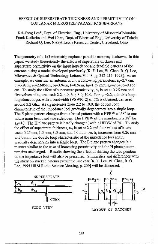
EFFECT OF SUPERSTRATE THICKNESS AND PERMITTIVITY ON COPLANAR MICROSTRIP PARASITIC SUBARRA YS
Kai-Fong Lee*, Dept. of Electrical Eng., University of Missouri-Columbia Frank Kollarits and Wei Chen, Dept. of Electrical Eng., University of Toledo
Richard Q. Lee, NASA Lewis Research Center, Cleveland, Ohio
The geometry of a lx3 microstrip coplanar parasitic subarray is shown. In this paper, we study theoretically the effects of superstrate thickness and superstrate permittivity on the input impedance and far-field patterns of the antenna, using a model developed previously [K. F. Lee, W. Chen, R. Q. Lee, Microwave & Optical Technology Letters, Vol. 8, pp.212-215, 1995]. As an example, we consider an antenna with the following parameters: a1=2.7 cm, b1=3.9cm, a2=2.605cm, b2=3.9cm, F=0.9cm, h2=1.59 mm, E,2=02.64, d=0.165 cm. To study the effect of superstrate permittivity, h1 is set at 0.26 mm and five values of E,1 are used: 2.2, 4.0, 6.0, 8.0, 10.0. For E,1=2.2, a double loop impedance locus with a bandwidth (VSWR=2) of 5% is obtained, centered around 3.2 Ghz. As E,1 increases from 2.2 to 10.0, the double loop characteristic of the impedance loci gradually degenerates into a single loop. The E plane pattern changes from a broad pattern with a HPBW of 58° to one with a main beam and two sidelobes. The HPBW of the mainbeam is 38° for E,1=10. The H plane pattern is hardly changed, with a HPBW of 74°. To study the effect of superstrate thickness, E,2 is set at 2.2 and four values ofh1 are used: 0.26mm, 1.0 mm, 3.0 mm, and 5.0 mm. As h1 increases from 0.26 mm to 5.0 mm, the double loop characteristic of the impedance loci again gradually degenerates into a single loop. The E plane pattern changes in a manner similar to the case of increasing permittivity and the H plane pattern remains unchanged. Results showing the effect of shifting the feed position on the impedance loci will also be presented. Similarities and differences with the study on stacked patches presented last year [K. F. Lee, W. Chen, R. Q. Lee, 1995 URSI Radio Science Meeting, p. 209] will be discussed.
SUPERSTRATE ' r-a2"1 ra2'1
h, €ri ti
f f X h1. Er2
11 COAX
b2 b -12 l
SIDE VIEW LAYOUT OF PATCHES
249
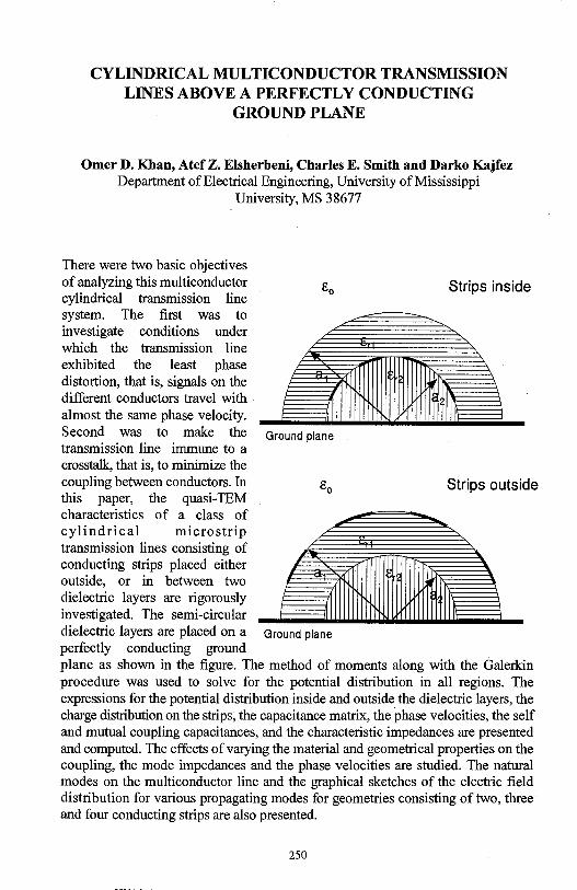
CYLINDRICAL MULTICONDUCTOR TRANSMISSION LINES ABOVE A PERFECTLY CONDUCTING
GROUND PLANE
Omer D. Khan, Atef Z. Elsherbeni, Charles E. Smith and Darko Kajfez Department of Electrical Engineering, University of Mississippi
University, MS 38677
There were two basic objectives of analyzing this multiconductor cylindrical transmission line system. The first was to investigate conditions under which the transmission line exhibited the least phase distortion, that is, signals on the different conductors travel with almost the same phase velocity. Second was to make the transmission line immune to a crosstalk, that is, to minimize the
Strips inside
Ground plane
coupling between conductors. In g0
Strips outside this paper, the quasi-TEM characteristics of a class of cylindrical micro strip transmission lines consisting of conducting strips placed either outside, or in between two dielectric layers are rigorously investigated. The semi-circular dielectric layers are placed on a Ground plane perfectly conducting ground plane as shown in the figure. The method of moments along with the Galerkin procedure was used to solve for the potential distribution in all regions. The expressions for the potential distribution inside and outside the dielectric layers, the charge distribution on the strips, the capacitance matrix, the phase velocities, the self and mutual coupling capacitances, and the characteristic impedances are presented and computed. The effects of varying the material and geometrical properties on the coupling, the mode impedances and the phase velocities are studied. The natural modes on the multiconductor line and the graphical sketches of the electric field distribution for various propagating modes for geometries consisting of two, three and four conducting strips are also presented.
250
CLOSED-FORM ASYMPTOTIC EXTRACTION OF DISPERSION CHARACTERISTICS OF OPEN MICROSTRIP LINES
Seong-Ook Park and Constantine A. Balanis Department of Electri~al Engineering Telecommunications Research Center
Arizona State University Tempe, Arizona 85287-7206
The spectral domain approach (SDA) is a most popular technique for calculating the dispersion characteristics of open microstrip lines. This is due to the fact that the SDA is easy to formulate and is a rigorous full-wave solution for simple and uniform planar structures. The SDA has been extensively studied and refined to find well-suited basis functions such that have the ability to accurately represent and resemble the longitudinal and transverse current densities while minimizing the computation time. However, there are still slight discrepancies of the relative effective permittivity between many numerical results obtained by various methods. These discrepancies are critically dependent on the type of basis functions used and the truncation error due to the finite upper limit (instead of infinity) for the numerical integration of the impedance matrix. Although the basis functions are carefully chosen to effectively represent the expected current densities, lengthy computation time is required for the numerical integration of the impedance matrix to achieve the desired accuracy.
In this work, as one possible technique to overcoming this difficulty, we present a closed-form asymptotic representation of the spectral impedance matrix to evaluate the relative effective permittivity in single open microstrip lines. Kummer's transformation is applied to convert the slowly converging impedance matrix element used in the SDA into the sum of a rapidly converging and a slowly converging term (tail integral). The latter term (tail integral) is recognized as being integrable in closed form by introducing Chebyshev polynomials basis functions which incorporate appropriate edge conditions. Closed-form solution of this tail integral can be represented by a simple algebraic formula which is very easy to use. This results in improved accuracy and significantly reduces the CPU time. The asymptotic value of the Green's function which can be determined using a recurrence relation is extracted and used in the tail integral. This method may also be used to solve the slotline. Computations based on this method have been performed for microstrip lines and the results compared favorably with those of other methods, however, at a dramatically reduced computational time and improved accuracy.
251
Analysis of the resonant modes of circular microstrip patches over ground planes with circular apertures
Rafael R. Bobe, Vicente Losada, Manuel Homo Microwave Group, Dpt. of Electronics and Electromagnetism
Avd. Reina Mercedes s/n, 41012 Sevilla, Spain E-mail [email protected]. Tph: #345 455 2891, Fax: #345 423 9434
Microstrip patches are used both as resonators and antennas in microwave int~ grated circuits. Microstrip patch antennas are sometimes fed by means of apertures fabricated in the ground planes located under the patches [D. M. Pozar, Electron. Lett., 21, 49-50, 1985). This makes it possible that the radiation arising from the feeding networks cannot interfere with the main radiation patterns generated by the patch antennas. Also, when patch antennas are fed by means of apertures, the antennas and the feeding networks can be designed separately to a great extent (M. I. Aksun, S. L. Chuang, Y. T. Lo, IEEE-AP, 38, 1224-1230, 1990). If microstrip patches are used as resonators, the apertures in the ground planes located under the patches can be used for tuning the resonant frequencies since these resonant frequencies depend on the dimensions of the apertures (K. Kawano, IEEE-MTT, 33, 38-43, 1985).
In this work, the authors analyze how the resonant modes of circular microstrip patches are affected by the presence or circular apertures in the ground· planes located under the patches. In particular, the authors carry out a rigorous full-wave analysis in the Hankel transform domain (K. Araki, T. Itoh, IEEE-AP, 29, 84-89, 1981) of the circular microstrip patches over ground planes with circular apertures in order to obtain the resonant frequencies, the quality factors and the radiation patterns of the first resonant modes of the patches. Thanks to the use of a suitable dyadic Green's function in the Hankel transform domain, the analysis has been carried out in the case in which both the circular microstrip patches and the ground planes containing the circular apertures are embedded in a multilayered substrate consisting of isotropic dielectric materials, uniaxial anisotropic dielectric materials (D. M. Pozar, IEEE-AP, 35, 613-621, 1987] and/or ferrite materials magnetized with a normal bias magnetic field (D. M. Pozar, IEEE-AP, 40, 1084-1092, 1992).
In order to check the validity of the numerical results obtained by the authors of this work, these numerical results have been compared with experimental results for the resonant frequencies of the first resonant modes of circular microstrip patches over ground planes with circular apertures which have been fabricated on dielectric substrates of different permittivities (Er ~ 2.5 and fr ~ 10). In all cases, the agreement between the experimental results for the resonant frequencies and the numerical results has been found to be within 4 %.
252
Capacitance matrix of thick microstrip patches
Gonzalo Plaza, Francisco Mesa, Manuel Homo Microwave Group, Dpt. of Electronics and Electromagnetism
Avd. Reina Mercedes s/n, 41012 Sevilla, Spain E-mail [email protected]. Tph: #345 455 2891, Fax: #345 423 9434
Rectangular patches play an important role in current microwave systems, where one of their most important uses is the simulation of lumped capacitances. The technological requirements of the manufacturing process makes necessary the development of CAD tools to take into account the effect of the conductor thickness. Nevertheless, to our knowledge there are not many works in the literature treating this relevant topic. In this paper, we present an alternative technique to compute the matrix capacitance of a system of thick rectangular patches. Our method accounts for the thick conductor by modelling the patch as a set of infinitesimally thin conductors at the same potential. This procedure was previously developed by the authors [G.Plaza et al. MMCAE 4,363-373, 1994) to compute the characteristic matrices of multiconductor and multilayered transmission lines (2D problem) and now is extended to deal with 30 problems.
The method here proposed obtains the capacitance coefficients by computing the charge on each thin rectangular conductor modelling a thick patch when the system of conductors are subjected to canonical excitations. The charge is readily computed after solving the integral equation for the free-charge density on the model system. This integral equation is solved applying the Galerkin's method in the spatial domain.
As is well known the solution of the integral equation requires a previous expression for the spatial Green's function. For a multilayered system, the systematic computation of this function turns out to be a very involved task when the number of layers is greater than two or three. In this work, we propose an approach to compute systematically this spatial Green's function starting from the spectral Green's function (which in turn can be readily obtained). The infinite spatial images series is approximated by retaining the dominant terms -easily determinedand approaching the remaining part by no more than three or four terms (by reversing some exponential terms from the spectral domain). Once the spatial Green's function has been obtained, the Galerkin method is applied using as basis funtions the Chebyshev polynomials weighed by the Maxwell distribution. The use of these basis functions enables a direct computation of the convolution and inner products by using Chebyshev quadratures. In order to treat the singularities appearing in the convolution integrands (when source and field points match), we use quadratures of different parity when computing the inner and convolution products. Several structures has been analyzed and the obtained results show a good agreement with previously reported data, e.g. [Z. Ning et al. IEEE ED-34, 644-649, 1987). It has been found that the effect of the thickness is specially notable in MMIC finite lines and patches where the ratio thickness/width can be quite significant.
253
Input Impedance of Rectangular Patch Antennas with a Laminated Ground Plane
Jean-Fu Kiang Department of Electrical Engineering
National Chung-Hsing University Taichung, Taiwan, ROC
Conventionally, microstrip patch radiators are built as low-profile radiating elements with a good conductor as ground plane. In modern aircraft designs, composite materials have been widely used in the vehicle surface to reduce the weight or the radar cross section. If a patch resonator is built on a composite surface, details of ground plane will affect its radiation properties. An anisotropic conductivity tensor has been used to study the shielding effectiveness of a G/E composite. The fibre separation in each G/E lamina is a tiny fraction of a wavelength, hence an equivalent conductivity tensor is used to model its propagation properties.
We will study the effects of a laminated ground plane on the input impedance of a rectangular patch radiator. Firstly, a transition matrix using conductivity tensors is formulated to model the laminated ground plane. Next, an integral equation is derived based on the electric surface current on the rectangular patch. Galerkin's method is applied to solve for the current distribution. The input impedance is then obtained by using a stationary formula.
Consider a laminated ground plane with N laminae of G/E composite. Each lamina is 25µm thick, and the fibre orientation in one lamina is perpendicular to that in the neighboring one. As the number of laminae increases, both the input resistance and reactance reduces in magnitude. The resonance frequency shifts and the bandwith increases significantly. The bandwidth broadening is due to the loss incurred by the conductive composite material.
When the substrate thickness is reduced, the resonance frequency shifts and the bandwidth is significantly broadened. The broadening is due to the power leakage through the G /E composite. This observation is, contrary to the conventional microstrip antennas in which a thicker substrate renders a broader bandwidth.
254
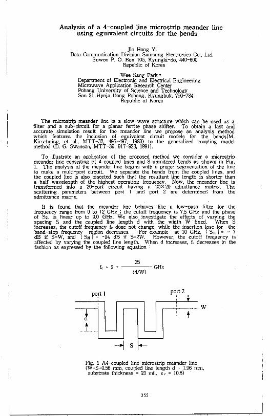
Aualysis of a 4-coupled line microstrip meander line using eguivalent circuits for the bends
Jin Hong Yi Data Communication Division Samsung Electronics Co., Ltd.
Suwon P. 0. Box 105, Kyungki-do, 440-600 Republic of Korea
Wee Sang Park • Department of Electronic and Electrical Engineering Microwave Application Research Center Pohang University of Science and Technology San 31 Hyoja Dong Pohang, Kyungbuk, 790-784
Republic of Korea
The rnicrostrip meander line is a slow-wave structure which can be used as a filter and a sub-circuit for a planar ferrite phase shifter. To obtain a fast and accurate simulation result for the meander line we propose an analysis method which features the inclusion of eguivalent circuit models for the bends(M. Kirschning, et al., MTT-32, 495-497, 1983) to the generalized coupling model method (D. G. Swanson, MTT-39, 917-923, 1991).
To illustrate an application of the proposed method we consider a microstrip meander line consisting of 4 coupled lines and 8 unmitered bends as shown in Fig. 1. The analysis of the meander line begins with a proper segmentation of the line to make a multi-port circuit. We separate the bends from the coupled lines, and the coupled line· is also bisected such that the resultant line length is shorter than a half wavelength of the highest operating frequency. Now, the meander line is transformed into a 20-port circuit having a 20 x 20 admittance matrix. The scattering. parameters between port 1 and port 2 are determined from the admittance matrix.
It is found that the meander line behaves like a low-pass filter for the frequency range from O to 12 GHz ; the cutoff frequency is 7.5 GHz and the phase of S21 is linear up to 9.0 GHz. We also investigate the effects of varying the spacing S and the coupled line length d with the width W · fixed. When S increases, the cutoff frequency fc dose not change, while the insertion lose for the band-stop frequency region decreases. For example at 10 GHz, I S21 I = - 7 dB if S=W, and I S21 I = -14 dB if S=2W. However, the cutoff frequency is affected by varying the coupled line length. When d increases, fc decreases in the fashion as expressed by the following equation :
35 fc = 2 + ----- GHz
(d/W)
port2
! '
11 u n u1 ----+ w
-1 s r--Fig. 1 A4-coupled line rnicrostrip meander line (W=S=0.56 mm, coupled line length d = 1.96 mm, substrate thickness = 25 mil, c r = 10.8)
255

THIS PAGE INTENTIONALLY LEFT BLANK.
256
Wednesday PM URSI-B Session 14 MD Suite Columbia
Hybrid Numerical Methods D. R. Wilton Page
1 :20 A Hybrid Numerical-Asymptotic Technique for the Analysis of ........ 258 Electrically Large Reverberation Chambers R. J. Burkholder, P. H. Pathak, Do-Hoon Kwon, The Ohio State University ElectroScience Laboratory
1 :40 A Hybrid MoM/FEM Technique for the Analysis of Cavity- ............ 259 Backed Patch Antennas Embedded in Large Conducting Surfaces U. Peke/, R. Mittra, University of Illinois
2:00 Hybrid Numerical Techniques for Modeling Ground Penetrating ....... 260 Radar Antennas Kenneth Demarest, Zhubo Huang, Richard Plumb, University
. of Kansas
2:20 A Hybrid FEM-FMM Technique for Electromagnetic Scattering ........ 261 Sunil S. Bindiganavale, John L. Volakis, University of Michigan
2:40 A Novel Matrix Compression Technique for Antenna Modeling ....... 262 Using the Finite Element - Boundary Integral Method Jian Gong, J. L. Volakis, University of Michigan
3:20 Hybrid Scattering Analysis (PTD+UFIM) for Large Airframe ........... 263 with Many Small Details Jacob J. Kim, Oren B. Kesler, Texas Instruments Incorporated
3:40 Hybrid FDTD-FD Quasi-Static Solution for Large ......................... 264 Heterogeneous Conductive Objects in the Electric Field Trevor Dawson, Jan De Moerloose, Maria A. Stuchly, Kris Caputa, University of Victoria
4:00 Modeling Wave Propagation Through a Building Using the ............ 265 Hybrid M24/S22 FDTD Algorithm Mohammed F. Hadi, Kuwait University, Melinda Piket-May, Eric T. Thiele, University of Colorado
4:20 IBM SP2 Implementation of the 3D IE-AP Procedure ..................... 266 X. Shen, R. Leibensperger, The Cornell Theory Center, K. R. Aberegg, A. F. Peterson, Georgia Institute of Technology
257
A Hybrid Numerical-Asymptotic Technique for the Analysis of Electrically Large Reverberation Chambers
R.J. Burkholder*, P.H. Pathak, and Do-Hoon Kwon The Ohio State University ElectroScience Laboratory
1320 Kinnear Road, Columbus, Ohio 43212
A useful Numerical-Asymptotic Hybrid Technique is presented for an efficient analysis of reverberation chambers. Reverberation chambers are being considered as an attractive alternative to the usual anechoic chambers for the purpose of testing the effect of high strength electromagnetic (EM) fields, with relatively arbitrary polarization, on objects containing electronic components. The test object is placed within such an electrically large reverberation chamber with metallic walls, and this chamber is excited by a source (or antenna). The fields excited by the source build up to a high value via multiple wave interactions between the metallic walls of the chamber: hence the name reverberation chamber. A rotating fan blade or a paddle wheel may also place inside the chamber to stir the fields so as to try and produce a nearly uniform field distribution within the chamber much like in a conventional microwave oven. As a result, the test object can be subjected to an almost uniform high EM field with a relatively arbitrary polarization, thereby allowing a rapid testing procedure. While rectangular cavity shapes are of interest in the design of such reverberation chambers, other shapes are also being considered.
In order to predict or asses the performance of such reverberation chambers, it is important to be able to accurately analyze the EM field behavior within such large metallic chambers. To date, it appears that the analysis of such large metallic enclosures has been performed largely by using power balance techniques which provide average field values rather than a detailed field structure, or by perturbational local plane wave procedures that may require the computation of a perturbational series. While a modal analysis of such cavities has also been presented previously for rectangular enclosures, this procedure is rather inefficient due to a very large number of modes present in the large cavity, and it is restricted to a handful of cavity shapes for which the wave equation is separable such that the modes can be found in closed form. A purely numerical solution can become intractable for such large chambers. In this paper, a relatively simple and efficient full wave hybrid technique which combines numerical and asymptotic procedures is proposed. An exact integral equation is formulated for the unknown equivalent currents associated with the source (or antenna) which excites the metallic chamber, and with any other interior objects such as the test object, paddle wheels, etc. The kernel of this integral equation is the dyadic Green's function for the metallic cavity. While an exact analytical solution cannot be obtained in general for this cavity Green's function, except in the few special cases of separable cavity shapes for which the modes can be found in closed form, an approximate but accurate cavity Green's function is constructed here using asymptotic high frequency ray methods. For rectangular cavities or relatively arbitrarily shaped smooth cavities, one can neglect diffraction effects and use only geometrical optics ray fields to construct the metallic cavity Green's function. The slight wall loss of the metallic cavity can be accounted for via the metallic reflection coefficient present in the reflected geometrical optic ray field description. Thus, the ray representation of the cavity Green's function includes multiple ray bounces across the interior metallic cavity walls. The source (or antenna) is connected through a transmission line to a generator in this model to account for the interaction of the cavity fields with the antenna load (which absorbs some energy). Simple examples are presented to show this concept of the hybrid technique in the frequency domain. Also, a pulsed antenna is often of interest to study the effect on a test object subjected to a transient cavity field. Therefore, a time domain analysis of the reverberation chamber is also presented for some simple cases to again illustrate the utility of this hybrid method.
258
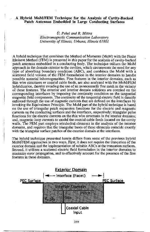
A Hybrid MoM/FEM Technique for the Analysis of Cavity-Backed Patch Antennas Embedded in Large Conducting Surfaces
V. Pekel and R. Mittra Electromagnetic Communication Laboratory University of Illinois, Urbana, Illinois 61801
A hybrid technique that combines the Method of Moments (MoM) with the Finite Element Method (FEM) is presented in this paper for the analysis of cavity-backed patch antennas embedded in a conducting body. The technique utilizes the MoM approach in the domain exterior to the cavities, which circumvents the need for any type of absorbing boundary condition (ABC), and combines the MoM with a scattered field version of the FEM formulation in the interior domains to handle possible material inhomogeneities. Fine features in the interior domains, such as thin wire structures or coaxial cable feeds, are also analyzed with the MoM/FEM hybridization, thereby avoiding the use of an unnecessarily fine mesh in the vicinity of these features. The exterior and interior domain solutions are coupled on the corresponding interfaces by imposing the continuity condition on the tangential magnetic field components. The continuity of the tangential electric field is directly enforced through the use of magnetic currents that are defined on the interfaces by invoking the Equivalence Principle. The MoM part of the hybrid technique is based on the use of triangular patch expansion functions for the electric and magnetic currents on the conducting surfaces and the interfaces, respectively; triangular pulse functions for the electric currents on the thin wire structures in the interior domains; and, magnetic loop currents to model the coaxial cable feeds located on the cavity walls. The FEM part employs tetrahedral elements in the analysis of the interior domains, and requires that the triangular bases of these elements coincide exactly with the triangular surface patches of the exterior domain at the interfaces.
The hybrid technique presented herein differs from some of the previous hybrid MoM/FEM approaches in two ways. First, it does not require the truncation of the exterior domain and the implementation of suitable ABCs at the truncation surfaces. Second, it utilizes a scattered electric field formulation in the interior domains to minimize error propagation, and to effectively account for the presence of the fine features in these domains.
PEC Surface
Exterior Domain I..__ Interface (Facet)
259
~1 PEC Surface
Hybrid Numerical Techniques for Modeling Ground Penetrating Radar Antennas
Kenneth Demarest*, Zhubo Huang, and Richard Plumb Radar Systems and Remote Sensing Laboratory
University of Kansas 2291 Irving Hill Road
Lawrence, Kansas 66045 *Phone: (913)864-7395
*Email: [email protected]
The increasing usage of ground penetrating radar (GPR) systems has brought about the need for sophisticated GPR modelers that are capable of analyzing the radar returns from scatterers buried in a variety of grounds. In general, a good GPR modeler is capable of correctly modeling the characteristics of the antennas, the ground, and the scatterers. Unfortunately, techniques that are good at modeling one aspect of the problem are usually not well suited for others. For example, the finite-difference time-domain technique (FDTD) is well suited for modeling dielectric spaces, such as grounds and scatterers, but is not well suited for modeling complex antennas. Conversely, the method of moments (MOM) is well suited for modeling complex antennas, but not grounds and penetrable scatterers. Since accurate ground modeling is usually essential, most GPR simulators concentrate on accurate' ground and scatterer modeling, at the expense of modeling real (i.e. complex) antennas.
This paper presents two hybrid schemes that are capable of modeling complex GPR antennas in the presence of grounds by merging two different numerical or analytical methods to model different aspects of the overall problem. Both of these techniques use equivalence theorems from electromagnetics, which allow them to split the overall GPR geometry into two regions - an antenna region and a ground/scatterer region. The two schemes differ in how they trade information between the two regions. The first scheme involves an iterative procedure. Here, each region is modeled sequentially, using field information supplied by the previous iteration in the other region. The second models both regions simultaneously and develops a system of simultaneous equations for the unknown fields in each region.
Both schemes are capable of providing accurate GPR simulations, but each has distinct advantages and disadvantages with respect to modeling complexity and the use of computer resources. We will present numerical results using both schemes and will offer general comments on their capabilities. ·
260
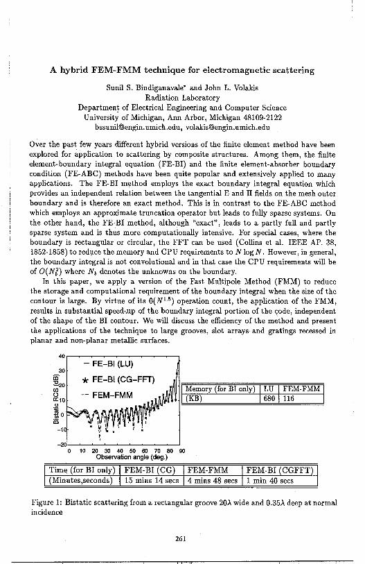
A hybrid FEM-FMM technique for electromagnetic scattering
Sunil S. Bindiganavale* and John L. Volakis Radiation Laboratory
Department of Electrical Engineering and Computer Science University of Michigan, Ann Arbor, Michigan 48109-2122
[email protected], volakis@engin. umich.ed u
Over the past few years different hybrid versions of the finite element method have been explored for application to scattering by composite structures. Among them, the finite element-boundary integral equation (FE-BI) and the finite element-absorber boundary condition (FE-ABC) methods have been quite popular and extensively applied to many applications. The FE-BI method employs the exact boundary integral equation which provides an independent relation between the tangential E and H fields on the mesh outer boundary and is therefore an exact method. This is in contrast to the FE-ABC method which employs an approximate truncation operator but leads to fully sparse systems. On the other hand, the FE-BI method, although "exact", leads to a partly full and partly sparse system and is thus more computationally intensive. For special cases, where the boundary is rectangular or circular, the FFT can be used (Collins et al. IEEE AP. 38, 1852-1858) to red1,1ce the memory and CPU requirements to N log N. However, in general, the boundary integral is not convolutional and in that case the CPU requirements will be of O(Nl) where N6 denotes the unknowns on the boundary.
In this paper, we apply a version of the Fast Multipole Method (FMM) to reduce the storage and computational requirement of the boundary integral when the size of the contour is large. By virtue of its O(NL5) operation count, the application of the FMM, results in substantial speed-.up of the boundary integral portion of the yode, independent of the shape of the BI contour. We will discuss the efficiency of the method and present the applications of the technique to large grooves, slot arrays and gratings recessed in planar and non-planar metallic surfaces.
30 in ~o (/) u a:10 .Q
!o in
-10
- FE-Bl (LU)
* FE-Bl (CG-FFT)
-201L-~~~~~-~~-~~_..J 0 10 20 30 40 50 60 70 80 90
Observation angle (deg.)
Memory (for BI only) LU FEM-FMM (KB) 680 116
Time (for BI only) FEM-BI (CG) FEM-FMM FEM-BI (CGFFT) (Minutes,seconds) 15 mins 14 secs 4 mins 48 secs 1 min 40 secs
Figure 1: Bistatic scattering from a rectangular groove 20>. wide and 0.35>. deep at normal incidence
261
A Novel Matrix Compression Technique for Antenna Modeling Using the Finite Element - Boundary Integral Method
Jiau Gong* and J .L. Volakis
Radiation Laboratory University of Michigan
Ann Arbor, MI 48109-2122 [email protected] [email protected]
The finite element - boundary integral technique is particularly attractive for modeling cavity backed antennas loaded with dielectric and incorporating complex feed structures. Nevertheless, for large apertures, the fully populated boundary integral matrix presents us with large CPU requirements. Various matrix compression techniques have been reported recently to improve the efficiency of integral-based methodologies. However, these approaches focus mainly on large scattering problems where decomposition of near and far fields is possible, and the need for simulation accuracy is not as stringent as is the case with antenna modeling. Moreover, since most antenna element simulations typically involve an aperture spanning no more than one or two wavelengths, the possibility of near and far zone decomposition does not apply.
To this end, we propose a novel matrix compression technique to significantly reduce the memory requirement. This compression is accomplished by factoring out as much information on mesh geometry as possible from the original impedance matrix and retaining only the fundamental interactions between the 'source' and 'testing' points. The interactions are found to be only a function of the 'source-to-testing' distance, and therefore storage of the entire matrix is avoided leading to a significant memory reduction.
For reduction in CPU needs, a fast uncompression technique is also required to carry out the matrix-vector products. An approach for accomplishing this will be discussed and applications for cavity-backed antenna modeling in conjunction with the new method will be presenj;ed.
262
HYBRID SCATTERING ANALYSIS(PTD+UFIM) FOR LARGE AIRFRAME WITH MANY SMALL DETAILS
Jacob J. Kim* and Oren B. Kesler Texas Instruments Incorporated 2501 W. University, MIS 8019
McKinney, Texas 75070
The electromagnetic(EM) contribution from cracks and panel joints is a matter of increasing concern in radar scattering, especially for low observable vehicle design. In recent years many RCS prediction codes such as XP ATCH, MISCAT, and SW AG codes, were developed to predict RCS levels from airframes and joints, respectively. However, none of them can efficiently predict accurate RCS levels from electrically large airframe with many complex small details due to their inherent limitations of high-frequency asymptotic techniques on geometry/materials and low-frequency numerical techniques on extensive computation/matrix size requirements. A few hybrid approaches were also developed to overcome the deficiencies of the conventional high- and lowfrequency techniques, but their applications are still severely limited by geometry/materials and computer resources. Thus, it is necessary to develop a new RCS analysis technique that is less dependent on the geometry/materials and computationally efficient For example, there are around 100,000 small details on F-22(See Aviation Week & Space Technology /May 16, 1994).
This paper describes a robust hybrid technique of Physical Theory of Diffraction(PTD) and Uniform Field Integration Method(UFlM) for an evaluation of EM scattering by large vehicles with many small details on their surfaces. The small details can be any of the followings or their combinations: step, slit, groove, dielectric filled gap, bump, impedance discontinuity, and coated or conducting wedges. This technique employs the PTD technique to compute the scattering from the large bodies with the joints filled with perfect conductors and the UFlM to predict the 3-D scattering from the complex small details. The UFlM is computationally very efficient and versatile since it utilizes simple 2-D scattered field formulations or measured data of the arbitrary shaped discontinuities rather than using computationally extensive 3-D numerical solutions(e.g., MOM, FEM and FDTD). The hybridization of the UFlM into PTD provides a total RCS solution for practical airframes with many small details in a timely manner.
Several test models with various joint shapes on curved surfaces were constructed and the results of the hybrid technique were compared with actual 3-D RCS measurements. All comparisons showed very good agreements. The main advantage of this technique is in its simplicity, computational efficiency, and its vast applications to many practical airframes.
263
Hybrid FDTD-FD Quasi-static Solution for Large Heterogeneous Conductive Objects in the Electric Field
Trevor Dawson, Jan De Moerloose, Maria A. Stuchly and Kris Caputa Dept. of Electrical & Computer Engineering, University of Victoria, Victoria, BC, Canada
Induced electric fields frequently need to be computed in large conductive bodies placed in a uniform or non-uniform low frequency electric field. A typical practical problem relates to the human body under a power line. Previously this problem has been solved for highly simplified body-models by applying the boundary integral equation to compute the charge distribution on the surface of a perfect conductor of the same shape as the body and than using the conservation of charge to compute cross-sectional currents (Chen et. al., IEEE Trans. Biomed. Eng., vol.33, pp.746-755, 1986). However, this method exhibits problems when high resolution is required for heterogeneous objects of complex shape.
In the method presented here, we use a special quasi-static formulation of the finite difference time domain (FDTD) to compute the external fields with a somewhat limited resolution. Since the resulting surface charge density is relatively smooth over the body exterior, it may be interpolated to a higher resolution. The resulting field then serves as the source term for a scalar potential formulation for the fields internal to the body.
Applying FDTD at low frequencies leads to prohibitively large simulation times because of the stability criterion. However, if the frequencies are sufficiently low and the body conductivities of the order of a few Sim, the associated characteristic wavelength and skin depth are much greater then the size of the structure under consideration, then the quasi-static condition applies. Hence, we can take advantage of the fact that the phase of the fields is known, fields exterior to conductors_ all have the same phase as the incident field. Interior fields are proportional to the time derivative of the incident field and are thus in quadrate with the incident field. If we use a ramp function for the incident field, all fields will eventually have. a linear (exterior) or constant (interior) behavior. As an excitation we introduce two plane waves traveling in opposite directions. When both waves have the same amplitude, phase and polarization, the electric fields add up while the magnetic fields cancel out. This leads to a uniform E-field excitation. Berenger's PML-layer can be applied successfully to low frequency evanescent waves (De Moerloose and Stuchly, IEEE Microwave Guided Wave Letters., 1996).
The quasi-static internal electric fields are computed using a finite difference scalar potential approach. The electric field is represented as the gradient of a scalar potential, which is in tum governed by the condition that the divergence of the conduction current be zero throughout the body volume. The exterior surface charge distribution is used to compute specified injection currents over the outer nodes, which then serve as boundary conditions. The resulting system of equations has a single unknown at each grid point, is naturally pre-conditioned, has a bandwidth of only 7, and can be made determinate by specifying the potential at one grid point. The resulting equations can be solved efficiently, using iterative schemes such as the Biconjugate Gradient or Generalized Minimum Residual methods. It is worth noting that the Impedance Method, commonly used to model low-frequency induced currents has a matrix bandwidth of 13, and as a vector method, involves roughly 3 times as many unknowns.
Computations are performed on an anatomically correct CT and MRI based model of the human body with voxels of 6.8 mm for the FDTD and 3.4 mm for the FD simulations. The results obtained for the interior problem with FD method for lower resolution model are very close to those obtained with the FDTD method.
264
Modeling Wave Propagation Through a Building Using the Hybrid M24/S22 FDTD Algorithm
Mohammed F. Hadi* Kuwait University
Melinda Piket-May and Eric T. Thiele Department of Electrical and Computer Engineering
Campus Box 425 University of Colorado
Boulder,CO 80309
A new fourth-order Finite-Difference Time-Domain (FDTD) scheme has been developed which exhibits extremely low phase errors at coarse grid resolutions compared to the conventional FDTD scheme. Unlike other higher-order FDTD schemes proposed in the past, this new scheme may be integrated with the conventional FDTD scheme to produce a stable hybrid algorithm. This unique ability allows the new scheme to utilize virtually all of the available FDTD tools that have been developed over the past three decades. Of particular importance, the seamless hybriding of the two schemes facilitates the successful modeling of conducting surfaces and absorbing boundary conditions, two problems that have posed formidable obstacles to previously proposed highorder schemes.
The combination of high phase accuracy and coarse grid resolutions that the new hybrid algorithm achieves dramatically extends the ability of the FDTD method, particularly with regard to modeling electrically large structures with high computational efficiency. Problems that would have required hours of supercomputing time to solve can now be completed in a matter of minutes with the same level of confidence and accuracy. Equally important, the lower grid resolution of the M24 scheme significantly redues the computer memory requirements relative to the standard FDTD scheme, again with the same level of accuracy.
When modeling electrically large. structures special attention must be paid to some of the FDTD tools-especially the source implementation and the absorbing boundary conditions. The details of these special requirements will be presented along with the results from modeling an electrically large building structure using the hybrid M24/S22 algorithm. Results from this hybrid algorithm will be compared with those from the conventional FDTD method. This comparison will illustrate the large savings in comupting resources that are afforded by the hybrid algorithm while at the same time maintaining high computational accuracy for the field solutions.
265
IBM SP2 Implementation of the 3D IE-AP Procedure
X. Shen*t, K. R. Aberegg:j:, A. F. Peterson+, R. Leibenspergert
t The Cqrnell Theory Center, Ithaca, NY 14853
+ Georgia Institute of Technology, Atlanta, GA 30332
This paper will describe the parallelization of an electromagnetic scattering code based on the 3D Integral Equation - Asymptotic Phase (IE-AP) method proposed by Aberegg and Peterson. The IE-AP method requires only about a one point per wavelength sampling rate for accurate solutions in 2D, and about ten points per square wavelength for accurate solutions in 3D, and thus results in a much smaller matrix to solve than traditional approaches. Since the matrix solve requires O(N3
) operations, where N is the number of basis functions, the IE-AP method appears better-suited than traditional numerical methods for the analysis of electrically large targets. It is well known that the greatest obstacle for the method of moments (MoM) analysis of electrically large targets is the sampling rate of about 10 points per wavelength usually needed to ensure sufficient accuracy. The IE-AP approach reduces the number of unknowns by an order of magnitude.
The computational burden of the IE-AP method is shifted from the matrix solve task to the task of computing the elements of the moment-method matrix. This drawback can be alleviated by using parallel processing. The matrix fill task involves little or no data dependency, and is very suitable for a parallel computer.
In this paper, we will discuss the procedure for parallelizing the 3D IE-AP scattering code for use on the 512-node IBM SP2 at the Cornell Theory Center (CTC). Domain decomposition is employed to partition the problem into subproblems on each processor. The Message Passing Interface (MPI) is used for communicating between processors. The IBM Parallel Engineering and Scientific Library is used to solve the moment matrix system in parallel.
We will demonstrate that state-of-the-art parallel computer technology fits well with computational electromagnetics for large problems. Specially, due to the nature of the MoM method, the workload in each processor is well balanced. We can expect to achieve linear speedup, where speedup is defined as the parallel execution time divided by the sequential execution time.
We will present results of EMCC benchmark targets obtained using the CTC SP2 in parallel mode. Parallel efficiency and scalability analysis will also be discussed.
266
Wednesday PM URSI-B Session 15 Chesapeake A
Guided Waves C. M. Butler Page
1 : 20 Penetration Through a Slot with Grounded Shield in a Parallel ... 268 Plate Waveguide Wenzhang Wang, Cengiz Ozzaim, Chalmers M. Butler, Clemson University
1 :40 Penetration Through a Shielded Slot in a Parallel-Plate ............. 269 Waveguide Y. Jiang, A. Q. Martin, C. M. Butler, Clemson University
2:00 On Fields Radiated by General Current Sources in Uniform ....... 270 Waveguides Loaded with Stratified Media Eric W. Lucas, Thomas P. Fontana, Westinghouse Electric Corporation
2:20 Finite Element Analyses of Waveguides/Cavities Using ........... 271 Null Space Elimination in the Lanczos Algorithm S. Polstyanko, G. Lizalek, R. Dyczij-Edlinger, J. F. Lee
2:40 Smooth Surface Discretization for the Design of Waveguide ...... 272 Mode Converters Tanveer Ul Haq, Kevin J. Webb, University of Delaware
3:20 A Methods of Moments Solution for the Scattering of Two ...... 273 Posts Inside a Rectangular Waveguide C. G. Buxton, W. T. Smith, University of Kentucky
3 :40 The Existence of Photonic Band Gaps in a Class of ................. 274 Artificial Materials Hung Y. David Yang, University of Illinois at Chicago
4:00 On the Static and Dynamic SDA of Coplanar Waveguide .......... 275 TW Electrodes Mach-Zender Optical Modulator G. Cano, F. Medina, M. Homo, Dept. of Electronics and Electromagnetism, Sevilla, Spain
4:20 Extraction of Singularities in Dyadic Green's Functions ............ 276 for Waveguide Structures Driven by Surface Current Densities Luiz Costa da Silva, Pontificia Universidade Catolica do Rio de Janeiro
267
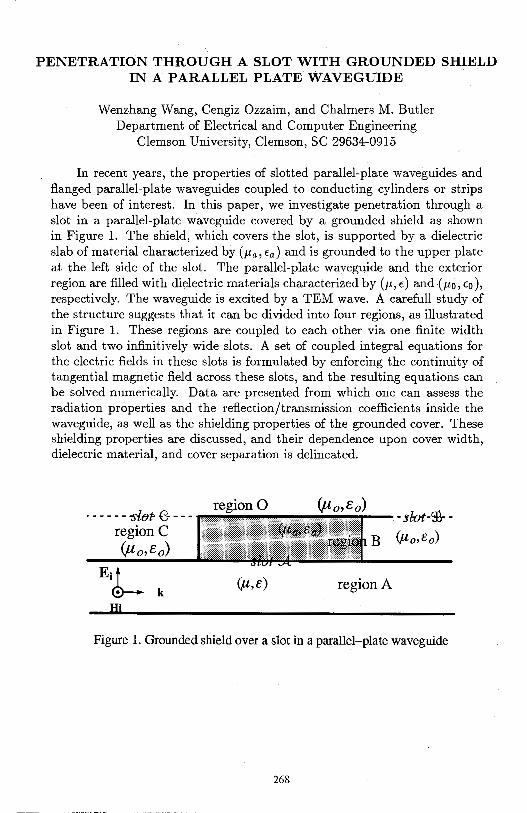
PENETRATION THROUGH A SLOT WITH GROUNDED SHIELD IN A PARALLEL PLATE WAVEGUIDE
Wenzhang Wang, Cengiz Ozzaim, and Chalmers M. Butler Department of Electrical and Computer Engineering
Clemson University, Clemson, SC 29634-0915
In recent years, the properties of slotted parallel-plate waveguides and flanged parallel-plate waveguides coupled to conducting cylinders or strips have been of interest. In this paper, we investigate penetration through a slot in a parallel-plate waveguide covered by a grounded shield as shown in Figure 1. The shield, which covers the slot, is supported by a dielectric slab of material characterized by (µa, ca) and is grounded to the upper plate at the left side of the slot. The parallel-plate waveguide and the exterior region are filled with dielectric materials characterized by(µ, c) and (µ 0 , co), respectively. The waveguide is excited by a TEM wave. A carefull study of the structure suggests that it can be divided into four regions, as illustrated in Figure 1. These regions are coupled to each other via one finite width slot and two infinitively wide slots. A set of coupled integral equations for the electric fields in these slots is formulated by enforcing the continuity of tangential magnetic field across these slots, and the resulting equations can be solved numerically. Data are presented from which one can assess the radiation properties and the reflection/transmission coefficients inside the waveguide, as well as the shielding properties of the grounded cover. These shielding properties are discussed, and their dependence upon cover width, dielectric material, and cover separation is delineated.
· - - - - - -slfJr e- --- region 0 (µo,eo) - til:Ot-9t- -
region C B (µo,fo)
(µo,eo)
Eidr-k
(µ,e) region A
Figure 1. Grounded shield over a slot in a parallel-plate waveguide
268
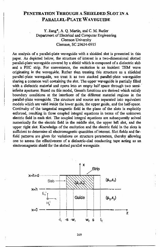
PENETRATION THROUGH A SHIELDED SLOT IN A
PARALLEL-PLATE WAVEGUIDE
Y. Jiang*, A. Q. Martin, and C. M. Butler Department of Electrical and Computer Engineering
Clemson University Clemson, SC 29634-0915
An analysis of a parallel-plate waveguide with a shielded slot is presented in this paper. As depicted below, the structure of interest is a two-dimensional slotted parallel-plate waveguide covered by a shield which is composed of a dielectric slab and a PEC strip. For convenience, the excitation is an incident TEM wave originating in the waveguide. Rather than treating this structure as a shielded parallel-plate waveguide, we treat it as two stacked parallel-plate waveguides sharing a common wall containing the slot. The upper waveguide is partially filled with a dielectric material and opens into an empty half space through two semi-· infinite apertures. Based on this model, Green's functions are derived which satisfy boundary conditions at the interfaces of the different material regions in the parallel-plate waveguide. The structure and source are separated into equivalent models which are valid inside the lower guide, the upper guide, and the half-space. Continuity of the tangential magnetic field in the plane of the slots is explicitly enforced, resulting in three coupled integral equations in terms of the unknown electric field in each slot. The coupled integral equations are subsequently solved numerically for the electric field in the middle slot, the upper left slot, and the upper right slot. Knowledge of the excitation and the electric field in the slots is sufficient to determine all electromagnetic quantities of interest. Slot fields and farfield patterns are given for variations on structure parameters, thereby allowing one to assess the effectiveness of a dielectric-clad conducting tape acting as an electromagnetic shield for the slotted parallel waveguide.
Slab ---f--X=h ---- ----.......,-~~__,_..__.._ ____ _
Exi I 0~, (Guide
X=O --··· -------------------z
269
On Fields Radiated by General Current Sources In Uniform Waveguides Loaded with Stratified Media
Eric W. Lucas and Thomas P. Fontana Antenna Department
Westinghouse Electric Corporation P.O. Box 746
Baltimore, Maryland 21203
In this presentation, we will discuss the problem of computing the electromagnetic fields radiated by general current sources within uniform waveguides. Both electric as well as magnetic current sources will be considered. The uniform waveguide will be assumed to be either homogeneous or loaded with stratified isotropic media. The radiated fields will be written as an appropriate superposition of the natural te and te z-directed vector eigenmodes of the waveguide structure. Beginning with the general biorthogonality relationship for uniform waveguide structures, we evaluate the unknown vector mode expansion coefficients for the homogeneously filled (isotropic) waveguide. These are found by considering the general source to be an ensemble of infinitesimally thin "sheets" of transverse and/or z-directed currents. At each "sheet" distribution, the expansion coefficients are determined such that the appropriate source conditions are satisfied. The fields radiated by the transverse sheet currents are found in a straightforward fashion. The z-directed sheet distributions are handled by an "effective" source model which produces the correct radiated fields outside of the source region. With the source region, as has been discussed by many in the literature, the solenoidal vector mode expansions must be augmented by an explicit delta function term for the z-directed current case for completeness.
To take into account the effect of the stratified media on the radiated fields, we invoke the approach similar to that reported by Munk (Tech. Rep. 715582-4 Electro Science Laboratory Ohio State University, Feb. 1986). The "spectral" te and tm vector mode coefficients in the homogeneous expansion are modified to account for the infinite sets of reflections within each of the stratified isotropic slabs in a simple manner. The concepts of effective transmission and reflection coefficients as well as the "bounce modes" of Munk are used. These are suitably modified such that the vector mode expansion coefficients, when squared, represent the complex power carried by that mode at the point of observation. This is simply a modal normalization issue, but must be recognized and accounted for in the reflection and transmission terms.
The approach outlined here is useful for deriving the Green's function of such structures, and, in particular, is quite useful for straightforward implementation in method of moments numerical formulations.
270
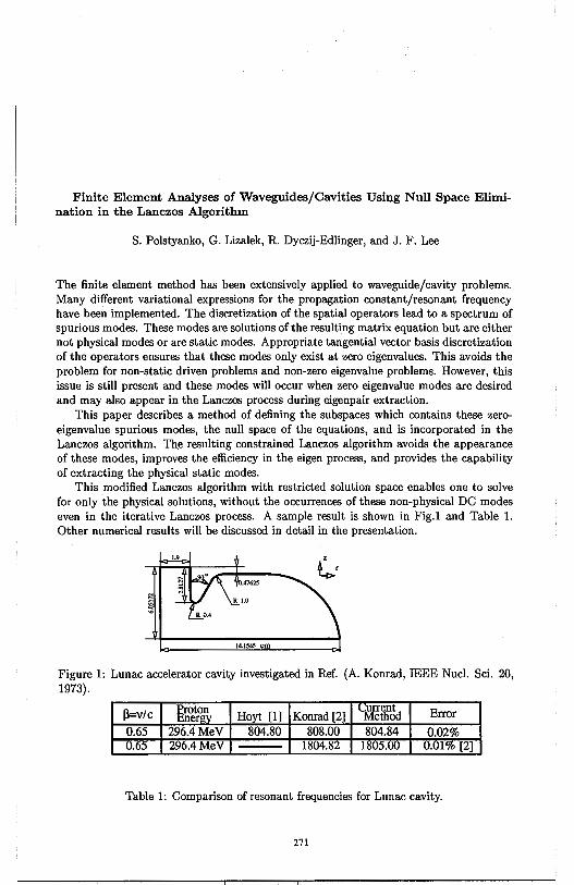
Finite Element Analyses of Waveguides/Cavities Using Null Space Elimination in the Lanczos Algorithm
S. Polstyanko, G. Lizalek, R. Dyczij-Edlinger, and J. F. Lee
The finite element method has been extensively applied to waveguide/cavity problems. Many different variational expressions for the propagation constant/resonant frequency have been implemented. The discretization of the spatial operators lead to a spectrum of spurious modes. These modes are solutions of the resulting matrix equation but are either not physical modes or are static modes. Appropriate tangential vector basis discretization of the operators ensures that these modes only exist at zero eigenvalues. This avoids the problem for non-static driven problems and non-zero eigenvalue problems. However, this issue is still present and these modes will occur when zero eigenvalue modes are desired and may also appear in the Lanczos process during eigenpair extraction.
This paper describes a method of defining the subspaces which contains these zeroeigenvalue spurious modes, the null space of the equations, and is incorporated in the Lanczos algorithm. The resulting constrained Lanczos algorithm avoids the appearance of these modes, improves the efficiency in the eigen process, and provides the capability of extracting the physical static modes.
This modified Lanczos algorithm with restricted solution space enables one to solve for only the physical solutions, without the occurrences of these non-physical DC modes even in the iterative Lanczos process. A sample result is shown in Fig.I and Table 1. Other numerical results will be discussed in detail in the presentation.
R 0.4
14.tS45 cm
Figure 1: Lunac accelerator cavity investigated in Ref. (A. Konrad, IEEE Nucl. Sci. 20, 1973).
l3=v/c Proton Ener Hoyt [1] Konrad [2]
804.80 808.00 1804.8
Table 1: Comparison of resonant frequencies for Lunac cavity.
271
Smooth Surface Discretization for the Design of Waveguide
Mode Converters TANVEER UL HAQ* KEVIN J. WEBB**
*Department of Electrical Engineering University of Delaware, Newark, DE 19716
**School of Electrical and Computer Engineering Purdue University, West Lafayette, IN 47907-1285
A smooth surface discretization method is introduced for the optimizationbased design of waveguide mode converters for high power applications. This solution of the inverse problem of determining a conducting wall geometry to achieve an optimum design yields more flexible designs than were previously available.
The classical approach to designing mode converters is to use a periodic perturbation wall profile. This approach searches for only a certain shape of mode converters and generally results in very lengthy structures. To search for shorter and more general structures a scattering optimization method was recently introduced (T. Haq, K. J. Webb, and N. C. Gallagher, IEEE Trans. Microwave Theory Tech., vol. 43, pp. 559-565, Mar. 1995). This technique resulted in shorter mode converters but the search was limited to only staircase wall profiles where the step heights and lengths could be of the order of>. ( the free space wavelength). Such a surface with sharp discontinuities could be unsuitable for high power applications. To resolve this problem the smooth surface discretization method uses a set of smooth basis functions to represent the wall topography. In this case, the scattering optimization method (SOM), where the desired mode conversion is optimized by varying a set of unknown parameters, yields the weights for these continuous functions. In order to solve for the output power, the continuous surface is discretized in such a way that the quantization step size is small relative to the wavelength, thereby allowing a mode matching solution for the forward problem. The method implemented in this way is therefore suitable for searching the domain of all regular and irregular surfaces and is not limited to a pre- determined set of shapes.
Some existing mode converter designs are modeled using this method to show its validity. New designs will be presented to illustrate the power of this approach.
272
A METHODS OF MOMENTS SOLUTION FOR THE SCATTERING OF TWO POSTS INSIDE A
RECTANGULAR WAVEGUIDE
C. G. Buxton*, W. T. Smith Department of Electrical Engineering
University of Kentucky Lexington, Kentucky 40506-0046
This paper presents a formulation for evaluating the scattering from two short post inside a rectangular waveguide using the Method of Moments. The close proximity of the posts to each other stipulates that the evanescent modes of the waveguide cannot be ignored. The appropriate solution for the scattered fields includes a doubly infinite sum of the waveguide modes. This formulation is general and is not restricted to specific excitations or scattered fi.eld modes.
This work follows previous studies concerning posts in rectangular waveguides. Lewin [IEE Monograph, 1957] formulated the solution for scattering from a resonant stub inside of a rectangular waveguide with a TE10 excitation. Leviatan, etal., [IEEE Trans. MTT, 1983, 1984] formulated a Method of Moments solution for electromagnetic scattering by a single inductive post inside of a waveguide. This formulation allowed for the analysis of scattering from large posts excited by a TE10 mode inside a waveguide.
The formulation in this paper makes no assumptions about the scattered and excitation modes as well as allowing for posts that do not span the width of the waveguide. In the presentation, the expansion of the currents into their basis and matching functions will be presented. The algorithm will be validated by comparison to previous publications. The results of the scattering from the two short posts will be presented.
273
The Existence of Photonic Band Gaps in a Class of Artificial Materials
Hung Y. David Yang Department of Electrical Engineering and Computer Science
University of Illinois at Chicago
Abstract
In recent years, there are many interests in the development of artificial electrical or optical materials. By tailoring the material electrical characteristics, one is able to control the flow of electromagnetic waves from microwave to optic frequencies. The concept of photonic band gap was first introduced (Yablonovitch, Phys. Rev. Letts., vol. 58, no. 20, 2059-2062, 1987) for semiconductor lasers and for photonic applications.
This paper presents the guided wave properties of a class of materials made of long periodic dielectric rods. The structure can be constructed with conventional machine tools in the cet~meter range and with micromachine technique in the micron range. The emphasis is on the existence of photonic band gaps in such materials, where the wave propagation is prohibited within certain frequency bands. We consider specificially the in-plane propagation in the materials made of infinite arrays of long dielectric rods. For in-plane propagation, the guided wave modes are either TE or TM modes. The photonic band structures are very much different for TE and TM modes. Of particular interest is the overlap of the band gap for TE and TM modes. Within the overlap region, the propagation is completely forbidden. The material parameters for the existence of complete bnad gap will be identified. Several specific shapes of rods which are of practical interests are considered such as square, cross, vein, and a group of such rods in a triangle lattice.
An efficient finite difference method is developed for the calculation of guided wave constants. The applications of photonic bandgap materials from microwaves to optics will also be discussed.
274
On the Static and Dynamic SDA of Coplanar Waveguide TW Electrodes Mach-Zender Optical Modulator
G. Cano, F. Medina, M. Homo Microwave Group, Dpt. of Electronics and Electromagnetism
Avd. Reina Mercedes s/n, 41012 Sevilla, Spain E-mail [email protected]. Tph: #34 5 455 2891, Fax: #34 5 423 9434
A coplanar waveguide structure printed on a double layer substrate consisting of a thin Si02 buffer layer over a Ti : LiNbOa one has been studied (K. Kawano et al., IEEE-MTT, Sept. 1991, pp. 1595-1601) when used as the traveling-wave electrodes of a Mach-Zender optical modulator. The analysis of this structure can be carried out by using the well-known SDA (both at quasi-static and dynamic regimes). However some numerical difficulties arise from the extremely thin thickness of the buffer layer. The first purpose of this communication is to show how this circumstance affects the convergence of the semi-numerical method. Once this fact has been addressed, our second goal is to provide a way to speed up the analysis without reducing accuracy.
The quasi-static analysis is formulated in the standard way, but the convergence of the spectral series defining the entries of the Galerkin matrix is drastically improved by applying the complex images theory proposed by Y.L. Chow et al. (IEEE-MTT, July 1991, pp. 1120-1125). The SDA using a full-wave model leads to a nonstandard eigenvalue problem. The solution process requires to compute several times the determinant of the Galerkin matrix for different values of the unknown propagation constant. Therefore it is very important to write the elements of the Galerkin matrix in such a way that the ,B-dependence appears as a multiplicative factor. In this way numerical series have to added up just once. In addition, these series can be quickly evaluated by applying appropriate extraction of their asymptotic tails. Finally, characteristic impedance computation is also accelerated by applying asymptotic extraction techniques. The convergence of this parameter with the number of basis functions is studied in detail when the Si02 layer is or not present. This procedure provides very accurate results both for the propagation parameters ( effective dielectric constant and characteristic impedance) and for the electric field distribution. This is particularly interesting when this transmission line is used as the external modulation device of a light modulator.
275
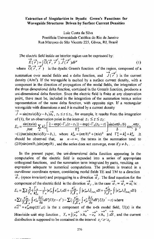
Extraction of Singularities in Dyadic Green's Functions for Waveguide Structures Driven by Surface Current Densities
Luiz Costa da Silva Pontificia Universidade Cat6lica do Rio de Janeiro
Rua Marques de Sao Vicente 225, Gavea, RJ, Brazil
The electric field inside an interior region can be expressed by: ~~ =~~I~~/ ~(r)=jG(r, r ).J(r )dV' (I)
where G((, 7 ) is the dyadic Green's function of the region, composed of a
summation over modal fields and a delta function, and J{ 1') is the current density (A/m2
). If the waveguide is excited by a surface current density, with a component in the direction of propagation of the modal fields, the integration of the three dimensional delta function, contained in the Green's function, produces a uni-dimensional delta function. Since the electric field is finite at any observation point, there must be, included in the integration of the summation term,a series representation of the same delta function, with opposite sign. If a rectangular waveguide with dimensions a and b is excited by a current density
J =sin(ru:la)8(y-b1)ti;, z1 $;z$;z2 , for example, it results from the integration
of(l), for an observation point in the interval z, ::;; z::;; z2:
E = sin(ru:/a) ~k2 [2-exp(-L(z-z1))-exp(-L(z2-z)]sin(mtbi/b) . (mty)
z . ~ en r2 b Sill b }~ n n
-(Ilj~)sin(ru:la)8(y-b1), where k~n=(mtlb)2+(rrJa) 2 and r~=k6+k~n .It should be observed that, as n ~ oo, the terms in the summation tend to (2/b)sin(mtlb1)sin(mrylb) , and the series does not converge, even ify '# b 1.
In the present paper, the uni-dimensional delta function appearing in the computation of the electric field is expanded into a series of appropriate orthogonal functions, and the summation term integrated by parts, resulting an expression adequate to numerical computations. The problem is treated in a curvilinear coordinate system, considering modal fields TE and TM to a direction
d; (space invariant) and propagating in a direction d1. The final equation for the
f h I . fi Id . h d. . ~ . h ~ ~ ~. component o t e e ectnc e m t e 1rect1on a 1 , m t e case a ; = a 1 = az 1s: r > <
Ez = L{y2 (-f-f )efnf efnJzdS+ :[' f leinJzlz=Z/S+ :[' f je;"nlzl=
2dS}
n ken n n n n n
~{ e;'n f < dJzdV} "( t) ~{ e;,, f > d}zdV} "( 1 ) h +~ Ynrn eznaz v,z-z -~ Ynrn einaz v•Z -z were
e:f.>l =einexp(±rnz) is the z component of the n-th modal field, U(z) is the < ~> > ~< --+
Heaviside unit step function , Yn = f{ e,; x hn - e";; x hn } .dS, and the current distribution is supposed to be contained in the interval z1 <z<z2.
276

Wednesday PM AP/URSI-B Session 6 Constel. Ball. C
Special Session
Novel Mathematical Techniques in EM Theory N. Engheta and P. L. Uslenghi Page
1 : 20 Differential Forms in Electromagnetic Field Theory ..................... APS Karl F. Warnick, David V. Arnold, Richard H. Selfridge, Brigham Young University
1 :40 Applications of Cohomology to Electromagnetic Theory .............. 278 Benjamin B. Wells, Mariott International
2:00 Wave Interactions with Trefoils and Untrefoils ............................ 279 0. Manuar, D. L. laggard, University of Pennsylvania
2:20 The Electromagnetic Field as a Gauge Field: Abelian and ............... 280 Nonabelian Symmetries with Applications to Superconductors and Magnetic Monopoles Arthur K. Jordan, Naval Research Laboratory
2:40 Application of Weyl-Heisenberg and Affine-Groups to ................. APS Scattering H. N. Kritikos, University of Pennsylvania
3:20 Symplectic (Nonseparable) Spectra and Novel, Nondispersive, ........ 281 Slowly Decaying Beam· Solutions to the Complex Parabolic Equation /oannis M. Besieris, Mohamed Abdel-Rahman, Virginia Polytechnic Institute and State University, Amr M. Shaarawi, Cairo University
3 :40 Determination of Propagation Constants in Arbitrarily ................. 282 Shaped and Inhomogeneous Waveguides by Path Integral Methods Robert D. Nevels, Texas A&M University
4:00 Genetic Algorithms in Electromagnetics ................................... APS J. Michael Johnson, Yahya Rahmat-Samii, University of California Los Angeles
4:20 The Design of Yagi Antennas Using a Genetic Algorithm ............... 283 Derek S. Linden, Edward E. Altshuler, Rome Laboratory
4:40 Fractional-Dipole Radiation ................................................... 284 Nader Engheta, University of Pennsylvania
277
APPLlCATIONS OF COHOMOLOGY TO ELECTROMAGNETIC TIIEORY Benjamin B. Wells, Marriott International
(Abstract) We attempt to bring some of the formalism of the theory of differential fonns and
deRahm cohomology to bear on classical electromagnetics. This theory is useful for framing many facts about classical electromagnetic nelds as well as for showing the existence of non-trivial fields on a compact manifold such as a torus or a trefoil knot.
The story begins with a given compact manifold M, say in the usual 3-dimensional space R3
• One may then speak of what is known as an exact sequence of differential forms: O--..+E0 ~E1 ~E2 ~E3 -+ 0. The E's are the vector spaces of
differential forms on the manifold M of orders O through 3, respectively. Eo is the vector space of all infinitely differentiable fimc1ions on M, and E1 is the vector space dual to the tangent space of M and spanned by the I-forms {dx, dy, dz}. E2 is spanned by the 2-forms {dx /\ dy, dy I\ dz, dx I\ dz}, and E3 by the single 3-form dx I\ dy I\ dz. The symbol "/\ " denotes the wedge or exterior product.
The three mappings d1, d2, and ds are the very familiar gradient, curl, and divergence operations, respectively. The term exactness refers to the fact that at any point in the sequence the range of a mapping on the left is contained in (but not necessarily equal to) the kernel of the mapping to its right. This is equivalent to saying that d2d1=d3d2=0.
The deRham cohomology groups H1(M) and H2(M) are defined as follows: H1(M) is the quotient of the vector space of all 1-forms µ such that d2 µ = 0 by that of all 1-forms µ such that µ = d1 ~ for some ~ in Eo- Similarly, H2(M) is the quotient of the vector space of all 2-fonns v such that d3 v = 0 by that of all 2-forms v such that d2 m = v for some 1-form m. Roughly speaking, the cohomology groups H1(M) and H2(M) measure the extent to which the containment relations referred to above are proper.
Stated in the familiar classical jargon, a non-zero element Z of H1(M) corresponds to an irrota1ional electric field F (curl F = 0) which has no potential fimction. (ie. F = grad(¢) for no ¢ defined on M) Therefore, H1(M) is a measure of the nontrivial irrota1ional electric fields on M .
Similarly, a non-zero element Z of H2(M) corresponds to a field I: such that div(I:) = 0, but for which no field B exists such that curl(B) = I: (ie. I: is not magnetostatic). For example, I: might be a charge density field, so H2(M) is a measure of the possible J fields on the manifold M having no sources.
Two facts about the deRahm cohomology groups are important to note here. The first, stated as a theorem is: "The deRahm cohomology groups of a compact, orientable, differentiable manifold are finite dimensional." See the book by Frank W. Warner, Foundations of Differentiable Manifolds, Scott, Foresman & Company 1971, page 226. The second fact is that they are computable via the singular cohomology groups. This is possible, ·since the two cohomology theories produce the same groups.
For a ball or a cube in R3 the singular cohomology groups are easily seen to be trivial (have only the O element). But these groups are not trivial for a torus and certain other 3-dimensional manifolds, and precisely what they are tells us something about the possible fields that exist on such structures.
278

Wave Interactions with Trefoils and Untrefoils
0. Manuart andD. L. Jaggard
Complex Media Laboratory Moore School of Electrical Engineering University of Pennsylvania Philadelphia, PA 19104-6390, USA
t Also Department of Biochemistry and Biophysics, School of Medicine University of Pennsylvania Philadelphia, PA 19104-6059
We provide insight into the physical mechanism behind the stronger backscattering of circularly polarized radiation into the same polarization from wire untrefoils than from symmetric wire trefoils.
Previously we presented results for backscattering from trefoils and untrefoils [0. Manuar and D. L. Jaggard, "Backscatter Signature of Knots," Opt. Lett .. 20, 115-117 (January 15, 1995); D. L. Jaggard and 0. Manuar, "Can One "Hear" The Handedness or Topology of a Knot?" 1995 AP-S/URSI Meeting, Newport Beach, CA (June 18 - 23, 1995)]. A striking difference occurs between symmetric trefoils and untrefoils when the incident radiation is a plane wave circularly polarized and incident perpendicular to the plane of the knot. The symmetric trefoil gives a significant backscattering cross section when detecting radiation with circular polarization opposite to the incident wave (i.e., cross-polarization), and numerically gives approximately 30 orders of magnitude less power when looking for radiation of the same polarization (i.e., co-polarization); the untrefoil, however, gives appreciable backscatter of radiation with both polarizations. Here we illustrate the physical underpinning for this difference between a wire trefoil and a wire untrefoil by examining the induced charges and dipole moments.
On the right we display the induced charge (left column) and the induced dipole (solid line in right column) and incident electric field (dashed line in right column) for circularly polarized waves illuminating a symmetric wire trefoil at different steps in time (top to bottom). We show that circularly polarized plane waves induce one rotating dipole on a symmetric trefoil wire structure (shown here) and two, counter rotating dipoles in an untrefoil (not shown). The additional rotating dipole of the untrefoil gives rise to the relatively large co-polarized backscattering of the untrefoil.
:;~ :;l@_ ........... . 0 -1 0 ·1
0 0 1 1 1 1
.:~.:@·· .... -1 -1~
0 -1 0 -1 0 0
11 1 1
:;~ :;~! o'\.~ -1 o -1
0 0 11 1 1
.:~· .:@_·· ... -1--~ -1~
0 -1 0 -1 0 0
1 1 11
279
The Electromagnetic Field as a Gauge Field: Abelian and N onabelian Symmetries
with Applications to Superconductors and Magnetic Monopoles
Arthur K. Jordan
Naval Research Laboratory
Washington, DC 20375
The electromagnetic field is the prototypical gauge field. By this we mean that it is the field
that has been introduced in order to guarantee invariance under local gauge transformations and that
the electromagnetic field theor~ serves as a model for other, more complex field theories in physics.
After a brief review of how Maxwell modified Ampere's law to satisfy the continuity equation,
Maxwell's equations are "derived" from the electromagnetic field Lagrangian and the global and local
gauge transformations are described. Then by using the fact that Maxwell's equations satisfy the
continuity equation of charge and current, it can be shown that this conservation law implies that the
Lagrangian of the electromagnetic interaction has U(l) unitary group symmetry, i.e. symmetry under
rotations in a plane. This group is abelian since a rotation 111 followed by a rotation 112 in the plane
is equivalent to a rotation 112 followed by a rotation 111 in the plane. This theory can be generalized to
a Lagrangian that has a higher symmetry than U(l), namely the nonabelian special unitary group
SU(2). Two electromagnetic examples of this nonlinear group, vortex lines in superconductors and
magnetic monopoles, will be discussed. Gauge field theory in the form of quantum chromodynamics
has been applied to the short-range strong nuclear interaction. Here the vacuum can be modeled by a
polarized dielectric, analogous to the vacuum polarization of quantum electrodynamics. It is
conjectured that further electromagnetic analogues can be found in the electroweak theory of
Glashow-Salaarn-Weinberg and that these analogues can lead to novel electromagnetic applications.
280
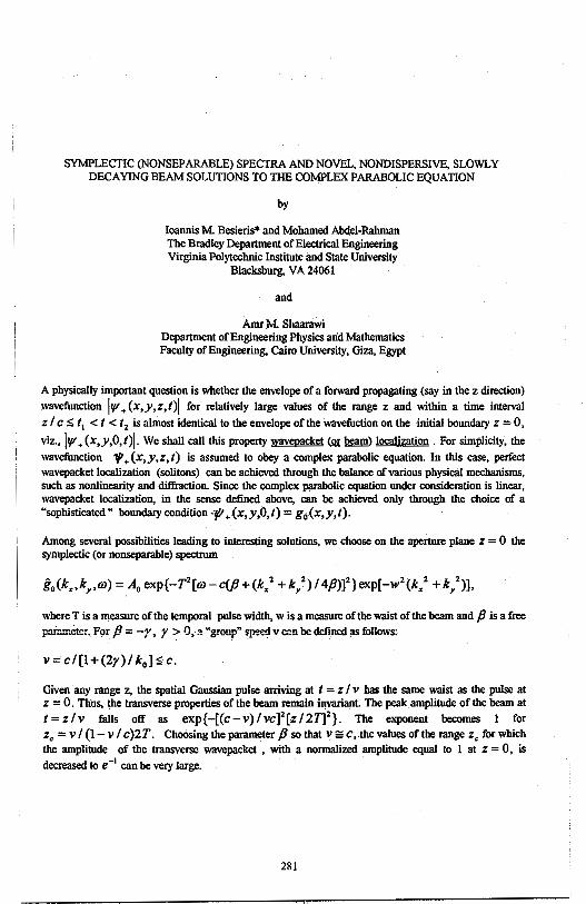
SYMPLECTIC (NONSEPARABLE) SPECTRA AND NOVEL, NONDISPERSIVE, SLOWLY DECAYING BEAM SOLUTIONS TO THE COMPLEX PARABOLIC EQUATION
by
Ioannis M. Besieris* and Mohamed Abdel-Rahman The Bradley Department of Electrical Engineering Virginia Polytechnic Institute and State University
Blacksburg, VA 24061
and
Amr .M. Sbaarawi Department of Engineering Physics and Mathematics Faculty of Engineering, Cairo University, Giza, Egypt
A physically important question is whether the envelope of a forward propagating (say in the z direction)
wavefunction IV'+ (x,y,z,t)I for relatively large values of the range z and within a time interval
z I c :;; t 1 < t < t 2 is almost identical to the envelope of the wavefuction on the ·initial boundary z = 0,
viz., IV'+ (x,y,O,t)I. We shall call this property wavepacket ti!! beam) localization. For simplicity, the
wavefunction 'J/1 + (x,y,z, t) ·is assumed to obey a complex parabolic equation. In this case, perfect wavepacket localization (solitons) can be achieved through the balance of various physical mechanisms, such as nonlinearity and diffraction. Since the complex parabolic equation under consideration is linear, wavepacket localization, in the sense defined above, can be achieved only through the choice of a "sophisticated" boundary condition ·7/1 +(x,y,O,t) = g0 (x,y,t).
Among several possibilities leading to interesting solutions, we choose on the aperture plane z = 0 the symplectic (or nonseparable) spectrum
where Tis a measure of the temporal pulse width, w is a measure of the waist of the beam and pis a free
p:ir::meter .. F9r /3 = -r, y > O,.:i "group~ sp'!'!d v c::n be defined as follows:
v = CI [I + (2y) I k0 ] :;; c.
Given any range z, the spatial Gaussian pulse arriving at t = z I v has the same waist as the pulse at z = 0. Thus, the transverse properties of the beam remain invariant. The peak amplitude of the beam at t=zlv falls off as exp{-[(c-v)/vc]2[z/21]2
}. The exponent becomes I for z. = v I (I-v I c)2T. Choosing the parameter p so that v = c, the values of the range z. for which the amplitude of the transverse wavepacket , with a normalized amplitude equal to I at z = 0, is decreased to e · 1 can be very large.
281
DETERMINATION OF PROPAGATION CONSTANTS IN ARBITRARILY SHAPED AND INHOMOGENEOUS WAVEGUIDES
BY PATH INTEGRAL METHODS
Robert D. Nevels Department of Electrical Engineering
Texas A&M University College Station, Texas 77843
Virtually every numerical method that has been used to solve for the electromagnetic field in a waveguide can also be used to compute waveguide propagation constants. These include variational, moment, finite-difference timedomain, and finite element methods, to name a few. For relatively simple structures the results obtained by these methods can be confirmed by modal analysis or in the case of dielectric waveguides with homogeneous layers, by the transcendental equation and transverse resonance analytical techniques. In this paper we will demonstrate that the path integral method in conjunction with the characteristic Green's fimction can be used to determine the characteristic modes of a waveguiding system. With the path integral method all that is required is a knowledge of the permittivity of the cross-sectional profile of the waveguide which can be arbitrarily shaped and inhomogeneous in content.
The Green's fimction form of the one-dimensional Helmholtz equation is given by
[:2 +k2(x)JG(xlx')=-8(x-x') (I)
where the inhomogeneous medium wave number k(x) = kn(x), with n(x) the index of refraction and k the free space propagation constant. By using the characteristic Green's fimction technique, one may obtain a representation for
G( xix') that emphasizes the existence of singularities in the complex k plane at
the eigenvalues k,, . It is also possible to solve Eq.( 1) by path integral methods ( R. D. Nevels, C. Huang, Z. Wu, IEE Proc., Part H,488-492,1993). As a simple example, Eqn.(1) is assumed to be the Green's fimction equation for the xdirection separation equation for a rectangular waveguide. The path integral solutionto (1) will be plotted as a fimction of the wave number k. Peaks in the spectrum of G will be shown to correspond to the x direction wavenumbers which can be found analytically. The waveguide propagation constant can be found by adding this result to that obtained by using the same procedure on they-direction separation equation. The method described here is general and can be easily applied to waveguides that have an inhomogeneous dielectric profile, such as optical :fibers, and to waveguides with an arbitrary transverse direction physical configuration.
282
The Design of Yagi Antennas Using a Genetic Algorithm
Derek S. Linden and Edward E. Altshuler Rome Laboratory 31 Grenier Street
Hanscom AFB, MA 01731-3010,USA
In this paper we describe a new process for designing Yagi antennas by using an electromagnetics code in conjunction with a Genetic Algorithm (GA); in this process the antenna is designed using a completely deductive approach. That is, the desired electromagnetic properties of the antenna are specified and the wire configuration that most closely produces these results is then synthesized.
The GA, which utilizes the mechanisms of evolution, starts with a randomly selected population of antenna configurations. Each configuration is represented by a chromosome which consists of a binary string of l's and O's. The desired electromagnetic characteristics of the antenna are represented by an objective function. The performance of each member of the population is computed using an electromagnetic code and ranked · in terms of its closeness to the objective function. As in the evolutionary process of "survival of the fittest," high quality strings mate and produce offspring; poor quality strings perish. To accomplish this, the top 30% of the solutions are kept and mated. Mating is done by creating a "weighted roulette wheel," where the best performers are given a proportionally larger share of the wheel. Once parents are chosen by "spinning" the wheel, the chromosomes of the parents are divided into two parts at a common, randomly selected crossover point. The child is created by combining the first part of one parent's chromosome with the last part of the other's. Mutations are also included in the algorithm. With succeeding generations the quality of the strings continually improves and the cycle of mating, mutating and evaluating ultimately converges to an optimal solution.
We have designed many Yagi .and Yagi-like antennas using this method; the gain and VSWR have been optimized for both narrowband and wideband applications. Unlike other Yagi antenna optimizers, the GA does not require an initial guess that will be close to the final solution. It has thus allowed us to explore antennas with asymmerty and with tilted elements. We have obtained higher gains and larger bandwidths than designs optimized conventionally. Some of these antennas have been fabricated and the computational results verified experimentally. We have shown that the GA is a very powerful tool fQr designing wire antennas; it is expected that this process can be used to . design any antenna that can be analyzed using an electromagnetic code.
283
FRACTION AL-DIPOLE RADIATION
Nader Engheta
Moore School of Electrical Engineering University of Pennsylvania
Philadelphia, Pennsylvania 19104, U.S.A. Tel: (215) 898-9777, Fax: (215) 573-2068
E-mail: [email protected]
Recently, we studied the idea of fractional multipoles in electromagnetism using the concept of fractional derivatives [N. Engheta, "On Fractional Calculus and Fractional Multipoles in Electromagnetism" IEEE Trans. Antennas & Propagation, Vol. 44, No. 4, 1996, in press]. Fractional derivatives and integrals are operators studied expensively in the area of fractional calculus in mathematics [K. B. Oldham and J. Spanier, The Fractional Calculus, Academic Press, New York, 1974]. In our work in applying fractional calculus in defining fractional multipoles in electromagnetism, we showed that in the electrostatic case, as far as their scalar potential distributions are concerned, such fractional-order multipoles effectively behave as "intermediate" sources bridging the gap between the cases of integer-order point multipoles such as intermediate cases between point-monopoles and point-dipoles, between point-dipoles and point-quadrupoles, etc. We also addressed an application of fractional multipoles in describing electrostatic image charges for perfectly conducting wedges and cones with arbitrary angles.
In this talk, we will discuss our theoretical results for the time-harmonic case of fractional multipoles, and will address the monochromatic radiation properties of such fractional multipoles. In particular, the case of the monochromatic fractional-dipole will be presented in detail. For the monochromatic time-harmonic case where the current and charge distributions in these fractional multipoles vary sinusoidally with time, we have studied the radiation properties in the far zone region. We show that for the fractional dipole, which we denote as 2a-pole where a is a non-integer number between zero and unity, the far-zone electromagnetic radiation can be divided into two terms: one term with characteristics of spherical wave and the second term with features of cylindrical wave. At the two limiting cases of a = 0 and a = 1, this fractional 2a-pole becomes the standard point-monopole and point-dipole, respectively, and its farzone radiation approaches that of the monopole and dipole. We will address some of the salient features of the fractional-dipole radiation and we will discuss its physical insights. Some of the radiation properties of higher-order fractional multipoles will also be mentioned.
284
Wednesday PM AP/URSI-F Session 4 MD S. Annapolis
Personal Access System Propagation Effects A. Solyman Page
1 :20 Sensitivity of CDMA RF Planning to the Choice of the ................. 286 Propagation Models Solyman Ashrafi, Tom Tran, Graham Stead, MU, Inc.
1 :40 Statistical Characteristics of UHF Propagation of ........................ 287 Microcellular Systems I-Tai Lu, Henry L. Bertoni, Song Jin Hong, Polytechnic University
2:00 A Switched Beam Antenna for Indoor Wireless Applications ........... 288 K. Sunidja, R. C. Compton, Cornell University
2:20 Prediction and Measurement of Wall Insertion Loss ...................... APS Thad B. Gibson, Naval Air Warfare Center - Weapons Division, David C. Jenn, Naval Postgraduate School
2:40 High-Resolution Measurements of AOA and Time-Delay ................ APS for Characterizing Indoor Propagation Environments John Litva, Amir Ghaforian, Vytas Kezys, McMaster University
3:20 Prediction of Radio Coverage Inside Rooms ............................... APS Yi Huang, The University of Liverpool
3 :40 Picocellular Radiowave Propagation ......................................... 289 T. Schober[, H. J. Schmitt, Aachen University of Technology
4:00 Comparison of Channel Impulse Response ................................ APS Measurements and Calculations in Indoor Environments T. Zwick, F. Demmerle, W. Wiesbeck, University of Karlsruhe
4:20 Measurement of Bi-Static Scattering Characteristics ..................... 290 of Human Body at 60 GHz Akihito Kato, Katsuyoshi Sato, Takeshi Manabe, Toshio /hara, Communications Research Laboratory, Ministry of Posts and Telecommunications
4:40 Channel Parameters Determination for Wireless .......................... 291 Indoor Propagation Hsueh-Jyh Li, Wen-Fong Tsen, National Taiwan University
5:00 The Dependence of Single Room Indoor Radio ............................ APS Propagation on Frequency Qin Zhou, A. K. Y. Lai, Chinese University of Hong Kong
285

Sensitivity of CDMA RF Planning to the Choice of The Propagation Models
Solyman Ashrafi1, Tom Tran2
, Graham Stead3
ML!, Inc. 1 JJ ON. Glebe Rd Suite 800 Arlington, Virginia 22201 Telephone: (703)741-3500
Fax: (703) 741-0312
A number of statistical and deterministic models are available in the literature for the prediction and calculation of transmission loss, but the main difference between them as well as their usefulness in a particular situation is not easy to assess. In this article, sensitivity of a CDMA radio planning to the choice of the propagation models is studied. The field strength predictions should be as accurate as possible, because any errors have immediate impact on the system design. Underprediction leads to interference effect thereby increasing the system's total noise level, whereas overprediction causes holes in the real coverage. While a finetuning of the system after it starts operating will always be necessary, the choice of the best possible propagation model can avoid the need for major adjustments in the future, and also eliminate or minimize the res1,1lting disruptions in the service. The forward and reverse link network performance using different propagation models, traffic loads and system parametei:s are analyzed using sophisticated RF planning tools. In addition, the dependence of the service probability and area reliability on the choice of the propagation models is studied and a link margin requirement is established for different propagation models. Experimental propagation loss measurements taken in Seattle at 1800 MHz are presented and are found to fall very nicely in the range predicted by multi-breakpoint deterministic model explained in the paper. It is concluded that a poor choice of propagation model severely effects a CDMA radio network performance.
1. Director of Advanced Technologies 2. Technology Project Manager 3. Scientific Programmer/Analyst
286
Statistical Characteristics of UHF Propagation of Microcellular Systems
I-Tai Lu, Henry L. Bertoni, and Song Jin Hong
Center for Advanced Technology in Telecommunications/Department of Electrical Engineering, Polytechnic University, Route 110, Farmingdale, NY 11735
ABSTRACT A knowledge of UHF propagation characteristics is required for the design and analysis of microcellular systems and fixed wireless loop systems. One of the important issues is how to enhance the signal to noise ratio at the base station using spatial diversity or antenna directivity. The performance of such a base station depends on the statistical properties of multipath arrivals. For example, spatial diversity requires antenna separations greater than the coherence distance of the spatial fading pattern generated by multipath arrivals. Alternatively, a highly directive antenna employing electronic steering and beam forming could be used to look at individual arriving rays and thereby avoid the spatial fading. In this paper, we use a simplified ray approach to compute the field received at a high rise antenna in residential environment. The statistical characteristics are obtained by the following three scenarios: a.) embedding randomly the tall buildings into the deterministic background; b.) placing the subscriber unit at random locations; c.) placing the base station at random locations. The important conclusion to be obtained here is how the beam width of the base station antenna will affect the multipath propagation characteristics. Numerical results will be presented.
287
A Switched Beam Antenna
for Indoor Wireless Applications
K Sunidja* and R. C. Compton
School of Electrical Engineering Cornell University, Ithaca, NY 14853
In this paper we report on propagation measurements for an omniazimuthal hub transceiver. The transceiver consists of an array of radial vi~ valdi tapered slot antennas integrated onto a circular disk. The size of each antenna is reduced by using an exponential slot taper near the wide end of the antenna, where most of the radiation occurs, and a linear taper was used for the less critical narrower portion of the slot (M. J. Vaughan and R. C. Compton, "28 GHz Oscillator for Endfire Quasi-Optical Power-Combining Arrays," Electronics Letters 31, p 1453-1455, Aug. 1995.). The linear taper can be made to transition to the slotline feed in a shorter distance than the exponential taper.
The hub switches between elements to select the beam which provides the largest signal level at the receiver.
0
'For indoor wireless networks this allows the link to reduce multipath effects by using a higher gain antenna and choosing the path which gives the best performance. A similar array could also be used in the receiver to further expand the range of possible paths.
In the work reported here, a series of indoor measurements were made to characterize the operation of the array. Comparisons between four and six element arrays, with a 90° and 60° separation between antennas is presented. Measurements made along a corridor indicate that selection of the optimal element depends on the spacing between the receiver and transmitter. Similar conclusions were drawn for measurements made around a corner. Traffic in the corridor also significantly effects the element selection.
288
Picocellular Radiowave Propagation
T. Schober/ and H.J. Schmitt Chair and Institute of High-Frequency Engineering
Aachen University of Technology Melatener Straf3e 25, 52072 Aachen, Germany
This paper discusses a raytracing model for radiowave propagation in indoor environments and presents comparisons between results of the model and propagation measurements. The radiowave travels from the transmitter to the receiver via many paths caused by transmissions of the wave through objects and walls, reflection,; and diffractions. The received signal depends on the transit time, the attenuation and the phase shift of the signals along any of the various paths. The complexity of the building complicates the determination of the paths. The presented raytracing model is based on a Monte Carlo simulation and considers all possible combinations of the reflected, transmitted and diffracted rays from ceilings, floors, walls edges and corners. The simulation calculates the complex channel impulse response, the RMS multipath time delay spread, the delay power profile and other characteristics parameters of the radio channel. The three dimensional database of the building includes the size, the material and the thickness of the walls and the electrical properties. Tua influence of the antenna pattern, the polarization and the frequency on the wave propagation are determinated by the simulation. A broadband omnidirectional discone antenna and a HP network analyser were used for the measurements of the channel impulse responses at a frequency of 1.9 GHz in the institute. Comparisons between the measurements and the raytracing model indicates a good agreement that the raytracing model works well for such indoor picocellular environments.
289
MEASUREMENT OF BI-STATIC SCATTERING CHARACTERISTICS OF HUMAN BODY AT 60 GHz
Akihito KA TO, Katsuyoshi SATO, Takeshi MAN ABE, and Toshio IHARA
Communications Research Laboratory
Ministry of Posts and Telecommunications
4-2-1 Nukui-kitamachi, Koganei, Tokyo 184, JAPAN
The feasibility of indoor high speed wireless digital transmission using millimeter waves is discussed in recent years. There are still many problems that need to be clarified. In high-speed digital indoor wireless communications system, multipath
propagation is a serious cause of channel degradation. Scattering due to human bodies is a possible cause of multipath propagation as well as reflections from various indoor objects. We measured the bi-static scattering characteristics of human body at 60 GHz, and we estimate the influence of the scattering of human bodies on the channel.
The target was the upper half of the body of a dressed male. The distance from the target to the transmitter or treceiver is 1.6 meters. The scattered waves from the target as a function of receiver angle were measured by a swept frequency method, sweeping the
frequency over a 1-GHz band centered around 57.5 GHz.
Figure l(a) and (b) show the transmitting and receiving angle dependencies of bi
static scattering characteristics of the target for horizontal and vertical polarizations,
respectively. The results indicate that the bi-static scattering cross section of human body
is almost omnidirectional in the horizontal plane. The mean values of the bi-static
scattering cross section of the target are estimated to be 0.11 m2 and 0.16 m2 for
horizontal and for vertical polarizations, respectively. These values are about one sixth
of those for perfectly conducting cylinders of equivalent diameters (E.F.Knott, et.al.,
RADAR CROSS SECTION, p.158, Artech House, 1985). Simple model calculations
indicate that the influence of multipath propagation caused by human bodies is not so
much serious as that caused by various indoor objects.
(a)
-9o~---.-.-.---c -80
-70 -60
-50 -40
-30 _20,,.__,__,__J---C -10 0
receiver angle 0R [deg]
transmitter angle 0T ········-!Odeg --30deg --50deg --?Odeg -------- -90 deg receiver angle 0R [deg]
transmitter angle 0T
•••••••• -10 deg -·-3Ddeg --50deg --70deg
········ -90deg
Figure 1. Measurement results of scattering characteristics of human body at 60 GHz.
290
Channel Parameters Determination for Wireless Indoor Propagation
Hsueh-Jyh Li and Wen-Fong Tsen Department of Electrical Engineering
National Taiwan Univ. Taipei, Taiwan, R.O.C.
Indoor radio channel characteristics for given locations of the transmitter and receiver can
be represented by an impulse response, which is usually expressed by a superposition of delta
functions. The complex amplitude and delay time of each delta function are usually used to
characterize the particular path channel. However, these two scalar quantities do not provide
full information about each path wave component. Complete parameters about an incident
wave should include the amplitude, the delay time, the direction of arrival as well as the
polarization.
The amplitude and delay time of multipath components can be obtained by wide band
measurements. The direction of arrival has been measured by scanning a high gain antenna.
However, methods for determining the polarization have not been reported. In this paper, we
will provide a cost-effective method to determine the above four channel parameters from
measured data. Amplitudes and delay times are obtained by wide band measurement in the
frequency domain. Two synthetic crossed dipole arrays are used to determine the azimuth and
elevation of incident waves. Fields received from vertical and horizontal dipoles are used to
determine polarization of each incident wave. The measurement arrangement and signal
processing algorithms used are much like those u.sed in synthetic aperture radar(SAR)
imaging or inverse synthetic aperture radar (ISAR) imaging. The MUSIC algorithm with
spatial smoothing is applied to enhance the time and angular resolutions for multipath waves.
The arrangement for collecting field data and algorithms for determining the amplitude, time
delay, direction of arrivals and wave polarization will be analyzed. Some numerical and
experimental results will be demonstrated to verify the effectiveness of our proposed method.
291

THIS PAGE INTENTIONALLY LEFT BLANK.
292
Wednesday PM AP/URSI-D Session 2
Photonics Applications to Antennas D. K. Paul and M. L. VanBlaricum
MD S. Frederick
Page
1 : 20 Optical Beam Forming and Steering Architectures for Satcom ......... APS Phased-Array Antennas Dilip K. Paul, Rajender Razdan, Brian J. Markey, COMSAT Labs
1 :40 Fiber-Optic Control of a Two-Dimensional, True Time- ................. APS Steered Array Transmitter Paul J. Matthews, Michael Y. Frankel, Ronald D. Esman, Naval Research Laboratory
-2:00 Optical Feed for Multibeam Microwave Array Antennas ................. APS Yu Ji, Keizo Inagaki, Ryu Miura, Yoshio Karasawa, ATR Optical & Radio Communications Research Laboratories
2:20 Hybrid Lidar-Radar - Concept and Experiment ............................. APS P. R. Hercefeld, L. Mullen, Drexel University, V. M. Contarino, Naval Air Warfare Center
2:40 Requirements, Current Status, and Future Strategy of .................... 294 Photonic True Time Delay Systems for Navy Applications Joon Y. Choe, Naval Surface Warfare Center, William J. Miceli, Office of Naval Research
3:20 Army Optically Controlled Phased Array Program ........................ 295 L. Coryell, J. Wright, A. Paolella, N. Vallestero, U. S. Army Communications-Electronics Command
3:40 Photonically Controlled Active Phased Array Architectures ............ 296 M. Russell, A. Marinilli, J. Preiss, D. L. Green, Raytheon Electronic Systems, Dr. F. Jain, University of Connecticut
4:00 Development of Photonically-Controlled, Wideband · .................... 297 Conformable Phased Array with Reconfigurable Integrated Antenna Phase Shifter J. J. H. Wang, J. K. Tillery, G. T. Thompson, K. E. Bohannan, R. M. Najafabadi, Wang Electro-Opto Corporation
4:20 Characteristics of Photoconducting Antenna Elements Excited ........ 298 by Picosecond Optical Pulses David W. Liu, Paul H. Carr, Steven D. Mittleman, Rome Laboratory, Anthony J. Devaney, Northeastern University
4:40 A CAE Tool for Performance Analysis of Photonic-Based .............. :299 Antenna Systems Michael L. VanBlaricum, Peter J. Stieber, Michael P. Grace, Toyon Research. Corporation
293
Requirements, Current Status, and Future Strategy of Photonic True Time Delay Systems for Navy Applications
Joon Y. Choe Naval Surface Warfare Center, White Oak, MD
William J. Miceli Office of Naval Research, Arlington, VA
A survey of Photonic True Time Delay (TTD) systems for Navy applications will be presented. First, quantitative requirements on the photonic TTD system will be discussed. After a rudimentary radar review to compare TTD with phase shift steering, quantitative system parameters relevant to the TTD will be provided. We will use a notional representative RF system such as AEGIS radar as an example. In this process we identify key technical difficulties for Navy TTD system.
Secondly, we will survey several existing TTD system architectures with the purposes of investigating how the current state of the art schemes compare with the Navy requirements, of discussing the various trends and techniques which the community is considering in trying to narrow the gap, and of determining the advantages and disadvantages for each scheme. Ways to reduce the complexity of the TTD control will be discussed in depth with several different view points.
Finally, the results are summarized by identifying the promising approaches, needed technical advances, and possible road map for future systems. We will also discuss some other issues that are not yet investigated but may hold promise for photonics implementation to the Navy system such as the multiple beam configuration.
294
ARMY OPTICALLY CONTROLLED PHASED ARRAY PROGRAM
L. Coryell, J. Wright, A Paolella and N. Vallestero U.S. Army Communications-Electronics Command
Attn: AMSEL-RD-ST-SY-TE Fort Monmouth, NJ 07703-5203
908-427-3640 Fax 908-427-4298
The intensity and speed of Operation Desert Storm highlighted the need for communications to keep up with the tactical commander. Developments to address these needs include both SATCOM (satellite communications) on-the-move (ground terminals) and terrestrial comm (communications) on-the-move. The capabilities offered by the realization of practical optically controlled phased arrays for ground communications terminals can contribute greatly in meeting this challenge. The Space Technology Branch of the Space and Terrestrial Communications Directorate has an ongoing program leading to the development of Integrated Photonic Subsystems (IPS) for this purpose.
A number of different applications are under investigation with carrier frequencies from 2~58 GHz and data rates from 2.4 Kb/s to 155 Mb/s or more. Survivability needs, combined with the desire for a scalable, modular architecture usable over a wide frequency range, led to the need to use an optically controlled phased array antenna. In this paper we will highlight the mobile Radio Access Point (RAP) which will incorporate a High Capacity Trunk Radio and multibeam Optically Controlled Phased Array Antenna operating at 7-8 GHz. The objective of this system is to give the battlefield commander a comm on-the-move capability through a high altitude UAVat data rates up to 155 Mb/s. Details on the phased array transmit and receive architecture will be given as well as the results of in-house and contractual development efforts, including Optical Phase Locked Loops using DFB and Y AG lasers, Lossless Optical Splitters, Integrated Phase and Amplitude Controller OEICS, and Hybrid Optical and MMIC T/R Modules/Antenna Elements.
295
Photonically Controlled Active Phased Array Architectures
A.Marinilli M. Russell Raytheon Electronic Systems
50 Apple Hill Drive Tewksbury,Mass.01876
(508) 858-4300
Raytheon Electronic Systems J. Preiss
Raytheon Electronic SysteE 528 Boston Post Road Sudbury,Mass.01776
(508)-440-3481 FAX (508) 440-1890
[email protected] FAX (508) 8584279
50 Apple Hill Drive Tewksbury,Mass.01876
(508) 858-4225 FAX(508)8584279
Dr.L. Green Raytheon Electronic Systems
528 Boston Post Road Sudbury,Mass.01776
(508)-440-2958 FAX (508) 440-1890
Dr. F. Jain University of Connecticut
260 Glenbrook Road Storrs, Conn. 06269
(203) 486-3752 FAX (203) 486-2447 [email protected]
Microwave, active phased array antenna systems have evolved over the years to play an increasingly significant role in the development and performance of airborne, ship, satellite, ground and mobile electronic systems. Radar, communication and surveillance systems have all benefited from the application of advanced phased array technology to meet today's stringent system requirements.
Realizable active arrays are limited in their application by their cost(T/R modules being the key cost driver), and weight. The key performance requirements facing active arrays are RF bandwidth(shared multifunction apertures, imaging, adaptive nulling), true time delay steering(wide instantaneous bandwidth), EMI and beam steering control. The application of photonic technology to phased array radar systems is necessary to reduce the size and weight, mitigate EMI, accommodate wider signal bandwidths, provide frequency independent beam steering of simultaneous multiple beams spanning multiple radar bands via the generation of true time delays and system costs.
Several different optically non-coherent architectures were investigated and evaluated. Two of these, the Dispersive Fiber True Time Delay configuration and the Time Delay Unit per Element configuration represent the extremes of simplicity with lower performance and complexity with full performance, respectively. The third approach, Wavelength Division Multiplexing is the preferred configuration and represents the best compromise between architecture complexity and array performance.
Raytheon, supported by the University of Connecticut, is developing a Photonically controlled, X-band active array consisting of Raytheon designed T/R modules and antenna radiators, and unique photonic devices including broadband optical modulators, tunable lasers and optical filters developed by the University of Connecticut This paper will summarize the array architecture trade-offs and the development of the photonic d~vices.
296
Development of Photonically-Controlled, Wideband Conformable Phased Array with Reconfigurable Integrated Antenna Phase Shifter
J. J. H. Wang, J. K. Tillery, G. T. Thompson, K. E. Bohannan, and R. M. Najafabadi
Wang Electro-Opto Corporatiort 1335 Capital Circle
Marietta, Georgia 30067
Photonic technology has been applied to wideband phased arrays by many researchers, mostly using optical delay lines as time shifters to steer the beam, or photonically reconfiguring the array aperture to broaden the bandwidth of the array elements. In this research, the need for wideband, low-profile, and platform-compatible radiating elements for phased arrays is dealt with by employing the newly invented patented spiral-mode microstrip (SMM) antenna [Wang and Tripp, U.S. patents 5,313,216 May 17, 1994 and 5,453,752, September 26, 1995]. At the same time, the inherent frequency-independent phase pattern of the SMM antenna is switched photonically to obtain phase shift; the SMM antenna element thus functions as an integrated antenna/phaseshifter. This paper presents successful initial results demonstrating the feasibility of this innovative design concept, which offers a practical solution for a multifunction structurally-embedded phased array.
Here, the SMM antenna element serves not only as a radiating element, but also as a frequency-independent phase shifter, with the phase shift being controlled by the optoelectronic switches through reconfiguration of the spiral element. The use of fiber-optic controlled switches without bias/control metallic wires in the antenna aperture allows antenna reconfiguration and phase shifting in a non-intrusive manner, which offers a decisive advantage over the conventional electronic controls, and optoelectronic switch with bias network, all of which contain RF-interfering control and bias wires.
Experiments are carried out on two-arm as well as multi-arm SMM antennas to achieve 2-bit, 3-bit, or finer phase shift per element. Although the ultimate goal is to demonstrate a 10: 1 bandwidth across the microwave region, preliminary prototype models over smaller frequency bands are developed to demonstrate feasibility in stages. While the SMM antenna has a nearly frequency-independent impedance, the inclusion of optoelectronic switches has affected its wideband impedance matching, which we expect to overcome as smaller and higher performance switches are implemented, low-EMI locations on the SMM antenna are identified, and low-interference configurations are devised.
297
CHARACTERISTICS OF PHOTOCONDUCTING ANTENNA ELEMENTS EXCITED BY PICOSECOND OPTICAL PULSES
David W. Liu, Paul H. Carr, Steven D. Mittleman
Rome Laboratory Electromagnetics and Reliability Directorate (RUERAC)
Hanscom AFB, MA 01731-3010
and
Anthony J. Devaney
Center for Electromagnetics Research Northeastern University
Boston, MA 02115
ABSTRACT
Photoconducting antenna elements activated by 80 picosecond laser pulses are reconfigurable sources of 1 - 20 GHz electromagnetic radiation. Eighty picosecond pulses from a frequency-doubled, mode-locked, Q-switched YLF laser excite photoelectrons in de-biased wafers of lnP:Fe, GaAs, and LT-grown GaAs. The microwave radiation generated by the de driven photocurrent is detected in the near field with an inductive loop and in the far field by an impulse antenna. These signals are observed in real-time with a Tektronix 11802 sampling scope (D.W. Liu, J.B. Thaxter and D.F. Bliss, OPTICS LETIERS, Vol. 20, 1544-1546, 1995). We have studied this radiation as a function of de-bias field as well as optical fluence up to 300 µJ/cm2
• We observed a nonlinear relationship between the radiated field amplitude vs. the bias field in a gigahertz photoconducting antenna, which is sensitive to the photocarrier population. The experimental data obtained can be qualitatively interpreted by the bias field depletion effect and intersubband scattering mechanisms. This technique can be utilized as a convenient tool to study the transient electronic behavior of the photocarriers in the picosecond regime.
Reconfiguration is achieved by moving the optical beams and the size of the radiating antenna element is varied by changing the diameter of the optical beam. Multi-element phased array antennas can be implemented with multiple laser beams. Fiber optic feeds for individual elements make novel 2-D and 3-D antenna arrays possible. Spectrum shaping of the radiated waveform is being investigated for highresolution-tracking-radars, noncodperative IFF systems, and directed high energy.
298
A CAE Tool for Performance Analysis of Photonic-Based Antenna Systems
Michael L. VanBlaricum Peter J. Stieber
Michael P. Grace
Toyon Research Corporation 75 Aero Camino, Suite A
Goleta, CA 93117
PHLASH is a PC/Windows-based computer aided engineering (CAE) tool for analyzing the performance of sensor, antenna, array, and microwave systems which include photonic link or photonic control in their architecture. The existing version of PHLASH allows systematic analysis of performance parameters such as gain, dynamic range, noise figure, and minimal detectable signal level. PHLASH allows the designer to assess the overall impact resulting from design changes to the photonic portion of the system by encompassing the entire system, including antennas, as well as photonic and electronic components. The code has interactive capability for circuit design, and photonic device modeling. The photonic-based link models include both transmit and receive capability incorporating photonic-based true-time delay modules. PHLASH includes antenna models in the code and is designed to interface with our method-of-moments antenna design and analysis code -ANTLER.
PHLASH is being developed to be used for advanced design of photonically based antenna and array systems. This talk will discuss the architecture and modeling aspects of PHLASH. It will present examples showing the present capabilities and the plans for future capabilities.
299

THIS PAGE INTENTIONALLY LEFT BLANK.
300
Wednesday PM APIURSI-B Sess. 7 Camden/Lombard
Scattering and Diffraction J. L. Volakis Page
1 :20 Electromagnetic Scattering from a Finite Planar Corrugated ............ 302 Structure A. Borgioli, R. Coccioli, G. Pelosi, University of Florence, J. L. Volakis, University of Michigan
1 :40 Effects of Multiple Scattering on the Microwave Absorptivity ........ 303 of Composite Media Herbert Uberall, Khalid Chouffani, Catholic University of America and Amresco Techscience, Inc., Aleksandr J. Stoyanov, NSWC Craderock Division, Barbara F. Howell, Eugene C. Fischer, NSWC Annapolis Detachment
2:00 Accuracy of Surface Impedance Characterization of Diffraction ....... .304 at Material Junctions L. W. Pearson, Wenzhang Wang, Clemson University, A. W. Gliso"n, University of Mississippi r
2:20 Distribution of Scattered Power from Small Clutter Cells ............. : .. .305 Lisa Mockapetris, Rome Laboratory, Muralidhar Rangaswamy, Northeastern University
2:40 Electromagnetic Wave Interaction with Electrically Small .............. 306 Particles M. A. Karam, A. Stogryn, Gencorp Aerojet
3:20 The Scattering by an Impedance Wedge at Skew Incidence .............. 307 C. Demetrescu, C. C. Constantinou, The University of Birmingham, United Kingdom, M. J. Mehler, British Telecom Laboratories
3:40 The Scattering of Electromagnetic Wave by the Edge of ................. 308 Cylindrically Curved Surfaces T. Ishihara, T. Yamaki, K. Goto, National Defense Academy, Japan
4:00 Improvement of the Convergence Rate of Solutions on the ............. 309 Yasuura Method for Calculating 3-D Scattering from Perfectly Conducting Indented Objects Hiroyoshi Ikuno, Mitsunori Kawano, Masahiko Nishimoto, Kumamoto University
4:20 An Exact Evaluation of Kirchhoff Approximation for ................... APS Backscattering from a One-Dimensional Rough Surface Yisok Oh, Hong-Ik University
4:40 EM Wave Scattering from a Rough Boundary of a One ................... 310 Dimensional Inhomogeneous Plasma Slab in an Arbitrarily Oriented External Magnetic Field S. N. Shulga, 0. V. Bagatskaya, N. P. Zhuck, Kharkov State University
301
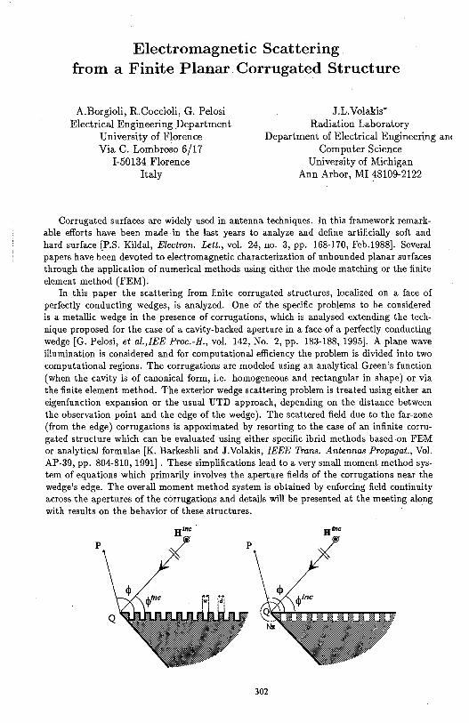
Electromagnetic Scattering from a Finite Planar Corrugated Structure
A.Borgioli, R.Coccioli, G. Pelosi Electrical Engineering _Department
University of Florence Via C. Lombroso 6/17
1-50134 Florence Italy
J.L.Volakis* Radiation Laboratory
Department of Electrical Engineering an< Computer Science
University of Michigan Ann Arbor, MI 48109-2122
Corrugated surfaces are widely used in antenna techniques. In this framework remarkable efforts have been made in the last years to analyze and define artificially soft and hard surface [P.S. Kildal, Electron. Lett., vol. 24, no. 3, pp. 168-170, Feb.1988]. Several papers have been devoted to electromagnetic characterization of unbounded planar surfaces through the application of numerical methods using either the mode matching or the finite element method (FEM).
In this paper the scattering from finite corrugated structures, localized on a face of perfectly conducting wedges, is analyzed. One of the specific problems to be considered is a metallic wedge in the presence of corrugations, which is analysed extending the technique proposed for the case of a cavity-backed aperture in a face of a perfectly conducting wedge [G. Pelosi, et al.,IEE Proc.-H., vol. 142, No. 2, pp. 183-188, 1995]. A plane wave illumination is considered and for computational efficiency the problem is divided into two computational regions. The corrugations are modeled using an analytical Green's function (when the cavity is of canonical form, i.e. homogeneous and rectangular in shape) or via the finite element method. The exterior wedge scattering problem is treated using either an eigenfunction expansion or the usual UTD approach, depending on the distance between the observation point and the edge of the wedge). The scattered field due to the far-zone (from the edge) corrugations is appoximated by resorting to the case of an infinite corrugated structure which can be evaluated using either specific ibrid methods based on FEM or analytical formulae [K. Barkeshli and J.Volakis, IEEE Trans. Antennas Propagat., Vol. AP-39, pp. 804-810, 1991]. These simplifications lead to a very small moment method system of equations which primarily involves the aperture fields of the corrugations near the wedge's edge. The overall moment method system is obtained by enforcing field continuity across the apertures of the corrugations and details will be presented at the meeting along with results on the behavior of these structures.
p p
302
H"'c •
EFFECTS OF MULTIPLE SCATTERING ON THE MICROWAVE ABSORPTMTY OF COMPOSITE MEDIA
Herbert Uberall and Khalid Chouffani Department of Physics, Catholic University of America
Washington, DC 20064 and Arnresco Techscience Inc, Bethesda, MD 20816
Aleksandr J. Stoyanov NSWC Carderock Division Carderock, MD 20084-5000
Barbara F. Howell and Eugene C. Fischer NSWC Annapolis Detachment
Annapolis, MD 21402-5067
The microwave and radar absorptivity of composite media is often estimated by effective-medium theory (D. E. Aspnes, Thin Solid Films 89,249, 1982) in which e.g. randomly distributed inclusions contained in a matrix are treated as a quasi-uniform effective medium whose electromagnetic properties depend on those of the individual constituents. This theory was applied to carbon or conducting polymer microspheres enclosed in another polymer of smaller conductivity (T. A Ezquerra et al., in Progress in Electromagnetics Research vol:6, A Priou, ed., Elsevier 1992). At higher concentrations of the inclusions, multiple scattering (rescattering between inclusions) cannot be neglected, and must be described in a self-consistent fashion using, e.g., the multiple scattering theories of Tsang and Kong (J. Appl. Phys. 51, 3465, 1980). In this theory, various degrees of approximation ( orders of rescattering) have been employed, of which we use the "quasicrystalline approximation" in order to compare with the results of effective field theory.
Various types of spherical particle inclusions are considered by us for such a comparison, and we obtain real and imaginary parts of the dielectric function for the effective medium. It is found that depending on the particle concentration and the frequency (in the GHz region), multiple scattering effects can modify permittivity and absorptivity of the effective media to a quite considerable extent. Passing with the concentration through the percolation region in which the inclusions form conducting chains or agglomerations, it is found that this effect can be described by empirical adjustment of the particle conductivities with again considerable modifications caused by multiple scattering effects.
303
Accuracy of Surface Impedance Characterization of Diffraction at Material Junctions
L. W. Pearson and Wenzhang Wang Dept. of Elec. & Comp. Engr.
Clemson University Clemson, SC 29634-0915
AW. Glisson Department of Electrical Engineering
University of Mississippi University, MS 38677
The scattering from the junction between materials with dissimilar electrical properties is often modeled by applying the surface impedance approximation to the respective material regions and expanding asymptotically the resulting solutions. The solution of such a scattering problem can be particularized from the impedance-faced-wedge solution of Maliuzhinets (Sov. Phys. Dok/., 3, 752-756, 1958). Asymptotic analyses based on the planar particularization ofMaliuzhinets' solution have been reported (Tiberio and Pelosi, IEEE Trans. Antennas and Propagat., AP-31(4), 590-596, 1983; Jones, Radio Science, 19(4), 959-965, 1984). The limitations that may arise in connection with asymptotic evaluation of the Maliuzhinets solution are difficult to characterize directly because the surface impedance approximation is applied ab initio, so that the limitations imposed are not revealed explicitly in the mathematical developments. The surface impedance approximation requires, at least, that the conductivity of the penetrable region be high.
We evaluate the surface impedance procedure described above by comparing the asymptotic solution to two canonical problems: (1) the diffiaction of a plane electromagnetic wave at a comer common to perfectly electrically conducting (p.e.c.) and penetrable quarter space and (2) diffiaction by a semi-infinite p.e.c. plane residing on the (planar) interface between electrically dissimilar materials. It is shown that the first structure leads to a modified Wiener-Hopf system so that quantitative evaluation requires a numerical solution step. The asymptotic diffiaction coefficients obtained from this solution is compared with that of the second case obtained by Coblin and Pearson (Radio Science, 19(5), 1277-1289, 1984).
The two canonical geometries both map into the same surface impedance model. A comparison of the two canonical diffraction models provides some measure of the reliability of the surface impedance diffraction model. The details of the metal region are lost in the surface-impedance approximation, while they influence the exact canonical formulations in a formal way, at least. Indeed, our computed results demonstrate a order-of-magnitude disparity between the two canonical cases for loss tangents as low as 0.1.
304
DISTRIBUTION OF SCATTERED POWER FROM SMALL CLUTTER CELLS
Lisa Mockapetris Rome Laboratory/ ERCS
31 Grenier St. Hanscom AFB, MA 01731
and Muralidhar Rangaswamy
ECE Department Northeastern University
Boston MA
For i:he new generation of high resolution radars, the clutter cell which is illuminated on the ground is small compared to the correlation length of the surface. For radars that illuminate large clutter cells, the scattering will have a Rayleigh distribution. However, this is only valid if there are many scatterers contributing to the overall scattering. As the number of scatterers decreases, which is the effect of decreasing the cell size, the assumption of a Rayleigh distribution becomes incorrect.
Previous studies have shown that as the clutter cell size decreases, the variance of the scattered power distribution increases over the value that would be expected for Rayleigh scattering. This increase becomes even more apparent in the backscatter direction. The calculations for the skewness of the distribution also show a deviation from Rayleigh scattering that becomes more pronounced in the backscatter direction. From the calculation of these first three moments of the distribution, one can conclude that the scattering from small clutter cells is not Rayleigh distributed, but no assumption can be made about what the actual distribution is.
The problem of estimating a PDF given the moments can be solved in terms of an . , orthogonal polynomial expansion of the PDF. We assume that/_lx) can be expanded in terms of an infinite series of Laguerre polynomials.
a >-1, b >O
where L~ ( x) is the generalized Laguerre polynomial. Because the Laguerre polynomials are
orthogonal in the interval (0,=), and we are working with scattered power, this interval is suitable for our requirements.
Oncefx(x) is approximated from the first three moments, comparisons to.other PDF's can be made to determine which known PDF most closely matches the PDF calculated from the first three moments. Also, using the predicted PDF, an estimation of the tails of the distribution can be determined in order to estimate what the effects on an actual radar system will be.
In this talk, we will show how the size of the clutter cell affects the first three moments of the distribution of the scattered power, and how a PDF can be determined from these moments. We will also discuss how the change in the PDF of the scattered power will affect radar performance.
305
ELECTROMAGNETIC WA VE INTERACTION WITH ELECTRICALLY SMALL PARTICLES
M. A Karam*, and A Stogryn GenCorp Aerojet
1100 West Hollyvale Street Azusa, CA 91702, USA
The subject of electromagnetic wave interaction with electrically small particles draws its importance from the following. Small spherical particles can be used to represent a variety of natural targets. They also can be used in developing numerical techniques, e.g. moment and coupled dipole methods, for calculating electromagnetic wave interaction with particles of arbitrary shapes and sizes. A full description for electromagnetic wave interaction with electrically small particles can be derived from the particle polarizability.
In this study,' three recently developed frequency formulations describing the polarizability of a spherical particle by Karam et al [M. A Karam et al, IEEE - APS, 43, 681-688, 1995], Lakhtakia [ A Lakhtakia, Intr. J. Modem Phys., 3, 583-603, 1992], and Doyle [W. T. Doyle, Physical Review B, 39, 9852-9858, 1989] are discussed. The Karam et al formulation satisfies energy conservation, irrespective to particle size and loss tangent. Neither the Doyle nor Lakhtakia equations conserve energy for particles with non-zero loss tangents. The Doyle formulation reduces to the Karam et al formulation in the limit of a very small particle size. In such a particle size limit, these agree with the Mie solution for the inner field and disagree with Lakhtakia formulation.
In addition, the Doyle formulation yields the most accurate values for the extinction efficiency followed by Karam et al formulation. However, the difference between the extinction efficiencies in the Doyle and Karam et al formulation is not high. Such an error difference can be traded with the simplicity of the Karam et al formulation, and its ability to satisfy energy conservation. Thus the use of the Karam et al equation over the Doyle and Lakhtakia equations may be recommended.
306
The scattering by an impedance wedge at skew incidence
C. Demetrescu 1, C. C. Constantinou 1, and M. J. Mehler2
1School of Electronic and Electrical Engineering The University ofBirmingham
Edgbaston, BirminghamB15 2TT United Kingdom
2British Telecom Laboratories, Martlesham Heath, Ipswich, United Kingdom
Electromagnetic scattering associated with diffraction from impedance wedges illuminated by a plane wave at skew incidence has been an area of great interest within rigorous theory of diffraction.
The diffraction from an impedance wedge at normal incidence has previously been obtained (G. D. Maliuzhinets, Sov. Phys. Dold. 3, 752-755, 1958). Both exact and approximate solutions for scattering from an impedance wedge at skew incidence have been derived (H. Syed and J. Volakis, Radio Sci. 3, 505-524, 1995) for few specific interior wedge angles.
This work presents a generalisation of Maliuzhinets' technique in order to extend its applicability over the scattering from an arbitrarily angled wedge at skew incidence. We represent the fields in the wedge region using the Sommerfeld-Maliuzhinets integral. The application of the impedance boundary condition on the faces of the wedge leads to four coupled functional equations for the two unknown spectral functions corresponding to the z-component of the electric and magnetic field respectively. Elimination of either of the spectral functions leaves us with a homogeneous second order difference equation for the remaining one. By using the general solution of a second order difference equation (C. Demetrescu, Radio Sci., submitted for publication, 1995) we find the unknown spectral functions. It is shown that the spectral functions are uniquely specified by the singularity and order requirements.
Particular cases are considered to exemplify the new approach. The uniform diffraction coefficients are obtained for the scattering from an impedance half-plane, two-sided plane and right-angled wedge. We have found exact agreement between our diffraction coefficients and those obtained by different methods for these particular geometries. Surface wave contnlmtions are also derived from th~ spectral functions.
By using the new approach we are able to derive all known solutions for the scattering from an impedance wedge at skew incidence and, in addition, to investigate the scattering from an arbitrarily angled wedge at skew incidence.
307
THE SCATTERING OF ELECTROMAGNETIC WAVE BY THE EDGE OF CYLINDRICALLY CURVED SURFACES
T. Ishihara*, T. Yamaki and K. Goto Dept. of Electrical Engineering
National Defense Academy Hashirimizu, Yokosuka, 239, Japan
High-frequency scattered field by an edge of a perfectly conducting curved surface is of interest for many configurations of scatterers and antennas. When a whispering gallery mode is incident on the edge of a cylindrically curved concave surface, the scattered field can be obtained explicitly by the Fourier transform method and the Wiener-Hopf technique [M. Idemen and L. B. Felsen, IEEE Trans. Antennas & Propag., AP-29, No.4, pp. 571-579(1981)] analogous to those applied in the half-plane problem. By applying the asymptotic analysis to the integral valid uniformly as the saddle point approaches the pole s~ngularity, we have derived the scattered field solution consisting of the geometrical ray and the edge diffracted ray [K.Goto and T.Ishihara, IEICE Transactions, Vol. J77-B-II, No.IO, pp. 539-54 7 (1994)]. The diffraction coefficient for the modal ray congruences of the whispering galley mode striking the edge of the concave boundary is represented by using the Fresnel integral, which agrees with the result obtained by R. G. Kouyoumjian and P.H. Pathak[Proc. of the IEEE, 62, No.11, pp. 1448-1461 (1974)].
In this work, we examine the scattered field generated by either a creeping wave or a geometrical ray at the edge of a cylindrically curved convex surface. By extending the angular coordinate ~ to - co< ~ <co and modeling the convex boundary as the surface defined by p =a, O< ~ <CO, the integral representation of the scattered field can be obtained explicitly from the Fourier transform method and Wiener-Hopf technique [M. Idemen and E. Erdogan, IEEE Trans. Antennas & Propag., AP-31, No.5, pp. 776-784(1983)]. By applying the asymptotic technique to the integral, we derive the scattered field representation consisting of the geometrical ray and the diffracted ray. We also derive the scattered field representation in the transition region near the boundary between the edge diffracted rays and the surface diffracted rays. The scattered field representations proposed in the present study are compared with the result obtained by assuming the equivalent line current at the edge and the GTD solution.
308
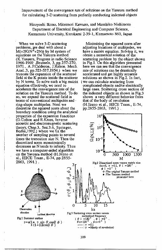
Improvement of the convergence rate of solutions on the Yasuura method for calculating 3-D scattering from perfectly conducting indented objects
Hiroyoshi Ikuno, Mitsunori Kawano, and Masahiko Nishimoto Department of Electrical Engineering and Computer Science,
Kumamoto University, Kurokami 2-39-1, Kumamoto 860, Japan
When we solve 3-b scattering problems, 'f.e deal with about a M(=2K(N +2N)) by M system of equations on the Yasuura method (K.Yasuura, Progress in radio Science 1966-1969 ,Brussels, 3, pp.257-270, 1971., A.P.Calderon, J.Ration. Mech. Anal.,3, pp.523-537,1954.) when we truncate the expansion of the scattered field at the K points inside the scatterer by N terms. To solve such a big matrix equation effectively, we need to accelerate the convergence rate of the solution on the Yasuura method. To do so, we expand the scattered field in terms of conventional multipoles and · ring-shape multipoles. Next we discretize the squared norm about the boundary condition using the analytical properties of the expansion functions (D.Colton and R.Kress, Inverse acoustic and electromagnetic scattering theory, Chap.3, Sec.3.6, Springer, Berlin,1992.) where we fix the number of sampling points to several times the truncation size N. Then the discretized norm monotonically decreases as N tends to infinity. Thus we have a computer-aided algorithm on the Yasuura method (H.lkuno et al., IEICE Trans., E-74, pp.2855-2863, 1991.) .
3
,// k: 0
Minimizing the squared norm after adjusting locations of multipoles, we have a matrix equation. Solving it, we obtain a numerical solution of the scattering problem by the object shown in Fig. I. On this algorithm presented here we can see that the convergence rate of solutions can be drastically accelerated and get highly accurate solutions as shown in Fig.2. In fact,
I we can calculate scattering from complicated objects and/or electrically large ones. Scattering cross section of the indented objects as shown in Fig.3 shows a very different behavior from that of the body of revolution (H.lkuno et al., IEICE Trans., E-74, pp.2855-2863, 1991.) .
f: .. ,. .. : ~ ·:
102
Fig.2 Discretized nonn versus matrix size (ka=5, r =0.1, e i = 180 ° ,
5 10 ka
¢, i =o· l o :The original Yasuura method • :The Yasuura method
presented here
Observation j direction --·
Incident .clirectio_n
Fig.1 Scatterer surface
Fig.3 Scattering cross section versus normalized frequency
c e i = 1so • , ¢, i =O • 00=120° , ¢0=0· l -:r =0.1
r=a(l+ r sin e cos2 </J) X (1 +0.2cos3 e )
- - - : r =O(body of revolution)
309
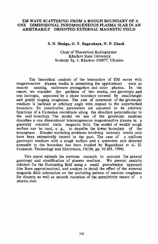
EM WAVE SCA'ITERING FROM A ROUGH BOUNDARY OF A ONE DIMENSIONAL INHOMOGENEOUS PLASMA SLAB IN AN
ARBITRARILY ORIENTED EXTERNAL MAGNETIC FIELD
S. N. Shulga, 0. V. Bagatskaya, N. P. Zhuck
Chair of Theoretical Radiophysics Kharkov State University
Svobody Sq. 4, Kharkov 310077, Ukraine
The theoretical analysis of the interaction of EM waves with magnetoactive plasma media is interesting for applications such as remote sensing, radiowave propagation and solar physics. In the report, we consider the problem of two media, one gyrotropic and one isotropic, separated by a plane boundary covered by small-height and gently sloping roughness. The axis of symmetry of the gyrotropic medium is inclined at arbitrary angle with respect to the unperturbed boundary. Its constitutive parameters are assumed to be arbitrary functions of a Cartesian coordinate along the direction perpendicular to the said boundary. The model we use of the gyrotropic medium describes a one dimensional inhomogeneous magnetoactive plasma in a generally oriented static magnetic field. The model of weakly rough surface c~n be used, e. g., to describe the lower boundary of the ionosphere . Simpler scattering problems involving isotropic media only have been extensivelly treated in the past. The case of a uniform gyrotropic medium with a rough surface and a symmetry axis directed normally to the boundary has been studied by Bagatskaya et al. [J. Commun. Technology and Electronics, 39(10), pp. 93-101, 1994].
This report extends the previous research to account for general gyrotropy and stratification of plasma medium. We present analytic solution for the fluctuating field using a small perturbation approach (the Born approximation), and analyze in detail the effect of the external magnetic field orientation on the scattering pattern of random roughness for discrete as well as smooth variation of the permittivity tensor of a plasma slab.
310
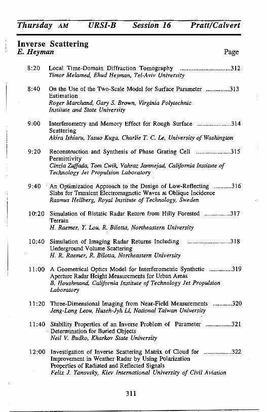
Thursday AM URSI-B Session 16 Pratt/Calvert
Inverse Scattering E. Heyman Page
8:20 Local Time-Domain Diffraction Tomography ............................. .312 Timor Melamed, Ehud Heyman, Tel-Aviv University
8:40 On the Use of the Two-Scale Model for Surface Parameter ............... 313 Estimation Roger Marchand, Gary S. Brown, Virginia Polytechnic Institute and State University
9:00 Interferometry and Memory Effect for Rough Surface ..................... 314 Scattering Akira Ishiaru, Yasuo Kuga, Charlie T. C. Le, University of Washington
9: 20 Reconstruction and Synthesis of Phase Grating Cell ..................... 315 Permi tti vi ty Cinzia Zuffada, Tom Cwik, Vahraz Jamnejad, California Institute of Technology Jet Propulsion Laboratory
9:40 An Optimization Approach to the Design of Low-Reflecting ........... 316 Slabs for Transient Electromagnetic Waves at Oblique Incidence Rasmus Hellberg, Royal Institute of Technology, Sweden
10:20 Simulation of Bistatic Radar Return from Hilly Forested ................ 317 Terrain H. Raemer, Y. Lou, R. Bilotta, Northeastern University
10:40 Simulation of Imaging Radar Returns Including ......................... .318 Underground Volume Scattering H. R. Raemer, R. Bilotta, Northeastern University
11: 00 A Geometrical Optics Model for Interferometric Synthetic .............. 319 Aperture Radar Height Measurements for Urban Areas B. Houshmand, California Institute of Technology Jet Propulsion Laboratory
11 :20 Three-Dimensional Imaging from Near-Field Measurements ............ 320 Jeng-Long Leou, Huseh-Jyh Li, National Taiwan University
11 :40 Stability Properties of an Inverse Problem of Parameter ............... .321 Determination. for Buried Objects Neil V. Budko, Kharkov State University
12:00 Investigation of Inverse Scattering Matrix of Cloud for ................. 322 Improvement in Weather Radar by Using Polarization Properties of Radiated and Reflected Signals Felix J. Yanovsky, Kiev International University of Civil Aviation
311
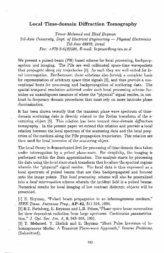
Local Time-domain Diffraction Tomography
Timar Melamed and Ehud Heyman Tel-Aviv University, Dept. of Electrical Engineering - Physical Electronics
Tel-Aviv 69918, Israel Fax: +912-3-6423508, E-mail: [email protected]
We present a pulsed-beam (PB) based scheme for local processing, backpropagation and imaging. The PBs are well collimated space-time wavepackets that propagate along ray trajectories [1]. As such they are well suited for local interrogation. Furthermore, these solutions also furnish a complete basis for representation of arbitrary space-time signals [2], and thus provide a conventional basis for processing and backpropagation of scattering data. The spatial-temporal resolution achieved under such local processing scheme furnishes an unambiguous measure of where the "physical" signal resides, in contrast to frequency domain procedures that must rely on more intricate phase discrimination.
It has been shown recently that the transient plane-wave spectrum of timedomain scattering data is directly related to the Radon transform of the scattering object [3]. This relation has been termed time-domain diffraction tomography. In the present paper we extend this relation and provide a local relation between the local spectrum of the scattering data and the local properties of the medium along the PBs propagation trajectories. This relation are then used for local inversion of the scattering object.
The local theory is demonstrated first for processing of time-domain data taken under interrogation by a pulsed plane-wave. For simplicity, the imaging is performed within the Born approximation. The analysis starts by processing the data using the local slant-stack transform that localizes the spectral regions wherein the "physical" signal resides. The local data is thus expressed as a local spectrum of pulsed beams that are then backpropagated and focused onto the image points. This local processing scheme will also be generalized into a local interrogation scheme wherein the incident field is a pulsed beams. Numerical results for local imaging of low contrast dielectric objects will be presented.
[1) E. Heyman, "Pulsed beam propagation in an inhomogeneous medium," IEEE Trans. Antennas Prop., AP-42, 311-319, 1994. [2] B.Z. Steinberg, E. Heyman and L.B. Felsen, "Phase space beam summation for time dependent radiation from large apertures: Continuous parametrization," J. Opt. Soc. Am. A, 8, 943-958, 1991. [3] T. Melamed, Y. Ehrlich and E. Heyman "Short Pulse Inversion of Inhomogeneous Media: A Transient Plane-wave Approach," Inverse Problems, (Submitted).
312
ONTHEUSE OF THE TWO-SCALE MODEL
FOR SURFACE PARAMETER ESTIMATION
by Roger Marchand and Gary S. Brown Bradley Department of Electrical Engineering
Virginia Polytechnic Institute and State University Blacksburg, VA 24061-0111
Many randomly rough surfaces can not be described as having only roughness with small heights (Bragg scattering dominated) or being only slowly undulating· (tangent plane dominated). Naturally, investigators have tried to combine the Bragg and tangent plane scattering models to describing surfaces which contain both kinds of roughness (i.e. composite or two scale surface). A number of simple two-scale models have been proposed in the literature which combine a tangent plane ( or a quasi-specular) model and a Bragg scattering model. Such models suggest that information about surface height and slopes, as well as, dielectric constant can be obtained from the average scattered fields. Of course, the two-scale models only bridges the gap between surfaces with small and large scale structure. In. addition to the limitation of the quasi-specular and Bragg scattering models, when there are irregularities on the order of the incident wavelength these models are expected to fail.
In this presentation, quantitative results of a numerical study on the use of the two-scale models for .parameter estimation in two dimensions (i.e. one-dimensional surfaces) is presented. This study shows how the accuracy of the model as an inversion tool varies for Pierson-Moskowitz surfaces through the use of Monte Carlo simulation results where exact surface parameters are known. A recently developed numerical technique known as the Method of Ordered Multiple Interactions (MOMI), as well as, traditional method of moment simulations are used to obtain the scattered fields and radar cross sections. This new approach will be discussed briefly.
Of particular importance in the parameter estimation problem is the numerical noise present in any finite length Monte Carlo simulation and the angular region over which "data" is to be compared to the model. As with most problems of this nature, there are a number of tradeoffs and these will be explored.
313
Interferometry and Memory Effect for Rough Surface Scattering
Akira Ishimaru, Yasuo Kuga, and Charlie T. C. Le Department of Electrical Engineering
University of Washington Box 352500
Seattle, Washington 98195-2500 Tel: 206-543-2169 Fax: 206-543-3842 E-mail: [email protected]
Interferometric techniques have been used for various applications in remote sensing problems, including Synthetic Aperture Radar (InSAR). Recently, we have investigated related correlation phenomena called the memory effect. In this paper, we extend the conventional interferometric technique to include the memory effect in order to obtain generalized interferometry for random media.
Two transmitting antennas illuminate the rough surface at two different incident angles, and the scattered waves are observed at two different scattering angles. The correlation between two scattered waves is shown to be strong if the difference in wave numbers along the surface is the same for the incident waves and the scattered waves. Thus, the scattered wave "remembers" the incident angle even under multiple scattering situations, and this is called the memory effect. We have made detailed studies on the memory effect for rough surfaces and applied the results to the detection of an object buried in random media making use of the drastic differences in the correlation signatures for deterministic and random media. This is now extended to the problem of determination of the average height profile of the rough surfaces. The theory is based on the Kirchhoff approximation and shows that the phase of the mutual coherence function is directly related to the average height, and thus the height profile can be obtained by the phase measurement. Locations of four antennas affect the sensitivity of the results and a memory signature diagram is developed to show these effects. Theoretical results are compared with millimeter wave experiments.
314
Reconstruction and Synthesis of Phase Grating Cell Permittivity
Cinzia Zuffada, Tom Cwik, Vahraz Jamnejad
Jet Propulsion La.boratory
California Institute of Technology
Pasadena, CA 9ll09
ABSTRACT
In phase grating and FSS design, far-field data (reflection and transmission coefficients) are specified at a number of possibly disjoint frequency bands, to attain the desired stop-band and pass-band features. Traditionally, optimum cell permittivity patterns are obtained by successive optimization of trial configurations. To explore the possibility of an alternative design approach, two types of inverse scattering techniques are examined here, to assess their accuracy for reconstructing and designing cell permittivity patterns for phase grating. The first technique is a direct two-step inversion; in the first step electric currents are obtained in the cell, from reflection and transmission coefficients specified at different frequencies. In the second step, enforcement of the constitutive relation between currents and electric fields, yields the reconstruction of electric permittivity patterns. Accuracy is assessed as a function of frequency and dielectric inhomogeneity. The second approach is an iterative inversion of the non-linear integral equation relating design parameter data (again, reflection and transmission coefficients) to the values of th~ electric permittivity in the cell. In this method, two sets of unknowns are introduced: the electric fields (at each frequency) and permittivity in the cell. The electric fields satisfy the Helmoltz equation in integral form and a radiation integral links them to the far-field design data. A functional weighting the defect in matching both the integral equation and the far-field is calculated, and is then minimized iteratively, solving for the electric field and permittivity simultaneously. The starting point to the solution is provided by the results obtained from the direct two-step inversion method. A preliminary assessment of the performance of this second approach is presented.
315
An optimization approach to the design of low-reflecting slabs for transient electromagnetic
waves at oblique incidence
Rasmus Hellberg
Department of Electromagnetic Theory Royal Institute of Technology 100 44 Stockholm
An optimization approach is used in order to design low-reflecting planestratified dissipative and dispersive slabs for transient plane waves at oblique incidence. Given the prescribed reflection and transmission kernels, an objective functional is minimized for a time larger than one roundtrip and for several incident angles.
The exact inverse problem of finding reflectionless plane-stratified dispersive slabs for transient plane waves at oblique incidence has earlier been studied. In this inverse problem, one parameter in the constitutive relation is determined given that the reflection kernel is identical to zero for one given incident angle. It is only possible to design a dispersive slab that is completely reflectionless for times less than one roundtrip and there are restrictions on the solution. A natural step is therefore to minimize the reflection kernel instead of having a reflection kernel that is identical to zero.
In the optimization (minimization) process an objective functional of the reflection and transmission kernels is introduced. The objective functional is minimized for time larger than one roundtrip and for several incident angles. By introducing dual functions, the exact and explicit expressions for the gradients are derived from the objective functional for the TE and TM mode. In the optimization process the direct problem is solved by a time-domain Green functions technique where Green kernels are introduced that determines the reflection and transmission kernels. Since the Green kernels are independent of the excitation, the reflection of the slab is minimized for an incident field of an arbitrary shape. Some numerical examples of low-reflecting slabs are presented in section where the dispersive models are based upon the Debye model and the Lorentz model. for solid materials.
316
Simulation of Bistatic Radar Return from Hilly Forested Terrain
H. Raemer, Y. Lou and R. Bilotta, Northeastern University, Boston, MA
A comprehensive radar scenario simulation program developed by H. Raemer can simulate monostatic and bistatic radar returns from a wide variety of terrain. Since there are many available options for both geometry and scattering models, it is important to validate this code against experimental results for as many of the options as possible.
The work reported in this paper is a comparison of bistatic results obtained in our simulation runs with experimental results obtained by McLaughlin, Boltniew et al(Electronics Letters, 30, 18, 1994, pp.1532-1533). These results were obtained with a polarimetric S-band radar transmitter operating at 2.71 GHz, using an antenna with elevation and azimuthal beams pointed in a nearly horizontal direction, thereby illuminating a small region of hilly forested terrain at a very low average grazing angle. The receiver is placed at a location remote from the transmitter. It receives out-of-plane bistatically scattered signals from the illuminated patch. The details of the geometry and the radar systems are given in the cited reference. The height profile for the simulation runs is specific to the region on which the experimental work was done.
The experimental study focused on the variation of the receiver polarization for fixed transmitted wave polarization, generating curves showing the variation of the received signal amplitude with receiver polarization as it varies over 180 degrees. Different sets of simulation results were obtained using different empirical and analytical terrain scattering models available as options in the program. For a single realization, the variation of the simulated received signal amplitude with polarization angle contains fluctuations that are at least as large as the experimentally obtained differences between copol and crosspol returns(i.e. about 4-8 dB)The experimental results also showed fluctuations of the same magnitude in pulse-to-pulse readings. To smooth out those fluctuations, each data point was averaged over many pulses. In our simulation runs, we also averaged the returns over many pulses to smooth out the fluctuations, which are partially due to the assumption of random phase for the return from each illuminated terrain patch. That assumption was required for empirical scattering models and for the incoherent portion of the analytical scattering models, for which no phase information was available.
The smoothed simulation results show differences between copol and crosspol results, but these differences are not very pronounced for out-of-plane bistatic scattering, where the hilliness of the terrain generates a significant portion of received power whose polarization direction in the receiver's coordinate frame is different from that of the transmitted wave in the transmitter's frame.
317
Simulation of imaging radar returns including underground volume scattering
H. R. Raemer and R. Bilotta, Northeastern University, Boston, MA
A radar scenario simulation program developed by H. Raemer has been extensively used to investigate cases in which all of the wave propagation is in free-space and the scattering is either from the earth's surface or a discrete object in free space. It has recently been extended to include volume scattering from a medium where the scattering material is embedded within the medium and the properties of the medium influence the propagation of incident and scattered waves. The obvious application is to ground-penetrating radar.
This is ongoing work, but the first stage has been implemented. It involves supplementation of the existing code to superpose on the earth's surface returns the additional returns from the subsurface volume due to deterministic and/or random fluctuations in complex permittivity within the medium. The deterministic variations may be due to objects embedded in the medium and the random variations are inherent in the medium itself.
The current results are based on the simplest volume scattering model, the first order Born approximation. Inclusion of higher order and extended Born approximation, which extends the regime of applicability to greater permittivity contrast, is planned as the next stage.
The capability of the program to simulate a SAR imaging radar scenario was the subject of a presentation at previous symposia(APSI/URSI 1994 and PIERS 1995). This capability, combined with the enhancement discussed above, has been used to obtain simulated high resolution images of a subsurface volume.
318
A Geometrical Optics Model for Interferometric Synthetic Aperture Radar Height Measurements for Urban Areas
B. Houshmand Jet Propulsion Laboratory
California Institute of Technology 4800 Oak Grove Drive
Pasadena, CA 91109-8099
In this talk a Geometrical Optics (GO) scattering model is presented for interferometric Synthetic Aperture Radar (InSar) height measurement of Urban areas which are charaterized by man-made objects. SAR measurements from Urban areas are dominated by multiple scattering and layover effects which are different from natural terrain. Two and three dimensional scattering models are considered to simulate the lntSar measurements. The model is based on the geometrical optics including edge diffraction and material effects. A forward ray tracing algorithm is used to provide efficient computation of multiple paths for arbitrary geometrical arrangements. For a two dimensional height profile, the backscatterd field is compued by launching a dense set of rays towards the geometry. The rays contributing to the backscatterd fields are collected on an aperture plane, and their contributions to an observation point are computed according to the transmitted signal pulse length. Each contributing ray is associated with a ray foot print and a linear phase taper indicating the direction of propagation with respect to the normal vector to the aperture plane. Scattering from three dimensional profiles are computed by a facet based high frequency electromagnetic-scattering prediction method (D.J. Andersh, M. Hazlett, S.W. Lee, D.D. Reeves, D.P. Sullivan and Y. Chu, IEEE Trans. Antennas propgat. Mag., vol. 36, pp.65-69, Feb. 1994). An estimate of the height profile is derived for the backscattered field measurements from two receivers displaced in the range direction by a baseline length (E. Rodriguez, and J.M. Martin, IEE Proceedings-F, Vol. 139, No. 2, April 1992). The relative phase difference between the receivers is used to locate the position of the dominant scattering center. It is of interest to characterize the multiple scattering and shadowing effects in the derived height profile. Multiple scattering, in general, displaces the scattering center position due to the increase in the effective path lenght of a contributing ray. For a corner reflector geometery, the path lengths for all the contributing rays are equal to the path lenght corresponding the origin of the corner reflector. In the case of scattering from a number of structures, the position of the scattering center is displaced further away from the actual scattering location with respect to the transmitting source. In this presentation a number of geometrical configurations which produce single and multiple scattering, layover , and shadowing effects are considered. The derived height accuracy as a function of radar parameters, angle of incidence, and the height profile will be disccused. The simulated results will be compared with the InSar measurements over a selected number of urban areas.
319
Three-Dimensional Imaging From Near-Field Measurements
Jeng-Long Leou and Hsueh-Jyh Li Department of Electrical Engineering
National Taiwan University Taipei, Taiwan, Republic of China
ABSTRACT
A generalized interpretation and prediction in far-field microwave imaging involving frequency and angular diversity has been discussed, where an Ewarld sphere representation for the Fourier-space data in the monostatic and bistatic diversity imaging has been established. Microwave images are obtained by inversely Fourier transforming the Fourier space data. In that imaging the Fourier-space data are the measured monostatic or bistatic far-field data. However, the distance required to satisfy the far-field condition will be large if the object size is much greater than the operating wavelength and it is very difficult to scan the bistatic angle both in the azimuth and elevation direction. Planar type near-field measurement techniques have been well-established to predict far-field antenna patterns, where the radiation source is a testing antenna and its radiated field is measured by a samll probe scanning over a large aperture close to the testing antenna. When an object is illuminated by a wave source, a surface current distribution will be induced and the incident wave will be scattered. If the scattered field is received by a probe scanning over a planar aperture close to the object, the field recorded can be considered as the secondary source. The two-dimensional Fourier transform of the secondary source field will give the far-field scattering patterns of the object. If multiple frequencies of plane waves have been utilized to illuminate the object and the same procedure has been performed, then we have multiple frequencies far-field scattering patterns, or the bistatic Eward sphere Fourier data. By three-dimensionally Fourier transformimg the Fourier-space data we can obtain the three-dimensional image of the object,
In this paper we will establish relationship between the far-field quantities and the near-field measurement. We will propose mehtods to obtain bistatic range profiles and 3-D images from near-field measurements. Several numerical results will be demonstrated in the presentation.
320
Stability properties of an inverse problem of parameter determination for burriw. objects
Neil V. Budko
Chair ofTheoretical Radiophysics, Kharkov State University Svobody Sq. 4, Kharkov 310077, Ukraine.
Recently a new approach to the problem of parameter determination involving objects embedded into the plane-stratified medium was proposed (N. V. Budko. ''The null-field method and inverse scattering problems", Proceedings of the Asia-Pacific Microwave Conf. 1995, Taejon, Korea). It is based on the inversion of customary nullfield equations which describe the direct scattering problem under consideration. When considering a scattering configuration which consists of a cylindrical homogeneous body in a stratified medium one has to substitute the Green's function of the stratified medium into the kernels of the null-field method's integral equations.
Here we concentrate on the inverse problem concerning the determination of electrical properties of the medium with known geometry. More precisely we consider the problem of estimate evaluation of the cylinder's wavenumber provided that all other parameters are given. We note that this formulation includes the case of a dissipative cylinder. Practically important is the case where geometry of the boundaries is not known precisely. .
We prove that one can solve the aforementioned problem simply by searching for the solution of the null-field method's direct formulae converted into an integral equation of the first kind. The searching process is controlled by properly choosing the parameter's value. A global minimum of the metrical difference functional corresponds to a correct estimate for the permittivity. It is essential to emphasize that our solution has no restrictions as for electrical contrast of the medium, precision of the first estimate and type of scattered information involved.
Direct null-field solution to scattering problems is known to be stable towards errors in its' integral operator. In general such a property of the direct solution damages the precision of the inversion procedure. However, numerical investigation of the ill-posed inverse problem (with incorrect a priori information) pointed out that one has to study the stability of the algorithms more carefully to obtain useful results.
It was shown that, when the permittivity of the object is the parameter to determine, the inverse algorithm is stable towards errors in the a priori information on the shape of the object and its location within the host layer of the plane stratified medium. The size of the available error depends on the size of the object. However, the algorithm appears to be sensitive even for small errors in the a priori information on the permittivity of the surrounding medium.
321
INVESTIGATION OF INVERSE SCATTERING MATRIX OF CLOUD FOR IMPROVEMENT IN WEATHER RADAR BY USING POLARIZATION
PROPERTIES OF RADIATED AND REFLECTED SIGNALS
Felix J. Yanovsky Kiev International University of Civil Aviation, Ukraine
There are some problems in the field of creation more effective· weather radars. One of them is a problem of trustworthy detection areas in clouds and precipitation dangerous for flying. It is very important to find not turbulent areas <:>nly but also to have a possibility to recognize zones of hail, increased electric activity, and icing. The other one is a problem of recognition and selection echosignals of meteoobjects and reflections of earth surface.
The theoretical study carried out made it possible to obtain mathematical patterns showing dependence of the scattering matrix's polarization structure on a shape, phase state and orientation of diffusing particles. Making use of characteristic statistic models of particles' totality we can define polarization parameters of the wave being scattered back from heavy rain, cumulus, stratified clouds, hail and other weather objects.
Besides our previous works, here consideration was executed from the point of view four-dimensional Stocks-vector in linear and circular basis. Such approach allows to find the complete polarization structure of electromagnetic field scattered.
Such quantities as degree of polarization, coefficient of ellipticity, orientation angle of polarization ellipse as well as differential reflectivity, linear and circular depolarization ratios, correlation coefficient between orthogonal polarization signals and other polarization parameters that are often used in weather radar polarimetry can be expressed with Stocks-parameters. The study determines how different polarization quantities depend on the orientation angle of diffusing particles, their form factor, and character of extended targets.
Given is the analysis of the data, obtained as a result of experiments carried out with ground-based and airborne polarimetric radars, that corresponds with the theoretical ideas. There has been discussed the possibility of working out new algorithms of polarization signal processing to create airborne and ground-based operative devices detecting the areas with high icing and hail probability in meteorological objects whose backgrounds are· reflections from the earth and sea surfaces.
The results show that it is possible to evaluate the electric field in a cloud and the microphysical characteristics of reflecting objects. It has obvious applied meaning for localizing the areas of electric activity, icing and hail dangerous for flying.
322

Thursday AM APIURSI-B Sess. 8 Constel. Ballroom D
Antennas II D. R. Jackson Page
8:20 Radiation from One-Dimensional Periodic Leaky-Wave Antennas .... .324 S. Majumder, D. R. Jackson, University of Houston, M. Guglielmi, European Space and Technology Centre (ESTEC)
8:40 Comparison of Antenna Architectures for Rapidly Deployable ........ 325 Radio Networks (RDRN) Based on Far-Field Pattern Performance D. Chatterjee, R. G. Plumb, University of Kansas
9:00 The SMM Antenna as a Radiating Element for Multioctave Low- ...... 326 Profile Phased Arrays and its Potential for Grating Lobe Suppression Johnson J. H. Wang, James K. Tillery, Michael A. Acree, Wang Electro-Op to Corporation (WEO)
9:20 Photonic Bandgap Structures for Antenna Applications: Theory ...... 327 and Measurements Morris P. Kesler, James G. Maloney, Brian L. Shirley, Stephen P. Blalock, Georgia Tech Research Institute, Glenn S. Smith, Georgia Institute of Technology
9:40 A New All-Metal Low-Pass Dichroic Plate .................................. 328 William A. Imbriale, California Institute of Technology Jet Propulsion Laboratory
10:20 Fractal Antennas ............................ , .................................... 329 Nathan Cohen, Fractal Antenna Systems, Inc.
10:40 Validity of Using a 1:600 Model to Measure HF Antenna .............. .330 Characteristics Darrell J. Butler, S. Ahmed Saoudy, Memorial University of Newfoundland.
11 :00 Analytic Calculation of Surface Wave Excitation in Planar .............. 331 Millimeter Wave Antennas Markus 0. Thieme, Erwin M. Biehl, Institut far Hochfrequenztechnik der Technischen Universitat Munchen
11 : 20 Single and Double Like are Cross Polarized Scatter from Two ......... APS Dimensional Random Rough Surfaces-High Frequency Approximations M. El-Shenawee, E. Bahar, University of Nebraska- Lincoln
323
RADIATION FROM ONE-DIMENSIONAL PERIODIC LEAKY-WAVE ANTENNAS
S. Majumder and D.R. Jackson Department of Electrical and Computer Engineering
University of Houston Houston, TX 77204-4793, USA
M. Guglielmi European Space and Technology Centre (ESTEC)
Postbus 299 2200 AG Noordwijk ZH THE NETHERLANDS
Leaky-wave antennas consisting of a periodic structure are quite common. One example is that of an infinite strip grating on top of a grounded substrate. For this one-dimensional structure the leaky wave may be excited by a simple feed such as a line source inside the substrate. In this presentation the radiation patterns for this antenna structure will be investigated, and the role of the leaky waves in determining the patterns will be explored. In particular, attention will be focused on the physical meaning of the leaky waves, defined from the correlation between the exact radiation patterns and those of the leaky waves alone. Although the investigation will use the simple one-dimensional grating structure for simplicity, the conclusions should be applicable to a wide class of periodic leaky-wave antennas.
In previous investigations involving a line source inside a grounded dielectric layer, it was concluded that the leaky wave responsible for the radiation pattern loses physical meaning as the leaky wave enters the "spectral-gap" region, where it becomes a slow wave (H. Ostner et al., IEEE Trans. AP, Vol. 43, pp. 331-339, April 1995).
More recently, the nature of the leaky-wave propagation and the behavior of the spectral gaps on the periodic strip-grating structure have been investigated (S. Majumder et al., Proc. PIERS 1995, p. 603). It was concluded that the spectral gap is more complicated for a periodic structure than a nonperiodic one. The main reason for the extra complication is that there are an infinite number of space harmonics in the periodic case, each with a different wavenumber. Some of the space harmonics may be radiating, while others are bound. Furthermore, one or more space harmonics may be in the physical region while the others are inside the spectral-gap region. The radiation patterns presented here demonstrate how the physical significance of the different leaky-wave solutions, and also the physical significance of the various space harmonics that make up a particular leaky-wave solution, change as the frequency changes.
324
COMPARISON OF ANTENNA ARCHITECTURES FOR RAPIDLY DEPLOYABLE RADIO NETWORKS (RDRN) BASED ON
FAR-FIELD PATTERN PERFORMANCE
D. Chatterjee and R. G. Plumb
Radar Systems and Remote Sensing Laboratory Department of Electrical Engineering and Computer Science
University of Kansas, Lawrence, KS 66045-2969
Abstract
For wireless communications applications [Shanmugan et. al., TISL tech. rep. TISL-10920-08, University of Kansas, 1995], it is always prefereable to evaluate the cost-benefit analysis of antenna systems. Such a proceedure involves comparison of far-field patterns for several candidate systems and then selecting the one that best suits the overall requirements. In both cases the azimuth (9 = 90°) plane of scan is of outmost importance to the systems engineer. The main reason is that the effects of interference are maximum in this plane [K. Fujimoto and J. R. James, Mobile Antenna Systems Handbook, Artech House, USA, 1994]. Consequently, it is imperative that pattern performances in this plane be assessed to obtain selection criteria for designing such antenna systems. Both the multi-face planar, and the cylindrical array can be analyzed using the NECBSC2 code [R. J. Marhefka and W. D. Burnside, TR-712242-14, ElectroScience Lab., OSU, 1982]. This code contains algorithms based of the Uniform Theory of Diffraction [P.H. Pathak, Proc. of IEEE, pp. 44-65, January 1992] and are very convenient for analyzing effects of the antenna geometry on the far-zone pattern. The cylindrical array exhibits pattern uniformity in the azimuth plane because of symmetry; however it has been shown [R. J. Mailloux, Phased Arn"ay Antenna Handbook, p. 378, Artech House, USA, 1994] that for electrically larger cylinders the creeping and space wave interference effects become dominant near the boresight. Such interference cause pattern degradation near the boresight and hence can cause the SINR to degrade [I. J. Gupta and A. A. Ksienski, IEEE '.lrans. Antennas Propagat., July 1982]. For multiface planar arrays, there could be a substantial amount pattern distortion because of the edges. However this effect has not been studied so far [R. J. Mailloux, op. it.]. Consequently, for beamforming applications, it turns out important to analyze both such architectures based on their far-field patterns. Results for both cylindrical and multiface planar arrays will be presented with particular emphasis on the effects of geometry of the architecture on the far-zone patterns in the azimuth plane. The effects of the amplitude taper on the performance of the two categories of antenna arrays will also be demonstrated.
325
The SMM Antenna as a Radiating Element for Multioctave Low-Profile Phased Arrays and its
Potential for Grating Lobe Suppression
Johnson J. H. Wang, James K. Tillery, and Michael A. Acree
Wang Electro-Opto Corporation (WEO) 1335 Capital Circle
Marietta, GA 30067
Wideband multioctave phased arrays have long been hampered by two fundamental difficulties: the lack of a low-profile radiating element and the grating lobe problem at upper frequencies. A new solution for both problems is to employ the newly invented spiral-mode microstrip (SMM) antenna as the radiating element (J. J. H. Wang and V. K. Tripp, IEEE AP Trans. 39, 332-335, 1991; patents awarded). The multioctave bandwidth (now 10:1) and the low-profile feature of the SMM antenna have been well established. The use of mode-1 and mode-2, either individually or in combination at the high band, enables us to overcome the grating lobe problem.
As is well known, mode-1 of the SMM antenna has a unidirectional pattern, and mode-2 has an off-broadside pattern (like that of a monopole on a finite ground plane). The use of mode-2, alone or in combination with mode--1, allows one to steer the pattern of the element antenna up to, say, 30°. As a result, beam steering at the level of the array factor is considerably reduced, and the occurrence of grating lobes is minimized. The use of both mode-1 and mode-2 to steer the beam of a single SMM antenna has been established both analytically and experimentally (J. J. H. Wang, et al, Proceedings from !SAP, 789-792, 1992). This basic technique can be used in the present approach for the suppression of grating lobes for the SMM phased array.
In this research, computer simulation of a finite array of SMM antennas is performed to demonstrate the suppression of grating lobes using multiple modes of the SMM antenna element. Experiments are also performed to validate the simulation model of the finite SMM antenna array and its grating lobe phenomena.
326
PHOTONIC BANDGAP STRUCTURES FOR ANTENNA APPLICATIONS: THEORY AND MEASUREMENTS
Morris P. Kesler*, James G. Maloney, Brian L. Shirley, Stephen P. Blalock Signature Technology Lab, Georgia Tech Research Institute
Atlanta, GA 30332-0800
Glenn S. Smith School of Electrical and Computer Engineering
Georgia Institute of Technology, Atlanta, GA 30332-0250
Photonic bandgap (PBG) materials are a class of periodic dielectric structures exhibiting frequency regions (bandgaps) in which electromagnetic propagation is prohibited. The existence and characteristics of the bandgaps are dependent on the lattice type (face-centered cubic (FCC), body-centered-cubic (BCC), etc.), element shape (spherical, cylindrical, etc.), and dielectric contrast between the element and the host material. Most analyses have been for infinite PBG structures; however, for antenna applications one must be able to analyze finite structures. Last year we presented detailed numerical results (FDTD, FDFD) for 2-D structures (finite thickness slabs) and limited results for fully 3-D structures, both combined with antennas (Maloney, et. al., Proc. USNC/URSI Mtg., June 1995). At that time, we also introduced the "reflection plane concept." This is a simple model that can be used to describe the PBG material as an all-dielectric reflector at frequencies within the bandgap (Kesler, et. al., Microwave and Opt. Tech. Lett., March 1996).
In this paper, we will present new results for a variety of 3-D PBG structures (woodpile, FCC, BCC, and diamond) combined with antennas. The effect of the PBG material on the performance of the antenna will be discussed for frequencies both within and outside the bandgap. The FDTD calculations and the performance based on the reflection plane concept will be compared with measurements.
A break in the periodicity of the PBG material ( adding a "defect") can introduce an additional effect: a transmission peak within the bandgap. Normally, the transmission through a finite thickness slab of PBG material is very small at frequencies within the bandgap. When the slab is split and a space introduced between the two halves, a defect is created and a narrow transmission peak occurs within the bandgap. This existence and location of this peak can be predicted using the reflection plane concept. This phenomenon can be used to tailor the performance of an antenna to a particular application. Again, theoretical results will be compared with measurements.
327

A New All-Metal Low-Pass Dichroic Plate
William A Imbriale Jet Propulsion Laboratory
California Institute ofTechnolrigy Pasadena, CA 91109
A new type of dichroic plate is described that can be completely transparent at lower frequencies and reflect the higher frequencies without the use of a dielectric substrate. Conventional dichroics accomplish this frequency response by supporting a metallic resonant element on a dielectric substrate. The c;oncems with this method are the power handling capacity of the thin metallic layer as well as the loss in the dielectric.
The basic concept of the new design is to use slots in a moderately thick metallic plate for the transmit band and to use chokes in the slot to reflect the upper frequency bands. Thus the dichroic plate is transparent at the lower frequency band and reflective at the upper frequency bands without using a dielectric.
A test plate consisting of a moderately thick plate with a periodic pattern of thin linear resonant slots is being fabricated. The slots are chosen to be resonant at the lower frequency band so the plate is transparent at these frequencies. Orthogonal slots are used for circular polarization. Since the plate surface. is mostly metal, it would be predominately reflective at the higher frequency bands, with the reflectivity loss related to the ratio of the area of the slots to total area. Hence it would be a fairly good reflector at all the higher frequencies, regardless of the plate thickness. To enhance the reflectivity at a selected set of higher frequencies, the thickness of the plate is used to insert a high-frequency choke. Manufacture of the thick plate is accomplished by stacking multiple layers of plates with the appropriate slot geometry. The experimental plate is designed to be transparent at X-band and reflective at Ka-band using a single-depth choke. The test results will be presented at the conference.
328
FRACTAL ANTENNAS Nathan Cohen, Fractal Antenna Systems, Inc.
5100 North Ocean Blvd Suite 1218, Ft. Lauderdale, FL 33308
We report the use of self-similar patterns applied to individual antenna elements. The resultant fractal antennae have unusual properties. In particular, resonance is acheived at frequencies far lower than those expected from the physical size. The 'Compressed Resonance (CR)' points are confirmed through NEC-based simulations. The radiation resistance appears to be much higher than expected from small conventional antennas of the same physical dimensions. Other typical characteristics include bandwidth broadening with high iteration number, increased gain for selective iterations and patterns, and supergain conditions. For many fractal antennas 25-75 ohm impedences are readily attainable without matching.
In addition to individual fractal antenna results we use fractal loops as a simple and compelling illustration of these fractal antenna properties. A Minkowski motif is used to show the effects of successive fractal iterations, from O to 3. In themselves, these fractals not only demonstrate the effects of 'fractal loading' but reveal the gross inaccuracy of the small loop approximation (SLA).
Fractal antennae may be incorporated into 'Fractal-Filled Arrays (FF A)' which allow for close packed, sub-arrays with gains exceeding the geometric aperture gain for apertures of a few wavelengths or less. They differ from 'Fractal-Distributed Arrays (FDA)' (see for example, Y. Kim and D. Jaggard, Proc. IEEE, 74, 1278-1280, 1986) in that the FDA places elements in a self-similar fashion rather than making the individual elements self-similar.
Individual fractal antenna elements or arrays may be used where size restrictions apply. In particular microwave telecommunications may be facilitated by small, embedded fractal antennas, or FF A's. Satellites may benefit from the smaJI, conformable footprint of fractal antennas or through adaptive FF A's.
329
VALIDITY OF USING A 1:600 MODEL TO MEASURE HF ANTENNA CHARACTERISTICS
Darrell J. Butler* ands. Ahmed Saoudy**
*Faculty of Engineering and Applied Science **C-CORE
Memorial University of Newfoundland st. John's, NF, A1B 3X5, Canada
Abstract
New high frequency (HF) antenna designs are being developed for use with ground wave radars (GWR). Experimental verification of their radiation characteristics can be achieved using scale modelling techniques inside an anechoic chamber. These antenna designs, which are in the shape of vertical log-periodic monopole arrays (VLPMA), have operating frequencies in the lower HF band (3-6 MHz). Measurements inside the compact range anechoic chamber at the University of Manitoba, are considered accurate for frequencies exceeding 1.5 GHz. Anechoic chamber testing, therefore, required building models of a scale 1:600 with frequency range 1.5 - 3 GHz to yield radiation patterns equivalent to the actual design frequency range of 2.5 - 5 MHz. Due to practical limitations, the antenna scale models did not exactly adhera to the scale factor. The VLPMA array elements were etched as flat strips on printed circuit boards with relative dielectric constants of 4-5 and were installed over a finite circular disc wit~ diameter of 1.2 metres. Also, the distance separating the feed line and ground was larger than the 1:600 ratio.
Experimental and numerical investigations of the radiation pattern of the VLPMA design were carried out. The method of moments (MoM) was used to calculate the geometric optics fields while the geometrical theory of diffraction (GTD) was used to determine diffracted field components. Three sets of radiation patterns were produced by:
1- calculating total field components for the HF VLPMA design over a piece-wise circular disc of diagonal length 731 metres.
2- calculating total field components for the scale model of the VLPMA design over a piece-wise circular disc of diagonal length 1.2 metres.
3- testing the 1:600 scale model of the VLPMA design over a circular disc of radius 1.2 metres in the anechoic chamber.
Quantitative comparison of the above three sets of data are presented. Results show that exact scale modelling and low modelling scales may not be necessary if reasonably acceptable far field radiation patterns are of interest.
330
Analytic Calculation of Surface Wave Excitation in Planar Millimeter Wave
Antennas
Markus 0. Thieme and Erwin M. Biehl Institut fiir Hochfrequenztechnik der Technischen Universitiit Miinchen,
Arcisstr. 21, 80333 Miinchen, Germany
The power fed into a lossless planar antenna is divided into two parts. One part of the power is radiated into free space while the other part is carried by surface waves. The excitation of surface waves degrades the properties of the antenna, e.g. radiation efficiency and polarization purity. Therefore, the calculation of the radiation pattern of the surface wave, as well as the power carried by the surface wave is of great interest.
The calculation 9f the surface wave's electromagnetic field components involves the calculation of the residue of Green's function in spectral domain. This is an ill-conditioned problem when tackled by numerical algorithms. However, using a network theorem presented in this paper, an analytical calculation of the residue is possible. The resulting algorithm is much more stable and faster than numerical algorithms.
To calculate Green's function in spectral domain, the immitance approach (T. ltoh, IEEE Trans. MTT 28, pp. 733-736, 1980) is used in this paper. A transmission line equivalent circuit representing the layered structure of the planar antenna results. The equivalent circuit is operated at resonance frequency, when surface wave modes are considered. The energy stored in the transmission line equivalent circuit can be calculated analytically. It will be shown, that the residue of the impedance function of a lossless oneport at resonance is related to the energy W stored in the oneport by
Res(Zlwo) == jl~r. (1)
In this equation, U denotes the complex amplitude of the voltage across the oneport. This allows for an analytical calculation of the residue of Green's function and hence an analytical expression for the surface wave's electromagnetic field can be derived.
Numerical results for various substrates will be presented.
This work was supported by the "Deutsche Forschungsgemeinschaft".
331

THIS PAGE INTENTIONALLY LEFT BLANK.
332
Thursday AM AP/URSI-F Sess. 5 MD Suite Baltimore
Earth-Satellite Propagation Effects Dr. L. Ippolito Page
8: 20 Optimum Millimeter Wave Regions for Satellite Communication .... .334 A. H. Jackson, NASA Goddard, P. Christopher, Stanford Telecom
8:40 Validating the Dynamic Model of the ACTS Rain Attenuation ......... 335 Prediction Model with ACTS Data Christopher R. Pearson, Stanford Telecom, ACS
9:00 Scintillation Fade Frequency Estimation .................................... 336 John M. Weinfield, Thomas A. Russell, Stanford Telecom
9:20 Statistical Combination of Attenuations by Multiple Atmospheric .. APS Effects Glenn Feldhake, Tom Russell, Stanford Telecom
9:40 The First Two Years of Experimental Results from the New ............ APS Mexico ACTS Propagation Terminal at 20.185 and 27.505 GHz Julie Feil, Dr. Louis Ippolito, Mike Buehrer, Glenn Feldhake, Stanford Telecom, Dr. Stephen Horan, New Mexico State University
10:20 Observations of the Rain Attenuation of Ku-Band and Ka- .............. 337 Band Satellite Signals and the Depolarization Due to Rain and Ice Yasuyuki Maekawa, Nion Sock Chang, Akira Miyazaki, Toshitaka Kojma, Osaka Electro-Communication University
10:40 Long Distance Site Diversity Characteristics Measurement ............ APS Results via JCSAT by Using One Earth Station Measuring Method T. Hatsuda, N. Okuno, H. Nagase, K. Kojyo, K. Kojim, R. Mitsuhashi, Hokkaido Institute of Tech., Y. Aoki, Hakkaido University, F. Takahata, Waseda University, H. Echigo, Tohuku Gakuin University
11 :00 Increase and Decrease in Depolarization of Ka-Band Satellite ........... APS Beacon Signal in Thunderstorm Events Yasuyuki Maekawa, Nion Sock Chank, Akira Miyazaki, Toshitaka Kojima, Osaka Electro-Communication University
11:20 Data by Default - Propagation Measurements Using Commercial ...... 338 Satellites Ray Sperber, Societe Europeenne des Satellites
11 :40 Scintillation Results for a Medium Elevation Earth- Satellite ......... .339 Link Armando Rocha, University of Aveiro, Jose Carlos da Silva Neves, lnstituto de Telecomunicacoes
12: 00 Effects of the Spatial Dispersion of Millimeter Waves and Its ......... .340 Model Y. M. Galaev, F. V. Kivva, National Academy of Sciences of Ukraine
333
Optimum Millimeter Wave Regions for Satellite Communication
AH Jackson NASA Goddard Greenbelt Md 20771
P Christopher Stanford Telecom Reston Va 22090
Concepts of optimum satellite communication frequencies have changed sharply during the past decade. Until 1980, frequencies greater than 6 GHZ were viewed as suboptimal, if not actually poor. The recent overwhelming success of satellite DirectTV at 12-14 GHZ has changed these assumptions. At least four major players are suddenly contending for the long neglected 28 GHZ satellite band.
We examine frequencies in the 14-18, 30-45, and 90-100 GHZ regions. Uncertainty in oxygen attenuation, water vapor attenuation, and rain attenuation have hindered these studies in the past. We use a new form of integrated Van Vleck oxygen attenuation, and use Liebe's updated line 'widths. Integrated Van Vleck water vapor attenuation and Crane rain attenuation are also included. Atmospheric attenuation vs. frequency is shown for the 1-100 GHZ region. Constant aperture antennas are then emphasized. Gain is subtracted from attenuation for a net loss. Net loss is plotted, and satellite frequencies are seen to be limited to the 14 GHZ region for low elevation angles. However, elevation angles greater than 30 degrees show optimum frequencies in the 14-18, 30-45, and 90-100 GHZ regions. The latter two regions appear to offer better performance (lower net loss) than the former, for light rain rates. We then digress to show two orbital constellations which can supply elevation greater than 30 deg. for the entire temperate regions.
A combination of two antipodal geosynchronous satellites and 3 Molniya satellites offer high elevation throughout the Northern Hemisphere for all time. At low altitudes, 24 inclined elliptic LEOs can supply high elevation from Miami to Thule. Both types of constellations also offer angle diversity for ground stations.
We conclude with a discussion of the benefits of diversity on net loss. Rain cell autocorrelation functions due to Furuhama or Goldhirsh may be used to show the strong benefits of diversity at even a few kilometers separation. A Furuhama function may also be used to derive an autocorrelation function for angle diversity. With diversity, millimeter wave advantages become even more apparent.
334
Validating the Dynamic Model of the ACTS Rain Attenuation Prediction Model with ACTS Data
Christopher R. Pearson Stanford Telecom, ACS
1761 Business Center Drive Reston, Virginia 22090
The ACTS Rain Attenuation Prediction Model, developed by Robert Manning of NASA , is a unified statistical model originally developed for the ACTS program for the purpose of assisting in the development of rain fade countermeasures. There are two basic parts to the statistical model, one is a static model and the other is a dynamic model. The static model is derived from extreme value statistical theory using long-term rain intensity curves and average rain fall amount data provided by the United States Weather Service. The static model relates rain rate statistics for a particular location to attenuation statistics along a slant path. The dynamic model is modeled as a Markov process and relies on certain parameters generated by the static model. This reliance indicates that the dynamic model can provide local temporal rain fade predictions for locations that possess rain statistics. This paper explores the validation of the dynamic model by first generating model predictions of certain statistics and probabilities for various Continental U.S. locations. Then for these locations multiple years of ACTS beacon data at 20 and 30 GHz, in the form of time series, are examined for rain events and compiled to produce the statistics and empirical results to compare with the predicted quantities. These quantities include the probability of a fade exceeding a given threshold, P(a ~) (assuming rain) , mean fade duration, mean number of fades, the joint probability of a fade exceeding a certain threshold and exceeding a certain duration, P( { t 2:: T} n { a 2:: A } ), and the conditional probability of a fade exceeding a certain duration given a certain fade threshold is exceeded, P({t 2:: T} I {a 2:: A}) for a set of fade durations, T, and attenuation thresholds A. The predictions and computed statistics are compared on a location by location basis.
335
Scintillation Fade Frequency Estimation
John M. Weinfield; Thomas A. R~ell Advanced Communications Systems Division
Stanford Telecommunications
Recent interest in the development of low fade margin satellite communications systems has created the need to accurately characterize scintillation, the fluctuatjon in received signal power caused by atmospheric turbulence. For many low elevation angle receive systems, the majority of fades below a desired threshold level are scintillation induced. Fading due to tropospheric scintillation can be approximately modeled as a log - normal random process that effectively rides on top of the much more slowly varying fade level due to rain, atmospheric absorption, and/ or cloud liquid water. The statistical dependence of scintillation on the other atmospheric factors has been the subject of much research, and strong correlation has been shown between scintillation intensity and atmospheric absorption.
Empipcally obtained cumulative distribution functions (cdfs) for signal fade levels due to atmospheric absorption, rain, clouds, and scintillation can be statistically combined to obtain estimates of the cdffor cumulative fade due to these four factors. This combined cdf is an estimate of the likelihood a signal falls below a set threshold, but does not provide information on the frequency of occurrence. However, the frequency of fade can be estimated using the static cdf and the well known "level cr9ssing formula" where expected fade rate for a Gaussian process is computed from the probability density function and the power spectral density function.
The power spectral density function for scintillation fading has been derived for a theoretical point receiver by Tartarski [ Wave Propagation in a Turbulent Medium. New York: Dover 1961] and we use a modified Haddon and Villar approximation [IEEE Trans. Antennas and Propagation. AP-34 No 5 , May 1986, p.646 - 657] which includes the effect of antenna aperture smoothing. Under the assumption that scintillation is a log normal process, this power spectrum and the estimated joint cdf for signal fade level are used to estimate frequency of fade through the level crossing formula. This provides a useful way to characterize the impact of the atmosphere on communications system performance from a dynamic point of view.
336
Observations of the Rain Attenuation of Ku-band and Ka-band Satellite Signals and the Depolarization due to Rain and Ice
Y asuyuki Maekawa *, Nion Sock Chang, Akira Miyazaki, and Toshitaka Kojma Osaka Electro-Communication University
18-8 Hatsucho, Neyagawa, Osaka 572, Japan
It is known that satellite communication systems are significantly affected by rain attenuation at Ku-band and Ka-band using the frequencies above 10 GHz. The dual polarization systems are also affected by raindrops and ice crystals which cause cross-talk between two orthogonal channels (T.Oguchi, Radio Sci., 12, 41-51, 1977; C.W.Bostian and J.E.Allnutt, Proc.IEE, 126, 951-960, 1979). This paper presents the attenuation and depolarization characteristics observed in our university using Ku-band and Ka-band satellite signals. The Ku-band satellite signal has been obtained from Japan's Broadcasting Satellite (BS, "Yuri"), and the radiowave carrier level has been measured by a BS tuner for a specific channel (11.84 GHz, RHCP,EL=41.4° ). The Ka-band satellite signal has been obtained from the CS-3 ("Sakura") beacon signal (19.45 GHz, RHCP, EL=49.5 °) during the satellite communication experiments in "Japan's CS-3 Pilot Program". These observations have been conducted for the past seven years from 1989 to 1995, in which these satellite signals have been almost continuously recorded at 1 min or 1 sec interval.
The rain depolarization effects generally consist of differential attenuation (DA) and differential phase shift (DPS) between major and minor axes of raindrops. The ratio of DA to DPS determines relative phase of the cross-polar component and possible DPS cancellation in the case of circular polarization. Our observational results have indicated that this ratio primarily depends on the kind of rain dropsize distributions (DSD) rather than the rainfall rates for cumulus-type rainfall events, where the effects of rain depolarization are much larger than those of ice depolarization. The larger dropsize distribution tends to yields the larger ratio that will make the cancellation by phase shifters more difficult. Also, the effects of DSD are closely related to the attenuation ratio of Ka-band to Ku-band satellite signals, and the larger dropsize distribution, to contrast, gives rise to the smaller attenuation ratio.
In the stratus-type rainfall events with comparatively low attenuation and rainfall rates of less than about 10 mm/h, the effects of ice depolarization become more predominant. In our experiments, the ice depolarization component is deduced above the rain height by subtracting theoretical rain depolarization calculated from the rain attenuation ( Oguchi, Radio Sci., 12, 41-51, 1977). The estimated ice depolarizations indicate much the same values for both amplitude and phase as those directly observed in the pure ice events with no appreciable attenuation. This result suggests certain models for ice depolarization process that may exist above the the rain height regardless of rainfall types or rainfall rates.
337
DATA BY DEFAULT -PROPAGATION MEASUREMENTS USING COMMERCIAL SATELLITES
Ray Sperber - SOCIETE EUROPEENNE DES SATELLITES
Chateau de Betzdorf L-6815 BETZDORF, LUXEMBOURG
This paper treats aspects of signal measurement systems in place in current corrunercial corrununications spacecraft systems pertinent to analyzing for propagation effects.
So, what are these systems? Starting with the uplink, many, and perhaps most, spacecraft have uplink,, power sensors in front of each main high power amplifier. These sensors are usually simple diode-type power detectors telemetered back to ground with a resolution of 8 bits. This allows an effective working range of somewhat over 10 dB. Telemetry rates are usually in the ~1 minute between samples. In addition, many spacecraft payloads have telemetry from technical parameters, such as helix current, which may be used in an indirect fashion to determine what the uplink power was. Lastly, the practice of many operators is to leave a corrunand uplink up on a continous basis. The corrunand receiver often has an AGC level telemetered as frequently as every telemetry frame (nominally 2 seconds.}
On the downlink, many operators (and some of their customers} have channel monitoring systems. These are of two types: Those based on spectrum analysers and those based on IF-band power meters after some sort of channel-selecting downconversion scheme. In either case, the systems typically scan across all channels every 5 to 10 minutes and have data archiving. There may be multiple channel monitoring systems to provide real verification of the downlink coverage.
The reader may object that such downlink data is corrupted by uplink effects; For high degradations this is true. However, in the Oto 10 dB degradation range, uplinks and downlinks are effectively separated by AGC circuits or limiters in place in front of the high power amplifier (corrunon practice at Ku band} and (in all bands} by compression in the high power amplifier.
If space permits, examples of typical data and its analysis for propagation versus other effects will be shown.
338
Scintillation Results For a Medium Elevation Earth-Satellite Link
Armando Rocha University of Aveiro - Department of Electronics
3810 Aveiro Portugal E-mail: [email protected]
Phone: 351 34 370324 Fax: 351 34 381128
Jose Carlos da Silva Neves Instituto de Telecomunica,;oes
Campus Universitario 3810 Aveiro Portugal
Abstract: A microwave signal crossing the atmosphere often encounters variations in · time and space of the refractive index. This variation is caused by turbulent mixing of air masses with different temperature and humidity. As a consequence the wave front exhibits amplitude and phase fluctuations around a mean value. Amplitude is often easier to measure and usually is studied in terms of log power signal fluctuations received by an antenna with a finite size. The characterisation of the scintillation phenomena is an 'important subject because it can reduce the availability of VSATs and cause severe impairments in low elevation. Jinks in general.
In the frame work of the Olympus Propagation Experiment we collected scintillation data at 20 GHz (vertical and horizontal polarisation) with a 1.5 meter antenna and 12 GHz with· a 3 meter antenna. The Olympus satellite beacons were received with an elevation angle of 42 degrees, the distance between the antennas was about 7 meters and the data acquisition rate of 20 Hz. This experimental arrangement allowed us to study time, frequency and polarisation dependence of the scintillation phenomena. In this communication we report some experiences on coll~cting scintillation data and· also some preliminary results on the phenomena at our site.
We present some results on our "poor man" hardware and data acquisition system based on an 386 PC with a conventional data acquisition card. Tp.e software performs a real time data analysis software deciding if scintillation was occurring and storing data if necessary reducing, in this way, storage requirements and off-line data handling. A comparison between scintillation amplitude time series show different behaviour: the 20 GHz vertical and horizontal time series are equal but they are not correlated with the 12 GHz data. Variance time series are very similar and variance frequency scaling is well predicted by the theory. Scintillation spectra is often well · described by the theory using the Kolmogrov spectrum for the spectral density of the refractive index fluctuationJishimaru, A., "Wave Propagation and .... ", Vol-2, Ch-19, pg 382) however some events show a slower decay. The corner frequency was found to be higher than the most of the published data. The predicted aperture smoothing effect (Haddon, J.,Villar, E. IEEE Trans. Ant. Prop., Vol AP-34, N°5) is detected on some stronger 20 GHz events.
339
EFFECTS OF THE SPATIAL DISPERSION
OF MILLIIMITER WAVES AND ITS MODEL
Y.M.Galaev and F.V.Kivva
InsLiLuLe for Radiophysics & Electronics NaLional Academy of Sciences of Ukraine
MeasuremenL resul Ls of propagation pecular i Lies of wide band signals .i.n Lhe band of 1GHz near the carrier frequency 37GHz on near-surface line-of-sight route path 13 km. have been presenLed. By conLrast Lo the earlier obtaind resulLs (R.K. Crane, Proc. IEEE, 69, 2, 196-209, 1981) on "weak" radiowaves dispersion it. has been discovered Lhat in some cases Lhe atmosphere shows properLies of a dispersion media, and the value and variabil.i.Ly of Lhe dispersion sufficienLly exceed Lheoretic esLimaLions and cannot be explaind by Lhe known phenomena. As a basis of Lhe meLhod of measuremenLs a method of the direct measurement of _Lhe dispersion according Lo values of the phase invariant !:,,p of Lhe modulated probing signal "I" (V.A. Zverev, DAN SSSR, 4, 91,, 791-794, 1953) was taken. The measurements were carried ouL !or one year under various season and weaLher conditions (clear weaLher, rain, snow, atmosferic fronts). The effects of normal and abnormal dispersion have been found, which are not connected Lo absorption in atmospheric gases or Lo direct influence of hydromeLeors or underlying surface. Daily and season dispersion variations Lhe effects of above-enumerated conditions on iLs value hctve Leen brought out. Phy~icctl aspects of disper~ion emergence have been considered. Dispersion phenomenologic model proved by results of nctLure measurements has Leen puL forward. The model enables Lo explain the measured effects and Lo calculctt.e Lheir Lime chctracLerisLics dS d single mechanism. The investigcttions conducted have shown that. Lhe ctLmosphere manifests properties of a medium with the regular dispersion. The measured effects may be· significant for high speed co111111uniccttion lines operctLion ctnd high spatial resolution radars. The model allows Lo Lctke account errors caused by the spalictl dispersion phenomenon.
340
Thursday AM AP/URSI-B Session 9 MD S. Frederick
Computational Speed and Efficiency A. C. Cangellaris Page
8: 20 The Parallel Solution of Matrix Equations Resulting from .............. .342 Unstructured Finite-Element Problems Daniel S. Katz, Cray Research, Tom Cwik, California Institute of Technology, Jet Propulsion Laboratory
8:40 An Efficient 3-D Linear System Solver for Large MoM Problems ...... 343 V. Varadarajan, Raj Mittra, Electromagnetic Communication Lab, Univ. of Illinois, Nick Jennings, J. Murphy, Sowerby Research Center
9:00 Large Scale Parallel Computation of Radiation from Complex ......... 344 Arrays Cinzia Zuffada, Tom Cwik, Vahraz Jamnejad, California Institute of Technology Jet Propulsion Lab, Daniel S. Katz, Cray Research, Inc.
9:20 Community-Based Evolutionary Optimization of Frequency ........... 345 Selective Surfaces D. S. Welle, E. Michielssen, University of Illinois at UrbanaChampaign, A. Boag, Israel Aircraft Industries
9:40 Comparison of Frequency [Z] Matrix Interpolation and .................. 346 [Y] Matrix Interpolation in the Method of Moments Kathleen L. Virga, Yahya Rahmat-Samii, Univ. of Calif., Los Angeles
10:20 Novel Applications of the Concept of Frames in the Method ........... 347 of Moments and the Complex Multipole Beam Approach Amir Boag, Israel Aircraft Industries, Eric Michielssen, Yoram Bresler, University of Illinois
10:40 Banded Matrix and Entire-Domain Basis Functions ....................... 348 Kaveh Heidary, Matrix Electronics, Jay K. Lee, Syracuse University
11 :00 Iterative Solution Method on Parallel Computers for a Faster .......... 349 Solution of MoM Linear Systems Paul Soudais, ONERA
11:20 Codesign Model for XPATCHF Optimization .............................. APS B. A. Kadrovach, T. S. Wailes, A. J. Terzuoli, Jr., D. S. Gelosh, Air Force Institute of Technology
11 :40 Iterative Solution Strategies for Large Hybrid Sparse/Dense ........... .350 Linear Systems Coming from 3D Industrial CEM Applications F. Gruzinov, A. Nikishin, A. Yeremin, Computing Center and Institute of Numerical Mathematics of the Russian Academy of Sciences and Elegant Mathematics, Inc., USA
12:00 Numerical Experiments with Matrix Free Iterative Solution ............. 351 Strategies for 3D Industrial CEM Applications on Parallel Computers A. Antonov, S. Kharchenko, I. Konshin, V. Voevodin, A. Yeremin, M. Zatsepin, Computing Center and Institute of Numerical Mathematics of the Russian Academy of Sciences and Elegant Mathematics, Inc., USA
341
The Parallel Solution of Matrix Equations Resulting from Unstructured Finite-Element
Problems
Daniel S. Katz1*, Tom Cwik2
1Cray Research, 222 N. Sepulveda Blvd., Ste. 1406, El Segundo, CA 90245
2Jet Propulsion Laboratory, California Institute of Technology, Pasadena, CA 91109
Finite element modeling has proven useful for accurately simulating scattered or radiated electromagnetic fields from complex three-dimensional objects whose geometry varies on the scale of a fraction of an electrical wavelength. An unstructured finite element model of realistic objects leads to a large, sparse, system of equations that needs to be solved efficiently with regard to machine memory and execution time. Both factorization and iterative solvers can be used to produce solutions to these systems of equations. Factorization leads to high memory requirements that limit the electrical problem size of three-dimensional objects that can be modeled. An iterative solver can be used to efficiently solve the system without excessive memory use and in a minimal amount of time if the convergence rate is controlled.
This paper will discuss a number of topics related to the parallel creation and solution of matrices resulting from large unstructured problems, in the context of an electromagnetic finite element code running on the Cray T3D located at the Jet Propulsion Laboratory. The JPL code, named PHOEBUS, has been used to obtain solutions for systems with nearly three-quarters of a million unknowns.
One of these topics is mesh vs. matrix partitioning. The code running at JPL decomposes the finite element matrix in row slabs, as compared with the usual strategy of decomposing the mesh. Another topic is the iterative solver, in this case a Quasi Minimum Residual (QMR) method. An examination of the computational kernel, a sparse matrix dense vector multiply, is given, and the issue of solving for a single right hand side (RHS) vs. multiple RHSs (possibly a block of RHSs) is discussed. Another question related to the iterative solver is parallel methods of preconditioning, such as using an incomplete Cholesky factorization or a sparse approximate inverse.
342

AN EFFICIENT 3-D LINEAR SYSTEM SOLVER FOR LARGE MOM
PROBLEMS
V. Varadarajan & Raj Mittra Electromagnetic Communication Laboratory ECE Department University of Illinois, Urbana IL 61801
Nick Jennings & J. Murphy British Aerospace
Sowerby Research Center Bristol, U.K.
We show in this paper that a fast solution algorithm for solving complex
linear systems, generated by using Method of Moments legacy codes, can be based
on the solution of an appropriate sparse system. The sparse system is constructed
by suitably thresholding the MoM matrix such that it approximates the dense, and
typically large MoM matrix well within 1 % in the sense of Frobenius norm. These
sparse systems can then be used either in a direct solution procedure or as a
preconditioner for an iterative algorithm. Next, a refinement of the resulting
solution can be obtained by using a perturbation procedure.
The above solution procedure has been applied to an industrial type of
problem involving MoM formulation of the problem of scattering by an aircraft
structure. This paper also discusses the prospects for an efficient direct solution
using thresholded sparse MoM matrices, the level of accuracy obtained in sparse
approximation, and its relationship to the effort involved in the perturbative
refinement procedure subsequently applied to the problem. Out-of-core solution
strategies with efficient preprocessing techniques and node reordering are employed
to obtain an efficient direct sparse solution. The results show that the convergence
properties of the above algorithm are quite favorable. For the example 3-D MoM
problem investigated, the solution was obtained with significant accuracy and the
total time was about 3.0 hours for one right hand side, whereas the estimated time
for a direct solution using LU decomposition was approximately 100 hours.
The paper will discuss other numerical examples and present timing results.
343
Large Scale Parallel Computation of Radiation From Complex Arrays
Cinzia Zuffada, Tom Cwik, Daniel S. Katzt, Vahraz Jamnejad
Jet Propulsion Laboratory
California Institute of Technology
Pasadena, CA 91109
t Cray Research, Inc.
El Segundo, CA 90245
ABSTRACT
A technique combining finite elements modeling with (a) an integral equation on the surface (chosen to be a surface of revolution) outwardly truncating the computational domain and (b) waveguide mode matching representing the source, is used to model radiation from antennas fed hy waveguides and coaxial cables. This method allows the representation of fields in highly inhomogeneous, penetrable, single and multiple feed radiators. Because of the electrical sizes involved, large scale parallel computation is an enabling resource to investigate realistic systems. The complete software package is implemented on the Cray T3b massively parallel processor located at JPL, using both Cray Adaptive FORTRAN (CRAFT) compiler constructs to simplify portions of the code that operate on the irregularly distributed data, and optimized message passing constructs on portions of the code that operate on regularly distributed data and require optimum machine performance. The unstructured mesh associated with finite element simulation of electromagnetic fields inside and around complex objects is handled here directly by the host Cray Y-MP, without using traditional mesh decomposition algorithms. An optimized parallel iterative solver, developed to solve large sparse systems, is employed here to operate on the large and mainly sparse component of the system resulting from the combination of the 'finite elements and the mode matching technique, together with a parallel dense matrix solver that operates on a much smaller, reduced component of the system of equations, related to the integral equation on the truncating surface. Results of the complete simulation are presented for problems of varying size and geometry .
344
Community-Based Evolutionary Optimization of Frequency Selective Surfaces
D. S. Weile* and E. Michielssen Center for Computational Electromagnetics University of Illinois at Urbana-Champaign
Urbana, IL 61801
A. Boag Israel Aircraft Industries
Department 4464 Ben-Gurion Airport 70100, Israel
Frequency Selective Surfaces (FSSs) constructed by alternating layers of dielectric with patterned periodic metallic patch elements can be used for spatial and frequency filtering in waveguides and radomes. By carefully choosing the dielectrics and metallization patterns, a designer has great freedom in filter creation. Unfortunately, because of the number of decision variables involved and the complexity of evaluating the filter response, very few systematic techniques for their design have been proposed. The design problem is further complicated because many applications restrict the FSS to a certain thickness, forcing the design process to be multiobjective in character. This study therefore presents several techniques from the field of evolutionary optimization (EO) including Genetic Algorithms (GAs) and Evolution Strategies (ESs) as methods for the design of FSSs. EO techniques are stochastic techniques based on Darwin's Theory of Evolution which are not a susceptible to getting trapped in local optima as standard gradient based optimization methods. Also, because EOs use a population-based approach to optimization, the method presented here can return the so-called Pareto optimal set-that is, all designs which are optimal in the sense that they approach the desired filter characteristics as closely as possible for a given filter thickness.
Unlike previous studies of FSS optimization by GA (E. Michielssen, J.M. Sajer and R. Mittra, 'Design of Multilayered Frequency Selective Surfaces and Waveguide Filters Using Genetic Algorithms,' AP-S Symposium Digest, Ann Arbor, 1993; E. Michielssen, A. Boag, J. M. Sajer and R. Mittra, 'Design of Frequency Selective Surfaces Using Massively Parallel Genetic Algorithms', URSI Radio Science Meeting, Seattle, 1994) this study does not use an S-parameter analysis to find the filter characteristic, but instead computes the reflectance an transmittance of the filter system through a full modal analysis of the structure. Because this analysis is computationally expensive, a community-based organization is employed to optimize the metallization pattern for a subpopulation of designs of identical dielectric structure. This prevents the algorithm from continually computing the Method of Moments matrix elements; after a single analysis of the underlying dielectric structure, the algorithm can just choose the matrix elements needed from a database. To further accelerate the design process, this study is the first to apply methods of {µ,A) ESs to the optimization of FSSs. In contrast to GAs which rely most strongly on genetic recombination (crossover) to progress toward a final goal, ESs rely on primarily mutation, that is small random changes, in designs to approach optima. The use of ES techniques in the design procedure allows the EO to process fewer population members, saving many expensive analyses per iteration. Moreover, because almost all of the computational expense in EOs comes from the evaluation of the performance of the population, this study implements the EO in a parallel architecture, using each processor in the parallel machine for evaluating a population member. A variety of numerical results illustrating the usefulness of the technique will be provided in the presentation.
345
Comparison of Frequency [Z] Matrix Interpolation and [Y] Matrix Interpolation in the Method of Moments
Kathleen L. Virga and Yahya Rahmat-Sarnii* University of California, Los Angeles
Los Angeles, CA 90095-1594
The method of moments (MoM) formulation based upon the triangular surface patch model is a popular approach for modeling antenna performance. fu this method, the system of equations, given by [Z][l]=[V], is set up and solved to determine the surface currents on the antenna. [Z] is the N x N MoM impedance matrix. The determination of antenna performance over a wide frequency band can take a long time, since the elements of [Z] must be directly evaluated for every frequency. The method of [Z] matrix interpolation with frequency reduces the time it takes to directly evaluate the elements of [Z] for each frequency (E. H. Newman, IEEE Trans. AP-36, pp.I820-1822, 1988). An alternative to [Z] matrix interpolation would be [Zr', or [Y], matrix interpolation. [Y] matrix interpolation would significantly save additional simulation time since it would eliminate the need to invert the [Z] matrix at each frequency.
The elements of [Z] vary slowly with frequency, while the elements of [Y] fluctuate rapidly and are sensitive to the location of the antenna resonant frequencies (K. L. Virga and Y. Rahmat-Samii, 1995 IEEE APS Symposium Digest, pp. 1262-1265). The elements .of [Z] can be interpolated by simple interpolation functions, such as a quadratic (1), while the interpolation of the elements of [Y] require complex functions. The use of rational functions to represent the elements of the [Y] matrix is suggested in (Burke et. al, IEEE Trans. Magn., pp. 2807-2809, 1995). The rational function form of [Y] can be written as a ratio of two polynomials (2). The factor fin (1) and (2) denotes frequency. The determination of the coefficients A, B, C, Di and Ej can typically be determined by several frequency samples or by the higher order derivatives of the function at one frequency.
This paper explores the computation of the [Z] matrix and [Y] matrix elements via interpolation and rational function approximation with frequency. A comparison of the implementation, the accuracy, and the simulation time of each method will be made. Both methods are used to analyze several diverse antenna structures commonly used for mobile communications applications. An examination of the characteristics of the elements of [Z] with respect to the corresponding elements of [Y] versus frequency will be presented.
346
Novel Applications of the Concept of Frames in the Method of Moments and the Complex Multipole Beam Approach
AmirBoag* Israel Aircraft Industries, Dept. 4464 Ben-Gurion Airport 70100, Israel
Eric Michielssen and Yoram Bresler Dept. of Electrical and Computer Engineering University oflllinois, Urbana, IL 61801, USA
The computational cost of solving matrix equations poses the main limitation on the electrical size of scattering problems that can be analyzed using the Method of Moments (MoM). The solution of very large linear systems is usually facilitated via iterative solvers, whose cost depends on two main factors, namely, the cost of matrix vector multiplication and the number of iterations required for convergence. The former is directly related to the sparsity of the matrix involved or availability of a fast multiplication algorithm. Recently, the problem of selecting expansion and testing functions in the MoM has attracted considerable attention mainly in the context of improved sparsity. For example, the impedance matrix localization approach relies on windowed exponentials to achieve an approximately banded MoM matrix. Wavelet expansion functions are also aimed at producing sparse matrices. In the Complex Multipole Beam Approach (CMBA), the scattered field is expanded in terms of fields produced by multipole sources which reside in a complex space. These fields comprise directive beams, and give rise to sparse MoM matrices. Now turning to the considerations of convergence, conventionally one attempts to find an orthogonal set of functions with the goal of obtaining a matrix with a low condition number. However, in three-dimensional problems, the construction of sets of functions leading to sparse matrices and being both the complete and orthogonal in the appropriate functional spaces becomes extremely challenging.
In this paper we reconsider the issue of convergence. Though a well-known upper bound on the number of iterations in the Conjugate Gradient Method is related to the matrix condition number, the actual rate of convergence can be considerably better than predicted by this upper bound, a phenomenon which is often described as superconvergence. For iterative methods based on Krylov subspaces, the convergence behavior depends on the distribution of the active eigenvalues, i.e., those eigenvalues whose corresponding eigenvectors are present in the right-hand side of the matrix equation. Qualitatively, the presence of clustered active eigenvalues leads to rapid convergence, even for matrices with high condition number. With this in mind, we study the concept of frames useful in describing sets of linearly dependent functions spanning given spaces. We propose to use sets of expansion and testing functions comprising snug frames. In fact, one needs only subsets of bandlimited functions since the spatial spectra of physical fields and currents are largely limited to the visible spectrum. It will be shown that in both MoM and CMBA this choice leads to matrices with the desired clustering of eigenvalues. In addition, the use of an overcomplete set of expansion functions makes the task of spanning the desired solution subspace considerably easier and allows for accurate representation of the solution.
347
Banded Matrix and Entire-Domain Basis Functions
Kaveh Heidary*, Matrix Technologies Jay K. Lee, Syracuse University
The efficacy of a streamlined banded matrix iteration (BMI) technique applied to the numerical computation of interior EM fields of an electrically large penetrable body is examined.
The illustrative example of a dielectric cylindrical shell of finite height partially encasing a conducting cylinder of infinite extent is considered. Elementary cylindrical wave functions inside the closed dielectric region (eigenfunctions) are utilized as entiredomain expansion (basis) functions in the context of moment method formalism. Completeness of the expansion function set ensures, in principle, exactitude of the numerical solution, with degree of precision governed by the number of employed expansion functions (modes).
I
Modal dispersion brought about by the three-dimensional nature of the problem results in generation of continuous spectra originating from discrete modes. Every individual expansion function (mode), identified by an integer dyad (mode indices) corresponding to its unique axial and circumferential disposition, spawns a particular polarization mode with a continuous spectrum representing its axial characteristic albeit retaining the modal angular feature.
The ubiquitous matrix equation for the numerical computation of the modal amplitudes, which will. render the internal EM fields, is arrived at by choosing a suitable inner product in conjunction with weighting (testing) functions which are intimately related to the basis functions. Transformation matrices relate the unknown modal amplitudes to the excitation parameters. The number of basis functions by virtue of imposing upper bounds on the circumferential and axial mode indices controls, respectively, the number of matrix equations and the dimensionality of each equation.
Elements of a typical transformation matrix represent mutual interaction ( coupling) between a pair of modes having identical circumferential and arbitrary axial mode indices with diagonal elements denoting self coupling. Owing to the sampling attributes of Sine functions mutual coupling is found to have an inverse relationship to the axial index separation. Basis functions having mutual axial index separation greater than a predetermined threshold value are assumed to be non-interacting. The threshold value is related to the geometry, being cheifly influenced by the electrical height of the dielectric shell, and the desired accuracy.
This approximation reduces the transformation matrix to a banded matrix and exploits all its computational advantages. The numerical effort expended for the computation of the coupling coefficients is significantly reduced. Furth~rmore the numerical solution of the linear system of equations is greatly simplified because of the handedness of the coefficient matrices. This results in a sizable reduction in the computational expenditure when an excessively large number of axial modes are present.
An error measure is defined and computed results based on the banded matrix approximation introduced herein are compared to the exact results obtained from full modal interaction. It has been demonstrated that very accurate numerical results are obtained when modes with large axial index separations are assumed to be noncoupling.
348
Iterative Solution Method on Parallel Computers for a Faster Solution of MoM Linear Systems.
Paul SOUDAIS ONERA B.P. 12 92322 Chatillon Cedex FRANCE
In this presentation, we report on the use of an iterative solution method on parallel computers as a way to speed up the solution of large dense linear systems arising from method of moments (MoM) computations. This study has been carried out in the MoM context as well as in the context of hybrid techniques mixing integral and partial differential equations.
The solution of MoM large discretized systems is typically obtained with a Gaussian elimination followed by back substitutions for each right hand side. However the operations count of the Gaussian elimination grows like the third power of the system dimension. As a consequence the solution time for large cases becomes a limiting factor.
It is clear that the iterative solution for one right hand side is very advantageous when compared to Gaussian elimination. But in most cases many right hand sides are to be computed and performing one iterative solution per right hand side becomes impractical. We use the MGCR algorithm {P. Soudais, IEEE Trans. on Antennas and Prop., 42, 70-75, July 1994) wliich has been developed to solve dense linear systems for a large number of right hand sides. The MGCR algorithm processes a set of right hand sides simultaneously. The solutions are expanded in terms of a single set of search vectors.
The MGCR algorithm has been implemented on distributed memory parallel computers {Intel Paragon, IBM SP2). The storage of the lower half of the symmetric matrix and the storage of the algorithm vectors (solution, residual and search vectors) are spread over the compute nodes. As expected, the computation load is then evenly distributed over the compute nodes and little communication is required between the nodes.
We will present results that show the benefits of iterative solution methods for large dense systems on both sequential and parallel architectures. The comparison with Gaussian elimination will be made in terms of operations count and of computational time on dense systems of size up to 20, 000 x 20, 000 for 360 right hand sides. The computation of inhomogeneous scatterers will also be considered. The iterative solution method takes advantage of the large memory available on parallel architectures to compute bigger cases while keeping the computational time reasonable.
349
Iterative Solution Strategies for Large Hybrid Sparse/Dense Linear Systems Coming from 3D Industrial CEM Applications
F. Gruzinov, A. Nikishin, A. Yeremin Computing Center and Institute of Numerical Mathematics
of the Russian Academy of Sciences and Elegant Mathematics, Inc.(USA)
E-mail: [email protected]
Hybrid Finite Element / Boundary Element (FE/BE) formulations provide a promising approach to obtaining an efficient and reliable numerical solution of many 3D industrial CEM applications. Typically, these formulations requires solution of large hybrid dense/sparse linear systems of the form
(1)
where K is an arbitrarily populated highly sparse symmetric complex indefinite n x n matrix, Z is a dense complex m x m matrix, C and B are arbitrarily populated sparse complex m x n rectangular matrices, and Eis an m x s block vector.
The standard approach to an iterative solution of (1) is based on computation of the Schur complement
(2)
using QMR preconditioned iterations applied to the auxiliary linear system
KY=BT
with m multiple right hand sides. While this approach requires the minimum amount of working memory, it typically leads to thousands and even tens of thousands of preconditioned ( e.g. using an incomplete Cholesky factorization) QMR iterations to solve auxiliary linear system (2), even when using a very weak stopping criteria. Thus, despite its very moderate memory consumption, the standard approach may require an enormous total solution time.
Unlike the standard approach, we suggest to apply ILU preconditioned variable block GMRES iterations (without restarts) straightforwardly to the original linear system (1). In this case one can expect convergence in a few tens of variable block iterations. Moreover, the ILU preconditioned variable block GMRES iterations allow a very efficient out-of-core implementation in a relatively small main memory window where most of the 1/0 activity can be overlapped by CP operations, and the total size of the Krylov subspace constructed by this approach is comparable with the number of multiple right hand sides. This strategy was implemented in the iterative solver Z-8PARSE (OJ.
We present results of numerical experiments with large hybrid linear systems coming from industrial CEM applications. For example, a linear system of size n = 188,671, m = 449, ands= 101 is solved for all right hand sides in 78 minutes on a single processor Cray YMP-J90. The Z-8PARSE Solver requires only 16 ILU preconditioned GMRES iterations to achieve a 10-4 relative reduction of the true unpreconditioned block residual.
The standard approach (using a similar preconditioning strategy for K to that of Z-8PARSE) requires a greater than 10 times larger processin.g time to produce a solution of equivalent accuracy.
ReferencesReferences (OJ
F. Gruzinov, A. Nikishin, A. Yeremin, Iterative solution methods for large hybrid sparse/dense complex linear systems. Research Report EM-RR-30,1995. ·
350
Numerical Experiments with Matrix Free Iterative Solution Strategies for 3D Industrial CEM Applications on Parallel
Computers
A. Antonov, S. Kharchenko, I. Konshin, V. Voevodin, A. Yeremin, M. Zatsepin Computing Center and Institute of Numerical Mathematics
of the Russian Academy of Sciences and Elegant Mathematics, Inc.(USA) E-mail: [email protected]
The principal bottleneck of many 3D industrial boundary integral applications is related to the necessity to store and solve large dense linear systems. Storage of these systems on disk requires 0( n 2)
Words of disk memory. The problem solution, using the best Direct Method Linear Equation Solvers typically applied to such problems, requires 0( n3) arithmetic operations. As an alternative, we suggest to use an algebraic "matrix-free" iterative solution strategy for such problems. The proposed method provides an O(na), where a< 2, serial arithmetic complexity and requires only O(nP), where f3 < 2, disk memory locations to store and solve the problem.
Our main idea is to r~place the original linear system AX = B by the so-called "compressed'.' linear system AX = B, where only O(nP), f3 < 2, disk memory locations are required to store A and on]y O(na), a < 2, multiplications are required t<: compute AY. At the S_!'-me time we guarantee that IIX - XII/IIXII < c: for any prescribed c: if IIA - AIIF :5 oAIIAIIF, where A is a block low rank matrix approximation.
Such a strategy was implemented in the matrix-free iterative solver LRA_CDENSE. LRA_CDENSE is based on block low rank matrix appwximations for constructing the compressed coefficient matrix A and on incomplete triangular factorization preconditioned GMRES iterations for solving the compressed linear system [OJ. LRA_CDENSE allows one to solve very large complex linear systems (of size up to several hundred thousand) on existing supercomputers. For example, a complex dense linear system of size n = 80,802 with 722 multiple right hand sides originating from the standard Metallic NASA Almond CEM benchmark has been solved on a single CPU of the Cray YMP-C90 in less than 26 hours by LRA-CDENSE. This solution required only 147 MWords of main memory and 21.2 GBytes of disk space. By comparison, a Direct Method Solver, assming it could drive the target computer at its maximum Mflop rate and induce no delay for out-of-core IO activity, would require more than 104 GBytes of disk to store the problem and more than 390 hours of CP time to solve the problem.
In order to pursue further increases of problem size, it is logical to consider application of these Low Rank Methods on parallel computers. However, since the LRA_CDENSE preconditioning strategy requires computation of an incomplete triangular factorization and solution of auxiliary linear systems with triangular coefficient matrices at each preconditioned GMRES iteration, a straightforward porting of the LRA_CDENSE code to a parallel computer (especially with a distributed main memory) is likely to be inefficient.
In this talk we discuss our approach to resolving this inefficiency and will describe an efficient parallel' implementation of LRA_CDENSE on shared and distributed memory parallel computers, including networks of high end workstations. We will place a special emphasis on an analysis of the method's parallel properties for incomplete triangular factorization preconditionings. We show that the LRA_CDENSE iterative solver allows an efficient parallel implementation without compromising the resulting convergence properties or serial arithmetic costs. We also. present results of numerical experiments when solving large dense complex linear systems of sizes 200K - 300K on parallel computers.
351

THIS PAGE INTENTIONALLY LEFT BLANK.
352
Thursday AM APIURSI-D Session 3 Chesapeake B
Photonic and Quasi-Optical Devices J. Mink Page
8:20 A 2-Dimensional Slab Quasi-Optical Power Combining ........... 354 System H. S. Hwang, T. W. Nuteson, M. B. Steer, J. W. Mink, North Carolina State University, J. Harvey, United States Army Research Office, A. Paolella, U. S. Army Research Laboratory
8:40 Microcontroller-Based Thermal Imaging System ...................... 355 Dr. Salim Akbar, PAF Academy, Pakistan
9:00 A Frequency-Agile RF Source Using Bistable Optically ........... 356 Controlled Semiconductor Switches (BOSS) Dr. David C. Stoudt, Dr. Frank E. Peterkin, Mr. Michael A. Richardson, Naval Su,face Wa,fare Center
9:20 Response of High Speed Nanoscale LT-GaAs Metal- ................ 357 Semiconductor-Metal (MSM) Photodetectors R. P. Joshi, Old Dominion University, J. A. McAdoo, NASA Langley Research Center
9:40 A New Approach to the Nonlinear Simulation of .................... 358 Load-Frequency Pulling of Microwave MESFET Oscillators C. L. Chen, P. S. Kooi, M. S. Leong, National University of Singapore, B. X. Gao, X. N. Hong, Tsinghua University
10:20 Externally Modulated CA TV Distribution Systems ................ APS Ganesh K. Gopalakrishnan, General Instrument Corporation
10:40 Boundary Integral Equations for CAD and Simulations ............ APS of Near-Field Optics Kazuo Tanaka, Masahiro Tanaka, Tatsuya Omoy, Gifu University
353
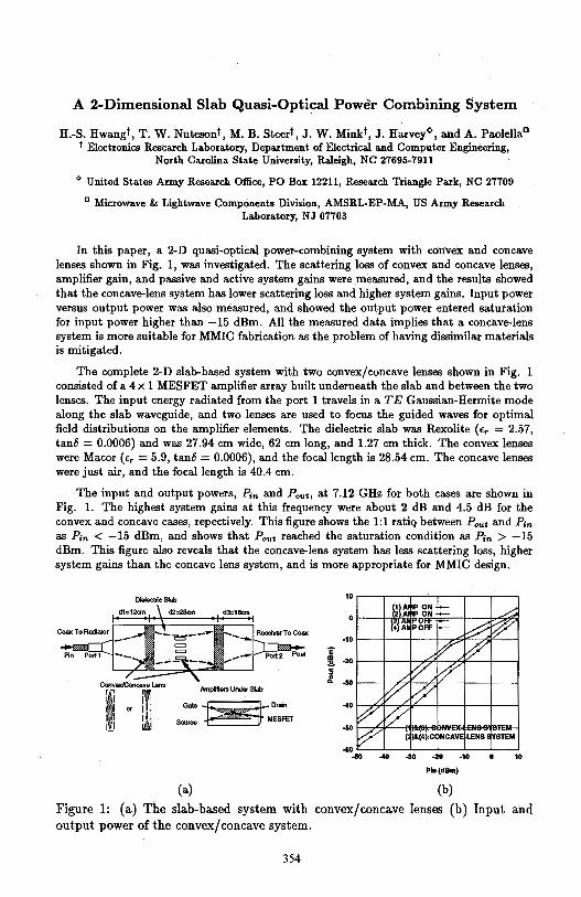
A 2-Dimensional Slab Quasi-Optical Power Combining System
H.-S. Hwangt, T. W. ·Nutesont, M. B. Steert, J. W. Minkt, J. Harvey<>, and A. Paolella0
t Electronics Research Laboratory, Department of Electrical and Computer Engineering, North Carolina State University, Raleigh, NC 27695-7911
~ United States Army Research Office, PO Box 12211, Research Triangle Park, NC 27709
0 Microwave & Lightwave Components Division, AMSRL-EP-MA, US Army Research Laboratory, NJ 07703
In this paper, a 2-D quasi-optical power-combining system with convex and concave lenses shown in Fig. 1, was investigated. The scattering loss of convex and concave lenses, amplifier gain, and passive and active system gains were measured, and the results showed that the concave-lens system has lower scattering loss and higher system gains. Input power versus output power was also measured, and showed the output power entered saturation for input power higher than -15 dBm. All the measured data implies that a concave-lens system is more suitable for MMIC fabrication as the problem of having dissimilar materials is mitigated.
The complete 2-D slab-based system with two convex/concave lenses shown in Fig. 1 consisted of a 4 x 1 MESFET amplifier array built underneath the slab and between the two lenses. The input energy radiated from the port 1 travels in a TE Gaussian-Hermite mode along the slab waveguide, and two lenses are used to focus the guided waves for optimal field distributions on the amplifier elements. The dielectric slab was Rexolite {fr = 2.57, tan8 = 0.0006) and was 27.94 cm wide, 62 cm long, and 1.27 cm thick. The convex lenses were Macor {fr= 5.9, tan8 = 0.0006), and the focal length is 28.54 cm. The concave lenses were just air, and the focal length is 40.4 cm.
The input and output powers, P;n and Pout, at 7.12 GHz for both cases are shown in Fig. 1. The highest system gains at this frequency were about 2 dB and 4.5 dB for the convex and concave cases, repectively. This figure shows the 1:1 ratiq between Pout and P;n as Pin < -15 dBm, and shows that Pout reached the saturation condition as P;n > -15 dBm. This figure also reveals that the concave-lens system has less scattering loss, higher system gains than the concave lens system, and is more appropriate for MMIC design.
Coax To Radiator
Dielectric Slab
d3:16an
Receiver To Coax
Amplm ... Under Slab
Gate~Drain
Soun:e = MESFET
i' ! g a.
10
0
-10
-20
-30
-40
-50
-40 -30 -20
Pln(dBm)
(a) (b)
-10
Figure 1: (a) The slab-based system with convex/concave lenses (b) Input and output power of the convex/ concave system.
354
MICROCONTROLLER-BASED THERMAL IMAGING SYSTEM
Dr. Salim Akbar, Department of Avionics Engineering, College of Aeronautical Engineering, PAF Academy, Risalpur, Pakistan
The electro-optical design of a microcontroller-based thermal imaging system is described. The optical head assembly, electro-mechanical raster scanning, analog and digital signal processing, scan conversion circuitry and display circuit are discussed.
The optical head assembly includes a stepper-motor mounted front-surface aluminum-oxide coated inirror, an 8-14 µ AR-coated infrared lens-system, an 8-14 µ optical filter, and a linear cryogenically-cooled 48-element Mercury-CadmiumTelluride 8-14 µ detector array.
The electro-mechanical raster scanning system features object-plane scanning with a stepper-motor mounted mirror. The l.8° stepper motor is used in conjunction with a gear box of25:2 to achieve a mechanical step size of0.144 ° and an optical step size of 0.288°. The stepper motor-based scanner offers an inexpensive open-loop system free from damping and oscillation considerations and promises sufficient torque to provide uninterrupted operation even when the host platform is undertaking high-G manoeuvre. In all, 128 linear mechanicalsteps per scan-frame are executed to yield a horizontal field of view of 36. 9°. The vertical field of view of the system is determined by the combination of lens system and detector array and calculated to be 13.4 °. The scan-frame rate is 2.6 Hz while the raster display-frame rate is 47.3 Hz.
The analog and digital signal processing features trans-resistance preamplifiers, post-amplifiers, electrical filtering, 48 x 1 analog multiplexing, digitalto-analog conversion and a digital dual memory set in which frame data are stored. The stored data are read out at a controllable rate.
The dual-memory based scan-conversion circuitry offers the convenience to display the target image on to a variety of display types (NTSC TV, flat-panel, or dedicated CRT) regardless of the electro-mechanical scan rate.
Lastly, the entire image acquisition process is controlled by an 8051 microcontroller. The electro-mechanical scanning, the D-A conversion, the memory write and read and image display are all · controlled by the microcontroller, yielding software-flexibility and reduced cost and component count.
355
A FREQUENCY-AGILE RF SOURCE USING BISTABLE OPTICALLY CONTROLLED SEMICONDUCTOR SWITCHES (BOSS)
Dr. David C. Stoudt, Dr. Frank E. Peterkin and Mr. Michael A. Richardson Dahlgren Division, Naval Surface Warfare Center
Pulsed Power Systems & Technology Group, Code B20 Dahlgren, Virginia 22448-5100
Recent experimental high-power, subnanosecond-switching results of the Bistable Optically controlled Semiconductor Switch (BOSS) are presented. The processes of persistent photoconductivity followed by photo-quenching have been demonstrated at megawatt power levels in copper-compensated, silicon-doped, semiinsulating gallium arsenide. These processes allow a switch to be developed that can be closed by the application of one laser pulse (A=l.06 µm) and opened by the application of a second laser pulse with a wavelength equal to twice that of the first laser (A=2.13 µm). Switch closure is primarily achieved by elevating electrons from a deep copper center which has been diffused into the material. The opening phase is a two-step process which relies initially on the 2-µm laser to elevate electrons from the valance band back into the copper center, and finally on the recombination of electrons in the conduction band with holes in the valance band. For fast opening behavior, the second step requires a high concentration of recombination centers which are generated in the bulk GaAs material by fast-neutron irradiation at a fluence level of about 2x1015 cm·2
•
Neutron-irradiated BOSS devices have been opened against a rising electric field of 36 kV /cm ( 18 kV) in a time less than one nanosecond. Electrical pulses have been generated, at ten's of kilovolts, with a FWHM of roughly 350 picoseconds and at repetition rates ofup to 1 GHz (within a two-pulse burst). The ability of the BOSS switch to open, as well as close, in the subnanosecond regime allows a new type of RF source to be developed that is capable of generating repetitive high-power microwave cycles of varying duration, depending on the relative delay between the tum-on and tum-off laser pulses. A source configuration that is capable of generating ac power with real-time frequency agility is called the pulse-switch-out (PSO) generator. The PSO generator consists of two BOSS devices, one housed in a positively charged transmission line and the other in a negatively charged transmission line, both feeding into a single transmission line that leads to the antenna. Positive and negative half-cycles are generated by first closing and opening each BOSS device in succession. The frequency content in the generated RF pulses can be adjusted by either varying the time between the tum-on and tum-off of each switch, or by varying the time between the closure of each BOSS device while keeping the electrical pulse width the same. Results demonstrating the operation of BOSS devices at high repetition rates in a frequency-agile RF source configuration will be discussed.
356
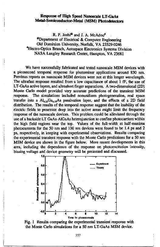
Response of High Speed Nanoscale LT -GaAs Metal-Semiconductor-Metal (MSM) Photodeteclors
R. P. Joshi8 and J. A. McAdoo' ®Department of Electrical & Computer Engineering Old Dominion University, Norfolk, VA 23529-0246
'Electro-Optics Branch, Aerospace Electronics Systems Division NASA Langley Research Center, Hampton, VA 23681
We have successfully fabricated and tested nanoscale MSM devices with a picosecond temporal response for photomixer applications around 830 nm. Previous reports on nanoscale MSM devices were not at this longer wavelength. The ultrafast response resulted from a low capacitance of about 1 tF, the use of L T-GaAs active layers, and ultrashort finger separations. A two-dimensional (2D) Monte Carlo model provided very accurate predictions of the transiept MSM response. The simulations included nonuniform photogeneration, real space transfer into a A1<,_25Gao.75As passivation layer, and the effects of a 2D field distribution. The results of the temporal response suggest that the inability of the electric fields to penetrate deep into the active areas might limit the frequency response of the nanoscale devices. This problem could be alleviated through the use of a backside LT GaAs-AIGaAs heterojunction to confine photocarriers within the high field regions near the top. Values of the full-width at half-maxima photocurrents for the 50 nm and 100 nm devices were found to be 1.4 ps and 2 ps, respectively, in keeping with experimental observations. Results comparing the experimental transient response with the Monte Carlo predictions for a 50 nm MSM device are shown in the figure below. More recent developments in this area, including the dependence of the response on photoexcitation intensity, biasing voltage and device geometry will be presented and discussed.
1~r--~-r----,i..-~...-~-.-~-.-~-.-~~
0.8
l 0.6
i 0.4
Ju
2
1, \
\ \
\
4
_ Experiment
·-····- Theoiy
• • 10 12 14 11me In picoseconds
Fig. 1 Results comparing the experimental transient response with the Monte Carlo simulations for a 50 nm LT-GaAs MSM device.
357
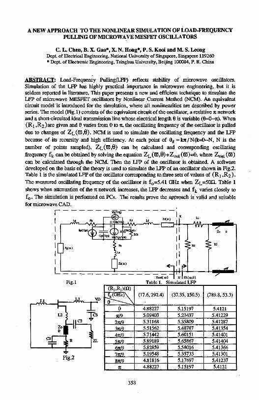
A NEW APPROACH TO THE NONLINEAR SIMULATION OF LOAD-FREQUENCY PULLING OF MICROWAVE MESFET OSCH.,LATORS
C. L. Chen, B. X. Gao*, X. N. Hong*, P. S. Kooi and M. S. Leong Dept of Electrical Engineering, National University of Singapore, Singapore 119260 * Dept. of Electronic Engineering, Tsinghua University, Beijing 100084, P. R. China
ABSTRACT: Load-Frequency Pulling(LFP) reflects stability of microwave oscillators. Simulation of the LFP has highly practical. importance in microwave engineering, but it is seldom reported in literature. This paper presents a new and efficient technique to simulate the LFP of microwave MESFET oscillators by Nonlinear Current Method (NCM). An equivalent circuit model 'is introduced for the simulation, where all noniinearities are described by power series. The model (Fig.I) consists of the equivalent circuit of the oscillator, a resistive 1t network and a short-circuited ideal transmission line whose electrical length 9 is variable (9=0--n:). When (R1 ,R2)are given and 9 varies from Oto 1t, the oscillating frequency of the oscillator is pulled due to changes of ZL(m,0). NCM is used to simulate the oscillating frequency and the LFP
because of its recursity and high efficiency. At each point of 9k =k1t/N(k=O--N, N is the number of points sampled), ZL(m,0) can b(l calculated and corresponding oscillating
frequency fk can be obtained by solving the equation ZL (m,0)+Zout (m)=O, where Z 001 (m) can be calculated through the NCM. Then the LFP of the oscillator is obtained. A software developed on the basis of the theory is used to simulate the LFP of an oscillator shown in Fig.2. Table 1 is the simulatedLFP of the oscillator corresponding to.three sets of values of (R1 ,R2).
The measured oscillating frequency of the oscillator is f0 =5.41 GHz when ZL=500. Table 1 shows when attenuation of the 7t network increases, the LFP decreases and fk varies closely to
f0 • The simulation is performed on PCs. The results prove the approach is valid and suitable for microwave CAD.
' 1 ------ldg(Vds) ------Ix I ~ Zl(m>
I I I z,,: .. i
I I
R2
L--,----------Zout( a,) X ZL{CD,8)
Fig.1 Table 1 Simulated LFP (R1,R1)(.Q)
fk(GHz)~ a=----:_ .
(17.6, 292.4) (37.35, 150.5)
0 4.88227 5.15197
Tr.19 5.09403 5.23437 2'11'19 5.31168 5.35809
3Tr./9 5.51562 5.48787
471:/9 5.71442 5.60151
5Tr19 5.89189 5.65867 fm19 5.82859 5.58016
7n/9 5.19548 5.35733
8n/9 4.81816 5.17697 Fig.2
7t 4.88227 5.15197
358
R2
(789.8, 53.3)
5.4121 5.41229 5.41287 5.41354 5.41401 5.41404 5.41366 5.41301 5.41237 5.4121

Thursday PM URSI-B Session 17 Constel. Ballroom E
Special Session
Recent Progress in PML Absorbing Boundary Condition in FEM and FDTD J. F. Lee and R. Mittra Page
1 :20 Application and Performance Issues of PML in 3D Frequency- ......... 360 Domain Finite Element Methods for Modeling MMIC Devices G. Peng, S. Pereplitsa, R. Dyczij-Edlinger, and J. F. Lee, Worcester Polytechnic Institute
1 :40 The Use of Higher Order Edge-Based Finite Elements to ................ .361 Improve the Accuracy of the Anisotropic Perfectly Matched Layer J. Y. Wu, R. Lee, and J. F. Lee, The Ohio State University
2:00 A Modal PML ..................................................................... 362 M. Okoniewski, J. De Moerloose, M. A. Stuchly, University of Victoria, M. Mrowwski, Technical University of Gdansk
2:20 Conformal PML Absorbers for Mesh Truncation in ·FEM ............... .363 M. Kuzuoglu, R. Mittra, University of Illinois at Urbana-Champaign
2:40 Closed Form Expression of Numerical Reflection Coefficient .......... 364 of Perfectly Matched Layers Jiayuan Fang, Zhonghua Wu, State University of New York at Binghamton
3:20 Application of a Modified PML Implementation Towards FDTD ....... 365 Antenna Analysis Jonathon C. Veihl, Raj Mittra, University of Illinois
3:40 The Uniaxial Perfectly Matched Layer (UPML) Truncation of ........... 366 of FDTD Lattices for Generalized Media Stephen D. Gedney, Alan Roden, University of Kentucky
4:00 Modification of Finite-Difference Equations at PML Interfaces ....... .367 to Reduce Numerical Reflection of PML Zhonghua Wu, Jiayuan Fang, State University of New York at Binghamton
4:20 Time-Domain Implementation of the Generalized, ........................ 368 Anisotropic PML James G. Maloney, Morris P. Kesler, Georgia Tech Research Institute
4:40 The Design of Maxwellian Absorbing Materials for Numerical ........ 369 Boundary Conditions and for Practical Engineering Applications Richard W. Ziolkowski, The University of Ariwna
359
Application and Performance Issues of PML in 3D Frequency-Domain Finite Element Methods for Modeling MMIC Devices
G. Peng*, S. Pereplitsa, R. Dyczij-Edlinger, and J. F. Lee
The use of an anisotropic material (PML absorber) in the frequency domain finite element methods has been proposed previously (Z. Sack etc., IEEE AP-8, 1460-1463, Dec. 1995) for the boundary truncation. In this paper, this PML condition has been extended to match multi-layered structures and subsequently incorporated into a frequency-domain H 1(curl) vector finite element method to model MMIC devices.
Higher order vector finite element methods offer the possibility of using a coarse grid to obtain accurate solutions of Maxwell's equations while at the same time, retaining the geometric flexibility of finite element methods. As early as 1980, Nedelec introduced a family of mixed finite elements in R3 that is unisolvent as well as conforming in 1l(curl) (J. C. Nedelec, Num. Math. 35, 1980). In this paper we discuss the application of the 1£1(curl) vector finite elements for the analyses of MMIC devices. This is a higher order scheme which is incomplete to second-order for the vector field, but is complete to first-order in the range of the curl operator.
By incorporating the PML material in the frequency domain finite element formulation for modeling three-dimensional MMIC devices, two major difficulties have been observed. They are: great number of unknowns introduced by the PML materials; and, slow convergences in the preconditioned conjugate gradient solvers. To circumvent these two difficulties, we have implemented a recursive PML formulation which reduces the memory consumption for the PMLs and investigated appropriate preconditioners for the resulting matrix equations.
Specific topics that will be addressed in the presentation include: the accuracy/ performance vs the per-layer damping factor of the PML absorber; the performance of a Schur complement preconditioner for solving the resulting matrix equation; and, the computational complexities of two formulations, E-field and A-V formulations.
360
THE USE OF HIGHER ORDER EDGE-BASED FINITE ELEMENTS TO IMPROVE THE ACCURACY OF THE
ANISOTROPIC PERFECTLY MATCHED LAYER
J. Y. Wu, R. Lee, and J. F. Lee
ElectroScience Laboratory Department of Electrical Engineering
The Ohio State University 1320 Kinnear Rd.
Columbus, Ohio 43212-1191
Since its introduction, the anisotropic perfectly matched layer (PML) (Sacks et al., IEEE Trans. Antennas and Propagat., Dec. 1995) has gained much interest in its use as a new boundary truncation scheme for finite methods. To be used for this purpose for 3-D electromagnetic scattering problems, the PML materials have to form a box with the scatterers enclosed inside, a11.9 special care must be taken for the materials on the edges and corners of the box, to ensure perfect matching. For the edge-based finite element method (FEM), where the edge elements (Whitney I-forms) are used, good accuracy with this boundary truncation scheme can be achieved, but depends heavily on the choices of the thickness, material properties, and mesh density for the PML region. Thin PML materials with high material properties are desirable to reduce computation costs. However, this means that the fields inside the PML region decay rapidly, which requires a very fine mesh to satisfactorily approximate the field behavior, increasing the computational cost. Therefore, there are trade-offs among these choices.
Alternatively, one can keep the mesh size fixed, and use higher order finite elements to better approximate the field behavior inside the PML region. Although higher order elements have been extensively studied for the nodal FEM, there have been only limited use of higher order elements for the edgebased FEM. Commonly referred to as tangential vector finite elements, these higher order vector elements are not as easy to understand or construct as their nodal counterparts. The performance evaluation of the tangential vector finite elements is not straightforward. Although the number of unknowns is much reduced with the use of higher order elements, the connectivity per element increases dramatically. The most important factor, however, should be the computational costs for obtaining solutions of comparable accuracy. This depends on the problems considered and the matrix solvers used.
In this presentation, we will show the results of some typical EM scattering problems with anisotropic PML for boundary truncation, modeled by different orders of tangential finite elements. We will show the advantages and disadvantages of the higher order elements. All the performance comparisons will be based on the use of the conjugate gradient method as the matrix solver.
361
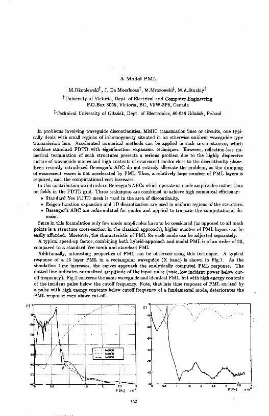
A Modal PML
M.Okoniewskit, J. De Moerlooset, M.Mrozowskii, M.A.Stuchlyt
tuniversity of Victoria, Dept. of Electrical aud Computer Engineering P.0.Box 3055, Victoria, BC, V8W-3P6, Canada
iTechnical University of Gdansk, Dept. of Electronics, 80-956 Gdansk, Polaud
In problems involving waveguide discontinuities, MMIC trausmission lines or circuits, one typically deals with small regions of inhomogeneity situated in au otherwise uniform waveguide-type trausmission line. Accelerated numerical methods cau be applied in such circumstauces, which combine staudard FDTD with eigenfunction expausion techniques. However, reflection-less numerical tern;unation of such structures presents a serious problem due to the highly dispersive nature of waveguide modes and high contents of evanescent modes close to the discontinuity plaue. Even recently introduced Berenger's ABC do not entirely alleviate the problem, as the dumping of evauescent waves is not accelerated by PML. Thus, a relatively large number of PML layers is requir_ed, aud the computational cost increases.
In this contribution we introduce Berenger's ABCs which operate on mode amplitudes rather than on fields in the FDTD grid. Three techniques are combined to achieve high numerical efficiency:
• Staudard Yee FDTD mesh is used in the area of discontinuity. • Eeigen-function expansion aud lD discretization are used in uniform regions of the structure. • Berenger's ABC are reformulated for modes and applied to truncate the computational do
main. Since in this formulation only few mode amplitudes have to be considered ( as opposed to all mesh
points is a structure cross-section in the classical approach), higher number of PML layers can be easily afforded. Moreover, the characteristic of PML for each mode can be adjusted separately.
A typical speed-up factor, combiRing both hybrid-approach aud modal PML is of an order of 20, compared to a staudard Yee mesh aud staudard PML.
Additionally, interesting properties of PML can be observed using this technique. A typical response of a 16 layer PML in a rectaugular waveguide (X baud) is shown in Fig.1. As the simulation time increases, the curves approach the aualytically computed PML response. The dotted line indicates normalized amplitude of the input pulse (note, low incident power below cutoff frequency). Fig.2 concerns the same waveguide aud identical PML, but with high energy contents of the incident pulse below the cutoff frequency. Note, that late time response of PML excited by a pulse with high energy contents below cutoff frequency of a fundamental mode, deteriorates the PML response even above cut-off.
362
-10.,L.-,io.s,--~-------:---c2:':5c---::---c;;;c--~. ; x101
1)
Conformal PML Absorbers for Mesh Truncation in FEM
M. Kuzuoglu* and R. Mittra Electromagnetic Communication Laboratory University of Illinois at Urbana-Champaign
1406 W. Green Street, Urbana, IL 61801
In the finite element modeling of electromagnetic radiation and/or scattering problems, the computational domain is usually truncated by an artificial boundary over which suitable absorbing boundary conditions (ABCs) are imposed. An alternative approach to mesh truncation, which was recently proposed by Berenger for FDTD implementation, employs an anisotropic layer of material called perfectly matched layer (PML) at the outer boundary, that is designed to absorb plane waves of arbitrary frequency and incident angles. However, since the Cartesian coordinate system is used in a majority of FDTD applications, the PML layers are typically placed on the six faces of a cubical surface and this, in turn, can lead to an increase in the computational domain for scatterers of arbitrary shape. To obviate this difficulty, we design a conformal anisotropic absorbing layer and choose its constitutive parameters such that it again has PML-like properties.
For two-dimensional TM or TE scattering problems, the partial differential equation satisfied by <p ( <p is E, (TM) or H, (TE)) is given by
V.(AV <p) + k2a<p = 0
where k is the wave number, a= 1- j_!!_, and A= [~xx ~xy] is a tensor (0£0 /l,yx /l,yy
whose entries are chosen to enforce the decay of the wave within the layer in the direction normal to the boundary. The tensor A is obtained by applying suitable
rotation operators to the tensor A, which is defined at a certain point P with respect to a local (l;,17) coordinate system in a way such that the field attenuates
along either l; or 1J; thus, A is the representation of A with respect to the global coordinates (x,y). The anisotropic absorbing layer, described by A, can be of arbitrary shape and, hence, can be chosen to be conformal to the surface of the scatterer to minimize the white space region of the computational domain.
Numerical results demonstrating the validity of the conformal PML approach have been obtained and will be included in the presentation.
* Supported by the Turkish Scientific and Technical Research Council as a NATO B2 scholar
363

Closed Form Expression of Numerical Reflection Coefficient of Perfectly Matched Layers
Jiayuan Fang* and Zhonghua Wu Department of Electrical Engineering
State University ofNew York at Binghamton Binghamton, NY 13902
It has been understood that, at an interface of two P:ML media, there is no reflection for incident waves of any angles and frequencies [Berenger, J. Comp. Phys., 114:185-200, 1994]. However, reflection does occur at the interface of two P:ML media in actual FDTD.computations. Analyses have been reported on the numerical reflection at an interface of two P:ML media [Chew and Jin, URSI, 338, 1995]. Typical practice is to have the conductivity profile of P:ML change gradually to maintain low numerical reflection. To achieve optimum performance for a given thickness of a perfectly matched layer, the amplitude and the pattern of the conductivity profile need to be properly chosen to reach best compromise between the wave attenuation and the numerical reflection inside the P:ML.
Our study shows that the numerical reflection at an interface between two P:ML media depends heavily on the finite-difference equation right at the interface. With numerical dispersion relations on both sides of the interface, and the finite-difference equation right at the interface, a. closed form expression of the numerical reflection coefficient at the interface can be derived. Starting from the single reflection coefficient for one interface, the expression for the total reflection coefficient for N interfaces can be found recursively. The validity of the closed form expression of the numerical reflection coefficient is checked with the results obtained directly from FDTD computations. It has been found that the reflection coefficients obtained directly from FDTD computations identically matches those from the closed form expression.
The resultant closed form expression of the reflection coefficient is a function of medium thickness and the pattern of the conductivity profile of P:ML. This expression significantly facilitates the effort of selecting parameters of P:ML to achieve optimum performance. The dependence of the numerical reflection on various parameters of P:ML, which reveals the optimum values of these parameters, will be presented.
364
APPLICATION OF A MODIFIED PML IMPLEMENTATION TOWARDS FDTD ANTENNA ANALYSIS
Jonathon C. Veihl* and Raj Mittra Electromagnetic Communication Laboratory
University of Illinois, Urbana, IL 61801
The perfectly matched layer (PML) concept for FDTD mesh truncation has been shown to provide near-field reflection errors several orders of magnitude less than that achieved with traditional one-way wave equation techniques [Berenger, J. Comput. Phys., 114: 185-200, 1994]. The main objective of this paper is to quantify the level of improved accuracy in the computed radiation characteristics for various antenna geometries due to these reduced reflection errors as a function of the computational cost incurred. The standard three-dimensional PML implementation requires the electric and magnetic fields to be split, resulting in 12 update equations for 12 unknowns [Katz et al., IEEE!MGWL, 4:268-270, 1994]. A modified formulation which utilizes only 8 unknowns in wall regions, i.e., where there is only one nonzero conductivity component, is combined with the standard PML in the much smaller edge and comer regions, where multiple nonzero conductivities exist, to provide a more efficient PML implementation while providing the same level of accuracy [Veihl, Mittra, IEEE!MGWL, Feb., 1996]. Computation time and memory savings of roughly 20% can be achieved with the hybrid formulation with no appreciable loss of accuracy for the near field solutions. Extensions to the modified PML for improved evanescent wave absorption will be discussed, together with the incorporation of the unsplit equations in the edge and comer regions. The latter is accomplished by defining an edge or comer to exist only on the diagonal of the region of overlap of multiple wall regions. Although feasible, the memory and coding complexity tradeoffs of this approach may make it unattractive compared to the hybrid approach. A more serious limitation exists in the inability to apply the modified PML in regions with nonzero background conductivity, where the generalized PML may be more appropriate.
The modified PML for nonuniform FDTD has been applied towards the analysis of antennas for input impedance and far field radiation pattern. The goal has been to bring the PML layer as close as possible to the antenna in order to reduce the white space between the antenna and the mesh truncation boundary. This reduction of buffer region and the nonuniform formulation allow finer detail to be applied in the modeling of the radiator without drastically increasing the solution time. Wire dipoles, coax-fed patch antennas, aperture-coupled microstrip patch antennas, and a handheld portable telephone in the presence of a head model have been investigated using the modified formulation. For the patch antennas, the input impedance and radiation pattern were computed as the distance between the patch and the mesh truncation condition was reduced. The radiation pattern was found to be relatively insensitive to the placement of the boundary condition and the location of the equivalent surface used for the nearfield to far-field transformation. The sensitivity of the input impedance on the proximity of the boundary condition will be discussed for various boundary conditions, including the dispersive boundary condition and various PML implementations.
365
The Uniaxial Perfectly Matched Layer (UPML) Truncation of FDTD Lattices for Generalized Media
Stephen D. Gedney* and Alan Roden Electromagnetic Laboratory, Department of Electrical Engineering
University of Kentucky, Lexington, KY 40506-0046
Explicit time-domain methods such as the finite-difference time-domain (FDTD) method and the planar generalized Yee (PGY) algorithm have been highly effective for the analysis of practical microwave circuit devices and antennas. One of the most challenging aspects of these methods is implementing absorbing boundary conditions that can accurately truncate the mesh over broad frequency bands. Recently, J.-P. Berenger (J. of Comp. Phys., 1994) introduced an absorbing material medium, referred to as a perfectly matched layer (PML), that provides a nearly reflectionless lattice truncation. Since its introduction, the PML absorbing media has rapidly demonstrated extraordinary success for the termination of FDTD lattices. It has been applied to homogeneous media, inhomogeneous media, as well as lossy media. A number of variations of the method have also been introduced, including a coordinate stretched approach (Chew and Weedon, IEEE MGWL 1994), (C. M. Rappaport, IEEE MGWL, 90-92, March, 1995), a uniaxial PML in the frequency domain (Z. Sacks, et al, IEEE. T. on AP, 1460-1464) and extended to the time-domain (S. Gedney and A. Roden, URSI Symp., Newport Beach, CA, 1994), and a generalized PML (Fang, IEEE MGWL, 451-453, 1995). The initial portion of this paper presents a unified theory for PML media. Specifically, it is demonstrated that the above generalizations of the PML media have mathematical equivalencies, and can be neatly summarized by the uniaxial PML (UPML) description. Subsequently, the application of the UPML to inhomogeneous, lossy, dispersive, and non-linear media are illustrated to demonstrating the generality of this absorbing medium. From these studies, it is demonstrated that in the discrete space the reflective properties of the PML are highly dependent on the material parameters and the depth of the PML as well as the spatial scaling of the PML parameters. However, an optimal choice of parameters is found that minimizes reflection across the entire spectrum of frequencies of the time-dependent simulated fields. Finally, the UPML is extended to non-Cartesian grids as well as the unstructured grid based PGY algorithm. The limitations of the UPML as well as the successful application of the UPML termination of such lattices is discussed.
366
Modification of Finite-Difference Equations at PML Interfaces to Reduce Numerical Reflection of PML
Zhonghua Wu* and Jiayuan Fang Department of Electrical Engineering
State University ofNew York at Binghamton Binghamton, NY 13902
Although there should be no reflection at the interface of PML media by analyzing corresponding differential equations, there actually is numerical reflection at the interface in finite-difference time-domain computations. It has been found that the amount of numerical reflection at the interface mostly depends on numerical implementations at the interface. That is, better finite-difference implementations at the interface can lead to smaller numerical reflections.
Consider an interface of two uniform PML media. The coefficients in FDTD equations depend on material properties at discrete finite-difference grid points. At the interface of the two PML media, the selection of coefficients of FDTD equations is ambiguous. The common practice is to let the coefficients at the interface be the average of the coefficients on both sides of the interface.
It can be shown that the closed form expression for the numerical reflection coefficient at the interface can be derived analytically. From this closed form expression, coefficients of FDTD equations at the interface can be determined to minimize the numerical reflection. Our ~tudy shows that, for minimum numerical reflection, the coefficients of FDTD equations at the interface should be chosen different from the average of those on both sides of the interface.
It can be shown both numerically and analytically that, for an interface of two uniform PML media, the numerical reflection of our modified finite-difference equation is several orders of magnitude smaller than that of the commonly used finite-difference scheme. Numerical tests show that our current modified finite-difference equation, however, does not always provide improvements over the conventional scheme for some non-uniform PML media. Both favorable and unfavorable results will be presented to stimulate discussions.
367

TIME-DOMAIN IMPLEMENTATION OF THE GENERALIZED, ANISOTROPIC PML
James G. Maloney* and Morris P. Kesler Signature Technology Lab, Georgia Tech Research Institute
Atlanta, GA 30332-0824
In 1994, Berenger introduced the concept of the Perfectly Matched Layer (PML) for use in truncating numerical grids for electromagnetic computations (Berenger, J. Comp. Phys., pp. 185-200, 1994). His original approach involved the splitting of the field components into two parts, and treating each part separately. Impressive results have been obtained using this formulation for truncating free space regions. However, its performance is degraded when used to truncate regions with loss. Also, the storage requirements are doubled in the PML regions. In 1995, another formulation of a PML suitable for use in frequency-domain electromagnetic codes (FEM, FDFD) was published (Sacks, et. al., IEEE Trans. Antennas and Propagation, pp. 1460-1463, Dec. 1995). This formulation involved using a lossy, anisotropic material to truncate the numerical grid.
At last year's URSI meeting, a generalization of the Berenger PML suitable for numerical truncation of lossy regions was discussed (Wu and Fang, Proc. USNCIURSI Mtg., p. 336, June 1995). However, the splitting of the field components was maintained and additional auxiliary variables were introduced. In addition, a time-domain implementation of the anisotropic PML was introduced (Gedney and Roden, Proc. USNCIURSI Mtg., p. 334, June 1995). However, there was little discussion of truncating regions with loss. In this presentation, we will discuss the generalization of the anisotropic PML for the truncation of lossy regions as well as the details of its time-domain implementation.
An FDTD numerical grid which is truncated by the generalized, anisotropic PML can be divided into four distinct sub-regions: the interior, the faces, the edges, and the corner regions. We consider the general case where the interior region can be lossy, either dielectric, magnetic or both. In the frequency domain, the generalized PML relations for the face regions are constructed by requiring zero reflection at the interface between the interior and face regions. The PML relations for the other regions are derived by enforcing the same requirement between two anisotropic PML regions. The time-domain implementation of the various PML relations requires the introduction of auxiliary variables, the number of which depends on the material parameters of the interior region. The details of the PML relations and implementation requirements for the various regions will be discussed during the presentation.
368
The Design of Maxwellian Absorbing Materials for Numerical Boundary Conditions and for Practical Engineering
Applications
Richard W. Ziolkowski
Electromagnetics Laboratory Department of Electrical and Computer Engineering
The University of Arizona P. 0. Box 210104, 1230 E. Speedway
Tucson, AZ 85721-0104
(520) 621-6173 (office), (520) 621-8076 (fax) [email protected] (e-mail)
Electromagnetic absorbers have many practical usages. These include the now famous stealth technologies as well as the more traditional cone absorbing materials for anechoic chambers. The need for such absorbers does not diminish. There are many applications for lighter weight, more highly absorbing materials.· The immense interest in complex media such as artificial chiral materials has arisen from such needs. Absorbers have also attracted much attention recently in the computational electromagnetics community. The need to truncate the simulation domain in any finite difference or finite element approach is well-known. Many absorbing boundary conditions (ABCs) have been developed to achieve this truncation. Like with any real-life absorber, the perfect ~BC would absorb perfectly any frequency of electromagnetic radiation incident upon it from any angle of incidence. The Berenger perfectly matched layer (PML) ABC comes quite close to this goal. However, a major drawback to the Berenger PML ABC is that it requires a nonMaxwellian implementation through the field equation splitting introduced by Berenger. This is not a serious drawback numerically, but it does mean that a PML region can not be realized physically.
A Maxwellian material interpretation of the Berenger perfectly matched layer (PML) will be developed in the presentation using polarization and magnetization fields. The PML material is found to be a passive lossy electric and magnetic medium with particular conductivity and Debye dispersion characteristics. Although it is recognized that the PML medium is physically unrealizable, this polarization and magnetization field interpretation reveals the necessary characteristics of a perfect electromagnetic absorber. A physically realizable, Maxwellian material that has those perfect absorption properties will then be constructed with these concepts. The numerical implementation of the perfect absorber will be given, and the resulting reflection coefficients from a perfect electric conductor-backed slab of this material will be characterized. It will be shown for broad bandwidth pulsed fields that this absorber, , like the non-Maxwellian PML, has absorption characteristics in the 70-110 dB range for large angles of incidence. Strategies will be discussed for engineering this dispersive electric and magnetic absorber artificially with a substrate that has an array of appropriately designed radiating elements embedded in it.
369

THIS PAGE INTENTIONALLY LEFT BLANK.
370
Thursday PM URSI-B Session 18 MD Suite Annapolis
High Frequency Techniques R. J. Marhefka Page
1 :20 High Frequency Analysis of Spatial Coupling in a Complex ........... 372 Environment Ronald J. Marhefka, The Ohio State University
1 :40 Scattering Analysis of Nonmetallic Faceted Solids Using ............... 373 Uniform Field Integration Method (UFIM) Jacob J. Kim, Oren B. Kesler, Texas Instruments Incorporated
2:00 Numerical Calculation of GTD Coefficients from Moment Method ... .374 Matrices Francis X. Canning, Rockwell Science Center
2:20 Numerical Calculation of Diffraction Coefficients of Generic .......... 375 Conducting and Dielectric Wedges Using FD-TD Glafkos Stratis, Motorola, Inc., Veeraraghavan Anantha, Allen Taflove, Northwestern University
2:40 Numerical Diffraction Coefficients for Wedges with Localized ......... 376 Inhomogeneities G. Manara, University of Pisa, R. Coccioli, G. Pelosi, University of Florence
3:20 Enhancing Directivity of Slots on a Face of an Impedance Wedge .... .377 by Surface Wave Diffraction G. Manara, P. Nepa, University of Pisa, P. H. Pathk, The Ohio State University, R. Tiberio, University of Siena
3 :40 Equivalence Between Physical Optics and Aperture Integration ....... .378 for Open-Ended Waveguides S. Maci, University of Florence, P. Y. Ufimtsev, University of California Los Angeles, R. Tiberio, University of Siena ·
4:00 Closed Form Solution for the Field Radiated at Finite Distance ........ 379 by an Open Ended Circular Waveguide F. Mioc, R. Tiberio, University of Siena, F. Capolino, M. Graziani, S. Maci, University of Florence
4:20 Diffraction at an Edge Close to a Point Caustic ............................ 380 S. Maci, P. Russotti, L. Borselli, F. Capolino, University of Florence, M. Albani, University of Siena
4:40 Time-Domain Incremental Length Diffraction Coefficients for ........ 381 Edges Peter M. Johansen, Electromagnetics Institute, Denmark
5:00 Calculation of Creeping Rays from a 3D Smooth Object by ........... .382 Using Equivalent Currents Masahiko Nishimoto, Hiroyoshi Ikuno, Kumamoto University
371
High Frequency Analysis of Spatial Coupling in a Complex Environment
Ronald J. Marhefka The Ohio State University ElectroScience Laboratory
1320 Kinnear Road Columbus, OH 43212-1191
In determining communication system performance, it is either necessary to optimize the transmission between two antennas or to minimize the interference from one antenna to another. This is especially true when the antennas are in close proximity to one another. In an open environment, it is usually desirable to use numerical methods such as integral or differential based techniques. When the environment is large and complex in terms of a wavelength, however, it is often difficult to use them in practice. Analyzing antennas systems at UHF or above on aircraft or in and around buildings are common examples.
The Uniform Geometrical Theory of Diffraction (UTD) has been used successfully for the analysis of antennas in the presence of large scattering structures. In the past, most work has been conducted on perfectly conducting structures. More recently, much theoretical development has been done to provide rigorous solutions to the general problem of material wedges. These solutions are usually limited to certain types of material, angles, two dimensions, etc. The use of a newly developed heuristic solution for the diffraction from the junction between multilayered material plates is possible. The types and number of interactions that lead to reasonable engineering solutions will be discussed. This entails double diffraction for perfectly conducting structures to multiple combinations of reflections, transmissions, and diffractions for transparent materials.
The spatial coupling between antennas is based here on the generalized reaction theorem. A modified Frii's transmission formula is used which allows the incorporation of the concept for pattern factors for the sources, vector effective heights for the receivers, and UTD ray fields from the scattering structures to obtain the coupled power. The antenna information can be obtained from numerical methods, pattern factors, or tabulated data from simpler situations.
Examples of the coupling between antennas in a complex environment will be discussed. The various individual diffraction mechanisms comprising the propagation paths between antennas for simple geometrical configurations are validated using moment methods. The examples are then extended to represent more realistic geometries such as simple aircraft and building models.
372
SCATTERING ANALYSIS OF NONMETALLIC FACETED SOLIDS USING UNIFORM FIELD INTEGRATION METHOD(UFIM)
Jacob J. Kim* and Oren B. Kesler Texas Instruments Incorporated 2501 W. University, MIS 8019
l\.1cKinney,Texas 75070
During the past decades many researchers investigated the high-frequency electromagnetic (El\.1) scattering from conducting faceted solids such as polygonal cylinders, and developed several asymptotic solutions to predict the scattering from the conducting object. Those high-frequency techniques include simple geometrical optics (GO), and physical optics (PO), and more complicated techniques, such as geometrical theory of diffraction (GTD), physical theory of diffraction (PTD), and uniform theories of diffraction (i.e., UTD and UAT), equivalent current method (ECJ\.1), and incremental length diffraction coefficients (ILDC). However, if the faceted solids become non-metallic materials or radar absorbing material(RAJ\.1) coated conducting materials, then their applications are still limited to the simple two-dimensional(2-D) geometry due to lack of threedimensional(3-D) analytic solutions or too many unknowns for matrix inversion.
This paper describes an efficient high-frequency El\.1 scattering analysis technique, which is referred to as Uniform Field Integration l\.1ethod(UFIJ\.1), to predict the first order 3-D scattering from either nonmetallic faceted solids or RAl\.1 coated conducting solids. The UFIJ\.1 (J. J. Kim and 0. B. Kesler, ACES Proceedings, 21-28, 1995) has been previously used in the El\.1 scattering analysis of complex discontinuities on an electrically large object, and proved its accuracy and computational efficiency. The same analytic approach can be used here for the nonmetallic faceted solids. The UFIJ\.1 utilizes simple 2-D scattered field formulations for nonmetallic or RAl\.1 coated wedge structures, and predicts 3-D scattering from the faceted solids. The 2-D scattered fields for the nonmetallic or RAl\.1 coated wedge shapes can be readily obtained by available numerical solutions such as 1\.101\.1, FDTD, 1Ll\.1, etc. An assumption made here is that the edge excited surface wave fields are not important and neglected in this analysis. This is true when the surface under consideration has some loss such that the edge excited surface waves decay very quickly away from the edge.
The UFIJ\.1 predicted results were compared with other known analytic solutions(e.g., ECJ\.1 and PTD) for conducting plates and polygonal cylinders. A few test models with RAl\.1 coated surfaces were also constructed and the results of the UFIJ\.1 prediction were compared with actual 3-D RCS measurements. All comparisons showed very good agreements. The main advantage of this technique is in its simplicity and applicability for the arbitrary shaped nonmetallic faceted solids.
373
NUMERICAL CALCULATION OF GTD COEFICIENTS FROM MOMENT METHOD MATRICES
Francis X. Canning Rockwell Science Center
1049 Camino Dos Rios Thousand Oaks, CA 91360
Previous work on the Impedance Matrix Localization (IML) method has repeatedly strengthened its analogy to ray methods. An new combined field equation generated using IML eliminated interactions across the interior of a closed convex perfectly conducting body. This equation is (quasi) local, similar in character to a local high frequency approximation. Can one use this to find numerical values for GTD coeficients, again strengthening the analogy? Scattering of TE radiation by a perfectly conducting circular cylinder is considered. The new combined field integral equation of IML gives a block circulant matrix T. On each block row of T, there is a sub matrix D on the diagonal, to the right of D there is a sub matrix R, and to the left there is L. Further away from the diagonal, we approximate all matrix elements by zero. The k-th block row of the moment method eqn. is
(1)
For k representing a part of the cylinder in the shadow region, Vk=O. Assume there is a complex number c such that
(2)
Combining Eq. (1) and Eq. (2) we get
The condition that the matrix in Eq. (3) have a zero eigenvalue is used to find c and then the associated eigenvector is found. The constant c and eigenvector Jk- l
are found to agree well with GTD formulas.
374
NUMERICAL CALCULATION OF DIFFRACTION COEFFICIENTS OF GENERIC CONDUCTING AND DIELECTRIC WEDGES USING FD-TD
Glafkos Stratis Cellular Infrastructure Division
Motorola Inc. Arlington Heights, IL 60004
Veeraraghavan Anantha Northwestern University Evanston, IL 60208
Allen Taflove Northwestern University Evanston, IL 60208
Classical theories such as the Uniform Theory of Diffraction (UTD) have been used in the past to obtain analytical expressions for diffraction coefficient for canonical problems such as the infinite perfectly conducting wedge. Although these theories predict the fields accurately in the far-field region for simple problems, it is difficult if not impossible to extend these theories to find diffraction coefficients for wedges composed of dielectric and imperfectly conducting materials. In fact, the classical problem of diffraction from an infinite lossless dielectric wedge has not been solved analytically.
In this paper we present numerical results for diffraction coefficients for the infinite conducting wedge and the infinite lossless dielectric wedge using FD-TD. We calculate the cfiffraction coefficients for frequencies from de to 1.5 GHz at a number observation points for steady state plane wave illumination. Comparison of the numerical results for the infinite conducting wedge with the analytical solutions obtained using UTD show a close correspondence between the two methods in the far-field region. In the near-field region and for the infinite lossless dielectric wedge, numerical convergence studies indicate the validity of our results.
Further, we study and compare the diffraction of CDMA (Code Division Multiple Access) and TDMA (Time Division Multiple Access) pulses impinging upon infinite conducting and dielectric wedges using FD-TD - a problem that is especially interesting to the cellular and personal communications industry.
Overall, we demonstrate that numerical simulation of diffraction using FD-TD is an extremely powerful tool that can provide solutions for practical problems which classical analytical techniques cannot provide.
375
NUMERICAL DIFFRACTION COEFFICIENTS FOR WEDGES WITH LOCALIZED INHOMOGENEITIES
G. Manara* Department of Information Engineering, University of Pisa
Via Diotisalvi 2, I - 56126 Pisa, Italy
R. Coccioli, G. Pelosi Electrical Engineering Department, University of Florence
Via C. Lombroso 6/17, I- 50134 Florence, Italy
The analysis of electromagnetic scattering from complex bodies with dimensions much greater than the wavelength can be efficiently accomplished by resorting to high-frequency codes based on asymptotic techniques, such as the Uniform Geometrical Theory of Diffraction (UTD). Usually, an electromagnetic model is defined by locally approximating the outer surface of the scatterer by canonical geometrical shapes and imposing on them suitable boundary conditions. In most cases, to simplify the problem the boundary condition for a perfect electric conductor is chosen, although impedance boundary conditions are sometimes used to take into account the material properties of the body. However, this procedure is in principle not able to accurately predict significant contributions to the scattered field which may arise from localized material inhomogeneities and geometrical irregularities of the structure. This issue is addressed in this communication, in which a standard numerical procedure is developed to account for contributions to the scattered field due to localized inhomogeneities, as for instance cavity - backed inhomogeneously filled apertures, in an otherwise canonical perfectly conducting wedge.
The technique described defines a standard way for constructing high - frequency numerical diffraction coefficients for irregular wedge configurations with localized inhomogeneities. It is worth noting that in such cases, codes based only on high-frequency techniques may fail, depending on the dimensions of the localized irregularities. The procedure proposed, which is obtained by reformulating the hybrid method described in (G. Pelosi, et al. IEE Proceedings-H, Vol. 142, No. 2, pp. 183-189, 1995) based on the Finite Element Method (FEM), allows extending the class of problems that can be analyzed by high - frequency codes. The actual configuration is regularized by recovering the corresponding perfectly conducting wedge canonical shape. The total field in the presence of the irregular wedge is evaluated by adding a correction term to the standard UTD diffraction coefficient, which is given by the product of a vector diffraction coefficient and a vector depending on the incident field. The vector diffraction coefficient is obtained by multiplying a constant matrix times a simple column vector whose entries account for the observation angle. For a given irregular structure, the constant matrix needs to be evaluated only once using the FEM based numerical procedure proposed, and then stored. It can be efficiently used later on in the context of a general high-frequency code, introducing only minor modifications into the code structure.
376
ENHANCING DIRECTIVITY OF SLOTS ON A FACE OF AN IMPEDANCE WEDGE BY SURFACE WA VE DIFFRACTION
G. Manara*, P.Nepa Department of Information Engineering, University of Pisa
Via Diotisalvi 2, 1-56126 Pisa, Italy
P.H. Pathak ElectroScience Laboratory, The Ohio State University
1320 Kinnear Rd., Columbus, OH 43212, U.S.A.
R. Tiberio College of Engineering, University of Siena
Via Roma 56, 1-53100 Siena, Italy
Radiation from slots on the faces of a wedge is a canonical problem in antenna analysis and design. In this context, the definition of simplified simulation models is of importance for understanding dominant radiation mechanisms. The main purpose of this paper is to investigate a specific useful phenomenon which may occur for an impedance wedge. In particular, when suitable reactive surface impedance boundary conditions are imposed on that face where the slots are present, surface waves can be excited and surface wave diffraction at the edge of the impedance wedge can be used to increase the directivity of the array of slots.
A simplified analysis is presented here, by modelling the slots by magnetic line sources. In a first instance, coupling effects among the slots are neglected. Within this approximation, it is found that space and surface wave diffraction contributions from the edge may play an important role in the radiation mechanism. On one hand, space wave diffraction provides the continuity of the field across the shadow boundary. On the other hand, the diffracted field due to a strongly excited surface wave provides an equivalent edge source, that radiates a field contribution with an amplitude which is comparable with that of the direct field from the slot array. Its phase depends on the distance between the phase center of the array and the edge, times the phase constant of the surface wave, which is different from that in free-space. Thus, this latter equivalent edge source field contribution may be usefully combined with the direct radiation of the array. In particular, when the distance between the phase center ofthe array and the edge source satisfies a Hansen-Woodyard condition, an enhanced maximum directivity is obtained. Uniform asymptotic expressions are used to calculate the diffracted field contributions; thus, providing a very accurate approximation of the actual Green's function of the impedance wedge.
In a second instance, a more accurate analysis is performed by resorting to a suitable hybrid technique which combines a Moment Method procedure with a ray field description of the Green's function of the wedge. This method allows to effectively account for mutual couplings due to surface wave excitation, propagation and diffraction from the edge.
Numerical results will be shown during the oral presentation.
377
EQUIV ALEN CE BETWEEN PHYSICAL OPTICS
AND APERTURE INTEGRATION FOR OPEN-ENDED WAVEGUIDES
S. Maci1, P. Ya. Ufimtsetr, R. Tiberio3
1 Dep. of Elec. Eng., Univ. of Florence, Via S.Marta 3, Florence, Italy
2 Electrical Eng. Dept., Univ. of California Los Angeles, CA 90024-1594, US.
3 College of Eng., Univ. of Siena, Via Roma 77, 53100, Siena, Italy
The eigen-mode radiation from an open-ended waveguide (OEW) of
arbitrary cross-section is considered. The following theorem is
demonstrated: the Kirchhoff-Kottler aperture integration (AI) for the
radiated field is equivalent to the physical optics (PO) approach applied
to the wall currents. In particular, it is found that the fields predicted
by AI and PO are exactly the same outside the OEW, while the sum of
the AI field plus the umperturbed feeding field is equal to the PO field
inside the OEW. No restrictions are imposed on the configuration of the
waveguide walls; thus, including non perfectly conducting, corrugated
and dielectric loaded walls.
Although this rigorously established equivalence between AI and PO
techniques is interesting per se, in practical applications it also provides
the freedom of choosing that technique which allows more efficient
calculations. In most instances, AI is a more desirable formulation
which implies a finite domain integration. However, owing to the semi
infinite extent of its integration domain, sometimes the PO integration
can be easily performed in a closed form along the generatrix of the
cylinder; thus, it allows AI to be reduced to a line integration along the
edge either exactly or by means of asymptotic approximations.
378
CLOSED FORM SOLUTION FOR THE FIELD RADIATED AT FINITE DISTANCE
BY AN OPEN ENDED CffiCULAR WAVEGUIDE
F. Mioc, F. Capolino1, M. Graziani1, S. Maci1, R. Tiberio2
1Dep. of Elec. Eng., Univ. of Florence, Via S.Marta 3, Florence, Italy
2 College of Eng., Univ. of Siena, Via Roma 56, 53100, Siena, Italy
A high-frequency formulation is presented for predicting the field at finite distance from open ended circular waveguide that is excited by an axially-symmetric mode. The formulation is based on the Incremental Theory of Diffraction (ITD) {Tiberio, Maci, IEEE Trans on Antennas Propagat, May 1994]. In particular, the field is predicted by correcting the Kirchoff-type aperture integration (AI) by a rim integration of incremental, fringe ITD contributions. When the observation point is below the aperture plane, first order field contributions from the rim are partially optically shadowed. As a consequence, the integration of the ITD contributions is limited to that part of the rim which is directly seen from the observation point. Double diffraction, incremental contributions are introduced in order to compensate the discontinuity of the first order field contributions across the aperture plane. This allows to describe the diffraction mechanism even for modes that are very close to their cut-off frequency, when a strong discontinuity occur at the aperture plane. All the line integrals described above are evaluated asymptotically, so that a complete closed-form solution is obtained. In particular, an AI closed form, asymptotic expression is derived by using its equivalence with the Physical Optics (PO) approach applied to the wall currents. Both the first and the second order ITD integrals are asymptotically evaluated by a uniform stationary phase method.
In the far field limit, this closed form expression recovers that presented in a previous work {AP-S Symposium, Newport-Beach, August 1995} which was successfully validated against the exact Wiener Hopf solution.
The solution presented here is found accurate also for waveguide of moderate dimensions and may usefully be employed to treat interactions among circular elements of a beam forming array.
379
DIFFRACTION AT AN EDGE CLOSE TO A POINT CAUSTIC
S. Maci1, P. Bussotti1, L. Borselli1, F. Capolino1, M. Albani"l
1 Dept. of Elec. Eng., Univ. of Florence, Via S.Marta 9, Florence, Italy
2College of Engineering, Univ. of Siena, Via Roma 56, 59100, Siena, Italy
High-gain reflector antennas for space applications sometimes require pressing performances of side lobes and cross-polarisation levels. These performances are particularly important in Cassegrain and Gregorian arrangements, where high polarisation purity is often imposed and where the spill-over lobe can approach the main beam direction.
In order to satisfy these strong requirements, could be convenient to block the direct spill-over from a Gregorian sub-reflector, as well as separating the primary feed from the main reflector surface for avoiding the perturbation of the induced currents on the same reflector. This can be done by inserting a suitable screening of the primary feed. This screening could be arranged by entirely enveloping the feed/subreflector system, except for a small aperture around the point caustic. On the other hand, this arrangement could provide strong diffraction effects if the edge of the aperture is not sufficiently far from the caustic zone. This effects may perturbate the antenna radiation pattern both directly or via deformation of the main reflector induced currents. An alternative, less perturbative screening could make use of a separation wall close to the primary feed. Again, particular care should be taken in getting the edge out from the caustic point.
In order to investigate the mechanism of perturbation caused by the above separation wall, a canonical, two dimensional problem is analyzed in this paper. It consists of a half-plane illuminated by a caustic point field, that is produced by an ellipse-shaped reflector illuminated by a prime focus Gaussian pattern.
As is well known, the geometrical and the uniform theory of diffraction (GTD/UTD) are not able to treat caustic field, so that alternative high-frequency methods are required. A hybrid Physical Optics (PO)/UTD approach is used to find the field at finite distance from te edge. In particular, the incident field is decomposed into elementary PO contributions, each of which illuminates the half- plane. The total field is obtained by integral superposition of the UTD response to each elementary contribution. An asymptotic highfrequency solution is derived from the above integral.
Numerical results are presented in order to show the perturbation of the screen on the secondary field for various distances of the edge from the caustic point.
380
Time-Domain Incremental Length Diffraction Coefficients for Edges
Peter M. Johansen Electromagnetics Institute
Technical University of Denmark, DK-2800 Lyngby, Denmark
The physical optics (PO) scattered field from perfectly conducting structures is limited in accuracy because the PO current fails to closely approximate the exact current on the structure close to shadow boundaries and surface discontinuities. The accuracy of the scattered field can be significantly increased by adding to the PO field the fringe wave (FW) field that takes into account the diffraction caused by edges. One way to calculate the FW field is to integrate the incremental length diffraction coefficients (ILDC's) for edges (R. A. Shore and A. D. Yaghjian, IEEE Trans. Antennas Propagat. 1, 55-70, 1988) along the illuminated part of the edges of the structure. The ILDC's can be determined from an analytical integration of the FW current on the canonical wedge along incremental strips.
The problem of extending the combination of PO and ILDC's for edges into the time domain is addressed in this talk. In fact, the time-domain version of PO (TD-PO) has already been derived and has been used in many publications recently. In this talk the time-domain version of the ILDC's (TD-ILDC's) for edges is developed by analytically Fourier transforming the ILDC's mentioned in the previous paragraph. The TD-PO field yields a good approximation to the exact scattered field for early observation times. By adding the field from the TD-ILDC's a good approximation to the exact scattered field can be obtained for longer observation times. This fact is illustrated numerically by consideration of a 2-dimensional triangular cylinder illuminated by a plane wave with Gaussian time dependence. The far field is calculated using both the fast Fourier transform on method of moments data and the combination of TD-PO and TD-ILDC's.
381
Calculation of Creeping Rays from a JD Smooth Object by Using Equivalent Currents
Masahiko Nishimoto and Hiroyoshi IKUNO
Department of Electrical Engineering and Computer Science Kumamoto University, Kurokami, Kumamoto 860, Japan
Geometrical Theory of Diffraction (GTD) is one of the powerful techniques for analyzing scattering and diffraction of electromagnetic waves by complicatedshaped objects. However, it fails near the caustics of the diffracted rays as well as near the shadow and reflection boundaries. In order to improve the failure of the GTD near the caustics of diffracted rays, the equivalent edge currents method (EECM) and the physical theory of diffraction (PfD) are proposed. However, the EECM and PfD are available only for the caustics of the edge-diffracted rays, and are not available for the caustic of the creeping rays. For example, in the case of diffraction by a smooth body of revolution for axial incidence, an infinite number of creeping rays are focused on the axis and a caustic is constructed. However, the EECM or PTD are not available for such a caustic, and effective method available for the caustics of the creeping rays is not proposed so far.
In this paper, we present a new method for calculating a creeping ray contribution which is valid at and near the caustic of creeping rays. The basic concept of this method is similar to the EECM. In this method, we assume the equivalent line currents for creeping rays along the contour on which the condition n(P) · r(P) = 0 is satisfied, where P is a point on the contour, n(P) is a normal vector on the surface at P, and r(P) is a vector directed from P to the observation point. In order to determine the strengths of equivalent line currents for the creeping rays, we employ the diffraction coefficients of the conventional GTD. By
evaluating the radiation integral of the obtained equivalent currents, we can get the creeping ray contribution which is valid within the caustic region. In order to check
the validity of this method, we apply it to the diffraction by a sphere and compare
the obtained results with the rigorous and the conventional GTD solutions. We can find, from the comparison, that the failure of the GTD near the caustic is removed in this method, and accurate solution is obtained in this area. Furthermore, in the region far away from the caustic, we can also find that the results of this method approach to those of the GTD.
382
Thursday PM URSI-B Session 19 Chesapeake B
Theoretical Electromagnetics II R. W. Scharstein Page
1 :20 Perturbation Expansion of a Cavity Green's Function ............... 384 Suggested by a Nonuniform Waveguide-Fed Aperture Robert W. Scharstein, University of Alabama
1 :40 Sources at the Edges of a Straight Conductor ......................... 385 Y. L. Chow, A. Torabian-Esfahani, University of Waterloo
2:00 The Radiowave Signal Can Exceed the Speed of Light ............. 386 in the Reissner-Nordstrom Metric T. Do-Nhat, University of Waterloo
2:20 Traveling Time of a Radiowave Signal Influenced by the ......... 387 Reissner-Nordstrom Metric T. Do-Nhat, University of Waterloo
2:40 Prediction of the Force Between a Point Mass and a Point ........ 388 Charge from Einstein's Gravitational Theory T. Do-Nhat, University of Waterloo
3:20 The Difference Between the Lorentz- and the Coulomb-Gauge .. .389 in Terms of the Displacement Current Adolf J. Schwab, Christoph Fuchs, Peter Kistenmacher, Karlsruhe University
3:40 Resonant and Bandwidth Transformer of Wave Types with ....... 390 Resistive Film (Topic Bl or B4) Prof V. B. Kazanskij, 0. V. Bondarenko, Kharkov State University
383
PERTURBATION EXPANSION OF A CAVITY
GREEN'S FUNCTION SUGGESTED BY A
NONUNIFORM WAVEGUIDE-FED APERTURE
ROBERT W. ScHARSTEIN
Electrical Engineering Department University of Alabama
Tuscaloosa, AL 35487-0286 phone 205-348-1761, fax 205-348-6959
e-mail [email protected]
The physical problem (in ~ 2) is a nonuniform, wedge-shaped waveguide that terminates in a ground-plane slot. A pair of simultaneous integral equations for the aperture (electric) fields in two displaced apertures results from the application of the equivalence principle. In addition to the half-space and sectoral-waveguide regions, a third lens-shaped cavity region is introduced in order to simplify the boundaries in terms of purely Cartesian or polar coordinate systems. Access to a Green's function of the Helmholtz operator, which satisfies Neumann boundary conditions (for the polarization considered) on the cavity walls, ensures uniqueness of the solution without having to introduce another pair (tangential magnetic fields) of unknown functions.
The important static Green's function for the cavity is obtained by transforming to bipolar coordinates. An integral expression for the second term in the perturbation expansion (for low frequency) of the dynamic Green's function is carried through the Galer kin analysis of the global integral equations. In this way, some economy is enjoyed by requiring computation of only the features of this Green's function that are directly applicable to the physical aperture problem. Further progress is achieved through some asymptotic evaluation of the correction term, by exploiting the electrical thinness of the lens-shaped cavity.
384

Sources at the Edges of a Straight Conductor
Y.L. Chow and A. Torabian-Esfahani Electrical and Computer Engineering
University of Waterloo
The tangential electric field on a conductor is zero. If the conductor is straight (flat patch or straight wire), as an antenna this geometry brings about a phenomenon that only the edges of the straight conductor appear to produce sources that give the tangential electric field, while the actual current and charge distributions on the conducting surface appear to produce nothing, i.e. zero net electric field parallel to the tangential direction. A well known example is the three point model of a dipole antenna, of which the radiation, both the near and far field, appears to emanate from points at top, bottom and the feed of the dipole. It was shown [ 1 ], with a suitable interpretation, that three point models applied as well to the normal electric field and the tangential magnetic field. We shall call these, for both dipoles and patches, edge sources.
This paper shows that such edge sources appear under both RF and DC conditions, and for both antennas and scatterers. In addition to the above dipole antenna, some examples are:
(1) Charged finite wire at DC, (2) Charged flat conducting patch at DC, (3) Radiation and scattering from an arbitrarily shaped dipole antenna, ( 4) Radiation and scattering from a slot antenna, (5) Radiation and scattering from a microstrip patch antenna, (6) Geom. theory of diffraction (GTD) of TE and TM waves on a conductive half plane.
Similar to the GTD sources, these edge sources are "simulated images", at the edges of an arbitrary conducting patch or finite wire. For an integral equation solution, this means that one can reduce a two dimensional integration of electric current over a patch antenna, to a one dimensional integration of magnetic current around the edge of the patch, like · Example 5 of the above. Also one can reduce the one dimensional integration of electric ( or magnetic) current along a piecewise-linear arbitrary antenna dipole ( or slot, or straight edges of the patch), to the evaluations of point sources at the inflation points, feed and ends of the antenna, like Example 3. Individually and in combination, they bring about a substantial reduction in computation, and an increase in physical insight to the properties of the fields and radiation impedance at the conductor. These physical insights, as well as their implications to the boundary conditions on the conductor, will be discussed.
[l] E.C. Jordan and KG. Bal.main, "Electromagnetic Waves and Radiating Systems" Second Edition, pp. 333 to 336, Prentice-Hall, Inc. Englewoo.S::liif, N.J., 1968.
385
The radiowave signal can exceed the speed of light in the Reissner-Nordstrom metric
T. Do-Nhat
Department of Electrical and Computer Engineering, University of Waterloo, Waterloo, Ontario, Canada N2L 3Gl.
ABSTRACT
The trajectory of a massless particle influenced by the ReissnerNordstrom metric has recently been expressed as a power series of the perturbation parameter €=3a/{2R) [T.Do-Nhat, Can.J. of Physics, Vol.73, Nu.9&10, 1995, pp.608-614], where a is the Schwarzschild radius and R is the nearest distance of. the orbit to the center source point having both mass Mand charge Q (Heaviside Lorentz units). The velocity v of a massless particle seen from the background frame is expressed in terms of its velocity v., in the qi direction in the equatorial plane of the spherical coordinate system (r,O ,t/i) as follows:
[ 2] 1/2
.E.. = :1.. l+..!.... (±...) C C r2 dtp
(1)
where c is the light velocity in vacuum. By using the conservation of angular momentum, energy and the null geodesic equation v., is given by
v., a b2 a b2 R - = (l--+-)-1/2(1--+-)- (2) c R R2 r r 2 r
where a=(2GM)/c2, b2=-r€2R 2/2 with -r=Q2/(181rGM2) and G being the gravi
tational constant. By using (1), (2) and the asymptotic expression of the trajectory of a massless particle, the ratio v/c can be calculated. For instance, if there is no charge, i.e., Q=O, v/c is always less than 1 and is about 0.8401 at r=R=l06cm for a neutron star of one solar mass and radius R. However, the effect of charge increases the ratio v/c. For instance if €=0.01 and 7€2=0.05 the ratio v/c is 1.0091 at r=R. In addition, for a massless particle moving along the radial direction in the equatorial plane it can be proved from the above metric that v/c=l-a/r+b 2/r2• The above results suggest that the speed of light influenced by the ReissnerNordstrom metric can exceed that in vacuum.
386
Travelling time of a radiowave signal influenced by the Reissner-Nordstrom metric
T. Do-Nhat
Dept. of Elect. & Comp. Eng. University of Waterloo Waterloo, Ontario, Canada, N2L 3Gl.
ABSTRACT
The trajectory of a massless particle infh,1enced by the ReissnerNordstrom metric has recently been expressed as a power series of the perturbation parameter E=3a/{2R) [T.Do-Nhat, Canadian J. of Physics, Vol.73, Nu.9&10, 1995, pp.608-614], where a is the Schwarzschild radius and R the nearest distance of the orbit to the center source point having both mass M and charge Q (Heaviside Lorentz units). The time T required for the electromagnetic signal to travel from point A{ri,</> 1) to point B(r2 ,</>2) in the equatorial plane of the spherical coordinate system is derived by using either the null geodesic equation or the equations governing the conservation of angular momentum and energy in the relativistic sense. Mathematically it is given by
'P2 [ 2 1-1 [ ] 1;2 cT = J 1-~+\ (dr /d</>)2-ar+b 2+r2 d</> , Null geodesic ,or
,1
r r (1)
= (1- ;+ ~: )'12[:r2/R(1-7+ ~:rd</>, Conser.ofEner.& Momen.
The above two equations are equivalent, however the second one is much more simpler given the known trajectory of a massless particle. By using representation of the trajectory in power series of e the time T can
00
also be expressed in power series of e, i.e., T = I; [Tn(<1>2)-Tn(<f>1)Jen , where n=O
1 2 sin</> 2 cT0(</>) = Rtan</>, cT1(</>) = R[-tan</>---2-+-ln(tan(ir/4+</>/2))]
3 3 cos </> 3 (2)
cT2 = R[(i._!'.r..)</>+(-..!.+.1.)tan</>+.!tan3</>+(-_!_+!1.)-"'-J 6 4 4 8 9 12 8 cos2cf>
It is noted that a=(2GM)/c2, 7e2=2b2/R2, 7=Q2/(18irGM2) where G is the
gravitational constant and c the light velocity in vacuum. The time T given by (2) was checked by utilizing two formulas of (1).
387
Prediction of the force between a point mass and a point charge from Einstein's gravitational theory
T. Do-Nhat
Department of Electrical and Computer Engineering, University of Waterloo, Waterloo, Ontario, Canada N2L 3Gl.
ABSTRACT
There are four known basic forces in nature: the Newtonian gravitational force, the electromagnetic force, the weak and strong nuclear forces. However, the interaction between masses and charges are not well understood although it exists in Einstein's gravitational theory in the metric form derived by Reissuer [Ann. Physik. 50, (1916) 106] and Nordstrom [Verhandl.Koninkl.Net. Akad. Wetenschap., Afdel. Natuurk., Amsterdam. 26, (1918) 1201] in 1916 and 1918, respectively. Recently, this metric has been used to describe the null geodesic of a massless particle by using the perturbation method [T.Do-Nhat, Canadian J. of Physics, Vol. 73, Nu. 9 & 10, 1995, pp.606-614]. It should be noted that the tensor Y;; of the Reissuer-Nordstrom metric satisfies Einstein's static field equations with the static electromagnetic energy-momentum tensor derived in the Minkowski space-time from the theory of special relativity. In this paper, by utilizing the thus mentioned metric and the classic Lagrangian in the Minkowski space-time in the low velocity regime with a potential, the potentials among point masses and point charges are derived in closed forms. It should be noted that in the process of this derivation the classic Newtonian and Chandrasekhar potentials were recovered. In particular, the newly discovered potentials between a point mass and point charge were obtained, from which the force between a point. mass and point charge can be found easily. The leading term of this repulsion force in dyne is given by
(1)
where G is the gravitational constant, m the mass of a point particle, r the distance between particles expressed in cgs units and Q the charge of a particle in Coulomb. We shall show the derivation of the new potential, as well as its significance. If this potential can be verified experimentally, then this is an indirect test to Einstein's gravitational theory which successfully predicts many interesting interactions so far.
388
The Difference between the Lorentz- and the Coulomb-Gauge in Terms of the Displacement Current
Schwab, Adolf J.; Fuchs, Christoph; Kistenmacher, Peter Institute ofElectric Energy Systems and High-Voltage Technology, Karlsruhe University, 76128 Karlsruhe, Germany
Titls paper states that the only difference between the Lorentz- and Coulomb-Gauge is the representation of the displacement current J0 in the magnetic vectorpotential A. It will be demonstrated, that in the Lorentz-Gauge cause and effect are intermingled for the sake of simplifying the solution process. Additionally, the physical meanings of the scalar and vector potentials q, and A are changed which is rarely appreciated. In the CoulombGauge cause and effect are clearly separated, at the expense of the more difficult solution of a complex volume integral.
By decomposing the current density fields into longitudinal (irrotational) and transversal (rotational) components, the difference between the Coulomb- and the Lorentz-Gauge can easily be visualized. For example, the total current density field of a dipole antenna can be divided into three components: the conduction current Jc (longitudinal component), the quasistatic displacement current completing the conduction current to a closed loop J01 (longitudinal component) and the non stationary displacement current in the far field Jlll (transversal component), Fig. 1.
Acoulomb
Applying the Coulomb-Gauge results mathematically in a wave equation for A where the disturbing function on the right side is the source function of the electromagnetic field: the applied conduction current Jc completed by its quasistationary displacement current J01 (only the longitudinal component!). Thus cause (right side) and effect (left side) are clearly separated. Unfortunately, solving for the vector potential Acowomb implies a very difficult volume integral over the conduction and the displacement current.
Wave equation using Coulomb-Gauge: • • Ir Ac0 ,,,,,.,, {J J ) ""'Cov!r,,nb-&µaP=-µ c+ DI
Solution for the vector potential Acau1omb:
The Lorentz-Gauge changes the wave equation in a way, that only the conduction current Jc remains as disturbing function which renders the solution of the volume integral much easier. The displacement current J01
which originates from the generated conduction current is hidden in the vector potential A1.o<cnu- Therefore a part of the cause, the displacement current, is moved to the effect A1.om,12•
Wave equation using Lorentz-Gauge: , if Ac.annlr l!.Ac.a,..,,-&µ~=-µJc
Solution for the vector potential AL=nu:
A1.o=1z and Acauiomb are different, as well as the scalar potential (jlLom,iz is not anymore the same scalar potential as it is used in electrostatics. A new derivation of the Lorentz-Gauge will be presented which shows clearly the correlations between physics and mathematics.
389
RESONANT AND BANDWIDTH TRANSFORMER OF WA VE TYPES WITH RESISTIVE FILM (Topic Bl or B4)
Prof. V.B. Kazanskij, O.V. Bondarenko Kharkov State University, Radio Physics Faculty, 4 Svobody Sqr.,
310077 Kharkov, Ukraine. Phone 7-0572-45-72-57
The object of the research work - to design an electrodynamic model of integral construction of facility with separate and common (merged) functions of frequency and mode selector, switch, mode inverter, phase rotator, absorbing coating.
The method of two-sided equivalent boundary conditions for narrow-meshed periodic grid of metal strips has been chosen by the way as basic one. The developed theory permits to extend the application of this method to vector problem in diffraction theory and for arbitrary material parameters of neighbourhood boundary medium. The theory is oriented to analytical solution convenient as for physical analysis as for its computer realization.
The integral construction of microwave energy control block for multifunctional duty has been offered. Its resonant cavity incorporates a resistive film as an absorbing element, polarized converter of narrow-meshed metal films, matched magnetodielectrical layers.
The results of the study, which deal with the total and partial resonance and wave band field transformation, inversion and reflection due to the change in frequency and excited ~egimes, may be considered as original. The study of reflection and transmission resonators with polarized sensitive connection.s and partially homogeneous filling material including resistive film has been carried out.
The opportunity of its multifunctional use as a dielectric resonator with raised Q-factor, mode stabilizer, exciter, inverter and power divisor among alternative degeneration models, mode stabilizer, device with nonmechanic phase and amplitude control of waveguide waves.
Signatures ~-V.B. Kazanskij- corresponding author
O.V. UL (post graduate student)-presenter
390
Thursday PM URSI-A Session 3 Chesapeake B
EM Modeling and Simulation G. Smith Page
4:00 Evaluation of the Pulse Radiation Performance of Novel .......... 392 Ultrawideband Antennas from FD-TD Computations Mark Kragalott, Michael S. Kluskens, William P. Pala, Naval Research Laboratory
4:20 Reflection Due to an Inhomogeneous Dielectric Slab in ........... 393 a Rectangular Waveguide Jean-Fu Kiang, National Chung-Hsing University
4:40 Resonances of Perfectly Conducting Wires and Bodies of ........ 394 Revolution Buried in a Lossy, Dispersive Half Space Stanislav Vitebskiy, Ltzwrence Carin, Duke University
5:00 Numerical Verification of the Resonance Wavenumber of ........ .395 an Empty Dielectrometer Joseph R. Mautz, Ercument Arvas, Syracuse University, Gordon Kent, G. D. K. Products
5:20 The Surge Coupling to Shielded Cables ................................ 396 Yinghau Lu, Jonhong Lin, Youngang Gao, Beijing University of Posts and Telecommunications
391
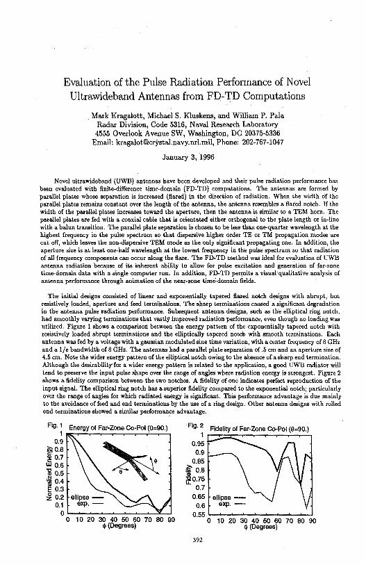
Evaluation of the Pulse Radiation Performance of Novel Ultrawideband Antennas from FD-TD Computations
Mark Kragalott, Michael S. Kluskens, and William P. Pala Radar Division, Code 5316, Naval Research Laboratory 4555 Overlook Avenue SW, Washington, DC 20375-5336
Email: [email protected], Phone: 202-767-104 7
January 3, 1996
Novel ultrawideband (UWB) antennas have been developed and their pulse radiation performance has been evaluated with finite-difference time-domain (FD-TD) computations. The antennas are formed by parallel plates whose separation is increased (flared) in the direction of radiation. When the width of the parallel plates remains constant over the length of the antenna, the antenna resembles a flared notch. If the width of the parallel plates increases toward the aperture, then the antenna is similar to a TEM horn. The parallel plates are fed with a coaxial cable that is orientated either orthogonal to the plate length or in-line with a balun transition. The parallel plate separation is chosen to be less than one-quarter wavelength at the highest frequency in the pulse spectrum so that dispersive higher order TE or TM propagation modes are cut off, which leaves the non-dispersive TEM mode as the only significant propagating one. In addition, the aperture size is at least one-half wavelength at the lowest frequency in the pulse spectrum so that radiation of all frequency components can occur along the flare. The FD-TD method was ideal for evaluation of UWB antenna radiation because of its inherent ability to allow for pulse excitation and generation of far-zone time-domain data with a single computer run. In addition, FD-TD permits a visual·qualitative analysis of antenna performance through animation of the near-zone time:.domain fields.
The initial designs consisted of linear and exponentially tapered flared notch designs with abrupt, but resistively loaded, aperture and feed terminations. The sharp terminations caused a significant degradation in the antenna pulse radiation performance. Subsequent antenna designs, such as the elliptical ring notch, had smoothly varying terminations that vast!)' improved radiation performance, even though no loading was utilized. Figure 1 shows a comparison between the energy pattern of the exponentially tapered notch with resistively loaded abrupt terminations and the elliptically tapered notch with smooth terminations. Each antenna was fed by a voltage with a gaussian modulated sine time variation, with a center frequency of 8 GHz and a 1/e bandwidth of 8 GHz. The antennas had a parallel plate separation of .5 cm and an aperture size of 4.5 cm. Note the wider energy pattern of the elliptical notch owing to the absence of a sharp end termination. Although the desirability for a wider energy pattern is related to the application, a good UWB radiator will tend to preserve the input pulse shape over the range of angles where radiation energy is strongest. Figure 2 shows a fidelity comparison between the two notches. A fidelity of one indicates perfect reproduction of the input signal. The elliptical ring notch has a superior fidelity compared to the exponential notch, particularly over the range of angles for which radiated energy is significant. This performance advantage is due mainly to the avoidance of feed and end terminations by the use of a ring design. Other antenna designs with rolled end terminations showed a similar performance advantage.
Fig. 1 Energy of Far-Zone Co-Pol (8=90.) 1
0.9 e;;o.8 ~ 0.7 W 0.6 al 0.5 ~ 0.4 § 0.3 ~ 0.2
0.1 0 ..._~__._..__.___._...__._ ................
0 10 20 30 40 50 60 70 80 90 tj> (Degrees)
Fig. 2 Fidelity of Far-Zone Co-Pol (8=90.) 1
0.95 0.9 ,__ __ ---..._
0.85 ~ 0.8 Q)
~0.75 0.7
0.65 0.6
0.55 .._...__.___._.__...__.___,____...__,
392
0 10 20 30 40 50 60 70 80 90 q> (Degrees)
Reflection Due to an Inhomogeneous Dielectric Slab in a Rectangular Waveguide
Jean-Fu Kiang Department of Electrical Engineering
National Chung-Hsing University Taichung, Taiwan, ROC
Waveguides loaded with dielectrics have been studied for different applications like cross polarization reduction, dielectric constant measurement, and scattering. Modematching technique, FDTD, and finite element methods have been used for analysis. In all these works, only homogeneous dielectrics have been considered.
The main contribution of this work is to derive a general numerical scheme to solve the reflection and transmission problems of rectangular waveguides loaded with an inhomogeneous dielectric slab. The. eigenmodes in an inhomogeneous layer is first solved numerically. The field distribution in each layer is then expressed in terms of these eigenmodes. Then reflection matrices across layer interfaces are defined to reduce the number of unknowns. The effects of the slab parameters including permittivity, conductivity, and air gap width on the reflection coefficient of the dominant mode are analyzed.
First, the reflection coefficient of the dominant mode is calculated with different slab dielectric constant and thickness. As the dielectric constant increases, the reflection coefficient oscillates as frequency changes. The maximum magnitude of reflection coefficient also increases, but never reaches one except at the cutoff frequency. When the slab conductivity increases from O.OlU/m to lOOU/m, the magnitude of the reflection coefficient first decreases then increases. The oscillation over the frequency range diminishes when the slab conductivity is higher than about lU/m.
Next, consider the effect of an air gap between the dielectric sample and the waveguide wall. When the gap is half of the waveguide height, total reflection may occur at certain frequencies. The reflection due to a slab with a parabolic profile has also been analyzed.
393

Resonances of Perfectly Conducting Wires and Bodies of Revolution Buried in a Lossy, Dispersive Half Space
Stanislav Vitebskiy and Lawrence Carin Department of Electrical and Computer Engineering
Duke University Durham, NC 27708-0291
The Method of Moments is utilized to compute the complex resonant frequencies and modal currents of perfectly conducting wires and bodies of revolution buried in a lossy, dispersive half space. To make such an analysis tractable computationally, the half-space Green's function is computed via the method of complex images, with appropriate modifications made to account for the complex frequencies characteristic of resonant modes. Results are presented for wires and bodies of revolution buried in lossy soil using frequency-dependent measured parameters for the complex permittivity, and we demonstrate that the resonant frequencies generally vary with target depth. In addition to presenting results, relevant issues are addressed concerning the numerical computation of buried-target resonant frequencies.
With recent developments in short-pulse sources and antennas, several researchers have been investigating transient radar techniques for the detection and identification of buried objects. For localized targets, an important identification tool is the well-known singularity expansion method (SEM), which exploits the fact that the late-time portion of the time-domain fields scattered from a target can be represented in terms of a sum of damped exponentials, each characterized by a complex frequency. The SEM is attractive for airborne targets because the resonant frequencies are aspect-independent (although their excitation strengths are generally aspect dependent), and therefore they provide a useful target signature. However, for objects buried in a half space (or other underground scenario), the total target is the object in the presence of its environment; i.e., when the object depth and orientation change, the characteristics of the total target will in general also change. Thus, in the context of SEM-based identification for GPR, it is important to determine the degree to which the resonant frequencies change as a function of target depth and orientation.
Although researchers have examined the SEM processing of GPR signatures, we are unaware of a rigorous analysis of the resonances of buried targets. Our algorithm computes the resonant frequencies of targets buried in a frequency-dependent, lossy half space, with rigorous account taken for the effects of the air-ground interface; particular results are presented here for the cases of buried perfectly conducting wires and bodies of revolution.
394
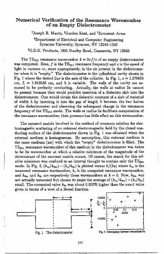
Numerical Verification of the Resonance Wavenumber of an Empty Dielectrometer
t Joseph R. Mautz, *Gordon Kent, and tErcument Arvas
tDepartment of Electrical and Computer Engineering Syracuse University, Syracuse, NY 13244-1240
*G.D.K. Products, 1995 Stanley Road, Cazenovia, NY 13035
The TE011 resonance wavenumber k = 21r f / c of an empty dielectrometer was computed. Here, f is the TE011 resonance frequency and c is the speed of light in vacuum or, more appropriately, in the air present in the dielectrometer when it is "empty." The dielectrometer is the cylindrical cavity shown in Fig. 1 where the dotted line is the axis of the cylinder. In Fig. 1, a= 1.270635 cm, L = 1.019556 cm, and h is variable. The walls of the cavity are assumed to be perfectly conducting. Actually, the walls at radius 2a cannot be present because they would prohibit insertion of a dielectric slab into the dielectrometer. One would obtain the dielectric constant of a slab of material of width h by inserting it into the gap of length h between the two halves of the dielectrometer and observing the subsequent change in the resonance frequency of the TEo11 mode. The walls at radius 2a facilitate computation of the resonance wavenumber; their presence has little effect on this wavenumber.
The moment matrix involved in the method of moments solution for electromagnetic scattering of an external electromagnetic field by the closed conducting surface of the dielectrometer shown in Fig. 1 was obtained when the external medium is homogeneous. By assumption, this external medium is the same medium (air) with which the "empty" dielectrometer is filled. The TE011 resonance wavenumber of this medium in the dielectrometer was taken to be its wavenumber at which a relative minimum of the magnitude of the determinant of the moment matrix occurs. Of course, the search for this relative minimum was confined to an interval thought to contain only the TEo11
mode. In Fig. 2, (km/k0m) - (kc/k0c) is plotted versus h/(2a) where km is the measured resonance wavenumber, kc is the computed resonance wavenumber, and k0m and k0c are respectively these wavenumbers at h = 0. Now, k0m was not actually measured but chosen to make the average of (km/k0m) - (kc/koc) small. The computed value k0c was about 0.003% higher than the exact value given in terms of a root of a Bessel function.
0.0001 + r .. .. + + + L 1;-;,;; I
I
.l 0 0.05 0.1 0.15
h + h,f2a)
r --0.0001 +
L +
1 +
I ~a-ti I
I I I I I I I I
Fig. 1 Toe dielectrometer Fig. 2 Discrepancy between ncxmalized k's.
395
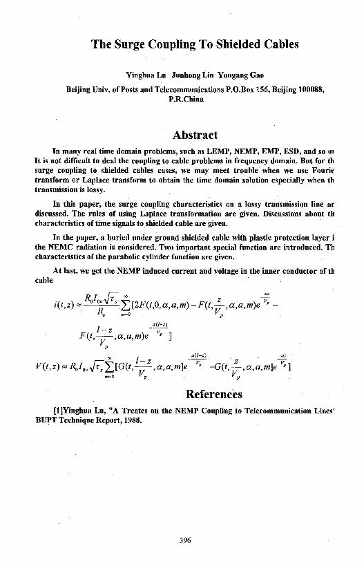
The Surge Coupling To Shielded Cables
Yinghua Lu Junhong Lin Yougang Gao
Beijing Univ. of Posts and Telecommunications P.O.Box 156, Beijing 100088, P.R.China
Abstract In many real time domain problems, such as LEMP, NEMP, EMP, ESD, and so OJ
It is not difficult to deal the coupling to cable problems in frequency domain. But for th surge coupling to shielded cables cases, we may meet trouble when we use Fourie transform or Laplace transform to obtain the time domain solution especially when th transmission is lossy.
In this paper, the surge coupling characteristics on a lossy transmission line ar discussed. The rules of using Laplace transformation are given. Discussions about th characteristics of time signals to.shielded cable are given.
In the paper, a buried under ground shielded cable with plastic protection layer i the NEMC radiation is considered. Two important special function are introduced. Th characteristics of the parabolic cylinder function are given.
At last, we get the NEMP induced current and voltage in the inner conductor of th cable
·c ) - IVovF. ~ z -~ 1 t,z - L,[2F(t,0,a,a,m)-F(t,-,a,a,m)e -
RC m=O VP a(/-z)
l-z --v:-F(t,-,a,a,m)e P ]
VP a(l-z) az
r::-~ I - z --v:- z -v V(t,z)~RoiovV'•LJ[G(t,-,a,a,m]e p -G(t,-,a,a,m]e p]
m=O VP VP
References [l]Yinghua Lu, "A Treates on the NEMP Coupling to Telecommunication Lines'
BUPT Technique Report, 1988.
396
Thursday PM AP/URSI-B Sess. 10 Constel. Ballroom D
Antennas III C. Courtney Page
1 :20 Concepts and Performance Estimates of the Coaxial Beam .............. 398 Rotating Antenna (COBRA) Clifton Courtney, Voss Scientific, Carl Baum, Kirtland Air Force Base
1 :40 Design and Performance of Gimbaled Reflector Antenna ................ 399 Guan G. Cheng, Henry S. Chang, F. C. Chang, TRW Space and Electronics Group
2:00 Designing Offset Reflector Antennas Using Constrained .............. .400 Minimization to Reduce Cross Polarization K. K. Shee, W. T. Smith. S. Y. Chea, University of Kentucky, M. C. Bailey, NASA Langley Research Center
2:20 Spacecraft Antennas for the Next Millennium ............................ .401 Te-Kao Wu, TRW Antenna Product Center
2:40 Electrical Size Limitations of Antennas .................................... .402 Craig A. Grimes, The University of Kentucky
3:20 A Novel Technique for Suppressing Antenna Side Lobes ................ 403 M. Hamid, S. Chaudhry, University of South Alabama
3:40 An Optimized Meanderline Polarizer ........................................ .404 Robert G. Schmier, Westinghouse Electronic Systems Group
4:00 Complex Source - Dual Series Approach in Simulating ................. .405 a Reflector Antenna Radiating Near an Interface S. V. Boriskina, Kharkov State University, A. I. Nosich, Institute of Radiophyics and Electronics, Ukraine
4:20 Integrated Q-Band MMIC Diffraction Grating Transmitter .............. APS Randall E. Lehmann, Texas Instruments, Inc., Nai-Hsiang Sun, Jerome K. Butler, Southern Methodist University
4:40 Annular Slot Antennas on Extended Hemispherical ...................... APS Dielectric Lenses F. Colomb, K. Hur, W. Stacey, M. Grigas, Raytheon Company
5:00 Aymmetrical Gaussian-Hermite Beam Mode Analysis of ................ APS a Corrugated Pyramidal Rectangular Hom with corrugations in the £-Plane Walls Tao Shen, Zhongliang Sun, Wenbin Dou, Southeast University, China
397
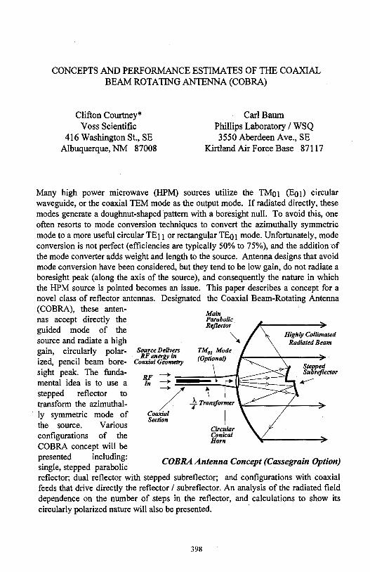
CONCEPTS AND PERFORMANCE ESTIMATES OF THE COAXIAL BEAM ROTATING ANTENNA (COBRA)
Clifton Courtney* Voss Scientific
416 Washington St., SE Albuquerque, NM 87008
Carl Bawn Phillips Laboratory / WSQ 3550 Aberdeen Ave., SE
Kirtland Air Force Base 87117
Many high power microwave (HPM) sources utilize the TM01 (Eo1) circular waveguide, or the coaxial TEM mode as the output mode. If radiated directly, these modes generate a doughnut-shaped pattern with a boresight null. To avoid this, one often resorts to mode conversion techniques to convert the azimuthally symmetric mode to a more useful circular TE11 or rectangular TE01 mode. Unfortunately, mode conversion is not perfect (efficiencies are typically 50% to 75%), and the addition of the mode converter adds weight and length to the source. Antenna designs that avoid mode conversion have been considered, but they tend to be low gain, do not radiate a boresight peak (along the axis of the source), and consequently the nature in which the HPM source is pointed becomes an issue. This paper describes a concept for a novel class of reflector antennas. Designated the Coaxial Beam-Rotating Antenna (COBRA), these antennas accept directly the guided mode of the source and radiate a high
Main Parabolic Reflector
~ gain, circularly polar- Source Delivers TM01 Mode
RF energy in /O ti 1, ized, pencil beam bore- Coaxia/Geometry '' 'P ona~
RF -In -
'
Highly Collimated Radiated Beam
Stepped Subrejlector .---sight peak. The funda
mental idea is to use a stepped reflector to transform the azimuthally symmetric mode of the source. Various configurations of the COBRA concept will be presented including: single, stepped parabolic
/ --} Transformer '°"'"-----,,'----+ Coaxial Section I
Circular Conical Horn
COBRA Antenna Concept (Cassegrain Option)
reflector; dual reflector with stepped subreflector; and configurations with coaxial feeds that drive directly the reflector / subreflector. An analysis of the radiated field dependence on the number of steps in the reflector, and calculations to show its circularly polarized nature will also be presented.
398
Design and Performance of Gimbaled Reflector Antenna
Cheng, Guan G., Chang, Henry S., and Chang, F.C. TRW Sp_ace and Electronics Group
One Space Park, 02/2356 Redondo Beach, CA 90278
Antenna systems with scanning beam capability via reflector gimbal are under investigation. The phased array antenna electrically scans the beams whereas gimbaled antenna for which the entire antenna is gimbaled, steers its beam mechanically. A gimbaled reflector antenna can be thus considered a scanned antenna half electrical and half mechanical per se. To gimbal the reflector instead of entire antenna is mainly the isssue of the weight and cost. Gimbaled reflector antenna compromises the scan performance over the weight of the gimbal mechanism structure.
Two configurations of gimbaled reflector antenna systems are proposed. First is an offset parabolic reflector antenna with a single feed element. The reflector is equipped with a gimbal pedestal whose pivot point placed near the center of the dish. The beam would be scanned roughly twice the angle as the reflector tilted. Computer simulation model has been developed and verified by the hardware measurements. Good agreement between calculated and measured data is evident. Parametric study for beam scan characteristics reveals interesting results to some extent, and useful design curves and beam deviation factors were generated for practical applications. Moreover, results from selection of different rotation axes of the gimbal system are also shown for comparison.
Second antenna is an offset Cassegrain system with multiple feed elements. The beamforming network (BFN) includes variable amplitude and phase (VAP) weight elements for each antenna feed. The gimbal pedestal is placed under the main reflector for the beam scan. It is shown that the scan loss as well as the beam distortion are more significant as oppose to the single feed case. However, the scan loss can be recovered in large portion by the adjustment of amplitude and phase weightings. In other words, the beam aberration caused by the reflector movement is corrected by the compensation of both amplitude and phase for each feed. An algorithm has been developed for the determination of the weight vector for any arbitrary scan angle. Numerical results show that the reflector gimbal with array feed suffers more gain loss if the weights remain unchanged, and it can regain more than 90% of the scan loss if the weights were adjusted to compensate for the scan effect. It addresses the feasibility of the gimbaled reflector antenna with array feed for minimal scan loss.
399
DESIGNING OFFSET REFLECTOR AN'l;'ENNAS USING CONSTRAINED MINIMIZATION TO REDUCE
CROSS POLARIZATION
K. K. Shee*, W. T. Smith, S. Y. Cheah Department of Electrical Engineering University of Kentucky Lexington, Kentucky 40506-0046
M. C. Bailey Electromagnetic Research Branch NASA Langley Research Center Hampton, Virginia 23681
This paper presents an approach for designing low cross-polarized offset reflector antennas using a constrained minimization algorithm. The elements for the array feeds of the reflectors are composed of Potter-type horns [Potter, Microwave Journal, 1963]. Previous studies have shown that multi.mode-type horns such as these can be used to reduce the cross polarization of reflector antennas [Rudge, Adatia, Elect. Lett., 197 5; Jacobsen, IEEE Trans APS, 1977]. The cross polarization improvement is achieved by determining the optimum ratios of the TE11 and TM 11 modes for the individual horns. The goal of this work is to use a conjugate gradient algorithm to determine these mode ratios for the feed elements subject to the constraint that the cross polarization levels of the antenna are below a given design threshold.
High levels of cross polarization in antennas can cause undesired interference and unacceptable performance degradation for communication links. Cross polarization can also cause measurement errors in radiometer applications. There are many sources for cross polarization including the polarization purity of the feed elements, reflector geometry, feed displacement, diffraction from supporting structures, etc. In this study, the cross polarization performance of offset reflectors with array feeds of Potter horns are considered. The TE11 modes dominate the designed performance of the co-polarized pattern while the TM 11 modes are used to reduce the cross-polarized pattern to desired levels.
In this presentation, the constrained minimization algorithm used to compute the mode ratios for a multi-element feed array that minimize the offset reflector cross polarization radiation will be outlined. Results will be presented for both unscanned and scanned reflector antennas.
400
Spacecraft Antennas for the Next Millennium
Te-Kao Wu TRW
Antenna Product Center One Space Park
Redondo beach, CA 90278
NASA's Deep Space programs, such as Cassini (to Saturn), Pluto fast fly-by, Mars Environmental Survey (MESUR), Rover, Mars Relay Satellites, ... etc., will usher the challenging exploration of the solar system well into the next millennium. The on-going and future space missions have already imposed stringent requirements (i.e. high efficiency, low mass, low cost, wide operating frequency band, and high data rate) on the spacecraft design. Advanced spacecraft antenna technologies are thus definitely needed to properly maintain the telecommunication link and to perform high resolution radar remote sensing and surface mapping.
Several new and advanced antenna concepts are proposed for the next millennium space missions. They are (1) light-weight solid reflector antenna, (2) inflatable or unfurlable reflector antenna, (3) beam waveguide antenna, (4) piezoelectric actuator array for large reflector antenna surface compensation, (5) neural network for reflector surface compensation, (6) reflectarray or FLAP (flat parabolic) antenna, (7) scan-lossless Luneberg lens antenna, (8) MMIC phased array, (9) optical beam forming phased array antenna, (10) quasi-optical grid array, (11) digital beam forming array, (12) superconductive beam forming array, (13) shared aperture solar/antenna array, (14) frequency scanning antenna, and (15) scanning beam antenna with dielectric wedges.
Some of these concepts are currently in their preliminary development stages and some others are new ideas which have to be investigated further. However, their potential advantages and disadvantages will be discussed in the presentation. As the antenna technology keeps advancing, some of these concepts might lead to a successful spacecraft antenna design for the next millennium. Finally, these advanced antenna concepts may also be applied to NASA's near-earth space missions, such as Earth Observing Satellite (EOS), Sea Winds, Space Imaging Radar (SIR), ... etc.
401
ELECTRICAL SIZE LIMITATIONS OF ANTENNAS
Craig A. Grimes Department of Electrical Engineering
The University of Kentucky; Lexington KY 40506, USA Ph: 606.257.2300 ext 273. email: [email protected]
The time domain Poynting theorem is used to develop a general expression for complex power at all points in any radiation field that is centered on and produced by a localized emitter. We find that the traditional method of calculating complex power using the complex Poynting vector applies to fields generated by sources that are either solenoidal, TE with respect to the radius vector, or irrotational, TM with respect to the radius vector, but not to mixtures of them. Chu's (L.J. Chu, J. Appl. Phys. 19, 1163-1175, 1948) commonly accepted proof that the Q of electrically small antennas is large and increases precipitously with decreasing size is based upon the traditional complex Poynting vector. Both Chu's and Harrington's (R. F. Harrington, J. Res. Nat. Bur. Stds. 64D, 1-12, 1960) later analytical proofs showing that whatever value of Q is tolerable there is an electrical size below which the value is exceeded and the antenna is unsatisfactory, are based upon the complex Poynting vector. Neither work, therefore, is applicable to mixed types of modal fields. Collin and Rothschild (R. E. Collin, S. Rothschild, IEEE Trans. Ant. Prop. 12, 23-27, 1964) supported the work, but their argument is based upon the unproved assertion that the reactive field energy is equal to the integral of the local field energy over all exterior space less the real part of the complex Poynting vector divided by the speed of light. Therefore there is no acceptable proof of antenna limitations in mixed modal types of fields.
Widely accepted reviews proclaim the issue to be settled: there is a severe lower limit to the usable electrical length of antennas. However an unanimous opinion is not necessarily a correct one. In this paper we give a simple example of an antenna that generates mixed TE and TM type modes of mixed orders, for which the input impedance can be purely resistive, independently of the electrical size, and Q increases with decreasing electrical size less rapidly than Chu showed to be necessary: We conclude that there is reasonable hope of obtaining an electrically small, efficient radiator of electromagnetic power.
402
A NOVEL TECHNIQUE FOR SUPPRESSING ANTENNA SIDE LOBES
M. Hamid and S. Choudhry Department of Electrical Engineering
University of South Alabama Mobile, Alabama 36888, U.S.A.
Homs, waveguides and dipoles are not only used as radiators, but also as primary feeds for reflector antennas and their high side lobes adversely affect the performance and efficiency of the antenna as a whole. Various approaches have been used to reduce the edge fields as in the dualmode horn by Potter (1963), the dielectric ring horn by Satoh (1972), the two concentric dielectric rings horn by Wong and Brandt (1979), the hybrid mode horn by Lawrie and Peters (1966) and Clarricoats and Taylor (1964), the dielectric conical horn by Lier (1986), the dielectric loaded born by Stanier et al (1986), the absorber lined born by Knop (1986) and the specially flanged horns by Burnside and Chuang (1982) and Chamma and Hamid (1986).
The proposed technique aims at increasing the main lobe level while suppressing the side lobe levels of apertures, reflectors and monopoles over ground planes. The technique involves placing a loop wire physically parallel and close to the diffracting edge and separately excited so as to radiate in phase opposition to the equivalent edge current The magnitude of the loop current is fixed for symmetric mode excitation of horns and waveguides and symmetric azimuthal currents on ground planes with monopoles vertically above the center point For a circular waveguide operating in the TEl 1 mode, a circular loop parallel to and at an optimum location away from the edge (inside the waveguide) excites the TMll mode to produce almost equal E- and H- plane radiation patterns or a very low cross-polarization pattern.
The paper describes several experimental arrangements to verify the proposed technique. The first consists of a special circular waveguide section fabricated with a slot in the wall to allow for insertion and sliding of the compensating loop. The optimum location of the loop was found by observing the reduction in the side lobe levels of the E-plane pattern until these levels became almost identical with the increased side lobe levels of the H-Plane pattern. At the same location the beamwidths of the two patterns became almost the same.
The second experiment consists of a wire loop located near the edge of a circular aperture in a conducting screen excited by a normally incident plane wave. The improvement in the main to first side lobe ratio was found to be significant. Similar results were obtained using a slit type aperture between the two edges of a double wedge with high conductivity.
The third experiment consists of a monopole over a ground plane formed experimentally from a bronze wire mesh over a flat wooden surface. the radiation pattern was measured for square and circular ground planes of different sizes with and without a compensating loop located along the border line of the ground plane. The improvement in the amplitude of the main beam and reduction in the first few diffraction lobes is encouraging and is expected to be even more significant when the technique is applied to reduce edge diffraction in compact ranges.
403
/
An Optimized Meanderline Polarizer
Robert G. Schmier Westinghouse Electronic Systems Group
P.O. Box 746, MS 55 Baltimore, MD 21203
Meanderline polarizers are commonly used in conjunction with linearly polarized antennas to convert the antenna's linear polarization to circular polarization. They are typically constructed from one or more layers of "meandering" planar metallic traces which when oriented relative to .the polarization of the antenna look like a staircase. The metal traces are typically etched on a very thin material, such· as a polyimide film, and several identical layers of these are spaced approximately one quarter wavelength apart by foam or honeycomb spacers. The polarizers constructed in this manner are very light, mechanically rigid, and can typically operate over more than an octave bandwidth with fairly good return loss (-15 dB) and axial ratio (-3 dB) performance.
If one requires better performance than the typical meanderline polarizer, or reduced thickness, several things can be done to optimize performance over a specified frequency band. These include the incorporation of various dielectric layers and variation of the metallic traces on various layers of the polarizer. Optimization can be performed empirically, but is implemented much more efficiently here via a spectral moment method computer code which is run inside an optimizer code.
This paper will present the design and performance of several optimized meanderline polarizer radomes. One of the polarizer panels is designed to operate over about 10% bandwidth at Ku-band with less than a 20 dB return loss and about 1 dB axial ratio. It incorporates two identical meanderline traces and an additional dielectric matching layer and is less than 0.25" thick. Another design, integrated directly into a radome, operates over about 20% bandwidth and allows variation in the metallic traces on different layers in addition to variation in dielectric thickness to optimize performance.
404
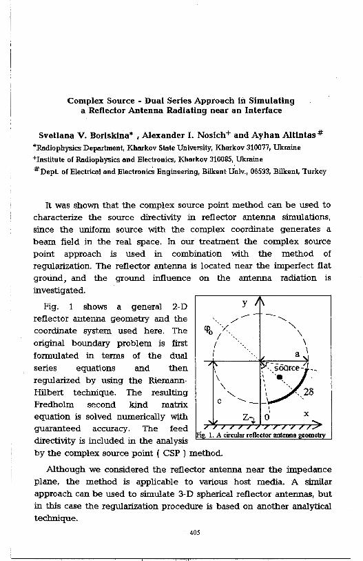
Complex Source - Dual Series Approach in Simulating a Reflector Antenna Radiating near an Interface
Svetlana V. Borisldna* , Alexander I. Nosich+ and Ayhan Altintas #
"'Radiophysics Department, Kharkov State UniveISity, Kharkov 310011, Ukraine
+Institute of Radiophysics and Electronics, Kharkov 310085, Ukraine
#Depl of Electrical and Electronics Engineering, Bilkent Univ., 06533, Bilkent, Turkey
It was shown that the complex source point method can be used to characterize the source directivity in reflector antenna simulations, since the uniform source with the complex coordinate generates a beam field in the real space. In our treatment the complex source point approach is used in combination with the method of regularization. The reflector antenna is located near the imperfect flat ground, and the ground influence on the antenna radiation is investigated.
Fig. 1 shows a general 2-D reflector antenna geometry and the coordinate system used here. The original boundary problem is first
formulated in terms of the dual series equations and then regularized by using the RiemannHilb.ert technique. The resulting Fredholm second kind matrix equation is solved numerically with guaranteed accuracy. The feed directivity is included in the analysis
y -' ...... /
<!lo ';< I ··,,
I I
--
--- I \ , ·y,· soarce- --
\ I •• • I '
\ ', ',,, 2~ "-... I ',, 0
C '---' ,
X
by the complex source point ( CSP ) method.
Although we considered the reflector antenna near the impedance plane, the method is applicable to various host media. A similar approach can be used to simulate 3-D spherical reflector antennas, but in this case the regularization procedure is based on another analytical technique.
405

THIS PAGE INTENTIONALLY LEFT BLANK.
406
Thursday PM APIURSI-A Session 2 Chesapeake A
Transmission Lines and Devices G. Smith and E. Niehenke Page
1:20 Use of Short-Time Fourier Transform on the Analysis of ....... APS Signal Distortion in Microstrip Lines Subba R. Kunasani, Cam Nguyen, Texas A&M University
1 :40 Effect of Inhomogeneous Dielectric Layers on Dispersion ........ APS of Microstrip Lines Using MoL M. El-Shenawee, Electronics Research Institute, Egypt
2:00 Effects of a Lossy Inhomogeneous Substrate on Microstrip ...... APS Lines Jean-Fu Kiang, National Chung Hsing University
2:20 The Design of Multi-Beam Microstrip Antennas Using ........... .408 Finite Difference Time Domain 3D Structure Simulator Chen Wu, Patrick Yue, Yan Zhuang, John Litva, McMaster University
2:40 Analysis of Slot Antenna with Dielectric Overlay Fed by ........ APS Dielectric Image Line Sridhar Kanamalur, Ming-Yi Li, Shyh-Jong Chung, Kai Chang, Texas A&M University
3:20 Complex Modes in Asymmetric Coplanar Waveguides ............ APS Khwajam M. Rahman, Cam Nguyen, Texas A&M University
3:40 Analysis of Unsymmetrical Broadside-Coupled Coplanar ......... APS Waveguides for Microwave Integrated Circuits Cam Nguyen, Texas A&M University
4:00 Slot-Coupled Directional Couplers Between Double-Sided ....... APS Cylindrical Microstrip Lines Jui-Han Lu, Kin-Lu Wong, National Sun Yat-Sen University
4:20 Dispersion Characteristics of Coplanar Waveguides on a ......... APS Cylindrical Substrate Hsin-Cheng Su, Kin-Lu Wong, National Sun Yat-Sen University
407
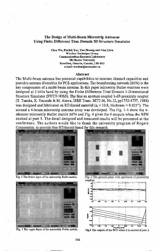
The Design of Multi-Beam Microstrip Antennas Using Finite Difference Time Domain 3D Structure Simulator
Chen Wu, Patrick Yue, Yan Zhuang and John Litva Wireless Technique Group
Communications Research Laboratory McMaster University
Hamilton, Ontario, Canada, LSS 4Kl e-mail: [email protected]
Abstract The Multi-beam antenna has potential capabilities to increase channel capacities and provides antenna diversities for PCS applications. The bearnforrning network (BFN) is the key components of a multi-beam antenna. In this paper microstrip Butler matrixes were designed at 2 GHz band by using the Finite Difference Time! Domain 3-Dimensional Structure Simulator (FDTD 3DSS). The first an aperture coupled 3-dB proximity coupler (T. Tanaka, K. Tsunoda & M. Aiawa, IEEE Trans. MTT-36, No.12, ppl 752-1757, 1988) was designed and fabricated on RT/duroid material(&,= 10.8, thickness= 0.025"). The second a 4-beam microstrip antenna array was developed. The Fig. 1-3 show the 4-element microstrip Butler matrix BFN and Fig. 4 gives the 4 outputs when the BFN excited at port 1. The detail designed and measured results will be presented at the conference. The authors would like to thank the university program of Rogers Co oration. to rovide free RT/duroid board for this research.
Fig. 1 The lower layer of the microstrip Butler matrix.
Fig. 3 The upper layer of the microstrip Butler matrix.
408
Fig. 2 The ground plane with apertures of proximity
couplersr--~-~-~~-~-----,
11::::;:;:, u = ~ = = ~ = u
200~
100 .... .. . · ... . ..... · ,; · · · · · · · : ·
l~~ -~.8 us 1.9 1.95 2 2.05 2.1 2.15 22
F~(GHz)
Fig.4 The outputs of the BFN when it is excited at port .2

Thursday PM APIURSI-F Session 6 Camden/Lombard
Propagation in the Ionosphere A. G. Sonsteby Page
1 :20 Initial Results of a High Latitude Propagation Experiment ............. .410 Conducted Over Auroral Paths A. G. Sonsteby, J. K. Breakall, The Pennsylvania State University, R. D. Hunsucker, RP Consultants, G. K. Lott, Naval Postgraduate School
1 :40 Single Site Location in the HF-Band - Long-Term Measure- ........... .411 ments with an Interferometric Direction Finder Hinrich Mewes, Jurgen Rumold C. Plath GmbH, DF Systems, Thomas Damboldt, Dr. Damboldt Telecommunications
2:00 Effects of Polarization in HF Localized Wave Beam ..................... .412 Propagation in Ionosphere Nikoli I. Petrov, All Russian Electrotechnical Institute
2:20 Investigation of Reactions of the Lower Ionosphere to Remote ...... .413 Strong Earthquakes Using Records of Radio Noise and PartiallyReflected Signals A. M. Gokov, A. I. Gritchin, 0. F. Tymov, Kharkiv State University
2:40 On Strong Thunderstorms Affecting the Ionospheric D-Region ....... .414 Parameters, Characteristics of Noise and Partially-Reflected Signals A. M. Gokov, A. I. Gritchin, 0. F. Tymov, Kharkiv State University
. 3:20 Influence of Global Disturbances on the Propagation of ................ APS
Ionospheric MF and HF Radio Waves: Technique L. S. Kostrov, S. I. Martunenko, Y. B. Milovanov, V. T. Rozumenko, 0. F. Turnov, A. M. Tsymbal, Kkarkov State University
3: 40 Electron Collision Frequency Variations and Electric .................... 415 Field Measurements in the Ionospheric D-Region A. M. Gokov, S. /. Martynenko, Kharkiv State University
4:00 Influence of Nuclear Accidents on the Parameters of VLF Signals ..... .416 S. I. Martynenko, Kharkiv State University, I. M. Fuks, R. S. Shubova, Ukranian Academy of Sciences
4:20 Phenomenon of Arising Stimulated Localized and Large-Scale ......... APS Scale Disturbances in the Ionosphere Under the Influence of Powerful MF and HF Radio Waves Leonid F. Chemogor, Konstantin P Garmash, Kharkiv State University
4:40 Investigations of Variations in VLF, LF, MF, HF Radio ................ APS Wave and Noise Characteristics Due to Disturbances in the Ionosphere L. F. Chernogor, K. P. Garmash, S. G. Leus, S. N. Polhil'ko, Kharkiv State University
5:00 Dispersive Distortion of High Frequency Ultrawideband Signals ...... APS Propagating in Near-to-Earth Space Leonid F. Chernogor, Oleg V. Lazorenko, Kharkiv State University
409
INITIAL RESULTS OF A IDGH LATITUDE PROPAGATION EXPERIMENTCONDUCTEDOVERAURORALPATHS
A. G. Sonsteby* Applied Research Laboratory
The Pennsylvania State University P.O. Box30
State College, PA 16804
R. I). llunsucker RP Consultants
7917 Gearhart Street Klamath Falls, OR 97601
J. K. Breakall l)epartment of Electrical Engineering
The Pennsylvania State University University Park, PA 16802
G. K. Lott Code EC/It
Naval Postgraduate School Monterey, CA 93943-5000
l)uring Phase- I of the PENEX program, a high frequency transmitter was installed at Wales, Alaska (65.6°N, 168.1 °W). Receivers were located at Fairbanks, Alaska (64.5°N, 147.5°W), Seattle, Washington (47.4°N, 122.2°W), and San l)iego, California (32.4 °N, 117.1 °W). The Wales - Fairbanks path and the Wales - Seattle path represent auroral high frequency circuits. The purpose of PENEX Phase-I was to collect calibrated high frequency propagation data over high latitude circuits. Presently, six months of data have been reduced and archived from the Fairbanks and Seattle receiver sites.
The channel probe waveform consisted of a wideband binary phase shift keyed signal transmitted at 5.604 Mllz, 11.004, and 16.804 Mllz. In addition to the probing waveform, system status telemetry and station callsign (NAF) were transmitted at regular intervals using frequency shift keyed and on/off keyed signaling waveforms respectively. Modified linear recursive sequences (LRS) were used to generate the probe waveform using sequence length of 1024, 2048, 4096, and 8192 bits. At each receiver site, downconverted in-phase and quadrature receiver channels were digitized and archived to l)AT. Correlation based processing techniques were then used to resolve the received propagation modes in terms of propagation delay and channel imposed l)oppler shift. Use of maximal length LRS to modulate the probing waveform provided fairly good resolution in time delay and l)oppler frequency. Receiver calibration data was then used to compute the signal strength (in microvolts) of each received propagation mode at the input of the receiver. The archived reduced data set includes signal strength, relative propagation time delay, l)oppler shift, signal power, and noise power information for up to three received modes at each of the transmission frequencies received at Fairbanks and Seattle.
An overview of the PENEX Phase-I system will be presented including a detailed description of the PENEX processing methodology. In addition, selected results from the PENEX high latitude propagation database will be presented.
410
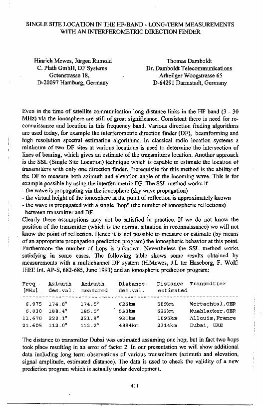
SINGLE SITE LOCATION IN THE HF-BAND- LONG-TERM MEASUREMENTS WITH AN INTERFEROMETRIC DIRECTION FINDER
Hinrich Mewes, Jurgen Rumold C. Plath GmbH, DF Systems
Gotenstrasse 18, D-20097 Hamburg, Germany
Thomas Damboldt Dr. Damboldt Telecommunications
Arheilger Woogstrasse 65 D-64291 Darmstadt, Germany
Even in the time of satellite communication long distance links in the HF band (3 - 30 MHz) via the ionosphere are still of great significance. Consistent there is need for reconnaissance and location in this frequency band. Various direction finding algorithms are used today, for example the interferometric direction finder (DF), beamforming and high resolution spectral estimation algorithms. In classical radio location systems a minimum of two DF sites at various locations is used to determine the intersection of lines of bearing, which gives an estimate of the transmitters location. Another approach is the SSL (Single Site Location) technique which is capable to estimate the location of transmitters with only one direction finder. Prerequisite for this method is the ability of the DF to measure both azimuth and elevation angle of the incoming wave. This is for example possible by using the interferometric DF. The SSL method works if - the wave is propagating via the ionosphere (sky wave propagation) - the virtual height of the ionosphere at the point of reflection is approximately known - the wave is propagated with a single "hop" (the number of ionospheric reflections) between transmitter and DF.
Clearly these assumptions may not be satisfied in practice. If we do not know the position of the transmitter (which is the normal situation in reconnaissance) we will not know the point of reflection. Hence it is not possible to measure or estimate (by means of an appropriate propagation prediction program) the ionospheric behavior at this point. Furthermore the number of hops is unknown. Nevertheless the SSL method works satisfying in some cases. The following table shows some results obtained by measurements with a multichannel DF system (H.Mewes, J.L ter Haseborg, F. Wolf: IEEE Int. AP-S, 682-685, June 1993) and an ionospheric prediction program:
Freq [MHz]
6.075 6.030
11. 670 21. 605
Azimuth Azimuth des.val. measured
174. 8° 174. 5° 188.4° 185. 5° 220.1° 221. 8° 112. 0° 112.2°
Distance des.val.
626km 533km 931km 4884km
Distance Transmitter estimated
589km Wertachtal,GER 622km Muehlacker,GER
1095km Allouis,France
2314km Dubai, UAE
The distance to transmitter Dubai was estimated assuming one hop, but in fact two hops took place resulting in an error of factor 2. In our presentation we will show additional data including long term observations of various transmitters (azimuth and elevation, signal amplitude, estimated distance). The data is used to check the validity of a new prediction program which is actually under development.
411
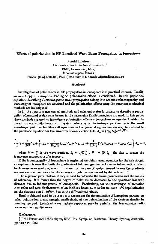
Effects of polarization in HF Localized Wave Beam Propagation in Ionosphere
Nikolai I.Petrov All-Russian Electrotechnical Institute
19-39, Lenina str., Istra, Moscow region, Russia
Phone: (095) 5603400, Fax: (095) 5603134, e-mail: [email protected]
Abstract
Investigation of polarization in HF propagation in ionosphere is of practical interest. Usually an anisotropy of ionosphere leading to polarization effects is considered. In this paper the equations describing electromagnetic wave propagation taking into account inhomogeneity and anisotropy of ionosphere are obtained and the polarization effects using the quantum mechanical methods are investigated.
In [1] the quantum mechanical methods and coherent states formalism to describe a propagation of localized scalar wave beams in the waveguide Earth-ionosphere are used. In this paper these methods are used to investigate polarization effects in ionosphere waveguide.Consider the dielectric permittivity tensor e = e0 + µ, where e0 is the isotropic part and µ is the small anisotropic part. Vector Maxwell equations in the paraxial approximation may be reduced to the parabolic equation for the two-dimensional electric field A.1 = (E~, E,)e-•k..Jios:
where k = :!f is the wave number, Be = ..ji;f, , V .1 = (8~,a,), the sign .l means the transverse components of a tensor µ.
H the inhomogeneity of ionosphere is neglected we obtain usual equation for the anisotropic ionosphere.It is seen that both the gradients of field and gradients ofµ enter into equation. Even for homogeneous medium, when µ = canst, in the case of spatial limited beams the gradients are not vanished and describe the changes of polarization caused by diffraction.
The algebraic perturbation theory is used to calculate the beam parameters and the matrix of coherency. It is found that the degree of polarization decreases by the quadratic law with distance due to inhomogeneity of ionospheric. Particularly, for the wavelength of radiation ,\ = 100m and axis displacement of an incident beam :i:0 = 50km we have 10% depolarization on the distance z !::! 1 · 103km due to the diffractional effects.
Results obtained need to be taken into account at the determination of ionosphere parameters using polarization measurements, particularly, at the determination of the electron density by Faradey method. Localized wave packets supposed may be useful at the transmission radio waves on the long distances.
References [1] NJ.Petrov and I.N.Sisakyan, URSI Int. Symp. on Electrom. Theory, Sydney, Australia,
pp 412-414, 1992.
412
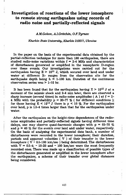
Investigation of reactions of the lower ionosphere to remote strong earthquakes using records of
radio noise and partially-reflected signals
A.M.Gokov, A.I.Gritchin, O.F.Tymov
Kharkiv State University, Kharkiv 310077, Ukraine
In the paper on the basis of the experimental data obtained by the partial-reflection technique for more than 180 earthquakes, there are studied radio-noise variations within f = 2-4 MHz and characteristics of disturbances generated or amplified in the ionospheric D-region over these events. Our investigations were carried out for the earthquakes having E > 1011 J, which occured over land and under water at different R- ranges from the observation site for the earthquake depth being h = 1-100 km. Duration of the continuous observation series was> 1-10 hr.
It has been found that for the earthquakes having E > 1012 J at a moment of the seismic shock and 2-4 min later, there are observed a sharp increase (several times) in radio-noise amplitudes ( A ) at f = 2-4 MHz with the probability p = 30-77 % ( for different conditions ); for those having E < 1012 J there is p < 10 %- For the earthquakes over land, p is 1.5-4 times larger than that for the earthquakes under water.
After the earthquakes on the height-time dependences of the radionoise amplitudes and partially-reflected signals having different time delays, one may observe quasi-harmonic changes with p = 65-70 % and p = 40 % for the events over land and under water, respectively. On the basis of analyzing the experimental data bank, a number of disturbancei, were recorded in the lower ionosphere; their duration, periods and apparent velocities ( V ) of their transfer in the lower ionosphere ( V - 0.5-100 km/sec) being determined The disturbances with V = 0.5-4; - 10-20 and - 100 km/sec were the most frequently recorded ones. There was made up a classification of possible types of the disturbances generated or amplified in the lower ionosphere after the earthquakes, a scheme of their transfer over global distances being considered
413
On strong thunderstorms affecting the ionospheric D-region parameters, characteristics of noise and
partially-reflected signals
A.M.Gokov, A.I.Gritchin, O.F.Tyrnov
Kharkiv State University, Kharkiv 310077, Ukraine
In the paper there are given results of our experimental investigation of possible effects of strong thunderstorms on the middle latitude ionospheric D-region parameters and characteristics of sounding SW radio waves by means of the partial reflection and vertical sounding ( ionosonde ) techniques. The total number of observation series having duration of - 1-10 hr over the periods of strong thunderstorms was 26.
Analyzing the experimental data has allowed to find the following feato/eS,
1. Over the periods of strong thunderstorms at h = 87-105 km, the occurence probability of sporadic layers becomes - 2-4 times larger;
2. Strong thunderstorms may cause in the atmosphere infra-acoustic waves with f > 0.5 Hz, which penetrate into the lower ionosphere with their vertical velocities being V > 300 m/sec;
3. For thunderstorms in the lower D-region ( h < 70 km ) in 40 % of the events, the background ionization has been found to become several times larger up to N < ( 5-7 ) 102 cm-3 ;
4. In the upper D-region ( h > 75 km ), no marked ( > 30 % ) changes in N during thunderstorms have been found;
5. The electron-molecule collision frequency v at h =63 km for some events has become 1.7-1.8 times larger if compared with that for the undisturbed conditions.
Possible reasons of such changes in N and v at h < 70 km may be precipitation of charged particles from the magnetosphere or variations of the ionosphere electric potential due to changes in the near-Earth atmosphere, conditioned by the strong thunderstorms.
414
Electron collision frequency variations and electric field measurements in the. ionospheric
D-region
A.M.Gokov, S.I.Martynenko
Kharkiv State University, 910077 Kharkiv, Ukraine
It is well known that electric field may produce dig disturbances in lower ionosphere parameters. Our experimental results have shown that a possible cause for the apparence of big enough electron collision frequency variations is the influence of atmospheric electric field. This fact gives a chance to measure the electric field in the lower ionosphere using remote sounding facilities.
During 1978 - 1994 in K.harkiv State University, there were investigated variations of the effective electron collision frequency in the ionospheric D-region in different geliogeophysical conditions ( seasons, zenith angle, solar and magnetic activity ) by means of the partitl reflection technique ( operational frequency of the partial reflection· facilities was f = 1.8-3.0 MHz, pulse length 25 mks , pulse repetition frequency F = 1 Hz ). The differential absorption of ordinary and extraordinary modes was neglected at the altitudes 60-66 km. The signal-to-noise ratio was more than 5. The total number of records has exceeded 170 ( the partial reflection amplitude records duration was 10-15 min ).,
It was obtained the distribution of the effective electron collision frequency changes at the altitudes 60-66 km ( the error of determining the collision frequency in these heights interval was < 50 % ). It was developed the technique for estimating atmospheric electric field variations on the lower boundary of the ionosphere using the experimental values of the effective electron collision· frequency. We found, that the electric field to be E > 0.25 V /m in approximately 70 % cases. Our results correspound to undisturbed ionospheric and atmospheric conditions. Under disturbed conditions, the magnitude of E was approximately two times larger than the undisturbed one.
So these facts must be taken into account in the research of ionospheric processes, meteorological and propagation effects ( for instance, during accidents at atomic power stations, the near-earth atmospheric layer condition may increase, wich results in decreasing a background electric field of the capacitor Earth-Ionosphere and in arising considerable disturbances of the lower ionosphere parameters (S.LMartynenko, LM.Fuks, R.S.Shubova, Geomagnetism i aeronomiya. V.34,N 2,pp.121-129, 1994 )).
415
Influence of nuclear accidents on the parameters of VLF signals
S.I.Martynenko
Kharkiv State University, Kharkiv 310077, Ukraine
I.M.Fuks and R.S.Shubova
Institute of Radio Astronomy, Ukranian Acadamy of Sciences, Kharkiv, 310002, Ukraine
Under receiving the GER-station signals ( operational frequency 16 kHz) in Kharkiv, passing near the Chernobyl NPS, 25.04.1986 through 11.05.1986, it has been found that over the accident period, the night signal-amplitude level increased and practically achieved the daytime one (under undisturbed conditions, the night signal-amplitude was 5-10 times less than the day-time one as the receiving station was situated in the vicinity of an interference minimum of the first and second night modes). The amplitude and phase records have shown quasi-periodic variations with a prevailing period of about 1.5 hours.All the above-mentioned effects were continuously observed 25.04.1986 through 11.05.1986, which coincides with the mass media information on the elimination of the consequences of the accident. More weak but also anomalous changes in a VLF phase (10.2 and 13.6 kHz) were observed during the Leningrad NPS accident (March 25-26, 1992).
One of the possible models of this phenomenon suggests that radioactive releases increase the near-to-Earth atmosphere conduction and change the vertical conduction current between the ionosphere and the Earth. Electric-field changes arising at the same time at the ionospheric boundary cause ionospheric plasma-parameter disturbances, and provide conditions for transforming the waveguide modes of VLF-signals. A cause of arising long-term quasiperiodic variations is not quite clear. One of the mechanisms suggests some intensification of ionospheric natural oscillations having a period of about 90 min under the influence of disturbing factors. Another mechanism is based on a possibility of modulating the ionospheric parameters being influenced by periodic radioactive releases from the reactor.
416
Author Index
Author Page Author Page
A Breakall, J. K .................. 147, 148, 410 Aberegg, K. R ................................ 266 Bresler, Y ....................................... 347 Abdel-Rahman, M .................. 217, 281 Bridges, G ................................ 74, 225 Acree, M.A .................................. 5326 Brown, D. E ..................................... 24 Adnanai, N ..................................... 225 Brown, G. S ................... 135, 144, 313 Adve, R. S ...................................... 220 Budko, N. V ................................... 321 Akbar, D. S ............................ 242, 355 Bukil, V . ........................................... 55 Albani, M ....................................... 380 Burkholder, R. J. ............................ 258 Alexandrov, C .................................. 77 Burnside, W. D ................................ 25 Alhargan, F .................................... 243 Bussotti, P ...................................... 380 Altshuler, E. E ................................ 283 Butler, C. M ........... 195,267,268; 269 Anastassiu, H. T ............................. ,.57 Butler, D. J. .................................... 330 Anderson, R. H .............................. 173 Buxton, C. G .................................. 273 Antar, Y. M .................................... 151 Antonov, A ..................................... 351 C Arai, H ............................................ 234 Calve, N ......................................... 191 Annengaud, L .................................. 76 Cangellaris, A. C .................... 118, 341 Arvas, E .......................................... 395 Canning, F. X .......................... .40, 374 Aubrey, T. A .................................. 122 Cano, G .......................................... 275
B Capolino, F ..................................... 380 Capolino, F ....... : ............................. 379
Bailey, M. C ................................... 400 Caputa, K ....................................... 264 Balanis, C. A. ................................. 251 Carr, P.H ....................................... 299 Bardati, F ........................................ 131 Carriere, A. G ................................... 70 Barkeshli, K ..................................... 87 Casey, J.P .......................................... 3 Barlow, F ........................................ 160 Castillo, L. E .................................... 54 Barrik, D. E .................................... 145 Castillo, S ......................................... 55 Baum, C ......................................... 398 Celuch-Marcysiak, M ..................... 192 van den Berg, P. M., ........................ 81 Cendes, Z ......................................... 53 Bertoni, H. L. ................................. 287 Cerezci, 0 ...................................... 128 Bertrand, V ....................................... 76 Chamma, W ....................................... 9 Besieris, I. M .................. 217, 218,281 Chan, T ............................................. 16 Bhalla, R .......................................... 15 Chang, H. S .................................... 399 Biehl, E. M ..................................... 331 Chatterjee, A. .. ................................. 56 Bilotta, R. ............................... 317, 318 Chatterjee, D .................................. 325 Bindiganavale, S.S ........................ 261 Chaudhuri, S. K ............................. 243 Blalock, S ....................................... 327 Chebolu, S ........................................ 95 Blaunstein, N .................................. 233 Chen, C. L ...................................... 358 Boag, A .................................. 345, 347 Chen, F ..................................... 86, 179 Bohannan, K. E .............................. 298 Chen, H ............................................ 66 Boiteau, 0 ........................................ 19 Chen, K. M ............... 17, 132,182,219 Boix, R. R . ..................................... 252 Chen, W ......................................... 249 Bolling, R. T .................................. 110 Chen, Y. H ..................... ; ................. 92 Borselli, L. .. ................................... 380 Chenakin, A. V ................................ 75 Brauer, J ........................................... 50 Cheng, G. G. .. .................. 72, 174, 399
Author Page Author Page
Chew, W. C .............................. 86, 179 Doviak, R. J. .................................. 208 Choe, J. Y ....................................... 295 Draganov, A ..................................... 77 Choudhry, S .................................. .403 Drewniak, J. L . ............................... 188 Choudhury, A. K .............. · .............. 167 Du, J. ................................................ 38 Chouffani, K .................................. 303 Dudley,. D. G ................................. 223 Chow, Y. L ............................... 52, 385 Dunn, J. .......................................... 190 Christodoulou,. C. G ............ 59, 60, 61 Dyczij-Edlinger, R. ................ 271, 360 Christopher, P ................................ 334 Chung, H .......................................... 66 E Chung, S ........................................... 66 Eden, D .......................................... 126 Coccioli, R. ............................ 302, 376 Einloft, C. M. . ................................ 113 Cohen, N ........................................ 329 Ekstrom, J. L .................................... 42 Combs, R ........................................ 166 El Khoury, S .................................. 191 Connor, P. J. ................................... 153 Elshabini-Riad, A ........................... 160 Constantinou, C. C .................. .45, 307 Elsherbeni, A. Z ..................... 186, 250 Contarino, V. M ............................. 294 Engheta, N ............................. 277, 284 Coryell, L. . ..................................... 296 Erer, I. ............................................ 239 Costa, E .......................................... 113 Costa, V. N ..................................... 113 F Costa de Silva, L ............................ 276 Fahmy, H. M .................................... 64 Courtney, C ............................ 397, 398 Fang, J. ................................... 364, 367 Cuhaci, M ....................................... 225 Fangzhou, S ................................... 161 Cwik, T ............. .47, 48,315,342,344 Fiddy, M.A. ......................... 80, 84, 85
D Fischer, E. C ................................... 303 Fleury, M ........................................... 7
Damboldt, T .................................. .411 Fontana, T. P ............................ 51, 270 Davis, V. B ..................................... 150 Frasier, S ........................................ 139 Davis, W. A .................................... 1, 2 Freeze, J. D ...................................... 28 Dawson, T ...................................... 264 Freni, A .................................. 146, 752 Dearholt, W ...................................... 55 Fuchs, C ......................................... 389 Delisle, G. Y ..................................... 73 Fuks, I. M ....................................... 416 Demarest, K. . ................................. 260 Demetrescu, C ................................ 307 G DeRaad, L. L .................................. 143 Gaevsky, V. L ................................ 133 Desphande, M. D ........................... 207 Galaev, Y. M .................................. 340 D_evaney, A. J ................................. 299 Gao, B. X ......................................... 58 van Deventer, T. E ........................... 64 Gao, Y ............................................ 396 Dey, S ............................................... 95 Gardner, R ...................................... 163 Dhanesh, G ..................................... 201 Gedney, S. D .................... 97, 119,366 Dhein, N. R .................................... 113 van Gestel, J. . ................................. 221 DiMarzio, C. A. .............................. 134 Gibble, J. ........................................ 166 Ding, H. Y ...................................... 241 Glison, A. W .................................. 304 Djorjevic, A ...................................... 54 Gogoi, A. K. ........................... 155, 165 Dobromyslov, V. S ........................ 162 Gokov, A. M ................. .413, 414, 415 Dockery,. G.D ...................... , .... 41, 44 Goldhirsh, J. .................. : ................ 108 Do-Nhat, T ............. 243, 386, 387, 388 Golubicic, Z. T .............................. :184 Donohue, D. J .................................. 44 Gomez-Tagle, J. ............................... 60
Author Page Author Page
Goswanli, H ................................... 155 Hutmacher, S. E ............................... 70 Goto, K ........................................... 308 Hwang, H. S ................................... 354 Grace, M. P .................................... 300 Hwang, Y ......................................... 68 Graglia, R. D ............................... : .... 31 Graziani, M .................................... 379 I Green, D. L .................................... 297 Ihara, T ........................................... 290 Green, R ......................................... 245 Ikuno, H ................................. 309, 382 Grimes, C. A .......................... 101, 402 Imbriale, W. A ............................... 328 Gritchin, A. I. ........................ .413, 414 Inan, S .............................................. 21 Gruzinov, F .................................... 350 Ince, T .............................................. 20 Guangzhao, Z ................................. 161 Ippolito, L ...................................... 333 Guglielmi, M .................................. 324 Ishiaru, A ....................................... 314 Gunel, T ......................................... 239 Ito, K .............................................. 130 Gwarek, W. K ................................. 192 Itoh, T .............................................. 96
H Ittipiboon, A ................................... 151 Ivanchenko, D. D ............................. 12
Hadi, M. F ...................................... 265 Hait1ada, L ...................................... 130 J Hanladi, A ........................................ 65 Jackson, A.H ................................. 334 Hanlid, M ....................................... 403 Jackson, D.R ................. 150, 323, 324 Han, F ............................................. 168 Jaggard, D. L .................. 203, 204,279 Hanyi, D ......................................... 161 Jain, F ............................................. 297 Harms, P ................. .-..................... 119 Jait1nejad, V ...................... 48, 315, 344 Harvey, J. ....................................... 354 Jecko, B ............................................ 76 Haupt, R. L ....................................... 34 Jennings, N ..................................... 343 Haussmann, G ........................ 237, 244 Jevtic, J. .......................................... 187 Hawes, I. D ..................................... 151 Jiang, Y .................................. 194,269 Herczfeld, P.R. .............................. 294 Jin, J. ................................................ 49 Hesany, V ....................................... 140 Jin, J. M ...................... , ........... 123, 124 Heyman, E ...................... 116, 311, 312 Johansen, P. M ............................... 381 Heyman, E ...................................... 216 Johansen, P. M ............................... 784 Hill, D. A .................................... 69, 71 Johnson, J. M ................................. 120 Hockanson, D ................................. 188 Jones, C. A ..................................... 159 Holliday, D ..................................... 143 Jordan, A. K ................................... 280 Holloway, C. L ............................... 208 Joshi, R. P ...................................... 357 Hong, S .......................................... 287 Hong, X. N ..................................... 358 K Hongxiong, W ................................ 161 Kahn, W. K .......................... 192, 1348 Hoorfar,.A .............................. 247, 248 Kaiser, J ......................................... 138 Homo, M ................................ 253, 275 Kajfez, D ........................................ 250 Houshmand, B .......................... 96, 319 Kang, S ........................................... 109 Howell, B. F ................................... 303 Hrycak, P ............................................ 1
Kapp, D. A ..................................... 144 Karanl, M.A ............... : .................. 306
Hsieh, T ............................................ 63 Kasai, H .......................................... 130 Hsu, S ............................................. 170 Kastner, R .............................. 116, 216 Huang, Y ........................................ 132 Katehi, L. P ...................................... 36 Huang, Z ........................................ 260 Kato, A ........................................... 190
Author Page Author Page
Katz, D.S ............................... 342, 344 Lane, R ........................................... 235 Kawakami, H. . ............................. 1134 Lansing, F ........................................ 97 Kazanskij, V.B. .............................. 390 LaPean, J. W ...................................... 2 Kchao, C .................................. 72, 174 Lataitis, R. J ................................... 208 Keller, M. G ....................................... 7 Le, C. T .......................................... 314 Keller, W. C ................................... 140 Le Blanc, M. . ................................... 73 Kelley, D. F .................................... 117 Leblebicioglu, K ........................ 20, 21 Kent, G ........................................... 395 Lee, C ............................................... 67 Kesler, M. P ........................... 327, 368 Lee, C. S ........................................... 63 Kesler, 0. B ............................ 263, 373 Lee, J.C ......................................... 153 Khan, 0. D ..................................... 250 Lee, J. F .................. 271, 359,360,361 Kharchenko, S ................................ 351 Lee, J. K. . ................................. 22, 348 Kiang, J. ......... 154, 228,229,254, 393 Lee, K ......................................... 4, 249 Kim, J. J ................................. 263, 373 Lee, K. F .......................................... 10 Kim;'K. T ......................................... 26 Lee, R ............................................... 96 King,R. W ..................................... 149 Lee, R ............................. 158, 187, 361 Kistenmacher, P ............................. 389 Lee, R. Q .................................... 4, 249 Kivva, F. V ..................................... 340 Lee, T ............................................. 170 Kizilay, A ......................................... 17 Leibensperger, R. . .......................... 266 Kleinman, R. E ........................... 79, 82 Leong, M. S ................................... 358 Kluskens, M. S ............................... 392 Leou, J. ........................................... 320 Knepp, D. L ...................................... 18 Levin, M .......................................... 233 Kojma, T ........................................ 337 Levy, M. F ....................................... 45 Kolchigin, N. N ................................ 12 Li, H ............................... 235, 291, 320 Kolev, N ........................................... 77 Li, M .............................................. 188 Kollarits, F ..................................... 249 Liao, C. W ........................................ 85 Konshin, I. ...................................... 351 Liepa, V. V ..................................... 175 Kontorovich, V .............................. 164 Lin, C ............................................. 200 Kooi, P. S ....................................... 358 Li[!, C ............................................. 478 Kooij, B. J. ....................................... 81 Lin, D ............................................. 240 Kotulski, J. D ................................... 27 Ii,in, H. B. . ...................................... 876 Kragalott, M ................................... 392 Lin, J .............................................. 396 Kralj, D .......................................... 214 Lin, T. . ................................... 170, 200 Krolik, J. L ..................................... 173 Lindberg, S. C ................................ 134 Kuga, Y .................................... 16, 314 Linden, D.S ................................... 283 Kunz, K. S ........................................ 94 Ling, H ............................................. 15 Kuo,C .............................................. 96 Litva, J ................................... 172, 408 Kustepeli, A. .................................. 195 Liu, D. W ....................................... 299 Kuttler, J. R ...................................... 43 Liu, J. C .......................................... 204 Kuzuoglu, M ............................ 50, 363 Liu, Q. H ........................................ 366 Kwak,J .......................................... 171 Liu, Q. H ........................................ 121 Kwon, D ......................................... 258 Liu, Y. W ................................. 52, 139
L Liu, Z ............................................... 54 Liu, Z. M ........................................ 122
Lai,C ............................................... 67 Lizalek, G ................................. 50, 271 Lakhtakia, A. .......................... 205, 206 Lo, T ............................................ ; ... 68 Lalande, M ....................................... 76 Long, S. A ...................................... 150

Author Page Author Page
Losada, V ....................................... 252 Mesa, F ............................................ 235 Lott, G. K ....................................... 410 Mewes, H ....................................... 411 Lou, Y ............................................ 317 Meyer, J. H ............................. 110, 111 Lu, I. ....................................... 171, 287 Mias, C ............................................. 45 Lu, N ........................................ 49, 124 Michielssen, E ........................ 345, 347 Lu, Y .............................................. 396 Millings, A. A ................................ 245 Lucas, E.W .............................. 51, 270 Mink,.J. W ............................. 353, 354 Luebbers, R. J. ................... 89, 91, 117 Mioc, F ........................................... 379 Luk,K.M ......................................... 52 Mittleman, S. D .............................. 299 Luo, Y. L .......................................... 52 Mittra, R. ... 50, 95, 259, 343, 359, 363, Lyandres, V .................................... 164 365
M Miura, R ....................................... 1516 Mix, J. ............................................ 244
Ma, K ............................................. 188 Miyazaki, A .................................... 337 Maci, S ........................... 378, 379, 380 Mockpetris, L. ................................ 305 MacLyman, R.H ............................ 153 Moerloose, J. D .............................. 264 MacPhie, R. H ........................ 318, 848 Mohan, A. S ................................... 122 Maekawa, Y ................................... 337 Mohanan, P ............................ 37, 1270 Mahan ta, A. K. ............................... 165 Moheb, H. . ..................................... 8, 9 Majumder, S ................................... 324 Mokole, E. L .................................. 167 Maloney, J. G ......................... 327, 368 Moore, J .............•............................. 15 Manabe, T ...................................... 290 Morgan, M. A. . .............................. 215 Manara, G .............................. 376, 377 Morris, J. B. . .............................. 80, 84 Manges, J. ........................................ 53 Moses, C. A .................................... 224 Manuar, 0 ...................................... 279 Mosig, J. R ..................... 396; 416,671 Maponi, P ......................................... 83 Mrozowski, M ................................ 362 Marcano, D. . .................................... 11 Mullen, L. . ..................................... 294 Marchand, R ................................... 313 Mur, G .............................................. 93 Marhefka,. R. J. ...................... 371, 372 Murphy, J. ...................................... 343 Marinilli, A. ................................... 297 Marr, R. A ........................................ 84 N Marrocco, G ................................... 131 Najafabadi, R. M ........................ 5, 298 Martin, A. Q ....... 23, 24, 194, 195,269 Nalbandian, V .................................. 63 Martynenko, S. I. .................. .415, 416 Nassar, E ........................................ 158 Marx, E .................................. 462, 839 Nepa, P ........................................... 377 Mautz, J. R ..................................... 395 Nevels, R. D ..................................... 33 Mayer, C. E ............................ 231, 232 Nevels, R. D ................................... 282 McAdoo, J. A. ................................ 357 Newman, E. H .................. 25, 196, 197 McClure, M ...................................... 14 Ng, K. T ................................. 123, 125 McCormack, C. J. .......................... 175 Nghiem, D ...................................... 153 McGahan, R. V. . .................. 79, 80, 84 Ngo, H ............................................ 146 McIntosh, R. ................................... 139 Niehenke, E .................................... 407 Medina, F ....................................... 275 Nieto, A ............................................ 11 Mehler, M. J. .................................. 307 Nikishin, A ..................................... 350 Mehrshahi, E .................................... 87 Nikneshan, S ................. , ................ 530 Mei, K. K. . ................................. 52, 92 Nikolajevic, V ................................ 268 Melamed, T .................................... 312 Nikonov, V. V ................................ 133
Author Page Author Page
Norman, A. ............... 17, 132,182,219 Pommet, D. A. .. ......................... 80, 84 Novak, D .................................... 41, 46 Porter, B. G .................................... 260 Nuteson, T. W ................................ 354 Prata, A .......................................... 238 Nyquist, D. P .................... 17, 182,219 Preiss, J .......................................... 297
0 Putnam, J.M .................................... 27 Pyati, V. P ............................ 142, 1390
Ogawa,M ......................................... 70 Ogihara, N .................................... 1560 Q Oh, Y .............................................. 404 Qiu, R. C ........................................ 171 Okoniewski, M ............................... 362 Oliver, M. B ................................. 7, 70 R Osipov, A. V .................................. 104 Raemer, H. R .......................... 317, 318 Ottaviano, G. I\{ ........................... .482 Rahmat-Samii, Y .... 120, 185, 186,346 Ozdemir, C ..................................... 268 Ramahi, 0. M ................................. 189 Ozdemir, T ..................................... 152 Rangaswamy, M ............................. 305
p Rao, B. S ........................................ 103 Rao, S. M ....................................... 220
Pacelli, G .......................................... 83 Rappaport, C. M ............. 213, 234,620 Palit, S. K ......................................... 65 Rassmussen, J. L .............................. 34 Pan, G. W ................................... 37, 38 Rayner, J.P ...................................... 65 Pantie-Tanner, Z ............................. 126 Recchioni, M. C ............................... 83 Paolella, A. ............................. 296, 354 Rengarajan, S. R .................... 193, 199 Park, S ............................................ 251 Riad, S .............................. 69, 157, 160 Park, W .......................................... 255 Rino, C ........................................... 146 Parker, J. W ...................................... 58 Rivera, H ........................................ 109 Pathak, P.H ............................ 258, 377 Robelj, M ......................................... 61 Paul, D. K ....................................... 293 Roberti, L ......................................... 31 Pearson, C.R .................................. 335 Robertson, R. C .............................. 215 Pearson, L. W ................................. 304 Rocha, A ........................................ 339 Peke!, V .......................................... 259 Roden, A ........................................ 366 Pelosi, G ................................. 302, 376 Romeu, J ........................................ 561 Peng, G ........................................... 360 Ros, A. E ........................................ 191 Penwell, C ........................................ 16 Rossacci, M. J ................................ 134 Pereplitsa, S .................................... 360 Rothwall, E. J ................... 17, 182, 219 Perrot, M ........................................ 183 Rottier, R. J .................................... 110 Peterkin, F. E .......................... 127, 356 Rowell, C. R ................................... 742 Peterson, A. F ................................. 266 Rowland, J. R ......................... 110, 111 Petre, P ............................................. 56 Roy, S ............................................ 209 Petrov, N. I. ............................ 230, 412 Ruan, Y. Z ...................................... 834 Philippouci, E ..................................... 7 Rumold, J. ...................................... 411 Piette, M ......................................... 183 Russell, M ...................................... 297 Piket-May, M ................. 190, 244, 265 Russell, T. A. . ................................ 336 Pivnenko, S. N ................................. 12 Ryan, F. J. ...................................... 490 Plant, W. J. ..................................... 140 Plath, C ........................................... 411 s Plumb, R ................................ 260, 325 Sabet, K. F ................................. 36, 39 Plumb, R. G .................................... 714 Said, R .............................................. 74
Author Page Author Page
Salazar-Palma, M ............................. 54 Sparks, K ........................................ 157 Saleheen, H. I ................................. 125 Spasenovski, B. ............................ 1406 Samaddar, S. N ............................... 167 Sperber, R ...................................... 338 Sanad, M .................................... 6, 738 Stapleton, J. K. ....................... 107, 109 Saoudy, S. A. ................................. 330 St-Cyr, G. J. ................................... 143 Sarkar, T. K .............................. 54, 220 Stead, g ........................................... 286 Sarto, M. S ..................................... 972 Steer, M. B ..................................... 354 Sato, K ........................................... 290 Stieber, P. J. ................................... 300 Sato, R ............................................ 776 Stillinger, D. C ............................... 153 Savov, S. V ...................................... 46 Stogryn, A ...................................... 306 Sayan, G. T ...................................... 20 Stogryn, A ...................................... 840
· Scharstein, R. W ..................... 383, 384 Stoudt, D. C ........................... 127, 356 Schmitt, H.J. .................................. 289 Stoyanov, A. J. ............................... 303 Schnetzer, M .................................. 153 Stratis, G ........................................ 375 Schober!, T ..................................... 289 Streit, R. L .......................................... 3 Schoebom, Z .................................. 190 Stuchly, M.A ......................... 264, 362 Scholl, J. F ....................................... 40 Stutzman, W. L .................................. 2 Schwab, A. J .................................. 389 Su, D. .. ........................................... 129 Scott, C. J. ...................................... 245 Su, W ............................................. 160 Sedky, S. M .................................... 218 Sun, D ........................................ 29, 30 Seguin, G ....................................... 553 Sunidja, K . ..................................... 288 Seker, S. S ...................................... 128 Svezentsev, A. Y ............................ 105 Sengupta, D. L ............................... 200 Shaarawi, A. M .............. 217, 218,281 T Shafai, L ...... ,, ..................................... 9 Taflove, A. ......................... 89, 98, 375 Shaker, J. ............................................ 8 Shee, K. K ...................................... 400
Taiel, F. M .................................... 218 Takada, J ........................................ 234
Shen, X ........................................... 266 Takahashi, M .................................... 62 Shen, Z ........................................... 318 Tan, D. G ....................................... 648 Shi, C ............................................. 240 Taylor, M. C ..................................... 22 Shi, H ............................................. 188 Taylor, C. D ................................... 186 Shirley, B. L ................................... 327 Tekin, I. .................................. 196, 197 Shlivinski, A. ................................. 216 Telikepalli, R ...................................... 6 Shubova, R. S ................................. 416 Thiele, E ......................................... 244 Shulga, S. N ................................... 310 Thiele, E.T ............................ 190, 265 Simons, N ....................................... 151 Thieme, M. 0 ................................. 331 Simons, N ....................................... 225 Thompson, G. T ............................. 298 Sinha, B .......................................... 201 Tiberio, R ....................... 377, 378, 379 Skolnik, M ..................................... 178 Tillery, J. K ............................ 298, 326 Slob, E. C ....................................... 221 Torabian-Esfahani, A. .................... 385 Smith, C. E ..................................... 250 Torrungrueng, D. . ............................ 25 Smith, G ......................... 327, 391,407 Toupikov, M .................................... 37 Smith, R. A .................................... 141 Toy, T .............................................. 54 Smith, W. T ............................ 273, 300 Toyoda, S ....................................... 238 Sohn, Y .......................................... 404 Trahan, W ...................................... 109 Solyman,. A. .......................... 285, 286 Tran, T ........................................... 286 Sonsteby, A.G ............................... 410 Trizna, D. B .................................... 138
Author Page Author Page
Turhan-Sayan, G .............................. 21 Wright, J. ........................................ 296 Tumov, 0. F .......................... .413, 414 Wu,C ............................................. 408
u Wu, F. I. ......................................... 129 Wu, J. Y ......................................... 361
Uberall, H ....................................... 303 Wu,L ............................................. 129 Ufimtsev, P. Y ........................ 102, 378 Wu, T ..................................... 198, 401 Ul Haq, T ....................................... 272 Wu, Y ............................................. 136 Uslenghi, P. L. ................. 99, 100,209 Wu, Z ..................................... 364, 367
V y Vallestero, N .................................. 296 Yamaki, T ..................................•... 308 Valor, L. ................................. 226, 227 Yang, H. Y ..................................... 274 VanB!aricum, M. L ........................ 300 Yanovsky, F. J. .............................. 322 Vandenberg, P. M ............................. 81 Yazgan, B ....................................... 239 Varadarajan, V ............................... 343 Yee, K .............................................. 90 Veihl, J.C ...................................... 365 Yeremin, A. ............................ 350, 351 Vescovo, R. . ..................................... 10 Yerramilli, Y .................................. 132 Vichot, P ........................................ 190 Yi, J ................................................ 255 Villanueva, E .................................. 806 Yoshida, N ..................................... 210 Virga, K. L ..................................... 346 Young, J. L ..................................... 158 Vitebskiy, S ............................ 180, 394 Yu, X .............................................. 172 Voevodin, V ................................... 351 Yuan, X ............................................ 53 Volakis, J. L. ... 57, 152,207,261,262, Yue, P ............................................. 408
301 Yung, E. K ..................................... 241 Voronovich, A. ............................... 142
w z Zakharov, I. G ................................ 133
Wahid, P. F ................................ 61, 62 Zaman,A ............................................ 4 Wallace, H.B ................................. 137 Zapata, J ................................. 226, 227 Wallinga, G .................................... 182 Zatsepin, M .................................... 351 Wallinga, G .................................... 219 Zejak, A. J. ..................................... 184 Wang, G ........................................... 35 Zelley, C. A ...................................... 45 Wang, J. J ........................... 5, 298, 326 Zhao, L ........................................... 118 Wang, W ................................ 268, 304 Zhou, W ........................................... 62 Watanabe, T ............................. 70, 204 Zhuang, Y ...................................... 408 Webb, K. J. ..................................... 272 Zhuck, N. P .................................... 310 Weedon, W. H .................................. 86 Ziolkowski,. R. W .................. 115, 116 Weiglhofer, W. S ................... 205, 206 Zippo, L. . ....................................... 445 Weil, C. M ...................................... 159 Zirilli, F. . .......................................... 83 Weinfield, J.M .............................. 336 Zuffada, C ....................... .48, 344, 315 Weiss, S. J ...................................... 192 Welle, D.S ..................................... 345 Wells, B. B ..................................... 278 Williams, J. H ................................... 24 Williams, J. T ................................. 150 Williams, L. . .................................... 53 Williams, W. J. ............................... 175

1997 IEEE AP-S International Symposium and ORSI North American Radio Science Meeting
The 1997 URSI North American Radio Science Meeting, sponsored by the USNC and CNC for URSI, and the IEEE AP-S International Symposium sponsored by theJEEE Antennas and Propagation Society (AP-S), will be held jointly at the Queen Elizabeth Hotel in Montreal, Canada, July 13-18, 1997. Authors are invited to submit papers on all topics of interest to the AP-S and URSI membership. The deadline for receipt of abstracts and summaries is January 10, 1997.
• For general information contact: Mrs. Doris Ruest, Conference Manager National Research Council Canada Montreal Road, Building M-19 Ottawa, ON, Canada KIA OR6 Tel: (613) 993-9228 Fax: (613) 993-7250 e-mail: [email protected]
• IEEE AP-S Technical Program Chair: Dr. Prakash Bhartia Defence Research Establishment Atlantic National Defence 9 Grove Street (POB 1012) Dartmouth, NS, Canada B2Y 3Z7 Tel: (902) 426-3100 ext. 133 Fax: (902) 426-9654 e-mail: [email protected]
• ORSI Technic~I Program Chair: Dr. Lot Shafai The University of Manitoba Department of Electrical Engineering Winnipeg, MB, Canada R3T 2N2 Tel: (204) 474-9615 Fax (204) 261-4639 e-mail: [email protected]
• Exhibit Chair: Christian Dube INNOVEM Technologies Inc. 18 Juliette-Beliveau St-Bruno, QC, Canada J3V 5T2 Tel: (514) 653-6674 Fax: (514) 653-8059 e-mail: [email protected]


. I