,19(57(5 7(&+12/2*< Type 6,5,2 (175< PRESSURE CONTROL
29
Rel. 7.42 230 V~ ±10% 50/60Hz 1x230 V~ 1500W max 25÷50Hz www.motor-pump-ventilation.com User's manual Type PRESSURE CONTROL
-
Upload
khangminh22 -
Category
Documents
-
view
1 -
download
0
Transcript of ,19(57(5 7(&+12/2*< Type 6,5,2 (175< PRESSURE CONTROL

Rel. 7.42
230 V~ ±10%50/60Hz
1x230 V~1500W max25÷50Hz
www.motor-pump-ventilation.com
User's manual
Regulateur-pression-SIRIO-ENTRY-mpvnotice.pdf
INVERTER TECHNOLOGY Type SIRIO ENTRY
PRESSURE CONTROL

10
CONNETTORECONTATTO AUSILIARIO
ATTENZIONE:- tutti i collegamenti elettrici devono essere eseguiti da personale specializzato- un collegamento non corretto del motore elettrico può causare il danneggiamento del dispositivo edel motore stesso della pompa.- il mancato rispetto di quanto riportato in questo paragrafo può causare seri danni a cose e/opersone per i quali la ditta costruttrice declina ogni responsabilità.- nel caso in cui il cavo di alimentazione oppure il cavo tra Sirio Entrye l’elettropompa sia danneggiato, lasostituzione deve essere eseguita unicamente dalla ditta costruttricedell’apparecchio o da un suo incaricato o da personale ugualmente qualificato, in modo daprevenire rischi alle cose o alle persone.
COLLEGAMENTO CONTATTO AUSILIARIO
ATTENZIONE: il connettore del controllo remoto non è estraibile!
Sirio Entry è dotato di un connettore particolaretramite il quale è disponibile un contatto ausiliario persfruttare funzionalità aggiuntive, interfacciando ildispositivo con altre apparecchiature esterne. Lafunzione svolta dal contatto ausiliario dipendedall’impostazione del parametro “Contatto Ausiliario” descritto al paragrafo relativo alla programmazione; diseguito vengono elencate le tre modalità configurabili,le relative funzioni e metodi di collegamento elettrico
IMPOSTAZIONE PARAMETRO “CONTATTO AUSILIARIO” = “1” - Funzione di scambioall’interno di gruppi di pressurizzazione.
Con il parametro “CONTATTO AUSILIARIO” impostato su “1”, Sirio Entry è predisposto perlavorare in maniera autonoma (impianto singolo)oppure di dialogare con un altro dispositivo partnerall’interno di un gruppo gemellare di pressurizzazione, a seconda che il cavo di collegamento sia presenteoppure no. Nel caso in cui il dispositivo lavori inmaniera autonoma non è necessario eseguire alcuncollegamento. Se invece il Sirio Entry viene collegatoad un’altra unità per creare un gruppo di pressurizzazione, attenersi allo schema elettrico dicollegamento riportato a fianco; per ulterioriinformazioni relative al modo di funzionare all’interno di gruppi di pressurizzazione gemellari fare riferimentoa quanto riportato in appendice al presente manuale allesezione “GRUPPI DI PRESSURIZZAZIONE”.

11
IMPOSTAZIONE PARAMETRO “CONTATTO AUSILIARIO” = “2” - Funzione di avvio edarresto a distanza
Con il parametro “CONTATTO AUSILIARIO” impostato su “2”, Sirio Entry è predisposto per essereavviato ed arrestato a distanza in funzione dellerichieste dell’impianto. Questa funzione è utile quando si intende programmare l’avvio dell’elettropompa in concomitanza con l’avvio di altre apparecchiature collegate ad un’unica unità di controllo, come avviene ad esempio negli impianti di irrigazione in cui lapompa viene avviata solo quando la centralina diirrigazione attiva una o più elettrovalvolenell’impianto. Eseguire il collegamento come indicato nello schema elettrico riportato a fianco, considerandoche quando il contatto esterno è aperto Sirio Entry non avvia la pompa anche se nell’impianto si raggiunge il valore di Pmin mentre quando il contatto esterno è chiuso il dispositivo lavora regolarmentesecondo i valori impostati.
IMPOSTAZIONE PARAMETRO “CONTATTO AUSILIARIO” = “3” - Funzione di secondoset-point (Pmax2)
Con il parametro “CONTATTO AUSILIARIO” impostato su “3”, Sirio Entry è predisposto perregolare i giri dell’elettropompa in funzione del valore di pressione impostato nel parametro Pmax2. Questafunzione è utile quando si intende far lavoraretemporaneamente l’impianto ad una pressione differente da quella impostata nel parametro Pmax,per esempio se si utilizzano degli utilizzatori cherichiedono una differente pressione. Eseguire ilcollegamento come indicato nello schema elettricoriportato a fianco, considerando che quando il contattoesterno è aperto Sirio Entry regola i giri della pompa in funzione del valore di pressione impostato inPmax mentre quando il contatto esterno è chiuso il dispositivo regolerà la velocità della pompa infunzione del valore impostato nel parametro Pmax2.
ATTENZIONE: un collegamento errato del contatto ausiliario potrebbe provocare uncortocircuito nel circuito in bassa tensione con conseguente rottura del fusibile! Prestare lamassima attenzione durante il collegamento.
CONTATTOESTERNO
CONTATTOESTERNO

12
MESSA IN FUNZIONE:ATTENZIONE: alla prima accensione evitare di far funzionare il dispositivo per molto tempo
senza acqua per evitare surriscaldamenti dell’inverter! Riempire il tubo di aspirazione della pompaprima di alimentare il sistema.
Una volta eseguiti tutti i collegamenti elettrici ed averne controllato la correttezza, chiudere il coperchiodell’unità e mettere in tensione l’impianto.Sirio Entry si trova in stand-by; da questa condizione (pompa ferma) è possibile impostare tutti i variparametri (vedere paragrafo “programmazione”) prima di mettere in funzione il sistema.Per avviare la pompa è sufficiente premere il tasto centrale “on-off”: Sirio Entry esce dalla modalità distand-by ed il motore inizia a girare.Se la pompa non gira, oppure produce anomale vibrazioni, verificare il corretto collegamento della pompastessa e del relativo condensatore.Per facilitare il riempimento dell’elettropompa, è possibile mantenere premuto il tasto “+” nella schermata principale, così da far girare forzatamente la pompa al massimo dei giri e senza l’intervento della protezione dalla marcia a secco.Dopo aver impostato tutti i dati all’interno dell’apparecchio riportarli nell’apposito modulo che sitrova alla fine di questo manuale per un futuro riferimento ed ai fini dellagaranzia.
PROGRAMMAZIONE:DESCRIZIONE INTERFACCIA
1. Display con indicazione digitale della pressione,visualizzazione errori, menù di configurazione.
2. Tasti per la programmazione e per l’avvio e l’arresto dell’elettropompa.3. Spia verde disegnalazione presenza rete (LINE)4. Spia rossa per segnalazione condizioni di errore (FAILURE)5. Spia gialla per segnalazione pompa in funzione (PUMP ON)
DESCRIZIONEDEI TASTI
Freccia sinistra: scorre le pagine dei menù indietro
Freccia destra:scorre le pagine dei menù avanti
On-Off/Reset: commuta il dispositivo dalla modalità di stand-by a quella di funzionamento ed esegue il reset dell’unità in caso di allarmi e/o errori.
Tasto “+”: incrementa il valore del parametro correntemente visualizzato sul display; permette il funzionamento forzato alla massima velocità
Tasto “-“: decrementa il valore del parametro correntemente visualizzato sul display; visualizza suldisplay la corrente istantanea assorbita dal motore.
1
2
43
5

13
STRUTTURA DEI MENU’
DESCRIZIONEDEI PARAMETRI EDELLE SCHERMATE
PARAMETRI UTENTE:
Questi parametri sono normalmente accessibili quando il dispositivo è alimentato.
Schermata principale: quando Sirio Entry sta funzionando regolarmente,nella prima linea del display vene visualizzata la pressione istantanearilevata dal sistema; nella seconda linea è visibile un grafico a barre cheriproduce la velocità del motore della pompa in percentuale. Da questacondizione, è possibile iniziare a scorrere i vari menù tramite le frecce,oppure commutare il sistema nella condizione di “Stand-by” premendo il tasto centrale “on-off”. Quando Sirio Entry si trova in stand-by la pompanon viene avviata anche se la pressione scende al di sotto del valore di“Pmin” impostato. Per uscire dallo stand-by premere nuovamente il tastocentrale. Tenendo premuto il tasto “+” la pompa viene portata al regime
massimo di rotazione e viene ignorata la protezione dalla marcia a secco (usare questa funzione per ilriempimento della pompa alla prima accensione). Premere il tasto “-“ per visualizzare l’assorbimento del motore.
Pmax: tramite questo parametro è possibile impostare il valore di set-point del dispositivo. Esso è il valore costante di pressione che si desideraavere nell’impianto (pressione massima). Durante il suo funzionamentoSirio Entry regola i giri dell’elettropompa in modo da adeguarli all’effettiva richiesta dagli utilizzi, mantenendo quindi la pressione
costante nell’impianto. Nel caso in cui si impostino valori di Pmax superiori alla massima prevalenza della pompa, l’arresto del motore alla chiusura dei rubinetti è comunque garantito, poiché Sirio Entryspegne la pompa stessa quando il flusso di acqua che lo attraversa scende sotto valori minimi ( circa 2litri/minuto), indifferentemente dalla pressione raggiunta nell’impianto. Agire sui tasti + e –permodificare il valore delparametro.

14
Pmax2: questa pagina appare solo se il parametro “CONTATTO AUSILIARIO” è impostato sul valore “3” ( funzione di doppio set-point);tramite questo parametro è possibile impostare il valore di set-pointsecondario del dispositivo. Quando il contatto ausiliario viene chiusoesternamente, il valore di pressione impostato in Pmax2 diventa il nuovo
set-point, in funzione delquale Sirio Entry regola i giri dell’elettropompa.
Pmin: questo valore rappresenta la pressione di ripartenza della pompa.All’apertura di un utilizzo qualsiasi, la pompa non viene avviata fino a che la pressione nell’impianto non è scesa sotto al valore di Pmin. Dopo che il motore è stato avviato, il suo regime di rotazione viene regolato in modo damantenere il valore della pressione quanto più vicino possibile a quello
impostato nel parametro Pmax. Il differenziale minimo impostabile tra Pmax e Pmin è di 0.3 Bar, quelloconsigliato è di almeno 0.5 Bar. Agire sui tasti + e–per modificare il valore delparametro.
Ritardo allo stop: attraverso questo parametro è possibile definire dopoquanti secondi l’elettropompa viene arrestata in seguito alla chiusura di tutti gli utilizzi. Se si notano ai flussi bassi continue accensioni e spegnimentidella pompa, aumentare il ritardo allo spegnimento per rendere piùomogeneo il funzionamento. Aumentare tale parametro può essere utileanche nell’eliminare un intervento troppo frequente della protezione contro
la marcia a secco, specialmente nelle pompe sommerse o in quelle che faticano ad auto-adescarsi.Il valore impostato di fabbrica è 10 secondi. Agire sui tasti “+” e “-“ per modificare il valore del ritardo allo spegnimento.
Intervallo auto-reset: se durante il funzionamento dell’elettropompa si verifica una temporanea mancanza d’acqua in aspirazione, Sirio Entrytoglie alimentazione al motore per evitarne il danneggiamento. Tramitequesta schermata è possibile impostare dopo quanti minuti il dispositivoesegue una ripartenza automatica per verificare una eventuale nuovadisponibilità di acqua in aspirazione. Se il tentativo ha successo, Sirio
Entry esce automaticamente dalla condizione di errore e il sistema è nuovamente funzionante; in casocontrario un altro tentativo verrà eseguito dopo lo stesso intervallo di tempo. L’intervallo massimo impostabile è di 300 minuti (valore consigliato 60 min.). Agire sui tasti + e–per modificare il valore delparametro.
N° test auto-reset: questo parametro definisce il numero di tentativi cheSirio Entry esegue per cercare di risolvere una condizione di arresto permarcia a secco. Superato questo limite il sistema si arresta ed è necessariol’intervento dell’utente. Impostando questo valore a zero, l’auto-reset èescluso. Il numero massimo di tentativi è pari a 10. Agire sui tasti + e–per
modificare il valore delparametro.
Partenze massime in un’ora: Da questa schermata è possibile impostareil numero massimo di partenze in un’ora dell’elettropompa prima che intervenga l’allarme per “Perdita Grave”. Vengono conteggiate unicamente le partenze di breve durata alle quali non segua un prelievo minimo diacqua di almeno 2,5 litri/min circa. Se si nota un intervento troppofrequente o non giustificato dell’errore per Perdita Grave, è consigliato
aumentare il parametro di questa pagina premendo il tasto “+”. Se si desidera invece disattivare completamente il controllo delle perdite, premere il tasto “-“ fino a far apparire la scritta “OFF” sulla riga inferiore di questa pagina.

15
Lingua: è possibile personalizzare la lingua dei menù e dei messaggi diallarme. Agire sui tasti + e–per modificare il valore del parametro.
PARAMETRI INSTALLATORE:
Questi parametri sono contenuti in schermate nascoste e, solitamente, dovrebbero essere modificati soloin fase di installazione. Per accedere a queste pagine, portare il dispositivo in Stand-by e premere per 5secondi contemporaneamente i tasti “+” e “-“. Una volta entrati nel menu nascosto, usare i tasti freccia “<<” e “>>” per scorrere le schermate e i tasti “+” e “-“ per modificare i parametri. Per tornare alla schermata principale, premere il tasto centrale.
Soft-Start (avvio progressivo): Da questa schermata è possibile attivare odisattivare la funzione di “soft start”. Quando questa funzione è attiva lapompa viene avviata progressivamente;in caso contrario viene avviatasempre al massimo dei giri per un tempo di 1 secondo prima di iniziare laregolazione del numero di giri. Per modificare il parametro, agire sui tasti“+” e “-“;
Controllo PID: Questo parametro determina la velocità di reazione delsistema alle variazioni di pressione (accelerazioni e decelerazioni). Valoribassidel valore PID determinano una reazione lenta ma più precisa(partenze e arresti più graduali) mentre valori più alti del parametro portanoad avere velocità di risposta più elevate. Quando il sistema è instabile
(oscillazioni di pressione continue con conseguenti variazioni di velocità del motore) è consigliabileimpostare valori PID più bassi. Quando invece il dispositivo reagisce troppo lentamente alle variazioni dipressione si consiglia di aumentare il valore PID (max. 50). L’impostazione di fabbrica è a 25. Agire sui tasti “+” e “-“ per modificare il valore del parametro PID.
Frequenza minima: Questo parametro permette di impostare la frequenzaminima di alimentazione dell’elettropompa (quindi il suo minimo numero di giri) ed è espresso in percentuale rispetto alvalore di frequenzamassima. I valori impostabili sono 50, 60 o 70%. Per le pompe disuperficie è consigliabile una frequenza minima del 50% come impostato
di fabbrica, per le pompe sommerse a profondità fino a 8-10 metri è consigliabile un valore del 60%, perpompe sommerse oltre i 10 metri è preferibile impostare il parametro al 70%. In ogni caso è utileaumentare questo parametro quando l’avvio dell’elettropompa è troppo lento e si nota in questa fase un sensibile decremento della pressione nell’impianto. Agire sui tasti “+” e “-“ per modificare il valore della frequenza minima.
Imax: tramite questo parametro è possibile impostare la corrente massimaassorbita dall’elettropompa in condizioni ordinarie, in modo tale da consentire l’arresto del motore stesso in caso di assorbimento eccessivo. L’arresto avviene anche se la corrente letta duranteil funzionamento èinferiore a 0,5 A in seguito all’interruzione del collegamento tra il motore

16
ed il Sirio Entry. Il tempo di intervento della protezione per eccessivo assorbimento è inversamenteproporzionale all’entità del sovraccarico in corso, quindiun leggero sovraccarico comporta tempi diintervento più lunghi mentre un sovraccarico intenso rende l’interruzione molto più rapida. Il parametro è impostabile da 0,5 a 9,7 A. All’accensione del dispositivo, se il parametro Imax è impostato a 0,5 A (impostazione di fabbrica), sul display appare automaticamente la pagina di impostazione della correntemassima e nessuna azione è consentita se prima non si è impostato un valore limite di assorbimento.
Contatto ausiliario: questo parametro permette di scegliere la funzioneda associare al contatto ausiliario; i valori impostabili sono i seguenti: “1 <->”il contatto ausiliario è impiegato per il collegamento di dueSirio Entry all’interno di un gruppo gemellare di pressurizzazione (impostazione di fabbrica)
“2 <-“ il contatto ausiliario è utilizzato per comandare a distanza l’avvio e l’arresto dell’elettropompa“3 X2” il contatto ausiliario è impiegato per comandare un secondo set-point di pressione (Pmax2).Nella sezione “COLLEGAMENTO CONTATTO AUSILIARIO” sono disponibili ulteriori informazioni circa il metodo di collegamento elettrico e le tre diverse modalità di funzionamento.
ALLARMI
Marcia a secco: questo messaggio appare quando il sistema viene arrestatoin seguito alla mancanza di acqua in aspirazione della pompa. Se è stataattivata la funzione di auto-reset, Sirio Entry esegue dei tentativi inautomatico per verificare una nuova disponibilità di acqua. Per eliminare lacondizione di errore, premere il tasto centrale “reset”.
Perdita grave: questo messaggio appare quando la pompa è stata arrestatain seguito a continue e brevi ripartenze causate da una possibile perditanell’impianto. Per ripristinare il sistema, dopo aver verificato le cause dell’allarme, premere il tasto centrale “reset”.Se la condizione si ripetecontinuamente, impedendo il normale funzionamento della pompa, è
possibile disattivare questo controllo dopo essersi accertati che ciò non provochidanni alla pompa oall’impianto (vedere sezione “DESCRIZIONE DEI PARAMETRI E DELLE SCHERMATE”).
Errore inverter: questo allarme appare quanto l’inverter è stato bloccato in seguito ad una sovra-tensione, sotto-tensione oppure al suosurriscaldamento, con conseguente arresto dell’elettropompa. Nonostante il sistema venga automaticamente ripristinato dopo circa 3 minuti dallascomparsa della condizione di errore, il messaggio rimane fisso sullo
schermo per segnalare all’utente una possibile anomalia nell’impianto idraulico e/o elettrico. Ogniqualvolta si veda questo allarme sull’unità è bene fare controllare il sistema da personalespecializzato per evitare danni di natura elettrica. Per rimuovere il messaggio di errore dal displaypremere il tasto centrale “reset”.
Corto Circuito: Questo messaggio appare sul display quando si verifica uncorto circuito all’uscita dell’inverter; questo può accadere in seguito al collegamento errato del motore elettrico, ad un danneggiamentodell’isolamento elettrico nei cavi che collegano l’elettropompa al dispositivo o
per un guasto al motore elettrico della pompa. Quando appare questo errore è fatto obbligo di farcontrollare al più presto l’impianto elettrico da personale specializzato. L’errore può essere rimosso solo sezionando l’apparecchio dalla sorgente di alimentazione elettrica e risolvendo le cause del guasto.

17
Tentare di far ripartire l’inverter in presenza di corto circuito in uscita può causare seri danni all’apparecchio ed essere fonte di pericolo per l’utilizzatore.
Sovraccarico: questo allarme appare quando l’assorbimento dell’elettropompaha superato il valore di corrente massima impostato nel valore Imax; questo puòaccadere in seguito a condizioni di funzionamento estremamente gravosedell’elettropompa, a continue ripartenze ad intervalli di tempo molto
ravvicinati, a problemi negli avvolgimenti del motore od in seguito a problemi di collegamento elettricotra il motore stesso ed il Sirio Entry. Se questo allarme si presenta frequentemente è opportuno farcontrollare l’impianto all’installatore.
ANOMALIE POSSIBILI:Aprendo uno dei rubinetti dell’impianto la pompa non parte, oppure parte dopo alcuni secondi
Il valore di Pmin impostato è troppo basso oppure si è montata una valvola di ritegno a valle deldispositivo. Provare ad aumentare il valore della pressione di partenza Pmin ed eliminare ogni eventualevalvola dopo il Sirio Entry.
Alla chiusura dei rubinetti la pompa si ferma ma riparte dopo pochi attimi senza che ci sianoperdite nell’impianto
La differenza tra i valori di Pmin e Pmax è troppo bassa e il calo di pressione che si verifica all’arresto della pompa è sufficiente per farla ripartire. Aumentare il valore di Pmaxoppure diminuire quello di Pmin
La pompa si attiva e disattiva in continuazione
L’impianto presenta delle perdite. Controllare le varie connessioni idrauliche. Controllare tramite ildisplay eventuali cali di pressione quando i rubinetti sono chiusi. Controllare la possibile presenza disporco nella valvola di ritegno del Sirio Entry che ne impedisca la perfetta chiusura ed eventualmenteprovvedere alla sua pulizia tramite un getto di aria compressa.
Il dispositivo segnala frequentemente una condizione di marcia a secco
Il tubo di aspirazione della pompa, durante i periodi di inattività delsistema, sisvuota impedendo il caricodella pompa stessa alla partenza successiva. Controllare la tenuta dell’eventuale valvola di fondo.
Il dispositivo segnala frequentemente una condizione di errore dell’inverter
La tensione di alimentazione potrebbe non essere conforme a quanto richiesto dalle specifichedell’apparecchio; fare eseguire un controllo da personale specializzato.L’inverter non è più in grado di scambiare calore con l’acqua che attraversa il dispositivo oppure la temperatura del fluido pompato è troppo elevata; controllare la presenza di corpi estranei che blocchino ilpassaggio dell’acqua ed eventualmente fare controllare il dispositivo dalla casa costruttrice.
Con flussi di acqua molto ridotti la pompa ha un funzionamento irregolare
Il flusso ha valori troppo bassi e, non potendo essere rilevato dall’apparecchio, porta all’arresto dell’elettropompa. Installare un piccolo vaso di espansione (1-2 litri) per rendere elastico il sistema eridurre il numero di ripartenze.

18
La pompa non si arresta
L’impianto ha perdite consistenti oppure la valvola di ritegno dell’apparecchio si è bloccata a causa dello sporco; provare a muovere la valvola di ritegno con le dita e verificare che la molla sia in grado digarantirne la chiusura.Il sensore che rileva la posizione della valvola si è guastato, fare controllare l’apparecchio dalla casa costruttrice.
La pompa gira al massimo regime ma con scarse prestazioni
Il collegamento della pompa o del condensatore non è corretto; controllare il cablaggio elettrico.La pompa è danneggiata oppure dei corpi estranei ostruiscono il passaggio dell’acqua.
Quando si richiede molta acqua dall’impianto la pressione si abbassa
Questa è una condizione normale dovuta al fatto che il dispositivo non è in grado di forzare la pompaoltre la sua curva di massima potenza; ne consegue che, superata una certa portata, la pressione non vienecompensata in quanto la pompa sta già girando al massimo dei giri consentiti. In questi casi è opportunoinstallare una pompa dalle prestazioni superiori.
Appare spesso la scritta “Errore inverter” sul display dopo alcuni secondi dall’avvio dell’elettropompa
L’errore può essere causato da una tensione di alimentazione non conforme. Misurando con un apposito strumento la tensione sui morsetti di alimentazione mentre la pompa è in funzione, determinare se si trattadi un problema di sottoalimentazione oppure di sovralimentazione. Nel primo caso utilizzare un cavo dialimentazione con sezione maggiorata per ridurre l’abbassamento di tensione, nel secondo contattare la casa costruttrice.
MANUTENZIONE:
Sirio Entry è stato progettato per ridurre al minimo la manutenzione. E’ indispensabile attenersi alle seguenti indicazioni per assicurare a lungo la piena funzionalità del dispositivo:
- evitare che il dispositivo raggiunga temperature inferiori a 3° C; se ciò non è possibile, assicurarsi chetutta l’acqua al suo interno sia stata scaricata per evitare che, ghiacciandosi, possa danneggiare il corpo in plastica dell’apparecchio stesso;- se la pompa è dotata di filtri in aspirazione, verificarne periodicamente la pulizia;- assicurarsi sempre che il coperchio sia ben chiuso per evitare infiltrazioni di acqua dall’esterno;- scollegare la tensione e scaricare l’acqua dall’impianto quando il sistema rimane inattivo per un lungo periodo;- evitare di forzare la marcia della pompa quando non c’è acqua in aspirazione: così facendo si può danneggiare sia la pompa stessa che il Sirio Entry;- prima di usare il dispositivo con liquidi diversi dall’acqua, interpellare la casa costruttrice.- non compiere operazioni con il dispositivo aperto- prima di togliere il coperchio del dispositivo attendere 3 minuti per permettere la scarica deicondensatori
19
ATTENZIONE: il dispositivo non contiene alcun componente che possa essere riparato osostituito dall’utente finale. Si raccomanda quindi di non rimuovere il coperchio di protezione della scheda elettronica onde evitare il decadimento della garanzia!
Data installazione …./…./……. InstallatoreClienteMarca-modello pompaN° seriale Sirio EntryVALORI IMPOSTATI ALL’INSTALLAZIONEPmax BarPmax2 BarPmin BarRitardo stop SecondiTempo auto-reset MinutiTest auto-reset N° testPartenze/ora max NO SI ( n° max partenze:_________)Soft Start NO SI PIDFrequenza minima 50% 60% 70% Imax AmpereContatto Ausiliario 1 2 3 Note

20
WARNING:
The manufacturer guarantees this product for a period of 24 months as of the date of sale; ifreturned, the device must be accompanied by this handbook, with the installation date andprogramming parameter values entered on the last page.The guarantee is forfeited in the event of the following: the device is tampered with, disassembled ordamaged due to mishandling and/or incorrect installation; the device is put to any other use than theone it was intended for; the device is installed in unsuitable environmental conditions or connectedto a non-standard electrical system.The manufacturer cannot be held responsible for any kind of damage to people and/or things ensuingfrom failure to install the necessary electrical safety devices upstream of the device, or as a result ofunprofessional installation.The installation and servicing of this device must be performed by specially trained personnel withthe ability to understand the entire contents of this owner’s manual.For all operations required to be carried out with the cover removed, the device must bedisconnected from the power supply.Even though there should not be any reason to remove the card, if you do so, remember that some ofits parts remain live for a few minutes after the unit has been disconnected from the mains.The manufacturer cannot be held responsible for any kind of damage to people and/or things ensuingfrom the failure of any internal safety devices to intervene, with the exception of compensation forthe device itself if still under guarantee.
READ THIS HANDBOOK CAREFULLY BEFORE INSTALLINGOR STARTINGTHE DEVICE.

21
This equipment complies with the ROHS 2002/95/EC directive.The symbol of the crossed out bin means that to safeguard the environment the equipmentcannot be disposed of with other household waste at the end of its lifecycle. The equipment
and packaging must be disposed of according to the local regulations.
CONTENTSOVERALL SIZE - DIMENSIONS - IDENTIFICATION………………..………………….22
DESCRIPTION……………………………………………………………………………...…23
SPECIFICATIONS …………………………………………………………………………....23
FEATURES……………..…………………………………………………………………........23
DEVICE PROTECTION FEATURES …………..……………………………………...…...24
INSTALLATION HYDRAULIC CONNECTION ……………………..……………………………………..24 ELECTRICAL CONNECTION …………………………………………………………...25
START-UP…………………………………………………………..……………………….29
PROGRAMMING DESCRIPTION OF THE INTERFACE…………………………………………………...29 DESCRIPTION OF BUTTON FUNCTIONS ……………...……………………………..29 MENU STRUCTURE………………………………………………………….……………30
DESCRIPTION OF THE PARAMETERS AND SCREEN PAGES ….………..……….30ALARMS………………….……………………………………………………….…………33
POSSIBLE MALFUNCTIONS ……..…………………………...............................................34MAINTENANCE……………………………………………………………………………….35

22
OVERALL SIZE - DIMENSIONS -IDENTIFICATION

23
DESCRIPTION
Sirio Entry is an electronic device, employing inverter-based technology, which controls motor pumpstopping and starting functions.Thanks to the particular type of technology used, it can modulate the frequency (Hz) of the motor’s input current to alter the speed (rpm) according to the water delivery rate required from the system.This way, the value of the pressure reaching the user appliances is maintained constant all the time andthe motor's absorption is always proportional to the actual system requirements, resulting in notableenergy savings over time.
SPECIFICATIONS
Power mains supply:……………………..single-phase, 230Vac ±10% - 50/60HzMotor power supply: ………………………single-phase 230V~Maximum power absorption:………………1500W –2HpMaximum motor phase current:……………9.7Arms Max. line absorption:………………….……12A @ 230V~Max. allowable pressure:…………….…......800 KPa (8 bar)Max. liquid temperature :……………….....50°CMax. theoretical flow rate:…………………150 l/min –9m3/h–9000 l/hSet-point adjustment range:………………..1.5÷7 barStart pressure adjustment range:……………1÷ 6.7 barHydraulic connection ………………………1”¼ male-maleFrequency modulation range:…………….…25÷50 Hz (30-60Hz optional)Degree of protection :………………… …..IP X5Weight………………………………………1.6 KgDimensions………………………………….254x147x143 mmType of action...…………………………….1 (according to EN 60730-1)
FEATURESConstant pressure due to motor pump speed regulationEnergy savings due to less pump absorptionGradual pump start and stop reduces hammeringProtection against dry running in the event of water shortage during intakeAutomatic reset in the event of dry running, with autonomous error condition recoveryEfficient leakage monitoring to protect pump in the event of repeated restartsDigital pressure displayOperation/error status signalling via LEDs and on-screen alertsAuxiliary contact for remote control, pair connection or double set-pointSoft-start can be enabled to allow a gradualstart of the motor pumpExtractable terminals to facilitate wiringPossibility of interfacing two devices as part of the pressurisation units

24
DEVICE PROTECTION FEATURES
Dry runningUnder-voltage on power line (activation at approx. 200 Volt)Overvoltage on power line (activation at approx. 260 Volt)Output terminal short circuitMotor output current controlInternal overheating in inverterSignificant leakage with continuous motor pump restarts
INSTALLATION
HYDRAULIC CONNECTION:
The Sirio Entry must be installed on the pump delivery side, either upright or horizontally and respectingthe flow direction shown by the arrow on the cover. The pump outlet water flows through the devicebefore being distributed to the various appliances connected.The water that enters the Sirio Entry unit must not contain any impurities and/or other substances thatcould jam up the check valve fitted inside it. To reduce this risk as much as possible, it is advisable to fitspecial filters on the intake side of the pump.Install a small expansion tank (1-2 litres) after the Sirio Entry, to limit restarts caused by any smallleakages which are common in most systems. The pre-charge value of the tank must be suitable for thepressure values set. This will also help to keep the operation constant in applications where waterrequirements are greater (e.g. for dishwashers, toilet flushing systems, etc.).On no account must a check valve be fitted between the Sirio Entry and the motor pump or between thedevice itself and the user appliances, as it could cause device malfunctions.A check valve can be fitted on the motor pump intake pipe, though, to prevent it draining when the pumpstops.It is recommended that you do not install the equipment in shafts or watertight casing where heavycondensation can form.
CAUTION: when the pump stops, the conduits are still pressured so a cock must be opened to bleedthe system before any work is carried out.

25
ELECTRICAL CONNECTION:
Fit the electric wires into the relative wire clamps, making sure the correctassembly order is maintained for all the components. Secure the threadednuts tightly enough to prevent the wires being pulled or turned from theoutside. The wire clamp for the auxiliary contact is a blind fastener: if youwish to insert a remote control wire, it is best to remove the said nut fromthe unit, then break open the plastic nut with a screwdriver.
If the device is used in one of the following situations:
- temperature of the fluid used higher than 30°C- ambient temperature higher than 35°C
cables with a thermal resistance of at least 100°C must be used for the power supply and motor cable.
MOTOR PUMP CONNECTION
Sirio Entry can be fitted on single-phase 230Vac electric pumps, already provided with capacitor. Whenwiring up the device it is necessary to check the terminals inside the pump to ensure they are connected asprescribed by the manufacturer of the pump. The figure belowshows a typical example of connection:
To make the electrical connection, extract the green bipolar terminal marked “MOTOR” and connect the two pump motor power wires; then fit the terminal back onto its seat and proceed by attaching the earthwire to one end of the double earth faston. The faston terminals must be crimped by specially trainedpersonnel, using proper crimping pliers.This device can run with pumps with a max. rated frequency of 50Hz (60Hz optional) and a capacity ofup to 1500 Watt.
The equipment is fitted with an output short circuit protection.
The wires have a 1.5 mm2 section and lengths of up to 30 m; for lengths from 30 m to 50 m it isrecommended that 2.5 mm2 section wire be used.
MOTOR3X220V~
EARTH

26
The type of wire must be selected according to the conditions of use (domestic, dry or wet, indoor oroutdoor installation).
LINECONNECTION
The device has a single-phase 230 Volt 50/60Hz powerline.The electrical system to which the equipment is connectedmust comply with the safety regulations in force and musttherefore be equipped with:
- an automatic magnetothermal switch with high breakingcapacity and with a trigger current proportional to thecapacity of the pump installed (see chart below)- earthing with total resistance in conformity with localstandards and in any case never over 100Ω.
If the device is used in swimming pools, fountains or garden ponds, an automatic type “A” residual current operated circuit breaker (with I∆n=30mA) must always be fitted.
The system comprising the Sirio Entry and a motor pump is considered a “fixed system”; it is therefore advisable to make arrangements to prevent the device being disconnected from the power line it wasoriginally connected to and mistakenly reconnected to another source of power not equipped with theelectrical protection required.If the device is not fitted with a power lead and plug, to disconnect it from the mains install an omnipolarcut-off device with a gap of at least 3 mm between the contacts.
To make the electrical connection, remove the green bipolar terminal marked “LINE” and connect the device’s two power wires; then fit the terminal back onto its seat andproceed by attaching the earth wire to oneend of the earth faston. The faston terminalsmust be crimped by specially trainedpersonnel, using proper crimping pliers.
The recommended wire section is 1.5mm2, which is compatible with motor pumps up to 1.1 kW. Forpowers over 1.1 kW and up to 1.5 kW a 2.5mm2 wire section is recommended.If the power lead is longer than 5-10 metres, a lead with a 2.5mm2 section should be used to reduce dropsin the power supplied by the lead and to reduce the chance of the under-voltage protection beingtriggered.
The type of wire must be selected according to the conditions of use (domestic, dry or wet, indoor oroutdoor installation).
CAPACITY OF PUMPINSTALLED(KW)
MAGNETOTHERMALPROTECTION(A)
0.37 (0.5 HP) 40.75 (1 HP) 61.5 (2 HP) 12
EARTH
LINE230V50/60Hz

27
AUXILIARYCONTACTCONNECTOR
All installation restrictions stated by the manufacturer of the motor pump to which the Sirio Entry isconnected must also be observed.
WARNING:- all wiring up must be carried out by specially trained personnel- an incorrect motor pump connection could result in damage to the device or the pump motor. -the manufacturer cannot be held responsible for anykind of damage to people and/or thingsensuing from failure to comply with the contents of this paragraph.- failure to comply with what is stated in this paragraph may cause serious damage to things and/orserious injuries to people, and the manufacturer declines all responsibility.- if the power supply cable or the cable between the Sirio Entry and electropump is damaged, onlythe manufacturer of the device, its appointee or equally qualified personnel can replace it; this is toprevent risks to things and people.
AUXILIARYCONTACT CONNECTION
WARNING: the auxiliary contact connector is not extractable!
Sirio Entry is fitted with a special connector for anauxiliary contact so that additional functions can beexploited by interfacing the device with externalequipment. The function of the auxiliary contact dependson the setting of the “Auxiliary Contact” parameter described in the paragraph on programming. The threeoperational modes, relevant functions and connectionmethods are described below.
SETTING OF “AUXILIARY CONTACT” PARAMETER = “1” –Exchange function in thepressurisation units.
When the “AUXILIARY CONTACT” parameter is set on “1” the Sirio Entry is set to work independently(single system) or to dialogue with another partnerdevice as part of a twin pump pressurisation unit,depending on whether the connection cable is used. Ifthe device is set to work independently no connectionis required. On the other hand, if the Sirio Entry isconnected to another unit to create a pressurisationgroup, follow the wiring diagramshown here; forfurther information on the operation as part of twinpump pressurisation units see the “PRESSURISATION UNITS” section in the appendix.

28
SETTING OF “AUXILIARY CONTACT” PARAMETER = “2” –Remote on/off control function
When the “AUXILIARY CONTACT” parameter is set on “2” the Sirio Entry is set to be switched on andoff by remote control according to the systemrequirements. This function is useful when there is theneed to programme the start of the motor pump at thesame time as other devices connected to one samecontrol unit, for example in irrigation systems wherethe pump is switched on only when the irrigationcontrol unit activates one or more of the system’s solenoid valves. Connect the device according to thewiring diagram shown here, bearing in mind that whenthe external contact is open the Sirio Entry shall notstart the pump even if the system reaches the Pmin value, while when the external contact is closed thedevice shall operate according to the values set.
SETTING OF “AUXILIARY CONTACT” PARAMETER = “3” –Second set-point(Pmax2) function
When the “AUXILIARY CONTACT” parameter is set on “3” the Sirio Entry is set to adjust the rotationsof the motor pump in accordance to the Pmax2pressure value. This function is useful when thedevice must temporarily work at a different pressureto the one set in the Pmaxparameter, for example ifdistributors requiring different pressures are used.Connect the device according to the wiring diagramshown here bearing in mind that when the externalcontact is open the Sirio Entry shall adjust the pumprotations according to the Pmaxpressure value , whilewhen the external contact is closed the device shall adjust the pump speed according to the Pmax2 value.
ATTENTION: incorrect wiring of the auxiliary contact may cause the low voltage circuit toshort circuit with consequent blowing of the fuse! Carry out the connection with particular care.
EXTERNALCONTACT
EXTERNALCONTACT

START-UP:
WARNING: do not allow the pump to run for long without water the first time it is switched onotherwise the inverter will overheat! Prime the pump before switching on the system.
Once all the electrical connections have been made and checked to ensure they are correct, close theunit’s cover and switch on the power.The Sirio Entry is now in stand-by; in this mode (pump stationary) all the various parameters can be set(see “programming” paragraph) before the system is started up.To start up the pump, simply press the “on-off” button in the centre: The Sirio Entry will quit the stand-bymode and the motor will start turning.If the motor pump does not run or if it produces anomalous vibrations, check the right connection of thepump and of its capacitor.To facilitate pump filling, the “+” button on the main screen can be pressed to force the pump up to top speed without the dry running protection feature cutting in.
After setting all the device parameters, write the data entered in the form found at the end of thishandbook for future reference and for guarantee purposes.
PROGRAMMING:DESCRIPTION OF THE INTERFACE
1. Digital display, showing pressure, errors and configuration menus.2. Motor pump start, stop and programming buttons.3. Green warning light to signal line is live (LINE)4. Red warning light to signal error conditions (FAILURE)5. Yellow warning light to signal pump operation (PUMP ON)
DESCRIPTION OF THE BUTTONS
Left-hand arrow: this scrolls back through the menu pages
Right-hand arrow: this scrolls forwards through the menu pages
On-Off/Reset: this switches the device from stand-by to operation mode and resets the unit in theevent of alarms and/or errors.
“+” button: this increases the value of the parameter currently shown on the display, it allows thepump to run at top speed under forced operation.
1
2
43
5
“ “-” button: this decreases the value of the parameter currently shown on the display; it displaysthe instantaneous current absorbed by the motor.

MENUSTRUCTURE
DESCRIPTION OF THE PARAMETERS AND SCREEN PAGES
USER PARAMETERS:
These parameters are accessible when the device is on.
Main screen page: when the Sirio Entry is in the standard operationmode, the first line on the display shows the instant pressure reading; thesecond line contains a bar chart showing the motor speed as a percentage.In this mode, the user can scroll through the various menus using thecursor buttons, or switch to stand-by by pressing the “on-off” button in the centre. When the Sirio Entry is in stand-by, the pump will not start up evenif the pressure drops below the “Pmin” value set. To quit stand-by, pressthe button in the centre again.If the “+” button is held down, the pump is brought up to the maximum operating speed, overriding the dry running protection (use this function to
fill the pump the first time it is switched on). Press the “-“ button to display the absorption of the motor.
Pmax: this parameter can be used to set the device set-point. This is theconstant pressure value the user wishes to set for the system (max.pressure). When it is operating, the Sirio Entry regulates the motor pumpspeed to suit it to the actual output required by the user appliances, therebykeeping the system pressure constant. If the Pmax is set to higher than the
max. pump head, the motor will always stop when the cocks are closed as the Sirio Entry switches off the

31
pump when the flow rate of the water running through it drops below the minimum settings (approx. 2litres/minute), regardless of the pressure reached in the system. Use the + and –buttons to alter theparameter setting.
Pmax2: this page is only displayed if the “AUXILIARY CONTACT ” parameter is set on “3” (second set-point function); this parameter is usedto set the secondary set-point of the device. When the auxiliary contact isexternally closed the Pmax2 pressure value becomes the new set-point
according to which the Sirio Entry adjusts the speed of the motor pump.
Pmin: this value represents the pump restart pressure. When any userappliance is switched on, the pump does not start up until the systempressure has dropped below the Pmin value. Once the motor has startedrunning, its rotation speed is regulated to keep the pressure as near aspossible to the value set for the Pmax. The minimum differential settable
between Pmax and Pmin is 0.3 bar, although it is advisable to keep it at least 0.5 bar. Use the + and –buttons to alter the parameter setting.
Stop delay: Use this parameter to define after how many seconds the motorpump should stop once all the functions have been closed. If when theflows are low the pump continuously switches on and off, increase theswitching off delay so that the operation is smoother. Increasing theparameter can also be useful to stop the frequent triggering of the dry run
protection device especially in submersed pumps or pumps that have self-priming problems. The defaultvalue set by the manufacturer is 10 seconds. Use the “+” and “-“ to change the stop delay value.
Auto-reset interval: if the pump experiences a temporary shortage ofintake water while it is operating, the Sirio Entry cuts off the power to themotor to prevent it being damaged. From this screen page, a deviceautomatic restart time can be set (in minutes) at the end of which a test willbe run to see if the intake water supply has returned. If the test issuccessful, the Sirio Entry automatically quits the error status and the
system becomes operative once again; if it fails, another attempt will be made after the same amount oftime has lapsed. The maximum interval allowed is 300 minutes (recommended value: 60 min). Use the +and–buttons to alter the parameter setting.
Auto-reset test n.: this parameter sets the number of attempts that theSirio Entry will make to resolve a stop condition due to dry running. Oncethis limit has been exceeded, the system shuts down and the user’s intervention is required. If this value is set to zero, the auto-reset functionis switched off. The maximum number of attempts allowed is 10. Use the+ and–buttons to alter the parameter setting..
Maximum number of starts in an hour: From this page you can set themaximum number of starts of the motor pump in one hour before theintervention of the Serious Leakage alarm. Only short starts are counted, inother words those which are not followed by the suction of minimum 2.5litres/min of water. If the Serious Leakage alarm is activated too often or

32
without reason, then it is advisable to increase the parameter on this page using the “+” button. If on the other hand you wish to completely deactivate the leakage control, then press the “-“ button until the word “OFF” appears on the bottom line of this page.
Language: The language used for the menus and the alarm messages canbe selected by the user. Use the + and –buttons to alter the parametersetting.
INSTALLER PARAMETERS:
These parameters can be found on hidden pages and usually they should only be changed in theinstallation phase. To access these pages switch the device to Stand-by and keep the “+” and “-“ buttons pressed down together for 5 seconds. Once you have entered the hidden menu, use the “<<” and “>>” buttons to scroll the pages and the “+” and “-“ buttons to change the parameters. To return to the main page press the button in the centre.
Soft-Start: Use this parameter to enable or de-activate the “soft-start” function. When soft-start is activated the pump starts gradually, otherwiseit starts always at maximum speed for 1 second before beginning r.p.m.modulation. To change the parameter, press “+” or “-“.
PID Control: This parameter is used to set the speed of reaction of thesystem to changes in pressure (accelerations and decelerations). Low PIDvalues represent a slow but more accurate reaction (more gradualstart andstop) while the higher values of this parameter can be used for a higherreaction speed. When the system is unstable (pressure oscillations with
consequent changes in the speed of the motor) it is advisable to set the lower PID values. On the otherhand, when the system's reaction to pressure variations is too slow we recommend increasing the PIDvalue (max. 50). The default value set by the manufacturer is 25. Use the “+” and “-“ buttons to change the values of the PID parameter.
Minimum frequency: Use this parameter to set the minimum frequency ofthe motor pump power supply (i.e. the number of rotations). The value isexpressed as percentage of the maximum frequency value. The parametercan be set at the following values: 50, 60 or 70%. For surface pumps a 50%minimum frequency is recommended as set by the manufacturer, forpumps submersed up to a depth of 8-10 metres a 60% value is
recommended, for pumps submersed over 10 metres the parameter should be set at 70%. In any case, it isuseful to increase this parameter when the start-up of the motor pump is too slowand there is a significantloss of pressure in the system during this phase. Use the “+” and “-“ buttons to change the minimum frequency values.
Imax: this parameter is used to set the maximum current that must beabsorbed by the motor pump in ordinary conditions, so that the motor willstop in case of excessive absorption. The motor shall stop also if thecurrent measured during operation is lower than 0.5 A following theinterruption of the connection between the motor and the Sirio Entry. The
intervention time of the protection in case of excessive absorption is inversely proportional to the
33
overload, therefore a slight overload shall trigger longer intervention times while a great overload willlead to a rapid interruption. The parameter can be set at a value between 0.5 a 9.7 A. When the device isswitched on if the Imax parameter is set at 0.5 A (manufacturer’s default setting), the page from which to set the maximum current value will be displayed; no action can be carried out until the maximumabsorption value has been set.
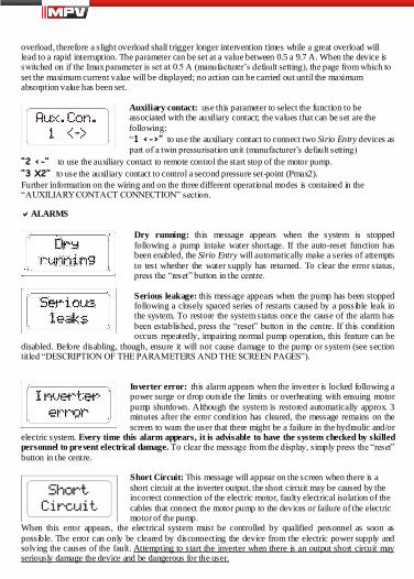
Auxiliary contact: use this parameter to select the function to beassociated with the auxiliary contact; the values that can be set are thefollowing:“1 <->”to use the auxiliary contact to connect two Sirio Entry devices aspart of a twin pressurisation unit (manufacturer’s default setting)
“2 <-“ to use the auxiliary contact to remote control the start stop of the motor pump.“3 X2” to use the auxiliary contact to control a second pressure set-point (Pmax2).Further information on the wiring and on the three different operational modes is contained in the“AUXILIARY CONTACT CONNECTION” section.
ALARMS
Dry running: this message appears when the system is stoppedfollowing a pump intake water shortage. If the auto-reset function hasbeen enabled, the Sirio Entry will automatically make a series of attemptsto test whether the water supply has returned. To clear the error status,press the “reset” button in the centre.
Serious leakage: this message appears when the pump has been stoppedfollowing a closely spaced series of restarts caused by a possible leak inthe system. To restore the system status once the cause of the alarm hasbeen established, press the “reset” button in the centre. If this conditionoccurs repeatedly, impairing normal pump operation, this feature can be
disabled. Before disabling, though, ensure it will not cause damage to the pump or system (see sectiontitled “DESCRIPTION OF THE PARAMETERS AND THE SCREEN PAGES”).
Inverter error: this alarm appears when the inverter is locked following apower surge or drop outside the limits or overheating with ensuing motorpump shutdown. Although the system is restored automatically approx. 3minutes after the error condition has cleared, the message remains on thescreen to warn the user that there might be a failure in the hydraulic and/or
electric system. Every time this alarm appears, it is advisable to have the system checked by skilledpersonnel to prevent electrical damage. To clear the message from the display, simply press the “reset” button in the centre.
Short Circuit: This message will appear on the screen when there is ashort circuit at the inverter output. the short circuit may be caused by theincorrect connection of the electric motor, faulty electrical isolation of thecables that connect the motor pump to the devices or failure of the electricmotor of the pump.
When this error appears, the electrical system must be controlled by qualified personnel as soon aspossible. The error can only be cleared by disconnecting the device from the electric power supply andsolving the causes of the fault. Attempting to start the inverter when there is an output short circuit mayseriously damage the device and be dangerous for the user.

34
Overload: This alarm appears when the absorption of the motor pump isgreater than the maximum current value set (Imax); this may be caused byextremely difficult working conditions for the motor pump, problemsrelated to the motor winding , if the pump is restarted continuously atshort intervals or following problems with the wiring of the motor to the
Sirio Entry. If this alarm is often displayed the system should be checked by the installer.
POSSIBLE MALFUNCTIONS:When one of the cocks in the system is opened, the pump does not start, or there is a fewsecondsdelay before it starts
The Pmin is set too low or a check valve has been fitted downstream of the device. Try increasing thestart pressure Pmin and remove all valves fitted downstream of the Sirio Entry.
When the cocks are closed, the pump stops but restarts a few seconds later and there is noleakage from the system
The difference between the Pmin and the Pmax is too low and the drop in pressure that occurs when thepump stops is sufficient to make it restart. Increase the Pmaxvalue or decrease the Pmin.
The pump keeps switching on and off
There is leakage in the system. Check the various hydraulic connections. Check the display for pressuredrops when the cocks are closed. Check the Sirio Entry's check valve for dirt which could be preventing itfrom closing properly and, if necessary, clean it with compressed air.
The device often signals 'dry running'
The pump intake pipe drains when the system is not used for some time, thereby preventing it primingthe next time it is started. If there is a foot valve fitted, check its seal.
The device frequentlysignals an inverter error.
The supply voltage may not comply with the equipment specifications; the control must be carried out byqualified personnel.The inverter no longer exchanges heat with the water that runs through the device or the temperature ofthe fluid pumped is too high; check for foreign bodies that block the flow of water and if necessary havethe device checked by the manufacturer.
When the water flowis extremely low, the pump does not operate normally.
The flow values are too low and as the device is unable to detect them, it shuts down the motor pump. Fita small surge tank (1-2 litres) in the system to give it more flexibility and reduce the number of restarts.
The pump does not stop
There is substantial leakage in the system or the check valve on the device is jammed by dirt; try movingthe check valve with your fingers and checking that the spring can maintain the seal.

35
The sensor which detects the valve position is broken. Have the device checked by the manufacturer.
The pump is running at top speed but performance levels are low
The pump or the capacitor connection is not correct: check the electric wiring.The pump is damaged or there is foreign matter clogging the waterway.
When more water is required of the system, the pressure drops
This is a normal condition which is due to the fact that the device is unable to force the pump above itscapacity curve. As a result, once a certain capacity is reached, the pressure is no longer offset as the pumpis already running at the highest number of revolutions allowed. In these cases, a pump with higherperformance levels should be installed.
The “Inverter error” message often appears on the display a few seconds after the motor pump is started
The error may be caused by a non-compliant power voltage. With the pump running, use a suitable gaugeto measure the voltage at the power terminals and determine whether the problem concernsunderpowering or overpowering. If it is the former, use a power lead with a larger section to reducevoltage drops, but if it is the latter, contact the manufacturer.
MAINTENANCE:The Sirio Entry is designed to keep maintenance requirements at a minimum. To guarantee the device along working life and perfect functionality, always follow the instructions below:
- ensure the device does not have to withstand temperatures of below 3° C; if this is not possible, makesure all the water inside it is drained out to prevent it from freezing up and damaging the device’s plastic body;- if the pump is equipped with intake filters, carry out regular checks to ensure they are clean;- make sure the cover is always properly closed to prevent water leaking in from outside;- switch off the power supply and drain the water from the system when it is going to be left unused forsome time;- do not force the pump to run without intake water, as this could damage both the pump and the SirioEntry;- before using the device with any other liquids than water, contact the manufacturer.- do not carry out any operations when the device is open- wait 3 minutes before removing the cover from the device so the condensers can discharge.

36
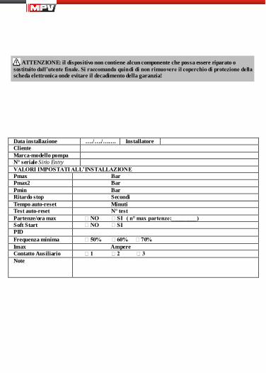
WARNING: this device does not contain any parts that can be repaired or replaced by the enduser. You are therefore advised not to remove the electronic card's protective cover as this wouldlead to forfeiture of the guarantee!
Installation date …./…./……. FitterCustomerPump make/modelSirio Entry serial n.VALUES SET AT INSTALLATIONPmax BarPmax2 BarPmin BarStop delay SecondsAuto-reset time MinutesAuto-reset test Test n.Start/hour max NO YES ( n° max start:_________)Soft Start NO YESPIDMinimum frequency 50% 60% 70% Imax AmpereAuxiliary contact 1 2 3 Notes

94
CE DECLARATION OF CONFORMITY
IT - Con la presente si dichiara che la macchina qui di seguito indicata, in base alla sua concezione, altipo di costruzione e nella versione da noi introdotta sul mercato, è conforme ai requisiti fondamentali disicurezza e di sanità delle direttive CE. In caso di modifiche apportate alla macchina senza il nostroconsen so, la presente dichiarazione perde ogni validità.EN - It is hereby declared that the machine specified herein, according to the specific design, type ofconstruction and version released onto the market, complies with the essential health and safetyrequirements of EC directives. In the event of modifications to the machine without prior authorisation,this declaration will be rendered null and void.FR - Nous déclaron s par la présente que la machine indiquée ci-dessou s, telle qu’elle a été conçue, construite et commercialisée par notre entreprise, est conforme aux exigences fondamentales desécurité et de santé des directives CE. En ca s de modifications apportées à la machine sans notreaccord, la présente déclaration n’a plus aucune validité.ES - Con la presente se declara que la máquina mencionada a continuación, según su diseño, tipo defabricación y en la versión comercializada, responde a los requerimientos fundamentales de seguridad yde sanidad de las directivas CE. En ca so de modificaciones hechas a la máquina sin nuestraautorización, esta declaración pierde su validez.DE - Hiermit erklären wir, dass die wie folgt genannte Maschine aufgrund ihres Konzepts, der Bauart undder von uns auf den Markt eingeführten Ausführung den grundsätzlichen Anforderungen bezüglich derSicherheit und der Gesundheit der EG-Richtlinien entspricht. Falls die Maschine ohne unsereZustimmung geändert wird, verliert diese Erklärung jegliche Gültigkeit.
MODEL: Sirio EntryTYPE: SR22251-XX-XXX
DIRETTIVA: CON RIFERIMENTO A: ANNO MARCHIATURA:DIRECTIVE: WITH REFERENCE TO: MARKING YEAR:DIRECTIF : CONCERNANT: ANNÉE D'INSCRIPTION:DIRECTIVA: REFERENTE A: AÑO DE LA MARCA:RICHTLINIEN: MIT BEZUG AUF: MARKIERUNGS-JAHR:2006/95/ECLVD
EN 60730-1:2002 08
2004/108/ECEMC
EN 61000-6-4:2007EN 61000-6-2:2006
08
Tribano, 06 November 2009
Mr. Demetrio Bertazzo
Italtecnica srlViale Europa 3135020 Tribano (PD) ItalyTel. +39 049 9585388Fax. +39 049 5342439www.italtecnica.com