17097.02-096-01 Weight and Stability - Skagit County
24
Guemes Island Ferry Replacement 23 September 2020 Weight and Stability 1 Job 17097.02, Rev P0 GUEMES ISLAND FERRY REPLACEMENT Weight and Stability PREPARED FOR: Skagit County Public Works Mount Vernon, Washington BY: Andrew L. Girdler, PE PROJECT ENGINEER CHECKED: William L. Moon, PE PROJECT MANAGER APPROVED: Matthew S. Miller, PE PRINCIPAL-IN-CHARGE DOC: 17097.02-096-01 REV: P0 FILE: 17097.02 DATE: 23 September 2020 References 1. Guemes Island Ferry, General Arrangement, Glosten Inc., Drawing No. 17097.02-070-01 2. 46 CFR, Shipping. 2020. 3. General HydroStatics (GHS) [software], Creative Systems Inc. v 17.00. 4. Weight Estimating and Margin Manual for Marine Vehicles, International Society of Allied Weight Engineers, Inc., Recommended Practice Number 14, 2001. 5. Guemes Island Ferry Replacement, Lines Plan, Glosten, Drawing No. 17097.02-070-03. Summary The Guemes Island Ferry Replacement vessel preliminary design intact and damage stability were evaluated against the required stability criteria and determined to be satisfactory. The subject vessel is characterized as a Subchapter T small passenger vessel, operating on partially protected waters according to Reference 2. The results of the intact and damage stability analyses are summarized by a plot of the maximum allowable vertical center of gravity measured from the keel (VCG) versus the full range of vessel operating displacements and trims (see Figure 6). This curve of maximum allowable VCG forms the basis for evaluating compliance of vessel loading conditions with the stability criteria. Figure 6 shows that the representative loading condition VCGs are located below the curve of maximum allowable VCG. This demonstrates that the vessel meets the stability criteria. All loading conditions are detailed in Appendix A. General Principal Characteristics Vessel particulars are as follows: Length, molded (ft) .......................................................160.0 Length, waterline (ft) ....................................................152.5 Beam, molded (ft) ...........................................................53.0 Beam, waterline (ft) ........................................................39.1 Depth, at centerline (ft) .................................................13.45 Depth, at deck edge (ft) ...................................................13.0 Draft, design waterline (ft) ..............................................7.41 Displacement, design waterline (LT SW) .....................505.6 Block coefficient .............................................................0.40 PRELIMINARY
-
Upload
khangminh22 -
Category
Documents
-
view
0 -
download
0
Transcript of 17097.02-096-01 Weight and Stability - Skagit County

Guemes Island Ferry Replacement 23 September 2020 Weight and Stability 1 Job 17097.02, Rev P0
GUEMES ISLAND FERRY REPLACEMENT Weight and Stability
PREPARED FOR:
Skagit County Public Works Mount Vernon, Washington
BY: Andrew L. Girdler, PE PROJECT ENGINEER
CHECKED: William L. Moon, PE PROJECT MANAGER
APPROVED: Matthew S. Miller, PE PRINCIPAL-IN-CHARGE
DOC:
17097.02-096-01 REV:
P0 FILE:
17097.02DATE:
23 September 2020
References 1. Guemes Island Ferry, General Arrangement, Glosten Inc., Drawing No. 17097.02-070-012. 46 CFR, Shipping. 2020.3. General HydroStatics (GHS) [software], Creative Systems Inc. v 17.00.4. Weight Estimating and Margin Manual for Marine Vehicles, International Society of Allied
Weight Engineers, Inc., Recommended Practice Number 14, 2001.5. Guemes Island Ferry Replacement, Lines Plan, Glosten, Drawing No. 17097.02-070-03.
Summary The Guemes Island Ferry Replacement vessel preliminary design intact and damage stability were evaluated against the required stability criteria and determined to be satisfactory. The subject vessel is characterized as a Subchapter T small passenger vessel, operating on partially protected waters according to Reference 2. The results of the intact and damage stability analyses are summarized by a plot of the maximum allowable vertical center of gravity measured from the keel (VCG) versus the full range of vessel operating displacements and trims (see Figure 6). This curve of maximum allowable VCG forms the basis for evaluating compliance of vessel loading conditions with the stability criteria. Figure 6 shows that the representative loading condition VCGs are located below the curve of maximum allowable VCG. This demonstrates that the vessel meets the stability criteria. All loading conditions are detailed in Appendix A.
General
Principal Characteristics Vessel particulars are as follows: Length, molded (ft) .......................................................160.0 Length, waterline (ft) ....................................................152.5 Beam, molded (ft) ...........................................................53.0 Beam, waterline (ft) ........................................................39.1 Depth, at centerline (ft) .................................................13.45 Depth, at deck edge (ft) ...................................................13.0 Draft, design waterline (ft) ..............................................7.41 Displacement, design waterline (LT SW) .....................505.6 Block coefficient .............................................................0.40
PRELIMIN
ARY

Guemes Island Ferry Replacement 23 September 2020 Weight and Stability 2 Job 17097.02, Rev P0
Subdivision Frame 0 is assumed to be at amidships, and the frame locations forward (f) and aft (a) of amidships are symmetric about amidships. Main transverse watertight bulkheads (MTWBs) are located at Frames 16a, 12a, 6a, 6f, 12f, and 16f following this convention with a 4'-0" transverse frame spacing. As a double-ended ferry, the bulkheads at Frames 16a and 16f are required to be collision bulkheads per 46 CFR 171.060(d). In addition, the vessel is subjected to requirements of Type II subdivision per 46 CFR 171.070 and must satisfy two-compartment flooding at the ends and one-compartment flooding otherwise. A draft of ~8' corresponds to the maximum load condition (see the Loading Conditions section) The allowable operating static trim ranges from 1.0° by the bow through 1.0° by the stern. The permeability is assumed to be 95% for all spaces for conservatism. The resulting floodable length curves are shown in Figure 1 with the bulkheads at Frames 16a and 16f removed to represent the required two-compartment flooding.
Figure 1 Floodable length curves by permeability, initial draft = 7.94 ft at 1 degrees aft trim, Min GM = 5.10 ft

Guemes Island Ferry Replacement 23 September 2020 Weight and Stability 3 Job 17097.02, Rev P0
Downflooding Points The following table shows the locations of the downflooding points used in the stability analysis. All downflooding points have been assumed symmetric about the centerline for intact stability analysis purposes. Table 1 Downflooding points
Downflooding Point Longitudinal Locationft + aft Fr. 0
Transverse Location ft + stbd. CL
Vertical Locationft + abv. BL
Battery Bank 1 Outlet 2 -25.27 16.5 Battery Bank 2 Outlet 6 -25.27 16.5
Switchboard Room Inlet -10.46 12.46 16.7
Generator Room Inlet 15.75 12.46 17.25
All other compartments are fitted with watertight closures at the compartment vents and thus are not downflooding points per 46 CFR 170.055(i).
Tank Capacities Tank capacities are shown in Table 2. Table 2 Tank Capacities
Tank Name Capacity @ 100%(gal)
Specific Gravity
LCG (ft)
TCG (ft)
VCG (ft)
Max Free Surface (LT-ft)
Fuel 1650.2 0.87 28.00a 0.00 8.98 8.2 Sanitary 538.6 1.00 12.06a 13.92s 6.99 0.6
Potable 538.6 1.00 4.10a 13.92s 6.99 0.6
Hydrostatic Model All stability calculations were performed using General Hydrostatics (GHS) software (Reference 3). All windage areas above the main deck not included in buoyant volume are modeled as sail components. The hydrostatic model is shown in Figure 2.

Guemes Island Ferry Replacement 23 September 2020 Weight and Stability 4 Job 17097.02, Rev P0
Figure 2 Hydrostatic model with sail area representing a full load of vehicles
Hydrostatics Vessel hydrostatics over the operating range of displacements and drafts are given in Table 3. Table 3 Hydrostatics at zero trim, zero heel
Displ LT SW
Draft ft
LCB ft +aft Fr. 0
VCB ft +abv.
BL
TPI LT/in
LCF ft +aft Fr. 0
MCT1° LT-ft/deg
KML ft
KMT ft
375 6.284 0 4.09 8.88 0 1902.91 290.7 29.55 400 6.516 0 4.24 9.08 0.01 2014.96 288.6 28.94 425 6.744 0 4.38 9.27 0 2115.69 285.2 28.41 450 6.966 0 4.52 9.44 0.01 2209.33 281.3 27.94 475 7.185 0 4.65 9.6 0 2295.28 276.8 27.53 500 7.397 0 4.78 9.96 0 2532.91 290.2 27.17 525 7.605 0 4.91 10.1 0 2605.63 284.3 26.84 550 7.81 0 5.04 10.24 0 2674.54 278.6 26.54 575 8.012 0 5.16 10.37 0 2739.98 273 26.28 600 8.212 0 5.29 10.49 0 2803.2 267.7 26.06
Weight
Lightship Weight The estimated lightship weight is shown in Table 4. This weight estimate uses the weight and VCG margins set forth in Reference 4, consistent with the level of design completion.

Guemes Island Ferry Replacement 23 September 2020 Weight and Stability 5 Job 17097.02, Rev P0
Table 4 Lightship weight summary
Loading Conditions Four loading conditions were evaluated as follows:
• Light Operating – 10% fuel, 10% potable water, 10% sanitary, no passengers nor vehicles• Most Probable – 50% fuel, 50% potable water, 50% sanitary, 42 passengers, 21
passenger vehicles• Full Operating – 95% fuel, 100% potable water, 0% sanitary, 110 passengers, 1 truck, 25
passenger vehicles• Max Load – 95% fuel, 100% potable water, 100% sanitary, 150 passengers, 3 trucks, 19
passenger vehiclesDetails of each loading condition can be found in Appendix A. Each loading condition is corrected for free surface, which is caused by liquids in partially filled tanks (slack tanks) shifting transversely in the direction of heel. The reduction in stability is accounted for by a virtual increase in VCG of the loading condition. The free surface correction is based on the maximum free surface moment of all tanks on the vessel.
Stability Calculations
Intact Stability This section summarizes the intact stability criteria. The allowable operating static trim ranges from 1.0° by the bow through 1.0° by the stern. According to Reference 2, a subchapter T small passenger vessel is required to comply with the applicable requirements of:
• 46 CFR§170.170 Weather Criteria;• 46 CFR§170.173(e) Righting Energy;• 46 CFR§171.050 Passenger Heel (zero trim only).
Each of the intact stability criteria was evaluated over a range of displacements from 350 LT to 650 LT in increments of 25 LT.
SWBS Group Description Margin Weight Margin LCG TCG VCG NotesNo. % LT LT ft +Aft Fr 0 ft +Stbd CL ft +Abv BL
100 Hull and House Structure 8.00% 241.71 19.34 0.31 0.64 10.04200 Propulsion Plant 9.00% 30.38 2.73 0.00 -0.08 8.00300 Electric Plant 12.00% 31.74 3.81 -4.32 1.48 10.96400 Command and Surveillance 12.00% 0.61 0.07 0.00 16.50 25.72500 Auxiliary Systems 12.00% 18.65 2.24 2.95 2.07 9.31600 Outfit and Furnishings 12.00% 23.29 2.80 0.05 6.21 13.38
Lightship (Without Margins) 346.39 -0.02 1.14 10.16
Design and Build Weight Margin (Total) 8.21% 30.99 % of WeightDesign and Build VCG Margin 9.00% 0.91 % of VCGContract Mods. Weight Margin 0.93% 3.49 % of WeightContract Mods. VCG Margin 0.78% 0.08 % of VCGLightship (Without Ballast) 380.87 -0.02 1.15 11.16
Fixed Ballast 13.00 0.00 -23.36 12.00
Lightship (Total) 393.87 -0.02 0.34 11.19

Guemes Island Ferry Replacement 23 September 2020 Weight and Stability 6 Job 17097.02, Rev P0
46 CFR§170.170 Weather Criteria
Wind pressure for service on partially protected waters is defined as follows: 𝑃 = 0.0033 + 𝐿14200 LT ftwhere: L = LBP [ft].
This pressure is used to develop a minimum GMt for every displacement evaluated. The expression for GMt is shown below:
)tan(TWPAHGMt ≥ ,
where: A = projected lateral area of vessel above waterline; H = height between lateral area above and below the waterline; W = vessel displacement; T = angle where one half of the freeboard is submerged.
The minimum GMt is used to calculate the maximum allowable VCG using the expression: 𝑉𝐶𝐺 = 𝑉𝐶𝐵 + 𝐵𝑀 − 𝐺𝑀 .
46 CFR§170.173(e) Righting Energy Criteria
The righting energy criteria for vessels operating on partially protected routes are excerpted below:
(e) (1) For partially protected routes, there must be— (i) Positive rights arms to at least 35 degrees of heel; (ii) No down flooding point to at least 20 degrees; and (iii) At least 15 foot-degrees of energy to the smallest of the following angles:
(A) Angle of maximum right arm. (B) Angle of down flooding. (C) 40 degrees.
46 CFR§171.050 Passenger Heel Criteria
A minimum required GMt based on passenger heeling is evaluated for each displacement. The expression for GMt is shown below: 𝐺𝑀 = 𝑊 ∆ 2 3 𝑏 tan 𝑇
where: W = total weight of persons other than required crew incl. personal effects; Δ = vessel displacement; b = distance from the vessel centerline to the geometric center of the passenger deck on one side of centerline; T = 14° or the angle of heel at which the deck edge is submerged, whichever is less.
The minimum GMt is used to calculate the maximum allowable VCG using the expression: 𝑉𝐶𝐺 = 𝑉𝐶𝐵 + 𝐵𝑀 − 𝐺𝑀 . This criterion has been evaluated at an even keel only (zero trim) since it is based on metacentric height.

Guemes Island Ferry Replacement 23 September 2020 Weight and Stability 7 Job 17097.02, Rev P0
Damage Stability This section summarizes the damage stability criteria and assumptions. The allowable operating trim ranges from 1.0° by the bow through 1.0° by the stern. The damage stability criteria were evaluated over a range of displacements from 350 LT to 650 LT in increments of 25 LT. Damage stability was calculated based on the following criteria:
• 46 CFR§171.080(f) Damage Stability.
46 CFR§171.080(f) Damage Stability Criteria
The damage criteria defined in 46 CFR§171.080(f) for all new vessels for service on partially protected waters were applied. The damage criteria are paraphrased by paragraph as follows:
(1) Positive righting arm for a minimum range of 10 degrees beyond the angle of equilibrium
(2) No downflooding that occurs within 10 degrees of equilibrium
(3) Area under each righting arm curve at least 2.82 ft-deg, measured from equilibrium to the smallest of :
(i) Downflooding angle (ii) Angle of vanishing stability
(4) GZ equal to or greater than 0.328 ft or 𝐺𝑍 = 𝐶 𝐻𝑒𝑒𝑙𝑖𝑛𝑔 𝑀𝑜𝑚𝑒𝑛𝑡∆ + 0.04
where: C = 0.75 for vessels on partially protected waters;
∆ = intact displacement.
The heeling moment is defined as the largest of:
(A) Passenger heeling moment (B) Heeling moment due to asymmetric escape routes (C) Heeling moment due to survival craft launching (D) Wind heeling moment
(5) Not applicable; no exemption from (4) requested.
(6) Angle of equilibrium that does not exceed:
(i) 7 degrees for one-compartment flooding
(ii) 12 degrees for flooding of two compartments; or
(iii) A maximum of 15 degrees for one- or two-compartment flooding where: (A) Positive righting arm for 20 degrees beyond equilibrium (B) Area under each righting arm curve greater than or equal to:
)1(4700.0 −≥ θA
where: A = area (ft-deg) under each righting-arm curve measured from the angle of equilibrium to the smaller of either the downflooding angle or the angle of vanishing stability;
θ = angle of equilibrium in degrees.
(7) The margin line must not be submerged at equilibrium
The damage calculations incorporate both 46 CFR§171.080 (f)(6)(i) and 46 CFR§171.080 (f)(6)(iii), meaning that the vessel was allowed to heel to a final equilibrium of 15° provided that 46 CFR§171.080 (f)(6)(iii)(A) and (B) were satisfied.

Guemes Island Ferry Replacement 23 September 2020 Weight and Stability 8 Job 17097.02, Rev P0
Margin Line
The margin line is defined in accordance with 46 CFR§171.015(b) for a vessel with a continuous bulkhead deck and insufficient shear (see Figure 3) with the margin line 9" below top of deck amidships as per Reference 2, Table 171.015.
Figure 3 Margin line for a vessel with a continuous bulkhead deck and insufficient shear (Reference 2)
Extent of Damage
For the calculation of extent and character of damage, 46 CFR§179.212(a) requires that the vessel comply with Type II subdivision. A combination of one- and two-compartment standard of flooding is required by 46 CFR§171.070(b). The extent and character of damage is from Table 171.080(a) for Category Y vessels. The extent of damage is shown in Table 5 below. The character of damage assumes damage to only the collision bulkheads at each end. Table 5 Damage extent
Direction Extent of Damage Value Longitudinal 10 ft + 0.03*LBP or 35 ft, whichever is less 14.55 ftTransverse B/5, where B is the beam of the vessel at the subdivision load line (BWL) 7.88 ftVertical Upward from baseline without limit Unlimited
Permeability
The permeability of each space in the vessel is shown in Table 6. These values are applied in accordance with 46 CFR§171.080(c). Table 6 Compartment permeability
Space Designation Permeability (%) Compartments in GHS Model Accommodations 95 N/A Machinery 85 MACHY_SPACE Tanks
Voids 95 VOID1, VOID2…VOID5, VOID6
FOT 95 FOT
FW, SAN 95 FW, SAN
Permanent Ballast 0 BALLAST
Damage Case Matrix
The vessel is divided into seven zones by the main transverse watertight bulkheads (MTWBs). These zones are approximately symmetric about amidships. For simplicity, only the forward end is analyzed with respect to damage stability with each damage case reflecting the damage to the compartment(s) in those zones. Table 7 describes the damage cases. Due to symmetry, only starboard damage is considered.
Guemes Island Ferry Replacement 23 September 2020 Weight and Stability 9 Job 17097.02, Rev P0
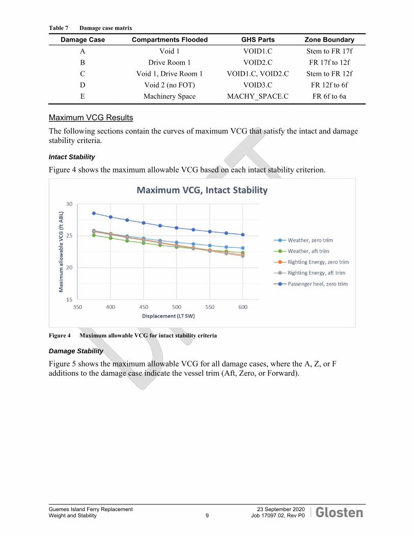
Table 7 Damage case matrix
Damage Case Compartments Flooded GHS Parts Zone Boundary A Void 1 VOID1.C Stem to FR 17f B Drive Room 1 VOID2.C FR 17f to 12f C Void 1, Drive Room 1 VOID1.C, VOID2.C Stem to FR 12f D Void 2 (no FOT) VOID3.C FR 12f to 6f E Machinery Space MACHY_SPACE.C FR 6f to 6a
Maximum VCG Results The following sections contain the curves of maximum VCG that satisfy the intact and damage stability criteria.
Intact Stability
Figure 4 shows the maximum allowable VCG based on each intact stability criterion.
Figure 4 Maximum allowable VCG for intact stability criteria
Damage Stability
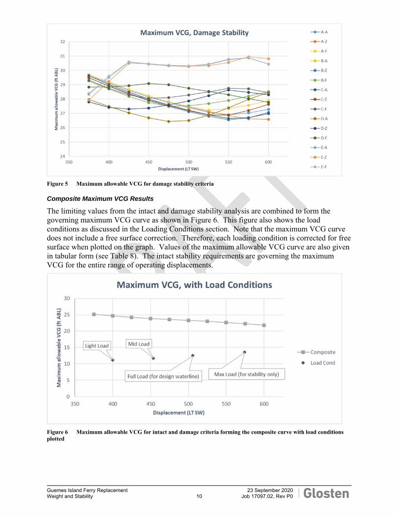
Figure 5 shows the maximum allowable VCG for all damage cases, where the A, Z, or F additions to the damage case indicate the vessel trim (Aft, Zero, or Forward).
Guemes Island Ferry Replacement 23 September 2020 Weight and Stability 10 Job 17097.02, Rev P0
Figure 5 Maximum allowable VCG for damage stability criteria
Composite Maximum VCG Results
The limiting values from the intact and damage stability analysis are combined to form the governing maximum VCG curve as shown in Figure 6. This figure also shows the load conditions as discussed in the Loading Conditions section. Note that the maximum VCG curve does not include a free surface correction. Therefore, each loading condition is corrected for free surface when plotted on the graph. Values of the maximum allowable VCG curve are also given in tabular form (see Table 8). The intact stability requirements are governing the maximum VCG for the entire range of operating displacements.
Figure 6 Maximum allowable VCG for intact and damage criteria forming the composite curve with load conditions plotted

Guemes Island Ferry Replacement 23 September 2020 Weight and Stability 11 Job 17097.02, Rev P0
Table 8 Values of maximum allowable VCG curves shown in Figure 6
Displ. Maximum VCG (ft ABL) (LT SW) Intact Damage Composite375 25.1 27.8 25.1 400 24.7 27.4 24.7 425 24.2 27.0 24.2 450 23.9 26.7 23.9 475 23.5 26.4 23.5 500 23.3 26.5 23.3 525 23.0 26.8 23.0 550 22.6 26.6 22.6 575 22.2 26.6 22.2 600 21.8 26.6 21.8

Guemes Island Ferry Replacement 23 September 2020 Weight and Stability A-1 Job 17097.02, Rev P0
Appendix A Loading Conditions

DRAFT
09/08/20 15:09:37 Glosten Page 1GHS 17.00 Untitled
***********************************************LIGHTSHIP WEIGHT ONLY
***********************************************
WEIGHT STATUSTrim: 0.00 deg., Heel: Stbd 1.08 deg.
Part------------------------------Weight(LT)----LCG-----TCG-----VCG-------FSMWEIGHT 393.87 0.02f 0.34s 11.19
Load-----SpGr-----Weight(LT)----LCG-----TCG-----VCGTotal Tanks---------> --- Included in Fixed Weight --- 9.4*Total Weight--------> 393.87 0.02f 0.34s 11.19
Free Surface Adjustment----------> 0.02Adjusted CG----------------------> 0.02f 0.34s 11.21
Distances in FEET.-------------------------------------------Moments in Ft-LT.
Note: FSM values marked with an asterisk (*) are formal values which arenot the same as the true values in the present condition.
HYDROSTATIC PROPERTIESTrim: 0.00 deg., Heel: Stbd 1.08 deg., VCG = 11.19
LCF Displacement Buoyancy-Ctr. Weight/ Moment/Draft----Weight(LT)----LCB-----VCB-----Inch-----LCF--Deg trim----GML-----GMT6.419 393.87 0.02f 4.17 9.04 0.02f 1910.71 277.9 17.89
Distances in FEET.-------Specific Gravity = 1.025.-----------Moment in Ft-LT.Draft is from Baseline. Formal Free Surface included.
Note: GMT includes the formal free surface moment 9.4 Ft-LT
HYDROSTATIC PROPERTIESTrim: 0.00 deg., Heel: Stbd 1.08 deg.
Origin Displacement Center of BuoyancyDepth----Weight(LT)----LCB-----TCB-----VCB-----WPA-----LCF------BML-----BMT6.418 393.87 0.02f 0.47s 4.17 3797 0.02f 284.9 24.92
Distances in FEET.----Specific Gravity = 1.025.---Formal Free Surface included.
Note: BMT includes the formal free surface moment 9.4 Ft-LT

DRAFT
09/08/20 15:09:37 Glosten Page 2GHS 17.00 Untitled
CG - Draft: 6.42 @ 0.00 Trim: 0.00 deg. Heel: stbd 1.08 deg.
Profile View
Plan View
Body @ 28.00a

DRAFT
09/08/20 15:09:37 Glosten Page 3GHS 17.00 Untitled
************************************************LIGHT OPERATING, 10% FUEL, NO PASSENGERS, NO CARS*************************************************
WEIGHT STATUSTrim: Aft 0.01 deg., Heel: Stbd 1.27 deg.
Part------------------------------Weight(LT)----LCG-----TCG-----VCGLIGHT SHIP 393.87 0.02f 0.34s 11.19Crew and Effects 0.30 0.00 15.42s 24.68General Stores 0.45 0.00 15.42s 15.42Crew Stores 0.45 0.00 15.42s 23.68Ships Stores and Spares 4.00 0.00 0.00 5.75
Total Fixed---------> 399.06 0.02f 0.38s 11.16Load-----SpGr-----Weight(LT)----LCG-----TCG-----VCG-------FSM
FOT.C 0.100 0.870 0.53 28.00a 0.34s 7.41 8.2SAN.S 0.100 1.000 0.20 12.06a 13.98s 4.97 0.6PW.S 0.100 1.000 0.20 4.10a 13.98s 4.97 0.6
Total Tanks---------> 0.94 19.46a 6.19s 6.36 9.4*Total Weight--------> 400.00 0.03a 0.40s 11.15
Free Surface Adjustment----------> 0.02Adjusted CG----------------------> 0.03a 0.39s 11.18
Distances in FEET.-------------------------------------------Moments in Ft-LT.
Note: FSM values marked with an asterisk (*) are formal values which arenot the same as the true values in the present condition.
HYDROSTATIC PROPERTIESTrim: Aft 0.01 deg., Heel: Stbd 1.27 deg., VCG = 11.15
LCF Displacement Buoyancy-Ctr. Weight/ Moment/Draft----Weight(LT)----LCB-----VCB-----Inch-----LCF--Deg trim----GML-----GMT6.474 400.00 0.03a 4.20 9.09 0.02a 1935.46 277.2 17.79
Distances in FEET.-------Specific Gravity = 1.025.-----------Moment in Ft-LT.Draft is from Baseline. Formal Free Surface included.
Note: GMT includes the formal free surface moment 9.4 Ft-LT
HYDROSTATIC PROPERTIESTrim: Aft 0.01 deg., Heel: Stbd 1.27 deg.
Origin Displacement Center of BuoyancyDepth----Weight(LT)----LCB-----TCB-----VCB-----WPA-----LCF------BML-----BMT6.473 400.00 0.03a 0.55s 4.20 3817 0.02a 284.2 24.74
Distances in FEET.----Specific Gravity = 1.025.---Formal Free Surface included.
Note: BMT includes the formal free surface moment 9.4 Ft-LT

DRAFT
09/08/20 15:09:37 Glosten Page 4GHS 17.00 Untitled
CG - Draft: 6.47 @ 0.00 Trim: aft 0.01 deg. Heel: stbd 1.27 deg.
12 3
Profile View
2 3
1
Plan View
1
Body @ 28.00a
Tanks 1 FOT.C..10% FUEL OIL 2 SAN.S..10% FRESH WATER 3 PW.S...10% FRESH WATER

DRAFT
09/08/20 15:09:37 Glosten Page 5GHS 17.00 Untitled
**********************************************MID OPERATING, 50% FUEL, 49 PASS ON MD, 21 CARS***********************************************
WEIGHT STATUSTrim: Aft 0.04 deg., Heel: Port 0.53 deg.
Part------------------------------Weight(LT)----LCG-----TCG-----VCGLIGHT SHIP 393.87 0.02f 0.34s 11.19Crew and Effects 0.30 0.00 15.42s 24.68General Stores 0.45 0.00 15.42s 15.42Crew Stores 0.45 0.00 15.42s 23.68Ships Stores and Spares 4.00 0.00 0.00 5.75MD Pax on Deck 2.56 0.00 5.65p 16.42MD Pax around House 1.49 0.00 17.25s 16.42Pass Vehicles 45.94 0.00 5.65p 16.42
Total Fixed---------> 449.05 0.02f 0.21p 11.75Load-----SpGr-----Weight(LT)----LCG-----TCG-----VCG-------FSM
FOT.C 0.500 0.870 2.67 28.00a 0.03p 8.11 8.2SAN.S 0.500 1.000 1.00 12.06a 13.91s 5.87 0.6PW.S 0.500 1.000 1.00 4.10a 13.91s 5.87 0.6
Total Tanks---------> 4.68 19.46a 5.95s 7.15 9.4*Total Weight--------> 453.73 0.18a 0.15p 11.70
Free Surface Adjustment----------> 0.02Adjusted CG----------------------> 0.18a 0.15p 11.72
Distances in FEET.-------------------------------------------Moments in Ft-LT.
Note: FSM values marked with an asterisk (*) are formal values which arenot the same as the true values in the present condition.
HYDROSTATIC PROPERTIESTrim: Aft 0.04 deg., Heel: Port 0.53 deg., VCG = 11.70
LCF Displacement Buoyancy-Ctr. Weight/ Moment/Draft----Weight(LT)----LCB-----VCB-----Inch-----LCF--Deg trim----GML-----GMT6.959 453.71 0.19a 4.50 9.47 0.14a 2129.18 268.9 16.16
Distances in FEET.-------Specific Gravity = 1.025.-----------Moment in Ft-LT.Draft is from Baseline. Formal Free Surface included.
Note: GMT includes the formal free surface moment 9.4 Ft-LT
HYDROSTATIC PROPERTIESTrim: Aft 0.04 deg., Heel: Port 0.53 deg.
Origin Displacement Center of BuoyancyDepth----Weight(LT)----LCB-----TCB-----VCB-----WPA-----LCF------BML-----BMT6.959 453.71 0.19a 0.22p 4.50 3978 0.14a 276.1 23.36
Distances in FEET.----Specific Gravity = 1.025.---Formal Free Surface included.
Note: BMT includes the formal free surface moment 9.4 Ft-LT

DRAFT
09/08/20 15:09:37 Glosten Page 6GHS 17.00 Untitled
CG - Draft: 6.96 @ 0.00 Trim: aft 0.04 deg. Heel: port 0.53 deg.
12 3
Profile View
2 3
1
Plan View
1
Body @ 28.00a
Tanks 1 FOT.C..50% FUEL OIL 2 SAN.S..50% FRESH WATER 3 PW.S...50% FRESH WATER

DRAFT
09/08/20 15:09:37 Glosten Page 7GHS 17.00 Untitled
***********************************************FULL OPERATING, 95% FUEL, 1 TRUCK ON MD
25 CARS ON MD, 100 PASS ON MD************************************************
WEIGHT STATUSTrim: Aft 0.06 deg., Heel: Port 0.91 deg.
Part------------------------------Weight(LT)----LCG-----TCG-----VCGLIGHT SHIP 393.87 0.02f 0.34s 11.19Crew and Effects 0.30 0.00 15.42s 24.68General Stores 0.45 0.00 15.42s 15.42Crew Stores 0.45 0.00 15.42s 23.68Ships Stores and Spares 4.00 0.00 0.00 5.75MD Pax on Deck 3.63 0.00 5.65p 16.42MD Pax around House 5.45 0.00 17.25s 16.42Pass Vehicles 54.69 0.00 5.65p 16.42Trucks 51'-8 35.71 0.00 1.75p 21.17
Total Fixed---------> 498.55 0.02f 0.29p 12.55Load-----SpGr-----Weight(LT)----LCG-----TCG-----VCG-------FSM
FOT.C 0.950 0.870 5.08 28.00a 0.03p 8.89 8.2PW.S 1.000 1.000 2.01 4.10a 13.92s 6.99 0.0
Total Tanks---------> 7.09 21.24a 3.92s 8.35 9.4*Total Weight--------> 505.64 0.28a 0.23p 12.49
Free Surface Adjustment----------> 0.02Adjusted CG----------------------> 0.28a 0.23p 12.51
Distances in FEET.-------------------------------------------Moments in Ft-LT.
Note: FSM values marked with an asterisk (*) are formal values which arenot the same as the true values in the present condition.
HYDROSTATIC PROPERTIESTrim: Aft 0.06 deg., Heel: Port 0.91 deg., VCG = 12.49
LCF Displacement Buoyancy-Ctr. Weight/ Moment/Draft----Weight(LT)----LCB-----VCB-----Inch-----LCF--Deg trim----GML-----GMT7.405 505.64 0.29a 4.78 10.00 0.17a 2439.58 276.4 14.59
Distances in FEET.-------Specific Gravity = 1.025.-----------Moment in Ft-LT.Draft is from Baseline. Formal Free Surface included.
Note: GMT includes the formal free surface moment 9.4 Ft-LT

DRAFT
09/08/20 15:09:37 Glosten Page 8GHS 17.00 Untitled
HYDROSTATIC PROPERTIESTrim: Aft 0.06 deg., Heel: Port 0.91 deg.
Origin Displacement Center of BuoyancyDepth----Weight(LT)----LCB-----TCB-----VCB-----WPA-----LCF------BML-----BMT7.403 505.64 0.29a 0.36p 4.78 4201 0.17a 284.1 22.31
Distances in FEET.----Specific Gravity = 1.025.---Formal Free Surface included.
Note: BMT includes the formal free surface moment 9.4 Ft-LT

DRAFT
09/08/20 15:09:37 Glosten Page 9GHS 17.00 Untitled
CG - Draft: 7.40 @ 0.00 Trim: aft 0.06 deg. Heel: port 0.91 deg.
13
Profile View
3
1
Plan View
1
Body @ 28.00a
Tanks 1 FOT.C..95% FUEL OIL Intact 3 PW.S..100% FRESH WATER Intact

DRAFT
09/08/20 15:09:37 Glosten Page 10GHS 17.00 Untitled
***********************************************MAXIMUM OPERATING, 98% FUEL, 3 TRUCKS ON MD
19 CARS ON MD, 150 PASS ON MD************************************************
WEIGHT STATUSTrim: Aft 0.06 deg., Heel: Port 1.35 deg.
Part------------------------------Weight(LT)----LCG-----TCG-----VCGLIGHT SHIP 393.87 0.02f 0.34s 11.19Crew and Effects 0.30 0.00 15.42s 24.68General Stores 0.45 0.00 15.42s 15.42Crew Stores 0.45 0.00 15.42s 23.68Ships Stores and Spares 4.00 0.00 0.00 5.75MD Pax on Deck 6.19 0.00 5.65p 16.42MD Pax around House 6.19 0.00 17.25s 16.42Pass Vehicles 46.65 0.00 5.65p 16.42Trucks 51'-8 107.14 0.00 1.75p 21.17
Total Fixed---------> 565.25 0.01f 0.40p 13.61Load-----SpGr-----Weight(LT)----LCG-----TCG-----VCG-------FSM
FOT.C 0.950 0.870 5.08 28.00a 0.04p 8.89 8.2SAN.S 0.950 1.000 1.91 12.06a 13.91s 6.88 0.6PW.S 1.000 1.000 2.01 4.10a 13.92s 6.99 0.0
Total Tanks---------> 8.99 19.29a 6.03s 8.04 9.4*Total Weight--------> 574.24 0.29a 0.30p 13.52
Free Surface Adjustment----------> 0.02Adjusted CG----------------------> 0.29a 0.30p 13.54
Distances in FEET.-------------------------------------------Moments in Ft-LT.
Note: FSM values marked with an asterisk (*) are formal values which arenot the same as the true values in the present condition.
HYDROSTATIC PROPERTIESTrim: Aft 0.06 deg., Heel: Port 1.35 deg., VCG = 13.52
LCF Displacement Buoyancy-Ctr. Weight/ Moment/Draft----Weight(LT)----LCB-----VCB-----Inch-----LCF--Deg trim----GML-----GMT7.964 574.24 0.30a 5.13 10.37 0.16a 2604.45 259.8 12.78
Distances in FEET.-------Specific Gravity = 1.025.-----------Moment in Ft-LT.Draft is from Baseline. Formal Free Surface included.
Note: GMT includes the formal free surface moment 9.4 Ft-LT

DRAFT
09/08/20 15:09:37 Glosten Page 11GHS 17.00 Untitled
HYDROSTATIC PROPERTIESTrim: Aft 0.06 deg., Heel: Port 1.35 deg.
Origin Displacement Center of BuoyancyDepth----Weight(LT)----LCB-----TCB-----VCB-----WPA-----LCF------BML-----BMT7.961 574.24 0.30a 0.50p 5.13 4358 0.16a 268.2 21.18
Distances in FEET.----Specific Gravity = 1.025.---Formal Free Surface included.
Note: BMT includes the formal free surface moment 9.4 Ft-LT

DRAFT
09/08/20 15:09:37 Glosten Page 12GHS 17.00 Untitled
CG - Draft: 7.96 @ 0.00 Trim: aft 0.06 deg. Heel: port 1.35 deg.
12 3
Profile View
2 3
1
Plan View
1
Body @ 28.00a
Tanks 1 FOT.C..95% FUEL OIL 2 SAN.S..95% FRESH WATER 3 PW.S..100% FRESH WATER