
1111111 II Il INN 1111 Illiflhl - World Radio History
128
-
Upload
khangminh22 -
Category
Documents
-
view
0 -
download
0
Transcript of 1111111 II Il INN 1111 Illiflhl - World Radio History

11111111 1111111 III aniummumin a 1 1111111
1111111 11111 II Il INN
1111 Illiflhl 1111111111 r_ July .19 57 A Chilton Publicatio

Specification of RMC DISCAPS, where design requires ceramic capacitors, has built
a volume operation where quality and service are paramount. Quality control is absolute
as every DISCAP is checked on the production line for power factor, capacity, leakage
resistance, and breakdown. Prompt shipment of orders is assured as RMC controls production from basic powders to completed capacitor.
RMC is prepared to service your requirements for standard or special ceramic
capacitors. Write for complete information.
RADIO MATERIALS CORPORATION GENERAL OFFICE: 3325 N. California Ave.. Chicago Ig, Ill. Two RI« Plants Devoted Exclusively to Ceramic Capacitors
FACTORIES AT CHICAGO, ILL. APED ATTICA, 10,10.

ELECTRONIC INDUSTRIES
& TELE-TECH
Vol. 16. No. 7 July 1957
MONTHLY NEWS ROUND-UP
Radarscope: What s Ahead for the Electronic Industries 2
As We Go To Press 5
TOTALS: Late Marketing Statistics 7
Electronic Industries' News Briefs 16
Coming Events 44
WashIngton News Letter 64
New Tech Data for Engineers 66
Editorial: WESCON 1957; Standardize Wired-TV 33
New Horizons for Battery Power A. E. Look 34
New Grids Improve Lead-Acid Cells Dr. H. J. Strauss 39
Telemetered Data Checks Vanguard Flight F. W. Phalen 40
What's New 42
1957 Coming Events Calendar (July to Dec.l 44
Cooling Robot Brains N E. Sheldon, C. A. Nolph & G. A. Fleischer 46
Design for an Improved HF Transistor G. Thornton, J. Roschen & T. Miles 47
Improving the Glow Transfer Tube
Metallurgical Aspects of Resistance .. Dr. T. P. Wong & E. T. Kubilins
Hot Junctions and Collector Cut-Off Current
High Amplitude Pulse Gate
International Electronic Sources
T. M. Jackson 50
52
B Reich 56
57
81
NEWSELECTRONIC EQUIPMENT
New Products . . . for the Design Engineer
New Products . . . for the Electronic Industries
New Products . . . for Communications
DEPARTMENTS
G A Sample
58
60
62
Tele-Tips 18 Industry News 114
Books 26 Personals 112
News of Reps 78
El PA N BlP
New Batteries! 34 Solid electrolyte, indium and nu-clear cells are adding a new di-mension to the battery field, in terms of in-creased shelf and service life. The familiar second-ary cells, too, are much improved.
A Look At "Vanguard" 40 Instrumentation in the Vanguard test vehicles faced the prob-lems of corrosive atmospheres, high acceleration and heat ranges from —300° to 900°F. Unique transducers sup-plied the answer.
Alloy Transistor 47
Manufacturing refinements make possible highly stable parame-ters for the sili-con surface alloy transistor when operated at high temperatures.
Computer Pulse Gate 57 A unique circuit has been de-signed which is capable of block-ing or passing positive pulses of 100 usec. mini-mum width. In-sertion loss is I 5%, with switch-ing time of 0.25 usec.
ELECTRON IC INDUSTRIES & Tele-Tech, July 1957, Vol. '6, No. 7. A monthly publication of Chilton Co. Execative, Editorial & Advertising offices at Chestnut 81 56th Sts., Phila.. Pa. Ac-cepted as controlled circulation publication at Phila., Pa. 754 per copy, except June (Direc-tory issue, $3 00 Subscription rates U. S. and U. S. Possessions: 1 yr. $5.00; 2 yrs. $8.00; 3 yrs. $10.00. Canada 1 yr. 57.00; 2 yrs. $11.00; ? yrs. $14.00. All other countries 1 yr. $10.00; 2 yrs. $16.00. Copyright 1957 by Chilton Company. Title Reg. U. S. Pat. Off. Reproduction or reprinting prohibited except by written authorization.
ELECTRONIC INDUSTRIES & Tele-Tech • July 1957 1

RADARSCOPE
RADAR INDICATOR
Latest feature of Sperry Gyroscope Co's APN-59 radar system is the pilot's auxiliary indicator shown in this Air Force C-97. A unique feature of the 5-in, indicator is the relative bearing presentation.
VANGUARD FLIGHT TEST on May 1 was made with a two-stage rocket combination which was launched to check out third stage separation tech-niques. The first stage, a modified Viking rocket, was attached to a medium size, solid propellant rocket simulating the third stage. The Viking at-tained 3500 mph by burn out and inclined into a horizontal trajectory while coasting up to 120 miles altitude. At that point the third stage was sepa-rated and fired. Both the vehicle and its instrumen-tation performed satisfactorily in all respects.
SELF-CHARGING ELECTRIC WATCH has been patented. Random motions of the wearer wind a small impulse spring which generates current to charge a small storage cell. The storage cell re-portedly is able to operate the watch for as much as several weeks in a bureau drawer. No plans to manufacture the watch have been announced.
OPERATION AT 1000° F will be demanded of elec-trical wiring, magnetics, and semi-conductors by 1962 — airframe temperatures will be as high as 2000° F in the next five years, according to latest industry predictions. Engineers will be required to provide instrumentation for high-temperature tests of specimens, structures, and equipment at these elevated temperatures. Aviation experts foresee needs for new and improved sources of eleotrical energy for future aircraft systems operating at these temperatures.
COLOR TV takes a decidedly optimistic turn with the announcement by RCA that within three months five major manufacturers will join them in promot-ing color and that the remaining manufacturers will join the color push before the end of the year. No mention of how many will be producing sets, but even having their moral support will be a great im-provement over the negative effect on the public of having the industry apparently split on whether color TV was practical. RCA's Robert A. Seidel com-plains that it is the dealer, not the public, that is holding back color sales. He says RCA's findings around the country are that the public is ready and willing to pay for color but that the apathy of deal-ers is creating doubts in the public's mind.
ENGINEER UNIONIZATION got a severe setback in Milwaukee where some 1,400 salaried engineers at Minneapolis-Honeywell voted overwhelmingly against both the UAW Federation of Honeywell Engineers and the Engineers and Scientists of America (ESA). The vote was 896 for "neither union," 314 for UAW and 197 for ESA. The vote was called for after union membership voted to terminate their decade-long affiliation with the ESA in favor of the more powerful UAW. Honeywell, supported by a group of non-union engineers, then challenged the federation's right to act as bargaining agent. While the engineers now will be without a collective bargaining agent there is a movement to organize a "sounding board" organiza-tion which would give professional employees a voice in their working conditions.
ATLAS TEST SITE
Secluded Sycamore Canyon, northest of San Diego, Calif., is the site of this Atlas Test tower. Here, systems tests and short periodic engine runups are conducted on the Convair-built missiles.
2 ELECTRONIC INDUSTRIES & Tele-Tech • July 1957

Analyzing current developments and trends throughout the electronic
industries that will shape tomorrow's research, manufacturing and operation
CANADIAN RADIO CROWDING has reached seri-ous proportions. Canada, already one of the four greatest users of radio, is seeking closer liaison between spectrum assigning officials and equipment manufacturers in order to cut interference.
RADIATION RESISTANCE OF TUBES made of ceramic materials is far greater than similar glass tubes. This, coupled with higher temperature toler-ance of the ceramic tubes, will bring a weight bonus to nuclear powered aircraft—the ceramic tube re-quires less radiation shielding, and no refrigeration equipment. Additional advantages of ceramic tubes come from the "stacked tube" technique which gives smaller size and unusually stable performance under physical and thermal shock.
BROADCASTING, 1994 STYLE, will probably in-clude automatic TV receivers which will turn on and off, and switch channels according to a pre-marked program card—and probably also program lights and other household electric devices. Remote switching for radio receivers, and camouflaged baffles to give room-filling acoustics to tiny sets are also among predictions made by NARTB president,
Harold E. Fellows.
BDSA DIVISION CUTS, will probably lead to as-sumption of industry division functions by another department or bureau, according to RETMA testi-mony before the Senate Subcommittee on Appropria-tions for the Commerce Department. RETMA urges restoration of funds for BDSA industry divisions to prevent less efficient performance of these necessary functions by another Governmental department less familiar with the Electronic Industry's problems. Importance of services performed by BDSA Elec-tronics Division for the $6 billion electronics in-dustry in 1956 is stressed in the testimony.
AIR FORCE PROCUREMENT
AIR MATERIEL COMMAND PROCUREMENT CHIEF, Maj. Gen. David H. Baker, warned editors attending the meeting of the Society of Business Magazine Editors in Washington last month that the shift in emphasis from manned aircraft to guided missiles will mean reduced business for firms acting as airframe sub-contractors to the prime industry. The Air Force is planning a sharp decrease in the
number of aircraft to be delivered over the next few years, and simultaneously a sharp rise in the com-plexity—and cost—of individual aircraft. For this reason, the Air Force will be unable to consider new systems that do not add significantly to the country's striking or defensive power. The smaller number of systems to be procured
will mean fewer prime contractors, and in turn, less opportunity for sub-contractors.
While the missiles involve a much higher propor-tion of electronic equipment than manned aircraft, Gen. Baker saw little likelihood that electronic firms will assume a more leading role in missile develop-ment. The management responsibility, he said, will remain with the aircraft firms because of the very valuable past experience which they have acquired.
In describing the Air Force plans, Gen. Baker cited these figures: the present aircraft and missile production is 5,000,000 lbs./month. Production will peak, early in 1958, at about 6,500,000 lbs./month, and then will tail off in the following three years to 2,500,000 lbs./month. For comparison, at the peak of the Korean War, production was 11,000,000 lbs./month.
FISCAL '58 MISSILE PROCUREMENT by USAF will amount to about $1,950,500,000. The Air Force will carry Thor development in fiscal 1958, and the Department of Defense hopes to continue the Jupiter program through calendar 1957, at which time a decision between the two, or a combination, will be possible. A similar decision may soon have to be made between Atlas and Titan ICBM's. The Air Force expects to have its long-range ballistic mis-siles in operational squadrons of the Strategic Air Command sometime after fiscal year 1960.
SUPER-RADAR ANTENNAS This shot of the Navy's missile ship CANBERRA shows the turret-like super-radar antennas which guide the Terrier missiles. The antennas are part of the two highly flexible SPQ-5 radar systems aboard the ship

••••••••••••431.1.
1111:Z=1
SPRAGUE AXIAL-LEAD POWER RESISTORS ARE
NOW AVAILABLE TO MEET ALL
CHARACTERISTICS OF MIL-R-26C When you want a lot of power in the smallest possible package—you'll be greatly interested in the Sprague Blue Jacket Resistor Type 151E--one of the smallest 3-watt resistors ever made. In Mil-R-26C it is desig-nated as RW59.
Military designers find Sprague vitreous enamel Blue Jackets Type RW57 (5-watt) and RW58 (10-watt) Characteristic G and V resistors, extremely use-ful for point-to-point wiring on terminal boards. When vibration is a factor in equipment, Sprague's
Koolohm Resistors are designed to solve your mount-ing problem. They mount directly to chassis with a
SPRAGUE ELECTRIC COMPANY
wrap-around clamp and still withstand a ground test voltage of 10,000 volts.
Sprague Koolohm Resistors have compiled an out-standing service record in military equipment for more than 15 years. Axial-lead Koolohms, encased in a ceramic shell are designated RW55 (5-watt) and RW56 (10-watt) Characteristic G resistors. The Sprague family of axial-lead resistors offers a
complete range of sizes, ratings and characteristics to meet your requirements. They're designed to give you the stability and the physical and atmospheric protec-tion you want. Write for Engineering Bulletins. * *
233 MARSHALL ST. NORTH ADAMS, MASS.
4 Circle 2 on Inquiry Card, page 89 ELECTRONIC INDUSTRIES & Tele -Tech • July 1957

As We Go To Press New Basic Material For High Temperatures
Pyroceram, a new family of basic materials, harder than high carbon steel, lighter than aluminum and up to 9 times stronger than plate glass, has been announced by Corn-ing Glass Works. The first com-mercial use of these new materials will be for a guided missile radome. The new material can be made
with a wide range of properties. Possible thermal expansions range from slightly negative to high enough to match those of heavy metals. It can have electrical in-sulating properties superior to those of the best commercial dielectric ceramics. It can be
This machined missile radome is made of Pyroceram, a new high-temp material
made opaque or it can be trans-parent, the first polycrystalline material ever to exhibit this optical property.
Experimental Pyroceram com-positions have flexural strengths as high as 60,000 pounds per square inch. The strength-to-weight ratio of one Pyroceram is identical to that of annealed aluminum, greater than that of titanium and stainless steel. Certain types of Pyroceram keep their strength at temperatures as high as 1300°F. The Pyroceram developed for
missile radomes is lighter than aluminum and has a flexural strength of 40,000 pounds per square inch. The softening point of this Pyroceram is 2460°F, which is above the melting point of some stainless steels.
SOLAR RADIO HELMET
Strips of solar cells on crown of Cl hel-met provide power for tiny helmet ra-dio designed by Sig-nal Corps. Storage batteries retain en-ergy for night time operation.
New Forward Scatter Network for NATO
SHF Radio Relay For Marine Corps A new lightweight radio relay
set, transportable on a man's back, is being produced for the Marines by Raytheon Mfg. Co. Previous sets had to be carried by truck or other vehicle.
Eight voice messages can be sent or received simultaneously with these new sets, adding flexibility to
troop operation. Super high frequency use makes
it possible to reduce the diameter of the antenna reflector to 21/2 ft. Power is supplied by a man-carried generator. The new radios have a point-to-
point range up to 10 mi., or, linked in chain fashion, up to 40 mi.
Bell Labs Develop Power Transistor A silicon power transistor, pro-
viding an output of 5 watts at 10 MC as an oscillator or an amplifier, is a most recent development at Bell Telephone laboratories. Uni-lateral gain in excess of 20 db, and
collector efficiency better than 40 per cent has been achieved.
A p-n-i-p diffused emitter and base transistor, it has a near-in-trinsic or "neutral" layer of silicon separating the collector from the other elements.
Alpha cutoff is about 100 MC— some samples have provided 1 watt output as an oscillator at 100 MC. Input and output impedances: 200 & 300û, respectively.
Supreme Headquarters Allied Powers Europe has issued a Letter of Intent to the International Standard Electric Corporation, foreign overseas management sub-sidiary of the International Tele-phone and Telegraph Corporation, including a directed subcontract to Hycon Eastern, Inc., Cambridge, Mass., for the engineering and in-stallation of one of the most mod-
ern and extensive military com-munications systems in the world. This new network will combine over-the-horizon tropospheric for-ward scatter and line-of-sight radio relay links to further integrate, from a communications viewpoint, certain international and national military agencies and installations.
SPACE SAVER
Designed to take "desk clutter- out of mo-bile radio base station installations, the "Minitrol" is the first combination talk-hear-control unit of its kind. Measuring 6 x 21/2 x 2 in., it can be pre-set for hands-free operation.
MORE NEWS ON PAGE 9
ELECTRONIC INDUSTRIES & Tele-Tech • July 1957 5

Question How to get fast response and close temperature control
Answer
40 Specify STEMCO Type C Thermostats for electronic devices
Semi-Enclosed Type C Thermostats
Patented
6 Circle 3 on Inquiry Card, page 89
Hermetically Sealed Type C Thermostats
When temperature stability and long thermostat life are musts—such as in the crystal oven shown at right—it always pays to specify Stemco Type C thermostats.
For these compact units respond only to heat from con-trolled device—give a clean, positive break. Available with virtually any type terminal in semi-enclosed or hermetically sealed styles, Type C5 thermostats open or close the circuit on any predetermined temperature rise from —75° to 300° F.
So insure the life—and performance—of your product with Stemco Type C thermostats. They perform better longer.
AA-61,2
STEVENS manufacturing company, inc. e4 e Lexington and Mansfield, Ohio .,11111 ._
STEMCOI" THERMOSTATS
Stemco thermostats ore used in leading Electronic and Avionic Devices • Computers • Radar • Appliances • Apparatus
Crystal oven courtesy James Knights CO.
ELECTRONIC INDUSTRIES & Tele-Tech • July 1957

Budget Category
Facts and Figures Round-Up July, 7 957
ELECTRONIC INDUSTRIES TOTALS
2
)00 1900
1800
1700
MO
500
I
RADIO E. TELEVISION PRODUCTION
1951-1957
1900 moo 1700
1600
1501 1400
1300
'ZOO
1100
100
RECEIVER RADIO SETS
1400
1300
1200
A -
• RADIO SETS
allik 11C0
)00 900.
r 900
800 eco . 700
SOO
501 400
600
500 900
a
- .7/P 1 W
TELEVISION SETS TELEVISION SETS-.-
300 19517 1952 . 1953 1954 1955 /956 I957-
J,F,M,IyI
300
200 200
7 M 4 Id „ „ J ... 9 0 ND ./ , , ,, , , J,F „ „ „ 646 J 6,9 „ , 0 9 17 Jr A 81,J,J,8 0 0,8,0 „ J,F,M,A,M,J,J,4,9,0,8,0 J,F,M,A,M,J,J,4,5,0,9,1) J,F,M11,8,/4,J,J,4,9,0,0,0 joo
RECEIVERS
(Tho
usan
ds)
PICTURE TUBE SALES (B & W)
1940 1950 1952 1954 1956 E 1957 J 1960 J 1963 J 1966 J
Average No. B & W Rate of TV Sets in Use Tube Failure
(000,000) Per Set
6.7 18.1 29.0 39.5 43.5 50.2 49.5 41.3
E-Estimate J-Projection
.09
.10
.13
.14
.15
.17
.17
.17
MILITARY EXPENDITURES
FY 1957 FY 1957 1st 2nd
Quarter Quarter
Renewal Tube Sales ( 000,000)
.6 1.9 3.8 5.6 6.5 8.3 8.4 7.1
Sylvania Electric Co.
Total
Aircraft Ships and Harbor Craft Combat Vehicles Support Vehicles Guided Missiles Electronics & Communications Research & Development Miscellaneous
Minions of Dollars
$213.0 17.0 1.0 .2
205.0 130.0 66.0
.4
$353.0 19.0 2.0 1.0
216.0 236.0 76.0
.7
$ 566.0 36.0 3.0 1.2
421.0 366.0 142.0
1.1
80
70
60
ou- 50
2 40 -1
30
cc 20 et
10
PROJECTED TRANSISTOR SALES
HOME COMMERCIAL MILITARY ENTERTAINMENT E. INDUSTRIAL
PRODUCT CATEGORY
"rhe Transistor Market in the United States - prepared for Phi/co Corp.,
$632.6 $903.7 $1,536.3 Lansdale Tube Co. Div., by Stanford Research Inst.
-RETMA
GOVERNMENT ELECTRONIC CONTRACT AWARDS
This list classifies and gives the value of electronic equipment selected from
contracts awarded by government procurement agencies in May. 1957.
Amplifiers Amplifiers, Audio Antennas & Accessories Batteries, Dry Batteries, Storage Beacon Sets, Radio Cable Assemblies Cable Sets, Interconnecting Capacitors Computers & Accessories Connectors Echo Boxes Facsimile Equip. Generators, Signal Headsets Indicators
2,607,611 936,457 635,505 673,573
1,204,884 216,962 194,826 262,075 146,649 605,172 153,540 203,889 294,524
2,357,281 787,627
2,998,265
Insulators Inverters Kits, Modification Kits, Radar Modification Meters, Frequency Meters, Noise & Field Modulators Multimeters Oscillators Oscillographs Oscilloscopes Power Supplies Power Units, Auxiliary Radar Equip. Radio Receivers Radio Receivers-Transmitters
107,514 356,647 522,052 240,597 520,010 292,650 255,940 464,747 255,000 227,652 421,784 755,995
1,115,999 2,283,575 894,417 531,509
Radio Sets Radio Transmitters Radiosonde Equip. Recorders & Accessories Relays Switches Syncros Tape, Recording Teletype Equip. Testers Test Sets Test Sets, Insulation Test Sets, Radio Transformers Tubes, Electron Wire & Cable
5,299,049 2,173,637 1,368,454 998,725 240 679 171,803 138,257 292,608
4,348,464 1,547,035 1,069,111
143,518 622,922 173,890
2,842,650 4,877,967
ELECTRONIC INDUSTRIES & Tele-Tech July 1957 7

r (
THERMAL DESIGN PROBLEMS? (Here's big news about thermally stable Hymu "80" laminations)
.•.
(--EUREKA! THIS IS IT!" WE WILL CALL THEM
THERMALLY STABLE
\ LAMINATIONS!
FROM
REMAIN
OTHER MAKE
—55*G TO 4-85°C THEY STABLE AND NO
LAMINATION CAN THAT STATEMENT!
0
THERAMiir STULE
e 'ç 1 gig ) RESEARCH (
ORDINARY LAMS-2 ( USE THERMALLV
STABLE LAMINATIONS
e e ? Wtht!th l
•••• .. . . .•
k ) WHERE HIGH PERMFABIL-. . •• ,: .....• THAT'S ITY MUST REMAIN CON- OUR HAPPYI4ONIE
STANT OVER A VVIDE
TEMPERATuRE RANGE \. C1P
.
OS!
.
'14‘
...i CURVES SHOW l3 OF THE VARIATION IN THIS MATERIAL
COMPARED WIN
REGULAR HYMUS0': ...._
USE 'EM FOR\ ROCKETS OROl.0
am -ANY THING! igeree
if _.....d
f
WE ASKED 4,952 TOP ENGINEERS AND GUESS WHAT WAS NIOSTLY
ON THEIR MINDS?..
ç --1 WE HAVE MORE INFORMATION FOR.
YOU!..J1IST ASK lis! L.._ _./
f
THERMALLY ACTIVE COMPONEWS
Magnetic Metals Company is processing Hymu "80" transformer lami-nations which will remain stable at temperatures from —55°C to -I-85°C. Core designers will find of great value the combination of thermal stability and reliable high permeability at low density. Laminations for a variety of applications are available in this material.
UlgETIC MFRS COUPLUY L _L ELECTROMAGNETIC CORES and SHIELDS
HAYES AVENUE AT 21st STREET • CAMDEN 1, N. J.
ELECTRONIC INDUSTRIES
& Tele-Tech
One of the Publications Owned and Published by
CH ILION (1) COMPANY
Address all mail to Chestnut á 56th Sts., Phila. 39, Pa
SHerwood 8-2000
ROBERT E. McKENNA, Publisher
BERNARD F. OSBAHR, Editor
MAURICE CLEMENTS ORESTES H. CALDWELL
Consultants
CREIGHTON M. MARCOTT Managing Editor
ARNOLD LOOK RICHARD G. STRANIX JOHN E. HICKEY. Jr.
Assistant Editors
DR,. A. F. MURRAY STANLEY GERSTIN Contributing Edit,
ROLAND C. DAVIES Washington News
B. V. SPINETTA Directory Editor
ELMER KETTERER Art Editor
BUSINESS STAFF Philadelphia Office—
ELMER DALTON Circulation Manager GORDON HERNDON
Production Manager WILLIAM D. McCARNEY Sales Promotion Manager
New York Office-100 East 42nd St. Phone OXford 7-3400 JOSEPH DRUCKER
GERALD B. PEL1SSIER MENARD DOSWELL Ill
Regional Managers
Chicago Office-360 N. Michigan Ave. RAndolph 6-2166 GEORGE FELT
Regional Manager
Cleveland Office-930 Keith Bldg. SUperior 1-2860
SHELBY A. McMILLION Regional Manager
Los Angeles Office-198 S. Alvarado St.
DUnkirk 7-4337 B. WESLEY OLSON Regional Manager
San Francisco Office-1355 Market St. Underhill 1-9737
DON MAY Regional Manager
Tulsa—Petroleum Building 420 S. Boulder St.
LUther 4-1769 HAROLD J. MOTT
JOHN W. SANGSTON Regional Managers
OFFICERS and DIRECTORS
JOS. S. HILDRETH, Board Chairman G. C. BUZBY, President
Vice Presidents: P. M. Fahrendorf, Harry V. Duffy. Treasurer, William H. Vallar; Secretary, John Blair Moffett; George T. Hook, Maurice E. Cox, Frank P. Tighe, Leonard V. Rowlands, Robert E. McKenna, Irving E. Hand, Event B. Terhune, Jr., Russell W. Case, Jr., John C. Hildreth, Jr. Stanley Appleby, Comptroller
8 Circle 4 on Inquiry Card, page 89 ELECTRONIC INDUSTRIES & Tele-Tech • July 1957

As We Go To Press (Continued) WESCON 1957
DuMont Now Markets All Receiving Tubes A complete line of receiving
tubes for television, radio, commun-ications, and industrial electronics is now being marketed by the Tele-vision Tube Division of Allen B. DuMont Laboratories, Inc., through their cathode-ray tube dealers.
USAF Hits Buying Rule A high Air Force source dis-
closes that it will have to delay or cancel up to $3.5 billion of long-range "installment" buying if it
complies with a new procurement regulation.
This "initial off-the-cuff esti-mate" was supplied by the Air Force to Defense Secretary Wilson in response to a directive that bans defense purchases not fully covered by Congressional spending author-ities.
GROUND SUPPORT MISSILE
Lacrosse all-weather missile for use against enemy troop concen-trations, is launched from standard Army truck. Federal Tele-communication labs supplied the guid-ance system.
New Semiconductor, Gallium Arsenide
Gallium arsenide microwave ca-pable of operation at radar fre-quencies, and at temperatures well above the maximum for silicon units, have been made in substan-tial sample quantities at RCA's David Sarnoff Research Center at Princeton, N. J. Efficient operation" is possible at temperatures as high as 850°F, nearly 300 degrees hotter than the maximum for present types.
Although many compounds are being tested in a search for im-proved semiconductors, Gallium arsenide shows notable promise for devices operating at the high tem-peratures required by ultra-high-speed aircraft and miniaturized computers.
Gallium arsenide solar cells have already been made, and laboratory tests show promising performance.
We are now putting the finishing touches on our sixth annual West Coast issue which is published in con-junction with the WESCON show and convention. A few of the highlights about this year's event are of interest. There will be more than
750 exhibitors occupying 175,-000 square feet of display space. More than 30,000 reg-istrants are expected, which is more than before. The San Francisco visitors bureau has reserved more hotel rooms for WESCON 1957 than for any single convention in the city's history! The technical papers this year have been carefully screened. There will be 225 papers at 48 Technical sessions. In addition to the regular exhibits the Army and the Air Force are plan-ning extensive military elec-tronic displays. There will be at least eight field trips to points of electronic interest in the San Francisco Bay area. A "Future Engineers" show has been arranged for the younger set accompany-ing WESCON registrants. It features "Science in Action" and offers a $500 scholarship to the youngster with the most ingenious scientific ex-hibit.
Full details in your August WESCON issue. Watch for it!
Inertial Guidance Sperry Corp last month gave industry a brief look at the problems enccuntered in the manufacture of gyroscopically controlled inertial guidance systems at their Lake Success, N. Y. plant. Dimen-sional tolerances to 25 millionths of an inch, and assembly under completely dust-proof conditions are highlights of the manufacturing process. Units are being delivered to the military for airborne use.
(Le ft) Assemblers wash, scrub shoes and don nylon uni-forms before enter-ing assembly area.
(Right) Super-accu-rate gyro is oriented on a true line to Polaris (North-South) within -± 2 secs of arc.
ELECTRONIC INDUSTRIES & Tele-Tech • July 1957 9

F-I-a-s-h!...from Transistor Center, U.S.A.
Announcing a new transistor class... The PHILCO Micro-Alloy Transistor (mAT)-
CHECK THESE UNEQUALLED FEATURES
T-1166 MICRO-ALLOY
TRANSISTOR,
• Excellent High Speed Switching characteristics. • Low Saturation Voltage
(low impedance)
• Excellent high frequency amplification.
• Excellent low-level amplifier over entire frequency range from D.C. to Megacycles.
• Exceptionally Long Life (hermetically sealed)
• Permits high speed computer design with Fewer Stages.
lOUt LLIZI1LNI
COLLEÇTQR CURRENT. MA.
Ir
50
40
30
20
10
o
,‘ e
e 000
000
PHILCO 11111
MICRO-ALLOY TRANSISTOR
i
TYPE T. 166 l_
400
200
HIGH GAIN._.........._...' i
LOW SATURATION laISISTANCE I I L
2 3 COLLECTOR VOLTS. lie
...world's first production transistor with
exceptionally high frequency and high
gain ... plus low saturation resistance!
This newest development from Philco Transistor Center features the characteristic high frequency response obtain-able with extremely precise base width control. Designed for low voltage operation, the new MAT transistor is especially well suited for high speed applications where low saturation resistance (reduced power consumption) is necessary.
To combine high gain at high currents with high fre-quency response, the new MAT transistor employs a gallium doped alloy junction for the emitter electrode. A special short-alloying cycle, combined with precise
electro-chemical production techniques (pioneered and developed at Philco Transistor Center for production of SBT). results in the micro-alloy contact for exceptionally high injection efficiency. This new process assures higher gain, and permits operation at higher current. Beta linearity is excellent over the entire range of operating currents .. . up to 50 milliamperes.
• Write for complete information and specifications. Make Philco your prime source of information for high frequency transistor applications.
°Patent Applied For
Visit The Unique Philco Transistor Display at WESCON Show, San Francisco Cow Palace, August 20-23, Booth #2217-2218.
CCIPPnw Amoninm LANSDALE TUBE COMPANY DIVISION
• • • LE, PENNSY • •

As We Go To Press ...
IGY PLANS
The arrangements committee of the Interna-tional Union of Geodesy and Geophysics XI Assembly in Toronto, September 3-14, dis-play equipment to be used this summer by University of Toronto and Canadian Re-search Board expeditions in British Columbia and the Canadian Arctic to study glaciers as part of the International Geophysical Year.
New RETA4A Committee RETMA is now forming a new
commercial committee to be known
as the Closed-Circuit TV and Tele-vision Distribution System Com-
mittee in order to better serve the
rapidly expanding closed-circuit TV and television distribution system industry, including master antenna
systems and community antenna systems, according to an announce-
ment today. The new committee will be a part
of the Broadcast and Closed-Circuit
TV Equipment Section of the Tech-
nical Products Division and will be
under the chairmanship of Max H.
Kraus, of Jerrold Electronics Corp.
of Philadelphia.
WEATHER RADAR
Braniff International Airways, Dallas, Texas, is installing RCA weather radar systems which enable pilots to "see" storm forma-tions up to 150 miles ahead. They are the sixth major American commercial airline company to purchase the RCA AVQ-10 weather radar system.
ELECTRONIC SHORTS The Electronic Messenger, a facsimile transceiver, manufactured by
Electronic Communications, Inc., has shrunk the 85 mi. between New York and Philadelphia, communication wise, to a matter of minutes. The equip-ment rapidly converts information contained on paper, be it handwritten, typed or pictorial, into electrical impulses which can be transmitted over a telephone circuit. A companion transceiver reconverts the impulses into an exact reproduction of the original on electro-chemical sensitive paper.
USAF crews flew Lockheed-built C-130 airplanes, propjet troop-and-cargo transports, at altitudes of 25,000 and 26,000 ft. and at a speed of over 350 mph across oceans and mountain peaks. The craft's ability to fly at high altitudes enabled them to avoid unfavorable weather and heavy air traffic and speed directly to bases in Europe and Panama on test missions. The plane, powered by 4 Allison P-56 propjet engines, sailed above the Alps—rather than around them—and flew directly from Athens, Greece, to Evreux, France.
In keeping with the increased costs of material and the continued upward spiral in manufacturing costs, Dage Television Div., manufacturers of industrial television equipment, have announced an overall increase in the list price of closed-circuit TV equipment ranging from 10% to 20%. Dage recently installed the world's largest closed-circuit TV system-105 TV cameras and 103 monitors—in New York's Pennsylvania RR Station. The system has speeded up ticket sales, reservations, and information as much as 90%.
A square wave drive test recently developed by Sylvania, has been termed the "most promising" for testing horizontal deflection tubes. The development of 110° wide angle TV picture tubes and "off the line" B+ power supplies have made obsolete the former static methods. G. M. Lankard, an advanced application engineer at Sylvania, also traced attempts to test dynamically the horizontal deflection tubes through the use of 60 cps sine wave grid drive voltage in his paper delivered at the 11th Annual Technical Conference on Television.
The Educational Television and Radio Center has moved into its modern new building in Ann Arbor, Mich., a move which gives National Educa-tional Television its first permanent home. N.E.T. is the youngest TV net-work, linking together 23 non-commercial stations.
Recognizing the need for a constant source of that vital raw material— the graduate engineer—the National Science Foundation has made a $10,000 grant to support the first phase of a comprehensive study of how American engineering colleges may attract and keep top flight engineering teachers for their growing numbers of students.
The U. S. A., Britain's best customer for high-fidelity equipment, sent 26 buyers to the Radio and Electronic Component Show in London. Nearly 24,000 people, including representatives from 28 countries abroad, visited the exhibition during its 4-day run.
The U. S. S. Skate will be powered by the third full-scale operating nuclear reactor designed and developed for the U. S. Navy by Westing-house Electric Corp. The Skate is the first of 4 fleet-type submarines with nuclear power plants to join the Navy's new "atomic fleet."
Production models of the IM-99 Bomarc pilotless interceptor have been ordered by the USAF from the Boeing Airplane Co. The contract is for more than $7-million. In a series of successful firings at Patrick AFB, Florida, the IM-99 has proved itself an excellent interceptor weapon. Its range is such that it can shoot down enemy bombers at a far greater dis-tance than any other missile presently in use in air defense.
Now, in addition to the TV picture tubes which it has provided to elec-tronic parts distributors since 1938, Dumont Television Tube Div. will market a complete line of receiving tubes for television, radio, communi-cations and industrial electronics. The complete tube requirements of parts jobbers can now be filled with Dumont products.
ELECTRONIC INDUSTRIES & Tele-Tech • July 1957 11

POT WRITING RATE:
FASTER THAN
THE
SPEED OF
LIGHT
Developed to meet the precise needs of nuclear research and investigation, the Du Mont Type K1409 cathode-ray tube develops a spot writing rate exceeding the speed of light.
This is another example of the "can do" spirit and ability of the Du Mont Tube Research Laboratory.
For cathode-ray tubes, or multiplier phototubes of unusual abilities, call on Du Mont's "can do" ...
DUMONT INDUSTRIAL TUBE SALES,
ALLEN B. DU MONT LABORATORIES, INC.
2 Main Ave., Passaic, N. J.
12 Circle 6 on Inquiry Card, page 89 ELECTRONIC INDUSTRIES & Tele-Tech • July 1957

PD-9 provides instant adjustment and soundless
mobility for dolly shots, with Power Driven up and down
camera movement. This new concept, Model PD-9,
allows the cameraman to devote maximum attention
to his subject without removing his hands from
the camera controls. Available in two models— PD-9C
for color and PD-9M for monochrome.
ALL NEW MOTOR DRIVEN TV
PEDESTAL
The Houston Fearless Line of TV and Motion Picture Studio
Equipment Also Includes This Variety of Products:
Standard Television Pedestals—Used in most of the leading television
stations throughout the country. Three different versions available.
Panoram Dolly—For complete camera mobility, smooth pan effects, angle
shots, running shots, tilts, dolly shots and countless special effects.
All-Metal Adjustable Tripod — Ideal for use with 35mm cameras in the studio or field.
Tripod Dolly—Designed to provide convenient mobility for
tripod-mounted television and motion picture cameras.
Cradle Heads—Perfect balance and remarkable ease of horizontal and vertical panning for monochrome and color television cameras.
Remote Control Units—For Mounting TV cameras in inaccessible places and operating them completely from a small portable camera control.
Remote Control Microwave Parabola—Easy control of the direction or degree of azimuth and tilt from the television
transmitter room at distances of over 1500 feet.
For complete information regarding model PD-9 and any or all of the Houston Fearless TV and Motion Picture Equipment, send in the attached coupon.
HOUSTON FEARLESS Dept. El 7
11801 W. Olympic Blvd. Los Angeles 64, Calif.
Please send me complete information on:
D PD-9 TV Pedestal
E Standard Pedestals
EJ Panoram Dolly
All-Metal Tripod
CI Cradle Heads
[] Remote Control Units
D Remote Control Microwave Parabola
ri Tripod Dolly
Name
Company
Position
Address
City Zone State
ELECTRONIC INDUSTRIES & Tele-Tech • July 1957 Circle 7 on Inquiry Card, page 89 13

smallest
CEC's NEW LIGHTWEIGHT MINIATURE CONNECTOR
FOR HIGH-ALTITUDE, HIGH-TEMPERATURE OPERATION
Consolidated's new series of miniature electrical connectors open new horizons for design engineers. De-signed especially for the electronics, avionic, and in-strumentation industries, these extremely reliable, multi-contact connectors meet or exceed MIL-E-5272A specifications. Recommended for all applications that require high-temperature characteristics, high break-down voltage between pins and ground, low noise, and positive sealing against moisture and pressure leakage.
SQUARE-FLANGE RECEPTACLE Series 100 PANEL-MOUNT RECEPTACLE
Series 200 CORD RECEPTACLE
Series 300
The unique cold-flow properties of the Teflon* inserts under compression provide a positive dielectric and me-chanical seal against leakage and eliminate air voids between individual contacts and between contacts and
ground. With CEC Connectors, no supplementary pres-sure-tight sealing is ever needed for missile applications.
*DuPont registered trademark. See drawing for exclu-sive CEC design features.
STANDARD PLUG serie, 400
cec's new miniature connector
14 ELECTRONIC INDUSTRIES & Tele-Tech • July 1957

with the bigg t story
CABLE-CONNECTING PLUG SHELL
SOCKET
RETAINING WIRE
COUPLING NUT
CABLE-CONNECTING RECEPTACLE SHELL
FRONT INSERT
TEFLON RING
PIN
REAR INSERT
COMPRESSION PLATE
COMP NUT
e
5'-
WRITE TODAY
For complete data and information pertaining to evaluation orders, request Bulletin CEC 4003-X6.
SUPERIOR ELECTRICAL
CHARACTERISTICS
Now, you can achieve positive sealing against moisture, corrosion, explosive vapors, and pressure leakage without the inconvenience and expense of potting. Interchangeably male or female, CEC Connectors are available with 1, 3, 7, or 19 contacts in three differently shaped receptacle hous-ings for cable-to-cable, cable-to-equipment, and bulkhead feed-through. A standard plug connector mates with all three receptacles. Compare these specifications—a small in-vestment in some evaluation units now may save you time and expense in the future.
ot> 0.00
SPECIFICATIONS
Max. Operating Voltage 1. Sea Level 1800-v, a-e 2. 70,000 feet 800-v, a-c
Vibration No resonances to 2000 cps Shock > 200 g's Temperature —67° to + 400°F Contact Voltage Drop Insulation Resistance... Humidity Corrosion
.<25 mv at 5 amps .. >106 megohms 160°F, 14 days, 95% RH Salt spray per QQ-M-15 la
Consolidated Electrodynamics
GLENDALE DIVISION 740 Salem Street, Glendale 3, California
OFFICES IN PRINCIPAL CITIES THROUGHOUT THE WORLD
ELECTRONIC INDUSTRIES & Tele-Tech • July 1957 Circle 8 on Inquiry Card, page 89 15

Electronic Industries' News Briefs Capsule summaries of important happenings in affairs of equipment and component manufacturers
EAST
FEDERAL TELEPHONE & RADIO CO. has received a contract for $19-million to manu-facture AN/ARN-21 Receiver-Transmitters for the Bureau of Aeronautics, U. S. Navy.
DIGITRONICS CORP., consultants and manufacturers of digital systems and com-ponents has recently been formed. Their of-fices will be at 36-10 36th Ave., Long Island City 6, N. Y.
GLASS-TITE INDUSTRIES, INC., 1391 At-wood Ave., Johnston 9, R. L, has been formed to manufacture hermetic seals for the elec-tronic industry.
H. K. PORTER CO., INC., has acquired Federal Wire & Cable Co., Ltd., Guelph, On-tario.
GULTON INDUSTRIES. INC., now makes ultrasonic systems and equipment available on a rental basis. There will be no exploitation of the company's patent position as the pur-chaser has the option of renting or buying the equipment outright.
RADIO CORPORATION OF AMERICA has been awarded a USAF product improvement contract under which it will develop industry wide design and reliability standards for vari-ous types of airborne electronic equipment.
GE'S MISSILE AND ORDNANCE SYSTEMS DEPT. has added guided missile production facilities. The production capability was added to supplement existing research and develop-ment capabilities.
WESTINGHOUSE ELECTRIC CORP. is working on multi-million dollar contracts to supply control equipment for the USAF's Project SAGE, the automatic early warning radar and air defense system.
ELECTRONIC SYSTEMS DIV., SYLVANIA ELECTRIC PRODUCTS, INC., has begun con-struction on a new multi-million dollar re-search and development center at Amherst, N. Y. Completion of the 100,000 sq ft building is scheduled for Feb., 1958.
SPERRY GYROSCOPE CO. has been awarded a $3.5-million contract for continued production of MA-2 automatic flight control systems for B-52 Stratofortress super bombers.
REMINGTON R AND UNIV AC DIV., SPERRY RAND CORP. is conducting free summer courses in electronic computers for college and university faculty members through its newly formed Univac Educational Depart-ment.
ORRADIO INDUSTRIES, INC., and AMPEX CORP. have "pooled resources" and joined forces toward the development of the highest possible quality instrumentation type magnetic recording tape.
MINNEAPOLIS - HONEYWELL REGULA-TOR CO. has received a USAF contract total-ing more than $1-million to supply its toss-bombing system for the B-47 stratojet bomber. Known as LABS (low-altitude bombing sys-tem), it is already in general use on a number of USAF. Navy and Royal Air Force fighters.
INTERNATIONAL BUSINESS MACHINES CORP. has announced that it will move the headquarters of its Data Processing Div., the company's largest, from New York City to Westchester County. The move will be made in two stages and will be completed in 1959.
GATES RADIO CO. has recently delivered two of its 30 kw transmitters and six 10 kw transmitters to Press Wireless, Inc., a radio communications company with connections in the important news centers of the world.
GENERAL TRANSISTOR CORP. has au-thorized Arrow Electronics, Inc., 525 Jericho Turnpike, Mineola, N. Y., to be the first elec-tronic wholesaler to become an authorized distributor.
MID-WEST
INSULATION MANUFACTURERS CORP. has moved its Milwaukee office to the Bockl Bldg., 2040 West Wisconsin Ave. Cyrus H. Lyle continues as office manager. The firm's Detroit office is now in the New Center Bldg., 7430 Second Blvd. Carl A. Brandelle will serve as branch manager.
SENTINEL RADIO CO. has moved its gen-eral sales offices to 2131 Bueter Rd., Fort Wayne, Ind.
GENERAL ATOMIC DIV., GENERAL DYNAMICS CORP.. has signed a contract with the Texas Atomic Energy Research Founda-tion for a four year. $10-million jointly soon-sored research program in the field of con-trolled thermonuclear reactions.
ELECTRONIC ENGINEERING CO. OF CALIFORNIA has occupied its new $550,000 40,000 sq. ft. bldg. at 1601 East Chestnut Ave.. Santa Ana. Calif.
GE's DISTRIBUTION ASSEMBLIES DEPT. is nearing completion of its $500,000 expan-sion and modernization program nt its Hous-ton, Texas, Plant.
SEMICONDUCTOR - COMPONENTS DIV.. TEXAS INSTRUMENTS INCORPORATED. has opened marketing department offices at its new quarters at 2929 Cedar Springs Rd.. Dallas, Texas.
RADIATION INSTRUMENT DEVELOP-MENT LABORATORY has begun construction on expanded facilities that will enable it to triple its present production.
FOREIGN
REFLECTONE CORP., manufacturers of precision devices, simulators, and training sys-tems, has appointed Nissho Co., Ltd.. of Osaka, Japan, as its representative in Japan, the Philippine Islands, Formosa, Thailand, In-donesia, and India.
WESTINGHOUSE ELECTRIC INTERNA-TIONAL CO. has signed a formal contract with Societe Cooperative Electro Nucleaire for 11.5-thousand kw atomic power plant which will provide Belgium with electrical energy by the end of 1959.
RCA COMMUNICATIONS. INC.. has opened a direct radio-teletype exchange service (TEX) between the United States and Portugal.
PHILCO (OVERSEAS) LTD. will furnish technical "know-how" along with The Plessey Co. Ltd. for Semiconductors Ltd., a new com-pany to manufacture transistors and other semiconductors in England.
MANSOL CERAMICS CO. has opened its first overseas manufacturing plant at Thorn-ton Heath, Surrey, England. The new plant will manufacture glass preforms for hermetic sealing.
WEST
PERMOFLUX PRODUCTS CO., with offices and plant formerly in Chicago, has concen-trated all manufacturing, engineering, and sales offices in their new modern, and enlarged plant at 4101 San Fernando Rd., Glendale 4, Calif.
AERO ELECTRONICS CORP.. Gardena, Calif., has been licensed to manufacture recti-linear potentiometers utilizing designs origin-ally developed by Hubbard Scientific Labora-tories, Inc., Pomona, Calif.
REMINGTON RAND has delivered a large scale Univac electronic data processing system to the Arizona Public Service Co.
SEABOARD PACIFIC DIV. is the new name of Seaboard Coil Spring Div., Associated Spring Corp., Gardena, Calif. The new desig-nation reflects more accurately the much broader range of types of precision mechanical springs which the division is now supplying.
HOFFMAN SOLAR DIV., HOFFMAN ELECTRONICS CORP., has been established in recognition of the growing importance in the field of solar energy. The new division will be headquartered in Evanston, Ill.
PROCESS INSTRUMENTS DIV.. BECK-MAN INSTRUMENTS INC.. has been estab-lished with headquarters in Fullerton, Calif. Mark H. Howlett will head the new division which will maintain an eastern manufacturing and engineering facility in Ronceverte, W. Va., as well as at Fullerton.
GOVERNMENT & INDUSTRIAL DIV., PHILCO CORP. has established new Western Development Laboratories at Redwood City, Calif.
rituGlIES AIRCRAFT CO. has been awarded n USAF contract for almost $3-million for modification of armament control system com-ponents.
HALLAMORE ELECTRONICS CO., SIEG-LER CORP. has announced that it has re-ceived a substantial increase in its contract for missile test enuipment from Convair Div. of General Dynamics Corp.. bringing the total contract up to more than $4-million.
SYSTEMS DIV.. DAYSTROM. INC., has been awarded a contract by North American Aviation, Inc., for automatic check-out systems for guided missiles.
SIERRA ELECTRONIC CORP. has moved into its new and larger facilities at 3885 Bohannon Drive. Menlo Park, Calif.
BARLOWE ELECTRONICS is the new com-pany name for Barlowe Television. The name change was made to cover more adequately the firm's diversified activities in the electronic field.
CIRTRONICS CORP. OF AMERICA has been formed and will have headquarters at 13736 Saticoy St., Van Nuys, Calif.
SHEPARD INSTRUMENT DIV., SAVAGE INDUSTRIES, INC., has begun operations in Phoenix. Ariz., manufacturing telemetric data systems. The plant is located at 3131 North 29th Avenue,
AERONUTRONIC SYSTEMS, INC., recently activated the newest facility in its series of leasehold expansions at 1234 Air Way in Glen-dale. Calif.
16 ELECTRONIC INDUSTRIES & Tele-Tech • July 1957

HIDDEN TREASURE!
.. the engineering skill in every componen Jy Burnell. Burnell files contain thousands )f special designs in regular and subminia-ture filters.
TOP OF THE LADDER ...
Burnell products incorporate the highest standards of engineering know-how and pre-cision manufacturing in toroids, filters and related networks.
o 1 CROSS-SECTION or A HUGE SELECTICNI Burnell has over 8,300 filter desigls in stock, including subminiature filters for air-craft and guided missiles, communications filters for receivers, and side-band filters for carriers ... iB addition to an array of other new, specialized components.
WHICH AD DO YOU LIKE BEST? they all tell the same basic story
WANT JAM ON IT?
Burnell supplies the extras in service, courtesy and sheer engineering value. Your inquiries on toroids, filters and related net-works will be handled promptly.
BEFORE YOUR WIRES GET CROSSED ...
... consult Burnell about your networks problems. Or write for technical information and catalog, without cost or obligation, with details on our toroidal components in reg-ular down to subminiature sizes.
CREAM COSTS NO EXTRA
HOW ABOUT SOME ICING?
Burnell provides the "top layer" that makes all the difference. Your toroid and filter problems are solved by the most advanced engineering in the field—by Burnell.
Depend on Burnell for toroids, filters and related networks whether you require standard components, or special, custom-designed equipment.
LIKE THE GRAVY TOO?
Burnell success depends on meeting your exact needs. If the toroidal component you requi .e is not alreacy on our files, we will make it to your exact specifications.
PELHAM MANOR, NEW YORK, Dept. T-87 TELEPH)NE: PELHAM 8-5002
PL:IIFIE DIVISION 720 MISSION STREET. SOUTH PASADENA, CALIF.
TE_ETYFE- PASADENA 7578 TELEPHONE RYAN 1 2841
first in tonids, lutes and re!a!ed netvérks
You are cordially invited to visit our booth, ----3101, at the WESCON Show.
ELECTRONIC INDUSTRIES & Tele-Tech • July 1957 Circle 9 art Inquiry Card, page 89 17

Tele-Tips
99.-vX
STAY WITH
ENGINEERS
DESIGNERS
THE ELECTRONICS DIVISION
GENERAL MOTORS
Pioneering Opportunities in the Following Fields! • Missile Guidance
• Avionics
• Automotive-Aviation Electronic Products
• Computers
• Jet Engine Fuel Controls
AC turn-over figures are amazing.
Less than 1%! Speaks highly for the
advancement opportunities, work-
ing conditions and wages we pay
our Engineers and Designers. It's
been that way for years at AC.
That's why we are so proud of and
why you should investigate your
Better Future at AC by writing
G. M.'s long-standing policy of de-
centralization creates unlimited op-
portunities for qualified Electrical,
Mechanical Engineers and Design-
ers. Masters Degree Program availa-
ble at University of Wisconsin, Mil-
waukee to all eligible AC Engineers.
Arrange a personal confidential
interview in your locality by writing
For Employment Application Mr. Cecil E. Sundeen, Supervisor of Technical Employment
AC the ELECTRONICS DIVISION
GENERAL MOTORS CORPORATION Flint 2, Michigan Milwaukee 2, Wisconsin
ENGINEERING DAFFINESS is summarized in this waggish collec-tions of definitions from "Berkeley Engineering," journal of Berkeley Division of Beckman Instruments:
Servomechanism: A system, usu-ally of great complexity, in which the output of a device is sampled and fed back into the input in or-der to produce uncontrollable os-cillations.
Feedback Loop: That portion of a servomechanism circuit which makes possible its instability.
Follow-Up: A device in a servo-mechanism which is used to fol-low, as faithfully as possible, its oscillations.
Rate Generator: A small but costly electrical device affixed to the out-put end of a servo system for ornamental purposes.
Stability: The desired optimum of servo performance, as manifested by violent threshing of an output member.
Amplifier: An electronic device for superimposing electrical insta-bilities on mechanical.
Specification: A form of heroic or epic poetry favored by engineers; a collection of impossible condi-tions; a collection of loopholes loosely held together by wistful verbiage.
Zero Back-Lash: A whimsical con-cept much professed by authors of specifications.
Nyquist Diagram: An ornamental figure derived from mathematics which demonstrates the stability of an obviously unstable system.
Wiring Diagram: A form of the graphic arts which has the char-acteristic of changing form con-stantly in the manner of cloud formations.
Production (With respect to servo electronics) : The process of pain-fully assembling, dismantling and reassembling electrical compo-nents in accordance with wiring diagrams (q. v.); a vicious circle.
(Continued on page 22)
18 Circle 10 on Inquiry Card, page 89 ELECTRONIC INDUSTRIES & Tele-Tech • July 1957

LL VIDEO TRANSMISSION TE STANDARDS
in a
suitcase
e Original Full rack
Id
the Portable Unit duce the same Pre-Test Signals.
Model 1003-B Video Transmission Test Signal Generator
* Completely self contained * Portable
* Multi-frequency burst * Stairstep * Modulated stairstep
Th White Jalneow * Composite sync * Regulated power supply.
• chrome y portab
standard.ratk mounting unit.
Everyday these Test Signals generated by Telechrome equipmert, ore transmitted Toast-to-Coast by NBC, CBS, ABC, the Bell System, Canadian Bell and leading independent TV stations
ehroughout the U.S. and Canada. Hundreds of network affliliated TV stations and telephone V centers thus clerk incoming video signals.
The compact, incepensive, portable Model 1003.B is all that is required to generate signals
tor local and remote performance checking of your entire video, cable, or microwave facilities.
DELIVERY 30 DAYS
Literature on the above and more than 100 additional instruments for monochrome and
lor TV ECHROME ore available o uest.
The Notion's Leaning SuPtilier- cif-Cohir TV Equipment
MULTI-FREQUENCY BURST AMPLITUDE vs FREQUENCY. Check wide band coaxial ta-bles, microwave links, indi-vidual units and complete TV systems for frequency response characteristics without point to point checking or sweep generator.
WHITE WINDOW
LOW 8 HIGH FREQUENCY CHARACTERISTICS. Determine ringing, smears, steps, low frequency tilt, phase shift, mismatched terminations, etc. in TV signals or systems.
STAIRSTEP SIGNAL modu-lated by crystal controlled 3.579 mc for differential am-plitude and differential phase measurement. Checks ampli-tude linearity, differential amplitude linearity cod dif-ferential phase of any unit or system. Model 1003-C includes vari-able duty cycle stairstep (1O-W% average picture level).
Model 608-A HI-LO CROSS FILTER for Signal analois.
MODULATED STAIRSTEP sig not thru high pass filter. Checks differential amplitude
MODULATED STAIRSTEP sig-nal thru low pass filter. Checks linearity.
• • * [amp
* • TX,..78
1571-A OSCILLOSCOPE CAM- 1000-A VIDEO TRANSMITSION 28 Remick Driv mityville, N. Y. ERA—Polaroid type for in- TEST SIGNAL RECEIVER for
stantaneous 1 to I ratio precise differential exam and LInco -3600 photo-recording from any 5.' gain measurements. Cowan.
jilliMit il*"*". .411111.11111111.11111E use with 100Z•B
ELECTRONIC INDUSTRIES & Tele-Tech • July 1 957 Circle II on Inquiry Card, page 89 19

FROM "GIANT" 10-1NCHERS TO "SUPER-COLOSSAL"
27'S . . . early black-and-white to the latest rainbow colors...
FROM PRIMITIVE "TRF'S" TO THE HIGHEST OF THE
"Fr . . . the earphone era to the most mod-ern of radios.
KESTER SOLDER COMPANY • 4210 WRIGHTWOOD AVENUE • CHICAGO 39, ILLINOIS
NEWARK 5, NEW JERSEY • BRANTFORD, CANADA
FOR MORE THAN HALF A CENTURY,
one of the "constants" of the ever-expanding
electronics industry has been Kester Solder.
Equipment and components originally sol-
dered with Kester continue to give excellent
service; regardless of their age, the soldered
joints stay in perfect condition for the life of
the unit. That's why Kester Flux-Core Solder
has the greatest acceptance in the industry
... why you should always insist on Kester.
WRITE TODAY for the KESTER 78 page text-
book "Solder . . . Its Fundamentals and
Usage - Free!
20 Circle 12 on Inquiry Card, page 89 ELECTRONIC INDUSTRIES & Tele-Tech • July 1957

MECHANICAL ENGINEERS are using their skills in the de-sign and development of new mechanisms required for business machines and for those mechanical products which are associ-ated with electronic data processing equipment.
ELECTRONIC ENGINEERS enjoy an unparalleled freedom in the development of new types of circuitry and components which are necessary to maintain leadership in the competitive geld of record-keeping automation.
ELECTROMECHANICAL ENGINEERS are constantly faced with the problems of capturing information from the various input devices and converting this information into a usable form for subsequent use in data-handling equipment.
COMPUTER ENGINEERS backed by the company's computer research since 1938 are developing an economical, flexible digi-tal computer to meet the requirements of all record-keeping applications.
ENGINEERING umumiren AT ONE OF THE WORLDS MOST SUCCESSFUL CORPORATIONS
If you are looking for a challenging opportunity with an established company which has tripled its sales in ten years—one that offers excellent starting salaries as well as permanent positions . . .
Act at once! Send resumé of your education and experience to Employ-ment Department, Technical Procurement Sec. L, The National Cash Register Company, Dayton 9, Ohio.
THE NATIONAL CASH REGISTER COMPANY
ELECTRONIC INDUSTRIES & Tele-Tech • July 1957 Circle 13 on Inquiry Card, page 89 21

IERC's FREE TUBE SHIELD GUIDE helps
you improve electron tube reliability
heat- ciissipating
tube shield guide eat *tee tor pettier rtti tn.ti,echttnog,
ut *'':le',"t-'eet‘t: tube ehield a
beet euet .,k ng, teseemon,
and reteattntlet tube We,
—provides information you need to properly match over 1,400 sizes and types of electron tubes and heat dissipating tube shields for best cooling, retention and protection against shock and vibration!
New 20 page IERC Heat-dissipating Tube Shield Guide has been carefully and accurately compiled in answer to many hundreds of Electronic Engineer suggestions and requests for just such a practical Guide. New design applications and retrofitting of electronic equipments with IERC Heat-dissipating Ube Shields (for the excellent cooling, extended tube life and reliability they provide) created the need for this type of professional information — plus another "first" for IERC— the first reference manual of this type to the electronic industry!
For a free copy, please send request on your company letterhead to: Dept. TSG.
International electronic research corporation 145 West Magnolia Boulevard, Burbank, California
Heat-dissipating tube shields for miniature, subminiature, octal/power electron tubes Circle 14 on Inquiry Card, page 89
Tele-Tips
(Continued from page 18)
Servomechanisms Engineer: A soothsayer of mystical powers skilled in mathematical rubrics and incantations; a prophet with-out honor in California or any-where else, a dreamer or wool-gatherer.
Performance Evaluation: A grate-ful appreciation of whatever re-sults from a servo system.
RELIABILITY of a transistor portable radio was proved the hard way when Arvin Industries salesman James R. Rohm fell, with an Arvin portable, to the foot of a long flight of concrete stairs. Final score: one unconscious salesman; one working portable.
LONGER LIFE EXPECTANCY is found at the managerial, techni-cal, and administrative level, con-trary to the current belief that promotion can kill you. Further improvement can result from ex-ecutive health examination plans. Health exams are given by the larger companies more often than the smaller concerns. Good health of the management team is a valu-able company asset, worthy of the same "preventative maintenance" given more tangible assets.
COMPUTER COURTSHIP re-cently featured on a TV show has gone on the rocks. UNIVAC picked Barbara Smith and John Caran as having most similar likes and dislikes among a number of unmarried folk. High expenses, the 70-mile distance between John's and Barbara's homes, and the prospect of a live-in mother-in-law have killed the romance. We don't need a computer to pre-dict that computer experts will plead "Insufficient data"!
THE TV ERA has brought another change in our way of life. West-port Connecticut is giving each fireman a small radio receiver to bring fire warnings inside the home where they can compete with TV, Radio and Hi-Fi!
•22 ELECTRONIC INDUSTRIES & Tele-Tech • July 1957

ci 1i: 'TRAIN S I SrIC()12t
MEETS NARROW PARAMETER SPECS
FOR COMPUTER CONTROL COMPANY'S
ONE SHOT MULTIVIBRATOR
RELIABILITY WITH SAVINGS
GAINED BY G. T.'S ENGINEERING
Complete reliability, performance, space and weight limits and competitive price were the requirements of this trans-istorized module for digital systems manufactured by the Computer Control Company. The application required narrow parameter spreads.
General Transistor met and surpassed these very tight specs with their GT-1 22 high current gain PNP type transistor. This problem was solved by "GT's" engineering skill and transistor "know-how" coupled with advanced production techniques plus the enforcement of strict quality controls.
As an added service "GT" engineers designed and constructed a special test circuit which enabled shock and vibration tests to be performed and environmental conditions created to assure the customer complete reliability under extreme conditions.
This is just one more example of why General Transistor is the fastest growing name in transistors.
Send today for complete technical data and specifications.
GENERAL TRANSISTOR 0 R A T I O N
91-27 138TH PLACE
JAMAICA 35. NEW YORK
ELECTRONIC INDUSTRIES & Tele-Tech • July 1957 Circle 256 on Inquiry Card, page 89 23

. • . SENDUST POWDER CORES
They use NON-STRATEGIC MATERIALS
...you can avoid alloy shortages
Try
SENDUST COF'ES
in these typical applications
• Cores for loading coils
• Cores for filter coils
• Transformer cores for voice and carrier frequencies
Write for a copy of the Sendust Core Bulletin SDC-110, contain-ing data on standard core sizes, electrical and magnetic properties, standard permeabilities, etc.
ADDRESS DEPT. T-77
Arnold sells SENDUST Powder Cores in this country under exclusive license from The Tohoku Metal Industries Co., Ltd., of Japan. They are available in a wide selection of sizes, ranging from .800" 0 D. to 3.346" 0.D.—and in permeabilities of 10, 13, 25, 30, 50 and 80, although not all sizes are available in all permeabilities. SENDUST cores possess magnetic proper-
ties that are generally superior to iron powder cores, but inferior to Mo-Permalloy powder cores in the audio and carrier frequency range. The eddy current loss for SENDUST
cores is lower than that of Mo-Permalloy powder cores, but the hysteresis loss of SENDUST cores is substantially higher, and they also have higher values of electrical resistivity. In other characteristics of powder cores, the two types are somewhat similar, but SENDUST cores contain no scarce or strategic materials and can offer a core source in times of alloy shortage. Sample SENDUST cores as well as pro-
duction quantities are available from stock. For more detailed information, send for technical data sheet SDC-110.
WSW 6320
DIE ARNOLD ENGWEERING COMRNY Moir: CI.ffiee & Pkiti learngo,
Fueifec Phiision Pinntt 641 East ¿ht Sheet, Los Ange!es, Catit.
District Sates Offices: Boston: 260 flerkeley St. Los Angeles: 3450 Wilshire Bh.d.
h'ew York: 350 Fifth Ave. Washington, D.C.: toot .15th St., N.W.
24 Circle 257 on Inquiry Card, page 89 ELECTRONIC INDUSTRIES & Tele-Tech July 1957

Paving your ups and downs?
... if they involve WIRE WOUND RESISTORS
DAL011111101 has the answer! All Dalohm components are carefully designed and skillfully made to assure you of supreme quality and dependability, plus the widest versatility of application. Outstanding examples of the Dalohm line are the following miniature, silicone coated, wire wound resistors. You can depend on Dalohm
FOR CRITICAL ELECTRONIC DESIGN WHERE SPACE IS A PROBLEM plL011414 TYPE RS TYPE RLS TYPE RSk
"RUGGEDIZED"
Smallest in size, Dalohm Type RS resistors are silicone sealed, offer high di-electric strength, maximum heat dissipation, and resistance to abrasion, plus every other desirable characteristic: • 100% impervious to moisture and salt spray • Complete welded construction from terminal to terminal • Temperature coefficient 0.00002/Deg. C • Resistance ranges from 0.05 ohm to 175K ohm, depending on type
• Tolerances 0.05% to 3%, depending on type
• Five wattages-2, 3, 5, 7, and 10; six physical sizes
Write for Bulletin R-23D
DALE PRODUCTS, Inc. 1304 28th Avenue
Columbus. Nebraska, U.S.A.
Essentially the same as Type RS, but built with radial leads for printed circuit applications. • Five wattages-
2, 3, 5, 7 and 10; six physical sizes
Write for Bulletin R-30A
A modified RS Type, with tremendous shock resistance obtained by encasing them in a metal housing, yet maintaining miniature size. • Five wattages--2, 3, 5, 7, and 10; seven physical sizes.
Write for Bulletin R-25B
JUST ASK US! You are invited to write for the com-plete catalog of Dalohm precision re-sistors, potentiometers and collet-fitting knobs.
If none of our standard line fills your need, our able engineers and skilled craftsmen, equipped with the most mod-ern equipment, are ready to help solve your problem in the realm of develop-ment, engineering, design and production.
Just outline your specific situation.
• Export Dept: Pan-Mar Corp.,
1270 Broadway, New York 1, N.Y.
• In Canada: Charles W. Pointon, Ltd.
6 Alcina Ave., Toronto, Ont,
ELECTRONIC INDUSTRIES & Tele-Tech • July 1957 Circle 258 on Inquiry Card, page 89 25
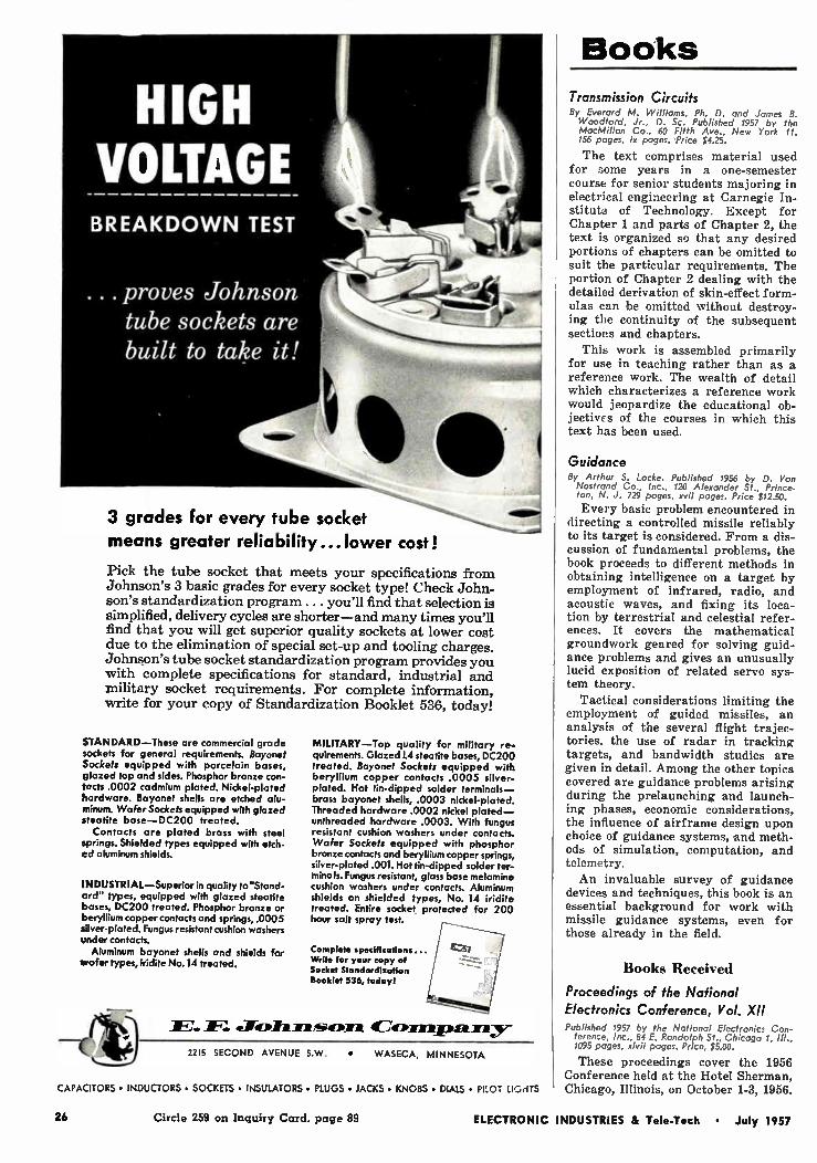
proves Johnson tube sockets are built to take it!
3 grades for every tube socket means greater reliability.. .lower cost!
Pick the tube socket that meets your specifications from Johnson's 3 basic grades for every socket type! Check John-son's standardization program ... you'll find that selection is simplified, delivery cycles are shorter—and many times you'll find that you will get superior quality sockets at lower cost due to the elimination of special set-up and tooling charges. Johnson's tube socket standardization program provides you with complete specifications for standard, industrial and military socket requirements. For complete information, write for your copy of Standardization Booklet 536, today!
STANDARD—These are commercial grade sockets for general requirements. Bayonet Sockets equipped with porcelain bases, glazed top and sides. Phosphor bronze con-tacts .0002 cadmium plated. Nickel-plated hardware. Bayonet shells are etched alu-minum. Wafer Sockets equipped with glazed steatite base—DC200 treated.
Contacts are plated brass with steel springs. Shielded types equipped with etch-ed aluminum shields.
INDUSTRIAL—Superior in quality to"Stand-cud" types, equipped with glazed steatite bases, DC200 treated. Phosphor bronze or beryllium copper contacts and springs, .0005 silver-plated. Fungus resistant cushion washers under contacts. Aluminum bayonet shells and shields for
wafer types, indite No.14 treated.
MILITARY—Top quality for military re-quirements. Glazed 1.4 steatite bases, DC200 treated. Bayonet Sockets equipped with beryllium copper contacts .0005 silver-plated. Hot tin-dipped solder terminals— brass bayonet shells, .0003 nickel-plated. Threaded hardware .0002 nickel plated— unthreaded hardware .0003. With fungus resistant cushion washers under contacts. Wafer Sockets equipped with phosphor bronze contacts and beryllium copper springs, silver-plated .001. Hot tin-dipped solder ter-mino Is. Fungus resistant, glass base melamine cushion washers under contacts. Aluminum shields on shielded types, No. 14 indite treated. Entire socket protected for 200 hour salt spray test.
Complete specifications... Write for your copy of Socket Standardization Booklet 336, today!
11E: «Jectilexasorm
2215 SECOND SECOND AVENUE S.W. • WASECA, MINNESOTA
CAPACITORS • INDUCTORS • SOCKETS • INSULATORS • PLUGS • JACKS • KNOBS • DIALS • PILOT LIGHTS
Books
Transmission Circuits By Everard M. Williams, Ph. D. and James B. Woodford, Jr., D. Sc. Published 1957 by the MacMillan Co., 60 Fifth Ave., New York 11. 156 pages, ix pages. 'Price $4.25.
The text comprises material used for some years in a one-semester course for senior students majoring in electrical engineering at Carnegie In-stitute of Technology. Except for Chapter 1 and parts of Chapter 2, the text is organized so that any desired portions of chapters can be omitted to suit the particular requirements. The portion of Chapter 2 dealing with the detailed derivation of skin-effect form-ulas can be omitted without destroy-ing the continuity of the subsequent sections and chapters.
This work is assembled primarily for use in teaching rather than as a reference work. The wealth of detail which characterizes a reference work would jeopardize the educational ob-jectives of the courses in which this text has been used.
Guidance By Arthur S. Locke. Published 1956 by D. Van Nostrand Co., Inc., 120 Alexander St., Prince-ton, N. J. 729 pages, xvii pages. Price $12.50.
Every basic problem encountered in directing a controlled missile reliably to its target is considered. From a dis-cussion of fundamental problems, the book proceeds to different methods in obtaining intelligence on a target by employment of infrared, radio, and acoustic waves, and fixing its loca-tion by terrestrial and celestial refer-ences. It covers the mathematical groundwork geared for solving guid-ance problems and gives an unusually lucid exposition of related servo sys-tem theory.
Tactical considerations limiting the employment of guided missiles, an analysis of the several flight trajec-tories, the use of radar in tracking targets, and bandwidth studies are given in detail. Among the other topics covered are guidance problems arising during the prelaunching and launch-ing phases, economic considerations, the influence of airframe design upon choice of guidance systems, and meth-ods of simulation, computation, and telemetry.
An invaluable survey of guidance devices and techniques, this book is an essential background for work with missile guidance systems, even for those already in the field.
Books Received
Proceedings of the National
Electronics Conference, Vol. XII
Published 1957 by the National Electronics Con-ference, Inc., 84 E. Randolph St., Chicago 1, 1095 pages, xlvii pages. Price, $5.00.
These proceedings cover the 1956 Conference held at the Hotel Sherman, Chicago, Illinois, on October 1-3, 1956.
26 Circle 259 on Inquiry Card, page 89 ELECTRONIC INDUSTRIES & Tele-Tech • July 1957

POLARAD
S PULSS CODED PAULTII-PULSS GE.SERATOR
Model PAP-1
Coded Multi-pulse
Generator
Generates 5 separate
pulses each with independently variable
width and delay for
missiles, beacons,
and other systems
A self-contained unit. Provides any code—one to five pulses—with com-
pletely independent adjustment for each pulse.
Any or all pulses can be time modulated. And, the Model MP-1 can be used to synchronize other equipment because of its trigger output.
The instrument is provided with internal calibration circuits — 1 micro-
second markers to check code settings. In addition, it supplies a square wave pulse, at a separate output jack,
operating at 40 to 4,000 pps. This is extremely useful for modulation and
general testing. Write to Polarad for a detailed data sheet on the Model MP-1.
SPECIFICATIONS:
lute ruai Pulse Characteristics:
No. of Channels 1 to 5 independently on or off
Repetition Rate 40 to 4,000 pps Pulse Width 0.2 to 2.0 microseconds Pulse Delay 0 to 30 microseconds
2 to 300 microseconds Minimum Pulse Separation
0.1 microsecond Initial Channel Delay
2 microseconds from sync. pulse Output Pulse Characteristics:
Rise Time 0.1 microsecond Delay Time 0.1 microsecond Overshoot less than 10% Amplitude....20 v. minimum into 100 ohms
Trigger Pulse Output:
(a)At zero time or simultaneous with any one of the output pulses.
(b) 10 volts positive and negative into 15-ohms.
External Sync Pulse:
F'ositive or negative pulse or sine wave
Pulse Time Modulation:
Frequency . 40-400 cps any or all channels Required Ext. Mod 1 volt rms min. Maximum deviation -.0.5 microsecond
ELECTRONICS CORPORATION
43-20 34th Street • Long Island City 1, New York
FEATURES:
. Provision for external pulse time modulation.
. Trigger selection at any of the code pulses.
. High level, low impedance output.
. Short rise and fall time of pulses.
. Square wave output
. Internal calibration time marker.
. Accurately calibrated delay dial.
Re/jab aintenance service th out
th u rvis an im
the Po/arad' ins omen
For private demonstration without obligation
ask for the
MORE FIELD DEMONSTRATOR
to stop al your plant
REPRESENTATIVES: Albany, Albuquerque, Atlanta, Baltimore, Boston, Chicago, Cleveland, Dayton, Denver, Englewood, Fort Worth, Kansas City, los Angeles, Philadelphia, Portland, Rochester, St. Louis, San Francisco, Schenectady, Stamford, Syracuse, Washington, D. C., Winston-Salem, Canada: Arnprior, Ontario.
Resident Representatives in Principal Foreign Cities
New York,
ELECTRONIC INDUSTRIES & Tele-Tech • July 1957 Circle 260 on Inquiry Card, page 89 27

Important Question No. 2
„
'4fr
ff9 ,."
,
ho submits the most complete laboratory reports with all custom-built delay line prototypes?
eedICORPORATION
It is a known fact that ESC Corporation is unequalled for the most complete and de-
finitive laboratory reports submitted with delay line prototypes. Every ESC lab re-
port includes submitted electrical requirements, photo-oscillograms (which indicate input
and output pulse shape and output rise-time), the test equipment used, and evalua-
tion of the electrical characteristics of the prototype. This is unmatched in the industry.
1st in sales!
1St company devoted exclusively to the manufacture of delay lines!
1St in research, design and development of custom-built delay lines!
Exceptional employment opportunities for engineers experienced in pulse techniques.
ESC CORPORATION 562 BERGEN BOULEVARD • PALISADES PARK • NEW JERSEY
28 Circle 149 on Inquiry Card, page 89 ELECTRONIC INDUSTRIES & Tele-Tech • July 1957

An Engine!, "Doodled' and Solved an
Explosive Ppodlein with FUSITE TERMINALS The problem was literally explosive. It was a pump and motor
to operate safely submerged in gasoline. The electrical
connections had to be made through a vapor-proof seal.
Two simple and inexpensive Fusite glass-to-metal
terminals did the job like this "doodle" shows.
CA Tfieif (;- PRESS F/T
ea4/Put T
Ft/SITE A SS- To - 41ErAL,
TERM/MAL
PilSàO
•••••••••1 *trey..
Dyer/met Pro teclor Neel» tel'ea//y Select wit-‘ Ale ne
-Ten
This can't be called a "typical" Fusite
case history. In our long list of success-
ful new applications, we have helped
engineer, there are none we could call
"typical".
So just keep Fusite Terminals in your
THE
4, a oltrü eimie /44(1) m or ir4 A& -,4
&live&
ose ••••••••*71,
"noodle" the next time you "doodle"
and pass your problems on to us.
We make hundreds of stock terminals
of both multiple bead and solid glass types. We're prepared to design and
make special terminals to your needs.
Write today for catalog —Dep't. U-4
FETE CORPORATION 6026 FERNVIEW AVE., CINCINNATI 13, OHIO
ELECTRONIC INDUSTRIES & Tele-Tech • July 1957 Circle 150 on Inquiry Card, page 89 29

Let the engineers who are doing it tell you
What it's like to work in a nerve center of the new industrial era
Dr. John L. Bower, Chief of our Auto-matic Industrial Controls Section, put it this way:
"Automatic electro-mechanical control systems are the eyes, ears, and brains of the second industrial revolution. At Auto-netics, we've been in the relatively young field of electro-mechanics for 11 years... making breakthroughs on many major fronts. The time was never riper for crea-tive engineers to get in on this work:' Today you can build your career on
this solid base of accomplishment, and grow forward with us as we tackle new and ever more challenging assignments.
For instance, if you are strong on servo, transistor, or digital techniques—you may qualify for a special position in the devel-opment of automatic machine tool con-trols, computers, automatic checkout equipment, bombing navigation systems.
or advanced inertial navigation systems. Two of our new developments in these
fields are: Numill— a completely transis-torized, numerical tape-directed control system for machine tools ... and Recontp —a 200 pound portable computer that has giant-computer capacity. Whatever field of engineering you enter
at AUTONETICS. you'll work in an engi-neering-management atmosphere that is conducive to your professional advance-ment. Youll enjoy research, development, and test facilities as advanced as the proj-ect on which you're working. Our engineering brochure tells the story
in more detail. It's easy to get one; just send the coupon below.
Autonetics A Division of North American Aviation, Inc.
AUTOMATIC CONTROLS MAN HAS NEVER BUILT BEFOR E
Dr. John Bower, former associate pro-fessor of electrical engineering of Yale, has been witn Autonetics 7 years ... 5 years in charge of automatic machine tool controls development. Last April he was promoted to automatic industrial controls section chief.
«Milk 01101111.11
Leo Noe, MSEE-Yarle, joined Autonetics in 1951 os research engineer in auto-pilots. In '53 he was promoted to super-visor. Lea's responsibilities included development of aircraft yaw and pitch dampers. In '56 he made group leader in automatic checkout.
Mr. A. N. Banning, AUTONETICS, Dept. 353, El-7, 9150 E. Imperial Hwy., Downey. California
Dear Mr. Denning: Please send me AUTONETICS' engineering brochure. I am interested in the following fields. (check one or more)
Guidance D Fire Control III Computers D Flight Control D Automated Machine Control D Systems Analysis D Test Equipment D
Name
Degree (s)
Experience
Home Address
Home Phone
30 Circle 151 on Inquiry Card, page 89 ELECTRONIC INDUSTRIES & Tele-Tech • July 1957
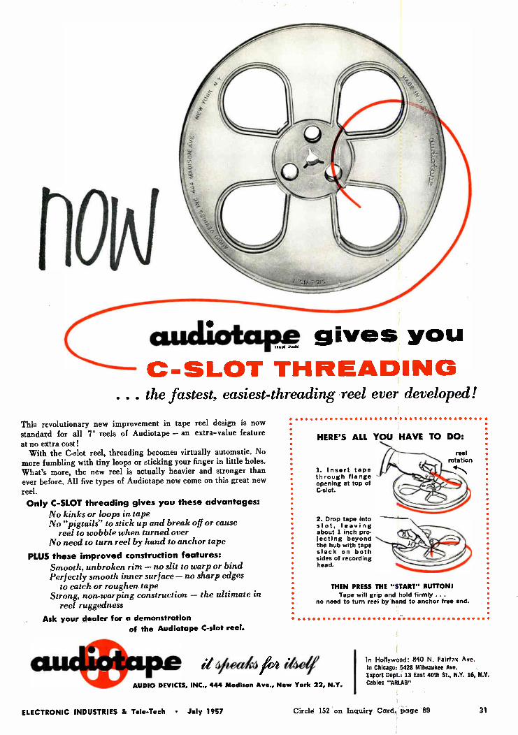
CUlearliallreaen K.« gives you
C-SLOT THREADING ... the fastest, easiest-threading reel ever developed!
This revolutionary new improvement in tape reel design is now standard for all 7" reels of Audiotape — an extra-value feature at no extra cost! With the C-slot reel, threading becomes virtually automatic. No
more fumbling with tiny loops or sticking your finger in little holes. What's more, the new reel is actually heavier and stronger than ever before. All five types of Audiotape now come on this great new reel. Only C-SLOT threading gives you these advantages:
No kinks or loops in tape No "pigtails" to stick up and break off or cause
reel to wobble when turned over No need to turn reel by hand to anchor tape
PLUS these improved construction features:
Smooth, unbroken rim — no slit to warp or bind Perfectly smooth inner surface — no sharp edges
to catch or roughen tape Strong, non-warping construction — the ultimate in
reel ruggedness
Ask your dealer for a demonstration of the Audiotape C-slot reel.
HERE'S ALL YOU HAVE TO DO:
reel rotation
1. Insert tape through flange opening at top of C-slot.
2. Drop tape into slot, leaving about 1 inch pro-jecting beyond the hub with tape slack on both sides of recording head.
THEN PRESS THE "START" BUTTON! Tape will grip and hold firmly ...
no need to turn reel by hand to anchor free end.
auc DIO elPDEVICEeS,
vieetkfre AU INC., 444 Madison Ave., New York 22, N.Y.
In Hollywood: 840 N. Fairfax Ave. In Chicago: 5428 Milwaukee Ave. Export Dept.: 13 East 40th St., N.Y. 16, N.Y. Cables "ARLAB"
ELECTRONIC INDUSTRIES & Tele-Tech • July 1957 Circle 152 on Inquiry Card, page 89 31

surface barrier transistors from SPRAGUE 4W.Eff26.1111M4
2N344/SB101 for Medium Gain
Amplifiers
Min. Typ. Max.
life 11 23 83
fmax 30 45 —
• actual Lori size
2N346/SB103 for High Frequency
Oscillators
Min. Typ. Max.
hf. 10
fmax 60 90
IN VOLUME PRODUCTION
2N345/SB102 for High Gain
Amplifiers
Min. Typ. Max.
fife 25 40 110
fmax 30 45 --
2N240/S65122 for Computer
Switching
Min. Max.
hfe
fmax
16
30
80
yew/ For general high frequency applications, and for high speed computer switching circuits, design around
Sprague surface barrier transistors. They are available now in production quantities from a completely new,
scrupulously clean plant, built from the ground up espe-cially to make high quality semi-conductor products.
The four transistor types shown are the most popular. Orders for these units are shipped promptly. What's
more, surface barrier transistors are reasonably priced.
High quality and excellent electrical characteristics make them an economical solution to many difficult circuit requirements.
WRITE FOR COMPLETE ENGINEERING DATA SHEETS ON THE TYPES IN WHICH
,̀OU ARE INTERESTED. ADDRESS REQUEST TO THE TECHNICAL LITERATURE
SECTION, SPRAGUE ELECTRIC CO., 233 MARSHALL ST., NORTH ADAMS, MASS.
TRANSISTORS • RESISTORS • MAGNETIC COMPONENTS
CAPACITORS • INTERFERENCE FILTERS • PULSE NETWORKS
HIGH TEMPERATURE MAGNET WIRE • PRINTED CIRCUITS
SPRAGUE® the trademark of reliability
32 Circle 153 on Inquiry Card, page 89 ELECTRONIC INDUSTRIES & Tele-Tech • July 1957

ELECTRONIC INDurVirrellES
TELE-TECH
ROBERT E. McKENNA, Publisher
Standardize
Wired-TV
• BERNARD F. OS 3 AHR, Editor
Like other things surrounding the rapidly-expanding field of wired TV, the present name—"Closed circuit TV" (CC-TV), just grew. At present the uses include: industrial, scientific, en-tertainment, sports, educational, busi-ness, community and other broadcast-ing services, exhibition of Motion Pictures in the home etc. Some day every modern home will boast of its own CC-TV system, with a camera at the front door so that the visitor can be "scanned" before he is admitted.
A quick glance over the field shows
that TV transmission over wires can be at rf or at vf frequencies. Distances covered can be from a few feet to 3,000 miles or more across our nation.
There are less than a dozen well-known CC-TV manufacturers. Each has designed along different but ortho-dox lines. The majority have only one item in common, a "Vidicon" tube in the camera. The employment of a sin-gle system, which is a must for TV broadcasting, is not necessary in CC-TV. Some use the FCC 525-line stand-ard; other supply 245-line, non-inter-laced systems which usually cost less.
There has been some standardization but much more is needed before a great deal of equipment is in the hands of users. The usual good reasons for standardization apply. In particular we need it to retard obsolescence, lower manufacturing costs, improve inter-changeability, aid installation and ser-vicing, and protect the customer by offering more uniform specifications.
What could be standardized? First, take Community Systems. Here char-acteristics such as transmission line impedance, voltage levels, etc. should be discussed. Second, for commercial, scientific and educational installations, where the user is the owner, the matter
of system, number of lines, interchange-ability and the like is important. Third,
in the case of business and sales con-ferences, where the customer goes to
the firm who owns equipment (which usually includes large screen projec-tors), leases the common-carrier net-work and often provides programming and director's services (very impor-tant), a different kind of standardiza-tion is needed. It is standardization of business practices and to a certain de-gree standardization of proposals out-lining definitely just what services will be furnished.
Why do we think wired television is
in an expansion era? The number of business conferences have increased 300% in 1956 over 1955. Large com-
panies are finding out that their scat-tered, key personnel can be thus linked together at a fraction of the travel cost
required to assemble at a resort con-vention site. Community TV systems are growing steadily in numbers. As yet we do not know what to expect from the newly-proposed home movie
service over wires. For certain types of education which require the eye of
the student to be close to the demon-stration, such as dentistry or surgery, we had the pleasure of seeing, at the world's most elaborate installation at
the Walter Reed Army Medical Center, Washington, with its color equipment,
the proof that such systems provide large-class viewing not possible by other means. On every hand we see industrial and scientific wired TV being used for more and more pur-poses. When the "packaged" installa-tion of a small camera and a receiver, which may replace one or more watch-
men now patrolling guarded property, costs around $1,000, what manager would not be interested? With most of our TV broadcasting stations now li-censed and operating, it is natural for the manufacturers of such TV equip-ment to look toward this expanding
field.
ELECTRONIC INDUSTRIES & Tele-Tech • July 1957 33

1.6
15
9 14 1.3 z
rr 1.2
Q LI
d
11
niuCONTINUOUS D SCHARGE in Rd
I
UIHhIhí 1111linhall 111110 Bab-- junk miim
'jig% Ili moan -11111 O
TIME (Hoons) Fig. 1: Modern Size "D" cells have improved characteristics.
100 1000
1.6
131.5 o > 14
n 13 u re 5 L2 o bi
union DISCHARGE 6 HOURS PER p.4)' 7°.
Mal "*M!iiii:E1111iii:ii;;ISIME111011 11111111111111 154012e11116:1 111111110•1111111111111Cillrgle min 11111111111111111•111111111M11111 111111.1 11111111
10 T ME (HOURS)
100
Fig. 2: Intermittent constant-current life of "D" dry cell.
Transistorized and miniaturized equipment have such low power requirements that batteries have become competitive with other power sources. The special requirements of air-borne and under-water missi/es have spurred the development of many different battery types, each with unique advantages. Shelf life and service life have extended far beyond the capabilities of pre-war mode/s.
New Horizons
For Battery Power
rr HE steady development of primary cells has, in recent years, been surmounted by a rapid spurt
in research and development of batteries to meet the needs of miniature and transistorized equipment. Great improvements in shelf life and capacity have been made, as well as improvements in power-to-weight characteristics. New shapes and manufactur-ing techniques, combined with improved active in-gredients and packaging materials give us better per-formance and greater economy. The large volume of battery sales makes possible the production of an ever increasing variety of shapes, voltages and capacities for specialized applications. The electronic engineer of today can choose from a wide variety of batteries for his new electronic equipment.
The modern dry cell was born in 1888, when Gassner modified the LeClanche cell to produce the first prac-tical dry cell. Those first cells, while embodying all the basic principles of present cells, had limited life and capacity. Our "flashlight" was originally just exactly that, because the first small dry cells could produce the necessary power only in short flashes.
Steady Improvement
Today's descendant of the original carbon-zinc dry cell is vastly improved. Back in 1901 the Government
By ARNOLD E. LOOK, JR. Assistant Editor,
ELECTRONIC INDUSTRIES & Tele-Tech
1000
tested early No. 6 dry cells and they showed an aver-age 35% deterioration during 6 months on the shelf. By 1916, this had dropped to 25%, still a severe limi-tation. In 1934, the average No. 6 cell was deteriorat-ing only 7% in six months. A series of tests in 1951 showed that the industry had improved the cell to such a degree it would deteriorate only a low 2% in half a year.
The same sort of improvement over the years can be traced for that work horse of the dry cells, the standard Size D flashlight cell. National Bureau of Standards ran a standardized 4-ohm intermittent test on a large batch of D cells in 1910. In those days the D cell gave 260 minutes of service. By 1935 this had been nearly tripled to 750 minutes, and a later test series, in 1951, showed average service of 800 minutes —and some types went over 1,000 minutes.
Flat Cells Automated manufacture, and decreased weight and
volume have resulted from the development of flat cells. These new cells consist of a sandwich of man-ganese dioxide mix between flat zinc and carbon elec-trodes. In one form, these flat cells are assembled by machine and wrapped in an airtight pliofilm envelope which is then heat sealed. In another version, a
ELECTRONIC INDUSTRIES & Tele-Tech • July 1957

plastic case is shrunk onto the machine-assembled cell. Advantages of these types of cell include automated manufacture and elimination of inter-cell leakage. Ex-tensive use of plastics has reduced weight and volume. The active ingredients are essentially unchanged, but more refined materials have increased shelf life and capacity of the cells.
Eie chic Waic
A striking example of convergent design efforts by equipment and cell engineers is the Hamilton electric wrist watch. The watch itself is a tribute to Hamil-ton engineering; its motor uses micro-coils wound of nearly invisibile .0006-in. wire. More than ten years
Fig. 5: Plastic-cased "wafer cells" give design freedom for Burgess Batteries. Fig. 3: New design concept of Elgin Indium
cell permits variety in shape and size.
Mercury Cell
The mercuric oxide zinc potassium hydroxide pri-mary cell, commonly called the "mercury cell" was developed during the early part of World War II. Since that time it has come into increasing use for both military and civilian applications. As in other electrochemical cell systems the electri-
cal energy of the mercury cell is produced by a reac-tion between the anode and the depolarizing cathode aided by the cell electrolyte. An anode pellet of pure amalgamated zinc is used, with a depolarizing cathode consisting of high purity mercuric oxide to which small amounts of other materials are added to improve physical and electrical characteristics. The potassium
Fig. 4: Mallory's mercury cell design includes a filtered relief vent space. between cases.
of design and development effort went into the new watch. It was made possible, however, only with the aid of concurrent development of a miniature cell which could power the watch for more than a year —about 125 million cycles of the motor.
Such a cell is National Carbon Company's new Eveready W-307. This tiny cell, weighing only 1/20 ounce is capable of providing 32 watt-hours per pound. Nominal rating of the cell is 1.5 volts, and it is rated at a total of 60 milliampere-hours to a 1.3-volt cutoff. Recommended average current is 60 ma or less. It employs highly refined standard dry-battery ingre-dients, and measures only .440-inch diameter by 1/ inch thick. It is made completely of non-magnetic materials.
Fig. 6 This Everyready W-307 cell is cap-able of driving a wrist watch for a year.
hydroxide electrolyte, with added zincate, provides a high degree of stability and limits the evolution of hydrogen during shelf storage and during normal dis-
charge. During abnormal conditions, such as reverse cur-
rents or short circuits, excessive gas can be generated within the cell. This need be no serious problem, however, due to the use of double-jacketed cells in which venting can occur in the space between the internal cell container and the outer steel jacket. A safety absorbent ring is provided so that any cell elec-trolyte carried into the space will be retained. Cor-rosive materials are thus prevented from escaping with gas through the vent hole at the bottom of the outer steel jacket.
Fig. 7: The new Hamilton electric wrist Fig. 8: Three strands of .0006-inch watch has fewer parts than a wound watch, watch-motor wire can be passed through
a pierced hair.
ELECTRONIC INDUSTRIES & Tele -Tech • July 1957 35

Fig. 9: Mallory's Solidion solid—elec-trolyte cells are rated at 200v/cu in.
Primary Cells (Continued) Life
Mercury cells display a variety of advantageous characteristics. One of the more important is long shelf life. A typical cell stored at room temperature will retain over 93% of its capacity after a twelve-month storage time. Low internal resistance gives good regulation under load.
Stability Voltage stability is such that the cells are widely
used as secondary voltage standards. The cells can withstand momentary short circuits with no perma-nent damage, and almost complete recovery of full open circuit emf within minutes. Small reverse cur-
indium cell are similar to those of the mercury cell, but important advances are claimed for the new cell.
The most common commercial disadvantage of pri-mary cells—parasitic reaction during storage and dis-charge—has been further minimized in the indium cell, giving a shelf life of at least one year and up to 2 years of service life. Other important advantages are: dimensional stability during storage or dis-charge, a sealed plastic case which eliminates leakage, high insensitivity to a wide range of ambient tem-peratures, essentially constant discharge voltage dur-ing service life, low weight and volume, and adapt-ability to unusual shapes.
Present cells deliver an open circuit voltage of about 1.15 volts, but recent studies show a change can be
Fig. 10: GE's solid - electrolyte cell can deliver 8 microamperes flash current.
rents can be tolerated without adverse effects. Tem-perature stability is high, emf varies only slightly over a wide range of temperatures. The cells are used suc-cessfully in sub-surface geological survey instruments where operation is required at temperatures which may briefly exceed 250°F. Many different shapes and sizes of mercury cell are manufactured, providing a wide variety of batteries and power packs.
Indium Cell Among the new cells recently announced is the
Elgin indium cell. This cell was developed specifically for use in electronic watches being developed by Elgin National Watch Co. Electrical characteristics of the
Fig 11: Life of the Eveready solid-elec-trolyte cell is estimated at "decades."
made in the cathode material to produce an open cir-cuit voltage of 1.37 volts. A half-penny-sized cell is now being produced by Elgin. Success of this first cell has led Elgin to consider opening production of the cells to any desired size or shape, a development of extreme interest to designers of micro-miniature electronic equipment.
Acknowledgments 1. Technical information on the carbon-zinc dry cell was pro-vided by Burgess Battery Co., Freeport, Ill. ; P. R. Mallory & Co., North Tarrytown, N. Y., National Carbon Co., New York 17, N. Y.; Radio Corp. of America, Harrison, N. J.; and Ray-0-Vac Co., Madison 10, Wisc. 2. Characteristics of the mercury cell were provided by P. R. Mallory & Co., North Tarrytown, N. Y., and National Carbon Co., New York 17, N. Y.
Nuclear Cells
B ETA-RAYS emitted by some radioactive isotopes consist of a stream of high-energy electrons. An
extremely simple, rugged cell can be constructed by coating the radioisotope on a central emitter electrode, and collecting the electrons by an outer conducting member. This technique has been developed and cells using this principle are available. These cells are capable of producing a very high voltage if enough time elapses for the charge of electrons to build up. With a sufficiently large capacitor in parallel with the nuclear cell, sufficient charge can be stored to operate low powered or one-shot devices. Such cells and cell-capacitor combinations are used for biasing elements, reference sources, radiation measurement,
timing circuits, and a number of classified military applications.
Beta-Current Among the more attractive features of the Beta-
current cell are rugged construction, elimination of corrosive elements, light weight, high reliability, im-
Fig. 12: Nuclear energy gives current in the Elgin-Kidde Cell.
SECRET OF ATOMIC CELL IS PRODUCTION OF "ATOMIC 'Jew. IN HEART OF BATTERY
PROMETHIUM I4T ATOM
EXPLODING ATOMS PRODUCE MILLIONS Of TINY LIGHT RAYS WHICH ARE SOAKED UP BY SILICON DIODES AND TRANSFORMED INTO USABLE ELECTRIC CURRENT
WIRE LEADS OR CONNECTORS
36 ELECTRONIC INDUSTRIES & Tele-Tech • July 1957

munity to short-circuit damage, linear self-charging rate, and a combined operational and shelf life of as much as 25 years. Pressure, temperature, and accelera-tion extremes can be tolerated by the cells.
C-P-D Cell
Several other effects of radioactivity can be utilized to produce useful voltages and currents. One of these, the contact-potential-difference cell, has received con-siderable attention in government-sponsored research. In this cell, maximum output voltage is the contact potential difference. These cells have dissimilar elec-trodes separated by a heavy gas diffused with a radio-active gas such as tritium. Radiated Beta-particles ionize the gas, and the oppositely charged ions migrate to opposite electrodes, where the ions are neutralized.
Secondary Emission
Other possible configurations include cells in which primary emissions bombard a secondary material from which a larger number of lower energy elec-trons would emit, a thermopile using a radioactive heat source, and direct irradiation of a semiconductor junction. This latter is among the more attractive, but early experimenters soon found out that radiation gradually destroyed the junction by altering the crys-talline structure of the semiconductor.
Nuclear-Light-Cell
Recently, however, a novel configuration has been devised which eliminates this problem. The new cell mixes a radioactive substance with a phosphor which both absorbs the destructive radiation and at the same time converts the radioactive energy to light. A photo-diode bordering the radioactive light source then converts the light to useful electric energy. As presently conceived, the light source consists of a mix-ture of finely divided phosphor and an oxide contain-ing about 41/2 curies of Promethium 147, one of the more abundant nuclear fission products. This amount of radioactive substance creats a cell with a nominal power output of 20 microwatts when new, decreasing to 10 mw after 21/2 years, and reaching a level of 5
mw after about five years.
Phosphors
The phosphor used contains cadmium sulphide or mixtures of cadmium and zinc sulphides. These phos-phors emit in the red and infra-red region, which is efficiently converted by the modified silicon solar cells. An interesting design feature of some of the present developmental cells is the use of four semicircular
silicon photo-diodes so that • output voltage can be varied from about 1/4 volt to 1 volt with no change in total power. Economic feasibility of the cell is enhanced by the fact that in large quantities, Pro-methium 147 is expected to cost approximately
50¢/curie.
Solid Electrolyte One of the most recent newcomers to the battery
field is the "solid electrolyte" battery. Production techniques have been devised to form the basic cell— electrodes and solid electrolyte—in extremely thin
(Continued on page 119)
5 -
N
I WATT HOURS PER CUBIC INCH I
I
I
I
I
te CO
Ni0KEI- - A hiltj
...,.. Oi .05 0.1 I.0 lu
HOURS 0 SCHARGE
Fig. 1: Typical power/pound curves for light-weight power cells.
Power Cells Compared OFTEN, the demands made on a battery are such
that rechargeable secondary cells are an economic necessity. Three types are used most frequently for mobile and portable equipment: lead-acid, nickel-cadmium, and silver-zinc cells.' These cells all have the ability to provide large amounts of power at high discharge rates. In addition to this, each cell has unique properties which lead to its use in certain applications. Even the oldest of these, the lead-acid cell, is the subject of research aimed at further im-provement of its characteristics. New alloying mate-rials for the lead grid for this cell have been intro-duced. An analysis of recent developments in the lead-acid cell is presented by Dr. Howard J. Strauss
on Page 39.
Nickel-Cadmium
The nickel-cadmium alkaline battery has been on the market for nearly fifty years.2 Among the im- . portant features of this cell is the alkaline electrolyte, which permits the use of sturdy steel grids and cases. In the original construction, still used extensively, the active nickel and cadmium oxides are enclosed in finely perforated steel pockets in the grid structure.
Low Gas Rate The potassium hydroxide electrolyte solution serves,
in effect, only as a conductor, and maintains constant specific gravity and conductivity at all conditions of charge. Because of this, there is no variation of resistance in the electrolyte during charge and dis-charge of the cell. The electrolyte serves only to trans-fer oxygen between negative and positive plates dur-ing charge and discharge. Gas is evolved almost ex-clusively as a result of electrolysis during extremely high charge rates or during overcharge periods.
Temperature Typically, the cells will take a charge at tempera-
tures from —65° to ±165°F. They can be stored without damage in any state of charge, including com-plete discharge. Long life and good voltage regula-tion during discharge are other important features. These cells find large use for standby power and con-trol, signal and alarm systems, laboratory de supply, and emergency lighting. Transistor engineers now use tiny nickel-cadmium cells as filters for smooth-ing ac-operated de power supplies and as power sources in conjunction with solar cells.5
ELECTRONIC INDUSTRIES & Tele -Tech • July 1957 37

Fig. 2: A nickel - cadmium cell powers this underwater "Power Diver" made by the Link Aeronautical Corp., Endicott, N. Y.
Power Cells (continued) Sintered Plate
During the past ten years, extensive research and development work has led to a new type of plate for the nickel-cadmium cell. This is the "sintered plate" now used in many commercial cells. These plates are formed by sintering nickel powder to a fine-mesh nickel screen. This produces a highly porous plate within which the active materials can be electro-chemically deposited, giving improved characteristics. The thin plates, separated by synthetic fabric, can be closely packed to produce a cell with small volume and great resistance to shock and vibration. Nickel-cadmium cells can be used with constant voltage, con-stant current, stepped constant current, or float charg-ing systems. Optimum charging occurs when the cell is given a charge equal to 140% of rated capacity within a maximum of three hours.
The inherent capabilities of the sintered-plate nickel-cadmium cell are revealed in recent tests made at the Naval Research Laboratory.3 The study shows that the sintered-plate construction makes possible a cell which will give satisfactory performance at low temperatures, is capable of being fully charged in less than one hour, and can be discharged in a few minutes without excessive capacity loss. Capacity loss during a 90-day stand was on the order of 20 to 25 per cent at room temperature and considerably less at 0°F. NRL reports that as cycling continued be-yond 700 cycles, there was still no indication of the approach of the end of cycle life. The electrolyte re-mained clear, there was no evidence that the plates had shed any active material after this series of tests including severe cycling under adverse conditions.
Fig. 4: Triggered gas generator injects elec-trolyte to energize Cook battery.
Fig. 3: Even skin-divers use power cells, in this electric underwater propulsion unit. Shielded propeller is in bow.
Silver-Zinc
A vigorous contender among the power cells is the silver-zinc cell. Much of the demand for this cell is based on two factors: the high capacity in watt-hours per unit weight, and the high current density at which this power can be produced. Research is being ac-tively pressed to bring still further improvement of these characteristics.4
High Rates The cell uses silver and zinc as active materials, and
potassium hydroxide for electrolyte. During cell dis-
charge, silver oxide is reduced at the positive plate and zinc is oxidized at the negative plate. The cells are capable of extremely high discharge rates without serious voltage drop; continuous high rate discharges are limited primarily by the heat evolved.
Light Weight
Low weight, low resistance, and high resistance to shock and vibration make the silver zinc cell particu-larly suitable to aircraft and missiles. In addition to these advantages, the cell evolves little or no gas dur-ing discharge, and is thus operable in any position. Cells now being manufactured include postage-stamp-sized cells rated at 0.1 ampere-hour, and cells rated at 300 ampere-hours. Experimental cells capable of several thousand ampere-hours have been designed.
"One Shot" Use
In addition to use as a secondary, or rechargeable cell, the silver-zinc cell can also be used as a primary, or "one shot" power supply. In one refinement, these cells are assembled with a built-in activating mech-anism which forces electrolyte into the charged cell
(Continued on page 118)
Fig. 5: Tiny Yardney silver - zinc, less Fig 6: This Exide silver - zinc battery than 4/5 oz., cell can deliver 45 amperes. can be stored dry - charged until needed.
38 ELECTRONIC INDUSTRIES & Tele-Tech • July 1957

New Grids Improve
Lead-Acid Cells A familiar standby power source for communica-tions centers, the lead-acid cell, has undergone steady improvement over the years. Now, al-loyed grids provide a choice of properties for
different applications.
By DR. HOWARD J. STRAUSS Chief Product Engineer
Exide Industrial Div. Electric Storage Battery Co.
42 S. 15 St., Phila. 2, Pa.
IN the Electronic Industries, the lead acid battery continues to be the standard for stand-by power in
alarm, signal, and all types of communication. In these areas, the lead acid battery finds its greatest use as a stationary installation. For stand-by power, the lead acid battery can economically provide large re-serve capacities with an absolute maximum of re-liability and a minimum of maintenance. In addition to this, the lead acid battery can serve as an excellent voltage stabilizer, frequently forming an actual func-tioning component of the electronic system. It also can be used to provide switching power and relay stability. In this regard, the fact that the state of
Fig. 1: New grids, plastic cases, and new manufacturing techniques result in improved perform-ance from tiny stor-age batteries such as this.
Fig. 2: This giant cell powers phone exchanges and submarines.
charge and general condition of the battery can be readily checked by specific gravity measurements of the electrolyte is of particular value.
Calcium Alloy
The fundamental lead acid system has undergone a steady, continuous development and improvement, un-til today, such batteries have a high degree of effi-ciency, both from the electrochemical and physical de-sign viewpoints. Notable among some of the more recent advances is the introduction of calcium alloy grids. This alloy, which is essentially a pure lead stiffened by a very small addition of calcium, elimi-nates certain impurities, which contribute to high charge maintaining currents. In this way, grid cor-rosion is minimized, as is water consumption, and the ultimate life of the battery is increased while the maintenance requirements are minimized. Calcium alloy batteries are now fully in production in a wide variety of sizes, but all are designed principally for emergency stand-by power and voltage stability, since this system is not at its best under repetitive deep cycling.
Lead-Antimony
Where some cycling is a routine requirement, and battery systems are frequently called upon to supply a variety of minor DC requirements in communica-tion and signal installations of all types, the anti-monial-alloy grid battery, or the Planté type, are recommended. Particularly where long life is re-quired, the Planté, or Manchester, battery has been improved even over its former performance by the use of special grid alloys particularly those containing arsenic and silver. Through continuous research, suit-
(Continued on page 118)
ELECTRONIC INDUSTRIES & Tele-Tech • July 1957 39

SECOND STAGE BURNOUT
LU
LJ
INITIATE 3RD STAGE SPIN: SEPARATE 2ND STAGE
\ OPIIMUM TRAJECTORY 'N
co\‘‘\*
FIRST STAGE BURNOUT AND SEPARATION
01 \CAL FLIGHT
cree FLIGHT
Telemetered Data Checks
Vanguard Flight
A Vanguard Viking test needs up to 200
measurements, including data from highly cor-
rosive fuels. Engineers are meeting the chal-
lenge with new components and techniques.
By F. W. PHALEN Director, Instrumentation Staff
Glenn L. Martin Co.
Baltimore 3, Md.
THIRD STAGE THIRD STnAkiGE BURNOUT &
IGNITION SEPARATION
SPIN STABILIZED SATELLITE ORBIT
VELOCITY 25,000 FT/SE ALTITUDE 200-400 MILES RANGE 1500 MILES TIME 10 MIN. AFTER
LAUNCHING
IlLIGHT testing for the earth satellite program be-gan on December 8, 1956, when a Navy-Martin
Viking rocket arched 123 miles into the upper atmos-phere from the Air Force Missile Test Center at Patrick Air Force Base, Florida. Additional test vehicles of increasing refinement will be fired in the months to come, paving the way for man's first full-dress attempt to place a satellite in orbit around the earth.
Problem
Vanguard mission requirements are novel and tough, and the instrumentation task reflects them. We are shooting for very high altitude—the satellite launch point is 300 miles up. Velocity is another chal-lenge. The 22-pound spherical payload must be ac-celerated to about 17,500 miles per hour if it is to stay in its prescribed orbit. The most exacting de-mand, however, is for precise control. At the time it is injected into orbit, the satellite must be travel-ing a course that roughly parallels the curve of the earth with angular deviation of no more than 2.5 degrees.
Vehicle
These orbiting conditions of altitude, velocity, and control are brought about by the successive impulses of a three-stage rocket, designed and built by Martin under management of the Naval Research Laboratory. Joined in tandem at launch, the combined stages mea-sure some 72 feet in length and 45 inches at the widest diameter. With fuel, the vehicle weighs about 22,000 pounds. As they complete the various trajectory phases, the stages drop off in numerical order to de-crease weight.
Stage one is an improved Martin Viking rocket pow-ered by a General Electric rocket engine operating on kerosene and liquid oxygen. An Aerojet General en-

gifle burning unsymmetrical dimethyl hydrazine (UDMH) and white fuming nitric acid (WFNA) drives the second stage of Vanguard, which houses the inertial reference guidance system and the magnetic amplifier control equipment. The third stage is a solid propellant ballistic rocket. The satellite vehicles will carry a minimum of in-
strumentation. But the test vehicles which precede them are heavily instrumented for 150 to 200 mea-su rements.
Test Instrumentation
With this array of internal instrumentation we are evaluating the design criteria of the vehicle and the performance of all components and systems. The vital control system comes in for special attention.
Fig. 1: Preparing the Vanguard test vehicle for a night launching
First- and second-stage engine performance is being analyzed, and checks are being made of separation techniques of the various stages and methods of start-ing the second and third stages at extreme altitudes. The kinds of information sought with internal in-
strumentation are indicated in Fig. 3, while Fig. 4 is a breakdown of the various engineering activities requiring measurements. External instrumentation, also used extensively, includes radar and doppler track-ing for trajectory and velocity measurements, which must be highly accurate. Good optical coverage is provided as well.
Data Channels
Data obtained by rocket-borne instruments are sent back to recording stations by up to four telemetering transmitters of these types: PWIVI/FM, providing 43 channels at 20 samples per second; PPM/AM with 15 channels, at 312.5 samples per second, subcommutated according to demand at lower rates; and FM/FM with 12 continuous data channels. (See Fig. 2 for details.)
Transducers
Potentiometric - type sensing elements are used wherever possible because the telemetering input re-quirements generally fall between 0 and 5 v. dc. Thermocouples, strain gauges and inductance pick-ups are avoided. They involve black boxes and as-sociated circuitry. The job of converting to a usable 0 to 5 v. can be a headache, not to mention the severe weight penalty for signal converters.
Guided by our Viking rocket experience, we set out to find new measuring techniques for the temperature and pressure of liquid oxygen and hydrogen peroxide in the first stage. Both are dangerously explosive when mishandled. Second-stage propellants, however, posed the knottiest problems. White fuming nitric acid used as oxidizer, is highly corrosive and will at-tack most metals vigorously. Among those showing the greatest corrosion resistance are titanium, alumi-num and stainless steel. Both WFNA and second-stage fuel (UDMH) are highly toxic, and present an
explosion and fire hazard. Understandably, we found no commercially avail-
able transducer that would measure these media satis-factorily. The need was filled by Rahm Instrument Company in an instrument development program.
(Continued on page 77)
Fig 2: Vanguard utilizes three methods of telemetering information
I tem
, «
. , GNATION
NO. OP DATA CHANNELS
SAMPLING HATE PER CHAN .NEL
PWMIFIid
(PULSE-WIDTH MODIa.ATION) 43 20 SAMPLES PER SECOND
PPM/AM
(PULSE POSITION MODULATION)
IS 312.5 SAMPLES PER SECOND •
PM) PM
(FREQUENCY MODULATION) CONTIN1.1()IIS

What's New . .
"Molded"
Circuits
A NEW method of producing printed wiring board, said to
eliminate one of the most impor-tant bottlenecks to the mass pro-duction of printed circuits, has been developed by Rogers Corpora-tion, Rogers, Conn., producers of non-metallic specialty materials.
Uncured Stock The basis of the new process is
a phenolic impregnated cellulose sheet material. The material can be cured and formed into three dimensional shapes, providing far greater design flexibility than has been possible by the use of stand-
ard phenolic laminates and meth-ods of producing printed circuits.
No Etching The new manufacturing process
eliminates the etching or plating processes required with standard methods, thus removing one of the most serious obstacles to the eco-nomic mass production of printed circuits. In addition, the new method permits the molding-in of three-dimensional effects at the same time the circuit itself is molded.
Hole concentration can be twice that of punched XXXP parts and can be molded at lower costs and with less difficulty. Molding also allows holes to be tapered or step-ped in depth, adding to freedom of creative designing. In addition, the Rogers technique forms a resin skin seal over all edges and hole walls, significantly reducing mois-ture absorption.
3-D Shapes
Supplied uncured, the • materials can be molded into three-dimen-
•
Method of mass producing printed circuits by the molding method developed by Rogers Corpo-ration, Rogers, Conn., is shown in this picture. Top, copper punched into the molding board; center, pattern on molding board with excess copper stripped away; bottom, th a molded circuit. This circuit is designed for an automotive radio part.
sional shapes, with holes for com-ponent lead insertion. Difficult fabrication, common to standard laminates, is thereby eliminated.
Several processes have been adapted by Rogers for producing circuits to meet various require-ments, including a die stamping process in which an adhesive-backed continuous copper strip is stamped into the molding board. Since the board serves as the cut-ting edge and female die, signifi-cant economy in tooling is achieved. The punch impresses the copper
below the surface of the board, ad-hering those parts which will form
the circuit. Excess copper is strip-
ped away prior to molding and sal-
vaged as scrap. Standard com-pression molding techniques are used to complete the circuit. Low-cost tooling methods for making the molds have been devised.
Low Cost
Other advantages claimed for the
new method are low initial invest-ment in equipment, economy of op-eration, adaptability to various molding techniques to meet user need, close control of product qual-ity, and consistency of product quality.
(Continued on page 100)
42 ELECTRONIC INDUSTRIES & Tele-Tech • July 1957

Precision Cutter for Short Iron Wire
By J. A. Price and P. L. Kerles
r 10 produce short lengths of soft wire with a 1/16-inch tol-
erance, a unique and simple wire cutter has been developed at Sandia Corporation in Albuquerque. The new device improves on the tol-erance permitted by using jigs and reduces the handcutting time for each operation from six hours to 20 minutes.
While developing a special pur-pose HV transformer, Sandia found a need for a more compact, lower-loss core material. No. 22 an-nealed soft iron wire in short lengths was considered best. When suppliers were unable to provide 11/2-inch and 2-inch lengths to ± 1/16-inch tolerance, with no bend of angle exceeding 10 percent, Sandia built its own wire cutter, which actually operates within 1/32-inch length tolerance.
The cutter operates as follows: wire is pushed through the guide tubing until it actuates a micro-switch lever and simultaneously comes to rest at the length-deter-mining bumper. The microswitch
Fig. I: When wires are fed into this sole-noid-operated cutter, it shears short pieces to within 1/32 inch.
WIRE GUIDES
CUTTER BLADE
energizes a solenoid which pulls the cutter blade upward, cutting the wire against the hardened shear sleeve.
Normally, because of upward mo-mentum of the wire on being sheared, it would bend. However, bumpers counteract this tendency. As the solenoid releases the cutting blade the straight pieces of wire, as pictured, fall downward. The microswitch lever then springs back to the open position against a bumper until the sequence is re-peated.
• Sandia Corp., Sandia Base, Albuquer-que, N. M.
SOLENOID
LENGTH
DETERMINING BUMPER
WIRE, GUIDE
SHEAR SLEEVE
CUTTER BLADE
WIRE STRAIGHTENING BUMPER
M ICROSWITCH LEVER
Fig. 2: In this sic e view of the precision cutter, we see the wire-straightening bumper which prevents bending of the wire when cut.
DEIONIZE SWITCH
40K
le" ADDITIONAL STAGES
(PART OF RELAY RELAY MULTIPLE FIXTURE CONTACTS SECTION SWITCH)
HI POT
CONTINUITY
, ENERGIZED
¡DE-ENERGIZED
(PART OF MULTIPLE SECTION SWITCH)
Q EVERAL years ago the military electronics division of the Mag-
navox Company began an informal program to minimize construction of specilaized test equipment. This is a familiar pattern, of course. Government contracts these days are for smaller quantities and com-petition is far keener. A piece of equipment which is good for only one part is an expensive luxury. For general purpose relays there had been two approaches—either a specialized black box, or a lash-up of meters, power supplies, con-tinuity indicators, and hipot test sets. Testing with a specialized test set can be run faster and with less skilled labor than the lab bench
Relay Test Set
Fig. I: Continuity circuit of the general purpose relay acceptance test set lone of four sections/.
approach. But temporary hookup of standard supplies, meters and so forth provides equipment with a long useful life. To provide the advantages of
each of these systems they built a general purpose or universal relay tester. It incorporates coil voltage controls and metering for DC, 60 cps and 400 cps. DC coil current is metered and a meter jack is pro-vided for AC coil current. Opening and closing of up to four pairs of contacts are indicated independ-ently on the front panel. Metered breakdown voltages up to 2500 volts AC or 5000 volts DC are applied separately to all the possible break-
(Continued on page 110)
ELECTRONIC INDUSTRIES & Tele-Tech • July 1957 43

rea
ELECTRONIC INDUSTRIES & Tele
-Tech
ELECTRONIC INDUSTRIES
• TELE -TECH
1957 Coming Events Calendar Portraying important electronic events ahead from July to December
Engineering Events Trade Events \NI Avionir Events
ELECTRONIC INDUSTRIES
•TEILIE-TECH
Fier No, tertmos cod Shows
2 3 4 5 6 7 8 9 10 11 12 13 14 15 16 17 18 19 20 21 22 23 24 25 26 27 28 29 30 31
.51
Internat crud Symposium on Color TV Pori,, Franc
Mus e Industry Trade S ow & Convention Notional Ano lotion of Music Marc onts, Inc.
Palmer House, Chicago
National Audlo•VIsual C tion
Notional Audio•Visual Asaxiation Morrison Hotel, Chicago
Ano og-Digital Conyers on Techriqu•s M slochusens Institute of Technology
M. I. T., Cambridge 39, Moss.
12th Gene el Assern ly of the
International Scl nf Ho Radio Union
Boulder, Colorado
11th Annual lion AI, Force Assocla len
Sheraton Park & Shor•horn Hotels Washington, D. C.
M aaaaa nt Scion •
end Computer Te hnology Cours•s University of Michigon Ann Arbo , Michigan
I I I I I
Western El cirenic S ow L C tien (WESCON)
West Coost Bloc ronic Monufacturers Association Cow &ace, San Francisco, California
Annual C tlon g Seminar Notionol Anion. of TV á Service Astociotions
Thornton Hotel, Chicago
SEPTEMBER
ARM. N lion& Convention American Radio Rol y League
Fn.—or House, Chicago
Tern's, I Confer nee on Magnetic Amplifiers
IRE á AIE Penn Thereon Hotel, ttsbwgh, Pa.
Notion. Tolovisi n Week NACU. NARDA PETS, E. tVB
I I I 12th Annual
lintrumenl-Aulomalion Conferance o exhibit Instrument. Society of America
Cleveland, Ohio
3rd Annual Titanium Conference New York University New York City
62nd A noel Meeting g C tien te nnnn ationol
Mun clued Signed Assoatati‘n Hotel Fountoinbleau, Miami Beach, Flo.
NARTB Regional Canfeeeneo
NARTB I ASME Poll Meeting
AWE Stotler Hotel,
Hartford, Conn.
Hotel Von Curler, Schenoctody, New York
Electr nic Cent el it Dote I Ing Symp.
PRIMA Ambassador Hotel, Los Angeles, Californio
I 1 NARTB Regional ConterA.,R,r.
N,
Hotel Grove Pork Asheville, N C
I I AIEE
Pori% Goner,? Meeting AIRE
Pasco, Washin ton
ARM. Nu tonal C ion Americon odio Relay League
Palmer House, Chicogo
Il 6th An uol Meet? R Tiondor-fs Engine is FcNaT Hotel Commodore, New York
7th Annual Tying., ions IRE Group on Broadcast TransmistIon Totems (PGTBS) Woshington, D. C.
X-Ray Dltro.tlon School Philip Electronic , Inc.
Sir Fronds Drake Hotel, Son Francisco, California
1 NARTB R•gional Confer* He NARTB
Hotel St tier, Clovelon , Ohio
'
1 Conference on Industrial El etronics
IRE N AIEE
Miet.u,

ELECTRONIC INDUSTRIES & Tele
-Tech
10 11 12 13 14 15 16 17 18 19 20
emi Annual Convention Society of Motion Pictures 8 TV Engineers
Sheraton Hotel, Philodelph,o
S•inl-Annuol Meeting The Electrochemical Society
Beaks, New York
National Electronics Co Wince
IRE, AIEE, RETMAIL SMPTE Hotel Sherman, Chicago
1957 El* tron Devic•s Meet, g IRE (Professional Group on Electron Devices)
Shoreham Hotel, W shington, D. C.
IRE Canadian Co venti•n IRE
Exhibition P rk Toronto, (onodo
Fall Ass mbly Meeting Radio Technical Commission for Marine Services Ambassador Hotel, Los Angeles, California
1 I
Audio Technical Sess'osn Audio Engineering Se iety New York Trade Show 8 aiding 11th Ave. A 35th St., New York
National Noise A element Symposium
Armour Research F undotion Sherman Hotel, Chicago
NOVEMBER
3rd Aero-Com Symposium
IRE (Communications Systems Group)
Hotel Utica, Utica, New York
International Congress 8 Exhibition at Mims° ira 8 Automation
IKAMA
Dusseldorf, Germany
Annual Symposium an Aare cortical Communications
IRE Hotel Utica, Utica, New York
10sh Annual [info once on Electronic Techniques in Medicine 8 Biology
ISA 8 AIDE Boston, Massachusetts
sidle Fall Mooting IRE Profeesion I Groups & RETMA
King Edward Hotel, Toronto, Canada
Weapons Systems
Management Meeting
Dee's, Texas
11311ffirr
Annual Meeting American S clety of Mechanical Engineers
Stab r f10101. New York, N. Y.
21 22 23 24 25 26
IR Australian C ion Australion IRE
Hotel Austrolia, Sidney, Au hobo
27 28 29 30 31
InlernatIonol Conference s,‘ Woo High Foroivarecy CIrcul4 B Attionnal
SorJet• .1todoselestrkIons 10 Ame. Pte., Molaht0 (Seine), Ern,
I I ' Computer Applications Symposium
Armour Research Foundation Sherrnon Hotel, Chicago
NIL 4th Annual East Coast Conference
on Ain nautical and Navigational E eoronics IRE
Lord Baltimore Hotel & 7th Reg. Armory Baltimore, Morylond
1957 Elect» Devices Meeting IRE (Professional Group on Electron Devices)
Shoreham Mote Washington, D. C
3rd IRE I strumentation Co ltrence
and Exhibit
IRE
Binmorn Hotel, Atlanta, Georgio
Technical Conf Kansas City Sec. IRE Municipal Auditorium, Konscis City, Missouri
I
I I Annual Convention
National Electrical Manufoct Associotion Troymore Hotel, Allontic City, N. J.
Eastern Joint Computer Conference IRE, PGEC, ACM I. AIES
Park Sheraton Hotel, Woshingto, D. C.
New England Radie•Electre ics Meeli g
IRE, Region 1 Mechanics Hall, flos on, Mass.
Illh Nati cal Standards Conferenc•
America Standards Association
St. Franc s Hotel, Son Francisco California Magnetism 8, Mien tie Mote iota Cent curie
AIEE, APS, AIMME, IRE & Office of Naval esearch
I Sheraton Park Hotel, Washington, D. C.
I 'emotional Meeting IAS
Montreal, Quebec, Commits
Abbreviations:
ACM: Assn for Computing Machinery VICE: Ameriton Mo. of Chemical Ergn,. AIEE: Arnericon Inst. of Electrical Engrs. AIMMEs Modem gnaw at mining and Metallurgic& Diemen APS: American MO«. Society ASCE: American Society of Civil Engineers ASFAE: Amer: Soc. of Mechanical Ergo. ASCICt American Society for Ouolity Control ASV& American Society for Testing Moterials IAS: Inst. of Aeronautical Silences ICA: Industrial Communication Association IRE: Institute of Rodio.Engioeers 'SA: Instrument Society of AMerica NARTI: Notional Assn. of Rodio 8 TV Broadcasters NEMA: National Electrical Monvfocturers Associotion NICE: Notional Industrial Conference Board RETMA: Rad.o-Electronic-TV Mfrs. Assn. SIAM: Society of Industrial ond Applied Mother-, c. SMPTE: Society olMoiion Belem& Television Engineers
Annual M•eting
IRE Prof ssional Group
on Vehicular Communications Statle,r H, teH W.asimnion D C.
Ith SPI Film, Sheeting & Coaled Fabrics Division Con
Society of the Plastics Industry Commodore Hotèl, New York, N. Y. I I I I I I

Two interesting approaches to the air conditioning of electronic equipment have been pursued by Carrier Corporation engineers at Sylvania Electric Products Com-pany's Data Processing Center in suburban Syracuse, N. Y., and in RCA's Bizmac at headquarters of the Army's Ordnance Tank-Auto-motive Command in Detroit. Bizmac is used in controlling
inventory' levels of automotive parts — some 150,000 different parts—at 12 U. S. and overseas supply depots. The system con-sists of 361 components, and con-tains 96,000 tubes and diodes. An air conditioning system, employing electrostatic filtering for keeping dust off magnetic tape, had to be designed to relieve an internal heat load of about 1.8 million Btu per hour. It is possibly the only data processing system yet built in which air conditioning has been incorporated directly into the design of electronic equipment. Air conditioning equipment here supplies conditioned fresh air via ducts connected directly to the electronic machines. A 15-second lapse in controlled air-supply re-sults in shutting down of the sys-tem. At Sylvania, on the other hand,
chilled water is furnished to components of a Univac System, to relieve an internal heat load of about 527,000 Btu per hour. The system operates on air recircu-lated through equipment cabinets. Temperature of the air is main-tained at 85° or less by passing it over chilled water coils in a plenum within each cabinet. Blow-ers recirculate the air. If temper-
Fig 2 (below): Extensive use of paper tape requires control of humidity and temperature.
Fig. 3 (right): Sylvania's Data Processing Center uses 200. ton Carrier conditioner.
FFg. 1: Univac, with its 5,400 heat-generating tubes, requires extensive cooling equipment.
Cooling Robot By NELSON E. SHELDON
CLARENCE A. NOLPH
GORDON A. FLEISCHER
Carrier Corp., Syracuse, N. Y.
ature reaches a danger level-88°—the Univac System is auto-matically shut down. The Sylvania Data Processing Center is the focal point of an inter-company communications network that ties in 71 plants and offices.
Virtually all electronic com-puter installations require some form of cooling in order to func-tion properly. By means of filters, dust or other damaging airborne
Brains
particles must be kept off circuits and working surfaces. And where paper is used in the form of tape or punch cards, its stability must be insured through close control of humidity. Thus, as electronic installations have grown in size and scope of function, the tech-niques of air conditioning — of providing cooling, filtering and humidity control—have become of
(Continued on page 102)
46 ELECTRONIC 'NDLISTRIES & Tele-Tech • July 1957

SILICON BLANK
C. Thornton
3OLDER
NISKER WIRE ---
ALUMINUM COLLECTOR
.011 DIA.
BASE WIDTH .0001
--- ALUMINUM EMITTER .008 DIA.
Fig. 1: Geometry of a silicon alloy transistor.
J. Roschen T. Miles
Silicon surface alloy transistor designed to meet military high temperature h-f appli-cations utilizes a thinner base width and smaller diameter electrodes.
Design For
An Improved High-Frequency Transistor
By C. THORNTON, J. ROSCHEN, and T. MILES Lansdale Tube Division, Philco Corp.
UCH has been learned during the past year about IV-I-making silicon surface alloy transistors. 1, 2 Many have now been made to a specified geometry, and op-erating parameters have been fully characterized as a function of temperature. The geometry of the L-6100 surface alloy transistor
is shown in Fig. 1. The design was chosen to meet objective specifications for a number of high tem-perature military applications by the Signal Corps. These include high frequency switching, oscillator, and amplifier circuits. The changes over previous units include a thinner
base width and smaller diameter electrodes—to im-prove the high frequency performance. The flat base region is produced by an electrochemical machining operation followed by a very carefully controlled alloy-ing process. The width of the machined blank in the base region is now automatically regulated by moni-toring the transmission of a portion of the visible light spectrum through the thin silicon.
Fig. 2: Photomicrograph of a cross-sectioned transistor.
ELECTRONIC INDUSTRIES & Tele-Tech • July 1957 47

96 tco DISTMEILITION
i0 10 /0" so itr4 10 VOLT Ico IN AMPS.
CHARACTERISTICS Cf A TYPICAL SILICON ALLOY TRANSISTOR ( Vc.-6 VCLTS, 1.. I ma)
O , 960
Yto 600 K.A
• @ IOV.. 00051Jo
410V.-.00C6,uo
bib 48."
1/01.9..E, _20 Oh
FM Cm,
(mot
Cob 6..»), fd
1.-600 Feb DISTRIIUTION
lo to tI IN mc
Fig. 3: Distribution of characteristics in 100 L-6100 transistors
Transistor (coni.) Extreme cleanliness is necessary
during the evaporation and alloy-ing process so that unwetted or improperly penetrated areas dur-ing alloying are kept to a minimum. An example of the excellent re-sults which can be obtained is seen in the cross section of a typical silicon surface alloy transistor of Fig. 2. The PN junction bounda-ries remain continuous and flat
across the entire junction area with a measured base width of .00007". Careful clean-up etching and
appropriate stabilization lead to very low values of surface recom-bination velocity, giving higher values of P at low currents. Im-proved emitter injection efficiencies now permit operation up to emitter current densities of 100-200 amp. per cm2 before a 50% loss in cur-rent gain results. A significant feature of silicon transistors is their ability to operate over a wide range of temperatures. Recent changes in materials used in the assembly of the units permit opera-tion up to 200°C.
Distribution of the more imrior-tant electrical characteristics on a
IS
Fig. 4: (top right)
Variation of I, with
temp.
Fig. 5: Variation of
parameters with
temp.
Fig. 6: Characteris-
tics as function of
collector volts (right)
Fig. 7: (bottom)
Typical V, -I, char-
acteristics near sat-
uration
ho
Ve - 6 VOLTS le - I &IQ
% %
.t.,
b
N •• .. ... h f
...
, - -
hib
fife , ....-- ...--
4 - - - -iptowbi 'it
AL NCTION TRANSISTOR .Of JUNCTION TRMISISTOR PHILCO
O
a
a
4
.2
-40 o 40 80
JUNCTION TEMP.
hib
*6
hfe r-ob
7h;
2 .4 .6 8 1.0 2 4 6 8 IO
EMITTER CURRENT IN nut
120 160
Ve u -6 VOLTS «rj r 25.°C
hob \re il 62
re el,
5,
hfe ib
bfe hot
-3
-2
.2 4 6 8 1.0 2 4 6 8 f0 IS 20
COLLECTOR VOLTAGE IN VOLTS
, - b4. -.
lis•-2.5•na
,•
II,. -Loma
í
,l_e • - 1. S rna
.--
. ....n, ma
/
r b.-0. I rn4
,2 - 3 -.4 -.5 - 6 -.7 -.8
VcE COLLECTOR VOLTAGE IN VOLTS
48 ELECTRONIC INDUSTRIES & Tele-Tech • July 1957

lot of 100 L-6100 transistors, together with the median values of measured parameters, is given in Fig. 3. In fabricating these units, the alloying schedule was chosen to produce a maximum of transistors capable of operation at collector voltages greater than 25 volts. Punch-through thus limited the minimum base thickness. Units with thinner base width, designed to operate at lower collector volt-ages, have correspondingly higher current gains and alpha cut-off fre-quencie. The common base output impedance is centered at about 600 kilohms and is limited almost entirely by the space charge widen-ing effect of the collector depletion layer on alpha. Input impedance has been reduced with greatly im-proved solder contacts to the aluminum-silicon eutectic elec-trodes.
The maximum frequency of oscillation averages about 16 Mc. Since the power gain of an alloy transistor falls off at approximate-ly 6 db per octave, the present units deliver a power gain of about 24 db at 1 Mc. At 455 KC, mea-sured stage power gains above 32 db are obtained on typical units. Collector capacitance is lower than earlier units by a factor of about two. The 10 v. Ieo is maintained below .1 p. amp. as a quality con-trol. Most of the units, however, have collector currents of tenths of millimicroamperes even at 10 v. A more difficult parameter to
measure is the intrinsic alpha cut-off frequency of the transistor. It has recently been shown, however, that this parameter can be obtained by measuring the common emitter current gain at a suitable fre-quency where the current gain is decreasing with frequency at a
Fig. 8: Characteristics as function
constant slope. The alpha cut-off is obtained as the product of the current gain and the frequency of measurement. This parameter is particularly useful in predicting performance in switching applica-tions. The variation in Ieo with tem-
perature for the L-6100 is shown in Fig. 4. The observed increase according to an exponential law is commonly observed on germanium and silicon transistors at low voltages (1 v.) where the satura-tion component of the collector current predominates. It is seldom realized at higher voltages, how-ever, due to the presence of leak-age components which lead to values of Ico that may be either
PULSE RESPONSE
Rise Fall Hole Unit fcc, Time Time Storage No. mc m sec M sec. M sec.
3875 3894 3534 3910 3825 3774 3474 1764 3252
4.9 6.8 9.9
15.1 15.4 16.0 35.7 48.0 48.5
.02
.02
.07
.05
.03
.02
.02
.05
.01
.11
.08
.09
.10
.07
.04
.04
.05
.02
.15
.18
.10
.08
.12
.05
.03
.04
.02
higher or lower than exponential extrapolation predicts at high temperatures. The nearly straight line dependence of this parameter, measured at 10 v. on the L-6100, indicates minimum effect of sur-face leakage components. The behavior of hob, hib, and hfe
with temperature is seen in Fig 5. The continuous increase in alpha and decrease in hob with elevated temperatures is typical of silicon transistors with a low resistivity base region. The dashed lines indi-cate the hfe and hob characteristics for a typical NPN grown junction transistor having similar room
of collector voltage.
20
200
000
500
500
0.
,
Id
i
i
m
•uuiiui i • •
liii •
1
•
.
.
•
10 LOO
temperature characteristics. It is worthwhile to note the relatively smaller changes in these param-eters for the PNP alloy unit where an extensive fall-off in gain at low temperatures would not be ex-pected. The continuous decrease in hob with temperature is in sharp contrast to the variation of this parameter in a germanium transis-tor where the output admittance increases by several hundred per cent as the temperature is raised, with a resultant loss in power gain. The output and feedback character-istics over a wide range of tem-peratures for a particular unit are shown in Fig. 6. The unit can be seen to be operable over the entire temperature range from -50°C to +200°C. The variation in param-eters with current and voltage can be seen in Figs. 7 and 8. These variations are similar to those in other transistors of conventional design. It is significant that this life value peaks at the relatively low value of 1 ma. indicating a small effect of surface recombination velocity on current gain. The silicon alloy transistor is ex-
pected to be very useful in switch-ing and computer applications be-cause of its very low saturation resistance, high impedance in the cut-off region, and rapid switching times. The saturation resistance, defined as the Pc collector-emitter resistance where I,/Ib = 1 at le -10 ma, is equal to about 7 ohms. This is to be compared with values of 40-200 ohms reported for silicon grown junction or melt-back tran-sistors. The low voltage character-istics for a typical unit at 125°C are shown on an expanded scale in Fig. 9. It is seen that the collector is readily driven into saturation
(Continued on page 124)
Fig. 9: Typical Vc-Ic cha acteristic in saturation region at 125'C. top
-D .950
.900 c r Ice
4-2 trfs
10-3
vie
fa-k
WO
500 \,
40
300
M2•94---.-g
100
"3506
X3507
."3522
0 '3523
MOO
140C STORAGE IN HOURS
ELECTRONIC INDUSTRIES & Tele -Tech • July 1957
140°C STORAGE IN HOURS
49

Improving the
Glow Transfer Tube
Glow counter tubes may misfire after long stationary periods. This is caused by cataphoresis, a migration of impurities toward the cathode. Careful design, however, has created tubes and circuits which will step reliably after the glow has remained on one cathode for over 1000 hours.
HT 4- ve
By T. M. JACKSON
«4-
PULSE INPUT
THE Nomotron is a ten point counter or distributor tube having one set only of commoned transfer
electrodes and providing ten output cathodes operating at a nominal current of 3.6 ma into a 15 k ohm load. The tube is unidirectional, the cathode directivity be-ing obtained by cathode geometry and the transfer directivity by means of residual bias level on con-trolled cathode time constant circuits. The tube oper-ates on a rectangular input pulse and is capable of operating at input recurrence frequencies up to 20 kilocycles. The diagram of Fig. 1 shows the cathode and transfer cathode arrangement. Assuming a glow _discharge to be established on K2, the glow will be located on the plate portion in distinct preference to the edge, or so called tail portion. The common trans-fer electrodes are biassed positively with respect to cathode and are "held off." In this condition the for-ward transfer electrode to the conducting cathode is primed to a much greater extent than any other transfer electrode due to its close proximity to the cathode glow. Lowering of transfer potential by ap-plication of a negative pulse transfers the glow from
I SHIELD o
Fig. 1: Counter cathode and trans-fer arrangement is shown.
Enfield Laboratories Standard Telephones and Cables, Ltd. Associate of IT&T Corp. London, England
K2 to T2 and provided the transfer voltage is suffi-ciently reduced, the cathode glow will be extinguished and the cathode output signal will decay according to the time constant of the cathode circuit. When this time constant is large compared with the applied pulse width, a positive bias voltage will remain on K2 at the end of the pulse, when the anode voltage becomes suffi-cient to cause breakdown of an adjacent gap. The choice is between K> and K3 but the residual bias on K2 makes K3 preferential, glow is established on the tail portion of K3 and rapidly spreads on to the plate section when the glow on the tail is extinguished.
Abnormal Behavior
Having described the normal glow transfer mech-anism, we now consider the effect of a non-uniform transfer surface. Supposing the surface state of a transfer electrode to be modified to the extent that an area of low work function exists at the tip such as marked on T3 in Fig. 1. A glow discharge at this electrode would show a preference for the low work function region and though it may, at high current,
50 ELECTRONIC INDUSTRIES & Tele-Tech • July 1957

spread to cover the entire surface, it would recede to the shaded area when the current was again re-duced. Considering the case where glow transfer is to be effected from K3 to K4, the process would be identical to that described above, until the termina-tion of the stepping pulse when, as before, a choice would have to be made, in this case, between K3 and K4. The ionization coupled breakdown of any gap is a function of the spacing; the effective change in spacing brought about by the localized glow position can be sufficient to overcome the differential produced by the residual bias on K3. Consequently, K3 may refire, con-stituting a failure to step.
This behavior has been observed in tubes after long resting periods on individual cathodes and is attrib-uted to cataphoresis — a phenomenon in gas dis-charges, by which impurities are carried towards the cathode and concentrated in this region, the accumu-lation of impurities being a function of current and time. The design of the Nomotron is based on a rela-tively high cathode current density and, consequently, close interelectrode spacing is necessary to obtain the degree of ionization coupling required for fast opera-tion. Under nominal operation conditions the cathode is in the abnormal glow region and the outer edge of the negative glow envelopes the extreme tip of the adjacent transfer electrode — the actual portion in which surface changes have been observed. The na-ture of the effect, being a surface change, caused some difficulty in studying the condition because very short periods of conduction restored the homogene-ous surface and the effect disappeared. Testing was therefore carried out on a single pulse basis, applied after a period of continuous cathode conduction and, in this way, the effect of various processing and aging techniques was investigated, with the aim of removing contaminants and depositing the remainder on parts of the tube remote from the glow areas. Substantial improvement in stability of characteris-tics was obtained by these methods, but a low inci-dence of the effect was still apparent.
Stabilization
Conduction tests carried out with various transfer bias settings indicated two settings which appeared
Fig. 2: Stable transfer characteristics are at "A" and "B". 250 I 210 90 50
I .—VAONLUGEE JCATH:E
a VOLTAGE 300 200 lOO 0 1 TUVE ION CURRENT ELECTRON CURREN TRANSFER CURRENT (MICROAPAPS)
OFFikir...„ •ION
I/2W +10% Q3/5 Q 27K I/2W ±5% 220K I/2W ±5%
0— NEGATIVE SQUARE PULSE INPUT 120 ±15V X 16 t4.0 sec. WIDE
12K 112W t 2% I2K 1/2 • t2% +20%
I5K I/2W 5%
330V STAB HT Fig. 3: Complete circuit for
\**.i the glow transfer counter tube.
62K '15%
• o EARTH
to produce stable transfer characteristics, i.e., free from the changes mentioned above. These are shown in Fig. 2, on a typical transfer I V characteristic adja-cent to a conducting cathode.
Point A, corresponding to zero transfer electrode current, at a bias setting of approximately 180 v. posi-tive, and point B, where the transfer conducts appre-ciable positive ion current. The former was unattrac-tive due to the high pulse voltage required; operation at point B, however, was examined further and was later shown by large scale tests to be a satisfactory solution. By this means, the part of the transfer electrode liable to contamination due to the relatively high current density of the adjacent cathode dis-charge, is continuously cleaned by the transfer con-duction current. This is in itself of such low current density that the effect on the forward part of the transfer electrode is negligible. The requirement therefore, was to maintain sufficient transfer current to stabilize the transfer characteristic but insufficient to reduce the break— (Continued on page 106)
Fig. 4: Variations in processing cause changes in characteristics.
9160 120 00 380 o o o r.£ 120 500 la 80 w 80 5' 60 o. e o
A
—^ • m.„. 10 100 CONDUCTION TIME ON ONE CATHODE (HOURS) 1000
ELECTRONIC INDUSTRIES & Tele-Tech • July 1957 51

The Metallurgical Aspects
of "Resistance" The resistance of a wire is determined by the alloys
and heat treatment used in its manufacture, as well as
subsequent deformation and elastic strains. An under-
standing of these metallurgical factors is essential
to the systematic design of resistive components.
By DR. T. P. WANG Research Metallurgist
and E. T. KUBILINS
PROGRESS in electronics creates a great demand for precision resistors and potentiometers. This
progress, in turn, creates a similarly great demand for more perfection in the resistance element, the "heart" of resistors and potentiometers. The primary requirements of resistance elements
are:
CONDUCTIVITY
(1) Low temperature coefficient of resistance. (2) Moderately high resistivity. (3) Stability of resistance at operating
temperature. (4) Good corrosion resistance. (5) Good mechanical properties.
(1
RECIPROCAL OF RESISTIVITY) .06
04
.02
o
Fig. 1: Conductivity vs. temperature coefficient.
.002 .004 .006
Soles Engineer Wilbur B. Driver Co.
1875 McCarter Highway Newark 4, N. J.
%CHANGE IN RE
SIST
IVIT
Y
Dr. T. P. Wang E. T. Kubilins
Cupron* is one alloy which possesses all these proper-ties. This alloy has a basic composition of 45 per cent nickel, 55 per cent copper, with minor amounts of iron, maganese, cobalt, etc. In the fully annealed state, it has a temperature coefficient of resistance between —60 to +100°C of less than ±-20 X 10-6 ohm/ohm/°C and a resistivity of about 294 ohms/cir. mil ft. or 48.8 microhm-cm. The stability of resistance of Cupron is excellent within the above temperature range. On account of its high nickel content, it has a high corrosion resistance at ambient temperatures. The mechanical properties of Cupron are a combina-tion of good strength (T.S. 70,000 to 100,000 p.s.i.)
0.5
o
0.5
Fig. 2: Percent change in resistivity vs. temperature.
Zero
O 100 200 300 400 500
52
TEMPERATURE COEFFICIENT (20.TO 100°C) TEMPERATURE IN *C
ELECTRONIC INDUSTRIES & Tele-Tech • July 1957

and ductility (up to 30 per cent elongation). It can be drawn to wire of .001 in. diameter while main-taining sufficient ductility and strength. Because of these properties, Cupron is widely used as resistance wire.
Resistance
By definition, as shown in Eq. (1), the resistance of a material at a certain temperature is a function of its dimension while resistivity is independent of dimension.
R p 1/A where R = resistance of the material in ohms
1 = length in inch or cm. A = cross sectional area in circular mils or sq. cm.
p = resistivity of the material in ohms/circular mil ft. or microhm — cm.
The temperature coefficient of resistance (T.C.) of a metal or an alloy between temperatures T1 and T2 is usually defined as:
Ro — RI T.C. = (2)
Ro (To — where R1 and R2 = resistance of a material at temperatures
T1 and T2 respectively. Ro = resistance of the alloy at a reference temperature
20°C is generally used as the reference tempera-ture.
Since in the above expression Ro, RI, and R2 are taken from the same material, Eq. (2) is actually
P2 — PI T.C. — (3)
Po (Ts — T1)
where po, p I and oo are the resistivities of the material at To, T1, and T2 respectively. Therefore T.C. is a function of resis-tivity and is independent of the dimension of the material.
The Metallurgical Engineer therefore strives to produce an alloy with a constant resistivity over a wide temperature range, in order to insure an alloy with a constant temperature coefficient. This also gives a wire with a constant resistivity. It does not, however, give an alloy whose resistance is independent of any dimensional change. The responsibility for a constant resistance in the finished product rests with the Electronics Engineer who must design and fabri-cate an assembly such that dimensional changes are avoided during manufacture and functioning of the precision resistors and potentiometers.
At a given temperature, the resistivity of a metal or an alloy is a function of its constituents and previ-ous treatment. Published data show that there is a linear relationship between the conductivity of a metal or a binary solid solution alloy and its tempera-ture coefficient of resistance. This relationship is schematically shown in Fig. 1. It can be observed that: (1) Temperature Coefficient increases as conductivity increases, or as resistivity decreases. (2) For every value of resistivity, there is one and only one corre-sponding T.C. (The reverse of this statement is not always true. In some alloys, it is possible to obtain two different resistivities and the same T.C. by heat treatment.)
%CHANGE IN
RESISTIVITY
,.•
eM•G•292 oewsieno it 120,o ,00•C I.• Odo.
enn.299 overtime YO 20,0100CP •M de^
C. Ced 7 own
- Srrenp annewed sl.ond am«. one aped
ea.c.323 ewendel it 120,o00%)aord eeen we •112oon
-60 0 20 40 60 80 'co
TEMPERATURE IN "C
Fig 3: Percent change in resistivity vs. temp. (-60 ° to 100°C).
2
o
2
-4
% CHANGE IN
RESISTIVITY
-80
--...... ...........
......„............
TC1.606, 20.0..20;
...,.............
,,,,
......, , , •-..,
e 25•C r O 120.10
.297 Monte.
eireCI. • Pen
TcI.60,20°C).•.44>^,
e-----,
'''''" e it
5•C•303 tn."!
120..o.00•CI •Zaorn
e25•C•32, 'C 120,
ewns ,crni Or: - e3oo.
a--- --
'—'• o - edd bow
0- Soto. Ann«. ,7, - re. annealed end ased
-60 -40 -20 0 20 40
TEMPERATURE IN °C
Fig. 4: Experimental Cupron resistivity vs. temperature curve.
I 5
05
05
.1,;-, 0 .CO 200 3CI„ 400
TEMPERATURE IN IIC
:•E•re ,
Rep,o
60 3
Fig. 5: Resistivity vs. temperature of two different melts.
ev,o,e0 ond aped
OI,yel Annealed
CG, Aden
COMPOSITION
Fig. 6: Variation of temperature coefficient with processing.
ELECTRONIC INDUSTRIES & Tele -Tech • July 1957 53

Resistance (Continued) Resistivity vs. Temperature
It has been well recognized that one of the primary conditions of an ideal resistance alloy is that the resistivity of the alloy remains unchanged throughout a wide temperature range. Resistivity is inversely proportional to the mean free path of the electrons, and the mean free path decreases as temperature increases. As a result, the resistivity of an alloy is always higher near its melting point than at a tem-perature close to absolute zero. But this does not necessarily mean that the resistivity increase of an alloy is a linear function of temperature. Some alloys, when properly heat treated, have a temperature range within which the resistance is relatively constant. It
is within this temperature range that an alloy is useful as a precision resistance element. Cupron is one of the alloys which possess this characteristic. The resistivity change versus temperature curve of
a fully annealed typical Cuprnn wire is shown in Fig. 2. The resistivity change is very small, through-out the range from —60° to +100°C. Within this range, there is a resistivity maximum around room temperature. Above room temperature, resistivity de-creases until around 250°C and then increases very sharply. For most applications, Cupron is used within —60° to +100°C range. Because of the presence of a resistance peak within this range, the T.C. of Cupron is usually taken between —60° to +20°C and from 20° to +100°C instead of from —60° to +100°C directly.
Fig. 7: Calculated vs. measured temperature coefficient of strand annealed and aged Cupion.
CALCULATED T C (20 TO I00°C)
)(10
-6/°0
60
40
20
O
-20
-40
-60
-80
-100
-120
T. C.. K + A Co Fe) +13(°/omn)+0(e/o0o)
-80 -40 o
o
o
C C
o
o
-120
MEASURED IC (20 TO 100°0 ) x10-1/°C
40
Effect of Heat Treatment
The heat treatment during the processing of Cupron consists of strand annealing and aging. Whether this aging treatment is given or not depends on the ulti-mate properties desired. Strand annealing consists of heating the cold drawn wire in strand form to above the recrystallization temperature for a short period of time, followed by rapid cooling. The subsequent aging treatment is done in batch form at temperatures below the recrystallization range for a longer period of time and followed by slow cooling. Both strand annealing and aging treatments are conducted in a protective atmosphere.
Table 1 Resistivity and T.C. Changes of a .0025" Cupron of Nominal
Composition
Cold Drawn Strand Reduction of Annealed Area = 99% and Aged
Resistivity, Ohms/cmf
T.C. (20 — 100°C) in p.p.m.*
Strand Annealed
300 323 292
—82 —36 —15
* p.p.m. = parts per million per °C. The resistivity versus temperature changes upon
heat treatment within the range of —60° to +100°C are shown in Fig. 3. Both the strand annealing and aging treatment cause a decrease in T.C. towards the positive direction. The T.C. change is analogous to pivoting the Resistivity versus Temperature curve in a counter clockwise direction around 20°C as refer-ence.
(Continued on page 120)
% CHANGE IN
RESISTANCE OR RESISTIVITY 40
30
20
10
o
10
O
-10
-20
Fig. 8: Effects of permanent uniform strain.
% Change in Resistance
Change 1r to the C
A ResistOtibt, Attribut ea one.
fr %Change in Resis vity A
Temperature Coeffiment
O 10 15 20
54
PERMANENT UNIFORM STRAIN IN % ELONGATION
ELECTRONIC INDUSTRIES & Tele-Tech • July 1957

- 12
-10
- ›-
- 4
- 2
-BO -60 -40 -20 0 +20 +40 +60 PERCENT
Fig. 1: Distribution of errors encountered in the prediction of lc°
WHEN power transistors are applied in circuits, it is very common for the junctions to be oper-
ated at temperatures above ambient. It is quite reasonable for a power transistor to be operated at an ambient temperature of 25°C and at a junction temperature of 85°C. The value of collector cut-off current, Ico, is often necessary from the design view-point. It is possible to measure this value, but in practice this is laborious and time consuming.
Reverse Current
The current in a p-n junction can be expressed as
follows: av
I =I, (e kT 1) . (1)
Considering the collector junction only, and as-suming a reverse bias applied to this junction with the emitter floating, the saturation component of leo is now defined as follows:
Ko.,2 I - I. - (2
«.1., Assuming V. > > 0.1 V. where ei is the intrinsic conductivity.
L. is the diffusion distances for electrons in p region Lh is the diffusion distances for holes in n region. crp conductivity of the p-type region 0,, conductivity of the n-type region.
K. is proportionality factor.
It is seen that, theoretically, the reverse current in a p-n junction is relatively independent of voltage above a few tenths of a volt. In practice, however, it is found that leo in power transistors is dependent on back voltage which probably occurs because of surface leakage effects. Due to this surface leakage effect, it is now assumed that leo can be expressed as follows:
lc() = I, ± IL, (3) where Is is the saturation component of leo and IL is the leakage component of la).
It is further assumed that the leakage component of Eq. 3 does not vary with temperature and that the saturation component increases 9%/°C. This in-crease is an approximate figure, quoted by Bell Tele-phone Laboratories and others based on experimental data. lc() at elevated temperatures can now be ex-pressed as follows:
With junctions operating far above ambient, the
designer must have some idea of the magnitude
of ¡co. The data show the only temperature sen-
sitive parameter is the saturation component.
Hot Junctions
and Collector
Cut-Off Current
By BERNARD REICH, U. S. Army Signal Engineering Laboratpry, Fort Monmouth N. J.
Table 1
Measured and Calculated Value &Jere Manufacturer: A Type: pnp Alloy
!co' at 40 v. leo' at 40 v. Is leo at 40 v. Calculated Measured
Unit 25°C 25°C 55°C 55°C No. ma ma ma ma Deviation
56 0.25 2.55 4.3 4.9 -12 58 0.23 1.5 3.1 2.2 +50 59 0.41 4.4 7.3 6.7 +9 60 0.175 1.1 2.4 3.4 - 29 62 0.47 3.0 6.26 5.0 +25 19 0.195 0.30 1.7 1.4 +21 20 0.177 0.21 1.3 1.47 -11 20-3 0.18 0.29 1.55 1.3 +19 20-6 0.16 0.32 1.44 1.3 +9 20-7 0.22 0.375 1.82 1.4 +30 21 0.26 0.51 2.33 1.9 +23
Average % Deviation 22
ELECTRONIC INDUSTRIES & Tele-Tech • July 1957 55

Collector Cut-Off Current (cont.) leo' = -I- IL. (4)
where Ico' is the Ico at elevated temperatures and I.' is the temperature sensitive component of satura-tion current.
On the basis of these assumptions, measurements were made on various types of power transistors. The results of these measurements are presented in the following section. The values of Ico were mea-sured below the rated voltage maxima of the tran-sistors.
Experimental Results
On the basis of assumptions made in the above section, measurements were made on 5 types of germanium alloyed power transistors, 4 being of the pnp variety and 1 of the npn variety. One measure-ment was made at a reverse collector voltage of 2 v. to indicate a value of the saturation component, and the other measurement made at an elevated reverse voltage as specified in the data tables; both voltage measurements at room ambient temperature. On the basis of this information, an attempt was made to calculate the value of Ico' at 55°C. This value was chosen since it is a common temperature listed on some military specifications for germanium tran-sistors.
Table 2
Measured and Calculated Value of Ico" Manufacturer: B Type pnp Alloy
Ico' at 25 v. Is lei) at 25 v. Calculated
Unit 25'C 25°C 55`C No. ma ma ma
leo' at 25v. Measured
55'C ma Deviation
1 0.022 2 0.0078 3 0.059 4 0.046 5 0.078 6 0.0078 7 0.043 8 0.56 9 0.185
10 0.014 11 0.011 12 0.041
0.51 0.066 1.3 0.28 1.1 0.055 0.27 0.275 1.2 0.105 1.1 0.27
0.664 0.122 1.7 0.6 1.65 0.11 0.57 0.667 2.5 0.2 1.18 0.55
0.68 -3 0.125 0 1.4 +21 0.85 --29 1.4 +18 0.15 -24 0.70 -19 0.51 +31 3.5 -28 0.18 -I-11 2.0 -42 1.6 -66
Average (/‘ Deviation 24
Table 4
Measured and Calculated Value of !co' Manufacturer: C Type: pnp Alloy
Ico' at 40 v. Ico' at 40 v. Is ICO at 40 v. Calculated Measured
Unit 23°C 23°C 55°C 55°C No. ma ma ma ma
tic Deviation
69 0.01 0.46 70 0.021 0.086 71 0.031 0.12 72 0.033 0.17 73 0.012 1.08 74 0.032 0.4 76 0.012 0.35 22 0.0096 0.084 23 0.011 0.034 28 0.02 0.73
0.53 0.263 0.234 0.45 1.18 0.674 0.454 0.154 0.129 0.9
0.58 0.285 0.212 0.375 1.7 0.71 0.95 0.32 0.134 1.4
-5 -8 +10 +25 -30 -5 -52 -52 -4 -36
Tables 1 through 5 list the data taken on 57 ran-dom samples of transistors representing 4 different manufacturers. The data sheets reflect a low voltage reading and higher voltage reading at about 25°C, representing Is and Ico, respectively. The 3d column represents Ico' calculated on the basis of low tem-perature measurements. The 4th column represents the actual high temperature reading, and the final column indicates the percentage deviation of the calculated value from the measured value.
Considering the overall results of the measure-ments and calculations of the pnp units, it is found that on the basis of the 45 samples, the average per-centage deviation is about 23%. Fig. 1 is a graph
showing the frequency distribution of errors en-countered in the prediction of Ico at elevated temper-atures. It should be pointed out that the errors shown could be attributed to experimental error in the mea-surement of I. at room temperature. The data points out that for the purposes of the
design engineer it can be assumed that the leakage component of Ico does not vary with temperature and that the only temperature sensitive parameter is the saturation component.
Acknowledgment is made of the efforts of Mr. Theodore Redgate, Solid State Devices Branch, Elec-tron Devices Div., who made the measurements pre-sented in this report.
Table 3
Measured and Calculated Value of Ico Manufacturer: B Type: npn Alloy
In' at 25 v. Is !co at 25 v. Calculated
Unit 25°C 25°C 55°C No. ma ma ma
!co' at 25 v. Measured
55°C ma Deviation
13 14 15 16 17 18 19 20 21 22 23 24
0.024 0.026 0.025 0.03 0.026 0.015 0.102 0.016 0.035 0.034 0.025 0.0115
1.4 0.65 0.044 0.09 0.58 1.4 2.4 0.2 1.06 1.56 1.35 0.475
1.54 0.86 0.25 0.30 0.79 1.62 2.57 0.34 1.34 1.77 1.56 0.545
1.5 0.8 0.2 0.346 0.75 1.5 3.7 0.38 1.36 1.85 1.53 +2 0.54 0
O +8 1-20 -15 +5 +8 -44 -12 -2 -5
Average % Deviation 11
Table 5
Measured and Calculated Value of Ico' Manufacturer: D Type: pnp Alloy
Ice' at 40 v. Ico' at 40 v. leo at 40 v. Calculated Measured
Unit 25°C 25°C 55°C 55°C No. ma ma ma ma Deviation
1 15 33 74 83 89
105 125 159 174 183 185
0.043 0.060 0.063 0.034 0.028 0.075 0.026 0.070 0.061 0.135 0.065 0.038
0.12 3.0 0.70 0.30 0.072 0.13 0.19 0.16 0.25 1.5 0.074 1.6
0.421 3.42 1.14 0.54 0.268 0.655 0.374 0.64 0.67 2.4 0.53 1.88
0.55 -24 4.5 -24 1.2 -5 0.56 -4 0.23 +16 0.45 +45 0.36 -F4 0.55 +16 0.54 +24 1.8 +33 0.45 +18 2.8 -33
56
Average % Deviation 23 Average (¡(• Deviation 21
ELECTRONIC INDUSTRIES & Tele-Tech • July 1957

CATHODE
SIGNAL INPUT
..(n-4 0L LO WE
CURRENT
GATE GATE INPUT
CLOgr67
GATE OP EN
-V
V2
SIGNAL OUTPUT
Fig: 1: Simplified gate circuit
Of particular interest to the computer designer, the pulse gate described here is capable of passing or blocking positive pulses of 100 v. maximum amplitude and 0.25 p.sec. minimum width. Additional features of the pulse gate are an insertion loss of approximately 15% (voltage attenuation), switch-ing time of 0.25 psec. and pedestal and read-through of 1.2 v. or less.
Operation
General operation of the gate may be described by means of Fig. 1. The input stage (cathode follower, V1) drives the output stage (cathode follower, V2) through the series resistor, R.. The gate is closed when the current tube V3 is conducting. The plate current of V3 flowing through the crystal diode, CR1, causes the grid of V2 to be clamped at approxi-mately ground potential. If thern resistance of R„ is large compared to the forward resistance of the diode, nearly all of any signal ap-pearing at the input to V1 is dis-sipated across R, and very little signal appears at the output of V2. The gate is open when V3 is not conducting. The grid of V2 is now at a high impedance with respect to ground for positive signals. If the parallel combination of the back resistance of the crystal diode and the cut-off plate impedance of V3 is large compared to R., signals appearing at the grid of VI will appear at the cathode of V2 with little attenuation.
General Electric Company Advanced Electronics Center Ithaca, N. Y.
A High Amplitude
Pulse Gate Important characteristics of this computer circuit are:
large signal capacity with low read-through; low ped-
estal output; rapid switching capacity (0.25 , sec)
By GEORGE A. SAMPLE
A practical circuit utilizing the device is given in Fig. 2. This switch is capable of accommodating positive pulses of 100-v. max. amplitude and 0.25 p.sec. minimum width. The characteristics of this circuit are summarized in Table 1 and Fig. 3 for a pulse width of 0.5 p.sec.
Design Considerations
The design of the circuits as-sociated with VI influences the amount of pedestal obtained, while the design of those of both V1 and
V2 determine the pulse-handling capabilities of the switch. The amount of pedestal, i.e., the
signal appearing at the output of V2 caused by turning the switch on, is determined by the change of potential at the grid of V2. When the switch is off the potential at this point is negative by an amount determined by the product of the current drawn by V3 and the for-ward resistance of the crystal diode. When the switch is on, this potential is equal to the potential
(Continued on page 94)
Fig. 2 (left): A practical gate circuit
Fig. 3: Pulse gate parameters
INPUT (volts)
ELECTRONIC INDUSTRIES & Tele-Tech • July 1957 57

New
Products ... for the Design Engineer
THERMAL DELAY
A new thermal time delay resets instantly when its energizing circuit is interrupted, either during the tim-ing cycle or after its completion. Type BR time delay unit contains thermal
and magnetic elements mounted in a single case. Available for standard delay intervals of 2, 5, 15, 20, 30, 60, 120, 180, and 300 seconds. Other delay intervals on special order. Energizing voltage is 28 vdc. Output contacts are either normally open or normally closed, spst. Contacts are rated at 2 a. up to 230 vac. and 1 a. up to 32 v. dc. G-V Controls, Inc., Holly-wood Plaza, East Orange, N. J. Circle 15 on Inquiry Card, page 89
VARIABLE RESISTOR
A new hot molded composition vari-able resistor, especially designed to withstand ambient temperatures up to 150°C, is available. Variable re-sistors are available in standard U, A, B, S, and DB resistance rotation characteristic tapers in nominal val-ues up to a maximum of 5.0 megohms total resistance. Also available with integrally molded terminals at stand-
ard 35%, 50%, and 65% of effective shaft rotation. Type K controls can be furnished in single, dual, and triple units, with plain or lock bushings. Allen-Bradley Co., 136 W. Greenfield Ave., Milwaukee 4, Wisc. Circle 16 on Inquiry Card, page 89
SILICON RECTIFIERS
A line of 170°C. stud-mount silicon rectifiers for use in military and com-mercial equipment power supplies, the 4 new rectifiers are RETMA de-signated 1N1115, 1N1116, 1N1117, and
1N1118. They have peak inverse voltage ratings of 100, 200, 300 and 400 v. with max. RMS voltage ratings of 70, 140, 210 and 280 v. respectively. Designed for a max. output of 600 ma. at a case temperature of 150°C. Maximum operating frequency for the new silicon rectifiers is specified as 100 kc. They will meet military mechanical specifications for rectifiers. General Electric Co., Syracuse, N. Y. Circle 17 on Inquiry Card, page 89
FERRITE MEMORY CORE
A new low-drive ferrite core for use as an information storage device in electronic computers is available. Designed to operate in the 300-500 ma. range, it features a high output signal and fast switching speed for a low-drive core. HCA-222M1 core is made of a special ferromagnetic spinel. Functioning in a coincident current memory, it will produce an
oa»
8
undisturbed "1" output signal of 64 mv. peak, a disturbed "0" output signal of 8 mv. peak and a switching time of 2.1 sec. when subjected to a typical driving current of 400 ma. RCA, Camden 2, N. J.
Circle 18 on Inquiry Card, page 89
PARALLELING REACTORS
Type PR580 paralleling reactors are designed to insure equal distribution of current loads to germanium recti-fier junctions operating in parallel. They provide dependable operation
and junction protection that more than pays for the cost of their in-corporation in the circuit. No derating of junction is required. Heat failure of junctions and life-shortening over-load due to unbalanced forward con-duction is greatly reduced. The par-alleling reactors are rated at 580 amps. rms for 50°C rise with normal convection cooling. International Rec-tifier Corp., El Segundo, Calif.
Circle 19 on Inquiry Card, page 89
AIRBORNE SUPPLIES
A new line of "Glennite" low volt-age AC, DC power supplies are avail-able. Engineered to deliver precise plate voltages to aircraft electronic systems, the telemeter and strain gauge power supplies, designed for 400 cycle operation are also available for 60 cycle circuits. Hermetic-ally sealed, the tubeless power sup-plies have no moving parts. Char-
acteristics include a regulation of ±-0.2%, ripple of 1% rms, recovery time of 0.5 sec., and a variety of out-puts. They will retain accuracy under extreme airborne conditions. Gulton Industries, Inc., Metuchen, N. J. Circle 20 on Inquiry Card, page 89
58 ELECTRONIC INDUSTRIES & Tele-Tech • July 1957

New I Products I
RATE GYROSCOPE The Golden Gnat Rate Gyro, type GN is well suited for autopilot damp-ing, radar antenna stabilization and fire control applications. Some fea-tures are: 1 in. dia., 2% in. 1g; 3.8 oz.;
wide range of full scale rates up to 600 degrees/sec.; fluid damping is temperature compensated; variable reluctance pickoff; linearity 0.1% of full scale to % range, within 2% to full range; ambient temp. range (out-rating) —55°C. to +85°C., Linear Vibration 10 G Peak, 0 to 2000 cps. Shock Up to 100 G depending upon range. Minneapolis - Honeywell, 1400 Soldiers Field Rd., Boston 35, Mass. Circle 21 on Inquiry Card, page 89
INDICATOR TUBE
Type 6977 filamentary subminiature indicator triode with fluorescent anode is designed specifically for visual monitoring of transistorized com-puters and other transistor circuits. It is approximately 1% in. lg. and less than 1/4 in. dia, and gives a bright blue-green indication. It is designed for 20,000 hours life. The
heater voltage is 1 v., 30 ma ac or dc. The anode draws 0.6 ma from a 50 v. supply during the zero-bias "on" condition. 3.5 vdc is sufficient to cut off plate current and light. Amperex Electronic Corp., 230 Duffy Ave., Hicksville, L. I., N. Y. Circle 22 on Inquiry Card, page 89
. for the Design Engineer AIRCRAFT TRANSFORMER A new lighter molded aircraft cur-
rent transformer is available. Used for metering and relaying on air-craft electrical systems, the unit has a 250/2 a. current ratio and operates
on 115 v., 3 phase, 4 wire, 400 cycle systems. It is molded from a high-temperature insulating resin and will operate in ambient temp. from —55°C to +170°C. Conforms to specifi-cation MIL-T-7210 for type D-2 cur-rent transformers. Max. height and width of 3.25 in., hole dia. of 1.12 in. min., and weighs less than 13 oz. Westinghouse Electric Corp., P. 0. Box 2099, Pittsburgh 30, Pa. Circle 23 on Inquiry Card, page 89
MULTI-PURPOSE OVEN The AM-1.00 oven is designed to
yield exacting temperature control of more than just crystals. Entire cir-cuits, components and/or complete sub-assemblies can be housed in one, low cost unit. It features: weight less than 7% oz.; long life expectancy due to triple insulation on heater wind-ings; high stability -±0.1°C.; Stand-
ard octal plug-in (stud mounting available); draws 20w. on initial warm-up, average dissipation less than 5 w. after warm-up; Meets vibration tests MIL-E-5272; 3 in. dia. X 5 in. Bulova Watch Co., Electronic Div. P-765, Woodside 77, N. Y. Circle 24 on Inquiry Card, page 89
JUNCTION TRANSISTOR
This new gaseous diffused-junction silicon transistor, with a rated power dissipation of 37.5 w. at 25°C and 15 w. at 100°C, now makes possible high power transistorized servo and
audio output systems suitable for use in high temperatures. With a 2 a. collector current, the 2N389 also fea-tures a maximum saturation resist-ance of only 6 ohms. When used in aircraft applications, a 60 v. collector-to-emitter rating allows power to be taken directly from the 28 v. power supplies used by military aircraft. Texas Instruments Inc., 6000 Lemmon Ave., Dallas, Texas.
Circle 25 on Inquiry Card, page 89
WAVE MODULATED CRT
A new short, lightweight version of the "Wamoscope," wave-modulated oscilloscope, a different type of CRT for radar, TV, and other electronic display applications is available. The new one is 17 in. lg., 13 in. shorter than the previous model behind it. The new tube weighs 21,4 lbs., or 75% less, and has a rectangular face.
Both have equivalent usable viewing areas in most applications. Advances in the reduction of size and weight are extending its use into airborne equipment. Sylvania Electric Prod-ucts, Inc., 1740 Broadway, New York 19, N. Y. Circle 26 on Inquiry Card, page 89
ELECTRONIC INDUSTRIES & Tele-Tech • July 1957 59

New Products ... for the Electronic Industries
ULTRASONIC GENERATOR
An ultrasonic amplifier-generator capable of producing 1500 w., has been developed for production and laboratory testing. Good results are possible even though the transducer
and the power supply are not matched perfectly. The equipment has been designed to protect itself and the transducer from damage. The Van--Sonic principle also permits rela-tively efficient transfer of energy in any process in which the load imposed on the transducer is variable. Can be operated by non-technical person-nel. Designers for Industry, Inc., 4241 Fulton Pkwy., Cleveland 9, 0. Circle 27 on Inquiry Card, page 89
GOLD BONDED DIODE A unique, gold bonded germanium
diode, type DR385, with controlled voltage drop, is being marketed. It features extremely high forward con-ductance, and at 10 ma., the voltage drop is controlled between .34 and .37 v. It is offered in the hermetically sealed, glass encased subminiature package. The reverse characteristics of the DR385 at 10 v. is 1 Meg, with a
piv of 60 v. It exhibits fast transient response. Similar diodes can be offered fully tested to individual recovery con-ditions. Radio Receptor Co., Inc., 240 Wythe Ave., Brooklyn 11, N. Y. Circle 28 on Inquiry Card, page 89
COLLECTING DEVICE
A new wire collecting device can be attached to the Artos CS-6 auto-matic wire measuring, cutting, and stripping machine designated as AE-478, the upper trough collects wire
lengths up to 60 inches, then auto-matically empties them into the lower trough after the wire has been cut. This eliminates the need of an opera-tor for collecting multiple stroke wire lengths. The new collecting device is easily attached to the CS-6 machine without drilling a hole. It is recom-mended that a wire straightener be mounted ahead. Artos Eng. Co., 2757 S. 28th St., Milwaukee 46, Wis. Circle 29 on Inquiry Card, page 89
AUTO TRANSFORMER
The type W5L has been designed for those 115 v. 60 cycle applications where the usual Variac over-voltage feature is not needed. It can control loads drawing up to 11 amps. at line voltage, thus giving the output power rating of over 11/4 kva. Up to 8.5 amps can be drawn from the unit at any voltage. The W5L uses the Dura-trak brush track. Cased models and
two- and three-gang assemblies are also available. All models can be had with ball bearings at extra cost. Gen-eral Radio Co., 275 Massachusetts Avenue, Cambridge 39, Mass. Circle 30 on Inquiry Card, page 89
INTEGRAL MEASUREMENTS The model 270 integrating system
is an all-electronic instrument for obtaining the time integral of rap-idly varying analog signals. Supplied as a portable or rack-mounted in-
strument, it gives accurate digital display of the integral and action time of phenomenon being measured. Output connectors are provided so information can be automatically printed by a typewriter or fed onto tape. A counting rate of 10,000 counts/sec. permits measured values over time intervals as short as 10 msecs. Allegany Instrument Co., Inc., 1091 Wills Mountain, Cumberland, Md. Circle 31 on Inquiry Card, page 89
ENGRAVING COOLANT Engravolube is a specially designed
coolant developed for cutting on hard metals such as stainless steel, nickel-chrome, bronze, brass, copper, high carbon, monel, and cast iron. It as-sures a cleaner, smoother cut, without burr, and also prolongs the life of your cutting tools. Engravolube is also ideal for tapping, milling, drill-ing, broaching, counter-broaching, etc.
The new plastic squeeze-type bottle makes it easy to keep handy and use as needed. New Hermes Engraving Machine Corporation, 13-19 Univer-sity Place, New York 3, N. Y. Circle 32 on Inquiry Card, page 89
60 ELECTRONIC INDUSTRIES & Tele-Tech • July 1957

New Products ...for the Electronic Industries
SPEED REDUCERS
A new in-line series of speed re-ducers to be marketed under the trade name StraitLine. StraitLine reduc-ers are available in double and triple reduction. Double reduction units are
offered in 15 standard ratios from 3.39:1 to 57.3:1 with ratings up to 100 HP. Triple reduction units are available in 9 ratios from 82.1:1 to 190.7:1 with ratings up to 50 HP. StraitLine reducers feature complete interchangeability of individual parts throughout frame sizes as well as packaged sub-assemblies. Western Gear Corp. Box 182, Lynwood, Calif.
Circle 33 on Inquiry Card, page 89
SIGNAL GENERATOR A new ultra broadband microwave
signal generator covering a frequency range equal to 2 or more present day units, the MSG-34 covers C and X band frequencies 4,200 to 11,000 MC with an output of 1 mw. Direct read-ing dials indicate frequency and at-tenuation. Other features are: pro-vision for external modulation; auto-matically tracked power monitor; and
non-contracting oscillator choke. The printed circuit modulator permits in-ternal pulse and square wave modu-lation from 10 to 10,000 pps at pulse widths of 0.2-10 t,i.sec. Polarad Elec-tronics Corp., 43-20 34th St., Long Island City 1, N. Y.
Circle 34 on Inquiry Card, page 89
DELAY LINE
Delay line with built-in oven pro-vides high stability performance in memory channel units. This temper-ature controlled delay line is sup-plied to specifications in delay time
range from 100 to 1000 microseconds with a stability -±.01% from 0°C. to +60°C. Known as the type SDL-25T, it is designed for use in commer-cial memory channel units. Carrier frequency is 10mc to 40mc. Oven heater voltage is 110 v; power con-sumption is 30 watts. Bliley Electric Company, Union Station Building, Erie, Pa. Circle 35 on Inquiry Card, page 89
PARABOLIC ANTENNA
These parabolic antennas utilize one of the following feeds: Button Hook, a rectangular horn preferred for its inherent broadband width, is fed by an accurately formed section of waveguide; Coaxial Horn, applied for broadband use in 1700-2100 MC and 2400-2700 MC range; Dipole, a coaxial fed dipole-reflector that is best suited for operations in the lower
frequencies of 890-950 MC. New mounting and adjustment features have been incorporated. They have elevation and azimuth adjustments which allow for ±5° in each plane. 36 models in stock. Andrew Corp., 363 E. 75th St., Chicago 19. Circle 36 on Inquiry Card. page 89
PORTABLE OSCILLOSCOPE
Portable 3 in. CRO is designed for field use or rack mounting, and com-bines features found in lab instru-ments. The unit weighs 27 lbs. and measures 5 x 19 x 111/2 in. The type
' 402 oscilloscope offers a sensitivity of 22 de mv./in., identical direct coupled X and Y amplifiers and amplitude calibration on both channels; cali-brated sweeps, both driven and "auto-matic"; and high sensitivity. 2.5 kv accelerating potential on the type 3WP CRT permits exceptionally bright trace. Allen B. Du Mont Labs., Inc., 750 Bloomfield Ave., Clifton, N. J.
Circle 37 on Inquiry Card, page 89
ALUMINIZING EQUIPMENT
A high-production unit for alumi-nizing color-TV plates or the screens of black & white picture tubes. Aluminizing equipment is a self-con-tained unit, with its own vacuum pumping system. It can handle 2 color plates or 2 black-and-white tubes at the same time. For color plates, a removable metal cone supports them. Dual-tube units will aluminize 20
color plates or black & white tubes per hour. Units can be used singly or mounted on dollies that travel around a circular or oval track for a continuous aluminizing system. F. J. Stokes Corp., 5500 Tabor Rd., Phila. 20, Pa. Circle 38 on Inquiry Card, page 89
ELECTRONIC INDUSTRIES & Tele-Tech • July 1957 61

New
Products . . for Communications TONE-ARM
The Studio Dynetic cartridge em-ploys a magnet moving within a stationary coil. Its counter-weighting applies a tracking force of 1 gm. The straight, tapered tone-arm is 15 in.
lg, 11 in. from pivot to stylus. Both horizontal and vertical suspensions have jeweled bearings. Pushing a control button set in the tone-arm, allows the needle to be moved. It may be used with any conventional turn-table. Damping is achieved by floating the arm counter-weight on a leaf-spring embedded in a viscous elas-tomer. Shure Brothers, Inc., 222 Hart-rey Ave., Evanston, Ill. Circle 39 on Inquiry Card, page 89
MODULAR INSTRUMENTS
Modular Instruments engineered to provide self sufficient test equipment which can be rack mounted, stacked on a bench, or carried without sacri-fice of space, performance, con-venience or appearance. These ad-vantages insure wide application in production test, inspection and quality control, as well as laboratory loca-tion. The following instruments are
presently available: Audio VTVM, AC-DC VTVM, Multimeter, Audio Oscillator, Regulated DC Power Sup-ply, AC Power Supply, Frequency Meter and Step Attenuator. Teletron-ies Laboratory, Inc., Westbury, N. Y.
Circle 40 on Inquiry Card, page 89
wawa
IN
A series of lightweight DC to AC power inverters for enabling port-able, aircraft, and vehicular electronic equipment to be battery powered is now available. Standard units that
produce up to 250 va. from 28 vdc. input; custom units to 2 kva. Units can be made to meet MIL Spec. Typical of this series is model UAC 100 va/115 - 1000 which delivers 100 N,rt (100 vac. 1000 cps at 1 A.) weighs 3 1/2 lbs. and comes in a 3 29/32 x 3 11/32 x 5 7/32 in. pack-age. DC to 3 o AC units are available. Universal Transistor Products Corp., 143 E. 49th St., New York 17. Circle 41 on Inquiry Card, page 89
SPRAY PROCESSOR
The 16/35mm spray processor makes possible high speed processing and drying of film in small equipment at rapid speeds. 16mm or 35mm posi-tive film processing is achieved at a rate up to 150 fpm. Negative 16mm and 35mm film can be turned out at a speed of 100 fpm, the dry to dry cycle taking less than 5 min. Machine contains five water and vapor-tight
toe stio
compartments, each containing an in-dependent spray system. The entire processing and drying section is de-signed for daylight operation. Hous-ton Fearless, 11801 W. Olympic, Los Angeles 64. Circle 42 on Inquiry Card, page 89
POWER UNIT
A completely transistorized unit with no moving parts and weighing 1.6 lbs. is available. Known as the DVIOA Dynaverter, it will replace dynamotors in nearly all ARC air-
craft radio and navigation receivers. Variations of the DVIOA, with spe-cial mountings, have been and will continue to be designed for users who wish to replace the rotating (dyna-motor) equipment. It is designed for input of 24 to 28 vdc. with a nominal of 27 v. Input current is 2.3 a. Out-put voltage is 270 vdc at 150 ma. AC ripple component is .03%. Air-craft Radio Corp. of Boonton, N. J. Circle 43 on Inquiry Card, page 89
SQUARE WAVE GENERATOR
The model 72 square wave gene-rator producing square waves with a rise time of 20 millimicrosec. with step selection of 18 frequencies over the range of 5 cycles to 5 Mc. It is a convenient source of ideal square waves for checking the performance of audio and video and components, as well as cathode-ray oscilloscopes. Some of the features are: fast rise
1
time, wide frequency range, control of square wave symmetry, two out-put impedances and accommodates synchronizing signals (step selection of 18 frequencies is provided). Mea-surements Corp., Boonton, N. J.
Circle 44 on Inquiry Card, page 89
62 ELECTRONIC INDUSTRIES & Tele-Tech • July 1957

New . . . for Communications
Products I
TAPE REEL
A new reel for magnetic recording tape, called the C-Slot Reel, features a curved groove in the hub for thread-ing. Tape is simply slipped into this groove in the opposite direction of
reel rotation and the recorder is ready for operation. No kinks or twists are made in the tape and no tape-ends are left sticking up. It is self-locking, there is no need to turn the reel by hand. All sharp edges have been eliminated. The new type hub con-struction has been so engineered that the reel is strong and well-balanced. Audio Devices, Inc., 444 Madison Ave., New York 22, N. Y. Circle 45 on Inquiry Card. page 89
STOP MOTION MOTOR
The small two speed stop motion motor was designed for the Arriflex 16mm camera. The motor provides for either a 1/4 or 1/4 sec. exposure. The pull of a knob quickly makes the interchange. A built-in Veeder Coun-ter is supplied to indicate the number of frames exposed. Designed to pro-vide the camerman with the optimum in operating efficiency, it operates
both forward and reverse in either a constant run or stop motion posi-tion. If the camerman wants to use a foot actuator, a receptacle has been installed on the control box. Camera Equip., Co. Inc., New York, N. Y. Circle 46 on Inquiry Card, page 89
TV OUTLET BOXES
A new series of single and double TV outlet boxes. All models feature 17 db isolation plus effective strain relief for RG 11/U or RG 59/U "through cable." The new 75 ohm out-
Model 202-71 Madfol 102.300
lets are designated TO1-75 for one receiver and TO2-75 for two receivers. The 300 ohm outlet boxes are matched internally to RG 59/U or RG 11/U distribution cables. These isolating TV outlets are easily installed to make up any signal distribution sys-tem. They offer ghost-free reception on color TV as well as black and white. Blonder-Tongue Labs. Inc., 9-25 Ailing St., Newark 2, N. J. Circle 47 on Inquiry Card, page 89
PULSE GENERATOR
The Dual Pultractor is a new piece of test equipment providing two pulse trains with variable spacing and dur-ation times. Each train has 10 pulses with variable spacing and pulse dur-ation times. Any of the pulses may be omitted or added to the pulse trains by means of selector switches. Pulses may be interlaced or positioned con-secutively, with a pulse width range
of 0.3 to 0.6 msec and spacing between pulses from 2 to 4 ,sec. Equipment weighs 38 lbs, is 21 x 9 9/16 x 13 7A3 inches. Packard-Bell Electronics Corp., 12333 W. Olympic Blvd., Los Angeles 64, Calif. Circle 48 on Inquiry Card, page 89
GROUNDING SWITCH
A new addition is a rugged yet simple three-position rotary ground-ing switch. It has been especially de-signed for TV, radio and other elec-tronic equipment. In such circuit
applications as sensitivity controls, the switch permits easy adjustment of signal strength for local, inter-mediate and fringe reception. The simplified construction permits quick, low-cost assembly thanks to twist-tab mounting of switch to chassis. Com-plete mechanical and electrical data, as well as suggested circuit applica-tions are available. P. R. Mallory & Co., Inc., Indianapolis, Ind. Circle 49 on Inquiry Card, page 89
CO-AXIAL CONNECTOR
TNC connectors are a screw type coupling version of the improved BNC connector series. The performance re-quirements of the TNC are identical to the improved BNC with the follow-ing advantages: a screw lock coupling, safety wire provisions, and better performance under vibration and temperature cycling. Two types are available in the series, high voltage
and low voltage. High voltage con-nectors are rated at 5,000 volts; low voltage rated at 500 volts. They may be safety wired. Cannon Electric Co., 3208 Humboldt St., Los Angeles 31, Calif. Circle 50 on Inquiry Card, page 89
ELECTRONIC INDUSTRIES & Tele -Tech • July 1957 63

WASHINGTON News Letter
$4 BILLION DEFENSE NEEDS—For the 1958 fiscal year of the Federal Government which started
July 1, nearly $4 billion has been allotted in the Department of Defense appropriations, just ap-proved by Congress, for communications and elec-tronics equipment requirements, together with elec-tronics components of guided missiles. In the hearings before the Congressional committees, top-ranking officers of the three armed services could not spell out the specific requirements for guided mis-siles and research and development of new elec-tronic weapons systems because of national defense security. The bulk of the spending for communica-tions-electronics equipment procurement during the current fiscal year will be by the Air Force. This accounted for more than half of the nearly $4 billion program.
BASIC INGREDIENT — In less than a quarter-century electronics has become a "basic ingredient" in military operations, J. M. Bridges, Director of Electronics Activities in the office of the Assistant Secretary of Defense, emphasized to a Washington military-industry communications-electronics group recently. More money, he noted, will be required to establish and maintain adequate research and devel-opment programs in military electronics—and these funds must be made available even if they must be obtained from the appropriations for production of weapons and weapon systems development. It is essential, he stated, that research and development efforts in this field be "substantially increased if the demands of new system developments are to be met on a timely and economical basis." He stressed that "significant advances" are needed in many areas of electronic components and technology.
VALUE ENGINEERING—The importance of value engineering in cutting costs for the armed services was emphasized by Rear Admiral Rawson Bennett, Chief of Naval Research, in a recent address. The goal is to produce efficient and reliable electronics equipment that is less complex and less costly, he stated. This can be accomplished, he pointed out, through manufacturers working with the armed ser-vices in the development of designs of equipment which meet this criterion. The Navy, the Admiral cited, is following the lead of General Electric in this concept and also received the full support of Motorola through its communications-electronics ex-ecutive, Vice President Daniel E. Noble.
AIR FORCE REQUIREMENTS — Specific equip-ment procurements by the Air Force in the 1958 fiscal year appropriations total over $1,390,500,000, Maj. Gen. A. L. Pachynski, Director of USAF Com-
munications-Electronics, informed the Congressional committees. This comprised $600,000,000 for air-borne communications, $514,471,000 for ground equipment and $148,867,000 for operation and main-tenance of the SAGE system, Dew line and White Alice network, backbone of the nation's air defense warning system.
MICROWAVE SURVEY—The pattern for future frequency allocation and usage policies for micro-wave radio services in the spectrum above 890 me was blueprinted before the FCC in hearings staged by the Commissioners the latter part of May and during the entire month of June. A most important session in the survey of microwave operation was on June 3 when James B. Williams, Chief Engineer of the Philco Corp.'s Government and Industrial Division, discussed the expected future adequacy of the microwave portion of the spectrum in his role as chairman of the Radio-Electronics-Television Manufacturers Association ad hoc committee on microwave matters. He described microwave equip-ment and operation to the FCC and outlined a RETMA spectrum utilization analysis.
PARTICIPANTS IN HEARINGS—Present and po-tential users of microwave radio service, the Bell System, Western Union Telegraph Co. and leading microwave equipment manufacturers—General Elec-tric, Lenkurt Electric, Motorola, Raytheon Manufac-turing Co. and Westinghouse—were witnesses in the three-day hearings each week before the FCC on microwave allocations and policies which ran during all of last month. The major user representation comprised the electric and gas utilities, petroleum industry, aviation, railroads, police, independent mobile radio systems, trucking industry, the Na-tional Association of Manufacturers, special indus-trial, plastics industry, and television including Dage Television.
CAUTIOUS APPROACH—The FCC has decided to move with care and exactitude on the troublesome question of subscription television, and as a result is not slated even to determine whether test opera-tions of the proposed service would be authorized until the fall—if not later. This was delineated by the Commission with unanimous action in its direc-tion to the pay-tv proponents to submit answers to 11 questions on a pay-tv trial plan by July 8. The FCC emphasized that an adequate trial demonstra-tion of subscription tv "is indispensable to a soundly based evaluation of its acceptability to the public."
National Press Building Washington 4
ROLAND C. DAVIES Washington Editor
64 ELECTRONIC INDUSTRIES & Tele-Tech • July 1957

DPA 32-34P DPA 32-335 DPA CONNECTORS:
Shell with retaining plate. Pin and Socket Inserts.
L. .0us D D9142.•
MORE THAN THIRTY YEARS
EXPERIENCE in the design and
manufacture of standard electronic
components insure
D SUB-MINIATURE
DPA AND DPX SERIES
*CANNON CONNECTORS
DPX 23-34P DPX 23-33$
DPX CONNECTORS: Split shell. Pin and Socket Inserts
2 062
L »IXES 0 '20 Pol
For your connector require-ments — you can depend on CINCH.
Centrally located plants at Chicago, Illinois; Shelby-ville, Indiana; LaPuente, California; St. Louis, Missouri.
CINCH MANUFACTURING CORPORATION 1026 South Homan Ave., Chicago 24, Illinois
Subsidiary of Urited-Carr Fastener Corporation, Cambridge, Mass.
D SUB-MINIATURE SPECIFICATIONS:
Shell, including flange — steel or brass; Finish — Cadmium plate or Irridite. Contacts — No. 20, 5 ampere rating—Copper base alloy, gold plate finish.
Insert arrangements — 5 plus coaxials in 9, 15, 25, 37 and 50 contacts.
Insulation material — Zytel 101 or DIALL.
Polarization — Keystone cornered shell.
Operating temperature —67 ° to +310 °F.
eilx Manufactured by Agreement with Cannon Electric Company
by CINCH to be of the highest quality materials, fabricated to specifications to main-tain consistent quality of product; highest standards throughout all operations.
size
DA-15P
DA-15S
D8-251,
DI1-2SS
DC-37P
DC-375
DD-50P
DD-SOS
DE-9P
DE-9S
DB 255
Send for illustrated Cata-log No. 157 with details of "D" Sub-Miniature, "DPA" and "DPX" Series.
D SUB-MINIATURES: STANDARD PIN AND SOCKET INSERTS:
A CD'. R
1,44 1544
1% 1544
19/14 114.4
13344 1544
21344 4E4
21144
234.
2*.4 43%4
4144
134,
1164
1344
1544
1544
2344
3116
2344
2344
51us 13,14,
2744
234,
5À6
FRACTIONS ±U.ITolerance
112/32
2364
2164
223/n
22%2
2%
2%
11344
1.312
1.312
1.852
1.852
2.500
2.500
2.406
2.406
.984
.984
MAX.
3144
3144
314,
3144
314,
3144
3944
394,
3144
3144
X weight
5/16 .013
5/16 .014
Me .023
%. .031
316 .035
Hs .035
3/16 .035
Yu .040
5S4 .011
3/16 .012
DECIMALS ±0.005 Tolerance

New Tech Data for Engineers
Connectors
A new 32-page 2-color catalog, GB6, contains complete information on bat-tery connectors, power connectors, and heavy duty connectors for industrial and allied applications. Cannon Elec-tric Co., 3208 Humboldt St., Los Angeles 31, Calif. Circle 52 on Inquiry Card, page 89
TV Products
Blonder-Tongue Laboratories, now located at 9-25 Ailing St., Newark 2, N. J. has issued a new catalogue of its complete line of TV products. Among the new items are crystal con-trolled VHF and UHF converters and a series of all-channel indoor cable tapoffs. Illustrations, descriptions and trade prices are included for each B-T model. Circle 53 on Inquiry Card, page 89
Control Theory
A new bulletin on pneumatic control instruments, featuring more than 10 pages of general automatic control theory has recently been published by The Bristol Co., 20 Waterbury, Conn. The 44-page, 2-color bulletin describes in simplified terms and illustrations the basic concepts of narrow band, proportional, reset, derivative, and reset plus derivative control actions. Also covered are selective, cascade, and ratio controls. Circle 54 on Inquiry Card, page 89
Company Bulletin
Burnell & Co., Yonkers, N. Y. have recently established a regular monthly periodical entitled the Burnell Bul-letin. The Bulletin will contain, in addition to information about Bur-nell's progress, background material on the development and application of their products. Circle 55 on Inquiry Card, page 89
High Power Termination
A bulletin has been issued by The Narda Corp., 160 Herricks Rd., Min-eola, N. Y. describing their Model 369 high power coaxial termination. Com-plete specifications and prices are included. Circle 56 on Inquiry Card, page 89
IGY Antenna
The Technical Appliance Corp., Sherburne, N. Y., has issued a 6-page booklet describing a satellite tracking antenna for use by individuals wish-ing to track the Vanguard satellites. Complete information is given. Circle 57 on Inquiry Card, page 89
Transistor Wall Chart
A wall chart showing, at a glance, application: and maximum ratings and typical characteristics at 25 degrees Centigrade of 56 types of germanium junction alloyed transistors. It also contains a handy interchangebility table, outlines of 5 different transistor cases, diagrams of various circuits and standard IRE symbols and defini-tions. General Transistor Corp., 91-27 138th Place, Jamaica 35, N. Y. Circle 59 on Inquiry Card, page 89
Resistance Wire
A new 12-page bulletin by Driver-Harris Co., Harrison, N. J. gives com-plete data on the electrical and physi-cal properties of their principal resistance alloys. Complete with charts and tables, the new bulletin makes it easy for the user to determine exactly which alloy will prove most economical and effective for his specific purpose. Circle 59 on Inquiry Card, page 89
Electronic Equipment
N"ems-Clarke, Inc., 916 Jesop Blair Dr., Silver Spring, Md., has issued a 60-page, multi-colored booklet describ-ing some of their equipment for broadcasting, telemetering and com-munications. Booklet is complete with photographs, specifications and prices. Circle 60 on Inquiry Card, page 89
Precision Resistors
Four-page bulletin contains data on construction, types, winding technique, winding forms, impregation, terminals and characteristics of precision wire wound resisters. Detailed charts and graphs are included. International Resistance Co., 401 N. Broad St., Philadelphia 8, Pa. Circle 61 on Inquiry Card, page 89
Bearings
A series of 2-color bulletins have been issued by Halax Corp., 17470 Shelbourne Way, Los Gatos, Calif. describing their line of bearings for electronic use. Complete with photo-graphs and specifications along with information on ordering custom bear-ings. Circle 62 on Inquiry Card, page 89
Dry Lubricant
A bulletin on "Henderlube," a new dry lubricant finish for heat-dissipat-ing tube shields is available from In-ternational Electronic Research Corp., 145 W. Magnolia Blvd., Burbank, Calif. Circle 63 on Inquiry Card, page 89
Socket Screws
A 6-page, 2-color bulletin describes The Bristol Co., Waterbury 20, Conn., complete line of socket screw products. Also included is a postcard for order-ing samples. Circle 64 on Inqury Card, page 89
Capacitor Chart
Erie Resistor Corp. of Erie, Pa. has produced a convenient reference chart giving data on capacitors in quickly available form. The plastic card is 7% x 4% in. It shows dielectric qual-ities and temperature coefficients of Erie tubular and Disc-Ceramicons as well as maximum available nominal capacities in mmf. Circle 65 on Inquiry Card, page 89
Rectifiers & Capacitors
The Rectifier-Capacitor Div. of Fan-steel Metallurgical Corp., North Chi-cago, Ill, are giving subscriptions to their bi-monthly technical publication "ReCap" which contains information on rectifiers and capacitors. Circle 66 on Inquiry Card, page 89
Power Supplies
The 4-page folder describes and illustrates filament power supplies, telemetering and strain gauge power supplies, computer power supplies, and miniature magnetic amplifier power supplies. Also discussed is the EM transistorized line including de voltage regulators and de inverters. Engi-neered Magnetics Div., Gulton Indus-tries, 212 Durham Ave., Metuchen, N. J. Circle 67 on Inquiry Card, page 89
Computing Amplifiers
A 2-color bulletin describes plug-in ferromagnetic computing amplifiers manufactured by Airpox Products Co., Middle River, Baltimore 20, Md. Bul-letin is complete with photographs and specifications. Circle 68 on Inquiry Card, page 89
Data Processing
A new series of illustrated bro-chures, detailing individual business applications of the Datatron electronic data processing system is available. The brochures document specific solu-tions to computational problems in payroll processing, invoice billing, parts inventory controlling, accounts payable processing, utility billing, and life insurance recording. ElectroData, 460 Sierra Madre Villa, Pasadena, Calif. Circle 69 on Inquiry Card, page 89
66 ELECTRONIC INDUSTRIES & Tele-Tech • July 1957

E
FREE BOOKLET answers your basic questions about instrumentation tape! Get all the latest information about America's
most dependable, most complete line of instru-
mentation tapes! Error-free tapes! Minnesota Min-
ing and Manufacturing Company wants to mail you
its new, illustrated instrumentation tape brochure.
In this reference book you'll find technical specs and analyses on tapes for industry and defense
. . . answers to questions, suggestions on instru-mentation applications. Mail the coupon for your
free copy now.
4b40-INSTRUMENTATION DIVISION
The term "SCOTCH' and the plaid design are iegistered trademarks for Magnetic Tape rhade In U.S.A. by MINNESOTA KILNING AND MFG. CO., St. Paul 6. Minn. ExPixt Sales Office: 99 Park Avenue, New York 16, N.Y. 0 3M Co., 1957
• How to solve rub-off problems
• What tape to use for high, medium, low speeds, pressures and temperatures
• What tape to use for long or short wave length recording
FILL OUT AND MAIL
Minnesota Mining & Mfg. Co. Dept. GO-77, St. Paul 6, Minnesota
Send me the 3M Instrumentation booklet at once.
NAME
POSITION
COMPANY
ADDRESS
CITY ZONE STATE
a
ELECTRONIC INDUSTRIES & Tele-Tech • July 1957 Circle 70 on Inquiry Card, page 89 67

KEEP UP-TO-DATE ON MAGNETICS
Here's the first design manual for your work with tape wound cores
Because engineers have expanded high permeability mag-netics. into a host of new uses, Magnetics, Inc. has combined its new tape wound core catalog with the industry's first design manual. If you and your staff need a working familiarity with magnetic equations, characteristics and terminology, this 28-page book will be of unusual value.
This design manual has been compiled under the direction of our laboratories. It contains basic units and conversion
factors, methods of testing (dynamic, EI loop and d-c), properties and magnetic values of nickel-iron alloys, and many pages of curves showing the variation of magnetic properties with temperature and of core loss with frequency.
This fact-packed catalog and design manual also describes in detail the tape wound cores and bobbin cores which we
manufacture. It will enable you to design around and specify the industry's only Performance-Guaranteed Tape
Wound Cores. Should your engineering departments feel
that more than one copy would be of value, please write for TWC-200 on company letterhead, giving full names and titles. Magnetics, Inc.., Dept. TT-40, Butler, Pa.
ararir MR011ETICS inc.
68 Circle 71 on Inquiry Card, page 89 ELECTRONIC INDUSTRIES & Tele-Tech • July 1957

New Tech Data for Engineers
(Continued from page 66)
Electron Tube Catalog
A new 16-page, 3-color Quick Refer-ence Catalog has been published by Eitel - McCullough, Inc., San Bruno, Calif. Summarized electrical and phys-ical data is given in handy tabulated form for each of the company's line of triodes, tetrodes, pentodes, kly-strons, high vacuum and mercury vapor rectifiers, vacuum capacitors, vacuum switches, ionization gauge, contact finger stock, heat dissipating connectors, air system sockets and chimneys. Circle 72 on Inquiry Card, page 89
Bobbins
A 1ww 12-page catalog covering a complete line of bobbins for use in the electrical manufacturing and metal-working industries is available from the Lestershire Spool Div. of National Vulcanized Fibre Co., 1057 Beech St., Wilmington, Del. Circle 73 on Inquiry Card, page 89
Custom Molded Plastics
Featuring the theme "What Makes a Good Custom Molder?" the 12-page booklet includes illustrated sections on molding facilities, finishing and as-sembly of components, research and development, and quality control. Chapters on injection molding, com-pression molding, and transfer mold-ing list examples of automatic equip-ment used in the molding of thermo-plastic and thermosetting materials at Sylvania Electric Products Inc., War-ren, Pa. Circle 74 on Inquiry Card, page 89
Numerical Positioning
Functional Description of Numeri-cal Positioning Control, bulletin GET-2675, 14 pages, describes functions of numerical positioning control, gives a detailed breakdown of the 3 major ele-ments, data input, director, and servo drive, lists features, and graphically illustrates each operation. General Electric Co., Schenectady 5, N. Y. Circle 75 on Inquiry Card, page 89
Commercial Glasses
A 16-page bulletin, "Properties of Selected Commercial Glasses" (B-83), has been completely revised and is now available. Several new glasses have been added to the property data chart, including aluminosilicate glass, low loss iron sealing glass, fused silica, and radiotron tube and capaci-tor glass. Corning Glass Works, Corning, N. Y. Circle 76 on Inquiry Card, page 89
ELECTRONIC INDU!' (1E5 & Tele-Tech
Antennas & Accessories
Catalog Supplement 21-S describes antennas, feeds, semi - flexible cable and fittings, waveguide and accesso-ries. Booklet is complete with photo-graphs, specifications, and price list. Andrew Corp., 363 East 75th St., Chicago 19, Ill. Circle 77 on Inquiry Card, page 89
Precision Optics
Precision optics produced by Texas Instruments Inc., 6000 Lemmon Ave., E. Dallas 9, Tex. at its Optics Divi-sion, including infrared systems com-ponents fabricated from TI-grown silicon crystals, are described in two new bulletins now available. Circle 78 on Inquiry Card, page 89
Power Rectifiers
Sarkes-Tarzian, Inc., 415 N. College Ave., Bloomington, Ind., has issued a series of 3-colored bulletins called "Design Notes" which give complete engineering information on their sili-con rectifiers. Circle 79 on Inquiry Card, page 89
Microwave Products
A new 4-page short form catalog (57-BG) describing all of the products manufactured by Microwave Associ-ates, Burlington, Mass. is now avail-able. Listed are: pulsed and CW magnetrons, TR and ATR duplexing tubes, microwave silicon diodes, sili-con power rectifiers, flange-mounted and solderable waveguide pressure windows, waveguide components, and test equipment. Circle 80 on Inquiry Card, page 89
Panel Instruments
Trio Laboratories, Inc., 4025 Mer-rick Rd., Seaford, N. Y., has issued a new 36-page catalog and designers guide with photos, outline drawings, description, theory of operation, mounting details and complete speci-fications on their entire line of minia-ture, panel - mounting electronic in-struments. Circle 81 on Inquiry Card, page 89
Precision Potentiometers
A 12-page, 2-color booklet has been issued by Beckman/Helipot Corp., Newport Beach, Calif. Booklet de-scribes their line of Helipots, turns-counting digital dials, and turns-counting dials. Booklet contains pho-tographs and complete specifications. Circle 82 on Inquiry Card, page 89
• July 1957
Instrumentation Tape
"For Insti un'entation Use" is the title of a booklet issued by Minnesota Min-ing & Mfg. Co., Dept. GO-77, St. Paul 6, Minn. It is a handy reference book for industry and defense that contains technical specifications, information and analysis on tapes. Circle 83 on Inquiry Card, page 89
Servo Information
"Around •the Servo Circuit" is a quarterly issue available to engineers interested in keeping up-to-date on latest developments in the controls field. Free subscriptions are available. Servo Corp. of America, 20-20 Jeri-cho Turnpike, New Hyde Park, N. Y. Circle 84 on Inquiry Card, page 89
Semiconductors
A note book type folder containing complete engineering data on germa-nium transistors has , been issued by Tung-Sol Electric Inc., 95 8th Ave., Newark 4, N. J. The data sheets in this folder contain physical and elec-trical specifications along with graphs. Circle 85 on Inquiry Card, page 89
Recording Equipment
A new 6-page folder, illustrating and describing their direct writing re-cording systems, has just been re-leased by the Brush Electronics Com-pany, Cleveland 14, Ohio. Covered is the company's line of oscillographs, amplifiers, its penmotor, plus acces-sories and supplies used with the basic instrumentation equipment. Circle 86 on Inquiry Card, page 89
Test Equipment
A new 8-page composite test equip-ment catalog lists 25 pieces of new test gear, 2 new color generators and the new Cardamatic "automatic" tube testing machine. Hickok Electrical Instrument Co., 10606 Dupont Ave., Cleveland 8, Ohio.
Circle 87 on Inquiry Card, page 89
Wire & Cable
Catalog No. 857, 20 pages, 2-color, describes the full line of wire and cable manufactured by Belden Mfg. Co., Chicago, Ill.. Includes a number of new additions to the Belden line, audio and mike cables, and new hook-up wire conforming to MIL spec 16878-B and others.
Circle 88 on Inquiry Card, page 89
6,1

NAVIGATION RECEIVER ACCURACY
ARC Type H-14A Signal Generator Checks Omni/ Localizer Equipment ARC's H-14A Signal Generator provides a simple and dependable means of checking omnirange and localizer receivers in aircraft on the field, by sending out on the hangar antenna a continuous test identi-fying signal that blankets the field. Tuned to this signal, individual pilots or whole squadrons can quickly test their own equipment. Voice can be trans-mitted simultaneously with signal. The instrument will check 24 omni courses, omni course sensitivity, operation of TO-FROM meter and flag-alarms, left-center-right on 90/150 cps localizer, receiver fre-quency calibration, reciprocal course accuracy, and receiver out put.The H-14A is also widely used for
fiircraft Miniaturized Automatic Direction Finders • Omni/Loc Receivers • Course Directors • UHF and VHF Receivers and Transmitters
LF Receivers ond Loop Direction Finders • 10-Channel Isolation Amplifiers • 8-Watt Audio Amplifiers Interphone Amplifiers • Omeironge Signal Generators and Standard Course Checkers • 900-2100 Mc Signal Generators
making quantitative measurements on the bench dur-ing receiver maintenance. Input power is 160 watts, 115 volts 60 cps. The H-16A Standard Course Checker measures
the accuracy of the indicated omni course in ARC's H-14A or other omni signal generator to better than 1/2 degree. It features a built-in method of checking its own precision. ARC's Type H-12 Signal Generator (900-2100
mc) is equal to military TS-419 U, and provides a reliable source of CW or pulsed rf. Internal circuits provide control of width, rate and delay of internally-generated pulses. Complete specifications on request.
Dependable Airborne Electronic Equipment Since 7928
adio Corporation BOONTON, NEW JERSEY
Circle 89 on Inquiry Card, page 89 ELECTRONIC INDUSTRIES & Tele -Tech • July 1957 70

To engineers interested in entering the field of
INERTIAL GUIDANCE
Here is a field whose potential is equalled by the magnitude of its problems. The development of components with extraordinary
precision alone offers unmatched scope for achievement.
Engineers and scientists on Lockheed's Sunnyvale
and Palo Alto Staffs are working on a number of different
inertial guidance systems. They are involved in all phases of inertial guidance and navigation.
Their expanding activities have created new positions for those possessing backgrounds in:
• Mathematics • Physics • Electronics (such as magnetic amplifiers) • Servomechanisms • Flight Controls • Precision mechanical and instrumentation development • Special purpose computer design
Engineers and scientists possessing experience or keen interest
in advanced applications of inertial guidance are invited
to write. Please address the Research and Development
Staff, Palo Alto 5, California.
E. V. Stearns (left), head of the Inertial Guidance Department, discusses navigation systems mechanization with Inertial Guidance Scientist R. L. McKenzie (center) and Senior Electronics
Scientist D. G. Peterson.
Zaelde,e1 MISSILE SYSTEMS DIVISION
LOCKHEED AIRCRAFT CORPORATION
PALO ALTO • SUNNYVALE • VAN NUYS
CALIFORNIA

UPS... the capacitor... with immortality Well, not quite. But for the critical applications where extended long capacitor life and highest dependability are imperative, the C-D UPB Electrolytic takes over where the normally long-life electrolytic succumbs.
Many intricate communication systems, telephone networks, laboratory test and control instruments, computing equipment, military and aircraft devices, and the like, require capacitors having this extra high degree of dependability and long service life. Such a capacitor is the C-D TYPE UPB ELECTROLYTIC. Materials ordinarily quite acceptable for commercial capac-itors are discarded only super-pure materials are used in the UPB. Every processing step is meticulously supervised under controlled atmospheric humidity and temperature conditions. All of the engineering and manufacturing skill of C-D's 46 years of experience is built into this UPB. The result is an electrolytic capacitor with "Immortality" --service life far beyond that of the conventional high-grade commercial electrolytic capacitor. Engineering data and ratings gladly furnished. Address Manufacturer's Division, Cornell-Dubilier Electric Corpo-ration, South Plainfield, New Jersey.
cop
RAW MAI, CIF MCI. AND • •
ROLLED I11.1 1.11Z SEAL. —10 4,511.ti A 0 AttiC111111 A 1414
COW
CMITELC-Diege CAPACITORS SOUTH PLAINFIELD. N. J., NEW BEDFORD, WORCESTER @ CAMBRIDGE. MASS.;
PROVIDENCE 11 HOPE VALLEY. R. I., INDIANAPOLIS. IND.; SANFORD. FUQUA',
SPRINGS @ VARINA, N. C., VENICE, CA,IF & SUBSIDIARtES,,,TTHE,RATD,oWn•Ar L CD ' RPO
A . Y • RATION, CLEVELAND, OHIO, CORNELL••DUBILIER ELECTRIC ER.,A
News of Reps
C. H. Newson and Associates with headquarters in Philadelphia have been appointed to represent Potter & Brumfield, Inc. in the Baltimore area.
Douglas T. Shaw is now a rep in Ontario, Quebec and the Maritime Provinces of Canada for the Heine-mann Electric Co.
William K. Cochrane Associates, 518 Dwight Building, Jackson, Mich. are reps in Michigan, Indiana, Western Ohio and Kentucky for the Gibson Electric Co.
R. B. Barnhill and Associates, P. 0. Box 6892, Towson 4, Md. will rep-resent Aladdin Electronics, a div. of Aladdin Industries, in the Middle At-lantic States and Florida, and Rene Bluzat Co. will represent them in Chicago, Northern Illinois and Wis-consin.
Ringer-Mezger Co., Inc. are now reps for The Electronics Div. of the Curtiss-Wright Corp. in Northern New Jersey, Metropolitan New York and Long Island.
Robert J. Marcy and Fred J. Neidig, formerly of Langevin Mfg. Corp., an-nounce the opening of their new of-fice at 1776 Broadway, New York 19, N. Y. The new firm is known as M & N Associates.
R. Edward Stemm has added Dud-ley A. Hansen to the staff of field en-gineers for the industrial components, instruments and production equip-ment which he represents.
The Goory Sales Co., 19555 Henry Rd., Cleveland 26, Ohio, was ap-pointed rep in Ohio for the Hudson Wire Co.
A. L. Livers 8z Associates, Inc., 4 Green Village Road, Madison, N. J. have been appointed reps for Clevite Transistor Products, a div. of Clevite Corp., in New York City, Long Island and Upper New Jersey areas.
O. F. Masin Co., Pelham, N. Y. are representing Tru-Ohm Products, div. of Model Engineering Mfg. Inc. They have the Metropolitan New York area.
Bertram D. Aaron of Los Angeles is now sales rep in Southern Califor-nia and Arizona for the Budd-Stanley Co., Inc.
J-F Sales Co. a new rep organiza-tion, has been established in Los An-geles by Jack W. Falck and John R. Foster. The firm covers the Southern California, Arizona and Southern Nevada markets.
(Continued on Page 78)
72 Circle 91 on Inquiry Card, page 89 ELECTRONIC INDUSTRIES & Tele-Tech • July 1957

Giant over-the-horizon antenna designed by Bell Telephone Lab-oratories for "White Alice," Air Force Alaskan defense communi-cations network.
THE huge antenna systems which project ultra-high frequency radio communications beyond the horizon began when a Bell Telephone Labora-tories engineer became intrigued with a strange phenomenon. Although these radio waves were supposed to be use-ful only over line-of-sight distances, the waves displayed a mysterious tend-ency to take off in a giant stride to antennas beyond the horizon.
This phenomenon had been studied both here and abroad, but no practical use was seen until the engineer became interested and thoroughly sifted the ex-perimental data. He came up with the stimulating conclusion that over-the-horizon transmission is far stronger and much more dependable than was generally supposed. Further he pre-dicted that it could be utilized to sup-ply dependable broadband communi-cations. Ile and his associates at Bell Laboratories confirmed the prediction experimentally, then drew up require-ments for the first over-the-horizon UHF transmission system.
How UHF radio
got seven-league
boots
This pioneer work at Bell Telephone Laboratories has greatly increased the usefulness of UHF communications. For example, over-the-horizon trans-mission now provides critically impor-tant communications between remote military outposts in the Arctic and in the far north.
For the Bell System it can provide important new links for telephone con-versations and television.
Kenneth Buffington, B.S.E.E., University of New Mexico; MS., Massachusetts Insti-tute of Technology; recipient of the 1956 Morris Liebmann Me-morial Prize and the 1956 Stuart Ballantine Medal for his contri-
butions in the field of over-the-horizon ultra-high frequency radio transmission.
Experimental antenna used in early over-the-horizon UHF radio transmission re-search. Research extended transmission from 30 miles line-of-sight to 200 miles.
BELL TELEPHONE LABORATORIES
WORLD CENTER OF COMMUNICATIONS RESEARCH AND DEVELOPMENT
ELECTRONIC INDUSTRIES & Tele-Tech • July 1957 73

You can save time and trouble
by standardizing on BUSS fuses. The BUSS fuse line is
most complete
You'll find the right fuse every time,
when you turn to BUSS. There are BUSS fuses of all types and sizes for the protection of television, radio, in-
struments, controls, avionics and other electronic and electrical equipment. A
companion line of fuse blocks, clips and holders is most complete.
Buying fuses from one source saves
you time, trouble and simplifies your stock handling records.
Safeguard the reputation of your equipment
for quality and service
BUSS fuses are tested in a sensitive electronic device that automatically re-jects any faulty fuse. As a result, there are never any 'kicks' or complaints from users about BUSS fuses failing to pro-tect or faulty fuses causing needless shutdowns of your equipment.
Why take a chance on anything less than BUSS quality in fuses? Specify BUSS fuses and be sure of dependable electrical protection for your equipment.
If your protection problem is unusual ...
let the BUSS fuse engineers work with you and save you engineering time. If possible, they will suggest a fuse or fuse mounting already available in local wholesalers' stocks, so that your device can be serviced easily.
For more information on BUSS and FUSETRON Small Dimension fuses and fuseholders . . . Write for bul-letin TT. Bussmann Mfg. Division (McGraw-Edison Co.) University at Jefferson, St. Louis 7, Mo.
BUSS fuses are made to protect—not to bloic, needlessly 757
FUSETRON TRUSTWORTHY NAMES HY
ELECTRICAL PROTESTIOIR
METer
Makers of a complete line of fuses for home, farm, commercial, electronic, automotive and industrial use.
74 Circle 92 on Inquiry Card, page 89 ELECTRONIC INDUSTRIES & Tele-Tech • July 1957

Reliable,
Efficient
DC
Conversion LQQQQQQQJ
R L
Industry's Highest Power Transistors Low saturation voltage of Delco Radio 2N173 and 2N174 opens new
opportunities for converter economy, efficiency and reliability
The excellent electrical characteristics of Delco High Power transistors permit the conversion of low DC voltage to higher DC voltage —with a high degree of efficiency—in a wide range of applications. This proved performance offers greater reliability than will be found in corre-sponding vibrator circuits.
The low saturation voltage of Delco 2N173 and 2N174 transistors also reduces their internal power dissipation in conversion applications to an insignificant degree so that little self-heating is apparent. The result is an overall economy which permits converters of smaller size . . . important in many applications.
DELCO RADIO
TYPICAL CHARACTERISTICS
Properties (25°C)
Maximum current
Maximum collector voltage
Saturation voltage (12 amp.)
Power gain (Class A, 10 warts)
Alpha cutoff frequency
Power dissipation
Thermal gradient from junction to mounting base
Distortion (Class A, 10 watts)
2N173 2N174
12 Volts 28 Volts
12 12
60 80
0.7 0.7
38 38
0.4 0.4
55 55
1.2° 1.2°
5% 5%
DIVISION OF GENERAL MOTORS KOKOMO. INDIANA
ELECTRONIC INDUSTRIES & Tele-Tech • July 1957 Circle 93 on Inquiry Card, page 89 75

•
•
•
•
OUT oF Fries mronr..» ske
04j1
•
in the 'ELJLITEI
•
•
Hundreds of miles out in space a rocket burns out
. . . and back on earth, optic and electronic instru-
ments begin tracking the first unmanned satellite
as it is launched into its orbit.
Speeding into outer space is perhaps the most
rigorous test of components that man has ever
devised.
Martin, Baltimore, prime contractor on Project
Vanguard, has specified A-MP Terminals and
Connectors for the Project because of their proven
dependability and enduring quality. Aircraft.
Marine products have always been designed to be
ahead of the present and abreast of the future.
AMP INCORPORATED
General Office: Harrisburg, Pa.
A-MP of Canada. Ltd . Toronto. Canada
A-MP Holland NV . ',Hertogenbosch. Holland
Aircraft-Marine Products 1G 8 Ltd , London. England
Societe A-MP de France. Courbevoie, Seine. France
• •
• •
s4
•
76 Circle 94 on Inquiry Card, page 89 ELECTRONIC INDUSTRIES 8£ Tele-Tech • July 1957

Telemetered Data
Checks
Vanguard Flight
(Continued from page 41
Fuel Pressures
Rahm came up with a 316 stainless steel bourdon tube. Hydrogen peroxide, YFNA or UDMH may be introduced directly into the instrument, which is pro-tected by a fail-safe stainless steel case. It tests satisfactorily in all respects. We overcame the problem of liquid oxygen pressure
measurement by eliminating from the transducer or-ganic materials having contact with the liquid oxygen. A Rahm-developed instrument handles hydrogen per-oxide pressure measurement in temperatures as high as 500°F. Here the medium is introduced into a capsule of welded stainless steel construction with ceramic interior components.
Fuel Temperatures
Measuring the temperature of liquids and gases used in the Vanguard vehicle calls for instruments that can withstand the effects of liquid oxygen, white fuming nitric acid, kerosene, hydrazine and hydrogen peroxide. At the same time the instruments must cover a temperature zone ranging from plus 300°F all the way down to —300°F, the approximate boiling point of liquid oxygen.
Thermistors, which have a resistance variable with temperature, receive major consideration. Thermo-couples, on the other hand, are avoided to do away with the additional equipment needed to amplify their low-level voltages. Previous experiments revealed that thermistor instruments, particularly in liquid oxygen systems, develop leakage when subjected to pressure. What is needed is a sealed thermistor temperature
probe, similar to the standard thermocouple probes, for assembly into a threaded boss. This has been fur-nished by Bendix-Friez who enclose the thermistor in an aluminum capsule to make it adaptable for all media in the required temperature ranges. It features series voltage dividing resistors and linearizing re. sistors in a potted plug and connecting cable assembly.
Skin Temperatures
Another Vanguard instrumentation challenge is the measurement of skin temperature during the ascent through the atmosphere when extreme aerodynamic heating takes place. With other rockets, similar mea-surements have been made—probably at lower skin temperatures—by a wire grid cemented to the inside surface of the skin. The electrical resistance of the grid is a function of its temperature.
Such a technique is ruled out in Vanguard. For one thing, the previously used cements have a maxi-mum usable temperature on the order of 600° to 900°F, which is too low for Vanguard. All known
PRESSURES
VOLTAGES
TEMPERATURES
MECHANICAL
ACCELERATIONS
STRAINS
FLOW RATES
VIBRATIONS
VELOCITIES
ATTITUDES
Fig. 3: A measure of the relative importance of telemetered test data is given by this chart of measurements by categories.
AERODYNAMIC
PROPULSION
CONTROLS
ELECTRONIC
STRUCTURAL .
INSTRUMENTATION
ELECTRICAL
Fig. 4: Relative complexity of different phases of Vanguard project are revealed by this chart of engineering activities.
cementing processes, moreover, require curing at an elevated temperature in an atmosphere of inert gas, usually nitrogen, which prevents the deposit of oxide coatings on the rocket skin. However, it is felt that Vanguard skin materials might warp if held at curing temperature for the required length of time. The answer to skin temperature measurement has
been found in gauges with platinum wire grids ce-mented to squares of metal foil the size of postage stamps and approximately one mil thick. The foil squares are spot-welded to the Vanguard skin sur-face, eliminating the need for exposing the skin to high curing temperatures. This fused ceramic process was developed by Aero Research Instrument Company for use in the measurement of jet engine turbine-blade temperatures.
Philosophy
These are some of the unusual Vanguard instrumen-tation jobs. For the most part, however, Vanguard instrumentation follows the pattern adopted for other missile and rocket test programs. Our aim has been to step up the quality of proved methods wherever possible instead of jumping into radical techniques that have not been thoroughly verified elsewhere.
It is this system of instrumentation for Vanguard test flights that gives us confidence that a successful satellite launch will take place during the forthcoming International Geophysical Year. Instrumentation, the indispensable bearer of inside information, thus mea-surably advances the science of rocketry.
* * *
ELECTRONIC INDUSTRIES & Tele -Tech • July 1957 77

Diaiitoset LITILICON 600
Actual Size
UTILICON
600
AN
TELEVISION CAMERA TUBE
This new high-sensitivity photo conductive television
pickup tube is for use in studio, telecine and ITV cameras.
Following are its important advantages: (1) High signal
output permitting greater depth of focus and requiring
less video amplification. (2) Rugged surface for industrial
use—cannot be burned by scan failure. (3) High light
current output and low dark current output. (4) Operation
at high ambient temperatures—dark current essentially
constant with temperature change. (5) Surface uniformity.
(6) Low target voltage required—significant in transistor
circuits. (7) Tube can be oriented for maximum resolution
in any desired direction because there is no side tubulation.
Write for Form 2109 giving specifications and performance data.
7789
ELECTRONICS DEPARTMENT
DIAMOND POWER SPECIALTY CORPORATION
LANCASTER, OHIO
News of Reps (Continued from Page 72)
Burt U. Levy has been added to the sales staff of Ed Nemeth Associates, industrial electronic reps covering Metropolitan New York and New Jersey.
IVIEL Sales of Arnprior, Ontario, is now Canadian rep for the Reflectone Corporation.
Components, Inc., 5451 Broadview Rd., Cleveland, will represent the Rotron Manufacturing Co. in Northern Ohio and the western half of Pennsyl-vania.
Forshay Sales Corp., 27 Park Pl., N. Y. 7, are representinz Welwyn International Inc. in Metropolitan New York, Northern New Jersey and Long Island.
J. Y. Schoonmaker Co., 2011 Cedar Springs, Dallas, Tex. has been ap-pointed reps for Clevite semi-conduc-tor products in the Texas, Arkansas, Louisiana, and Oklahoma areas.
Herbert G. Krumich has been ap-pointed rep for the electronic tube division of the Westinghouse Electric Corp.
Yarbrough Sales Co., Los Angeles rep firm, has announced an expansion into new, larger quarters at 2636 Mis-sion St., Marino, Calif.
Loren F. Green & Associates, 5218 W. Diversey Ave., Chicago 39, Ill, has been appointed reps by the Electronic Tube Corp. of Philadelphia, for the states of Illinois, Indiana, Wisconsin, Minnesota and Iowa.
Herman H. Sticht Co., Inc., New York will distribute to the trade in Southern California via Frank A. Em-met Co., Los Angeles electronic rep firm.
East Coast Engineering Sales & Service Co., 1405 Northern Blvd., Ros-lyn, N. Y. have been appointed reps for the General Hermetic Sealing Corp. in the area east of the Rocky Mountains.
M. J. Howard & Co., 132 Crocus Ave., Ottawa, Ont., Canada are now reps in the Provinces of Ontario and Quebec for the Waters Manufactur-ing, Inc.
Precision Radio, Ltd., H on o lul u electronic components distributor, has been appointed Hawaiian outlet for WYCO Metal Products line.
Bernard L. Cahn Co. has been formed with offices at 247 Lake St. in San Francisco. They will cover the Northern California and Northern Nevada areas.
78 Circle 95 on Inquiry Card, page 89 ELECTRONIC INDUSTRIES & Tele-Tech • July 1957

NEW! RAM S FOR MICROWAVE SYSTEMS Here is a new 10 page Bullétin prepared especially to provide answers
to your specific questiOns "What type tower do I need?"
"How much will it cost?"
Describes design featiatres sypu should look for in selecting a tower.
Contains pictorial description of best tower fabrication methods and
procedures leading;tc simplified erection.
Gives you time 'saving,' step-by-step procedure for obtaining the
tower designed to bests suit yoUr specific requirements.
Call or write today or Bullétin 2538.
BLAW-Kt4OX Bl4wK4 Equipm
iétsb -38, Pe
114.4
nt sylve
NY on
_
\.
NINO'S FOR MICROWAVE SYSTEMS
'111111111111111P' MICROWAVE TOWERS Blaw-Knox designs, engineers and fabricates guyed and self-supporting type Microwave Towers and ...Transmission Towers ...Guyed and self-supporting Antenna Towers for AM, FM, TV, Radar. ... Parabolic Antennas for tropospheric scatter propagation ... Structures custom built to support special equipment
Circle 96 on Inquiry Card, page 89

Reliability
TYPE P4-71
Freq. Range 7125-7425 MC
Man. VSWR 1.10 Min. Gain Over
Isotropic 36.8 db Side Lobe Level —24,0 di Input Connection UG-243A'U
Pressurired (Mar. 15 PSI)
Isolated microwave relay installations must be reliable and require the extra performance factors of mechanical and electrical design found only in ANDREW Parabolic Antennas.
Thousands of installations serving over a mil-lion channel miles of microwave have proven their superiority.
ANDREW offers a complete range of sizes and frequencies. Specify ANDREW Antennas for
your microwave system. Here is a representa-tive selection of stock antennas.
TYPE NUMBERS OF STOCK PARABOLIC ANTENNAS
Frequency Range ANDREW Type Number
(MC) 4 ft. dia. 6 ft. dia. 8 ft. dia. 10 ft. dia.
890- 920 1004A-1 1006A -i 1010A-1 920- 960 1004A-2 1006A-2 1010A-2 1700-1850 2004A-1 2006A-1 2008A-1 2010A-I 1850 -1990 2004A-2 2006A-2 2008A-3 2010A-3 1990-2110 2004A-3 2006A-3 2008A-3 2010A-3 2450 -2700 P6-24 P10 -24 3750 -4200 PS8 -37 5925-6425 P4-59 P6-59 P8 -59 P10 - 59 6575 -7125 P4-65 P6-65 P8 - 65 P10 -65 7125-7425 P4-71 P6-71 P8 -71 IP10 -71
Specifications of these and other stock anten-nas and special design antennas are available by consulting the ANDREW Sales Engineer in your area or by writing to:
CORPORATION
363 EAST 75th STREET • CHICAGO 19
_Offices: New York • Boston • Los Angeles • Toronto
Circle 100 on Inquiry Card

International
ELECTRONIC SOURCES ELECTRONIC INDUSTRIES' exclusive monthly digest of the world's top electronic engineering articles
IIIT ANTENNAS. PROPAGATION
Adjacent Channels and the Fourier Curse, J. S. Smith. "IRE Trans. PGVC-9." June 1967. 9 pp. The author discusses adjacent channel interference due to wide and narrow band FM. AM, and SSBAM transmitters. Results of measurements are given, together with a brief analytic discussion to illustrate why the ex-pected results are obtained. Improvements re-sulting from audio cutoff filters are demon-strated.
Directional Antennas with Apertures of Special Shapes, G. F. Koch. "Nach. Z." April 1957. 12 pp. A description is given of rhombic re-flectors as examples of homogeneously illumi-nated aperture radiators with specially shaped apertures. Part II outlines the theory of in-homogeneously illuminated aperture radiators. The appendix contains an explanation of the theory for the calculation of reflections back into the feed caused by a homogeneously illuminated substitute aperture and of the horizontal radiation pattern for paraboloid re-flectors with an offset feed.
The Mode Theory of VLF Ionospheric Propaga-tion for Finite Ground Conductivity, by J. R. Wait. "Proc. IRE." June 1967. 8 pp. The space between the earth and the ionosphere is considered as a waveguide with sharply bounded walls. It is shown that the effect of the finite conductivity of the ground is quite important for propagation to great distances. Good agreement is obtained with the experimental results of J. Heritage.
Antenna System Problems with High-Speed Aircraft, by F. W. Bushman, "Aero. Eng. Rev." May 1957. 4 pp.
Reflection at a Sharply-Bounded Ionosphere, by I. W. Yabroff. "Proc. IRE." June 1967. 4 pp. A quantitative description of the waves trans-mitted into and reflected from a sharply-bounded, anisotropic ionosphere with losses is given. Curves show the effects of the earth's field and losses for a particular model of the night time E layer at VLF.
The Present State of Knowledge Concerning the Lower Ionosphere, by A. H. Waynick. "Proc. IRE." June 1957. 9 pp. A survey of present VLF knowledge.
The Effect of Fading on Communication Cir-cuits Subject to Interference, by F. E. Bond and H. F. Meyer. "Proc. IRE." May 1967. 7 pp.
AUDIO
Hybrid Hi-Fi Amplifier, by L. Feldman and S. A. Lipsky. "El. Des." May 1, 1957. 1 p. A transistorized preamplifier operating from a high voltage source is described. Circuits described are part of a commercial hybrid amplifier.
CIRCUITS
On the Approximation of Particular Depen-dencies on Frequency by Means of Frequency Function Tables, H. Dobsch. "Ilochf req." March 1967. 6 pp. An approximation method applicable to two-terminal networks is de-scribed which facilitates the circuit design with the aid of tables. Reactive impedance curves, and phase and group velocity curves can be obtained.
On the Chain Properties of Amplifier-Four-Terminal Networks and Their Equivalent Cir-cuits as Applied to Transistors, C. Kurth. "Freq." April 1967. 8 pp. The theory of de-terminants as applied to four terminal vacuum-tube amplifier circuits is developed and modified to be applicable to the different properties of transistor networks. A filter, modulator, filter sequence is discussed as example.
Transitron Negative Resistance, A. G. Bogle. "E & R Eng." May 1957. 6 pp. Investigation is reported which leads to the conclusion the negative resistance of the screen of a transi-tron-connected pentode is approximately in-versely proportional to the cathode current.
A Transistor Demodulator, H. Sutcliffe. "El. Eng." March 1957. 2 pp. Economical design is achieved by using transistors both as linear signal amplifiers and as non-linear rectifying elements.
Designing for Reliability, N. H. Taylor. "Proc. IRE." June 1957. 12 pp. The thorough de-sign method developed by Lincoln Laboratory is described in detail; the method provides reasonable component tolerances and adequate safety margins. A detailed example of a high-speed, vacuum-tube flip-flop is used for illustra-tion.
A Low-Voltage D.C. Stabilizer Using a Satu-rated-Diode Controller, F. A. Benson and M. S. Seaman. "El. Eng." March 1957. 6 pp. An experimental de stabilizer with an output voltage of 6.3 y and capable of supplying cur-rents up to 30 amp, is described. It uses a saturated diode as the controlling element and is particularly suitable for supplying tube heaters. The circuit can be adapted to operate at other output voltages.
A Feedback Modulator, by J. L. Douce and M. Flinders. "El. Eng." May 1957. 2 pp. The unit modulates the mark-to-space ratio of a 10 kc pulse train in accordance with an input voltage. Feedback is used to obtain high ac-curacy and long term stability.
Circuit Analysis by Normalization, by J. J. Hupert. "El. Eng." May 1957. 5 pp. The author draws attention to a method of net-work analysis based on a procedure of nor-malization similar to that used in the concept of the normalized resonance curve. The con-cept of frequency as a complex number opens a number of interesting possibilities in ap-plication of lucid mathematical techniques to the examination of network functions.
REGULARLY REVIEWED
AEG Prou. %El.; Progress A ero. Eng. Rev. Aeronautical Engineering
Rev ien Ann. de Radm. Annales de Radloelectricite Arc. El. fiber. Archly der elektrischen Ober-
tregulla ASTM Bul. ASTI, Bulletin Auto. Con. Automatic Control Auto. El. The Automatic Electric Technical
Journal Avto. i Tel. A vtomatika I Telemekhanika AW A Tech. Rev. AW A Technical Review BBC Mono. BBC Engineering Monographs Bell Rec. Bell Laboratories Record Bell J. Bell System Technical Journal Bul. Fr. El. Bulletin de la Societe Fran
cuise des Electriciens Cab. & Trans. Cables & Transmission Comp. Rend. Comptes Rendus Hebdomadairee
des Seances Comp. Computers and Automation Con. Eng. Contrai Engineerint E. & R. Eno. Electronic & Radio Engineer Elek. Elektrichestve El. Electronics El. & Comm. Electronics and Communications El. Des. Electronic Design El. Energy. Electrical Energy El. Eng. Electronic Engineering El Eq. Electronic Equipment EL. Ind. ELECTRONIC INDUSTRIES & Tele-
Tech El. Mfg. Electrical Manufacturing El. Rued. Electronische Rundschau Eric. Rev. Ericsson Review Freq. Prequel= GE Rev. General Electric Review H ochf req. Hochfrequena-technik und Ilektroa
kustik IBM J. IRM Journal Instil. Insulation IRE Trans. IRE Transactions of l'rof. Groups It. Abad. livestla Akademil Nauk SSSIt J. BIR E. Journal uf the British Institution
of Radio Engineers J. ITE. Journal of The Institution of Tele-
communication Engineers J. IT&T. Electrical Communication. J. UIT. Journal of the International Tele-
communication Union Nach. Z. Nachrichtentechnische Zeitschrift NBS Bull. NBS Technical News Bulletin NBS J. Journal of Renard' of the NBS. N R L. Report of NUL Progress Onde. L'Onde Electrique Phil. Tech. Philips Technical Review Proc. AIRE. Proceedings of the Institution
of Radio Engineers Proc. BIE E. Proceedings of the Institution of
Electrical Engineers Proc. IRE. Proceedings of the Institute of
Burilo Engineers R adiotek. Itadloteklinika Radio Rev. La Radio Roue RCA. RCA Review Rev. Scl. Review of Scientific Instruments Rev. Tech. Revue Technique Syl. Tech. The Sylvania Technologist Tech. Sous. Technische HausmItteilungen Tech. Rev Western Union Technical Review Telande. Telonde Toute R. Toute la Radio yak. Tech. Vakuum-Technik Vide. Le Vide Vestnik. Vestnik Slyazy Wire. W Id Wireless World
For more information, contact the respec-tive publishers directly. Names and addresses of publishers may be obtained upon request by writing to "Electronic Sources" Editors. ELECTRONIC INDUSTRIES & Tele-Tech, Chestnut à 56th Sta. PhiadelPhia SIC
ELECTRONIC INDUSTRIES & Tele -Tech • July 1957 81

International ELECTRONIC SOURCES
Bandwidth Limitations in Equalizers and Transistor Output Circuits, by J. L. Stewart. "IRE Trans. PGCT." March 1967. 6 pp.
Degenerate Solutions and an Algebraic Ap-proach to the Multiple-Input Linear Filter Design Problem, by R. M. Stewart and R. J. Parke. "IRE Trans. PGCT." March 1957. 5
Optimum Filters for Independent Measurements of Two Related Perturbed Messages, by J. S. Bendat. "IRE Trans. PGCT." March 1967. 6 pp.
A Crystal-Controlled Signal Generator, by M. T. Stockford. "El. Eng." May 1957. 4 pp. The generator gives 5 watt output at 937.6 mc to drive a VX8176 klystron.
Design of Three-Resonator Dissipative Band-Pass Filters Having Minimum Insertion Loss, by J. J. Taub and B. F. Bogner. "Proc. IRE." May 1967. 7 pp.
Preset Gating Unit for Aeroballistic Testing.
by S. E. Dorsey. "El." May 1, 1957. 3 pp. Circuits were devised for control of flash units to photograph missile models during free fl ight.
Electronic Organ Uses Shared Oscillators, by T. J. George and S. Cutler. "El." May 1, 1957. 3 pp. The design of the tone generator and controls is described. Only 16 oscillators are required in this system.
Missile Telemeter Uses Transistor Amplifier, by J. H. Porter. "El." May 1, 1957. 2 pp.
A Two-Phase Low-Frequency Oscillator (part two), by E. F. Good. "El. Eng." May 1957. 4 pp.
Power Amplifier For Servo Testing, by J. M. Diamond. "El." May 1, 1957. 2 pp. A 90-watt system provides 400 to 2,600 cps power for servo tests. Circuits and description are i ncluded.
Tristable Gate Moves CRO Line Drawings, by P. A. Ryan. "El." May 1, 1957. 3 pp. A novel simulator of facial outlines is described. A line drawing of a face appears on the oscil-loscope and can be animated by suitable po-tentiometer controls.
A Millimicrosecond Time-Base, by M. W. Jer-vis and R. T. Taylor. "El Eng." May 1957. 2 pp. A circuit suitable for sweeping typical single stroke cathode-ray tubes in a few mil-limicroseconds is described.
High-Temperature Subassembly Det,'qn, by R. Bruce Kieburtz. "El." May 1, 1957. 4 pp. Work toward 500 °C operation is summarized.
Forming Musical Tone Colours From Complex Waveforms, by A. Douglas. "El. Eng." May 1967. 6 pp. A survey is made of the principal methods used to derive musical waveforms.
VLF Oscillator Keys VHF Generator, by L. H. Dulberger. "El." May 1, 1957. 2 pp. A transistorized keyer for signal generator out-put is described.
COMMUNICATIONS
Very Low-Frequency Radiation from Light-ning Strokes, E. L. Hill. "Proc. IRE." June 1957. 3 pp. A theory of the generation of low-frequency electro-magnetic radiation by cloud-ground lightning strokes is presented. Some qualitative considerations on the emission of radiation at extremely low frequencies are given.
The Correction of Synchronism in Radio Op-erated Start-Stop Teleprinter Systems, W. Kronjager, B. Lenhart, and K. Vogt. "Nach. Z." April 1957. 8 pp. This article tells of the difficulties encountered with start-stop syn-chronized teletype radio circuits produced by interference effects on the synchronization pulses. An improvement of transmission qual-ity is effected for uni-directional links when the text is not ciphered.
Out-of-Channel Radiation from Mobile FM VHF Transmitters, A. L. Rowles. "EL Eng." March 1967. 6 pp. The peak-clipper method of restricting frequency deviation in mobile fm transmitters produces harmonic distortion of the modulating waveform; this can result in adjacent channel interference. Some theoretical consideration is given to the problem of eliminating the effects of clipped-wave-form sidebands by the use of a post-limiter filter in the transmitter.
Data Link Rides on Tacan Signals, J. Holahan. "Aviation Age." May 1967. 4 pp. This is a review of the data link developed by Federal Telecommunication Laboratories. The data link utilizes Tacan signals for transmission of data and acknowledgement signals.
A Basic Modulation Unit for Military Carrier Systems, A. E. Peterson. "Bell Rec." May 1957. 4 pp. A modulator and demodulator for the basic group of four channels used by two new carrier telephone systems for the military services is described.
Where Do We Stand on Data Link? J. Hola-han. "Aviation Age." May 1957. 4 pp. The author reviews the general status of data links. Multiplexing and modulation techniques are compared.
Experience with Single-Sideband Mobile Equip-ment, R. Richardson, O. Eness, and R. Brun-suth. "Proc. IRE." June 1967. 7 pp. Ex-perimental vhf single-sideband equipment used for performance comparison with narrow-band fm equipment is described. A lab com-parison and a field comparison of the SSB equipment and the fm equipment indicates that for comparable size equipment using the same final amplifier tube, an equal service range can be obtained.
A Review of Proposed Carrier Systems for Data Transmission, F. B. Bramhall. "Tech. Rev." April 1957. 9 pp. This is a review of requirements for high-speed transmission and some work done in this field by IBM, Bell, MIT, Sperry Rand, and Western Union.
Noise Investigation at VLF by the National Bureau of Standards, W. Q. Crichlow. "Proc. IRE." June 1957. 6 pp. A review of present work.
Auxiliary Facsimile Developments, A. S. Hill. "Tech. Rev." April 1957. 4 pp. Some little publicized features of facsimile machines are described, including a synchronous power sup-ply for Desk-Fax machines in d-c powered areas, and an automatic stylus adjustment.
Some Recent Measurements of Atmospheric Noise in Canada, by C. A. McKerrow. "Proc. IRE." June 1967. 5 pp.
Radio Relay Carrier Improvements, R. R. Cose. "Tech. Rev." April 1967. 8 pp. New micro-wave components and improved FM carrier terminal apparatus provide for 640 teleprinter circuits on 640 different channel frequencies over 32 three-kilocycle bands.
The Installations for Wire-Bound Communica-tion in the Air Traffic Control Within the Federal Republic of Germany, K. Heidelauf. "Nach. Z." April 1967. 8 pp. A review is given of the development and application of the wire communication installations since civil air traffic control was taken over by the Ger-man administration in 1953. The installations designed especially for the Air Traffic Control Services are described.
Investigations into the Possibilities of C with Offset Operation on VHF/FM, E. Belger, E. Paulsen, and I. Dahrendorf. "Rundfunk." April 1957. 7 pp. According to available data, the offset principle, using two or more geo-graphically adjacent transmitters, is only in exceptional cases suitable for regional cover-age. The main reason for this lies in the greatly increased susceptibility to interference with a third transmitter. However, the method offers advantages where transmitters working in other channels are located between the transmitters offset in frequency, as this avoids whistling interference such as occurs between transmitters of nearly the same frequency in the same group. Moreover, it offers advantages for small auxiliary transmitters serving small concentrations of population and in very broken country.
Phase-Lock A.F.C. Loop, R. Leek. "E & R Eng." April & May 1957. 13 pp. The ap-plication discussed here is concerned with tracking a high-order property of the input signal, namely, its rate of change of frequency. The rate of change discussed is of the order of 10 kc.
Characteristics of Atmospheric Noise from 1 to 100 KC, A. D. Watt and E. L. Maxwell. "Proc. IRE." June 1957. 8 pp. Results of preliminary statistical measurements of the envelope of narrow band atmospheric noise are presented for a range of center frequencies from 1 to 100 kc.
Improvements in Western Union's First Micro-wave Telegraph System, T. M. Grybowski. "Tech. Rev." April 1967. 7 pp. Recent changes and improvements in the system in-stalled in 1947 are detailed.
COMPONENTS
Improving the Glow Transfer Tube, T. M. Jackson. "El. Ind." July 1957. 3 pp. Glow counter tubes may misfire after long stationary periods. This is caused by cataphoresis, a migration of impurities toward the cathode. Careful design can eliminate this.
New Horizons for Battery Power, A. E. Look, Jr. "El. Ind." July 1957. 6 pp. A survey of new developments in the field of battery power.
New Grids Improve Lead-Acid Cells, Dr. H. J. Strauss. "El. Ind." July 1957. 2 pp.
Reliability in Electrical Connections, R. George Roesch. "El. Des." May 1, 1957. 4 pp. Elec-trical connection reliability in printed circuits, mechanical assemblies, and soldered joints is discussed.
Component Developments Influencing Aviation Electronics, L. Davis, Jr., and L. G. Rubin. "Aero. Eng. Rev." May 1957. 6 pp. The im-pact of transistors, infrared devices, ferrites, and MASER devices on aviation electronics is conjectured.
Transformer Design with Modern Materials, R. Lee. "El. Eq." May 1957. 4 pp.
The Magnetic Disc Memory, O. Schroter. "El. Rund." April 1957. 6 pp. Design, recording process, and address selection of the IBM sys-tem are considered. Reference is made to RAMAC and DPM applications of the magnetic disc memory.
Transformer Design Nomograph-I, M. Berger. "El. Des." May 1, 1967. 2 pp. An Iron Core Inductance nomograph is described. It is in-tended for use in designing small audio trans-formers and filter inductances.
Flattening response of Crystal Pickups, by A. L. Cleland. "El." May 1, 1957. 3 pp.
82 ELECTRONIC INDUSTRIES & Tele•Tech • July 1957

International ELECTRONIC SOURCES
The Design of Iron-Cored Chokes Carrying Direct Current, P. K. McElroy. "Experi-menter." March 1957. 8 pp. Design considera-tions are systematically explored, and prac-tical design curves presented.
Solid-State Research Brews Upheaval, P. J. Klass. "Av. Wk." April 8, 1967. 4 pp. Micro-miniaturization development and future possi-bilities as a result of recent solid-state research are discussed.
Tolerance Limit of Resistors in Binary Scaling Units, by B. M. Banerjee and S. Choudhury. "El. Eng." May 1957. 6 pp.
On the General Solution of Boundary Value Problems in the Transmission of Heat or Electrical Energy, L. v. Szalay and K. H. Loecherer. "Freq." April 1967. 10 pp. The method of Picone and Ameno is applied to the solution of the differential equation for the transmission of heat or electrical energy for various initial and boundary conditions. The solutions for the prism, the cylinder with circular symmetry, and the sphere with radial symmetry are derived.
Magnetic Amplifiers. "E & R Eng." April 1957. 6 pp. Basie principles, advantages, and limitations are discussed-and areas of com-petition from other devices are studied.
Emission Current Regulator for Rocket-Borne Radio-Frequency Mass Spectrometer, J. C. Holmes. "Rev. Sri." April 1957. 1 p. A transistorized series-type regulator meeting weight, size, and power requirements of rockets is described.
Simplified Design of Small Extension Springs, P. F. Recca and F. W. Smith. "Tech. Rev." April 1967. 12 pp. Theory, practical con-siderations, and extensive engineering design data are presented.
Protection of Communication Cables in Regions with Strong Inductive Disturbances, P. Simon. "Freq." March 1967. 6 pp. The dangers to communication cables and personnel due to the proximity of power stations are outlined. The effects of increased insulation, increased distance, insertion of repeaters, voltage-reduc-ing leakage paths, repeaters or chokes grounded at their center, compensating circuits, and relays circuits are studied.
Damp-Proofing Electronic Equipment, A. M. Foote. "El. & Comm." April 1957. 1 p. A large-area heat source is placed in electronic equipment to prevent condensation.
A New Approach to Conservative Design, K. A. Pullen. "El. Eq." May 1967. 4 pp. The author describes minor improvements in design information needed to improve the reliability of many common circuits.
Electronic Equipment Cooling by Simultaneous Heat and Mass Transfer, A. R. Saltzman, B. T. Plizak, and L. F. Tomko. "Aero. Eng. Rev." May 1967. 8 pp. In the system de-scribed here, air is assigned the subordinate role of carrier of vapor heat, thus allowing its usage at relatively high temperature levels.
Designing for Vibration and Shock Resistance, T. M. Billings. "Environmental Quarterly." Vol. 3, No. 2. 1967. 4 pp.
What You Should Know About Shielded En-closures, E. S. Kesney. "El. Eq." May 1967. 4 pp. Several common types of shielded en-closure are described, and the relative ad-vantages of each discussed.
Piezoelectric Crystal Engineering, H. O. Koch. "Freq." March 1967. 11 pp. This second in-stallment of an extensive article deals with the etching method in an electric field and the results obtained with a light microscope. The observations made during a large number of experiments are reported and illustrations show the various surface configurations found.
Quality Is no Accident, E. N. Lent. "El. & Comm." April 1967. 3 pp. A general descrip-tion of quality control functions and facilities for an electronic equipment manufacturer.
How to Pick Cooling Systems for Electronics at Mach 1-3, C. F. Johnson. "Aviation Age." May 1967. 3 pp. A review of the present state of the art of cooling airborne electronic equip-ment.
Incidents Due to Lightning on the Telephone Cable at Abidjan-Agboville, R. Beraud. "Cab. & Trans." April 1967. 9 pp. When laying the 84 km long, loaded multiple telephone cable in French West Africa, serious incidents were caused by thunderstorms during the splicing of the conductors. Various precautionary measures to prevent the occurrence of such incidents are suggested and their effectiveness is reported.
Cryostats and Mechanical Stage for Nuclear Magnetic Resonance Studies, L. N. Mulay. "Rev. Sel." April 1967. 4 pp. Cryostats for use with liquid helium and other coolants pro-viding temperatures in the range 77* to 600 °K constant to within -F1* are described.
Flush Discharger Cuts Corona Static, P. J. Klass. "Av. Wk." April 29, 1967. 2 pp. A flush-mounted replacement for troublesome wick static dischargers is described.
COMPUTERS
High Amplitude Pulse Gate, G. A. Sample. "El. Ind." July 1967. 2 pp. A pulse gate is described which is capable of passing or block-ing positive pulses of 100 volts maximum amplitude and 0.26 microsecond minimum width. Insertion loss is about 15%.
Cooling Robot Brains, N. E. Sheldon, C. A. Nolph & G. A. Fleischer. "El. Ind." July 1967. 2 pp. Carefully engineered cooling systems must be provided for modern electronic com-puters. Filtered and cooled air must be sup-plied to give reliability.
Characteristic Function-Groups of Data Proc-essing Systems, H. Zschekel. "El. Rund." April 1967. 2 pp. The construction of data processing systems comprise a number of functional groups. By way of example, an electric coordinator effecting input and output magnitude coordination by plug connections is described, its essential properties are con-sidered. A multiplication unit is described.
How to Use Magnetic Shift Registers. "El. Eq." May 1967. 3 pp. Basic theory is dis-cussed and a typical equipment described.
A 32,000-Word Magnetic-Core Memory, by E. Foss and R. S. Partridge. "IBM J." April 1957. 7 pp. Development and engineering as-pects are described for a memory unit con-taining over one million magnetic cores and their circuits. Electrical and mechanical ar-rangements and packaging are discussed, and a description is given of the driver circuits and the sense amplifier used.
Binary Data Transmission Techniques for Linear Systems, by M. L. Doelz, E. T. Heald, and D. L. Martin. "Proc. IRE." May 1957. 6 pp. Advantages of SSB equipment for binary data transmission are discussed.
Addressing for Random-Ames Storage, by W. W. Peterson. "IBM J." April 1967. 17 pp. Estimates are made of the amount of searching required for the exact location of a record in several types of storage systems, including the index-table method of addressing and the sorted-file method. Detailed data and formulas for access time are given for an
"open" system which offers high exibility and speed of access.
A Symmetrical-Transistor Steering Circuit, J. L. Walsh. "IBM J." April 1967. 4 pp. A bilateral transistor phase-inverter having ap-plication in digital computer switching cir-cuits is discussed.
A Self-Clocking System for Information Trans-fer, L. D. Seader. "IBM J." April 1967. 4 pp. The author describes a circuit which generates a continuous train of clock pulses bearing a fixed phase relationship to informa-tion pulses. By switching two gated oscillators, the information pulsee continuously correct the phase of the clock pulses.
On Matrices of Residues of the Impedance or Admittance Matrices of "n" Ports, by I. Cederbaum. "IRE Trans. PGCT." March 1967. 2 pp.
The Multipurpose Bias Device, Part I-The Commutator Transistor, by B. Dunham. "IBM J." April 1967. 15 pp. A study is made of the Rutz commutator transistor largely in application to three-input, one-output logical situations.
CONTROLS
Automatic Punched Card-Controlled Fill-up Weighing Machine, A. Sessler. "El. Rund." April 1967. 1 p. The machine described here contains photo-electric control elements and electronic counters which are set according to a punched card containing the mixture com-position. Operation and application possibili-ties of such automatic recording multi-in-gredient fill-up weighing machines are con-sidered.
Control and Instrumentation in a Nuclear Power Station, R. J. Smith. "El. Energy." May 1967. 5 pp. A survey of the systems used in the first Scottish nuclear power station.
azfl'ese,
INDUSTRIAL ELECTRONICS
Printing System for Digital Measuring Instru-ments, J. Hacks and M. Klose. "El. Rund." April 1957. 3 pp. By electronic supplementing of an ordinary electric balancing unit, a con-trol device for the printing of digits taken from linear rising voltage steps can be made. The system is applied for the recording of measurement results of electronic counters. digital frequency, time, and voltage meters and similar instruments. The balancing unit remains unaltered, thus facilitating optional conventional hand actuation. Circuits are de-scribed for the linear rising voltage step origination.
An Electronic Measuring System for a Jig Borer, C. R. Borley. "El. Eng." March 1967. 4 pp.
MATERIALS
The Metallurgical Aspects of "Resistance." Dr. T. P. Wang and E. T. Kubilins. "El. Ind." July 1967. 3 pp. The resistance of a wire is determined by the alloys and heat treatment used in its manufacture, as well as subsequent deformation and elastic strains.
ELECTRONIC INDUSTRIES & Tele-Tech • July 1957 83

International ELECTRONIC SOURCES
Microwave Frequency Doubling from 9 to 18 KMC in Ferrites, by J. L. Melchor. W. E. Ayres, and P. H. Vartanian. "Proc. IRE." May 1957. 4 pp. Improved conversion ef-ficiency is reported-marked dependency on geometry of the ferrite is found.
Effects of Zero Ferrite Permeability on Circu-larly Polarized Waves, by B. J. Duncan and L Swern. "Proc. IRE." May 1957. 9 pp. Ex-perimental data on propagation characteristics of ferrites in the vicinity of zero permeability is presented. Work in the 9 KMC region is cited.
Selection of Non-Metallic Materials, J. H. Du Bois. "El. & Comm." April 1957. 4 pp. A general discussion of ceramics, ceramo-plastics, glass-bonded mica, and commonly used plastics.
MEASURING & TESTING
Telemetered Data Checks Vanguard Flight, F. W. Phalen. "El. Ind." July 1957. 3 pp. A Vanguard Viking test needs up to 200 measure-ments, including data from highly corrosive fuels. Engineers are meeting the challenge with new components and techniques.
New Test Signals Monitor TV Transmission, J. R. Popkin-Clurman and F. Davidoff. "El. Ind." July 1957. 3 pp. Signals inserted dur-ing the vertical blanking interval provide a constant indication of picture quality, yet do not interfere with home reception. Signals check relays simply.
Localization of Dielectric Faults in Coaxial and Balanced Lines, I. Eyraud. "Cab. & Trans." April 1957. 11 pp. The apparatus for the localization of the dielectric fault comprises a bridge. Two arms of the bridge are formed by a potentiometer, the two other arms are two line sections on either side of the fault. The bridge is balanced by means of a sensi-tive galvanometer. The circuit, the measure-ment technique, subsequent calculations, and results obtained are discussed in detail.
A Selective Tube Voltage Indicator for the VHF Range, H. Mack. "El. Rund." April 1957. 4 pp. For echo attenuation measure-menta, for the recording of attenuation curves of filters, for the measurement of antenna radiation patterns, and many other purposes selective voltage indicators are required with a measuring range up to 80 db. A selective tube voltage indicator for the 30-300 inc fre-quency range is described. The discussion of its individual stages is combined with an in-vestigation into the sensitivity of the unit, the stability of its gain, and its measuring preci-sion.
Attenuation and Transients of Electrical Measuring Instruments According to the Regu-lations for Measuring Instruments VDE 0410/1.53, G. Jentsch. "Freq." March 1957. 7 pp. The regulations prescribed by the VDE for the behaviour of electrical measuring in-struments are set forth. A first excess ampli-tude of 20% is permissible and a smoothing time of 4 sec. is considered a maximum. The performance of a measuring instrument as based on these two characteristics is discussed and curves to determine the optimum reproduc-tion of a value to be measured are included.
Speed Indicator Has Expanded Scale, by P. J. Pollard. "El." May 1, 1957. 3 pp. An ac-curate electronic speed indicator circuit for operation from an a-c tachometer is described.
A Continuous Amplitude/Time Analyser for a Band of Low Frequencies, by W. A. P. Young. "El. Eng." May 1957. 3 pp. A two channel bandpaas amplifier and integrator for 16 to 30 cps is used to analyse the faster waves in electroencephalo7rams.
Transistor Beta Tester, by G. F. Montgomery. "El." May I, 1957. 1 p. Circuit and operat-ing technique are described for a transistor leta test instrument.
Measuring Aircraft Engine Speed, J. J. Fraizer. "GE Rev." May 1957. 3 pp. A review of mod-ern requirements for measurement of aircraft engine speeds.
Sand and Dust Testing, B. Friedman. "En-vironmental Quarterly." Vol. 3, No. 2. 1957. 3 pp. The author describes extensive tests, the result of which show testing in strict ac-cordance with MIL-E-5272A is feasible.
Simultaneous Color-TV Test Signal, by R. C. Kennedy. "El." May 1, 1957. 4 pp. Prin-ciples and operating characteristics of the NBC-developed color test signal system are discussed.
The Shortest Radio Waves, W. Gordy. "Scien-tific American." May 1957. 8 pp. The gap between infrared and microwave has been closed. One result is a microwave spectro-scope offering extraordinarily high resolution and high precision compared with infrared spectroscopes in the same frequency range. Techniques and some early results of work at Duke University are presented.
An Absolute Microwave Wattmeter, by A. MacPherson. "Proo. IRE." May 1957. 1 p. Simple, accurate measurements are claimed for a calorimetric highpower microwave watt-meter.
Counter Circuits Analyze Ignition, by E. F. Weller, Jr., N. W. Schubring, and M. E. Fitch. "El." May 1, 1957. 5 pp. An igni-tion analyzer is described; circuits are given.
A Technique for the Rapid Analysis of Whis-tlers, J. K. Grierson. "Proc. IRE" June 1957. 5 AIL A new type of sound spectrograph, in-tended for analyzing whistlers, is described. The instrument is a single-channel scanning type, scanning the frequency-time plane in frequency at a fixed time rather than in time at a fixed frequency. This type of audio fre-quency spectrograph appears to combine speed of operation with fine resolution in frequency.
Role of the Earth Satellite in Four Important ICY Experiments, R. W. Porter. "Aero. Eng. Rev." May 1957. 6 pp.
Intercontinental Frequency Comparison by Very Low-Frequency Radio Transmission, J. A. Pierce. "Proc. IRE" June 1957. 10 pp. Evidence is given that a single source of standard frequency can be made available at vif on a world-wide basis. At 16 ke, and at a distance of 5200 km, the Doppler effects in transmission seldom exceed 4-3 parts in 109, and a measurement can be made to 1 part in 109 in a few minutes.
A Simple Apparatus for Measuring Circuit Capacitances, J. C. S. Richards. "El. Eng." March 1957. 3 pp. Capacitance to ground can be measured with an accuracy better than 2% with the simple instrument described.
Relation Between the Character of Atmospher-ics and Their Place of Origin, J. Chapman and E. T. Pierce. "Proc. IRE" June 1957. 8 pp.
A Transistor Cardlotaehometer, L. Molyneux. "El. Eng." March 1957. 3 pp. Transistors may be used to construct a small portable cardio-tachometer which is suitable for use in the presence of inflammable vapors such as those found in the operating rooms of a hospital.
Microwave Model Crystallography, J. F. Ram-Say and S. C. Snook. "E & R Eng." May 1957. 5 pp. Simulation of X-ray diffraction at millimeter wavelengths.
A Survey of Shock Test Procedures-One Phase of Laboratory Simulation, C. A. Mills.
& Comm." April 1957. 6 pp.
A Foetal Pulse Rate Recorder, D. H. Smith. "El. Eng." March 1967. 4 pp.
Replacing an Environmental Chamber, T. F. Foti. "Environmental Quarterly" Vol. 3 No. 2 1957. 4 pp. Design and operational problems of an environmental test chamber for avionic equipment are discussed, and reasons for spe-cific design specifications in the replacement chamber presented.
The Measurement of Cable Characteristics, W. R. Thurston. "Experimenter" May 1967. 4 pp. In this first of several parts, the author dis-cusses basic characteristics of coaxial cables. Included are such subjects as current distribu-tion in coaxial transmission lines, variation of inductance with frequency, and variation of velocity of propagation with frequency.
Magnetography, F. G. Foster. "Bell Rec." May 1967. 4 pp. This art, "the microscopy of mag-netism," includes a technique for "seeing" the actual orientation of poles and domains on the surface of a magnetic material. Thus, the optical microscope is an increasingly important research tool in studies of magnetism.
Compensation of the Earth's Magnetic Field, G. G. Scott. "Rev. Sci." April 1957. 4 pp. Horizontal fields in the working space for gyromagnetic ratio experiments are held to less than 0.01% of the earth's horizontal com-ponent.
Strain Gauge Measurements, J. T. Broch and W. E. Green. "Technical Review" No. 2, 1967. 21 pp. The authors describe resistance strain gauges and comment on the different types of measuring instruments-stressing the advan-tage of an electronic system.
A Phase-Sensitive Valve Voltmeter, R. Kitai. "E & R Eng." April 1957. 6 pp. Design and characteristics of a phase-sensitive vacuum-tube voltmeter are discussed. A schematic of such an instrument is included.
Electronic Monitor Checks Jet Temperatures, I. Samuels. "El. Eq." May 1957. 2 pp. Jet overtemperature monitor and recorder system is described.
RADAR, NAVIGATION
The Probability of Occurrence of Radar Echoes Over Areas of Arbitrary Size, I. Katz. "Aero. Eng. Rev." May 1967. 5 pp.
Radar Propagation Diagram, E. Glaser. "El. Eq." May 1967. 2 pp. A chart is presented for plotting the coverage patterns of radars-cor-rection for the effects of "standard refraction" is included.
Common System Standards, H. K. Morgan. "Aero, Eng. Rev." May 1957. 3 pp. The author discusses the need for preliminary standards before development proceeds on integrated re-porting, signaling, and surveillance systems for the airways.
Jamming Figure of Merit for Radar Designers, A. Mandell and W. G. Madison. "El. Des." May 1, 1967. 2 pp. A copyrighted hand com-puter for calculating the range at which a radar target signal will appear through the target's jamming noise is described.
Curtis Team Shows Way to Up-To-Date Avia-tion Facilities, and Blueprint for Jet Age ATC System, W. G. Osrnun. "Aviation Age" May 1957. 5 pp. The report of the President's spe-cial assistant for aviation facilities planning for the next twenty years has been submitted. The author of these two articles examines this report and outlines its major features.
84 ELECTRONIC INDUSTRIES & Tele-Tech • July 1957

International ELECTRONIC SOURCES
Radio Tracking, Orbit and Communication for the Earth Satellite, J. P. Hagen. "Aero. Eng. Rev." May 1957. 6 pp. The system is described by which satellite orbit and geophysical infor-mation will be derived.
Air-Borne Computers Will Reduce Cockpit Workload, V. I. Weihe. "Aero. Eng. Rev." May 1957. 4 pp.
SEMICONDUCTORS
Design for an Improved High-Frequency Tran-sistor, C. Thornton, J. Roschen, and T. Miles. "El. Ind." July 1967. 3 pp. Recent advances in manufacturing techniques have led to im-proved silicon surface transistors for high temperature operation.
Hot Junctions and Collector Cut-Off Current, B. Reich. "El. Ind. Op. Sect." July 1957. With junctions operating far above ambient, the designer must have some idea of the mag-nitude of the collector cut-off current. It is shown that the only temperature sensitive parameter is the saturation component.
Tandem Transistors with Electron-Tube Prop-erties, H. E. Hollmann. "Hochf req." March 1967. 11 pp. A scale for the measurement of the duality in active four-terminal networks is introduced. The grid-controlled space-charge tube is at the bottom of the scale, the grid-output tube with voltage amplification at the top. In this scale, the transistor assumes an intermediate place. Several tandem transistor circuits are discussed in detail.
Temperature Dependence of Junction Tran-sistor Parameters, by W. W. Gartner. "Proc. IRE." May 1957. 19 pp. Calculated results are given which may serve as a guide line in transistor design and temperature com-pensation of transistor circuits.
The High Current Limit for Semiconductor Junction Devices, N. H. Fletcher. "Proc. IRE" June 1957. 11 pp. At very high operating levels, the density of carriers injected into the body of a semiconductor junction device is comparable with the carrier density in the emitter regions of the device. The effect of these high densities on the lifetime and mo-bility of carriers is considered, and new equa-tions derived relating the carrier densities on either side of a forward biased junction. These equations are applied to derive the forward characteristics of two diode types, and to con-sider the dependence of emitter efficiency on current density for alloy junction transistors.
Designing Transistor Circuits—Video Ampli-fiers, R. B. Hurley. "El. Eq." May 1957. 4 pp. The author summarizes pertinent information on the design of broadband transistor ampli-fiers whose response extends down to audio frequencies.
Theory and Experiments on Shot Noise in Semiconductor Junction Diodes and Transistors, W. Cuggenbuehl and M. J. O. Strutt. "Proc. IRE" June 1967. According to the general theory of junction diode and transistor shot noise in the region of low-level injection cur-rents presented in this article, general theory presented in this article, junction diode and transistor shot noise in the region of low-level injection currents is dependent on frequency including If and hf regions. Equations for noise figures in the three basic transistor con-nections are derived. Experimental curves at high-level injection are presented, and coordi-nation with previous theoretical and experi-mental data is shown to br satisfactory in the lf region.
Use Transistors as Protective Devices, R. H. White. "El Eq." May 1957. 2 pp. Transistors can be used to protect meters or powcr sup-plies. Typical circuits are discussed.
Transistor Bias Stabilization, J. S. Murray. "E & R Eng." May 1967. 5 pp. Feedback cir-cuitry for low-voltage operation is discussed. Low noise operation can be augmented by these techniques.
te TELEVISION
On the Visibility of Sinusoidal Interference in Television Pictures, H. Grosskopf and R. Suhr-mann. "Rundfunk." April 1957. 8 pp. After reviewing the interference patterns which sinusoidal interference produces on the screen of a TV receiver, the authors examine more closely the effect of interference having fre-quencies corresponding to a multiple of the line frequency or differing from the picture frequency by an even multiple thereof. They also consider the effect of various parameters on the visibility of these frequencies. Evalua-tion curves are given from some groups of frequencies which are of interest, particularly in the planning of TV transmitter networks. The protection ratios for adjacent trans-mitters resulting therefrom are compared with the recommendations of the CCIR.
Frequency Transposers (Satellites) as Very-Low-Power Transmitters, A. Kolarz. "Rund-funk." April 1957. 5 pp. In order to provide a TV service for the smaller localities, very low power satellites with an output of 60 raw have been developed. By means of aerials with the appropriate gain, or by the insertion of suitable attenuators, it is possible to adjust the radiated power between 10 and 300 mw, according to requirements. The units do not use an intermediate frequency. Sudwestfunk intends shortly to take into service an increas-ing number of very low power satellites.
The Myriatron, G. H. Lunn. "E & R Eng." May 1957. 5 pp. An image dissector is used in combination with an image-converter for high-speed cinematography.
Television Terminals for the L3 System, J. J. Jansen. "Bell Rec." May 1957. 5 pp. Special terminals have been developed for television transmission over the L3 coaxial cable system. Design considerations and equipment details are discussed.
Operation Point and Range of Video Stages, W. Sparbier. "El. Rund." April 1957. 4 pp. The author discusses input voltage, gain, linearity of characteristic, contrast control, and counter coupling. It is pointed out that the coupling mode between video detector and video tube influences operation point definition and range, also tube losses and disturbance dis-position.
The Limits of Optical Compensation with Polygon Prisms in Relation to Freedom from Flicker, Registration and Relative Aperture, H. Grabke. "Rundfunk." April 1957. 8 pp. It is shown that the manufacture of a polygon-ring scanner with 40 to 80 faces is quite prac-ticable, and that it produces satisfactory pic-tures und is able to compete with other types of flying-spot scanners.
Apparatus for Representing Oscillographically the Phase and Amplitude Displacements of Video and Intermediate-Frequency Networks, W. Kroebel and L. A. Wegner. "Rundfunk." April 1957. 8 pp. Because the calculation of the transient time of amplifiers and of the formation of harmonics of the modulation takes up a considerable amount of time when com-plicated systems are in question, a measuring device has been developed which directly in-dicates the phase displacement and amplitude distortion which the modulation of a carrier-f requency undergoes when passing through a network. Provision is made for indicating the
second harmonic produced in the measured net-work (indicative of linearity). As a typical application, measurements in delay circuits in the video-frequency range are reproduced.
Interesting Details of This Year's TV Receivers, W. Taeger. "Freq." April 1957. 8 pp. Dia-grams of several recently developed German TV receiver circuits are presented and dis-cussed. In particular, a block diagram by "Graetz," intermediate amplifiers by "Grun-dig," circuits designed to prefer the high video amplitudes without other effects, and sound amplifiers are included.
Electronic Shutter for TV Kinescope Recorder, by D. C. Crocker. "El." May 1, 1967. 2 pp. Electronic circuits including multivibrators and gates blank the video-recording kinescope during film pulldawn, then allow 525 scanning lines to appear for exposure of the next frame. Thus one complete TV frame is recorded on each film frame despite frame-rate difference.
High-Speed TV Office Duplicator. "Research for Industry," Jan. 1957. 2 pp. This is a progress report on a high-speed office duplicat-ing device which employs a closed-circuit TV network for multiple reproduction. The system, which can be a TV link counterpart of teletype which employs phone circuits, is capable of exceeding the reproduction rate of standard facsimile transmission. It is being developed for the A. B. Dick Co. by Stanford Research Institute.
AG = AG/enippg.
THEORY
Remark on Signals of Finite Duration with Maximum Filtered Energy, J. A. Ville and J. Bauzitat. "Cab. & Trans." April 1967. 27 pp. This is an extensive mathematical investiga-tion of the maximum power efficiency obtain-able in transmitting a signal of finite dura-tion through an ideal low-pass filter with a sharp cut-off. Further, the wave shape de-sirable for such a signal to suffer a minimum energy loss when the high-frequency com-ponents are suppressed is established.
The Electrical and Mechanical Impedance of Electroacoustic Transducers, R. Bien. "Nach. Z." April 1957. 8 pp. Equivalent electro-mechanical circuits, which take impedance variations during oscillation into account, can be given for all electro-acoustic transducers and the radiators coupled with these when the electro-mechanical coupling factor is fully known. The acoustic impedance of resonators with distributed mass and elasticity can be approximately represented by combinations of resonators for single frequencies. The theoreti-cal conclusions are confirmed by measurements with transducers coupled to tubes and cones.
Space Charge Waves Along Magnetically Focused Electron Beams, J. Labus. "Proc. IRE." June 11,57. 8 pp. The propagation of perturbations along electron beams of finite diameter is determined by boundary conditions. Two different procedures are compared: one assuming a surface current, the other intro-ducing additional but continuous ac space charges and currents over the beam cross section.
Principles of Magnetic Amplifier Engineering, F. Kummel. "Nach. Z." April 1957. 7 pp. The operation of circuits for magnetic ampli-fiers with and without feedback is explained on the basis of the non-linear magnetization curve for chokes with ferrous cores. Various types of choke designs are compared with one another. A quality factor, which can be ob-tained from measured characteristic curves, is used for the qualitative critique of ampli-fiers.
ELECTRONIC INDUSTRIES & Tele-Tech • July 1957 85

International ELECTRONIC SOURCES
Distortion Introduced by RC-Sections in Fre-quency-Modulated Oscillations, E. G. Wosehni. "Hochf req." March 1967. 6 pp. The noise due to RC coupling and differentiating networks is evaluated, as well as the noise due to filters with unsymmetrical phase distortion and an amplitude curve that has mirror symmetry for slight mistuning. An example involving stray tube capacities is presented.
The Lorenz Number, P. J. Price. "IBM J." April 1967. 11 pp. The theory of the Lorenz number of a conducting crystal is developed for the common models of the electron assem-bly. For the one-electron model it is shown that, provided scattering is elastic to an ap-proximation which is examined, the Lorenz number is equal to the square fluctuation of the thermo-electric power.
Frequency Conversion with Nonlinear React-ance, by C. H. Page. 'NBS J." May 1957. 10 pp. A lossless nonlinear impedance subject to an almost periodic voltage (sum of sinusoids) will absorb power at some frequencies and sup-ply power at other frequencies. Necessary and sufficient relations among these powers are found. It is shown that simple cubic capaci-tors are sufficient for producing any possible conservative modulation or distortion process.
Breakdown of Air at Microwave Frequencies, by W. Roberts. "Vide." Sept.-Oct. 1966. 7 pp. A simple theory for the breakdown mechanism is developed which can be applied with success over a wide range of experi-mental conditions.
Designing Electronics to Resist Nuclear Energy, by H. L. Morgan. "El." May 1, 1957. 8 pp. A general discussion of the problem arising out of nuclear power for aircraft and ships.
Transistor Relaxation Oscillations, by F. J. Hyde and R. W. Smith. "El. Eng." May 1967. 8 pp. Relaxation oscillations in a point-contact transistor circuit including a parallel CR combination in shunt with the emitter input are studied as functions of emitter bias and ambient temperature. Applications of the circuit to FM telemetry are discussed.
Topological Analysis of Linear Nonreciprocal Networks, S. J. Mason. "Proc. IRE." June 1957. 10 pp. The concept of the unistor, a branch-like element whose current is propor-tional to one of its two terminal potentials and independent of the other terminal poten-tial, or gyristor, whose current is proportional to the sum of its two terminal potentials can be used to model any linear network, in gen-eral nonreciprocal. Kirchoff-Maxwell methods are applicable with a relatively simple modifica-tion of the transmission expression.
Light-Waves and Photons. "E. & R. Eng." April 1967. 4 pp. The article presents a re-view and summary of particle and wave theories of light, written in popular style.
Triode Amplification Factor, P. Hammond. "E. & R. Eng." April 1957. 3 pp. The author reveiws recent work establishing theoretical triode relationships in conflict with traditional concepts—"On the Amplification Factor of the Triode," by E. B. Moulin, I.E.E. Monograph #211 R, November 1966.
Transistor Impedance Matching, H. P. Wil-liams. "E. & R. Eng." April 1957. 2 pp. The author presents as a simplifying concept, the fact that the product of the input and output impedances is, for practical purposes, the same for all three transistor configurations.
Saving Labour in Numerical Computations. "E. & R. Eng." May 1967. 2 pp. Mathemati-cal tools for speeding up computations are dis-cussed.
Frequency Transformations and Dissipative Effects in Electric Wave Filters, D. J. H. Maclean. "El. Eng." March 1967. 7 pp.
Anti-Gravity, Fact or Fantasy, I. Stambler. "Aviation Age." May 1967. 3 pp. Editor Stambler surveys scientific opinion on the sub-ject. The Gluhareff gravitational theory is discussed.
011)
TRANSMISSION LINES
The Attenuation vs Frequency Characteristics of VLF Radio Waves, J. R. Wait. "Proc. IRE." June 1957. 4 pp. Theoretical depen-dence on frequency of the attenuation of the wave guide modes in VLF propagation is dis-cussed in some detail. It is indicated that most of the published experimental data be-tween 1 and 30 KC was compatible with the sharply bounded model of the ionosphere with a reflecting height of about 70 km during the day and 90 km during the night.
The Application of Negative Impedance Ele-ments to Telephone Transmission Lines, H. P. Lavrther, Jr. "Carrier." March 1957. 7 pp.
Q Factors of a Transmission Line Cavity, by L. Young. "IRE Trans. PGCT." March 1967. 3 pp.
Printed-Circuit Directional Coupler. "E & R Eng." April 1967. 2 pp. An r-f strip line is coupled by proximity to two auxiliary lines —the coupling exhibits directional properties. The three transmission lines are printed on one side of a printed-circuit board, the other aide of which is coated to form an earth-plane.
A Directional Brancher For A H51-Wave In A Waveguide With A Circular Cross-Section, by M. V. Persikov. "Radiotekhnika i Elektron-ika," Jan. 1957. 10 pp. The paper examines the system used for
coupling a circular waveguide to a metering channel. As a result of the analysis the condi-tions are found which govern the segregation of the 11,,,-wave from waves of other types; the formulas for computing the coupling co-efficients, the directivity coefficients, and the suppression coefficients for undesirable waves are derived. The theoretical computations are verified experimentally.
TUBES
New Cathode Ray Tubes of High Luminance and Deflection System Sensitivity, E. Gundert and W. Schaffernicht. "El. Rund." April 1967. 2 pp. In order to retain higher deflection system sensitivity while increasing anode volt-ages, cathode ray tubes have been provided with various kinds of post-acceleration sys-tems. A particularly favorable solution is offered by a resistor coil mounted on the in-side bulb wall of the tube. Through this resistor coil a post-acceleration voltage is ap-plied, and a homogeneous post acceleration field is generated. Two crt models of this type are described, a wide-band oscillography tube and a pulse reflex measuring tube.
The Klystron, W. Knippschild. "TechRep." March-April 1967. 12 pp. This article reviews the theory of operation, the type of modulation, the tuning methods, and the construction of the reflex klystron, as well as the recent de-velopments in high-power klystron amplifiers.
Space-Charge Effects in Klystrons. by W. E. Waters, Jr. "IRE Trans. PGED." Jan. 1957. 10 pp. The results of a digital computer cal-culation of the effects due to the dc field of
the space charge in a reflex klystron are pre-sented. It is shown that theoretical determina-tion of the large space charge conditions do not correlate closely with the conditions found in actual practice. Improvements on the theory are suggested.
Low-Voltage Color Tube Gun Assembly with Periodic Focusing. by P. H. Gleichauf and H. Su. "IRE Trans. PGED." Jan. 1967. 7 pp.
Electron Bunching and Energy Exchange in a Traveling-Wave Tube, by S. E. Webber "IRE Trans. PGED." Jan. 1957. 5 pp.
Voltage-Tuned Magnetron For F-M Applica-tions, by T. R. Bristol and G. J. Griffin, Jr. "El." May 1, 1957. 2 pp. A stacked metal-ceramic magnetron for the 2 to 4 kmc range is described. Average power capability is up to 10 watts.
Noise Gating Tube for AGC and Sync, by J. G. Spracklen, W. J. Stroh, and G. C. Wood. "El." May 1, 1957. 4 pp. A single minia-ture tube, the 6BU8 performs age, sync clip-ping, and noise pulse discrimination functions in a TV circuit.
U. S. GOVERNMENT
Rescind' reports designated (LC) after the price are available from the Library of Con-gress. They are photostat (pho) or microfilm (mic.), as indicated by the notation preceding the price. Prepayment is required. Use com-plete title and PB number of each report ordered. Make cheek or money order payable to "Chief, Photoduplication Service, Library of Congress," and address to Library of Congress, Photoduplication Service. Publications Board Service, Washington 25, D. C. Orders for reports designated (OTS) should
be addressed to Office of Technical Services, U. S. Department of Commerce, Washington 26, D. C. Make check or money order payable to "OTS, Department of Commerce," OTS re-ports may also be ordered through Department of Commerce field offices. When an agency other than LC or OTS is
the source, use the full address included in the abstract of the report. Make check or money order payable to that agency. Complete copies of the selected patents de-
scribed below may be obtained for $.26 each from the Commissioner of Patents, Washington 25, D. C.
Test Apparatus for Ferroelectric Memory Con-densers, C. F. Pulvari, The Catholic University of America. Dec. 1955. 29 pages. 75 cents. (PB 121204, OTS) Design and construction data are described for a test apparatus for ferroelectric memory condensers which enables quick determination of optimum operating con-ditions and selection of condensers with iden-tical properties for a particular application. The apparatus was designed for use in de-velopment of improved bistable storage con-densers. The test reflects the practical ap-plicability of the developed ferroelectrie dielec-tric in a condenser structure through de-termination of switching characteristics, optimum switching pulse amplitude, and se-lection index.
Transistor Feedback Amplifier Design. G. L. Benning, University of California. Oct. 1956. 29 pages. 75 cents. (PB 121556, OTS) A method was devised for design of a multistage wideband transistor incorporating constant resistance ladder networks in the external feedback path. The method allows synthesis of the feedback amplifier without use of equivalent circuits for the transistors. This is accom-plished by approximating the measured ampli-fier gain function without feedback with a
86 ELECTRONIC INDUSTRIES & Tele-Tech • July 17

International ELECTRONIC SOURCES
rational function of frequency, then applying unilateral feedback theory in design of the feedback path. Interaction effects are elimi-nated by use of constant resistance ladder networks in the feedback path. Among other advantages, the method is said to consider-ably reduce design time through use of equip-ment such as a complex plane analyzer or Spirule, and applying root locus techniques.
Lovotron — A Low Voltage Triggered Gap Switch. E. H. Cullington, W. G. Chace, and R. L. Morgan, Air Force Cambridge Research Center. Sept. 1955. 19 pages. 50 cents. (PB 121061, OTS) A triggered gap switch called Lovotron was developed which allows switch-ing of currents in the le ampere region. The switch operates successfully at considerably below the corona voltages. It is described as especially adaptable to "one shot" operation. Time interval between the initiating trigger and firing of the gap is reproducible to 0.1 microseconds. The Lovotron may be used for any operation requiring accurate control of large currents, such as surge current genera-tors, magnetron testing, and light pulse gen-eration. It is said to be simple and inexpensive to construct, and not critical in adjustment.
Factors Affecting the Frequency of Various Final Digits. J. Cohen and V. L. Senders, Antioch College. Nov. 1954. 18 pages. 60 cents. (PB 121396, OTS) Visual testing in the past has shown that where subjects report or make responses in terms of numerals, the fre-quencies with which the various digits are used are not equal and do not always corres-pond to the distribution of such digits in the stimuli. These departures are called "number preferences," and data on their relationships to scale design have application in the design of instruments and of experiments on instru-ment reading. In this research, 50,000 numeri-cal responses to scale reading were analyzed to determine the effects on patterns of number preferences of such variables as exposure time, exposure number, scale graduation, and the final digit of the pointer setting. The last two variables proved most influential. It was con-cluded that the factors which determined the pattern of final digits used in reading skills were rounding, gradients of overestimation and underestimation, and a "liking" for certain numbers.
Optimum Knob Diameter. J. V. Bradley and J. Arginteanu, Wright Air Development Center. Nov. 1956. 23 pages. 76 cents. (PB 121852, OTS) Instrument control knobs must be of a minimum size in order to conserve panel space, but not so small as to impair efficient opera-tion. Research into the relationship between knob diameter and operation time concluded that a diameter of two inches for single-rota-tion, cylindrical knobs is most effective, re-gardless of frictional resistance. Where fric-tional resistance is moderate, a diameter as small as one inch can be used without greatly increasing operation time. But with heavy frictional resistance, diameter cannot be re-duced below 1-1/2 inches without considerable increase in operation time.
Effect of Knob Arrangement on Consumption of Panel Space. J. V. Bradley, Wright Air Development Center. June 1966. 13 pages. 50 cents. (PB 121518, OTS) This report inte-grates and compares data from two previous experiments on the arrangement of instrument control knobs so as to minimize the likelihood of accidental operation and, at the same time, use the least amount of panel space. The beat arrangement was found to be a line of knobs %-inch in diameter mounted side-by-side with % to 1-% inches between edges. This grouping was preferred over side-by-side mounting of one-inch diameter knobs or mounting of shielded knobs on concentric shafts..
Phosphorescent and Fluorescent Material. L. H. Dawson, NRL. Dec. 1966. 60 pages. $1.25. (PB 121641, OTS) Increasing interest has been shown in luminous properties and uses of phosphorescent and fluorescent material. In-
dustrial applications may be suggested by this survey report of the properties and military uses of phosphorescent and fluorescent mate-rials. Vision at low values of illumination is discussed, along with methods of photometry and colorimetry as applied to measurement of luminosity and color of luminous material. Characteristics of commercially-obtainable ma-terial are shown, and some possible uses are suggested.
A Study of Environmental Temperature and Pressure Effects on the Plate Dissipation Rat-ing of Receiving Tubes: Part 2. B. M. Schmidt, University of Dayton. Dec. 1955. 40 pages. $1. (PB 121780, OTS) This report supple-ments Part 1 with information on plate dis-sipation rating extrapolation curves for cer-tain subminiature tube types; general curves showing constant plate temperature contours; evidence showing that internal tube tempera-tures are not directly affected by environmental conditions; an empirical method for determina-tion of the maximum bulb temperature; and confidence limits on maximum bulb temperature and plate temperature showing variation by m a r uf acturer.
The Effect of Variations in Control-Display Ratio During Training on Transfer to a "High" Ratio. M. R. Rockway, Wright Air Develop-ment Center. Oct. 1956. 18 pages. 50 cents. (PB 121316, OTS) An important consideration in the design of synthetic training devices is the extent of simulation necessary to achieve adequate transfer of learning from training to actual operation. This research considers the relevance of control-display (C/D) ratio, or the magnitude of display change by a given control input, to operational systems utilizing manual tracking. The relationship was studied between amount of transfer of a two-dimen-sional compensatory tracking skill and the degree, in terms of C/D ratio, between training and final tasks. Subjects received training using either a low, medium, or high ratio, and then were tested at the high (least sensitive) ratio. During training it was shown that tracking performance was a function of the C/D ratio employed. All training ratios pro-duced significant positive transfer to the test ratio. The amount of transfer to the initial test trial was a function of the training ratio employed.
The Effect of Target Velocity and the Area of Error-Tolerance Circles Upon Performance in a Two-Dimensional Compensatory Tracking Task. .F. C. McGuire, Washington University. Aug. 1954. 38 pages. $1. (PB 121380, OTS) Increasing demands of highly complex ma-chines on the human operator create a need for new data on his response system. One source of such information is human tracking behavior. This report presents results of a study of tracking performance on a two-dimen-sional task in which target velocity and size of target were varied. Ten male subjects tracked a spot on a cathode ray oscilloscope by joy-stick manipulation. The instantaneous value of the error was recorded as a function of time and was integrated with equipment devel-oped for the investigations. Among the results, it was found that the displayed size of target had virtually no effect on the error integrated around the center of the target. However, target velocity produced significant variation in performance.
Efficiency of Verbal Versus Motor Responses in Handling Information Encoded by Means of Colors and Light Patterns. P. F. Muller, Jr., The Ohio State University. Dec. 1955. 21 pages. 76 cents. (PB 121620, OTS) This two-phase project, part of research into human engineering aspects of air traffic control, was undertaken to compare the relative compatibil-ity of verbal versus motor responses to differ-ent visual stimuli, and to determine the effect of verbalization as a factor affecting the ability to transfer from one type of response to the other. Data on information handling rates were obtained from eight groups of subjects working with spatial and color symbols and
making verbal and motor responses. Perfor-mance with lights was far superior to that with color symbols. Verbal and motor re-sponses were comparable to color symbols, and motor responses were superior to verbal with spatial symbols. Transfer from verbal to motor responses was easier than transfer from motor to verbal. Hypotheses were drawn in terms of the general concept of stimulus-response compatibility.
Stimulation Study of Control of an Aircraft at or Near the Absolute Ceiling. A. C. Robin-son, J. W. Early, and B. J. Doody, Wright Air Development Center. Mar. 1956. 57 pages. $1.50. (PB 121469, OTS) From the standpoint of ac-curacy, controls using airspeed information were found considerably more effective than those using information on altitude, pitch angle, and angle of attack in this simulation study of controlling and maintaining a B-46C aircraft at its absolute ceiling. Object was to determine with simulated automatic pilots whether a human pilot can meet the accuracy requirements of the problem. Airspeed control was the only one which apparently could be used with ordinary cockpit instruments. It was controlled to a consistent value which corres-ponded to the ceiling value. Besides being quite accurate, airspeed control had good dy-namic characteristics and should be easily con-trollable, even by a human pilot, according to the report.
Development of a Lightweight Distance-Mea-suring Interrogator. Part 1: The Model DIB Interrogator. C. C. Trout and W. E. Haworth. CAA. Dec. 1956. 34 pages. 1. (PB 121789, OTS) Testa showed this simple (23 tubes), lightweight (26 pounds), compact interrogator to be particularly adaptable to small com-mercial and private aircraft. Satisfactory op-eration was achieved with the 100-channel distance-measuring equipment system to mini-mum accuracy requirements without the use of crystal-controlled if oscillators, multistage in-termediate-frequency amplifiers, magnetostric-tive coders and decoders, mechanically driven ranging and indicating systems, and remote controls.
Development of Lightweight Distance-Measur-ing Interrogator. Part 2: The Model DIC In-terrogator. C. C. Trout, CAA. Jan. 1957. 88 pages. $1. (PB 121787, OTS) This new inter-rogator incorporates a number of design fea-tures not used in the Model DIB unit, yet was developed under the same specification. It con-tains 35 tubes and weighs 32.8 pounds. The power requirement was reduced from that of earlier designs to a practical value, enabling its use in single-engine executive and personal aircraft. The unit may be connected for either 13.5-volt or 27-volt de supplies; no additional inverter is required. An important advance in design is the introduction of direct crystal con-trol to the interrogator. The unit exceeded specifications for accuracy of distance measure-ment and maximum range performance.
The Silver Oxide-Zinc Alkaline Primary Cell: Part 4, Anodic Characteristics of Zinc Alloys, C. M. Shepherd, NRL. Feb. 1957. 25 pages. 75 cents. (PB 121744, OTS) Preliminary work to-ward the improvement of the silver oxide-zinc alkaline battery through a possible increase in cell capacities of zinc alloy electrodes is de-scribed. Although the investigation was not completed, and the data is recommended only as a basis for further study, it was reported that most alloying elements decrease cell capac-ity, particularly if they are present in ap-preciable amounts. Mercury, however, im-proved capacity, and a few other elements such as cobalt and calcium indicated promise. The grain structure of electrodes made of zinc and its alloys was shown to have a large effect on cell capacity.
Design of Minimum Weight Magnetic Cores, J. W. Kallander, NRL. Jan. 1957. 8 pages. 50 cents. (PB 121776, OTS) A method of cal-culation useful wherever weight is a factor in the design of magnetic amplifier components
ELECTRONIC INDUSTRIES & Tele-Tech • July 1957 87

International ELECTRONIC SOURCES
has been devised. The method enables calcula-tion of the configuration of the magnetic core, case and coil yielding minimum weight for a given volt-second capacity of a magnetic core and coil. The analysis is very general and takes into account limiting quantities such as winding resistances and magnetizing currents. It can be extended to include weights of other related components such as the associated bat-teries merely by the addition of the appropriate terms to the total weight equation.
Accelerated Modernization of the U. S. Air Traffic Control and Navigation System, Presi-dent's Air Coordinating Committee. 111 pages. $1.75 (Order PB 121932 from Office of Techni-cal Services, U. S. Department of Commerce, Washington 25, D.C.) Recommendations are contained in the report concerning the use of new flight procedures, research and develop-ment toward systems automation, newly avail-able electronic facilities such as long-range radar, and highly accurate navigation devices, as well as expanded use of existing facilities. The report is the result of an operational re-view of the nation's airways begun early in 1954 by the Special Working Group 13 of the ACC's Air Traffic Control and Navigation Panel. The Group is comprised of specialists from government, industry and research-devel-opment establishments.
Human Engineering Aspects of Radar Air Traffic Control, Part I: Performance in Se-quencing Aircraft for Landings as a Function of Control Time Availability. Feb. 1956. 19 pages. 50 cents. (PB 121524, OTS) Results of testa on problems in simulated radar control of air traffic showed specifically that four in-experienced controllers were as efficient in guiding aircraft in sequence to a hypothetical Ground Controlled Approach gate within the critical four minutes available to them as when eight minutes were available. An elec-tronic simulator was used to vector groups of aircraft blips in the GCA control zone to the GCA gate. Each group of planes had fixed airspeeds, was equidistant from the gate and headed directly toward it. Contact was effected exclusively with turns. Conflicts (near misses) occurred relatively often due to the inexperi-ence of the controllers, but performance and safety improved with practice. Investigators felt that with highly skilled controllers the percentage of conflicts would probably be close to zero percent instead of almost nine percent obtained in these experiments. It was thought that the sequencing technique might result in improved control procedures and markedly re-duce the number of commands to pilots.
Human Engineering Aspects of Radar Air Traffic Control, Part IV: A Comparison of Sector and In-Line Control Procedures. L. M. Schipper et. al. Ohio State University. Sept. 1956. 34 pages. $1 (PB 121773, OTS) The effects of three variables on the relative effi-ciency and safety of two-man air traffic con-trol procedures in simulating landing prob-lems of numerous jet aiicraft returning from a mission are evaluated. The object was to guide the jeta safely and efficiently to the 3-mile-wide GCA gate from the moment each one entered the GCA control area. Aircraft en-tered the GCA gate zone at two different rates, one every minute and one every minute and a half. Efficiency data show that there were no differences between the In-Line and Sector two-man control procedures, the rates at which aircraft entered the system, and the two con-trollers. While there were no significant dif-ferences between the systems with the entrance rates used, the sector system was found slightly superior in efficiency when planes en-tered at the rate of one every minute. This was a definite indication that at rates still higher than one per minute, the sector system of control might prove to be significantly su-perior to the in-line system used in present-day military air traffic control centers. Exten-sive operational tests of the sector system are recommended. Results suggest that different controllers may be able to use the two types of control procedures with different degrees of effectiveness.
PATENTS
Complete copies of the selected patents de-scribed below may be obtained for $.26 each from the Commissioner of Patents, Washing-ton 25, D. C.
Cathode-Ray Tube Apparatus, #2,789,156. Inv. B. E. Arneson. Issued April 16, 1967. A target grid electrode having a plurality of electrically connected conductors is arranged in the path of the electron beam. The beam will intercept one of the conductors each time it has inter-cepted all three color phosphors, generating a signal for each color cycle. A phase splitting circuit provides three out-of-phase signals de-rived from this signal, each to be added to one of the color signals.
Cascode Amplifier-Mixer with Trap to Prevent Local Oscillator in Driven Stage from Affect-ing Driving Stage, #2,789,213. Inv. M. Marks and R. Adler. Assigned Zenith Radio Corp. Issued April 16, 1957. An r-f amplifier is coupled to the cathode of a subsequent tube over a circuit presenting zero shunt impedance at a heterodyne frequency to prevent feedback thereof to the r-f amplifier. The grid of the second tube is connected to a circuit of high impedance at the heterodyne frequency and low impedance at the r-f frequency, and the transconductance of this tube is varied at the heterodyne frequency.
Rotatable Shutter and Transmit-Receive De-vice, #2,789,272. Inv. H. C. Alexander and J. E. Burr. Assigned Bomac Laboratories, Inc. Issued April 16, 1967. A transmit-receive hermetically sealed gaseous-discharge device comprises suitably spaced resonant discharge capacitive electrodes and inductive iris mem-bers and a rotatable shutter comprising a metallic cylinder with a passageway perpendic-ular to its axis and containing suitably posi-tioned plural capacitive electrodes and induc-tive iris members.
Directional Radio Systems, #2,789,285. Inv. J. Ortual and A. Robert. Assigned Co. Gen-erale de Telegraphic Sans Fil. Issued April 16, 1957. Two overlapping polar radiation dia-grams are produced. Their line of intersection defines the direction. The amplitudes of the polar diagrams are oppositely varied according to a predetermined periodic law having a pe-riod substantially greater than the duration of the polar diagrams.
Pick-Up Tube with Induced Conductivity Tar-get, #2,771,387. Inv. L. Pensak. Assigned Radio Corporation of America. Issued Jan. 1,
Transistor Amplifier Circuit, #2,790,033. Inv. F. P. Keiper. Assigned Phil«, Corp. Issued April 23, 1967. A parallel resistor-capacitor network is connected to the collector electrode of a transistor and with its other terminal to a resistor which is connected to the base elec-trode of the transistor. The ratio of the ab-solute impedances of the resistance-capacitance network and the resistor is the same as that of the equivalent collector impedance to the equivalent base impedance of the transistor. The input signal is applied between the emit-ter electrode and the junction between the resistor-capacitor network and the resistor.
Multiple Band-Pass Amplifier, #2,790,036. Inv. A. E. Hylas and W. V. Tyminsky. Assigned Allen B. DuMont Laboratories, Inc. Issued April 23, 1967. The single-ended amplifier passes two frequency-separated pass bands. The input is connected between the cathode of the first stage and the grounded grid, the cathode being grounded over the series combi-nation of an inductance and a parallel ca-pacitor-inductance circuit. A double band-pass network couples to the cathode of a second stage which is grounded over an inductance; the second grid is positively biased. The output is derived from a second double band-pass net-work.
Semiconductor Signal Translating Devices, #2-790,037. Inv. W. Shockley. Assigned Bell Tele-phone Laboratories, Inc. Issued April 23, 1957. First and second zones of low specific resis-tivity semiconductive material of one type and a third and fourth zone of the opposite con-ductivity type are spacedly arranged in a semi-conductive body having high specific resistivity. The input is applied between the first zone and the third and fourth zone, the output derived between the first and second zone. Suitable bias potentials are applied, and a space-charge limited flow of the carriers predominant in the first zone flows from that zone to the second zone.
Vehicle Reporting System, #2,790,071. Inv. D. L. Gunn. Assigned Westinghouse Air Brake Co. Issued April 23, 1957. A coil on the vehicle can be resonated at a plurality of frequencies. A plurality of coils selectively responsive to different frequencies is arranged in a wayside apparatus; it contains at least one coil respon-sive to one of the vehicle coil frequencies for detecting the identity of the vehicle. Another wayside apparatus is provided with a single coil selectively responsive to another vehicle coil frequency serves to cancel the identifica-tion.
Tunable Transceiver, #2,790,072. Inv. E. H. Hugenholtz and M. R. Mantz. Assigned North American Philips Co., Inc. Issued April 23, 1957. The transmitter oscillator and the super-heterodyne oscillator of a transceiver can be alternately frequency controlled by a control voltage generator, the frequency difference of the two oscillators to be controlled is an in-tegral multiple of the pulse recurrence fre-quency of the control voltage. The control voltage comprises a coarse component derived from a frequency discriminator and a fine component derived from a phase discriminator.
Gated Cathode Followers, #2,790,077. Inv. R. H. Hinckley and P. W. Borgeson. Assigned Raytheon Manufacturing Co. Issued April 23, 1957. The third and first grid of a pentode are maintained at cut-off when no signal is ap-plied; the second grid and plate are connected to the positive terminal of a battery, the nega-tive terminal of which is connected to the cathode over a resistor. A capacitor between the cathode and the second grid prevents any voltage from appearing at the cathode output terminal unless signals are applied to both, the first and the third grids.
Semiconductor Measuring System, #2,790,141. Inv. D. V. Geppert. Assigned Motorola, Inc. Issued April 28, 1957. The lifetime of excess minority carriers in a semiconductor is mea-sured by measuring the electrical conductance between points spaced apart a distance several times the diffusion length of the minority car-riers. A signal is impressed to inject excess carriers, thereby varying the electrical conduc-tance of the sample. The phase difference be-tween the variation of the sample conductance and the impressed signal is indicative of the lifetime of excess minority carriers.
Reactance Tube Circuitry, #2,790,147. Inv. A. C. Armstrong and J. W. Kee. Assigned Vitro Corporation of America. Issued April 23, 1957. An inductance and a series resistance-reactance branch are connected in shunt to the plate-cathode path of a tube. The grid and cathode path of the tube are connected between a tap on the inductance and the junction point of the resistor-reactor-branch parallel thereto.
Phase Inversion Circuit, #2,791,642. Inv. J. R. Kobbe. Assigned Tektronix, Inc. Issued May 7, 1957. The cathodes of a pair of substantially identical tubes are connected to the point on the cathode resistor of a cathode-follower tube at which the signal voltage is equal to half its input value. The full signal voltage is ap-plied to the grid of one tube of the pair, while the grid of the other tube of the pair is grounded. Hence the two voltages taken off the plate of the tube pair will be of equal amplitude and opposite polarity.
88 ELECTRONIC INDUSTRIES & Tele-Tech • July 1957

HE
IS FREE READER SERVICE CARD
Mail Card Below
Today For Quick In-
formation On New
Products Described
in This Issue. No
Postage 'Weeded.
01>
Circle the item number, fill in your name, title, com-pany: detach and mail.
Keep up to date—get the facts about the new products and equip-ment as they hit the market. ELECTRONIC INDUSTRIES' adver-tisers will be glad to send you complete literature giving specifica-tions and data relating to those products advertised in this issue. To help you, the new product items, new literature and advertis-ments in this issue are numbered consecutively, from the front to the back of the book. The extra cards are for the use of your associ-ates with whom you share your copy of ELECTRONIC INDUSTRIES.
FIRST CLASS PERMIT NO. 36
(Sec. 34.9. P.I..&R.)
NEW YORK. N. Y.
BUSINESS REPLY CARD NO POSTAGE STAMP NECESSARY IF MAILED IN UNITED STATES
POSTAGE WILL BE PAID BY
ELECTRONIC INDUSTRIES & Tele-Tech
P. 0. BOX 73. VILLAGE STATION
NEW YORK 14, N. Y.
Postcard valid 8 weeks only. After that use own letterhead fully describlul item wanted JULY 1957 Please send me further information on the items I have circled below.
1 21 41 61 81 DD1 121 141 161 181 201 221 241
2 22 42 62 82 102 122 142 162 182 202 222 242
3 23 43 63 83 103 123 143 163 183 203 223 243
4 24 44 64 84 104 124 144 164 184 204 224 244
5 6 25 26 45 46 65 66 85 86 105 106 125 126 145 146 165 166 185 186 205 206 225 226 245 246
7 8 9 27 28 29 47 48 49 67 68 69 87 88 89 107 108 109 127 128 129 147 148 149 167 168 169 187 188 189 207 208 209 227 228 229 247 248 249
10 30 50 70 90 110 130 150 170 190 210 230 250
11 31 51 71 91 111 131 151 171 191 211 231 251
12 32 52 72 92 112 132 152 172 192 212 232 252
13 33 53 73 93 113 133 153 173 193 213 233 253
14 34 54 74 94 114 134 154 174 194 214 234 254
15 35 55 75 95 115 135 155 175 195 215 235 253
16 36 56 76 96 116 136 156 1:6 196 216 236 256
17 37 57 77 97 117 137 157 177 197 217 237 257
18 38 58 78 98 118 138 158 178 198 218 238 258
19 39 39 79 99 119 139 159 179 199 219 239 259
20 40 60 80 100 120 140 160 180 200 220 240 260
YOUR NAME TITLE
FIRM
FIRM ADDRESS JULY
CITY OR TOWN ZONE STATE

ALPHABETICAL LISTING OF CIRCLE THE NUMBERS OPPOSITE THE NAMES OF THE ADVERTISERS
10 AC Electronics Div., General Motor. Corp.—Engineering personnel
09 Aircraft Radio Corporation—Navigation signal generator
103 Alford Manufacturing Co., Inc. —TV transmitting antennas
128 Alpha Wire Corporation —Teflon wire kits
115 American Lava Corporation—High tem-perature alumina ceramics
94 AMP Incorporated—Terminals and con-nectors
100 Andrew Corporation—Parabolic anten-nas
137 Applegate & Co., C. J.—Filament & transistor power supplies
257 Arnold Engineering Company—Powder cores
152 Audio De‘ices, Inc.—Magnetic tape
127 Angst Brothers. Inc.—Transistor clips
143 Automatic Coil Company—Coils
151 Autoneties Div, North American Avia-tion Inc.—Engineering personnel
96 Blaw-Knox Company—Microwave towers
116 Bochase, Inc., H.. 0.—Precision gears
114. Bourns Laboratories—Sub-miniature Po-tentiometers
Burnell & Co.—Toroids, filters and net-works
92 Bussmann Manufacturing Co.—Fuses and holders
51 Cinch Manufacturing Co. —Sub-minia-ture connectors
97 Collins Radio Company—Broadcast con-sole
S Consolidated Electrodynamics—Miniature connector
91 Cornell-Dubilier—Electrolytic capacitor
258 Dale Products, Ine.—Wire wound resin-ttls
93 Delco Radio Div., General Motors Corp. —High power transistors
Foiling:1rd valid 8 weeks only. After that use own letterhead fully describing Item wonted JULY 1957 Please send me further information on the items I have circled below.
1 2 3 4 5 6 7 8 9 10 11 12 13 14 15 16 17 18 19 20 21 22 23 24 25 26 27 28 29 30 31 32 33 34 35 36 37 38 39 40 41 42 43 44 45 46 47 48 49 50 51 ..;2 53 54 55 56 57 58 59 60 1 62 63 64 65 66 67 68 69 70 71 72 73 74 75 76 77 78 79 80
61 62 83 84 85 86 87 88 89 90 91 92 93 94 95 96 97 98 99 100 01 102 103 104 105 106 107 108 109 110 Ill 112 113 114 115 116 117 118 119 120 121 122 123 124 125 126 127 128 129 130 131 132 133 134 135 136 137 138 139 140
141 142 143 144 145 146 147 148 149 150 151 152 153 154 155 156 157 158 159 160
161 162 163 164 165 166 167 168 169 170 171 172 173 174 175 176 177 178 179 180 181 182 183 184 185 186 187 188 189 190 191 192 193 194 195 196 197 198 199 200 201 202 203 204 205 206 207 208 209 210 211 212 213 214 215 216 217 218 219 220 221 222 223 224 225 226 227 228 229 230 231 232 233 234 23$ 236 237 238 239 240
241 242 241 244 245 246 247 248 249 250 251 252 253 254 255 256 257 258 259 240
YOUR NAME TITLE
FIRM
FIRM ADDRESS JULY
CITY OR TOWN ZONE STATE
FIRST CLASS PERMIT NO. 36
(Sec. 34.e, P.L.&R.) NEW YORK, N. Y.
BUSINESS REPLY CARD NO POSTAGE STAMP NECESSARY IF MAILED IN UNITED STATES
POSTAGE WILL BE PAID BY
ELECTRONIC INDUSTRIES & Tele-Tech
P. 0. BOX 73, VILLAGE STATION
95 Diamond Power Specialty Corp.—Photo conductive TV
105 Donner Scientific (en any—Wave ana-lyzer
117 Dow Corning Corp.—S Icr.,ne-glass lami-nates
6 DuMont I.abr., Inc., Allen B.—Cathode-ray tube
149 ESC Corporation—TtiaY lines
146 Ford Instrument Co., bis-. Sperry Rand Corp.—Engineering y ersonnel
142 Freed Transformer Company — 27A Power, filament, pulse & audio transformers
150 Fusite Corporation—Multiple bead and solid glass terminals
Ill General Electrodynamics Corp.—Vidicon television pickup t-,:te
140 General Electric Corp., Light Military Electronic Equipment — Engineering personnel
129 General Radio Company—VHF-UHF ad-mittance meter
256 General Transistor Corp.—Transistor
146 G-V Controls—Thermal relays
112 Heath Company — rectronic Analog Computer Kit
131 Hoffman Radio Corp.— Engineering per-sonnel
7 Houston Fearless Ccm.—Motor driven TV pedestal
1111 Hughes Aircraft Company—Engineering Personnel
130 Illumitronie Engineering—Spiral wrap cabling
122 Indiana Steel Products Co.—Permanent magnets
133 Intelex Systems Inc.— 7c.ld cathode de-cade counter
14 International Electronic Research Corp, —Heat-dissipating tube shields
259 Johnson Co., E. F.—Tube 'sockets
138 Jones Div., H. B., Cinch Mfg Co.—Plug and sockets
12 Kester Solder Company—Flux-core sod. der
90 Lockheed Aircraft Cerp — Engineering, personnel
132 Magnecord Div.. Midwestern maim. ments, Inc.—Tnpe recorders
4 Magnetic Metals Co.—Transformer lanai. nations
71 Magnetics. Inc.—Core ¿taiga manual
126 Mallory & Co, Int., P. R.—Low-endw taper control
108 Melpar, Inc.—Engineering personnel
70 Minnesota Mining & bifg. Co.—Maned« tape for instrumentation use bookler
NEW YORK 14, N. Y.

&DVERTISIERS IN THIS ISSUE tOM WHOM YOU DESIRE FURTHER INFORMATION
3 National Cash Register ('o.—Enxineenng personnel
5 New Hermes Engravers, Inc.—Plastic legend plates
3 Ohmite Mfg. Co.—Rheaetats, resistors, relays
,6 Onan & Sons, Inc., D. W.—Electric power plants
:4 Permag Corp.—Magnets
)9 Phelps Dodge Copper Products Corp.— Coaxial cable
85 Phelps Dodge Copper Products Corp., Wire Products Div.—Solderable Elm wire
5 Philco Corporation, Lansdale Tube Com-pany Div.—Micro-alloy transistor
60 Poiarad Electronic. Corp.-5 pulse coded multi-pulse generator
07 Polytechnic Research & Development Corp.—Rotary standing wave eetector
98 Radio Corporation of America—Travel-ing wave antenna
02 Radio Corporation of America—Photo-tubes
04 Radio Corporation of America—Indus-trial electron tubes
47 Radio Corporation of America—"Pre-rnium" and computer tubes
1 Radio Materials Corporation — Ceramic capacitors
48 Raytheon. Inc.—Wideband television mi-crowave relay
54 Reeves Snundcraft Corp.—Magnetic in-strumentation tape
09 Resistance Products Co.—Resistors for all uses
139 Rohn Manufacturing Co.—Communica-tions towers
2 Sprague Electric Company — Axial-lead power resistors
153 Sprague Electric Company—Surface bar-rier transistors
136 Sta-Warm Electric Company—Compound melting equipment
3 Stevens Manufacturing Company — Sealed thermostats
141 Stromberg-Carlson Company Div of Gen-eral Dynamics Corp.—Special purpose telephone handset
11 Telechroine, Inc.—Video transmission test standards
110 Tower Construction Company—Towers, reflectors and buildings
134 Trio Labe —Panel-mounting electronic instruments
101 Truseon Steel Div., Republic Steel Corp. —Steel towers
119 United Transformer Company — Trans-formers
113 Westinghouse Electric Corp.—Normalized transformer coil@
121 t‘ eaten Electrical Instrument Corp., Bab- 144 Williams & Co., Inc., C. K.—Ferrie ox-nidiary of Daystrom, Inc.—Test equip. ides for ferrite*
NE W Subscription Order
Please enter a new complimentary subscription to ELECTRONIC INDUSTRIES & Tele-Tech
Name: Position
Company Name:
Company Address:
City. Zone State
Products Manufactured
FIRST CLASS
PERMIT NO. 36
(Sec. 34.1, P.L.84.)
NEW YORK, N. Y.
BUSINESS REP NO POSTAGE STAMP NECESSARY IF MA
LY CARD ILED IN UNITE) STATES
POSTAGE WILL BE PAID BY
ELECTRONIC INDUSTRIES & Tele-Tech
P. 0. BOX 73, VILLAGE STATION
NEW YORK 14, N. Y.
Postcard valid 8 weeks only. Affer that use own letterhead fully describing Item wanted JULY 1957 Please send me further information on the items 1 have circled below.
1 2 3 4 5 6 7 8 9 10 11 12 13 14 15 16 17 18 19 20 21 22 23 24 25 26 27 28 29 30 31 32 33 34 35 36 37 38 39 40
41 42 43 44 45 46 47 48 49 50 51 52 53 54 55 56 57 58 59 60 61 62 63 64 65 66 67 68 69 70 71 72 73 74 75 76 77 78 79 80 81 82 83 84 85 86 87 88 89 90 91 92 93 94 95 96 97 98 99 100 101 102 103 104 105 106 107 108 109 110 Ill 112 113 114 115 116 117 118 119 120
121 122 123 124 125 126 127 128 129 130 131 132 133 134 135 136 137 138 139 140 141 142 143 144 145 146 147 148 149 150 151 152 153 154 155 156 157 158 159 160
161 162 163 164 165 166 167 168 169 170 171 172 173 174 175 176 177 178 179 180 181 182 183 184 185 186 187 188 189 190 191 192 193 194 195 196 197 198 199 200
201 202 203 204 205 206 207 208 209 210 211 212 213 214 215 216 217 218 219 220
221 222 223 224 225 226 227 228 229 230 231 232 233 234 235 236 237 238 239 240 241 242 243 244 245 246 247 248 249 250 251 252 253 254 255 256 257 258 259 260
YOUR NAME TITLE
FIRM
FIRM ADDRESS JULY
CITY OR TOWN ZONE STATE

New Products & Tech Data
33 Aluminizing equipment—F. T. Stokes Corp.
37 Antenna, parabolic—Andrew Corp. 155 Camera, TV—DuMont Laboratories, Inc. 26 CRT, wave modulated—Sylvania Electric
Products, Inc. 50 Connector, co-axial—Cannon Electric Co. 32 Coolant, engraving—New Hermes En-
graving Machine Corp.
156 Crystal & oven—Bliley Electric Co. 36 Delay line—Bliley Electric Co. 15 Delay, thermal—G-V Controls. Inc. 28 Diode, gold bonded—Radio Receptor Co. 12 Film Processor—Houston Fearless 48 Generator, pulse — Packard-Bell Elec-
tronics Corp. 35 Generator, signal —Polarad Electronics
Corp.
FIRST CLASS PERMIT NO. 36
(Sec. 7.4.9, P.L.&R.1 PHILA., PA.
BUSINESS REPLY CARD NO POSTA6E STAMP NECESSARY IF MAILED IN UNITED STATES
POSTAGE WILL BE PAID BY
ELECTRONIC INDUSTRIES & Tcle-Tech
CHESTNUT & 561It STS.,
PHILADELPHIA 39, PA.
Chilton Company
_
Postcard valid 8 weeks only. After that use own letterhead fully describing Item wanted JULY 1957 Please send me further information on the items I have circled below.
1 2 3 4 5 6 7 8 9 10 11 12 13 14 15 16 17 18 19 20 21 22 23 24 25 26 27 28 29 30 31 32 33 34 35 36 37 38 39 40
41 42 43 44 45 46 47 48 49 50 51 52 53 54 55 56 57 38 59 60
61 62 63 64 65 66 67 68 69 70 71 72 73 74 75 76 77 78 79 80 81 82 83 84 85 86 87 88 89 90 91 92 93 94 95 96 97 98 99 100 101 102 103 104 105 106 107 108 109 110 Ill 112 113 114 115 116 117 118 119 120 121 122 123 124 125 126 127 128 129 130 131 132 133 134 135 136 137 138 139 140
14 I 142 143 144 145 146 147 148 149 150 151 152 153 154 155 156 157 158 159 160
161 162 163 164 165 166 167 168 169 170 171 172 173 174 175 176 177 178 179 180 181 182 183 184 185 186 187 188 189 190 191 192 193 194 195 196 197 198 199 200 201 202 203 204 205 206 207 208 209 210 211 212 213 214 215 216 217 218 219 220
221 222 223 224 225 226 227 228 229 230 231 232 233 234 235 236 237 238 239 240 241 242 243 244 245 246 247 248 249 250 251 252 253 254 255 256 257 258 259 260
YOUR NAME TITLE
FIRM
FIRM ADDRESS
CITY OR TOWN
JULY
ZONE STATE
FIRST CLASS PERMIT NO. 36
(Sec. 34.9, P.L.&R.) NEW YORK. N. Y.
BUSINESS REPLY CARD NO POSTAGE STAMP NECESSARY IF MAILED IN UNITED STATES
POSTAGE WILL BE PAID BY
ELECTRONIC INDUSTRIES & Tele-Tech
P. 0. BOX 73, VILLAGE STATION
ffle11111.11111
44 Generator, square wave—Measurement.i Corp.
27 Generator, ultrasonic—Designers for In-dustry. Inc.
21 Gyroscope, rate—Minneapolis-Honeywell. 31 Integral measuring equipment — Alle-
ghany Instrument Co. 41 Inverters—Universal Transistor Products
Corp. 18 Memory core, ferrite—Radio Corporation
of America 46 Motor, stop motion—Camera Equipment
Co. 38 Oscilloscope, portable—Allen B. DuMont
Labs, Inc. 47 Outlet boxes, TV—Blunder-Tongue Labs..
Inc. 24 Oven, multi-purpose—Bulova Watch Co. 20 Power supplies, airborne—Gulton Indus-
tries, Inc. 43 Power unit—Aircraft Radio Corp. 19 Reactors, paralleling—International Rec-
tifier Corp. 34 Reducers, speed—Western Gear Corp. 17 Rectifiers, silicon—General Electric Co. 45 Reel, tape—Audio Devices. Inc. 16 Resistor, variable—Allen-Bradley Co. 49 Switch. grounding—P. R. Mallory & Co. 40 Test instruments, modular—Teletronics
Laboratory, Inc. 39 Tone-arm—Shure Brothers, Inc. 23 Transformer, aircraft — Westinghouse
Electric Corp. 30 Transformer. auto—General Radio Co. 25 Transistor, junction—Texas Instrumenta
Inc. 22 Tube, indicator — Amperex Electronic
Corp. 29 Wire collecting device—Artos Engineer-
ing Co.
NEW TECHNICAL DATA 68 Amplifiers, computing—Airpax Products
Co.
57 Antenna, ICY—The Technical Appliance Corp.
77 Antennas & accessories—Andrew Corp. 62 Bearings—Halax Corp.
73 Bobbins—National Vulcanized Fibre Co. 65 Capacitor chart—Erie Resistor Corp.
55 Company bulletin—Burnell & Co.
52 Connectors—Cannon Electric Co.
54 Control theory—The Bristol Co.
69 Data processing—ElectroData
60 Electronic equipment—Nems-Clarke, Inc.
76 Glass, commercial types—Corning Glass Works
63 Lubricant, dry — Electronic Research Corp.
80 Microwave products—Microwave Asso-ciates
75 Numerical positioning—General Electric Co.
78 Optics, precision — Texas Instruments Inc.
81 Panel instruments — Trio Laboratories, Inc.
74 Plastics, custom moulded—Sylvania Elec-tric Products Inc.
82 Potentiometers, precision — Beckman/ Helipot Corp.
67 Power supplies--Gulton Industries
86 Recording equipment—Brush Electronics Co.
66 Rectifiers & capacitors—Fansteel Metal-lurgical Corp.
79 Rectifiers, power—Sarkes-Tarzian, Inc. 59 Resistance wire—Driver-Harris Co. 61 Resistors, precision — International Re-
sistance Co.
64 Screws, socket—The Bristol Co.
85 Semiconductors—Tung-Sol Electric Inc. 84 Servo information — Servo Corp. of
America
83 Tape, instrumentation—Minnesota Min-ing & Mfg. Co.
53 TV products— Blonder-Tongue Labora-tories
56 Terminations, high-power — The Nerds Corp.
87 Test equipment—Hickok Electrical In-strument Co.
58 Transistor wall chart—General Tran-sistor Corp.
72 Tube catalog, electronic — Eitel-McCul-
lough Inc. 83 Wire & cable—Belden Mfg. Co.
ELECTRONIC INDUSTRIES
NEW YORK 14, N. Y.
-.-ELE TECH

MICROWAVE PROGRESS
Impedance Measurements in the 100-1000 mc/s Range
Trying to understand the workings of a woman's mind is like measuring impedance in the 100— 1000 mc/s range ... both are fraught with dif-ficulties.
While we haven't, as yet, made any progress on the first problem, we have solved the impedance measure-ment difficulties with our Type 219 Rotary Standing Wave Detector.
Basically, the 219 consists of a co-axial Tee junction. One arm is fed by the generator. The other two arms are terminated, respectively, by a variable capacitor and by the un-known impedance. Vertically above the Tee junction, is a concentrically mounted round cutoff tube which contains the pickup structure.
It can be shown mathematically that an elliptically polarized field exists in the cutoff tube; and if the variable capacitor is adjusted such that at any frequency its normalized sus-ceptance, as seen at the junction, is equal to unity, then the ratio of the major and minor axes of the ellipse is equal to the VSWR of the load. Further, the geometrical orientation of the major and minor axes of the ellipse with respect to the Tee junc-tion is determined by the angle of the reflection coefficient. A rotating probe samples the elliptical field, and with suitable detection, indicates values of Er max (electric field vec-tor corresponding to -the major axis of the ellipse), and Er min (minor axis vector), and e (angle of reflec-tion coefficient). The ratio of Er max to Er min is the VSWR of the un-known impedance. The dominant
mode in the cutoff tube is the TE11 and other modes are eliminated by a mode filter consisting of a series
of thin parallel blades mounted in the cutoff tube.
You can obtain additional discussions on the 219, including Theory of Op-eration, Instrument Accuracy, and Applications, by requesting our PRD Report Vol. 3, No. 2E
PRD Rotary Standing Wave Detector
for the 100 to 1000 mc/s Range
• Small, Compact, Lightweight°
• Direct Reading of Reflection Coefficient Angle
• Direct Measurement of VSWR
• Non-Ambiguous Display of Inductive or Capacitive Components
Now, a simple-to-use, easy-to-handle standing wave detector for
impedance measurements in the 100 to 1000 mc/s range! A turn
of the calibrated top drum dial to minimum indication enables
you to read the VSWR: and the angle of the voltage reflection
coefficient directly in electrical degrees, and, with the 219, you
can immediately determine the character of the reactive com-
ponent as inductance or capacitance ( or —).
SPECIFICATIONS
Frequency Range: 100 to 1000 mc/s Residual VSWR: Less than 1.03 Minimum Input Signal: Approx. 1V at 100 mc/s; 0.1V at 1000 mc/s for measuring
a matched load. Characteristic Impedance: 50 ohms Detector: G.E. G-7 crystal inchided RF Input Connector: EINC jack RF Output Connector: Type N jack. Other Interchangeable connectors available. Audio Output Connector: BNC jack *Dimensions: 8" long x 5" wide x 53/4" high *Weight: 41/2 pounds Price: ;525. FOB Brooklyn, N. Y.
For additional details on PRD 219 Rotary Standing Wave Detec-tor, contact your local PRD Engineering Representative or write to Technical Information Group, Dept. 9.
Polytechnic Research and Development Co., Inc., 202 Tillery Street • Brooklyn 1, N. Y. • Tel: UL 2-6800
Cable Address: MICROWAVE, NEW YORK
Circle 107 on Inquiry Card, page 89 93 ELECTRONIC INDUSTRIES & Tele-Tech • July 1957

MeIpar's work or the earth satellite is one of many di'iersifiea projects.
ENGINEERS: Electronic ce Mechanical, PHYSICISTS
Me!par's more than 90 projects give
wider scope to
men of talent
At Melpar the problems posed by our more than 90 current projects allow you to work in the area of your choice and make contributions on advanced levels. Our dynamic growth {we've doubled in size every 24 months for
the past 11 years) constantly creates new middle and top level open-ings; our policy of individual recognition allows you to compete for them strictly on merit, and to receive financial compensation limited only by your ability. As a member of a Melpar project group you'll enjoy freedom and a
team spirit found only in a young organization of our size. Each project group is charged with responsibility for solving problems from conception to prototype. This means that you gain invaluable expe-Yience in inter-related spheres, essential to eventual directorship responsibility.
Living is relaxed and good in the Washington, D. C. area with its mellow climate and spacious suburbs. Our new air-conditioned laboratory is well-instrumented with an eye to future needs and is situated on a wooded 44-acre tract.
DUE TO OUR DIVERSIFICATION, OPENINGS EXIST IN PRACTICALLY EVERY PHASE OF ELECTRONIC RESEARCH 4, DEVELOPMENT
Qualified engineers wir be invited to V131. Melpar at company expense.
• For detailed iniormation on openings, the laboratory, and the industry-free area ir which we're located, wri-e:
i® 'echnical Pe-sonnel Representative
IVI EL PA R Incorporated A Subsidiary of Westinghouse Air Brake Company 3101 Arlington Boulevard Falls Church, Virginia
Pulse Gate (Continued from page 57)
at the cathode of Vi. To make this change small the potential at the cathode of V1 should be only slightly positive with respect to ground. It must be equal to or greater than zero, however, to pre-vent condition of current by CRI when the switch is on. To obtain this condition the cathode resistor of V1 is returned to a negative voltage, and the cathode potential is then adjusted to approximately +1v. by means of the 250 K grid-bias potentiometer.
It is well-known that difficulty is often encountered in the design of cathode followers for fast wave-forms of high amplitude, particu-larly for the negative swings 1, 2. Using the design methods of the two referenced papers, a quiescent plate current of approximately three ma and a cathode resistor of 8.2 K ohms was selected for V1 and V2. These values give approximate-ly equal rise and fall times for input pulses of 100-v. amplitude
Fig. 4: Pulse selector gate
which have rise and fall times of 0.1 g.sec. or more. The 33 K re-sistors, bypassed by 0.01-vid capa-citors, are necessary only because the use of a standard 150-v. nega-tive supply appeared desirable. It should be noted that, when the gate is off, the effective cathode load resistance of V1 is the parallel combination of the 8.2 K cathode resistor and the 10 K resistor used for Rs. The cathode followers as de-
signed here should be used only for low duty cycle pulses since the load lines obtained extend well
(Continued from page 96)
94 Circle 108 on Inquiry Card, page 89 ELECTRONIC INDUSTRIES & Tele-Tech • July 1957

‘,I\ 1 if#
Printed Circuit Precision Resistors
To meet the requirements for printed circuitry, RPC has developed Type P Encapsulated Wire Wound Precision Resistors Miniature, single ended units designed for easy rapid mounting on printed circuit panels with no support other than the wire leads. Many newly developed techniques are employed in the manufacture of Type P Resistors. These units can be oper-ated in ambient temperatures up to 125°C. and will withstand all applicable tests of MIL-R-93A, Arndt. 3. Available in 6 sizes, rated from 1/10 watt to .4 watt. ti" diameter by i',,," long to ,¡" diameter by 3.;," long. Re-sistance values to 3 megohms. Tolerances from 1% to 0.05%.
...... .. .. ----.....
I 4 e f
. ,. I '1"(• at ..,
NOG PA !
.._
Encapsulated Precision Wire Wound Resistors .
RPC Type L Encapsulated Resistors will with-stand temperature and humidity cycling, salt water immersion and extremes of altitude, hu-midity, corrosion and shock without electrical or mechanical deterioration. Type L resistors are available in many sizes and styles rang-ing from sub-miniature to standard with lug terminals, axial or radial wire leads. Avail-able for operation at 105° C. or 125° C. am-bient temperatures. These resistors will meet all applicable requirements of MIL-R-93A, Amdt. 3. Type L can be furnished with all re-sistance alloys and resistance tolerances from 1% to .02%.
1
t
i siiq , 1
High Voltage Resistors
Type B Resistors are stable compact units for use up to 40 KV. These resistors are used for VT voltmeter multipliers, high resistance volt-age dividers, bleeders, high resistance stan-dards and in radiation equipment. They can be furnished in resistance to 100,000 megohms. Available as tapped resistors and matched pairs. Sizes range from a 1 watt resistor 1 inch long x 54,,, inch diameter rated at 3500 volts, to a 10 watt resistor 6V2 inches long x ?¡',, inch diameter rated at 40 KV. Low temperature and voltage coefficients. Standard resistance tolerance 15%. Tolerances of 10%, 5% and 3% available. Tolerance of 2% available in matched pairs.
L. RESISTANCE
HIGH QUALITY RESISTORS FOR ELECTRONICS
RPC is a widely recognized supplier of high quality resistors to industry, Government Agen-cies and the Armed Forces. Advanced production methods, modern equipment and scien-tific skill enables RPC to manu-facture resistors of highest quality in large quantities at reasonable cost. Modern manu-facturing plant is completely air conditioned and equipped with electronic dust precipi-tators to insure highest pro-duction accuracy. RPC resistors are specified for use in instru-ments, electronic computers, radiation equipment, aircraft equipment and scientific in-struments.
Test equipment and stand-ards for checking and calibrat-ing are equalled by only a few of this country's outstand-ing laboratories. Our ability to produce resistors of highest quality coupled with prompt delivery have established RPC as a leading manufacturer of resistors. Small or large orders are promptly filled.
Representatives in principal cities. For full information send for latest catalog.
High Frequency Resistors Used where requirements call for very low inductance, capacitance and skin effect in cir-cuits involving pulses and steep wave fronts. Depending on size and resistance value, these resistors are usable at frequencies to over 400 mc. Resistance values range from 20 ohms to 100 megohms with tolerance of 20% to 5%. 2 types available. TYPE G resistors (shown) are tubular, in 6 sizes from 41/3" long x 3/4" diameter to 181/2" long x 2" diameter. With band terminals or ferrules. Power rat.ng 10 to 100 watts. TYPE F resistors (not shown) in 8 sizes from 9/16'' long x 0.10" diameter to 61/2" long x 9/16" diameter. Lugs or wire leads. Power rating 1/4 to 10 watts.
CZ:1Z-
Unsealed Precision Wire Wound Resistors Unsealed precision resistors are wound on steatite forms and are used for all general requirements. They con be furnished with all resistance alloys in tolerances from 1% to .02%. These resistors will meet the require-ments of MIL-R-93A, Amdt. 2, characteristic B. Special winding techniques, impregnation and thermal aging result in resistors of excep-tional stability. They are available in a wide variety of sizes, styles and terminal types. Matched resistors, networks and special as-semblies can be supplied.
High Megohm Resistors Type H Resistors are used in electrometer cir-cuits, radiation equipment and as high resis-tance standards. Resistance available to 100 million megohms, (101° ohms). For utmost sta-bility under adverse conditions Type HSD and HSK Hermetically Sealed ore recommended. Eight sizes from 7/8 inch to 3 inches long are available. Voltage rating to 15,000 volts. Low temperature and voltage coefficients. Stand-ard resistance tolerance 10%. Tolerance of 5% and 3% available. Also matched pairs 2% tolerance.
PRODUCTS C 914 S. 13th Street
RRISBURG, PA. 4
ELECTRONIC INDUSTRIES & Tele-Tech • July 1957 Circle 109 on Inquiry Card, page 89 95

In 1956, TOWER supplied over one hundred major
Microwave Installations
Mid-Continent Broadcasting Co.
Television Station KSAZ
Radio Station KFYR
Radio Station WWTV
Amalgamated Wireless Ltd., Australia
Collins Radio Co.
General Electric
Lenkurt Electric Co.
Motorola, Inc.
Page Communications Engineers, Inc.
PhiIca Corp.
Radio Corporation of America
Raytheon
Western Electric
American Telephone & Telegraph Co.
Bell Telephone Laboratories
Colorado Interstate Gas Co.
Michigan Bell (SAGE project)
Mid Valley Pipe Line
Ohio Power Co.
Southwestern Bell Telephone Co.
U.S. Air Force
with Towers, Reflectors and Buildings
WRITE TODAY FOR FREE
BOOKLET
tower fabricators and erectors
the world over
TOWER CONSTRUCTION CO. SIOUX CITY_ IOWA
M um mil mu et moi mos um
TOWER CONSTRUCTION CO
2700 Hawkeye Dr., Sioux City, Iowa
Please send me FREE copy of "Aluminum Reflectare'
Name
Firm
Address_
City State
MILIMAIM
(Continued from page 94)
above the maximum permissible plate dissipation curve.
Series Resistance The value of the series resistor,
R5, affects both the minimum pulse width which the gate can pass and the maximum pulse amplitude which can be blocked. In order for the gate to pass a pulse, the total stray capacity appearing at the grid of V2 must be charged, through R5, to the amplitude of the pulse ap-pearing at the cathode of Vi (V3 not conducting). Then for narrow pulses widths Rs should be small. When the gate is off (V3 con-
ducting) the current flowing through Rs, during the time the pulse appearing at the cathode of V1 is at maximum amplitude, must be less than the current drawn by V3; otherwise, the potential at the
Fig. 5: Pulse selector curves—the gate cir-cuit selects the first of two impulses (scale: 20v/div. and 0.5 gsec/div.)
grid of V2 will rise and the gate will exhibit undesirable read-through.
For a given maximum pulse amplitude then, R9 should be large in order to make the current re-quirements of V3 small.
In practice a compromise in the size of Rs is made, based on pulse-amplitude handling capability, pulse with capability, and the cur-rent requirements for V3.
(Continued on page 98)
96 Circle 110 on Inquiry Card, page 89 ELECTRONIC INDUSTRIES & Tele-Tech • July 1957

announcing
6326A
Gee Your GEC Vidicons will reach
you in factory condition because of GEC-built shockproof packaging.
GEC VIDICON
this tube
an ay be operated or carried in any position
a superior television pickup tube
Now you can get sturdy GEC Vidicons built for hard handling and usage. Also, you are assured exceptionally long service life by precision manufacture under controlled conditions in GEC's ultra-modern new plant. Both the Industrial 6198A and Broadcasting 6326A types (improved design with side tips eliminated) are available for immediate delivery. See your parts distributor or write directly to GEC.
Write for new data sheet...
GENERAL ELECTRODYNAMICS CORPORATION 443 0 FOREST LANE I GARLAND, TEXAS
ELECTRONIC INDUSTRIES & Tele-Tech • July 1957 Circle 111 on Inquiry Card, page 89 97

address
solve problems* electronically HEATH Electronic Analog Computer Kit
* In the college classroom, or "on
the job" in industry, the Heathkit
Analog Computer solves physical
or mechanical problems by
electronic simulation
of conditions. Full kit $94500
This advanced "slide-rule" is a highly accurate device that permits engineering or research personnel to simulate equations or physical problems electronically, and save many hours of involved calculation.
Ideal for industry, research, or instructional demonstra:ions. Incorporates such features as:
• 30 coefficient potentiometers, each capable of being set with extreme accuracy.
• 15 amplifiers using etched-metal circuit boards for quick assembly and stable operation.
• A nulling meter for accurate setting of computer voltages. • A unique patch-board panel which enables the operator to "see" his computer block layout.
Because it is a kit, and you, yourself, supply the labor, you can now afford this instrument, which ordinarily might be out of reach eco-nomically. Write for full details today!
save money with HEATHKITS Now for the first time, the cost of this highly accurate, time and
work-saving computer need not rule out its use—You assemble it yourself and save hundreds of dollars.
FREE CATALOG also available describ-ing test equipment, ham gear, and hi-fi equipment in kit form. Write for your copy today!
HEATH COMPANY A Subsidiary of Daystrom Inc.
BENTON HARBOR 37, MICH.
City 4, zone
state
Get the complete computer
story from this four-page folder, available free!
(Continued on page 96)
Crystal Diode
The crystal diode must have a maximum allowable back-voltage characteristic greater than the maximum pulse appearing at the grid of V2. In addition the forward current handling capability must be consistent with the current drawn by V3. In view of th è discus-sion above in regard to the shunt capacity at the grid of V2, a low value of shunt capacity for the crystal diode is desirable. For this type crystal in the
above circuits, hole storage in the crystal appears to be at most a second-order effect.
7enveYr.17:\
Fig. 6: Here, the gate functions as a sam-pling switch (scale: 20v/div. and 0.5 gsec/div.)
Current Tube, V3
The current requirement for V3 is based upon the considerations discussed in the section on the series resistor, R. A pentode is desirable in this application in order to secure a constant current source and to minimize gate signal feed-through via the grid-plate capacity of V3.
Pulse Selection
If the gate is driven by a bistable multivibrator whose output is con-nected to the gate input terminal of the current source, the gate may be opened by application of a
(Continued on page 100)
98 Circle 112 on Inquiry Card, page 89 ELECTRONIC INDUSTRIES & Tele-Tech • July 1957

"Normalizing" relieves internal stresses, prevents core movement and physical damage such as spreading at the butt joint when subjected to high-temperature operation or encapsulation.
"Normalizing" Hipersil® Cores holds magnetic values constant
Westinghouse has licked the bugaboo of heat in transformer treatment and operation. "Normalizing," a process exclusive with Hipersil cores, relieves internal stresses in the core structure.
Both exciting current and inductance "stay put" when a transformer is built around a "normalized" Hipersil core. Thus, magnetic values remain constant (within practical limits) even when the transformer is cast or encapsulated in high-temperature resin, or operated at high temperatures.
Electronics industry demands are ideally met with Hipersil cores. Smaller, lighter transformers result from such revolutionary core proper-ties as oriented grain direction, with 100% coincidental flux; lowest pos-sible core volume for high-temperature transformers; highest permeability, lowest loss; and 100% flux-carrying activity. These values, plus the extra magnetic stability added by "normalizing" make Hipersil the preferred core for more efficient, compact transformers . . . at lower cost.
Also available from Westinghouse: a complete line of both Hipermag* and Hiperthin* cores for every electronic application.
For extra profits from your production, send for the Type "C" Hipersil Core Design and Application Manual. Write to Westinghouse Electric Corporation, P. O. Box 868, Pittsburgh 30, Pennsylvania. 'Trade -Mark J-70799
YOU CAN BE SURE...IF IT'S
Westinghouse
Both "normalized" and un-"norm-alized" cores record the same excit-ing current before encapsulation in high-temperature resin.
"Normalized" Hipersil core shows exciting current unchanged after encapsulation.
Un-'n ormalized" core, with the same applied voltage, records consider-ably higher exciting current after encapsulation.
ELECTRONIC INDUSTRIES & Tele-Tech • July 1957 Circle 113 on Inquiry Card, page 89 99

BOURNS Tfirii-POT ® and related sub-miniature potentiometers -thousands of variations available from stock
SELECT from the many combinations shown below. Any choice is available in a wide selection of standard resistance values... for military or commercial applications.
WIRE LEADS
HIGH OR HUMIDITY MEDIUM PROOF TEMPERATURE
SOLDER LUGS
in these TYPES:
(select one or any combination) HIGH DUAL
RESISTANCE OUTPUT
PRINTED
CIRCUIT PINS
with these RESISTANCE ELEMENTS:
WIREWOUND CARBON
VARIABLE RESISTOR
ALL UNITS FEATURE sub-miniature size ... space-saving configuration... self-locking shaft with 25-turn screwdriver adjustment ... excellent accel-eration, vibration and shock characteristics ... mounting individually or in stacked assemblies, with standard 2-56 screws.
Over 50,000 units in stock. Send for complete catalog on the TRIMPOT and related potentiometers.
PATENTS ISSUED AND PENDING COPS el.
1.30URNS LABORATORIES, INC.
Micro-miniature size 3;6"e6"xl" 2.0-watt power rating. Humidity proof. 175°C. max. operating temperature.
TRIMPOT
z General Offices: 6135 Magnolia Ave., Riverside, Calif. Plants: Riverside, California—Ames, Iowa
• LINEAR MOTION POTENTIOMETERS • PRESSURE TRANSDUCERS AND ACCELEROMETERS
(Continued from page 98) negative pulse to one input of the multivibrator. The gate will then pass the first pulse appearing and automatically shut itself off by means of the circuitry of Fig. 4.
Sampling Switch
The circuit of Fig. 1 may also be used as a sampling switch. For this type of operation the cathode follower V1 must be redesigned (to prevent excessive plate dis-sipation) if high voltage signals appear at the input for a high percentage of the total time.
Both negative and positive sig-nals can be passed by the gate if the diode CR1 is returned to a
negative voltage slightly greater than any expected negative signal. In this case there would be a signal at the output for no signal at the input. This would present no problem, however, if the gate were being used to sample a con-tinuous signal.
TABLE 1
Input Output Read-through (v.1 110 90 100 82 90 76 80 68 70 59 60 51 50 42.5 40 35 30 26 20 17 10 9
Pulse width is 0.5 laser.
References 1. Mills, B. V., "Transient Response of
Cathode Followers in Video Circuits," Proc. I.R.E., June 1949.
2. Baer, Ralph A., "Cathode Follower Response," Electronics, October 1950.
1.2 1.0
0.8
0.6
0.4
0.2
Moulded Circuits
Pedestal lv.1 1.2 1.2
1.2
1.2
1.2
1.2
(Continued from page 42) Present marketing plans call for
the licensing of companies produc-ing printed circuits for their own use and the licensing of a limited number of firms producing circuits on a contract basis. Rogers Cor-poration's Killingly division, which specializes in the fabrication of specialty materials, will produce circuits for outside customers.
Other Uses
In addition to molded circuits and printed wiring devices, this process lends itself also to the pro-duction of terminal boards and slid-ing contact switches.
100 Circle 114 on Inquiry Card, page 89 ELECTRONIC INDUSTRIES & Tele-Tech • July 1957

The. Design. Engineers
•
•
•
STRONG RIGHT
là11 HIGH TEMPERATURE
ALUMINA CERAMICS No. 576 and No. 614
Industry endorsed. For demanding me-chanical and electrical applications: Al-SiMag 576 is strong, versatile, economi-cal; AlSiMag 614 offers even greater strength plus valuable low loss factors. Many more special purpose AlSiMag Aluminas available.
Important physical advantages: Sapphire hard (9 on Mohs' scale). Permanently rigid. Abrasion resistant. Chemically in-ert. Vacuum tight. High compressive, flex-ural, tensile strengths. Uniform. Resist chipping and spalling. Held to precision tolerances.
Important performance values: Superior dielectric properties. Great hot-cold and mechanical shock resistance. Stable, withstand radiation bombardment with-out producing contaminants.
A Subsidiary of Minnesota Mining and
Manufacturing Company
Parts shown approximately 1/2 size.
Metal-ceramic combinations: Large-scale metalizing facilities ... high or low tem-perature. Custom and standard designs in any volume. Advanced techniques. Permanent bonding.
Prototype Service available: Test your designs under actual operating condi-tions . . . without investing in production tooling!
Prompt shipment in any quantity! For complete information on AlSiMag parts in the Alumina material best suited for your application, send blueprint or sketch with details of operation.
AMERICAN LAVA CORPORATION
Aircraft Ignition Insulators
Bearings
Chemical Resistant Parts
Electron Tube Parts: Envelopes, Spacers, Supports, Windows
Extrusion Dies
Fire Detection
Apparatus Parts
Fiermetic Terminals
Instrument Parts
High Heat Resistant Parts for Jet Engines,
Rockets, etc.
Mounting Plates
Pump Liners
Pump Plungers
Refractory Plates and Supports
Thermocouple Tubes
Wear Plates and Guides
Work Holding Devices
Lie
CHATTANOOGA 5, TENN. /
56TH YEAR OF CERAMIC LEADERSHIP \
For service, contact Minnesota Mining & Manufacturing Co. Offices in these cities (see your local telephone directory): Atenta, Ga. • Boston: Newton Center, Mass • Buffalo, N. Y. • Chicago, Ill. • Cincinnati, O. • Cleveland, O. • Dallas, Texas • Detroit, Mich. • High Point, N. C. • Los Angeles, Calif. • New York: Ridgefield, N. J. • Philadelphia, Pa. • Pittsburgh, Pa. • St. Louis, Mo. • St. Paul, Minn. • So. San Francisco, Calif. • Seattle, Wash. Canada: Minnesota Mining & Manufacturing of Canada, Ltd., P. 0. Box 757, London, Ont. All other export: Minnesota Mining & Manufacturing Co.,
International Division, 99 Park Ave., New York, N. Y.
Circle 115 on Inquiry Card, page 89

FINE PRECISION
TOP QUALITY
GEARS
... Is routine production at Boehme. A glance at this High Precision Reducing Gear Train (300-1 in 6 steps) exemplifies the skill and abilities of BOEHME Instrument Craftsmen
Fine Precision Top Quality Gears are not hard to get at BOEHME If your requirements include up to AGMA Precision #3 IA" to 5" 0.D. 180 — 16 D.P. There is no obligation ... just send us your requirements. They will receive prompt attention.
H. O. Boehme, Inc. Designers and Manufacturers
Communication Equipment
Precision Electro-Mechan irai
Apparatus Since 1917
915 Broadway
New York 10, N.Y.
Circle 116 on Inquiry Card, page 89
Computer Cooling (Continued from page 46)
increasing interest to equipment designers. The working area that sur-
rounds Univac, containing such auxiliary equipment as 11 mag-netic tape stations and a variety of data input and output devices, requires air conditioning. So does the adjacent communication's room, or message center, where original information for Univac, as well as communications to be channeled to personnel through-out the Company, are received via what might be termed a "closed circuit" teletype network. In other words, through central teletype facilities in the Data Processing Center and two remotely-located switching centers, all Sylvania plants, offices and laboratories can communicate directly with one an-other. Reason for air conditioning
these two areas, in addition to the comfort of personnel, is this: in the message center, incoming mes-sages are punched out on paper tape which tends to grow limp and unmanageable under conditions of excessive humidity. The same is true for punch cards used in the Univac area. Here, messages are first transferred from paper tape to punch cards, then to magnetic tape which makes a permanently useful record of the information. Since the information is put on magnetic tape in the form of digital symbols, dust or other air-borne particles, settling on the tape, could distort the message and cause errors. RCA's Bizmac, built and in-
stalled for Army Ordnance in Detroit for use in stock control, is the largest data processing in-stallation to incorporate air con-ditioning directly into the design of electronic equipment. Occupy-ing 20,000 square feet, it consists of 361 recording, transcribing, sorting and computing units, and maintains complete stock and in-ventory control over more than 155,000 types of automotive and equipment parts at 12 U. S. and overseas supply depots. Bizmac contains 96,000 tubes and diodes, and the internal heat load relieved by air conditioning is nearly 1,800,000 Btu per hour. Since
Bizmac employs magnetic tape extensively, it is also necessary to eliminate dust and other air-borne particles from the atmos-phere. As evidence of the importance
of air conditioning to Bizmac, RCA engineers have estimated that even a 15-second lapse in controlled air -supply would ad-versely affect the 70,000 crystal diodes that compose many of the logical elements, requiring the shutdown of machine units. To prevent such a lapse, Bizmac
has its own refrigeration plant, consisting of two 135-ton, multi-stage Carrier centrifugal ma-chines. As a precautionary mea-sure, Bizmac's cooling load is balanced between the two refrig-erating machines, either of which .can provide all the chilled water needed to cool the electronic units. The Carrier refrigerating ma-
chines furnish 45°F. chilled water, each at a rate of 325 gpm, to six central - system air conditioners serving computer components.
The fan-coil type air condition-ers are suspended around the periphery of the Bizmac area. Electrostatic filters remove air-borne particles down to 0.1 mi-cron. As incoming outdoor air passes over spiral - fin chilled water coils, its temperature is raised or lowered to a thermo-statically - controlled temperature of 55°F. to 65°F. Ductwork car-ries the conditioned air directly to Bizmac units, through which it is distributed by lateral ducts in the base of the equipment. Each of the six air conditioning
units is equipped with its indi-vidual duct distribution system. Each supplies conditioned air to one section of the Bizmac equip-ment. But, as a further precaution against a possible failure of the air system, the air conditioners are paired by means of intercon-necting ductwork. In the event of failure of one unit, a blast gate in the interconnecting duct can be opened, enabling the partner air conditioning unit to supply all the needed air until the other unit is back on the line.
Bizmac's designers expect that air conditioning will account for 50 per cent longer life of the system's 25,000 tubes, an impor-tant factor in operating costs.
102 ELECTRONIC INDUSTRIES & Tele•Tech • July 1957

DOW CORNING
CORPORATION Silicone News ELECTRICAL AND ELECTRONIC NEWS No.12
Blind Workers Build Silicone Insulated Canned Motor-Pumps While many manufacturers are making imaginative use of Dow Corning Sili-cones to improve product performance, other progressive companies are also using these versatile materials to simplify design and assembly. A strik-ing example of this trend is provided by Nuclear Pump, Inc.
Nuclear has licensed the Philadelphia branch of the Pennsylvania Institute for the Blind to build silicone insulated canned motor-pumps ranging in capacity from 40 tri 310 gpm. In addition to assembling the pumps, the blind workers also build the % to 10 hp silicone insulated motors which power the units.
The motor production and assembly oper-ations performed by these workers include uncrating, weighing, stacking, riveting and grinding laminations, cutting and inserting slot insulation, winding and inserting coils, insulating top sticks, wrapping, connecting, dipping and baking.
The finished units, used primarily in the chemical and food industries, have only
one moving part and can be disassembled in two minutes with a screw driver. An exceptionally low rejection rate highlights the fact that handicapped people are very capable workers, and proves again that electrical insulating components made with Dow Corning Silicones are easy to handle.
The reliability of the motors proves that silicone insulation is the most dependable motor protection money can buy. No.49
SILICONE-GLASS LAMINATES—NEW SOLUTION TO HIGH TEMPERATURE INSULATING PROBLEMS Faced with a need for electrical or electronic insulat-ing parts that re-tain high physical and dielectric prop-erties at elevated temperatures, more and more design-ers are specifying laminated glass parts bonded with Dow Corning sili-cone resins. Typi-cal is Stromberg-Carlson's use of silicone-glass lami-nates for coil spacers and insulators in military field-type telephone switches.
While the cellulose acetate spacers pre-viously employed proved durable enough under normal conditions, they didn't stand up in high temperature use. They failed quickly, for example, when continuing oper-ation with faulty circuits sometimes raised coil temperatures to 320 C (680 F).
problem Stromberg-Carlson solved the
once and for all by replacing the acetate
spacers with single-ply silicone-glass lami-
nates supplied by Mica Insulator Company.
According to Stromberg-Carlson engineers,
the use of silicone bonded glass laminates has "increased the service life and depend-
ability of the telephone switch." No. 47
Boost Insulation Resistance With Silicone Fluids Because Dow Corning 200 Fluid has better electrical resistance than wax at elevated temperatures, many designers use this high temperature liquid dielec-tric to increase the life and reliability of capacitors, small transformers and other electronic assemblies.
Gudeman Company of Chicago, for example, impregnate their special line of miniature tubular paper capacitors for filter, by-pass and blocking service with Dow Corning 200 Fluid.
Only about half as big as comparable conventional units, these silicOne-im-pregnated capacitors are designed to meet all the electrical and environmental re-quirements for Char-
acteristic "K", M1L-C-25A.
While the insulation resistance of corn-
parable wax-impregnated capacitors at
85 C (185 F) is only about 15 megohm-
microfarads, the new silicone fluid impreg-
nated units register 150 megohm-micro-
farads at the same temperature. That's
approximately ten times the insulating
efficiency of conventional units. No.48
Send Coupon for More Information
DOW CORNING CORPORATION - Dept. 1619 Midland, Michigan
Please send me 47 48 49
NAME
TITLE
COMPANY
STREET
CITY ZONE STATE
ATLANTA • BOSTON • CHICAGO • CLEVELAND • DALLAS • DETROIT • LOS ANGELES • NEW YORK • WASHINGTON, D. C.
Canada: Dow Corning Silicones Ltd., Toronto; Great Britain: Midland Silicones Ltd., London; Frans.: St. Gobala, Paris
ELECTRONIC INDUSTRIES & Tele-Tech • July 1957 Circle 117 on Inquiry Card, page 89 103

104
When railroad traffic gets too heavy or complex, a train will be switched onto a siding until the tracks are clear. However, high-speed aircraft in busy traffic patterns over metropolitan areas cannot wait...
THERE ARE NO RAILROAD SIDINGS IN THE SKY
C:rcle 118 on Inquiry Card, page 89
Hughes, a leader in the development of highly advanced data processing tech-niques, is doing research on air traffic control systems which can continuously monitor a high volume of air traffic and precisely control each individual airplane. With this system the time delays, ineffi-ciency and inaccuracies present in manual control are practically eliminated.
Air traffic control represents only one of many projects underway. Confidential new projects ... many infinitely more complex . . . promise an unlimited future to scientists and engineers in the Hughes Ground Systems Division.
If your experience is in electronic circuit design, logical design, electronic packag-ing, and radar systems, we invite you to in-vestigate these outstanding opportunities.
the West's leader in advanced electronics
HUGHES
SCIENTIFIC STAFF RELATIONS
RESEARCH AND
DEVELOPMENT LABORATORIES
Hughes Aircraft Co., Culver City, California
VACATIONING IN
SOUTHERN CALIFORNIA?
YOU ARE INVITED
TO VISIT HUGHES.
ELECTRONIC INDUSTRIES & Tele-Tech • July 1957

HERMETIC POWER COMPONENTS..
HIGHEST RELIABILITY FOR MILITARY AND INDUSTRIAL USE
Listed below are just a few of fifty stock LUC hermetic power compon-ents. All proved to MIL-T-27A, eliminating costs and delays of initial MIL-T-27A testing.
Exceptional reliability makes these units ideal for industrial, broadcast, and test service (55-C. ambient) use,as well as military (40-C. ambient) applications.
For complete listing of these stock items and 650 others, write for UTC catalog.
. From Stock
e
••• •?,e6?,,s o
ezDzie
MIL-T-27A RATINGS N RE3ULAR TYPE INDUSTRIAL RATINGS IN BOLD TYPE
TYPICAL POWER TRANSFORMERS, PRI: 1 15V., 50-60 Cycles . .. suited to 400 cycles.
Type No.
HV Sec. Approx• DC C T. DC volts MA
Fil. Approx . MA Fil. MIL Wdg. DC volts DC Wdg. Case
H-81 500 L 180
C 265 550 L 200
C 300
65 55 6.3VC f -3A 60 5V-2A 50
L 170 C 240 L 190 C 280
75 65 6.3VCT-3A HA 70 5V-2A 60
H-84 700 L 255
C 400 750 L 275
C 420
170 110 160 105
6.3V-5A 6.3V-IA 5V-3A
L 240 C 360 L 260 C 380
210 150 200 140
6.3V-6A 6.3V-1.5A 5V-4A
KA
H-86 720 L 240
C 425 790 L 270
C 450
260 170 250 160
6.3V-6A 6.3V-2A 5V-3A
L 220 C 410 L 250 C 440
310 210 300 200
6.3V-7.5A 6.3V-2A 5V-4A
MB
H-92 900 L 330 230 1050 L 385 220
6.3V-EA 6.3V-2A 5V-4A
L 320 290 6.3V-8A L 370 270 6.3V-2A
5V-411
MB
'After appropriate H series choke. L ratings are choke input filter, c ratings are condenser input.
-.hied "H" series filter reactors are !xtrenely flexible in design and rat-
_ng. L'stings show actual inductance It four different values of DC. Bold ype listings are industrial aplica-on maximums.
United "H" series power trans-formers are available in types suited to every electronic application. Proven ratings are listed for both high voltage outputs ... condenser and choke input filter circuits military and industrial applications.
'7)
Type Ind. g MA No. Hys. DC
H-71 20 40
H-73 11 100
A FEW TYPICAL LISTINGS OF FILTER REACTORS,
Inc. MA Hi,. DC
1E.5 50
9.5 125
Ind. MA Hy.s. DC
15.5 60
7.5 150
Ind. MA Hys. EC
10 70
Res. Max. DCV• Test V MIL Ohms Ch. Input RMS Case
350 500 2500 FB
5.5 175 150 700 2500 HB
H-75 11 200 :C 230 8.5 250 6.5 300 90 700 2500 KB
H-77 10 300 ç. 350 8 390 6.5 4::.5 60 2000 5500 MB
-""> H-79 7 800 Ci.5 900 6 1000 5.5 1250 20 3000 9000 Bx7x8
*Based on maximum rippic voltage across choke in choke input filter circuit, in terms of oc output voltage.
-YPICAL FILAMENT TRANSFORMERS, PRI: 105/115/210/220V., 50-60 cycles ... suited to 400 cycles.
Type No.
H-I21
Sec. Volts
H-126
H-127
2.5
5
5
Amps. (MIL)
10
20
20
Amps. (Ind)
12
25
30
Tess. Volts RM:;
10000
1000C
21000
MIL Case
.113
LA
NA
H-131 6.3CT 2 2.5 2500 FB
H-134 6.3CT 10 12 250C HA
H-I36 14, 12, 11CT 10 14 25C0 LA
nited "H" series plate transformers Icorporate dual high voltage ratings nd tapped primaries to provide ver-atile units for a wide range of mili-ary and industrial electronic ale. ations. Large unts have :ermirals ,pposite moulting for typica: trans-nittr use.
United "H" series filament trans-formers have multi-tapped primaries, good regulation, and are rated for industrial as well as military service.
Type No.
H-111
TYPICAL PLATE TRANSFORMERS, PRI: 105/115/210/220V., 50-60 cycles.
Sec. V. Approx.' MA Choke MA Choke C.T. DC Volts DC No. DC No. Case
10518 1200
415 480
440 H-77 400 H-77
H-112 1500 1900
615 790
290 H-77 250 H-76
H-114 2500 1050 450 3000 1265 400
550 H-77 NA 500 H-77
350 N-77 300 H-78
NA
H-79 500 N-78 63/4 x 6112 x 8 H-78 450 H-78
H-116 5000 2125 450 6000 2550 400
H-79 580 11-79 81/2 x 93/4 x 101/4 H-78 500 H-78
*After filter choke, el ratings are for choke input filter
1.0000fflomiximmo UNITED TRANSFORMER CORPORATION 1.50 Varick Street, New York 13, N. Y. EXPORT DIVISION. 13 E. 40th S.., New York 16. N. Y CABLES: "ARLAB"
PACIFIC MFG. DIVISION: 4008 W. Jefferson Blvd., Los Angeles 16, Calif.

Glow Counter (Continued from page 51)
down of the next forward cathode. Automatic biassing by a high re-sistance leak to earth is preferred to direct biassing, because of the current sensitivity at this point of the characteristic. The value of the transfer leak resistance is im-portant and is selected to give the maximum permissible leak current below the minimum self-maintain-ing current of an independent dis-charge. The 4-V„ characteristic of an independent transfer discharge shows a negative slope below about 350 p.a and is self extinguishing at a slightly lower current value, whereas, adjacent to a conducting cathode discharge current is main-tained to very low values. A leak resistance value of 220 kohms passes a clean-up current of ap-proximately 250 tot and due to the factors described above, it follows that conduction only takes place on the transfer electrode in front of a conducting cathode.
Modified Circuit
A complete circuit is shown in Fig. 3.
In the static condition the Q6/4 selenium rectifier isolates the in-put circuit from the transfer elec-trode, the automatic bias level be-ing approximately 50 v. The nega-tive pulse is applied to the input condenser and is restored to a bias level of ±75 v. During the pulse the Q6/4 diode conducts and glow stepping is effected in the normal manner. The anode resistor is re-placed by a network as shown and assists in two functions, the cath-ode current is adjusted to compen-sate for transfer conduction and during the pulse, the by-pass con-denser provides a lower impedance to pulse current. The input im-pedance of the tube in the circuit is approximately 16 kohms and in order to maintain the correct oper-ating conditions it is necessary to match the driving tube to the Nom-otron, so that the 120 volt pulse appears at the input condenser with the tube operating. With the circuit as described
above, test circuits were set up, using tubes in scales of three. The first tube of a scale was supplied with input pulses arriving in
bursts of nine pulses, occurring at approximately one per second, each pulse spacing during a burst be-ing 200 !Ism. The pulses were gated by one output on to the sec-ond tube of the scale, the glow stepping on single pulses at ap-proximately one step per second. By gating again from the second tube, the third tube received one stepping pulse every 10 sec. Twelve such scales of three were operated in parallel. The pulse system was controlled by a mechanical switch and was set so that pulses were applied for about two minutes at fifteen-minute intervals. A detector system was arranged so that any mis-step was immediately detected and the pulses disconnected, the tube involved was then identified by visual examination of the glow positions. Other tests were car-ried out using functional equip-ments, several operating in tandem and involving over 100 tubes. A similar start stop duty cycle of approximately 5:1 was maintained in this case but with somewhat different sequence, tubes remained with stationary glow for periods of several hours followed by a glow stepping period. All tubes were ex-amined before and after running tests by means of an automatic routine tester which varied all parameters individually while the tube is operating on a start-stop basis, 18 test conditions appear for each cathode position, i.e. 180 tests carried out in a period of about 1 minute.
Tests were also carried out in-volving long periods of continuous cathode conduction which repre-sents the worst operating condi-tions corresponding to zero duty cycle. In this case a number of sockets was provided with connec-tion made to one cathode only, to-gether with the appropriate trans-fer input circuit. The tubes were removed periodically and tested by measuring the minimum pulse am-plitude required to step the glow from the cathode under test. This was done on a single pulse basis, care being taken to apply the mini-mum number of pulses to avoid further changes in transfer char-acteristics. Fig. 4C shows a typi-cal result obtained with improved processing and modified input cir-cuit. Fig. 4A shows the behavior
of an unprocessed tube under the original circuit conditions and Fig. 4B indicates the degree of im-provement obtained by processing only. The points at which the pulse amplitude required for transfer becomes greater than the specified limits are marked and represent the useful life of the tube under these conditions. The exact mech-anism of the subsequent restora-tion of transfer sensitivity as il-lustrated in Figs. 4A and B is not perfectly understood though it is clearly associated with the quan-tity of current conducted in the transfer electrode i.e. at some stage during the deterioration of the transfer sensitivity the current value becomes sufficient to clean up the transfer tip, and so tends to restore the normal characteristic. The stage at which the actual re-versal takes place and the transfer sensitivity begins to improve was found to vary between tubes which suggests control by an aging proc-ess at the cathode. Good performance has been ob-
tained at all times under continu-ously operating conditions at fre-quencies above a few cycles per second. Under start-stop condi-tions, changes in characteristics had been observed in some cases after periods as short as 5 min-utes of glow resting on one cath-ode. Under the new conditions, tubes survive periods of 1000 hours' continuous conduction on one cathode without change in characteristics. Operational tests on several batches under the stop-start conditions described above have indicated an overall perform-ance of between 12,000 and 30,000 tube hours per tube failure. Tests which have been extended to 4000 hours under these conditions show no deterioration in reliability and performance with time.
In order to eliminate the occa-sional breakdown of two cathodes when switching on, which prevents glow stepping, it is recommended that switching on be accomplished in two stages, by arranging in-itially to disconnect the common transfer leak resistance and all cathodes, except that required for initial discharge. This may be achieved by the use of a double
pole, three-way switch, with make-before-break contacts.
106 ELECTRONIC INDUSTRIES & Tele-Tech • July 1957

WESTON CORMAG ®
PANEL INSTRUMENTS
Weston's core-magnet instrument mechanism has made a big difference in panel meters . . . a big difference in
instrument reliability, mounting facility, and instrument costs. The core-magnet construction is extremely sim-ple, yet it provides measurement reliability meeting Weston's exacting standards. It is self-shielding, thus
permitting the instruments to be used interchangeably on magnetic or non-magnetic panels; as well as mount-
ing close together without intereffect. The final differ-ence is their cost. Due to design simplification, they are yours for less than you pay for conventional panel in-struments. For complete specifications and prices, con-
sult your nearest Weston representative or write Weston Electrical Instrument Corp., Newark 12, N. J.
coetikeedit
FArsmom «On ELECTRONIC INDUSTRIES & Tele-Tech • July 1957 Circle 121 on Inquiry Card, page 89 107

a
o
0
How You Can Save Time
Estimating Leakage Factors for Magnetic Circuits
Computing even approximate values for leakage flux in magnetic circuits is a time consuming job. The research department of Indiana Steel recently undertook a se-ries of studies, supported by the U.S. Air Force, to simplify these computations. Dr. R. K. Tenzer reported the results of this work, which reduce the time in com-puting leakage flux up to 90% by dimin-ishing the number of mathematical oper-ations necessary.
The investigations were done on circuits with permanent magnets; the results were also found applicable to unsaturated electromagnetic circuits when the coil-covered parts were treated as permanent magnet parts.
After checking values obtained by this method with actual measured values for many Type I, II, and III magnetic cir-cuits, deviations were found to be less than 10%.
Leakage Flfpc, Leakage Factor
Because of magnetic leakage, only a part of the total flux through theneutral zone of the permanent magnet is found in the air gap. The difference between these two values is !mown as leakage flux. Mathe-matically this is:
= tbt (1)
In practical design, leakage is best con-sidered as a factor stated thus:
= = 1 + (2)
For simplification, the flux can be as-sumed to follow three basic, probable paths: q5. between parts a, ob between parts b, and along part c. The equation above then becomes:
± tbb ,Re = 1 + (3)
With qt. = mmf X P, this formula can be written:
1 (mmf, = 1 +- int.(ntg P„
, mm!,,mmf, -r - 11 • mmf, , mmf,
Letting the mmf ratios be denoted by K,
a = 1 + -1 (K.P. KbP« P,
(5) This becomes the basic equation for nu-merical calculations of leakage factors after introducing simple expressions for leakage permeances and mmf ratios.
Simplified Leakage Permeances The following formulas have been found satisfactory for leakage permeances be-tween soft steel parts:
= 1.7 X U. a X a ± La where U is (6) cross-section perimeter;
Ub Pb = 1.4 X b X 11- + .25 (7)
where Ub/c is greater than .25 and less than 4. The total length of part b is used.
Since permanent magnets have a neutral zone which does not contribute to leak-age, the value of 2/3 of the magnet's total length is used when computing leak-age permeances-this is the effective length a' and b' to compute P'; thus the two equations above become:
.67a P' = 1.7 U« .67a + L, (6a)
and b P' b = 1.4 X .67bli U - .25 = .67 Pb.
(7a) When part c consists of a permanent mag-net (Type III) its permeance can be cal-culated as:
P„ = .5 U, (8)
THE INDIANA STEEL PRODUCTS COMPANY VALPARAISO, INDIANA
THE WORLD'S LARGEST MANUFACTURER
OF PERMANENT MAGNETS
The permeance of the air gap itself is P, = Ag/L0 . (9)
Simplified MMF Ratios Simplifying the mmf ratios is done by neg-lecting the reluctance in soft steel parts; so
mm!. = tnmfb = mmf„ or K. = Kb = 1 (mmf, = 0 so K, = 0). (10) Since the mmf along permanent magnet parts is not constant, integral values (in tf) are used. Experiments showed that 2/3 of the mm!, was the effective mmf for leakage flux between permanent magnet parts; thus
mmf. = minf« = mmf, = 2/3 mm.l.«
K. = K1, = K, = 2/3. (11)
Basic Formulas
By inserting the permeances for soft steel into equation (5), the general formula becomes:
or
L =1-FK„-(. X 1.7 U, - a + Kb
A, Ub
X 1.4 1)117 + .25 + K, X .5 U.) . (12)
This formula contains only constants and dimensions; and by the two following rules this can be modified into the three basic equations for the Type I, Type II, and Type III circuits.
Rules: (1) For leakage flux paths between soft steel parts, use total lengths and con-stant K of 1. (2) For leakage flux paths between permanent magnet parts, use 2/3 of lengths and K of .67. The following provide the leakage factors for the three types of circuits:
Type I: .67a
(cr = 1 -I X .67 X 1.7 A, Type II:
L, a = 1 + A, (1.7 (10 a + L, +.67
X .67 X 1.4b1/ Li b7 + .25)
Typ: a
= 1 + (1.7 U a ± L,
+ U + .25 + .67 X .5 Ue) b
For variations on these basic formulas, write today for the April-June issue of Applied Magnetics which also shows ex-amples of the formulas in use.
NEW DESIGN MANUAL READY
Write today for your copy of the newest edition of the Indiana Permanent Magnet Design Manual No. 6. Write to Dept. N-7.
INDIANA
PERMANENT
MAGNETS
In Canada ...The Indiana Steel Products Company of Canada Limited, Kitchener, Ontario
108 Circle 122 on Inquiry Card, page 89 ELECTRONIC INDUSTRIES & Tele-Tech • July 1957

the complete
line of
industry-preferred COMPONENTS
Long life and dependability are synonymous with the name Ohmite. When you specify Ohmite components . . . you build reliability into your product. This reliability is backed by Ohmite's continuing research programs which explore new product ideas, improve present products, and develop more efficient manufacturing processes. All this plus the fact that Ohmite is the world's leading specialist in the manufacture of power-type resistance components —high quality rheostats and wire-wound resistors in the most complete range of sizes and types available to in-dustry. Reliability is also characteristic of Ohmite tap switches, precision wire-wound resistors, molded composi-tion resistors and potentiometers, general-purpose relays, subminiature tantalum capacitors, and R. F. chokes. Write on company letterhead for the complete Ohmite Catalog and Engineering Manual.
1 WAY/
UTILE DEVIL." COMPOS:TION RESISTORS
RELAY
RHEOSTATS
COMPOSITION POTENTIOMET "
TAN-O-MITE TANTALUM CAPACITORS
AXIAL LEAD RESISTORS
BE RIGHT WITH
RHEOSTATS • RESISTORS • RELAYS • TAP SWITCHES • TANTALUM CAPACITORS
OHMITE MANUFACTURING COMPANY • 3662 Howard Street, Skokie, Illinois

Relay Tester (Continued from page 43)
down paths by a front panel selec-tor switch. These include coil to frame, contacts to coil, contacts to frame, and across open contacts in both the energized and de-energized conditions. Make-before-break or break-before-make can be indicated on the front panel. An operating time jack is brought out for con-nection to a timer or time interval meter when desired. The relay to be tested is plugged
HIGH
ENERGY
PRECISION
ALNICO
PERMANENT
MAGNETS
WE CARRY
IN STOCK
ALL SIZES,
ALL SHAPES,
ALL ALNICO
GRADES . . .
into a holding fixture which is in turn coupled to the relay test panel by a standard connector. This hold-ing fixture is the only equipment required which is peculiar to a particular relay. In operation the first step is to select the coil volt-age—switching to DC or AC, and to 60 or 400 cps. With the relay de-energized, the hipot voltage selector is then set to the proper range, and breakdown checks are made on the various positions of the hipot circuit selector switch.
The panel layout is such that the
When you need them — as you need them. Experi-mental or pro-duction quantities.
PERMAG services include:
• ENGINEERING
• PRECISION
CUTTING
• PRECISION
GRINDING
MAGNETIZING
24 HOUR DELIVERY
Send for Catalog
PERMAG CORP. 210 TAAFFE PLACE, BROOKLYN 5, N. Y.
Phone, MAin 2-0114
Circle 124 on Inquiry Card, page 89
REPEAT CYCLE
OFF
Amisfameall11.111".".—
Chip-ptoof PLASTIC
LEGEND PLATES make them yourself
Tough GRAVOFLEX blanks are laminated in sharp contrast colors. No need to keep large in-ventory—all sizes, varied colors available on short notice. Low-cost GRAVOFLEX legend plates stand up better, stand out better!
Use the portable ENGRAVOGRAPH to mark legend plates to your specifications, on the
spot, when you need them—with unskilled labor, because it's tracer-guided.
Big savings on short runs and "one-shot" jobs. Eliminates costly delays.
17,000 Engravographs in use.
Send for Booklet KL-1 and sample plate.
iieir hIPTElteS ENGRAVING MACHINE CORP. 13 -19 UNIVERSITY PLACE, NEW YORK 3, N. Y.
Fig. 2: The Universal Relay tester.
hipot voltage can be brought up to rated value before or after closing the circuit, whichever is desired. The hipot voltage is metered, and breakdown is shown by a neon in-dicator. The indicator is across the secondary of a transformer sensing current changes in the primary of the high voltage transformer.
After running three possible breakdown circuits in this de-en-ergized condition, the relay is en-ergized and rechecked for break-down across the open contacts and from the contacts to the frame. For the shortest over-all cycle time, armature pull-in and contact opera-tion can also be checked at this stage. For straightforward accept-ance tests the approach is to set the coil voltage at the maximum allowed pull-in value, close the coil circuit, and check the contact opera-tion. (For each pair of contacts, the indicator light comes on when a normally closed contact is open).
Thyratron circuits indicate con-tact continuity, with the contacts under test in series with the cathode control circuit. The normal condition of the circuit is to have supposedly closed contacts in the circuit which provides cutoff bias to the cathode of a 2D21. This con-dition is true for both the ener-gized and de-energized conditions of the relay. These tests can be performed in
less than one-half minute base time per relay. The test set is an ap-proach to the most commonly en-countered tests of general purpose relays. This does not include "dry circuit" relays or polarized tele-graphic types. The universal relay tester is primarily a packaging of the circuits common to operational tests, with switching provided to make these tests fast.
110 Circle 125 on Inquiry Card, page 89 ELECTRONIC INDUSTRIES & Tele-Tech • July 1957

20
Conventional Vacuum Tube
15 Control
10
5
1 o
Early Transistor Control
10
New Mallory
Transistor Control
20
Rotation
EXPANDED "LO-END" CURVE
30 40
Now... A Control with Low-end Taper Especially Designed for Transistor Circuits
A new Mallory volume control, created specifically for use with transistors, provides characteristics not previ-ously available to designers.
Low "hop-off" or zero rotation resistance gives exceptionally low minimum volume level in low impedance circuits... permits full turn-down of vol-ume level.
Special "low-end" taper Starting from the "hop-off" value, resistance rises gradu-ally through the first 20 to 30 degrees of rotation . . . thus providing smooth control of transistor circuit volume throughout the entire volume range.
Printed circuit design Several models of the new control are available for use
Serving Industry with These Products:
Electromechanical — Resistors • Switches • Tuning Devices • Vibrators
Electrochemical — Capacitors • Mercury and Zinc-Carbon Batteries
Metallurgical — Contacts • Special Metals • Welding Materials
Parts distributors in all major cities stock Mallory
standard components for your convenience.
Patera applied for
in printed circuits, for mounting vertical to or horizontal to the printed circuit panel.
Push-pull switch* Available on all models ... new Mallory push-pull line switch. Conventional rotary action switches can also be supplied with these new "low-end" taper controls.
Each sample control is supplied with a tag on which are given its overall resistance-rotation curve, plus a new "low-end" curve showing detailed resistance character-istics in the minimum volume range. Write to Mallory today for a sample in the resistance value, taper and mounting arrangement that you are considering for new designs ... and for a consultation by Mallory control specialists on your particular requirements.
Expect more ... get more from
INDIANAPOLIS 6, INDIANA
ELECTRONIC INDUSTRIES & Tele-Tech • July 1957 Circle 126 on Inquiry Card, page 89 111

AUGAT'S NEW TRANSISTOR CLIPS
Augat Brothers have developed a new line of clips for the retention of transistors, crystals, diodes, etc. Now available in all standard sizes, they
are the answer to the engineers' layout problems in regards to shock and vibration. Made of either 1065 spring steel or 25 alloy beryllium copper to retain shape, a mini-mum of clamping action is lost in use.
If your requirements are not listed in our catalog, write us for information on clips made to your specifications.
AUGAT BROS. INC. 31 PERRY AVENUE • ATTLEBORO, MASS.
Circle 127 on Inquiry Card, page 89
now available from stock the
WIDEST VARIETY of
TEFLON* we
KITS
ALPHA
Specifically designed for ALL your laboratory, prototype, research and development needs ... • 36 individual assortments • 8 stranded sizes (16 thru 3 0) • 10 Mil-approved solid colors • 100', 50', 25', 10' spools
*extruded hook-up wire per MIL spec 16878 — Type E
Buy it from the leading electronic parts distributors coast to coast. Write for Bulletin T-2 and name of nearest distributor.
.. from prototype to mass production
ALPHA WIRE CORP., 200 Varick St., New York 14, N. Y.
In Canada: ALPHA ARACON RADIO, 79 Adelaide St. W , Toronto 1. Ontario
Personals
J. M. Miller and E. F. Lapham have been appointed to key engineer-ing positions in the missile section of the Products Division of Bendix Avia-tion Corp.
Albert E. Schwerin, manager of Flight Test Engineering for the Mis-sile and Ordnance Systems Dept. of the General Electric Co., has been as-signed to Patrick Air Force Base to head up the department's test activity in the testing of the Air Force's strategic ballistic missiles.
Bill Waddell, formerly technical as-sistant to the general manager of G. M. Giannini & Co., has joined the Sys-tems Division of Daystrom, Inc. as Chief Engineer, New Products.
W. Waddell A. Del Duca
Anthony Del Duca is now Chief Electronics Engineer for the Process Instruments Division of Beckman In-struments, Inc. He will direct the design of electronic circuitry for a variety of instrumentation developed for the monitoring and control of In-dustrial processes.
Dr. Russell R. Law, formerly direc-tor of research and development for CBS-Hytron, division of Columbia Broadcasting System, Inc., has joined Hughes Aircraft Co. as director of new product development.
Robert P. Adams, electrical en-gineer, has joined the technical staff of the Guided Missile Research Div. The Ramo-Wooldridge Corp., Los Angeles.
Louis G. Karagianis has been ap-pointed military relations engineer for the Semiconductor-Components Div. of Texas Instruments Inc. He will function in a liaison capacity be-tween Defense Dept. engineers and Texas Instruments management and engineering.
William G. Alexander is now chief engineer at the San Diego plant of Stromberg-Carlson, a div. of General Dynamics Corp. He will direct all en-gineering activities of the company in San Diego.
112 Circle 128 on Inquiry Card, page 89 ELECTRONIC INDUSTRIES & Tele-Tech • July 1957

for VHF-UHF
measurements
SO
VHF Snag. VHF 13 00s Ma 9W I 0/ t
300 MC Admi ance Met
/—/M—S10/0/0
U—M—F ADMITTANCE ME.TER TYPE MO MM. MO akeee
1:3EMt.R1kL RADIO W. OSIISSOOE 0 SAMOSA
çn Panel' deo, tael457
4111014
LI /000 SIC SOO MC 2000
rot inneceine r
Versatile the only instrument that can measure Impedance, Admittance, VSWR, and many other characteristics directly.
le Easy to Use unmatched speed of measurement — move two levers to obtain detector null; answer appears directly on dial.
e, Inexpensive simplicity of operating principle makes for low cost; accuracy, wide impedance and frequency range inherent in the design.
The Admittance Meter permits measurements on antennas, lines, networks, and components with Rapidity, Ease, and Accuracy not found in other equip-ment. Resistive and reactive components of impedance or admittance are read directly on scales which are independent of both frequency and detector calibration.
This instrument can just as easily be used to match a load to a line or to compare directly the impedance of one circuit or component with that of another. When used with a Constant-Impedance Adjustable Line, measure-ments are simplified further, as the correction for the length of line between the unknown and the instrument can be eliminated. A component mount, precision variable attenuator, filters, rectifiers, modulators, adaptors to a wide variety of coaxial connectors, and a full complement of other accessories adapt the Admittance Meter for practically any work. G-R Unit Oscillators and the Type DNT series of detectors are available for measurements over the Admittance Meter's entire range.
This complete and well-integrated line is the simplest and most convenient system available for measurements at very-high and ultra-high frequencies. Over one thousand Admittance Meters are now in use for design, production, and maintenance of apparatus and systems for radar, mobile- and aircraft-commu-nications, navigation, radio-astronomy and television.
Write for VHF-UHF Measurements Bulletin for Complete Information and Specifications.
GENERAL RADIO Company
Brad Avenue at Linden, Ridgefield, N. J. NEW YORK AREA 9:0 S Alich•g in Ave. CHICAGO 5
8055 13th St., Silver Spring, Md WASHINGTON, D. C. 1150 York Road, Abington, Pa PHILADELPHIA
WOO N. Seward St. LOS ANGELES 38 1182 Los Altos Ave., Los Altos, Calif. SAN FRANCISCO
Type 1602-B Admittance Meter $295
with complete set of standards and interconnecting elements
Frequency Range: 20-1500 Mc; direct readingbetween 41 and 1500 Mc.
Impedance Range: with accessory Type 8.74-LK Line Stretcher, 1 to 5000 ohms resistive, and 1 to ±5000 ohms reactive.
Admittance Range: conductance, 0.2 to 1000 millimhos; susceptance, ±0.2 to ±I000 millimhos.
VSWR Range: 1 to 10. Basic Accaracy: ±3%.
Small Size, Light Weight
An Asset In Matching and Aligning UHF-TV Transmitting Antenna
Admittance Meter is connected directly to 3%" transmission line through G-R adaptor. ... is supported only at the point of connection. Driving oscillator and DNT Detector are shown in the background. This system finds use at all stages:
... at manufacturer's plant, to insure the quality of the finished product . . . at TV station, fourtesting upon first delivery and during preliminary transmitter setting-up . . . after station is "on the air," to make certain of impedance uniformity and max-imum transmission of power.
All G-R Products
are now covered by a
-Vear Warranty WE SELL DIRECT
Prices are net, FOB Cambridge or West Concord, Moss.

t.•
de
SAVE with Spirally cut polyethylene tubing with time saving advantages for cabling loose wires into neat cables. For mass production or laboratory prototypes. Spiral Wrap is available from stock in 1/4 inch and 3/8 inch 0.D., both expandable to 2 inches. Available in four colors:
white, black, red, and blue. Stocked by leading electronic jobbers. Send for illustrated color brochure for more
details. Illumitronic Engineering, 680 East Taylor, Sunnyvale, California.
Circle 130 on Inquiry Card, page 89
COMMUNICATIONS SYSTEMS ENGINEERS The expanding scope of advanced communications projects has created several unique positions in fields related to VHF, UHF, microwave transmission and reception, forward scatter and single sideband applications at Hoffman. Electronics engineers with appropriate backgrounds will find these new assignments profes-sionally stimulating and financially rewarding. Please address Vice President of Engineering:
an LABORATORIES, INC. A SUBSIDIARY or HOFFMAN ELECTRONICS CORP. 3761 South Hill St., Los Angeles 7, Calif. Telephone: Richmond 9-4831.
R. L. Trent H. R. Lowry
Industry
News
L. M. Heineman, President of Per-moflux Products Co., is now also head of Linlar, Inc., a Glendale, Calif., ad-vanced electronic products corpora-tion, of which Permoflux is a division.
John R. Campbell has assumed the duties of Regional Sales Manager for Philco's G & I Div. for the Western Regional area with headquarters at Redwood City, Calif.
Walter H. Smith has been ap-pointed Supervisor of Technical Pub-lications for Packard-Bell Electronics.
Raymond E. Ward has become Sales Manager for Distributor ac-counts at Shure Bros., Inc.
Robert L. Trent has joined Texas Instruments Incorporated to direct a newly-formed engineering branch for applications and test equipment in the Semiconductor-Components Div.
Hugh R. Lowry has been named Manager of Application Engineering for the Semiconductor Products Dept., General Electric Co.
James Ford is now Manager of the Detroit district office of ElectroData Div. of Burroughs Corp.
Henry Kogel has joined the staff of Century Lighting, Inc., in the ca-pacity of Sales Engineer.
William J. Voss has been named Di-rector of Purchasing for the Indus-trial and Television Tube Div. of A. B. Dumont Labs, Inc.
M. R. Johnson is now serving as Manager of the newly established Armament & Control Section of the Light Military Electronic Equipment Dept. of General Electric.
Walton Ayer has joined the Gates Radio Co. as a Sales Engineer. Mr. Ayer will cover a new territory con-sisting of the states of Pennsylvania, Maryland and Delaware.
(Continued on page 116)
I 14 Circle 131 on Inquiry Card, page 89 ELECTRONIC INDUSTRIES & Tele-Tech • July 1957

Top quality delivers the greatest economy!
Used where demands are the greatest Gerry Van Caster, studio engineer at Station WBAY, Green Bay, Wisconsin, operating a panel of five Magnecord M-90 tape recorders, which are in opera-tion 8 hours daily. Two other Magnecords give the station equally dependable performance—one being used for pre-taping to save time, and the other as part of the station's mobile unit.
FREE!
P-63 (above) N E W compatible tape trans-Pert Instantly converts your present Magnecord equipment :o the In-dustry's best standards.
P-60 Stereo (at left) The answer to the pro-
fessional's request.
PT-6-6 The workhorse in tape recording — new — better than ever: ideal for both studio and field work.
Consider the
Magnecord
M90
From coast to coast, in every state in the union Magnecord has been and is the choice of professionals. In a recent survey (copy available if you'd care to see it) four out of every five radio and TV stations in the greater Chicago area said in effect, "we depend on our Magnecord M90's. They're the workhorses in. our daily operations. Don't know what we'd do with-out them."
Now we're happy to tell you thai the M90 is better than ever and will deliver top performance with a positive minimum of service. You bet—the top quality you get in the Magnecord M90 is not cheap but you'll enjoy the greatest long run economy from this equip-ment.
FEATURES: • Interlocking push-button controls. • Precision-made heads for extended-range reproduction.
• Separate record and playback amplifiers permit simul-taneous monitoring from tape.
• 15" and 71/2" tape speeds with switch selection. • Automatic tape lifter. • Instantaneous start and stop less than I/10 sec. • High speed cueing control. • Record interlock. • Full remote control.
Write Dept. TT7 for beautiful 16-page illustrated catalog!
MAGNECORD DIVISION, MilDWESTERN INSTRUMENTS, INC., 1101 S. KILBOURN, CHICAGO, ILL.
ELECTRONIC INDUSTRIES & Tele-Tech • July 1957 Circle 100 on Inquiry Card, page 89 115

SPEEDS...up to 20Kc WITH THE
"NOMOTRON" COLD CATHODE DECADE COUNTER
For reliable, high-speed
Counting • Stepping • Distributing
• High cathode power output
• Instantaneous positive transfer • Immune to photoelectric effects
The "Nomotron" operates at speeds hith-erto unattainable with tubes of this type. It contains 10 separate cathodes—provid-ing ample output power to control exter-nal circuits without additional amplifica-tion.
Complete immunity to photoelectric effects assures dependable operation in brilliant sunlight or total darkness.
For information in technical brochure
CVX2223, write to Dept. Y-166
INTELEX SYSTEMS INCORPORATED
22 Thames St. • New York 6, N. Y.
An Associate of International Telephone and Telegraph Corporation
TYP6 G10/241E
Applications include:
MISSILE GUIDANCE SYSTEMS
TELEMETERING CIRCUITRY
MULTIPLEXING CIRCUITRY
AUTOMATIC MACH.,NE CONTROL
DATA PROCESSING
BUSINESS OPERATIONS AUTOMATION
HIGH-SPEED COUNTING
In telex API ASSOCIATE OF
1111r,11" Circle 133 on Inquiry Card, page 89
free engineering guide tells you how to design-in panel-mounting miniature electronic instruments
(r;
r-wita
t 11 . i« N0011.10MIS MC ..... • .
Please send me your FREE engineering guide.
Name Title
Firm
HOW TO build-in such miniature instruments as:
DC VTVMs and AC VTVMs Ruggedized Versions Phase-sensitive AC devices Low-LeveF DC Millivoltmeteri Standard and Special designs ... with high sensitivity, broad frequency response, high input Z
TRIO laboratories inc., SEAFORD, N. Y. I
EI•7
... when ordinary instruments Address
are too big or inadequate City Zone State
iris:), ... the leader in panel-mounting electronic instruments.
1
Industry
News (Continued on page 114)
W. E. Lyons has assumed the duties of General Manager of the Ca-pacitor Div., Good-All Electric Mfg. Co., Ogallala, Neb.
Dr. John P. Nash, noted mathema-tician, has been appointed Manager of the Information Processing Div. of Lockheed Missile Systems Div., Re-search and Development branch.
Allan A. Segal is now Vice-Presi-dent of Hermetic Seal Corp. respon-sible for Sales and Administration.
A. A. Segal S. Pfannstiehl
Stewart Pfannstiehl is now Vice-President in Charge of Sales at Cinch Mfg. Corp. Other appointments were Leonard Hvale, Vice-President, Con-troller and Asst. Treasurer, and John Todd, Vice-President, Attorney.
James S. Locke has been named Manager of Operations for Minneapo-lis-Honeywell Regulator Co.'s com-mercial division activities in Minne-apolis.
Richard H. Hall will now serve as Manager of the Mycalex Corp. of America, Pacific Div.
Herbert R. Tragesser is now Re-gional Sales Manager for Non-Linear Systems, Inc. He will establish a sales and engineering office in Cleve-land, Ohio.
Richard L Wilson has been ap-pointed Philadelphia District Man-ager of Phelps Dodge Copper Prod-ucts Corp.
W. E. Boss will now serve as Direc-tor, Color Television Coordination, Radio Corporation of America. Mr. Boss will be responsible for guiding, coordinating, and integrating all tele-vision activities throughout the Corp.
Dr. Herbert C. Corben has been ap-pointed Associate Director of the Electronic Research Laboratory, Ramo-Wooldridge Corp.
William R. Huddleston is now Tele-phone Sales Representative for the Telecommunications Div. of Strom-berg-Carlson.
116 Circle 134 on Inquiry Card, page 89 ELECTRONIC INDUSTRIES & Tele-Tech • July 1957

If you have this problem, investigate
EZ an example of Phelps Dodge's
realistic approach
to Magnet Wire research
THE PROBLEM: To develop a solderable film-coated wire without fabric for winding universal lattice-wound coils without adhesive application.
THE SOLUTION: Phelps Dodge Grip-eze—a solderable film wire with controlled surface friction for lattice-wound coils that provides mechanical gripping between turns and keeps wire in place.
EXAMPLE: Coils wound with (a) conventional film wire; (b) Grip-eze. Note clean pattern of Grip-eze as compared to fall-down of conventional film wire.
FIRST FOR
LASTING QUALITY
— FROM MINE
TO MARKET!
Any time magnet wire is your problem, consult Phelps Dodge
for the quickest, easiest answer!
Visit our Booth 1111 at Wescon Show, August 20-23, 1957
PEPS MOE COPPER PRODINTI CORPORATION
INCA MANUFACTURING DIVISION FDRT WAYNE INDIANA
ELECTRONIC INDUSTRIES & Tele-Tech • July 1957 Circle 135 on Inquiry Cara, page 89 117

Power Cells (Continued from page 38)
2.0
1.5
to, ti 1•0 _ o
0.5
o
11.111.111111MMI1201» 11c1MF1111111111WAIIIIM
Q". DI SCHARGE
immummum 1 2 3 4 5
AMP FIRS and develops full power within a fraction of a second. The alkaline electrolyte presents no severe corrosion problem, and such cells can be stored in an inert state for an almost unlimited shelf life.
Further developments are expected to include her-metically sealed cells, large batteries having outputs of several kilowatts per cell, and cells in odd con-figurations to fit into tightly packed electronic gear. In primary battery design cell designers predict more refined activating systems, improved performance and reliability.
Acknowledgments 1. Technical information concerning power cells was provided by: C&D Batteries, Inc., Conshohocken, Pa. (L-A) ; Frank R. Cook Co., Denver 23, Colo. (S-Z) : Exide Industrial Div., Electric Storage Battery Co., Philadelphia 2, Pa. (L-A, N-C, S-Z); Gould National Battery Co., Depew, N. Y. (N-C) ; Nickel Cad-mium Battery Corp., Easthampton, Mass. (N-C) ; Sonotone Corp., Elmsford, N. Y. (N-C) ; Willard Storage Battery Div., Cleveland 1, Ohio (L-A) Yardney Electric Corp., New York 13, N. Y. (S-Z).
2. Nickel Cadmium Batteries, by Dr. A. Fleischer, Proceedings of Tenth Annual Battery Research and Development Conference, May 23, 1956.
3. A Sintered-Plate Nickel-Cadmium Cell, by G. W. Work. Naval Research Laboratory (Report #4852-0TS PB121533).
4. The Silver Oxide-Zinc Alkaline Primary Cell, Part IV, by C. M. Shepherd. Naval Research Laboratory (Report #4885— OTS PB121744).
5. Designing "Free Power" AM & FM Transistorized Receivers, by Dr. H. E. Hollmann, ELECTRONIC INDUSTRIES & Tele. Tech, September, 1956.
DISPENSE MELTED COMPOUNDS ACCURATELY and FAST
To dispense many kinds of heated compounds, soft metals, resins, etc., a drop at a time or for continuous small flow, use the Sta -Warm "CVN" electrically heated compound dispenser. Fast acting, easily con-trolled. Speed production.
For special applica-tions, variations of the "CNV" employ power agitators, overhead sling installation, bottom operated valves and similar modifications to meet your needs. All have thermostat controlled heat. Write for catalog
literature today
5 gal. model CNV molter with needle valve dis-penser is one of 7 sizes in 2 qt. to 25 gal. cap.
:.3
"If You Can Wrap a String Around It, Sta-Warm Can Heat It for You."
ELECTRIC CO. 222 N. CHESTNUT ST., RAVENNA, OHIO
Subsidiory of AIRASIVE L METAL PRODUCTS CO.
7 8
Fig. 7 (above): Typ-ical silver - zinc charge - discharge curves show good voltage regulation.
Fig. 8 (right): Rela-tive voltage stability at fast discharge rates can be seen from these curves.
24
22
20
113
16
14
I 20 CELLS SILVER - ZINC
21 CELLS NICKEL CADMIUM
12 C LLS LEAD- ACID
BATTERY VOLTS
1
MI UTES DISCHARGE
2 3 4 5
Lead-Acid Cell (Continued from page 39)
able combinations of these metal additives to the fundamental lead structure have resulted in alloys which have a resistance to corrosion as much as four times that of formerly used alloys. The rapidly increasing use of plastic components,
both internally and externally, is another feature ap-pearing in stationary battery designs. The plastic industry has introduced new materials which have good thermal stability and are completely impervious to the environment within the battery. With these plastics, new separation systems have been developed to insulate the positive and negative plates, materially improving the performance characteristics and life of the battery. In addition, the cell containers have largely been converted to clear plastic so as to readily permit visual examination of the contents of the cell, particularly the water level, which is the prin-cipal maintenance requirement of such batteries. The use of containers made of modern, high-
strength plastics has also permitted the elements of long-life batteries to be suspended from the side of the container or from the cover (as contrasted to the former practice of having the element ribs at the bot-tom of the cell). This permits the element a degree of freedom which heretofore it could not enjoy, thereby minimizing distortion of the parts of the bat-tery, as the cell components modify their dimensions in accordance with the service conditions.
Developments in the lead acid field have generally not been of the spectacular variety, but rather of the slow, but continuous improvement of the product. Future developments, which battery laboratories are currently working on, promise significant improve-ments even over the present state of development. Principal among these is the work being done, with good indications of success, on a hermetically-sealed cell. Such cells give indications of even longer life than current types, with practically all physical maintenance being eliminated. Further improvements in efficient use of the active materials are also within the foreseeable future. These improvements will ap-pear as greater capacity in present cell configurations, so as to meet the ever increasing demands which the long-term stand-by power system must satisfy.
118 Circle 136 on Inquiry Card, page 89 ELECTRONIC INDUSTRIES & Tele-Tech • July 1957

Nuclear Cells (Continued from page 37)
wafers. These cells then are assembled into high volt-age stacks. Typically, 200 of the paper-thin cells are packaged to form a 95-volt battery only one-third of an inch in diameter and one inch long. The first truly "dry" chemical primary cells, the new cells are immune to freezing, cannot leak, have virtually unlimited shelf life. Voltage is appreciably unchanged at tempera-tures from —70° to +170°F. Suggested uses include reference, bias, and polarization voltages; and capaci-tor charging for missile and other one-shot applica-tions.
Water-Activated
A war-developed cell, now available for civilian equipment, is the water-activated cell. This cell is constructed with either silver chloride or cuprous chloride and magnesium electrodes. Separated single electrodes can be wound condenser-style to form a com-pact cell of high capacity per pound, or many electrodes can be interwound to form a compact multi-cellular battery of higher voltage.
Dry Storage
The cells are built into emergency electronic cir-cuits in a dry state. If kept dry, they can be stored for many years with no noticeable loss of capacity.
40.4m INITIAL OUTPUT
35
g 30
1 25
O 20
• 15
• lo
î 5 • 0
2 3 4 5 PROYEINIUM 147 DECAY PERIOD 1 IN YEA18)
Fig. 13: Age, alone, determines the dis-charge capacity of the Elgin - Kidde promethium-powered nuclear battery.
They can be energized very simply by immersion in water, fresh, brackish, or salt.
In general, the silver chloride-magnesium types are more stable, have higher output ratings per unit volume, and are somewhat smaller and lighter than cuprous chloride-magnesium types having equivalent electrical characteristics. Generally, the cuprous chloride-magnesium batteries can be used if they are not subjected to prolonged high humidity conditions prior to use, are used shortly after activation, and are not required to expend their full energy within a very short period of time.
Acknowledgments 1. Data on nuclear powered cells was provided by Elgin National Watch Co., Elgin, Ill. ; Walter Kidde Nuclear Laboratories, Inc., 975 Stewart Ave., Garden City, L.I., N.Y.; Patterson Moos Div., Universal Winding Co., Inc., 90-28 Van Wyck Expressway, Jamaica 18, N.Y.; and Tracerlab, Inc., 130 High St., Boston 10, Mass. 2. Solid Electrolyte cells have been announced by General Elec-tric Co., West Genesee St., Auburn, N.Y.; P. R. Mallory & Co., Inc., North Tarrytown, N.Y.; and National Carbon Co., 30 E. 42nd St., New York 17, N.Y. 3. Description of water-activated cells is based on information supplied by Burgess Battery Co., Freeport, Ill.; and General Electric Co., Pittsfield, Massachusetts.
UNIPLUG DC
FILAMENT
TRANSISTOR Power
Supplies
Model
119
125A
*125B
*225
*226
Output
12.6 y @ 0.9 a
6.3 y c 1.2 a
6.3 v@ 1.5 a
6.3 v@ 2.0 a
6.3 v@ 0.6 a
Ripple Input Price
200 mv 115 vac $36.00
200 mv 115 vac 39.50
175 mv 115 vac 44.00
200 mv 115 vac 69.00
600 mv 6.3 vac 29.00 • Silicon Rectifiers. Special "Uniplugs" to short delivery. Quantity prices.
your specifications on
e. .4pp/eaíe & C.. Phone Hillcrest 2-8750 1840 24th St. Boulder, Colo.
S-306-AB Socket with
Angle Brackets.
y,
P-306-CCT Plug, Cable Clamp
in Cap.
• Knife-switch socket con-tacts phosphor bronze, cad-mium plated. • Bar type Plug contacts brass, cadmium plated, with cross section of 5/32" by 3/64". • Installation molded bake-lite.
with JONES--PLUGS AND
SOCKETS Jones Series 300 Illustrated. Small Plugs & Sockets for 1001 Uses. Cap or panel mounting.
• All Plugs and Sockets pol-arized. • Metal Caps, with formed fibre linings. • Made in 2 to 33 contacts. • For 45 volts, 5 amperes. Efficient at much higher rat-ings where circuit character-istics permit.
Ask for Jones Catalog No. 21 showing complete line of Electrical Con-necting Devices, Plugs, Sockets, Terminal Strips. Write or wire today.
HOWARD B. JONES DIVISION CINCH MANUFACTURING CORPORATION CHICAGO 24, ILLINOIS
SUBSIDIARY OF UNITED-CARE FASTENER CORP.
Circle 137 on Inquiry Card, page 89
ELECTRONIC INDUSTRIES & Tele-Tech • July 1957
Circle 138 on Inquiry Card, page 89
119

t
Communications
Engineers
...to exploit recent technological breakthrough
Synchronous Detection Tech-niques have been transformed from a promising theory to a concrete reality by the re-search staff at General Elec-tric. So impressive was the recent demonstration of the prototype equipment that the Light Military Electronic Equipment Department has given the go-ahead signal for a projected three-year pro-gram to develop Synchronous Detection to the product stage.
There are opportunities now at Light Military Department for results-oriented elec-tronic engineers to work on circuitry and systems for the project.
This is a special group with exceptional potential, for this new communications system holds definite promise of be-coming a large-scale business, with commercial and military applications.
FILL IN THE COUPON BELOW FOR FURTHER DETAILS AND MAIL To US TODAY:
Mr. John Sternberg Light Military Electronic Equipment Dept. General Electric Company French Road, Utica, New York
Please send me further details on op-portunities at Light Military Dept.
Name Degree
Address
871
111F-01T
Light Military Electronic Equipment Dept.
GENERAL
Circle 131 on Inquiry Card, page 89
Metallurgy
(Continued from page 54)
The aging treatment results in an observable shifting of the re-sistivity peak to a higher tempera-ture within this range. Although heat treatment (strand
annealing or aging) changes resis-tivity and temperature coefficient as described above, these changes are
characteristic and independent of the temperature of treatment above a certain minimum temperature.
Effect of Alloying
Small variations in minor con-stituents have a relatively insig-nificant effect on resistivity but a very marked effect on temperature coefficient. The change in resistiv-ity versus temperature of an ex-perimental melt with various proc-essing heat treatments is shown in Fig. 4. Its response to heat treat-ment was similar to material of nominal composition. However, it showed a flatter resistivity peak between the range of —60° to +100°C and a lower temperature coefficient between 20 ° to 300°C as shown in Fig. 5.
Small variations in alloying con-stituents have no significant effect on the characteristic temperature coefficient changes from one proc-essing stage of heat treatment to another as shown in Fig. 6. How-ever, it is the alloying constituents which determine the value of T.C.
after heat treatment. The tempera-ture coefficient of Cupron in any processing stage can be expressed as a function of the alloying con-stituents as shown in Eq. (4).
T.C. (between T1 and T2) = f (% Ni,
% Cu, % Fe, % Mn, % Co, etc.) (4)
From a series of experimental and production melts, it was found that for a definite ratio of Ni and Cu the effect of each individual element on T.C. of the alloys is linear up to a certain composition and additive to one another. There-fore, Eq. (4) becomes
T.C. = K ± A (% Fe)
B (% Mn) C (% Co) ± - - - (5)
where K -= a constant which depends on the Ni to Cu ratio and the processing stage of the alloy.
A, B, C - - - - are constants.
BEST ANSWER for Tower Jobs—ROHN
Picture illustra Tower installai munity televisi T. V. Corp., 0
AMERICA'S FINEST COMMUNICATIONS TOWER OF ITS KIND ... WITH EXCLUSIVE BUILT-IN ECONOMY
• REDUCE COSTS by getting the right tower for the right job. When a job calls for a medium weight tower from 200-300 ft. guyed, or self-sup-porting from 50-66 ft., a Rohn tower can do the job at far less cost. Check your particular tower needs against the "job-rating" a Rohn tower has and you'll save money.
• HOT DIPPED GALVANIZED finishes are available. The erection is quick and easy as all towers are in 10 ft. sections. Rohn towers are de-signed for economy in erection as no specially trained help is re-quired.
• PROVEN DESIGN that has been tested with thousands of in-stallations. Workman-ship is unexcelled. Mass production ma-chinery is used for precision fabrication yet a big reduction in labor cost.
tes 300 ft. Rohn No. 40 ion as being used for corn-on by Caspian Community spian, Michigan.
Write, wire or phone for data and prices and nearest source of supply. ROHN repre-sentatives are coast-to-coast to serve you.
ROHN Manufacturing Co. 116 Limestone, Bellevue
I Peoria, Illinois
"Pioneer Manufacturers of TV and Com-munication Towers of All Kinds."
Circle 130 on Inquiry Card, page 89
120 ELECTRONIC INDUSTRIES & Tele-Tech • July 1957

The temperature coefficient of Cupron can be calculated from Eq. (5) after the determination of the above constants. The calculated tem-perature coefficients were plotted versus the measured values in Fig. 7 and found to be within ±10 X 10-6/°C of the measured values.
Permanent Strain
The effects of permanent strain on resistance, resistivity and T.C. of Cupron are shown in Table 2. These results were obtained by straining .0056 in Cupron wire from 2 to 20 per cent on an Instron Tensile Machine. The resistivity after deformation was calculated by Eq. (6) which was derived from Eq. (1) by assuming the constancy of volume before and after defor-mation. Temperature coefficients between 20 and 100°C were also obtained from resistance measure-ments of the deformed specimens at the above mentioned tempera-tures.
p = R dê/(1 + e) (6)
where p -= resistivity of the strained wire, ohms/cmf
R = resistance of the strained wire, ohms/ft.
do = diameter of wire before straining, in mils (this is found by weight measure-ment)
e = percent elongation
The results in Table 2 are plotted in Fig. 8. It can be readily observed that, after permanent deformation, the resistance increases signifi-cantly while the increase in resis-
Strain in % Elong.
tivity and decrease in T.C. are very slight. The majority of the resis-tance increase is caused by dimen-sional changes. For example, the resistance increase is 46 per cent after a sample is strained to 20 per cent elongation. The percent change in the dimensional factor (1/A) can be found as follows:
11/A1 - 10/Ao % change in (1/A) -
10/A0
10 (1 ± 110/Ao
Ae/(1 o) 44%
10/A0
The corresponding increase in re-sistivity can also be calculated as follows:
10 R0(1 + 0.46) po -Fx) -(1 + 0.44)
Ao X = 1%
Thus, the change in resistance of a strained sample is caused prima-rily by the dimensional changes attending deformation.
Elastic Strain
In T.C. measurements, the re-sistance wire which has been wound on the mandrel at room tempera-ture tends to contract when the resistor is submerged in a -60°C bath. Generally, the coefficient of linear expansion of most metals and alloys are much greater than that of ceramics. As a result, the wire is prevented from contracting by the ceramic mandrel, thereby the 1/A ratio of the wire is larger
Table 2
Effect Of Uniform Strain On The Electrical Properties Of Cupron
Resistance After Deformation
Measured Value R* in 2/ft. R/ft. X (1 + e)
Change in Resistivity Resistance ohm/cmf
T.C. Change in (20-100°C) Resistivity 10-6/°C
original 9.17 9.17 294 2 9.37 9.56 +4.2 294 0 5 9.63 10.11 +10.3 294 0 10 10.21 11.23 +22.5 298 +1 15 10.68 12.34 +34 298 +1 20 11.17 13.40 +46 298 +1
* Calculated total resistance of strained sample in ohms.
Table 3
Resistance And T.C. Change Of .0025' Cupron After Being Wound On Small Enameled Metallic Mandrels
Dia. of Mandrel Before After to 13. fR, Inches Winding Winding
Resistance of Wire, Ohms
.015 75.56 78.16
.188 79.96 81.40
.5 104.3 104.6
Change in T.C.
20 to 100°C p.p.m.
-6 -7 -7 -9 -10 -11
Equivalent Strain %
(Interpolated Results) % Aplp
+3.4 +1.7
•3
ELECTRONIC INDUSTRIES & Tole-Tech •
0 0 0
July 1957
1.6 0.9 <.2
<1; <1 <1
STROMBERG-CARLSON Special-Purpose
TELEPHONE HANDSET
You can mount this special-purpose hang-up telephone almost anywhere: on desk, wall or piece of equipment. The handset shown is only one of many standard and special-application types you may order. The right-angle bracket provides 6 dif-ferent mounting positions.
HOOKSWITCH
You can get hookswitches w,th any spring combination you need. Illustrated are two of many possible arrangements.
BRACKET This special bracket gives you a choice of 12 different mounting positions. You may or-
der it separately or with any combination of components you need. You'll find complete details in Booklet T-5005. To et your free copy, write to
itt> tre
STROMBERG-CARLSON A DIVISION OF GENERAL DYNAM'CS CORPORATION
Telecommunication Ildustrial Sales
126 Carlson Road. Rochester 3, New York
Circle 141 on Inquiry Card, page 89 121

FREED MIL-T-27A POWER, FILAMENT, PULSE & AUDIO TRANSFORMERS
FOR IMMEDIATE
DELIVERY FROM STOCK
POWER AI
Cat. No.
TICP1-400/200 --/ACP2 MCP3
TRANSFORMERS primaries
Hi Volt Sec.
650 650
105 115 -STANDARD
125 v., 60 c.p.s.
Filament Filament #1 #2
et
« tà=
ts >
» 43 46 OE
..z
..., -0 41
Amp.
'a >
•MIL Í Case » Size
V V
185 260
.070
.070 6.3/5 6.3/5
8.3 6.3
3 HA « 4 18
V 245 .150 6.3 - 5.0 3 KB MGP4 800 V 318 .175 5.0 3 6.3 8 LB TAGP5 900 V 345 .250 5.0 3 6.3 8 MB MGP6 700 V 255 .250 KB MCP7 1100 V 419.250 LB Mein 1600 V 640 .250 NB
FIL•MENT •II .rim.
Cat.
T• • ries 105/115,125.
Secondary Test
'S.
MIL Case No. Volt Amp VRMS
MCF1 2.5 3.0 2,500 EB MGF2 2.5 10.0 2,500 GB
F8-NB---
MCF3 5.0 3.0 2,500 MGF4 5.0 10.0 2,500 MGF5 6.3 270 2,500 FB MGF6 6.3 5.0 2,500 GB MGF7 6.3 10.0 2,500 18 MCF8 6.3 20.0 2,500 KB MCF9 2.5 10.0 10,000 1B
KB-MCF10 5.0 10.0 10,000
PULSE TRANSFORMERS
.,a1.1*
à à-
u j •
el t I. 1 9 e ii. t 3
Pulse Voltage Klima
Puls
e Duration
I
Micr
osec
onds
Duty Rate
Na. Of
Misr
I
Test Volt. 'WRNS
Char
. Imp. Ohms
MPT1 V V 0.25/0.25,0.25 0.2-1.0 .000 3 0.7 250 MPT2 V V 0.25/0.25 0.2-1.0 .004 2 0.7 250 MPT3 y V 0.5/0.5/0.5 0.2.1.5 .002 3 1.0 250 MPT4 V y 0.5/0.5 0.2.1.5 .002 2 1.0 250 MPT5 V v 0.5/0.5/0.5 0.5.2.0.002 3 1.0 500 MPTS V V 0.5/0.5 0.5-2.0 .002 2 1.0 500 MPT7 V V V 0.7/0.7/0.7 0.5-1.5 .002 3 1.5 200 MPTS V V V 0.7/0.7 0.5-1.5 .002 2 1.5 200 MPT9 V v v 1.0/1.0/1.0 0.7-3.5 .002 3 2.0 200 T4PTIO V V V 1.0/1.0 0.7.3.5 .002 2 2.0 20C MPT11 V V V 5.0/1.0/1.0 1.0.5.0 .002 3 2.0 FOS-MPT12 v v v 0.15/0.15/0.3/0.3 0.2.1.0 .004 4 0.7 700-
AUDIO TRANSFORMERS Crepe re p. 300 to 10000 cps , 2 DB. All Ca e Sizes A/
Y,
8- Application
DC Impedance Current
LI
L,s.".,
gm
e" a
,' Split
4. IS 16
e"
‘' . ,,, . ...,, .
0 0
V 0 0
0 0
T. 13, -, ta :3 4'
e.-- . ' '
. 33
- IS
i-15
„mu Single or P.P. Plates - te Single or P.P. Grids
1443A2 She h Voice Coll
MGA3 Liele to Single or P.P. Grids et 135K
MGA4 Lima to Line 600 Spli
600 Split
MGM Single Plate to Line 7.6K 4.8T
Zer(
Split
4.1.
40 40 • 33
MGM Simile Plate to Voice Coil 40 40
10 10
1 33
+ 33 MGA7 Singlet., P.P. Plates to Liee ISK V rpt
MGM P.P. Plates to Liee 24K 600
N smi 10 I 4. 30
MGM P.P. Plates to Liee 60K 600
N' spin 10 I 7
Write for further info ma ion on these units, or special designs. Send for NEW 48 page catalog. Also ask for complete Laboratory
Test Instrument Catalog
FREED TRANSFORMER CO., INC.
1726 Weirfield Street Brooklyn (Ridgewood) 27. New York
Circle 142 on Inquiry Card, page 89
(Continued from page 121) than it would normally be at -60°C, or R-60°C of the wire wound mandrel is greater than R-60°C of the wire if there were no elastic strain. Therefore, the temperature coefficient of resis-tance of the wire wound mandrel will be more negative. An example is shown as follows:
Condition T.C. in p.p.m.
Strain free wire Wire wound on ceramic mandrel
Wire wound on enameled metallic mandrel
+13
+3
+11
(Material used was a Cr :Ni :Al resistance alloy wire, Mandrel size and winding tension were i(entical.)
Non-Uniform Strain
The effect of non-uniform per-manent strain on the electrical properties of Cupron were investi-gated by winding .0025 in. wire on small enameled metallic mandrels with a constant winding tension of 30 gm. (14,000 p.s.i.). The enameled metallic mandrels were used to avoid T.C. changes caused by elas-tic strain. The results are shown in Table 3. It can be observed that after the wire is wound on small mandrels of different sizes, its re-sistance increases ranged from 0.3 to 3.4 per cent, while the respective T.C. and resistivity are unaffected. A term "equivalent strain" is in-
troduced. It is the permanent strain which would produce an equivalent increase in resistance if the wire were plastically deformed in ten-sion instead of being wound on mandrels. The equivalent strain can be obtained by interpolation from Fig. 8 with the resistance change before and after winding. And, the corresponding change in resistivity and T.C. can be esti-mated from Fig. 8 with the equiva-lent strain.
For example, the equivalent strains corresponding to A R/R of +.3, +1.7, and +3.4 per cent are .2, .9 and 1.6 per cent respectively. From Fig. 8 the T.C. changes should be zero which is in agree-ment with the measured values shown in Table 3. Therefore, the equivalent strain is useful in esti-mating the T.C. and resistivity change after the wire is wound on a mandrel. The winding tension is an im-
(Continued on page 124)
111111MIIIIIIMIIIIII
IF COi I Company . IF An excellent source for all your coil Z Il needs. Coils and electronic assemblies . I of any design and requirement are
mi manufactured to meet your speci-fic demands. Quality materials
imim and precision workmanship as-sure you of maximum per-formance and reliability.
111h. • Rabin»
MEETS AND EXCEEDS
• L MIL/JAN SPECS
THE mar ANSWER TO YOUR um IV COIL PROBLEMS. 1M ir • Made to withstand rigid • temperature and humidity specs. • MIL • Coils molded in plastic. Ig ilk • Close tolerances held. in
Our facilities are at your AU service WRITE, WIRE, • or PHONE A
AUTOMATIC COIL COMPANY INC. 415 BEDFORD AVE., BKLYN., 11, N. Y.
Circle 143 on Inquiry Card, page 89
SEPTEMBER . . .
cm important mont h!
ELECTRONIC INDUSTRIES
& Tele-Tech
will feature
guided missiles and mili-
tary orocurement.
* Electronic production and
procurement directory.
* Who's who in guided missiles;
types being made and who
makes them.
* Government posts, camps and
stations employing electronic
scientists with their grades.
Ad deadline: August 1
122 ELECTRONIC INDUSTRIES & Tele-Tech • July 1957'

ELECTRONIC INDUSTRIES & Tele Tech Advertisers July 1957 AC ELECTRONICS DIV., GENERAL MO-TORS CORP Agency—E. H. Brown Advertising
AIRCRAFT RADIO CORPORATION Agency—Burke Dowling Adams Inc.
ALFORD MANUFACTURING CO., INC. Agency—Engineered Advertising
FORD INSTRUMENT CO., DIV. SPERRY RAND 18 CORP. 124
Agency—G. M. Basford Company
70 FREED TRANSFORMER COMPANY 122 Agency—Franklin Advertising Service
015* FUSITE CORPORATION Agency—Perry-Brown, Inc
ALPHA WIRE CORPORATION 112 Agency—Krate-Basch Associates
AMERICAN LAVA CORPORATION Agency—Power & Condon
AMP INCORPORATED Agency—M. Russell Berger
ANDREW CORPORATION Agency—Frank C. Nahser, Inc.
APPLEGATE & CO., C. J. 119
ARNOLD ENGINEERING COMPANY 24 Agency—W. S. Walker Advertising
AUDIO DEVICES, INC. 31 Agency—Marsteller, Rickard, Gebhardt & Reed Inc.
AUGAT BROTHERS, INC. 112 Agency—Knight & Gilbert Inc.
AUTOMATIC COIL COMPANY 122 Agency—Spertus Advertising
AUTONETICS DIV., NORTH AMERICAN AVIATION INC. 30
Agency—Batten, Barton, Durstine & Osborn
BELL TELEPHONE LABS, INC. 73 Agency—N. W. Ayer & Son
BLAW-KNOX COMPANY 79 Agency—Ketchum, MacLeod & Grove Inc
BOEHME, H. O., INC. 102 Agency—William A. Battista
BOURNS LABORATORIES 100 Agency—Allen, Dorsey & Hatfield, Inc.
BURNELL & CO. 17 Agency—Mohr Associates, Inc.
BUSSMANN MANUFACTURING CO.
CHILTON CO., INC.
29
GENERAL ELECTRODYNAMICS CORP. . 97 101 Agency—Don L. Baxter, Inc.
GENERAL ELECTRIC CORP., LIGHT MM 76 TARY ELECTRONIC EQUIPMENT 120
Agency—Deutsch & Shea
80 GENERAL RADIO COMPANY 113 Agency—K. E. Morang Co.
GENERAL TRANSISTOR CORP. 23 Agency—Conti Advertising
G-V CONTROLS Cover 3 Agency—Keyes-Martin Advertising
HEATH COMPANY 98 Agency—Advance Advertising Service
HOFFMAN RADIO CORP. 114 Agency—Dan B. Miner
HOUSTON FEARLESS CORP. 13 Agency—Anderson-McConnell Adv. Inc.
HUGHES AIRCRAFT COMPANY 104 Agency—Foote, Cone & Belding
ILLUMITRONIC ENGINEERING 114 Agency—James Logan Associates
INDIANA STEEL PRODUCTS CO. 108 Agency—Fensholt Advertising
1NTELEX SYSTEMS INC., ASSOCIATE OF 1 T & T 116
INTERNATIONAL ELECTRONIC RESEARCH CORP. Agency—Jaycraft Company
22
74 JOHNSON CO., E. F. 26 Agency—Firestone-Goodman Advertising
JONES DIV., H. B., CINCH MFG. CO. 122 Agency—Symonds, MacKenzie & Co.
CINCH MANUFACTURING CO. 65 Agency—D. T. Campbell, Inc.
COLLINS RADIO COMPANY 04* Agency—W. D. Lyon Co.
CONSOLIDATED ELECTRODYNAMICS 14, 15 Agency—Hixson & Jorgensen
CORNELL-DUBIL1ER Agency—Friend-Reiss Advertising
72
DALE PRODUCTS, INC. 25 Agency—Ayres, Swanson & Associates
DELCO RADIO DIV., GENERAL MOTORS 75 Agency—Compbell-Ewald Company
DIAMOND POWER SPECIALTY CORP. . 78 Agency—Witte 8. Burden
DONNER SCIENTIFIC COMPANY 016* Agency—Wank & Court 8/ Lee
DOW CORNING CORP. 103 Agency—Church & Guisewite Advertising
DuMONT LABS., INC., ALLEN B. 12 Agency—C. Lescorboura & Staff
ESC CORPORATION Agency—Keyes-Martin Advertising
KESTER SOLDER COMPANY Agency—Paul J. Steffen Co.
LOCKHEED AIRCRAFT CORP. Agency—Hal Stebbins, Inc.
119
20
OHMITE MFG. CO. 109 Aaency—FenshoFt Advertising
ONAN & SONS, INC., D. W 016* Agency—Graves & Associates
PERMAG CORP. 110 Agency—Joseoh P. Schneider, Inc.
PHELPS DODGE COPPER PRODUCTS CORP. 010* Agency—Compton Advertising Inc.
PHELPS DODGE COPPER PRODUCTS CORP., WIRE PRODUCTS DIV. 117 Agency—Compton Advertising, Inc.
PHILCO CORPORATION, LANSDALE TUBE COMPANY DIV. 10 Agency—Moxwel Associates, Inc.
POLARAD ELECTRONICS CORP Agency—Howard A. Harkavy, Inc.
POLYTECHNIC RESEARCH & DEVELOP-MENT CORP. Agency—Smith. Winters, Mabuchi, Inc.
27
93
RADIO CORPORATION OF AMERICA 08*, 09*, 014*, 015*, Cover 4
Agency—Al Paul Lefton
RADIO MATERIALS CORPORATION .Cover 2 Agency—Turner Advertising
RAYTHEON. INC. 07* Agency—Donahue & Coe
REEVES SOUNDCRAFT CORP. 011* Agency—The Wexton Co.
RESISTANCE PRODUCTS CO. 95 Agency—Arthur Olian, Inc.
ROHN MANUFACTURING CO. 120 Agency—Jackson. Hoerr, Peterson & Hall, Inc.
SPRAGUE ELECTRIC COMPANY 32 Agency—The HoEry P. Bridge Company
SPRAGUE ELECTRIC COMPANY Agency—Stuart Sande Advertising
STA-WARM ELECTRIC COMPANY 118
Agency—E. T. Geddes
STEVENS MANUFACTURING COMPANY 6 Agency—Palm & Patterson, Inc.
STROMBERG-CARLSON COMPANY DIV. OF GENERAL DYNAMICS CORP 121
Agency—The Rumrill Company
4
TELECHROME, INC. 19 71 Agency—Powerad Company
TOWER CONSTRUCTION COMPANY 96 Agency—Amundscn-Bolstein, Inc.
MAGNECORD DIV., MIDWESTERN INSTRU-MENTS, INC. 115 Agency—Gourfain-Cobb Assoc.
MAGNETIC METALS CO. Agency—Milt Dubins
MAGNETICS, INC. 68 Agency—Lando Advertising
MALLORY a CO., INC., P. R. III Agency—Aitkin-Kynett Company
MELPAR, INC. Agency—M. Belmont Ver Standig Inc.
MINNESOTA MINING & MFG. CO Agency—Batten, Barton, Durstine & Osborn
NATIONAL CASH REGISTER CO. Agency—McCann-Erickson Inc.
94
67
TRIO LABS Agency—Krate-Basch Associates
TRUSCON STEEL DIV., REPUBLIC STEEL CORP. 013* Agency—Meldrum & Fewsmith Inc.
116
UNITED TRANSFORMER COMPANY 105 Agency—Shappe-Wilkes, Inc.
WESTINGHOUSE ELECTRIC CORP. 99 Agency—Fuller 8. Smith & Ross, Inc
WESTON ELECTRICAL INSTRUMENT CORP., SUBSIDIARY OF DAYSTROM INC. 107 Agency—G. M. Basford Company
21 WILLIAMS & CO., INC., C. K. 124 Agency—William A. Hatch Advertising
28 NEW HERMES ENGRAVERS, INC. 110 Agency—Mann-Ellis •1n Operations Section only
ELECTRONIC INDUSTRIES & Tele-Tech • July 1957 For product information, use inquiry card on page 89 123

I let Williams help you apply
FERRIC OXIDES
to the manufacture I of your
FERRITES You'll be well repaid by getting the facts on a special group of Pure Ferric Oxides, developed by Williams es-pecially for use in the manu-facture of ferrites.
Williams Ferric Oxides analyze better than 99% Fe2O3. They contain a minimum of impuri-ties. They are available in a broad range of particle sizes and shapes. Among them, we're certain you'll find one that's "just right" for your requirements. The proper ap-plication of Ferric Oxides to the manufacture of Ferrites is our specialty.
Tell us your requirements . . . we'll gladly send samples for test. Chances are good that our Ferric Oxide "Know How" can save you considerable time and money. Address Dept. 30, C. K. Williams 86 Co., Easton, Pa.
W1L WAS COLORS 8- PIGMENTS
C. K. WILLIAMS & CO. Easton, Pa. • East St. Louis,
Emeryville, Cal.
5. We also produce IRN Magnetic Iron powders for the Electronic
Core Industry, the Magnetic Tape Re-torting Industry and others. Write for Icomplete technical information.
Circle 144 on Inquiry Card, page 89
(Continued from page 122)
portant factor in the resulting elec-trical properties of resistance wire. Unnecessarily high winding ten-sions would alter these properties, particularly the resistance change. The winding tension employed in the above case was 14,000 p.s.i., or about one-quarter of the yield strength of Cupron. Therefore, the uniform strain thus introduced could be taken as zero. As a result, the resistance increase was attrib-uted to non-uniform strain.
Transistor (Continued from page 49)
with a voltage drop of the order of a tenth of a volt, leading to a low power dissipation in the unit in the "on" condition and the choice of a low voltage and a minimum load impedance.
Values of pulse response times for units covering a range of alpha cut-off frequencies are given in Fig. 10. Rise, fall, and storage times in the range of tens of milli-microseconds are typical. Response and storage times were measured in a grounded emitter configura-tion with the transistor in satura-tion. Test conditions were achieved by adjusting the base input pulse until the transistor was just in saturation with V „ = — 6 volts and then lowering V„ to — 1.5 volts for a saturated pulse curve.
Fig 11 shows a phenomenon that appears on earlier lots of silicon transistors when operated or stored at elevated temperatures. Although there are no catastrophic failures to 3000 hours at 140°C, there is considerable variation in alpha, 1/hob, and I,, during the indicated periods. The tendency for alpha and 1/hob to increase steadily with time was characteristic of these earlier units. Data on a group of specially processed units at 140°C storage is seen in Fig. 12. At this writing, surface alloy silicon tran-sistors have been on storage life at 145°C for ten thousand hours with-out any serious degradation in parameters.
REFERENCES (1) The work for this paper was sup-
ported in part by the Signal Corps. (2) A. D. Rittman and T. J. Miles, IRE
Transactions on Electron Devices, Vol. Ed.-3, #2, 1956.
ENGINEERS CAN YOU QUALIFY?
ELECTRICAL
and ELECTRONIC ENGINEERS
with at least 2 years experience in:
Microwaves and Radar Antennas Beacons Receivers Transmitters Pulse Circuits
Gyro Development Digital Computers and Data Proc-
essing Servo-mechanisms and Feedback
Systems Fire Control Systems Analog Computers Military Specifications Electronic Circuitry
NUCLEAR ENGINEERS
and
PHYSICIST With experience
Control in the Metallurgy Physics
0. _Instrumentation r NUCLEAR REACTORS
MECHANICAL ENGINEERS
with at least 2 years experience in:
Gyro Development Fire Control Systems Military Specifications Product Design and Packaging of
Electro-mechanical Devices
For details write Philip F. McCaffrey at:
e FORD INSTRUMENT CO DIVISION OF
•SPERRY RAND CORP
31-10 Thomson Ave.,
Long Island City 1, N. Y. DIVISION OF SPERRY RAND CORP.
Circle 145 on Inquiry Card, page 89
124 ELECTRONIC INDUSTRIES & Tele-Tech • July 1957

Bernard Benz
an important G -V specialty . . . SOLVING THERMAL RELAY PROBLEMS
These Application Engineers study each proposed new use of thermal re-lays, select the relay best suited for the job, and test the relay under your conditions to tell you exactly what it will do. They can choose from more than 1,000 variations of the G-V ther-mal relay line which are available as standard items, at no additional cost and on dependable delivery schedules. With these standard relays, they solve over 98% of all thermal relay prob-lems submitted to us. The occasional user who needs a
special design finds the separate G-V Research and Development Staff ready to apply their experience and ingenuity to the design of a new unit. Complete reliability in all G-V prod-
ucts is assured by certified qualifica-tion testing in the G-V Environmental Test Laboratory under the most se-vere conditions found in field use. These are just some of the reasons
why the country's leading manufac-turers of aircraft and electronic equipment have used more than a half million G-V Thermal Time Delay Re-lays... Hot Wire Time Delay Relays ...Voltage and Current Sensing Re-lays...finding them more reliable and more economical than any other.
Well-qualified G-V representatives, backed up by Regional Field Engi-neers, are ready to serve you any-where in the U. S. or Canada. Com-plete catalog data on G-V Relays and Thermostats is available.
G-V CONTROLS INC. 50 Hollywood Plaza, East Orange, New Jersey
-
G -V THERMAL,, TIME DEIA 7 RELAY
«4P PF-2 0 HEATER 1631 SE T FOR 201
CONTACTS 00
7".‘i CONTRO°,'
. •
U1! 1L
ED Circle 146 on Inquiry Card, page 89

Operating Reliability ...extended to new levels of performance
To pace the demands for higher quality tubes in critical applications, RCA "Premium" Tubes and Computer Tubes have opened new possibilities for sustained reliability that exceeds previous levels of tube performance. Here are two important ways in which RCA insures that it builds QUALITY into these tubes:
1 RCA has developed a precision-type quality-control system that provides never-ending vigilance over the quality of "Premium" Tubes and Computer Tubes—throughout every phase of tube manufacture.
2 RCA backs up this quality-control system with 100% microscopic monitor-ing of 24 different categories of tube workmanship. By this method, each manufacturing point is constantly under surveillance, and prompt correc-tive action can be taken if needed.
Precision Quality-Control— coupled closely with microscopic monitoring—is another big step ahead in the manufacture of RCA "Premium" Tubes and Computer Tubes to assure excellent uniformity of characteristics and long-term reliability.
Your RCA Field Representative will wel-come an opportunity to discuss the un-usual advantages of RCA "Premium" Tubes and Computer Tubes for your specific applications. Contad i him at the RCA Field Office nearest you:
East 744 Brood Streei Newark 2, N. J.
HUmboldt 5-3900
Midwest. .. Suite 1181 Merchandise Mart Plazo
Chicago 54, Illinois
WHitehall 4-2900
West 6355 E. Washington Blvd. Los Angeles 22, Calif.
RAymond 3-8361
OM RADIO CORPORATION OF AMERICA
lee® Tube Division • Harrison, N. J.