
~1 ~ Scope of Work (SOW) INDEX
11
206802# ~ 1 ~ Scope of Work (SOW) INDEX Introduction ...................................................................................................... 2 General ............................................................................................................ 2 Scope of Work ................................................................................................. 3 Electrical Issues ............................................................................................... 5 Scope of Supply ............................................................................................... 5 Contractor's Scope: ......................................................................................... 5 The Company's Scope: .................................................................................... 6 Specifications: .................................................................................................. 7 Tanks Details ................................................................................................... 7 T-69 ................................................................................................................. 7 T-131 ............................................................................................................... 7 Appendix no 1- Drawings ................................................................................. 8 Appendix no 2 - Surveyor Reports…………………………………………… 10
-
Upload
khangminh22 -
Category
Documents
-
view
0 -
download
0
Transcript of ~1 ~ Scope of Work (SOW) INDEX

206802#
~1 ~
Scope of Work (SOW)
INDEX Introduction ...................................................................................................... 2 General ............................................................................................................ 2 Scope of Work ................................................................................................. 3 Electrical Issues ............................................................................................... 5 Scope of Supply ............................................................................................... 5 Contractor's Scope: ......................................................................................... 5 The Company's Scope: .................................................................................... 6 Specifications: .................................................................................................. 7 Tanks Details ................................................................................................... 7 T-69 ................................................................................................................. 7 T-131 ............................................................................................................... 7 Appendix no 1- Drawings ................................................................................. 8 Appendix no 2 - Surveyor Reports…………………………………………… 10

206802#
~2 ~
Introduction PEI (the "Company") is a company fully owned by the government of Israel, and deals with the storage and transportation of crude oil and distillates, Terminal Kiryat-Haim, in Haifa bay, is one of the Company's terminals for storage of crude oil in above ground, external floating roof, storage tanks, 36 m' diameter. The tanks are constructed as a welded or riveted shell. This scope of work document describes the general stages for cleaning the tanks, based on "no man entry" methods, using mechanical means with minimum manual intervention and vapor elimination method.
General 1. The tanks that are in need of cleaning are Tanks No. 69 and 131. These
tanks have been shut down during the last 4 years and are not in use. 2. The tanks will be delivered to the Contractor in phases, successively (as
detailed in the Contract), and the order will be determined by the Company. 3. The Company emphasizes that there is no steam supply at the site. 4. The process of crude oil tank cleaning shall involve shifting of ALL sludge
available inside the tank to temporary tanks to be supplied by the Contractor or to a designated tank of the company, by using a "no man entry" method, and involving vacuum pumps, vacuum truck system and mechanical cleaning means of tank internals, and handing over the crude tank for maintenance & inspection with minimum manual intervention.
5. The removed sludge shall be processed for oil recovery by using mechanical shakers, hydro cyclones, centrifuge, etc. outside the tank, in a parallel process.
6. The cake after de-sludging shall be suitable for landfill and will be stored in sealed containers or suitable UV protected big – bags, with double wall (will be provided by the Contractor) ,for disposal by the Company.
7. The Contractor will collect the drainage water to iso-tanks, for disposal by the Company.
8. The Company and the Contractor will weigh the recovered oil, the drainage water, the sludge cakes or any other residual.
9. Along with their Bid, Bidders must submit: detailed method for carrying out the entire activity, along with a bar chart, process of de-sludging and oil recovery with process diagram, area required to install the equipment for de-sludging process. The Contractor will be responsible for all health, safety (including fire safety) in the work environment, including in all the equipment it brought on site.
10. The Company will provide electricity, water and foam supply to a point inside the tank band, as detailed in the tanks details below.
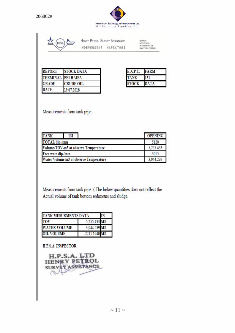
11. Attached as Appendix no 2 are surveyor reports with respect to estimated amount of sludge in each Tank and the analysis of the sludge contained in the Tanks, based upon samples taken. Bidders may also sample the sludge themselves or via a surveyor on their behalf, during the Tour. However, the Company does not undertake any responsibility with relation to its surveyor report, and the winning Bidder shall have no claim or demand whatsoever

206802#
~3 ~
towards the Company, including without limitation regarding the consideration to be paid or any other of the contractual conditions, in the event that the analysis or quantity of the sludge at the time of execution of the Works, shall differ in any way from that contained in the report provided by the Company.
12. A representative of the Contractor who is a Hebrew or English speaker must be at the Site at all working times.
Scope of Work 13. The main issues of the SOW are:
- Stage 1: "No man entry" cleaning Maximum oil recovery from sludge Minimum Vapor emission
- Stage 2 : Final cleaning to "gas free" status, including cleaning of pontoons, roof legs and roof exterior using manual cleaning.
14. The recovered crude oil will be delivered, by pipeline or trucks, to a designated tank of the Company, and the Contractor will need to arrange, install and test all pipework (tie-in) needed for connection of the oil recover pumps to existing 10/8" pipeline.
15. The cleaning process will be executed accordingly to the description and the condition and location of each tank detailed below and the visual findings by the Contractor, during the Contractor's Tour.
16. Detailed procedures with equipment layout, approved chemical additives, if necessary to use, and bar chart of the total activity scheduled for tank cleaning and oil recovery activity has to be submitted for approval prior to job commencement to the Company's Representative.
17. All of the man holes will be closed and the shell valves will be in lock position before the tanks are handed to the Contractor.
18. The sludge quantity in each tank will be measured by a reputable surveyor acceptable to both Parties. The quantity will be measured from the roof top after pumping out the free oil and draining the water from the tank. The measured quantity which will be determined will be the baseline for the payment.
19. The Contractor may request and the Company will approve and supply light crude oil to dilute the sludge. See also details in section 54 herein, and section 27 of the contract with respect to use of excessive light crude oil by the contractor.
20. During the no man entry cleaning process the maximum oxygen level inside the tank should not exceed 8%.
21. Before every pump out of recovered crude oil from the Tank, the Contractor shall sample the recovered oil and order a laboratory test to see if the BS&W (bottom sediment and water) in the recovered crude oil is less than 5%. If yes - the Contractor will be allowed to pump out. The Company will then send the sample of the recovered crude oil to the laboratory to perform an ASTM D 4007 test. If the test results show that the BS&W is 5% or more, then the pump out will be stopped and the Contractor undertakes to perform additional cleaning and retesting (as above) before it will be allowed to pump
206802#
~4 ~
out again. The Company will take samples of the recovered oil every 2 hours during the transfer.
22. Following completion of the "no man entry" stage, the Company's Representative along with the Contractor shall jointly sample the tank, the recovered oil, drainage water and sludge cake and send the samples to be tested at a laboratory, to be selected by the Company, in order to make sure that they meet the following requirements, referred to in the Contract as the "Acceptance Tests", all within the Timeframe designated for each Tank's Works as specified in the Contract: 22.1 The total volume of crude oil/sludge in the tank should be not more
than 5% of the volume measured in the Tank before the commencement of that Tanks' works, as detailed in Section 17 above.
22.2 Next, the following must be achieved: (i) The recovered crude oil will contain a maximum of 5% BS&W
(bottom sediment and water), this test (ASTM D4007) will be performed before every pump out from the tank, if there will a large difference between the laboratories result and the Contractor’s result the Company will send the sample for a test in anther laboratory and the average result between the two laboratories will be the determined result;
(ii) The drainage water will be free from solids content and have a maximum of 1,000 PPM TPH (Total Petroleum Hydrocarbons);
(iii) The sludge cakes will contain less than 10% wt oil. After these requirements are fully met, the "no man entry" stage for each tank will be considered completed.
23. The Contractor will need to design and place its tank cleaning &sludge processing units in the tank band. The Timeframe specified in the Contract for each Tanks' Works shall include mobilization of the aforesaid Contractor's units into the tank band of the current Tank. The Contractor will arrange all transportation of the infrastructure needed to maneuver the equipment near the tank.
24. The Contractor will carry out all pipe connections to the tanks' roof and the Tanks' shell including hot tapping, if necessary.
25. The Contractor shall provide mechanical or digital measuring instruments for measuring the quantity of light crude oil received and also to measure the recovered oil pumped out.
26. The Contractor shall provide qualified safety personnel, fire watchers and breathing apparatus (BA) to persons required to enter inside the crude tanks and carry out the vacuuming of sludge.
27. The Contractor shall maintain proper daily records which shall include, at least, the following: date and time of measurements and activities, light crude oil received, sludge processed in cubic meters, oil recovered in cubic meters, samples tested for BS&W at its laboratory. Any other relevant data as advised by the Company's Representative, as defined in the Contract, from time to time also is incorporated in the records on daily basis.
28. The Contractor shall provide calibrated flow meters (mechanical or digital) to measure the recovered oil pumped to the Company's batch wise which shall be recorded and counter signed by the Company Representative.

206802#
~5 ~
29. Before entering the tank the Contractor will have to receive the Company's Representative's approval for a work permit.
30. Before entering into the tank, it is the Contractor's obligation to check roof support and make all construction needed by qualified manpower if there is any doubts about the roof support integrity.
31. The Contractor shall install high capacity air educator, exhaust fan and compressor on the man hole to ventilate the tank internally before allowing any person with breathing apparatus to enter physically into the tank. It must clean the whole area within the tank band and residue collection area including the path of transportation by removing all residue, cotton waste, oil etc. to the satisfaction of the Company's Representative. The Contractor shall be responsible to maintain the area of work with good housekeeping at all time and the surrounding area safe for people to work.
Electrical Issues 32. All equipment, including electrical equipment and communication, brought
to the site by the Contractor should be suitable for hazardous area -Area classification: Class I, Division I, Gas group IIA &B Power to the contractor's or ATEX- Zone 1.
33. Power supply available in 3 phases, 400 + 10% V, 50 Hz+3%, 40 A. 34. The Company cannot guarantee continuous electrical supply, so the
Contractor shall arrange alternate source of power supply distribution skids including grounding system e.g: the entire electrical equipment of Contractor shall be earthed through separate adequately sized earth strips and brought to the panel's main earth points.
35. All the motors of the unit shall have independent push button stations with start &emergency stop near motor itself.
36. Contractor shall provide in its Bid the electrical power requirements along with all necessary details.
37. Cabling and wiring within the unit is included in the scope of Contractor. 38. Area lighting and specific lighting requirement for the job is in the
Contractor's scope. 39. Electrical generator and all electrical connections shall be checked by an
qualified engineer examiner prior to commencement of work under the responsibility of the contractor.
Scope of Supply
Contractor's Scope: 40. Providing all equipment/accessories/tools for the successful recovery of oil
from processing sludge from inside and outside the tank will be in the scope of the Contractor with necessary skilled operators. This will include jet mixer, vacuum truck, circulating pump, filter, exhaust fan, centrifuge, decanter, high solid separation unit, hydro dozer, air compressor, suction and discharge high pressure hoses/lines, power cable, two power distribution

206802#
~6 ~
boards, measuring equipment/flow measuring instruments for receipts of diluent & recovery oil.
41. Special positive displacement pumps required for handling liquefied sludge and residue. The pump would have the ability to overcome pipe line pressure drop.
42. Hydro-jetting machines and other mechanical devices for final cleaning of tank internals.
43. Diesel required for running diesel driven equipment's hired/owned by the contractor will be purchased by the Contractor.
44. Skilled manpower required for roof supporting sludge/residue collection, shifting, unloading, shoveling, housekeeping etc.
45. Consumables like approved additives/ diluents for liquefying the sludge, cotton waste, hand gloves, scrappers, rubber mop, shovels, spades, axe, buckets etc.
46. The Contractor will have to provide his own site office in the Company's plant area.
47. The Contractor shall arrange all transportation to and from the site, local accommodation for their manpower, materials, consumables, material handling equipment's etc.
48. Arrangement of crane will be done by the Contractor as and when required. 49. Safety equipment like oxygen/gas meters, breathing sets, air lamps,
personal protective equipment etc. as required for safe working inside the tank.
50. Any other consumables / equipment / materials required for the completion of the job and not specifically mentioned in the Company's scope of supply shall be arranged by the Contractor.
51. Provide the laboratory services for testing / analysis purpose of recovered oil and sludge cake samples during sludge processing activities.
The Company's Scope: 52. De-Commissioning of the Crude Oil Storage Tanks, and pumping out oil and
water up to the extent possible by using the Company's existing pumping system.
53. Spading of tanks inlet/outlet headers by the Company. 54. Light crude oil will be supplied by the Company, up to a maximum of 2000
CBM for every 1000 CBM of sludge. For use of light crude oil, in the course of any Tank's cleaning, in excess of the quantity stated in the Contractor's Bid (following a pro rata adjustment to the quantity after the sludge volume is measured in accordance with Section 11 of the Contract), the Contractor shall be charged 500 USD per CBM. The winning Bidder may not use light crude oil for the cleaning process, purchased from a source other than the Company.
55. The Company will supply water from the hydrant, and electricity from the nearest available source up to 20 KWH. However the Contractor shall arrange for necessary connections as and when required. Contractor is to indicate the power requirement, if any, along with its Bid. Potable water for flushing will be supplied to the contractor from the nearest source. Maximum water pressure – 7 Bar.

206802#
~7 ~
56. The water will be measured by a meter and the contractor will receive water up to 130 CBM per Tank. For any quantity exceeding the above mentioned the Contractor will be charged 20 USD per CBM. It is to be noted that it's prohibited to bring in water supply from outside the Site.
Specifications: 57. The Contractor's cleaning procedure for the execution of the work will be
according to the specifications mentioned below:
• API 2015-SAFE ENTRY AND CLEANING OF PETROLEUM STORAGE
TANKS
• API RP 2016 – GUIDELINES AND PROCEDURE FOR ENTERING AND
CLEANING PETROLEUM STORAGE TANKS
• NFPA 11 -Standard for Low-Expansion Foam
• ASTM D4007 – standard test method for water and sediment in crude
oil
Tanks Details
T-69
- Diameter – 36 m' - Height- 15 m' - Riveted shell constructed. - Capacity 14,700 m^3 - Floating roof, single deck, with circumference pontoons - Floating roof equipped with adjustable roof legs. - Stairs are vertical to the shell. - Rolling ladder from the upper shell to the roof. - Two (2) 24" man holes on the shell and one on the roof. - The tank has rim space fire extinguishing system. - Shell Manhole location: 0.5 m from ground - Distance to tank no 127- approx. 450 m.
T-131 - Diameter – 36 m' - Height- 15 m' - Welded shell constructed. - Capacity 14,700 m^3 - Floating roof, single deck, with circumference pontoons - Floating roof equipped with adjustable roof legs. - Stairs are vertical to the shell. - Rolling ladder from the upper shell to the roof. - Two (2) 24" man holes on the shell and one on the roof.

206802#
~8 ~
- The tank has rim space fire extinguishing system. - Shell Manhole location: 0.5 m from ground - Distance to tank no 127- approx. 350 m.
Appendix no 1- Drawings

206802#
~9 ~
Terminal pipeline from T-138 to T-130

206802#
~10 ~
Appendix no 2 – Surveyor Reports
206802#
~11 ~