
SECTION 1 - OBJECT AND SCOPE
43
STEAM TURBINES SECTION 1 - OBJECT AND SCOPE ASME PTC 6-1996 1.3 FUll-SCALE AND ALTERNATIVE TEST5 Two steam turbine testing procedures are pre- sented. For either procedure, primary flow may be 1.1 OBJECT This Code provides procedures for the accurate testing of steam turbines. It is recommended for use in conducting acceptance tests of steam turbines and for any other situation in which performance levels must be determined with minimum uncer- tainty. It is the intent of this Code that accurate instrumentation and best possible measurement tech- niques be used to determine the performance. In planning and running the test, the parties must strive to follow the Code procedures as c10sely as possible to achieve the lowest level of uncertainty. measured either in the condensate line or in the feedwater line downstream of the final feedwater heater. The parti es may agree to variations between the full-scale and alternative tests as long as the philosophy of minimum uncertainty is followed in detail. 1.3.1 Full-scale test. The full-scale test requires extensive thermal cycle measurements and calcula- tions which provide detailed information about the turbine HP, IP, and LP individuai component per- formance. A full-scale test will produce results with a minimum uncertainty. 1.3.2 The full-scale test with condensate flow mea- surement is recommended far conducting accept- 1.2 SCOPE ance tests of fossi I unii steam turbines. Without This Code may be used for testing of steam prior written agreement between the parties to an turbines operating either with' a significant amount acceptance test, this procedure shall be used. af superheat in the initial steam (typically fossil- 1.3.3 Alternative test. The alternative test relies fueled units) or predominantly within the moisture on fewer measurements and makes greater use of region (typically nuclear-fueled units). correction curves for cycle adjustments and heater This Code contains rules and procedures for the performance with resultant cost savings over the full- conduct and reporting of steam turbine testing, in- scale test. The test uncertainty is slightly increased c1uding mandatory requirements for pretest arrange- compared with the full-scale test. For a nuclear unit, ments, instruments to be employed, their application the alternative test with feedwater flow measurement and methods of measurement, testing techniques, may be preferred depending on the turbine cycle __!- a-rn_d _T_h,e---;!p_e_r_-__ud.ces:>Jign I Ise formamoeparameterswh ichmaybe determi nedfrom oetWèenlne·partiès loan-acceptancelesf: a Còde test include: (a) heat rate 1.3.4 The data from the alternative test procedure (b) generator output may produce a slightly higher uncertainty in results, (c) steam flow particularly if there is substantial divergence between (d) steam rate the test and the specified cycle. The parties to the (e) feedwater f10w test must agree on a course of action if the turbine It also contains procedures and techniques re- fails to meet specified performance. The alternative quired to determine enthalpy values within the mois- test may not provi de the information necessary to ture region and modifications necessary to permit determine individuai component performance com- testing within the restrictions of radiological safety pared to expected because only those measurements requirements in nuclear plants. needed to calculate test heat rate and to permit comparison to specific conditions are required. It is recommended that ali provisions and source connec- tions for a full-scale test be included in the design of the cycle, should such a test be required at a later time and to facilitate individuai turbine component performance testing.
-
Upload
khangminh22 -
Category
Documents
-
view
3 -
download
0
Transcript of SECTION 1 - OBJECT AND SCOPE
STEAM TURBINES
SECTION 1 - OBJECT AND SCOPE
ASME PTC 6-1996
1.3 FUll-SCALE AND ALTERNATIVE TEST5
Two steam turbine testing procedures are presented. For either procedure, primary flow may be
1.1 OBJECT
This Code provides procedures for the accuratetesting of steam turbines. It is recommended for usein conducting acceptance tests of steam turbinesand for any other situation in which performancelevels must be determined with minimum uncertainty. It is the intent of this Code that accurateinstrumentation and best possible measurement techniques be used to determine the performance. Inplanning and running the test, the parties must striveto follow the Code procedures as c10sely as possibleto achieve the lowest level of uncertainty.
measured either in the condensate line or in thefeedwater line downstream of the final feedwaterheater. The parties may agree to variations betweenthe full-scale and alternative tests as long as thephilosophy of minimum uncertainty is followed indetail.
1.3.1 Full-scale test. The full-scale test requiresextensive thermal cycle measurements and calculations which provide detailed information about theturbine HP, IP, and LP individuai component performance. A full-scale test will produce results witha minimum uncertainty.
1.3.2 The full-scale test with condensate flow measurement is recommended far conducting accept-
1.2 SCOPE ance tests of fossi I unii steam turbines. Without
This Code may be used for testing of steam prior written agreement between the parties to anturbines operating either with' a significant amount acceptance test, this procedure shall be used.
af superheat in the initial steam (typically fossil- 1.3.3 Alternative test. The alternative test reliesfueled units) or predominantly within the moisture on fewer measurements and makes greater use ofregion (typically nuclear-fueled units). correction curves for cycle adjustments and heater
This Code contains rules and procedures for the performance with resultant cost savings over the full-conduct and reporting of steam turbine testing, in- scale test. The test uncertainty is slightly increasedc1uding mandatory requirements for pretest arrange- compared with the full-scale test. For a nuclear unit,ments, instruments to be employed, their application the alternative test with feedwater flow measurementand methods of measurement, testing techniques, may be preferred depending on the turbine cycle
__!- a-rn_d m_e~t_:..:h_=_o_=_d~s _o_f---,c_a_lc_u_la.t.io.n_o_f~t-Tes'-.:t'-.:r-i-e~su~l-=-ts-;. _T_h,e---;!p_e_r_-__ud.ces:>Jign I Ise oLlhis-procedUl:e-r-equir-es-agreement~----formamoeparameterswh ichmaybe determinedfrom oetWèenlne ·partiès loan-acceptancelesf:a Còde test include:
(a) heat rate 1.3.4 The data from the alternative test procedure(b) generator output may produce a slightly higher uncertainty in results,(c) steam flow particularly if there is substantial divergence between(d) steam rate the test and the specified cycle. The parties to the(e) feedwater f10w test must agree on a course of action if the turbineIt also contains procedures and techniques re- fails to meet specified performance. The alternative
quired to determine enthalpy values within the mois- test may not provide the information necessary toture region and modifications necessary to permit determine individuai component performance com-testing within the restrictions of radiological safety pared to expected because only those measurementsrequirements in nuclear plants. needed to calculate test heat rate and to permit
comparison to specific conditions are required. It isrecommended that ali provisions and source connections for a full-scale test be included in the designof the cycle, should such a test be required at a latertime and to facilitate individuai turbine componentperformance testing.
mdl
Evidenziato
mdl
Evidenziato
mdl
Evidenziato
mdl
Evidenziato
mdl
Evidenziato
mdl
Evidenziato
mdl
Evidenziato
mdl
Evidenziato
mdl
Evidenziato
ASME PTC 6- 1996 STEAM TURBINES
1.5.1 The provisions of the Code on Generai Instructions, PTC 1, are a mandatory part of this Code.PTC 1 should be studied and followed in detailwhen preparing the procedure for testing a specificsteam turbine. .
1.5.2 The Code on Definitions and Values, PTe2, defines certain technical terms and numericalconstants whieh are used throughout this Code.Unless otherwise specified in this Code, instrumentation should eomply with the appropriate sections ofSupplements on Instruments and Apparatus, PTC 19series.
1.5 ADDITIDNAL REQUIREMENTS ANDREFERENCE5
tainty and demonstrates examples of uncertaintycalculations in Tables 9.1-9.4
lt
1.4.5 A post-test uncertainty analysis performedaccording to procedures as described in PTC 19.1is recommended. However, a post-test uncertaintyanalysis may be made optional upon agreement bythe parties that a test adhered to ali instrumentationrequirements and procedures contained in this Code.
1.4.6 Code instrumentation and procedures maynot always be economically feasible or physicallypossible for specific turbine acceptance tests. Inthese cases, the intent of the Code cannot be met,and PTC 6 Report should be consulted for guidancein designing the test and calculating the test uncertainty.
1.4.2 The tests should be conducted with the strictest possible adherence to the provisions of this Code.However, equipment limitations may dictate thatthe parties cannot comply with one or more Coderequirements because of a conflict with anothercondition specified by the Code. In such cases,agreement between the parties is necessary. Theagreement shall conform to the intent of the Codeas c10sely as possible. The agreement should providedetails for handling departures from specific Coderequirements.
1.4.1 Other procedures and instrumentation maybe used only if they have demonstrated accuracyequivalent to that required by this Code. Only therelevant portion of this Code need apply to anyindividuai case.
1.4 CONFOIRMANCE TO CODE
1.4.3 Any departure from Code requirements mustbe agreed upon in writing and must conform to theintent of the Code. In the absence of writtenagreement, the Code requirements shall be mandatory.
1.4.4 Uncertainty of Cqde Test. The results of afull-scale Code test, expressed as a heat rate, for atypical fossi I fuel reheat cycle unit have an uncertainty of about ~ percent compared to an uncertaintyof about tpercent for the alternative test. Test resultsfor steam turbines operating predominantly withinthe moisture region have uncertainties of about ~
percent and t percent, respectively. Values of uncer-tainty will be affected by cycle configuration and 1.5.3 An Appendix to this Code, PTC 6A, publishedequipment type and may be significantly higher. separately, gives numerical examples of various cal-
______-':::S~ec~t~io~n~9~dC'..:is~c:.'='u~ss~e""_s~th~e~ra~t~io~n~a~le,---f!-"o~r...Lh!Siec9.atLrU;;al1lte~u!.!nc!",Je;<!r=--_------!culatLonLo~stres..ults~. _
2
mdl
Evidenziato
mdl
Evidenziato
mdl
Evidenziato
mdl
Evidenziato

STEAM TURBINES
SECTION 3 - GUIDING PRINCIPlES
ASME PTC 6-1996
3.1 PLANNING FOR TEST
3.1.1 Requirements for Agreements. The partiesto any test under this Code shall reach definiteagreement on the specific objective of the test andon the method of operation. This agreement shallreflect the intent of any applicable contract or specification. Any specified or contract operating conditions or specified performance pertinent to the objective of the test shall be ascertained. Unless thealternative test procedures are specified, full-scaletest procedures shall be used. Omissions or ambiguities about any of the conditions must be eliminatedor their values or intent agreed upon before thetest is started. The cycle arrangement, operatingconditions, al)d testing procedures shall be established during the agreement on test methods.
of make-up lines and emergency valving that may notbe blocked off and far which accounting must bemade. (see Subsection 3.5.8)
(g) method of handling leakage flows, orificed continuous drain flows, continuous blowdowns, etc. toavoid complications in testing or the introduction oferrors
(h) method of complying with the criteria and recommendation of ASME Standard No. TDP-l, Parts 1and 2, "Recommended Practices for the PreventionofWater Damage to Steam Turbines Used for ElectricPower Generation" as related to handling of, or accounting for, drain flows
(i) means of measuring pump-shaft seal and leakage flows
(j) number and location of temperature wells andpressure connections
(k) number and Iocation of duplicate instrument3.2 ITEM5 ON WHICH AGREEMENT SHALL BE connections required to ensure correct measurements
REACHED at criticai points(/) calibration and connection of instrument trans-
3.2.1 The following is a list of typical items upon formers to be used for measuring electrical outputwhich agreement shall be reached during the engi- (m) where a plant computer is used far data acqui-neering phase of a new unit or modification of an sition, provisions fortotal-system, in-piace calibrationexisting unit. of station instrumentation and computer (Calibration
(a) objective of test and methods of operation should include comparison of known inputs to the(b) the intent of any contract or specifications as output of the computer.)
to~ott~l~iY_~JE!st]?rQeed.t:Jr~~'v\I~i(O;h=-ml:lst'---. --I~RI-methQd-Qf-d@tel=miningJ:badifferentiaLpLes2u.Le~ _include a review of specified heat cycle andfin-iil-across-co-nffor-,Téilve(sffosafisfy-the-proVisiOnçofexpected values (refer to para. 3.4.1) paras. 3.13.2 and 3.13.4 (Pressure tap should be pro-
(c) the intent of any contract or specifications as to vided immediately upstream and downstream of thetiming of test, operating conditions, and guarantees, last controI valve(s) to open.) .including definitions of heat rate, method of compar- (o) method of determining steam quality includinging test results with guarantee and responsibility for sampling technique as required (The recommendedthe preparation of test report(s) methods are tracer, heater-drain flow measurements,
(d) location of, and piping arrangement around, and calorimeter method.)primary flow measuring device(s) on which test calcu- (p) responsibility for obtaining a license for radio-lations are to be based (see paras. 4.9.1-4.9.7) active tracer and method of shipping, receiving, han-
(e) location and type of secondary flow measuring dling, storing, and using both the tracer and its associ-devices and provisions for calibration, including tem- ated equipmentporary piping far in-piace calibration, if required (q) level of undue deterioration at which the ac-
(f) number and location of valves or other means ceptance test will be postponed until after the firstrequired to ensure that no unaccounted-for flow enters internai inspectionor leaves the test cycle or bypasses any cycle compo- (r) method of establishing the efficiency of the feed-nent. (In a nuclear plant, particular note must be taken water pump turbine, if required
9
mdl
Evidenziato
mdl
Evidenziato
mdl
Evidenziato
mdl
Evidenziato
mdl
Evidenziato
mdl
Evidenziato
mdl
Evidenziato
mdl
Evidenziato
mdl
Evidenziato
mdl
Evidenziato
mdl
Evidenziato
mdl
Evidenziato
mdl
Evidenziato
mdl
Evidenziato
mdl
Evidenziato

ASME PTC 6-1996 STEAM TURBINES
between test timing and seasonal effects on operatingconditions .,
(x) where a nuclear unit is involved, ali test plans-must reflect compliance with the technical specification for that unit
(y) load Iimitations caused by licensing considerations (nuclear steam-supply limitations, or otherwise)which prevent attainment of full power within a practical time period
(z) deviations from test arrangements and test procedures that may be required due to a radioactiveenvironment in the testing area
(s) criteria for instrument recalibration after the test
3.2.2 The following is a list of typical items uponwhich agreement shall be reached prior to conducting the test:
(a) procedure for determining the condition of theturbine prior to the test (see paras. 3.3.1, 3.3.2, and3.4.5)
(b) location, type, and calibration of instruments(see para. 3.10.1)
(c) methods of measurement not established in (b)(d) isolation of cycle during test (see Subsection
3.5)(e) method of detecting excessive feedwater-heater
leakage (see para. 4.16.6)(f) means for maintaining constant test conditions 3.3 TIMING Of ACCEPTANCE TEST
(see paras. 3.8.1 and 3.8.2)(g) method of isolating or arresting control valve 3.3.1 The acceptance test should be scheduled as
action such as those caused by variations in combus- soon as practicable, preferably within eight weeks,tion-control systems signal, electrical system, etc. after the turbine is first put into initial operation under
(h) operating conditions at which tests are to be load. This allows for detailed planning, materialconducted including, but not limited to, the loads, procurement, instrument - acquisition, preparation,valve settings, or valve points to be used for each run shipment, controls adjustment, preliminary tests, and(see paras. 3.8.3 and 3.13) detection and correction of 'problems with the unito
(i) position of manually and automatically operated The tests should be conducted if no serious operatingvalves (see para. 3.8.9) difficulty has been experienced and there is reason-
(j) frequency of observations (see para. 3.9.2) able assurance the unit is free of deposits and(k) number of test runs at the same test point (see undamaged.
paras. 3.7.1 and 3.7.2) It is the intent during this period to minimize(/) duration of test runs (see para. 3.9.2) performance deterioration and risk of damage to(m) duration of operation at test load before read- the turbine. Enthalpy drop tests or preliminary tests
ings are commenced (see para. 3.8.1) should be made during this period to monitor the(n) computer or data acquisition system to be used performance of turbine sections operating entirely
for test data acquisition and analysis in the superheat region. However, enthalpy drop(o) arrangements for data acquisition and analysis, tests do not provide performance for turbine sections
------il1~ltI:Qjl}g~li!:>r'!tit>1l::t:>i~~t~~~tJ1s:i~i()_~~ys!~Il'I_-_ ---'witlì-a-wet-e-xAal:lst.-T:RerefQre,-it-is-imperativ-e-tol----
(p) procedures and format for recording data conductffleacceptance--tesfassoonàspossible:---(q) organization and training of test personnel and In any event, if the enthalpy drop tests show
identification of the responsibility for the test (see undue deterioration, or if plant conditions delay theparas. 3.4.2, 3.4.3, and 3.4.5) tests for more than four months after initial operation,
(r) procedures for calculating test results the accept;;mce test should be postponed until imme-(s) curves to correct for measured generator output diately following the first internai inspection, pro-
for deviations from specified power factor and speci- vided that any deficiencies in the turbine generatorfied hydrogen pressure affecting performance have been corrected during
(t) corrections for deviation of test steam conditions the inspection periodo Except with written agreementfrom those specified (see Subsection 3.12) to the contrary, the acceptance test shall take piace
(u) curves to correct test heat rate to specified cycle within the warranty period specified in the contracI.conditions (alternative test only) Adjusting of heat rate test results to start-up enthalpy
(v) method of conducting test runs to determine the drop efficiencies or for the effects of aging are notvalue of any correction factors (see para. 3.4.5 and permitted by this Code.Subsection 3.12) In lieu of an internai inspection, the following
(w) method of handling deviations beyond the methods may be used prior to the acceptance teststated permissible levels as a result of a mismatch to establish the approximate condition of the turbine:
10
mdl
Evidenziato
mdl
Evidenziato
mdl
Evidenziato
mdl
Evidenziato
mdl
Evidenziato
mdl
Evidenziato
mdl
Evidenziato
mdl
Evidenziato
mdl
Evidenziato
mdl
Evidenziato
mdl
Evidenziato
mdl
Evidenziato
mdl
Evidenziato
mdl
Evidenziato
mdl
Evidenziato
mdl
Evidenziato
mdl
Evidenziato
mdl
Evidenziato
mdl
Evidenziato
mdl
Evidenziato

STEAM TURBINES ASME PTC 6-1996
supply), it is not possible to use an enthalpy-dropefficiency test to establish benchmark performance.If a preliminary heat rate test can be performed,this would be an excellent method to establishbenchmark performance. If this is not practical,however, it is recommended that a "capacity" testbe conducted at the licensed thermal output of thenuclear steam supply system. In a capacity test,cycle conditions are stabilized and electrical outputof the generator is carefully measured, together withali cycle conditions which affect performance, suchas initial and condenser pressure. Generator outputis corrected for differences in cycle conditions fromtheir nominai values using appropriate correctionfactor curves. It is also corrected for any differencebetween measured and licensed reactor thermal output, assuming electrical output is proportional toreactor thermal output. This corrected electrical output can then be used as a benchmark, since it canbe compared to an electrical output derived inexactly the same way at the time of the test. Theaccuracy of this procedure depends upon the repeatabi Iity of electrical output and reactor thermal output.Since this capacity test is performed with a measuredheat input, it is analogous to a simplified heat ratetest; therefore, it is necessary to isolate the cycleto achieve an accurate determination of any deterioration.
(a) For turbines using superheated steam, a comparison between enthalpy-drop efficiency tests conducted immediately afterthe start-up and again immediately before the test. (See para. 3.3.2.)
(b) By running preliminary tests. For turbines operating predominantly in the moisture region, this maybe the only applicable method.
(c) By a combination of these methods.If the turbine is shut down prior to the test, an
inspection of ali accessible parts is desirable. Theparties to the test must agree as to the action tobe taken on evidence of deterioration.
3.3.2 Performance Bench Mark Determinations. Itis desirable that a performance bench mark beestablished immediately after the turbine is firstplaced in service, so that, should the Code test bedelayed past eight weeks, there can be reasonableassurance that the turbine has not been damaged orbecome fouled with deposits during the interveningperiod of operation. (See para. 3.3.1.) For turbinesoperating in the superheated steam region, the internai efficiency (actual enthalpy drop divided by theisentropic drop) of each turbine element should bedetermined by measurement of the pressure andtemperature of the steam entering and leaving thesection. These measurements should be made withali control valves fully open. The instrumentationto be used for the benchmark testing shall meet thesame accuracy and calibration requirements speci-fied for Code test measurements.
Unlike the intermediate-pressure turbine section, 3.4 GENERAL TEST REQUIREMENTSfar which efficiency is substantially constant over a 3.4.1 Various methods are presented in the Codewide range of steam flow, the efficiency of the high- for conducting certain details of the test and forpressure section is affected by the position of the computing the results. The test report shall state
1-------';;cc;;:o-=nt;;:;ro"'"IL valves=JL lì IS notpossìoIEtobringJbcr<e------,w~'niCn alternativeThcwe-b~lIl~mptoygd-:-(S_t=E[SeçtipJrrl-----
turbine up to full load immediately after initial start- 6.) Since the alternative method requires fewer mea-up, the internai efficiency test should be made by surements, it is important that cycle componentsreducing the throttle steam pressure sufficiently to operate close to specified conditions. If not, appra-permit operation with fully-open control valves with- priate corrections must be developed reflecting testout exceeding limitations on output. The internai conditions to minimize the uncertainty.efficiencies of ali turbine sections measured underthese conditions will then be compared with tests 3.4.2 The parties to the test may designate a personrun with design steam pressures and fully open to direct the test and to serve as mediator in eventcontrol valves. Steam pressure and temperature mea- of disputes as to the accuracy of observations, condi-surements (or test data) should be supplemented tions, or methods of operation.
with output measurements to provide data on the 3.4.3 Designated representatives of the parties tolow-pressure section of the turbine. With some stages the test shall be present to verify that the test isoperating in the wet steam region the low pressure conducted in accordance with this Code and thesection cannot be checked by internai efficiency arrangements made prior to the test.measurements.
When a turbine has wet steam exhausting fram 3.4.4 Provisions shall be made for ali precautionsali sections (such as a turbine with a nuclear steam specified in Section 4 for respective measurements.
11

ASME PTC 6-1996 STEAM TURBINES
Provisions far cycle isolation shall be made in accordance with Subsection 3.5.
3.4.5 Preliminary tests may be run far the purpose of:
(a) determining whether the turbine and plant arein a suitable condition for the conduct of the test (seeparas. 3.3.1 and 3.3.2)
(b) checking ali instruments(c) training personnel(d) establishing valve points(e) determining corrections far deviation of condi
tions from specified(f) confirming cycle isolation
3.4.6 Test Data. Unless an agreement is reachedto the contrary, records shall be kept of ali test databefore the application of any calibration factors,corrections, conversions, or statistical analysis. Acopy of the originai records shall become the property of each of the principal parties to the test. Nooriginai data may be erased or deleted.
any other storage points within the cycle are to betaken into accoun~
3.5.4 Internai Isolation. Internai isolation dealswith flows which do not enter or leave the turbinecycle but which may bypass the component theywere designed to go. through. Examples of suchflows are steam line drain flows to the condenseror feedwater heater bypass flows. Internai isolationcannot be verified by the inventory summationmethod discussed above. The isolation proceduregiven in paras. 3.5.6 and 3.5.8 must be followedto verify internai isolation.
3.5.5 Flows That Shall Be Isolated. The followinglist includes items of equipment and extraneousflows that shall be isolated:
(a) large-volume storage tanks not directly in thecycle
(b) evaporators and allied equipment such as evaporator condenser and evaporator preheaters
(c) bypass systems and auxiliary steam lines forstarting
(d) bypass Iines for primary flow measuring devices3.5 ISOlATION Of THE CYClE (e) turbine sprays
(f) drain lines on stop, intercept, and control valves3.5.1 Generai. The accuracy of the test results (g) drain lines on main steam, cold reheat, hot re-depends on the isolation of the system. Cycle isola- heat, and extraction steam pipingtion is equally important to both the full-scale and (h) interconnecting lines to other unitsalternative procedures. Extraneous flows should be (i) demineralizing equipment. Isolation of demin-isolated, if possible, to eliminate errors. Extraneous eralizing equipment does not necessarily mean re-flows for equipment that is includèd in the contract moving the equipment from the cycle. (lt does, how-cycle should be isolated only with mutuai agreement ever, mean that ali ties with other units must beby the parties. If there is any doubt about the isolated and such components as recirculating Iinesability to isolate extraneous flows during the test, that affect the primary flow measurement must bepreparations shall be made prior to the test to isolated or the flows measured.)measure the flows. '===~-==~=~~~~~~~~~~~~~~~~~~~~~~~~~~~~~~~chem~l~e~~equlpmenLuslngconaensa~
3.5.2 The equipment and flows to be isolated and (k) steam generator fili Iinesthe method to accomplish this should be outlined (/) steam generator ventswell ahead of the initial operation date of the turbine. (m) steam-operated soot blowers
(n) condensate and feedwater f10w bypassing3.5.3 External Isolation. External isolation deals heaterswith flows which enter or leave the turbine cycle, (o) heater drain bypassessuch as condensate make-up or boiler blowdown (p) heater shell drainsflow. This system isolation shall be effected so that (q) heater water-box ventsthe difference between the sums of the measured (r) hogging jetsstorage changes and the entering and leaving flows (5) condenser water-box priming vents(the unaccounted-for leakage) is minimized. The (t) steam or water lines for station heatingunaccounted-for leakage shall not exceed 0.1 per- (u) steam or water lines installed far water washingcent of the test throttle flow at full load. Excessive the turbineunaccounted-for leakages shall be eliminated beforecontinuing the test. Water storage in the condenser, 3.5.6 Flows That Shall Be Isolated or Measured.deaerating and other extraction feedwater heaters, Extraneous flows which enter or leave the cycle orsteam generator drum(s), moisture separators, and bypass a component in such a manner that if ignored
12

NES STEAM TURBINES ASME PTC 6-1996
3.5.8 Methods of Isolating. The following methodsare suggested for isolating or verifying isolation ofmiscellaneous equipment and extraneous flows fromthe primary feedwater cycle:
(a) use of double valves and telltales(b) use of blank flanges(c) use of blank between two flanges(d) removal of spool piece for visual inspection(e) visual inspection for steam blowing to atmo-
sphere from such sources as safety valves and valvestem packings
(f) use of a c10sed valve which is known to beleak-proof (test witnessed by both parties) and is notoperated prior to or during test
(g) tracer indicator of presence of leakage(h) for steam lines terminating at the condenser,
pipe surface temperature indication(i) for bypass lines around feedwater heaters, tem
perature measurement of condensate/feedwater befare and after the bypass Iines tee into the condensate/feedwater lines
O) temperature measurement for situations otherthan described in (h) and (i) (acceptable only undercertain conditions with mutuai agreement necessary)
(k) acoustic techniques, with mutuai agreement
internai turbine leakage, and turbine drain flows, itwill be necessary to use calculated values. For thealternative procedure, calculated values may be usedin Iieu of measured values.
3.5.7 For the full scale test, when it is impossible tomeasure shaft packing leakage, valve-stem leakage,
g
~s
vIe
e-1-
ese-
es
or
p-
he
ngus
be
!alsineleyIchserononjreed
will cause an errar in the flows through the turbineshall be isolated or measured. Typical of suchflows are:
(a) boiler-fire-door cooling flow and boiler-slag-tapcooling-coil flow
(b) sealing and gland cooling flow on the following(both supply and return):
(7) condensate pumps(2) feedwater pumps(3) boiler or reactor-water circulating pumps(4) heater drain pumps when not self-sealed(5) turbines far turbine-driven pumps(6) reactor control-rod drive flows
(c) desuperheating water flow(d) feedwater pump minimum-flow lines and bal
ance drum flow when the piping is arranged to allowrecireulation of the f10w through the primary flowelement
(e) steam for fuel oil atomization and heating(f) steam generator blowdowns(g) turbine water-seal flows(h) desuperheating water for turbine cooling steam(i) emergency blowdown valve or turbine-packing
leakage and sealing steam(j) turbine water-seal overflows(k) steam, otherthan packing leakage steam, to the
steam-seal regulating valve(/) make-up water, if necessary(m) pegging or sparging steam (such as higher-stage
extraction at low loads) for low pressure operation ofdeaerator
(n) heater shell vents are to be c1osed, if possible,and if not possible, shall be throttled to a minimum 3.6 LOCATION OF TURBINE VALVE POINTS
(o) deaerator overflow line . . 3.6.1 The method used to establish turbine valve(p) deaerator vents ~hall be throttled to a mlnlmum points depends on valve point definition. A valve
__+- --'(è:f'-)---'-w.:....:a=-=te=r-----=-=Ie=a~kagemto anx water-s=ale~~·(Jatm mayoe estaoti5nea In terms of high pressure·suchas water-sealed vacuum. breakers turbine efficiency, certain measured turbine pres-
(r) pump-se.al leakag: leavlng the ~ystem . sures,or valve-stem positions. The turbine is then(s) automatlc extractlon steam for Industriai use tested accordingly.(t) continuous drains from wet-steam turbine cas-
ings and connection lines 3.6.2 For units with a high pressure section op-(u) subcooled moisture used for moisture separator erating entirely in the superheat region; a valve point
or reheater coil-drain cooling may be located by finding a point of local maximum(v) reactor core spray high pressure section efficiency. To do this, the f10w(w) heater-blanketing steam lines to the unit is changed in small increments throughout(x) water and steam sampling equipment. If it is a range which includes the valve point. At each
impossible to isolate water and steam sampling equip- f10w increment, pressure and temperature measure-ment and if the sampling flow is significant, it shall ments are taken at both inlet and exhaust so thatbe measured. high pressure section efficiency can be derived. A
(y) steam to air preheaters local maximum efficiency will be evident, providedsuitable instruments and test procedures have beenused. During testing, a parameter which varies withflow (such as control valve position(s), or pressure
13

ASME PTe 6-1996 STEAM TURBINES
are not met, according to PTe 1-1991, subpart P,para. 4.16, the partj,es to the test may eliminate thetest runs by mutuai agreement. The eriteria are toverify correct operating conditions and are not todetermine statistical outliers.
The heat rate differences used are based on experience and do not relate direetly to uncertainties inTables 9.1-9.4.
3.7 NUMBER Of TEST RUNS
3.6.3 A valve point established in terms of pressuresis found by measuring pressure at a tap pravidedfor each steam admission zone served by a valve.While the valve remains c1osed, the pressure in thiszone will be nearly the same as the first stagepressure of the turbine. As the valve opens, thedifference between these two pressures will graduallychange and the zone pressure will rise above thefirst stage pressure.
3.6.4 A valve point established in terms of valvestem position is found by taking the appropriatemeasurements during operation.
3.6.5 lf valve points are located prior to the startof the test series, time and labor ean be saved duringthe tests.
3.6.6 Valve points are numbered conseeutivelyfrom the minimum arc of admission. For example,consider a machine with four control valves designedsuch that the first two valves open together. Thefirst valve point occurs where the third valve isabout to open, and the second valve point occurswhere the fourth valve is about to open.
ratio across either the first stage or the completehigh pressure section) should also be recorded sothe valve point can be readily set during the testseries.
3.7.2 Duplicate Test Runs. The requirements ofthis Code for agreement between the results ofduplicate test runs are i1lustrated by severaI hypothetical sequences of test results in examples (a) thraugh(g) below. When two test runs are conducted at thesame test point, the corrected test heat rates shallagree within 0.25 percent. Thus, neither test differsfram the average by more than one-half this amountor 0.125 pereent. Units for the heat rates in thefollowing are Btu/kWhr.
(a) 2 test runs within 0.25%80097991use average = 8000
If the two test runs differ by more than 0.25 .percent, additional test runs are required at the sametest point unti! the corrected heat rates of at leasttwo test runs agree within the 0.25 percent. If morethan one pair of test runs meets the 0.25 pereentcriterion, then the pair that most c10sely falls onthe locus eurve of the correeted test heat rates fromother test points shall be accepted. Alternatively,another test run may be made.
3.7.1 Recommended Test. As a mmlmum, dupl i- (b) 3 test runs with third outside range of other twocate test runs should be performed at valves-wide- 8010 > 0.25% from nearest oneopen and at two part load points. Duplicate test 7988
-------fl:lfls--at-tlìe-same--0J3er-<l;tifl~€E)Acliti0A_=fecll:l€~t~,ee------7-98QI----------------
ranCiom-error-compo-nentof uncertainty. the- part~ I.lseave-rage-oflasnwo-,;, 79"84load tests should be performed at valve points to (e) 3 test runs agree with third test run betweenensure that duplicate test runs are at the same other twoeonditions. The test series should begin and end 8015with the same valve point test run, preferably the 7985 > 0.25% from first onevalves-wide-open test run. 8000
Consecutive tests should not be perfarmed at the use average fram third test (8000)same load without changing valve positions and in a pair that best fits locus curvebreaking isolation. It may be necessary to break (d) 3 tests runs with third test run between otherisolation to maintain hotwell level during the load two, followed by a fourth test runchange. Load change should be at least to the 8011 > 0.25% from nearest onenext higher, or lower, valve point, or, far full-are 7979admission turbines, at least 15 percent of load. 7988
The criteria of para. 3.7.2 are to verify that op- 7983erating conditions during duplicate test runs are use average of last three = 7983eorrect, provided that changes in load and isolation If no two corrected heat rates fall within 0.25are made between these duplicate runs. If the criteria percent of eaeh other after three test runs have been
14
mdl
Evidenziato
mdl
Evidenziato
mdl
Evidenziato
mdl
Evidenziato
mdl
Evidenziato

\IES STEAM TURBINES ASME PTC 6-1996
the turbine at a slightly higher speed in the eventof loss of load.
3.8.3 Operating Conditions. Every effort shall bemade to run the tests under specified operatingconditions, or as close to specified operating conditions as possible in order to avoid the applicationof corrections to test results, or minimize the magnitude of the corrections. In addition, variations inany condition that may influence the results of the .test, shall be made as nearly constant as practicablebefore the test begins and shall be so maintainedthroughout the test. Steam generator and turbinecontrols shall be fine-tuned prior to the test tominimize deviation of variables. Table 3.1 lists thepermissible deviation of variables prescribed withthe exceptions as noted in para. 3.8.11. A slowchange in variables, or "drift," during the test run,will frequently occur in addition to the fluctuationsaddressed in Table 3.1. For some key parameters,"drift" should be limited to 50 percent of the permissible deviations presented in Table 3.1 for the average of the test conditions from design or ratedconditions. These key parameters are initial steampressure, initial and reheat steam temperature, exhaust pressure, output, and speed. Operating withinthe Iimits of Table 3.1 is especially important forthe alternative test, since more correction curvesare used than in the full-scale test. .
3.8.4 Hydrogen purity should be maximized todecrease windage 1055, improve heat transfer, andfor safety reasons. Operating manuals specify a minimum hydrogen purity, with safety as the primaryconsideration. For instances where hydrogen purityis below the manufacturer's specified value, the testsoouIctbe postponeeLuno t111e::prrrtty::cetIT:b:e=brolJg·~hlt--. --to the specified value. Improvement is usually easyto achieve and should not impose undue hardshipon the parties to the test. The hydrogen purityinstrumentation should be checked to ensure correctindication.
3.8.5 The turbine and its cycle shall be in normaloperation during the test, except for cycle isolation,(see Subsection 3.5). Except as provided in para.3.8.2, no special adjustments shall be made tothe turbine that are inappropriate for norma I andcontinuous operation.
3.8.6 The turbine shaft-sealing system, if controlled,shall be adjusted to normal operating conditionsduring a test and arrangement made to measure anyflow outward or inward that will influence testresults.
made at the same test point, the test procedureand instrumentation must be carefully reviewed todetermine and correct the cause before proceedingto run more test runs.
(e) 3 test runs with no pair within 0.25%802180007979find cause before proceeding
At any one test point, ali corrected test heat ratesfalling within 0.125 percent of their average shallbe accepted.
(f) 4 tests with close grouping8010800580128000use average of ali four =8007,since each is within 0.125%of their average.
25
ler
1/110
P,thetoto
ofof
letJghthelallersJntthe
~ri
in
!en
25 .meast)re
~nt
on)m
!Iy,
3.8 TESTING CQNDITIONS
3.8.1 Constancy oi Test Conditions. Preparatory toany test run, the turbine and ali associated equipmentshall be operated for a sufficient time to attainsteady-state condition. Steady-state conditions shallhave been attained when the criteria of para. 3.8.3are met.
When a tracer is used for determining steamquality, the injection period should commence sufficiently prior to the start of the test run to attainequilibrium. As a guide, it may be conservatively
i--_-----1f--__--"e=xp-ected that e~uilibrium is attained when a timeperiod;equal·to-twice thecalculatedtransit-timethrough the longest injection line plus the longestsample line following the commencement of injection, has passed. For the purpose of this Code,equilibrium shall have been attained when the concentration of tracer in two consecutive samples takenduring the test at a 30-minute interval differ by nomore than 3 percent from one another.
3.8.2 Appropriate means shall be employed forsecuring constant load. This may be accomplishedby blocking the valve-gear or control valve travelin the opening direction at the desired load, leavingthe control valves free to move in the closing direction in the event of upsets or emergency situations.While the machine is so operating, it will be unableto carry more load than that far which the valvegear or contrai valves are blocked, but will regulate
15

ASME PTC 6-1996 STEAM TURBINES
TABUE 3.1PERMISSIBlE DEViATION OIF VARIAIIUES ..
Variable
(a) Initial sleam pressure
(b) Initial and reheat steam temperature
(c) Initial sleam quality
(d) Primary f10w
(e) Secondary flows
(f) Pressure drop through fossil unit reheater
(g) Extraction pressures
(h) Extracti~n f1aws***
(i) Temperature of feed water leaving finalheater
(j) Exhaust pressure****
(k) Load
(/) Voltage
(m) Power factor
(n) Speed
(o) Aggregate isentropic enthalpy drop ofanyone of lhe sections of an automaticextraction turbine
*Permissible Devialion for the Averageof the Test Conditions from Design or
Rated Conditions
±3.0% of the absolute pressure
±lsoF (8K) when superheat is 27"-SO°F(l5-30K); ±30°F (16K) when superheat is in excess af 50°F (30K)
±O.S percentage points of quality for turbines with wet throttle steam
Not specified
±S.O% x (primary f1ow)/(secondary flow)
±SO.O%
±S.O%
±S.O%
±lO°F (6K)
±O.OS psi (0.34 kPa) or ±2.S% of the ab-solute pressure, whichever is larger
Refer to para. 3.1 3.5
±5.0%
Not specified
±S.O%
±1O.0%
**Permissible Fluctualions During AnyTest Run
±0.2S% of the absolute pressure or 5.0psi (34.5 kPa). whichever is larger
±4°F (2K) where superheat is 27°-50°F(15-30K); ± 7°F (4K) where superheatis in excess of 50°F (30K)
±0.1 percentage points of quality for turbines with wet throttle steam
Refer to para. 4.10.1
Same as (d) x (primary f1ow)/(secondaryflow)
±0.02 psi (0.14 kPa) or ±1. 0% of theabsolute pressure, whichever is larger
±0.2S%
±1.0%
±0.2S%
In any event, the manufacturer's allowable variations in pressure temperature and speed are not to be exceeded, unless specificallyagreed to befare the test.
** Fluctuations would be indicated by scatter in the data (refer to para. 3.9.2).*** When steam is extracted for feedwater heaters, the extraction pressures (which are fjxed by the turbine design and f10w conditions)
may deviate from expected values by a few percent. This normally has a negligible effect upon the overall performance. Il shall be---------a""'s"'c"'er:r.ta'""In=.eoJl1<ltsuclLaevlabonsasBoexlstare notdue tomaltunctlOnlng oUeedwateLheaters.lt large devlatlonsperslst. agreement
must be reached as to the course to be followed.****If it is not practicable to obtain design or rated exhaust pressure, the test may be conducted by agreement at another exhaust pressure,
and either party may require that the exhaust pressure correction curve be verified by test.
3.8.7 During any heat rate, steam rate, or capacitydetermination of a constant-speed turbine, the turbine shall be operated at specified speed.
3.8.8 Permissible Adjustments. To attain specifiedoperating conditions it is permissible to:
(a) Lower initial pressure. If this is accomplishedby throttling the initial steam supply, it must be donenot less than 10 pipe diameters upstream from thepoint at which the initial steam pressure and temperature are measured.
16
(b) Adjust exhaust pressure. This may possibly bedone by bleeding air into the suction ofthe air removalequipment, by removing some air removal equipmentfrom service, or by reducing cooling capacity. Hotwellconductivity should be c10sely monitored·if these adjustments are made.
3.8.9 Valve Positions. Nozzle, bypass, extraction,and secondary flow valves ta or from the turbine,if provided, shall be in the position contemplatedby the specified performance. If the specification is
mdl
Evidenziato
5TEAM TURBINES
not c1ear in this respect, or if any of these valvepositions cannot be attained, the parties to the testshall agree as to the intento
3.8.10 Measurements of feedwater heater and condenser circulating water leakage are not required, butthese components should be checked for excessiveleakage. This check is particularly important onfeedwater heaters where leakage would affect thedetermination of primary flow or reheater flow.
3.8.11 Deviations. Deviations of variables in excessof the limits prescribed in Table 3.1, or as otherwiseagreed upon, may occur during a test run. If suchdeviations are observed during the test run, thecause shall be eliminated and the test continued,if possible, until ali variables are within the specifiedlimits far the planned duration of the test run.
If the cause of the deviations cannot be eliminatedduring the test run, or if deviations are discoveredduring computation of results from a completed testrun, that run shall be rejected in whole, or in part,and repeated as necessary after the cause of thedeviations has been eliminated, except in the caseof initial steam pressure and initial and reheat steamtemperature.
If the initial steam pressure, initial steam temperature, or reheat steam temperature exceed the maximum permissible deviation indicated in Table 3.1,the correction factors far these variables must becalculated for the specific cycle being consideredand used in piace of the standard steam conditionscorrections normally provided with the turbine.
Any rejected portions of the test run shall not beused in computing the overall averages. The resultsof that test run will then be deemed acceptable
-I-+-------.-p=ro""'v-,-,-Ioea:(a) valid periods aggregate to one hour or more,(b) quantity of readings obtained during the valid
period satisfies the criteria of paras. 3.9.1 through3.9.5, and
(e) selected time periods do not include generationchanges, level changes, or any integrated data fromany part of the invalid periods.
3.9 FREQUENCY OF OBSERVATIONS ANDDURATIONS OF TEST
3.9.1 Frequency of Observations. For steam rateor heat rate tests, output observations from indicatingmeters and differentials on flow meters for primaryf10w shall be made at intervals no greater thanone minute. Other important measurements shall
17
ASME PTC 6-1996
be made at no greater than five-minute intervals.Integrating meters and water levels shall be read atintervals not exceeding 10 minutes.
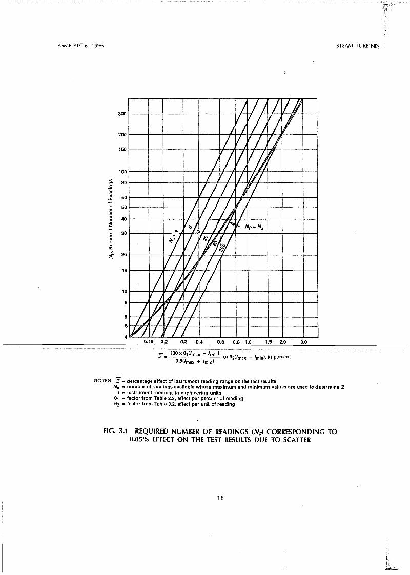
3.9.2 Duration of Test Runs. This Code recommends a minimum steady-state test run of two-hourduration for each load point. Although high speeddata acquisition systems may permit enough readingsto be taken in less than two hours to satisfy otherrequirements, the two-hour minimum is recommended to verify cycle isolation, In any case thelength of the test period for which readings areaveraged shall be at least as long as the periodwhich corresponds to NR from Fig. 3.1. N R is therequired number of readings whose averaged scatterwill affect the test results by an uncertainty no largerthan 0.05 percent. Table 3.2 contains..!he percentagecoefficients to be used to calculate Z, the abscissaon Fig. 3.1.
3.9.3 Numberof Readings Available. During a testrun, after severaI readings have been recorded andtheir scatter established, Fig. 3.1 may be used todetermine how many readings are needed to complywith the 0;05 percent effect of the scatter on theresults or to determine if improvements are neededin the instrumentation or in the controI of testconditions.
3.9.4 iIIustrations and Derivation. Section 7 in thisCode presents illustrations for the use of Fig. 3.1as well as its derivation. A method is also presentedand illustrated for estimating the uncertainty of atest based on ali the readings of a specific type thatare used to calculate the test results. A comprehen-sive treatment of calculation of uncertainty is preser:Jted-in-P-1=G---1-9..1.....---------------
3.9.5 Only such observations and measurementsneed be made as apply and are necessary to attainthe objective of the test. In the case of the alternativetest, additional measurements beyond those requiredmay be desirable to aid in the analysis of test results.
3.10 CALIBRATION OF INSTRUMENTS
3.10.1 Ali measuring instruments shall be accurateand reliable and shall be calibrated as required incompliance with criteria given in Section 4. Calibration standards shall be traceable to those maintainedby the National Institute of Standards and Technology.
The ratio of the accuracy of the measuring standardcompared to the instrument being calibrated is re-
ASME PTC 6-1996 STEAM TURBINES
60
40
50
80
3.01.5 2.00.6 0.8 1.00.3 0.40.15 0.2
J // / /11) V/ 1/IlVIV
/ VJ1// 1//
J~/1/V~ 'fI
I Il I 11//IlV) J~I
) / I / I/ II VJ /
V;/I.vr. lI-NR=Na-;; I~V/ ,~
VI1/)~I// V}r'1VI
V I ~) / V
I I~VI VII~ I I I il
IV/1/ v / J- .
30
200
100
6
5
4
15
10
8
300
150
<IlClc::cC1lCI>a:'O~.cE::::lZ"'O
2!':5c-CI>a:;f 20
z= 100 X9,(Jmax - Imln) or 92(1max - 'mln), in percent0.5(/max + 'mln)
NOTES: Z .. percentage effect of instrument reading range on the test resultsNa .. number of readlngs available whose maximum and mlnimum values are used to determine Z
I .. Instrument readings In engineering units9, .. factor from Table 3.2, effect per percent of reading92 =fa~or from Table 3.2, effect per unit of readlng
FIG. 3.1 REQUIRED NUMBER Of READlNGS (NR> CORRESPONDING TO0.05% EFFECT ON THE TEST RESULTS DUE TO SCATIER
18

STEAM TURBINES
TABlE 3.2DEFINITIONS AND NOTES TO FIGURE 3.1
(A) 01 , O2 INFLUENCE FACTORS FOR CALCULATIONS THE ABSClSSA OF FIG. 3.1
ASME PTC 6-1996
Notes: .(7) 01 is expressed as percent effect per percent of instrument reading.
(2) O2 is expressed as percent effect per unit of instrument reading.
(3) O,', 0/ are the slopes of the correction-factor curves.
(4) O," or 0/' are used to take into account the effect of the instrument-reading range far f1uctuation in measurements used to establishany enthalpy appearing in the heat rate equation. Far O," or O2'' values use the applicable Figs. 7.2, 7.3, 7.4 or 7.5 after converting theordinate to percentage effect per percent of absolute pressure or absolute temperature for O," or percent effect per unit of reading for O{.
Type of Data
(1) Power(2) Flow by Volumetric Weigh Tanks(3) Flow by Flow-Nozzle Differentials(4) Steam Pressure and Temperature(5) Feedwater Temperature(6) Exhaust Pressure
(B) FOR COMBINING TYPES OF DATA
01
1.01.00.5O,' + 8( 82' + O2''
(h"0/
Type oi Data
(7) Average of n columns of similar readings such as 4 exhaust-pressure taps
(2) Total effect of m types of readings with the same time interval between readings.such as load and fiow, or pressure and temperature
Combined
~_ .y2.-; 1'=Zn = = - ·,h:.Zì
...[ii n
- .r;::-:;jiZm = "\JkZ"
NOTES:(1) Z is the percentage effect the instrument readings range (maximum reading - minimum reading) has on the test results.(2) Subscript i refers to columns of individuai measurements.
ferred to as accuracy ratio. Wherever achievable, to be calibrated and the calibration standard. A plotan accuracy ratio of 10:1 is desirable for calibration or table of deviation versus instrument measurement
--+---77wO::o=-=rK.... Extremely .. accurate ìnst1'Ill11eDtLcmpLcgçhing==is:--th~ll...-tJSE!cl=t(J=fJ~tefmifle-:tAe--.amEJtlHt__Elf...-G0~mGti?r-I------the accuracy of the measuring standard may have to be applied toa-tesi measu-reme-i1t.Caliorationa ratio of 4:1 . results also may take the form of instrument output
Consideration shall be given to the environment at a known value of input as determined by thein which the calibration takes piace. Even under calibration standard. From this, a conversion equa-laboratory conditions, the quantity being measured tion can be developed for the instrument.and the instruments. obtaining the measured value The calibration report should include the identifi-can be influenced by vibration, magnetic fields, cation of the calibration equipment and instruments,ambient temperature, changes in local acceleration a desc;ription of the calibration process, a statementdue to gravity, f1uctuation, instability of the voltage of uncertainty of the measuring standard, and asource, and other variables. tabulation of the recorded calibration data. The
A calibration should cover the range for which report should be signed by a responsible representa-the instrument is used. The increment between cali- tive of thecalibration laboratory. Where appropriate,bration points and the method of interpolation be- calibration shall be performed with test instrumentstween these points shall be selected so as to attain installed in piace for the test and ali calibrationsthe lowest possible calibration uncertainty. shall be available prior to the test.
For each calibration point, a deviation may be In-piace calibration of station instrumentation isfound between the value measured by the instrument necessary when secondary f10w measurements are
19

ASME PTC 6-1996 STEAM TURBINES
made by a permanently installed flow element forwhich calibration is required or where station instruments and a computer are used for test data acquisition.
Installation of ali test instrumentation shall complywith ali applicable criteria of Section 4. Instrumentssubject to failure or breakage in service should beduplicated by reserve instruments, properly calibrated, and ready to be placed in service withoutdelay.
denser neck shall be considered cycle losses, notturbine losses.
3.12.2 The numerica I values of corrections shallbe agreed upòn prior to the test. Auxiliary tests maybe run for the purpose of verifying the value ofcertain correction factors. Any such special testsshall be completely described in the test report, asto the methods employed and the results obtained.(See paras. 3.4.5 and 3.8.11 and Section 5.)
3.13 METHODS OF COMPARING TESTRESULTS
3.13.1 The method of comparing test results to thespecified performance shall be agreed upon by bothparties prior to the test. The following are differentmethods that can be utilized to make these comparisons.
3.12 CORRECTIONS
3.12.1 Corrections shall be applied to the testresults for any deviations of the test conditions fromthose. specified. Correction factors may be in theform of curves or numerical values. The method ofapplying corrections shall be carried out as requiredin Section 5. Thermallosse~ associated with unlaggedheaters and connecting piping located in the con-
3.11 STEAM PRESSURE AND TEMPERATUREMEASUREMENTS
3.11.1 Extraction pressure and temperature measurements, when required, should be made both atthe turbine end and the feedwater heater end ofthe extraction piping for feedwater heaters locatedoutside the condenser neck. Source connections inthe intermediate pressure to low pressure crossover 3.13.2 Valve Point Basis. If the specified perform-pipe or in the low pressure turbine bowl may be ance is based on valve points, then a locus curveused as a common point for intermediate pressure can be drawn through the specified performancesection and low pressure section efficiency determi- points for comparison with another locus curvenations. Paragraphs 4.17.21 and 4.18.3 should be drawn through the corrected test heat rates con-consulted for guidance in selecting locations for ducted at valve points. Test results may be comparedpressure taps and thermowells. with the specified performance by reading the differ-
3.11.2 Steam enthalpy shall be determined from ence between the two locus curves at the specifiedkilowatt load(s). Alternatively, the comparison may
temperature and pressure measurements only whenthe steam is superheated at least 2rF (15K). be made at the test valve-point loads. In any case,
the provisions and intent of the contract must be met.3.11.3 Thermodynamic Properties. Except with There may be instances when regulatory restric-written agreements to the contrary, the latest edition tions Iimit operation of a unit to loads below theof the ASME Steam Tables, "Thermodynamic and valves-wide-open point. In such cases it is necessaryTransport Properties of Steam" and its enthalpy- to apply a correction for operating on a valve loop
-----------ct:!11:nJPd@gIClllljLY\-Qlli~cçb:crIt), ... ?b:crU=l:>t:::]:l~-jinIJ-.---eS0-··that-tAe:=t~st· ..Aeat=r~te:=at=the:-hignest __peFFfli55ible-e--the calculation of test results. When computers aretestfoac(may be TnCluded on the cùive of corrected •used, they may link to compiled versions of the test heat rates.source code as supplied with the steam tables. It is recommended that the highest test load beOtherwise, they shall be programmed in accordance as close to the valves-wide-open load as possiblewith the 1967 International Formulations for Indus- to keep the valve loop correction to a minimum.trial Use. Testing at reduced steam generator pressure is recom
mended, where practical, to minimize the loopcorrection.
The following approach is recommended:(a) Establish by test the pressure drop across the
last controIvalve(s) to open in valves-wide-open operation. Steam generator pressure may be reduced toopen the last valve(s). If this is not possible, use thedesign pressure drop for the last control valve(s), whenfully open.
(b) Measure the pressure drop across the last control valve(s) to open during the highest load test.
20

STEAM TURBINES ASME PTC 6-1996
- )----
k values for other types of turbines should beobtained from the manufacturer.
3.13.3 Mean-of-the-Valve-loop Basis. If the specified performance is based on mean of the valveloopsl it may be convenient to convert to the valvepoint basis, and the correction curves for this conversion shall be furnished by the manufacturer. However, if there is any doubt as to their accuracy,enthalpy drop or other efficiency tests can be l'unto establish the difference between the valve-pointcurve and the mean-of-the-valve-Ioop curve.
3.13.4 Throttled Valve(s) Basis. For mach ines witha single valve or multiple valves operating in unison,each test heat rate should be compared to design
wherePc= corrected first stage inlet (bowl) absolute
pressurePo= test first stage inlet (bowl) absolute pressPs= specified throttle absolute pressurePI= test throttle absolute pressure
(b) In tests of light water reactor (LWR) cycles withreheat, the use of the alternative procedure may notprovide sufficient data to establish the turbine throttle(IQw,particLJlmty.i ftl-re-rTTairrstE:<ìl1ìflow-te>-th~r~heater~----is not measured. In such tests, one of the followingprocedures may be used by agreement of the partiesto the test:
(1) Determine the main steam flow to the reheater with avàilable plant instrumentation or;
(2) Conduct calibration tests, without the reheater in service, of the first stage pressure versusthrottle flow, and correct the flow using manufacturer's data to obtain the throttle f10w during tests withthe reheater in the cycle.
If either of these procedures cannot be implemented, then;
(3) Use the design values for the reheater flowand subtract this value from the total f10w to obtainthe throttle flow for each test point.
(c) Using the above relationship, extrapolate to athrottle f10w which would exist at the valves-wide-
heat rate at the same percent of valves-wide-openload. This can best be done by including a test atthe valves-wide-open load. Therefore, this is thepreferred condition. However, some units cannotbe tested with valves wide open. In these cases, itis necessary to predict the test valves-wide-openload using the available test information given below.It is recommended that the highest test load be atleast 95 percent of the load corresponding to ratedflow at specified steam conditions and cycle arrangement in order to minimize uncertainty in the extrapolation method. The following approach is recommended:
(a) Establish the relationship between the test throttle f10w vs. first stage inlet (bowl) pressure over asmuch of the load range as possible. See Fig. 3.2. Correctthe throttle flow from the test th rottie steam conditions to the specified throttle steam conditions atvalves wide open as shown in para. 5.4.2. The firststage inlet (bowl) pressure must be corrected to specified throttle pressure at valves wide open as follows:
Pspc = po X -.
Pt
\l'n
Wma
the ratio of f10w through the final valve(s)to total flow during the highest load test(decimai fraction of total flow being subjected to extra throttling.)
W n (APmo !lPVWO)Percent !lHR = - 100kwmo Pt
(c) Apply the following equation to obtain the percentage heat rate correction:
where subscript ma indicates highest load test, and
f
the ratio of (1) the difference between pressure drop across the final valve(s) duringthe highest load test and the pressure dropacross .the same valve(s) at valves-wideopen conditions, to (2) throttle pressure (extra pressure drop due to final valve(s) notbeing wide open.)
k= the percentage effect on heat rate for a 1percent change in pressure drop
Pr=absolute throttle pressurek= 0.15 for turbines with nuclear steam supply
operating predominantly in the moistureregion.
k= 0.10 for turbines operating predominantlyr--'-----j- ...!Jinl..L...!tJ..!h~e_.is~uf;1erheat region.
21

ASME PTe 6-1996 STEAM TURBINES
Specified throttle pressure
---~X---~)(:"'----4<~----- Design pressuredrop at VWO
PredictedVWO
throttlef10w
I
x = Test va lues. corrected tospeclfied th rollie pressu re
Throttle Flow Corrected to Specified Conditions
FIG. 3.2 CORRECTED FIRST STAGE INlET (BOWl) PRESSURE VS.CORRECTED THROTTLE FlOW FOR USE IN DETERMINING
PREDlCTED VWO THROTTLE FlOW
open point, using the design pressure drop from thethrottle inlet to first stage inlet (bowl) at valves wideopen.
(d) Determine the valves-wide-open load by establishing a curve of corrected throttle flow vs. correctedtest load. See Fig. 3.3. Extrapolate to valves-wide-openflow (from item 2) using the slope ofthe correspondingcurves derived from design heat balances as a ref-
i-----erence.. ---~--_._-- ---_...-
(e) The percent of valves-wide-open load for anytest point can be determined using the extrapolatedvalves-wide-open load.
Predicted VWO throllie f10w
x • Test valuBs, corrected tospecified throllie pressure
3.13.5 Specified load Basis. During steam rate orheat rate tests at specified loads, it shall be permissible to adjust the load of the test so that when alicorrections have been applied, the corrected loadwill be within five percent of the load specified forthe test. The test results may be reported at a loadwithin this percentage.
The load correction may be applied only whenguarantees are made at specified loads and when thevalve point or mean-of-the-valve-Ioop comparisonscannot be utilized.
PredlctedVWOload
Corrected Test Load
FIG. 3.3 CORRECTED THROTTlE FlOW VS.CORRECTEO TEST lOAD FOR USE IN
DETERMINING PREDlCTEO VWO lOAO
22

STEAM TURBINES
3.14 TOlERANCES
3.14.1 Tolerances are contractual adjustments totest results or to guarantees and are beyond thescope of this Code. Allowances for test uncertaintiesshall not be applied to the test results when a testis run in accordance with this Code. The test resultsshall be reported as calculated fram test observationswith only such corrections as are provided for inthis Code.
23
ASME PTC 6-1 996

STEAM TURBINES ASME PTC 6-1996
SECTION 4 - INSTRUMENTS AND METHODSOf MEASUREMENT
4.1.5 Necessarylnstruments. The instruments generally required for a Code test of a steam turbineare listed below and are for check purposes only:
(a) far a mechanical-drive turbine, a dynamometerof a type suitable to the turbine and to the circumstances of the test, see Subsection 4.2
(b) far a turbine-generator, instruments for the measurements of the electrical output and power far excitation, if separately supplied, and for other turbine-
GENERAl
4.1.3 Equivalent Instrumentation. By mutuaiagreement of the parties to the test, manual instrument systems as described herein may be used asan alternative to the advanced instrument systemsspecified by this Code.
4.1.4 Use of Mercury in Instrumentation. Certainmanual instrumentation systems require the use ofindìcating fluids to indicate pressure or differentialpressure. Historically, mercury is one of the fluidscommonly used for this purpose. Mercury will alloywith many other metals such as copper, lead, tin,bronze, and Monel and their alloys. There is evidence that Inconel alloys, zircaloy, and certain stainless steels are also sensitive to mercury. These materi-
4.1
4.1.1 In the absence of special agreements to thecontrary, this Code presents the mandatory requirements for instruments, methods, and precautionswhich shall be employed. It emphasizes the use ofadvanced instrument systems, such as those usingelectronic devices or mass flow techniques, that aresuitable for use with digitai systems. The Supplementson Instruments and Apparatus, PTC 19 serìes, providegenerai and authoritative information concerninginstruments and their use and should be consultedif sufficient information is not included in this Code.
als are used extensively in the construction of variousnuclear steam supply system components that comein contact with feedwater returned from the turbinecycle.
Mercury constitutes a hazard to light-water cooledand moderated nuclear steam supply .systems ifintroduced into the feedwater stream. If the use ofmercury cannot be avoided in pressure measuringinstruments, the following precautions are recommended:
(a) Keep valves to test instriJments c10sed exceptduring test runs.
(b) Install quick-c1osing solenoid valves in test in-4.1.2 Duplicate Instrumentation. This Code speci- strument sensing lines to close automatically on sys-fies duplicate instrumentation far measuring certain tems upsets.types of data that are criticai to .the test results; such (c) Employ double mercury traps.data may include flow nozzle pressure differentials (d) Locate primary flow element in the low pressureand steam temperatures. Other data, such as exhaust part of the feedwater cycle where it is more remotepressures, vary over the region involved; the several from the nuclear steam supply system (see para. 4.9.1).measurements required confirm each other by their Mercury metal and compounds of mercury maypattern from test point to test point. Beyond these, cause dangerous environmental problems. The rela-duplication of many types of instrumentation should tively high vapor pressure of mercury presents abe seriously considered to assure successful use of serious health hazard if spillage occurs. Extremethe instruments or to detect trouble, and to gain care is necessary and strict adherence must be giventhe significant reduction of the uncertainty of the to ali applicable regulations concerning mercury. If
--I--------::l\lE!rfl:gE!:=e>f-=til_~=:_el1;l,:ili~a!il'lg_=in~~~l;Il'fl~lìtS_:::_"~lati\le___t0==the--l'i5k--0f-\;J5iFlg---lT-Ier-Gblr-y-:fi.I.leQ-mar:lQr-neter~s~i:5-:judged-----
that of a single instrument. Refer to Figs: 4.ffa- ·unaccepiélble by oneOi DOtn partiesto the tèst,4.11 e. regardless of the degree of precaution exercised, the
parties may employ advanced instrument systems(such as those employing certain high sensitivitydifferential-pressure transducers) in accordance withparas. 4.1.1 and 4.8.1 of this Code.
2S
mdl
Evidenziato
mdl
Evidenziato
mdl
Evidenziato
mdl
Evidenziato
mdl
Evidenziato

ASME PTC 6-1996 5TEAM TURBINES
p = NT
27TNTp=-
33000
4.2 MEASUREMENT Of MECHANICALOUTPUT
whereP= power, watts (W)N= rotational speed, rad/secT= torque, newton-meters
For power expressed in U.S. customary units
generator auxiliary services, see Subsections 4.4through 4.7
(c) for determining condenser leakage, instrumentsrequired for using tracer techniques, electrolytic orother measuring means refer to PTC 12.2, SurfaceSteam Condensers .
(d) for the location and type of test instrumentationrequired for full scale testing of a typical unit, see Fig.4.11 (a) to Fig. 4.11 (c) and Subsection 4.8 throughpara. 4.19.1.8
(e) for the location and type of test instrumentationrequired for the alternative test witn final feedwaterflow measurement, see Fig. 4.11 (d) to Fig. 4.11 (e) andSubsection 4.8 through para. 4.19.1.8
(f) for measurement of speed, see Subsection 4.20.
4.1.6 Measuring Devices with Digitai Outputs. Tominimize uncertainty, it is recommended that measurement signals snould be converted from analogto digitai only once. Therefore, if a measuring devicehas a digitai output, this digitai signal should betransmitted to a data logger ratner than use ananalog converter.
wherep= power, horsepower (hp)N = rotational speecl (rpm)T= torque, foot-pounds (ft Ibf)
Rotational speed measurement is discussed in Subsection 4.20.
For shaft power measurement when the primemover is driving a connected load, such as requiredfor a feedwater pump drive turbine in an acceptancetest, the transmission dynamometer (shaft torquemeter) is recommended. Absorption dynamometers(reaction torque measurement systems) absorb theprimer mover power output and cannot be usedwhile simultaneously driving a connected load.
Either surface strain shaft torque meters or angulardisplacement shaft tarque meters which are compatible for use in either computerized data recordingsystems or for use with electronic digitai indicatorsshould be used.
For shaft power measurement of a mechanicaldrive turbine that can be tested without its connectedload, an absorption dynamometer (reaction torquemeasurement system) can be used. Such a test mightoccur when a mechanical drive turbine is testedindependently of a turbine-generator acceptance test.
Precautions must be taken in the construction anduse of torque meters to ensure accuracy. The torque
4.2.1 Recommended Measurement Methods. Ab- meter shall be accurate within 1 percent of torque.sorption dynamometers (reaction torque measure- Torque meter readings shall be taken with the fre-ment systems) or transmission dynamometers (shaft quency indicated in Subsection 3.9 and shall nottorque meters) shall be used to measure mechanical exceed the permissible deviations shown in Tableoutput of prime movers which can be an auxiliary 3.1. Because power is proportional to speed, speed
shall be accurately determined in accordance withturbine, turbine generator shaft, or electric motor. Subsection 4.20.Tnese measurement systems are described in detail
-----inJ~IC.J..9J--On~easllrement..o.f...ShafU:lorsepower-"--....4.2.2----IransmissiOILfiyJ1amometer.s..--lShafLturtllle""- _The ·direcfmétnod f6rméasOfintrpowér; iJtil izihg 'mefer);Tràìisiiiissi6ndynambiiiétérssh'aIl bé Cali:
a dynamometer or a torque meter, involves determi- brated before and after the test series with thenation of the variables in the following equation: torsional member at approximately the same temper-
For power expressed in SI units ature as expected during the test. The calibrationshall be conducted with the torsion indicating devicein piace, taking care not to introduce any bendingmoments in the torque meter shaft. One such methodof calibration is shown in PTC 19.7. Recordings ofthe indicator shall be made with a series of increasingloads and then with a series of decreasing loads,with the precaution tnat during the recording of eachseries of readings the loads shall not be reversed. Thecalculation of output shall be based on the averageof the increasing and decreasing readings. If thedifference in readings between increasing and decreasing loads exceeds 0.2 percent of the load, thedynamometer shall be deemed unsatisfactory.
26
mdl
Evidenziato
mdl
Evidenziato
mdl
Evidenziato
mdl
Evidenziato
mdl
Evidenziato

STEAM TURBINES ASME PTC 6-1996
4.2.5 Absorption dynamometers shall be carefullyexamined before and after the test and zero scalereadings taken. The output shall be determined asshown in PTe 19.7.
4.2.3 Absorp'tion Dynamometers (Reaction torquesystem). Absorption dynamometers are preferablyarranged so that the reaction due to friction of anybearings that are essentially a part of the dynamometer will be automatically included inthe dynamometer readings. Otherwise the parties to the test shallagree upon an allowance for these losses whichshall be stated in the test report.
The shaft torque meter may be ~ Ither a specialcoupling spacer, installed only during the test, thatconnects the prime mover shaft to the connectedload or it may be a permanently installed partof either the prime mover shaft or the connectedload shaft.
To minimize potential error, the shaft torque metercapacity range should be approximately equal tobut slightly greater than the torque range of theprime mover.
Temperature compensation in the electronic circuit is recommended to minimize errors that couldoccur if the test is conducted at temperatures differentfrom the temperature that existed when the torquemeter was calibrated.
4.3 MEASUREMENT OF FEEDWATER PUMPPOWER
4.3.1 GeneraI. Any thermal energy that is eitheradded to or removed from the turbine cycle by thefeedwater pump or its associated auxiliary systemsshall be measured and properly accounted for inthe turbine heat rate calculations (see paras. 5.7.1and 5.7.2). The following types of feedwater pumpdrives can be used: auxiliary turbine drives, motar,and turbine-generator shaft drives.
Regardless of the type of feedwater pump drivethat is used, the feedwater pump power can bedetermine.d by either of the following methods:
(a) pump shaft power calculated from measuredshaft torque and speed (see Subsection 4.2 for torquemeasurement and Subsection 4.20 far speed measurement)
(b) pump power calculated by an energy balancearound the pump using measured fluid flow rates,temperature, and pressure of ali fluids that enter andleave the feedwater pumps (see para. 4.3.5). The energy balance method is described in this Section.
4.3.1.1 For auxiliary turbine driven feedwaterpumps, it is also necessary to determine the thermalenergy that is extracted from the turbine cycle.This can be accomplished by one of the followingmethods: .4.2.4 Precautionary Measures for Absorption Dy-
namometers. In the case of absorption dynamome- (a) measurement of flow rate, pressure, and neces-ters, care must be taken so that no external forces sary measurements to obtain enthalpy of steam thatare applied which may introduce errors. The op- enters and leaves the auxiliary turbine (see Subsectionerating fluid of water brakes and cooling air of 4.12 and para. 4.16.3)electric absorption dynamometers shall enter and (b) shaft power calculated from measured torqueleave in the radiai or axial direction. There shall and speed and then divided by the efficiency of the
~~~~~~~~~;I~~~i~àv~{)~~~est:~;~~~~~;~;'-'-'~nJJJt~"'-~_-..-.":~:~~~~n~~;~~toobtain the energy removed fram
Hose connections, if employed, shall cause no sensi- Method (b) requires the use of the manufacturer'sble force in the tangential direction. If automatic predicted turbine efficiency and must be agreed tovalves are employed to regulate operating fluid flow by ali parties to the test, especially if the auxiliaryby means of movement of the stationary dynamome- turbine is being acceptance tested concurrently withter element, these valves shall have their resistance the turbine-generator.
to motion equal in both directions. Oashpots em- 4.3.2 Typical Instrumentation for Pump Power byployed to dampen oscillation shall also have their Energy Balance Method. Fig. 4.1 shows the typicalresistance to motion equal in both directions. Other instrumentation for measurement of feedwater pumpprecautions for specific types of absorption dyna- power and is representative of feedwater pumps thatmometers are detailed in PTe 19.7. have a speed changer and hydraulic coupling. The
prime' mover could be an auxiliary turbine,' motordrive, or turbine generator shaft drive. The hydrauliccoupling and speed changer are not commonlyused with ali three types of feedwater pump drives.However, in some situations they may be used.Therefore, the following text describes thermody-
27
mdl
Evidenziato
mdl
Evidenziato
mdl
Evidenziato

ASME PTC 6-1996
Primemover
STEAM TURBINES
Dischargefrom otherpump
Discharge'-r-....,.....,-- for reheat
spray
F---_... Suctionto otherpump
gi = Gland-injection-water inletgo = Gland-injection-water outletai = Oil-cooler-inlet water00 = Oil-cooler-outlet waterao = Interstage leakoff
for reheat spray
4.3.5 Calculations. The calculations shown belowc10sely follow PTC 8.2 on "Centrifugai Pumps."
The power taken from the prime mover shaft isthe sum af the power equivalent of the enthalpyrise of the water flow through the pump, the powerused in bearing losses, gear losses, and hydraulic
FIG. 4.1 TYPICAL INSTRUMENTATION FOR MEASUREMENT OF FEEDWATERPUMP POWER
namic property measurements and calculations for feedwater pumps in service is ali that is needed farthe most generai situation. an overall test.
The temperature, pressure, and flow measurements4.3.3 Turbine-Generalor Shaft Driven Pumps.When feedwater pumps are driven from the turbine should be of such accuracy that the effect on the
overall test result shall be less than 0.1 percent.generator shaft, the measurements described belowmust be made as accurately as possible to determine The measurements requiring the most care are the
---------:~=:huc;:em==~'-~w,)--=:=rn~~~~~i~~ss~~la~~~=~;~~~~~~~_~~u~~::=i~-=~n-r-(~;---~i:~id~d~~~:~~~;~;'~~:~-----and/or speed increaser(s}.
temperatures may be measured by two or more4.3.4 Required Measurements. The power trans- precision resistance thermometers and precisionmitting oil for the hydraulic coupling and lubricating bridges or a difference resistance bridge (see Subsec-oil for the pump, speed changer, and hydraulic tion 4.18). The individuai measurements far eachcoupling is cooled in heat exchangers using water location shall agree within O.2°F (0.1 K). Alternatively,as a cooling medium (see Fig. 4.1). Changes in the temperature differences between pump dischargeinstrumentation requirements resulting from any vari- and suction may be measured by multiple junctionation in this arrangement shall be agreed upon prior differential thermocouple devices and precision mil-to the test. The illustration on Fig. 4.1 is for one livolt instruments.pump but the same measurements will be necessaryfar each pump in service. In some cases it may notbe practical ta measure the individuai water flowthrough each pump or the injection water flows toand from each pump. In such cases, the power fareach individuai pump cannot be accurately determined. However, the total power consumed by the
28

STEAM TURBINES ASME PTC &-1996
coupling losses, and the power equivalent of theradiation losses.
The power equivalent of the enthalpy rise of thewater (Penthalpy rise) is:
The basic equations for pump shaft power are:
(Whp)O.746kW= _-c-__
T]
Penthalpy rise =
w9(h lO - h9 ) - wao(h lO - hao)
+ wg/(hlQ - hgl ) - wgo (h lO - hgo)
K(QyH)O.746
kW=---550T]
where1] = pump efficiency from curveQ= volumetric flow rate at pump discharge, ft3/
sec (m3/s)y =specific weight, Ibflf(3 (N/ m3
)
H= pump total discharge head minus total suction head, ft (m)
Pump discharge flow rate =
Determination of water flow at the pump dischargewill vary, depending on whether the main f10wmeasurement nozzle is located in the pump suctionor pump discharge piping. If the nozzle is locatedin the suction piping, the pump discharge flow rate(WlO) is:
where K is a constant depending on theunits of P, w, and h.(See Section 2 and Fig. 4.1 for nomenclature).
If P is in kW, w in kg/s and h in k)lkg, then K = 1If P is in Kw, w in kg/ h and h in Kj/kg, then K = 3600If P is in Kw, w in Ibm/hr and h in Btu/lbm, then
K = 3412.14The power equivalent of the bearing, gear, and
hydraulic coupling heat losses (Pheat losses), as determined from the heat absorbed by the oil coolingwater is:
Measurements and calculations of water horsepower are detailed in PTC 8.2.
Other losses, such as hydraulic coupling losses,speed changer losses, seal flows, radiation, andspray water takeoffs must also be accounted far asdescribed in para. 4.3.5. Refer to Fig. 4.1 for theseitéms.
An ordinary pump characteristic curve suppliedwith the pump has two major Iimitations. First, theefficiency versus capacity curve is valid at only onepoint because it is plotted at constant speed andmany feedwater pumps run at variable speed. Oneshould obtain the variable speed efficiency versuscapacity curve prior to using this method.
Second, if the pump is operating at off designspeed during the test, the pump efficiency is usuallydifferent from predicted efficiency by a small amount.Hence, test speed should be within two percent of
---1------------------------_---..1.. ~!)igl'1::::s.PEled=in=()rder=th~t=pl:Jfnp-pE>VVer=€aA~~e!.- ~---Wl ()=. wc) +' Wil"" Wgii "" W,,-,) determined as accurately as possibie: .... .. ..
The power equivalent of the radiation losses(Pradiation lesses) can be calculated or estimated, butthe amount of this loss may be negligible (refer toPTC 10 on "Compressors and Exhausters" far themethod of calculating this loss).
The pump shaft power (P) is:
p = Penthalpy rise + Pheat losses + Pradiatioo losses
43.6 Alternative Calculations. Another method ofdetermining pump shaft power involves pump efficiency curves. Water horsepower (Whp) is determined from these measurements and then dividedby expected pump efficiency to obtain pump shaftpower.
4.4 MEASUREMENT OF ElECTRICAl POWER
4.4.1 Generai Requirements for A-C Generators.It is recommended that the power output of an a-cgeneratar be measured by sufficient instrumentationto ensure that accurate metering (i.e., no uncertaintyis introduced due to the metering method) will beprovided under ali conditions of load power factarand load unbalance.
Generatar loss curves provided by the manufacturer may require either the kilovolt-ampere (kVA)output or kilowatt output and power factor of thegenerator to determine the generator loss at specifiedhydrogen pressure.
29
mdl
Evidenziato
mdl
Evidenziato

ASME PTe 6-1996 STEAM TURBINES
4.4.2 Recommended Metering Connection Methods. The recommended metering methods thatachieve accurate metering for three-phase systemsare as follows:
(a) four-wire generator connections - three single-phase meters
(b) three-wire generator connections - two single-phase meters
Refer to para. 4.5.1, below, for further discussion.The necessity for the recommended metering
methods is discussed in the following paragraphs.
4.4.3 Blondel's Theorem for the measurement ofelectrical power or energy states that in an electricalsystem of N conductors, N-l metering elements arerequired to measure the true power or energy ofthe system. It is evident, then, that the electricalconnections of the generator to the system governthe selection of the metering system.
Connections for three-phase generating systemscan be divided into the following two generai categories:
(a) three-wire connections with no neutraI returnto the generating source
(b) four-wire connections with the fourth wire acting as a neutral current return path to the generator
4.4.4 The following describes different types ofthree-wire and four-wire generator connections thatare used
former, it is also an example of a three-wire generatorconnection. [See Fig,;. 4.2(a).]
A final example of a three-wire generator connection is the delta connected generator. The deltaconnected generator .has no neutral connection tofacilitate a neutral conductor; hence, it can beconnected only in a three-wire connection. [see Fig.4.2(b).]
4k4.2 Four-Wire System. Four-wire generatorconnections can be made only with a wye connectedgenerator with the generator neutral either solidlygrounded or, more typically, grounded through animpedance. Load distribution is made at generatorvoltage rather than being separated from the generator by a delta-wye transformer. This type of connection has a separate fourth conductor which directlyconnects the generator neutraI (or neutraI groundingdevice) with the neutraI of the connected loads.[see Fig. 4.2(c).]
For the generating system connections describedin the preceding paragraphs, accurate metering willbe provided under ali conditions of loaCl powerfactor and load unbalance by application of therecommended metering methods, which were described in para. 4.4.2.
A typical instrument connection diagram is shownon Fig. 4.2(d).
4.4.5 Alternative Metering Connection Methods.Alternative metering methods that may be used
4.4.4.1 Three-Wire System. A common three- by mutuai agreement between ali test parties arewire system is a wye connected generator with described in PTC 6 Report. However, the uncertaintya high impedance neutral grounding device. The of the power measurement with the alternative meter-generator is connected directly to a transformer with ing methods will be greater than that of the recom-a delta primary winding and load distribution is mended metering methods.
-------maGle-QR-tl:Je-seGondar.!l~gr-OuRded~w-\l~sl· -:l''of_tl::-,,, ----;r-,.-,.-l----r=-.--=-cc-r"'===-='"'=c-r--==-=c= .
n "tràrisfOrmer. 15eeFig:4.:t(ar:TToadGri6al~~es6~ 4.4.6 .MeterConneclions. Connectlons fOLvoltagethe load distribution side of the generator transformer and current measuring instruments shall be made
on the generator side of the step-up transformer(s)are seen as neutral current in the grounded wyeconnection. However, on the generator-side of the as dose to the generator terminals as possible.transformer, the neutraI current is effectively filtered Current connections shall be made on the generatorout due to the delta winding and a neutraI conductor side of any external connections of the power circuitis not required. by which power can enter or leave this circuit.
Another type of three-wire system utilizes a wye 4.4.7 Excitation Power Measurement. If the excita-connected generator with a low impedance neutral tion or auxiliary systems receive power from thegrounding resistor. The generator is connected' to a generator, then either it must be separately meteredthree-wire load distribution bus and the loads are or the generator power metered beyond the excita-connected either phase to phase, single phase, or tion connections but ahead of any auxiliary powerthree phase delta. The grounding resistor is sized connections.to carry 400 to 2000 amperes fault current. Electrical power separately supplied to produce
An ungrounded wye generator is less common either excitation or any other service to the turbinethan the high impedance grounded-wye generator, generator unit, not specifically covered byagreementbut when used with a delta-wye grounded trans- of the parties to the test, shall be measured at the
30
mdl
Evidenziato
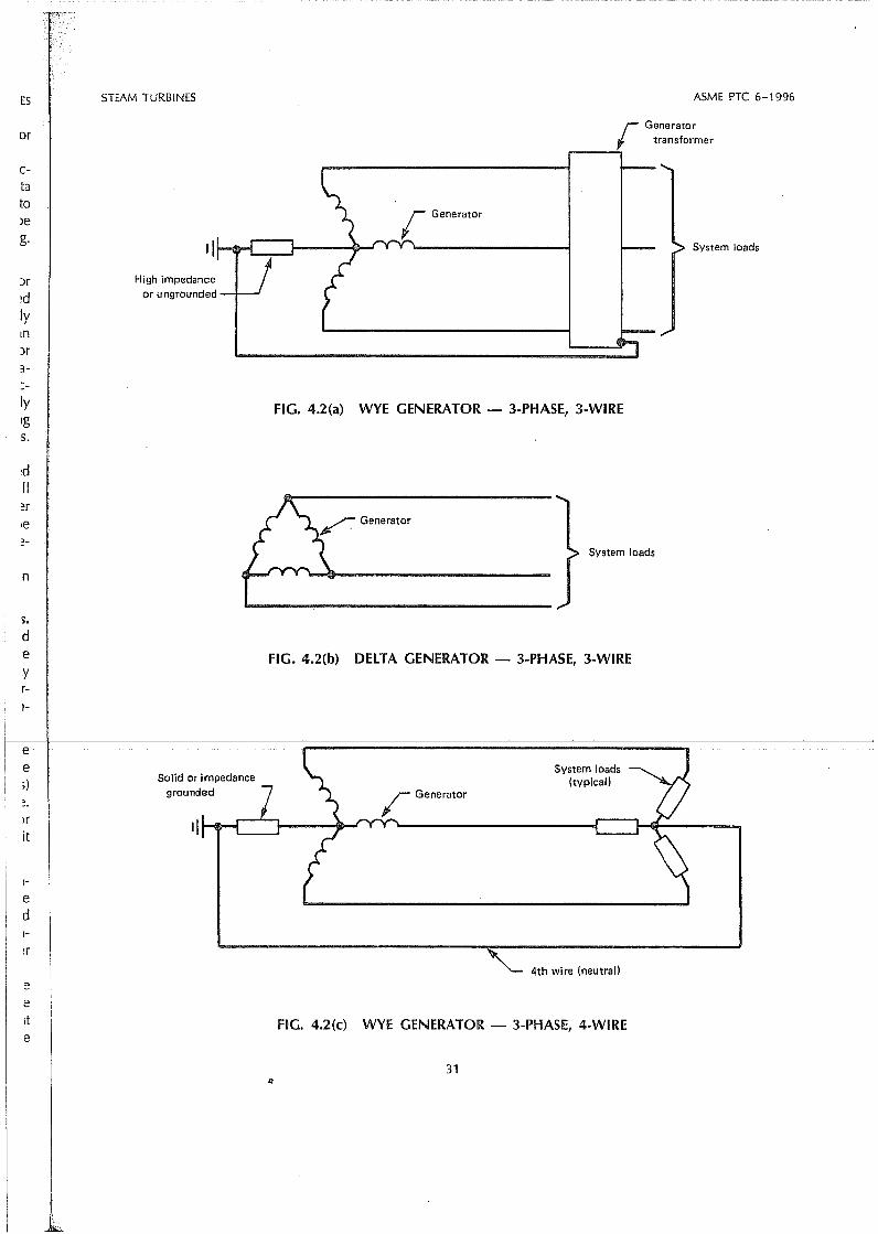
ES
or
5TEAM TURBINES ASME PTC 6-1996
r Generatortransformer
,..--.....;
etato
>eg.
IyIg5.
~d
Il
n
s.d'eyr1-
e;)
lrit
l
ed1-
eeIt
e
High impedanceor ungrou nded
Solid or impedancegrounded
FIG. 4.2(a) WYE GENERATOR - 3-PHASE, 3-WIRE
System loads
FIG.4.2(b) DElTA GENERATOR - 3-PHA5E, 3-WIRE
System loads(typical)
4th wire (neutral)
FIG. 4.2(c) WYE GENERATOR - 3-PHASE, 4-WIRE
31
System loads

ASME PTC 6-1996 STEAM TURBINES
Instrument CT'S~
~-
.-J I::
~-
O, ,.....J L t--~
,J L I-
[/I I l I I3
~ u...v...~Ph.3-r- Instrument PT'S
~enerator Iìt r-')~--I
Ph.1 Ph.2
IPh.1
Ph.2 - I-.'Il> Transformer secondaries may begrounded at secondary terminals
Ph.3 or ground connection on table .
...fJt}CT C~ ) ::>,
.ho";,, f}iswitch f ] ( (
.l.. -L- -VM VM
~[] ~[] ·ffiJVM
AM AM AM....--
~~~ ~~ ""C)::I-~~ o-~
""Il 0-h O-h ""hWM l ~~~ I~ ~WM l-l WM • ...~..~ I
Phase 1 Phase 2 Phase 3
VM - VoltmeterAM - AmmeterWM - WattmeterCT - Current transformerPT - Potential transformer.. - Polarity mark
~ - Fuse
FIG. 4.2(d) TYPICAl CONNECTIONS FOR MEASURING ElECTRIC POWER OUTPUT BY THE THREEWATTMETER METHOD
32

STEAM TURBINES
point of supply to the auxiliary apparatus producingthe excitation or other servi ce.
4.4.8 D-C Generator Power Measurement. Powerautput af d-c generatars shall be measured by thed-c voltmeter-ammeter method. Connectians for voltage and current measuring devices shall be madean the generator side of any connections to thepower circuit by which power can enter or leavethis circuit and as close to the generatar terminalsas physically possible.
4.4.9 Guidance for Power Measurement. ANSI/IEEE Std 120, Master Test Guide for Electrical Measurements in Power Circuits, contains detailed information on the construction and use of electricalmeasurement equipment and instructions for measurement of electrical quantities.
4.5 A-C GENERATDR TEST INSTRUMENTS
:4.5.1 Test Instruments. Active power or energy'(kilawatts/kilowatt hours) shall be measured by precision watt/watthour meters (uncertainty of ± 0.10percent of reading for power factors 2:: 0.8). Thereactive power (kilovars) shall be measured eitherby a var transducer (uncertainty of ± 0.20 percentof range) or calculated from measurements of voltageand current. The active power, and either voltage.and current, or the reactive power of each required'phase, as described in paras. 4.4.2 through 4.4.4,shall be measured.
As an alternative to active and reactive power'measurements of each phase, polyphase precisionwatt/watthour transducers and polyphase precision
t---t----uélIivCiTO-oLlL tr:crImlQ@lS .. maybe .LlSe:Q.CQL .. fQLlI: ..wire generator connections, three-element polyphasetransducers are requ i red. For three-wi re generatorconnections, two-element polyphase transducersmay be used. The metering uncertainty with thepolyphase transducers must be equivalent to thecombined metering uncertainty of the single-phasemeters and calibrated per para. 4.7.2.
As noted in para. 4.1.6, any power measuringdevice with digitai outputs should not use analogconverters for signal transmission to data loggers.
The power output measurement instruments shallbe calibrated before and after the tests. The laboratory(ies) and standard(s) used for the calibrations shallbe mutually agreed upon by the parties to the test.It is required that the instruments have their bestoperating characteristics over the range of valuesthat will occur during the tests.
33
ASME PTC 6-1996
Extreme care must be exercised in the transportation of calibrated portable instruments. The instruments should be located in an area as free of strayelectrostatic and magnetic fields as possible. Wherewatthour meters are used, a suitable timing deviceshall be provided to accuratel)' determine the timesfor the number of disc revolutions or pulse countsrecorded during the predetermined test time period,to one part in four thousand.
4.5.2 Instrument Transformers. Correctly rated current and potential transformers of the 0.3 percentaccuracy c1ass (metering type) shall be used for thetests. Transformers shall be calibrated for ratio andphase angle prior to the test over the ranges ofvoltage, current, and burden expected to be experienced during the test. Burdens shall be determinedfrom instrument nameplate data and by measurementaf lead resistance or by measurement of the voltamperes or the secondary impedance and must beconstant during the test. Protective relay devices orvoltage regulators shall not be connected to theinstrument transformers used for the test. Normalstation instrumentation may be connected to thetest transformers if the resulting total burden is knownand is within the range of calibration data.
4.5.2.1 Precautions for Current Transformers.Current transformer cores may be permanently magnetized by inadvertent operation with the secondarycircuit opened, resulting in a change in the ratioand phase-angle characteristics. If magnetization issuspected, it should be removed by proceduresdescribed in ANSI/IEEE Std 120, under "Precautionin the Use of Instrument Transformers."
4.5.2.2 Precautions for Potential Transformer~.~ _.. Potentialtransformers may have either one ortwo
secondary windings; however, one secondary winding is the most common arrangement. If potentialtransformers with two secondary windings are used,the total burden on the two secondary windingsmust be less than or equal to the total allowableburden of the tvvo windings and the burden on eachwinding must be less than or equal to the allowableburden of each winding. Failure to observe the aboveprecautions will introduce increased uncertainty inthe measurement of electrical potential.
4.5.3 Instrument Connections. Test instrumentsshall be connected into the Iines fram the generatoras near to the generator terminals as practical, andon the generator side af any external connectionsby which power can enter or leave the generatorcircuit. Instruments should be connected as shown

ASME PTC 6-1996 STEAM TURBINES
Series field
dcgenerator
Load
FIG. 4.2(e) DlRECT CURRENT SERIES GENERATOR
on connection diagrams given in ANSI/IEEE Std120. Guidance on the use of computer-compatibieinstruments is provided in PTC 19.22, DigitaiSystems.
The leads to the instruments shall be arranged sothat inductance -or any other similar cause will notinfluence the readings. Inductance may be minimized by utilizing twisted and shielded pairs forinstrument leads. It is desirable to check the wholearrangement of instruments for stray fields.
The wiring influence of the voltage circuit shallnot cause a sigriificant errar in the measured poweroutput. Wire gauge shall be chosen considering thelength of wiring and a given load of the potentialtransformers, taking into account the resistance ofthe safety fuses to be used in the voltage circuitoThe errars due to wiring resistance (including fuses)shall always be taken into account.
"" _._ . . ~ __. 0'_- . __ ._._.._ _ __.. .... . ._ ~ __,_~
4.5.4 Excitation and Auxiliary Service. Test instruments for meaSl,lrement of the excitation and auxiliary power services shall be the same type as described in para. 4.5.1 above.
4.6 D-C GENERATOR TEST INSTRUMENTS
4.6.1 Instruments. Portable indicating d-c ammeters (with shunts if required) and d-c voltmeters of the0.25 percent accuracy c1ass shall be used. Ammetershunts shall be calibrated prior to installation.
Typical instrument locations are shown in Figs.4.2(e), 4.2<0, 4.2(g) for a direct current series generator, a direct current shunt generator, and a directcurrent short-shunt compound generator, respectively. The power output and efficiency of each of
34
the three types of direct current generators is calculated as follows.
D-C Series Generator and D-C Shunt Generator:
D-C Short-Shunt Compound Generator:
wherePE= power expended in generator
PM=mechanical power loss = windageand bearing loss
Po=power output77gen = generator efficiency
h= load currentISh Fld = shunt field current
lA = armature currentEF= field voltageEA = armature voltageEL~ load voltage
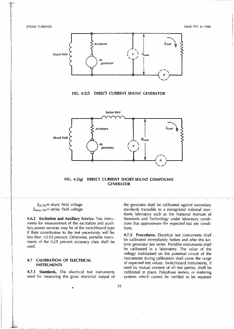
STEAM TURBINES ASME PTC 6-1996
( .....\ V \'- /dc
generator
/" -"L-.---....-------_D-_-'-__-! A !'=-__
' .... /
Shunt field
FIG. 4.2(f) DIRECT CURRENT SHUNT GENERATOR
Series field
Shunt field
dcgenerator
_...... Eload
( V \\ J
.......
r2\
,..- .....
A ':-.---, J..........
FIG. 4.2(g) DIRECT CURRENT SHORT-SHUNT COMPOUNDGENERATOR
fSh Fld = shunt field voltagefSeries Fld = series field voltage
4.6.2 Excitation and Auxiliary Service. Test instruments for measurement of the excitation and auxiliary power services may be of the switchboard typeif their contribution to the test uncertainty will beless than ±0.03 percent. Otherwise, portable instruments of the 0.25 percent accuracy c1ass shall beused.
4.7 CALIBRATION Of ELECTRICALINSTRUMENTS
4.7.1 Standards. The electrical test instrumentsused for measuring the gross electrical output of
the generator shall be calibrated against secondarystandards traceable to a recognized national standards laboratory such as the National Institute ofStandards and Technology under laboratory conditions that approximate the expected test site conditions.
4.7.2 Procedures. Electrical test instruments shallbe calibrated immediately before and after the turbine generator test series. Portable instruments shallbe calibrated in a laboratory. The value of thevoltage maintained on the potential circuit of theinstruments during calibration shall cover the rangeof expected test values. Switchboard instruments, ifused by mutuai consent of ali test parties, shall becalibrated in piace. Polyphase meters, or meteringsystems which cannot be verified to be separate
35

"----------------------"------====
ASME PTC 6-1996 5TEAM TURBINES
4.8 PRIMARY FlOW MEASUREMENT
single-phase meters, shall not be used unless theycan be calibrated three phase.
4.8.2 Measurement of Water Flow. Whileweighing of water can be the most accurate methodof measuring flow, it is seldom practical or economical to employ weigh tanks or volumetric tanks fortesting of the large units installed in modern powerplants. The usual method of determining flow iswith a differential pressure producing device. Twosets of pressure taps and a differential pressureinstrument for each set of taps will be used.
4.8.4 Flow Section. Throat-tap nozzles are recommended for measurement of primary flow providedthey comply with the following requirements:
(a) The beta-ratio (d/O) is Iimited to the range of0.25 to 0.50.
(b) The test flow section shall be calibrated (seeparas. 4.8.13,4.8.14, and 4.8.15). The f10w sectionis comprised of the primary element, including thediffusing section, if used, and the upstream and downstream pipe sections. The upstream pipe section shallbe a minimum af 20 diameters of straight pipe andinclude a flow straightener installed at least 16 pipediameters upstream of the primary element.
4.8.1 The accurate determination of primary flowto the turbine is necessary to compute turbine heatrate or steam rate if the results are to be consideredas a basis for turbine acceptance. Recognizing theIimitations presented herein, this Code recommendsmeasurement of water flow in the feedwater cycle.Extreme care must be taken to obtain the highorder of accuracy necessary in primary water-flowmeasurement. Any deviation from the requirementsset forth in the following paragraphs may result inan increase in uncertainty. Ali known errors mustbe reduced so that their individuai effect is less than0.05 percent of the primary flow to be measured.
The preferred flow straightener utilizes a low presosure drop perforateq, or tubed plate with a non.uniform hole distribution. The geometry of the designis shown in Fig. 4.5 and hole coordinates are speci.fied in Table 4.1. The design and hole coordinatesare identica I for both the perforated and the tubedplate straightener. The upstream side of the holesmust be beveled in ali cases. The straightener islocated between 2 and 4 diameters downstream afthe test flow section inlet, as shown in Fig. 4.3a.
An alternative is a perforated-plate flow straighte.nerI as shown in PTC 19.5. However, because it islikely to have a higher pressure drop, there is anincreased chance of cavitation in the nozzle duringcalibration which may limit the maximum ReynoldsNumber achieved.
Another design, utilizing a bundle of at least 50tubes 2D long (see Fig. 4.3b) has been used extensively. Recent data indicates that this design maynot necessarily eliminate flow swirl. Its use may,therefore, introduce an added measurement uncertainty.
Other types of f10w straighteners may be used iftheir ability to remove swirl and distortion from theupstream flow has been demonstrated.
(c) The primary flow element and its flow sectionshall be known to be c1ean (see para. 4.8.18) andundamaged throughout the test periodo This shall bedetermined by inspection as soon as possible before
4.8.3 Recommended Method. Excellent results and after the test. The location of the primary flowhave been obtained using low beta-ratio throat-tap section in the cycle, its physical configuration, andnozzles and, for this reason, this Code recommends the technique which is employed to obtain the flowthat they be used. The stringent requirements for measurements are criticai and are discussed in subse-the recommended primary flow device contained quent paragraphs.in this Code are based on experience with the low 4.8.5 PTC 19.5 contains a description of the low-
------l5eta~ratiotnroaEterp=I1m::z1esjtJsli:1IJ:t=d:jrr_.4 irl.tQ_2:8==oeta-ratlo tnroat-tap... nozzle; nowever, adoltlonal-ol=n------in. fl?w sections. Larger ~Iow se~tions may be us~d formation is included in the following paragraphsprovlded they can be callbrated In accordance wlth which applies specifically to throat-tap nozzles usedparas. 4.8.13 and 4.8.14. for steam turbine testing.
PTC 19.5 also contains procedures for calculatingthe flow of water through a throat-tap nozzle usingmeasured values of pressure differential between anin-line set of upstream and throat taps.
4.8.6 Design and Manufacture. Because of thehigh degree of accuracy necessary, the followingrequirements are given in regard to the design andmanufacture of throat-tap nozzles for primary flowmeasurement. Fig. 4.4 of this Code and PTC 19.5show examples of a long-radius, low beta-ratio nozzie shapes with throat taps that satisfy these requ irements. It is recommended that this nozzle be manufactured with four throat taps, located 90 deg. apart.
36
mdl
Evidenziato
mdl
Evidenziato
mdl
Evidenziato
mdl
Evidenziato

:BINES STEAM TURBINES ASME PTC 6-1996
14-----16 D min. ----''v------ll/l>i
1Ei----------20·D min.--------"v------iIol
NOTE: No obstruction, such as thermocouple wells, backing rings, etc. are permitted.
Compressed gasketthickness not toexceed 1/16 in. (1.6 mm)
Throat tapnozzle
LlODmIO~
Plate - type f10w straightener
Upstream pressuretaps
14---- 2 to 4 o---..t
it 50<tenmaynay,lcer-
presnonesignpecinatesubedholeser ism of·.3a.ghte. it iss anJringlolds
~d if1 the
FIG. 4.3(a) PRIMARY-FLOW SECnON WITH PLATE-TYPE FLOW STRAIGHTENER (RECOMMENDED)
:tionand
Il be!foreflowandf10wbse-
ow-
Iphs/sed
ting5ingl an
Tube - type f10w straightener
Upstream pressuretaps
Flow
Throat taps Compressed gasketthickness not toexceed 1116 in. /1.6 mm)
Throat tapnozzle
thelingandlow9.510Z
irenulart.
20 D m_l_n._~_ 10. D--.../'v--_--JjlDol14----------min. -A...r- min.
FiG. 4.3(b) PRiMARY-FLOW SECTION WITH TUBE-TYPE FLOW STRAIGHTENER
NOTE: No obstruction, such as thermocouple wells, backing rings, etc. are permitted.These figures are diagrammatic and are not intended to represent details of actual construction.
Q37

ASME PTe 6-1996 STEAM TURBINES
(No Scale)
t0.06 In.
Varies
(Thls figure is diagrammalic and is not Intended to representdetails of actual construction.)
Pressure taps drill andream to size '/4 in. max., '/a in. min.
~10deg.
True elllpsetolerance :tO.OOl in.
FIG.4.4 THROAT-TAP FLOW NOZZLE
Great care must be taken in the manufactureand inspection of throat-tap nozzles, particularlyin regard to the geometry of the nozzle and thedownstream pressure taps; otherwise, difficultiesmeeting the calibration criteria may occur. This isparticularly true when the flow section is weldedtogether, since problems with calibration will notbe evident until after the nozzle has been weldedinto the upstream and downstream pipe sections.Any required rework of the nozzle would obviously FIG. 4.5 PERFORATED OR TUBED PLATEbe much more difficult than with a flanged con- FLOW STRAIGHTENER WITH NON·UNIFORM
_____str.uction,~--------------------~H~O=LE'=---..':::D~IS~T~R~I~BU~TI~O~N-.:'.-__~_ _'___ _
4.8.7 The entrance· provided by the low-beta-ratioprofile gives a favorable pressure gradient so thatthe boundary layer will be very thin in the throatsection and there will be no flow separations. Thearea in the piane of the throat taps shall be usedin the coefficient calculation. The nozzle shall bemade from a corrosion-resistant material with knownthermal expansion coefficient and its surface shallbe free of ali burrs, scratches, imperfections, orripples. The surface should be either "hydraulicallysmooth" or 16 micro inches, whichever is smoother.For turbulent boundary layers, the surface is "hydraulically smooth" when protuberances are containedwithin the laminar sublayer. Figure 4.6 presents thesurface finish necessary to be hydraulically smoothas a function of throat diarrìeter and the maximum .throat Reynolds number achieved during either testor calibration.
TABLE 4.1HOLE COORDINATES FOR PERFORATED OR
TURED PLATE
No. X-axis Y·axis
l O O2 O 0.142 D3 O 0.283 D4 O 0.423 D
S 0.129 D 0.078 D6 0.134 D 0.225 D7 0.156 D 0.381 D8 0.252 D O9 0.255 D 0.146 D
10 0.288 D 0.288 D11 0.396 D O12 00400 D 0.151 D
(D: pipe Inside diameter)
38
mdl
Evidenziato
mdl
Evidenziato
mdl
Evidenziato
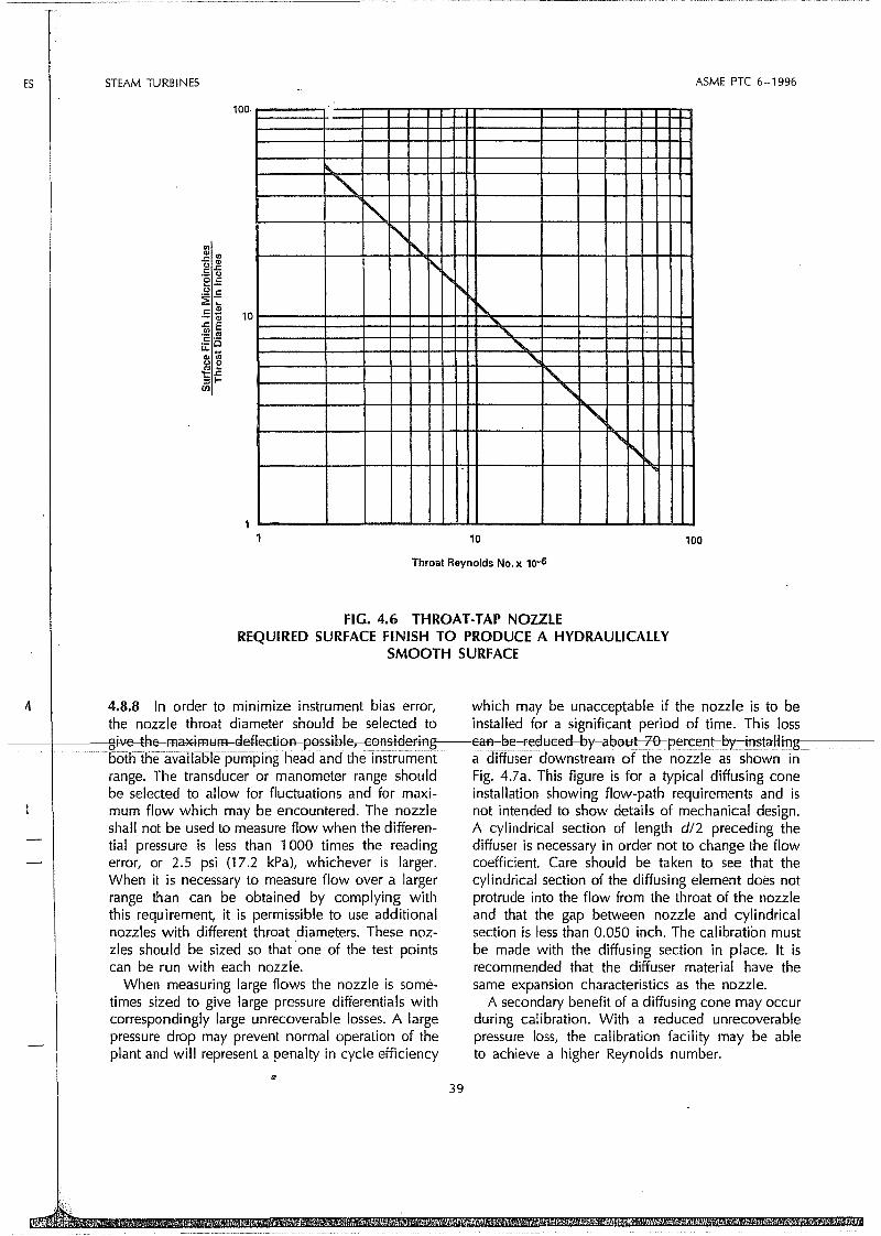
ES STEAM TURBINES
100
"'-
"-~
"r'\..
"~" "-......'-
""-
""-"\
"",
ASME PTC 6-1996
11 10
Throat Reynolds No. x 10-6
100
FIG. 4.6 THROAT-TAP NOZZlEREQUIRED SURFACE FINI5H TO PRODUCE A HYDRAUlICALlY
5MOOTH 5URFACE
4.8.8 In arder to minimize instrument bias error, which may be unacceptable if the nozzle is to bethe nozzle throat diameter should be selected to installed for a significant period of time. This 1055
f----&!i-ve-=th~r:nélxirnblm-gefl~Eti0A_=pf)ssil:>.Ie,___(2f)nsi~eFiAg___Ean_=l:>e_=Fe~l:lee~_=~y=a~()l:lt--:t0_=pere;eflt-=~y--:il1~ta-I·lil1g'-__----botli the availiiole-pumpingneadandthe rnstrument a diffuser downstream of the nozzle as shown inrange. The transducer or manometer range should Fig. 4.7a. This figure is far a typical diffusing eonebe selected to allow for fluctuations and far maxi- installation showing flow-path requirements and ismum flow which may be encountered. The nozzle not intended to show details of mechanical design.shall not be used to measure flow when the differen- A cylindrical section of length d/2 preceding thetial pressure is less than 1000 times the reading diffuser is necessary in order not to change the flowerror, or 2.5 psi (17.2 kPa), whichever is larger. coefficient. Care should be taken to see that theWhen it is necessary to measure flow over a larger cylindrical section of the diffusing element does notrange than can be obtained by complying with protrude into the flow from the throat of the nozzlethis requirement, it is permissible to use additional and that the gap between nozzle and cylindricalnozzles with different throat diameters. These noz- section is less than 0.050 inch. The calibration mustzles should be sized so that 'one of the test points be made with the diffusing section in piace. It iscan be run with each nozzle. recommended that the diffuser material have the
When measuring large flows the nozzle is some- same expansion charaeteristics as the nozzle.times sized to give large pressure differentials with A secondary benefit of a diffusing eone may occureorrespondingly large unrecoverable losses. A large during calibration. With a reduced unrecoverablepressure drop may prevent normal operation of the pressure 1055, the calibration facility may be ableplant and will represent a penalty in cycle efficiency to aehieve a higher Reynolds number.
39

ASME PTC 6-1996
Stainless steeldiffusing eone /Il
(finish with 3/16 in.minimum thieknessl
-"li>I:=~----2.5d -----ll>ll
Hydraulieallysmooth surfaee
5 deg.
STEAM TURBINES
Smoothtransition
Enlarged View of 'X'
FIG. 4.7(a) THROAT·TAP NOZZlE WITH OPTIONAL DlFFUSING eONE
.4Jl:9P'ressiireTaps:Thepressuretaps shall bebetween 1ta in. (3 mm) and 1/4 in. (6 mm) in diameterand at least two pressure-tap diameters deep. Theyshall be machined perpendicular to the surface, shallhave sharp corners, and shall be free from burrsand scratches. The downstream pressure taps shall
.be machined in the thraat of the nozzle in orderto decrease the effect of downstream disturbanceson this pressure measurement. They shall be drilledand reamed previous to the final boring and polishingof the throat. A plug with a press fit is then insertedin the hole. The final boring and polishing operationshould be done after the insertion of the plug. Theplug should be made with provisions for pulling itout of the hole after the polishing and machiningis completed. After removal of this plug, any slightburr which might be left on the edge of the holemay be removed by using a tapered piece of hard-
40
woodsuchasmapletorollaroundthe tap eages.The upstream taps shall be carefully made and shallbe located one inside-pipe diameter upstream framthe nozlle entrance.
4.8.10 Pipe Section. The pipe on either side ofthe flow nOlzle shall be smooth, free from rust,scale, and blisters. For the upstream pipe section,the inside diameter measured at four points at anycross-section shall not differ by more than 0.2 percento Checks on concentricity should include planes0.5, 1.0, and 2.0 times the pipe inside diameterupstream from the nOlzle inlet. The average insidediameter at different cross-sections shall not differby more than one percent. The allowable variationsin inside diameter for the downstream pipe shallbe twice those for the upstream pipe section. (SeeFig. 4.7b.)

STEAM TURBINES ASME PTC 6-1996
Flow~
Machine withtapper noI exceeding3-1/2 deg.
Machine cylindricalwithin :tO.OOl in.wilh minimum removalof metal
the difference in linear expansion coefficients forthe different materials of the camponents. To reducethe possibility af thermal dislortion of the nozzle,it is desirable that the pipe and the flanges of theflow section adjacent to. the nozzle be made of amaterial having the same coefficient of expansianas the nozzle.
To avoid damage to the nozzle during flushingthat normally precedes the initial startup of the plant,it is recommended that the flow section be installedafter flushing.
FIG. 4.7(b) BORING IN FlOW SECTIONUPSTREAM OF NOZZlE
e
s
sIl
e
'-
yl,
!r
4.8.12 Welded Assembly. If the flow section isdownstream of the main feed pumps where it issubject to high pressure levels, it may be weldedtogether and then be welded in the station pipingafter the piping has been flushed. A typical suchflow section is shown in Fig. 4.8. To meet therequirement of inspecting the nozzle both beforeand after a test, a welded flow section shall includeTo achieve compliance with pipe inside diameter
I· 't th t . h t b b d f a plugged inspection port immediately upstream ofImi s, e ups ream pipe may ave o e ore or the nozzle. The orientation of the inspection porta length equal to 4D and then tapered at 3.5 deg. will be determined by the ease of inspection, easeto the untouched pipe ID. of c1eaning, and other design considerations. An4.8.11 Flanged Assemblies. Flanged assemblies are example of such an inspection port is shown in Fig.normally used with relatively low pressures such as 4.9. The inside diameter of the inspection port shouldwhen the flow element is in the condensate line be at least 4 in. (100 mm) to allow easy accessupstream of the main feed pump. This arrangement and nozzle c1eaning if required.is associated with the recommended procedure for The inspection device (typically a fiber optic de-the full scale test. The flow nozzle shall be centered vice) shall not damage the sharp edges of the inspec-in the pipe within 1/32 in. (0.8 mm) of the pipe axis. tion hole or the surface of the nozzle, particularly
If the flow section is downstream of the main around the taps. The plug must be undamaged andfeed pumps where it is subject to high pressure the contour of the plug must be properly alignedlevels, flanges should conform with the pressure- to preserve the flow profile of the water. A plugtemperature rating in ANSI 816.5. Considerations radiai c1earance of up to 1/32 in. (0.8 mm) will be
-1-f-------.s""urd1jas fne cosLof:lneJlanges,tn;e---:c;;a":;'s;t~o;-f-;'m;o:;v;i· n=-g=-.-----:a:=::c.:::c:,:::ep--,t.;-a~b~1e::":,=iA-=-=....-=re:-::e=::e-:-:ss:=:J··~(i--=;e-=-;i-dT,i~st~a~n':-ce~=-jfr-:=:o---m~";ith~e=-:":'e-"-ndj--=a:=;:f---:-----
them into piace, and the added cost of pipe hangers the plug to the inside diameter af the pipe) of upmay make it desirable to use a welded assembly. to 1hz in. (0.8 mm) is acceptable. The plug mustSee para. 4.8.12. not protrude into the pipe.
When the flow section is assembled with f1anged For flow sectians welded into the feedwater pipe,connections, the pipe joints at the flow nozzle shall the flow nozzle must be constructed of a corrosionhave the inner bores square with the faces of the resistant material if the pipe is subject to chemicalflanges. The gap between the nozzle flange and the c1eaning. The c1eaning of the flow test section canpipe flange shall not exceed 1/16 in. (1.6 mm). Th.e be accomplished by the use af very high pressuregaskets shall not extend within the pipe. water jet devices. In the design of the plant, the
Flanges adjacent lo the nozzle should be provided design of available c1eaning devices should be re-with dowels or other means to ensure that ali compo- viewed and the practicality of performing the c1ean-nents of the complete flow section are always assem- ing through the inspection port should be evaluated.bled in exactly the same relative lacations as when It may be advisable to install a special port down-it was calibrated. Some methods of manufacture stream of the downstream pipe section specificallymay subject the nozzle throat to distortion due to for the introduction of a high pressure water c1eaningthermally induced: stress. This could be caused by device.
41
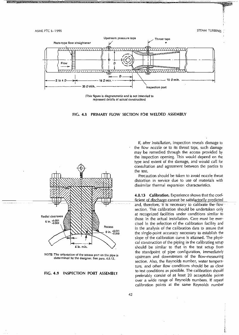
STEAM TURB1NES
Throat tapsUpstream pressu re ta ps
Plate-type f10w straightener 1: V ..\ rln
,\\,\\\ ,\ .\\\\\\ \ ,\ 1//\ \\ .\ .\ \:i.\ \\\ . \ . \
\( t /,:::. f,
-" '"", I
t -Flow D
( - i +.::::......
~1\ ~II. ~. ,\ \
Jl'I.J.IlJ \ 1-~
I I---D~
~2to4D );>~ 16 Dmin. 10 Dmin.
2ODmin•. Inspection port
ASME PTC 6-1996
IThis figure is diagrammatic and is not intended torepresent details of actual construction)
FIG. 4.8 PRIMARY FlOW SECTION FOR WELDED ASSIEMBlY
FIG. 4.9 INSPECTION PORT ASSEMBlY
NOTE: The orientation of the access port on the pipe isdetermined by the designer. 5ee para. 4.8.12.
4in. min.
If, after installation, inspection reveals damage tothe flow nozzle or to its throat taps, such damagemay be remedied through the access provided bythe inspection opening. This would depend on thetype and extent of the damage, and would cali forconsu ltation and agreement between the parties tothe test.
Precaution should be taken to avoid nozzle throatdistortion in service due to use of materia.ls withdissimilar thermal expansion characteristics.
4.8.13 Calibration. Experience shows that the coef-_, fic.ieJ:Jt...oLdischarge cannot be satisfactorilY_Rredicted
aridi therefore;itisnecessary tocalibrate the flowsection. This calibration should be undertaken onlyat recognized facilities under conditions similar tothose in the actual installation. Care must be exercised in the selection of the calibration facility andin the analysis of the calibration data to assure thatthe single-point accuracy necessary to establish theslope of the calibration curve is attained. The physical construction of the piping in the calibrating setupshould be similar to that in the test setup fromthe standpoint of pipe configuration, immediatelyupstream and downstream of the flow-measuringsection. Also, the Reynolds number, water tempera-ture, and other flow conditions should be as closeto test conditions as possible. The calibration shouldpreferably consist of at least 20 acceptable pointsover a wide range of Reynolds numbers. If repeatcalibration points at the same Reynolds number
42

:5STEAM TURBINES ASME PTC 6-1996
U 0.99
- I----I--
0.98105 2 3 4 5 6 8 106 2 3 4 5 6 8 107 2 11 4 S
Throat Reynolds Number. Rd
FIG. 4.10 REFERENCE CURVE FOR NOZZLE CALIBRATION
The equation, discussed in para. 4.15, is a descriptionof the coefficient of discharge, C, of a throat-tapdevice throughout the entire range of Reynolds numbers of interest.
4.8.15 Evaluation of laboratory Calibration Data.The recommended method for determining if thecalibration data of a throat-tap nozzle is satisfactory,Le. can be extrapolated parailei to the referencecurve as required in para. 4.8.14, is as follows:
TABLE 4.2REFERENCE NOZZLE COEFFICIENTS OF
OISCHARGE DERIVED FROM THE EXPRESSIONC = 1.0054 - 0.185. Rd-o.2 [1 - 361,239IRd]o.8,
WHICH REASONABlY MATCH THE REFERENCECURVE SHOWN IN FIG. 4.10
0.99720.99670.99690.99720.99740.99760.99800.99820.99910.99950.99991.0001
Coefficient ofDischarge, C
1.02.03.04.05.06.08.0
10.020.030.040.050.0
Throat ReynoldsNumber-MILlIDN5
differ by more than 0.1 percent, an additional calibration point at the same Reynolds number is recommended. When it is not possible to calibrate at testReynolds number, it is permissible to extrapolatethe calibration curve as described in para. 4.8.16.Since the effect of the transition reg.ion becomesincreasingly smaller as Reynolds number rises, thisCode recommends that the value of the coefficientbe established at highest Reynolds number possibleso that tliis effect is minima!. Ali four tap sets shouldbe calibrated. Far the test, select the two tap setsthat most c10sely comply with first, the calibrationcriteria (see paras. 4.8.13, 4.8.14, and 4.8.15) andsecond, with the guidelines in Fig. 4.13. If thecalibration of the flow section does not complywith para. 4.8.14, the nozzle should be carefullyinspected as described in para. 4.8.7, corrected, ifnecessary, and the flow section recalibrated. If therecalibration stili does not comply with para. 4.8.14,
.theflowsectionshouIdagainbe reEal ibratedusingdifferent facilities. In the event different facilities arenot available, the parties to the test must agree onthe course of action before the test is started.
4.8.14 Compliance with the requirements of paras.4.8.4 through 4.8.12 is determined by the shape ofthe coefficient of discharge, C, versus Reynoldsnumber curve established by calibration. For each setof selected taps, the calibration curve (not necessarilyeach individuai point) shall be within 0.25 percentof the reference curve (see reference curve Fig. 4.10and Table 4.2) and shall have the same slope asthe reference curve (see para. 4.8.15). The referencecurve shown in Fig. 4.10 was derived from a detailedboundary layer analysis and corroborated later bya study yielding the expression given in Table 4.2.
to
~r
ndlathesiup1m~Iy
ngraIseJldnts=at)er
~f
edIW
·lly,··to
43
li!
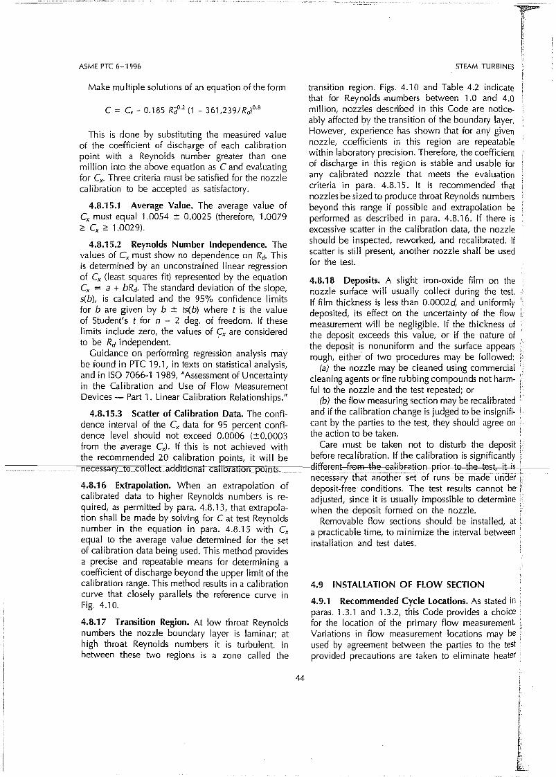
ASME PTC 6-1996
Make multiple solutions of an equation of the form
c = Cx - 0.185 R"d°·2 (1 - 361,239IRd)o.8
This is dane by substituting the measLired valueof the coefficient of discharge of each calibrationpoint with a Reynolds number greater than onemillion into the above equation as C and evaluatingfar Cx. Three criteria must be satisfied far the nozzlecalibration to be accepted as satisfactory.
4.8.15.1 Average Value. The average value ofCx must equal 1.0054 ± 0.0025 (therefore, 1.0079~ ex ~ 1.0029).
4.8.15.2 Reynolds Number Independence. Thevalues of ex must show no dependence on Rd. Thisis determined by an unconstrained linear regressionof Cx (Ieast squares fit) represented by the equationCx = a + bRd' The standard deviation of the slope,s(b), is calculated and the 95% confidence Iimitsfor bare given by b ± ts(b) where t is the valueof Student's t for n - 2 deg. of freedom. If theselimits include zero, the values of Cx are consideredto be Rd independent. .
Guidance on perfarming regression analysis maybe found in PTC 19.1, in texts on statisticaI analysis,and in ISO 7066-1 1989, "Assessment of Uncertaintyin the Calibration and Use of Flow MeasurementDevices - Part 1. Linear Calibration Relationships."
4.8.15.3 Scatter of Calibration Data. The eonfidenee interval of the Cx data far 95 pereent confidenee level should not exceed 0.0006 (±0.0003fram the average Cx)' If this is not aehieved withthe reeommended 20 ealibration points, it will be
----------.n"'e"'e""e""ss""a"'ry"_"""""t"o'c"""'o1\ecC adaitlonaLcaItoratlon poi nts. "0
4.8.16 Extrapolation. When an extrapolation ofealibrated data to higher Reynolds numbers is required, as permitted by para. 4.8.13, that extrapolation shali be made by solving far C at test Reynoldsnumber in the equation in para. 4.8.15 with Cxequal to the average value determined for the setof calibration data being used. This method providesa precise and repeatable means for determining acoefficient of discharge beyond the upper limit of thecalibration range. This method results in a calibrationcurve that c10sely parallels the reference curve inFig. 4.10.
4.8.17 Transition Region. At low throat Reynoldsnumbers the nozzle boundary layer is laminar; athigh throat Reynolds numbers it is turbulent. Inbetween these two regions is a zone called the
44
STEAM TURBINES
transition region. Figs. 4.10 and Table 4.2 indicatethat far Reynolds ..numbers between 1.0 and 4.0million, nozzles described in this Code are noticeably affected by the transition of the boundary layer.However, experience has shown that for any givennozzle, coefficients in this region are repeatablewithin laboratory precision. Therefare, the eoefficientof discharge in this region is stable and usable forany calibrated nozzle that meets the evaluationcriteria in para. 4.8.15. It is recommended thatnozzles be sized to produce throat Reynolds numbersbeyond this range if possible and extrapolation beperformed as described in para. 4.8.16. If there isexcessive scatter in the calibration data, the nozzleshould be inspected, reworked, and recalibrated. Ifscatter is stili present, another nozzle shall be usedfor the test.
4.8.18 Deposits. A slight iron-oxide film on thenozzle surface will usually collect during the test. !
If film thickness is less than 0.0002d, and uniformly i
deposited, its effect on the uncertainty of the flow !measurement will be negligible. If the thickness of (the deposit exeeeds this value, or if the nature of f
the deposit is nonuniform and the surface appears irough, either of two procedures may be followed: .
(a) the nozzle may be c1eaned using commerciai !c1eaning agents or fine rubbing compounds not harm- ifui to the nozzle and the test repeated; or i
(b) the flow measuring section may be recalibrated .and if the calibration change is judged to be insignifi- !cant by the parties to the test, they should agree on .the action to be taken.
Care must be taken not to disturb the deposit lbefore recalibration. If the calibration is significantly !
clifferent-frem-tl:Je-GalibFatiGn-p~iGr-tG-tR@-test,-it-is-+i----i-necessary iFùltanotnersef of rI.Jl"s be made LJndefrdeposit-free conditions. The test results cannot be' iadjusted, since it is usually impossible to determine :when the deposit formed on the nozzle. .
Removable flow sections should be installed, ata practicable time, to minimize the interval betweeninstaliation and test dates.
4.9 INSTALlATION Df FlOW SECTION
4.9.1 Recommended Cycle locations. As stated inparas. 1.3.1 and 1.3.2, this Code provides a choicefar the location of the primary flow measurement.Variations in flow measurement locations may beused by agreement between the parties to the testprovided precautions are taken to eliminate heater

STEAM TURBINES ASME PTC 6-1996
pumped-ahead drains upstream of the feedwaterpump (Fig. 4.11 (b)), it is recommended that the condensate flow and the heater drain flow both be measured immediately upstream of the point where theymix and the sum of the two flows be used as primaryflow, pravided that the absence of heater leakage isverified by use of a suitable tracer technique. Otherwise, the feedwater flow from the highest pressureheater also must be measured far comparison withthe primary f10w with adjustment far feedwater pumpinjection and leak-off flows. The difference betweenthese values is the amount of suspected high pressureheater leakage.
If the feedwater cycle has only heaters with drainscascading to the condenser [Fig. 4.11 (c)], it is recommended that feedwater pump suction flow be measured, provided that the absence of heater leakageis verified by use of a suitable tracer technique.Otherwise, feedwater flow from the highest pressureheate.r must be measured for determination of suspected water leakage, as in the case of the intermediate pumped-ahead-heater cycle. When measuringfeedwater pump suction flow,. use of a meteringpressure drop that infringes on the pump requiredminimum NPSH should be avoided.
(c) Before aborting or discarding a test because ofsuspected high heater leakage (see para. 3.8.10), theisolation of the cycle should be recheeked, the calibration curves of the flow measuring devices should beinvestigated, and the possibility of errar in the finalfeedwater or heater drain flow measurements shouldbe considered.
leakage and recirculation flows and appropriate instrumentation is installed.
Figures 4.11 (a) through 4.11 (e) show the locationof f10w instrumentation in typical cycles. While thesediagrams show only single strings of heaters, twoor three strings are commonly used with the largersized turbine-generator units. Far cycles of largeunits and particularly those with nuclear steamsupply systems, two or more flow measuring devicesmay be used in parai lei at each primary flow 10cation.
at
I in,ice~nt.
betestiter
~en
:edifion
he!st.lly)w
ofof
ars!d: ':ialm-
Ite.0:e-
enIle!nt'Dr
:mlat~rs
beis
deIf
ed
:!r.
4.9.2 Condensate Flow Section(a) For units with high pressure feedwater heaters
supplied with superheated extraction steam, see Fig.4.11 (a). If the feedwater cycle has a deaerator, it isrecommended that condensate flow entering it bemeasured as primary flow. This eliminates the possibility of any heater tube leakage recirculating thraughthe flow measuring device.
If the feedwater cycle has no deaerator but doeshave a heater with pumped-ahead drains immediately upstream of the feedwater pump, it is recommended that thè condensate flow entering this heaterbe measured. Again, there is no possibility of heatertube leakage recirculating through the flow measuring device.
If the feedwater cycle has no deaerator and nopumped-ahead. heater drains immediately upstrearnof the feedwater pump, it is recommended thatcondensate flow be measured downstream of thelow pressure heaters, and upstream of the feedwaterpump. If the absence of high pressure heater leakage
)sit is not verified by use of a suitable tracer or other 4.9.3 Feedwater Flow Section. The primary flowItly technique, it will be necessary to measure the total measuring device is installed, perhaps welded, in the: is drain flow fram the high pressure heaters far com ar- feedwater line, downstream of the highest pressure
-3er-.t'--'---';::'ls:";o:::'n:":'w"':':';:it'~t~e'='.:":'s:"-u=-m:':: ..~ofrt~h~eJ::e':"'x~t:=:ra=:c~ti~o-:':n:::;f~lo::':w'='s-:-.'Tfr"::o=-m=-···jthl:-e:=:s'::-e-·--neater,so mat Ita.rectly measures feedwater f10wbe~-'- heaters as calculated by heat balance. The difference to the steam generator.ine
between these values is the amount of suspected 4.9.4 To minimize the difficulty of obtaining steadyhigh pressure heater leakage. flow, the flow measuring device should not be
The preceding primary flow locations were se- located at a pump discharge. Advantage should belected to improve the accuracy of the measurement taken of the damping effect of any existing heatby (1) avoiding difficulties associated with use of exchangers and long lengths of pipe in the cyclef1anged joints in high pressure piping, (2) taking in locating the flow measuring device. The flowadvantage of lower water temperatures that minimize measuring device should also be located to eliminatethe added uncertainty associated with the extrapola- the effects of recirculating and bypassing flows. Iftion of the coefficient-of-discharge curve and this is not possible, extraneous flows shall be mea-(3) avoiding the lower temperatures in the cycle sured with sufficient accuracy so that the effect onwhere the transition region may cause higher uncer- primary flow uncertainty is less than ±O.OS percent.tainty in the coefficient of discharge.
(b) Far units with high pressure feedwater heaters 4.9.5 The installation of the flow measuring sectionsupplied with wet extraction steam, see Fig. 4.11 (b) in a horizontal run is recommended. To minimizeand (c). If the feedwater cycle has a heater with the effects of distortion due to thermal expansion
45

»lJ13:m
~nCf'I
1.01.0Cf'
~
~-IC;;ucoZ[li
ti
-i~ I ,,/.
Pow-srtransformer
PUMPEO FORWAROi TRACER TECHNIQUE
NOTES:(1) Recommended primary flow measurement when heater
leakage Is measured by tracer.(21 Recommended alternate primary flow measuremenl.
See para. 4.8.4 (cl for Inspection requirements.{31 A calibrated turbine meter may be used where flashing mighl
otherwise be a problem or where flow rate Is less than 50/0 ofprlmary f1ow: . ~_
(41 Omit water sample If main steam has at leasl 27°F superheal.(5) Specific flow moasuring primary olements aro suggested
for guidance. Alternale f10w elemenls are permissibleprovided the final measuremenl has no hlgheruncertalnty than the best al1ainable wilh Ihe specifiedprimary elemenl.
12- a Basket tips in exhaustI>- a Tracer Injection
r := Water sample
d a level
€i> = Wal1meter
@ a Ammeter@ = Voltmeter
G5C = Gland-steam condenser
SJAE - Steam-jet-alr ejeetor
SSR = Steam-seal regulatorC.T. = Current transformerP.T. = Polential transformer
a Temperature measurement
Pressure measurement
Pressure measurernent
Pressure measurement
a Orifice and differential pressure measurement
a Nozzle or venturi and differentialpressure measurement
Impaet and statle taps wlthpressure rneasurement
:= Absolute-pressure gage
,..------------,I Aflernate Instrumentatlon II Il stmam has atleast II 27-F superheat I
L J_l J
From nuclearste,m supp1v
syst.m 1NOI. W
=f9If
Referto para. 4.1.3 {:regarding cautionon use of mercury b
<>
FlG.4.11(c) lOCATION ANO TYPE OF TEST INSTRUMENTATION (HEATER ORAINSFOR FlOW MEASUREMENT)
.J>,O:>

FlG.4.11(d) LOCATION ANO TYPE Of TEST INSTRUMENTATION fOR ALTERNATIVE TEST PROCEDURE - fOSSIL
generalor
c:~
~Cf'I
'-O'00O'
»ti)
3:m
ti)
-im»$:-IC""00Zmti)
Generator
cL[?:
Powertransf.3~ I •• I> ~* i
L.P. turbine
NOTiEI H' h . .. h ' I. i 19 -accuracy Instrumentatlon 15 5 own In co or.
Pressure-baskel tips
Flow
Current
Pressure-tranducers
Temperature
V Voltage
W Power
To superhealer
From reheater
To reheater
Legend:-xO<>../-...A
To rehealer
~'-Cl
..

U"l$:rn-o-inCi'I~
'"'"Ci'
Generator
Tocond. (2) @~A
Power 3 phases ~
tra;~
FromNSSS
Legend:-X Temperature
D Pressure-tranducers LL-J I I I~ IY-rJ1 ~<><O' Pressure-basket tips
:< Flow
A Current
V Voltage
W Power
lJ1o
NOTE: High-accuracy instrumentation is shown!ih color.U"l-irn»$:
FIG.4.11(e) lOCATION AND TYPE OF TEST INSTRUMENTATION FO", lA.LTERNATIVE TEST PROCEDURE - NUClEAR
-iC::o<:D
ZrnU"l

4.10 FLOW CHARACTERI5TICS
4.9.6 for further discussion af necessary water legcorrection for taps at different elevations.
STEAM TURBINES ASME PTC 6-1996
--1----h = difference in
OP water leg
I---...[><I----.A. __1_--For upward f1ow: 96Ptrue = 6Pmeas. + (Pamb - Pplpe) ( go )h
For downward flow: 96Ptrue = 6Pmeas. - (Pamb - Pplpe) ( 90 )h
FIG. 4.12 WATER LEG CORRECTION FOR FLOWMEASUREMENT
· and nozzle-coefficient extrapolation due to higherReynolds numbers, flow nozzle locations havingwater temperatures below 300°F (422K) are preferred. However, flow nozzles located downstreamof the highest pressure heater are acceptable if theyare designed in accordance with this Code, see 4.10.1 Flow measurements shall not be undertakenparas. 4.8.6 through 4.8.18. unless the flow is steady or fluctuates only slightly4.9.6 When the flow measuring device is installed with time. The permissible fluctuation is ±1 percentsuch that the upstream and downstream tap locations of the differential pressure for fluctuations with aare at different elevations, it is necessary to correct frequency greater than twice the frequency of succes-
1---f-·()r:-:~t~CI~g]:Iiffe.Il:!~s:--b~lliTe-en th-e=t~levati:~o=n~s-_-----.s,-:.'v"e"-r=e=aolngsano-::E4percent-forsmallerfrequencies.caused by the difference in density of the water in Fluctuations in the flow shall be suppressed beforethe flow section and tne water in the pressure sensing the beginning of a test by very careful adjustmentIines. (See Fig. 4.12.) of flow and level controls or by introducing a
combination of conductance, sud as pump recircu4.9.7 If the only two acceptable sets af taps are90 deg. apart instead of the recommended 180 deg. ~~i~~~r;;,di~~~~t~~~\~~~e~\~~r~~:~~~;~:~~~~apart in a horizantal pipe, one set should be located and the flow measuring device. Damping devicesat the horizontal axis of the pipe. (See Fig. 4.13.). on instruments do not eliminate errors due to pulsa-
~~r~aemo~:=; ~~tn~:~~~~ ~a~h~~i~s~~~~e~~~t ~~;~~ tions and, therefore, shall not be used. If the pulsa-tions exceed the above values after every effort hastions, special attention to insulation must be given been made to suppress them, mutuai agreement isto minimize any specific weight differences between required before tne test can proceed.the water flowing through the pipe and the water
in the pressure tap lines. (See para. 4.9.6 and Fig. 4.10.2 In passing tnrough the flow measuring de-4.12.) If the flow section is located in a vertical vice, the water shall not flash into steam. Tnepipe, any tap configuration is acceptable. See para. minimum throat static pressure shall be higher than
51

ASME PTC 6-1996
Recommended:
Acceptable:
Not recommended(Subject to dirtpluggage)
First preference Second preference
STEAM TURBINES
FIG. 4.13 FLOW ELEMENT TAP LOCATIONS FOR HORIZONTAL PIPES---------------------(-Se~=P!lr:a.----4..9.-7-)---------------------
the saturation pressure corresponding to the temperature of the flowing water by at least 20 percent ofthe throat velocity head, as required per para. 4.16.2,to avoid cavitation.
4.11 OTHER FLOW MEASURING DEVICES
4.11.1 Information relative to the construction, calibration, and installation of other flow-measuringdevices is described in PTe 19.5. Although thesedevices are not recommended for the measurementof primary flow, they may be used provided theyconform to the generai requirements of paras. 4.8.4and 4.8.14 with the following exceptions:
52
(a) For the requirement stated in para. 4.8.4(a), thebeta-ratio shall be Iimited to the range 0.25 to 0.50far wall-tap nozzles and venturis arid 0.30 to 0.60 fororifices.
(b) For the requi rement stated in para. 4.8.14, theappropriate reference coefficient far the actual devicegiven in PTe 19.5 shall be used. The parties to a testshould become familiar with the contents of PTe 19.5regarding these devices.
4.12 MEASUREMENT OF STEAM FLOW
4.12.1 To measure the primary steam flow directly,the requirements far accurate steam flow measure-


![KLV-30MR1 - Error: [object Object]](https://static.fdokumen.com/doc/165x107/631786651e5d335f8d0a6a63/klv-30mr1-error-object-object.jpg)