1. Mini Wind Turbine - NCSU MAE
9
1 Figure 9. Wind mills 1. Mini Wind Turbine 1.1. Wind power introduction Although most people don’t think about it, wind power is essentially another form of solar power. Sunlight that reaches the Earth heats surface air, causing a temperature difference, which in turn causes the less dense heated air to rise and the cooler surrounding air rushes in to fill the void creating a surface wind. One of the earliest uses of wind energy was the sail. Sails were, and are still today, used to power various modes of transportation, like sailboats. Wind energy was also converted into mechanical energy in order to pump water and spin grinding wheels. In the Netherlands windmills were used extensively to pump seawater out of low-lying areas in order to dry the land out and produce useful farmland. Windmills were, and are still used today, on many farms to pump water from wells to water troughs for livestock. The most recent adaptation of windmills and wind energy is the conversion of mechanical energy into electrical energy through the use of wind turbines. The key to success in this process is the electrical generator. The blades of the wind turbine are connected to a rotating shaft, which goes through a gearbox and into a generator, which converts the work of the shaft into useful electrical energy. The one of the simplest types of generators is a permanent magnet alternator, also known as a magneto. It works on the exact opposite principle as an electromagnet. An electromagnet uses a rotating coil of wire with a current running through it to induce a magnetic field in the iron bar that is placed in the middle of the coil, where as, a magneto uses a magnetic field in the vicinity of a coil to induce a current in the coil. Magneto’s are generally used to produce brief high voltage burst to power spark plugs in lawn equipment, and other small engine powered devices. A magneto, for use in spark plug applications, usually consists of several permanent magnets, two coils of wire, one with about 200 turns of thick wire and the other with about 20,000 turns of very fine wire, wrapped together and a flywheel. Magneto’s in this application also require an electronic control unit, a capacitor and a breaker. In order to test the wind’s power you will be building a simple wind turbine, which will supply electrical energy via a permanent magnet alternator. In this simplified version of an alternator, you will use strong magnets passing over four coils of fine wire to produces an alternating current.
-
Upload
khangminh22 -
Category
Documents
-
view
2 -
download
0
Transcript of 1. Mini Wind Turbine - NCSU MAE

1
Figure 9. Wind mills
1. Mini Wind Turbine 1.1. Wind power introduction Although most people don’t think about it, wind power is essentially another form of solar power. Sunlight that reaches the Earth heats surface air, causing a temperature difference, which in turn causes the less dense heated air to rise and the cooler surrounding air rushes in to fill the void creating a surface wind. One of the earliest uses of wind energy was the sail. Sails were, and are still today, used to power various modes of transportation, like sailboats. Wind energy was also converted into mechanical energy in order to pump water and spin grinding wheels. In the Netherlands windmills were used extensively to pump seawater out of low-lying areas in order to dry the land out and produce useful farmland. Windmills were, and are still used today, on many farms to pump water from wells to water troughs for livestock.
The most recent adaptation of windmills and wind energy is the conversion of mechanical energy into electrical energy through the use of wind turbines. The key to success in this process is the electrical generator. The blades of the wind turbine are connected to a rotating shaft, which goes through a gearbox and into a generator, which converts the work of the shaft into useful electrical energy. The one of the simplest types of generators is a permanent magnet alternator, also known as a magneto. It works on the exact opposite principle as an electromagnet. An electromagnet uses a rotating coil of wire with a current running through it to induce a magnetic field in the iron bar that is placed in the middle of the coil, where as, a magneto uses a magnetic field in the vicinity of a coil to induce a current in the coil. Magneto’s are generally used to produce brief high voltage burst to power spark plugs in lawn equipment, and other small engine powered devices. A magneto, for use in spark plug applications, usually consists of several permanent magnets, two coils of wire, one with about 200 turns of thick wire and the other with about 20,000 turns of very fine wire, wrapped together and a flywheel. Magneto’s in this application also require an electronic control unit, a capacitor and a breaker.
In order to test the wind’s power you will be building a simple wind turbine, which will supply electrical energy via a permanent magnet alternator. In this simplified version of an alternator, you will use strong magnets passing over four coils of fine wire to produces an alternating current.

2
1.2. Wind Turbine Activity Adapted from reference 5 Who: Group of 4 students What: Build a small wind turbine with generator and test power out in wind tunnel. The purpose of this activity is to learn concepts of wind energy, mechanical work, electric generators and AC power. Where: Classroom and Wind tunnel Time: 4 hours Supplies: Item Quantity Check-out Check-in Notes Scissors 1 Electrical tape 1 Ruler 1 White glue bottle 1 10 cm Nail 1 Utility knife 1 Rare earth magnets 4 Cardboard sheet (22x30 cm) 1 NA Permanent marker 1 Magnetic compass 1 Small cardboard box 1 NA Plastic spoons 10 NA Large cork 1 NA Wooden dowel 6mm x 20 cm 1 NA 24 gage - copper wire 100 m Shared items Quantity Check-out Check-in Notes Hot glue gun 1 Wire cutter 1 Objectives: ● Learn the basic principles of the conversion of mechanical energy to electrical energy. ● Measure the resistance of coils ● Explore the effects of blade design, wind speed, and rpm’s of turbine on voltage and
current production. ● Power an LED with the apparatus. Safety: ● Strong Magnets – keep away from all personal electronics. ● Cut Hazard – careful use of utility knife ● Burn Hazard – Use of hot glue gun must be under activity leader supervision
3
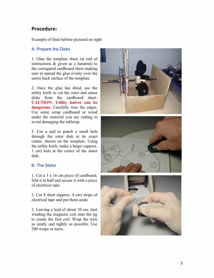
Procedure: Example of final turbine pictured on right A. Prepare the Disks 1. Glue the template sheet (at end of instructions & given as a handout) to the corrugated cardboard sheet making sure to spread the glue evenly over the entire back surface of the template. 2. Once the glue has dried, use the utility knife to cut the rotor and stator disks from the cardboard sheet. CAUTION: Utility knives can be dangerous. Carefully trim the edges. Use some scrap cardboard or wood under the material you are cutting to avoid damaging the tabletop. 3. Use a nail to punch a small hole through the rotor disk at its exact center, shown on the template. Using the utility knife, make a larger (approx. 1 cm) hole at the center of the stator disk. B. The Stator 1. Cut a 3 x 16 cm piece of cardboard, fold it in half and secure it with a piece of electrical tape. 2. Cut 8 short (approx. 4 cm) strips of electrical tape and put them aside. 3. Leaving a lead of about 10 cm, start winding the magnetic coil onto the jig to create the first coil. Wrap the wire as neatly and tightly as possible. Use 200 wraps or turns.

4
4. Carefully slip the coil off the jig and secure it using two pieces of the previously set aside electrical tape. 5. Create 3 more coils by repeating steps 1-4, leaving about 3 cm of wire between the individual coils. Leave 10 cm of wire after the last coil has been wrapped. 6. Lay the coils loosely on the disk in the positions shown on the template. Arrange the coils so their windings alternate between clockwise and counterclockwise (twist it if necessary). If done correctly, an electron should travel in the direction indicated by the arrows on the template, starting with the counterclockwise coil on the left hand side. 7. Using a small patch of emery cloth or sand paper, remove the enamel insulation from two free ends of wire, exposing about 1 cm of bare wire (make sure this wire is completely bare). 8. Check your connections: Set your multi-meter for measuring electrical resistance (ohms). If your connections are good, there should be little resistance to the movement of electrons, and the meter should read about 10 ohms or less. To check this, touch or connect the multi-meter probes to the two free ends of the wire. If the coils are not properly connected, the reading will be either a very large number or infinity. 9. Once you are confident the coils have been constructed and positioned properly, glue them to the stator disk. Lift each coil up a little and apply a large blob of glue to the template where the coil should rest. Let the glue solidify before gluing the next coil. C. The Rotor 1. Using a magnetic compass, determine the polarity of each of the 4 magnets and mark the south pole of two magnets and the north pole of the remaining two using a felt pen. 2. Warm up your hot glue gun, and prepare to attach the magnets to the rotor disk. CAUTION: Hot glue guns can cause burns. Be sure glue guns are warmed up only when needed, and are unplugged immediately after. Hot glue can stick to skin and

5
clothing. The magnets must be arranged so that their polarity alternates (i.e. N-S-N-S). Their position and polarity are indicated on the template. 3. Squeeze a small (1 cm) blob of hot glue on the spot where the first magnet will go. Quickly press a magnet with its washer onto the blob. Allow the glue to solidify before moving onto the next magnet. 4. Repeat this for the remaining magnets, making sure to alternate north and south poles as you go. D. The Shaft 1. Using a pencil sharpener, put a point on each end of the wooden dowel (it is not necessary to make a sharp point – blunt will do). E. The Turbine 1. Center the wide end of the cork on the marking guide on the template page, and mark the cork with a pen or pencil, as shown below. 2. Place the cork wide-end down on a cutting board. Use the utility knife to cut shallow slits into the cork where the spoons will be inserted. USE CAUTION! 3. Using the wire cutters, cut the spoon handles off of the 8 plastic spoons leaving a 1 cm stem on the bowl of the spoon. (Should have been already done) 4. Be sure the glue gun is warmed up and that you have a glue stick or two handy. 5. Insert the first spoon into the cork, using the turbine template as a guide. Push the stem of the spoon into the cork to a depth of about 1 cm.

6
6. Repeat step 6 with the remaining 7 spoons. Adjust the angle and depth of the spoons so they are evenly spaced and all project from the cork at the same angle. 7. When you are satisfied with your turbine, add some hot glue to each spoon to secure it on the cork. F. The Housing 1. Assemble the bottom of the cardboard box and tape it shut. 2. Using a ruler, find the center of one of the sides as accurately as you can. Mark this point with the permanent marker. Repeat this process for the other side. 3. At the mark on each side of the container, cut a 1/4" (6 mm) hole through the cardboard. 4. Lay the stator with its attached coils on the side of the container so that its center hole is over the hole in the box. Tape the stator to the cardboard box using clear tape. 5. Using the utility knife, make 4 small slits on the side of the cardboard box, corresponding with those on the stator disk. 6. Using the brass paper fasteners, securely mount the stator disk to the side of the cardboard box. Bend the tabs flat on the inside of the cardboard box.
7. Using scissors, cut the front and back of the cardboard box above the centerline hole on the sides of the box (a cm or two of excess won’t hurt too much).
Cardboard Box
Clear-‐taped Cardboard Disks

7
G. Final Assembly 1. From scrap cardboard, cut out two 2 cm diameter disks and tape over one side of each cut-out with clear tape. Carefully using a utility knife, cut out a ¼" (6 mm) hole in the center of each disk using a utility knife. 2. Insert the dowel through the side of the box, one of the taped cardboard disks (with the taped side facing the cardboard box, the turbine, the other side of the box, stator and rotor as shown on the previous page. 3. Wrap electrical tape around the dowel so that when the rotor is placed on it, it will rotate close to but not touch the stator. 4. Adjust the rotor on the electrical tape and rotate it until the rotor is able to rotate without wobbling. Glue it in that position to ensure stability. 5. Adjust the position of the rotor so that the magnets are able to rotate closely to the coils of magnetic wire without touching them, and then glue the taped cardboard disk to the dowel so that it rests on the edge of the cardboard box. Finally, glue the other cardboard disk to the dowel on the outside of the cardboard box with the clear taped side facing it. H. Test the Wind Turbine The wind turbine electric generator is now ready to be tested. 1. Using the multimeter, turn it to the resistance setting (200Ω), connect the test leads to
apparatus. Record the resistance of the four-coil setup. a. If you are not getting a reading, check the connections between individual
coils, and between the test leads and coils. 2. Place the apparatus in the wind tunnel. Following the directions given on site, adjust
the wind velocity and measure/record the current and voltage produced at three different velocities.
a. To measure voltage, connect the multimeter to the apparatus and use the AC Volt (V~) setting.
b. To measure current to turn the multimeter to the AC Current (A~) setting. c. Connect your LED to the device and see if it lights up or not, if it does, do you
notice anything about how it lights up? Record your results. d. Repeat these steps for three different wind speeds.
3. Come up with a way to roughly measure the area of one spoon, you will use this measurement when calculating wind power.
4. Calculate the electrical power of the generator and the power of the wind; then calculate the efficiency of the generator.
5. Fill in your data on the chart below.

8
Data Velocity (m/s)
Current (A) Voltage (V)
Power (W)
Wind Power (W)
Efficiency (η)
Electrical Power = Current*Voltage Wind Power = 0.5 x Area x Air Density x Velocity^3 Efficiency = Electrical Power / Wind Power

9