
1 Introduction The subject Machine Design is the creat
29
ROHINI COLLEGE OF ENGINEERING AND TECHONOLGY ME8593 DESIGN OF MACHINE ELEMENTS UNIT-I STEADY STRESSES AND VARIABLE STRESSES IN MACHINE MEMBERS CHAPTER - 1 Introduction The subject Machine Design is the creation of new and better machines and improving the existing ones. A new or better machine is one which is more economical in the overall cost of production and operation. The process of design is a long and time consuming one. From the study of existing ideas, a new idea has to be conceived. The idea is then studied keeping in mind its commercial success and given shape and form in the form of drawings. In the preparation of these drawings, care must be taken of the availability of resources in money, in men and in materials required for the successful completion of the new idea into an actual reality. In designing a machine component, it is necessary to have a good knowledge of many subjects such as Mathematics, Engineering Mechanics, Strength of Materials, Theory of Machines, Workshop Processes and Engineering Drawing. Classifications of Machine Design The machine design may be classified as follows: Adaptive design. In most cases, the designer ‘s work is concerned with adaptation of existing designs. This type of design needs no special knowledge or skill and can be attempted by designers of ordinary technical training. The designer only makes minor alternation or modification in the existing designs of the product. Development design. This type of design needs considerable scientific training and design ability in order to modify the existing designs into a new idea by adopting a new material or different method of manufacture. In this case, though the designer starts from the existing
-
Upload
khangminh22 -
Category
Documents
-
view
1 -
download
0
Transcript of 1 Introduction The subject Machine Design is the creat

ROHINI COLLEGE OF ENGINEERING AND TECHONOLGY
ME8593 DESIGN OF MACHINE ELEMENTS
UNIT-I
STEADY STRESSES AND VARIABLE STRESSES IN MACHINE MEMBERS
CHAPTER - 1
Introduction
The subject Machine Design is the creation of new and better machines and improving
the existing ones. A new or better machine is one which is more economical in the overall
cost of production and operation. The process of design is a long and time consuming one.
From the study of existing ideas, a new idea has to be conceived. The idea is then studied
keeping in mind its commercial success and given shape and form in the form of
drawings. In the preparation of these drawings, care must be taken of the availability of
resources in money, in men and in materials required for the successful completion of the
new idea into an actual reality. In designing a machine component, it is necessary to have a
good knowledge of many subjects such as Mathematics, Engineering Mechanics, Strength
of Materials, Theory of Machines, Workshop Processes and Engineering Drawing.
Classifications of Machine Design
The machine design may be classified as follows:
Adaptive design. In most cases, the designer ‘s work is concerned with adaptation of
existing designs. This type of design needs no special knowledge or skill and can be
attempted by designers of ordinary technical training. The designer only makes minor
alternation or modification in the existing designs of the product.
Development design. This type of design needs considerable scientific training and design
ability in order to modify the existing designs into a new idea by adopting a new material or
different method of manufacture. In this case, though the designer starts from the existing

ROHINI COLLEGE OF ENGINEERING AND TECHONOLGY
ME8593 DESIGN OF MACHINE ELEMENTS
design, but the final product may differ quite markedly from the original product.
New design. This type of design needs lot of research, technical ability and creative
thinking. Only those designers who have personal qualities of a sufficiently high order can
take up the work of a new design. The designs, depending upon the methods used, may be
classified as follows:
(a) Rational design. This type of design depends upon mathematical formulae of
principle of mechanics.
(b) Empirical design. This type of design depends upon empirical formulae based on
the practice and past experience.
(c) Industrial design. This type of design depends upon the production aspects to
manufacture any machine component in the industry.
(d) Optimum design. It is the best design for the given objective function under the
specified constraints. It may be achieved by minimising the undesirable effects.
(e) System design. It is the design of any complex mechanical system like a motor
car.
(f) Element design. It is the design of any element of the mechanical system like
piston, crankshaft, connecting rod, etc.
(g) Computer aided design. This type of design depends upon the use of computer
systems to assist in the creation, modification, analysis and optimisation of a design.
General Considerations in Machine Design
Following are the general considerations in designing a machine component:
1. Type of load and stresses caused by the load. The load, on a machine
component, may act in several ways due to which the internal stresses are set up. The
various types of load and stresses are discussed later.

ROHINI COLLEGE OF ENGINEERING AND TECHONOLGY
ME8593 DESIGN OF MACHINE ELEMENTS
2. Motion of the parts or kinematics of the machine. The successful operation
of any machine depends largely upon the simplest arrangement of the parts which
will give the motion required.
The motion of the parts may be:
Rectilinear motion which includes unidirectional and reciprocating
motions.
Curvilinear motion which includes rotary, oscillatory and simple harmonic.
Constant velocity.
Constant or variable acceleration.
3. Selection of materials. It is essential that a designer should have a thorough
knowledge of the properties of the materials and their behaviour under working
conditions. Some of the important characteristics of materials are: strength,
durability, flexibility, weight, resistance to heat and corrosion, ability to cast, welded
or hardened, machinability, electrical conductivity, etc. The various types of
engineering materials and their properties are discussed later.
4. Form and size of the parts. The form and size are based on judgment. The
smallest practicable cross-section may be used, but it may be checked that the stresses
induced in the designed cross-section are reasonably safe. In order to design any
machine part for form and size, it is necessary to know the forces which the part
must sustain. It is also important to anticipate any suddenly applied or impact load
which may cause failure.
5. Frictional resistance and lubrication. There is always a loss of power due to
frictional resistance and it should be noted that the friction of starting is higher than
that of running friction. It is, therefore, essential that a careful attention must be given

ROHINI COLLEGE OF ENGINEERING AND TECHONOLGY
ME8593 DESIGN OF MACHINE ELEMENTS
to the matter of lubrication of all surfaces which move in contact with others, whether
in rotating, sliding, or rolling bearings.
6. Convenient and economical features. In designing, the operating features of the
machine should be carefully studied. The starting, controlling and stopping levers
should be located on the basis of convenient handling. The adjustment for wear must
be provided employing the various take up devices and arranging them so that the
alignment of parts is preserved. If parts are to be changed for different products or
replaced on account of wear or breakage, easy access should be provided and the
necessity of removing other parts to accomplish this should be avoided if possible.
The economical operation of a machine which is to be used for production or for the
processing of material should be studied, in order to learn whether it has the
maximum capacity consistent with the production of good work.
7. Use of standard parts. The use of standard parts is closely related to cost,
because the cost of standard or stock parts is only a fraction of the cost of similar parts
made to order. The standard or stock parts should be used whenever possible; parts
for which patterns are already in existence such as gears, pulleys and bearings and
parts which may be selected from regular shop stock such as screws, nuts and pins.
Bolts and studs should be as few as possible to avoid the delay caused by changing
drills, reamers and taps and also to decrease the number of wrenches required.
8. Safety of operation. Some machines are dangerous to operate, especially those
which are speeded up to insure production at a maximum rate. Therefore, any moving
part of a machine which is within the zone of a worker is considered an accident
hazard and may be the cause of an injury. It is, therefore, necessary that a designer
should always provide safety devices for the safety of the operator. The safety
appliances should in no way interfere with operation of the machine.

ROHINI COLLEGE OF ENGINEERING AND TECHONOLGY
ME8593 DESIGN OF MACHINE ELEMENTS
9. Workshop facilities. A design engineer should be familiar with the limitations
of this employer ‘s workshop, in order to avoid the necessity of having work done in
some other workshop. It is sometimes necessary to plan and supervise the workshop
operations and to draft methods for casting, handling and machining special parts.
10. Number of machines to be manufactured. The number of articles or machines
to be manufactured affects the design in a number of ways. The engineering and
shop costs which are called fixed charges or overhead expenses are distributed over
the number of articles to be manufactured. If only a few articles are to be made, extra
expenses are not justified unless the machine is large or of some special design. An
order calling for small number of the product will not permit any undue expense in
the workshop processes, so that the designer should restrict his specification to
standard parts as much as possible.
11. Cost of construction. The cost of construction of an article is the most important
consideration involved in design. In some cases, it is quite possible that the high cost
of an article may immediately bar it from further considerations. If an article has been
invented and tests of handmade samples have shown that it has commercial value, it
is then possible to justify the expenditure of a considerable sum of money in the
design and development of automatic machines to produce the article, especially if
it can be sold in large numbers. The aim of design engineer under all conditions
should be to reduce the manufacturing cost to the minimum.
12. Assembling. Every machine or structure must be assembled as a unit before it
can function. Large units must often be assembled in the shop, tested and then taken
to be transported to their place of service. The final location of any machine is
important and the design engineer must anticipate the exact location and the local
facilities for erection.
ROHINI COLLEGE OF ENGINEERING AND TECHONOLGY
ME8593 DESIGN OF MACHINE ELEMENTS
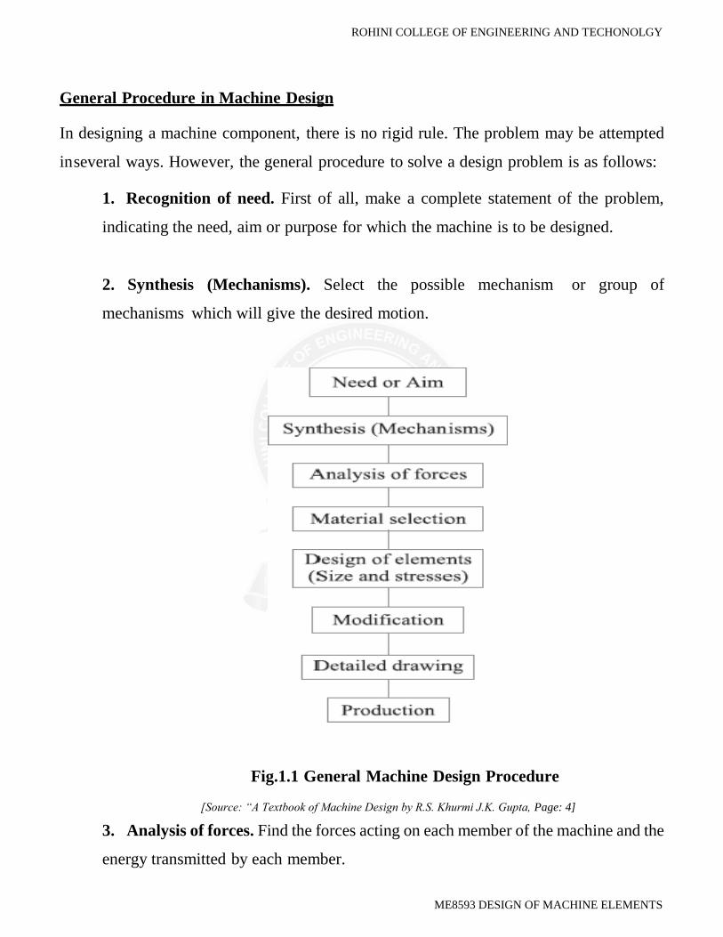
General Procedure in Machine Design
In designing a machine component, there is no rigid rule. The problem may be attempted
in several ways. However, the general procedure to solve a design problem is as follows:
1. Recognition of need. First of all, make a complete statement of the problem,
indicating the need, aim or purpose for which the machine is to be designed.
2. Synthesis (Mechanisms). Select the possible mechanism or group of
mechanisms which will give the desired motion.
Fig.1.1 General Machine Design Procedure
[Source: “A Textbook of Machine Design by R.S. Khurmi J.K. Gupta, Page: 4]
3. Analysis of forces. Find the forces acting on each member of the machine and the
energy transmitted by each member.
ROHINI COLLEGE OF ENGINEERING AND TECHONOLGY
ME8593 DESIGN OF MACHINE ELEMENTS
4. Material selection. Select the material best suited for each member of the
machine.
5. Design of elements (Size and Stresses). Find the size of each member of the
machine by considering the force acting on the member and the permissible stresses
for the material used. It should be kept in mind that each member should not deflect
or deform than the permissible limit.
6. Modification. Modify the size of the member to agree with the past experience
and judgment to facilitate manufacture. The modification may also be necessary by
consideration of manufacturing to reduce overall cost.
7. Detailed drawing. Draw the detailed drawing of each component and the
assembly of the machine with complete specification for the manufacturing processes
suggested.
8. Production. The component, as per the drawing, is manufactured in the
workshop. The flow chart for the general procedure in machine design is shown in
Fig.
Note: When there are number of components in the market having the same qualities of
efficiency, durability and cost, then the customer will naturally attract towards the most
appealing product. The aesthetic and ergonomics are very important features which gives
grace and lustre to product and dominates the market.

ROHINI COLLEGE OF ENGINEERING AND TECHONOLGY
ME8593 DESIGN OF MACHINE ELEMENTS
Design Considerations:
Design considerations are the characteristics which influence the design of the element or
perhaps, the entire system. Normally, a number of such characteristics have to be considered
in any design problem.
In a given design problem, the design engineer should identify the various design
considerations and incorporate them in the design process in their order of importance.
Some of the common design considerations are as follows:
1. Strength. The machine elements are subjected to any one or combination of loads
like forces, bending moments and torque. A machine element should have
sufficient strength to avoid failure either due to yielding or due to fracture under
the loads.
2. Rigidity. A machine element should have sufficient rigidity so that its linear as
well as angular deflections, under the loading are within permissible limits.
3. Reliability. The reliability is defined as the probability that a component, system
or device will perform without failure for a specific period of time under the specified
operating conditions. A machine element should have reasonable good reliability so
that it can perform its function satisfactorily over its life span.
4. Safety. A machine element should be designed such that it ensures safety of users
and machine.
5. Cost. The life cycle cost of the machine element consists of production cost,
operating cost, maintenance cost and disposal cost. A machine element should have a
minimum possible life cycle cost.

ROHINI COLLEGE OF ENGINEERING AND TECHONOLGY
ME8593 DESIGN OF MACHINE ELEMENTS
6. Weight. A machine element should have a minimum possible weight.
7. Ergonomics. Ergonomics is defined as the scientific study of the man-machine
working environment relationship and the application of anatomical, physiological,
and psychological principles to solve the problems arising from the relationship. The
objective of ergonomics is to make the machine fit for user rather than to make the
user adopt himself or herself to the machine. If the user is likely to communicate
directly with the machine element, it should be designed with ergonomic
considerations.
8. Aesthetics. Aesthetics deals with the appearance of the product. In a present day
of buyer’s market, with a number of products available in the market are having most
of the parameters identical, the appearance of the product is often a major factor in
attracting the customer. This is particularly true for consumer durables like
automobiles, domestic refrigerators, television, mobile etc.
9. Manufacturing. In a design of machine element, the selection of manufacturing
processes must be given a due importance. The manufacturing processes should be
selected such that the machine element can be produces with minimum manufacturing
cost and as far as possible, with existing manufacturing facilities.
10. Conformance to Standards. A design of machine element should conform to the
national and/or international standards and codes.
11. Assembly. A machine element or a product should be designed such that it
facilitates to minimize the assembly cost and time.

ROHINI COLLEGE OF ENGINEERING AND TECHONOLGY
ME8593 DESIGN OF MACHINE ELEMENTS
12. Friction and Wear. Friction and wear are major contributing factors for reducing
the life of machine elements and increasing the power loss. The friction can be
reduced by improving the surface finish, adequately lubricating the surfaces and
replacing the sliding motion by rolling motion. The wear can be reduced by increasing
the surface hardness.
13. Life. A machine element should be designed for an adequate life.
14. Vibrations. A machine element should be designed so as to keep the vibrations
at minimum level.
15. Thermal considerations. A machine element should be able to withstand the
temperature to which it may be subjected. In addition, it should dissipate the heat
generated, if any.
16. Lubrication. In the design of machine elements, due considerations must be given
for the lubrication of the elements, if there is relative sliding or rolling motion between
the elements.
17. Maintenance. A machine element should be such that it can be easily repaired or
serviced.
18. Flexibility. A machine element should be flexible so that the modifications can
be carried out with minimum efforts.
19. Size and Shape. As far as possible, standard sizes and shaped should be adopted
for machine elements

ROHINI COLLEGE OF ENGINEERING AND TECHONOLGY
ME8593 DESIGN OF MACHINE ELEMENTS
20. Stiffness. Whenever stiffness is a functional requirement like in springs, the
machine element should be designed with a precise value of required stiffness.
21. Corrosion. A machine element should be corrosion resistant. This can be
achieved by a proper selection of material and adopting the surface coating.
22. Noise. The machine element should be designed such that the noise during
operation is at minimum.
Engineering materials and their properties
The knowledge of materials and their properties is of great significance for a design
engineer. The machine elements should be made of such a material which has properties
suitable for the conditions of operation. In addition to this, a design engineer must be
familiar with the effects which the manufacturing processes and heat treatment have on the
properties of the materials. Now, we shall discuss the commonly used engineering materials
and their properties in Machine Design.
Classification of Engineering Materials
The engineering materials are mainly classified as:
1. Metals and their alloys, such as iron, steel, copper, aluminum, etc.
2. Non-metals, such as glass, rubber, plastic, etc. The metals may be further
classified as:
(a) Ferrous metals and
(b) (b) Non-ferrous metals.
The ferrous metals are those which have the iron as their main constituent, such as cast
iron, wrought iron and steel. The non-ferrous metals are those which have a metal other than
iron as their main constituent, such as copper, aluminum, brass, tin, zinc, etc.

ROHINI COLLEGE OF ENGINEERING AND TECHONOLGY
ME8593 DESIGN OF MACHINE ELEMENTS
Selection of Materials for Engineering Purposes
The selection of a proper material, for engineering purposes, is one of the most difficult
problems for the designer. The best material is one which serves the desired objective at the
minimum cost. The following factors should be considered while selecting the material:
1. Availability of the materials,
2. Suitability of the materials for the working conditions in service, and
3. The cost of the materials.
The important properties, which determine the utility of the material, are physical, chemical
and mechanical properties. We shall now discuss the physical and mechanical properties
of the material in the following articles.
Physical Properties of Metals
The physical properties of the metals include luster, colour, size and shape, density, electric
and thermal conductivity, and melting point. The following table shows the important
physical properties of some pure metals.
Mechanical Properties of Metals
The mechanical properties of the metals are those which are associated with the ability of
the material to resist mechanical forces and load. These mechanical properties of the metal
include strength, stiffness, elasticity, plasticity, ductility, brittleness, malleability, toughness,
resilience, creep and hardness. We shall now discuss these properties as follows:
1. Strength. It is the ability of a material to resist the externally applied forces
without breaking or yielding. The internal resistance offered by a part to an externally
applied force is called stress.

ROHINI COLLEGE OF ENGINEERING AND TECHONOLGY
ME8593 DESIGN OF MACHINE ELEMENTS
2. Stiffness. It is the ability of a material to resist deformation under stress. The
modulus of elasticity is the measure of stiffness.
3. Elasticity. It is the property of a material to regain its original shape after
deformation when the external forces are removed. This property is desirable for
materials used in tools and machines. It may be noted that steel is more elastic than
rubber.
4. Plasticity. It is property of a material which retains the deformation produced
under load permanently. This property of the material is necessary for forgings, in
stamping images on coins and in ornamental work.
5. Ductility. It is the property of a material enabling it to be drawn into wire with
the application of a tensile force. A ductile material must be both strong and plastic.
The ductility is usually measured by the terms, percentage elongation and
percentage reduction in area. The ductile material commonly used in engineering
practice (in order of diminishing ductility) are mild steel, copper, aluminium, nickel,
zinc, tin and lead.
6. Brittleness. It is the property of a material opposite to ductility. It is the property
of breaking of a material with little permanent distortion. Brittle materials when
subjected to tensile loads snap off without giving any sensible elongation. Cast iron
is a brittle material.
7. Malleability. It is a special case of ductility which permits materials to be rolled
or hammered into thin sheets. A malleable material should be plastic but it is not
essential to be so strong. The malleable materials commonly used in engineering
practice (in order of diminishing malleability) are lead, soft steel, wrought iron,
copper and aluminium.

ROHINI COLLEGE OF ENGINEERING AND TECHONOLGY
ME8593 DESIGN OF MACHINE ELEMENTS
8. Toughness. It is the property of a material to resist fracture due to high impact
loads like hammer blows. The toughness of the material decreases when it is heated.
It is measured by the amount of energy that a unit volume of the material has absorbed
after being stressed upto the point of fracture. This property is desirable in parts
subjected to shock and impact loads.
9. Machinability. It is the property of a material which refers to a relative case with
which a material can be cut. The machinability of a material can be measured in a
number of ways such as comparing the tool life for cutting different materials or
thrust required to remove the material at some given rate or the energy required to
remove a unit volume of the material. It may be noted that brass can be easily
machined than steel.
10. Resilience. It is the property of a material to absorb energy and to resist shock
and impact loads. It is measured by the amount of energy absorbed per unit volume
within elastic limit. This property is essential for spring materials.
11. Creep. When a part is subjected to a constant stress at high temperature for a
long period of time, it will undergo a slow and permanent deformation called creep.
This property is considered in designing internal combustion engines, boilers and
turbines.
12. Fatigue. When a material is subjected to repeated stresses, it fails at stresses
below the yield point stresses. Such type of failure of a material is known as fatigue.
The failure is caused by means of a progressive crack formation which are usually
fine and of microscopic size. This property is considered in designing shafts,
connecting rods, springs, gears, etc.

ROHINI COLLEGE OF ENGINEERING AND TECHONOLGY
ME8593 DESIGN OF MACHINE ELEMENTS
13. Hardness. It is a very important property of the metals and has a wide variety
of meanings. It embraces many different properties such as resistance to wear,
scratching, deformation and machinability etc. It also means the ability of a metal to
cut another metal. The hardness is usually expressed in numbers which are dependent
on the method of making the test. The hardness of a metal may be determined by the
following tests:
(a) Brinell hardness test,
(b) Rockwell hardness test,
(c) Vickers hardness (also called Diamond Pyramid) test, and
(d) Shore scleroscope.
Steel
It is an alloy of iron and carbon, with carbon content up to a maximum of 1.5%. The carbon
occurs in the form of iron carbide, because of its ability to increase the hardness and
strength of the steel. Other elements e.g. silicon, sulphur, phosphorus and manganese are
also present to greater or lesser amount to impart certain desired properties to it. Most of
the steel produced now-a-days is plain carbon steel or simply carbon steel. A carbon steel
is defined as a steel which has its properties mainly due to its carbon content and does not
contain more than 0.5% of silicon and 1.5% of manganese. The plain carbon steels varying
from 0.06% carbon to 1.5% carbon are divided into the following types depending upon the
carbon content.
1. Dead mild steel — up to 0.15% carbon
2. Low carbon or mild steel — 0.15% to 0.45% carbon
3. Medium carbon steel — 0.45% to 0.8% carbon
4. High carbon steel — 0.8% to 1.5% carbon
According to Indian standard *[IS: 1762 (Part-I)–1974], a new system of designating the
steel is recommended. According to this standard, steels are designated on the following

ROHINI COLLEGE OF ENGINEERING AND TECHONOLGY
ME8593 DESIGN OF MACHINE ELEMENTS
two basis:
(a) On the basis of mechanical properties, and
(b) On the basis of chemical composition. We shall now discuss, in detail, the
designation of steel on the above two basis, in the following pages.
Steels Designated on the Basis of Mechanical Properties
These steels are carbon and low alloy steels where the main criterion in the
selection and inspection of steel is the tensile strength or yield stress. According to
Indian standard IS: 1570 (Part–I)- 1978 (Reaffirmed 1993), these steels are designated
by a symbol ‗ Fe ‘or ‗Fe E‘ depending on whether the steel has been specified on the
basis of minimum tensile strength or yield strength, followed by the figure indicating the
minimum tensile strength or yield stress in N/mm2. For example, ‗Fe 290‘means a steel
having minimum tensile strength of 290 N/mm2 and ‗Fe E 220‘means a steel having
yield strength of 220 N/mm2.
Steels Designated on the Basis of Chemical Composition
According to Indian standard, IS: 1570 (Part II/Sec I)-1979 (Reaffirmed 1991), the
carbon steels are designated in the following order:
(a) Figure indicating 100 times the average percentage of carbon content,
(b) Letter ‗C ‘, and
(c) Figure indicating 10 times the average percentage of manganese content.
The figure after multiplying shall be rounded off to the nearest integer. For example, 20C8
means a carbon steel containing 0.15 to 0.25 per cent (0.2 per cent on average) carbon and
0.60 to 0.90 per cent (0.75 per cent rounded off to 0.8 per cent on an average) manganese.
Effect of Impurities on Steel
The following are the effects of impurities like silicon, sulphur, manganese and

ROHINI COLLEGE OF ENGINEERING AND TECHONOLGY
ME8593 DESIGN OF MACHINE ELEMENTS
phosphorus on steel.
1. Silicon. The amount of silicon in the finished steel usually ranges from 0.05 to
0.30%. Silicon is added in low carbon steels to prevent them from becoming porous.
It removes the gases and oxides, prevent blow holes and thereby makes the steel
tougher and harder.
2. Sulphur. It occurs in steel either as iron sulphide or manganese sulphide. Iron
sulphide because of its low melting point produces red shortness, whereas
manganese sulphide does not affect so much. Therefore, manganese sulphide is less
objectionable in steel than iron sulphide.
3. Manganese. It serves as a valuable deoxidising and purifying agent in steel.
Manganese also combines with sulphur and thereby decreases the harmful effect of
this element remaining in the steel. When used in ordinary low carbon steels,
manganese makes the metal ductile and of good bending qualities. In high speed
steels, it is used to toughen the metal and to increase its critical temperature.
4. Phosphorus. It makes the steel brittle. It also produces cold shortness in steel.
In low carbon steels, it raises the yield point and improves the resistance to
atmospheric corrosion. The sum of carbon and phosphorus usually does not exceed
0.25%.
Manufacturing considerations in Machine design
Manufacturing Processes
The knowledge of manufacturing processes is of great importance for a design
engineer. The following are the various manufacturing processes used in Mechanical
Engineering.

ROHINI COLLEGE OF ENGINEERING AND TECHONOLGY
ME8593 DESIGN OF MACHINE ELEMENTS
1. Primary shaping processes. The processes used for the preliminary shaping of
the machine component are known as primary shaping processes. The common
operations used for this process are casting, forging, extruding, rolling, drawing,
bending, shearing, spinning, powder metal forming, squeezing, etc.
2. Machining processes. The processes used for giving final shape to the machine
component, according to planned dimensions are known as machining processes.
The common operations used for this process are turning, planning, shaping, drilling,
boring, reaming, sawing, broaching, milling, grinding, hobbing, etc.
3. Surface finishing processes. The processes used to provide a good surface finish
for the machine component are known as surface finishing processes. The common
operations used for this process are polishing, buffing, honing, lapping, abrasive
belt grinding, barrel tumbling, electroplating, super finishing, sheradizing, etc.
4. Joining processes. The processes used for joining machine components are
known as joining processes. The common operations used for this process are
welding, riveting, soldering, brazing, screw fastening, pressing, sintering, etc.
5. Processes effecting change in properties. These processes are used to impart
certain specific properties to the machine components so as to make them suitable for
particular operations or uses. Such processes are heat treatment, hot-working, cold-
working and shot peening.
Other considerations in Machine design
1. Workshop facilities.
2. Number of machines to be manufactured
3. Cost of construction

ROHINI COLLEGE OF ENGINEERING AND TECHONOLGY
ME8593 DESIGN OF MACHINE ELEMENTS
4. Assembling
Interchangeability
The term interchangeability is normally employed for the mass production of
identical items within the prescribed limits of sizes. A little consideration will show that
in order to maintain the sizes of the part within a close degree of accuracy, a lot of time is
required. But even then there will be small variations. If the variations are within certain
limits, all parts of equivalent size will be equally fit for operating in machines and
mechanisms. Therefore, certain variations are recognized and allowed in the sizes of the
mating parts to give the required fitting. This facilitates to select at random from a large
number of parts for an assembly and results in a considerable saving in the cost of
production.
In order to control the size of finished part, with due allowance for error, for
interchangeable parts is called limit system. It may be noted that when an assembly is
made of two parts, the part which enters into the other, is known as enveloped surface (or
shaft for cylindrical part) and the other in which one enters is called enveloping surface
(or hole for cylindrical part). The term shaft refers not only to the diameter of a circular
shaft, but it is also used to designate any external dimension of a part. The term hole
refers not only to the diameter of a circular hole, but it is also used to designate any internal
dimension of a part.
Important Terms used in Limit System
The following terms used in limit system (or interchangeable system) are important
from the subject point of view:
1. Nominal size. It is the size of a part specified in the drawing as a matter of
convenience.

ROHINI COLLEGE OF ENGINEERING AND TECHONOLGY
ME8593 DESIGN OF MACHINE ELEMENTS
Fig 1.2 Limits of sizes.
[Source: “A Textbook of Machine Design by R.S. Khurmi J.K. Gupta, Page:63]
2. Basic size. It is the size of a part to which all limits of variation (i.e. tolerances)
are applied to arrive at final dimensioning of the mating parts. The nominal or basic
size of a part is often the same.
3. Actual size. It is the actual measured dimension of the part. The difference
between the basic size and the actual size should not exceed a certain limit; otherwise
it will interfere with the interchangeability of the mating parts.
4. Limits of sizes. There are two extreme permissible sizes for a dimension of the
part as shown in Fig. The largest permissible size for a dimension of the part is called
upper or high or maximum limit, whereas the smallest size of the part is known as
lower or minimum limit.
5. Allowance. It is the difference between the basic dimensions of the mating parts.
The allowance may be positive or negative. When the shaft size is less than the hole
size, then the allowance is positive and when the shaft size is greater than the hole
size, then the allowance is negative.

ROHINI COLLEGE OF ENGINEERING AND TECHONOLGY
ME8593 DESIGN OF MACHINE ELEMENTS
Fig 1.3 Method of assigning Tolerances
[Source: “A Textbook of Machine Design by R.S. Khurmi J.K. Gupta, Page:63]
6. Tolerance. It is the difference between the upper limit and lower limit of a
dimension. In other words, it is the maximum permissible variation in a dimension.
The tolerance may be unilateral or bilateral. When all the tolerance is allowed on one
side of the nominal size, e.g.0.000 200.004, then it is said to be unilateral system of
tolerance. The unilateral system is mostly used in industries as it permits changing
the tolerance value while still retaining the same allowance or type of fit. When the
tolerance is allowed on both sides of the nominal size, e.g. 0.002 200.002 then it is
said to be bilateral system of tolerance. In this case + 0.002 is the upper limit and –
0.002 is the lower limit.
7. Tolerance zone. It is the zone between the maximum and minimum limit size.

ROHINI COLLEGE OF ENGINEERING AND TECHONOLGY
ME8593 DESIGN OF MACHINE ELEMENTS
Fig 1.4 Tolerance Zone
[Source: “A Textbook of Machine Design by R.S. Khurmi J.K. Gupta, Page: 64]
8. Zero line. It is a straight line corresponding to the basic size. The deviations are
measured from this line. The positive and negative deviations are shown above and
below the zero line respectively.
9. Upper deviation. It is the algebraic difference between the maximum size and
the basic size. The upper deviation of a hole is represented by a symbol ES (Ecart
Superior) and of a shaft, it is represented by es.
10. Lower deviation. It is the algebraic difference between the minimum size and
the basic size. The lower deviation of a hole is represented by a symbol EI (Ecart
Inferior) and of a shaft, it is represented by ei.
11. Actual deviation. It is the algebraic difference between the actual size and basic
corresponding size.
12. Mean deviation. It is the arithmetical mean between the upper and lower
deviations.
13. Fundamental deviation. It is one of the two deviations which are conventionally
chosen to define the position of the tolerance zone in relation to zero line, as shown
in Fig

ROHINI COLLEGE OF ENGINEERING AND TECHONOLGY
ME8593 DESIGN OF MACHINE ELEMENTS
Fig 1.5 Fundamental deviation
[Source: “A Textbook of Machine Design by R.S. Khurmi J.K. Gupta, Page: 64]

ROHINI COLLEGE OF ENGINEERING AND TECHONOLGY
ME8593 DESIGN OF MACHINE ELEMENTS
Fits
The degree of tightness or looseness between the two mating parts is known as a fit of the
parts. The nature of fit is characterized by the presence and size of clearance and
interference. The clearance is the amount by which the actual size of the shaft is less than
the actual size of the mating hole in an assembly as shown in Fig. 3.5 (a). In other words,
the clearance is the difference between the sizes of the hole and the shaft before assembly.
The difference must be positive.
The clearance is the amount by which the actual size of the shaft is less than the actual
size of the mating hole in an assembly as shown in Fig. (a).
In other words, the clearance is the difference between the sizes of the hole and the shaft
before assembly. The difference must be positive.
Fig 1.6 Types of fits.
[Source: “A Textbook of Machine Design by R.S. Khurmi J.K. Gupta, Page: 65]
The interference is the amount by which the actual size of a shaft is larger than the
actual finished size of the mating hole in an assembly as shown in Fig. (b). In other
words, the interference is the arithmetical difference between the sizes of the hole and the
shaft, before assembly. The difference must be negative.

ROHINI COLLEGE OF ENGINEERING AND TECHONOLGY
ME8593 DESIGN OF MACHINE ELEMENTS
Types of Fits
According to Indian standards, the fits are classified into the following three groups:
1. Clearance fit. In this type of fit, the size limits for mating parts are so selected
that clearance between them always occur, as shown in Fig. (a). It may be noted
that in a clearance fit, the tolerance zone of the hole is entirely above the tolerance zone
of the shaft. In a clearance fit, the difference between the minimum size of the hole and
the maximum size of the shaft is known as minimum clearance whereas the difference
between the maximum size of the hole and minimum size of the shaft is called maximum
clearance as shown in Fig. (a). The clearance fits may be slide fit, easy sliding fit, running
fit, slack running fit and loose running fit.
2. Interference fit. In this type of fit, the size limits for the mating parts are so selected
that interference between them always occur, as shown in Fig. (b). It may be noted that
in an interference fit, the tolerance zone of the hole is entirely below the tolerance
zone of the shaft. In an interference fit, the difference between the maximum size of
the hole and the minimum size of the shaft is known as minimum interference,
whereas the difference between the minimum size of the hole and the maximum size
of the shaft is called maximum interference, as shown in Fig. (b). The interference fits
may be shrink fit, heavy drive fit and light drive fit.
3. Transition fit. In this type of fit, the size limits for the mating parts are so selected
that either a clearance or interference may occur depending upon the actual size of the
mating parts, as shown in Fig. (c). It may be noted that in a transition fit, the tolerance
zones of hole and shaft overlap. The transition fits may be force fit, tight fit and push fit.
Basis of Limit System
The following are two bases of limit system:

ROHINI COLLEGE OF ENGINEERING AND TECHONOLGY
ME8593 DESIGN OF MACHINE ELEMENTS
1. Hole basis system. When the hole is kept as a constant member (i.e. when the
lower deviation of the hole is zero) and different fits are obtained by varying the
shaft size, as shown in Fig. (a), then the limit system is said to be on a hole basis.
2. Shaft basis system. When the shaft is kept as a constant member (i.e. when the upper
deviation of the shaft is zero) and different fits are obtained by varying the hole size,
as shown in Fig.(b), Then the limit system is said to be on a shaft basis.
Fig 1.7 Bases of Limit System
[Source: “A Textbook of Machine Design by R.S. Khurmi J.K. Gupta, Page: 66]
Fig 1.8 Bases of Limit System
[Source: “A Textbook of Machine Design by R.S. Khurmi J.K. Gupta, Page: 66]

ROHINI COLLEGE OF ENGINEERING AND TECHONOLGY
ME8593 DESIGN OF MACHINE ELEMENTS
The hole basis and shaft basis system may also be shown as in Fig. with respect to the
zero line. It may be noted that from the manufacturing point of view, a hole basis system
is always preferred. This is because the holes are usually produced and finished by
standard tooling like drill, reamers, etc., whose size is not adjustable easily. On the other
hand, the size of the shaft (which is to go into the hole) can be easily adjusted and is
obtained by turning or grinding operations.
Problem 1
The Dimension of the mating parts, according to basic hole system, are given as follows:
Hole: 25.00mm Shaft: 24.97mm
25.02mm 24.95mm
Find the hole tolerance, shaft tolerance and allowance.
Solution:
Given:
Lower Limit of Hole =25mm
Upper limit of Hole =25.02mm
Upper Limit of Shaft =24.97mm
Lower Limit of Shaft = 24.95mm
Hole Tolerance
We know that hole tolerance
= Upper limit of Hole - Lower Limit of Hole
= 25.02 - 25
= 0.02 mm
Shaft Tolerance
We know that shaft tolerance
= Upper Limit of Shaft - Lower Limit of Shaft
= 24.97 - 24.95
= 0.02 mm

ROHINI COLLEGE OF ENGINEERING AND TECHONOLGY
ME8593 DESIGN OF MACHINE ELEMENTS
Allowance
We know that allowance
= Lower Limit of Hole - Upper Limit of Shaft
= 25.00 - 24.97 = 0.03mm
Problem 2
Calculate the tolerances, fundamental derivations and limit of sizes of shaft designates as
40H8/f7
Solution
Given
Shaft designation = 40Hs/f7
The shaft designation 40HS/F7 means that the basic size is 40mm and the tolerance grade
for the hole is (i.e. I T 8) And shaft is 7(i.e. I T 7)
Tolerances
Since 40mm lies in the diameter steps of 40to 50mm, therefore the geometric mean
diameter,
D = √30𝑥 50 = 38.73mm
We know that standard tolerance used
i = 0.45 √𝐷3
+ 0.001D
= 0.45√38.733
+ 0.001
= 38.73 mm
= 0.45 × 3.38 + 0.01873
= 1.55973 or 1.56microns
= 1.56 × 0.001 = 0.00156mm (1microns = 0.001mm)
From Table 3.2, we find the standard tolerances for the hole II (I T 8)
= 25i = 25 × 0.00156 = 0.039mm
and standard tolerance for shaft of grade 7(I T 7)
= 16i = 16 × 0.00156 = 0.025mm
Fundamental deviation

ROHINI COLLEGE OF ENGINEERING AND TECHONOLGY
ME8593 DESIGN OF MACHINE ELEMENTS
We know that fundamental deviation (lower deviation) for hole H,
EI = 0
From Table 3.7, we find that fundamental deviation (upper deviation) for shaft f,
s = – 5.5 (D)0.41
= – 5.5 (38.73)0.41
= – 24.63 or – 25 microns
= – 25 × 0.001
= – 0.025 mm.
∴ Fundamental deviation (lower deviation) for shaft f,
ei = es – I T
= – 0.025 – 0.025
= – 0.050 mm.
The –ve sign indicates that fundamental deviation lies below the zero line.
Limits of sizes
We know that lower limit for hole
= Basic size = 40 mm.
Upper limit for hole = Lower limit for hole + Tolerance for hole
= 40 + 0.039
= 40.039 mm.
Upper limit for shaft = Lower limit for hole or Basic size – Fundamental deviation
(upper deviation) ... (Q Shaft f lies below the zero line)
= 40 – 0.025
= 39.975 mm.
and lower limit for shaft = Upper limit for shaft – Tolerance for shaft
= 39.975 – 0.025
= 39.95 mm