APPENDIX 1 SPECIFICATIONS SUBJECT
159
Page 1 of 2 Initials: __________ Date: __________ STATE OF NEW HAMPSHIRE DEPARTMENT OF MILITARY AFFAIRS AND VETERANS SERVICES EXHIBIT B – APPENDIX 1 SPECIFICATIONS SUBJECT: NHARNG Building F Boiler Replacement STATEMENT OF UNDERSTANDING The Contractor clearly understands the following NHARNG Building F Replacement Specifications and will meet all requirements herein. TABLE OF CONTENTS GENERAL SPECIFICATIONS SECTION 00 41 00 General Conditions SECTION 01 20 00 Price and Payment Procedures SECTION 01 33 00 Submittal Procedures SECTION 01 50 00 Temporary Facilities and Controls SECTION 01 70 00 Execution Requirements TECHNICAL SPECIFICATIONS DIVISION 22- PLUMBING SECTION 220000 Plumbing SECTION 220100 Operation and Maintenance of Plumbing SECTION 220500 Common Work Results for Plumbing SECTION 220523 General-Duty Valves for Plumbing Piping SECTION 220529 Hangers and Supports for Plumbing Piping and Equipment SECTION 220553 Identification for Plumbing Piping and Equipment SECTION 220610 Schedules for Plumbing Piping SECTION 220640 Schedules for Plumbing Fixtures SECTION 220700 Plumbing Insulation SECTION 220800 Commissioning of Plumbing SECTION 221512 Natural Gas Piping DIVISION 23- HEATING, VENTILATION AND AIR CONDITIONING (HVAC) SECTION 230000 Heating, Ventilating and Air Conditioning SECTION 230100 Operation and Maintenance of HVAC Systems
-
Upload
khangminh22 -
Category
Documents
-
view
0 -
download
0
Transcript of APPENDIX 1 SPECIFICATIONS SUBJECT

Page 1 of 2 Initials: __________ Date: __________
STATE OF NEW HAMPSHIRE DEPARTMENT OF MILITARY AFFAIRS AND VETERANS SERVICES
EXHIBIT B – APPENDIX 1
SPECIFICATIONS
SUBJECT: NHARNG Building F Boiler Replacement
STATEMENT OF UNDERSTANDING
The Contractor clearly understands the following NHARNG Building F Replacement Specifications and will meet all requirements herein.
TABLE OF CONTENTS
GENERAL SPECIFICATIONS
SECTION 00 41 00 General Conditions SECTION 01 20 00 Price and Payment Procedures SECTION 01 33 00 Submittal Procedures SECTION 01 50 00 Temporary Facilities and Controls SECTION 01 70 00 Execution Requirements
TECHNICAL SPECIFICATIONS DIVISION 22- PLUMBING SECTION 220000 Plumbing SECTION 220100 Operation and Maintenance of Plumbing SECTION 220500 Common Work Results for Plumbing SECTION 220523 General-Duty Valves for Plumbing Piping SECTION 220529 Hangers and Supports for Plumbing Piping and Equipment SECTION 220553 Identification for Plumbing Piping and Equipment SECTION 220610 Schedules for Plumbing Piping SECTION 220640 Schedules for Plumbing Fixtures SECTION 220700 Plumbing Insulation SECTION 220800 Commissioning of Plumbing SECTION 221512 Natural Gas Piping DIVISION 23- HEATING, VENTILATION AND AIR CONDITIONING (HVAC) SECTION 230000 Heating, Ventilating and Air Conditioning SECTION 230100 Operation and Maintenance of HVAC Systems
Page 2 of 2 Initials: __________ Date: __________
SECTION 230500 Common Work Results for HVAC SECTION 230516 Expansion Fittings and Loops for HVAC Piping SECTION 230523 General-Duty Valves for HVAC Piping SECTION 230529 Hangers and Supports for HVAC Piping and Equipment SECTION 230548 Vibration Isolation and Seismic Controls for HVAC Piping and
Equipment SECTION 230553 Identification for HVAC Piping and Equipment SECTION 230593 Testing, Adjusting, and Balancing for HVAC SECTION 230620 Schedules for HVAC Piping and Pumps SECTION 230700 Pipe Insulation SECTION 230800 Commissioning of HVAC Piping Systems SECTION 230900 Instrumentation and Control for HVAC SECTION 232000 HVAC Piping, Pumps and Specialties SECTION 232500 HVAC Water Treatment SECTION 233100 HVAC Ducts and Accessories SECTION 235216 Condensing Boilers DIVISION 25- INTEGRATED AUTOMATION SECTION 250000 Integrated Automation SECTION 250800 Commissioning of Integrated Automation SECTION 259000 Integrated Automation Controls DIVISION 26- ELECTRICAL SECTION 260100 Basic Electrical Requirements SECTION 260519 Low-Voltage Electrical Power Conductors and Cables SECTION 260526 Grounding and Bonding for Electrical Systems SECTION 260529 Hangers and Supports for Electrical Systems SECTION 260534 Conduit SECTION 260537 Boxes SECTION 260553 Identification for Electrical Systems SECTION 262717 Equipment Wiring SECTION 262726 Wiring Devices SECTION 262818 Enclosed Switches

Page 1 of 29
SECTION 00 41 00
GENERAL CONDITIONS
1. CONTRACT DOCUMENTS A. The Contract Documents consist of the Contract Agreement, General Conditions, and
Supplementary General Conditions, Drawings and Specifications, including all Addenda issued prior to execution of the Contract; Bonds where required; insurance certificates: and subsequently thereto, Change Orders issued in accordance with the General Conditions.
B. The Contract Documents shall be signed by the Department and the Contractor in as many original counterparts as may be mutually agreed. No Contract shall be considered as in effect until it has been fully executed by all of the parties thereto and the award concurred in by Governor and Council. If there is federal funding, it must also have the concurrence of the applicable Federal Agency having jurisdiction.
C. This Contract is executed in a number of counterparts, each of which is an original and constitutes the entire agreement between the parties. This Contract shall be construed according to the laws of the State of New Hampshire. No portion of this Contract shall be understood to waive the sovereign immunity of the State. This Contract shall not be amended, except as specified herein, except with the approval of the Governor and Council.
D. The Contract Documents are complementary and anything called for by one of the Contract Documents and not called for by the others shall be of like effect as if required by all.
E. Should the Contract Documents disagree in themselves or with each other, the Contractor shall provide the better quality or greater quantity of work and or materials, unless specifically otherwise directed by written Addendum to the Contract.
F. The Contractors and all subcontractors shall refer to all of the Contract Documents, including those not specifically showing the work of their specialized trades, and shall perform all work reasonably inferable from them as being necessary to produce the intended results.
G. All indications or notations which apply to one of a number of similar situations, materials or processes shall be deemed to apply to all such situations, materials or processes wherever they appear in the work, except where a contrary result is clearly indicated by the Contract Documents.
H. Where codes, standards, requirements, and publications of public and private bodies are referred to in the Contract Documents, such references shall be understood to be to the latest revision prior to the date of receiving Bids, except where otherwise indicated.
I. Where no explicit quality or standards for materials or workmanship is established for work, such work is to be of good quality for the intended use and consistent with the quality of the surrounding work and of the construction of the Project in general.
J. All manufactured articles, materials, and equipment shall be applied, installed, connected, erected, tested, cleaned, and conditioned in accordance with the manufacturer's written or printed directions and instructions, unless specifically

Page 2 of 29
indicated otherwise in the Contract Documents. K. The Drawings are generally made to scale, but all working dimensions shall be taken
from the figured dimensions or by actual measurements at the job. In case by scaling. Study and compare all the Drawings and verify all figures before laying out or constructing work. The Contractor shall be responsible for errors in his work that might have been avoided thereby. Whether or not an error is believed to exist, deviation from the Drawings and the dimensions given thereon shall be made only after approval in writing from the Department.
L. The Mechanical, Fire Protection (sprinkler) and Electrical Drawings, when provided, are diagrammatic only, and are not intended to show the exact physical locations or configurations of work. Such work shall be installed to clear all obstructions, permit proper clearances by coordinating his work with other trades, and present an orderly appearance where exposed.
2. ACCESS TO THE WORK
A. The Contractor shall provide for access to the work for inspection by the Department and government officials having jurisdiction. The Consultant, Engineer, and officials of Local, State, and Federal Agencies in the case of such programs as they administer and their authorized representatives shall have access at all times to the work for inspection wherever it is in preparation or progress, and the Contractor shall provide proper facilities for such access and inspection.
3. CONTRACT ADMINISTRATION A. The Department shall determine the amount, quality, and acceptability and fitness of
all parts of the work, shall interpret the Contract Documents, and any Change Orders, and shall decide all other issues in connection with the work. The Department shall have the authority to approve or order changes in the work that alter the terms or conditions of the Contract. The Department shall confirm in writing any oral order, direction, requirements or determination.
B. When a Federal Agency participates in the cost of the work covered by this Contract, the work shall be under the observation and inspection of the Department, but subject to the inspection and approval of the proper officials of the Federal Agency.
4. ACCIDENT PROTECTION
A. It is a condition of this Contract, and shall be made a condition of each subcontract entered into pursuant to the Contract, that the Contractor and any Subcontractors shall not require any laborer or mechanic employed in the performance of the Contract to work in surroundings or under working conditions which are unsanitary, hazardous or dangerous to his health of safety as determined by construction safety and health standards of the Occupational Safety and Health Administration, United States Department of Labor, which standards include, by reference, the established Federal Safety and Health Regulations for Construction. These standards and regulations comprise Part 1910 and Part 1926 respectively of Title 29 of the Code of Federal Regulations and are set forth in the Federal Register. In the event any revisions in the

Page 3 of 29
Code of Federal Regulations are published, such revisions will be deemed to supersede the appropriate Part 1910 and Part 1926, and be effective as of the date set forth in the revised regulation.
5. HAZARDOUS MATERIALS A. The Contractor shall also be aware of laws and regulations relating to hazardous
materials that may be encountered during construction operations, either within project limits or at material sites off the project. The health and safety of employees, the general public, and the potential of damage to the overall environment is possible if hazardous materials are not recognized, reported, and the appropriate action taken to dispose of, remove from the site, or otherwise contain the possible contaminants.
B. If any abnormal condition is encountered or exposed that indicates the presence of a hazardous material or toxic waste, construction operations shall be immediately suspended in the area and the Department notified. No further work shall be conducted in the area of the contaminated material until the site has been investigated and the Department has given approval to continue the work in the area. The Contractor shall fully cooperate with the Department and perform any remedial work as directed. Work shall continue in other areas of the Project unless otherwise directed.
C. Exposure to hazardous materials may result from contact with, but not necessarily limited to, such items as drums, barrels, and other containers, waste such as cars, batteries, and building construction debris. Containers leaking unknown chemicals or liquids, abandoned cars leaking petroleum products, batteries leaking acid, construction debris which may include asbestos, or any other source of suspected hazardous material found within excavation areas or stockpiled on land within construction limits shall be referred to the Department of Environmental Services and the Department so that a proper identification of the materials may be made and disposal procedures initiated as required.
D. Disposition of the hazardous material or toxic waste shall be made under the requirements and regulations of the Department of Environmental Services. Work required disposing of these materials and any remedial work shall be performed under a Supplemental Agreement or Contract item, if included in the Contract.
6. SUBCONTRACTS
A. Nothing contained in the Specifications or Drawings shall be construed as creating any contractual relationship between any Subcontractor and the Department. The Divisions or Sections of the Specifications are not intended to control the Contractor in dividing the work among Subcontractors or to limit the work performed by any trade.
B. The Contractor shall be as fully responsible to the Department for the acts and omissions of Subcontractors and of persons employed by them, as he is for the acts and omissions of persons directly employed by him.
C. The Contractor shall, without additional expense to the State, utilize the services of specialty Subcontractors, as required.
D. The Department will not normally undertake to settle any differences between the Contractor and his Subcontractors or between Subcontractors.

Page 4 of 29
E. The Contractor shall cause appropriate provisions to be inserted in all subcontracts relative to the work to bind Subcontractors to the Contractor by the terms of the General Conditions and other Contract Documents insofar as applicable to the work of Subcontractors and to give the Contractor the same power as regards terminating any subcontract that the Department may exercise over the Contractor under any provisions of the Contract Documents.
F. Within fifteen (15) days after the award of the Contract, the Contractor shall submit a complete list of all of the Subcontractors setting forth in detail the work they will be responsible for. If a subcontractor is added during the construction process the Contractor will revise the list and resubmit to the Department.
7. RESPONSIBILITY OF CONTRACTOR TO ACT IN EMERGENCY
A. In case of any emergency that threatens loss or injury of property, and/or safety of life, the Contractor shall act, without previous instructions from the Department, as the situation may warrant. He shall notify the Department thereof immediately thereafter. Any compensation claimed by the Contractor together with substantiating documents in regard to expense, shall be submitted to the Department and the amount of compensation shall be determined by agreement.
8. SEPARATE CONTRACTS
A. The Department may award other Contracts in connection with the Project, the work under which will proceed simultaneously with the execution of this Contract. The Contractor shall coordinate operations with those of other Contractors.
9. MUTUAL RESPONSIBILITY OF CONTRACTORS
A. If the Contractor or any of his/her Subcontractors or employee’s causes loss or damage to any separate Contractor or Subcontractor on the work, the Contractor or Subcontractor agrees to settle with such separate Contractor or Subcontractor by agreement, if he/she will so settle. If such separate Contractor or Subcontractor sues the State because of any loss so sustained, the Department shall notify the Contractor and/or their subcontractors, who shall indemnify and hold harmless the Department against any expenses or judgment arising there from.
10. PAYMENTS TO CONTRACTOR
A. The Department will manifest payments to the Contractor each calendar month on the basis of duly certified and approved estimate of the work performed during the preceding period. In preparing estimates, the material delivered on the site and any preparatory work done may be taken into consideration.
B. At least ten (10) days before the end of the billing period, the Contractor shall submit to the Department an itemized Requisition for Payment, supported by such data substantiating the Contractor's right to payment as the Department may require. If payment is to be made on account of materials or equipment not incorporated in the work, but delivered and suitably stored at the site, such payment shall be conditional upon submission by the Contractor of bills of sale or such other procedure satisfactory

Page 5 of 29
to the Department to establish the State's title to such materials or equipment or otherwise protect the State's interest including applicable insurance.
C. Immediately upon receipt of the Department Approved Monthly Requisition for Payment, Contractor shall post same at the Contractor's Field Office or project site in a location where Subcontractors and Suppliers have clear access.
D. A five (5) percent retainage of the value of the work performed on each partial estimate will be deducted and retained by the Department until after completion of the entire Contract in an acceptable manner. The balance remaining after the specified percentage has been retained, less all previous payments, will be certified for payment on each partial estimate.
E. Within thirty (30) days after acceptance, the Department shall pay to the Contractor the amount of the Contract less all prior payments. All prior payments and estimates, including those relative to extra work, shall be subject to correction by this payment, which is throughout this Contract called the Final Payment.
F. Retainage will be released at Final Payment. i. After the Certificate of Substantial Completion has been issued, upon written
application by the Contractor and with the approval of the Surety, the Department may release a portion of the retained amount.
G. Payment for Material On Hand: i. Partial payments are made for materials to be incorporated in the Work,
provided the materials meet the requirements of the Contract and are delivered on, or in the vicinity of, the Project site and stored in acceptable places. Partial payments will not exceed 90 percent of the Contract unit price for the item or the amount supported by copies of paid invoices, freight bills, or other supporting documents required by the Department. The quantity paid will not exceed the corresponding quantity estimate in the Contract. No partial payment will be made on living or perishable materials until incorporated in the Work.
ii. When material payments exceed $100,000 or 10 percent (10%) of the total contract amount, whichever is less, notarized copies of paid invoices or copies of canceled checks for all such materials must be submitted to the Department within 45 days of the end date of the estimate on which the material allowance was paid. Failure to provide such documentation will result in the deduction of such material allowance from future estimates until documentation is provided.
iii. All material and work covered by partial payments made shall thereupon become the sole property of the Department, but this provision shall not be construed as relieving the Contractor of the sole responsibility of all materials and work upon which payments have been made or the restoration of any damaged work or as a waiver of the right of the State to require the fulfillment of all the terms of the Contract.
H. Payment for Material Not on Hand: i. The Department will not pay for products and or materials that have not been
delivered and stored properly on the construction site. I. Release of Claims:
i. Neither the final payment nor any part of the retained percentage shall become

Page 6 of 29
due until the Contractor shall deliver a complete release of all claims arising under and by virtue of this Contract, including claims for all Subcontractors and suppliers of either materials or labor, plus a release of the Contract Bond and a statement that all Subcontractors and suppliers have been paid. The Department, may pay any and all such claims, in whole or in part, and deduct the amount or amounts so paid from any partial or final payment.
J. Final Payment: i. Application for Final Payment received from the Contractor will be processed
for payment not less than 60 days after project acceptance and final completion unless accompanied by a release of the Contract Bond. This payment shall be the amount of the Contract, amended by approved change orders, less previous payments minus liquidated damages, additional penalties or holdbacks. All prior partial estimates and payments shall be subject to correction in the final estimate and payment.
K. Acceptance of Final Payment Constitutes Release: i. The acceptance of the Final Payment by the Contractor shall be and shall
operate as a release to the Contractor of all claims and of all liability to the Department for all things done or furnished in connection with this work. No payment, however, final or otherwise, shall operate to release the Contractor and its Sureties from any obligations under this Contract or the Contract Bond. Acceptance of Final Payment shall not impact any warrantees provided by the Contractor with respect to this project.
11. LIMITATION OF CONSTRUCTION OPERATIONS
A. The normal working hours will be from 7:00 am until 3:30 pm M-F unless otherwise agreed in writing by the department.
B. The contractor may be displaced at any time with no notice in the event of a military mission that takes priority over construction.
C. In the State of New Hampshire, legal holidays occur on: a. New Year's Day b. Washington's Birthday c. Memorial Day d. Juneteenth e. Fourth of July f. Labor Day g. Veterans' Day h. Thanksgiving Day and Day After i. Christmas Day j. Whenever a holiday is observed on a Friday or a Monday, the Contractor shall be
required to suspend work for three (3) calendar days. k. No work shall be performed on Saturday, Sundays, or legal holidays except in cases
of emergency and upon permission of the Department.
12. CONTRACTOR'S TITLE TO MATERIALS
Page 7 of 29
A. No materials or supplies for the work shall be purchased by the Contractor or any Subcontractor subject to any chattel mortgage or under a conditional sale or other agreement by which an interest is retained by the seller. The Contractor warrants that he has good title to all materials and supplies for which he accepts partial payment. If any claim is made with respect to materials provided by the contactor, subcontractors, or Independent Contractors, the Contractor shall defend any such claim and shall pay any judgment or settlement thereon.
13. CHANGES IN WORK
A. The Department may at any time, by a written order, and without notice to the Sureties, make changes in the Drawings and Specifications and Completion Date of this Contract and within the general scope thereof.
B. The order shall stipulate the mutual agreed upon lump sum price, which shall be added to or deducted from the Contract Price. The Contractor shall furnish an itemized breakdown of the prices used in computing the value of any change that might be ordered.
C. The compensation herein provided shall be accepted by the Contractor as payment in full, including superintendence, bond, overhead, and profit, for extra work performed on a force account basis. For all such work, the Contractor shall furnish certified copies of the payrolls on forms provided for that purpose, invoices of all materials, and such other information as may be required by the Department.
14. TAXES
A. The Contractor shall pay all applicable Federal, State and Local sales and other taxes, except taxes and assessments on the real property comprising the site of the Project.
15. PATENTS
A. The Contractor shall hold and save the Department and its officers, agents, servants, and employees harmless from liability of any nature including cost and expenses, for or on account of any patented or unpatented invention, process, article or applicable manufactured or used in the performance of the Contract, including its use, unless otherwise specifically stipulated in the Contract Documents.
16. ASSIGNMENTS
A. The Contractor shall not assign the whole or any part of this Contract or any monies due or to become due hereunder, without the written consent of the Department and of all Sureties executing any Bonds on behalf of the Contractor if in connection with said Contract.
17. SUPERINTENDENCE BY CONTRACTOR
A. The Contractor shall employ a competent Foreman or Superintendent, satisfactory to the Department, on the work site at all times to supervise the work in progress, with authority to act for him. The Contractor shall not change superintendents without permission from the Department and shall submit a request in writing with justification

Page 8 of 29
for such a change. i. The superintendent shall be responsible for verifying that all materials,
installation, coordination, and workmanship are in conformance with the contract documents.
ii. Unless the Department has granted prior written approval, the superintendent shall not, himself, engage in “hands on” construction work.
iii. In the event the superintendent fails or refuses to perform functions mentioned above as determined by the Department, the Contractor agrees to a stipulated penalty of up to $500.00 per day, in addition to any liquidated damages provided hereunder.
18. FAILURE TO COMPLETE WORK ON TIME
A. If the Contractor fails to complete all of the work or sections of the Project, if sections are indicated, within the time specified in the Contract or within any additional time allowed, for each working day the Liquidated Damages identified in Section C below will be deducted from any money due the Contractor. This deduction will be made. not as a penalty, but as fixed, agreed liquidated damages for inconvenience to the Department and for reimbursing the Department the cost of the Administration of the Contract, including personnel, time, engineering and inspection. Should the amount of money otherwise due the Contractor be less than the amount of such liquidated damages, the Contractor and its Surety shall be liable to the Department for such deficiency.
B. If the Department permits the Contractor to continue and finish the work after the time fixed for its completion, it shall in no way operate as a waiver on the part of the Department of any of its rights under the Contract. When the final acceptance has been duly made by the Department, any liquidated damage charges shall end.
C. The fixed, agreed, liquidated damages shall be assessed in accordance with the following schedule:
Original Contract Amount Amount for Liquidated
Damages Per Day From more than: Up to and including: $0.00 $25,000.00 $200.00
$25,000.00 $50,000.00 $300.00 $50,000.00 $100,000.00 $400.00
$100,000.00 $500,000.00 $500.00
19. SUBSTANTIAL COMPLETION AND FINAL INSPECTION A. When the Contractor believes the project is substantially complete, they shall submit
an application for substantial completion to the Department. The Contractor shall submit to the Department a list of items of work to be completed or corrected, accompanied by a cost value of these items. The Department will also provide a “punch List” of items to be completed based on their interpretation of the required finished product. The failure to include any items on such list does not alter the responsibility of the Contractor to complete all work in accordance with the Contract Documents. On

Page 9 of 29
the basis of an inspection by the Department which determines that the work is substantially complete, a certificate of Substantial Completion shall be issued which will establish the Date of Substantial Completion and state the responsibilities of the Department and the Contractor for such as security, maintenance, heat, utilities, damage to the work and insurance, any other pertinent issues and fix the time limit within which the Contractor shall complete the items listed herein. Warranties required by the Contract Documents shall commence on the Date of Substantial Completion unless otherwise provided in the Certificate of Substantial Completion.
B. If the Contractor fails to proceed to complete the items on the "punch list," then in addition to the corrective measures listed in the Certificate of Substantial Completion, the Department may use the monies still due the Contractor to have such items completed and the Contractor shall lose any claim to the monies so used.
C. Upon written notice that the work is ready for final inspection and acceptance, the Department shall promptly make such inspection, and when they find the work acceptable under the Contract Documents and the Contract fully performed, the Contractor will be provided written notice to that effect. The Contractor shall provide all certificates and reports, as required, throughout the contract and shall coordinate their preparation and submission. Failure to submit such certificates and reports shall be considered default of contract.
20. TERMINATION OF CONTRACT WITH FAULT
A. If the Contractor: i. Fails to begin work under Contract within the time specified in the notice to
proceed, or ii. Fails to perform the work with sufficient workmen and equipment, or with
sufficient materials to assume prompt completion of said work, or iii. Performs the work unsuitably or neglects or refuses to remove materials or to
perform anew such work as may be rejected as unacceptable and unsuitable, or iv. Discontinues the prosecution of the work, or v. Fails to resume work, which has been discontinued, within a reasonable time
after notice to do so, or vi. Becomes insolvent or has declared bankruptcy, or commits any act of
bankruptcy or insolvency, or vii. Fails to pay subcontractors and material/product suppliers, or
viii. Makes an assignment for the benefit of creditors, or ix. For any other causes whatsoever, fails to carry on the work in an acceptable
manner. B. The Department will give notice, in writing, to the Contractor and his Surety for such
delay, neglect, and default for any item identified above. i. If the Contractor or Surety does not proceed in accordance with the Notice, then
the Department will, upon the Contractor's failure to comply with such Notice, have full power and authority without violating the Contract, to take the prosecution of the work out of the hands of the Contractor. The Department may enter into an agreement for the completion of said Contract according to

Page 10 of 29
the terms and conditions thereof, or use such other methods as in his opinion will be required for the completion of said Contract in an acceptable manner.
ii. All extra costs and charges incurred by the Department as a result of such delay, neglect or default, together with the cost of completing the work under the Contract will be deducted from any monies due or which may become due said Contractor. If such expenses exceed the sum that would have been payable under the Contract, then the Contractor and the Surety shall be liable and shall pay to the Department, the amount of such excess.
21. TERMINATION OF CONTRACT WITHOUT FAULT
A. Except in cases controlled by the preceding section, the Department, for any cause, including, but not limited to an order of any Federal authority or petition of the Contractor due to circumstances beyond his control may by written notice to the Contractor and the Surety terminate the Contract or any portion thereof subject to the Condition(s) i, ii, iii and iv provided below.
B. Notwithstanding anything to the contrary contained in these condition, it is understood and agreed by the parties hereto that all obligations of the Department hereunder, including the continuance of payments, are contingent upon the availability and continued appropriation of State and/or Federal Funds, and in no event shall the Department be liable for any payments hereunder in excess of such available or appropriated funds. In the event of a reduction, termination or failure to appropriate any or all such available funds or appropriations or a reduction of expenditures of State funds the Department may, by written notice to the Contractor and Surety, immediately terminate this Contract in whole or in part in accordance with the following conditions:
i. When a Contract, or portion thereof, is terminated before completion of all items of work in the Contract, payment will be made for the actual items of work completed. Payment of items of work not completed at time of termination shall be the greater of the following amounts: (1) a percentage of the Contract unit price, which percentage shall be the percentage of completion of the particular item at time of termination or (2) such amount as shall be mutually agreed upon by the parties. No claim for loss of anticipated profits on items or units of work not completed will be allowed.
ii. Reimbursement for organization of the work and mobilization, when not otherwise included in the Contract, shall be made where the volume of work completed is too small to compensate the Contractor for these expenses under the Contract; the intent being that an equitable settlement be made with the Contractor.
iii. Acceptable materials, obtained or ordered by the Contractor for the work, and that are not incorporated in the work shall, at the option of the Contractor, be purchased from the Contractor based upon the delivered cost of the materials at such points of delivery as may be designated by the Department. The Contractor shall do everything possible to cancel unfilled orders.
iv. Termination of a Contract, or a portion thereof, shall not relieve the Contractor of his responsibilities for the work completed nor shall it relieve his Surety of
Page 11 of 29
its obligations for and concerning any claims arising out of the work performed.
22. ASSIGNMENT PROVISION A. The Contractor hereby agrees that it will assign to the Department all causes of action
that it may acquire under the anti-trust laws of New Hampshire and the United States as a result of conspiracies, combinations or contracts in restraint of trade which affect the price of goods or services obtained by the Department under this Contract, if so requested by the Department.
END OF SECTION

Page 12 of 29
SECTION 01 20 00
PRICE AND PAYMENT PROCEDURES
1. REQUISITION FOR PAYMENT A. Submit electronically each application on the AIA Application and Certificate for
Payment G702 and Continuation sheet G703 or another document/form that has been previously approved by the Department.
B. Content and Format: Items on the Requisition for Payment shall be consistent with the items on the Proposal Form. Utilize the Schedule of Values as documentation for payment items.
C. Submit updated construction schedule with each Requisition for Payment. D. Payment Period: Submit at intervals stipulated in the General Conditions. E. Submit with transmittal letter to the attention of the project Architect/Engineer for
review and approval. F. Substantiating Data: When the Department requires substantiating information, submit
data justifying dollar amounts in question.
2. SCHEDULE OF VALUES A. Submit printed schedule on AlA Form G703 - Continuation Sheet for G702 or approved
equal. (See item 1.A above) B. Submit Schedule of Values within 15 days after date of issuance of Notice to Proceed.
Failure to submit within specified time period will constitute Default of Contract. C. Format: Utilize Table of Contents of these specifications. Identify each line item with
number and title of major specification section. Identify bonds, insurance, general conditions, allowances etc.
D. Include a separate line item for closeout to include record drawings, owner’s manuals and other pertinent information due to the Department.
E. Include a separate line item for the amount of each Allowance and Alternates specified in this section. For unit cost Allowances, identify quantities taken from Contract Documents multiplied by unit cost to achieve total for each item.
F. Revise schedule to list approved Change Orders, with each Requisition or Payment.
3. UNIT PRICES A. Authority: Measurement methods are delineated in individual specification sections. B. Measurement methods delineated in individual specification sections complement
criteria of this section. In event of conflict, requirements of individual specification section govern,
C. Take measurements and compute quantities. Architect/Unit Quantities: Quantities and measurements indicated in Bid Form are for contract purposes only. Quantities and measurements supplied or placed in the Work shall determine payment
i. When actual Work requires more or fewer quantities than those quantities indicated, provide required quantities at unit sum/prices contracted.

Page 13 of 29
D. Payment Includes: Full compensation for required labor, products, tools, equipment, plant and facilities, transportation, services and incidentals; erection, application or installation of item of the Work; overhead and profit,
E. Final payment for Work governed by unit prices will be made on basis of actual measurements and quantities accepted by Architect/Engineer multiplied by unit sum/price for Work incorporated in or made necessary by the Work.
F. Measurement of Quantities: Measurement by Weight: Concrete reinforcing steel, rolled or formed steel or other metal shapes will be measured by handbook weights. Welded assemblies will be measured by handbook or scale weight.
G. Measurement by Volume: Measured by cubic dimension using mean length, width and height or thickness.
H. Measurement by Area: Measured by square dimension using mean length and width or radius.
I. Linear Measurement: Measured by linear dimension, at item centerline or mean chord. J. Stipulated Sum/Price Measurement: Items measured by weight, volume, area, or linear
means or combination, as appropriate, as completed item or unit of the Work.
4. CHANGE PROCEDURES A. Submittals: Submit name of individual authorized to receive change documents, and
be responsible for informing others in Contractor's employ or Subcontractors of changes to the Work.
B. The Department will advise of minor changes in the Work not involving adjustment to Contract Sum/Price or Contract Time, or that may be necessary to carry out the work included in the Contract, by issuing Supplemental Instructions.
C. The Department may issue a Proposal Request including a detailed description of proposed changes with supplementary or revised Drawings and specifications, with or without a change in Contract Time for executing the change. The Contractor will prepare and submit estimate within ten days.
D. Contractor may propose changes by submitting a request for change(s) to the Department, describing proposed change and its full effect on the Work. Each request shall be a separate item and sequentially numbered. Include a statement describing reason for the change, and effect on Contract Sum/Price and Contract Time with full documentation and a statement describing effect on Work by separate or other Contractors.
E. Stipulated Sum/Price Change Order: Based on Proposal Request and Contractor's fixed price quotation or Contractor's request for Change Order as approved by the Department. Submit the breakdown of the following items on a Department Change Order Form for review and approval by the Department:
i. The Contractor shall include the following indirect costs for work performed by the General Contractor as part of the Contractors' price:
a. Worker's Compensation and Employee Liability. b. Unemployment and Social Security Taxes.
ii. In addition to the above indirect costs the General Contractor shall be allowed the following markups:

Page 14 of 29
a. Twenty percent (20%). Said twenty percent (20%) shall be all inclusive for overhead, supervision, and profit for Work performed by the General Contractor.
b. Ten percent (10%) on that part of work performed by all Subcontractors.
iii. On any change that involves a net credit to the State, no allowance for overhead, supervision and profit shall be figured.
iv. Contractor shall provide back-up information for all change order pricing. v. Extension of Contract Time: State any requests for extension of Contract Time
with justification for such a request. F. Unit Price Change Order: For contract unit prices and quantities, the Change Order will
be executed on fixed unit price basis. For unit costs or quantities of units of work which are not pre-determined, execute Work under Construction Change Directive. Changes in Contract Sum/Price or Contract Time will be computed as specified for Time and Material Change Order.
G. Construction Change Directive: The Department may issue a directive instructing the Contractor to proceed with changes in the Work, for subsequent inclusion in a Change Order. Document will describe changes in the Work, and designate method of determining any change in Contract Sum/Price or Contract Time. Promptly execute change. Failure to comply will result in Default of Contract.
H. Time and Material Change Order: Submit itemized account and supporting data within 10 days of completion of change. The Department will determine change allowable in Contract Sum/Price and Contract Time as provided in Contract Documents.
i. Maintain detailed records of work done on Time and Material basis. Provide full information required for evaluation of proposed changes, and to substantiate costs for changes in the Work.
I. Execution of Change Orders: The Contractor is responsible for preparing and updating a spreadsheet log itemizing all Proposed Changes. A separate spreadsheet shall be completed for each Allowance Item. The spreadsheet shall include columns for Proposed Change Number, Description, Amount of Change, Status, and Approved Amounts. In addition a current balance remaining shall be included. Change Orders will be processed per the following procedures:
i. The Department reviews cost for Change in Work. If needed the Department will request additional items, back-up information, and request any possible changes or clarifications.
ii. Contractor can proceed with Change Order Work with direction from the Department.
iii. Contractor shall not proceed with any work that will exceed the amount of Allowance remaining.
iv. Fully signed and executed Change Order is issued by the Department to the Consultant and Contractor.
J. Correlation Of Contractor Submittals:

Page 15 of 29
i. Promptly revise Schedule of Values and Application for Payment forms to record each authorized Change Order as separate line item and adjust Contract Sum/Price.
ii. Promptly revise progress schedules to reflect change in Contract Time, revise sub-schedules to adjust times for other items of work affected by the change, and resubmit.
iii. Promptly enter changes in Project Record Documents.
5. DEFECT ASSESSMENT A. Any work or materials found to be defective or not in compliance with the plans and
specifications in the determination of the Department shall be handled in the following manner.
B. Replace the Work, or portions or the Work, not conforming to specified requirements. C. If, in the opinion of the Department, it is not practical to remove and replace the Work,
the Department will direct appropriate remedy or adjust payment. D. The defective Work may remain, but unit sum/price will be adjusted to new sum/price
at discretion of the Department. E. Defective Work will be repaired to instructions of and acceptance by the Department
and unit sum/price will be adjusted to new sum/price at discretion of the Department. F. Authority of the Department to assess defects and identify payment adjustments, is
final. G. Non-Payment For Rejected Products: Payment will not be made for rejected products
for any of the following: i. Products wasted or disposed of in a manner that is not acceptable.
ii. Products determined as unacceptable before or after placement. iii. Products not completely unloaded from transporting vehicle. iv. Products placed beyond lines and levels of required Work. v. Products remaining on hand after completion of the Work.
vi. Loading, hauling, and disposing of rejected products.
6. ALTERNATES A. Alternates quoted on Proposal Forms will be reviewed and accepted or rejected at the
Department’s discretion. Accepted Alternates will be identified in the Department -Contractor Agreement.
B. Coordinate related work and modify surrounding work.
7. ALLOWANCES A. Allowances: If included in the Contract, a stipulated amount of funding for use only
upon the Department’s instruction. An allowance will make money available for modifications and/or additions to contract items due to owner-initiated changes, unforeseen conditions, for unknown, latent or differing existing conditions, for testing of hazardous materials or for the removal of hazardous materials, asbestos, lead, mercury, sealant etc. that are encountered by construction

Page 16 of 29
B. Contractor's costs for products, delivery, installation, labor, insurance, payroll, taxes, equipment rental, overhead and profit will be included in Change Orders authorizing expenditure of funds from an Allowance. The cost of the bond for the amount of Allowance shall be included as part of the lump sum base bid.
C. Funds will be drawn from an Allowance only by Change Order. Contractor can proceed with Change Order Work against Allowance with direction from the Department. The Contractor shall not proceed with any work that will exceed the amount of Allowance remaining.
D. Notwithstanding the Contractor's objection, the Department may at any time reduce the funds remaining in the Allowance by Change Order.
E. At Final Payment of the Contract, funds remaining in the Allowance will be credited to the Department.
8. TESTING AND INSPECTION A. Testing and Inspecting: Cost to engage testing and inspecting agency; execution of tests
and inspecting; and reporting results are to be paid by the Contractor. B. Testing as required by plan and specification shall be performed by an independent
certified testing agency that may not be a subsidiary or employee of the Contractor. C. Contractor shall make all testing information readily available to the Department for
review before proceeding to the next phase of any such tested work.
END OF SECTION

Page 17 of 29
SECTION 01 33 00
SUBMITTAL PROCEDURES
1. SUBMITTAL PROCEDURES A. Submittals shall be made for all materials to be used in construction of the project
for review and acceptance of the Department PRIOR to installation of said materials.
B. The word “Submittals” shall include all products and materials that will become part of the finished product whether or not they are specified in the construction documents. This shall also include any shop drawings that need to be approved for any kind of layout of installation. (i.e.: Rebar, steel fabrication, etc...)
C. Shop drawings will be reviewed for the limited purpose of checking for conformance with information given and design concept expressed in the contract documents.
D. Contractor to indicate any special utility and/or electrical characteristics, utility connection requirements, and location of utility outlets for service for functional equipment and appliances on shop drawings as applicable.
E. Transmit each submittal electronically via e-mail with a cover sheet and all pertinent information for review to the Department and the Department’s Consultant simultaneously. Schedule submittals to expedite the Project.
F. Sequentially number transmittal forms and separate items logically. Mark revised submittals with original number and sequential alphabetic suffix.
G. Identify Project, Contractor, subcontractor and supplier; pertinent drawing and detail number, and specification section number, appropriate to submittal.
H. Apply Contractor's stamp, signed or initialed certifying that review, approval, verification of products required, field dimensions, adjacent construction Work, and coordination of information is in accordance with requirements of the Work and Contract Documents. Incomplete items or items submitted without the Contractor's signed stamp of approval thereon will be returned rejected.
I. For each submittal for review, allow 14 days excluding delivery time to and from Architect, Engineer and the Department and Contractor.
J. The Department and the Department’s Consultant will review submittals and coordinate return of same to the Contractor.
K. Identify variations from Contract Documents and product or system limitations that may be detrimental to successful performance of completed Work.
L. Allow space on submittals for Contractor and Architect or Engineer review stamps. M. When revised for resubmission, identify changes made since previous submission. N. Distribute copies of reviewed submittals as appropriate. Instruct parties to promptly
report inability to comply with requirements. O. Work shall not begin until submittal items have been approved and returned to
General Contractor by the Department. P. Contractor shall keep a binder on site of all approved submittals for review by the
Department and their consultants at any time during construction.

Page 18 of 29
2. CONSTRUCTION PROGRESS SCHEDULES
A. Submit initial schedule at Preconstruction Meeting. B. Submit revised Progress Schedules with each Application for Payment. C. Distribute copies of revised schedules to Project site file, subcontractors, suppliers,
and other concerned parties. D. Instruct recipients to promptly report, in writing, problems anticipated by
projections indicated in schedules. E. Submit horizontal bar chart with separate line for each section of Work, identifying
first work day of each week.
3. SAMPLES A. Submit for review for limited purpose of checking for conformance with
information given and design concept expressed in Contract Documents. B. Samples For Selection as specified in individual specification sections or as noted
on plans: i. Submit to the Department for aesthetic, color, or finish selection.
ii. Submit samples of finishes from full range of manufacturers' standard colors, textures, and patterns for the Department and Architect/Engineer selection.
C. Submit samples to illustrate functional and aesthetic characteristics of Products, with integral parts and attachment devices, Coordinate sample submittals for interfacing work.
D. Include identification on each sample with full Project information. E. Submit number of samples specified in individual specification sections; the
Department will retain one sample and Architect or Engineer will retain one sample.
F. Reviewed samples which may be used in the Work are indicated in individual specification sections.
4. TEST REPORTS A. Submit for Department and Architect and Engineer's knowledge as required per
plans or individual specification sections. B. Submit test reports for information for limited purpose of assessing conformance
with information given and design concept expressed in Contract Documents.
5. CERTIFICATES A. When specified in individual specification sections, submit certification by
manufacturer, installation/application subcontractor, or Contractor, to the Department in quantities specified for Product Data.
B. Indicate material or product conforms to or exceeds specified requirements. Submit supporting reference data, affidavits, and certifications as appropriate.
C. Certificates may be recent or previous test results on material or Product, but must be acceptable to the Department.

Page 19 of 29
6. MANUFACTURER'S INSTRUCTIONS
A. When specified in individual specification sections, submit printed instructions for delivery, storage, assembly, installation, start-up, adjusting, and finishing, to the Department in quantities specified for Product Data.
B. Indicate special procedures, perimeter conditions requiring special attention and special environmental criteria required for application or installation.
7. CONSTRUCTION PHOTOGRAPHS A. Provide photographs of site and construction throughout progress of Work. B. Contractor will NOT take any photographs of military personnel or equipment. C. Contractor will NOT use any project photographs for any reason other than stated
in this section without prior written consent of the Department. D. Each month submit photographs with Application for Payment. E. Photographs: Submit digital images on compact discs. F. In addition to progress photos, contractor is to take four site photographs from
differing directions and four interior photographs of each building area indicating relative progress of the work, five days maximum, prior to submitting.
G. Take photographs as evidence of existing project conditions. H. Identify each image, identify name of Project, orientation of view, date and time of
view.
END OF SECTION

Page 20 of 29
Section 01 50 00
TEMPORARY FACILITIES AND CONTROLS
1. TEMPORARY ELECTRICITY A. The Department will pay cost of energy used. Exercise measures to conserve
energy. B. Provide temporary electric feeder from existing building electrical service at
location as directed by the Department. C. Complement existing power service capacity and characteristics as required for
construction operations. D. Provide power outlets, with branch wiring and distribution boxes located at each
floor, as required for construction operations. Provide flexible power cords as required for portable construction tools and equipment.
E. Provide main service disconnect and over-current protection at convenient location. F. Permanent convenience receptacles may be utilized during construction.
2. TEMPORARY LIGHTING FOR CONSTRUCTION PURPOSES
A. Provide and maintain lighting for construction operations. B. Provide and maintain lighting to exterior staging and storage areas after dark for
security purposes. C. Provide and maintain lighting to interior work areas after dark for security purposes. D. Provide branch wiring from power source to distribution boxes with lighting
conductors, pigtails, and lamps for specified lighting levels. E. Maintain lighting and provide routine repairs, F. Permanent building lighting may be utilized during construction.
3. TEMPORARY HEATING
A. Existing building heating system may be used during construction. Exercise measures to conserve energy.
B. Provide and pay for any temporary heating devices and cost of heat as needed to maintain specified conditions for construction operations.
C. Enclose building prior to activating temporary heat. D. Prior to operation of permanent equipment for temporary heating purposes, verify
installation is approved for operation, equipment is lubricated and filters are in place,
E. Provide and pay for operation, maintenance, and regular replacement of filters and worn or consumed parts.
F. Maintain minimum ambient temperature of 50 degrees F (10 degrees C) in areas where construction is in progress, unless indicated otherwise in product sections.
4. TEMPORARY VENTILATION
A. Ventilate enclosed areas to achieve curing of materials, to dissipate humidity, and to prevent accumulation of dust, fumes, vapors, or gases.

Page 21 of 29
B. Provide temporary fan units as required to maintain clean air for construction operations.
5. WATER SERVICE
A. The Department will pay cost of temporary water used. Exercise measures to conserve energy. Utilize Department’s existing water system, extend and supplement with temporary devices as needed to maintain specified conditions for construction operations.
B. Extend branch piping with outlets located so water is available by hoses with threaded connections. Provide temporary pipe insulation to prevent freezing.
6. TEMPORARY SANITARY FACILITIES
A. Provide and maintain required facilities and enclosures. Existing facility use is not permitted. Provide facilities at time of project mobilization.
7. FIELD OFFICES AND SHEDS
A. Do not use existing facilities for field offices or for storage. B. If the contractor chooses to use a field office or shed for this project it shall be a
portable or mobile buildings, or buildings constructed with floors raised above ground, securely fixed to foundations with steps and landings at entrance doors. Maintain during progress of Work; remove at completion of Work.
C. Storage Areas and Sheds: Size to storage requirements fill products of individual Sections, allowing for access and orderly provision for maintenance and for inspection of products.
D. Maintenance and Cleaning: Maintain approach walks free of mud, water, and snow. E. Removal: At completion of Work remove buildings, foundations, utility services,
and debris. Restore areas.
8. VEHICULAR ACCESS A. Provide unimpeded access for emergency vehicles. Maintain 20 feet (6 m) wide
driveways with turning space between and around combustible materials. B. Provide and maintain access to fire hydrants and control valves free of obstructions. C. Use designated existing on-site roads for construction traffic.
9. PARKING
A. Parking shall be in designated areas only, DMAVS project manager to identify acceptable areas for contractor.
10. PROGRESS CLEANING AND WASTE REMOVAL
A. Maintain areas free of waste materials, debris, and rubbish. Maintain site in clean and orderly condition.
B. Remove debris and rubbish from pipe chases, plenums, attics, crawl spaces, and other closed or remote spaces, prior to enclosing spaces.
C. Broom and vacuum clean interior areas prior to start of surface finishing, and

Page 22 of 29
continue cleaning to eliminate dust. D. Collect and remove waste materials, debris, and rubbish from site weekly and
dispose off-site. E. Open free-fall chutes are not permitted. Terminate closed chutes into appropriate
containers with lids.
11. SECURITY A. Security Program:
i. Protect new Work and existing premises from theft, vandalism, and unauthorized entry.
B. Entry Control. i. Restrict entrance of persons and vehicles into Project site and existing facilities,
ii. Allow entrance only to authorized persons with proper identification. iii. Maintain log of workers and visitors, make available to Department on request.
C. Personnel Identification i. Maintain list of accredited persons, submit copy to Department on request.
ii. A driver's license or other acceptable positive identification will be required.
12. DUST CONTROL A. Execute Work by methods to minimize raising dust from construction operations. B. Provide positive means to prevent air-borne dust from dispersing into atmosphere. C. After completion of work, clean all interior work surfaces.
13. POLLUTION CONTROL
A. Provide methods, means, and facilities to prevent contamination of soil, water, and atmosphere from discharge of noxious, toxic substances, and pollutants produced by construction operations.
B. Comply with pollution and environmental control requirements of authorities having jurisdiction.
14. REMOVAL OF UTILITIES, FACILITIES, AND CONTROLS
A. Remove temporary utilities, equipment, facilities, materials, prior to Final Application for Payment.
B. Remove underground installations. Grade site as indicated on Drawings. C. Clean and repair damage caused by installation or use of temporary work. D. Restore existing facilities used during construction to original condition.
END OF SECTION

Page 23 of 29
SECTION 01 70 00
EXECUTION REQUIREMENTS
1. CLOSEOUT PROCEDURES A. Submit a signed Substantial Completion Application attesting that the Contract
Documents have been reviewed, Work has been inspected, and that all Work is complete in accordance with Contract Documents and ready for the Department review.
B. Only after completion of all Punch List items and submission of all items the Contractor shall submit a Final Application for Payment identifying total adjusted Contract Sum, previous payments, and sum remaining due.
2. FINAL CLEANING
A. Execute final cleaning prior to final project assessment. B. Clean interior and exterior glass, surfaces exposed to view; remove temporary labels,
stains and foreign substances, polish transparent and glossy surfaces, vacuum carpeted and soft surfaces.
C. Clean equipment and fixtures to sanitary condition with cleaning materials appropriate to surface and material being cleaned. Clean new light fixtures free from dust, dirt and fingerprints.
D. Replace filters of operating equipment. E. Clean debris from roofs, roof drains, downspouts, and drainage systems. F. Clean site, sweep paved areas, rake landscaped surfaces. G. Remove waste and surplus materials, rubbish, and construction facilities from site.
3. STARTING OF SYSTEMS
A. Coordinate schedule for start-up of various equipment and systems with Department. B. Notify the Department seven days prior to start-up of each item. C. Verify each piece of equipment or system has been checked for proper lubrication,
drive rotation, belt tension, control sequence, and for conditions which may cause damage.
D. Verify tests, meter readings, and specified electrical characteristics agree with those required by equipment or system manufacturer.
E. Verify wiring and support components for equipment are complete and tested. F. When specified in individual specification Sections, require manufacturer to provide
authorized representative to be present at site to inspect, check, and approve equipment or system installation prior to start-up, and to supervise placing equipment or system in operation.
G. Execute start-up under supervision of applicable manufacturer's representative and Contractors' personnel in accordance with manufacturer’s instructions.
H. Submit a written report stating that the equipment or system has been properly installed and is functioning correctly.

Page 24 of 29
4. DEMONSTRATION AND INSTRUCTIONS A. Demonstrate operation and maintenance of products and equipment to Department
personnel prior to date of Substantial Completion at mutually agreed time. B. For equipment or systems requiring seasonal operation, schedule and perform
demonstration for other season within six months with department personnel. C. Utilize operation and maintenance manuals as basis for instruction. Review contents of
manual with the Department personnel in detail to explain all aspects of operation and maintenance.
D. Demonstrate start-up, operation, control, adjustment, troubleshooting, servicing, maintenance, and shutdown of each item of equipment at agreed time, at designated location.
E. Prepare and insert additional data in operations and maintenance manuals when need for additional data becomes apparent during instruction.
F. Required instruction time for each item of equipment and system is specified in individual sections.
5. TESTING, ADJUSTING AND BALANCING A. Contractor will appoint and employ services of independent firm to perform testing,
adjusting and balancing of systems and equipment. B. Independent firm will perform services specified. C. Reports will be submitted by independent firm to the Department indicating
observations and results of tests and indicating compliance or non-compliance with requirements of Contract Documents.
6. PROTECTING INSTALLED CONSTRUCTION A. Protect installed Work and provide special protection where specified in individual
specification sections. B. Provide temporary and removable protection for installed products. Control activity in
immediate work area to prevent damage. C. Provide protective coverings at walls, projections, jambs, sills and soffits of openings. D. Protect finished floors, stairs, and other surfaces from traffic, dirt, wear, damage, or
movement of heavy objects, by protecting with durable sheet materials. E. Prohibit traffic or storage upon waterproofed or roofed surfaces. When traffic or
activity is necessary, obtain recommendations for protection from waterproofing or roofing material manufacturer.
F. Prohibit traffic from landscaped areas.
7. PROJECT RECORD DOCUMENTS A. Maintain on site one set of the following record documents; record actual revisions to
the Work: i. Drawings.
ii. Specifications. iii. Addenda. iv. Change Orders and other modifications to the Contract.

Page 25 of 29
v. Reviewed Shop Drawings, Product Data, approved submittals, and Samples. vi. Manufacturer's instruction for assembly, installation, and adjusting.
B. Ensure data is complete and accurate, enabling future reference by the Department. C. Store record documents separate from documents used for construction. D. Record information concurrent with construction progress, not less than weekly. E. Specifications: Legibly mark and record at each product section description of actual
products installed, including the following: i. Manufacturer's name and product model and number.
ii. Product substitutions or alternates utilized. iii. Changes made by Addenda and modifications.
F. Record Drawings and Shop Drawings: Legibly mark each item to record actual construction including:
i. Measured depths of' foundations in relation to finish floor datum. ii. Measured horizontal and vertical locations of underground utilities and
appurtenances, referenced to permanent surface improvements. iii. Measured locations of internal utilities and appurtenances concealed in
construction, referenced to visible and accessible features of the Work. iv. Field changes of dimension and detail. v. Details not on original Contract drawings.
vi. Contractor to provide record drawings in AutoCad or Revit format compatible with current Department software as well as in PDF format.
vii. Contractor to supply two (2) full size paper sets of record drawings to Department.
G. Submit documents to the Department prior to final payment and release of retainage.
8. OPERATION AND MAINTENANCE DATA A. Submit data bound in 8·1/2 x 11-inch text pages, three D side ring binders with durable
plastic covers. (2 complete copies of all materials required.) B. Submit electronic copy of all data on CD or other Department acceptable method. C. Prepare binder cover with printed title "OPERATION AND MAINTENANCE
INSTRUCTIONS", title of project, and subject matter of binder when multiple binders are required.
D. Internally subdivide binder contents with permanent page dividers, logically organized as described below; with tab titling clearly printed under reinforced laminated plastic tabs.
E. Contents: Prepare Table of Contents for each volume, with each product or system description identified, typed on white paper, in three parts as follows:
i. Part I: Directory, listing names, addresses, and telephone numbers of Architect/Engineers), Contractor, Subcontractors, and major equipment suppliers.
ii. Part 2: Operation and maintenance instructions, arranged by system and subdivided by specification section. For each category, identify names, addresses, and telephone numbers of Subcontractors and suppliers. Identify the following:

Page 26 of 29
a. Significant design criteria. b. List of equipment. c. Parts list for each component. d. Operating instructions. e. Maintenance instructions equipment and systems. f. Maintenance instructions for special finishes, including recommended
cleaning methods, materials and schedules, and special precautions identifying detrimental agents.
iii. Part 3: Project documents and certificates, including the following as required: a. Shop drawings and product data. b. Air and water balance reports. c. Certificates. d. Originals and Photocopies of warranties and bonds.
9. MANUAL FOR MATERIALS AND FINISHES
A. Submit one copy of preliminary draft or proposed formats and outlines of contents before start of Work. The Department will review draft and return one copy with comments.
B. For equipment, or component parts of equipment put into service during construction and operated by the Department, submit documents within ten days after acceptance.
C. Submit one copy of completed volumes prior to Substantial Completion. Draft copy be reviewed and returned with Architect/Engineer comments. Revise content of document sets as required prior to final submission.
D. Submit two sets of revised final volumes in final form prior to final inspection. E. Building Products, Applied Materials, and Finishes: Include product data, with catalog
number, size, composition, and color and texture designations. Include information for re-ordering custom manufactured products.
F. Instructions for Care and Maintenance: Include manufacturer's recommendations for cleaning agents and methods, precautions against detrimental agents and methods, and recommended schedule for cleaning and maintenance.
G. Moisture Protection and Weather Exposed Products: Include product data listing applicable reference standards, chemical composition, and details of installation. Include recommendations for inspections, maintenance, and repair.
H. Additional Requirements: As specified in individual product specification sections. I. Include listing in Table of Contents for design data, with tabbed fly sheet and space for
insertion of data.
10. MANUAL FOR EQUIPMENT AND SYSTEMS A. Submit two copies of preliminary draft or proposed formats and outlines of contents
before start of Work. Contract Administrator will review draft and return one copy with comments.
B. For equipment, or component parts of equipment put into service during construction and operated by the Department, submit documents within ten days after acceptance.

Page 27 of 29
C. Submit one copy of completed volumes 15 days prior to Substantial Completion. Draft copy shall be reviewed and returned after Substantial Completion, with Architect/Engineer comments. Revise content of document sets as required prior to final submission.
D. Submit two sets of revised final volumes in final form prior to final inspection. E. Each Item of Equipment and Each System: Include description of unit or system, and
component parts. Identify function, normal operating characteristics, and limiting conditions. Include performance curves, with engineering data and tests, and complete nomenclature and model number of replaceable parts.
F. Panelboard Circuit Directories: Provide electrical service characteristics, controls, and communications; typed and/or by label machine.
G. Include color coded wiring diagrams as installed. H. Operating Procedures: Include stall-up, break-in, and routine normal operating
instructions and sequences. Include regulation, control, stopping, shutdown, and emergency instructions. Include summer, winter, and special operating instructions.
I. Maintenance Requirements: Include routine procedures and guide for preventative maintenance and troubleshooting; disassembly, repair, and reassembly instructions; and alignment, adjusting, balancing, and checking instructions.
J. Include servicing and lubrication schedule, and list of lubricants required. K. Include manufacturer's printed operation and maintenance instructions. L. Include sequence of operation by controls manufacturer. M. Include original manufacturer's parts list, illustrations, assembly drawings, and
diagrams required for maintenance. N. Include control diagrams by controls manufacturer as installed. O. Include Contractor's coordination drawings, with color coded piping diagrams as
installed. P. Include charts of valve tag numbers, with location and function of each valve, keyed to
flow and control diagrams. Q. Include list of original manufacturer's spare parts, current prices, and recommended
quantities to be maintained in storage. R. Include test and balancing reports as specified in Section 01400. S. Additional Requirements: As specified in individual product specification sections. T. Include listing in Table of Contents for design data, with tabbed dividers and space for
insertion of data.
11. SPARE PARTS AND MAINTENANCE PRODUCTS A. Furnish spare parts, maintenance, and extra products in quantities specified in
individual specification sections. B. Deliver to Project site and place in location as directed by State; obtain receipt prior to
final payment.
12. PRODUCT WARRANTIES AND PRODUCT BONDS A. Obtain warranties and bonds executed in duplicate by responsible subcontractors,
suppliers, and manufacturers, within ten days after Substantial Completion. All

Page 28 of 29
warranties start dates shall be the Substantial Completion Date. If project is phased all warranties to start at the date of Substantial Completion of each phase.
B. Execute and assemble transferable warranty documents and bonds from subcontractors, suppliers, and manufacturers.
C. Verify documents are in proper form, contain full information, and are notarized. D. Co-execute submittals when required. E. Include Table of Contents and assemble in three D side ring binder with durable plastic
cover. F. Submit prior to final Application for Payment. G. Time Of Submittals:
i. For equipment or component parts of equipment put into service during construction with State's permission, submit documents within ten days after acceptance.
ii. Make other submittals within ten days after Date of Substantial Completion, prior to final Application for Payment.
iii. For items of Work for which acceptance is delayed beyond Date of Substantial Completion, submit within ten days after acceptance, listing date or acceptance as beginning or warranty or bond period.
13. MAINTENANCE SERVICE
A. Furnish service and maintenance of components indicated in specification sections during warranty period.
B. Examine system components at frequency consistent with reliable operation. Clean, adjust, and lubricate as required.
C. Include systematic examination, adjustment, and lubrication of components. Repair or replace parts whenever required. Use parts produced by manufacturer of original component.
D. Do not assign or transfer maintenance service to agent or Subcontractor without prior written consent of the Department.
14. GUARANTEE OF WORK A. Except as otherwise specified, all work shall be guaranteed by the Contractor against
defects resulting from the use of inferior materials, equipment, or workmanship for one (1) year from the Date of Substantial Completion of the work.
B. If, within any guarantee period, repairs or changes are required in connection with guaranteed work, which in the opinion of the Department, is rendered necessary as a result of the use of materials, equipment or workmanship which are inferior, defective, or not in accordance with the terms of the Contract shall, promptly upon receipt of notice from the Department and at his own expense:
i. Place in satisfactory condition in every particular, all such guaranteed work, correct all defects therein.
ii. Make good all damage to the building or site, or equipment or contents thereof; which in the opinion of the Department is the result of the use of materials,

Page 29 of 29
equipment or workmanship which are inferior, defective, or not in accordance with the terms of the Contract.
iii. Make good any work or material, or the equipment and contents of said building or site disturbed in fulfilling any such guarantee.
C. In any case, wherein fulfilling the requirements of the Contract or of any guarantee, embraced in or required thereby, the Contractor disturbs any work guaranteed under another contract, he shall restore such disturbed work to a condition satisfactory to the Department and guarantee such restored work to the same extent as it was guaranteed under such other contracts.
D. If the Contractor, after notice, fails to proceed promptly to comply with the terms of the guarantee, the Department may have the defects corrected and the Contractor and his/her Surety shall be liable for all expense incurred.
E. All special guarantees applicable to definite parts of the work that may be stipulated in the Specifications or other papers forming a part of the Contract shall be subject to the term of this paragraph during the first year of the life of such special guarantee.
F. Failure to adhere to guarantee terms may result in suspension or barring from the prequalification list, or, alternatively, the requirement of' a Letter of Credit or other guaranty equal to a percentage of the Contract amount.
END OF SECTION

NHARNG Building F Boiler – Type A & B Services March 14, 2022
Division 22 - 1
TABLE OF CONTENTS
DIVISION 22 - PLUMBING SECTION 220000 Plumbing SECTION 220100 Operation and Maintenance of Plumbing SECTION 220500 Common Work Results for Plumbing SECTION 220523 General-Duty Valves for Plumbing Piping SECTION 220529 Hangers and Supports for Plumbing Piping and Equipment SECTION 220553 Identification for Plumbing Piping and Equipment SECTION 220610 Schedules for Plumbing Piping SECTION 220640 Schedules for Plumbing Fixtures SECTION 220700 Plumbing Insulation SECTION 220800 Commissioning of Plumbing SECTION 221512 Natural Gas Piping
NHARNG Building F Boiler – Type A & B Services March 14, 2022
Plumbing
220000 - 1
SECTION 220000
PLUMBING
PART 1 - GENERAL
1.1 SECTION INCLUDES A. Description of Plumbing system(s), quality expectations, materials and general requirements.
1.2 SYSTEM(S) DESCRIPTION A. Plumbing systems of this contract shall include:
1. Systems of domestic hot and cold water distribution and make-up water connections where indicated.
2. Natural Gas Piping. 3. Fixtures as specified and/or indicated. 4. Thermal insulation for all systems. 5. Testing and adjusting of all systems. 6. Condensate drainage system. 7. General conditions of the contract. 8. Secure all required permits. 9. Miscellaneous itemized.
1.3 RELATED DIVISIONS and SECTIONS A. DIVISION 00 - General B. DIVISION 01 - General Requirements C. DIVISION 07 - Thermal and Moisture Protection D. DIVISION 21 - Fire Suppression E. DIVISION 23 - Heating, Ventilating and Air-Conditioning (HVAC) F. DIVISION 25 - Integrated Automation G. DIVISION 26 - Electrical
1.4 REFERENCES A. 2015 International Building Code with NH amendments B. 2015 NFPA 101, Life Safety Code with NH amendments C. New Hampshire State Fire Code Saf-C6000 D. 2009 NFPA 1, Fire Prevention Code with NH amendments E. UFC 3-600-01 Fire Protection Engineering for Facilities F. 2015 International Plumbing Code with NH amendments G. 2015 International Mechanical Code with NH amendments H. 2015 International Energy Conservation Code with NH amendments I. 2009 ASHRAE Standard 189.1 (referenced in NH State high Performance Building Code) J. 2017 NFPA 70, National Electric Code with NH amendments K. New Hampshire Bureau of Public Works Design Guidelines L. City of Concord, New Hampshire ordinances, rules and regulations M. Concord Fire Department rules and regulations N. All applicable ASTM Standards O. NHARNG Rules and Regulations
1.5 SUBMITTALS A. See Section 013300 - Submittal Procedures, for Submittal Requirements.

NHARNG Building F Boiler – Type A & B Services March 14, 2022
Plumbing
220000 - 2
B. Ordering of equipment and materials for installation shall not proceed without an approved submittal.
END OF SECTION 220000

NHARNG Building F Boiler – Type A & B Services March 14, 2022
Operation and Maintenance of Plumbing 220100 - 1
SECTION 220100
OPERATION AND MAINTENANCE OF PLUMBING
PART 1 - GENERAL
1.1 INTENT A. All work shall comply with applicable NHARNG construction standards. B. Furnish and install all plumbing work of this contract in accordance with governing codes and in a
workmanlike manner. C. The run and arrangement of all plumbing pipes shall be approximately as shown on the drawings
and as directed during installation and shall be as straight and direct as possible, forming right angles or parallel lines with building walls and other pipes, and be neatly spaced.
D. Arrange work to avoid all interference with the work of all other trades. Consult with other contractors, and coordinate the location of their work with that of the others.
1.2 COLD WATER SYSTEMS A. Cold water distribution systems shall supply water to all fixtures and other water consuming
equipment and hot water heating equipment. Valved outlets for the use of other trades shall be furnished and installed complete.
1.3 GENERAL INSTALLATION OF PLUMBING PIPING A. Offsets shall be permitted only where required to permit the pipes to follow walls, where standard
fittings shall be used. B. All risers shall be erected plumb and true and shall be parallel with walls and other pipes and be
neatly spaced. C. All roughing, underground or concealed in floors or wall construction, shall be installed before the
construction is closed up. D. Horizontal runs of piping, except where concealed in partitions, shall be kept as high up as
possible and close to walls. Consult with other trades so that grouped lines shall not interfere with each other.
E. The arrangement, positions and connections of pipes, fixtures, drains and valves shown on the drawings shall be followed as closely as possible. However, the right is reserved by the Owner’s representative to change locations of pipes and associated specialties to accommodate any conditions which may arise during the progress of the work, without additional cost. The responsibility for accurately laying out the work rests with the contractor.
F. Piping shall be installed concealed in building construction in all finished areas. 1. Special precaution shall be taken in the installation of piping concealed to see that the piping
is properly installed. Should it be necessary to correct piping so installed, this subcontractor shall be held liable for any injury caused to other work and the correction of piping.
G. Pipe shall not be bent, flattened or otherwise injured either before installation or during installation.
H. Connections to fixtures shown to be installed concealed in building construction shall, in general, be carried concealed to a point above floor at wall (near fixtures), where they shall break out and rise exposed to fixtures, all as required. Exposed waste and supplies (including in cabinets) shall be chrome. The chrome tailpiece connection to plumbing roughed behind the cabinet shall be a threaded compression fitting with extended escutcheon.
I. Reducing fittings, unless otherwise approved in special cases, shall be used in making reduction in size of pipe.
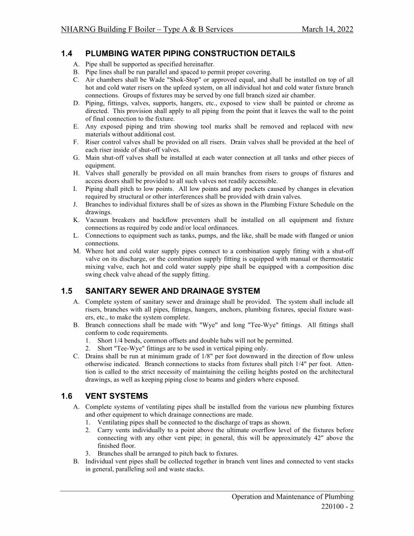
NHARNG Building F Boiler – Type A & B Services March 14, 2022
Operation and Maintenance of Plumbing 220100 - 2
1.4 PLUMBING WATER PIPING CONSTRUCTION DETAILS A. Pipe shall be supported as specified hereinafter. B. Pipe lines shall be run parallel and spaced to permit proper covering. C. Air chambers shall be Wade "Shok-Stop" or approved equal, and shall be installed on top of all
hot and cold water risers on the upfeed system, on all individual hot and cold water fixture branch connections. Groups of fixtures may be served by one full branch sized air chamber.
D. Piping, fittings, valves, supports, hangers, etc., exposed to view shall be painted or chrome as directed. This provision shall apply to all piping from the point that it leaves the wall to the point of final connection to the fixture.
E. Any exposed piping and trim showing tool marks shall be removed and replaced with new materials without additional cost.
F. Riser control valves shall be provided on all risers. Drain valves shall be provided at the heel of each riser inside of shut-off valves.
G. Main shut-off valves shall be installed at each water connection at all tanks and other pieces of equipment.
H. Valves shall generally be provided on all main branches from risers to groups of fixtures and access doors shall be provided to all such valves not readily accessible.
I. Piping shall pitch to low points. All low points and any pockets caused by changes in elevation required by structural or other interferences shall be provided with drain valves.
J. Branches to individual fixtures shall be of sizes as shown in the Plumbing Fixture Schedule on the drawings.
K. Vacuum breakers and backflow preventers shall be installed on all equipment and fixture connections as required by code and/or local ordinances.
L. Connections to equipment such as tanks, pumps, and the like, shall be made with flanged or union connections.
M. Where hot and cold water supply pipes connect to a combination supply fitting with a shut-off valve on its discharge, or the combination supply fitting is equipped with manual or thermostatic mixing valve, each hot and cold water supply pipe shall be equipped with a composition disc swing check valve ahead of the supply fitting.
1.5 SANITARY SEWER AND DRAINAGE SYSTEM A. Complete system of sanitary sewer and drainage shall be provided. The system shall include all
risers, branches with all pipes, fittings, hangers, anchors, plumbing fixtures, special fixture wast-ers, etc., to make the system complete.
B. Branch connections shall be made with "Wye" and long "Tee-Wye" fittings. All fittings shall conform to code requirements. 1. Short 1/4 bends, common offsets and double hubs will not be permitted. 2. Short "Tee-Wye" fittings are to be used in vertical piping only.
C. Drains shall be run at minimum grade of 1/8" per foot downward in the direction of flow unless otherwise indicated. Branch connections to stacks from fixtures shall pitch 1/4" per foot. Atten-tion is called to the strict necessity of maintaining the ceiling heights posted on the architectural drawings, as well as keeping piping close to beams and girders where exposed.
1.6 VENT SYSTEMS A. Complete systems of ventilating pipes shall be installed from the various new plumbing fixtures
and other equipment to which drainage connections are made. 1. Ventilating pipes shall be connected to the discharge of traps as shown. 2. Carry vents individually to a point above the ultimate overflow level of the fixtures before
connecting with any other vent pipe; in general, this will be approximately 42" above the finished floor.
3. Branches shall be arranged to pitch back to fixtures. B. Individual vent pipes shall be collected together in branch vent lines and connected to vent stacks
in general, paralleling soil and waste stacks.

NHARNG Building F Boiler – Type A & B Services March 14, 2022
Operation and Maintenance of Plumbing 220100 - 3
1. Wherever possible, vent stack offsets shall be connected to adjacent soil stacks for the purpose of draining condensation.
2. Where possible, the waste of a fixture shall be connected to the base of each vent stack for the purpose of washing out any scale or dirt which may accumulate.
3. The soil stack may be used to wash out the heel of the vent. C. Tops of all soil and waste stacks shall be extended as additional ventilating pipes.
1. Pipes smaller than 4" size shall be increased to 4" by means of approved increasers before passing through the roof.
2. The tops of all ventilating stacks shall collect together and run through the roof in series of larger pipes as shown on the drawings.
1.7 NATURAL GAS DISTRIBUTION SYSTEM A. The entire installation shall be installed in accordance with the requirements of the AHJ and
NFPA Pamphlet No. 54 and 58 (adopted edition), which are hereby included in and shall form part of this specification.
B. Starting at the gas service provided by the gas utility, or as indicated on the drawings, provide distribution system to all fixtures and equipment requiring gas, including all mains, branches, risers, drips, shut-offs, pressure regulators and all other required parts. Connect to all equipment and appliances indicated and/or specified as requiring gas for their operation.
C. Provide a gas shut-off cock at individual pieces of equipment to permit isolation from adjoining system.
D. Install drains at all low points in piping system and secondary regulators noted. E. Paint all exterior gas piping and exposed interior piping with two (2) coats of rust inhibitor
“Caution Yellow” paint. Label all clearly per Specification.
END OF SECTION 220100

NHARNG Building F Boiler – Type A & B Services March 14, 2022
Common Work Results for Plumbing 220500 - 1
SECTION 220500
COMMON WORK RESULTS FOR PLUMBING
PART 1 - GENERAL
1.1 SCOPE OF WORK A. Furnish all labor and materials to complete the installation of the plumbing systems as shown on
the drawings, specified herein or both as follows: 1. Systems of domestic hot and cold water distribution and make-up water connections where
indicated. 2. Natural Gas Piping. 3. Fixtures as specified and/or indicated. 4. Thermal insulation for all systems. 5. Testing and adjusting of all systems. 6. Condensate drainage system. 7. General conditions of the contract. 8. Secure all required permits. 9. Miscellaneous itemized.
END OF SECTION 220500

NHARNG Building F Boiler – Type A & B Services March 14, 2022
General-Duty Valves for Plumbing Piping 220523 - 1
SECTION 220523
GENERAL-DUTY VALVES FOR PLUMBING PIPING
PART 1 - GENERAL
1.1 SCOPE A. Provide shut-off valves to isolate sections of piping, every fixture and equipment. Valves shall be
located at the inlet and outlet to permit removal for repairs without interfering with the remainder of the system.
B. Do not locate valves with stems below horizontal. Provide ball, check, balancing cocks, plus air vents and other type of valves as required for complete and proper valving of the entire installation, to control flow, shut-off, prevent backflow, provide drainage and control pressure and temperatures.
C. Valves shall be as manufactured by Watts, Apollo, Nibco, Victaulic or Milwaukee Valve Co. and be of “lead free” construction.
PART 2 - PRODUCT
2.1 SUBSTITUTIONS A. Materials shall be as specified herein, except consideration shall be given to other products that
meet or exceed those specified if requested five (5) business days prior to the date of bid opening in accordance with Section 016000, Product Requirements.
2.2 MATERIAL A. Valves used for isolation and flow control in domestic water systems shall be brass construction
appropriate for potable water applications, equal to Watts LFB6080, Apollo 77CLF-100/200 Series or approved equal.
B. Check valves 2½” and less shall be bronze horizontal swing check, 125 swp, equal to Nibco S-413-Y-LF. Check valves 3” and larger shall be iron body, bronze trim, 125 swp, equal to Nibco F-910-B-LF or approved equal.
C. Drain valves to be installed at low points in piping and as otherwise required to completely drain piping system and equipment. Drain valves shall be ball valves of size as shown or required, in no case smaller than ½” I.P.S., equal to Watts B-6000-CC, Apollo 70 HC Series or approved equal with ¾” male thread for hose, outlet with cap and chain.
D. Approved strainers shall be installed in the inlet connections to equipment and automatic control valves to protect all apparatus or any automatic character whose proper function would be interfered with by dirt on the seat or by scoring of the seat. Strainers shall be equal to Watts series LF777 and 77F-DI-125.
E. Approved pressure reducing valves for domestic water shall be of anti-siphon check type with built-in strainer equal to Watts LFU5B and LFN223BS.
F. Where manual balancing valves are indicated, furnish and install Macon Balancing “globe style” Model STV/L or equal by Tour Andersson. Valves shall be tight shut-off and sized for GPM as recommended by the manufacturer.
G. Automatic balancing valves shall be low lead equal to Macon Balancing Model “AI” with integral unions, removable ultrason flow cartridge set to GPM indicated on drawings.
H. All valves for domestic water services shall be “Lead Free” construction and classified as such. I. Valves used in natural gas lines for isolation shall be equal to Watts B-6000-UL-YRPV, Apollo
80-100-YRPV or approved equal.
END OF SECTION 220523

NHARNG Building F Boiler – Type A & B Services March 14, 2022
Hangers and Supports for Plumbing Piping and Equipment 220529 - 1
SECTION 220529
HANGERS AND SUPPORTS FOR PLUMBING PIPING AND EQUIPMENT
PART 1 - GENERAL
1.1 SCOPE A. Provide suitable and substantial hangers and supports for all horizontal and vertical lines as
manufactured by B-Line, Allegheny Industrial, Tolco or ITT Grinnell. B. Support copper, steel, cast iron and all other material piping in accordance with the pipe
manufacturer’s published instructions, or the schedule below, whichever is more stringent. C. Support piping in accordance with the following schedule:
Pipe Material Max. Horizontal Spacing Max. Vertical Spacing Copper tubing 6’ 10’ 1¼” & smaller Copper tubing 10’ 10’ 1½” & larger Steel pipe 12’ 15’ Cast iron At joint or 10’ At joint PVC & CPVC As recommended by pipe manufacturer.
D. Piping and equipment shall not be hung from the work of other trades.
PART 2 - PRODUCT
2.1 SUBSTITUTIONS A. Materials shall be as specified herein, except consideration shall be given to other products that
meet or exceed those specified if requested five (5) business days prior to the date of bid opening in accordance with Section 016000, Product Requirements.
2.2 MATERIAL A. Hangers shall be of heavy construction suitable for the size of pipe to be supported. All materials,
except pipe rollers, shall be wrought or malleable iron or steel. Hangers shall be adjustable type. B. Hangers and pipe clamps used on copper piping shall be solid copper or copper plated. Where
tube is in contact with dissimilar metal, protect with shield or plastic cover. C. The intention is to provide supports which in each case shall be amply strong and rigid for the
load, but which shall not weaken or unduly stress the building construction. D. Hangers for pipes up to and including 4” shall be split ring type. E. Hangers for pipes above 4” shall be standard clevis or roller. F. For insulated piping ≥ 3” provide teflon slide type supports MSS (Manufacturer’s Standardization
Society) Type 35 or protective saddles MSS Type 39. Fill interior voids of saddles with segments of insulation to match adjoining pipe insulation.

NHARNG Building F Boiler – Type A & B Services March 14, 2022
Hangers and Supports for Plumbing Piping and Equipment 220529 - 2
G. For all insulated piping provide protective insulation shields MSS (Manufacturer’s
Standardization Society) Type 40 as follows: Pipe Size Length Thickness
¼” to 3½” 12” 18 ga. 4” 12” 16 ga.
END OF SECTION 220529

NHARNG Building F Boiler – Type A & B Services March 14, 2022
Identification for Plumbing Piping and Equipment 220553 - 1
SECTION 220553
IDENTIFICATION FOR PLUMBING PIPING AND EQUIPMENT
PART 1 - GENERAL
1.1 GENERAL A. Identification shall be provided on all piping that is exposed, as well as at all concealed locations
such as shafts and above removable ceilings in which piping may be viewed. 1. Furnish and affix approved adhesive bands/markers identifying the service and direction of
flow of the various piping systems. 2. A set of such bands/markers shall be affixed to each pipe not less than 30' and there shall be at
least one set of identifying bands/markers in every room where piping may be viewed. 3. Each set shall consist of one band/marker on which the name of the service is printed and one
band/marker on which is printed a black directional arrow. B. Identification bands/markers shall have adhesive backing. Submit same for approval.
1. The name of the service shall be printed with the lettering not to be less than 1¼" high for 3" pipe and larger; ¾" high for pipe 2½" and smaller.
2. Bands/markers shall be applied where they can be read with their long dimension parallel to the axis of the pipe or duct. Bands/markers shall be applied only after finish painting is completed.
3. Bands/markers shall be applied only after finish painting is complete. 4. Identification bands/markers shall conform to ASME/ANSI A13.1 2015 and ANSI Z 535.1
established standards for color.
1.2 SCOPE A. Attach to each valve a 2” brass tag on which shall be stamped designating letters and numbers ½”
high filled with black enamel. Letters designate service. 1. The tags shall be securely fastened to the handle or spindle of the valve by a brass chain. 2. Cross reference valve tags on the “As-Built” drawings and include schedules in the Operation
& Maintenance (O&M) manuals. 3. One (1) copy of the valve schedule shall be provided in the O&M Manual. Review
numbering with the Owner’s representative prior to installation and honor any existing numbering systems in force today.
B. Provide nameplates for all equipment, motor starters, push button stations, pilot light stations or control points, and any other points in the building deemed necessary by the Owner’s representative. 1. Nameplates shall be fabricated from black bakelite with white recessed letters permanently
secured with screws. 2. Nameplate schedule and sample shall be submitted for approval.
C. Provide permanent labels on all pieces of mechanical equipment designating the unit tag as it is shown on mechanical drawings.
D. As part of the Owner Instruction session, review the location of valves, circulators and other specialties concealed above ceilings. Furnish and install adhesive dots on ceiling tiles (in the corner) for access reference.
Dot Color Service
Blue Domestic water

NHARNG Building F Boiler – Type A & B Services March 14, 2022
Identification for Plumbing Piping and Equipment 220553 - 2
PART 2 - PRODUCT
2.1 SUBSTITUTIONS A. Materials shall be as specified herein, except consideration shall be given to other products that
meet or exceed those specified if requested five (5) business days prior to the date of bid opening in accordance with Section 016000, Product Requirements.
2.2 MATERIAL A. Identification bands, tags, charts and dots shall be as manufactured by Seton, Carlton or Brimar.
END OF SECTION 220553
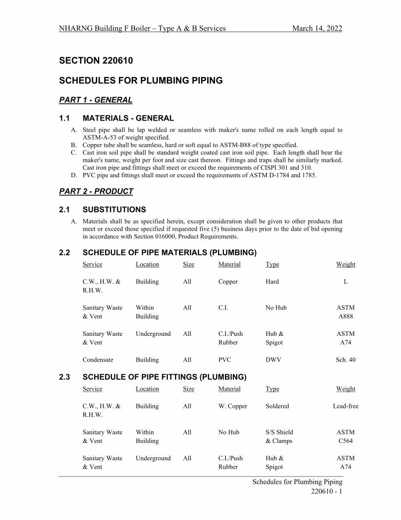
NHARNG Building F Boiler – Type A & B Services March 14, 2022
Schedules for Plumbing Piping 220610 - 1
SECTION 220610
SCHEDULES FOR PLUMBING PIPING
PART 1 - GENERAL
1.1 MATERIALS - GENERAL A. Steel pipe shall be lap welded or seamless with maker's name rolled on each length equal to
ASTM-A-53 of weight specified. B. Copper tube shall be seamless, hard or soft equal to ASTM-B88 of type specified. C. Cast iron soil pipe shall be standard weight coated cast iron soil pipe. Each length shall bear the
maker's name, weight per foot and size cast thereon. Fittings and traps shall be similarly marked. Cast iron pipe and fittings shall meet or exceed the requirements of CISPI 301 and 310.
D. PVC pipe and fittings shall meet or exceed the requirements of ASTM D-1784 and 1785.
PART 2 - PRODUCT
2.1 SUBSTITUTIONS A. Materials shall be as specified herein, except consideration shall be given to other products that
meet or exceed those specified if requested five (5) business days prior to the date of bid opening in accordance with Section 016000, Product Requirements.
2.2 SCHEDULE OF PIPE MATERIALS (PLUMBING) Service Location Size Material Type Weight C.W., H.W. & Building All Copper Hard L R.H.W. Sanitary Waste Within All C.I. No Hub ASTM & Vent Building A888 Sanitary Waste Underground All C.I./Push Hub & ASTM & Vent Rubber Spigot A74 Condensate Building All PVC DWV Sch. 40
2.3 SCHEDULE OF PIPE FITTINGS (PLUMBING) Service Location Size Material Type Weight C.W., H.W. & Building All W. Copper Soldered Lead-free R.H.W. Sanitary Waste Within All No Hub S/S Shield ASTM & Vent Building & Clamps C564 Sanitary Waste Underground All C.I./Push Hub & ASTM & Vent Rubber Spigot A74
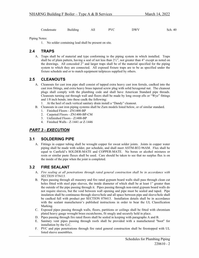
NHARNG Building F Boiler – Type A & B Services March 14, 2022
Schedules for Plumbing Piping 220610 - 2
Condensate Building All PVC DWV Sch. 40
Piping Notes:
1. No solder containing lead shall be present on site.
2.4 TRAPS A. Traps shall be of material and type conforming to the piping system in which installed. Traps
shall be of plain pattern, having a seal of not less than 2½”, not greater than 4” except as noted on the drawings. All concealed 2” and larger traps shall be of the material specified for the piping system to which they are connected. All exposed fixture traps are to be as specified under the fixture schedule and or to match equipment tailpieces supplied by others.
2.5 CLEANOUTS A. Cleanouts for cast iron pipe shall consist of tapped extra heavy cast iron ferrule, caulked into the
cast iron fittings, and extra heavy brass tapered screw plug with solid hexagonal nut. The cleanout plugs shall comply with the plumbing code and shall have American Standard pipe threads. Cleanouts turning out through wall and floors shall be made by long sweep ells or “Wye” fittings and 1/8 inch bends; into these caulk the following: 1. At the heel of each vertical sanitary drain install a “Dandy” cleanout.
B. Cleanouts in cast iron piping systems shall be Zurn models listed below, or of similar standard. 1. Finished Floors - ZN1400-BP 2. Carpeted Floors - ZN1400-BP-CM 3. Unfinished Floors - Z1400-BP 4. Finished Walls - Z-1441 or Z-1446
PART 3 - EXECUTION
3.1 SOLDERING PIPE A. Fittings in copper tubing shall be wrought copper for sweat solder joints. Joints in copper water
piping shall be made with solder, per schedule, and shall meet ASTM-B32-96AM. Flux shall be equal to Canfield’s SOLDER-MATE and COPPER-MATE. No borax or alcohol mixtures or resin or similar paste fluxes shall be used. Care should be taken to see that no surplus flux is on the inside of the pipe when the joint is completed.
3.2 FIRE SEALANT A. Fire sealing at all penetrations through rated general construction shall be in accordance with
SECTION 078413. B. Pipes passing through all masonry and fire rated gypsum board walls shall pass through clean cut
holes fitted with steel pipe sleeves, the inside diameter of which shall be at least 1” greater than the outside of the pipe passing through it. Pipes passing through non-rated gypsum board walls do not require sleeves, but the void between wall opening and pipe must be sealed and taped. Pipe insulation shall be continuous through sleeve/hole and all space between pipe and sleeve/hole shall be caulked full with product per SECTION 078413. Installation details shall be in accordance with the sealant manufacturer’s published instructions in order to bear the UL Classification Marking.
C. Exposed pipes passing through walls, floors, partitions or ceilings shall be fitted with chromium plated heavy gauge wrought brass escutcheons, fit snugly and securely held in place.
D. Pipes passing through fire rated floors shall be sealed in keeping with paragraphs A and B. E. Sanitary vent pipes passing through roofs shall be provided with a manufactured "boot" for
installation by the G.C. F. PVC and pipe penetrations through fire rated general construction shall be firestopped with UL
listed sleeve assemblies.

NHARNG Building F Boiler – Type A & B Services March 14, 2022
Schedules for Plumbing Piping 220610 - 3
G. Submit firestopping product and details for review and approval. Coordinate product with the G.C. to assure project consistency. Provide a shop drawing by the fire sealant manufacturer that clearly identifies all products and the applicable UL classification or listing.
END OF SECTION 220610

NHARNG Building F Boiler – Type A & B Services March 14, 2022
Schedules for Plumbing Fixtures 220640 - 1
SECTION 220640
SCHEDULES FOR PLUMBING FIXTURES
PART 1 - GENERAL
1.1 FIXTURES A. Plumbing fixtures shall be as scheduled on the drawings.
END OF SECTION 220640
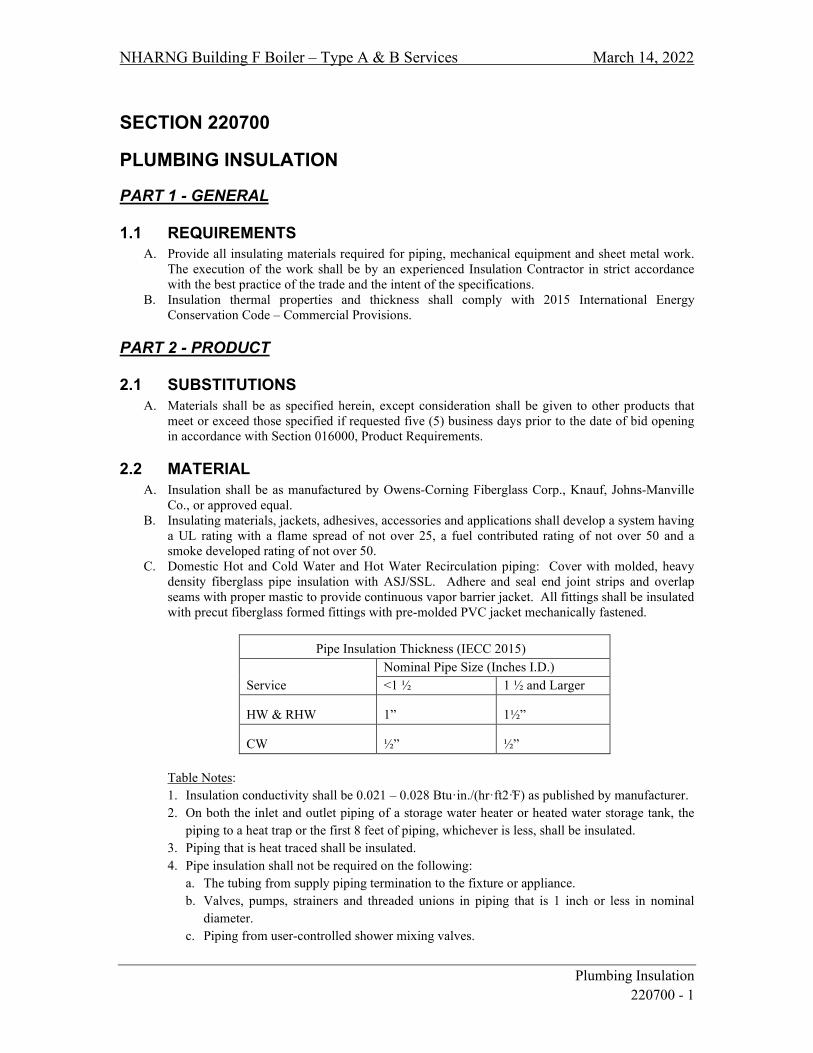
NHARNG Building F Boiler – Type A & B Services March 14, 2022
Plumbing Insulation 220700 - 1
SECTION 220700
PLUMBING INSULATION
PART 1 - GENERAL
1.1 REQUIREMENTS A. Provide all insulating materials required for piping, mechanical equipment and sheet metal work.
The execution of the work shall be by an experienced Insulation Contractor in strict accordance with the best practice of the trade and the intent of the specifications.
B. Insulation thermal properties and thickness shall comply with 2015 International Energy Conservation Code – Commercial Provisions.
PART 2 - PRODUCT
2.1 SUBSTITUTIONS A. Materials shall be as specified herein, except consideration shall be given to other products that
meet or exceed those specified if requested five (5) business days prior to the date of bid opening in accordance with Section 016000, Product Requirements.
2.2 MATERIAL A. Insulation shall be as manufactured by Owens-Corning Fiberglass Corp., Knauf, Johns-Manville
Co., or approved equal. B. Insulating materials, jackets, adhesives, accessories and applications shall develop a system having
a UL rating with a flame spread of not over 25, a fuel contributed rating of not over 50 and a smoke developed rating of not over 50.
C. Domestic Hot and Cold Water and Hot Water Recirculation piping: Cover with molded, heavy density fiberglass pipe insulation with ASJ/SSL. Adhere and seal end joint strips and overlap seams with proper mastic to provide continuous vapor barrier jacket. All fittings shall be insulated with precut fiberglass formed fittings with pre-molded PVC jacket mechanically fastened.
Pipe Insulation Thickness (IECC 2015)
Service Nominal Pipe Size (Inches I.D.) <1 ½ 1 ½ and Larger
HW & RHW 1” 1½”
CW ½” ½” Table Notes: 1. Insulation conductivity shall be 0.021 – 0.028 Btu·in./(hr·ft2·̊F) as published by manufacturer. 2. On both the inlet and outlet piping of a storage water heater or heated water storage tank, the
piping to a heat trap or the first 8 feet of piping, whichever is less, shall be insulated. 3. Piping that is heat traced shall be insulated. 4. Pipe insulation shall not be required on the following:
a. The tubing from supply piping termination to the fixture or appliance. b. Valves, pumps, strainers and threaded unions in piping that is 1 inch or less in nominal
diameter. c. Piping from user-controlled shower mixing valves.

NHARNG Building F Boiler – Type A & B Services March 14, 2022
Plumbing Insulation 220700 - 2
d. Where a vertical support of the piping is installed.
D. Insulate water and drain lines under lavatories designated for use by the handicapped and all counter sinks with TRUEBRO “Lav-Guard 2” preformed insulation system (white).
E. Insulate concealed horizontal roof drains and drain sumps with 1½” thick fiberglass flexible blanket with FSK vapor barrier facing. Insulate all exposed horizontal and vertical drainage with ½” thick heavy density fiberglass with ASJ/SSL.
END OF SECTION 220700

NHARNG Building F Boiler – Type A & B Services March 14, 2022
Commissioning of Plumbing 220800 - 1
SECTION 220800
COMMISSIONING OF PLUMBING
PART 1 - GENERAL
1.1 COMMISSIONING OF SYSTEM(S) A. The Plumbing Contractor shall be responsible for self-commissioning the installed Plumbing
system(s) and demonstrating proper operation and functions at conclusion of the contract. B. The Plumbing Contractor shall participate in the formal commissioning process as requested and
instructed by the project Commissioning Authority.
1.2 WATER SYSTEMS STERILIZATION A. Chlorination Method:
1. Fill the system or any part thereof with a water solution containing 50 parts per million (ppm) available chlorine and let it stand for 24 hours before flushing and returning to service.
2. During the chlorination process, all valves and accessories shall be operated. 3. After chlorination, the water shall be flushed from the line at its ends until the replacement
water when tested shall be found equal chemically and bacteriologically to tests of the perma-nent source of supply. Submit to the Owner’s representative written verification that all procedures and tests, here specified, have been performed and that water at the building out-lets on test will be found identical to the source water.
1.3 PRESSURE TESTS A. All piping shall be pressure tested before being covered or concealed. This contractor shall
provide all equipment necessary for said test. All tests shall be recorded on a log sheet noting piping section being tested, initial and final pressures, duration of test and date of test.
B. All tests shall be made in the presence of and to the satisfaction of the Owner's representative. Provide a copy of all test log sheets to the Owner’s representative upon completion of testing.
C. The piping systems may be tested in sections as the work progresses, but no joint or portion of the system shall be left untested.
D. All elements within the system that may be damaged by the testing operation shall be removed or otherwise protected during the operation.
E. All defects and leaks observed during the tests shall be corrected and made tight in an approved manner and the tests repeated until the system is proven tight.
F. Repair all damage done to existing or adjacent work or materials due to or on account of the tests. G. All pressure piping shall be tested hydrostatically at a pressure of at least 1½ times the maximum
operating pressure, but not less than 80 psi, for a two (2) hour duration with no drop in pressure. H. Natural gas piping shall be tested at a pressure of not less than a two (2) hour duration with no
drop in pressure. I. Soil, waste and vent systems shall be tested by filling systems with water from lowest point to
highest point. Water shall be allowed to stand for four (4) hours during which time there shall be no loss or leakage.
END OF SECTION 220800

NHARNG Building F Boiler – Type A & B Services March 14, 2022
LP Gas Piping 221512 - 1
SECTION 221512
NATURAL GAS PIPING
PART 1 - GENERAL
1.1 SCOPE A. The entire installation shall be installed in accordance with the requirements of NHARNG and NFPA
Pamphlet No. 54 (adopted edition) and NFPA 58, which are hereby included in and shall form part of this specification.
B. Provide distribution system to all fixtures and equipment requiring natural gas, including all mains, branches, risers, drips, shut-offs and all other required parts. Connect to all equipment and appliances indicated and/or specified as requiring natural gas for their operation.
C. Provide a natural gas shut-off valve at individual pieces of equipment to permit isolation from adjoining system.
D. Provide distribution system to all fixtures and equipment requiring gas including all mains, branches, risers, drips, shut-offs and all other required parts connected to all equipment and appliances indicated and/or specified as requiring gas for their operation.
E. Provide UL listed braided stainless steel flex connections to the infrared heaters. Submit cut on manufacturer and model for review and approval.
PART 2 - PRODUCT
2.1 MATERIAL A. Refer to specification Section 220610 for piping material and Section 220523 for valves.
END OF SECTION 221512
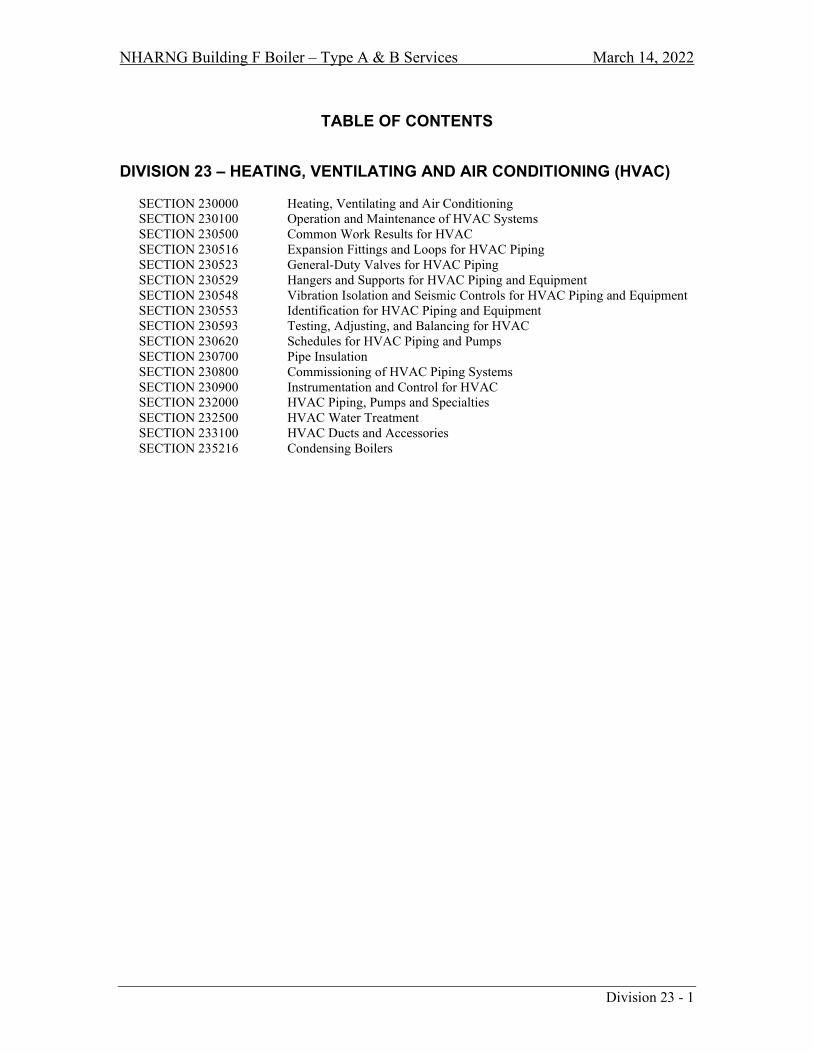
NHARNG Building F Boiler – Type A & B Services March 14, 2022
Division 23 - 1
TABLE OF CONTENTS
DIVISION 23 – HEATING, VENTILATING AND AIR CONDITIONING (HVAC) SECTION 230000 Heating, Ventilating and Air Conditioning SECTION 230100 Operation and Maintenance of HVAC Systems SECTION 230500 Common Work Results for HVAC SECTION 230516 Expansion Fittings and Loops for HVAC Piping SECTION 230523 General-Duty Valves for HVAC Piping SECTION 230529 Hangers and Supports for HVAC Piping and Equipment SECTION 230548 Vibration Isolation and Seismic Controls for HVAC Piping and Equipment SECTION 230553 Identification for HVAC Piping and Equipment SECTION 230593 Testing, Adjusting, and Balancing for HVAC SECTION 230620 Schedules for HVAC Piping and Pumps SECTION 230700 Pipe Insulation SECTION 230800 Commissioning of HVAC Piping Systems SECTION 230900 Instrumentation and Control for HVAC SECTION 232000 HVAC Piping, Pumps and Specialties SECTION 232500 HVAC Water Treatment SECTION 233100 HVAC Ducts and Accessories SECTION 235216 Condensing Boilers

NHARNG Building F Boiler – Type A & B Services March 14, 2022
Heating, Ventilation and Air Conditioning (HVAC) 230000 - 1
SECTION 230000
HEATING, VENTILATING AND AIR CONDITIONING (HVAC)
PART 1 - GENERAL
1.1 SECTION INCLUDES A. Description of HVAC system(s), quality expectations, materials and general requirements.
1.2 SYSTEM(S) DESCRIPTION A. HVAC systems of this contract shall include:
1. Furnish and install new natural gas fired boilers. 2. Furnish and install new hot water system pumps. 3. Hot water piping and specialties. 4. Thermal insulation for all systems. 5. Testing and adjusting of all systems. 6. General Conditions of the contract. 7. Control systems and specialties. 8. Miscellaneous itemized. 9. Secure all required permits.
1.3 RELATED DIVISIONS and SECTIONS A. DIVISION 00 - General B. DIVISION 01 - General Requirements C. DIVISION 07 - Thermal and Moisture Protection D. DIVISION 21 - Fire Suppression E. DIVISION 22 - Plumbing F. DIVISION 25 - Integrated Automation G. DIVISION 26 - Electrical
1.4 REFERENCES A. 2015 International Building Code with NH amendments B. 2015 NFPA 101, Life Safety Code with NH amendments C. New Hampshire State Fire Code Saf-C6000 D. 2009 NFPA 1, Fire Prevention Code with NH amendments E. UFC 3-600-01 Fire Protection Engineering for Facilities F. 2015 International Plumbing Code with NH amendments G. 2015 International Mechanical Code with NH amendments H. 2015 International Energy Conservation Code with NH amendments I. 2009 ASHRAE Standard 189.1 (referenced in NH State high Performance Building Code) J. 2017 NFPA 70, National Electric Code with NH amendments K. New Hampshire Bureau of Public Works Design Guidelines L. City of Concord, New Hampshire ordinances, rules and regulations M. Concord Fire Department rules and regulations N. All applicable ASTM Standards O. NHARNG Rules and Regulations
1.5 SUBMITTALS A. See Section 013300 - Submittal Procedures, for Submittal Requirements. B. Ordering of equipment and materials for installation shall not proceed without an approved
submittal.

NHARNG Building F Boiler – Type A & B Services March 14, 2022
Heating, Ventilation and Air Conditioning (HVAC) 230000 - 2
END OF SECTION 230000

NHARNG Building F Boiler – Type A & B Services March 14, 2022
Operation and Maintenance of HVAC Systems 230100 - 1
SECTION 230100
OPERATION AND MAINTENANCE OF HVAC SYSTEMS
PART 1 - GENERAL
1.1 GENERAL CONDITIONS A. Provide all items, articles, materials, operations, or methods listed, mentioned, scheduled on the
drawings and/or specified herein including all labor, materials, equipment and incidentals necessary and required for completion of this contract.
1.2 INTENT A. The intent of the specifications and drawings is to call for finish work, tested and ready for
operation. B. Any apparatus, appliance, material or service not specified or indicated, but necessary to make the
work complete and perfect in all respects and ready for operation shall be provided. C. The drawings are generally diagrammatic, intended to convey the scope of work and indicate the
general arrangement of equipment and piping, plus approximate size and locations of equipment.
1.3 WORKMANSHIP A. All work shall be executed in the best and most thorough manner under the direction of, and to the
satisfaction of, the Owner’s representative. B. This contractor shall, at all times, keep a competent foreman in charge of the work and shall
facilitate inspection of installations by the Owner’s representative.
1.4 RULES, REGULATIONS, PERMITS AND FEES A. All work shall comply with applicable portions of all state or local laws, ordinances, rules and
regulations, plus NHARNG construction standards. B. Nothing contained in these specifications or indicated on the drawings shall be construed to
conflict with applicable portions of any laws, ordinances, rules and regulations. 1. All pressure vessels shall be furnished and installed in strict accordance with the applicable
regulations of the state and the ASME codes and shall be equipped with all appurtenances re-quired by the aforesaid codes.
C. All required permits and fees relative to this Division shall be obtained and paid for by this contractor.
1.5 OPERATING AND MAINTENANCE MANUAL A. In accordance with DIVISION 01 - GENERAL REQUIREMENTS, manufacturer’s printed
operating and maintenance instructions for each piece of equipment furnished under DIVISION 23.
B. Each manual shall be suitably and neatly marked to identify the particular equipment furnished and shall include lubricating charts.
C. All instructions and charts shall be bound in appropriate cover binders properly indexed, identified, and titled to provide three (3) complete manuals.
D. Completed manuals shall be submitted for review. After approval, the manuals shall become property of the Owner.
1.6 OWNER INSTRUCTION A. This contractor and suppliers, if necessary, shall thoroughly instruct the Owner’s representative
and maintenance personnel in the proper maintenance and operation of materials and systems installed under this Division, as follows:

NHARNG Building F Boiler – Type A & B Services March 14, 2022
Operation and Maintenance of HVAC Systems 230100 - 2
1. Detailed written instructions shall be provided for all mechanical systems, including but not limited to: a. Winter shut-down, spring start-up of systems, if applicable. b. Heating fuel conversion, if applicable. c. All other operations that, if improperly performed, might endanger the building’s
occupants or damage the building’s equipment or contents. 2. Sessions shall be held at the completed facility to instruct the Owner in the proper operation,
cleaning, lubricating and maintenance of all mechanical systems, as well as water systems chemical treatment.
END OF SECTION 230100

NHARNG Building F Boiler – Type A & B Services March 14, 2022
Common Work Results for HVAC 230500 - 1
SECTION 230500
COMMON WORK RESULTS FOR HVAC
PART 1 - GENERAL
1.1 INTENT A. Furnish all labor and materials to complete the installation of the HVAC systems as shown on the
drawings, specified herein, or both as follows: 1. Furnish and install new Natural gas fired boilers. 2. Furnish and install new hot water system pumps. 3. Hot water piping and specialties. 4. Thermal insulation for all systems. 5. Testing and adjusting of all systems. 6. General Conditions of the contract. 7. Control systems and specialties. 8. Miscellaneous itemized. 9. Secure all required permits.
END OF SECTION 230500

NHARNG Building F Boiler – Type A & B Services March 14, 2022
Expansion Fittings and Loops for HVAC Piping 230516 - 1
SECTION 230516
EXPANSION FITTINGS AND LOOPS FOR HVAC PIPING
PART 1 - GENERAL
1.1 SCOPE A. Expansion compensators shall be as manufactured by NAI, Keflex, Victaulic, Southeastern Hose,
Inc., Mason Industries, or approved equal, and sized for expansion indicated or required. B. Anchors shall be designed to suit job conditions and located where indicated on drawings or
directed. C. Expansion joints, loops and anchors shall be provided as required to control expansion and allow
pipes to move from anchor points to expansion points. D. Refer to SECTIONS 230529 and 230548 for further information and requirements relative to this
Section.
END OF SECTION 230516

NHARNG Building F Boiler – Type A & B Services March 14, 2022
General-Duty Valves for HVAC Piping 230523 - 1
SECTION 230523
GENERAL-DUTY VALVES FOR HVAC PIPING
PART 1 - GENERAL
1.1 SCOPE A. Provide shut-off valves to isolate sections of piping, every fixture and equipment. Valves shall be
located at the inlet and outlet to permit removal for repairs without interfering with the remainder of the system.
B. Do not locate valves with stems below horizontal. Provide ball, check, balancing cocks, plus air vents and other type of valves as required for complete and proper valving of the entire installation, to control flow, shut-off, prevent backflow, provide drainage and control pressure and temperatures.
C. Valves shall be as manufactured by Watts, Apollo, Nibco, Victaulic, Anvil International, Grinnell or Milwaukee Valve Co.
PART 2 - PRODUCT
2.1 SUBSTITUTIONS A. Materials shall be as specified herein, except consideration shall be given to other products that
meet or exceed those specified if requested five (5) business days prior to the date of bid opening in accordance with Section 016000, Product Requirement.
2.2 MATERIAL A. HWS&R 2” and smaller - Ball valves for flow control and/or tight shut-off shall be all bronze
construction, full port brass ball with hard chrome plating, 150 swp, with blow-out-proof stem design, by Apollo 77 Series, Watts, Nibco, or approved equal.
B. HWS&R 2½” and larger - Butterfly valves for flow control and/or tight shut-off shall be 200 psi, C.I. body, S.S. stem, equal to Watts DBF, Victaulic Vic-300, or approved equal.
E. Check valves 2½” and less shall be bronze horizontal swing check, 125 swp, equal to Nibco T-413-B, or approved equal. Check valves 3” and larger shall be iron body, bronze trim, 125 swp, equal to Nibco F-918-B, or approved equal.
F. Drain valves to be installed at low points in piping and as otherwise required to completely drain piping system and equipment. Drain valves shall be ball valves of size as shown or required, in no case smaller than ½” I.P.S., equal to Watts Series B-6000-CC, Apollo 70HC Series or approved equal, with ¾” male thread for hose, end outlet with cap and chain.
G. Where manual balancing valves are indicated, furnish and install Macon Balancing “globe style” Model STV/L for sizes ½” thru 2” and Model STVA for 2½” thru 12” or approved equal. Valves shall be tight shut-off and sized for GPM as recommended by the manufacturer.
H. Approved strainers shall be installed in the inlet connections to equipment and automatic control valves to protect all apparatus or any automatic character whose proper function would be interfered with by dirt on the seat or by scoring of the seat. Strainers shall be equal to Watts series 777 and 77F-D.
I. Pressure reducing valves for water shall be of anti-siphon check type with built-in strainer equal to Watts U5B and N223BS, or approved equal.
END OF SECTION 230523
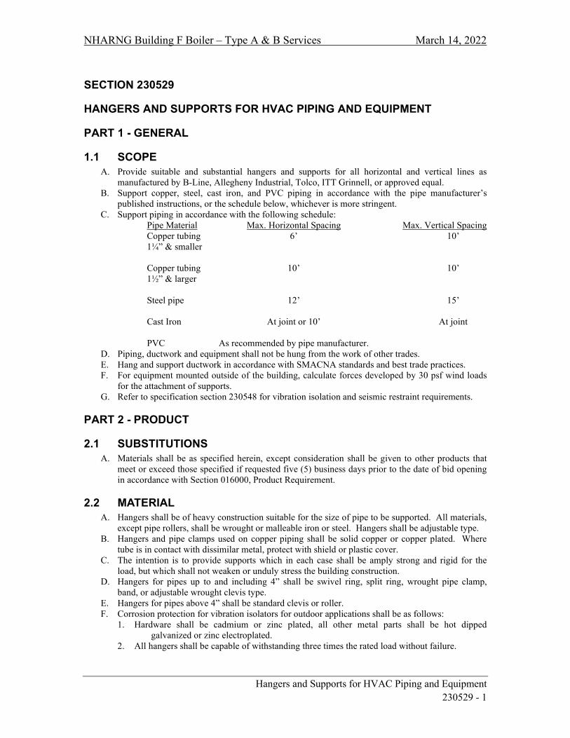
NHARNG Building F Boiler – Type A & B Services March 14, 2022
Hangers and Supports for HVAC Piping and Equipment 230529 - 1
SECTION 230529
HANGERS AND SUPPORTS FOR HVAC PIPING AND EQUIPMENT
PART 1 - GENERAL
1.1 SCOPE A. Provide suitable and substantial hangers and supports for all horizontal and vertical lines as
manufactured by B-Line, Allegheny Industrial, Tolco, ITT Grinnell, or approved equal. B. Support copper, steel, cast iron, and PVC piping in accordance with the pipe manufacturer’s
published instructions, or the schedule below, whichever is more stringent. C. Support piping in accordance with the following schedule:
Pipe Material Max. Horizontal Spacing Max. Vertical Spacing Copper tubing 6’ 10’ 1¼” & smaller Copper tubing 10’ 10’ 1½” & larger Steel pipe 12’ 15’ Cast Iron At joint or 10’ At joint PVC As recommended by pipe manufacturer.
D. Piping, ductwork and equipment shall not be hung from the work of other trades. E. Hang and support ductwork in accordance with SMACNA standards and best trade practices. F. For equipment mounted outside of the building, calculate forces developed by 30 psf wind loads
for the attachment of supports. G. Refer to specification section 230548 for vibration isolation and seismic restraint requirements.
PART 2 - PRODUCT
2.1 SUBSTITUTIONS A. Materials shall be as specified herein, except consideration shall be given to other products that
meet or exceed those specified if requested five (5) business days prior to the date of bid opening in accordance with Section 016000, Product Requirement.
2.2 MATERIAL A. Hangers shall be of heavy construction suitable for the size of pipe to be supported. All materials,
except pipe rollers, shall be wrought or malleable iron or steel. Hangers shall be adjustable type. B. Hangers and pipe clamps used on copper piping shall be solid copper or copper plated. Where
tube is in contact with dissimilar metal, protect with shield or plastic cover. C. The intention is to provide supports which in each case shall be amply strong and rigid for the
load, but which shall not weaken or unduly stress the building construction. D. Hangers for pipes up to and including 4” shall be swivel ring, split ring, wrought pipe clamp,
band, or adjustable wrought clevis type. E. Hangers for pipes above 4” shall be standard clevis or roller. F. Corrosion protection for vibration isolators for outdoor applications shall be as follows:
1. Hardware shall be cadmium or zinc plated, all other metal parts shall be hot dipped galvanized or zinc electroplated.
2. All hangers shall be capable of withstanding three times the rated load without failure.

NHARNG Building F Boiler – Type A & B Services March 14, 2022
Hangers and Supports for HVAC Piping and Equipment 230529 - 2
G. Furnish and install shields and blocks to protect insulation and maintain thickness integrity at hanger rest points.
H. For piping ≥ 3” provide Teflon slide type supports MSS (Manufacturer’s Standardization Society) Type 35 or protective saddles MSS Type 39. For insulated piping, fill interior voids of saddles with segments of insulation to match adjoining pipe insulation.
I. For all insulated piping provide protective insulation shields MSS (Manufacturer’s Standardization Society) Type 40 as follows: Pipe Size Length Thickness
¼” to 3½” 12” 18 ga. 4” 12” 16 ga.
END OF SECTION 230529
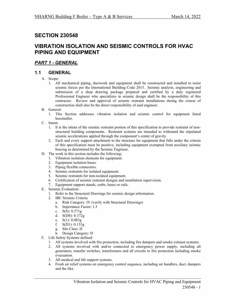
NHARNG Building F Boiler – Type A & B Services March 14, 2022
Vibration Isolation and Seismic Controls for HVAC Piping and Equipment 230548 - 1
SECTION 230548
VIBRATION ISOLATION AND SEISMIC CONTROLS FOR HVAC PIPING AND EQUIPMENT
PART 1 - GENERAL
1.1 GENERAL A. Scope:
1. All mechanical piping, ductwork and equipment shall be constructed and installed to resist seismic forces per the International Building Code 2015. Seismic analysis, engineering and submission of a shop drawing package prepared and certified by a duly registered Professional Engineer who specializes in seismic design shall be the responsibility of this contractor. Review and approval of seismic restraint installations during the course of construction shall also be the direct responsibility of said engineer.
B. General: 1. This Section addresses vibration isolation and seismic control for equipment listed
hereinafter. C. Intent:
1. It is the intent of the seismic restraint portion of this specification to provide restraint of non-structural building components. Restraint systems are intended to withstand the stipulated seismic accelerations applied through the component’s center of gravity.
2. Each and every support attachment to the structure for equipment that falls under the criteria of this specification must be positive, including equipment exempted from auxiliary seismic bracing as determined by the Seismic Engineer.
D. The work in this section includes the following: 1. Vibration isolation elements for equipment. 2. Equipment isolation bases. 3. Piping flexible connectors. 4. Seismic restraints for isolated equipment. 5. Seismic restraints for non-isolated equipment. 6. Certification of seismic restraint designs and installation supervision. 7. Equipment support stands, curbs, bases or rails.
E. Seismic Evaluation: 1. Refer to the Structural Drawings for seismic design information. 2. IBC Seismic Criteria
a. Risk Category: IV (verify with Structural Drawings) b. Importance Factor: 1.5 c. S(S): 0.371g d. S(DS): 0.372g e. S(1): 0.083g f. S(D1): 0.133g g. Site Class: D h. Design Category: D
F. Life Safety Systems defined: 1. All systems involved with fire protection, including fire dampers and smoke exhaust systems. 2. All systems involved with and/or connected to emergency power supply, including all
generators, transfer switches, transformers and all circuits to fire protection including smoke evacuation.
3. All medical and life support systems. 4. Fresh air relief systems on emergency control sequence, including air handlers, duct, dampers
and the like.

NHARNG Building F Boiler – Type A & B Services March 14, 2022
Vibration Isolation and Seismic Controls for HVAC Piping and Equipment 230548 - 2
1.2 OEM EQUIPMENT ISOLATION PACKAGES A. Internal and/or External Systems:
1. Substitution of internally or externally isolated and restrained equipment in lieu of the isolation and restraints specified in this section is acceptable provided all conditions of this section are met. The equipment manufacturer shall provide a letter of guarantee from their Engineering Department stamped and certified per the section on Seismic Restraints and Analysis stating that the seismic restraints are in full compliance with these specifications. Letters from field offices or representatives are not acceptable.
2. All costs for converting to the specified vibration isolation and/or restraints shall be borne by the equipment manufacturer in the event of non-compliance with the proceeding.
3. In the event that the equipment is internally isolated and restrained, the entire unit assembly must be seismically attached to the structure. This attachment and certification thereof shall be by this section.
1.3 SUBMITTAL DATA REQUIREMENTS A. Submittals:
1. Catalog cuts or data sheets shall be submitted for review on specific vibration isolators and restraints to be utilized detailing compliance with the specification.
2. An itemized list shall be submitted for review of all isolated and non-isolated equipment including detailed schedules showing isolator and seismic restraints proposed for each piece of equipment, referencing material and seismic calculation drawing numbers.
B. Shop Drawings: 1. Submit shop drawings that indicate base construction for equipment, including dimensions,
structural member sizes and support point locations. 2. When walls and slabs are used as seismic restraint locations, details of acceptable methods for
ducts and pipe must be included in the submission. 3. Shop drawings shall indicate isolation devices selected with complete dimensional and
deflection data before condition is accepted for installation. 4. Shop drawings shall provide specific details of seismic restraints and anchors; include
number, size and locations for each piece of equipment. 5. Coordinated or contract drawings shall be marked-up with the specific locations and types of
restraints shown for all pipe and duct. Rod bracing requirements and assigned load at each restraint location shall be clearly delineated. Any and all tributary loads shall be considered for proper restraint sizing.
6. Shop drawings shall address ceiling suspended equipment design restraints for a minimum installation angle of 30° from vertical. Shop drawings shall indicate maximum installation angle allowed for restraint system as well as braced and unbraced rod lengths at each allowable installation condition.
7. Shop drawings shall calculate thrust for fan heads, axial and centrifugal fans to determine whether thrust restraints are required.
C. Seismic Certification and Analysis: 1. Seismic restraint calculations must be provided for all connections of equipment to the
structure. Performance of products, such as strut, cable, anchors, clips, etc., associated with restraints must be explained and supported with manufacturer’s data sheets or certified calculations.
2. For roof mounted equipment both, the seismic acceleration and wind loads (30 psf) shall be calculated, with the highest load utilized for the design of the restraints and isolators.
3. Certification of calculations to support seismic restraint designs must be stamped by a Professional Engineer registered in the State were the project is located. a. Analysis must indicate calculated dead loads, derived loads and materials utilized for
connections to equipment and structure. Analysis must detail anchoring methods, bolt diameter, embedment and weld length.
4. An in force Errors and Omissions insurance certificate must accompany submittals. Manufacturer’s product liability insurance certificates are not acceptable.

NHARNG Building F Boiler – Type A & B Services March 14, 2022
Vibration Isolation and Seismic Controls for HVAC Piping and Equipment 230548 - 3
1.4 MANUFACTURER’S RESPONSIBILITY A. Manufacturer of vibration and seismic control equipment shall have the following responsibilities:
1. Determine vibration isolation and seismic restraint sizes and locations. 2. Provide equipment vibration isolation and seismic restraints as specified. 3. Guarantee specified isolation system deflections. 4. Provide installation instructions, drawings and field supervision to insure proper installation
and performance of systems.
1.5 RELATED WORK A. Supplementary Support Steel:
1. This contractor shall supply supplementary support steel and connections for all equipment, piping, ductwork and the like, including roof mounted equipment, as required or specified.
B. Attachments: 1. This contractor shall provide restraint attachment plates cast into housekeeping pads, concrete
inserts, double sided beam clamps, etc., in accordance with specifications of the Seismic Engineer.
1.6 CODE REQUIREMENTS A. Seismic restraints as described herein shall be provided in accordance with the International
Building Code 2009, or AHJ adopted edition.
PART 2 - PRODUCTS
2.1 SUBSTITUTIONS A. Materials shall be as specified herein, except consideration shall be given to other products that
meet or exceed those specified if requested five (5) business days prior to the date of bid opening in accordance with Section 016000, Product Requirments.
2.2 DESCRIPTION A. Devices:
1. All vibration isolation and seismic devices described in this section shall be the product of a single supplier. Novia Associates, Inc. (NAI) is the preferred supplier. Equivalent products manufactured by MCS will be considered provided their systems comply with intent, structural design, performance and deflections of these specifications.
2.3 SEISMIC RESTRAINTS AND VIBRATION ISOLATION A. General:
1. All isolation and seismic restraint devices shall be capable of accepting, without failure, the “G” forces as determined by the seismic certification and calculations.
2. Corrosion protection for outdoor applications shall be as follows: a. Springs shall be cadmium plated, zinc electroplated or powder coated. b. Hardware shall be cadmium or zinc plated. c. All other metal parts shall be hot spray or hot dipped galvanized or zinc electroplated.
3. All seismic restraint devices: a. Shall maintain the equipment in a captive position and not short circuit isolation device
during normal operating conditions. b. Shall have provisions for bolting and/or welding to the structure.
4. Welding of springs to isolator housing, base plates, etc. is strictly prohibited.

NHARNG Building F Boiler – Type A & B Services March 14, 2022
Vibration Isolation and Seismic Controls for HVAC Piping and Equipment 230548 - 4
PART 3 - EXECUTION
3.1 GENERAL A. Isolation and seismic restraint systems must be installed in strict accordance with the
manufacturer’s submittal data. B. Vibration isolators shall not cause any change of position of equipment resulting in stress on
equipment connections.
3.2 PIPING AND DUCTWORK ISOLATION A. Installation:
1. General. a. Hanger isolators shall be installed with the hanger box hung as close as possible to the
structure (without touching). b. Hanger rods shall not short-circuit the hanger box.
3.3 SEISMIC RESTRAINTS A. Installation:
1. All floor mounted equipment whether isolated or not shall be snubbed, anchored, bolted or welded to the structure. Calculations that determine that isolated equipment movement may be less than the operating clearance of snubbers (restraints) do not preclude the need for snubbers. All equipment must be positively attached to the structure.
2. All suspended equipment including, but not limited to; air handling units, pumps, fans, tanks, stacks, VAV boxes, unit heaters, fan powered boxes, cabinet unit heaters, etc. shall be two or four point independently braced with TYPE III restraints. Install cable braces taught for non-isolated equipment and slack with ½” cable deflection for isolated equipment. VAV Boxes (without fans) attached directly to ductwork on the main supply side shall be considered as ductwork for seismic design purposes. Rod bracing shall be installed as per approved submittals and shop drawings. Equipment connected to ductwork weighing less than 75 lbs. is excluded.
3. All horizontally suspended pipe and duct shall use RESTRAINT TYPE III. Spacing of seismic bracing shall be as per TABLE B at the end of this Section.
4. For all trapeze-supported piping, the individual pipes must be attached to the trapeze support at the designated restraint locations.
5. For overhead supported equipment, over stress of the building structure must not occur. Bracing may occur from: a. Flanges of structural beams. b. Upper truss chords in bar joists. c. Cast in place inserts or drilled and shielded inserts in concrete structures.
6. Pipe Risers: a. Where pipe pass through cored holes, holes must be packed with resilient material or fire
stop as specified in other sections of this specification and/or state and local codes. No additional horizontal seismic bracing is required at these locations.
b. Non-isolated, constant temperature pipe risers through cored holes require a riser clamp at each floor level on top of the slab attached in a seismically approved manner for vertical restraint.
c. Non-isolated, constant temperature pipe risers in pipe shafts require structural steel attached in a seismically approved manner at each floor level and a riser clamp at each floor level on top of, and fastened to the structural steel. The riser clamp and structural steel must be capable of withstanding all thermal, static and seismic loads.
d. Isolated and/or variable temperature risers through cored holes require Type K riser resilient Guides and Anchors installed to meet both thermal expansion and seismic acceleration criteria.
e. Isolated and/or variable temperature risers in pipe shafts require Type K resilient riser guides and anchors installed on structural steel to meet both thermal expansion and

NHARNG Building F Boiler – Type A & B Services March 14, 2022
Vibration Isolation and Seismic Controls for HVAC Piping and Equipment 230548 - 5
seismic acceleration criteria. Each floor level must have a riser clamp that does not interfere with the thermal expansion/contraction of the pipe.
7. Diffusers shall be attached to lay-in ceilings with earthquake clips or other approved means of positive attachment to the T-bar ceiling structure.
8. A rigid piping or duct system shall not be braced to dissimilar parts of a building or two dissimilar building systems that may respond in a different mode during an earthquake. Examples: Wall and roof; solid concrete wall and a metal deck with lightweight concrete fill, pipes and duct that cross a building expansion joint.
B. Exemptions: 1. Exclusions from seismic requirements on life safety and non-life safety mechanical equipment
will be determined by the Seismic Engineer based on analysis of the adopted code.
3.4 INSPECTION A. If, in the opinion of the project engineer, the seismic restraint installation does not meet with the
project requirements, an outside consultant will be retained to inspect, verify and submit corrective measures to be taken. The consultant’s fees and all work associated with such a review shall be borne by the contractor.
3.5 REFERENCE TABLE B
TABLE B SEISMIC BRACING TABLE
EQUIPMENT ON CENTER SPACING
TRANSVERSE LONGITUDINAL DUCT 30 Feet 60 Feet PIPE 40 Feet 80 Feet
BOILER BREECHING
30 Feet 60 Feet
CHIMNEYS & STACKS
30 Feet 60 Feet
3.6 TABLE B NOTES A. Projects that contain large pipe may require that the allowable spacing shown in this Table be
reduced to minimize structural loading. All associated costs shall be the responsibility of the contractor. Close coordination and approval by the structural engineer is mandatory for all seismic point loads exceeding 2,000 lbs.
END OF SECTION 230548

NHARNG Building F Boiler – Type A & B Services March 14, 2022
Identification for HVAC Piping and Equipment 230553 - 1
SECTION 230553
IDENTIFICATION FOR HVAC PIPING AND EQUIPMENT
PART 1 - GENERAL
1.1 SCOPE A. Identification shall be provided on all piping that is exposed, as well as at all concealed locations
such as shafts and above removable ceilings in which piping may be viewed. 1. Furnish and affix approved adhesive bands/markers identifying the service and direction of
flow of the various piping systems. 2. A set of such bands/markers shall be affixed to each pipe not less than 30' and there shall be at
least one set of identifying bands/markers in every room where piping may be viewed. 3. Each set shall consist of one band/marker on which the name of the service is printed and one
band/marker on which is printed a black directional arrow. B. Identification bands/markers shall have adhesive backing. Submit same for approval.
1. The name of the service shall be printed with the lettering not to be less than 1¼" high for 3" pipe and larger; ¾" high for pipe 2½" and smaller.
2. Bands/markers shall be applied where they can be read with their long dimension parallel to the axis of the pipe or duct. Bands/markers shall be applied only after finish painting is completed.
3. Bands/markers shall be applied only after finish painting is complete. 4. Identification bands/markers shall conform to ASME/ANSI A13.1 2013 and ANSI Z 535.1
established standards for color. 5. All existing pipe services currently void of identification that fall within the contract area
shall be labeled as part of this contract. New labels shall be applied over existing insulation in cases where existing piping remains as is.
C. Attach to each valve a 2” brass tag on which shall be stamped designating letters and numbers ½” high filled with black enamel. Letters designate service. 1. The tags shall be securely fastened to the handle or spindle of the valve by a brass chain. 2. Furnish four (4) schedules of valves so tagged, mounted in the Operation & Maintenance
(O&M) manuals. 3. One (1) copy of such schedules shall be mounted in glazed frames located in the Mechanical
Room or where directed by the Owner’s representative. Review numbering with the Owner’s representative prior to installation and honor any existing numbering systems in force today.
4. The system of numbering for each service shall start with the No. 1 beginning at the point of main service and progress throughout the contract area.
D. Provide nameplates for all equipment, motor starters, push button stations, pilot light stations or control points, and any other points in the building deemed necessary by the Owner’s representative. 1. Nameplates shall be fabricated from black bakelite with white recessed letters permanently
secured with screws. 2. Nameplate schedule and sample shall be submitted for approval. 3. Coordinate identification of exhaust fan switches provided by the Electrical Contractor.
E. Provide permanent labels on all pieces of mechanical equipment designating the unit tag as it is shown on mechanical drawings.
F. As part of the Owner Instruction session, review the location of valves, circulators, dampers and other specialties concealed above ceilings. Furnish and install adhesive dots on ceiling tiles (in the corner) for access reference.
Dot Color Service
Red Heating
Blue Cooling

NHARNG Building F Boiler – Type A & B Services March 14, 2022
Identification for HVAC Piping and Equipment 230553 - 2
Green Air-side specialty
PART 2 - PRODUCT
2.1 SUBSTITUTIONS A. Materials shall be as specified herein, except consideration shall be given to other products that
meet or exceed those specified if requested five (5) business days prior to the date of bid opening in accordance with Section 016000, Product Requirements.
2.2 MATERIAL A. Identification bands, tags, charts and dots shall be as manufactured by Seton, Carlton or Brimar.
END OF SECTION 230553

NHARNG Building F Boiler – Type A & B Services March 14, 2022
Testing, Adjusting, and Balancing for HVAC 230593 - 1
SECTION 230593
TESTING, ADJUSTING, AND BALANCING FOR HVAC
PART 1 - GENERAL
1.1 TESTING AND BALANCING A. Procure the service of an independent Testing and Balancing Agency that specializes in the testing
and balancing of heating, ventilating and air conditioning systems. B. All water systems shall be done by the same agency. C. Work shall not begin until the agency has been notified in writing that all systems have been
completed, cleaned and placed in full working sequence by this contractor. Clean filters shall be installed by this contractor prior to start of balancing work.
D. Test, balance and adjust all air moving equipment, terminals, supply, return and exhaust systems. Work together with the ATC Contractor to adjust setpoints of outside/return/exhaust dampers where applicable.
E. Test, balance and adjust all water systems to provide scheduled flows to all terminals and eliminate noise.
F. Test, balance and adjust the domestic hot water recirc. system to provide scheduled flows to all terminals shown on the plumbing drawings.
G. When all control systems and preliminary testing and balancing are complete, this contractor, with the cooperation of the ATC Contractor, shall perform an independent test of all systems for specified sequences of operation. Refer to DIVISION 25. 1. The test shall include all operations as specified in DIVISION 25, “Sequences of Operation”. 2. All dampers, valves, and similar appurtenances shall be visually or physically confirmed to
operate as specified. Operating and safety devices such as aquastats and freezestats shall be verified operational.
3. All interlocks between equipment shall be confirmed to operate as specified. 4. This contractor shall provide the ATC Contractor with operating setpoints as well as alarm
setpoints such as dirty filters, high/low limits, etc., as required. 5. Report findings per K. below.
H. Perform all tests in accordance with standard procedures such as those outlined by the Associated Air Balance Council (AABC) and/or Sheet Metal and Air Conditioning Contractors National Association, Inc., (SMACNA).
I. At completion of all testing and balancing, leave all equipment systems, components, etc., adjusted within the limits of installed equipment and to within 10% of design requirements. Mark all setpoints of all dampers and valves with distinguishing marks. If requested, conduct tests in the presence of the Owner’s representative.
J. Within 15 days after completion of testing and balancing, submit for review six (6) copies of the testing and balancing results on industry recognized forms. Include a warranty period of 90 days during which time the Owner’s representative may request recheck or re-adjustment of any part of the job.
K. All reports shall clearly indicate the following minimum information: 1. Air - System name, rated and actual HP, BHP, motor nameplate efficiency, voltage,
amperage, fan rpm, suction, discharge and total static pressures, total system flow rate (system traverse), individual terminal flow rates. Terminal readings must show location, make, model and size of register, grille, or diffuser. Include a static pressure profile of all AHU’s components.
2. Water - Pump full flow and no-flow suction and discharge pressures, rated and actual amperage, HP, BHP, motor nameplate efficiency, voltage and total dynamic head. Calibrated balancing device readings shall indicate location, size, setting, differential pressure, and rated and actual GPM. All new automatic balancing valves installed shall be tested to verify proper
NHARNG Building F Boiler – Type A & B Services March 14, 2022
Testing, Adjusting, and Balancing for HVAC 230593 - 2
function, and reported on. Review details with the project engineer prior to conducting the work.
3. ATC Sequence Check: Report shall include a paragraph-by-paragraph review of the sequence of controls specification, noting either “operates as specified”, or detailing any deviations or deficiencies. a. Should the HVAC systems be found incomplete or not performing per specification, the
ATC Contractor shall correct deficiencies and the Testing and Balancing Subcontractor shall recheck until all sequences have been verified proper.
END OF SECTION 230593

NHARNG Building F Boiler – Type A & B Services March 14, 2022
Schedule for HVAC Piping and Pumps 230620 - 1
SECTION 230620
SCHEDULES FOR HVAC PIPING AND PUMPS
PART 1 - GENERAL
1.1 MATERIALS - GENERAL A. Steel pipe shall be lap welded or seamless with maker's name rolled on each length equal to
ASTM-A-53 of weight specified. B. Copper tube shall be seamless, hard or soft equal to ASTM-B88 of type specified. C. PVC pipe and fittings shall meet or exceed the requirements of ASTM D-1784 and 1785. D. Pumps shall be of capacity and manufacturer scheduled on the drawings and as specified
hereinafter.
PART 2 – PRODUCT
2.1 SUBSTITUTIONS A. Materials shall be as specified herein, except consideration shall be given to other products that
meet or exceed those specified if requested five (5) business days prior to the date of bid opening in accordance with Section 016000, Product Requirements.
2.2 SCHEDULE OF PIPE MATERIALS (HEATING AND COOLING) Service Location Size Material Type Weight HWS&R In Building 2” & Steel or Screwed Sch. 40 Smaller Hard Tube Type L Copper HWS&R In Building 2½” & Steel Flanged or Sch. 40 Larger Welded
2.3 SCHEDULE OF PIPE FITTINGS & FLANGES Service Location Size Material Type Weight HWS&R All 2” & Steel or Screwed 150# Smaller W. Copper Soldered Lead-free HWS&R All 2½” & Cast Iron Flanged or 150# Larger or Steel Welded
2.4 PUMPS A. In-Line Wet Rotor Pumps:
Pumps shall be Taco Model Viridian (VR) Series. The pumps shall be single stage, canned-rotor type, in-line design. The capacities and characteristics shall be as called for in the plans / schedules. Pump casing shall be constructed of EN- GJL-250 or ASTM-A 48 Class 35 cast iron. The pump casing / volute shall be rated for 175psi working pressure for all jobs. The pump flanges shall be matched to suit the working pressure of the piping components on the job, with ANSI Class 125 flanges.
1. All casings shall be flanged connections. 2. The impeller and shaft shall be Class 304 stainless steel.

NHARNG Building F Boiler – Type A & B Services March 14, 2022
Schedule for HVAC Piping and Pumps 230620 - 2
3. The pump and motor form an integral unit without a mechanical seal. The bearings are lubricated by the pumped liquid. No petroleum lubricated bearings will be accepted.
4. The pumps shall be able to operate as single or parallel variable speed pumps, where the speed is regulated by an integrated variable speed drive. The integrated electronics shall allow these pumps to run in parallel, standby or alternating modes. - Parallel pump communication via Ethernet cabling - 24 hour run time automatic operation - Main/standby operation in the event of failure - Simultaneous parallel operation as required by system demand
5. The commissioning and set up of the pump shall be accessed v i a : - A web interface (data exchange) and use HTML 1.1 web language. The pump shall provide a port for a RJ-45 cable connection. - A user interface located on the face of the speed controller - The user interface: Adjusts modes and mode values LED display reads real time mode set values, flow, head, speed and power Lockouts unauthorized adjustment of the pump
6. The electronics shall provide “Auto” as factory default whereas the slope of the proportional curve will automatically match the required system curve, constant pressure control (∆p-c), variable differential pressure control (∆p-v), and constant curve duty (uncontrolled pump), RPM regulation. RPM (speed) regulation can be accomplished by: - Manual (via user interface or HTML) - Remote via 0-10Vdc - Modbus RTU data protocol
7. The pump electronics shall come standard with multiple digital inputs and one external digital output to be available for additional mechanical room control and pump status monitoring.
8. The wiring / electronics enclosure shall be class 2, IP44. 9. Pumps shall meet UL 778, 1004-1, 508C, CAN/CSA C22.2 #108, #100, #107.1, EMC
(89/366 EEC): EN 61000, LVD (73/23/EC): EN 60335-1, EN 60335-2-51, and machine safety (98/37/EC): EN ISO 12100.
10. The pumps shall be electronically protected, be rated for continuous duty and have a built-in startup circuit. The pump electronics shall provide overcurrent, line surge and current limit protection, thermal monitoring, heat sink status and over temperature protection.
11. The pump shall be capable of being monitored 24/7 via integrated internet link. 12. The pump must be driven by an electrically commutated electrical motor (ECM) with
permanent magnet rotor. The rotor magnets shall by time stable, nontoxic ceramic magnets (Sr-Fe). The electrically commuted electrical motor shall be driven by a frequency converter with an integrated PFC filter.
4 PART 3 - EXECUTION 1.7 PUMPS A. General
1. Contractor shall install pump in accordance with the manufacturer’s instructions. Pipe connections to pumps shall be made in such a manner so as not to exert any stress on pump housings. Pumps may be suspended direct in the pipes provided the piping can support the pump. If necessary to meet this requirement, provide additional pipe supports and flex connectors.
2. The pump shaft shall be installed horizontally. The pump may b e installed in horizontal or vertical pipes as long as the pump shaft is parallel to the ground.
3. Arrows on the pump housing indicate the liquid flow direction through the pump. The liquid flow direction can be horizontal or vertical, depending on the pump motor and wiring box (as a group). Motor/wiring box may be turned to various positions and is described in the manufacturer’s instructions.
4. For indoor use only. 5. Pumps shall NOT be run dry to check rotation.

NHARNG Building F Boiler – Type A & B Services March 14, 2022
Schedule for HVAC Piping and Pumps 230620 - 3
PART 3 - EXECUTION
3.1 INTENT A. General:
1. Contractor shall install pump in accordance with the manufacturer’s instructions. Pipe connections to pumps shall be made in such a manner so as not to exert any stress on pump housings. Pumps may be suspended direct in the pipes provided the piping can support the pump. If necessary to meet this requirement, provide additional pipe supports and flex connectors. 2. The pump shaft shall be installed horizontally. The pump may b e installed in horizontal or vertical pipes as long as the pump shaft is parallel to the ground. 3. Arrows on the pump housing indicate the liquid flow direction through the pump. The liquid flow direction can be horizontal or vertical, depending on the pump motor and wiring box (as a group). Motor/wiring box may be turned to various positions and is described in the manufacturer’s instructions. 4. For indoor use only. 5. Pumps shall NOT be run dry to check rotation.
B. Furnish and install all mechanical work of this contract in accordance with governing codes and in a workmanlike manner.
C. The run and arrangement of all HVAC related pipes shall be approximately as shown on the drawings and as directed during installation and shall be as straight and direct as possible, forming right angles or parallel lines with building walls and other pipes, and be neatly spaced.
D. Arrange work to avoid all interference with the work of all other trades. Consult with other contractors, and coordinate the location of their work with that of the others.
3.2 GENERAL INSTALLATION OF HVAC RELATED PIPING A. All piping shall be properly supported or suspended on stands, clamps, hangers and the like, in
accordance with sections 230529 and 230548. 1. Supports shall be designed to permit free expansion and contraction while minimizing
vibration. B. Screw threads shall be cut clean and true. Bushings shall not be used.
1. All reductions shall be made with eccentric reducers or eccentric fittings. 2. All pipe two inch (2") or less shall be reamed after cutting to remove all burrs.
C. The drawings indicate generally the size and location of piping, and while sizes must not be decreased, the right is reserved for Owner’s representative to change runs and sizes of pipes in order to accommodate conditions on the job. 1. Any pipes not indicated on the drawings shall be sized as directed and run where directed by
the Owner’s representative. D. Piping shall be properly graded to insure easy circulating and prevent noise and water hammer.
Water piping shall pitch upward in the direction of flow, except the water piping located above finished ceilings which may be run level. 1. Proper provision shall be made for expansion and contraction in all portions of pipe work to
prevent undue strain on piping, fixtures or apparatus connected therewith. E. Vent all high points and drain all low points in water systems as required to achieve perfect water
circulation. F. Take runouts off top of mains at 45° or 90° angle with at least one swing joint between riser or
stub and main. G. For change in horizontal piping size use eccentric reducer coupling with bottom of coupling
horizontal.
3.3 HVAC RELATED PIPE JOINTS AND FITTINGS A. Fittings for use on steel pipe shall be screwed iron or welded fittings of type and weight as
scheduled. B. Flanges on steel pipe shall be screwed cast iron or welded type of weight to match the piping on
which installed.

NHARNG Building F Boiler – Type A & B Services March 14, 2022
Schedule for HVAC Piping and Pumps 230620 - 4
C. Dissimilar pipe materials (copper to steel, etc.) shall be joined with an approved dielectric fitting or brass coupling.
D. Flexible metal hose connectors shall be as manufactured by NAI, Southeastern Hose, Inc., Keflex, Proco Products, Inc., Victaulic or equal.
E. Furnish and install adapter fittings to mate the R-flex metric tube sizes to imperial fittings.
3.4 WELDING AND SOLDERING PIPE A. Welded joints, outlets and flanges shall be used as shown on drawings, specified or directed.
Welded joints may also be provided elsewhere at this Contractor's option except on piping smaller than 2½", or at points where it may be explicitly specified or directed to leave flanged joints in order to facilitate future changes.
B. All welded joints (except pipe welded end to end) shall be made by use of forged one-piece welding flanges caps, nozzles, elbows, branch outlets and tees, equal to WELDBEND. 1. All such fittings shall be of a type which maintains full wall thickness at all points, ample
radius and fillets, and proper bevels or shoulders at ends. 2. Wel-o-lets or Thread-o-lets may be used where standard fittings or required sizes are not
available and elsewhere approved. C. All job welding shall be done by the electric arc welding process.
1. All welding shall be done in accordance with the welding procedures of the National Certified Pipe Welding Bureau or other approved procedure, conforming to the requirements of the ASME Boiler and Pressure Vessel Code or the ASA Code for Pressure Piping.
D. All piping 2½" size and larger shall be butt welded with welded fittings. Stub welding shall not be permitted.
E. Fittings in copper tubing shall be wrought copper for sweat solder joints. Joints in copper water piping shall be made with solder, per schedule, and shall meet ASTM-B32-96AM. Flux shall be equal to Canfield’s SOLDER-MATE and COPPER-MATE. No borax or alcohol mixtures or resin or similar paste fluxes shall be used. Care should be taken to see that no surplus flux is on the inside of the pipe when the joint is completed.

NHARNG Building F Boiler – Type A & B Services March 14, 2022
Schedule for HVAC Piping and Pumps 230620 - 5
3.5 FIRE SEALANT A. Fire sealing at all penetrations through rated general construction shall be in accordance with
SECTION 078413. B. Pipes passing through all masonry and fire rated gypsum board walls shall pass through clean cut
holes fitted with steel pipe sleeves, the inside diameter of which shall be at least 1” greater than the outside of the pipe passing through it. Pipes passing through non-rated gypsum board walls do not require sleeves, but the void between wall opening and pipe must be sealed and taped. Where UL approved for the application, pipe insulation shall be continuous through sleeve/hole, and all space between pipe and sleeve/hole shall be caulked full with product per SECTION 078413. Installation details shall be in accordance with the sealant manufacturer’s published instructions in order to bear the UL Classification Marking.
C. Exposed pipes passing through walls, floors, partitions or ceilings shall be fitted with chromium plated heavy gauge wrought brass escutcheons, fit snugly and securely held in place.
D. Ducts passing through rated walls shall be caulked with a minimum of 1¼” thickness of fill material applied within annulus, flush with both surfaces of wall assembly. At the point contact location between duct and wallboard, a minimum ¼” diameter bead of caulk shall be applied at the wallboard/duct interface on both surfaces of wall assembly. Void fill material must bear the UL Classification Marking and installation details shall be in accordance with the sealant manufacturer’s published instructions in order to bear the UL Classification Marking.
E. Pipes and ducts passing through fire rated floors shall be sealed in keeping with paragraphs A, B and D.
F. PVC and CPVC pipe penetrations through fire rated general construction shall be firestopped with UL listed sleeve assemblies.
G. Submit firestopping product and details for review and approval. Coordinate product with the G.C. to assure project consistency. Provide a shop drawing by the fire sealant manufacturer that clearly identifies all products and the applicable UL classification or listing for penetrations applicable to the project.
END OF SECTION 230620

NHARNG Building F Boiler – Type A & B Services March 14, 2022
Pipe Insulation 230700 - 1
SECTION 230700
PIPE INSULATION
PART 1 - GENERAL
1.1 SCOPE A. Provide all insulating materials required for piping and mechanical equipment. The execution of
the work shall be by an experienced Insulation Contractor in strict accordance with the best practice of the trade and the intent of the specifications.
B. Insulation thermal properties and thickness shall comply with 2015 International Energy Conservation Code, Commercial Provisions.
PART 2 - PRODUCT
2.1 SUBSTITUTIONS A. Materials shall be as specified herein, except consideration shall be given to other products that
meet or exceed those specified if requested five (5) business days prior to the date of bid opening in accordance with Section 016000, Product Requirements.
2.2 MATERIAL A. Insulation shall be as manufactured by Owens-Corning Fiberglass Corp., Knauf, Johns-Manville
Co., or approved equal. B. HWS&R and CHWS&R insulating materials, jackets, adhesives, accessories and applications
shall develop a system having a UL rating with a flame spread of not over 25, a fuel contributed rating of not over 50 and a smoke developed rating of not over 50.
C. Hot Water Supply & Return, Chilled Water Supply & Return, Steam and Condensate Return piping: Cover all new and disturbed existing piping with molded, heavy density fiberglass pipe insulation with ASJ/SSL. Adhere and seal end joint strips and overlap seams with proper mastic to provide continuous vapor barrier jacket. All fittings shall be insulated with precut fiberglass formed fittings with pre-molded PVC jacket mechanically fastened, including unions, couplings, flanges and air separators where applicable.
Pipe Insulation Thickness (IECC 2015)
Service* Nominal Pipe Size (Inches I.D.) <1 1 to <1 ½ 1 ½ to <4 4 to <8
High (HP) Pressure Steam 3 4 4.05 4.05
Low Pressure (LP) Steam (<15 psig), and HP Steam Condensate 2.05 2.05 2.05 3
HW Heating Supply & Return, and LP Steam Condensate 1.05 1.05 2 2
Low Temp Heating HW (< 140 F) Supply & Return 1 1 1.05 1.05
Chilled Water Supply & Return 0.05 0.05 1 1
* For direct buried pipe, the insulation thicknesses shown may be reduced by 1 ½ inches, down to a minimum insulation thickness of 1 inch.

NHARNG Building F Boiler – Type A & B Services March 14, 2022
Pipe Insulation 230700 - 2
D. Insulate exposed pipe drops to heating terminals subject to physical abuse per C. of this Section, and cover entire exposed length with protective PVC jacket (white).
E. Insulate exposed pipe drops to heating terminals per C. of this Section, but cover entire exposed length with protective 30 mil PVC jacket (white).
F. Piping installed outdoors, exposed to the elements, shall be insulated with the thickness indicated in the table above and covered with aluminum jacket and matching cover fitting. Horizontal piping shall lap to have the aluminum jacketing pointing down to prevent any rain runoff from seeping in. Fab Straps shall be placed every foot of piping making sure placement is close to the joints of two sections of jacketing. On vertical piping, joints at sections shall overlap with the higher piece being placed over the lower piece. On exterior pipes, all joints and laps should be caulked with aluminum colored silicone caulking. An expansion joint of 6” in length shall be installed on each run of pipe insulation and overlapped to address expansion and contraction due to temperature changes.
END OF SECTION 230700

NHARNG Building F Boiler – Type A & B Services March 14, 2022
Commissioning of HVAC Piping Systems 230800 - 1
SECTION 230800
COMMISSIONING OF HVAC PIPING SYSTEMS
PART 1 - GENERAL
1.1 COMMISSIONING OF SYSTEM(S) A. The Mechanical Contractor shall be responsible for self-commissioning the installed HVAC
system(s) and demonstrating proper operation and functions at conclusion of the contract. B. The HVAC Contractor shall participate in the formal commissioning process as requested and
instructed by the project Commissioning Authority.
1.2 PRESSURE TESTS A. All piping shall be pressure tested before being covered or concealed. This contractor shall
provide all equipment necessary for said test. All tests shall be recorded on a log sheet, noting piping section tested, initial and final pressures, duration of test and date of test.
B. All tests shall be made in the presence of and to the satisfaction of the Owner's representative. Provide a copy of all test log sheets to the Owner’s representative upon completion of testing.
C. The piping systems may be tested in sections as the work progresses, but no joint or portion of the system shall be left untested.
D. All elements within the system that may be damaged by the testing operation shall be removed or otherwise protected during the operation.
E. All defects and leaks observed during the tests shall be corrected and made tight in an approved manner and the tests repeated until the system is proven tight.
F. Repair all damage done to existing or adjacent work or materials due to or on account of the tests. G. All pressure piping shall be tested hydrostatically at a pressure of at least 1½ times the maximum
operating pressure, but not less than 80 psi, for two (2) hour duration with no drop in pressure.
1.3 SYSTEMS FLUSHING A. For the hot water systems, extreme caution shall be exercised by contractor to prevent dirt and
other foreign matter from entering pipes or components of system during construction. Pipe stored on project shall have open ends capped and equipment shall have all openings fully protected. Before erection, each piece of pipe, fitting or valve shall be visually examined and all dirt removed.
B. The entire heating system shall be completely flushed and refilled with clean water. C. With the system filled with clean water, circulation established and trapped air vented, the boiler
plants shall be energized. Any leaks in piping shall be repaired before proceeding with further test procedures. Low point drains in the system shall be opened for initial flush and blowdown, with water fill valves set to make up water at an equal rate. Check pressure gauge at pump suction and manually adjust make-up water to maintain steady positive pressure before and after opening drain valves. Flushing shall continue until clean water is evident leaving open drains. In no case shall the flushing period be less than two hours. Upon completion of flushing, all strainers shall be removed, cleaned and reinstalled.
D. After initial system flushing, chemically clean the hot and chilled water piping systems in accordance with best trade practices and recommendations offered by the Owner’s water treatment contractor.
E. After said cleaning procedure, the systems shall then be drained completely and refilled with fresh water.
F. After systems have been completely cleaned, they shall be tested by an independent agency and left on the slightly alkaline side (pH 7.5). If systems are still on the acid side, cleaning by use of trisodium phosphate shall be repeated. Submit certified test results to the Owner’s representative for record.

NHARNG Building F Boiler – Type A & B Services March 14, 2022
Commissioning of HVAC Piping Systems 230800 - 2
G. Refer to spec. section 232500 for additional HVAC water treatment. H. Inhibitors shall be introduced to the hot water piping system as specified hereinafter and/or as
directed by the Owner’s water treatment contractor.
1.4 AUTOMATIC TEMPERATURE CONTROLS (ATC) SEQUENCE CHECK A. This contractor shall be responsible for the scheduling and coordination of subcontractors,
specifically the Testing and Balancing Subcontractor and ATC Subcontractor, for the performance of an ATC sequence check on all HVAC systems described in DIVISION 25, “Sequences of Operation”. 1. ATC installation and preliminary testing and balancing shall be complete prior to the
scheduling of the ATC sequence check. B. This contractor shall notify the engineer 48 hours prior to the scheduled performance of the ATC
sequence check.
END OF SECTION 230800

NHARNG Building F Boiler – Type A & B Services March 14, 2022
Instrumentation and Control for HVAC 230900 - 1
SECTION 230900
INSTRUMENTATION AND CONTROL FOR HVAC
PART 1 - GENERAL
1.1 AUTOMATIC TEMPERATURE CONTROL A. Refer to DIVISION 25 for Automatic Temperature Control work.
END OF SECTION 230900

NHARNG Building F Boiler – Type A & B Services March 14, 2022
HVAC Piping, Pumps and Specialties 232000 - 1
SECTION 232000
HVAC PIPING, PUMPS AND SPECIALTIES
PART 1 - GENERAL
1.1 DESCRIPTION A. HVAC piping shall be as scheduled in SECTION 230620. B. Pumps shall be as scheduled on the drawings, Taco, Bell & Gossett, Armstrong or approved equal.
1.2 SCOPE A. Furnish all hot water equipment and specialties of configuration, model and manufacturer
indicated on the drawings or as specified hereinafter.
PART 2 - PRODUCT
2.1 SUBSTITUTIONS A. Materials shall be as specified herein, except consideration shall be given to other products that
meet or exceed those specified if requested five (5) business days prior to the date of bid opening in accordance with Section 016000, Product Requirements.
2.2 SPECIALTIES A. Manual Air Venting Devices:
1. For hot water terminals (unless otherwise shown on drawings), provide manual air vents. Air vents shall be quarter turn open ¼” ball cocks with extended drain line, located to permit easy use.
B. Pressure relief valves shall be ASME rated for pressure and duty intended. C. Furnish and install expansion tank(s), air separator(s) and automatic air vents of capacity shown
on plans.
END OF SECTION 232000
NHARNG Building F Boiler – Type A & B Services March 14, 2022
HVAC Water Treatment 232500 - 1
SECTION 232500 HVAC WATER TREATMENT
PART 1 - GENERAL
1.1 SUMMARY
A. This Section includes the following HVAC water-treatment systems:
1. Chemical treatment test equipment. 2. HVAC water-treatment chemicals. 3. TF1 Total Filter.
1.2 PERFORMANCE REQUIREMENTS
A. Water quality for HVAC systems shall minimize corrosion, scale buildup, and biological growth for optimum efficiency of HVAC equipment without creating a hazard to operating personnel or the environment.
B. Base HVAC water treatment on quality of water available at Project site, HVAC system equipment material characteristics and functional performance characteristics, operating personnel capabilities, and requirements and guidelines of authorities having jurisdiction.
C. Closed hydronic systems, including hot-water heating, chilled water, solar thermal water and glycol heating, shall have the following water qualities:
1. pH: Maintain a value within 6.6 – 8.5. 2. "P" Alkalinity: Maintain a value within 300 ppm. 3. Chloride: Less than 100 ppm. 4. Total Hardness: 50 – 200 ppm. 5. Copper: Less than 3 ppm. 6. TDS: Maintain a maximum value of 10 ppm. 7. Iron: Less than 50 ppm. 8. Aluminum: Less than 3 ppm.
1.3 SUBMITTALS
A. Product Data: For each type of product indicated.
B. Shop Drawings: Pretreatment and chemical treatment equipment showing tanks, inline magnet, isolation, dosing ports, maintenance space required, and piping connections to HVAC systems.
C. Field quality-control test report.

NHARNG Building F Boiler – Type A & B Services March 14, 2022
HVAC Water Treatment 232500 - 2
1.4 QUALITY ASSURANCE
A. HVAC Water-Treatment Service Provider Qualifications: An experienced HVAC contractor trained to test and analyze water qualities, installing water-treatment equipment, and applying water treatment as specified in this Section.
PART 2 - PRODUCTS
2.1 MANUFACTURERS
A. Available Manufacturers: Subject to compliance with requirements, manufacturers offering products that may be incorporated into the Work include, but are not limited to, the following:
1. Fernox. Contact Emerson Swan 2. Noble 3. Sentinel
2.2 CHEMICAL TREATMENT TEST EQUIPMENT
A. Test Kit: Manufacturer-recommended equipment and chemicals for testing pH, inhibitor, chloride, alkalinity, and hardness. TDS meter required for TDS measurement.
2.3 CHEMICALS
A. F3 Central Heating Cleaner
1. Removal of sludge, scale, flux, misc. debris in accordance with BS7593:1992 2. Inhibited and compatible with all metals and materials commonly used in a heating system. 3. Neutral, non-hazardous formula (COSHH rated zero).
B. F1 Central Heating Protector
1. Provides long term protection of heating systems against corrosion and lime scale formation. 2. Prevents corrosion of ferrous metals, copper, copper alloys, and aluminum. 3. Suitable for all types of boiler, radiators and pipework systems. 4. Non-toxic, environmentally friendly.
NHARNG Building F Boiler – Type A & B Services March 14, 2022
HVAC Water Treatment 232500 - 3
2.4 MAGNETIC FILTER
A. Install TF1 Total Filter
1. Hydrocyclonic and magnetic inline filter that removes all magnetic and non-magnetic contaminants.
2. Vertical or Horizontal installation only. 3. 9000 Gauss Neodymium magnet. 4. Magnet is in sleeve centrally located within filter. 5. Dosing port. 6. Isolation connections and drain down fitting.
PART 3 - EXECUTION
3.1 EXISTING/RETROFIT INSTALLATION
A. F3 Cleaner added to the system via dosing port, feeder, ect.
B. Motorized and thermostatically controlled valves must be set so that no part of the system is closed during cleansing.
C. Circulate for a minimum of 1 hour at normal operating temperatures. Cleansing time can be extended to up to a week based on system requirements.
D. System drained and thoroughly flushed until water runs clear within 1 hour of circulation.
E. F1 Protector added with final fill water for longer term protection.
F. Fernox TDS meter shall be used to ensure efficient flushing by comparing the readings of the system and main water. Readings should be within 10% of each other.
3.2 FIELD QUALITY CONTROL
G. For continued protection, check protector levels annually using the Fernox test kit and TDS Meter.
H. Additional F1 may need to be added annually based results.
END OF SECTION 232500

NHARNG Building F Boiler – Type A & B Services March 14, 2022
HVAC Duct and Accessories 233100 - 1
SECTION 233100
HVAC DUCTS AND ACCESSORIES
PART 1 - GENERAL
1.1 SCOPE A. Furnish and install all ductwork, grille boxes, plenum chambers, dampers, and all auxiliary work
of any kind necessary to make the various air handling systems of the building complete and ready for satisfactory operating. All ductwork shall be constructed in accordance with SMACNA Standards for the applicable pressure classification.
B. Ductwork shall be shipped to the site sealed with tape and plastic. Throughout construction, all open end supply/return air ductwork and terminals shall be sealed with tape and plastic until the building is free of dust. No air handling equipment shall be operated until the building is clean. Refer to Division 01.
PART 2 - PRODUCT
2.1 SUBSTITUTIONS A. Materials shall be as specified herein, except consideration shall be given to other products that
meet or exceed those specified if requested five (5) business days prior to the date of bid opening in accordance with Section 016000, Product Requirements.
2.2 MATERIAL A. Rectangular Low Pressure and Medium Pressure Ductwork:
1. Ductwork, except where otherwise specified, shall be made of the best grade galvanized iron, constructed in accordance with the recommendations of the ASHRAE Guide, and SMACNA Guide, latest edition.
2. Volume dampers shall be furnished and installed as shown or required for balancing the systems. Dampers operators shall be of the quadrant type provided with approved operating and locking device mounted outside the duct in accessible location. Install handles to indicate position of damper blades.
3. Ductwork layouts as shown on the drawings shall be adhered to as closely as possible, however, the right is reserved to vary the runs and sizes of ductwork and to make offsets where necessary to accommodate conditions arising in the field.
4. Flexible connections shall be installed at the inlet and outlet of each fan and in main runs of ductwork where indicated. Flexible connections shall be 30 oz. glass cloth with neoprene coating on each face.
5. Seal all joints with a water based sealant, equal to DUCTMATE PROseal or approved equal, applied per manufacturer's recommendations. Joints shall be sealed to meet SMACNA Seal Class A.
6. Dimensions of acoustically lined ductwork shown on plans are inside dimensions of the duct after the lining has been installed.
7. Sheet metal angle closures shall be provided around all ductwork penetrating walls exposed to view.
8. Flat seam construction shall be employed where standing seam may present a hazard to personnel.
9. All exposed ductwork shall have a paintable finish and shall be field cleaned and prepared for final painting by others.
B. Spiral and Flat Oval Ductwork: 1. Spiral and flat oval ductwork shall be SMACNA recommended gauge, medium and low
pressure uniseal duct and fittings as manufactured by United Sheet Metal or approved equal.
NHARNG Building F Boiler – Type A & B Services March 14, 2022
HVAC Duct and Accessories 233100 - 2
2. Duct shall be machine formed, made from standard gauge premium grade, coiled, galvanized sheet metal in a series of continuous automatic operations.
3. Duct shall be manufactured from galvanized steel meeting ASTM A-527-71 in manufacturer’s gauges.
4. Fittings shall be die-stamped SMACNA recommended gauge galvanized steel, continuously welded seams.
5. Joints shall be slip coupling type sealed with DUCTMATE PROseal or equal. Low pressure ductwork shall be sealed to meet SMACNA Seal Class C - 2" w.g., and medium pressure Seal Class A - 4" w.g., as applicable.
6. All exposed ductwork shall have a paintable finish and shall be field cleaned and prepared for final painting by others.
C. Snap Lock Ductwork: 1. Longitudinal snap-lock galvanized ductwork (ASTM A653 and A924) with G-60 galvanized
coating of SMACNA recommended gauge, equal to Ductmate Greenseam pipe, and associated fittings, including adjustable elbows and volume dampers, may be used for concealed low pressure (-1” w.g. to 2” w.g.) applications. Install one (1) mechanical fastener (screw) in longitudinal seam of each straight run. Spiral duct shall be used for all exposed and medium pressure applications.
D. Flex Duct: 1. Flexible duct shall be coated, fiberglass cloth fabric liner as manufactured by Buckley
“Flexmaster Type 4”, Thermaflex, Novaflex or equal, uninsulated for ventilating applications (exhaust and return) and insulated for heating and cooling applications (supply).
E. Access Doors: 1. Access doors shall be provided no smaller than 12”x12” (if duct size permits) to completely
access and functionally service equipment contained within the ductwork. 2. Access doors shall meet ASHRAE Standards criteria, and be equal to Ruskin model ADC22
for rectangular ductwork, or United McGill bolted access doors for spiral ductwork. 3. Access doors shall be installed in ductwork on upstream and downstream sides of all heating
coils and as required to reset fire dampers. 4. Coordinate location of access doors with all trades to allow full door size access to interior of
ductwork. F. Fire Dampers:
1. Fire dampers shall be installed where shown and/or required by all applicable codes and regulations. Dampers shall be Type B, low leakage, out airstream type and meet UL 555 rating requirements for dynamic systems. All dynamic fire dampers installed in low pressure ductwork shall be rated for 2000 feet per minute and 4” w.g. static pressure as required by UL 555.
END OF SECTION 233100

NHARNG Building F Boiler – Type A & B Services March 14, 2022
Condensing Boilers 235216 - 1
SECTION 235216 CONDENSING BOILERS PART 1 - GENERAL
1.1 BOILERS
A. Natural gas fired condensing boilers shall be manufactured by Lochinvar of scheduled capacity and performance.
PART 2 - PRODUCT
2.1 SUBSTITUTIONS
A. Materials shall be as specified herein, except consideration shall be given to other products that meet or exceed those specified if requested five (5) business days prior to the date of bid opening in accordance with Section 016000, Product Requirement.
B. The BOILER shall be a LOCHINVAR KNIGHT XL Model KBN801 having a modulating input rating of 800 Btu/Hr, an output of 776 Btu/Hr and shall be operated on Natural Gas. The BOILER shall be capable of full modulation firing down to 20% of rated input with a turndown ratio of 10:1.
C. The BOILER shall bear the ASME "H" stamp for 160 psi working pressure and shall be National Board listed. There shall be no banding material, bolts, gaskets or "O" rings in the header configuration. The 316L stainless steel combustion chamber shall be designed to drain condensation to the bottom of the heat exchanger assembly. A built-in trap shall allow condensation to drain from the heat exchanger assembly. The complete heat exchanger assembly shall carry a ten (10) year limited warranty.
D. The BOILER shall be certified and listed by C.S.A. International under the latest edition of the harmonized ANSI Z21.13 test standard for the U.S. and Canada. The BOILER shall comply with the energy efficiency requirements of the latest edition of the ASHRAE 90.1 Standard and the minimum efficiency requirements of the latest edition of the BTS2000 Standard. The BOILER shall operate at a minimum of 93% thermal efficiency at full fire on 399,999 and 500,000 Btu/hr models and at a minimum 94% thermal efficiency at full fire on 600,000, 700,000 and 800,000 Btu/hr models. All models shall operate up to 98% thermal efficiency with return water temperatures at 100°F or below. The BOILER shall be certified for indoor installation. The BOILER’s Thermal Efficiency shall be verified through third party testing by the Hydronics Institute Division of AHRI and listed in the AHRI Certification Directory.
E. The BOILER shall be constructed with a heavy gauge steel jacket assembly, primed and pre-painted on both sides. The combustion chamber shall be sealed and completely enclosed, independent of the outer jacket assembly, so that integrity of the outer jacket does not affect a proper seal. A burner/flame observation port shall be provided. The burner shall be a premix design and constructed of high temperature stainless steel with a woven metal fiber outer covering to provide modulating firing rates. The BOILER shall be supplied with a gas valve designed with negative pressure regulation and be equipped with a variable speed blower system, to precisely control the fuel/air mixture to provide modulating boiler firing rates for maximum efficiency. The BOILER shall operate in a safe condition at a derated output with gas supply pressures as low as 4 inches of water column. The BOILER shall be equipped with leveling legs.

NHARNG Building F Boiler – Type A & B Services March 14, 2022
Condensing Boilers 235216 - 2
F. The BOILER shall utilize a 24 VAC control circuit and components. The control system shall have an electronic display for boiler set-up, boiler status, and boiler diagnostics. All components shall be easily accessed and serviceable from the front and top of the jacket. The BOILER shall be equipped with; a temperature/pressure gauge, high limit temperature control certified to UL353, ASME certified pressure relief valve, outlet water temperature sensor, return water temperature sensor, a UL 353 certified flue temperature sensor, outdoor air sensor, low water flow protection and built-in adjustable freeze protection.
G. The BOILER shall feature the “Smart System” control with a Multi-Colored Graphic LCD display with Navigation Dial and Soft Keys for, password security, three loop temperature setpoints with individual outdoor air reset curves, pump delay with adjustable freeze protection, pump exercise, domestic hot water prioritization with DHW modulation limiting and USB PC port connection. The BOILER shall be capable of controlling a variable speed boiler pump to keep a constant Delta T at all modulation rates. The BOILER shall have the capability to accept a 0-10 VDC input connection for BMS control of modulation or setpoint, enable disable of the boiler, variable system pump signal and a 0-10VDC output of boiler modulation rate. The Boiler shall have a built-in “Cascade” with sequencing options for “lead lag” or “efficiency optimized” modulation logic, with both capable of rotation while maintaining modulation of up to eight boilers without utilization of an external controller. Supply voltage shall be 120 volt / 60 hertz / single phase.
H. The BOILER shall be equipped with two terminal strips for electrical connection. A low voltage connection board with 42 data points for safety and operating controls, i.e., Auxiliary Relay, Auxiliary Proving Switch, Alarm Contacts, Runtime Contacts, Manual Reset Low Water Cutoff, Flow Switch, High and Low Gas Pressure Switches, Tank Thermostat, Three Wall Thermostat/Zone Controls, System Supply Sensor, Outdoor Sensor, Building Management System Signal, Modbus Control Contacts and Cascade Control Circuit. A high voltage terminal strip shall be provided for supply voltage. The high voltage terminal strip plus integral relays are provided for independent pump control of the System pump, the Boiler pump and the Domestic Hot Water pump.
I. The BOILER shall be installed and vented with a (select one):
1. Vertical Vent with Sidewall Air system with a vertical rooftop termination of the vent with the combustion air being drawn horizontally from a sidewall. The flue shall be Stainless Steel sealed vent material terminating at the roof top with the manufacturers specified vent termination. A separate pipe shall supply combustion air directly to the BOILER from the outside. The air inlet may be PVC, CPVC, ABS, Galvanized, Dryer Vent, or Stainless Steel sealed pipe. The air inlet must terminate on a sidewall using the manufacturers specified air inlet cap. The BOILER’s total combined air intake length shall not exceed 100 equivalent feet. The BOILER’s total combined exhaust venting length shall not exceed 100 equivalent feet. Foam Core pipe is not an approved material for exhaust piping.
J. The BOILER shall have an independent laboratory rating for Oxides of Nitrogen (NOx) of 20 ppm or less corrected to 3% O2. The manufacturer shall verify proper operation of the burner, all controls and the heat exchanger by connection to water and venting for a factory fire test prior to shipping.
K. The BOILER shall operate at altitudes up to 4,500 feet above sea level without additional parts or adjustments.
L. The BOILER shall be suitable for use with polypropelene glycol, up to 50% concentration without contingencies.
END OF SECTION 235216

NHARNG Building F Boiler – Type A & B Services March 14, 2022
Division 25 -1
TABLE OF CONTENTS
DIVISION 25 - INTEGRATED AUTOMATION
SECTION 250000 Integrated Automation SECTION 250800 Commissioning of Integrated Automation SECTION 259000 Integrated Automation Controls

NHARNG Building F Boiler – Type A & B Services March 14, 2022
Integrated Automation
250000 - 1
SECTION 250000
INTEGRATED AUTOMATION
PART 1 - GENERAL
1.1 SECTION INCLUDES
A. Description of Integrated Automation system(s), quality expectations, materials and general
requirements.
1.2 SYSTEM(S) DESCRIPTION
A. The intent is upgrade the existing head end by providing a new N4 head end controller capable of
connecting to the existing guard network.
B. System shall be based on an open network protocol and shall allow for secured internet based
access for remote monitoring and control of mechanical systems. Owner requires a Tridium
Niagara 4 platform framework utilizing JACE 8000 Controller and BACnet Network Controllers.
Substitutes are not allowed without written pre-approval.
C. New ATC work shall be achieved using BACnet/MSTP protocol and hardware.
D. The EMS shall consist of BACnet/MSTP protocol DDC controllers that may be written to, and
read from the existing front end workstation or by directly connecting a laptop. Each controller
shall provide sequences of operation independent of the central workstation and continue to
function if the network is down.
E. This contractor shall be fully responsible for coordination of all details necessary for establishing
the seamless integration between the new controller(s) and established EMS. New graphical
interface “screens” shall be provided, as necessary, for all new work.
F. This Contractor is responsible for fully understanding the existing building controls system and
associated intricacies to ensure that new work does not affect the operation equipment remaining
on the existing building control system. Adjustments to the existing system by this Contractor
shall also include any work required to maintain current function of equipment not included in this
contract.
G. All ATC work shall be in keeping with current NHARNG requirements and practices, including
submittals, programming responsibilities, equipment, controllers, wiring methods, sequences of
operation, input/output points and Owner instruction.
H. Equipment Controls – Vendor equipment shall be procured “stripped” of sensors and controllers
whenever practicable, with provisions for wiring remote I/O and controller mounting by the ATC.
All safety interlocks and equipment functions required for an agency certified listing shall be
provided factory installed. Equipment Vendors to provide complete sequence and network
addresses to integrate all on-board functions to the EMS. Where integrated factory controls are
required all I/O control and monitoring points shall be addressable and available to the EMS
through a BACnet/MSTP network interface card provided as part of the Vendor system controls.
I. System shall be configured with dynamic system graphics screens and historical trending
capabilities. Data acquisition storage capacity (on-site) to be a minimum of one year (365) days at
15 second sampling frequency of all analog data points plus all digital change of state conditions.
EMS shall provide local Owner accessibility to all data and include color plotting capability for
multiple (minimum 6) variables on a single trend.
J. All ATC work shall be in keeping with current NHARNG requirements and practices, including
submittals, programming responsibilities, equipment, controllers, wiring methods, sequences of
operation, input/output points and Owner instruction.
NHARNG Building F Boiler – Type A & B Services March 14, 2022
Integrated Automation
250000 - 2
1.3 RELATED DIVISIONS and SECTIONS
A. DIVISION 00 - General
B. DIVISION 01 - General Requirements
C. DIVISION 07 - Thermal and Moisture Protection
D. DIVISION 21 - Fire Suppression
E. DIVISION 22 - Plumbing
F. DIVISION 23 - Heating, Ventilating and Air-Conditioning (HVAC)
G. DIVISION 26 - Electrical
1.4 REFERENCES
A. 2015 International Building Code with NH amendments
B. 2015 NFPA 101, Life Safety Code with NH amendments
C. New Hampshire State Fire Code Saf-C6000
D. 2009 NFPA 1, Fire Prevention Code with NH amendments
E. UFC 3-600-01 Fire Protection Engineering for Facilities
F. 2015 International Plumbing Code with NH amendments
G. 2015 International Mechanical Code with NH amendments
H. 2015 International Energy Conservation Code with NH amendments
I. 2009 ASHRAE Standard 189.1 (referenced in NH State high Performance Building Code)
J. 2017 NFPA 70, National Electric Code with NH amendments
K. New Hampshire Bureau of Public Works Design Guidelines
L. City of Concord, New Hampshire ordinances, rules and regulations
M. Concord Fire Department rules and regulations
N. All applicable ASTM Standards
O. NHARNG Rules and Regulations
1.5 SUBMITTALS
A. See Section 013300 - Submittal Procedures, for Submittal Requirements.
B. Ordering of equipment and materials for installation shall not proceed without an approved
submittal.
END OF SECTION 250000

NHARNG Building F Boiler – Type A & B Services March 14, 2022
Commissioning of Integrated Automation 250800 - 1
SECTION 250800
COMMISSIONING OF INTEGRATED AUTOMATION
PART 1 - GENERAL A. The ATC Contractor shall be responsible for self-commissioning the installed ATC controls and
demonstrating proper operation and functions at conclusion of the contract.
END OF SECTION 250800

NHARNG Building F Boiler – Type A & B Services March 14, 2022
Integrated Automation Controls
259000 - 1
SECTION 259000
INTEGRATED AUTOMATION CONTROLS
PART 1 - GENERAL
1.1 SCOPE
A. Refer to Division 250000, Section 1.2 for description of the required work.
B. All ATC work shall be in keeping with current NHARNG requirements and practices, including
submittals, programming responsibilities, equipment, controllers, wiring methods, sequences of
operation, input/output points and Owner instruction.
C. The following incidental work shall be furnished by the designated contractor.
1. The Mechanical Contractor shall:
a. Install automatic valves and separable wells that are specified to be supplied by the
successful Controls Contractor.
b. Furnish and install all necessary valved pressure taps, water, drain and overflow
connections and piping.
c. Provide, on magnetic starters furnished, all necessary step-down transformers and
auxiliary contacts, with buttons and switches in the required configurations.
d. Provide necessary sheet metal baffle plates to eliminate stratification and attain proper
mixing of air streams. Locate baffles by experimentation and affix and seal permanently
in place only after stratification problem has been eliminated.
e. Provide access doors or other approved means of access through ducts for service of
control equipment and components.
1.2 COORDINATION
A. The Controls Contractor shall cooperate with other divisions performing work on this project as
necessary to achieve a complete and neat installation. The Controls Contractor shall also consult
the drawings and specifications of all trades to determine the nature and extent of others’ work.
B. The Controls Contractor shall support all Commissioning activities, including programming
overrides, testing, and data trending.
1.3 SUBMITTALS
A. The Controls Contractor shall submit within 60 days after award of contract installation drawings
and control strategies for review.
B. Each submittal shall have a cover sheet that includes submittal ID number, date, project name,
address, title and project engineer name and phone number.
C. Each submittal shall include the following information:
1. EMS riser diagram showing all DDC controllers, operator workstations, network repeaters
and network wiring.
2. One-line schematics and system flow diagrams showing the location of all control devices.
3. Points list for each DDC controller, including tag, point type, system name, object name,
expanded ID, display units, controller type, address, cable destination, module type, terminal
ID, panel, slot number, reference drawing and cable number.
4. The Controls Contractor shall submit written description for each sequence of operation to
include the following:
a. Sequences shall reference input/output and software parameters by name and description.
b. The sequences of operations provided in the submittal by the Controls Contractor shall
represent the detailed analysis needed to create actual programming code from the design
documents.

NHARNG Building F Boiler – Type A & B Services March 14, 2022
Integrated Automation Controls
259000 - 2
c. Points shall be referenced by name, including all software points such as programmable
setpoints, range limits, time delays, and so forth.
d. The sequence of operations shall cover normal operation and operation under the various
alarm conditions applicable to that system.
5. User interface functional outline. The outline shall include each display screen to be provided,
data to be displayed, and links to other screens. The outline level hierarchy shall be:
e. Site
f. Building
g. Floor
h. System
6. Detailed Bill of Material list for each panel, identifying quantity, part number, description and
associated options.
7. Control Damper Schedules: This spreadsheet type schedule shall include a separate line for
each damper and a column for each of the damper attributes, including code number, fail
position, damper type, damper operator, blade type, bearing type, seals, duct size, damper
size, mounting and actuator type.
8. Control Valve Schedules: This spreadsheet type schedule shall include a separate line for
each valve and a column for each of the valve attributes, including code number,
configuration, fail position, pipe size, valve size, body configuration, close off pressure,
capacity, valve CV, calculated CV, design pressure, actual pressure and actuator type.
9. Cataloged cut sheets of all equipment used. This includes, but is not limited to, DDC panels,
peripherals, sensors, actuators, dampers, control air system components and the like.
10. Range and scale information for all transmitters and sensors. This sheet shall clearly indicate
one device and any applicable options. Where more than one device to be used is on a single
sheet, submit two sheets, individually marked.
11. Training course outlines for each four-hour session.
12. Hardware data sheets for all operator workstations, local access panels, and portable operator
terminals.
13. Software manuals for all applications programs to be provided as a part of the operator
workstations, portable operator terminals, programming devices, and so forth for evaluation
for compliance with the performance requirements of this Specification.
14. Initial project team Quality Assurance compliance report.
D. The Controls Contractor shall not order material or begin fabrication or field installation until
receiving authorization to proceed in the form of an approved submittal. The Controls Contractor
shall be solely responsible for the removal and replacement of any item not approved by submittal
at no cost to the Owner.
1.4 O&M MANUALS
A. Submit three (3) sets of each manual.
1. Include the following documentation in the Hardware Manual:
i. General description and cut sheets for all components.
j. Detailed wiring and installation illustrations and complete calibration procedures for each
field and panel device.
k. Complete trouble-shooting procedures and guidelines.
l. Complete operating instructions for all systems.
m. Document all equipment maintenance and repair/replacement procedures.
2. Include the following documentation in the DDC Software Manual:
n. Sequence of Operations
o. Program listing of software source code or flow chart diagrams of programming objects.
p. Printed listing of controller and operator workstation database files.
q. Software point name abbreviation list. Include name, description, controller where
located, point type and point ID.
r. I/O Point List. Include point name, controller location, point number, control device,
range and span.
s. Printouts of all reports, group listings and alarm messages.

NHARNG Building F Boiler – Type A & B Services March 14, 2022
Integrated Automation Controls
259000 - 3
t. Index of all DDC point names with documentation manual page number references.
3. Provide three copies of all manufacturers manuals covering the installed system. This shall
include, at a minimum:
u. System Engineering Manual
v. System Installation Manual
w. Programming Manual
x. Engineering and Troubleshooting Bulletins
y. Operator Workstation Software Manual
z. All other pertinent manuals published by the control system manufacturer.
B. All manuals shall be provided in hard copy format or on a single Compact Disk (CD) as part of an
on-line documentation system through the operator workstation.
C. Record Drawings shall be included in the O&M Manual.
1.5 WARRANTY
A. Material:
1. The Control System shall be free from defects in material and workmanship under normal use
and service. If within twelve (12) months from the date of completion any of the equipment
herein described is defective in operation, workmanship or materials, it will be replaced,
repaired or adjusted at the option of the Controls Contractor.
B. Installation:
1. The EMS shall be free from defects in installation workmanship for a period of one year from
acceptance. The Controls Contractor shall correct any defects in workmanship within one
week of notification in writing by the Owner.
PART 2 - PRODUCT
2.1 SUBSTITUTIONS
A. Materials shall be as specified herein, except consideration shall be given to other products that
meet or exceed those specified if requested five (5) business days prior to the date of bid opening
in accordance with Section 016000, Product Requirements.
2.2 INPUT DEVICES
A. Room Temperature Sensors:
1. Room sensors shall be constructed for either surface or wall box mounting.
2. Room sensors shall have the following features:
a. LCD displays
b. Override (O/R) controls to switch HVAC system from unoccupied to occupied for a
period of three (3) hours (adjustable).
c. Limited range manual adjustment capability
d. Locking covers in public and maintenance areas.
e. Sensor to communicate with EMS through communications network.
B. Thermostats:
1. Electric room thermostats of the heavy-duty type shall be provided for unit heaters and
ventilation fans, unless noted otherwise. All these items shall be provided with concealed
adjustment. Finish of covers for all room-type instruments shall match and, unless otherwise
indicated or specified, covers shall be manufacturer’s standard finish.
2.3 OUTPUT DEVICES
A. Actuators:
1. General Requirements:
a. Damper and valve actuators shall be electronic.
2. Electronic Damper Actuators:
a. Electronic damper actuators shall be direct shaft mount.

NHARNG Building F Boiler – Type A & B Services March 14, 2022
Integrated Automation Controls
259000 - 4
b. Modulating and two-position actuators shall be provided as required by the sequence of
operations. Damper sections shall be sized based on actuator manufacturer’s
recommendations for face velocity, differential pressure and damper type. The actuator
mounting arrangement and spring return feature shall permit normally open or normally
closed positions of the dampers, as required. All actuators (except terminal units) shall be
furnished with mechanical spring return unless otherwise specified in the sequences of
operations. All actuators shall have external adjustable stops to limit the travel in either
direction, and a gear release to allow manual positioning.
c. Modulating actuators shall accept 24 VAC or VDC power supply, consume no more than
15 VA, and be UL listed. The control signal shall be 2-10 VDC or 4-20 mA, and the
actuator shall provide a clamp position feedback signal of 2-10 VDC. The feedback
signal shall be independent of the input signal and may be used to parallel other actuators
and provide true position indication. The feedback signal of one damper actuator for each
separately controlled damper shall be wired back to a terminal strip in the control panel
for trouble-shooting purposes.
d. Two-position or open/closed actuators shall accept 24 or 120 VAC power supply and be
UL listed. Isolation, smoke, exhaust fan, and other dampers, as specified in the sequence
of operations, shall be furnished with adjustable end switches to indicate open/closed
position or be hard wired to start/stop associated fan. Two-position actuators, as specified
in sequences of operations as “quick acting,” shall move full stroke within 20 seconds.
All smoke damper actuators shall be quick acting.
e. All fire damper actuators shall be shown by manufacturer to be fully compliant with UL
555.
f. All smoke damper actuators shall be shown by manufacturer to be fully compliant with
UL 555S.
g. Actuator shall be sized for required damper torque. List torque required and torque
available for each damper in a table included with submittal.
3. Electronic Valve Actuators:
a. Electronic valve actuators shall be manufactured by the valve manufacturer.
b. Each actuator shall have current limiting circuitry incorporated in its design to prevent
damage to the actuator.
c. Modulating and two-position actuators shall be provided as required by the sequence of
operations. Actuators shall provide the minimum torque required for proper valve close-
off against the system pressure for the required application. The valve actuator shall be
sized based on valve manufacturer’s recommendations for flow and pressure differential.
All actuators shall fail in the last position unless specified with mechanical spring return
in the sequence of operations. The spring return feature shall permit normally open or
normally closed positions of the valves, as required. All direct shaft mount rotational
actuators shall have external adjustable stops to limit the travel in either direction, and a
gear release to allow manual positioning.
d. Modulating Actuators shall accept 24 VAC or VDC and 120 VAC power supply and be
UL listed. The control signal shall be 2-10 VDC or 4-20 mA and the actuator shall
provide a clamp position feedback signal of 2-10 VDC. The feedback signal shall be
independent of the input signal, and may be used to parallel other actuators and provide
true position indication. The feedback signal of each valve actuator (except terminal
valves) shall be wired back to a terminal strip in the control panel for trouble-shooting
purposes.
e. Two-position or open/closed actuators shall accept 24 or 120 VAC power supply and be
UL listed. Butterfly isolation and other valves, as specified in the sequence of operations,
shall be furnished with adjustable end switches to indicate open/closed position or be
hard wired to start/stop the associated pump or chiller.
B. Control Dampers:
1. The Controls Contractor shall furnish all automatic dampers. All automatic dampers shall be
sized for the application by the Controls Contractor or as specifically indicated on the
Drawings.

NHARNG Building F Boiler – Type A & B Services March 14, 2022
Integrated Automation Controls
259000 - 5
2. All dampers used for throttling airflow shall be of the opposed blade type arranged for
normally open or normally closed operation, as required. The damper is to be sized so that,
when wide open, the pressure drop is a sufficient amount of its close-off pressure drop to shift
the characteristic curve to near linear.
3. All dampers used for two-position, open/close control may be parallel or opposed blade type
arranged for normally open or closed operation, as required.
4. Damper frames and blades shall be constructed of either galvanized steel or aluminum.
Maximum blade length in any section shall be 48”. Damper blades shall be 16-gauge
minimum and shall not exceed six (6) inches in width. Damper frames shall be 16-gauge
minimum hat channel type with corner bracing. Additional stiffening or bracing shall be
provided for any section exceeding 48” in height. All damper bearings shall be made of
stainless steel or oil-impregnated bronze. Dampers shall be tight closing, low leakage type,
with synthetic elastomer seals on the blade edges and flexible stainless steel side seals.
Dampers of 48”x48” size shall not leak in excess of 8.5 cfm per square foot when closed
against 4” w.g. static pressure when tested in accordance with AMCA Std. 500.
5. Air foil blade dampers of double skin construction with linkage out of the air stream shall be
used whenever the damper face velocity exceeds 1500 FPM or system pressure exceeds 2.5”
w.g., but no more than 4000 FPM or 6” w.g.; Ruskin CD50, Vent Products 5650, or approved
equal.
6. One piece rolled blade dampers with exposed or concealed linkage may be used with face
velocities of 1500 FPM or below; Ruskin CD36, Vent Products 5800, or approved equal.
7. Multiple section dampers may be jack-shafted to allow mounting actuators and direct connect
electronic actuators. Each end of the jack shaft shall receive at least one actuator to reduce
jack shaft twist.
C. Control Valves:
1. All automatic control valves shall be fully proportioning and provide near linear heat transfer
control. The valves shall be quiet in operation and fail-safe open, closed, or in their last
position. All valves shall operate in sequence with another valve when required by the
sequence of operations. All control valves shall be sized by the control manufacturer, and
shall be guaranteed to meet the heating and cooling loads, as specified. All control valves
shall be suitable for the system flow conditions and close against the differential pressures
involved. Body pressure rating and connection type (sweat, screwed, or flanged) shall
conform to the pipe schedule elsewhere in this Specification.
2. Modulating water valves shall be sized per manufacturer’s recommendations for the given
application. In general, valves (2 or 3-way) serving variable flow air handling unit coils shall
be sized for a pressure drop equal to the actual coil pressure drop, but no less than 5 PSI.
Mixing valves (3-way) serving secondary water circuits shall be sized for a pressure drop of
no less than 5 PSI. Valves for terminal reheat coils shall be sized for a 2 PSIG pressure drop,
but no more than a 5 PSI drop.
3. Modulating plug water valves of the single-seat type with equal percentage flow
characteristics shall be used for all hot and chilled water applications, except those described
hereinafter. The valve discs shall be composition type. Valve stems shall be stainless steel.
4. Ball valves with characterized disc shall be acceptable for water terminal reheat coils, radiant
panels, unit heaters, package air conditioning units, and fan coil units.
5. Butterfly valves shall be acceptable for modulating large flow applications greater than
modulating plug valves, and for all two-position, open/close applications. In-line and/or three-
way butterfly valves shall be heavy-duty pattern with a body rating comparable to the pipe
rating, replaceable lining suitable for temperature of system, and a stainless steel vane. Valves
for modulating service shall be sized and travel limited to 50 degrees of full open. Valves for
isolation service shall be the same as the pipe. Valves in the closed position shall be bubble-
tight.

NHARNG Building F Boiler – Type A & B Services March 14, 2022
Integrated Automation Controls
259000 - 6
PART 3 - EXECUTION
3.1 INSTALLATION PRACTICES
A. EMS Wiring:
1. All conduit, wiring, accessories and wiring connections required for the installation of the
Facility Energy Management System, as herein specified, shall be provided by The Controls
Contractor unless specifically shown on the Electrical Drawings under Division 260000. All
wiring shall comply with the requirements of applicable portions of Division 260000 and all
local and national electric codes, unless specified otherwise in this section.
2. All system input wiring shall be twisted shielded pair, minimum 18 gauge wire, or as
required. All system analog output wiring shall be twisted shielded pair/3-wire as required,
minimum 18 gauge wire. Preconfigured cables between Terminal Unit Controllers and
Thermostats are acceptable, minimum 24 gauge.
3. All internal panel device wiring for binary outputs and pilot relay shall be minimum 16 gauge
wire.
4. All Class 2 (24VAC or less) wiring shall be installed in conduit unless otherwise specified.
a. Class 2 wiring not installed in conduit shall be supported every 5’ from the building
structure utilizing metal hangers designed for this application. Wiring shall be installed
parallel to the building structural lines. All wiring shall be installed in accordance with
local code requirements. Exposed wiring shall only be allowed in concealed accessible
locations.
5. Low voltage control wiring and 24VAC can be run in the same conduit. Power wiring
120VAC and greater must be in a separate conduit.
6. All wiring in mechanical rooms shall be in conduit. Minimum control wiring conduit size
3/4”.
B. Identification Standards:
1. Controller Identification: All controllers shall be identified by a plastic engraved nameplate
securely fastened to the outside of the controller enclosure.
2. Panel Identification: All local control panels shall be identified by a plastic engraved
nameplate securely fastened to the outside of the controller enclosure.
3. Field Devices. All field devices shall be identified by a typed (not handwritten) securely
attached tag label.
4. Panel Devices: All panel devices shall be identified by a typed label securely fastened to the
backplane of the local control panel.
5. Raceway Identification: All the covers to junction and pull boxes of the control system
raceways shall be painted blue or have identification labels stating “Control System Wiring”
affixed to the covers. Labels shall be typed, not hand written.
6. Wire Identification: All low and line voltage control wiring shall be identified by a number,
as referenced to the associated control diagram, at each end of the conductor or cable.
Identification number shall be permanently secured to the conductor or cable and shall be
typed.
3.2 TRAINING
A. The Controls Contractor shall provide the following training services:
1. One day of on-site orientation by a field engineer who is fully knowledgeable of the specific
installation details of the project. This orientation shall, at a minimum, consist of a review of
the project as-built drawings, the control system software layout and naming conventions, and
a walk through of the facility to identify panel and device locations.
2. Operator Training: Operator training shall include the detailed review of the control
installation drawings, points list, and equipment list. The instructor shall then walk through
the building identifying the location of the control devices installed. For each type of
systems, the instructor shall demonstrate how the system accomplishes the sequence of
operation.

NHARNG Building F Boiler – Type A & B Services March 14, 2022
Integrated Automation Controls
259000 - 7
3. From the workstation, the operator shall demonstrate the software features of the system. As
a minimum, the operator demonstrate and explain logging on, setting passwords, setting up a
schedule, trend, point history, alarm, and archiving the database.
B. Acceptance Check List:
1. An acceptance checklist shall be completed that documents compliance with each item of this
Specification.
C. Testing Procedure:
1. Upon completion of the installation, the Controls Contractor shall start-up the system and
perform all necessary testing and run diagnostic tests to ensure proper operation. The Controls
Contractor shall be responsible for generating all software and entering all database
information necessary to perform the sequences of control herein specified.
D. Testing Documentation:
1. Prior to acceptance testing, the Controls Contractor shall create, on an individual system
basis, trend logs of input and output points, or have an automatic Point History feature for
documentation purposes.
E. Field Points Testing:
1. This step shall verify that all of the installed points receive or transmit the correct information
prior to loading/activating the system software.
2. ON/OFF commands from the workstation shall be performed in order to verify each binary
output point.
3. All binary input points are to be tested using the HAND/OFF/AUTOMATIC selector switch
on the associated motor control center or by manually jumping across the field device
contacts.
4. All analog output points shall be tested using a command from the workstation to modulate
the output device from minimum calibrated signal to maximum calibrated output.
5. All analog input points are to be tested by comparing the reading obtained through the
workstations or portable terminal to the value of an independent testing meter.
3.3 ALARM MANAGEMENT
A. Alarm management shall be provided to monitor, buffer and direct alarm reports to operator
devices and memory files. Each DDC panel shall perform distributed, independent alarm analysis
and filtering to minimize operator interruptions due to non-critical alarms, to minimize network
traffic and to prevent alarms from being lost. At no time shall the DDC panel’s ability to report
alarms be affected by either operator activity at a PC Workstation or local I/O device, or
communications with other panels on the network.
PART 4 - EXECUTION
4.1 SEQUENCES OF OPERATION
A. Boiler Plant Control (B-1, 2 & 3):
1. Boilers B-1, B-2 & B-3 and associated boiler pumps BP-1, BP-2 and BP-3 shall be controlled
via an integral boiler plant controller furnished with the boiler. Boiler control including
enabling of the boiler, start/stop of the associated boiler pump and safety controls shall be
accomplished by the furnished boiler plant controller. The ATC contractor shall provide
boiler plane interface and monitoring through the EMS.
2. Boilers shall be wired for cascade operation. Boilers shall be controlled in lead/lag fashion.
The role of lead boiler shall change every 24 hours of operation, with all three boilers
receiving equal lead operating time.
3. HW Reset Schedule shall be a linear relationship of 180°F HWS (adj.) @ 10°F OAT (adj.) to
110°F HWS (adj.) @ 50°F OAT (adj.).
4. Boiler pumps BP-1, BP-2 and BP-3 shall operate whenever the associated boiler is signaled to
start.
5. The high efficiency natural gas fired boilers shall be provided with an integral control
package to reset heating hot water supply temperature based on outside air temperature.

NHARNG Building F Boiler – Type A & B Services March 14, 2022
Integrated Automation Controls
259000 - 8
6. Boiler controller shall be capable of integration with EMS, with at least one 0-10 volt input
and one 0-10 volt output.
7. All boilers shall be enabled only when any of the system pumps P-1A thru P-5B are enabled.
8. Monitoring and Control Points:
▪ Boiler pump enable
▪ Boiler pump status
▪ Hot water supply setpoint
▪ Hot water supply temperature actual
▪ Boiler enable
▪ Boiler alarm
▪ Fire rate
B. Hot Water Pumps P-1A & P-1B Control:
1. Pumps P-1A & P-1B shall automatically start based at 68°F outside air temperature (adj.) or
on a call for heating by any terminal in the system, as programmed based on owner
preference.
2. Pump speed is constant and pumps shall run continuously when enabled.
3. Pumps shall be shut down when the OAT rises above 68°F, except on a call for domestic hot
water.
4. Pumps P-1A and P-1B shall automatically alternate service. Owner shall be able to select
daily alternation, or weekly, or based on runtime, or by manual selection. The system shall be
originally set to alternate weekly.
5. The lag pump shall automatically operate whenever the lead pump has been enabled for
operation and a flow sensor (furnished by the ATC Contractor, installed by the Mechanical
Contractor) in the HWS piping senses no flow.
6. Monitoring and Control Points:
▪ Operating Status
▪ Run Hours
▪ Alarm
▪ Lead/Lag Status
▪ Pump Enable/Disable
C. Hot Water Pump P-2, P-3 & P-4 Control:
1. Pumps P-2 & P-3 & P-4 shall automatically start based at 68°F outside air temperature (adj.)
or on a call for heating by any terminal in the system, as programmed based on owner
preference.
2. Pump speed is constant and pumps shall run continuously when enabled.
3. Pumps shall be shut down when the OAT rises above 68°F, except on a call for domestic hot
water.
4. Monitoring and Control Points:
▪ Operating Status
▪ Run Hours
▪ Alarm
▪ Lead/Lag Status
▪ Pump Enable/Disable
D. Domestic Hot Water Control P-5 & P-5B
1. Pumps P-5A and P-5B shall operate as required to maintain 140°F (adj.) stored water
temperature in the indirect heated storage tanks. One pump shall operate at a time. Pumps
shall alternate service every 24 hours. P-5A and P-5B operate as constant volume pumps.
2. Whenever DHW tank sensor demand begins, the lead boiler shall respond as it would on a
call for heat from the building.
3. Monitoring and Control Points:
▪ Operating Status
▪ Run Hours
▪ Alarm
▪ Lead/Lag Status
▪ Pump Enable/Disable

NHARNG Building F Boiler – Type A & B Services March 14, 2022
Integrated Automation Controls
259000 - 9
END OF SECTION 259000

NHARNG Building F Boiler – Type A & B Services March 14, 2022
Division 26 - 1
TABLE OF CONTENTS
DIVISION 26 - ELECTRICAL
SECTION 260100
SECTION 260519
SECTION 260526
SECTION 260529
SECTION 260534
SECTION 260537
SECTION 260553
SECTION 262717
SECTION 262726
SECTION 262818
Basic Electrical Requirements
Low-Voltage Electrical Power Conductors and Cables
Grounding and Bonding for Electrical Systems
Hangers and Supports for Electrical Systems
Conduit
Boxes
Identification for Electrical Systems
Equipment Wiring
Wiring Devices
Enclosed Switches

NHARNG Building F Boiler – Type A & B Services March 14, 2022
Basic Electrical Requirements
260100 - 1
SECTION 260100
BASIC ELECTRICAL REQUIREMENTS
PART 1 – GENERAL
1.1 WORK INCLUDED
A. Basic electrical requirements specifically applicable to Division 26 sections, in addition to
Division 1 - General Requirements.
B. Furnish all labor, materials, services, supplies, tools, equipment, apparatus, transportation,
facilities and incidentals required and perform all operations necessary to accomplish and
complete installation of the electrical power, lighting, motor control systems, and electrical
accessories as shown on the Contract Drawings, specified herein or as reasonably may be implied
as being incidental to this work, and as required for complete electrical systems.
C. The performance of the work under Division 26 shall be in accordance with the regulations and
rulings of all authorities having jurisdiction over the work.
D. The scope of work involves and includes but is not limited to the following:
1. Electrical make safe demolition and removal of existing wiring and systems for existing
boilers and pumps being removed by mechanical.
2. Power and control wiring for equipment by mechanical and other systems including new
circuit breakers for existing panelboards.
3. Grounding and bonding of new equipment and other wiring systems.
4. Modifications to existing fire alarm system including reprogramming, testing and approval.
E. Work of Division 26 shall include the coordination of all arrangements and payment of all
required fees for agency permits and associated inspections.
1.2 RELATED DOCUMENTS
A. This Specification is partially of the abbreviated or "streamlined" type and includes incomplete
sentences. Omitted words or phrases shall be supplied in inference in the same manner as they are
when a "note" occurs on the Drawings. Words "shall be" will be supplied by inference where
colon (:) is used within sentences or phrases.
B. Drawings and general provisions of the Contract, including General and Supplementary General
Conditions and other Division 1 specification sections, apply to this Section and to all Contractors,
Subcontractors, or other persons supplying materials and/or labor, entering into the Project site
and/or premises, directly, or indirectly.
C. The Specifications and Drawings are intended to be complementary. A particular section,
paragraph or heading in a Division may not describe each and every detail concerning work to be
done and materials to be furnished. The Drawings are diagrammatic and may not show all of the
work required or all construction details. Dimensions are shown for critical areas only; all
dimensions and actual placements are to be verified in the field. It is to be understood that the best
trade practices of the Division will prevail. It remains the responsibility of the Contactor or
Subcontractor to provide all items, equipment, construction, and services required to the proper
execution and completion of the Work.
D. Reference listings are provided as a convenience to the Contractor or Subcontractor providing the
Work of this Section and may not contain all the requirements affecting this Section. It remains
the responsibility of the Contractor or Subcontractor to locate and comply with all requirements of
the Contract Documents.
E. All trade subcontractors are to note that the organization of these Specifications into divisions,
sections, and paragraphs, and likewise the arrangement of the Drawings, is set up for the
convenience of understanding the scope of the Work only. This structuring shall not control the
General Contractor in dividing the Work among trade subcontractors or in establishing the extent
of the Work to be performed by any trade.
F. All related Specification Sections shall be used in conjunction with this Section.

NHARNG Building F Boiler – Type A & B Services March 14, 2022
Basic Electrical Requirements
260100 - 2
1.3 DEFINITIONS
A. Definitions pertaining to Division 26:
1. Provide: Furnish, install and connect.
2. Furnish: Supply materials only.
3. Indicated: On Contract Drawings.
4. Concealed: Hidden from sight at completion of work.
5. Trade: Site Contractor, HVAC, plumbing, etc.
6. Contractor: The person, firm or corporation performing the work called for in this Electrical
Specification, whether they be prime or sub.
7. Whenever the word "Engineer" appears, it shall be construed as meaning the Owner's
representative.
1.4 SUBMITTALS
A. Refer to Division 1 for submittal requirements. The following paragraphs supplement the
requirements of Division 1.
B. Submit shop drawings and product data as requested by other Division 26 sections. All submittals
to follow requirements of General Conditions, modifications to General Conditions, and Division
1.
C. The Contractor will be held responsible for checking and verifying all field measurements, and
shall submit promptly, as to cause no delay in any work, shop drawings and schedules required for
the work. The Contractor shall check and approve all submittals before forwarding to the
Architect. All submittals shall be transmitted to the Architect using the submittal transmittal form
contained in Division 1. The Architect will forward submittals to the Engineer. The Engineer will
check and review the submittals with reasonable promptness, but only for conformance with
design concept of the project and for compliance with information given in Contract Documents.
The Contractor shall make any corrections required by the Engineer. The Engineer's review of
submittals shall not relieve the Contractor from responsibility for deviations from Drawings or
Specifications, unless he has, in writing, called the Engineer's attention to such deviations at the
time of submission and has secured the Engineer's written approval. Additionally, the Engineer's
review of submittals shall not relieve the Contractor from responsibility for any errors or
omissions contained in the submittals.
D. Submittals shall be clear and concise. The submittals shall clearly indicate the product name,
applicable Specification Section, proposed location and all features and ratings. The intended
product shall be differentiated from others with a model number or highlighting.
E. When necessary, shop and setting drawings shall be based upon actual measurements taken at the
site and upon other job conditions. Show any variations and revisions to Drawings or
Specifications that are necessary for proper installation.
F. Submit copies of manufacturer's shop drawings showing illustrated cuts of item to be furnished,
scale details, sizes, dimensions, performance characteristics, capacities, installation instructions,
wiring diagrams and controls and all pertinent information. Submit the quantity of copies
indicated in Division 1.
G. The Contractor shall note that where more than one manufacturer's name is listed for the various
major items of equipment and materials specified herein, the plans and specifications have been
developed on the basis of equipment as manufactured by the first manufacturer name. Other
manufacturers names are included to indicate the equipment manufactured by them may be
considered acceptable for this project, provided that the equipment meets all requirements as to
quality, size, and adaptability to space requirements, etc. It shall be the Contractor's responsibility
to assure that the equipment, as manufactured by other than the first name manufacturer, shall
meet all requirements as to equipment ratings, quality, size, capacity, function, adaptability to
space requirements, etc. The Engineer’s review of shop drawings for equipment as manufactured
by other than the first named manufacturer shall in no way relieve the Contractor of this
responsibility.
NHARNG Building F Boiler – Type A & B Services March 14, 2022
Basic Electrical Requirements
260100 - 3
1.5 OPERATION AND MAINTENANCE DATA
A. Refer to Division 1 for operation and maintenance manual requirements. The following
paragraphs supplement the requirements of Division 1.
B. The Contractor shall provide the following information in a bound manual:
1. Description of function, normal operating characteristics and limitations, performance curves,
engineering data and tests, and complete nomenclature and commercial numbers of all
replaceable parts.
2. Manufacturer's printed operating procedures to include start-up, routine and normal operating
instructions; regulation, control, and emergency instructions.
3. Maintenance procedures for routine preventative maintenance and troubleshooting;
disassembly, repair, and reassembly; aligning and adjusting instructions.
4. Servicing instructions and schedules.
C. Two (2) copies of operations and maintenance data shall be submitted to the Architect for review:
one (1) copy shall be returned to the Contractor (with any instructions for changes). After
implementing any changes, five (5) copies of instructions covering all equipment shall be
furnished to the Architect who will forward two (2) copies to the Owner for his information and
use.
D. Append to the manual, the name, address and telephone number of the Contractors and
Subcontractors and for electrical items, provide the name, address and telephone number of
companies servicing installed equipment on a 24-hour basis.
E. After submission and approval of the operating and maintenance data, the Contractor shall furnish
competent Operation Engineer(s) at such time or times as directed by the Architect to meet with
the Owner or his representative, to fully explain instructions and to demonstrate and fully
familiarize the Owner or his representative with all of the equipment and all phases of its operation
and maintenance. The amount of time devoted to instructions shall be reasonable and consistent
with the size of the installation and the complexity therefore. Instructions shall be adequate to the
extent that the Owner's personnel may proceed with normal operations in a safe and efficient
manner.
1.6 FINAL SUBMITTALS
A. As a requisite for final acceptance, the following are required:
1. Project Record Documents:
a. During progress of the Work, maintain an accurate record of the installation of the
electrical system, locating each concealed conduit precisely by dimension. This shall
include, but not be limited to: conduit below ground level and in or below building slab.
All service, sub-service and main riser conduits for both power and communication
systems. All spare conduits stubbed in concealed spaces and the locations of all electrical
equipment essential for system operation (such as end of line resistors, etc.).
b. Upon completion of the electrical installation, transfer all record data to prints of the
original Drawings. Where required by Division 1, provide project record documents in
AutoCAD file format.
2. Manual: Upon completion of the electrical installation, and as a condition of its acceptance,
deliver to the Owner and the Engineer operation manuals compiled in accordance with the
provisions of Division 1 and paragraph 1.05 of this Specification Section; include one copy of
as-built Project Record Drawings in each copy of the manual. Provide quantity of manuals as
required in Division 1.
3. Certificates:
a. Two (2) copies of the City Building Inspector's Certificate of Approval showing
acceptability of work done under this Contract. Deliver to the Owner with a copy to the
Engineer.
b. Two (2) copies of any other Certificates of Approval. Deliver to the Owner with a copy
to the Engineer.
4. At completion of construction, the Contractor shall furnish the Owner with one (1) unused
copy of all reviewed shop drawings, manufacturer's diagrams, installation instructions,
literature, etc., that were used in execution of the work.

NHARNG Building F Boiler – Type A & B Services March 14, 2022
Basic Electrical Requirements
260100 - 4
5. Warranties: Provide all indicated warranties in accordance with Division 1.
1.7 SUBSTITUTIONS
A. Materials shall be as specified herein, except consideration shall be given to other products that
meet or exceed those specified if requested five (5) business days prior to the date of bid opening
in accordance with Section 016000, Product Requirements.
1.8 TRAINING
A. Refer to individual equipment sections for specific training requirements beyond those indicated
here.
B. The Contractor shall provide a written agenda for each training session, as well as provide all
supplemental training materials, literature, etc., necessary to cover the topics to be discussed.
C. Training shall not commence until after substantial completion, but shall be provided prior to
acceptance by the Owner.
1.9 COORDINATION
A. Coordination Drawings: For locations where several elements of electrical (of combined
mechanical and electrical) work must be sequenced and positioned with precision in order to fit
into the available space, prepare coordination drawings (shop drawings) showing the actual
physical dimensions (at accurate scale) required for the installation. Prepare and submit
coordination drawings prior to purchase-fabrication-installation or any of the elements involved in
the coordination.
1. Arrange electrical work in a neat, well organized manner with conduit and similar services
running parallel with primary lines of the building construction, and with a minimum of 7'-0"
overhead clearance where possible.
2. Locate operating and control equipment properly to provide easy access, and arrange entire
electrical work with adequate access for operation and maintenance, and for proper Code
clearances.
3. Advise other trades of openings required in their work adequately in advance for the
subsequent move-in of large units of electrical work (equipment).
B. Coordinate scheduling, proposed routing, and critical dimensions with all other trades prior to
roughing and equipment installation.
C. Coordinate with each utility company and make all installations for their services in accordance
with all utility company requirements.
D. It shall be the responsibility of the Contractor to verify dimensions and elevations shown or scaled
on Drawings by actual field measurements after building construction has progressed to the point
where such measurements may be taken.
E. Advise Owner in writing regarding those critical dimensions which must be held by other Trades
as they perform their work.
F. Assume full responsibility for accuracy of all work under this Division and make corrections as
required.
G. It shall be this Division's responsibility to coordinate with all other Trades and separate equipment
contracts regarding mechanical equipment layouts, space requirements, mounting details,
"roughing-in" dimensions, and for items substituted for those specified herein to avoid conflict.
H. Arrange for disassembling large pieces of equipment for entry into buildings as necessary to pass
through available openings.
I. Layouts of feeders and wiring shown on Drawings are diagrammatic, and shall be constructed as
such, intended to show scope of work and general arrangement, unless otherwise noted.
J. Where lighting fixtures and other electrical items are shown in conflict with locations of structural
members and mechanical or other equipment, furnish and install all required supports and wiring
to clear the encroachment.
K. Where job conditions require reasonable changes in indicated locations or arrangements prior to
roughing, make such changes without extra cost to the Owner.

NHARNG Building F Boiler – Type A & B Services March 14, 2022
Basic Electrical Requirements
260100 - 5
L. Any Work installed contrary to or without approval of the Engineer shall be subject to change as
directed by the Engineer, and no extra compensation will be allowed the Contractor for making
these changes.
M. Provide all power wiring to equipment furnished by this and other Trades (heating, ventilation,
plumbing, site construction, etc.) unless otherwise indicated or specified.
N. Control wiring by Division 26 shall include, but not be limited to that wiring between starters,
controllers, interlocks and motors not included as a manufacturer packaged unit, wired by factory
installers or wired by Temperature Control Trade.
1. Where only portions of control packages are prewired, Division 26 shall provide balance of
power and control wiring, and as indicated on control diagrams.
O. Division 26 shall provide all required circuit breakers in addition to those indicated on panelboard
schedule for equipment provided by other divisions.
P. Where locations are dimensioned on the Drawings, they may be changed only with the written
approval of the Owner or his representative. If interferences are found between the electrical work
and that of other Trades, Owner shall decide which must be relocated.
Q. Contractor shall study and compare all Contract Drawings, Specifications, and other instructions
and shall at once report to the Engineer any error, inconsistency or omission which he may
discover.
R. Where a conflict occurs between this Specification and other Contract Documents, the more
stringent requirements shall govern.
S. Contractor shall have a competent foreman in charge of work with authority to receive verbal and
written instructions from Owner. Contractor shall inform Owner of foreman's name and title.
T. The Drawings are diagrammatic and functional only, and are not intended to show exact layouts,
number of fittings, or other installation details. The Contractor shall furnish all labor and
materials necessary to install and place in satisfactory operation all power, lighting, and other
electrical systems shown. Additional circuits shall be installed by the Contractor wherever needed
to conform to the specific requirements of the equipment.
U. The locations of equipment, fixtures, outlets, and similar devices shown on the Drawings are
approximate only. Exact locations shall be verified during construction so that they shall
coordinate with all other work and equipment. The Contractor shall obtain in the field all
information relevant to the placing of electrical work and, in case of any interference with other
work, shall proceed as directed by the Engineer and shall furnish all labor and materials necessary
to complete the Work in an approved manner.
V. The ratings of motors and other electrically operated devices, together with the size shown for
their branch circuit conductors and conduits, are approximate only, and are indicative of the
probable power requirements insofar as they can be determined in advance of the purchase of
equipment. Equipment sizes may vary from sizes indicated on the Drawings and must be
verified with actual equipment to be furnished and coordinated with all other equipment and
material sizes. If equipment or material sizes need to change due to this coordination, such
changes shall be made with prior Engineer approval and at no cost to the Owner.
NHARNG Building F Boiler – Type A & B Services March 14, 2022
Basic Electrical Requirements
260100 - 6
1.10 QUALITY ASSURANCE
A. Qualifications of Installers:
1. For the actual fabrication, installation, and testing of the Work of this Division, use only
thoroughly trained and experienced personnel who are completely familiar with the codes
and requirements for this Work and with the installation recommendations of the
manufacturers of the specified items.
B. Workmanship:
1. Complete electrical installation shall be made in a neat and workmanlike manner and to the
full satisfaction and approval of the Owner and Engineer.
2. Work not meeting Owner's standard for adequate workmanship shall be removed and replaced
at once, at no additional Contract cost to the Owner.
3. Remove and replace all work rejected by Owner as defective, non-operational or not in
conformance with intent of this Contract.
1.11 REGULATORY REQUIREMENTS
A. Perform the work and provide material under this Division in strict accordance with applicable
provisions of all governing codes, rules, laws and ordinances as amended and in effect on date of
issue for bids, specifically including but without being limited to:
1. American National Standards Institute (ANSI).
2. American Society for Testing Materials (ASTM).
3. Americans with Disabilities Act (ADA).
4. Association of Edison Illuminating Companies (AEIC).
5. Canadian Standards Association (CSA)
6. Edison Electric Institute (EEI).
7. Environmental Protection Agency (EPA)
8. Factory Mutual (FM)
9. Federal Communications Commission (FCC)
10. Federal Information Processing Standards Publication 94 (FIPS Pub 94)
11. Institute of Electrical and Electronics Engineers (IEEE).
12. Insulated Cable Engineers Association (ICEA).
13. International Building Code (IBC)
14. International Electrotechnical Commission (IEC)
15. International Energy Conservation Code (IEEC)
16. International Organization for Standardization (ISO 9001)
17. Local ordinances, regulations and electric codes.
18. Occupational Safety and Health Act (OSHA).
19. National Electrical Code (NEC).
20. National Electrical Safety Code (NESC).
21. National Electrical Manufacturers' Association (NEMA).
22. National Fire Protection Association (NFPA).
23. New Hampshire Department of Environmental Services (NHDES)
24. Sheetmetal Air Conditioning Contractors National Association (SMACNA)
25. Requirements for Underwriters' Laboratories, Incorporated for all items installed for which
UL standards have been established.
26. Pertinent requirements of the local utility companies.
27. Pertinent UFC’s Documents
B. In each case, codes are minimum requirements.
C. It shall be understood that all codes and standards mentioned shall be those in force at the time the
Contract is signed. If any code is changed during the construction period, these Specifications
may be changed by change order.
D. Each item of equipment and material shall conform to requirements of these applicable
publications which make them most suitable for environmental conditions where they shall be
installed.
E. Items which are within scope of items tested by Underwriter's Laboratories, Inc., or other suitable
nationally recognized independent testing laboratories shall have their conformance with these
NHARNG Building F Boiler – Type A & B Services March 14, 2022
Basic Electrical Requirements
260100 - 7
applicable publications evidenced by attachment of authorized seal, label, or stamp of those testing
laboratories.
F. The Contractor shall cooperate with and assist Owner in securing from the authority enforcing the
codes any "special permission" or interpretation needed to complete work.
G. The work required by the Drawings and the Specifications shall comply with applicable codes.
Conflicting provisions of the Contract Documents to the contrary notwithstanding, it shall be the
sole responsibility of the Contractor as part of the base Contract to execute the work so as to
obtain the approval of the Local Authority at completion of the work.
H. On preparing his bid, the Contractor shall carefully check the Drawings and Specifications for
compliance with applicable codes and other legal requirements. He shall inform the Engineer in
writing of any non-conformance before he submits his bid.
1.12 PROJECT/SITE CONDITIONS
A. Install work in locations shown on the Drawings, unless prevented by project conditions.
B. Prepare drawings showing proposed rearrangement of work to meet project conditions, including
changes to work specified in other sections. Obtain permission of Architect before proceeding.
1.13 PRODUCTS
A. In all design and purchasing, interchangeability of items of equipment, subassemblies, parts,
motors, starters, relays and other items is essential. All similar items shall be of the same
manufacturer, type, model and dimensions or, in the case of special systems which are a composite
of a number of manufacturers' products, shall be supplied and/or serviced from an organization
with one source of responsibility.
B. Provide products which are compatible within systems and other connected items.
C. For ease of maintenance and parts replacement, to the maximum extent possible, use equipment of
a single manufacturer.
D. The Engineer reserves the right to reject any submittal which contains equipment from various
manufacturers if suitable materials can be secured from fewer manufacturers and to require that
source of materials be unified to the maximum extent possible.
E. All equipment and fixtures shall be of the capacity and type shown on the Drawings and specified
herein and shall be as manufactured by one of the manufacturers designated or shall be an equal
approved in advance by the Engineer.
F. All other materials, not specifically described but required for a complete and operable electrical
installation, shall be new, first quality of their respective kinds, and as selected by the Contractor
subject to the approval of the Engineer.
G. Install all equipment and fixtures in complete accordance with the manufacturer's
recommendations and all pertinent codes and regulations.
H. Materials and equipment shall be listed by Underwriters Laboratories unless it can be
demonstrated that no UL standards exist for a specific items or class of equipment.
1.14 NAMEPLATE DATA
A. Provide permanent operational data nameplate on each item of power operated electrical
equipment, indicating manufacturer, product name, model number, serial number, capacity,
operating and power characteristics, labels of tested compliances, and similar essential data.
Locate nameplates in an accessible location.
1.15 DELIVERY, STORAGE AND HANDLING
A. Deliver products to project properly packaged and protected to prevent damage during shipment,
storage, and handling.
B. Use all means necessary to protect electrical system materials during and after installation and to
protect the installed work and materials of all trades until testing and final acceptance.
C. Store equipment and materials at the site, unless off-site storage is authorized in writing. Product
stored equipment and materials from damage.
NHARNG Building F Boiler – Type A & B Services March 14, 2022
Basic Electrical Requirements
260100 - 8
D. Provide approved protection of all work and property against damage, injury, loss, etc., until
testing and final acceptance. Follow manufacturer's recommendations for protection of equipment
and materials during storage and construction; protect equipment outlets, pipe and conduit
openings with temporary plugs or caps.
E. Coordinate deliveries of electrical materials and equipment to minimize construction site
congestion. Limit each shipment of materials and equipment to the items and quantities needed
for the smooth and efficient flow of installations.
F. Replacements: In the event of damage, immediately make all repairs and replacements necessary
to the approval of the Engineer and at no additional cost to the Owner.
G. The Contractor shall be responsible for the work of other trades that may be damaged or disturbed
in the course of his work and he shall restore the damaged work to the condition existing prior to
damage without additional cost to the Owner.
1.16 ELECTRICAL INSTALLATION
A. Coordinate electrical equipment and materials installation with other building components.
B. Verify all dimensions by field measurements.
C. Arrange for chases, slots, and openings in other building components to allow for electrical
installations.
D. Coordinate the installation of required supporting devices and sleeves to be set in poured in place
concrete and other structural components, as they are constructed.
E. Sequence, coordinate, and integrate installations of electrical materials and equipment for efficient
flow of the work. Give particular attention to large equipment requiring positioning prior to
closing in the building.
F. Coordinate the cutting and patching of building components to accommodate the installation of
mechanical equipment and materials.
G. Where mounting heights are not detailed or dimensioned, install electrical conduits and services to
provide the maximum headroom possible.
H. Install electrical equipment to facilitate maintenance and repair or replacement of equipment
components. As much as practical, connect equipment for ease of disconnecting, with minimum
of interference with other installations.
I. Coordinate the installation of electrical materials, light fixtures, and equipment in ceilings with
suspension system, mechanical equipment, and other piping installations.
J. Coordinate connection of electrical systems with exterior underground and overhead utilities and
services. Comply with requirements of governing regulations, franchised service companies, and
controlling agencies. Provide required connection for each service.
K. Note that special efforts have been made to layout mechanical and electrical systems exposed to
view in order to achieve a certain aesthetic quality. The Contractor is responsible to layout and
install all systems, especially those exposed to view, in a neat, orderly, and workmanlike manner
in order to provide a high quality installation, and to maintain the desired aesthetic quality, as
appropriate.
1.17 CUTTING AND PATCHING
A. Unnecessary cutting and patching shall be avoided through proper planning of work, provision of
pipe and duct sleeves and cooperation with other Contractors. Each Contractor shall be
responsible for all cutting, patching and restoration of his own work at no expense to the Owner
and to the satisfaction and approval of the Owner.
B. In no case shall structural members be cut or notched without approval of the Engineer.
C. All patching shall be done only by mechanics who are skilled in this line of work to produce a neat
finished job acceptable to the Owner in all respects.
D. Repair and/or replace the work of Trades damaged as a result of work performed under this
Division, at no additional cost to the Owner.

NHARNG Building F Boiler – Type A & B Services March 14, 2022
Basic Electrical Requirements
260100 - 9
1.18 SURFACE CONDITIONS
A. Inspection:
1. Prior to all work of this Division, carefully inspect the installed work of all other trades and
verify that all such work is complete to the point where this installation may properly
commence.
2. Verify that the electrical installation may be made in complete accordance with all pertinent
codes and regulations and the original design.
B. Discrepancies:
1. In the event of discrepancy, immediately notify the Engineer.
2. Do not proceed with installation in areas of discrepancy until all such discrepancies have
been fully resolved.
1.19 CLEANING
A. Thoroughly inspect all equipment and any items dented, scratched or otherwise damaged in any
manner shall be replaced or repaired and painted to match original finish.
1. All items so repaired and refinished shall be brought to the attention of the Engineer for
inspection and approval.
B. Upon completion of all installation, lamping, and testing, thoroughly inspect all exposed portions
of the electrical installation and completely remove all exposed labels, soil, markings and foreign
material.
1.20 MECHANICAL SYSTEMS COORDINATION
A. Furnish and install, as indicated on the electrical drawings all disconnect switches.
B. Provide all power wiring as indicated on the electrical drawings.
1.21 OVERCURRENT PROTECTION COORDINATION
A. The Contractor shall be responsible for an overcurrent protective device coordination study to
ensure proper circuit opening sequence and equipment protection. Applicable ANSI and IEEE
standards shall be followed.
B. Provide to the Engineer prior to equipment approval, in one bound submittal in accordance with
Division 1, the following:
1. Type written description of the coordination study and parameters used.
2. Time current curves for all overcurrent protective devices.
3. One-line diagram indicating overcurrent protective devices location in circuit, type and
settings, if needed.
4. Letter by Contractor stating that coordination study has been performed, who performed the
study and that equipment is properly coordinated.
C. The Engineer reserves the right to review the submittal for conformance with this contract.
Engineer approval is needed prior to equipment purchase. Conform to Division 1 for submittal
requirements.
1.22 TEMPORARY SERVICES
A. Electric: If the existing service is not sufficient for the added construction load or if no service
exists, temporary electrical service shall be provided.
1. Temporary electrical service shall be coordinated with the utility and be sized for the
maximum construction load. Operation on the existing generator shall be allowed during
scheduled construction related power outages. Fuel cost shall be the responsibility of the
contractor.
2. All power requirements of individual trades shall be provided.
3. All wiring shall be in accordance with the NEC.
4. All receptacles shall be ground fault protected.
B. Lighting: Provide temporary lighting for construction needs throughout the construction period.
Areas to be illuminated shall include but not be limited to:
NHARNG Building F Boiler – Type A & B Services March 14, 2022
Basic Electrical Requirements
260100 - 10
1. Construction areas: Uniform 20 foot-candles minimum.
2. Security area: Uniform 1 foot-candle minimum.
3. Temporary offices, storage, shop and other construction buildings: Light levels as required.
1.23 WARRANTIES
A. Refer to Division 1 for warranty requirements. The following paragraphs supplement the
requirements of Division 1.
B. Compile and assemble all warranties for equipment specified in Division 26 into vinyl-covered
three-ring binders, tabulated and indexed for easy reference.
C. Provide complete warranty information for each item. Include product or equipment, date of
beginning of warranty or bond, duration of warranty or bond, and names, addresses, and telephone
numbers and procedures for filing a claim and obtaining warranty services.
1.24 GUARANTEE
A. The Contractor shall guarantee all work to be free from defects for a period of one (1) year after
acceptance. Any and all work found defective or not in accordance with the Contract during this
period shall be corrected promptly by the Contractor after written notification from the Owner.
The Contractor shall repair or correct the work within ten (10) days of the written notification and
if the Contractor does not comply, the Owner may have the work corrected and charge all such
work to the Contractor.
1.25 PHASING/WORK SEQUENCING
A. Refer to General Conditions and Division 1 sections, and to the Construction Manager's and
Architect's phasing and/or work sequencing descriptions and/or plan(s), for necessary
phasing/sequencing of this project.
B. Coordinate with the General Contractor in order to determine all phasing/sequencing requirements
and to schedule work. Electrical work shall be executed in such a manner as to cause minimal or
no disruption of other trades' activities in the building. Coordinate all deliveries, installations, etc.
as required to avoid disruption and/or inconvenience. Continue to inform the General Contractor
and the Architect of work anticipated to take place each day and/or week, sufficiently in advance
of the work for comment and potential redirection of those activities to avoid conflict and/or
disruption
1.26 ALTERNATES
A. Refer to General Conditions and Division 1 Alternates Section 012300 for additional information
concerning bid alternates associated with this project. Electrical associated Bid alternates as
follows:
PART 2 – PRODUCTS - NOT USED
PART 3 – EXECUTION - NOT USED
END OF SECTION 260100

NHARNG Building F Boiler – Type A & B Services March 14, 2022
Low-Voltage Electrical Power
Conductors & Cables
260519 - 1
SECTION 260519
LOW-VOLTAGE ELECTRICAL POWER CONDUCTORS AND CABLES
PART 1 GENERAL
1.1 SECTION INCLUDES
A. Single conductor building wire.
B. Wiring connectors.
1.2 RELATED REQUIREMENTS
A. Section 078400 - Firestopping.
B. Section 260526 - Grounding and Bonding for Electrical Systems: Additional requirements for
grounding conductors and grounding connectors.
C. Section 260553 - Identification for Electrical Systems: Identification products and requirements.
D. Section 262100 - Low-Voltage Electrical Service Entrance: Additional requirements for electrical
service conductors.
E. Section 263100 - Photovoltaic Collectors: Additional wiring requirements for photovoltaic
systems.
F. Section 283100 - Fire Detection and Alarm: Fire alarm system conductors and cables.
1.3 REFERENCE STANDARDS
A. ASTM B3 - Standard Specification for Soft or Annealed Copper Wire; 2013.
B. ASTM B8 - Standard Specification for Concentric-Lay-Stranded Copper Conductors, Hard,
Medium-Hard, or Soft; 2011.
C. ASTM B787/B787M - Standard Specification for 19 Wire Combination Unilay-Stranded Copper
Conductors for Subsequent Insulation; 2004 (Reapproved 2014).
D. FS A-A-59544 - Cable and Wire, Electrical (Power, Fixed Installation); Federal Specification;
Revision A, 2008.
E. NEMA WC 70 - Nonshielded Power Cable 2000 V or Less for the Distribution of Electrical
Energy; 2009.
F. NFPA 70 - National Electrical Code; Most Recent Edition Adopted by Authority Having
Jurisdiction, Including All Applicable Amendments and Supplements.
G. UL 44 - Thermoset-Insulated Wires and Cables; Current Edition, Including All Revisions.
H. UL 83 - Thermoplastic-Insulated Wires and Cables; Current Edition, Including All Revisions.
I. UL 486A-486B - Wire Connectors; Current Edition, Including All Revisions.
J. UL 486C - Splicing Wire Connectors; Current Edition, Including All Revisions.
K. UL 486D - Sealed Wire Connector Systems; Current Edition, Including All Revisions.
1.4 ADMINISTRATIVE REQUIREMENTS
A. Coordination:
1. Coordinate sizes of raceways, boxes, and equipment enclosures installed under other sections
with the actual conductors to be installed, including adjustments for conductor sizes increased
for voltage drop.
2. Coordinate with electrical equipment installed under other sections to provide terminations
suitable for use with the conductors to be installed.
3. Notify Architect of any conflicts with or deviations from the contract documents. Obtain
direction before proceeding with work.

NHARNG Building F Boiler – Type A & B Services March 14, 2022
Low-Voltage Electrical Power
Conductors & Cables
260519 - 2
1.5 SUBMITTALS
A. See Section 013000 - Administrative Requirements, for submittal procedures.
B. Product Data: Provide manufacturer's standard catalog pages and data sheets for conductors and
cables, including detailed information on materials, construction, ratings, listings, and available
sizes, configurations, and stranding.
C. Project Record Documents: Record actual installed circuiting arrangements. Record actual routing
for underground circuits.
1.6 QUALITY ASSURANCE
A. Conform to requirements of NFPA 70.
1.7 DELIVERY, STORAGE, AND HANDLING
A. Receive, inspect, handle, and store conductors and cables in accordance with manufacturer's
instructions.
1.8 FIELD CONDITIONS
A. Do not install or otherwise handle thermoplastic-insulated conductors at temperatures lower than
14 degrees F, unless otherwise permitted by manufacturer's instructions. When installation below
this temperature is unavoidable, notify Architect and obtain direction before proceeding with
work.
PART 2 PRODUCTS
2.1 SUBSTITUTIONS
A. Materials shall be as specified herein, except consideration shall be given to other products that
meet or exceed those specified if requested five (5) business days prior to the date of bid opening
in accordance with Section 016000, Product Requirements.
2.2 CONDUCTOR AND CABLE APPLICATIONS
A. Do not use conductors and cables for applications other than as permitted by NFPA 70 and
product listing.
B. Provide single conductor building wire installed in suitable raceway unless otherwise indicated,
permitted, or required.
C. Nonmetallic-sheathed cable is not permitted.
D. Underground feeder and branch-circuit cable is not permitted.
2.3 CONDUCTOR AND CABLE GENERAL REQUIREMENTS
A. Provide products that comply with requirements of NFPA 70.
B. Provide products listed, classified, and labeled as suitable for the purpose intended.
C. Unless specifically indicated to be excluded, provide all required conduit, boxes, wiring,
connectors, etc. as required for a complete operating system.
D. Comply with NEMA WC 70.
E. Comply with FS A-A-59544 where applicable.
F. Thermoplastic-Insulated Conductors and Cables: Listed and labeled as complying with UL 83.
G. Thermoset-Insulated Conductors and Cables: Listed and labeled as complying with UL 44.
H. Conductors for Grounding and Bonding: Also comply with Section 260526.
I. Conductors and Cables Installed in Cable Tray: Listed and labeled as suitable for cable tray use.
J. Conductor Material:
1. Provide copper conductors only. Aluminum conductors are not acceptable for this project.
Conductor sizes indicated are based on copper.

NHARNG Building F Boiler – Type A & B Services March 14, 2022
Low-Voltage Electrical Power
Conductors & Cables
260519 - 3
2. Copper Conductors: Soft drawn annealed, 98 percent conductivity, uncoated copper
conductors complying with ASTM B3, ASTM B8, or ASTM B787/B 787M unless otherwise
indicated.
K. Minimum Conductor Size:
1. Branch Circuits: 12 AWG.
a. Exceptions:
1) 20 A, 120 V circuits longer than 75 feet: 10 AWG, for voltage drop.
2) 20 A, 120 V circuits longer than 150 feet: 8 AWG, for voltage drop.
2. Control Circuits: 14 AWG.
L. Where conductor size is not indicated, size to comply with NFPA 70 but not less than applicable
minimum size requirements specified.
M. Conductor Color Coding:
1. Color code conductors as indicated unless otherwise required by the authority having
jurisdiction. Maintain consistent color coding throughout project.
2. Color Coding Method: Integrally colored insulation.
a. Conductors size 4 AWG and larger may have black insulation color coded using vinyl
color coding electrical tape.
3. Color Code:
a. 208Y/120 V, 3 Phase, 4 Wire System:
1) Phase A: Black.
2) Phase B: Red.
3) Phase C: Blue.
4) Neutral/Grounded: White.
b. Equipment Ground, All Systems: Green.
c. For control circuits, comply with manufacturer's recommended color code.
d. 480/277 V, 3 Phase, 4 Wire System:
1) Phase A: Brown.
2) Phase B: Orange
3) Phase C: Yellow
4) Neutral/Grounded: Grey.
2.4 SINGLE CONDUCTOR BUILDING WIRE
A. Description: Single conductor insulated wire.
B. Conductor Stranding:
1. Feeders and Branch Circuits:
a. Size 10 AWG and Smaller: Solid.
b. Size 8 AWG and Larger: Stranded.
2. Control Circuits: Stranded.
C. Insulation Voltage Rating: 600 V.
D. Insulation:
1. Copper Building Wire: Type THHN/THWN or THHN/THWN-2, except as indicated below.
a. Fixture Wiring Within Luminaires: Type TFFN/TFN for luminaires with labeled
maximum temperature of 90 degrees C; Approved suitable type for luminaires with
labeled maximum temperature greater than 90 degrees C.
2.5 WIRING CONNECTORS
A. Description: Wiring connectors appropriate for the application, suitable for use with the
conductors to be connected, and listed as complying with UL 486A-486B or UL 486C as
applicable.
B. Connectors for Grounding and Bonding: Comply with Section 260526.
C. Wiring Connectors for Splices and Taps:
1. Copper Conductors Size 8 AWG and Smaller: Use twist-on insulated spring connectors.
2. Copper Conductors Size 6 AWG and Larger: Use mechanical connectors or compression
connectors.

NHARNG Building F Boiler – Type A & B Services March 14, 2022
Low-Voltage Electrical Power
Conductors & Cables
260519 - 4
D. Wiring Connectors for Terminations:
1. Provide terminal lugs for connecting conductors to equipment furnished with terminations
designed for terminal lugs.
2. Provide compression adapters for connecting conductors to equipment furnished with
mechanical lugs when only compression connectors are specified.
3. Where over-sized conductors are larger than the equipment terminations can accommodate,
provide connectors suitable for reducing to appropriate size, but not less than required for the
rating of the overcurrent protective device.
4. Provide motor pigtail connectors for connecting motor leads in order to facilitate
disconnection.
5. Copper Conductors Size 8 AWG and Larger: Use mechanical connectors or compression
connectors where connectors are required.
6. Stranded Conductors Size 10 AWG and Smaller: Use crimped terminals for connections to
terminal screws.
7. Conductors for Control Circuits: Use crimped terminals for all connections.
E. Do not use insulation-piercing or insulation-displacement connectors designed for use with
conductors without stripping insulation.
F. Do not use push-in wire connectors as a substitute for twist-on insulated spring connectors.
G. Twist-on Insulated Spring Connectors: Rated 600 V, 221 degrees F for standard applications and
302 degrees F for high temperature applications; pre-filled with sealant and listed as complying
with UL 486D for damp and wet locations.
H. Mechanical Connectors: Provide bolted type or set-screw type.
I. Compression Connectors: Provide circumferential type or hex type crimp configuration.
J. Crimped Terminals: Nylon-insulated, with insulation grip and terminal configuration suitable for
connection to be made.
PART 3 EXECUTION
3.1 EXAMINATION
A. Verify that interior of building has been protected from weather.
B. Verify that work likely to damage wire and cable has been completed.
C. Verify that raceways, boxes, and equipment enclosures are installed and are properly sized to
accommodate conductors and cables in accordance with NFPA 70.
D. Verify that field measurements are as shown on the drawings.
E. Verify that conditions are satisfactory for installation prior to starting work.
3.2 PREPARATION
A. Clean raceways thoroughly to remove foreign materials before installing conductors and cables.
3.3 INSTALLATION
A. Circuiting Requirements:
1. Unless dimensioned, circuit routing indicated is diagrammatic.
2. When circuit destination is indicated and routing is not shown, determine exact routing
required.
3. Arrange circuiting to minimize splices.
4. Include circuit lengths required to install connected devices within 10 ft of location shown.
5. Maintain separation of Class 1, Class 2, and Class 3 remote-control, signaling, and power-
limited circuits in accordance with NFPA 70.
6. Circuiting Adjustments: Unless otherwise indicated, when branch circuits are shown as
separate, combining them together in a single raceway is permitted, under the following
conditions:
a. Provide no more than six current-carrying conductors in a single raceway. Dedicated
neutral conductors are considered current-carrying conductors.
b. Increase size of conductors as required to account for ampacity derating.

NHARNG Building F Boiler – Type A & B Services March 14, 2022
Low-Voltage Electrical Power
Conductors & Cables
260519 - 5
c. Size raceways, boxes, etc. to accommodate conductors.
7. Common Neutrals: Unless otherwise indicated, sharing of neutral/grounded conductors
among up to three single phase branch circuits of different phases installed in the same
raceway is not permitted. Provide dedicated neutral/grounded conductor for each individual
branch circuit.
B. Install products in accordance with manufacturer's instructions.
C. Installation in Raceway:
1. Tape ends of conductors and cables to prevent infiltration of moisture and other contaminants.
2. Pull all conductors and cables together into raceway at same time.
3. Do not damage conductors and cables or exceed manufacturer's recommended maximum
pulling tension and sidewall pressure.
4. Use suitable wire pulling lubricant where necessary, except when lubricant is not
recommended by the manufacturer.
D. Paralleled Conductors: Install conductors of the same length and terminate in the same manner.
E. Secure and support conductors and cables in accordance with NFPA 70 using suitable supports
and methods approved by the authority having jurisdiction. Provide independent support from
building structure. Do not provide support from raceways, piping, ductwork, or other systems.
1. Installation Above Suspended Ceilings: Do not provide support from ceiling support system.
Do not provide support from ceiling grid or allow conductors and cables to lay on ceiling
tiles.
2. Installation in Vertical Raceways: Provide supports where vertical rise exceeds permissible
limits.
F. Terminate cables using suitable fittings.
G. Install conductors with a minimum of 12 inches of slack at each outlet.
H. Where conductors are installed in enclosures for future termination by others, provide a minimum
of 5 feet of slack.
I. Neatly train and bundle conductors inside boxes, wireways, panelboards and other equipment
enclosures.
J. Group or otherwise identify neutral/grounded conductors with associated ungrounded conductors
inside enclosures in accordance with NFPA 70.
K. Make wiring connections using specified wiring connectors.
1. Make splices and taps only in accessible boxes. Do not pull splices into raceways or make
splices in conduit bodies or wiring gutters.
2. Remove appropriate amount of conductor insulation for making connections without cutting,
nicking or damaging conductors.
3. Do not remove conductor strands to facilitate insertion into connector.
4. Clean contact surfaces on conductors and connectors to suitable remove corrosion, oxides,
and other contaminates. Do not use wire brush on plated connector surfaces.
5. Mechanical Connectors: Secure connections according to manufacturer's recommended
torque settings.
6. Compression Connectors: Secure connections using manufacturer's recommended tools and
dies.
L. Insulate splices and taps that are made with uninsulated connectors using methods suitable for the
application, with insulation and mechanical strength at least equivalent to unspliced conductors.
M. Insulate ends of spare conductors using vinyl insulating electrical tape.
N. Field-Applied Color Coding: Where vinyl color coding electrical tape is used in lieu of integrally
colored insulation as permitted in Part 2 under "Color Coding", apply half overlapping turns of
tape at each termination and at each location conductors are accessible.
O. Install firestopping to preserve fire resistance rating of partitions and other elements, using
materials and methods specified in Section 078400.
P. Unless specifically indicated to be excluded, provide final connections to all equipment and
devices, including those furnished by others, as required for a complete operating system.
END OF SECTION 260519

NHARNG Building F Boiler – Type A & B Services March 14, 2022
Grounding & Bonding
for Electrical Systems
260526 - 1
SECTION 260526
GROUNDING AND BONDING FOR ELECTRICAL SYSTEMS
PART 1 GENERAL
1.1 SECTION INCLUDES
A. Grounding and bonding requirements.
B. Conductors for grounding and bonding.
C. Connectors for grounding and bonding.
D. Ground bars.
E. Ground rod electrodes.
F. Ground access wells.
1.2 RELATED REQUIREMENTS
A. Section 096500 - Resilient Flooring: Static control flooring.
B. Section 260519 - Low-Voltage Electrical Power Conductors and Cables: Additional requirements
for conductors for grounding and bonding, including conductor color coding.
C. Section 260553 - Identification for Electrical Systems: Identification products and requirements.
D. Section 264113 - Lightning Protection for Structures.
E. Section 265600 - Exterior Lighting: Additional grounding and bonding requirements for pole-
mounted luminaires.
1.3 REFERENCE STANDARDS
A. NECA 1 - Standard for Good Workmanship in Electrical Construction; 2010.
B. NEMA GR 1 - Grounding Rod Electrodes and Grounding Rod Electrode Couplings; 2007.
C. NFPA 70 - National Electrical Code; Most Recent Edition Adopted by Authority Having
Jurisdiction, Including All Applicable Amendments and Supplements.
D. NFPA 780 - Standard for the Installation of Lightning Protection Systems; 2014.
E. UL 467 - Grounding and Bonding Equipment; Current Edition, Including All Revisions.
1.4 ADMINISTRATIVE REQUIREMENTS
A. Coordination:
1. Verify exact locations of underground metal water service pipe entrances to building.
2. Coordinate the work with other trades to provide steel reinforcement complying with
specified requirements for concrete-encased electrode.
3. Notify Architect of any conflicts with or deviations from the contract documents. Obtain
direction before proceeding with work.
B. Sequencing:
1. Do not install ground rod electrodes until final backfill and compaction is complete.
1.5 SUBMITTALS
A. See Section 013000 - Administrative Requirements for submittals procedures.
B. Product Data: Provide manufacturer's standard catalog pages and data sheets for grounding and
bonding system components.
1.6 QUALITY ASSURANCE
A. Conform to requirements of NFPA 70.

NHARNG Building F Boiler – Type A & B Services March 14, 2022
Grounding & Bonding
for Electrical Systems
260526 - 2
1.7 DELIVERY, STORAGE, AND HANDLING
A. Receive, inspect, handle, and store products in accordance with manufacturer's instructions.
PART 2 PRODUCTS
2.1 SUBSTITUTIONS
A. Materials shall be as specified herein, except consideration shall be given to other products that
meet or exceed those specified if requested five (5) business days prior to the date of bid opening
in accordance with Section 016000, Product Requirements.
2.2 GROUNDING AND BONDING REQUIREMENTS
A. Do not use products for applications other than as permitted by NFPA 70 and product listing.
B. Unless specifically indicated to be excluded, provide all required components, conductors,
connectors, conduit, boxes, fittings, supports, accessories, etc. as necessary for a complete
grounding and bonding system.
C. Where conductor size is not indicated, size to comply with NFPA 70 but not less than applicable
minimum size requirements specified.
D. Grounding Electrode System:
1. Provide connection to required and supplemental grounding electrodes indicated to form
grounding electrode system.
a. Provide continuous grounding electrode conductors without splice or joint.
b. Install grounding electrode conductors in raceway where exposed to physical damage.
Bond grounding electrode conductor to metallic raceways at each end with bonding
jumper.
2. Metal Underground Water Pipe(s):
a. Provide connection to underground metal domestic and fire protection (where present)
water service pipe(s) that are in direct contact with earth for at least 10 feet at an
accessible location not more than 5 feet from the point of entrance to the building.
b. Provide bonding jumper(s) around insulating joints/pipes as required to make pipe
electrically continuous.
c. Provide bonding jumper around water meter of sufficient length to permit removal of
meter without disconnecting jumper.
3. Metal Building or Structure Frame:
a. Provide connection to metal building or structure frame effectively grounded in
accordance with NFPA 70 at nearest accessible location.
4. Concrete-Encased Electrode:
a. Provide connection to concrete-encased electrode consisting of not less than 20 feet of
either steel reinforcing bars or bare copper conductor not smaller than 4 AWG embedded
within concrete foundation or footing that is in direct contact with earth in accordance
with NFPA 70.
5. Ground Ring:
a. Provide a ground ring encircling the building or structure consisting of bare copper
conductor not less than 2 AWG in direct contact with earth, installed at a depth of not less
than 30 inches.
b. Where location is not indicated, locate ground ring conductor at least 24 inches outside
building perimeter foundation.
c. Provide connection from ground ring conductor to:
1) Perimeter columns of metal building frame.
2) Ground rod electrodes located as indicated.

NHARNG Building F Boiler – Type A & B Services March 14, 2022
Grounding & Bonding
for Electrical Systems
260526 - 3
6. Ground Rod Electrode(s):
a. Provide three electrodes in an equilateral triangle configuration unless otherwise
indicated or required.
b. Space electrodes not less than 10 feet from each other and any other ground electrode.
c. Where location is not indicated, locate electrode(s) at least 5 feet outside building
perimeter foundation as near as possible to electrical service entrance; where possible,
locate in softscape (uncovered) area.
d. Provide ground access well for each electrode.
7. Provide additional ground electrode(s) as required to achieve specified grounding electrode
system resistance.
8. Ground Bar: Provide ground bar, separate from service equipment enclosure, for common
connection point of grounding electrode system bonding jumpers as permitted in NFPA 70.
Connect grounding electrode conductor provided for service-supplied system grounding to
this ground bar.
a. Ground Bar Size: 1/4 by 2 by 12 inches unless otherwise indicated or required.
b. Where ground bar location is not indicated, locate in accessible location as near as
possible to service disconnect enclosure.
c. Ground Bar Mounting Height: 18 inches above finished floor unless otherwise indicated.
9. Ground Riser: Provide common grounding electrode conductor not less than 3/0 AWG for
tap connections to multiple separately derived systems as permitted in NFPA 70.
E. Service-Supplied System Grounding:
1. For each service disconnect, provide grounding electrode conductor to connect neutral
(grounded) service conductor to grounding electrode system. Unless otherwise indicated,
make connection at neutral (grounded) bus in service disconnect enclosure.
2. For each service disconnect, provide main bonding jumper to connect neutral (grounded) bus
to equipment ground bus where not factory-installed. Do not make any other connections
between neutral (grounded) conductors and ground on load side of service disconnect.
F. Grounding for Separate Building or Structure Supplied by Feeder(s) or Branch Circuits:
1. Provide grounding electrode system for each separate building or structure.
2. Provide equipment grounding conductor routed with supply conductors.
3. For each disconnecting means, provide grounding electrode conductor to connect equipment
ground bus to grounding electrode system.
4. Do not make any connections and remove any factory-installed jumpers between neutral
(grounded) conductors and ground.
G. Separately Derived System Grounding:
1. Separately derived systems include, but are not limited to:
a. Uninterruptible power supplies (UPS), when configured as separately derived systems.
b. Generators, when neutral is switched in the transfer switch.
2. Provide grounding electrode conductor to connect derived system grounded conductor to
nearest effectively grounded metal building frame. Unless otherwise indicated, make
connection at neutral (grounded) bus in source enclosure.
3. Provide bonding jumper to connect derived system grounded conductor to nearest metal
building frame and nearest metal water piping in the area served by the derived system, where
not already used as a grounding electrode for the derived system. Make connection at same
location as grounding electrode conductor connection.
4. Where common grounding electrode conductor ground riser is used for tap connections to
multiple separately derived systems, provide bonding jumper to connect the metal building
frame and metal water piping in the area served by the derived system to the common
grounding electrode conductor.
5. Outdoor Source: Where the source of the separately derived system is located outside the
building or structure supplied, provide connection to grounding electrode at source in
accordance with NFPA 70.
6. Provide system bonding jumper to connect system grounded conductor to equipment ground
bus. Make connection at same location as grounding electrode conductor connection. Do not
make any other connections between neutral (grounded) conductors and ground on load side
of separately derived system disconnect.

NHARNG Building F Boiler – Type A & B Services March 14, 2022
Grounding & Bonding
for Electrical Systems
260526 - 4
7. Where the source and first disconnecting means are in separate enclosures, provide supply-
side bonding jumper between source and first disconnecting means.
H. Bonding and Equipment Grounding:
1. Provide bonding for equipment grounding conductors, equipment ground busses, metallic
equipment enclosures, metallic raceways and boxes, device grounding terminals, and other
normally non-current-carrying conductive materials enclosing electrical
conductors/equipment or likely to become energized as indicated and in accordance with
NFPA 70.
2. Provide insulated equipment grounding conductor in each feeder and branch circuit raceway.
Do not use raceways as sole equipment grounding conductor.
3. Where circuit conductor sizes are increased for voltage drop, increase size of equipment
grounding conductor proportionally in accordance with NFPA 70.
4. Unless otherwise indicated, connect wiring device grounding terminal to branch circuit
equipment grounding conductor and to outlet box with bonding jumper.
5. Terminate branch circuit equipment grounding conductors on solidly bonded equipment
ground bus only. Do not terminate on neutral (grounded) or isolated/insulated ground bus.
6. Provide bonding jumper across expansion or expansion/deflection fittings provided to
accommodate conduit movement.
7. Provide bonding for interior metal piping systems in accordance with NFPA 70. This
includes, but is not limited to:
a. Metal water piping where not already effectively bonded to metal underground water
pipe used as grounding electrode.
b. Metal gas piping.
8. Provide bonding for interior metal air ducts.
9. Provide bonding for metal building frame where not used as a grounding electrode.
10. Provide bonding for metal siding not effectively bonded through attachment to metal building
frame.
I. Communications Systems Grounding and Bonding:
1. Provide intersystem bonding termination at service equipment or metering equipment
enclosure and at disconnecting means for any additional buildings or structures in accordance
with NFPA 70.
2. Provide bonding jumper in raceway from intersystem bonding termination to each
communications room or backboard and provide ground bar for termination.
a. Bonding Jumper Size: 6 AWG, unless otherwise indicated or required.
b. Raceway Size: 3/4 inch unless otherwise indicated or required.
c. Ground Bar Size: 1/4 by 2 by 12 inches unless otherwise indicated or required.
d. Ground Bar Mounting Height: 18 inches above finished floor unless otherwise indicated.
J. Lightning Protection Systems, in Addition to Requirements of Section 264113:
1. Do not use grounding electrode dedicated for lightning protection system for component of
building grounding electrode system provided under this section.
2. Provide bonding of building grounding electrode system provided under this section and
lightning protection grounding electrode system in accordance with NFPA 70 and NFPA 780.
K. Cable Tray Systems: Also comply with Section 260536.
L. Photovoltaic Systems: Also comply with Section 263100.
M. Pole-Mounted Luminaires: Also comply with Section 265600.
N. Static Control Flooring: Provide bonding of static control flooring provided in accordance with
Section 096500.
2.3 GROUNDING AND BONDING COMPONENTS
A. General Requirements:
1. Provide products listed, classified, and labeled as suitable for the purpose intended.
2. Provide products listed and labeled as complying with UL 467 where applicable.

NHARNG Building F Boiler – Type A & B Services March 14, 2022
Grounding & Bonding
for Electrical Systems
260526 - 5
B. Conductors for Grounding and Bonding, in Addition to Requirements of Section 260526:
1. Use insulated copper conductors unless otherwise indicated.
a. Exceptions:
1) Use bare copper conductors where installed underground in direct contact with earth.
2) Use bare copper conductors where directly encased in concrete (not in raceway).
C. Connectors for Grounding and Bonding:
1. Description: Connectors appropriate for the application and suitable for the conductors and
items to be connected; listed and labeled as complying with UL 467.
2. Unless otherwise indicated, use exothermic welded connections for underground, concealed
and other inaccessible connections.
a. Exceptions:
1) Use mechanical connectors for connections to electrodes at ground access wells.
3. Unless otherwise indicated, use mechanical connectors, compression connectors, or
exothermic welded connections for accessible connections.
a. Exceptions:
1) Use exothermic welded connections for connections to metal building frame.
D. Ground Bars:
1. Description: Copper rectangular ground bars with mounting brackets and insulators.
2. Size: As indicated.
3. Holes for Connections: As indicated or as required for connections to be made.
E. Ground Rod Electrodes:
1. Comply with NEMA GR 1.
2. Material: Copper-bonded (copper-clad) steel.
3. Size: 3/4 inch diameter by 10 feet length, unless otherwise indicated.
4. Where rod lengths of greater than 10 feet are indicated or otherwise required, sectionalized
ground rods may be used.
F. Ground Access Wells:
1. Description: Open bottom round or rectangular well with access cover for testing and
inspection; suitable for the expected load at the installed location.
2. Size: As required to provide adequate access for testing and inspection, but not less than
minimum size requirements specified.
a. Round Wells: Not less than 8 inches in diameter.
b. Rectangular Wells: Not less than 12 by 12 inches.
3. Depth: As required to extend below frost line to prevent frost upheaval, but not less than 10
inches.
4. Cover: Factory-identified by permanent means with word "GROUND".
PART 3 EXECUTION
3.1 EXAMINATION
A. Verify that work likely to damage grounding and bonding system components has been
completed.
B. Verify that field measurements are as shown on the drawings.
C. Verify that conditions are satisfactory for installation prior to starting work.
3.2 INSTALLATION
A. Install products in accordance with manufacturer's instructions.
B. Install grounding and bonding system components in a neat and workmanlike manner in
accordance with NECA 1.
C. Ground Rod Electrodes: Unless otherwise indicated, install ground rod electrodes vertically.
Where encountered rock prohibits vertical installation, install at 45 degree angle or bury
horizontally in trench at least 30 inches (750 mm) deep in accordance with NFPA 70 or provide
ground plates.
1. Outdoor Installations: Unless otherwise indicated, install with top of rod 6 inches below
finished grade.

NHARNG Building F Boiler – Type A & B Services March 14, 2022
Grounding & Bonding
for Electrical Systems
260526 - 6
D. Make grounding and bonding connections using specified connectors.
1. Remove appropriate amount of conductor insulation for making connections without cutting,
nicking or damaging conductors. Do not remove conductor strands to facilitate insertion into
connector.
2. Remove nonconductive paint, enamel, or similar coating at threads, contact points, and
contact surfaces.
3. Exothermic Welds: Make connections using molds and weld material suitable for the items to
be connected in accordance with manufacturer's recommendations.
4. Mechanical Connectors: Secure connections according to manufacturer's recommended
torque settings.
5. Compression Connectors: Secure connections using manufacturer's recommended tools and
dies.
E. Identify grounding and bonding system components in accordance with Section 260553.
END OF SECTION 260526

NHARNG Building F Boiler – Type A & B Services March 14, 2022
Hangers & Supports
for Electrical Systems
260529 - 1
SECTION 260529
HANGERS AND SUPPORTS FOR ELECTRICAL SYSTEMS
PART 1 GENERAL
1.1 SECTION INCLUDES
A. Support and attachment components for equipment, conduit, cable, boxes, and other electrical
work.
1.2 RELATED REQUIREMENTS
A. Section 033000 - Cast-in-Place Concrete: Concrete equipment pads.
B. Section 055000 - Metal Fabrications: Materials and requirements for fabricated metal supports.
C. Section 260534 - Conduit: Additional support and attachment requirements for conduits.
D. Section 260537 - Boxes: Additional support and attachment requirements for boxes.
E. Section 265100 - Interior Lighting: Additional support and attachment requirements for interior
luminaires.
F. Section 265600 - Exterior Lighting: Additional support and attachment requirements for exterior
luminaires.
1.3 REFERENCE STANDARDS
A. ASTM A123/A123M - Standard Specification for Zinc (Hot-Dip Galvanized) Coatings on Iron
and Steel Products; 2015.
B. ASTM A153/A153M - Standard Specification for Zinc Coating (Hot-Dip) on Iron and Steel
Hardware; 2009.
C. ASTM B633 - Standard Specification for Electrodeposited Coatings of Zinc on Iron and Steel;
2013.
D. MFMA-4 - Metal Framing Standards Publication; 2004.
E. NECA 1 - Standard for Good Workmanship in Electrical Construction; 2010.
F. NFPA 70 - National Electrical Code; Most Recent Edition Adopted by Authority Having
Jurisdiction, Including All Applicable Amendments and Supplements.
G. UL 5B - Strut-Type Channel Raceways and Fittings; Current Edition, Including All Revisions.
1.4 ADMINISTRATIVE REQUIREMENTS
A. Coordination:
1. Coordinate sizes and arrangement of supports and bases with the actual equipment and
components to be installed.
2. Coordinate the work with other trades to provide additional framing and materials required for
installation.
3. Coordinate compatibility of support and attachment components with mounting surfaces at
the installed locations.
4. Coordinate the arrangement of supports with ductwork, piping, equipment and other potential
conflicts installed under other sections or by others.
5. Notify Architect of any conflicts with or deviations from the contract documents. Obtain
direction before proceeding with work.
B. Sequencing:
1. Do not install products on or provide attachment to concrete surfaces until concrete has fully
cured in accordance with Section 033000.
1.5 SUBMITTALS
A. See Section 013000 - Administrative Requirements, for submittal procedures.

NHARNG Building F Boiler – Type A & B Services March 14, 2022
Hangers & Supports
for Electrical Systems
260529 - 2
B. Product Data: Provide manufacturer's standard catalog pages and data sheets for metal channel
(strut) framing systems, non-penetrating rooftop supports, and post-installed concrete and masonry
anchors.
1.6 QUALITY ASSURANCE
A. Comply with NFPA 70.
B. Comply with applicable building code.
PART 2 PRODUCTS
2.1 SUBSTITUTIONS
A. Materials shall be as specified herein, except consideration shall be given to other products that
meet or exceed those specified if requested five (5) business days prior to the date of bid opening
in accordance with Section 016000, Product Requirements.
2.2 SUPPORT AND ATTACHMENT COMPONENTS
A. General Requirements:
1. Provide all required hangers, supports, anchors, fasteners, fittings, accessories, and hardware
as necessary for the complete installation of electrical work.
2. Provide products listed, classified, and labeled as suitable for the purpose intended, where
applicable.
3. Where support and attachment component types and sizes are not indicated, select in
accordance with manufacturer's application criteria as required for the load to be supported
_________. Include consideration for vibration, equipment operation, and shock loads where
applicable.
4. Do not use products for applications other than as permitted by NFPA 70 and product listing.
5. Steel Components: Use corrosion resistant materials suitable for the environment where
installed.
a. Indoor Dry Locations: Use zinc-plated steel or approved equivalent unless otherwise
indicated.
b. Outdoor and Damp or Wet Indoor Locations: Use galvanized steel, stainless steel, or
approved equivalent unless otherwise indicated.
c. Zinc-Plated Steel: Electroplated in accordance with ASTM B633.
d. Galvanized Steel: Hot-dip galvanized after fabrication in accordance with ASTM
A123/A123M or ASTM A153/A153M.
B. Conduit and Cable Supports: Straps, clamps, etc. suitable for the conduit or cable to be supported.
1. Conduit Straps: One-hole or two-hole type; steel or malleable iron.
2. Conduit Clamps: Bolted type unless otherwise indicated.
C. Outlet Box Supports: Hangers, brackets, etc. suitable for the boxes to be supported.
D. Metal Channel (Strut) Framing Systems: Factory-fabricated continuous-slot metal channel (strut)
and associated fittings, accessories, and hardware required for field-assembly of supports.
1. Comply with MFMA-4.
2. Channel (Strut) Used as Raceway (only where specifically indicated): Listed and labeled as
complying with UL 5B.
E. Hanger Rods: Threaded zinc-plated steel unless otherwise indicated.
1. Minimum Size, Unless Otherwise Indicated or Required:
F. Anchors and Fasteners:
1. Unless otherwise indicated and where not otherwise restricted, use the anchor and fastener
types indicated for the specified applications.
2. Concrete: Use preset concrete inserts, expansion anchors, or screw anchors.
3. Solid or Grout-Filled Masonry: Use expansion anchors or screw anchors.
4. Hollow Masonry: Use toggle bolts.
5. Hollow Stud Walls: Use toggle bolts.
6. Wood: Use wood screws.

NHARNG Building F Boiler – Type A & B Services March 14, 2022
Hangers & Supports
for Electrical Systems
260529 - 3
7. Plastic and lead anchors are not permitted.
8. Preset Concrete Inserts: Continuous metal channel (strut) and spot inserts specifically
designed to be cast in concrete ceilings, walls, and floors.
a. Comply with MFMA-4.
b. Channel Material: Use galvanized steel.
c. Minimum Channel Thickness: Steel sheet, 12 gage, 0.1046 inch minimum base metal
thickness.
d. Manufacturer: Same as manufacturer of metal channel (strut) framing system.
9. Post-Installed Concrete and Masonry Anchors: Evaluated and recognized by ICC Evaluation
Service, LLC (ICC-ES) for compliance with applicable building code.
PART 3 EXECUTION
3.1 EXAMINATION
A. Verify that field measurements are as shown on the drawings.
B. Verify that mounting surfaces are ready to receive support and attachment components.
C. Verify that conditions are satisfactory for installation prior to starting work.
3.2 INSTALLATION
A. Install products in accordance with manufacturer's instructions.
B. Install support and attachment components in a neat and workmanlike manner in accordance with
NECA 1.
C. Install anchors and fasteners in accordance with ICC Evaluation Services, LLC (ICC-ES)
evaluation report conditions of use where applicable.
D. Provide independent support from building structure. Do not provide support from piping,
ductwork, or other systems.
E. Unless specifically indicated or approved by Architect, do not provide support from suspended
ceiling support system or ceiling grid.
F. Unless specifically indicated or approved by Architect, do not provide support from roof deck.
G. Do not penetrate or otherwise notch or cut structural members without approval of Structural
Engineer.
H. Equipment Support and Attachment:
1. Use metal fabricated supports or supports assembled from metal channel (strut) to support
equipment as required.
2. Use metal channel (strut) secured to studs to support equipment surface-mounted on hollow
stud walls when wall strength is not sufficient to resist pull-out.
3. Use metal channel (strut) to support surface-mounted equipment in wet or damp locations to
provide space between equipment and mounting surface.
4. Securely fasten floor-mounted equipment. Do not install equipment such that it relies on its
own weight for support.
I. Preset Concrete Inserts: Use manufacturer provided closure strips to inhibit concrete seepage
during concrete pour.
J. Secure fasteners according to manufacturer's recommended torque settings.
K. Remove temporary supports.
L. Identify independent electrical component support wires above accessible ceilings (only where
specifically indicated or permitted) with color distinguishable from ceiling support wires in
accordance with NFPA 70.
END OF SECTION 260529

NHARNG Building F Boiler – Type A & B Services March 14, 2022
Conduit
260534 - 1
SECTION 260534
CONDUIT
PART 1 GENERAL
1.1 SECTION INCLUDES
A. Galvanized steel rigid metal conduit (RMC or RGS).
B. Intermediate metal conduit (IMC).
C. Flexible metal conduit (FMC).
D. Liquidtight flexible metal conduit (LFMC).
E. Electrical metallic tubing (EMT).
F. Rigid polyvinyl chloride (PVC) conduit.
F. Conduit fittings.
H. Accessories.
1.2 RELATED REQUIREMENTS
A. Section 033000 - Cast-in-Place Concrete: Concrete encasement of conduits.
B. Section 078400 - Firestopping.
C. Section 260519 - Low-Voltage Electrical Power Conductors and Cables: Metal clad cable (Type
MC), armored cable (Type AC), and manufactured wiring systems, including uses permitted.
D. Section 260526 - Grounding and Bonding for Electrical Systems.
1. Includes additional requirements for fittings for grounding and bonding.
E. Section 260529 - Hangers and Supports for Electrical Systems.
F. Section 260537 - Boxes.
G. Section 260553 - Identification for Electrical Systems: Identification products and requirements.
H. Section 262100 - Low-Voltage Electrical Service Entrance: Additional requirements for electrical
service conduits.
I. Section 271005 - Structured Cabling for Voice and Data - Inside-Plant: Additional requirements
for communications systems conduits.
J. Section 312316 - Excavation.
K. Section 312323 - Fill: Bedding and backfilling.
1.3 REFERENCE STANDARDS
A. ANSI C80.1 - American National Standard for Electrical Rigid Steel Conduit (ERSC); 2005.
B. ANSI C80.3 - American National Standard for Steel Electrical Metallic Tubing (EMT); 2005.
C. ANSI C80.6 - American National Standard for Electrical Intermediate Metal Conduit (EIMC);
2005.
D. NECA 1 - Standard for Good Workmanship in Electrical Construction; 2010.
E. NECA 101 - Standard for Installing Steel Conduits (Rigid, IMC, EMT); 2013.
F. NECA 111 - Standard for Installing Nonmetallic Raceways (RNC, ENT, LFNC); 2003.
G. NEMA FB 1 - Fittings, Cast Metal Boxes, and Conduit Bodies for Conduit, Electrical Metallic
Tubing, and Cable; 2012.
H. NEMA TC 2 - Electrical Polyvinyl Chloride (PVC) Conduit; 2013.
I. NEMA TC 3 - Polyvinyl Chloride (PVC) Fittings for Use with Rigid PVC Conduit and Tubing;
2015.
J. NFPA 70 - National Electrical Code; Most Recent Edition Adopted by Authority Having
Jurisdiction, Including All Applicable Amendments and Supplements.
K. UL 1 - Flexible Metal Conduit; Current Edition, Including All Revisions.
L. UL 6 - Electrical Rigid Metal Conduit-Steel; Current Edition, Including All Revisions.
M. UL 360 - Liquid-Tight Flexible Steel Conduit; Current Edition, Including All Revisions.
N. UL 514B - Conduit, Tubing, and Cable Fittings; Current Edition, Including All Revisions.

NHARNG Building F Boiler – Type A & B Services March 14, 2022
Conduit
260534 - 2
O. UL 651 - Schedule 40, 80, Type EB and A Rigid PVC Conduit and Fittings; Current Edition,
Including All Revisions.
P. UL 797 - Electrical Metallic Tubing-Steel; Current Edition, Including All Revisions.
Q. UL 1242 - Electrical Intermediate Metal Conduit-Steel; Current Edition, Including All Revisions.
1.4 ADMINISTRATIVE REQUIREMENTS
A. Coordination:
1. Coordinate minimum sizes of conduits with the actual conductors to be installed, including
adjustments for conductor sizes increased for voltage drop.
2. Coordinate the arrangement of conduits with structural members, ductwork, piping,
equipment and other potential conflicts installed under other sections or by others.
3. Verify exact conduit termination locations required for boxes, enclosures, and equipment
installed under other sections or by others.
4. Coordinate the work with other trades to provide roof penetrations that preserve the integrity
of the roofing system and do not void the roof warranty.
5. Notify Architect of any conflicts with or deviations from the contract documents. Obtain
direction before proceeding with work.
B. Sequencing:
1. Do not begin installation of conductors and cables until installation of conduit is complete
between outlet, junction and splicing points.
1.5 SUBMITTALS
A. See Section 013000 - Administrative Requirements for submittals procedures.
B. Product Data: Provide manufacturer's standard catalog pages and data sheets for conduits and
fittings.
C. Project Record Documents: Record actual routing for conduits installed underground, conduits
embedded within concrete slabs, and conduits 2 inch (53 mm) trade size and larger.
1.6 QUALITY ASSURANCE
A. Conform to requirements of NFPA 70.
PART 2 PRODUCTS
2.1 SUBSTITUTIONS
A. Materials shall be as specified herein, except consideration shall be given to other products that
meet or exceed those specified if requested five (5) business days prior to the date of bid opening
in accordance with Section 016000, Product Requirements.
2.2 CONDUIT APPLICATIONS
A. Do not use conduit and associated fittings for applications other than as permitted by NFPA 70
and product listing.
B. Unless otherwise indicated and where not otherwise restricted, use the conduit types indicated for
the specified applications. Where more than one listed application applies, comply with the most
restrictive requirements. Where conduit type for a particular application is not specified, use
galvanized steel rigid metal conduit.
C. Underground:
1. Under Slab on Grade: Use galvanized steel rigid metal conduit, intermediate metal conduit
(IMC), PVC-coated galvanized steel rigid metal conduit, or rigid PVC conduit.
2. Exterior, Direct-Buried: Use galvanized steel rigid metal conduit, intermediate metallic
conduit (IMC), PVC-coated galvanized steel rigid metal conduit, or rigid PVC conduit.
3. Exterior, Embedded Within Concrete: Use galvanized steel rigid metal conduit, intermediate
metal conduit (IMC), PVC-coated galvanized steel rigid metal conduit, or rigid PVC conduit.
NHARNG Building F Boiler – Type A & B Services March 14, 2022
Conduit
260534 - 3
4. Where rigid polyvinyl (PVC) conduit is provided, transition to galvanized steel rigid metal
conduit where emerging from underground.
5. Where rigid polyvinyl (PVC) conduit larger than 2 inch (53 mm) trade size is provided, use
galvanized steel rigid metal conduit elbows for bends.
6. Where steel conduit is installed in direct contact with earth where soil has a resistivity of less
than 2000 ohm-centimeters or is characterized as severely corrosive based on soils report or
local experience, use corrosion protection tape to provide supplementary corrosion protection
or use PVC-coated galvanized steel rigid metal conduit.
7. Where steel conduit emerges from concrete into soil, use corrosion protection tape to provide
supplementary corrosion protection for a minimum of 4 inches on either side of where conduit
emerges or use PVC-coated galvanized steel rigid metal conduit.
D. Concealed Within Masonry Walls: Use galvanized steel rigid metal conduit, intermediate metal
conduit (IMC), or electrical metallic tubing (EMT).
E. Concealed Within Hollow Stud Walls: Use electrical metallic tubing (EMT).
F. Concealed Above Accessible Ceilings: Use electrical metallic tubing (EMT).
G. Interior, Damp or Wet Locations: Use galvanized steel rigid metal conduit.
H. Exposed, Interior, Not Subject to Physical Damage: Use electrical metallic tubing (EMT).
I. Exposed, Interior, Subject to Physical Damage: Use galvanized steel rigid metal conduit.
1. Locations subject to physical damage include, but are not limited to:
a. Where exposed below 8 feet, except within electrical and communication rooms or
closets.
J. Exposed, Exterior: Use galvanized steel rigid metal conduit or PVC-coated galvanized steel rigid
metal conduit.
K. Corrosive Locations Above Ground: Use PVC-coated galvanized steel rigid metal conduit or
aluminum rigid metal conduit.
L. Hazardous (Classified) Locations: Use galvanized steel rigid metal conduit, intermediate metal
conduit (IMC), aluminum rigid metal conduit, or PVC-coated galvanized steel rigid metal conduit.
M. Connections to Luminaires Above Accessible Ceilings: Use flexible metal conduit.
1. Maximum Length: 6 feet.
N. Connections to Vibrating Equipment:
1. Dry Locations: Use flexible metal conduit.
2. Damp, Wet, or Corrosive Locations: Use liquidtight flexible metal conduit.
3. Maximum Length: 6 feet unless otherwise indicated.
4. Vibrating equipment includes, but is not limited to:
2.3 CONDUIT REQUIREMENTS
A. Electrical Service Conduits: Also comply with Section 262100.
B. Communications Systems Conduits: Also comply with Section 271005.
C. Fittings for Grounding and Bonding: Also comply with Section 260526.
D. Provide all conduit, fittings, supports, and accessories required for a complete raceway system.
E. Provide products listed, classified, and labeled as suitable for the purpose intended.
F. Minimum Conduit Size, Unless Otherwise Indicated:
1. Branch Circuits: 3/4 inch (21 mm) trade size.
2. Branch Circuit Homeruns: 3/4 inch (21 mm) trade size.
3. Control Circuits: 1/2 inch (16 mm) trade size.
4. Flexible Connections to Luminaires: 3/8 inch (12 mm) trade size.
5. Underground, Exterior: 1 inch (27 mm) trade size.
G. Where conduit size is not indicated, size to comply with NFPA 70 but not less than applicable
minimum size requirements specified.
2.4 GALVANIZED STEEL RIGID METAL CONDUIT (RMC)
A. Description: NFPA 70, Type RMC galvanized steel rigid metal conduit complying with ANSI
C80.1 and listed and labeled as complying with UL 6.
NHARNG Building F Boiler – Type A & B Services March 14, 2022
Conduit
260534 - 4
B. Fittings:
1. Non-Hazardous Locations: Use fittings complying with NEMA FB 1 and listed and labeled
as complying with UL 514B.
2. Hazardous (Classified) Locations: Use fittings listed and labeled as complying with UL 1203
for the classification of the installed location.
3. Material: Use steel or malleable iron.
a. Do not use die cast zinc fittings.
4. Connectors and Couplings: Use threaded type fittings only. Threadless set screw and
compression (gland) type fittings are not permitted.
2.5 INTERMEDIATE METAL CONDUIT (IMC)
A. Description: NFPA 70, Type IMC galvanized steel intermediate metal conduit complying with
ANSI C80.6 and listed and labeled as complying with UL 1242.
B. Fittings:
1. Non-Hazardous Locations: Use fittings complying with NEMA FB 1 and listed and labeled
as complying with UL 514B.
2. Hazardous (Classified) Locations: Use fittings listed and labeled as complying with UL 1203
for the classification of the installed location.
3. Material: Use steel or malleable iron.
a. Do not use die cast zinc fittings.
4. Connectors and Couplings: Use threaded type fittings only. Threadless set screw and
compression (gland) type fittings are not permitted.
2.6 FLEXIBLE METAL CONDUIT (FMC)
A. Description: NFPA 70, Type FMC standard wall steel flexible metal conduit listed and labeled as
complying with UL 1, and listed for use in classified firestop systems to be used.
B. Fittings:
1. Description: Fittings complying with NEMA FB 1 and listed and labeled as complying with
UL 514B.
2. Material: Use steel or malleable iron.
a. Do not use die cast zinc fittings.
2.7 LIQUIDTIGHT FLEXIBLE METAL CONDUIT (LFMC)
A. Description: NFPA 70, Type LFMC polyvinyl chloride (PVC) jacketed steel flexible metal
conduit listed and labeled as complying with UL 360.
B. Fittings:
1. Description: Fittings complying with NEMA FB 1 and listed and labeled as complying with
UL 514B.
2. Material: Use steel or malleable iron.
a. Do not use die cast zinc fittings.
2.8 ELECTRICAL METALLIC TUBING (EMT)
A. Description: NFPA 70, Type EMT steel electrical metallic tubing complying with ANSI C80.3
and listed and labeled as complying with UL 797.
B. Fittings:
1. Description: Fittings complying with NEMA FB 1 and listed and labeled as complying with
UL 514B.
2. Material: Use steel or malleable iron.
a. Do not use die cast zinc fittings.
3. Connectors and Couplings: Use compression (gland) or set-screw type.
a. Do not use indenter type connectors and couplings.
4. Damp or Wet Locations (where permitted): Use fittings listed for use in wet locations.
5. Embedded Within Concrete (where permitted): Use fittings listed as concrete-tight. Fittings
that require taping to be concrete-tight are acceptable.
NHARNG Building F Boiler – Type A & B Services March 14, 2022
Conduit
260534 - 5
2.9 RIGID POLYVINYL CHLORIDE (PVC) CONDUIT
A. Description: NFPA 70, Type PVC rigid polyvinyl chloride conduit complying with NEMA TC 2
and listed and labeled as complying with UL 651; Schedule 40 unless otherwise indicated,
Schedule 80 where subject to physical damage; rated for use with conductors rated 90 degrees C.
B. Fittings:
1. Manufacturer: Same as manufacturer of conduit to be connected.
2. Description: Fittings complying with NEMA TC 3 and listed and labeled as complying with
UL 651; material to match conduit.
2.10 ACCESSORIES
A. Corrosion Protection Tape: PVC-based, minimum thickness of 20 mil.
1. Substitutions: See Section 016000 - Product Requirements.
B. Conduit Joint Compound: Corrosion-resistant, electrically conductive; suitable for use with the
conduit to be installed.
C. Solvent Cement for PVC Conduit and Fittings: As recommended by manufacturer of conduit and
fittings to be installed.
D. Pull Strings: Use nylon cord with average breaking strength of not less than 200 pound-force.
E. Sealing Compound for Sealing Fittings: Listed for use with the particular fittings to be installed.
F. Modular Seals for Conduit Penetrations: Rated for minimum of 40 psig; Suitable for the conduits
to be installed.
PART 3 EXECUTION
3.1 EXAMINATION
A. Verify that field measurements are as shown on drawings.
B. Verify that mounting surfaces are ready to receive conduits.
C. Verify that conditions are satisfactory for installation prior to starting work.
3.2 INSTALLATION
A. Install products in accordance with manufacturer's instructions.
B. Install conduit in a neat and workmanlike manner in accordance with NECA 1.
C. Install galvanized steel rigid metal conduit (RMC) in accordance with NECA 101.
D. Install intermediate metal conduit (IMC) in accordance with NECA 101.
E. Install rigid polyvinyl chloride (PVC) conduit in accordance with NECA 111.
F. Conduit Routing:
1. Unless dimensioned, conduit routing indicated is diagrammatic.
2. When conduit destination is indicated and routing is not shown, determine exact routing
required.
3. Conceal all conduits unless specifically indicated to be exposed.
4. Conduits in the following areas may be exposed, unless otherwise indicated:
a. Electrical rooms.
b. Mechanical equipment rooms.
c. Within joists in areas with no ceiling.
5. Unless otherwise approved, do not route conduits exposed:
a. Across floors.
b. Across roofs.
c. Across top of parapet walls.
d. Across building exterior surfaces.
6. Conduits installed underground or embedded in concrete may be routed in the shortest
possible manner unless otherwise indicated. Route all other conduits parallel or perpendicular
to building structure and surfaces, following surface contours where practical.
7. Arrange conduit to maintain adequate headroom, clearances, and access.
8. Arrange conduit to provide no more than the equivalent of four 90 degree bends between pull
points.

NHARNG Building F Boiler – Type A & B Services March 14, 2022
Conduit
260534 - 6
9. Arrange conduit to provide no more than 150 feet between pull points.
10. Arrange conduit to prevent moisture traps. Provide drain fittings at low points and at sealing
fittings where moisture may collect.
11. Maintain minimum clearance of 6 inches between conduits and piping for other systems.
12. Maintain minimum clearance of 12 inches between conduits and hot surfaces. This includes,
but is not limited to:
a. Heaters.
b. Hot water piping.
c. Flues.
13. Group parallel conduits in the same area together on a common rack.
G. Conduit Support:
1. Secure and support conduits in accordance with NFPA 70 and Section 260529 using suitable
supports and methods approved by the authority having jurisdiction.
2. Provide independent support from building structure. Do not provide support from piping,
ductwork, or other systems.
3. Installation Above Suspended Ceilings: Do not provide support from ceiling support system.
Do not provide support from ceiling grid or allow conduits to lay on ceiling tiles.
H. Connections and Terminations:
1. Use approved zinc-rich paint or conduit joint compound on field-cut threads of galvanized
steel conduits prior to making connections.
2. Where two threaded conduits must be joined and neither can be rotated, use three-piece
couplings or split couplings. Do not use running threads.
3. Use suitable adapters where required to transition from one type of conduit to another.
4. Provide drip loops for liquidtight flexible conduit connections to prevent drainage of liquid
into connectors.
5. Terminate threaded conduits in boxes and enclosures using threaded hubs or double lock nuts
for dry locations and raintight hubs for wet locations.
6. Where spare conduits stub up through concrete floors and are not terminated in a box or
enclosure, provide threaded couplings equipped with threaded plugs set flush with finished
floor.
7. Provide insulating bushings or insulated throats at all conduit terminations to protect
conductors.
8. Secure joints and connections to provide maximum mechanical strength and electrical
continuity.
I. Penetrations:
1. Do not penetrate or otherwise notch or cut structural members, including footings and grade
beams, without approval of Structural Engineer.
2. Make penetrations perpendicular to surfaces unless otherwise indicated.
3. Provide sleeves for penetrations as indicated or as required to facilitate installation. Set
sleeves flush with exposed surfaces unless otherwise indicated or required.
4. Conceal bends for conduit risers emerging above ground.
5. Seal interior of conduits entering the building from underground at first accessible point to
prevent entry of moisture and gases.
6. Provide suitable modular seal where conduits penetrate exterior wall below grade.
7. Where conduits penetrate waterproof membrane, seal as required to maintain integrity of
membrane.
8. Make penetrations for roof-mounted equipment within associated equipment openings and
curbs where possible to minimize roofing system penetrations. Where penetrations are
necessary, seal as indicated or as required to preserve integrity of roofing system and maintain
roof warranty. Include proposed locations of penetrations and methods for sealing with
submittals.
9. Provide metal escutcheon plates for conduit penetrations exposed to public view.
10. Install firestopping to preserve fire resistance rating of partitions and other elements, using
materials and methods specified in Section 078400.
J. Underground Installation:
1. Provide trenching and backfilling in accordance with Section 312316 and Section 312323.

NHARNG Building F Boiler – Type A & B Services March 14, 2022
Conduit
260534 - 7
2. Minimum Cover, Unless Otherwise Indicated or Required:
a. Underground, Exterior: 24 inches.
b. Under Slab on Grade: 12 inches to bottom of slab.
3. Provide underground warning tape in accordance with Section 260553 along entire conduit
length for service entrance where not concrete-encased.
K. Hazardous (Classified) Locations: Where conduits cross boundaries of hazardous (classified)
locations, provide sealing fittings located as indicated or in accordance with NFPA 70.
L. Conduit Movement Provisions: Where conduits are subject to movement, provide expansion and
expansion/deflection fittings to prevent damage to enclosed conductors or connected equipment.
This includes, but is not limited to:
1. Where conduits cross structural joints intended for expansion, contraction, or deflection.
2. Where calculated in accordance with NFPA 70 for rigid polyvinyl chloride (PVC) conduit
installed above ground to compensate for thermal expansion and contraction.
3. Where conduits are subject to earth movement by settlement or frost.
M. Condensation Prevention: Where conduits cross barriers between areas of potential substantial
temperature differential, provide sealing fitting or approved sealing compound at an accessible
point near the penetration to prevent condensation. This includes, but is not limited to:
1. Where conduits pass from outdoors into conditioned interior spaces.
2. Where conduits pass from unconditioned interior spaces into conditioned interior spaces.
3. Where conduits penetrate coolers or freezers.
N. Provide pull string in all empty conduits and in conduits where conductors and cables are to be
installed by others. Leave minimum slack of 12 inches at each end.
O. Provide grounding and bonding in accordance with Section 260526.
3.3 CLEANING
A. Clean interior of conduits to remove moisture and foreign matter.
3.4 PROTECTION
A. Immediately after installation of conduit, use suitable manufactured plugs to provide protection
from entry of moisture and foreign material and do not remove until ready for installation of
conductors.
END OF SECTION 260534

NHARNG Building F Boiler – Type A & B Services March 14, 2022
Boxes
260537- 1
SECTION 260537
BOXES
PART 1 GENERAL
1.1 SECTION INCLUDES
A. Outlet and device boxes up to 100 cubic inches, including those used as junction and pull boxes.
B. Cabinets and enclosures, including junction and pull boxes larger than 100 cubic inches.
C. Boxes for hazardous (classified) locations.
D. Floor boxes.
E. Underground boxes/enclosures.
1.2 RELATED REQUIREMENTS
A. Section 033000 - Cast-in-Place Concrete.
B. Section 078400 - Firestopping.
C. Section 083100 - Access Doors and Panels: Panels for maintaining access to concealed boxes.
D. Section 260526 - Grounding and Bonding for Electrical Systems.
E. Section 260529 - Hangers and Supports for Electrical Systems.
F. Section 260534 - Conduit:
1. Conduit bodies and other fittings.
2. Additional requirements for locating boxes to limit conduit length and/or number of bends
between pulling points.
G. Section 260553 - Identification for Electrical Systems: Identification products and requirements.
H. Section 262726 - Wiring Devices:
1. Wall plates.
2. Floor box service fittings.
3. Poke-through assemblies.
4. Additional requirements for locating boxes for wiring devices.
I. Section 271005 - Structured Cabling for Voice and Data - Inside-Plant: Additional requirements
for communications systems outlet boxes.
J. Section 337119 - Electrical Underground Ducts and Manholes: Concrete manholes for electrical
systems.
1.3 REFERENCE STANDARDS
A. NECA 1 - Standard for Good Workmanship in Electrical Construction; 2010.
B. NECA 130 - Standard for Installing and Maintaining Wiring Devices; 2010.
C. NEMA FB 1 - Fittings, Cast Metal Boxes, and Conduit Bodies for Conduit, Electrical Metallic
Tubing, and Cable; 2012.
D. NEMA OS 1 - Sheet-Steel Outlet Boxes, Device Boxes, Covers, and Box Supports; 2013.
E. NEMA OS 2 - Nonmetallic Outlet Boxes, Device Boxes, Covers and Box Supports; 2013.
F. NEMA 250 - Enclosures for Electrical Equipment (1000 Volts Maximum); 2014.
G. NFPA 70 - National Electrical Code; Most Recent Edition Adopted by Authority Having
Jurisdiction, Including All Applicable Amendments and Supplements.
H. SCTE 77 - Specification for Underground Enclosure Integrity; 2013.
I. UL 50 - Enclosures for Electrical Equipment, Non-Environmental Considerations; Current
Edition, Including All Revisions.
J. UL 50E - Enclosures for Electrical Equipment, Environmental Considerations; Current Edition,
Including All Revisions.
K. UL 508A - Industrial Control Panels; Current Edition, Including All Revisions.
L. UL 514A - Metallic Outlet Boxes; Current Edition, Including All Revisions.

NHARNG Building F Boiler – Type A & B Services March 14, 2022
Boxes
260537- 2
M. UL 514C - Nonmetallic Outlet Boxes, Flush-Device Boxes, and Covers; Current Edition,
Including All Revisions.
N. UL 1203 - Explosion-Proof and Dust-Ignition-Proof Electrical Equipment for Use in Hazardous
(Classified) Locations; Current Edition, Including All Revisions.
1.4 ADMINISTRATIVE REQUIREMENTS
A. Coordination:
1. Coordinate the work with other trades to avoid placement of ductwork, piping, equipment, or
other potential obstructions within the dedicated equipment spaces and working clearances for
electrical equipment required by NFPA 70.
2. Coordinate arrangement of electrical equipment with the dimensions and clearance
requirements of the actual equipment to be installed.
3. Coordinate minimum sizes of boxes with the actual installed arrangement of conductors,
clamps, support fittings, and devices, calculated according to NFPA 70.
4. Coordinate minimum sizes of pull boxes with the actual installed arrangement of connected
conduits, calculated according to NFPA 70.
5. Coordinate the placement of boxes with millwork, furniture, devices, equipment, etc. installed
under other sections or by others.
6. Coordinate the work with other trades to preserve insulation integrity.
7. Coordinate the work with other trades to provide walls suitable for installation of flush-
mounted boxes where indicated.
8. Notify Architect of any conflicts with or deviations from the contract documents. Obtain
direction before proceeding with work.
1.5 SUBMITTALS
A. See Section 013000 - Administrative Requirements, for submittal procedures.
B. Product Data: Provide manufacturer's standard catalog pages and data sheets for outlet and device
boxes, junction and pull boxes, cabinets and enclosures, floor boxes, and underground
boxes/enclosures.
1. Underground Boxes/Enclosures: Include reports for load testing in accordance with SCTE 77
certified by a professional engineer or an independent testing agency upon request.
C. Maintenance Materials: Furnish the following for Owner's use in maintenance of project.
1. See Section 016000 - Product Requirements, for additional provisions.
2. Keys for Lockable Enclosures: Two of each different key.
1.6 QUALITY ASSURANCE
A. Conform to requirements of NFPA 70.
PART 2 PRODUCTS
2.1 SUBSTITUTIONS
A. Materials shall be as specified herein, except consideration shall be given to other products that
meet or exceed those specified if requested five (5) business days prior to the date of bid opening
in accordance with Section 016000, Product Requirements.
2.2 BOXES
A. General Requirements:
1. Do not use boxes and associated accessories for applications other than as permitted by NFPA
70 and product listing.
2. Provide all boxes, fittings, supports, and accessories required for a complete raceway system
and to accommodate devices and equipment to be installed.
3. Provide products listed, classified, and labeled as suitable for the purpose intended.
NHARNG Building F Boiler – Type A & B Services March 14, 2022
Boxes
260537- 3
4. Where box size is not indicated, size to comply with NFPA 70 but not less than applicable
minimum size requirements specified.
5. Provide grounding terminals within boxes where equipment grounding conductors terminate.
B. Outlet and Device Boxes Up to 100 cubic inches, Including Those Used as Junction and Pull
Boxes:
1. Use sheet-steel boxes for dry locations unless otherwise indicated or required.
2. Use cast iron boxes or cast aluminum boxes for damp or wet locations unless otherwise
indicated or required; furnish with compatible weatherproof gasketed covers.
3. Use cast iron boxes or cast aluminum boxes where exposed galvanized steel rigid metal
conduit or exposed intermediate metal conduit (IMC) is used.
4. Use nonmetallic boxes where exposed rigid PVC conduit is used.
5. Use suitable concrete type boxes where flush-mounted in concrete.
6. Use suitable masonry type boxes where flush-mounted in masonry walls.
7. Use raised covers suitable for the type of wall construction and device configuration where
required.
8. Use shallow boxes where required by the type of wall construction.
9. Do not use "through-wall" boxes designed for access from both sides of wall.
10. Sheet-Steel Boxes: Comply with NEMA OS 1, and list and label as complying with UL
514A.
11. Cast Metal Boxes: Comply with NEMA FB 1, and list and label as complying with UL
514A; furnish with threaded hubs.
12. Nonmetallic Boxes: Comply with NEMA OS 2, and list and label as complying with UL
514C.
13. Boxes for Supporting Luminaires and Ceiling Fans: Listed as suitable for the type and weight
of load to be supported; furnished with fixture stud to accommodate mounting of luminaire
where required.
14. Boxes for Ganged Devices: Use multigang boxes of single-piece construction. Do not use
field-connected gangable boxes.
15. Minimum Box Size, Unless Otherwise Indicated:
a. Wiring Devices (Other Than Communications Systems Outlets): 4 inch square by 1-1/2
inch deep (100 by 38 mm) trade size.
b. Communications Systems Outlets: 4 inch square by 2-1/8 inch (100 by 54 mm) trade
size.
c. Ceiling Outlets: 4 inch octagonal or square by 1-1/2 inch deep (100 by 38 mm) trade
size.
16. Wall Plates: Comply with Section 262726.
C. Cabinets and Enclosures, Including Junction and Pull Boxes Larger Than 100 cubic inches:
1. Comply with NEMA 250, and list and label as complying with UL 50 and UL 50E, or UL
508A.
2. NEMA 250 Environment Type, Unless Otherwise Indicated:
3. Junction and Pull Boxes Larger Than 100 cubic inches:
a. Provide screw-cover or hinged-cover enclosures unless otherwise indicated.
4. Cabinets and Hinged-Cover Enclosures, Other Than Junction and Pull Boxes:
a. Provide lockable hinged covers, all locks keyed alike unless otherwise indicated.
b. Back Panels: Painted steel, removable.
c. Terminal Blocks: Provide voltage/current ratings and terminal quantity suitable for
purpose indicated, with 25 percent spare terminal capacity.
D. Boxes for Hazardous (Classified) Locations: Listed and labeled as complying with UL 1203 for
the classification of the installed location.
E. Floor Boxes:
1. Description: Floor boxes compatible with floor box service fittings provided in accordance
with Section 262726; with partitions to separate multiple services; furnished with all
components, adapters, and trims required for complete installation.
2. Use cast iron floor boxes within slab on grade.
3. Metallic Floor Boxes: Fully adjustable (with integral means for leveling adjustment prior to
and after concrete pour).

NHARNG Building F Boiler – Type A & B Services March 14, 2022
Boxes
260537- 4
4. Manufacturer: Same as manufacturer of floor box service fittings.
F. Underground Boxes/Enclosures:
1. Description: In-ground, open bottom boxes furnished with flush, non-skid covers with legend
indicating type of service and stainless steel tamper resistant cover bolts.
2. Size: As indicated on drawings.
3. Depth: As required to extend below frost line to prevent frost upheaval, but not less than 12
inches.
4. Provide logo on cover to indicate type of service.
5. Applications:
a. Sidewalks and Landscaped Areas Subject Only to Occasional Nondeliberate Vehicular
Traffic: Use polymer concrete enclosures, with minimum SCTE 77, Tier 8 load rating.
b. Parking Lots, in Areas Subject Only To Occasional Nondeliberate Vehicular Traffic:
Use polymer concrete enclosures, with minimum SCTE 77, Tier 15 load rating.
c. Do not use polymer concrete enclosures in areas subject to deliberate vehicular traffic.
6. Polymer Concrete Underground Boxes/Enclosures: Comply with SCTE 77.
a. Combination fiberglass/polymer concrete boxes/enclosures are acceptable.
PART 3 EXECUTION
3.1 EXAMINATION
A. Verify that field measurements are as shown on drawings.
B. Verify that mounting surfaces are ready to receive boxes.
C. Verify that conditions are satisfactory for installation prior to starting work.
3.2 INSTALLATION
A. Install products in accordance with manufacturer's instructions.
B. Perform work in a neat and workmanlike manner in accordance with NECA 1 and, where
applicable, NECA 130, including mounting heights specified in those standards where mounting
heights are not indicated.
C. Arrange equipment to provide minimum clearances in accordance with manufacturer's instructions
and NFPA 70.
D. Provide separate boxes for emergency power and normal power systems.
E. Unless otherwise indicated, provide separate boxes for line voltage and low voltage systems.
F. Flush-mount boxes in finished areas unless specifically indicated to be surface-mounted.
G. Unless otherwise indicated, boxes may be surface-mounted where exposed conduits are indicated
or permitted.
H. Box Locations:
1. Locate boxes to be accessible. Provide access panels in accordance with Section 083100 as
required where approved by the Architect.
2. Unless dimensioned, box locations indicated are approximate.
3. Locate boxes as required for devices installed under other sections or by others.
a. Switches, Receptacles, and Other Wiring Devices: Comply with Section 262726.
b. Communications Systems Outlets: Comply with Section 271005.
4. Locate boxes so that wall plates do not span different building finishes.
5. Locate boxes so that wall plates do not cross masonry joints.
6. Unless otherwise indicated, where multiple outlet boxes are installed at the same location at
different mounting heights, install along a common vertical center line.
7. Do not install flush-mounted boxes on opposite sides of walls back-to-back. Provide
minimum 6 inches horizontal separation unless otherwise indicated.
8. Acoustic-Rated Walls: Do not install flush-mounted boxes on opposite sides of walls back-
to-back; provide minimum 24 inches horizontal separation.
9. Fire Resistance Rated Walls: Install flush-mounted boxes such that the required fire
resistance will not be reduced.

NHARNG Building F Boiler – Type A & B Services March 14, 2022
Boxes
260537- 5
a. Do not install flush-mounted boxes on opposite sides of walls back-to-back; provide
minimum 24 inches separation where wall is constructed with individual
noncommunicating stud cavities or protect both boxes with listed putty pads.
b. Do not install flush-mounted boxes with area larger than 16 square inches or such that the
total aggregate area of openings exceeds 100 square inches for any 100 square feet of
wall area.
10. Locate junction and pull boxes as indicated, as required to facilitate installation of conductors,
and to limit conduit length and/or number of bends between pulling points in accordance with
Section 260534.
11. Locate junction and pull boxes in the following areas, unless otherwise indicated or approved
by the Architect:
a. Concealed above accessible suspended ceilings.
b. Within joists in areas with no ceiling.
c. Electrical rooms.
d. Mechanical equipment rooms.
I. Box Supports:
1. Secure and support boxes in accordance with NFPA 70 and Section 260529 using suitable
supports and methods approved by the authority having jurisdiction.
2. Provide independent support from building structure except for cast metal boxes (other than
boxes used for fixture support) supported by threaded conduit connections in accordance with
NFPA 70. Do not provide support from piping, ductwork, or other systems.
3. Installation Above Suspended Ceilings: Do not provide support from ceiling grid or ceiling
support system.
4. Use far-side support to secure flush-mounted boxes supported from single stud in hollow stud
walls. Repair or replace supports for boxes that permit excessive movement.
J. Install boxes plumb and level.
K. Flush-Mounted Boxes:
1. Install boxes in noncombustible materials such as concrete, tile, gypsum, plaster, etc. so that
front edge of box or associated raised cover is not set back from finished surface more than
1/4 inch or does not project beyond finished surface.
2. Install boxes in combustible materials such as wood so that front edge of box or associated
raised cover is flush with finished surface.
3. Repair rough openings around boxes in noncombustible materials such as concrete, tile,
gypsum, plaster, etc. so that there are no gaps or open spaces greater than 1/8 inch at the edge
of the box.
L. Install boxes as required to preserve insulation integrity.
M. Metallic Floor Boxes: Install box level at the proper elevation to be flush with finished floor.
N. Nonmetallic Floor Boxes: Cut box flush with finished floor after concrete pour.
O. Underground Boxes/Enclosures:
1. Install enclosure on gravel base, minimum 6 inches deep.
2. Flush-mount enclosures located in concrete or paved areas.
3. Mount enclosures located in landscaped areas with top at 1 inch above finished grade.
4. Install additional bracing inside enclosures in accordance with manufacturer's instructions to
minimize box sidewall deflections during backfilling. Backfill with cover bolted in place.
P. Install firestopping to preserve fire resistance rating of partitions and other elements, using
materials and methods specified in Section 078400.
Q. Close unused box openings.
R. Install blank wall plates on junction boxes and on outlet boxes with no devices or equipment
installed or designated for future use.
S. Provide grounding and bonding in accordance with Section 260526.
T. Identify boxes in accordance with Section 260553.
3.3 CLEANING
A. Clean interior of boxes to remove dirt, debris, plaster and other foreign material.

NHARNG Building F Boiler – Type A & B Services March 14, 2022
Boxes
260537- 6
3.4 PROTECTION
A. Immediately after installation, protect boxes from entry of moisture and foreign material until
ready for installation of conductors.
END OF SECTION 260537

NHARNG Building F Boiler – Type A & B Services March 14, 2022
Identification for
Electrical Systems
260553 - 1
SECTION 260553
IDENTIFICATION FOR ELECTRICAL SYSTEMS
PART 1 GENERAL
1.1 RELATED REQUIREMENTS
A. Section 099113 - Exterior Painting.
B. Section 099123 - Interior Painting.
C. Section 260519 - Low-Voltage Electrical Power Conductors and Cables: Color coding for power
conductors and cables 600 V and less; vinyl color coding electrical tape.
D. Section 260536 - Cable Trays for Electrical Systems: Additional identification requirements for
cable tray systems.
E. Section 260573 - Power System Studies: Arc flash hazard warning labels.
F. Section 262726 - Wiring Devices - Lutron: Device and wallplate finishes; factory pre-marked
wallplates.
G. Section 263100 - Photovoltaic Collectors: Additional identification requirements for photovoltaic
systems.
H. Section 271005 - Structured Cabling for Voice and Data - Inside-Plant: Identification for
communications cabling and devices.
1.2 REFERENCE STANDARDS
A. ANSI Z535.2 - American National Standard for Environmental and Facility Safety Signs; 2011.
B. ANSI Z535.4 - American National Standard for Product Safety Signs and Labels; 2011.
C. NFPA 70 - National Electrical Code; Most Recent Edition Adopted by Authority Having
Jurisdiction, Including All Applicable Amendments and Supplements.
D. NFPA 70E - Standard for Electrical Safety in the Workplace; 2015.
E. UL 969 - Marking and Labeling Systems; Current Edition, Including All Revisions.
1.3 SUBMITTALS
A. See Section 013000 - Administrative Requirements for submittals procedures.
B. Product Data: Provide manufacturer's standard catalog pages and data sheets for each product.
1.4 QUALITY ASSURANCE
A. Conform to requirements of NFPA 70.
PART 2 PRODUCTS
2.1 SUBSTITUTIONS
A. Materials shall be as specified herein, except consideration shall be given to other products that
meet or exceed those specified if requested five (5) business days prior to the date of bid opening
in accordance with Section 016000, Product Requirements.
2.2 IDENTIFICATION REQUIREMENTS
A. Identification for Equipment:
1. Use identification nameplate to identify each piece of electrical distribution and control
equipment and associated sections, compartments, and components.
a. Switchgear:
1) Identify ampere rating.
2) Identify voltage and phase.

NHARNG Building F Boiler – Type A & B Services March 14, 2022
Identification for
Electrical Systems
260553 - 2
3) Identify power source and circuit number. Include location when not within sight of
equipment.
4) Use identification nameplate to identify main and tie devices.
5) Use identification nameplate to identify load(s) served for each branch device. Do
not identify spares and spaces.
b. Switchboards:
1) Identify ampere rating.
2) Identify voltage and phase.
3) Identify power source and circuit number. Include location when not within sight of
equipment.
4) Use identification nameplate to identify main overcurrent protective device.
5) Use identification nameplate to identify load(s) served for each branch device. Do
not identify spares and spaces.
c. Panelboards:
1) Identify ampere rating.
2) Identify voltage and phase.
3) Identify power source and circuit number. Include location when not within sight of
equipment.
4) Identify main overcurrent protective device. Use identification label for panelboards
with a door. For power distribution panelboards without a door, use identification
nameplate.
5) Use typewritten circuit directory to identify load(s) served for panelboards with a
door. Identify spares and spaces using pencil.
6) For power panelboards without a door, use identification nameplate to identify
load(s) served for each branch device. Do not identify spares and spaces.
d. Enclosed switches, circuit breakers, and motor controllers:
1) Identify voltage and phase.
2) Identify power source and circuit number. Include location when not within sight of
equipment.
3) Identify load(s) served. Include location when not within sight of equipment.
e. Time Switches:
1) Identify load(s) served and associated circuits controlled. Include location.
f. Transfer Switches:
1) Identify voltage and phase.
2) Identify power source and circuit number for both normal power source and standby
power source. Include location when not within sight of equipment.
3) Identify load(s) served. Include location when not within sight of equipment.
g. Electricity Meters:
1) Identify load(s) metered.
2. Service Equipment:
a. Use identification nameplate to identify each service disconnecting means.
b. For buildings or structures supplied by more than one service, or any combination of
branch circuits, feeders, and services, use identification nameplate or means of
identification acceptable to authority having jurisdiction at each service disconnecting
means to identify all other services, feeders, and branch circuits supplying that building
or structure. Verify format and descriptions with authority having jurisdiction.
c. Use identification label at each piece of service equipment to identify the available fault
current and the date calculations were performed.
3. Emergency System Equipment:
a. Use identification nameplate or voltage marker to identify emergency system equipment
in accordance with NFPA 70.
b. Use identification nameplate at each piece of service equipment to identify type and
location of on-site emergency power sources.
c. Use identification nameplate to identify emergency operating instructions for emergency
system equipment.
4. Use voltage marker to identify highest voltage present for each piece of electrical equipment.

NHARNG Building F Boiler – Type A & B Services March 14, 2022
Identification for
Electrical Systems
260553 - 3
5. Use identification label to identify overcurrent protective devices for branch circuits serving
fire alarm circuits. Identify with text "FIRE ALARM CIRCUIT".
6. Use field-painted floor markings, floor marking tape, or warning labels to identify required
equipment working clearances where indicated or where required by the authority having
jurisdiction.
a. Field-Painted Floor Markings: Alternating black and white stripes, 3 inches wide,
painted in accordance with Section 099123 and 099113.
7. Arc Flash Hazard Warning Labels: Comply with Section 260573.
8. Arc Flash Hazard Warning Labels: Use warning labels to identify arc flash hazards for
electrical equipment, such as switchboards, panelboards, industrial control panels, meter
socket enclosures, and motor control centers that are likely to require examination,
adjustment, servicing, or maintenance while energized.
a. Minimum Size: 3.5 by 5 inches.
b. Legend: Include orange header that reads "WARNING", followed by the word message
"Arc Flash and Shock Hazard; Appropriate PPE Required; Do not operate controls or
open covers without appropriate personal protection equipment; Failure to comply may
result in injury or death; Refer to NFPA 70E for minimum PPE requirements" or
approved equivalent.
9. Use warning signs to identify electrical hazards for entrances to all rooms and other guarded
locations that contain exposed live parts operating at 600 V nominal or less with the word
message "DANGER; Electrical hazard; Authorized personnel only" or approved equivalent.
10. Use warning labels, identification nameplates, or identification labels to identify electrical
hazards for equipment where multiple power sources are present with the word message
"DANGER; Hazardous voltage; Multiple power sources may be present; Disconnect all
electric power including remote disconnects before servicing" or approved equivalent.
B. Identification for Conductors and Cables:
1. Color Coding for Power Conductors 600 V and Less: Comply with Section 260519.
2. Identification for Communications Conductors and Cables: Comply with Section 271005.
3. Use identification nameplate or identification label to identify color code for ungrounded and
grounded power conductors inside door or enclosure at each piece of feeder or branch-circuit
distribution equipment when premises has feeders or branch circuits served by more than one
nominal voltage system.
4. Use wire and cable markers to identify circuit number or other designation indicated for
power, control, and instrumentation conductors and cables at the following locations:
a. Within boxes when more than one circuit is present.
5. Use wire and cable markers to identify connected grounding electrode system components for
grounding electrode conductors.
6. Use underground warning tape to identify direct buried cables.
C. Identification for Raceways:
1. Use voltage markers to identify highest voltage present for accessible conduits at maximum
intervals of 20 feet.
2. Use voltage markers or color-coded bands to identify systems other than normal power
system for accessible conduits at maximum intervals of 20 feet.
a. Color-Coded Bands: Use field-painting or vinyl color coding electrical tape to mark
bands 3 inches wide.
1) Color Code:
(a) Emergency Power System: Red.
(b) Fire Alarm System: Red.
2) Field-Painting: Comply with Section 099123 and 099113.
3) Vinyl Color Coding Electrical Tape: Comply with Section 260519.
3. Use identification labels, handwritten text using indelible marker, or plastic marker tags to
identify spare conduits at each end. Identify purpose and termination location.
4. Use underground warning tape to identify underground raceways.
5. Use voltage markers to identify highest voltage present for wireways at maximum intervals of
20 feet.

NHARNG Building F Boiler – Type A & B Services March 14, 2022
Identification for
Electrical Systems
260553 - 4
D. Identification for Boxes:
1. Use voltage markers to identify highest voltage present.
2. Use voltage markers or color coded boxes to identify systems other than normal power
system.
a. Color-Coded Boxes: Field-painted in accordance with Section 099123 and 099113 per
the same color code used for raceways.
1) Fire Alarm System: Red.
3. Use identification labels or handwritten text using indelible marker to identify circuits
enclosed.
a. For exposed boxes in public areas, use only identification labels.
E. Identification for Devices:
1. Identification for Communications Devices: Comply with Section 271005.
2. Wiring Device and Wallplate Finishes: Comply with Section 262726.
3. Factory Pre-Marked Wallplates: Comply with Section 262726.
4. Use identification label to identify fire alarm system devices.
a. For devices concealed above suspended ceilings, provide additional identification on
ceiling tile below device location.
5. Use identification label or engraved wallplate to identify serving branch circuit for all
receptacles.
a. For receptacles in public areas or in areas as directed by Architect, provide identification
on inside surface of wallplate.
6. Use identification label or engraved wallplate to identify load controlled for wall-mounted
control devices controlling loads that are not visible from the control location and for multiple
wall-mounted control devices installed at one location.
F. Identification for Luminaires:
1. Use permanent red dot on luminaire frame to identify luminaires connected to emergency
power system.
G. Identification for Photovoltaic Systems: Comply with Section 263100
2.3 IDENTIFICATION NAMEPLATES AND LABELS
A. Identification Nameplates:
1. Materials:
a. Indoor Clean, Dry Locations: Use plastic nameplates.
b. Outdoor Locations: Use plastic, stainless steel, or aluminum nameplates suitable for
exterior use.
2. Plastic Nameplates: Two-layer or three-layer laminated acrylic or electrically non-conductive
phenolic with beveled edges; minimum thickness of 1/16 inch; engraved text.
a. Exception: Provide minimum thickness of 1/8 inch when any dimension is greater than 4
inches.
3. Stainless Steel Nameplates: Minimum thickness of 1/32 inch; engraved or laser-etched text.
4. Aluminum Nameplates: Anodized; minimum thickness of 1/32 inch; engraved or laser-etched
text.
5. Mounting Holes for Mechanical Fasteners: Two, centered on sides for sizes up to 1 inch high;
Four, located at corners for larger sizes.
B. Identification Labels:
1. Materials: Use self-adhesive laminated plastic labels; UV, chemical, water, heat, and
abrasion resistant.
a. Use only for indoor locations.
2. Text: Use factory pre-printed or machine-printed text. Do not use handwritten text unless
otherwise indicated.
C. Format for Equipment Identification:
1. Minimum Size: 1 inch by 2.5 inches.
2. Legend:
a. System designation where applicable:
1) Emergency Power System: Identify with text "EMERGENCY".

NHARNG Building F Boiler – Type A & B Services March 14, 2022
Identification for
Electrical Systems
260553 - 5
2) Fire Alarm System: Identify with text "FIRE ALARM".
b. Equipment designation or other approved description.
c. Other information as indicated.
3. Text: All capitalized unless otherwise indicated.
4. Minimum Text Height:
a. System Designation: 1 inch.
b. Equipment Designation: 1/2 inch.
c. Other Information: 1/4 inch.
d. Exception: Provide minimum text height of 1 inch for equipment located more than 10
feet above floor or working platform.
5. Color:
a. Normal Power System: White text on black background.
b. Emergency Power System: White text on red background.
c. Fire Alarm System: White text on red background.
D. Format for General Information and Operating Instructions:
1. Minimum Size: 1 inch by 2.5 inches.
2. Legend: Include information or instructions indicated or as required for proper and safe
operation and maintenance.
3. Text: All capitalized unless otherwise indicated.
4. Minimum Text Height: 1/4 inch.
5. Color: Black text on white background unless otherwise indicated.
E. Format for Caution and Warning Messages:
1. Minimum Size: 2 inches by 4 inches.
2. Legend: Include information or instructions indicated or as required for proper and safe
operation and maintenance.
3. Text: All capitalized unless otherwise indicated.
4. Minimum Text Height: 1/2 inch.
5. Color: Black text on yellow background unless otherwise indicated.
F. Format for Receptacle Identification:
1. Minimum Size: 3/8 inch by 1.5 inches.
2. Legend: Power source and circuit number or other designation indicated.
a. Include voltage and phase for other than 120 V, single phase circuits.
3. Text: All capitalized unless otherwise indicated.
4. Minimum Text Height: 3/16 inch.
5. Color: Black text on clear background.
G. Format for Control Device Identification:
1. Minimum Size: 3/8 inch by 1.5 inches.
2. Legend: Load controlled or other designation indicated.
3. Text: All capitalized unless otherwise indicated.
4. Minimum Text Height: 3/16 inch.
5. Color: Black text on clear background.
H. Format for Fire Alarm Device Identification:
1. Minimum Size: 3/8 inch by 1.5 inches.
2. Legend: Designation indicated and device zone or address.
3. Text: All capitalized unless otherwise indicated.
4. Minimum Text Height: 3/16 inch.
5. Color: Red text on white background.
2.4 WIRE AND CABLE MARKERS
A. Markers for Conductors and Cables: Use wrap-around self-adhesive vinyl cloth, wrap-around
self-adhesive vinyl self-laminating, heat-shrink sleeve, plastic sleeve, plastic clip-on, or vinyl split
sleeve type markers suitable for the conductor or cable to be identified.
B. Markers for Conductor and Cable Bundles: Use plastic marker tags secured by nylon cable ties.
C. Legend: Power source and circuit number or other designation indicated.
D. Text: Use factory pre-printed or machine-printed text, all capitalized unless otherwise indicated.
NHARNG Building F Boiler – Type A & B Services March 14, 2022
Identification for
Electrical Systems
260553 - 6
1. Do not use handwritten text.
E. Minimum Text Height: 1/8 inch.
F. Color: Black text on white background unless otherwise indicated.
2.5 VOLTAGE MARKERS
A. Markers for Conduits: Use factory pre-printed self-adhesive vinyl, self-adhesive vinyl cloth, or
vinyl snap-around type markers.
B. Markers for Boxes and Equipment Enclosures: Use factory pre-printed self-adhesive vinyl or self-
adhesive vinyl cloth type markers.
C. Minimum Size:
1. Markers for Equipment: 1 1/8 by 4 1/2 inches.
2. Markers for Conduits: As recommended by manufacturer for conduit size to be identified.
3. Markers for Pull Boxes: 1 1/8 by 4 1/2 inches.
4. Markers for Junction Boxes: 1/2 by 2 1/4 inches.
D. Legend:
1. Markers for Voltage Identification: Highest voltage present.
2. Markers for System Identification:
a. Emergency Power System: Text "EMERGENCY".
E. Color: Black text on orange background unless otherwise indicated.
2.6 UNDERGROUND WARNING TAPE
A. Materials: Use non-detectable type polyethylene tape suitable for direct burial, unless otherwise
indicated.
1. Exception: Use foil-backed detectable type tape where required by serving utility or where
directed by Owner.
B. Non-detectable Type Tape: 6 inches wide, with minimum thickness of 4 mil.
C. Foil-backed Detectable Type Tape: 3 inches wide, with minimum thickness of 5 mil, unless
otherwise required for proper detection.
D. Legend: Type of service, continuously repeated over full length of tape.
E. Color:
1. Tape for Buried Power Lines: Black text on red background.
2. Tape for Buried Communication, Alarm, and Signal Lines: Black text on orange background.
2.7 FLOOR MARKING TAPE
A. Floor Marking Tape for Equipment Working Clearance Identification: Self-adhesive vinyl or
polyester tape with overlaminate, 3 inches wide, with alternating black and white stripes.
2.8 WARNING SIGNS AND LABELS
A. Comply with ANSI Z535.2 or ANSI Z535.4 as applicable.
B. Warning Signs:
1. Materials:
a. Indoor Dry, Clean Locations: Use factory pre-printed rigid plastic or self-adhesive vinyl
signs.
b. Outdoor Locations: Use factory pre-printed rigid aluminum signs.
2. Rigid Signs: Provide four mounting holes at corners for mechanical fasteners.
3. Minimum Size: 7 by 10 inches unless otherwise indicated.
C. Warning Labels:
1. Materials: Use factory pre-printed or machine-printed self-adhesive polyester or self-
adhesive vinyl labels; UV, chemical, water, heat, and abrasion resistant; produced using
materials recognized to UL 969.
a. Do not use labels designed to be completed using handwritten text.
2. Machine-Printed Labels: Use thermal transfer process printing machines and accessories
recommended by label manufacturer.
3. Minimum Size: 2 by 4 inches unless otherwise indicated.

NHARNG Building F Boiler – Type A & B Services March 14, 2022
Identification for
Electrical Systems
260553 - 7
PART 3 EXECUTION
3.1 INSTALLATION
A. Install products in accordance with manufacturer's instructions.
B. Install identification products to be plainly visible for examination, adjustment, servicing, and
maintenance. Unless otherwise indicated, locate products as follows:
1. Surface-Mounted Equipment: Enclosure front.
2. Flush-Mounted Equipment: Inside of equipment door.
3. Free-Standing Equipment: Enclosure front; also enclosure rear for equipment with rear
access.
4. Elevated Equipment: Legible from the floor or working platform.
5. Branch Devices: Adjacent to device.
6. Interior Components: Legible from the point of access.
7. Conduits: Legible from the floor.
8. Boxes: Outside face of cover.
9. Conductors and Cables: Legible from the point of access.
10. Devices: Outside face of cover.
C. Install identification products centered, level, and parallel with lines of item being identified.
D. Secure nameplates to exterior surfaces of enclosures using stainless steel screws and to interior
surfaces using self-adhesive backing or epoxy cement.
1. Do not use adhesives on exterior surfaces except where substrate can not be penetrated.
E. Install self-adhesive labels and markers to achieve maximum adhesion, with no bubbles or
wrinkles and edges properly sealed.
F. Install underground warning tape above buried lines with one tape per trench at 3 inches below
finished grade.
G. Secure rigid signs using stainless steel screws.
H. Mark all handwritten text, where permitted, to be neat and legible.
END OF SECTION 260553

NHARNG Building F Boiler – Type A & B Services March 14, 2022
Equipment Wiring
262717 - 1
SECTION 262717
EQUIPMENT WIRING
PART 1 GENERAL
1.1 SECTION INCLUDES
A. Electrical connections to equipment.
1.2 RELATED REQUIREMENTS
A. Section 260519 - Low-Voltage Electrical Power Conductors and Cables.
B. Section 260534 - Conduit.
C. Section 260537 - Boxes.
D. Section 262726 - Wiring Devices.
E. Section 262818 - Enclosed Switches.
1.3 REFERENCE STANDARDS
A. NEMA WD 1 - General Color Requirements for Wiring Devices; 1999 (R 2010).
B. NEMA WD 6 - Wiring Devices - Dimensional Specifications; 2012.
C. NFPA 70 - National Electrical Code; Most Recent Edition Adopted by Authority Having
Jurisdiction, Including All Applicable Amendments and Supplements.
1.4 ADMINISTRATIVE REQUIREMENTS
A. Coordination:
1. Obtain and review shop drawings, product data, manufacturer's wiring diagrams, and
manufacturer's instructions for equipment furnished under other sections.
2. Determine connection locations and requirements.
1.5 QUALITY ASSURANCE
A. Conform to requirements of NFPA 70.
B. Products: Listed, classified, and labeled as suitable for the purpose intended.
C. Product Listing Organization Qualifications: An organization recognized by OSHA as a
Nationally Recognized Testing Laboratory (NRTL) and acceptable to authorities having
jurisdiction.
PART 2 PRODUCTS
2.1 SUBSTITUTIONS
A. Materials shall be as specified herein, except consideration shall be given to other products that
meet or exceed those specified if requested five (5) business days prior to the date of bid opening
in accordance with Section 016000, Product Requirements.
2.2 MATERIALS
A. Cords and Caps: NEMA WD 6; match receptacle configuration at outlet provided for equipment.
1. Colors: Conform to NEMA WD 1.
2. Cord Construction: NFPA 70, Type SO, multiconductor flexible cord with identified
equipment grounding conductor, suitable for use in damp locations.
3. Size: Suitable for connected load of equipment, length of cord, and rating of branch circuit
overcurrent protection.
B. Disconnect Switches: As specified in Section 262818 and in individual equipment sections.

NHARNG Building F Boiler – Type A & B Services March 14, 2022
Equipment Wiring
262717 - 2
C. Wiring Devices: As specified in Section 262726.
D. Flexible Conduit: As specified in Section 260534.
E. Wire and Cable: As specified in Section 260519.
F. Boxes: As specified in Section 260537.
PART 3 EXECUTION
3.1 EXAMINATION
A. Verify that equipment is ready for electrical connection, wiring, and energization.
3.2 ELECTRICAL CONNECTIONS
A. Make electrical connections in accordance with equipment manufacturer's instructions.
B. Make conduit connections to equipment using flexible conduit. Use liquidtight flexible conduit
with watertight connectors in damp or wet locations.
C. Connect heat producing equipment using wire and cable with insulation suitable for temperatures
encountered.
D. Provide receptacle outlet to accommodate connection with attachment plug.
E. Provide cord and cap where field-supplied attachment plug is required.
F. Install suitable strain-relief clamps and fittings for cord connections at outlet boxes and equipment
connection boxes.
G. Install disconnect switches, controllers, control stations, and control devices to complete
equipment wiring requirements.
H. Install terminal block jumpers to complete equipment wiring requirements.
I. Install interconnecting conduit and wiring between devices and equipment to complete equipment
wiring requirements.
J. Coolers and Freezers: Cut and seal conduit openings in freezer and cooler walls, floor, and
ceilings.
END OF SECTION 262717

NHARNG Building F Boiler – Type A & B Services March 14, 2022
Wiring Devices
262726 - 1
SECTION 262726
WIRING DEVICES
PART 1 GENERAL
1.1 SECTION INCLUDES
A. Wall switches.
B. Wall dimmers.
C. Receptacles.
D. Wall plates.
E. Floor box service fittings.
F. Poke-through assemblies.
1.2 RELATED REQUIREMENTS
A. Section 260519 - Low-Voltage Electrical Power Conductors and Cables: Manufactured wiring
systems for use with access floor boxes with compatible pre-wired connectors.
B. Section 260526 - Grounding and Bonding for Electrical Systems.
C. Section 260537 - Boxes.
D. Section 260553 - Identification for Electrical Systems: Identification products and requirements.
E. Section 260923 - Lighting Control Devices: Devices for automatic control of lighting, including
occupancy sensors and in-wall time switches.
F. Section 262717 - Equipment Wiring: Cords and plugs for equipment.
G. Section 271005 - Structured Cabling for Voice and Data - Inside-Plant: Voice and data jacks.
1.3 REFERENCE STANDARDS
A. FS W-C-596 - Connector, Electrical, Power, General Specification for; Federal Specification;
Revision G, 2001.
B. FS W-S-896 - Switches, Toggle (Toggle and Lock), Flush-mounted (General Specification);
Federal Specification; Revision F, 1999.
C. NECA 1 - Standard for Good Workmanship in Electrical Construction; 2010.
D. NEMA WD 1 - General Color Requirements for Wiring Devices; 1999 (R 2010).
E. NEMA WD 6 - Wiring Devices - Dimensional Specifications; 2012.
F. NFPA 70 - National Electrical Code; Most Recent Edition Adopted by Authority Having
Jurisdiction, Including All Applicable Amendments and Supplements.
G. UL 20 - General-Use Snap Switches; Current Edition, Including All Revisions.
H. UL 498 - Attachment Plugs and Receptacles; Current Edition, Including All Revisions.
I. UL 514D - Cover Plates for Flush-Mounted Wiring Devices; Current Edition, Including All
Revisions.
J. UL 943 - Ground-Fault Circuit-Interrupters; Current Edition, Including All Revisions.
K. UL 1310 - Class 2 Power Units; Current Edition, Including All Revisions.
L. UL 1449 - Standard for Surge Protective Devices; Current Edition, Including All Revisions.
M. UL 1472 - Solid-State Dimming Controls; Current Edition, Including All Revisions.
1.4 ADMINISTRATIVE REQUIREMENTS
A. Coordination:
1. Coordinate the placement of outlet boxes with millwork, furniture, equipment, etc. installed
under other sections or by others.
2. Coordinate wiring device ratings and configurations with the electrical requirements of actual
equipment to be installed.
3. Coordinate the placement of outlet boxes for wall switches with actual installed door swings.

NHARNG Building F Boiler – Type A & B Services March 14, 2022
Wiring Devices
262726 - 2
4. Coordinate the installation and preparation of uneven surfaces, such as split face block, to
provide suitable surface for installation of wiring devices.
5. Coordinate the core drilling of holes for poke-through assemblies with the work covered
under other sections.
6. Notify Architect of any conflicts or deviations from the contract documents to obtain direction
prior to proceeding with work.
B. Sequencing:
1. Do not install wiring devices until final surface finishes and painting are complete.
1.5 SUBMITTALS
A. See Section 013000 - Administrative Requirements, for submittal procedures.
B. Product Data: Provide manufacturer's catalog information showing dimensions, colors, and
configurations.
1. Surge Protection Receptacles: Include surge current rating, voltage protection rating (VPR)
for each protection mode, and diagnostics information.
C. Project Record Documents: Record actual installed locations of wiring devices.
1.6 QUALITY ASSURANCE
A. Conform to requirements of NFPA 70.
B. Products: Listed, classified, and labeled as suitable for the purpose intended.
C. Product Listing Organization Qualifications: An organization recognized by OSHA as a
Nationally Recognized Testing Laboratory (NRTL) and acceptable to authorities having
jurisdiction.
PART 2 PRODUCTS
2.1 SUBSTITUTIONS
A. Materials shall be as specified herein, except consideration shall be given to other products that
meet or exceed those specified if requested five (5) business days prior to the date of bid opening
in accordance with Section 016000, Product Requirements.
2.2 MANUFACTURERS
A. Hubbell Incorporated; ______: www.hubbell-wiring.com.
B. Leviton Manufacturing Company, Inc; ______: www.leviton.com.
C. Lutron Electronics Company, Inc; __________: www.lutron.com.
D. Pass & Seymour, a brand of Legrand North America, Inc; ______: www.legrand.us
E. Substitutions: See Section 016000 - Product Requirements.
F. Source Limitations: Where possible, provide products for each type of wiring device produced by
a single manufacturer and obtained from a single supplier.
G. Source Limitations: Where wall controls are furnished as part of lighting control system, provide
accessory matching receptacles and wallplates by the same manufacturer in locations indicated.
2.3 WIRING DEVICE APPLICATIONS
A. Provide wiring devices suitable for intended use and with ratings adequate for load served.
B. For single receptacles installed on an individual branch circuit, provide receptacle with ampere
rating not less than that of the branch circuit.
C. Provide weather resistant GFCI receptacles with specified weatherproof covers for receptacles
installed outdoors or in damp or wet locations.
D. Provide tamper resistant receptacles for receptacles installed in guest rooms.
E. Provide GFCI protection for receptacles installed within 6 feet of sinks.
F. Provide GFCI protection for receptacles installed in kitchens.
G. Provide GFCI protection for receptacles serving electric drinking fountains.
H. Unless noted otherwise, do not use combination switch/receptacle devices.

NHARNG Building F Boiler – Type A & B Services March 14, 2022
Wiring Devices
262726 - 3
I. For flush floor service fittings, use tile rings for installations in tile floors.
J. For flush floor service fittings, use carpet flanges for installations in carpeted floors.
2.4 WIRING DEVICE FINISHES
A. Provide wiring device finishes as described below unless otherwise indicated.
B. Wiring Devices, Unless Otherwise Indicated: White with white nylon wall plate.
2.5 WALL SWITCHES
A. Manufacturers:
1. Hubbell Incorporated; ______: www.hubbell-wiring.com.
2. Leviton Manufacturing Company, Inc; ______: www.leviton.com.
3. Pass & Seymour, a brand of Legrand North America, Inc; ______: www.legrand.us
B. Wall Switches - General Requirements: AC only, quiet operating, general-use snap switches with
silver alloy contacts, complying with NEMA WD 1 and NEMA WD 6, and listed as complying
with UL 20 and where applicable, FS W-S-896; types as indicated on the drawings.
1. Wiring Provisions: Terminal screws for side wiring and screw actuated binding clamp for
back wiring with separate ground terminal screw.
C. Standard Wall Switches: Industrial specification grade, 20 A, 120/277 V with standard toggle
type switch actuator and maintained contacts; single pole single throw, double pole single throw,
three way, or four way as indicated on the drawings.
D. Pilot Light Wall Switches: Industrial specification grade, 20 A, 120/277 V with red illuminated
standard toggle type switch actuator and maintained contacts; illuminated with load on; single pole
single throw, double pole single throw, three way, or four way as indicated on the drawings.
2.6 WALL DIMMERS
A. Manufacturers:
1. Leviton Manufacturing Company, Inc; ______: www.leviton.com.
2. Lutron Electronics Company, Inc; Maestro Series: www.lutron.com.
3. Pass & Seymour, a brand of Legrand North America, Inc; ______: www.legrand.us
B. Wall Dimmers - General Requirements: 0-10V dimming compatible with the load served
__________.
C. Control: Slide control type with separate on/off switch.
D. Provide locator light, illuminated with load off.
E. Provide accessory wall switches to match dimmer appearance when installed adjacent to each
other.
2.7 RECEPTACLES
A. Manufacturers:
1. Hubbell Incorporated; ______: www.hubbell-wiring.com.
2. Leviton Manufacturing Company, Inc; ______: www.leviton.com.
3. Pass & Seymour, a brand of Legrand North America, Inc; ______: www.legrand.us
4. Substitutions: See Section 016000 - Product Requirements.
5. Source Limitations: Where wall controls are furnished as part of lighting control system,
provide accessory matching receptacles and wallplates by the same manufacturer in locations
indicated.
B. Receptacles - General Requirements: Self-grounding, complying with NEMA WD 1 and NEMA
WD 6, and listed as complying with UL 498, and where applicable, FS W-C-596; types as
indicated on the drawings.
1. Wiring Provisions: Terminal screws for side wiring or screw actuated binding clamp for back
wiring with separate ground terminal screw.
2. NEMA configurations specified are according to NEMA WD 6.
C. Convenience Receptacles:
1. Standard Convenience Receptacles: Industrial specification grade, 20A, 125V, NEMA 5-
20R; single or duplex as indicated on the drawings.

NHARNG Building F Boiler – Type A & B Services March 14, 2022
Wiring Devices
262726 - 4
2. Weather Resistant Convenience Receptacles: Industrial specification grade, 20A, 125V,
NEMA 5-20R, listed and labeled as weather resistant type complying with UL 498
Supplement SE suitable for installation in damp or wet locations; single or duplex as indicated
on the drawings.
3. Tamper Resistant Convenience Receptacles: Industrial specification grade, 20A, 125V,
NEMA 5-20R, listed and labeled as tamper resistant type; single or duplex as indicated on the
drawings.
D. GFCI Receptacles:
1. GFCI Receptacles - General Requirements: Self-testing, with feed-through protection and
light to indicate ground fault tripped condition and loss of protection; listed as complying with
UL 943, class A.
2. Standard GFCI Receptacles: Industrial specification grade, duplex, 20A, 125V, NEMA 5-
20R, rectangular decorator style.
3. Weather Resistant GFCI Receptacles: Industrial specification grade, duplex, 20A, 125V,
NEMA 5-20R, rectangular decorator style, listed and labeled as weather resistant type
complying with UL 498 Supplement SE suitable for installation in damp or wet locations.
4. Tamper Resistant GFCI Receptacles: Industrial specification grade, duplex, 20A, 125V,
NEMA 5-20R, rectangular decorator style, listed and labeled as tamper resistant type.
E. USB Charging Devices:
1. USB Charging Devices - General Requirements: Listed as complying with UL 1310.
a. Charging Capacity - Two-Port Devices: 2.1 A, minimum.
2. USB Charging/Tamper Resistant Receptacle Combination Devices: Two-port USB charging
device and receptacle, commercial specification grade, duplex, 20A, 125V, NEMA 5-20R,
listed and labeled as tamper resistant type; rectangular decorator style.
F. Surge Protection Receptacles:
1. Surge Protection Receptacles - General Requirements: Listed and labeled as complying with
UL 1449, Type 2 or 3.
a. Energy Dissipation: Not less than 240 J per mode.
b. Protected Modes: L-N, L-G, N-G.
c. UL 1449 Voltage Protection Rating (VPR): Not more than 700 V for L-N, L-G modes
and 1200 V for N-G mode.
d. Diagnostics:
1) Visual Notification: Provide indicator light to report functional status of surge
protection.
2) Audible Notification: Provide switchable audible alarm to report that surge
protection is not functional.
2. Standard Surge Protection Receptacles: Industrial specification grade, duplex, 20A, 125V,
NEMA 5-20R, rectangular decorator style.
2.8 WALL PLATES
A. Manufacturers:
1. Hubbell Incorporated; ______: www.hubbell-wiring.com.
2. Leviton Manufacturing Company, Inc; ______: www.leviton.com.
3. Pass & Seymour, a brand of Legrand North America, Inc; ______: www.legrand.us
B. Wall Plates: Comply with UL 514D.
1. Configuration: One piece cover as required for quantity and types of corresponding wiring
devices.
2. Size: Standard; __________.
3. Screws: Metal with slotted heads finished to match wall plate finish.
C. Nylon Wall Plates: Smooth finish, high-impact thermoplastic.
D. Weatherproof Covers for Wet Locations: Gasketed, cast aluminum, with hinged lockable cover
and corrosion-resistant screws; listed as suitable for use in wet locations while in use with
attachment plugs connected and identified as extra-duty type.
NHARNG Building F Boiler – Type A & B Services March 14, 2022
Wiring Devices
262726 - 5
2.9 FLOOR BOX SERVICE FITTINGS
A. Manufacturers:
1. Hubbell Incorporated; ______: www.hubbell-wiring.com.
2. Thomas & Betts Corporation; ______: www.tnb.com.
3. Wiremold, a brand of Legrand North America, Inc; ______: www.legrand.us
4. Substitutions: See Section 016000 - Product Requirements.
B. Description: Service fittings compatible with floor boxes provided under Section 260537 with
components, adapters, and trims required for complete installation.
C. Flush Floor Service Fittings:
1. Dual Service Flush Combination Outlets:
a. Cover: Rectangular.
b. Configuration:
1) Power: One standard convenience duplex receptacle(s) with duplex flap opening(s).
2) Communications: __________.
3) Voice and Data Jacks: As specified in Section 271005.
2. Accessories:
a. Tile Rings: Finish to match covers; configuration as required to accommodate specified
covers.
b. Carpet Flanges: Finish to match covers; configuration as required to accommodate
specified covers.
2.10 POKE-THROUGH ASSEMBLIES
A. Manufacturers:
1. Hubbell Incorporated; ______: www.hubbell-wiring.com.
2. Thomas & Betts Corporation; ______: www.tnb.com.
3. Wiremold, a brand of Legrand North America, Inc; ______: www.legrand.us
4. Substitutions: See Section 016000 - Product Requirements.
B. Description: Assembly comprising floor service fitting, poke-through component, fire stops and
smoke barriers, and junction box for conduit termination; fire rating listed to match fire rating of
floor and suitable for floor thickness where installed.
C. Flush Floor Service Fittings:
1. Single Service Flush Convenience Receptacles:
a. Configuration: One standard convenience duplex receptacle(s) with duplex flap
opening(s).
2. Dual Service Flush Combination Outlets:
a. Cover: Hinged door(s).
b. Configuration:
1) Power: One standard convenience duplex receptacle(s).
2) Communications: __________.
3) Voice and Data Jacks: As specified in Section 271005.
3. Accessories:
a. Closure Plugs: Size and fire rating as required to seal unused core hole and maintain fire
rating of floor.
PART 3 EXECUTION
3.1 EXAMINATION
A. Verify that field measurements are as shown on the drawings.
B. Verify that outlet boxes are installed in proper locations and at proper mounting heights and are
properly sized to accommodate devices and conductors in accordance with NFPA 70.
C. Verify that wall openings are neatly cut and will be completely covered by wall plates.
D. Verify that final surface finishes are complete, including painting.
E. Verify that branch circuit wiring installation is completed, tested, and ready for connection to
wiring devices.

NHARNG Building F Boiler – Type A & B Services March 14, 2022
Wiring Devices
262726 - 6
F. Verify that conditions are satisfactory for installation prior to starting work.
3.2 PREPARATION
A. Provide extension rings to bring outlet boxes flush with finished surface.
B. Clean dirt, debris, plaster, and other foreign materials from outlet boxes.
3.3 INSTALLATION
A. Perform work in a neat and workmanlike manner in accordance with NECA 1 and, where
applicable, NECA 130, including mounting heights specified in those standards unless otherwise
indicated.
B. Coordinate locations of outlet boxes provided under Section 260537 as required for installation of
wiring devices provided under this section.
1. Mounting Heights: Unless otherwise indicated, as follows:
a. Wall Switches: 48 inches above finished floor.
b. Wall Dimmers: 48 inches above finished floor.
c. Receptacles: 18 inches above finished floor or 6 inches above counter unless otherwise
indicated.
2. Orient outlet boxes for vertical installation of wiring devices unless otherwise indicated.
3. Where multiple receptacles, wall switches, or wall dimmers are installed at the same location
and at the same mounting height, gang devices together under a common wall plate.
4. Locate wall switches on strike side of door with edge of wall plate 3 inches from edge of door
frame. Where locations are indicated otherwise, notify Architect to obtain direction prior to
proceeding with work.
5. Locate receptacle(s) for electric drinking fountains concealed behind drinking fountain
according to manufacturer's instructions.
C. Install wiring devices in accordance with manufacturer's instructions.
D. Install permanent barrier between ganged wiring devices when voltage between adjacent devices
exceeds 300 V.
E. Where required, connect wiring devices using pigtails not less than 6 inches long. Do not connect
more than one conductor to wiring device terminals.
F. Connect wiring devices by wrapping conductor clockwise 3/4 turn around screw terminal and
tightening to proper torque specified by the manufacturer. Where present, do not use push-in
pressure terminals that do not rely on screw-actuated binding.
G. Unless otherwise indicated, connect wiring device grounding terminal to branch circuit equipment
grounding conductor and to outlet box with bonding jumper.
H. Provide GFCI receptacles with integral GFCI protection at each location indicated. Do not use
feed-through wiring to protect downstream devices.
I. Install wiring devices plumb and level with mounting yoke held rigidly in place.
J. Install wall switches with OFF position down.
K. Install wall dimmers to achieve full rating specified and indicated after derating for ganging as
instructed by manufacturer.
L. Do not share neutral conductor on branch circuits utilizing wall dimmers.
M. Install vertically mounted receptacles with grounding pole on top and horizontally mounted
receptacles with grounding pole on left.
N. Install wall plates to fit completely flush to wall with no gaps and rough opening completely
covered without strain on wall plate. Repair or reinstall improperly installed outlet boxes or
improperly sized rough openings. Do not use oversized wall plates in lieu of meeting this
requirement.
O. Install blank wall plates on junction boxes and on outlet boxes with no wiring devices installed or
designated for future use.
P. Install poke-through closure plugs in each unused core holes to maintain fire rating of floor.
3.4 FIELD QUALITY CONTROL
A. See Section 014000 - Quality Requirements, for additional requirements.

NHARNG Building F Boiler – Type A & B Services March 14, 2022
Wiring Devices
262726 - 7
B. Inspect each wiring device for damage and defects.
C. Operate each wall switch, wall dimmer, and fan speed controller with circuit energized to verify
proper operation.
D. Test each receptacle to verify operation and proper polarity.
E. Test each GFCI receptacle for proper tripping operation according to manufacturer's instructions.
F. Inspect each surge protection receptacle to verify surge protection is active.
G. Correct wiring deficiencies and replace damaged or defective wiring devices.
3.5 ADJUSTING
A. Adjust devices and wall plates to be flush and level.
B. Adjust presets for wall dimmers according to manufacturer's instructions as directed by Architect.
3.6 CLEANING
A. Clean exposed surfaces to remove dirt, paint, or other foreign material and restore to match
original factory finish.
END OF SECTION 262726
NHARNG Building F Boiler – Type A & B Services March 14, 2022
Enclosed Switches
262818 - 1
SECTION 262818
ENCLOSED SWITCHES
PART 1 GENERAL
1.1 SECTION INCLUDES
A. Enclosed safety switches.
1.2 RELATED REQUIREMENTS
A. Section 260526 - Grounding and Bonding for Electrical Systems.
B. Section 260529 - Hangers and Supports for Electrical Systems.
C. Section 260553 - Identification for Electrical Systems: Identification products and requirements.
D. Section 260573 - Power System Studies: Additional criteria for the selection of equipment and
associated protective devices specified in this section.
E. Section 262813 - Fuses.
F. Section 262913 - Enclosed Controllers: Manual motor controllers.
G. Section 263600 - Transfer Switches: Automatic and non-automatic switches listed for use as
transfer switch equipment.
1.3 REFERENCE STANDARDS
A. NECA 1 - Standard for Good Workmanship in Electrical Construction; 2010.
B. NEMA 250 - Enclosures for Electrical Equipment (1000 Volts Maximum); 2014.
C. NEMA KS 1 - Heavy Duty Enclosed and Dead-Front Switches (600 Volts Maximum); 2013.
D. NETA ATS - Acceptance Testing Specifications for Electrical Power Equipment and Systems;
2013.
E. NFPA 70 - National Electrical Code; Most Recent Edition Adopted by Authority Having
Jurisdiction, Including All Applicable Amendments and Supplements.
F. UL 50 - Enclosures for Electrical Equipment, Non-Environmental Considerations; Current
Edition, Including All Revisions.
G. UL 50E - Enclosures for Electrical Equipment, Environmental Considerations; Current Edition,
Including All Revisions.
H. UL 98 - Enclosed and Dead-Front Switches; Current Edition, Including All Revisions.
1.4 ADMINISTRATIVE REQUIREMENTS
A. Coordination:
1. Coordinate the work with other trades. Avoid placement of ductwork, piping, equipment, or
other potential obstructions within the dedicated equipment spaces and within working
clearances for electrical equipment required by NFPA 70.
2. Coordinate arrangement of electrical equipment with the dimensions and clearance
requirements of the actual equipment to be installed.
3. Verify with manufacturer that conductor terminations are suitable for use with the conductors
to be installed.
4. Notify Architect of any conflicts with or deviations from the contract documents. Obtain
direction before proceeding with work.
1.5 SUBMITTALS
A. See Section 013000 - Administrative Requirements, for submittal procedures.
B. Product Data: Provide manufacturer's standard catalog pages and data sheets for enclosed
switches and other installed components and accessories.

NHARNG Building F Boiler – Type A & B Services March 14, 2022
Enclosed Switches
262818 - 2
C. Shop Drawings: Indicate outline and support point dimensions, voltage and current ratings, short
circuit current ratings, conduit entry locations, conductor terminal information, and installed
features and accessories.
D. Project Record Documents: Record actual locations of enclosed switches.
1.6 QUALITY ASSURANCE
A. Conform to requirements of NFPA 70.
1.7 DELIVERY, STORAGE, AND HANDLING
A. Store in a clean, dry space. Maintain factory wrapping or provide an additional heavy canvas or
heavy plastic cover to protect units from dirt, water, construction debris, and traffic.
B. Handle carefully in accordance with manufacturer's written instructions to avoid damage to
enclosed switch internal components, enclosure, and finish.
1.8 FIELD CONDITIONS
A. Maintain ambient temperature between -22 degrees F and 104 degrees F during and after
installation of enclosed switches.
PART 2 PRODUCTS
2.1 SUBSTITUTIONS
A. Materials shall be as specified herein, except consideration shall be given to other products that
meet or exceed those specified if requested five (5) business days prior to the date of bid opening
in accordance with Section 016000, Product Requirements.
2.2 MANUFACTURERS
A. Eaton Corporation; www.eaton.com.
B. General Electric Company; www.geindustrial.com.
C. Schneider Electric; Square D Products; www.schneider-electric.us.
D. Siemens Industry, Inc; www.usa.siemens.com.
E. Substitutions: See Section 016000 - Product Requirements.
F. Source Limitations: Furnish enclosed switches and associated components produced by the same
manufacturer as the other electrical distribution equipment used for this project and obtained from
a single supplier.
2.3 ENCLOSED SAFETY SWITCHES
A. Description: Quick-make, quick-break enclosed safety switches listed and labeled as complying
with UL 98; heavy duty; ratings, configurations, and features as indicated on the drawings.
B. Provide products listed, classified, and labeled as suitable for the purpose intended.
C. Unless otherwise indicated, provide products suitable for continuous operation under the
following service conditions:
1. Altitude: Less than 6,600 feet.
2. Ambient Temperature: Between -22 degrees F and 104 degrees F.
D. Horsepower Rating: Suitable for connected load.
E. Voltage Rating: Suitable for circuit voltage.
F. Short Circuit Current Rating:
1. Provide enclosed safety switches, when protected by the fuses or supply side overcurrent
protective devices to be installed, with listed short circuit current rating not less than the
available fault current at the installed location as determined by short circuit study performed
in accordance with Section 260573.
2. Minimum Ratings:
a. Switches Protected by Class H Fuses: 10,000 rms symmetrical amperes.

NHARNG Building F Boiler – Type A & B Services March 14, 2022
Enclosed Switches
262818 - 3
b. Heavy Duty Single Throw Switches Protected by Class R, Class J, Class L, or Class T
Fuses: 200,000 rms symmetrical amperes.
G. Provide with switch blade contact position that is visible when the cover is open.
H. Fuse Clips for Fusible Switches: As required to accept fuses indicated.
1. Where NEMA Class R fuses are installed, provide rejection feature to prevent installation of
fuses other than Class R.
I. Conductor Terminations: Suitable for use with the conductors to be installed.
J. Provide insulated, groundable fully rated solid neutral assembly where a neutral connection is
required, with a suitable lug for terminating each neutral conductor.
K. Provide solidly bonded equipment ground bus in each enclosed safety switch, with a suitable lug
for terminating each equipment grounding conductor.
L. Enclosures: Comply with NEMA 250, and list and label as complying with UL 50 and UL 50E.
1. Environment Type per NEMA 250: Unless otherwise indicated, as specified for the following
installation locations:
2. Finish for Painted Steel Enclosures: Manufacturer's standard, factory applied grey unless
otherwise indicated.
M. Provide safety interlock to prevent opening the cover with the switch in the ON position with
capability of overriding interlock for testing purposes.
N. Heavy Duty Switches:
1. Comply with NEMA KS 1.
2. Conductor Terminations:
a. Provide mechanical lugs unless otherwise indicated.
b. Lug Material: Aluminum, suitable for terminating aluminum or copper conductors.
3. Provide externally operable handle with means for locking in the OFF position, capable of
accepting three padlocks.
a. Provide means for locking handle in the ON position where indicated.
PART 3 EXECUTION
3.1 EXAMINATION
A. Verify that field measurements are as shown on the drawings.
B. Verify that the ratings of the enclosed switches are consistent with the indicated requirements.
C. Verify that mounting surfaces are ready to receive enclosed safety switches.
D. Verify that conditions are satisfactory for installation prior to starting work.
3.2 INSTALLATION
A. Install enclosed switches in accordance with manufacturer's instructions.
B. Install enclosed switches securely, in a neat and workmanlike manner in accordance with NECA
1.
C. Arrange equipment to provide minimum clearances in accordance with manufacturer's instructions
and NFPA 70.
D. Provide required supports in accordance with Section 260529.
E. Install enclosed switches plumb.
F. Except where indicated to be mounted adjacent to the equipment they supply, mount enclosed
switches such that the highest position of the operating handle does not exceed 79 inches above
the floor or working platform.
G. Provide grounding and bonding in accordance with Section 260526.
H. Provide fuses complying with Section 262813 for fusible switches as indicated or as required by
equipment manufacturer's recommendations.
I. Identify enclosed switches in accordance with Section 260553.
3.3 FIELD QUALITY CONTROL
A. See Section 014000 - Quality Requirements, for additional requirements.
B. Inspect and test in accordance with NETA ATS, except Section 4.

NHARNG Building F Boiler – Type A & B Services March 14, 2022
Enclosed Switches
262818 - 4
C. Perform inspections and tests listed in NETA ATS, Section 7.5.1.1.
D. Correct deficiencies and replace damaged or defective enclosed safety switches or associated
components.
3.4 ADJUSTING
A. Adjust tightness of mechanical and electrical connections to manufacturer's recommended torque
settings.
3.5 CLEANING
A. Clean dirt and debris from switch enclosures and components according to manufacturer's
instructions.
B. Repair scratched or marred exterior surfaces to match original factory finish.
END OF SECTION 262818