1 g 1 s-is1 g I - International Nuclear Information System (INIS)
284
ANL/APS-CP—2 DE90 000869 ARGONNE NATIONAL LABORATORY 9700 South Cass Avenue Argonne, Illinois 60439 ANL/APS-CP-2 '7> ^. $•'i& % •> ' ~s a s «* • •€ - .= » 5 c D. _, 2 O 0 'C PROCEEDINGS OF THE SECOND USERS MEETING FOR THE ADVANCED PHOTON SOURCE Held at Argonne National Laboratory March 9-10, 1988 1 g 1 s-i s 1 g I S _ <n - C "3 | 8 = £ • c x E t> 2_- u !! 1 > a " ^ u. o-ox: u — u S - * - S"'o * M O S S I » 5 o " 3 1 3» Advanced Photon Source Division . •£ us » i = a . November 1988 Work sponsored by U. S. DEPARTMENT OF ENERGY Office of Energy Research 8 "T T
-
Upload
khangminh22 -
Category
Documents
-
view
4 -
download
0
Transcript of 1 g 1 s-is1 g I - International Nuclear Information System (INIS)

ANL/APS-CP—2
DE90 000869
ARGONNE NATIONAL LABORATORY9700 South Cass Avenue
Argonne, I l l i n o i s 60439
ANL/APS-CP-2
'7> ^. $• 'i & % •> ' ~s
a s «* • •€ - .=
» 5 c D . _, 2
O 0 'C
PROCEEDINGS OF THESECOND USERS MEETING FOR
THE ADVANCED PHOTON SOURCE
Held at Argonne National LaboratoryMarch 9-10, 1988
1 g 1 s-i s 1 g IS _ <n - C
"3 | 8 = £• c x E t>
2_- u
!! 1 > a "^ u.
o-ox:u —
u
S - * - S " ' o * M O S
S I » 5 o " 3 1 3 »
Advanced Photon Source D iv i s ion
. • £ us » i = a .
November 1988
Work sponsored byU. S. DEPARTMENT OF ENERGYOffice of Energy Research
8 "T T

FOREWORD
The Second Users Meeting fo r the Advanced Photon Source, organized bythe Advanced Photon Source Users Organization (APSUO), was held at ArgonneNational Laboratory on March 9-10, 1988. Some 300 sc i en t i s t s and engineersfrom around the United States and from overseas took pa r t . The pr inc ipa lreasons fo r the meeting were to celebrate the inc lus ion of construct ionfunding fo r the APS in the President 's January 1988 budget message toCongress; to remind the user community that t h e i r continued ac t i ve support isrequi red; and to begin organiz ing user groups and to make plans for bu i ld ingbeam l ines and other technica l f a c i l i t i e s fo r research.
Presentations included an overview of the APS project plans and s ta tus ,accelerator design, inser t ion -dev ice and beam-line p lans, x-ray scat te r ingstud ies , x-ray microtomography, studies of novel ma te r ia l s , t ime-resolvedstudies, and summaries of APS-related top ica l workshops. Par t i c ipan ts toureda f u l l - s c a l e mock-up of an APS storage-r ing sector . At the banquet at theChicago Museum of Science and Indust ry , Kazutake Kohra, founder of the PhotonFactory, spoke of plans to b u i l d a number of large and small synchrotron-rad ia t ion f a c i l i t i e s in Japan.
High attendance at the meeting r e f l e c t s cont inuing enthusiasm for theAPS pro ject among po ten t ia l users. The meeting documented progress amongusers in forming top ica l subgroups to address spec i f i c research concerns andin consider ing issues of user access to APS beam l i n e s . Users also adoptedproposed bylaws for the APSUO and elected a new member to the organ izat ion 'sSteering Committee.
Conference Co-Chairs: David W. Lynch, Iowa State Univ . , Ames LaboratoryPaul M. Horn, IBM, T . J . Watson Lab.
APSUO Steering Comnittee: Walter T re la , Los Alamos National Lab. , ChairPaul M. Horn, IBM, T . J . Watson Lab., Vice-Chair
Boris Batterman, Cornell Univ. Keith Hodgson, Stanford Univ.Arthur Bienenstock, SSRL Michael Knotek, NSLSRobert Broach, A l l i e d Signal David Lynch, Iowa State Un iv . , Ames Lab.Katherine Cantwel l , SSRL Denis McWhan, Bel l Laborator iesRoy Clarke, Univ. of Mich. Keith Mof fa t , Cornell Univ.Jerome Cohen, Northwestern Univ. R. Siemann, Cornell Univ.Peter Eisenberger, Exxon J.H. Weaver, Univ. of Minn.

CONTENTS
PREFACE vii
ABSTRACT 1
WELCOMING REMARKS 3
Alan Shriesheim, DirectorArgonne National Laboratory 5
Congressman Harris FawellHouse Space, Science, and Technology Committee 8
Donald Stevens, Associate DirectorOffice of Basic Energy Sciences, U.S. Department of Energy 10
Walter Trela, ChairAPS Users Organization Steering Committee 13
John Straus, Executive DirectorIllinois Governor's Commission on Science and Technology 15
PRESENTATIONS BY APS STAFF 17
Advanced Photon Source Project OverviewDavid Moncton o , 19
APS Accelerator DesignYangl ai Cho 43
Energy and Time Structure of Photons from APSInsertion DevicesGopal Shenoy , 46
APS Conventional Facilities OverviewMarti n Knott , 72
FRONTIERS IN SYNCHROTRON APPLICATIONS 101
Millisecond-Resolution Scattering Studies of Phase-TransitionKi netics
Brian Stephenson, IBM T.J. Watson Laboratory 103
Synchrotron X-Ray MicrotomographyKevin D'Amico, Exxon Research and Development 122
CONTENTS (Cont'd)
Liquid and Solid SurfacesPeter Pershan, Harvard University 140
Time-Resolved Macromolecular CrystallographyKeith Moffat, Cornell University 176
WORKSHOP REPORTS 195
X-Ray and Neutron Scattering from Magnetic MaterialsDoon Gibbs, Brookhaven National Laboratory 197
X-Ray Synchrotrons and the Development of New MaterialsStephen Durbin, Purdue University 199
X-Ray Synchrotrons and New Opportunities in the Earth SciencesJoseph Smith, The University of Chicago 200
Time-Resolved Studies and UUrafast Detectors
Paul Sigler, The University of Chicago 201
REPORTS ON R&D AT OTHER SYNCHROTRON FACILITIES 203
R&D at SSRL in Support of the Advanced Photon SourceHerman Winick, Stanford Synchrotron Radiation Laboratory 205
CHESS Support for APSMichael Bedzyk, Cornell University 226
R&D Efforts at BNL in Support o^ the APS
Peter Stefan, Brookhaven National Laboratory 236
BUSINESS MEETING OF THE APS USERS ORGANIZATION 245
DISCUSSION OF APS USER ACCESS POLICY 249
USER SUBGROUP DISCUSSIONS 253
PROGRAM 255
PARTICIPANTS 261
VI
PREFACE
This report documents the second Advanced Photon Source users'meeting. Since the first users' meeting 16 months ago, there has beenincreased interest on the part of the user community in the project andincreased development of the project itself. This development has taken placenot only as a result of much hard work by a strongly motivated group atArgonne, but also through the efforts of scientists at other laboratories,notably CHESS, NSLS, and SSRL, who have carried out research on concepts andcomponents critical to the operation of the Advanced Photon Source. These aresummarized at the end of this report.
A major part of these proceedings is an update on the facilityitself. During the interval between users' meetings, a number of designimprovements were made—some at the suggestion of the user community, some byother advisory committees, and some by the APS staff. More improvements maybe expected in the future. One purpose of users' meetings is to informprospective users about the facility and to introduce them to the personnelresponsible for each aspect of its design and construction so that they maybetter interact with them.
A second purpose of users' meetings at this early stage is to bringusers together so that they may discuss the formation of groups to build beamlines, influence the beam lines to be built by others, or do collaborativeresearch on facility beam lines. The method of allotting beam lines and fundsto build them has not yet completed its evolution. Considerable discussion ofthis issue took place at the meeting, and the public portions of thisdiscussion are described in these proceedings. Private discussions shouldcontinue until user policy is settled. Suggestions from users are mostwelcome.
This meeting was relatively easy for us to organize, for there had beena number of workshops on topics of direct concern to the Advanced PhotonSource, and summaries of those workshops were in order. In addition, somevery fine research using x-rays had been done in the past year or so, andreports on some of this research formed a major part of the meeting. Theharder part of the organization was the logistics, and these were taken careof in exemplary fashion by staff at Argonne. We especially wish to thankBonnie Meyer.
David W. LynchPaul M. Horn
Vll

PROCEEDINGS OF THESECOND USERS MEETING FOR THE
ADVANCED PHOTON SOURCE
ABSTRACT
The second national users meeting for the Advanced PhotonSource (APS) at Argonne National Laboratory -- held March 9-10, 1988, at Argonne -- brought scientists and engineers fromindustry, universities, and national laboratories together toreview the status of the facility and expectations for itsuse. Presented papers and status reports in theseproceedings include the current status of the APS withrespect to accelerator systems, experimental facilities, andconventional facilities; scientific papers on frontiers insynchrotron applications; summaries of reports on workshopsheld by users in certain topical groups; reports on researchand development activities in support of the APS at othersynchrotron facilities; and notes from a discussion of APSuser access policy. In addition, actions taken by the APSUsers Organization and its Executive Committee are documentedin this report.

WELCOMING REMARKS

Welcoming Remarks
Alan Schriesheim, DirectorArgonne National Laboratory
Ladies and gentlemen, to tell you I am pleased to welcome you to thisconference would be a gross understatement. I am purely delighted to meetwith you and celebrate a landmark event — the specific mention of construc-tion funding in 1989 for the Advanced Photon Source in President Reagan'sbudget proposal to Congress,
During a gestation period of five years, the APS has passed othersignificant milestones. But none has been more important than the commitmentto bricks and mortar that DOE and the President have now made and that Ibelieve Congress will endorse. Each of you deserves praise for bringing alongthis vital project over past hurdles. It has taken your good work in scienceand engineering and your foresight in planning for the needs of the nextcentury. It has taken your patience, your aggressiveness, and your judgmentas to when to apply each of those techniques. Finally, it has taken theability to swim strongly against a tide of tighter and tighter budgets inorder to accomplish our mutual goal.
So I want to congratulate all of you and the broad array ofinstitutions you represent. I especially want to acknowledge the presence andthe contribution of Don Stevens, Associate Director of Basic Energy Science atthe U.S. Department of Energy; George Duda of DOE's Office of Health andEnvironmental Research; Harlan Watson of the staff of the House Committee onSpace, Science, and Technology; and John Straus, Executive Director of theIllinois State Governor's Commission on Science and Technology.
In addition, I can only broadly recognize the representatives presentfrom a wide spectrum of industry -- ranging from coal to computers. Andwithout the input and support of the university researchers, the APS mightstill be a gleam in the eye of a few scattered materials scientists. It tookall this talent and more to bring us to our present happy state.
However, I do not want to sound as if this is the end of the race. AsChurchill observed, this is not the end. It is not the beginning of theend. But it is the end of the beginning. Our reward for having done a goodjob to date is that we get to continue to do a good job in pressing thisproject forward to completion. We probably should consider ourselves halfwaythrough the process. We started five years ago with the formation of theEisenberger-Knotek Committee. God willing, we would like to complete theconstruction in something close to a like period into the future.
Our immediate goal is two-fold. First, we need to make sure thatCongress supports the start of construction that has been proposed by Presi-dent Reagan. It is essential that every member of Congress recognize the

benefits that will be lost to our universities, to industry, and to Americanscience generally if we delay this important project.
Our second immediate goal is to use the funding that has been providedto demonstrate top-level research management and leading-edge science andtechnology. This meeting is one of the essential means that we have offulfilling that responsibility.
Finally, we have to keep a tight focus this year and in the years tocome on the goals that we established for the Advanced Photon Source from thebeginning of its planning:
o We aim to make the APS the absolute forerunner in technologyof its type in the world.
o We expect the facility to generate first-class basic researchin materials science.
o And we are dedicated to making this the most user-friendly ...researcher-convenient...cost-effective...userfacility ever built in this nation.
I believe everyone in this auditorium shares those aspirations. When Iconsider the quality of the leadership we have drawn here today, I do not havethe least doubt that we are going to achieve both our short-range and long-range goals. So at the same time that I welcome you, I want to thank you forthe progress we have made in the past. Finally, I pledge to you Argonne'stotal dedication to realize the promise we all recognize in the AdvancedPhoton Source.
Thank you.
Introduction of U.S. Representative Harris Fawell
A key player for this project, as for any federally funded project, isthe U.S. Congress. And a key congressional leader in representing theinterests of the Advanced Photon Source has been our next speaker. He enteredCongress in 1985 and immediately sought a seat on the Science, Space, andTechnology Committee. There he holds an important post on the Energy Researchand Development Subcommittee, which administers authorizing legislationinvolving the Advanced Photon Source. He has become an expert on the proposedfacility and a reference source of information to his peers in Congress.
Please join me in welcoming a dedicated member of the APS Team... U.S.Representative Harris W. Fawell.

Introduction of APSUG Steering Committee Chair Halter Treia
As I said, we aim to make this the best user facility everconstructed. In addition to meetings like this, our primary source ofguidance toward that goal comes from your Steering Committee. For the lastyear, the Chairman of that Committee has been a leader in the field, both as ascientist and as an organiser and administrator of research effort. We arefortunate to have in that position, and with us at this meeting... Dr. WalterTrela.

Welcoming Remarks
Congressman Harris Fawell
House Committee on Space, Science, and Technology
It is a pleasure to speak today before so many people interested in the
Advanced Photon Source. It's also unusual, which is why you, as users, have
an important part to play. I don't need to tell you how important this
facility will be for scientific research and competitiveness. The presence of
such a large number of potential users is proof of the importance of the
Advanced Photon Source.
I would like to focus on the view from Congress. Last montL wereceived the President's Fiscal 1989 budget, which calls for nearly a two-billion-dollar, or about b%, increase for support of scientific research.That's good news. However, the last budget summit agreement allowed only athree-billion-dollar increase in all discretionary, nondefense spending. Thefact that this increase comes primarily in the areas of science and technologydemonstrates that the President is committed to improving the state ofAmerican research.
While I was delighted to see these numbers, I would be less than honestif I were to say that I expect Congress to agree to such a large increase inthe science budget alone. Members of the House Science Committee, on which Iserve, were decidedly skeptical when the President's Science Advisor, Dr.William Graham, testified or, the science budget last month. The generalfeeling was that the other committees of the House would be unwilling toaccept cuts in their programs in order to increase funding for science alone.
Needless to say, every program will be under intense scrutiny this year
as we try to- grapple with the deficits. Let Me explain why I believe that,
nevertheless, the Advanced Photon Source still has an excellent chance to
receive the support it needs from Congress.
Competitiveness
First, the Advanced rnoton Source is a machine for the times. Congressis awakening to the fact, as is the nation in general, that if we want toremain competitive in the global economy we need to invest in scientific andtechnological research. Clearly, the Advanced Photon Source is such aninvestment. You, the users, know how important materials research — madepossible by the APS -- will be for research and competitiveness. Industrialcompetitiveness makes a very compelling case for the APS.

National Project, National Constituency
Second — and this is most important — the Advanced Photon Source hasa large and growing constituency. This is not just an "Argonne" project; noris it an "Illinois" project: This is a national project, with a nationalconstituency. You, the users, represent a diversity of industries,universities, and research institutions from across the country. Let me, as amember of Congress, emphasize to you that the greater the number of members ofCongress who hear that they have a firm or university or research institutionin their districts that is supportive of the Advanced Photon Source, the morewe can count on their support. You have the interest, you have theunderstanding — communicate that interest, that understanding!
Investment Quality
Third, the Advanced Photon Source will be a very good investment. Thepotential payoffs could run into billions of dollars in new technology tobenefit the national economy. On the other hand, the costs are modest.
Of course, the shorter the construction period, the less the totalcost. But ever, if the cost rose to half a billion dollars, it would representless than one-third of one percent of the total federal nondefense researchbudget, given current levels. I feel confident my colleagues will recognizethe soundness of this investment — especially if reminded by their consti-tuents.
Location
Finally, we could have found no better place to make this investment.Argonne National Laboratory has an excellent reputation for designing,constructing, and operating accelerator facilities. One need look no furtherthan the Intense Pulsed Neutron Source and the ATLAS accelerator here atArgonne to know that this is true.
Relationship to Indtistry
In addition, Argonne is recognized as a good friend to industry and toscientists from outside the Laboratory. During Dr. Graham's appearance beforethe House Science Committee, he specifically complimented Argonne as thenation's leading laboratory in technology transfer and collaborative researchwith industry.

Welcoming Remarks
Donald K. Stevens, Associate Director for
Basic Energy Sciences, Office of Energy Research
U.S. Department of Energy
It is a pleasure to be here today. I sometimes wondered whether thispleasure would ever Dccur. I know that there are many in this audience whohad those same concerns, whether we would ever reach a point where in factthis project was in the budget and before Congress for funding. I would liketo add a couple of comments to those made by Congressman Fawell earlier.There are things to be done before we reach that final day when we will havean opening ceremony under way. And this audience here has a large part toplay, in the immediate future and in the years to come.
Congressman Fawell mentioned that we have a very serious hurdle to getover yet, and that is the actions of Congress to authorize the project and toappropriate funds for the project. He pointed out that you people areparticularly important in this phase when you talk to your Representativesback home and instill in them your enthusiasm for this project. I want toadd, however, a note of warning. And that is, sometimes to do the Job onlyhalf way can cause more problems in the end than if you don't do the job atall. It is one thing to get the Representatives to recognize and follow theimportance of a given project, but there has to ,-be a fcllow-up effort to makesure the funds are provided with it.
As an example that may be meaningful to you, there is a problem that wea1" BES Programs have this current fiscal year. There were a number ofprojects written into the program for BES, for which funds were provided, andthese were construction projects for laboratories, university nampuses, and soforth. You all heard about those things, I won't say any more about them.But in addition to that, there were a number of items earmarked in ouroperating budget. Funds were provided for some of these and not for others.For instance, the Materials Science program, which is the principal fundingprogram for the Advanced Photon Source, had $27.7 million worth of researchearmarked by Congress because of constituents who had gone to theirRepresentatives to say "Hey, this is good stuff; make sure they do it." For$27.7 million in such earmarked research, they only provided an additional$2.7 million in our operating budget -- a $25 million shortfall, which has tobe eaten by the program. Unfortunately, it is a wind-out budget -- that is,so much for materials and so much for chemistry, etc. — and these things wereearmarked for the materials program, so we can't steal from chemistry to helpout on such a problem. I simply put this in front of you to warn you that youmust do a complete job. It is an important job you must do. Please followthrough and make sure it is done completely; otherwise, we get into trouble.Because then we might have to be in the position of stealing from SSRL or fromNSLS or whatever for here; then we would really have an insurrection, and wewish to avoid that.
10

Another thing I would like to bring to your attention: names of peopleand groups that have been key players in bringing this project to its presentstate have been mentioned. One who hasn't been mentioned and who played avery critical role is Al Trivelpiece, Director of the Office of EnergyResearch. Al Trivelpiece was one of the best directors of the Office ofEnergy Research and its predecessor or organizations that we have in thescientific community have ever had the pleasure of having in such aposition. He was a magnificent intellectual, knowledgeable person. Hefigured out how to get things done. You think back about four years ago andthink about looking forward from that point. Al Trivelpiece had in front ofhim the big problems associated with funding projects in the magnetic energyfusion program. SSC was already on the track and moving. The Seitz-EastmanCommit-cee had come forward with recommendations from the condensed-mattercommunity to build a 1-2 GeV source with a $100 million pricetag on it, a 6-7GeV light source with a $400 million pricetag, the Advanced Neutron Sourcewith a $600 million pricetag, and the Relativistic Heavy Ion Collider with apricetag somewhere in the $600 million range, along with CEBAF and a fewothers: an absolutely horrendous pie, if you will, that had to be cooked,baked, and separated out somehow. And after you people, the scientists, hadconvinced us that you needed these things, it was our job to convince AlTrivelpiece and the Department, to go to the OMB, to get it into thePresident's budget, to go to Congress, and for you again to get into thepicture and convince your Representatives that this was the right thing to do.
A critical step at that time was to get it in the DOE budget as alogical thing for DOE to do. That was Al Trivelpiece's problem, and he didit, in a magnificent way. He took those four projects — the 1-2 GeV source,the 7-GeV source, the Advanced Neutron Source, and the Relativistic Heavy IonCollider — as a program to revitalize the aging DOE laboratories. And it wasspecified then, the 1-GeV machine for Lawrence Berkeley Laboratory, the 7-GeVmachine for Argonne National Laboratory, and this settled the half so therewas going to be no more doubt on where things were going to be located. Andthe neutron source would clearly go to Oak Ridge National Laboratory, and theRHIC to Brookhaven National Laboratory. That plan went through with little orno debate. The Secretary of Energy bought it, the OMB bought it, and we wereon the track. If he hadn't come up with that idea, we would still be fiddlingaround figuring how to get even one of these things in. I think, then, onehas to remember Al Trivelpiece as playing a very critical role, a role thatonly Al could have swung in view of the high esteem in which he was held inWashington.
Well, so be it. Of those four, I am proud to say, two of them are onthe road. The 1-2 GeV source, you know, is under construction out atBerkeley. We now have the 7-GeV source in the President's budget. We havehigh hopes for the Advanced Neutron Source in about 1991. The RelativisticHeavy Ion Collider is kind of shaky, but that is not a problem of mine. Thebig job is ahead. We got through the politics, at least in the ExecutiveDepartment. We have to crash this final barrier in Congress, and then the
11

heavy load and responsibilities on Argonne and its staff begin. They can Joit, backed up by a user group, and we have here one of the strongest usergroups I have seen. You have a continuing part to play after r.r."authorization and the funding to express your wishes and soe that theLaboratory produces what you need to do the best science for' th13 nation andthe world. Thank you.

Welcoming Remarks
Walter J. Trela
Los Alamos National Laboratory
On behalf of the Advanced Photon Source Users Organization SteeringCommittee, I too welcome you to this, the Second Users Meeting for theAdvanced Photon Source. There are several reasons why we are having thismeeting at this time. The first is that this is truly ^ time of celebration,and we will celebrate. We have been confident that our scientific andtechnical plans for the Advanced Photon Source would become reality. Theappearance of the APS as a construction project in the President's Budget forFY1989 marks a major milestone toward achieving that reality and provides uswith an occasion for celebration.
Through the efforts of dedicated individuals from Argonne NationalLaboratory, the University of Chicago, the Department of Energy, the Office ofManagement and Budget, the U.S. Congress and its staff, and the nationalsynchrotron radiation user community, this tremendous success has beenachieved. I want to thank all those responsible.
While we celebrate, we all should know that there is one final steprequired in the political process -- Congressional approval of thePresident's budget. Again, we are confident that we will succeed. Throughmany peer reviews, workshops, and this user community activity, the scientificand technical case for the APS has been made and verified. Congress knows ofthese justifications, and we believe that there is strong support for the APSin Congress. However-, *"here also are very strong budget pressures, and weneed to continue to articulate the scientific importance of this project sothat it achieves final approval in the Congress. This is the second purposeof this meeting, to remind you that your continued active support is required.
A third reason for having this meeting now is to begin to organize usergroups and to make technical, scientific, and financial plans for buildingbeam lines and other technical facilities required to accomplish the researchchat we want to do with the APS. I would like to call to your attention thenumerous sessions in this meeting that will help you to achieve theseobjectives. Beginning with Dave Moncton's talk and for the rest of themorning, you will hear a series of presentations from the Argonne staffdescribing the APS project, the accelerator, insertion devices, laboratory andsupport facilities, and so forth. This afternoon we have a session, "Frontierin Synchrotron Applications," that will highlight some of today's excitingresearch in the synchrotron radiation community. We hope this session willpoint toward some of the opportunities that will open up with the advent ofthe APS.
In order to stimulate specifically ideas for the future science thatcan be accomplished with APS, the APSUO Steering Committee has sponsored a
13

series of workshops, the results of which will be reported on Thursdaymorning. The focus for user organization planning for the APS at this meetingis the User Subgroup meetings tomorrow. I urge you all to attend the meetingin your area of interest. Lest someone think it is too early for seriousplanning, we already have heard expressions of concern regarding some groupslocking up certain funding sources.
Well, let me welcome you all again. I believe that this meeting willbe an important step on the path toward the APS and the science that willfollow.
L4

Welcoming Remarks
John Straus, Executive Director
Governor's Commission on Science and Technology
State of Illinois
On behalf of Governor James R. Thompson I want to welcome you toIllinois and the Second APS User's Conference here at Argonne NationalLaboratory. And I want to thank you on behalf of the Governor's Commission onScience and Technology for this opportunity to address you this morning.
We are very fortunate in Illinois to be the home to Argonne NationalLaboratory. The Laboratory, as an international multi-purpose research anddevelopment facility, serves an important role in the state's economicdevelopment mission. State government is involved in supporting Argonne inareas which are beneficial to both the Laboratory and the State. Our effortsin this regard have taken many forms. For example, when the synchrotron isbuilt, Illinois will pledge financial support to build housing for visitors tothis state of the art facility.
Illinois recognizes Argonne's immense scientific and technicalresources and since 1984 has supported the Laboratory's operation of atechnology commercialization Center to develop, transfer, and commercializenew and advanced technologies. This Center, with funding from the state,works with Argonne personnel and Illinois businesses to identify newtechnologies that can be applied to the needs and wants of our businesses.Further, Argonne has received a $200,000 grant from the state to form theIllinois Superconductivity Institute, a multi-institution consortium, whichwill bring business and industry together with Argonne's staff to collaborateon applied research projects in superconductivity.
Argonne is also a key player in at least three other state-supportedprograms. The Midwest P -.t Biotechnology Consortium, which was started hereat Argonne, has received a $200,000 grant from Illinois in support of itsefforts for the agricultural economy. Argonne and Illinois have also teamedwith other institutions and a number of Illinois businesses, to form theIllinois Defense Technology Association, conceived to enhanc'e Illinois'efforts to pursue federal research and development procurement opportun-ities. Illinois' relationship with Argonne National Laboratory is unique. Noother state has developed such a strong partnership with a federal labora-tory. Of this fact, we are perhaps most proud and most appreciative ofrgor.ne's interest in Illinois, its businesses, and their economic develop-ment .
In closing let me thank >ou again for this opportunity to tell you alittle more about Illinois' efforts to develop new technologies, and theimportant role Argonne plays in that plan. I welcome vou again to our state,and wish you success at your research, and the best for a worthwhile andproductive conference.
15

PRESENTATIONS BY APS STAFF
I

ADVANCED PHOTON SOURCE*
David E. Moncton, Acting Project DirectorAdvanced Photon Source
I would like to start by mentioning some things 1 think are important and prohahlvunique about this project in the history of the field of synchrotron radiation. "lTiis pnijtvthas some imponant strengths, the first of which is the very intense involvement by theuser community. This project was a user-driven initiative, predating the interest <fArgonne National Laboratory, and the users have been very actively involved. The APSSteering Committee and its subcommittees have worked closely with the project staff .imimade valuable contributions to the design.
This project and the ALS project at Lawrence Berkeley Laboratory, as (he duelpriorities of the laboratories at which they're sited, represent transitions in the history ofsynchrotron radiation There is a very strong commitment by Argonne NationalLaboratory to this project The project staff is dedicated to the job organizationallywithin the Laboratory, and it reports directly to the Director of the Laboratory, Dr.Schnesheim, and can draw on the Laboratory's resources very effectively.
And, of course, we have a strong belief in frequent external review You can besure that the cost, schedule, and technical basis for this project have been thoroughlyreviewed by many different groups of experts.
We have estimated the total cost for the project at $274 million in FY 1987dollars, this includes the conventional facilities, the technical components, and the beamlines Contingency costs of around 25% of the total project are explicitly included, so thetotal cost in FY 1987 dollars is set at $336 million. Conventional facilities are the largestcomponent at $1 10 million, followed by a contingency of $61 million and an estimatedcost of $57 million for the storage ring.
Depending on the rate of funding, there are escalations that come into the finalotal cost. In the President's budget, $6 million is proposed for FY 1989, following on
for a total of seven years, with commissioning in April 1995 and initial operations inApril 1996 at a total cost of $456 million for construction. In our judgment, we couldbuild the APS in five years on an optimal schedule of funding, with a completion date ofApril 1994. While we do understand the considerations that face both the Department ofEnergy and the Congress as they wrestle with priorities, we urge all of you to push thecase, to the extent you can, for expeditious funding.
*The summary presented here is based on notes taken at the meeting; copies ofviewgraphs were provided by the speaker.
19

A number of things are going on at 'the site. The environmental assessment is animportant preconstruction site-assessment effort, and a comprehensive environmentalassessment document is very near completion. Another assessment activity has to dowith cultural resources. The archaeologists have been out there for the last two years, andthe field work is now completed and a summary report is being prepared. A finalcategory of site-assessment activities, geotechnical studies, is very important to theproject to certify that we will have a stable foundation for the buildings. The state hasprovided matching funds for a program involving the Illinois State Geological Survey.
Let's turn to the accelerator itself. We want to produce x-rays in the spectralrange from 1 to 100 keV. We are designing this facility to have stored currents in excessof 100 mA. The emittance will be low, on the order of 10 nm-rad or less. The undula'c; -:should reach energies up to 20 keV, providing access to all the elements with K or Ledges and all the energies important for x-ray diffraction. It would be appropriate to beable to tune the energy in each undulator over a wide spectral range: A group ofscientists decided the most effective arrangement is to be able to tune the first harmonicfrom five to 15 keV and the third harmonic from about 15 to 40 keV. This tunability hasbeen achieved by raising the lUcuiating beam energy from 6 GeV to 7 GeV.
The storage ring design includes 40 straight sections, with 34 available forinsertion devices. We expect to have 35 bending magnet sources, for a total of 69sources. Some of these sources will feed multiple experimental stations, either bysplitting a bending magnet beam or by using optics to deflect an undulator beam. Sothere could be on the order of 100 experimental stations around the ring.
There is a $40-million beam-line trust fund to be used to develop an optimalexperimental program. The question is, how far will the $40 million go in instrumentingthe facility? Roughly speaking, an undulator beam line outfitted with a reasonableselection of hardware will cost about $3.2 million; a shorter undulator, $2.9 million; awiggler, $2.8 million; and a bending magnet line, $1.3 million. One strategy would be tobuild eight complete, project-funded beam lines for $20 million and fund insertiondevices and front ends for access by various teams with the remaining $20 million. Weexpect to have those parts of the beam line that lie behind the shield wall funded byproject funds, while collaborative teams build the parts outside the shield wall.
A subcommittee under the APSUO Steering Committee is to develop the policyfor user access. At its first meeting, it was agreed a user policy would be set about a yearfrom now. It is our thinking that each sector of the storage ring — one insertion deviceand its accompanying bending magnet - should be run by a collaborative team. Let meemphasize that independent investigators not associated with these teams would haveaccess to nearly all the beam lines, because a fraction of time would be reserved on eachof the beam lines. We want this facility to be as open as possible, but there has to be acommitment on the part of independent investigators, as well as the collaborative teams,and that commitment has to be assessed in some manner in allowing access to the facility.

SOURCE
PROJECT OVERVIEW
Project Strengths:
• User Involvemtnt in Design
• Institutional Commitment
• Dedicated Projtct Staff
• Frequent External Review
Project Highlights:
• User Activities and Reviews
• Project Cost and Schedule
e Site Assessment Work
• Accelerator Complex
• Conventional Facilities
t Btamiine Facilities
• User Access Issues21

VONCSHOFS M O CMFEftEIICES
October 1984March 198SOctober 1985December 1985December 1985May 1986November 1986
November 1987
November 1987December 1987January 1988January 1*83January 1988
Future Meetings:February 1988March 1988Summer 1988
Ames Program ReviewMachine Physics WorkshopProject Planning WorkshopScientific Case WorkshopInsertion Device WorkshopRing Energy Task GroupFirst Annual Users Meeting(300 Attendees)Joint X-r&y and Neutron ScatteringWorkshop (3M Satellite Meeting)RF WorkshopNew Materials WorkshopGeosciences WorkshopTime Resolved Studies WorkshopX-Ray Optics Study Group
Industrial Applications WorkshopSecond APS Users MeetingMedical Imaging Workshop
22

REVIEWS
February 1986
March 1986
April 1986
CDR-86
Ad hoc Review, Lake GenevaER Construction Readiness Review
MA Validation Review
CDR-87
February 1987
May 11, 1987
May 12, 1987
May 21, 1987
May 27-28, 1987
June 9-11, 1987
June 1987
July 1987
September 1987
October 1987
November 1987
December 1987
APS Steering Committee Review
(Accelerator System Conventional
Construction R&D)
APS Steering Committee Review
(Beamlines, Costs)
Independent Cost Estimate (ICE) Review
MA Validation Review
Accelerator Advisory Committee Review
ER Construction Readiness Review
ICE Reconciliation
APS Users Organization Subcommittee
Review (Conventional Facilities)
APS Steering Committee Meeting
Accelerator Advisory Committee Review
MA Validation Review
(Conventional Facilities)
APS Steering Committee Meeting
23

fi 87 DOLLARS:
Estimate[ContingencyI Sum
274 i, 5361:61
336.134
Project Management ;InjectorStorage RingInsertion Devices and Beam LinesComputer Systems !Technical Component Support FacilitiesConventional FacilitiesMiscellaneous CostsContingency
12.59928,91157.14841.0668.7125,007
109.31611.76761.608
PRESIDENT1
(1n $M)
FT89! FY90 i FY91
S BUDGET !; i
6; 39 ;; i
ANL "OPTIMAL* COS* SCHEOUL
(In $M) i 20; - j 70 !i • '
68
no
FY92
90
•
!
FY93
92
80
FY94
Ii
iii
FY95
45
*
i 00• i
FY96
5
po
TOTAL
456
430
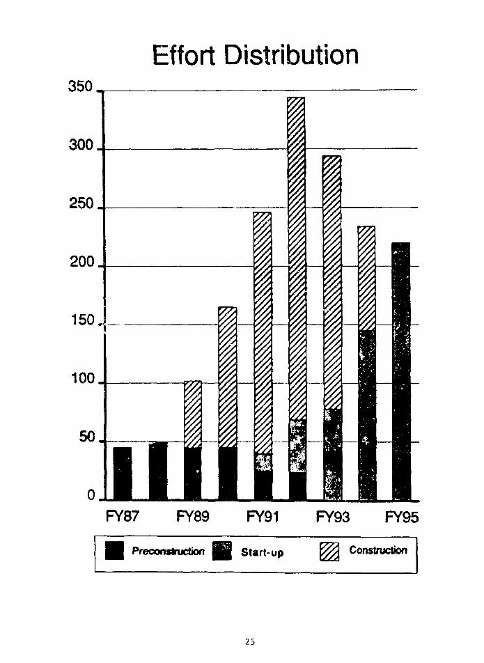
Effort Distribution350,
300
250
200
150 J_
100
0FY87 FY89 FY91 FY93 FY95
Preconstruction WSm Start-up Construction
25

ADVANCED PHOTON SOURCE
SITE ASSESSMENT ACTIVITIES
Environmental Assessment
• U.S. Fish & Wildlife Service finds noendangered species problem.
• U.S. Army Corps of Engineers must issuepermit to allow alteration of wetlands.
• Comprehensive Environmental Assessmentby ORNL is near completion (expectedApril 1988).
Cultural Resources Survey
t Field work is completed.
t Evaluation of prehistoric sites (circa 6000 B.C.)shows subsurface features and artifacts relatedto butchering, cooking, hide preparation, andhabitation.
t Historic sites (circa 1840) predate constructionof the Illinois-Michigan Canal.
• Summary Report to be ready for theState Historical Preservation Officer(April 1988).
26

SITE ASSESSMENT ACTIVITIES(Continued)
Geotechnical Studies
t The State of Illinois has provided $250K forthe Illinois State Geological Survey to characterizesubsurface soils and their stratigraphy.
§ Current 24-hole drilling program and geophysicalstudies will provide the basis for foundationdesign and vibrational analyses.

USEt GOALS
For Optical Experimental Prograa
1. Beaa Stability
• Position and angle
• Constant current (top-up node)
• Independent control of ID's
• Reliability > 951
• Operations > 751
• No extended shut-downs
Z. Conventional Facilities
• Maximize access to BL
• Provide adequate floor space
• Provide convenient office/lab space
• Support facilities, housing, etc.
28

3. Beaaiines
• Provide a flexible radiation source
• Develop prototypes for optical components
• Hake headlines affordable
Take advantage of "quantity production1
without sacrificing capability
• Develop M appropriate "PRT" policy
• Provide "general user" facilities
29

BEAM. M E DEVELOPMENT PLAN
a J40M Beamline "Trust Fund" (Phase I)
• Beamline Planning Committee
Average Cost 1n K$ of Major Component Groupfor the IDs and Binding Magnet
O
Source
Undulator (5m)
Undulator (2.5m)
Wiggler
Bendina Maanet
SourceCost
1326
796
683
Front-End
487
487
447
351
Beam TransportF1rit-0ptics
476
476
476
ExperimentalStation
1196
1196
1196
952
Total
3495
2955
2802
1303

USER ACCESS PROCESS
• APSUO Access Policy Subcommittee: March 1988
• Policy to be Set: April 1989
• Establish Review Committee: January 1990
t Access Approved: April 1990

USER ACCESS IDEAS
• Each sector (ID & BM) run by a collaborative team.
• Collaborative teams will be of various types. Forexample*
* "Third party" national facilities, e.g., DOE/OHERproposed biomedical complex.
* Universities.
* National laboratories.
* Industries.
* Synchrotron service companies.
* Argonne research divisions.
* Advanced Photon Source
• Proposal approval based on
* Scientific content.
* Researchers' competence.
* Management Plan.
* Periodic review.
• Independent Investigators will have accessto (nearly) all beamlines.
* Fraction of reserved beamtime will dependon the nature of the collaborative team,negotiated at the time of proposal approval.
* Access to this beamtime will be managedby the collaborative teams.
• Types of research permitted: open, proprietary,and classified.
32

TECHNICAL OBJECTIVES
• HIGH-BRILLIANCE SYNCHROTRON RADIATION FROM
INSERTION DEVICES: I'LOO KEV
• HIGH STORED CURRENTS > 100 MAMPS
• LOW-EMITTANCE < 10NM-RAD
• FIRST UNDULATOR HARMONIC UP TO 20 KEV
- ACCESS ALL ELEMENTS WITH K OR L EDGES- ENERGIES IMPORTANT FOR X-RAY DIFFRACTION
t UNDULATOR TUNABILITY WITH SINGLE DEVICE
1ST HARMONIC M.7 - 14 KEV
3RD HARMONIC 14 - 42 KEV
33

—i—r—i—i—p i—I—i—r T 1 1 1 1—II I"
CDO
CO
to
>CD
CD
CD
o .
ooin
oo
oo
CL<CD
OO
ru
oo
-I L J i. 1 J 1 I 1
inru o
Q
ID
O
O
ooin
oo
ooo
A9H3N3
34

Tunabiiity of Undulators A and B
40.0 r-—
£UJ
£
30.0
ao.o
10.0
o.oo
10"
I
10"
03
10'
Period s 3.3 cm
0.50 1.00 i.50 2.00 2.50 3.00MAGNET GAP (cm)
: U£gjl|£rA<FundamtntaQ
^ ^ v N^ .Undutotor B (Fundi
4
0.00 10.0 20.0 30.0 40.0ENERGY (ktV)
35

1020
CM
ECM
CO
I
1018
1016
u8
CDO
<0
CD
1014
1012
\ 1-2 GeVNSLSX1 \Undulators
7 GeV APS Wiggler
PEP Undulator
SSRL 54-Pole Wiggler
NSLS Bend(2.5 GeV)
I1 keV 10keV 100 keV
36

HIGHLIGHTS OF CHANGES
6-GeV Design 7-GeV Design % Change
Beamlines (#)
Construction Area(KSF)
Cost in FY86 MS(including contingency)
Total Estimated Cost(including escalation)
55
596
304.52
375.94('88)
69
679
309.25
383.88('89)
+26*
+14%
+ 2%
+ 2%

LAH/OFFICE BUILDING*-^ ?£
HULTIUSE
MEETING
FACILITY
POSITRON ACCUMULATOR RING
38

ACCELERATOR FACILITY
Linac 200 MeV e" (3 amps)450 MeV e + (15 mamps)Rep rate 60 HzLength: 40 m
Accumulator 450 MeV DC ringAccumulate 24 linac pulses in 1/2 secDamp positron emittanceCircumference: 30 m
Booster 450 MeV -* 7.7 GeV (1/3 sec)1 sec rep rateCircumference: 367 m
Storage Ring 7.0 (0.7) GeV 100-300 mamps40 periods353 MHz 1248 bucketsLattice: Green-ChasmanCircumference: 1060 mFilling time for 100mA less than min

Facility:
Insertion Device Sources : 34
Bending Magnet Sources : 35
Total Sources : 69
Experimental Stations ~ 100
40

ID Bsamlfmi ATM - 23* 5 «Q. M**r*
•M B—mint ArM - 197.7 tq. Mtfws
18
• ^^^WHfl^» ^ T W ^ ^ ^ ^ ^ ^ w^^%^^^^% wi^^Jnd^
0 2 4 S 8 10[ ' * j i t
0 10 20 30

User Lab/Office Module- 1988 Design

APS ACCELERATOR DESIGN*
Yanglai Cho
Argonne National Laboratory
Introduction
Project staff are seeking users' input to help guide our planning andtell us what is important for the commissioning and operation of the APSaccelerator and experimental facilities. Progress has been made on theaccelerator design since the first users meeting in terms of decisions on thestorage-ring lattice and further refinements and improvements in prototypingactivities, construction tolerances, and impedance budgets.
The present design calls for a 40-sector Chasman-Green type of latticewith a nominal operating energy of 7 GeV (7.5 GeV for initial operation). Thehardware is to be capable of 7.7 GeV with a beam current of 280 mA. Thesespecifications have been reviewed by the project's Accelerator AdvisoryCommittee and by the DOE/ER Review Committee.
Current prototyping activities involve the vacuum system, the magnets,and the rf system. Lattice work continues, by means of computer modeling andcalculations, with attention focused on construction tolerances. Impedancebudgets are being improved to assure high-current operation.
Storage Ring, Injection, and Bunch Parameters
The main parameters specified at the Ames meeting have been modified topermit operation at 7 GeV. Since the present storage-ring design calls for 40sectors instead of the 32 in the Ames parameters, there are also 40 straightsections, of course. 0 p these straight sections, three will be used for rfcavities, one for injection, and one for beam-abort and other acceleratorphysics applications, leaving 35 available for insertion-device (ID) beamlines in the experimental area layout. The lattice element-to-element lengthis 6.2 m, while the straight-section length available for IDs is 5.2 m. Forlonger devices, a length of 8 m can be achieved by removing one quadrupolemagnet from each end.
In 1987, the DOE/ER Review Committee recommended that we study apossible shortening of the filling time for injection of positrons into thebooster synchrotron; the committee added $4 million to the project's cost tosupport this change. In the 1987 APS Conceptual Design Report (CDR-87), the
The summary presented here is based on notes taken at the meeting.
43

booster had a "cold" filling time of 4 min, with an overall efficiency ofabout U0%. In our new filling scheme, a 30-m-circumference positronaccumulator ring (PAR) between the linac and the booster shortens this time bya factor of six.
With respect to bunch separation and bunch current, the present designgoal is 5 mA per bunch or greater. At 5 mA per bunch, 20 bunches would mean100-mA operation (60 bunches, 300 mA). (The number of rf buckets available inthe ring is 12^8. ) Bunch separation in the 20-banch mode would be 177 ns.These bunch separations and currents are intended for "timing" experiments.
Vacuum Chamber System
Our first priority in prototyping activities has been to assure theconstructibility and serviceability of the vacuum system. Studies of chambersurface cleaning using the LEP method are under way. We plan to use bothactive and passive systems to prevent overheating by mis-steering of thephoton beam. The active system monitors machine conditions and dumps thestored beam if mis-steering exceeds some specified limit.
The passive protection system, which is more interesting, is based on abuilt-in orbit-correction scheme. This scheme involves using highly accuratefeedback on the photon beam (both position and angle) to determine adjustmentsto correction-magnet field strengths and positions that will correct the orbitof the circulating beam. (Photon-beam-position feedback accuracy depends onthe accuracy of photon detection; we need help from users on this.) Magnetsavailable include eight horizontal correction magnets, plus two in thedipoies, and nine vertical correction magnets; we can use four plus four fororbit correction and another four plus four for ID beam feedback. The designgoals are to limit (vertical) corrector strengths to less than 0.25 mrad, sothat the photon beam cannot, strike the chamber wall, and to provide verticallyadjustable quadrupole mounts.
Ccwnnissioning and Operating Considerations
It is not too early to consider plans fr.r commissioning and operatingthe APS accelerator .systems, and we request user n.put to these plans. Retro-fitting is both expensive and painful, so we prefer to do our planning now.That 13 one of the principal reasons for our building a full-scale mock-up ofoi'.e sector of the storage ring; this mock-up, ^hK'h you will see later todayin the Building 362 High Bay, shows us what '".o jvori as we refine the design.
On the basis of past experience w;tn ,;cce .erator facilities, we areplanning not to run the APS at the hardware limit -; thus, we have a built-inreserve. We are also planning, particular.v fo- " • <•• commissioning period, tohave adequate, even redundant, diagnostic eq-i iprv-'.v

With respect to hardware, the straight-section vacuum chamber segments(designed to have much narrower apertures than segments in the bending-magnetsections) will be built in three different sizes: normal ring-chamberaperture, for Day 1 operation; 1.4-cm aperture, for early operation; and 1.0-cm aperture, for operation during system maturity. Since initial operationwill be with electrons rather than positrons in the circulating beam, allmagnet power supplies wilL have reversible switches for electron operation.
Except for the first day, we plan no Lock-out of the experimental areaduring routine operation. Instead, sufficient lead shielding will be providedfor local shielding if needed.
Start-Up Considerations
At start-up, while we search for the optimal operating point and makecorrections to the beam orbit, we will be able to detune the lattice tofacilitate orbit corrections. The machine wLLl be operated at low intensityfor becun diagnostics. If photon beam scrubbing of the chamber is needed, wemay use an electron beam for this purpose.
As N is noted above, at start-up the straight sections will containvacuum-chamber segments of large (normal) aperture. At the time of IDinstallation, we plan to install chambers with 1.4-cm aperture at somereasonable current (say, 50 mA) using sector valves; at this point, during theinitial experiments, the ring would be run at 7.5 GeV. Later, when the"golde- orDit" iv achieved, the smaller, 1.0-cm-aperture chambers will beinstalled.

ENERGY AND TIME STRUCTURE OF PHOTONSFROM APS INSERTION DEVICES*
Gopal K. ShenoyArgonne National Laboratory
Today I would like to point out some of the highlights of the current designs withrespect to insertion devices and beam lines and bring you up to date on the R&Dactivities we are planning. The ultimate goals, as you know, are spatial brightness andspectral brightness. We are looking for (1) a large number of x-rays in a very small solidangle and (2) large density with extremely narrow bandwidth, and this is accomplishedusing undulators.
Within a given undulator, the change in the energy of the photons produced is afunction of the deflection parameter K, which is proportional to the magnetic field andthe period. The period gets Lorentz-transformed twice to get to the range from a fewcentimeters to a few Angstroms; it is proportional to E squared. As for the magneticfield, you open up the jaws of the undulator to increase the gap and decrease the field.When you decrease the magnetic field, K decreases and so does the photon energy. Now,we have plotted minimum magnet gap as a function of ring energy, and the resultingcurve, which represents first-harmonic tunability from 4.7 to 14 keV, tells us we need tooperate the ring at 7 GeV and with a 1-cm gap to achieve that tunability.
For a complete Monte Carlo calculation of spectral brilliance, as you change thegap of this undulator (period of 3.3 cm, K = 2.2), K changes and the fust-harmonic peakmoves along an envelope. Later on, the third harmonic starts to appear, so you can coverthe range farther on using the third harmonic. We have plotted brilliance as a function ofenergy for that undulator, which we call Undulator A; with it, we lose roughly two ordersof magnitude in going from 4 to 40 keV. This is the sort of device that can be utilized bymost people, and if we produce a lot of them we can do so economically. If this rangecan meet the needs of most of the synchrotron community, then I think it is the one to gowith.
A 2.3-cm-period undulator, called Undulator B, will produce higher brilliance athigher photon energy and may be useful for some experiments. Now, a certain number ofexperiments are brilliance-intensive, while others are flux-intensive. For people who aremore interested in flux than in brilliance, I have a curve that shows flux through aptnhole. You can get 10 -101-5 photons per second through the pinhole. The angulardivergence is on the order of 9 microradians vertically and 24-25 microradianshorizontally. To translate this, that's a spot less than a millimeter in size 50 meters fromthe source poinr.
*The summary presented here is based on notes taken at the meeting; viewgraphs wereprovided by the speaker.
46

Let me consider wiggler sources. Almost all wiggler sources on this 7-GeV ringcan be built using permanent magnet technology. You can get critical energies up to 60kilovolts with permanent magnet technology, so you can get radiation at a few hundredkeV and a fair amount of flux and brilliance without any trouble.
Here are two designs. One has a 33-kilovolt critical energy; this, of course,corresponds to the hard-ion edge, in which biologists are taking a lot of interest. Theother is a 10-kilovolt critical-energy wiggler; this is not your typical wiggler, becausehere we're reducing the critical energy of the radiation coming out and making it lessthan that produced by bending magnets (19 kilovolts). In addition, the angular openingof this wiggler's radiation is considerably smaller than what we are used to at currentfacilities.
We have been thinking about special devices of interest for specific kinds ofexperiments. One functions as an undulator in the low-energy range, about 2-7 keV, andthen as you close the gap it becomes a 10-keV critical-energy wiggler. You can alsobuild a wiggler with vertical polarization; this is fairly straightforward to build around theproposed APS insertion-device vacuum chambers. We are also looking into a wiggler forproducing elliptical radiation.
We had a workshop here recently that raised the issue of time structure, and we'readdressing some questions on that. A single-bunch mode is ideal for some experiments(there is a whole class of experiments related to this, depending on the excitationprocess), but most users are interested in the multibunch mode, simply because itproduces more flux. We are considering loading the storage ring with say, a lone bunchon one side and 19 bunches on the other side and having a chopper synchronized with thesingle bunch. With a 5-mA current in this bunch and the rest in the remaining bunches,the typical user won't see much difference between this mode and normal operation,while the single-bunch experimenter can use a chopper outside the beam line to get darktimes (when you don't see an x-ray) for several microseconds.
On the 3.3-cm insertion device, we have developed a prototype in collaborationwith Cornell. This device, which is 2 meters long, is now being built and will be testedon CESR in a month or so using a special low-emittance mode (actually eight or ninetimes larger than the anticipated APS emittance). And so we will have some firsthandexperience at getting this radiation and testing it out.
Another issue is power. When a large heat load hits an optical surface, there aredistortions of the surface and distortions from the rocking curve. Of course, you will betaking this radiation at an appropriate Bragg angle, but this is still not enough to relievethe heat problem. We have developed a liquid gallium electromagnetic induction pump --there are no moving parts in it -- and it is functioning. Two weeks ago this pump wastaken to Cornell, and a very useful experiment was carried out. Bob Smither is leadingthis effort.
47

7.230
.0,30
0 0U SO 04 05 SF 05 04 SO
4ER SHIELD
0 1 2 3 4 5 METERSSCALE
Location of Insertion-Device and Bending-Magnet Sources

TYPICAL SPECTRUM FROM UNDULATOR A (PERIOD = 3.3 cm)GAP = 1.3 cm, K = 1.65
/mm
'
fO
e
CQ
O
(ph
/s/
(_>
i—i
ZJi—i
CECQ
i o 4 a
1 0 1 7
1 0 1 6
1 0 1 5
10"
1OU
0.00 5.00 10.0 15.0
ENERGY (keV)
20.0 25.0
Tuoability of Undulator A (Period - 3.3 cm)
0.00 5.00 10.0ENERGY (koV)
15.0 20.0
49

Tunability of Undulators A and B
40.0
30.0
Undulator A (Third Harmonic) ^-* '
9
§ 20.0UJ
Ui
I 10.0
0.00
Ondulator B (Fundamental)Period = 2.3 cm
Undulator A (Fundamental^
Period = 3.3 cm
0.50 1.00 1.50 2.00MAGNET GAP (cm)
2.50 3.00
• • • • i J ' ' r
Undulator A (Fundamental)
E
1 10"03
S to"
CO
Undulator B (Fundamental)
Undulator A (Third Harmonic)
10"0.00 10.0 20.0 30.0 40.0
50

First-Harmonic Brilliance, Brightness and FluxThrough a Pin-Hole on the Axis of Undulator A
at Various Energies
3
17
BI 1016
ffl 1 Q 1 4
10 13
BrillianceBrightness
Flux through Pin-Hole 22urad X 22|xrad
8 1 0
Energy (keV)
12 14
Nd-Fe-B Undulator C with 20 cmPeriod for Low-Energy X-ray Work
Energy (keV)
51

APS Wiggler Flux
aX
E
10
10
10
10
10
13
12
1 1
10
APS-A(7GeV,100mA)APS-B(7GeV,100mA)CHESS (5.5 GeV,80 mA)SSRl-VI(3GeV,100mA)NSLS-X17(2.5GeV,500mA)
.1 10 100
10
10
10
10
10
10
10
10
1 7
ENERGY (keV)
APS Wiggler Brilliance
16_
1 5
1 4
13
1 2
1 1
10
APS-WIG A (7 GcV.100 mA)APS-WIG B (7 GcV.100 mA)CHESS (5.5 GeV,80mA)SSRL-VI(3GeV,100mA)NSLS X-17 (2.5 GeV,500 mA)
- i i i i J . i • i i • i l l .
\v\\
VV
• ' I I I I I I
1 10ENERGY (keV)
100
52

3
2
s
AP5 Bending Magnet Flux
APS(7GeV,100mA)NSLS (2.5 GeV,500 mA)SSRL(3GeV,lOOmA)CHESS (5.5 GeV,80 mA)
10 16
1 10Energy (keV)
APS Bending Magnet Bri l l iance
100
p
s•a
p
in
• I .
3
10
10
10
10
15
14
13
12
•I. 10
10
1 1
10
APS (7 GeV, 100 mA)NSLS (2.5 GeV,500mA)SSRL(3GeV,100mA)CHESS (5.5 GeV,80 mA)
\ ^ -:
•. \
10.1
ENERGY (keV)10 100
53

ECM
T3
CO
1020
1018
ous
JO
a.
ance
10
10
16
14
1012
7 GeV APSUndulator
\ 1-2 GeVNSLSX1 \Undulators
7Ge\^APSWiggler
PEP Undulatoi*
SSRL 54-Pole Wiggler
L_1 keV
NSLS Bend(2.5 GeV)
L_10keV 100 keV

"S 10
I'C
-0.3 -0.2 -0.1 0.0
Horizontal Angle (mrad)
0.2 0.3
- 0 . 3 - 0 . 2 - 0 . 1
Vertical Angle (mrad)
55

— 30 m0 250 microns
1015Undulator
uI 1 0
% 1013
05
c
G»
1 1011
LL,10
10
Through Pinhole
Q = 8 firad X 8 urad
10 15Energy (keV)
20
High BrillianceCentral Spot
(about 10 l 5 photons/sec/O.1%BW)
25
Source Size:85 urn X 308 prn9 Mr-ad X 7A \ira6
56

CQ
t/5Cooa,X3
10
10
10
10
10
10
15.
14
13
12
1 1
10
10
10 8
Flux Through a Pin-Hole on the Axisof Unduiator A (Period = 3.3 cm)
/Pin -Hole 14.6 prad x 14.6 (irad
*" • Pin -Hole 7.3 |irad x 7.3 |iradPin -Hole 3 pxad x 3 p.rad
i . . . . . i . . . . . i . . . . . i . . . . . i
4 6 8 10 12 14Energy (keV)
16
57

BROAD BAND UNOULAIOH
GAP (mm)
PERIOD
20.0
35
19.3
32
18.G
29
18.0
27
17.4
26
FLAT-TOP ENERGY RANGE - 1 keV
ee
•o
e
CD
o
»—i
BROAD-BAND UND0LATOR
7 .0 GeV 100 mA P e r i o d = 3 . 3 5 cm
10"
iO16 t-
10 15
JO"
cr
6.00 8 .00 10.00
ENERGY (keVJ
12.0 16.0
58

Time Structure of theAdvanced Photon Source
Bunch Length 116 ps (2xrms)
Orbital Period 3526 ns
Interbunch Period
1 Bunch 3536 ns (max 5 mA)
20 Bunches 177 ns (100 mA total)
60 Bunches 59 ns (100mA total)
59

Time Typical Flux Through a Pin-hole(8 urad X 8 urad) in a Single-Bunch Mode
» 10 1 3 /sec/0.
Time

Flux per Bunch for APS X-raySources
Source Energy Flux(k e V ) X-rays/bunch/0.1 % BW
BM 19 1.7 x 10⁶/mrad8
Wiggler A 33 3.9 x 10 7/mrad 8
Wiggler B 10 4.5 x 10 7/mrad 0
Undulator A 8 |2.1 x 10 8
UndulatorB 14 li.7 x
61

Use of X-ray Chopper
Storage Ring / Asymmetrically Spaced Bunches
19 Bunch
Total BunchesMaximum CurrentCurrent in the Lone BunchLone Bunch DurationDark Time Using X-rayChopper: Min
Max(for 18000 RPM)
20100 mA5 mA116 ps
3.56 usec3.33 msec
62

PRE-MONOCHRQMATOR R&D
Cooling with Liquid GalliumBob Smither: Argonne
A. Design, Construction and Testing of Liquid6a Pumps:
Bob Smither: ArgonneGeorge Forster: Argonne
B. Optimization of Crystal Geometries withFinite-element AnalysisAH KhounsariChristian KotTuncer KuzayDenny MillsBob SmitherJim Viccaro
> Argonne
C. Testing at CHESS WigglerFebruary 1988
Bob Smither and George Forster: ArgonneDon Bilderback, Mike Bedzyk, K. Finkelstein,C. Henderson and J. White: CornellLony Berman, Peter Stefan and TomOversluizen: Brookhaven
63

Geometry AStandard CHESS Watercooled
Geometry
Foot-Print
H20
Ga-ln Eutectic
. / Si Crystal
Copper
64

80000 k-
60000
40000H-
20000H
100 200 300 400 500
65

TESTLOAD
cv
Q
EL-MAG.FLOWMETER
h
GaRLL
VACUUM
LEVELINDICATOR
COPPERENDRING
SILVERSOLDER
STANDPIPE
HEATSOURCE
\ \
MAGNETICCORE
POLYPHASE STATORFROM INDUCTION MOTOR
SPIRALWOUNDTUBING
HEATER
SPIRAL DETAIL
HEATER
.tfc
OILPUMP
COOLINGWATER
Schematic drawing of the new gallium pumpand its test system.
66

Geometry BCHESS Standard Si Crystal
Foot-Print
Si Crystal
H2O or Liquid Gallium
67

S (111) ROCKING CURVES, 8 KEV, CORE-DRILLED XTAL W H20 COOLING
S1GNA
S00000 —
400000 —
3000C0 —
200000 —
100000 —
PZT VOLTAGE600
68

Geometry CArgonne Optimized Si Crystal
Si Crystal Foot-Print
o o o o o
Liquid Gallium
69

o
300K20keV46 mA
Feb. '88 A
200 K
(0
cO
o
100K
Argonne Channel Cooled-*-' Ga, 0.67 gpm
BCHESS Channel Cooled
^ Ga 0.6? gpm
Geometry BCHESS Channel Cooled
H2O 5
GeometryWatercooled
-20 -15 -10 10 15 20
ARC SEC

30SURFACETEMPERATURE
PRGFILE
20
OO
10
Geometry ACHESS Watercooled
Hoo Geometry B^ ..5 gpm C H E S S channel Cooled
Geomfthry CGa\Argonne Channel Cooled
0.67 gpm
Position (cm)
71

APS CONVENTIONAL FACILITIES OVERVIEW*
Martin J. KnottArgonne National Laboratory
Since the last users meeting and publication of the APS Conceptual Design Report,we've done considerable refinement on the design. Much of this work has been promptedby user requests through the conventional facilities subcommittee of the APSUO SteeringCommittee; some of it has also resulted from Department of Energy comments and fromour own evaluation.
You've heard some references to the new user module design- We've also donesome redesign on the central lab/office building and on the meeting facility, and ofcourse we're working on an additional device, a positron accumulator ring. In addition,we have given considerable attention to the concrete shielding for the storage ring.
The design of the user lab/office modules was a particular concern of the SteeringCommittee. They wanted at least one laboratory and four office spaces for each beamline, and they wanted to reduce the travel distance between the labs and offices and thebeam lines ~ close to the experiment hall floor, but not so close as to be congested. Wealso thought it would be nice to allow for some custom design. And of course, anunderlying goal was to try tc hold the costs down.
We chose a 20 x 30 standard kind of laboratory space. This module here [seeviewgraph], for example, has two labs and eight offices ~ the arhitect's drawingsindicate the range of customization possible. The common areas in the center are aconference room, a break area, restrooms, staff shop, and utilities. A parking lot isassociated with each module. To summarize the changes: For the four units in the CDRdesign, we have a total of 16 laboratories. Lab space has been doubled and office spaceincreased by half over the old design. We now have fewer clean rooms, but clean roomsdid not seem to be a primary concern for the Committee. Gross square footage hasincreased to about half again the old value.
The central lab/office building has been redesigned in line with userrecommendations and our own internal reviews. In light of the new user module design,we felt we could cut the number of user-specific labs in this building. We eliminated theClass 100 clean room to shorten the travel distance between the entrance and the floor;the Class 1000 clean room, for handling large objects, should be adequate for our needs.We also shortened the high-bay and machine-shop areas. But what really made thebuilding design more compact is that we took the entire three-story lab/office building,raised it by one floor, and put it on top of these labs [see viewgraph]. We are now able to
The summary presented here is based on notes taken at the meeting; copies ofviewgraphs were provided by the speaker.
72

provide a storage area that we can get into with a truck, rather than by elevator, and youcan move large objects between the storage and the assembly areas.
What used to be the auditorium is now the "Multi-Use Meeting Facility." Thisredesign was done &i the prompting of the Department of Energy. The idea is to servethe user community better by providing the ability to handle a variety of meeting types,both large and small. For large meetings, this design provides a 600-seat capacity.There is room for several small meetings at 60 seats each, and we will be able to handletables for tutorials and seminars, poster sessions, maybe catered banquets. The floorarea can be divided up into halves, quarters, and even eighths to furnish this multi-usespace. Soundproof walls can be brought across in two directions. The design is a bitcomplicated, in terms of making sure all these areas have doors and power and othernecessities, but we feel it's a much more usable, flexible space than we had originally.
The ratchet-wall redesign effort was prompted by users' concern over how muchbeam-line space they would have available to them on the experiment hall floor. In theideal storage ring, the beam line would begin at the source point. But in this design, as inany lattice, the beam takes a while to emerge from the lattice. So the users wanted usto move the ratchet wall toward the machine in order to bring the first optics closer tothe source point. Of course, we still had to maintain radiation shielding quality andaccommodate any front-end devices required, which have to be within the shield, but wemanaged to provide over six meters. The beam-line length on the floor was increased by6.1 m for insertion devices and 6,4 m for bending magnets.
The first thing we did was switch to heavy concrete for the wall material, allowingus to decrease the thickness from 80 cm down to 56 cm. Also, we found that the front-end components could be put closer together and fit in a shorter length. The result waswe gained more than six meters, and the clearances are the same as in the first design.You'll see this in the mock-up. At present only the inside skin is modeled; perhaps lateron we may model the outside skin and some beam-line components and see if this isreally workable.
73

CL,
00
Cco
74
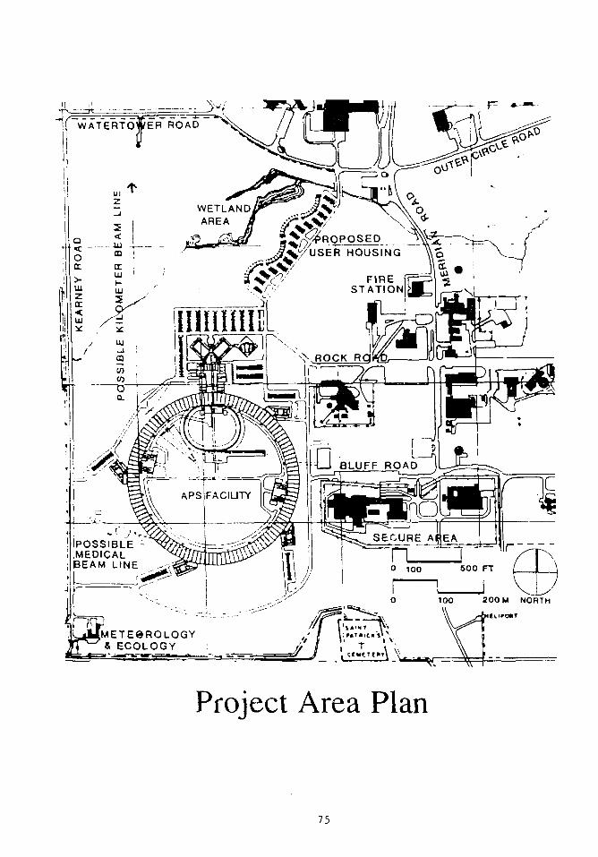
WATERTOWER ROAO
WETLANDAREA
FIRESTATION
BLUFF ROAD
POSSIBLE -MEDICALBEAM LINE
SECURE AfiEA
200 M NORTH
METEOROLOGY& ECOLOGY
Project Area Plan
75

PtoposociUser Housing
MultiuseMeetingFacility
°o
CentralLab/Office
Building
PositronAccumulation
Ring
* ; y
Lab OfficeModule
Project Site Plan
76

\ .
EXTRACTION^LULDING\ NBERM
RF BUILDING
..-• 'SYNCHROTRON
INJECTION BUILDIN
Infield Area

r-T?
• T—(
2
o
78

-~.Z:-t
_ d p D •l_ , Lj SYNCHROTRON
in ITTTTI
DTTTi n
BERU - .
\ f
I Of SYNCHROTRON
IH-i I
RING
r IT.=4-
r• > -
TOP Of
"~ HW5T R.OO"EL * 740 -0"
MCZ2AN1HE ABOVCMAIN fLOORCONTROL RQDH
Synchrotron Injection Building

80

A
rRANSFORMERS
£ • •••
ROOR EL. -740 0"
RF Building
0 5 15 30 fEET
01 S 10
81
A<o
crScQwCl ONITOOO o o
Ji DDDDLi
cr
UJ
L.
- • e :
' • ! •.: f a
£ §
<
P .0 - CC '
I
1
cii
i
i-^
ii
1
•
G
• i—(
4
82

co• t-H
o00
cs
6exX
83

RATCHET-WALL
DESIGN EFFORT
Objectives:
- Move ratchet-wall and first opticscloser to source point.
- Maintain radiation shielding quality.
- Accommodate frontend devices.
Results:
- ID beamline length-on-floorincreased by 6.1 meters.
- BM beamline length-on-floorincreased by 6.4 meters.
- All important clearances maintained.
84

ID
• 6 . 4
CDR-1987 Design 6.1 BM
0
ID
Ratchet-Wall Design Change

APS BEAMLINE
DIMENSION SUMMARY
(meters)
LONGITUDINAL IDBEAM
Source - to - frontend 23.1
Frontend length 6.1
Ratchet wall thickness 0.8
Ratchet wall - to - end 50.0
Total
TRANSVERSE
80.0
BMBEAM
21.7
5.0
0.8
52.5
80.0
(BOTH)
Frontend centerline - to - wall 0.8
Beamline centerline - to - wall
Beamline - to - beamline
0.2 (increasing to 0.5in the first 4 m)
2.3 (both emerged)5.5 (at end)
86
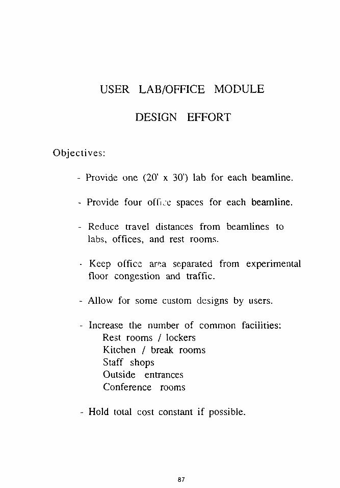
USER LAB/OFFICE MODULE
DESIGN EFFORT
Objectives:
- Provide one (20' x 30') lab for each beamline.
- Provide four office spaces for each beamline.
- Reduce travel distances from beamlines tolabs, offices, and rest rooms.
- Keep office area separated from experimentalfloor congestion and traffic.
- Allow for some custom designs by users.
- Increase the number of common facilities:Rest rooms / lockersKitchen / break roomsStaff shopsOutside entrancesConference rooms
- Hold total cost constant if possible.
87

Design
1988 Design
UserLab / OfficeModules
88

GO
GJ
QOOCO
o
uofaOX)03
CD
89

USER MODULE
DESIGN CHANGE SUMMARY
CDR-1987 PRESENT PRESENTPARAMETER DESIGN DESIGN DESIGN
(4 units) (4 units) (8 units)
Laboratories 16 32 64
Offices 80 128 256
Clean rooms 4 2 4
(or other special)
Staff shops 0
Rest / locker rooms 4
Large conference 0
Kitchens 0
Truck air-locks 4 2 4
Gross area (sq. ft.) 54.4K 76. K 152.K
4
4
4
4
8
8
8
8
90

CENTRAL LAB/OFFICE BUILDING
DESIGN EFFORT
Objectives:
- Reduce experimental-support lab countin light of new user module design.
- Shorten travel distance from theentrance to the experimental floor.
- Eliminate Class-100 clean room(retain Class-1000 clean room).
- Provide path for staff and visitors
which avoids high-bay assembly area.
- Make other visitor provisions if possible.
- Retain all adjacencies betweenvarious types of areas.
- Reduce cost(in light of new user module design).
91

1988 Design
OFFICE WING
Central Lab / Office
Building
SUPPORT WING
1987 Design

CentralLab / OfficeBuilding
GroundFloor

CentralLab / OfficeBuilding
MainEntranceFloor
J

AUDITORIUM/MEETING FACILITY
DESIGN EFFORT
Objectives:
- Serve the APS community by accommodating:Large and small meetingsSeminars and tutorialsSocial and interactive functionsSeveral simultaneous functions
- Increase utility by accommodating:One large (600 seat) meetingSeveral small (60 seat) meetingsSeminar/tutorial tablesPoster sessionsBanquets (catered)Vendor equipment demos
- Retain lobby interaction area.
- Add small kitchen facility.
- Control sound for multiple programs.
- Retain proximity to parking.
- Retain proximity to centrallab/office building.
- Avoid cost increase.

Oo
1987 Design
1988 Design
Auditorium / Meeting Facility

Multi-Use Meeting Facility Site Plan
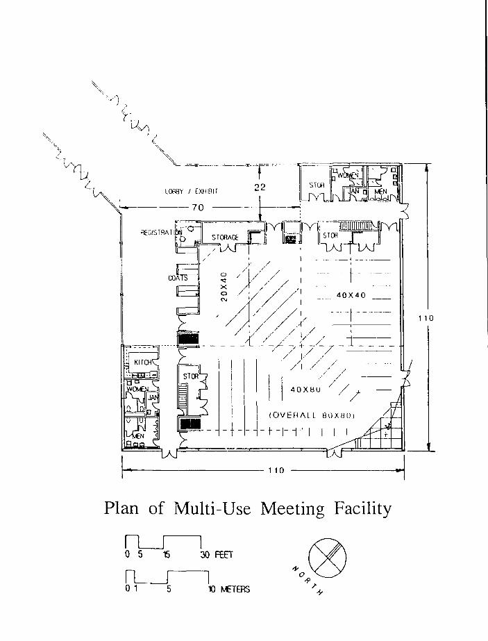
Plan of Multi-Use Meeting Facility
10 5 1
n0 1
s
5
30 FEET
I10 METEBS

v: V: v? fci', v; i-y \
i" r- o r> r-> •
(•KATE
11tatuit
Multi-Use Meeting FacilityLayout Examples

FRONTIERS IN SYNCHROTRON APPLICATIONS

MILLISECOND-RESOLUTION SCATTERING STUDIESOF PHASE-TRANSITION KINETICS*
G. Brian StephensonIBM Thomas J . Watson Research Center
Yorktown Heights, New York
ABSTRACT
A wide-bandpass monochromator and fast detector systemat the IBM/MiT beam line X-20C at the National SynchrotronLight Source allow the collection of x-ray scattering patternswithin milliseconds. The monochromator incorporates artificialmultilayers rather than crystals and provides a flux of 1 x10 -* photons per second at 6 keV with an energy resolution ofAE/E = 1.1 x 10~2 fwhm. The detector system is based on alinear photodiode array. Using this beam line, we have carriedout in-situ time-resolved scattering studies of the initialkinetics of crystallization, phase separation, and ordering attime scales orders of magnitude faster than previously possiblefor such nonrepetitive processes. These results have revealeda transient structure present during the rapid crystallizationof amorphous NiZr^ and the presence of nonlinearities duringearly-stage spinodal decomposition near the critical point inAl-Zn.
itThe following abstract and copies of viewgraphs were provided by the speaker.
103

STUDIES Of
PNASE
/C. Ludu
ISM £e
T. J. <*)«+
M. Sofa
J
w. J . MA^IUC, y. y«H*•* • J "
'• PAysi'eS
fahd %-****
• CrusU
104

N5LS IBM/MIT BEAMLINE5 X-20A AND X-20C
EXPERIMENTAL HUTCH
o
SYNCHROTRONSENDING MAGNETX-RAY SOURCE
0OU6LE-CRYSTALM0NOCHR0MAT0R
^FIXEOGONIOMETER
BERYLLIUM WINDOW
BENT CYLINDERMRAD HORIZ
ACCEPTANCETRAVELLINGGONIOMETER
m

OPTICS
SILICON
ZOO
TiPlCAL MOVOCHItdHATlC 66AM
10
10.01
0.001
I * I I T
ooe o
oo
I NT £6.
• . . . . .o
• IM ti» 6.1
ENERGY. KEV
106
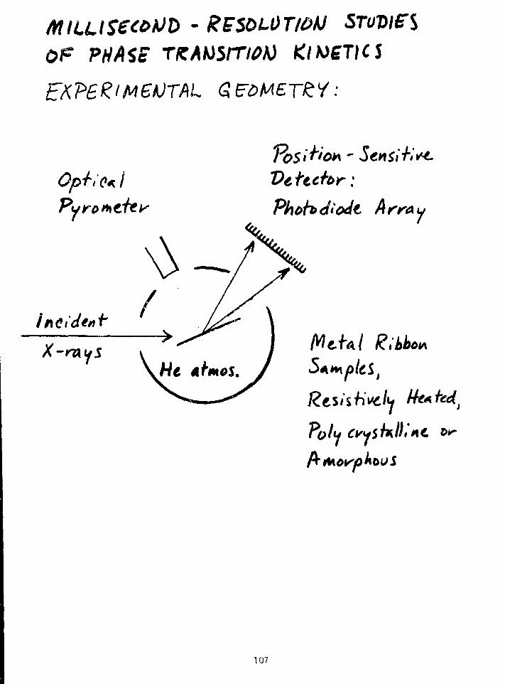
OF PHASc TKAMlTlOh) KINETICJ
Opiio*. I Vettchr:
u
McUl Ribbo*
Cryy
107

108

Intensity (arbitrary units)

O
tu
h 25-
AMORPHOUS
OF Mi l r
0 TIME"
r.67
2 . 7 2.8 2.9 3.0 3 .
WAVENUMBER. A""1
3.2
110

- 3 milli'
M"O
ou01(ft
c3O
u
41
oto
800f
700
600'
- 500
400
300
200
100
ratwr* - ?X*
t-.729sccs
726s«cs
2.5 2.6 2.7 2.8 2.9 3.0
111

FRACTION
H
S

t« 0$ t* I $
•f -
I 1
I l_ I 1 >
14 2.* M
AM6RPH00S
113

Zn (at.%) in A l -Zn
/U7
114

if
I
O
o o o o o o
o00
oCD
o o o
1-MJ '39NVH0 N0I103S SSOfcD
115
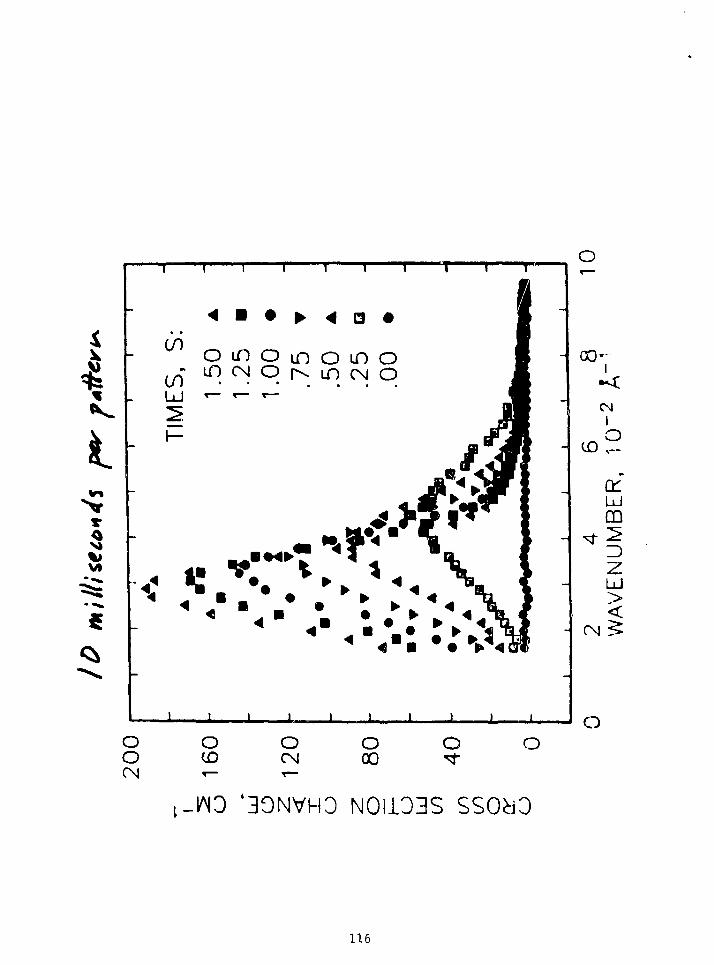
VI
i r I T i i
• 4 Q
CO
COUJ
omoinomoLf) CN O p^ LO CM O
J I J 1 1 J I
o
00'-I
CN
afUJCD
z
O
ooCM
o(D,—
OCN,—
OCO
O
-INO '30NVH3 N0I103S
116

CROSS SECTION CHANGE, CMooCN
Oin
oo o
QOLO
d -
d
o
oo
oro
OCN
O00CN
uu6
S3
117

s « a
o
1 1 i i i i
I I 1 ! I I I
o
U
a
as
00'
UJ
no
CN ^
OO if) O
-WO '30NVH0 NOii03S SSOdD
118

CROSS SECTION CHANGE, CM""1
o
oo
o00m
o o o
o
saNi
119

aJi- bv SOOrct
pUohdlodt - &VYA»
Tk',£'cs of
Neoo
vJ\ ILr^ ' TtnmiSi^'t structure
of- SR.0
j - shac
i M pd* I cU to**poii tit
120

~ l
j\ sec
*r>
[ « "
A/5LS APS
10
iO
X 10
- to
3
-310
L
to
010
-3to
-/
to
—
/r
-6to
-fto
121
SYNCHROTRON X-RAY MICRITOMOGRAPHY*
Keven L. D'AmicoExxon Research and Engineering Co.
Annandale, New Jersey
ABSTRACT
We have developed a technique for viewing the internal,three-dimensional structure of small (1 mm) objects with aspatial resolution of approximately 10 microns. The techniqueis referred to as "microtomography" and is based on the samephysical principles as are conventional medical CAT and NMRtomography procedures. Our technique employs synchrotronradiation as the x-ray probe. We have used the system for aseries of preliminary experiments at the Brookhaven MSLS, wherewe are currently building a dedicated beam line for tomographystudies. The unique features and intensity of the synchrotronbeam make a wide variety of studies possible. The techniquepromises to have application to many areas of materials scienceand medicine. We will describe the principles of the techniqueand show the apparatus required for taking tomography data.Representative data will be shown that illustrate thecapabilities of the technique.
Reference
B.P. Flannery, H.W. Deckman, W.G. Roberge, and K.L. D'Amico, Science 237:1439(1987).
The following abstract and copies of viewgraphs were provided by the speaker.
122

TOMOGRAPHY EFFORTCOLLEAGUES AT EXXON
• H.W. DECKMAN
J.M. DUNSMUIR
S.M. GRUNER
• B.P. FLANNERY
W.G. ROBERGE
M.S. WAINGER
• RX. HEWITT
M. SANSONE
DETECTORDEVELOPMENT
RECONSTRUCTION
ALGORITHMS
BEAMLINEDEVELOPMENT
P. EISENBERGER
NATIONAL SYNCHROTRON LIGHT SOURCEBROOKHAVEN NATIONAL LABORATORY
UPTON, NY(SUPPORTED BY US DOE #DEAC0276CH00Q16)
123

OUTLINE
• GENERAL INTRODUCTION-MEDICAL TOMOGRAPHY-MICROTOMQGRAPHY-SYNCHROTRON RADIATION
• TOMOGRAPHIC TECHNIQUES
-GENERAL CONCEPTS-NUMERICAL DATA ANALYSIS-INSTRUMENTATION
• MICROTOMOGRAPHY-MOTIVATION-TECHNICAL CHALLENGES-DATA ACQUISITION
• RESULTS-STANDARD SAMPLES
-UNKNOWNS-QUANTITATIVE RESULTS
• FUTURE DIRECTIONS-DETECTOR SYSTEM-DEDICATED BEAMLINE-SCIENTIFIC ISSUES
124

OUTLINE
GENERAL INTRODUCTION-MEDICAL TOMOGRAPHY-MICROTQMQGRAPHY-SYNCHROTRON RADIATION
TOMOGRAPHIC TECHNIQUES-GENERAL CONCEPTS-NUMERICAL DATA ANALYSIS-INSTRUMENTATION
MICROTOMOGRAPHY-MOTIVATION-TECHNICAL CHALLENGES-DATA ACQUISITION
RESULTS-STANDARD SAMPLES-UNKNOWNS-QUANTITATIVE RESULTS
FUTURE DIRECTIONS-DEDICATED BEAMLINE-SCIENTIFIC ISSUES
125

GENERAL INTRODUCTIONWHAT IS TOMOGRAPHY?
-TECHNIQUE FOR DETERMINING THE INTERNALSTRUCTURE OF AN OBJECT
-BASED ON MEASUREMENT OF THE INTERACTIONOF A PROBE BEAM WITH THE MATERIAL
-MEDICAL X-RAY TOMOGRAPHY DEVELOPED BYHOUNSEFIELD AND CORMACK
-NMR TOMOGRAPHY DEVELOPED BY LAUTERBUR
•BOTH TECHNIQUES WIDELY USED FOR MEDICINE
•X-RAY TECHNIQUE ALSO WIDELY APPLIED TONON-DESTRUCTIVE EVALUATION
-CORE FLOODS-SOLID ROCKET MOTORS-TURBINE BLADES-CERAMICS
126

CONVENTIONAL MEDICAL
CAT SCANNER
•1 MM RESOLUTION•256 X 256 PLANAR IMAGE
RotatingX-FUy
Sourct
FixedPhototubeDetectors
1 Meter
in
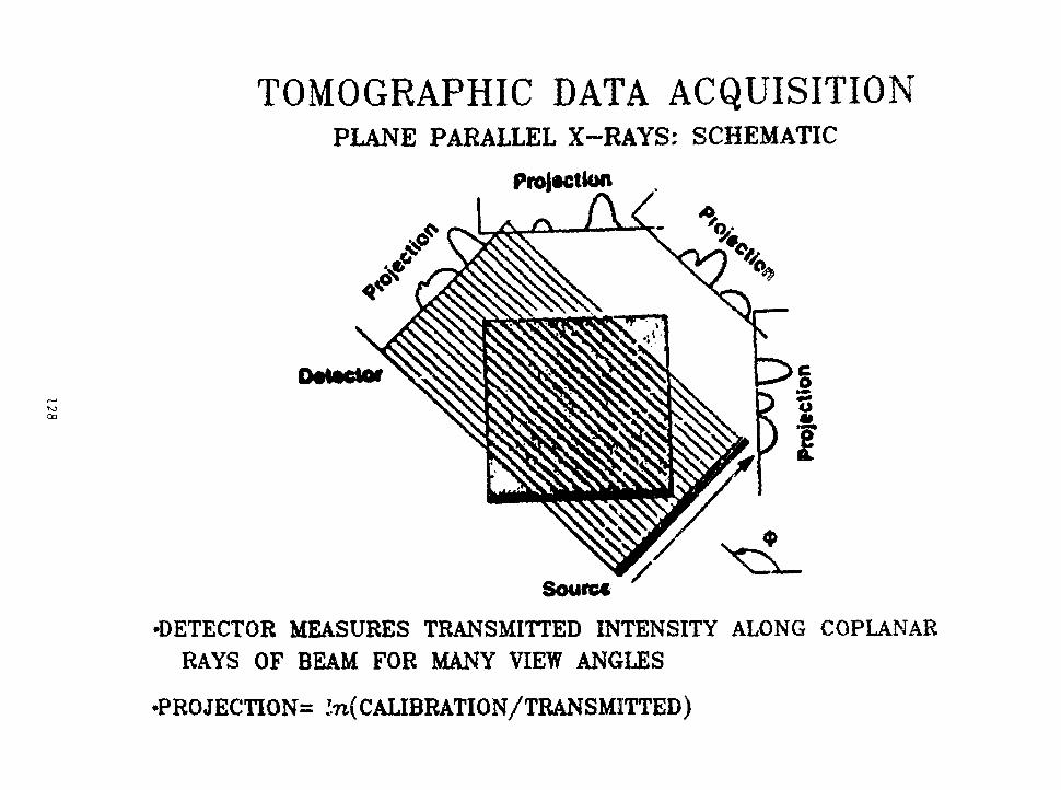
TOMOGRAPHIC DATA ACQUISITIONPLANE PARALLEL X-RAYS: SCHEMATIC
Projection
A, A.
Ottotfc*
Source
•DETECTOR MEASURES TRANSMITTED INTENSITY ALONG COPLANARRAYS OF BEAM FOR MANY VIEW ANGLES
•PROJECTION ln(CALIBRATION/TRANSMITTED)

TOMOGRAPHIC DATA INVERSIONRESULT
•INVERSION RECOMBINES THE PROJECTION DATA TO DETERMINEATTENUATION COEFFICIENT IN THE OBSERVED PLANE OF THESAMPLE

GENERAL INTRODUCTIONMICROTOMOGRAPHY
-THE EXTENSION OF TOMOGRAPHY TECHNIQUES TOSMALLER MATERIALS AND HIGHER RESOLUTION
-NO FUNDAMENTAL REASON WHY THIS SHOULDN'TWORK
-IN PRACTICE THERE ARE TECHNICAL PROBLEMS
-FOR THE CASE OF X-RAY TOMOGRAPHY
•DETECTORS WITH SUFFICIENT SPATIALRESOLUTION
•X-RAY SOURCE WITH SUFFICIENT FLUX
•MECHANICALLY STABLE SAMPLE MOUNTS
•MATHEMATICS AND STATISTICS OF PROCESS
130

MICROTOMOGRAPHYPROJECT
TOMOGRAPHY: A NON-DESTRUCTIVE IMAGINGTECHNIQUE BASED ON ATTENUATION OFPENETRATING RADIATION
•GOAL: USE SYNCHROTRON X-RAY SOURCE TOCREATE IMAGES WITH MICRON RESOLUTIONAND 1% PRECISION IN THE DETERMINATIONOF THE DENSITY (ATTENUATION COEFFICIENT)
•FEATURES:-RESOLUTION 1000 TIMES BETTER THAN
MEDICAL CAT SCANNER-COMPLETE 3D MAPS OF INTERNAL STRUCTURE-SMALLER SAMPLE SIZE
•PRINCIPAL INNOVATIONS:-HIGH RESOLUTION DETECTOR-FAST METHODS FOR DATA INVERSION-SYNCHROTRON X-RAY SOURCE
NOVEL PROBE FOR HETEROGENEOUS MATERIALS
131

See Nuclear Instruments and Methods B206(3): 542 (1983)
132

N o
WiVEWlEKT Of COSPtjTEO TOPOGRAPHIC 1HAG1NC SYSTEM US!NC KONOOlRfMmC X-RAYSKatsuhisa USAK1. Kooioo SAKAMOTO, f l iroshi KO'iAKA. T a U u a i IIIRANO.
Voshio SUZUKI*. Kazunobu IIAYAtUW** , Hideai SIIlUNO"«nd Hidcki KOGNO"Hitach i Research Lab. , H i t a c h i L td . , Hitachi ibaraki
» Advanced Research Lab. . H i t a c h i Ltd- , Kokubunji Tokyo• • Central Research Lab. , Hi tach i Led. , Kohubunji Tokyo
IntroductionX-r»y computed tosograpliy (CT) in « Mtliod
lor reconstructing the distribution of linearabsorpEian coefficients in the cross section of* saaple. This technique se«*s lo be an attrac-tive Method for non-destructi»a evaluation ofindustrial »«lerisU. liavever, it is i<ecessaryto i«prove Uv£ ?srfor«ance iactora of CT scan-ners such »s contrast sensitivity, accuracy «fattenuation cocfficienm, and space resolution.Tha use of a tunable and konochroaatic lr»yaource i* on« advantafeous neUxx) far thesepurposes.
A CT scanner vith a aonocHronatic J-r*»source usins synchrotron radiation tas deve-loped and trial CT iaaces vere obtained forseveral saaclea as reported herein.
InstrumentFit.I shovs a schematic of the developed
stic I-ray CT scanner, iynclirotrasradiation i s aoocchroaatized by a channel-cutaoaochroawtor. The beaa size i s 30 aa vide (Ad0.1-1 aa hi(h. Two channel-cut aonochroMtor,Si(220) and Si(400), are utilized. A set oftransmitted X-ra>' intensities is aessured byrotating the saaple. A 1024 channel array dela-tor, 2S A« vide x 2.5 as high, vhich i s a photo-diode array vith a scintillstor, i s used.
In this systea, space resolution is deter-•irved by the detector resolution. Modulationtransfer function (Ht£|i«asurea«nt» indicatethm raaolution jwTtjTi2 i i N A fcaLura of this
an
sy.tten is Uiat the projection i«ir,e can he a.if,•njfied by an aayimctr^cal Bragg ruTSecLion.Keso)uti«n of Q.03 M i s attained t>y a fivufold aaeiiiricatiorrT^
fleaultsTests of the scanner fere carried out end
Iriai CT laajes vere obtained. Fig.2 shovs tlteCT >aa«<> of an pkra cross section, Coaplei andlin« stt'uctures such as the Uiin aeabranes l>et-»*«!> vh« aeeds are c learly ol>ervcd.
The arii'antage of using a aonochroKitic X-raysource i s Uiat the di l t ibution of an aleacnt at ncross section can be obtained by the diffi.-rrencc^"Iwi'f'o CT i»aj(?s at higher anij lnwi»r ctierniathan the absorption edge energy. Fin.4 showstest results for on elemental distribution. TheHo I N | C js exructcd by the difjcrencc oi I heCT iaates (A) and (0)
1) Vu.l.Borodin e t a l . , Nucl. Instr. and HcthA246 (1986) 649.
2) A.C.Thompson et a l . , Nucl. Instr. and Nctti.222 (1984) 319.
Fi j .2 CT i"»ee of ofera.Energy = 15 KeV.Sl ice width = 0.3 • » .
fto X-edge* 0 . 6 KeV E = Ho K-ed«*-w".
F i t . 1 5ch<?«atlc layout of the conputed topographic
/5Ce» u i j n j »onochroiwt ic X-rays.F j£ .2 Ko mage ob ta ined by the di f irrrnr c of
CT taares (A) and (8) .
133

EXXON 3D
MICROTOMOGRAPHY SYSTEM
•1 MICRON RESOLUTION•500 X 500 PLANAR IMAGE•3D DATA SET: 300 PLANES
Detector Bottling Target
1 cm
Cc!Si«natedX-Ray Beam
— M
L34

Materials Sdencr E&TK November/Drcrtnbrr
The energy of the incident x-raybeam can be selected using a single-crystal monochromator, but mostsynchrotron beam lines use a double-crystal configuration to restore thex-ray beam to its original direction.The double-crystal arrangement alsohelps remove higher-order harmonicsthat also satisfy the Bragg conditions.The energy resolution is typically inthe range &om O.I to 0.01% overenergies ranging from 4 to 70 keV,and higher energy resolution canbe obtained by using dispersivelyoriented crystals.
The rotating sample stage enablesus to use computed tomography (CT)reconstruction algorithms to obtaintrue three-dimensional images ofchemical distributions within theample . The spatial resolution aftermagnification, determined by the
quality of the phosphor coatings, is4 to 5 jjm in three dimensions.
Why Synchrotron Radiation?
Three x-ray source parameters—x-ray intensity, energy spectrum, anddivergence of the incident beam—determine the spatial resolution andrensitivity of our camera. Theintensity of the radiation sourcedetermines the exposure time toachieve a given signal-to-noise ratio.In two-dimensional imaging, this ratioKales with the square root of theexposure (increasing the exposure 100-fbld decreases the uncertainty in thex-ray data by a factor of 10). Recauseof the way errors propagate in thereconstruction algorithms ofthree-dimcnaonal CT, determining the
signal-to-noise ratio depends on thesensitivity and spatial resolutiondesired. Here, sensitivity is consideredto be the ability to recognize smallchanges in absorption, above thebackground noise, between adjacentpixels. A sensitivity of 1% means thatchanges in sample contrasts of 1% canbe measured. The fluence requiredfor a given sensitivity is inverselyproportional to sensitivity, asensitivity of 10% requires 100 timesless fluence than a sensitivity of 1%.
Figure 2 gives the relationshipbetween resolving power and requiredfluence (conservatively estimated) toachieve a sensitivity of 1% in CT.(The resolving power is given bythe ratio of the maximum samplediameter to the width of a pixel;imaging a 1-mm sample to l-pmresolution requires a resolving power
Pnoaphorr
Coated CCO
L
Figure I . The experimental BJaetnbly for perfbnnlag high-resolution x-ray imaging. After tbey pass through the Minpk, x rayi are coo-m t r d fato rblMe Ught In a phosphor that k focwed on a fiber-optic image plane by a biconvex lets. The optical fiber* transmit the im-aff? to the CCD, from which ft is read Mt ia digital form by the camera controller and rooted to the computer. The ipedmen can be heldMotionless tor two-dimensional Imaging (dkhromotraphy) or topography, or routed to obtain the Multiple images needed for computedtomograph).
38
L35

XIOA BEAMLINESCHEMATIC
MUM(12*) <2Qtt)
FEATURES-COMPUTER CONTROLLED/STEPPING MOTOH DRIVEN- 1 0 ( E l i ) PHOTONS/S FOCUSSED MONOCHROMATIC BEAM-FLEXIBLE CONFIGURATIONS
•BEAMLINE STAFF-RICH HEWITT-MIKE SANSONE, STEVE CONSTANTINO, BILL VARADY-RANDY ABROMAWITZ, STEVE BENNETT, BOB WIESER-GARY NINTZEL

SUMMARYHIGHLIGHT IMPORTANT FEATURES
•RESOLUTION-CURRENTLY <1O MICRONS-APPROACHING 1 MICRON-VARIABLE 1-50 MICRONS
•SAMPLES-WIDE VARIETY POSSIBLE-MANY CUSTOM CELLS POSSIBLE
•SENSITIVITY
- 5 % DIFFERENCES IN ABSORPTION COEFFICIENT-CHEMICAL ANALYSIS THROUGH ABSORPTION EDGE-FIRST ROW TRANSITION METALS IDEAL
•DATA SET
-FULL THREE DIMENSIONAL INFORMATION ACQUIRED-QUANTITATIVE ANALYSIS POSSIBLE
137

00
SUMMARYIMPACT OF NEXT GENERATION SOURCE
• MOST IMPORTANT FEATURES OF SOURCE-INTRINSIC COLLIMATION-HIGH INTENSITY-SEMI-MONOCHROMATIC CHARACTER
COUPLED WITH
• DEVELOPMENTS IN HARDWARE-COMPUTING POWER-DATA STORAGE-DATA TRANSFER
COULD LEAD TO
NEAR REAL-TIME IMAGING

CONCLUSIONSAND FUTURE DIRECTIONS
•DEMONSRATED:-SYNCHROTRON BASED MICROTOMOGRPHY-NEAR MICRON SCALE RESOLUTION-ELEMENTAL SPECIFICITY-QUANTITATIVE ANALYSIS CAPABILITY
•ANTICIPATE:
-WIDE VARIETY OF DIAGNOSTIC APPUCATIONS-EXTENSION TO MICRON RESOLUTION-SCIENTIFIC APPLICATIONS IN INTERMEDITE
LENGTH SCALE RANGE
•FUTURE DIRECTIONS:-DETECTOR IMPROVEMENTS-BEAMUNE CONSTRUCTION
• X2 9 / 8 8-SPECIALIZED SAMPLES AND ENVIRONMENTS
3 9

LIQUID AND SOLID SURFACESt
P.S. PershanPhysics Department & Div. of Applied Science
Harvard University
The use of specular reflection of X-rays to study the structure of theliquid-vapor and solid-vapor interfaces along the direction normal to thesurface is described. If Rp(0) is the theoretical Fresnel reflection law for x-rays incident on an ideal flat surface at an angle 0 and R(0) is themeasured reflectivity from the true surface, the ratio RCByR^O) is ameasure of the electron density along the surface normal: i.e.
2R(8)
RF(0)1
Poo
iQzzd z
where p™ is the electron density far from the surface, <3p(z)/3z> is theaverage gradient of the electron density along the surface normal andQz=(4ji;A.)sin(9). Experimental results will be presented for: i) the surface ofsimple liquids; ii) smectic order induced on the surface of certain liquidcrystals ; iii) structure on the surface of micellar phases; and iv) organiccoatings on silicon.
+ The research reported here was supported by the U.S. National ScienceFoundation through Grant NSF-DMR-85-13523, through the HarvardMaterials Research Laboratory, Grant Number NSF-DMR-86-14003 and bythe Joint Services Electronics Program through grant N00014-75-C-0648.
140

User's Meeting for the Advanced Photon SourceArgonne National Laboratory, March 9-10,1988
LIQUID AND SOLID SURFACES
P.S. PershanPhysics Department & Div. of Applied Science
Harvard University
HARVARD: PHYSICSAlan Braslau, Dan Schwartz, Gerry Swislow, IanTidswell, Alex Weiss
HARVARD: CHEMISTRYGeorge Whitesides, Roy Gordon, SteveWasserman
BROOKHAVEN NATIONAL LABORATORYJohn Axe, Ben Ocko
RISO NATIONAL LABORATORY DENMARKJens Als-Nielsen
BAR-ILAN UNIVERSITY, ISRAELMoshe Deutsch
EXXON CORPORATE RESEARCH LABORATORYJohn Huang
OUTLINE
SPECULAR REFLECTION:Basic IdeasExamples: Simple Liquids H2O, CCI4, CH3OH
Liquid CrystalsMicellar MaterialsSolid Surfaces
DIFFUSE SCATTERING FROM SURFACESPROBLEMS AND POSSIBILITIES
141

KINEMATICS OF SPECULAR REFLECTION
SPECULAR REFLECTION: a = p and y s 0
Qx = Qy = 0 and Qz = — sin(a)
DIFFUSE SCATTERING:
a*[i=>Qy = [ P - a ] = 2110
¥- — cos{a>~
L42

SPECULAR REFLECTIONGEOMETRY
MonochrumatcrTilt Direct Beam
Beammonitor
=T sin(<p)=(2ir/X)sin(«)
RAD\A7ICAH
DetectorSlit
Coupling of X and 0 (Xr/2fr):?=2t 1 -cos(«)cos(20)J
Beam height: a'Foot Print* on Sample
ir «=o.i° then w-eoo-a
143

Detector Height Scans At Varying Qz
3s
£
-2
-4
"•" Log(Dir Beam)-+ Log(0.225/A)••• Log(0.10/A)-»• log(0.06/A)
-2 -1
Detector Height(mm)
144

REFLECTIVITY
8O
ft t i mini t 11 it ml m i Ju
I I I M I | 1 > I H I
o
4
,5
x

SPECULAR REFLECTION FROM AN IDEALFLAT SURFACE
Dielectric constant
Eeoi(k-r)
k(incid)
r A A
k(scattered)
A PCX, i n n
| r -« J[p(x,y,z)5z]ei[kin-kscatl#r
dxdy
« 5z[<p(z)>52(Qx>y)Specular reflection is obtained from the leading term!!
for 0>>ec
R(9)R F ( 6 ) "
1
Pco
^^3p(z)*. iQzz2

DENSITY PROFILE
( x.y)
2a2=2<u2>t
p(z)
i z
t i l (1 /p)3<fi>/92=( 1 /y/27t02 )exp(-z2/2a2)
H20, CC14, etC'Debye-Waller"surface energy/unit area
u}2
1-2
Jd2q/q2 « ln(L2/L,)Li
L2=7r/molecular sizeA"1
Resolution

Log2
a:
R/RF vs Q For Simple Liquids
a waterfr Methanol1 CCl l ° w resolutonp 4 high resolution =6.2%
0.05 0.10 0.15 0.20
148

ROUGHNESS OF LIQUID SURFACESContribution From Capillary Waves:
Oc2(Q2) = - — log J2K7
whereupper limit of integral is = 7i/rm (rm= radius of molecule)
2K QZ
lower limit of integral is = T-0A8d ~ ~2~
fAed
Q.
Oc2(Qz) depends on : 1-Height of detector slit (i.e.resolution)
2-Incident angle (Qz)3-Surface tension of liquid
Total Roughness: OT2(QZ) = Oc2(Qz) + a i 2
where oi is the "intrinsic" width of the profile.RESULTS
Resol.
LowHigh
sample
H2O
ecu
CH3OH
r m
(A)1.93
3-38
2J52
y(dyncs/cm)
73
27
23
ac(CuA-l)(A)2.77
4.834.41
4.65
OxCmc^sured)(A)3.3
5.95.1
4.8
(A)I.8±0.2
3.4+0.12.6+0.1
1.210.4
L49

LIQUID CRYSTALS
TYPICAL MOLECULEMO.B
28.6 A
Isotropic Nematic
OrientationalOrder
Smectic-A
PositionalOrder( I Dimension)
TransverseScan

Q O O O O O O O OHI LU LLJ LU LU LU LU UJ '* '
^^ GD tf^ c i C J c*i ^D fyfc ^^ftpinn-<?r\tifin o N o -o d d a d
CD O -
o o d
m ino _4
O
CV
CD
0 .
QCM
00S
Q
oo
oo
ooo•
o
oo
O
o
X
o o o
I oI vr
ooo
151

LOG (COUNTS/FRESNEL) LOG (COUNTS/NONITOR)
zxII
o
oo
7Zit
o
oo
LOG (COUNTS/MONITOR)

LIQUID CRYSTALS
SURFACE INDUCED SMECTIC-A ORDER
A
A A
REFELECTED SIGNAL:
A(Q)+ lBn(Q)e i Q ( n d )
n=l
n
Anwhere Q = —-sin(9)
P(z)
2% 1Lorentzian peaked at Q-"X with a HWHM AQ ~-
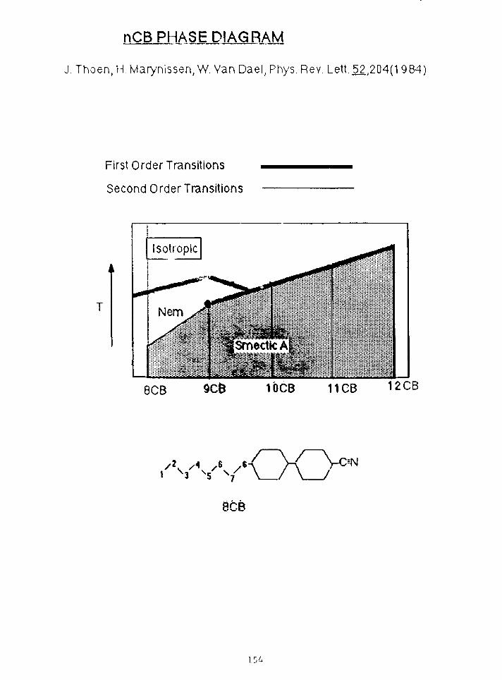
nCB PHASE DIAGRAM
J. Thoen, H Marynissen, W. Van Dael, Phys. Rev. Lett. 52,204(1 984)
First Order Transitions
Second Order Transitions
Isotr opic
llijijiiljiijllljijliijljiiliiiij!
8CB 10CB 11CB 12CB
8CB
154

fkoM TugN
010
10 -
0 0.25 0.50 0.75 1.00 1.25 1.50
is:

Nematic to Smectic-A
exponential density oscillationssin(Qoz + <t>)-exp(-z/^n)
Lorentzian Fourier transform+ (W(Q-Q0 )2 l
isotropic to Smectic-A
Finite number of periods
p(z)
Fourier Transform of Square Wavesinf(Q-Q0>nd/2lsin[(Q-Q0).d/2]
Q-QoV7
156

~ 1
o
o
c
1
-
-
-
-
1
• 1
5V.
i i
4
H
i i
i
•*
4T<
|
1 1
.,2
#
1 1
1
1
|
1
}
l
1 1
-
-
-
":'K-• i
10"5 10"4 10"3 ]0'Z
t = ( T-T IA)/T I f l
L57

2CB—r—i—i—i—i—i—i
: b) ^
u.
a:
: f)
0.50 1.50
158

1 OCR Harvard March 86
: I
-
1CB NSLS nay 86
12CBHosulobOct 85
0 001 0 01 00 0T-TN|CC)
139

ISOTROPIC LIQUID CRYSTAL
p(z) R(Q)/RF(Q)
Sharp Interface
Rough Interface
Diffuse Interface160

AOTREPRODUCED FROM BEST
AVAILABLE COPY
NaSOj
H2O
AOT MICELLE
161
REPRODUCED FROM BESTAVAILABLE COPY

0.05 0.10 0.15 0.20 0.25 a 30
162

CD
CD
in
•
OCM•
CD
in<—*•CD
o
r—i
2:i i
N
a"
CD
inCD
•
CD
CD
163

,- \
0.50 ~
0.25 -
1.25 -
1.00 -
33-75 h
a. 0.50CD
a.
0.25
1.25
LOO
0.75
0.50
0.25
0
0 = 0. 305
0 = 0. 181
U 50Z [A]
1G3 150
If) 4

b)
AOT TAIL
HEAD GROUP
D 2 O
DECANE
Re Rm
165

HYRQCAKBON COATEwith George Whitesides
Self Assembling Monolayers:Cn-Silanes(n=10 ~ 22)
Bei(Q-d)
Density of Si«Density of SiO2Density of (-CH2-)n * 0.43 Density of Si
Without Roughness: A«0.43Boc (1-0.43)
Mimmum=(A-B)2«(l-0.86)2«0.02Maximum«(A4-B)2«l .0
Observed
log(A)or
Minimum/Maximum~0.008B
B rougherthan A
lob(B)
166

IffNSLS Solid Surface Results Oct. 1986
io-3 -
i ,-B -
10-II
I ' ' 1
- %
-—
-
1 • • — 1
Sir———^
«»O o
* •
\
—
1
1 ' 1
a Btre Silicon
A Cw Silane ~
v Cl2 Silane
o Cf- Silanew _
ooBo
O• —
0 0.3 0.6(4ir/X)8in(«) [A -1
0.9
167

Double Bond Termination and Bromination
1 r
0.1
a:
0.01
0.001
15 30 2Si-C..H..CH=CH
0 0.2 0.4 0.6 0.8
q,
J I
1.0
168

PATTERSON FUNCTION
R(6)9
oo
Q=(4n/Wsin(e)
1 ^3p3p(s-z)
169
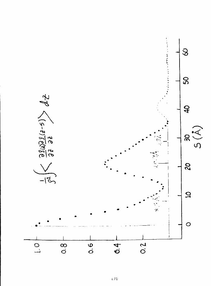
A
o~»t <*k
*•
••
•
t
*•*
«%*
•
** f .
•
*
ft*
ft*
• ' '<
*
Y-
\ 1 J
\ r
i —
oin
od d o d
o
J p
J Q
i 7 0

0.1
en
0.01
f
/
ron Silicon/>
0.001
Fit PedometersSilicon Oxide UA TnickTin Oxide 127A ThickSilicon Oxide Relative Density .95Tin Oxide Relative Density 1.6Si/SiO Roughness 2.3ASiO/SnO Roughness 1.8XSnO/Vocuum Roughness 36.6A
o 0.2 0.4 0.6 0.8 1.0
171

THEORY FOR DIFFUSE (ROUGH) SURFACE
V2E+e(z)k0E=0
i(kvy)E =e yy
[ky2-e(z)ko2] = 0=0
= o
Electron Motion in One Dimensionp2/2m +V(z)=po2/2m
[-po2/2m+V(z)]\|/=OANALOGY
2mV(z)/h2
172

DIFFUSE SCATTERING
da •(QQ^]/dx<h(O)h(x)>ei(k(r'-k°)'X
a
h(x,y)
4 for [a « ec]1 for [a < 6C3
173

to
Ul
I(M
CD
to
Q
I
3d
I
i n n
S0t[ I I I 1 1 t i l H I III nniii I I Ul l l 1 1 1 A 8
£0t 2 0t jQt
33S/S1N3
174

SUMMARYTO DATE: Rotating Anode & Bending Magnet Radiation
SPECULAR REFLECTIVITY OF LIQUID SURFACES:1 - Simple Liquids Roughness2 - Liquid Crystal Induced Layered Structure3 - Micelles Nature of Surface
SOLID SURFACES1 - Silane Coated Si/SiC-2 Thickness
UniformityStructure
2 - SnO2 Buried Surface3 - Glasses Surface Specific Diffuse Scattering
WORK BY OTHERS1 - In Plane Structure of Monolayers on H2O
Als-Nielsen, et al. Phys. Rev.Lett 58,2224(1986)
Dutta, Rice, et al. Preprint (1986)2 - Liquid Metals Rice, Nature, 316,108(1986)
B0310, J. Chem. Phys., 80, 959(1984)
POSSIBILITIES FOR FUTURE: Wiggler Lines, etc.1 - Solids Samples Smaller than Incident Beam2 - Liquid/Solid Interface3 - Small Angle Diffuse Scattering From Liquid Surfaces
Bonse-Hart Crystal Analyzer
175

TIME-RESOLVED MACROMOLECULAR CRYSTALLOGRAPHY*
Kei th MoffatCorne l l U n i v e r s i t y
ABSTRACT
The essential link between macromolecular structure atthe atomic level and biochemical function has proved remarkablydifficult to establish. Although several hundred suchstructures have now been determined through the efforts ofnumerous x-ray crystallographers, the number of well-established mechanisms of action is a great deal smaller. Evenfor those mechanisms that are apparently understood, new in-sights provided by protein engineering have often revealed thelimitations on our understanding.
Why is the structural basis of mechanism so difficult toestablish? I believe that this is due, in large part, to theinability of classical x-ray crystallography to examine short-lived structures, such as catalytic intermediates, orintermediates in ligand binding and release, or in the earlystages of protein unfolding. Many macromolecules are active inthe crystal, and hence structural intermediates do exist andmay be accessible to, for example, spectroscopic probes. Canthey be made accessible to crystallographic probes that willreveal the transient changes in atomic structure directly?Here, the goal is to develop time-resolved macromolecularcrystallography: the technique itself, and the biochemicalsystems to which it may be applied.
Time-resolved crystallography is based on three mainareas. The best time resolution is accessible with the highestincident x-ray intensity, which depends on the x-ray source(for example, undulator vs. wiggler vs. bending-magnet sourcesat the Cornell High Energy Synchrotron Source, CHESS, or theAdvanced Photon Source, APS), on the x-ray optics (for example,focusing vs. nonfocusing), and on the x-ray technique (forexample, polychromatic Laue vs. monochromatic). Second, tech-niques for uniform, rapid reaction initiation throughout thecrystal, such as laser photolysis, pose a major experimentalchallenge. And third, data acquisition and reduction with thenecessary integrating detectors (for example, film or the Kodakstorage phosphor detector) is not straightforward.
The following abstract and copies of viewgraphs were provided by the speaker.
176

The principles of time-resolved macromolecularcrystallography will be discussed and illustrated with examplesof preliminary studies at CHESS and Daresbury.
177

MO
178

O H
oft
179

0
- N fiTx)ft<iL CO -
o< »
e SHOT
1-8 L£ V
180
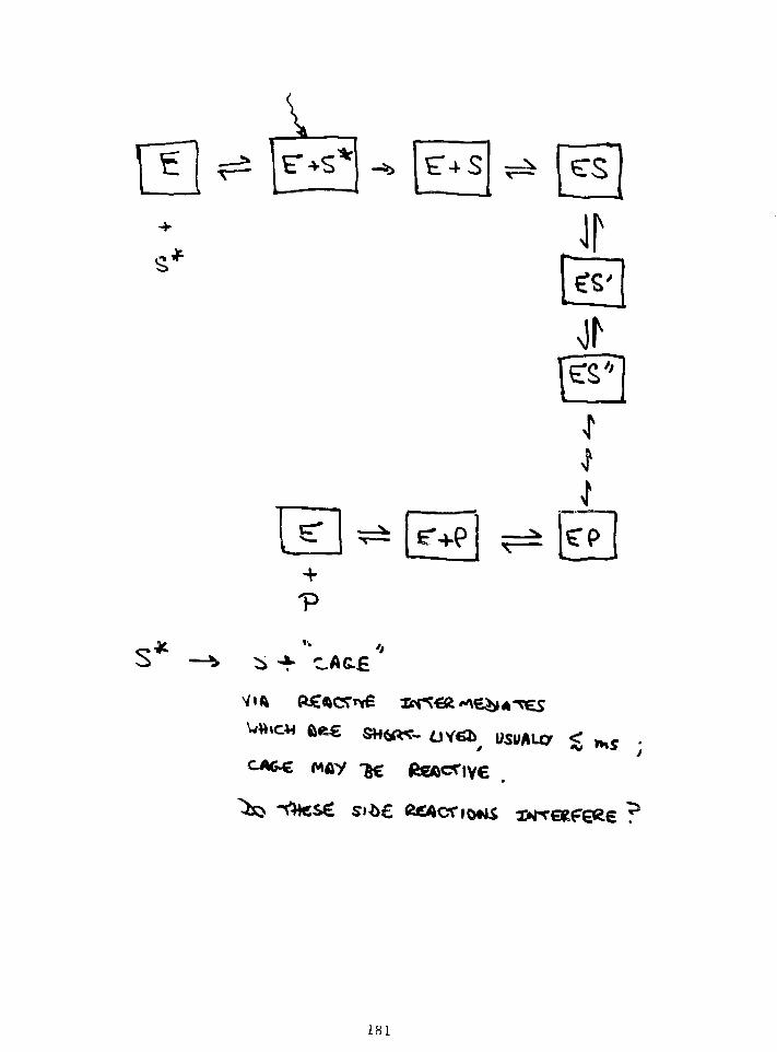
pFV
r+p
ii
181

/,'//
of
L82

of con <=o£->^owS CJ ^ X ^ J . . . Ci
^ ^
183
SMALL
^C -TM£ ^ e f C r ^ C C OP

o
MLC A ^U#*C^«o«4 O^ ALL ^H£ AO
NOW
«o.€ t ^
184

C_( C2L C3
, \ + 4 1 *.•»! - 4,
IS 4 Co€CtfCl£«-T A*— 3
L85

\S A
is it* o^e
I T ^ r CAUSt
is "By
T=
18fa

» S
5TO
S
Z
I.S
UI.O)
I
10
. «f 02.
cm
- H- C-
L87

ftfc IS
A s Avotfll • C C G ^ f i * "8> OPTICS
188

»s
»s
2.2. ^iv
189

V
V -
is
»S
K>
- S I
I s
190

cu
CDCELUZL
-Q/s/d) 33NVIT1IH8

J.S qdCN
O
CDCO
qd
ooCM
qd
qdCD
qd
qd
Of 9 O0'9 O9'5
L92

fc
IOO
-we
is

WORKSHOP REPORTS

X-RAY AND NEUTRON SCATTERING FROM MAGNETIC MATERIALS*
Doon GibbsBrookhaven National Laboratory
On November 6-7, 1987, a workshop was held at Argonne to discuss technicaland scientific advances in the study of magnetic materials by x-ray and neutron scatteringtechniques: the complementarity of the two kinds of probes, their relative strengths, andrecent developments. This was the first workshop, I believe, to combine x-ray andneutron scattering studies of magnetic materials, at least in the context of magnetic x-rayscattering, and it attracted 100 people from all over the world. The meeting organizerswere Jerry Lander, Harold Myron, and myself. The workshop was opened by DavidMoncton, and the first speaker was Ken Kliewer, who discussed the complementarity ofx-ray and neutron scattering.
The first session had as its common denominator surface magnetism andmultilayers. The afternoon session was largely devoted to x-ray and neutron polarizationdependence, with a couple of high-Q resolution talks as well. There were talks on nuclearBragg scattering, and the last session dealt with high-Tc superconducting materials.
I would like now to present a few details about magnetic x-ray scattering per seand indicate some possible uses at the Advanced Photon Source.
In principle, one can separate the orbital and spin densities in an x-ray scatteringexperiment. This is not the case in neutron scattering. There is an interference term thatis nonzero only when the Bragg peaks and the magnetic peaks come at the same positionin reciprocal space, but then something has to be done to extract the magnetic scattering— typically, a magnetic field is introduced. If you align the spin in the direction of thefield, measure the Bragg intensity and then change the field, the spin dependence can beisolated. Thus, one can directly study ferromagnetic structures, as well asantiferromagnetic ones, with x-rays.
I would like to discuss some new results involving polarization dependence andresonance in holmium. If you separately measure the parallel and perpendicularcomponents of a linearly polarized beam incident on a sample, it is possible to separatethe orbital and spin magnetization densities directly. In fact, this applies generally toarbitrary magnetic structures, and it can be done for any incident polarization. Thetechnique is still not sensitive enough to extract the Q dependence of the ratio of orbitaland spin densities in holmium; that situation can be improved by increasing the linearpolarization of the incident beam, something of importance at APS. Most ferromagneticmaterials are studied using circular polarization, so what one would really like to have isa beam line with tunable polarization.
*The summary presented here is based on notes taken at the meeting.
197

A second example involves the energy dependence of the magnetic x-rayscattering cross-section in holmium. There is a 50-fold increase in the scattering intensityat the L3 edge. You also get harmonics at values where the usual picture of holmium'smagnetic structure would forbid them; these are resonance effects. The resonant lineshape is really a probe of excited magnetic states in holmium vs. energy. Results such asthese open up a new range of possible studies.
Synchrotron-based experiments on magnetic x-ray scattering performed in the last15 years have covered a range of materials -- transition metals, rare earths, ironchromium, superlattices ~ and difference techniques — spin-dependent Thompsonscattering, interference techniques, and pure studies of magnetic scattering inantiferromagnetic magnets. High-Q resolution will be at an advantage at the APS. Suchfacilities will also be particularly useful for investigating sensitivity to lattice modulationsin rare earth metals, a unique polarization dependence that allows separation of orbitaland spin densities, and novel resonance and interference effects. The beam is naturallysmall, an advantage in studying small samples. The scattering is so weak there isessentially no extinction in the magnetic scattering. In fact, with properly designed beamlines the incident polarization and energy could be tunable, permitting a whole range ofnew experiments: detailed magnetic structure determinations, separation of spin and orbitin ferromagnets and antiferromagnets, resonant spectroscopy, and possibly even surfacemagnetic x-ray scattering.
198

X-RAY SYNCHROTRONS AND DEVELOPMENT OF NEW MATERIALS*
Stephen Durbin
Purdue University
The Advanced Photon Source Users Organization sponsored a workshop, "X-Ray Synchrotrons and the Development of New Materials," at Argonne NationalLaboratory on December 10-11, 1987. This workshop focused on two issues: (1)how materials research at existing x-ray synchrotrons has advanced theunderstanding and development of new materials and (2) how the Advanced PhotonSource (APS) can be optimized to stimulate the science and technology of new^materials. Presentations described the broad range of materials requiring anx-ray synchrotron source for the investigation of important properties. Muchof the research using synchrotron radiation has been directed toward improvingthe understanding of existing materials and the engineering of new materialswith specific physical properties having technological applications.Discussions of new materia'i-3 that have resulted from synchrotron-radiation-based research (e.g., Fibonacci superlattices, ultra-high pressure phases,catalysts, etc.) indicated that the APS can become an important part of theprocess of developing new materials.
Specific recommendations by workshop participants for materialsresearch on APS beam lines included the following:
• A high-brightness undulator beam line should be dedicated toextremely high-resolution diffraction measurements of singlecrystals.
• A second high-brightness undulator should be dedicated tohigh-resolution powder diffraction measurements to permitstructural determinations of materials that cannot beprepared as single crystals.
• A dedicated wiggler source should provide high fluxes over alarge energy range for extended x-ray absorption fine-structure (EXAFS), surface extended x-ray absorption fine-structure (SEXAFS), and x-ray absorption near edge structure(XANES) spectroscopy. This wiggler source would providemaximum sensitivity for absorption determinations ofelectronic and structural properties for a wide range ofmaterials.
*Summary based on workshop organizers' Executive Summary in "X-RaySynchrotrons and the Development of New Materials: Workshop Report," ArgonneNational Laboratory Report ANL/APS-TM-1 (Feb. 1988).
199

X-RAY SYNCHROTRONS AND NEW OPPORTUNITIESIN THE EARTH SCIENCES*
Joseph SmithThe University of Chicago
On January 18-20, 1988, a workshop entitled "X-Ray Synchrotrons and NewOpportunities in the Earth Sciences," sponsored by the APS Users Organization,Argonne National Laboratory's Division of Educational Programs, and TheUniversity of Chicago, was held at Argonne. The workshop was devoted topresentations in four principal areas of research involving the use ofsynchrotron radiation: (1) x-ray scattering studies, including diffraction,on very small single crystals, powders, noncrystalline materials (glasses,melts, liquids, metamict materials) and mineral surfaces and interfaces, aswell as studies of transient phenomena requiring time-resolved measurements;(2) x-ray scattering studies on minerals and melts at ultra high pressures (upto 500 GPa) and temperatures (up to 7000 K); (3) x-ray spectroscopy studies,including x-ray absorption, emission, and photoelectron spectroscopy, onminerals, melts, glasses, liquids, and interfaces; and (4) x-ray fluorescencemicroprobe analyses of a wide range of natural materials. The first threeareas primarily involve structure-property relationships, while the fourtharea is concerned with compositional variations in solid earth materials.
At the workshop, an organization — named "GeoSync" — was establishedto promote and coordinate research in the geosciences using synchrotronradiation. The establishment of Geosync marks the beginning of what it ishoped will be a very active and productive program for the use of the APS inresearch on earth materials.
Summary based on Executive Summary and Introduction in "Synchrotron X-RaySources and New Opportunities in the Earth Sciences: Workshop Report,"Argonne National Laboratory Report ANL/APS-TM-3 (April 1988).
200

TIME-RESOLVED STUDIES AND ULTRAFAST DETECTORS*
Paul SiglerThe University of Chicago
Participants in a workshop on "Time-Resolved Studies and UltrafastDetectors," held at Argonne National Laboratory on January 25-26, 1988,discussed new avenues in time-resolved research that will be opened by theAdvanced Photon Source (APS). The APS will provide an enormous enhancement inbrilliance over existing x-ray sources, dramatically increasing capabilitiesfor the extension of static x-ray techniques into the time domain, withtimescales from milliseconds to picoseconds. Interest in time-resolvedmeasurements spans the materials and biological sciences, from semiconductorsto metalloproteins, and the whole area represents a major frontier forsynchrotron radiation research. Working groups considered the physicalcharacteristics of the source that would be crucial for successfulexperiments. Also discussed were the experimental difficulties to beovercome, such as uniform excitation of samples and development of improveddetectors. Presentations by detector designers and builders outlined currenttechnologies and indicated future research directions.
One of the most exciting opportunities offered by the new generation ofsynchrotron x-ray sources is the ability to do single-pulse experiments. Suchexperiments are feasible with insertion devices capable of supplying more than10' photons in a single subnanosecond burst at greater than \% bandwidth.Speakers identified electron transfer mechanisms in photosynthetic reactionsand metal-ligand bonding in proteins as examples of areas in which the timestructure of the synchrotron source could be important.
Detector shortcomings appear to be a limiting factor in much of thework now under way at existing synchrotron facilities. Without concertedeffort, detection schemes will be inadequate for taking advantage of the highfluxes and novel temporal characteristics of new sources like the APS.Virtually every workshop speaker remarked on this problem.
Summary based on Abstract and Introduction in "Time-Resolved Studies andUltrafast Detectors: Workshop Report," Argonne National Laboratory ReportANL/APS-TM-2 (Feb. 1988).

REPORTS ON R4D AT OTHERSYNCHROTRON FACILITIES

R&D AT SSRL IN SUPPORT OF THEADVANCED PHOTON SOURCE*
Herman WinickStanford Synchrotron Radiation Laboratory
Many activities at SSRL are relevant to the APS and can therefore beconsidered R&D in support of the APS. This includes work on SPEAR on beamsteering and stability, insertion-device development, and the development ofbeam-line optics and monochromators that can function under high thermalloading.
The work on PEP is even more relevant, because the PEP ring and the twooperational undulator beam lines on PEP can now perform at levels approachingthe performance levels planned for the APS. This talk therefore concentrateson the work done on PEP, particularly the low-emittance 7.1-GeV run that tookplace over December 9-21, 1987. Accelerator physicists from the APS, as wellas from other facilities, participated in this run. The excellent resultsachieved on the run are due to the fine cooperation and contributions of morethan 20 scientists from five laboratories. We look forward to continuedcollaborations in the future.
Recently, a new concept for a reliable, simple, inexpensive vacuumchamber for use with insertion devices was, suggested by Richard Boyce ofSSRL. The concept is being developed in collaboration with James Viccaro ofthe APS. E. Hoyer of LBL and Henry Halama of NSLS are also involved. Thebasic concept is shown in the figures. If such a chamber were successfullydeveloped, it would have a major impact on the effective utilization of theAPS, because it would make large apertures available for injection and smallerapertures for the stored beam, thus facilitating the use of the smallestundulator gaps consistent with good lifetime.
A joint project between APS, SSRL, and also LBL and NSLS is proposed todesign and build a prototype of such a chamber that could be tested in PEPalong with the APS/CHESS 3.3-cm-period undulator.
The following statement and copies of viewgraphs were provided by thespeaker.
205
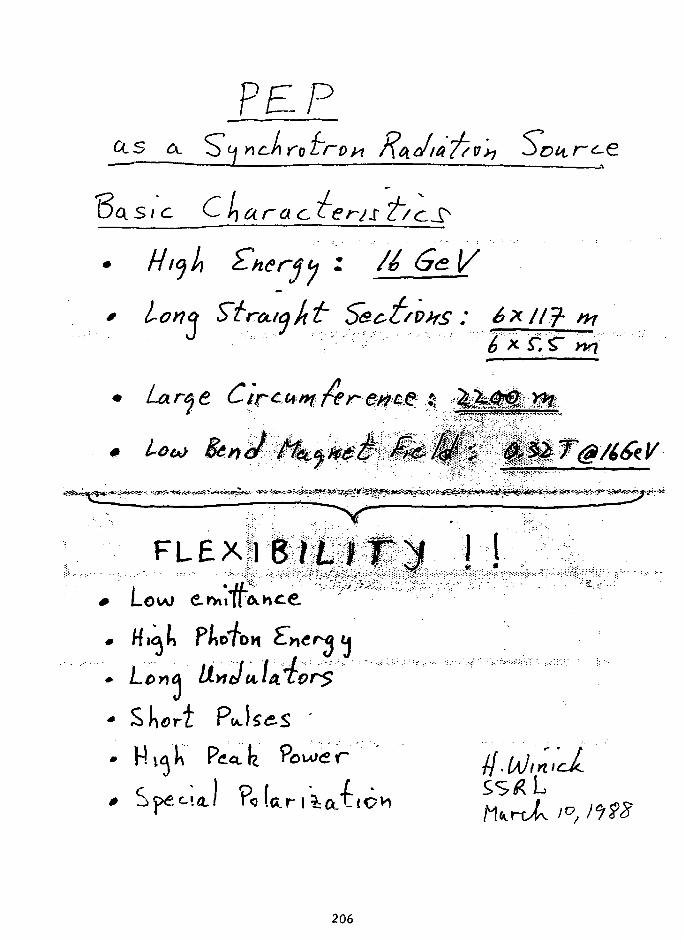
?E /
CLS a.
Hijh
0 LonctJ
. u0 Low
a
J
V
T " • •7*.- . ^ S
\L* iU^M^illiill'Kiil^^ W
f.^J^M\~:!g^aS^&&%^
\ \
Sdort PJlse-S
206

err next"
&
ro
/^ £k
X-
P E I o f f
Capo, hi hries >\ouo and /,as the
on <xs a. St*h c ^ . . J4
Report A I/A / /a /p /J-<3»7 SS £ L
fi£PHOD(iC£D FROM BESTAVAILABLE COP/
207

f\ PS /PEP Cooperation /ColU
l e w Cry? q
• Iest/ y}ct Ynono on
nt
REPRODUCED FRONTBESTAVAILABLE COPY
208

209

PEPLong Straight Sections
(117m)
Uses:
1. Damping Wigglers: Achieve ultra-low emittance ( <10"^ m-rad),highest brilliance, high coherent power (Wiedemann)
2. Long Insertion Devices: e.g. proposed 12 m undulator
3. Chicane Beam Lines: 2-4 beam lines in each long straight
4. Bypass: To accommodate special insertion devices.
Long straight sections of PEP have zero dispersion - no broadening ofsource size due to energy spread ' >
210

CD 0) (0 UJ ro
211

fbw tew cah tl\f ie B<e /
c!
QH
A<JL divert onttO
£*,= V <£>Phofc
JS n IM DTJ lli^nce 01 fh<t "
i f Tie
" V
/o /oo
(nm) /Z.Y /.^y
JO 0.0 i
212

PARTICIPANTS IN THE DECEMBER, 1987 PEPLOW EMITTANCERUN
ADVANCED LIGHT SOURCE (LBD: Alan Jackson, MichaelZisman
ADVANCED PHOTON SOURCE (AND: Stephen Kramer,Moohyun Yoon
NATIONAL SYNCHROTRON LIGHT SOURCE (BNL):Ben Craft, Glenn Decker, John Galayda
SLAC: Matthew Allen, Elliott Bloom, Martin Donald.Ewan Paterson, Jean-Louis Pellegrin, Burton Richter,Leonid Rivkin, Heinz Schwarz
SSRL: George Brown, Roberto Coisson, Robert Hettel,Teresa Troxel, Helmut Wiedemann, Herman Winick
STANFORD/SSRL GRADUATE STUDENTS:Michael Borland, Louis Emery, William Lavender,James Safranek, Wanfen Xie
213

Low £wil1UhC<L PEP
op tics
m-t~Q.a ; /)er/H4/
Cu.rr£hL
3 3 AI A ) *y) *nm
j 2-3 AoM.rs
It mi TS ; ^to r-oust,
Commits zoned Z Undulamr o&t»{ /the.knJer
Ci/ptt~ciAt~t ef
214

HONOCHROHATORCRYSTALS(56 meters)
PIN HOLESCANNER(58 meters)
CHAMBER
Be WINDOWS(54 meters)
UNDULATOR(0 meter)
PIN HOLE PLATE(34 meters)
RecorderAmplifier
EXIT PORT(18 meters)
i 1-7-E

> -,
912
INTENSITY (ARBITRARY UNITS)
r..
n
v>C
C; o
INJ
o
CDm>
uo
m

LU
ci
O
M>
o
c
; £ 1 I N I , . 'H
217

218

Cs,
<L) a -
I «V
: l • l I l I I I I I 1 1 i ! — I ! 1 L-
inru
, . J I,\l . 'HV-HliqHV; ,i i l . . !s;qj r-
219

8
100
r. ViccA-ro
= 26
20

PEP/8 GeV/lW #»A/LEO/Nd-Fc-B 3 3 cm/N = 60

' OPEN POSITION (20 mm).787
/•'"*:?&•
i>^||iii|.ip:( 88 jm};:.'-'**r-V^f--'--.''vJ-^l|"-"si •• I 1 P
• . * • . u * 4 ' I I «K « • • ^ l~> I ^B I J M «IB>
CLOSED POSITION(11 mm)
.434
1T
(91.54 mm
222

223

fL UperL f f'£'/y
Dettrm meJ h^ E>*d<^eL
Up to ?~ $ tnontiis/ur parasitic
2-3 *nonths/yr c/edr£<z ired
clement Icj E. Rtcttcr a£ PEP
Hear term pUh
- Novemberj /9ft;
224

Future J)/Vcctio^s To
flPS, ESRF_
5" x. 10Provide. /£> '*- SO J? kv<t
/ar-fie User Commit??/ to er\
PrvviJt rcli&hU J stctlft of>ar-a'('ioh*r\4.yiu hours /ue.a.r,
J[ - larae £ /& colliders as<ta as.J J P
/o• Could prvvjJe ^ S*?c
* Gain car/w &x ptricuce. Mich /O ~/0
le.vc.1 of brthi
fo
n<k strongh£
225

CHESS SUPPORT FOR APS*
Michael BedzykCornell University
From CHESS: From ANL:
D. Bilderback G. ShenoyC. Henderson R. SmitherM. Bedzyk J. ViccaroQ. Shen D. MonctonD. Mills* .. D. Mills*K. FinkelsteinW. SchildkampB. Batterman
From CESR:
E. BlumD. Hartell
The following copies of viewgraphs were provided by the speaker.
*On leave from CHESS, Cornell University.
226

222OSS7-OIS
CleclromogntlWiQQler(6P04«l
j
Syndvotro*
Southcost
SouthInteraction RtgionCESR Slorogt
Ring
CHCSSSoppofl Aft«
CUR !u*»«t Arto
Sch(im*tlc of the synchrotron radiation facility shown Inrotation to the high energy experimental halls. The presentsynchrotron radiation beam)I ties and support area are denotedas CHESS West. The new CHESS East development will occupyfloor space Just to the East of the South Interaction Region.

to
oo
Layout of CHESS East thawing lource andbaamltnes. Synchrotron radiation fromHard (lend Hagnat 7 East end a permanentmagnet wlflgler ara the sources for thaAlpha Una. Tha Gama Una racalvas Itsradiation from Hard Band Hagnat 5 last.
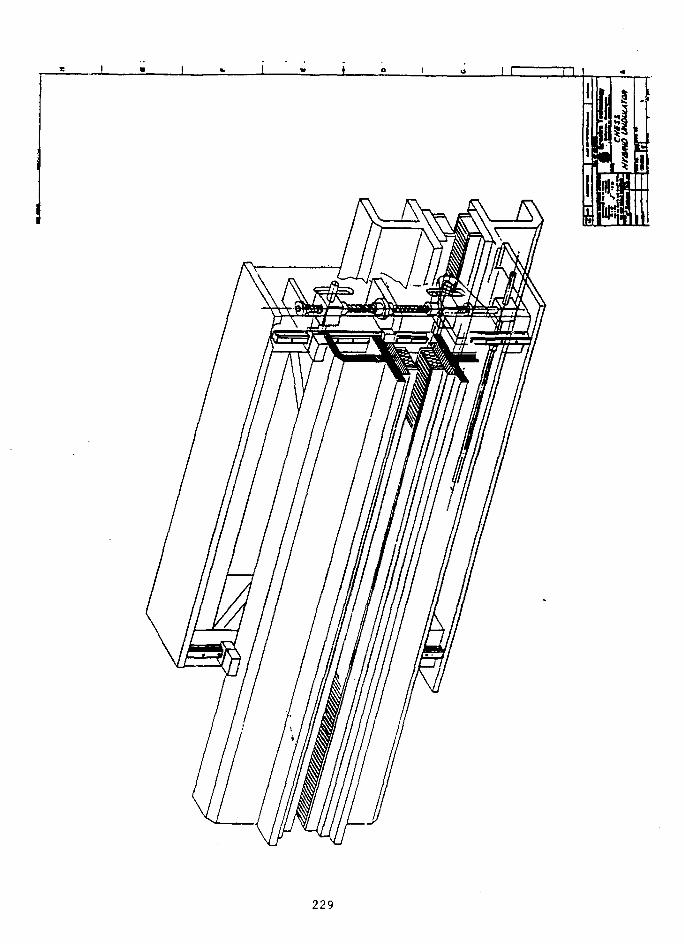
229

J{ -{
230

I
REPRODUCED FROM BESTAVAILABLE COPY
231

232

Iro c»•tf cr>
coCOLJa:i -CO
~Z. ZL •• O
II IIILttO.
• 00 t-i •- ^ G1 O ©LO CU CD CO • CO l -< J d"
• If) II • • C\J Tx D II II III • • ^ [ - • • ^ l U J I X f O ^ ^ PII II II CO II II II CJ) II II O — 2
COcct
Q Q
CDC DC3CCL_
233

" t
234

Cs
(4U £3'3
1-3
/oo
-2.OO*
1$*1100°

R&D EFFORTS AT BML IM SUPPORTOF THE ADVANCED PHOTOS SOURCE*
Peter StefanBrookhaven National Laboratory
The following copies of viewgraphs were provided by the speaker.
236

ffFORTS AT
/A/ SUPPORT or r#? APS
i. srup/ss OF cxysrAi COOUA/6
pos/r/o/Y Afow/ro* AA/O
V /?£S/6A/ sroo/es OP sy/r
237

WO/?/rS//0fiS AA/D£FfOHTS
AWl, BA/L, CHSSS, EXXON, LBL
PARTICULAR BA/l CO//r/?/3(jr/OA/S ;
2. SAW- c UT c/?ysr/)i- COOL/A/C
238

VJ
239

ts.V)
r!
o
240

pos/r/o/i/
C JOhW
COW EX *£SOlC/r/OAf
(A/SIS
241

O/?B/r Wl/
C y o )
I. PfiOlX/CFS /I 61O&J9C C €>/?/?fC7/0A/
3. fi£GV//f£f LOW
3, MUCH LESS S£tfS/r/l'£ TO"TM£*
242

Stf/IU - CAP MSf/fF/OA/
MINIMUM GAP, AA/D
X.COA/STXVCT AA/O rSST S/1411-6AP
3. /F WAfi/fA#r£D, COA/sr/fl/cr /I0£WC£
243

SI OT
START OF B6//O \
CROSS S€Cf/(>N
(SOS///I
OLP
v/>0
NEW
{\iACO0M)
- 6063
- MOV£
~S0% MP/?OVFAf£A/r /A/
L/M/T.
244

BUSINESS MEETING OF THE ADVANCED PHOTON SOURCEUSERS ORGANIZATION
The annual meeting of the Advanced Photon Source Users Organization was called toorder at 11:15 a.m. A set of bylaws proposed for the Organization was adopted (seefollowing page).
Walter Trela summarized the recommendations from the APSUO SteeringCommittee's review of the APS program, together with the Argonne APS team'sresponse. The Committee had recommended that tha shield-wall design be modified tokeep the wall as close to the source as possible; this has been done. Previous designs foruser laboratory/office modules were not what the users wanted, and the design of thesemodules has been modified. The expected quality of the experiment area was alsoimproved, in terms of noise control and the ambience on the experiment hall floor.
Trela noted that Argonne was extraordinarily open to user input, giving future usersan unprecedented opportunity to have their voices heard. All good suggestions wereimplemented. It will be the users' responsibility, said Trela, if they are not happy whenthe APS is finished, because the opportunity existed to be heard. He concluded bythanking David Moncton, Gopal Shenoy, and the other ANL staff for their contributionsto the project and the meeting.
The floor was declared open for nominations to fill an opening on the APSUOSteering Committee. (The bylaws adopted earlier provide for half of the Committee tobe elected yearly, with two-year terms. It was agreed that the present membershipwould stand through the present meeting; the nominations were to fill a vacancy.) Thoseaccepting nomination were Howard Birnbaum, University of Illinois; Stephen Durbin,Purdue University; and Stuart Rice, The University of Chicago. The Committee electedStephen Durbin.

ADVANCED PHOTON SOURCE USERS ORGANIZATION BYLAWS
I. NAME
This organization will be called the Advance:; Photon Source UsersOrganization (APSUO).
II. PURPOSE
The purpose of this Organization is to facilitate the availability andeffective use of the Advanced Photon Source by the synchrotron radiationresearch community so that the greatest overall scientific and technicalbenefits are realized.
III. ORGANIZATION
Membership - All APS users or potential users are eligible to be votingmembers.
Meetings - An Annual Meeting of the membership will be held at the APSsite. The agenda and brief summaries of discussion items will be postedat the APS and circulated one month in advance of the meeting. Theminutes of the meeting will be circulated within two months after themeeting.
Steering Committee - A Steering Committee will be elected to conduct thebusiness of the APSUO. This Steering Committee will consist of 12members plus the Past Chair. Six members will be elected each year fora two year term. Elections will occur at the Annual Meeting. Interimappointments, if required, will be handled by the Chairman.
Officers - The officers shall be elected by the Steering Committee fromits membership for a one year term. The officers of the Organizationwill be a Chair and a Vice-chair. The Vice-chair will succeed the Chairat the end of the Chair's term. The Chair will remain as an ex-officiomember of the committee for the following year. Administrative andfinancial support will be provided by Argonne National Laboratory.
Officers' terms on the Steering Committee shall be extended as needed toperform the above services.
Steering Committee Meetings - The Steering Committee shall meet at thetime of the Annual Meeting and at such other times as called for by theChair or by a majority of the Steering Committee membership. A quorumconsists of a majority of the Steering Committee membership.
247
IV. FUNCTIONS
The APSUO shall be advisory to the Director of the Advanced PhotonSource.
o The Organization will serve as an advocacy group for the Facility.
o The Organization will provide advice to the Director on mattersaffecting the user community.
o The Organization will assure good communication between the APS usercommunity and the APS management.
V. AMENDMENTS
These bylaws shall be amended by a favorable vote of two-thirds of themembers participating in the business part of an Annual Meeting.
Adopted:
248

DISCUSSION OF APS USER ACCESS POLICY
Jerome Cohen (Northwestern University) started the discussion, notingthat the users organization for the APS project was started in the Midwest 5jyears ago. This is only the second meeting of the present organization.Cohen said that Katherine Cantwell chairs the Steering Committee'ssubcommittee on user access policy. This summer, the subcommittee willtransmit a letter to Argonne advising it of proposed policies, and inSeptember 1988 the question of user access policy will be taken up by the fullSteering Committee. The Laboratory management will be asked to come to thenext APSUO Steering Committee next spring with a policy.
Cohen said there are two issues: what the user policy should be andhow the policy should be reviewed.
Katherine Cantwell (SSRL) presented an overview of a variety ofapproaches considered by the subcommittee. These approaches, framed in termsof "Cooperative Access Teams" (CATs), were as follows:
o Standard CATsA-CATs — Investigators cooperating on the basis of a
common scientific purposeB-CATs — Investigators cooperating on the basis ofpooled resourcesC-CATs — Investigators working without the need forcooperation beyond their own organization ("FAT CATs")
o Supported (S-) CATs — facility owned and operated; facilityowned and user-operated
o Rapid Access to Technology (RAT-) CATs — beam linesavailable for fast, short-term access
o Academic CATs — 50£ ANL appointments
o Venture CATs — Fee-for-service beam-line operations (e.g.,"mail-order" EXAFS)
o Mil-CATs — Classified research
Kantwell said the subcommittee is interested in hearing ideas for other typesof access over the next six months.
Michael Knotek (NSLS) said there are two major time periods to consider— getting established and operations. He listed steps to use in formulatingthe type of CAT one might fit:
249

Stage People and Resources
1. Goal setting and funding Scientific and administrative2. Design Scientific, instrumentation,
and engineering3. Engineering Engineering, design, and
service4. Procurement and fabrication Industry, shops5. Assembly Technical and engineering
resources6. Commissioning Scientific and technical7. Operation Scientific, technical, and
administrative
Management of the APS must make sure everything is covered, so that facilityusers and industry support come on line smoothly. Early planning and closecoordination will be necessary.
David Moncton (APS) summarized projected costs of the initial beam-linedevelopment plan for the APS. Plans call for setting aside a $40-million"trust fund" for the initial (Phase 1) beam lines. He said the "entry-level"cost for an undulator beam line is expected to exceed $3 million. The APSUOwill try to help collaborative teams get started. It is proposed that $20million from the trust fund be used to complete eight beam lines (projectfunded and staffed by collaborative teams); this includes the USARprofessorships. The remaining $20 million would be used to build variousinsertion devices and front ends, with collaborative teams paying fordownstream components outside the shield wall; this would result inapproximately another ten beam lines being made available.
Moncton described the sector-management concept, in which eachcollaborative team would be responsible for a sector (one insertion-devicebeam line and one bending-magnet beam line, treated as a unit); thecollaborative teams could be of various types. He also said proposals for useof the APS should be based on scientific content, competence of theresearchers, a management plan, and periodic reviews.
Boris Batterman (CHESS) said an example of the "S-CAT" exists right nowat CHESS, where a small laboratory has total ownership of the beam lines andpartial use. He cited an NIH-supported biomedical resource as an example ofan S-CAT supported by a third party; this resource exists specifically topromote protein crystallographic research at CHESS. A second, formative S-CATat CHESS is the National Facility for High-Pressure Research. Batterman hascommitted half time on one beam line for this facility, which is funded for acombination of geoscience experiments.
Robert Broach (Allied Signal Corp.) noted that most industrial users ofNSLS beam lines are operating with multiple (four to seven) partners. Broach
250

discussed CAT concepts with respect to the needs of industry. The kinds ofaccess of interest to industry include wholly owned, shared, V-CATs, RAT-CATs,and general user access. Whooly owned lines offer the greatest ease of usefor a company, but they also have the highest capital cost. Sharing beamlines is less costly but harder to manage.
Jerome Cohen concluded the subcommittee's presentation, discussing (1)decisions on allowing collaborators to use equipment and (2) Academic CATs, anapproach he hopes Argonne will pursue. With Academic CATs, funding would beprovided on a 50/50 basis by the Laboratory and the experimenter's universityfor a faculty position.
General Discussion
Question: In forming and managing cooperative teams, any group wouldneed access to a bending magnet (BM) beam line. Insertion devices (IDs) andbending magnets are tied together in the scheme outlined here. How would timebe split between ID and BM lines? Would separate proposals be needed for theID and BM beam lines?
Answer: A possible solution would_be for the Argonne/APS management toarrange that two or three BM lines would be available to ID teams forpreparation; BMs are a valuable resource.
Comment (Joe P.): I suggest we think about the division of labor.What percentage of the facility resources should go into providing advice ondesign and what percentage into construction of beam lines? On the one hand,it's not advisable for the facility to own every beam line; the other extreme,letting people build whatever they want, is also not the best policy. Carefulthought is needed =ibout the facility's role as a coordinator.
Ques. (S. Durbin): This trust fund concept sounds like we're creatinga new funding agency, to which one could send proposals instead of to NSF orDOE. How would these proposals be reviewed, and what would be the role of NSFand DOE?
Ans. (Cohen): The trust fund is not intended to serve as a fundingagency; it is to be a source of money to help build some beam lines.
Ques. (Paul Heiney): With regard to the funding issue, we're talkingabout 100 beam lines eventually, at about $3 million apiece. Where's themoney coming from? There may be some FAT CATs, but a lot of the funding willhave to come from DOE and NSF -- are they ready to make that kind ofcommitment?
Ans. (Cohen): With bottom-driven organizations, good proposals will befunded. Another place to look is centers for particular kinds of research —for instance, Stanford has a center that's funding a beam line.
Ques.: Could the trust fund be considered as a source of matching
251

funds? Will it be expanded later on, or is it a case of being first with themost? Could trust fund money be used to pay part of tb>- cost on jointdevelopment efforts for IDs?
Ans. (Cohen): These are already matching funds. As for the chance forexpansion, this is a new approach Dave Moncton has worked out to make asizable chunk of money available; we have to consider carefully how people arechosen, what the selection rate should be.
(D. Moncton): We're talking about $140 million for beam lines, which with twophases give about $80 million. This is perhaps a factor of two greater thanat NSLS.
Norm: Longevity of ownership of beam lines, periodic review of proper use of
beam lines.
Cohen: In a proposal, high-quality science will enable you to get the fundsyou need. Don't scrimp — plan appropriately.
252

USER SUBGROUP DISCUSSIONS
Meeting participants were invited to take part in user subgroupdiscussions under various topical headings at a working lunch on Thursday, 10March. Subgroup topics are listed below:
o Absorption spectroscopies
o Dynamical diffraction
o Earth sciences
o Inelastic scattering
o Macromolecular crystallography
o Magnetic scattering
o Microtomography
o Small angle
o Surface studies
o Topography
Persons interested in the conclusions reached by the various user subgroupsshould contact the APS User Administrator, Elizabeth Stefanski.

PROGRAM

SECOND USERS MEETING
FOR THE ADVANCED PHOTON SOURCE
March 9-10, 1988Argonne National Laboratory
Argonne, IllinoisBldg. 362 Auditorium
Wednesday, March 9, 1988
Morning Session: Status Reports on the Advanced Photon Source
8:15 a.m. Registration and Coffee
9:00 a.m. Welcoming Remarks
Alan Sehriesheim, Director, Argonne National LaboratoryCongressman Harris Fawell, House Science and TechnologyCommittee
Donald K. Stevens, Associate Director for Basic EnergySciences, Office of Energy Research, DOE
John Straus, Executive Director, Illinois State Governor'sCommission on Science and Technology
Walter Trela, Chairman of the Steering Committee of the APSUser Organization
10:00 a.m. Advanced Photon Source Project Overview
David Moncton, Interim Director, Advanced Photon Source
10:30 a.m. Break
CHAIRMAN Walter J. Trela, Los Alamos National Laboratory
11:00 a.m. APS Accelerator DesignYang Cho, Associate Division Director, Advanced Photon Source
11:30 a.m. Energy and Time Structure of Photons from the APS InsertionDevicesGopal Shenoy, Associate Division Director, Advanced Photon Source
12:00 noon APS Conventional Facilities OverviewMartin Knott, Advanced Photon Source
12:30 p.m. No-host Lunch, Argonne Cafeteria,Bus transportation from Bldg. 362
1 ;i45 p.m. Buses return to Bldg. 362
257

Afternoon Session: Frontiers in Synchrotron ApplicationsCHAIRMAN: Paul M. Horn, IBM T.J. Watson Laboratory
2:00 p.m. Millisecond-Resolution Scattering Studies of Phase TransitionKineticsBrian Stephenson, IBM T.J. Watson Lab, Yorktown Heights, N.Y.
2:30 p.m. Synchrotron X-Ray MicrotomographyKevin D'Amico, Exxon Research and Development, Annandale, N.J.
3:00 p.m. Liquid and Solid SurfacesPeter Pershan, Harvard University, Cambridge, Mass.
3:30 p.m. Time-Resolved Macromolecular CrystallographyKeith Moffat, Cornell University, Ithaca, N.Y.
4:00 p.m. Tour of the Mock-Up of the APS Storage-Ring Sector and LaboratoryReception
5:30 p.m. Board Buses for Chicago Museum of Science and Industry
6:30 p.m. Cocktails and Dinner at the Museum Sponsored by the Universityof Chicago
After dinner speaker: Kazutake Kohra, Executive Director,Foundation for Promotion of High Energy Accelerator Science
10:00 p.m. Buses return to Willowbrook Holiday Inn and Argonne
Thursday. March 10, 1988
Morning Session: APS Workshop Reports and User ActivitiesCHAIRMAN: David Lynch, Ames Laboratory
8:30 a.m. X-Ray and Neutron Scattering from Magnetic Materials,November 6-7, 1987, Doon Gibbs, Brookhaven National Laboratory,Upton, N.Y.
8:?0 a.m. X-Ray Synchrotrons and the Development of New Materials,December 10-11, 1987, Stephen Durbin, Purdue University,West Lafayette, Ind.
9:10 a.m. X-Ray Synchrotrons and New Opportunities in the Earth Sciences,January 18-20, 1988, Joseph Smith, University of Chicago,Chicago, 111.
9:30 a.m. Time-Resolved Studies and Ultrafast Detectors, January 25~26,1988, Paul Sigler, University of Chicago, Chicago, 111.
9:50 a.m. Reports on R&D at other Synchrotron Facilities in Supportof the APS
10:45 a.m. Break
258

CHAIRMAN: Walter J. Trela, Los Alamos National Laboratory
11.-15 a.m. APSUO Business Meeting/Report of APSUO Steering Committee
11:30 a.m. Election of New Steering Committee Member
11:40 a.m. Discussion on APS User Access Policy
12:^0 p.m. No-host Working Lunch of User Subgroups at the Cafeteria,Bus transportation from Bldg. 362
2:00 p.m. Buses return to Bldg. 362
2:30 p.m. Bus departs for 0'Hare Airport
APSUO STEERING COMMITTEE:B. W. Batterman (CHESS)A. Bienenstock (SSRL)R. W. Broach (Allied-Signal)K. Cantwell (SSRL)R. Clarke (Michigan)J. B. Cohen (Northwestern)P. Eisenberger (Exxon)K. Hodgson (Stanford)P. M. Horn (IBM T.J. Watson Lab)M. L. Knotek (BNL)D. W. Lynch (Ames)D. McWhan (AT&T Bell Labs)K. Moffat (Cornell)R. Siemann (Cornell)W. J. Trela (LANDJ. H. Weaver (Minnesota)
Co-Chairmen:Paul M. Horn (IBM T.J. Watson Lab)David W. Lynch (Ames)
Local Organizing Committee:Bonnie Meyer (ANDHarold W. Myron (ANL)

PARTICIPAHTS
261 - -.*>

Charles W. AllenMaterials Sciences DivisionArgonne National LaboratoryBuilding 2129700 South Cass AvenueArgonne, IL 60439
Donald P. AmesMcDonnell Douglas Research
LaboratoriesP.O. Box 516St. Louis, MO 63166
Ercan E. AlpAdvanced Photon SourceArgonne National LaboratoryBuilding 3609700 South Cass AvenueArgonne, IL 60439
Joseph AsburyOffice of the DirectorArgonne National LaboratoryBuilding 2019700 South Cass AvenueArgonne, IL 60439
Massimo Altarel1iEuropean Synchrotron Radiation FacilityAvenue des MartyrsB.P. 220F-38043 Grenoble CedexFRANCE
Samuel D. BaderMaterials Science DivisionArgonne National LaboratoryBuilding 2239700 South Cass AvenueArgonne, IL 60439
Ivars AmbatsHigh Energy PhysicsArgonne National LaboratoryBuilding 3609700 South Cass AvenueArgonne, IL 60439
William A. BassettGeological SciencesCornell UniversityShee HallIthaca, NY 14853
Marcianne AmbatsAdvanced Photon SourceArgonne National LaboratoryBuilding 3609700 South Cass AvenueArgonne, IL 60439
Bob BattermanCornell University/CHESS210A Clark HallIthaca, NY 14853
263

David BauracOffice of Public AffairsArgonne National LaboratoryBuilding 2019700 South Cass AvenueArgonne, IL 60439
Floyd Carse Bennett, Jr.Advanced Photon SourceArgonne National LaboratoryBuilding 3609700 South Cass AvenueArgonne, IL 60439
Laurence BeaulaigueMaterials Science DivisionArgonne National LaboratoryBuilding 2239700 South Cass AvenueArgonne, IL 60439
Mark BenoChemistry DivisionArgonne National LaboratoryBuilding 2009700 South Cass AvenueArgonne, IL 60439
Michael BedzykCornell University/CHESS200L Wilson LaboratoryIthaca, NY 14853
Gordon BerryPhysics DivisionArgonne National LaboratoryBuilding 2039700 South Cass AvenueArgonne, IL 60439
Ali BelkacemPhysics DivisionArgonne National LaboratoryBuilding 2039700 South Cass AvenueArgonne, IL 60439
Donald BilderbackCornell University/CHESS200L Wilson LaboratoryIthaca, NY 14853
Ralph BenbowDepartment of PhysicsNorthern Illinois UniversityDeKalb, IL 60115
John C. BilelloSchool of Engineering & Computer SciencCalifornia State UniversityE100AFulierton, CA 92634
264

Howard K. BirnbaumMaterials Research LaboratoryUniversity of Illinois104 South Goodwin AvenueUrbana, IL 61801
J. Mati BlochMaterials Sciences DivisionArgonne National LaboratoryBuilding 2239700 South Cass AvenueArgonnne, IL 60439
Robert C. BirtcherMaterials Science DivisionArgonne National LaboratoryBuilding 2129700 South Cass AvenueArgonne, IL 60439
Martin BlumeDeputy DirectorBrookhaven National LaboratoryUpton, NY 11973
Bruce M. BiwerChemical Technology DivisionArgonne National LaboratoryBuilding 2059700 South Cass AvenueArgonne, IL 60439
Thomas M. BohanonDepartment of Materials Science
and EngineeringNorthwestern UniversityEvanston, IL 60201
Richard BlaskieAdvanced Photon SourceArgonne National LaboratoryBuilding 3629700 South Cass AvenueArgonne, IL 60439
Ira BornsteinReactor Analysis & Safety DivisionArgonne National LaboratoryBuilding 2089700 South Cass Avenue'Argonne, IL 60439
Allen Edward BlaurockTechnology CenterKraft, Inc.801 Waukegan RoadGlenview, IL 60025
Jim F. BridgesAdvanced Photon SourceArgonne National LaboratoryBuilding 3609700 South Cass AvenueArgonne, IL 60439
265

Robert W. BroachAllied Signal EMRC50 East Algonquin RoadDes Plaines, IL 60017
Frank BrumwellIntense Pulsed Neutron SourceArgonne National LaboratoryBuilding 3609700 South Cass AvenueArgonne, IL 60439
Merwyn B. BrodskyMaterials Science DivisionArgonne National LaboratoryBuilding 2239700 South Cass AvenueArgonne, IL 60439
Bruce BunkerDepartment of PhysicsCollege of ScienceUniversity of Notre DameNotre Dame, IN 46556
Bruce S. BrownIntense Pulsed Neutron SourceBuilding 360Argonne National Laboratory9700 South Cass AvenueArgonne, IL 60439
Bob BurkeRocketdyne6633 Canoga AvenueCanoga Park, CA 94703
Gordon E. Brown, Jr.Department of GeologyStanford UniversityStanford, CA 94306
Brent ButlerDepartment of Materials Science
and EngineeringNorthwestern UniversityEvanston, IL 60201
Sandra BrownAdvanced Photon SourceArgonne National LaboratoryBuilding 3609700 South Cass AvenueArgonne, IL 60439
Fred A. CafassoChemistry DivisionArgonne National LaboratoryBuilding 2009700 South Cass AvenueArgonne, IL 60439
266

Juan Carlos CampuzanoMaterials Science DivisionArgonne National LaboratoryBuilding 2239700 South Cass AvenueArgonne, IL 60439
Stephen Howard CarrNorthwestern University2145 Sheridan RoadEvanston, IL 60208
Katherine CantwellStanford Syncrotron Radiation
LaboratoryStanford UniversitySLAC, BIN 69P.O. Box 4349Stanford, C/\ 94305
Kathleen A. CarradoChemistry DivisionArgonne National LaboratoryBuilding 2009700 South Cass AvenueArgonne, IL 60439
T. Weston CapehartPhysics DepartmentGeneral Motors Research LaboratoryWarren, MI 48090-9055
Donald Andrew CarterOptic-Electronic Corp.11545 Pagemill RoadDallas, TX 75243
G. Slade Cargill, IIIIBMP.O. Box 218Room 30-060Yorktown Heights, NY 10598
Karen ChapmanSynchrotron Radiation CenterThe University of Wisconsin3731 Schneider DriveStoughton, WI 53589-3097
David W. Carnegie, Jr.MaqnquenchDivision of General Motors6435 South Scatterfield RoadAnderson, IN 46011
Haydn ChenUniversity of IIlinois1304 West Green StreetUrbana, IL 61801
267

Jie-Nan ChenChemistry DivisionArgonne National LaboratoryBuilding 2009700 South Cass AvenueArgonne, IL 60439
Chang Chong-HwanBiological, Environmental &Medical Research
Argonne National LaboratoryBuilding 2029700 South Cass AvenueArgonne, IL 60439
Chann ChengMaterials & Components TechnologyArgonne National LaboratoryBuilding 2239700 South Cass AvenueArgonne, IL 60439
Weiren ChouAdvanced Photon SourceArgonne National LaboratoryBuilding 3609700 South Cass AvenueArgonne, IL 60439
Tai-Chang ChiangPhysics DepartmentUniversity of Illinois1110 West Green StreetUrbana, IL 61801
Krishna M. ChoudharyMaterials Science & Engineering Dept.University of Notre DameBox ENotre Dame, IN 46556
William ChildsPhysics DivisionArgonne National LaboratoryBuilding 2039700 South Cass AvenueArgonne, IL 60439
Jerome B. CohenThe Technological InstituteNorthwestern University2145 Sheridan RoadEvanston, IL 60208
Yanglai ChoAdvanced Photon SourceArgonne National LaboratoryBuilding 3609700 South Cass AvenueArgonne, IL 60439
Richard ColeSynchrotron Radiation CenterThe University of Wisconsin3731 Schneider DriveStoughton, WI 53589
268

J. M. CollinsPhysics DepartmentMarquette UniversityMilwuakee, WI 53233
Am it DasGuptaU.S. Department of Energy-CHBuilding 2019800 South Cass AvenueArgonne, IL 60439
Joseph M. CookAdvanced Photon SourceArgonne National LaboratoryBuilding 3609700 South Cass AvenueArgonne, IL 60439
Joanne I. DayHigh Energy PhysicsArgonne National LaboratoryBuilding 3629700 South Cass AvenueArgonne, IL 60439
Dennis CrossleySynchrotron Radiation CenterThe University of Wisconsin3731 Schneider DriveStoughton, WI 53589-3097
James A. DePadroBiological, Environmental &Medical Research
Argonne National LaboratoryBuilding 2029700 South Cass AvenueArgonne, IL 60439
Robert DalyElectronics DivisionArgonne National LaboratoryBuilding 2229700 South Cass AvenueArgonne, IL 60439
George D. DudaOffice of Health and
Environmental ResearchU.S. Department of EnergyER-72 GTNWashington, DC 20545
Kevin D'AmicoExxon Research & Development CompanyRoute 22 EastClinton TownshipAnnandale, NJ 08801
Robert DunfordPhysics DivisionArgonne National LaboratoryBui iding 2039700 South Cass AvenueArgonne, IL 60439
269

Stephen M. DurbinPhysics DepartmentPurdue UniversityWest Lafayette, IN 47907
John EricksonAbbott LaboratoriesD-47EAbbott Park, IL 60064
Pulak DuttaDepartment of PhysicsNorthwestern UniversityEvanston, IL 60208
John FaberMaterials Science DivisionArgonne National LaboratoryBuilding 2129700 South Cass AvenueArgonne, IL 60439
James C. EhrhardtDepartment of RadiologyUniversity of Iowa HospitalIowa City, IA 52242
Harris W. FawellU.S. House of Representatives318 Cannon House Office BuildingWashington, DC 20515-1313
Peter M. EisenbergerExxon Research & Engineering CompanyRoute 22 EastClinton TownshipAnnandale, NJ 08801
Mohamed FiazMaterials Science DivisionArgonne National LaboratoryBuilding 2239700 South Cass AvenueArgonne, IL 60439
Ernest EppersonMaterials Science DivisionArgonne National LaboratoryBuilding 2129700 South Cass AvenueArgonne, IL 60439
Thomas H. FieldsHigh Energy PhysicsArgonne National LaboratoryBuilding 3629700 South Cass AvenueArgonne, IL 60439
270

Adriano FilipponiSynchrotron Radiation CenterThe University of Wisconsin3731 Schneider DriveStoughton, WI 53589
Jay D. GellerQuality Assurance, Environment& Safety Office
Argonne National LaboratoryBuilding 2019700 South Cass AvenueArgonne, IL 60439
Gary L. Find leyCAMD ProjectLouisiana State University16 Fraternity LaneBaton Rouge, LA 70803
Donald GemmellPhysics DivisionArgonne National LaboratoryBuilding 2039700 South Cass AvenueArgonne, IL 60439
Kenneth D. FinkelsteinWilson LaboratoryCornell University/CHESSIthaca, NY 14853
Joe GeorgopoulosDepartment of Materials ScienceNorthwestern UniversityEvanston, IL 60201
Frank Y. FradinOffice of the DirectorArgonne National LaboratoryBuilding 2219700 South Cass AvenueArgonne, IL 60439
Doon GibbsBrookhaven National LaboratoryBuilding 510BUpton, NY 11973
Marc Anthony GalloAdvanced Photon SourceArgonne National LaboratoryBuilding 3609700 South Cass AvenueArgonne, IL 60439
Jules B. GodelNSLSBrookhaven National LaboratoryBuilding 510EUpton, NY 11973
271

Dave GoldmanU.S. Department of Energy-CHBuilding 2019800 South Cass AvenueArgonne, IL 60439
Henry HalamaBrookhaven National LaboratoryBuilding 725LUpton, NY 11973
Walter S. GoliszewskiCentral ShopsArgonne National LaboratoryBuilding 3019700 South Cass AvenueArgonne, IL 60439
Roger HansenSynchrotron Radiation CenterThe University of Wisconsin3731 Schneider DriveStoughton, WI 53589-3097
Marcos GrimsditchMaterials Science DivisionArgonne National LaboratoryBuilding 2239700 South Cass AvenueArgonne, IL 60439
Richard L. HarlowE.I. Du Pont De Nemours & CompanyE228/316D CR&OWilmington, DE 19898
Dieter GruenChemistry DivisionArgonne National LaboratoryBuilding 2009700 South Cass AvenueArgonne, IL 60439
Robert George HathwayMathematics DepartmentIllinois State UniversityNormal, IL 61761
Gary R. GundersonAdvanced Photon SourceArgonne National LaboratoryBuilding 3609700 South Cass AvenueArgonne, IL 60439
Stewart HeatonFluor Daniel, Inc.200 West Monroe StreetChicago, IL 60606
272

Britt G. M. HedmanStanford Synchrotron Radiation
LaboratoryStanford UniversitySLAC, Bin 69P.O. Box 4349Stanford, CA 94305
Russell H. HuebnerAdvanced Photon SourceArgonne National LaboratoryBuilding 3609700 South Cass AvenueArgonne, IL 60439
Richard HeeseBrookhaven National Laboratory40 Brookhaven RoadUpton, NY 11973
Zdenek HurychDepartment of PhysicsNorthern Illinois UniversityDeKalb, IL 60115
Paul A. HeineyPhysics DepartmentUniversity of Pennsylvania209 South 33rd StreetPhiladelphia, PA 19104
Shin InouyeFluor Daniel, Inc.200 West Monroe StreetChicago, IL 60606
Raymond T. HemzacekCentral ShopsArgonne National LaboratoryBuilding 3019700 South Cass AvenueArgonne, IL 60439
Lennox E. ItonMaterials Science DivisionArgonne National LaboratoryBuilding 2239700 South Cass AvenueArgonne, IL 60439
Keith HodgsonDepartment of ChemistryStanford UniversityStanford, CA 94305
Terrence James JachNational Bureau of StandardsRoom B248BuiIding 222Gaithersburg, MD 20899
273

Yuming JinAdvanced Photon SourceArgonne National LaboratoryBuilding 3609700 South Cass AvenueArgonne, IL 60439
Keith W. JonesBrookhaven National LaboratoryBuilding 815Upton, NY 11973
George JochGraphic ArtsArgonne National LaboratoryBuilding 2229700 South Cass AvenueArgonne, IL 60439
Noel Ouane JonesLilly Research LaboratoriesEli Lilly and CompanyLilly Corporate CenterIndianapolis, IN 46285
John E. JohnsonDepartment of Biological SciencePurdue UniversityLilly Hall of Life ScienceWest Lafayette, IN 47907
Howard JulienKaiser Engineers, Inc.1800 Harrison StreetOakland, CA 94623
Judith K. JohnsonAdvanced Photon SourceArgonne National LaboratoryBuilding 3609700 South Cass AvenueArgonne, IL 60439
Milton KablerNaval Research LaboratoryCode 4600Washington, DC 20375
Robert Chandler JohnsonE.I. Du Pont De Nemours & CompanyExperimental Station. 228Room 210Wilmington, DE 19898
Elliot KanterPhysics DivisionArgonne National LaboratoryBuilding 2039700 South Cass AvenueArgonne, IL 60439
274

Andy KellyAdvanced Photon SourceArgonne National LaboratoryBuilding 3609700 South Cass AvenueArgonne, IL 60439
Thomas E. KlippertMaterials Science DivisionArgonne National "LaboratoryBuilding 2123700 South Cass AvenueArgonne, IL 60439
Richard F. Kelly, Jr.State Senate329 Capitol BuildingSpringfield, IL 62706
Roy KlissAdvanced Photon SourceArgonne National LaboratoryBuilding 3609700 South Cass AvenueArgonne, IL 60439
John B. KettersonNorthwestern UniversityTech BuildingEvanston, IL 60203
Michael L. KnotekNational Synchrotron Light SourceBrookhaven National LaboratoryUpton, NY 11973
Ali M. KhounsaryAdvanced Photon SourceArgonne National LaboratoryBuilding 3609700 South Cass AvneueArgonne, IL 60439
Martin KnottAdvanced Photon SourceArgonne National LaboratoryBuilding 3609700 South Cass AvenueArgonne, IL 60439
Suk Hong KimAdvanced Photon SourceArgonne National LaboratoryBuilding 3609700 South Cass AvenueArgonne, IL 60439
Kazutake KohraPhoton Factory (KEK)Oho-machiTsukuba, Ibaraki-Ken 305JAPAN
275
Bruno J. KoprowskiCentral ShopsBuilding 3019700 South Cass AvenueArgonne, IL 60439
Sam KrinskyBrookhaven National LaboratoryBuilding 725Upton, NY 11973
Jeffrey B. KortrightLawrence Berkeley LaboratoryMail Stop 8-102Berkeley, CA 94720
A. B. KrisciunasOffice of Public AffairsArgonne National LaboratoryBuilding 2019700 South Cass AvenueArgonne, IL 60439
Stephen L. KramerAdvanced Photon SourceArgonne National LaboratoryBuilding 3609700 South Cass AvenueArgonne, IL 60439
Robert L. KustomAdvanced Photon SourceArgonne National LaboratoryBuilding 3609700 South Cass AvenueArgonne, IL 60439
Alan KraussChemistry DivisionArgonne National LaboratoryBuilding 2009700 South Cass AvenueArgonne, IL 60439
Nghi Q. LamMaterials Science DivisionArgonne National LaboratoryBuilding 2129700 South Cass AvenueArgonne, IL 60439
Chuck I. KriegerAdvanced Photon SourceArgonne National LaboratoryBuilding 3609700 South Cass AvenueArgonne, IL 60439
Gerry H. LanderEuropaisches Institut fur TransuranePostfach 23 407500 Karlsruhe 1WEST GERMANY
276

Frank R. LenkszusElectronics DivisionArgonne National LaboratoryBuilding 2229700 South Cass AvenueArgonne, IL 60439
Ron LuthaU.S. Department of Energy-AAOBuilding 2019800 South Cass AvenueArgonne, IL 60439
Keng S. LiangExxon Research & Engineering CompanyRt. 22 EastAnnandale, NJ 08801
James S. LymanLester B. Knight & Associates, Inc.549 West Randolph StreetChicago, IL 60606
Robert C. LiimatainenOffice of International Energy
Development ProgramsArgonne National LaboratoryBuilding 3729700 South Cas-s AvenueArgonne, IL 60439
David W. LynchPhysics DepartmentAmes LaboratoryIowa State UniversityAmes, IA 50011
Binhua LinPhysics DepartmentNorthwestern University1915 Maple AvenueApt. 220Evanston, IL 60201
Robert P. MaddenNational Bureau of StandardsRoom A251Building 221Gaithersburg, MD 20899
Chia-Jung LiuPhysics DivisionArgonne National LaboratoryBuilding 2039700 South Cass AvenueArgonne, IL 60439
Abdelkader MansourIntense Pulsed Neutron SourceArgonne National LaboratoryBuilding 3609700 South Cass AvenueArgonne, IL 60439
277

Noura Berrah MansourPhysics DivisionArgonne National LaboratoryBuilding 2039700 South Cass AvenueArgonne, IL 60439
Ron MartinAdvanced Photon SourceArgonne National LaboratoryBuilding 3609700 South Cass AvenueArgonne, IL 60439
Giorgio MargaritondoSynchrotron Radiation CenterThe University of Wisconsin3731 Schneider DriveStoughton, WI 53589-3097
Sarah MartinU.S. Department of Energy-CHBuilding 2019800 South Cass AvenueArgonne, IL 60439
Emanuel MargoliashBiochemistry & Molecular
Biology DepartmentNorthwestern UniversityEvanston, IL 60201
Walter MasseyThe University of ChicagoBuilding 2019700 South Cass AvenueArgonne, IL 60439
Jay MarkLawrence Berkeley Laboratory1 Cyclotron RoadMail Stop 46-161Berkeley, CA 94720
George S. MavrogenesAdvanced Photon SourceArgonne National LaboratoryBuilding 3609700 South Cass AvenueArgonne, IL 60439
Victor MaroniChemical Technology DivisionArgonne National LaboratoryBuilding 2059700 South Cass AvenueArgonne, IL 60439
William P. McDowellAdvanced Photon SourceArgonne National LaboratoryBuilding 3609700 South Cass AvenueArgonne, IL 60439
278

Walter McFallHuman Resources DivisionArgonne National LaboratoryBuilding 2019700 South Cass AvenueArgonne, IL 60439
Bonnie MeyerAdvanced Photon SourceArgonne National LaboratoryBuilding 3609700 South Cass AvenueArgonne, IL 60439
Don McGheeAdvanced Photon SourceArgonne National LaboratoryBuilding 3609700 South Cass AvenueArgonne, IL 60439
James MeyerArgonne National Laboratory ConsortiumArgonne National Laboratory9700 South Cass AvenueArgonne, IL 60439
Denis B. McWhanAT&T Bell LabsBrookhaven National LaboratoryBuilding 510CUpton, NY 11973
Egils MilbergsInstitute for Illinois525 School Street, SWSuite 304Washington, DC 20024
Robert H. MellottLester B. Knight & Associates, Inc.549 West Randolph StreetChicago, IL 60606
Dennis M. Mi 1 IsAdvanced Photon SourceArgonne National LaboratoryBuilding 3609700 South Cass AvenueArgonne, IL 60439
Andres MenckeChemistry DepartmentOhio State UniversityBox 109Columbus, OH 43210
Susan MiniMaterials Science DivisionArgonne National LaboratoryBuilding 2239700 South Cass AvenueArgonne, IL 60439
279
Wladyslaw MinorPurdue UniversityWest Lafayette, IN 47907
Timothy I. MorrisonDepartment of PhysicsIllinois Institute of Technology3301 South DearbornChicago, IL 60616
Keith MoffatCornell University252 Clark HallIthaca, NY 14853
John Neil MundyMaterials Science DivisionArgonne National LaboratoryBuilding 2129700 South Cass AvenueArgonne, IL 60439
David E. MonctonAdvanced Photon SourceArgonne National LaboratoryBuilding 3609700 South Cass AvenueArgonne, IL 60439
William MurphyArgonne Regional Consortium1900 West 75th StreetWoodridge, IL 60517
Pedro MontanoBrooklyn CollegeCity University of New YorkBrooklyn, NY 11210
Ann MurrayDivision of Educational ProgramsArgonne National LaboratoryBuilding 2009700 South Cass AvenueArgonne, IL 60439
Andrea L. MorrisChemistry DivisionArgonne National LaboratoryBuilding 2009700 South Cass AvenueArgonne, IL 60439
Harold W. MyronDivision of Educational ProgramsArgonne National LaboratoryBuilding 2239700 South Cass AvenueArgonne, IL 60439
280

A. NarayanasamyMaterials Science DivisionArgonne National LaboratoryBuilding 2129700 South Cass AvenueArgonne, IL 60439
Joel D. OliverMiami Valley LaboratoriesThe Procter & Gamble CompanyP.O. Box 398707Cincinnati, OH 45239-8707
Michael V. NevittMaterials Science DivisionArgonne National LaboratoryBuilding 2129700 South Cass AvenueArgonne, IL 60439
David L. 011 isDepartment of Materials Science
and Engineering ; •Northwestern University2153 Sheridan RoadEvanston, IL 60201
Gilbert L. NichollsAdvanced Photon SourceArgonne National LaboratoryBuilding 3609700 South Cass AvenueArgonne, IL 60439
Clifford G. OlsonSynchrotron Radiation CenterThe University of Wisconsin3725 Schneider DriveStoughton, WI 53589-3097
Robert W. NielsenAdvanced Photon SourceArgonne National LaboratoryBuilding 3609700 South Cass AvenueArgonne, IL 60439
A. P. PaulikasMaterials Science DivisionArgonne National LaboratoryBuilding 2129700 South Cass AvenueArgonne, IL 60439
Frank NovakThe University of Chicago5734 South Ellis AvenueChicago, [L 6C63 7
Gary PeabodyU.S. Department of Energy-CHBui lding 2019800 South Cass AvenueArgonne, IL 60439
281

Keith PerkinsSynchrotron Radiation CenterThe University of Wisconsin3731 Schneider DriveStoughton, WI 53589-3097
Edward PorlierProcurement DepartmentArgonne National LaboratoryBuilding 2019700 South Cass AvenueArgonne, IL 60439
Peter PershanDivision of Applied SciencesHarvard University205C Pierce HallCambridge, MA 02138
Walter F. PraegAdvanced Photon SourceArgonne National LaboratoryBuilding 3609700 South Cass AvenueArgonne, IL 60439
Kenneth J. PetersonLester B. Knight & Associates, Inc.549 West Randolph StreetChicago, IL 60606
Denys L. ProteauChemistry DepartmentNorth Carolina State UniversityHillsboro StreetRaleigh, NC 27607
E. Gale PewittOffice of the Chief Operations
OfficerArgonne National LaboratoryBuilding 2019700 South Cass AvenueArgonne, IL 60439
Charles PruettSynchrotron Radiation CenterThe University of Wisconsin3731 Schneider DriveStoughton, WI 53589-3097
Joseph J. PluthThe University of Chicago5734 South Ellis AvenueChicago, IL 60637
Rick PutnamAdvanced Photon SourceArgonne National LaboratoryBuilding 3609700 South Cass AvenueArgonne, IL 60439
282

Xiuying QianAdvanced Photon SourceArgonne National LaboratoryBuilding 3609700 South Cass AvenueArgonne, IL 60439
James W. RichardsonIntense Pulsed Neutron SourceArgonne National LaboratoryBuilding 3609700 South Cass AvenueArgonne, IL 60439
John QuintanaDepartment of Materials Science
& EngineeringNorthwestern UniversityEvanston, IL 60201
Stuart A. RiceThe University of Chicago5640 South Ellis AvenueChicago, IL 60637
Antanas V. RauchasIntense Pulsed Neutron SourceArgonne National LaboratoryBuilding 3609700 South Cass AvenueArgonne, IL 60439
Enloe RitterU.S. Department of Energy-CHBuilding 2019800 South Cass AvenueArgonne, IL 60439
Lynn Edward RehnMaterials Science OivisionArgonne National LaboratoryBuilding 2129700 South Cass AvenueArgonne, IL 60439
Mark L. RiversBuilding 815Brookhaven National LaboratoryThe University of ChicagoUpton. NY 11973
Zofia RekStanford Synchrotron Research LaboratoryStanford UniversityStanford, CA 94309
Nicolas RivierMaterials Science DivisionArgonne National LaboratoryBuilding 2239700 South Cass AvenueArgonne, IL 60439
283

Elizabeth H. RizzoAdvanced Photon SourceArgonne National LaboratoryBuilding 3609700 South Cass AvenueArgonne, IL 60439
David G. RognlieBlake Industries, Inc.660 Jerusalem RoadScotch Plains, NJ 07076-2099
Heinz RobotaAllied Signal EMRC50 East Algonquin RoadDes Plaines, IL 60017-5016
Daniel J. SajkowskiAmoco Research CenterP.O. Box 400Naperville, IL 60566
Charles T. RocheEngineering DivisionArgonne National LaboratoryBuilding 2079700 South Cass AvenueArgonne, IL 60439
Nobuhiko SakaiThe Institute of Physical andChemical Research (RIKEN)
Hirosawa 2-1Wako, Saitama, 351-01JAPAN
Brian RodricksAdvanced Photon SourceArgonne National LaboratoryBuilding 3609700 South Cass AvenueArgonne, IL 60439
Michael SansoneExxon Research & Development CompanyRoute 22 EastAnnadale, NJ 08801
Anthony J. RogersCentral ShopsArgonne National LaboratoryBuilding 3019700 South Cass AvenueArgonne, IL 60439
Wilfried SchildkampCornell University/CHESS200L Wilson LaboratoryIthaca, NY 14853
284

Melvin SchmidtAmoco Research CenterP.O. Box 400MS F-4Naperville, IL 60566
Nick SesolIntense Pulsed Neutron SourceArgonne National LaboratoryBuilding 3609700 South Cass AvenueArgonne, IL 60439
Alan SchriesheimOffice Of The DirectorArgonne National LaboratoryBuilding 2019700 South Cass AvenueArgonne, IL 60439
A. V. SetlurFluor Daniel, Inc.200 West Monroe StreetChicago, IL 60606
Carlo SegreDepartment of PhysicsIllinois Institute of Technology3301 South DearbornChicago, IL 60616
R. P. SharmaMaterials Science DivisionArgonne National LaboratoryBuilding 2129700 South Casb AvenueArgonne, IL 60439
Robert SelmanIllinois Institute of Technology3301 South DearbornChicago, IL 60616
Leon M. StockChemistry DivisionArgonne National LaboratoryBuilding 2009700 South Cass AvenueArgonne, IL 60439
John Joseph SenderaAdvanced Photon SourceArgonne National LaboratoryBuilding 3609/00 South Cass AvenueArgonne, IL 60439
Gopal ShenoyAdvanced Photon SourceArgonne National LaboratoryBuilding 3609700 South Cass AvenueArgonne, IL 60439
285

Robert SiemannCornell University/CHESSNewman LaboratoryIthaca, NY 14853
Robert K. SmitherAdvanced Photon SourceArgonne National LaboratoryBuilding 2239700 South Cass AvenueArgonne, IL 60439
Paul SiglerDepartment of Biochemistry andMolecular Biology
The University of Chicago920 East 48th StreetChicago, IL 60637
Joel SnowThe University of ChicagoBuilding 2019700 South Cass AvenueArgonne, IL 60439
Sunil K. SinhaExxon Research & Engineering CompanyRoute 22 EastAnnandale, NJ 08801
Stanley Earl SobottkaDepartment of PhysicsUniversity of VirginiaCharlottesvilie, VA 22901
Kurt G. SlavickBradley UniversityPeoria, IL 61625
Lynn SoderholmChemistry DivisionArgonne National LaboratoryBuilding 2009700 South Cass AvenueArgonne, IL 60439
Joseph V. SmithThe University of Chicago5734 South Ellis AvenueChicago, IL 60637
S. Michael SoltisDepartment of Chemistry
and BiochemistryUniversity of California405 Hilgard AvenueLos Angeles, CA 90024-1569
286

Robert StanekHigh Energy Physics DivisionArgonne National LaboratoryBuilding 3629700 South Cass AvenueArgonne, IL 60439
John StottSynchrotron Radiation CenterThe University of Wisconsin3731 Schneider DriveStoughton, WI 53589-3097
Peter StefanDepartment of PhysicsBrookhaven National LaboratoryUpton, NY 11973
John StrausIllinois State Governor's Commissionon Science and Technology
100 West Randolph StreetSuite 3-400Chicago, IL 60601
Brian StephensonT.J. Watson Research CenterIBM Research DivisionP.O. Box 218Yorktown Heights, NY 10598
Michael StraussElectronics DivisionArgonne National LaboratoryBuilding 2229700 South Cass AvenueArgonne, IL 60439
Mark L. SternbergChemical Technology/Materials
Science DivisionArgonne .National LaboratoryBuilding 2059700 South Cass AvenueArgonne, IL 60439
Elane StreetsChemical Technology DivisionArgonne National LaboratoryBuilding 2059700 South Cass AvenueArgonne, IL 60439
Donald K. StevensAssociate Director for
Basic Energy SciencesU.S. Department of EnergyWashington, D.C. 20545
Sherman SusmanMaterials Science DivisionArgonne National LaboratoryBuilding 2129700 South Cass AvenueArgonne, IL 60439
287

Robert M. SuterDepartment of PhysicsCarnegie Mellon UniversityPittsburgh, PA 15213
Lee TengAdvanced Photon SourceArgonne National LaboratoryBuilding 3609700 South Cass AvenueArgonne, IL 60439
Steve SuttonBrookhaven National LaboratoryBuilding 318Upton, NY 11973
P. ThiyagarajanIntense Pulsed Neutron SourceArgonne National LaboratoryBuilding 3609700 South Cass AvenueArgonne, IL 60439
Ann SwozziChemistry DivisionArgonne National LaboratoryBuilding 2039700 South Cass AvenueArgonne, IL 60439
Britt ThomasPhysical Science DivisionThe University of Chicago5734 South Ellis StreetChicago, IL 60637
Anibal TaboasU.S. Department of Energy-AAOBuilding 2019800 South Cass AvenueArgonne, IL 60439
Ken ThompsonArgonne National LaboratoryBuilding 3609700 South Cass AvenueArgonne, IL 60439
Anthony TaylorMaterials Science DivisionArgonne National LaboratoryBuilding 2129700 South Cass AvenueArgonne, IL 60439
Jim ThonnFluor Daniel, Inc.200 West Monroe StreetChicago, IL 60606
288

Brian TonnerDepartment of PhysicsThe University of Wisconsin1900 East Kenwood BoulevardMilwaukee, WI 53211
Cristina VazquezChemical Technology DivisionArgonne National LaboratoryBuilding 2059700 South Cass AvenueArgonne, IL 60439
Jim TouChemistry DivisionArgonne National LaboratoryBuilding 2009700 South Cass AvenueArgonne, IL 60439
Boyd W. VealMaterials Science DivisionArgonne National LaboratoryBuilding 2129700 South Cass AvenueArgonne, IL 60439
Walter J. TrelaLos Alamos National LaboratoryP-14 MSD 410Los Alamos, NM 87545
P. James ViccaroAdvanced Photon SourceArgonne National LaboratoryBuilding 3609700 South Cass AvenueArgonne, IL 60439
Larry TurnerAdvanced Photon SourceArgonne National LaboratoryBuilding 3609700 South Cass AvenueArgonne, IL 60439
Don VossAdvanced Photon SourceArgonne National LaboratoryBuilding 3609700 South Cass AvenueArgonne, IL 60439
John P. UnikSupport Services DivisionArgonne National LaboratoryBuilding 2019700 South Cass AvenueArgonne, IL 60439
Jerry VolkIntense Pulsed Neutron SourceArgonne National LaboratoryBuilding 3609700 South Cass AvenueArgonne, IL 60439
289

Karl VorresChemistry DivisionArgonne National LaboratoryBuilding 2119700 South Cass AvenueArgonne, IL 60439
Tsutomu WatanabeAtomic Processes LaboratoryThe Institute of Physical & Chemical
Research (RIKEN)2-1 HirosawaWako-shi, Saitama, 351-01JAPAN
Joyce L. WakelingAdvanced Photon SourceArgonne National LaboratoryBuilding 3609700 South Cass AvenueArgonne, IL 60439
Keith D. WatenpaughThe Upjohn Company7255-209-1301 Henrietta StreetKalamazoo, MI 49001
Dan Wai laceSynchrotron Radiation CenterThe University of Wisconsin3731 Schneider DriveStoughton, WI 53589-3097
Harlan L. WatsonEnergy CoordinatorU.S. House Committee on Science,
Space & TechnologyRoom B3742321 Rayburn House Office BuildingWashington, DC 20515-6301
Ed WallaceAdvanced Photon SourceArgonne National LaboratoryBuilding 3609700 South Cass AvenueArgonne, IL 60439
Glenn A. WaychunasCenter for Materials ResearchStanford University105 McCullough BuildingStanford, CA 94305
Dayung WangMaterials & Components TechnologyArgonne National LaboratoryBuilding 2129700 South Cass AvenueArgonne, IL 60439
John H. WeaverDepartment of Chemical Engineering
& MateriaIs ScienceUniversity of Minnesota151 Amundson Hal 1Minneapolis, MN 55455
290

Marvin WeberLawrence Livermore National LaboratoryL-356P.O. Box 808Livermore, CA 94550
David WieslerDepartment of Physics.University of Illinois1100 West Green StreetUrbana, IL 61801
Bob WehrleAdvanced Photon SourceArgonne National LaboratoryBuilding 3609700 South Cass AvenueArgonne, IL 60439
Randall E. WinansChemistry DivisionArgonne National LaboratoryBuilding 2009700 South Cass AvenueArgonne, IL 60439
Edwin WestbrookBiological, Environmental andMedical Research
Argonne National LaboratoryBuilding 2029700 South Cass AvenueArgonne, IL 60439
Michael WinokurDepartment of PhysicsThe University of WisconsinMadison, WI 53706
Hartmut WiedersichMaterials Science DivisionArgonne National LaboratoryBuilding 2129700 South Cass AvenueArgonne, IL 60439
David L. WorcesterBiology DivisionUniversity of MissouriTucker HallColumbia, M0 65211
Herman WinickStanford Synchrotron Radiation LaboratoryStanford UniversityStanford, CA 94309
Thomas G. WorltonAdvanced Photon SourceArgonne National LaboratoryBui id ing 36097Q0 South Cass AvenueArgonne, '.I 60439
291

William A. WundrackSverdrup Corporation801 North Eleventh StreetSt. Louis, MO 63101
Gerry W. ZajacAmoco Research CenterP.O. Box 400Naperville, IL 60566
Moohyun YoonAdvanced Photon SourceArgonne National LaboratoryBuilding 3609700 South Cass AvenueArgonne, IL 60439
Bob ZoleckiIntense Pulsed Neutron SourceArgonne National LaboratoryBuilding 3609700 South Cass AvenueArgonne, IL 60439
Hoydoo YouDepartment of PhysicsBrookhaven National LaboratoryUpton, NY 11973
Linda YoungPhysics DivisionArgonne National LaboratoryBuilding 2039700 South Cass AvenueArgonne, IL 60439
Wenbing YunMaterials Science DivisionArgonne National LaboratoryBuilding 2129700 South Cass AvenueArgonne, IL 60439
292

PAID DID NOT ATTEND
Robert E. BottoChemistry DivisionArgonne National Laboratory9700 South Cass AvenueBuilding 200Argonne, IL 60439
293

Distribution for ANL/APS-CP-2
Internal:
Associate Laboratory Director for the ANL Contract FileAdvanced Photon Source (ALD/APS) (461) ANL Libraries
ANL Patent Dept. TIS Files (3)
External:
DOE-TIC, for distribution per UC-400 (25)DOE Chicago Operations Office:
ManagerUniversity of Chicago Board of Governors for Argonne National Laboratory, Committee
to Advise the Laboratory Director on APS Construction (7)
294 U.S. GOVERNMENT PRINTING OFFICE 1969—643-177/00008