1 Demineralised Water Production Planning
20
1 Demineralised Water Production Planning Author: Corné du Plooy, Lower Germiston Road, Rosherville, Eskom SOC, Johannesburg, South Africa Telephone: +27 11 629 5072 Email: [email protected] Co-author: Nalini Sooknanan Pillay, Lower Germiston Road, Rosherville, Eskom SOC, Johannesburg, South Africa Telephone: +27 11 629 5436 Email: [email protected] Abstract—This project involved using a system dynamics methodology to develop a demineralised (demin) water production planning tool to optimize and strategise the process of demin water production to meet the water demand at a coal-fired power plant. The paper includes discussion of the causal loop diagram (CLD), System Architecture Map (SAM) and Model Boundary Chart(MBC), as well as selected modelling structures of the demin process. The system dynamics methodology assisted in enabling scenario and sensitivity analyses of dynamics pertaining to the complexities of the demin water production plant generating targets and was developed to assist in understanding so that better decisions can be made to effectively compensate for maintenance and regeneration to secure availability of demin water for power generation. Keywords: Demineralised water, planning tool, system dynamics, regeneration, coal-fired power station I. INTRODUCTION A. Role in electricity generation process The coal-fired power stations that are used to produce electricity in South Africa utilize a steam/water cycle. Demineralized (demin) water is solely used in this steam/water. On each station, there is a dedicated demin plant which produces all the demin water requirements from filtered water, for operation. The water that is produced by the demin plant is contained in storage tanks. From these storage tanks, the water is pumped to a Reserve Feed Water Tank (RFT) located at each of the boiler units. Each South African power station has multiple units, which could vary from 6 to 10 units per power station. The water is then pumped from the RFT into the steam drum inside the unit. In this drum, the water is mixed with extremely hot water and steam, so there is conversion of the incoming demin water into steam. The steam exits the drum and is heated to extremely high temperatures and pressures through the primary super-heater tube bank. This steam has enough kinetic force to turn the high pressure turbine blades. The turbine then turns the generator which converts the kinetic energy of motion into electrical energy through Faraday’s principle. The steam then flows through the pre- heater, secondary re-heater and then the intermediate pressure turbine and finally through the low pressure turbine. The water contained in the water/steam cycle is treated in the condensate polishing plant and returned to the boiler cycle. The demin water can then be seen as the energy transporter, converting the thermal energy from the combustion of coal to mechanical energy and finally to propel the turbine blades. The evaporation process produces pure steam and the rest of the ions inside of the water condense and accumulate in
-
Upload
khangminh22 -
Category
Documents
-
view
2 -
download
0
Transcript of 1 Demineralised Water Production Planning
1
Demineralised Water Production Planning
Author: Corné du Plooy,
Lower Germiston Road, Rosherville, Eskom
SOC, Johannesburg, South Africa
Telephone: +27 11 629 5072
Email: [email protected]
Co-author: Nalini Sooknanan Pillay,
Lower Germiston Road, Rosherville, Eskom
SOC, Johannesburg, South Africa
Telephone: +27 11 629 5436
Email: [email protected]
Abstract—This project involved using a system dynamics methodology to develop a demineralised (demin) water production planning tool to optimize and strategise the process of demin water production to meet the water demand at a coal-fired power plant. The paper includes discussion of the causal loop diagram (CLD), System Architecture Map (SAM) and Model Boundary Chart(MBC), as well as selected modelling structures of the demin process. The system dynamics methodology assisted in enabling scenario and sensitivity analyses of dynamics pertaining to the complexities of the demin water production plant generating targets and was developed to assist in understanding so that better decisions can be made to effectively compensate for maintenance and regeneration to secure availability of demin water for power generation.
Keywords: Demineralised water, planning tool, system dynamics, regeneration, coal-fired power station
I. INTRODUCTION
A. Role in electricity generation process
The coal-fired power stations that are used to produce electricity in South Africa utilize a steam/water cycle. Demineralized (demin) water is solely used in this steam/water. On each station, there is a dedicated demin plant which produces all the demin water requirements from filtered water, for operation. The water that is produced by the demin plant is contained in storage tanks. From these storage tanks, the water is pumped to a Reserve Feed Water Tank (RFT) located at each of the boiler units. Each South African power station has multiple units, which could vary from 6 to 10 units per power station. The water is then pumped from the RFT into the steam drum inside the unit. In this drum, the water is mixed with extremely hot water and steam, so there is conversion of the incoming demin water into steam. The steam exits the drum and is heated to extremely high temperatures and pressures through the primary super-heater tube bank. This steam has enough kinetic force to turn the high pressure turbine blades. The turbine then turns the generator which converts the kinetic energy of motion into electrical energy through Faraday’s principle. The steam then flows through the pre-heater, secondary re-heater and then the intermediate pressure turbine and finally through the low pressure turbine. The water contained in the water/steam cycle is treated in the condensate polishing plant and returned to the boiler cycle. The demin water can then be seen as the energy transporter, converting the thermal energy from the combustion of coal to mechanical energy and finally to propel the turbine blades. The evaporation process produces pure steam and the rest of the ions inside of the water condense and accumulate in
2
the boiler drum and tube walls at the side of the boiler. This can ultimately lead to boiler tube failures, attributed to be the largest cause of unit shut downs (Lenntech, 2015). When the unit is shut down, no electricity can generated, more importantly, returning the unit to service then requires a large volume of demin water and an extensive amount of time. To prevent unwanted minerals entering and accumulating in the boiler tubes, the water is demineralized before entering the water/steam cycle. Without deionized/demineralised water, the water/steam cycle would never be able to operate efficiently and failures on the plant would most likely become unmanageable (GPFE, 2014). Demin water is therefore critical and the production thereof just as much. Currently, the consumption of demin water at many South African power stations has increased as the plant has aged and due to an attempt to minimize disruption to the economy with load shedding, it has been challenging to strictly follow planned maintenance schedules. This has resulted in the demin plant being required to operate more frequently and out of design conditions to meet this. This operational mode requires a lot more planning to prevent the demin water storage tanks from emptying and/or regeneration cycles of the demin trains to become synced. This will be explained in the following section.
II. LITERATURE
A. Demin water production process
The definition of demineralization is that all the minerals in the water, which consist of positive and negative ions, are removed, leaving pure water (H20) molecules or trace amounts of these ions (Oxford, 2015). The positive ions are defined as cations and may include magnesium, sodium, calcium, iron and copper. The negative ions are referred to as anions and may include chlorides and sulphates. The conductivity of demin water for power generation is typically around 0.055 µS/cm. At this conductivity, it will not conduct energy electrical currents through it (Whitehead, 2013). Power stations receive raw water that needs to be purified to demineralized water. Raw water mostly comes from dams and rivers sourced in close proximity to the power stations. The properties of the raw water that need to be addressed before the water can be defined as demineralized are as follows:
• Suspended solids like sand and silt need to be removed. • The cations and anions, which are dissolved salts and minerals, needs to be removed. • Certain gases that dissolve into the water like CO2 need to be taken out. • Living material such as microorganisms (bacteria) need to be eliminated as far as possible.
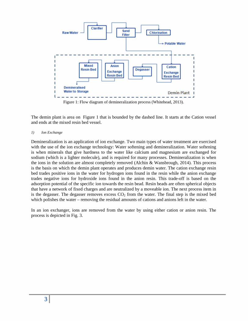
The water purification process from raw water to potable and demin water is illustrated in Fig.2.
3
Figure 1: Flow diagram of demineralization process (Whitehead, 2013).
The demin plant is area on Figure 1 that is bounded by the dashed line. It starts at the Cation vessel and ends at the mixed resin bed vessel. 1) Ion Exchange
Demineralization is an application of ion exchange. Two main types of water treatment are exercised with the use of the ion exchange technology: Water softening and demineralization. Water softening is when minerals that give hardness to the water like calcium and magnesium are exchanged for sodium (which is a lighter molecule), and is required for many processes. Demineralization is when the ions in the solution are almost completely removed (Alchin & Wansbrough, 2014). This process is the basis on which the demin plant operates and produces demin water. The cation exchange resin bed trades positive ions in the water for hydrogen ions found in the resin while the anion exchange trades negative ions for hydroxide ions found in the anion resin. This trade-off is based on the adsorption potential of the specific ion towards the resin bead. Resin beads are often spherical objects that have a network of fixed charges and are neutralized by a moveable ion. The next process item in is the degasser. The degasser removes excess CO2 from the water. The final step is the mixed bed which polishes the water – removing the residual amounts of cations and anions left in the water. In an ion exchanger, ions are removed from the water by using either cation or anion resin. The process is depicted in Fig. 3.

4
Figure 2: Ion exchange during demineralization (Aqua, 2014).
2) Column Operation The columns or vessels are the containers in which these resin are found. An example of how the columns operate can be seen in Fig. 4 below.
Figure 3: Column operation (Rohm & Haas, 2008)
In Figure 3 it can be seen that the fresh resin gets loaded progressively with ions from the feed solution until leakage/exhaustion occurs, that is, once the resins are fully loaded and the ions from the feed escape the ion exchanger. The resin is loaded in the direction of the flow. When the resin is exhausted, the next step is regeneration. Regeneration can only take place when the regenerant concentration is high, typically 1000 times the concentration in normal water (Rohm & Haas, 2008). In the case of demineralization, strong acids such as hydrochloric acid and sulphuric acid are fully dissociated and can supply H+ ions to replace the cations that have been exchanged. Almost the whole process takes place with OH- ions in the anion vessel. In practice, caustic soda (NaOH) is used and supplies the OH- ion to replace the anions sitting on the anion exchange resin beads at the end of the run. For the ion exchange to be efficient there must be a difference in affinity between the ion in the resin and the ion in the solution (Rohm & Haas, 2008). The resin must have a higher affinity for the ion in solution compared to the ion in the resin.
B. System Dynamics
1) Origin of System Dynamics The following few points explains briefly the history of System Dynamics from Aristotle, Bertalanffy and Forrester:
5
• The first main idea of systems thinking was depicted in Aristotle’s idea that the whole is not the sum of its parts and that the interactions between the parts also have an effect in the end. (Upton et al, 2014)
• In 1940, Von Bertalanffy distinguished between open and closed systems. Closed systems have no interaction with its environment while open systems readily exchange mass, energy and information through its boundaries. He also did some work on isomorphic laws where he discovered the same laws in different systems (Drack, M).
• While Jay W Forrester was working on the WHIRLWIND I, MIT’s first general purpose digital computer to be used to control combat information system, this is where he learned to appreciate the difficulties faced by corporate managers. His insights into the common foundations that underlie engineering and management led to the creation of system dynamics during the 1950s (Origin of system dynamics, 2014).
• In 1962, Forrester wrote his popular book, Industrial Dynamics. Within 10 years of its publication, the span of applications grew from corporate and industrial problems to include the management of research and development, urban stagnation and decay, commodity cycles and the dynamics of growth in a finite world (Origin of system dynamics, 2014).
2) Description of the software that was used:
The software used in this model is iSee Stella. The following is a description of the software from the iSee website: “STELLA allows you to quickly create system diagrams that can be simulated over time. Working in a completely risk-free environment and discover hidden aspects of your system that lead to unexpected outcomes. STELLA also allows you to create a user interface on top of your system diagram that makes it easy to share your understanding of the system, run your scenarios as part of a presentation, and enable others to experiment with their own policy combinations.” (iSeeSystems, 2015) 3) Why was this software chosen:
This tool was chosen since it is one of the leading tools in the field of System Dynamics. It is well-established software which is continuously being developed but the main reason for using this specific tool is for the creation of the interface. The interface can be customized to customer requirements and enables the user to interact with the model through this easy-to-use interface. STELLA also provides almost instant comparisons between scenarios and the effect of doing a sensitivity analysis can easily be seen.
III. RESEARCH APPROACH
The next few sections outline the research process that was followed in the creation of the simulation. The first would be the key variables and concepts, dynamic hypothesis where the Causal Loop Diagram (CLD) and Model Boundary Chart (MBC) will be discussed, simulation modelling structure and testing. The simulation was created in iSee STELLA version 9.4 and the simulation period was 100 hours.
6
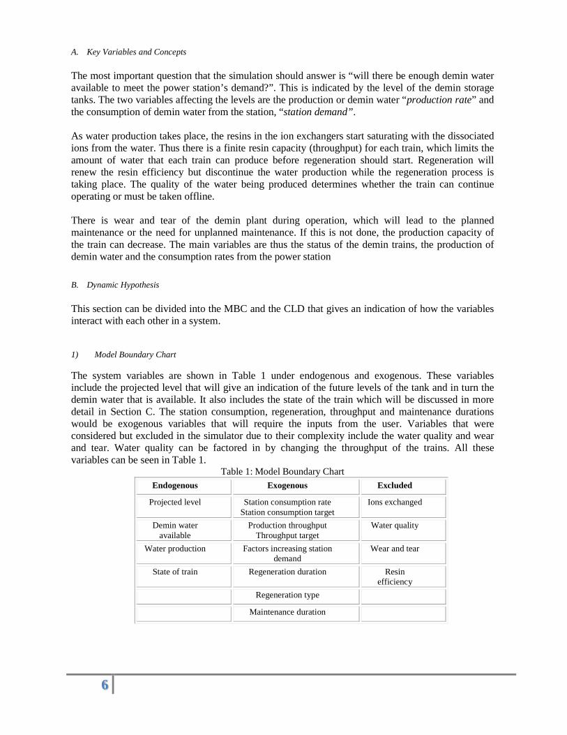
A. Key Variables and Concepts
The most important question that the simulation should answer is “will there be enough demin water available to meet the power station’s demand?”. This is indicated by the level of the demin storage tanks. The two variables affecting the levels are the production or demin water “production rate” and the consumption of demin water from the station, “station demand”. As water production takes place, the resins in the ion exchangers start saturating with the dissociated ions from the water. Thus there is a finite resin capacity (throughput) for each train, which limits the amount of water that each train can produce before regeneration should start. Regeneration will renew the resin efficiency but discontinue the water production while the regeneration process is taking place. The quality of the water being produced determines whether the train can continue operating or must be taken offline. There is wear and tear of the demin plant during operation, which will lead to the planned maintenance or the need for unplanned maintenance. If this is not done, the production capacity of the train can decrease. The main variables are thus the status of the demin trains, the production of demin water and the consumption rates from the power station
B. Dynamic Hypothesis
This section can be divided into the MBC and the CLD that gives an indication of how the variables interact with each other in a system.
1) Model Boundary Chart
The system variables are shown in Table 1 under endogenous and exogenous. These variables include the projected level that will give an indication of the future levels of the tank and in turn the demin water that is available. It also includes the state of the train which will be discussed in more detail in Section C. The station consumption, regeneration, throughput and maintenance durations would be exogenous variables that will require the inputs from the user. Variables that were considered but excluded in the simulator due to their complexity include the water quality and wear and tear. Water quality can be factored in by changing the throughput of the trains. All these variables can be seen in Table 1.
Table 1: Model Boundary Chart
Endogenous Exogenous Excluded
Projected level Station consumption rate Station consumption target
Ions exchanged
Demin water available
Production throughput Throughput target
Water quality
Water production Factors increasing station demand
Wear and tear
State of train Regeneration duration Resin efficiency
Regeneration type
Maintenance duration
7
2) Causal Loop Diagram (CLD)
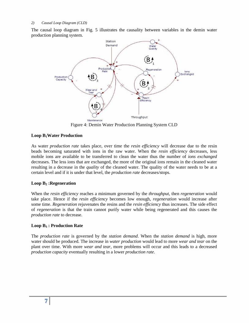
The causal loop diagram in Fig. 5 illustrates the causality between variables in the demin water production planning system.
Figure 4: Demin Water Production Planning System CLD
Loop B1Water Production As water production rate takes place, over time the resin efficiency will decrease due to the resin beads becoming saturated with ions in the raw water. When the resin efficiency decreases, less mobile ions are available to be transferred to clean the water thus the number of ions exchanged decreases. The less ions that are exchanged, the more of the original ions remain in the cleaned water resulting in a decrease in the quality of the cleaned water. The quality of the water needs to be at a certain level and if it is under that level, the production rate decreases/stops. Loop B2 :Regeneration When the resin efficiency reaches a minimum governed by the throughput, then regeneration would take place. Hence if the resin efficiency becomes low enough, regeneration would increase after some time. Regeneration rejuvenates the resins and the resin efficiency thus increases. The side effect of regeneration is that the train cannot purify water while being regenerated and this causes the production rate to decrease. Loop B3 : Production Rate The production rate is governed by the station demand. When the station demand is high, more water should be produced. The increase in water production would lead to more wear and tear on the plant over time. With more wear and tear, more problems will occur and this leads to a decreased production capacity eventually resulting in a lower production rate.

8
Loop B4 : Maintenance When wear and tear increases, more planned maintenance would occur. The side effect of maintenance is similar to that of regeneration in that the train needs to be shut down while maintenance is conducted and this decreases water production rate. Loop B1 indicates what will happen when no regeneration takes place, leading ultimately to a decrease in production rate. The regeneration cycles, loop B2, changes the resulting loop and increases the resin efficiency which ultimately leads to a sustainable production rate. The same principle accounts for the wear and tear which will ultimately result in a decrease in production, indicated by loop B3, but maintenance counters the wear and tear and leads to a stable production rate, loop B4.
C. Simulation Model
1) Basic Simulator
Currently there is an MS Excel file that was created by senior engineer in Eskom (Chemistry Department), Dick Cramer (Cramer) which requires the power station operators to take account of their demin water production and power station consumption so that the MS Excel calculations can make a projection of the future level of the demin storage tanks. The basic structure can then be seen in Error! Reference source not found.. There are three trains (green blocks) that each produce demin water. They are then summed in the cumulative production Error! Reference source not found..
Figure 5: System Architecture Map
The station consumption is introduced as the red block and the difference between the station consumption and the cumulative production is the gain or shortfall, in orange. The projected level is then calculated by using the gain/shortfall, previous level and tank volume. The formula is given below:
9
������������ � �������������������������� �����!"��#$���
���������� Equation 1
The demin water available is a conversion from projected level. The simulation was then expanded from here
to compensate for a few other concepts mentioned in the following sections.
2) Status of Demin Train
Each train has a certain status. According to the design philosophy, one train should be online, the next on regeneration and the last on standby. In reality, this is not done due to the demin water consumption rate being too high and the demin water production rate being too low. In this section, each state will be defined. The information was obtained by having contact sessions with the customer (Marais, 2014) Online: This is when the train is operating at normal capacity and purifying water at a relatively constant production rate.
Regeneration: When the train has been online to the extent that one of the exchange units starts leaking (exhaustion), the train is put on regeneration. The anion, cation and mixed bed each have their own regeneration duration. The anion and cation will be regenerated regularly while the mixed bed will be regenerated less often due to most of the ions being exchanged in the anion and cation exchangers. Another type of regeneration that does not involve the ions attached to the resin is brine washes. After about every tenth regeneration cycle, brine washes should also be done. The main purpose of brine washes is to remove the organic foulants in the demin train. If this is not done, the throughput of the demin train drastically falls and decreases the online time. During operation the conductivity of the water produced by the train is measured regularly and if the conductivity increases above specifications regeneration is initiated. While regeneration is occurring the train will not produce any demin water.
Standby: This state is when the train is ready to go online if needed but not yet required. The main function of this state is to serve as a backup when another train enters regeneration or maintenance. This state does not produce any demin water. Awaiting Regeneration: This state occurs when a train needs to go into regeneration but cannot, due to equipment or regenerant unavailability. Most stations, like Duvha, can only regenerate one train at a time and when two trains need regeneration this state will come into play. During the awaiting regeneration state no demin water is produced. Maintenance: This state is when planned or unplanned maintenance must be done on the trains. Planned maintenance may be to replace the resin beads for one of the exchange units, while unplanned maintenance could consist of unclogging the strator when resin beads get stuck in them. Again, no demin water is produced during this state. Brine Wash/Cleaning Process: Organics in the water accumulate in the anion resin and to remove these organics, brine washes have to be conducted. During brine washes the column is flushed with a salt solution. The cation resin can also accumulate substances and to remove them, they also undergo a cleaning process.

10
To better understand the flow of each state, a simplified decision tree was created to illustrate how the states are decided on. This can be seen in Fig. 7.
Figure 6: Decision tree related to different statuses
3) Demand from Power station
The demand from each unit of each power station is different and is influenced by many factors. The main factors that lead to increased demand from the power station will be defined as follows (Marais, 2014):
• Blow downs: In stations with drum boilers, the liquid gets concentrated with ions as the cycles of operation increases and results in blow downs. The water lost due to blow downs, must be made up by the demin water and increases the demand from the station.
• Condenser tube leaks: Condenser tube leaks result in raw cooling water contaminating the high purity water/steam and the quality of the water decreases. This decrease in quality increases the need for blow downs as indicated by the previous point. The conductivity of the water in the condenser tubes could be about 3000 µS/cm while the requirements in the steam cycle is less than 0.08 µS/cm, indicating that even a small condenser tube leak results in blow downs (Marais, 2014).
• Steam and water leaks: Across the power station, there are leaks that increase the demand of the station.
• Control & Instrumentation problems: Sometimes the control and instrumentation is not functioning properly, especially after refurbishments of the controls or maintenance on valves, where a valve was not properly closed. This results in losses of water and increases the demin makeup water requirements.
• Boiler tube leaks: Leaks can take place within boiler tubes. These leaks cause water to be lost and the makeup water must come from the demin plant, so the demand on the production plant increases.

11
• Soot blowing: To remove some of the ash on the boiler tubes, steam is used and the lost steam needs to be replaced by demin water.
• Return to service (Light-ups): Demin water is required to clean, dump and refill the boiler tubes. The amount of water used for this is determined by the type of startup:
� Hot Startup: Requires the least amount of water since the system is closer to steady state conditions.
� Cold Startup: Requires more water to reach steady state. • Condensate Polishing Plant (CPP): Demin water is used to transfer the resin from the CPP to the condensate polishing regeneration plant. This also contributes to the power station’s consumption of demin water.
D. Assumptions
• Water quality is not a major factor that will influence the production of demin water in this simulation and can be compensated by changing the throughput of the vessels. • When regeneration is completed, it is assumed that the throughput is fully restored. • The maintenance defined in the simulation is maintenance that will be done excluding maintenance that will be done simultaneously with regeneration or any other state.
E. Decision Rules
• The simulation will set the train’s status to automatically go into regeneration state if the maximum throughput of the status is reached and no other state has been defined previously. If the station cannot accommodate simultaneous regeneration and another train is being regenerated, the train will enter the awaiting regeneration step. • The train will automatically go into the online state if no other state is specified and the maximum throughput on the train has not been reached. • When the demin storage tanks are full, the status of the trains will be changed to stand by. • A simulation time of 96 hours has been used.
F. Testing
The simulation has not been tested against real operation, but it does import most of its data from the user and builds simulation scenario on this basis. Thus the data that is fed into the simulator will ensure that the results are accurate. Currently all the values used in the simulation are purely theoretical and should not be considered as operational.
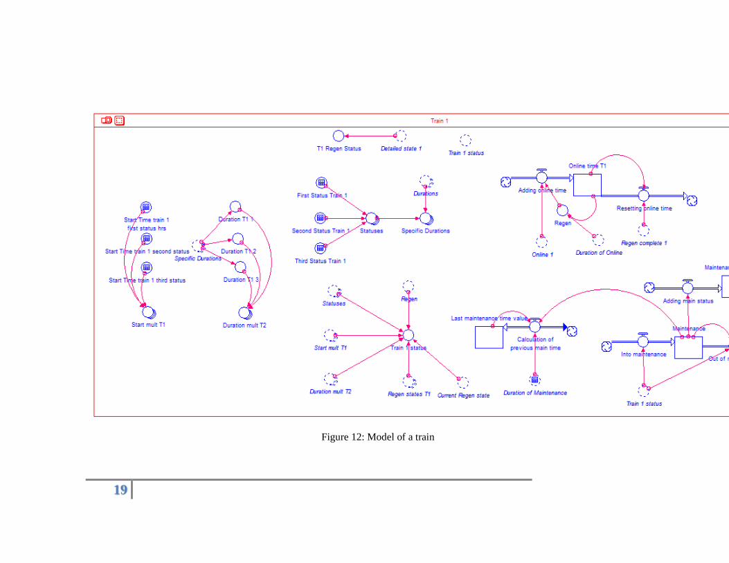
G. Model Structure
A selected section of the system dynamics model in iSee Stella can be found in the Appendix as Figure 12. This structure shows that the status that is partly defined by the user will start the online stock counter. When the throughput is reached, the train will be put offline and the regeneration process will start which can be found in Figure 13. When the regeneration is complete, then the “Regen Complete” variable will reset the online structure and the train can be put back online. The factors that are mentioned in Section C, part 2, are built into the model and when these aspects like maintenance takes place, it will put the train off line. When the train is online, then it will produce demin water and contribute to the projected
12
levels. The consumption of demin water is also built and consists of Section C, part 3. The consumption and production of demin water is seen in the projected levels as discussed in section IV.
IV. RESULTS AND DISCUSSION
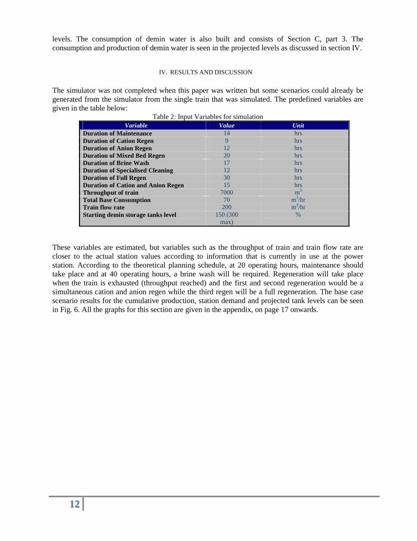
The simulator was not completed when this paper was written but some scenarios could already be generated from the simulator from the single train that was simulated. The predefined variables are given in the table below:
Table 2: Input Variables for simulation Variable Value Unit
Duration of Maintenance 14 hrs Duration of Cation Regen 9 hrs Duration of Anion Regen 12 hrs Duration of Mixed Bed Regen 20 hrs Duration of Brine Wash 17 hrs Duration of Specialised Cleaning 12 hrs Duration of Full Regen 30 hrs Duration of Cation and Anion Regen 15 hrs Throughput of train 7000 m3 Total Base Consumption 70 m3/hr Train flow rate 200 m3/hr Starting demin storage tanks level 150 (300
max) %
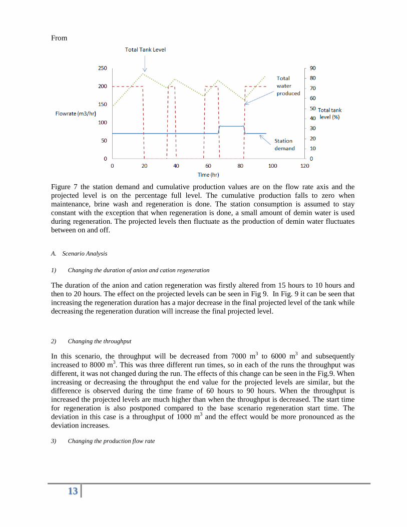
These variables are estimated, but variables such as the throughput of train and train flow rate are closer to the actual station values according to information that is currently in use at the power station. According to the theoretical planning schedule, at 20 operating hours, maintenance should take place and at 40 operating hours, a brine wash will be required. Regeneration will take place when the train is exhausted (throughput reached) and the first and second regeneration would be a simultaneous cation and anion regen while the third regen will be a full regeneration. The base case scenario results for the cumulative production, station demand and projected tank levels can be seen in Fig. 6. All the graphs for this section are given in the appendix, on page 17 onwards.
13
From
Figure 7 the station demand and cumulative production values are on the flow rate axis and the projected level is on the percentage full level. The cumulative production falls to zero when maintenance, brine wash and regeneration is done. The station consumption is assumed to stay constant with the exception that when regeneration is done, a small amount of demin water is used during regeneration. The projected levels then fluctuate as the production of demin water fluctuates between on and off.
A. Scenario Analysis
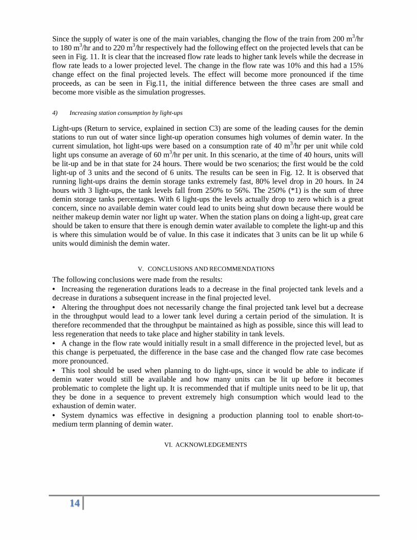
1) Changing the duration of anion and cation regeneration
The duration of the anion and cation regeneration was firstly altered from 15 hours to 10 hours and then to 20 hours. The effect on the projected levels can be seen in Fig 9. In Fig. 9 it can be seen that increasing the regeneration duration has a major decrease in the final projected level of the tank while decreasing the regeneration duration will increase the final projected level.
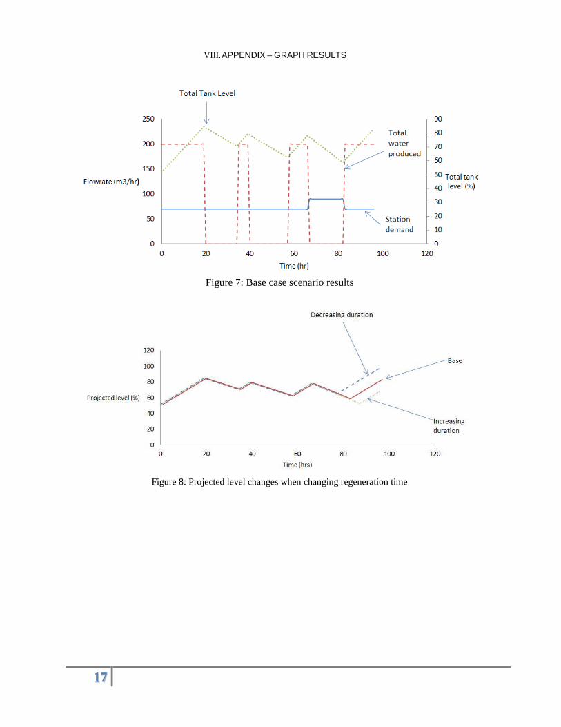
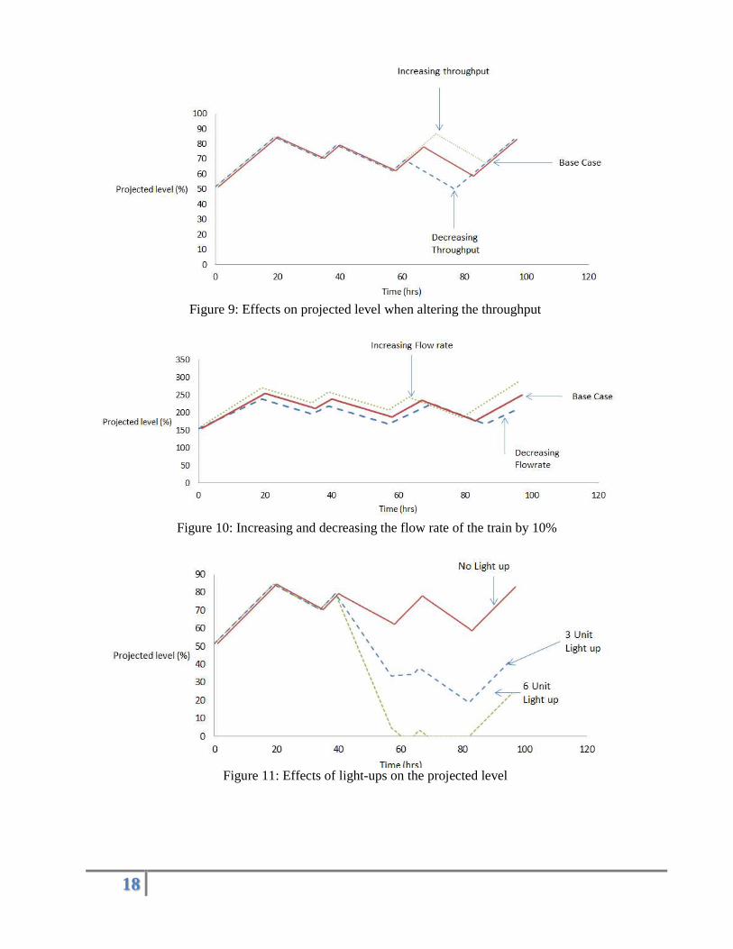
2) Changing the throughput
In this scenario, the throughput will be decreased from 7000 m3 to 6000 m3 and subsequently increased to 8000 m3. This was three different run times, so in each of the runs the throughput was different, it was not changed during the run. The effects of this change can be seen in the Fig.9. When increasing or decreasing the throughput the end value for the projected levels are similar, but the difference is observed during the time frame of 60 hours to 90 hours. When the throughput is increased the projected levels are much higher than when the throughput is decreased. The start time for regeneration is also postponed compared to the base scenario regeneration start time. The deviation in this case is a throughput of 1000 m3 and the effect would be more pronounced as the deviation increases.
3) Changing the production flow rate
14
Since the supply of water is one of the main variables, changing the flow of the train from 200 m3/hr to 180 m3/hr and to 220 m3/hr respectively had the following effect on the projected levels that can be seen in Fig. 11. It is clear that the increased flow rate leads to higher tank levels while the decrease in flow rate leads to a lower projected level. The change in the flow rate was 10% and this had a 15% change effect on the final projected levels. The effect will become more pronounced if the time proceeds, as can be seen in Fig.11, the initial difference between the three cases are small and become more visible as the simulation progresses.
4) Increasing station consumption by light-ups
Light-ups (Return to service, explained in section C3) are some of the leading causes for the demin stations to run out of water since light-up operation consumes high volumes of demin water. In the current simulation, hot light-ups were based on a consumption rate of 40 m3/hr per unit while cold light ups consume an average of 60 m3/hr per unit. In this scenario, at the time of 40 hours, units will be lit-up and be in that state for 24 hours. There would be two scenarios; the first would be the cold light-up of 3 units and the second of 6 units. The results can be seen in Fig. 12. It is observed that running light-ups drains the demin storage tanks extremely fast, 80% level drop in 20 hours. In 24 hours with 3 light-ups, the tank levels fall from 250% to 56%. The 250% (*1) is the sum of three demin storage tanks percentages. With 6 light-ups the levels actually drop to zero which is a great concern, since no available demin water could lead to units being shut down because there would be neither makeup demin water nor light up water. When the station plans on doing a light-up, great care should be taken to ensure that there is enough demin water available to complete the light-up and this is where this simulation would be of value. In this case it indicates that 3 units can be lit up while 6 units would diminish the demin water.
V. CONCLUSIONS AND RECOMMENDATIONS
The following conclusions were made from the results: • Increasing the regeneration durations leads to a decrease in the final projected tank levels and a decrease in durations a subsequent increase in the final projected level. • Altering the throughput does not necessarily change the final projected tank level but a decrease in the throughput would lead to a lower tank level during a certain period of the simulation. It is therefore recommended that the throughput be maintained as high as possible, since this will lead to less regeneration that needs to take place and higher stability in tank levels. • A change in the flow rate would initially result in a small difference in the projected level, but as this change is perpetuated, the difference in the base case and the changed flow rate case becomes more pronounced. • This tool should be used when planning to do light-ups, since it would be able to indicate if demin water would still be available and how many units can be lit up before it becomes problematic to complete the light up. It is recommended that if multiple units need to be lit up, that they be done in a sequence to prevent extremely high consumption which would lead to the exhaustion of demin water. • System dynamics was effective in designing a production planning tool to enable short-to-medium term planning of demin water.
VI. ACKNOWLEDGEMENTS

15
• I would like to acknowledge Stephanie Marais for assisting with understanding the demin plant and windtunneling the simulator. • Dick Cramer for the initial concept of the demin water production planning tool that he created on excell. • Danie Booyens for assistance with modelling using STELLA software.
VII. REFERENCES
Alchin D, Wansbrough H, ION EXCHANGE RESIN, XIII-Water-D-Ion Exchange Resins, Retrieved 30 March, 2014, from nzic.org.nz/ChemProcesses/water/13D.pdf
Aqua technology. Retrieved from 24 February, 2014, from
http://www.aquatechnology.net/industrial_deionization.html
Cramer D, Senior Engineer, Eskom SOC, South Africa, Tel: +27 11 629 5046
Drack M. Ludwig Von Bertalanffy’s early system Approach, University of Vienna, retrieved 12 May 2015,
from http://journals.isss.org/index.php/proceedings52nd/article/viewFile/1032/322
Generation Plant for Engineers (GPFE), Course Material, Auxiliary Plant Module 5. 2014.
iSeeSystems, Product Description: Stella, Retrieved on 26 June 2015 from
http://www.iseesystems.com/softwares/STELLA-iThink.aspx#
Lenntech, Scaling in boilers, Retrieved on 26 May 2015 from:
http://www.lenntech.com/applications/process/boiler/scaling.htm
Marais S.D. 2014. e-mail: 31 March 2014, [email protected]
Origin of System Dynamics, system dynamics, retrieved 8 January 2014, from
http://www.systemdynamics.org/DL-IntroSysDyn/origin.htm,
Oxford, Demineralize, Retrieved on 26 June 2015 from
http://www.oxforddictionaries.com/definition/english/demineralize
Rohm & Haas. 2008. Ion exchange for dummies: an Introduction, Retrieved 24 February, 2014, from
http://www.lenntech.com/Data-sheets/Ion-Exchange-for-Dummies-RH.pdf

16
Upton J, Janeka I, Ferraro N, The whole is more than the sum of its parts: Aristotle, metaphysical. The
Journal of craniofacial surgery, Jan 2014, Retrieved 26 June 2015 from
http://www.ncbi.nlm.nih.gov/pubmed/24406559
Whitehead K. 2013. Water treatment plant: The demineralization Process, Eskom
17
VIII. APPENDIX – GRAPH RESULTS
Figure 7: Base case scenario results
Figure 8: Projected level changes when changing regeneration time
18
Figure 9: Effects on projected level when altering the throughput
Figure 10: Increasing and decreasing the flow rate of the train by 10%
Figure 11: Effects of light-ups on the projected level
19
Figure 12: Model of a train

20
Figure 13: Model of regeneration and status management