1-CFD-Analysis-of-Catalytic-Converter-to-Reduce Particulate-Matter-and-Achieve-Limited-Back...
7
P a g e | 2 Vol.10 Issue 5 (Ver1.0) October 2010 Global Journal of Researches in Engineering GJRE-A:Classification(FOR) 091304, 091399 CFD Analysis of Catalytic Converter to Reduce Particulate Matter and Achieve Limited Back Pressure in Diesel Engine PL.S. Muthaiah 1 , Dr.M. Senthil kumar 2 , Dr. S. Sendilvelan 3 Abstract-The superior performance, higher output power and comparatively less-cost fuel make the diesel engines more popular in both heavy and light duty automobile applications. The main disadvantage in diesel engines is the emission of dangerous pollutants like oxides of nitrogen (NO X ) and particulate matter (PM) heavily, which affect seriously the environment and human health. The rare earth metals now used as catalyst to reduce NO X are costly and rarely available. The scarcity and high demand of present catalyst materials necessitate the need for finding out the alternatives. Among all other particulate filter materials, knitted steel wire mesh material is selected as filter materials. Models with filter materials of very fine grid size wire meshes packed inside the manifold develop more back pressure which causes more fuel consumption due to lower volumetric efficiency. Use of larger grid size wire meshes results in less back pressure, but the filtration efficiency is also reduced which may not be sufficient to meet the most stringent emission norms prescribed. Through CFD analysis, a compromise between these two parameters namely, more filtration efficiency with limited back pressure is aimed at. In CFD analysis, various models with different wire mesh grid size combinations were simulated using the appropriate boundary conditions and fluid properties specified to the system with suitable assumptions. The back pressure variations in various models are discussed in this paper. I. INTRODUCTION ith the introduction of the turbo charged high-speed diesel engines, the use of diesel engine vehicles in transport sector is increasing enormously. The main drawback in diesel engine is that it produces large amount of pollutants which include NO X , CO, unburned HC, smoke etc. Apart from these unwanted gases, air borne Particulate Matter (PM) such as lead, soot, and other forms of black carbon are also produced in the diesel engine exhaust. All these pollutants are harmful to environment and human health. They are the main causes for greenhouse effect, acid rain, global warming etc. The simplest and the most effective way to reduce NO X and PM, is to go for the after treatment of exhaust. The catalyst and filter materials placed inside the exhaust manifold increase back pressure ____________________________ About 1 - Research Scholar, Sathyabama University, Chennai About 2 - Principal, SKR Engineering College, Chennai About 3 -Principal, Aksheyaa College of Engineering, Chennai This increase in back pressure causes more fuel consumption, and in most cases, engine stalling might happen. The filtration efficiency and back pressure are interrelated. If maximum filtration efficiency using very fine grid size wire meshes, is achieved, the back pressure will also be increased, which causes more fuel consumption. On the other hand, if larger grid size wire meshes are used, back pressure will be less, but the filtration efficiency will also be reduced, which does not help in meeting the present emission norms. With the help of CFD analysis, it is attempted to find out the optimum solution to get maximum filtration efficiency with limited back pressure developed inside the exhaust manifold. II. CATALYST As this study deals only with the filtration efficiency of the trap system and the back pressure developed inside the exhaust manifold, the details pertaining to the type of catalyst, preparation of catalyst, reaction chemistry and NO X conversion efficiency that can be achieved are not discussed in this paper. However, the shape of the catalyst bead which is relevant for the back pressure development inside the manifold is shown in Figure 1. The flowing exhaust gas is free to move in all directions inside the manifold. As the movement of exhaust gas is not abruptly obstructed anywhere in its path, the back pressure is limited to minimum level. The porous nature of catalyst beads also help the gas to flow over the larger surface area of the catalyst enabling better reaction to take place for reducing NO X as in the case of SCR system. W
Transcript of 1-CFD-Analysis-of-Catalytic-Converter-to-Reduce Particulate-Matter-and-Achieve-Limited-Back...
P a g e | 2 Vol.10 Issue 5 (Ver1.0) October 2010 Global Journal of Researches in Engineering
GJRE-A:Classification(FOR) 091304, 091399
CFD Analysis of Catalytic Converter to Reduce
Particulate Matter and Achieve Limited Back
Pressure in Diesel Engine
PL.S. Muthaiah1, Dr.M. Senthil kumar
2, Dr. S. Sendilvelan
3
Abstract-The superior performance, higher output power and
comparatively less-cost fuel make the diesel engines more
popular in both heavy and light duty automobile applications.
The main disadvantage in diesel engines is the emission of
dangerous pollutants like oxides of nitrogen (NOX) and
particulate matter (PM) heavily, which affect seriously the
environment and human health. The rare earth metals now
used as catalyst to reduce NOX are costly and rarely available.
The scarcity and high demand of present catalyst materials
necessitate the need for finding out the alternatives. Among all
other particulate filter materials, knitted steel wire mesh
material is selected as filter materials. Models with filter
materials of very fine grid size wire meshes packed inside the
manifold develop more back pressure which causes more fuel
consumption due to lower volumetric efficiency. Use of larger
grid size wire meshes results in less back pressure, but the
filtration efficiency is also reduced which may not be sufficient
to meet the most stringent emission norms prescribed.
Through CFD analysis, a compromise between these two
parameters namely, more filtration efficiency with limited back
pressure is aimed at. In CFD analysis, various models with
different wire mesh grid size combinations were simulated
using the appropriate boundary conditions and fluid properties
specified to the system with suitable assumptions. The back
pressure variations in various models are discussed in this
paper.
I. INTRODUCTION
ith the introduction of the turbo charged high-speed
diesel engines, the use of diesel engine vehicles in
transport sector is increasing enormously. The main
drawback in diesel engine is that it produces large amount of
pollutants which include NOX, CO, unburned HC, smoke
etc. Apart from these unwanted gases, air borne Particulate
Matter (PM) such as lead, soot, and other forms of black
carbon are also produced in the diesel engine exhaust. All
these pollutants are harmful to environment and human
health. They are the main causes for greenhouse effect, acid
rain, global warming etc. The simplest and the most
effective way to reduce NOX and PM, is to go for the after
treatment of exhaust. The catalyst and filter materials placed
inside the exhaust manifold increase back pressure
____________________________ About1
- Research Scholar, Sathyabama University, Chennai
About2- Principal, SKR Engineering College, Chennai
About3-Principal, Aksheyaa College of Engineering, Chennai
This increase in back pressure causes more fuel
consumption, and in most cases, engine stalling might
happen. The filtration efficiency and back pressure are
interrelated. If maximum filtration efficiency using very
fine grid size wire meshes, is achieved, the back pressure
will also be increased, which causes more fuel consumption.
On the other hand, if larger grid size wire meshes are used,
back pressure will be less, but the filtration efficiency will
also be reduced, which does not help in meeting the present
emission norms. With the help of CFD analysis, it is
attempted to find out the optimum solution to get maximum
filtration efficiency with limited back pressure developed
inside the exhaust manifold.
II. CATALYST
As this study deals only with the filtration efficiency of the
trap system and the back pressure developed inside the
exhaust manifold, the details pertaining to the type of
catalyst, preparation of catalyst, reaction chemistry and NOX
conversion efficiency that can be achieved are not discussed
in this paper. However, the shape of the catalyst bead which
is relevant for the back pressure development inside the
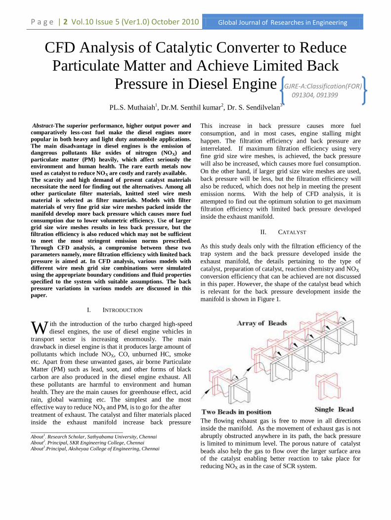
manifold is shown in Figure 1.
The flowing exhaust gas is free to move in all directions
inside the manifold. As the movement of exhaust gas is not
abruptly obstructed anywhere in its path, the back pressure
is limited to minimum level. The porous nature of catalyst
beads also help the gas to flow over the larger surface area of the catalyst enabling better reaction to take place for
reducing NOX as in the case of SCR system.
W
Global Journal of Researches in Engineering Vol.10 Issue5 (Ver 1.0)October 2010 P a g e | 3
1) SCR Catalyst System
Presently, ammonia derived from urea is used to reduce NOX from diesel engines. This is achieved by allowing the
ammonia plus exhaust gas to flow over the platinum coated
ceramic substrates, and it has been proved as highly
effective in reducing NOX in heavy duty applications [2].
Ammonia is produced on-board by rapid hydrolysis of
nonhazardous form of urea solution. The problem with this
is, cost of on-board production of ammonia, cost of
additional on-board air supply equipments, and high cost of
rare metals like platinum etc. In this paper, rare earth metal
catalyst is replaced by a specially prepared catalyst. This
catalyst selectively reacts with NO and NO2 species and
effectively reduces them to form nitrogen and oxygen using SCR technology.
2) Diesel Oxidation Catalyst
DOC is made as a flow through device that consists of
specially made catalytic beads and steel wire mesh material
which are coated with metal catalyst. As the hot gases contact the catalyst and the coated wire mesh, most of the
exhaust pollutants such as CO, gaseous hydrocarbons,
unburnt fuel and lube oil, toxic aldehydes etc. are oxidized
to CO2 and water, thus reducing harmful emissions. DOC
does not collect or burn the soot particles in diesel exhaust.
But it is accomplished by oxidizing the soluble organic
fraction of diesel PM.DOC can also produce sulphate
particles by oxidizing the SO2 present in the exhaust gas and
thus increases the PM emission. This may not be a problem,
if the fuel contains <50ppm of sulphur [3].
3) Volume Of Catalyst
The size of exhaust manifold is based on the engine exhaust
flow rates. For maximizing catalyst applied surface area, the
volume of catalyst must be 1.5 to 2 times the engine
displacement [3]. The engine selected for this study is a four
stroke twin cylinder (80mm bore and 110mm stroke length)
water cooled diesel engine. The engine displacement is
calculated as 603 cm3/sec for the assumed velocity of 60 m/s. The total volume of catalyst used in the model is 1383
cm3. The total trap material (catalytic beads plus coated wire
meshes) kept inside the manifold occupies one third of its
total volume. This means, the remaining volume is used for
the exhaust gas to flow out freely. This helps for limiting the
back pressure and ensuring effective DOC and SCR
systems.
III. SELECTION OF FILTER MATERIAL
Ceramic monolith, ceramic foam, steel wire meshes,
ceramic silicon fiber, porous ceramic honey comb are the
few types of filter materials reported in the literature. Out of
these filter materials, steel wire mesh is selected as trap
material because knitted steel wire mesh material is ranked
first [4] for its collection efficiency of PM. The other
reasons for its selection are,
Thermal stability during regeneration.
Good mechanical properties.
Long durability.
Easy availability and less cost.
Wiremesh Specifications
In this analysis, the selected steel wire mesh grid sizes are
1.96, 1.61, 1.01 and 0.65mm. The specifications of these
wire meshes are shown in Table 1. Three models are made, each using two different grid size wire meshes placed in two
separate compartments. The details of wire mesh grid sizes
used in different models are shown in Table 2.
Table 1: Wire Mesh Specifications
Wire
Mesh
size
(gap)
in mm
Wire
Dia (d)
in mm
Open
Area
%
Wt in
Kg/m2
Mesh
per
inch
CPSI
1.96 0.58 59.3 1.71 10 100
1.61 0.51 57.7 1.56 12 144
1.01 0.41 50.8 1.51 18 324
0.65 0.25 51.8 0.92 28 576
Table 2: Models and Wire Mesh Grid Sizes
Model No. Wire Mesh Grid
Size (in mm) in
Compartment I
Wire Mesh Grid
Size (in mm) in
Compartment II
Model 4 1.96 1.61
Model 5 1.61 1.01
Model 6 1.01 0.65
Since number of steel wire mesh pieces are stacked one over
the other as a bunch, the gas flow cannot be straight, rather
it is a zig-zag flow. This type of flow provides increased
travel length and contact time so that more amount of DOC
action can take place and hence more PM reduction is
achievable.
IV. PHYSICAL MODEL
To meet the less ground clearance available in the present
vehicles, the height of the manifold is restricted to 110 mm.
The cross section is made as rectangular of size 176 x 110
mm. In CFD, the system consumes less memory space and
less response time, if the rectangular cross section is
assumed. However, in actual practice, the rectangular
corners are suitably rounded off which ensures the smooth
flow of exhaust gas with less turbulence near the wall sides.
a. Construction
The exhaust manifold designed for this study comprises two
compartments. The first one is meant for filtration and DOC
catalyst. The second compartment is meant for filtration and
SCR system.

P a g e | 4 Vol.10 Issue5 (Ver1.0)October 2010 Global Journal of Researches in Engineering
Figure 2: Sectional Plan Showing Two Compartments
Figure 3: Sectional Elevation at x-x
Figure 4: Meshing of Elements
The upstream of the first compartment is filled with steel
wire meshes for about one-fourth of its length. These wire
meshes are placed vertically with their surface being parallel
to the flow of gas. Sufficient gaps are provided amongst the
bunch of wire meshes which make the gas to flow crosswise
also for better filtration and reduce back pressure as shown
in Figure 2. The enlarged view showing the flow directions of exhaust gas is shown as sectional elevation in Figure
3.The downstream of first compartment is filled with
catalyst beads and steel wire meshes arranged in alternate
layers. The beads are arranged horizontally in a single layer
so that the gas can enter at one end of the bead and come out
in the opposite end. During its travel, the gas follows the up
and down movement and meets the entire inner surface area
of the catalyst as shown in Figure 3. There are 322 catalytic
beads of size 16x16x16 mm placed in each compartment.
More contact surface area of the catalytic beads enables the
better catalytic reaction to take place between the catalyst
and the flowing exhaust gas. The beads are designed so that the top and bottom portions are open and the gas can go up
and down to the next layer of beads through the steel wire
mesh layers which are also horizontally placed as shown in
Figure 3.
b. Operating Principle
A part of the exhaust gas passes through the wire mesh layers which trap a portion of the soot. The remaining
exhaust gas flows out to the neighboring bead placed in the
same line – similar to a flow-through substrate. The soot
trapped in the wire mesh material is combusted by the NO2
that is generated by the upstream catalyst and thus the filter
is regenerated continuously. If a situation occurs where
filter regeneration is stopped and a saturation point occurred
with the collected soot, the wire meshes placed over the
catalytic beads will not plug as happened in wall flow filter.
In this condition, the exhaust gas can flow out through the
catalytic beads which are similar to a flow-through substrate. However, much larger part of exhaust gas flows
through the catalytic beads in the direction as shown in
Figure 3.As the path of the gas is not totally blocked, the
back pressure developed inside the exhaust manifold is very
much limited and no further increase in back pressure can
happen beyond certain limit, irrespective of the soot loading
over a period of time.A compressed air cleaning process is
suggested to clean the PM deposition on steel wire meshes
and catalytic beads. In this process, two numbers of
compressed air inlet points are placed in between two
compartments at diametrically in opposite position. By
Global Journal of Researches in Engineering Vol.10 Issue5 (Ver 1.0)October 2010 P a g e | 5
using compressed air available air at the fuel filling stations,
the cleaning operation can be carried out. A hinged door of
very thin size provided at the inlet end of the exhaust
manifold will act as a non-return valve. This will prevent the
cleaned PM dust going back into the engine while
cleaning.It can be estimated and proved that, with the
existing volume of catalyst and steel wire meshes, the
cleaning may be required for every 10,000 Kilometers of engine run, for efficient fuel consumption.
V. MATHEMATICAL MODELLING
Air is used as fluid media, which is assumed to be steady
and compressible. High Reynolds number k-ε turbulence
model is used in the CFD model. This turbulence model is
widely used in industrial applications. The equations of mass and momentum are solved using SIMPLE algorithm to
get velocity and pressure in the fluid domain. The
assumption of an isotropic turbulence field used in this
turbulence model is valid for the current application. The
near-wall cell thickness is calculated to satisfy the
logarithmic law of the wall boundary. Other fluid properties
are taken as constants. Filter media of catalytic converter is
modelled as porous media using coefficients. For porous
media, it is assumed that, within the volume containing the
distributed resistance there exists a local balance everywhere
between pressure and resistance forces such that
Where ξI (i = 1, 2, 3) represents the (mutually orthogonal)
orthotropic directions.
Ki is the permeability
ui is the superficial velocity in direction ξiThe permeability
Ki is assumed to be a quasi linear function of the superficial
velocity. Superficial velocity at any cross section through
the porous medium is defined as the volume flow rate
divided by the total cross sectional area (i.e. area occupied
by both fluid and solid).
VI. THREE DIMENSIONAL CFD STUDY
A three-dimensional model of a catalytic converter is
generated in CFD tool CFX for the analysis.
1) Modeling And Meshing
The geometry of the element is made as tetrahedral mesh,
with a refined mesh near the wall. The RNG K-E turbulence
model is used, with standard wall functions for near-wall
treatment. The model has approximately 0.8 million
tetrahedron fluid elements, and the same is shown in Figure
4.
2) Governing Equations
Commercial CFD solver CFX is used for this study. It is a
finite volume approach based solver which is widely used in
the industries. Governing equations solved by the software
for this study in tensor Cartesian form are
Continuity:
Momentum:
Where ρ is density, ui and uj Cartesian velocity, p is static
pressure, η is viscous stress tensor.
3) Boundary Conditions And Solver Modeling
The inlet boundary condition is defined with the static
pressure and temperature, and the outlet boundary condition
is defined with the outlet static pressure. Exhaust gas is used
as working fluid with initial pressure of 1.35 bar and 350o
C.Isothermal heat transfer model is for the entire domain.
For outlet, the static pressure is specified as 1.15 bar. No
slip boundary condition is applied on all wall surfaces. The discretisation scheme used is second order in space. The
convergence criterion is set to a maximum residual equal to
1x10⁻⁴ for all the equations.
VII. METHODOLOGY
In the present study, the CFD analysis is carried out in two
different stages as Stage I and II.
STAGE I In Stage I, the length of conical portions of inlet and outlet
of the exhaust manifold is varied as 70, 80, and 90 mm and
are named as model 1, 2, and 3 respectively and the flow
pattern is studied in CFD. The model which offers less back
pressure is selected for further analysis.
STAGE II
In Stage II, 1.96 and 1.01 mm grid size wire meshes are
filled in first and second compartments respectively. This
particular combination is named as model 4. Similarly, the
model with 1.61 and 1.01 mm grid size wire mesh is named
as model 5. The model 6 contains 1.01 and 0.65 mm grids
size wire meshes. After the CFD analysis, the best one from these three models is selected for further analysis.
VIII. RESULTS AND DISCUSSIONS
The primary aim of this CFD analysis is to find out the right
grid size of the filter material for the exhaust manifold
which can offer minimum back pressure with maximum
filtration efficiency of PM, using new catalyst for NOX reduction. At present, the wall flow ceramic substrate are
used as filters which are costly and also offer more back
pressure resulting more fuel consumption. In the present
study, steel wire meshes with coarse, fine and very fine grid
sizes are used as filter materials.
a) Back Pressures In Models 1, 2 & 3
It is observed that the back pressure in model 1, 2 and 3 are
found to be 0.907, 0.812 and 0.784 bar respectively as
shown in Figure 5. The back pressure is found to be
reduced with the increase in length of taper for the same
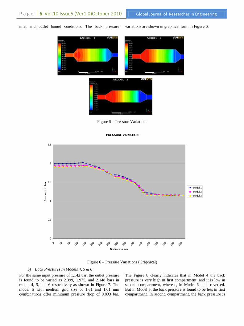
P a g e | 6 Vol.10 Issue5 (Ver1.0)October 2010 Global Journal of Researches in Engineering
inlet and outlet bound conditions. The back pressure variations are shown in graphical form in Figure 6.
Figure 5 – Pressure Variations
Figure 6 – Pressure Variations (Graphical)
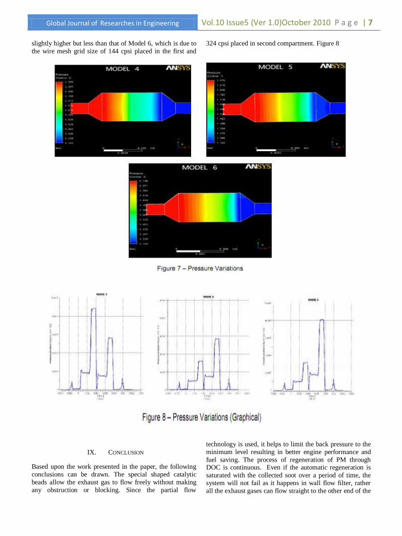
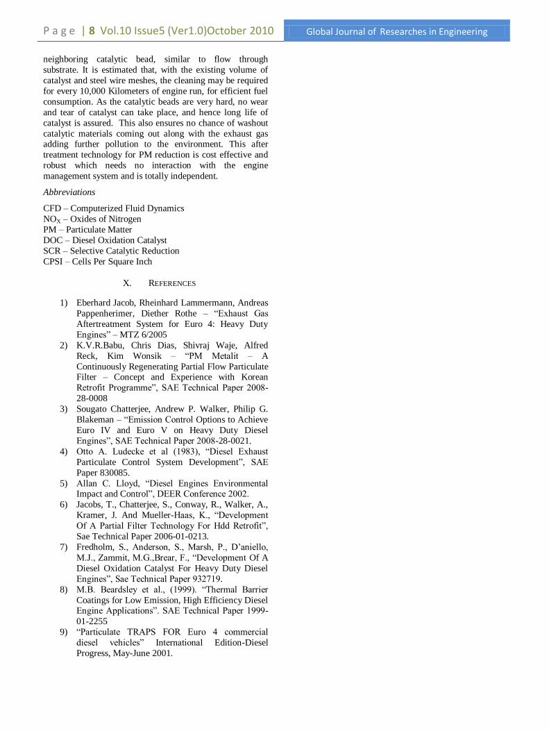
b) Back Pressures In Models 4, 5 & 6
For the same input pressure of 1.142 bar, the outlet pressure
is found to be varied as 2.399, 1.975, and 2.148 bars in model 4, 5, and 6 respectively as shown in Figure 7. The
model 5 with medium grid size of 1.61 and 1.01 mm
combinations offer minimum pressure drop of 0.833 bar.
The Figure 8 clearly indicates that in Model 4 the back
pressure is very high in first compartment, and it is low in second compartment, whereas, in Model 6, it is reversed.
But in Model 5, the back pressure is found to be less in first
compartment. In second compartment, the back pressure is
PRESSURE VARIATION
0
0.5
1
1.5
2
2.5
0 40 80 120
160
200
240
280
320
360
400
440
480
520
560
600
628
Distance in mm
Pre
ssu
re in
bar
Model 1
Model 2
Model 3
Global Journal of Researches in Engineering Vol.10 Issue5 (Ver 1.0)October 2010 P a g e | 7
slightly higher but less than that of Model 6, which is due to
the wire mesh grid size of 144 cpsi placed in the first and
324 cpsi placed in second compartment. Figure 8
IX. CONCLUSION
Based upon the work presented in the paper, the following
conclusions can be drawn. The special shaped catalytic
beads allow the exhaust gas to flow freely without making
any obstruction or blocking. Since the partial flow
technology is used, it helps to limit the back pressure to the
minimum level resulting in better engine performance and
fuel saving. The process of regeneration of PM through DOC is continuous. Even if the automatic regeneration is
saturated with the collected soot over a period of time, the
system will not fail as it happens in wall flow filter, rather
all the exhaust gases can flow straight to the other end of the
P a g e | 8 Vol.10 Issue5 (Ver1.0)October 2010 Global Journal of Researches in Engineering
neighboring catalytic bead, similar to flow through
substrate. It is estimated that, with the existing volume of
catalyst and steel wire meshes, the cleaning may be required
for every 10,000 Kilometers of engine run, for efficient fuel
consumption. As the catalytic beads are very hard, no wear
and tear of catalyst can take place, and hence long life of
catalyst is assured. This also ensures no chance of washout
catalytic materials coming out along with the exhaust gas adding further pollution to the environment. This after
treatment technology for PM reduction is cost effective and
robust which needs no interaction with the engine
management system and is totally independent.
Abbreviations
CFD – Computerized Fluid Dynamics
NOX – Oxides of Nitrogen
PM – Particulate Matter
DOC – Diesel Oxidation Catalyst
SCR – Selective Catalytic Reduction
CPSI – Cells Per Square Inch
X. REFERENCES
1) Eberhard Jacob, Rheinhard Lammermann, Andreas
Pappenherimer, Diether Rothe – ―Exhaust Gas
Aftertreatment System for Euro 4: Heavy Duty
Engines‖ – MTZ 6/2005
2) K.V.R.Babu, Chris Dias, Shivraj Waje, Alfred
Reck, Kim Wonsik – ―PM Metalit – A
Continuously Regenerating Partial Flow Particulate Filter – Concept and Experience with Korean
Retrofit Programme‖, SAE Technical Paper 2008-
28-0008
3) Sougato Chatterjee, Andrew P. Walker, Philip G.
Blakeman – ―Emission Control Options to Achieve
Euro IV and Euro V on Heavy Duty Diesel
Engines‖, SAE Technical Paper 2008-28-0021.
4) Otto A. Ludecke et al (1983), ―Diesel Exhaust
Particulate Control System Development‖, SAE
Paper 830085.
5) Allan C. Lloyd, ―Diesel Engines Environmental Impact and Control‖, DEER Conference 2002.
6) Jacobs, T., Chatterjee, S., Conway, R., Walker, A.,
Kramer, J. And Mueller-Haas, K., ―Development
Of A Partial Filter Technology For Hdd Retrofit‖,
Sae Technical Paper 2006-01-0213.
7) Fredholm, S., Anderson, S., Marsh, P., D‘aniello,
M.J., Zammit, M.G.,Brear, F., ―Development Of A
Diesel Oxidation Catalyst For Heavy Duty Diesel
Engines‖, Sae Technical Paper 932719.
8) M.B. Beardsley et al., (1999). ―Thermal Barrier
Coatings for Low Emission, High Efficiency Diesel Engine Applications‖. SAE Technical Paper 1999-
01-2255
9) ―Particulate TRAPS FOR Euro 4 commercial
diesel vehicles‖ International Edition-Diesel
Progress, May-June 2001.