
Transcript of Hearing in Writing on Pickering Units 6-7-8 of ...
Upload
khangminh22Category
view
0download
0
PNo. 003-21036-10509 NB 1000
Printed in Japan
SERVICE3-4.qxd 05.8.24 11:48 AM ページ 1

TABLE OF CONTENTS
Service Safety
General Service Information
Fuel System
Powerhead
Midsection
Gearcase
Electrical System
Power Trim/Tilt
12345678
3-/ 4-Cylinder


3-/ 4-Cylinder
1-1
Introduction ......................................................................................................................... 1-2
Safety Statements................................................................................................................ 1-2
Safety Precautions ............................................................................................................... 1-3
Workmanship Standards...................................................................................................... 1-5
Test Tank Guidlines .............................................................................................................. 1-7
SECTION 1SERVICE SAFETY
TABLE OF CONTENTS

SECTION 1
1-2
3-/ 4-Cylinder
WARNING
Inadequate knowledge of safe shop practicescan result in severe injury or death. Reviewgeneral safety procedures and specific safetyinformation provided for each procedure prior tobeginning any repairs.
INTRODUCTION
Marine manufacturers are required to comply with specialregulations and standards to ensure their products are safe andreliable for the consumer. As the marine technician, it is yourresponsibility to keep these products safe when performing normalrigging, repair, and maintenance operations.
It is not possible to foresee all safety hazards which may occur orto include all the knowledge of an experienced technician in asingle service manual. Therefore, it is assumed that those using thismanual have a working knowledge of 2-cycle outboard enginesand the proper technical training for servicing them.
This section discusses safe shop practices and general safetyconcerns relevant to the operations performed throughout thismanual. Read this section carefully and follow all safety statementsin this manual as they pertain to the procedures at hand.Remember, always use common sense when servicing outboardengines!
SAFETY STATEMENTS
The following safety statements are found throughout this manualand indicate information which, if ignored, could result in safetyhazards or faulty service techniques:
DANGER
Indicates the presence of a hazard which, ifignored, WILL result in severe injury or death.
WARNING
Indicates the presence of a hazard which, ifignored, COULD result in severe injury or death.
CAUTION
Indicates the presence of a hazard which, ifignored, COULD result in minor personal injury ordamage to product, equipment, or other property.
NOTE
Indicates special information to facilitate theinstallation, operation, or maintenance of the productor further clarify information which is important butnot hazard related.
KC-5030

SERVICE SAFETY
1-3
3-/ 4-Cylinder
SAFETY PRECAUTIONS
Handling Outboard Engines
• Never disable the neutral switch start-in-gear prevention systemto accommodate installation of a foot control or other option.Always test the neutral switch and emergency stop switch beforereturning an engine to the customer.
• Lifting devices and hardware must be of suitable capacity for theweight of the outboard engine. Some models are equipped witha fixed hanger on the powerhead. Hanger may be used to lift thecomplete engine or to remove the powerhead unit. Be aware theengine may swing outward when lifted by the hanger.
• Engine stands must be in good condition, of adequate size, andmounted properly to prevent unexpected shifting or collapse.
• Engine covers are guards to prevent personal contact with thespinning flywheel and high voltage components such as sparkplugs and coils. Never wear jewelry or loose clothing near arunning engine. Keep hands, arms and hair away from theflywheel. Never touch electrical components when the engine isrunning.
• Two people working on a running engine must use extremecaution and be aware of one another. Never attempt to start anengine or operate any controls, including steering, beforesignaling your partner.
• To prevent accidental startup during operations which maycause the flywheel to turn, always perform the following steps:
1. Turn the ignition key to OFF and remove the key.
2. Disable the engine ignition system.
3. Shift engine to NEUTRAL and verify propeller shaft is not ingear.
• Rotating propellers are not equipped with guards and can causesevere injury or dismemberment. Always stay clear of rotatingpropellers and make sure there is no possibility of engine startupbefore removing or installing a propeller. The propeller nut mustalways be tightened to torque specification prior to starting theengine.
KC-5000
KC-4090
KC-4075.3

SECTION 1
1-4
3-/ 4-Cylinder
• Avoid running the engine at high RPM. Engine speed can easilyincrease to excessive RPM when under a no load condition. Toavoid engine damage during testing, always use the correct testpropeller and keep engine speed below 2000 RPM.
• Run engines only in well ventilated areas to prevent exposure toCarbon Monoxide (CO) gas. Direct and prolonged exposure toCO will cause brain damage or death.
• Always wear eye protection, protective clothing, gloves and useother applicable safety equipment when work activities presentthe risk of personal injury.
Lead Acid Batteries
• Never check battery charge by placing a metal object across theterminal posts; sparks may occur, resulting in serious burns.
• Avoid contact with battery acid. If battery acid is spilled on skin,thoroughly wash area with plenty of water. If battery acid getsinto eyes, flush eyes with water for at least 15 minutes and getprompt medical attention.
• Never remove charger cables from a battery when the charger isenergized; sparks and explosion are possible. To remove chargercables, follow these steps:
1. Turn the charger to OFF.
2. Disconnect the charger power cord from its power source.
3. Remove the charger cables from the battery posts.
• Batteries emit explosive vapor through the vented caps duringcharging. Never charge or test batteries near sparks or flames;explosion can result. Extinguish all smoking materials and flameproducing devices before charging and make sure the chargingarea is well ventilated.
• Make sure battery vents are not clogged or pressure may buildand cause battery to explode.
KC-5032
KC-4080
KC-5050

SERVICE SAFETY
1-5
3-/ 4-Cylinder
Hazardous Materials
• Gasoline vapors are highly flammable and can cause anexplosion. Never smoke or allow sparks or flames nearby whenhandling fuel. Always store gasoline in a shaded, well ventilatedarea in an approved safety container.
• Ventilate gasoline fumes as soon as detected. Be aware thatappliance pilot lights, such as those in furnaces and waterheaters, can ignite gasoline vapors and cause explosion.
• Never use gasoline as a cleaner, and always clean up fuel spillsimmediately and properly dispose of rags in an approved safetycontainer.
• Read and follow the safety labels on products used around theshop. Adhesives, lubricants, solvents, and fuel additives areusually poisonous and flammable. Store and dispose of theseproducts properly.
Shop Environment
• Make sure the shop and your work area are properly ventilated.
• Shops must be equipped with the proper tools and safetyequipment such as fire extinguisher, eye flushing device, and firstaid kit.
• Keep the shop clean and free of clutter. Clean up spills on thefloor as soon as possible to prevent someone from slipping.
WORKMANSHIP STANDARDS
1. Avoid damage to the mating surfaces of crankcase and cylinderassembly. Do not use a sharp metal scraper to clean these areas.
2. Replace gaskets, o-rings, seals, split pins, lock nuts, and springpins when removed during repair operations.
3. Use only genuine factory replacement parts and accessories.
4. Use recommended special tools when specific repairs requirethem.
5. Calibrate measurement tools and test equipment on a regularbasis.
6. Clean all metal parts with solvent before inspection andassembly operations.
7. Use penetrating solvents when necessary to remove rusted orseized hardware.
KC-5040
KC-0135
KC-5001
KC-5055

SECTION 1
1-6
3-/ 4-Cylinder
8. Keep all removed parts separated for ease of identificationduring assem bly.
9. Locate alignment marks on components being disassembled.If marks are not present and should be, scribe or match mark themyourself to ensure the pieces are assembled properly.
10. Follow torque sequences and specifications where they apply.First, tighten each bolt in the specified sequence. Use the samesequence to torque each bolt to final specification. Special torquespecifications are listed at the beginning of each section. Standardtorque specifications for common fasteners are listed in Section 2.
11. Use specified lubricant when assembling seals to preventdamage to the seal lips. Make sure seal lips are facing the correctdirection.
12. Use the correct type and amount of sealing compound on metalto metal surfaces.
13. When using compressed air to clean or dry parts, make sure airsupply is regulated not to exceed 25 psi [172 kPa / 1.76 kg/cm
2
].
14. Replace missing or damaged safety labels on the engine beforereturning it to the customer.

SERVICE SAFETY
1-7
3-/ 4-Cylinder
TEST TANK GUIDELINES
When properly setup, test tanks provide a safe and controlledenvironment in which to perform outboard engine adjustment andtesting procedures. Test tanks must be setup to the minimumdimensions shown. If multiple engines will be installed in the tank,secure partition plate
(1)
so that the minimum dimensions aremaintained for each outboard engine installed. In addition, adhereto the following guidelines to prevent engine damage:
• Continuous usage raises the water temperature in the tank whichcan lead to engine seizure. Make sure water temperature in thetank does not exceed 77˚F [25˚C].
• Repeated use introduces carbon into the water which canadhere to the engine cooling system and degrade its ability tocool the engine. Always replace dirty tank water at regularintervals with clean, fresh water.
• Exhaust gases produced during engine operation can collectaround the engine, causing suction into the carburetors andaffecting engine performance. To prevent this condition, installforced ventilation equipment
(2)
to remove gases from the engineand work area.
• Water may splash out of the tank during testing. Maintain waterlevel
(3)
in the tank as illustrated.
• Keep transom board
(4)
at an approximate angle of 75˚ to thetank bottom to ensure near vertical engine position.
T1016

SECTION 1
1-8
3-/ 4-Cylinder
THIS PAGE INTENTIONALLY LEFT BLANK.

3-/ 4-Cylinder
2-1
General Precautions ............................................................................................................ 2-2
Abbreviations and Symbols ................................................................................................ 2-3
Unit Conversions ................................................................................................................. 2-4
Service Specifications ......................................................................................................... 2-5
Engine Specifications .......................................................................................................... 2-8
Lubrication Chart .............................................................................................................. 2-11
Periodic Inspections .......................................................................................................... 2-14
Break-In Procedure ........................................................................................................... 2-18
Tune-Up Procedure ........................................................................................................... 2-20
Emergency Stop Switch and Lanyard ............................................................................... 2-21
Operator Alert Systems ..................................................................................................... 2-22
Synchronization and Linkage Adjustments ....................................................................... 2-25
Anodes - Inspection and Testing ...................................................................................... 2-39
SECTION 2GENERAL SERVICE
INFORMATION
TABLE OF CONTENTS

SECTION 2
2-2
3-/ 4-Cylinder
GENERAL PRECAUTIONS
Before performing any service work on the outboard engine, readand understand Section 1 - Service Safety.
Use only genuine factory replacement parts with equivalentcharacteristics such as type, material, and strength. Failure to doso may result in product malfunction and injury to the operator orpassengers.
Follow the
Standard Torque Values
chart when a special torquevalue for a certain fastener is not listed in the
Special TorqueValues
chart at the beginning of each section.
Rather than just repairing a bad part, use repair kits and overhaulkits when applicable to ensure complete and efficient repair of thecomplete component. Wear not readily noticed on other parts canlead to malfunction soon after the repair.
When indicated in a procedure, use manufacturer special tools. Insome cases, the use of substitute tools will damage the part.
When using compressed air to clean ordry parts, make sure airsupply is regulated not to exceed 25 psi [172 kPa/ 1.76 kg/cm
2
].

GENERAL SERVICE INFORMATION
2-3
3-/ 4-Cylinder
ABBREVIATIONS AND SYMBOLS
Abbreviations
AACAHapprox.APIATDCBTDC˚CCCAcmcm
3
cm
3
/mincu-inDCDVAKg-m˚Ffl ozfl oz/minftft-lbft-lbf/minggal/hrgalGLGMHPI.D.inin-lbkgkg/cm
2
ESGkPakW
amperealternating currentampere-hourapproximatelyAmerican Petroleum Instituteafter top dead centerbefore top dead centerdegree Celsiuscold cranking ampcentimetercubic centimetercubic centimeter per minutecubic inchdirect currentdirect volt adapterkilogram meterdegree Fahrenheitfluid ounce (U.S.)fluid ounce (U.S.) per minutefootfoot poundfoot pound force per minutegramgallon (U.S.) per hourgallon (U.S.)gear lubricantGeneral Motors Companyhorsepower (U.S.)inside diameterinchinch poundkilogramkilogram per square centimeterelectronic speed governorkilopascalkilowatt
LL/hrIbmLmmmVNN-mNMMA
No.O.D.ozPSpsiqtRPMSAEsec.tTDCVVACVDCW
Symbols
˚+-±
Ω
µ
%
literliter per hourpoundmillilitermillimetermillivoltnewtonnewton meterNational MarineManufacturers Associationnumberoutside diameterouncehorsepower (metric)pound per square inchquart (U.S.)revolution per minuteSociety of Automotive Engineerssecondshort ton 2000 Ibtop dead centervoltvolt alternating currentvolt direct currentwatt
angular degreeplusminusplus or minusohmmicropercent

SECTION 2
2-4
3-/ 4-Cylinder
UNIT CONVERSIONS
Unit Prefixes
Prefix Symbol Power
mega M x 1,000,000 kilo k x 1,000 centi c x 0.01 milli m x 0.001 micro
µ
x 0.000001
Units of Length
mile x 1.6090 = km ft x 0.3050 = m in x 2.5400 = cm in x 25.4000 = mm km x 0.6210 = mile m x 3.2810 = ft cm x 0.3940 = in mm x 0.0394 = in
Units of Volume
gal (U.S.) x 3.78540 = L qt U.S.) x 0.94635 = L cu-in x 0.01639 = L cu-in x 16.38700 = mL fl oz (U.S.) x 0.02957 = L fl oz (U.S.) x 29.57000 = mL cm
3
x 1.00000 = mL cm
3
x 0.03382 = fl oz (U.S.)
Units of Mass
lb x 0.45360 = kg oz x 28.35000 = g kg x 2.20500 = Ib g x 0.03527 = oz
Units of Force
lbf x 4.4480 = N lbf x 0.4536 = kgf N x 0.2248 = Ibf N x 0.1020 = kgf kgf x 2.2050 = Ibf kgf x 9.8070 = N
Units of Torque
ft-lb x 1.3558 = N-m ft-lb x 0.1383 = kg-m in-lb x 0.1130 = N-m in-lb x 0.0115 = kg-m kg-m x 7.2330 = ft-lb kg-m x 86.8000 = in-lb kg-m x 9.8070 = N-m N-m x 0.7376 = ft-lb N-m x 8.8510 = in-lb N-m x 0.1020 = kg-m
Units of Pressure
psi x 0.0689 = bar psi x 6.8950 = kPa psi x 0.0703 = kg/cm
2
bar x 14.5030 = psi bar x 100.0000 = kPa bar x 29.5300 = in Hg (60˚F) kPa x 0.1450 = psi kPa x 0.0100 = bar kPa x 0.0102 = kg/cm
2
kg/cm
2
x 98.0700 = psi kg/cm
2
x 0.9807 = bar kg/cm
2
x 14.2200 = kPa in Hg (60˚F) x 0.0333 = bar in Hg (60˚F) x 3.3770 = kPa in Hg (60˚F) x 0.0344 = kg/cm
2
Units of Power
HP x 1.01400 = PS HP x 745.70000 = W HP x 550.00000 = ft-lbf/s PS x 0.98630 = HP PS x 735.50000 = W PS x 542.50000 = ft-lbf/s W x 0.00134 = HP W x 0.00136 = PS W x 0.73760 = ft-lbf/s kW x 1.34100 = HP kW x 1.36000 = PS kW x 737.56000 = ft-lbf/s ft-lbf/s x 0.00181 = HP ft-lbf/s x 0.00184 = PS ft-lbf/s x 1.35600 = W
Units of Temperature
˚F = (1.8 · ˚C) + 32 ˚C = 0.556 · (˚F - 32)

GENERAL SERVICE INFORMATION
2-5
3-/ 4-Cylinder
SERVICE SPECIFICATIONS
Standard Torque Values
Manufacturer Special Tools Required
Powerhead
Flywheel Puller Assembly Kit......................................... 3C7-72211-0Plate, Flywheel Puller ........................ 3B7-72783-0, 3C7-72783-0Bolt, M8 x 25 mm (3 pcs) ..........................................3B7-72786-0Bolt, M8 x 40 mm (3 pcs) ..........................................3B7-72785-0Washer (3 pcs) ...........................................................940191-0800Pressing Bolt .............................................................3B7-72784-0
Powerhead Stand .......................................................... 353-72247-1Piston Pin Tool ....................................... 345-7221 5-0, 353-72215-0Piston Ring Tool ............................................................. 353-72249-0Thickness Gauge Set .................................................... 353-72251-0
Gearcase
Socket, Bevel Gear B Nut ......................345-72232-0, 3B7-72232-0Wrench, Bevel Gear B Nut ......................346-72231-0, 3B7-72231-0Bevel GearA Bearing Puller Assembly .. 3A3-72755-0 , 3B7-72755-0Bevel GearA Bearing Set Tool .............. 3C8-72719-0 , 3B7-72719-0Bevel Gear A Bearing Outer Race Fitting Tool ..............3B7-72739-0Needle Roller Bearing Puller Kit ............ 3C8-72700-0, 3B7-72700-0Needle Bearing Press Kit ...............................................3C7-72900-1
Backlash Measurement Tool Kit (Gear A & B)
...... 3C8-72234-0, 3B7-72234-0
Backlash Measurement Tool Kit (Gear B & C)
..............................3B7-72255-0Backlash Measuring Tool Clamp ...................................3B7-72720-0Bolt for Lower Pump Case (4 pcs) ........910191-0830, 910191-0835Dial Gauge Plate .............................................................3B7-72729-0Shimming Gauge ............................................................3B7-72250-0Thickness Gauge Set ................................................... (353-72251-0)Shift Rod Joint Puller ..................................................... 353-72248-0Spring Pin Tool A .................................... 345-72227-0, 369-72217-0Spring Pin Tool B .................................... 345-72228-0, 369-72218-0Clutch Pin Snap Tool ...................................................... 345-72229-0
Size in-lb ft-lb N·m kg-m
M4 10 - 17 0.8 - 1.4 1 - 2 0.1 - 0.2
M5 26 - 35 2.2 - 2.9 3 - 4 0.3 - 0.4
M6 44 - 52 3.6 - 4.3 5 - 6 0.5 - 0.6
M8 97 - 133 8 - 11 11 - 15 1.1 - 1.5
M10 204 - 274 17 - 22 23 - 31 2.3 - 3.1
Torque
These torque values apply only when a special torque specification is not listed in the
Special TorqueValues
chart at the beginning of each section.
SECTION 2
2-6
3-/ 4-Cylinder
Power Trim/Tilt
Tilt Rod Guide Wrench ...........................................3C8-72791-0Trim Rod Guide Wrench .........................................3B7-72792-0
General Equipment Required
Water Pressure Gauge, 0 - 15 psi [0 - 103 kPa / 0 - 1 kg/cm
2
]Fuel Pressure Gauge, 0 - 15 psi [0 - 103 kPa / 0 - 1 kg/cm
2
]Torque Wrench, 0 - 150 in-lb [0 - 17 N
⋅
m / 0- 1.7 kg-m]Torque Wrench, 0 - 750 ft-lb [0 - 1000 N
⋅
m / 0 - 102 kg-m]Dial Gauge, minimum scale 0.0001 in [0.01 mm]Micrometer Set or Dial Caliper, minimum scale 0.0001 in [0.01 mm]Telescoping Gauge, Inside Micrometer Set, or Dial Caliper, minimum scale 0.0001 in [0.01 mm] Variable Load High Rate Discharge Tester,
Electronic Specialties
®
Model 700 or equivalent
Analog Multimeter,
Electronic Specialties
®
Model M-530 or equivalent
Digital Multimeter,
Electronic Specialties
®
Model KD 3200 or equivalent
Digital Pulse Tachometer, 10 - 6000 RPM,
Electronic Specialties
®
Model 321 or equivalent
Ammeter, 0 - 100A Gearcase Pressure Tester,
Stevens
®
S-34 or equivalent
Gearcase Vacuum Tester,
Stevens
®
V-34 or equivalent
Engine Compression Gauge, 0 - 300 psi [0 - 2000 kPa / 0 - 20 kg/cm
2
] Spark Gap Tester,
Stevens
®
S-13C, S-48, or equivalent
Flexible Fuel Tubing, 1/4 in I.D. x 5 in [6 mm I.D. x 127 mm] Flexible Fuel Tubing, 3/8 in I.D. x 5 in [9.5 mm I.D. x 127mm] Industrial Thermometer, minimum 300˚F [150˚C] Heat-Resistant Container,
Pyrex
®
Bearing Puller Seal Pullers Seal Installers HeatGun Hydrometer

GENERAL SERVICE INFORMATION
2-7
3-/ 4-Cylinder
Consumables Required
Threadlocker,
Loctite
®
242
Threadlocker,
Loctite
®
243
Gasket Dressing,
Permatex
®
Hylomar
®
Aerosol High-Temp Gasket Dressing
Gasket Sealant,
Permatex
®
High Tack Gasket Sealant
Anaerobic Gasket Maker,
Loctite
®
518
Silicone Sealant,
Permatex
®
Hi-Temp RTV Silicone Gasket
Super Bond Adhesive,
Permatex
®
Super Glue Gel
Cleaning Pads,
Scotch-Brite
®
Abrasive Pads
Low Temperature Lithium GreaseGenuine Grease or Equivalent Friction Surface Marine GreasePower Trim/Tilt Fluid,
Nisseki
®
power torque fluid or GM approved automatic transmission fluid
Isopropyl AlcoholCleaning SolventGasket RemoverGear Lubricant,
Genuine gear oil or API grade GL5, SAE #80 - #90
Engine Lubricant,
Genuine engine oil or NMMA certified TC-W3 oil
Automotive Crankcase Oil, flashpoint above 300˚F [150˚C]Battery Spray Protector,
Permatex
®
Battery Protector & Sealer
Electrical Shrink Tubing, various diameters

SECTION 2
2-8
3-/ 4-Cylinder
Standard Bore
40, 50 ............................................2.677 in [68 mm] 60, 70 ............................................2.913 in [74 mm] 80, 90 ............................................3.386 in [86 mm] 115, 120, 140 ................................ 3.465 in [88 mm]
Stroke
40, 50 ..............................................2.52 in [64 mm] 60, 70, 80, 90, 115, 120, 140 ......... 2.86in [72.7mm]
Piston Clearance
40, 50 .............. 0.0012 - 0.0028 in [0.03 - 0.07 mm] 60, 70 .............. 0.0016 - 0.0031 in [0.04 - 0.08 mm] 80, 90 .............. 0.0031 - 0.0051 in [0.08 - 0.13 mm] 115, 120, 140 .. 0.0039 - 0.0055 in [0.10 - 0.14 mm]
Piston Ring End Gap
40, 50 Top Ring ... 0.009 - 0.015 in [0.22 - 0.37 mm] 40, 50 2nd Ring .. 0.013 - 0.019 in [0.33 - 0.48 mm] 60, 70 .................. 0.009 - 0.015 in [0.22 - 0.37 mm] 80, 90 .................. 0.010 - 0.016 in [0.25 - 0.40 mm] 115, 120, 140....... 0.011 - 0.019 in [0.28 - 0.49 mm]
Crankshaft Dimensions
Dimension
40, 50 ...................
60, 70 ...................
80, 90 ...................
115, 120, 140 .......
Dimension
80, 90 only ...........
T1756
1
1*
ENGINE SPECIFICATIONS
Operation
2.598 0
in - 0.001 [66 0
mm]- 0.02
Power
40 ...................................................40 HP [29.4 kW] 50 ...................................................50 HP [36.8 kW] 60 ...................................................60 HP [44.1 kW] 70 ...................................................70 HP [51.5 kW] 80 ...................................................80 HP [58.8 kW] 90 ...................................................90 HP [66.2 kW] 115 ...............................................115 HP [84.6 kW] 120 ...............................................120 HP [88.3 kW] 140 ...............................................140 HP [103 kW]
Full Throttle RPM Range
40D ...................................................... 4500 - 5500 40D
2
..................................................... 5000 - 5700 50D ...................................................... 5000 - 5700 50D
2
..................................................... 5150 - 5850 60B, 70B .............................................. 4900 - 5600 60C, 70C .............................................. 5150 - 5850 80, 90 ................................................... 5000 - 5500 115, 120, 140 ....................................... 5200 - 5700
IN Idle RPM
GEAR NEUTRAL
40, 50 ........................................... 750 900 60, 70 ........................................... 750 900 80, 90, 115, 120, 140 ................... 700 900
Fuel Consumption at Full Throttle
40 ..................................................4.5 g/hr [17 L/hr] 50 ..................................................5.6 g/hr [21 L/hr] 60 ..................................................6.3 g/hr [24 L/hr] 70 ..................................................7.4 g/hr [28 L/hr] 80, 90 ............................................9.5 g/hr [36 L/hr] 115 ..............................................13.2 g/hr [50 L/hr] 120 ..............................................13.2 g/hr [50 L/hr] 140 ..............................................15.3 g/hr [58 L/hr]
Test Propeller
40, 50 ................................................. 3C8-64111-0 60B, 70B .............................................3F3-64111-0 60C, 70C ............................................ 3B7-64111-0 80, 90 ................................................. 3B7-64111-0 115, 120, 140 ..................................... 3C7-64111-0
Powerhead
Number of Cylinders
40, 50, 60, 70, 80, 90 .............................................3 115, 120, 140 .........................................................4
Displacement
40, 50 .................................... 42.5 cu. in [697 cm
3
]60, 70 .................................... 57.2 cu. in [938 cm
3
]80, 90 .................................... 77.3 cu. in [1267 cm
3
]115, 120, 140 ...................... 107.9 cu. in [1768 cm
3
]
2.087 0
in - 0.001 [53 0
mm] - 0.02
2.362 - 0.008
in - 0.009 [60- 0.20
mm]- 0.22
2.677 0
in - 0.001 [68 0
mm]- 0.02
2.677 0
in - 0.001 [68 0
mm]- 0.02

GENERAL SERVICE INFORMATION
2-9
3-/ 4-Cylinder
Spark Plug (with resistor)
40 ............... NGK BR7HS-10 or Champion RL-82C50, 60, 70, 80, 90, 115, 120, 140 ...NGK BR8HS-10 or Champion RL-78C
Spark Plug (without resistor)
40 .................... NGK B7HS-10 or Champion L-82C50, 60, 70, 80, 90, 115, 120, 140 ..... NGK B8HS-10 or Champion L-78C
Spark Plug Gap
...... 0.035 - 0.039 in [0.9 -1.0 mm]
Battery
................ 12 V, 500 CCA with 105 minutes [70 AH] reserve capacity
Engine Fuse
.................................................... 20 A
Alternator
40, 50, 60, 70, 80, 90 ............................ 12 V 130 W115, 120, 140 ....................................... 12 V 330 W
Charging Performance (at 1500 RPM)
40, 50, 60, 70, 80, 90 ......................................... 3 A115, 120, 140 .................................................... 12A
Charging Performance (at 5500 RPM)
40, 50, 60, 70, 80, 90 ..................................9 - 11 A115, 120, 140 ......................................24.5 - 27.5 A
Number of Tachometer-to-AlternatorCoil Impulses
40, 50, 60, 70, 80, 90 .............................................6115, 120, 140 .......................................................12
Alternator Coil Resistance
40, 50 ...........................................W - Y, 0.2 - 0.3
Ω
60, 70 .............................................W-Y, 0.2 - 0.3
Ω
80, 90 ......................................................0.2 - 0.3
Ω
115, 120, 140 ......................................0.26 - 0.40
Ω
Ignition Coil Resistance (±25%)
Primary Coil40, 50 ..................................................0.18 - 0.24
Ω
60, 70 ..................................................0.18 - 0.24
Ω
80, 90 ..................................................0.19 - 0.25
Ω
115, 120, 140 .....................................0.18 - 0.24
Ω
Secondary Coil40, 50 ....................................................2.7 - 3.7 k
Ω
60, 70 ....................................................2.7 - 3.7 k
Ω
80, 90 ....................................................3.6 - 4.8 k
Ω
115, 120, 140 .......................................2.7 - 3.7 k
Ω
Dimension
40,50 ....................
60,70 ....................
80,90 ....................
115,120, 140 ........
Dimension 40, 50 ......................................... 9.173 in [233 mm]60, 70 .................................... 10.020 in [254.5 mm]80, 90 ....................................... 11.339 in [288 mm]115, 120, 140 ........................... 15.669 in [398 mm]
Gearcase
Gear Ratio
40, 50 ............................................... 13 : 24 (0.542)60B, 70B .......................................... 13 : 23 (0.565)60C, 70C .......................................... 13 : 28 (0.464)80, 90, 115, 120, 140 ....................... 13 : 26 (0.500)
Lubricant
.............................Genuine manufacturer gear oil or API GL5, SAE #80 - #90
Capacity
40, 50 ...................... Approx. 17 U.S. fl oz [500 mL]60B, 70B ................. Approx. 24 U.S. fl oz [700 mL]60C, 70C ................. Approx. 30 U.S. fl oz [900 mL]80, 90, 115,120, 140 .............. Approx. 30 U.S. fl oz [900 mL]
Clutch System
..............................Dog clutch type (Forward-Neutral-Reverse)
Electrical System
Ignition Type
............. Flywheel magneto capacitor discharge
Ignition Timing
40D .............................ATDC 3˚ ± 1˚ - BTDC 18˚ ± 1˚40D
2
...........................ATDC 3˚ ± 1˚ - BTDC 18˚ ± 1˚50D .............................ATDC 3˚ ± 1˚ - BTDC 24˚ ± 1˚50D
2
...........................ATDC 3˚ ± 1˚ - BTDC 20˚ ± 1˚60B .............................ATDC 3˚ ± 1˚ - BTDC 16˚ ± 1˚60C ..........................ATDC 3˚ ± 1˚ - BTDC 17.5˚ ± 1˚70B .............................ATDC 3˚ ± 1˚ - BTDC 20˚ ± 1˚70C ..........................ATDC 3˚ ± 1˚ - BTDC 17.5˚ ± 1˚80 ...............................ATDC 5˚ ± 1˚ - BTDC 20˚ ± 1˚90 ...............................ATDC 5˚ ± 1˚ - BTDC 20˚ ± 1˚115 .............................. ATDC 10˚ - BTDC 17.5˚ ± 1˚120 .............................. ATDC 10˚ - BTDC 17.5˚ ± 1˚140 ................................. ATDC 10˚ - BTDC 20˚ ± 1˚
2
3
1.457 + 0.002
in 0 [37 + 0.05
mm] 0
1.467 + 0.002
in 0 [37.25+ 0.05
mm] 0
1.732 + 0.002
in 0 [44+ 0.05
mm]0
1.654 + 0.002
in 0 [42+ 0.05
mm] 0

SECTION 2
2-10
3-/ 4-Cylinder
CD Unit Output (Cranking)
40, 50, 60, 70, 80, 90, 115, 120, 140...........130 Min
Exciter Coil Output (Cranking)
40, 50, 60C, 70C, 80, 90, 115, 120, 140 ...130 DVAMin 60B, 70B .... 10-15 DVA (Brown/White to White/Yellow)
100-200 DVA (White/Green to White/Yellow)
Pulser Coil Output (Cranking)
40, 50, 60, 70, 80, 90, 115, 120, 140 ...........3.0 Min
note
Magneto for Model 60 / 70
Magneto style for Model 60/70 was
changed and they are not interchangeable
between both parts. The followingSerial Numbers indicate breakpointsbetween older and newer magnetomodels.
Remark) Magneto consists a flywheel cup, coilplate assembly, CD unit and ignition coils.
Fuel System
Required Fuel, Lubricant, and Mix Ratio
See Fuel System Requirements in Section 3
Oil Pump
Plunger type with internal worm gear, crankshaftdriven
Oil Pump Output at 1500 RPM (Engine Speed)
Note: Lever opening position is 50˚ to full.40, 50 ....................... 0.049 fl oz/min [1.45 cm
3
/min] 60, 70 ....................... 0.085 fl oz/min [2.50 cm
3
/min] 80, 90 ....................... 0.123 fl oz/min [3.65 cm
3
/min] 115, 120, 140 ........... 0.192 fl oz/min [5.67 cm
3
/min]
Oil Pump Mix Ratio
At Trolling Speed ................. 120-100 gasoline:1 oil At Full Throttle Speed ....................50 gasoline:1 oil
Model Magneto Serial number
60B / 70B
Older All of Engines
60C Older and NewerNewer : 10840 or
higher
70C Older and NewerNewer : 13002 or
higher
Oil Automixing Tank Capacity
40, 50 ................................................ 2.11 qt [2.0 L] 60, 70 ................................................ 2.75 qt [2.6 L] 80, 90 ................................................ 3.70 qt [3.5 L] 115, 120, 140 .................................... 6.34 qt [6.0 L]
Carburetor
40, 50, 60, 70, 80, 90 .............3 butterfly valve type
carburetors, float feed 115, 120, 140 .........................4 butterfly valve type
carburetors, float feed
Power Trim/Tilt
Lubricant
Nisseki power torque fluid (as shipped from factory)or any GM approved automatic transmission fluid:
• Mobil DTE #22 or Mobil AFT 220 • Shell Dextron II orShell Tellus Oil #22 K22 • Esso Automatic Transmission Fluid

GENERAL SERVICE INFORMATION
2-11
3-/ 4-Cylinder
LUBRICATION CHART
Low temperature lithium grease
Genuine grease or equivalent friction surface marine grease
Location
Typeof
Lubricant
Frequency
Fresh Water
Salt Water
Advancer Arm, Throttle Cam, andLinkage Ball Joints
Every 50 hours
(3 month )
Every 30 hours
(1 months)
Shitt Lever and Shift Arm
Guide Plate and Set Ring
Starter Motor Pinion
Throttle Cables
Manual Choke Lever
Carburetor Choke Valve Control Levers
Throttle Shaft and Steering Handle Bushings
Steering Handle Grip Portion
1 1
2 1
3 1
4 2
5 2
6 2
7 2
8 2
9 2
1
2
T1045 T1046 T1047
T1048
T1049
T1050
T1051T1053 T1052

SECTION 2
2-12
3-/ 4-Cylinder
Genuine grease or equivalent friction surface marine grease
Location
Typeof
Lubricant
Frequency
Fresh Water
Salt Water
Swivel Bracket Grease Fitting
Every 50 hours
(3 month )
Every 30 hours (1 month)
Clamp Screws
Engine Cover Latches
Propeller Shaft and Thrust Holder
Tilt Tube Grease Fittings
Tilt Stopper Lever or Tilt topper Grease
Fitting
Upper Cylinder Pin
10 2
11 2
12
132
14 2
15 2
16
172
18 2
2
T1054 T1055 T1056
T1057
T1058
T1059
T1060T1061T1062

GENERAL SERVICE INFORMATION
2-13
3-/ 4-Cylinder
CAUTION
Do not mix different brands or types of oil. Doingso can cause oil gelling which may cause seriousengine damage.
Low temperature lithium grease
Genuine grease or equivalent friction surface marine grease
Nisseki power torque fluid (as shipped from factory) or any GMapproved automatic transmission fluid:
• Mobil DTE #22 or Mobil AFT 220
• Shell Dextron II or Shell Tellus Oil #22 K22
• Esso Automatic Transmission Fluid
Genuine gear oil or API GL5, SAE #80 - #90
Location
Typeof
Lubricant
Frequency
Fresh Water
Salt Water
Lower Cylinder Pin Grease Fitting
Every 50 hours
(3 month )
Every 30 hours (1 month)
Trim/Tilt Reservoir
Check level at time ofdelivery, after first 10hours of operation, andevery 100 hours(6 months). Fill reservoiras needed but do notmix different brands of oil.
Gearcase
Change oil after first 10 hours of operation. Check level every 50 hours (3 months). Change every 200 hours (1 year).
19 2
19
3
20
4
1
2
3
4
T1063 T1064

SECTION 2
2-14
3-/ 4-Cylinder
PERIODIC INSPECTIONS
NOTE
It is recommended that a complete engine overhaul be performedafter 300 operating hours
Item Inspection Remarks
Fastener Torque
Check the following:• Cylinder head bolts • Cylinder head cover bolts • Exhaust cover bolts • Carburetor mounting bolts or nuts • Intake manifold bolts • Crankcase bolts • Oil pump mounting bolt • Flywheel nut • Starter motor installation bolts • Driveshaft housing bolts • Gearcase bolts • Propeller shaft housing bolts • Propeller nut • Lower engine cover mounting bolts • Engine mounting bolts
• •
Torque to specification.
Gearcase • Check oil level and add oil as required. • Check for water or metallic matter in
gear oil.
• •
See Lubrication Chart in this section.
Spark Plugs • Check plug gap. • Remove carbon deposits.
•
Replace plugs when electrodes are worn.
Carburetors • Disassemble and clean. • Check float valve for wear.
•
Replace worn parts as required.
Fuel Tank, Pick-up Tube, Filters, and Fuel Pump
• Disassemble, clean, and inspect. • Check for leakage. • Check for cracks.
• •
Bef
ore
Eac
h U
se
Aft
er F
irst
10
Ho
urs
(2 w
eeks
)
Eve
ry 3
0 H
our
s (1
mo
nth)
Eve
ry 5
0 H
our
s (3
mo
nth)
Eve
ry 1
00 H
our
s (6
mo
nth)

GENERAL SERVICE INFORMATION
2-15
3-/ 4-Cylinder
Item Inspection Remarks
Fuel andRecirculation Hoses
• Clean and inspect. • Check all hose clips.
•
Replace hoses every 2 years.
Engine Compression
• Check with compression gauge.
•
Obtain normal operating temperature and check at full throttle.
Warning Systems
• Check function of warning horn or pilot lamp.
•
See Operator Alert Systems in this section.
Water Pump • Check for wear and damage.
•
Replace impeller every 200 hours (12 months).
Cooling and Exhaust Components
Remove dirt and deposits from the following:• Water pump and impeller• Water pipe • Thermostat • Exhaust cover • Exhaust pipe • Engine base • Reverse gas passage
•
Powerhead Cleaning
Inspect and remove carbon depositsfrom the following:• Cylinder head • Pistons • Rings • Inner exhaust cover • Outer exhaust cover
Check every200 hours(12 months).
Bef
ore
Eac
h U
se
Aft
er F
irst
10
Ho
urs
(2 w
eeks
)
Eve
ry 3
0 H
our
s (1
mo
nth)
Eve
ry 5
0 H
our
s (3
mo
nth)
Eve
ry 1
00 H
our
s (6
mo
nth)

SECTION 2
2-16
3-/ 4-Cylinder
Item Inspection Remarks
ElectricalWiring
• Check for loose connections.• Inspect wires and insulation for
damage.
• •
IgnitionTiming and CarburetorAdjustments
• Check and adjust timing. • Adjust linkage.
• •
See Synchronization and Linkage Adjustments in this section.
Throttle andChokeValveLinkage
Inspect for the following:• Loose ball joints and lock nuts• Bent link rods• Loose rod snaps
• •
Lubrication System
Clean and inspect the following:• Oil tank• Oil hoses • Oil filter• Check components for damage and
leakage
• •
Replace automixing check valve and oil hoses every 2 years.
SacrificialAnodes
• Inspect amount of erosion.• Test for proper installation.
•
Replace when anode has been reduced to 2/3 its original size (1/3 eroded). See Anodes - Inspection and Testing in this section.
Water Intake Screens
• Check for blockages.
•
Remove and clean as required.
Bef
ore
Eac
h U
se
Aft
er F
irst
10
Ho
urs
(2 w
eeks
)
Eve
ry 3
0 H
our
s (1
mo
nth)
Eve
ry 5
0 H
our
s (3
mo
nth)
Eve
ry 1
00 H
our
s (6
mo
nth)

GENERAL SERVICE INFORMATION
2-17
3-/ 4-Cylinder
Item Inspection Remarks
OperationalChecks
Check function and condition of the following : • Water discharge from check ports• Tiller or remote steering controls• Power trim/tilt system• Manual or remote clutch engagement• Main switch key• Emergency stop switch• Drag link and hardware
•
Power Trim/Tilt Manual Release Valve
• Check for proper operation.
•
Open valve and move motor up and down.
Bef
ore
Eac
h U
se
Aft
er F
irst
10
Ho
urs
(2 w
eeks
)
Eve
ry 3
0 H
our
s (1
mo
nth)
Eve
ry 5
0 H
our
s (3
mo
nth)
Eve
ry 1
00 H
our
s (6
mo
nth)

SECTION 2
2-18
3-/ 4-Cylinder
BREAK-IN PROCEDURE
CAUTION
Failure to follow the Break-In Procedure andspecial fuel mixture requirements for break-inmay lead to serious engine damage andshortened engine life.
To prevent serious engine damage and ensure long engine life, newengines, used engines with new powerhead, used engines withnewly rebuilt powerhead, and engines coming out of storage mustbe run for a period of 10 hours in accordance with the break-inprocedure.
CAUTION
During break-in of engines with automixingsystem, a 50:1 gasoline/oil mixture is required inthe fuel tank in addition to oil in the oil tank.Replenish fuel tank with pure gasoline ONLY afterthe first 10 hours of break-in are complete andfuel tank has been completely emptied.
CAUTION
Periodically check the level of lubricant in the oiltank has lowered, indicating automixing systemis working properly and oil is being consumed bythe engine.
CAUTION
Premix engines and engines with automixingsystem disabled, require a 25:1 gasoline/oilmixture in the fuel tank during the 10 hour break-in period. A 50:1 ratio is required after break-in.
First 10 Minutes
• Operate the engine at fast idle speed
ONLY
.
• Verify a steady stream of water from the cooling water check portand idle port on the engine, indicating the water pump isfunctioning properly.
GENERAL SERVICE INFORMATION
2-19
3-/ 4-Cylinder
Next 50 Minutes
•
DO NOT
operate the engine above 1/2 throttle (approx. 3000RPM).
•
DO NOT
maintain a constant throttle setting. Vary engine speedevery 15 minutes.
NOTE
For boats which come onto plane easily, use fullthrottle to quickly accelerate onto plane; thenimmediately reduce throttle to 1/2 and maintain thisspeed.
Second Hour
• Use full throttle to quickly accelerate boat onto plane; thenimmediately reduce throttle to 3/4 (approx. 4000 RPM) andmaintain this speed.
• At intervals, run engine at full throttle for 1 - 10 minutes; thenreturn to 3/4 throttle for a cooling period.
• Vary engine speed every 15 minutes.• Check for water discharge from cooling water check ports.
Next Eight Hours
• Run engine at full throttle for short periods of time.• Vary engine speed every 15 minutes.•
DO NOT
exceed the Full Throttle RPM Range of the engine. SeeEngine Specifications in this section.
After Break-in
• Retorque cylinder head bolts to specification after engine hasbeen run and cylinder head has cooled to the touch.
• Automixing Applications – Empty the fuel tank and replenish withpure gasoline. Fill the automixing tank with specified oil.
• Premix Applications – Empty the fuel tank and replenish with a50:1 gasoline/oil mixture.

SECTION 2
2-20
3-/ 4-Cylinder
TUNE-UP PROCEDURE
WARNING
Deteriorated or damaged parts identified duringengine tune-up must be replaced in order tomaintain safe engine operation.
1. Inspect engine for leaks, missing, loose or damaged parts, orother visible defects.
2. Remove each spark plug and check for fouling, cracks inceramic, and incorrect gap. Replace plugs if needed.
3. Check engine compression. Refer to Cylinder Compression Testin Section 4.
4. Check all wiring, connectors, and clamps for damage. Replaceparts as needed.
5. Replace fuel and oil filters and inspect each carburetor. Check allfuel hoses for deterioration and replace as needed.
6. Check for proper clutch engagement and make shift cableadjustments as needed.
7. Check for proper operation of the reverse lock mechanism.
8. Adjust the engine ignition timing and carburetors. SeeSynchronization and Linkage Adjustments, this section.
9. Remove propeller and inspect propeller shaft oil seal for leakage.Inspect propeller, thrust washer, and other propeller shaft hardwarefor damage. Replace as needed.
10. Drain and refill the gearcase with specified gear oil. See EngineSpecifications in this section.
11. Lubricate all engine components as specified in the LubricationChart, this section.
12. Retorque all bolts and screws to specification.
Model Adjustment Part
40 /50 Shift lever stopper : Position onto Shift arm
60 / 70 F-type Shift lever stopper : Position onto Shift lever stopper plate
60 / 70 P-type Cable rod/joints : Length
80 / 90 F-type Shift lever stopper : Position onto Shift lever stoppeer plate
80 / 90 P-type Cable rod/joints : Length
115 / 120 / 140 Cable rod/joints : Length

GENERAL SERVICE INFORMATION
2-21
3-/ 4-Cylinder
13. Run engine in test tank with proper test propeller and check forthe following:
• Abnormal engine noise.• Improper clutch operation.• Little or no cooling water discharge from check port and idle
port.• Fuel leaks from mating surfaces of crankcase.• Fuel leaks from mounting surface of intake manifold.• Cooling water leaks from mating surfaces of cylinder head.• Cooling water leaks from engine mounting surfaces.• Cooling water leaks from exhaust cover mounting surfaces.• Improper idle RPM and stability.• Defective stop switch.
EMERGENCY STOP SWITCH AND LANYARD
The emergency stop switch and lanyard should always beinspected and tested after rigging or servicing the outboard. Beforeeach outing, the operator should perform the function test with theboat in the water and prior to leaving the launch area.
WARNING
Do not attempt to repair worn or faulty stopswitch and lanyard. Replace only with genuineparts. Do not substitute.
Inspection
1. Inspect lanyard
(1)
for cuts or fraying, lock clip
(2)
forcracks.
2. Inspect stop switch assembly
(3)
for signs of wear andmake sure the switch has adequate spring tension to hold
the lanyard lock clip in place.
1
1
T1065

SECTION 2
2-22
3-/ 4-Cylinder
Function Test
1. Attach the lanyard lock clip to the stop switch.
2. Start the engine.
3. With engine running, pull the lanyard to disengage the lock clip.Engine should stop running.
NOTE
The stop switch is designed to also operate as apushbutton switch with the lanyard left attached.
Repeat the test but do not remove the lanyard. Press down firmlyand hold the stop switch until engine stops running. If enginecontinues to run in either test, the stop switch or wiring are faultyand must be replaced before engine is operated, see Section 7.
OPERATOR ALERT SYSTEMS
To help protect the engine from serious powerhead damage, it isadvisable to test the operator alert systems at the start of eachboating season and periodically during the season.
Warning Horn Test
A warning horn is built into the prewired remote control box or iswired separately on tiller models. The horn emits a constant tone toalert the operator of critical operating conditions. Depending onengine model, these conditions may include:
• Clogged or obstructed cooling water intake • Engine overheat • Low oil level in oil automixing tank
WARNING
Disable the ignition system to prevent accidentalengine startup.
1. Place the remote control lever (if equipped) in the FORWARD orREVERSE position.
2. Turn the main switch key to the ON position.
3. Remove the cover from the electrical box.

GENERAL SERVICE INFORMATION
2-23
3-/ 4-Cylinder
4. Disconnect the oil level sensor connection at the electricalbox.
5. Connect the main switch side of the bullet connector to aclean engine ground and verify the warning horn sounds. If
the horn does not sound, but other electrical components arefunctioning properly, the horn or wiring may be faulty. Repair orreplace as needed. To test the oil level sensor, refer to AutomixingSystem in Section 3.
1
2
T1066
T1067
SECTION 2
2-24
3-/ 4-Cylinder
Pilot Lamp Test
Models 40 and 50 EFGO, EFTO type are equipped with a pilot lampmounted on the front surface of the lower engine cover. The pilotlamp illuminates to alert the operator of a low oil level in the oilautomixing tank.
WARNING
Disable the ignition system to prevent accidentalengine startup.
1. Turn the main switch key to the ON position.
2. Remove the cover from the electrical box.
3. Disconnect the oil level sensor bullet connector.
4. Connect the main switch side of the bullet connector to a cleanengine ground and verify the pilot lamp illuminates. If the lamp doesnot illuminate, but other electrical components are functioningproperly, the lamp or wiring may be faulty. Repair or replace asneeded.

GENERAL SERVICE INFORMATION
2-25
3-/ 4-Cylinder
SYNCHRONIZATION ANDLINKAGE ADJUSTMENTS
To ensure consistent engine idling and smooth operationthroughout the full RPM range, it is important that each procedurebe performed exactly as written and in the following sequence:
• 1 st - Ignition Timing Adjustment • 2nd - Carburetor Synchronization • 3rd - Oil Pump Aperture Adjustment
WARNING
Before beginning procedures, disable the ignitionsystem to prevent accidental engine startup.
CAUTION
The following applies to all engines:1. Should the stopper lever barely contact the
stopper, damage to the carburetor may occurwhen the throttle lever is in the full throttleposition. Stopper lever should firmly contactthe stopper.
2. If stopper lever is not in firm contact with thestopper, but a small gap is present, nodamage should occur.
3. Carburetors #2, #3 and/or #4 will have a gapbetween throttle stop and stopper whenCarburetor #1 is properly adjusted.
4. After fine adjustment, stopper bolt lengthsmay differ from pre-adjustment settings.
NOTE
Adjustment lengths for links
(1)
, stoppers
(2)
, andcarburetor link rods
(3)
are measured as shown.
NOTE
The seam at the mating surfaces of the crankcasehalves is the alignment point for all ignition timingdegree measurements.
1
T1068

SECTION 2
2-26
3-/ 4-Cylinder
Ignition Timing Adjustment
Models 40D / 50D
1. Pre-set ignition timing link
(1)
and throttle link
(2)
tospecified lengths.
2. Check that the carburetor throttle is fully open when theadvancer arm
(3)
is in the fully advanced position. If throttleis not fully open, make fine adjustments using throttle link
(2)
.
3. Adjust ignition timing link
(1)
so that the ignition timing atfull throttle matches the following specifications:
NOTE
Align flat surface
(4)
of crankcase mold boss withcalibration of set ring.
4. After adjusting at maximum engine speed, set the advancerarm
(3)
to minimum engine speed and adjust the ignition toATDC 3˚ ± 1˚ using the low speed side stopper
(5)
.
NOTE
Align flat surface
(4)
of crankcase mold boss with calibrationmarks on set ring.
ModelLength (approximately)
Ignition Timing Link
Throttle Link
40D 5.04 in [129 mm] 3.86 in [99 mm]
50D 5.04 in [129 mm] 3.86 in [99 mm]
Model Ignition Timing - Full Throttle
40D BTDC 18˚ ± 1˚
50D BTDC 24˚ ± 1˚
Model Ignition Timing - Throttle Closed
40D ATDC 3˚ ± 1˚
50D ATDC 3˚ ± 1˚
2
1 2
3
2
4
5
6
T1069
T1070
T1071
T1072
T1073

GENERAL SERVICE INFORMATION
2-27
3-/ 4-Cylinder
Ignition Timing Adjustment
Models 40D2 / 50D2
1. Adjust ignition timing link
(1)
and throttle link
(2)
tospecified length.
2. Place advancer arm
(3)
in the maximum speed position(wide open throttle) and make sure the carburetor throttle is
fully open. If throttle is not fully open, make fine adjustments usingthrottle link
(2)
.
3. Adjust ignition timing link
(1)
so ignition timing at fullthrottle is matches the following specifications:
NOTE
Align flat surface
(4)
of crankcase mold boss withcalibration marks on set ring.
4. Place advancer arm
(3)
in the minimum speed position(throttle fully closed) and adjust low speed side stopper
(5)
so ignition timing matches the following specifications:
NOTE
Align flat surface
(4)
of crankcase mold boss with calibrationmarks on set ring.
ModelLength
Ignition Timing Link
Throttle Link
40D2 3.98 in [101 mm] 4.53 in [115 mm]
50D2 3.86 in [98 mm] 4.53 in [115 mm]
Model Ignition Timing - Full Throttle
40D2 BTDC 18˚ ± 1˚
50D2 BTDC 20˚ ± 1˚
Model Ignition Timing - Throttle Closed
40D2 ATDC 3˚ ± 1˚
50D2 ATDC 3˚ ± 1˚
7
1 2
8
7
9
10
11
T1069
T1070
T1072
T1071
T1073

SECTION 2
2-28
3-/ 4-Cylinder
Ignition Timing Adjustment
Models 60B / 70B
1. Pre-set ignition timing link
(1)
, throttle link
(2)
, and highspeed side stopper
(3)
to specified length.
2. Place advancer arm
(4)
in the maximum speed position(wide open throttle) and make sure the carburetor throttle is
fully open. If throttle is not fully open, make fine adjustments usingthrottle link
(2)
.
3. With the advancer arm still in the maximum speedposition (wide open throttle), set the ignition timing to
specification by adjusting ignition timing link
(1)
.
NOTE
Align flat surface
(6)
of crankcase mold boss withcalibration marks on set ring.
4. Place advancer arm
(4)
in the minimum speed position(throttle fully closed). Adjust throttle link
(2)
so ignition timingis ATDC 3˚ ± 1˚ when the advancer arm is in contact with low speedside stopper
(7)
.
Model
Length (approximately)
Ignition Timing
Link
Throttle
Link
High Speed
Stopper
60B 5.24 in [133 mm] 5.00 in [127 mm] 0.28in [7 mm]
70B 5.24 in [133 mm] 5.00 in [127 mm] 0.28 in [7 mm]
Model Ignition Timing - Full Throttle
60B BTDC 16˚ ± 1˚
70B BTDC 20˚ ± 1˚
Model Ignition Timing - Throttle Closed
60B ATDC 3˚ ± 1˚
70B ATDC 3˚ ± 1˚
12
1 2 3
13
14
15
1616
T1074
T1075
T1076
T1077
T1078
GENERAL SERVICE INFORMATION
2-29
3-/ 4-Cylinder
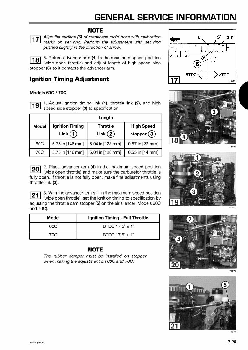
NOTE
Align flat surface
(6)
of crankcase mold boss with calibrationmarks on set ring. Perform the adjustment with set ringpushed slightly in the direction of arrow.
5. Return advancer arm
(4)
to the maximum speed position(wide open throttle) and adjust length of high speed side
stopper
(3)
so it contacts the advancer arm.
Ignition Timing Adjustment
Models 60C / 70C
1. Adjust ignition timing link
(1)
, throttle link
(2)
, and highspeed side stopper
(3)
to specification.
2. Place advancer arm
(4)
in the maximum speed position(wide open throttle) and make sure the carburetor throttle is
fully open. If throttle is not fully open, make fine adjustments usingthrottle link
(2)
.
3. With the advancer arm still in the maximum speed position(wide open throttle), set the ignition timing to specification by
adjusting the throttle cam stopper
(5)
on the air silencer (Models 60Cand 70C).
NOTE
The rubber damper must be installed on stopperwhen making the adjustment on 60C and 70C.
Model
Length
Ignition Timing
Link
Throttle
Link
High Speed
stopper
60C 5.75 in [146 mm] 5.04 in [128 mm] 0.87 in [22 mm]
70C 5.75 in [146 mm] 5.04 in [128 mm] 0.55 in [14 mm]
Model Ignition Timing - Full Throttle
60C BTDC 17.5˚ ± 1˚
70C BTDC 17.5˚ ± 1˚
17
18
19
1 2 3
20
21
T1079
T1080
T1074
T1075
T1076

SECTION 2
2-30
3-/ 4-Cylinder
NOTE
Align flat surface
(6)
of crankcase mold boss withcalibration marks on set ring.
4. Place advancer arm
(4)
in the minimum speed position(throttle fully closed). Adjust throttle link
(2)
so ignition timingis ATDC 3˚ ± 1˚ when the advancer arm is in contact with low speedside stoooer
(7)
.
NOTE
Align flat surface
(6)
of crankcase mold boss with calibrationmarks on set ring. Perform the adjustment with set ringpushed slightly in the direction of arrow.
5. Return advancer arm
(4)
to the maximum speed position(wide open throttle) and adjust length of high speed side
stopper
(3)
so it contacts the advancer arm.
Model Ignition Timing - Throttle Closed
60C ATDC 3˚ ± 1˚
70C ATDC 3˚ ± 1˚
22
23
24
25
T1077
T1079

GENERAL SERVICE INFORMATION
2-31
3-/ 4-Cylinder
Ignition Timing Adjustment
Models 80A / 90A
1. Adjust ignition timing link
(1)
and throttle link
(2)
tospecification :
2. Place advancer arm
(3)
in the maximum speed position(wide open throttle) and make sure the carburetor throttle is
fully open. If throttle is not fully open, make adjustments usingthrottle link
(2)
.
3. With the advancer arm at maximum speed (wide openthrottle), adjust throttle cam stopper
(4)
(Pre-setting length =20 mm) on the air silencer to obtain the specified ignition timing atfull throttle:
NOTE
The rubber damper must be installed on stopperwhen making the adjustment.
4. Adjust high speed stopper
(5)
to specification:
ModelLength
Ignition Timing Link
Throttle Link
80A 4.88 in [124 mm] 5.18 in [131.5 mm]
90A 4.88 in [124 mm] 5.18 in [131.5 mm]
Model Ignition Timing - Full Throttle
80A BTDC 20° ± 1˚
90A BTDC 20° ± 1˚
Model Pre-setting Length
High Speed Side Stopper
80A 0.6 in (15 mm)
90A 0.6 in (15 mm)
26
1 2
27
28
29
5
T1081
T1082
T1083
T1084

SECTION 2
2-32
3-/ 4-Cylinder
5. Place the advancer arm in the minimum speed position(throttle fully closed) and adjust stopper
(6)
(Pre-settinglength = 12 mm) to obtain the specified ignition timing:
NOTE
The rubber damper must be installed on stopperwhen making the adjustment.
6. Return advancer arm
(3)
to the maximum speed position(wide open throttle) and check if comes in contact with the
high speed stopper
(5)
. If advancer arm does not contact stopper,make fine adjustment using throttle link
(2)
.
7. Adjust shift link rod to specification.
Model Ignition Timing - Throttle Closed
80A ATDC 5° ± 1˚
90A ATDC 5° ± 1˚
Model
Length
Shift Link Rod
80A 3.11 in [79 mm]
90A 3.11 in [79 mm]
30
31
32
T1085
T1086
T1087

GENERAL SERVICE INFORMATION
2-33
3-/ 4-Cylinder
Ignition Timing Adjustment
Models 115 / 120 / 140
1. Adjust ignition timing link
(1)
and throttle link
(2)
tospecification:
2. Place advancer arm
(3)
in the minimum speed position(throttle fully closed). Set ignition timing to ATDC 10˚ ± 1˚ . If
throttle is not fully closed, make adjustments using throttle link
(2)
.
3. Adjust stopper bolt
(5)
length so that it contacts theadvancer arm joint at maximum speed.
4. With the advancer arm at maximum speed (wideopen throttle), adjust throttle cam stopper
(4)
on theair silencer to obtain the specified ignition timing at full throttle:
NOTE
The rubber damper must be installed on stopperwhen making the adjustment.
5. Adjust high speed stopper
(5)
to specification:
ModelLength
Ignition Timing Link
Throttle Link
115 5.00 in [127 mm] 6.22 in [158 mm]
120 5.00 in [127 mm] 6.22 in [158 mm]
140 5.00 in [127 mm] 6.22 in [158 mm]
Model Ignition Timing - Full Throttle
115 BTDC 17.5˚ ± 1˚
120 BTDC 17.5˚ ± 1˚
140 BTDC 20˚ ± 1˚
Model Length
High Speed Side Stopper
115 0.71 in [18 mm]
120 0.71 in [18 mm]
140 0.55 in [14 mm]
33
1 2
34
35
35 36
37
5
T1081
T1086
T1083
T1084
36

SECTION 2
2-34
3-/ 4-Cylinder
6. Place the advancer arm in the minimum speed position(throttle fully closed) and adjust stopper
(6)
to obtain thespecified ignition timing:
NOTE
The rubber damper must be installed on stopper whenmaking the adjustment.
7. Return advancer arm
(3)
to the maximum speed position(wide open throttle) and verify that advancer arm contacts
the high speed stopper
(5)
. If advancer arm does not contactstopper, make fine adjustments using throttle link
(2)
.
8. Adjust shift link rod to specification.
Model Ignition Timing - Throttle Closed
115 ATDC 10˚ ± 1˚
120 ATDC 10˚ ± 1˚
140 ATDC 10˚ ± 1˚
Model Length
Shift Link Rod
115 3.66 in [93 mm]
120 3.66 in [93 mm]
140 3.66 in [93 mm]
38
39
40
41
T1757
T1085
T1086
T1087

GENERAL SERVICE INFORMATION
2-35
3-/ 4-Cylinder
Carburetor Synchronization
NOTE
Engine ignition timing must be properly adjustedbefore synchronizing the carburetors.
1. Remove the air silencer cover.
2. Disconnect ignition timing link
(1)
and throttle link
(2)
sothrottle lever roller
(3)
does not make contact with throttlecam
(4)
.
3. Adjust the length of each carburetor throttle link rod
(5)
tospecification :
4. Reconnect timing link
(1)
.
5. Turn
all
throttle lever screws
(6)
clockwise to loosen. Thethrottle butterfly valves should return to a fully closed
position.
6. Loosen throttle stop screw
(7)
on top carburetor (middlecarburetor on models 60 and 70) so it does not make
contact with throttle lever
(8)
. The throttle butterfly valve shouldreturn to a fully closed position.
7. Starting with the second carburetor from the top of theengine, apply light upward pressure to linkage tab
(9)
andturn throttle lever screw
(6)
counterclockwise to tighten the throttlelever. Repeat this step for each remaining carburetor, workingtoward the bottom carburetor.
Model
Length
Link
40 / 50 3.54 in [90 mm]
60 / 70 3.81 in [97 mm]
80 / 90 / 115 / 120 / 140 4.33 in [110 mm]
1
2
5
1
3
4
5
T1088
T1089
T1090
T1091
T1092

SECTION 2
2-36
3-/ 4-Cylinder
8. Turn throttle stop screw
(7)
until it touches throttle lever
(8)
, then tighten the screw to the specified number of turns:
9. Install the air silencer cover.
10. Start and run engine up to normal operating temperature.Working from top to bottom carburetor, gradually adjust
each pilot screw
(10)
to find the setting at which engine speedincreases most when screw is opened to the specified number ofturns from its fully closed position:
NOTE
For the following step, the boat and engine must bein the water under normal operating conditions withthe correct propeller installed. The boat cannot betied to a trailer or dock and must be free to move.
Model
Throttle Stop Screw
Number of Turns
40 / 50 2-1/2
60 / 70 1-1/4
80 / 90 / 115 / 120 / 140
As needed so throttle valve is open 5˚
Model Pilot Screw
Number of Turns
40D 1-1/4 ± 3/4
40D
2
1 -5/8 ± 3/4
50 D 2-3/4 ± 3/4
50D
2
2 ± 3/4
60B / 70B 1-1/2 ± 1/4
60C / 70C 1-3/8 ± 1/4
80 / 90 1-5/8 ± 1/4
115 / 120 / 140 1-5/8 ± 1/4
6
7
7
10
T1091
T1093

GENERAL SERVICE INFORMATION
2-37
3-/ 4-Cylinder
11. Start and run the engine up to normal operating temperature.With an accurate tachometer installed, adjust the throttle stopscrew to obtain the specified RPM at neutral idle and trollingspeeds:
Oil Pump Aperture Adjustment
NOTE
Engine ignition timing must be properly adjusted andthe carburetors synchronized before adjusting the oilpump aperture.
The oil pump aperture is adjusted at a specified throttle setting byadjusting the length of the oil pump link rod so the control lever isproperly aligned with the 7 mm scribe mark on the oil pump. Usethe following specification table and procedure to adjust the oilpump aperture.
1. Set the carburetor throttle as specified.
2. Check the alignment of the specified indicator mark on thecontrol lever with the scribe mark on the oil pump. Marks must bealigned as shown in the correct figure. If not aligned, determine iflink rod needs to be lengthened or shortened to bring the marksinto alignment.
3. Remove the oil pump link rod and make length adjustment.Reinstall link rod.
4. Recheck the alignment at the specified throttle setting(s).
5. Repeat procedure until oil pump aperture is properly adjusted.
Model Neutral Idle RPM Trolling RPM
40 / 50 900 750
60 / 70 900 750
80 / 90 900 700
115 / 120 / 140 900 700

SECTION 2
2-38
3-/ 4-Cylinder
*Verify only adjustment made in CLOSED position.
Model Throttle Position Aperture Setting
40 / 50 Fully OPEN
Marks and aligned.
60 / 70 Fully CLOSED
Marks and aligned.
70 Fully OPEN*
Marks and aligned.
90 / 115 /120 / 140
Fully CLOSED
Marks and aligned.
90 Fully OPEN*
Marks and aligned.
1 1 2
2 1 3
3 1 4
4 1 5
5 1 6
T1094 T1095 T1096
T1097
T1098

GENERAL SERVICE INFORMATION
2-39
3-/ 4-Cylinder
ANODES - INSPECTION AND TESTING
Engines are equipped with several sacrificial anodes to help protectmetal parts from the effects of galvanic corrosion (electrolysis).Disintegration of the anodes indicates they are performing theirfunction. An anode must be replaced when it has been reduced to2/3 its original size (1/3 eroded). Engine corrosion will increase iferoded anodes are not replaced.
CAUTION
Do not paint or coat anodes or their mountingsurfaces.
External Anodes
Anodes mounted externally on the engine should be inspectedevery 3 months, or more frequently if the engine is operated in saltor polluted water.
Inspect sacrificial trim tab
(1)
for erosion.
Inspect stern bracket anode
(2)
for erosion.
Crankcase Anode
The powerhead is protected by an anode mounted in thecrankcase under the cylinder head. Replace crankcase
anode
(3)
when service work requires removal of the cylinder heador when a complete overhaul of the engine is performed.
Installation Test
Use the following procedure to test for proper installation ofanodes. Make sure anode surface is clean before testing.
1. Calibrate an ohmmeter on high ohms scale.
2. Connect one meter lead to a ground on the powerheadand the other lead to the anode. The ohmmetershould show
a low reading. If not, remove the anode and clean the surfacewhere it was mounted. The anode and its mounting hardwareshould also be cleaned. Install anode and retest.
1
2
3
4
T1099
T1100
T1101
T1102

SECTION 2
2-40
3-/ 4-Cylinder
THIS PAGE INTENTIONALLY LEFT BLANK.

3-/ 4-Cylinder
3-1
General Precautions ............................................................................................................ 3-2
Service Specifications ......................................................................................................... 3-3
Fuel System Requirements ................................................................................................. 3-4
Troubleshooting ................................................................................................................... 3-6
Description of Operation ..................................................................................................... 3-8
Fuel Tank ........................................................................................................................... 3-11
Fuel Line and Primer ......................................................................................................... 3-12
Fuel and Oil Filters ............................................................................................................ 3-13
Fuel Pump ......................................................................................................................... 3-14
Automixing System ........................................................................................................... 3-17
Carburetor ......................................................................................................................... 3-20
Intake Manifold .................................................................................................................. 3-24
SECTION 3FUEL SYSTEM
TABLE OF CONTENTS

SECTION 3
3-2
3-/ 4-Cylinder
GENERAL PRECAUTIONS
WARNING
Gasoline is extremely flammable and can readilyexplode if mishandled.
Before performing any service work on the fuel system, read andunderstand Section 1 - Service Safety.
Before servicing the fuel system, disable the engine ignition systemto prevent accidental starting of engine.
Fuel leakage can contribute to a fire or explosion. After servicework is complete and engine is fully assembled, always run theengine momentarily to pressurize the fuel system, then check forleaks.
Never run the engine with any fuel system component removed ordisconnected.
Check fuel hoses and other nonmetallic components for indicationsof damage or deterioration. Always replace components withgenuine factory replacement parts suitable for fuel systems.
Clean up fuel spills immediately and store rags in approvedcontainers. Keep drained fuel in approved containers for properdisposal.
When using compressed air to clean or dry parts, make sure airsupply is regulated not to exceed 25 psi [172 kPa / 1.76 kg/cm
2
].

FUEL SYSTEM
3-3
3-/ 4-Cylinder
SERVICE SPECIFICATIONS
Special Torque Values
*Refer to Section 2 for Standard Torque Values chart.
Carburetor Specifications
Description
Torque in-Ib N·m
kg-m Threadlocker
Model
40 / 50 60 / 70 80 / 90 115 / 120 / 140
Carburetor Mounting Bolt
44 - 53 5 - 6
0.5 - 0.6
44 - 53 5 - 6
0.5 - 0.6 –– –– ––
Intake Manifold Bolt
53 6
0.6
80 9
0.9
53 6
0.6 *
Air Silencer Bolt *
26 - 35 3 - 4
0.3 - 0.4 * * Loctite 242
Air Silencer Cover Bolt *
8.9 1
0.1
8.9 1
0.1
26 - 44 3 - 5
0.3 - 0.5 ––
Model Main Jet Main Air Jet Slow Jet Slow Air
Jet Pilot Screw
Turn-Out
Neutral Idle Speed
AdjustmentRPM
Trolling Speed
AdjustmentRPM
40D #125 #210 #66 #130 1-14 ± 3/4 900 750
40D
2
#122 #190 #66 #130 1-5/8 ± 3/4 900 750
50D #135 #230 #74 #130 2-3/4 ± 3/4 900 750
50D
2
#132 U&C#135 L
#230 #80 #150 2 ± 3/4 900 750
60B #145 #145 #75 #75 1-1/2 ± 1/4 900 750
60C #138 U&L#140 C
#155 #72 #75 1-3/8 ± 1/4 900 750
70B #145 #145 #75 #75 1-1/2 ± 1/4 900 750
70C #138 U&L#140 C
#155 #72 #75 1-3/8 ± 1/4 900 750
80 #150 #165 #75 #85 1-5/8 ± 1/4 900 700
90 #150 #165 #75 #85 1-5/8 ± 1/4 900 700
115 #162 #160 #75 #70 1-5/8 ± 1/4 900 700
120 #162 #160 #75 #70 1-5/8 ± 1/4 900 700
140 #162 #160 #75 #70 1-5/8 ± 1/4 900 700
U - Upper Carburetor C - Center Carburetor L - Lower Carburetor
SECTION 3
3-4
3-/ 4-Cylinder
Manufacturer Special Tools Required
None
General Equipment Required
Fuel Pressure Gauge, 0 - 15 psi [0 - 103 kPa / 0 - 1 kg/cm
2
]Torque Wrench, 0 - 150 in-lb [0 - 17 N-m / 0 - 1.7kg-m]Digital Pulse Tachometer, 10 RPM,
Electonic Specialties
®
Model 321 or equivalent
Flexible Fuel Tubing, 1/4 in. I.D. x 5 in. [6 mm I.D. x 127 mm] Flexible Fuel Tubing, 3/8 in. I.D. x 5 in. [9.5 mm I.D. x 127 mm]Gearcase Pressure Tester,
Stevens
®
S-34 or equivalent
Consumable Supplies Required
Thread Locker,
Loctite
®
242
Isopropyl Alcohol Cleaning Solvent Engine Lubricant,
Genuine Engine Oil or NMMA Certified TC-W3 Oil
Gasket Sealant,
Permatex
®
High Tack Gasket Sealant
FUEL SYSTEM REQUIREMENTS
Acceptable Fuel
Any premium gasoline with pump posted octane rating over 89(research octane rating of 91) and with no more than 10% Ethanolby volume.
Unacceptable Fuel
Gasoline with more than 5% Methanol (even if it contains co-solvents or corrosion inhibitor) or more than 10% Ethanol, regardlessof the octane rating.
Fuel Storage Life
Untreated gasoline or premixed fuel stored longer than 2 weeksshould not be used for outboard engine operation. Fuel treated witha stabilizer additive at the time of storage should not be used aftera period of 3 months.
Acceptable Lubricant
Any NMMA certified TC-W3 2-cycle outboard engine oil isacceptable for automixing system and fuel tank premixapplications. Do not use automotive oils which can damage theengine and shorten spark plug life.
CAUTION
Do not mix different brands or types of oil. Doingso can cause oil gelling which may block the oilfilter screen and cause serious powerheaddamage due to lack of lubrication.

FUEL SYSTEM
3-5
3-/ 4-Cylinder
Mix Ratios
CAUTION
In addition to oil in the oil tank, a 50:1 gasoline/oilmixture is required during engine break-in. Referto Break-In Procedure in Section 2.
Automixing
The gasoline/oil mixing ratio varies automatically between 50:1 (2%oil) and 120:1 (0.8% oil) according to throttle opening and enginespeed.
Premixing
Engines not equipped with automixing system, or engines to beoperated with automixing system disabled require a 50:1 gasoline/oil mixture (2% oil). New engines, reconditioned powerheads, andengines coming out of storage require a 25:1 gasoline/oil mixture(4% oil) during the first 10 hours of operation.

SECTION 3
3-6
3-/ 4-Cylinder
TROUBLESHOOTING
The troubleshooting chart lists common engine symptoms relatedto problems with the fuel system. It also indicates specificmalfunctions in the fuel system which may be causing the problemso it can be isolated more effectively. Before beginning majortroubleshooting operations on the fuel system, perform thefollowing operations:
• Disconnect fuel tank hose from the engine. Connect a knowngood tank and hose and determine if the problem persists.
• Remove and clean the engine fuel filter assembly and replace thefilter element.
• Replace filter element in the fuel tank pickup tube. • Remove and clean the automixing check valve.
FUEL TANK AND FILTERS
Empty fuel tank • •
Low fuel in tank • •
Fuel tank air vent closed • • • •
Poor quality or old fuel • • • •
Water in fuel system • • •
Fuel hose pinched or disconnected • • • •
Restricted fuel pickup pipe or clogged pipe filter
• • • •
Faulty primer bulb •
Improper or faulty anti-siphon valve • • • •
Clogged fuel filter • • • •
Loose connector or vacuum leak • •
Symptom
Checks
Har
d t
o st
art
or
will
not
sta
rt
Low
sp
eed
mis
s or
will
not
idle
sm
ooth
and
slo
w e
noug
h H
igh
spee
d
mis
s P
oor
acce
lera
tion,
he
sita
tion,
cou
ghs
Run
s ro
ugh
and
sm
okes
w
ith v
ibra
tion
Idle
s w
ell,
then
sl
ows
and
sto
ps
Will
not
sta
rt a
nd a
fter
fires
in
to e
xhau
st h
ousi
ng
No
acce
lera
tion,
lo
w t
op e
nd R
PM
Id
les
wel
l but
sl
ows
whe
n ac
cele
rate
d
Run
s at
hig
h sp
eed
onl
yw
hen
hand
prim
er is
use
d
Eng
ine
stop
ssu
dd
enly
R
uns
nois
y an
d k
nock
s E
xces
sive
fuel
co
nsum
ptio
n

FUEL SYSTEM
3-7
3-/ 4-Cylinder
OIL MIXTURE
No oil in engine oil tank • •
Mixture too rich (too much oil) • •
Mixture too lean (not enough oil) • • • • •
CARBURETOR
Carburetor out of adjustment • • • • • • •
Carburetor obstruction or faulty needle valve
•
Restricted air flow to carburetor •
Faulty choke valve • • •
Carburetor and ignition timing not synchronized
• •
Carburetors not synchronized • • • •
Float position too high • •
Float position too low • • •
Jet obstructed or defective • • • •
Carburetor gasket leakage • •
RECIRCULATION SYSTEM
Puddle drain valve or hose blockage • • •
Recirculation hose misrouted • •
FUEL PUMP
Mounting gasket leakage • •
Check valve sticking open or closed • •
Ruptured diaphragm • •
INLET MANIFOLD
Warped inlet manifold • •
Manifold gasket leakage • •
Faulty reed valve operation or broken valve
• • •
Reed valve gasket leakage • • • •
Symptom
Checks
Har
d t
o st
art
or
will
not
sta
rt
Low
sp
eed
mis
s or
will
not
idle
sm
ooth
and
slo
w e
noug
h H
igh
spee
d
mis
s P
oor
acce
lera
tion,
he
sita
tion,
cou
ghs
Run
s ro
ugh
and
sm
okes
w
ith v
ibra
tion
Idle
s w
ell,
then
sl
ows
and
sto
ps
Will
not
sta
rt a
nd a
fter
fires
in
to e
xhau
st h
ousi
ng
No
acce
lera
tion,
lo
w t
op e
nd R
PM
Id
les
wel
l but
sl
ows
whe
n ac
cele
rate
d
Run
s at
hig
h sp
eed
onl
yw
hen
hand
prim
er is
use
d
Eng
ine
stop
ssu
dd
enly
R
uns
nois
y an
d k
nock
s E
xces
sive
fuel
co
nsum
ptio
n
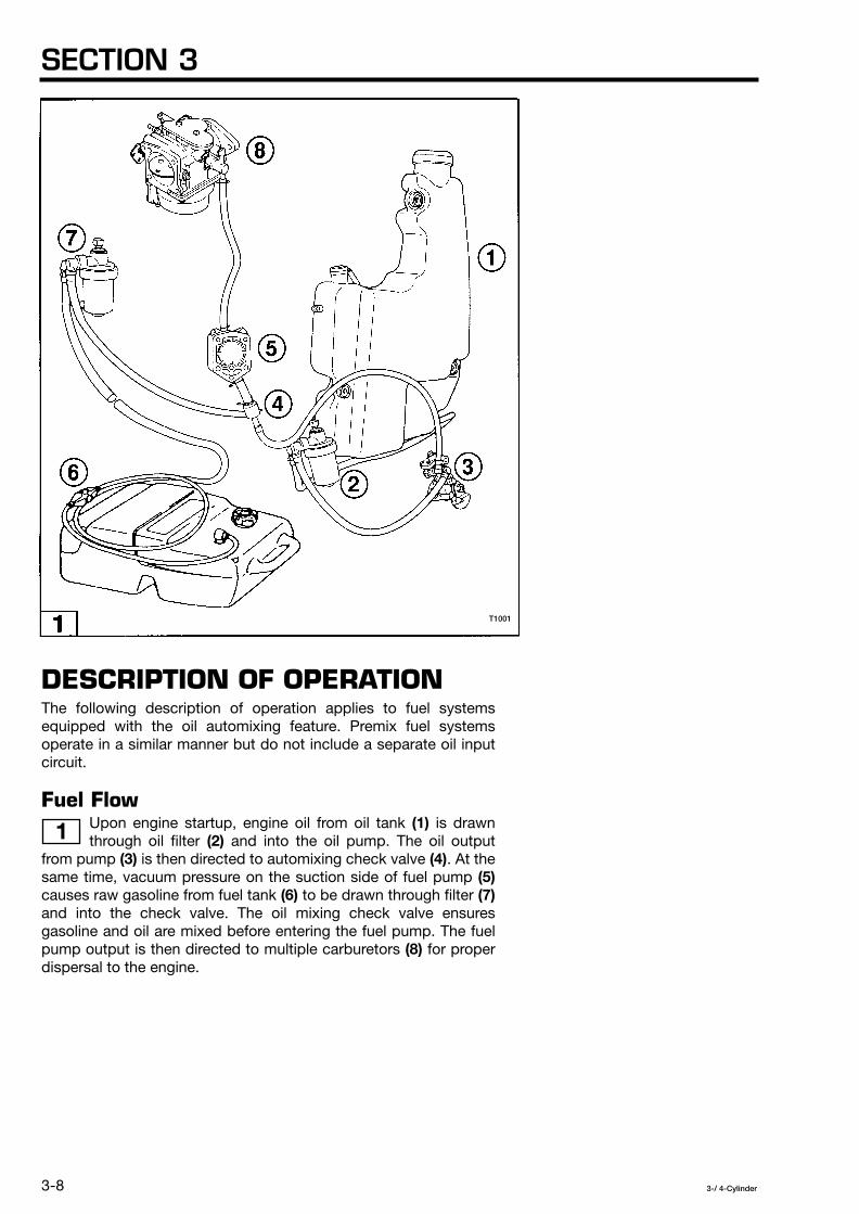
SECTION 3
3-8
3-/ 4-Cylinder
DESCRIPTION OF OPERATION
The following description of operation applies to fuel systemsequipped with the oil automixing feature. Premix fuel systemsoperate in a similar manner but do not include a separate oil inputcircuit.
Fuel Flow
Upon engine startup, engine oil from oil tank
(1)
is drawnthrough oil filter
(2)
and into the oil pump. The oil outputfrom pump
(3)
is then directed to automixing check valve
(4)
. At thesame time, vacuum pressure on the suction side of fuel pump
(5)
causes raw gasoline from fuel tank
(6)
to be drawn through filter
(7)
and into the check valve. The oil mixing check valve ensuresgasoline and oil are mixed before entering the fuel pump. The fuelpump output is then directed to multiple carburetors
(8)
for properdispersal to the engine.
1
T1001

FUEL SYSTEM
3-9
3-/ 4-Cylinder
Oil Pump
The oil pump is a plunger type mainly containing an internalworm gear driven by engine revolution, a spindle gear, and a
cam shaft connected to engine throttle linkage.
Fuel Pump
The fuel pump is integral with the carburetor or mounted onthe side of the crankcase and contains one or more internal
diaphragms
(1)
. The diaphragms fluctuate in response to changingcrankcase pressures
(2)
which produces fuel input
(3)
and output
(4)
through multiple check valves
(5)
in the pump.
Carburetors
The carburetors use a pilot system and main system tometer and deliver an atomized fuel mixture to the engine for
proper combustion under varying operating conditions.
2
3
4
T1002
T1003
T1004
T1005

SECTION 3
3-10
3-/ 4-Cylinder
Pilot System
The pilot system in the carburetor is a slow speed systemconsisting of the slow jet, slow air jet, pilot outlet, bypass,
and pilot adjusting screw. At low throttle, mixed fuel
(1)
enters thecarburetor and flows from carburetor float chamber
(2)
throughpassage
(3)
to slow jet
(4)
. Air
(5)
measured at slow air jet
(6)
isdirected through passage
(7)
and combines with the existing fuelfrom the slow jet to form fuel/air mixture
(8)
. After exiting bypass
(9)
, the mixture directly enters engine
(10)
or passes pilotadjustment screw
(11)
for output to engine through pilot outlet
(12)
.Unrestricted air flow to the engine is available through venturi
(13)
.
Under idling conditions, the mixture of fuel and air is mainly outputfrom the pilot outlet. As throttle is increased, the negative pressureapplied to the pilot system increases and allows more of themixture to be output from the bypass. When the throttle is openedfurther, the increase of air causes a pressure drop which allows themain system to assume almost full control of fuel delivery.
Main System
The main system in the carburetors is a high speed systemconsisting of the main jet, main nozzle, and main air jet. As
the throttle valve opens, mixed fuel
(1)
enters the carburetor andflows from carburetor float chamber
(2)
to main jet
(3)
. The fuel isthen measured and directed to main nozzle bleed hole
(4)
where itcombines with air
(5)
from main air jet
(6)
. The increased air quantityand flow rate at venturi
(7)
allows pressure to drop at the tip of mainnozzle
(8)
, causing increased output of fuel/air mixture
(9)
. The fuelmixture combines with main air at the venturi before enteringengine
(10)
.
Recirculation
Recirculation hoses at the inlet manifold and crankcase assist inrecirculation of unburned fuel for consumption by the engine.
Mixture Enrichment
Fuel mixture enrichment for cold engine starting is controlled by anelectric choke solenoid actuated at the remote control box, or by amanual choke lever mounted on the air silencer.
5
6
T1006

FUEL SYSTEM
3-11
3-/ 4-Cylinder
FUEL TANK
Water or dirt in the fuel tank can cause fuel starvation and engineproblems. Clean and inspect fuel tank once a year or after long timestorage (more than 3 months).
Cleaning
1. Disconnect fuel line from fuel tank.
2. Empty remaining fuel from tank and properly dispose.
3. Fill tank 1/4 with fresh gasoline and install cap. Rigorously shaketank for 30 seconds to loosen dirt particles.
4. Empty gasoline from tank and properly dispose.
5. Inspect tank components before refilling.
Inspection
All worn, damaged, or missing parts must be replaced.
1. Inspect overall condition of tank exterior and interior. Cracked ordamaged tanks must be removed from service.
2. Inspect the cap vent screw and inner gasket
(1)
for wearor damage. Check float
(2)
moves freely and operates thegauge needle.
3. Unscrew tank pickup tube and check for cracks. Removeand inspect connector
(3)
, filter
(4)
, and o-ring
(5)
.
4. Reassemble and install all tank components.
5. See Fuel Line and Primer, this section.
1
2
T1017
T1018

SECTION 3
3-12
3-/ 4-Cylinder
FUEL LINE AND PRIMER
CAUTION
Model 115, 120, and 140 fuel line assembly is notsame model 90, 70, 60, 50 and 40 one.
NOTE
Before complete disassembly of fuel line and primer,check for damage or blockage of fuel line quickdisconnects at engine and fuel tank.
Disassembly
1. Disconnect fuel line from engine and fuel tank.
2. Carefully remove all hose clamps with flat blade screwdriver.
3. Disassemble all components.
Cleaning and Inspection
All worn, damaged, or missing parts must be replaced.
1. Clean all components with warm soapy water and rinsethoroughly with fresh water.
2. Dry all components with low pressure compressed air. All partsand passages must be completely dry.
3. Inspect all parts for wear or damage. Make sure check valves inquick disconnects open freely when pressed.
T1019

FUEL SYSTEM
3-13
3-/ 4-Cylinder
4. Reassemble all components.
NOTE
Install primer so arrow points in direction of fuel flow.Use pliers to compress hose clamps to propershape.
FUEL AND OIL FILTERS
The fuel and oil filter assemblies should be removed from theengine and serviced after engine break-in and after every 50 hoursof operation (3 months). Replace the filter element at least onceeach season. Service the fuel pickup tube filter as described in FuelTank, this section.
To periodically inspect and clean the filter element withoutremoving the filter assembly from the engine, loosen and
remove the filter bowl with a wrench by turning it clockwise.
Disassembly
NOTE
Before servicing fuel filter, disconnect the fuel hosefrom the engine to prevent excessive fuel spillage.
1. Disconnect hoses from filter assembly.
2. Loosen nut from filter mounting bolt and remove filter assemblyfrom engine.
3. Unscrew filter bowl and remove two o-rings and filter element.
4. Clean and inspect parts.
Cleaning and Inspection
All worn, damaged, or missing parts must be replaced.
1. Clean all parts of filter assembly with a mild aerosol solvent orisopropyl alcohol.
2. Allow filter element
(1)
to air dry. Dry all other parts withlow pressure compressed air.
3. Inspect o-rings
(2)
for cracks and deterioration. Checkbody
(3)
and filter bowl
(4)
for damage. Replace filterelement
(1)
if torn or still dirty.
4. Reassemble and install filter assembly.
1
2
3
T1020
T1021

SECTION 3
3-14
3-/ 4-Cylinder
5. Connect filter hoses.
6. After servicing oil filter, bleed automixing system. See AutomixingSystem, this section.
FUEL PUMP
NOTE
Before servicing the fuel pump, disconnect the fuelhose from the engine to prevent excessive fuelspillage.
NOTE
Improper arrangement of fuel pump parts may notprevent full assembly of the unit. Match mark partsbefore disassembly and reference the illustrations inthe Inspection procedure to ensure proper orientationof internal components.
Disassembly
NOTE
Models 40 and 50 are equipped with carburetormounted fuel pump. Disconnect fuel hoses frompump, loosen the four mounting screws and removepump. Gently separate the pump components andcontinue with Cleaning and Inspection procedures.
1. Disconnect fuel hoses from fuel pump.
2. Loosen pump mounting screws and remove fuel pump
(1)
and gasket
(2)
from crankcase.
3. Remove the fuel pump cover screws and cover. Gently separatethe pump components.
NOTE
The fuel pump of the former production models 60,70, 80 and 90 uses a guide plate
(3)
and a spring
(4)
.For the present production models 60, 70, 80 and90, the material of the pump diaphragm has beenchanged, and the guide plate
(3)
and the spring
(4)
are not used. Those components are still used for themodels 115, 120 and 140.
1
2
T1007
T1008

FUEL SYSTEM
3-15
3-/ 4-Cylinder
4. Remove and discard all serviceable gaskets and diaphragms.
NOTE
Use of gasket
(5)
with black rubber diaphram
(6)
isdiscontinued on past production models 60, 70, 80and 90. Remove and discard them. Factoryreplacement parts include resin film diaphragm withtwo gaskets.
5. Remove all checkvalves
(7)
from pump body.
Cleaning
1. Clean all pump components with mild solvent or isopropylalcohol.
2. Clean pump mounting surface on carburetor with isopropylalcohol (models 40 and 50).
3. Dry all components with low pressure compressed air. Ensure allpassages are completely dry.
Inspection
1. Inspect pump body
(1)
for cracks.
2. Inspect check valves
(2)
for deformation.
3. Inspect pump covers
(3)
for cracks, surfacedeformation, and thread damage.
4. Inspect guide plate
(4)
and spring
(5)
for deformation andproper tension (models 115, 120, and 140).
3
4
5 6 7
5 6 7
5 6 7
7
T1022
T1009
T1010
T1011 T1012

SECTION 3
3-16
3-/ 4-Cylinder
5. Inspect gasket between crankcase and fuel pump for dryness(crankcase-mounted pumps).
6. Verify pre-drilled pressure intake hole
(1)
exists in rearpump cover. Hole diameter must be 0.079 in [2 mm]
(crankcase-mounted pumps) (115-140 only).
Assembly
1. Install all check valves in pump body.
2. Fully assemble fuel pump. All serviceable gaskets and diaphragmsmust be replaced
NOTE
Use of rear gasket, black rubber diaphram, guideplate, and spring is discontinued on past productionmodels 60, 70, 80 and 90. Factory replacement partsinclude resin film diaphram
(1)
with gaskets
(2)
.
NOTE
On past production models 60, 70, 80, and 90 and allmodels 115, 120, and 140, first install internal guideplate and spring assemblies in pump body.
3. Install fuel pump. Use Loctite 242 on mounting screw threads.
4. Connect fuel hoses to fuel pump.
8
9
10
T1979
T1023
T1014
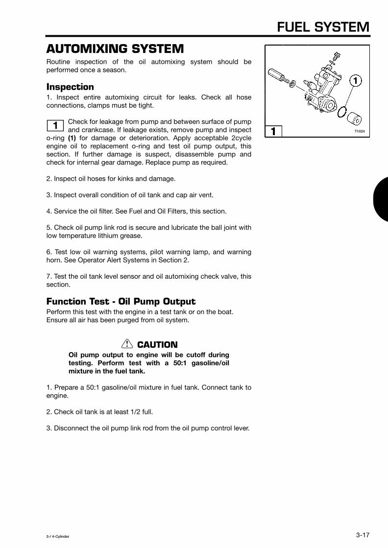
FUEL SYSTEM
3-17
3-/ 4-Cylinder
AUTOMIXING SYSTEM
Routine inspection of the oil automixing system should beperformed once a season.
Inspection
1. Inspect entire automixing circuit for leaks. Check all hoseconnections, clamps must be tight.
Check for leakage from pump and between surface of pumpand crankcase. If leakage exists, remove pump and inspect
o-ring
(1)
for damage or deterioration. Apply acceptable 2cycleengine oil to replacement o-ring and test oil pump output, thissection. If further damage is suspect, disassemble pump andcheck for internal gear damage. Replace pump as required.
2. Inspect oil hoses for kinks and damage.
3. Inspect overall condition of oil tank and cap air vent.
4. Service the oil filter. See Fuel and Oil Filters, this section.
5. Check oil pump link rod is secure and lubricate the ball joint withlow temperature lithium grease.
6. Test low oil warning systems, pilot warning lamp, and warninghorn. See Operator Alert Systems in Section 2.
7. Test the oil tank level sensor and oil automixing check valve, thissection.
Function Test - Oil Pump Output
Perform this test with the engine in a test tank or on the boat.Ensure all air has been purged from oil system.
CAUTION
Oil pump output to engine will be cutoff duringtesting. Perform test with a 50:1 gasoline/oilmixture in the fuel tank.
1. Prepare a 50:1 gasoline/oil mixture in fuel tank. Connect tank toengine.
2. Check oil tank is at least 1/2 full.
3. Disconnect the oil pump link rod from the oil pump control lever.
1
T1024

SECTION 3
3-18
3-/ 4-Cylinder
4. Using a short piece of wire, secure the oil pump control lever inthe WIDE OPEN position.
NOTE
See Oil Pump Aperture Adjustment in Section 2 forcorrect position of oil pump control lever at fullthrottle.
5. Install tachometer.
6. Disconnect the oil pump OUTPUT hose from the automixingcheck valve and route hose into a clean graduated container.
7. Start and run engine in NEUTRAL at 1500 RPM for 10 minutes.Starttiming when oil begins to drip from oil OUTPUT hose. Stopengine after 10 minutes and measure oil quantity in container.Repair or replace oil pump if following oil output is not obtained:
Function Test - Oil Level Sensor
1. Disconnect the oil level sensor leads at the electrical box andremove sensor from tank.
2. Reconnect the sensor leads.
3. Place the remote control lever in the FORWARD or REVERSEposition.
4. Turn the main switch key to the ON position and check thefollowing:
Models 115 / 120 / 140:
Model Oil Output fl oz / 10 min [mL / 10 min]
40 / 50 0.4 - 0.5 [13 - 16]
60 / 70 0.8 - 0.9 [23 - 28]
80 / 90 1.1 - 1.4 [33 - 40]
115 / 120 / 140 1.7 - 2.1 [51 - 62]
2
3 4
3 4
• Lower oil level indicator
(1)
flashes, warning hornsounds and ESG limits RPM to 3000 ± 200 RPMwhen float
(2)
makes contact with sensor switch
(3)
.
• Upper oil level indicator
(4)
illuminates when float
(5)
makes contact with sensor switch
(6)
.
T1025
T1026
T1027

FUEL SYSTEM
3-19
3-/ 4-Cylinder
Models 60 / 70 / 80 / 90:• Oil level indicator on tachometer illuminates and warning horn
sounds when float makes contact with sensor switch.
Models 40 / 50 with remote control:
• Oil level indicator on tachometer illuminates and warning hornsounds when float makes contact with sensor switch.
Models 40 / 50 with tiller control:
• Pilot lamp on lower motor cover illuminates when float makescontact with sensor switch.
5. Re-install oil level sensor. Apply a silicone-based sealant to thesensor cap.
Function Test - Automixing Check Valve
1. Disconnect the oil INPUT hose and fuel OUTPUT hose from theautomixing check valve.
2. Connect a gear case pressure tester to the oil INPUT fitting onautomixing check valve.
3. Slowly pump up pressure and watch gauge. Gauge readingshould drop off at 5 psi [34 kPa/0.34 kg/cm
2
], indicating the valvehas opened. If pressure drops at lower or higher reading, replacethe valve.
Bleeding the Automixing System
Always bleed the air from the oil automixing system in the followingsituations:• When the engine is new from the factory.• After engine runs out of oil.• After checking the oil filter element.• After disconnecting any oil hose between the oil tank and pump.
1. Fill the oil tank.
2. Momentarily run engine to ensure the oil system is pressurized.Stop engine.
3. Loosen air bleed screw
(1)
on oil pump.
4. Visually check no air remains in the transparent oil hoses fromtank to filter and from filter to pump, then tighten the bleed screw.
5. Start and idle engine in NEUTRAL until no air remains in thetransparent oil hose between pump and automixing check valve.
NOTE
To purge the air more quickly, remove oil pump linkrod and idle engine with pump control lever in WIDEOPEN position.
5
T1028

SECTION 3
3-20
3-/ 4-Cylinder
CARBURETOR
Removal
1. Remove the air silencer and oil tank.
2. Remove the carburetor throttle and choke linkage.
3. Disconnect the choke solenoid plunger hook or choke knob linkrod as required.
4. Remove all fuel hoses from carburetor fuel fittings.
CAUTION
Do not pull fuel hoses off fuel fittings –– pushthem off. If hose cannot be pushed off, carefullycut the hose along its side and peel it off to avoiddamaging the fitting.
5. Remove carburetors and discard the carburetor base gaskets.
Disassembly
NOTE
Bottom carburetor on models 40 and 50 is equippedwith integral fuel pump. To ensure proper cleaning ofthe carburetor, remove and service the fuel pump atthis time. Refer to Fuel Pump, this section.
1. Remove drain screw from float chamber and allow to drain.
2. Fully disassemble the carburetor as illustrated in the Inspectionprocedure.
CAUTION
Use the following precautions during carburetordisassembly:• Use correct size screwdrivers to avoid damaging
the carburetor jets.• Throttle stop screw spring has higher tension
than pilot screw spring. DO NOT interchangethe springs.
Cleaning
CAUTION
Never clean carburetor by submerging or soakingin a hot tank or carburetor dip cleaner. Do notexpose plastic parts to any carburetor cleaner.

FUEL SYSTEM
3-21
3-/ 4-Cylinder
1. Clean all metal components using a mild aerosol solvent orisopropyl alcohol. Use a soft bristle brush to remove gummydeposits. Clean plastic parts with warm soapy water.
2. Dry all components with low pressure compressed air. Whendrying passages, direct the flow of air opposite the direction of fuelflow.
3. Inspect the carburetors, this section.
Inspection
All worn, damaged, or missing parts must be replaced.
Internal Components
1. Inspect the following float valve components:• Check tip of float valve
(1)
for grooves, nicks, or distortion.• Check float valve pin
(2)
and float clip
(3)
for damage ordeformation.
• Check float
(4)
for damage and signs of fuel saturation.
2. Inspect pilot adjust screw
(5)
for thread damage. Check tip forgrooves, nicks, or distortion.
3. Check tension of throttle stop screw and pilot adjust screwsprings. DO NOT interchange the springs.
4. Inspect main jet
(6)
for thread damage and blockage. Check allpassages in main nozzle
(7)
are free of blockage.
5. Inspect slow jet
(8)
for thread damage and blockage.
Carburetor Body
6. Check all passages and drillings with a syringe filled withisopropyl alcohol.
1 2 3
T1029
T1031T1030

SECTION 3
3-22
3-/ 4-Cylinder
7. Inspect float valve seat
(9)
for nicks, scratches, or distortion.DO NOT remove the seat. If valve seat is defective, carburetor
must be replaced.
8. Inspect all gasket surfaces for damage.
9. Check throttle shaft and choke shaft for excessive play. Inspectthe butterfly valves for damage.
10. Visually inspect the fuel fitting, carburetor cover, float chamber,drain screw, and all other screws and washers for damage.
Assembly
NOTE
Before proceeding, be sure all components arecompletely clean and dry and all replacement partsmatch the originals.
NOTE
Fully assemble bottom carburetor on models 40 and50 before installing the fuel pump.
1. During assembly, replace all serviceable gaskets
(1)
and plugs
(2)
as illustrated.
4
5 6 7
T1032
T1035T1034T1033

FUEL SYSTEM
3-23
3-/ 4-Cylinder
2. Invert carburetor and install following components. Tighten jetssecurely but do not use threadlocker:
• Main nozzle and main jet.
• Slow jet and plug.
• Float valve assembly.
3. Check the float height with the carburetor inverted on aflat surface. Measure the distance between the top of the
float and the float chamber surface at the opposite side of theneedle valve.
NOTE
If float height is not correct, remove the float valveassembly and make minor adjustments by slightlybending the tabs on the float hinge clip. Models 40and 50 cannot be adjusted.
4. Install new gasket on float chamber.
5. Install float chamber, and tighten screws in a criss-cross pattern.
6. Install drain screw and new o-ring gasket.
7. Place carburetor in upright position and install gasket plates (ifequipped), new gasket(s), and carburetor cover.
8. Install pilot and throttle stop screws and springs. DO NOTinterchange springs.
MODEL FLOAT HEIGHT
40D / 40D2 0.591 in (15.0 mm)
500 / 50D2 0.591 in (15.0 mm)
60B / 60C 0.551 in (14 mm)
70B / 70C 0.551 in (14 mm)
80A 0.768 in (19.5 mm)
90A 0.768 in (19.5 mm)
115A2 0.768 in (19.5 mm)
120A2 0.768 in (19.5 mm)
140A2 0.768 in (19.5 mm)
8
9
T1036
T1037

SECTION 3
3-24
3-/ 4-Cylinder
Installation
1. Clean the carburetor mounting surfaces on the intake manifoldwith isopropyl alcohol.
2. Install new carburetor base gaskets dry.
3. Mount carburetors to intake manifold and torque to specification.
4. Install all fuel hoses and clamps.
5. Install the oil tank.
6. Install the throttle and choke linkage and reconnect the chokesolenoid or choke knob.
7. Run the engine momentarily to pressurize the fuel system andcheck for leaks.
8. Adjust the ignition timing and synchronize the carburetors. Referto Synchronization and Linkage Adjustments in Section 2.
9. Mount air silencer to carburetors. If gaskets are required, applygasket sealant to air silencer side of new gaskets. Use Loctite 242on mounting screw threads and torque to specification.
10. Install air silencer cover and new gasket. Apply gasket sealantto air silencer side of gasket. Torque cover bolts to specification.
INTAKE MANIFOLD
Disassembly
1. Remove the carburetors. See Carburetor, this section.
2. Disconnect the linkage at the throttle cam.
3. Remove the crankcase recirculation hose from the manifold(models 80, 90, 115, 120, and 140).
4. Remove recoil starter or flywheel cover as applicable.
5. Remove the manifold bolts and manifold.
CAUTION
Reed valve assemblies are not bolted to themanifold on models 80, 90, 115, 120, and 140.Valves assemblies could fall off and be damagedif they stick to the manifold when removing it.

FUEL SYSTEM
3-25
3-/ 4-Cylinder
6. Remove the reed valve assemblies from the manifold or lift themfrom the crankcase as applicable. DO NOT disassemble the reedvalve assemblies.
7. Inspect the manifold and reed valve assemblies, this section.
Inspection
1. Inspect the reed valve assemblies:All gasket surfaces must be flat, within ± 0.003 in [0.08 mm].
Inspect reeds
(1)
for cracks or chips. Reeds must be seatedflat without any preload.
Inspect valve seat surfaces
(2)
for rise, wear, or damage.
Check tightness of reed valve stoppers. If loose, tighten screwsusingLoctite 242.
Lift height of each reed valve stopper must be withinspecification.
Inspect entire valve assembly for corrosion.
If any part of the reed valve assembly is worn, damaged, orcorroded, entire valve assembly must be replaced.
CAUTION
Used reeds must never be turned over and reused.Reed could break when returned to service,causing serious powerhead damage.
2. Inspect the intake manifold. All gasket surfaces must besmooth and free of nicks. Check manifold surface for flatness
in all directions. Mounting surface must be flat, within ± 0.004 in[0.10 mm].
NOTE
All intake manifold components must be perfectlyclean before assembly. Use isopropyl alcohol. DONOT use a carburetor cleaner or hot soaking tank.
Model Lift Height Limit in [mm]
40 0.25 - 0.26 [6.5 - 6.7]
50 0.36 - 0.37 [9.3 - 9.5]
60 / 70 / 80 / 90 0.39 - 0.40 [10.0 - 10.2]
115 / 120 / 140 0.36 - 0.37 [9.3 - 9.5]
1
2
3
4
T1038
T1039
T1040
T1041

SECTION 3
3-26
3-/ 4-Cylinder
Assembly
Components must be clean and all serviceable gaskets must bereplaced.
1. Assemble the intake manifold components asillustrated:
• Apply Loctite 242 to threads of reed valve assembly screws
(1)
.
• Install all gaskets dry.
• Torque manifold bolts
(2)
evenly to specification.
2. Connect the crankcase recirculation hose to the manifold (models80, 90, 115, 120, and 140).
3. Install carburetors. See Carburetor, this section.
4. Connect the linkage at the throttle cam.
5. Install recoil starter or flywheel cover as applicable.
5 6
T1042 T1043

3-/ 4-Cylinder
4-1
General Precautions ............................................................................................................ 4-2
Service Specifications ......................................................................................................... 4-3
Troubleshooting ................................................................................................................... 4-7
Description of Operation ..................................................................................................... 4-8
Cylinder Compression Test ................................................................................................. 4-9
RPM Performance Test ..................................................................................................... 4-10
Overheat Sensor ............................................................................................................... 4-11
Water Pressure Sensor ..................................................................................................... 4-12
Thermostat ........................................................................................................................ 4-14
Recoil Starter .................................................................................................................... 4-15
Flywheel ............................................................................................................................ 4-20
Powerhead ........................................................................................................................ 4-23
SECTION 4POWERHEAD
TABLE OF CONTENTS

SECTION 4
4-2
3-/ 4-Cylinder
GENERAL PRECAUTIONS
Before performing any service work on the powerhead, read andunderstand the Service Safety section at the beginning of thismanual.
Use the manufacturer special tools as indicated during servicing ofthe powerhead.
Use caution when performing tests with the engine cover removed.Do not wear loose clothing or jewelry. Keep hair, hands, andclothing away from the flywheel.
Check entire fuel system for leaks after servicing the powerhead toprevent fire or explosion.
Make sure all ignition and electrical leads are properly routed andclamped in their original positions.
Disable the ignition system and disconnect the battery whenservicing the powerhead.
Replace locking fasteners when their locking feature becomesweak. Use only factory replacement parts.
Always inspect and test the start-in-gear prevention system beforereturning engine to customer.

POWERHEAD
4-3
3-/ 4-Cylinder
SERVICE SPECIFICATIONS
Special Torque Values
Description
Torque in-lb (ft-lb)
N·m kg-m
Threadlocker
Model
40 / 50 60 / 70 80 / 90
115 / 120 / 140
Thermostat Cap 44 - 53 5 - 6
0.5 - 0.6
44 - 53 5 - 6
0.5 - 0.6
44 - 53 5 - 6
0.5 - 0.6
44 - 53 5 - 6
0.5 - 0.6 ––
Electrical Box Cover Bolt ––
4 - 9 0.45 - 1.0 0.05 - 0.1
4 - 9 0.45 - 1.0 0.05 - 0.1
26 - 443 - 5
0.3 - 0.5 ––
Spark Plug (18 - 22) 25 - 292.5 - 2.9
(18 - 22) 25 - 292.5 - 2.9
(18 - 22) 25 - 292.5 - 2.9
(18 - 22) 25 - 292.5 - 2.9
––
Engine Mounting Bolt (14 - 15) 19 - 211.9 - 2.1
(14 - 15) 19 - 211.9 - 2.1
(17 - 19) 24 - 262.4 - 2.6
(25 - 30) 34 - 413.4 - 4.1
––
Exhaust Cover Bolt 71 - 88 8 - 10
0.8 - 1.0
71 - 88 8 - 10
0.8 - 1.0
115 - 133 13 - 151.3 - 1.5
115 - 133 13 - 151.3 - 1.5
––
Flywheel Nut (65 - 80) 88 - 1088.8 - 10.8
(101 - 116) 137 - 15713.7 - 15.7
(101 - 116) 137 - 15713.7 - 15.7
(181 - 195) 245 - 26524.5 - 26.5
––
Cylinder Head Bolt
M6: (3 - 5)5 - 6
0.5 - 0.6 M8:
(22 - 25) 29 - 34 2.9 - 3.4
(22 - 25) 29 - 342.9 - 3.4
(22 - 25) 29 - 342.9 - 3.4
(22 - 25) 29 - 342.9 - 3.4
––
Cylinder Head Cover Bolt ––
44 - 53 5 - 6
0.5 - 0.6
44 - 53 5 - 6
0.5 - 0.6
44 - 53 5 - 6
0.5 - 0.6 ––
Crankcase Bolt (17 - 19) 24 - 262.4 - 2.6
M8: (17 - 19) 24 - 26 2.4 - 2.6
M10: (27 - 30) 37 - 41
3.7 - 4.1
M8: (17 - 19) 24 - 26 2.4 - 2.6
M10: (27 - 30) 37 - 41
3.7 - 4.1
M8: (17 - 19) 24 - 26 2.4 - 2.6
M10: (27 - 30) 37 - 41
3.7 - 4.1
––
Carburetor Mounting Bolt
44 - 53 5 - 6
0.5 - 0.6
44 - 53 5 - 6
0.5 - 0.6–– –– ––
Intake Manifold Bolt 44 - 53 5 - 6
0.5 - 0.6
68 - 88 8 - 10
0.8 - 1.0
44 - 535 - 6
0.5 - 0.6
44 - 535 - 6
0.5 - 0.6––

SECTION 4
4-4
3-/ 4-Cylinder
2.087 0
in - 0.001
[53 0
mm] - 0.02
2.362 - 0.008
in - 0.009
[60- 0.20
mm]- 0.22
*Refer to Section 2 for Standard Torque Values chart.
Powerhead Specifications
Description
Torque in-Ib N·m
kg-m
Threadlocker
Model
40 / 50 60 / 70 80 / 90
115 / 120 / 140
Air Silencer Bolt 44 - 53
5 - 60.5 - 0.6
27 - 35 3 - 4
0.3 - 0.4
44 - 53 5 - 6
0.5 - 0.6
44 - 53 5 - 6
0.5 - 0.6Loctite 242
Air Silencer Cover Bolt ––
4 - 90.45 - 1.0 0.05 - 0.1
4 - 90.45 - 1.0 0.05 - 0.1
27 - 353 - 4
0.3 - 0.4
Figure Description Unit 40 / 50 60 / 70 80 / 90
115 / 120 / 140
CompressionpsikPa
kg/cm
2
101.5699.87.14
120.8833.08.50
116.6804.08.20
127.9882.09.00
ThermostatOpeningTemperature
˚F˚C
14060
14060
14060
14060
Crankshaft
inmm
–– –– ––
9.173 in233.0 mm
10.020 in254.5 mm
11.339 in288.0 mm
15.669 in398.0 mm
1
1
1*
2
3
T1756
2.677 0
in - 0.001
[68 0
mm]- 0.02
2.677 0
in - 0.001
[68 0
mm]- 0.02
2.598 0
in - 0.001
[66 0
mm]- 0.02
1.457 + 0.002
in - 0
[37+ 0.05
mm]- 0
1.467 + 0.002
in - 0
[37.25+ 0.05
mm]- 0
1.732 + 0.002
in - 0
[44+ 0.05
mm]- 0
1.654 + 0.002
in - 0
[42+ 0.05
mm]- 0
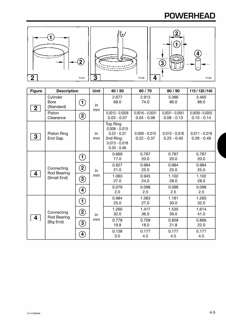
POWERHEAD
4-5
3-/ 4-Cylinder
Figure Description Unit 40 / 50 60 / 70 80 / 90
115 / 120 /140
Cylinder Bore (Standard) in
mm
2.677 68.0
2.913 74.0
3.38686.0
3.46588.0
Piston Clearance
0.0012 - 0.0028
0.03 - 0.07
0.0016 - 0.0031
0.04 - 0.08
0.0031 - 0.0051
0.08 - 0.13
0.0039 - 0.0055
0.10 - 0.14
Piston Ring End Gap
in mm
Top Ring
0.008 - 0.015 0.22 - 0.37
2nd Ring:
0.013 - 0.018 0.33 - 0.48
0.009 - 0.015
0.22 - 0.37
0.010 - 0.016
0.25 - 0.40
0.011 - 0.019
0.28 - 0.49
Connecting Rod Bearing(Small End)
in mm
0.669 17.0
0.787 20.0
0.78720.0
0.787 20.0
0.827 21.0
0.984 25.0
0.984 25.0
0.984 25.0
1.063 27.0
0.945 24.0
1.102 28.0
1.102 28.0
0.079 2.0
0.098 2.5
0.098 2.5
0.098 2.5
Connecting Rod Bearing(Big End)
in mm
0.984 25.0
1.063 27.0
1.181 30.0
1.260 32.0
1.260 32.0
1.417 36.0
1.535 39.0
1.614 41.0
0.778 19.8
0.709 18.0
0.858 21.8
0.866 22.0
0.138 3.5
0.177 4.5
0.177 4.5
0.177 4.5
21
2
3
4
1
2
3
4
4
1
2
3
4
T1157 T1158 T1159

SECTION 4
4-6
3-/ 4-Cylinder
Manufacturer Special Tools Required
Flywheel Puller Assembly, 3B7-72214-0, 3C7-72211-0Plate, Flywheel Puller, 3B7-72781 -2, 3C7-72783-0Bolt, M8 x 25 mm, 3B7-72786-0Bolt, M8 x 40 mm, 3B7-72785-0Washer, 940191-0800Pressing Bolt, 3B7-72784-0Powerhead Stand, 353-72247-0, 353-7247-1Shackle, 353-01512-0Piston Pin Tool, 345-72215-0, 353-72215-0Piston Ring Tool, 353-72249-0Thickness Gauge Set, 353-72251-0
General Equipment Required
Compression Gauge, 0 - 199 psi [0 - 1372 kPa / 0 - 14 kg/cm
2
]Water Pressure Gauge, 0 - 15 psi [0 - 103 kPa / 0 - 1 kg/cm
2
]Torque Wrench, 0- 150 in-lb [0 - 17 N-m / 0- 1.7 kg-m]Torque Wrench, 0 - 750 ft-lb [0 - 1000 N-m / 0 - 100 kg-m]Micrometer Set or Venier Caliper, graduation 0.0001 in [0.01 mm], range 0 - 1 in [0 - 30 mm]Telescoping Gauge, Inside Micrometer Set, or Venier Caliper, minimum scale 0.0001 in [0.01 mm]Dial Indicator, graduation 0.0001 in [0.01 mm], range 0 - 1 in [0 - 30 mm]Analog Multimeter,
Electronic Specialties
®
Model M-530 or equivalent
Digital Pulse Tachometer, 10 - 6000 RPM,
Electronic Specialties
®
Model 321 or equivalent
Industrial Thermometer, minimum 300˚F [150˚C]Heat-Resistant Container,
Pyrex
®
Bearing PullerSealPullersSealInstallerSurface Plate, 20 x 20 in [500 x 500 mm], 0.0001 in [0.01 mm] accuracy
Consumables Required
Threadlocker,
Loctite
®
242
Threadlocker,
Loctite
®
243
Gasket Dressing,
Permatex
®
Hy/omar
®
Aerosol High-Temp Gasket Dressing
Gasket Sealant,
Permatex
®
High Tack Gasket Sealant
Anaerobic Gasket Maker,
Loctite
®
518
Dielectric Lubricant,
Permatex
®
Dielectric Tune-Up Grease
Cleaning Pads,
Scotch-Brite
®
Abrasive Pads
Isopropyl AlcoholCleaning SolventGasket RemoverHeat-Sensitive Markers, 125˚F [52˚C] and 163˚F [73˚C],
Markal
®
Thermomelt Stik
Low Temperature Lithium GreaseBearing Cup GreaseEngine Lubricant,
Genuine engine oil or NMMA certified TC-W3 oil
Automotive Crankcase Oil, flashpoint above 300˚F [150˚C]

POWERHEAD
4-7
3-/ 4-Cylinder
TROUBLESHOOTING
The troubleshooting chart lists common engine symptoms relatedto problems with the powerhead. It also indicates specificcomponent failures which may be causing the problem so it can beisolated more effectively.
Poor crankcase seal
•
Ignition timing or throttle linkage out of adjustment, see Section 2
• •
Water entering lower crankcase
• •
Defective thermostat
• • •
Fouled, defective or incorrect spark plug; wrong gap setting
• • • • •
Worn or defective cylinder, piston, rings or warped head
• • • •
Blown cylinder head or engine base gasket
• • • • • • •
Worn connecting rod or crankshaft bearings, internal wear limits out of specification
• • •
Defective ignition components, see Section 7
• • •
Carbon accumulation in combustion chamber
• • •
Har
d t
o st
art
or
will
not
sta
rt
Low
cyl
ind
er
com
pre
ssio
n
Run
s ro
ugh
or
erra
tical
ly
Idle
s p
oorly
No
acce
lera
tion,
lo
w t
op e
nd R
PM
RP
M d
ecre
ases
Eng
ine
over
heat
s
Run
s no
isy
or h
as
exce
ssiv
e vi
bra
tion
Symptom
Checks
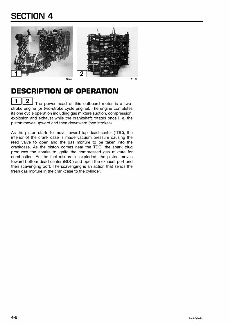
SECTION 4
4-8
3-/ 4-Cylinder
DESCRIPTION OF OPERATION
The power head of this outboard motor is a two-stroke engine (or two-stroke cycle engine). The engine completesits one cycle operation including gas mixture suction, compression,explosion and exhaust while the crankshaft rotates once i. e. thepiston moves upward and then downward (two strokes).
As the piston starts to move toward top dead center (TDC), theinterior of the crank case is made vacuum pressure causing thereed valve to open and the gas mixture to be taken into thecrankcase. As the piston comes near the TDC, the spark plugproduces the sparks to ignite the compressed gas mixture forcombustion. As the fuel mixture is exploded, the piston movestoward bottom dead center (BDC) and open the exhaust port andthen scavenging port. The scavenging is an action that sends thefresh gas mixture in the crankcase to the cylinder.
1 2
T1160 T1161

POWERHEAD
4-9
3-/ 4-Cylinder
CYLINDER COMPRESSION TEST
1. Operate engine up to normal operating temperature.
2. Stop engine.
3. Disconnect the magneto leads to disable the ignition system.
WARNING
Ignition system must be disabled to preventaccidental engine startup during compressiontest.
4. Remove all spark plugs and install thread-type compressiontester in spark plug hole.
5. Place throttle in fully open position and crank engine with starterthrough at least four compression strokes. Take reading for eachcylinder and verify specified pressure is obtained:
* Compression variation among cylinders should not exceed 15psi [103 kPa / 1.05 kg/cm
2
].
If variation of cylinder compression exceeds 15 psi [103 kPa / 1.05kg/cm
2
], check for the following:
• Scored cylinder walls.
• Piston damage.
• Head gasket damage.
• Stuck or broken piston rings.
If cylinder compression is low, engine is difficult to start and runspoorly, check for the following:
• Scored cylinder walls.
• Piston damage.
• Stuck or worn piston rings.
Model Cylinder Compression* psi [kPa / kg/cm
2
]
40 / 50 117 [800 / 8.2] ± 13 %
60 / 70 121 [830 / 8.5] ± 13 %
80 / 90 117 [810 / 8.2] ± 13 %
115 / 120 / 140 128 [880 / 9.0] ± 13 %
1
T1162

SECTION 4
4-10
3-/ 4-Cylinder
RPM PERFORMANCE TEST
NOTE
Engines are equipped with RPM limiting function. Iffull throttle RPM values cannot be obtained, seeRPM Limitation Test in Section 7.
CAUTION
Do not perform RPM test if engine shows signs ofoverheating.
Perform this test with correct test propeller installed and with theengine in a test tank.
1. Operate engine up to normal operating temperature.
2. Stop engine and install tachometer.
3. Start and run engine at NEUTRAL idle and verify specified RPMis obtained. If test tank conditions permit, run engine in forwardgear at trolling and full throttle speeds and check for correct RPM:
4. If test results vary, refer to Troubleshooting in this section.
Model NEUTRAL
Idle RPM
TrollingSpeed RPM
Full ThrottleSpeed RPM
40D 900 750 4500 - 5500
500 900 750 5000 - 5700
40D2 900 750 5000 - 5700
50D2 900 750 5150 - 5850
60B 900 750 4900 - 5600
70B 900 750 4900 - 5600
60C 900 750 5150 - 5850
70C 900 750 5150 - 5850
80A 900 700 5000 - 5500
90A 900 700 5000 - 5500
115A2 900 700 5200 - 5700
120A2 900 700 5000 - 5500
140A2 900 700 5200 - 5700
1
T1170

POWERHEAD
4-11
3-/ 4-Cylinder
OVERHEAT SENSOR
Overheat sensor
(1)
is a heat sensitive switch installed in thecylinder head to monitor engine temperature The sensor is
connected in series with the warning horn. If the sensor detectstemperature in excess of a predetermined limit, contacts close andcause the warning horn to emit a continuous tone when the keyswitch is ON and the remote control lever is in the FORWARD orREVERSE position. Depending on model, the engine RPMlimitation function will also activate.
NOTE
The overheat sensor is not standard equipment onmodel 40 prior to 1994 but is available as an option.
Function Test
1. Disconnect the overheat sensor bullet connector at the electricalbox and the ground wire.
2. Remove the overheat sensor from the cylinder head.
3. Using a continuity light or calibrated ohmmeter, connect onetester lead to each sensor lead.
4. Place sensor and thermometer in a heat-resistant containerfilled with automotive crankcase oil. Slowly heat the oil using
an external heat source.
WARNING
Avoid fire or explosion:• Use a heat-resistant container such as Pyrex
®
glassware.• Use oil with a flashpoint above 300˚F [150˚C].• DO NOT use open flame as a heat source.
5. Verify the sensor switch reacts to the changing temperature asfollows:
NOTE
Apply light coat of dielectric lubricant to sensor beforeinstallation.
Model Switch Closed
(Continuity Present) ˚F [˚C]
Switch Open (No Continuity)
˚F [˚C]
40 / 50 212 [100] 185 [85]
60 / 70 257 [125] 230 [110]
80 / 90 176 [80] 156 [69]
115 / 120 / 140 212 [100] 185 [85]
1
2
3
T1164
T1165
T1248

SECTION 4
4-12
3-/ 4-Cylinder
WATER PRESSURE SENSOR
The water pressure sensor is a pressure-sensitive switchinstalled on the powerhead to monitor the forced water
cooling system. The sensor is connected in series with the warninghorn. If the sensor detects low water pressure at a predeterminedRPM, contacts close and cause the warning horn to emit acontinuous tone. The engine RPM limitation function is alsoactivated.
NOTE
The water pressure sensor is standard equipment onmodels 80, 90, 115, 120, and 140. It is available asan option for models 60 and 70.
Function Test and Adjustment
Verify the lower unit water intake screens are not clogged beforetesting a suspect water pressure sensor. Perform this test with theengine in a test tank or on the boat.
WARNING
Test and adjustment requires running the enginein close proximity to the technician. To avoidserious injury, keep wires, test equipment, tools,and body parts away from powerhead linkageand flywheel.
1. Remove sensor mounting screws
(1)
and disconnect thesensor ground wire.
2. Disconnect the sensor bullet connector at the electrical box.
3. Using a continuity light or ohmmeter, connect one testerlead to each sensor lead
(2)
and
(3)
. Tester should indicatecontinuity (switch closed).
1
2
3
T1171
T1172
T1173

POWERHEAD
4-13
3-/ 4-Cylinder
If tester indicates no continuity (switch open), loosenadjustment screw
(4)
just enough so the switch button doesnot make contact with the diaphragm pressure button. If still nocontinuity, replace the sensor assembly.
4. Disconnect the INPUT hose from the sensor fitting. Usinga T-fitting (obtain locally), install a water pressure gauge
between the sensor and the hose.
WARNING
Make sure all hose connections are tight and alltest leads and equipment are clear of powerheadlinkage and flywheel.
5. Start and idle engine in NEUTRAL.
6. Slowly increase engine speed. Take pressure reading when testerindicates no continuity (switch open). Switch should open at 4.3 psi[29.4 kPa / 0.30 kg/cm
2
]. If switch opens at lower over higherpressure, continue as follows:
• Fully loosen the adjustment screw.
• Set and maintain throttle position so water pressure is at 4.3 psi[29.4 kPa / 0.30 kg/cm
2
].
• Gradually tighten adjustment screw until tester indicates nocontinuity (switch open).
4
5
T1174
T1175

SECTION 4
4-14
3-/ 4-Cylinder
THERMOSTAT
Removal
1. Remove thermostat cap screws. Gently tap thermostat capwith rubber mallet to loosen and remove cap and gasket.
Discard gasket.
2. Remove and inspect thermostat.
NOTE
Earlier 90, 115, 120 and 140 engines had a flat metalbypass valve with a spring and retainer. This hasbeen eliminated from newer 90, 115, 120 and 140engines.
3. Perform thermostat Function Test if thermostat is suspect.
Installation
1. Install thermostat in cylinder head.
2.Install thermostat cap
(2)
and gasket
(1)
and torque tospecification.
1
2
3
T1166
T1167
T1168

POWERHEAD
4-15
3-/ 4-Cylinder
Function Test
1. Suspend thermostat and thermometer in a heat-resistantcontainer filled with water.
2. Slowly heat and stir the water. Verify the thermostat opens at140˚F [60˚C]. If it does not open at specified temperature, replacethermostat.
WARNING
Use a heat-resistant container such as Pyrex
®
glassware. DO NOT allow thermostat orthermometer to rest against the glass. Itemscould overheat and rupture.
3. Remove thermostat and observe its closing action as it cools. Ifclosing action is not slow and smooth, replace thermostat.
RECOIL STARTER
WARNING
F-type of 40/50 engines have neutral startmechanism (start-in-gear protection) attached tothe recoil starter. This feature disables the enginefrom starting wheel in gear (forward or reverse).During reassembly of the engine following repair,ensure that you DO NOT DISABLE THE START-IN-GEAR PROTECTION.
WARNING
Ignition system must be disabled to preventaccidental engine startup during servicing of therecoil starter.
Removal
1. Place engine in NEUTRAL to relieve tension from neutral startcable.
2. Disconnect cable
(1)
from stopper arm
(2)
. Loosen cableclamp
(3)
and remove cable from recoil starter.
3. Remove recoil starter mounting bolts and lift starter off powerhead.
Disassembly
WARNING
Recoil starter rewind spring is under hightension. Wear safety glasses at all times duringdisassembly.
1. Remove pin from stopper arm and disassemble theneutral lockout components: pin, washer, stopper
arm, stopper spring, and reel stopper.
4
1
2 3
T1177
T1178
T1169
T1176

SECTION 4
4-16
3-/ 4-Cylinder
2. Place recoil starter top side down on bench. Pull out approximately24 in [60 cm] of starter rope and hold the reel tightly to prevent it fromrewinding.
3. Hold reel tightly at all times so it does not suddenlyrewind while completing the following steps:
• Allow reel to slowly rewind just enough so the notch in the reelaligns with the rope guide in the starter housing.
• Use a screw driver to position the rope in the reel notch. With therope caught in the notch, allow reel to slowly rotate clockwise toslacken the rope. Repeat until no starter spring tension is felt onthereel.
4. Remove the starter rope handle.
5. Remove the friction plate bolt and lift off friction plate
(1)
, slide plate
(2)
, and friction spring
(3)
.
6. Carefully remove the snap ring. DO NOT remove the washerbelow the snap ring.
WARNING
Use caution removing snap ring and handlingrecoil starter after its removal. Sudden impact tothe starter could dislodge rewind spring causingserious injury.
WARNING
DO NOT attempt to remove washer from reelassembly at this time.
7. Remove the reel from the starter housing by slowlyrotating it back and forth while lifting upward. Once
removed, take out reel washer
(4)
, ratchet
(5)
, and return spring
(6)
.
WARNING
DO NOT pull hard or quickly on the reel. Keepface away from the spring at all times.
4
5 6
7
8 9
T1183
T1184
T1182
T1179 T1180 T1181

POWERHEAD
4-17
3-/ 4-Cylinder
8. Carefully turn over recoil starter on bench so spring isfacing down. Firmly hold starter housing against bench and
lightly tap housing with rubber mallet to dislodge the starter spring.Remove the spring.
9. Turn recoil starter over and remove sliding plate
(7)
andbushing
(8)
.
Cleaning and Inspection
All worn, damaged, or missing parts must be replaced.
1. Clean metal parts with solvent and dry with low pressurecompressed air. Clean plastic parts with isopropyl alcohol.
2. Inspect following components as follows:
Starter rewind spring for cracked or broken end loops.
• Ratchet and reel stopper springs for deformation or poor tension.
• Sliding plates, stopper components, and busing for cracks orsigns of wear.
• Reel assembly for wear.
• Starter housing for sharp or rough edges which could fray starterrope.
Starter rope for frays and rope handle for damage.
Assembly
WARNING
Recoil starter rewind spring is under high tension.Wear safety glasses at all times during assembly.
1. Apply low temperature lithium grease to the following:
Inner and outer surfaces of bushing
(1)
.
Both sides of sliding plates
(2)
and
(3)
.
Rewind spring
(4)
.
Bushing shaft in starter housing.
2. Install bushing
(1)
and sliding plate
(2)
in starter housing
(5)
.
10
11
12
13
14
14
14
15
14
T1187
T1188
T1186
T1185

SECTION 4
4-18
3-/ 4-Cylinder
3. Wind starter rewind spring
(4)
into starter housing.
4. Thread starter rope through rope hole in reel
(6)
. Knot therope and pull it tight in the reel. Route the remaining rope
through the rope guide and attach the handle.
5. Hold reel so knot is facing up. Wind the starter rope clockwise 1-1/2times around the reel and hook it into the reel notch.
6. Position reel in starter housing so rope notch is alignedwith the rope guide. Install washer
(7)
and snap ring
(8)
.
7. Install return spring
(9)
and ratchet
(10)
on the reel.
14
14
14
14 16
T1191
T1190
T1189

POWERHEAD
4-19
3-/ 4-Cylinder
8. Place sliding plate
(3)
on friction plate
(11)
and install frictionspring
(12)
. Position the assembly on the reel so key hole in frictionplate is properly aligned. Install mounting bolt.
9. With the rope hooked in the reel notch and aligned with the ropeguide, rotate the reel counterclockwise 5 times to tighten therewind spring. Remove the rope from the notch and allow the reelto slowly wind the remaining starter rope onto the reel.
10. Install the neutral lockout mechanism in the starter housing: pin,washer, stopper arm, stopper spring, and reel stopper.
11. Check operation of the recoil starter before installation.
Installation
1. Position recoil starter on powerhead and install mounting bolts.
2. Make sure engine is in NEUTRAL. Thread the neutral startcable through cable clamp
(13)
on the starter housing. Tightenthe cable clamp and connect the cable to stopper arm
(14)
. Press theremaining cable into the cable clamps on the starter housing.
3. Test the operation of the neutral start mechanism.
WARNING
Start-in-gear protection mechanism must beinstalled. NEVER return engine to customer withmechanism disconnected or not functioningproperly.
17
T1315

SECTION 4
4-20
3-/ 4-Cylinder
FLYWHEEL
NOTE
Flywheel magnets must be of a particular strength inorder to run the ignition system. Weak magnets cancause low ignition voltage which may affect engineperformance. Flywheels seldom go bad and wouldonly be replaced as a last resort in solving an ignitionproblem.
CAUTION
Flywheel is under high torque and requires theuse of special tools for removal and installation.Failure to use the specified tools can result ininjury or damage to the flywheel or coil plateelectrical components.
CAUTION
The force needed to loosen and tighten theflywheel nut requires flywheel be removed andinstalled with engine mounted and secured on anengine stand.
NOTE
Reference the following specification table forflywheel Removal and Installation special toolrequirements.
Tool Part
Number
Applicability Engine Serial
Number Model
Flywheel Puller - 3C7-72211-1
40 / 50 / 60 / 70 / 80 / 90 / 115 / 120 / 140
All
Bolt , M8 x 25 mm 3B7-72786-0
40 / 50 / 60 / 70 / 80 / 90 / 115 / 120 / 140
All
Flywheel Puller Plate 3B7-72783-0
40 / 50 / 60 / 70 / 80 / 90
All
Flywheel Puller Plate 3C7-72783-0
115 / 120 / 140
All
Bolt , M8 x 40 mm 3B7-72785-0
40 / 50 / 60 / 70 / 80 / 90 / 115 / 120 / 140
All
Washer 940194-0800
40 / 50 / 60 / 70 / 80 / 90 / 115 / 120 / 140
All
Pressing Bolt 3B7-72784-0
40 / 50 / 60 / 70 / 80 / 90 / 115 / 120 / 140
All
1 6
2
3
3
4
5
6
1
T1192

POWERHEAD
4-21
3-/ 4-Cylinder
Removal
WARNING
Ignition system must be disabled to preventaccidental engine startup during removal of theflywheel.
1. Remove recoil starter and starter pulley or remove the flywheelcover as required.
2. Determine the direction of rotation for removing flywheel nut byrunning your thumbnail along the threads of the crankshaft.
CAUTION
Past production models may have reverse thread.
3. Install puller
(1)
on flywheel using bolts
(2)
.
4. Hold puller by its handle and remove flywheel nut with asocket wrench. Make sure to turn nut in the correct
direction.
5. Install puller
(1)
and plate
(3)
on flywheel using bolts
(4)
and washers
(5)
.
6. Install pressing bolt
(6)
in plate
(3)
.
7. Hold puller by its handle and tighten pressing bolt untilflywheel releases.
Inspection
1. Inspect flywheel for cracks, chips, and worn taper.
2. Inspect crankshaft for thread damage and worn taper.
3. Inspect flywheel key and keyway for damage.
2
3
4
5
6
T1197
T1196
T1193 T1194 T1195

SECTION 4
4-22
3-/ 4-Cylinder
Installation
WARNING
Ignition system must be disabled to preventaccidental engine startup during installation ofthe flywheel.
1. Remove all grease from crankshaft threads and tapered portionof flywheel with solvent.
2. Check flywheel key is inserted in crankshaft.
3. Align flywheel keyway and install on crankshaft. Install the flywheelwasher.
4. Install puller
(1)
on flywheel using bolts
(2)
. Hold pullerhandle and torque flywheel nut to specification.
5.Install recoil starter or flywheel cover as required.
Model
Flywheel Nut Torque ft-lb N·m
kg-m
40 / 50 65.1 - 79.5 88.2 - 107.8 9.0 - 11.0
60 / 70 / 80 / 90 101.2 - 115.7 137.2 - 156.8 14.0 - 16.0
115 / 120 / 140 181.0 - 195.0 245.0 - 264.6 25.0 - 27.0
7
8
T1199
T1198

POWERHEAD
4-23
3-/ 4-Cylinder
POWERHEAD
Typical 3-Cylinder
T1200

SECTION 4
4-24
3-/ 4-Cylinder
Typical 4-Cylinder
T1201

POWERHEAD
4-25
3-/ 4-Cylinder
Removal
WARNING
Ignition system must be disabled to preventaccidental engine startup during removal of thepowerhead.
NOTE
If service work requires flywheel to be removed,remove flywheel before lifting powerhead from therest of the engine. See Flywheel, this section.
NOTE
Mark the mounting location of all clamps so they canbe returned to their original positions duringassembly of the powerhead.
1. Disconnect the battery and fuel tank.
2. Disable the ignition system and disconnect the battery terminalson the powerhead.
3. Disconnect all electrical connections as applicable:
• Ground connections between lower engine cover and cylinderblock.
• Power trim and tilt connections.
• Remote control or main key switch wire harness.
• Neutral switch.
4. Disconnect fuel INPUT hose from fuel filter.
5. Disconnect pilot water hose from exhaust cover.
6. Complete the following operations.
Tiller models:
• Disconnect shift arm L-link
(1)
.
• Remove throttle cable
(2)
from throttle cable bracket
(3)
.
• Remove advancer arm
(4)
and throttle cable.
• Disconnect choke knob link rod.
Remote control models:
• Disconnect shift cable from shift arm.
• Remove shift assist case
(5)
.
• Disconnect throttle cable from advancer arm.
7. Remove the splash pan.
8. Remove the engine mounting bolts.
3
4
5
6
T1204
T1205
T1203
T1202

SECTION 4
4-26
3-/ 4-Cylinder
9. Using an adequate hoist, lift and remove the powerheadby its lifting eye.
10. Remove lower crankcase head bolts. Insert screwdriver inpinch groove and remove lower crankcase head.
11. Install specified powerhead stand in vice. Bolt powerheadbase surface to powerhead stand.
Disassembly
Preliminary
1. Remove all carburetion, ignition, and electrical components fromthe powerhead.
2. Remove the intake manifold and reed valves. See Intake Manifoldin Section 3.
3. Remove the check valves (models 80, 90, 115, 120, and140) and recirculation lines.
Cylinder Head
4. Remove and inspect the thermostat. See Thermostat, this section.
Powerhead Stand Part
Number
Applicability
Model
— 40 / 50
353-72247-1 60 / 70 / 80 / 90 / 115 / 120 / 140
7
8
9
10
T1208
T1209
T1207
T1206

POWERHEAD
4-27
3-/ 4-Cylinder
5. Remove the cylinder head cover bolts and cylinderhead bolts. Separate and remove cylinder head cover
(1)
and cylinder head
(2)
.
NOTE
Remove the smallest size bolts first. Remove thebolts in order from highest embossed number tolowest. If the bolts are not numbered, start withthose farthest from the center of the cylinder headand work inward.
6. Using a pointed scribe, identify the heads of the cylinders forcorrect positioning during assembly operations.
Exhaust Cover
7. Remove the exhaust cover bolts. Insert screwdriver intopinch grooves to separate and remove outer
(3)
and inner
(4)
exhaust covers.
NOTE
Remove the bolts in order from highest embossednumber to lowest.
Crankcase and Crankshaft
NOTE
Crankshaft on models 40 and 50 is equipped withbearing thrust plates
(5)
and crankshaft thrust plates
(6)
. Mark these parts so they can be returned to theiroriginal positions during assembly.
8. Remove and discard oil seals
(7)
and
(8)
and o-ring
(9)
from lower crankcase head. Use a seal puller to preventdamage to the head.
11 12
13
15
T1213
T1214
T1211 T1212T1210
14

SECTION 4
4-28
3-/ 4-Cylinder
9. Remove the crankcase bolts and separate the crankcasefrom the cylinder block.
NOTE
Remove the smallest size bolts first. Start with thebolts farthest from the center of the crankcase andwork inward.
10. Lift the crankshaft and pistons from the cylinder blockand place on bench for disassembly.
11. Remove oil pump driven gear
(10)
and bushing
(11)
fromthe cylinder block.
12. Slide the upper main bearing off the crankshaft. Removeand discard bearing oil seal
(12)
and o-ring
(13)
.
Pistons
NOTE
Pistons, rings, and connecting rod bearings are wearparts which seat with operation of the engine. Makesure these parts are marked and kept together sothey can be returned to their original positions duringassembly.
13. Remove piston pin clip
(14)
from both sides of eachpiston. Discard the clips.
14. Tap out the piston pins using specified piston pin tool
(15)
:
16
17
18
19
20
21
T1219
T1220
T1218
T1217T1216T1215

POWERHEAD
4-29
3-/ 4-Cylinder
15. Remove the piston, bearing washers
(16)
(models 80, 90,115, 120 and 140), and bearing
(17)
from the connecting rod.
16. Remove each piston ring using the piston ring tool (PartNo. 353-72249-0).
NOTE
Identify each ring so it can be returned to its originalpiston and ring groove.
Cleaning
1. Remove all carbon accumulation from exhaust port areas andcylinder head combustion chambers.
2. Use gasket remover and Scotch-Brite Abrasive Pads toremove all traces of gasket and sealer from the cylinder
block, crankcase, cylinder head, intake manifold, exhaust covers,and air silencer.
CAUTION
DO NOT use a metal scraper on gasket surfacesor the mating surfaces of the crankcase.
3. Remove all carbon deposits from the tops and ringgrooves of the pistons.
NOTE
A ring groove cleaning tool can be made by breakingan old ring and grinding an angle on its end. Do notdamage the grooves when cleaning.
Piston Pin Tool Part Number
Applicability Model
345-72215-0 40 / 50
353-72215-0 60 / 70 / 80 / 90 / 115 / 120 / 140
22
23
24
25
T1223
T1224
T1222
T1221

SECTION 4
4-30
3-/ 4-Cylinder
4. Wipe off all traces of oil and thoroughly wash the cylinderblock and crankcase with warm, soapy water. Air dry the
cylinder block and crankcase. Dry all holes and passages with lowpressure compressed air.
5. Coat the cylinder walls with genuine engine oil or certifiedTC-W3 oil to protect them from corrosion.
Inspection
NOTE
Before inspection of the powerhead, all componentsmust be perfectly clean and free of contaminants.
CAUTION
If it is determined after complete inspection thatcylinder resurfacing or boring is necessary, alloperations must be performed at a qualifiedmachine shop. Light scuffing or burn does notrequire boring for removal. Use water-resistantsand paper of around #320 to remove thedamages, and then use #400 and #600 to finish.
1. Visually inspect all internal components. Inspect for unusual wearpatterns, heat-related discoloration of bearings, broken parts, andscuffing or damage to aluminum parts.
2. Inspect the intake manifold and reed valves. See Intake Manifoldin Section 3.
3. Check the cylinder head for warpage using a machiniststraight edge and the thickness gauge set (Part No. 353-
72251-0). If warpage exceeds 0.004 in [0.10 mm], replace thecylinder head.
4. Using an accurate dial indicator, measure the crankshaftdeflection with the upper and lower main bearings installed.
Measure as follows:
• Support both ends of the crankshaft in precision V-blocks or analignment jig.
• Slowly rotate crankshaft and record measurement at eachcrankshaft bearing
(1)
and at both ends of the crankshaft.
If deflection is more than 0.002 in [0.05 mm] on either end, replacethe crankshaft.
26
27
28
29
T1227
T1228
T1226
T1225

POWERHEAD
4-31
3-/ 4-Cylinder
5. Measure and record the following crankshaft dimensions andcheck for signs of wear:
• Dimension 1 : Distance between the outside edges of eachpair of crankshaft webs. Measure at both ends of thewebs.
• Dimension 2 : Distance between each pair of crankshaftwebs.
• Dimension 3 : Distance between the outside edges of thefirst and last crankshaft webs.
If any dimension is not within specification, replace the crankshaftassembly.
Figure Description Unit 40 / 50 60 / 70 80 / 90
115 / 120 / 140
Crankshaft
inmm
–– –– ––
9.173 in233.0 mm
10.020 in254.5 mm
11.339 in288.0 mm
15.669 in398.0 mm
1
1
1*
2
3
T1231T1230T1229
2.087 0
in - 0.001
[53 0
mm] - 0.02
2.362 - 0.008
in - 0.009
[60- 0.20
mm]- 0.22
2.677 0
in - 0.001
[68 0
mm]- 0.02
2.677 0
in - 0.001
[68 0
mm]- 0.02
2.598 0
in - 0.001
[66 0
mm]- 0.02
1.457 + 0.002
in - 0
[37+ 0.05
mm]- 0
1.467 + 0.002
in - 0
[37.25+ 0.05
mm]- 0
1.732 + 0.002
in - 0
[44+ 0.05
mm]- 0
1.654 + 0.002
in - 0
[42+ 0.05
mm]- 0
30
31
32

SECTION 4
4-32
3-/ 4-Cylinder
6. Check for smooth operation of all crankshaft and connectingrod bearings. Inspect the oil pump drive gear for damage.
Upper and lower main bearings, small end connecting rodbearings, and the oil pump drive gear are serviceable. Wear of otherparts requires replacement of the crankshaft assembly. If lowermain bearing
(2)
or oil pump drive gear
(3)
is defective, proceed toremove the components as follows:
• Remove snap ring
(4)
.
• Install a universal bearing puller with bearing retainer plate andremove lower main bearing
(2)
and oil pump drive gear
(3)
fromthe crankshaft.
• See powerhead Assembly procedure for installation.
7. Measure and record the diameter of each cylinderbore and the outside diameter of its respective piston.
Subtract the values to calculate the piston clearances. If any borediameter or piston clearance exceeds the specified limit, thecylinder must be professionally bored oversize for use with anoversize piston.
8. Complete the following inspection for new or used pistonring sets. Inspect each ring separately:
• Place ring in its respective cylinder bore.
• Use a piston to square the ring in the bore.
• Use the thickness gauge set (Part No. 353-72251-0) to measurethe ring end gap.
Model
Standard Bore Diameter
in [mm] Piston Clearance
in [mm]
40 / 50 2.677 [68.0]
0.0012 - 0.0028 [0.03 - 0.07]
60 / 70 2.913 [74.0]
0.0016 - 0.0031 [0.04 - 0.08]
80 / 90 3.386 [86.0]
0.0031 - 0.0051 [0.08 - 0.13]
115 / 120 / 140 3.465 [88.0]
0.0039 - 0.0055 [0.10 - 0.14]
33
34 35
36
T1833
T1235
T1832
T1232

POWERHEAD
4-33
3-/ 4-Cylinder
The ring end gap must be within specification:
9. Measure the specified dimensions of the small endconnecting rod bearings. If measurements are not as
specified, the bearing is excessively worn and must be replaced.
If crankshaft was fully disassembled for further inspection, measurethe big end connecting rod bearings in the same manner. Wear ordamage to large end connecting rod bearings requires replacementof the crankshaft assembly.
Model Ring End Gap in [mm]
STD Value Repair Limit
40 / 50
Top Ring: 0.009 - 0.015 [0.22 - 0.37]
2nd Ring 0.013 - 0.019 [0.33 - 0.48]
0.032[0.8]
0.032[0.8]
60 / 70 0.009 - 0.015 [0.22 - 0.37]
0.032[0.8]
80 / 90 0.010 - 0.016 [0.25 - 0.40]
0.032[0.8]
115 / 120 / 140 0.011 - 0.019 [0.28 - 0.49]
0.032[0.8]
Model
Small End Connecting Rod Bearing Dimensionsin [mm]
Inside Diameter (1)
Outside Diameter (2) Height (3)
Needle Roller Diameter (4)
40 / 50 0.669 [17.0] 0.827 [21.0] 1.063 [27.0] 0.079 [2.0]
60 / 70 0.787 [20.0] 0.984 [25.0] 0.945 [24.0] 0.098 [2.5]
80 / 90 0.787 [20.0] 0.984 [25.0] 1.102 [28.0] 0.098 [2.5]
115 / 120 / 140 0.787 [20.0] 0.984 [25.0] 1.102 [28.0] 0.098 [2.5]
Model
Big End Connecting Rod Bearing Dimensions in [mm]
Inside Diameter (1)
Outside Diameter (2) Height (3)
Needle Roller Diameter (4)
40 / 50 0.984 [25.0] 1.260 [32.0] 0.779 [19.8] 0.138 [3.5]
60 / 70 1.063 [27.0] 1.417 [36.0] 0.709 [18.0] 0.177 [4.5]
80 / 90 1.181 [30.0] 1.535 [39.0] 0.858 [21.8] 0.177 [4.5]
115 / 120 / 140 1.260 [32.0] 1.614 [41.0] 0.866 [22.0] 0.177 [4.5]
37
T1159

SECTION 4
4-34
3-/ 4-Cylinder
10. Inspect recirculation line nipples for damage or obstruction.
Assembly
NOTE
Before assembly of the powerhead, all componentsmust be perfectly clean and lightly coated withgenuine engine oil or a NMMA certified TC-W3 oil.All serviceable gaskets and seals must be replaced.
CAUTION
Proceed slowly when assembling powerhead. DONOT make forced assemblies unless a pressingoperation is indicated.
Preliminary
1. Before installation, lightly coat the outside surfacesof new bearing seals and o-rings with genuine engine
oil or TC-W3 oil. Apply bearing cup grease to the seal lips. Press fitthe seals into place using an appropriate size seal installer to avoiddamaging the seal or component.
• Install new oil seals
(1)
and
(2)
in lower crankcase head. Installnew o-ring
(3)
.
• Install new oil seal
(4)
in upper main bearing and new o-ring
(5)
.
2. Coat the rotating surfaces of the crankshaft and connecting rodbearings, bearing washers, and bearing thrust plates (models 40and 50) with genuine engine oil or TC-W3 oil.
Crankshaft
3. Slide upper main bearing onto crankshaft so bearing seal
(6)
faces threaded end
(7)
.
38 39
40
T1238
T1237
T1236

POWERHEAD
4-35
3-/ 4-Cylinder
4. If oil pump drive gear
(8)
and lower main bearing
(9)
wereremoved, coat lower end of crankshaft with genuine engine
oil or TC-W3 oil and install the lower crankshaft components inorder, press fitting the gear and bearing onto the crankshaft. Makesure snap ring
(10)
is properly seated.
NOTE
On models 80, 90, 115, 120, 140, measure the endgap between oil pump drive gear
(8)
and snap ring
(10)
with all lower crankshaft components properlyseated. If end gap exceeds 0.004 in [0.09 mm], installcorrect size shim
(11)
.
Pistons
5. Install each piston ring in its original groove on its originalpiston using the piston ring tool (Part No. 353-72249-0).
Each ring must be installed so end notches
(12)
fit the contour ofpiston knock
(13)
when the ring is compressed.
6. Install each piston on its respective connecting rod as follows:
NOTE
Each piston must be installed so [UP] mark
(14)
points to the flywheel end. Use the same piston pintool as was specified for disassembly.
41
42
T1242
T1240
T1239
41
43

SECTION 4
4-36
3-/ 4-Cylinder
Insert bearing
(15)
into bearing collar of connecting rod
(16)
.
Correctly position piston
(17)
onto the connecting rod.
Insert bearing washer
(18)
on each side of the connectingrod (models 80, 90, 115, 120 and 140).
Align components so piston pin hole is not obstructed andinstall piston pin
(19)
using piston pin tool.
Install new piston pin clips
(20)
. Do not reuse old clips.
Cylinder Block and Crankcase
7. Install the oil pump driven gear and bushing in the cylinder block.
8. Coatthe pistons, rings, cylinder walls, and oil pump drive gear anddriven gear with genuine engine oil or TC-W3 oil. Install the bearingwashers or thrust plates (models 40 and 50) and lower crankshaftassembly into cylinder block, guiding each piston into its respectivecylinder. Ensure the following:
Dowel pin
(21)
in cylinder block is inserted in the hole in theupper main bearing.
All main bearing nocks
(22)
are seated against thecrankcase mating flange of the cylinder block for proper
alignment with the crankcase.
• Oil pump drive gear on crankshaft is meshed with the oil pumpdriven gear.
• Bearing washers or thrust plates (models 40 and 50) are seatedproperly in the cylinder block.
44
44
44
44
44
45
46
T1244
T1243T1241

POWERHEAD
4-37
3-/ 4-Cylinder
9. Degrease the crankcase flange and mating surface of thecylinder block. Apply anaerobic gasket maker to the cylinder
block flange. The application must cover the flange evenly and notbe excessive.
10. Install crankcase on cylinder block. Ensure the following:
• All dowel pins in cylinder block are properly aligned in thecrankcase.
• All main bearing nocks are seated in the crankcase notches.
11. Install crankcase mounting bolts and torque to specification:
NOTE
Install and torque the largest size bolts first. Startwith the bolts closest to the center of the crankcaseand work outward.
Cylinder Head
12. Lightly coat both sides of new cylinder head gasket andcylinder head cover gasket with high temperature gasket
dressing. Install the gaskets.
13. Install the cylinder head, cylinder head cover, and overheat sensor(if equipped). Torque the bolts to specification.
NOTE
Apply light coat of dielectric lubricant to sensorbefore installation.
NOTE
On models 40 and 50, torque the cylinder head M6bolts first, starting with those nearest the center ofthe cylinder head and working outward. Torque theM8 bolts in order from lowest embossed number tohighest.
NOTE
On models 60, 70, 80, 90, 115, 120, and 100, torqueall bolts in order from lowest embossed number tohighest.
14. Install thermostat and torque thermostat cap bolts to specification.See Thermostat, this section.
47
48
49
50
T1247
T1248
T1246
T1245

SECTION 4
4-38
3-/ 4-Cylinder
Exhaust Cover
15. Lightly coat both sides of new inner and outer exhaustcover gaskets with gasket sealant. Install gaskets and
mount exhaust covers to cylinder block. Torque exhaust coverbolts to specification from lowest embossed number to highest.
Final Assembly
16. Install the reed valves and intake manifold. See Intake Manifoldin Section 3.
17. Install new recirculation lines from the cylinder block tothe crankcase and from the crankcase to intake manifold
(23)
as applicable.
NOTE
Install check valve
(24)
so flap is bent toward thecylinder block. Install new gaskets
(25)
and
(26)
dry.
51
52
53
T1251
T1249
T1250

POWERHEAD
4-39
3-/ 4-Cylinder
18. Install all carburetion, ignition, and electrical components on thepowerhead using the following guidelines. Assemble as much aspossible before mounting powerhead to engine midsection.
• Follow all relevant procedures and wiring diagrams in othersections of this manual.
• Torque fasteners to specification. Use Loctite 243 on the pulsarcoil assembly screws.
• Lubricate powerhead components as specified. See LubricationChart in Section 2.
• Route and clamp all wires and hoses away from moving engineparts.
• Do not install flywheel until powerhead has been bolted to enginebase.
19. Using an adequate hoist, lift powerhead by its lifting eye.
20. Install lower crankcase head so F mark
(27)
facescarburetors and R mark
(28)
faces cylinders.
21. Apply high temperature gasket dressing to engine basegasket and install gasket on powerhead.
Installation
1. Degrease the engine base surface and coat driveshaftsplines
(1)
with genuine engine oil or TC-W3 oil.
54
55
56
T1253
T1254
T1252

SECTION 4
4-40
3-/ 4-Cylinder
2. Apply high temperature gasket dressing to bottom surface of enginebase gasket. Lower powerhead onto engine base, guiding thedriveshaft into the lower crankcase head.
3. Install the engine mounting bolts and torque to specification.
4. Install the splash pan. Use Loctite 242 on splash pan mountingbolts.
5. Connect fuel INPUT hose to fuel filter.
6. Connect pilot water hose to exhaust cover.
7. Complete the following electrical connections:
• Ground connections between lower engine cover and cylinderblock.
• Power trim and tilt connections.
• Remote control or main key switch wire harness.
• Neutral safety switch.
Reference the appropriate wiring diagram in Section 7 for electricalbox connections. Leave ignition system disabled.
8.Complete the following operations.
Tiller models:
• Connect shift arm L-link
(2)
.
• Secure throttle cable
(3)
to throttle cable bracket
(4)
.
• Install advancer arm
(5)
.
• Connect choke knob link rod.
Remote control models:
• Connect shift cable to shift arm.
• Install shift assist case so beveled edge
(6)
faces upward.
• Connect throttle cable to advancer arm.
9. Install flywheel and recoil starter (if equipped). See Flywheel andRecoil Starter, this section.
10. Perform all carburetor and ignition timing adjustments. SeeSynchronization and Linkage Adjustments in Section 2.
11. Purge all air from the oil automixing system. See AutomixingSystem in Section 3.
12. Perform all tune-up operations. See Tune-Up Procedure inSection 2.
13. Test and inspect all safety features of the engine.
57
58
59 60
T1255
T1256
T1204
T1205

3-/ 4-Cylinder
5-1
General Precautions ............................................................................................................ 5-2
Service Specifications ......................................................................................................... 5-3
Tiller Steering Handle .......................................................................................................... 5-5
Lower Engine Cover ............................................................................................................ 5-9
Driveshaft Housing ............................................................................................................ 5-10
Stern and Swivel Brackets ................................................................................................ 5-16
SECTION 5MIDSECTION
TABLE OF CONTENTS

SECTION 5
5-2
3-/ 4-Cylinder
GENERAL PRECAUTIONS
Before performing any service work on the midsection, read andunderstand the Service Safety section at the beginning of thismanual.
Replace locking fasteners when their locking feature becomesweak. Use only factory replacement parts.
When using compressed air to clean ordry parts, make sure airsupply is regulated not to exceed 25 psi [172 kPa / 1.76 kg/cm
2
].
Always inspect and test the start-in-gear prevention system beforereturning engine to customer.
Most service work on the midsection requires preliminary steps toremove major components. Follow all applicable procedures inother sections when indicated.
Use threadlockers and follow torque specifications as indicated toensure shock-absorbing components remain secure after returningthe engine to service.

MIDSECTION
5-3
3-/ 4-Cylinder
SERVICE SPECIFICATIONS
Special Torque Values
Refer to Section 2 for Standard Torque Values chart.
Manufacturer Special Tools Required
Shackle, 353-01512-0 (for powerhead removal only, if necessary)
General Equipment Required
Torque Wrench, 0 - 150 in-lb [0 - 17 N
⋅
m / 0 - 1.7kg-m] Torque Wrench, 0 - 750 ft-lb [0 - 1000 N
⋅
m / 0 - 100 kg-m] Dial Gauge, minimum scale 0.0001 in [0.01 mm]
Description
Torque in-lb (ft-lb)
N·mkg-m
Thread locker
Model
40 / 50 60 / 70 80 / 90
115 / 120 / 140
Engine Mounting Bolt (14 - 15) 19 - 211.9 - 2.1
(14 - 15) 19 - 211.9 - 2.1
(17 - 19) 24 - 262.4 - 2.6
(25 - 30) 34 - 413.4 - 4.1
––
Bracket Bolt Nut (Tilt Tube Nut)
(17 - 19) 24 - 262.4 - 2.6
(17 - 19) 24 - 262.4 - 2.6
(17 - 19) 24 - 262.4 - 2.6
(17 - 19) 24 - 262.4 - 2.6
––
Rubber Mount Bolt - Upper
(18 - 25) 25 - 342.5 - 3.4
(29 - 43) 39 - 59 3.9 - 5.9
(29 - 43) 39 - 59 3.9 - 5.9
(27 - 30) 37 - 413.7 - 4.1
Loctite 242
Rubber Mount Bolt - Lower
(25 - 33) 34 - 443.4 - 4.4
(25 - 33) 34 - 443.4 - 4.4
(22 - 25) 29 - 342.9 - 3.4
(22 - 25) 29 - 342.9 - 3.4
Loctite 243
Gearcase Mounting Bolt
(14 - 15) 19 - 21 1.9 - 2.1
M8: (17 - 19)24 - 26 2.4 - 2.6
M10: (27 - 30) 37 - 41 3.7 - 4.1
M8: (17 - 19)24 - 26 2.4 - 2.6
M10: (27 - 30) 37 - 41 3.7 - 4.1
M8:(17 - 19)24 - 26 2.4 - 2.6
M10: (27 - 30) 37 - 41 3.7 - 4.1
Loctite 242
Shift Lever Shaft Holder Bolt
—52 - 69 6 - 8
0.6 - 0.8
52 - 69 6 - 8
0.6 - 0.8
52 - 69 6 - 8
0.6 - 0.8
Handle B (to Steering Shaft) Bolt
—(17 - 19) 24 - 26 2.4 - 2.6
(17 - 19) 24 - 26 2.4 - 2.6
—

SECTION 5
5-4
3-/ 4-Cylinder
Consumable Supplies Required
Threadlocker,
Loctite
®
242
Threadlocker,
Loctite
®
243
Gasket Dressing,
Permate
®
Hylomai
®
Aerosol High-Temp Gasket Dressing
Silicone Sealant,
Permatex
®
Hi-Temp RTV Silicone Gasket
Super Bond Adhesive,
Permatex
®
Super Glue Gel
Cleaning Pads,
Scotch-Brite
®
Abrasive Pads
Isopropyl Alcohol Cleaning Solvent Gasket Remover Genuine Grease or Equivalent Friction Surface Marine Grease

MIDSECTION
5-5
3-/ 4-Cylinder
TILLER STEERING HANDLE
NOTE
Reference the following illustrations for all procedures.
Models 40 and 50
Models 60 / 70 / 80 / 90
T1257
T1258

SECTION 5
5-6
3-/ 4-Cylinder
Removal
1. Disconnect throttle cables from advancer arm and removecables from lower engine cover.
2. Remove the tiller steering assembly from steeringshaft
(1)
and place on bench for disassembly.
Disassembly
1. Remove grip
(2)
.
2. Disconnect throttle cables
(3)
from throttle shaft
(4)
.Remove the throttle shaft.
3. Fully disassemble all remaining components asillustrated.
Cleaning and Inspection
All worn, damaged, or missing parts must be replaced.
1. Wipe off all excess grease from components. Thoroughly cleanindividual parts with mild solvent or isopropyl alcohol.
2. Dry all parts with low pressure compressed air.
3. lnspect all plastic and rubber bushings and spacers,grip
(2)
, and friction piece
(5)
for cracks or deformationcaused by wear.
4. Check all fasteners for thread damage, all washers for deformation.
5. Replace throttle label
(6)
if damaged or missing.
6. Verify the following components and their frictionsurfaces are not cracked, bent, or worn:
• Steering handle
(7)
.• Steering bracket
(8)
and holder
(9)
or handle B
(10)
.
7. lnspect throttle cables
(3)
for kinks, wear, cracks inthe protective covering, and excessive stretch.
1 2
1 2
1 2
1 2
1 2
1 2
1 2
1 2

MIDSECTION
5-7
3-/ 4-Cylinder
Assembly
NOTE
Apply genuine grease or equivalent friction surfacemarine grease to bushings
(11)
, spacer
(12)
, throttleshaft roller
(13)
, and the grip portion of steeringhandle
(7)
before assembly. DO NOT lubricatefriction piece
(5)
.
1. Apply spray lubricant to the throttle cables. Work the cables backand forth to ensure full coverage under the protective covering.
2. Assemble all components onto throttle shaft
(4)
andconnect throttle cables
(3)
to throttle shaft as required.Route opposite end of throttle cables through steering handle
(7)
.
3. Install throttle shaft in steering handle.
4. Install grip
(2)
.
5. Fully assemble all remaining components as illustrated.
Installation
1. lnstall the tiller steering assembly onto steeringshaft
(1)
. Torque handle B bolt to specification(models 60, 70, 80, and 90).
1 2
1 2
1 2
1 2
1 2

SECTION 5
5-8
3-/ 4-Cylinder
2. Route throttle cables through lower enginecover, clamp in place, and connect cables toadvancer arm.
3 4 5
T1259
T1260

MIDSECTION
5-9
3-/ 4-Cylinder
3. Adjust the throttle cable length at adjustingnut
(14)
so grip
(2)
contacts stop screw
(15)
when the grip is in the fully open position (models 60, 70, 80 and90). Return grip to fully closed position and confirm sufficientfreeplay between grip and stop screw.
4. Adjust throttle friction piece
(5)
by tightening or looseningthe bolt to obtain proper grip turning resistance.
LOWER ENGINE COVER
Removal
1. Remove powerhead as described in Section 4.
2. Remove control cables and electrical leads as required from lowerengine cover.
3. Remove nut or clip from shift lever shaft
(1)
. Disconnectshift rod
(2)
from shift rod lever
(3)
.
4. Remove lower engine cover bolts
(4)
.
5. Lift cover off engine base.
4 5 6
6
1
2
3
T1261
T1262
T1263
T1264
T1265

SECTION 5
5-10
3-/ 4-Cylinder
Installation
Installation is done in the reverse order of Removal. UseLoctite 242 on shift lever shaft holder bolts
(1)
if removed.
DRIVESHAFT HOUSING
Removal
1. Remove powerhead as described in Section 4.
2. Remove tiller steering handle if equipped, this section.
3. Remove lower engine cover, this section.
4. Remove gearcase as described in Section 6.
5. Remove upper rubber mount cap
(1)
.
6. Remove lower rubber mount cap
(2)
.
7. With driveshaft housing tilted fully down, remove the nutfrom each lower rubber mount bolt. Do not remove the
bolts.
CAUTION
Driveshaft housing is free to fall if lower rubbermount bolts are removed.
8. Hold driveshaft housing securely. Pull out lower rubbermount bolts
(3)
and remove driveshaft housing. Placehousing on bench for disassembly.
4
1
2
3
4
T1267
T1268
T1269
T1266T1336

MIDSECTION
5-11
3-/ 4-Cylinder
Disassembly
1. Remove and disassemble the upper and lower rubbermounts.
2. Remove upper rubber mount damper
(1)
if equipped,from engine base.
3. Remove bolts securing engine base
(2)
to driveshafthousing
(3)
. Use rubber mallet to break seal between baseand housing. Lift base section from driveshaft housing.
CAUTION
Engine base and driveshaft housing are alignedwith dowel pins and may be difficult to separate.Avoid damage to the mating surfaces and gentlypry sections apart if necessary.
4. Remove reverse gas passage
(4)
and water pipe
(5)
.Remove mounting bolts and lift exhaust housing
(6)
offengine base.
NOTE
On model 90, verify two pre-drilled holes
(7)
exist inthe exhaust housing on side opposite the reverse gaspassage. If not, drill two #10 (10 mm) holes at thelocation shown. Measure the drill holes at center, 60mm from top of exhaust housing and 20 mm apart.
5. Remove exhaust pipe
(8)
and discard gaskets
(9)
.
5
6
7
9
11
T1273
T1274
T1314
T1272T1271T1270
T1275
8
10

SECTION 5
5-12
3-/ 4-Cylinder
Cleaning and Inspection
All worn, damaged, or missing parts must be replaced.
1. Before cleaning, examine the following rubber parts asapplicable and remove if damaged, dry, or brittle:
• Exhaust housing grommet
(1)
.
• Idle port grommet
(2)
.
• Lower engine coverseal
(3)
.
• Engine base drain plugs
(4)
.
• Water pipe seal
(5)
and locking rubber
(6)
.
Use super bond adhesive to install new rubber parts as needed onmetal surfaces. Make sure metal surfaces are clean and dry beforeinstallation of rubber parts.
12
T1276

MIDSECTION
5-13
3-/ 4-Cylinder
2. Thoroughly clean all parts including fasteners with solvent anddry with low pressure compressed air. Verify all carbon deposits,gasket adhesives, and threadlocker residue have been removed.
3. Inspect water pipe
(7)
for kinks or obstruction, reversegas passage
(8)
for signs of deterioration. Replace asneeded.
4. Inspect exhaust housing
(9)
, exhaust pipe
(10)
, enginebase
(11)
, and driveshaft housing
(12)
for cracks, chips,dents or other damage.
5. Check driveshaft housing for distortion. Place housing ona surface plate and use a dial gauge to measure the run-out
on the top edge of the housing. The run-out measurement shouldnot exceed 0.009 in [0.228 mm]. If dial gauge and surface plate arenot accessible, seek the services of a qualified machine shop.
CAUTION
DO NOT attempt to straighten a distorted driveshafthousing. It must be replaced. A distorted driveshafthousing can cause excessive wear of upperdriveshaft splines and will damage the crankshaftsplines.
6. Examine the upper and lower rubber mount componentsfor damage or signs of deterioration. Replace as needed.
7. Inspect the upper rubber mount damper if equipped, forcracks or chips.
Assembly
1. Verify all new rubber replacement parts have been installed oncomponents as needed.
2. Position engine base with powerhead side facing down.Seal the bottom portion of upper mount cap bolt holes
(1)
with silicone sealant and allow to dry.
12
12
13
14
15
16
T1277
T1278
T1279
T1280
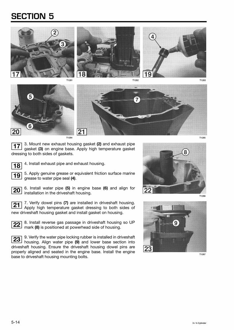
SECTION 5
5-14
3-/ 4-Cylinder
3. Mount new exhaust housing gasket
(2)
and exhaust pipegasket
(3)
on engine base. Apply high temperature gasketdressing to both sides of gaskets.
4. Install exhaust pipe and exhaust housing.
5. Apply genuine grease or equivalent friction surface marinegrease to water pipe seal
(4)
.
6. Install water pipe
(5)
in engine base
(6)
and align forinstallation in the driveshaft housing.
7. Verify dowel pins
(7)
are installed in driveshaft housing.Apply high temperature gasket dressing to both sides of
new driveshaft housing gasket and install gasket on housing.
8. Install reverse gas passage in driveshaft housing so UPmark
(8)
is positioned at powerhead side of housing.
9. Verify the water pipe locking rubber is installed in driveshafthousing. Align water pipe
(9)
and lower base section intodriveshaft housing. Ensure the driveshaft housing dowel pins areproperly aligned and seated in the engine base. Install the enginebase to driveshaft housing mounting bolts.
17
18
19
20
21
22
23
T1285
T1286
T1287
T1283
T1284
T1281 T1282

MIDSECTION
5-15
3-/ 4-Cylinder
Installation
1. Assemble the upper rubber mount components.
2. Apply Loctite 242 to bolt threads and install upper rubbermounts on steering shaft. Torque to specification.
3. Install the upper rubber mount damper if equipped, inengine base.
4. Position driveshaft housing so upper rubber mounts areproperly seated in engine base. Install upper mount cap
(1)
.
5. Install lower rubber mount components. Apply Loctite243 to bolt threads and torque to specification.
6. Install gearcase as described in Section 6.
7. Install lower engine cover, this section.
8. Install tiller steering handle if equipped, this section.
9. Install powerhead as described in Section 4.
24
25
26
27
28
T1293
T1294
T1290
T1288 T1289
T1266
T1291 T1292

SECTION 5
5-16
3-/ 4-Cylinder
STERN AND SWIVEL BRACKETS
NOTE
The following procedures cover full disassembly ofthe stern and swivel bracket components with theengine mounted on an engine stand. To service onlythe stern brackets, suspend engine with adequatehoist and remove and install stern brackets asillustrated. To service only the power trim/tilt unit, seeSection 8.
Models 40 and 50 (for Manual Tilt)
Models 40 and 50 (for Gas Assist Tilt and PT/T)
Models 60 and 70 (for Manual Tilt)
Models 60 / 70 / 80 / 90 (for Gas Assist Tilt and Old PT/T) Models 115 / 120 / 140 (for Old PTT)
Models 60 / 70 / 80 / 90 / 115 / 120 / 140 (for New PT/T)
1
2
3
4
5
T1295

MIDSECTION
5-17
3-/ 4-Cylinder
T1296
T1297
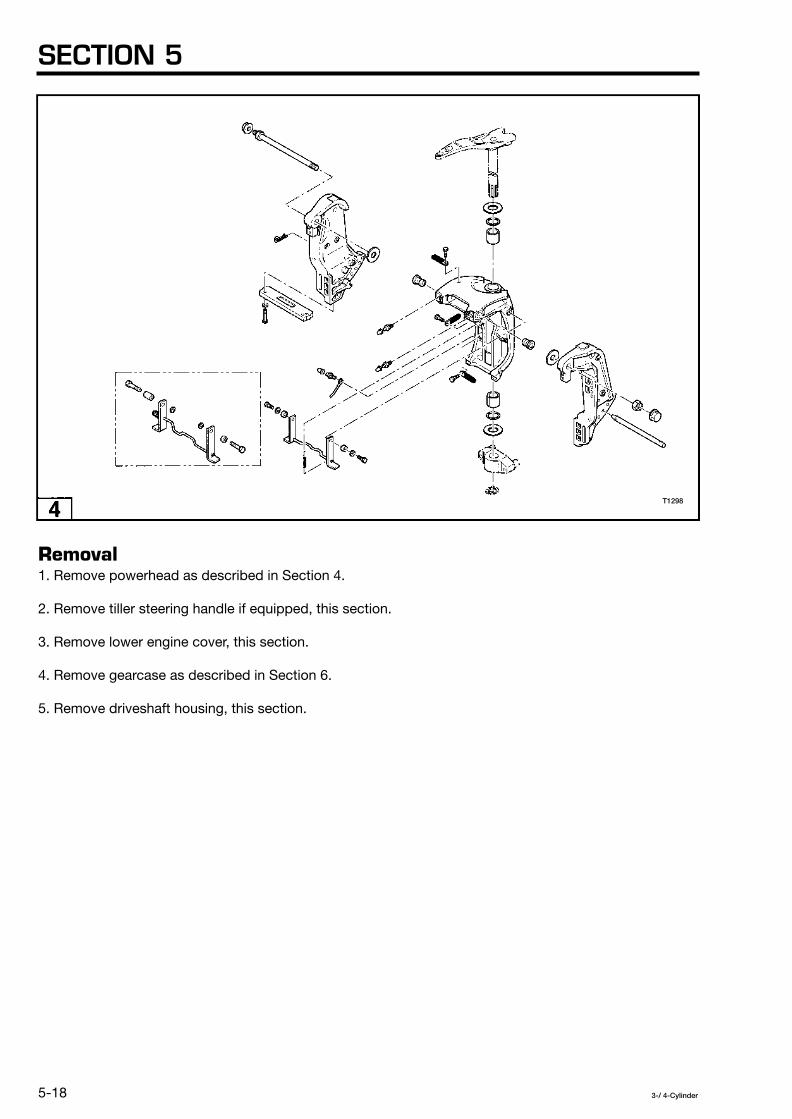
SECTION 5
5-18
3-/ 4-Cylinder
Removal
1. Remove powerhead as described in Section 4.
2. Remove tiller steering handle if equipped, this section.
3. Remove lower engine cover, this section.
4. Remove gearcase as described in Section 6.
5. Remove driveshaft housing, this section.
T1298

MIDSECTION
5-19
3-/ 4-Cylinder
Disassembly
NOTE
Disconnect all bracket ground wires before disassembly.
1. Remove snap ring
(1)
from steering shaft. Discard thesnap ring.6
T1299
T1300

SECTION 5
5-20
3-/ 4-Cylinder
2. Pull lower mount bracket
(2)
off steering shaft.
3. Lift steering shaft from swivel bracket.
4. Remove the bracket bolt nut.
5. Remove the bracket bolt, upper cylinder pin
(3)
ifequipped, and lift swivel bracket
(4)
from stern brackets.
6. Remove the gas assist cylinder or power trim/tilt unit if equipped.Refer to Section 8 for power trim/tilt removal.
7. Remove the stern brackets from engine stand.
8. If required, fully disassemble and inspect the manual tilt or gasassist tilt components as illustrated. Refer to Section 8 for servicingpower trim/tilt.
Models 40 and 50 - Manual Tilt
Models 40 and 50 - Gas Assist Tilt
Models 60 and 70 - Manual Tilt
Models 60 / 70 / 80 / 90 - Gas Assist Tilt
7
8
9
10
11
12
13
14
T1301
T1302
T1303
T1304
T1305

MIDSECTION
5-21
3-/ 4-Cylinder
T1307
T1306

SECTION 5
5-22
3-/ 4-Cylinder
Assembly
NOTE
Before proceeding, make sure all components havebeen thoroughly cleaned with solvent and allowed todry. Inspect all parts, especially bushings, thrustwashers, and upper and lower engine mounts fordamage and deterioration. Replace all seals and o-rings.
NOTE
Improper arrangement of bushings and thrustwashers may not prevent full assembly of the bracketcomponents. Reference the preceding illustrations toensure correct orientation of all parts.
NOTE
During assembly, apply genuine grease or equivalentfriction surface marine grease to all friction parts andsurfaces.
T1308

MIDSECTION
5-23
3-/ 4-Cylinder
1. Mount the stern brackets on engine stand.
2. Fully assemble and install the manual tilt or gas assist tiltcomponents as illustrated in the Disassembly procedure or installthe power trim/tilt unit at this time as described in Section 8.
3. Place swivel bracket between stern brackets. Installupper cylinder pin
(1)
if equipped, and bracket bolt
(2)
.Torque bracket bolt nut to specification.
NOTE
Upper cylinder pin must be locked in place by washer
(3)
and bolt
(4)
or new snap ring as applicable.
4. Connect bracket ground leads as required.
5. Install steering shaft.
NOTE
Note the installation of friction plate
(5)
on manual tiltmodels.
6. Slide lower mount bracket
(6)
onto steering shaft andinstall new snap ring
(7)
. DO NOT use old snap ring.
7. Fill all grease fittings. See Lubrication Chart in Section 2.
Installation
Installation is done in the reverse order of Removal.
15
17
19
T1311
T1312
T1313
T1310T1309
18
16

SECTION 5
5-24
3-/ 4-Cylinder
THIS PAGE INTENTIONALLY LEFT BLANK.

3-/ 4-Cylinder
6-1
General Precautions ............................................................................................................ 6-2
Service Specifications ......................................................................................................... 6-3
Water Pump ........................................................................................................................ 6-4
Gearcase ............................................................................................................................. 6-9
Backlash - Shim Adjustment Table ................................................................................... 6-29
Gearcase Repair Procedures ............................................................................................ 6-30
SECTION 6GEARCASE
TABLE OF CONTENTS

SECTION 6
6-2
3-/ 4-Cylinder
GENERAL PRECAUTIONS
Before performing any service work on the gearcase, read andunderstand the Service Safety section at the beginning of thismanual.
Full servicing of the gearcase requires manufacturer special tools.Follow all special tool requirements as specified. Substitutingspecial tools with those not provided by the manufacturer mayresult in severe personal injury, equipment or engine damage, orfaulty service work.
Perform bearing removal and installation operations exactly asspecified to avoid damage to the bearing or housing duringpressing operations.
Replace locking fasteners when their locking feature becomesweak. Use only factory replacement parts.
When using compressed air to clean or dry parts, make sure airsupply is regulated not to exceed 25 psi [172 kPa / 1.76 kg/cm
2
].

GEARCASE
6-3
3-/ 4-Cylinder
SERVICE SPECIFICATIONS
Special Torque Values
Refer to Section 2 for Standard Torque Values chart.
Manufacturer Special Tools Required
Socket, Bevel Gear B Nut, 345-72232-0, 3B7-72232-0
Wrench, Bevel Gear B Nut, 346-72231-0, 353-72231-0, 3B7-72231-0
Bevel Gear A Bearing Puller Assembly, 3A3-72755-0 , 387-72755-0
Bevel Gear A Bearing Set Tool, 3C8-72719-0, 3B7-72719-0
Shift Rod Joint Puller, 353-72248-0
Spring Pin Tool A, 345-72227-0, 369-72217-0
Spring Pin Tool B, 345-72228-0, 369-72218-0
Bevel Gear A Bearing Outer Race Fitting Tool, 3B7-72731-0
Needle Roller Bearing Puller Kit, 3C8-72700-0, 3B7-72700-0
Backlash Measurement Tool Kit, 3C8-72234-0, 3B7-72234-0, 3B7-72255-0
Clutch Pin Snap Tool, 345-72229-0
Needle Bearing Press Kit, 3C7-72900-0
Description
Torque in-lb (ft-lb)
N·m kg-m
Thread locker
Model
40 / 50 60 / 70 80 / 90
115 / 120 / 140
Propeller Nut (22 - 29) 29 - 392.9 - 3.9
(22 - 29) 29 - 392.9 - 3.9
(22 - 29) 29 - 392.9 - 3.9
(22 - 29)29 - 39 2.9 - 3.9
Gearcase Mounting Bolt
(14 - 15) 19 - 211.9 - 2.1
M8: (17 - 19) 24 - 26 2.4 - 2.6
M10: (27 - 30) 37 - 41 3.7 - 4.1
M8: (17 - 19)24 - 26 2.4 - 2.6
M10: (27 - 30) 37 - 41 3.7 - 4.1
M8: (17 - 19) 24 - 26 2.4 - 2.6
M10: (27 - 30) 37 - 41 3.7 - 4.1
Loctite 242
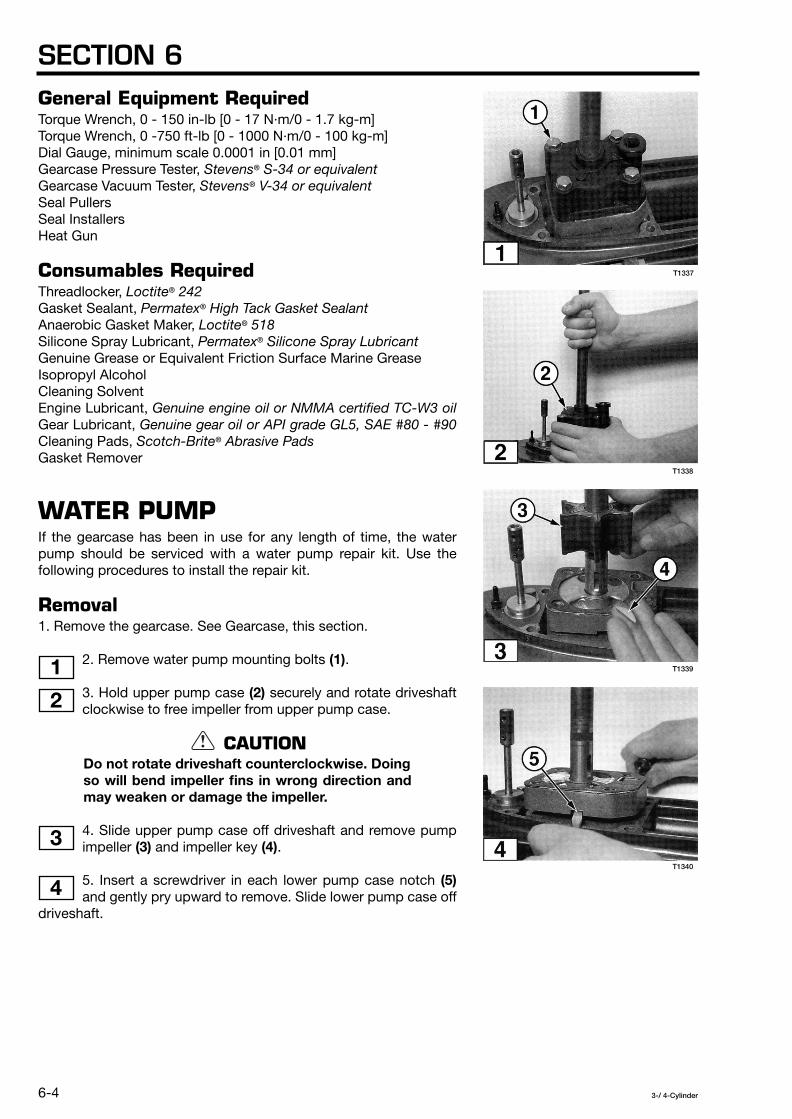
SECTION 6
6-4
3-/ 4-Cylinder
General Equipment Required
Torque Wrench, 0 - 150 in-lb [0 - 17 N·m/0 - 1.7 kg-m]Torque Wrench, 0 -750 ft-lb [0 - 1000 N·m/0 - 100 kg-m]Dial Gauge, minimum scale 0.0001 in [0.01 mm]Gearcase Pressure Tester,
Stevens
®
S-34 or equivalent
Gearcase Vacuum Tester,
Stevens
®
V-34 or equivalent
Seal PullersSeal InstallersHeat Gun
Consumables Required
Threadlocker,
Loctite
®
242
Gasket Sealant,
Permatex
®
High Tack Gasket Sealant
Anaerobic Gasket Maker,
Loctite
®
518
Silicone Spray Lubricant,
Permatex
®
Silicone Spray Lubricant
Genuine Grease or Equivalent Friction Surface Marine GreaseIsopropyl AlcoholCleaning SolventEngine Lubricant,
Genuine engine oil or NMMA certified TC-W3 oil
Gear Lubricant,
Genuine gear oil or API grade GL5, SAE #80 - #90
Cleaning Pads,
Scotch-Brite
®
Abrasive Pads
Gasket Remover
WATER PUMP
If the gearcase has been in use for any length of time, the waterpump should be serviced with a water pump repair kit. Use thefollowing procedures to install the repair kit.
Removal
1. Remove the gearcase. See Gearcase, this section.
2. Remove water pump mounting bolts
(1)
.
3. Hold upper pump case
(2)
securely and rotate driveshaftclockwise to free impeller from upper pump case.
CAUTION
Do not rotate driveshaft counterclockwise. Doingso will bend impeller fins in wrong direction andmay weaken or damage the impeller.
4. Slide upper pump case off driveshaft and remove pumpimpeller
(3)
and impeller key
(4)
.
5. Insert a screwdriver in each lower pump case notch
(5)
and gently pry upward to remove. Slide lower pump case offdriveshaft.
1
2
3
4
T1338
T1339
T1340
T1337

GEARCASE
6-5
3-/ 4-Cylinder
Disassembly and Assembly
1. Disassemble the water pump components asillustrated and verify the kit parts match the
originals before discarding old parts.
NOTE
Lower pump case dowel pins are difficult to removeand should only be pulled out if replacement isnecessary.
2. Remove all gasket residue from lower pump case withabrasive cleaning pads and gasket remover. Do not scrape
the gasket surface with metal scraper. Thoroughly clean allcomponents with isopropyl alcohol and dry with low pressurecompressed air.
3. Inspect the upper and lower pump cases for signs of cracks.Replace as needed.
4. Examine lower pump case oil seals
(1)
for signs ofdamage and deterioration.
NOTE
If necessary to replace seals, use appropriate sizeseal puller and installer to avoid damaging new sealsand seating surfaces in lower pump case. Applysilicone spray lubricant to seals and install so lipsface direction indicated.
5 6 7
8
9
10
T1341 T1342 T1343
T1344
T1345
T1346

SECTION 6
6-6
3-/ 4-Cylinder
5. Apply anaerobic gasket maker to seating surface of waterpipe lower seal
(2)
.
6. Install seal in upper pump case so locking tabs
(3)
alignwith holes
(4)
.
7. Slide pump case liner
(5)
partially into upper pump casehousing so locking tab
(6)
is aligned with notch in housing.
NOTE
Pump case liner must be flush with flanged surfaceof upper pump case. If not, remove liner and re-alignlocking tab with notch in upper pump case housing.
9. Install lower pump case dowel pins
(7)
if removed.And install new O-ring
(8)
.
10. Apply gasket sealant to both sides of guide plate gasket
(9)
. Mount gasket and guide plate
(10)
on lower pump case.
11
12
13
14
15
T1351
T1352
T1349T1348T1347

GEARCASE
6-7
3-/ 4-Cylinder
11. Apply gasket sealant to guide plate side of upper pumpcase gasket
(11)
. Mount gasket on guide plate.
NOTE
Models 115, 120, and 140 are equipped with specialshaped pump case o-ring seal
(12)
instead of gasket.Apply a thin bead of anaerobic gasket maker in theupper pump case seal groove and install o-ring sealin groove.
Installation
1. Apply a light coating of genuine grease or equivalentfriction surface marine grease to the oil seal lips
(1)
, and o-ring
(2)
. Apply an aerobic gasket maker to flanged surface
(3)
toprovide adequate seal between lower pump case and gearcase.
2. Slide lower pump case down driveshaft and seat intoposition on gearcase.
3. Insert impeller key
(4)
in driveshaft and align impeller slotwith key. Hold the impeller key in place and push impeller
down until seated in position.
16
17
18
19
20
T1356
T1357
T1355
T1354
T1353

SECTION 6
6-8
3-/ 4-Cylinder
5. Lubricate the impeller fins with soapy water and slide upperpump case down driveshaft. Hold pump case securely and
push downward while rotating driveshaft clockwise to seat theimpeller.
CAUTION
Do not rotate driveshaft counterclockwise. Doingso will bend impeller fins in wrong direction andmay weaken or damage the impeller.
6. Ensure upper pump case is aligned and fully seated on the dowelpins. Hold the upper pump case in position and rotate driveshaftclockwise to ensure free movement.
CAUTION
Make sure impeller fins are not caught or pinchedbetween upper and lower pump cases whenupper pump case is fully seated.
7. Apply genuine grease or equivalent friction surface marinegrease to neck portion of water pump mounting bolts. Install
the bolts.
8. Install the gearcase. See Gearcase, this section.
21
22
T1356
T1355

GEARCASE
6-9
3-/ 4-Cylinder
GEARCASE
Typical Gearcase
T1360

SECTION 6
6-10
3-/ 4-Cylinder
Removal
WARNING
Ignition system must be disabled to preventaccidental engine start-up during removal of thegearcase.
1. Place engine in FORWARD gear so shift rod joint
(1)
isaccessible. If necessary, use shift rod joint puller
(2)
(PartNo. 353-72248-0) to hook and pull up the shift rod joint.
2. Use correct size spring pin tool A
(3)
to remove upperspring pin from shift rod joint. Discard the spring pin.
3. Complete the following for models 60, 70, 80, 90, 115, 120, and140:
Remove gearcase plate
(4)
or sub water strainer fromunderside of cavitation plate.
Remove internal coupling bolt
(5)
.
4. Remove gearcase mounting bolts
(6)
from both sides ofgearcase.
5. Separate gearcase from driveshaft housing anddisconnect speedometer pickup tube
(7)
if equipped.
Description Part Number Application
Spring Pin Tool A 345-72227-0 3 mm spring pins
Spring Pin Tool A 369-72217-0 3.5 mm spring pins
1
2
3
4
5
6
T1364
T1365
T1363T1362T1361
T1366

GEARCASE
6-11
3-/ 4-Cylinder
Disassembly
CAUTION
Gearcase must be secured in a suitable holdingfixture during disassembly.
1. Drain all gearcase oil into a container and inspect the oil for metalchips.
NOTE
Small metal fragments may indicate normal wear ofgears, bearings, and shafts. Large metal chipsusually indicate extensive internal damage. Recordyour observations for future reference wheninspecting internal components.
2. Remove the water pump and install a water pump repair kit ifgearcase has been in service for any length of time. See WaterPump, this section.
3. Remove propeller mounting hardware and propeller.
4. Remove propeller shaft housing bolts
(1)
.
5. Install propeller shaft housing puller
(2)
(Part No. 353-72252-0). Tighten the pressing bolt until propeller housing
separates from gearcase.
6. Remove propeller shaft and housing from gearcase. Makesure clutch push rod
(3)
is also removed. Set the assemblyaside.
7. Thoroughly degrease the driveshaft splines and thebevel gear B nut. Install specified socket
(4)
andwrench
(5)
. Hold bevel gear B nut with wrench and turn driveshaftcounterclockwise to loosen the nut. Remove bevel gear B
(6)
andnut
(7)
from gearcase.
7
8
9
10 11
T1370
T1369T1368T1367
T1371

SECTION 6
6-12
3-/ 4-Cylinder
8. Lift the driveshaft from the gearcase and set it aside.
9. Using a piece of wire or other hooking device, removedriveshaft spring guide
(8)
.
NOTE
Models 40 and 50 are not equipped with removabledriveshaft spring guide.
10. Reach inside gearcase and remove roller bearing
(9)
andbevel gear A
(10)
.
11. Remove the stopper and lift cam rod
(11)
from gearcase.Fully disassemble the cam rod components, including the
cam rod bushing internal and external o-rings.
12. Remove clutch push rod
(12)
and detent ball
(13)
frompropeller shaft. Pull propeller shaft out of housing.
13. Remove washer
(14)
, bevel gear
(15)
, and all shims
(16)
from propeller shaft.
Tool Part Number Model
Socket, Bevel Gear B Nut 345-72232-0
40 / 50 / 60B / 70B
Socket, Bevel Gear B Nut 3B7-72232-0
60C / 70C / 80 / 90 115 / 120 / 140
Wrench, Bevel Gear B Nut 346-72231-0
40 / 50
Wrench, Bevel Gear B Nut 353-72231-0
60B / 70B
Wrench, Bevel Gear B Nut 3B7-72231-0
60C / 70C / 80 / 90 115 / 120 / 140
12
13
14
15
16
17
T1375
T1376
T1374T1373T1372
T1377

GEARCASE
6-13
3-/ 4-Cylinder
14. Insert screwdriver under one end of clutch pin snapspring
(17)
. Remove spring from groove by unwrapping itfrom clutch. Discard the spring.
CAUTION
DO NOT reuse clutch pin snap spring (17), it mustbe replaced. Reusing clutch pin snap spring maycause severe damage to gears and othercomponents.
15. Place propeller shaft open end against bench surfaceand push out clutch pin
(18)
. Remove clutch spring
(19)
andspring holder
(20)
.
WARNING
Wear safety glasses and DO NOT hold open endof propeller shaft towards face or body whenremoving clutch pin. Clutch spring and springholder come out with great force.
16. Pull clutch
(21)
off propeller shaft.
Cleaning and Inspection
NOTE
All worn, damaged, and missing parts must be replaced.
1. Discard the clutch pin snap spring and all seals and o-rings thathave been removed.
2. Clean all gearcase components with solvent and dry with lowpressure compressed air. After cleaning, apply specified gear oil toall internal components to prevent rusting.
3. Perform the following inspections:
Gearcase Housing
• Inspect internal and external surfaces of housing for cracks andother damage. All threaded holes must be undamaged and freeof corrosion and sealing agents.
• Check the sacrificial trim tab for damage and erosion. SeeAnodes - Inspection and Testing in Section 2.
• Inspect the water intake screens for damage and blockage. Ifscreens cannot be fully cleaned, replace them.
18
19
20
T1380
T1379T1378

SECTION 6
6-14
3-/ 4-Cylinder
Propeller and Shaft
• Verify the propeller is true and free of nicks, chips, and otherdamage that will affect performance. Inspect the thrust washerand mounting hardware for damage.
• Check the propeller shaft threads and splines for wear anddamage.
Propeller Shaft Housing
Examine propeller shaft housing and components for wear,damage, and deterioration. And repair as needed. See
Gearcase Repair Procedures, this section.
Driveshaft
• Check driveshaft threads and splines forwear, chips, and cracks.Severe spline wear or the appearance of spline “twisting”indicates the gearcase has been distorted, possibly by impactdamage.
• Bearing(s) must be free of damage, corrosion, and discoloration.Replace bearing(s) as required. See Gearcase Repair Procedures,this section.
All Internal Components
Inspect all internal components for signs of wear, chipping, pitting,distortion, and discoloration due to improper lubrication. Specialattention to the following:
• Check the bevel gear A tapered roller bearing outer race. Ifdamaged or corroded, replace both the race and the bearing.See Gearcase Repair Procedures in this section.
• Inspect clutch and gear teeth and the clutch cam for chips andsigns of metal transfer. Replace parts as needed.
Assembly
CAUTION
Gearcase must be secured in a suitable holdingfixture during assembly.
1. Install new gearcase needle bearing, bevel gear A roller bearingand outer race, and driveshaft bearing(s) if any of these parts wereremoved. See Gearcase Repair Procedures, this section.
2. Secure gearcase in holding fixture with water pump side facingupward.
3. Slide the driveshaft spring onto the driveshaft soflat side
(1)
faces threaded end of driveshaft. Positionthe spring exactly as shown so flat side
(1)
is seated againstshoulder
(2)
.
CAUTION
The driveshaft spring provides oil lubrication tothe tapered roller bearing(s) under the lowerwater pump case. If spring is installed too high,oil supply may be insufficient.
21
22 23
T1382
T1383
T1381

GEARCASE
6-15
3-/ 4-Cylinder
4. Install the removable spring guide if equipped sokey
(3)
is seated in keyway
(4)
of gearcase housing.Spring guide will not rotate in gearcase when properly installed.
5. Install the driveshaft through the drive shaft housing. Make suredriveshaft bearing outer race is fully seated against the bearing.
NOTE
Models 40 and 50 are not equipped with bearingouter race.
6. Apply Loctite 242 to bevel gear B nut
(5)
. Slide bevel gearB
(6)
onto driveshaft
(7)
as shown from propeller shaft sideof gearcase. Hand tighten nut
(5)
to secure the gear in place.
7. Install specified socket
(8)
and wrench
(9)
. Hold bevelgear B nut with wrench and turn driveshaft clockwise to
tighten the nut. Torque bevel gear B nut to specification.
8. Perform all adjustment steps before proceeding. See Adjustments,this section.
CAUTION
Failure to perform the adjustment steps mayresult in poor engine performance, prematurewear of parts, or severe damage to gearcasecomponents.
9. Install the water pump. See Water Pump, this section.
NOTE
Make sure all necessary adjustment shims areinstalled on driveshaft bearing before installing lowerpump case.
Tool Part Number Model
Socket, Bevel Gear B Nut 345-72232-0
40 / 50 / 60B / 70B
Socket, Bevel Gear B Nut 3B7-72232-0
60C / 70C / 80 / 90 / 115 / 120 / 140
Wrench, Bevel Gear B Nut 346-72231-0
40 / 50
Wrench, Bevel Gear B Nut 353-72231-0
60B / 70B
Wrench, Bevel Gear B Nut 3B7-72231-0
60C / 70C / 80 / 90 / 115 / 120 / 140
24 25
26
27
T1385
T1386
T1384
T1387
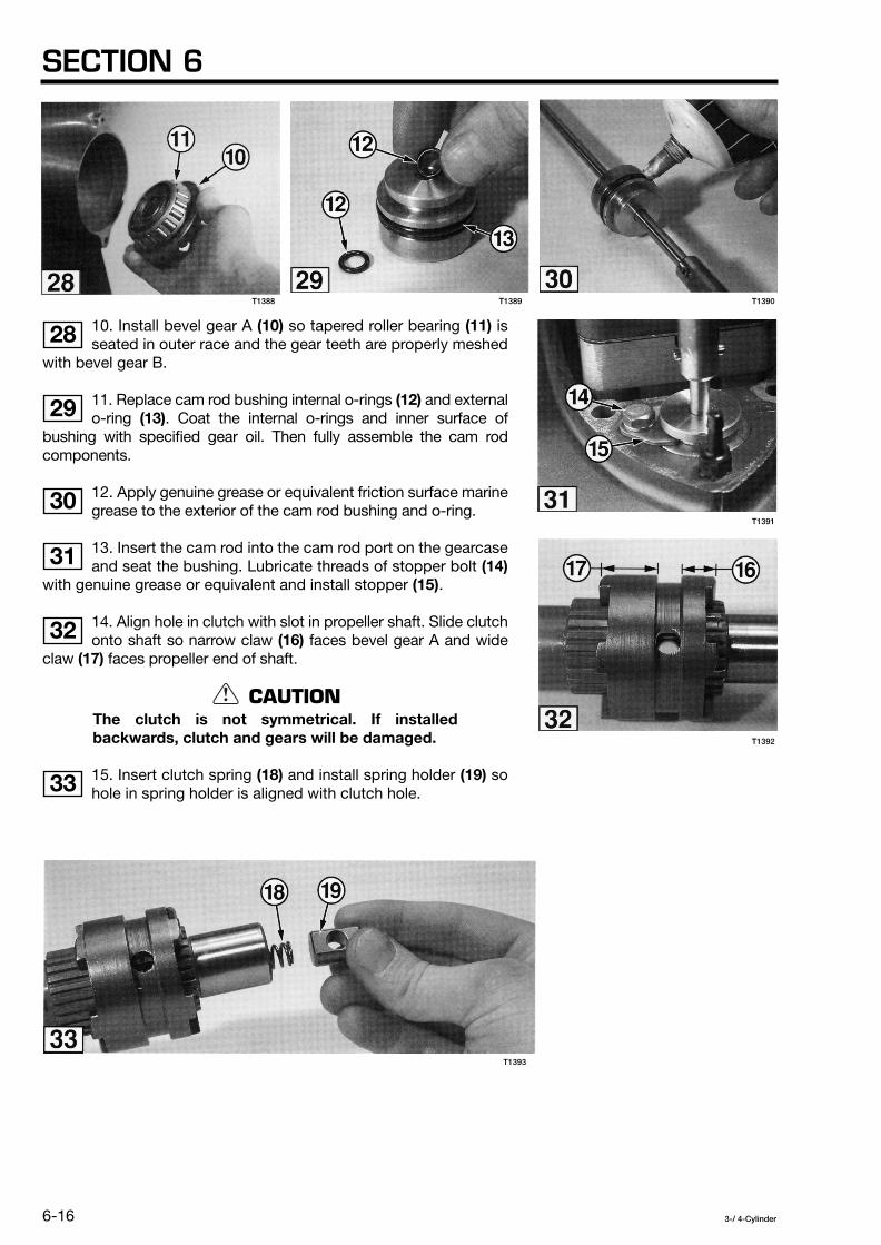
SECTION 6
6-16
3-/ 4-Cylinder
10. Install bevel gear A
(10)
so tapered roller bearing
(11)
isseated in outer race and the gear teeth are properly meshed
with bevel gear B.
11. Replace cam rod bushing internal o-rings
(12)
and externalo-ring
(13)
. Coat the internal o-rings and inner surface ofbushing with specified gear oil. Then fully assemble the cam rodcomponents.
12. Apply genuine grease or equivalent friction surface marinegrease to the exterior of the cam rod bushing and o-ring.
13. Insert the cam rod into the cam rod port on the gearcaseand seat the bushing. Lubricate threads of stopper bolt
(14)
with genuine grease or equivalent and install stopper
(15)
.
14. Align hole in clutch with slot in propeller shaft. Slide clutchonto shaft so narrow claw
(16)
faces bevel gear A and wideclaw
(17)
faces propeller end of shaft.
CAUTION
The clutch is not symmetrical. If installedbackwards, clutch and gears will be damaged.
15. Insert clutch spring
(18)
and install spring holder
(19)
sohole in spring holder is aligned with clutch hole.
28
29
30
31
32
33
T1391
T1392
T1390T1389T1388
T1393

GEARCASE
6-17
3-/ 4-Cylinder
16. Insert detent ball
(20)
. Install clutch push rod
(21)
sotapered end faces bevel gear A.
17. Compress the clutch spring by applying pressure topush rod
(21)
. Align the holes of the clutch and spring holderand insert clutch pin
(22)
.
CAUTION
Wear safety glasses and DO NOT hold spring endof propeller shaft towards face or body whencompressing the clutch spring.
18. Install new clutch pin snap spring
(23)
. Do not reuse oldsnap spring.
CAUTION
DO NOT reuse clutch pin snap spring (23), it mustbe replaced. Reusing clutch pin snap spring maycause severe damage to gears and othercomponents.
19. Make sure all necessary adjustment shims are installedon bevel gear C
(24)
and install gear onto propeller shafthousing
(25)
. Install washer
(26)
onto bevel gear.
20. Apply genuine grease or equivalent to the propeller shafthousing o-ring and oil seal. Slide the propeller shaft into the
propeller shaft housing.
21. Lift the cam rod to the fully UP position and verifythrough the gearcase opening that clutch cam beveled side
(27)
faces gearcase opening.
34
35
36
37
38
39
T1397
T1398
T1396T1395T1394
T1399

SECTION 6
6-18
3-/ 4-Cylinder
22. Align the clutch push rod with the clutch cam and slidethe propeller shaft and housing into the gearcase opening.
Push forward and rotate the propeller shaft as needed until bevelgears have engaged. Ensure the propeller shaft housing bolts arecompletely clean and apply Loctite 242 to the bolt threads. Installand torque the bolts evenly to prevent improper seating of thehousing.
23. Move the cam rod to each position and rotate thedriveshaft to test gearcase function in all gears. Check the
propeller shaft for looseness in the forward and reverse directions.If looseness exceeds 0.016 in [0.40 mm], replace bevel gear Cwasher
(28)
with one of correct thickness.
NOTE
Refer to current Parts Catalog for washer availability.
24. Before adding gear oil, pressure test and vacuum testthe gearcase as follows:
• Remove the oil level plug and install gearcase pressure tester.
• Pump pressure tester until gauge indicates 3 - 6 psi [21 - 42 kPa/ 0.2 - 0.4 kg/cm
2
]. If pressure loss occurs, determine source ofleakage by submerging gearcase in water. Make necessaryrepairs to correct the problem and retest.
• Remove the pressure tester and install gearcase vacuum tester.
40
41
42
T1402
T1401
T1400

GEARCASE
6-19
3-/ 4-Cylinder
• Pump vacuum tester until gauge indicates 3 - 5 in [76 - 127 mm]of mercury. If loss of vacuum occurs, apply oil around suspectedseal. If leak stops or oil is drawn in, the seal is defective and mustbe replaced. Make necessary repairs to correct the problem andretest.
25. Fill gearcase with specified gear lubricant. See EngineSpecifications in Section 2 for gearcase capacities.
26. Apply genuine grease or equivalent to the propeller shaft andpropeller mounting hardware. Install the propeller and propellermounting hardware. Torque propeller nut to specification.
CAUTION
Make sure propeller thrust holder is installed andseated against the propeller shaft oil seal beforeinstalling propeller. If installed improperly,propeller may be pushed into gearcase housingduring tightening.
Adjustments
CAUTION
DO NOT attempt gearcase adjustments withoutproper manufacturer special tools and adequateknowledge of gearcase setup.
NOTE
Specific assembly steps must be completed in orderto perform the gearcase adjustments. If these stepshave not been performed, refer to Assembly, thissection.
NOTE
Unless otherwise indicated, all gearcase adjustmentspecifications are based on measurements obtainedwith manufacturer special tools.
1. Slide lower pump case onto driveshaft and seat intoposition on gearcase. Secure lower pump case with bolts
(1)
and flat washers
(2)
.
43
T1403

SECTION 6
6-20
3-/ 4-Cylinder
Bevel Gear B Adjustment
2. Insert specified shimming gauge
(3)
into gearcase.
NOTE
Correct positioning of the shimming gauge in thegearcase is critical. Make sure tapered side
(4)
is fullyseated in bevel gear A bearing outer race with flatside
(5)
and notch
(6)
facing upward.
Tool Part Number Model
Shimming Gauge 3C8-72250-0
40 / 50 / 60B / 70B
Shimming Gauge 3B7-72250-0
60C / 70C / 80 / 90 / 115 / 120 / 140
44
T1404

GEARCASE
6-21
3-/ 4-Cylinder
3. Eliminate all looseness between driveshaft and gearcaseusing one of the following methods:
• Lift driveshaft upward and tap down on gearcase with rubbermallet.
• Slide a compression spring (obtain locally) over driveshaft andseat onto lower pump case. Install backlash measuring toolclamp assembly (Part No. 3B7-72720-0) on driveshaft.Compress the spring and tighten the clamp to maintain thespring compression and provide constant upward pressureagainst driveshaft.
With all looseness eliminated, measure the gap between collar
(7)
and bevel gear B using thickness gauge set
(8)
(Part No. 353-72251-0). If gap measurement is not within 0.023 - 0.025 in [0.60 -0.64 mm], remove the lower pump case and install correct sizeshim onto roller bearing outer race at location
(9)
.
NOTE
Refer to current Parts Catalog for shim availability.
4. If shimming was necessary re-install the lower pump case beforeproceeding with Backlash Adjustment - Bevel Gears A and B.
44

SECTION 6
6-22
3-/ 4-Cylinder
Backlash Adjustment - Bevel Gears A and B
NOTE
Obtain backlash measuring tool kit. Reference thefollowing specification table for Backlash Adjustmentspecial tool requirements:
5. With the tapered roller bearing installed, position bevel gear A ingearcase so bearing is fully seated in outer bearing race. Rotate thedriveshaft to ensure gears are properly meshed.
Tool Part Number Model
Backlash Measuring Tool Kit for Gears “A” & “B”
3C8-72234-0 40 / 50
Backlash Measuring Tool Kit for Gears “A” & “B”
3B7-72234-0 60 / 70 / 80 / 90 / 115 / 120 / 140
Collar, Backlash Measuring Tool 353-72245-1 40 / 50
Set Piece A, Backlash Measuring Tool
3A3-72245-0 60B / 70B
Set Piece A, Backlash Measuring Tool
3B7-72245-0 60C / 70C / 80 / 90 / 115 / 120 / 140
O-ring, 2-9 332-60002-0 40 / 50 / 60B / 60C / 70B / 70C /80 /90 / 115 / 120 / 140
Conedisk Spring Washer
3B7-72734-0 40 / 50 / 60B / 60C / 70B / 70C / 80 / 90 / 115 / 120 / 140
Shaft, Backlash Measuring Tool 345-72723-0 40 / 50
Shaft, Backlash Measuring Tool
3B7-72723-0 60B / 60C / 70B / 70C / 80 / 90 / 115 / 120 / 140
Plate (order separately or obtain from Bevel Gear A Bearing Puller Assembly Part No. 345-72224-1 )
3A3-72724-0 40 / 50
Plate, Backlash Measuring Tool
3B7-72724-0 60B / 60C / 70B / 70C / 80 / 90 / 115 / 120 / 140
Nut, Shaft 930191-1000 40 / 50
Nut, Shaft, 12Pl.5 3B7-72735-0 60B / 60C / 70B / 70C / 80 / 90 / 115 / 120 / 140
Clamp Assembly, Backlash Measuring Tool
3B7-72720-0 40 / 50 / 60B / 60C / 70B / 70C / 80 / 90 / 115 / 120 / 140
Dial Gauge Plate 3B7-72729-0 40 / 50 / 60B / 60C / 70B / 70C / 80 / 90/ 115 / 120 / 140
Bolt, Lower Pump Case 910191-0830 40 / 50
Bolt, Lower Pump Case 910191-0835 60B / 60C / 70B / 70C / 80 / 90 / 115 / 120 / 140
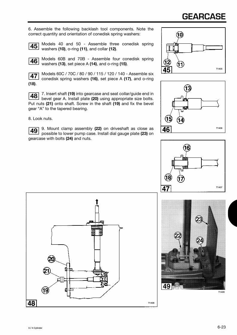
GEARCASE
6-23
3-/ 4-Cylinder
6. Assemble the following backlash tool components. Note thecorrect quantity and orientation of conedisk spring washers:
Models 40 and 50 - Assemble three conedisk springwashers
(10)
, o-ring
(11)
, and collar
(12)
.
Models 60B and 70B - Assemble four conedisk springwashers
(13)
, set piece A
(14)
, and o-ring
(15)
.
Models 60C / 70C / 80 / 90 / 115 / 120 / 140 - Assemble sixconedisk spring washers
(16)
, set piece A
(17)
, and o-ring
(18)
.
7. Insert shaft
(19)
into gearcase and seat collar/guide end inbevel gear A. Install plate
(20)
using appropriate size bolts.Put nuts
(21)
onto shaft. Screw in the shaft
(19)
and fix the bevelgear “A” to the tapered bearing.
8. Look nuts.
9. Mount clamp assembly
(22)
on driveshaft as close aspossible to lower pump case. Install dial gauge plate
(23)
ongearcase with bolts
(24)
and nuts.
45
46
47
48
49
T1406
T1407
T1405
T1409
T1408

SECTION 6
6-24
3-/ 4-Cylinder
10. Mount a magnetic base and dial gauge (obtain locally)as shown. Lift driveshaft upward and tap down on gearcase
with rubber mallet to eliminate all looseness and proceed to adjustthe setup so dial gauge
(25)
is aligned with V-notch
(26)
.
11. Set dial gauge to zero. Lift driveshaft upward and tapdown on gearcase with rubber mallet to eliminate
looseness. Rotate driveshaft in both directions and record the dialgauge reading.
lf the dial gauge reading is not within the specified range,adjust, shim thickness between bevel gear A
(27)
andtapered roller bearing
(28)
in accordance with the Backlash - ShimAdjustment Table, this section. See Gearcase Repair Procedures inthis section for removal and installation of the bevel gear A rollerbearing.
12. Proceed with Backlash Adjustment - Bevel Gears B and C.
Model Acceptable Dial Gauge Reading
in mm
40 / 50
0.0122 - 0.0244 0.31 - 0.62
60B / 70B
0.0094 - 0.0319 0.29 - 0.58
60C / 70C
0.0106 - 0.0213 0.27 - 0.54
80 / 90 / 115 / 120 / 140
0.0094 - 0.0189 0.24 - 0.48
50
51
52
T1412
T1410
T1411
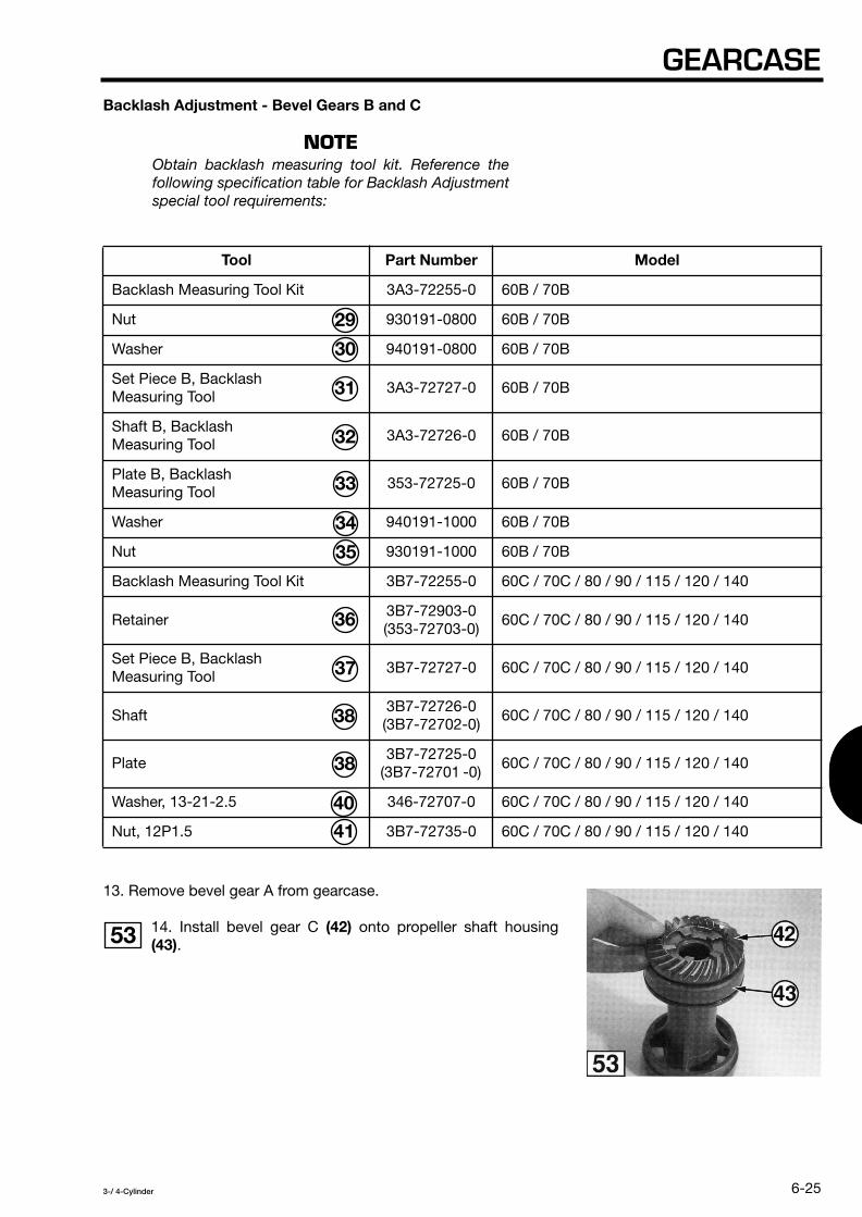
GEARCASE
6-25
3-/ 4-Cylinder
Backlash Adjustment - Bevel Gears B and C
NOTE
Obtain backlash measuring tool kit. Reference thefollowing specification table for Backlash Adjustmentspecial tool requirements:
13. Remove bevel gear A from gearcase.
14. Install bevel gear C
(42)
onto propeller shaft housing
(43)
.
Tool Part Number Model
Backlash Measuring Tool Kit 3A3-72255-0 60B / 70B
Nut 930191-0800 60B / 70B
Washer 940191-0800 60B / 70B
Set Piece B, Backlash Measuring Tool
3A3-72727-0 60B / 70B
Shaft B, BacklashMeasuring Tool
3A3-72726-0 60B / 70B
Plate B, Backlash Measuring Tool
353-72725-0 60B / 70B
Washer 940191-1000 60B / 70B
Nut 930191-1000 60B / 70B
Backlash Measuring Tool Kit 3B7-72255-0 60C / 70C / 80 / 90 / 115 / 120 / 140
Retainer 3B7-72903-0(353-72703-0)
60C / 70C / 80 / 90 / 115 / 120 / 140
Set Piece B, Backlash Measuring Tool
3B7-72727-0 60C / 70C / 80 / 90 / 115 / 120 / 140
Shaft3B7-72726-0(3B7-72702-0)
60C / 70C / 80 / 90 / 115 / 120 / 140
Plate3B7-72725-0
(3B7-72701 -0) 60C / 70C / 80 / 90 / 115 / 120 / 140
Washer, 13-21-2.5 346-72707-0 60C / 70C / 80 / 90 / 115 / 120 / 140
Nut, 12P1.5 3B7-72735-0 60C / 70C / 80 / 90 / 115 / 120 / 140
53
T1413
29
30
31
32
33
34
35
36
37
38
38
40
41

SECTION 6
6-26
3-/ 4-Cylinder
15. Assemble special tools as follows:
Models 60B / 70B:
• Slide shaft
(32)
through propeller shaft housing so shorter lengthof thread is at gear end of housing.
• Attach set piece B
(31)
and secure with nut
(29)
and washer
(30)
.Tighten the nut to secure bevel gear C to propeller shaft housing.
• Slide plate B
(33)
onto shaft and attach washer
(34)
and nut
(35)
.
Models 60C / 70C / 80 / 90 / 115 / 120 / 140:
• Slide shaft
(38)
through propeller shaft housing and bevel gear Cas shown.
• Install set piece B
(37)
and attach retainer
(36)
to shaft grooveshown.
• Slide plate
(39)
onto shaft and attach washer
(40)
and nut
(41)
.
16. Insert the assembly into the gearcase and rotate thedriveshaft to ensure bevel gears B and C are properly
meshed. Install the propeller shaft housing bolts. Seat the plateagainst the propeller shaft housing and finger tighten the shaft nutagainst the plate. Then tighten the nut an addition 1/4-turn.
54
55
56
T1415 T1416
T1414

GEARCASE
6-27
3-/ 4-Cylinder
17. Lift driveshaft upward and tap down on gearcase withrubber mallet to eliminate all looseness and proceed to
adjust the dial gauge
(42)
is aligned with V-notch
(43)
.
18. Set dial gauge to zero. Lift driveshaft upward and tapdown on gearcase with rubber mallet to eliminate
looseness. Rotate driveshaft in both directions and record the dialgauge reading.
If the dial gauge reading is not within the specified range,adjust shim thickness between bevel gear C
(44)
andpropeller shaft housing bearing
(45)
in accordance with theBacklash - Shim Adjustment Table, this section.
Model Acceptable Dial Gauge Reading
in mm
40 / 50
0.0122 - 0.0244 0.31 - 0.62
60B / 70B
0.0094 - 0.0319 0.29 - 0.58
60C / 70C
0.0106 - 0.0213 0.27 - 0.54
80 / 90 / 115 / 120 / 140
0.0094 - 0.0189 0.24 - 0.48
57
58
59
T1419
T1418
T1411

SECTION 6
6-28
3-/ 4-Cylinder
Installation
WARNING
Ignition system must be disabled to preventaccidental engine start-up during installation ofthe gearcase.
1. Lightly coat the driveshaft splines with genuine engine oilor TC-W3 oil and apply silicone spray lubricant to water pipe
lower seal
(1)
.
2. Slide driveshaft into lower crankcase head. Connectspeedometer pickup tube
(2)
if equipped and align waterpipe with lower seal
(3)
before seating gearcase on driveshafthousing.
3. Apply Loctite 242 to threaded portion of gearcasemounting bolts. Install bolts at two locations marked B
(4)
for initial positioning of the gearcase. Install the remaining gearcasemounting bolts and torque all bolts specification.
4. Install internal coupling bolt
(5)
.
5. Install gearcase plate
(6)
or subwater strainer if equippedusing Loctite 242 on the screw threads.
6. Use correct size spring pin tool B
(7)
to install new upperspring pin in shift rod joint. DO NOT reuse the old spring pin.
Description Part Number Application
Spring Pin Tool B 345-72228-0 3 mm spring pins
Spring Pin Tool B 369-72218-0 3.5 mm spring pins
60
61
62
63
64
65
T1364
T1422
T1421T1420T1417
T1423

GEARCASE
6-29
3-/ 4-Cylinder
BA
CK
LASH
- S
HIM
AD
JUSTM
EN
T TA
BLE
NO
TE
Ref
er t
o cu
rren
t P
arts
Cat
alog
for
shim
ava
ilab
ility
.
1. D
eter
min
e D
ial G
auge
Rea
din
g ra
nge
in t
able
tha
t ha
s a
low
end
val
ue c
lose
st t
o th
e ob
tain
ed d
ial g
auge
rea
din
g.
2. F
ind
cor
resp
ond
ing
Shi
m T
hick
ness
val
ue in
tab
le.
3. In
stal
l or
rem
ove
shim
s to
incr
ease
or
dec
reas
e sh
im t
hick
ness
by
the
valu
e sp
ecifi
ed.
4. R
e-ch
eck
the
bac
klas
h m
easu
rem
ent.
Dia
l Gau
ge
Rea
din
g
Shi
m T
hick
ness
+ In
crea
se s
him
thic
knes
s - D
ecre
ase
shim
thic
knes
s
40 /
50
60B
/ 7
0B
60C
/ 7
0C
80 /
90
/ 11
5 /
120
/ 14
0
in
mm
in
m
m
in
mm
in
m
m
in
mm
0.00
00 -
0.0
063
0.00
- 0
.16
0.00
00 -
0.0
071
0.00
- 0
.18
0.00
00 -
0.0
055
0.00
- 0
.14
0.00
00 -
0.0
043
0.00
- 0
.11
-0.0
039
-0.1
0
0.00
67 -
0.0
118
0.17
- 0
.30
0.00
75 -
0.0
110
0.19
- 0
.28
0.00
59 -
0.0
102
0.15
- 0
.26
0.00
47 -
0.0
091
0.12
- 0
.23
-0.0
020
-0
.05
0.01
22 -
0.0
244
0.31
- 0
.62
0.01
14 -
0.0
228
0.29
- 0
.58
0.01
06 -
0.0
213
0.27
- 0
.54
0.00
94 -
0.0
189
0.24
- 0
.48
0.00
00
0.00
0.02
48 -
0.0
291
0.63
- 0
.74
0.02
32 -
0.0
264
0.59
- 0
.67
0.02
17 -
0.0
260
0.55
- 0
.66
0.01
93 -
0.0
232
0.49
- 0
.59
+0.
0020
+
0.05
0.02
95 -
0.0
370
0.75
- 0
.94
0.02
68 -
0.0
327
0.68
- 0
.83
0.02
64 -
0.0
331
0.67
- 0
.84
0.02
36 -
0.0
291
0.60
- 0
.74
+0.
0039
+
0.10
0.03
74 -
0.0
445
0.95
- 1
.13
0.03
31 -
0.0
390
0.84
- 0
.99
0.03
35 -
0.0
398
0.85
- 1
.01
0.02
95 -
0.0
350
0.75
- 0
.89
+0.
0059
+
0.15
0.04
49 -
0.0
524
1.14
- 1
.33
0.03
94 -
0.0
453
1.00
- 1
.15
0.04
02 -
0.0
469
1.02
- 1
.19
0.03
54 -
0.0
409
0.90
- 1
.04
+0.
0079
+
0.20
0.05
28 -
0.0
598
1.34
- 1
.52
0.04
57 -
0.0
516
1.16
- 1
.31
0.04
72 -
0.0
539
1.20
- 1
.37
0.04
13 -
0.0
472
1.05
- 1
.20
+0.
0098
+
0.25
0.06
02 -
0.0
677
1.53
- 1
.72
0.05
20 -
0.0
579
1.32
- 1
.47
0.05
43 -
0.0
606
1.38
- 1
.54
0.04
76 -
0.0
531
1.21
- 1
.35
+0.
0118
+
0.30
0.06
81 -
0.0
756
1.73
- 1
.92
0.05
83 -
0.0
642
1.48
- 1
.63
0.06
10 -
0.0
677
1.55
- 1
.72
0.05
35 -
0.0
591
1.36
- 1
.50
+0.
0138
+
0.35
0.07
60 -
0.0
831
1.93
- 2
.11
0.06
46 -
0.0
705
1.64
- 1
.79
0.06
81 -
0.0
748
1.73
- 1
.90
0.05
94 -
0.0
650
1.51
- 1
.65
+0.
0157
+
0.40
0.08
35 -
0.0
909
2.12
- 2
.31
0.07
09 -
0.0
768
1.80
- 1
.95
0.07
52 -
0.0
815
1.91
- 2
.07
0.06
54 -
0.0
713
1.66
- 1
.81
+0.
0177
+
0.45
0.09
13 -
0.0
988
2.32
- 2
.51
0.07
72 -
0.0
831
1.96
- 2
.11
0.08
19 -
0.0
886
2.08
- 2
.25
0.07
17 -
0.0
772
1.82
- 1
.96
+0.
0197
+
0.50
—
——
——
—0.
0776
- 0
.083
1 1.
97 -
2.1
1+
0.02
17
+0.
55
——
——
——
0.08
35 -
0.0
890
2.12
- 2
.26
+0.
0236
+
0.60
= A
ccep
tab
le r
ange

SECTION 6
6-30
3-/ 4-Cylinder
GEARCASE REPAIR PROCEDURES
CAUTION
DO NOT attempt gearcase repairs without propermanufacturer special tools.
Use this section when service work requires disassembly orreplacement of the following gearcase components:
• Driveshaft roller bearings.
• Gearcase needle bearing.
• Propeller shaft housing needle bearing.
• Bevel gear A bearing outer race.
• Bevel gear A roller bearing.
Driveshaft Roller Bearings
CAUTION
If it is determined after complete inspection thatreplacement of driveshaft roller bearings (1) isnecessary, all pressing operations during removaland installation must be performed at a qualifiedmachine shop equipped with minimum 4 ton press.Your local machine shop may be able to assist you.
NOTE
On models equipped with tapered roller bearing,bearing must be installed on driveshaft so taperedend faces powerhead.
1
T1424

GEARCASE
6-31
3-/ 4-Cylinder
Gearcase Needle Bearing -Models 40 / 50 / 60 / 70 / 80 / 90
NOTE
Obtain needle roller bearing puller kit. Reference thefollowing specification table for gearcase needlebearing Removal and Installation special toolrequirements:
Tool Part Number Model
Needle Bearing Puller Kit 3C8-72700-0 40 / 50
Needle Bearing Puller Kit 3B7-72700-0 60C / 70C / 80 / 90 /115 / 120 / 140
Shaft, Needle Bearing Puller 346-72702-0 40 / 50
Shaft, Needle Bearing Puller 3B7-72702-0 60B / 60C / 70B / 70C / 80 / 90
Retainer A, Needle Bearing Puller 345-72703-0 40 / 50
Retainer, Needle Bearing Puller 353-72703-0 60B / 60C / 70B / 70C / 80 / 90
Guide A, Needle Bearing Puller 345-72705-0 40 / 50
Guide, Needle Bearing Puller 353-72705-0 60B / 70B
Guide A, Needle Bearing Puller 3B7-72705-0 60C / 70C / 80 / 90
Flange A, Needle Bearing Puller 3C8-72701-0 40 / 50
Plate, Needle Bearing Puller 353-72701-0 60B / 70B
Plate, Needle Bearing Puller 3B7-72701-0 60C / 70C / 80 / 90
Washer, 13-21-2.5 346-72707-0 40 / 50 / 60B / 60C / 70B / 70C / 80 / 90
Nut, 12P1.25 346-72706-0 40 / 50
Nut, 12P1.5 3B7-72735-0 60B / 60C / 70B / 70C / 80 / 90
Stopper A, Needle Bearing Puller 3C8-72704-0 40 / 50
Stopper, Needle Bearing Puller 353-72704-0 60B / 60C / 70B / 70C / 80 / 90

SECTION 6
6-32
3-/ 4-Cylinder
Removal
1. Insert shaft
(1)
through needle bearing from water pumpside of gearcase.
2. Attach retainer
(2)
from propeller shaft side of gearcase tospecified shaft groove. Make sure retainer is fully seated in
groove with raised surface facing bearing:
Models 40 and 50 - groove
(3)
.
Models 60B / 60C / 70B / 70C / 80 / 90 - groove
(4)
.
3. Slide guide
(5)
onto shaft from water pump side of gearcase.Make sure guide is seated in bearing.
4. Install plate/flange
(6)
, washer
(7)
, and nut
(8)
onto shaft.
5. Hold end of threaded shaft with wrench and tighten nut
(8)
untilbearing releases from housing.
2
2
3
4
2
T1425
T1426
T1427

GEARCASE
6-33
3-/ 4-Cylinder
Installation
1. Insert shaft
(1)
through needle bearing housing in gearcase.
2. Coat the new needle bearing with gear oil. Slide bearing ontoshaft from propeller shaft side of gearcase so bearing stampedsurface
(2)
faces propeller shaft side.
CAUTION
Stamped surface of needle bearing must facepropeller shaft side of gearcase or bearing couldbe damaged during installation.
3. Attach retainer
(3)
from propeller shaft side of gearcase tospecified shaft groove. Make sure retainer is fully seated in groovewith raised surface facing bearing:
Models 40 and 50 - groove
(4)
.
Models 60B / 60C / 70B / 70C / 80 /90 - groove
(5)
.
4. Slide guide
(6)
onto shaft from water pump side of gearcase.Make sure guide is seated in bearing.
5. Install stopper
(7)
, plate/flange
(8)
, washer
(9)
, and nut
(10)
ontoshaft from water pump side of gearcase.
6. Hold end of threaded shaft with wrench and tighten nut
(10)
untilstopper
(7)
contacts plate/flange
(8)
.
7. Remove tools and verify needle bearing is fully seated in housing.
6
7
8
6
T1428
T1429
T1430

SECTION 6
6-34
3-/ 4-Cylinder
Gearcase Needle Bearing -Models 115 / 120 / 140
NOTE
Reference the following specification table forgearcase needle bearing Removal and Installationspecial tool requirements :
Removal
1. Place pressing rod
(6)
through hole in bearing outerpressing guide
(7)
. Note side stamped with F mark
(11)
.
Tool Part Number Model
Needle Bearng Press Kit 3C7-72900-1 115 / 120 / 140
Pressing Bolt, Needle Bearing
3C7-72766-0 115 / 120 / 140
Bolt, 8-110 3C7-72773-0 115 / 120 / 140
Washer 940191-0800 115 / 120 / 140
Flywheel Puller Plate 3C7-72901-0 115 / 120 / 140
Pressing Collar, NeedleRoller Bearing
3C7-72768-0 115 / 120 / 140
Pressing Rod, Needle Roller Bearing
3C7-72767-0 115 / 120 / 140
Bearing Outer Pressing Guide
3C7-72765-0 115 / 120 / 140
Press B, Needle Roller Bearing
3C7-72770-0 115 / 120 / 140
O-ring, 4.25-19.5 3B2-62415-0 115 / 120 / 140
Bolt, 8-80 910194-0880 115 / 120 / 140
10
11
T1431
T1432
2
3
4
5
6
7
8
9
10
1

GEARCASE
6-35
3-/ 4-Cylinder
2. Install o-ring
(9)
on press B
(8)
. Place washer
(3)
on bolt
(10)
and insert bolt through hole closest to shoulder
(12)
.
3. Attach press B
(8)
to pressing rod
(6)
by tightening bolt
(10)
into threaded portion of rod.
4. Install bearing outer pressing guide
(7)
on gearcase so Fmark
(11)
faces cam rod port
(13)
. Holes in guide
(7)
shouldalign with water pump bolt holes in gearcase.
5. Assemble bolts
(2)
, washers
(3)
, flywheel puller plate
(4)
,and pressing collars
(5)
. F-marks
(11)
must be aligned.
12
13
14
15
T1433
T1434 T1435
T1436
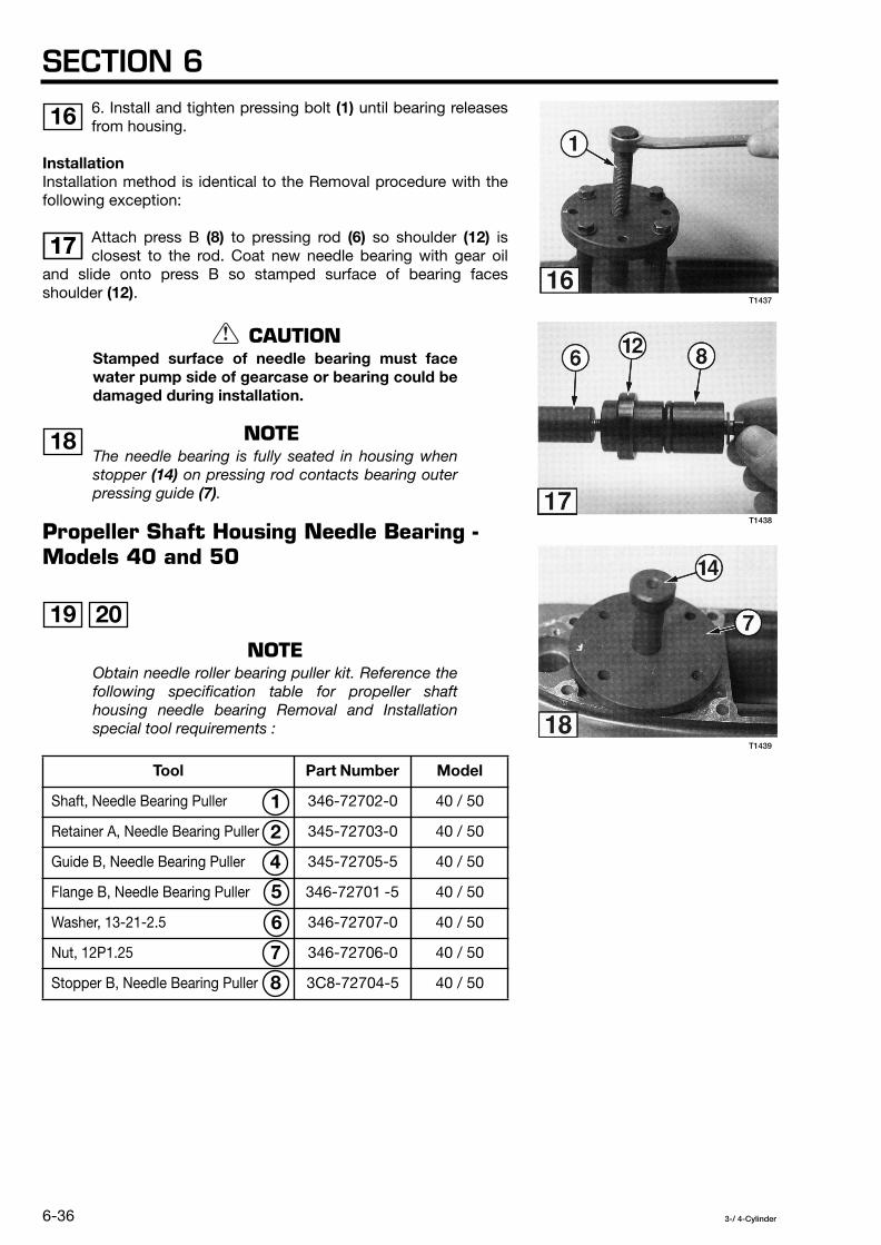
SECTION 6
6-36
3-/ 4-Cylinder
6. Install and tighten pressing bolt
(1)
until bearing releasesfrom housing.
Installation
Installation method is identical to the Removal procedure with thefollowing exception:
Attach press B
(8)
to pressing rod
(6)
so shoulder
(12)
isclosest to the rod. Coat new needle bearing with gear oil
and slide onto press B so stamped surface of bearing facesshoulder
(12)
.
CAUTION
Stamped surface of needle bearing must facewater pump side of gearcase or bearing could bedamaged during installation.
NOTE
The needle bearing is fully seated in housing whenstopper
(14)
on pressing rod contacts bearing outerpressing guide
(7)
.
Propeller Shaft Housing Needle Bearing - Models 40 and 50
NOTE
Obtain needle roller bearing puller kit. Reference thefollowing specification table for propeller shafthousing needle bearing Removal and Installationspecial tool requirements :
Tool Part Number Model
Shaft, Needle Bearing Puller
346-72702-0 40 / 50
Retainer A, Needle Bearing Puller
345-72703-0 40 / 50
Guide B, Needle Bearing Puller
345-72705-5 40 / 50
Flange B, Needle Bearing Puller
346-72701 -5 40 / 50
Washer, 13-21-2.5
346-72707-0 40 / 50
Nut, 12P1.25
346-72706-0 40 / 50
Stopper B, Needle Bearing Puller
3C8-72704-5 40 / 50
16
1717
18
19 20
T1437
T1438
T1439
1
2
4
5
6
7
8

GEARCASE
6-37
3-/ 4-Cylinder
Removal
1. Remove oil seal from propeller shaft housing.
2. Remove roller bearing from propeller shaft housing by heating thehousing with a heat gun.
3. Place shaft
(1)
through needle bearing.
4. Attach retainer A
(2)
to shaft groove
(G)
with raised surface ofretainer facing bearing.
5. Slide guide B
(4)
and flange B
(5)
onto shaft and secure withwasher
(6)
and nut
(7)
.
6. Tighten nut
(7)
until needle bearing releases from housing.
Installation
1. Attach retainer A
(2)
to shaft groove
(G)
with raised surface ofretainer facing bearing.
2. Coat new needle bearing with gear oil. Slide bearing onto shaftso bearing stamped surface faces retainer A
(2)
.
CAUTION
Stamped surface of needle bearing must faceretainer or bearing could be damaged duringinstallation.
3. Slide stopper B
(8)
and guide B
(4)
onto shaft and insert shaft inpropeller shaft housing.
4. Slide flange B
(5)
onto shaft and secure with washer
(6)
and nut
(7)
.
5. Tighten nut
(7)
until stopper B
(8)
contacts flange B
(5)
.
6. Remove tools and verify needle bearing is fully seated in housing.
19
20
T1440
T1441

SECTION 6
6-38
3-/ 4-Cylinder
Propeller Shaft Housing Needle Bearing -Models 60B and 70B
NOTE
Obtain needle roller bearing puller kit. Reference thefollowing specification table for propeller shafthousing needle bearing Removal and Installationspecial tool requirements :
Removal
1. Remove oil seal from propeller shaft housing.
2. Remove roller bearing from propeller shaft housing by heatingthe housing with a heat gun.
3. Place shaft
(1)
through needle bearing.
4. Attach retainer
(2)
to shaft groove
(G)
with raised surface ofretainer facing bearing.
5. Slide guide
(4)
and plate
(5)
onto shaft and secure with washer
(6)
and nut
(7)
.
6. Tighten nut
(7)
until needle bearing releases from housing.
Tool Part Number Model
Shaft, Needle Bearing Puller
3B7-72702-0 60B / 70B
Retainer, Needle Bearing Puller
353-72703-0 60B / 70B
Guide, Needle Bearing Puller
353-72705-0 60B / 70B
Plate, Needle Bearing Puller
353-72701 -0 60B / 70B
Washer, 13-21-2.5
346-72707-0 60B / 70B
Nut, 12P1.5
3B7-72735-0 60B / 70B
Stopper, Needle Bearing Puller
353-72704-0 60B / 70B
21 22
21
T1442
8
7
6
5
4
2
1

GEARCASE
6-39
3-/ 4-Cylinder
Installation
1. Attach retainer
(2)
to shaft groove
(G)
with raised surfaceof retainer facing bearing.
2. Coat new needle bearing with gear oil. Slide bearing onto shaftso bearing stamped surface faces retainer
(2)
.
CAUTION
Stamped surface of needle bearing must faceretainer or bearing could be damaged duringinstallation.
3. Slide guide B
(4)
onto shaft and insert shaft in propeller shafthousing.
4. Slide stopper
(8)
and plate
(5)
onto shaft and secure with washer
(6)
and nut
(7)
.
5. Tighten nut
(7)
until stopper
(8)
contacts plate
(5)
.
6. Remove tools and verify needle bearing is fully seated in housing.
Propeller Shaft Housing Needle Bearing -Models 60C / 70C / 80 / 90 / 115 / 120 / 140
NOTE
Obtain needle roller bearing puller kit. Reference thefollowing specification table for propeller shafthousing needle bearing Removal and Installationspecial tool requirements :
Tool Part Number Model
Shaft, Needle Bearing Puller 3B7-72702-0 60C / 70C / 80 / 90 / 115 / 120 / 140
Retainer, Needle Bearing Puller 3B7-72709-0 60C / 70C / 80 / 90 / 115 / 120 / 140
Guide B, Needle Bearing Puller 3B7-72710-0 60C / 70C / 80 / 90 / 115 / 120 / 140
Plate, Needle Bearing Puller 3B7-72701-0 60C / 70C / 80 / 90 / 115 / 120 / 140
Washer, 13-21-2.5 346-72707-0 60C / 70C / 80 / 90 / 115 / 120 / 140
Nut, 12P1.5 3B7-72735-0 60C / 70C / 80 / 90 / 115 / 120 / 140
Stopper, Needle Bearing Puller 353-72704-0 60C / 70C / 80 / 90 / 115 / 120 / 140
22
23 24
T1443
1
2
4
5
6
7
9

SECTION 6
6-40
3-/ 4-Cylinder
Removal
1. Remove oil seal from propeller shaft housing.
2. Remove roller bearing from propeller shaft housing by heating thehousing with a heat gun.
3. Place shaft
(1)
through needle bearing.
4. Attach retainer
(2)
to shaft groove
(G)
with raised surface ofretainer facing bearing.
5. Slide guide B
(4)
and plate
(5)
onto shaft and secure with washer
(6)
and nut
(7)
.
6. Tighten nut
(7)
until needle bearing releases from housing.
Installation
1. Attach retainer
(2)
to shaft groove
(G)
with raised surface ofretainer facing bearing.
2. Coat new needle bearing with gear oil. Slide bearing onto shaftso bearing stamped surface faces retainer
(2)
.
CAUTION
Stamped surface of needle bearing must faceretainer or bearing could be damaged duringinstallation.
3. Slide guide B
(4)
onto shaft and insert shaft in propeller shafthousing.
4. Slide stopper
(9)
and plate
(5)
onto shaft and secure with washer
(6)
and nut
(7)
.
5. Tighten nut
(7)
until stopper
(9)
contacts plate
(5)
.
6. Remove tools and verify needle bearing is fully seated in housing.
23
24
T1444
T1445

GEARCASE
6-41
3-/ 4-Cylinder
Bevel Gear A Bearing Outer Race
NOTE
Reference the following specification table for bevelgear A bearing outer race Removal and Installationspecial tool requirements:
Removal
1. Install bevel gear A bearing puller assembly.
2. Tighten bolt
(1)
until bearing race releases from housing.
Installation
1. Secure gearcase horizontally in padded vice or other fixture sopropeller shaft opening faces upward.
2. Verify bearing race seating surface in gearcase is clean andsmooth.
3. Apply specified gear oil to exterior of bearing race. Position racein gearcase so stamped surface faces closed end of gearcase.
4. Attach plate
(1)
to threaded end of rod
(2)
using springwasher
(3)
and nut
(4)
. Tighten nut with wrench.
Tool Part Number Model
Bevel Gear A Bearing Puller Assembly 3A3-72755-0(345-72224-1)
40 / 50
Bevel Gear A Bearing Puller Assembly 3B7-72755-0(3B7-72224-0)
60B / 60C / 70B / 70C / 80 / 90 / 115 / 120 / 140
Bearing Outer Press Kit 3B7-72739-0 40 / 50 / 60 / 70 / 80 / 90 / 115 / 120 / 140
Guide, Bearing Outer Pressing 346-72733-0 40 / 50
Guide, Bearing Outer Pressing 3B7-72733-0 60B / 60C / 70B / 70C / 80 / 90 / 115 / 120 / 140
Rod, Bearing Outer Pressing 3B7-72731-0 40 / 50 / 60B / 60C / 70B / 70C / 80 / 90 / 115 / 120 / 140
Plate, Bearing Outer Pressing 353-72732-0 40 / 50 / 60B / 70B
Plate, Bearing Outer Pressing 3B7-72732-0 60C / 70C / 80 / 90 / 115 / 120 / 140
Spring Washer 941392-1000 40 / 50 / 60B / 60C / 70B / 70C / 80 / 90 / 115 / 120 / 140
Nut 931191-1000 40 / 50 / 60B / 60C / 70B / 70C / 80 / 90 / 115 / 120 / 140
25
26
T1447
T1446

SECTION 6
6-42
3-/ 4-Cylinder
5. Insert rod
(2)
into gearcase so plate
(1)
is seated withinthe bearing race.
6. Slide guide
(5)
onto rod and seat into position ongearcase. Raised surface of guide must fit tightly within the
circumference of the gearcase opening.
7. Fully seat bearing race in gearcase by hammering the rodend.
Bevel Gear A Roller Bearing
Removal and Installation
1. Insert screwdrivers in notches of bevel gear A and gentlypry gear and bearing apart.
2. Use specified set tool
(1)
to press fit bearing onto bevelgear.
Tool Part Number Model
Set Tool, Bevel Gear A Bearing 3C8-72719-0 40 / 50 / 60B / 70B
Set Tool, Bevel Gear A Bearing 3B7-72224-0 60C / 70C / 80 / 90 / 115 / 120 / 140
27
28
29
30
31
T1450T1449T1448
T1451
T1452

3-/ 4-Cylinder
7-1
General Precautions ............................................................................................................ 7-2
Service Specifications ......................................................................................................... 7-3
Electrical Servicing Standards ............................................................................................ 7-7
Troubleshooting ................................................................................................................. 7-11
Description of Operation ................................................................................................... 7-13
Battery Care and Maintenance ......................................................................................... 7-17
Ignition System ................................................................................................................. 7-22
RPM Limitation Test .......................................................................................................... 7-47
Ignition System Repair Procedures ................................................................................... 7-59
Starting System ................................................................................................................. 7-74
Charging System ............................................................................................................. 7-106
SECTION 7ELECTRICAL SYSTEM
TABLE OF CONTENTS

SECTION 7
7-2
3-/ 4-Cylinder
GENERAL PRECAUTIONS
Before performing any service work on the electrical system, readand understand the Service Safety section at the beginning of thismanual.
Use the manufacturer and special tools as indicated duringservicing of the electrical system.
Avoid electrical shock:
• Do not handle spark gap tester leads during performancetesting.
• Do not touch ignition coils, exciter coil, pulser coils, or alternatorcoils while the engine is cranking or running.
Use the spark gap tester to prevent the engine from starting whenperforming static ignition performance tests.
Use caution when performing tests with the engine cover removed.Do not wear loose clothing or jewelry. Keep hair, hands, andclothing away from the flywheel and other moving parts.
After repairs are complete, make sure all ignition and electricalleads are properly routed and clamped in their original positions.
Replace locking fasteners when their locking feature becomesweak. Use only factory replacement parts.
Always inspect and test the start-in-gear prevention system beforereturning engine to customer.
note
Magneto for Model 60 / 70
Magneto style for Model 60/70 was changed andthey are not interchangeable between both parts.The following Serial Numbers indicate breakpointsbetween older and newer magneto models.
Remark) Magneto consists a flywheel cup, coil plate assembly, CDunit and ignition coils.
Model Magneto Serial number
60B /70B Older All of Engines
60C Older and Newer Newer : 10840 or higher
70C Older and Newer Newer : 13002 or higher

ELECTRICAL SYSTEM
7-3
3-/ 4-Cylinder
SERVICE SPECIFICATIONS
Special Torque Values
* Refer to Section 2 for Standard Torque Values chart.
Manufacturer Special Tools Required
None
Description
Torque in-lb (ft-lb)
N·m kg-m Threadlocker
Model
40 and 50 60 and 70 80 and 90
115 / 120 / 140
Electrical Box Cover Bolt
––4 - 9
0.5 - 1.0 0.05 - 0.1
4 - 9 0.5 - 1.0
0.05 - 0.1
26 - 43 3 - 5
0.3 - 0.5––
Spark Plug (18 - 22) 25 - 292.5 - 2.9
(18 - 22) 25 - 292.5 - 2.9
(18 - 22) 25 - 29 2.5 - 2.9
(18 - 22) 25 - 29 2.5 - 2.9
––
Flywheel Nut (65 - 80) 88 - 1089 - 11
(101 - 116) 137 - 15714 - 16
(101 - 116) 137 - 15714 - 16
(181 - 195) 245 - 26525 - 27
––

SECTION 7
7-4
3-/ 4-Cylinder
General Equipment Required
Analog Multimeter,
Electronic Specialties
®
Model M-530 or equivalent
Digital Multimeter,
Electronic Specialties
®
Model KD 3200 or equivalent
Spark Gap Tester,
Stevens
®
S-13C, S-48, or equivalent
Digital Pulse Tachometer, 10 - 6000 RPM,
Electronic Specialties
®
Model 321 or equivalent
Variable Load High Rate Discharge Tester,
Electronic Specialties
®
Model 700 or equivalent
HydrometerHeat GunTorque Wrench, 0 -150 in-lb [0 -17 N-m / 0 - 1.7 kg-m]
Consumables Required
Dielectric Lubricant,
Permate
®
Dielectric Tune-Up Grease
Battery Spray Protector,
Permatex
®
Battery Protector and Sealer
Low Temperature Lithium GreaseGenuine Grease or Equivalent Friction Surface Marine GreaseThreadlocker,
Loctite
®
243
Isopropyl AlcoholCleaning SolventThermomelt Stik, 125˚F [52˚C] and 163˚F [73˚C]Electrical Shrink Fit Tubing, various diameters
Electrical System
NOTE
Refer to Outboard Motors Service Data publication for all wiring diagrams when performingelectrical testing.
Ignition Type
Flywheel magneto capacitor discharge
Ignition Timing
degree
40D:
ATDC 3˚ ± 1˚ - BTDC 18˚ ± 1˚
50D:
ATDC 3˚ ± 1˚ - BTDC 24˚ ± 1˚
40D
2
:
ATDC 3˚ ± 1˚ - BTDC 18˚ ± 1˚
50D
2
:
ATDC 3˚ ± 1˚ - BTDC 20˚ ± 1˚
60B:
ATDC 3˚ ± 1˚ - BTDC 16˚ ± 1˚
70B:
ATDC 3˚ ± 1˚ - BTDC 20˚ ± 1˚
60C:
ATDC 3˚ ± 1˚ - BTDC 17.5˚ ± 1˚
70C:
ATDC 3˚ ± 1˚ - BTDC 17.5˚ ± 1˚
80:
ATDC 5˚ ± 1˚ - BTDC 20˚ ± 1˚
90:
ATDC 5˚ ± 1˚ - BTDC 20˚ ± 1˚
115:
ATDC 10˚ - BTDC 17.5˚ ± 1˚
120:
ATDC 10˚ - BTDC 17.5˚ ± 1˚
140:
ATDC 10˚ - BTDC 20˚ ± 1˚

ELECTRICAL SYSTEM
7-5
3-/ 4-Cylinder
Spark Plug (with resistor)40:
NGK BR7HS-10 or Champion RL-82C
50, 60, 70, 80, 90, 115, 120, 140:
NGK BR8HS-10 or Champion RL-78C
Spark Plug (without resistor) 40:
NGK B7HS-10 or Champion L-82C
50, 60, 70, 80, 90, 115, 120, 140:
NGK B8HS-10 or Champion L-78C
Spark Plug Gap
in [mm]
0.035 - 0.039 [0.9 - 1.0]
Battery
12 V, 500 CCA with 105 minutes [70 AH] reserve capacity
Engine Fuse
20 A
Alternator 40, 50, 60, 70, 80, 90:
12 V 130 W
115, 120, 140:
12 V 330 W
Charging Performance At 1500 RPM 40, 50, 60, 70, 80, 90 :
3 A
115, 120, 140 :
12 A
At 5500 RPM 40, 50, 60, 70, 80, 90 :
9 - 11 A
115, 120, 140 :
24.5 - 27.5 A
Number of Tachometer-to-Alternator Coil Impulses 40, 50, 60, 70, 80, 90 :
6
115, 120, 140 :
12

SECTION 7
7-6
3-/ 4-Cylinder
Alternator Coil Resistance40, 50:
W - Y, 0.2 - 0.3
Ω
60, 70:
W - Y, 0.2 - 0.3
Ω
80, 90:
0.2 - 0.3
Ω
115, 120, 140:
0.26 - 0.40
Ω
Ignition Coil ResistancePrimary Coil40, 50:
0.18 - 0.24
Ω
60, 70:
0.18 - 0.24
Ω
80, 90:
0.19 - 0.25
Ω
115, 120, 140:
0.18 - 0.24
Ω
Secondary Coil40, 50:
2.7 - 3.7 k
Ω
60, 70:
2.7 - 3.7 k
Ω
80, 90:
3.6 - 4.8 k
Ω
115, 120, 140:
2.7 - 3.7 k
Ω
CD Unit Output (Cranking)40, 50, 60, 70, 80, 90, 115, 120, 140:
198 - 220 DVA
Exciter Coil Output (Cranking)40, 50, 60C, 70C, 80, 90, 115, 120, 140:
135 - 150 DVA
60B, 70B:
8.1 - 9.9 DVA (WHITE/GREEN to BROWN/WHITE)34.2 - 41.8 DVA (WHITE/GREEN to WHITE/YELLOW) 35.1 - 42.9 DVA (BROWN/WHITE to WHITE/YELLOW)
Pulser Coil Output (Cranking) 40, 50, 60, 70, 80, 90, 115, 120, 140:
4.75 - 5.0 DVA (minimum 3.0 DVA)

ELECTRICAL SYSTEM
7-7
3-/ 4-Cylinder
ELECTRICAL SERVICINGSTANDARDS
Electrical Connectors
When you replace electrical components or perform diagnostictests, you must disconnect electrical connectors in manyinstances.
The following discussion will help you recognize connectors inelectrical drawings and show you how to disconnect and connectthem.
Electrical Connector Drawings
In most of the electrical drawings in this section, the physical shapeof electrical connectors has been eliminated to clarify testingprocedures.
Atypical electrical drawing illustrates several connectors.Items
(1), (2), (3), (4), (7)
and
(8)
are terminals that arelocated inside of electrical connectors. The dashed line betweentwo terminals [e.g., between terminal
(7)
and
(8)
] means that theyare a part of the same connector but have been disconnected fortesting.
Note that Terminal
(7)
is directly connected to the CD Unit
(9)
(noconnectors between the terminal and CD Unit). When youdisconnect an electrical connector to test a component, it is veryimportant that you disconnect the FIRST CONNECTOR.Terminals
(1)
,
(3)
and
(7)
are examples of how the first connector isillustrated.
1
T1476

SECTION 7
7-8
3-/ 4-Cylinder
Special cases are the connectors used to test componentslocated on the coil plate assembly. For testing purposes, the
first connector is located at the far end of the cable (away from thecoil plate assembly) and usually found inside of the electrical box.
Bullet Connectors
NOTE
Bullet connectors
(1)
are shown like this in electricaldrawings.
Disconnecting Bullet Connectors
1. Carefully examine the connector to determine which end isremovable and which end is fixed. Typically the insulationsurrounding the removable end is tapered so it fits inside of theinsulation for the fixed end.
2. Grasp the fixed end
(1)
of the connector and carefully pullthe removable end
(2)
straight out without twisting orbending it.
NOTE
Never twist or bend bullet connectors or damage tothe connectors will occur. Always PULL theseconnectors apart.
2
3
4
T1465
T1477
T1479

ELECTRICAL SYSTEM
7-9
3-/ 4-Cylinder
Connecting Bullet Connectors
Grasp the fixed end
(1)
of the connector and carefully push theremovable end
(2)
into it without twisting or bending the connector.
Rectangular and Triangular Multi-Conductor Connectors
NOTE
Multiple-conductor connectors may be shown likethis
(1)
or this
(2)
in electrical drawings.
These types of connectors are held closed with a plastic tab. Thetab is constructed with a “spring” action so it stays locked. Twotypes of locks are typically used:
PRESS tab
(1)
and pull connector apart.
LIFT UP on tab
(1)
and pull connector apart.
NOTE
Always PRESS or LIFT UP the tab of theseconnectors while you pull them apart. Do not pry ortwist the connector or use force or damage willoccur.
5
6
7
T1466
T1467
T1478

SECTION 7
7-10
3-/ 4-Cylinder
Round Multi-Conductor Cable Connectors
NOTE
Multiple-conductor connectors may be shown like this
(1)
or this
(2)
in electrical drawings.
These types of connectors are held closed with a lock ring.SQUEEZE both ridged locks
(1)
and at the same timecarefully pull the connector apart without twisting or bending it.
NOTE
Always SQUEEZE both ridged locks on theseconnectors while you pull them apart. Do not pry ortwist the connector or use force or damage willoccur.
Electrical Cable Color Codes
Electrical cables have color coded conductors so you can locate thecorrect conductor during troubleshooting and repair procedures. Allconductor colors are in capital letters in this manual.
Some conductors have a background color and a different colorstripe that runs the length of the conductor. These conductors aredesignated as follows:
A/B Where A = Background Color
B = Stripe Color
Example: BLACK/WHITE This conductor has a BLACK background with a WHITE stripe.
8
9T1479
8
T1468
T1479

ELECTRICAL SYSTEM
7-11
3-/ 4-Cylinder
Electrical Drawings
All electrical drawings shown in this manual have been simplified toclarify the circuit that is being tested. They represent typicalconfigurations and may not look exactly like the electrical wiring foryour engine. Complete electrical schematics are provided in theOutboard Motors Service Data publication.
TROUBLESHOOTING
The troubleshooting chart lists common engine symptoms relatedto problems with the electrical system. It also indicates specificmalfunctions in the electrical system which may be causing aproblem so it can be isolated more effectively. Before beginningmajor troubleshooting on the electrical system, perform thefollowing operations:
• Check battery fluid level and specific gravity. Charge or replaceas required. See Battery Care and Maintenance, this section.
• Check the following electrical connections and make sure theyare secure and free of corrosion:
- Battery cables- Starter solenoid wiring- Starter motor wiring (including ground connection)- Spark plug leads- Ignition circuit wiring- Stop circuit wiring- Charge circuit wiring
• Make sure shift lever or remote control lever operates freely.
• Attach lanyard to emergency stop switch, see Section 2.
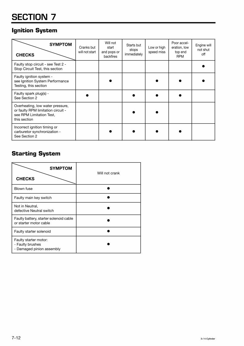
SECTION 7
7-12
3-/ 4-Cylinder
Ignition System
Starting System
Cranks but will not start
Will not start
and pops orbackfires
Starts butstops
immediately
Low or high speed miss
Poor accel-eration, low
top end RPM
Engine will not shut
off
Faulty stop circuit - see Test 2 - Stop Circuit Test, this section
¡
Faulty ignition system - see Ignition System Performance Testing, this section
¡
¡
¡ ¡
Faulty spark plug(s) - See Section 2
¡
¡ ¡ ¡
Overheating, low water pressure, or faulty RPM limitation circuit - see RPM Limitation Test, this section
¡ ¡
Incorrect ignition timing or carburetor synchronization - See Section 2
¡ ¡ ¡ ¡
Will not crank
Blown fuse
¡
Faulty main key switch
¡
Not in Neutral, defective Neutral switch
¡
Faulty battery, starter solenoid cable or starter motor cable
¡
Faulty starter solenoid
¡
Faulty starter motor: - Faulty brushes - Damaged pinion assembly
¡
SYMPTOM
CHECKS
SYMPTOM
CHECKS

ELECTRICAL SYSTEM
7-13
3-/ 4-Cylinder
Charging System
DESCRIPTION OF OPERATION
Ignition System
The ignition system consists of the magneto
(1)
,Capacitive Discharge (CD) unit
(2)
, ignition coils
(3)
, main key switch
(4)
and emergency stop switch
(5)
. Thepurpose of this system is to provide an electric spark inside eachcylinder at the precise moment needed by the combustionchamber.
Battery does not maintain
charge or overcharges
Blown fuse
¡
Shorted or faulty alternator coil
¡
Faulty recitier/regulator
¡
Faulty charge circuit wiring
¡
1 2 3
SYMPTOM
CHECKS
T1454
T1455
T1453

SECTION 7
7-14
3-/ 4-Cylinder
Magneto
For models 40 / 50 / 60 / 70 / 80 / 90 :
The magneto consists of a cover
(1)
, flywheel
(2)
, and coilplate assembly
(3)
, guide plate
(4)
, shim
(5)
, and set ring
(6)
.Mounted radially inside the flywheel are a series of high-performanceferrite magnets. The boss, located in the center of the flywheel, iskeyed to maintain proper alignment with the crankshaft. Theflywheel is plated to help prevent corrosion.
The coil plate assembly consists of an alternator coil set
(7)
, excitercoil set
(8)
, and pulser coil set
(9)
. The alternator coil set providescharging voltage and will be discussed further in the chargingsystem description.
For models 115 / 120 / 140: The magneto has similarcomponents except, the pulser coils
(1)
are on a separateassembly called the pulser coil assembly
(2)
. The alternator
(3)
andexciter coils
(4)
are on an assembly called the alternator assembly
(5)
.
Exciter Coil Set
The exciter coil set consists of many windings of wire wrappedaround a metal lamination. Once the flywheel exceeds a minimumcranking RPM, the lines of force from the ferrite magnets cutthrough the exciter coil windings to produce about 150 DVA (peakvoltage) at cranking speed. The output from the exciter coil set isused to power the CD Unit.
60B and 70B engines have two exciter coils; one activates atspeeds up to 1700 RPM and both coils are activated at speedsover 1700 RPM.
4
5
T1457
T1456

ELECTRICAL SYSTEM
7-15
3-/ 4-Cylinder
Pulser Coil Set
Each pulser coil in the coil consists of a permanent magnet withmany windings of wire wrapped around it. The flywheel has ametallic cam, called an interrupter, molded on it. When theinterrupter passes in close proximity to the pulser coil, the lines offorce produced by the permanent magnet collapse momentarily. Atcranking speed this produces a 4.75 to 5.0 DVA signal in the coil.
The output voltage from each pulser coil is used to control a smallelectronic switch (SCR) located inside of the CD Unit. When the CDUnit receives an output from a pulser coil, it directs an output,approximately 220 DVA, to the appropriate ignition coil primary.
• 3 cylinder models - Three pulser coils are provided, one per cylinder.• 4 cylinder models - Four pulser coils are provided, one per
cylinder.
CDUnit
The CD Unit has three major functions:
• The CD Unit receives its operating voltage from the exciter coil(s)and converts it into pulsating direct current for storage.
• The CD Unit stores this pulsating direct current in a capacitor.• The CD Unit uses a series of electronic switches (SCRs),
activated by pulser coil output, to select the correct ignition coilprimary winding for firing. The CD Unit has one SCR for eachignition coil it controls.
Depending upon the engine model, the CD Unit will limit the enginespeed to about half its maximum RPM when the overheat sensor,water pressure sensor, or oil level sensor signals an abnormalcondition. A safety feature provided by the CD Unit on all enginemodels, is over-speed limitation. The 115, 120 and 140 modelengines have a third type of speed limitation. The CD Unit will limitthe top engine speed to about 1500 RPM if the RED/YELLOW leadfrom the CD Unit to the remote control box is not properlyconnected. Refer to the RPM Limitation Test section for more detailon RPM limitation functions.
The engines of the models 115, 120 and 140 are provided with astarting-automatic-advance mechanism that is described below.
IgnitionCoil
Each ignition coil consists of two windings of wire wrapped arounda compacted ferrite material. The coil has a primary and secondaryterminal connection and a ground plate.
Through mutual induction, the ignition coil transforms the outputfrom the CD Unit to as much as 40,000 volts to fire the spark plug.
• 3 cylinder models - Three ignition coils are provided, one percylinder.
Choke solenoid Angle of advance Period of connection
when inactive 6 degrees 1 to 4 seconds
when active 6 degreesWhen the choke solenoid is active, and 30 seconds after it stops its operation

SECTION 7
7-16
3-/ 4-Cylinder
• 4 cylinder models - Four ignition coils are provided, one percylinder.
Main Key Switch and Emergency Stop Switch
The main key switch and emergency stop switch are connected tothe CD Unit through an engine wiring harness. When the main keyswitch is in the OFF position, or the lanyard is removed from theemergency start switch, an input to the CD Unit is grounded. Thisdeactivates the CD Unit and the engine shuts down.
Starting System
The starting system consists of thebattery, main key switch
(1)
, neutralstart switch
(2)
, starter solenoid
(3)
, starter motor
(4)
and 20 Aengine fuse
(5)
. When the main key switch is in the START position,and the start contacts of the neutral start switch are closed, poweris sent to the starter solenoid, energizing it. When the startersolenoid is energized, a connection between the positive terminalof the battery and the starter motor is provided. The connectionbetween the starter motor and ground completes the circuit. Thefuse opens if the coil circuit of the starter solenoid shorts oroverloads.
6 7 8 9 10
T1461
T1462
T1460
T1459
T1458

ELECTRICAL SYSTEM
7-17
3-/ 4-Cylinder
Charging System
The charging system consists of the alternator coilset
(1)
, rectifier/regulator
(2)
, 20 A engine fuse, andthe battery. When the flywheel is turning approximately 1500 RPMor higher, the alternator coil set provides alternating current (AC)voltage to the rectifier/regulator. The rectifier/regulator transformsthe AC voltage into direct current (DC) voltage. Regulator output isabout 15 volts DC with a current rating of 9 - 11 A [models 40 / 50 /60 / 70 / 80 / 90] or 24.5 - 27.5 A [models 115 / 120 / 140] at 5,500RPM. The fuse protects the charging circuit from shorts or anoverload.
BATTERY CARE AND MAINTENANCE
WARNING
Batteries produce an explosive mixture of oxygenand hydrogen! Keep any sparks or open flameaway from battery while charging or performingterminal voltage test. When you charge thebattery, remove the filler caps (if any) from eachcell. Always remove the negative cable first, thenthe positive one.
CAUTION
Battery electrolyte is an acidic solution and ispoisonous. It is strong enough to burn skin, eatholes in clothing, and cause blindness if splashedinto the eyes. Work in a well-ventilated area, weareye protection and protective gloves.
If electrolyte is spilled, flush exposed skin withplenty of clean water. Flush eyes for 10 to 15minutes. Get medical help immediately.
If electrolyte is ingested, do not induce vomiting,drink large amounts of milk of magnesia, beateneggs, or vegetable oil. Get medical help immediately.
Inspection and Cleaning
Inspection
The first step in determining the condition of a battery should be avisual inspection. Check:
• Battery case
(1)
for cracks or other damage.
• Terminals
(2)
for corrosion; make sure they have not come loosefrom battery.
• Cable connectors
(3)
for corrosion; tighten to manufacturer’sspecifications for good electrical contact.
• Cables
(4)
for cracked or frayed insulation.
• Electrolyte level (if not a sealed maintenance free type); add fluid(distilled water) according to manufacturer’s instructions; checkfor visible contamination; check specific gravity
(5)
.
• Battery mounting
(6)
for corrosion; tighten to manufacturer’sspecifications.
11 12
1
T1464
T1469
T1463

SECTION 7
7-18
3-/ 4-Cylinder
Cleaning
Follow this procedure to clean the battery:
1. Disconnect cables and remove battery.
2. Prepare a solution of one part baking soda to four parts ofwater. Clean battery, terminals, cable connectors, battery
mounting, and battery box.
NOTE
Keep cleaning solution out of battery cells.
3. Flush with clear water. Let dry.
4. Install battery according to manufacturer’s specifications.
5. Apply battery spray protector to battery terminals andcable connectors to prevent corrosion.
6. Attach cables and tighten to manufacturer’s specifications.
Testing
Specific Gravity Test
If the battery is not a sealed maintenance free type, follow thisprocedure to check the specific gravity:
1. Make sure electrolyte in each cell is up to level specified bymanufacturer.
NOTE
If more fluid is added, only fill to lower fill line sincethe fluid level will rise during charging process.Charge battery per the instructions provided in theCharging Capacity Test in this section,
2
3
T1471
T1470

ELECTRICAL SYSTEM
7-19
3-/ 4-Cylinder
2. Insert the hydrometer tube into the battery cell and usethe bulb to withdraw fluid until the float is free.
3. View the hydrometer with your eye at the same level as the fluid.
4. Note the temperature of the battery fluid or ambient air.
5. For a fully charged battery, specific gravity should be 1.260 at68˚F [20˚C] and uniform [variation 0.030 or less between any twocells]. Correct for actual temperature as follows:
Corrected specific gravity = MSP + (temperature - 20) x 0.0007
Where: MSP = measured specific gravitytemperature = measured temperature in ˚C
6. If the corrected specific gravity is below 1.260, or the specificgravity between any two cells is greater than 0.030, perform theCharging Capacity Test which is described next.
Charging Capacity Test
WARNING
Batteries produce an explosive mixture of oxygenand hydrogen! Keep any sparks or open flameaway from battery while charging or performingterminal voltage test. When you charge thebattery, remove the filler caps (if any) from eachcell.
WARNING
To avoid the potential for an explosion with fuelvapor, always remove the battery from boat whenyou are charging it.
WARNING
Always remove the negative cable first, then thepositive one.
This test determines whether a battery can take a full charge (if thebattery is not a sealed maintenance free type).
1. Clean the battery and make sure electrolyte is at lower fillline.
4
5
T1470
T1472

SECTION 7
7-20
3-/ 4-Cylinder
2. Test the specific gravity of the battery. See the SpecificGravity Test previously discussed in this section.
3. Find the Battery Charge Percent using the SpecificGravity/ Battery Charge Relationship Chart.
4. Calculate the amount of discharge in ampere hours using thisformula:
Amount of Discharge (AH) = Rated Ampere Hours xBattery Charge Percent x 0.01
Where: RatedAmpere Hours = Manufacturer’s rating forbattery being tested.
Battery Charge Percent = Equals value obtainedfrom chart.
5. Calculate the charging current using this formula:
Charging Current (A) = 0.3 x Rated Ampere Hours
Where: Rated Ampere Hours = Manufacturer’s rating forbattery being tested.
6. Calculate the number of hours to charge the battery using thisformula:
Charging (hours) = Amount of Discharge (AH) x 1.5Charging Current (A)
7. Remove the caps from each cell and begin charging at thecharging current previously determined.
CAUTION
Reduce charging current, and lengthen thecharging time proportionately, if the temperatureof the electrolyte rises above 115˚F [45˚C] orgassing becomes excessive. Heat will shortenthe life of the battery.
NOTE
Set the battery charger to the charging current valuepreviously determined or the nearest lower chargingcurrent value.
8. Monitor the battery voltage while it is charging. If the voltagesuddenly jumps to over 13 volts just after the start of charging, theplates are probably sulfated and the battery should be replaced.
A good battery will rise to 12 volts immediately and then graduallygo up to 12.5 to 13 volts in about 30 to 60 minutes after charging isstarted.
9. If one cell produces little or no gas bubbles during charging, it isprobably shorted and the battery should be replaced.
6
7
T1473
T1472

ELECTRICAL SYSTEM
7-21
3-/ 4-Cylinder
10. As soon as the charging process has completed, measure thebattery voltage and specific gravity. The voltage should be 15 to 16volts and the specific gravity should be 1.260 (corrected fortemperature). If either of these conditions are not met, replace thebattery.
Terminal Voltage Test
WARNING
Batteries produce an explosive mixture of oxygenand hydrogen! Keep any sparks or open flameaway from battery while charging or performingterminal voltage test. When you charge thebattery, remove the filler caps (if any) from eachcell.
WARNING
To avoid the potential for an explosion with fuelvapor, always remove the battery from boat whenyou are charging it.
WARNING
Always remove the negative cable first, then thepositive one.
Check electrolyte level and specific gravity beforerunning the terminal voltage test.
1. Connect the Variable Load High Rate Discharge Tester to batteryterminals.
2. Discharge at 210 amperes (3 x ampere hour rating of battery) for15 seconds.
3. Measure voltage at battery terminals. If 9.6 volts, or higher,battery has a good output capacity. If lower than 9.6 volts, replacethe battery.
Charging
See the Charging Capacity Test procedure in this section for thecorrect battery charging procedure.

SECTION 7
7-22
3-/ 4-Cylinder
IGNITION SYSTEM
CAUTION
All cranking output tests must be performed withspark plugs installed and torqued in the cylinderhead. If necessary to remove the spark plugs, besure to keep the spark gap tester away fromopen spark plug holes.
CAUTION
Avoid electrical shock:
• Do not handle spark gap tester leads duringperformance testing.
• Do not touch ignition coils, exciter coil, pulsercoils, or alternator coils while the engine iscranking or running.
CAUTION
Use proper precautions when performing testswith the engine cover removed. Do not wearloose clothing or jewelry. Keep hair, hands, andclothing away from the flywheel and othermoving parts.
CAUTION
When repairs are complete, make sure all ignitionand electrical leads are properly routed andclamped in their original positions and the start-ingear prevention system must be tested beforereturning engine to customer.

ELECTRICAL SYSTEM
7-23
3-/ 4-Cylinder
Ignition System Performance Testing
Ignition Performance Testing is divided into two sections. The firstsection consists of a flow chart. This chart presents the correctsequence of performing ignition system performance tests toeffectively and efficiently check for problems in starting and runningthe engine. Follow the steps in the order listed until the problem isresolved and the ignition system meets specifications while theengine is running.
The chart references specific performance tests that must becompleted to resolve each problem. These tests are described indetail in the section which follows the flow chart.
The performance tests, identified as Test 1 through Test 7, containspecific instructions for testing and servicing various ignitionsystem components. Use this section to perform the tests correctlyin accordance with the factory recommendations.
NOTE
After you complete each performance test refer backto the flow chart for the next step. You must followthe flow chart until the ignition system meetsspecifications while the engine is running. The onlyway to be sure that you have uncovered and repairedall ignition system problems is to follow theseprocedures in a systematic fashion.
If you only have problems in stopping the engine,proceed directly to Test 2 - Stop Circuit Test.

SECTION 7
7-24
3-/ 4-Cylinder
Ignition System Performance Testing Flow Chart1
T1557

ELECTRICAL SYSTEM
7-25
3-/ 4-Cylinder
Test 1 - Spark Test
NOTE
Make sure all electrical terminals are connectedduring this test except those that are noted in thetest procedure.
Check for continuity between chassis ground andthe ground connection for the magneto plate, CDUnit, and ignition coils before conducting thefollowing procedure.
1. Remove all spark plug caps.
2. Adjust spark gap tester
(1)
to 7/16 in [11 mm].
3. Connect each spark plug cap
(2)
to spark gap tester
(1)
.
4. Secure spark gap tester to a clean ground on engine block.
WARNING
To avoid possible shock hazard, do not handleignition coils or spark gap tester during crankingtests.
NOTE
To prevent possible arcing of high voltage, routetester leads at least 2 in [51 mm] from any metalsurface.
Ground unused test leads to a clean engine ground.
5. Attach lanyard to emergency stop switch.
6. Crank engine.
A spark should jump across the gap for each cylinder and alternatefrom one gap to another.
7. Reconnect all wires disconnected during test.
8. Return to Ignition System Performance Testing Flow Chart.
2
T1474

SECTION 7
7-26
3-/ 4-Cylinder
Test 2 - Stop Circuit Test
Stop circuit malfunction can cause the engine not to start orprevent it from stopping.
Several component failures can cause the stop circuit tomalfunction. Use this flow chart to isolate and repair all componentfailures.
NOTE
After you complete each stop circuit test, refer backto the flow chart for the next step.3
T1558

ELECTRICAL SYSTEM
7-27
3-/ 4-Cylinder
Test 2a - Stop Circuit Main Key Switch Test
This test is used to determine whether the main key switch andconnecting wiring are functioning normally.
NOTE
Make sure all electrical terminals are connectedduring this test except those that are noted in thetest procedure.
Check for continuity between chassis ground andthe ground connection for the magneto plate, CDUnit, and ignition coils before conducting thefollowing procedure.
All continuity tests must be conducted with negativelead from battery disconnected or you may damagethe meter.
1. Remove negative lead from battery.
2. Disconnect main key switch terminals
(1)
,
(2)
,
(3)
and
(4)
.
3. Set analog multimeter to check continuity. Connect onemeter lead to terminal
(1)
and the other to terminal
(3)
.
4. Turn main key switch
(7)
to OFF position, meter mustshow continuity. If not, replace main key switch.
5. Turn main key switch to ON position, meter must not showcontinuity. If it does, replace it.
4
4
4
T1475

SECTION 7
7-28
3-/ 4-Cylinder
6. Disconnect CD Unit
(8)
terminals
(5)
and
(6)
.
7. Connect one meter lead to terminal
(6)
and the other toterminal
(2)
and check continuity. If the meter does not showcontinuity, replace the cable.
8. Connect one meter lead to terminal
(6)
and the other to aclean engine ground. If the meter shows continuity, replace
the cable.
9. Reconnect all wires and return to Test 2 - Stop Circuit Test flowchart.
Test 2b - Stop Circuit Emergency Stop Switch Test
This test is used to determine whether the emergency stop switchand connecting wiring are functioning normally.
NOTE
Make sure all electrical terminals are connectedduring this test except those that are noted in thetest procedure.
Check for continuity between chassis ground andthe ground connection for the magneto plate, CDUnit, and ignition coils before conducting thefollowing procedure.
All continuity tests must be conducted with negativelead from battery disconnected or you may damagethe meter.
5
5
5
T1476

ELECTRICAL SYSTEM
7-29
3-/ 4-Cylinder
1. Remove negative lead from battery.
2. Disconnect emergency stop switch terminals
(1)
,
(2)
,
(3)
and
(4)
.
3. Set analog multimeter to check continuity. Connect onemeter lead to terminal
(1)
and the other to terminal
(3)
.
4. Attach lanyard
(5)
to emergency stop switch
(6)
, metermust not show continuity. If it does, replace emergency stop
switch.
5. Remove lanyard
(5)
from emergency stop switch
(6)
,meter must show continuity. If not, replace emergency stop
switch.
6. Disconnect CD Unit
(9)
terminals
(7)
and
(8)
.
7. Connect one meter lead to terminal
(8)
and the other toterminal
(2)
and check continuity. If the meter does not showcontinuity, replace the cable.
8. Connect one meter lead to terminal
(8)
and the other to aclean engine ground. If the meter shows continuity, replace
the cable.
9. Reconnect all wires and return to Test 2 - Stop Circuit Test flowchart.
6
6
6
6
6
6
6
T1476

SECTION 7
7-30
3-/ 4-Cylinder
Test 3 - Exciter Coil Test
NOTE
Make sure all electrical terminals are connectedduring this test except those that are noted in thetest procedure.
Check for continuity between chassis ground andthe ground connection for the magneto plate, CDUnit, and ignition coils before conducting thefollowing procedure.
Reference the following electrical drawings for theexciter coil test. The pulser and alternator coils havebeen removed from both illustrations for clarity.
- Figure 1 - models 40 / 50 / 60C / 70C 80 / 90 / 115 / 120 / 140.
- Figure 2 - models 60B / 70B.
7
8
T1479
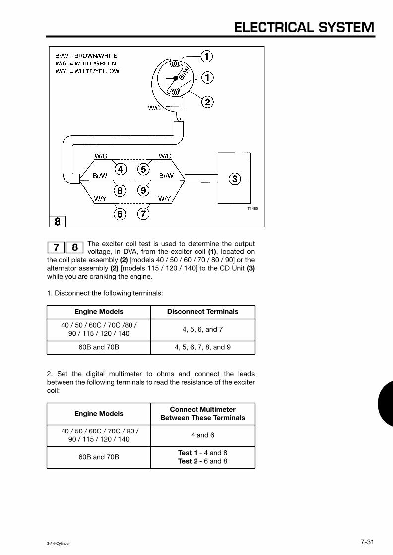
ELECTRICAL SYSTEM
7-31
3-/ 4-Cylinder
The exciter coil test is used to determine the outputvoltage, in DVA, from the exciter coil
(1)
, located onthe coil plate assembly
(2)
[models 40 / 50 / 60 / 70 / 80 / 90] or thealternator assembly
(2)
[models 115 / 120 / 140] to the CD Unit
(3)
while you are cranking the engine.
1. Disconnect the following terminals:
2. Set the digital multimeter to ohms and connect the leadsbetween the following terminals to read the resistance of the excitercoil:
Engine Models Disconnect Terminals
40 / 50 / 60C / 70C /80 / 90 / 115 / 120 / 140
4, 5, 6, and 7
60B and 70B 4, 5, 6, 7, 8, and 9
Engine Models Connect Multimeter Between These Terminals
40 / 50 / 60C / 70C / 80 / 90 / 115 / 120 / 140
4 and 6
60B and 70B
Test 1
- 4 and 8
Test 2
- 6 and 8
7 8
T1480

SECTION 7
7-32
3-/ 4-Cylinder
3. The meter should indicate the following resistance:
4. If the resistance is not within the indicated range, replace theexciter coil set. See Ignition System Repair Procedures - ExciterCoil. After repairs are made, return to Ignition System PerformanceTesting Flow Chart.
If the resistance is within the indicated range, proceed to the nextstep.
Engine Models Results
40 and 50 530 - 720
Ω
± 25%
60B and 70B
Test 1
: 216 - 324
Ω
± 25%
Test 2
: 16 - 24
Ω
± 25%
60C and 70C 220 - 330
Ω
± 25%
80 and 90 174 - 236
Ω
± 25%
115 / 120 / 140 255 - 345
Ω
± 25%
T1479
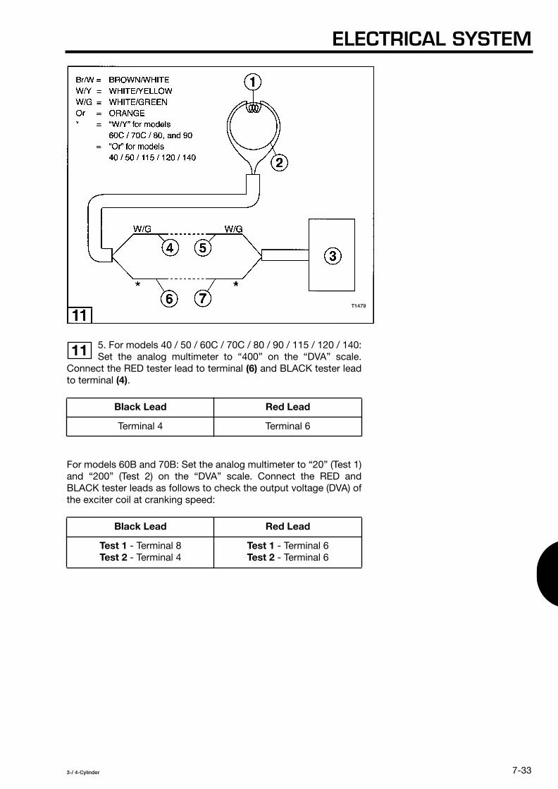
ELECTRICAL SYSTEM
7-33
3-/ 4-Cylinder
5. For models 40 / 50 / 60C / 70C / 80 / 90 / 115 / 120 / 140:Set the analog multimeter to “400” on the “DVA” scale.
Connect the RED tester lead to terminal
(6)
and BLACK tester leadto terminal
(4)
.
For models 60B and 70B: Set the analog multimeter to “20” (Test 1)and “200” (Test 2) on the “DVA” scale. Connect the RED andBLACK tester leads as follows to check the output voltage (DVA) ofthe exciter coil at cranking speed:
Black Lead Red Lead
Terminal 4 Terminal 6
Black Lead Red Lead
Test 1
- Terminal 8
Test 2
- Terminal 4
Test 1
- Terminal 6
Test 2
- Terminal 6
11
T1479

SECTION 7
7-34
3-/ 4-Cylinder
6. Attach lanyard to emergency stop switch.
7. Crank engine.
8. At cranking RPM, the tester should show the following results:
9. If the exciter coil test results are not within the acceptable range,replace the exciter coil set. See Ignition System Repair Procedures-Exciter Coil.
10. Reconnect all wires disconnected during test.
11. Return to flow chart.
Engine Models Test Results
40 / 50 / 60 / 70 / 80 / 90 / 115 / 120 / 140
130 DVA Minimum
Test 1
- 10 - 15 DVA
Test 2
- 100 - 200 DVA
T1480

ELECTRICAL SYSTEM
7-35
3-/ 4-Cylinder
Test 4 - Pulser Coil Test
NOTE
Make sure all electrical terminals are connectedduring this test except those that are noted in thetest procedure.
Check for continuity between chassis ground andthe ground connection for the magneto plate, CDUnit, and ignition coils before conducting thefollowing procedure.
Reference the following electrical drawings for thepulser coil test. The exciter and alternator coils havebeen removed from both illustrations for clarity.
- Figure 2 - models 40 / 50 / 60B / 70B / 60C / 70C / 80 / 90.
- Figure 3 - models 115 / 120 / 140.
13
14
T1481

SECTION 7
7-36
3-/ 4-Cylinder
The pulser coil test is used to determine the outputvoltage, in DMA, from the pulser coil
(1)
, located onthe coil plate assembly
(2)
[pulser coil assembly on models 115 /120 / 140], to the CD Unit
(3)
while you are cranking the engine.
1. Disconnect the following terminals:
Engine Models Disconnect Terminals
40 / 50 / 60B / 70B / 60C / 70C / 80 / 90
4, 5, 6, 7, 8, 9, 10, and 11
115 / 120 / 140 4,5, 6, 7, 8, 9, 10,
11, 12, and 13
13 14
T1482

ELECTRICAL SYSTEM
7-37
3-/ 4-Cylinder
2. Setthe digital multimeter to ohms and connect theleads to (one terminal at a time) to test the resistance
of each pulser coil:
3. The meter should indicate the following resistance for eachpulser coil:
4. If the resistance is not within the indicated range, replace thepulser coil set. See Ignition System Repair Procedures - PulserCoil. After repairs are made, return to Ignition System PerformanceTesting Flow Chart.
If the resistance is within the indicated range, proceed to the nextstep.
Engine Models Connect Multimeter Between These Terminals
40 / 50 / 60B / 70B / 60C / 70C / 80 / 90
• 4 and 6 • 4 and 8 • 4 and 10
115 / 120 / 140
• 4 and 6 • 4 and 8 • 4 and 10 • 4 and 12
Engine Models Results
40 / 50 / 60 / 70 / 80 / 90 160 - 220
Ω
± 25%
115 / 120 / 140 187 - 253
Ω
± 25%
14 15
T1481

SECTION 7
7-38
3-/ 4-Cylinder
5. Set the analog multimeter to “20” on the “DVA” scale.
6. Insert the banana plug of the RED tester lead into the meterconnection labeled “DVA” and the banana plug of the BLACK testerlead into the meter connection labeled “-COM”.
• Terminal 6.• Terminal 8.• Terminal 10.• Terminal 12 (models 60B and 70B only).
8. Attach lanyard to emergency stop switch.
9. Crank engine.
10. See Ignition System Repair Procedures - Pulser Coil. Afterrepairs are made, return to Ignition System Performance TestingFlow Chart.
T1481

ELECTRICAL SYSTEM
7-39
3-/ 4-Cylinder
11. Set the analog multimeter to “20” on the “DVA”scale. Connect the RED and BLACK tester leads as
follows (one terminal at a time) to check the output voltage (DVA) ofeach pulser coil at cranking speed:
12. Attach lanyard to emergency stop switch.
13. Crank engine.
14. At cranking RPM, the tester should show the following results:
• Minimum 3.0DVA
15. If the pulser coil test results are not within the acceptable range,replace the pulser coil set. See Ignition System Repair ProceduresPulser Coil.
16. Reconnect all wires disconnected during test.
Engine Models Black Lead Red Lead
40 / 50 / 60B / 70B / 60C / 70C
/ 80 / 90 • Terminal 4
• Terminal 6 • Terminal 8• Terminal 10
115 / 120 / 140 • Terminal 4
• Terminal 6 • Terminal 8 • Terminal 10• Terminal 12
19 21
T1482

SECTION 7
7-40
3-/ 4-Cylinder
Test 5 - CD Unit Output Test - Cranking RPM
NOTE
Make sure all electrical terminals are connectedduring this test except those that are noted in thetest procedure.
Check for continuity between chassis ground andthe ground connection for the magneto plate, CDUnit, and ignition coils before conducting thefollowing procedure.
Reference the following electrical drawings for theCD Unit Output Test - Cranking RPM:
- Figure 4 - models 40 / 50 / 60B / 70B / 60C / 70C / 80 / 90.
- Figure 5 - models 115 / 120 / 140.
22
23
T1483

ELECTRICAL SYSTEM
7-41
3-/ 4-Cylinder
The CD Unit Output Test - Cranking RPM is used todetermine the output voltage, in DVA, from the CD
Unit
(1)
, to each ignition coil
(2)
while you are cranking the engine.
1. Remove all spark plug caps.
2. Adjust spark gap tester
(1)
to 7/16 in [11 mm].
3. Connect each spark plug cap
(2)
to spark gap tester
(1)
.
4. Secure spark gap tester to a clean ground on engine block.
WARNING
To avoid possible shock hazard, do not handleignition coils or spark gap tester during crankingtests.
22 23
24
24
T1484
T1474

SECTION 7
7-42
3-/ 4-Cylinder
NOTE
To prevent possible arcing of high voltage, routetester leads at least 2 in [51 mm] from any metalsurface.
Ground unused test leads to a clean engine ground.
5. Set the tester to “400” on the “DVA” scale.
6. Insert the banana plug of the RED tester lead into the meterconnection labeled “DVA” and the banana plug of the BLACK testerlead into the meter connection labeled “-COM”.
7. Connect the BLACK tester lead to terminal
(3)
.
8. Carefully slide the RED tester into the bulletconnector [terminal
(4)
] sleeve until it makes contactwith the terminal.
25 26
T1483

ELECTRICAL SYSTEM
7-43
3-/ 4-Cylinder
NOTE
DO NOT disconnect the CD Unit outputconnector [terminals
(4)
and
(5)
]. Damage to the CD Unit may result.
Repeat for each CD Unit output connector.
9. Attach lanyard to emergency stop switch.
10. Crank engine.
11. At cranking RPM, the tester should show the following result foreach CD Unit output:
• 130 DVA Minimum
12. If the test results for any CD Unit output is not within acceptablerange, replace the CD Unit. See Ignition System Repair Procedures-CD Unit.
13. Reconnect all wires disconnected during test.
14. Return to flow chart.
25 26
T1484

SECTION 7
7-44
3-/ 4-Cylinder
Test 6 - Ignition Coil Tests
NOTE
Make sure all electrical terminals are connectedduring this test except those that are noted in thetest procedure.
Check for continuity between chassis ground andthe ground connection for the magneto plate, CDUnit, and ignition coils before conducting thefollowing procedure.
The following tests check the resistance of the primary andsecondary windings in each ignition coil
(1)
.
1. Remove spark plug cap
(2)
.
2. Set digital multimeter to ohms.
3. Disconnect terminals
(4)
and
(5)
.
4. Connect one tester lead to terminal
(3)
and the otherterminal
(4)
.
5. The meter should indicate the following readings for the primarywinding.
Repeat readings for each ignition coil:
6. If primary winding for any ignition coil is not within theacceptable range, replace the ignition coil. See Ignition SystemRepair Procedures - Ignition Coil. After repairs are made, return toIgnition System Performance Testing Flow Chart.
If the primary windings are within the acceptable range, proceed tothe next step.
7. Connect one tester lead to terminal
(3)
and the other tospark plug cap [terminal
(2)
].
8. The meter should indicate the following readings for thesecondary winding.
Repeat readings for each ignition coil:
Engine Models Results
40 and 50 0.18 - 0.24
Ω
± 25%
60B / 70B / 60C / 70C 0.18 - 0.24
Ω
± 25%
80 and 90 0.19 - 0.25
Ω
± 25%
115 / 120 / 140 0.18 - 0.24
Ω
± 25%
Engine Models Results
40 and 50, 60 / 70C 2.7 - 3.7 K Ω ± 25%
60B / 70B 2.7 - 3.7 K
Ω
± 25%
80 / 90 3.6 - 4.8 K
Ω
± 25%
115 / 120 / 140 2.7 - 3.7 K
Ω
± 25%
27
27
2727
27
T1485

ELECTRICAL SYSTEM
7-45
3-/ 4-Cylinder
9. If secondary winding for any ignition coil is not within theacceptable range, replace the ignition coil. See Ignition SystemRepair Procedures - Ignition Coil. After repairs are made, return toIgnition System Performance Testing Flow Chart.
10. Reconnect all wires disconnected during test.
11. Return to flow chart.
Test 7 - Output Tests - Engine Running
CAUTION
The following tests must be performed withcorrect test propeller and with the engine in atest tank. Note that some performance problemscannot be duplicated in a test tank, in thesecases the tests must be conducted with theengine mounted on a boat and operated in openwater.
NOTE
Make sure all electrical terminals are connectedduring this test except those that are noted in thetest procedure.
Check for continuity between chassis ground andthe ground connection for the magneto plate, CDUnit, and ignition coils before conducting thefollowing procedure.
These series of tests are designed to efficiently find faulty ignitioncomponents that can cause an engine to run poorly. Use the flowchart to systematically eliminate the possible causes to theproblems.
The tests assume that:
• The engine starts.
• Tune-Up Procedure has been performed, see Section 2.
• Ignition Timing and the Carburetor Synchronization Procedurehas been performed, see Section 2.
• Engine is at operating temperature.
• Tests are performed with engine running in forward gear.
• Tachometer is installed.
NOTE
Some steps refer to other ignition tests. After youcomplete those tests, return to the flow chart forfurther instructions.

SECTION 7
7-46
3-/ 4-Cylinder
Output Tests - Engine Running - Flow chart28
T1559

ELECTRICAL SYSTEM
7-47
3-/ 4-Cylinder
RPM LIMITATION TEST
CAUTION
The following tests must be performed withcorrect test propeller and with the engine in atest tank. Note that some performance problemscannot be duplicated in a test tank, in thesecases the tests must be conducted with theengine mounted on a boat with the correctpropeller installed and operated in open water.
CAUTION
Avoid electrical shock:
• Do not touch ignition coils, exciter coil, pulsercoils, or alternator coils while the engine iscranking or running.
CAUTION
Use proper precautions when performing testswith the engine cover removed. Do not wearloose clothing or jewelry. Keep hair, hands, andclothing away from the flywheel and othermoving parts.
CAUTION
When repairs are complete, make sure all ignitionand electrical leads are properly routed andclamped in their original positions and the start-ingear prevention system must be tested beforereturning engine to customer.

SECTION 7
7-48
3-/ 4-Cylinder
Half-Maximum RPM Limitation
The CD Unit will limit the engine speed to about half the maximumRPM when the overheat sensor, water pressure sensor, or oil levelsensor signals an abnormal condition. Depending upon the modelof the engine, one, two or all three sensors are provided.
Description of Operation for models 40 / 50 / 60 / 70 / 80 / 90Engines
In these engines, the water pressure sensor
(1)
and overheatsensor
(2)
control the half-maximum RPM limitation input[terminal
(9)
] to the CD Unit
(4)
. When either, or both, of thesesensors detect an abnormal condition (see Section 4), the half-maximum RPM limitation input goes low and the CD Unit limits theengine speed to about half its maximum RPM. At the same time,the abnormal condition also activates the warning horn
(6)
. Notethat the oil level sensor
(3)
only activates the warning horn and theoil level light
(17)
in the tachometer
(5)
because the diodes
(15)
block the signal from CD Unit.
1
T1487

ELECTRICAL SYSTEM
7-49
3-/ 4-Cylinder
The following table summarizes the availability of the sensors andapproximate RPM when this feature is activated:
Description of Operation for 115/1 20/140 Engines
In these engines, the water pressure sensor
(1)
and lower oillevel float
(16)
of the oil level sensor
(2)
control the half-maximum RPM limitation input [terminal
(9)
] to the CD Unit
(3)
.When either, or both, of these sensors detect an abnormalcondition (see Section 4 for the water pressure sensor and Section3 for the oil level sensor), the half-maximum RPM limitation inputgoes low and the CD Unit limits the engine speed to about half itsmaximum RPM.
Sensor Type Engine Model RPM Limitation
Overheat Sensor 40 (optional) / 50 60 / 70 / 80 / 90
3500 ± 400 RPM
Water Pressure Sensor
40 (not available) / 50 (not available) / 60 (optional) / 70 (optional) / 80 / 90
3500 ± 400 RPM
Oil Level Sensor 40 / 50 / 60 / 70 / 80 / 90
NA
2
T1488

SECTION 7
7-50
3-/ 4-Cylinder
At the same time, an abnormal condition from either sensoralso activates the warning horn
(6)
. The CD Unit activatesthe horn by sending an output signal to lead
(20)
. Note that thelower oil level float
(16)
also causes the lower oil level indicator
(18)
in the LCD multi-purpose meter
(4)
to flash when it detects a low oilcondition.
It is important to note that the if the upper oil level float
(15)
detects a low oil condition, it activates the upper oil levelindicator
(17)
in the LCD multi-purpose meter
(4)
but will not triggerthe RPM limitation feature or the warning horn
(6)
.
An abnormal condition detected by the overheat sensor
(5)
causes the warning horn to sound and the overheatindicator
(19)
in the LCD multi-purpose meter
(4)
to flash. The RPMlimitation feature is not triggered in this case.
3
3
3
T1488

ELECTRICAL SYSTEM
7-51
3-/ 4-Cylinder
The following table summarizes the availability of the sensors andapproximate RPM when this feature is activated:
Half-Maximum RPM Limitation Feature - Test
Perform this test when engine speed is limited to about halfmaximum RPM or has a miss at about half maximum RPM.
The test assumes that:
• Tune-Up Procedure has been performed, see Section 2.
• Ignition Timing and the Carburetor Synchronization Procedurehas been performed, see Section 2.
• Engine is at operating temperature.
• Tests are performed with engine running in forward gear.
• Tachometer is installed.
NOTE
Make sure all electrical terminals are connectedduring this test except those that are noted in thetest procedure.
Check for continuity between chassis ground andthe ground connection for the magneto plate, CDUnit, and ignition coils before conducting thefollowing procedure.
Sensor Type RPM Limitation
Overheat Sensor NA
Water Pressure Sensor 2800 ± 400 RPM
Oil Level Sensor 2800 ± 400 RPM (lower float only)

SECTION 7
7-52
3-/ 4-Cylinder
1. Verify that engine operating temperature (Section 4), waterpressure (Section 4), and oil level (Section 3) are in their normalrange.
2. Disconnect RPM limitation jumper at terminals
(7)
and
(8)
.
3. Run engine. Does engine performance improve?
If yes, proceed to next step. If not, see Section 3, Troubleshooting.
4. Reconnect RPM limitation jumper at terminals
(7)
and
(8)
.
5. Disconnect one sensor input at a time:
Engine Models Sensor Disconnect Terminals
40 / 50 / 60 / 70 / 80 / 90
Water Pressure(noton 40 and 50) (60, 70 optional)
and
Overheat (40 optional) and
3 4
3 4
11 12
13 14
T1487
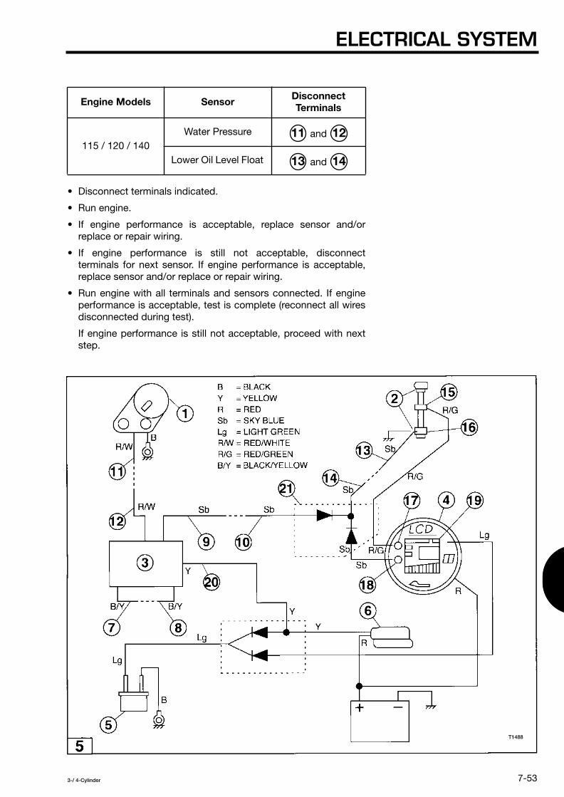
ELECTRICAL SYSTEM
7-53
3-/ 4-Cylinder
• Disconnect terminals indicated.
• Run engine.
• If engine performance is acceptable, replace sensor and/orreplace or repair wiring.
• If engine performance is still not acceptable, disconnectterminals for next sensor. If engine performance is acceptable,replace sensor and/or replace or repair wiring.
• Run engine with all terminals and sensors connected. If engineperformance is acceptable, test is complete (reconnect all wiresdisconnected during test).
If engine performance is still not acceptable, proceed with nextstep.
Engine Models Sensor Disconnect Terminals
115 / 120 / 140 Water Pressure and
Lower Oil Level Float and
11 12
13 14
T1488
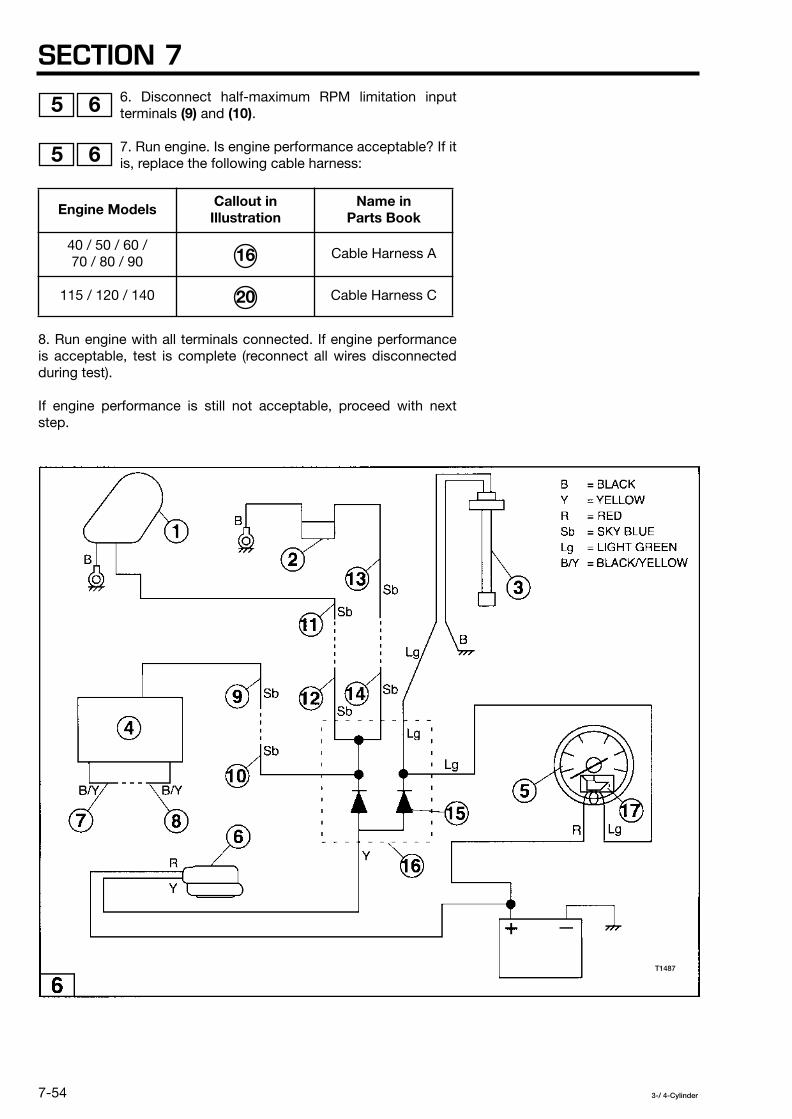
SECTION 7
7-54
3-/ 4-Cylinder
6. Disconnect half-maximum RPM limitation inputterminals
(9)
and
(10)
.
7. Run engine. Is engine performance acceptable? If itis, replace the following cable harness:
8. Run engine with all terminals connected. If engine performanceis acceptable, test is complete (reconnect all wires disconnectedduring test).
If engine performance is still not acceptable, proceed with nextstep.
Engine Models Callout in Illustration
Name in Parts Book
40 / 50 / 60 / 70 / 80 / 90 Cable Harness A
115 / 120 / 140 Cable Harness C
5 6
5 6
16
20
T1487

ELECTRICAL SYSTEM
7-55
3-/ 4-Cylinder
9. Replace CD Unit. See Ignition System Repair Procedures - CD Unit.
Run engine. Is engine performance acceptable? If it is, test iscomplete (reconnect all wires disconnected during test).
If engine performance is still not acceptable, proceed with nextstep.
10. Replace exciter coil(s). See Ignition System Repair ProceduresExciter Coil.
Reconnect all wires disconnected during test.
Over-Speed Limitation
Another type of RPM limitation is over-speed limitation. The CD Unitwill prevent the engine from going faster than the maximum RPM.The following table indicates the maximum RPM for each engine:
Engine Models Maximum RPM
40D and 50D 5900 ± 250 RPM
40D
2
and 50D
2
6050 ± 250 RPM
60B and 70B 6100 ± 200 RPM
60C and 70C 6150 ± 200 RPM
80 and 90 5900 ± 250 RPM
115 / 120 / 140 6000 ± 250 RPM
T1488

SECTION 7
7-56
3-/ 4-Cylinder
Overspeed Limitation Test
Perform this test if engine has a high speed miss.
NOTE
An engine may over-speed if the propeller is notsized correctly. Refer to the engine owner’s manualto determine the correct propeller.
The test assumes that:• Tune-Up Procedure has been performed, see Section 2.
• Ignition Timing and the Carburetor Synchronization Procedurehas been performed, see Section 2.
• Engine is at operating temperature.
• Tests are performed with engine running in forward gear.
• Tachometer is installed.
T1487

ELECTRICAL SYSTEM
7-57
3-/ 4-Cylinder
NOTE
Make sure all electrical terminals are connectedduring this test except those that are noted in thetest procedure.
Check for continuity between chassis ground andthe ground connection for the magneto plate, CDUnit, and ignition coils before conducting thefollowing procedure.
1. Disconnect RPM limitation jumper at terminals
(7)
and
(8)
.
2. Run engine. Does engine performance improve?
If engine performance improves, replace CD Unit. See IgnitionSystem Repair Procedures - CD Unit and proceed to next step.
If engine performance does not improve, see Section 3,Troubleshooting.
8 9
T1488

SECTION 7
7-58
3-/ 4-Cylinder
3. Run engine. Is engine performance acceptable? If it is, test iscomplete (reconnect all wires disconnected during test).
If engine performance is still not acceptable, proceed with nextstep.
4. Replace exciter coil(s). See Ignition System Repair ProceduresExciter Coil.
Reconnect all wires disconnected during test.
Low Speed RPM Limitation
The 115, 120 and 140 model engines have a third type of speedlimitation. The CD Unit will limit the top engine speed to about 1500RPM if the RED/YELLOW lead from the CD Unit to the remotecontrol box is not properly connected.
Low Speed RPM Limitation Test
If a 120 or 140 engine has a top speed of 1500 RPM, check for:
• RED/YELLOW wire connector
(3)
inside of engine housing
(4)
makes good contact.
• RED/YELLOW wire
(1)
intact at CD Unit
(2)
.
• RED/YELLOW wire connector
(5)
inside of remote controlbox
(6)
makes good contact.
10
10
10
T1489

ELECTRICAL SYSTEM
7-59
3-/ 4-Cylinder
IGNITION SYSTEM REPAIRPROCEDURES
WARNING
Disable ignition system, by disconnecting excitercoil terminals (4), (5), (6), (7), [(8) and (9) formodels 60B and 70B only] to prevent accidentalengine startup during removal and replacementof the flywheel.
CAUTION
Flywheel is under high torque and requires theuse of special tools for removal and installation.Failure to use the specified tools can result ininjury or damage to the flywheel or coil plateelectrical components.
1 2
T1479

SECTION 7
7-60
3-/ 4-Cylinder
CAUTION
The force needed to loosen and tighten theflywheel nut requires flywheel be removed andinstalled with engine mounted and secured on anengine stand.
CAUTION
Use proper precautions when performing testswith the engine cover removed. Do not wearloose clothing or jewelry. Keep hair, hands, andclothing away from the flywheel and othermoving parts.
CAUTION
When repairs are complete, make sure all ignitionand electrical leads are properly routed andclamped in their original positions and the start-ingear prevention system must be tested beforereturning engine to customer.
T1480

ELECTRICAL SYSTEM
7-61
3-/ 4-Cylinder
Flywheel
Replacing the exciter coil or coil plate assembly requires theremoval of the flywheel, see Section 4, Flywheel, for the properprocedure.
NOTE
Flywheel magnets must be of a particular strength inorder to run the ignition system. Weak magnets cancause low ignition voltage which may affect engineperformance. Flywheels seldom go bad and wouldonly be replaced as a last resort in solving an ignitionproblem.
Carefully inspect flywheel
(1)
for cracks, chips, andworn taper after it is removed. Also inspect the
magnets
(2)
for cracks and chips and make sure they are firmlyattached to the flywheel.
Exciter Coil
NOTE
Disconnect negative battery cable from batterybefore removing exciter coil.
This procedure assumes exciter coil is available as aseparate replaceable component. Some engineconfigurations might require replacement of entirecoil plate assembly. Check current Parts Catalog foravailability.
3 4
T1491
T1490

SECTION 7
7-62
3-/ 4-Cylinder
Removal
1. Remove the flywheel.
2. Disconnect following terminals for exciter coil
(1)
connectors. Note that these terminals interconnectcable from coil plate assembly
(2)
to cable from CD Unit
(3)
:
Engine Models Disconnect Terminals
60B and 70B and
5 6
4 5 6 7 8 9
T1480
T1479

ELECTRICAL SYSTEM
7-63
3-/ 4-Cylinder
3. For models 40 / 50 / 60 / 70 / 80 / 90 ONLY: Remove coilplate assembly cable clamp screws
(1)
and cable clamp
(2)
.
4. For models 40 / 50 / 60 / 70 / 80 / 90 ONLY: Carefully slitcoil plate assembly cable shield
(1)
.
NOTE
Make sure you don’t cut electrical conductors insideof coil plate assembly cable when you slit cableshield.
On models 60B / 708 / 60C / 70C there are two coilplate assembly cables
(1)
and
(2)
. Make sure you slitthe cable shield for coil plate assembly cable thatcontains the electrical conductors for the excitercoil(s).
5. For models 40 / 50 / 60 / 70 / 80 / 90 ONLY: Cut tie wrap.
6. For models 40 / 50 / 80 / 90 ONLY: Remove exciter coilscrews
(1)
and exciter coil from the mounting bracket.
NOTE
On models 60B / 70B remove both exciter coils, theyare replaced as a pair.
7
8
9
T1493
T1495
T1492

SECTION 7
7-64
3-/ 4-Cylinder
For models 60B / 70B / 60C / 70C ONLY: Removealternator coil screws and move alternator coil
(1)
outof way. Pull exciter coil leads
(2)
out of way of way of alternator coil.Remove exciter coil screws
(3)
and exciter coil from the mountingbracket.
For models 115 / 120 / 140 ONLY: Remove mounting screws
(1)
and alternator assembly
(2)
from the mounting bracket
(3)
.
Cleaning and Inspection
Clean coil plate assembly, upper main bearing seal
(1)
, setring, ignition timing link, alternator coils, pulser coils, coil
leads, and coil connectors with isopropyl alcohol as required.
Check for the following and repair or replace as required:
• Bent, chipped, cracked, or corroded coil plate assembly.
• Coil leads for integrity, cut or cracked insulation, and damagedconnectors.
• Broken or bent alternator coil laminations damaged alternatorcoil windings and missing alternator coil screws.
• Broken, cracked, or misaligned pulser coils and missing pulsercoil screws.
• Free motion of ignition timing link
(1)
. Repair, adjust, andlubricate as needed, see Section 2.
10 11
12
13
14
T1497
T1498
T1496
T1499
T1500

ELECTRICAL SYSTEM
7-65
3-/ 4-Cylinder
Installation
Install in reverse order of removal.
NOTE
Disconnect negative battery cable from batterybefore installing exciter coil.
Use threadlocker on screw threads before installingscrews.
Use a length of shrink tube to fabricate a new coilplate assembly cable shield as required. Insidediameter of shrink tubing must be large enough topass over the largest connector.
Pulser Coil Assembly
NOTE
On models 115 / 120 / 140 you must replace the pulsercoil assembly. Individual pulser coils are not available.
On models 40 / 50 / 60B / 70B / 60C / 70C / 80 / 90you must replace the entire coil plate assembly (seeprocedure later in this section). Individual pulser coilsare not available.
Disconnect negative battery cable from batterybefore removing pulser coil assembly
Removal (models 115 / 120 / 140)
1. Remove the flywheel.
2. Disconnect the following pulser coil
(1)
terminals. Notethat these terminals interconnect cable from coil plate
assembly
(2)
to cable from CD Unit
(3)
:
• Pulser coil terminals
(4), (5), (6), (7), (8), (9), (10), (11), (12),
and
(13)
.
15
T1482

SECTION 7
7-66
3-/ 4-Cylinder
3. Remove the screws
(1)
and clamps
(2)
and remove pulsercoil assembly
(3)
from the mounting bracket
(4)
.
Cleaning and Inspection
Clean upper main bearing seal and o-ring
(1)
guide plateand bushing, ignition timing link, alternator assembly,
electrical leads and connectors with isopropyl alcohol as required.
Check for the following and repair or replace as required:• Bent, chipped, cracked, or corroded guide plate and bushing.
• Electrical leads and connectors for integrity, cut or crackedinsulation.
• Broken or bent alternator assembly and missing screws.
Apply light coat of low temperature lithium grease to guideplate and bushing
(2)
.
16
17
17
T1502T1501

ELECTRICAL SYSTEM
7-67
3-/ 4-Cylinder
Installation
Install in reverse order of removal.
NOTE
Disconnect negative battery cable from batterybefore installing pulser coil assembly.
Use threadlocker on screw threads before installingscrews.
Coil Plate Assembly
NOTE
Disconnect negative battery cable from batterybefore removing coil plate assembly.
On models 40 / 50 / 60B / 70B / 60C / 70C / 80 / 90the pulser coils cannot be replaced individually. Youmust replace the entire coil plate assembly.
On models 115 / 120 / 140 the pulser coils cannot bereplaced individually. You must replace the pulsercoil assembly (see previous procedure).
Removal (models 40D / 50D / 60B / 70B / 60C / 70C / 80 / 90)
1. Remove the flywheel.

SECTION 7
7-68
3-/ 4-Cylinder
2. Disconnect the following terminals:
Exciter coil
(1)
terminals. Note that these terminalsinterconnect cable from coil plate assembly
(2)
tocable from CD Unit
(3)
:
18 19
T1479
T1480
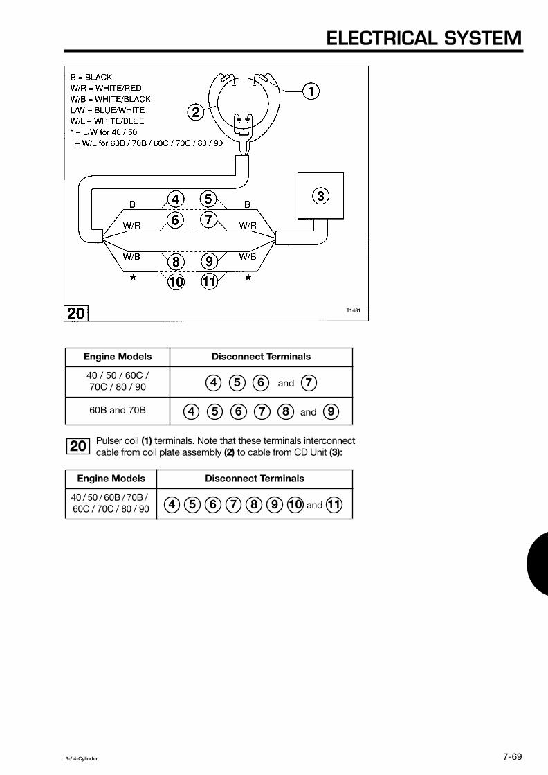
ELECTRICAL SYSTEM
7-69
3-/ 4-Cylinder
Pulser coil
(1)
terminals. Note that these terminals interconnectcable from coil plate assembly
(2)
to cable from CD Unit
(3)
:
Engine Models Disconnect Terminals
40 / 50 / 60C / 70C / 80 / 90 and
60B and 70B and
Engine Models Disconnect Terminals
40 / 50 / 60B / 70B / 60C / 70C / 80 / 90
and
4 5 6 7
4 5 6 7 8 9
20
4 5 6 7 8 9 10 11
T1481

SECTION 7
7-70
3-/ 4-Cylinder
Alternator coil
(1)
terminals. Note that these terminalsinterconnect cable from coil plate assembly
(2)
to rectifier /regulator
(3)
:
3. Remove the screws
(1)
and remove coil plate assembly
(2)
from the mounting bracket.
Cleaning and Inspection
Clean upper main bearing seal
(1)
, guide plate
(2)
andignition timing link
(3)
with isopropyl alcohol as required.
Check for the following and repair or replace as required:• Bent, chipped, cracked, or corroded guide plate.
• Broken or bent ignition timing link.
Engine Models Disconnect Terminals
40 / 50 / 60B / 70B / 60C / 70C / 80 / 90
21
4 5 6 7
22
23
T1505
T1504
T1503

ELECTRICAL SYSTEM
7-71
3-/ 4-Cylinder
Installation
Install in reverse order of removal.
NOTE
Disconnect negative battery cable from batterybefore installing coil plate assembly.
Use threadlocker on screw threads before installingscrews.
Apply light coat of low temperature lithium grease tothe upper main bearing outer and guide plate.
Ignition Coil
NOTE
Disconnect negative battery cable from batterybefore removing ignition coil.
Removal
1. Disconnect CD Unit output lead
(1)
from ignition coilprimary cable
(2)
.
2. Disconnect spark plug cap
(1)
from spark plug
(2)
.
3. Remove bolts
(1)
and remove ignition coil.
24
25
26
T1508
T1506
T1507

SECTION 7
7-72
3-/ 4-Cylinder
Cleaning and Inspection
Clean mounting area with isopropyl alcohol.
Check for the following and repair or replace as required:
Remove spark plug(s) and inspect for fouling, damagedelectrodes, or damaged ceramic insulator.
CD Unit output connectors and leads for integrity, cut or crackedinsulation.
Installation
Install in reverse order of removal.
NOTE
Disconnect negative battery cable from batterybefore installing ignition coil.
Use threadlocker on bolt threads before installingbolts.
CD Unit
NOTE
Disconnect negative battery cable from batterybefore removing CD Unit.
Make note of the location of the spare 20A enginefuse
(1)
. It is usually located near the CD Unit andcan easily be misplaced when the CD Unit isserviced.
Removal
1. For models 40 / 50 / 60B / 70B / 60C / 70C / 80 / 90:Carefully stretch elastic CD Unit hold down
(1)
and remove itfrom CD Unit retaining groove
(2)
.
For models 115 / 120 / 140: Remove bolts
(1)
.
NOTE
Formodels 115 / 120 / 140 make note of the locationof cable retainer
(2)
.
2. Remove CD Unit.
27
28
29
30
30
T1510
T1511
T1509
T1512

ELECTRICAL SYSTEM
7-73
3-/ 4-Cylinder
Cleaning and Inspection
Examine electrical conductors and connectors.
Installation
Install in reverse order of removal.
NOTE
Disconnect negative battery cable from batterybefore installing CD Unit.
For models 115 / 120 / 140: Use threadlocker on boltthreads before installing bolts.
Make sure that all electrical conductors are properlyrouted before you insert CD Unit to avoid pinchingthem.
For models 40 / 50 / 60B / 70B / 60C / 70C / 80 / 90make sure that BLACK/YELLOW connector is tuckedbehind CD Unit before you install it
(1)
.
31
T1512

SECTION 7
7-74
3-/ 4-Cylinder
STARTING SYSTEM
WARNING
Disable ignition system, by disconnecting excitercoil terminals (4), (5), (6), (7), [(8) and (9) formodels 60B and 70B only] to prevent accidentalengine startup during testing of starter circuit.
1 2
T1479
T1480

ELECTRICAL SYSTEM
7-75
3-/ 4-Cylinder
CAUTION
Flywheel is under high torque and requires theuse of special tools for removal and installation.Failure to use the specified tools can result ininjury or damage to the flywheel or coil plateelectrical components.
CAUTION
The force needed to loosen and tighten theflywheel nut requires flywheel be removed andinstalled with engine mounted and secured on anengine stand.
CAUTION
Use proper precautions when performing testswith the engine cover removed. Do not wearloose clothing or jewelry. Keep hair, hands, andclothing away from the flywheel and othermoving parts.
CAUTION
When repairs are complete, make sure all ignitionand electrical leads are properly routed andclamped in their original positions and the start-in-gear prevention system must be tested beforereturning engine to customer.
Starter System Testing
The starter system may cause three types of problems:• The engine does not crank, see Starter Circuit Tests inthis
section.
• The starter motor runs but does not engage or disengage fromthe flywheel, see Starter Motor Test in this section.
• The starter motor will not shut off, see Starter Solenoid Test inthis section.
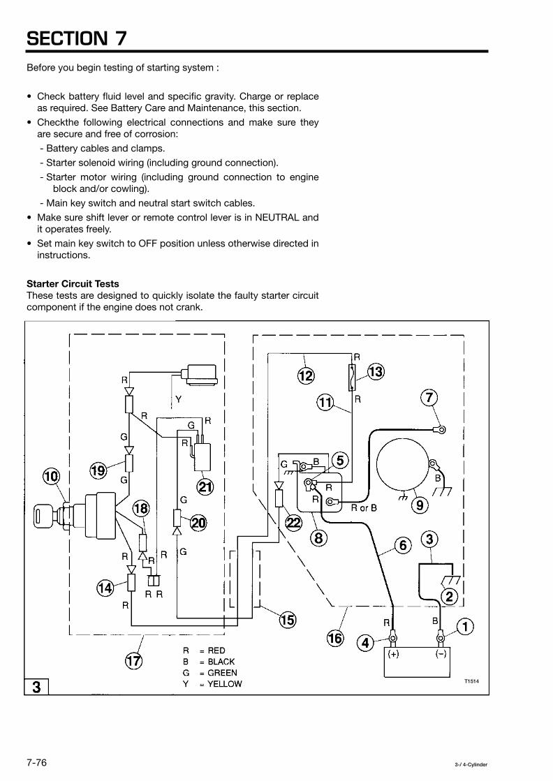
SECTION 7
7-76
3-/ 4-Cylinder
Before you begin testing of starting system :
• Check battery fluid level and specific gravity. Charge or replaceas required. See Battery Care and Maintenance, this section.
• Checkthe following electrical connections and make sure theyare secure and free of corrosion:
- Battery cables and clamps.
- Starter solenoid wiring (including ground connection).
- Starter motor wiring (including ground connection to engineblock and/or cowling).
- Main key switch and neutral start switch cables.
• Make sure shift lever or remote control lever is in NEUTRAL andit operates freely.
• Set main key switch to OFF position unless otherwise directed ininstructions.
Starter Circuit Tests
These tests are designed to quickly isolate the faulty starter circuitcomponent if the engine does not crank.
T1514

ELECTRICAL SYSTEM
7-77
3-/ 4-Cylinder
NOTE
The electrical drawings have been simplified to showonly those elements necessary to test the startercircuit.
Two types of starter circuits are used and illustrated in:
• Figure 1 - models with remote control box.
• Figure 2 - models without remote control box.
3
4
T1515

SECTION 7
7-78
3-/ 4-Cylinder
1. Disconnect negative battery cable
(3)
from negativebattery terminal
(1)
.
2. Set analog multimeter to check continuity. Connectone tester lead to negative battery terminal
(1)
and theother tester lead to the ground connection
(2)
for negative batterycable
(3)
.
If the meter does not indicate continuity, clean connections and/orreplace negative battery cable.
If the meter indicates continuity, go to the next step.
3. Set analog multimeter to “DCV” and set range to “20”. ConnectBLACK tester lead to “- COM” and the RED tester lead to “+ V
Ω
”.
4. Connect BLACK tester lead to clean engine ground.
5 6
5 6
T1514

ELECTRICAL SYSTEM
7-79
3-/ 4-Cylinder
5. Connect RED tester lead to positive batteryterminal
(4)
.
If meter does not indicate 11.8 to 13.2 VDC (battery voltage), seeBattery Care and Maintenance, this section.
If meter indicates battery voltage go to next step.
5 6
T1515
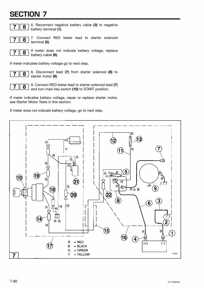
SECTION 7
7-80
3-/ 4-Cylinder
6. Reconnect negative battery cable
(3)
to negativebattery terminal
(1)
.
7. Connect RED tester lead to starter solenoidterminal
(5)
.
If meter does not indicate battery voltage, replacebattery cable
(6)
.
If meter indicates battery voltage go to next step.
8. Disconnect lead
(7)
from starter solenoid
(8)
tostarter motor
(9)
.
9. Connect RED tester lead to starter solenoid lead
(7)
and turn main key switch
(10)
to START position.
If meter indicates battery voltage, repair or replace starter motor,see Starter Motor Tests in this section.
If meter does not indicate battery voltage, go to next step.
7 8
7 8
7 8
7 8
7 8
T1514
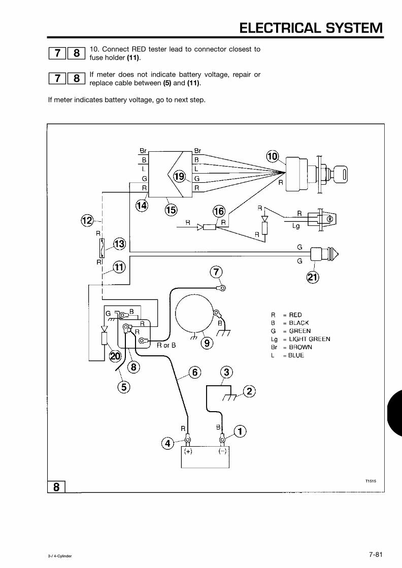
ELECTRICAL SYSTEM
7-81
3-/ 4-Cylinder
10. Connect RED tester lead to connector closest tofuse holder
(11)
.
If meter does not indicate battery voltage, repair orreplace cable between
(5)
and
(11)
.
If meter indicates battery voltage, go to next step.
7 8
7 8
T1515

SECTION 7
7-82
3-/ 4-Cylinder
11. Connect RED tester lead to connector closest tofuse holder
(12)
.
If meter does not indicate battery voltage, find sourceof overload or short and replace 20A engine fuse
(13)
.Possible sources of short or overload:
• Short in starter circuit wiring or components, such as startersolenoid, main key switch, or neutral start switch.
• Short in charging circuit wiring or components, such as thealternator coils or rectifier/regulator.
• Short in accessories such as power trim/tilt.
• Overload in starter motor or power trim/tilt motor.
If meter indicates battery voltage, go to next step.
9 10
9 10
T1514

ELECTRICAL SYSTEM
7-83
3-/ 4-Cylinder
12. Connect RED tester lead to connector closest tomain key switch
(14)
.9 10
T1515

SECTION 7
7-84
3-/ 4-Cylinder
NOTE
For models with remote control box - Make sure you test thecorrect terminal in this step. Terminal
(14)
is connecteddirectly to the main key switch
(10)
and the RED lead thatcomes out of the large cable
(15)
that connects the enginecompartment
(16)
to the remote control box
(17)
. DO NOTCONFUSE TERMINAL
(14)
WITH TERMINAL
(18)
.
NOTE
For models without remote control box - You might have topull connector
(15)
apart and measure voltage at terminalindicated in drawing.
11
12
T1514

ELECTRICAL SYSTEM
7-85
3-/ 4-Cylinder
If meter does not indicate battery voltage, repair orreplace cable between
(12)
and
(14)
.
If meter indicates battery voltage, go to next step.
13. Connect RED tester lead to main key switch lead
(19)
and turn main key switch
(10)
to START position.
11 12
11 12
T1515

SECTION 7
7-86
3-/ 4-Cylinder
NOTE
For models without remote control box - You might have topull connector
(15)
apart and measure voltage at terminalindicated in drawing.
If meter does not indicate battery voltage, test mainkey switch. Refer to Main Key Switch Test in this
section.
If meter indicates battery voltage, go to next step.
13
13 14
T1514

ELECTRICAL SYSTEM
7-87
3-/ 4-Cylinder
14. Connect RED tester lead to neutral start switchlead
(20)
and turn main key switch
(10)
to STARTposition.
If meter does not indicate battery voltage, test neutralstart switch
(21)
. Refer to Neutral Start Switch Test inthis section.
If meter indicates battery voltage, go to next step.
13 14
13 14
T1515

SECTION 7
7-88
3-/ 4-Cylinder
15. For models with remote control box ONLY - ConnectRED tester lead to starter solenoid lead
(22)
and turn mainkey switch
(10)
to START position.
If meter does not indicate battery voltage, repair or replacecable between
(20)
and
(22)
.
If meter indicates battery voltage, go to next step.
15
15
T1514

ELECTRICAL SYSTEM
7-89
3-/ 4-Cylinder
16. Connect RED tester lead to starter solenoid lead
(7)
and turn main key switch
(10)
to START position.
If meter does not indicate battery voltage, test starter solenoid
(8)
.Refer to Starter Solenoid Test in this section.
15 16
T1515

SECTION 7
7-90
3-/ 4-Cylinder
Starter Motor Tests
• If the engine does not crank and you completed the StarterCircuit Tests previously described, remove the starter motor andinspect the brush assembly. If the brush assembly meetsspecifications, replace the starter motor or have it rebuilt.
• If the starter motor runs but the starter motor does not engage ordisengage from the flywheel, remove the starter motor andinspect the pinion assembly. If the pinion assembly meetsspecifications, inspect the flywheel for chipped or worn teethand replace as needed.
Remove Starter Motor
NOTE
Disconnect negative battery cable from batterybefore removing starter motor.
For models 40 / 50 / 80 / 90 / 115 / 120 / 140 moveoil tank out of the way for access.
1. Disconnect starter solenoid cable
(1)
and ground cable
(2)
.
2. Remove starter motor band bolts and starter motor band
(3)
.
3. Remove mounting bolts and slide starter motor out ofbracket
(4)
.
4. Clean bracket with cleaning solvent.
Inspect and Remove Pinion Assembly
1. Grasp pinion collar
(1)
and wind pinion gear
(2)
in aclockwise direction (view from top). Make sure gear moves
freely and returns to original position. If any binding is noted,remove and replace pinion assembly.
17
17
17
18
T1516
T1524

ELECTRICAL SYSTEM
7-91
3-/ 4-Cylinder
2. Release pinion collar
(1)
by tapping it with a socket
(2)
[with same outside diameter as pinion collar and clearancefor motor shaft] and mallet
(3)
.
3. Push down on pinion collar
(2)
and remove locking ring
(1)
.
4. Remove pinion gear
(3)
, spring
(4)
and pinion collar
(5)
.
19
20
21 22
T1522
T1523
T1517 T1518

SECTION 7
7-92
3-/ 4-Cylinder
5. Clean removed components with cleaning solvent and examinepinion gear for wear and chipped teeth and spring for tension ordistortion and replace assembly as required.
NOTE
Do not allow cleaning solvent to come in contactwith starter motor.
6. Aoolv a liaht coat of low temperature lithium greaseto motor shaft
(7)
and slide on pinion gear
(3)
, windcounterclockwise to seat.
7. Slide spring
(4)
and pinion collar
(5)
on motor shaft
(7)
.
23 24
23 24
T1517 T1518
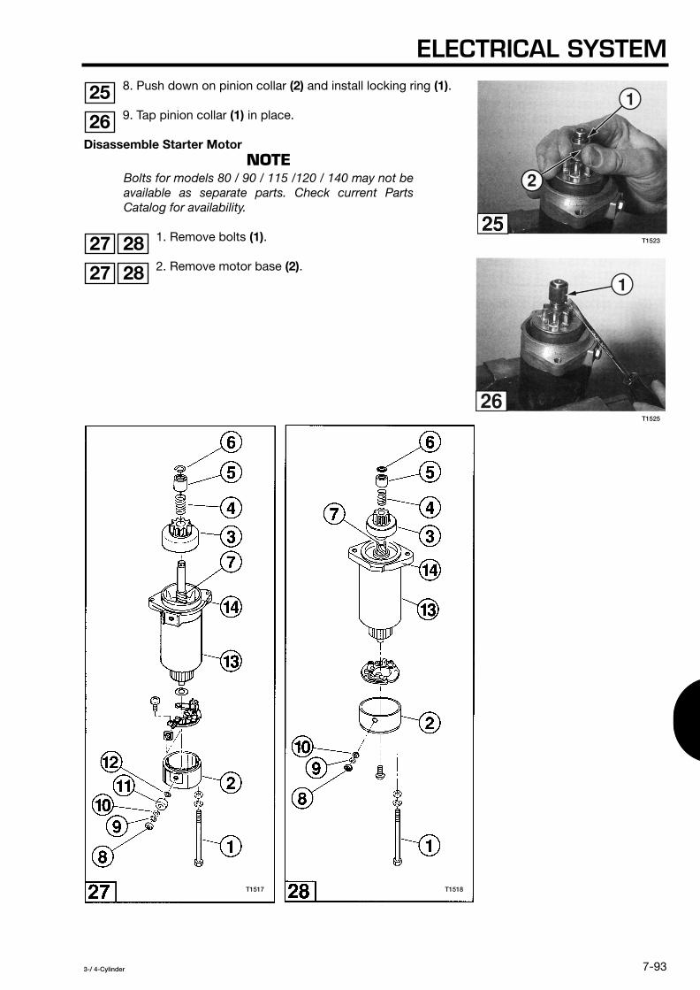
ELECTRICAL SYSTEM
7-93
3-/ 4-Cylinder
8. Push down on pinion collar
(2)
and install locking ring
(1)
.
9. Tap pinion collar
(1)
in place.
Disassemble Starter Motor
NOTE
Bolts for models 80 / 90 / 115 /120 / 140 may not beavailable as separate parts. Check current PartsCatalog for availability.
1. Remove bolts
(1)
.
2. Remove motor base
(2)
.
25
26
27 28
27 28
T1517 T1518
T1523
T1525
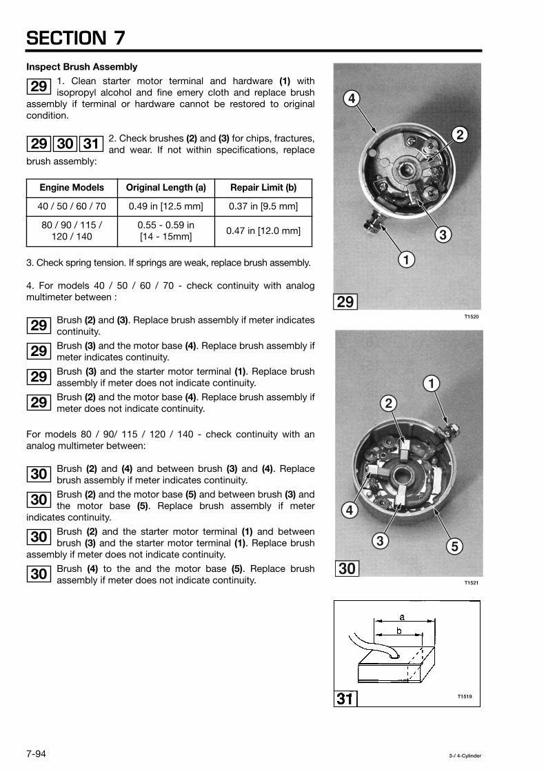
SECTION 7
7-94
3-/ 4-Cylinder
Inspect Brush Assembly
1. Clean starter motor terminal and hardware
(1)
withisopropyl alcohol and fine emery cloth and replace brush
assembly if terminal or hardware cannot be restored to originalcondition.
2. Check brushes
(2)
and
(3)
for chips, fractures,and wear. If not within specifications, replace
brush assembly:
3. Check spring tension. If springs are weak, replace brush assembly.
4. For models 40 / 50 / 60 / 70 - check continuity with analogmultimeter between :
Brush
(2)
and
(3)
. Replace brush assembly if meter indicatescontinuity.
Brush
(3)
and the motor base
(4)
. Replace brush assembly ifmeter indicates continuity.
Brush
(3)
and the starter motor terminal
(1)
. Replace brushassembly if meter does not indicate continuity.
Brush
(2)
and the motor base
(4)
. Replace brush assembly ifmeter does not indicate continuity.
For models 80 / 90/ 115 / 120 / 140 - check continuity with ananalog multimeter between:
Brush
(2)
and
(4)
and between brush
(3)
and
(4)
. Replacebrush assembly if meter indicates continuity.
Brush
(2)
and the motor base
(5)
and between brush
(3)
andthe motor base
(5)
. Replace brush assembly if meterindicates continuity.
Brush
(2)
and the starter motor terminal
(1)
and betweenbrush
(3)
and the starter motor terminal
(1)
. Replace brushassembly if meter does not indicate continuity.
Brush
(4)
to the and the motor base
(5)
. Replace brushassembly if meter does not indicate continuity.
Engine Models Original Length (a) Repair Limit (b)
40 / 50 / 60 / 70 0.49 in [12.5 mm] 0.37 in [9.5 mm]
80 / 90 / 115 /120 / 140
0.55 - 0.59 in [14 - 15mm]
0.47 in [12.0 mm]
29
29 30 31
29
29
29
29
30
30
30
30
T1519
T1521
T1520

ELECTRICAL SYSTEM
7-95
3-/ 4-Cylinder
Remove Brush Assembly
NOTE
Hardware for models 80 / 90 / 115 / 120 / 140 maynot be available as separate parts. Check currentParts Catalog for availability.
1. For models 40 / 50 / 60 / 70: Remove nut
(8)
, washer
(9)
,washer
(10)
, bushing
(11)
and o-ring
(12)
.
For models 80 / 90 / 115 / 120 / 140: Remove nut
(8)
,washer
(9)
and washer
(10)
.
32
33
T1517 T1518

SECTION 7
7-96
3-/ 4-Cylinder
2. Remove screws
(1)
.
3. For models 40 / 50 / 60 / 70: Remove brush assembly
(1)
.
For models 80 / 90 / 115 / 120 / 140: Remove brushassembly
(1)
carefully guiding the starter motor terminal
(2)
through the bushing
(3)
.
4. For models 40 / 50 / 60 / 70 ONLY: Remove bushing
(1)
.
34 35
36
37
38
T1530
T1528
T1527T1529T1526

ELECTRICAL SYSTEM
7-97
3-/ 4-Cylinder
Install Brush Assembly
1. Apply genuine grease to bearing cup
(1)
.
2. For models 40 / 50 / 60 / 70 ONLY: Install bushing
(1)
.
3. For models 40 / 50 / 60 / 70: Install brush assembly
(1)
.
For models 80 / 90 / 115 / 120 / 140: Install brush assembly
(1)
. Make sure that the starter motor terminal
(2)
is fullyseated in the bushing
(3)
.
4. For models 40 / 50 / 60 / 70 ONLY: Apply threadlocker toscrew threads and install screws
(1)
.
39 40
41
42
43
44
T1527
T1530
T1528T1532T1531
T1526

SECTION 7
7-98
3-/ 4-Cylinder
5. For models 40 / 50 / 60 / 70: Install O-ring
(12)
, bushing
(11)
, washer
(10)
, washer
(9)
and secure with nut
(8)
.
For models 80 / 90 / 115 / 120 / 140: Install washer
(10)
,washer
(9)
and secure with nut
(8)
.
Assemble Starter Motor
NOTE
Bolts for models 80 / 90 / 115 / 120 / 140 may not beavailable as separate parts. Check current PartsCatalog for availability.
1. Clean commutator
(1)
with fine emery cloth.
2. For models 40 / 50 / 60 / 70 ONLY: Install washer
(1)
.
3. Align clearance holes for bolt
(1)
in starter motorbody
(13)
with bolt holes in mounting collar
(14)
.
45
46
47
48
45 46
T1535
T1534
T1517 T1518

ELECTRICAL SYSTEM
7-99
3-/ 4-Cylinder
4. For models 40 /50 / 60 / 70: Retract brushesas you slide motor base
(1)
over commutator
(2)
. Align notch
(3)
in motor base with tab
(4)
in motor body
(5)
andseat motor base to motor body.
For models 80 / 90 / 115 / 120 / 140: Retract brushes
(1)
asyou slide brush assembly
(2)
over commutator
(3)
.
5. For models 80 / 90 / 115 / 120 / 140 ONLY: Align tab
(1)
inmotor base with notch
(2)
in motor body and seat motorbase to motor body.
6. For models 80 / 90 / 115 / 120 / 140 ONLY: Applythreadlocker to brush assembly screw threads. Align
clearance holes for brush assembly screws in motor base withscrew holes in brush assembly and secure with screws
(3)
.
49 50 51
52
53
53
T1539
T1537T1536T1533
T1540

SECTION 7
7-100
3-/ 4-Cylinder
7. Apply threadlocker to bolt threads and install bolts
(1)
.
8. Grasp pinion collar
(1)
and rotate several times to makesure brushes are seated.
NOTE
If pinion collar
(1)
rotates freely without turning motorshaft, seat pinion collar.
Install Starter Motor
NOTE
Disconnect negative battery cable from batterybefore installing starter motor.
For models 40 / 50 / 80 / 90 / 115 / 120 / 140 moveoil tank out of the way for access.
For models 115 / 120 / 140 make sure you install themount rubber B
(1)
.
Make sure you install the starter motor rubber
(1)
.
If pinion collar
(1)
rotates freely without turning motorshaft, seat pinion collar.
54 55
56
57
58
59
57
T1525
T1542T1541T1538
T1544
T1543

ELECTRICAL SYSTEM
7-101
3-/ 4-Cylinder
1. Slide starter motor into bracket
(4)
, apply threadlocker tobolt threads, and install mounting bolts.
2. Install starter motor band
(3)
apply threadlocker to boltthreads, and starter motor band bolts.
3. Connect starter solenoid cable
(1)
and ground cable
(2)
.
4. Coat terminals with battery spray protector.
Starter Solenoid Test
1. Disconnect terminals
(4)
and
(5)
and disconnect terminal
(3)
from chassis ground.
2. Set analog multimeter for continuity. Check for continuitybetween terminals:
(3)
and
(5)
. If meter does not show continuity, replace startersolenoid
(1)
.
(5)
and clean chassis ground. If meter shows continuity,replace starter solenoid.
(3)
and clean chassis ground. If meter shows continuity,replace starter solenoid.
3. Disconnect positive battery lead
(8)
and RED starterswitch lead
(9)
from starter terminal
(2)
and disconnectstarter motor lead
(7)
from starter terminal
(6)
.
4. Check for continuity between terminals:
(2)
and
(6)
. If meter shows continuity, replace startersolenoid.
(2)
and clean chassis ground. If the meter shows continuity,replace starter solenoid.
(6)
and clean chassis ground. If the meter shows continuity,replace starter solenoid.
60
60
60
61
61
61
61
61
61
61
61
T1516
T1545

SECTION 7
7-102
3-/ 4-Cylinder
Main Key Switch Test
1. Disconnect terminals
(2), (3), (4), (5), (6), (7), (8), (9), (10),(11), (12)
and
(13)
.
2. Set analog multimeter for continuity. With main key switch
(1)
set to OFF, ON, START, and PUSH IN positions, check forcontinuity between a clean chassis ground and one of theseterminals (test one terminal at a time):
If meter shows continuity in any of these tests, replace main keyswitch.
3. With main key switch set to the OFF position, check forcontinuity between terminals
(4)
and
(6)
. If meter does notshow continuity, replace main key switch.
Check for continuity between the following terminals, ifmeter shows continuity, replace main key switch.
Terminal Terminal Terminal
Terminal Terminal Terminal
Terminal
and
Terminal
and
Terminal
and
Terminal
and
Terminal
and
Terminal
and
62
62
2 4 6
8 10 12
62
62
2 8 2 10 2 12
8 10 8 12 10 12
T1546

ELECTRICAL SYSTEM
7-103
3-/ 4-Cylinder
4. With main key switch set to the ON position, check forcontinuity between terminals
(2)
and
(8)
. If meter does notshow continuity, replace main key switch.
Check for continuity between the following terminals, ifmeter shows continuity, replace main key switch.
5. With main key switch set to the START position, check forcontinuity between terminals
(2)
,
(8)
and
(12)
. If meter doesnot show continuity between all three terminals, replace main keyswitch.
Check for continuity between the following terminals, ifmeter shows continuity, replace main key switch.
Terminal
and
Terminal
and
Terminal
and
Terminal
and
Terminal
and
Terminal
and
Terminal
and
Terminal
and
Terminal
and
63
63
4 6 4 10 4 12
6 10 6 12 10 12
63
63
4 6 4 10 6 10
T1546

SECTION 7
7-104
3-/ 4-Cylinder
6. With main key switch set to the OFF position, PUSH INthe key, check for continuity between terminals
(4)
and
(6)
. Ifmeter does not show continuity, replace main key switch. Check forcontinuity between all remaining terminals, if meter showscontinuity, replace main key switch.
Check for continuity between the following terminals, ifmeter shows continuity, replace main key switch.
7. With main key switch set to the ON position, PUSH IN thekey, check for continuity between terminals
(2)
,
(8)
and
(10)
.If meter does not show continuity between all three terminals,replace main key switch. Check for continuity between allremaining terminals, if meter shows continuity, replace main keyswitch.
Check for continuity between the following terminals, ifmeter shows continuity, replace main key switch.
8. With main key switch set to the START position, PUSH INthe key, check for continuity between terminals
(2)
,
(8)
,
(10)
and
(12)
. If meter does not show continuity, between all fourterminals replace main key switch. Check for continuity between allterminals
(4)
and
(6)
, if meter shows continuity, replace main keyswitch.
Terminal
and
Terminal
and
Terminal
and
Terminal
and
Terminal
and
Terminal
and
Terminal
and
Terminal
and
Terminal
and
64
64
2 8 2 10 2 12
8 10 8 12 10 12
64
64
4 6 4 12 6 12
64
T1546

ELECTRICAL SYSTEM
7-105
3-/ 4-Cylinder
Neutral Start Switch Test
1. For models without remote control box: Disconnectterminals
(2)
and
(3)
.
For models with remote control box: Disconnect terminals
(2)
,
(3)
and
(4)
.
2. For models without remote control box: Set analog multimeterfor continuity. With shift lever set at NEUTRAL, FORWARD, andREVERSE positions, check for continuity between a clean chassisground and one of these terminals (test one terminal at a time):
If meter shows continuity in any of these tests, replaceneutral start switch
(1)
.
For models with remote control box: Set analog multimeterfor continuity. With remote control lever set at NEUTRAL,
FORWARD, and REVERSE positions, check for continuity betweena clean chassis ground and one of these terminals (test oneterminal at atime):
If meter shows continuity in any of these tests, replace neutral startswitch.
3. With shift lever set at NEUTRAL, check for continuitybetween terminals
(2)
and
(3)
.
If meter does not show continuity, put shift lever inFORWARD gear and press in neutral start switch
plunger
(1)
all the way in. If meter shows continuity, adjust, repair,or replace shift lever linkage. If meter does not show continuity,replace the neutral start switch.
4. For models with remote control box ONLY: With remotecontrol lever set at FORWARD and then REVERSE, check
for continuity between terminals
(3)
and
(4)
. If meter does not showcontinuity in either test, replace the neutral start switch.
Terminal Terminal
Terminal Terminal Terminal
65
66
2 3
65
66
2 3 4
65 66
67 68
66
T1550
T1547
T1549
T1548

SECTION 7
7-106
3-/ 4-Cylinder
Choke Solenoid Test
1. Disconnect terminals
(2)
and
(3)
.
2. Set analog multimeter for continuity. Check for continuitybetween a clean chassis ground and one of these terminals (testone terminal at a time):
If meter shows continuity in any of these tests, replacechoke solenoid
(1)
.
3. Check for continuity between terminals
(2)
and
(3)
. Ifmeter does not show continuity, replace choke solenoid.
CHARGING SYSTEM
CAUTION
Avoid electrical shock:
• Do not handle spark gap tester leads duringperformance testing.
• Do not touch ignition coils, exciter coil, pulsercoils, or alternator coils while the engine iscranking or running.
CAUTION
Use proper precautions when performing testswith the engine cover removed. Do not wearloose clothing or jewelry. Keep hair, hands, andclothing away from the flywheel and othermoving parts.
Terminal Terminal
69
2 3
69
69
T1551

ELECTRICAL SYSTEM
7-107
3-/ 4-Cylinder
CAUTION
When repairs are complete, make sure all ignitionand electrical leads are properly routed andclamped in their original positions and the start-ingear prevention system must be tested beforereturning engine to customer.
CAUTION
The following tests must be performed with correcttest propeller and with the engine in a test tank.
If the battery fails to maintain a charge:
1. Check battery, see Battery Care and Maintenance in this section.
2. Check 20 A engine fuse. If it is blown, check the following shortor overload conditions:
• Short in charging circuit wiring or components, such as thealternator coils or rectifier/regulator.
• Short in starter circuit wiring or components, such as startersolenoid, main key switch, or neutral start switch.
• Short in accessories such as power trim/tilt.
• Overload in starter motor or power trim/tilt motor.
3. Check main key switch for continuity between RED leads withswitch in OFF position, see Main Key Switch Test in this section.
4. Check alternator coils, see Alternator Coil Tests in this section.
5. Check rectifier/regulator, see Rectifier/Regulator Tests in thissection.

SECTION 7
7-108
3-/ 4-Cylinder
Alternator Coil Tests
NOTE
Make sure all electrical terminals are connectedduring this test except those that are noted in thetest procedure.
Check for continuity between chassis ground andthe ground connection for the magneto plate, CDUnit, and ignition coils before conducting thefollowing procedure.
Reference the following electrical drawings for thealternator coil test. The pulser and exciter coils havebeen removed from both illustrations for clarity.
- Figure 1 - models 40 / 50 / 60 / 70 / 80 / 90.
- Figure 2 - models 115 / 120 / 140.
The alternator coil test is used to determine whetherthe alternator coils
(1)
, located on the coil plateassembly
(2)
[models 40 / 50 / 60 / 70 / 80 / 90] or the alternatorassembly
(2)
[models 115 / 120 / 140] are open or shorted. Theoutput from the alternator coil goes to the rectifier/regulator
(9)
.
1
2
1 2
T1552

ELECTRICAL SYSTEM
7-109
3-/ 4-Cylinder
1. Disconnect the following terminals:
2. Set the digital multimeter to ohms and connect theleads between the following terminals to read the
resistance of the alternator coil:
Engine Models Disconnect Terminals
40 / 50 / 60 / 70 / 80 / 90 and
115 / 120 / 140 and
Engine Models Connect Multimeter Between These Terminals
40 / 50 / 60 / 70 / 80 / 90 and
115 / 120 / 140
Tesf1
- and
Test2
- and
1 2
2 4 5 6
3 4 5 6 7 8
1 2
4 6
4 6
6 8
T1553

SECTION 7
7-110
3-/ 4-Cylinder
3. The meter should indicate the following resistance:
4. If the resistance is not within the indicated range,replace the alternator coils. See Charging System
Repair Procedures - Alternator Coils.
If the resistance is within the indicated range, proceed to the nextstep.
5. Connect one tester lead to a clean engine groundand connect the other tester lead to the following
terminals (one terminal at a time) to check for any resistance toground:
Engine Models Results
40 and 50 60 and 70 80 and 90
115 / 120 / 140
W-Y, 0.2 - 0.3
Ω
W-Y, 0.2 - 0.3
Ω
0.2 - 0.3
Ω
(Test 1 and 2) 0.26 - 0.40
Ω
Engine Models Connect Multimeter Between These Terminals
40 / 50 / 60 / 70 / 80 / 90 • Terminal
• Terminal
115 / 120 / 140
• Terminal
• Terminal
• Terminal
3 4
3 4
4
6
4
6
8
T1552
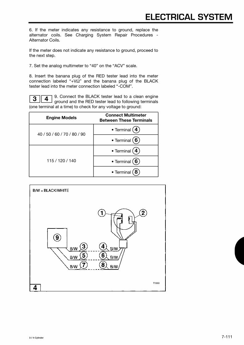
ELECTRICAL SYSTEM
7-111
3-/ 4-Cylinder
6. If the meter indicates any resistance to ground, replace thealternator coils. See Charging System Repair Procedures -Alternator Coils.
If the meter does not indicate any resistance to ground, proceed tothe next step.
7. Set the analog multimeter to “40” on the “ACV” scale.
8. Insert the banana plug of the RED tester lead into the meterconnection labeled “+V
Ω
” and the banana plug of the BLACKtester lead into the meter connection labeled “-COM”.
9. Connect the BLACK tester lead to a clean engineground and the RED tester lead to following terminals
(one terminal at a time) to check for any voltage to ground:
Engine Models Connect Multimeter Between These Terminals
40 / 50 / 60 / 70 / 80 / 90 • Terminal
• Terminal
115 / 120 / 140
• Terminal
• Terminal
• Terminal
3 4
4
6
4
6
8
T1553

SECTION 7
7-112
3-/ 4-Cylinder
10. Start engine.
11. At idle and full throttle, if the meter indicates any voltage toground, replace alternator coils. See Charging System RepairProcedures Alternator Coils.
If no voltage to ground is indicated, the test is complete.
12. Reconnect alternator terminals.
Rectifier/Regulator Tests
NOTE
Make sure all electrical terminals are connectedduring this test except those that are noted in thetest procedure.
Check for continuity between chassis ground andthe ground connection for the magneto plate, CDUnit, and ignition coils before conducting thefollowing procedure.
Reference the following electrical drawings for therectifier/regula tor test.
- Figure 1 - models 40 / 50 / 60 / 70 / 80 / 90.
- Figure 2 - models 115 / 120 / 140.
The rectifier/regulator tests check whether the rectifier/regulator
(1)
is shorted or open.
1. Disconnect the following terminals from all otherwiring:
Engine Models Disconnect Terminals
40 / 50 / 60 / 70 / 80 / 90 and
115 / 120 / 140 and
5
6
5 6
2 3 4 5
2 3 4 5 6
T1555
T1554

ELECTRICAL SYSTEM
7-113
3-/ 4-Cylinder
2. Set analog multimeter to check continuity.
3. Insert the banana plug of the RED tester lead into the meterconnection labeled “+V
Ω
” and the banana plug of the BLACKtester lead into the meter connection labeled “-COM”.
4. For models 40 / 50 / 60 / 70 / 80 / 90: Connect the RED andBLACK tester leads to the terminals as shown and note the results:
• Follow the tests listed in the chart starting at the TOP of eachCOLUMN and going DOWN.
• Follow the tests listed in the chart starting at the LEFT of eachROW and going to the RIGHT.
Replace rectifier/regulator if continuity tests are not as shown. Ifcontinuity checks are within specifications, proceed to next step.
NOTE
Continuity on chart means that the meter showedcontinuity (some resistance indicated by meter -exact value depends on test conditions). NoContinuity on chart means that meter had nodeflection.
For models 115 / 120 / 140: Connect the RED and BLACK testerleads to the terminals as shown and note the results:
• Follow the tests listed in the chart starting at the TOP of eachCOLUMN and going DOWN.
• Follow the tests listed in the chart starting at the LEFT of eachROW and going to the RIGHT.
Replace rectifier/regulator if continuity tests are not as shown. Ifcontinuity checks are within specifications, proceed to next step.
RED Tester Lead
Terminal
Terminal
Terminal
Terminal
BLACK Tester Lead
Terminal
NA Continuity Continuity Continuity
Terminal
No Continuity NA No Continuity Continuity
Terminal
No Continuity No Continuity NA Continuity
Terminal
No Continuity No Continuity NA NA
2 3 4 5
2
3
4
5

SECTION 7
7-114
3-/ 4-Cylinder
NOTE
Continuity on chart means that the meter showedcontinuity (some resistance indicated by meter -exact value depends on test conditions). NoContinuity on chart means that meter had nodeflection.
5. Connect rectifier/regulator leads.
RED Tester Lead
Terminal
Terminal
Terminal
Terminal
Terminal
BLACK Tester Lead
Terminal
NA Continuity Continuity Continuity Continuity
Terminal
No Continuity
NA No
ContinuityNo
Continuity No
Continuity
Terminal
No Continuity
Continuity NA No
Continuity No
Continuity
Terminal
No Continuity
Continuity No
Continuity NA
No Continuity
Terminal
No Continuity
Continuity No
Continuity No
Continuity NA
2 3 4 5 6
2
3
4
5
6

ELECTRICAL SYSTEM
7-115
3-/ 4-Cylinder
Charging System Repair Procedures
WARNING
Disable ignition system, by disconnecting excitercoil terminals (4), (5), (6), (7), [(8) and (9) for 60B/70B only] to prevent accidental engine startupduring removal and replacement of the flywheel.
7 8
T1480
T1479
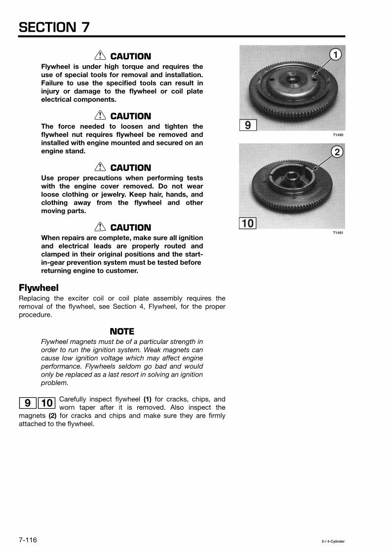
SECTION 7
7-116
3-/ 4-Cylinder
CAUTION
Flywheel is under high torque and requires theuse of special tools for removal and installation.Failure to use the specified tools can result ininjury or damage to the flywheel or coil plateelectrical components.
CAUTION
The force needed to loosen and tighten theflywheel nut requires flywheel be removed andinstalled with engine mounted and secured on anengine stand.
CAUTION
Use proper precautions when performing testswith the engine cover removed. Do not wearloose clothing or jewelry. Keep hair, hands, andclothing away from the flywheel and othermoving parts.
CAUTION
When repairs are complete, make sure all ignitionand electrical leads are properly routed andclamped in their original positions and the start-in-gear prevention system must be tested beforereturning engine to customer.
Flywheel
Replacing the exciter coil or coil plate assembly requires theremoval of the flywheel, see Section 4, Flywheel, for the properprocedure.
NOTE
Flywheel magnets must be of a particular strength inorder to run the ignition system. Weak magnets cancause low ignition voltage which may affect engineperformance. Flywheels seldom go bad and wouldonly be replaced as a last resort in solving an ignitionproblem.
Carefully inspect flywheel
(1)
for cracks, chips, andworn taper after it is removed. Also inspect the
magnets
(2)
for cracks and chips and make sure they are firmlyattached to the flywheel.
9 10
T1491
T1490

ELECTRICAL SYSTEM
7-117
3-/ 4-Cylinder
Alternator Coils
NOTE
Disconnect negative battery cable from battery beforeremoving alternator coils.
This procedure assumes alternator coils are availableas a separate replaceable component. Some engineconfigurations might require replacement of entire coilplate assembly. Check current Parts Catalog foravailability.
Removal
1. Remove the flywheel.
2. Disconnect following terminals for alternator coils
(1)
. Alternator coils are located on the coil plateassembly
(2)
[models 40 / 50 / 60 / 70 / 80 / 90] or the alternatorassembly
(2)
[models 115 / 120 / 140].
11 12
T1552

SECTION 7
7-118
3-/ 4-Cylinder
3. For models 40 / 50 / 60 / 70 / 80 / 90 ONLY: Remove coilplate assembly cable clamp screws
(1)
and cable clamp
(2)
.
NOTE
Make sure you don’t cut electrical conductors insideof coil plate assembly cable when you slit cableshield.
On models 60B / 708 / 60C / 70C there are two coilplate assembly cables
(1)
and
(2)
. Make sure you slitthe cable shield for coil plate assemble cable thatcontains the electrical conductors for the alternatorcoil.
Engine Models Disconnect Terminals
40 / 50 / 60 / 70 / 80 / 90 and
115 / 120 / 140 and
3 4 5 6
3 4 5 6 7 8
13
13
T1553
T1492

ELECTRICAL SYSTEM
7-119
3-/ 4-Cylinder
4. For models 40 / 50 / 60 / 70 / 80 / 90 ONLY: Carefully slitcoil plate assembly cable shield
(1)
.
NOTE
Make sure you don’t cut electrical conductors insideof coil plate assembly cable when you slit cableshield.
On models 60B / 70B / 60C / 70C there are two coilplate assembly cables
(1)
and
(2)
. Make sure you slitthe cable shield for coil plate assembly cable thatcontains the electrical conductors for the excitercoil(s).
5. For models 40 / 50 / 60 / 70 / 80 / 90 ONLY: Cut tie wrap.
6. For models 40 / 50 / 60 / 70 / 80 / 90 ONLY: Removealternator coil screws
(1)
and alternator coils
(2)
from themounting bracket.
For models 115 / 120 / 140 ONLY: Remove mounting screws
(1)
and alternator assembly
(2)
from the mounting bracket
(3)
.
14
14
15
16
T1556
T1493
T1500

SECTION 7
7-120
3-/ 4-Cylinder
Cleaning and Inspection
Clean coil plate assembly, upper main bearing seal
(1)
, setring, ignition timing link, exciter coil(s), pulser coils, coil
leads, and coil connectors with isopropyl alcohol as required.
Check for the following and repair or replace as required:
• Bent, chipped, cracked, or corroded coil plate assembly.
• Coil leads for integrity, cut or cracked insulation, and damagedconnectors.
• Broken or bent exciter coil laminations, damaged exciter coilwindings, and missing exciter coil screws.
• Broken, cracked, or misaligned pulser coils and missing pulsercoil screws.
• Free motion of ignition timing link
(1)
. Repair, adjust, andlubricate as needed, see Section 2.
Installation
Install in reverse order of removal.
NOTE
Use threadlocker on screw threads before installingscrews.
17
18
T1499
T1498

3-/ 4-Cylinder
8-1
General Precautions ............................................................................................................ 8-2
Service Specifications ......................................................................................................... 8-3
Air Bleeding Procedure ....................................................................................................... 8-6
Trim Sender/Trim Meter Test ............................................................................................... 8-7
Power Trim/Tilt .................................................................................................................. 8-11
Troubleshooting ................................................................................................................. 8-19
SECTION 8POWER TRIM/TILT
TABLE OF CONTENTS

SECTION 8
8-2
3-/ 4-Cylinder
GENERAL PRECAUTIONS
Before performing any service work on the power trim/tilt system,read and understand the Service Safety section at the beginning ofthis manual.
Pressurized hydraulic oil in the PT/T unit can cause serious injury.Always wear safety glasses and skin protection when servicing thesystem.
Before disassembly, always depressurize the PT/T unit as follows:
• Fully extend the tilt cylinder rod and engage the tilt stopper.
• Open the manual valve in increments.
• Allow PT/T unitto fully depressurize.
Do not fully open the manual valve when the engine is tilted down.Oil pressure is at its highest when engine is in this position.
Never apply heat to the PT/T manifold or cylinder body. Heat cancause high pressure leaks and failure of parts.
If manual valve is opened for manual tilting, engine cannot be heldin the UP position by closing the manual valve. Engine must besafely supported using the tilt stopper or a suitable traileringbracket or hoist.
Significant residual pressure can exist behind components whenremoved. Always cover each part with a shop rag when removing it.
Replace locking fasteners when their locking feature becomesweak. Once removed, always install new snap rings. Use onlyfactory replacement parts.
When using compressed air to clean or dry parts, make sure airsupply is regulated not to exceed 25 psi [172 kPa / 1.76 kg/cm
2
].
Before returning the engine to customer:
• Make sure the manual valve is torqued to specification.
• Make sure the thrust rod is installed in its original location.Leaving the rod out or moving it closer to the boat will allow theengine to trim in farther than expected by the customer andcould result in loss of control.
Serial Number Breakpoints
Reference is made to differences between old and new Style PowerTrim and Tilt Units (PT/T). The following
Serial Numbers
indicatebreakpoints between older and newer Power Trim and Tilt models:
HP New Style PT/T
60 B 11646 or higher
60 C 10001 or higher
70 B23401 - 23413, 23439 or higher
70 C 10001 or higher
90 22313 - 22342, 22348 - 22358, 22365 or higher
115/120 21739 or higher
140 12174 or higher

POWER TRIM/TILT
8-3
3-/ 4-Cylinder
SERVICE SPECIFICATIONS
Special Torque Values
Description
Torque in-lb (ft-lb)
N·mkg-m
Threadlocker
40 / 50
Old Style PT/T New Style PT/T
PT/T Assembly Mounting Bolt —
(17 - 22) 23 - 31 2 - 3
— —
Oil Reservoir Mounting Bolt —
43 - 60 5 - 7
0.5 - 0.7
35 - 52 4 - 6
0.4 - 0.6 —
Oil Reservoir Cap 26 - 43
3 - 50.3 - 0.5
26 - 43 3 - 5
0.3 - 0.5
43 - 87 5 - 10
0.5 - 1.0 —
Manual Valve 26 - 35
3 - 4 0.3 - 0.4
18 - 262 - 3
0.2 - 0.3
26 - 35 3 - 4
0.3 - 0.4—
Oil Tube Nut —96 - 112 11 - 13 1.1 - 1.3
— —
Motor Assembly Mounting Bolt
43 - 60 5 - 7
0.5 - 0.7
43 - 60 5 - 7
0.5 - 0.7
26 - 35 3 - 4
0.3 - 0.4—
Motor Through Bolt —30 - 39 3 - 4
0.3 - 0.4 — —
Motor Cable Outlet Plate Screw —
30 - 39 3 - 4
0.3 - 0.4 — —
Oil Pump Mounting Bolt
43 - 47 5 - 6
0.5 - 0.6
43 - 47 5 - 6
0.5 - 0.6
61 - 87 7 - 10
0.7 - 1.0—
Relief Valve Up 104 - 121 12 - 14 1.2 - 1.4
104 - 121 12 - 14 1.2 - 1.4
— —
Relief Valve Down —104 - 121
12 - 14 1.2 - 1.4
— —
Pilot Relief Valve Down —104 - 121
12 - 14 1.2 - 1.4
— —
Spool Check Valve 78 - 87 9 - 10
0.9 - 1.0
78 - 87 9 - 10
0.9 - 1.0 — —
Trim Rod Guide —(51 - 65) 69 - 88 6.9 - 8.8
(55 - 60) 75 - 81 7.5 - 8.1
—
Tilt Rod Guide (58 - 87) 78 - 1187.8 - 11.8
(58 - 87) 78 - 1187.8 - 11.8
(80 - 108) 108 - 147 10.8 - 14.7
—

SECTION 8
8-4
3-/ 4-Cylinder
Refer to Section 2 for Standard Torque Values chart.
Power Trim/Tilt Specifications
Description
Torque in-lb (ft-lb)
N·mkg-m
Threadlocker
40 / 50
Old Style PT/T New Style PT/T
Tilt Rod Nut (36 - 54) 49 - 74 4.9 - 7.4
(58 - 87) 78 - 1187.8 - 11.8
(58 - 87) 78 - 1187.8 - 11.8
Loctite 242
PT/T Switch (P Type) Mounting Screw
4 - 6 0.45 - 0.7
0.05 - 0.07
4 - 6 0.45 - 0.7
0.05 - 0.07
4 - 6 0.45 - 0.7
0.05 - 0.07—
PT/T Switch (F Type) Mounting Screw
13 - 26 2 - 3
0.2 - 0.3
13 - 26 2 - 3
0.2 - 0.3
13 - 262 - 3
0.2 - 0.3—
Lower Cylinder Pin Nut (51 - 65) 69 - 88 6.9 - 8.8
— — —
Description Unit Specification
40 / 50 Old Style PT/T New Style PT/T
Pump Manifold Assembly
Pump Type — Geared oil pump Geared oil pump Geared oil pump
Relief Valve UP Opening Pressure
psi kPa
kg/cm
2
1991 - 2417 13729 - 16671
140 - 170
1706 - 199111767 - 13728
120 - 140
1280 - 1706 8825 - 11768
90 - 120
Relief Valve DOWN Opening Pressure
psi kPa
kg/cm
2
284 - 483 1961 - 3334
20 - 34—
568 - 1066 3922 - 7354
40 - 75
Pilot Relief Valve DOWN OpeningPressure
psi kPa
kg/cm
2
— 569 - 995
3922 - 6864 40 - 70
—
Free Piston Relief Valve OpeningPressure
psi kPa
kg/cm
2
—
36 - 50 245 - 3432.5 - 3.5
—
Upper Chamber Side Check Valve (ValveSeat Assembly A) Opening Pressure
psi kPa
kg/cm
2
34 2352.4
34 2352.4
—
Lower Chamber Side Check Valve (ValveSeat Assembly B) Opening Pressure
psi kPa
kg/cm
2
17 1181.2
17 118 1.2
—
Oil Type —Nisseki
®
Power Torque Fluid (as shipped from factory) or any GM approved automatic transmission fluid (see Engine Specifications, Section 2)
Oil Capacity fl oz cm
3
18.6 550
24.7 730
23.0 682
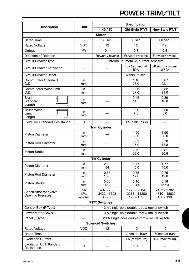
POWER TRIM/TILT
8-5
3-/ 4-Cylinder
Description Unit Specification
40 / 50 Old Style PT/T New Style PT/T
Motor
Rated Time — 60 sec. 60 sec. 60 sec.
Rated Voltage VDC 12 12 12
Output kW 0.4 0.3 0.4
Direction of Rotation —
Forward / reverse Forward / reverse Forward / reverse
Circuit Breaker Type — Internal, bi-metallic, current-sensitive
Circuit Breaker Activation — — 40- 120 sec. at 52A
20 sec. (minimum) at 80A
Circuit Breaker Reset — — Within 35 sec. —
Commutator Standard O.D.
in mm — 1.10
28.00.87 22.1
Commutator Wear Limit O.D.
in mm — 1.06
27.00.82 21.0
Brush Standard Length
in mm —
0.45 11.5
0.39 10.0
Brush Wear Limit Length
in mm —
0.29 7.5
0.20 5.0
Field Coil Standard Resistance
Ω
— 0.05 (pink - blue) —
Trim Cylinder
Piston Diameter in mm — 1.50
38.01.5038.0
Piston Rod Diameter in mm — 0.63
16.00.7017.8
Piston Stroke in mm — 2.72
69.03.81 96.9
Tilt Cylinder
Piston Diameter in mm
2.13 54
1.77 45.0
1.7745.0
Piston Rod Diameter in mm
0.63 16.0
0.75 19.0
0.75 19.0
Piston Stroke in mm
5.55 141.0
6.16 131.0
6.19 157.3
Shock Absorber Valve Opening Pressure
psi kPa
kg/cm
2
497 - 782 3432 - 5393
35 - 55
1778 - 2204 12258 - 15200
125 - 155
2133 - 2702 14710 - 18632
150 - 190
PT/T Switches
Control Box (P Type) — 3 A single-pole double-throw rocker switch
Lower Motor Cover — 3 A single-pole double-throw rocker switch
Panel (F Type) — 20 A single-pole double-throw rocker switch
Solenoid Switches
Rated Voltage VDC 12 12 12
Rated Time — — 30sec. at 100A 60sec. at 80A
Excitation Current — — 3 A (maximum) 4 A (maximum)
Excitation Coil Standard Resistance
Ω
— 5.20 —
T1316
T1316

SECTION 8
8-6
3-/ 4-Cylinder
Manufacturer Special Tools Required
Tilt Rod Guide Wrench, 3B7-72791-0, 3C8-72791-0Trim Rod Guide Wrench, 3B7-72792-0Power Trim/Tilt Test Stand, 3B7-72794-0
General Equipment Required
Ammeter, 0 - 100AAnalog Multimeter,
Electronic Specialties
®
Model M-530 or equivalent
Digital Multimeter,
Electronic Specialties
®
Model KD 3200 or equivalent
Test Battery, 12 V, 500 CCAwith 105 minutes [70AH] reserve capacity
Consumable Supplies Required
Power Trim/Tilt Fluid,
Nisseki
®
Power Torque Fluid (as shipped fromfactory) or any GM approved automatic transmission fluid, seeEngine Specifications in Section 2
Genuine Grease or Equivalent Friction Surface Marine GreaseCleaning Solvent Threadlocker,
Loctite
®
242
AIR BLEEDING PROCEDURE
Air in the PT/T hydraulic system can sometimes be detected by thepresence of muffled sounds during trim/tilt operation. Use thefollowing procedure to bleed air from the system.
1. Ensure oil reservoir cap is tight.
2. Open the manual valve several turns.
3. Lift engine manually to fully UP position. Engage the tilt stopperto lock engine in position.
4. Confirm oil level is sufficient. Add oil if needed.
5. Fully close the manual valve and maintain the UP position for aminimum of 5 minutes.
6. Disengage the tilt stopper. Operate the PT/T motor and lowerengine to fully DOWN position. Maintain this position for a minimumof 5 minutes.
7. Operate the PT/T motor and raise engine to fully UP position.Engage the tilt stopper and check oil level. Add oil if needed.Maintain the UP position for a minimum of 5 minutes.
8. Repeat Steps 6 and 7 for a minimum of five cycles.
NOTE
Air trapped deep within the manifold may not beeasily bled from the system. If air remains trapped inthe system, repeat the Air Bleeding Procedure over aperiod of several days.

POWER TRIM/TILT
8-7
3-/ 4-Cylinder
PT/T Storage Positions
The engine or PT/T assembly itself should be stored so thePT/T unit is in one of the positions shown. Storing the unit in
other positions will allow air to enter the system.
PT/T Oil Fill Positions
NOTE
Refer to Power Trim/Tilt Specifications for oilcapacity listing.
Normal filling of the PT/T reservoir with no air in the systemshould be performed with the PT/T unit positioned vertical
or slightly tilted.
The forward tilt position can allow for over-filling and maydamage the PT/T unit.
TRIM SENDER / TRIM METERTEST
Perform this test to determine if the trim sender and trim meter(analog or LCD) are functioning properly.
NOTE
A fully charged battery rated at 12 V, 500 CCA with105 minutes [70 AH] reserve capacity must be usedfor all testing.
NOTE
The main key switch must be in the ON position toobtain voltage readings during testing.
1
2
3
T1317 T1318
T1319

SECTION 8
8-8
3-/ 4-Cylinder
R = RED P = PINK
B = BLACK O = ORANGE
L = BLUE
Lg = LIGHT GREEN
W = WHITE
NOTE
Reference the applicable electrical diagram for alltesting :
Figure 1 - Models equipped with trim analog meter.
Figure 2 - Models equipped with LCD multi-purpose meter.
1
2
T1320

POWER TRIM/TILT
8-9
3-/ 4-Cylinder
R = RED Lg = LIGHT GREEN
B = BLACK Y = YELLOW
L = BLUE Sb = SKY BLUE
W = WHITE R/G = RED/GREEN
P = PINK P/L = PINK/BLUE
O = ORANGE
T1321

SECTION 8
8-10
3-/ 4-Cylinder
Trim Indicator Input Voltage
1. Disconnect the following:Analog trim meter - terminals
(1)
and
(2)
.
LCD trim meter - terminals
(1)
,
(2)
,
(3)
,
(4)
and connector
(5)
.
2. Using a multimeter, test for 12 VDC input to the trim meter.Connect the RED tester lead to:
Analog trim meter - terminal
(3)
.
LCD trim meter - terminal
(6)
.
Connect the BLACK tester lead to:Analog trim meter - terminal
(4)
.
LCD trim meter - terminal
(7)
.
If no voltage or low voltage is obtained, check the following andcorrect the problem before proceeding: • 20 A engine fuse.• All input wiring to the trim meter for loose connections and
shorts to-ground.• Main switch, see Main Key Switch Test in Section 7.
3. Reconnect all wiring before proceeding.
Trim Meter Output Voltage
4. Disconnect the following:Analog trim meter - terminals
(5)
,
(6)
,
(7)
and
(8)
.
LCD trim meter - connectors
(8)
and
(9)
.
5. Using a multimeter, test for 9 VDC output from the trim meter.Connect the RED tester lead to:
Analog trim meter - terminal
(6)
.
LCD trim meter - terminal
(10)
.
Connect the BLACK tester lead to:Analog trim meter - terminal
(8)
.
LCD trim meter - terminal
(11)
.
1
2
1
2
1
2
1
2
1
2
1
2

POWER TRIM/TILT
8-11
3-/ 4-Cylinder
If no voltage or low voltage is obtained, the trim meter or trim meteroutput wiring is defective. Repair or replace as needed beforeproceeding.
6. Reconnect all wiring and repeat voltage output test for 9 VDC. Ifno voltage or low voltage is obtained, perform the following:
Analog trim meter- Check all wiring between trim sender
(9)
and terminals
(5)
,
(6)
,
(7)
, and
(8)
for shorts-to-ground.
LCD trim meter - Check all wiring between trim sender
(12)
and connector
(8)
for shorts-to-ground.
If wiring is shorted, repair or replace as needed.
7. Reconnect all wiring before proceeding.
Trim Sender Output Voltage
8. Operate PT/T motor and lower engine to fully DOWN position.
9. Using a digital multimeter, connect the RED tester lead to:Analog trim meter - terminal
(7)
.
LCD trim meter - terminal
(13)
.
Connect the BLACK tester lead to:Analog trim meter - terminal
(5)
.
LCD trim meter - terminal
(14)
.
10. Operate the PT/T motor from DOWN to UP and verify thefollowing: • DOWN voltage is between - 5 and - 15 mV.• UP voltage is between -115 and -125 mV.
If test results vary, trim sender unit is defective and must bereplaced.
POWER TRIM/TILT
WARNING
Always wear safety glasses and skin protectionwhen servicing power trim/tilt unit.
WARNING
Never fully open the manual valve when engine istilted down – oil pressure is at its highest.
NOTE
The following procedures apply to all PT/T models.New style PT/T shown in photographs.
1
2
1
2
1
2

SECTION 8
8-12
3-/ 4-Cylinder
Models 40 and 50
1. Motor Assembly 2. Drive Joint 3. Filter B 4. Pump 5. Relief Valve DOWN 6. Cap
7.Upper Chamber Side CheckValve (Valve Seat Assembly A)
8.Spool 9.Relief Valve UP 10.Manual Valve
11.Inner Collar12.Lower Chamber Side Check
Valve (Valve Seat Assembly B) 13.Free Piston 14.Piston Rod Assembly 15.Rod Guide
T1322

POWER TRIM/TILT
8-13
3-/ 4-Cylinder
Models 60 / 70 / 80 / 90 / 115 / 120 / 140 - Old PT/T
1. Motor Assembly2. Filter B3. Pump Coupling4. Pump5. Trim Rod Guide Assembly6. Trim Piston Rod Assembly7. Upper Chamber Side Check
Valve (Valve Seat Assembly B)
8.Spool 9.Shaft10.Lower Chamber Side Check
Valve (Valve Seat Assembly A) 11.Manual Valve 12.Inner Collar 13.Relief Valve UP
14. Pilot Relief Valve DOWN 15. Cap 16. Reservoir Tank 17. Cylinder Assembly 18. Free Piston 19. Tilt Piston Rod Assembly 20. Tilt Rod Guide
T1323

SECTION 8
8-14
3-/ 4-Cylinder
Models 60 / 70 / 80 / 90 / 115 / 120 / 140 - New PT/T
1. Motor Assembly2. Bracket Assembly 3. Pump Coupling 4. Filter B 5. Pump 6. Manual Valve
7.Orifice 8.Valve Seat 9.Orifice10.Trim Piston Rod Assembly 11.Trim Rod Guide Assembly 12.Plug
13. Filter14. Reservoir Tank15. Cap16. Free Piston17. Tilt Piston Rod Assembly 18. Tilt Rod Guide
T1324

POWER TRIM/TILT
8-15
3-/ 4-Cylinder
Removal
1. Operatethe PT/T motor and raise engine to fully UP position.Engage the tilt stopper to lock engine in position.
NOTE
If power trim/tilt motor is not functional, open manualvalve several turns and raise engine by hand.
2. Remove thrust rod
(1)
if equipped, and uppercylinder pin
(2)
.
3. With tilt stopper engaged, fully retract the piston rod(s) anddisconnect the battery.
4. Disconnect two PT/T motor leads
(3)
from the UP andDOWN solenoid switches in the electrical box and remove
them from the lower motor cover and stern bracket.
NOTE
The PT/T motor cable on old style PT/T unitscontains an additional ground lead which must bedisconnected. For ease of identification and toprevent improper wire connections during testingand installation, mark all electrical leads beforedisconnecting.
5. Remove the PT/T assembly mounting bolts (old style PT/T)and lower cylinder pin
(4)
.
6. Lift the PT/T unit from between the stern brackets.
4 5
6
7
8
T1328
T1329
T1327T1326T1325

SECTION 8
8-16
3-/ 4-Cylinder
Disassembly and Assembly
WARNING
DO NOT disassemble any component until allsystem pressure has been released and the oilreservoir has been drained. Depressurize the PT/T unit as described in General Precautions at thebeginning of this section.
WARNING
Significant residual pressure can exist behindcomponents when removed. Always cover eachpart with a shop rag when removing it.
Disassemble and assemble the PT/T internal components inaccordance with the previous system diagrams and the componentguidelines contained in this section.
Reference the following specification table for Disassemblyand Assembly special tool requirements.
Tool Part Number Applicability
Tilt Rod Guide Wrench
3C8-72791-0 40 / 50
Tilt Rod Guide Wrench
3B7-72791-0 Old Style and New Style PT/T
Trim Rod Guide Wrench
3B7-72792-0 Old Style and New Style PT/T
Power Trim/Tilt Test Stand
3B7-72794-0 Old Style PT/T
9
1
1
2
T1330
3

POWER TRIM/TILT
8-17
3-/ 4-Cylinder
CAUTION
Use the following precautions during disassemblyand assembly of the PT/T unit:
• PT/T exterior must be thoroughly cleaned be-fore disassembly to prevent contaminantsfrom entering the hydraulic system.
• Use the required special tools to prevent dam-age to components.
• Perform all workwith PT/T unit secured in pad-ded vice or test stand.
• DO NOT force the disassembly or assembly ofany part.
• DO NOT attempt to disassemble the internalpump components.
• Clean all components removed and keep themfree of dust and other debris by placing themon clean paper. DO NOT lay parts on shop ragsor other cloth materials.
• Verify components are within wear limits andare not damaged before assembly.
• Apply specified PT/T oil to all internal partsbefore assembly.
• Torque all valves and fasteners to specification.
Tilt and Trim Cylinders
Guidelines:
1. Use special tools as specified for removing and installing the rodguides.
2. Before assembling, apply specified PT/T oil to inner surface of tiltcylinder and/or manifold and all internal cylinder components,especially o-rings and backup rings.
3. Apply Loctite 242 to the tilt rod nut and torque to specification.
4. Install piston rods as follows:
• Fill bottom of cylinder with specified PT/T oil.
• Insert piston rods into cylinder and push downward until levelwith oil surface.
• Fill remaining portion of cylinder with oil.
• Tighten the rod guides.

SECTION 8
8-18
3-/ 4-Cylinder
5. On old style PT/T, thread the oil tube nuts by hand several turnsbefore tightening with a wrench to avoid leakage caused bycrossthreading.
Manual Valve
Guidelines:
On models 40 and 50 and old style PT/T, use caution toassemble the seal washers, spring, and inner collar in the
correct order. Inner collar
(1)
must be positioned properly as shownto avoid breakage.
Spool Valve
Guidelines:
On old style PT/T, avoid interchanging the upper and lowerchamber side check valves. Upper chamber side check
valve
(2)
is identified by a black colored head stamped with a “1”marking. Lower chamber side check valve
(3)
is not marked or isstamped with a “0” marking.
Motor
Guidelines:
1. Perform the following checks before assembly:
• Using an ohmmeter, verify no electrical continuity between thearmature and commutator. Also verify no electrical continuitybetween the commutator segments. Replace armature assemblyif continuity is detected.
• Inspect the commutator surface and undercuts for signs ofpitting and wear. Polish commutator with fine emery cloth orreplace armature if wear exceeds specification limit.
• Inspect the brush lengths and replace if wear exceedsspecification limit.
10
11
T1332T1331

POWER TRIM/TILT
8-19
3-/ 4-Cylinder
2. Avoid damage to the brushes during disassembly and assemblyof the motor.
3. On old style PT/T, ensure motor match marks
(4)
arealigned when assembling the armature and yoke
compressor.
4. Ensure armature shaft is seated properly in pump coupling.
Installation
Installation is done in the reverse order of Removal.
CAUTION
Use the following precautions during installationof the PT/T unit:• Ensure all bushings and washers have been
inspected and are properly installed.• Lubricate friction surfaces with genuine
grease or equivalent friction surface marinegrease.
• Replace all snap rings that have been removed.• Torque fasteners to specification.
TROUBLESHOOTING
This section is designed as a troubleshooting resource for qualifiedservice technicians familiar with the operation and repair of PT/Telectrical and hydraulic systems. Follow all information in the orderindicated; an organized approach more quickly isolates the causeof the problem.
It is important when receiving the engine to question the owner andobtain any symptom information which might assist in determiningand correcting the problem. Particularly ask whether symptomsoccur during forward or reverse running of the engine. Document allinformation gathered.
WARNING
Follow the Removal, Disassembly, Assembly, andInstallation procedures as applicable when trouble-shooting. The procedures contain important safetyinformation.
12
T1333
SECTION 8
8-20
3-/ 4-Cylinder
CAUTION
Never connect PT/T motor leads directly tobattery when testing. Use battery jumper cablesto prevent sparking and damage to the motorlead terminals.
NOTE
Refer to Outboard Motors Service Data publicationfor wiring diagrams when performing electricaltesting.
NOTE
A fully charged battery rated at 12 V, 500 CCA with105 minutes [70 AH] reserve capacity must be usedfor all testing.
NOTE
All worn, damaged, or missing parts identified duringtroubleshooting must be replaced. Refer to latestParts Catalog for serviceable parts information.
Preliminary Service Checks
Before troubleshooting, perform the following Service Checks inthe order indicated. Use these checks to help identify problems ofsimple origin and to obtain a complete assessment of the unit sotroubleshooting can begin.
Service Check 1
1. Open the manual valve several turns and manually move theengine through the complete trim/tilt range. Verify the tilt and trimrods are straight, undamaged, and slide smoothly. Verify there is norestriction or binding of the swivel and stern brackets and bracketbolt (tilt tube).
2. Turn the manual valve fully CLOSED and torque to specification.
Service Check 2
1. Check the condition and quantity of the oil in the reservoir. If oilappears bad or level is low, completely drain, refill, and bleed thesystem. Check the old oil for metal fragments or signs of gelling.
CAUTION
Do not mix different brands or types of oil. Doingso can cause oil gelling which may damage thesystem.
POWER TRIM/TILT
8-21
3-/ 4-Cylinder
Service Check 3
1. Fill a container with water and place it under the PT/T unit.Operate the PT/T motor and check the following:
NOTE
If motor does not run, proceed with next ServiceCheck.
• Check for oil floating on the water and try to identify the point ofleakage. Leakage often indicates an internal component is worn,damaged, or assembled incorrectly.
• Listen for muffled sounds which may indicate air in the system. Ifair is present, bleed the system.
Service Check 4
1. Disconnect customer battery from engine and replace withknown good test battery.
2. Test PT/T operation. If symptoms disappear, check the capacityand charge of customer battery as described in Battery Care andMaintenance, Section 7. Make sure there is no significant drain onthe battery caused by added accessories.
Service Check 5
1. Isolate the PT/T unit from the rest of the engine by disconnectingthe two PT/T motor leads from the UP and DOWN solenoidswitches in the electrical box. Remove the leads from the lowermotor cover.
NOTE
The PT/T motor cable on old style PT/T unitscontains an additional ground lead which must bedisconnected. For ease of identification and toprevent improper wire connections during testingand installation, mark all electrical leads beforedisconnecting.
2. Connect the UP and DOWN leads to a known good test batteryusing battery jumper cables. Connect the leads as follows andverify proper PT/T function in one direction. Then reverse the UPand DOWN lead connections and verify proper PT/T function in theopposite direction.
Old style PT/T:
• Connect either the UP or DOWN lead to positive (+).
• Connect ground lead to negative (-).
Models 40 and 50 and new style PT/T:
• Connect either lead to positive (+) and the other to negative (-).

SECTION 8
8-22
3-/ 4-Cylinder
3. Proceed as follows:• If symptoms disappear, go to PT/T Electrical Troubleshooting in
this section.• If symptoms remain or test results vary, first perform the No Load
Motor Test in this section to rule out possible motor problems.While motor is removed, verify the pump coupling is notdamaged or disconnected. Repair or replace parts as neededand proceed with PT/T Component Troubleshooting in thissection if symptoms are not corrected.
PT/T Electrical Troubleshooting
Use this section to troubleshoot problems with the PT/T electricalsystem.
NOTE
Complete all Preliminary Service Checks beforetroubleshooting the PT/T electrical system.
WARNING
Disable the ignition system to prevent accidentalengine startup.
Follow the Service Checks in the order indicated:
Service Check 1 - Engine Fuse
1. Remove upper motor cover.
2. Open fuse holder and remove engine fuse.
3. Check condition of fuse holder contacts.
4. Check fuse condition and type. Fuse must be rated at 20A.
5. Proceed as follows:
• If fuse is blown, replace.
• If fuse appears not blown, test it for continuity.
Service Check 2 - Wire Connections
Verify all PT/T circuit wiring is properly terminated in accordancewith the wiring diagram. Make sure all connections are secure.
NOTE
Refer to Outboard Motors Service Data publicationfor wiring diagrams.

POWER TRIM/TILT
8-23
3-/ 4-Cylinder
Service Check 3 - Switches
NOTE
Reference the applicable PT/T circuit diagram for thefollowing switch tests:
-
Figure 1 - Models 40 and 50 and new style PT/T
-
Figure 2 - Old style PT/T
1
2
T1334
R = RED
B = BLACK
Sb = SKY BLUE
P = PINK
L = BLUE
G = GREEN

SECTION 8
8-24
3-/ 4-Cylinder
Main Switch
Operate components which run off the main switch circuit, such asstarter motor, choke solenoid, and warning horn. If thesecomponents do not operate or operate improperly, the main switchmay be defective. To test the main switch, see Main Key SwitchTest in Section 7.
R = RED
B = BLACK
L = BLUE
P = PINK
W = WHITE
T1335

POWER TRIM/TILT
8-25
3-/ 4-Cylinder
PT/T Switches
1. Operate each PT/T switch in the UP and DOWN direction andverify audible “clicking” is heard at UP solenoid switch
(1)
andDOWN solenoid switch
(2)
. If all PT/T switches function properly,proceed with Solenoid Switches. Test suspect PT/T switches asfollows:
• Disconnect UP solenoid lead
(3)
and DOWN solenoid lead
(4)
atthe bullet connectors closest to the solenoids.
• Place UP solenoid lead
(3)
in contact with solenoid terminal
(5)
and verify the solenoid “clicks.” Place DOWN solenoid lead
(4)
incontact with solenoid terminal
(6)
and verify the solenoid“clicks.” If the solenoids now “click,” the PT/T switch or wiringmay be defective, proceed with step 2.
2. Disconnect the suspect PT/T switch leads at the bullet connectorsclosest to the PT/T switch and test as follows using ohmmeter: • Verifycontinuity between the PT/T switch RED lead and PT/T
switch SKY BLUE or BLUE lead when switch is in the UPposition.
• Verify continuity between PT/T switch RED lead and PT/T switchPINK lead when switch is in the DOWN position.
If test results vary, replace the PT/T switch.
Solenoid Switches
1. Disconnect UP solenoid lead
(3)
and DOWN solenoid lead
(4)
atthe bullet connectors closest to the solenoids.
2. Disconnect the RED leads from solenoid terminals
(5)
and
(6)
.
3. Disconnect the PT/T motor leads from the solenoid terminals.
4. Proceed as follows:
Models 40 and 50 and new style PT/T:
NOTE
Reference Figure .
• Connect ohmmeter across UP solenoid terminals
(7)
and
(8)
andverify continuity is present when solenoid is OFF. Then place UPsolenoid lead
(3)
in contact with the RED lead that wasdisconnected from terminal
(5)
and verify no continuity whensolenoid is ON.
• Connect ohmmeter across UP solenoid terminals
(7)
and
(5)
andverify no continuity when solenoid is OFF. Then place UPsolenoid lead
(3)
in contact with the RED lead that wasdisconnected from terminal
(5)
and verify continuity is presentwhen solenoid is ON.
1

SECTION 8
8-26
3-/ 4-Cylinder
• Connect ohmmeter across DOWN solenoid terminals
(9)
and
(10)
and verify continuity is present when solenoid is OFF. Then placeDOWN solenoid lead
(4)
in contact with the RED lead that wasdisconnected from terminal
(6)
and verify no continuity whensolenoid is ON.
• Connect ohmmeter across DOWN solenoid terminals
(9)
and
(6)
and verify no continuity when solenoid is OFF. Then place DOWNsolenoid lead
(4)
in contact with the RED lead that wasdisconnected from terminal
(6)
and verify continuity is presentwhen solenoid is ON.
If test results vary, replace the defective solenoid switch.
Old Style PT/T:
NOTE
Reference Figure .
• Connect ohmmeter across UP solenoid terminals
(7)
and
(5)
andverify no continuity when solenoid is OFF. Then place UPsolenoid lead
(3)
in contact with the RED lead that wasdisconnected from terminal
(5)
and verify continuity is presentwhen solenoid is ON.
• Connect ohmmeter across DOWN solenoid terminals
(9)
and
(6)
and verify no continuity when solenoid is OFF. Then place DOWNsolenoid lead
(4)
in contact with the RED lead that wasdisconnected from terminal
(6)
and verify continuity is presentwhen solenoid is ON.
If test results vary, replace the defective solenoid switch.
Service Check 4 - Wire Leakage and Shorts
Verify all PT/T circuit wiring is free from electrical leakage andshortsto-ground. Repair or replace wiring as needed.
2

POWER TRIM/TILT
8-27
3-/ 4-Cylinder
PT/T Component Troubleshooting
Use this section to troubleshoot problems internal to the PT/T unit.
NOTE
Complete all Preliminary Service Checks beforetroubleshooting problems internal to the PT/T unit.
Identify the symptom below which best describes the problem athand and follow the specified Service Checks in the orderindicated:
Service Check 1 - Manual Valve
Disassemble the manual valve and check for wear or damage toapplicable components:
• Valve end surface.
• O-rings and seal washers.
• Bottom surface of valve mounting hole.
Symptoms Service Checks
40 / 50 PT/T Old Style PT/T New Style PT/T
Upward Trim/Tilt Problems
Unit does not move UP. 1, 2, 3, 4, 8, 9, 11, 12, 14
1, 2, 3, 4, 8, 9, 10, 12, 14
1, 2, 3, 5, 9, 10, 12, 14
UP operation stops halfway. 3, 4, 9, 11, 12, 14 3, 4, 9, 10, 11,12, 14
5, 9, 10, 11, 12, 14
Unit does not hold UP position when motor stops.
1, 6, 11, 14 1, 4, 6, 10, 12, 14 1, 9, 10, 12, 14
UP operation is slow. 1, 3, 4, 8, 9, 11, 12, 14
1, 3, 4, 8, 9, 1012, 14
1, 3, 5, 9, 10, 12, 14
Downward Trim/Tilt Problems
Unit does not move DOWN. 2, 5, 8, 9, 14 2, 5, 8, 9, 14 1, 3, 5, 9, 14
DOWN operation stops halfway.
8, 9, 14 5, 8, 9, 14 5, 9, 14
DOWN operation is slow. 1, 5, 8, 9, 14 1, 5, 8, 9, 14 1, 3, 5, 9, 14
Thrust-Related Trim/Tilt Problems
Unit does not hold trim position during or after forward running.
1, 4, 6, 8, 11, 12, 14
1, 4, 6, 8, 10, 12, 14
1, 9, 10, 12, 14
Unit does not hold trim position during reverse running.
1, 5, 7, 8, 11, 13, 14
1, 7, 8, 11, 13, 14 1, 9, 11, 13, 14

SECTION 8
8-28
3-/ 4-Cylinder
Service Check 2 - Pump Coupling
1. Remove motor.
2. Inspect pump coupling for wear, damage, or separation from thegeared pump.
Service Check 3 - Filters
1. Remove motor.
2. Remove and clean filter B.
3. Remove and clean manifold filter (new style PT/T).
4. Inspect filters for damage or obstruction.
Service Check 4 - Relief Valve UP
1. Remove reservoir tank (old style PT/T).
2. Remove and clean relief valve UP.
3. Inspect for the following as applicable:
• Damage to valve seat.
• Smooth operation; push ball manually and check its return.
• Wear or damage to valve ball.
• Fatigue or deformation of spring.
• Damage or deterioration of o-ring.
• Dirty filter.
Service Check 5 - Relief Valve DOWN
1. Remove pump or reservoir tank (old style PT/T).
2. Remove and clean relief valve DOWN.
3. Inspect for the following as applicable:
• Damage to valve seat.
• Smooth operation; push ball manually and check its return.
• Wear or damage to valve ball.
• Fatigue or deformation of spring.
• Damage or deterioration of o-ring.
• Dirty filter.

POWER TRIM/TILT
8-29
3-/ 4-Cylinder
Service Check 6 - Lower Chamber Side Check Valve
1. Remove and clean lower chamber side check valve.
2. Inspect for thread and surface damage.
3. Inspect for damage or deterioration of o-rings.
Service Check 7 - Upper Chamber Side Check Valve
1. Remove and clean upper chamber side check valve.
2. Inspect for thread and surface damage.
3. Inspect for damage or deterioration of o-rings.
Service Check 8 - Spool
1. Remove upper chamber side valve seat.
2. Remove and clean spool components.
3. Inspect for the following:
• Smooth operation; push manually and check its return.
• Fatigue or deformation of springs.
• Damage or deterioration of back-up ring.
Service Check 9 - Oil Pump
Replace the oil pump and retest PT/T operation.
Service Check 10 - Trim Cylinder Piston
1. Remove rod guide.
2. Remove and clean trim piston components.
3. Inspect for the following:
• Damage to piston sliding surface in cylinder.
• Damage or deformation of piston rod and rod guide.
• Damage or deterioration of o-rings and back-up ring.

SECTION 8
8-30
3-/ 4-Cylinder
Service Check 11 - Tilt Cylinder Piston
1. Remove and clean tilt piston rod assembly.
2. Inspect for the following:
• Damage to piston sliding surface in cylinder.
• Damage or deformation of piston rod and rod guide.
• Damage or deterioration of o-rings and back-up ring.
Service Check 12 - Tilt Cylinder Free Piston
1. Remove tilt piston rod assembly.
2. Remove free piston.
3. Inspect for the following:
• Damage to free piston.
• Damage to free piston seating surface in cylinder.
• Damage or deterioration of o-ring and back-up ring.
Service Check 13 - Tilt Cylinder Shock Absorber Valve
1. Remove the tilt cylinder piston rod.
2. Inspect internal shock absorber valve for the following:
• Fatigue or deformation of spring.
• Damage to valve ball.
• Damage to valve seat.
• Inhibited operation caused by accumulation of dirt.
Service Check 14 - PT/T Assembly
Replace the PT/T assembly.
Copyright © 2022 FDOKUMEN