09349847 2010 493990
15
This article was downloaded by: [Universita Studi la Sapienza] On: 02 January 2012, At: 07:50 Publisher: Taylor & Francis Informa Ltd Registered in England and Wales Registered Number: 1072954 Registered office: Mortimer House, 37-41 Mortimer Street, London W1T 3JH, UK Research in Nondestructive Evaluation Publication details, including instructions for authors and subscription information: http://www.tandfonline.com/loi/urnd20 Cork Embedded Internal Features and Contrast Mechanisms with Dei Using 18, 20, 30, 36, and 40 keV Synchrotron X- Rays V. Rao Donepudi a , Roberto Cesareo a , Antonio Brunetti a , Zhong Zhong b , Tetsuya Yuasa c , Takao Akatsuka c , Tohoru Takeda d & Giovanni E. Gigante e a Istituto di Matematica e Fisica, Universita di Sassari, Sassari, Italy b National Synchrotron Light Source, Brookhaven National Laboratory, Upton, New York, USA c Department of Bio-System Engineering, Faculty of Engineering, Yamagata University, Yonezawa, Japan d Institute of Clinical Medicine, University of Tsukuba, Tsukuba, Japan e Departimento di Fisica, Universita di Roma “La Sapienza”, Rome, Italy Available online: 02 Aug 2010 To cite this article: V. Rao Donepudi, Roberto Cesareo, Antonio Brunetti, Zhong Zhong, Tetsuya Yuasa, Takao Akatsuka, Tohoru Takeda & Giovanni E. Gigante (2010): Cork Embedded Internal Features and Contrast Mechanisms with Dei Using 18, 20, 30, 36, and 40 keV Synchrotron X-Rays, Research in Nondestructive Evaluation, 21:3, 171-183 To link to this article: http://dx.doi.org/10.1080/09349847.2010.493990 PLEASE SCROLL DOWN FOR ARTICLE Full terms and conditions of use: http://www.tandfonline.com/page/terms-and-conditions This article may be used for research, teaching, and private study purposes. Any substantial or systematic reproduction, redistribution, reselling, loan, sub-licensing, systematic supply, or distribution in any form to anyone is expressly forbidden. The publisher does not give any warranty express or implied or make any representation that the contents will be complete or accurate or up to date. The accuracy of any instructions, formulae, and drug doses should be independently verified with primary
Transcript of 09349847 2010 493990
This article was downloaded by: [Universita Studi la Sapienza]On: 02 January 2012, At: 07:50Publisher: Taylor & FrancisInforma Ltd Registered in England and Wales Registered Number: 1072954 Registeredoffice: Mortimer House, 37-41 Mortimer Street, London W1T 3JH, UK
Research in Nondestructive EvaluationPublication details, including instructions for authors andsubscription information:http://www.tandfonline.com/loi/urnd20
Cork Embedded Internal Features andContrast Mechanisms with Dei Using 18,20, 30, 36, and 40 keV Synchrotron X-RaysV. Rao Donepudi a , Roberto Cesareo a , Antonio Brunetti a , ZhongZhong b , Tetsuya Yuasa c , Takao Akatsuka c , Tohoru Takeda d &Giovanni E. Gigante ea Istituto di Matematica e Fisica, Universita di Sassari, Sassari, Italyb National Synchrotron Light Source, Brookhaven NationalLaboratory, Upton, New York, USAc Department of Bio-System Engineering, Faculty of Engineering,Yamagata University, Yonezawa, Japand Institute of Clinical Medicine, University of Tsukuba, Tsukuba,Japane Departimento di Fisica, Universita di Roma “La Sapienza”, Rome,Italy
Available online: 02 Aug 2010
To cite this article: V. Rao Donepudi, Roberto Cesareo, Antonio Brunetti, Zhong Zhong, Tetsuya Yuasa,Takao Akatsuka, Tohoru Takeda & Giovanni E. Gigante (2010): Cork Embedded Internal Featuresand Contrast Mechanisms with Dei Using 18, 20, 30, 36, and 40 keV Synchrotron X-Rays, Research inNondestructive Evaluation, 21:3, 171-183
To link to this article: http://dx.doi.org/10.1080/09349847.2010.493990
PLEASE SCROLL DOWN FOR ARTICLE
Full terms and conditions of use: http://www.tandfonline.com/page/terms-and-conditions
This article may be used for research, teaching, and private study purposes. Anysubstantial or systematic reproduction, redistribution, reselling, loan, sub-licensing,systematic supply, or distribution in any form to anyone is expressly forbidden.
The publisher does not give any warranty express or implied or make any representationthat the contents will be complete or accurate or up to date. The accuracy of anyinstructions, formulae, and drug doses should be independently verified with primary

sources. The publisher shall not be liable for any loss, actions, claims, proceedings,demand, or costs or damages whatsoever or howsoever caused arising directly orindirectly in connection with or arising out of the use of this material.
Dow
nloa
ded
by [
Uni
vers
ita S
tudi
la S
apie
nza]
at 0
7:50
02
Janu
ary
2012
CORK EMBEDDED INTERNAL FEATURES AND CONTRASTMECHANISMS WITH DEI USING 18, 20, 30, 36, AND 40KEVSYNCHROTRON X-RAYS
V. Rao Donepudi,1 Roberto Cesareo,1 Antonio Brunetti,1 Zhong Zhong,2
Tetsuya Yuasa,3 Takao Akatsuka,3 Tohoru Takeda,4 and Giovanni E. Gigante5
1Istituto di Matematica e Fisica, Universita di Sassari, Sassari, Italy2National Synchrotron Light Source, Brookhaven National Laboratory,Upton, New York, USA3Department of Bio-System Engineering, Faculty of Engineering, YamagataUniversity, Yonezawa, Japan4Institute of Clinical Medicine, University of Tsukuba, Tsukuba, Japan5Departimento di Fisica, Universita di Roma ‘‘La Sapienza’’, Rome, Italy
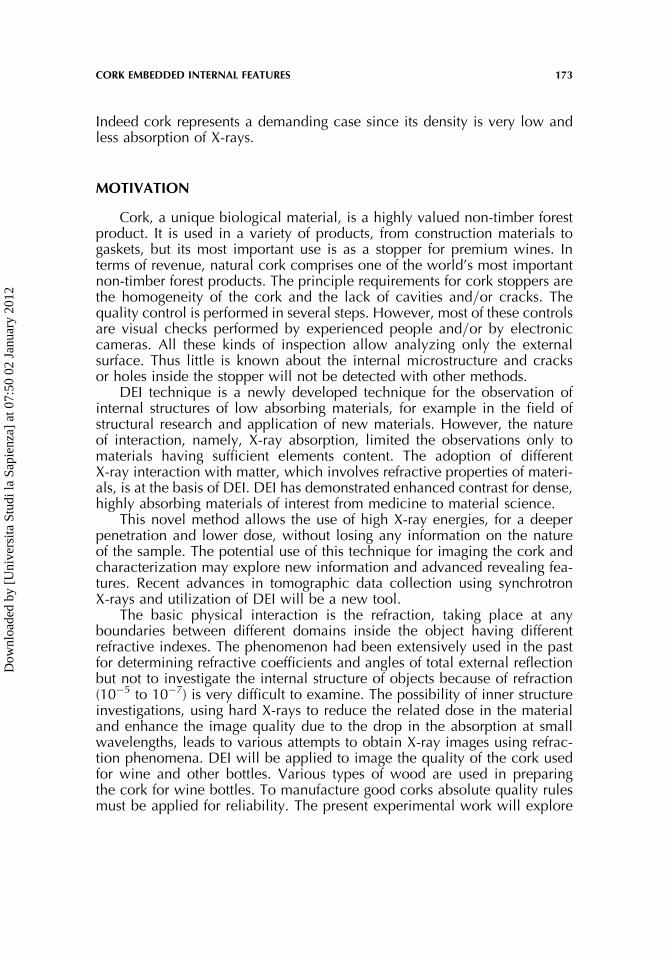
Images of the cork used for wine and other bottles are visualized with the use ofdiffraction-enhanced imaging (DEI) technique. Present experimental studies allowed usto identify the cracks, holes, porosity, and importance of soft-matter (soft-material) andassociated biology by visualization of the embedded internal complex features of thebiological material such as cork and its microstructure. Highlighted the contrast mechan-isms above and below the K-absorption edge of iodine and studied the attenuation througha combination of weakly and strongly attenuating materials.
Keywords: biological material, biology, cork, soft-matter, synchrotron X-rays, visualization, wine
INTRODUCTION
The behavior of X-rays as they traverse through a sample can bedescribed using a complex index of refraction, just as in conventionaloptics. In the X-ray region, the index of refraction, n, deviates only slightlyfrom unity; it can be written as n¼ 1� d� ib, where ‘b’ describes theabsorption of X-rays and the phase-shift term ‘d’ incorporates refractiveeffects.
Diffraction-enhanced imaging (DEI) technique derives contrast fromabsorption, refraction, and extinction. Real and imaginary parts of the refrac-tive indices are responsible for the phase-shifts and absorption for enhancedcontrast imaging. For biological samples, the real part is up to 1000 timesgreater than the imaginary part. In this context, phase-sensitive imagingtechniques are more efficient than conventional methods. It provides better
Address correspondence to V. Rao Donepudi, Department of Physics, Sir CRR Autonomous College,Elura-534007, W.G.Dt., A.P., India. E-mail: [email protected]
Research in Nondestructive Evaluation, 21: 171–183, 2010
Copyright # American Society for Nondestructive Testing
ISSN: 0934-9847 print=1432-2110 online
DOI: 10.1080/09349847.2010.493990
171
Dow
nloa
ded
by [
Uni
vers
ita S
tudi
la S
apie
nza]
at 0
7:50
02
Janu
ary
2012

contrast, and the X-ray dose is correspondingly reduced. Recently, refractionproperties of X-rays turn out to have more attractive advantages for imagingover the absorption properties. Refraction is one or two orders of magnitudemore sensitive, particularly for biological and low Z materials. DEI techniqueexploits these refraction properties for differentiating the biological soft-tissuewith high collimated synchrotron X-rays and retrieve internal structuralinformation [1,2].
DEI technique uses a single-energy fan beam of X-rays instead of thebroad energy beam used in conventional imaging. The object is scannedthrough the beam. The key to the new imaging method is an analyzer crys-tal placed between the tissue under study and the X-ray detector. The ana-lyzer can differentiate between X-rays that are traveling much less thanone ten-thousandth of a degree part. This method of line scan imagingreduces scatter and helps to visualize low-contrast areas that otherwisewould be lost.
With the introduction of DEI which is capable of rendering images withabsorption, refraction, and scatter rejection qualities has allowed detectionof specific soft tissue based on small differences in tissue densities [3]. Thisnew X-ray imaging technology carried out at NSLS, BNL, USA, haspreviously shown to allow visualization of breast tissue and a number ofrelated medical samples explored new information [4–10].
Our experience is based at the moment on experiments that utilize highintensity synchrotron X-rays for better contrast and visualization, and rapiddevelopment of new approaches that can detect X-ray phase shifts within softmaterial. Some examples include, images of rat bone and lumber vertebra[11], rat spine [12] imaging applications [13], cartilage damage [14], oph-thalmic diseases [15], controlled defects within bone, including bone-metalgaps [16], mass density images [17], multiple-image radiography [18–21],compositional images [22], images of seeds [23], and biological soft-tissueimages [24]. For the last few years, DEI is continuously and consistentlyupgraded with the inclusion of new optics, electronics, mechanics andmountings, and soft-ware at various stages before imaging, at NSLS, BNL,USA. Improvements in image quality were carried out regularly on phantomsand biological samples. These studies suggest that DEI is a potential, valu-able, and reliable tool for studying the refraction and scattering properties.In view of this, we applied this novel technique for the soft-materail suchas cork in order to produce pure absorption and refraction images rather thantwo, for better understanding of the associated internal features throughvisualization.
The usefulness of this method was to investigate the improvement inimage contrast from specimens of biological nature with synchrotron-basedsystem. The present work is an attempt to examine an applicability of the DEImethod in an exceptional case, such as, an investigation of a very lightmaterial which is difficult for examination using conventional approaches.
172 V. R. DONEPUDI ET AL.
Dow
nloa
ded
by [
Uni
vers
ita S
tudi
la S
apie
nza]
at 0
7:50
02
Janu
ary
2012
Indeed cork represents a demanding case since its density is very low andless absorption of X-rays.
MOTIVATION
Cork, a unique biological material, is a highly valued non-timber forestproduct. It is used in a variety of products, from construction materials togaskets, but its most important use is as a stopper for premium wines. Interms of revenue, natural cork comprises one of the world’s most importantnon-timber forest products. The principle requirements for cork stoppers arethe homogeneity of the cork and the lack of cavities and=or cracks. Thequality control is performed in several steps. However, most of these controlsare visual checks performed by experienced people and=or by electroniccameras. All these kinds of inspection allow analyzing only the externalsurface. Thus little is known about the internal microstructure and cracksor holes inside the stopper will not be detected with other methods.
DEI technique is a newly developed technique for the observation ofinternal structures of low absorbing materials, for example in the field ofstructural research and application of new materials. However, the natureof interaction, namely, X-ray absorption, limited the observations only tomaterials having sufficient elements content. The adoption of differentX-ray interaction with matter, which involves refractive properties of materi-als, is at the basis of DEI. DEI has demonstrated enhanced contrast for dense,highly absorbing materials of interest from medicine to material science.
This novel method allows the use of high X-ray energies, for a deeperpenetration and lower dose, without losing any information on the natureof the sample. The potential use of this technique for imaging the cork andcharacterization may explore new information and advanced revealing fea-tures. Recent advances in tomographic data collection using synchrotronX-rays and utilization of DEI will be a new tool.
The basic physical interaction is the refraction, taking place at anyboundaries between different domains inside the object having differentrefractive indexes. The phenomenon had been extensively used in the pastfor determining refractive coefficients and angles of total external reflectionbut not to investigate the internal structure of objects because of refraction(10�5 to 10�7) is very difficult to examine. The possibility of inner structureinvestigations, using hard X-rays to reduce the related dose in the materialand enhance the image quality due to the drop in the absorption at smallwavelengths, leads to various attempts to obtain X-ray images using refrac-tion phenomena. DEI will be applied to image the quality of the cork usedfor wine and other bottles. Various types of wood are used in preparingthe cork for wine bottles. To manufacture good corks absolute quality rulesmust be applied for reliability. The present experimental work will explore
CORK EMBEDDED INTERNAL FEATURES 173
Dow
nloa
ded
by [
Uni
vers
ita S
tudi
la S
apie
nza]
at 0
7:50
02
Janu
ary
2012

potential source of information based on visibility and provide sharp imageswith high contrast.
THEORY AND PRINCIPLES OF DEI
For hard X-rays (i.e., 20–70 keV) considerable transmission through thickbody sections, the rocking curve width of a perfect silicon crystal is around 1to 10 microradians, depending on the energy and the order of perfect crystal.The intensity of X-rays reaching the detector that have traversed a sampleand have been diffracted by the analyzer can be expressed as
I ¼ IRRðh0 þ hzÞ; ð1Þ
where IR is the intensity through the sample after attenuation is considered,R (h) is the reflectivity of the crystal, h0 is the tuning angle of the analyzer,and Dhz is the refracting angle. The refracting angle, Dhz, is defined as theangle in the plane of diffraction by which the X-rays deviate from the originaldirection while traversing the sample. Assuming there is no significant effectof small-angle scattering, Dhz, can be derived by measuring the intensity ofthe X-rays transmitted through the sample and then diffracted by the analyzer,with the analyzer tuned to the shoulders of the rocking curve, once at thehigh-angle side, hH, and once at the low-angle side, hL, as shown in Fig. 1.It can be seen that the slope at the low-angle side or the high-angle side ofthe rocking curve is the steepest; the rocking curve can be approximated by
Rðh0 þ hzÞ ¼ Rðh0Þ þ ðdR=dhÞðh0ÞDhz: ð2Þ
FIGURE 1. Physical principles of DEI. Variation of relative intensity with analyzer (h) settings.
174 V. R. DONEPUDI ET AL.
Dow
nloa
ded
by [
Uni
vers
ita S
tudi
la S
apie
nza]
at 0
7:50
02
Janu
ary
2012

In DEI, two images are acquired, one from each side of the rocking curvebecause the absorption will be the same for each image, but the sensitivityto refraction will be of opposite signs due to the difference in the signs ofthe slopes on the two sides. Thus, the intensity of the images taken on thelow-angle side (hL) and the high-angle side (hH) of the rocking curve are
IL ¼ IR½RðhLÞ þ ðdR=dhÞðhLÞDhz� ð3Þ
IH ¼ IR½RðhHÞ þ ðdR=dhÞðhHÞDhz�: ð4Þ
These two equations can be solved for the intensity affected by apparentabsorption, IR, and for the refraction angle image, Dhz, the angle throughwhich IR is refracted in the z direction in traversing the object. The solu-tions are
IR ¼ ILðdR=dhÞðhHÞ � IHðdR=dhÞðhLÞ=RðhLÞðdR=dhÞðhHÞ� RðhHÞðdR=dhÞðhLÞ
ð5Þ
Dhz ¼ IHRðhLÞ � ILRðhHÞ=ILðdR=dhÞðhHÞ � IHðdR=dhÞðhLÞ: ð6Þ
In Eqs. (4) and (5), IH and IL are the intensities measured with the analyzer athH and hL, respectively, R (h) is the height of the rocking curve at the analyzerposition h, and (dR=dh) (hH) and (dR=dh) (hL) are the slopes of the rockingcurves at (hH) and (hL), respectively. Equation (5) produces the apparentabsorption image, because it contains both absorption and other extinctioninformation about the sample and Eq. (6), when applied on a pixel-by-pixelbasis to the DEI images, will produce a map of the refraction angle, refereedas the refraction image [25]. This analysis is applied to all the samples atdifferent energies.
MATERIALS AND METHODS
The details of DEI technology and the associated instrumentation havebeen presented previously, and we will highlight the brief description. Aschematic of the DEI system used for our experiments at the X15A beamline,NSLS, BNL, USA, is shown in Fig. 2.
The collimated fan beam of X-rays is prepared by the Silicon [3,3,3]monochromator consisting of two perfect silicon crystals. Once this beampasses through the subject, a third crystal (analyzer crystal) of the samereflection index diffracts the X-rays onto radiographic film (KodakProfessional Industrie 150, Industrex SR45) or an image plate detector (FujiHRV image plate, read out by a Fuji BAS2500 image plate reader). Thedistance between the X-ray source and the specimen is approximately
CORK EMBEDDED INTERNAL FEATURES 175
Dow
nloa
ded
by [
Uni
vers
ita S
tudi
la S
apie
nza]
at 0
7:50
02
Janu
ary
2012

20m, while the distance between the specimens and the X-ray film or imageplate detector is 1m. The image of the subject is formed by scanning thesubject and X-ray film at the same speed through the fan beam, in approxi-mately opposite directions to take account of the Bragg reflection by the ana-lyzer crystal. Because of the nondispersive nature of the crystals, the narrowDarwin-width of the diffraction used, and the small distance between thesample and the detector, the resolution of the image obtained is limited bythe resolution of the X-ray film, which is approximately 50mm, or the pixelsize of the image plate detector, which is approximately 75 mm.
The Bragg condition for the analyzer crystal is met only when the inci-dent beam makes the correct angle with the lattice planes in the crystal fora given X-ray energy. When this condition is met, the beam diffracts fromthe planes over a narrow range of incident angles. As the analyzer crystalis rotated about a horizontal plane, the crystal will go through a Bragg con-dition for diffraction and the diffracted intensity will trace out a profile or arocking curve. The rocking curve of the analyzer in the protocol describedhere is roughly triangular and has peak intensity close to that of the beam
FIGURE 2. Experimental arrangement and the associated DEI=Conventional system.
176 V. R. DONEPUDI ET AL.
Dow
nloa
ded
by [
Uni
vers
ita S
tudi
la S
apie
nza]
at 0
7:50
02
Janu
ary
2012
striking in it. The width of this profile is typically a few micro radians (thefull width at half maximum is 1.5 micro radians at an X-ray energy of40 keV and 3.6 micro radians at 18 keV, using the Si [3,3,3] reflection). Thisnarrow angular width provides the tools necessary to prepare and analyze,on the micro radian scale, the angle of X-ray beams modified by the subjectwhile traversing it. Since the range of the angles that can be accepted by theanalyzer crystal is only a few micro radian, the analyzer crystal detects thesubject’s X-ray scattering (ultra-small-angle-scattering) and refraction ofX-rays at the micro radian level, an angular sensitivity which is not possiblein conventional radiography. The X-ray intensity in the subject is, therefore,modulated by the scattering and refraction properties of the subject. Toextract refraction information, the analyzer is typically set to the half inten-sity points on the low and high angle sides of the rocking curve refereed toas �1 and þ1, respectively, in the following discussion), or at the base ofthe rocking curve (refereed as �2 and þ2, respectively, for the low andhigh angle sides), while the imaging takes place. For optimal extinction(scatter rejection) sensitivity, the analyzer is typically set to the peak ofthe rocking curve during imaging.
In addition, if two images are taken on the steepest slope of the reflectiv-ity a so called absorption image and refraction image can be calculated. DEIrelies on images recorded at well-known positions on the reflectivity curve ofthe analyzer crystal.
The reproducibility of the DEI images is maintained by monitoring theintensity of the diffracted X-rays by the analyzer just prior to imaging, toensure that the analyzer is at the prescribed angular position. DEI systemat 20, 30, and 40 keV with fixation of the sample is shown in Fig. 2. Diffrac-tion enhanced techniques make use of the sample mounted on an x-y trans-lation stage, so it can be a widely used method for materials testing.
All specimens were imaged in a medial to lateral direction at 20, 30, and40 keV with DEI, and by conventional synchrotron X-ray radiography byremoving the analyzer crystal and scanning the subject and detector throughthe monochromatic fan beam, at the same X-ray energy using the same X-raydose as DEI. It should be noted that a conventional synchrotron X-ray imageis of high quality in comparison to a non-synchrotron radiograph. Dependingon the current of the electron storage ring, the dose delivered to the subjectwas measured with an ion chamber and maintained by adjusting the speed ofeach scan.
All scans are controlled by PC running a Windows-based C program.The program was specially written to control the DEI experiment. Theprogram obtains from the user the type of scan, scan range, and analyzerpositions, and performs the scan by controlling the image-plate motion(both horizontal and vertical), the sample’s motion and the analyzer’sposition through the stepper motors. The program also monitors theion-chamber response throughout the scan to obtain dose informationand controls the shutter [26].
CORK EMBEDDED INTERNAL FEATURES 177
Dow
nloa
ded
by [
Uni
vers
ita S
tudi
la S
apie
nza]
at 0
7:50
02
Janu
ary
2012

SPECIMENS
Natural cork provides unique physical properties that are perfectly suitedfor preservation and development of fine wine. Following the harvest, thebark is seasoned and sorted prior to processing. Seasoning allows the corkto stabilize and develop a uniform level of moisture. Cork’s intricate cellstructure creates a material that is compressible, resilient, and impervious.This type of cork withstands for environmental changes in heat, cold, andmoisture. This benefits the wine by protecting against any leakage and earlyoxidation. They are then washed in a solution of hydrogen peroxide (H2O2)to bleach and sterilize the corks and eliminate microorganisms. After wash-ing, the corks are dried in industrial ovens or with sterilized air to the correctmoisture content. Finally, batches of corks are packed in polyethylene withsulfur dioxide (SO2) gas, a widely-used preservative in the wine industry, andsealed in readiness for storage and shipping to cork distributors and wineproducers around the world. A variety of chemicals are used to sanitizethe corks against bacterial growth. Corks (dry) of above nature of varioussizes are collected and stored and used for the acquisition of the images.
RESULTS AND DISCUSSION
Images of the cork obtained at 40 keV are shown in Figs. 3 to 6. Improvedrevealing features are observed in the images with high contrast. At optimumenergy, it is possible to know the exact nature of the internal portion of thematerial. The difference of attenuation is more in weakly attenuating softmaterials as distinguished from strongly attenuating materials. With optimumvalue of energy and improving the spatial resolution, the image contrast ofthe weakly attenuating materials such as cork can be improved considerably.The quality control of cork stoppers is mandatory in order to guarantee the
FIGURE 3. Images of the cork using 20 keV synchrotron X-rays.
178 V. R. DONEPUDI ET AL.
Dow
nloa
ded
by [
Uni
vers
ita S
tudi
la S
apie
nza]
at 0
7:50
02
Janu
ary
2012

perfect conservation of the wine. Several techniques have been developed,but until now the quality control was essentially related to the status of theexternal surface. Thus possible cracks, holes, and porosity inside the stopperwill be hidden. The present technique put in evidence the presence ofinternal imperfections.
The images of the CT are shown in Figs. 7 to 8. In order to differentiatethe soft material, we inserted the needle nearer to the center of the cork andsimulated the image. The interior microstructure is clearly visible without
FIGURE 4. Images of the cork using 30 keV synchrotron X-rays.
FIGURE 6. Image of the cork (larger dimension) using 40 keV synchrotron X-rays.
FIGURE 5. Image of the cork (smaller dimension) using 40 keV synchrotron X-rays.
CORK EMBEDDED INTERNAL FEATURES 179
Dow
nloa
ded
by [
Uni
vers
ita S
tudi
la S
apie
nza]
at 0
7:50
02
Janu
ary
2012
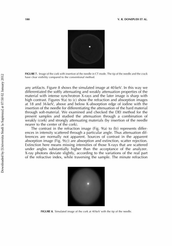
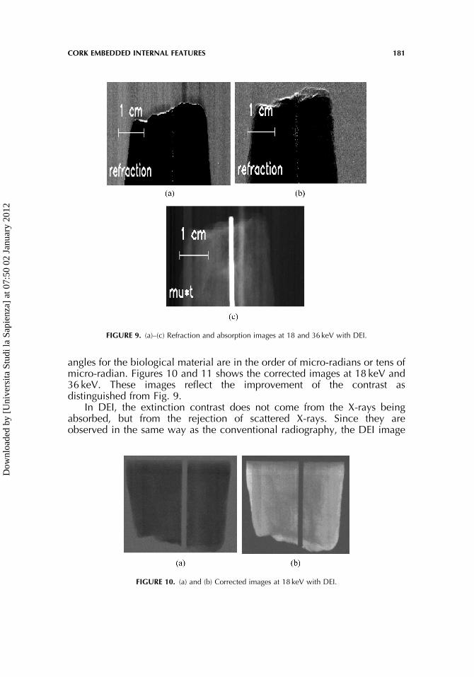
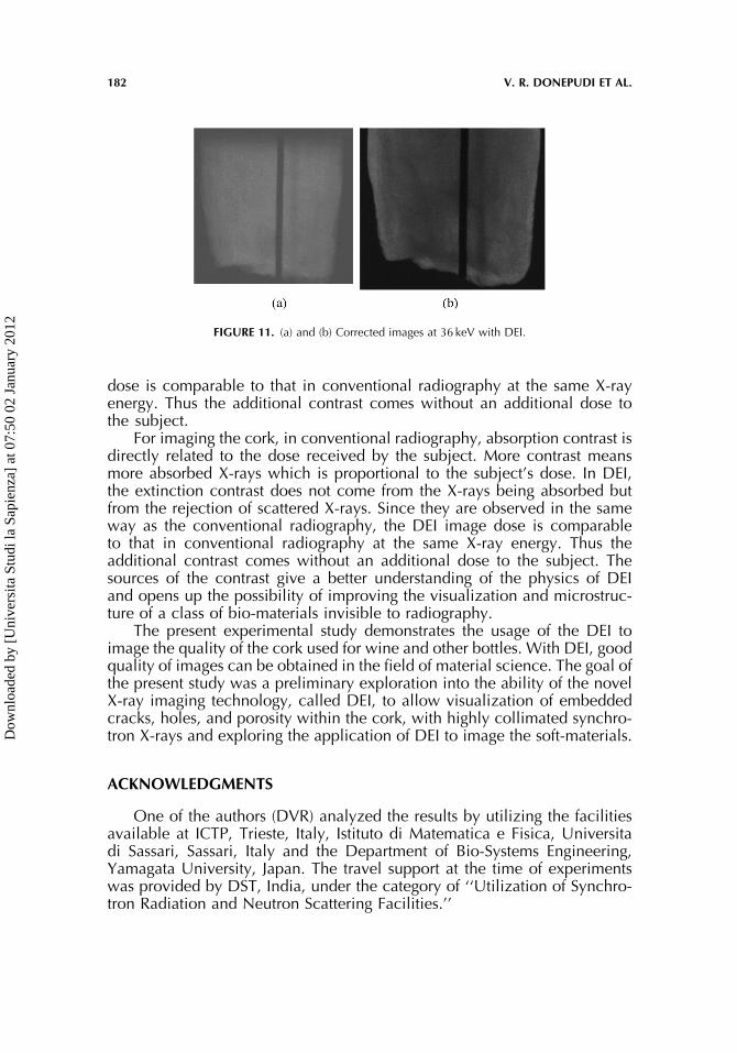
any artifacts. Figure 8 shows the simulated image at 40 keV. In this way wedifferentiated the softly attenuating and weakly attenuation properties of thematerial with intense synchrotron X-rays and the later image is sharp withhigh contrast. Figures 9(a) to (c) show the refraction and absorption imagesat 18 and 36 keV, above and below K-absorption edge of iodine with theinsertion of the needle for differentiating the attenuation of the hard materialthrough soft-material. We examined and checked the DEI method for thepresent samples and studied the attenuation through a combination ofweakly (cork) and strongly attenuating materials (by insertion of the needlenearer to the center of the cork).
The contrast in the refraction image (Fig. 9(a) to (b)) represents differ-ences in intensity scattered through a particular angle. Thus attenuation dif-ferences are normally not apparent. Sources of contrast in the apparentabsorption image (Fig. 9(c)) are absorption and extinction, scatter rejection.Extinction here means missing intensities of those X-rays that are scatteredunder angles substantially higher than the acceptance of the analyzer.X-ray photons deviate slightly, according to the variations of the real partof the refractive index, while traversing the sample. The minute refraction
FIGURE 7. Image of the cork with insertion of the needle in CT mode. The tip of the needle and the crackhave clear visibility compared to the conventional method.
FIGURE 8. Simulated image of the cork at 40 keV with the tip of the needle.
180 V. R. DONEPUDI ET AL.
Dow
nloa
ded
by [
Uni
vers
ita S
tudi
la S
apie
nza]
at 0
7:50
02
Janu
ary
2012
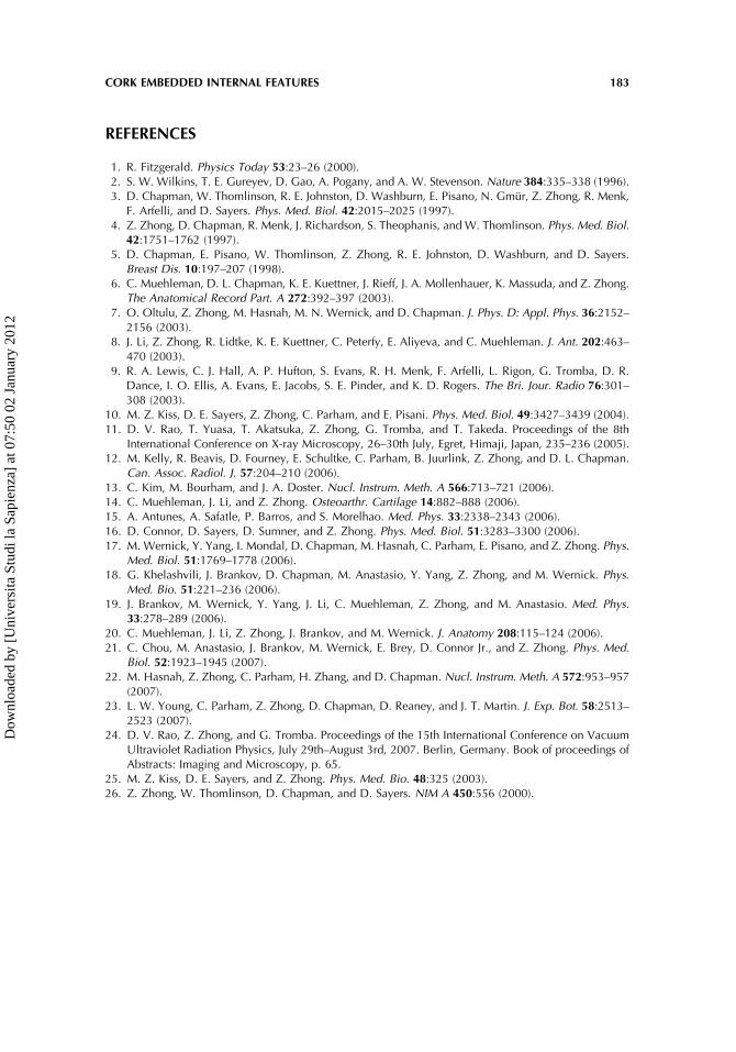
angles for the biological material are in the order of micro-radians or tens ofmicro-radian. Figures 10 and 11 shows the corrected images at 18 keV and36 keV. These images reflect the improvement of the contrast asdistinguished from Fig. 9.
In DEI, the extinction contrast does not come from the X-rays beingabsorbed, but from the rejection of scattered X-rays. Since they areobserved in the same way as the conventional radiography, the DEI image
FIGURE 9. (a)–(c) Refraction and absorption images at 18 and 36 keV with DEI.
FIGURE 10. (a) and (b) Corrected images at 18 keV with DEI.
CORK EMBEDDED INTERNAL FEATURES 181
Dow
nloa
ded
by [
Uni
vers
ita S
tudi
la S
apie
nza]
at 0
7:50
02
Janu
ary
2012
dose is comparable to that in conventional radiography at the same X-rayenergy. Thus the additional contrast comes without an additional dose tothe subject.
For imaging the cork, in conventional radiography, absorption contrast isdirectly related to the dose received by the subject. More contrast meansmore absorbed X-rays which is proportional to the subject’s dose. In DEI,the extinction contrast does not come from the X-rays being absorbed butfrom the rejection of scattered X-rays. Since they are observed in the sameway as the conventional radiography, the DEI image dose is comparableto that in conventional radiography at the same X-ray energy. Thus theadditional contrast comes without an additional dose to the subject. Thesources of the contrast give a better understanding of the physics of DEIand opens up the possibility of improving the visualization and microstruc-ture of a class of bio-materials invisible to radiography.
The present experimental study demonstrates the usage of the DEI toimage the quality of the cork used for wine and other bottles. With DEI, goodquality of images can be obtained in the field of material science. The goal ofthe present study was a preliminary exploration into the ability of the novelX-ray imaging technology, called DEI, to allow visualization of embeddedcracks, holes, and porosity within the cork, with highly collimated synchro-tron X-rays and exploring the application of DEI to image the soft-materials.
ACKNOWLEDGMENTS
One of the authors (DVR) analyzed the results by utilizing the facilitiesavailable at ICTP, Trieste, Italy, Istituto di Matematica e Fisica, Universitadi Sassari, Sassari, Italy and the Department of Bio-Systems Engineering,Yamagata University, Japan. The travel support at the time of experimentswas provided by DST, India, under the category of ‘‘Utilization of Synchro-tron Radiation and Neutron Scattering Facilities.’’
FIGURE 11. (a) and (b) Corrected images at 36 keV with DEI.
182 V. R. DONEPUDI ET AL.
Dow
nloa
ded
by [
Uni
vers
ita S
tudi
la S
apie
nza]
at 0
7:50
02
Janu
ary
2012
REFERENCES
1. R. Fitzgerald. Physics Today 53:23–26 (2000).2. S. W. Wilkins, T. E. Gureyev, D. Gao, A. Pogany, and A. W. Stevenson. Nature 384:335–338 (1996).3. D. Chapman, W. Thomlinson, R. E. Johnston, D. Washburn, E. Pisano, N. Gmur, Z. Zhong, R. Menk,
F. Arfelli, and D. Sayers. Phys. Med. Biol. 42:2015–2025 (1997).4. Z. Zhong, D. Chapman, R. Menk, J. Richardson, S. Theophanis, and W. Thomlinson. Phys. Med. Biol.
42:1751–1762 (1997).5. D. Chapman, E. Pisano, W. Thomlinson, Z. Zhong, R. E. Johnston, D. Washburn, and D. Sayers.
Breast Dis. 10:197–207 (1998).6. C. Muehleman, D. L. Chapman, K. E. Kuettner, J. Rieff, J. A. Mollenhauer, K. Massuda, and Z. Zhong.
The Anatomical Record Part. A 272:392–397 (2003).7. O. Oltulu, Z. Zhong, M. Hasnah, M. N. Wernick, and D. Chapman. J. Phys. D: Appl. Phys. 36:2152–
2156 (2003).8. J. Li, Z. Zhong, R. Lidtke, K. E. Kuettner, C. Peterfy, E. Aliyeva, and C. Muehleman. J. Ant. 202:463–
470 (2003).9. R. A. Lewis, C. J. Hall, A. P. Hufton, S. Evans, R. H. Menk, F. Arfelli, L. Rigon, G. Tromba, D. R.
Dance, I. O. Ellis, A. Evans, E. Jacobs, S. E. Pinder, and K. D. Rogers. The Bri. Jour. Radio 76:301–308 (2003).
10. M. Z. Kiss, D. E. Sayers, Z. Zhong, C. Parham, and E. Pisani. Phys. Med. Biol. 49:3427–3439 (2004).11. D. V. Rao, T. Yuasa, T. Akatsuka, Z. Zhong, G. Tromba, and T. Takeda. Proceedings of the 8th
International Conference on X-ray Microscopy, 26–30th July, Egret, Himaji, Japan, 235–236 (2005).12. M. Kelly, R. Beavis, D. Fourney, E. Schultke, C. Parham, B. Juurlink, Z. Zhong, and D. L. Chapman.
Can. Assoc. Radiol. J. 57:204–210 (2006).13. C. Kim, M. Bourham, and J. A. Doster. Nucl. Instrum. Meth. A 566:713–721 (2006).14. C. Muehleman, J. Li, and Z. Zhong. Osteoarthr. Cartilage 14:882–888 (2006).15. A. Antunes, A. Safatle, P. Barros, and S. Morelhao. Med. Phys. 33:2338–2343 (2006).16. D. Connor, D. Sayers, D. Sumner, and Z. Zhong. Phys. Med. Biol. 51:3283–3300 (2006).17. M. Wernick, Y. Yang, I. Mondal, D. Chapman, M. Hasnah, C. Parham, E. Pisano, and Z. Zhong. Phys.
Med. Biol. 51:1769–1778 (2006).18. G. Khelashvili, J. Brankov, D. Chapman, M. Anastasio, Y. Yang, Z. Zhong, and M. Wernick. Phys.
Med. Bio. 51:221–236 (2006).19. J. Brankov, M. Wernick, Y. Yang, J. Li, C. Muehleman, Z. Zhong, and M. Anastasio. Med. Phys.
33:278–289 (2006).20. C. Muehleman, J. Li, Z. Zhong, J. Brankov, and M. Wernick. J. Anatomy 208:115–124 (2006).21. C. Chou, M. Anastasio, J. Brankov, M. Wernick, E. Brey, D. Connor Jr., and Z. Zhong. Phys. Med.
Biol. 52:1923–1945 (2007).22. M. Hasnah, Z. Zhong, C. Parham, H. Zhang, and D. Chapman. Nucl. Instrum. Meth. A 572:953–957
(2007).23. L. W. Young, C. Parham, Z. Zhong, D. Chapman, D. Reaney, and J. T. Martin. J. Exp. Bot. 58:2513–
2523 (2007).24. D. V. Rao, Z. Zhong, and G. Tromba. Proceedings of the 15th International Conference on Vacuum
Ultraviolet Radiation Physics, July 29th–August 3rd, 2007. Berlin, Germany. Book of proceedings ofAbstracts: Imaging and Microscopy, p. 65.
25. M. Z. Kiss, D. E. Sayers, and Z. Zhong. Phys. Med. Bio. 48:325 (2003).26. Z. Zhong, W. Thomlinson, D. Chapman, and D. Sayers. NIM A 450:556 (2000).
CORK EMBEDDED INTERNAL FEATURES 183
Dow
nloa
ded
by [
Uni
vers
ita S
tudi
la S
apie
nza]
at 0
7:50
02
Janu
ary
2012