( ﻭ ﻗُﻞْ ﺭ ﺏِّ ﺯِﺩ ﻧ ﻲ ﻋ ﻠْﻤ ﺎ ) - SUST Repository
42
i اﻵﯾﺔ ﻗﺎل ﺗﻌﺎﻟﻲ ﯾم ﱠﺣ اﻟر ن ﻣ ﱠﺣ اﻟر اﻟﻠﱠﻪ م ﺳ ﺑ) ﺎﻤْﻠﻲ ﻋﻧﺩِ ﺯِّﺏ ﺭْﻞُﻗ ﻭ( ﺻدق اﷲ اﻟﻌظﯾم ﺳورة طﻪ ا ﻵ ﯾﺔ) ١١٤ (
-
Upload
khangminh22 -
Category
Documents
-
view
1 -
download
0
Transcript of ( ﻭ ﻗُﻞْ ﺭ ﺏِّ ﺯِﺩ ﻧ ﻲ ﻋ ﻠْﻤ ﺎ ) - SUST Repository

i
اآلیة
قال تعالي
ن الرحیم سم الله الرحم ب
)وقل رب زدني علما(
صدق اهللا العظیم
)١١٤(یةآلسورة طه ا

ii
DEDICATION
To whom the paradise is under her feet ,my mother.
To who assisted my scientific intention to be possib,my father.
To all who assisted me, I offer my humble effort asking God to give them long
life to see the result of their efforts.

iii
ACKNOWLEDGMENT
With great pleasure I offer my grateful thanks to my Supervisor Ust. Abd
Allah Salih Ali who supported me with all his knowledge and experience and
advices.
All my best thanks and wishes to my favorite University of Karari and Sudan
University of Science and Technology.
I will not forget to offer my thanks and respect to Ust.Elzain Elmahi and
Engineer Abubaker Faisal and to all who supported me to continue in steady
steps on my studies up to the completion of the work.

iv
ABSTRACT
The speed regulation of servo motor can be improved by using phase locked
loop. The speed of motor must be converted to digital pulse train using a
speed encoder. The output of the encoder acts as speed feedback signal.
A phase detector is used to compare the reference pulse with feedback
frequency and provide a Pulse Width Modulation (PWM) output voltage
which is proportional to the difference in phases and frequencies of reference
and feedback pulse trains. The phase detector (or comparator) is available in
integrated circuits. A low-pass filter converts the pulse trains to continuous dc
level which varies the output of the power converter and in turn the motor
speed.
When the motor runs at the same speed as the reference pulse the two
frequencies would be synchronized or locked together with a phase
difference.
The output of the phase detector would be constant voltage proportional to the
phase difference and the steady-state motor speed would be maintained at a
fixed value irrespective of the load on the motor. Any disturbances
contributing the speed change would result in a phase difference and the
output of the phase detector would respond immediately to vary the speed of
the motor in such a direction and magnitude as to retain the locking of the
reference and feedback frequencies. The response of the phase detector is
very fast. As long as the two frequencies are locked, the speed regulation
should ideally be zero. However, in practice the speed regulation is limited to
0.002%, and this represents a significant improvement over the analog speed
control system.

v
المستخلص
سرعة المحرك یجب أن ، ظیم سرعة محرك المؤازرة یمكن أن تحسن بإستعمال حلقة الطور المغلقةتن
كاشف .كإشارة راجعة عملمشفر السرعة یخرج مشفر السرعة باستعمالضات رقمیة تحول الي نب
النبضة خرج ویدعم تعدیل عرض،یستعمل لمقارنة اإلشارة المرجعیة مع تردد التغذیة الراجعة طورال
نبض التغذیة في الموجات وترددات اإلشارة المرجعیة وقطارات االختالفالفولتیة الذي یتناسب مع
مرشح المرور المنخفض یحول تكاملیةالدائرة ال متوفر داخل) أو المقارن( طوركاشف ال،الراجعة
عندما .عا سرعة المحركقطارات النبضة الي المستوي المستمر الذي یغیر ناتج المحول الكهربائي وتبا
.یعمل المحرك بنفس سرعة النبضة المرجعیة الترددان سیتزامنان أو تفعالن سویا مع إختالف الموجة
ناتج كاشف الموجة سیكون فولطیة ثابتة تتناسب مع إختالف الموجة وحالة اإلستقرار للمحرك السرعة
ت تساهم في تغیر السرعة یؤدي الي أي إضرابا،ستبقي ثابتة بصرف النظر عن الحمل علي المحرك
خرج كاشف الموجة یستجیب فورا لإلختالف في سرعة المحرك في مثل . اختالف في إختالف الموجة
إستجابة كاشف الموجة .هذا اإلتجاه والمقدار یحتفظان بقفل اإلشارة المرجعیة وترددات التغذیة الخلفیة
علي أي حال في ،سرعة یجب أن یكون مثالیا صفرتنظیم ال،سریعة جدا طالما الترددان مغلقان
. وهذه تمثل تحسین هام علي نظام سیطرة السرعة المناظر،%٠٠٢الممارسة تنظیم السرعة تحدد الي

vi
List of Contents
Page
یةآلا i
Dedication ii
Acknowledgment iii
Abstract iv
v المستخلص
List of Contents vi
List of Figures ix
Chapter One: Introduction
1.1 General 1
1.2 Problem statement 1
1.3 Objective ١
1.4 Methodology 1
1.5 The layout ٢
Chapter Two: Control Systems
2.1 Previous studies ٣
2.2 type of control systems 4
2.2.1 Feedback Control Systems 4

vii
2.2.2 Open loop control system 5
2.2.3 Close loop control system 6
2.3 Compensation 7
2.4 Performance Specifications 8
2.5 Design Procedures 9
2.6 Servo Motors ١0
2.6.1 Split Field Motor 10
Chapter Three: Implementation of Control Circuit
3.1 Design of Main Circuit 13
3.2 Timer IC Unit Operation 14
3.2.1 Astable operation 14
3.2.2 Monostable operation 15
3.3 Phase Detector 17
3.4 Voltage_Controlled Oscillator 18
3.5 Phase _locked loop 21
3.5.1 Basic phase_locked loop operation 22
3.5.2 Applications 23
3.5.3 Interfacing circuitry 23
Chapter Four: Results and Discussion

viii
4.1Introduction 26
4.2 Circuit Test 26
Chapter Five: Conclusion and Recommendations
5.1 Conclusion 31
5.1 Recommendations 31
References 32
Appendixes

ix
List of Figures
Figure Title Page
2.1 The DC servo motor 10
2.2 Phase sensitive rectification 11
2.3 The two phase servo motor 12
2.4 Speed torque carve 12
3.1 block digram of control circuit 13
3.2 shows the detail of figure3.1 13
3.3 Details of 555 timer IC. 14
3.4 A stable multivibrator using 555 IC 15
3.5 A stable multivibrator 16
3.6 One shot monostable multivibrator 23
3.7 Phase angle between signals 18
3.8 Phase detector 18
3.9 Output of phase detector 18
3.10 Block diagram of A 566 function generator 19
3.11 Pin configureuration and summary of operating data for
A566 function generator
20
3.12 Connection of 566 VCO unit. 20

x
3.13 Connection of 566 as VCO unit. 21
3.14 Block diagram of basic phase-locked loop 22
3.15 Dual-line drivers 24
3.16 Dual-line receivers (SN75152) 24
4.1 The complete simulation 26
4.2 The circuit implementation using phase locked_loop 27
4.3 The frequency locked at 207 KHz 28
4.4 The frequency locked at 301 KHz 29
4.5 The frequency locked at 617 KHz 30

١
CHAPTER ONE
INTRODUCTION 1.1GeneralThe speed of a servo motor is sensed by tachometer which
compared with reference speed to generate the error signal to vary armature
voltage of the motor.The speed sensor and comparing signals are not ideal
and the speed regulate is more than 0.2%. The speed regulator can be
improved if phase locked loop control is used.
1.2Problem Statement Servo motor using phase locked_loop (PLL) is used to control the airplane
when its landing or take off and also opening and closing of the air plane
plates need precise control for safety landing and take off of the airplane .The
above action was achieved by locking the frequency in the rang (200 to
600)kHz. The regulator of the speed is about 0.2%.
1.3 Objective 1. To adjust the center frequency of phace_locked loop.
2. To observe the locked range.
3. To measure the maximum and minimum capture frequencies.
4. To measure the Direct current (DC) voltage from the Frequency
Modulation output.
1.5 Methodology 1. Study of servo motor and Phase Lock Loop
2. Study and understand main components.
3. Design the complete hardware circuit.
4. Evalute performance of servo motor based an experiment result.
1.5 The layout

٢
This research consists of fivechapters. The scope of each chapter is explained
as stated below:
Chapterone presents general concepts, problem statement,objectives, and
methodology.Chapter two includes the previous works, control systems
types,compensation, performance specifications, design procedure and servo
motor.
Chapter three the implementation of control circuit is introduced.
Furthermore, main components of main circuit are discussed.
Chapter four presents the simulation are experimental results.
Finally, chapter five provides the conclusion and recommendation.

٣
CHAPTER TWO
CONTROL SYSTEM 2.1PreviousStudies Guan-Chyun use phase-locked loop which is a technique has contributed
significantly toward the technology advancement in communication and servo
motor control systems in the past 30 years. Inventions in phase-locked loop
schemes combining with novel integrated circuit (IC) technology have made
phase-locked loop devices important system components. The development of
better modular phase-locked loop IC,s is continuing. As a result, it is expected
that it will contribute to improvement in performance and reliability for future
communication systems. It will also contribute to the development of higher
accuracy and higher reliability servo motor control systems, such as those
involved in machine tools .This paper serves as an introduction for this phase-
locked loop special section. It provides a concise review of the basic phase-
locked loop principles applicable to communication and servo control
systems, gives the configuration of phase-locked loop applications, and
reports a number of popular phase-locked loop chips[5]. Dennis use phase-locked loop to measure its response in time domain, and
present an all-digital measurement circuit that enables wafer-level test and
characterization of phase-locked loop response. Through modifications only
in the phase-locked loop feedback divider state machine, this technique
facilitates accurate estimation of phase-locked loop frequency-domain closed-
loop bandwidth and gain peaking by respectively measuring the time-domain
crossover time and maximum overshoot of phase error to a self-induced phase
step in the feedback clock. These transient measurements are related back to
bandwidth and peaking through the proportionality relationships of crossover
time to reciprocal bandwidth and maximum overshoot to peaking. The
design-for-test circuit can be used to generate a transient plot of step response,
measure static phase error, and observe phase-lock status. We report silicon

٤
results from two demonstration vehicles built in a 45-nm SOI-CMOS logic
technology for high-performance microprocessors [6].
Wisnu Djatmiko and otherconsider controlling motor terminal voltages using
chopper method. The input DC voltage is chopped byInsulated Gate Bipolar
Transistor (IGBT). Phase Locked Loop (offer a stable frequency controller
system. It has been widely used in communications, instrumentation and
motor controlled. We synthesis a phase-locked loop system using Field
Programmable Gate Array (FPGA)chip and an analog Voltage Controlled
Oscillator (VCO). Phase comparator (phase detector) and programmable
counter (frequency divider) are implemented in FPGA. The result of the
experiment shows that motor speed is not affected so much with the varying
loads. In this experiment, the motor speed is holding constant, Independent of
the motor load, which is a voltage generator with a constant current source
load. On loading the motor speed slow down for about283 rpm (10%) in 1780
milliseconds, on unloading the motor speed is hunting about 100 rpm (3%) in
1220 milliseconds. The DC motor used in this experiment is a DC motor with
rated speed of 8000 rpm and rated voltage of 100 Volt and rated current of 1
Ampere [7].
2.2 Type of Control Systems The are many type of control systems, the most popular control systems are
presented below.
2.2.1Feedback Control Systems A system that maintains a prescribed relationship between the output and the
reference input by comparing them and using the difference as a means of
control is called a feedback control system. An example would be a room-
temperature control system. By measuring the actual room temperature and
comparing it with the reference temperature (desired temperature), the
thermostat turns the heating or cooling equipment ON or OFF in such a way
as to ensure that the room temperature remains at acomfortable level

٥
regardless of outside conditions. Feedback control systems are not limited to
engineering but can be found in various nonengineering fields as well. The
human body, for instance, is a highly advanced feedback control system. Both
body temperature and blood pressure are kept constant by means of
physiological feedback. In fact, feedback performs a vital function: It makes
the human body relatively insensitive to external disturbances, thus enabling
it to function properly in a changing environment. Control system can be
classified as open loop and closed loop systems [1].
2.2.2Open-loop control system These systems in which the output has no effect on the control action are
called open-loop control systems. In other words, in an open-loop control
system the output is neither measured nor fed back for comparison with the
input. One practical example is a washing machine. Soaking, washing, and
rinsing in the washer operate on a time basis. The machine does not measure
the output signal, that is, the cleanliness of the clothes. In any open-loop
control system the output is not compared with the reference input. Thus, to
each reference input there corresponds a fixed operating condition; as a result,
the accuracy of the system depends on calibration. In the presence of
disturbances, an open-loop control system will not perform the desired task.
Open-loop control can be used, in practice, only if the relationship between
the input and output is known and if there are neither internal nor external
disturbances. Clearly, such systems are not feedback control systems. Note
that any control system that operates on a time basis is open loop. For
instance, traffic control by means of signals operated on a time basis is
another example of open-loop control [1]. The major advantages of open-loop control systems are as follows:
1. Simple construction and ease of maintenance.
2. Less expensive than a corresponding closed-loop system.
3. There is no stability problem.
٦
4. Convenient when output is hard to measure or measuring the output
precisely is economically not feasible. (For example, in the washing
machine system, it would be quite expensive to provide a device to
measure the quality of the washer’s output, cleanliness of the clothes).
The major disadvantages of open-loop control systems are as follows:
1. Disturbances and changes in calibration cause errors, and the
output may be different from what is desired.
2. To maintain the required quality in the output, recalibration is
necessary from time to time.
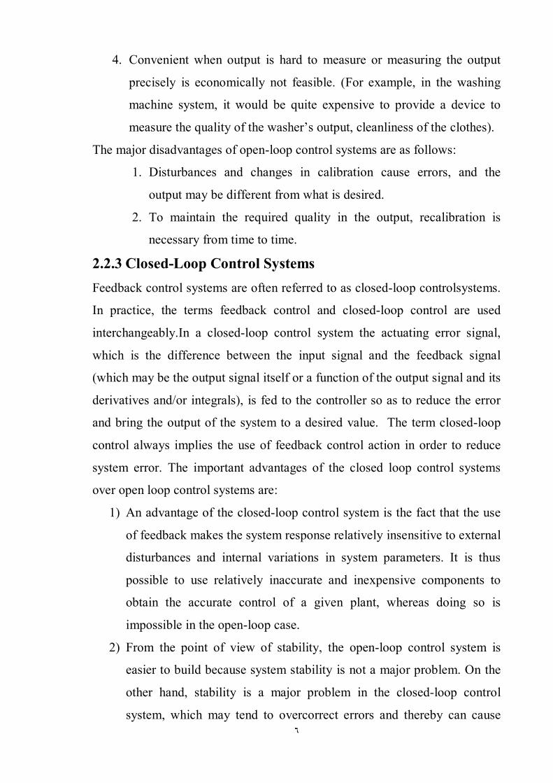
2.2.3 Closed-Loop Control Systems Feedback control systems are often referred to as closed-loop controlsystems.
In practice, the terms feedback control and closed-loop control are used
interchangeably.In a closed-loop control system the actuating error signal,
which is the difference between the input signal and the feedback signal
(which may be the output signal itself or a function of the output signal and its
derivatives and/or integrals), is fed to the controller so as to reduce the error
and bring the output of the system to a desired value. The term closed-loop
control always implies the use of feedback control action in order to reduce
system error. The important advantages of the closed loop control systems
over open loop control systems are:
1) An advantage of the closed-loop control system is the fact that the use
of feedback makes the system response relatively insensitive to external
disturbances and internal variations in system parameters. It is thus
possible to use relatively inaccurate and inexpensive components to
obtain the accurate control of a given plant, whereas doing so is
impossible in the open-loop case.
2) From the point of view of stability, the open-loop control system is
easier to build because system stability is not a major problem. On the
other hand, stability is a major problem in the closed-loop control
system, which may tend to overcorrect errors and thereby can cause

٧
oscillations of constant or changing amplitude. It should be emphasized
that for systems in which the inputs are known ahead of time and in
which there are no disturbances it is advisable to use open-loop control.
Closed-loop control systems have advantages only when unpredictable
disturbances and/or unpredictable variations in system components are
present. Note that the output power rating partially determines the cost,
weight, and size of a control system.
3) The number of components used in a closed-loop control system is
more than that for a corresponding open-loop control system. Thus, the
closed-loop control system is generally higher in cost and power. To
decrease the required power of a system, open-loop control may be
used where applicable. A proper combination of open-loop and closed-
loop controls is usually less expensive and will give satisfactory overall
system performance.
4) Most analyses and designs of control systems presented in this research
are concerned with closed-loop control systems. Under certain
circumstances (such as where no disturbances exist or the output is hard
to measure) open-loop control systems may be desired. Therefore, it is
worthwhile to summarize the advantages and disadvantages of using
open-loop control systems.
2.3 Compensation Setting the gain is the first step in adjusting the system for satisfactory
performance. In many practical cases, however, the adjustment of the gain
alone may not provide sufficient alteration of the system behavior to meet the
given specifications. As is frequently the case, increasing the gain value will
improve the steady-state behavior but will result in poor stability or even
instability. It is then necessary to redesign the system by modifying the
structure or by incorporating additional devices or components to alter the

٨
overall behavior so that the system will behave as desired. Such a redesign or
addition of a suitable device is called compensation.
A device inserted into the system for the purpose of satisfying the
specifications is called a compensator. The compensator compensates for
deficient performance of the original system.Compensation is the
modification of the system dynamics to satisfy the given specifications. The
approaches to control system design and compensation used in the root-locus
approach, frequency-response approach, and the state-space approach.
In the actual design of a control system, whether to use an electronic,
pneumatic, or hydraulic compensator is a matter that must be decided partially
based on the nature of the controlled plant. For example, if the controlled
plant involves flammable fluid, then we have to choose pneumatic
components (both a compensator and an actuator) to avoid the possibility of
sparks. If, however, no fire hazard exists, then electronic compensators are
most commonly used. In fact, we often transform nonelectrical signals into
electrical signals because of the simplicity of transmission, increased
accuracy, increased reliability, ease of compensation, and the like) [1].
2.4 Performance Specifications
Control systems are designed to perform specific tasks. The requirements
imposed on the control system are usually spelled out as performance
specifications. The specifications may be given in terms of transient response
requirements (such as the maximum overshoot and settling time in step
response) and of steady-state requirements (such as steady-state error in input
signal) or may be given in frequency-response terms. The specifications of a
control system must be given before the design process begins. For routine
design problems, the performance specifications (which relate to accuracy,
relative stability, and speed of response) may be given in terms of precise
numerical values. In other cases they may be given partially in terms of
precise numerical values and partially in terms of qualitative statements. In

٩
the latter case the specifications may have to be modified during the course of
design, since the given specifications may never be satisfied (because of
conflicting requirements) or may lead to a very expensive system. Generally,
the performance specifications should not be more stringent than necessary to
perform the given task. If the accuracy at steady-state operation is of prime
importance in a given control system, then we should not require
unnecessarily rigid performancespecifications on thetransient response, since
such specifications will require expensive components. Remember that the
most important part of control system design is to state the performance
specifications precisely so that they will yield an optimal control system for
the given purpose [1].
2.5 Design Procedures In the process of designing a control system, we set up a mathematical model
of the control system and adjust the parameters of a compensator. The most
time-consuming part of the work is the checking of the system performance
by analysis with each adjustment of the parameters. The designer can use
MATLAB or other available computer package to avoid much of the
numerical drudgery necessary for this checking. Once a satisfactory
mathematical model has been obtained, the designer must construct a
prototype and test the open-loop system. If absolute stability of the closed
loop is assured, the designer closes the loop and tests the performance of the
resulting closed loop system. Because of the neglected loading effects
among the components, nonlinearities, distributed parameters, and so on,
which were not taken intoconsideration in the original design work, the actual
performance of the prototype system will probably differ from the theoretical
predictions. Thus the first design may not satisfy all the requirements on
performance. The designer must adjust system parameters and make changes
in the prototype until the system meets the specifications. In doing this, he or
she must analyze each trial, and the results of the analysis must

١٠
beincorporated into the next trial. The designer must see that the final system
meets the performance pacifications and, at the same time, is reliable and
economical [1].
2.6 Servo Motors Electrical servos may be (a) Entirely DC operated, using voltage dividers, DC
amplifiers, and DC driving motors, (b) Entirely Alternative Current (AC)
operated using synchros, AC amplifiers and 2-phase AC driving motors, or
(c) AC/DC operated using AC error detection, phase sensitive rectification
and DC driving motors [4].The are a number of types of servo motor, most
popular ones are:
2.6.1 Split Field Motor Small DC servo motors are generally of the split-field type as shown in Figure
2.1. Neglecting saturation and assuming a constant armature current, the
output torque will be proportional to the net field current, and will reverse
when this net field current reverses. The field may be fed from a push-pull
amplifier stage. If the armature is not fed from a constant-current source, the
build-up of armature e.m.f. with speed causes a falling torque/speed
characteristic, which is equivalent to viscous-friction damping in the servo
system.Approximately constant armature current can be achieved by feeding
the armature through a high resistance from a high-voltage DC supply.
Figure 2.1: The DC servo motor

١١
Figure 2.2 shows the phase sensitive rectifier circuit. An AC error signal may
be used with a Phase-Sensitive Rectifier (PSR) to produce a DC error voltage.
The basic operation of a PSR shown in Figure 2.2,when there is no error
voltage, each diode conducts during positive half-cycles of the reference
voltage and there is no net voltage between A and B. The peak error signal,
ve, is arranged to be smaller than the reference voltage, vr. When the error
signal is in phase with the reference voltage, the voltage applied to D1 during
the positive half-cycles of vr, i.e. (vr + vei), is greater than that applied to D2
(vr — ve2), and hence A is positive with respect to B. During the negative
half-cycles of vr both diodes remain non conducting (since vR> ve). If the error
voltage is now changed in phase by 180°, D2 has a larger voltage applied to it
during the positive half- cycles than D1 and B is positive with respect to
A.Hence the voltage between A and B gives the magnitude and sense of the
error, and may be applied direct to the bases of a long-tailed pair. The
capacitors provide smoothing of the output signal [4].
Figure 2.2: Phase sensitive rectification
2.6.2 Two phase servo motor In an auxiliary,Servo the error signal from a synchro is fed to an AC.
amplifier, whose output feeds one phase of two-phase motor. The phase of the
voltage applied to this winding is arranged to be in quadrature with that

١٢
applied from a constant reference source to the second winding of the motor
(the reference winding), as shown in Figure 2.3.
Figure 2.3: The two phase servo motor.
When there is no error voltage, only the reference winding is energized and
the rotor is locked in position. The motor is designed to give maximum torque
at standstill. The size of the output torque will depend on the magnitude of the
error signal, and the direction of the torque will depend upon whether the
error signal lags or leads the reference voltage by 90°. Typical characteristics
are shown in Figure 2.3.
Figure2.4: Speed torqure carve
The AC servo is not used where large power is required, because the
electronic amplifier has a limited power output. In such cases rotating DC
amplifiers (amplifying or metaldyne type) or magnetic amplifiers are used
with DC driving motors. High-power servos will not be dealt here.Note that in
both DC and AC servo motors the armatures are usually long and of small
diameter in order to give a high torque/inertia ratio [4].

١٣
CHAPTER THREE
IMPLEMENTATION OF CONTROL CIRCUIT
3.1 Design of Main Circuit Figure 3.1 shows the block diagram of the control circuit. It consists of the
following elements: phase detector, filter, DC motor and speed encoder.
Figure 3.2 shows the detail of figure 3.1.
Fiqure 3.1: block digram of the control circuit
Figure3.2:shows the detail of Figure3.1

١٤
3.2 Timer IC Unit Operation Another popular analog–digital integrated circuit is the versatile 555 timer.
The IC is made of a combination of linear comparators and digital flip-flops
as shown in Figure 3.3 .The entire circuit is usually housed in an 8-pin
package as specified in Figure 3.3. A series connection of three resistors sets
the reference voltage levels to the two comparators at 2VCC/3 and VCC/3, the
output of these comparators setting or resetting the flip-flop unit. The output
of the flip-flop circuit is then brought out through an output amplifier stage.
The flip-flop circuit also operates a transistor inside the IC, the transistor
collector usually being driven low to discharge a timing capacitor[3].
Figure 3.3: Details of 555 timer IC.
3.2.1 Astable operation
One popular application of the 555 timer IC is as an a stable multivibrator or
clock circuit. The following analysis of the operation of the 555 as and a
stable circuit includes details of the different parts of the unit and how the
various inputs and outputs are utilized. Figure 3.4 shows and a stable circuit
built using an external resistor and capacitor to set the timing interval of the
output signal.
Capacitor C1charges toward VCCthrough external resistors RAand RB. Referring
to figure3.4, the capacitor voltage rises until it goes above 2VCC/3. This
voltage is the threshold voltage at pin 6, which drives comparator 1 to trigger
the flip-flop so that the output at pin 3 goes low. In addition, the discharge
transistor is driven on, causing the output at pin 7 to discharge the capacitor

١٥
through resistor RB. The capacitor voltage then decreases until it drops below
the trigger level (VCC/3).
(a) A stable circuit (b)Output of waveform of a stable circuit
Figure 3.4:A stable multivibrator using 555 IC
The flip flop is triggered so that the output goes back high and the discharge
transistor is turned off, so that the capacitor can again charge through resistors
RAand RBtoward VCC. Figure 3.4 shows the capacitor and output waveforms
resulting from the stable circuit. Calculation of the time intervals during
which the output is high and low can be made using the relations in Equations
(3.1) and respectively (3.2), as follows:
푇 ≈ 0.7(푅 + 퐵 )퐶(3.1)
푇 ≈ 0.7푅 퐶(3.2)
The total period is
푇 = 푃푒푟푖표푑 = 푇 + 푇 (3.3)
The frequency of the a stable circuit is then calculated using:
푓 =1푇
≈1.44
(푅 + 2푅 )퐶(3.4)
3.2.2 Monostable operation

١٦
The 555 timer can also be used as a one-shot or monostable multivibrator
circuit, as shown in Figure 3.5. When the trigger input signal goes negative, it
triggers the oneshot, with output at pin 3 then going high for a time period
T high = 1.1RAC1 referring back to Figure 3.4, the negative edge of the trigger
input causes comparator 2 to trigger the flip-flop, with the output at pin 3
going high. Capacitor C charges toward VCCthrough resistor RA. During the
charge interval, the output remains high. When the voltage across the
capacitor reaches the threshold level of 2VCC/3, comparator 1 triggers the flip-
flop, with output going low. The discharge transistor also goes low, causing
the capacitor to remain at near 0 V until triggered again.
(a)The circuit (b) waveformsFigure 3.5:
Astable multivibrator
Figure 3.6 shows the input trigger signal and the resulting output waveform
for the 555 timer operated as a one-shot. Time periods for this circuit can
range from microseconds to many seconds, making this IC useful for a range
of applications [3].

١٧
(a)The circuit(b)One shot pulses
Figure 3.6: One shot monostable multivibrator
3.3 Phase Detector Suppose we have a mixer with input frequencies of 50 Hz and 50 Hz. Then
the deference frequency is 0, which represent DC. In other words, a DC
voltage comes out of a mixer when the input frequencies are equal.A phase
detector is a mixer optimized for use with equal input frequencies. It is called
a phase detector (or phase comparator) because the amount of DC voltage
depends on the phase angle 휙 between the input signals. As the phase angle
changes, so too does the DC voltage. Figure 3.7 illustrates the phase angle
between two sinusoidal signals. When these signals drive the phase detector
of Figure. 3.8DC voltage comes out. One type of phase detector has a DC
output voltage that varies as shown in Figure. 3.9,when the phase angle 휙 is
0, the DC voltage is maximum. As the phase angle increases from 0 to 180◦,
the DCvoltage decreases to a minimum value. When 휙 is 90◦, the DC output
is the average of the maximum and minimum outputs.For example, suppose a
phase detector has a maximum output of 10 V and a minimum output of 5 V.
when the two inputs are in phase, the DC output is 10 V. when the inputs are
90◦ out of phase, the DC output is 7.5 V. when the inputs are 180◦out of phase

١٨
the DC output is 5 V. The key idea is the dc output decrease when the phase
angle increases.
Figure 3.7:phase angle between signals
Sin(휔푡 + 휙)
sin 휔푡
Figure3.8: Phase detector
Figure3.9:output of phase detector
3.4Voltage_Controlled Oscillator Voltage-Controlled Oscillator (VCO) is a circuit that provides a varying
output signal (typically of square-wave or triangular-wave form) whose
frequency can be adjusted over a range controlled by a DC voltage. An
example of a VCO is the 566 IC unit, which contains circuitry to generate
both square-wave and triangular-wave signals whose frequency is set by an
external resistor and capacitor and then varied by an applied DC voltage.
Figure 3.10 shows that the 566 contains current sources to charge and
discharge an external capacitor C1 at a rate set by external resistor R1 and the
Phase Detector
vdc
١٩
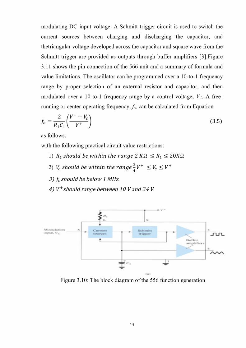
modulating DC input voltage. A Schmitt trigger circuit is used to switch the
current sources between charging and discharging the capacitor, and
thetriangular voltage developed across the capacitor and square wave from the
Schmitt trigger are provided as outputs through buffer amplifiers [3].Figure
3.11 shows the pin connection of the 566 unit and a summary of formula and
value limitations. The oscillator can be programmed over a 10-to-1 frequency
range by proper selection of an external resistor and capacitor, and then
modulated over a 10-to-1 frequency range by a control voltage, VC. A free-
running or center-operating frequency, fo, can be calculated from Equation
푓 =2
푅 퐶푉 − 푉푉
(3.5)
as follows:
with the following practical circuit value restrictions:
1) 푅 푠ℎ표푢푙푑푏푒푤푖푡ℎ푖푛푡ℎ푒푟푎푛푔푒2퐾Ω ≤ 푅 ≤ 20퐾Ω
2) 푉 푠ℎ표푢푙푑푏푒푤푖푡ℎ푖푛푡ℎ푒푟푎푛푔푒 푉 ≤ 푉 ≤ 푉
3) 푓 shouldbebelow1MHz.
4) 푉 shouldrangebetween10Vand24V.
Figure 3.10: The block diagram of the 556 function generation

٢٠
Figure 3.11: pin configuration of the 556 function generator
Figure 3.12 shows an example in which the 566 function generator is used to
provide both square-wave and triangular-wave signals at a fixed frequency set
by R1, C1, and VC. A resistor divider R2 and R3 sets the DC modulating voltage
at a fixed value.
Figure 3.12Connection of 566 VCO unit
푉 =푅
푅 + 푅(3.6)
The circuit in Figure 3.13 shows how the output square –wave frequency can
be adjusted using the input voltage, VCto vary the signal frequency.
Potentiometer R3allows varying VC from about 9V to near 7V, over the full
10-to-1 frequency range. With the potentiometer wiper set at the top, the
control voltage is:
푉 =푅 + 푅
푅 + 푅 + 푅(3.7)

٢١
Figure 3.13 Connection of 566 as a VCO unit
3.2.4 Phase-Locked Loop A phase-locked loop (PLL) is an electronic circuit that consists of a phase
detector, a low-pass filter, and a voltage-controlled oscillator connected as
shown in Figure 3.14. Common applications of a PLL include: (1) Frequency
synthesizers that provide multiples of a reference signal frequency [e.g., the
carrier frequency for the multiple channels of a Citizens’ Band (CB) unit or
marine-radio-band unit can be generated using a single-crystal-controlled
frequency and its multiples generated using a phase-locked loop]; (2) FM
demodulation networks for FM operation with excellent linearity between the
input signal frequency and the PLL output voltage; (3) Demodulation of the
two data transmission or carrier frequencies in digital-data transmission used
in Frequency-Shift keying (FSK) operation; and (4) A wide variety of areas
including modems, telemetry receivers and transmitters, tone decoders, AM
detectors, and tracking filters. An input signal, Vi, and that from a VCO, Vo,
are compared by a phase comparator providing an output voltage, Ve, that
represents the phase difference between the two signals. This voltage is then

٢٢
fed to a low-pass filter that provides an output voltage (amplified if necessary)
that can be taken as the output voltage from the PLL and is used internally as
the voltage to modulate the VCO’s frequency.The closed-loop operation of
the circuit is to maintain the VCO frequencyLocked to that of the input signal
frequency [3].
Figure 3.14: Block diagram of basic phase-locked loop
3.5.1Basic phase-locked loop operation The basic operation of a PLL circuit can be explained using the circuit of
Figure 3.14 as reference. We will first consider the operation of the various
circuits in the phase locked loop when the loop is operating in lock (the input
signal frequency and the VCO frequency are the same). When the input signal
frequency is the same as that from the VCO to the comparator, the voltage,
Vd, taken as output is the value needed to hold the VCO in lock with the input
signal. The VCO then provides output of a fixed-amplitude square-wave
signal at the frequency of the input. Best operation is obtained if the VCO
center frequency, fo, is set with the DC bias voltage midway in its linear
operating range. The amplifier allows this adjustment in DC voltage from that
obtained as output of the filter circuit. When the loop is in lock, the two
signals to the comparator are of the same frequency, although not necessarily
in phase. A fixed phase difference between the two signals to the comparator
٢٣
results in a fixed DC voltage to the VCO. Changes in the input signal
frequency then result in change in the DC voltage to the VCO. Within a
capture-and-lock frequency range, the DC voltage will drive the VCO
frequency to match that of the input. While the loop is trying to achieve lock,
the output of the phase comparator contains frequency components at the sum
and difference of the signals compared. A low pass filter passes only the
lower-frequency component of the signal so that the loop can obtain lock
between input and VCO signals.
Owing to the limited operating range of the VCO and the feedback connection
of the PLL circuit, there are two important frequency bands specified for a
PLL. The capture range of a PLL is the frequency range centered about the
VCO free running frequency, fo, over which the loop can acquire lock with
the input signal. Once the PLL has achieved capture, it can maintain lock with
the input signal over a somewhat wider frequency range called the lock range
[3].
3.5.2Applications The PLL can be used in a wide variety of applications, including frequency
demodulation, frequency synthesis and Frequency-Shift keying decoders.
3.5.3Interfacing circuitry
Connecting different types of circuits, either in digital or analog circuits, may
require some sort of interfacing circuit. An interface circuit may be used to
drive a load or to obtain a signal as a receiver circuit. A driver circuit
provides the output signal Connection of 565 as Frequency-Shift keying
decoder. voltage or current level suitable to operate a number of loads, or to
operate such devices as relays, displays, or power units. A receiver circuit
essentially accepts an input signal, providing high input impedance to
minimize loading of the input signal.
Furthermore, the interface circuits may include strobing, which provides
connecting the interface signals during specific time intervals established by

٢٤
the strobe. Figure 3.15 shows a dual-line driver, each driver accepting input of
TTL signals, providing output capable of driving TTL or MOS device
circuits. This type of interface circuit comes in various forms, some as
inverting and others as no inverting units. The circuit of figure 3.16 shows a
dual-line receiver having both inverting and no inverting inputs so that either
operating condition can be selected. As an example, connection of an input
signal to the inverting input would result in an inverted output from the
receiver unit. Connecting the input to the no inverting input would provide the
same interfacing except that the output obtained would have the same polarity
as the received signal. The driver-receiver unit of Figure 3.16 provides an
output when the strobe signal is present (high in this case) [3].
Figure 3.15: Dual line drivers
Figure 3.16: dual-line
receivers (SN75152)
Another type of interface circuit is that used to connect various digital input
and output units, signals with devices such as keyboards, video terminals, and
printers.One of the electronic industry standardsis referred to as RS-232C.
This standard states that a digital signal represents a mark (logic-1) and a

٢٥
space (logic-0). The definitions of mark and space vary with the type of
circuit used (although a full reading of the standard will spell out the
acceptable limits of mark and space signals).

٢٦
CHAPTER FOUR
RESULTS AND DISCUSSION
4.1 Introduction Figure 3.13 The circuit Diagram The chapter demonstrators the experimental
results of the servo motor.
4.2 Circuit Test Figure 4.1 shows the complete simulation circuit using the proteus software.
Figure 4.1: The complete simulationcircuit

٢٧
Figure 4.2: The circuit implementation using phase locked loop
Figure 4.3 shows the experimental result at 207KHz.

٢٨
Figure 4.3: The frequency locked at 207KHz
As it appears in the results, at 207KHz the phase locked loop shows agood
tracking to the input signal, but the response of the actuatoris relatively slow,
thus it’s suitable to be used for low flying speeds. Figure 4.3 shows the
experimental result at 301KHz.
٢٩
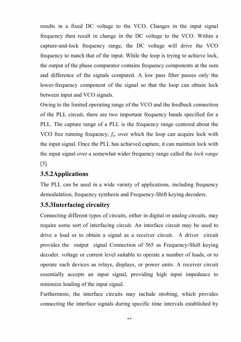
Figure 4.4: The frequency locked at 301KHz.
At301KHz the phase locked loop tracks the input signal appropritely, thus
keeping the VCO output at the required level,also the response of the actuator
is increased reasonably good thus it’s compatible for medium speeds of flight.
Figure 4.3 shows the experimental result at 617KHz.

٣٠
Figure 4.5: The frequency locked at 617KHz.
While at 617KHz the phase locked loop tracking and the actuator response
are extremely rapid and accurate, thus it will be optimum for high speed of
flight.

٣١
CHAPTER FIVE
CONCLUSION and RECOMMENDATIONS
5.1 Conclusion
The phase locked loop (PLL) used to control the landing, take off and change
of direction using servo motor. The output of the phase detector would
respond immediately to vary the speed of the motor in such a direction and
magnitude as to retain the locking of the reference and feedback frequencies.
The response of the phase detector is very fast. As long as the two frequencies
are locked, the speed regulation should ideally be zero. However, in practice
the speed regulation is limited to 0.002%, and this represents a significant
improvement over the analog speed control system.
The PLL synthesis by Voltage Control Oscillator, phase detector, low pass
filter. The result of the experiment shows the servo motor has lock rang
200kHz to 600kHz and capture range can controlled by Phase Locked Loop
between (200-600)KHz must be at minimum greater than 200KHz or equal
and maximum less than 600KHz or equal.
5.2 Recommendations 1. Use phase locked loop (PLL) for reversing speed direction.
2. To determine the feature phase locked loop control scheme, it is
recommended to use a pulse width modulation circuit and compare the
control results with phase locked loop circuit.
3. Using discrete component such as OP_AMP and transistor.

٣٢
References
[1] Katsuhiko Ogata, “Modern Control Engineering”, Fifth Edition, Pearson
Education, 2010.
[2]Colin Mitchell ,50-555Circuits.
[3]Robert Boylestad and Louis Nashelsky,”Electronic Devices and Circuit
Theory”, Seven Edition ,Prentice Hall.
[4]J Shephrd, A H Morton and L FSpence,”Higher Electrical Engineering”,
Letterpress, and Bound in Great Britain,1975.
[5] Guan-Chyun Hsich,and James C.Hung,”Phase-Locked loop Techniques-A
Survey”,1996.
[6]Dennis M. Fischette, Alvin L. S. Loke, Richard J. DeSantis, andGerry R.
Talbot,“An Embedded All-Digital Circuit to Measure Phase-Locked Loop
Response”, August 2010.
[7] Wisnu Djatmiko, and Bambang Sutopo,”Speed Control DC Motor under
Varying Load Using Phase-Locked Loop System”.