
Slide Show Malam Ni Siap
37
High Voltage Application
-
Upload
afiq-anhar -
Category
Documents
-
view
228 -
download
0
Transcript of Slide Show Malam Ni Siap

8/8/2019 Slide Show Malam Ni Siap
http://slidepdf.com/reader/full/slide-show-malam-ni-siap 1/37
8/8/2019 Slide Show Malam Ni Siap
http://slidepdf.com/reader/full/slide-show-malam-ni-siap 2/37
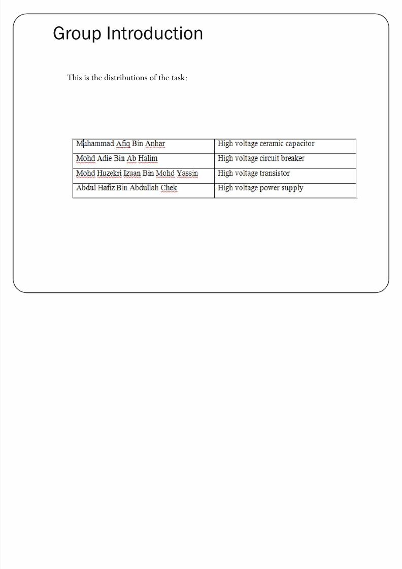
Group Introduction
This is the distributions of the task:

8/8/2019 Slide Show Malam Ni Siap
http://slidepdf.com/reader/full/slide-show-malam-ni-siap 3/37
High Voltage Ceramic Capacitor
Type of capacitor
The capacitor can be divided to two types that is:
1. Polarisedy Large values, 1µF+
y Example of the polarised capacitor is electrolytic capacitors and tantalum beadcapacitors.
2.Unpolarised
y small values, up to 1µF
8/8/2019 Slide Show Malam Ni Siap
http://slidepdf.com/reader/full/slide-show-malam-ni-siap 4/37
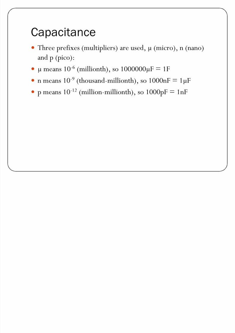
Capacitance
y Three prefixes (multipliers) are used, µ (micro), n (nano)and p (pico):
y µ means 10-6 (millionth), so 1000000µF = 1F
yn means 10
-9
(thousand-millionth), so 1000nF = 1µFy p means 10-12 (million-millionth), so 1000pF = 1nF
8/8/2019 Slide Show Malam Ni Siap
http://slidepdf.com/reader/full/slide-show-malam-ni-siap 5/37
Ceramic Capacitor for high voltage
engineering
y The capacitor is really needed to be used in high voltageengineering. The most common type of capacitor to be usedin this high voltage industry is ceramic capacitor. A ceramiccapacitor is a two-terminal, non-polar device. The classicalceramic capacitor is the "disc capacitor". This device pre-dates the transistor and was used extensively in vacuum-tubeequipment.
8/8/2019 Slide Show Malam Ni Siap
http://slidepdf.com/reader/full/slide-show-malam-ni-siap 6/37
Shapes and styles
y disc, resin coated, with through-hole leads
y multilayer rectangular block, surface mount
y bare leadless disc, sits in a slot in the PCB and is soldered in
place, used for UHF applicationsy tube shape, not popular now
8/8/2019 Slide Show Malam Ni Siap
http://slidepdf.com/reader/full/slide-show-malam-ni-siap 7/37
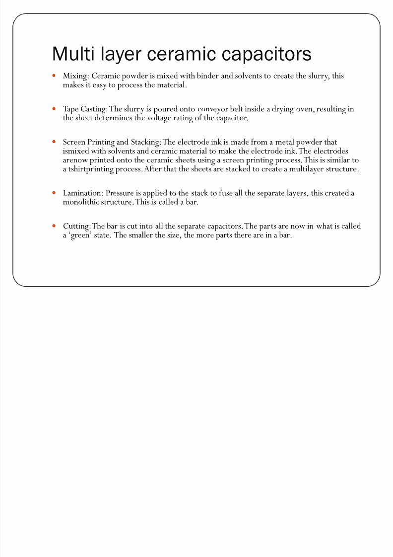
Multi layer ceramic capacitorsy Mixing: Ceramic powder is mixed with binder and solvents to create the slurry, this
makes it easy to process the material.
y Tape Casting: The slurry is poured onto conveyor belt inside a drying oven, resulting inthe sheet determines the voltage rating of the capacitor.
y Screen Printing and Stacking: The electrode ink is made from a metal powder thatismixed with solvents and ceramic material to make the electrode ink. The electrodesarenow printed onto the ceramic sheets using a screen printing process. This is similar toa tshirtprinting process. After that the sheets are stacked to create a multilayer structure.
y Lamination: Pressure is applied to the stack to fuse all the separate layers, this created a
monolithic structure. This is called a bar.
y Cutting: The bar is cut into all the separate capacitors. The parts are now in what is calleda ¶green· state. The smaller the size, the more parts there are in a bar.

8/8/2019 Slide Show Malam Ni Siap
http://slidepdf.com/reader/full/slide-show-malam-ni-siap 8/37
y Firing: The parts are fired in kilns with slow moving conveyor belts. The temperatureprofile is very important to the characteristics of the capacitors.
y Termination: The termination provides the first layer of electrical and mechanical
y connection to the capacitor.Metal powder is mixed with solvents and glass frit to createthe termination ink. Each terminal of the capacitor is then dipped in the ink and theparts are fired in kilns.
y Plating: Using an electroplating process, the termination is plated with a layer of nickeland then a layer of tin. The nickel is a barrier layer between the termination and the tinplating. The tin is used to prevent the nickel from oxidizing.
y Testing: The parts are tested and sorted to their correct capacitance tolerances.
y At this point the capacitor manufacturing is complete. The parts could be packaged ontape and reel after this process or shipped as bulk.

8/8/2019 Slide Show Malam Ni Siap
http://slidepdf.com/reader/full/slide-show-malam-ni-siap 9/37
Application in militaryy Capacitor with high performance and reliability is needed in the military weapons and
device. This is because the device being used with the military will work at the maximumperformance. If normal capacitor is being used, the device will be easily broken. Themulti layer ceramic capacitor is a high voltage capacitor that is affordable. Because of theaffordability and reliability, it is the most common types of capacitors used in themilitary devices.
y
As an example, capacitor is used in power converter. Power converter usually used inelectrical part of military transport such as fighter jets and navy frigates. A powerfulconverter is needed to ensure less power loss during the energy conversion.
y
y Then, capacitor is also used in energy storage. In military, backup for power supply isreally needed because shortage of energy can happened anytime during the war.
y
y Ceramic Chip Capacitors are designed for High Voltage performance and reliability withconservative designs.
y

8/8/2019 Slide Show Malam Ni Siap
http://slidepdf.com/reader/full/slide-show-malam-ni-siap 10/37
Capacitor for power supply and energystorage
8/8/2019 Slide Show Malam Ni Siap
http://slidepdf.com/reader/full/slide-show-malam-ni-siap 11/37
Power Supplies in Military Application
A power supply is a device that supplies electrical energy toone or more electric loads. The term is most commonlyapplied to devices that convert one form of electrical energyto another, though it may also refer to devices that convertanother form of energy to electrical energy
y Mechanical to electrical
y
Chemical to electrical

8/8/2019 Slide Show Malam Ni Siap
http://slidepdf.com/reader/full/slide-show-malam-ni-siap 12/37
8/8/2019 Slide Show Malam Ni Siap
http://slidepdf.com/reader/full/slide-show-malam-ni-siap 13/37
Every power supply must obtain the energy it supplies to its load,as well as any energy it consumes while performing that task, froman energy source. Depending on its design, a power supply mayobtain energy from:
y Electrical energy transmission systems. Common examples of thisinclude power supplies that convert AC line voltage to DCvoltage.
y Energy storage devices such as batteries and fuel cells.y Electromechanical systems such as generators and alternators.
y Solar power
8/8/2019 Slide Show Malam Ni Siap
http://slidepdf.com/reader/full/slide-show-malam-ni-siap 14/37
A power supply may be implemented as a discrete, stand-alonedevice or as an integral device that is hardwired to its load. In thelatter case, for example, low voltage DC power supplies arecommonly integrated with their loads in devices such ascomputers and household electronics.Constraints that commonly
affect power supplies include:
y The amount of voltage and current they can supply.y How long they can supply energy without needing some kind of
refuelling or recharging (applies to power supplies that employ
portable energy sources).y How stable their output voltage or current is under varying load
conditions.y Whether they provide continuous or pulsed energy
8/8/2019 Slide Show Malam Ni Siap
http://slidepdf.com/reader/full/slide-show-malam-ni-siap 15/37
Type of power supply
y Battery power supply
y Unregulated power supply
y Linear regulated power supply
y AC/DC supplyy Switched-mode power supply
y Programmable power supply
y Uninterruptible power supply
y High-voltage power supply
y Voltage multipliers

8/8/2019 Slide Show Malam Ni Siap
http://slidepdf.com/reader/full/slide-show-malam-ni-siap 16/37
Overload protection
y Power supplies often include some type of overloadprotection that protects the power supply from load faults(e.g., short circuits) that might otherwise cause damage byoverheating components or, in the worst case, electrical fire.Fuses and circuit breakers are two commonly usedmechanisms for overload protection
8/8/2019 Slide Show Malam Ni Siap
http://slidepdf.com/reader/full/slide-show-malam-ni-siap 17/37
Fuses
A fuse is a piece of wire, often in a casing that improves itselectrical characteristics. If too much current flows, the wire becomes hot and melts. This effectively disconnects the powersupply from its load, and the equipment stops working until theproblem that caused the overload is identified and the fuse is
replaced.y There are various types of fuses used in power supplies.y fast blow fuses cut the power as quick as they cany slow blow fuses tolerate more short term overloady wire link fuses are just an open piece of wire, and have poorer
overload characteristics than glass and ceramic fusesy Some power supplies use a very thin wire link soldered in place as
a fuse.

8/8/2019 Slide Show Malam Ni Siap
http://slidepdf.com/reader/full/slide-show-malam-ni-siap 18/37
Circuit breakers
y One benefit of using a circuit breaker as opposed to a fuse isthat it can simply be reset instead of having to replace the
blown fuse. A circuit breaker contains an element that heats, bends and triggers a spring which shuts the circuit down.Once the element cools, and the problem is identified the
breaker can be reset and the power restored.

8/8/2019 Slide Show Malam Ni Siap
http://slidepdf.com/reader/full/slide-show-malam-ni-siap 19/37
Thermal cutouts
y Some PSUs use a thermal cutout buried in the transformerrather than a fuse. The advantage is it allows greater currentto be drawn for limited time than the unit can supplycontinuously. Some such cutouts are self resetting, some aresingle use only.
8/8/2019 Slide Show Malam Ni Siap
http://slidepdf.com/reader/full/slide-show-malam-ni-siap 20/37
Current limiting
y Some supplies use current limiting instead of cutting off power if overloaded. The two types of current limiting usedare electronic limiting and impedance limiting. The former iscommon on lab bench PSUs, the latter is common onsupplies of less than 3 watts output.
y A foldback current limiter reduces the output current tomuch less than the maximum non-fault current.
8/8/2019 Slide Show Malam Ni Siap
http://slidepdf.com/reader/full/slide-show-malam-ni-siap 21/37
Power Supplies For Military
Applications.
The list below details some of the supplies that have been designedand reached production, many of which are currently still inproduction. The identity of the end user is classified for someproducts.
y Full suite of 28V DC DC converters for FLIR (Forward LookingInfra Red), used on thermal imaging equipment for Air force,Navy and Army.
y 28VDC to 100VAC converter for cooling engine electronics in the
same FLIR.y Various multiple output very low profile DC DC converters for
video recoding surveillance in unmanned drones.

8/8/2019 Slide Show Malam Ni Siap
http://slidepdf.com/reader/full/slide-show-malam-ni-siap 22/37
y Multiple output supplies for IFF, Identify Friend Or Foe.
y Various supplies for Direct Infra Red Counter Measureelectronics, (DIRCM), also named Nemesis.
y High reliability intelligent battery charger for land basedvehicles.
y High voltage 3 phase 400Hz AC AC converter, used as lineconditioner for cooling FLIR equipment.
y High efficiency, very high reliability power supplies for
location on the sea bed underneath oil rigs.y Other designs cannot be listed or mentioned due to the
classified nature of those products.

8/8/2019 Slide Show Malam Ni Siap
http://slidepdf.com/reader/full/slide-show-malam-ni-siap 23/37
Circuit breaker
y A circuit breaker is an automatically-operated electrical switchdesigned to protect an electrical circuit from damage caused byoverload or short circuit.
y Its basic function is to detect a fault condition and, by interrupting
continuity, to immediately discontinue electrical flow.
y Unlike a fuse, which operates once and then has to be replaced, acircuit breaker can be reset (either manually or automatically) toresume normal operation.
y Circuit breakers are made in varying sizes, from small devices thatprotect an individual household appliance up to large switchgeardesigned to protect high voltage circuits feeding an entire city.
8/8/2019 Slide Show Malam Ni Siap
http://slidepdf.com/reader/full/slide-show-malam-ni-siap 24/37
Operation
y detect a fault condition.
y contacts within the circuit breaker must open to interruptthe circuit.
y
contacts must carry the load current without excessiveheating, and must also withstand the heat of the arc producedwhen interrupting the circuit.
y when a current is interrupted, an arc is generated.
yonce the fault condition has been cleared, the contacts mustagain be closed to restore power to the interrupted circuit.
8/8/2019 Slide Show Malam Ni Siap
http://slidepdf.com/reader/full/slide-show-malam-ni-siap 25/37
Arc interruption
y Miniature low-voltage circuit breakers use air alone toextinguish the arc.
y Magnetic blowout coils deflect the arc into the arc chute.
y
Air circuit breakers may use compressed air to blow out thearc, or alternatively, the contacts are rapidly swung into asmall sealed chamber, the escaping of the displaced air thus
blowing out the arc.
y
Circuit breakers are usually able to terminate all current veryquickly.

8/8/2019 Slide Show Malam Ni Siap
http://slidepdf.com/reader/full/slide-show-malam-ni-siap 26/37
Short circuit currenty Circuit breakers are rated both by the normal current that are
expected to carry, and the maximum short-circuit current thatthey can safely interrupt.
y Under short-circuit conditions, a current many times greater than
normal can exist.y This condition can create conductive ionized gasses and molten or
vaporized metal which can cause further continuation of the arc,or creation of additional short circuits, potentially resulting in theexplosion of the circuit breaker and the equipment that it is
installed in.y The maximum short-circuit current that a breaker can interrupt is
determined by testing.
8/8/2019 Slide Show Malam Ni Siap
http://slidepdf.com/reader/full/slide-show-malam-ni-siap 27/37
Standard current ratingsy International standard IEC 60898-1 and European standard EN
60898-1 define the rated current In of a circuit breaker for lowvoltage distribution applications as the current that the breaker isdesigned to carry continuously (at an ambient air temperature of 30 °C).
y The commonly-available preferred values for the rated current are6 A, 10 A, 13 A, 16 A, 20 A, 25 A, 32 A, 40 A, 50 A, 63 A, 80 Aand 100 A.
y The circuit breaker is labelled with the rated current in amperes, but without the unit symbol "A".
yInstead, the ampere figure is preceded by a letter "B", "C" or "D"that indicates the instantaneous tripping current, that is theminimum value of current that causes the circuit-breaker to tripwithout intentional time delay.

8/8/2019 Slide Show Malam Ni Siap
http://slidepdf.com/reader/full/slide-show-malam-ni-siap 28/37
High-voltage circuit breakersy Electrical power transmission networks are protected and
controlled by high-voltage breakers.
y The definition of high voltage varies but in power transmissionwork is usually thought to be 72.5 kV or higher, according to a
recent definition by the International Electro technicalCommission (IEC).
y High-voltage breakers are nearly always solenoid-operated, withcurrent sensing protective relays operated through currenttransformers.
y In substations the protective relay scheme can be complex,protecting equipment and busses from various types of overloador ground/earth fault.

8/8/2019 Slide Show Malam Ni Siap
http://slidepdf.com/reader/full/slide-show-malam-ni-siap 29/37
Military Circuit Breakersy All military circuit breakers carried byMIL-COM comply
with all mil-spec requirements.
y Remote control circuit breakers (RCCB)by functioning as acombination of a relay and circuit breaker, this device
controls high power circuits and a control signal to thecockpit.
y Mil-spec circuit breakers are available with a wide range of versatile and fully functional features carry such a selection to
provide with maximum efficiency and dependableperformance in some of the most demanding military,aerospace, and commercial applications.

8/8/2019 Slide Show Malam Ni Siap
http://slidepdf.com/reader/full/slide-show-malam-ni-siap 30/37
Circuit Breakers and Alerting Devices in
Military Aircrafty Automatic protective devices (circuit breakers) are provided
within aircraft systems to minimize distress to the electricalsystem and hazard to the aircraft in the event of wiring faults orserious malfunction of a system or connected equipment.
y Alerting devices provide the pilot with a visual and/or aural alarm
to direct the pilot·s attention to a situation that may require animmediate intervention by the pilot.
y Deactivating the alerting or warning device by pulling circuit breakers compromises or may compromise the safety of flight.
y Exceptions would be acceptable for an obvious malfunction
resulting in continuous erroneous warnings.y In these cases, a defect entry in the aircraft journey log book must
be made.

8/8/2019 Slide Show Malam Ni Siap
http://slidepdf.com/reader/full/slide-show-malam-ni-siap 31/37
Circuit Breaker Maintenance &
Application
y A circuit breaker is a device designed to open and close anelectric circuit and to open the circuit automatically at apredetermined overload current, without damage to itself.
y Correct circuit breaker selection should result in a protective
device with the lowest standard rating that will not tripinadvertently.
y The nameplate current rating of circuit breakers is a nominalrating for identification and the actual useable rating for a
particular application may be considerably different.y The instantaneous trip current is usually in the order of ten
times the current rating of the circuit breaker.
8/8/2019 Slide Show Malam Ni Siap
http://slidepdf.com/reader/full/slide-show-malam-ni-siap 32/37
The High Voltage Transistory transistors with higher specification than the normal
transistor.
y usually located in the area of power transformer such as theswitch mode power transformer and fly back transformer.
y In television and monitor that uses the fly back transformerto generate high voltage, a high voltage transistor is requiredto perform the job.
y It's location mainly beside the fly back transformer and attach
to a heat sink in order to transfer heat faster.O
therwise itmay blow in a very short time due to the hard work of thistransistor in switching.

8/8/2019 Slide Show Malam Ni Siap
http://slidepdf.com/reader/full/slide-show-malam-ni-siap 33/37

8/8/2019 Slide Show Malam Ni Siap
http://slidepdf.com/reader/full/slide-show-malam-ni-siap 34/37
Power Transistor Advances Enhance Military Radar Designs
y Military avionics and radar design has seen profound changesover the past few decades. New multimode systems nowallow radar to simultaneously track air and sea targets whilecontinuously scanning an operational area.
y New signal processing techniques such as pulse compressionincrease resolution while maintaining range.
y Ground-based radar (GBR) systems operating in the 1.2 GHzto 1.4 GHz band offer better range and visibility than theyever have before.

8/8/2019 Slide Show Malam Ni Siap
http://slidepdf.com/reader/full/slide-show-malam-ni-siap 35/37
y Over the last several decades, the constant evolution of theRF power transistor, and its impact on PA design, has played
a crucial role in this process.y By continually improving RF transistor performance, military
avionics and radar system designers have been able to deliverPAs capable of providing higher levels of power at higher
efficiency and with higherlinearity.

8/8/2019 Slide Show Malam Ni Siap
http://slidepdf.com/reader/full/slide-show-malam-ni-siap 36/37
Hot Carrier Ageing Mechanisms in High Voltage CMOS transistors
y In the automotive industry, in consumer electronics as well as inindustrial applications integrated circuits are required which canswitch high voltages (and high currents) and perform complexlogic and analogue operations at the same time.
y The lateral High Voltage CMOS transistors which are
implemented in such a technology can switch voltages in the rangeof 10 to some 100 Volts.
y due to the high electrical fields encountered in these transistors,physical effects such as non-equilibrium energy distributions of carriers (hot carrier generation), impact ionization in silicon,
micro structural damage at the silicon / silicon oxide interface andself- heating take place.y These effects lead to a permanent shift of important electrical
parameters of the transistor which can reduce its lifetime.
8/8/2019 Slide Show Malam Ni Siap
http://slidepdf.com/reader/full/slide-show-malam-ni-siap 37/37
High voltage power bipolar transistors for lighting
y High voltage power bipolar transistors are part of industry-leading portfolio for energy-efficient lighting.
y Designed to support electronic ballast and transformerapplications, they are available in versions from 700 to 1200
V and deliver very high efficiency with exceptional reliability.y series of high voltage power bipolar transistors use planar
technology that delivers industry-leading cost-performanceratios.
y
The high-voltage (up to 1200 V) capability is suitable forpush-pull technologies. Fast switching times and low VCEsatratings combine to reduce switching and conduction losses.